Analysis Procedures for Evaluating Superheavy Load Movement on Flexible Pavements, Volume VII: Appendix F, Failure Analysis of Sloped Pavement Shoulders PUBLICATION NO. FHWA-HRT-18-055 MARCH 2019 Research, Development, and Technology Turner-Fairbank Highway Research Center 6300 Georgetown Pike McLean, VA 22101-2296

Welcome message from author
This document is posted to help you gain knowledge. Please leave a comment to let me know what you think about it! Share it to your friends and learn new things together.
Transcript

Analysis Procedures for Evaluating Superheavy Load Movement on Flexible Pavements, Volume VII: Appendix F, Failure Analysis of Sloped Pavement ShouldersPUBLICATION NO. FHWA-HRT-18-055 MARCH 2019
Research, Development, and TechnologyTurner-Fairbank Highway Research Center6300 Georgetown PikeMcLean, VA 22101-2296

FOREWORD
The movement of superheavy loads (SHLs) on the Nation’s highways is an increasingly
common, vital economic necessity for many important industries, such as chemical, oil,
electrical, and defense. Many superheavy components are extremely large and heavy (gross
vehicle weights in excess of a few million pounds), and they often require specialized trailers and
hauling units. At times, SHL vehicles have been assembled to suit the load being transported,
and therefore, the axle configurations have not been standard or consistent. Accommodating
SHL movements without undue damage to highway infrastructure requires the determination of
whether the pavement is structurally adequate to sustain the SHL movement and protect any
underground utilities. Such determination involves analysing the likelihood of instantaneous or
rapid load-induced shear failure of the pavement structure.
The goal of this project was to develop a comprehensive analysis process for evaluating SHL
movement on flexible pavements. As part of this project, a comprehensive mechanistic-based
analysis approach consisting of several analysis procedures was developed for flexible pavement
structures and documented in a 10-volume series of Federal Highway Administration reports—a
final report and 9 appendices.(1–9) This is Analysis Procedures for Evaluating Superheavy Load
Movement on Flexible Pavements, Volume Ⅶ: Appendix F, Failure Analysis of Sloped
Pavement Shoulders, and it details the method developed for investigating the stability of sloped
pavement shoulders under SHL-vehicle movements. It also presents verification of the proposed
approach using the measurements obtained from tests on full-scale pavement structures. This
report is intended for use by highway agency pavement engineers responsible for assessing the
structural adequacy of pavements in the proposed route and identifying mitigation strategies,
where warranted, in support of the agency’s response to SHL-movement permit requests.
Cheryl Allen Richter, Ph.D., P.E.
Director, Office of Infrastructure
Research and Development
Notice
This document is disseminated under the sponsorship of the U.S. Department of Transportation
(USDOT) in the interest of information exchange. The U.S. Government assumes no liability for
the use of the information contained in this document.
The U.S. Government does not endorse products or manufacturers. Trademarks or
manufacturers’ names appear in this report only because they are considered essential to the
objective of the document.
Quality Assurance Statement
The Federal Highway Administration (FHWA) provides high-quality information to serve
Government, industry, and the public in a manner that promotes public understanding. Standards
and policies are used to ensure and maximize the quality, objectivity, utility, and integrity of its
information. FHWA periodically reviews quality issues and adjusts its programs and processes to
ensure continuous quality improvement.

TECHNICAL REPORT DOCUMENTATION PAGE
1. Report No.
FHWA-HRT-18-055
2. Government Accession No.
3. Recipient’s Catalog No.
4. Title and Subtitle
Analysis Procedures for Evaluating Superheavy Load Movement
on Flexible Pavements, Volume Ⅶ: Appendix F, Failure
Analysis of Sloped Pavement Shoulders
5. Report Date
March 2019
6. Performing Organization Code
7. Author(s)
Hadi Nabizadeh (ORCID: 0000-0001-8215-1299),
Raj V. Siddharthan (ORCID: 0000-0002-3847-7934),
Sherif Elfass (ORCID: 0000-0003-3401-6513), and Elie Y. Hajj
(ORCID: 0000-0001-8568-6360)
8. Performing Organization Report No.
WRSC-UNR-201710-01F
9. Performing Organization Name and Address
Department of Civil and Environmental Engineering
University of Nevada
1664 North Virginia Street
Reno, NV 89557
10. Work Unit No.
11. Contract or Grant No.
DTFH61-13-C-00014
12. Sponsoring Agency Name and Address
Office of Infrastructure Research and Development
Federal Highway Administration
Turner-Fairbank Highway Research Center
6300 Georgetown Pike
McLean, VA 22101
13. Type of Report and Period Covered
Final Report; August 2013–July 2018
14. Sponsoring Agency Code
HRDI-20
15. Supplementary Notes
Nadarajah Sivaneswaran (HRDI-20; ORCID: 0000-0003-0287-664X), Office of Infrastructure Research and
Development, Turner-Fairbank Highway Research Center, served as the Contracting Officer’s Representative.
16. Abstract
The movement of superheavy loads (SHLs) on the Nation’s highways is an increasingly common, vital
economic necessity for many important industries, such as chemical, oil, electrical, and defense. SHL hauling
units are much larger in size and weight than standard trucks. SHL gross vehicle weights may be in excess of a
few million pounds, so they often require specialized trailers and components with nonstandard spacing between
tires and axles. Accommodating SHL-vehicle movements requires determining whether pavement is structurally
adequate and analyzing the likelihood of instantaneous or rapid load-induced shear failure. As part of the
Federal Highway Administration project, Analysis Procedures for Evaluating Superheavy Load Movement on
Flexible Pavements, a method of investigating the stability of a sloped pavement shoulder under an SHL-vehicle
movement was developed by modifying the well-accepted wedge method. This new method, with the use of 3D-
Move Analysis software, is capable of considering a layered medium with distinct layer-stiffness values along
with the unconventional SHL-vehicle loading configuration.(10) To account for the existence of a sloped
pavement shoulder in 3D-Move Analysis, computed SHL vehicle-induced stresses are modified using a stress
adjustment factor for a sloped shoulder (SAFShoulder). SAFShoulder was determined based on results from large-
scale pavement experiments conducted in this study.
17. Key Words
Superheavy load, flexible pavement, large-scale
testing, instrumentation, pavement shoulder, slope
stability
18. Distribution Statement
No restrictions. This document is available through the
National Technical Information Service, Springfield,
VA 22161.
http://www.ntis.gov
19. Security Classif. (of this report)
Unclassified
20. Security Classif. (of this page)
Unclassified
21. No. of Pages
51
22. Price
N/A
Form DOT F 1700.7 (8-72) Reproduction of completed page authorized.

ii
SI* (MODERN METRIC) CONVERSION FACTORS APPROXIMATE CONVERSIONS TO SI UNITS
Symbol When You Know Multiply By To Find Symbol
LENGTH in inches 25.4 millimeters mm
ft feet 0.305 meters m
yd yards 0.914 meters m mi miles 1.61 kilometers km
AREA in
2square inches 645.2 square millimeters mm
2
ft2
square feet 0.093 square meters m2
yd2
square yard 0.836 square meters m2
ac acres 0.405 hectares ha
mi2
square miles 2.59 square kilometers km2
VOLUME fl oz fluid ounces 29.57 milliliters mL
gal gallons 3.785 liters L ft
3 cubic feet 0.028 cubic meters m
3
yd3
cubic yards 0.765 cubic meters m3
NOTE: volumes greater than 1000 L shall be shown in m3
MASS oz ounces 28.35 grams g
lb pounds 0.454 kilograms kg
T short tons (2000 lb) 0.907 megagrams (or "metric ton") Mg (or "t")
TEMPERATURE (exact degrees) oF Fahrenheit 5 (F-32)/9 Celsius
oC
or (F-32)/1.8
ILLUMINATION fc foot-candles 10.76 lux lx fl foot-Lamberts 3.426 candela/m
2 cd/m
2
FORCE and PRESSURE or STRESS lbf poundforce 4.45 newtons N
lbf/in2
poundforce per square inch 6.89 kilopascals kPa
APPROXIMATE CONVERSIONS FROM SI UNITS
Symbol When You Know Multiply By To Find Symbol
LENGTHmm millimeters 0.039 inches in
m meters 3.28 feet ft
m meters 1.09 yards yd
km kilometers 0.621 miles mi
AREA mm
2 square millimeters 0.0016 square inches in
2
m2 square meters 10.764 square feet ft
2
m2 square meters 1.195 square yards yd
2
ha hectares 2.47 acres ac
km2
square kilometers 0.386 square miles mi2
VOLUME mL milliliters 0.034 fluid ounces fl oz
L liters 0.264 gallons gal
m3
cubic meters 35.314 cubic feet ft3
m3
cubic meters 1.307 cubic yards yd3
MASS g grams 0.035 ounces oz
kg kilograms 2.202 pounds lbMg (or "t") megagrams (or "metric ton") 1.103 short tons (2000 lb) T
TEMPERATURE (exact degrees) oC Celsius 1.8C+32 Fahrenheit
oF
ILLUMINATION lx lux 0.0929 foot-candles fc
cd/m2
candela/m2
0.2919 foot-Lamberts fl
FORCE and PRESSURE or STRESS N newtons 0.225 poundforce lbf
kPa kilopascals 0.145 poundforce per square inch lbf/in2
*SI is the symbol for th International System of Units. Appropriate rounding should be made to comply with Section 4 of ASTM E380. e
(Revised March 2003)

iii
ANALYSIS PROCEDURES FOR EVALUATING SUPERHEAVY LOAD MOVEMENT
ON FLEXIBLE PAVEMENTS PROJECT REPORT SERIES
This volume is the seventh of 10 volumes in this research report series. Volume Ⅰ is the final
report, and Volume Ⅱ through Volume Ⅹ consist of Appendix A through Appendix I. Any
reference to a volume in this series will be referenced in the text as “Volume Ⅱ: Appendix A,”
“Volume Ⅲ: Appendix B,” and so forth. The following list contains the volumes:
Volume Title Report Number
Ⅰ Analysis Procedures for Evaluating Superheavy Load
Movement on Flexible Pavements, Volume Ⅰ: Final Report
FHWA-HRT-18-049
Ⅱ Analysis Procedures for Evaluating Superheavy Load
Movement on Flexible Pavements, Volume Ⅱ: Appendix A,
Experimental Program
FHWA-HRT-18-050
Ⅲ Analysis Procedures for Evaluating Superheavy Load
Movement on Flexible Pavements, Volume Ⅲ: Appendix B,
Superheavy Load Configurations and Nucleus of Analysis
Vehicle
FHWA-HRT-18-051
Ⅳ Analysis Procedures for Evaluating Superheavy Load
Movement on Flexible Pavements, Volume Ⅳ: Appendix C,
Material Characterization for Superheavy Load Movement
Analysis
FHWA-HRT-18-052
Ⅴ Analysis Procedures for Evaluating Superheavy Load
Movement on Flexible Pavements, Volume Ⅴ: Appendix D,
Estimation of Subgrade Shear Strength Parameters Using Falling
Weight Deflectometer
FHWA-HRT-18-053
Ⅵ Analysis Procedures for Evaluating Superheavy Load
Movement on Flexible Pavements, Volume Ⅵ: Appendix E,
Ultimate and Service Limit Analyses
FHWA-HRT-18-054
Ⅶ Analysis Procedures for Evaluating Superheavy Load
Movement on Flexible Pavements, Volume Ⅶ: Appendix F,
Failure Analysis of Sloped Pavement Shoulders
FHWA-HRT-18-055
Ⅷ Analysis Procedures for Evaluating Superheavy Load
Movement on Flexible Pavements, Volume Ⅷ: Appendix G,
Risk Analysis of Buried Utilities Under Superheavy Load
Vehicle Movements
FHWA-HRT-18-056
Ⅸ Analysis Procedures for Evaluating Superheavy Load
Movement on Flexible Pavements, Volume Ⅸ: Appendix H,
Analysis of Cost Allocation Associated with Pavement Damage
Under a Superheavy Load Vehicle Movement
FHWA-HRT-18-057
Ⅹ Analysis Procedures for Evaluating Superheavy Load
Movement on Flexible Pavements, Volume Ⅹ: Appendix I,
Analysis Package for Superheavy Load Vehicle Movement on
Flexible Pavement (SuperPACK)
FHWA-HRT-18-058

iv
TABLE OF CONTENTS
INTRODUCTION ............................................................................................1
SLOPE STABILITY–ANALYSIS METHODOLOGY ................................5 2.1 WEDGE METHOD ....................................................................................................6
DETERMINATION OF SAFSHOULDER .........................................................11 3.1 DESCRIPTION OF LARGE-SCALE EXPERIMENTS ......................................11 3.2 COMPARISON OF STRESS MEASUREMENTS ...............................................22
3.3 SAFSHOULDER ..............................................................................................................28
VALIDATION OF SLOPE STABILITY USING THE
WEDGE METHOD .....................................................................................................................35
4.1. FOS FOR A SLOPED EDGE IN EXPERIMENT NO. 4 .....................................35
SUMMARY AND CONCLUSION ...............................................................39
REFERENCES .............................................................................................................................41

v
LIST OF FIGURES
Figure 1. Flowchart. Overall SHL-vehicle analysis methodology ..................................................2
Figure 2. Equation. Calculation of FOS for slope-stability analysis ...............................................5 Figure 3. Equation. Calculation of τstrength ........................................................................................5 Figure 4. Equation. Allowable τinduced required for equilibrium ......................................................5 Figure 5. Equation. Calculation of cD ..............................................................................................5
Figure 6. Equation. Calculation of D ..............................................................................................5 Figure 7. Illustration. Search schemes for failure wedges ...............................................................7 Figure 8. Illustration. Failure wedge with horizontal slip surface and applied forces .....................7 Figure 9. Illustration. Failure wedge with inclined slip surface and applied forces ........................8
Figure 10. Equation. FOS against failure for wedges with an inclined slip surface ........................8
Figure 11. Equation. FOS against failure for wedges with a horizontal slip surface ......................8
Figure 12. Equation. Calculation of Ka ............................................................................................8 Figure 13. Equation. Calculation of σa .............................................................................................9 Figure 14. Illustration. Plan view for large-scale-box instrumentations in experiment No. 3 .......12 Figure 15. Illustration. Section A-A view for large-scale-box instrumentations in
experiment No. 3 ..................................................................................................................13 Figure 16. Illustration. Section 1-1 view for large-scale-box instrumentations in experiment
No. 3 .....................................................................................................................................14 Figure 17. Illustration. Section 2-2 view for large-scale-box instrumentations in experiment
No. 3 .....................................................................................................................................15
Figure 18. Illustration. 3D view of large-scale-box instrumentations in experiment No. 4
(elevation of 77 inches) ........................................................................................................16
Figure 19. Illustration. Plan view for large-scale-box instrumentations in experiment No. 4
(elevation of 77 inches) ........................................................................................................17
Figure 20. Illustration. Front elevation of large-scale-box instrumentations in experiment
No. 4 (elevation of 77 inches) ..............................................................................................18
Figure 21. Illustration. Side elevation of large-scale-box instrumentations in experiment
No. 4 (elevation of 77 inches) ..............................................................................................19 Figure 22. Illustration. Plan view of large-scale-box instrumentations in experiment No. 4
(elevation of 69 inches) ........................................................................................................20 Figure 23. Illustration. Plan view of large-scale-box instrumentations in experiment No. 4
(elevation of 60 inches) ........................................................................................................21 Figure 24. Illustration. Plan view of large-scale-box instrumentations in experiment No. 4
(elevation of 46 inches) ........................................................................................................22 Figure 25. Graph. Comparison between surface displacements in experiment No. 3 and
experiment No. 4 (load applied at Loc36) ............................................................................23 Figure 26. Graph. Comparison between measured σv in experiment No. 3 and experiment
No. 4 (nonslope side, 6 inches from SG surface, offset from the centerline of the load
equal to 12 inches) ................................................................................................................24 Figure 27. Graph. Comparison between measured σv in experiment No. 3 and experiment
No. 4 (nonslope side, 6 inches from SG surface, offset from the centerline of the load
equal to 24 inches) ................................................................................................................24 Figure 28. Graph. Comparison between measured σv in experiment No. 3 and experiment
No. 4 (20 inches from SG surface, centerline of the load) ...................................................25

vi
Figure 29. Graph. Comparison between measured σv in experiment No. 3 and experiment
No. 4 (6 inches from SG surface, centerline of the load) .....................................................25
Figure 30. Graph. Comparison between measured σv in experiment No. 3 and experiment
No. 4 (slope side, 6 inches from SG surface, offset from the centerline of the load
equal to 12 inches) ................................................................................................................26 Figure 31. Graph. Comparison between measured σv in experiment No. 3 and experiment
No. 4 (load applied at Loc36, slope side, 6 inches from SG surface, offset from the
centerline of the load equal to 12 inches) .............................................................................27 Figure 32. Graph. Comparison between measured σv in experiment No. 3 and experiment
No. 4 (load applied at Loc36, slope side, 6 inches from SG surface, offset from the
centerline of the load equal to 24 inches) .............................................................................27 Figure 33. Graph. Measured deflection basins in experiment No. 3 .............................................28
Figure 34. Graph. Comparison between σv and σv calculated using 3D-Move Analysis in
experiment No. 3 ..................................................................................................................29 Figure 35. Graph. Comparison between σv and σv calculated using 3D-Move Analysis in
experiment No. 4 (20 inches from SG surface, centerline of the load) ................................30
Figure 36. Graph. Comparison between σv and σv calculated using 3D-Move Analysis in
experiment No. 4 (6 inches from SG surface, centerline of the load) ..................................31 Figure 37. Graph. Comparison between σv and σv calculated using 3D-Move Analysis in
experiment No. 4 (slope side, 20 inches from SG surface, offset from the centerline
of the load equal to 12 inches) .............................................................................................31
Figure 38. Graph. Comparison between σv and σv calculated using 3D-Move Analysis in
experiment No. 4 (slope side, 20 inches from SG surface, offset from the centerline
of the load equal to 24 inches) .............................................................................................32
Figure 39. Graph. Comparison between σv and σv calculated using 3D-Move Analysis in
experiment No. 4 (slope side, 6 inches from SG surface, offset from the centerline of
the load equal to 12 inches) ..................................................................................................32 Figure 40. Graph. Comparison between σv and σv calculated using 3D-Move Analysis in
experiment No. 4 (slope side, 6 inches from SG surface, offset from the centerline of
the load equal to 24 inches) ..................................................................................................33
Figure 41. Illustration. Schematic of experiment No. 4 .................................................................35 Figure 42. Illustration. Possible failure wedge ..............................................................................36 Figure 43. Illustration. Diagram of the force applied on the possible failure wedge ....................36
Figure 44. Equation. Calculation of Kp ..........................................................................................37 Figure 45. Equation. Calculation of σP ..........................................................................................37 Figure 46. Equation. FOS against failure for the wedges in experiment No. 4 .............................37
Figure 47. Graph. Adjusted horizontal stresses calculated using 3D-Move Analysis ...................38

vii
LIST OF TABLES
Table 1. Developed analysis procedures to evaluate SHL movement on flexible pavements ........3
Table 2. Summary of computed SAFShoulder ...................................................................................33 Table 3. Properties of materials in experiment No. 4 ....................................................................37

viii
LIST OF ABREVIATIONS AND SYMBOLS
Abbreviations
3D three-dimensional
AC asphalt concrete
CAB crushed aggregate base
FWD falling weight deflectometer
Loc location
No. number
SG subgrade
SHL superheavy load
TEPC total earth pressure cell
Symbols
ASG trapezoidal side surfaces composed of subgrade
Bwedge width of the wedge
c cohesion
cD developed cohesion
FD resultant force from the bottom soil (slip surface)
FOS factor of safety
Ka Rankine active earth pressure coefficient
Kp Rankine passive earth pressure coefficient
l length of bottom slip surface
P resultant horizontal force due to a surcharge load
PD resistive force from the side soil that makes an angle the resultant force
makes with the normal to the bottom slip surface with the normal to the
side surfaces (i.e., front and back)
Q lateral earth pressure from the adjacent soil
SAFShoulder stress adjustment factor for a sloped shoulder
T'D developed resisting cohesion force resulting from mobilized cohesion
acting on the side surfaces (i.e., front and back)
TD mobilized cohesion acting on the bottom slip surface
W weight of the sliding wedge
wedge angle between the slip surface and horizontal surface
σ0 vertical soil pressure
σa Rankine active earth pressure
σn normal stress on the failure plane
σP Rankine passive earth pressure
σv vertical stress
τinduced induced shear stress
τstrength shear strength
angle of internal friction
ϕD developed angle of internal friction

1
INTRODUCTION
Many industries, such as chemical, oil, electrical, and defense, require the movement of
superheavy loads (SHLs) on the Nation’s highways. SHL hauling units are much larger in size
and weight than standard trucks, often with gross vehicle weights in excess of a few million
pounds. Accordingly, SHL vehicles frequently necessitates specialized trailers and components
with nonstandard spacing between tires and axles. Accommodating SHL-vehicle movements
requires determining whether pavement is structurally adequate and analyzing the likelihood of
instantaneous or rapid load-induced shear failure. Figure 1 shows the flowchart of the overall
approach developed as part of this Federal Highway Administration project, Analysis Procedures
for Evaluating Superheavy Load Movement on Flexible Pavements. In general, the approach
consists of the following four major components:
• Ultimate failure analyses.
• Buried utility risk analysis.
• Service limit analyses.
• Cost allocation analysis.
Mitigation strategies may be needed at any stage of the evaluation process when the calculated
results fail to meet the respective requirements imposed (e.g., when results indicate a high
potential for shear failure of the pavement or damage to buried utilities).
As shown in figure 1, the first step of this approach involves a risk analysis of instantaneous or
rapid load-induced ultimate shear failure. Subgrade (SG) is generally the weakest layer in a
pavement structure. Thus, a bearing failure analysis should be performed to investigate the
likelihood of general bearing capacity failure under an SHL vehicle within the influenced zone of
an SG layer. Sloped-shoulder failure analysis, which examines the bearing capacity failure and
edge-slope stability associated with a sloped ground under an SHL-vehicle movement, would be
the next step. If the ultimate failure analyses reveal no failure in the sloped shoulder, a buried
utility risk analysis should be conducted (when applicable). In this analysis, induced stresses and
deflections by an SHL vehicle on existing buried utilities are evaluated and compared to
established design criteria. Subsequently, if no mitigation strategies are needed, service limit
analyses for localized shear failure and deflection-based service limits should be conducted. A
localized shear failure analysis is performed to investigate the possibility of failure at the critical
location on top of an SG layer under an SHL vehicle. A deflection-based service limit analysis
assesses the magnitude of load-induced pavement deflections during an SHL-vehicle movement.
This analysis, for instance, may suggest the need for mitigation strategies to meet the imposed
acceptable surface-deflection limits. After successfully completing all previously described
analyses (i.e., ultimate failure analyses, buried utility risk analysis, and service limit analyses), a
cost allocation analysis should be conducted.
A summary of the various analysis procedures developed in this study and the associated
objectives (including related volume numbers) are summarized in table 1. This report
(Volume Ⅶ: Appendix F) is the seventh of 10 volumes and presents the slope-stability approach
that allows for the stability analysis of a sloped shoulder subjected to an SHL-vehicle movement.

2
© 2018 UNR.
Figure 1. Flowchart. Overall SHL-vehicle analysis methodology.
Mitigation Strategies
Pavement Damage–Associated Costs
(PDAC)
SHL Analysis Vehicle
Subgrade Bearing Failure Analysis
Sloped Shoulder Failure Analysis
Localized Shear Failure Analysis
Deflection-Based Service Limit Analysis
Flexible Pavement Structure
Satisfactory ?
Yes
No
Satisfactory ?
Yes
Satisfactory ?
Satisfactory ?
Yes
Buried Utility Risk Analysis
No
Exclude Buried
Utilities ?
No
Satisfactory ?
Yes
No
Yes YesNo
No

3
Table 1. Developed analysis procedures to evaluate SHL movement on flexible pavements.
Procedure Objective
SHL analysis vehicle Identify segment(s) of the SHL vehicle configuration
that can be regarded as representative of the entire
SHL vehicle (Volume Ⅲ: Appendix B)(3)
Flexible pavement structure Characterize representative material properties for
existing pavement layers (Volume Ⅳ: Appendix C
and Volume Ⅴ: Appendix D)(4)
SG bearing failure analysis Investigate instantaneous ultimate shear failure in
pavement SG (Volume Ⅵ: Appendix E)(6)
Sloped-shoulder failure analysis Examine the stability of sloped pavement shoulders
under SHL-vehicle movement (Volume Ⅶ:
Appendix F)
Buried utility risk analysis Perform risk analysis of existing buried utilities
(Volume Ⅷ: Appendix G)(7)
Localized shear failure analysis Inspect the likelihood of localized failure (yield) in
the pavement SG (Volume Ⅵ: Appendix E)(6)
Deflection-based service limit analysis Investigate the development of premature surface
distresses (Volume Ⅵ: Appendix E)(6)
Cost allocation analysis Determine pavement damage–associated cost
attributable to SHL-vehicle movement (Volume Ⅸ:
Appendix H)(8)
SHL vehicles are usually moved during periods of controlled traffic, so it is often possible to
keep SHL vehicles far from the edges and shoulders of a pavement. Due to narrow lanes or wide
SHL vehicles, however, keeping SHL vehicles away from a pavement edge, particularly on
routes where there is an unpaved shoulder and/or a steep slope, is not always possible. Therefore,
it is necessary to investigate the stability of sloped pavement shoulders under SHL-vehicle
movements.
Although slope stability is a common problem in geotechnical practice, it has not been a major
concern for roads subjected to only standard truck loading. However, substantially higher
surcharge loads resulting from SHL-vehicle movements might lead to sloped shoulder failure.
Fernando hypothesized that the role of an SHL vehicle can be investigated by comparing
pavement responses at the edges and interior of a lane under falling weight deflectometer (FWD)
loading.(11) However, analysis of the stability of a sloped shoulder under SHL-vehicle
movements had not been undertaken. Such an analysis requires information, including geometry,
failure planes, and shear strength (τstrength) parameters.
In this study, the wedge method, which is a common means of analyzing slope stability in
geotechnical practices, was modified to evaluate the stability of a sloped, layered medium
consisting of typical pavement-layer configurations and properties subjected to an SHL-vehicle
movement.
In geotechnical practice, the Boussinesq theory, which is limited to a homogenous soil medium,
is routinely used to determine stress distribution. In this study, 3D-Move Analysis software was

4
used to compute stress distributions within the layered medium of a pavement.(10) 3D-Move
Analysis was considered an ideal candidate for stress distributions computation because it can
account for viscoelastic properties of an asphalt concrete (AC) layer as well as for a moving load
with nonuniform tire–pavement interface stresses on a loaded area of any shape. However, this
software assumes that pavement layers extend laterally to infinity. Therefore, the role of a sloped
shoulder on stress distributions near the edge of a pavement should be accounted for when this
software is used to compute SHL vehicle–induced stresses on a shoulder. To address this issue,
the stresses computed using 3D-Move Analysis are modified using a stress adjustment factor for
a sloped shoulder (SAFShoulder). In this report, SAFShoulder, determined based on large-scale
experiments (i.e., experiment number (No.) 3 and experiment No. 4), is presented. The validation
of the proposed methodology is also presented and discussed.

5
SLOPE STABILITY–ANALYSIS METHODOLOGY
Conventional slope-stability approaches are based on a limit equilibrium analysis of a mass of
soil bounded between an assumed possible slip surface(s) and slope surface. Failure is
investigated by comparing the corresponding driving and resisting sliding forces and moments.
Such approaches are generally categorized as limit equilibrium analyses, and to identify the most
critical slip surface, they consider several of these surfaces for possible failure. In general, the
stability of a soil mass depends upon its weight, the external forces acting upon it (such as
surcharges), and τstrength and porewater pressures along the slip surface(s). The stability of a slope
is investigated by calculating a factor of safety (FOS), which is defined as the ratio of the
available τstrength to the induced shear stress (τinduced) required for equilibrium. In an analysis based
on total stresses, the FOS is evaluated using the equations shown in figure 2 and figure 3.
Figure 2. Equation. Calculation of FOS for slope-stability analysis.
Figure 3. Equation. Calculation of τstrength.
Where:
c = cohesion.
ϕ = angle of internal friction.
σn = normal stress on the failure plane.
By rewriting the equation in figure 2, the allowable τinduced to maintain stability can be expressed
by the equation in figure 4. The terms on the right-hand side of the equation in figure 4 represent
the developed (i.e., mobilized) c (cD) (figure 5) and developed (D) (figure 6), respectively.
Figure 4. Equation. Allowable τinduced required for equilibrium.
Figure 5. Equation. Calculation of cD.
Figure 6. Equation. Calculation of tanD.
By assuming a value for FOS and calculating the corresponding mobilized shear stress, a
possible static equilibrium condition between resisting and driving forces and moments can be
determined. This process is repeated until the minimum value of FOS is determined.
𝐹𝑂𝑆 =𝜏𝑠𝑡𝑟𝑒 𝑛𝑔𝑡ℎ
𝜏𝑖𝑛𝑑𝑢𝑐𝑒𝑑
𝜏𝑠𝑡𝑟𝑒 𝑛𝑔𝑡 ℎ = 𝑐 + 𝜎𝑛 tan𝜙
𝜏𝑖𝑛𝑑𝑢𝑐 𝑒𝑑 =𝑐
𝐹𝑂𝑆+𝜎𝑛 tan𝜙
𝐹𝑂𝑆
𝑐𝐷 =𝑐
𝐹𝑂𝑆
tan𝜙𝐷 =tan𝜙
𝐹𝑂𝑆

6
Many limit equilibrium methods, such as the ordinary method of slices, simplified Bishop,
modified Swedish method, and Spencer’s method, use different assumptions to achieve a
solution because the slope-stability problem is statically indeterminate. Methods, such as the
Morgenstern–Price method, that satisfy all static equilibrium conditions are referred to as
“complete” equilibrium methods. Although complete equilibrium methods are generally more
accurate than “incomplete” ones (e.g., simplified Bishop method), they do require a rigorous and
time-consuming analysis. However, incomplete equilibrium methods are often sufficiently
accurate and have been useful for many practical applications (e.g., water retaining structures
and tailings dams).(12,13) All such methods assume a plane strain condition, and therefore, only
vertical cross sections are used in the analysis.
WEDGE METHOD
The wedge method has been used extensively by the U.S. Army Corps of Engineers and the
geotechnical engineering community for slope-stability analysis.(12,13) This method satisfies the
force equilibrium in both horizontal and vertical directions but does not satisfy the moment
equilibrium. The use of circular failure surfaces is appropriate for homogeneous slopes; for
layered soils, however, especially when layers with contrasting strength characteristics are
present in the domain, the wedge method has been recommended by U.S. Army Corps of
Engineers.(12) The wedge method is appropriate for investigating the stability of a sloped
shoulder subjected to an SHL-vehicle movement, but it needs to be modified when a layered
medium exists. This chapter summarizes the modified wedge method developed in this study.
Figure 7 illustrates a typical flexible pavement structure with a sloped shoulder. As illustrated in
this figure, to investigate the stability of a pavement shoulder subjected to an SHL-vehicle
movement, various wedges of failure are selected. This figure shows several slip surfaces
passing through point A as solid lines. In all cases, the failure wedge is bounded by a vertical
plane, and a horizontal or inclined slip surface is located in the SG layer. The vertical plane is
located to the left of the AC layer as it is assumed that the vertical plane cannot extend through
the AC layer. It is also assumed that the slip surface is developed in the SG layer because it is the
weakest layer in the pavement structure. Searching for the critical location of the failure wedge
involves systematically varying the horizontal boundaries of the wedges until the corresponding
minimum FOS is found.

7
© 2018 UNR.
CAB = crushed aggregate base.
Figure 7. Illustration. Search schemes for failure wedges.
The stability of each failure wedge is evaluated by considering the wedge as a rigid sliding mass
or a gravity-retaining structure. As shown in figure 8 and figure 9, five forces acting on the
failure wedge can be identified as follows:
• The weight of the sliding wedge (W).
• The developed resisting c force resulting from the mobilized c acting on the bottom slip
surface (TD).
• The resultant force from the bottom soil (slip surface) (FD) that makes ϕD.
• The two components of horizontal driving forces acting on the vertical plane: lateral earth
pressure from the adjacent soil (Q) and resultant horizontal force due to a surcharge load
(P) (i.e., SHL vehicle).
© 2018 UNR.
CAB = crushed aggregate base.
Figure 8. Illustration. Failure wedge with horizontal slip surface and applied forces.

8
© 2018 UNR.
CAB = crushed aggregate base.
Figure 9. Illustration. Failure wedge with inclined slip surface and applied forces.
To determine FOS, the force equilibrium equations in parallel and perpendicular directions to the
slip surface are applied. Consequently, FOS using the equation presented in figure 10 or
figure 11 can be determined. Here, wedge is the angle between the slip surface and horizontal
surface (figure 9), and l is the length of the bottom slip surface. For the failure wedges with a
horizontal slip surface where wedge is 0, FOS can be simplified to the equation shown in
figure 11. To investigate the stability of a sloped shoulder under an SHL-vehicle movement, the
slope stability–analysis module, which is capable of analyzing all possible failure wedges, was
incorporated into the Superheavy Load Pavement Analysis PACKage (SuperPACK).
Figure 10. Equation. FOS against failure for wedges with an inclined slip surface.
Figure 11. Equation. FOS against failure for wedges with a horizontal slip surface.
Q is calculated by using Rankine active earth pressure (a), which is a well-accepted procedure
for designing retaining structures.(14) This is achieved by integrating the distribution of a along
the vertical plane of the failure wedge under consideration. a is calculated using figure 12 as a
function of the vertical soil pressure (σ0), c, and the Rankine active pressure coefficient (Ka) that
is defined in figure 13.
Figure 12. Equation. Calculation of Ka.
𝐹𝑂𝑆 =(𝑊 cos 𝜃𝑤𝑒𝑑𝑔𝑒 − (𝑄 + 𝑃) sin𝜃𝑤𝑒𝑑𝑔𝑒 ) tan𝜙 + 𝑐𝑙
(𝑊 sin𝜃𝑤𝑒𝑑𝑔𝑒 + (𝑄 + 𝑃) cos𝜃𝑤𝑒𝑑𝑔𝑒 )
𝐹𝑂𝑆 =𝑊tan𝜙 + 𝑐𝑙
𝑃 + 𝑄
𝐾𝑎 = tan2 45 −𝜙
2

9
Figure 13. Equation. Calculation of σa.
P is calculated by using the load-induced horizontal stress distribution on the sliding wedge
based on the Boussinesq theory.(14) This means that an elastic, homogenous, and isotropic semi-
infinite soil medium is assumed. Subsequently, the load-induced horizontal stress on the sliding
wedge calculated using the Boussinesq theory is doubled to account for the yielding soil
continuum. In other words, the stresses given by the Boussinesq solution are multiplied by
SAFShoulder with a value equal to 2. It should be noted that P is the integration of the calculated
load-induced horizontal stress distribution along the vertical plane of the same failure wedge
under consideration.
These assumptions may not hold true for a pavement structure with layers that have distinct
strength properties. Moreover, the complex loading configuration of an SHL vehicle cannot be
handled by Boussinesq equations. Since 3D-Move Analysis can account for the viscoelastic
properties of an AC layer, nonuniform tire–pavement interface stresses on a loaded area of any
shape, as well as moving loads, it was an ideal candidate for computing load-induced horizontal
stresses of sloped shoulders. However, computed lateral stresses using 3D-Move Analysis, which
assumes the pavement layers extend laterally to infinity, are a concern. To address this issue, a
modification of 3D-Move Analysis computed stresses using SAFShoulder was proposed. Discussion
regarding the determination of SAFShoulder is presented in the next chapter.
𝜎𝑎 = 𝜎0𝐾𝑎 − 2𝑐 𝐾𝑎


11
DETERMINATION OF SAFShoulder
To determine a suitable SAFShoulder for sloped shoulder stability analysis, large-scale tests of a
sloped edge (i.e., experiment No. 4) were conducted. A careful comparison between experiment
No. 3 (which had no sloped pavement shoulder) and experiment No. 4 identified the role of a
sloped edge in the stress distribution within a typical pavement structure. This chapter first
describes both experiments along with corresponding observations and then describes the
exercise to determine SAFShoulder.
DESCRIPTION OF LARGE-SCALE EXPERIMENTS
As the main objective of this comparative analysis was to determine the role of a sloped shoulder
in the load-carrying capacity of a pavement structure under an SHL-vehicle movement, the same
pavement structure, materials, and construction practice were used in experiment No. 3 and
experiment No. 4.
Experiment No. 3 included FWD testing on the full pavement structure, which was composed of
5 inches of AC, 6 inches of crushed aggregate base (CAB), and 66 inches of SG. FWD loads of
9,000; 12,000; 16,000; 21,000; and 27,000 lb were applied to the pavement surface and in the
middle of the pavement. Figure 14 through figure 17 detail the instrumentation plans. A detailed
discussion regarding the large-scale experiments (construction practice, instrumentation, material
properties, etc.) can be found in Volume Ⅱ: Appendix A.(2)
In experiment No. 4, a full pavement structure was constructed with a total thickness of
77 inches and a side slope of 1:1.5 (33.7 degrees with the horizontal). Figure 18 through
figure 24 are drawings of the experiment setup. Similar to experiment No. 3, the pavement
structure consisted of 5 inches of AC, 6 inches of CAB, and 66 inches of SG. FWD loads were
applied on top of the AC layer at the following three locations: 12, 24, and 36 inches from the
edge of the pavement (i.e., the slope). Similar to experiment No. 3, FWD loads of 9,000; 12,000;
16,000; 21,000; and 27,000 lb were applied at each of three locations. These locations are
referred to as Loc12, Loc24, and Loc36, respectively.

12
© 2018 UNR.
L = linear variable differential transformer; A = accelerometer.
Figure 14. Illustration. Plan view for large-scale-box instrumentations in experiment No. 3.

13
© 2018 UNR.
Note: All elevations are in inches.
L = linear variable differential transformer; P = total earth pressure cell; A = accelerometer.
Figure 15. Illustration. Section A-A view for large-scale-box instrumentations in
experiment No. 3.

14
© 2018 UNR.
P = total earth pressure cell; A = accelerometer.
Figure 16. Illustration. Section 1-1 view for large-scale-box instrumentations in experiment
No. 3.

15
© 2018 UNR.
P = total earth pressure cell; A = accelerometer.
Figure 17. Illustration. Section 2-2 view for large-scale-box instrumentations in experiment
No. 3.

16
© 2018 UNR.
L = linear variable differential transformer; A = accelerometer.
Figure 18. Illustration. 3D view of large-scale-box instrumentations in experiment No. 4
(elevation of 77 inches).

17
© 2018 UNR.
Note: All dimensions are in inches.
L = linear variable differential transformer; A = accelerometer.
Figure 19. Illustration. Plan view for large-scale-box instrumentations in experiment No. 4
(elevation of 77 inches).

18
© 2018 UNR.
Note: All dimensions are in inches.
L = linear variable differential transformer.
Figure 20. Illustration. Front elevation of large-scale-box instrumentations in experiment No. 4 (elevation of 77 inches).

19
© 2018 UNR.
Note: All dimensions are in inches.
Figure 21. Illustration. Side elevation of large-scale-box instrumentations in experiment No. 4 (elevation of 77 inches).

20
© 2018 UNR.
Note: All dimensions are in inches.
P = total earth pressure cell; A = accelerometer.
Figure 22. Illustration. Plan view of large-scale-box instrumentations in experiment No. 4
(elevation of 69 inches).

21
© 2018 UNR.
Note: All dimensions are in inches.
P = total earth pressure cell; A = accelerometer.
Figure 23. Illustration. Plan view of large-scale-box instrumentations in experiment No. 4
(elevation of 60 inches).

22
© 2018 UNR.
P = total earth pressure cell.
Figure 24. Illustration. Plan view of large-scale-box instrumentations in experiment No. 4
(elevation of 46 inches).
COMPARISON OF STRESS MEASUREMENTS
Figure 25 depicts the deflection basins measured in experiment No. 3 and experiment No. 4 at
three load levels (i.e., 9,000; 16,000; and 27,000 lb) applied at Loc36. This figure implies that,
when the load is far enough from the edge in experiment No. 4, surface deflections are similar to
the ones in experiment No. 3, which means that the stiffness properties of the pavement layers in
the two experiments are reasonably similar. Consequently, experiment No. 3 can be treated as a
control experiment so that any difference in stress measurements at the same location in both
experiments can be attributed to the sloped edge.

23
© 2018 UNR.
Figure 25. Graph. Comparison between surface displacements in experiment No. 3 and
experiment No. 4 (load applied at Loc36).
Figure 26 and figure 27 show the measured vertical stresses (σv) in the SG on the nonslope side
of the pavement structure with respect to the location of the applied surface load. Compared to
the corresponding measured stresses in experiment No. 3, the stress distribution in the nonslope
side of the pavement structure was not affected by the sloped edge.
Figure 28 and figure 29 demonstrate the load-induced σv measured by the total earth pressure
cells (TEPCs) that were installed under the exact centerline of the load at different depths in the
SG. (In this study, specific TEPCs are denoted by a P and a corresponding number.) These
figures show the increase in the measured σv in experiment No. 4 compared to experiment No. 3.
0
0.01
0.02
0.03
0.04
0.05
0.06
0.07
0.08
0.09
0 10 20 30 40 50 60
Su
rfa
ce D
efle
ctio
n (
inch
)Radial Distance (inch)
Exp. No. 3_9,000 lb
Exp. No. 4_9,000 lb
Exp. No. 3_16,000 lb
Exp. No. 4_16,000 lb
Exp. No. 3_27,000 lb
Exp. No. 4_27,000 lb

24
© 2018 UNR.
Figure 26. Graph. Comparison between measured σv in experiment No. 3 and experiment
No. 4 (nonslope side, load applied at Loc12 and Loc24, 6 inches from SG surface, offset
from the centerline of the load equal to 12 inches).
© 2018 UNR.
Figure 27. Graph. Comparison between measured σv in experiment No. 3 and experiment
No. 4 (nonslope side, load applied at Loc12 and Loc36, 6 inches from SG surface, offset
from the centerline of the load equal to 24 inches).

25
© 2018 UNR.
Figure 28. Graph. Comparison between measured σv in experiment No. 3 and experiment
No. 4 (load applied at Loc12, 20 inches from SG surface, centerline of the load).
© 2018 UNR.
Figure 29. Graph. Comparison between measured σv in experiment No. 3 and experiment
No. 4 (load applied at Loc12, 6 inches from SG surface, centerline of the load).
Figure 30 through figure 32 depict the measured σv at the location of the TEPCs, which were
located in the slope side with respect to the applied surface load in experiment No. 4. Figure 30

26
shows the measured load-induced σv at 6 inches from the SG surface in experiment No. 4 along
with the matching ones in experiment No. 3. For two different distances of surface load from the
edge of the slope (i.e., 12 and 24 inches), a significant increase in the measured σv was observed,
which reveals the role the sloped edge had on the stress distribution in the slope side.
Figure 31 and figure 32 represent the stresses measured by P9 and P10 when surface loads were
applied at the farthest location from the edge in experiment No. 4 (i.e., Loc36). These figures
imply that, although the surface load was applied 36 inches from the edge of the slope,
significant change in the σv distribution, which is attributed to the role of the sloped edge, is
expected.
© 2018 UNR.
Figure 30. Graph. Comparison between measured σv in experiment No. 3 and experiment
No. 4 (load applied at Loc12 and Loc24, slope side, 6 inches from SG surface, offset from
the centerline of the load equal to 12 inches).

27
© 2018 UNR.
Figure 31. Graph. Comparison between measured σv in experiment No. 3 and experiment
No. 4 (load applied at Loc36, slope side, 6 inches from SG surface, offset from the
centerline of the load equal to 12 inches).
© 2018 UNR.
Figure 32. Graph. Comparison between measured σv in experiment No. 3 and experiment
No. 4 (load applied at Loc36, slope side, 6 inches from SG surface, offset from the
centerline of the load equal to 24 inches).
28
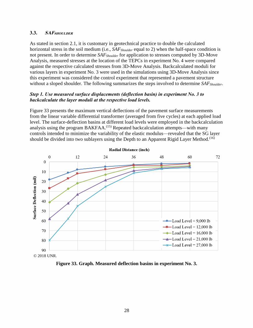
SAFSHOULDER
As stated in section 2.1, it is customary in geotechnical practice to double the calculated
horizontal stress in the soil medium (i.e., SAFShoulder equal to 2) when the half-space condition is
not present. In order to determine SAFShoulder for application to stresses computed by 3D-Move
Analysis, measured stresses at the location of the TEPCs in experiment No. 4 were compared
against the respective calculated stresses from 3D-Move Analysis. Backcalculated moduli for
various layers in experiment No. 3 were used in the simulations using 3D-Move Analysis since
this experiment was considered the control experiment that represented a pavement structure
without a sloped shoulder. The following summarizes the steps involved to determine SAFShoulder.
Step 1. Use measured surface displacements (deflection basin) in experiment No. 3 to
backcalculate the layer moduli at the respective load levels.
Figure 33 presents the maximum vertical deflections of the pavement surface measurements
from the linear variable differential transformer (averaged from five cycles) at each applied load
level. The surface-deflection basins at different load levels were employed in the backcalculation
analysis using the program BAKFAA.(15) Repeated backcalculation attempts—with many
controls intended to minimize the variability of the elastic modulus—revealed that the SG layer
should be divided into two sublayers using the Depth to an Apparent Rigid Layer Method.(16)
© 2018 UNR.
Figure 33. Graph. Measured deflection basins in experiment No. 3.

29
Step 2. Compare measured σv at the location of the TEPCs in experiment No.3 with those
calculated by 3D-Move Analysis using the associated backcalculated moduli.
Comparison between the measured and calculated vertical stresses at six different locations in
the SG and CAB layers (figure 34) revealed that 3D-Move Analysis is capable of reasonably
estimating load-induced stresses when the pavement layers extend laterally to infinity.
© 2018 UNR.
Figure 34. Graph. Comparison between σv and σv calculated using 3D-Move Analysis in
experiment No. 3.
Step 3: Compute σv at the location of the TEPCs in experiment No. 4 using 3D-Move Analysis
in conjunction with the layer moduli backcalculated from experiment No. 3 and compare with
those measured in experiment No. 4.
As described in section 3.2, measured σv values on the nonslope side with respect to the applied
surface load in experiment No. 4 were similar to the corresponding values recorded in
experiment No. 3. Therefore, the comparison between measured σv in experiment No. 4 and
those computed by 3D-Move Analysis were only conducted on data collected from the TEPCs
located exactly under the centerline of the load on the slope side with respect to the surface load.
The following observations can be made from these comparisons:
• Figure 35 and figure 36 display the comparison between the calculated and measured σv
recorded by P1 and P10 in experiment No. 4, which were located under the centerline of
the load (i.e., Loc12) at two different depths. The σv measured by P1 and P10 are 80 and
40 percent higher than those calculated by 3D-Move, respectively.
• The σv measured by P1 in experiment No. 4 when the load was applied at Loc24 and
Loc36 are presented in figure 37 and figure 38, respectively. These measurements in

30
comparison to the corresponding ones calculated by 3D-Move Analysis show a
60 percent increase in the load-induced σv due to the slope.
• Figure 39 depicts the measured load-induced σv at 6 inches from the SG surface and at a
12-inch radial distance from the centerline of the load in experiment No. 4. when the
surface load was applied at two different distances (i.e., 12 and 24 inches) from the edge
of the slope. This figure shows an almost 60-percent increase in the measured σv
compared to σv calculated by 3D-Move Analysis at the same locations.
• As shown in figure 40, at the 24-inch offset from the centerline of the surface load when
applied 36 inches from the edge (Loc36), the measured σv were 80-percent higher than
those calculated by 3D-Move Analysis.
© 2018 UNR.
Figure 35. Graph. Comparison between σv and σv calculated using 3D-Move Analysis in
experiment No. 4 (20 inches from SG surface, centerline of the load).

31
© 2018 UNR.
Figure 36. Graph. Comparison between σv and σv calculated using 3D-Move Analysis in
experiment No. 4 (6 inches from SG surface, centerline of the load).
© 2018 UNR.
Figure 37. Graph. Comparison between σv and σv calculated using 3D-Move Analysis in
experiment No. 4 (slope side, 20 inches from SG surface, offset from the centerline of the
load equal to 12 inches).

32
© 2018 UNR.
Figure 38. Graph. Comparison between σv and σv calculated using 3D-Move Analysis in
experiment No. 4 (slope side, 20 inches from SG surface, offset from the centerline of the
load equal to 24 inches).
© 2018 UNR.
Figure 39. Graph. Comparison between σv and σv calculated using 3D-Move Analysis in
experiment No. 4 (slope side, 6 inches from SG surface, offset from the centerline of the
load equal to 12 inches).

33
© 2018 UNR.
Figure 40. Graph. Comparison between σv and σv calculated using 3D-Move Analysis in
experiment No. 4 (slope side, 6 inches from SG surface, offset from the centerline of the
load equal to 24 inches).
Using the data presented in figure 35 through figure 40, SAFShoulder was computed, and the results
are presented in table 2. It can be concluded that sloped shoulders play a major role in stress
distribution within a pavement structure, particularly in the slope side. SAFShoulder ranged from
1.4 to 1.8, with an average of 1.63. Accordingly, SAFShoulder equal to 1.6 should be used to adjust
the calculated stresses using 3D-Move Analysis in the presence of a sloped shoulder.
This conclusion was derived from observations based on experiment No. 3 and experiment
No. 4. However, the influence of different parameters—such as pavement structure and layer
thicknesses, angle of the slope, distance of the surface load from the edge of the slope, distance
of response points from the slope and surface load, etc.—requires further investigation by
conducting complementary experiments and additional numerical analyses, which is
recommended for future studies.
Table 2. Summary of computed SAFShoulder.
TEPC Depth
Location of Surface Load in
Experiment No. 4
Offset From
Centerline of Load SAFShoulder
P1 20 inches from SG surface Loc12 0 inch 1.4
P10 6 inches from SG surface Loc12 0 inch 1.8
P1 20 inches from SG surface Loc24 12 inches 1.6
P1 20 inches from SG surface Loc36 24 inches 1.6
P9S* 6 inches from SG surface Loc12 12 inches 1.6
P10 6 inches from SG surface Loc24 12 inches 1.6
P10 6 inches from SG surface Loc36 24 inches 1.8
*S denotes TEPC on the slope side.


35
VALIDATION OF SLOPE-STABILITY WEDGE METHOD FOR SHL-
VEHICLE MOVEMENTS
Investigating the applicability of the proposed approach to evaluate the stability of a sloped,
layered medium consisting of typical pavement-layer configurations and properties is a concern
because slope-stability failure methods have traditionally been used for homogenous or layered
soil mediums. In this chapter the exercise to evaluate the validity of the proposed wedge method
using experiment No. 4 is presented.
FOS FOR A SLOPED EDGE IN EXPERIMENT NO. 4
To evaluate the applicability of the wedge method to measure slope stability, FOS for the sloped
edge in experiment No. 4 was determined when the FWD loads were applied at three locations
(i.e., Loc12, Loc24, and Loc36). (The pavement structure, instrumentation plan, and loading
protocol can be found in section 3.1.) Figure 41 is an illustration of the pavement structure and
loading locations in experiment No. 4. In this figure, different failure wedges with horizontal and
inclined slip surfaces were considered. A spacing between the horizontal slip surfaces of 3 inches
was selected.
© 2018 UNR.
Figure 41. Illustration. Schematic of experiment No. 4.
As stated in chapter 2, the wedge method assumes the plane strain condition for the slope-
stability analysis under an SHL-vehicle movement because the length of SHL vehicles can be
substantial. However, in experiment No. 4, the FWD load was applied on an 11.9-inch circular
plate, meaning that the plane strain assumptions do not hold true. Therefore, a three-dimensional
(3D) analysis of the wedge method should be used.
Figure 42 illustrates the possible 3D failure wedge in experiment No. 4 where the width of the
wedge (Bwedge) equal to 11.9 inches (i.e., the width of the FWD plate) was assumed. A diagram
of the force applied on the failure wedge is shown in figure 43. A total of seven forces acted on

36
the failure wedge. Five of these forces, W, TD, FD, Q, and P (due to the FWD load), are defined
in section 2.1. The following are two additional forces:
• Developed resisting c force resulting from the mobilized c acting on the side surfaces
(i.e., front and back) (T'D).
• The resistive force from the side soil that makes an angle (ϕD) with the normal to the side
surfaces (i.e., front and back) (PD).
© 2018 UNR.
Figure 42. Illustration. Possible failure wedge.
© 2018 UNR.
Figure 43. Illustration. Diagram of the force applied on the possible failure wedge.
As shown in section 2.1, the Rankine active earth pressure was used to determine the Q. The
horizontal stress distribution on the vertical side of the failure wedge was computed with 3D-
Move Analysis using the backcalculated resilient moduli and was subsequently adjusted with
SAFshoulder equal to 1.6. T'D was only applied on the trapezoidal side surfaces composed of SG
(ASG) because cohesionless properties for the base material were assumed.
Meyerhoff et al. proposed that PD is a passive resistance force from the surrounding SG and can
be determined using the Rankine passive earth pressure (σP) expressed by the equations in

37
figure 44 and figure 45.(17) σ0 should be calculated at the center of gravity of the triangular area
of the base layer and the trapezoidal area of the SG layer within the failure surface.
Figure 44. Equation. Calculation of Kp.
Figure 45. Equation. Calculation of σP.
Using the force equilibrium equations in parallel and perpendicular directions to the slip surface,
FOS can be determined, which is expressed in figure 46. There is no explicit solution for the
calculation of FOS.
Figure 46. Equation. FOS against failure for the wedges in experiment No. 4.
As a representative example of calculations, FOS for the possible failure wedge where the
horizontal slip surface was located 9 inches from the SG surface (i.e., 20 inches from the
pavement surface) equal to 3.5 was calculated. In this exercise, the FWD loading at the highest
load level (about 27,000 lb) applied at Loc12 was considered. Table 3 summarizes the properties
of the materials used in experiment No. 4. Figure 47 depicts the calculated horizontal stresses
adjusted by SAFshoulder equal to 1.6 using 3D-Move Analysis.
For the same load level and location (i.e., about 27,000 lb at Loc12), a minimum FOS equal to
1.3 was determined for the possible failure wedge where the horizontal slip surface is located 3
inches from the SG surface (i.e., 14 inches from the pavement surface). For a similar load level
applied at Loc24 and Loc36, minimum FOS values equal to 1.6 and 3.1 were determined,
respectively. Slope failure was not observed for the same loading cases in experiment No. 4,
confirming that the proposed wedge method is capable of analyzing the stability of a sloped,
layered medium consisting of typical pavement-layer configurations and properties.
Table 3. Properties of materials in experiment No. 4.
Properties Value
Density of CAB material 125 pcf
ϕ of CAB material 38 degrees
Density of SG material 110 pcf
ϕ of SG material 38 degrees
c of SG material 2 psi
𝐾𝑝 = tan2 45 +𝜙
2
𝜎𝑃 = 2 𝜎0𝐾𝑝 + 2𝑐 𝐾𝑝
𝑊tan𝜙
𝐹𝑂𝑆+𝑐𝑙𝐵𝑤𝑒𝑑𝑔𝑒
𝐹𝑂𝑆+
2𝑐𝐴𝑆𝐺𝐹𝑂𝑆
+ 𝑃𝐷 sin tan−1 tan𝜙
𝐹𝑂𝑆 = 𝑃 + 𝑄

38
© 2018 UNR.
Figure 47. Graph. Adjusted horizontal stresses calculated using 3D-Move Analysis.

39
SUMMARY AND CONCLUSION
Although it is recommended that an SHL vehicle stay away from a pavement edge to avoid
sloped pavement shoulder failure, doing so is not always possible when an SHL vehicle is
traveling along a narrow roadway. Therefore, in such cases of SHL-vehicle movements, slope-
stability analysis is necessary.
In this study, the wedge method, which is a well-accepted slope stability–analysis methodology
in geotechnical practice, was modified so that the stability of a sloped, layered medium
consisting of pavement layers with distinct properties could be evaluated under SHL-vehicle
movements. This method evaluates the stability of possible failure wedges by considering them
as a rigid sliding mass or gravity-retaining structure. P (i.e., the SHL vehicle) is the major
component of the horizontal driving force leading to the instability of a failure wedge. 3D-Move
Analysis was used to compute the horizontal stresses since it accounts for the viscoelastic
properties of the AC layer as well as the moving load with nonuniform tire–pavement interface
stresses on a loaded area of any shape.
The computed stresses using 3D-Move Analysis need to be modified to account for the role of
the sloped shoulder near the edge of the pavement because this software assumes that pavement
layers extend laterally to infinity. To this end, SAFShoulder was determined based on the results
obtained from two large-scale experiments, experiment No. 3 and experiment No. 4. Both
experiments had similar pavement structures, except experiment No. 4 had a sloped edge. The
measured stresses at the location of the TEPCs in experiment No. 4 were compared against the
respective calculated stresses from 3D-Move Analysis. In these calculations, backcalculated
moduli for the various layers from experiment No. 3 (i.e., the control experiment) were used.
The sloped shoulder was found to play a major role in the stress distribution within a pavement
structure, particularly in the slope side. Accordingly, in the presence of sloped shoulder, it is
recommended to have SAFShoulder equal to 1.6 to adjust the calculated stresses from 3D-Move
Analysis. The validity of the proposed wedge method using experiment No. 4 was verified.
Further investigation by conducting complementary experiments and additional numerical
analyses is recommended. Such analyses should consider various scenarios of flexible pavement
structures, slope angles, distance of the surface load from the edge of the slope, etc., to cover
other cases that were not considered as part of this study in the determination of SAFShoulder.


41
REFERENCES
1. Hajj, E.Y., Siddharthan, R.V., Nabizadeh, H., Elfass, S., Nimeri, M., Kazemi, S.F., Batioja-
Alvrez, D.D., and Piratheepan, M. (2018). Analysis Procedures for Evaluating Superheavy
Load Movement on Flexible Pavements, Volume I: Final Report, Report No. FHWA-HRT-
18-049, Federal Highway Administration, Washington, DC.
2. Nimeri, M., Nabizadeh, H., Hajj, E.Y., Siddharthan, R.V., Elfass, S, and Piratheepan, M.
(2018). Analysis Procedures for Evaluating Superheavy Load Movement on Flexible
Pavements, Volume II: Appendix A, Experimental Program, Report No. FHWA-HRT-18-
050, Federal Highway Administration, Washington, DC.
3. Nimeri, M., Nabizadeh, H., Hajj, E.Y., Siddharthan, R.V., and Elfass, S. (2018). Analysis
Procedures for Evaluating Superheavy Load Movement on Flexible Pavements, Volume III:
Appendix B, Superheavy Load Configurations and Nucleus of Analysis Vehicle, Report No.
FHWA-HRT-18-051, Federal Highway Administration, Washington, DC.
4. Nabizadeh, H., Hajj, E.Y., Siddharthan, R.V., and Elfass, S. (2018). Analysis Procedures for
Evaluating Superheavy Load Movement on Flexible Pavements, Volume Ⅳ: Appendix C,
Material Characterization for Superheavy Load Movement Analysis, Report No. FHWA-
HRT-18-052, Federal Highway Administration, Washington, DC.
5. Nabizadeh, H., Hajj, E.Y., Siddharthan, R.V., Nimeri, M., Elfass, S., and Piratheepan, M.
(2018). Analysis Procedures for Evaluating Superheavy Load Movement on Flexible
Pavements, Volume V: Appendix D, Estimation of Subgrade Shear Strength Parameters
Using Falling Weigh Deflectometer, FHWA-HRT-18-053, Federal Highway Administration,
Washington, DC.
6. Nabizadeh, H., Nimeri, M., Hajj, E.Y., Siddharthan, R.V., Elfass, S., and Piratheepan, M.
(2018). Analysis Procedures for Evaluating Superheavy Load Movement on Flexible
Pavements, Volume VI: Appendix E, Ultimate and Service Limit Analyses, Report No.
FHWA-HRT-18-054, Federal Highway Administration, Washington, DC.
7. Nabizadeh, H., Elfass, S., Hajj, E.Y., Siddharthan, R.V., Nimeri, M., and Piratheepan, M.
(2018). Analysis Procedures for Evaluating Superheavy Load Movement on Flexible
Pavements, Volume VIII: Appendix G, Risk Analysis of Buried Utilities Under Superheavy
Load Vehicle Movements, Report No. FHWA-HRT-18-056, Federal Highway
Administration, Washington, DC.
8. Batioja-Alvarez, D.D., Hajj, E.Y., and Siddharthan, R.V. (2018). Analysis Procedures for
Evaluating Superheavy Load Movement on Flexible Pavements, Volume IX: Appendix H,
Analysis of Cost Allocation Associated with Pavement Damage Under a Superheavy Load
Vehicle Movement, Report No. FHWA-HRT-18-057, Federal Highway Administration,
Washington, DC.

42
9. Kazemi, S.F., Nabizadeh, H., Nimeri, M., Batioja-Alvarez, D.D., Hajj, E.Y., Siddharthan,
R.V., and Hand, A.J.T. (2018). Analysis Procedures for Evaluating Superheavy Load
Movement on Flexible Pavements, Volume X: Appendix I, Analysis Package for Superheavy
Load Vehicle Movement on Flexible Pavement (SuperPACK), Report No. FHWA-HRT-18-
058, Federal Highway Administration, Washington, DC.
10. 3D-Move Analysis software V2.1. (2013). University of Nevada, Reno, NV. Available
online at: http://www.arc.unr.edu/Software.html#3DMove, last accessed September 19, 2017.
11. Fernando, E.G. (1997). Guidelines for Evaluating Superheavy Load Routes, Report No. TX-
98/3923-S, Texas Transportation Institute, College Station, TX.
12. U.S. Army Corps of Engineers. (2003). Slope Stability, Department of the Army,
Washington, DC.
13. Southern California Earthquake Center. (2002). Recommended Procedures for
Implementation of DMG Special Publication 117 Guidelines for Analyzing and Mitigating
Landslide Hazards in California. SCEC, Los Angeles, CA. Available online:
http://scecinfo.usc.edu/resources/catalog/LandslideProceduresJune02.pdf, last accessed
February 21, 2019.
14. Das, B.M. and Sobhan, K. (2014). Principles of Geotechnical Engineering, Cengage
Learning, Stamford, CT.
15. BAKFAA software V2.0. (2012). Federal Aviation Administration, Washington, DC.
16. Rohde, G.T. and Scullion, T. (1990). MODULUS 4.0: Expansion and Validation of the
MODULUS Backcalculation System, Report No. FHWA/TX-91/1123-3, Texas
Transportation Institute, College Station, TX.
17. Meyerhof, G.G. and Hanna, A.M. (1978). “Ultimate Bearing Capacity of Foundations on
Layered Soil under Inclined Load.” Canadian Geotechnical Journal, 15(4), pp. 565–572,
NRC Research Press, Ottawa, Canada.


HRDI-20/03-19(WEB)E
Related Documents