VTT PUBLICATIONS 368 TECHNICAL RESEARCH CENTRE OF FINLAND ESPOO 1998 FFUSION Research Programme 1993 - 1998 Final Report of the Finnish Fusion Research Programme Seppo Karttunen 1 , Heikki Ahola 3 , Olgierd Dumbrajs 6 , Aarne Halme 6 , Jukka Heikkinen 1 , Veli Heikkinen 4 , Juhani Keinonen 8 , Riitta Korhonen 1 , Taina Kurki-Suonio 6 , Jari Likonen 5 , Timo Pättikangas 1 , Rainer Salomaa 6 , Mikko Siuko 7 , Juhani Teuho 9 , Seppo Tähtinen 2 and Frej Wasastjerna 1 1 VTT Energy, Espoo 2 VTT Manufacturing Technology, Espoo 3 VTT Automation, Espoo 4 VTT Electronics, Oulu 5 VTT Chemical Technology, Espoo 6 Helsinki University of Technology, Espoo 7 Tampere University of Technology, Tampere 8 University of Helsinki, Helsinki 9 Outokumpu Superconductors Oy, Pori Association Euratom-Tekes

Welcome message from author
This document is posted to help you gain knowledge. Please leave a comment to let me know what you think about it! Share it to your friends and learn new things together.
Transcript
VTT PUBLICATIONS 368
TECHNICAL RESEARCH CENTRE OF FINLANDESPOO 1998
FFUSION Research Programme1993 - 1998Final Report
of the Finnish Fusion Research Programme
Seppo Karttunen1, Heikki Ahola3, Olgierd Dumbrajs6, Aarne Halme6, JukkaHeikkinen1, Veli Heikkinen4, Juhani Keinonen8, Riitta Korhonen1, Taina
Kurki-Suonio6, Jari Likonen5, Timo Pättikangas1, Rainer Salomaa6, MikkoSiuko7, Juhani Teuho9, Seppo Tähtinen2 and Frej Wasastjerna1
1VTT Energy, Espoo2VTT Manufacturing Technology, Espoo
3VTT Automation, Espoo4VTT Electronics, Oulu
5VTT Chemical Technology, Espoo6Helsinki University of Technology, Espoo
7Tampere University of Technology, Tampere8University of Helsinki, Helsinki
9Outokumpu Superconductors Oy, Pori
Association Euratom-Tekes
ISBN 951–38–5347–0 (soft back ed.)ISSN 1235–0621 (soft back ed.)
ISBN 951–38–5348–9 (URL: http://www.inf.vtt.fi/pdf/)ISSN 1455–0849 (URL: http://www.inf.vtt.fi/pdf/)
Copyright © Valtion teknillinen tutkimuskeskus (VTT) 1998
JULKAISIJA – UTGIVARE – PUBLISHER
Valtion teknillinen tutkimuskeskus (VTT), Vuorimiehentie 5, PL 2000, 02044 VTTpuh. vaihde (09) 4561, faksi (09) 456 4374
Statens tekniska forskningscentral (VTT), Bergsmansvägen 5, PB 2000, 02044 VTTtel. växel (09) 4561, fax (09) 456 4374
Technical Research Centre of Finland (VTT), Vuorimiehentie 5, P.O.Box 2000, FIN–02044 VTT, Finlandphone internat. + 358 9 4561, fax + 358 9 456 4374
VTT Energy, Nuclear Energy, Tekniikantie 4 C, P.O.Box 1604, FIN–02044 VTT, Finlandphone internat. + 358 9 4561, fax + 358 9 456 5000
VTT Manufacturing Technology, Materials and Structural Integrity,Kemistintie 3, P.O.Box 1704, FIN–02044 VTT, Finlandphone internat. + 358 9 4561, fax + 358 9 456 7002, + 358 9 456 5875
VTT Automation, Mechanics, Metallimiehenkuja 8, P.O.Box 1303, FIN–02044 VTT, Finlandphone internat. + 358 9 4561, fax + 358 9 455 3349
VTT Electronics, Optoelectronics, Kaitoväylä 1, P.O.Box 1100, FIN–90571 OULU, Finlandphone internat. + 358 8 551 2111, fax + 358 8 551 2320
VTT Chemical Technology, Industrial Physics, Otakaari 3 A, P.O.Box 1404, FIN–02044 VTT, Finlandphone internat. + 358 9 4561, fax + 358 9 456 6390
Several authors have contributed to this report; only the subject editors are mentioned in the author list.
Cover:Fusion is the energy source of the sun and the stars.The cover image shows the NGC 6188 nebula and NGC 6193.© Anglo-Australian Observatory, Photograph by David Malin.
Technical editing Maini Manninen
Libella Painopalvelu Oy, Espoo 1998
3
Foreword
Energy availability and its proper utilization have always played an essential role insocio-economic development. The overall world energy consumption has increased someeighteen-fold over the last hundred years and this increase is observed to correlate percapita with the level of wealth, health and education in any specific region. Fusion, theprocess utilized by nature as the fundamental energy source in the sun and the stars,provides us in the long term with a sustainable development path for a safe andenvironmentally friendly energy option. Globally, the responsibility of this long-termdevelopment of world energy options belongs to the industrialized countries. Finland isstrongly committed to this international co-operation.
The competitiveness of a country today depends on its capability to create innovations,which are based on science and technology and on its industries’ ability to turn them intoproducts and services for the world market. Despite the vast amount of research alreadyperformed on fusion development, it still remains a challenge that stimulates newthinking, new technologies and new industrial capabilities. In the FFUSION programmethe participation of Finnish industry has increased laudably. This verifies the chosenstrategy, where it is stated that the best type of technology transfer occurs whereenterprises are linked to the carrying out of the work. International fusion researchprovides us with a first-class platform for benchmarking new technologies and findingspin-offs and even technology jumps.
The role of education and training has been evident from the very beginning of theprogramme. The high degree of cohesion among the researchers and their motivation tocontribute to the technology transfer have promoted many new clustering initiativesaround specific themes together with industry. The programme has also gained a lot bythe excellent research results, proving the level of Finnish know-how.
4
The future of fusion research in Finland is very closely connected to internationalco-operation. From the good experiences gained from this programme we are lookingforward to contributing to a technology-driven international programme, which has tolead to an energy source that is both economically and socially acceptable. Manyquestions, such as quality of life, progress, security, and well-being are linked to thetheme of energy and environment and therefore they have a direct impact on the issue offusion energy.
The Technology Development Centre of Finland expresses its sincere thanks to allindividuals, enterprises and institutes who have contributed to the programme. Thisgratitude is extended also to the international scientific and industrial fusion community.
In Helsinki, 18 September, 1998
Technology Development Centre of Finland
5
Karttunen, Seppo, Ahola, Heikki, Olgierd, Dumbrajs, Halme, Aarne, Heikkinen, Jukka, Heikkinen, Veli,Keinonen, Juhani, Korhonen, Riitta, Kurki-Suonio, Taina, Likonen, Jari, Pättikangas, Timo, Salomaa, Rainer,Siuko, Mikko, Teuho, Juhani, Tähtinen, Seppo & Wasastjerna, Frej. FFUSION Research Programme 1993 -1998. Final Report of the Finnish Fusion Research Programme. Espoo 1998, Technical Research Centre ofFinland, VTT Publications 368. 110 p. + app 48 p.
Keywords fusion reactors, fusion physics, plasma engineering, remote handling, nuclear energy
Summary
This report summarizes the results of the Fusion Energy Research Programme,FFUSION, during the period 1993-1998. After the planning phase the programme startedin 1994, and later in March 1995 the FFUSION Programme was integrated into the EUFusion Programme and the Association Euratom-Tekes was established.
Research areas in the FFUSION Programme are (1) fusion physics and plasmaengineering, (2) fusion reactor materials and (3) remote handling systems. In all researchareas industry is involved. Recently, a project on environmental aspects of fusion andother future energy systems started as a part of the socio-economic research (SERF) inthe Euratom Fusion Programme.
A crucial component of the FFUSION programme is the close collaborationbetween VTT Research Institutes, universities and Finnish industry. This collaborationhas guaranteed dynamic and versatile research teams, which are large enough to tacklechallenging research and development projects. Regarding industrial fusion R&Dactivities, the major step was the membership of Imatran Voima Oy in the EFETConsortium (European Fusion Engineering and Technology), which further strengthenedthe position of industry in the engineering design activities of ITER.
The number of FFUSION research projects was 66. In addition, there were 32industrial R&D projects. The total cost of the FFUSION Programme in 1993-1998 amountedto FIM 54 million in research at VTT and Universities and an additional FIM 21 million forR&D in Finnish industry. The main part of the funding was provided by Tekes, 36%. Since1995, yearly Euratom funding has exceeded 25%.
The FFUSION research teams have played an active role in the European Programme,receiving excellent recognition from the European partners. Theoretical and computationalfusion physics has been at a high scientific level and the group collaborates with the leadingexperimental laboratories in Europe. Fusion technology is focused on reactor materials,joining techniques, superconductor development and water-hydraulic applications, in whichFFUSION teams have achieved a firm position in the EU Fusion Programme. A challengingfull-scale prototype system for the ITER in-vessel viewing has been completed as acollaborative effort between VTT, Helsinki University of Technology and IVO TechnologyCentre.
6
Contents
Page
Foreword 3
Summary 5
Contents 6
1 FFUSION Research Programme 91.1 Background 91.2 European Fusion Programme 101.3 FFUSION Programme Objectives 111.4 Research Areas 111.5 Participating Institutes and Companies 14
1.5.1 The Technology Development Centre Finland (Tekes)141.5.2 Finnish Fusion Research Unit 141.5.3 Industrial Companies 151.5.4 FFUSION Steering Committee 16
1.6 FFUSION Programme Funding 171.7 International Collaboration 20
1.7.1 Association Euratom-Tekes 201.7.2 Participation in the Committees of the EuropeanFusion Programme 21
1.7.3 European and Other International Collaboration 22
2 Fusion Physics and Plasma Engineering 242.1 Radio-Frequency Heating of Tokamak Plasmas 24
2.1.1 JET Task: Ion Cyclotron Heating and Current Drive 252.1.2 JET Task: Development of Radio-Frequency
Modules for Transport Codes 272.1.3 ITER Task: Support of Physics and Engineering
Design of the Ion Cyclotron System 272.1.4 Tore Supra Collaboration: Analysis of Parasitic
Absorption of Lower Hybrid Power 302.1.5 Gyrotrons for Electron Cyclotron Heating and
Microwave Diagnostics 332.2 Plasma Confinement and Transport 35
7
2.2.1 ASDEX Upgrade Agreement: Transition from Low to High Confinement 35
2.2.2. Electron Density Profile Measurements and Particle Transport Studies with Multichannel Interferometer at the Wendelstein 7-AS 39
2.3 Dielectric Window Prototype for the Reactor VacuumTransmission Line of Ion Cyclotron Power 41
2.3.1 Requirements for a Reactor Window 41 2.3.2 Design 42 2.3.3 Joining Experiments 45
2.4 Central Solenoid Development for Spherical Tokamaks 472.4.1 Design Characteristics 47
2.4.2 Solenoid Design, Fabrication, and Testing 47
3 Fusion Reactor Materials 493.1 Characterisation of Irradiated Copper Alloys 50
3.1.1 Microstructure 50 3.1.2 Fracture Toughness 51 3.1.3 Creep 52 3.1.4 Mixed Mode Loading 53 3.1.5 Corrosion 54
3.2 Cu/SS Joining Technology and Characterisation 573.2.1 Metallurgy of Joints 573.2.2 Mechanical Properties of Copper to StainlessSteel Joints 59
3.2.3 Fracture Toughness of Joints 61 3.2.4 Non Destructive Examination of Joints 62
3.3 Behaviour of Hydrogen Isotopes in First Wall Materials 643.4 Fusion Neutronics 693.5 Development of ITER Superconductors 71
3.5.1 Development of Superconducting Niobium-TitaniumWires for ITER 713.5.2 Development of Superconducting Niobium-Tin
Wires for ITER 72
4 Remote Handling and Viewing 744.1 In-Vessel Viewing System - IVVS 74
4.1.1 Introduction 744.1.2 IVVS Design Work 764.1.3 Optomechanical Prototype 80
8
4.1.4 Imaging Tests 824.1.5 Conclusions 82
4.2 Water-Hydraulic Remote Maintenance Tools for ITER 854.2.1 Introduction 85
4.2.2 Water-Hydraulic Feasibility 85 4.2.3 Divertor Cassette Replacing and Refurbishment 87 4.2.4 The Divertor Cassette Replacing 87 4.2.5 The Divertor Cassette Refurbishment 89 4.2.6 Other ITER-generated Research Projects 92 4.2.7 Conclusion 94
5 Socio-Economic Studies 95
6 Summary of Objectives and Main Results 976.1 Meeting of the FFUSION Programme Objectives 976.2 Fusion Physics and Plasma Engineering – Objectivesand Main Results 97
6.2.1 Physics of Radio-Frequency Heating andCurrent Drive 98
6.2.2 Plasma Confinement and Transport 100 6.2.3 Plasma Engineering Projects 101
6.3 Fusion Reactor Materials - Objectives and Main Results 1026.3.1 Characterisation of Irradiated Cu and Cu-alloys 103
6.3.2 Cu/SS Joining Technology and Characterisation 1046.3.3 Behaviour of Hydrogen Isotopes in First WallMaterials 1056.3.4 Fusion Neutronics 106
6.4 Remote Handling and Viewing - Objectives andMain Results 107
6.4.1 In-Vessel Viewing System 1076.4.2 Water Hydraulic Tools for Divertor Refurbishment 109
Appendix A: FFUSION Projects and TasksAppendix B: Participating Institutes, Companies,Contacts and Research Personnel 1993 - 1998Appendix C: Seminars and MeetingsAppendix D: Graduate, Licentiate and Doctorate ThesesAppendix E: Publications, Reports and Patents 1993 – 1998
9
1 FFUSION Research Programme
1.1 Background
Fusion energy research in Finland started as a small effort at the TechnicalResearch Centre of Finland (VTT) in the mid-1970's. The main objective was towatch the scientific and technological development in international fusionresearch and to carry out theoretical and computational studies in fusionphysics. In the early 1990's, it became evident that Finland was to have closerrelations with the European Community and that this would open a possibility tojoin to the European Fusion Programme and with it to the world-wide ITERProject (International Thermonuclear Experimental Reactor).
In 1992, the Finnish Nuclear Energy Commission presented an initiativeto the Ministry of Trade and Industry for embarking on a national fusionresearch programme in Finland. The aim was to organize all fusion-relatedresearch in Finland under a single programme and to increase the researchvolume to a relevant level in European terms before joining the CommunityFusion Programme. It was also realized that the European Programme and ITERwould provide challenging opportunities for Finnish hi-tech industry.Negotiations with the European Fusion Programme started in early 1993. At thesame time, a systematic survey of the possibilities and interest of Finnishindustry was made. Programme planning was carried out in 1993 and theFinnish Fusion Research Programme - FFUSION officially started in thebeginning of 1994.
The first phase of the FFUSION programme (1993-1994) was thepreparation for association into the Community Programme. The goal was toreach a critical size in research volume and to identify our own research areas.The strategy was to emphasize fusion technology parallel with the basic fusionand plasma physics and to activate Finnish industry into collaborating andparticipating in the FFUSION programme, and subsequently in the EuropeanFusion Programme. The key element in the strategy was focusing our fairlysmall R&D efforts on a few topics, where Finland has possibilities to becompetitive in Europe.
The early objectives above were met when the FFUSION programme wasfully integrated into the European Fusion Programme, just after Finland hadjoined the European Union. The Association Euratom-Tekes was established

10
when the Contract of Association between Euratom and Tekes was signed inHelsinki, on March 13, 1995. Tekes became the 14th Euratom Association inthe EU Fusion Programme. Other contracts include the multilateral NETAgreement and the Staff Mobility Agreement. Finland, represented by Tekes,became a member of the JET Joint Undertaking on May 7, 1996.
1.2 European Fusion Programme
The EU Fusion Programme is a fully integrated programme that includes allfusion research carried out in the Member States and Switzerland. The EU isinvesting about ECU 840 million in fusion research in its Fourth FrameworkProgramme (1994-1998). The European Fusion Programme consists of fourelements: the JET Joint Undertaking, the NET Team, the fusion technologyresearch at the Joint Research Centre (JRC) in Ispra and Petten, and the fusionresearch in the Associations. The largest fusion research installation in theworld is the Joint European Torus (JET) tokamak in England. The JET JointUndertaking will end in December 1999. The present plan is that after 1999 theJET facilities will be operated and exploited by the research teams from theAssociation Euratom-UKAEA and other Associations.
A significant proportion of European fusion research is carried out innational laboratories that have signed the Contract of Association with theCommunity programme. At the moment, there are 16 Associations in theEuropean Programme including Switzerland. Only Greece and Luxembourg arewithout a Contract of Association, but Greece is participating in the EUprogramme on a project basis. There is a number of large and medium-sizetokamaks and plasma devices in the associated laboratories. Euratom is alsofinancing research into fusion installations alternative to the tokamak. A newJT-II stellarator in Spain started plasma operation in 1998 and a largeWendelstein 7-X stellarator is under construction in Greifswald, Germany to becompleted in 2004.
The main global research project is the engineering design activities(EDA) of the tokamak test reactor ITER (International ThermonuclearExperimental Reactor). The participants are Euratom, Japan, Russia and theUnited States. The ITER EDA was completed in summer 1998. The partnersare planning to extend the design work by three years to include site-specificstudies and procurement specifications and to complete the tests of largeprototype components, e.g., superconducting model coils and blanket modules.The possibilities of reducing the capital cost of ITER significantly, but stillsatisfying the programme objectives of the ITER EDA Agreement, are understudy.
11
The NET Team co-ordinates fusion technology work and European HomeTeam work for ITER. These include several fusion technology research projectsinvolving fusion reactor materials, tritium handling, remote maintenanceequipment, large superconductor magnets, safety and environmental issues andsocio-economic studies.
1.3 FFUSION Programme Objectives
The Finnish Fusion Programme FFUSION / the Association Euratom-Tekes, isfully integrated into the European Programme, which has set the long-term goal of“the joint creation of safe, environmentally sound prototype reactors, whichshould result in the construction of economically viable power stations”. Thenational objectives of the FFUSION Programme in the shorter term are:
• to carry out high-level scientific and technological research in supportof the European Fusion Programme and ITER
• to promote collaboration between the research institutes, universitiesand Finnish industry
• to focus the R&D effort on a few competitive areas.
Active participation in the Euratom Fusion Programme and ITEREngineering Design Activities has opened challenging opportunities andprojects to the Finnish science and technology community and hi-techcompanies.
1.4 Research Areas
The FFUSION programme consists of fusion plasma physics and fusiontechnology.
The physics programme is carried out at the Technical Research Centre ofFinland (VTT), Helsinki University of Technology (HUT), and the Universityof Helsinki (UH). The research areas in fusion physics are:
• fusion plasma engineering / radio-frequency heating and plasmadiagnostics
• plasma-wall interactions.
The physics programme consists of theoretical and computational studiesof radio-frequency heating and current drive, particle and energy transport and
12
diagnostics in tokamak plasmas. Experiments on plasma-wall interactions areperformed with the ion beam facility at the University of Helsinki. ITER Tasksdealing with the R&D and design of radio-frequency systems have partly beenperformed under the physics programme. A major part of the physicsprogramme is conducted in collaboration with the JET Joint Undertaking andAssociations IPP Garching (Germany), CEA Cadarache (France), and CRPPLausanne (Switzerland).
The technology programme is carried out at VTT, HUT and TampereUniversity of Technology (TUT) in close collaboration with Finnish industry.The technology research is focused on three areas:
• fusion reactor materials – first-wall components, joining techniquesand characterization
• remote handling and viewing systems• superconductors.
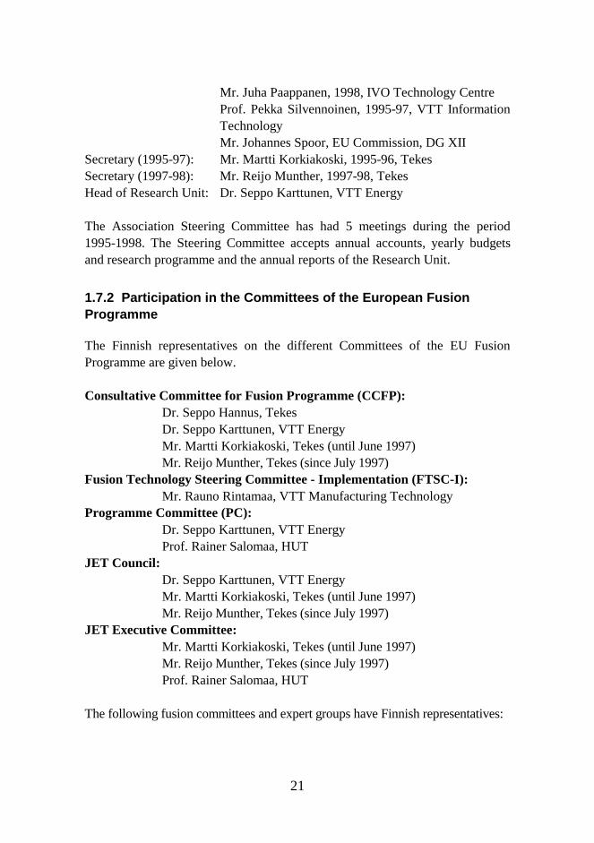
The respective volumes of the FFUSION research projects and industrialR&D projects in the main research areas are given in Table 1.1. The followingAssociation Technology Tasks, NET Contracts and JET Task Agreements werecarried out during 1995-1998:
Association Technology Tasks:
Task T361 Vacuum Window Development for Ion CyclotronRadio-Frequency Power Transmission Line
Task T212 Cu/SS Joining TechnologyTask BL12.2-1 Detailed Investigation of CuAl25(IG1), its Joints with
316LN SS and Joints Testing ProceduresTask T213 Cu and Cu-Alloys Irradiation TestingTask BL16.5-2 Titanium Alloys Irradiation TestingTask T217 Aqueous Corrosion of 316L SS and Cu-Based AlloysTask T301/3 High-Energy Beam Welding for Manufacture of Large
Tokamak Containment SectorsTask T226a Evaluation of Erosion / Re-depositionTask T227 Tritium Permeation and InventoryTask T221 Plasma Facing Armour MaterialsTask DV7a Tritium Permeability, Retention, Wall Conditioning /
Clean UpTask M11 ITER NbTi Superconducting Wire Development
13
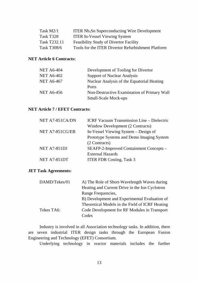
Task M2/1 ITER Nb3Sn Superconducting Wire DevelopmentTask T328 ITER In-Vessel Viewing SystemTask T232.11 Feasibility Study of Divertor FacilityTask T308/6 Tools for the ITER Divertor Refurbishment Platform
NET Article 6 Contracts:
NET A6-404 Development of Tooling for DivertorNET A6-402 Support of Nuclear AnalysisNET A6-467 Nuclear Analysis of the Equatorial Heating
PortsNET A6-456 Non-Destructive Examination of Primary Wall
Small-Scale Mock-ups
NET Article 7 / EFET Contracts:
NET A7-851CA/DN ICRF Vacuum Transmission Line – DielectricWindow Development (2 Contracts)
NET A7-851CG/EB In-Vessel Viewing System – Design ofPrototype Systems and Demo Imaging System(2 Contracts)
NET A7-851DJ SEAFP-2-Improved Containment Concepts –External Hazards
NET A7-851DT ITER FDR Costing, Task 3
JET Task Agreements:
DAMD/Tekes/01 A) The Role of Short-Wavelength Waves duringHeating and Current Drive in the Ion CyclotronRange Frequencies,B) Development and Experimental Evaluation ofTheoretical Models in the Field of ICRF Heating
Tekes TA6: Code Development for RF Modules in TransportCodes
Industry is involved in all Association technology tasks. In addition, thereare seven industrial ITER design tasks through the European FusionEngineering and Technology (EFET) Consortium.
Underlying technology in reactor materials includes the further
14
development of fracture resistance test methods and verification of specimensize effects, measuring techniques for characterising surface film properties ofmetals in coolant water environments and the development of non-destructiveexamination techniques applicable to inspection of primary wall modules.
Association Euratom-Tekes contributes to the socio-economic research onfusion (SERF) with the project “Identification and comparative evaluation ofenvironmental impacts of fusion and other possible future energy productiontechnologies”.
Three NET Assignments and two JET Task Agreements have been madesince 1995, and one to two persons have been working on JET. Collaborationwith the NET Team, JET Joint Undertaking, ITER Joint Central Team,Association Risø (Denmark), Association FZK Karlsruhe (Germany) andAssociation ENEA Frascati (Italy) has played an essential role in the fusiontechnology activities of the FFUSION Programme.
1.5 Participating Institutes and Companies
1.5.1 The Technology Development Centre Finland (Tekes)
The Technology Development Centre Finland (Tekes) is the main fundingauthority and co-ordinator for technological research and development activitiesin Finland. Tekes is the co-ordinator of eleven national technology researchprogrammes in the energy sector including the FFUSION programme. Thefusion research co-ordinators in Tekes are Dr. Seppo Hannus (Director ofEnergy Technology), Mr. Martti Korkiakoski (Senior Adviser) until June 1997and Mr. Reijo Munther (Senior Adviser) from July 1997.
1.5.2 Finnish Fusion Research Unit
Research activities in the FFUSION programme are carried out in several VTTResearch Institutes and in universities. The FFUSION research programme isco-ordinated by VTT Energy. The director of the FFUSION programme isDr. Seppo Karttunen and he is acting as Head of Research Unit of theAssociation Euratom-Tekes.
The following universities and VTT Institutes have been participating inthe fusion research in 1993-1998:
15
Technical Research Centre of Finland (VTT): VTT Energy (FFUSION co-ordination, plasma engineering,neutronics)VTT Manufacturing Technology (materials)VTT Chemical Technology (materials)VTT Automation (remote handling)VTT Electronics (remote handling)
Helsinki University of Technology (HUT):Department of Engineering Physics and Mathematics (plasmaengineering, diagnostics)Laboratory of Automation Technology (remote handling)
University of Helsinki (UH):Accelerator Laboratory (plasma-wall interactions, first-wallmaterials)
Tampere University of Technology (TUT):Institute of Hydraulics and Automation (remote handling)Laboratory of Control Engineering (remote handling)
The Finnish Fusion Research Unit consists of research groups from theinstitutes and universities above.
1.5.3 Industrial Companies
The following industrial companies have been collaborating with the FFUSIONresearch programme:
Imatran Voima Oy (IVO, Finnish EFET partner)Outokumpu Superconductors OyOutokumpu Poricopper OyPlustech OyHigh Speed Tech OyDiarc Technology OyHytar OyRauma Materials Technology OyPI-Rauma OyTehdasmallit Oy
16
Pori Works OyPatria Finavitec Oy
Industrial activities related to the FFUSION programme are co-ordinatedby Prizztech Oy. The Finnish Blanket Group and Remote Handling Groupinvolving the companies above were formed in 1995 and they are withOutokumpu Superconductors accepted onto the list of qualified companies forITER EDA. Imatran Voima Oy became a member of the European FusionEngineering and Technology (EFET) Consortium in 1996. The other EFETmembers are: Siemens (Germany), Framatom (France), Belgatom (Belgium),CITEF (Italy), NNC Limited (UK) and IBERTEF (Spain).
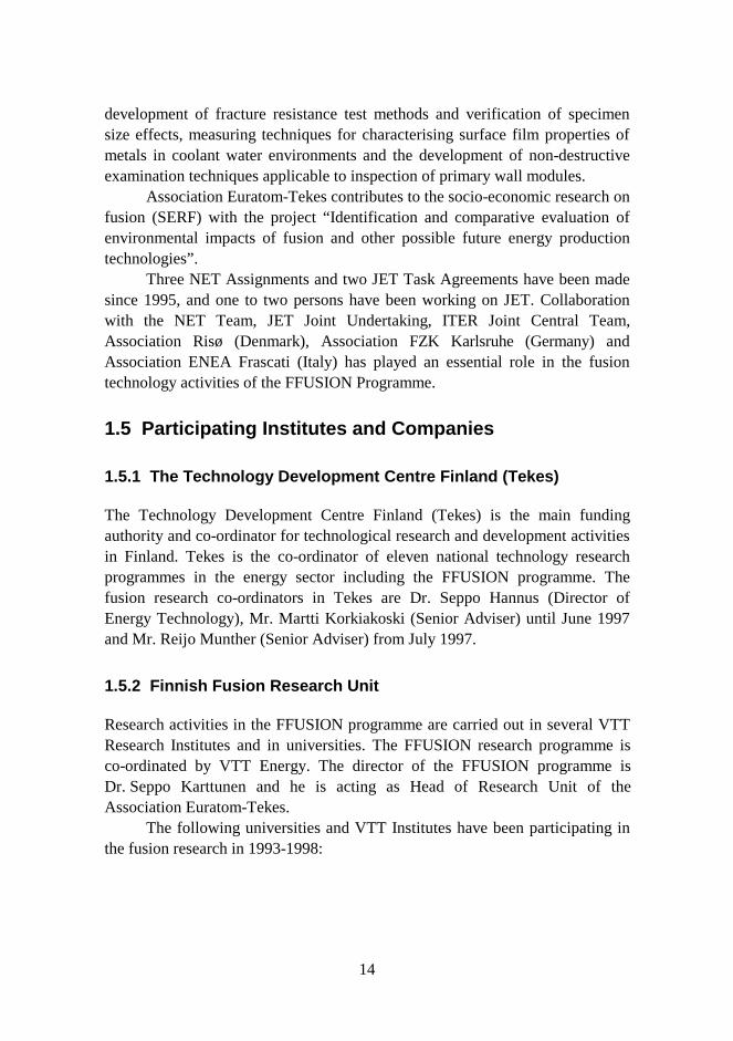
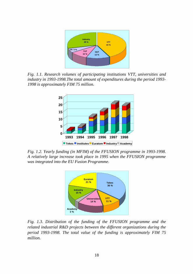
The relative volume of the research and development work in theparticipating institutions can be seen in Fig. 1.1. Five VTT institutes accountfor about 43% of the research volume, universities 28% and industry 29%.
1.5.4 FFUSION Steering Committee
The national steering committee of the FFUSION Programme advises in theplanning of fusion research and promotes collaboration with Finnish industry.
The members of the FFUSION Steering Committee are:
Chairman: Rainer Salomaa, Professor, Helsinki University ofTechnology
Members: Erkki Kare, Managing Director, Plustech OyJuhani Keinonen, Professor, University of HelsinkiMartti Korkiakoski, Senior Technical Adviser (1995-97),TekesReijo Munther, Senior Technical Adviser (1997-98), TekesLenni Laakso, General Manager, Outokumpu PoricopperOyLasse Mattila, Research Professor, VTT EnergyJukka Lindgren, Senior Technical Adviser (1993-1994),Ministry of Trade and IndustryJuha Paappanen, General Manager, Imatran Voima OyPertti Pale, The NET Team / Prizztech Oy
FFUSION director: Seppo Karttunen, Senior Research Scientist, VTT EnergySecretary: Timo Pättikangas, Research Scientist, VTT Energy
17
Since 1994, there have been 13 meetings of the FFUSION SteeringCommittee.
1.6 FFUSION Programme Funding
The FFUSION research programme is financed by the Ministry of Trade andIndustry (in 1993), Tekes (from 1994), the Finnish Academy of Sciences, theparticipating institutes (VTT, HUT, TUT and UH) and industry. From thesigning of the Contract of Association on March 13, 1995, European fundingsupport has also been provided by Euratom.
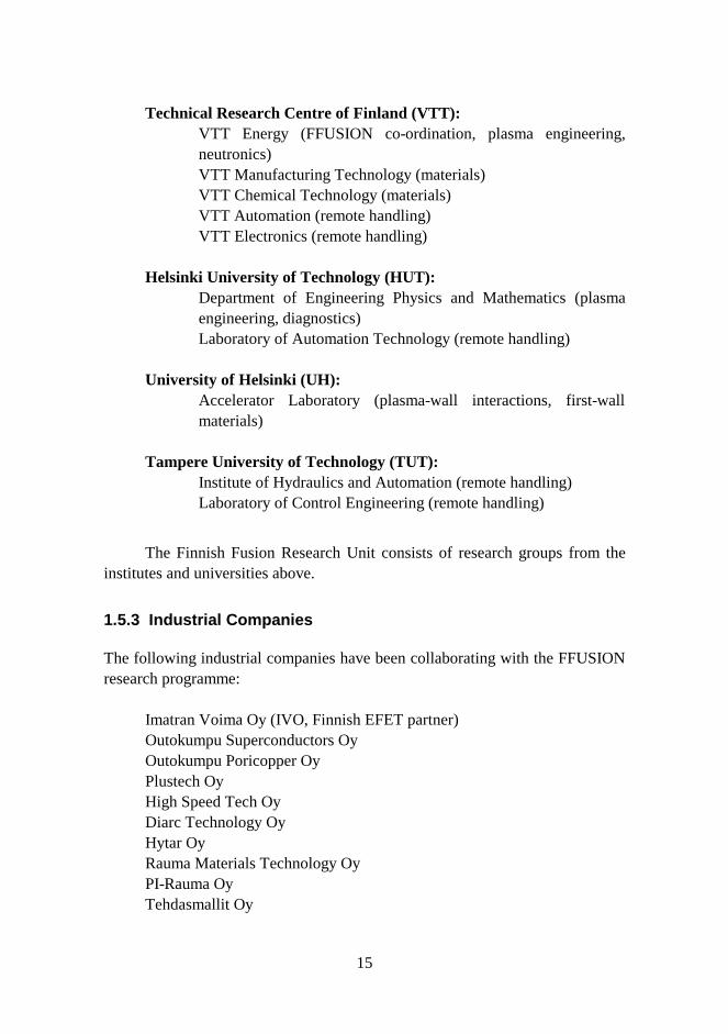
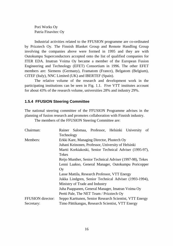
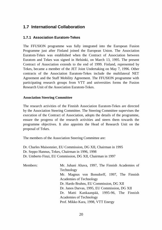
Fig. 1.2 shows the yearly funding of the FFUSION programme from 1993to 1998, including the funding from the participating industrial companies. Thedistribution of the total funding between the different organizations during thesix-year period 1993-1998 is shown in Fig. 1.3. The total funding of theFFUSION research programme for 1993-1998 is about FIM 54.4 million. Thetotal volume of the industrial activities related to the FFUSION programme isabout FIM 21 million for the same period.
The funding details of the FFUSION research and industry R&D projectsare given in Table 1.2. Table 1.2 shows that the funding of the FFUSIONresearch projects is fairly balanced between the three research areas. In theindustrial R&D, remote handling projects and superconductor development takethe major share of the funding.
18
Fig. 1.1. Research volumes of participating institutions VTT, universities andindustry in 1993-1998.The total amount of expenditures during the period 1993-1998 is approximately FIM 75 million.
Fig. 1.2. Yearly funding (in MFIM) of the FFUSION programme in 1993-1998.A relatively large increase took place in 1995 when the FFUSION programmewas integrated into the EU Fusion Programme.
Fig. 1.3. Distribution of the funding of the FFUSION programme and therelated industrial R&D projects between the different organizations during theperiod 1993-1998. The total value of the funding is approximately FIM 75million.
VTT43 %
Industry29 %
HUT13 %
TUT10 %
UH 5 %
Academy3 %
Universities14 %
Industry15 %
Euratom21 % Tekes
36 %
VTT 11 %
0
5
10
15
20
25
1993 1994 1995 1996 1997 1998
Tekes Institutes Euratom Industry Academy
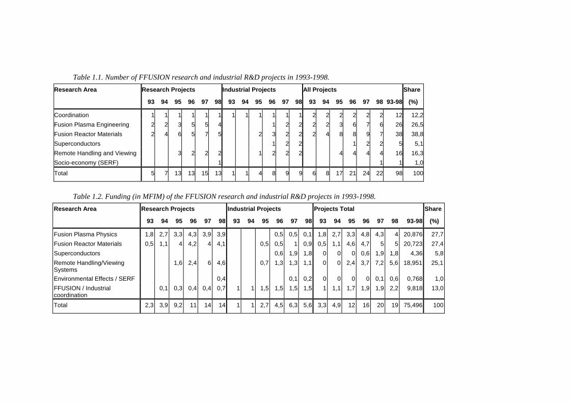
Table 1.1. Number of FFUSION research and industrial R&D projects in 1993-1998.
Research Area Research Projects Industrial Projects All Projects Share
93 94 95 96 97 98 93 94 95 96 97 98 93 94 95 96 97 98 93-98 (%)
Coordination 1 1 1 1 1 1 1 1 1 1 1 1 2 2 2 2 2 2 12 12,2
Fusion Plasma Engineering 2 2 3 5 5 4 1 2 2 2 2 3 6 7 6 26 26,5
Fusion Reactor Materials 2 4 6 5 7 5 2 3 2 2 2 4 8 8 9 7 38 38,8
Superconductors 1 2 2 1 2 2 5 5,1
Remote Handling and Viewing 3 2 2 2 1 2 2 2 4 4 4 4 16 16,3
Socio-economy (SERF) 1 1 1 1,0
Total 5 7 13 13 15 13 1 1 4 8 9 9 6 8 17 21 24 22 98 100
Table 1.2. Funding (in MFIM) of the FFUSION research and industrial R&D projects in 1993-1998.
Research Area Research Projects Industrial Projects Projects Total Share
93 94 95 96 97 98 93 94 95 96 97 98 93 94 95 96 97 98 93-98 (%)
Fusion Plasma Physics 1,8 2,7 3,3 4,3 3,9 3,9 0,5 0,5 0,1 1,8 2,7 3,3 4,8 4,3 4 20,876 27,7
Fusion Reactor Materials 0,5 1,1 4 4,2 4 4,1 0,5 0,5 1 0,9 0,5 1,1 4,6 4,7 5 5 20,723 27,4
Superconductors 0,6 1,9 1,8 0 0 0 0,6 1,9 1,8 4,36 5,8
Remote Handling/ViewingSystems
1,6 2,4 6 4,6 0,7 1,3 1,3 1,1 0 0 2,4 3,7 7,2 5,6 18,951 25,1
Environmental Effects / SERF 0,4 0,1 0,2 0 0 0 0 0,1 0,6 0,768 1,0
FFUSION / Industrialcoordination
0,1 0,3 0,4 0,4 0,7 1 1 1,5 1,5 1,5 1,5 1 1,1 1,7 1,9 1,9 2,2 9,818 13,0
Total 2,3 3,9 9,2 11 14 14 1 1 2,7 4,5 6,3 5,6 3,3 4,9 12 16 20 19 75,496 100
20
1.7 International Collaboration
1.7.1 Association Euratom-Tekes
The FFUSION programme was fully integrated into the European FusionProgramme just after Finland joined the European Union. The AssociationEuratom-Tekes was established when the Contract of Association betweenEuratom and Tekes was signed in Helsinki, on March 13, 1995. The presentContract of Association extends to the end of 1999. Finland, represented byTekes, became a member of the JET Joint Undertaking on May 7, 1996. Othercontracts of the Association Euratom-Tekes include the multilateral NETAgreement and the Staff Mobility Agreement. The FFUSION programme withparticipating research groups from VTT and universities forms the FusionResearch Unit of the Association Euratom-Tekes.
Association Steering Committee
The research activities of the Finnish Association Euratom-Tekes are directedby the Association Steering Committee. The Steering Committee supervises theexecution of the Contract of Association, adopts the details of the programme,ensure the progress of the research activities and steers them towards theprogramme objectives. It also appoints the Head of Research Unit on theproposal of Tekes.
The members of the Association Steering Committee are:
Dr. Charles Maisonnier, EU Commission, DG XII, Chairman in 1995Dr. Seppo Hannus, Tekes, Chairman in 1996, 1998Dr. Umberto Finzi, EU Commission, DG XII, Chairman in 1997
Members: Mr. Juhani Ahava, 1997, The Finnish Academies ofTechnologyMr. Magnus von Bonsdorff, 1997, The FinnishAcademies of TechnologyDr. Hardo Bruhns, EU Commission, DG XIIDr. Janos Darvas, 1995, EU Commission, DG XII
Dr. Matti Kankaanpää, 1995-96, The FinnishAcademies of TechnologyProf. Mikko Kara, 1998, VTT Energy
21
Mr. Juha Paappanen, 1998, IVO Technology CentreProf. Pekka Silvennoinen, 1995-97, VTT InformationTechnologyMr. Johannes Spoor, EU Commission, DG XII
Secretary (1995-97): Mr. Martti Korkiakoski, 1995-96, TekesSecretary (1997-98): Mr. Reijo Munther, 1997-98, TekesHead of Research Unit: Dr. Seppo Karttunen, VTT Energy
The Association Steering Committee has had 5 meetings during the period1995-1998. The Steering Committee accepts annual accounts, yearly budgetsand research programme and the annual reports of the Research Unit.
1.7.2 Participation in the Committees of the European FusionProgramme
The Finnish representatives on the different Committees of the EU FusionProgramme are given below.
Consultative Committee for Fusion Programme (CCFP):Dr. Seppo Hannus, TekesDr. Seppo Karttunen, VTT EnergyMr. Martti Korkiakoski, Tekes (until June 1997)Mr. Reijo Munther, Tekes (since July 1997)
Fusion Technology Steering Committee - Implementation (FTSC-I):Mr. Rauno Rintamaa, VTT Manufacturing Technology
Programme Committee (PC):Dr. Seppo Karttunen, VTT EnergyProf. Rainer Salomaa, HUT
JET Council:Dr. Seppo Karttunen, VTT EnergyMr. Martti Korkiakoski, Tekes (until June 1997)Mr. Reijo Munther, Tekes (since July 1997)
JET Executive Committee:Mr. Martti Korkiakoski, Tekes (until June 1997)Mr. Reijo Munther, Tekes (since July 1997)Prof. Rainer Salomaa, HUT
The following fusion committees and expert groups have Finnish representatives:
22
- Dr. Jukka Heikkinen is a member of the Co-ordinating Committee for FastWave Heating (CCFW).
- Dr. Seppo Karttunen (1995-96) and Dr. Timo Pättikangas (1997-1998) havebeen members of the Co-ordinating Committee for Lower Hybrid Heatingand Current Drive (CCLH).
- Prof. R. Salomaa is a member of the European Fusion Information Network(EFIN) since 1998.
- Mr. Seppo Tähtinen is a Materials Liaison Officer in the European BlanketProject
- Dr. Olgierd Dumbrajs is a member of the international experts commissionon Electron Cyclotron Wave Systems.
- Dr. Seppo Karttunen was a member of the Ad-Hoc Groups, which carriedout an evaluation of different heating and current drive methods and anassessment of the ITER Physics Performance presented in the ITERDetailed Design Report and ITER Final Design Report.
Both co-ordinating committees CCFW and CCLH have had meetings inFinland. Tekes hosted the 12th ITER Council and the 4th ITER Explorers´meetings in Tampere, in July 1997. Dr. Karttunen participated in the 12th ITERCouncil Meeting in Tampere as a local organizer.
1.7.3 European and Other International Collaboration
All fusion research in the Euratom Associations is co-ordinated on a Europeanlevel so that joint projects, collaboration between Associations and EU HomeTeam work for ITER EDA are the basic elements of the EU Fusion Programme.
In plasma physics, the Association Euratom-Tekes participates in the JETfusion experiments with two Task Agreements and in experiments at IPPGarching (ASDEX Upgrade tokamak and Wendelstein AS-7 stellarator) and atCEA Cadarache (Tore Supra). In gyrotron development work, collaborationwith Associations FZK Karlsruhe and CRPP Lausanne has been started.
In fusion technology, there are joint research projects with theAssociations Risö (reactor materials) and ENEA Frascati / Brasimone (in-vesselviewing and divertor refurbishment). The NET Team in Garching co-ordinatesthe European collaboration in fusion technology tasks and work for ITER EDA.
The staff mobility scheme of the EU Fusion Programme offers excellentopportunities for the exchange of scientists and engineers in Europe. There hasbeen over 15 mobility visits of 1 to 6 months in 1996-98. Longer visits over oneyear under other arrangements have been made for JET, NET Team and IPP. In

23
addition, several shorter visits both ways have taken place since 1993.Collaboration with non-EU countries has played a minor role after the
Association agreement in 1995. There is still close collaboration with the IoffeInstitute in St. Petersburg (fusion theory, Globus tokamak) and Institute forApplied Physics in Nizhny Novgorod (gyrotrons). Yearly fusion symposiumsbetween HUT and the Ioffe Institute have been organized since 1993.Collaboration with the Centre Canadien de Fusion Magnétique (Tokamak deVarennes) in Canada will continue.
24
2 Fusion Physics and Plasma Engineering
During 1993–98, the work within fusion physics and plasma engineering wasstrongly focused on modelling and design efforts on various European fusionfacilities, e.g., ASDEX Upgrade and Wendelstein 7-AS in Germany, JET inEngland, Tore Supra in France, and the international ITER project. The mainfields of research were radio-frequency heating and transport processes, inwhich the fusion and plasma physics group has acquired a high level ofexpertise and knowledge, particularly in numerical modelling.
The locally developed code arsenal includes the orbit-following codeASCOT, various wave codes, as well as gyrotron models, all of which areinternationally recognised and have formed a basis for a number of task andcollaboration agreements with other Associations and JET. Currently, the mostsophisticated and versatile numerical tool is ASCOT, which has been developedfor several years and used for many different research topics. ASCOT followscharge particle orbits in realistic tokamak geometry. Besides external electricand magnetic fields, ASCOT also has operators modelling Coulomb scatteringbetween the test particles and the plasma background, as well as operators forradio-frequency waves and anomalous radial transport. ASCOT has recentlybeen parallelized to facilitate studies requiring very large numbers of testparticles. The latest addition to the research tools is particle-in-cell simulationsto model lower hybrid heating.
Two plasma engineering projects have also been initiated: incollaboration with industry, the group is engaged in the development of thecentral solenoid for a spherical tokamak, and in the design and construction of aradio-frequency vacuum window. Particularly the latter project has significantlyincreased contacts and common research activity of the group with industry.The group members have also actively participated in various internationalcommittees and ad-hoc groups for co-ordination and evaluation of physics andengineering in their field, and have also been entrusted with severalinternational review and referee duties.
2.1 Radio-Frequency Heating of Tokamak Plasmas
Before the energy-producing fusion reactions can occur in a deuterium-tritiumplasma, the plasma has to be heated up to a very high temperature. In modern
25
tokamaks, the external heating is provided by either neutral beam injection(NBI), or by radio-frequency (rf) waves. Fusion reactions produce alphaparticles, which are nuclei of He-4 atoms. These alphas have a kinetic energy of3.5 MeV, which is collisionally transferred to plasma ions and electrons.Ignition is achieved if the alpha heating alone is able to sustain the temperatureof the plasma fuel, and the auxiliary heating can be turned off.
In ion cyclotron heating, waves with relatively low frequencies of 10–60 MHz are used. The ion cyclotron waves have traditionally been launched totokamak plasmas using inductive loop antennas. The waves are absorbed in theregion where the wave frequency equals the ion gyro-frequency (the ions gyratearound the magnetic field line), or a multiple of the gyro-frequency.
In lower hybrid heating, waves with frequencies of 1–10 GHz are used.The wave is launched using a phased waveguide array, called a grill. The mainapplication of the lower hybrid waves is non-inductive current drive.
In electron cyclotron heating, waves with high frequencies of 10–200 GHz are typically used. Gyrotrons are used as power sources. The electroncyclotron waves can be launched simply from the waveguide aperture, or theradiation pattern can be taylored with the aid of mirrors inside the vacuumchamber. The waves are absorbed in the region where the wave frequencyequals the electron gyro-frequency.
In addition to heating a plasma, the radio-frequency waves are also usedfor generating a toroidal electric current in a tokamak. Traditionally, the plasmacurrent is produced inductively, thus making a tokamak an inherently pulsedmachine. A non-inductive current drive using rf-waves could allow a continuousoperation of a tokamak.
In the following, the most important results on radio-frequency heatingand current drive, obtained in the FFUSION Programme, are described.
2.1.1 JET Task: Ion Cyclotron Heating and Current Drive
The main motivation of the present Task Agreement, initiated in 1995, has beento develop and use efficient codes to model high performance ion cyclotronradio-frequency heating (ICRH) experiments in JET tokamak. The workcontinues the close collaboration of JET, Helsinki University of Technology,and VTT on radio-frequency physics which started in 1988.
A combined power deposition and Fokker-Planck code, PION, developedfor dynamical evaluation of ICRF-heated ion distributions has been developed atJET. PION, in parallel with the transport code TRANSP, has been used tomodel neutron production rate and heating in the recent high-power deuterium-
26
tritium experiments. The record fusion amplification by pure ion cyclotronheating was obtained in these experiments. The world record fusion power wasachieved with the combined neutral beam and ion cyclotron heating. PION hasaccurately reproduced the observed neutron emission in most ICRH scenarios inJET.
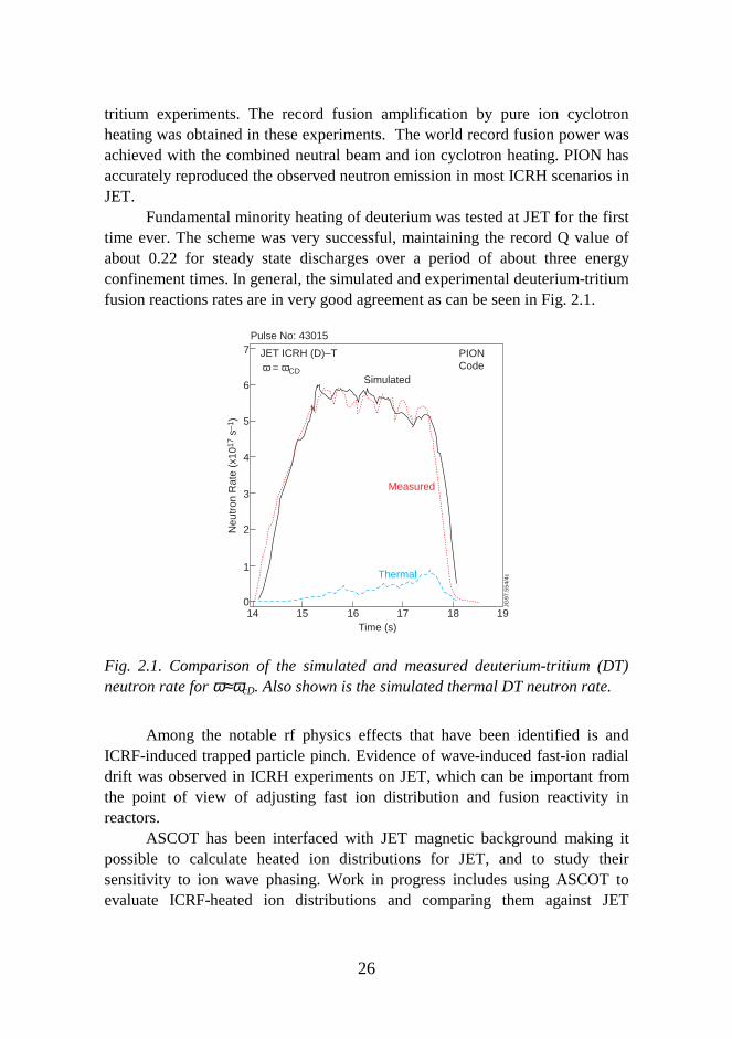
Fundamental minority heating of deuterium was tested at JET for the firsttime ever. The scheme was very successful, maintaining the record Q value ofabout 0.22 for steady state discharges over a period of about three energyconfinement times. In general, the simulated and experimental deuterium-tritiumfusion reactions rates are in very good agreement as can be seen in Fig. 2.1.
14 15 16 17 18 190
1
2
3
4
6
5
7
JG97
.554
/4c
Time (s)
Thermal
Neu
tron
Rat
e (x
1017
s–1
)
JET ICRH (D)–T PIONCode
Measured
Simulatedω = ωCD
Pulse No: 43015
Fig. 2.1. Comparison of the simulated and measured deuterium-tritium (DT)neutron rate for ω≈ωcD. Also shown is the simulated thermal DT neutron rate.
Among the notable rf physics effects that have been identified is andICRF-induced trapped particle pinch. Evidence of wave-induced fast-ion radialdrift was observed in ICRH experiments on JET, which can be important fromthe point of view of adjusting fast ion distribution and fusion reactivity inreactors.
ASCOT has been interfaced with JET magnetic background making itpossible to calculate heated ion distributions for JET, and to study theirsensitivity to ion wave phasing. Work in progress includes using ASCOT toevaluate ICRF-heated ion distributions and comparing them against JET
27
experimental data. ASCOT is also used to study transitions in plasmaconfinement at JET.
2.1.2 JET Task: Development of Radio-Frequency Modules forTransport Codes
Development of lower hybrid radio-frequency modules for the transport codesused at JET was started during 1998. First, the code will be validated againstJET experimental data, and then the rf- modules will be implemented into thetransport codes. Finally, experimental data from JET will be analysed using theintegrated rf- and transport codes.
This work is a continuation to the ray-tracing studies for lower hybridcurrent drive which were performed with the coupled ASTRA transport code andthe Fast Ray Tracing Code FRTC, developed at the Ioffe Institute, St. Petersburg.The ray-tracing studies addressed the role of the so-called fast wave in lowerhybrid current drive. Initially, the lower hybrid waves launched from the grillare so-called slow waves, but part of the wave power may transform to fastwaves, which have different propagation and absorption properties. The resultsshow that, at high plasma densities, up to half of the wave power can beabsorbed as a fast wave in JET and ITER.
2.1.3 ITER Task: Support of Physics and Engineering Design of theIon Cyclotron System
Mode Conversion and Minority Current Drive for Plasma Current Control. In amode conversion, ion cyclotron waves are converted into electrostatic, short-wavelength waves, that are rapidly absorbed to the plasma. A high conversionfactor would allow using ion cyclotron waves in mode conversion current drive.Mode conversion of ion cyclotron waves has been modelled numerically and, incertain conditions, 100% conversion has been demonstrated. Recently, in anumber of experiments world-wide, the high conversion have been verified. Aparameter analysis of the conversion coefficients and optimisation of antennaspectrum have been performed for ion cyclotron heating scenarios of ITER. Itshows that mode conversion current drive is difficult to realize in the large-sizeITER because of competing absorption mechanisms.
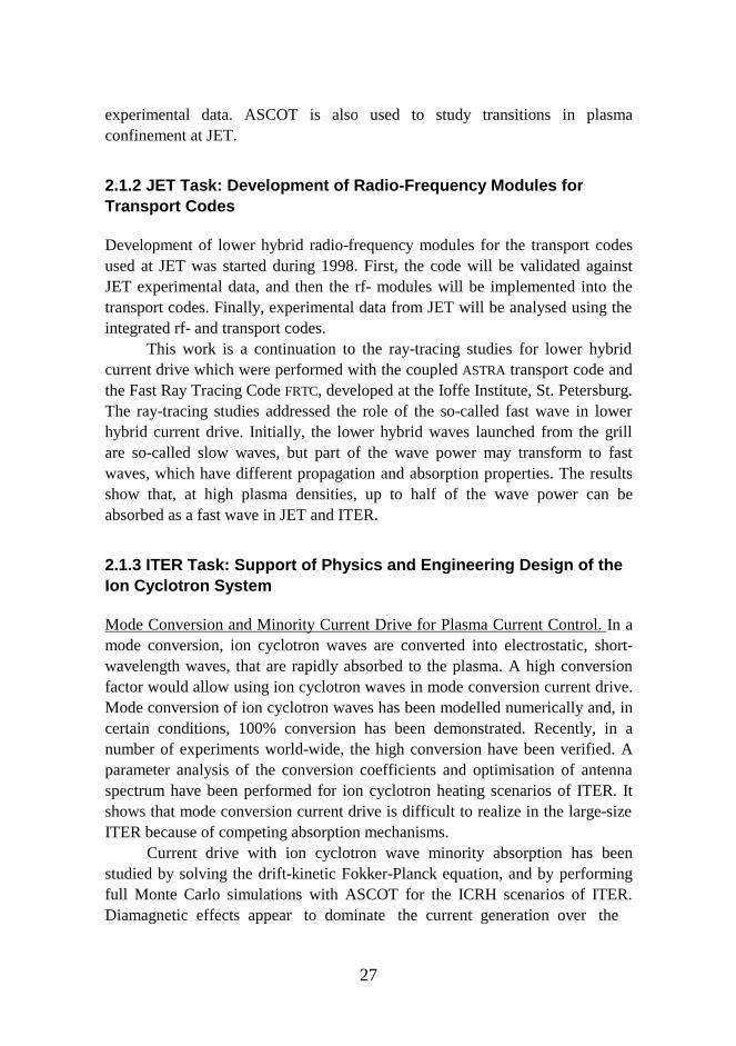
Current drive with ion cyclotron wave minority absorption has beenstudied by solving the drift-kinetic Fokker-Planck equation, and by performingfull Monte Carlo simulations with ASCOT for the ICRH scenarios of ITER.Diamagnetic effects appear to dominate the current generation over the
28
Fig. 2.2. Comparison of driven currents from the simulation and theanalytical estimate.
momentum transfer and asymmetric heating mechanisms. The driven current isonly found to be significant in ITER for hydrogen minority heating, which at themoment is not one of the candidates for ITER.
We have developed an analytical estimate to describe driven current in awide parameter range. Fig. 2.2 shows the results obtained from a Monte Carlosimulation, together with the analytical estimate for the integrated absolutecurrent. The fairly good agreement between the analytical results and thesimulations supports the conclusion that most of the driven current originatesfrom the fast ion diamagnetic current. Also, the dependencies of the current onthe wave and plasma parameters, obtained from toroidal Monte Carlosimulations, are satisfactorily reproduced by the analytical estimate.
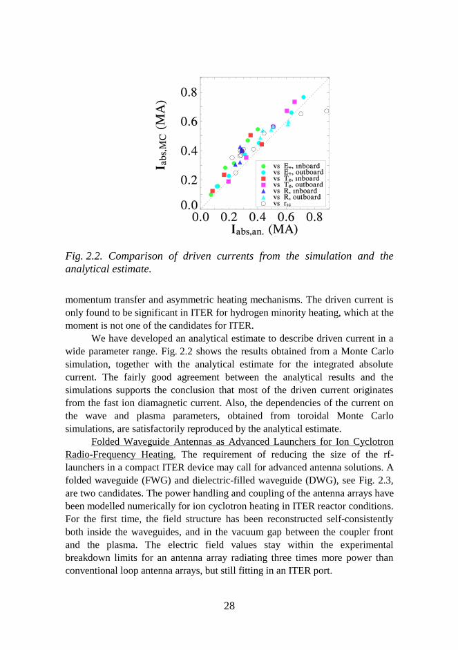
Folded Waveguide Antennas as Advanced Launchers for Ion CyclotronRadio-Frequency Heating. The requirement of reducing the size of the rf-launchers in a compact ITER device may call for advanced antenna solutions. Afolded waveguide (FWG) and dielectric-filled waveguide (DWG), see Fig. 2.3,are two candidates. The power handling and coupling of the antenna arrays havebeen modelled numerically for ion cyclotron heating in ITER reactor conditions.For the first time, the field structure has been reconstructed self-consistentlyboth inside the waveguides, and in the vacuum gap between the coupler frontand the plasma. The electric field values stay within the experimentalbreakdown limits for an antenna array radiating three times more power thanconventional loop antenna arrays, but still fitting in an ITER port.
29
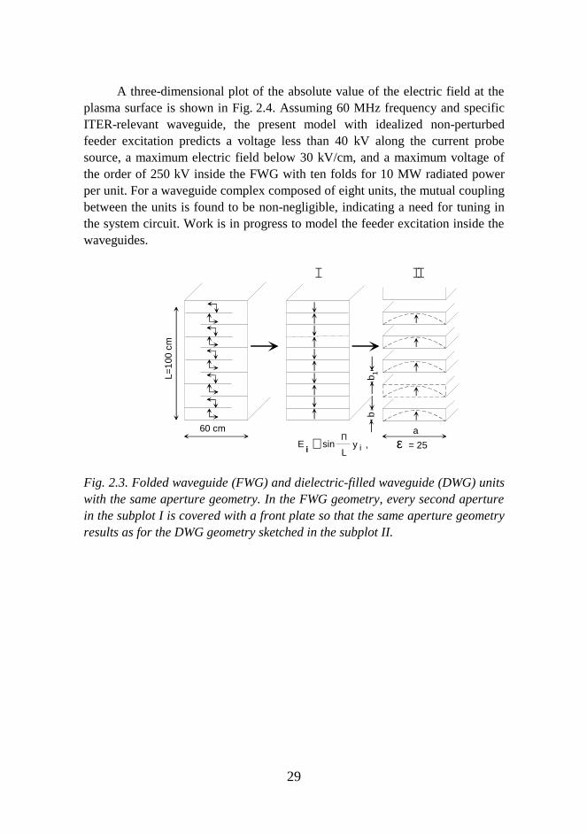
A three-dimensional plot of the absolute value of the electric field at theplasma surface is shown in Fig. 2.4. Assuming 60 MHz frequency and specificITER-relevant waveguide, the present model with idealized non-perturbedfeeder excitation predicts a voltage less than 40 kV along the current probesource, a maximum electric field below 30 kV/cm, and a maximum voltage ofthe order of 250 kV inside the FWG with ten folds for 10 MW radiated powerper unit. For a waveguide complex composed of eight units, the mutual couplingbetween the units is found to be non-negligible, indicating a need for tuning inthe system circuit. Work is in progress to model the feeder excitation inside thewaveguides.
L=10
0 cm
60 cm
I
E sin ∼ Π εL
y ,i = 25
a
bb
II
1
Fig. 2.3. Folded waveguide (FWG) and dielectric-filled waveguide (DWG) unitswith the same aperture geometry. In the FWG geometry, every second aperturein the subplot I is covered with a front plate so that the same aperture geometryresults as for the DWG geometry sketched in the subplot II.
30
Fig. 2.4. Electric field in the vacuum layer at the plasma surface for a 4×2 FWGarray, Prad =32 MW and vacuum gap is 10 cm.
Alpha Power Channelling with Waves. It has been suggested that locallyconstrained waves could be used for converting fusion alpha particle power tofuel ion energy and for enhancing alpha particle removal from the fuel. 5DMonte Carlo simulations with ASCOT, taking into account a realistic alphaparticle birth distribution, full collision operator, and a realistic tokamakgeometry, indicate that there are severe problems in implementing this schemefor standard heating methods. However, ASCOT calculations for frequency-chirped Alfven eigenmodes appear promising, and may suggest a scheme forharnessing alpha power for current drive, and for power channelling to fuel ions.
2.1.4 Tore Supra Collaboration: Analysis of Parasitic Absorption ofLower Hybrid Power
Generation of impurities has been observed in Tore Supra and Tokamak deVarennes (TdeV) when lower hybrid waves at frequencies of 3.7 GHz havebeen launched. At Tore Supra, heat fluxes of 5–10 MW/m2 on plasma facingcomponents have been measured by infrared video imaging. Toroidallyasymmetric heat loads have been observed on the divertor plates and limiters ofTdeV. Melting of the grill mouth due to strong local heating has occurred inJET, as well as on LH grills in other tokamaks.
A possible explanation for the impurity production is sputtering caused byfast electrons generated by the near field of the rf-launcher. Such electrons can

31
be generated when part of the rf-power is absorbed within a short distance fromthe launcher. When the launched power is several megawatts or even tens ofmegawatts, fast electrons containing a few percent of the rf-power may damagethe launcher or limiter structures.
The parasitic absorption of lower hybrid waves and the generation of thefast electrons near the launcher has been investigated via particle-in-cell (PIC)simulations in collaboration with Tore Supra and JET. A particle-in-cell modelof a lower hybrid grill has been developed and coupled with the SWAN code,which calculates the launched wave spectrum.
Fig. 2.5 shows the wave potential in a simulation performed for ToreSupra. The fine structure close to the grill mouth is due to the short-wavelengthmodes emitted by the antenna. Further away from the grill, the field structure isvery smooth because the short-wavelength part of the spectrum is absorbedwithin a distance of a few millimetres from the launcher.
0 10 20 30 400
10
20
30
40
50
60
Rad
ial c
o−or
dina
te, x
[mm
]
Toroidal co−ordinate, z [mm]
Fig. 2.5. Contour plot of the potential of the lower hybrid wave obtained from aparticle-in-cell simulation of the Tore Supra lower hybrid grill. The grill mouthis located at the bottom and the plasma density increases upwards.
32
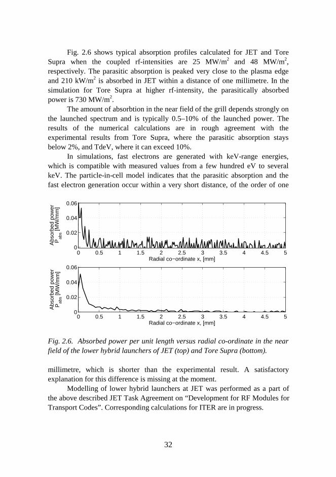
Fig. 2.6 shows typical absorption profiles calculated for JET and ToreSupra when the coupled rf-intensities are 25 MW/m2 and 48 MW/m2,respectively. The parasitic absorption is peaked very close to the plasma edgeand 210 kW/m2 is absorbed in JET within a distance of one millimetre. In thesimulation for Tore Supra at higher rf-intensity, the parasitically absorbedpower is 730 MW/m2.
The amount of absorbtion in the near field of the grill depends strongly onthe launched spectrum and is typically 0.5–10% of the launched power. Theresults of the numerical calculations are in rough agreement with theexperimental results from Tore Supra, where the parasitic absorption staysbelow 2%, and TdeV, where it can exceed 10%.
In simulations, fast electrons are generated with keV-range energies,which is compatible with measured values from a few hundred eV to severalkeV. The particle-in-cell model indicates that the parasitic absorption and thefast electron generation occur within a very short distance, of the order of one
0 0.5 1 1.5 2 2.5 3 3.5 4 4.5 50
0.02
0.04
0.06
Radial co−ordinate x, [mm]
Abs
orbe
d po
wer
Pab
s [MW
/mm
]
0 0.5 1 1.5 2 2.5 3 3.5 4 4.5 50
0.02
0.04
0.06
Radial co−ordinate x, [mm]
Abs
orbe
d po
wer
Pab
s [MW
/mm
]
Fig. 2.6. Absorbed power per unit length versus radial co-ordinate in the nearfield of the lower hybrid launchers of JET (top) and Tore Supra (bottom).
millimetre, which is shorter than the experimental result. A satisfactoryexplanation for this difference is missing at the moment.
Modelling of lower hybrid launchers at JET was performed as a part ofthe above described JET Task Agreement on “Development for RF Modules forTransport Codes”. Corresponding calculations for ITER are in progress.
33
2.1.5 Gyrotrons for Electron Cyclotron Heating and MicrowaveDiagnostics
Electron-cyclotron heating is playing an increasingly important role in tokamakand stellarator plasma research. The power for this heating method is providedby gyrotrons.
Conventional hollow waveguide-cavity gyrotrons are alreadycommercially available. However, they are limited in both output power andfrequency (about 1 MW, 140 GHz). Current issues in gyrotron research anddevelopment include techniques for increasing the efficiency of gyrotrons above50%, and techniques for increasing the unit power of gyrotrons to over 3 MW atfrequencies of about 170 GHz. Only gyrotrons with coaxial cavities have thepotential to meet these requirements, and are in the front line of the research.
The gyrotron research in Finland started in 1993. It is done at the HelsinkiUniversity of Technology. There are no gyrotron experiments. The researchwork can be grouped as follows:
• Participation in theoretical work on the world-wide development ofspecific advanced gyrotrons.
• Development of the general gyrotron theory.• Data analysis for various experiments (e.g. W7-AS stellarator) where
gyrotrons are used for plasma heating, current drive, and diagnostics.The results of this analysis are used as feedback for gyrotron research.
The most important achievements are summarized below.
Resonator design. Resonators have been designed for specific gyrotrons, e.g.,the 140 GHz, 1.5 MW, TE28,16 mode coaxial gyrotron developed in acollaboration between the Forschungszentrum Karlsruhe in Germany and theInstitute of Applied Physics at Nizhny Novgorod in Russia; and for the 280GHz, 1 MW, TE23,16 mode and 140 GHz, 3 MW, TE21,13 mode coaxial gyrotronsdeveloped at the Massa-chusetts Institute of Technology in USA. Nonlinearcalculations of mode competition in these resonators, including the effect ofelectron beam velocity spread, have been carried out using numerical toolsdeveloped at the Helsinki University of Technology.
The third harmonic 280 GHz quasi-optical gyrotron designed at theCentre de Recherches en Physique des Plasmas of the Ecole PolytechniqueFederale de Lausanne in Switzerland for plasma diagnostics has been analyzed.A new special code, taking into account the space-charge effects as a source ofelectron energy spread, has been developed and applied. Based on resultsobtained from this code it has been proposed that the magnet system of this
34
gyrotron should be modified to increase its efficiency.
General theory of gyrotrons. A general theory describing symmetry breaking incoaxial cavities has been developed. This theory includes both the resonatorwall - electron beam and the resonator wall - coaxial insert eccentricities.
New schemes of tuning the frequency of a gyrotron have been proposedand investigated. These include the fast frequency step tuning by means ofchanging operating voltages, and the continuous frequency tuning by movingthe inner conductor in a coaxial cavity. A design of a multifrequency gyrotron,i.e., a gyrotron which generates microwaves simultaneously at severalfrequencies, has been presented. For this purpose, the multimode, time-dependent and self-consistent codes developed at Karlsruhe and NizhnyNovgorod have been modified and improved.
A general theory describing the effect of fluctuations in technicalparameters (voltages, beam current, external magnetic fields) on the linewidthof gyrotron radiation has been developed.
Various schemes of transition of gyrotron radiation from regular tochaotic regimes have been investigated. It was shown that chaos which candevelop in a resonator for some values of control parameters can be onlytransient.
Use of specific gyrotrons in tokamaks and stellarator. A gyrotron has been usedto study effects of the off-axis plasma heating at the W7-AS stellarator at theMax-Planck-Institut für Plasmaphysik at Garching in Germany. In particular, ithas been shown that such a heating leads to electron density increase at theplasma center.
Suitability of frequency tunable gyrotrons for various plasma heating anddiagnostics applications has been investigated. These include the possibility ofusing a single gyrotron for plasma heating and collective Thomson scatteringexperiments, as well as for stabilization of tearing modes.
INTAS coordination. An INTAS project was co-ordinated in 1995–1997 tostudy modern frequency-tunable gyrotrons, in order to improve the diagnosticsand heating schemes in fusion plasmas. Fast and slow, discrete and continuoustunability of the source frequency, as well as new methods to widen thefrequency window at high power, were investigated.
A fully kinetic code for calculating the collective Thomson scatteringcross section was developed in the sub-millimeter and millimeter wavelengthregime. The code has been validated by benchmarking against the warm plasma
35
codes at JET, and has been used for the design of microwave scatteringdiagnostics of fast particles.
2.2 Plasma Confinement and Transport
Confining the hot fusion plasma is a fundamental problem en route to acommercial fusion reactor. The initial, optimistic predictions on the availabilityof fusion power were based on the assumption that the transport of heat andparticles in a tokamak geometry were solely due to Coulomb collisions.Experimentally, however, it has been found that the plasma transport is stronglydriven by turbulence, thus leading to poorer confinement characteristics thananticipated. A comprehensive transport theory for a tokamak plasma is stillbeing fomulated, while experimentally various regimes of improvedconfinement have been discovered. In certain circumstances a tokamak plasmais found to make a rapid transition from Low confinement- or L-mode to Highconfinement- or H-mode. The mechanism behind these transitions is yet to beunderstood, but it seems that a radial electric field plays a crucial role. Becauseattaining good confinement properties is crucial for a commercial fusion reactor,efforts to understand and control L-H transition are of utmost importance.
2.2.1 ASDEX Upgrade Agreement: Transition from Low to HighConfinement
Collaboration between VTT Energy, HUT, and Association IPP Garching tocarry out detailed simulation studies to explain the L-H transition characteristicsat ASDEX Upgrade in IPP started in 1996. ASCOT has been interfaced with theASDEX Upgrade background data, including the ripple in the magnetic field,neutral beam injection, and charge exchange diagnostics. Presently, this codecan consistently follow electromagnetic fields generated in the plasma, and istherefore appropriate for studies of transport and neoclassical mechanisms.
Detecting radial electric field by NPA of ripple-trapped slowing-down ions.Several theories that include the radial electric field have been proposed toexplain the mechanism with which a tokamak plasma switches from L- to H-mode. It is widely believed that the sheared E×B-rotation associated with a non-uniform radial electric field suppresses turbulence and thus reduces anomaloustransport. However, the time resolution of the spectroscopic measurementsprobing the dynamics of the L-H transition has not yet been good enough (about0.5 ms on DIII-D) to decide whether the changes in the radial electric field are
36
sufficiently fast, and if they indeed precede the L-H transition.In neutral beam heated discharges on ASDEX Upgrade, neutral particle
fluxes, originating from slowing-down ions trapped in local magnetic ripples,are observed to evolve at the L-H transition: the flux starts increasing at thetransition, and the increase in a given energy channel starts the earlier the lowerthe energy of the channel. As a result, the energy spectra of these neutrals arequalitatively different in L- and H-modes. The particle flux also responds toELMs (Edge Localized Modes), with the particle flux collapsing simultaneouslywith the observed increase in the Dα-signal.
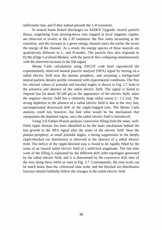
Monte Carlo calculations using ASCOT code have reproduced theexperimentally observed neutral particle analyzer (NPA) signal by turning on aradial electric field near the plasma periphery, and assuming a backgroundneutral particle density profile consistent with experimental conditions. The fluxfor relevant values of poloidal and toroidal angles is shown in Fig. 2.7 both inthe presence and absence of the radial electric field. The signal is found torespond fast (in about 50-100 µs) to the appearance of the electric field, whenthe negative electric field has a relatively large radial extent (> 1-2 cm). Thestrong depletion in the absence of a radial electric field is due to the very fast,uncompensated downward drift of the ripple-trapped ions. The Monte Carloanalysis could not, however, but hint what would be the mechanism thatrepopulates the depleted region, once the radial electric field is introduced.
Using 3-D Fokker-Planck analysis, convective filling from the inner, well-filled ripple domain has been identified to be the main mechanism behind thefast growth in the NPA signal after the onset of the electric field. Near theplasma periphery, at small poloidal angles, a strong suppression in the deeplyripple-blocked ion distribution is observed in the absence of a radial electricfield. The deficit of the ripple-blocked ions is found to be rapidly filled by theonset of an inward radial electric field of a sufficient magnitude. The fast timescale of the filling is explained by the different drift orbit topologies generatedby the radial electric field, and it is determined by the convective drift time ofthe ions along these orbits as seen in Fig. 2.7. Consequently, the time scale canbe much faster than the collisional time scale, and the blocked ion distributionfunction should faithfully follow the changes in the radial electric field.
37
Fig. 2.7. A 3-D plot of the neutral flux from the simulation as a function of thetoroidal (ϕ*) and poloidal (θ) angle. The detector’s energy window is from 5 to15 keV, and the pitch window is |ξ|<0.07; (a) without a radial electric field; (b)with the radial electric field.
The fast response of the NPA signal to the radial electric field assists indiagnosing the dynamics of the radial electric field in the transition from L- toH-mode. The obtained experimental and simulation results appear to exclude afast (<< 1 ms) jump in the radial electric field at ASDEX Upgrade, at least for afinite halfwidth of the field radial profile.
Radial electric field generation at L-H transition. One of the most populartheories for L-H transition assumes that the generation of the radial electric fieldis due to direct ion orbit losses. With ASCOT, we have evaluated the ion orbitloss trajectories in ASDEX-Upgrade plasma using a toroidal magneticcoordinate presentation appropriate both inside and outside the separatrix. Theion orbit loss current has been calculated for the real ASDEX Upgradegeometry. The theory, based on a multivalued balance between the orbit losscurrent and neoclassical current, was then tested by comparing the calculatedorbit loss current to an analytical estimate for the neoclassical return current.The approximate analytical theory, based on cylindrical geometry, predicts thata bifurcation happens for normalized collisionality ν*i ≈ 1. This holds true alsofor more realistic calculations, carried out for the ASDEX Upgrade shot 8044,with collisionality ν*i ≈ 3.8. The ion orbit loss current ensuing from neoclassicaldiffusion is far too small to explain the bifurcation for the experimentalconditions of ASDEX Upgrade.
38
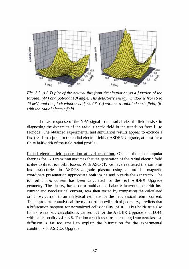
In order to evaluate the dynamics of the radial electric field, usingASCOT, the ion trajectories have been calculated self-consistently with theradial electric field obtained from the Maxwell equations including the radialcurrents by parallel and perpendicular viscosity, and polarization. Thesimulations carried out for a wide collisionality regime show a strong butnarrow negative radial electric field just inside the separatrix even in the plateauregime. An example of the time dynamics of the electric field radial profile isshown in Fig. 2.8. This field, which arises from the particle loss mechanismtaking place over the separatrix, does not experience bifurcation, but a gradualbroadening and strengthening as the collisionality decreases.
Fig. 2.8. Radial electric field profile as a function of time as calculated with agyrokinetic version of ASCOT for ASDEX Upgrade L-H transition conditions.
39
2.2.2 Electron Density Profile Measurements and Particle TransportStudies with Multichannel Interferometer at the Wendelstein 7-AS
A 10-channel microwave interferometer was build 1995 for the Wendelstein7-AS stellarator in Garching. The interferometer started its operation in June1996. Within the agreement between the Helsinki University of Technology andMax-Planck-Institut für Plasmaphysik (IPP), software for interpreting data frommeasurements has been developed. The electron density profile has to bereconstructed from line-integrated interferometer data. The reconstructionproblem is similar to tomographic inversion problems. A new algorithm basedon Fisher-information as the regularizational functional was developed, andcorresponding software built. The new method was checked and benchmarkedby comparing the resulting density profiles to density profiles measured withThomson scattering, Lithium beam-diagnostics, and reflectometry. Theagreement was very good. The density profile reconstruction software has beena part of everyday diagnostics at W7-AS since 1996. Since the interferometerhas a good time resolution, it is possible to study fast changes in plasma density.
The main emphasis in the interferometer measurements was in transientparticle transport studies. Gas feed to the plasma was modulated harmonicallyproducing a density perturbation, which propagated from the plasma edge to thecentre. Diffusion coefficient and the convective velocity of the plasma electronscan be determined from the magnitude and phase of the propagating densityperturbation, both of which can be extracted from the interferometer data. Anexample of a large magnitude and slow density perturbation can be seen in Fig.2.9, where the density oscillates during modulated gas puffing.
40
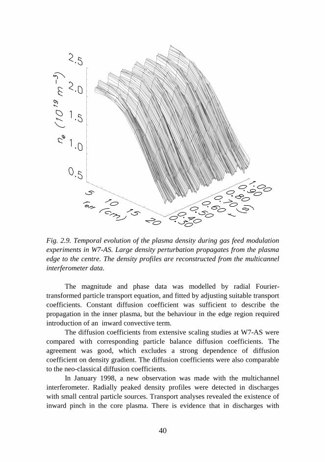
Fig. 2.9. Temporal evolution of the plasma density during gas feed modulationexperiments in W7-AS. Large density perturbation propagates from the plasmaedge to the centre. The density profiles are reconstructed from the multicannelinterferometer data.
The magnitude and phase data was modelled by radial Fourier-transformed particle transport equation, and fitted by adjusting suitable transportcoefficients. Constant diffusion coefficient was sufficient to describe thepropagation in the inner plasma, but the behaviour in the edge region requiredintroduction of an inward convective term.
The diffusion coefficients from extensive scaling studies at W7-AS werecompared with corresponding particle balance diffusion coefficients. Theagreement was good, which excludes a strong dependence of diffusioncoefficient on density gradient. The diffusion coefficients were also comparableto the neo-classical diffusion coefficients.
In January 1998, a new observation was made with the multichannelinterferometer. Radially peaked density profiles were detected in dischargeswith small central particle sources. Transport analyses revealed the existence ofinward pinch in the core plasma. There is evidence that in discharges with
41
peaked temperature profiles, the inward pinch is cancelled out by outwarddirected thermodiffusion.
2.3 Dielectric Window Prototype for the Reactor VacuumTransmission Line of Ion Cyclotron Power
The ITER Tasks on "Dielectric Window Development for the ITER VacuumTransmission Line of Ion Cyclotron Power” were conducted 1995-1998 at VTT,IVO Technology Centre, and Helsinki University of Technology. The goal wasto obtain specifications for constructing two prototype vacuum windows for theITER-like vacuum transmission line. The task objective was to present a designof the window which is compatible with the ITER radiation fluence, withstandsthe strong dielectric heating and related thermal stresses, is resistant againstbreakdown with appropriate arc monitoring, can be remote handled, and can bemanufactured by welding the ceramics to the conductor.
2.3.1 Requirements for a Reactor Window
The double dielectric window is an essential and the most delicate componentof the ICRF Vacuum Transmission Line for ITER, as it provides the ultimatevacuum, as well as tritium containment. In the current baseline design, thereare eight windows for each of the four ICRF arrays. The ITER windowrequires a specific design and careful selection of the dielectric materialbecause of the long ICRF pulse length, high electric field strengths, possibledegradation of the dielectric properties due to neutron or gamma irradiation,and possible changes in mechanical and thermal properties and in gaspermeation. Furthermore, the metal-ceramic joints required for the windowsand the support structures need to retain reliable vacuum tightness undercyclic operation conditions.
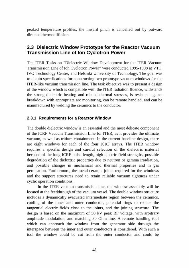
In the ITER vacuum transmission line, the window assembly will belocated at the feedthrough of the vacuum vessel. The double window structureincludes a dynamically evacuated intermediate region between the ceramics,cooling of the inner and outer conductor, potential rings to reduce thetangential electric fields close to the joints, and the joining structure. Thedesign is based on the maximum of 50 kV peak RF voltage, with arbitraryamplitude modulation, and matching 30 Ohm line. A remote handling toolwhich can approach the window from the generator side through theinterspace between the inner and outer conductors is considered. With such atool the window could be cut from the outer conductor and could be

42
withdrawn inside the outer conductor. This type of arrangement is obviouslypossible if the window is placed at the vacuum vessel feedthrough and isinserted in a casing attached to the outer transmission line conductors on bothside of the window as schematically shown in Fig. 2.10.
2.3.2 Design
A Monte Carlo program MCNP4A was used to evaluate the neutron fluence atthe window for 1500 MWth reactor power. The fast neutron flux at the vacuumwindows is about 7×10¹⁰ n/cm2s, if they are not shielded by an additional plugclosing the port. By closing the end of the equatorial port with a 55 -30 cm thickplug of steel and water, and locating the vacuum windows outside this plug, thefast flux will be 5×10⁸ - 5×10⁹n/cm2 s.
By inspection of the material data of irradiated ceramics, unirradiateddata for the loss tangent, thermal conductivity, and mechanical and electricalstrength can be used for alumina and beryllia with fluences below 1016 n/cm2.For fluences up to 1018 n/cm2 the changes can also be regarded small (<30%).The dielectric heating calculations with a disk shaped ceramic showed that forthe dielectric material in real construction, BeO or Al2O3 (97.5%) (latter onlyin unirradiated situations) can be accepted, and that only titanium andniobium are reasonable alternatives for conductor. This is due to the smalldifference in the value of the thermal expansion coefficient between thesemetals and the ceramics.
Extensive finite element calculations of the temperature, stress, andelectric field on the vacuum window were performed to optimise the conical-shaped dielectric geometry in a coaxial with proper material choices. BeOceramic and titanium conductor were chosen to minimise the dielectricheating, alleviate the stresses, and to help the brazing. Based on the obtainedfluences, it has been decided to place the window at the vacuum vesselfeedthrough.
43
Fig. 2.10. Sketch of the prototype vacuum window immersed in a stainlesssteel casing and with bullet-type inner conductor connections to the rest of thetransmission line. Water cooling at both ceramic-conductor joints (inner andouter) is arranged. The window was designed at VTT Energy, VTTManufacturing Technology, IVO Technology Centre, and Helsinki Universityof Technology
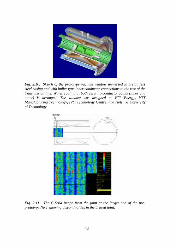
Fig. 2.11. The C-SAM image from the joint at the larger end of the pre-prototype No 1 showing discontinuities in the brazed joint.
44
The optimized shape for the ceramics is conical with an angle ofinclination of approximately 18o. In the present model, the casing is thermallyconnected to the outer conductor at the ends above the ceramic/outerconductor joint. A sketch of the design is shown in Fig. 2.10. An X-shapedgeometry of the two ceramics has been adopted as suggested by B. Waltonand A. Kaye (JET, 1996), because it gives a comparable strength as thecorresponding one with two parallel conical septa while decreasing thetangential electric field. The maximum tangential field obtained is 0.60 MV/mat the inner side, and the maximum field normal to the surface of ceramics is0.19 MV/m. The electric field levels which remain significantly below 2MV/m are not expected to be prone to a breakdown discharge along theceramics.
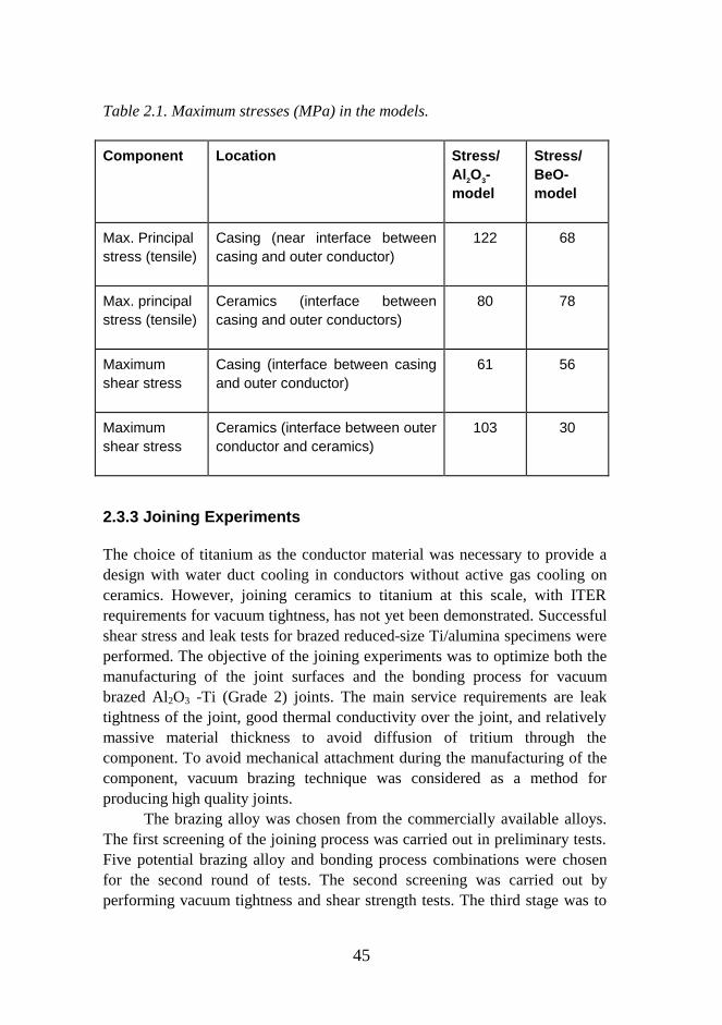
Temperature time histories are evaluated using discharge duration of1000 s and a volume 1000 cm3 of the ceramic. The source of the volumetricheating is a high frequency electric field, together with the Joule heatgenerated by the current in the titanium conductors. Ohmic losses with Nicoating will be two times lower. The maximum temperature was found to be270 oC at the centre of the Al2O3 ceramic and 185 oC at the centre of the BeOceramic, when the ohmic heating of the conductor was 750 kW. A stationarytemperature was reached after 400 s with maximum principle stress less than125 MPa . The stress values at different positions of the window are given inTable 2.1.
45
Table 2.1. Maximum stresses (MPa) in the models.
Component Location Stress/Al 2O3-model
Stress/BeO-model
Max. Principalstress (tensile)
Casing (near interface betweencasing and outer conductor)
122 68
Max. principalstress (tensile)
Ceramics (interface betweencasing and outer conductors)
80 78
Maximumshear stress
Casing (interface between casingand outer conductor)
61 56
Maximumshear stress
Ceramics (interface between outerconductor and ceramics)
103 30
2.3.3 Joining Experiments
The choice of titanium as the conductor material was necessary to provide adesign with water duct cooling in conductors without active gas cooling onceramics. However, joining ceramics to titanium at this scale, with ITERrequirements for vacuum tightness, has not yet been demonstrated. Successfulshear stress and leak tests for brazed reduced-size Ti/alumina specimens wereperformed. The objective of the joining experiments was to optimize both themanufacturing of the joint surfaces and the bonding process for vacuumbrazed Al2O3 -Ti (Grade 2) joints. The main service requirements are leaktightness of the joint, good thermal conductivity over the joint, and relativelymassive material thickness to avoid diffusion of tritium through thecomponent. To avoid mechanical attachment during the manufacturing of thecomponent, vacuum brazing technique was considered as a method forproducing high quality joints.
The brazing alloy was chosen from the commercially available alloys.The first screening of the joining process was carried out in preliminary tests.Five potential brazing alloy and bonding process combinations were chosenfor the second round of tests. The second screening was carried out byperforming vacuum tightness and shear strength tests. The third stage was to
46
study the application of the filler materials, and the effects of the circular jointgap geometry in a real window application.
The He-leak test samples were made with a tube-to-plate configuration.Before the He-leak test, six of the bonded samples were heat-treated. Athermal cycling from room temperature to 200°C was repeated ten times tosimulate the thermal conditions at the joints in service. In the He-leak test, thespecimens were first, one by one, tightened mechanically with the aid of aclamping chuck on the chromatographic apparatus. Based on the test, all thesamples except those brazed with the alloys CB6 and Gold ABA, areacceptable. The rejection of these brazing alloys was due to a porous structureof the joint revealed by metallography.
Non-Destructive Evaluation (NDE) using ultrasonic examination wasperformed for butt-joined samples (used for the shear strength tests) with thesample immersed in water, and the ultrasonic transducer was scanned in an X-Y-pattern over the sample. The results were in accordance with the vacuumtightness test results.
The verification of the potential manufacturing procedures obtainedfrom the experimental phase was done with a full-scale alumina to titaniumcomponent sketched in Fig. 2.10. The first trials were done with one ceramicwindow and half of the titanium tubes. The weight of such a half-componentis around 7.3 kg, being relatively massive for a ceramic-to-metal component.The main conclusions from these full-scale pre-prototype tests are:
• the amount and spreading of the brazing filler material must be optimisedcarefully
• the type of the brazing alloy is critical, not only the brazing temperaturebut also the wetting properties must be taken into account
• the preheat treatment and the dimensional control of the metallic titaniumparts are essential in order to control the dimensional changes in titaniumduring the bonding cycle
• the accurate finishing and tight tolerances of the joined parts areimportant for the proper bonding.
Fig. 2.11 shows the C-SAM image from the joint at the larger end of theprototype showing discontinuities in the brazed joint. Work shall continue toimprove the quality of the joint in the post-EDA phase after 1998, togetherwith the production of the prototypes as well as with the design andproduction of new ITER-like vacuum windows for high power density rf-launcher prototypes. In particular, a vacuum-tight brazing of full-sized BeO
47
ceramics to the titanium housing is to be experimentally verified.
2.4 Central Solenoid Development for SphericalTokamaks
Central solenoid is the most critical magnet component in tight aspect ratiotokamaks. Its function is to provide inductively the plasma current required forconfinement. In present devices, water-cooled copper conductor is used for itswinding. A project to design and construct an appropriate solenoid conductorfor spherical tokamaks started in 1994 as a Tekes project at VTT, HUT andOutokumpu Poricopper. In due course of the project, a manufacturing methodwas developed for producing a world record of 66m-long high- strength hollowconductor and a full specimen was delivered to the Efremov Institute in St.Petersburg, where it is wound and tested during 1998. Outokumpu Poricopperprovided the required solenoid conductor also to the MAST tokamak in Culham.
2.4.1 Design Characteristics
In the Globus-M spherical tokamak under construction at Ioffe Institute, St.Petersburg, the goal is to generate and sustain a plasma current of up to 0.5 MAfor 0.2s pulses. The central solenoid conductor material must provide reliableoperation over a lifetime of at least 4×10⁴ full power shots with a flux swingevery 10 minutes, which requires heat removal by water cooling. It is importantalso to wind the solenoid from a continuous conductor, precluding the need foradditional electrical contact joints. High magnetic and thermal cyclic loadsacting on the solenoid require that it be manufactured from high strength hollowconductor. CuAg0.1(OF) was selected as the conductor material.
2.4.2 Solenoid Design, Fabrication, and Testing
A solenoid prototype with full scale radius and decreased length (one-sixth offull length) was fabricated from a ten-meter piece of silver-bearing hollowcopper conductor. The conductor after extrusion was cold-drawn with a 30%reduction in area, and subjected to mechanical static and cyclic tests. In theexperiments, the tensile load amplitude was in the range 140-220 MPa, which isgreater than the stress intensity in the solenoid’s inner layer, where it reaches127 MPa near the cooling hole. The conductor fractured after 2×10⁵ cycles with

48
an applied load of 220 MPa. The mechanical properties of silver bearing copperwere measured at room temperature with virgin material and with materialinitially strained cyclically using a load amplitude 150 MPa for 6×10⁵ loadcycles. This load did not reveal any significant variation in mechanical strength.
The optimum conductor profile was designed by using a finite elementcode DEFORM 3D to simulate the bending process. To verify the simulations,several test pieces of the conductor were manufactured and bent to the requiredradius. The experimental results were in good agreement with the calculations.
A 2D axisymmetric finite element model of the solenoid was developedto analyze the stresses. Within a range of currents up to 92 kA, the measuredstrains had an elastic character. The values of Tresca stress, calculated fromstrains measured at the horizontal midplane, are plotted in Fig. 2.12 as afunction of current. The stress averaged over two layers was well below thestatic allowable limit for the conductor material. The shear stress did not exceed10 MPa in the outer turn of the insulation. The conductor was wrapped in threelayers with polyimide tape, followed by one layer of protective glass fibre tape.
0
20
40
60
80
100
120
0 20 40 60 80 100
Current, kA
Calculations
Experiment
Tresca stress, MPa
0
10
20
30
40
50
60
70
0 20 40 60 80 100
Current, kA
Tresca stress, MPa
Calculations
Experiment
Fig. 2.12. Measured and calculated Tresca stresses at the solenoid prototypeinner and outer surface as a function of current.

49
3 Fusion Reactor Materials
The selection of materials and joining technologies to be used in ITER is a tradeoff among multiple and often conflicting requirements derived from the uniquefeatures of the fusion environment. Material selection must encompass a totalengineering approach, by considering not only physical and mechanicalproperties and processing, but also the maintainability and reliability of eachmaterial. As far as technically feasible, the material choice has been orientedtoward industrially available materials and well established manufacturingtechniques. This is very much the case for the structural materials of the basicmachine e.g. cryostat, magnet case and vacuum vessel for which a critical factoris the availability of industrial suppliers with experience in forming and joiningtechnology. The structural integrity of these components after manufacturingand throughout the entire design lifetime is important for the machineavailability and safety. The materials for the in-vessel components will operateunder the simultaneous influence of different life-limiting factors such asneutron irradiation, hydrogen atmosphere, dynamic stresses, thermal loads,cyclic mode of operation and water cooling environment. Even though no safetyfunctions are attributed to the in-vessel components to achieve goodperformance and adequate availability of the whole machine they have toremain highly reliable throughout the design lifetime. Ease of fabrication, goodweldability, resistance to corrosion, good strength and fatigue resistance,adequate ductility and fracture toughness after neutron irradiation are essentialrequirements.
Austenitic stainless steel 316LN-IG (ITER Grade) is the most suitable forstructural material of the ITER basic machine and in-vessel components as it isqualified in many national design codes, has satisfactory resistance to stresscorrosion cracking and high level of strength and fracture toughness. There isalso extensive database in the unirradiated and irradiated conditions and a largeindustrial experience in nuclear applications. Two copper alloys have beenselected for the heat sink of Plasma Facing Components one age-hardenedCuCrZr-IG alloy and one dispersion strengthened CuAl25-IG alloy. Mechanicalproperties of both alloys are sufficient for the components to sustain thermaland mechanical loads. For plasma facing materials carbon fibre composite,beryllium and tungsten have been selected as reference materials. Referencemethods for component manufacturing is high temperature HIPing and brazing.
50
Main focus of fusion reactor material research work has been oncharacterisation of in-vessel materials and development of componentmanufacturing techniques applicable for ITER blanket modules. Criticalproperties of candidate copper alloys and their joints with stainless steel havebeen determined in the ITER relevant temperature and neutron fluence ranges.Fracture mechanical characterisation of dissimilar metal joints with specialemphasis on miniaturised specimen technology have also been carried out.Explosion welding and hot isostatic pressing methods have been evaluated aspossible manufacturing techniques for ITER primary wall module. Non-destructive examination methods suitable for examining dissimilar metal planarand tubular interfaces in ITER small scale primary wall mock ups have alsobeen developed.
3.1 Characterisation of Irradiated Copper Alloys
The current design for ITER utilises copper alloys in the first wall and divertorstructures. The function of the copper alloy in the first wall is to dissipate heatproduced by plasma disruptions and therefore the copper alloy is not designed toprovide structural support for the first wall. However, the copper alloy for thedivertor is designed also for structural support of the divertor cassette inaddition to heat dissipation. On the basis of the currently available data, thedispersion strengthened CuAl25 IG0 alloy is being considered as the primarycandidate alloy and the precipitation hardened CuCrZr alloy has been chosen asthe backup alloy. Within the frame work of the ITER technology programme,screening experiments are being carried out to determine the effect of irradiationon physical and mechanical properties of these alloys, however, there is veryfew results on the effect of irradiation on the fracture toughness behaviour ofthese alloys in the open literature.
3.1.1 Microstructure
The microstructure of candidate copper alloys is markedly different from eachother due to different routes to produce the alloys. The CuCrZr alloy studied isproduced by Outokumpu Poricopper Oy using conventional melting and hotrolling practices where the optimum strength is obtained by intermediate colddeformation before final precipitation heat treatment. The resultingmicrostructure consists of homogeneously distributed precipitates and equaxedgrain structure. Mechanical properties of CuCrZr alloy are inherently sensitiveto the temperature cycle and presently foreseen component manufacturing
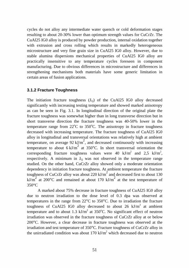
51
cycles do not alloy any intermediate water quench or cold deformation stagesresulting to about 20-30% lower than optimum strength values for CuCrZr. TheCuAl25 IG0 alloy is produced by powder production, internal oxidation togetherwith extrusion and cross rolling which results in markedly heterogeneousmicrostructure and very fine grain size in CuAl25 IG0 alloy. However, due tostable alumina dispersions mechanical properties of CuAl25 IG0 alloy arepractically insensitive to any temperature cycles foreseen in componentmanufacturing. Due to obvious differences in microstructure and differences instrengthening mechanisms both materials have some generic limitation incertain areas of fusion applications.
3.1.2 Fracture Toughness
The initiation fracture toughness (JQ) of the CuAl25 IG0 alloy decreasedsignificantly with increasing testing temperature and showed marked anisotropyas can be seen in Fig. 3.1. In longitudinal direction of the original plate thefracture toughness was somewhat higher than in long transverse direction but inshort transverse direction the fracture toughness was 40-50% lower in thetemperature range from 22oC to 350oC. The anisotropy in fracture toughnessdecreased with increasing temperature. The fracture toughness of CuAl25 IG0alloy in longitudinal and transversal orientations was relatively high at ambienttemperature, on average 92 kJ/m
2, and decreased continuously with increasing
temperature to about 6 kJ/m2 at 350°C. In short transversal orientation the
corresponding fracture toughness values were 40 kJ/m2 and 2,5 kJ/m2,respectively. A minimum in JQ was not observed in the temperature rangestudied. On the other hand, CuCrZr alloy showed only a moderate orientationdependency in initiation fracture toughness. At ambient temperature the fracturetoughness of CuCrZr alloy was about 220 kJ/m
2 and decreased first to about 130
kJ/m2 at 200°C and remained at about 170 kJ/m
2 at the test temperature of
350°CA marked about 75% decrease in fracture toughness of CuAl25 IG0 alloy
due to neutron irradiation to the dose level of 0.3 dpa was observed attemperatures in the range from 22°C to 350°C. Due to irradiation the fracturetoughness of CuAl25 IG0 alloy decreased to about 26 kJ/m2 at ambienttemperature and to about 1.3 kJ/m2 at 350oC. No significant effect of neutronirradiation was observed in the fracture toughness of CuCrZr alloy at or below200°C. However, a clear decrease in fracture toughness was observed at theirradiation and test temperature of 350°C. Fracture toughness of CuCrZr alloy inthe unirradiated condition was about 170 kJ/m2 which decreased due to neutron
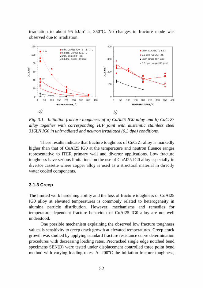
52
irradiation to about 95 kJ/m2 at 350°C. No changes in fracture mode wasobserved due to irradiation.
0
20
40
60
80
100
120
0 50 100 150 200 250 300 350 400
TEMPERATURE, oC
J Q, k
J/m
2
unirr. CuAl25 IG0, ST, LT, TL0.3 dpa CuAl25 IG0, TLunirr. single HIP joint0.3 dpa single HIP joint
ST
LT, TL
a)
0
100
200
300
400
0 50 100 150 200 250 300 350 400
TEMPERATURE, oCJ Q
, kJ/
m2
unirr. CuCrZr, TL & LT
0.3 dpa CuCrZr ,TL
unirr. single HIP joint
0.3 dpa single HIP joint
b)
Fig. 3.1. Initiation fracture toughness of a) CuAl25 IG0 alloy and b) CuCrZralloy together with corresponding HIP joint with austenitic stainless steel316LN IG0 in unirradiated and neutron irradiated (0.3 dpa) conditions.
These results indicate that fracture toughness of CuCrZr alloy is markedlyhigher than that of CuAl25 IG0 at the temperature and neutron fluence rangesrepresentative to ITER primary wall and divertor applications. Low fracturetoughness have serious limitations on the use of CuAl25 IG0 alloy especially indivertor cassette where copper alloy is used as a structural material in directlywater cooled components.
3.1.3 Creep
The limited work hardening ability and the loss of fracture toughness of CuAl25IG0 alloy at elevated temperatures is commonly related to heterogeneity inalumina particle distribution. However, mechanisms and remedies fortemperature dependent fracture behaviour of CuAl25 IG0 alloy are not wellunderstood.
One possible mechanism explaining the observed low fracture toughnessvalues is sensitivity to creep crack growth at elevated temperatures. Creep crackgrowth was studied by applying standard fracture resistance curve determinationprocedures with decreasing loading rates. Precracked single edge notched bendspecimens SEN(B) were tested under displacement controlled three point bendmethod with varying loading rates. At 200°C the initiation fracture toughness,
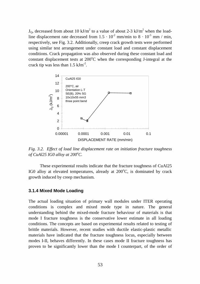
53
JQ, decreased from about 10 kJ/m2 to a value of about 2-3 kJ/m2 when the load-line displacement rate decreased from 1.5 · 10-2 mm/min to 8 · 10-5 mm / min,respectively, see Fig. 3.2. Additionally, creep crack growth tests were performedusing similar test arrangement under constant load and constant displacementconditions. Crack propagation was also observed during these constant load andconstant displacement tests at 200oC when the corresponding J-integral at thecrack tip was less than 1.5 kJm-2.
0
2
4
6
8
10
12
14
0.00001 0.0001 0.001 0.01 0.1
DISPLACEMENT RATE (mm/min)
J Q (
kJ/m
2 )
CuAl25 IG0
200°C, airOrientation L-TSE(B), 20% SG10x10x55 mm3three point bend
Fig. 3.2. Effect of load line displacement rate on initiation fracture toughnessof CuAl25 IG0 alloy at 200oC.
These experimental results indicate that the fracture toughness of CuAl25IG0 alloy at elevated temperatures, already at 200oC, is dominated by crackgrowth induced by creep mechanism.
3.1.4 Mixed Mode Loading
The actual loading situation of primary wall modules under ITER operatingconditions is complex and mixed mode type in nature. The generalunderstanding behind the mixed-mode fracture behaviour of materials is thatmode I fracture toughness is the conservative lower estimate in all loadingconditions. The concepts are based on experimental results related to testing ofbrittle materials. However, recent studies with ductile elastic-plastic metallicmaterials have indicated that the fracture toughness locus, especially betweenmodes I-II, behaves differently. In these cases mode II fracture toughness hasproven to be significantly lower than the mode I counterpart, of the order of
54
several tens of percents at room temperature and inert conditions.The fracture toughness between modes I and II for martensitic stainless
steel F82H and CuAl25 IG0 in the form of fracture resistance curves wasstudied and a drastic drop in fracture resistance values as the portion of mode IIloading increased was observed, Fig. 3.3. In F82H the decrease in fracturetoughness was more gradual but in CuAl25 IG0 a more severe drop occurred atcertain location of the envelope, approximately at ψ = 50°. The differingbehaviour of CuAl25 IG0 is to be attributed to an orientation effect incombination to a sharp change in crack nucleation mechanism due to extensiveshearing.
In complex loading situations the mixed-mode fracture behaviour ofmetallic materials can lead to lower values of fracture toughness which iscontrary to the general understanding of mixed-mode fracture. Quantitatively,differences are in the range of 40-50% and, therefore, can not be neglected.Differences in fracture toughness are a consequence of alterations inmicromechanisms of fracture between modes I and II. The transitions can beexplained through changes in stress and strain states, which cause a transition inthe fracture mechanisms as a result of a competition between typical mode I andII type of fractures.
0.0 0.5 1.0 1.50
50
100
150
200
250
300
350
12.8 degrees 27 degrees, curve 1 27 degrees, curve 2 45.5 degrees 63.9 degrees 76.2 degrees, curve 1 76.2 degrees, curve 2
J-in
tegr
al [k
N/m
]
Crack growth [mm]
0.0 0.5 1.0 1.50
50
100
150
200
250
300
350
12.8 degrees 27 degrees, curve 1 27 degrees, curve 2 45.5 degrees 63.9 degrees 76.2 degrees, curve 1 76.2 degrees, curve 2
J-int
egra
l [kN
/m]
Crack growth [mm]
a) b)
Fig. 3.3. Mixed mode fracture resistance curves for a) martensitic stainlesssteel F82H and b) dispersion strengthened CuAl25 IG0 alloy.
3.1.5 Corrosion
The ITER blanket and divertor components are water cooled during the plasmaoperation. The long term corrosion properties as well as the stress corrosioncracking susceptibility of the materials in a given environment are controlled by
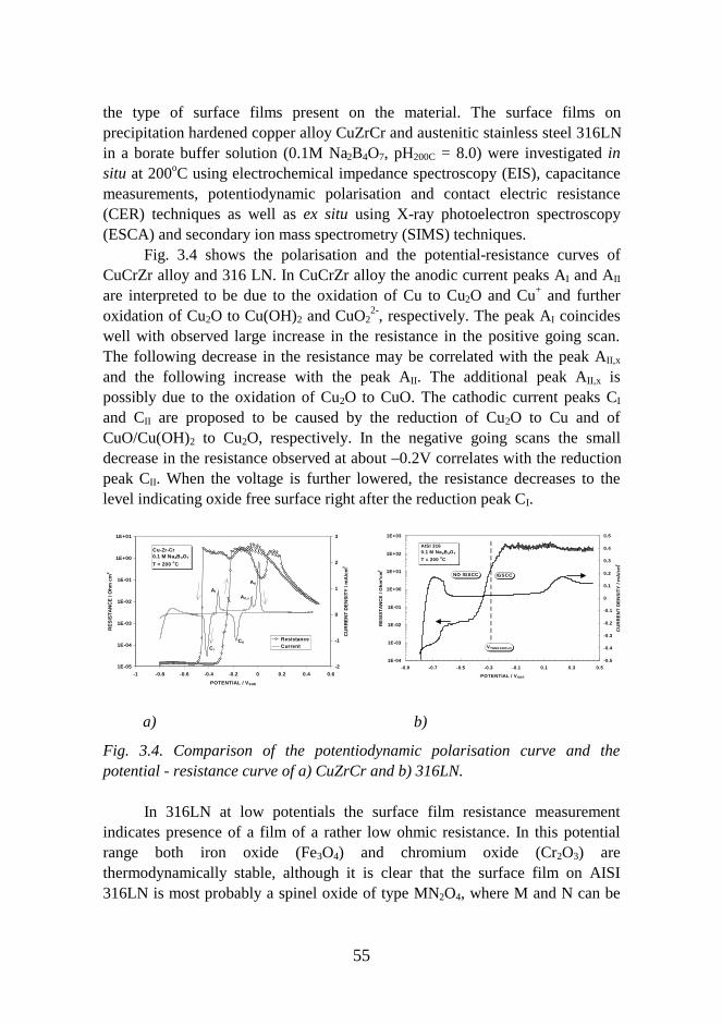
55
the type of surface films present on the material. The surface films onprecipitation hardened copper alloy CuZrCr and austenitic stainless steel 316LNin a borate buffer solution (0.1M Na2B4O7, pH200C = 8.0) were investigated insitu at 200oC using electrochemical impedance spectroscopy (EIS), capacitancemeasurements, potentiodynamic polarisation and contact electric resistance(CER) techniques as well as ex situ using X-ray photoelectron spectroscopy(ESCA) and secondary ion mass spectrometry (SIMS) techniques.
Fig. 3.4 shows the polarisation and the potential-resistance curves ofCuCrZr alloy and 316 LN. In CuCrZr alloy the anodic current peaks AI and AII
are interpreted to be due to the oxidation of Cu to Cu2O and Cu+ and furtheroxidation of Cu2O to Cu(OH)2 and CuO2
2-, respectively. The peak AI coincideswell with observed large increase in the resistance in the positive going scan.The following decrease in the resistance may be correlated with the peak AII,x
and the following increase with the peak AII. The additional peak AII,x ispossibly due to the oxidation of Cu2O to CuO. The cathodic current peaks CI
and CII are proposed to be caused by the reduction of Cu2O to Cu and ofCuO/Cu(OH)2 to Cu2O, respectively. In the negative going scans the smalldecrease in the resistance observed at about –0.2V correlates with the reductionpeak CII. When the voltage is further lowered, the resistance decreases to thelevel indicating oxide free surface right after the reduction peak CI.
1E-05
1E-04
1E-03
1E-02
1E-01
1E+00
1E+01
-1 -0.8 -0.6 -0.4 -0.2 0 0.2 0.4 0.6
POTENTIAL / V SHE
RE
SIS
TA
NC
E /
Ohm
cm
2
-2
-1
0
1
2
3
CU
RR
EN
T D
EN
SIT
Y /
mA
/cm
2
ResistanceCurrent
Cu-Zr-Cr0.1 M Na2B 4O7
T = 200 oC
AI
AII,x
AII
CI
CII
1E-04
1E-03
1E-02
1E-01
1E+00
1E+01
1E+02
1E+03
-0.9 -0.7 -0.5 -0.3 -0.1 0.1 0.3 0.5
POTENTIAL / V SHE
RE
SIS
TA
NC
E /
Ohm
*cm
2
-0.5
-0.4
-0.3
-0.2
-0.1
0
0.1
0.2
0.3
0.4
0.5
CU
RR
EN
T D
EN
SIT
Y /
mA
/cm
2
AISI 316 0.1 M Na2B 4O7
T = 200 oC
NO IGSCC IGSCC
VTHRESHOLD
a) b)
Fig. 3.4. Comparison of the potentiodynamic polarisation curve and thepotential - resistance curve of a) CuZrCr and b) 316LN.
In 316LN at low potentials the surface film resistance measurementindicates presence of a film of a rather low ohmic resistance. In this potentialrange both iron oxide (Fe3O4) and chromium oxide (Cr2O3) arethermodynamically stable, although it is clear that the surface film on AISI316LN is most probably a spinel oxide of type MN2O4, where M and N can be
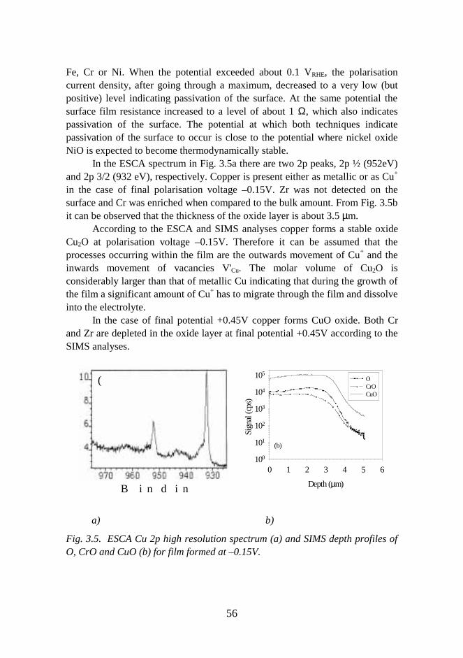
56
Fe, Cr or Ni. When the potential exceeded about 0.1 VRHE, the polarisationcurrent density, after going through a maximum, decreased to a very low (butpositive) level indicating passivation of the surface. At the same potential thesurface film resistance increased to a level of about 1 Ω, which also indicatespassivation of the surface. The potential at which both techniques indicatepassivation of the surface to occur is close to the potential where nickel oxideNiO is expected to become thermodynamically stable.
In the ESCA spectrum in Fig. 3.5a there are two 2p peaks, 2p ½ (952eV)and 2p 3/2 (932 eV), respectively. Copper is present either as metallic or as Cu+
in the case of final polarisation voltage –0.15V. Zr was not detected on thesurface and Cr was enriched when compared to the bulk amount. From Fig. 3.5bit can be observed that the thickness of the oxide layer is about 3.5 µm.
According to the ESCA and SIMS analyses copper forms a stable oxideCu2O at polarisation voltage –0.15V. Therefore it can be assumed that theprocesses occurring within the film are the outwards movement of Cu+ and theinwards movement of vacancies V'Cu. The molar volume of Cu2O isconsiderably larger than that of metallic Cu indicating that during the growth ofthe film a significant amount of Cu+ has to migrate through the film and dissolveinto the electrolyte.
In the case of final potential +0.45V copper forms CuO oxide. Both Crand Zr are depleted in the oxide layer at final potential +0.45V according to theSIMS analyses.
B i n d i n
(
Depth (µm)
0 1 2 3 4 5 6
Sig
nal (
cps)
100
101
102
103
104
105OCrOCuO
(b)
a) b)
Fig. 3.5. ESCA Cu 2p high resolution spectrum (a) and SIMS depth profiles ofO, CrO and CuO (b) for film formed at –0.15V.
57
The behaviour of the CuZrCr alloy resembles closely that of pure copper.The bulk of the film growing on the alloy is a very good electronic and ionicconductor. Both the oxides Cu2O and CuO present at different polarisationvoltages had a thin p-type semiconducting layer located at the interface of thefilm and electrolyte solution. The semiconducting layer was shown to have athickness of 10-8 m while the thickness of the film was of the order of 10-6 m.
Finally it can be concluded that the in-situ methods give informationmerely on the electrical properties of the surface films whereas the ex-situmethods provide additional information on the chemical structure and thicknessof the films. The knowledge on the properties of the surface films can be used indeeper understanding of the corrosion and environmental induced crackingphenomena.
3.2 Cu/SS Joining Technology and Characterisation
The present design of ITER primary wall modules is based on multimaterialconcept with stainless steel as a structural material, copper alloy as a heat sinkand beryllium as a plasma facing material. The candidate joining method formanufacturing these multimaterial blanket modules is hot isostatic pressing(HIP). Other joining methods for stainless steel copper components consideredare friction welding, explosion welding (EXW), fusion welding and rheocastbrazing. Assessment and validation of joining methods and evaluation of jointintegrity of ITER primary wall module and other in-vessel components andcharacterisation of the joint properties in non- and post-irradiated conditions isessential for reliable reactor design. In this work HIP and EXW methods werestudied and corresponding joint properties were characterised and compared.
3.2.1 Metallurgy of Joints
HIP and EXW are both solid state bonding methods although HIP can also beapplied for powder compacting. However, due to differences in bondingmechanisms also the subsequent metallurgy and mechanical properties ofconstituent metals and their joints will be different after bonding treatment. HIPbonding is based on diffusion of alloying elements across the joint interface atelevated temperatures which is further enhanced by applying isostatic pressure.EXW bonding is based on high impact pressure induced by explosives atambient temperature and therefore there is practically no diffusion of alloyingelements across the joint interface.

58
The microstructure of copper alloys and stainless steel after typical HIPcycle are close to those of solution annealed structures because the appliedtemperature ranges during HIP bonding and solution anneal heat treatments ofboth copper alloys and stainless steel are almost similar. However, diffusion ofelements across the joint interface may induced extra phase transformations andprecipitation reactions in the area close to joint interface. During the HIPthermal cycle alloying elements of CuCrZr alloy like zirconium readily reactswith nitrogen and carbon in stainless steel and precipitates as zirconium nitridesat the joint interface. Diffusion of elements like nickel and carbon decreases thestability of austenite and induces ferrite phase transformation in stainless steelclose to joint interface. The chromium dissolved from precipitates of copperalloy and from austenite diffuses and enriches in ferrite layer. In the case ofCuAl25 alloy the diffusion of elements results in precipitation of chromium andiron rich phase in copper alloy but no ferrite phase formed in the stainless steelside of the joint.
A typical wavy like, solid interface with front and rear vortices is formeddue to explosion welding of stainless steel to copper alloy. Vortices are typicalfor explosion welded interfaces and they are composed of a mixture of thecomponent metals. Cavities and pores are commonly observed at the edges ofthe explosion welded plate associated with vortices. According to simulationsthe velocity of the flyer plate and also the impact pressure are lower close tofree ends of the plate compared with the middle section of the plate. Thesefactors can deteriorate the weldability and should be taken in to account incomponent manufacturing. On the other hand, the shock waves induced byexplosives results in macroscopic plastic deformation close to the joint interfaceand in generation of high dislocation density while macroscopic strains arenegligible further away from the joint interface.
The manufacturing of prototype primary wall modules and divertorcomponents will need several joining operations e.g. multiple HIP and/orbrazing thermal cycles and the various joints must withstand all thesetemperature cycles. Multiple HIP thermal cycles was shown to further enhancediffusion of alloying elements and to increase thickness of diffusion layers andamounts of precipitates, Fig. 3.6. After high temperature post weld heattreatment simulating HIP thermal cycle the microstructure of explosion weldedcopper to stainless steel joint is quite similar to corresponding HIP joint. In thecase of explosion welded CuCrZr alloy to stainless steel joint zirconium nitridesand ferrite layer were observed at the joint interface. However, due to gradientin plastic deformation and internal dislocation structure induced by shockwaves, the recrystallisation and extensive grain growth in copper alloy near the
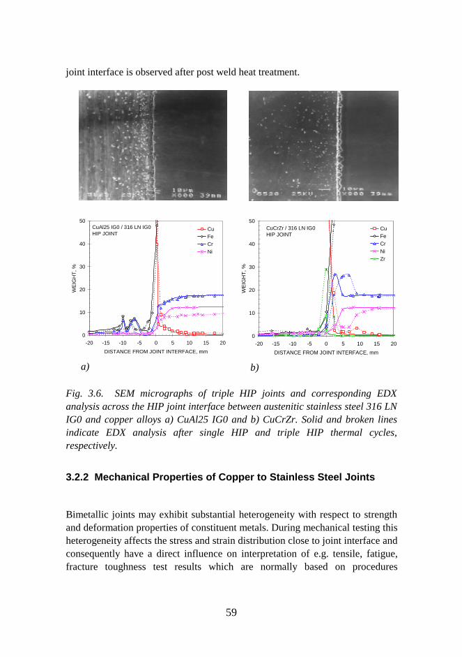
59
joint interface is observed after post weld heat treatment.
0
10
20
30
40
50
-20 -15 -10 -5 0 5 10 15 20
DISTANCE FROM JOINT INTERFACE, mm
WE
IGH
T, %
CuFe
Cr
Ni
CuAl25 IG0 / 316 LN IG0HIP JOINT
a)
0
10
20
30
40
50
-20 -15 -10 -5 0 5 10 15 20
DISTANCE FROM JOINT INTERFACE, mm
WE
IGH
T, %
CuFeCrNiZr
CuCrZr / 316 LN IG0HIP JOINT
b)
Fig. 3.6. SEM micrographs of triple HIP joints and corresponding EDXanalysis across the HIP joint interface between austenitic stainless steel 316 LNIG0 and copper alloys a) CuAl25 IG0 and b) CuCrZr. Solid and broken linesindicate EDX analysis after single HIP and triple HIP thermal cycles,respectively.
3.2.2 Mechanical Properties of Copper to Stainless Steel Joints
Bimetallic joints may exhibit substantial heterogeneity with respect to strengthand deformation properties of constituent metals. During mechanical testing thisheterogeneity affects the stress and strain distribution close to joint interface andconsequently have a direct influence on interpretation of e.g. tensile, fatigue,fracture toughness test results which are normally based on procedures
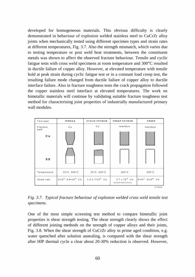
60
developed for homogeneous materials. This obvious difficulty is clearlydemonstrated in behaviour of explosion welded stainless steel to CuCrZr alloyjoints when mechanically tested using different specimen types and strain ratesat different temperatures, Fig. 3.7. Also the strength mismatch, which varies dueto testing temperature or post weld heat treatments, between the constituentmetals was shown to affect the observed fracture behaviour. Tensile and cyclicfatigue tests with cross weld specimens at room temperature and 300°C resultedin ductile failure of copper alloy. However, at elevated temperature with tensilehold at peak strain during cyclic fatigue test or in a constant load creep test, theresulting failure mode changed from ductile failure of copper alloy to ductileinterface failure. Also in fracture toughness tests the crack propagation followedthe copper stainless steel interface at elevated temperatures. The work onbimetallic materials will continue by validating suitable fracture toughness testmethod for characterising joint properties of industrially manufactured primarywall modules.
T E N S IL E C Y C L IC F A T IG U E C R E E P F A T IG U E C R E E P
C u
S S
T e s t ty p e
F ra c tu rep a th
T e m p e ra tu re
S tra in ra te
C u C u In te r fa c e In te r fa c e
2 0 °C , 3 0 0 °C 2 0 °C , 3 0 0 °C 3 0 0 °C 3 0 0 °C
3 •1 0 -6 .6 •1 0 1 /s-4 1 .3 -2 .7 •1 0 1 /s-4 2 .7 x 1 0 1 /s-4
te n s i le h o ld 2 9 m in
S T 9 6 2 D
-5 5 •1 0 -3 •1 0 1 /s-8-7
Fig. 3.7. Typical fracture behaviour of explosion welded cross weld tensile testspecimens.
One of the most simple screening test method to compare bimetallic jointproperties is shear strength testing. The shear strength clearly shows the effectof different joining methods on the strength of copper alloys and their joints,Fig. 3.8. When the shear strength of CuCrZr alloy in prime aged condition, e.g.water quenched after solution annealing, is compared with the shear strengthafter HIP thermal cycle a clear about 20-30% reduction is observed. However,
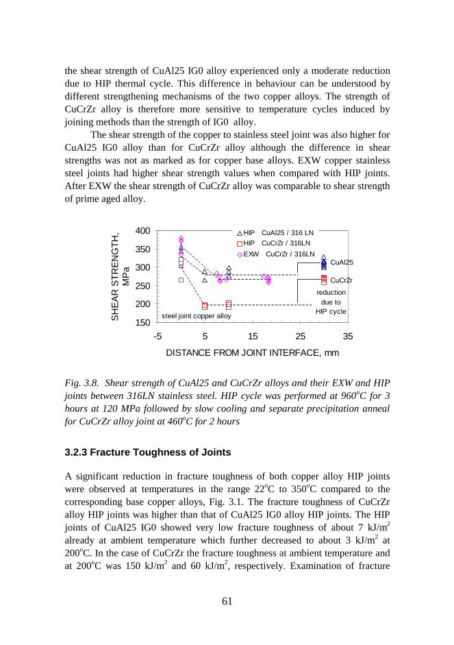
61
the shear strength of CuAl25 IG0 alloy experienced only a moderate reductiondue to HIP thermal cycle. This difference in behaviour can be understood bydifferent strengthening mechanisms of the two copper alloys. The strength ofCuCrZr alloy is therefore more sensitive to temperature cycles induced byjoining methods than the strength of IG0 alloy.
The shear strength of the copper to stainless steel joint was also higher forCuAl25 IG0 alloy than for CuCrZr alloy although the difference in shearstrengths was not as marked as for copper base alloys. EXW copper stainlesssteel joints had higher shear strength values when compared with HIP joints.After EXW the shear strength of CuCrZr alloy was comparable to shear strengthof prime aged alloy.
150
200
250
300
350
400
-5 5 15 25 35
DISTANCE FROM JOINT INTERFACE, mm
SH
EA
R S
TR
EN
GT
H,
MP
a
HIP CuAl25 / 316 LN
HIP CuCrZr / 316LN
EXW CuCrZr / 316LN
steel joint copper alloy
CuAl25
CuCrZr
reductiondue to
HIP cycle
Fig. 3.8. Shear strength of CuAl25 and CuCrZr alloys and their EXW and HIPjoints between 316LN stainless steel. HIP cycle was performed at 960oC for 3hours at 120 MPa followed by slow cooling and separate precipitation annealfor CuCrZr alloy joint at 460oC for 2 hours
3.2.3 Fracture Toughness of Joints
A significant reduction in fracture toughness of both copper alloy HIP jointswere observed at temperatures in the range 22oC to 350oC compared to thecorresponding base copper alloys, Fig. 3.1. The fracture toughness of CuCrZralloy HIP joints was higher than that of CuAl25 IG0 alloy HIP joints. The HIPjoints of CuAl25 IG0 showed very low fracture toughness of about 7 kJ/m2
already at ambient temperature which further decreased to about 3 kJ/m2 at200oC. In the case of CuCrZr the fracture toughness at ambient temperature andat 200oC was 150 kJ/m2 and 60 kJ/m2, respectively. Examination of fracture
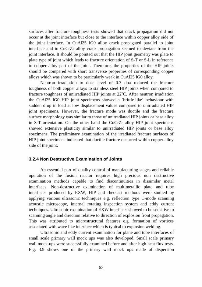
62
surfaces after fracture toughness tests showed that crack propagation did notoccur at the joint interface but close to the interface within copper alloy side ofthe joint interface. In CuAl25 IG0 alloy crack propagated parallel to jointinterface and in CuCrZr alloy crack propagation seemed to deviate from thejoint interface. It should be pointed out that the HIP joint geometry was plate toplate type of joint which leads to fracture orientation of S-T or S-L in referenceto copper alloy part of the joint. Therefore, the properties of the HIP jointsshould be compared with short transverse properties of corresponding copperalloys which was shown to be particularly weak in CuAl25 IG0 alloy.
Neutron irradiation to dose level of 0.3 dpa reduced the fracturetoughness of both copper alloys to stainless steel HIP joints when compared tofracture toughness of unirradiated HIP joints at 22oC. After neutron irradiationthe CuAl25 IG0 HIP joint specimens showed a `brittle-like´ behaviour withsudden drop in load at low displacement values compared to unirradiated HIPjoint specimens. However, the fracture mode was ductile and the fracturesurface morphology was similar to those of unirradiated HIP joints or base alloyin S-T orientation. On the other hand the CuCrZr alloy HIP joint specimensshowed extensive plasticity similar to unirradiated HIP joints or base alloyspecimens. The preliminary examination of the irradiated fracture surfaces ofHIP joint specimens indicated that ductile fracture occurred within copper alloyside of the joint.
3.2.4 Non Destructive Examination of Joints
An essential part of quality control of manufacturing stages and reliableoperation of the fusion reactor requires high precious non destructiveexamination methods capable to find discontinuities in dissimilar metalinterfaces. Non-destructive examination of multimetallic plate and tubeinterfaces produced by EXW, HIP and rheocast methods were studied byapplying various ultrasonic techniques e.g. reflection type C-mode scanningacoustic microscope, internal rotating inspection system and eddy currenttechniques. Ultrasonic examination of EXW interfaces showed to be sensitive toscanning angle and direction relative to direction of explosion front propagation.This was attributed to microstructural features e.g. formation of vorticesassociated with wave like interface which is typical to explosion welding.
Ultrasonic and eddy current examination for plane and tube interfaces ofsmall scale primary wall mock ups was also developed. Small scale primarywall mock-ups were successfully examined before and after high heat flux tests.Fig. 3.9 shows one of the primary wall mock ups made of dispersion
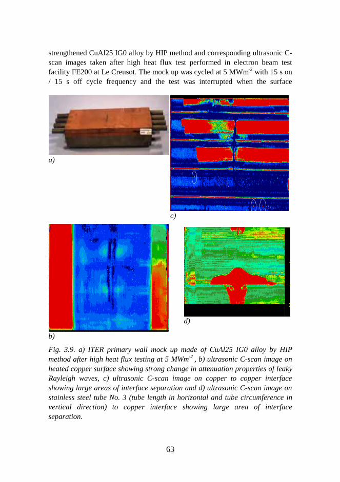
63
strengthened CuAl25 IG0 alloy by HIP method and corresponding ultrasonic C-scan images taken after high heat flux test performed in electron beam testfacility FE200 at Le Creusot. The mock up was cycled at 5 MWm-2 with 15 s on/ 15 s off cycle frequency and the test was interrupted when the surface
a)
c)
b)
d)
Fig. 3.9. a) ITER primary wall mock up made of CuAl25 IG0 alloy by HIPmethod after high heat flux testing at 5 MWm-2 , b) ultrasonic C-scan image onheated copper surface showing strong change in attenuation properties of leakyRayleigh waves, c) ultrasonic C-scan image on copper to copper interfaceshowing large areas of interface separation and d) ultrasonic C-scan image onstainless steel tube No. 3 (tube length in horizontal and tube circumference invertical direction) to copper interface showing large area of interfaceseparation.
64
temperature of copper reached 900oC after 962 cycles. During the test the mockup was continuously cooled by cooling water at 140oC and 2.6 MPa pressure.The ultrasonic examination showed large change in attenuation properties ofleaky Rayleigh waves on the heated copper surface which was related toextensive crack formation on the copper surface, crack depth was less than100µm. Also the copper to copper interface and stainless steel tube to copperinterfaces were separated from large areas but no defects were found on copperto stainless steel interface. It is noteworthy that simultaneously testedprecipitation hardened CuCrZr mock up was successfully tested without anyfailures at 5 MWm-2 for 1000 cycles. Also both types of mock ups were testedat 0.75 MWm-2 for 13000 cycles without no failures. It should be noted that thedesign heat load for the ITER primary wall modules is 0.5 MWm-2.
Ultrasonic and eddy current techniques were successfully applied for nondestructive examination of both plane and tube interfaces of small scale primarywall mock ups. Resolution for detection of discontinuities depends in principleon materials, particular geometry and ultrasonic frequency used forexamination. In the case of CuAl25 IG0 alloy ultrasonic frequencies of 25 MHzwere used whereas due to strong attenuation frequencies of only 10 MHz wereused in the case CuCrZr alloy. However, based on detection of differentcalibration defects the resolution for detecting interface discontinuities was lessthan 1 mm on all plane and tube interfaces in small scale primary wall mock upsmade of both candidate copper alloys.
3.3 Behaviour of Hydrogen Isotopes in First WallMaterials
The aim of this project was to understand and control hydrogen retentionin first wall materials. The project comprised studies of physical interactionsbetween plasma and first wall materials, namely the retention of hydrogenisotopes (H, D) in metals and diamond-like carbon (DLC) films. The researchincluded investigations of the properties of physical vapour deposited (PVD)DLC films on Si and stainless steel substrates and the migration of hydrogenisotopes in implanted and co-deposited DLC films.
Study of hydrogen migration in Ta, Ni, W and stainless steel AISI 316Lwas carried out. The effect of ion induced damage and annealings on the H/Heretention was investigated. Stopping of 5-100 keV He-ions in Ta, Ni, W, AISI316L, Cu, Ni, Mo and Cr was carried out to understand the mechanisms ofdamage production under ion bombardment.
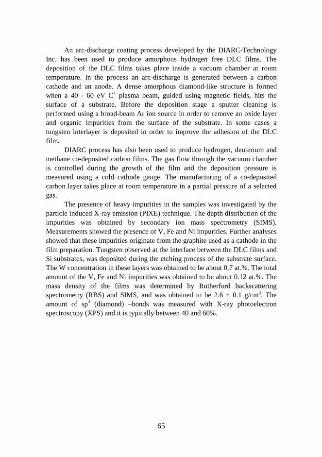
65
An arc-discharge coating process developed by the DIARC-TechnologyInc. has been used to produce amorphous hydrogen free DLC films. Thedeposition of the DLC films takes place inside a vacuum chamber at roomtemperature. In the process an arc-discharge is generated between a carboncathode and an anode. A dense amorphous diamond-like structure is formedwhen a 40 - 60 eV C+ plasma beam, guided using magnetic fields, hits thesurface of a substrate. Before the deposition stage a sputter cleaning isperformed using a broad-beam Ar ion source in order to remove an oxide layerand organic impurities from the surface of the substrate. In some cases atungsten interlayer is deposited in order to improve the adhesion of the DLCfilm.
DIARC process has also been used to produce hydrogen, deuterium andmethane co-deposited carbon films. The gas flow through the vacuum chamberis controlled during the growth of the film and the deposition pressure ismeasured using a cold cathode gauge. The manufacturing of a co-depositedcarbon layer takes place at room temperature in a partial pressure of a selectedgas.
The presence of heavy impurities in the samples was investigated by theparticle induced X-ray emission (PIXE) technique. The depth distribution of theimpurities was obtained by secondary ion mass spectrometry (SIMS).Measurements showed the presence of V, Fe and Ni impurities. Further analysesshowed that these impurities originate from the graphite used as a cathode in thefilm preparation. Tungsten observed at the interface between the DLC films andSi substrates, was deposited during the etching process of the substrate surface.The W concentration in these layers was obtained to be about 0.7 at.%. The totalamount of the V, Fe and Ni impurities was obtained to be about 0.12 at.%. Themass density of the films was determined by Rutherford backscatteringspectrometry (RBS) and SIMS, and was obtained to be 2.6 ± 0.1 g/cm3. Theamount of sp3 (diamond) –bonds was measured with X-ray photoelectronspectroscopy (XPS) and it is typically between 40 and 60%.
66
Two sets of samples were prepared for H migration studies. In the first setsamples were implanted with 30-keV 1H+ ions to a dose of 1 x 10¹⁶ ions cm-2. Inthe second set both 35-keV 4He+ and 30-keV 1H+ ions were implanted to dosesof 1 x 10¹⁶ ions cm-2. The isochronal annealings (40 min) were made in a quartz-tube furnace (pressure below 0.05 mPa) at temperatures between 100 oC and1100 oC. For the depth profiling of H atoms the nuclear resonance broadening(NRB) technique with the 6.39-MeV resonance of the 1H(15N,αγ)12C reactionwas used (see Fig. 3.10).
Fig. 3.10. Hydrogen concentration distribution observed in NRB measurementsin H+ (a) and He+ (b) implanted samples. Distributions were observed after theimplantation and after annealings at different temperatures. Solid line is thePearson IV fit of the implanted depth profile. Dashed lines show the depthprofiles calculated using a diffusion model developed.
The concentration profiles of implanted He and H atoms were measuredby the elastic-recoil-detection-analysis technique (ERDA). It was obtained thatno significant loss of He took place in the annealings. Results of NRBmeasurement showed that background hydrogen concentration was 0.07 at.%.
67
Migration of implanted hydrogen is described well with a concentrationindependent diffusion equation. The diffusion coefficients for hydrogen in thetemperature range 700 – 1100 oC were extracted from NRB and SIMSmeasurements (see Fig. 3.10). The diffusion coefficients exhibit a goodArrhenius behaviour with an activation energy of 2.0 ±0.1 eV.
To study diffusion of deuterium in DLC films, a set of samples wasimplanted by 54-keV D2
+ ions to a dose of 1 x 10¹⁶ ions cm-2. The depth profilesof D ions were measured with SIMS. The measured D concentration profileswere fitted with a concentration-dependent diffusion model, assuming that Dexists as immobile pairs and diffusing atoms (see Fig. 3.11). The results showthat the concentration of D clusters relative to the total D concentrationincreases when the total D concentration decreases, leading to a concentrationdependent diffusion. The diffusion coefficient for atomic deuterium exhibits agood Arrhenius behaviour with an activation energy of 2.9 ± 0.1 eV. Adecreasing solid solubility of D in DLC films with increasing temperature wasobserved.
In the study on H diffusion no concentration-dependent process wasobserved due to the initial hydrogen background of about 0.07 at.% in thesefilms, whereas in the case of D the fits were made to the low concentrationregime. This explains the difference in activation energies (Ea = 2.0 ± 0.1 eV forH). Therefore, the diffusion coefficients for hydrogen and deuterium can not becompared directly with each other. However, by employing the matrix methodto fit D profiles and choosing the lowest concentration limit of 0.07 at.% onegets an activation energy of 2.0 ± 0.1 eV matching the value for H. The ratio ofthe pre-exponential factors for H and D diffusion is 1.3, which is explained bythe isotope effect.
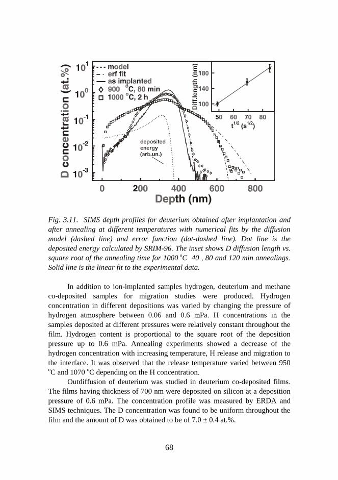
68
Fig. 3.11. SIMS depth profiles for deuterium obtained after implantation andafter annealing at different temperatures with numerical fits by the diffusionmodel (dashed line) and error function (dot-dashed line). Dot line is thedeposited energy calculated by SRIM-96. The inset shows D diffusion length vs.square root of the annealing time for 1000 oC 40 , 80 and 120 min annealings.Solid line is the linear fit to the experimental data.
In addition to ion-implanted samples hydrogen, deuterium and methaneco-deposited samples for migration studies were produced. Hydrogenconcentration in different depositions was varied by changing the pressure ofhydrogen atmosphere between 0.06 and 0.6 mPa. H concentrations in thesamples deposited at different pressures were relatively constant throughout thefilm. Hydrogen content is proportional to the square root of the depositionpressure up to 0.6 mPa. Annealing experiments showed a decrease of thehydrogen concentration with increasing temperature, H release and migration tothe interface. It was observed that the release temperature varied between 950oC and 1070 oC depending on the H concentration.
Outdiffusion of deuterium was studied in deuterium co-deposited films.The films having thickness of 700 nm were deposited on silicon at a depositionpressure of 0.6 mPa. The concentration profile was measured by ERDA andSIMS techniques. The D concentration was found to be uniform throughout thefilm and the amount of D was obtained to be of 7.0 ± 0.4 at.%.
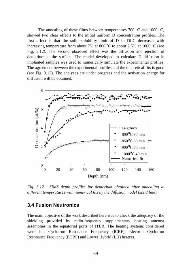
69
The annealing of these films between temperatures 700 oC and 1000 oC,showed two clear effects to the initial uniform D concentration profiles. Thefirst effect is that the solid solubility limit of D in DLC decreases withincreasing temperature from about 7% at 800 oC to about 2.5% at 1000 oC (seeFig. 3.12). The second observed effect was the diffusion and ejection ofdeuterium at the surface. The model developed to calculate D diffusion inimplanted samples was used to numerically simulate the experimental profiles.The agreement between the experimental profiles and the theoretical fits is good(see Fig. 3.12). The analyses are under progress and the activation energy fordiffusion will be obtained.
Fig. 3.12. SIMS depth profiles for deuterium obtained after annealing atdifferent temperatures with numerical fits by the diffusion model (solid line).
3.4 Fusion Neutronics
The main objective of the work described here was to check the adequacy of theshielding provided by radio-frequency supplementary heating antennaassemblies in the equatorial ports of ITER. The heating systems consideredwere Ion Cyclotron Resonance Frequency (ICRF), Electron CyclotronResonance Frequency (ECRF) and Lower Hybrid (LH) heaters.
Depth (nm)
0 20 40 60 80 100 120 140 160
D c
onc
ent
ratio
n (
at.
%)
0
2
4
6
8
as-grown
800oC 90 min
850oC 60 min
900oC 60 min
1000oC 40 minNumerical fit

70
The calculations were performed using MCNP4B, the most recent versionof the MCNP program, and a point wise cross-section library based on FENDL-1. Only the contribution to the flux coming through the equatorial port itself wascalculated, neutron leakage through the bulk shielding and through other portswas suppressed.
The goal was to find shielding arrangements that would satisfy certaincriteria. These criteria were:
• To limit the dose rate in biological tissue behind eachport near the cryostat 106 s after shutdown to acceptable levels, thefast neutron flux (above 0.1 MeV) in the zone behind the port closureplate must not exceed 107 n/cm2 s.
• The nuclear heating (neutron+gamma heating) in thecryogenic systems (mainly the toroidal and poloidal field coils andthe intercoil structure) must be less than 500 W for one port.
• The nuclear heating density must be below 2 mW/cm3
in the TF coil case (which was taken to include the intercoil structureas well) and 1 mW/cm3 in the winding pack.
The second and third of these criteria were rather easily met, but the firstcriterion turned out to be much tougher. For none of the three supplementaryheating systems considered was the original design of the antenna arrayadequate to meet the first criterion. However, the fast flux beyond the portclosure plate can be reduced to acceptable levels with additional shielding.Certainly there is more than enough space inside the port for the requiredshielding, though the weight of the shielding may be a problem.
For the ICRF antenna array, the measures needed to ensure adequateshielding include curving the coaxial cables, to avoid straight streaming pathsthrough the vacuum between the inner and outer conductors. The all-metalsupports for the inner conductor of the coaxial cables should be as massive aspossible to further decrease the streaming. The front part of the metal/waterblocks serving as a substitute for the shield/blanket in the equatorial port shouldpreferably have a minimum thickness of at least 1 m, with an additional 40 cmof shielding between the tails of these blocks. The box surrounding the antennaarray must be designed so that straight streaming paths from the plasma to theclosure plate are avoided. Moreover, the gap between this box and the port wallsshould be kept as narrow as feasible. A gap of 2 cm is acceptable, but muchmore cannot be accepted.
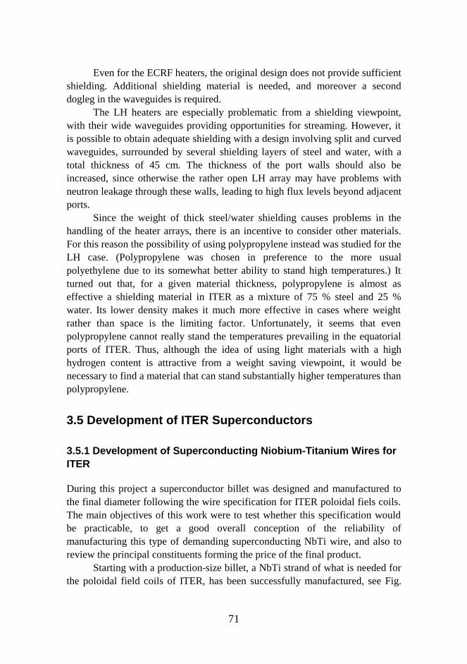
71
Even for the ECRF heaters, the original design does not provide sufficientshielding. Additional shielding material is needed, and moreover a seconddogleg in the waveguides is required.
The LH heaters are especially problematic from a shielding viewpoint,with their wide waveguides providing opportunities for streaming. However, itis possible to obtain adequate shielding with a design involving split and curvedwaveguides, surrounded by several shielding layers of steel and water, with atotal thickness of 45 cm. The thickness of the port walls should also beincreased, since otherwise the rather open LH array may have problems withneutron leakage through these walls, leading to high flux levels beyond adjacentports.
Since the weight of thick steel/water shielding causes problems in thehandling of the heater arrays, there is an incentive to consider other materials.For this reason the possibility of using polypropylene instead was studied for theLH case. (Polypropylene was chosen in preference to the more usualpolyethylene due to its somewhat better ability to stand high temperatures.) Itturned out that, for a given material thickness, polypropylene is almost aseffective a shielding material in ITER as a mixture of 75 % steel and 25 %water. Its lower density makes it much more effective in cases where weightrather than space is the limiting factor. Unfortunately, it seems that evenpolypropylene cannot really stand the temperatures prevailing in the equatorialports of ITER. Thus, although the idea of using light materials with a highhydrogen content is attractive from a weight saving viewpoint, it would benecessary to find a material that can stand substantially higher temperatures thanpolypropylene.
3.5 Development of ITER Superconductors
3.5.1 Development of Superconducting Niobium-Titanium Wires forITER
During this project a superconductor billet was designed and manufactured tothe final diameter following the wire specification for ITER poloidal fiels coils.The main objectives of this work were to test whether this specification wouldbe practicable, to get a good overall conception of the reliability ofmanufacturing this type of demanding superconducting NbTi wire, and also toreview the principal constituents forming the price of the final product.
Starting with a production-size billet, a NbTi strand of what is needed forthe poloidal field coils of ITER, has been successfully manufactured, see Fig.
72
3.13. This strand is very near the strand needed for the dipoles of the CERNLarge Hadron Collider (LHC). The addition of a CuNi layer of 10 µm within theouter copper shell, to control AC losses, has not resulted in any degradation ofthe strand properties.
Fig. 3.13. Cross-section of the ITER-type NbTi superconductor developed atOutokumpu Superconductors Ltd.
The critical current density, the RRR and the effective filament diameterare well within the specification. Mechanically the programme was success.After small adjustments the processing was finalized without any breaks and theunit length was 16 700 m, which proves that the process is applicable inindustrial scale, too. It was anticipated that the differences between ITERpoloidal field coil and CERN LHC-wires could slightly increase the price of thematerial.
3.5.2 Development of Superconducting Niobium-Tin Wires for ITER
The main objective of this project was to develop, manufacture and test Nb3Snsuperconducting wire as a final goal to meet the ITER HP II specification. Themain product of Outokumpu Superconductors Oy is NbTi superconducting wireand there has been no earlier experience of Nb3Sn wire production. Thedevelopment of Nb3Sn started from the manufacture of the matrix material andcontinued with laboratory-scale wire production trials and design optimizationfor ITER HP II wire. About 25 kg of ITER HP II wire was set for the deliverableof the project.

73
The first set of Nb3Sn superconducting wire was successfully produced.The production process was demonstrated to work and valuable informationabout the workability and achievable properties of Nb3Sn wire were obtained. Asmall quantity of Nb3Sn wire designed to meet the ITER HP II specification is atpresent in production.
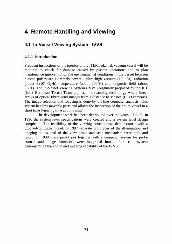
74
4 Remote Handling and Viewing
4.1 In-Vessel Viewing System - IVVS
4.1.1 Introduction
Frequent inspections of the interior of the ITER Tokamak vacuum vessel will berequired to check for damage caused by plasma operations and to planmaintenance interventions. The environmental conditions in the vessel betweenplasma pulses are extremely severe - ultra high vacuum (10-7 Pa), radiation(about 3x10⁴ Gy/h), temperature (about 200°C) and magnetic field (about5.7 T). The In-Vessel Viewing System (IVVS) originally proposed by the JET(Joint European Torus) Team applies line scanning technology where lineararrays of optical fibres send images from a distance to sensors (CCD cameras).The image selection and focusing is done by off-line computer analysis. Thissystem has few movable parts and allows the inspection of the entire vessel in ashort time (viewing time about 6 min.).
The development work has been distributed over the years 1996-98. In1996 the system level specifications were created and a system level designcompleted. The feasibility of the viewing concept was demonstrated with aproof-of-principle model. In 1997 separate prototypes of the illumination andimaging optics, and of the view probe and scan mechanism were built andtested. In 1998 these prototypes together with a computer system for probecontrol and image formation were integrated into a full scale systemdemonstrating the end to end imaging capability of the IVVS.
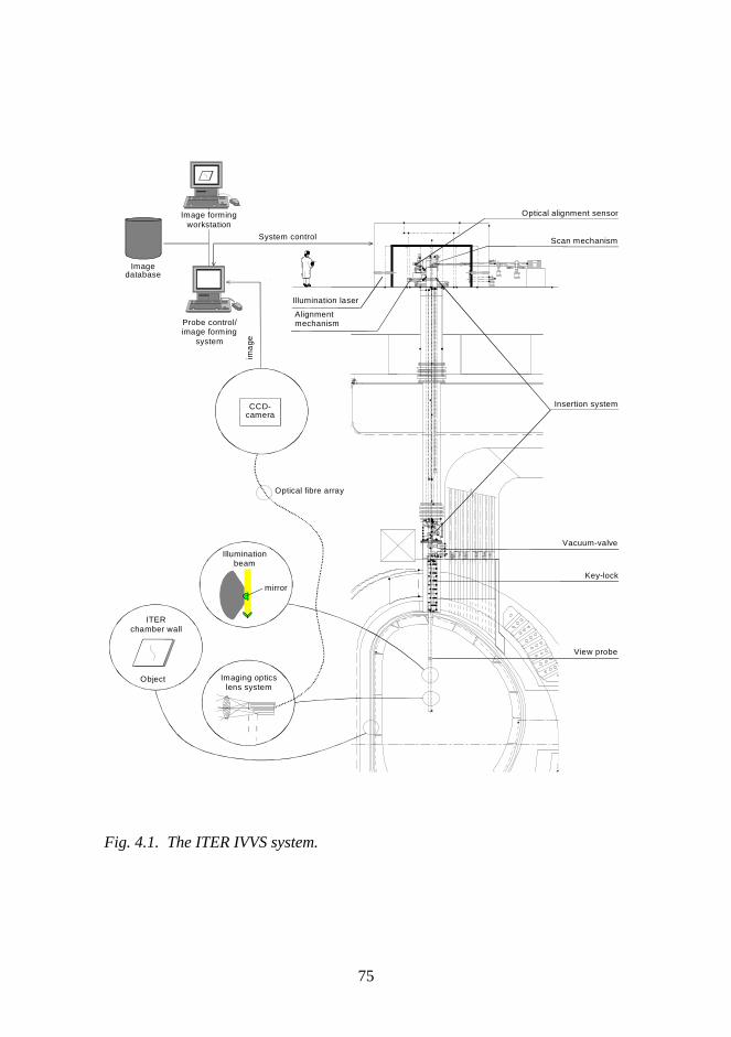
75
Image formingworkstation
Imagedatabase
Probe control/image forming
system
Object
View probe
Key-lock
Vacuum-valve
Scan mechanism
Alignmentmechanism
Optical alignment sensor
Imaging opticslens system
System control
Illumination laser
ima
ge
ITERchamber wall
Illuminationbeam
mirror
Optical fibre array
Insertion system
ITER IN-VESSEL VIEWING SYSTEM PRINCIPLE DRAWING
CCD-camera
Fig. 4.1. The ITER IVVS system.
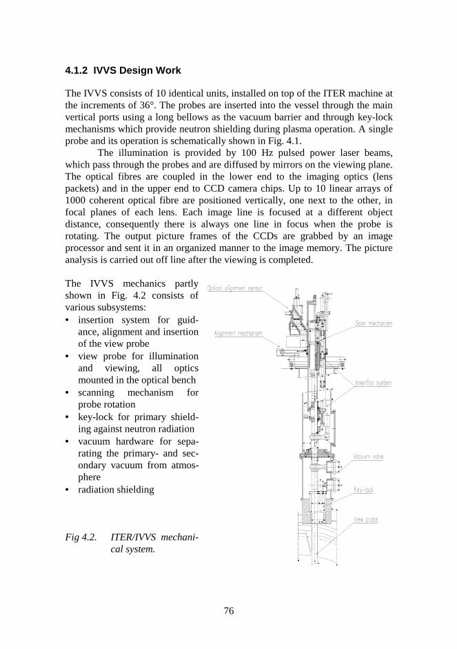
76
4.1.2 IVVS Design Work
The IVVS consists of 10 identical units, installed on top of the ITER machine atthe increments of 36°. The probes are inserted into the vessel through the mainvertical ports using a long bellows as the vacuum barrier and through key-lockmechanisms which provide neutron shielding during plasma operation. A singleprobe and its operation is schematically shown in Fig. 4.1.
The illumination is provided by 100 Hz pulsed power laser beams,which pass through the probes and are diffused by mirrors on the viewing plane.The optical fibres are coupled in the lower end to the imaging optics (lenspackets) and in the upper end to CCD camera chips. Up to 10 linear arrays of1000 coherent optical fibre are positioned vertically, one next to the other, infocal planes of each lens. Each image line is focused at a different objectdistance, consequently there is always one line in focus when the probe isrotating. The output picture frames of the CCDs are grabbed by an imageprocessor and sent it in an organized manner to the image memory. The pictureanalysis is carried out off line after the viewing is completed.
The IVVS mechanics partlyshown in Fig. 4.2 consists ofvarious subsystems:• insertion system for guid-
ance, alignment and insertionof the view probe
• view probe for illuminationand viewing, all opticsmounted in the optical bench
• scanning mechanism forprobe rotation
• key-lock for primary shield-ing against neutron radiation
• vacuum hardware for sepa-rating the primary- and sec-ondary vacuum from atmos-phere
• radiation shielding Fig 4.2. ITER/IVVS mechani-
cal system.

77
The insertion system consists of a ball screw driven by a servo motorand linear guides mounted on the inner wall of the IVVS guide tube.With the aid of the long bellows surrounding the view probe, theinsertion can be performed without affecting the primary ITERvacuum.
The view probe (shown in the left) is exposed to the plasmachamber and is designed to experience the harsh environment. Itconsists of a non-rotating support tube, a rotating viewing tube,imaging and illumination optics (which include the mirrors, thelenses, the optical fibres, and the CCDs). The rotating tube carriesthe optics and is rotated by the scan mechanism. Also, theillumination laser beam is guided within the rotating tube into thedispersing mirror. The probe outline is a smooth Ø150 mm diametertube for its entire length to facilitate the insertion to the vessel.
The illumination system (see Fig 4.3) is designed to use fourlasers emitting collimated beams that are expanded and combinedtogether. The upper part of the illumination lobe is generated on theupper surface of the primary (dispersing) mirror, whereas the lowerfan uses the beam reflected from the secondary mirror. Theillumination beam has divergence angles of 2.5° ∗ 170° (horiz. ∗vertical).
The imaging optics consists of 16 lens-fibre packages thateach cover a FOV of 12° ⋅ 12° (combined 12° ⋅ 162°). All aremounted into one rigid frame called the optical bench. The packagesare of five different designs to meet the field-of-view and pointingrequirements and to fit in the rotating probe tube. The optical fibresare bundled to cables that are attached to the rotating tube wall bystainless steel clamps. The picture resolution is determined by thenumber of fibres per degree and by the number of laser pulses during360° rotation of the probe. With the proposed parameters (80fibres/°, 36000 pulses/ 6 min) the quasi-spherical field of viewcontains appr. 5 ∗ 108 pixels. This corresponds to a spatial resolutionslightly better than the requirement (1 mm at 3 m). Fig 4.3. The view probe.
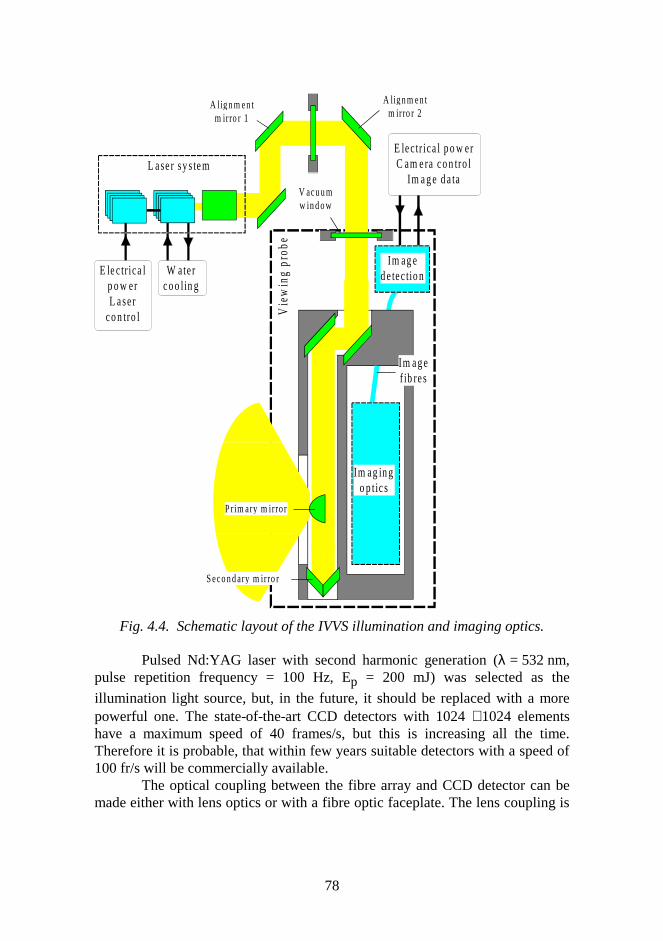
78
Fig. 4.4. Schematic layout of the IVVS illumination and imaging optics.
Pulsed Nd:YAG laser with second harmonic generation (λ = 532 nm,pulse repetition frequency = 100 Hz, Ep = 200 mJ) was selected as the
illumination light source, but, in the future, it should be replaced with a morepowerful one. The state-of-the-art CCD detectors with 1024 ⋅ 1024 elementshave a maximum speed of 40 frames/s, but this is increasing all the time.Therefore it is probable, that within few years suitable detectors with a speed of100 fr/s will be commercially available.
The optical coupling between the fibre array and CCD detector can bemade either with lens optics or with a fibre optic faceplate. The lens coupling is
A li gn m en tm irro r 2
V acu u mw in d o w
W aterco o l in g
E le ctr ica lp o w erL aser
co n tro l
A l i gn m en tm irro r 1
S eco n d ary m irro r
P rim ary m irro r
L ase r sy s tem
Vie
win
g pr
obe
Im ag in go p tics
Im ag ed e tectio n
E lectr ica l p o w erC am era co n tro l
Im a g e d a ta
Im ag ef ib res
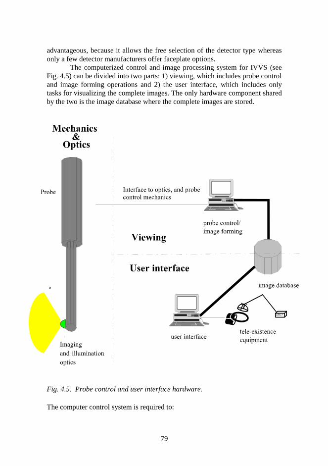
79
advantageous, because it allows the free selection of the detector type whereasonly a few detector manufacturers offer faceplate options.
The computerized control and image processing system for IVVS (seeFig. 4.5) can be divided into two parts: 1) viewing, which includes probe controland image forming operations and 2) the user interface, which includes onlytasks for visualizing the complete images. The only hardware component sharedby the two is the image database where the complete images are stored.
Fig. 4.5. Probe control and user interface hardware. The computer control system is required to:

80
• control probe movements into and out from the vessel• open and close keylock• control the probe rotation during viewing• adjust and align the probe• control the auxiliary equipment like cooling, etc.• control (synchronize) the illumination laser• grab the line images (pixel stripes)• form the complete images from grabbed pixels
Computer hardware consists of three parts:1. For probe and keylock control: I/O-cards, motor controllers, a laser
controller and a control computer2. For image forming: A/D converters, frame grabbers, image forming
computer (same as control computer)3. For user interface: user interface computer, head tracker, virtual helmet,
database for images
The image formation is an integrated process of image capture, transfer, storing,processing and visualization. A 10-probe IVVS requires a 100 Mbits/sec datatransmission rate, 12.5 Mbyte/sec total disk transfer rate, and 5 Gbyte storagecapacity per 1 image of the whole vessel.
4.1.3 Optomechanical Prototype
When the IVVS feasibility study and system level design was completed it wasdecided to build a complete end-to-end imaging prototype in order to investigateall factors affecting the image quality. This was accomplished in two stages.First, a full scale mechanical prototype of the scan mechanism and view probewas erected in the IVO Technology Center in Helsinki and it was outfitted witha CCD imaging system and an illumination laser. Separately an opticalprototype of the illumination and imaging optics was built at VTT Electronics inOulu. Preliminary imaging tests were made with both systems. Finally, theoptical prototype was integrated in the mechanical prototype and representativeimaging tests were performed.
The 14-m tall full scale prototype has all the essential components of theIVVS needed for viewing. No insertion system or vacuum hardware is included.The components selected are commercial units, which can be developed toITER qualified versions. The scan mechanism includes a stepper motor withinternal planetary gear, an optical position encoder and structures required tosupport and rotate the view probe. The view probe consists of two concentricAISI 316 stainless steel tubes. The inner tube is rotating and carries the opticalbench in the low end. The whole prototype is supported by a rigid platform
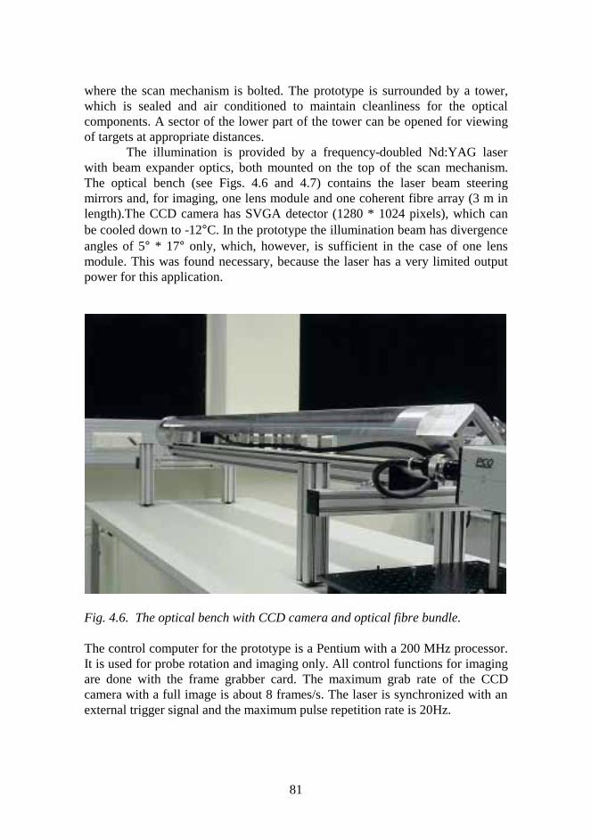
81
where the scan mechanism is bolted. The prototype is surrounded by a tower,which is sealed and air conditioned to maintain cleanliness for the opticalcomponents. A sector of the lower part of the tower can be opened for viewingof targets at appropriate distances.
The illumination is provided by a frequency-doubled Nd:YAG laserwith beam expander optics, both mounted on the top of the scan mechanism.The optical bench (see Figs. 4.6 and 4.7) contains the laser beam steeringmirrors and, for imaging, one lens module and one coherent fibre array (3 m inlength).The CCD camera has SVGA detector (1280 * 1024 pixels), which canbe cooled down to -12°C. In the prototype the illumination beam has divergenceangles of 5° * 17° only, which, however, is sufficient in the case of one lensmodule. This was found necessary, because the laser has a very limited outputpower for this application.
Fig. 4.6. The optical bench with CCD camera and optical fibre bundle.
The control computer for the prototype is a Pentium with a 200 MHz processor.It is used for probe rotation and imaging only. All control functions for imagingare done with the frame grabber card. The maximum grab rate of the CCDcamera with a full image is about 8 frames/s. The laser is synchronized with anexternal trigger signal and the maximum pulse repetition rate is 20Hz.
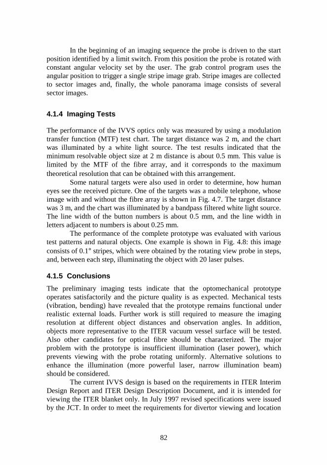
82
In the beginning of an imaging sequence the probe is driven to the startposition identified by a limit switch. From this position the probe is rotated withconstant angular velocity set by the user. The grab control program uses theangular position to trigger a single stripe image grab. Stripe images are collectedto sector images and, finally, the whole panorama image consists of severalsector images.
4.1.4 Imaging Tests
The performance of the IVVS optics only was measured by using a modulationtransfer function (MTF) test chart. The target distance was 2 m, and the chartwas illuminated by a white light source. The test results indicated that theminimum resolvable object size at 2 m distance is about 0.5 mm. This value islimited by the MTF of the fibre array, and it corresponds to the maximumtheoretical resolution that can be obtained with this arrangement.
Some natural targets were also used in order to determine, how humaneyes see the received picture. One of the targets was a mobile telephone, whoseimage with and without the fibre array is shown in Fig. 4.7. The target distancewas 3 m, and the chart was illuminated by a bandpass filtered white light source.The line width of the button numbers is about 0.5 mm, and the line width inletters adjacent to numbers is about 0.25 mm.
The performance of the complete prototype was evaluated with varioustest patterns and natural objects. One example is shown in Fig. 4.8: this imageconsists of 0.1° stripes, which were obtained by the rotating view probe in steps,and, between each step, illuminating the object with 20 laser pulses.
4.1.5 Conclusions
The preliminary imaging tests indicate that the optomechanical prototypeoperates satisfactorily and the picture quality is as expected. Mechanical tests(vibration, bending) have revealed that the prototype remains functional underrealistic external loads. Further work is still required to measure the imagingresolution at different object distances and observation angles. In addition,objects more representative to the ITER vacuum vessel surface will be tested.Also other candidates for optical fibre should be characterized. The majorproblem with the prototype is insufficient illumination (laser power), whichprevents viewing with the probe rotating uniformly. Alternative solutions toenhance the illumination (more powerful laser, narrow illumination beam)should be considered.
The current IVVS design is based on the requirements in ITER InterimDesign Report and ITER Design Description Document, and it is intended forviewing the ITER blanket only. In July 1997 revised specifications were issuedby the JCT. In order to meet the requirements for divertor viewing and location
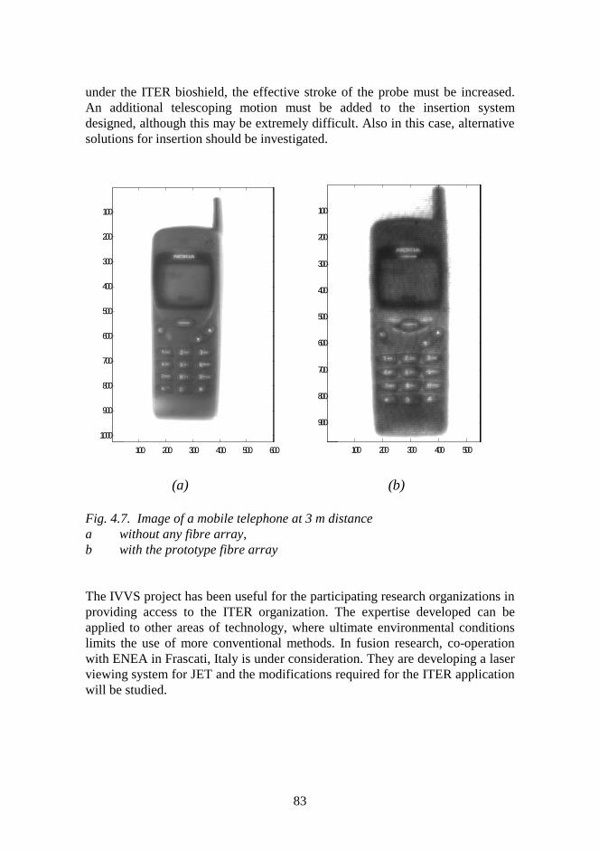
83
under the ITER bioshield, the effective stroke of the probe must be increased.An additional telescoping motion must be added to the insertion systemdesigned, although this may be extremely difficult. Also in this case, alternativesolutions for insertion should be investigated.
100 200 300 400 500 600
100
200
300
400
500
600
700
800
900
1000
100 200 300 400 500
100
200
300
400
500
600
700
800
900
(a) (b)
Fig. 4.7. Image of a mobile telephone at 3 m distancea without any fibre array,b with the prototype fibre array
The IVVS project has been useful for the participating research organizations inproviding access to the ITER organization. The expertise developed can beapplied to other areas of technology, where ultimate environmental conditionslimits the use of more conventional methods. In fusion research, co-operationwith ENEA in Frascati, Italy is under consideration. They are developing a laserviewing system for JET and the modifications required for the ITER applicationwill be studied.

84
Fig.4.8. A test image (distance 2.5 m) obtained by rotating the view probe insteps.
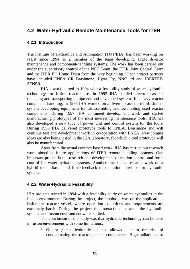
85
4.2 Water-Hydraulic Remote Maintenance Tools for ITER
4.2.1 Introduction
The Institute of Hydraulics and Automation (TUT/IHA) has been working forITER since 1994 as a member of the team developing ITER divertormaintenance and component-handling systems. The work has been carried outunder the supervisory control of the NET Team, the ITER Joint Central Teamand the ITER EU Home Team from the very beginning. Other project partnershave included ENEA CR Brasimone, Hytar Oy, NNC ltd and IBERTEF-SENER.
IHA’s work started in 1994 with a feasibility study of water-hydraulictechnology for fusion reactor use. In 1995 IHA studied divertor cassettereplacing and transporting equipment and developed systems for heavy reactorcomponent handling. In 1996 IHA worked on a divertor cassette refurbishmentsystem developing equipment for disassembling and assembling used reactorcomponents. During 1997 IHA continued development work and startedmanufacturing prototypes of the most interesting maintenance tools. IHA hasalso developed a new type of power unit and control system for the tools.During 1998 IHA delivered prototype tools to ENEA, Brasimone and willcontinue test and development work in co-operation with ENEA. New joiningideas are also being tested in the IHA laboratory, for which a tool prototype willalso be manufactured.
Apart from the actual contract-based work, IHA has carried out researchwork aimed at future applications of ITER remote handling systems. Oneimportant project is the research and development of motion control and forcecontrol for water-hydraulic systems. Another one is the research work on ahybrid model-based and force-feedback teleoperation interface for hydraulicsystems.
4.2.2 Water-Hydraulic Feasibility
IHA projects started in 1994 with a feasibility study on water-hydraulics in thefusion environment. During the project, the emphasis was on the applicationsinside the reactor vessel, where operation conditions and requirements areextremely harsh. During the project the interactions between the hydraulicsystems and fusion environment were studied.
The conclusion of the study was that hydraulic technology can be usedin fusion environment with some limitations:
∗ Oil or glucol hydraulics is not allowed due to the risk ofcontaminating the reactor and its components. High radiation also
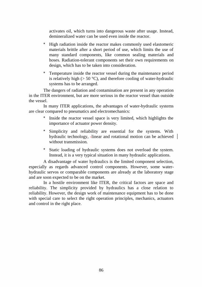
86
activates oil, which turns into dangerous waste after usage. Instead,demineralized water can be used even inside the reactor.
∗ High radiation inside the reactor makes commonly used elastomericmaterials brittle after a short period of use, which limits the use ofmany standard components, like common sealing materials andhoses. Radiation-tolerant components set their own requirements ondesign, which has to be taken into consideration.
∗ Temperature inside the reactor vessel during the maintenance periodis relatively high (> 50 °C), and therefore cooling of water-hydraulicsystems has to be arranged.
The dangers of radiation and contamination are present in any operationin the ITER environment, but are more serious in the reactor vessel than outsidethe vessel.
In many ITER applications, the advantages of water-hydraulic systemsare clear compared to pneumatics and electromechanics:
∗ Inside the reactor vessel space is very limited, which highlights theimportance of actuator power density.
∗ Simplicity and reliability are essential for the systems. Withhydraulic technology, linear and rotational motion can be achievedwithout transmission.
∗ Static loading of hydraulic systems does not overload the system.Instead, it is a very typical situation in many hydraulic applications.
A disadvantage of water hydraulics is the limited component selection,especially as regards advanced control components. However, some water-hydraulic servos or comparable components are already at the laboratory stageand are soon expected to be on the market.
In a hostile environment like ITER, the critical factors are space andreliability. The simplicity provided by hydraulics has a close relation toreliability. However, the design work of maintenance equipment has to be donewith special care to select the right operation principles, mechanics, actuatorsand control in the right place.
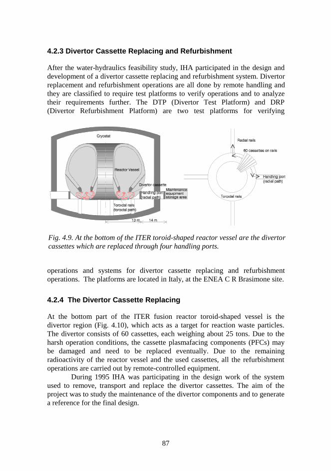
87
4.2.3 Divertor Cassette Replacing and Refurbishment
After the water-hydraulics feasibility study, IHA participated in the design anddevelopment of a divertor cassette replacing and refurbishment system. Divertorreplacement and refurbishment operations are all done by remote handling andthey are classified to require test platforms to verify operations and to analyzetheir requirements further. The DTP (Divertor Test Platform) and DRP(Divertor Refurbishment Platform) are two test platforms for verifying
operations and systems for divertor cassette replacing and refurbishmentoperations. The platforms are located in Italy, at the ENEA C R Brasimone site.
4.2.4 The Divertor Cassette Replacing
At the bottom part of the ITER fusion reactor toroid-shaped vessel is thedivertor region (Fig. 4.10), which acts as a target for reaction waste particles.The divertor consists of 60 cassettes, each weighing about 25 tons. Due to theharsh operation conditions, the cassette plasmafacing components (PFCs) maybe damaged and need to be replaced eventually. Due to the remainingradioactivity of the reactor vessel and the used cassettes, all the refurbishmentoperations are carried out by remote-controlled equipment.
During 1995 IHA was participating in the design work of the systemused to remove, transport and replace the divertor cassettes. The aim of theproject was to study the maintenance of the divertor components and to generatea reference for the final design.
Fig. 4.9. At the bottom of the ITER toroid-shaped reactor vessel are the divertorcassettes which are replaced through four handling ports.
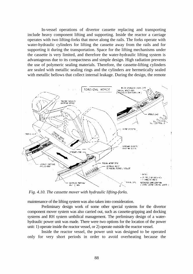
88
In-vessel operations of divertor cassette replacing and transportinginclude heavy component lifting and supporting. Inside the reactor a carriageoperates with two lifting-forks that move along the rails. The forks operate withwater-hydraulic cylinders for lifting the cassette away from the rails and forsupporting it during the transportation. Space for the lifting mechanisms underthe cassette is very limited, and therefore the water-hydraulic lifting system isadvantageous due to its compactness and simple design. High radiation preventsthe use of polymeric sealing materials. Therefore, the cassette-lifting cylindersare sealed with metallic sealing rings and the cylinders are hermetically sealedwith metallic bellows that collect internal leakage. During the design, the remote
maintenance of the lifting system was also taken into consideration.Preliminary design work of some other special systems for the divertor
component mover system was also carried out, such as cassette-gripping and dockingsystems and RH system umbilical management. The preliminary design of a water-hydraulic power unit was made. There were two options for the location of the powerunit: 1) operate inside the reactor vessel, or 2) operate outside the reactor vessel.
Inside the reactor vessel, the power unit was designed to be operatedonly for very short periods in order to avoid overheating because the
Fig. 4.10. The cassette mover with hydraulic lifting-forks.
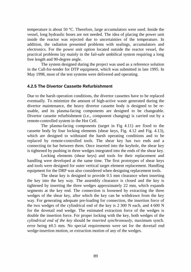
89
temperature is about 50 °C. Therefore, large accumulators were used. Inside thevessel, long hydraulic hoses are not needed. The idea of placing the power unitinside the reactor was rejected due to uncertainties of the temperature. Inaddition, the radiation presented problems with sealings, accumulators andelectronics. For the power unit option located outside the reactor vessel, thepractical problems lay mainly in the fail-safe umbilical system requiring a longfree length and 90-degree angle.
The system designed during the project was used as a reference solutionin the Call-for-tender for DTP equipment, which was submitted in late 1995. InMay 1998, most of the test systems were delivered and operating.
4.2.5 The Divertor Cassette Refurbishment
Due to the harsh operation conditions, the divertor cassettes have to be replacedeventually. To minimize the amount of high-active waste generated during thedivertor maintenance, the heavy divertor cassette body is designed to be re-usable, and its plasma-facing components are designed to be changeable.Divertor cassette refurbishment (i.e., component changing) is carried out by aremote-controlled system in the Hot Cell.
The plasma-facing components (target in Fig 4.11) are fixed to thecassette body by four locking elements (shear keys, Fig. 4.12 and Fig. 4.13),which are designed to withstand the harsh operating conditions and to bereplaced by remote-controlled tools. The shear key has two ends and aconnecting tie bar between them. Once inserted into the keyhole, the shear keyis tightened by pushing in three wedges integrated into the ends of the shear key.
Locking elements (shear keys) and tools for their replacement andhandling were developed at the same time. The first prototypes of shear keysand tools were designed for outer vertical target element replacement. Handlingequipment for the DRP was also considered when designing replacement tools.
The shear key is designed to provide 0.5 mm clearance when insertingthe key into the key way. The assembly clearance is closed and the key istightened by inserting the three wedges approximately 22 mm, which expandssegments at the key end. The connection is loosened by extracting the threewedges of the shear key, after which the key can be withdrawn from the keyway. For generating adequate pre-loading for connection, the insertion force ofthe two wedges of the cylindrical end of the key is 2 300 N each, and 4 600 Nfor the dovetail end wedge. The estimated extraction force of the wedges isdouble the insertion force. For proper locking with the key, both wedges of thecylindrical end of the key should be inserted synchronously, maximum synch.error being ±0.5 mm. No special requirements were set for the dovetail endwedge-insertion motion, or extraction motion of any of the wedges.
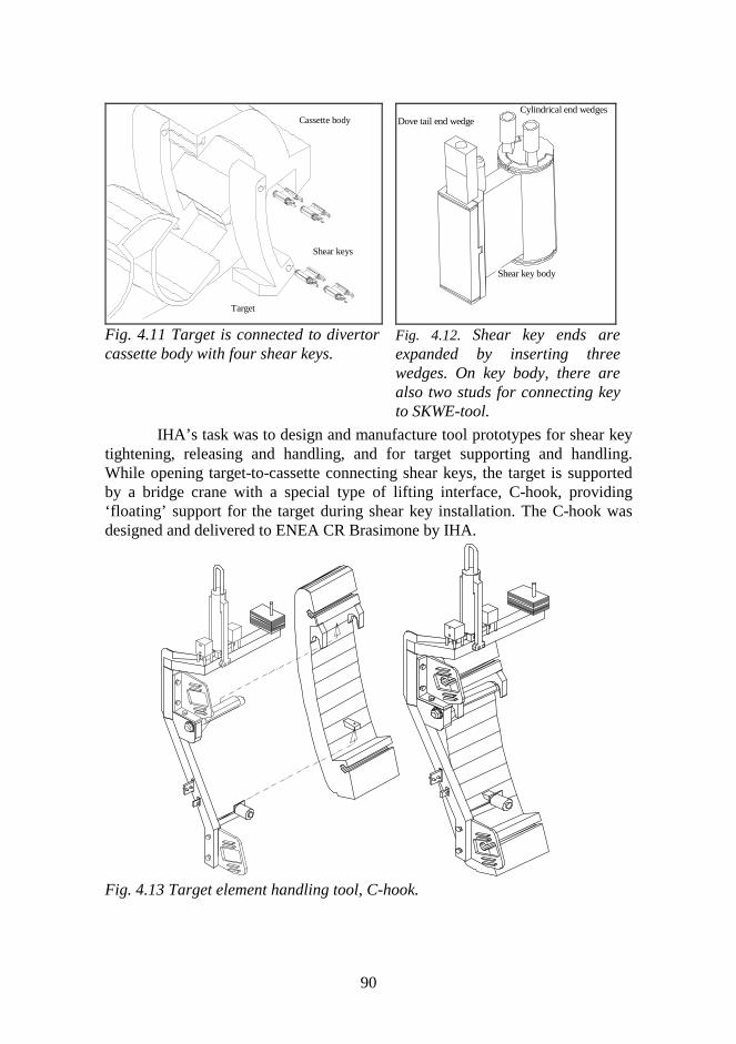
90
Shear keys
Target
Cassette body
Fig. 4.11 Target is connected to divertorcassette body with four shear keys.
Shear key body
Cylindrical end wedgesDove tail end wedge
Fig. 4.12. Shear key ends areexpanded by inserting threewedges. On key body, there arealso two studs for connecting keyto SKWE-tool.
IHA’s task was to design and manufacture tool prototypes for shear keytightening, releasing and handling, and for target supporting and handling.While opening target-to-cassette connecting shear keys, the target is supportedby a bridge crane with a special type of lifting interface, C-hook, providing‘floating’ support for the target during shear key installation. The C-hook wasdesigned and delivered to ENEA CR Brasimone by IHA.
Fig. 4.13 Target element handling tool, C-hook.
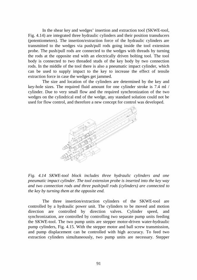
91
In the shear key and wedges’ insertion and extraction tool (SKWE-tool,Fig. 4.14) are integrated three hydraulic cylinders and their position transducers(potentiometers). The insertion/extraction force of the hydraulic cylinders aretransmitted to the wedges via push/pull rods going inside the tool extensionprobe. The push/pull rods are connected to the wedges with threads by turningthe rods at the opposite end with an electrically driven bolting tool. The toolbody is connected to two threaded studs of the key body by two connectionrods. In the middle of the tool there is also a pneumatic impact cylinder, whichcan be used to supply impact to the key to increase the effect of tensileextraction force in case the wedges get jammed.
The size and location of the cylinders are determined by the key andkey-hole sizes. The required fluid amount for one cylinder stroke is 7.4 ml /cylinder. Due to very small flow and the required synchronization of the twowedges on the cylindrical end of the wedge, any standard solution could not beused for flow control, and therefore a new concept for control was developed.
Fig. 4.14 SKWE-tool block includes three hydraulic cylinders and onepneumatic impact cylinder. The tool extension probe is inserted into the key wayand two connection rods and three push/pull rods (cylinders) are connected tothe key by turning them at the opposite end.
The three insertion/extraction cylinders of the SKWE-tool arecontrolled by a hydraulic power unit. The cylinders to be moved and motiondirection are controlled by direction valves. Cylinder speed, andsynchronization, are controlled by controlling two separate pump units feedingthe SKWE-tool. The two pump units are stepper motor-driven water-hydraulicpump cylinders, Fig. 4.15. With the stepper motor and ball screw transmission,and pump displacement can be controlled with high accuracy. To feed twoextraction cylinders simultaneously, two pump units are necessary. Stepper

92
motors are controlled by PLC according to information received from positiontransducers integrated into the SKWE-tool.
System control is achieved with a PLC SIEMENS S7-200, whichcontrols two stepper motors, five hydraulic valves and three pneumatic valves ofthe SKWE-tool impact cylinder, and also other auxiliary systems. The operatorcan change several operation parameters of the pumps. These parameters are:Two stepper motor speeds (normal speed and closing speed), upper and lowerlimit values for two pump synchronization, pressure limits and travel limits.
Stepper motor
Lin. guide + ball screw
Pump cylinderActuator
Tank
Fig. 4.15 One of the two pump units of the hydraulic power unit.
4.2.6 Other ITER-generated Research Projects
Water hydraulic test bench
One optional locking element for the component-cassette connection requiredhigh extraction forces. The most suitable way to disassemble and assemble theseelements is to use a water-hydraulic cylinder tool to generate the extractionforce. The control of the extraction motion at the very moment of breaking thejam and controlling extraction/insertion speed under varying load/friction arevery important properties. To meet the control requirements of the ITER tasks,the IHA laboratory has established a test bench for developing and testingdifferent control methods. The test bench is a two-axis water-hydraulic x-y tableequipped with a gripping system for gripping and breaking test bars formaterials testing. Both the axes are controlled by a PC. The PC is connected to agraphical model in the Telegrip-software in the Silicon Graphics workstation viaEthernet.

93
Fig. 4.16 Water-hydraulic test bench.
The test bench will be used to develop the motion control for the ITERshear key extraction. By breaking apart the test bars, sudden load changes canbe simulated and methods for their control developed. The results can beutilized to better control also stick-slip phenomena, which is especially difficultwith water-hydraulics.
Besides the control problem in breaking the test bars, the test benchprovides a test platform for different valve-types and control methods for single-axis and x-y motion, position and force control. The test bench will also be usedto verify the general properties of water-hydraulic proportional and servo valvesand to verify water-hydraulic simulation models and thus develop the simulationof water-hydraulic systems.
For position control, the known hydraulic control methods, like 3-stateand 5-state control and position servo control will be tested for water-hydraulics. Also, on-off and servo operating together will be tested. Water-hydraulic on-off type valves with sophisticated control algorithms developed,for example with pulse width modulation, will also be tested.
Telegrip with the test bench’s graphical model in the workstation isused to teleoperate the test bench. With Telegrip, the user generates targetpoints in the x-y plane. The target co-ordinates are sent to the PC that controlsthe test bench, against which the measured positions are sent to the workstationwhen motion proceeds. The user gets visual feedback on the workstation screen.The aim of the study is to test different options in transmitting target locationsto the device, how to get the best feedback and how to be able to control theinterruptions of the manipulator.
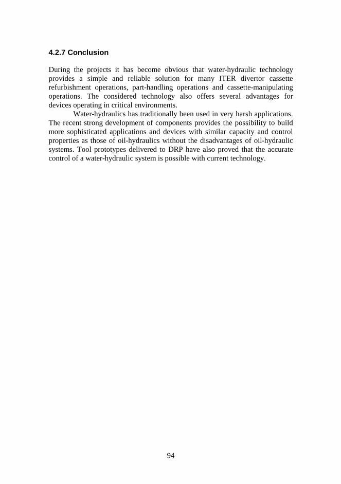
94
4.2.7 Conclusion
During the projects it has become obvious that water-hydraulic technologyprovides a simple and reliable solution for many ITER divertor cassetterefurbishment operations, part-handling operations and cassette-manipulatingoperations. The considered technology also offers several advantages fordevices operating in critical environments.
Water-hydraulics has traditionally been used in very harsh applications.The recent strong development of components provides the possibility to buildmore sophisticated applications and devices with similar capacity and controlproperties as those of oil-hydraulics without the disadvantages of oil-hydraulicsystems. Tool prototypes delivered to DRP have also proved that the accuratecontrol of a water-hydraulic system is possible with current technology.
95
5 Socio-Economic Studies
The Socio-Economic Research on Fusion (SERF) was started in autumn 1997.The SERF programme includes five subtasks: Long-Term Scenarios, ProductionCosts, External Costs and Benefits, Fusion as a Large Technical System, andFusion and the Public Opinion.
VTT has participated in the subtask External Costs and Benefits ofFusion. Other participating institutes are Studsvik, Risø, Max-Plank-Institut fürPlasmaphysik, CIEMAT and ENEA. With the aid of the concept of externalcosts, preferences of parties other than producer and consumer are taken intoaccount by evaluating these preferences in an extra price term. In evaluating theexternal costs, the project uses the EU ExternE methodology, where the bottom-up, site-specific, marginal approach is used. Monetarization of caused damagesis an important point in the evaluation process. The monetarized environmentalcosts calculated as mECU/kWh might be used as a part of price to determine thetotal costs of energy production.
Material from the earlier SEAFP study (Safety and EnvironmentalAssessment of Fusion Power) has been used to find the necessary informationfor model plants. Some parts are taken from the ITER design and conventionalfission reactors. Two conceptual power plant designs producing 1 000 MW ofelectricity were considered. Model 1 applies helium cooling and vanadium alloystructures for the components near the plasma, thus emphasizing the use of low-activation materials. Model 2 is based on reduced activation martensitic steel forthe structures and uses water-cooling. The plants are assumed to be situated inLauffen near the River Neckar in the south-western part of Germany.
On the basis of the preliminary studies performed, external costs of fusionhave been evaluated to be very low for the Model plant 1 (less than 1mECU/kWh) and also relatively low for the Model plant 2 (about 2mECU/kWh). So far the disposal component has not been monetarized. If thatcomponent has to be low in the evaluations using the ExternE methodology, it isnecessary that decommissioning is performed using deep repositories wheresolubility and water flow are very small.
In the environmental costs of fusion, some cost components seemdominant. Carbon dioxide emissions caused by the production of plant materialsand from constructing the plant give rise to a relatively high cost component dueto the global-warming impact, which is the same for both model plants. Ofcourse, the component is very small compared to energy technologies using
96
fossil fuels. These costs might also be avoided if future energy systems do notemit large amounts of greenhouse gases. Then, however, the alternative energyproduction measures also have lowered environmental costs. (Anotherpossibility is to consider that the necessary electricity for material production isproduced by using fusion power and not the average energy system.) Otherimportant emissions are C-14 emissions due to normal operation (Model 2) anddue to decommissioning.
A relatively high amount of C-14 has been evaluated to be produced inshield materials in the SEAFP project. If the effects of this C-14 inventory areestimated taking long-term global impacts into account, the C-14 componentbecomes very important. Disposal can cause, using ExternE methodology,relatively high extra contributions to external costs. If, in commercial fusionplants, C-14 releases due to normal operation can be avoided, the disposalcomponent is even more important. A conclusion is that shield materials shouldbe further studied in order to avoid to a large extent activation to C-14.
Both important cost components are due to global impacts. Local impactsare, in the preliminary study, considered to be lower by some orders ofmagnitude than the global impacts. Therefore, the site of the fusion power plantis not very important in environmental considerations. On the other hand, thesite for the waste disposal has still to be chosen rather carefully.
Methodological questions are very important in the evaluation ofenvironmental impacts of fusion. In the SERF project, EU ExternE methodologyis used. It offers good possibilities for comparisons with other energyproduction technologies that have been studied using the same methodology. Onthe other hand, comparison inside ExternE is a bit too straightforward ifvaluation questions are taken as given. For instance, the comparison of the mostimportant cost components — global warming and the long-term doses — is notas easy as must be assumed in monetarization approach. The context withinwhich the costs are evaluated also influences the costs considerably. Emissionsas well as impacts caused are dependent on the energy production scenariounder consideration. The SERF task “Long-Term Scenarios” includes materialthat could also be used in the calculation of external costs. It is also still possiblethat some rather important sociological aspects have not at all been taken intoaccount so far.
97
6 Summary of Objectives and Main Results
6.1 Meeting of the FFUSION Programme Objectives
The early objective of the FFUSION programme was to collect and organize allthe fusion-related activities under one single research programme and to identifypotential research areas where Finland could make a relevant contribution to theEuropean and international fusion effort. This was the first step in preparing theformal association with the European Fusion Programme. The important role ofindustry in the future R&D of fusion technology was realized and a systematicsurvey to find potential Finnish companies was undertaken.
Those early objectives were well achieved when the FFUSIONprogramme was fully integrated into the European Fusion Programme in 1995and the Association Euratom-Tekes was established. By this time a number ofFinnish hi-tech companies had expressed their interest in fusion technology andstarted to collaborate with the Finnish Fusion Research Unit. In 1996, elevenFinnish companies were included on the list of qualified industry for ITER EDAand Imatran Voima Oy became a member of the EFET consortium.
The national objective is to provide a high-level contribution to the EUFusion Programme in focused areas of fusion science and technology. The vitalelement in reaching this goal has been close collaboration between researchinstitutes, universities and industry.
During the six years of FFUSION, over 100 publications in internationalscientific journals, over 120 conference articles, 64 research reports, 11 generalarticles have been published. In addition, two patents have been granted. Threedoctoral, three licentiate and eight graduate theses have been produced duringthe programme period.
6.2 Fusion Physics and Plasma Engineering – Objectivesand Main Results
Characteristic of the work within fusion physics and plasma engineering in1993-98 was a strong concentration on modelling and design effort on theEuropean fusion facilities, e.g., ASDEX Upgrade and Wendelstein 7-AS inGermany, JET in England, Tore Supra in France and on the international ITERproject. The main lines of the research were radio-frequency heating and
98
transport processes, where distinguished expertise and knowledge have beenacquired by the fusion and plasma physics group during the past two decades.This experience has also been valuable in supporting other activities outside thescope of physics within the fusion programme.
The orbit-following code ASCOT, various wave codes, and gyrotronmodels, developed at VTT and HUT, are internationally recognised, and haveformed a basis for a number of task and collaboration agreements with otherAssociations and JET. New lines of research have been opened by startingparticle-in-cell simulations to model lower hybrid heating. Two importantplasma engineering projects were also launched on the central solenoid of atokamak and radio-frequency vacuum window design and construction. Thelatter have significantly increased the contacts and common research activity ofthe group with industry.
6.2.1 Physics of Radio-Frequency Heating and Current Drive
JET Task Agreement: Ion Cyclotron Heating and Current Drive. The mainmotivation of the present Task, initiated in 1995, was to develop and useefficient codes to model high-performance ion cyclotron resonance heating(ICRH) experiments in JET tokamak. The work continues the closecollaboration of JET, HUT and VTT on radio-frequency (rf) physics. ThePION-code developed in JET, in parallel with with the transport codeTRANSP, has been used to model the neutron production rate and heating inthe recent high-power deuterium-tritium experiments. It has accuratelyreproduced the observed neutron emission in important high-power shots.
The 5D Monte Carlo ASCOT, which follows trajectories of chargedparticles in a tokamak, was developed at HUT and VTT during 1991-98. It hasbeen interfaced with the JET magnetic background. Work is in progress to applyASCOT for a detailed comparison of ion cyclotron heated ion distributions andtransport with the JET experimental data.
JET Task Agreement: Development of Radio-Frequency Modules forTransport Codes. The development of lower hybrid radio-frequency modules forthe transport codes used in JET was started during 1998. The work will consistof participation in the code validation on JET experimental data and theimplementation of rf-modules into the transport codes and analysingexperimental JET-data.
ITER Task: Support of Physics and Engineering Design of the Ion
99
Cyclotron System. 1) Mode Conversion and Minority Current Drive for PlasmaCurrent Control. The mode conversion of rf-waves has been modelled at VTTand HUT, and in certain conditions 100 % conversion has been numericallypredicted. A number of experiments have verified the high conversion factorsfor the use of ion cyclotron waves in mode conversion current drive. Within thepresent Task, a parameter analysis of the conversion and optimization ofantenna spectrum have been performed for ion cyclotron heating scenarios ofITER. Current drive with ion cyclotron waves has been studied by solving thedrift-kinetic Fokker-Planck equation and by performing full Monte Carlosimulations with ASCOT. The driven current is mostly of diamagnetic originand is significant in ITER only for hydrogen minority heating.
2) Advanced Launchers for RF-Heating. The requirement of sizereduction of the rf-launchers in a compact ITER device may call for advancedantennas. The power handling and coupling of a folded waveguide antenna inion cyclotron heating have been numerically modelled in ITER reactorconditions. The electric field values stay within the experimental breakdownlimits for an antenna array radiating three times more power than a conventionalloop antenna, whilst still fitting to an ITER port.
3) Alpha Power Channelling with Waves. It has been suggested thatlocally constrained waves could be used for converting fusion alpha particlepower to D/T-ion energy and for enhancing alpha particle removal from theplasma. ASCOT-simulations have been performed to take into account arealistic alpha particle distribution, collisions, and the tokamak geometry.Harnessing this scheme in standard heating methods of tokamaks is found to bevery difficult.
Tore Supra Collaboration: Analysis of Parasitic Absorption of LowerHybrid Power. The generation of impurities has been observed in Tore Supraand Tokamak de Varennes (TdeV) when lower hybrid waves at 3.7 GHz havebeen launched in tokamaks. A possible explanation for the impurity productionis the sputtering caused by fast electrons generated by the near field of the rf-launcher. Such electrons can be generated when part of the rf-power is absorbedwithin a short distance from the launcher. When the launched power is severalmegawatts, fast electrons containing a few per cent of the rf-power may damagethe launcher structures.
The parasitic absorption of lower hybrid waves and the generation of thefast electrons near the launcher have been investigated by particle-in-cellsimulations in collaboration with the Tore Supra Team. A particle-in-cell modelof a lower hybrid grill has been developed and coupled with the SWAN code,
100
which calculates the launched wave spectrum. Numerical simulations show that,depending on the launched spectrum, between one to ten percent of the rf-poweris absorbed within a distance of a few millimetres from the launcher. This is inagreement with the experimental results. The modelling of lower hybridlaunchers of JET has been performed as a part of the above described JET TaskAgreement on “Development of RF Modules for Transport Codes” and also forITER.
Gyrotrons for Electron Cyclotron Heating and Microwave Diagnostics.Gyrotron microwave source research has concentrated on advanced sourcedevelopment for electron cyclotron resonance heating and microwavediagnostics in tokamaks. Mode competition in coaxial gyrotrons andmultifrequency gyrotrons have been studied in collaboration with the FZK,Karlsruhe. A high-frequency quasi-optical gyrotron has been studied incollaboration with CRPP Lausanne. A gyrotron operating close to 1 THz (3rdharmonic of 280 GHz) has been considered for plasma diagnostics applicationsbased on the Collective Thomson Scattering (CTS). A kinetic code wasdeveloped to model CTS and it was benchmarked with a fluid-code used in JET.The code can predict the scattered spectra in high temperature plasma wherefluid models are not valid. Scattering measurements are planned for alphaparticle diagnostics in fusion plasmas.
A fast Fokker-Planck code was developed to model electron cyclotronheating in reactor conditions. The stabilization of magnetohydrodynamic modesin ITER by using frequency-tunaeble gyrotron sources was analysed with thecode. An INTAS project was co-ordinated during 1995-1997 to study modernfrequency-tunaeble microwave power sources, e.g., gyrotrons, which improvedthe present diagnostics and heating schemes in fusion plasmas.
6.2.2 Plasma Confinement and Transport
ASDEX Upgrade Collaboration: Transitions from Low to High Confinement.Achieving a transition from low to high confinement, so-called L-H transition,is an essential step towards ignition or high-fusion gain operation of fusionreactors. The mechanism behind the transition is not, however, wellunderstood. Collaboration between VTT Energy, HUT and Association IPPGarching started in 1996 to launch detailed simulation studies to explain the L-H transition characteristics in the ASDEX Upgrade at IPP. To understand thedynamics of the L-H transition, experimental data from ripple-trapped neutralbeam-injected ions at the transition in ASDEX were first reproduced with
101
ASCOT. The results from ASCOT and from a specially developed Fokker-Planck code show that the charge exchange diagnostics can measure the radialelectric field with an excellent time resolution. ASCOT has been used to testsome well-known theory models of the L-H transition. Work is in progress toresolve stationary and self-consistent neo-classical ion transport fluxes at thetransition region in order to reveal the role of neo-classical transport in the L-Htransition.
Electron Density Profile Measurements and Particle Transport Studieswith Multichannel Interferometer at the Wendelstein 7-AS. A new multichannelmicrowave interferometer was build and used in 1995-8 for the Wendelstein 7-AS stellarator in Garching. Within an agreement between HUT and IPPGarching, software for interpreting the signals from the measurements has beenprepared. The code was used to study the electron density profile evolution inconventional discharges and during density oscillations produced by injecting aharmonically modulated gas feed to the plasma edge. Electron densityoscillations were produced by modulating the gas feed to the plasma, and thepropagating electron density perturbation was measured with the multichannelinterferometer. In the experiments, the diffusion coefficients were found not toexceed the neo-classical level. An inward pinch, not predicted by the neo-classical theory, was detected at the plasma edge.
6.2.3 Plasma Engineering Projects
ITER Task: Dielectric Window Prototype for the ITER RF Transmission Line.VTT, HUT, IVO Technology Centre, and Rauma Materials Technologyconducted an ITER Task during 1995-98 on rf-window development for theITER vacuum transmission line (VTL) of ion cyclotron power. The goal was toobtain specifications for constructing two prototype vacuum windows for theITER VTL being tested at Oak Ridge National Laboratory in the USA, and topresent a design of the window. It was required that the window is compatiblewith the ITER conditions, withstands the strong dielectric heating and relatedthermal stresses, is resistant to breakdown with appropriate arc monitoring, canbe remote handled, and can be manufactured by welding the ceramics to theconductor. Finite element calculations of the temperature, stress, and electricfield were performed to find the conical-shaped dielectric geometry in a coaxialwith proper materials. Accurate neutron flux calculation for the VTL with theMCNP4 code was performed for the ITER ion cyclotron system. Based on theneutron calculations the window is placed at the vacuum vessel feedthrough. A
102
special remote handling scheme based on a window complex inserted inside astainless steel casing has been invented. The choice of titanium as the conductormaterial was necessary to provide a design with water duct cooling inconductors without active gas cooling on ceramics. However, joining ceramicsto titanium in this scale with ITER requirements for vacuum tightness has not sofar been demonstrated. Initial new brazing experiments with full-size windowprototypes at VTT have provided a promising scheme to meet the brazing needs.
The work continues with the production of the prototypes and design andthe production of new vacuum windows for rf-launcher prototypes at highpower density. The group has also prepared cost estimates of the antenna andtransmission line parts of the ITER rf-heating systems in collaboration with IVOTechnology Centre.
Central Solenoid Development for Spherical Tokamaks. The centralsolenoid is the most critical magnet component in tight aspect ratio tokamaks.The project to design and construct an appropriate water-cooled solenoidconductor for the Globus-M tokamak at the Ioffe Institute in Russia was startedin 1994 as a Tekes project at VTT, HUT, and Outokumpu Poricopper. Amanufacturing method has been invented for producing a 66-meter-long high-strength hollow conductor and it has been delivered to Russia, where it will bewound and tested in 1998. Outokumpu Poricopper provided a similar solenoidconductor also for the MAST tokamak in Association UKAEA Culham.
6.3 Fusion Reactor Materials - Objectives and MainResults
The objective of the fusion reactor materials research in the FFUSIONprogramme is to carry out high-level research and development by applyingnovel manufacturing and testing methods. The work has been focused onadvanced materials, advanced joining techniques, fracture mechanics,environmentally induced cracking and structural integrity in order to estimateradiation damage of fusion reactor components. Also studies in the fields ofplasma facing materials and superconductors have been carried out. Theresearch and development are performed in close collaboration with industry toencourage and increase the competitiveness of national companies to participatein the EU fusion programme. The fusion reactor materials research work isperformed in the framework of ITER technology, Underlying Technology andEuropean Blanket Programme-Structural Materials programmes in collaborationwith Associations Risø, CEA and CRPP Lausanne.
103
6.3.1 Characterisation of Irradiated Cu and Cu-alloys
The current design for ITER utilizes Cu-alloys in the first wall and divertorstructures. The function of the copper alloy in the first wall is to dissipate heatproduced by plasma disruptions and it does not provide structural support forthe first wall. However, the Cu-alloy for the divertor is designed also forstructural support of the divertor cassette in addition to heat dissipation.
The objectives of the Cu alloy activities were (i) to determine the fracturetoughness behaviour of both canditate CuAl25 IG0 and CuCrZr alloys in theITER relevant temperature and neutron fluence ranges and (ii) to determine themechanisms of elevated temperature fracture of the candidate copper alloys.
The main results are: (i) fracture toughness of CuCrZr alloy is clearlyhigher than that of CuAl25 IG0 alloy in ITER relevant temperature and neutronfluence ranges, (ii) fracture toughness of CuAl25 IG0 alloy is highly sensitive totemperature and neutron irradiation, (iii) miniaturized bend specimens ofCuCrZr alloy give comparable fracture toughness results with standard sizespecimens, (iv) fracture toughness of CuAl25 IG0 alloy is highly strain ratesensitive and anisotropic indicating creep as a dominant fracture mechanism.
It was verified that the fracture toughness of both Cu-alloys decreasedwith increasing temperature up to 350 C. However, the fracture toughness ofCuAl25 IG0 is much lower than that of CuCrZr alloy and decreases to a verylow value already at temperature of 200 C. This apparent difference in fracturebehaviour of the candidate Cu alloys is due to differences in microstructure.Reduction in fracture toughness of CuAl25 IG0 is observed after neutronirradiation to a dose level of 0.3 dpa on the contrary to CuCrZr alloy where onlymoderate effect of irradiation is observed as compared to unirradiated condition.
Significant reduction in fracture toughness of CuAl25 IG0 alloy is alsoobserved with decreasing displacement rate at temperature of 200 C. Thus,fracture toughness is strain rate sensitive. This kind of time dependent fracturetoughness behaviour indicates that at elevated temperatures creep mechanismdominate the crack growth in CuAl25 IG0 alloy.
Marked fracture toughness anisotropy of CuAl25 IG0 alloy plate is alsoobserved due to fracture plane orientation and crack propagation direction. Thefracture toughness along short transverse plane is significantly lower than thatalong longitudinal or transversal plane. The fracture toughness anisotropydecrease with increasing temperature.
Different size and type SEN(B) and C(T) specimens give similar fractureresistance curves for CuCrZr alloy when crack extension does not exceed 25-
104
30% of the initial ligament size. This result indicates that the ASTM standardrequirements for allowable crack extension and J-integral values areconservative for the side grooved high constraint type of 10 mm and 3 mm thickSEN(B) test specimens and that reliably fracture toughness data can begenerated by using miniaturized SEN(B) specimens. Specimen size effect wasalso verified with CuAl25 IG0, Ti-alloys and F82H modified steel. By applyingmixed mode (I/II) loading it is verified that mode I fracture toughness is not aconservative value for ductile materials like F82H modified stainless steel andCuAl25 IG0 alloy.
6.3.2 Cu/SS Joining Technology and Characterisation
The present design of ITER primary wall modules is based on multimaterialconcept with stainless steel as a structural material, copper alloy as a heat sinkand beryllium as a plasma facing material. The candidate joining method formanufacturing these components is hot isostatic pressing (HIP). Joiningmethods for ITER first wall modules and other in-vessel components andcharacterization of the joint properties in non- and post-irradiated conditions isessential for reliable reactor design.
The objectives of the Cu/SS joining activities were (i) to developadvanced joining methods for copper alloys and stainless steel, (ii) tocharacterize the integrity and fracture toughness properties of the Cu/SS jointsand (iii) to further develop testing methods for miniaturized Cu/SS jointspecimens.
The main results is summarized in the following (i) verification thatexplosion welding (EXW) and HIP methods are viable methods to manufactureCu/SS components, (ii) determination of general fracture behaviour and fracturetoughness of Cu/SS joints at ITER relevant temperature and neutron fluenceranges, (iii) development of ultrasonic and eddy current methods for integrityassessment of ITER first wall mock-ups and (iv) verification of the fracturetoughness test method for Cu/SS joints which utilizes miniaturized single edgenotched bend SEN(B) specimens.
It has been verified that EXW and HIP can be used to produce goodquality Cu-alloy to SS-joints. The metallurgy and mechanical properties of asreceived explosion welding (EXW) and HIP joints are different due to basicdifferences in bonding methods. However, after appropriate post weld heattreatment microstructure and mechanical properties of EXW and HIP joints aresimilar.
Mechanical testing of copper stainless steel joints is complicated due to
105
differences in elastic and plastic properties of the constituent metals. It has beenshown that fracture in many cases occur within copper alloy, however, atelevated temperatures and under creep condition fracture occurs along the jointinterface. The fracture toughness of the Cu/SS joints is lower than that of theconstituent copper alloys and a further reduction is observed after neutronirradiation to a dose level of 0.3 dpa. In the studied temperature range theprecipitation hardened CuCrZr/SS joints showed higher fracture toughnesswhen compared to dispersion strengthened CuAl25 IG0/SS joints. The very lowfracture toughness of dispersion strengthened CuAl25 IG0/SS joints is partlydue to strong anisotropy of the CuAl25 IG0 alloy. Multiple HIP thermal cycleswas shown to have only a moderate effect on fracture toughness of the joints,however, at elevated temperatures fracture propagated along the joint interface.
The integrity of various Cu/SS joints and ITER primary wall mock upsmanufactured by EXW, HIP or rheocast methods have been successfullyevaluated using ultrasonic and eddy current techniques. VTT participated in EUHome Team test programme of ITER primary wall mock ups by characterizingthe integrity of the industrially manufactured Cu/SS and Be/Cu/SS mock upsbefore and after high heat flux testing. The main results so far indicate thatprecipitation hardened CuCrZr/SS mock ups have larger operational marginsince first failures were observed at 7 MW/m2 compared to dispersionstrengthened CuAl25/SS mock ups which failed at 5 MW/m2. No failures wereobserved at 0.75 MW/m2 after 13000 cycles in either type of mock-ups.
6.3.3 Behaviour of Hydrogen Isotopes in First Wall Materials
The aim of this project was focused on the hydrogen cycle and it was based onstudies of the physical interactions between plasma and first-wall materials, i.e.,on studying the hydrogen isotope (H,D) behaviour in metals and in diamond-likecarbon (DLC) films.
A study of hydrogen migration between impurity layers in Ta, Ni, W andstainless steel AISI 316L was carried out. The effect of ion-induced damage andannealings in the H/He retention was investigated. A stopping power of 5-100keV He-ions in Ta, Ni, W, AISI 316L, Cu, Ni, Mo and Cr was studied.
Carbon-based composites or DLC-films are potential plasma facingmaterials in fusion machines. Investigations were also focused on thedevelopment of a method for the production of co-deposited DLC-layers withvariable H/D-concentration via DIARC plasma arc-discharge coating method forstudies of erosion, migration, trapping and O2 gas exposure removal, and on thedevelopment, characterization and production of test samples of DLC/SiC
106
composite coatings for erosion studies and thick DLC/graphite coatings for re-deposition studies. A study of the trapping, de-trapping and migration ofhydrogen isotopes in DLC films and carbon-based composite materials wascarried out. The impurities in the coatings, their depth distribution, samplethickness, density and amount of diamond-like sp3 -bonds were measured.
The annealing behaviour of hydrogen and hydrogen containing He-precipitates was studied in implanted and co-deposited samples. The migrationof H and D in implanted coatings is well described with a diffusion equation andexhibits good Arrhenius behaviour.
A set of films grown in a hydrogen atmosphere for migration studies wasalso made. The H-concentration in different depositions was varied by changingthe pressure of the H-atmosphere between 0.06 and 0.6 mPa. Annealingexperiments showed a decrease in the hydrogen concentration with increasingtemperature, hydrogen release and migration to the interface.
6.3.4 Fusion Neutronics
Capacity for neutron and gamma flux calculations for fusion reactors wasestablished at VTT Energy in 1993-95. The objective is to provide nuclearanalysis for the ITER design and to support Finnish industry in the design andsupply of components for ITER. This was to be done by calculating theradiation environment of various components, which is important for selectingmaterials and proving shielding. Initially, the work was done using SN-codes,such as ANISN, contained in the REPVICS software created for radiationcalculations in fission reactors.
The SN method, in which discrete directions for neutrons are selected, isnot very useful in a complicated geometry of fusion reactors. The Monte Carlomethod is better in such a geometry, and the MCNP program with the FENDL-1cross-section library has become an international standard in the field and it hasbeen explicitly chosen for the ITER project.
The MCNP-calculations have mainly dealt with the neutron and gammaflux in and near equatorial ports containing the launching structures of rf-heating systems In addition, other calculations have been performed to verifyand compare the results calculated by other teams.
The calculations for a port containing an ion cyclotron antenna alsoprovide data on the flux at the vacuum window position. Thus, there has beengood synergy between the work done for the ITER Team and that done tosupport the ion cyclotron vacuum window project in the FFUSION programme.In addition, neutronics calculations and nuclear analysis for the ITER lower
107
hybrid launcher have led to major modifications to the early launcher design. Ithas been shown that all rf-heating systems require more shielding than wasoriginally envisaged to meet the limit for the shutdown dose in the cryostatregion. Some work has also been done to determine the approximate flux atvarious locations in the In-Vessel Viewing System.
Thus the original objectives have been well achieved and useful contactswith the ITER Team have been established. One scientist from VTT Energy has,during the period 1996-1998 spent about two to three months per year in theITER Team in Garching under the Visiting Home Team Personnel Contracts.
6.4 Remote Handling and Viewing – Objectives and MainResults
Close collaboration between research institutes, universities and industry, whichwas one of the main objectives in the FFUSION programme, has been wellestablished in the remote handling activities. IVO Technology Centre has adesign responsibility in the IVVS project and Hytar Oy is actively involved inthe development work of the water hydraulic tools for ITER divertorrefurbishment.
6.4.1 In-Vessel Viewing System
The visual inspection of the interior of the ITER tokamak vacuum vessel will beperiodically required to check for damage caused by plasma operations and forplanning maintenance interventions. The In-Vessel Viewing System (IVVS)designed is based on rotating line scanning technology using linear arrays ofoptical fibres to send images from a distance to sensors (CCD cameras). Thisconcept originally proposed by the JET Team has been further analysed anddeveloped in the FFUSION programme.
The complete IVVS consists of 10 identical units installed on top of theITER torus 36° apart. For viewing, the IVVS probes are inserted into the vesselthrough vertical ports using long bellows as the vacuum barrier and throughkey-lock mechanisms which shield the probes from neutron bombardmentduring plasma operation. The complete picture of the vessel interior is generatedby rotating each probe 360°. During viewing, the illumination is provided bypulsed high-power laser beams that pass through the probes and are diffused bymirrors on the vertical viewing plane. The line images from the optical headsare first transferred to CCD camera chips with optical fibre arrays, then grabbedby an image processor and finally stored in the image memory for further
108
analysis. The IVVS is designed to complete the viewing cycle of the wholevessel in 6 minutes.
Design Activity: A detailed design of a single IVVS probe complete withmechanics, laser illumination, fibre optics, control electronics and pictureanalysis has been carried out.
The mechanics include the insertion system, which moves and aligns theview probe, the scanning system for probe rotation, the key-lock mechanism forshielding the probe during plasma operation, and vacuum hardware forseparation of the primary and secondary vacuum from the atmosphere.
The optical head of the probe consists of 16 optical modules covering avertical field-of-view of 16 ° each. Their lens optics is based on the double-Gauss configuration using radiation-hardened Schott glass material. Up to 10linear arrays of 1000 coherent optical fibres are positioned vertically, next toeach other, in focal planes of each lens package. Each array is focused at adifferent object distance, which means that there is always one image line infocus when the probe is rotating.
The control and viewing system control the probe motion, collect imagedata from the CCD camera chips, form the image from raw data and show theready images to the operator. The images are also saved in the image databasefor further inspection.
Prototype Activity: Essential parts of the IVVS have been developed toprototype stage. These include: 1) a full-scale mechanical prototype of the viewprobe and its scan mechanism; 2) an optical prototype with an illuminationlaser, one lens package, optical fibre arrays and a CCD-camera, and 3) acomputer system for scan control, frame-grabbing and picture analysis.
The mechanical prototype has been fully assembled and tested. Furthertests will take place in the fall 1998 when the optical prototype has beenintegrated into the system.
Future Considerations: The current IVVS design is suitable for theinspection of the vacuum vessel walls (blanket) only. The current specifications(Naka JCT Remote Handling Group, July 1997) set requirements also ondivertor viewing, which increases the probe length by several meters. Inaddition, the whole IVVS system is to be located below the ITER bioshield.This implies that the probe, the insertion mechanism, the optical bench and theshielding system selected (key-lock, plug) need to be redesigned.
The IVVS project has been useful for the participating research
109
organizations in providing access to the ITER organization. The expertisedeveloped can also be applied to other areas of technology, where ultimateenvironmental conditions limits the use of more conventional methods. In fusionapplication, co-operation with JET Joint Undertaking should be developedbecause the JET machine would provide a most realistic environment for theIVVS system.
6.4.2 Water Hydraulic Tools for Divertor Refurbishment
Tampere University of Technology, Institute of Hydraulics and Automation(TUT/IHA) has been working in the FFUSION programme since 1994 in thefield of ITER reactor divertor cassette remote handling maintenance. TUT/IHAhas been working in close co-operation with the NET Team, ITER Joint CentralTeam, Association ENEA and NNC Limited.
The divertor is located on the bottom of the reactor vessel. The divertor,consisting of 60 divertor cassettes, operates as a collector for particles from theplasma. Due to harsh operation conditions, the divertor cassettes have to bereplaced eventually. To minimize the amount of radioactive waste generatedduring maintenance on the divertor, the divertor cassette body is designed to bere-usable, but its plasma facing components are designed to be changed in a hot-cell. The divertor maintenance operations are verified in two test platforms inBrasimone, Italy. The divertor test platform is to demonstrate the divertorcassette replacement and transportation and the divertor refurbishment platformis for cassette disassembly and assembly of fresh parts, i.e., refurbishment.
The aim of TUT/IHA work was to provide information for the systemdesign of the two platforms and for required maintenance operations onexpertise areas of TUT/IHA. In particular, the aim was to provide knowledge onwater-hydraulic technology and to design and deliver tool prototypes for somemaintenance operations. The aim was also to acquire information on the nuclearfield and experience of new, demanding water-hydraulic applications.
During 1996–97 TUT/IHA worked on divertor cassette refurbishmentdeveloping tools for the replacement of plasma-facing-components. Prototypesof the most important tools were manufactured and have been delivered to thedivertor refurbishment test platform in Brasimone.
The 1996 work also included development work of water-hydraulicmotion control, for which IHA established a two-degree-of-freedom test benchat the early phase of the project. The test bench has been used for studyingproperties of control systems for ITER. The same environment is also beingused for the development of the teleoperation system.
110
At the beginning of 1998, TUT/IHA started working on developmentproject for cassette component joining methods. TUT/IHA will providehydraulic test facilities for large force requiring tests, perform joining tests anddevelop joining tools on the basis of tests.
In addition to the work that has been carried out directly on certain ITERapplications, TUT/IHA has also studied some topics important for moresophisticated future remote handling applications. These are, for example,advanced valve and control technology and alternative methods for accuratelycontrolling flow and pressure, and the teleoperation of hydraulic-driven devicesby combining model-based teleoperation and force-feed back.
The main results of TUT/IHA projects in the FFUSION programme are:• Increased knowledge of water-hydraulics advantages in nuclear
environments, specially in ITER.• Input for the ITER divertor test platform and divertor cassette mover design
process.• Delivered prototype tools for ITER divertor refurbishment platform in Italy.• Design information for ITER divertor element joining development.• Increased knowledge and experience of the control of water hydraulics. A
new method for accurately controlling water-hydraulic actuators was alsodeveloped.
• Increased teleoperation experience and first steps towards an easy-to-installteleoperation system.
• New contacts and projects with the conventional nuclear industry
Future plans cover continuing the research work on water-hydraulicmotion control and force control. The new control method developed for anITER application will be developed further. New application areas for waterhydraulics with improved control will be sought from ITER and theconventional nuclear industry. The knowledge acquired during ITER work willalso be applied to more common industries.
The teleoperation of water-hydraulic systems by combining force andmodel-based principles is under further study, and work for ITER will becontinued, at first on developing water-hydraulic tool systems for joining andjoint replacing.
Appendix A:
FFUSION Projects and Tasks
The three research areas in the FFUSION programme consists of the followingprojects:
I Fusion Physics• Fusion Plasma Engineering (FUS)• Radio-Frequency Applications of Fusion Plasmas (PLA)
II Fusion Reactor Materials• First Wall Materials (MAT)• Ion Beam Studies on Plasma Facing Components (ION)• Analytical Chemistry of Fusion Materials (ANA)• Fusion Neutronics (NEU)• Superconductor Development (SCD)
III Remote Viewing and Handling Systems• In-Vessel Wieving System (IVVS)• Water Hydraulic tools for Divertor Refurbishment (HYD)• Teleoperation Techniques (TEL)• Remote Manipulation (MAN)
Since 1995, the most of the work carried out in the FFUSION programmeconsists of the Physics and Technology Tasks of the EU Fusion Programme.The FFUSION projects cover the following Physics and Technology Tasks:
Fusion Plasma Engineering (FUS):1. Vacuum Window Development for Ion Cyclotron Radio-Frequency
Power Transmission Line (NET Task T361)2. ICRF Vacuum Transmission Line – Dielectric Window Design (NET
Contract A7-851CA)3. Code Development for RF Modules in Transport Codes (JET Task,
Tekes TA6)
4. ITER FDR Costing (NET Contract A7-851DT)
Radio-Frequency Applications of Fusion Plasmas (PLA):1. The Role of Short Wavelength Waves during Heating and Current
Drive in the Ion Cyclotron Range Frequencies (JET TaskDAMD/Tekes/01)
2. Development and Experimental Evaluation of Theoretical Models in theField of ICRF Heating (JET Task DAMD/Tekes/01)
First Wall Materials (MAT):1. Cu/SS Joining Technology (NET Task T212)2. Cu and Cu-Alloys Irradiation Testing (NET Task T213)3. Titanium Alloys Irradiation Testing (NET Task BL16.5-2)4. Detailed Investigation of CuAl25(IG1), it´s Joints with 316LN SS and
Joints Testing Procedures (NET Task T213)5. Aqueous Corrosion of 316L SS and Cu-Based Alloys (NET Task T217)6. High Energy Beam Welding for Manufacture of Large Tokamak
Containment Sectors (NET Task T301/3)7. Non-Destructive Examination of Primary Wall Small Scale Mock-ups
(NET Contract A6-456)
Ion Beam Studies on Plasma Facing Components (ION):1. Tritium Permeation and Inventory (NET Task T227)2. Plasma Facing Armour Materials (NET Task T221)
Analytical Chemistry of Fusion Materials (ANA):1. Evaluation of Erosion / Re-deposition (NET Task T226a)2. Tritium Permeability, Retention, Wall Conditioning/Clean-Up (NET
Task DV7a)
Fusion Neutronics (NEU):1. Support of Nuclear Analysis (NET Contract A6-404)2. Nuclear Analysis of Equatorial Heating Ports (NET Contract A6-467)
Superconductor Development (SCD):1. ITER NbTi Superconducting Wire Development (NET Task M11)2. ITER Nb3Sn Superconducting Wire Development (NET Task M2/1)

In-Vessel Wieving System (IVVS):1. ITER In-Vessel Viewing System – IVVS (NET Task T328)2. In-Vessel Viewing System (NET Contract A7-851CG)3. Linear Array IVVS – Design of Prototype Systems and Demo Imaging
System (NET Contract A7-851EB)
Water Hydraulic tools for Divertor Refurbishment (HYD):1. Development of Tooling for Divertor (NET Contract A6-404)2. Feasibility Study of Divertor Facility (NET Task T232.11)3. Tools for ITER Divertor Refurbishment Platform (NET Task T308/6)
Socio-Economic and Safety Studies (SERF/SEAFP):1. SEAFP-2 – Improved Containment Concepts – External Hazards (NET
Contract A7-851DJ)2. Identification and comparative evaluation of environmental impacts of
fusion and other possible future energy production technologies

VTT Energy FFUSION Research and Industrial Projects in 1993 - 98 (1000 mk) 28.9.1998
Seppo Karttunen Appendix-pro-ffusion.xls
Project Institute/Company Period Tekes Academy VTT HUT/TUT UH Industry Euratom Total Partners
FFUSION-Research Programme IVO/EFETFFUSION co-ordination 001 HAL VTT ENE 94/98 1 341 30 402 1 773
Fusion Plasma Engineering 101 FUS VTT ENE 93/98 5 394 2 183 305 1 771 9 653 IVO (ITER Cost)
RF-applications 102 PLA HUT TF 93/98 1 991 5 314 1 923 9 228
RF Vacuum Window 103 ICH VTT ENE,MAT 96/97 320 200 15 987 178 1 700 IVO, HUT
Fusion Materials 201 MAT VTT MAT,CHE 93/98 5 550 3 893 2 667 12 110 Hi Speed Tech, OKU
Fusion Neutronics 202 NEU VTT ENE 94/98 630 404 324 1 358
Analytical Chemistry 203 ANA VTT CHE 94/95 250 144 394 DiarcTech, UH
Ion Beam Research 204 ION UH AL 93/98 1 050 104 2 103 883 4 140 Diarc, VTT CHE
In-Vessel Viewing Sys 301 IVVS VTT AUT,ELE,HUT 96/98 2 900 820 410 3 439 2 094 9 663 DEMO at IVO
Water Hydraulics 302 HYD TUT IHA 95/98 2 565 2 764 1 985 7 314 Hytar
Telemanipulation 303 MAN TUT CON 95 100 75 175 Plustech
Teleoperation TOP HUT AUT 95 250 50 300 Plustech
Sosio-economic studies SERF VTT ENE 98 200 100 100 400
FFUSION Research Total 20 550 1 991 7 878 8 628 2 103 4 731 12 327 58 208
Industry R&D ProjectsExposive Welding High Speed Tech 95/96 182 437 182 801 VTT MAT
Diamond-like Coatings Diarc 95/98 696 765 569 2 030 VTT MAT, CHE, UH
Water Hydraulics Hytar 95/98 733 733 1 466 TUT IHA
Superconductors OKU-SC 96/98 918 1 836 917 3 671
CATIA Service PI-Rauma 95/97 221 221 442
Fusion Safety SEAFP-2 IVO 97 147 147
NET assignments Prizztech 95/98 403 403 1 661 2 467 Plustech, PI-Rauma
Industry co-ordination Prizztech 93/98 2 821 3 236 6 057 VTT ENE
Industry Total 5 974 0 0 0 0 7 631 3 476 17 081
Project partners in EU Fusion Programme: JET Joint Undertaking, UK ENEA Frascati, ItalyNET Team, IPP and FZK, Germany Risö, DenmarkCEA Cadarache, France

B1
Appendix B:
Participating Institutes, Companies, Contactsand Research Personnel 1993-1998
B1 Research Institutes and Universities
Technology Development Centre Finland (Tekes)
TekesMalminkatu 34P.O. Box 69, FIN-00101 Helsinki, Finlandtel. +358 105 2151; fax: +358 105 215903FFUSION Contact Person: Reijo MuntherEmail: [email protected]
Technical Research Centre of Finland (VTT)
VTT EnergyTekniikantie 4C, EspooP.O. Box 1604, FIN-02044 VTT, Finlandtel. +358 9 4561; fax: +358 9 456 5000FFUSION Contact Person: Seppo Karttunen,Email: [email protected] Group: J. Heikkinen, S. Karttunen, R. Korhonen T. Pättikangas, K.Rantamäki, T. Tala and F. Wasastjerna
VTT Manufacturing TechnologyKemistintie 3, EspooP.O. Box 1704, FIN-02044 VTT, Finlandtel. +358 9 4561; fax: +358 9 456 7002FFUSION Contact Person: Seppo Tähtinen,Email: [email protected] Group: P. Auerkari, M. Bojinov, U. Ehrnstén, L. Heikinheimo, H.Hänninen, H. Jeskanen, L-S. Johansson, P. Karjalainen- Roikonen, P.
B2
Kauppinen, J. Keskinen, J. Koskinen, P. Kuusinen, K. Lahdenperä, T. Laitinen,A. Laukkanen, G. Marquis, P. Moilanen, M. Nevalainen, S. Nuutinen, T.Planman, M. Pyykkönen, K. Rahka, T. Saario, J. Salmi, M. Sirén, P. Sirkiä, A.Toivonen, S. Tähtinen, M. Valo and K. Wallin.
VTT Chemical TechnologyOtakaari 3A, EspooP.O. Box 1404, FIN-02044 VTT, Finlandtel. +358 9 4561; fax: +358 9 456 6390FFUSION Contact Person: Jari Likonen,Email: [email protected] Group: J. Likonen, R. Rosenberg and R. Zilliacus
VTT AutomationMetallimiehenkuja 8, EspooP.O. Box 1303, FIN-02044 VTT, Finlandtel. +358 9 4561; fax: +358 9 455 3349FFUSION Contact Person: Heikki AholaEmail: [email protected] Group: H. Ahola, H. Hannula, S. Kuitunen, V-P. Lappalainen, M.Lopez, T. Luntama, P. Stigell, K. Viherkanto and T. Ylikorpi
VTT ElectronicsKaitoväylä 1P.O. Box 1100, FIN-90571 Oulu, Finlandtel. +358 8 551 2111; fax: +358 8 551 2320FFUSION Contact Person: Veli HeikkinenEmail: [email protected] Group: M. Aikio, H. Ailisto, A. Haapalainen, V. Heikkinen, M.Lindholm, J-T. Mäkinen and T. Seppänen
Helsinki University of Technology (HUT)
Helsinki University of TechnologyAdvanced Energy SystemsP. O. Box 2200, FIN-02015 HUT, Finlandtel. +358 9 4511; fax: +358 9 451 3195FFUSION Contact Person: Rainer Salomaa
B3
Email: [email protected] Group: M. Alava, K. Alm, A. Daavittila, O. Dumbrajs, J. Hyppönen,T. Kiviniemi, J. Koponen, T. Kurki-Suonio, M. Mantsinen, P. Nikkola, S.Saarelma, R. Salomaa, M. Santala, S. Sipilä
Helsinki University of TechnologyAutomation TechnologyP. O. Box 3000, FIN-02015 HUT, Finlandtel. +358 9 4511; fax: +358 9 451 3308FFUSION Contact Person: Aarne HalmeEmail: [email protected] Group: P. Aarnio, A. Halme, P. Jakubik and J. Suomela
Tampere University of Technology (TUT)
Tampere University of TechnologyInstitute of Hydraulics and AutomationKorkeakoulunkatu 2P.O. Box 589, FIN-33101 Tampere, Finlandtel. +358 3 365 2111; fax: +358 3 365 2240FFUSION Contact Person: Mikko SiukoEmail: [email protected] Group: K. Koskinen, T. Koivula, M. Lamminpää, E. Luodemäki, E.Mäkinen, A. Raneda, M. Siuko, M. Vilenius, T. Virvalo and J. Uusi-Heikkilä
University of Helsinki (UH)
University of HelsinkiAccelerator LaboratoryP.O. BOX 43, FIN-00014, University of Helsinki, Finlandtel. +358 9 191 40005; fax: +358 9 191 40042FFUSION Contact Person: Juhani KeinonenEmail: [email protected] Group: P. Haussalo, J. Jokinen, J. Keinonen, S. Maisala, K. Norlundand E. Vainonen-Ahlgren
B4
B2 Companies
Prizztech OyPripoli, Tiedepuisto, FIN-28600 Pori, Finlandtel. +358 2 627 1013; fax: +358 2 627 1101FFUSION Contact Person: Iiro AnderssonEmail: [email protected]
Imatran Voima Oy (IVO)IVO Technology Centre, FIN-01019 IVO, Finlandtel. +358 9 8561 4630; fax +358 9 563 2225FFUSION Contact Person: Juha PaappanenEmail: [email protected]
Outokumpu Poricopper OyP.O. Box 60, FIN-28101 Pori, FinlandTel. +358 2 626 5314; fax: +358 2 626 5314FFUSION Contact Person: Lenni LaaksoEmail: [email protected]
Outokumpu Superconductors OyFIN-28101 Pori, FinlandTel. +358 2 626 5314; fax: +358 2 626 5314FFUSION Contact Person: Rauno LiikamaaEmail: [email protected]
DIARC Technology OyArinatie 17, FIN-00370 Helsinki, FinlandTel. +358 9 5840 0733; fax: +358 9 5840 0734FFUSION Contact Person: Jukka KolehmainenEmail: [email protected]
B5
Hytar OyIlmailunkatu 13P.O.Box 534, FIN-33101 Tampere, FinlandTel. +358 3 389 9340; fax: +358 3 389 9341FFUSION Contact Person: Olli PohlsEmail: [email protected]
High Speed Tech OyHatanpään valtatie 26, FIN-33100 Tampere, FinlandTel. +358 40 062 8917; fax +358 3 222 4720FFUSION Contact Person: Jaakko SäiläkiviEmail: [email protected]
Plustech OyLokomokatu 15P.O.Box 306, FIN-331010 Tampere, FinlandTel. +358 20 4804682; fax: +358 20 480 4690FFUSION Contact Person: Arto TimperiEmail: [email protected]
Rauma Materials Technology OyP.O.Box 306, FIN-33101 Tampere, FinlandTel. +358 20 480 142; fax: +358 20 480 4707FFUSION Contact Person: Jari LiimatainenEmail: [email protected]
Tehdasmallit OyTekniikantie 12, FIN-02150 Espoo, FinlandTel. +358 9 4354 3340; fax: +358 9 455 2773FFUSION Contact Person: Heikki AaltoEmail: [email protected]
Metorex International OyNihtisillankuja 5P.O.Box 85, FIN-02631 Espoo, FinlandTel. +358 9 3294 1320; fax: +358 9 3294 1301FFUSION Contact Person: Heikki SipiläEmail: [email protected]

B6
Patria Finavitec OyP.O.Box 10FIN-37241 Linnavuori, FinlandTel. +358 3 341 7661; fax: +358 3 341 7660FFUSION Contact Person: Jukka ParkkiEmail: [email protected]
PI-Rauma OyP.O. Box 157,FIN-26101 Rauma, FinlandTel. +358 2 38 377 71; fax: +358 2 38 822 5942FFUSION Contact Person: Matti MattilaEmail: [email protected]
C1
Appendix C:
Seminars and Meetings
The following Seminars and Meetings were organized by the FFUSIONprogramme. The ITER Council and ITER Explorer´s´ Meetings were organizedin collaboration with the European Commission, DG XII.
• 1st Finnish-Russian Symposium on Fusion Research and Plasma Physics atHelsinki University of Technology, Espoo, May 16-19, 1993.
• Seminar on European Fusion Research and International Fusion ReactorProject - ITER at VTT, Espoo, October 22, 1993.
• 3rd Finnish-Russian Symposium on Fusion Research and Plasma Physics inSjökulla Kirkkonummi, May 10-11, 1994.
• 1st Annual FFUSION Programme Seminar in Sjökulla Kirkkonummi,September 5, 1994.
• 2nd Annual FFUSION Programme Seminar at Prizztech Oy, Pori, May 24,1995.
• Meeting of the Co-ordinating Committee for Fast Wave Heating (CCFW) atVTT Energy, Espoo, June 26-27, 1995.
• International Workshop on Copper Magnet Design for the Central Core ofTight Aspect Ratio Tokamaks at Helsinki University of Technology, Espoo,September 19-20, 1995.
• Meeting on the INTAS Project “Application of Frequency-TunableMicrowave Sources for Plasma Heating and Diagnostics at HelsinkiUniversity of Technology, Espoo, October 30-31, 1995.
C2
• 3rd Annual FFUSION Programme Seminar at Tampere University ofTechnology, Tampere, March 7-8, 1996.
• 12th Meeting of the Co-ordinating Committee for Lower Hybrid Heating andCurrent Drive (CCLH) at VTT Energy, Espoo, June 27-28, 1996.
• 5th Finnish-Russian Symposium on Fusion Research and Plasma Physics atHelsinki University of Technology, Espoo, November 4-5, 1996.
• 4th Annual FFUSION Programme Seminar at M/S Silja Symphony,Helsinki-Stockholm, May 20-21, 1997.
• 12th ITER Council Meeting and 4th ITER Explorers´ Meeting at HotelRosendal, Tampere, July 23-23, 1997.
• 5th Annual FFUSION Programme Seminar in Sjökulla Kirkkonummi, June10, 1998.
• FFUSION Programme 1993-1998 Summary Seminar at Dipoli, Espoo,November 12, 1998
• 7th Finnish-Russian Symposium on Fusion Research and Plasma Physics atHelsinki University of Technology, Espoo, November, 1998.

D1
Appendix D:
Graduate, Licentiate and Doctorate Theses
1. Mikko Alava, "On Mode Conversion to Electrostatic Waves in Ion CyclotronRange Radiofrequency Heating of Fusion Plasmas", Doctorate Thesis, ActaPolytechnica Scandinavica, Applied Physics Series No. 189, Helsinki 1993,32 pp + app.
2. Pekka Haussalo, “Study of Hydrogen Trapping at Precipitates in View ofFusion Reactor Materials,” Doctorate Thesis, Acta PolytechnicaScandinavica, Applied Physics Series No. 206, Helsinki 1996, 24 pp. + app.
3. Seppo Sipilä, “Monte Carlo Simulation of Charged Particle Orbits in thePresence of radiofrequency Waves in Tokamak Plasmas”, (1997) DoctorateThesis, Helsinki University of Technology, Espoo 1997.
4. Seppo Sipilä, "Simulations of Charged Particle Orbits in a Tokamak",Licentiate Thesis, Helsinki University of Technology, Department ofTechnical Physics, Espoo 1993, 72 pp.
5. Mervi Mantsinen, "Simulations of Burning Tokamak Plasmas", LicentiateThesis, Helsinki University of Technology, Department of Technical Physics,Espoo 1994, 111 pp.
6. Karin Rantamäki, “An Electrostatic Particle-in-Cell Model for a LowerHybrid Grill”, Licentiate Thesis, September 1998, Helsinki University ofTechnology, 71 pp.
7. Mikko Juntunen, "Participation of Finnish Industry and Research inInternational Fusion Research Programmes", Diploma Thesis, HelsinkiUniversity of Technology, Department of Technical Physics, Espoo 1993, 77pp. (in Finnish)
8. Karin Rantamäki, “Particle-in-Cell Simulations of Lower Hybrid CurrentDrive,” Helsinki University of Technology, Diploma Thesis, March 15,1996, 69 pp.
D2
9. Antti Daavittila, “Application of Lasers in Plasma Diagnostics,” HelsinkiUniversity of Technology, Diploma Thesis, 1996, 75 pp.
10. Timo Kiviniemi, “3D Fokker–Planck Code for Numerical Simulation ofTokamaks,” Helsinki University of Technology, Diploma Thesis, August23, 1996, 68 pp.
11. Anssi Laukkanen, “The Effect of Asymmetric Loading on FractureToughness of Metallic Materials”, Diploma Thesis, 1997, Espoo, HelsinkiUniversity of Technology, 198 p.
12. Mika Pyykkönen, “Pienten koesauvojen särönpituuden mittausmurtumismekaanisissa kokeissa sähköisellä menetelmällä”, Diploma Thesis,1997, Espoo, Helsinki University of Technology, 75 p. (in Finnish).
13. Samuli Saarelma, “Magnetohydrodynamic Equilibrium in Strongly ShapedTokamak Plasmas”, Diploma Thesis, 1997, Helsinki University ofTechnology, 87 p.
14. Tuomas Tala, “Mode Transformation of Lower Hybrid Waves inTokamaks”, Diploma Thesis, May 1998, Helsinki University ofTechnology, 61 pp.
E1
Appendix E:
Publications, Reports and Patents 1993-1998E1 Fusion Physics – Plasma Engineering
1.1 Publications in Scientific Journals – Fusion Physics
1. J.A. Heikkinen, S.K. Sipilä and T.J.H. Pättikangas, "Monte Carlo Simulation ofRunaway Electrons in a Toroidal Geometry", Computer Physics Communications 76(1993) 215–230.
2. J.A. Heikkinen, S.J. Karttunen, T.J.H. Pättikangas and S.K. Sipilä, "Runaway Lossesin Current Ramp-Up with Lower Hybrid Waves", Nuclear Fusion 33 (1993) 887–894.
3. J.A. Heikkinen and R.R.E. Salomaa, "Diffusion by Amplitude Modulation inHamiltonian Systems", Physica D 64 (1993) 365–378.
4. O. Dumbrajs, "Review of the theory of mode competition in gyrotrons" in the Book"Gyrotron Oscillators" Eds. Edgcombe, Taylor and Francis, London 1993, pp. 87–121.
5. J.T. Berndtson, J.A. Heikkinen, S.J. Karttunen, T.J.H. Pättikangas, and R.R.E.Salomaa, "Analysis of Velocity Diffusion of Electrons with Vlasov–PoissonSimulations," Plasma Physics and Controlled Fusion 36 (1994) 57–71.
6. J.A. Heikkinen and T.J.H. Pättikangas, "Effect of a Large-Amplitude Wave onVelocity Distribution of Particles in a Collisional Vlasov Plasma", Physical ReviewE 50 (1994) 2208–2216.
7. P. Bertrand, A. Ghizzo, S.J. Karttunen, T.J.H. Pättikangas, R.R.E. Salomaa and M.Shoucri, "Generation of Ultrafast Electrons by Simultaneous Stimulated RamanBackward and Forward Scattering", Physical Review E 49 (1994) 5656–5659.
8. O. Dumbrajs "Nonstationary theory of mode competition in gyrotrons withallowance for small inhomogeneity of the guiding magnetic field," Journal ofApplied Physics 76 (1994) 5580–5585.
9. O. Dumbrajs and J.A. Heikkinen, "Fast Frequency-Step-Tunable Gyrotrons forPlasma Heating and Fusion Diagnostics", Fusion Technology 26 (1994) 561–565.
10. M.J. Alava, J.A. Heikkinen and T. Hellsten, "On the Origin of Parasitic Modes inNumerical Modeling of Wave Propagation in Plasmas", Journal of ComputationalPhysics 114 (1994) 85–99.
E2
11. M.J. Alava, J.A. Heikkinen, T. Hellsten, I. Pavlov, and O.N. Shcherbinin, "On theModelling of Fundamental Cyclotron Absorption by Finite Larmor Radius WaveEquations", Physica Scripta 50 (1994) 275–282.
12. M.J. Alava, J.A. Heikkinen, I.P. Pavlov, and O.N. Shcherbinin, "The Effect ofAlfvén Resonance on Ion Cyclotron Heating in a Small Aspect Ratio Tokamak",Zh. Tekh. Fiz. 64 (1994) 31–41.
13. S.J. Karttunen, T.J.H. Pättikangas and R.R.E. Salomaa, "Momentum Diffusion inCurrent Drive by Electron Plasma Waves", Plasma Physics and Controlled Fusion36 (1994) 657–671.
14. T.K. Kurki-Suonio, M.J. Alava, S.K. Sipilä, and J.A. Heikkinen, "Monte CarloSimulation of Edge Ion Dynamics in the Presence of Collisions and a Radial ElectricField", Contributions to Plasma Physics 34 (1994) 180–185.
15. G. M. Staebler, F. L. Hinton, J. C. Wiley, R. R. Dominguez, C. M. Greenfield, P.Gohil, T. K. Kurki-Suonio, and T. H. Osborne, "High and very high modes fromenergy, particle, and momentum transport models", Physics of Plasmas 1 (1994)909-926.
16. S.K. Sipilä and J.A. Heikkinen, "Monte Carlo Simulation of Lower Hybrid CurrentDrive in Tokamaks", IEEE Transactions on Plasma Science 22 (1994) 260–266.
17. O. Dumbrajs "Eccentricity of the Electron Beam in a Gyrotron Cavity," InternationalJournal of Infrared and Millimeter Waves 15 (1994) 1255–1262.
18. O. Dumbrajs and M. Thumm, "Gyrotrons for Technological Applications"International Journal of Electronics 76 (1994) 351–364.
19. G.S. Nusinovich, M.E. Read, O. Dumbrajs and K.E. Kreischer, "Theory ofGyrotrons with Coaxial Resonators", IEEE Transactions on Electron Devices 41(1994) 433–438.
20. J.A. Heikkinen and S.K. Sipilä, “Alpha Particle Transport Driven Current inTokamaks,” Physical Review E, Rapid Communication 51 (1995) 1655–1658.
21. M.J. Alava, J.A. Heikkinen, and T. Hellsten, “Investigation of the Effect of AlfvénResonance Absorption on Fast Wave Current Drive in ITER,” Nuclear Fusion 35(1995) 881–889.
22. I.P. Pavlov and J.A. Heikkinen, “Effect of Antenna Orientation and PlasmaAnisotropy on the Directivity of Fast Wave Antenna Radiation,” Physics of Plasmas2 (1995) 3573–3581.
E3
23. J.A. Heikkinen and S.K. Sipilä, “Power Transfer and Current Generation of FastIons with Large-kθ Waves in Tokamak Plasmas,” Physics of Plasmas 2 (1995) 3724–3733.
24. P. Bertrand, A. Ghizzo, S.J. Karttunen, T.J.H. Pättikangas, R.R.E. Salomaa and M.Shoucri, “Two-stage Electron Acceleration by Simultaneous Stimulated RamanBackward and Forward Scattering,” Physics of Plasmas 2 (1995) 3115–3129.
25. O. Dumbrajs, J.A. Heikkinen, K. Sarparanta, S.K. Sipilä, K. Novik, and A. Piliya,“Diagnostics of Density Fluctuations by Enhanced Scattering withFrequency-Tunable Microwave Power Sources,” International Journal of Infraredand Millimeter Waves 16 (1995) 307–315.
26. P. Gantenbein, E. Borie, O. Dumbrajs and M. Thumm, "Design of a High OrderVolume Mode Cavity for a 1 MW/140 GHz Gyrotron", International Journal ofElectronics 78 (1995) 771-787.
27. G.S. Nusinovich and O. Dumbrajs, "Two Harmonic Prebunching of Electrons inMulticavity Gyrodevices", Physics of Plasmas 2 (1995) 568-577.
28. G.S. Nusinovich, P. Latham and O. Dumbrajs, "Theory of RelativisticGyroklystrons”, Physical Review E 52 (1995) 998-1012.
29. O. Dumbrajs and J. Koponen, "Magnetic Field Tapering in the KfK CoaxialGyrotron", International Journal of Infrared Millimeter Waves 16 (1995) 473-477.
30. O. Dumbrajs, G.S. Nusinovich and B. Levush, "Wave Interaction in Gyrotrons withOff-Axis Electron Beams", Physics of Plasmas 2 (1995) 4621-4630.
31. J.A. Heikkinen and T.P. Kiviniemi, “Ion Cyclotron Minority Ion Heating in thePresence of Lower Hybrid Waves,” Physics Letters A214 (1996) 53–58.
32. J.A. Heikkinen and S.K. Sipilä, “Current Driven by Lower Hybrid Heating ofThermonuclear Alpha Particles in Tokamak Reactors,” Nuclear Fusion 36 (1996)1345–1355.
33. J.A. Heikkinen, T.P. Kiviniemi, M.J. Mantsinen, A. Saveliev, L.-G. Eriksson,T.J.H. Pättikangas, S.K. Sipilä and A. Piliya, “Analysis of Fast Minority IonDistribution and Current Generation for ICRF and LH Heating,” Plasma Physics andControlled Fusion 38 (1996) 2063–2078.
34. G. Manfredi, M. Shoucri, I. Shkarofsky, A. Ghizzo, P. Bertrand, E. Fijalkow,M. Feix, S. Karttunen, T. Pättikangas and R. Salomaa, “Collisionless Diffusion ofParticles and Current across a Magnetic Field in Beam Plasma Interaction,” FusionTechnology 29 (1996) 244–260.
E4
35. J.A. Heikkinen and O. Dumbrajs, “Kinetic Model of Collective Scattering off FastIon Generated Electromagnetic Fluctuations in Magnetized Vlasov Plasma,” Physicsof Plasmas 3 (1996) 696–698.
36. M.E. Read, G.S. Nusinovich, O. Dumbrajs, G. Bird, J.P. Hogge, K. Kreischer andM. Blank, “Design of a 3 MW 140 GHz Gyrotron with a Coaxial Cavity,” IEEETransactions on Plasma Science 24 (1996) 586-595.
37. G.S. Nusinovich, B. Levush and O. Dumbrajs, “Optimization of MultistageHarmonic Gyrodevices,” Physics of Plasmas 3 (1996) 3133-3144.
38. G.S. Nusinovich and O. Dumbrajs, “Theory of Gyro-Backward Wave Oscillatorswith Tapered Magnetic Field and Waveguide Cross Section,” IEEE Transactions onPlasma Science 24 (1996) 620-629.
39. A.T. Dyson, A.E. Dangor, A.K.L. Dymoke-Bradshaw, T. Ashfar-Rad, P. Gibbon,A.R. Bell, C.N. Danson, C.B. Edwards, F. Amiranoff, G. Matthieusent,S.J. Karttunen and R.R.E. Salomaa, “Observations of Relativistic Plasma WavesExcited by a 1.064 µm and 1.053 µm Laser Beat,” Plasma Physics and ControlledFusion 38 (1996) 505–525.
40. J.A. Heikkinen and S.K. Sipilä, “Monte Carlo Simulation of Minority Ion BootstrapCurrent by Off-Axis Ion Cyclotron Heating in Tokamaks”, Nuclear Fusion 37(1997) 835-849.
41. J.A. Heikkinen, M.A. Irzak and O.N. Shcherbinin, “Modeling of Folded WaveguideAntennas”, Nuclear Fusion 37 (1997) 1477-1495.
42. O. Dumbrajs, “A Multifrequency Gyrotron for Plasma Heating and Diagnostics”,International Journal of Infrared and Millimeter Waves 18 (1997) 2111-2115.
43. J.A. Heikkinen, W. Herrmann and T. Kurki-Suonio, “The Effect of a Radial ElectricField on Ripple-Trapped Ions Observed by Neutral Particle Fluxes”, Physics ofPlasmas 4 (1997) 3655-3662.
44. S.J. Karttunen, T.J.H. Pättikangas, T.J.J. Tala and R.A. Cairns, “Particle Simulationsof Efficient Fast Electron Generation Near the Cut-off Layer of an ElectrostaticWave”, Physical Review E 56 (1997) 3515-3526.
45. T.P. Kiviniemi and J.A. Heikkinen, “Choice of Constants of Motion Coordinates inNumerical Solving of the Three-Dimensional Fokker–Planck Equation forTokamaks”, Computer Physics Communications 107 (1997) 149-154.
46. O. Dumbrajs and A.B. Pavelyev, “Insert Misalignment in Coaxial Cavities and ItsInfluence on Gyrotron Operation”, International Journal of Electronics 82 (1997)261-268.
E5
47. G.S. Nusinovich and O. Dumbrajs, “Technical Noise in Gyroklystrons and Phase-Locked Gyrotron Oscillators”, Physics of Plasmas 4 (1997) 1424-1433.
48. O. Dumbrajs and G.S. Nusinovich, “Effect of Technical Noise on RadiationLinewidth in Free-Running Gyrotron Oscillators”, Physics of Plasmas 4 (1997)1413-1423.
49. J.A. Heikkinen and T. Kurki-Suonio, “Analysis of the Tokamak Ripple-Blocked IonDistribution with Abrupt Changes of a Radial Electric Field”, Physics of Plasmas 5(1998) 692-704.
50. J.A. Heikkinen, M.A. Irzak and O.N. Shcherbinin, “Radiation Properties of ICRFWaveguide Couplers”, IEEE Transactions of Plasma Science 26 (1998) 26-35.
51. L.-G. Eriksson, M.J. Mantsinen, F.G. Rimini, F. Nguyen, C. Gormezano, D.F.H.Start and A. Gondhalekar, “ICRF Heating of JET Plasmas with the Third-HarmonicDeuterium Resonance,” Nuclear Fusion 38 (1998) 265-278.
52. J.A. Heikkinen, W. Herrmann and T. Kurki-Suonio, “Fast Response in the Ripple-Trapped Ion Distribution to Abrupt Changes in a Radial Electric Field inTokamaks”, Nuclear Fusion 38 (1998) 419-424.
53. M.J. Mantsinen and R.R.E. Salomaa, “Transients in D-T and D-3He TokamakFusion Reactors,” Fusion Technology 33 (1998) 237-251.
54. D.F. Start, J. Jacquinot, V. Bergaud, V.P. Bhatnagar, G.A. Cottrell, S. Clement, L.-G. Eriksson, A. Fasoli, A. Gondhalekar, C. Gormezano, G. Grosshoeg, K. Guenther,P.J. Harbour, L.D. Horton, A Howman, H. Jackel, O.N. Jarvis, K.D. Lawson, C.Lowry, M. Mantsinen, F.B. Marcus, R. Monk, E. Righi, F.G. Rimini, G.J. Sadler,G.R. Saibene, R. Sartori, B. Schunke, S. Sharapov, A.C.C. Sips, M. Stamp and P.Van Belle, “D-T Fusion with Ion Cyclotron Resonance Heating in JET Tokamak,”Physical Review Letters 80 (1998) 4681-4684.
55. W. Herrmann, J.A. Heikkinen and T. Kurki-Suonio, “The Time Behaviour of RadialElectric Fields at the L-H Transition from the Observation of Ripple-Trapped Ions”,Plasma Physics and Controlled Fusion 40 (1998) 683-687.
56. K.M. Rantamäki, T.J.H. Pättikangas, S.J. Karttunen, X. Litaudon and D. Moreau,“Generation of Hot Spots by Fast Electron in Lower Hybrid Grills,” Physics ofPlasmas 5 (1998) 2553-2559.
57. L.-G. Eriksson, M. Mantsinen, D. Borba, A. Fasoli, R. Heeter, S. Shaparov, D.F.H.Start, J. Carlsson, A. Gondhalekar, T. Hellsten and A. Korotkov, ”Evidende for aWave Induced Pinch in the Presence of Toroidally Asymmetric ICRF Waves”,Physical Review Letters 81 (1998) 1231-1235.
E6
58. O. Dumbrajs, R. Meyer-Spasche and A. Reinfelds, “Analysis of Electron Trajectories in aGyrotron Resonator”, IEEE Transactions on Plasma Science 26 (1998) 846-853.
59. G.A. Cottrell, Y. Baranov, D.O’Brien, C.D. Challis, J.G. Cordfey, J.C.M. de Haas, L.-G.Eriksson, C. Gormezano, A.C. Howman, T.C. Luce, M. Mantsinen, G.J. Sadler, A.C.C.Sips, F.X. Sips. F.X. Söldner, D.F.H. Start, P.M. Stubberfield, B.J.T. Tubbing, D.J. Ward,M. von Hellermann and W.P. Zwingmann, “Transport in JET Deuterium Plasmas withOptimised Shear,” Plasma Physics and Controlled Fusion 40 (1998) 1251-1268.
60. R. Sartori, B. Balet, S. Clement, G. Conway, B. de Esch, J.C.M. de Haas, G. Fishpool, L.D.Horton, J. Lingertat, A. Loarte, C.G. Lowry, C. Maggi, M.J. Mantsinen, R.D. Monk, V.Riccaro, E. Righi, G. Saibene, D. Stork, K. Thomsen, and M.G. von Hellermann,“Confinement of high-current steady-state ELMy H-modes with the JET Mark II divertor,”Plasma Physics and Controlled Fusion 40 (1998) 757-763.
61. J. Koponen and O. Dumbrajs, “Electron Density Profile Reconstruction from MultichannelMicrowave Interferometer Data at W7-AS”, 1997, Review of Scientific Instruments 68(1997) 4038-4042.
62. O. Dumbrajs and J. Koponen, “On Determination of the Particle Pinch Coefficient fromData on Gas Modulation Experiments”, Plasma Physics and Controlled Fusion 40 (1998)447-449.
63. T. Geist, H.-J. Hartfuss and J. Koponen, “Inital Operation of a Multichannel Interferometerat W7-AS”, Stellarator News 47 (1996) 6.
64. M. Hirsch, P. Amadeo, M. Anton, J. Baldzuhn, R. Brakel, J. Bleuel, S. Fiedler, T. Geist, P.Grigull, H.-J. Hartfuss, E. Holzhauer, R. Jaenicke, M. Kick, J. Kisslinger, J. Koponen, F.Wagner, A. Weller, H. Wobig, S. Zoletnik and the W7-AS Team, “Operational Range andTransport Barrier of the H-Mode in the Stellarator W7-AS”, Plasma Physics and ControlledFusion 40 (1998) 631-634.
65. U. Stroth, J. Baldzuhn, J. Geiger, T. Geist, L. Giannone, H.-J. Hartfuss, M. Hirsch, R.Jaenicke, M. Kick, J. Koponen, G. Kuehner, F.-P. Penningsfeld, F. Wagner and the W7-ASTeam, “High-Confinement NBI Discharges in the W7-AS Stellarator”, Plasma Physics andControlled Fusion 40 (1998) 1551-1565.
66. J.A. Heikkinen, T.P. Kiviniemi, A.G. Peeters, T. Kurki-Suonio, S.K. Sipilä, W. Herrmann,W. Suttrop and H. Zohm, "Ion Orbit Loss Current in Asdex Upgrade", Plasma Physics andControlled Fusion 40 (1998) 693-696,
67. J.A. Heikkinen, T. Kurki-Suonio and W. Herrmann, “Ripple-Trapped Beam Ions inthe Presence of a Radial Electric Field”, Plasma Physics and Controlled Fusion 40(1998) 679-682.
E7
68. W. Herrmann, J.A. Heikkinen and T. Kurki-Suonio, “The Time Behaviour of RadialElectric Fields at the L-H Transition from the Observation of Ripple-Trapped Ions”,Plasma Physics and Controlled Fusion 40 (1998) 683-687.
69. Dumbrajs and A. Möbius, “Tunable Coaxial Gyrotron for Plasma Heating andDiagnostics”, International Journal of Electronics 84 (1998) 411-419.
70. V.K. Gusev, N.V. Sakharov, V.V. Shpeizman, V.A. Korotkov, A.G. Panin, V.F.Soikin, S.O.J. Kivivuori, A.J. Helenius, J.V.A. Somerkoski and J.A. Heikkinen,“Central Solenoid for Spherical Tokamak GLOBUS-M”, Fusion Technology 34(1998) 137-146.
71. W. Kerner, D. Borba, S.E. Sharapov, B.N. Breizman, J. Candy, A. Fasoli, L.C.Appel, R. Heeter, L.-G. Eriksson and M. Mantsinen, “Theory of Alfvén EigenmodeInstabilities and Related Anomalous Alpha Particle Transport in D-T Plasmas,”1997 accepted for publication in Nuclear Fusion.
72. P. Bertrand, A. Ghizzo, S.J. Karttunen, T.J.H. Pättikangas, R.R.E. Salomaa, M.Shoucri and I. Shkarofsky, “Simulations of Absorption of a Compound Spectrum ofLower Hybrid Waves,” 1997, submitted to Physica Scripta.
73. G.A. Cottrell, Y. Baranov, D. Bartlett, C.D. Challis, A. Ekedahl, L.-G. Eriksson, C.Gormezano, G.T.A. Huysmans, X. Litaudon, F. Rochard, A.C. Howman, M.Mantsinen, D. O’Brien, V. Parail, G.J. Sadler, P. Schild, A.C.C. Sips, F.X. Söldner,D.F.H. Start, B.J.T. Tubbing, D.J. Ward, M. von Hellermann and W.P. Zwingmann,“Ion Cyclotron Heating of JET D-D and D-T Optimized Shear Plasma,” submittedfor publication in Nuclear Fusion.
74. M. Mantsinen, L.-G. Eriksson, A. Gondhalekar and T. Hellsten, “Evidence forRegions of Nearly Suppressed Velocity Space Diffusion Caused by Finite LarmorRadius Effects during ICRF Heating,” submitted to Nuclear Fusion.
75. L.-G. Eriksson, M. J. Mantsinen, T. Hellsten and J. Carlsson, “On the OrbitAveraged Monte Carlo Operator Describing ICRF Wave Particle Interaction in aTokamak,” submitted to Physics of Plasmas.
76. L.-G. Eriksson, M. Mantsinen, D.F.H. Start, V.P. Bhatnagar, A. Gondhalekar, C.Gormezano, P. Harbour, T. Hellsten, J.G. Jacquinot, H. Jäckel, K.D. Lawson, C.Lowry, E. Righi, G. Sadler, B. Schunke, A. Sips and M. Stamp, “TheoreticalAnalysis of JET ICRF Scenarios with Relevance for a Reactor,” submitted toNuclear Fusion.
77. S.E. Sharapov, D.N. Borba, A. Fasoli, L.-G. Eriksson, R.F. Heeter, G.T.A.Huysmans, W. Kerner and M. Mantsinen, “Stability of Alpha Particle Driven AlfvénEigenmodes in High Performance JET DT Plasmas,” submitted to Nuclear Fusion.
E8
78. C. Gormezano, V.P. Bhatnagar, M. Bures, G. Cottrell, L.-G. Eriksson, B. Fechner,L. Horton, P. Lamalle, J. Jacquinot, M.J. Mantsinen, G. Matthews, E. Righi, F.G.Rimini, M. Simon, A.C.C. Sips, D.F.H. Start and K.D. Zastrow, “Ion CyclotronResonance Heating of H-modes in the JET Mark I Divertor Configuration,” ReportJET−P(96)60, 1997, submitted for publication in Nuclear Fusion.
79. D.F. Start, J. Jacquinot, V. Bergeaud, V.P. Bhatnagar, S. Conroy, G.A. Cottrell, S.Clement, G. Ericsson, L.-G. Eriksson, A. Fasoli, V. Fuchs, A. Gondhalekar, C.Gormezano, G. Gorini, G. Grosshoeg, K. Guenther, P. Harbour, R.F. Heeter, L.D.Horton, A Howman, H.J.F. Jäckel, O.N. Jarvis, J. Källne, C.N. Lashmore Davies,K.D. Lawson, C. Lowry, M. Mantsinen, F.B. Marcus, R. Monk, E. Righi, F.G.Rimini, G.J. Sadler, G.R. Saibene, R. Sartori, B. Schunke, S. Sharapov, A.C.C. Sips,M. Stamp, M. Tardocchi and P. Van Belle, “Bulk Ion Heating with ICRH in JET D-T Plasmas,” submitted to Nuclear Fusion.
80. H. Walter, U. Stroth, J. Bleuel, R. Burhenn, T. Geist, L. Giannone, H. Hartfuss,J.P.T. Koponen, L. Ledl, G. Pereverzev, the ECH Group and the W7-AS Team,“Transient Transport Phenomena Induced by Cold Pulses in W7-AS”, 1998, PlasmaPhysics and Controlled Fusion (in print).
81. J. P. T. Koponen, T. Geist, U. Stroth, O. Dumbrajs, S. Fiedler, H.-J. Hartfuss, O.Heinrich and H. Walter, “Perturbative Particle Transport Studies in W7-ASStellarator”, 1998, submitted to Nuclear Fusion.
82. O. Dumbrajs and J. P. T. Koponen, “Determination of Plasma Transport Matrix onthe Basis of Experimental Data”, 1998, submitted to Computer PhysicsCommunications.
83. J.A. Heikkinen, S. Orivuori, S. Saarelma, L. Heikinheimo and J. Lindén, “Aluminaand Beryllia Dielectric Materials for High-Power Use with Irradiation in Coaxial RfTransmission Lines”, 16 pp. (1998) submitted to IEEE Transactions on Dielectricsand Electrical Insulation.
84. L. Heikinheimo, J.A. Heikkinen, J. Lindén, A. Kaye, S. Orivuori, S. Saarelma, S.
Tähtinen, R. Walton and F. Wasastjerna, “Dielectric Window for Reactor Like ICRFVacuum Transmission Line”, 27 pp. (1998) submitted to Fusion Engineering andDesign.
85. T.P. Kiviniemi, J.A. Heikkinen and A. Peeters, “Test Particle Simulation ofNonambipolar Ion Diffusion in Tokamaks”, 18 pp. (1998) submitted to NuclearFusion.
86. O. Dumbrajs and J. P. T. Koponen, “Generalized Nonlinear Gyrotron Theory withInclusion of Electron Velocity Spread”, 1998, submitted to Physics of Plasmas.
E9
87. U. Stroth, T. Geist, J. P. T. Koponen, H.-J. Hartfuss, the ECRH and W7-AS team,“Evidence for Convective Inward Particle Transport in a Stellarator”, 1998,submitted to Physical Review Letters.
88. V.L. Bratman, O. Dumbrajs, P. Nikkola and A.V. Savilov, “Space-Charge Effects asa Source of Electron Energy Spread and Efficiency Degradation in Gyrotrons",1998, submitted to IEEE Transactions on Plasma Science.
89. O. Dumbrajs, J. Anderer, S. Illy, B. Piosczyk, M. Thumm and N.A. Zavolsky,“Multifrequency Operation of a Gyrotron”, 1998, submitted to IEEE Transactionson Plasma Science.
1.2 Conference Articles – Fusion Physics
1. S. Karttunen, T.J.H. Pättikangas, M.J. Alava, J.T. Berndtson, J.A. Heikkinen, R.R.E.Salomaa and S.K. Sipilä, "Ion Heating and Current Drive by Localized ElectrostaticWave Structures in Tokamaks", Proceedings of the 14th International Conference onPlasma Physics and Controlled Nuclear Fusion Research, Würzburg, Germany, 30September – 7 October, 1992, IAEA Vienna 1993, Vol. 1, pp. 711–718,
2. E. Doyle, C. Rettig, K. Burrell, P. Gohil, R. Groebner, T. Kurki-Suonio, R. LaHaye,R. Moyer, T. Osborne, W. Peebles, R. Philipona, T. Rhodes, T. Taylor, J. Watkins,"Turbulence and transport reduction mechanisms in the edge and interior ofofDIII-D H-mode plasmas", Proceedings of the 14th International Conference onPlasma Physics and Controlled Nuclear Fusion Research, Würzburg, Germany, 30September – 7 October, 1992, IAEA Vienna 1993, Vol. 1, pp. 235-250.
3. P. Bertrand, A. Ghizzo, S.J. Karttunen, T.J.H. Pättikangas, R.R.E. Salomaa and M.Shoucri, "Vlasov–Maxwell Simulation of Simultaneous Stimulated Raman Forwardand Backward Scattering", 20th EPS Conference on Controlled Fusion and PlasmaPhysics, Lisboa, Portugal, 26 – 30 July 1993. Europhysics Conference Abstracts17C, Part IV (1993) 1245–1248.
4. J.T. Berndtson, J.A. Heikkinen, S.J. Karttunen, T.J.H. Pättikangas and R.R.E.Salomaa, "Vlasov–Poisson Simulation of Wave-Induced Velocity Diffusion ofElectrons in a Collisional Plasma", 20th EPS Conference on Controlled Fusion andPlasma Physics, Lisboa, 26–30 July, 1993, Europhysics Conference Abstracts,Contributed papers 17C Part III (1993) 1053–1056.
5. M.J. Alava, J.A. Heikkinen and T. Hellsten, "Minority Cyclotron Absorption inFinite Larmor Radius Wave Equations", 20th EPS Conference on Controlled Fusionand Plasma Physics, Lisboa, 26–30 July, 1993, Europhysics Conference Abstracts,Contributed papers 17C Part III (1993) 1005–1008.
E10
6. J.A. Heikkinen and S.K. Sipilä, "Stochastic ExB Particle Transport of Fast Electrons inthe Presence of Lower Hybrid Waves", 20th EPS Conference on Controlled Fusion andPlasma Physics, Lisboa, 26–30 July, 1993, Europhysics Conference Abstracts,Contributed papers 17C Part III (1993) 921–924.
7. T. Kurki-Suonio, M.J. Alava, S.K. Sipilä and J.A. Heikkinen, "The Effect of Collisions onDirect Ion Orbit Loss in the Presence of a Radial Electric Field in a Tokamak", 20th EPSConference on Controlled Fusion and Plasma Physics, Lisboa, 26–30 July, 1993,Europhysics Conference Abstracts, Contributed papers 17C Part IV (1993) 1439–1442.
8. O. Dumbrajs and M. Thumm, "Mode Selection, Magnetic Field Tapering, and ResonatorDesign for an Industrial Gyrotron", Proceedings of the International Workshop on StrongMicrowaves in Plasmas, Moscow-Nizhny Novgorod-Moscow, Russia, August 15–22,1993, pp. 747–753.
9. M.E. Read, G.S. Nusinovich, O. Dumbrajs, H.Q. Dinh, D. Opie, G. Bird, K. Kreischer,and M. Blank, "Design of a 3 Megawatt, 140 GHz Gyrotron Based on a TE21,13 CoaxialCavity", Digest of the 18th International Conference on Infrared and Millimeter Waves atColchester, United Kingdom, September 6–10, 1993, pp. 521–522.
10. M.J. Alava, J.A. Heikkinen and T. Hellsten, Alfvén Resonance Effects on Fast WaveCurrent Drive, 21st EPS Conference on Controlled Fusion and Plasma Physics,Montpellier, France, 27 June – 1 July 1994, Europhysics Conference Abstracts 18B PartIII (1994) pp. 1114–1117.
11. J.A. Heikkinen and S.K. Sipilä, "Simulation of Fusion Alpha Particle Interaction withIntense Waves in a Toroidal Configuration", 21st EPS Conference on Controlled Fusionand Plasma Physics, Montpellier, France, 27 June – 1 July 1994, Europhysics ConferenceAbstracts 18B Part III (1994) pp. 1158–1161.
12. P. Bertrand, A. Ghizzo, S.J. Karttunen, T.J.H. Pättikangas, R.R.E. Salomaa, M. Shoucriand I. Shkarofsky, Drift-Kinetic Simulations of Wave–Particle Interactions in LowerHybrid Current Drive. 21st EPS Conference on Controlled Fusion and Plasma Physics,Montpellier, France, 27 June – 1 July 1994, Europhysics Conference Abstracts 18B, PartIII (1994) 1082–1085.
13. M.J. Mantsinen and R.R.E. Salomaa, "Simulations of Reactivity Transients in TokamakFusion Reactors", 21st EPS Conference on Controlled Fusion and Plasma Physics,Montpellier, France June 27 – July 1, 1994, Europhysics Conference Abstracts 18B, PartII, (1994) 684–687.
14. S.J. Karttunen, T.J.H. Pättikangas, "Superthermal Electrons Near the Cut-Off Layer ofIntense Electron Plasma Waves", 21st EPS Conference on Controlled Fusion and PlasmaPhysics, Montpellier, France, 27 June – 1 July 1994, Europhysics Conference Abstracts18B, Part III (1994) 1452– 455.

E11
15. M. Shoucri, I. Shkarofsky, A. Ghizzo, P. Bertrand, G. Manfredi, E. Fijalkow, M.Feix, S. Karttunen, T. Pättikangas and R. Salomaa, "Numerical Simulation of theCollisionless Diffusion of Particles and Current Across a Magnetic Field", 21st EPSConference on Controlled Fusion and Plasma Physics, Montpellier, France, 27 June– 1 July 1994, Europhysics Conference Abstracts 18B, Part III (1994) 1434–1437.
16. T. Kurki-Suonio, M. A. Alava, and S. K. Sipilä, "Radial Current across theSeparatrix due Direct Ion Orbit Loss of Fast Ion Population", 21st EPS Conferenceon Controlled Fusion and Plasma Physics, Montpellier, France, 27 June - 1 July1994, Europhysics Conference Abstracts 18B Part II (1994) 664-667.
17. O. Dumbrajs, J.A. Heikkinen, K. Novik, A. Piliya, K. Sarparanta, and S.K. Sipilä,"Frequency-Tuned Microwave Diagnostics Based on Enhanced Scattering", 21stEPS Conference on Controlled Fusion and Plasma Physics, Montpellier, France, 27June – 1 July 1994, Europhysics Conference Abstracts, Contributed Papers 18B PartIII (1994) 1240–1243.
18. O. Dumbrajs, J.A. Heikkinen and K. Sarparanta, "Use of Frequency-TunableMicrowave Sources for Plasma Diagnostics", Proceedings of the SecondInternational Workshop on Strong Microwaves in Plasmas, Moscow-NizhnijNovgorod-Moscow, Russia, August 15–22, Vol. 2 (1994) pp. 741–746.
19. V.A. Flyagin, V.I. Khizhnyak, V.N. Manuilov, A.B. Pavelyev, V.G. Pavelyev,B. Piosczyk, G. Dammertz, O. Hoechtl, C. Iatrou, S. Kern, H.U. Nickel, M. Thumm,A. Wien, and O. Dumbrajs "Development of a 1.5 MW, 140 GHz coaxial gyrotron,"Digest of the 19th International Conference on Infrared and Millimeter Waves,Sendai, Japan, October 17–21, 1994, pp. 75–76.
20. J.A. Heikkinen and S.K. Sipilä, "Monte Carlo Simulation of High Energy Electronsin Toroidal Geometry", MC 93 International Conference on Monte Carlo Simulationin High Energy and Nuclear Physics, February 22–26, 1993, Tallahassee, Florida,USA, World Scientific, Singapore, 1994, pp. 143–153.
21. M.J. Mantsinen and R.R.E. Salomaa, ”Transients and Burn Dynamics in AdvancedTokamak Fusion Reactors”, in Proceedigns of the 7th International Conference onEmerging Nuclear Energy Systems, Makuhari, Japan, September 20–24, 1993,World Scientific, Singapore, 1994, pp. 41–46.
22. O. Dumbrajs and A.B. Pavelyev "Symmetry Breaking in Coaxial Cavities and ItsInfluence on Gyrotron Operation," Proceedings of the 18th Symposium on FusionTechnology, SOFT 18, August 22–26, 1994, Karlsruhe, Germany, North Holland,Vol. 1 (1995) 521-524.
23. P. Bertrand, A. Ghizzo, S.J. Karttunen, T.J.H. Pättikangas, R.R.E. Salomaa, M.Shoucri and I. Shkarofsky, “Simulations of Filling the Spectral Gap with LowerHybrid Waves”, 22nd EPS Conference on Controlled Fusion and Plasma Physics,

E12
Bournemouth, United Kingdom, July 3–7, 1995. Europhysics Conference Abstracts 19CPart III (1995) 357–360.
24. J.A. Heikkinen and S.K. Sipilä, “Momentum and Energy Exchange between LH Wavesand MeV Alpha Particles,” 22nd EPS Conference on Controlled Fusion and PlasmaPhysics, Bournemouth, England, July 3–7, 1995, Europhysics Conference Abstracts 19CPart II (1995) 349–352.
25. J.A. Heikkinen and O. Dumbrajs, “Hot Plasma Effects on the Collective Scattering off ofElectromagnetic Fluctuations,” 22nd EPS Conference on Controlled Fusion and PlasmaPhysics, Bournemouth, England, July 3-7, 1995, Europhysics Conference Abstracts 19CPart III (1995) 181–184.
26. M. Mantsinen and R. R. E. Salomaa, “Influence of Alpha Particle Diffusion on BurnDynamics in Tokamaks”, in Proceedings of 22nd European Conference on ControlledFusion and Plasma Physics, Bournemouth, United Kingdom, July 3-7, 1995, EurophysicsConference Abstracts 19C Part II (1995) 249-252.
27. S.J. Karttunen, T. Pättikangas, R. Salomaa, M. Shoucri, P. Bertrand and A. Ghizzo,“Vlasov Simulations of the Hot Tail Formation in Lower-Hybrid Current Drive,” 37thAnnual Meeting of APS Division of Plasma Physics, November 6–10, 1995, Louisville,USA.
28. M.J. Alava, O. Dumbrajs, J.A. Heikkinen, T. Hellsten, S.J. Karttunen, T. Kurki-Suonio,M. Mantsinen, S.K. Sipilä, R.R.E. Salomaa, “Simulations of RF Current Drive andInteraction of Alpha Particles with Waves in Tokamaks,” Proceedings of the 15th
International Conference on Plasma Physics and Controlled Nuclear Fusion Research,Seville, Spain, September 26–October 1, 1994, IAEA Vienna 1996, Vol 3, pp. 581–587.
29. J.A. Heikkinen and S.K. Sipilä, “Bipolar Modification of Bootstrap Current Density byLocalized RF Heating,” 23rd EPS Conference on Controlled Fusion and Plasma Physics,Kiev, Ukraine, 24–28 June 1996, Europhysics Conference Abstracts, Contributed Papers,20C Part II (1996) 930–933.
30. J.A. Heikkinen, H. Bindslev, and O. Dumbrajs, “Dynamics of ECRH Current Drive in thePresence of Source Frequency Tuning,” 23rd EPS Conference on Controlled Fusion andPlasma Physics, Kiev, Ukraine, 24–28 June 1996, Europhysics Conference Abstracts 20CPart II (1996) 973–976.
31. K.M. Rantamäki, T.J.H. Pättikangas, S.J. Karttunen, X. Litaudon and D. Moreau,“Simulations of Fast Particle Generation by LH Waves near the Grill,” 23rd EPSConference on Controlled Fusion and Plasma Physics, Kiev, Ukraine, 24–28 June 1996,Europhysics Conference Abstracts, 20C, Part II (1996) 875–878.
32. J.A. Heikkinen, T.P. Kiviniemi, and A. Saveliev, “On Channeling of ICRF Minority TailEnergy,” 23rd EPS Conference on Controlled Fusion and Plasma Physics, Kiev,

E13
Ukraine, 24–28 June 1996, Europhysics Conference Abstracts 20C Part III (1996)1497–1500.
33. G.T. Razdobarin, A. Daavittila, V.K. Gusev, E.E. Mukhin, R. Salomaa, andS. Tolstyakov, “The Concept of ITER Divertor Plasma Diagnostics by Means ofLIDAR Technique,” in Diagnostics for Experimental Thermonuclear Fusion Reactors,Eds. P. Stott, G. Gorini, and E. Sindoni, Plenum, New York, 1996, pp. 259–268.
34. J.A. Heikkinen and S.K. Sipilä, “Power Transfer of Fast Ions to Large-kθWaves inTokamak Plasmas”, 11th Topical Conference on Radio Frequency Power in Plasmas,Palm Springs, USA, 17–19 May 1995, AIP Conference Proceedings 355 (1996) 281–284.
35. J.A. Heikkinen and I. Pavlov, “Effect of Antenna Geometry and Plasma SurfaceImpedance on the Directivity of Fast Wave Antenna Radiation,” 11th TopicalConference on Radio Frequency Power in Plasmas, Palm Springs, USA, 17–19 May1995, AIP Conference Proceedings 355 (1996) 401–404.
36. P. Bertrand, A. Ghizzo, S.J. Karttunen, T.J.H. Pättikangas, R.R.E. Salomaa,M. Shoucri and I. Shkarofsky, “Simulations of Absorption of a Compound Spectrum ofLower Hybrid Waves,” 11th Topical Conference on Radio Frequency Power inPlasmas, Palm Springs, USA, 17–19 May 1995, AIP Conference Proceedings 355(1996) 126–129.
37. O. Dumbrajs, J.A. Heikkinen, S.J. Karttunen, T.P. Kiviniemi, T. Kurki-Suonio, M.Mantsinen, T.J.H. Pättikangas, K.M. Rantamäki, R.R.E. Salomaa and S.K. Sipilä,“Local Current Profile Modification in Tokamak Reactors in Various RadiofrequencyRanges”, Proceedings of the 16th International Conference on Fusion Energy,Montréal, Canada, October 7–11, 1996, Fusion Energy 1996 Vol. 3, IAEA Vienna(1997) 373-380.
38. D.F. Start and the JET Team (including M. Mantsinen), “Alfven Eigenmodes and FastParticle Physics in JET Reactor Relevant Plasmas,” Proceedings of the 16th
International Conference on Fusion Energy, Montréal, Canada, October 7–11, 1996,Fusion Energy 1996 Vol. 1, IAEA Vienna (1997) 303-311.
39. P.J. Lomas and the JET Team (including M. Mantsinen), “High Fusion PerformanceELM-free H-modes and the Approach to Steady Operation,” Proceedings of the 16th
International Conference on Fusion Energy, Montréal, Canada, October 7–11, 1996,Fusion Energy 1996 Vol. 1, IAEA Vienna (1997) 239-246.
40. M. Hirsch, E. Holzhauer, J. Baldzuhn, B. Branas, S. Fiedler, J. Geiger, T. Geist, P.Grigull, H.-J. Hartfuss, J. Hofmann, R. Jaenicke, C. Konrad, J. Koponen, G. Kuhner,W. Pernreiter, F. Wagner, A. Weller, H. Wobig, W7-AS Team, Proceedigns of the16th International Conference on Fusion Energy, Montreal, Canada, October 7–11,1996, Fusion Energy 1996 Vol. 2, IAEA Vienna (1997) 315-322.
E14
41. H. Zohm, W. Suttrop, H.J. de Blank, R.J. Buttery, D. Gates, J.A. Heikkinen, W.Herrmann, A. Kallenbach, T. Kass, M. Kaufmann, T. Kurki-Suonio, B. Kurzan, M.Maraschek, H. Reimerdes, F. Ryter, H. Salzmann, J. Schweinzer, J. Stober, “Studyof H-Mode Physics in ASDEX Upgrade”, Proceedings of the 16th InternationalConference on Fusion Energy, Montréal, Canada, October 7–11, 1996, FusionEnergy 1996 Vol. 1, IAEA Vienna (1997) 439-451.
42. J.A. Heikkinen, T.P. Kiviniemi, T. Kurki-Suonio, S.K. Sipilä, W. Herrmann, W.Suttrop, H. Zohm, "Ion Orbit Loss Flux in the Presence of a Radial Electric Field",Proceedings of the 24th EPS Conference on Controlled Fusion and Plasma Physics,Berchtesgaden, Germany, June 9-13, 1997, Europhysics Conference Abstracts 21APart III (1997) 1209-1212.
43. J.A. Heikkinen, W. Herrmann, and T. Kurki-Suonio, “Monte Carlo Simulations ofRipple-Trapped Beam Ions in the Presence of a Non-Uniform Radial Electric Field”,proc. of the 24th EPS Conference on Controlled Fusion and Plasma Physics,Berchtesgaden, Germany, June 9-13, 1997, Europhysics Conference Abstracts 21APart III (1997) 1205-1208.
44. J.A. Heikkinen, M.A. Irzak, and O.N. Shcherbinin, “Radiation Characteristics ofWaveguide Antennas for ICRF Heating”, proc. of the 24th EPS Conference onControlled Fusion and Plasma Physics, Berchtesgaden, Germany, June 9-13, 1997,Europhysics Conference Abstracts 21A Part III (1997) 1241-1244.
45. M.J. Mantsinen, V. Bhatnagar, J. Carlsson, G. Cottrell, L.-G. Eriksson, G.Gondhalekar, C. Gormezano, T. Hellsten, R. König, P. Lomas, E. Righi, F. Rimini,G. Sips, D. Start, F.X. Söldner, B. Tubbing and K.-D. Zastrow, “Analysis of ICRFHeating in JET at Harmonics of the Ion Cyclotron Frequency,” 24th EPSConference on Controlled Fusion and Plasma Physics, June 9−13, 1997,Berchtesgaden, Germany, Europhysics Conference Abstracts 21A Part I (1997)137−140.
46. K.M. Rantamäki, T.J.H. Pättikangas, S.J. Karttunen, X. Litaudon, and D. Moreau,“Particle-in-Cell Simulations of Parasitic Absorption of Lower Hybrid Power inITER,” Proc. of the 24th EPS Conference on Controlled Fusion and Plasma Physics,Berchtesgaden, Germany, June 9-13, 1997, Europhysics Conference Abstracts 21APart III (1997) 1013-1016.
47. F.G. Rimini, P. Andrews, B. Balet, G. Cottrell, L.-G. Eriksson, C. Gormezano, C.Gowers, T.T.C. Jones, R. König, P.J. Lomas, A. Maas, M. Mantsinen, F.B. Marcus,B. Schunke, D.F.H. Start, D. Testa and P.R. Thomas, “High Fusion Performancewith Combined Heating in ELM-free H-mode in JET,” 24th EPS Conference onControlled Fusion and Plasma Physics, June 9−13, 1997, Berchtesgaden, Germany,Europhysics Conference Abstracts 21A Part I (1997) 85−88.
E15
48. D.F.H. Start, V. Bergeaud, L.-G. Eriksson, B Gayral, C. Gormezano, M. Mantsinen,“Bulk Ion Heating with ICRH on the ITER Path to Ignition,” 24th EPS Conferenceon Controlled Fusion and Plasma Physics, June 9−13, 1997, Berchtesgaden,Germany Europhysics Conference Abstracts 21A Part I (1997) 141−144.
49. D. Testa, A. Gondhalekar, L.-G. Eriksson, C.N. Lashmore-Davies, M.J. Mantsinenand T.J. Martin, “Measurement of Interaction of MeV Energy Protons with LowerHybrid Waves in JET Plasma”, 24th EPS Conference on Controlled Fusion andPlasma Physics, June 9−13, 1997, Berchtesgaden, Germany, EurophysicsConference Abstracts 21A Part I (1997) 129−132.
50. G.A. Cottrell, Y. Baranov, D. O’Brien, C.D. Challis, J.G. Cordey, J.C.M. de Haas,L.-G. Eriksson, C. Gormezano, A.C. Howman, T.C. Luce, M. Mantsinen, G.J.Sadler, A.C.C. Sips. F.X. Söldner, D.F.H. Start, P.M. Stubberfield, B.J.T. Tubbing,D.J. Ward, M. von Hellermann, W.P. Zwingmann, “Modelling of JET OptimisedShear Discharges,” 24th EPS Conference on Controlled Fusion and Plasma Physics,9−14 June 1997, Berchtesgaden, Germany, Europhysics Conference Abstracts 21APart I (1997) 81−84.
51. L. Giannone, E. Bellido, R. Brakel, R. Burhenn, R. Dux, A. Elsner, S. Fiedler, T.Geist, H. Hacker, H. Hartfuss, A. Herrmann, J.P.T. Koponen, F. Penningsfeld, G.Pereverzev, U. Stroth, F. Wagner, NBI Team and W7-AS Team, “BolometerMeasurements and Transport Simulations of the Density Limit on the W7-ASStellarator”, 24th EPS Conference on Contrololled Fusion and Plasma Physics,Berchtesgaden 1997, Europhysics Conference Abstracts 21A Part III (1997) 1565-1569.
52. M. Hirsch, E. Holzhauer, J. Baldzuhn, R. Brakel, S. Fiedler, T. Geist, P. Grigull, H.-J. Hartfuss, J. Hofmann, R. Jänicke, J. Koponen, F. Wagner, A. Weller, H. Wobigand the W7-AS Team, “Dynamic Behaviour of the H-Mode Edge Transport Barrierin the W7-A Stellarator”, 24th EPS Conference on Controlled Fusion and PlasmaPhysics, Berchtesgaden 1997, Europhysics Conference Abstracts 21A Part III(1997) 1601-1605.
53. U. Stroth, M. Anton, J. Baldzuhn, R. Burhenn, M. Frances, J. Geiger, T. Geist, L.Giannone, H. Hartfuss, M. Hirsh, R. Jänicke, J.P.T. Koponen, M. Kick, G. Kuhner,F.-P. Penningsfeld F. Wagner, A. Weller, “High-Confinement NBI Discharges inW7-AS”, 24th EPS Conference on Controlled Fusion and Plasma Physics,Berchtesgaden 1997, Europhysics Conference Abstracts 21A Part III (1997) 1597-1601.
54. R. Sartori, B. Balet, S. Clement, G. Conway, B. de Esch, J.C.M. de Haas, G.Fishpool, L.D. Horton, J. Lingertat, A. Loarte, C.G. Lowry, C. Maggi, M.J.Mantsinen, R.D. Monk, V. Riccaro, E. Righi, G. Saibene, D. Stork, K. Thomsen,M.G. von Hellermann, “Confinement and Performance of High Current Steady StateELMy H-Modes with the JET Mark II Divertor,” 24th EPS Conference on
E16
Controlled Fusion and Plasma Physics, June 9−13, 1997, Berchtesgaden, Germany,Europhysics Conference Abstracts 21A Part I (1997) 73−76.
55. O. Dumbrajs, J. Heikkinen, and H. Zohm, "Current Profile Control Using FastFrequency Tuning ECRH and ECCD", Proceedings of the 10th Joint Workshop onElectron Cyclotron Emission and Electron Cyclotron Resonance Heating, Ameland,The Netherlands, April 6-11, 1997, Proceedings of the Tenth Joint Workshop onElectron Cyclotron Emission and Electron Cyclotron Heating, 1997, Eds. T. Donne& T. Verhoeven, pp. 91-98.
56. C. Gormezano, F.Rimini, V. Bhatnagar, G. Cottrell, L.-G. Eriksson, J. Jacquinot,P.J, Lomas, M. Mantsinen, E. Righi, D.F.H. Start, F.X. Söldner, A.C.C. Sips and B.Tubbing, “ICRH on JET High Performance Plasmas,” Proceeding of 12th TopicalConference on RF Power in Plasmas, April 1−3, 1997, Savannah, USA, AIPConference Proceedings 403, American Institute of Physics, Woodbury, New York,1997, pp. 3-12.
57. J.A. Heikkinen and T. Kurki-Suonio, “Effect of the Radial Electric Field on Ripple-Blocked Alpha Particles”, 5th IAEA Technical Committee Meeting on AlphaParticles in Fusion Research, JET Joint Undertaking, England, 8-11 September1997, Contributed Papers, pp. 97-100.
58. R.R.E. Salomaa, S.J. Karttunen, P. Mulser, T.J.H. Pättikangas and W. Schneider,”Generation of Superhot Electrons by Intense Field Structures”, Superstrong Fieldsin Plasmas, First International Conference, The American Institute of Physics 1998,pp. 377-382.
59. L. Heikinheimo, J.A. Heikkinen, J. Linden, M. Kemppainen, S. Orivuori, M.Peräniitty, S. Saarelma, S. Tähtinen, F. Wasastjerna and G. Bosia, “PrototypeDesign of the ITER ICRF Vacuum Transmission Line Dielectric Window”, 2ndEurophysics Topical Conference on Radio Frequency Heating and Current Drive ofFusion Devices, Brussels, Belgium, January 20-23, 1998, Europhysics ConferenceAbstracts 22A (1998) 49-52.
60. L.-G. Eriksson, M. Mantsinen, D. Start, V. Bhatnagar, A. Gondhalekar, G.Gormezano, P. Harbour, T. Hellsten, J. Jacquinot, H. Jäckel, K. Lawson, C. Lowry,E. Righi, G. Sadler, B. Schunke, A. Sips and M. Stamp, ”Analysis of JET ICRFHeating Scenarios with Relevance for a Reactor”, 2nd Europhysics TopicalConference on Radio Frequency Heating and Current Drive of Fusion Devices,Brussels, Belgium, January 20-23, 1998, Europhysics Conference Abstracts 22A(1998) 109-112.
61. M. Mantsinen, L.-G. Eriksson, D. Borba, A. Fasoli, R. Heeter, S. Sharapov D. Start,J. Carlsson, A. Gondhalekar, T. Hellsten and A. Korotkov, ”ICRH-induced Saptialtransport of Resonating Ions in the Presence of an Asymmetrical Toroidal WaveNumber Spectrum”, 2nd Europhysics Topical Conference on Radio Frequency
E17
Heating and Current Drive of Fusion Devices, Brussels, Belgium, January 20-23, 1998,Europhysics Conference Abstracts 22A (1998) 113-116.
62. P. Froissard, P. Bibet, G. Bosia, L. Bruno, M. Goniche, F. Kazarian, C. Portafaix, G.Rey, G. Tonon, F. Wasastjerna and J. Wegrowe, ”Design of the Lower Hybrid Heatingand Current Drive System for ITER EDA”, 2nd Europhysics Topical Conference onRadio Frequency Heating and Current Drive of Fusion Devices, Brussels, Belgium,January 20-23, 1998, Europhysics Conference Abstracts 22A (1998) 125-128.
63. K.M. Rantamäki, T.J.H. Pättikangas, S.J. Karttunen, X. Litaudon and D. Moreau,”Simulation of a Lower Hybrid Grill Mouth by Coupling SWAN and Particle-in-CellCode”, 2nd Europhysics Topical Conference on Radio Frequency Heating and CurrentDrive of Fusion Devices, Brussels, Belgium, January 20-23, 1998, EurophysicsConference Abstracts 22A (1998) 173-176.
64. J.A. Heikkinen and O. Dumbrajs, ”Electron Cyclotron Heating and Current DriveControl Using Frequency Tuning”, 2nd Europhysics Topical Conference on RadioFrequency Heating and Current Drive of Fusion Devices, Brussels, Belgium, January20-23, 1998, Europhysics Conference Abstracts 22A (1998) 209-212.
65. V.P. Bhatnagar, C. Gormezano, J. Jacquinot, D.F.H. Start, L.-G. Eriksson, L. Horton,M. Mantsinen, E. Righi, F. Rimini, G. Saibene, B. Schunke and A.C.C. Sips, “JETPlasma Performance in Diverse ICRH DT Scenarios,” 2nd Europhysics TopicalConference on Radio Frequency Heating and Current Drive of Fusion Devices,Brussels, Belgium, 20-23 January 1998, Europhysics Conference Abstracts 22A(1998) 29-32.
66. V.L. Bratman, O. Dumbrajs, P. Nikkola and A.V. Savilov, “On the Negative-MassInstability as a Source of Electron Energy Spread in Gyrotrons”, Proceedings of theITG Conference on Displays and Vacuum Electronics, Garmisch-Partenkirchen,Germany, April 29-30, 1998, pp. 305-308.
67. O. Dumbrajs, J.P. Hogge, P. Nikkola and M. Siegrist, “Quasioptical GyrotronOperating at the Third Harmonic”, Proceedings of the ITG Conference on Displaysand Vacuum Electronics, Garmisch-Partenkirchen, Germany, April 29-30, 1998, pp.435-438.
68. S.E. Sharapov, D.N. Borba, A. Fasoli, L.-G. Eriksson, R.F. Heeter, G.T.A. Huysmans,W. Kerner and M. Mantsinen, “Stability of Alpha Particle Driven Alfvén Eigenmodesn high Performance JET DT Plasmas,” to appear in Proceedings of 25th EPSConference on Controlled Fusion and Plasma Physics, June 1998, Prague, CzechRepublic, 4 pp.
69. X. Litaudon, T. Aniel, Y. Baranov, D. Bartlett, A Bécoulet, C. Challis, G. Cottrell, A.Ekedahl. M. Erba, L-G. Eriksson, C. Gormezano, G.T. Hoang, G. Huysmans, F.Imbeaux, E. Joffrin, M. Mantsinen, V. Parail, Y. Peysson, F. Rochard, A. Sips, F.Söldner, B. Tubbing, I. Voitsekhovitch, D. Ward, W. Zwingmann, “Electron and Ion
E18
Internal Transport Barriers in Tore Supra and JET,” to appear in Proceedings of25th EPS Conference on Controlled Fusion and Plasma Physics, June 1998, Prague,Czech Republic, 4 pp.
70. J.A. Heikkinen, T.J.J. Tala, T.J.H. Pättikangas, S.J. Karttunen, A.D. Piliya andA.N. Saveliev, “Effect of Mode Transformation on Lower Hybrid Current Drive,” toappear in Proceedings of 25th EPS Conference on Controlled Fusion and PlasmaPhysics, 29 June – 3 July,1998, Prague, Czech Republic, 4 pp.
71. A.Fasoli, D. Borba, L.-G. Eriksson, C. Gormezano, J. Jacquinot, R. Heeter, A. Jaun,J.B. Lister, M. Mantsinen, S. Sharapov, D. Start, “Alfvén Eigenmode Experiments inJET: Damping and Fast Particle Drive,” to appear in Proceedings of the 5th IAEATCM on Alpha Particles in Fusion Research, JET Joint Undertaking, UK, September8-11, 1997.
72. V.P. Bhatnagar, D.F.H. Start, J. Jacquinot, C. Gormezano, L.-G. Eriksson, M.Mantsinen, F. Rimini, B. Schunke and the JET Team, “Ion Cyclotron ResonanceHeating of D-T Divertor Plasmas in JET,” to appear in Proceedings of 25th EPSConference on Controlled Fusion and Plasma Physics, June 1998, Prague, CzechRepublic.
73. L.-G. Eriksson, V.P. Bhatnagar, A. Gondhalekar, C. Gormezano, P. Harbour, T.Hellsten, J.G. Jacquinot, H. Jäckel, K.D. Lawson, C. Lowry, M. Mantsinen, E.Righi, G. Sadler, B. Schunke, A. Sips, M. Stamp and D.F.H. Start, “TheoreticalAnalysis of JET ICRF Scenarios with Relevance for a Reactor”, to appear inProceedings of 25th EPS Conference on Controlled Fusion and Plasma Physics,June 1998, Prague, Czech Republic, 4 pp.
74. J. P. T. Koponen, T. Geist, U. Stroth, O. Dumbrajs, S. Fiedler, H.-J. Hartfuss, O.Heinrich and the W7-AS Team., “Measurement of Transient Particle TransportCoefficients in W7-AS”, 25th EPS Conference on Controlled Fusion and PlasmaPhysics, June 29 − July 3, 1998, Prague, Czech Republic, 4 pp., to be published inproceedings.
75. W. Ott, J. P. T. Koponen, F. P. Penningsfeld, H. Walter, NBI Team and W7-ASTeam, “Neutral-Beam Modulation for Profile Measurements of Power and ParticleDeposition in the W7-AS Stellarator”, 25th EPS Conference on Controlled Fusionand Plasma Physics, June 29 − July 3, 1998, 4 pp., Prague, Czech Republic, to bepublished in proceedings.
76. H. Walter, U. Stroth, J. Bleuel, R. Burhenn, T. Geist, L. Giannone, H. Hartfuss, J. P.T. Koponen, L. Ledl, G. Pereverzev and the W7-AS Team, “Local and GlobalTransport in Berturbative Experiments in W7-AS”, 25th EPS Conference onControlled Fusion and Plasma Physics, June 29 − July 3, 1998, 4 pp., Prague, CzechRepublic, to be published in proceedings.
E19
77. K.M. Rantamäki, T.J.H. Pättikangas, S.J. Karttunen, A. Ekedahl, X. Litaudon andD. Moreau, “Interaction of Lower Hybrid Waves with Scrape-off-Layer Electrons,”to appear in Proceedings of Edge-Plasma Theory and Simulation Workshop,Innsbruck, Austria, 1-8 July, 1998, 6 pp.
78. S.E. Sharapov, D.N. Borba, A. Fasoli, R.F. Heeter, L.-G. Eriksson, C. Gormezano,G.T.A. Huysmans, W. Kerner, M. Mantsinen, A.B. Mikhailovskii, and D.F.H. Start,“Studies of Alfvén Instabilities on JET in the Recent D-T Campaign,” to appear inProceedings of Theory of Fusion Plasmas, Joint Varenna-Lausanne InternationalWorkshop, Varenna, Italy, August 31-September 4, 1998.
79. K.M. Rantamäki, T.J.H. Pättikangas, S.J. Karttunen, X. Litaudon and D. Moreau,“Particle-in-Cell Simulations of Power Absorption in the Near Field of LowerHybrid Grills,” to appear in Proceedings of Theory of Fusion Plasmas, JointVarenna-Lausanne International Workshop, Varenna, Italy, August 31-September 4,1998, 6 pp.
80. T. Hellsten, J. Carlsson, L.-G. Eriksson, J. Hedin, and M. Mantsinen, “ Finite OrbitWidth Effects on Ion Cyclotron Heating and Current Drive,” to appear inProceedings of Theory of Fusion Plasmas, Joint Varenna-Lausanne InternationalWorkshop, Varenna, Italy, August 31-September 4, 1998.
81. O. Dumbrajs, J.A.Heikkinen, S.J. Karttunen, T.P.Kiviniemi, T.Kurki-Suonio, X.Litaudon1, D. Moreau1, K.M. Rantamäki, A. Peeters2, T.J.H. Pättikangas, S.Saarelma, R.R.E. Salomaa, S. Sipilä, “Impact of Edge Electric Fields on ParticleTransport and Dynamics in Tokamaks”, 17th International Conference on FusionEnergy, Ykohama, Japan, October 18-24, 1998, Paper IAEA-F1-CN-69/THP2/10, 6pp., to appear in Proceedings.
1.3 Research Reports – Fusion Physics
1. J.T. Berndtson, J.A. Heikkinen, S.J. Karttunen, T.J.H. Pättikangas, and R.R.E.Salomaa, "Analysis of Velocity Diffusion of Electrons with Vlasov–PoissonSimulations", JET Report JET-P(93) 26, JET Joint Undertaking, Abingdon (1993)16 pp.
2. J.A. Heikkinen and T.J.H. Pättikangas, "Effect of a Large-Amplitude Wave onVelocity Distribution of Particles in a Collisional Vlasov Plasma", ReportTKK-F-A720, Helsinki University of Technology, Otaniemi 1993, 22 pp.
3. J.T. Berndtson, J.A. Heikkinen, S.J. Karttunen, T.J.H. Pättikangas, and R.R.E.Salomaa, "Electron Diffusion Analysis in LHCD with Test Particle and Vlasov–Poisson Simulations", Report TKK-F-A712, Helsinki University of Technology,Otaniemi 1993, 82 pp.

E20
4. A. Brizard, J. Fitzpatrick, T.K. Fowler, X.Q. Xu, K.H. Burrell, and T.K. Kurki-Suonio,"Searching for the ITG mode in DIII-D", University of California at Berkley, ReportUC-BFE-038, 1993, 21 pp.
5. M. Shoucri, I. Shkarofsky, A. Ghizzo, P. Bertrand, S. Karttunen, T. Pättikangas,"Numerical Simulation of the Collisionless Diffusion of Particles and Current Across aMagnetic Field", Centre Canadien de Fusion Magnétique, Tokamak de Varennes,Report CCFM RI 413e, Varennes 1993, 24 pp.
6. M.J. Alava, J.A. Heikkinen, and T. Hellsten, "Investigation of the Effect of AlfvénResonance Absorption during Fast Wave Heating and Current Drive in ITER", ReportTKK-F-A717, Helsinki University of Technology, Otaniemi 1993, 12 pp.
7. S.K. Sipilä and J.A. Heikkinen, "Monte Carlo Simulation of Lower Hybrid CurrentDrive in Tokamaks", Report TKK-F-A723, Helsinki University of Technology,Otaniemi 1994, 19 pp.
8. G. Manfredi, M. Shoucri, I. Shkarofsky, A. Ghizzo, P. Bertrand, E. Fijalkow, M. Feix,S. Karttunen, T. Pättikangas, R. Salomaa, "Collisionless Diffusion of Particles andCurrent Across a Magnetic Field in DC Helicity Injection", Centre Canadien de FusionMagnétique, Tokamak de Varennes, Report CCFM RI 439e, Varennes 1994, 78 pp.
9. M.J. Mantsinen, "Simulation of Burning Tokamak Plasmas", Helsinki University ofTechnology, Department of Technical Physics, Report TKK-F-B155, Otaniemi 1994,111 pp.
10. Kurki-Suonio, and S.K. Sipilä, “Radial Current across the Separatrix due to Direct IonOrbit Loss of a Fast Ion Population”, Report TKK-B-156, Helsinki University ofTechnology, Otaniemi 1995, 29 pp.
11. J.A. Heikkinen and S.K. Sipilä, “Power Transfer and Current Generation of Fast Ionswith Large-kθ Waves in Tokamak Plasmas,” Report TKK-F-A740, Helsinki Universityof Technology, Otaniemi 1995, 23 pp.
12. Mantsinen, FRESCO: Fusion Reactor Simulation Code for Tokamaks, Report TKK-F-B157, Helsinki University of Technology, Otaniemi 1995, 30 pp.
13. M.J. Mantsinen and R.R.E. Salomaa, "Simulation of Burn Dynamics in TokamakFusion Reactors", Helsinki University of Technology, Department of TechnicalPhysics, Report TKK-F-A773, Otaniemi 1997, 59 pp.
14. O. Dumbrajs, “Tunable Gyrotrons for Plasma Heating and Diagnostics”, RAUScientific Reports 3, Riga 1998, in print.
15. D.C. Robinson, H. Bruhns, F. Engelmann, S. Karttunen, A. Pizzuto, J. Sanchez, B.Tubbing, R. Wilhelm and R. Saison, ”Strengths, Needs and Possible Drawbacks of the
E21
Different Heating and Current Drive Systems in Relation to ITER” (Ad-Hoc GroupReport), EUR 17656 EN, European Commission, Brussels 1997, 20 pp.
E2 Fusion Technology – Materials
2.1 Publications in Scientific Journals – Fusion Materials
1. P. Haussalo, J. Keinonen, U.-M. Jäske and J. Sievinen, ”Trapping of HydrogenImpurities in Helium-Implanted Niobium and Tantalum”, J. Applied Physics 75(1994) 7770–7773.
2. P. Haussalo, K. Nordlund and J. Keinonen, “Stopping of 5–100 keV Helium inTantalum, Niobium, Tungsten and AISI 316L Steel,” Nuclear Instruments andMethods in Physics Research B 111 (1996) 1-6.
3. J. Jokinen, J. Keinonen, P. Tikkanen, A. Kuronen, T. Ahlgren and K. Nordlund,“Comparison of TOF-ERDA and Nuclear Resonance Reaction Techniques forRange Profile Measurements of keV Energy Implants,” Nuclear Instruments andMethods in Physics Research B 119 (1996) 533-542.
4. E. Vainonen, J. Likonen, T. Ahlgren, P. Haussalo, J. Keinonen, and C.H. Wu,“Hydrogen Migration in Diamondlike Carbon Films”, Journal of Applied Physics 82(1997) 3791-3796.
5. P. Haussalo, "Recovering of He, H and D Implanted Ta, Nb, W and AISI 316LSteel," Radiation Effects & Defects in Solids 140 (1997) 221-227.
6. J. Sillanpää, P. Haussalo, E. Vainonen and J. Keinonen, “Stopping of 5–100 keVMolybdenum, Chromium, Cpooer and Nickel,” Nuclear Instruments and Methods inPhysics Research B 142 (1996) 1-8.
7. T. Ahlgren, E. Vainonen, J. Likonen and J. Keinonen, “Concentration DependentDeuterium Diffusion in Diamondlike Carbon Films”, Physical Review B57 (1997)9723-9729.
8. M. Bojinov, G. Fabricius, T. Laitinen, and T. Saario, “The Mechanism of theTranspassive Dissolution of Chromium in Acidic Sulphate Solutions”, Journal ofElectrochemical Society 145 (1998) 2043-2050.
9. E. Vainonen-Ahlgren, P. Tikkanen, J. Likonen, E. Rauhala and J. Keinonen,“Hydrogen in Diamondlike Carbon Films”, 1997, accepted for publication in Journalof Nuclear Materials.

E22
10. M. Bojinov, G. Fabricius, T. Laitinen, T. Saario, and G. Sundholm, “ConductionMechanism of the Anodic Film on Chromium in Acidic Sulphate Solutions”, submittedfor publication in Electrochim. Acta, 1997.
11. M, Bojinov, I, Betova, G. Fabricius, T. Laitinen, , R. Raicheff and T. Saario, “TheStability of the Passive State of Iron-Chromium Alloys in Sulphuric Acid Solution,submitted for publication in Corrosion Science, 1998.
12. Laukkanen A., ”Analysis of Experimental Factors in Mixed-Mode I-II FractureMechanical Testing,” submitted for publication in Engineering Fracture Mechanics, 1998.
13. Laukkanen A., ”Mixed-Mode I-II micromechanisms of Ductile Elastic-Plastic MetallicMaterials,” submitted for publication in Engineering Fracture Mechanics, 1998.
14. P. Karjalainen-Roikonen, M. Pyykkönen and S. Tähtinen, “Effect of Specimen Type andSize on Fracture Resistance Curve Determination for CuCrZr Alloy,” submitted forpublication in Journal of Nuclear Materials, 1998.
15. S. Tähtinen, M. Pyykkönen, P. Karjalainen-Roikonen, B. N. Singh and P. Toft, “Effect ofNeutron Irradiation on Fracture Toughness Behavior of Copper Alloys,” submitted forpublication in Journal of Nuclear Materials., 1998.
16. A. Toivonen, P. Moilanen, M. Pyykkönen, S. Tähtinen, R. Rintamaa and T. Saario, “TheFeasibility of Small Size Specimens for Testing of Environmentally Assisted Cracking ofIrradiated Materials and of Materials Under Irradiation In Reactor Core,” submitted forpublication in Nuclear Engineering and Desing, 1998.
17. Yu. Jagodzinski, A. Tarasenko, S. Smuk, S. Tähtinen and H. Hänninen, "Internal FrictionStudy of Hydrogen Behaviour In Low Activated Martensitic F82H Steel", submitted forpublication in Journal of Nuclear Materials, 1998.
18. S. Tähtinen, M. Pyykkönen, B. N. Singh and P. Toft, “Effect of Neutron IrradiationonTensile and Fracture Toughness Behavior of Copper Alloys,” submitted for publicationin Journal of Nuclear Materials, 1998.
2.2 Conference Articles – Fusion Materials
1. T. Planman, M. Nevalainen, K. Wallin, M. Valo, and S. Tähtinen, “Use of SubsizeImpact Specimens for Evaluating the Properties of Ferritic Steels,” Proceedings of theIEA / JUPITER Joint Symposium on Small Specimen Test Technologies for FusionResearch, March 13–16, 1996, Tougatta Onsen, Miyagi, Japan.
2. M. Nevalainen, K. Wallin, T. Planman, M. Valo, and S. Tähtinen, “Static FractureToughness Determination with Various Small specimen Types Made of F82H-ModifiedSteel,” Proceedings of the IEA / JUPITER Joint Symposium on Small Specimen TestTechnologies for Fusion Research, March 13–16, 1996, Tougatta Onsen, Miyagi, Japan.
E23
3. S. Tähtinen, P. Kauppinen, K. Rahka, and P. Auerkari, “Performance of Copper-StainlessSteel EXW Welds,” Proceedings of 2nd International Symposium on Mis-Matching ofWelds, April 24–26, 1996, Reinstorf-Luneburg, 1997, pp. 521-532.
4. S. Tähtinen, “Comparison of F82H Mod Steel Properties from Heats No. 9741 and9753,” Extended Abstract. 2th Milestone Meeting, September 9, 1996, Karlsruhe, 1997,pp. 15-19.
5. S. Tähtinen, U. Ehrnstén, A. Kiiski, and P. Auerkari, “Metallurgy of Explosion WeldedCopper-Stainless Steel Joints”, Proceedings of the 8th International Conference on theJoining of Materials JOM-8, May 11-14, 1997, Helsingør, Denmark, pp. 273-278.
6. P. Karjalainen-Roikonen, M. Pyykkönen and S. Tähtinen, “Effect of Specimen Type andSize on fracture Resistance Curve Determination for CuCrZr Alloy”, Eighth InternationalConference on Fusion Reactor Materials ICFRM-8, October 26-31, 1997, Sendai, Japan,9 p.
7. A. Laukkanen, K. Wallin, and R. Rintamaa, Evaluation of the Effects of Mixed-Mode I-IILoading to the Elastic-Plastic Ductile Fracture of Metallic Materials, Symposium onMixed-Mode Crack Behavior, May 6-7, 1997, Atlanta, Georgia, USA, Mixed-ModeCrack Behavior, ASTM STP 1359, American Society for Testing and Materials, 1998, 27p.
8. L. Heikinheimo, S. Nuutinen, A. Kiiski and S. Tähtinen,”Active Brazing of Al2O3-Ceramic to a Metallic Conductor and Joint Characterisation,” Proceeding of the 5th
International Conference on Brazing, High Temperature Brazing and Diffusion Welding,Düsseldorf, Germany, June 16-18, 1997, German Welding Society D192, 1998, pp. 328-331.
9. A. Laukkanen, P. Karjalainen-Roikonen, P. Moilanen and S. Tähtinen, “The Fracture ofBimetallic Copper-Stainless Steel Interfaces with Three-point Bend Configuration,” 12th
European Conference on Fracture, University of Sheffield, UK, Sept. 14-18, 1998,Fracture from Defects, ESIS 1998, 6 pp.
10. A. Laukkanen, “Ductile Elastic-plastic Mixed-mode I-II Crack Nucleation and GrowthMicromechanisms in Metallic Materials and Effects on Macroscopic FractureToughness”, 12th European Conference on Fracture, University of Sheffield, UK, 14-18September, 1998, Fracture from Defects, ESIS 1998, 6pp.
11. S. Tähtinen, M. Pyykkönen, B.N. Singh and P. Toft, “Effect of Neutron Irradiation ontensile and fracture Toughness Properties of Copper Alloys and Their Joints withStainless Steel,” Effects of Radiation on Materials, 19th International Symposium, Seattle,USA, June 16-18, 1998, ASTM STP 1366, American Society for Testing andMaterials, 1999, 16 pp.
E24
12. F. Tavassoli, H. Burlet, A. Lind, B. N. Singh, S. Tähtinen and E. van Osch, “Effectof Irradiation on Structural Materials in Fusion Reactors,” Effects of Radiation onMaterials, 19th International Symposium, Seattle, USA, June 16-18, 1998, ASTMSTP 1366, American Society for Testing and Materials, 1999, 12 pp.
13. S. Tähtinen, P. Moilanen, P. Karjalainen-Roikonen, and U. Erhnsten,“Characterization of Copper-Stainless Steel EXW Joints”, Proceedings of the 19th
Symposium on Fusion Technology, September 16-20, 1996. Lisbon. FusionTechnology 1996, Elsevier, Amstredam, 1997, p. 395-398
14. M. Merola, P. Fenici, R. Scholz, B. Weckermann and S. Tähtinen, “Thermal FatigueTest of a Cu/SS Primary Wall Mock-up”, Proceedings of the 19th Symposium onFusion Technology, September 16-20, 1996. Lisbon. Fusion Technology 1996,Elsevier, Amsterdam, 1997, 419-422 p.
15. Auerkari, L. Heikinheimo, J.A. Heikkinen, J. Linden, M. Kemppainen, K.Kotikangas, S. Nuutinen, S. Orivuori, M. Peräniitty, S. Saarelma, M. Siren, S.Tähtinen, F. Wasatjerna, G. Bosia, and E. Hodgson, “Joining Technology andMaterial and Shape Optimization for the ICRF Vacuum Transmission LineDielectric Window”, Proceedings of the 19th Symposium on Fusion Technology,September 16-20, 1996. Lisboa. Fusion Technology 1996, Elsevier, Amsterdam,1997, pp. 787-790.
16. M. Pyykkönen, S. Tähtinen, B. N. Singh and P. Toft, “Effects of HIP ThermalCycles and Neutron Irradiation on Metallurgy and Fracture Toughness of Cu/SSJoints,” Proceedings of the 20th Symposium on Fusion Technology, Marseille,France, September 7-11, 1998. Fusion Technology 1998, ed. B. Beaumont, P.Libeyre, B. de Gentile and G. Tonon (Association Euratom-CEA, 1998) vol. 1,p. 173-176.
17. J. Linden, L. Heikinheimo, J.A. Heikkinen, M. Kemppainen, S. Orivuori, M.Peräniitty, S. Saarelma, S. Tähtinen, F. Wasastjerna and G. Bosia, “PrototypeDesign of the ITER ICRF Vacuum Transmission Line Dielectric Window”,Proceedings of the 20th Symposium on Fusion Technology, Marseille, FranceSepember 7-11, 1998. Fusion Technology 1998, ed. B. Beaumont, P. Libeyre, B. deGentile and G. Tonon (Association Euratom-CEA, 1998) vol. 1, p. 383-386.
18. P. Lorenzetto, A. Gardella, P. Chappuis, W. Dänner, M. Fébvre, G. Hofmann, H.Stamm, S. Tähtinen and G. Walsh, “The EU HT Test Programme of ITER PrimaryWall Small Scale Mock Ups,” Proceedings of the 20th Symposium on FusionTechnology, Marseilles, France, September 6-11, 1998. Fusion Technology 1998,ed. B. Beaumont, P. Libeyre, B. de Gentile and G. Tonon (Association Euratom-CEA, 1998) vol. 1, p. 195-198.
E25
19. A. Toivonen, P. Moilanen, S. Tähtinen, P. Aaltonen, K. Wallin, “The Feasibility ofPrefatigued Sub Size Specimens tTo Fracture Mechanical Studies in Inert and inReactor Environments,” Enlarged Halden Programme Group Meeting, Lillehammer,Norway, March 15 - 20, 1998, 18 pp.
20. J. Markgraf, P. Moilanen, M. Pyykkönen, R. Rintamaa, S. Tähtinen, A. Toivonenand T. Saario, “The Feasibility of Small Size Specimens for Testing ofEnvironmentally Assisted Cracking of Reactor Core Materials,” 4th InternationalSymposium Fontevraud IV, Fontevraud, France, September 14-18, 1998, 11 pp.
21. A. Toivonen, P. Moilanen, M. Pyykkönen, S. Tähtinen, R. Rintamaa and T. Saario,“The Feasibility of Small Size Specimens for Testing of Environmentally AssistedCracking of Irradiated Materials and of Materials Under Irradiation In ReactorCore,” 23rd MPA-Seminar. Stuttgart, Germany, October 1-2, 1997, 9 pp.
22. A. Laukkanen, ”The Effects of Asymmetric Loading on Fracture Resistance ofMetallic Materials,” VTT Publications, Technical Research Centre of Finland, 1998,312 pp.
23. M. Bojinov, T. Laitinen, K. Mäkelä, T. Saario and P. Sirkiä, “Characterisation ofMaterial Behaviour in High Temperature Water by Electrochemical Techniques,”Enlarged Halden Programme Group Meeting, Lillehammer, Norway, March 15-20,1998,
2.3 Research Reports – Fusion Materials
1. S. Tähtinen, U. Ehrnstén, P. Karjalainen-Roikonen, P. Moilanen, P. Kauppinen,P. Auerkari, and K. Rahka, “Development of Explosion Welding (EXW) techniqueand Characterization of EXW Joints,” NET/ITER Task T212, FINAL REPORT,Espoo, Technical Research Centre of Finland, Report VALB220, 1996, 30p+9app.
2. J. Kolehmainen, J. Likonen, J. Keskinen, and S. Tähtinen, “Evaluation ofErosion/Redeposition in PFCs - NET / ITER Task 226a,” FINAL REPORT, Subtask4, September 1996, 12 p.
3. T. Saario and P. Sirkiä, “Surface Film Characterisation of a Copper Alloy CuCrZr(PH) Alloy, Austenitic Stainless Steel 316 and Ferritic Stainless Steel F82Hmodified,” Espoo 1996, Technical Research Centre of Finland, Report VALB218,23 p.
4. M. Pyykkönen, “Effect of Specimen Type and Size on Fracture Resistance CurveDetermination for CuCrZr Alloy,” Special Assignment, Helsinki University ofTechnology, Department of Technical Physics, 1996.
E26
5. J. Salmi and S. Tähtinen, “Alumiinioksidi-teräs ja alumiinioksidi-titaani-FG-materiaalien valmistus ja rakenne,” Technical Research Centre of Finland, Report,Espoo, VALB199, 1996, 26 p. (in Finnish)
6. P. Auerkari, P. Pankakoski, and S. Tähtinen, “Local Tensile Properties of ExplosionWelded Joints Between CuCrZr Alloy and 316LN,” Technical Research Centre ofFinland, Espoo, Report VALB277, 1996, 24 p.
7. S. Tähtinen, P. Kauppinen, H. Jeskanen, K. Lahdenperä, U. Ehrnstén, “NDE ofExplosion Welded Copper Stainless Steel First Wall Mock-Up,” Technical ResearchCentre of Finland, Espoo, Report VALB221, 1996, 18 p.
8. S. Tähtinen, U. Erhnsten, P. Karjalainen-Roikonen, M. Moilanen, P. Kauppinen, P.Auerkari, and K. Rahka, “Development of Explosion Welding (EXW) technique andCharacterization of EXW Joints”, Final Report NET/ITER Task T212, 1997, Espoo,Technical Research Centre of Finland, Report VALB220, 30 p+9 app.
9. S. Tähtinen, M. Pyykkönen, P. Moilanen, B. N. Singh, P. Toft, “Tensile andFracture Toughness Properties of High Strength Copper Alloys and Their HIP Jointswith Austenitic Stainless Steel in Unirradiated and Neutron Irradiated Conditions”,Espoo, Technical Research Centre of Finland, Report VALB282, 25 pp.
10. H. Jeskanen, K. Lahdenperä, P. Kauppinen and S. Tähtinen, “Non DestructiveExamination of Primary Wall Small Scale Mock up SSMU-DS-5K”, Espoo,Technical Research Centre of Finland, Report VALB265, 16 p+7 app.
11. H. Jeskanen, K. Lahdenperä, P. Kauppinen and S. Tähtinen, “Non DestructiveExamination of Primary Wall Small Scale Mock up DS-1F”, Espoo, TechnicalResearch Centre of Finland, Report VALB280, 26 p+6 app.
12. H. Jeskanen, K. Lahdenperä, P. Kauppinen and S. Tähtinen, “Non DestructiveExamination of Primary Wall Small Scale Mock-up PHS-1F”, Espoo, TechnicalResearch Centre of Finland, Report VALB303, 30 p+6 app.
13. H. Jeskanen, K. Lahdenperä, P. Kauppinen and S. Tähtinen, “Non DestructiveExamination of Primary Wall Small Scale Mock-up DS-3I”, Espoo, TechnicalResearch Centre of Finland, Report VALB281, 18 p.
14. M. Gasik, and H. Jalkanen, “Diffusion and Thermodynamics of Joints BetweenCopper Alloys and Stainless Steel for Use in Fusion Reactor Components”,Research Report 1997, Espoo, Helsinki University of Technology, 28 p.
15. S. Smouk, A. Tarasenko, Y. Jagodzinski, H. Hänninen and S. Tähtinen, InternalFriction, Study of Interstitial Behaviour in Low Activated Martensitic F82H Steel,Report MTR 6/97, Espoo, Helsinki University of Technology, 28 p.
E27
16. L.-S. Johansson, J. Likonen, S. Tähtinen, and T. Saario, Surface FilmCharacterization of Electrochemically Treated Copper Alloy by ESCA, SIMS andCER, Poster in Finnish Chemical Congress and Exhibition, November 11-13, 1997,Helsinki.
17. M. Bojinov, L.S. Johansson, T. Laitinen, J. Likonen, T. Saario and P. Sirkiä,Combination of Electrochemical Techniques with ESCA and SIMS forCharacterisation of Corrosion Reaction Products on Cu-Cr-Zr Alloy, Espoo,Technical Research Centre of Finland, Report VALB287, 19 p.
18. L. Heikinheimo, S. Nuutinen, S. Tähtinen, Joining Technology Development for TheDielectric Window to Conductor Assembly, Espoo, Technical Research Centre ofFinland, Report VALB294, 33 p.
19. L. Heikinheimo, J.A. Heikkinen, Y. Hytönen, J. Linden, M. Kemppainen, K.Kotikangas, O. Majamäki, S. Nuutinen, S. Orivuori, M. Peräniitty, P. Rahkola, S.Saarelma, M. Siren, S. Tähtinen, F. Wasastjerna, G. Bosia and T. Gustafsson,“Dielectric Window Development for the ITER ICRF Vacuum Transmission Line”,VTT Publications 359, Technical Research Centre of Finland, Espoo 1998, 60 pp.
20. H. Eriksson, T. Halme, J. Hurskainen, J. Kekki, J. Ketola, M. Leino, R. Liikamaa,H. Riikonen, J. Seppälä and J. Teuho, “Report on ITER NbTi Wire”, EU TaskM11/ITER Task N12TT01, Outokumpu Superconductors Oy, 1998, 30 pp.
21. J. Teuho ja R. Liikamaa, “NbTi-supralangan kehitys ITER-magneetteihin”,NET/ITER Task M11 Loppuraportti, 1998, 3 pp. (in Finnish)
2.4 Research Reports – Fusion Neutronics
1. F. Wasastjerna, “Neutron Flux Calculations for the ICRH Vacuum Windows inITER”. Part 1. VTT Energy Technical Report RFD-20/96 (1996) 16 pp.
2. F. Wasastjerna, “Neutron Flux Calculations for the ICRH Vacuum Windows inITER”. Part 2. VTT Energy Technical Report RFD-21/96 (1996) 9 pp.
3. F. Wasastjerna, “MCNP4A Calculations of the Neutron and Gamma Flux In andNear an ITER Equatorial Port Containing an ICRH Array”. VTT Energy TechnicalReport RFD-22/96 (1996) 21 pp.
4. F. Wasastjerna, “Effects of an Auxiliary Shield on the Neutron Flux in theEquatorial Ports of ITER”. VTT Energy Technical Report RFD-23/96 (1996) 6 pp.
5. F. Wasastjerna, “Calculating the Flux in an Annular Gap in a Black Material”. VTTEnergy Technical Report RFD-24/96 (1996) 9 pp.
E28
6. F. Wasastjerna, “The Dose Rate from an Activation Product Source behind aConcrete Shield of 1.2 m Thickness Containing a Duct of 23 cm Diameter”. VTTEnergy Technical Report RFD-25/96 (1996) 10 pp.
7. F. Wasastjerna, “Dose Rate Estimate around Heat Exchanger in FW/SB PrimaryCoolant Loop”, Benchmark Calculations at ITER JCT Garching Using MCNP4Aand FENDL-1. VTT Energy Technical Report RFD-26/96 (1996) 8 pp.
8. F. Wasastjerna, “Calculation of the Heating Rate in the Lower Outboard Quadrant ofthe Toroidal Field Coils of ITER Due to Neutrons Streaming Through the DivertorPort”. VTT Energy Technical Report RFD-27/96 (1996) 12 pp.
9. F. Wasastjerna, “Work Done as Visiting Home Team Personnel at ITER Joint WorkSite Garching”, March 11 – June 7, 1996. VTT Energy Technical Report RFD-28/96 (1996) 12 pp.
10. G. Rey, P. Froissard, F. Wasastjerna et al., "The Lower Hybrid Current DriveSystem for ITER: Progress on the Route of the New Launchers", 17th IEEE/NPSSSymposium on Fusion Engineering, San Diego, 1997.
E3 Fusion Technology – Remote Handling
3.1 In-Vessel Viewing System - IVVS
1. Arto Timperi, D. Maisonnier, E.R. Hager, T. Businaro, L Consano, H. Hannula,S. Kuitunen, V-P Lappalainen, M. Lopez, P. Stigell, T. Ylikorpi, M. Aikio,H. Ailisto, V. Heikkinen and M. Lindholm, A. Halme, P.Jakubik, J Suomela,J. Heimsch, I. Bhandal, “International Thermonuclear Experimental Reactor In-Vessel Viewing System (ITER/IVVS),” Proceedings of Symposium On FusionTechnology (SOFT), p. 1637-1640, September 16–20, 1996, Lisboa.
2. H. Ahola, V. Heikkinen, P. Jakubik, J. Suomela, K. Viherkanto, T. Ylikorpi, “ITERIn-Vessel Inspection System (IVVS), Final Report”, 55 p., VTT Automation, July1998.
3. H. Ahola, T. Luntama, K. Viherkanto, T. Ylikorpi, V. Heikkinen, M. Aikio, K.Keränen, J-T. Mäkinen, V-P. Aarnio, A. Halme, P. Jakubik, M. Savela, J. Suomela,J. Heimsch, “ITER In-Vessel Viewing System Prototype Campaign”, Proceedings ofthe 20th Symposium on Fusion Technology, 7-11 September 1998, Marseille,France. Fusion Technology 1998, ed. B. Beaumont, P. Libeyre, B. de Gentile and G.Tonon (Association Euratom-CEA, 1998) vol. 2, p. 1051-1054.

E29
3.2 Divertor Cassette Refurbishment – Water Hydraulics
1. K.T. Koskinen, M.J. Vilenius, T. Virvalo, E. Mäkinen, “Water as a PressureMedium in Position Servo Systems”. The Fourth Scandinavian InternationalConference on Fluid Power, Tampere, Finland, September 26-29, 1995. p. 859-871.
2. M. Siuko, K.T. Koskinen, M.J. Vilenius, “Water hydraulics in fusion reactormaintenance equipment”. The Fourth Scandinavian International Conference onFluid Power, Tampere, Finland, September 26-29, 1995. p. 885-897.
3. M. Siuko, M.J. Vilenius, T. Virvalo, K.T. Koskinen, E. Mäkinen, E. Luodemäki, A.Timperi, 1997. ”Water Hydraulics in ITER Divertor Refurbishment”, FusionTechnology 1996, Proceedings of the 19th Symposium on Fusion Technology,Lisbon Portugal, 16-20 September 1996. Vol. 2. Amsterdam. Elsevier. p. 1629-1636.
4. K.T. Koskinen, J.K. Uusi-Heikkilä, M.J. Vilenius, “Simulation and Control of WaterHydraulic Proportional Ceramic Spool Valve,” Ninth Bath International Fluid PowerWorkshop, Bath, United Kingdom, September 9–11, 1996. 13 p.
5. K.T. Koskinen, J.K. Uusi-Heikkilä, M.J. Vilenius, “The Characteristics of CeramicSpool Valve Piloted Water Hydraulic Proportional Valve,” International MechanicalEngineering Congress and Exposition, Fluid Power Systems Technology Symposia,Atlanta, Georgia, USA, November 17–22, 1996. p. 71-76.
6. K.T. Koskinen, M.J. Vilenius, B. Hollingworth, U. Samland, “The Characteristics ofTwo-Stage Water Hydraulic Proportional Valves,” 12. Aachener FluidtechnischesKolloquium. Aachen, Germany, March 12–13, 1996. p. 115-132.
7. K.T. Koskinen, E. Mäkinen, M.J. Vilenius, T. Virvalo, “Position Control of a WaterHydraulic Cylinder,” Third JHPS International Symposium on Fluid Power,Yokohama, Japan, November 4–6, 1996. p. 43-48.
8. M. Siuko, K.T. Koskinen, M.J. Vilenius, “Water Hydraulic Applications inHazardous Environments,” International Conference on Remote Techniques forHazardous Environments, Leicestershire, UK, April 20–30, 1996. p. 131-138.
9. D. Maisonnier, G. Cerdan, A. Timperi, C. Damiani, L. Pierazzi, C. Calvaresi, P.Gaggini, M. Siuko, S. Chiocchio, E. Martin, A. Antipenkov, E. Tada, S. Fukatsu, J.Sheppard, J. Millard, J. Blevins, I. Erce, P. Herrero, D. Pascual, A. Tesini, J.Dagenais and R. Bossu, “Status of Development of Remote Maintenance of ITERDivertor Cassettes”, Proceedings of the 16th International Conference on FusionEnergy, Montréal, Canada, October 7–11, 1996, Fusion Energy 1996 Vol. 3, IAEAVienna (1997) 905-916.
E30
10. S. Chiocchio, A. Turner, G. Cerdan, H. Heidl, R. Jakeman, D. Maisonnier, A.Poggianti, M. Siuko and R. Tivey, “The Attachment System of the ITER DivertorPlasma Facing Components”, Proceedings of the 20th Symposium on FusionTechnology, Marseille, France, September 7-11, 1998. Fusion Technology 1998, ed.B. Beaumont, P. Libeyre, B. de Gentile and G. Tonon (Association Euratom-CEA,1998) vol. 1, p. 203-206.
11. M. Siuko, M. Lamminpää, E. Mäkinen, K.T. Koskinen, M.J. Vilenius, 1997. Waterhydraulic tools and equipment for ITER fusion reactor maintenance. The FifthScandinavian International Conference on Fluid Power, SICFP 97, Linköping, Sweden,May 28-30, 1997. p. 211-224.
12. M. Siuko, R. Tuokko, P. Kilpeläinen, 1997. Use of 3D graphical telerobotics softwarein design, development and control of machines and equipment. In: J. Halttunen & R.Tuokko (ed). 1997. XIV IMEKO World Congress. New Measurements - Challengesand Visions. ISMCR'97. Topical Workshop on Virtual Reality and Advanced Man-Machine Interfaces, June 1-6, 1997 Tampere, Finland. Vol. IXB, Helsinki.SASIMEKO. Topic 17, p. 138-145.
13. M. Siuko, M. Lamminpää, M.J. Vilenius, 1997. Extreme applications for waterhydraulics. Fluid Power Theme Days in IHA, Water Hydraulics, September 25-26,1997 Tampere, Finland. Tampere. Institute of Hydraulics and Automation, 6 p.
14. M. Siuko, 1997. Water Hydraulics in Fusion Environment - Research work since -94.Nordic Research Workshop on Fluid Power and Mechatronics, DTU, Lyngby,Denmark, 20-22.8.1997. 14 p.
15. K.T. Koskinen, J.K. Uusi-Heikkilä, M.J. Vilenius, 1997. Improving the characteristicsof water hydraulic proportional valves. The Fifth Scandinavian InternationalConference on Fluid Power, SICFP 97, Linköping, Sweden, 28-30 May 1997. p. 277-290.
16. K. Santamäki, K.T. Koskinen, J.K. Uusi-Heikkilä, M.J. Vilenius, J. Nummela, O.Nummela, C. Hindsberg, V. Lampinen, 1997. On the way towards a fully autonomouswater hydraulic pipe crawler robot. The Fifth Scandinavian International Conferenceon Fluid Power, SICFP 97, Linköping, Sweden, May 28-30, 1997. p. 33-42.
17. M. Hyvönen, K.T. Koskinen, J. Lepistö, M.J. Vilenius, 1997. Experiences of usingservo valves with pure tap water. The Fifth Scandinavian International Conference onFluid Power, SICFP 97, Linköping, Sweden, May 28-30, 1997. p. 21-32.
18. M.J. Vilenius, K.T. Koskinen, 1997. Fluid Power for Environment. Cetop GeneralAssembly, May 21-23, Tampere, Finland. 9 p.
19. A.Koskinen, K.T. Koskinen, 1997. Fluid Power Theme Days in IHA, WaterHydraulics, September 25-26, 1997. Tampere. 174 p.
E31
20. K. Santamäki, K.T. Koskinen, M.J. Vilenius, J. Nummela, O. Nummela, C.Hindsberg, V. Lampinen, 1997. Water hydraulic pipe crawler. Fluid Power ThemeDays in IHA, Water Hydraulics, September 25-26, 1997 Tampere, Finland.Tampere. Institute of Hydraulics and Automation. 8 p.
21. K.T. Koskinen, J.K. Uusi-Heikkilä, M.J. Vilenius, 1997. Simulation and control of aproportional waterhydraulic ceramic spool valve. In: Burrows, C.R. & Edge, K.A.(Eds). Fluid Power Systems. Ninth Bath International Fluid Power Workshop, 9th-11th September 1996, University of Bath, England. Taunton, Somerset, England.Research studies press Ltd., p. 181-194.
22. J.K. Uusi-Heikkilä, 1997. A study of energy saving aspects in water hydraulics.Fluid Power Theme Days in IHA, Water Hydraulics, September 25-26, 1997Tampere, Finland. Tampere. Institute of Hydraulics and Automation (IHA), 8 p.
23. J.K. Uusi-Heikkilä, 1997. Water hydraulic energy saving. Nordic ResearchWorkshop on Fluid Power and Mechatronics, 20-22 August 1997, TechnicalUniversity of Denmark (DTU), Lyngby, Denmark, 5 p.
24. M. Siuko, K.T. Koskinen, ITER Divertor region Test Platform, Phase 2, Stage 2,Task 7. Water hydraulics, Final Report, FFUSION R-9504, Tampere, 1995. 63 p.
25. M. Siuko, K.T. Koskinen, ITER: Divertor Region Test Platform Water Hydraulics,Report 39, TUT/IHA, Tampere, 1995. 60 p.
26. K.T. Koskinen, “Improving the Characteristics of Water Hydraulic ProportionalValves using Simulation and Measurement,” Dissertation, Publication 189, TUT,1996, 121 p.
27. K.T. Koskinen , J.K. Uusi-Heikkilä, “Simulation and Control of Water HydraulicProportional 3/2-Way Ceramic Spool Valve,” Report 45, TTKK/IHA, 1996, 30 p.
28. M. Hyvönen, J. Lepistö, K.T. Koskinen, “Electrohydraulic Servovalves in WaterHydraulics,” Report 56, TTKK/IHA, 1996, 26 p.
29. M.J. Vilenius, K.T. Koskinen, “Hydrauliikka ja ympäristöarvot”. TampereUniversity of Technology, Institute of Hydraulics and Automation, IHA, Report.Tampere. TTKK 65, 1997, 10 p. (in Finnish)
30. M.J. Vilenius, K.T. Koskinen, “Fluid Power for Environment”, Tampere Universityof Technology, Institute of Hydraulics and Automation, IHA, Report. Tampere.TTKK 66, 1997, 9 p.
31. M. Siuko, G. Cerdan, S. Chiocchio, M. Järvinen, T. Koivula, K.T. Koskinen, M.Lamminpää, D. Maisonnier, A. Poggianti, A. Turner, M.J. Vilenius and T. Virvalo,“Water Hydraulics in ITER Divertor Maintenance”, Proceedings of the 20th
Symposium on Fusion Technology, Marseille, France, September 7-11, 1998.
E32
Fusion Technology 1998, ed. B. Beaumont, P. Libeyre, B. de Gentile and G. Tonon(Association Euratom-CEA, 1998) vol. 2, p. 1083-1086.
32. G. Cerdan, S. Chiocchio, C. Damiani, M. Lamminpää, D. Maisonnier, A. Poggianti,M. Siuko, A. Timperi, A. Turner, “R.H. Divertor Maintenance - DivertorRefurbishment Platform”, Proceedings of the 20th Symposium on FusionTechnology, Marseille, France, September 7-11, 1998. Fusion Technology 1998, ed.B. Beaumont, P. Libeyre, B. de Gentile and G. Tonon (Association Euratom-CEA,1998) vol. 2, p. 1115-1118.
33. M. Lamminpää, T. Koivula, M. Siuko, M.J. Vilenius, Synchronization of waterhydraulic cylinders, Fluid Power Theme Days in IHA, Mobile & Water Hydraulics,October 7.1998. Institute of Hydraulics and Automation (IHA), Tampere, Finland,to be published.
34. D. Maisonnier et al. (29 authors including M. Lamminpää and M. Siuko), “TheDivertor Remote Maintenance Project”, 4 p., 17th IAEA Fusion Energy Conference,Yokohama, Japan, 19-24 October, 1998. IAEA-F1-CN69/ITERP1/28.
E4 Socio-Economic Studies
1. B. Hallberg, T. Hamacher, R. Korhonen, Y. Lechón, R. M. Sáez, H. Cabal and L.Schleisner, “External Costs of Future Fusion Plants,” Proceedings of the 20th
Symposium on Fusion Technology, Marseille, France, September 7-11, 1998.Fusion Technology 1998, ed. B. Beaumont, P. Libeyre, B. de Gentile and G. Tonon(Association Euratom-CEA, 1998) vol. 1, p. 1613-1616.
E5 General Articles and Annual Reports1. Rainer Salomaa, "Forty Years of Fusion Research - Future Prospects as Seen Today",
Acta Polytechnica Scandinavica, Applied Physics Series No. 188, Helsinki 1993, pp.77–82 (in Finnish).
2. Seppo Karttunen, ”Solution of Fusion Energy in Horizon”, Tieteessä Tapahtuu No 5(1994), pp. 14-16 (in Finnish).
3. Seppo Karttunen, "New Challenges in Fusion Energy Research", Kemia-Kemi 21(1994) 5, 380-382, Invited Lecture at the Seminar of the 75th Anniversary of theFinnish Chemical Society. (In Finnish).
4. Seppo Karttunen, "European Fusion Research and International ITER Project", ATSYdintekniikka 21 (1994) 2, 18-20, (In Finnish).
E33
5. Rainer Salomaa, "Prospects of nuclear Energy", Energia 10 (1994) 3, 40-43, (inFinnish).
6. Rainer Salomaa, Timo Pättikangas, and Seppo Sipilä, "Numerical Simulation of FusionPlasmas", CSC News 6 (1994) 4, 24-27.
7. Seppo Karttunen, “Suomi mukaan Euroopan fuusio-ohjelmaan”, Tekniikan Näköalat 2(1995) s. 15-16 (in Finnish).
8. Seppo Karttunen, “Suomi liittyi Euroopan fuusiotutkimusohjelmaan”, ATSYdintekniikka 24 (1995) 2/95, p. 29 (in Finnish).
9. Seppo Karttunen, “ITER-fuusioreaktorin suunnittelu loppusuoralla”, ATSYdintekniikka 26 (1997) 3/97, 15-18. (In Finnish).
10. Jukka Heikkinen, Seppo Karttunen and Timo Pättikangas, ”Radio-FrequencyHeating of Fusion Plasmas”, VTT Energy - Highlights 1998, Libris Oy, Espoo 1998,pp. 56-59.
11. Seppo Karttunen, “FFUSION Fusion Research Programme”, Energy TechnologyProgrammes 1993-1998, Technology Programmes Report 4/97, Tekes, Helsinki1997, pp. 39-52.
12. Seppo Karttunen and Timo Pättikangas (Eds.), Finnish Fusion Research ProgrammeFFUSION Yearbook 1993-1994, Report FFUSION R95-1, Espoo 1995, 91 pp.
13. Seppo Karttunen and Taina Kurki-Suonio (Eds.), FFUSION Yearbook 1995, AnnualReport of the Finnish Fusion Research Unit, Association Euratom-Tekes, ReportFFUSION R96-1, VTT Energy, Espoo 1996, 83 pp.
14. Seppo Karttunen and Timo Pättikangas (Eds.), FFUSION Yearbook 1996, AnnualReport of the Finnish Fusion Research Unit, Association Euratom-Tekes, ReportFFUSION R97-1, VTT Energy, Espoo, May 1997, 129 pp.
15. Seppo Karttunen and Timo Pättikangas (Eds.), FFUSION Yearbook 1997, AnnualReport of the Finnish Fusion Research Unit, Association Euratom-Tekes, ReportFFUSION R98-1, VTT Energy, Espoo, February 1998, 122 pp.
16. Olgierd Dumbrajs, “Nuclear Fusion”, RAU Scientific Reports 3, Riga 1998, in print.
E6 Patents
1. O. Dumbrajs and A. Möbius, “Verfahren zur Erhöhung und/oder Sicherstellung desWirkungsgrades eines Gyrotrons und Gyrotron zur Durchführung des Verfarens”,Patentanmeldung 4236149.4, Anmeldung 27.10.92, Deutsches Patentamt, München,October 27, 1995.

E34
2. O. Dumbrajs, A. Möbius and M. Mühlleisen, “Ein in der Frequenz einstellbaresGyrotron”, Patentanmeldung 19532785, Anmeldung 06.09.95, Deutsches Patentamt,München, April 17, 1997.
Related Documents


