Deluxe speed controllers with digital display feedback High capacity or room-side replaceable filter modules available Quiet, low heat, energy efficient ECM motor programmed for constant flow pricecriticalenvironments.com for additional product information, including, product videos and brochures. LED kits for convenient room- side visual of filter condition and motor status FFU Series FAN FILTER UNITS The FFU Series of fan filter units are specifically designed to provide clean, unidirectional supply air at controlled discharge velocities for cleanroom, pharmacy and laboratory applications. These units come standard with many useful features and can be customized with standard or special options to suit virtually any project. Fan powered diffusers with integrated high efficiency filters for critical applications requiring additional static pressure boost.

Welcome message from author
This document is posted to help you gain knowledge. Please leave a comment to let me know what you think about it! Share it to your friends and learn new things together.
Transcript

Deluxe speed controllers with digital display feedback
High capacity or room-side replaceable filter modules
available
Quiet, low heat, energy efficient ECM motor programmed
for constant flow
pricecriticalenvironments.com for additional product information, including, product videos and brochures.
LED kits for convenient room-side visual of filter condition
and motor status
FFU SeriesFAN FILTER UNITSThe FFU Series of fan filter units are specifically designed to provide clean, unidirectional supply air at controlled discharge velocities for cleanroom, pharmacy and laboratory applications. These units come standard with many useful features and can be customized with standard or special options to suit virtually any project.
Fan powered diffusers with integrated high efficiency filters for critical applications requiring additional static pressure boost.

Fan Filter UnitsFFU Series
Product Information
Price FFU Series modules consist of a fan/motor assembly and high efficiency HEPA/ULPA filter. The modules are designed to provide filtered, unidirectional vertical air flow over a cleanroom space. Price fan filter units are recommended for use in all types of cleanroom environments – semiconductor and microelectronics manufacturing facilities, as well as pharmaceutical and medical labs. The product is designed for use in Class 10 through Class 100,000 cleanroom spaces.
High capacity (FFU-HC) units offer the largest active filter area and the highest air flow capacity of all Price fan filter units. Removable filters allow for periodic filter changes (filter removal and replacement requires access to the ceiling plenum), and an expanded metal mesh screen protects the filter media from inadvertent damage during installation. Filter face is PSL tested post-assembly.
Room-Side-Removable (FFU/FFUSS) units offer the convenience and flexibility to periodically replace filters from the room-side of installed modules. All RSR units are PAO tested to ensure the knife-edge frame is completely sealed. Filters are latched in place such that the continuously welded knife-edge is embedded into the filter gel seal, creating a leak-proof barrier. Additional benefits include optional room-side removable motors and 3/8 in. NPT aerosol injection ports. Once installed, the filter is protected by a perforated face that is secured to the main assembly using quarter-turn fasteners.
ECM motor technology is an available option on all Price fan filter units. Key benefits of these motors include:• Lowerenergyuse.• Loweroperatingtemperatures.• Programmed to deliver constant air
volume, independent of filter condition.
Features• Quietoperation-Highefficiencysound-
absorbing foam liners and Motors mounted with vibration isolators.
• Non-ductedmodulesareETLcertifiedtoUL507 standard.
• Ducted modules are ETL certified toUL1995 standard (with optional plenum rated polymer foam insulation).
Filter Retainers• Four(4)thumbwheel
retaining latches hold the filter in place and allow for easy filter replacement without the need for tools.
• Uniqueadjustablelatchdesign does not penetrate the knife-edge, further reducing the risk of leaks.
FFU-HC - High Capacity Construction
FFU - Room-Side Replaceable Construction
© Copyright Price Industries Limited 2011. All Metric dimensions ( ) are soft conversion. Imperial dimensions are converted to metric and rounded to the nearest millimeter. E-137
CR
ITIC
AL
EN
VIR
ON
ME
NT
S

Fan Filter UnitsFFU Series
Standard Features (all FFU types)• UL900certifiedfilters.• Integral fan/motor assembly. Blower
wheel is directly driven by PSC thermally protected motor. Blower wheel is encased in an engineered enclosure to optimize capacity and reduce noise.
• 25-30% efficient washable prefilter(MERV4).
• Lined with foam insulation to reducesound levels.
• Solidstatespeedcontrol.• Eyebolts at each plenum corner for
support from above.
FFU-HC Unit Features• ReplaceableHEPA(99.99%efficiencyon
0.3 um particles) filter requires access above ceiling.
• Expandedmetal mesh screen protectsfilter media.
• Largestactivefilterarea.• FilterfaceisPSLTestedpost-assembly.
FFU Room-Side Replaceable Features• Room-side replaceable HEPA filter
(minimum 99.99% efficiency on 0.3 μm particles).
• Knife-edgeframeforgelfilterseal.• Perforated laminarflow facewith easy
access ¼ turn fasteners.• All units factory PAO tested to ensure
casing leakage is consistent with the filter.
• Walkable Plenum (up to 250lbs)aluminum FFU.
• Staticpressureport.• 3/8 in. NPT aerosol injection port
(optional).• WashablePre-Filter(non-ductedunits).
Options (FFU and FFU-HC)• 1/3 HP ECM - energy efficient motor
programmed for constant flow.• ULPA filter (minimum 99.9995%
efficiency on 0.12 μm particles) – recommended with ECM motor.
• 115V, 208V, 240V and 277V supplyvoltages (115, 240, 277 for ECM).
• 10 in.or12 in.diameter inletcollar fordirect connection to conditioned air.
• 8 ft power cord (115V, 277V (non-ducted)).
• Ion bar for neutralizing static charges(optional).
• WashablePre-Filter(ductedunits).
Construction / Finish
Plenum• 14gaugemillfinishaluminum(optional
powder coat finishes available.• 20 gauge stainless steel (2B polished
finish) – RSR units only.
Product Information
FFU Room-Side Replaceable
Dimensional Data - FFU (RSR Filter) - Imperial, in. (Metric, mm)
Unit SizeInlet Collar
W LH
F G PSC ECM2 x 4
16(406)
20(508)
23 3/4
(603)
47 3/4 (1213) 14 1/4
(362)16 1/2
(419)2 x 3 35 3/4 (908)2 x 2 23 3/4 (603) 15 1/4 (387)* 17 1/2 (445)*
Dimensional Data - FFU (Standard Filter) - Imperial, in. (Metric, mm)
Unit SizeInlet Collar
W LH
F G PSC ECM2 x 4 16
(406)20
(508)23 5/8
(600)47 5/8 (1210) 12 1/2 (318) 14 3/4 (375)
2 x 2 23 5/8 (600) 12 1/2 (318) 14 3/4 (375)
ETL certified to:
UL507 - open inlet
UL1995 - ducted inlet
PSL Tested - FFU-HC
PAO Tested - FFU/FFUSS
Face - HC Units• Aluminum frame w/expanded mesh
screen protecting filter media.
Face - RSR Units• Aluminum perforated face – 16 gauge
mill finish aluminum (optional powder coat or anodized finishes available).
• Stainless steel perforated face – 20gauge stainless steel (#4 brushed finish).
W
H
G F
L
FFU-HC
* 3” filter media.
L
W
HFG
E-138 All Metric dimensions ( ) are soft conversion. © Copyright Price Industries Limited 2011. Imperial dimensions are converted to metric and rounded to the nearest millimeter.
CR
ITIC
AL
EN
VIR
ON
ME
NT
S

ECM Motor
Unit Size
Filter Type
Motor HP Voltage
Operating* Range FPM
Amps @ 90FPM
Watts @ 90FPM
Sensible Heat
(BTU/HR) @ 90FPM
Max Amps
Total Unit Weight (approx) Lb (kg)
Max Static
Pressure
Sound Level dBA
2x4 HEPA 1/3 115 60 - 140 1.8 140 400 4.7 75 (34) 1.0 522x4 HEPA 1/3 240 60 - 140 0.8 120 400 2.5 75 (34) 1.0 522x4 HEPA 1/3 277 60 - 140 0.8 140 400 2.1 75 (34) 1.0 522x4 ULPA 1/3 115 60 - 115 2.4 180 461 5.0 75 (34) 1.1 542x4 ULPA 1/3 204 60 - 115 1.1 180 461 2.2 75 (34) 1.1 542x4 ULPA 1/3 277 60 - 115 1.1 200 461 1.9 75 (34) 1.1 542x3 HEPA 1/3 115 60 - 140 0.8 48 304 5.9 53 (24) 1.4 442x3 HEPA 1/3 240 60 - 140 0.3 42 304 2.4 53 (24) 1.4 442x3 HEPA 1/3 277 60 - 140 0.3 48 304 2.1 53 (24) 1.5 442x3 ULPA 1/3 115 60 - 140 1.0 60 304 5.5 53 (24) 1.8 452x3 ULPA 1/3 240 60 - 140 0.4 60 304 2.3 53 (24) 1.8 452x3 ULPA 1/3 277 60 - 140 0.4 58 304 2.1 53 (24) 1.8 452x2 HEPA 1/3 115 60 - 140 1.3 90 160 3.5 55 (25) 0.9 522x2 HEPA 1/3 240 60 - 140 0.6 80 160 1.6 55 (25) 0.9 522x2 HEPA 1/3 277 60 - 140 0.4 70 160 1.4 55 (25) 0.9 522x2 ULPA 1/3 115 60 - 140 1.5 100 160 3.3 55 (25) 1.0 522x2 ULPA 1/3 240 60 - 140 0.7 110 160 1.4 55 (25) 1.0 522x2 ULPA 1/3 277 60 - 140 0.6 100 160 1.3 55 (25) 1.0 52
* To determine Air Flowrate in CFM, multiply operating range velocity (fpm) by the filter face area, (2x4 = 5.04ft2, 2x3½ = 4.31ft2, 2x3 = 3.59ft2, 2x2 = 2.13ft2) do not select at high velocity end as it is rated with clean filter only.
It is not recommended to have a filter face velocity exceeding 140 fpm. Above this point filter efficiency decreases.
Fan Filter UnitsFFU Series
FFU Room-Side Replaceable FiltersPerformance Data
Standard PSC Motor
Unit Size
Filter Type
Motor HP Voltage
Operating* Range FPM
Amps @ 90FPM
Watts @ 90FPM
Sensible Heat
(BTU/HR) @ 90FPM
Max Amps
Total Unit Weight (approx) Lb (kg)
Max Static
Pressure
Sound Level dBA
2x4 HEPA 1/4 115 60 - 120 4.5 400 957 4.7 75 (34) 0.9 542x4 HEPA 1/4 208 60 - 120 1.4 400 1128 1.6 75 (34) 0.9 542x4 HEPA 1/4 240 60 - 120 1.5 350 854 1.7 75 (34) 0.9 542x4 HEPA 1/4 277 60 - 120 1.6 350 1051 1.8 75 (34) 0.9 542x4 ULPA 1/4 115 60 - 120 4.9 350 784 4.9 80 (36) 1.0 552x4 ULPA 1/4 208 60 - 120 1.7 290 513 1.7 80 (36) 1.0 552x4 ULPA 1/4 240 60 - 120 1.9 300 507 1.9 80 (36) 1.0 552x4 ULPA 1/4 277 60 - 120 1.8 360 692 1.8 80 (36) 1.0 552x3 HEPA 1/4 115 90 - 140 3.9 190 507 3.9 53 (24) 1.0 452x3 HEPA 1/4 208 90 - 140 1.6 170 439 1.7 53 (24) 1.0 452x3 HEPA 1/4 240 90 - 140 1.7 190 405 1.8 53 (24) 1.0 452x3 HEPA 1/4 277 90 - 140 1.6 230 462 1.7 53 (24) 1.0 452x3 ULPA 1/4 115 90 - 140 3.7 180 490 3.9 53 (24) 1.2 472x3 ULPA 1/4 208 90 - 140 1.6 170 473 1.7 53 (24) 1.3 472x3 ULPA 1/4 240 90 - 140 1.6 180 434 1.8 53 (24) 1.3 472x3 ULPA 1/4 277 90 - 140 1.5 220 404 1.7 53 (24) 1.1 472x2 HEPA 1/3 115 90 - 130 3.0 110 336 3.0 55 (25) 0.6 542x2 HEPA 1/3 208 90 - 130 1.4 120 275 1.4 55 (25) 0.6 542x2 HEPA 1/3 204 90 - 130 1.5 120 270 1.5 55 (25) 0.6 542x2 HEPA 1/3 277 90 - 130 1.3 120 245 1.3 55 (25) 0.6 54
© Copyright Price Industries Limited 2011. All Metric dimensions ( ) are soft conversion. Imperial dimensions are converted to metric and rounded to the nearest millimeter. E-139
CR
ITIC
AL
EN
VIR
ON
ME
NT
S

Fan Filter UnitsFFU Series
FFU-HC Performance Data
Performance
Average velocityThe unit will provide filtered air at an average velocity of 90 FPM (+/-15 FPM).
FFU Performance notes:1. Units are tested in accordance with IEST
RP-CC002.2, Recommended Practice for Unidirectional Flow Clean-Air Devices.
2. Sound levels were measured with unit installed in a T-Bar ceiling, with gasket, in a standard room. Sound levels in dBA were measured at a distance of 30 inches from the filter face, with the unit set to produce 90 fpm average face velocity. (Note that data is for a clean filter only. If fan speed is increased to compensate for filter loading the noise level will increase.)
3. Amp and Watt ratings are based on a unit with a clean filter.
4. Max Static Pressure - The maximum static pressure drop in inches w.g. pro-duced across the unit while maintaining a face velocity of 90 fpm at maximum motor speed.
FFU-HC Performance notes:1. Units are tested in accordance with IEST
RP-CC002.2, Recommended Practice for Unidirectional Flow Clean-Air Devices.
2. Airflow measured in accordance with the (ANSI/AMCA 210-07), (ANSI/ASHRAE 51-07) test standards for Certified Aero-dynamic Performance Rating.
3. Sound levels were measured with unit installed in a T-Bar ceiling, with gasket, in a standard room. Sound levels in dBA were measured at a distance of 30 inches from the filter face, with the unit set to produce 90 fpm average face velocity. (Note that data is for a clean filter only. If fan speed is increased to compensate for filter loading the noise level will increase.)
4. Amp and Watt ratings are based on a unit with a clean filter.
* To determine Flowrate (Capacity) in CFM, multiply filter face velocity (FPM) by the filter face area.** Sensible Heat: BTU = Watts X 3.413
It is not recommended to have a filter face velocity exceeding 140 FPM. Above this point, filter efficiency decreases.
HEPA Filter
Nominal Unit Size
Motor Type
Voltage (Volts)
Active Filter Area
(Sq. Ft)
Capacity @ 90FPM
(CFM)
Operating Range (FPM)
Watts @ 90FPM (Watts)
Amps @ 90FPM (Amps)
Weight (lbs)
Sensible Heat
@ 90 FPM (BTU)
Sound @ 90FPM (dBA)
2x4 PSC 115 7.2 650 60 - 95 275 2.9 65 940 54.5
2x4 PSC 240 7.2 650 50 - 95 255 1.2 65 870 54.5
2x4 PSC 277 7.2 650 50 - 95 265 1.0 65 905 54.5
2x2 PSC 115 3.5 315 65 - 135 130 2.5 42 445 52.5
2x2 PSC 240 3.5 315 65 - 135 115 0.9 42 395 52.5
2x2 PSC 277 3.5 315 65 - 135 120 0.9 42 410 52.5
2x4 ECM 115 7.2 650 55-110 215 3.2 65 735 54.5
2x4 ECM 240 7.2 650 55-110 215 1.6 65 735 54.5
2x4 ECM 277 7.2 650 55-105 210 1.4 65 720 54.5
2x2 ECM 115 3.5 315 45-140 65 1.0 42 225 49.5
2x2 ECM 240 3.5 315 45-140 60 0.5 42 205 49.5
2x2 ECM 277 3.5 315 40-135 65 0.5 42 225 49.5
E-140 All Metric dimensions ( ) are soft conversion. © Copyright Price Industries Limited 2011. Imperial dimensions are converted to metric and rounded to the nearest millimeter.
CR
ITIC
AL
EN
VIR
ON
ME
NT
S

Fan Filter UnitsFFU Series
Energy Consumption Comparison Charts
Fan Performance Curves
0
50
100
150
200
250
300
350
400
450
0 50 100 150 200 250 300 350 400 450 500
Pow
er (W
)Fi
lter L
oadi
ng A
dditi
onal
Sta
tic P
ress
ure,
inch
es w
.g.
FFU-HC 2x2 ECM
0 50 100 150 200 250 300 350 400 450 500
Air Flow Rate, cfm
Min. Max.90 FPM
0.00
0.05
0.45
0.30
0.35
0.40
0.20
0.25
0.10
0.15
0.50
Constant Air Flow
Filte
r Loa
ding
Add
ition
al S
tatic
Pre
ssur
e, in
ches
w.g
.
FFU-HC 2x2 PSC
0 50 100 150 200 250 300 350 400 450 500
Air Flow Rate, cfm
Min. Max.90 FPM
0.00
0.05
0.45
0.30
0.35
0.40
0.20
0.25
0.10
0.15
0.50
Filte
r Loa
ding
Add
ition
al S
tatic
Pre
ssur
e, in
ches
w.g
.
FFU-HC 2x4 PSC
200 300 400 500 600 700 800
Air Flow Rate, cfm
Min. Max.90 FPM
0.00
0.05
0.45
0.30
0.35
0.40
0.20
0.25
0.10
0.15
0.50
Filte
r Loa
ding
Add
ition
al S
tatic
Pre
ssur
e, in
ches
w.g
.
FFU-HC 2x4 ECM
200 300 400 500 600 700 800 900
Air Flow Rate, cfm
Min. Max.90 FPM
0.00
0.05
0.45
0.30
0.35
0.40
0.20
0.25
0.10
0.15
0.50
Constant Air Flow
150% Filter Load
PSC
ECM
PSC
ECM
150% Filter Load150% Filte
r Load
150% Filter Load
FFU-HC 2x2
Air Flow Rate, cfm
FFU-HC 2x4
Air Flow Rate, cfm
0
50
100
150
200
250
300
350
400
450
0 100 200 300 400 500 600 700 800 900
Pow
er (W
)
0
50
100
150
200
250
300
350
400
450
0 50 100 150 200 250 300 350 400 450 500
Pow
er (W
)Fi
lter L
oadi
ng A
dditi
onal
Sta
tic P
ress
ure,
inch
es w
.g.
FFU-HC 2x2 ECM
0 50 100 150 200 250 300 350 400 450 500
Air Flow Rate, cfm
Min. Max.90 FPM
0.00
0.05
0.45
0.30
0.35
0.40
0.20
0.25
0.10
0.15
0.50
Constant Air Flow
Filte
r Loa
ding
Add
ition
al S
tatic
Pre
ssur
e, in
ches
w.g
.
FFU-HC 2x2 PSC
0 50 100 150 200 250 300 350 400 450 500
Air Flow Rate, cfm
Min. Max.90 FPM
0.00
0.05
0.45
0.30
0.35
0.40
0.20
0.25
0.10
0.15
0.50
Filte
r Loa
ding
Add
ition
al S
tatic
Pre
ssur
e, in
ches
w.g
.
FFU-HC 2x4 PSC
200 300 400 500 600 700 800
Air Flow Rate, cfm
Min. Max.90 FPM
0.00
0.05
0.45
0.30
0.35
0.40
0.20
0.25
0.10
0.15
0.50
Filte
r Loa
ding
Add
ition
al S
tatic
Pre
ssur
e, in
ches
w.g
.
FFU-HC 2x4 ECM
200 300 400 500 600 700 800 900
Air Flow Rate, cfm
Min. Max.90 FPM
0.00
0.05
0.45
0.30
0.35
0.40
0.20
0.25
0.10
0.15
0.50
Constant Air Flow
150% Filter Load
PSC
ECM
PSC
ECM
150% Filter Load150% Filte
r Load
150% Filter Load
FFU-HC 2x2
Air Flow Rate, cfm
FFU-HC 2x4
Air Flow Rate, cfm
0
50
100
150
200
250
300
350
400
450
0 100 200 300 400 500 600 700 800 900
Pow
er (W
)
© Copyright Price Industries Limited 2011. All Metric dimensions ( ) are soft conversion. Imperial dimensions are converted to metric and rounded to the nearest millimeter. E-141
CR
ITIC
AL
EN
VIR
ON
ME
NT
S

Electronically Commutated Motors (ECM) are optional on all FFU Series modules. These brushless DC motors include a built-in inverter and microprocessor-based motor control. The ECM motor includes several features that make them superior to conventional electric motors:• Factorysetfanflow• Energyefficientoperation• Longmotorandfilterlife• Programmable• Wideoperatingrange• Lowheatgeneration• Quietoperation
As filter pressure increases with use, the ECM motor automatically compensates with increased speed to maintain a constant flow of supply air.
ECM Technology
Options
Ion Bar OptionIon bars are easily fastened to the FFU perforated face and provide ionization to help statically neutralize the air and work surfaces serviced by the FFU.
Many industries use ion bars as a portion of their defense against electrostatic discharge damage to sensitive electronic components.
• 24VACinputpower• Siliconemitters• Steady-DCionemission• Availablein11”,22”and44”lengths.
Note: * 60 FPM airflow velocity required at ion bar for proper operation.
** Not available for FFU-HC.
ECM
FFU with Ion Bar
Fan Filter UnitsFFU Series
E-142 All Metric dimensions ( ) are soft conversion. © Copyright Price Industries Limited 2011. Imperial dimensions are converted to metric and rounded to the nearest millimeter.
CR
ITIC
AL
EN
VIR
ON
ME
NT
S

FFU Series modules are supplied with a motor/blower assembly that is easily accessible and removable from the top of the unit (left-hand image). RSR filter modules are also available with a room-side-removable motor/blower option (right-hand image).
REM OptionStandard Construction
Fan Filter UnitsFFU Series
Product Options
LED Filter Indicator Option (FL)*• LEDindicatorlightturnsfromgreento
yellow when the pressure drop over the filter exceeds the specified limit.
• Yellowlightindicatesthatfilterisstillfunctional but should be replaced as soon as possible.
• LEDoperation isunaffectedby roompressure changes.
LED Motor Indicator Option (ML)*• LEDindicatorturnsfromgreentored
if the motor stops running.
Motor BAS Signal Option (MBAS)• Motor signal is wired directly to the
building automation system to provide a signal for the motor status. The signal originates from a differential pressure switch that switches when the motor/blower is moving air.
General• LED, are visible from occupied area,
so there is no need to open the unit in order to determine the filter or motor status.
• LEDkitrequires24VAC power supply, which is to be provided by others. (PSC motor units).
• LEDkitisavailablefactoryinstalledorshipped loose for field installation.
• Factory installed LED kit comes withfactory pre-calibrated switch. Switches can be field adjusted if required. Max available pressure setting is 1.0 in. w.g.
• Field installed kit may comes withswitch that requires field calibration to suit specific job conditions – instructions are included in Installation Manual.
Note: * Not available for FFU-HC.
LED Pressure Switch LED Controls Enclosure
Face Mounted LED Indicator Light
© Copyright Price Industries Limited 2011. All Metric dimensions ( ) are soft conversion. Imperial dimensions are converted to metric and rounded to the nearest millimeter. E-143
CR
ITIC
AL
EN
VIR
ON
ME
NT
S

Fan Filter UnitsFFU Series
DescriptionThe Price Universal Speed Controller provides variable speed control of permanent split capacitor (PSC) motors used in Price fan filter units.
The USC is a solid state device with integral heat sink/mounting plate. This results in a long life component that is easy to install.
WiringThe connection is 2-wire (no-polarity). The USC is connected in series with one of the motor lines. (Typically the hot).
SetupThe USC is factory calibrated for the fan filter unit it is installed on. This means the minimum adjust dial has been set to a specified voltage. The user adjust dial can then adjust the motor speed between minimum and maximum speed.
NotesWhen measuring the voltage output from the speed controller you must use a TRUE-RMS volt-meter. A non TRUE-RMS volt-meter will give inaccurate readings due to the shape of the AC waveform coming from the electronic speed controller.
It is not recommended to change the minimum adjust dial since running the motor at lower speed may reduce its life due to overheating the windings and stressing the shaft bearings. (Low RPM prevents lubrication of the bearings).
Universal Speed Controller (USC)
CertificationAll USC models are UR (Underwriters Laboratories) Recognized components.
USC label with UR mark and model number. USC model 277-08 shown
Minimum Adjust DialUser Adjust Dial
E-144 All Metric dimensions ( ) are soft conversion. © Copyright Price Industries Limited 2011. Imperial dimensions are converted to metric and rounded to the nearest millimeter.
CR
ITIC
AL
EN
VIR
ON
ME
NT
S
Fan Filter UnitsFFU Series
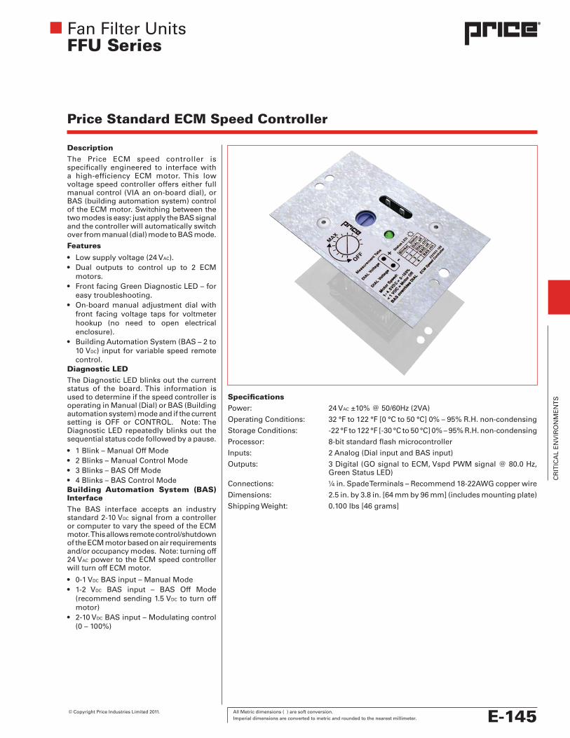
DescriptionThe Price ECM speed controller is specifically engineered to interface with a high-efficiency ECM motor. This low voltage speed controller offers either full manual control (VIA an on-board dial), or BAS (building automation system) control of the ECM motor. Switching between the two modes is easy: just apply the BAS signal and the controller will automatically switch over from manual (dial) mode to BAS mode.
Features
• Lowsupplyvoltage(24VAC).• Dual outputs to control up to 2 ECM
motors.• FrontfacingGreenDiagnosticLED–for
easy troubleshooting.• On-boardmanual adjustment dialwith
front facing voltage taps for voltmeter hookup (no need to open electrical enclosure).
• BuildingAutomationSystem(BAS–2to10 VDC) input for variable speed remote control.
Diagnostic LEDThe Diagnostic LED blinks out the current status of the board. This information is used to determine if the speed controller is operating in Manual (Dial) or BAS (Building automation system) mode and if the current setting is OFF or CONTROL. Note: The Diagnostic LED repeatedly blinks out the sequential status code followed by a pause.
• 1Blink–ManualOffMode• 2Blinks–ManualControlMode• 3Blinks–BASOffMode• 4Blinks–BASControlModeBuilding Automation System (BAS) InterfaceThe BAS interface accepts an industry standard 2-10 VDC signal from a controller or computer to vary the speed of the ECM motor. This allows remote control/shutdown of the ECM motor based on air requirements and/or occupancy modes. Note: turning off 24 VAC power to the ECM speed controller will turn off ECM motor.
• 0-1VDC BAS input – Manual Mode• 1-2 VDC BAS input – BAS Off Mode
(recommend sending 1.5 VDC to turn off motor)
• 2-10VDC BAS input – Modulating control (0 – 100%)
Price Standard ECM Speed Controller
SpecificationsPower: 24 VAC ±10% @ 50/60Hz (2VA)
Operating Conditions: 32 °F to 122 °F [0 °C to 50 °C] 0% – 95% R.H. non-condensing
Storage Conditions: -22 °F to 122 °F [-30 °C to 50 °C] 0% – 95% R.H. non-condensing
Processor: 8-bit standard flash microcontroller
Inputs: 2 Analog (Dial input and BAS input)
Outputs: 3 Digital (GO signal to ECM, Vspd PWM signal @ 80.0 Hz, Green Status LED)
Connections: ¼ in. Spade Terminals – Recommend 18-22AWG copper wire
Dimensions: 2.5 in. by 3.8 in. [64 mm by 96 mm] (includes mounting plate)
Shipping Weight: 0.100 lbs [46 grams]
© Copyright Price Industries Limited 2011. All Metric dimensions ( ) are soft conversion. Imperial dimensions are converted to metric and rounded to the nearest millimeter. E-145
CR
ITIC
AL
EN
VIR
ON
ME
NT
S

Fan Filter UnitsFFU Series
DescriptionThe Price Deluxe ECM speed controller works with a high efficiency ECM motor. This low voltage (24 VAC) speed control allows full manual (push button adjust) or BAS (2-10 VDC signal) control of the ECM motor.
Features:
• Dual outputs for controlling 2 ECMmotors (Note: Both motors will receive the same signal.)
• Red three-digit digital display forreading out:
a) Speed 0-100% b) Motor RPM (for motor number 1 only) c) BAS input voltage (Digital readout of
incoming BAS voltage signal.)• Building Automation System input
(2-10 VDC) for remote control
LED Digital Display The Digital Display shows the user several modes of operation. This allows for easier and more precise field adjustment and troubleshooting.
By pressing both the UP and DOWN push buttons at the same time the user can cycle between the following modes:
1) Speed Adjustment – is easier and more precise with the digital display and push buttons than with a standard dial.
2) Motor RPM – displays the real time motor speed to aid in troubleshooting.
3) BAS input voltage – displays the input voltage signal from the building automation system (BAS). Note: any BAS voltage signal above 1 VDC overrides local speed control.
Important Information Regarding the ECM MotorDo not switch 120/208/240/277 VAC power to turn ECM motor on and off. Instead control the 24 VAC signal or BAS signal to turn the ECM motor on and off. The ECM motor has large capacitors that charge quickly on mains power up. Switching on several motors frequently could reduce building power quality and is not recommended.
Display Mode Range Spd Manual Speed Adjust Mode 0-100 %
rPn Shows current RPM of ECM motor #1 0-1350 RPM
bAS BAS Mode – Voltage Signal 2-10 VDC
Deluxe ECM Speed Controller
SpecificationsPower: 24 VAC ±10% @ 50/60Hz (2VA)
Operating Conditions: 32 °F to 122 °F [0 °C to 50 °C] 0% – 95% R.H. non-condensing
Storage Conditions: -22 °F to 122 °F [-30 °C to 50 °C] 0% – 95% R.H. non-condensing
Processor: 8-bit enhanced flash microcontroller
Inputs: 1 Analog and 3 digital inputs
Outputs: 2 Digital (GO signal to ECM and Vspd PWM signal @ 80.0 Hz)
Connections: ¼ in. Spade Terminals – Recommend 18-22AWG copper wire
Dimensions: 2.8 in. by 3.8 in. [71 mm by 96 mm] (includes mounting plate)
Shipping Weight: 0.220 lbs, 100 grams
E-146 All Metric dimensions ( ) are soft conversion. © Copyright Price Industries Limited 2011. Imperial dimensions are converted to metric and rounded to the nearest millimeter.
CR
ITIC
AL
EN
VIR
ON
ME
NT
S

Fan Filter UnitsFFU Series
Product Options
ECM Wall Mounted Control
ECMDX Wall Control
PSC Wall Mounted ControlWall Mounted Speed Control Kit Option - WKThe Wall Mounted Speed Control Kit is provided for customer convenience when air flow adjustment is required from the occupied zone without the use of any tools.
When WK is provided there is no need to access the FFU unit directly. The WK kit can be easily installed in the field by a qualified electrician – instructions are included in the installation manual. The WK kit will be provided in 3 different styles to match motor selection:
• WKkitforECMmotoruses24VAC and comes supplied with approximately 1 ft of cable soldered to the controller and to the wall-mount for field installation in a field supplied junction box. The wall-mounted potentiometer is supplied loose in addition to a standard ECM speed controller mounted on the FFU unit. This potentiometer has to be wired to the speed controller by matching the coordinated wire colors. As opposed to a standard speed controller, the WK kit is easily accessible and can be adjusted by a user without a screw driver.
• WKkitforECMmotorandPriceDeluxeSpeedControlleruses24VAC and comes supplied with approximately 2 ft of cable connected to the speed controller, to be field installed in a field supplied junction box. This WK kit also comes with a 2 ft cable with connector to attach to the ECM motor, and must be field wired by a qualified electrician. In total, 8 wires should be run in the conduit; 6 for motor control, and 2 for 24 VAC. The WK kit is supplied loose in place of a speed controller usually mounted on the FFU unit. This option will also display motor RPM, giving the user an indication of how the FFU is responding to control.
• WK kit for PSC Motor is high voltage and, as such, requires field suppliedconduit and junction box. It is supplied loose for field installation in place of a speed controller usually located on the FFU unit. As opposed to standard speed controller, it is easily accessible and comes with a knob that can be adjusted without the use of a screw driver.
© Copyright Price Industries Limited 2011. All Metric dimensions ( ) are soft conversion. Imperial dimensions are converted to metric and rounded to the nearest millimeter. E-147
CR
ITIC
AL
EN
VIR
ON
ME
NT
S

Critical Environments Suggested Specification
Fan Filter Units
FFU-HC – High Capacity Fan Filter Unit
PART 1 – GENERAL
1.01 Module shall be furnished with a bench-top replaceable, UL900 certified HEPA (minimum 99.99% efficiency on 0.3µm particle size) or ULPA (minimum 99.9995% efficiency on 0.12µm particle size) high efficiency filter.
1.02 Module sizes, power requirements, efficiencies, capacities and options shall be as scheduled.
PART 2 – PRODUCTS
A. Performance
1. The discharge sound level shall be less than 55dBA when measured at 30 in. from filter face at 90 fpm (average face velocity).
2. The filter shall be PAO scan tested post assembly to assure leakage is consistent with an uncompromised filter.
B. Construction
1. Filters shall be framed in an aluminum housing which is integral to the plenum.
2. Modules to be provided with an expanded-metal perforated face protecting the downstream side of the filter.
3. Plenum construction shall be mill finish, 0.063” aluminum.
4. Inlet shall include a 25 – 30% MERV 4 washable pre-filter.
5. Unit shall be provided with eyebolts at each plenum corner for support from above.
6. Plenum shall be walkable up to 250lbs.
7. Motor/blower to be direct drive with thermally protected PSC or constant flow programmed ECM style motor and manufacturedin North America. Motor/blower assembly shall be accessible and removable from the top of the unit. Solid state speed control shall be provided.
o Units specified with ECM style motor shall have BAS Interface to accept industry standard 2 – 10VDC signal for variable speed remote control.
8. Unit shall be ETL Certified to:
o UL 507, unit shall be lined with urethane foam for additional noise attenuation.
o UL 1995, unit shall be lined with plenum-rated elastomeric insulation tested to ASTM E84, having a flame spread index of less than 25 and a smoke developed index of less than 50.
Options (If Specified) • Ducted units shall be providedwith either a 10” or 12” round inlet, and an optional 25-30% MERV 4 washable pre- filter
• UnitshallprovideoperationstatussignaltoaBASthrough factory mounted contacts.
• Unitshallbeprovidedwithwallmountedspeedcontrol potentiometer shipped loose for field installation.
• Unitshallbeprovidedwithwallmountedspeedcontrol with digital display capable of reading out Speed (0-100%), Motor RPM and BAS Input Voltage Signal.
• UnitshallbeprovidedwithLEDFilterIndicatorlightthat turns from green to yellow when the pressure drop across the filter becomes 1.5 times the pressure drop of a clean filter. LED operation shall be unaffected by room pressure changes.
• UnitshallbeprovidedwithLEDMotorIndicatorlightthat turns from green to red if the motor stops running.
• UnitshallprovidemotoroperationstatussignaltoaBAS through factory mounted contacts.
• Unitshallbeprovidedwithwallmountedspeedcontrol potentiometer shipped loose for field installation.
• Unitshallbeprovidedwithwallmountedspeedcontrol with digital display capable of reading out Speed (0-100%), Motor RPM and BAS Input Voltage Signal.
• Motor/blowerassemblyshallbeaccessibleandremovable from the room side.
• UnitshallbeprovidedwithaSimco-Ionmodel5685ionbar
• Unitconstructionshallbe0.035”,304stainlesssteel.
© Copyright Price Industries Limited 2011. All Metric dimensions ( ) are soft conversion. Imperial dimensions are converted to metric and rounded to the nearest millimeter. E-199
CR
ITIC
AL
EN
VIR
ON
ME
NT
S

Critical Environments Suggested Specification
Fan Filter Units
FFU/FFUSS - Room-Side Replaceable Fan Filter UnitGeneral • Moduleshallbefurnishedwithroomsidereplaceable,UL900 certified HEPA (minimum 99.99% efficiency on 0.3µm particle size) or ULPA (minimum 99.9995% efficiency on 0.12µm particle size) high efficiency filter with gel seal frame.
• Modulesizes,powercharacteristics,efficiencies,capacities and options shall be as scheduled on the drawings.
Performance • Thedischargesoundlevelshallbelessthan55dBAwhen measured at 30 in. from filter face at 90 fpm (average face velocity).
• TheunitistobefactorysealedandPAOtestedtoassure leakage is consistent with the filter.
Construction • Filtersshallbeframedinextrudedaluminumandprovided with a gel knife-edge seal.
• Modulestobeprovidedwithaluminumperforatedlaminar flow face with quarter-turn fasteners.
• Plenumshallbeconstructedwith0.063inaluminumand have a powder coat pain finish tested to ASTM D1654, ASTM D610 and ASTM D714.
• Inletincludesa25–30%MERV4washablepre-filter
• Unitshallbeprovidedwithstaticpressure/aerosolsample port in the knife-edge frame.
• Unitshallbeprovidedwitheyeboltsateachplenumcorner for support from above.
• Aluminumplenumsshallbewalkableupto250lbs
• Motor/blowertobedirectdrivewiththermallyprotectedPSC or constant flow programmed ECM style motor, and manufactured in North America. Motor/blower assembly shall be accessible and removable from the top of the unit. Solid state speed control shall be provided.
o Units specified with ECM style motor shall have BAS Interface to accept industry standard 2 – 10VDC signal for variable speed remote control.
• UnitshallbeETLCertifiedto:
o UL 507, unit shall be lined with urethane foam for additional noise attenuation.
o UL 1995, unit shall be lined with plenum-rated elastomeric insulation tested to ASTM E84, having a flame spread index of less than 25 and a smoke developed index of less than 50.
Options (If Specified) • Ducted units shall be providedwith either a 10” or 12” round inlet, and an optional 25-30% MERV 4 washable pre- filter
• UnitshallbeprovidedwithLEDFilterIndicatorlightthat turns from green to yellow when the pressure drop across the filter becomes 1.5 times the pressure drop of a clean filter. LED operation shall be unaffected by room pressure changes.
• UnitshallbeprovidedwithLEDMotorIndicatorlightthat turns from green to red if the motor stops running.
• UnitshallprovidemotoroperationstatussignaltoaBAS through factory mounted contacts.
• Unitshallbeprovidedwithwallmountedspeedcontrol potentiometer shipped loose for field installation.
• Unitshallbeprovidedwithwallmountedspeedcontrol with digital display capable of reading out Speed (0-100%), Motor RPM and BAS Input Voltage Signal.
• Motor/blowerassemblyshallbeaccessibleandremovable from the room side.
• UnitshallbeprovidedwithaSimco-Ionmodel5685ionbar
• Unitconstructionshallbe0.035”,304stainlesssteel.
E-200 All Metric dimensions ( ) are soft conversion. © Copyright Price Industries Limited 2011. Imperial dimensions are converted to metric and rounded to the nearest millimeter.
CR
ITIC
AL
EN
VIR
ON
ME
NT
S
Related Documents