Chemical and Process Engineering 2013, 34 (2), 293-307 DOI: 10.2478/cpe-2013-0024 *Corresponding author, e-mail: [email protected] 293 EFFECT OF SOME DESIGN PARAMETERS ON THE FLOW FIELDS AND POWER CONSUMPTION IN A VESSEL STIRRED BY A RUSHTON TURBINE Sarra Youcefi * , Mohamed Bouzit, Houari Ameur, Youcef Kamla and Abdelkader Youcefi Laboratoire de Mécanique Appliquée, Faculté de Génie Mécanique, USTO-MB 1505 El M’naouar, Oran, Algérie Knowledge of the fluid dynamic characteristics in a stirred vessel is essential for reliable design and scale-up of a mixing system. In this paper, 3D hydrodynamics in a vessel agitated by a Rushton turbine were numerically studied (with the help of a CFD computer program (CFX 13.0)). The study was carried out covering a wide Reynolds number range: 10 4 – 10 5 . Computations, based on control volume method, were made using the k-ε model. Our main purpose was to investigate the effect of vessel configuration and agitation rates on the flow structure and power consumption. Three types of vessels were used: unbaffled, baffled and a vessel with slots placed at the external perimeter of its vertical wall. The effect of slot length has been investigated. The comparison of our predicted results with available experimental data shows a satisfactory agreement. Keywords: CFD modeling, mixing, cylindrical tank, internal baffles, external slots, vortex 1. INTRODUCTION Stirred tanks are encountered in many operations in process industries, employed to carry out a variety of mixing tasks at different stages that lead from raw materials to the desired final product. Efficient design of stirred tank reactors requires knowledge of the hydrodynamic behavior of the flows in such apparatuses. To date, many efforts have been made in order to obtain data both by experimental and computational techniques (Bo et al., 2006; Ducci and Yianneskis, 2007; Escudie and Line, 2003; Escudie et al., 2004; Gabriele et al., 2009; Galletti et al., 2003; Mavros, 2001; Mahmud et al., 2009; Nikiforaki et al., 2003; Roy et al., 2010; Yeoh et al., 2004; Yoon et al., 2005). Trailing vortices behind rotating blades, vortices behind baffles and large recirculation zones in the bulk of the tank flow affect strongly mixing quality, power consumption and circulation times. These flow structures are very complex, and were studied by many researchers. Fentiman et al. (1999) using Laser–Doppler Anemometry angle-resolved measurements comprehensively investigated the velocity characteristics of a trailing vortex structure produced by the blades of a profiled blade impeller. Their results showed that the axes of the vortices generated by all three impeller blades remain at essentially a constant radius of 0.14 T, and the inclination of the axes to the horizontal plane is about 13°. The turbulence levels in the region dominated by the vortices are an order of magnitude higher than elsewhere in the vessel and the turbulence in the vicinity of the vortices is mostly anisotropic. vortices provide a potentially very useful source of turbulence generation in the vessel which could be

Welcome message from author
This document is posted to help you gain knowledge. Please leave a comment to let me know what you think about it! Share it to your friends and learn new things together.
Transcript
Chemical and Process Engineering 2013, 34 (2), 293-307
DOI: 10.2478/cpe-2013-0024
*Corresponding author, e-mail: [email protected]
293
EFFECT OF SOME DESIGN PARAMETERS ON THE FLOW FIELDS AND POWER CONSUMPTION IN A VESSEL STIRRED BY
A RUSHTON TURBINE
Sarra Youcefi*, Mohamed Bouzit, Houari Ameur, Youcef Kamla and Abdelkader Youcefi
Laboratoire de Mécanique Appliquée, Faculté de Génie Mécanique, USTO-MB 1505 El M’naouar, Oran, Algérie
Knowledge of the fluid dynamic characteristics in a stirred vessel is essential for reliable design and scale-up of a mixing system. In this paper, 3D hydrodynamics in a vessel agitated by a Rushton turbine were numerically studied (with the help of a CFD computer program (CFX 13.0)). The study was carried out covering a wide Reynolds number range: 104 – 105. Computations, based on control volume method, were made using the k-ε model. Our main purpose was to investigate the effect of vessel configuration and agitation rates on the flow structure and power consumption. Three types of vessels were used: unbaffled, baffled and a vessel with slots placed at the external perimeter of its vertical wall. The effect of slot length has been investigated. The comparison of our predicted results with available experimental data shows a satisfactory agreement.
Keywords: CFD modeling, mixing, cylindrical tank, internal baffles, external slots, vortex
1. INTRODUCTION
Stirred tanks are encountered in many operations in process industries, employed to carry out a variety of mixing tasks at different stages that lead from raw materials to the desired final product. Efficient design of stirred tank reactors requires knowledge of the hydrodynamic behavior of the flows in such apparatuses. To date, many efforts have been made in order to obtain data both by experimental and computational techniques (Bo et al., 2006; Ducci and Yianneskis, 2007; Escudie and Line, 2003; Escudie et al., 2004; Gabriele et al., 2009; Galletti et al., 2003; Mavros, 2001; Mahmud et al., 2009; Nikiforaki et al., 2003; Roy et al., 2010; Yeoh et al., 2004; Yoon et al., 2005).
Trailing vortices behind rotating blades, vortices behind baffles and large recirculation zones in the bulk of the tank flow affect strongly mixing quality, power consumption and circulation times. These flow structures are very complex, and were studied by many researchers. Fentiman et al. (1999) using Laser–Doppler Anemometry angle-resolved measurements comprehensively investigated the velocity characteristics of a trailing vortex structure produced by the blades of a profiled blade impeller. Their results showed that the axes of the vortices generated by all three impeller blades remain at essentially a constant radius of 0.14 T, and the inclination of the axes to the horizontal plane is about 13°. The turbulence levels in the region dominated by the vortices are an order of magnitude higher than elsewhere in the vessel and the turbulence in the vicinity of the vortices is mostly anisotropic. vortices provide a potentially very useful source of turbulence generation in the vessel which could be
S. Youcefi, M. Bouzit, H. Ameur, Y. Kamla, A. Youcefi, Chem. Process Eng., 2013, 34 (2), 293-307
294
harnessed to optimise blending and homogenisation of miscible fluids in stirred vessels, for example through a selection of feed pipe locations.
Ducci and Yianneskis (2007) have shown that mixing times in reactors stirred by radial impellers can be reduced by 20–30% when feed insertion is made in the vortex core of precessional flow structures, denoted as macro-instabilities (MIs). The aim of the work of Doulgeraki et al. (2009) was to investigate the interaction between large-scale flow structures, such as MIs and trailing vortices, and assess to which extent local mixing might be affected by their combined activity. It was shown that the combined presence of the trailing vortex and MI structures in the impeller vicinity results in energy levels that are substantially enhanced and thus locations showing further promise for feed insertion and mixing enhancement may be identified.
Bujalski et al. (1987) for the Rushton turbine and Beshay et al. (2001) for a standard Rushton turbine and a pitched blade turbine show that significant influence of the separating disk thickness of the turbine impeller corresponds fairly well to some empirical equations.
Jing et al. (2011) used Particle Image Velocimetry technique to analyse trailing vortices and elucidate their relationship with turbulence properties in a stirred tank of 0.48 m diameter, agitated by four different disc turbines, including a Rushton turbine, a concaved blade disk turbine, a half elliptical blade disk turbine, and a parabolic blade disk turbine. Results showed that the blade shape had a great effect on trailing vortex characteristics: a the larger curvature resulted in longer residence time of the vortex at the impeller tip, a bigger distance between the upper and lower vortices and a longer vortex life, also leading to smaller and stronger vortices. In addition, high turbulent kinetic energy and turbulent energy dissipation regions were located between the upper and lower vortices.
In a mixing system, the quality of flow generated by the impeller mainly depends upon the impeller design and interaction of flow with the vessel wall (Kumaresan et al., 2006). In classical geometry, agitated vessels are fitted with baffles which are generally used in transitional and turbulent flow regimes. Many agitated vessels use standard wall baffles which consist of four flat vertical plates, directed radially, spaced at 900 intervals around the vessel periphery, starting at the bottom tangent line of the lower vessel head and running the length of the vessel side to the top tangent line of the upper head. Most vessels have at least three baffles, with four being the most common, often referred to as a fully baffled condition (Torré et al., 2007).
Because, the rotating impeller imparts a tangential motion to the liquid and if no baffles are used, the bulk fluid undergoes a swirling motion which approximates solid-body rotation (Alcamo et al., 2005). The fluid moves along circular trajectories with high circumferential velocity creating poor mixing and a vortex is created at the free surface (Torré et al., 2007). The fully baffled condition destroys the vortex, keeping the free surface flat (Ranade, 1997), leading to an improved mixing rate and the swirling flow is converted into a preferred flow pattern desirable for process objectives, such as axial flow for blending and solids suspension, or radial flow for dispersions (Myers et al., 2002).
This paper reports a computational investigation into the hydrodynamics of a cylindrical vessel agitated by a Rushton turbine. Our main was focused on the effects of vessel configuration on flow structures and power consumption. It concerns the effects of baffles and slots on the size of vortices. Interestingly, this topic has not been investigated before.
2. DESCRIPTION OF THE STIRRED SYSTEM
The mixing system employed in the present study consists of a vessel stirred by a Rushton turbine. The vessel has a cylindrical shape with a flat bottom. The liquid height (H) is equal to the vessel diameter (D), D = 150 mm. Water at 25 °C (density = 997 kg/m3, dynamic viscosity = 0.00089 kg/ms) was used
Effect of some design parameters on the flow fields and power consumption ...
295
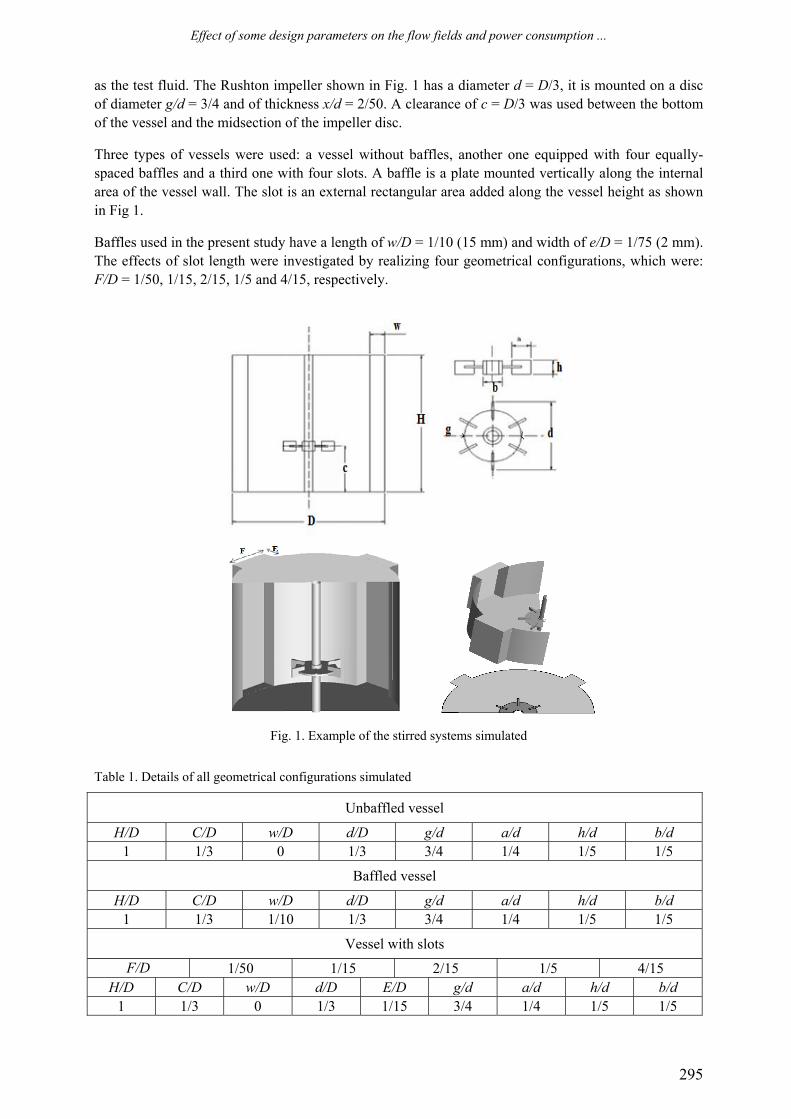
as the test fluid. The Rushton impeller shown in Fig. 1 has a diameter d = D/3, it is mounted on a disc of diameter g/d = 3/4 and of thickness x/d = 2/50. A clearance of c = D/3 was used between the bottom of the vessel and the midsection of the impeller disc.
Three types of vessels were used: a vessel without baffles, another one equipped with four equally-spaced baffles and a third one with four slots. A baffle is a plate mounted vertically along the internal area of the vessel wall. The slot is an external rectangular area added along the vessel height as shown in Fig 1.
Baffles used in the present study have a length of w/D = 1/10 (15 mm) and width of e/D = 1/75 (2 mm). The effects of slot length were investigated by realizing four geometrical configurations, which were: F/D = 1/50, 1/15, 2/15, 1/5 and 4/15, respectively.
Fig. 1. Example of the stirred systems simulated
Table 1. Details of all geometrical configurations simulated
Unbaffled vessel
H/D C/D w/D d/D g/d a/d h/d b/d 1 1/3 0 1/3 3/4 1/4 1/5 1/5
Baffled vessel
H/D C/D w/D d/D g/d a/d h/d b/d 1 1/3 1/10 1/3 3/4 1/4 1/5 1/5
Vessel with slots F/D 1/50 1/15 2/15 1/5 4/15
H/D C/D w/D d/D E/D g/d a/d h/d b/d 1 1/3 0 1/3 1/15 3/4 1/4 1/5 1/5
S. Youcefi, M. Bouzit, H. Ameur, Y. Kamla, A. Youcefi, Chem. Process Eng., 2013, 34 (2), 293-307
296
3. THEORETICAL BACKGROUND
In this study, the Reynolds number is varying from 104 to 9.104. The standard k-ε model is used for modeling the turbulent flow. Chtourou et al. (2011) studied the effect of turbulence models on Rushton turbine generated flow in a stirred vessel. They investigated the standard k-ε model, the RNG k-ε model, the realizable k-ε model and the RSM model. Their study demonstrated that the RNG k-ε model takes into account small scale effects in isotropic coefficients calculated explicitly. Thus, it seems to be the most appropriate one as it enables to directly calculate the specifications of the turbulence.
By using different Reynolds-averaged turbulence models and the CFX computer code, Ciofalo et al. (1996) conducted numerical simulations of turbulent fluid flow in unbaffled tanks stirred by single-stage radial impellers. Their results showed that only the use of a second-order Reynolds stress transport model allowed to achieve a correct prediction of the main flow characteristics, and, in particular, of radial profiles of the tangential velocity, whereas the k–ε model yielded an almost rigid-body motion with unphysical profiles of tangential velocity increasing monotonically from the rotation axis to the peripheral wall.
Alopaeus et al. (2009) reported in their paper that no significant differences were observed between the SST and k-ε models except at the regions of highest turbulence dissipation, where SST predicts lower dissipation levels than k-ε.
By using the k-ε model, Baccar and Abid (1999) showed that their numerical prediction has given a good representation of the hydrodynamics and the turbulence characteristics of flows in a stirred tank. However, the k–ε model presents some limitations. It is a two-transport-equation model providing solutions for kinetic energy (k) and turbulent dissipation (ε). Turbulent dissipation is the rate at which velocity fluctuations dissipate. This is the default k–ε model: coefficients are empirically derived and valid for fully turbulent flows only. In the standard k-ε model, the eddy viscosity is determined from a single turbulence length scale, so the calculated turbulent diffusion is that which occurs only at a specified scale, whereas in reality all scales of motion will contribute to turbulent diffusion.
The Reynolds number for the flow in a stirred vessel is defined as:
2NDRe ρ
η= (1)
where N is the impeller rotational speed, η the viscosity of working fluid and ρ the fluid density.
All results are presented in a dimensionless form: • The radial (R) and axial (Z) coordinates are written in a dimensionless form as follows:
R*= 2R/D, Z* = Z/D (2)
• The tangential (Vθ), radial (Vr) and axial (Vz) velocities are normalised as follows:
/ , / , /* * *
tip r r tip z z tip
tip
V V V V V V V V V
V NDθ θ
π
= = =
= (3)
The power consumption used for mixing, P, can be calculated using two methods. The first one integrates the viscous dissipation energy, Qv, in the whole vessel volume:
vvessel volume
P Q dvη= ∫ (4)
The element dv is written as:
dv r dr d dzθ= (5)
Effect of some design parameters on the flow fields and power consumption ...
297
2 22 2 2 2
2 r z r r z r zv
dV dVdV dV dV dV dV dV dVQdR d dZ d dR dZ d dZ dR
θ θ
θ θ θ⎡ ⎤⎛ ⎞ ⎡ ⎤⎛ ⎞ ⎛ ⎞ ⎡ ⎤ ⎡ ⎤= + + + + + + + +⎢ ⎥⎜ ⎟ ⎜ ⎟⎜ ⎟ ⎢ ⎥⎢ ⎥ ⎢ ⎥⎝ ⎠ ⎝ ⎠ ⎣ ⎦ ⎣ ⎦⎝ ⎠ ⎣ ⎦⎢ ⎥⎣ ⎦
(6)
The second methodology uses the torque, C, applied on the agitation system as given in the following equation:
2P NCπ= (7)
The power number is calculated according to:
3 5PPN
N Dρ= (8)
4. NUMERICAL DETAILS
The present study is performed with the help a CFD computer program (CFX 13.0). CFX is a general purpose computer program using a finite volume method. Navier-Stokes equations written in a rotating, cylindrical frame of references are solved.
In the case of an unbaffled vessel, the rotating reference frame (RRF) technique is used. In this approach, the stirrer was kept stationary while the vessel walls were assigned an angular velocity, which was equal and opposite to the impeller rotational speed. The no-slip velocity condition was applied to all solid surfaces. Further details can be found elsewhere (Ameur et al., 2011).
In the case of agitated vessels involving baffles or slots, computational flow could nonetheless have been easily achieved with an MRF (Naude, 1998) or sliding meshes approaches.
For the MRF (Multiple Reference Frame) technique, the computational grid consists of two parts: an inner rotating cylindrical volume enclosing the turbine, and an outer, stationary volume containing the rest of the tank.
However, the sliding mesh approach (Luo et al., 1993) is to divide the computational domain into two meshes, one moving with the impeller while the other one is fixed. The two meshes interact along a common surface of slip, which is defined by artificial boundary faces. The moving mesh is allowed to shear and slide successively relative to the stationary mesh along the interface. In our study, the MRF approach was used for the vessel with baffles or slots.
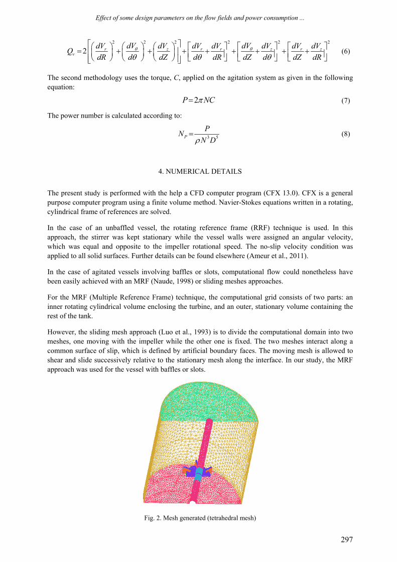
Fig. 2. Mesh generated (tetrahedral mesh)
S. Youcefi, M. Bouzit, H. Ameur, Y. Kamla, A. Youcefi, Chem. Process Eng., 2013, 34 (2), 293-307
298
With the help of the ICEM CFD 13.0 software, the domain was discretised using an unstructured tetrahedral mesh (Fig. 2). A refined mesh has been created in the vicinity of impeller and near the vessel walls. The mesh size was selected based on details given by Haque et al. (2006).
Results were considered converged when a lower level of residual, of the order of 10−7, was reached and the field values were almost identical over the last 400 iterations. The simulations were run on a Pentium Core i7 with 8 Gb of RAM and a typical run time was 7 h.
5. RESULTS AND DISCUSSION
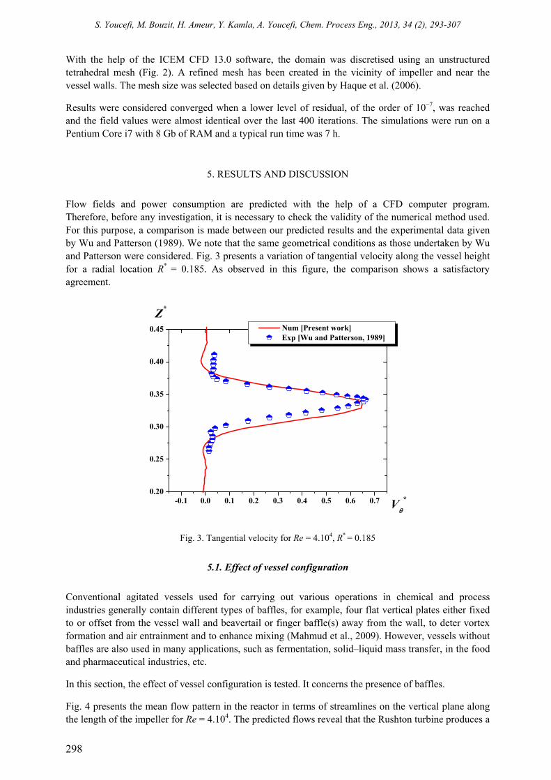
Flow fields and power consumption are predicted with the help of a CFD computer program. Therefore, before any investigation, it is necessary to check the validity of the numerical method used. For this purpose, a comparison is made between our predicted results and the experimental data given by Wu and Patterson (1989). We note that the same geometrical conditions as those undertaken by Wu and Patterson were considered. Fig. 3 presents a variation of tangential velocity along the vessel height for a radial location R* = 0.185. As observed in this figure, the comparison shows a satisfactory agreement.
-0.1 0.0 0.1 0.2 0.3 0.4 0.5 0.6 0.70.20
0.25
0.30
0.35
0.40
0.45
Z*
Vθ
*
Num [Present work] Exp [Wu and Patterson, 1989]
Fig. 3. Tangential velocity for Re = 4.104, R* = 0.185
5.1. Effect of vessel configuration
Conventional agitated vessels used for carrying out various operations in chemical and process industries generally contain different types of baffles, for example, four flat vertical plates either fixed to or offset from the vessel wall and beavertail or finger baffle(s) away from the wall, to deter vortex formation and air entrainment and to enhance mixing (Mahmud et al., 2009). However, vessels without baffles are also used in many applications, such as fermentation, solid–liquid mass transfer, in the food and pharmaceutical industries, etc.
In this section, the effect of vessel configuration is tested. It concerns the presence of baffles.
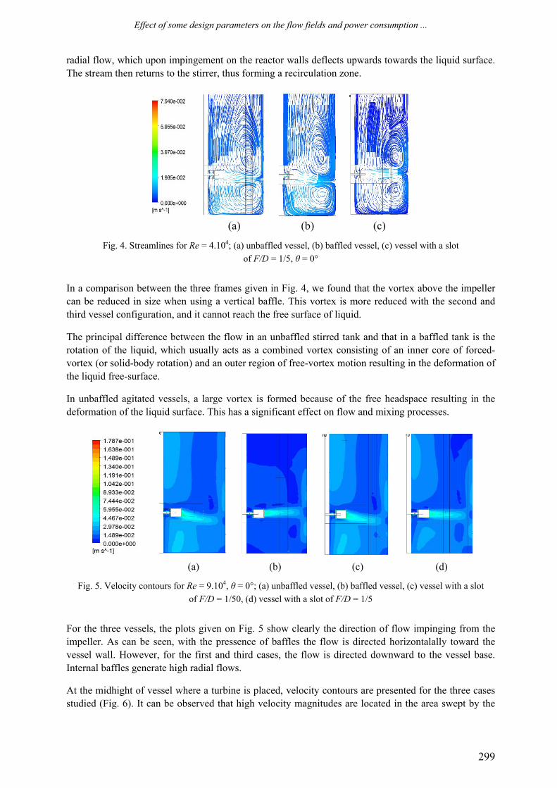
Fig. 4 presents the mean flow pattern in the reactor in terms of streamlines on the vertical plane along the length of the impeller for Re = 4.104. The predicted flows reveal that the Rushton turbine produces a
Effect of some design parameters on the flow fields and power consumption ...
299
radial flow, which upon impingement on the reactor walls deflects upwards towards the liquid surface. The stream then returns to the stirrer, thus forming a recirculation zone.
(a) (b) (c)
Fig. 4. Streamlines for Re = 4.104; (a) unbaffled vessel, (b) baffled vessel, (c) vessel with a slot of F/D = 1/5, θ = 0°
In a comparison between the three frames given in Fig. 4, we found that the vortex above the impeller can be reduced in size when using a vertical baffle. This vortex is more reduced with the second and third vessel configuration, and it cannot reach the free surface of liquid.
The principal difference between the flow in an unbaffled stirred tank and that in a baffled tank is the rotation of the liquid, which usually acts as a combined vortex consisting of an inner core of forced-vortex (or solid-body rotation) and an outer region of free-vortex motion resulting in the deformation of the liquid free-surface.
In unbaffled agitated vessels, a large vortex is formed because of the free headspace resulting in the deformation of the liquid surface. This has a significant effect on flow and mixing processes.
(a) (b) (c) (d)
Fig. 5. Velocity contours for Re = 9.104, θ = 0°; (a) unbaffled vessel, (b) baffled vessel, (c) vessel with a slot of F/D = 1/50, (d) vessel with a slot of F/D = 1/5
For the three vessels, the plots given on Fig. 5 show clearly the direction of flow impinging from the impeller. As can be seen, with the pressence of baffles the flow is directed horizontalally toward the vessel wall. However, for the first and third cases, the flow is directed downward to the vessel base. Internal baffles generate high radial flows.
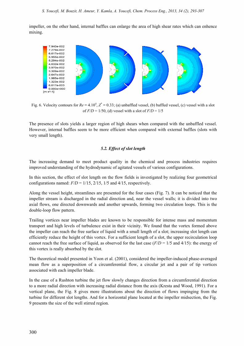
At the midhight of vessel where a turbine is placed, velocity contours are presented for the three cases studied (Fig. 6). It can be observed that high velocity magnitudes are located in the area swept by the
S. Youcefi, M. Bouzit, H. Ameur, Y. Kamla, A. Youcefi, Chem. Process Eng., 2013, 34 (2), 293-307
300
impeller, on the other hand, internal baffles can enlarge the area of high shear rates which can enhence mixing.
Fig. 6. Velocity contours for Re = 4.104, Z* = 0.33; (a) unbaffled vessel, (b) baffled vessel, (c) vessel with a slot of F/D = 1/50, (d) vessel with a slot of F/D = 1/5
The presence of slots yields a larger region of high shears when compared with the unbaffled vessel. However, internal baffles seem to be more efficient when compared with external baffles (slots with very small length).
5.2. Effect of slot length
The increasing demand to meet product quality in the chemical and process industries requires improved understanding of the hydrodynamic of agitated vessels of various configurations.
In this section, the effect of slot length on the flow fields is investigated by realizing four geometrical configurations named: F/D = 1/15, 2/15, 1/5 and 4/15, respectively.
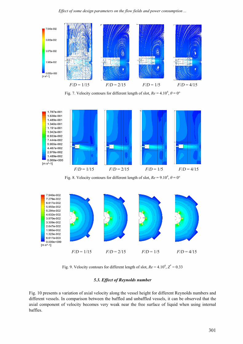
Along the vessel height, streamlines are presented for the four cases (Fig. 7). It can be noticed that the impeller stream is discharged in the radial direction and, near the vessel walls; it is divided into two axial flows, one directed downwards and another upwards, forming two circulation loops. This is the double-loop flow pattern.
Trailing vortices near impeller blades are known to be responsible for intense mass and momentum transport and high levels of turbulence exist in their vicinity. We found that the vortex formed above the impeller can reach the free surface of liquid with a small length of a slot; increasing slot length can efficiently reduce the height of this vortex. For a sufficient length of a slot, the upper recirculation loop cannot reach the free surface of liquid, as observed for the last case (F/D = 1/5 and 4/15): the energy of this vortex is really absorbed by the slot.
The theoretical model presented in Yoon et al. (2001), considered the impeller-induced phase-averaged mean flow as a superposition of a circumferential flow, a circular jet and a pair of tip vortices associated with each impeller blade.
In the case of a Rushton turbine the jet flow slowly changes direction from a circumferential direction to a more radial direction with increasing radial distance from the axis (Kresta and Wood, 1991). For a vertical plane, the Fig. 8 gives more illustrations about the direction of flows impinging from the turbine for different slot lengths. And for a horizontal plane located at the impeller midsection, the Fig. 9 presents the size of the well stirred region.
Effect of some design parameters on the flow fields and power consumption ...
301
F/D = 1/15 F/D = 2/15 F/D = 1/5 F/D = 4/15
Fig. 7. Velocity contours for different length of slot, Re = 4.104, θ = 0°
F/D = 1/15 F/D = 2/15 F/D = 1/5 F/D = 4/15
Fig. 8. Velocity contours for different length of slot, Re = 9.104, θ = 0°
F/D = 1/15 F/D = 2/15 F/D = 1/5 F/D = 4/15
Fig. 9. Velocity contours for different length of slot, Re = 4.104, Z* = 0.33
5.3. Effect of Reynolds number
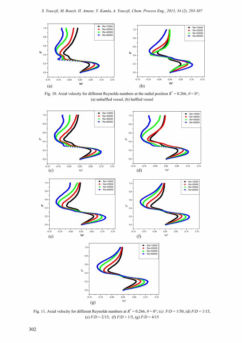
Fig. 10 presents a variation of axial velocity along the vessel height for different Reynolds numbers and different vessels. In comparison between the baffled and unbaffled vessels, it can be observed that the axial component of velocity becomes very weak near the free surface of liquid when using internal baffles.
S. Youcefi, M. Bouzit, H. Ameur, Y. Kamla, A. Youcefi, Chem. Process Eng., 2013, 34 (2), 293-307
302
Fig. 10. Axial velocity for different Reynolds numbers at the radial position R* = 0.266, θ = 0°;
(a) unbaffled vessel, (b) baffled vessel
Fig. 11. Axial velocity for different Reynolds numbers at R* = 0.266, θ = 0°; (c) F/D = 1/50, (d) F/D = 1/15,
(e) F/D = 2/15, (f) F/D = 1/5, (g) F/D = 4/15
-0,15 -0,10 -0,05 0,00 0,05 0,10 0,15
0,0
0,2
0,4
0,6
0,8
1,0
Z*
Vz*
Re=10000 Re=20000 Re=40000 Re=60000
-0,15 -0,10 -0,05 0,00 0,05 0,10 0,15
0,0
0,2
0,4
0,6
0,8
1,0
Z*
Vz*
Re=10000 Re=20000 Re=40000 Re=60000
-0,15 -0,10 -0,05 0,00 0,05 0,10 0,15
0,0
0,2
0,4
0,6
0,8
1,0
Z*
Vz*
Re=10000 Re=20000 Re=40000 Re=60000
-0,15 -0,10 -0,05 0,00 0,05 0,10 0,15
0,0
0,2
0,4
0,6
0,8
1,0
Z*
Vz*
Re=10000 Re=20000 Re=40000 Re=60000
-0,15 -0,10 -0,05 0,00 0,05 0,10 0,15
0,0
0,2
0,4
0,6
0,8
1,0
Z*
Vz*
Re=10000 Re=20000 Re=40000 Re=60000
-0,15 -0,10 -0,05 0,00 0,05 0,10 0,15
0,0
0,2
0,4
0,6
0,8
1,0
Z*
Vz*
Re=10000 Re=20000 Re=40000 Re=60000
-0,15 -0,10 -0,05 0,00 0,05 0,10 0,15
0,0
0,2
0,4
0,6
0,8
1,0
Z*
Vz*
Re=10000 Re=20000 Re=40000 Re=60000
(a) (b)
(c) (d)
(e) (f)
(g)
Effect of some design parameters on the flow fields and power consumption ...
303
Fig. 11 presents the slot effect on velocity magnitude. As illustrated, for F/D = 1/50, 1/15 and 2/15 the velocity is intense near the free surface of liquid, i.e. the vortex is present at this region. However, for the last two cases (1/5, 4/15) the velocity magnitude is very weak, which explains the dissipation of vortex at this region.
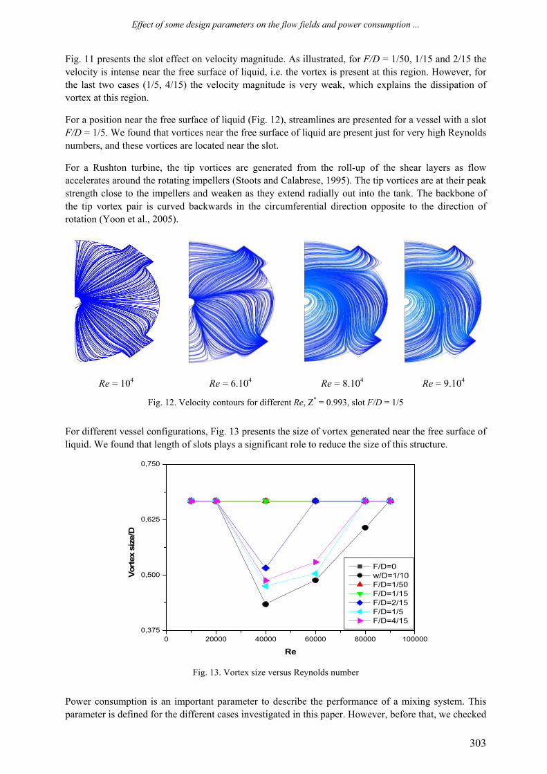
For a position near the free surface of liquid (Fig. 12), streamlines are presented for a vessel with a slot F/D = 1/5. We found that vortices near the free surface of liquid are present just for very high Reynolds numbers, and these vortices are located near the slot.
For a Rushton turbine, the tip vortices are generated from the roll-up of the shear layers as flow accelerates around the rotating impellers (Stoots and Calabrese, 1995). The tip vortices are at their peak strength close to the impellers and weaken as they extend radially out into the tank. The backbone of the tip vortex pair is curved backwards in the circumferential direction opposite to the direction of rotation (Yoon et al., 2005).
Re = 104
Re = 6.104
Re = 8.104
Re = 9.104
Fig. 12. Velocity contours for different Re, Z* = 0.993, slot F/D = 1/5
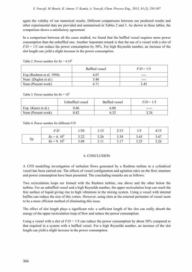
For different vessel configurations, Fig. 13 presents the size of vortex generated near the free surface of liquid. We found that length of slots plays a significant role to reduce the size of this structure.
Fig. 13. Vortex size versus Reynolds number
Power consumption is an important parameter to describe the performance of a mixing system. This parameter is defined for the different cases investigated in this paper. However, before that, we checked
0 20000 40000 60000 80000 1000000,375
0,500
0,625
0,750
Vort
ex s
ize/
D
Re
F/D=0 w/D=1/10 F/D=1/50 F/D=1/15 F/D=2/15 F/D=1/5 F/D=4/15
S. Youcefi, M. Bouzit, H. Ameur, Y. Kamla, A. Youcefi, Chem. Process Eng., 2013, 34 (2), 293-307
304
again the validity of our numerical results. Different comparisons between our predicted results and other experimental data are provided and summarised in Tables 2 and 3. As shown in these tables, the comparison shows a satisfactory agreement.
In a comparison between all the cases studied, we found that the baffled vessel requires more power consumption than the unbaffled one. Another important remark is that the use of a vessel with a slot of F/D = 1/5 can reduce the power consumption by 50%. For high Reynolds number, an increase of the slot length can yield a slight increase in the power consumption.
Table 2. Power number for Re = 4.104
Baffled vessel F/D = 1/5
Exp (Rushton et al. 1950) 6.07 ---- Num (Deglon et al.) 5.40 ---- Num (Present work) 6.71 3.45
Table 3. Power number for Re = 105
Unbaffled vessel Baffled vessel F/D = 1/5
Exp (Karcz et al.) 0.86 6.00 ----- Num (Present work) 0.82 6.32 3.24
Table 4. Power number for different F/D
F/D 1/50 1/15 2/15 1/5 4/15
Np Re = 4. 104 3.22 3.26 3.38 3.45 3.47 Re = 9. 104 3.08 3.11 3.17 3.25 3.26
6. CONCLUSION
A CFD modelling investigation of turbulent flows generated by a Rushton turbine in a cylindrical vessel has been carried out. The effects of vessel configuration and agitation rates on the flow structure and power consumption have been presented. The concluding remarks are as follows:
Two recirculation loops are formed with the Rushton turbine, one above and the other below the turbine. For an unbaffled vessel and a high Reynolds number, the upper recirculation loop can reach the free surface of liquid giving rise to high vibrations in the mixing system. Using a vessel with internal baffles can reduce the size of this vortex. However, using slots at the external perimeter of vessel seem to be a more efficient method of eliminating this issue.
The effect of slot length plays a significant role: a sufficient length of the slot can really absorb the energy of the upper recirculation loop of flow and reduce the power consumption.
Using a vessel with a slot of F/D = 1/5 can reduce the power consumption by about 50% compared to that required in a system with a baffled vessel. For a high Reynolds number, an increase of the slot length can yield a slight increase in the power consumption.
Effect of some design parameters on the flow fields and power consumption ...
305
SYMBOLS
a blade length, m b shaft diameter, m c impeller off-bottomed clearance, m d impeller diameter, m g disc diameter, m h blade height , m w baffle length, m x disc thickness, m C torque, N.m D tank diameter, m E slot depth, m F circumference slot, m H liquid level, m N impeller rotational speed, 1/s P power, W Np power number, dimensionless Qv viscous dissipation function, 1/s2
R radial coordinate, m Re Reynolds number, dimensionless V velocity, m/s Vz axial velocity, m/s
Vθ tangential velocity, m/s
Vr radial velocity, m/s
Greek symbols τ shear stress, Pa ρ fluid density, kg/m3 η viscosity, Pa s θ angular coordinate, degree ω angular velocity, rad/s
REFERENCES
Alcamo R., Micale G., Grisafi F., Brucato A., Ciofalo M., 2005. Large eddy simulation of turbulent flow in an unbaffled stirred tank driven by a Rushton turbine. Chem. Eng. Sci., 60, 2303-2316. DOI: 10.1016/j.ces.2004.11.017.
Alopaeus V., Moilanen P., Laakkonen M., 2009. Analysis of stirred tanks with two-zone models. AIChE J., 55, 2545-5552. DOI: 10.1002/aic.11850.
Ameur H., Bouzit M., Helmaoui M., 2011. Numerical study of fluid flow and power consumption in a stirred vessel with a Scaba 6SRGT impeller. Chem. Process Eng., 32, 351-366. DOI: 10.2478/v10176-011-0028-0.
Baccar M., Abid M.S., 1999. Characterization of turbulent flow and heat transfer generated by anchor and gate in a stirred tank. Int. J. Therm. Sci., 38, 892-903. DOI: 10.1016/S1290-0729(99)80043-X.
Beshay K.R, Kratěna J., Fořt I., Bruha O., 2001. Power input of high-speed rotary impellers. Acta Polytechnica, 41, 18-23.
Bo W., Jieyu Z., Youduo H., Shengli A., 2006. Investigation on eccentric agitation in the stirred vessel using 3D-Laser Doppler Velocimeter. Chinese J. Chem. Eng., 14, 618-625. DOI: 10.1016/S1004-9541(06)60124-9.
Bujalski W., Nienow A.W., Chatwin S., Cooke M., 1987. The dependency scale of power numbers of Rushton disc turbines. Chem. Eng. Sci., 42, 317-326. DOI: 10.1016/0009-2509(87)85061-3.
S. Youcefi, M. Bouzit, H. Ameur, Y. Kamla, A. Youcefi, Chem. Process Eng., 2013, 34 (2), 293-307
306
Chtourou W., Ammar M., Driss Z., Abid M.S., 2011. Effect of the turbulence models on Rushton turbine generated flow in a stirred vessel. Cent. Eur. J. Eng., 1(4), 380-389. DOI: 10.2478/s13531-011-0039-0.
Ciofalo M., Brucato A., Grisafi F., Torraca N., 1996. Turbulent flow in closed and free-surface unbaffled tanks stirred by radial impellers. Chem. Eng. Sci., 51, 3557–3573. DOI: 10.1016/0009-2509(96)00004-8.
Doulgerakis Z., Yianneskis M., Ducci A., 2009. On the interaction of trailing and macro-instability vortices in a stirred vessel-enhanced energy levels and improved mixing potential. Chem. Eng. Res. Des., 87, 412-420. DOI: 10.1016/j.cherd.2008.12.019.
Ducci A., Yianneskis M., 2007. Vortex identification methodology for feed insertion guidance in fluid mixing processes. Chem. Eng. Res. Des., 85, 543-550. DOI: 10.1205/cherd06192.
Ducci A., Yianneskis M., 2007. Vortex tracking and mixing enhancement in stirred processes. AIChE J., 53, 305-315. DOI: 10.1002/aic.11076.
Escudie R., Bouyer D., Line A., 2004. Characterization of trailing vortices generated by a Rushton turbine. AIChE J., 50, 75-86. DOI: 10.1002/aic.10007.
Escudie R., Line A., 2003. Experimental analysis of hydrodynamics in a radially agitated tank. AIChE J., 49, 585-603. DOI: 10.1002/aic.690490306.
Fentiman N.J., Lee K.C., Paul G.R., Yianneskis M., 1999. On the trailing vortices around hydrofoil impeller blades. Chem. Eng. Res. Des., 77, 731-742. DOI: 10.1205/026387699526700.
Gabriele A., Nienow A.W., Simmons M.J.H., 2009. Use of angle resolved PIV to estimate local specific energy dissipation rates for up-and down-pumping pitched blade agitators in a stirred tank. Chem. Eng. Sci., 64, 126-143. DOI: 10.1016/j.ces.2008.09.018.
Galletti C., Brunazzi E., Yianneskis M., Paglianti A., 2003. Spectral andwavelet analysis of the flow pattern transition with impeller clearance variations in a stirredvessel. Chem. Eng. Sci., 58, 3859-3875. DOI: 10.1016/S0009-2509(03)00230-6.
Haque J.N., Mahmud T., Roberts K.J., Rhodes D., 2006. Modelling turbulent flows with free-surface in unbaffled agitated vessels. Ind. Eng. Chem. Res., 45, 2881-2891. DOI: 10.1021/ie051021a.
Jing Z., Zhengming G., Yuyun B., 2011. Effects of the blade shape on the trailing vortices in liquid flow generated by disc turbines. Chinese J. Chem. Eng., 19, 232-242. DOI: 10.1016/S1004-9541(11)60160-2.
Kresta S.M., Wood P.E., 1991. Prediction of the three-dimensional turbulent flow in stirred tanks. AIChE J., 37, 448-460. DOI: 10.1002/aic.690370314.
Kumaresan T., Joshi J.B., 2006. Effect of impeller design on the flow pattern and mixing in stirred tanks. Chem. Eng. J., 115, 173-193. DOI:10.1016/j.cej.2005.10.002.
Luo J.Y., Gosman A.D., Issa R.I., Middleton J.C., Fitzgerald M.K., 1993. Full flow field computation of mixing in baffled stirred vessels. Chem. Eng. Res. Des., 71, 342-344.
Mahmud T., Haque J.N., Roberts K.J., Rhodes D., Wilkinson D., 2009. Measurements and modelling of free-surface turbulent flows induced by a magnetic stirrer in an unbaffled stirred tank reactor. Chem. Eng. Sci., 64, 4197-4209. DOI:10.1016/j.ces.2009.06.059.
Mavros P., 2001. Flow visualization in stirred vessels a review of experimental techniques. Chem. Eng. Res. Des., 79, 113-127. DOI: 10.1205/02638760151095926.
Myers K.J., Reeder M.F., Fasano J.B., 2002. Optimize mixing by using the proper baffles. Chem. Eng. Prog., 91, 42-47.
Naude I., 1998. Direct simulations of impellers in a stirred tank. Contribution to the optimization of the choice of an agitator. Ph.D. thesis. INPT, France.
Nikiforaki L., Montante G., Lee K.C., Yianneskis M., 2003. On the origin, frequency and magnitude of macro-instabilities of the flows in stirred vessels. Chem. Eng. Sci., 58, 2937- 2949. DOI:10.1016/S0009-2509(03)00152-0.
Ranade V.V., 1997. An efficient computational model for simulating flow in stirred vessels: A case of Rushton turbine. Chem. Eng. Sci., 52, 4473-4484. DOI: 1016/S0009-2509(97)00292-3.
Roy S., Acharya S., Cloeter M.D., 2010. Flow structure and the effect of macro-instabilities in a pitched-blade stirred tank. Chem. Eng. Sci., 65, 3009-3024. DOI: 10.1016/j.ces.2010.01.025.
Stoots C.M., Calabrese R.V., 1995. Mean velocity field relative to a Rushton turbine blade. AIChE J., 41, 1-11. DOI: 10.1002/aic.690410102.
Torré J.P., Fletcher D.F., Lasuye T., Xuereb C., 2007. An experimental and computational study of the vortex shape in a partially baffled agitated vessel, Chem. Eng. Sci., 62, 1915- 1926. DOI:10.1016/j.ces.2006.12.020.

Effect of some design parameters on the flow fields and power consumption ...
307
Wu H., Patterson G.K., 1989. Laser-Doppler measurements of turbulent flow parameters in a stirred mixer. Chem. Eng. Sci., 44, 2207-2221. DOI: 10.1016/0009-2509(89)85155-3.
Yeoh S.L., Papadakis G., Yianneskis M., 2004. Numerical simulation of turbulent flow characteristics in a stirred vessel using the LES and RANS approaches with the sliding deforming mesh methodology. Chem. Eng. Res. Des., 82, 834-848. DOI: 10.1205/0263876041596751.
Yoon H.S., Hill D.F., Balachandar S., Adrian R.J., Ha M.Y., 2005. Reynolds number scaling of flowin a Rushton turbine stirred tank. Part I—Mean flow, circular jet and tip vortex scaling. Chem. Eng. Sci., 60, 3169-3183. DOI: 10.1016/j.ces.2004.12.039.
Yoon H.S., Sharp K.V., Hill D.F., Adrian R.J., Balachandar S., Ha M.Y., Kar K., 2001. Integrated experimental and computational approach to simulation of flow in a stirred tank. Chem. Eng. Sci., 56, 6635-6649. DOI: 10.1016/S0009-2509(01)00315-3.
Received 23 January 2013 Received in revised form 23 April 2013 Accepted 29 May 2013
Related Documents