Ferroelectric Polarization Induces Electric Double Layer Bistability in Electrolyte-Gated Field-Effect Transistors Simone Fabiano, Xavier Crispin and Magnus Berggren Linköping University Post Print N.B.: When citing this work, cite the original article. Original Publication: Simone Fabiano, Xavier Crispin and Magnus Berggren, Ferroelectric Polarization Induces Electric Double Layer Bistability in Electrolyte-Gated Field-Effect Transistors, 2014, ACS Applied Materials and Interfaces, (6), 1, 438-442. http://dx.doi.org/10.1021/am404494h Copyright: American Chemical Society http://pubs.acs.org/ Postprint available at: Linköping University Electronic Press http://urn.kb.se/resolve?urn=urn:nbn:se:liu:diva-104116

Welcome message from author
This document is posted to help you gain knowledge. Please leave a comment to let me know what you think about it! Share it to your friends and learn new things together.
Transcript

Ferroelectric Polarization Induces Electric
Double Layer Bistability in Electrolyte-Gated
Field-Effect Transistors
Simone Fabiano, Xavier Crispin and Magnus Berggren
Linköping University Post Print
N.B.: When citing this work, cite the original article.
Original Publication:
Simone Fabiano, Xavier Crispin and Magnus Berggren, Ferroelectric Polarization Induces
Electric Double Layer Bistability in Electrolyte-Gated Field-Effect Transistors, 2014, ACS
Applied Materials and Interfaces, (6), 1, 438-442.
http://dx.doi.org/10.1021/am404494h
Copyright: American Chemical Society
http://pubs.acs.org/
Postprint available at: Linköping University Electronic Press
http://urn.kb.se/resolve?urn=urn:nbn:se:liu:diva-104116

1
Ferroelectric polarization induces electric double
layer bistability in electrolyte-gated field-effect
transistors
Simone Fabiano,* Xavier Crispin, and Magnus Berggren
Organic Electronics, Department of Science and Technology, Linköping University, SE-601 74,
Norrköping (Sweden)

2
ABSTRACT: The dense surface charges expressed by a ferroelectric polymeric thin film induce
ion displacement within a polyelectrolyte layer, and vice versa. This because the density of
dipoles along the surface of the ferroelectric thin film and its polarization switching time matches
that of the (Helmholtz) electric double layers formed at the ferroelectric/polyelectrolyte and
polyelectrolyte/semiconductor interfaces. This combination of materials allows for introducing
hysteresis effects in the capacitance of an electric double layer capacitor. The latter is
advantageously used to control the charge accumulation in the semiconductor channel of an
organic field-effect transistor. The resulting memory transistors can be written at a gate voltage
of around 7 V and read out at a drain voltage as low as 50 mV. The technological implication of
this large difference between write and read-out voltages lies in the non-destructive reading of
this ferroelectric memory.
KEYWORDS: electrolytes, ferroelectric, P(VDF-TrFE), electric double layer, memory, field-
effect transistors
Introduction
Memory functionality is a prerequisite for many electronic applications in modern society. In
fact, most of the envisaged electronic applications require non-volatile memory systems that can
be programmed, erased and read-out electrically.1,2
Organic non-volatile memory devices based
on ferroelectric polymers represent a promising approach towards the development of a low-cost
technology that is possible to manufacture using common printing techniques.3 Ferroelectric
polymers are especially attractive as the active medium for data storage, owing to their high
flexibility, low cost and simple production protocol.4-6
Ferroelectric memories based on the

3
copolymer poly(vinylidenefluoride-co-trifluoroethylene) (P(VDF-TrFE)) are of particular
interest to the organic electronics community due to the excellent processability (i.e. low
temperature and from solution). The ferroelectricity of this material stems from the molecular
dipole moments, residing perpendicular to the P(VDF-TrFE) backbone defined by the
electronegativity difference between hydrogen-disubstituted carbon and fluorine-disubstituted
carbons. The dipoles can be aligned collectively with the applied field by a rotation of the
monomer groups in crystalline domains. The binary states of the memory device reflect two
stable polarization states of the ferroelectric material that can be maintained even in the absence
of an externally applied electric field. Switching between the two polarization directions occurs
only above a certain threshold of the external electric field, which provides the non-volatile
character. Organic ferroelectric field-effect transistors are technologically relevant because they
can be addressed easily in an array of memory elements.
In the last years, several groups have demonstrated that solution processable solid polymer
electrolytes can be used as gate insulator materials in transistors.7-9
In electrolyte-gated field-
effect transistors (FETs) indeed, the polarization mechanism of such dielectrics involves the
reorganization of the included ions forming two (Helmholtz) electric double layers, EDLs, on the
microsecond time scale at the gate/electrolyte and electrolyte/semiconductor interfaces. Most of
the applied gate-source bias drops across these EDLs. The charged sheets of the EDLs are
separated by only a few Angstroms within the Helmholtz double layer, leading to extraordinary
high transversal electric fields (109 V m
–1), established already at very low gate-source voltages.
Thus, the high capacitance of the EDL capacitor enables low operating voltages, which are
typically less than 1 V. However, none has yet introduced a memory function in these low-
voltage FETs.

4
Here, we demonstrate that a bi-layer comprising an electrolyte and a ferroelectric
fluoropolymer can promote memory functionality when used as the gate dielectric in a polymer
transistor. The electrolyte layer transfers efficiently the polarization state of the ferroelectric
layer to the semiconductor channel via ion displacement and through the formation of an EDL at
the electrolyte/semiconductor interface. We then combine the bistable polarization of the
ferroelectric with the high capacitance of the EDLs to create low-readout voltage electrolyte-
gated transistors, ideal for printed non-destructive memory elements.
Results and discussion
A polyelectrolyte comprising fixed anions and mobile cations is favorably utilized to separate
the ferroelectric film from the semiconductor. The use of a polyelectrolyte rather than an
electrolyte where both anions and cations are mobile, suppresses any undesired penetration of
ions in the organic semiconductor (i.e. electrochemical doping). Hence, poly(vinylphosphonic
acid-co-acrylic acid) (P(VPA-AA)) is chosen as the polyelectrolyte thin film whereas P(VDF-
TrFE) is used as a ferroelectric layer (Figure 1a). It is important to note that the polarization
induced in the ferroelectric/polyelectrolyte bi-layer is not limited (in time and amplitude) by any
of the materials since both ferroelectric and polyelectrolyte display similar surface charge density
and time scale. P(VDF-TrFE) shows indeed a remanent polarization as high as 10 µC cm–2
, a
value which is of the same order of magnitude as the EDL surface charge density in P(VPA-
AA).9 Moreover, the switching time for a P(VDF-TrFE) layer is about 0.1 ms
10 also of a similar
order of magnitude as the EDL formation in P(VPA-AA).9 Regio-regular poly(3-hexylthiophene)
(P3HT) is used as the semiconductor material because of its high field-effect mobility and low
contact resistance when gold is used as source/drain electrodes.

5
b
P(VPA-AA)
!
P(VDF-TrTE)
a
V - +
P3HT
+
+
+
+
+
+
Figure 1. (a) Structure of the polyelectrolyte and ferroelectric copolymer. (b) Schematic
illustration of the charge and ion distribution within the polyelectrolyte layer for a meta-
insulator-semiconductor structure.
The net surface charge density of the ferroelectric thin film can be induced to be either positive
or negative depending on the direction of the applied polarizing electric field. It has been
proposed that an EDL can be formed at the surface of an inorganic ferroelectric layer in contact
with an electrolyte, leading to the electrostatic adhesion of charged particles.11,12
Recent studies
have also shown that dipolar interactions identified as Coulomb attractions between hydrogen
atoms in the PVDF chains and anions promote ferroelectric polarization in a PVDF-ionic liquid
blend.13
Based on these concepts, we propose a mechanism of polarization across a
ferroelectric/polyelectrolyte/organic semiconductor stack, which appears as a cross section of the
ferroelectric electrolyte-gated FET presented below. The electrolyte is a polarizable medium that
transfers the surface charge of the ferroelectric to the semiconductor surface, with only a minor
potential drop across the bulk of the polyelectrolyte film. So, when a negative (positive) voltage
is applied to the ferroelectric high enough to overcome the coercive voltage, that is, the
minimum bias required to switch the full remanent polarization, two EDLs are established at the
ferroelectric/polyelectrolyte and polyelectrolyte/semiconductor interfaces, respectively (Figure
1b). The first EDL is defined by the surface charges from the dipoles of the switched
ferroelectric film balanced by the mobile counter ions of the electrolyte. The latter EDL is

6
represented by the accumulated holes (electrons) residing along the outermost sheet along the
organic semiconductor film balanced by charged polyelectrolyte chains (depleted of counter
ions). The concept of EDLs induced by switching of the ferroelectric polarization is general and
can be applied to p-type as well as n-type semiconducting materials.
Figure 2. (a) Representative capacitance-voltage characteristic of a Au/P3HT/P(VPA-
AA)/P(VDF-TrFE)/Au-based MIS structure (see inset). (b) Programming the ferroelectric layer
with a voltage sequence of the same polarity results in a loss of hysteresis corroborating the fact
that ion migration is not the origin of the capacitance bistability.
7
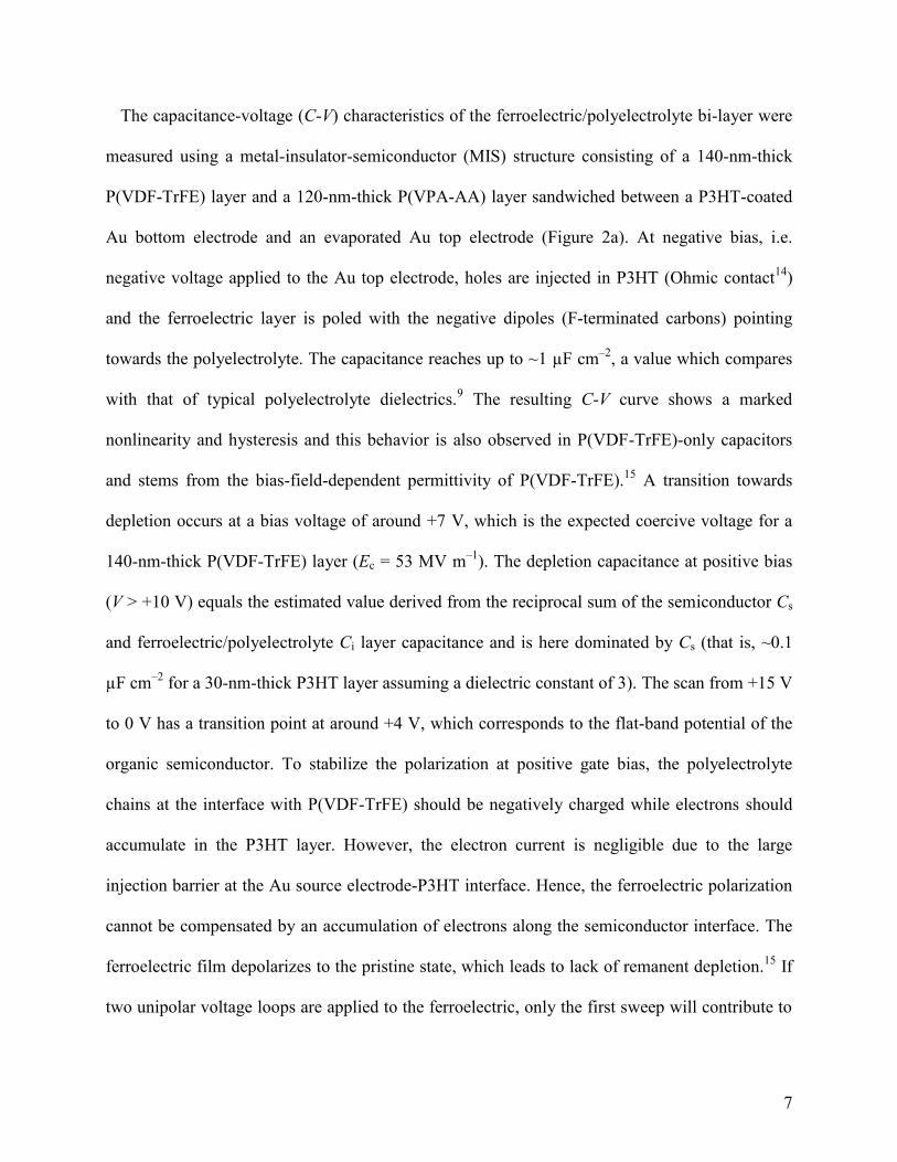
The capacitance-voltage (C-V) characteristics of the ferroelectric/polyelectrolyte bi-layer were
measured using a metal-insulator-semiconductor (MIS) structure consisting of a 140-nm-thick
P(VDF-TrFE) layer and a 120-nm-thick P(VPA-AA) layer sandwiched between a P3HT-coated
Au bottom electrode and an evaporated Au top electrode (Figure 2a). At negative bias, i.e.
negative voltage applied to the Au top electrode, holes are injected in P3HT (Ohmic contact14
)
and the ferroelectric layer is poled with the negative dipoles (F-terminated carbons) pointing
towards the polyelectrolyte. The capacitance reaches up to ~1 µF cm–2
, a value which compares
with that of typical polyelectrolyte dielectrics.9 The resulting C-V curve shows a marked
nonlinearity and hysteresis and this behavior is also observed in P(VDF-TrFE)-only capacitors
and stems from the bias-field-dependent permittivity of P(VDF-TrFE).15
A transition towards
depletion occurs at a bias voltage of around +7 V, which is the expected coercive voltage for a
140-nm-thick P(VDF-TrFE) layer (Ec = 53 MV m–1
). The depletion capacitance at positive bias
(V > +10 V) equals the estimated value derived from the reciprocal sum of the semiconductor Cs
and ferroelectric/polyelectrolyte Ci layer capacitance and is here dominated by Cs (that is, ~0.1
µF cm–2
for a 30-nm-thick P3HT layer assuming a dielectric constant of 3). The scan from +15 V
to 0 V has a transition point at around +4 V, which corresponds to the flat-band potential of the
organic semiconductor. To stabilize the polarization at positive gate bias, the polyelectrolyte
chains at the interface with P(VDF-TrFE) should be negatively charged while electrons should
accumulate in the P3HT layer. However, the electron current is negligible due to the large
injection barrier at the Au source electrode-P3HT interface. Hence, the ferroelectric polarization
cannot be compensated by an accumulation of electrons along the semiconductor interface. The
ferroelectric film depolarizes to the pristine state, which leads to lack of remanent depletion.15
If
two unipolar voltage loops are applied to the ferroelectric, only the first sweep will contribute to

8
the switching of the ferroelectric dipoles.16
Programming of the ferroelectric layer with a voltage
bias sequence of the same polarity results in a loss of hysteresis (Figure 2b). This suggests that
ion migration is not the origin of the capacitance bistability switching in these devices.
The combination of ferroelectric bistability with semiconductivity allows for non-volatile
memories with non-destructive read-out where the resistance and the polarization can be tuned
independently.17
In this respect, ferroelectric field-effect transistors (FeFETs) are ideally suited
for the achievement of memory technology, as they allow for a complete decoupling of the write
and read-out functionalities.18,19
Top-gated polymer FETs were fabricated using the
ferroelectric/polyelectrolyte bi-layer as the insulator and P3HT as the semiconductor channel
(see Experimental methods for further details). Figure 3a-c shows the current-voltage
characteristics of a representative device. The transistor operates in the accumulation mode
where holes are the majority charge carriers. A typical transfer characteristic (Ids vs. Vg),
recorded in the linear regime at low source–drain bias (Vds = –0.2 V), shows a clockwise
hysteresis of the drain current consistent with the accumulation and depletion of p-type charge
carriers in the channel (Figure 3a). This is consistent with the current retention behavior due to
the dipolar polarization of the ferroelectric layer.18
In fact, when the polarization switches from
one state to another, charges are displaced across the ferroelectric insulator film. The
accompanying switching currents are observed as sharp features in the gate current at –7 V and
at +7 V, respectively, and as steep increase/decrease of the drain current. Their presence
confirms that the memory effect is driven by ferroelectric polarization switching, rather than
charge trapping mechanisms or ion migration in and through the ferroelectric layer.20,21
Hence,
the transistor behaves as a bi-stable memory cell element; before the very first sweep, the
ferroelectric film is unpolarized. Upon increasing the negative gate bias beyond the coercive

9
field (Ec = 53 MV m–1
for the 140-nm-thick P(VDF-TrFE)) the ferroelectric film becomes fully
polarized and an electrical double layer is quickly formed along the ferroelectric/polyelectrolyte
interface. At the same time an elevated hole density is established at the
semiconductor/polyelectrolyte interface and a high drain current is then measured already at Vds
= –0.2 V. Upon scanning back the gate voltage, towards and beyond zero, the ferroelectric
material is kept polarized and the current remains high (ON-state). At a positive gate voltage bias
of around +7 V, the coercive field is reached and the sign of the ferroelectric polarization
changes swiftly. The accumulation of electrons along the semiconductor/polyelectrolyte
interface, i.e. in the transistor channel, is severely hampered by the large energy barrier for
electron injection from the gold contact into the P3HT conduction band. The output
characteristics, Ids vs. Vds, is shown in Figure 3b. We note that, at high drain bias voltages where
the saturated Ids is proportional to the square of the gate drive, two distinct slopes are found for
Ids vs. Vg2 with a typical crossover point at around –7 V (Figure S1). This is consistent with an
increased carrier density distribution in the channel region established after that the ferroelectric
material becomes polarized. We also notice that the transistor characteristics in fact improve
slightly with device ageing, showing excellent performances even after several weeks with read-
out voltages as low as Vds = –50 mV (Figure 3c). This reduced read-out voltage is up to two
orders of magnitude lower than what is usually reported for conventional FeFETs.18
For
comparison, a typical p-channel P3HT FeFET with a 200-nm-thick P(VDF-TrFE) gate dielectric
without electrolyte interlayer produces output currents no greater than 20 nA at comparable Vds.22
We attribute this to the high hygroscopic properties of the P(VPA-AA) layer which allows for an
improvement of the impedance characteristics of the ferroelectric/polyelectrolyte/semiconductor
configuration23
as well as doping of the semiconductor layer.24
When the P(VDF-TrFE) layer is

10
placed in direct contact with P3HT, as in conventional FeFETs, the devices show poor
performance at Vds = –0.2 V with ON/OFF ratio at zero Vg of about 60, while no field-effect
modulation is observed at even lower Vds (see Figure 3d and Figure S2). This is attributed to the
high gate current for these FeFET devices comprising a 140-nm-thick ferroelectric layer, which
is of the same order of magnitude as the drain current. The drop in ON/OFF ratio, observed for
devices with polyelectrolyte interlayer at high Vds (> –1 V), is not due to degradation of the ON-
current but is due to a shift of the threshold voltage at more positive Vg, which thus reduces the
final ON/OFF ratio when measured at zero Vg.

11
Figure 3. (a) Ids and Ig as a function of Vg for the P3HT ferroelectric transistor (Vds = −0.2 V).
The arrows show the clockwise hysteresis of the drain current consistent with accumulation and
depletion of the charge carriers. (b) Ids as a function of Vds for a typical ferroelectric transistor (Vg
from 0 to –10 V in steps of 1 V). The inset shows the same data in (b) for Vg from 0 to –6 V in
steps of 1 V. (c) Ids and Ig as a function of Vg for a ferroelectric transistor at Vds = −50 mV. (d)
ON/OFF ratio as a function of Vds for ferroelectric OFET with (open squares) and without (open
circles) P(VPA-AA) interlayer.
Due to the relatively high coercive field of P(VDF-TrFE) (EC 50 MV m–1
), the Vg necessary
to switch the devices is rather high. Low-voltage switching transistors can be attained by
reducing the ferroelectric layer thickness well below 100 nm. Indeed, by shrinking the P(VDF-
TrFE) layer thickness down to 60 nm results in a lower operating bias for switching (VC < 3 V,
Figure 4). However, we notice that such a narrow voltage window leads to unstable performance
in terms of remanent polarization characteristics. Since the leakage current appears to be
independent of the ferroelectric layer thickness (see Figure 3a and Figure 4 for comparison), the
primary mechanism of current degradation may be ascribed to a ferroelectric domain pinning due
to ionic contaminations which becomes predominant when the ferroelectric layer thickness is
lowered down to 50-60 nm. This would result in a low current retention.25

12
Figure 4. Ids and Ig as a function of Vg for a P3HT ferroelectric transistor (Vds = −0.2 V)
comprising a 60-nm-thick P(VDF-TrFE) layer.
The switching current in our polyelectrolyte-gated transistors was monitored during the
experiments using a 5 kΩ resistor connected in series with the source electrode (Figure 5a).
When Vds = –0.2 V, the output source-drain current tracks the input gate signal. Distortion of the
output waveform is due to short-lived capacitive displacement, which is typical of electrolyte-
gated transistors.8,9
When Vds = –0.2 V, no steady output current in produced as expected.
Interestingly, the OFF-to-ON state transition typically amounts to 0.2 ms for pulses of ±10 V.
Programming pulses shorter than 0.1 ms resulted in a state with a low ON-current of the same
order of magnitude as the OFF-current. On the other hand, the ON-to-OFF state transition is
found to occur in nearly 50 µs, indicating that the programming time is primarily determined by
the conductance of the semiconductor channel. Hence, the switching time is comparable with
that of conventional ferroelectric transistors and capacitors where dipoles fully switch in 0.1-0.3

13
ms,18
suggesting that in our devices the programming time is not limited nor affected by the
polyelectrolyte interlayer. We note indeed that the typical switching time of electrolyte-gated
FETs is also of the order of 0.1 ms and decreases when the ion mobility is increased (i.e. at
higher relative humidity).26
The field-effect mobility in the linear regime, µlin, has been
calculated according to µlin = (LW–1
Ci–1
V–1
)(dIds/dVg). The mobility reaches about 0.1 cm2 V
–1
s–1
, which is in good agreement with previous reports.27
The current levels in the OFF-state and
ON-state (the ON/OFF ratio at zero Vg) differ by 3 orders of magnitude or higher for all the
prepared devices.
Figure 5. (a) Transient response of a polyelectrolyte-gated ferroelectric transistor at constant Vds
when the Vg is pulsed at 10 Hz. (b) Data retention time obtained by programming the device once
in the ON- or OFF-state and monitoring the drain current over time at Vds = –0.2 V and zero gate
bias.
Data retention characteristics were examined by measuring the remnant drain current level as a
function of time. Long retention time is typical for ferroelectric capacitors17
and FETs.18
Figure

14
5b shows the value of drain current in the ON- and OFF-states as a function of the retention time,
measured at Vds = −0.2 V. The ON- and OFF-states were programmed by poling the ferroelectric
at gate voltages of −15 V and +15 V with a 3 s pulse, respectively. The memory retention is
found to be rather excellent for these devices with the ON/OFF ratio being more than two orders
of magnitude even after 104 s. The long retention time strengthen the viability of this kind of
devices for non-volatile memory applications.
Conclusions
In summary, we have demonstrated that the surface charge density expressed by a ferroelectric
polymer thin film matches the density of charges in a dissociated polyelectrolyte. This
ferroelectric-induced electric double layer promotes memory functionality in electrolyte-gated
FETs. The combination of ferroelectric and polyelectrolyte bi-layer as the gate insulator provides
a large specific capacitance (~1 µF cm–2
), fast polarization response times (~0.2 ms) and high
semiconductor surface charge density at source-drain voltages of only fractions of a volt,
resulting in non-volatile memory devices. Notably, this ferroelectric-induced EDL shows long
retention times of more than 104 s.
Experimental methods
The ferroelectric P(VDF-TrFE) 70/30 mol% copolymer was purchased from Solvay SA and
used as received. The P(VDF-TrFE) powder was dissolved in diethyl carbonate (DEC) at a
concentration of 4% w/v and filtered through a 0.1 µm filter. The polyelectrolyte P(VPA-AA))
was supplied by Rhodia, dissolved in a mixture of 1-propanol and deionized water (4% w/v) with
a solvent ratio of 4:1 and filtered with a 0.2 μm nylon syringe filter. Regioregular poly(3-

15
hexylthiophene) (P3HT) was purchased from Sigma-Aldrich and used without further
purification. The semiconductor was dissolved in 1,2-dichlorobenzene (1% w/v) and filtered
with a 0.2 µm polytetrafluoroethylene (PTFE) syringe filter. Thin films were prepared by spin-
coating in a class 1,000 clean room environment.
Corning glass substrates were cleaned sequentially in deionized water, acetone and
isopropanol. Interdigitated source and drain electrode (3-nm-thick Ti and 27-nm-thick Au) were
defined by photolithography and wet etching procedure. The substrates were cleaned carefully
again using deionized water, acetone and isopropanol before use. The semiconductor layer was
formed by spin-coating the warm solution at 2000 rpm for 30 s giving a film thickness of 30 nm.
The films were then annealed at 120 °C for 30 min under nitrogen. The polyelectrolyte solution
was spin-coated at 2000 rpm for 60 s and dried on a hot plate under vacuum at 120 °C for 120 s,
resulting in a thickness of about 120 nm. The P(VDF-TrFE) layer was subsequently spin-coated
on top of the polyelectrolyte layer and annealed at 135°C for 1 h in vacuum oven in order to
increase the film crystallinity. The film thickness was controlled by varying the spin speed,
measured by ellipsometry and confirmed by using a DekTak profilometer. An 80-nm-thick top
electrode for the capacitors and gate electrode for the transistors are formed by thermal
evaporation of various metals through a Ni shadow mask (Tecan Ltd.).
The electrical characteristics of the ferroelectric transistors were measured using a
semiconductor parameter analyzer (Keithley 4200-SCS). The impedance measurements were
carried out with an Alpha high-resolution dielectric analyzer (Novocontrol GmbH). An AC
voltage of 0.3 V was applied, the frequency was set at 1 kHz, and the DC voltage was swept
from positive to negative voltages. An equivalent circuit model made of a resistor and a capacitor

16
in parallel was used to extract the effective capacitance, which was calculated from the equation
C = 1/(2πfIm(Z)) and where f is the frequency and Z is the measured impedance.
AUTHOR INFORMATION
Corresponding Author
*E-mail: [email protected]
ACKNOWLEDGMENT
This research was partially supported by the Advanced Functional Materials Center at Linköping
University and the Önnesjö Foundation. Authors wish to thank also the Knut and Alice
Wallenberg Foundation (Power Paper project, scholars) and VINNOVA for financial support.
ASSOCIATED CONTENT
Supporting Information Available: Electrical measurements, Figures S1-S2. This material is
available free of charge via the Internet at http://pubs.acs.org.
REFERENCES
(1) Scott, J. F.; Dearaujo, C. A. P. Science 1989, 246, 1400-1405.
(2) Berggren, M.; Nilsson, D.; Robinson, N. D. Nat. Mater. 2007, 6, 3-5.
(3) Scott, J. C.; Bozano, L. D. Adv. Mater. 2007, 19, 1452-1463.
(4) Lovinger, A. J. Science 1983, 220, 1115-1121.
(5) Horiuchi, S.; Tokura, Y. Nat. Mater. 2008, 7, 357-366.
(6) Li, M.; Wondergem, H. J.; Spijkman, M.-J.; Asadi, K.; Katsouras, I.; Blom, P. W. M.; de
Leeuw, D. M. Nat. Mater. 2013, 12, 433-438.

17
(7) Dhoot, A. S.; Yuen, J. D.; Heeney, M.; McCulloch, I.; Moses, D.; Heeger, A. J. PNAS
2006, 103, 11834-11837.
(8) Cho, J. H.; Lee, J.; Xia, Y.; Kim, B.; He, Y. Y.; Renn, M. J.; Lodge, T. P.; Frisbie, C. D.
Nat. Mater. 2008, 7, 900-906.
(9) Herlogsson, L.; Crispin, X.; Robinson, N. D.; Sandberg, M.; Hagel, O. J.; Gustafsson, G.;
Berggren, M. Adv. Mater. 2007, 19, 97-101.
(10) Naber, R. C. G.; Blom, P. W. M.; Marsman, A. W.; de Leeuw, D. M. Appl. Phys. Lett.
2004, 85, 2032.
(11) Ferris, R. J.; Lin, S. H.; Therezien, M.; Yellen, B. B.; Zauscher, S. Acs Appl. Mater.
Interfaces 2013, 5, 2610-2617.
(12) Ferris, R.; Yellen, B.; Zauscher, S. Small 2012, 8, 28-35.
(13) Wang, F. P.; Lack, A.; Xie, Z. L.; Frubing, P.; Taubert, A.; Gerhard, R. Appl. Phys. Lett.
2012, 100, 062903.
(14) Braun, S.; Salaneck, W. R.; Fahlman, M. Adv. Mater. 2009, 21, 1450-1472.
(15) Naber, R. C. G.; Massolt, J.; Spijkman, M.; Asadi, K.; Blom, P. W. M.; de Leeuw, D. M.
Appl. Phys. Lett. 2007, 90, 113509.
(16) Kalbitz, R.; Frübing, P.; Gerhard, R.; Taylor, D. M. Appl. Phys. Lett. 2011, 98, 033303.
(17) Asadi, K.; Leeuw, D. M. D.; Boer, B. D.; Blom, P. W. M. Nat. Mater. 2008, 7, 547-550.

18
(18) Naber, R. C. G.; Tanase, C.; Blom, P. W. M.; Gelinck, G. H.; Marsman, A. W.;
Touwslager, F. J.; Setayesh, S.; De Leeuw, D. M. Nat. Mater. 2005, 4, 243-248.
(19) Khan, M. A.; Bhansali, U. S.; Alshareef, H. N. Adv. Mater. 2012, 24, 2165-2170.
(20) Sekitani, T.; Yokota, T.; Zschieschang, U.; Klauk, H.; Bauer, S.; Takeuchi, K.;
Takamiya, M.; Sakurai, T.; Someya, T. Science 2009, 326, 1516-1519.
(21) Egginger, M.; Irimia-Vladu, M.; Schwodiauer, R.; Tanda, A.; Frischauf, I.; Bauer, S.;
Sariciftci, N. S. Adv. Mater. 2008, 20, 1018-1022.
(22) Naber, R. C. G.; de Boer, B.; Blom, P. W. M.; de Leeuw, D. M. Appl. Phys. Lett. 2005,
87, 203509.
(23) Said, E.; Larsson, O.; Berggren, M.; Crispin, X. Adv. Funct. Mater. 2008, 18, 3529-3536.
(24) Fabiano, S.; Braun, S.; Fahlman, M.; Crispin, X.; Berggren, M. Adv. Funct. Mater.
[online early access] 2013, DOI: 10.1002/adfm.201302070. Published online: 28 Aug 2013.
http://onlinelibrary.wiley.com/doi/10.1002/adfm.201302070/abstract (accessed 28 Aug 2013).
(25) Gelinck, G. H.; Marsman, A. W.; Touwslager, F. J.; Setayesh, S.; de Leeuw, D. M.;
Naber, R. C. G.; Blom, P. W. M. Appl. Phys. Lett. 2005, 87, 092903.
(26) Larsson, O.; Said, E.; Berggren, M.; Crispin, X. Adv. Funct. Mater. 2009, 19, 3334-3341.
(27) Naber, R. C. G.; Mulder, M.; de Boer, B.; Blom, P. W. M.; de Leeuw, D. M. Org.
Electron. 2006, 7, 132-136.

19
TOC

1
Supporting Information
Ferroelectric polarization induces electric double layer bistability in
electrolyte-gated field-effect transistors
Simone Fabiano,* Xavier Crispin, and Magnus Berggren
Organic Electronics, Department of Science and Technology, Linköping University, SE-601
74, Norrköping (Sweden) E-mail: [email protected]

2
Figure S1 Saturated source–drain current as measured at Vds = −1.2 V as a function of the squared
gate voltage for the P3HT p-channel transistor shown in Fig. 2 of the main text. The figure shows two
distinct slopes for Ids(Vg2) with typical crossover point at around –7 V. This is consistent with an
increased carrier density distribution in the channel region after ferroelectric polarization.

3
Figure S2 Source–drain current as a function of gate voltage for a conventional P3HT-based
ferroelectric transistor where the 140-nm-thick P(VDF-TrFE) layer is place in direct contact with the
semiconductor layer. The FET has a channel length of 20 μm and a channel width of 1,000 μm.
Related Documents

![Effect of the sintering technique on the ferroelectric and ...The sinter-forging technique in ceramic materials induces a crystallographic texture with a preferred orientation [12].](https://static.cupdf.com/doc/110x72/61219e592f84f469642ef27f/effect-of-the-sintering-technique-on-the-ferroelectric-and-the-sinter-forging.jpg)
![Polarization fatigue in Pb(Zn[sub 1/3]Nb[sub 2/3])O[sub 3]–PbTiO[sub 3] ferroelectric single crystals](https://static.cupdf.com/doc/110x72/6324ff664643260de90d8571/polarization-fatigue-in-pbznsub-13nbsub-23osub-3pbtiosub-3-ferroelectric.jpg)


