ACME Electronics Corporation 1 Ferrite Specification & ACME Ferrites Technical Aspects By Ray Lai, FAE June 2015 With Supports of RD & Marketing Teams

Welcome message from author
This document is posted to help you gain knowledge. Please leave a comment to let me know what you think about it! Share it to your friends and learn new things together.
Transcript

ACME Electronics Corporation 1
Ferrite Specification&
ACME Ferrites
Technical Aspects
By Ray Lai, FAEJune 2015
With Supports of RD & Marketing Teams

ACME Electronics Corporation
Table of Content
1. Specifications of Ferrites – Materials & Products2. ACME ferrite road map and development trend
3. Technical Application Example: CMC
4. Technical Application Example: DC-DC choke
5. Technical Application Example: SMPS transformer
6. Appendix A: Further on ferrite specifications
7. Appendix B: (a) Fringing effect of gapped core (b) Manipulating magnetizing curve
8. Appendix C: An analogy and differentiation on R, C, and L and why magnetic components are so UNIQUE
Q & A2

ACME Electronics Corporation 3
6. Appendix A: Further on ferrite specifications
Appendix A explains the meaning and catch of
1. Remanence (Brms) and Coercivity (Hc),
2. Loss Factor
3. Hysteresis Material Constant (ηB),
4. Disaccommodation Factor (DF) and Temperature Factor of Permeability (αF)
5. Total Harmonic Distortion (%THD)
6. Quality Factor (Q)
which are important in understanding the operation and quality of ferrite products.

ACME Electronics Corporation 4
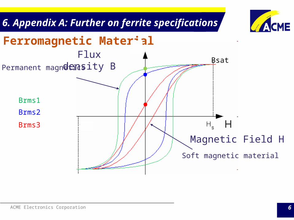
6. Appendix A: Further on ferrite specifications1. Magnetic Remanence (Brms) and Coercivity (Hc),
Brms is a magnetic flux density remaining in material before being magnetized to its saturation point, when magnetic field strength decreases to zero.
Hc is the magnetic field strength which the magnetic flux density of material has previously magnetized to the saturation point decreased to zero.
The unit of H is The unit of B is why?

ACME Electronics Corporation 5
6. Appendix A: Further on ferrite specificationsSo the vector dot integral across the B-H loop is the core loss.
(unit )
(unit ) lower core less depends on the lower Brms and/or Hc
☆ NiZn materials generally has lower Bsat/Brms ratio. This will mislead the test result and judge a good part to a failed one if no correct perception.
Low Loss Material EMI-Suppression Material Low Loss Material
Freq. Flux den. Temp. P41 K15 K081
Initial Permeability μi ≤ 10KHz 0.25mT 25°C 2400 ± 25% 1500 ± 25% 800 ± 25%
25°C 495 330 41025°C 170 200 27225°C 11 10 27
Symbol Unit Measuring Conditions
H=1200A/m
mT 10KHz
Saturation Flux Density Bms mT 10KHz
H=1200A/m
Coercivity Hc A/m 10KHz H=1200A/m
Remanence Brms
ACME Electronics Corporation 6
6. Appendix A: Further on ferrite specifications
Ferromagnetic Material
Magnetic Field H
Flux density BPermanent magnetics
Soft magnetic material
Bsat
Brms1
Brms2
Brms3
ACME Electronics Corporation 7
6. Appendix A: Further on ferrite specifications
LS(uH)DCR
AppliedVoltage
LS(uH) LS(uH)DCR
AppliedVoltage
LS(uH)
BeforeDCR (mV)
AfterDCR Before DCR (mV) After DCR
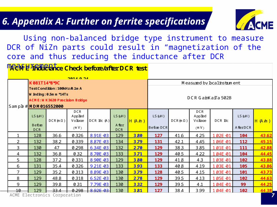
1 128 36.6 0.326 8.91E-03 129 3.80 127 41.6 4.25 1.02E-01 104 43.622 132 38.2 0.339 8.87E-03 134 3.79 131 42.1 4.45 1.06E-01 112 45.153 130 47 0.298 6.34E-03 132 2.70 129 38.3 3.85 1.01E-01 111 42.884 132 36.8 0.32 8.70E-03 133 3.71 129 40.5 4.22 1.04E-01 104 44.455 128 37.2 0.331 8.90E-03 129 3.80 129 41.8 4.3 1.03E-01 102 43.886 131 35.4 0.326 9.21E-03 133 3.93 133 40.8 4.19 1.03E-01 105 43.867 129 35.2 0.313 8.89E-03 130 3.79 128 40.5 4.15 1.03E-01 101 43.738 129 48.8 0.318 6.52E-03 130 2.78 129 39.5 4.13 1.05E-01 102 44.639 129 39.8 0.31 7.79E-03 130 3.32 129 39.5 4.1 1.04E-01 99 44.2510 129 33.4 0.298 8.92E-03 130 3.81 127 38.4 3.99 1.04E-01 102 44.38
ACME Inductance Check before/after DCR test 2014.9.24
Sample #
K081T14*8*9CTest Condition: 100kHz/0.1mAWinding: 0.5mm*14TsACME: WK3620 Precision Bridge
MDM016552000
DCR(mΩ) DCR Idc (A) H (A/m) DCR(mΩ) DCR Idc H (A/m)
Measured by local instrument
DCR GainKaiTa 502B
Using non-balanced bridge type instrument to measure DCR of NiZn parts could result in “magnetization of the core and thus reducing the inductance after DCR measurement.
ACME Electronics Corporation 8
6. Appendix A: Further on ferrite specifications2. Loss Factor Ferrite uses complex permeability to model the inductive and lossy part nature )
This representation is the keystone of CMC in EMC/EMI application. The phase shift caused by magnetic losses is and is termed “Loss Factor” is the “quality factor” [test condition is critical, and winding resistance is incorporated in real life]

ACME Electronics Corporation 9
6. Appendix A: Further on ferrite specifications2. Loss Factor
is the core’s total loss factor composing of hysteresis, eddy current and residual losses; it’s a function of frequency.

ACME Electronics Corporation 10
6. Appendix A: Further on ferrite specifications3. Hysteresis Material Constant (ηB) The parameter characterizes the hysteresis losses in ferrite. It does not depend on the air gap. It represents the nonlinearity of BH curves and is an index of the hysteresis.
(unit
Using this term, core’s hysteresis loss can be singled out from the lumped loss by
This factor is more core nature oriented.

ACME Electronics Corporation 11
6. Appendix A: Further on ferrite specifications
4. Disaccommodation Factor (DF) and Temperature Factor of Permeability (αF)
Disaccommodation is understood as a time variation of the initial permeability occurring after each demagnetization under constant operating conditions. It has been proven by experiments that initial permeability decreases in a linear way by plotting time on a logarithmic scale.
(unit: dimensonless
This is a specification in power ferrite material.
ACME Electronics Corporation 12
6. Appendix A: Further on ferrite specifications
4. Disaccommodation Factor (DF) and Temperature Factor of Permeability (αF)
The permeability of ferrite is a function of temperature.
(unit:
is independent of the air-gap. Temperature coefficient of a coil inductance, having ferrite core with an air-gap, may be calculated by multiplying of the ferrite material, with effective permeability of the core:
inductance thus impedance variation over time, but ui vs. Temp is a “two-peak” curve. chosen is critical, i.e., application specified.

ACME Electronics Corporation 13
6. Appendix A: Further on ferrite specifications
5. Total Harmonic Distortion (THD) Harmonic distortion is generated when a sine wave magnetic field H, which is proportional to the current (), induces a non-sinusoidal flux density B ().
This is due to a non linear relation between B and H in the ferrite core of a transformer. is not a constant but a function of H, also.
in absolute value, normally expressed as %THD in power application

ACME Electronics Corporation 14
6. Appendix A: Further on ferrite specifications
5. Total Harmonic Distortion (%THD)
in dB for telecom application.
V3/V1dB -67 -66 -65 -64 -63 -62 -61 -60
Absolute 4.467E-04 5.012E-04 5.623E-04 6.310E-04 7.079E-04 7.943E-04 8.913E-04 1.000E-03
66 vs. 67 112.20%
65 vs. 67 125.89%
64 vs. 67 141.25%
63 vs. 67 158.49%
62 vs. 67 177.83%
61 vs. 67 199.53%
60 vs. 67 223.87%
THD

ACME Electronics Corporation 15
6. Appendix A: Further on ferrite specifications
5. Total Harmonic Distortion (%THD)
in dB for telecom application.
As in telecom application, the THD requirement is tough, the process and measurement must be taken great care of to avoid ineffective measurement.

ACME Electronics Corporation 16
6. Appendix A: Further on ferrite specifications
5. Total Harmonic Distortion (THD)Example by PSPICE Simulation, by 10 turns (Example in Power) * TX22_14_13_3E27 CORE model (Ae=50.7mm^2, le=54.2mm).MODEL TX22_14_13_3E27 CORE+ MS=377.56E3 A=12.672 C=.20161 K=5.5151 AREA=.507+ PATH=5.4200
Excitation(100kHz)
Magnetic FieldStrength
FluxDensity(1st)
V1 THD (B) THD (B) THD (V) THD (V)
mA H (A/M) mT Volt % (Vn/V1) dB (Vn/V1) % (Vn/V1) dB (Vn/V1)
1 0.185 1.19 0.378 0.81% -41.81 2.52% -31.9610 1.845 15.01 4.764 6.00% -24.43 18.79% -14.5250 9.225 132.49 41.590 12.62% -17.98 38.79% -8.23
100 18.450 269.07 84.761 15.23% -16.35 47.15% -6.53200 36.900 398.77 125.052 19.48% -14.21 64.61% -3.79

ACME Electronics Corporation 17
6. Appendix A: Further on ferrite specifications
5. Total Harmonic Distortion (THD)Example by PSPICE Simulation, by 10 turns * TX22_14_13_3E27 CORE model (Ae=50.7mm^2, le=54.2mm)
B-H curve can be simulated with ferrite core model incorporated
ACME Electronics Corporation 18
6. Appendix A: Further on ferrite specifications
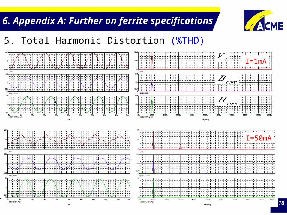
5. Total Harmonic Distortion (%THD)
I=1mA
I=50mA
𝐵𝑐𝑜𝑟𝑒
𝑉 𝐿
𝐻𝑐𝑜𝑟𝑒

ACME Electronics Corporation 19
6. Appendix A: Further on ferrite specifications
5. Total Harmonic Distortion (%THD)I=100mAB=270mT

ACME Electronics Corporation 20
6. Appendix A: Further on ferrite specifications
6. Quality Factor (Q) Quality factor is related to loss factor but more a finished product specification.
This Q factor is a good index for CMC or signal filtering type applications, i.e., for “signal” level application. But for power choke, using the Q as the index of quality is really misleading and this mistake is seen commonly.
ACME Electronics Corporation 21
6. Appendix A: Further on ferrite specifications
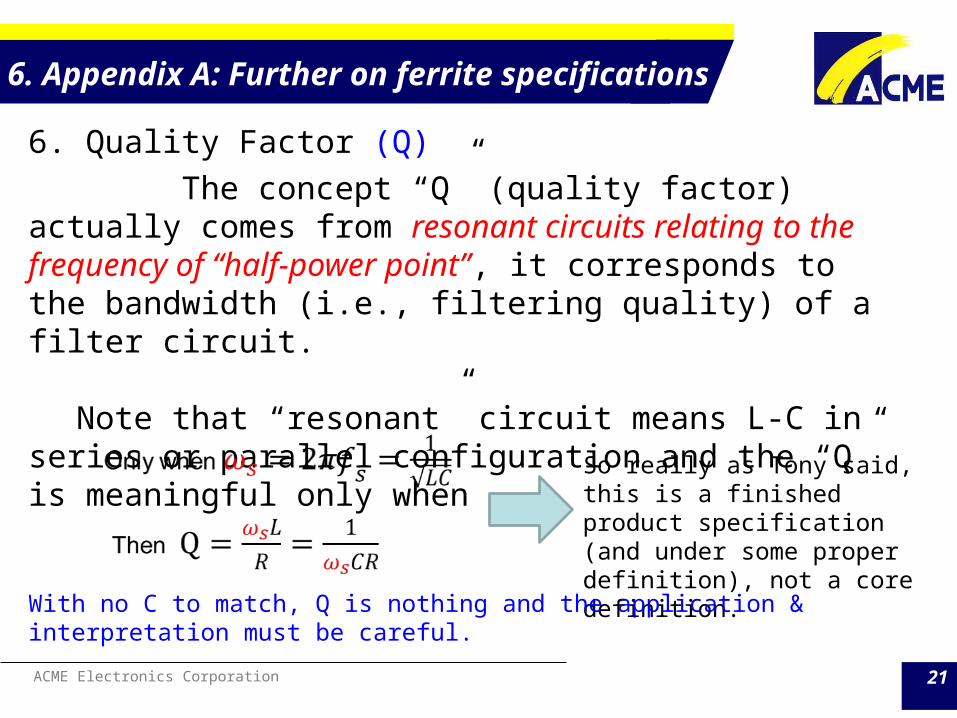
6. Quality Factor (Q) The concept “Q” (quality factor) actually comes from resonant circuits relating to the frequency of “half-power point”, it corresponds to the bandwidth (i.e., filtering quality) of a filter circuit.
Note that “resonant” circuit means L-C in series or parallel configuration and the “Q” is meaningful only when
So really as Tony said, this is a finished product specification (and under some proper definition), not a core definition.
With no C to match, Q is nothing and the application & interpretation must be careful.

ACME Electronics Corporation 22
6. Appendix A: Further on ferrite specifications
LC fixed
smaller
larger
Illustration of serial resonant circuit
6. Quality Factor (Q)
ACME Electronics Corporation 23
6. Appendix A: Further on ferrite specifications
6. Quality Factor (Q) If this Q is to be employed as the core loss quality indicator, we already know the flux and flux density can be obtained by:
where is the highest possible flux density in the design
The inductance of a specific core
where is the zero gap single turn inductance (permeance)

ACME Electronics Corporation 24
6. Appendix A: Further on ferrite specifications
6. Quality Factor (Q)
For to be able to reflect the core’s (or the choke’s) quality in terms of losses. The “flux” level must meet the real application scenario to obtain the meaningful figure.
For example: A core with Ae=146.67mm^2, le=61.36mm with 22 turns of winding for power choke. The operational condition will require flux density well above 200mT. To have this , the applied voltage will be
Assuming the switching frequency is 100kHz
ACME Electronics Corporation 25
6. Appendix A: Further on ferrite specifications
6. Quality Factor (Q) If the Q measuring requirement in the approval sheet is specified as 1Vrms/100kHz, the flux density will be
The Q number obtained with this flux level will never reflect the real quality scenario in the loss aspect of real application.
If this is DC-DC choke, the perturbation of V and I is small, theoretically, small Vrms is nothing wrong. But …….

ACME Electronics Corporation 26
6. Appendix A: Further on ferrite specifications
6. Quality Factor (Q)
Idc must be applied in doing the Q measurement, why? Q=
𝜔𝐿𝑅
ACME Electronics Corporation 27
7. Appendix B: (a) Fringing Effect of Gapped Core
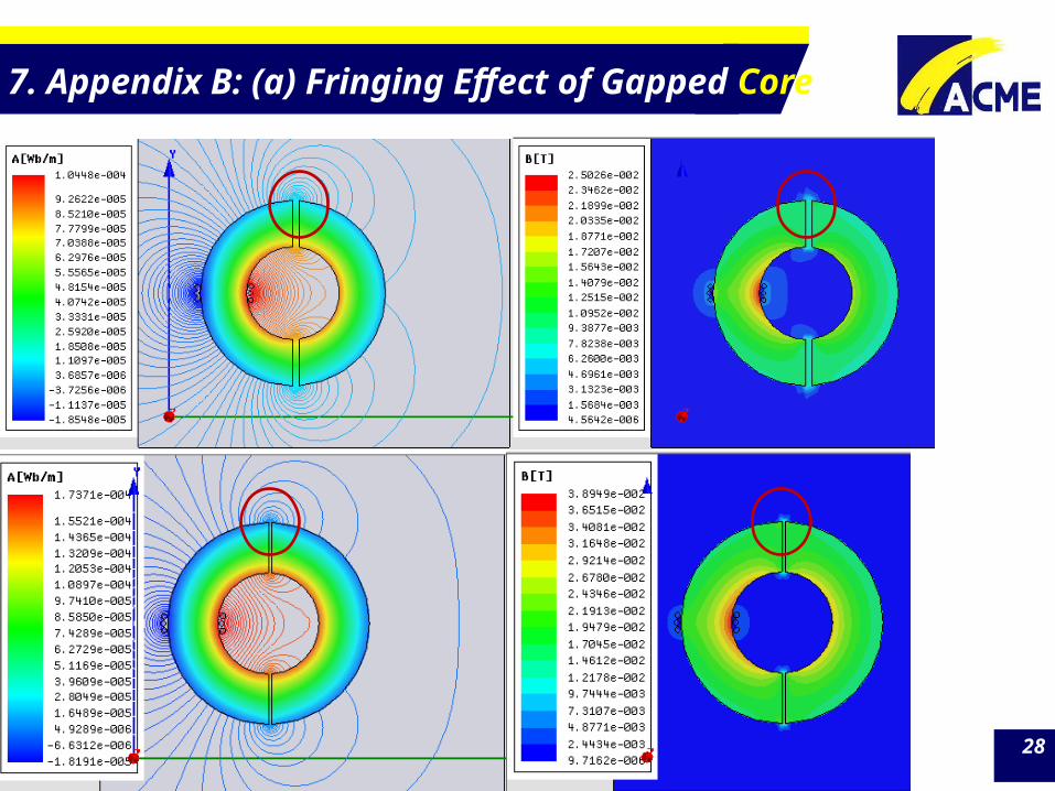
Most of the time, the inductance calculation of gapped cores ignores the fact of “fringing effect” and the distribution of MMF and magnetic field strength H across the flux loop is
But for “big” gap, the effect can not be ignored, it means1. The effective area for the core, Ac, and air, Ag, will be different. 2. Bigger results in a smaller air flux density , thus a smaller ,
The result, the actual inductance is higher than the calculation result by assuming no fringing effect for the same gap.
ACME Electronics Corporation 28
7. Appendix B: (a) Fringing Effect of Gapped Core

ACME Electronics Corporation 29
7. Appendix B: (a) Fringing Effect of Gapped Core

ACME Electronics Corporation 30
The simplest way to model is to assuming the fringing area extended one gap length around the gap, thus
for rectangular cores
for circular path
7. Appendix B: (a) Fringing Effect of Gapped Core
ACME Electronics Corporation 31
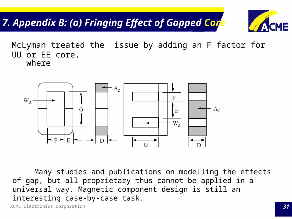
McLyman treated the issue by adding an F factor for UU or EE core. where
Many studies and publications on modelling the effects of gap, but all proprietary thus cannot be applied in a universal way. Magnetic component design is still an interesting case-by-case task.
7. Appendix B: (a) Fringing Effect of Gapped Core

ACME Electronics Corporation 32
Even for a simple EE core, there are at least two distinctive , and the coherence between the inductance calculation (modeling) and real measurement becomes very interesting and challenging.
Ampere’s law and Faraday’s law of magnetic induction still work
=
But the bondage between and thus and is broken, that’s why so many modeling effort before FEM tool came into place.
7. Appendix B: (a) Fringing Effect of Gapped Core

ACME Electronics Corporation 33
For ur=3000 material of core EEL25E (Ae=32.62mm2 & le=81.48mm), assuming the B-H curve from standard ring core can be directly applied, then a 50um gap will have the magnetizing curve inflated as show below.
7. Appendix B: (b) Manipulating magnetizing curve

ACME Electronics Corporation 34
The “gap” not only decreases the inductance but also increases the power dissipations on the core.
𝑃𝑐=𝑉 𝑐𝑜𝑟𝑒 ∙ 𝑓𝑟𝑒𝑞 ∙ ∮𝑑 𝑦𝑛𝑎𝑚𝑖𝑐 𝑙𝑜𝑎𝑑
❑
�⃗� 𝑑 �⃗� 𝑃𝑐=𝑑 ( Λ⃗ ∙ �⃗�)𝑑𝑡
7. Appendix B: (b) Manipulating magnetizing curve

ACME Electronics Corporation 35
8. Appendix C: An analogy and differentiation on R, C, and L

ACME Electronics Corporation 36
8. Appendix C: An analogy and differentiation on R, C, and L Resistor (R) & Capacitor (C)1. Highly standardized in size, power rating, and tolerance per different
applications need.
2. Electrical/electronic engineers know how to use it “out-of-box” per vendor’s part number and specification sheet, due to its high degree of standardization.
3. R might be a function temperature or its many intrinsic material properties. But it is uniquely determined by the and at the instant. No time varying nature of the and involved.
4. C is defined to describe the electrical energy transfer in between the potential energy (voltage) and kinetic energy (current) forms. It is the coefficient for the time variant behavior but purely electrical in nature, beside the intrinsic material properties.

ACME Electronics Corporation 37
8. Appendix C: An analogy and differentiation on R, C, and L Inductor (L) & Transformer (X’mer)1. Inductor L is created to interpret the phenomenon of generated counter-
force (electro-magnetic force, EMF) from a time-varying current through a closed-loop circuit (by the Faraday Law of Electromagnetic Induction)
+i
Electron orbiting the nucleus of an atom produces a magnetic field..

ACME Electronics Corporation 38
8. Appendix C: An analogy and differentiation on R, C, and L Inductor (L) & Transformer (X’mer)
2. Ferrite is a magnetic material, but not magnetic component like L or X’mer.
ACME only produces ferrites that can be applied to make L or X’mer in applications.
3. The nature of L and X’mer involves magneto-electrical conversion (highly non-linear) based on the properties of the magnetic material; and can only be designed under case-by-case condition.
No “out –of-box” L or X’mer is available when designing them with ferrite cores.

ACME Electronics Corporation 39
8. Appendix C: An analogy and differentiation on R, C, and L
Different from capacitors, the intrinsic natures of magnetic material are more “non-linear” or highly variant, thus more elaborated design-in effort to the customer side is needed. [Note: this “design-in effort” is not as intense as the case of L in R & C, as it is taken care of by the neat component properties and during the component making.]

ACME Electronics Corporation 40
8. Appendix C: An analogy and differentiation on R, C, and L

ACME Electronics Corporation 41
8. Appendix C: An analogy and differentiation on R, C, and L

ACME Electronics Corporation 42
8. Appendix C: An analogy and differentiation on R, C, and L
ACME Electronics Corporation 43
8. Appendix C: An analogy and differentiation on R, C, and L
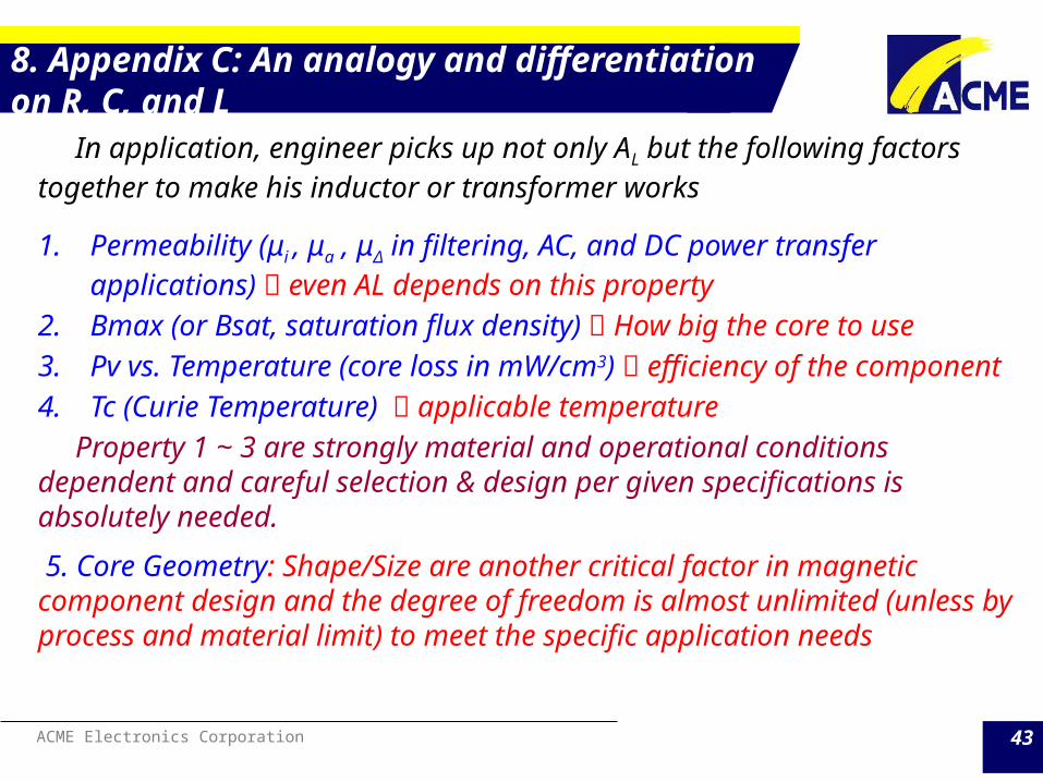
In application, engineer picks up not only AL but the following factors together to make his inductor or transformer works
1. Permeability (μi , μa , μΔ in filtering, AC, and DC power transfer applications) even AL depends on this property
2. Bmax (or Bsat, saturation flux density) How big the core to use3. Pv vs. Temperature (core loss in mW/cm3) efficiency of the component4. Tc (Curie Temperature) applicable temperature Property 1 ~ 3 are strongly material and operational conditions dependent and careful selection & design per given specifications is absolutely needed.
5. Core Geometry: Shape/Size are another critical factor in magnetic component design and the degree of freedom is almost unlimited (unless by process and material limit) to meet the specific application needs

ACME Electronics Corporation 44
8. Appendix C: An analogy and differentiation on R, C, and L
Unlike inductor which is a single winding device, any core wound with two (or above) windings can be called a transformer. Still the “magnetizing inductance” is the essence underlining the “transformer” operation.
Equivalent circuit model of a two-winding transformer, the red rectangle part is the magnetizing inductance

ACME Electronics Corporation 45
8. Appendix C: An analogy and differentiation on R, C, and L
Ideal transformer
𝑖𝑠𝑢𝑚=𝑖𝑚+𝑖1
𝑣1=𝐿𝑚𝑑𝑖𝑚𝑑𝑡
Lm is the key that a transformer works
ACME Electronics Corporation 46
8. Appendix C: An analogy and differentiation on R, C, and L
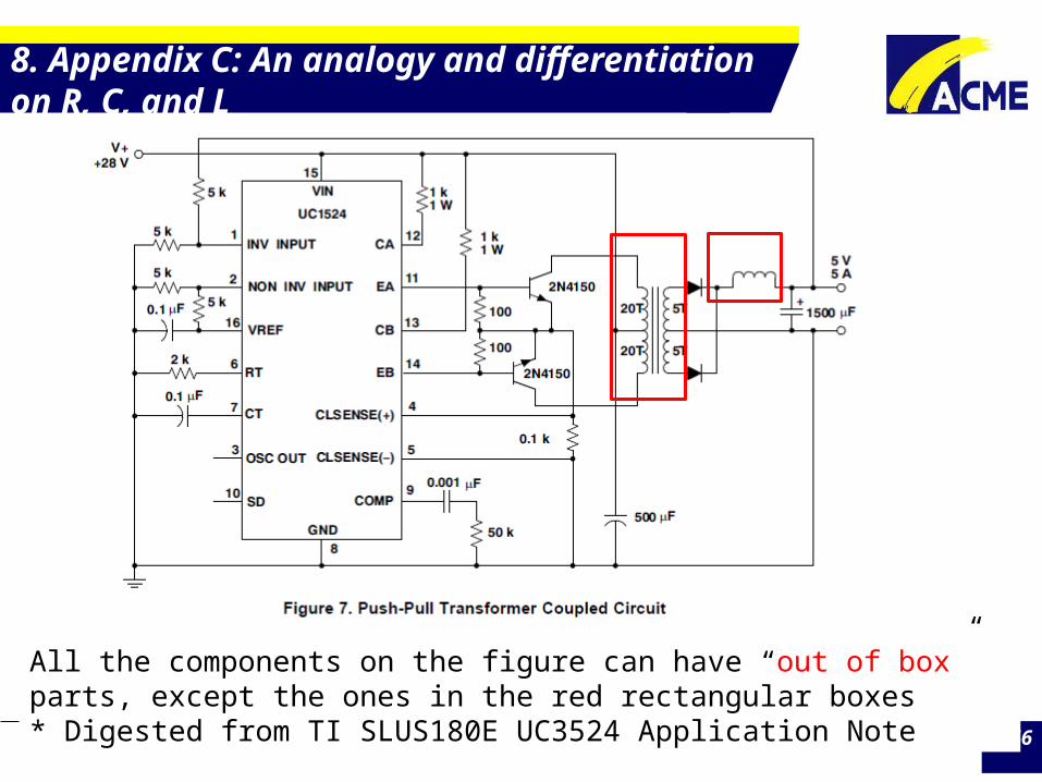
All the components on the figure can have “out of box” parts, except the ones in the red rectangular boxes * Digested from TI SLUS180E UC3524 Application Note
ACME Electronics Corporation 47
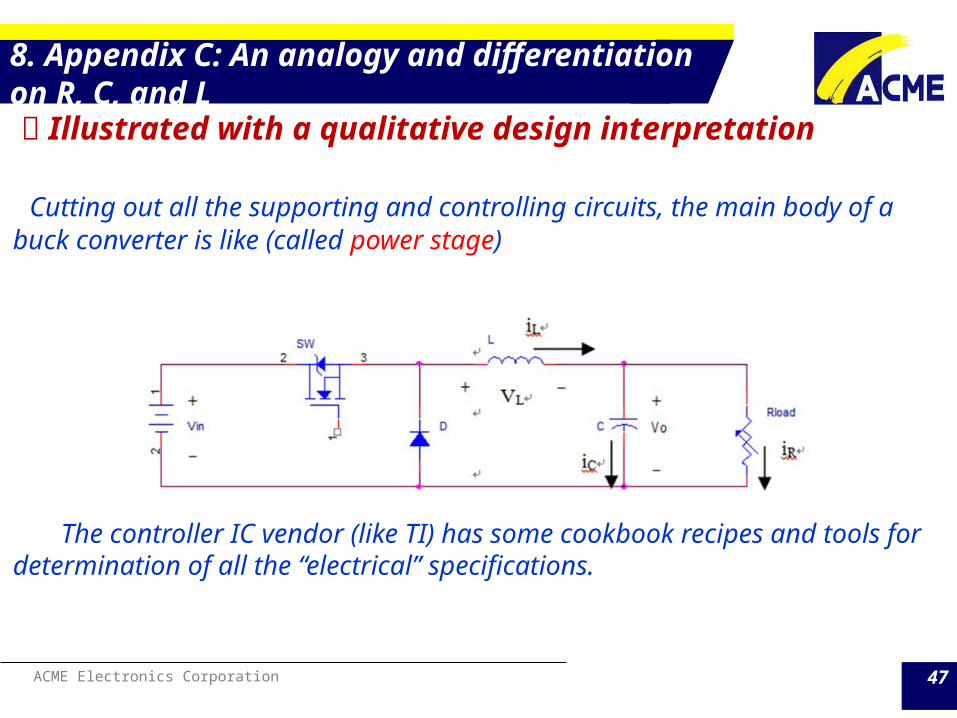
8. Appendix C: An analogy and differentiation on R, C, and L Illustrated with a qualitative design interpretation Cutting out all the supporting and controlling circuits, the main body of a buck converter is like (called power stage)
The controller IC vendor (like TI) has some cookbook recipes and tools for determination of all the “electrical” specifications.

ACME Electronics Corporation 48
8. Appendix C: An analogy and differentiation on R, C, and L

ACME Electronics Corporation 49
8. Appendix C: An analogy and differentiation on R, C, and L
The voltage and current waveforms across the inductor
Volt-second balance principle:The above two shades must be equal in area,
the area V*time actually is the magnetic flux linkage.This value determines whether the magnetic material should be silicon steel, amorphous, SiFe compound or ferrite.

ACME Electronics Corporation 50
8. Appendix C: An analogy and differentiation on R, C, and L
System design engineer by his/her knowledge usually knows how to choose L correctly.
But the majority of them have no idea on how to make the L work for the design. This is assigned to another group of people with adequate knowledge in magnetic component making.
From the information of the blue rectangle, an inductor with inductance 500uH can be made.
How L is determined? By the tolerable current ripple:

ACME Electronics Corporation
8. Appendix C: An analogy and differentiation on R, C, and L How L is determined? By the tolerable current ripple:
From the information of the blue rectangle, an inductor with inductance 500uH can be made per the following steps.1) First select the valid material suitable (frequency range,
mr 、 Hc 、 Br 、 Bsat 、 temperature coefficient of mr)
2) Determine the CORE’s mechanical dimensions and gap sizeThe degree of freedom is high
3) Applying the windings N to have the desired inductance. This procedure can be summarized as:
ACME Electronics Corporation
8. Appendix C: An analogy and differentiation on R, C, and L
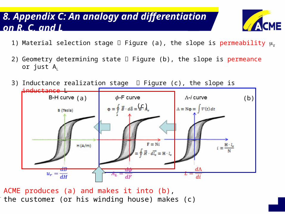
1) Material selection stage Figure (a), the slope is permeability mr
2) Geometry determining state Figure (b), the slope is permeance or just AL
3) Inductance realization stage Figure (c), the slope is inductance L (a) (b) (c)
ACME produces (a) and makes it into (b), the customer (or his winding house) makes (c)

ACME Electronics Corporation 53
7. Open Discussions

ACME Electronics Corporation
ACME Electronics Corporation Aggressively Committed to Manufacturing Excellence
Thank You~
Related Documents