Fermi National Accelerator Laboratory Minimizing Dispersion in Flexible Momentum Compaction Lattices S.Y. Lee, K.Y. Ng and D. Trbojevic Fermi National Accelerator Laboratory P.O. Box 500, Bat&a, Illinois 60510 July 1993 Submitted to Physical Review E G Operated by Unlvetities Research Association Inc. under Cmtlact No. DE-ACm-76CH03WO witi the United States Deparknent of Energy

Welcome message from author
This document is posted to help you gain knowledge. Please leave a comment to let me know what you think about it! Share it to your friends and learn new things together.
Transcript
Fermi National Accelerator Laboratory
Minimizing Dispersion in Flexible Momentum Compaction Lattices
S.Y. Lee, K.Y. Ng and D. Trbojevic
Fermi National Accelerator Laboratory P.O. Box 500, Bat&a, Illinois 60510
July 1993
Submitted to Physical Review E
G Operated by Unlvetities Research Association Inc. under Cmtlact No. DE-ACm-76CH03WO witi the United States Deparknent of Energy

Disclaimer
This report was prepared as an account ofwork sponsored by an agency ofthe United States Government. Neither the United States Government nor any agency thereof nor any of their employees, makes any warranty, express or implied, or assumes any legal liability or responsibility for the accuracy, completeness, or usefulness of any information, apparatus, product, or process disclosed, or represents that its use would not infringe privately owned rights. Reference herein to any specific commercial product, process, or service by trade name, trademark, manufacturer, or otherwise, does not necessarily constitute or imply its endorsement, recommendation, or favoring by the United States Government or any agency thereof, The views and opinions of authors expressed herein do not necessarily state or reflect those of the United States Government or any agency thereof.

PUB-93-187
Minimizing Dispersion in Flexible Momentum Compaction Lattices
S.Y. Lee,* K.Y. Ng, and D. Trbojevic’
Fermi National Accelerator Lnboratory,t P.O. Box 500, Batavia, IL 60510
(June 1992)
(To be published in Physical Review E)
‘Permanent address: Department of Physics, Indiana University, Bloomington, IN 47405.
+Present address: Brookhaven National Laboratory, Upton, Long Island, NY 11973.
‘Operated by the Universities Research Association, Inc., under contract with the U. S. Depart.
ment of Energy.

Abstract
Medium energy accelerators are often confronted with problems during transi-
tion energy crossing, such as longitudinal microwave instability and nonlinear
synchrotron motion. These problems can be avoided by an accelerator having
a negative momentum compaction factor. A modular method for designing a
lattice with adjustable momentum compaction factor is presented. The dis-
persion excursion of the basic flexible momentum compaction module can be
reduced to less than the maximum dispersion of the FODO lattice containing
the same FODO cells. The phase advance of the module can be adjusted to be
an odd multiple of quarter betatron waves. We found that a lattice composed
of such modules possesses excellent chromatic properties with excellent tnn-
ability, smaller systematic stopband widths, and smaller sextupole distortion
functions.

I. INTRODUCTION
The deviation of the revolution period AT for an off-momentum particle at momentum
p. + Ap relative to that of the synchronous (on-momentum) particle at momentum po and
revolution period To is given by
AT -= TO
(1.1)
where the 7 = 01 - y -s is called the phase-slip factor, y is the Lorentz relativistic factor
for the on-momentum particle, and 01 is the momentum compaction factor, which measures
the path length difference, AC, between the off-momentum particle and the on-momentum
particle, i.e. g = cr%, where Co is the circumference of the reference orbit. To the lowest
order in Ap/po, 01 is related to the horizontal momentum dispersion function D(s) by
1 !
D(s) ds aI=- - co P(S) '
(14
where p is the radius of curvature and s is the longitudinal path length measured along the
reference orbit. During the acceleration of beam particles, the phase-slip factor changes sign
as y crosses yt = a-‘/*. The particle energy at “it is called the transition energy.
There are many unfavorable effects on the particle motion around transition energy.
The momentum spread of a bunch around transition can become so large that it exceeds the
available momentum aperture and beam loss occurs. There is little or no Landau damping
against microwave instability near transition [I]. As a result, the bunch area grows due
to the space-charge force of the beam as well as due to the wake forces created by the
bunch inside the vacuum chamber. Particles with different momenta may cross transition
at different times leading to longitudinal phase space distortions and beam loss.
To avoid all the above unfavorable effects, it is appealing to eliminate transition crossing.
A +yt jump mechanism was proposed by Lee and Teng [2] to ease beam dynamics problems
associated with the transition crossing, where a special set of quadrupoles are pulsed so
that the transition energy is lowered or raised during the transition energy crossing. Such
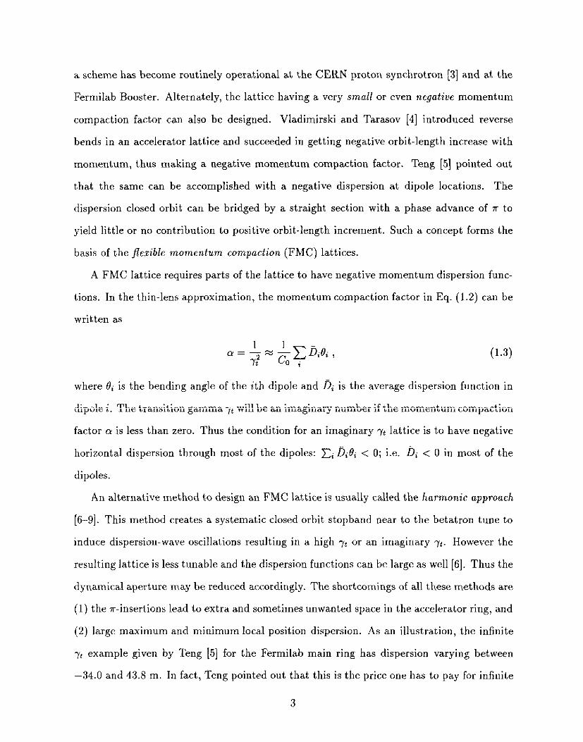
a scheme has become routinely operational at the CERN proton synchrotron [3] and at the
Fermilab Booster. Alternately, the lattice having a very small or even negative momentum
compaction factor can also be designed. Vladimirski and Tarasov [4] introduced reverse
bends in an accelerator lattice and succeeded in getting negative orbit-length increase with
momentum, thus making a negative momentum compaction factor. Teng [5] pointed out
that the same can be accomplished with a negative dispersion at dipole locations. The
dispersion closed orbit can be bridged by a straight section with a phase advance of ?r to
yield little or no contribution to positive orbit-length increment. Such a concept forms the
basis of the jkzible momentum compaction (FMC) lattices.
A FMC lattice requires parts of the lattice to have negative momentum dispersion func-
tions. In the thin-lens approximation, the momentum compaction factor in Eq. (1.2) can be
written as
1 a=-i~~CDitli, 72 0,
(1.3)
where Bi is the bending angle of the ith dipole and Di is the average dispersion function in
dipole i. The transition gamma 7t will be an imaginary number if the momentum compaction
factor cy is less than zero. Thus the condition for an imaginary y* lattice is to have negative
horizontal dispersion through most of the dipoles: Ci DiQi < 0; i.e. 0; < 0 in most of the
dipoles.
An alternative method to design an FMC lattice is usually called the harmonic approach
[6-91. This method creates a systematic closed orbit stopband near to the betatron tune to
induce dispersion-wave oscillations resulting in a high yt or an imaginary yt. However the
resulting lattice is less tunable and the dispersion functions can be large as well [6]. Thus the
dynamical aperture may be reduced accordingly. The shortcomings of all these methods are
(1) the a-insertions lead to extra and sometimes unwanted space in the accelerator ring, and
(2) large maximum and minimum local position dispersion. As an illustration, the infinite
-yt example given by Teng 151 for the Fermilab main ring has dispersion varying between
-34.0 and 43.8 m. In fact, Teng pointed out that this is the price one has to pay for infinite
3
transition energy.
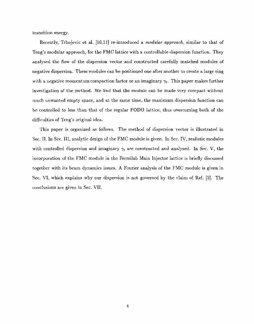
Recently, Trbojevic et al. [l&11] re-introduced a modular approach, similar to that of
Teng’s modular approach, for the FMC lattice with a controllable dispersion function. They
analysed the flow of the dispersion vector and constructed carefully matched modules of
negative dispersion. These modules can be positioned one after another to create a large ring
with a negative momentum compaction factor or an imaginary Y<. This paper makes further
investigation of the method. We find that the module can be made very compact without
much unwanted empty space, and at the same time, the maximum dispersion function can
be controlled to less than that of the regular FODO lattice, thus overcoming both of the
difficulties of Teng’s original idea.
This paper is organized as follows. The method of dispersion vector is illustrated in
Sec. II. In Sec. III, analytic design of the FMC module is given. In Sec. IV, realistic modules
with controlled dispersion and imaginary -n are constructed and analysed. In Sec. V, the
incorporation of the FMC module in the Fermilab Main Injector lattice is briefly discussed
together with its beam dynamics issues. A Fourier analysis of the FMC module is given in
Sec. VI, which explains why our dispersion is not governed by the claim of Ref. [5]. The
conclusions are given in Sec. VII.
4
II. REVIEW OF THE METHOD OF DISPERSION ANALYSIS
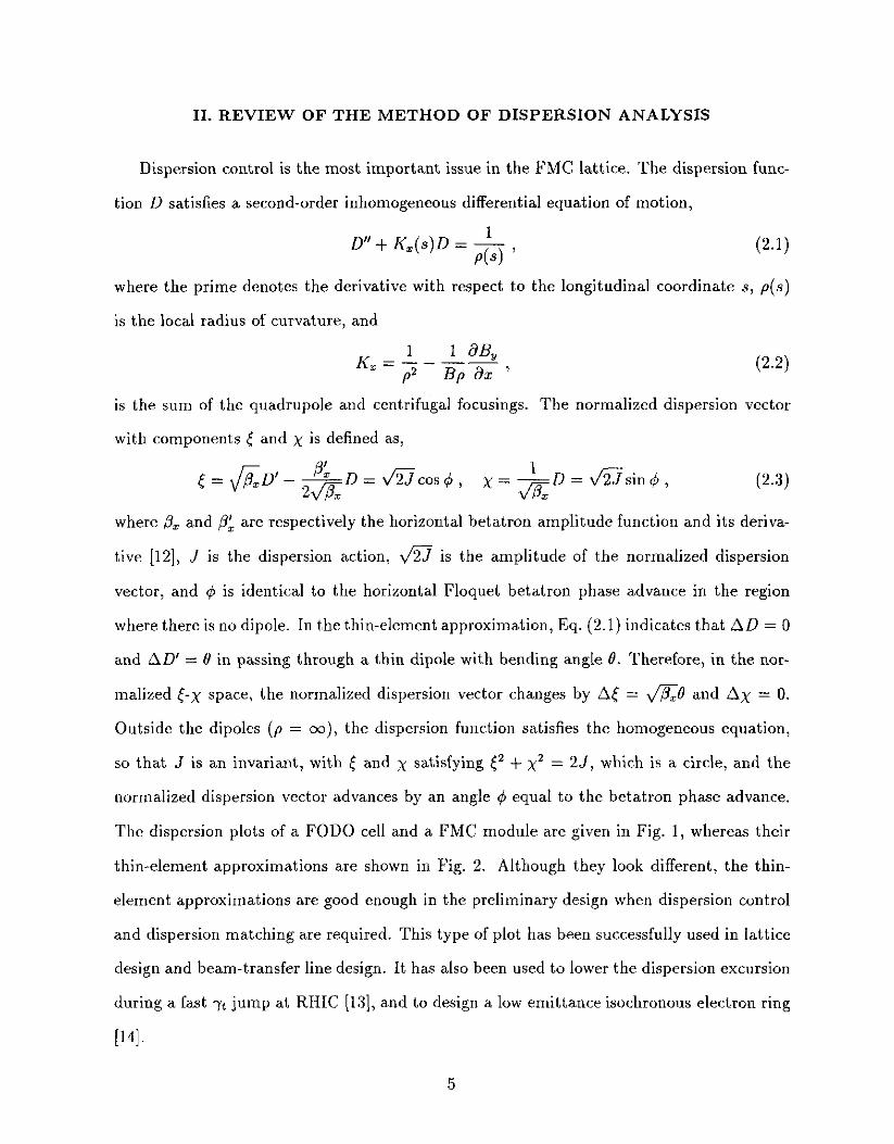
Dispersion control is the most important issue in the FMC lattice. The dispersion func-
tion D satisfies a second-order inhomogeneous differential equation of motion,
D” + K,(s)D = h ,
where the prime denotes the derivative with respect to the longitudinal coordinate s, p(.s)
is the local radius of curvature, and
K =~-r% 5 P2 Bp ax ’ (2.2)
is the sum of the quadrupole and centrifugal focusings. The normalized dispersion vector
with components [ and x is defined as,
~=fiD’-~D=~cos~, ‘D=v’%sin4, I x=dE
(2.3)
where /& and ,BL are respectively the horizontal betatron amplitude function and its deriva-
tive [12], J is the dispersion action, a is the amplitude of the normalized dispersion
vector, and 4 is identical to the horizontal Floquet betatron phase advance in the region
where there is no dipole. In the thin-element approxima,tion, Eq. (2.1) indicates that AD = 0
and AD’ = 0 in passing through a thin dipole with bending angle 0. Therefore, in the nor-
malized t-x space, the normalized dispersion vector changes by A[ = fi0 and Ax = 0.
Outside the dipoles (p = XI), the dispersion function satisfies the homogeneous equation,
so that J is an invariant, with [ and x satisfying <* + x2 = 25, which is a circle, and the
normalized dispersion vector advances by an angle 4 equal to the betatron phase advance.
The dispersion plots of a FODO cell and a FMC module are given in Fig. 1, whereas their
thin-element approximations are shown in Fig. 2. Although they look different, the thin-
element approximations are good enough in the preliminary design when dispersion control
and dispersion matching are required. This type of plot has been successfully used in lattice
design and beam-transfer line design. It has also been used to lower the dispersion excursion
during a fast -n jump at RHIC (131, and to design a low emittance isochronous electron ring
1141.
5

III. THE BASIC MODULE
A basic FMC module is made of two parts: (1) the FODO cell part where the negative
dispersion function in dipoles provides a negative momentum compaction factor and (2) a
matching section which matches the optical functions. Let us assume a reflective symmetry
of all Courant-Snyder functions within the module with respect to the vertical x axis in
the normalized dispersion space. Although this is not a necessary condition, the reflection
symmetry simplifies the analysis and optical matching considerably. The basic module
containing two FODO cells can therefore be expressed as
M, { ;QF B QD B $QF} Ma { QF, 01 QD, CJz} M, + refl. sym. beam line , (3.1)
where IW~,~,~ are marker locations, Q’s are quadrupoles, O’s are drift spaces, and B’s stand
for dipoles.
The horizontal betatron transfer matrix of the FODO cell from marker M, to marker
Mb is given by
cos p j9j7ssinp D,r(l-cosp)
M FODO =
t
-&sinp cos ,u %ssinp ,
i
(3.2)
0 0 1
where (I is the horizontal phase advance in the FODO cell, /3p, Dp are respectively the
betatron amplitude and dispersion function at the center of the focusing quadrupole for
the regular FODO cell, with symmetry condition & = 0 and D& = 0. In the thin-lens
approximation with equal focusing and defocusing strengths, the Courant-Snyder parameters
are given by
P LF
sin 2 = 5 ’ PF=
2LF(1 + sin $) sin fl , DF=
L.42 + sin $) 2sin*f ’ (3.3)
where LF is the length of the half FODO cell, f is the focal length of quadrupoles in the
FODO cell, and 8 is the bending angle of the dipole B. However it is worth pointing out
that the applicability of Eq. (3.2) 1s not limited to thin-lens approximation.
6
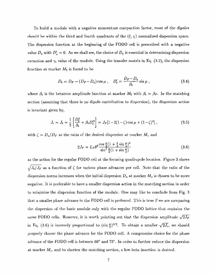
To build a module with a negative momentum compaction factor, most of the dipoles
should be within the third and fourth quadrants of the ([, x) normalized dispersion space.
The dispersion function at the beginning of the FODO cell is prescribed with a negative
value Da with 0: = 0. As we shall see, the choice of D, is essential in determining dispersion
excursion and -n value of the module. Using the transfer matrix in Eq. (3.2), the dispersion
function at marker Mb is found to be
Db = DF - (D,v-Da)cosp, D, = DF-Da .
b @b
slnp,
where @b is the betatron amplitude function at marker Mb with pb = @F. In the matching
section (assuming that there is no dipole contribution to dispersion), the dispersion action
is invariant given by,
.=.=;[$$+.D(, = J~[1-2(1-~)cos~ + (l--C)‘] ,
with < = D,/DF as the ratio of the desired dispersion at marker Ma and
2JF = LF@ cos ‘(1 + i sin $)a
sin3 t( 1 + sin $j)
(3.5)
as the action for the regular FODO cell at the focusing quadrupole location. Figure 3 shows
/ Jb Jp as a function of [ for various phase advances per cell. Note that the ratio of the
dispersion norms increases when the initial dispersion D, at marker M, is chosen to be more
negative. It is preferable to have a smaller dispersion action in the matching section in order
to minimize the dispersion function of the module. One may like to conclude from Fig. 3
that a smaller phase advance in the FODO cell is preferred. This is true if we are comparing
the dispersion of the basic module only with the regular FODO lattice that contains the
same FODO cells. However, it is worth pointing out that the dispersion amplitude v”%&
in Eq. (3.6) is inversely proportional to (sin :)“/a. To obtain a smaller a, we should
properly choose the phase advance for the FODO cell. A compromise choice for the phase
advance of the FODO cell is between 60” and 75”. In order to further reduce the dispersion
at marker MC, and to shorten the matching section, a low-beta insertion is desired.
7
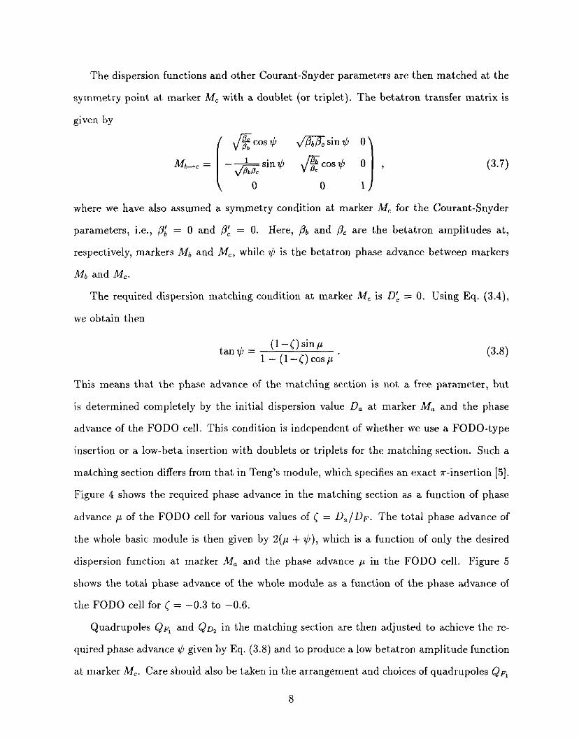
The dispersion functions and other Courant-Snyder parameters are then matched at the
symmetry point at marker M, with a doublet (or triplet). The betatron transfer matrix is
given by
f &fcos$ di%iZsinti O\ M b-c =
I
-*sin* cos$ 0
0 0 1 J
,
where we have also assumed a symmetry condition at marker MC for the Courant-Snyder
parameters, i.e., /3: = 0 and & = 0. Here, /& and /I$ are the betatron amplitudes at,
respectively, markers Mb and MC, while II, is the betatron phase advance between markers
Mb and MC.
The required dispersion matching condition at marker MC is 0: = 0. Using Eq. (3.4),
we obtain then
(1-<)sin/l tang = 1- (I-<)cos/L
This means that the phase advance of the matching section is not a free parameter, but
is determined completely by the initial dispersion value D, at marker A4, and the phase
advance of the FODO cell. This condition is independent of whether we use a FODO-type
insertion or a low-beta insertion with doublets or triplets for the matching section. Such a
matching section differs from that in Teng’s module, which specifies an exact r-insertion [5].
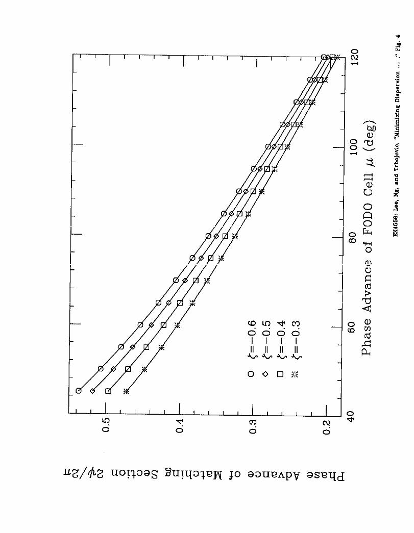
Figure 4 shows the required phase advance in the matching section as a function of phase
advance p of the FODO cell for various values of C = D,/DF. The total phase advance of
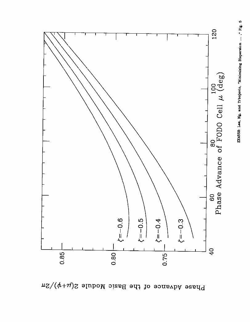
the whole basic module is then given by 2(~ + $), w nc 1 h IS a function of only the desired
dispersion function at marker M, and the phase advance p in the FODO cell. Figure 5
shows the total phase advance of the whole module as a function of the phase advance of
the FODO cell for [ = -0.3 to -0.6.
Quadrupoles QF, and Qn, in the matching section are then adjusted to achieve the re-
quired phase advance II, given by Eq. (3.8) and to produce a low betatron amplitude function
at marker M,. Care should also be taken in the arrangement and choices of quadrupoles QF,
8

and Qoz in order to achieve reasonably small vertical Courant-Snyder parameters. Then,
the matching becomes relatively simple. From the beam dynamics point of view, a basic
module with a phase advance of $ is preferable due to the cancellation in the systematic
half-integer stopband and the sextupole distortion functions. To achieve a $r phase advance,
C = -0.3 to -0.4 and a phase advance per FODO cell of p = 60” to 75” can be used.
The dispersion values at the midpoints of dipoles in the FODO cell are given by
DB, = D,(l - isin ip), ~~~ = D,(l - i sin ip) + (Dp-Do) sin* $p.
In the thin-element approximation, the momentum compaction becomes
oL= (DBI +DB& Ln ’
(3.9)
(3.10)
where 0 is the bending angle of each dipole and L, is the length of the half-module. In com-
parison with the momentum compaction factor of a lattice composed entirely of conventional
FODO cells, we obtain
a 2LF -= L %ODO m
(3.11)
Note that the momentum compaction factor of the module is determined entirely by the
choice of D,, the phase advance of the FODO cell and the ratio of the lengths of the
FODO cell and the module. When length of the module is a constant, the momentum
compaction factor depends linearly on the initial dispersion function D,. Although the
thin-lens approximation has been used for the quadrupoles and dipoles, it is easy to see that
this linear relationship is exact even for thick elements. If the horizontal phase advance pz
of the FODO cell is different from its vertical phase advance py, Eqs. (3.9) and (3.11) still
hold when the replacements,
. 21 21 sm 2~ + sm 5~~ ,
~sin~fl+~(S-+JGXJ , (3.12)
are made, where s& = sin*$~,fsin’~~,.
9

The above analysis can be applied also to a DOFO cell discussed in our previous study
[lo]. In the case with DOFO cells, the variables with the subscript F in Eqs. (3.1) to (3.4)
should be replaced with the values at the defocusing quadrupole. In fact, JD is slightly
larger than JF. A slightly smaller ]<I h as o t b e used in order to minimize the magnitude
of the dispersion function in the module, because the dispersion value at the defocusing
quadrupole location is smaller than that at the focusing quadrupole location. From Fig. 5,
we observe therefore that a larger phase advance should be used in the low-beta matching
section, where a triplet should be used. It becomes harder, however, to achieve the condition
of irr phase advance in the basic module.
For some economical reasons, one may try to use DOFODO in place of the FODO cell
in Eq. (3.1), i.e., three FODO cells instead of two are placed inside a basic module, The
betatron transfer matrix in the DOFODO cell becomes
M o+b = -*sin$ #cos~p
i
&sin$ , (3.13) F
0 0 1 J
where /L is the phase advance of a FODO cell, PF, /3n, DF, DD are, respectively, betatron
amplitudes and dispersion values at the focusing and defocusing quadrupoles of the FODO
cells. Similar analysis with different number of FODO cells can be repeated easily. In
general, the result will be a larger total dispersion value with less favorable phase advance
for the module.
10
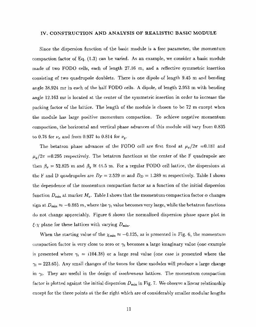
IV. CONSTRUCTION AND ANALYSIS OF REALISTIC BASIC MODULE
Since the dispersion function of the basic module is a free parameter, the momentum
compaction factor of Eq. (1.3) can be varied. As an example, we consider a basic module
made of two FODO cells, each of length 27.16 m, and a reflective symmetric insertion
consisting of two quadrupole doublets. There is one dipole of length 9.45 m and bending
angle 38.924 mr in each of the half FODO cells. A dipole, of length 2.953 m with bending
angle 12.163 mr is located at the center of the symmetric insertion in order to increase the
packing factor of the lattice. The length of the module is chosen to be 72 m except when
the module has large positive momentum compaction. To achieve negative momentum
compaction, the horizontal and vertical phase advances of this module will vary from 0.835
to 0.76 for V, and from 0.937 to 0.814 for vy.
The betatron phase advances of the FODO cell are first fixed at pz/27r =0.181 and
pY/27r =0.295 respectively. The betatron functions at the center of the F quadrupole are
then & = 52.825 m and p, g 44.5 m. For a regular FODO cell lattice, the dispersions at
the F and D quadrupoles are DF = 2.529 m and DD = 1.289 m respectively. Table I shows
the dependence of the momentum compaction factor as a function of the initial dispersion
function Dh,, at marker M,. Table I shows that the momentum compaction factor cy changes
sign at Dh,, x -0.885 m, where the yt value becomes very large, while the betatron functions
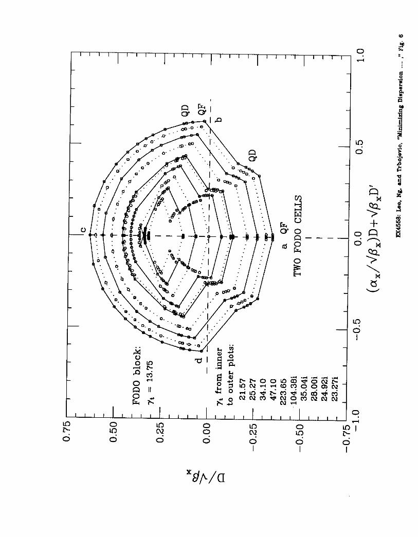
do not change appreciably. Figure 6 shows the normalized dispersion phase space plot in
t-x plane for these lattices with varying Dmi,,.
When the starting value of the ~,,r,, x -0.125, as is presented in Fig. 6, the momentum
compaction factor is very close to zero or -n becomes a large imaginary value (one example
is presented where +y* = i104.38) or a large real value (one case is presented where the
7t = 223.65). Any small changes of the tunes for these modules will produce a large change
in 7t. They are useful in the design of isochronous lattices. The momentum compaction
factor is plotted against the initial dispersion DInin in Fig. 7. We observe a linear relationship
except for the three points at the far right which are of considerably smaller modular lengths
11
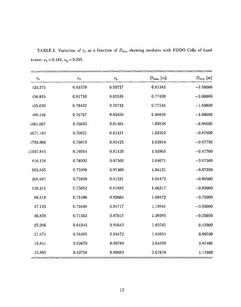
TABLE I. Variation of -yt as a function of D,i, showing modules with FODO Cells of fixed
tunes: v, ~0.181, v,, =0.295.
Yr vzz “!J Qnax bl Dmin [ml i23.275 0.83579 0.93727 0.81343 -2.50000
i26.935 0.81710 0.85538 0.77439 -2.00000
i35.039 0.79452 0.76733 0.77516 - 1.50000
i80.440 0.76767 0.80456 0.98849 -1.00000
i461.607 0.76033 0.81404 1.03838 -0.88000
i671.104 0.76021 0.81421 1.03923 -0.87800
i789.966 0.76018 0.81425 1.03944 -0.87750
i1007.845 0.76014 0.81429 1.03965 -0.87700
816.158 0.76002 0.87500 1.04071 -0.87500
502.835 0.75989 0.87300 1.04131 -0.87300
268.897 0.75939 0.81531 1.04472 -0.86500
120.311 0.75652 0.81882 1.06317 -0.82000
80.518 0.75196 0.82604 1.09472 -0.75000
47.123 0.73448 0.84777 1.19941 -0.50000
36.859 0.71503 0.87015 1.29385 -0.25000
25.266 0.64343 0.92643 1.62542 0.42900
21.574 0.58485 0.93472 1.83655 0.66500
18.841 0.52070 0.90784 2.04859 0.87400
15.885 0.42758 0.89983 2.67670 1.17600
12

needed in the matching.
The momentum compaction factor becomes zero (isochronism) at C = -0.261 (LIti,, =
-0.660 m) obtained from Eq. (3.11). H owever, this occurs actually at C = -0.35 (DA, =
-0.885 m) as shown in Fig. 7. The discrepancy is due to the positive contribution of the
extra dipole in the low-beta matching section of the module which was not included in the
analytic model. Nevertheless, the analytic formula provides a valuable guide in the design
of the modules.
The rule for the choice of the phase advances within a FODO cell is different in the
modular imaginary yt lattice design. For the conventional FODO cell design, the phase
advance of a FODO cell is usually chosen to be 90” or 60”. The 90” phase advance is
preferred to obtain smaller dispersion functions. On the other hand, the dispersion function
for the FMC lattice is minimum at about 60” phase advance. The magnitude of dispersion
function of FMC lattice is about half of the corresponding regular FODO cell lattice. To
illustrate this point, three modules, made of the same magnetic elements but with different
horizontal betatron phases within the FODO cells, were constructed to produce the same
value of the imaginary yl N i45. The vertical tune within the FODO cells was kept the
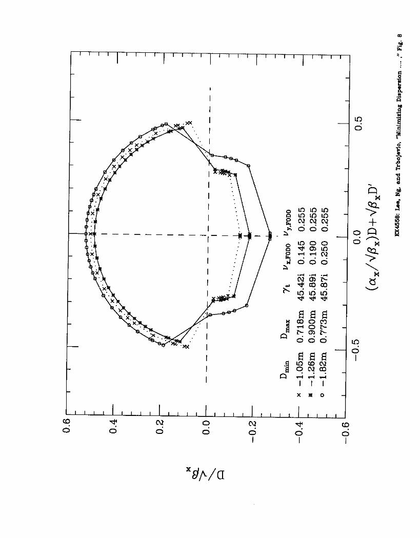
same at vv = 0.255 in these three examples. Figure 8 shows the dependence of the minimum
dispersion function on the horizontal betatron phase advance of the FODO cell. They are
respectively 90”, 68.4” and 52.2”, for which @F is roughly the same. It is clear that the
module with 52.2” FODO cells provides the smallest negative dispersion at marker A4,.
13
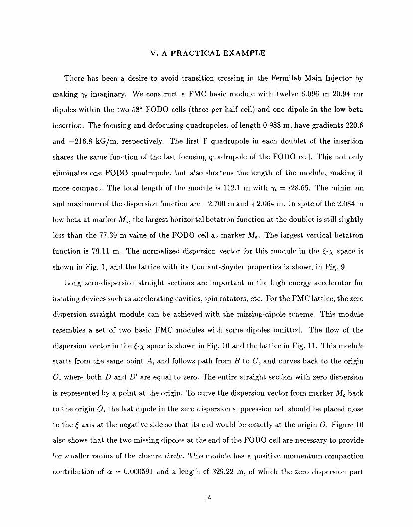
V. A PRACTICAL EXAMPLE
There has been a desire to avoid transition crossing in the Fermilab Main Injector by
making yt imaginary. We construct a FMC basic module with twelve 6.096 m 20.94 mr
dipoles within the two 58” FODO cells (three per half cell) and one dipole in the low-beta
insertion. The focusing and defocusing quadrupoles, of length 0.988 m, have gradients 220.6
and -216.8 kG/m, respectively. The first F quadrupole in each doublet of the insertion
shares the same function of the last focusing quadrupole of the FODO cell, This not only
eliminates one FODO quadrupole, but also shortens the length of the module, making it
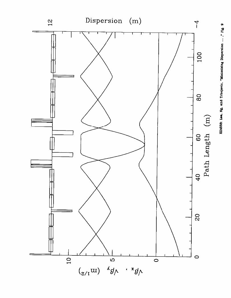
more compact. The total length of the module is 112.1 m with it = i28.65. The minimum
and maximum of the dispersion function are -2.700 m and +2.064 m. In spite of the 2.084 m
low beta at marker MC, the largest horizontal betatron function at the doublet is still slightly
less than the 77.39 m value of the FODO cell at marker M,. The largest vertical betatron
function is 79.11 m. The normalized dispersion vector for this module in the s-x space is
shown in Fig. 1, and the lattice with its Courant-Snyder properties is shown in Fig. 9.
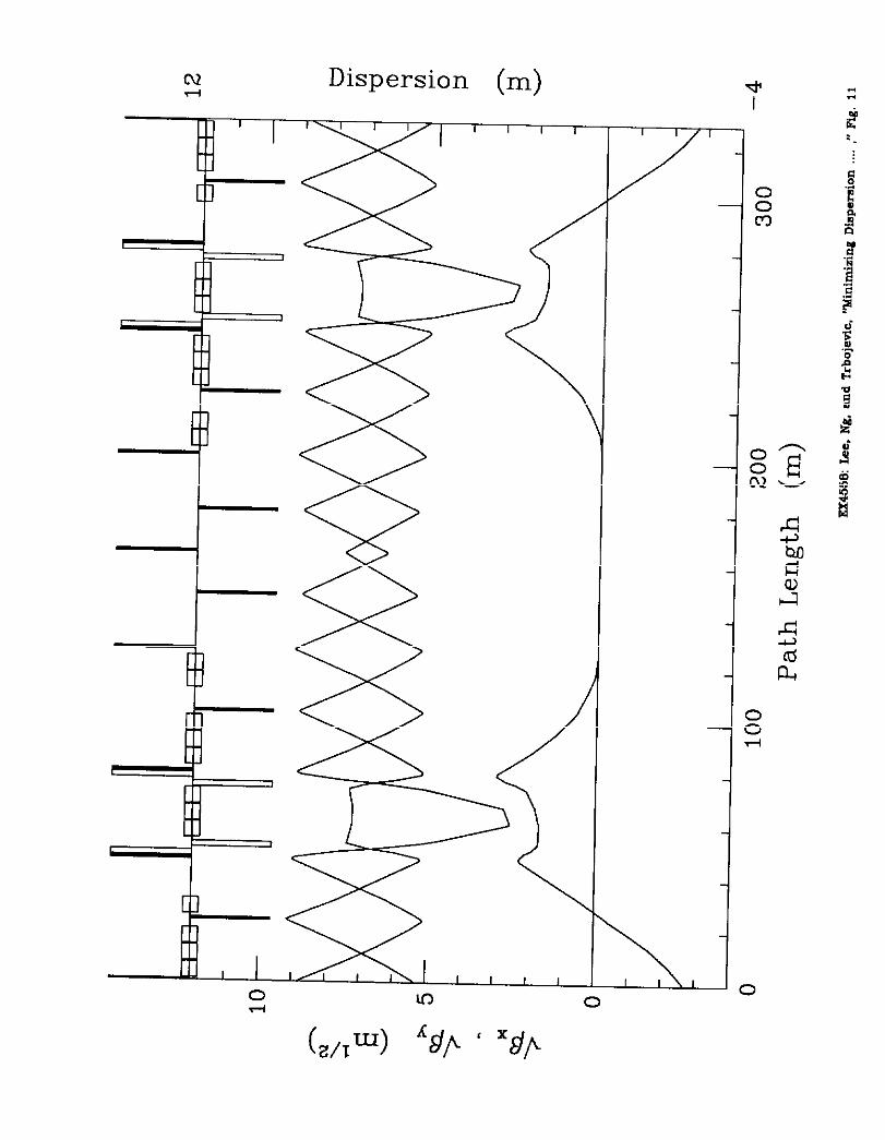
Long zero-dispersion straight sections are important in the high energy accelerator for
locating devices such as accelerating cavities, spin rotators, etc. For the FMC lattice, the zero
dispersion straight module can be achieved with the missing-dipole scheme. This module
resembles a set of two basic FMC modules with some dipoles omitted. The flow of the
dispersion vector in the s-x space is shown in Fig. 10 and the lattice in Fig. 11. This module
starts from the same point A, and follows path from B to C, and curves back to the origin
0, where both D and D’ are equal to zero. The entire straight section with zero dispersion
is represented by a point at the origin. To curve the dispersion vector from marker MC back
to the origin 0, the last dipole in the zero dispersion suppression cell should be placed close
to the 6 axis at the negative side so that its end would be exactly at the origin 0. Figure 10
also shows that the two missing dipoles at the end of the FODO cell are necessary to provide
for smaller radius of the closure circle. This module has a positive momentum compaction
contribution of a = 0.000591 and a length of 329.22 m, of which the zero dispersion part
14

spans 80 m.
Beam dynamics issues are also important to lattice performance. The beam dynamics
properties of a whole lattice built from putting together a number of basic blocks, two zero-
dispersion-straight blocks, and a few extraction/injection blocks have been studied seriously
[15]. We find that this lattice is extremely tunable and is insensitive to misalignment errors.
Its chromatic properties are at least comparable to that of the regular FODO lattice. Since
each basic module and extraction/injection module has phase advance close to 0.75, the
distortion functions of the sextupoles necessary for chromaticity corrections cancel for every
block of four modules. This applies to the systematic half-integer stopband also. As a
result, the lattice provides dynamical aperture as large as that of the regular FODO lattice.
A detailed analysis is given in Ref. [15].
15
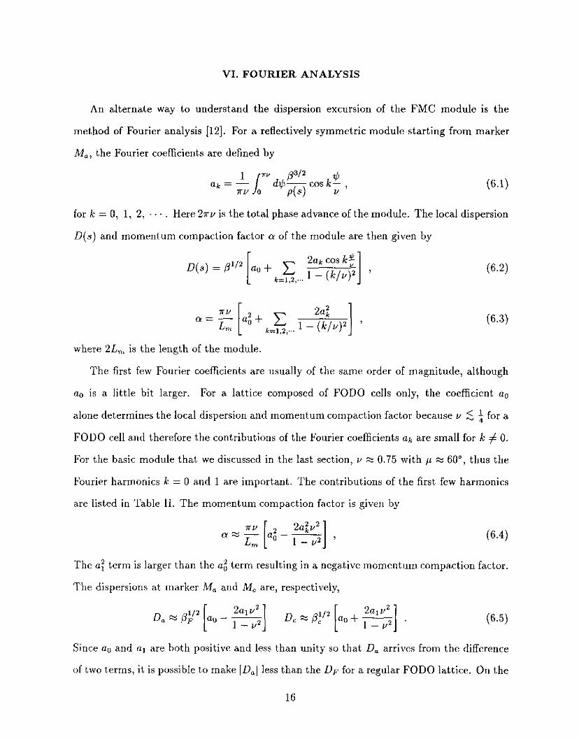
VI. FOURIER ANALYSIS
An alternate way to understand the dispersion excursion of the FMC module is the
method of Fourier analysis [12]. F or a reflectively symmetric module starting from marker
M,, the Fourier coefficients are defined by
312 ay d$P ?b cos k- ,
4s) v
for k = 0, 1, 2, Here 2nv is the total phase advance of the module. The local dispersion
D(s) and momentum compaction factor cy of the module are then given by
D(s) = pz ao + c 2akcoskf k=l,z,... 1 - (k/u)* I ’
c 2a:.
le=,,z ,... 1 - (k/v)’ I ’
(6.2)
(‘5.3)
where 2L, is the length of the module.
The first few Fourier coefficients are usually of the same order of magnitude, although
au is a little bit larger. For a lattice composed of FODO cells only, the coefficient an
alone determines the local dispersion and momentum compaction factor because u 5 i for a
FODO cell and therefore the contributions of the Fourier coefficients ak are small for k # 0.
For the basic module that we discussed in the last section, v ‘c 0.75 with p x 60”, thus the
Fourier harmonics k = 0 and 1 are important. The contributions of the first few harmonics
are listed in Table II. The momentum compaction factor is given by
(6.4)
The e: term is larger than the ug term resulting in a negative momentum compaction factor.
The dispersions at marker M, and M, are, respectively,
D,++g] D,w3~+&o+~] Since au and aI are both positive and less tha,n unity so that D, arrives from the difference
of two terms, it is possible to make ID,( 1 ess than the D,P for a regular FODO lattice. On the
16
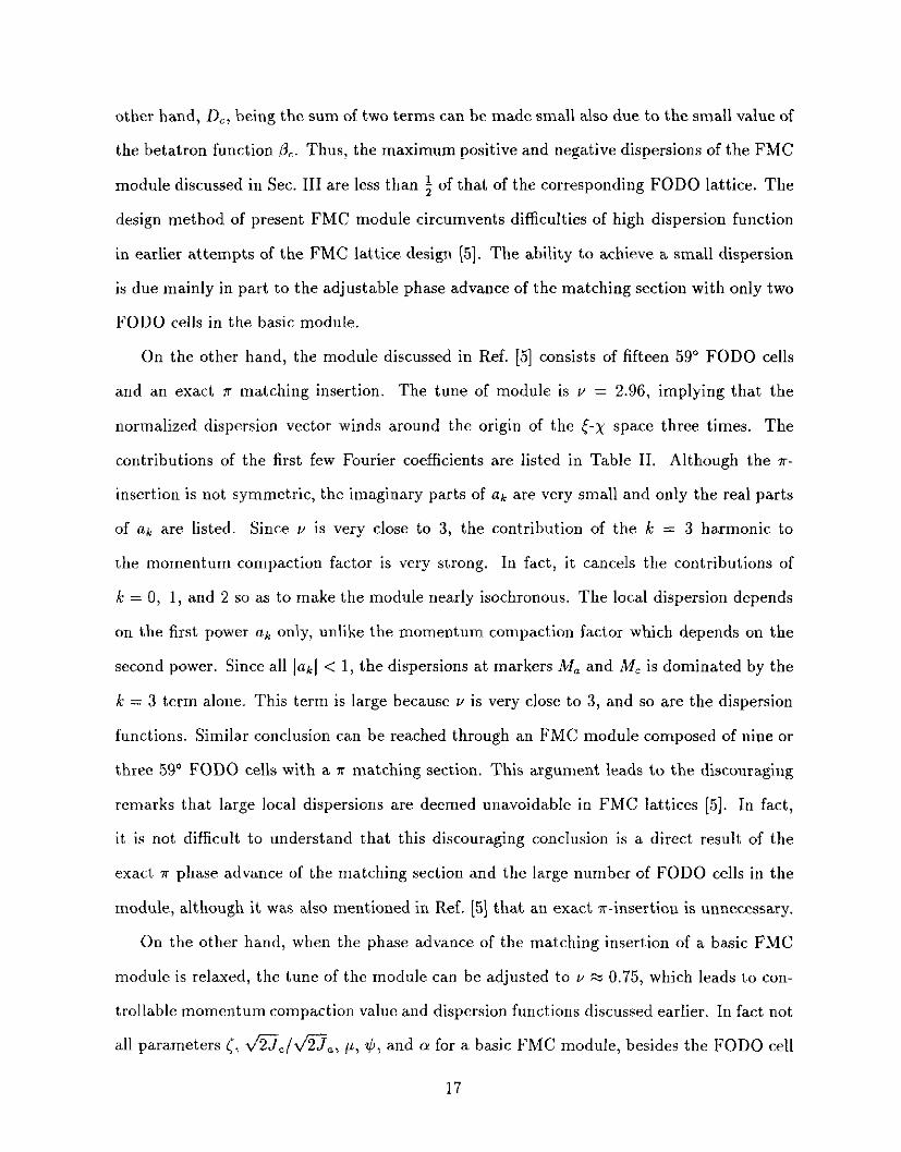
other hand, D,, being the sum of two terms can be made small also due to the small value of
the betatron function PC. Thus, the maximum positive and negative dispersions of the FMC
module discussed in Sec. III are less than i of that of the corresponding FODO lattice. The
design method of present FMC module circumvents difficulties of high dispersion function
in earlier attempts of the FMC lattice design (51. The ability to achieve a small dispersion
is due mainly in part to the adjustable phase advance of the matching section with only two
FODO cells in the basic module.
On the other hand, the module discussed in Ref. [5] consists of fifteen 59” FODO cells
and an exact K matching insertion. The tune of module is v = 2.96, implying that the
normalized dispersion vector winds around the origin of the (-2 space three times. The
contributions of the first few Fourier coefficients are listed in Table II. Although the r-
insertion is not symmetric, the imaginary parts of ak are very small and only the real parts
of ak are listed. Since u is very close to 3, the contribution of the Ic = 3 harmonic to
the momentum compaction factor is very strong. In fact, it cancels the contributions of
k = 0, 1, and 2 so as to make the module nearly isochronous. The local dispersion depends
on the first power nh only, unlike the momentum compaction factor which depends on the
second power. Since all 1~1 < 1, the dispersions at markers M, and IW~ is dominated by the
k = 3 term alone. This term is large because Y is very close to 3, and so are the dispersion
functions. Similar conclusion can be reached through an FMC module composed of nine or
three 59” FODO cells with a x matching section. This argument leads to the discouraging
remarks that large local dispersions are deemed unavoidable in FMC lattices [5]. In fact,
it is not difficult to understand that this discouraging conclusion is a direct result of the
exact = phase advance of the matching section and the large number of FODO cells in the
module, although it was also mentioned in Ref. [5] that an exact ?r-insertion is unnecessary.
On the other hand, when the phase advance of the matching insertion of a basic FMC
module is relaxed, the tune of the module can be adjusted to v zz 0.75, which leads to con-
trollable momentum compaction value and dispersion functions discussed earlier. In fact not
all parameters 5, v%~/v’%,, p, $, and (Y for a basic FMC module, besides the FODO cell
17
length and the modular length, are independent as was discussed in Sec. III. If we restrict
the phase advance of the matching section, the dispersion can no longer be minimized.
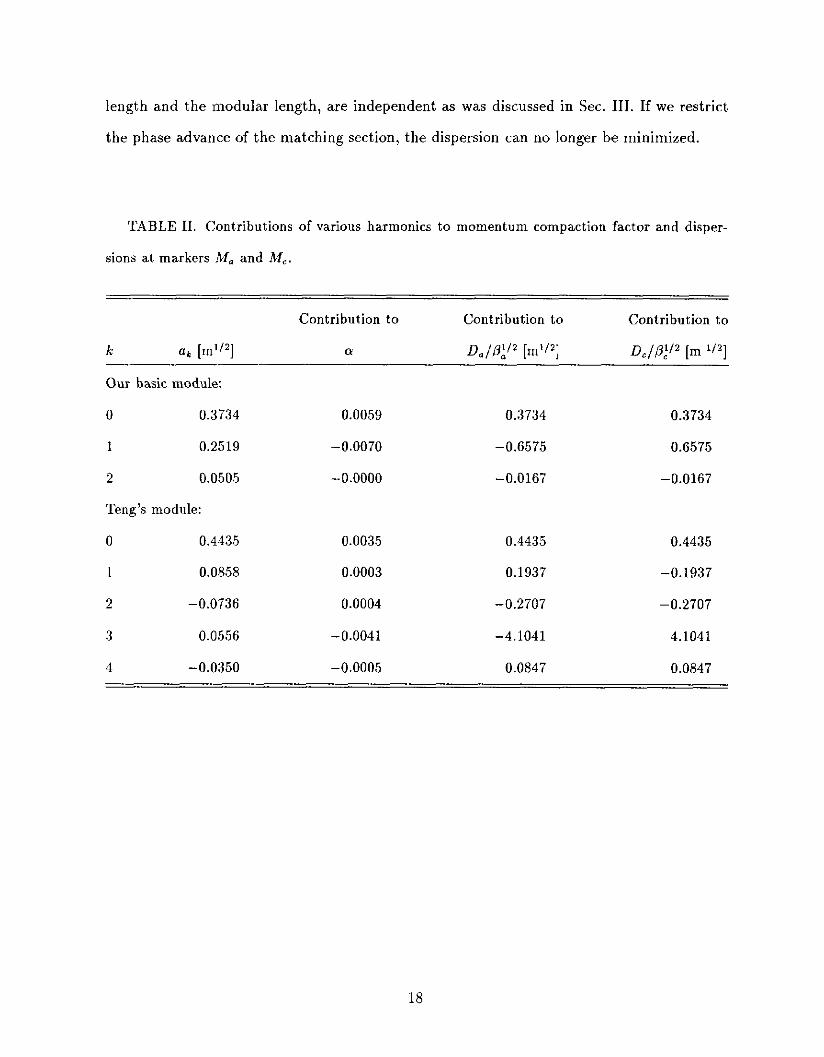
TABLE II. Contributions of various harmonics to momentum compaction factor and disper-
sions at markers M. and M,.
Contribution to Contribution to Contribution to
k a& [In”*] a D,./&" [d2] D,/p;'z [m 1/2]
Our basic module:
0 0.3734
1 0.2519
2 0.0505
Ten@ module:
0 0.4435
1 0.0858
2 -0.0736
3 0.0556
4 -0.0350
0.0059 0.3734 0.3734
-0.0070 -0.6575 0.6575
-0.0000 -0.0167 -0.0167
0.0035 0.4435 0.4435
0.0003 0.1937 -0.1937
0.0004 -0.2707 -0.2707
-0.0041 -4.1041 4.1041
-0.0005 0.0847 0.0847
18

VII. CONCLUSION
In conclusion, we have reviewed methods of designing an accelerator or storage ring
lattice with flexible momentum compaction (FMC) factor. Analytic formulas as well as
numerical examples have been used to demonstrate the basic design principle of a lattice
with a negative momentum compaction and small dispersion function. A basic module of
the FMC lattice is made of two FODO cells matched by a reflective symmetric doublet-
matching low-beta insertion. Analytic analysis and numerical examples indicate that the
dispersion and betatron amplitude matching can be achieved easily.
We proved analytically that the phase advance of the module is determined by two
parameters, the phase advance per FODO cell in the module and the initial dispersion
function at the focusing quadrupole. The magnitude of the momentum compaction factor
is determined in turn by the initial dispersion value. With a proper choice of this initial
value, the amplitude of the dispersion function is demonstrated to be less than that of the
corresponding lattice composed of FODO cells alone. The phase advance in each module can
also be adjusted to be an odd multiple of t so as to minimize the half-integer and third-order
stopband widths, resulting in a lattice with excellent chromatic properties. With such phase
advance, excellent distortion function cancellation due to chromatic sextupoles is possible
without resorting to extra families of sextupoles. Therefore, the dynamical aperture achieved
in the present imaginary it lattice is at least as large as that of the regular FODO cell lattice.
A major advantage of the imaginary yt lattice is tha,t transition crossing is avoided.
Because the momentum compaction factor is negative, the longitudinal motion of beam
particles is always below transition where the space-charge impedance does not cause mi-
crowave instability. The longitudinal phase space blowup and possible beam loss due to
nonlinear synchrotron motion around the transition energy region can be avoided. Applying
the imaginary it design principle, a lattice with zero momentum compaction factor, or the
isochronous storage ring, can be designed with excellent beam dynamics properties by a
proper choice of the dispersion function.
19
REFERENCES
[l] S.Y. Lee and J.M. Wang, Microwave Instabilities wwss the Transition Energies, IEEE
Trans. Nucl. Sci. NS-32,2323 (1985).
[2] W.W. Lee and L.C. Teng, Proc. 8th Int. Conf. on High-energy Accelerators, CERN,
pp. 327-330 (1971).
[3] W. Hardt and D. M6h1, Q-jump at transition, CERN ISR-300/GS/69-16, (1969); W.
Hardt, Gamma Transition Jump scheme of the CPS, Proc. 9th Int. Conf. on high energy
accelerators, Stanford, April (1974); T. R lesselada, Design of Quadrupole schemes to
modify Gamma Transition, CERN PS/90-51 (1990).
[4] V.V. Vladimirski and E.K. Tarasov, Theoretical Problems of the Ring Accelerators,
USSR Academy of Sciences, Moscow (1955).
[5] L.C. Teng, Infinite Transition-energy Synchrotron Lattice using Ir-straight Section, Part.
Act. 4, pp. 81-85 (1972);
[6] R. Gupta and J.I.M. Botman, High Transilion Energy Magnet Ldtices, IEEE Trans.
Nucl. Sci. NS-32, 2308 (1985).
[7] T. Collins, Beta Theory, Technical Memo, Fermilab, 1988
(81 G. Guignard, A Lattice with no Transition and Largest Aperture, Proc. of 1989 IEEE
Part. Accel. Conf., March 20-23, 1989, Chicago, IL, pp 915-917.
[9] E.D. Courant, A.A. Garren, and U. Wienands, Low Momentum Compaction Lattice
Study for the SSC Low Energy Booster, Proc. of 1991 IEEE Part. Accel. Conf., May
6-9, 1991, San Francisco, California, pp 2829-2831.
[lo] D. Trbojevic, D. Finley, R. Gerig, and S. Holmes, Design Method Jor High Energy
Accelerator without Transition Energy, Proc. of Second European Particle Accelerator
Conference, Nice, France, June 1990, pp 1536.1538.
20

[ll] K.Y. Ng, D. Trbojevic, and S.Y. Lee, A Transitionless Lattice for the Fermilab Main In-
jector, Proc. of 1991 IEEE Part. Accel. Conf., May 6-9, 1991, San Francisco, California,
pp 159-161.
[12] E.D. Courant and H.S. Snyder, Theory of the Alternating Gradient Synchrotron, Ann.
Phys. 3, 1 (1958).
[13] D. Trbojevic, S. Peggs, and S. Tepikian, First Order Modification of Transi2ion Energy
at RHIC, Proc. of 1993 IEEE Part. Accel. Conf., May 17-25, 1993, Washington, DC,
(to be published).
[14] S.Y. Lee, K.Y. Ng, and D. Trbojevic, Properties of an Isochronous Electron Ring, Proc.
of 1993 IEEE Part. Accel. Conf., May 17-25, 1993, Washington, DC, (to be published).
[15] S.Y. Lee, K.Y. Ng, and D. Trbojevic, Design and Study OJ Accelerator Lattices without
transition, Fermilab Internal Report FN-595, 1992.
21
FIG. 1. Normalized dispersion t-x plot for the basic module and its corresponding FODO
lattice, which is magnified in the insert.
FIG. 2. Normalized dispersion t-x plot for the same basic module and FODO lattice (magnified
in the insert) of Fig. 1, but in the thin-element approximation. Except the one at marker MC where
the betatron function is extremely small, all thin dipoles can be seen as horizontal lines.
FIG. 3. Ratio of dispersion amplitudes (Jb/ JF)~” as a function of C = D./DF for various phase
advances @ in the FODO cell.
FIG. 4. Phase advance in the matching section as a function of phase advance p in the FODO
cell for various C = D,/Dp.
FIG. 5. Total phase advance of the whole module as a function of phase advance p in the
FODO cell for various C = D,/Dp.
FIG. 6. The normalized dispersion phase space (t, x) for various lattices with different yI values
given in Table I with the same FODO cell are compared.
FIG. 7. Plot of momentum compaction factor as a function of minimum dispersion for the
modules discussed in Table I and Fig. 6. The dotted line is the linear relationship predicted
analytically by Eq. (3.10) with the dipole in the low-beta matching section omitted.
FIG. 8. Normalized dispersion c-x plots for a basic imaginary 7, module with different phase
advances for the FODO cell section.
FIG. 9. Betatron and dispersion functions for the basic module of the imaginary yt lattice.
FIG. 10. Normalized dispersion f-x plot for the zero-dispersion long straight, which has the
same matching properties as the basic module.
FIG. 11. Betatron and dispersion functions for the dispersion-free module of the imaginary 7t
lattice.
22

I I , I , I I I I I I I I I I I I I
I
I-
I-
8 --
5
I
I
I I I I I I I I I I I 1 I I 0 In t-i
0 d
m d d
I
----_
tn 6
b x
-=” Ol=l
.- 0 K
9 \
2 U-l- d I
0 74
I
-I. m
s-7 1
0 2
e I
.A 2 =.
t .d E k ; u
i .- r $ .g $ i d z 4 . . $ a

tn ’ l ” ” l~~~ji
I I
I I I I I I I I I I I I I I I I I I I I I , I I I , I I 0 0 v) v) A A
0 0 d d
m m d d d d
I I
I I I
In d
b x
7 On
.A 0 w
P
0 A
I

I I I I I I I , I I I
T-i %-i d
r-
I ,
c - . s: d
0 A
In h dn
\
a”
II
b
I? 0 0 ‘2 d $
2 .d n 3 0
02 $z
3 A I
(Jf/qf)p sapn~gdrrry uorsJads!a JO ogq.~
cqmd+o Oddd I I I I II II II II Ii II Ii iii
Gb-bJu-
0 0 0 3::
I I I I I I I I I I I I I I I In * d
@Y 6
nl %
6 d
uz/(~z UolJ3aS %I?y3Je~ JO a3UQApv aSW&j
I I I I I I I I I I
d d d
lg al 62
.g a PC6 VI ’ &&WZ ..-I ..-I .- -4 .d E II
EC &O c;lrj4;,:
zjiQ!‘stg& FZ
(UcV-* . _- - 4 zz$i%%$F: I I I , I I I I I I I I 0 I I I I I I I I I I I I
E 5: %.i 6
0” 6
kc 6
5: d
gr;
d 7
6 I I

i’ -_ I
X -_
-_
JOJOEJ uogmdtuo=) umquaao~
8 zs-iz & “NN z;ood . a g %g h bi 66.5 a .ti ..+ .r( nlcJJ)P- + -+cqm + up$
g im fl zz: ca ddd
;I y qcum I I I
x 31 0
I I I I I I I I I I I I I I I I I I I I I I I I
m +
d ol 0
d 6 d N -+ co 0 d d I I I
I
In
d
b x
-=”
On -A
0 x
9 \
ax
u-2 d
m
2
:-
.t e St z
m
i .I F
.$-
.$
s m %
d 2
i .
$
ii
Dispersion (m)
-
-
-
-
-
, I
_ ( .
:
c 0 In
%+ (
0
z/r=9 Qp ‘ “tip

:
2 8
“2 2w Orn9 -a Eig c34
E z
I - I
ah ----- t w c
i
u - c
VI I I C
I Y
I
I I
t,,1,,,,1,,,,1,,,,1,,,,- U
0 4 Ln 0 0 m 6 d
s-i
I -7
“#/a
-
Ln A
0 3-i
0 5
%
r” >n
.A ’ w
-Y- \
2 D- 5 I
2
2
i-
i E FL 2
u
! .” F .$ .$
$ P % d z
i- $j
i
Dispersion (m) z 2
g .- lz & g a .a .N 8 g .g .$ $ i i2 $ 65
i!
0 ln
r( (
0
z/m “dp ‘ “dp
Related Documents