Patrick Safarian, ANM-120S Page 3-1 Airframe Breakout Session Seattle DER Recurrent Seminar – November 6, 2003 FEM Validation and Requirements FEM Validation and Requirements Patrick Safarian SACO Airframe Branch, ANM-120S Seattle DER Conference Airframe Breakout Session November 6, 2003 Seattle DER Conference, Airframe Breakout Session 2 November 6, 2003 Contents ? What is Finite Element Analysis? ? Brief History ? Basic Steps ? Assumptions and Judgments ?Geometry ?Elements ?Meshing tips ?Boundary Conditions ? Most Appropriate Solution ? Verify and Document the Results ? Instrumented Structural Test ? Observation ? A Simple Illustration FEM Validation and Requirements

Welcome message from author
This document is posted to help you gain knowledge. Please leave a comment to let me know what you think about it! Share it to your friends and learn new things together.
Transcript

Patrick Safarian, ANM-120SPage 3-1
Airframe Breakout SessionSeattle DER Recurrent Seminar – November 6, 2003
FEM Validation and Requirements
FEM Validation and Requirements
Patrick SafarianSACO Airframe Branch, ANM-120S
Seattle DER ConferenceAirframe Breakout Session
November 6, 2003
Seattle DER Conference, Airframe Breakout Session2November 6, 2003
Contents? What is Finite Element Analysis?? Brief History? Basic Steps
?Assumptions and Judgments?Geometry?Elements?Meshing tips?Boundary Conditions
?Most Appropriate Solution?Verify and Document the Results? Instrumented Structural Test?Observation
? A Simple Illustration
FEM Validation and Requirements

Patrick Safarian, ANM-120SPage 3-2
Airframe Breakout SessionSeattle DER Recurrent Seminar – November 6, 2003
FEM Validation and Requirements
Seattle DER Conference, Airframe Breakout Session3November 6, 2003
FEM Validation and Requirements
?What is FEA?? Finite Element Analysis (FEA) is not a Stress Analysis; it is an
integrated part of it? A computer-aided mathematical technique for obtaining
approximate numerical solutions to the abstract equations of calculus that predict the response of physical systems subject to external influences
? This numerical procedure is used for analyzing complex problems in continuum mechanics such as structures, fluids, heat-transfer, electromagnetic
? A method that engineer routinely use to efficiently and accurately solve problems which are utterly intractable to solve by classical analytical methods
? A method of describing the response of a loaded continuum as the solution to a set of simultaneous algebraic equations
Seattle DER Conference, Airframe Breakout Session4November 6, 2003
FEM Validation and Requirements
?What is FEA? (Continued)? A virtually universal tool across all disciplines of engineering and
throughout all engineering industries? Results are rarely exact, however they could be sufficiently
accurate? Accuracy depend on such things as,
? Element selection and mesh refinement? Physical property and dimensions? Boundary conditions (loads and constrains)? Convergence
? The results MUST ALWAYSMUST ALWAYS be looked upon with suspicion, until they are verified and proved to be sufficiently accurate
? Understanding of the structure and of the FEM is a must in FEA? FEA is not the end of the analysis, is only a part of the work? Model validation must be part of Model development

Patrick Safarian, ANM-120SPage 3-3
Airframe Breakout SessionSeattle DER Recurrent Seminar – November 6, 2003
FEM Validation and Requirements
Seattle DER Conference, Airframe Breakout Session5November 6, 2003
?Brief History of FEA? Concept began in France about 1850-1875 by Navier, St.
Venant, Maxwell, Castgliano, Mohr, and others. Later expanded as Matrix Structural Analysis
? In period of 1875-1920 due to practical limitations FEA was in dormant
? Around 1920’s Ostenfeld of Denmark and Maney of US expanded the concept to practical truss and framework analysis
? In 1932 Hardy Cross advanced the concept to more complex problems by introducing the method of moment distribution
? In 1943 Courant used piecewise continuos functions defined over a subdomain to approximate unknown functions
FEM Validation and Requirements
Seattle DER Conference, Airframe Breakout Session6November 6, 2003
?Brief History of FEA (continue)? In 1960 Professor Clough of UC Berkley coined the term
“finite element”? Since 1950 many advancements in the computer
technology has occurred. Meanwhile the concept of framework and continuum analysis were combined and results were presented in matrix format.
? These developments were followed by a period of rather intensive developments of practical ‘general purpose ”software packages such as Ansys, Nastran and Abaqus.
FEM Validation and Requirements

Patrick Safarian, ANM-120SPage 3-4
Airframe Breakout SessionSeattle DER Recurrent Seminar – November 6, 2003
FEM Validation and Requirements
Seattle DER Conference, Airframe Breakout Session7November 6, 2003
? 4 minimum required steps for FEA process? Establish a clearly define goal? Compile and qualify the inputs? Solve the problem with the most
appropriate means? Verify and document the results
FEM Validation and Requirements
Seattle DER Conference, Airframe Breakout Session8November 6, 2003
? To establish these goals ask 2 questions:1. How accurate the results need to be?
? Exact? Ballpark? Show trends
2. What specific data is necessary?? Load Distribution? Detail Stresses? Displacements? Reaction forces
FEM Validation and Requirements

Patrick Safarian, ANM-120SPage 3-5
Airframe Breakout SessionSeattle DER Recurrent Seminar – November 6, 2003
FEM Validation and Requirements
Seattle DER Conference, Airframe Breakout Session9November 6, 2003
? Example: FEM to determine local stresses in a fuselage frame at stringer cutout
Step 1: Be Goal Oriented
Seattle DER Conference, Airframe Breakout Session10November 6, 2003
Step 1: Be Goal Oriented
? Example: FEM to determine stresses in a fuselage skin lap joint

Patrick Safarian, ANM-120SPage 3-6
Airframe Breakout SessionSeattle DER Recurrent Seminar – November 6, 2003
FEM Validation and Requirements
Seattle DER Conference, Airframe Breakout Session11November 6, 2003
? Compile and qualify the inputs? Geometry
? Idealization (Simulation) of the geometry? Mesh: element type, shape, order
? Material Properties? Scatter? Units
? Boundary Conditions? Loads? Constraints
? Involves assumptions and judgments ? NO different than manual analysis
Step 2: Compile and qualify the inputs
Seattle DER Conference, Airframe Breakout Session12November 6, 2003
? In FEA the complex structure is partitioned into finite regions (elements) which are connected at nodes
? Higher node density is required for areas of rapid change; Nodes are requires where the loads and BC’s are applied and where results are desired
? Element are mathematical representation which simulate the structure behavior
? So understanding of the structural behaviorstructural behaviorand the element formulationelement formulation in FEA is FundamentalFundamental
Assumptions and Judgments

Patrick Safarian, ANM-120SPage 3-7
Airframe Breakout SessionSeattle DER Recurrent Seminar – November 6, 2003
FEM Validation and Requirements
Seattle DER Conference, Airframe Breakout Session13November 6, 2003
? In modeling the structural behavior, idealization (simulation) of the items subject to investigation is essential
1. Modeling of a Seat Pan2. Effect of foreign object damage (FOD)
? Modeled-In Dent? Formed Dent (Low Velocity Impact)
? Nonlinear geometry and plasticity
Assumptions and Judgments
Seattle DER Conference, Airframe Breakout Session14November 6, 2003
? Actual Seat Pan- Geometry
Assumptions and JudgmentsExample 1- Seat Pan

Patrick Safarian, ANM-120SPage 3-8
Airframe Breakout SessionSeattle DER Recurrent Seminar – November 6, 2003
FEM Validation and Requirements
Seattle DER Conference, Airframe Breakout Session15November 6, 2003
? First attempt in simulating the foreign object damage (FOD) was done by “Modeled-In” dents? Most expeditious way of modeling the
dent in the fuselage skin is to actually include it in the model
? Stress free? One step simulations
? Results are unrealistic
Assumptions and JudgmentsExample 2- Skin Dent
Seattle DER Conference, Airframe Breakout Session16November 6, 2003
Fuselage Skin with Modeled-In Dent
Assumptions and JudgmentsExample 2- Skin Dent

Patrick Safarian, ANM-120SPage 3-9
Airframe Breakout SessionSeattle DER Recurrent Seminar – November 6, 2003
FEM Validation and Requirements
Seattle DER Conference, Airframe Breakout Session17November 6, 2003
? Next attempt in simulating the FOD was done by plastic deformation of the skin? Low velocity impact of an object with the skin? Plastic Strain on the back surface of the skin is
about 10x greater than than the front surface? Two step process
? Impact of the object with the skin; various depths?Removal of the object and allowing plastic deformation to
form
? Results are realistic
Assumptions and JudgmentsExample 2- Skin Dent
Seattle DER Conference, Airframe Breakout Session18November 6, 2003
? For this configuration ? Stress levels due to cabin pressure for moderate
dents (<0.20”) are lower than for similar “Modeled-In” dents
? Stress levels due to cabin pressure for deep dents (>0.20”) are higher than for similar “Modeled-In”dents
? Stress levels for very shallow dents are very low. The more stable formed dents resist snap through, or “oil canning” when pressurized
Assumptions and JudgmentsExample 2- Skin Dent

Patrick Safarian, ANM-120SPage 3-10
Airframe Breakout SessionSeattle DER Recurrent Seminar – November 6, 2003
FEM Validation and Requirements
Seattle DER Conference, Airframe Breakout Session19November 6, 2003
Schematic of the two simulations of dent
Assumptions and JudgmentsExample 2- Skin Dent
Seattle DER Conference, Airframe Breakout Session20November 6, 2003
Skin Dent at the Formation Stage
Assumptions and JudgmentsExample 2- Skin Dent

Patrick Safarian, ANM-120SPage 3-11
Airframe Breakout SessionSeattle DER Recurrent Seminar – November 6, 2003
FEM Validation and Requirements
Seattle DER Conference, Airframe Breakout Session21November 6, 2003
? Since the understanding of the structural behavior and the element formulation in FEA is ESSENTIAL one must be intimately familiar with: 1) Fundamentals such as Strength of Material 2) Element formulation, assumptions, capabilities,
limitations and restrictions of the FEA code at hand
? To demonstrate this point let us examine different elements and their applications? Element shape function? Element shape and order
Assumptions and Judgments:Choice of element
Seattle DER Conference, Airframe Breakout Session22November 6, 2003
? In bending of thick plates where the transverse shear effect is not negligible certain shell elements, without the appropriate extra shape functions, will produce erroneous results.? Use Shell elements that have the extra shape
functions? Use solid elements (Only way for very thick plates
subject to bending)
? Let us consider a thick plate with a hole in the center, subject to pure bending
? Compare results to “handbook” solutions
Assumptions and Judgments:Choice of element- Shape Function
Patrick Safarian, ANM-120SPage 3-12
Airframe Breakout SessionSeattle DER Recurrent Seminar – November 6, 2003
FEM Validation and Requirements
Seattle DER Conference, Airframe Breakout Session23November 6, 2003
Elements Elements Solidwithout shape with shape Elements
D t W Functions functions1 0.03 8 1.65 1.615 1.595 N/A1 0.05 8 1.65 1.615 1.605 N/A1 0.1 8 1.65 1.615 1.605 N/A1 1 8 2.02 1.615 2.07 2.111 2 8 2.23 1.615 2.31 2.31 4 8 2.43 1.615 2.53 2.57
Plate GeometryKt
Comparison of stress concentrations:
Assumptions and Judgments:Choice of element- Shape Function
Seattle DER Conference, Airframe Breakout Session24November 6, 2003
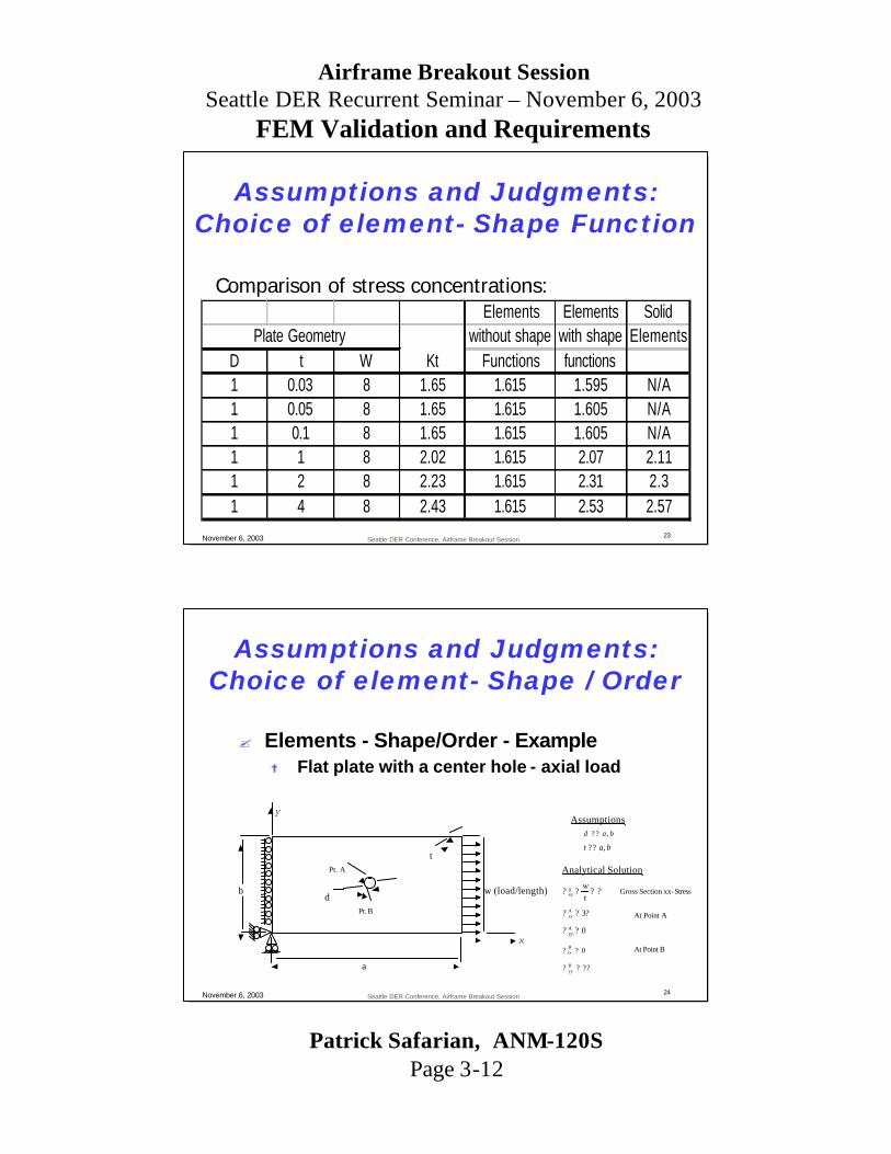
? Elements - Shape/Order - Example? Flat plate with a center hole - axial load
y
x
a
bd
w (load/length)
Pt. A
Pt. B
tAnalytical Solution
Assumptionsbad ,? ?
bat ,??
?? ??twg
xx
?? 3?Axx
Gross Section xx-Stress
0?Ayy?
0?Bxx?
?? ??Byy
At Point A
At Point B
Assumptions and Judgments:Choice of element- Shape / Order

Patrick Safarian, ANM-120SPage 3-13
Airframe Breakout SessionSeattle DER Recurrent Seminar – November 6, 2003
FEM Validation and Requirements
Seattle DER Conference, Airframe Breakout Session25November 6, 2003
? Elements - Order - ExampleTriangle
3-Node
# DOF: 318
# Nodes: 163
# Elems: 270
Assumptions and Judgments:Choice of element- Shape / Order
Seattle DER Conference, Airframe Breakout Session26November 6, 2003
? Elements - Order - Example
Triangle
6-Node
# DOF: 1018
# Nodes: 516
# Elems: 236
Assumptions and Judgments:Choice of element- Shape / Order

Patrick Safarian, ANM-120SPage 3-14
Airframe Breakout SessionSeattle DER Recurrent Seminar – November 6, 2003
FEM Validation and Requirements
Seattle DER Conference, Airframe Breakout Session27November 6, 2003
Quad
4-Node
# DOF: 526
# Nodes: 269
# Elems: 229
? Elements - Shape - Example
Assumptions and Judgments:Choice of element- Shape / Order
Seattle DER Conference, Airframe Breakout Session28November 6, 2003
? Elements - Shape/Order - Element Checks? Element geometry affects the mathematical
approximation of the problem domain? Singularities can occur? Physically impossible geometry can be
generated mathematically? Tri elements should be avoided in areas of
interest (much too stiff)?Performance of higher order Tri elements are
comparable to Quad elements
Assumptions and Judgments:Meshing Tips

Patrick Safarian, ANM-120SPage 3-15
Airframe Breakout SessionSeattle DER Recurrent Seminar – November 6, 2003
FEM Validation and Requirements
Seattle DER Conference, Airframe Breakout Session29November 6, 2003
? Elements - Shape/Order - Element Checks? Aspect Ratio? Internal Angles? Parallel Deviation? Jacobian Ratio? Warpping Factor
? See Appendix A for some examples
Assumptions and Judgments:Meshing Tips
Seattle DER Conference, Airframe Breakout Session30November 6, 2003
? Elements - Shape/Order - Element Checks? Features that inform the user of presence of any
bad quality element(s) are available in many contemporary FEA systems?Failed elements automatic selection?Useful for mesh refinement
?Failed elements plot?Specially useful in large FEA models
? Ultimately the user is responsible to ensure the goodness of the elements
Assumptions and Judgments:Meshing Tips

Patrick Safarian, ANM-120SPage 3-16
Airframe Breakout SessionSeattle DER Recurrent Seminar – November 6, 2003
FEM Validation and Requirements
Seattle DER Conference, Airframe Breakout Session31November 6, 2003
? Elements - Density? Directly relates to accommodation of structural behavior ? Generally more elements means more accuracy? More elements also means more resources? Regions with relatively high stress gradients require a finer
mesh to resolve the peaks? Regions of the model where concentrated loads and BC’s are
applied show unrealistic results? For small models a simple manual convergence study using
smaller and smaller elements is one easy route? For larger models automated error checking with automatic bad
element selection is very useful
? See Appendix A for Error Estimation techniques.
Assumptions and Judgments:Meshing Tips
Seattle DER Conference, Airframe Breakout Session32November 6, 2003
?Constraints- Boundary Conditions? Models the remaining of the world that is not
included in the model? Sets axial and rotational DOF to a set value, usually
zero? Where the input loads are reacted in the model? At times it is best when symmetric characteristics of
a model is utilized? If the BC is applied at discrete points the results may
be incorrect in that vicinity, since the resultant reaction loads are applied at a zero area geometric entity, which results in a mathematical singularity
Assumptions and Judgments:Loads and Constraints

Patrick Safarian, ANM-120SPage 3-17
Airframe Breakout SessionSeattle DER Recurrent Seminar – November 6, 2003
FEM Validation and Requirements
Seattle DER Conference, Airframe Breakout Session33November 6, 2003
? Loads - Force? Applied force or displacement? Applied bending moment or rotation? Satisfactory for beam modeling and “far field”
results; Usually unsatisfactory for 2D, 3D modeling? Incorrect results in vicinity of load application since
load is applied at a discrete point, a zero area geometric entity, which results in a mathematical singularity
Assumptions and Judgments:Loads and Constraints
Seattle DER Conference, Airframe Breakout Session34November 6, 2003
? If large displacement is anticipated the load and boundary condition applications must account for the variation in magnitude, orientation and distribution
? If accurate solution near load point is required there are two general options? Replace load with a pressure loading over a small
representative area? If the stress under the force is not of interest use course mesh to
distribute the resultant stress to larger neighboring elements
? Model both parts in detail and perform contact analysis
Assumptions and Judgments:Loads and Constraints

Patrick Safarian, ANM-120SPage 3-18
Airframe Breakout SessionSeattle DER Recurrent Seminar – November 6, 2003
FEM Validation and Requirements
Seattle DER Conference, Airframe Breakout Session35November 6, 2003
? Loads - Pressure? Discretization is based on consistency with the
displacement law used in the element formulation? If calculating outside of FEA program, work equivalency
must be considered? Usually more representative of actual loading? Many commercial FEA codes have built-in tools for
applying pressure in various manners often utilizing associatively; work equivalent consistent loads are calculated as necessary?Parametric variation (linear, non-linear)
? Easy to apply?Lines, Edges (Force/Length)?Faces (Force/Area)
Assumptions and Judgments:Loads and Constraints
Seattle DER Conference, Airframe Breakout Session36November 6, 2003
747 Strut Midspar Fitting- Pin load simulated by cosine distribution pressure load
Assumptions and Judgments:Loads and Constraints
Patrick Safarian, ANM-120SPage 3-19
Airframe Breakout SessionSeattle DER Recurrent Seminar – November 6, 2003
FEM Validation and Requirements
Seattle DER Conference, Airframe Breakout Session37November 6, 2003
747 Strut Midspar Fitting Subject to Unit Load
Assumptions and Judgments:Loads and Constraints
Seattle DER Conference, Airframe Breakout Session38November 6, 2003
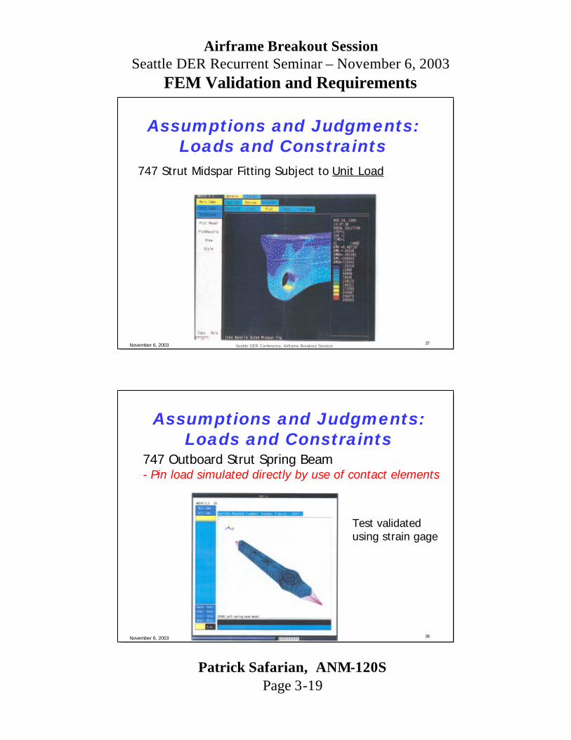
747 Outboard Strut Spring Beam- Pin load simulated directly by use of contact elements
Test validated using strain gage
Assumptions and Judgments:Loads and Constraints
Patrick Safarian, ANM-120SPage 3-20
Airframe Breakout SessionSeattle DER Recurrent Seminar – November 6, 2003
FEM Validation and Requirements
Seattle DER Conference, Airframe Breakout Session39November 6, 2003
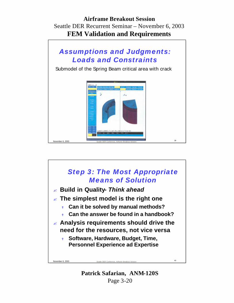
Submodel of the Spring Beam critical area with crack
Assumptions and Judgments:Loads and Constraints
Seattle DER Conference, Airframe Breakout Session40November 6, 2003
? Build in Quality- Think ahead? The simplest model is the right one
? Can it be solved by manual methods?? Can the answer be found in a handbook?
? Analysis requirements should drive the need for the resources, not vice versa? Software, Hardware, Budget, Time,
Personnel Experience ad Expertise
Step 3: The Most Appropriate Means of Solution

Patrick Safarian, ANM-120SPage 3-21
Airframe Breakout SessionSeattle DER Recurrent Seminar – November 6, 2003
FEM Validation and Requirements
Seattle DER Conference, Airframe Breakout Session41November 6, 2003
? Using FEA to analyze a problem requires:? Strong understanding of the problem and its
details, and idealizing them? Strong understanding of the structural behavior
and accommodation for it? Strong understanding of the analytical tool at hand
such as assumptions and limitations? Thorough investigation of the output
? Validation of FEA is critical to its credibility?
The Most Appropriate Means of Solution
Seattle DER Conference, Airframe Breakout Session42November 6, 2003
? Should NOTNOT be the last-step in the process
? Common Misconceptions:? Meshing is everything
?Resist mindless auto-meshing for everything
? FEA replaces understanding of fundamentals such as Static and Strength of Material
? FEA replaces testing?FEA augments testing and vice versa?Levels of uncertainty inherent in the process will almost
always require that final products, at a minimum, be tested
Step 4: Verify and Document the Results

Patrick Safarian, ANM-120SPage 3-22
Airframe Breakout SessionSeattle DER Recurrent Seminar – November 6, 2003
FEM Validation and Requirements
Seattle DER Conference, Airframe Breakout Session43November 6, 2003
? Assumptions regarding material, assembly variability, and other unpredictability need to be weighted, qualified and documented.
? No different than traditional “manual”approach where validity of analysis technique, assumptions and limitations are validated prior to application of the approach.
? Manual Post-Processing of the FEM results is an acceptable and common approach
Verify and Document the Results
Seattle DER Conference, Airframe Breakout Session44November 6, 2003
? Invisible Meshing? Program uses appropriate p or h element
refinement with minimal user intervention? There are FEA systems that use p elements
to obtain quantities such as? Stress concentrations? Stress intensity factors
? “Contemporary ” stress handbook? Replacing the old hardbound books? Allow for more flexibility and variation in
geometry
Verify and Document the Results

Patrick Safarian, ANM-120SPage 3-23
Airframe Breakout SessionSeattle DER Recurrent Seminar – November 6, 2003
FEM Validation and Requirements
Seattle DER Conference, Airframe Breakout Session45November 6, 2003
?Basic checks of the FEA results:? Review the results
?Review the reactions ?Review the deflected shape?Review max/min displacement and stress locations/values
? Ask questions?Can I make sense out of the results??Are these results different from the analytical/test results??Which results are different??How much do they differ by? Why might this be??What can be done to have a closer match in the results? ?What level of accuracy is necessary for the design of this part?
? Refine model and re-analyze if necessary
Verify and Document the Results
Seattle DER Conference, Airframe Breakout Session46November 6, 2003
? Components to be validated? Element Formulation? Solution Code? FEM Construction and Analysis
? Element Formulation and Solution Code? Generally accomplished by software provider? Generally based upon comparison of FEA Solution
to theoretical solution?Theoretical problem selected to exercise element?More than 50,000 problems used as check in a certain
FEA code
Verify and Document the Results

Patrick Safarian, ANM-120SPage 3-24
Airframe Breakout SessionSeattle DER Recurrent Seminar – November 6, 2003
FEM Validation and Requirements
Seattle DER Conference, Airframe Breakout Session47November 6, 2003
? Finite Element Model construction and analysis? Model validation to be provided by
user/applicant? Validation plan
? Part of the Certification Plan? Agreed upon
? Measure of success– Ask ACO Engineers for examples
– Many examples; Good and Bad
Verify and Document the Results
Seattle DER Conference, Airframe Breakout Session48November 6, 2003
? Verification? Correctness vs. Accuracy
?A poorly posed problem can have a high degree of accuracy yet provide incorrect results
?The solution can only be considered accurate AND correct if it is properly defined and well posed
?The following are some important considerations in evaluating the correctness of a solution:?Structural idealization, mesh quality, element type,
boundary conditions, material model, solution type and control parameters, method of post-processing
Verify and Document the Results

Patrick Safarian, ANM-120SPage 3-25
Airframe Breakout SessionSeattle DER Recurrent Seminar – November 6, 2003
FEM Validation and Requirements
Seattle DER Conference, Airframe Breakout Session49November 6, 2003
? Verification? Test correlation
?Analysis can only be as good as the test?A good way to verify the integrity of a finite element model?Can be used to help evaluate assumptions and
idealizations?Can be used to evaluate failure theories?Most beneficial when used at the beginning stages of a
new design type to develop a database of experimental correlation curves - once the design has matured and only minor derivatives are being designed and manufactured, testing may not be necessary
Verify and Document the Results
Seattle DER Conference, Airframe Breakout Session50November 6, 2003
? Verification? Test correlation
?Pros? Inherently correct and accurate if conducted properly? Includes all real physical effects that are part of test?Builds confidence in analysis methodology?Provide insight into the limitations of the analysis
?Cons?Relatively expensive (time, labor, schedule)?Provides only “single point” results?Test can only verify the analysis and possibly point to an error,
it does not ensure absence of error!
Verify and Document the Results
Patrick Safarian, ANM-120SPage 3-26
Airframe Breakout SessionSeattle DER Recurrent Seminar – November 6, 2003
FEM Validation and Requirements
Seattle DER Conference, Airframe Breakout Session51November 6, 2003
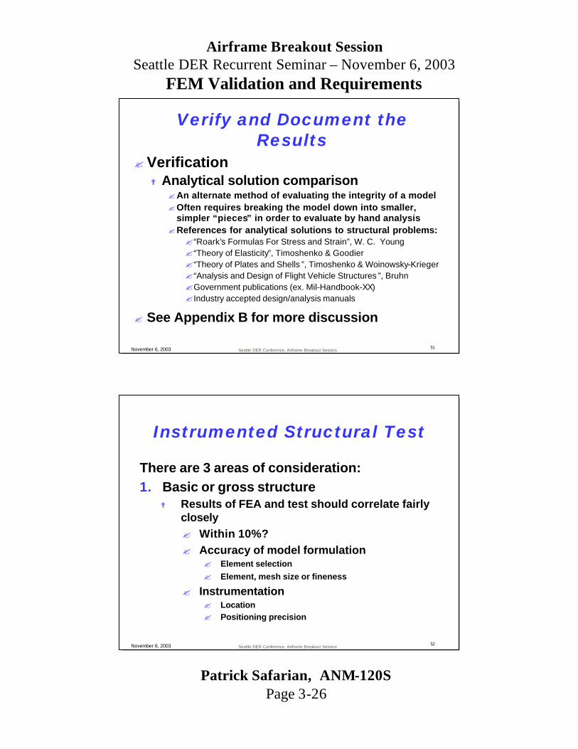
? Verification? Analytical solution comparison
?An alternate method of evaluating the integrity of a model?Often requires breaking the model down into smaller,
simpler “pieces” in order to evaluate by hand analysis?References for analytical solutions to structural problems:?“Roark’s Formulas For Stress and Strain”, W. C. Young?“Theory of Elasticity”, Timoshenko & Goodier?“Theory of Plates and Shells ”, Timoshenko & Woinowsky-Krieger?“Analysis and Design of Flight Vehicle Structures ”, Bruhn?Government publications (ex. Mil-Handbook-XX)? Industry accepted design/analysis manuals
? See Appendix B for more discussion
Verify and Document the Results
Seattle DER Conference, Airframe Breakout Session52November 6, 2003
Instrumented Structural Test
There are 3 areas of consideration:1. Basic or gross structure
? Results of FEA and test should correlate fairly closely? Within 10%?? Accuracy of model formulation
? Element selection? Element, mesh size or fineness
? Instrumentation? Location? Positioning precision
Patrick Safarian, ANM-120SPage 3-27
Airframe Breakout SessionSeattle DER Recurrent Seminar – November 6, 2003
FEM Validation and Requirements
Seattle DER Conference, Airframe Breakout Session53November 6, 2003
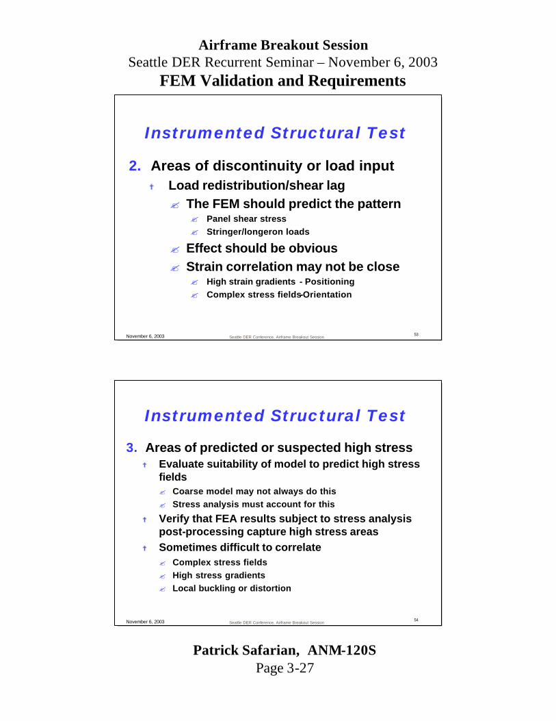
2. Areas of discontinuity or load input? Load redistribution/shear lag? The FEM should predict the pattern
? Panel shear stress? Stringer/longeron loads
? Effect should be obvious? Strain correlation may not be close
? High strain gradients - Positioning? Complex stress fields-Orientation
Instrumented Structural Test
Seattle DER Conference, Airframe Breakout Session54November 6, 2003
3. Areas of predicted or suspected high stress? Evaluate suitability of model to predict high stress
fields? Coarse model may not always do this? Stress analysis must account for this
? Verify that FEA results subject to stress analysis post-processing capture high stress areas
? Sometimes difficult to correlate? Complex stress fields? High stress gradients? Local buckling or distortion
Instrumented Structural Test

Patrick Safarian, ANM-120SPage 3-28
Airframe Breakout SessionSeattle DER Recurrent Seminar – November 6, 2003
FEM Validation and Requirements
Seattle DER Conference, Airframe Breakout Session55November 6, 2003
? An Observation: Users of FEA are some? 1) FASCINATED
? Believes any problem worth meshing is worth over meshing. Rejects beam and plate elements as analytically impure. Prefers contact element algorithms over actual boundary conditions. Plots everything. Punches and keeps plots (even the ugly ones). Spends about 2-3 times more effort writing macros than the macros actually save. Reports quite colorful; heavy on graphics and FEA-speak and light on insight.
? 2) FRUSTRATED ? Refines mesh selectively; shows resignation to dealing with ambiguity. Relies less on clever elements;
truly trusts only classical element types. Abandons attempts to model welds with solid elements. No longer weeps at sight of tetrahedral elements. Time spent writing and debugging macros about equals time saved by macros. Reports contain caveats and warnings about applicability.
? 3) HEALTHY ? Meshing aimed at specific problem areas; seldom models the entire airplane to find stress in the door
latch. Element choice reflects engineering considerations; comfortable with approximation. Keeps obsession with computational efficiency under control, usually without medication. Makes frequent use of tabular results; understands use of numbers and text. Reports balanced between engineering issues and eye candy. Makes appropriate use of both.
? Remember - There is no substitute for experience; Finite element analysis results should always be scrutinized on the basis of sound engineering judgement.
Observation
Seattle DER Conference, Airframe Breakout Session56November 6, 2003
Example - 50” long Cantilever I-Beam? 200 Lb/in distributed load
? The Cantilever Beam is idealized as?? Beam ElementsBeam Elements?? RodRod--PlatePlate--Rod ElementsRod Elements?? Shell ElementsShell Elements
?All three idealizations are equally acceptable
A Simple Illustration

Patrick Safarian, ANM-120SPage 3-29
Airframe Breakout SessionSeattle DER Recurrent Seminar – November 6, 2003
FEM Validation and Requirements
Seattle DER Conference, Airframe Breakout Session57November 6, 2003
A Simple Illustration-Comparison of DeflectionsTheoretical Solution
? Vertical Deflection= 0.522”FEA Approximations
? Beam element: 0.522”?0% difference
? Rod-Plate-Rod elements:0.800”?+53% difference
? Shell element:0.876”?+68% difference
Seattle DER Conference, Airframe Breakout Session58November 6, 2003
A Simple Illustration-Comparison of Stresses
Theoretical Solution? Maximum Stress= 50.099 Ksi
FEA Approximations? Beam element: 50.099 KSI?0% difference
? Rod-Plate-Rod elements: 52.464 KSI?+5% difference
? Shell element: 56.596 KSI?+13% difference
See Appendix C for complete analysis
Patrick Safarian, ANM-120SPage 3-30
Airframe Breakout SessionSeattle DER Recurrent Seminar – November 6, 2003
FEM Validation and Requirements
Appendix A
Assumptions and JudgmentsMeshing Tips
Seattle DER Conference, Airframe Breakout Session60November 6, 2003
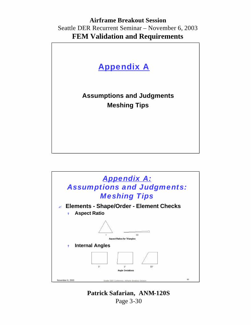
? Elements - Shape/Order - Element Checks? Aspect Ratio
? Internal Angles
Appendix A:Assumptions and Judgments:
Meshing Tips

Patrick Safarian, ANM-120SPage 3-31
Airframe Breakout SessionSeattle DER Recurrent Seminar – November 6, 2003
FEM Validation and Requirements
Seattle DER Conference, Airframe Breakout Session61November 6, 2003
? Elements - Shape/Order - Element Checks? Parallel Deviation
? Jacobian Ratio
Appendix A:Assumptions and Judgments:
Meshing Tips
Seattle DER Conference, Airframe Breakout Session62November 6, 2003
? Elements - Shape/Order - Element Checks? Warp
Appendix A:Assumptions and Judgments:
Meshing Tips

Patrick Safarian, ANM-120SPage 3-32
Airframe Breakout SessionSeattle DER Recurrent Seminar – November 6, 2003
FEM Validation and Requirements
Appendix B
Verify and Document the Results
Seattle DER Conference, Airframe Breakout Session64November 6, 2003
? Element Formulation and Solution Code? Documented
? Assumptions, Conditions, Limitations, Results? Quality assurance and other manuals
? Available from Software Provider? Procedures, Command, Theory, Element, Verification,
and Validation Manuals; Linear, Non-linear, Dynamics, Etc.
? New elements, New solution algorithms or Unknown/Undocumented code? Request validation documents
Appendix B Verify and Document the Results

Patrick Safarian, ANM-120SPage 3-33
Airframe Breakout SessionSeattle DER Recurrent Seminar – November 6, 2003
FEM Validation and Requirements
Seattle DER Conference, Airframe Breakout Session65November 6, 2003
? Structure is rarely, if ever, fully tested for all loads, environments and deterioration
? Analysis is used to decide what to test? Validation of analysis develops confidence that
? Analysis is capable of selecting test conditions? Analysis is capable of identifying
? Non-Significant Effects? Compensating for factors not included in test
Appendix B Verify and Document the Results
Seattle DER Conference, Airframe Breakout Session66November 6, 2003
? Instrumented structural test? Full sale test of actual or representative structure? Validation is done in combination with proof-of-
structure
? Comparison to classical analysis? Is the classical analysis applicable to the structure?? Is the FEA applicable to the classical analysis?
Appendix B Verify and Document the Results

Patrick Safarian, ANM-120SPage 3-34
Airframe Breakout SessionSeattle DER Recurrent Seminar – November 6, 2003
FEM Validation and Requirements
Seattle DER Conference, Airframe Breakout Session67November 6, 2003
? Building Block? Basic structure validated by comparison to theory? Detail or configuration subset models validated by:
? Analysis? Test
? Integrated structure does not invalidate model configuration? Detail or configuration subset model integrated into
Overall structure model does not have significant changes? Parametric variational analysis, sensitivity studies
Appendix B Verify and Document the Results
Seattle DER Conference, Airframe Breakout Session68November 6, 2003
? Verification? Failure modes/theories
? In linear analyses the program doesn’t know anything about plasticity, failure modes/limits - these usually must be evaluated in manual post -processing steps
? In non-linear analyses, the non-linearities must be defined and the associated solution controls must be properly specified
?The analyst (in most cases) must know ahead of time what type of failure mode is to be predicted
Appendix B Verify and Document the Results

Patrick Safarian, ANM-120SPage 3-35
Airframe Breakout SessionSeattle DER Recurrent Seminar – November 6, 2003
FEM Validation and Requirements
Seattle DER Conference, Airframe Breakout Session69November 6, 2003
? Verification? Failure modes/theories
? One analysis can include multiple failure modes? All must be accounted for? Failed members must be eliminated (At least
their stiffness)
? Often user intervention is required during the analysis in order to drive the analysis in the expected direction
Appendix B Verify and Document the Results
Seattle DER Conference, Airframe Breakout Session70November 6, 2003
? Verification? Failure modes/theories
?Most FEA systems have “built-in” theories, such as the Von-Mises equivalent stress calculation for ductile metal yield surface determination
?The user must determine what is appropriate to use for a given analysis
?Material properties used in this kind of analysis is different than handbook values
?Joints must be accounted for separately if not modeled accurately- Manual postManual post --processingprocessing
Appendix B Verify and Document the Results

Patrick Safarian, ANM-120SPage 3-36
Airframe Breakout SessionSeattle DER Recurrent Seminar – November 6, 2003
FEM Validation and Requirements
Seattle DER Conference, Airframe Breakout Session71November 6, 2003
? Verification? Other failure modes/theories
? What stress to use?? Ductile metals? Brittle materials
? Plastics? Other material; e.g. Glass
? Crack growth due to fatigue loading? Structural instabilities
Appendix B Verify and Document the Results
Seattle DER Conference, Airframe Breakout Session72November 6, 2003
? Verification? Boundary conditions
? Can significantly impact the solution? Can be difficult to determine accurately? Can be difficult to apply accurately? Require post-analysis evaluation,
especially when designing “on the edge”? It is good validation to substantiate the
BC’s by test
Appendix B Verify and Document the Results

Patrick Safarian, ANM-120SPage 3-37
Airframe Breakout SessionSeattle DER Recurrent Seminar – November 6, 2003
FEM Validation and Requirements
Seattle DER Conference, Airframe Breakout Session73November 6, 2003
? Verification? Material models
? Can significantly impact the solution? Can be difficult to obtain accurately? Can require significant post-analysis
evaluation to become satisfied with the results
? Always allow for reasonable variation
Appendix B Verify and Document the Results
Seattle DER Conference, Airframe Breakout Session74November 6, 2003
? Verification? Error estimation
? Most contemporary FEA systems have some measures of error estimation built in
? The most common is the “structural energy error”which is a measure of the continuity of the stress field from element to element
? Useful for determining required level of mesh refinement? Valid only for linear analyses using 2D or 3D shell or
solid elements
Appendix B Verify and Document the Results

Patrick Safarian, ANM-120SPage 3-38
Airframe Breakout SessionSeattle DER Recurrent Seminar – November 6, 2003
FEM Validation and Requirements
Seattle DER Conference, Airframe Breakout Session75November 6, 2003
? Verification? Error estimation
? For h-elements adaptive meshing uses error estimates internally to re-mesh a model where the error is high (higher than a user-specified tolerance)
? These are often accompanied by a graphical display of the variation in the magnitude of the error with solution iteration for quick evaluation
Appendix B Verify and Document the Results
Seattle DER Conference, Airframe Breakout Session76November 6, 2003
? Verification? Acceptance criteria?Each user must determine this for each
particular problem?Should include reference to:?Design requirements?Model quality?Error estimation?Failure mode/theory?Solution convergence (non-linear problems)
Appendix B Verify and Document the Results

Patrick Safarian, ANM-120SPage 3-39
Airframe Breakout SessionSeattle DER Recurrent Seminar – November 6, 2003
FEM Validation and Requirements
Appendix C
A Simple Illustration:Modeling a Beam
Seattle DER Conference, Airframe Breakout Session78November 6, 2003
Example - 50” long Cantilever I-Beam? 200 Lb/in distributed load
? The Cantilever Beam is idealized as?? Beam ElementsBeam Elements?? RodRod--PlatePlate--Rod ElementsRod Elements?? Shell ElementsShell Elements
? All three idealizations are acceptable? Theoretical solution:
? Vertical Deflection= 0.522”? Maximum Stress= 50.099 Ksi
Appendix CA Simple Illustration

Patrick Safarian, ANM-120SPage 3-40
Airframe Breakout SessionSeattle DER Recurrent Seminar – November 6, 2003
FEM Validation and Requirements
Seattle DER Conference, Airframe Breakout Session79November 6, 2003
Element plot of the I-Beam
Appendix CA Simple Illustration-
Beam Elements
Seattle DER Conference, Airframe Breakout Session80November 6, 2003
Deflection plot:
Appendix CA Simple Illustration-
Beam Elements

Patrick Safarian, ANM-120SPage 3-41
Airframe Breakout SessionSeattle DER Recurrent Seminar – November 6, 2003
FEM Validation and Requirements
Seattle DER Conference, Airframe Breakout Session81November 6, 2003
Stress output: PRINT ELEM ELEMENT SOLUTION PER ELEMENT ***** POST1 ELEMENT SOLUTION LISTING ***** LOAD STEP 1 SUBSTEP= 1 TIME= 1.0000 LOAD CASE= 0
EL= 1 NODES= 1 3 MAT= 1BEAM3 TEMP = 0.00 0.00 0.00 0.00 PRES LOAD KEY = 1 FACE NODES = 1 3 PRESSURES(F/L) = 200.00 200.00 LOCATION SDIR SBYT SBYB 1 (I) 0.0000 50099. -50099. 2 (J) 0.0000 40580. -40580.
EL= 2 NODES= 3 4 MAT= 1BEAM3 TEMP = 0.00 0.00 0.00 0.00 PRES LOAD KEY = 1 FACE NODES = 3 4 PRESSURES(F/L) = 200.00 200.00 LOCATION SDIR SBYT SBYB 1 (I) 0.0000 40580. -40580. 2 (J) 0.0000 32063. -32063.
Appendix CA Simple Illustration-
Beam Elements
Seattle DER Conference, Airframe Breakout Session82November 6, 2003
Element plot of the I-Beam
Appendix CA Simple Illustration-
Rod-Plate-Rod Elements

Patrick Safarian, ANM-120SPage 3-42
Airframe Breakout SessionSeattle DER Recurrent Seminar – November 6, 2003
FEM Validation and Requirements
Seattle DER Conference, Airframe Breakout Session83November 6, 2003
Deflection plot:
Appendix CA Simple Illustration-
Rod-Plate-Rod Elements
Seattle DER Conference, Airframe Breakout Session84November 6, 2003
Stress output:PRINT ELEM ELEMENT SOLUTION PER ELEMENT
***** POST1 ELEMENT SOLUTION LISTING *****
LOAD STEP 1 SUBSTEP= 1 TIME= 1.0000 LOAD CASE= 0
EL= 11 NODES= 1 3 MAT= 1LINK1 TEMP = 0.00 0.00 FLUENCES = 0.000E+00 0.000E+00 MFORX= 19674. SAXL= 52464.
EL= 30 NODES= 22 13 MAT= 1LINK1 TEMP = 0.00 0.00 FLUENCES = 0.000E+00 0.000E+00 MFORX= -19674. SAXL= -52464.
Appendix CA Simple Illustration-
Rod-Plate-Rod Elements

Patrick Safarian, ANM-120SPage 3-43
Airframe Breakout SessionSeattle DER Recurrent Seminar – November 6, 2003
FEM Validation and Requirements
Seattle DER Conference, Airframe Breakout Session85November 6, 2003
Element plot of the I-Beam
Appendix CA Simple Illustration-
Shell Elements
Seattle DER Conference, Airframe Breakout Session86November 6, 2003
Deflection plot:
Appendix CA Simple Illustration-
Shell Elements
Patrick Safarian, ANM-120SPage 3-44
Airframe Breakout SessionSeattle DER Recurrent Seminar – November 6, 2003
FEM Validation and Requirements
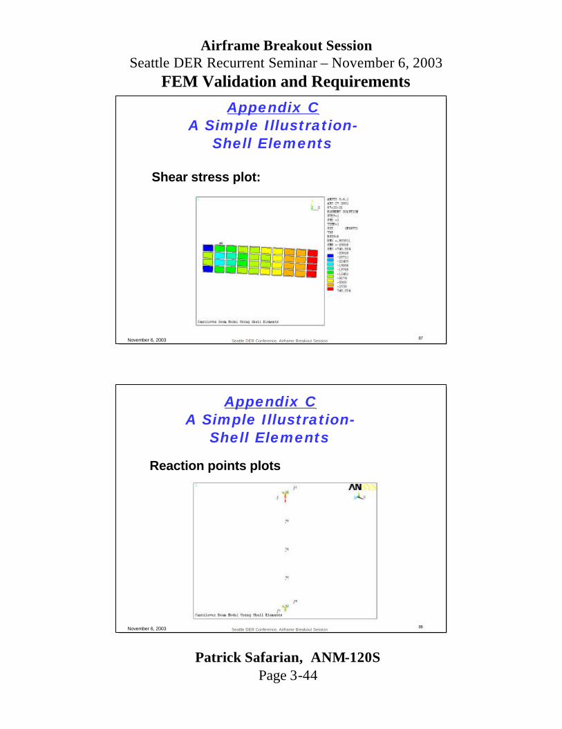
Seattle DER Conference, Airframe Breakout Session87November 6, 2003
Shear stress plot:
Appendix CA Simple Illustration-
Shell Elements
Seattle DER Conference, Airframe Breakout Session88November 6, 2003
Reaction points plots
Appendix CA Simple Illustration-
Shell Elements

Patrick Safarian, ANM-120SPage 3-45
Airframe Breakout SessionSeattle DER Recurrent Seminar – November 6, 2003
FEM Validation and Requirements
Seattle DER Conference, Airframe Breakout Session89November 6, 2003
Reaction forces and moments:PRINT REACTION SOLUTIONS PER NODE
***** POST1 TOTAL REACTION SOLUTION LISTING *****
LOAD STEP= 1 SUBSTEP= 1 TIME= 1.0000 LOAD CASE= 0
THE FOLLOWING X,Y,Z SOLUTIONS ARE IN GLOBAL COORDINATES
NODE FX FY FZ MX MY MZ 12 -20808. 5180.3 0.62755E-10-0.21909E-09-0.14583E-08 158.58 46 20808. 4819.7 0.79173E-10 0.10639E-09-0.15063E-08 141.05
TOTAL VALUES VALUE 0.36016E-09 10000. 0.14193E-09-0.11270E-09-0.29645E-08 299.63
Appendix CA Simple Illustration-
Shell Elements
Seattle DER Conference, Airframe Breakout Session90November 6, 2003
Stress output:
PRINT S NODAL SOLUTION PER NODE
***** POST1 NODAL STRESS LISTING *****
LOAD STEP= 1 SUBSTEP= 1 TIME= 1.0000 LOAD CASE= 0 SHELL NODAL RESULTS ARE AT TOP/BOTTOM FOR MATERIAL 1
THE FOLLOWING X,Y,Z VALUES ARE IN GLOBAL COORDINATES
NODE SX SY SZ SXY SYZ SXZ12 90451. 47078. -0.38537E-23 -29018. 0.12668E-09-0.15729E-0746 -91288. -46655. -0.39952E-23 -28730. -0.16560E-09-0.16318E-07
Appendix CA Simple Illustration-
Shell Elements

Patrick Safarian, ANM-120SPage 3-46
Airframe Breakout SessionSeattle DER Recurrent Seminar – November 6, 2003
FEM Validation and Requirements
Seattle DER Conference, Airframe Breakout Session91November 6, 2003
? Revise Boundary Condition -WebGrid 2 12X 23
72X71X70X
57 46X 34
X = Constrained
Appendix CA Simple Illustration-
Shell Elements
Seattle DER Conference, Airframe Breakout Session92November 6, 2003
Reaction forces and moments:PRINT REACTION SOLUTIONS PER NODE
***** POST1 TOTAL REACTION SOLUTION LISTING *****
LOAD STEP= 1 SUBSTEP= 1 TIME= 1.0000 LOAD CASE= 0
THE FOLLOWING X,Y,Z SOLUTIONS ARE IN GLOBAL COORDINATES
NODE FX FY FZ MX MY MZ 12 -18793. 2568.4 -0.40700E-10-0.28488E-09-0.12363E-09 118.34 46 18519. 2178.9 -0.41706E-10-0.38849E-09-0.43746E-09 103.58 70 4400.8 1511.0 0.13642E-09-0.20379E-10-0.26982E-09 0.15732E-02 71 106.07 2115.2 -0.67394E-10-0.73225E-11 0.50690E-10 0.28416E-02 72 -4233.2 1626.5 0.87921E-10-0.93032E-12-0.15933E-09 0.16688E-02
TOTAL VALUES VALUE 0.29740E-09 10000. 0.74539E-10-0.70200E-09-0.93955E-09 221.92
Appendix CA Simple Illustration-
Shell Elements

Patrick Safarian, ANM-120SPage 3-47
Airframe Breakout SessionSeattle DER Recurrent Seminar – November 6, 2003
FEM Validation and Requirements
Seattle DER Conference, Airframe Breakout Session93November 6, 2003
Stress output:PRINT S NODAL SOLUTION PER NODE ***** POST1 NODAL STRESS LISTING ***** LOAD STEP= 1 SUBSTEP= 1 TIME= 1.0000 LOAD CASE= 0 SHELL NODAL RESULTS ARE AT TOP THE FOLLOWING X,Y,Z VALUES ARE IN GLOBAL COORDINATES
NODE SX SY SZ SXY SYZ SXZ 2 27618. -0.78609E-13 5004.9 317.01 -7.8946 7591.0 12 76302. 5414.2 3063.9 -6495.1 -0.24406E-09-0.18744E-07 23 27618. 0.96678E-15 5004.9 317.01 7.8946 -7591.0 34 -29283. 0.75908E-15 -4486.9 277.47 6.1986 10067. 46 -78524. -5454.5 -3231.2 -6039.1 -0.37655E-09-0.27518E-07 57 -29283. -0.68718E-13 -4486.9 277.47 -6.1986 -10067. 70 -29453. -10396. -0.65793E-25 -19206. -0.21778E-11-0.27043E-09 71 -511.56 -146.73 0.16539E-24 -21690. -0.26030E-11 0.67526E-09 72 28471. 10189. -0.16263E-24 -20036. -0.12320E-11-0.66226E-09
NODE 46 70 57 71 2 57 VALUE -78524. -10396. -4486.9 -21690. -7.8946 -10067.MINIMUM VALUES
MAXIMUM VALUES NODE 12 72 23 23 23 34 VALUE 76302. 10189. 5004.9 317.01 7.8946 10067.
Appendix CA Simple Illustration-
Shell Elements
Seattle DER Conference, Airframe Breakout Session94November 6, 2003
? Revise Boundary Condition -Web/FlangesGrid 2X 12X 23X
72X71X70X
57X 46X 34X
X = Constrained
Appendix CA Simple Illustration-
Shell Elements

Patrick Safarian, ANM-120SPage 3-48
Airframe Breakout SessionSeattle DER Recurrent Seminar – November 6, 2003
FEM Validation and Requirements
Seattle DER Conference, Airframe Breakout Session95November 6, 2003
? Reaction forces and moments:PRINT REACTION SOLUTIONS PER NODE
***** POST1 TOTAL REACTION SOLUTION LISTING *****
LOAD STEP = 1 SUBSTEP= 1 TIME= 1.0000 LOAD CASE= 0
THE FOLLOWING X ,Y,Z SOLUTIONS ARE IN GLOBAL COORDINATES
NODE FX FY FZ MX MY MZ 2 -4087.1 15.080 3395.3 4.2405 -0.27730E-03 26.476 12 -11191. 2371.6 -0.25830E-09-0.23387E-10-0.51608E- 11 90.292 23 -4087.1 15.080 -3395.3 -4.2405 0.27730E-03 26.476 34 4021.6 12.906 3344.1 -3.8684 -0.27242E-03 22.927 46 11027. 1984.9 -0.19806E-08 0.19600E-10-0.19187E-11 78.175 57 4021.6 12.906 -3344.1 3.8684 0.27242E-03 22.927 70 3280.1 1801.1 0.23711E-11 0.63627E-12-0.63500E-11 0.74169E-03 71 109.17 1863.7 0.72721E-12-0.21000E-12-0.40583E-11 0.35842E-02 72 -3093.9 1922.7 0.31072E-11-0.57332E-12-0.66728E-11 0.80487E-03
TOTAL VALUES VALUE 0.43156E-09 10000. 0.13263E-09-0.47127E-11-0.24343E-10 267.28
Appendix CA Simple Illustration-
Shell Elements
Seattle DER Conference, Airframe Breakout Session96November 6, 2003
? Stress output:PRINT S NODAL SOLUTION PER NODE ***** POST1 NODAL STRESS LISTING ***** LOAD STEP= 1 SUBSTEP= 1 TIME= 1.0000 LOAD CASE= 0 SHELL NODAL RESULTS ARE AT TOP
THE FOLLOWING X,Y,Z VALUES ARE IN GLOBAL COORDINATES
NODE SX SY SZ SXY SYZ SXZ 2 55518. 0.64393E-14 16762. -26.291 -0.36833E-11 -1374.3 12 56596. 4139.0 11175. -7026.6 -0.52061E-11-0.25440E-08 23 55518. 0.57057E-27 16762. -26.291 0.51723E-11 1374.3 34 -59146. -0.99092E-28 -17843. -22.036 -0.13554E-11 -1508.8 46 -59005. -4197.3 -11896. -6571.9 -0.46591E-11 0.18765E-08 57 -59146. 0.53970E-14 -17843. -22.036 -0.89547E-11 1508.8 70 -26070. -8293.8 -0.80341E-26 -19158. -0.20563E-11-0.34399E-10 71 -543.64 -155.94 -0.80243E-27 -19515. -0.24228E-11-0.33095E-11 72 25025. 8050.5 -0.61465E-26 -20014. -0.12673E-11-0.23563E-10
MINIMUM VALUES NODE 34 70 34 72 57 34 VALUE -59146. -8293.8 -17843. -20014. -0.89547E-11 -1508.8
MAXIMUM VALUES NODE 12 72 23 57 23 57
Appendix CA Simple Illustration-
Shell Elements
Related Documents