FEM modeling of structures based on close range digital photogrammetry Julia Armesto a, ⁎, Izabela Lubowiecka b , Celestino Ordóñez a , Fernando I. Rial a a Department of Natural Resources and Environmental Engineering, University of Vigo, Campus Universitario As Lagoas–Marcosende s/n, C.P. 36200 Vigo, Spain b Department of Structural Mechanics and Bridges, Faculty of Civil and Environmental Engineering, Gdańsk University of Technology, Narutowicza 11/12, 80-952 Gdańsk, Poland abstract article info Article history: Accepted 21 November 2008 Keywords: Structural damage Finite Element Method Photogrammetry Historic structures The aim of this paper is to present a methodology for the evaluation of historic timber structures, based on numerical modeling coupled with on site measurements. A method to measure the geometry of structural elements of a timber roof using a photogrammetric modeling procedure is described. In particular, we show the utility of photogrammetric based models when applied to structural analysis by directly introducing 3D geometry files in the preprocessing module of computational software based on the Finite Element Method. The 2D and 3D FEM models of the roof are considered to compare the simple and more complex modeling, and static and dynamic analyses are performed. Both models are prepared using the photogrammetric data. © 2008 Elsevier B.V. All rights reserved. 1. Introduction Wood and masonry have been used as building materials for cen- turies. Recently, they have lost their principal roles since advances in structural mechanics have focused the attention of engineers on new structures. This has resulted in iron and reinforced concrete becoming the favored building materials in the last century. However, some structures built with traditional materials still exist and remain in service to this day. Some of these are considered integral parts of the rural architecture and important features of European cultural heritage. Their preservation is considered an important issue owing to cultural requirements and economic and developmental demands, especially in regions where tourism and leisure have become major industries. In recent years, the need for the rehabilitation and conservation of architectural heritage has shown a lack of reliable methods for maintaining traditional structures in good condition while simulta- neously satisfying modern requirements for renovations, such as non- destructive inspection, minimum amount of repair, and maintenance of the original appearance, as well as maintaining the functionality and structural stability of the structure [1]. Structural analysis is the only way to assess the structural condition of a particular building (see e.g., [2]). The first and most important steps in this activity are the documentation of the structure and the geometrical assessment of the model. In most examples, the original designs and plans are not available, and on-site measure- ments are necessary. However, the commonly used traditional methods of making measurements by hand are usually not sufficiently accurate and very time consuming. These techniques require substantial effort and do not give satisfactory results about the structure's geometry and the materials used. For structures with out- of-plane deformations, often seen in historic buildings, optical non contact techniques might be applied for the 3D modeling. This kind of techniques allow measuring directly from camera pictures avoiding physical contact with the object (close range photogrammetry) or storing directly the 3D coordinates of measured points obtained by the projection of a laser beam on the object surface (time of flight or phase based 3D laser scanners). Non contact 3D modeling techniques have become especially important as measuring tools in heritage applica- tions, where intervention and manipulation might be kept to a minimum, and also in high structures, where physical access to the structure involves important risk for operators. Commonly, the reliability of a timber structure has to be estimated for maintenance, repair or structural modification, in order to conform to building standards that fulfill the safety requirements (usual building, standard timber and materials). In these cases, only simple structural assessments are used, usually because of design costs. Different types of uncertainties, such as physical, statistical and modeling, should be also considered. For many other cases (old timber frames, complex structures with high 3D effects, unusual climatic environment, non-standard material; see e.g. [3]), standard techniques and simple modeling cannot be applied. This paper presents a general method for the evaluation of structures with timber roof construction, considering that these structures have complex geometries and that material properties are unknown and cannot be directly assessed experimentally. We perform the preliminary static and dynamic analyses of the roof structure (see Fig. 1) of a historic building which is situated in the small rural village of Salvaterra do Miño Council, in north-west Spain (see Fig. 2). Automation in Construction 18 (2009) 559–569 ⁎ Corresponding author. Tel.: +34 986 813 423. E-mail address: [email protected] (J. Armesto). 0926-5805/$ – see front matter © 2008 Elsevier B.V. All rights reserved. doi:10.1016/j.autcon.2008.11.006 Contents lists available at ScienceDirect Automation in Construction journal homepage: www.elsevier.com/locate/autcon

Welcome message from author
This document is posted to help you gain knowledge. Please leave a comment to let me know what you think about it! Share it to your friends and learn new things together.
Transcript
Automation in Construction 18 (2009) 559–569
Contents lists available at ScienceDirect
Automation in Construction
j ourna l homepage: www.e lsev ie r.com/ locate /autcon
FEM modeling of structures based on close range digital photogrammetry
Julia Armesto a,⁎, Izabela Lubowiecka b, Celestino Ordóñez a, Fernando I. Rial a
a Department of Natural Resources and Environmental Engineering, University of Vigo, Campus Universitario As Lagoas–Marcosende s/n, C.P. 36200 Vigo, Spainb Department of Structural Mechanics and Bridges, Faculty of Civil and Environmental Engineering, Gdańsk University of Technology, Narutowicza 11/12, 80-952 Gdańsk, Poland
⁎ Corresponding author. Tel.: +34 986 813 423.E-mail address: [email protected] (J. Armesto).
0926-5805/$ – see front matter © 2008 Elsevier B.V. Adoi:10.1016/j.autcon.2008.11.006
a b s t r a c t
a r t i c l e i n f oArticle history:
The aim of this paper is Accepted 21 November 2008Keywords:Structural damageFinite Element MethodPhotogrammetryHistoric structures
to present a methodology for the evaluation of historic timber structures,based on numerical modeling coupled with on site measurements. A method to measure the geometryof structural elements of a timber roof using a photogrammetric modeling procedure is described. Inparticular, we show the utility of photogrammetric based models when applied to structural analysis bydirectly introducing 3D geometry files in the preprocessing module of computational software based onthe Finite Element Method. The 2D and 3D FEM models of the roof are considered to compare the simpleand more complex modeling, and static and dynamic analyses are performed. Both models are preparedusing the photogrammetric data.
© 2008 Elsevier B.V. All rights reserved.
1. Introduction
Wood and masonry have been used as building materials for cen-turies. Recently, they have lost their principal roles since advances instructural mechanics have focused the attention of engineers on newstructures. This has resulted in iron and reinforced concrete becomingthe favored building materials in the last century. However, somestructures built with traditional materials still exist and remain inservice to this day. Some of these are considered integral parts of therural architecture and important features of European culturalheritage. Their preservation is considered an important issue owingto cultural requirements and economic and developmental demands,especially in regions where tourism and leisure have become majorindustries.
In recent years, the need for the rehabilitation and conservation ofarchitectural heritage has shown a lack of reliable methods formaintaining traditional structures in good condition while simulta-neously satisfying modern requirements for renovations, such as non-destructive inspection, minimum amount of repair, and maintenanceof the original appearance, as well as maintaining the functionalityand structural stability of the structure [1].
Structural analysis is the only way to assess the structuralcondition of a particular building (see e.g., [2]). The first and mostimportant steps in this activity are the documentation of the structureand the geometrical assessment of the model. In most examples, theoriginal designs and plans are not available, and on-site measure-ments are necessary. However, the commonly used traditional
ll rights reserved.
methods of makingmeasurements by hand are usually not sufficientlyaccurate and very time consuming. These techniques requiresubstantial effort and do not give satisfactory results about thestructure's geometry and the materials used. For structures with out-of-plane deformations, often seen in historic buildings, optical noncontact techniques might be applied for the 3D modeling. This kind oftechniques allow measuring directly from camera pictures avoidingphysical contact with the object (close range photogrammetry) orstoring directly the 3D coordinates ofmeasured points obtained by theprojection of a laser beam on the object surface (time of flight or phasebased 3D laser scanners). Non contact 3D modeling techniques havebecome especially important as measuring tools in heritage applica-tions, where intervention and manipulation might be kept to aminimum, and also in high structures, where physical access to thestructure involves important risk for operators.
Commonly, the reliability of a timber structure has to be estimated formaintenance, repair or structural modification, in order to conform tobuilding standards that fulfill the safety requirements (usual building,standard timber and materials). In these cases, only simple structuralassessments are used, usually because of design costs. Different types ofuncertainties, such as physical, statistical and modeling, should be alsoconsidered. For many other cases (old timber frames, complex structureswith high 3D effects, unusual climatic environment, non-standardmaterial; see e.g. [3]), standard techniques and simple modeling cannotbe applied.
This paper presents a general method for the evaluation ofstructures with timber roof construction, considering that thesestructures have complex geometries and that material properties areunknown and cannot be directly assessed experimentally.We performthe preliminary static and dynamic analyses of the roof structure(see Fig. 1) of a historic building which is situated in the small ruralvillage of Salvaterra do Miño Council, in north-west Spain (see Fig. 2).
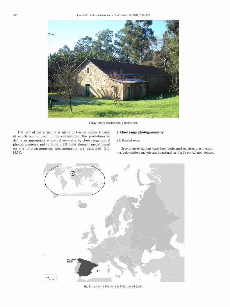
Fig. 1. Historic building with a timber roof.
560 J. Armesto et al. / Automation in Construction 18 (2009) 559–569
The roof of the structure is made of twelve timber trusses,of which one is used in the calculations. The procedures todefine an appropriate structural geometry by close range digitalphotogrammetry and to build a 3D finite element model basedon the photogrammetric measurements are described (c.f.,[4,5]).
Fig. 2. Location of Salvaterra
2. Close range photogrammetry
2.1. Related work
Several investigations have been performed on structures measur-ing, deformation analysis and structural testing by optical non-contact
de Miño council, Spain.
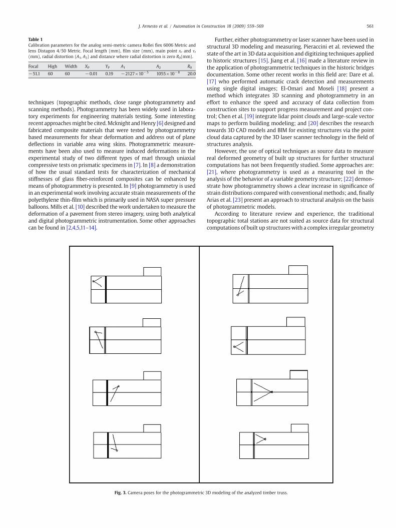
Table 1Calibration parameters for the analog semi-metric camera Rollei flex 6006 Metric andlens Distagon 4/50 Metric. Focal length (mm), film size (mm), main point XP and YP
(mm), radial distortion (A1, A2) and distance where radial distortion is zero R0(mm).
Focal High Width XP YP A1 A2 R0
−51.1 60 60 −0.01 0.19 −2127×10−5 1055×10−8 20.0
561J. Armesto et al. / Automation in Construction 18 (2009) 559–569
techniques (topographic methods, close range photogrammetry andscanning methods). Photogrammetry has been widely used in labora-tory experiments for engineering materials testing. Some interestingrecent approachesmight be cited.Mcknight andHenry [6] designed andfabricated composite materials that were tested by photogrammetrybased measurements for shear deformation and address out of planedeflections in variable area wing skins. Photogrammetric measure-ments have been also used to measure induced deformations in theexperimental study of two different types of marl through uniaxialcompressive tests on prismatic specimens in [7]. In [8] a demonstrationof how the usual standard tests for characterization of mechanicalstiffnesses of glass fiber-reinforced composites can be enhanced bymeans of photogrammetry is presented. In [9] photogrammetry is usedin an experimental work involving accurate strainmeasurements of thepolyethylene thin-film which is primarily used in NASA super pressureballoons. Mills et al. [10] described thework undertaken tomeasure thedeformation of a pavement from stereo imagery, using both analyticaland digital photogrammetric instrumentation. Some other approachescan be found in [2,4,5,11–14].
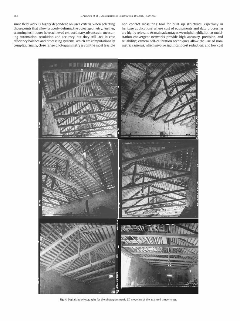
Fig. 3. Camera poses for the photogrammetric
Further, either photogrammetry or laser scanner have been used instructural 3D modeling and measuring. Pieraccini et al. reviewed thestate of the art in 3D data acquisition and digitizing techniques appliedto historic structures [15]. Jiang et al. [16] made a literature review inthe application of photogrammetric techniques in the historic bridgesdocumentation. Some other recent works in this field are: Dare et al.[17] who performed automatic crack detection and measurementsusing single digital images; El-Omari and Moseli [18] present amethod which integrates 3D scanning and photogrammetry in aneffort to enhance the speed and accuracy of data collection fromconstruction sites to support progress measurement and project con-trol; Chen et al. [19] integrate lidar point clouds and large-scale vectormaps to perform building modeling; and [20] describes the researchtowards 3D CAD models and BIM for existing structures via the pointcloud data captured by the 3D laser scanner technology in the field ofstructures analysis.
However, the use of optical techniques as source data to measurereal deformed geometry of built up structures for further structuralcomputations has not been frequently studied. Some approaches are:[21], where photogrammetry is used as a measuring tool in theanalysis of the behavior of a variable geometry structure; [22] demon-strate how photogrammetry shows a clear increase in significance ofstrain distributions comparedwith conventional methods; and, finallyArias et al. [23] present an approach to structural analysis on the basisof photogrammetric models.
According to literature review and experience, the traditionaltopographic total stations are not suited as source data for structuralcomputations of built up structureswith a complex irregular geometry
3D modeling of the analyzed timber truss.
562 J. Armesto et al. / Automation in Construction 18 (2009) 559–569
since field work is highly dependent on user criteria when selectingthose points that allow properly defining the object geometry. Further,scanning techniques have achieved extraordinary advances inmeasur-ing automation, resolution and accuracy, but they still lack in costefficiency balance and processing systems, which are computationallycomplex. Finally, close range photogrammetry is still the most feasible
Fig. 4. Digitalized photographs for the photogramm
non contact measuring tool for built up structures, especially inheritage applications where cost of equipments and data processingare highly relevant. Asmain advantageswemight highlight thatmulti-station convergent networks provide high accuracy, precision, andreliability; camera self-calibration techniques allow the use of non-metric cameras, which involve significant cost reduction; and low cost
etric 3D modeling of the analyzed timber truss.
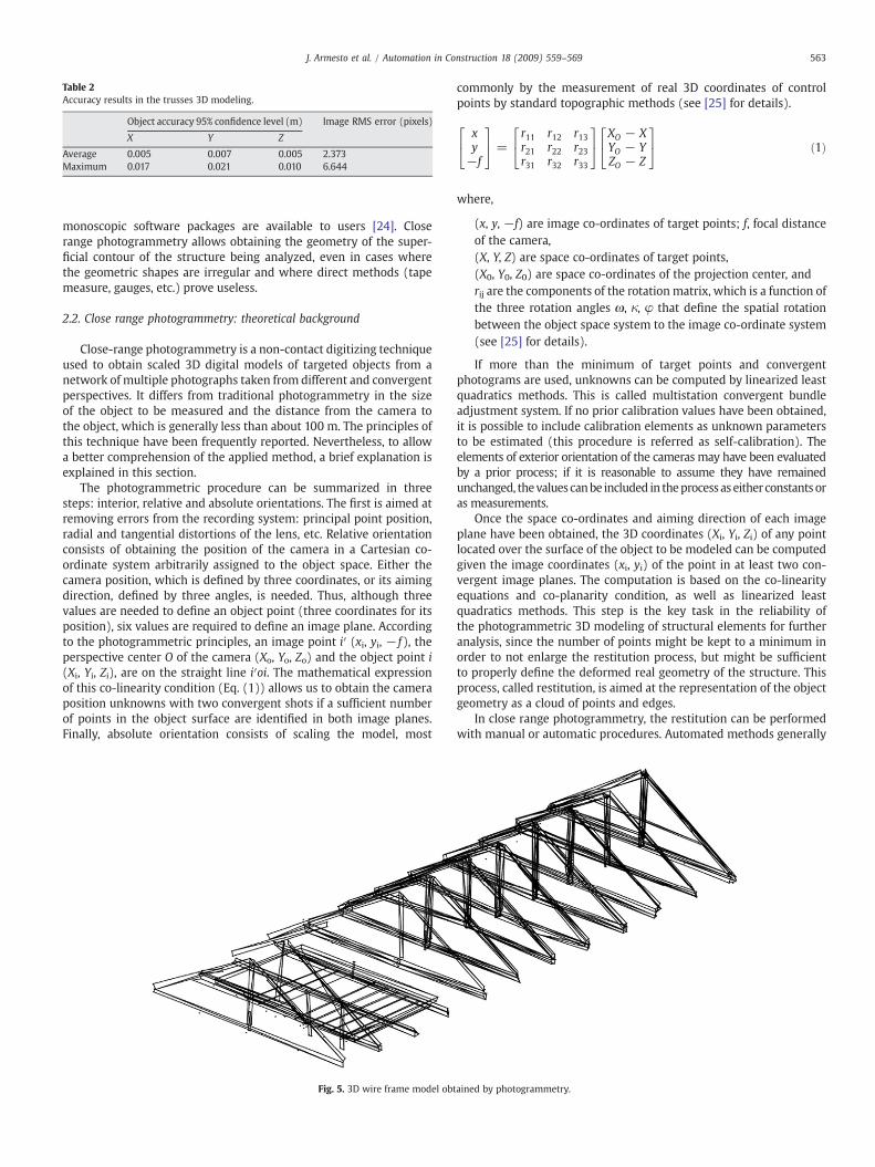
Table 2Accuracy results in the trusses 3D modeling.
Object accuracy 95% confidence level (m) Image RMS error (pixels)
X Y Z
Average 0.005 0.007 0.005 2.373Maximum 0.017 0.021 0.010 6.644
563J. Armesto et al. / Automation in Construction 18 (2009) 559–569
monoscopic software packages are available to users [24]. Closerange photogrammetry allows obtaining the geometry of the super-ficial contour of the structure being analyzed, even in cases wherethe geometric shapes are irregular and where direct methods (tapemeasure, gauges, etc.) prove useless.
2.2. Close range photogrammetry: theoretical background
Close-range photogrammetry is a non-contact digitizing techniqueused to obtain scaled 3D digital models of targeted objects from anetwork of multiple photographs taken from different and convergentperspectives. It differs from traditional photogrammetry in the sizeof the object to be measured and the distance from the camera tothe object, which is generally less than about 100 m. The principles ofthis technique have been frequently reported. Nevertheless, to allowa better comprehension of the applied method, a brief explanation isexplained in this section.
The photogrammetric procedure can be summarized in threesteps: interior, relative and absolute orientations. The first is aimed atremoving errors from the recording system: principal point position,radial and tangential distortions of the lens, etc. Relative orientationconsists of obtaining the position of the camera in a Cartesian co-ordinate system arbitrarily assigned to the object space. Either thecamera position, which is defined by three coordinates, or its aimingdirection, defined by three angles, is needed. Thus, although threevalues are needed to define an object point (three coordinates for itsposition), six values are required to define an image plane. Accordingto the photogrammetric principles, an image point i′ (xi, yi, − f), theperspective center O of the camera (Xo, Yo, Zo) and the object point i(Xi, Yi, Zi), are on the straight line i′oi. The mathematical expressionof this co-linearity condition (Eq. (1)) allows us to obtain the cameraposition unknowns with two convergent shots if a sufficient numberof points in the object surface are identified in both image planes.Finally, absolute orientation consists of scaling the model, most
Fig. 5. 3D wire frame model obt
commonly by the measurement of real 3D coordinates of controlpoints by standard topographic methods (see [25] for details).
xy−f
24
35 =
r11 r12 r13r21 r22 r23r31 r32 r33
24
35
XO − XYO − YZO − Z
24
35 ð1Þ
where,
(x, y, −f) are image co-ordinates of target points; f, focal distanceof the camera,(X, Y, Z) are space co-ordinates of target points,(X0, Y0, Z0) are space co-ordinates of the projection center, andrij are the components of the rotation matrix, which is a function ofthe three rotation angles ω, κ, φ that define the spatial rotationbetween the object space system to the image co-ordinate system(see [25] for details).
If more than the minimum of target points and convergentphotograms are used, unknowns can be computed by linearized leastquadratics methods. This is called multistation convergent bundleadjustment system. If no prior calibration values have been obtained,it is possible to include calibration elements as unknown parametersto be estimated (this procedure is referred as self-calibration). Theelements of exterior orientation of the cameras may have been evaluatedby a prior process; if it is reasonable to assume they have remainedunchanged, thevalues canbe included in theprocess as eitherconstants oras measurements.
Once the space co-ordinates and aiming direction of each imageplane have been obtained, the 3D coordinates (Xi, Yi, Zi) of any pointlocated over the surface of the object to be modeled can be computedgiven the image coordinates (xi, yi) of the point in at least two con-vergent image planes. The computation is based on the co-linearityequations and co-planarity condition, as well as linearized leastquadratics methods. This step is the key task in the reliability ofthe photogrammetric 3D modeling of structural elements for furtheranalysis, since the number of points might be kept to a minimum inorder to not enlarge the restitution process, but might be sufficientto properly define the deformed real geometry of the structure. Thisprocess, called restitution, is aimed at the representation of the objectgeometry as a cloud of points and edges.
In close range photogrammetry, the restitution can be performedwith manual or automatic procedures. Automated methods generally
ained by photogrammetry.
564 J. Armesto et al. / Automation in Construction 18 (2009) 559–569
provide very dense point clouds, but mismatches, irrelevant points andmissing parts may be present in the results, requiring a post-processingcheck of the data [26]. The manual data processing in monoscopicdigital systems is performed identifying all thosepointswhich representthe object geometry, and marking them in at least two photographs.
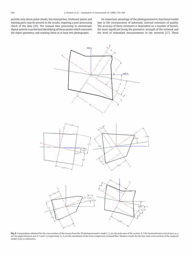
Fig. 6. Computations obtained for the cross sections of the trusses from the 3D photogrammeare the angles between axis X–I and Y–J respectively; Xi, Yi are the coordinates of the most comtimber truss in milimeters.
An important advantage of the photogrammetric functional modellays in the incorporation of automatic internal estimates of quality.The accuracy of these estimates is dependent on a number of factors,the most significant being the geometric strength of the network andthe level of redundant measurements in the network [27]. These
tric model: I, J, are the main axes of the section, X, Y the horizontal and vertical axes; α, φpressed/strained fiber. Numeric results for the four main cross sections of the analyzed
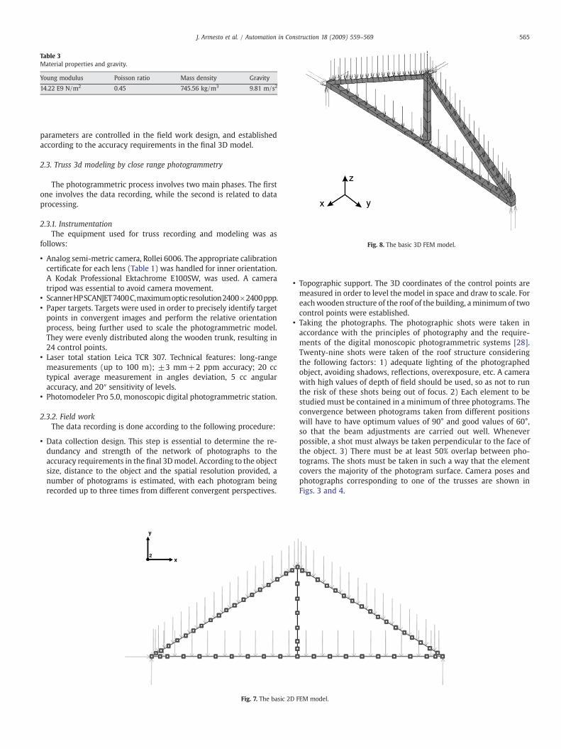
Table 3Material properties and gravity.
Young modulus Poisson ratio Mass density Gravity
14.22 E9 N/m2 0.45 745.56 kg/m3 9.81 m/s2
Fig. 8. The basic 3D FEM model.
565J. Armesto et al. / Automation in Construction 18 (2009) 559–569
parameters are controlled in the field work design, and establishedaccording to the accuracy requirements in the final 3D model.
2.3. Truss 3d modeling by close range photogrammetry
The photogrammetric process involves two main phases. The firstone involves the data recording, while the second is related to dataprocessing.
2.3.1. InstrumentationThe equipment used for truss recording and modeling was as
follows:
• Analog semi-metric camera, Rollei 6006. The appropriate calibrationcertificate for each lens (Table 1) was handled for inner orientation.A Kodak Professional Ektachrome E100SW, was used. A cameratripod was essential to avoid camera movement.
• ScannerHPSCANJET7400C,maximumopticresolution2400×2400ppp.• Paper targets. Targets were used in order to precisely identify targetpoints in convergent images and perform the relative orientationprocess, being further used to scale the photogrammetric model.They were evenly distributed along the wooden trunk, resulting in24 control points.
• Laser total station Leica TCR 307. Technical features: long-rangemeasurements (up to 100 m); ±3 mm+2 ppm accuracy; 20 cctypical average measurement in angles deviation, 5 cc angularaccuracy, and 20″ sensitivity of levels.
• Photomodeler Pro 5.0, monoscopic digital photogrammetric station.
2.3.2. Field workThe data recording is done according to the following procedure:
• Data collection design. This step is essential to determine the re-dundancy and strength of the network of photographs to theaccuracy requirements in the final 3Dmodel. According to the objectsize, distance to the object and the spatial resolution provided, anumber of photograms is estimated, with each photogram beingrecorded up to three times from different convergent perspectives.
Fig. 7. The basic 2D
• Topographic support. The 3D coordinates of the control points aremeasured in order to level the model in space and draw to scale. Foreachwooden structure of the roof of the building, aminimumof twocontrol points were established.
• Taking the photographs. The photographic shots were taken inaccordance with the principles of photography and the require-ments of the digital monoscopic photogrammetric systems [28].Twenty-nine shots were taken of the roof structure consideringthe following factors: 1) adequate lighting of the photographedobject, avoiding shadows, reflections, overexposure, etc. A camerawith high values of depth of field should be used, so as not to runthe risk of these shots being out of focus. 2) Each element to bestudied must be contained in a minimum of three photograms. Theconvergence between photograms taken from different positionswill have to have optimum values of 90° and good values of 60°,so that the beam adjustments are carried out well. Wheneverpossible, a shot must always be taken perpendicular to the face ofthe object. 3) There must be at least 50% overlap between pho-tograms. The shots must be taken in such a way that the elementcovers the majority of the photogram surface. Camera poses andphotographs corresponding to one of the trusses are shown inFigs. 3 and 4.
FEM model.
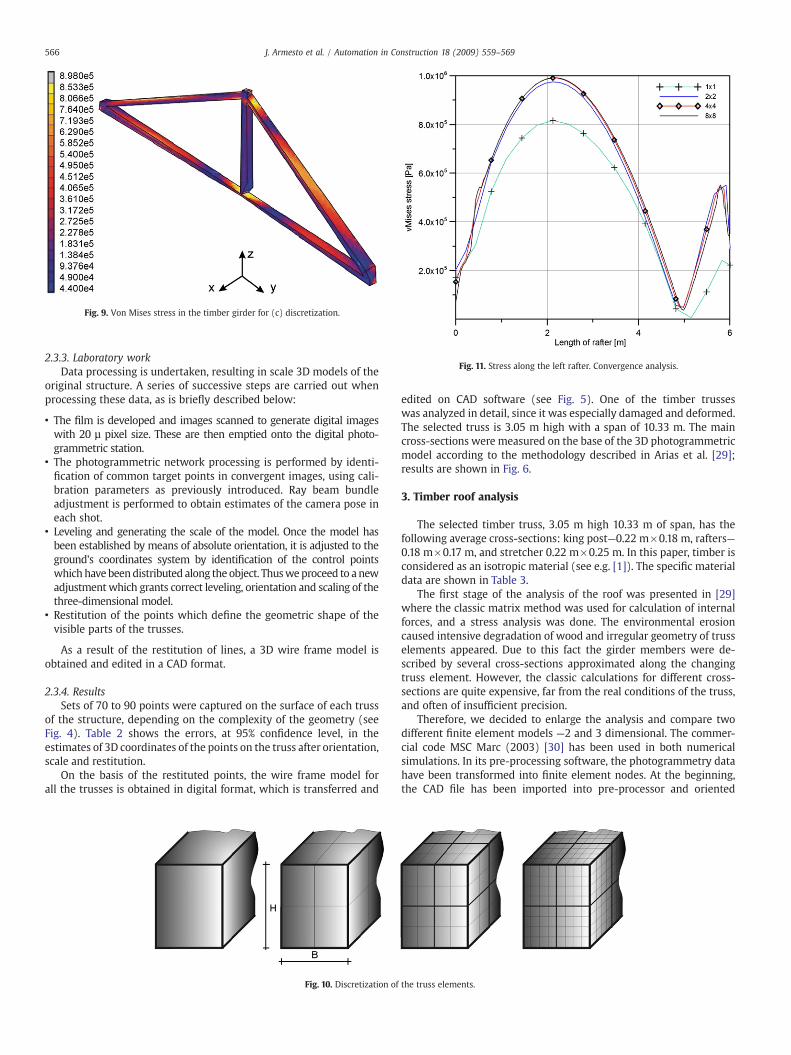
Fig. 11. Stress along the left rafter. Convergence analysis.
Fig. 9. Von Mises stress in the timber girder for (c) discretization.
566 J. Armesto et al. / Automation in Construction 18 (2009) 559–569
2.3.3. Laboratory workData processing is undertaken, resulting in scale 3D models of the
original structure. A series of successive steps are carried out whenprocessing these data, as is briefly described below:
• The film is developed and images scanned to generate digital imageswith 20 µ pixel size. These are then emptied onto the digital photo-grammetric station.
• The photogrammetric network processing is performed by identi-fication of common target points in convergent images, using cali-bration parameters as previously introduced. Ray beam bundleadjustment is performed to obtain estimates of the camera pose ineach shot.
• Leveling and generating the scale of the model. Once the model hasbeen established by means of absolute orientation, it is adjusted to theground's coordinates system by identification of the control pointswhich have beendistributed along the object. Thusweproceed to anewadjustment which grants correct leveling, orientation and scaling of thethree-dimensional model.
• Restitution of the points which define the geometric shape of thevisible parts of the trusses.
As a result of the restitution of lines, a 3D wire frame model isobtained and edited in a CAD format.
2.3.4. ResultsSets of 70 to 90 points were captured on the surface of each truss
of the structure, depending on the complexity of the geometry (seeFig. 4). Table 2 shows the errors, at 95% confidence level, in theestimates of 3D coordinates of the points on the truss after orientation,scale and restitution.
On the basis of the restituted points, the wire frame model forall the trusses is obtained in digital format, which is transferred and
Fig. 10. Discretization of
edited on CAD software (see Fig. 5). One of the timber trusseswas analyzed in detail, since it was especially damaged and deformed.The selected truss is 3.05 m high with a span of 10.33 m. The maincross-sections were measured on the base of the 3D photogrammetricmodel according to the methodology described in Arias et al. [29];results are shown in Fig. 6.
3. Timber roof analysis
The selected timber truss, 3.05 m high 10.33 m of span, has thefollowing average cross-sections: king post—0.22 m×0.18 m, rafters—0.18 m×0.17 m, and stretcher 0.22 m×0.25 m. In this paper, timber isconsidered as an isotropic material (see e.g. [1]). The specific materialdata are shown in Table 3.
The first stage of the analysis of the roof was presented in [29]where the classic matrix method was used for calculation of internalforces, and a stress analysis was done. The environmental erosioncaused intensive degradation of wood and irregular geometry of trusselements appeared. Due to this fact the girder members were de-scribed by several cross-sections approximated along the changingtruss element. However, the classic calculations for different cross-sections are quite expensive, far from the real conditions of the truss,and often of insufficient precision.
Therefore, we decided to enlarge the analysis and compare twodifferent finite element models —2 and 3 dimensional. The commer-cial code MSC Marc (2003) [30] has been used in both numericalsimulations. In its pre-processing software, the photogrammetry datahave been transformed into finite element nodes. At the beginning,the CAD file has been imported into pre-processor and oriented
the truss elements.
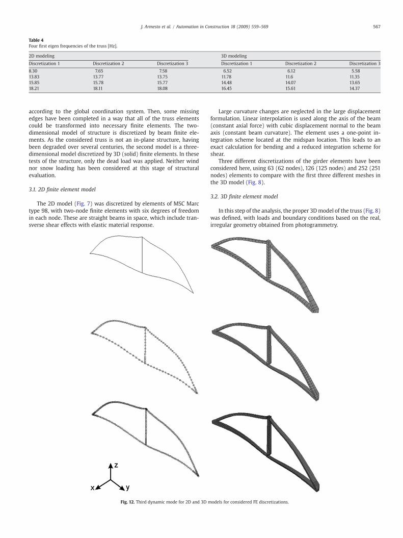
Table 4Four first eigen frequencies of the truss [Hz].
2D modeling 3D modeling
Discretization 1 Discretization 2 Discretization 3 Discretization 1 Discretization 2 Discretization 3
8.30 7.65 7.58 6.52 6.12 5.5813.83 13.77 13.75 11.78 11.6 11.3515.85 15.78 15.77 14.48 14.07 13.6518.21 18.11 18.08 16.45 15.61 14.37
567J. Armesto et al. / Automation in Construction 18 (2009) 559–569
according to the global coordination system. Then, some missingedges have been completed in a way that all of the truss elementscould be transformed into necessary finite elements. The two-dimensional model of structure is discretized by beam finite ele-ments. As the considered truss is not an in-plane structure, havingbeen degraded over several centuries, the second model is a three-dimensional model discretized by 3D (solid) finite elements. In thesetests of the structure, only the dead load was applied. Neither windnor snow loading has been considered at this stage of structuralevaluation.
3.1. 2D finite element model
The 2D model (Fig. 7) was discretized by elements of MSC Marctype 98, with two-node finite elements with six degrees of freedomin each node. These are straight beams in space, which include tran-sverse shear effects with elastic material response.
Fig. 12. Third dynamic mode for 2D and 3D m
Large curvature changes are neglected in the large displacementformulation. Linear interpolation is used along the axis of the beam(constant axial force) with cubic displacement normal to the beamaxis (constant beam curvature). The element uses a one-point in-tegration scheme located at the midspan location. This leads to anexact calculation for bending and a reduced integration scheme forshear.
Three different discretizations of the girder elements have beenconsidered here, using 63 (62 nodes), 126 (125 nodes) and 252 (251nodes) elements to compare with the first three different meshes inthe 3D model (Fig. 8).
3.2. 3D finite element model
In this step of the analysis, the proper 3Dmodel of the truss (Fig. 8)was defined, with loads and boundary conditions based on the real,irregular geometry obtained from photogrammetry.
odels for considered FE discretizations.
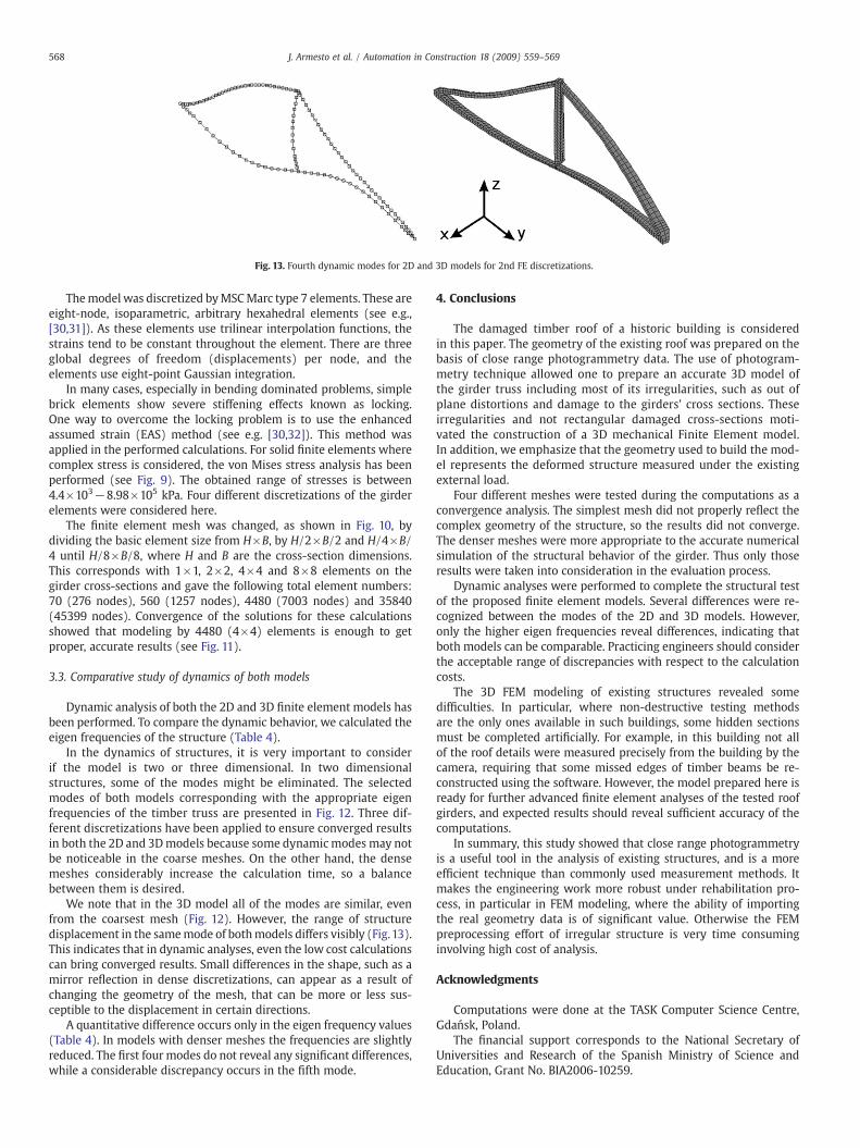
Fig. 13. Fourth dynamic modes for 2D and 3D models for 2nd FE discretizations.
568 J. Armesto et al. / Automation in Construction 18 (2009) 559–569
Themodel was discretized byMSCMarc type 7 elements. These areeight-node, isoparametric, arbitrary hexahedral elements (see e.g.,[30,31]). As these elements use trilinear interpolation functions, thestrains tend to be constant throughout the element. There are threeglobal degrees of freedom (displacements) per node, and theelements use eight-point Gaussian integration.
In many cases, especially in bending dominated problems, simplebrick elements show severe stiffening effects known as locking.One way to overcome the locking problem is to use the enhancedassumed strain (EAS) method (see e.g. [30,32]). This method wasapplied in the performed calculations. For solid finite elements wherecomplex stress is considered, the von Mises stress analysis has beenperformed (see Fig. 9). The obtained range of stresses is between4.4×103−8.98×10⁵ kPa. Four different discretizations of the girderelements were considered here.
The finite element mesh was changed, as shown in Fig. 10, bydividing the basic element size from H×B, by H/2×B/2 and H/4×B/4 until H/8×B/8, where H and B are the cross-section dimensions.This corresponds with 1×1, 2×2, 4×4 and 8×8 elements on thegirder cross-sections and gave the following total element numbers:70 (276 nodes), 560 (1257 nodes), 4480 (7003 nodes) and 35840(45399 nodes). Convergence of the solutions for these calculationsshowed that modeling by 4480 (4×4) elements is enough to getproper, accurate results (see Fig. 11).
3.3. Comparative study of dynamics of both models
Dynamic analysis of both the 2D and 3D finite element models hasbeen performed. To compare the dynamic behavior, we calculated theeigen frequencies of the structure (Table 4).
In the dynamics of structures, it is very important to considerif the model is two or three dimensional. In two dimensionalstructures, some of the modes might be eliminated. The selectedmodes of both models corresponding with the appropriate eigenfrequencies of the timber truss are presented in Fig. 12. Three dif-ferent discretizations have been applied to ensure converged resultsin both the 2D and 3Dmodels because some dynamicmodes may notbe noticeable in the coarse meshes. On the other hand, the densemeshes considerably increase the calculation time, so a balancebetween them is desired.
We note that in the 3D model all of the modes are similar, evenfrom the coarsest mesh (Fig. 12). However, the range of structuredisplacement in the samemode of bothmodels differs visibly (Fig.13).This indicates that in dynamic analyses, even the low cost calculationscan bring converged results. Small differences in the shape, such as amirror reflection in dense discretizations, can appear as a result ofchanging the geometry of the mesh, that can be more or less sus-ceptible to the displacement in certain directions.
A quantitative difference occurs only in the eigen frequency values(Table 4). In models with denser meshes the frequencies are slightlyreduced. The first four modes do not reveal any significant differences,while a considerable discrepancy occurs in the fifth mode.
4. Conclusions
The damaged timber roof of a historic building is consideredin this paper. The geometry of the existing roof was prepared on thebasis of close range photogrammetry data. The use of photogram-metry technique allowed one to prepare an accurate 3D model ofthe girder truss including most of its irregularities, such as out ofplane distortions and damage to the girders' cross sections. Theseirregularities and not rectangular damaged cross-sections moti-vated the construction of a 3D mechanical Finite Element model.In addition, we emphasize that the geometry used to build the mod-el represents the deformed structure measured under the existingexternal load.
Four different meshes were tested during the computations as aconvergence analysis. The simplest mesh did not properly reflect thecomplex geometry of the structure, so the results did not converge.The denser meshes were more appropriate to the accurate numericalsimulation of the structural behavior of the girder. Thus only thoseresults were taken into consideration in the evaluation process.
Dynamic analyses were performed to complete the structural testof the proposed finite element models. Several differences were re-cognized between the modes of the 2D and 3D models. However,only the higher eigen frequencies reveal differences, indicating thatboth models can be comparable. Practicing engineers should considerthe acceptable range of discrepancies with respect to the calculationcosts.
The 3D FEM modeling of existing structures revealed somedifficulties. In particular, where non-destructive testing methodsare the only ones available in such buildings, some hidden sectionsmust be completed artificially. For example, in this building not allof the roof details were measured precisely from the building by thecamera, requiring that some missed edges of timber beams be re-constructed using the software. However, the model prepared here isready for further advanced finite element analyses of the tested roofgirders, and expected results should reveal sufficient accuracy of thecomputations.
In summary, this study showed that close range photogrammetryis a useful tool in the analysis of existing structures, and is a moreefficient technique than commonly used measurement methods. Itmakes the engineering work more robust under rehabilitation pro-cess, in particular in FEM modeling, where the ability of importingthe real geometry data is of significant value. Otherwise the FEMpreprocessing effort of irregular structure is very time consuminginvolving high cost of analysis.
Acknowledgments
Computations were done at the TASK Computer Science Centre,Gdańsk, Poland.
The financial support corresponds to the National Secretary ofUniversities and Research of the Spanish Ministry of Science andEducation, Grant No. BIA2006-10259.
569J. Armesto et al. / Automation in Construction 18 (2009) 559–569
References
[1] A. Cointe, P. Castera, P. Morlier, P. Galimard, Diagnosis and monitoring of timberbuildings of cultural heritage, Structural Safety 29 (4) (2006) 337–348.
[2] M.J. Chapman, B. Norton, J.M.A. Taylor, D.J. Lavery, The reduction in errors associatedwith ultrasonic non-destructive testing of timber arising from differential pressureon and movement of transducers, Construction and Building Materials 20 (2006)841–848.
[3] A. Giordano, E. Mele, A. De Luca, Modeling of historical masonry. Structures:comparison of different approaches through a case study, Engineering Structures24 (2002) 1057–1069.
[4] P. Arias, J. Armesto, H. Lorenzo, C. Ordonez, Digital photogrammetry and finiteelement in heritage documentation: geometry and structural analysis, Proceed-ings of the ISPRS V Symposium, 25–27 Sept 2006, Dresden, Germany, 2006, 6 pp.
[5] E. Alby, P. Grussenmeyer, J.-P. Perrin, Integration Of Close Range PhotogrammetricSurveys In The Design Process Of Architectural Projects, Proceedings of the CIPA2003 19th International Symposium, 30 Sep.–4 Oct 2003, Antalya, 46–51.
[6] G.P. McKnight, C.P. Henry, Large strain variable stiffness composites for sheardeformations with applications to morphing aircraft skins, Proceedings of SPIE-The International Society for Optical Engineering 6929, Art. No. 692919, 2008.
[7] A.M. Ferrero, M.Migliazza, R. Roncella, G. Tebaldi, Analysis of the failure mechanismsof a weak rock through photogrammetrical measurements by 2D and 3D visions,Engineering Fracture Mechanics 75 (3–4) (2008) 652–663.
[8] I. Koke, W.H. Müller, F. Ferber, R. Mahnken, H. Funke, Measuring mechanicalparameters in glass fiber-reinforced composites: standard evaluation techniquesenhanced by photogrammetry, Composites Science and Technology 68 (5) (2008)1156–1164.
[9] L.G. Young, G.J. Garde, W.J. Sterling, A practical approach for scientific balloon filmstrain measurement using photogrammetry, AIAA Balloon Systems Conference,2007, pp. 94–104.
[10] J.P. Mills, I. Newton, G.C. Peirson, Pavement deformation monitoring in a rollingload facility, Photogrammetric Record 17 (97) (2001) 7–24.
[11] S. Cantré, H. Thomas, Application of low-cost photogrammetric systems ingeotechnical laboratories, Geotechnik 31 (1) (2008) 23–34.
[12] C.C. Chang, Y.F. Ji, Flexible videogrammetric technique for three-dimensionalstructural vibration measurement, Journal of Engineering Mechanics 133 (6)(2007) 656–664.
[13] H.G. Maas, U. Hampel, Photogrammetric techniques in civil engineering materialtesting and structuremonitoring, Photogrammetric Engineering & Remote Sensing72 (1) (2006) 39–45.
[14] B. Ergun, I. Baz, Design of an expert system for close-range photogrammetricapplications, Optical Engineering 45 (5) (2006) 1–5.
[15] M. Pieraccini, G. Guidi, C. Atzeni, 3D digitizing of cultural heritage, Journal ofCultural Heritage 2 (1) (2001) 63–70.
[16] R. Jiang, D.V. Jáuregui, K.R. White, Close-range photogrammetry applications inbridge measurement: literature review, Measurement 41 (2008) 823–834.
[17] P.M. Dare, H.B. Hanley, C.S. Fraser, B. Riedel,W. Niemeier, An operational applicationof automatic feature extraction: the measurement of cracks in concrete structures,Photogrammetric Record 17 (99) (2002) 453–464.
[18] S. El-Omari, O. Moselhi, Integrating 3D laser scanning and photogrammetry forprogress measurement of construction work, Automation in Construction 18 (1)(2008) 1–9.
[19] L.C. Chen, T.A. Teo, C.Y. Kuo, J.Y. Rau, Shaping polyhedral buildings by the fusion ofvector maps and lidar point clouds, Photogrammetric Engineering and RemoteSensing 74 (9) (2008) 1147–1157.
[20] Y. Arayici, Towards building information modelling for existing structures,Structural Survey 26 (3) (2008) 210–222.
[21] L.M. Macareno, C. Angulo, D. López, J. Agirrebeitia, Analysis and characterizationof the behaviour of a variable geometry structure. Proceedings of the Institution ofMechanical Engineers, Part C, Journal of Mechanical Engineering Science 221 (11)(2007) 1427–1434.
[22] S. Franke, B. Franke, K. Rautenstrauch, Strain analysis of wood components by closerange photogrammetry, Materials and Structures/Materiaux et Constructions 40(1) (2007) 37–46.
[23] P. Arias, J. Armesto, D. Di-Capua, R. González-Drigo, H. Lorenzo, V. Pérez-Gracia,Digital photogrammetry, GPR and computational analysis of structural damages ina mediaeval bridge, Engineering Failure Analysis 14 (8) (2007) 1444–1457.
[24] J.Mills, D. Barber, Geomatics techniques for structural surveying, Journal of SurveyingEngineering 130 (2) (2004) 56–64.
[25] M.A.R. Cooper, S. Robson, Theory of close range photogrammetry, in: K.B. Atkinson(Ed.), Close Range Photogrammetry and Machine Vision, Whittles Publishing,Caithness, 2001.
[26] F. Remondino, S. El-Hakim, Image-based 3Dmodeling: a review, PhotogrammetricRecord 21 (115) (2006) 269–291.
[27] S.O.Mason, Conceptual model of the convergentmultistation network configurationtask, Photogrammetric Record 15 (86) (1995) 277–299.
[28] P. Arias, C. Ordóñez, H. Lorenzo, J. Herráez, J. Armesto, Low-cost documentation oftraditional agro-industrial buildings by close-range photogrammetry, Buildingand Environment 42 (2007) 1817–1827.
[29] P. Arias, J.C. Caamaño, H. Lorenzo, J. Armesto, 3D modeling and section propertiesof ancient irregular timber structures by means of digital photogrammetry,Computer-Aided Civil and Infrastructure Engineering 22 (2007) 597–611.
[30] MSC, Marc System—User Manual, MSC. Software Corporation v, 2003.[31] S. Klinkel, W. Wagner, A geometrical non-linear brick element based on the EAS-
method, International Journal for Numerical Methods in Engineering 40 (1997)4529–4545.
[32] S. Reese, P. Wriggers, B.D. Reddy, A new locking-free brick element techniquefor large deformation problems in elasticity, Computers and Structures 75 (2000)291–304.
Related Documents

![A Concept for Three-Dimensional Particle Metrology Based ... · SfM photogrammetry [18] is sometimes also called “close-range photogrammetry” [19]. SfM photogrammetry has been](https://static.cupdf.com/doc/110x72/5f048f2e7e708231d40e91e8/a-concept-for-three-dimensional-particle-metrology-based-sfm-photogrammetry.jpg)