FEED Study for Tambakboyo Field Development RFQ FOR SAFETY STUDIES (FERA/QRA) Client : Saka Indonesia Pangkah Limited Contract No. / WO No. : 4600012802 (Provision of Engineering Services for Pangkah Development) Document No. : TBD-TJ-G10-LC-RQ-9002 Revision Date Description Originator Checker Approver Client Approval B 20-09-2021 Issued for Information STF ADM IMS/BAS B1 28-10-2021 Re-Issued for Information STF ADM IMS/BAS

Welcome message from author
This document is posted to help you gain knowledge. Please leave a comment to let me know what you think about it! Share it to your friends and learn new things together.
Transcript

FEED Study for Tambakboyo Field Development
RFQ FOR SAFETY STUDIES (FERA/QRA)
Client : Saka Indonesia Pangkah Limited
Contract No. / WO No. : 4600012802 (Provision of Engineering
Services for Pangkah Development)
Document No. : TBD-TJ-G10-LC-RQ-9002
Revision Date Description Originator Checker Approver Client
Approval
B 20-09-2021 Issued for Information STF ADM IMS/BAS
B1 28-10-2021 Re-Issued for Information STF ADM IMS/BAS
AAnugrahesa
Stamp
ImamS
Stamp

RFQ FOR SAFETY STUDIES (FERA/QRA)
TBD-TJ-G10-LC-RQ-9002_Rev. B1 Page 2 of 12
RECORD OF REVISION
Rev. No.
Section Page Company Comment Incorporated
(Y/N) Contractor Response
B Attachment ToR QRA
17
Add in Section 3.4:
- Subsea &Umbilical Cable (Electrical Power & FO) Risk Calculation
- Dropped Object Risk Calculation
Y Incorporated

RFQ FOR SAFETY STUDIES (FERA/QRA)
TBD-TJ-G10-LC-RQ-9002_Rev. B1 Page 3 of 12
TABLE OF CONTENT
RECORD OF REVISION ............................................................................................................ 2
TABLE OF CONTENT ................................................................................................................ 3
1. INTRODUCTION ................................................................................................................. 5
Project Background ..................................................................................................... 5 1.1
Objectives ................................................................................................................... 6 1.2
References.................................................................................................................. 6 1.3
Abbreviation ................................................................................................................ 6 1.4
Definition of Terms ...................................................................................................... 7 1.5
2. SCOPE OF WORK .............................................................................................................. 8
FERA Study ................................................................................................................ 8 2.1
QRA Study .................................................................................................................. 8 2.2
3. SCHEDULE ......................................................................................................................... 9
4. PROPOSAL ....................................................................................................................... 10
Technical Proposal .................................................................................................... 10 4.1
Commercial Proposal ................................................................................................ 10 4.2
5. ACCEPTANCE OF SERVICES ......................................................................................... 11
Report Content .......................................................................................................... 11 5.1
Service Completion ................................................................................................... 11 5.2
6. ATTACHMENTS ................................................................................................................ 12
RFQ FOR SAFETY STUDIES (FERA/QRA)
TBD-TJ-G10-LC-RQ-9002_Rev. B1 Page 4 of 12
LIST OF TABLES
Table 1 List Specification and Documentation ............................................................................ 6
LIST OF FIGURES
Figure 1 Tambakboyo Platform (WHP-E) Location ..................................................................... 5
RFQ FOR SAFETY STUDIES (FERA/QRA)
TBD-TJ-G10-LC-RQ-9002_Rev. B1 Page 5 of 12
1. INTRODUCTION
Project Background 1.1
SAKA Indonesia Pangkah Limited / SIPL (herein referred as COMPANY) has been
commissioned to undertake the operator of Ujung Pangkah Block in East Java since January
2014 from HESS. The Ujung Pangkah field is located offshore of the north coast of East Java
approximately 35 km north of Gresik, East Java, Indonesia; lies adjacent to the Bengawan Solo
river delta.
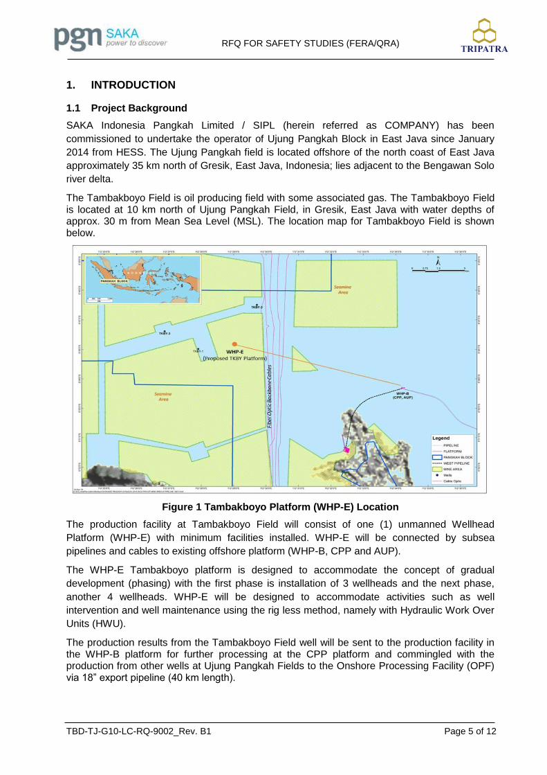
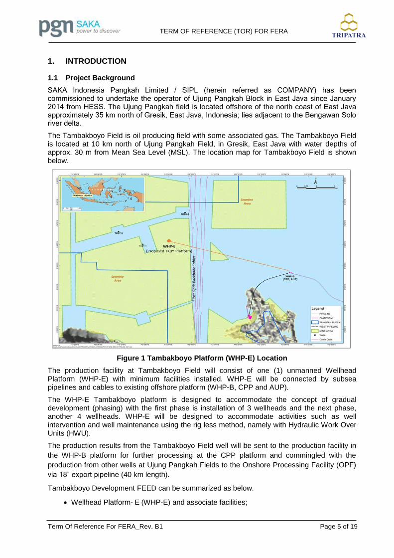
The Tambakboyo Field is oil producing field with some associated gas. The Tambakboyo Field is located at 10 km north of Ujung Pangkah Field, in Gresik, East Java with water depths of approx. 30 m from Mean Sea Level (MSL). The location map for Tambakboyo Field is shown below.
Figure 1 Tambakboyo Platform (WHP-E) Location
The production facility at Tambakboyo Field will consist of one (1) unmanned Wellhead
Platform (WHP-E) with minimum facilities installed. WHP-E will be connected by subsea
pipelines and cables to existing offshore platform (WHP-B, CPP and AUP).
The WHP-E Tambakboyo platform is designed to accommodate the concept of gradual
development (phasing) with the first phase is installation of 3 wellheads and the next phase,
another 4 wellheads. WHP-E will be designed to accommodate activities such as well
intervention and well maintenance using the rig less method, namely with Hydraulic Work Over
Units (HWU).
The production results from the Tambakboyo Field well will be sent to the production facility in the WHP-B platform for further processing at the CPP platform and commingled with the production from other wells at Ujung Pangkah Fields to the Onshore Processing Facility (OPF) via 18” export pipeline (40 km length).

RFQ FOR SAFETY STUDIES (FERA/QRA)
TBD-TJ-G10-LC-RQ-9002_Rev. B1 Page 6 of 12
Tambakboyo Development FEED can be summarized as below.
Wellhead Platform- E (WHP-E) and associate facilities;
Subsea pipeline from WHP-E to WHP-B;
Subsea Umbilical for Powerline and Fiber Optic Cable penetrate and stop on WHP-B
Platform, then continue routing to AUP via cable tray;
Tie-in and modification of existing facilities (WHP-B, CPP and AUP) to accommodate Tambakboyo’s production.
Objectives 1.2
This request for quotation defines the minimum requirements of scope of work and services for
the following studies:
1. FERA
2. QRA
Any deviations to this request for quotation shall be listed by the THIRD PARTY with reference to the document clause in their quotation. In absence of any deviations, it will be assumed that the THIRD PARTY is in full compliance to the stated requirements.
References 1.3
All the Project Documents are listed below shall be formed as Applicable Documents. Unless otherwise specified, the latest edition / revision shall be used.
Table 1 List Specification and Documentation
Document Number Title
- Term of Reference for FERA
- Term of Reference for QRA
Abbreviation 1.4
The following abbreviations are used for purpose of this document:
FERA : Fire and Explosion Risk Assessment
HAZOP : Hazard and Operability
HAZID : Hazard Identification
IRPA : Individual Risk per Annum
LSIR : Location Specific Individual Risk
P&ID : Piping and Instrumentation Diagram
PFD : Process Flow Diagram
PLL : Potential Loss of Life
QRA : Quantitative Risk Assessment

RFQ FOR SAFETY STUDIES (FERA/QRA)
TBD-TJ-G10-LC-RQ-9002_Rev. B1 Page 7 of 12
UFD : Utility Flow Diagram
WHP : Wellhead Platform
Definition of Terms 1.5
The following definitions are used for purpose of this document:
COMPANY : Saka Indonesia Pangkah Limited (SIPL)
CONTRACTOR : PT TRIPATRA ENGINEERING
VENDOR : Party which supplies equipment specified and ordered by CONTRACTOR (or COMPANY)
MANUFACTURER : Party which manufactures equipment/materials specified and ordered by CONTRACTOR (or COMPANY)
RFQ FOR SAFETY STUDIES (FERA/QRA)
TBD-TJ-G10-LC-RQ-9002_Rev. B1 Page 8 of 12
2. SCOPE OF WORK
FERA Study 2.1
SUBCONTRACTOR shall have sufficient skill and experience to perform the activities below:
Selecting the scenarios of HAZOP and HAZID.
Prepare the study in liaison with the CONTRACTOR
Ensure the full compliance as per Term of Reference
Identify the hazardous substances (flammable) relevant to possible accidental releases from equipment items of the new facilities
Identify the isolatable section of the new facilities
Define a representative set of release point locations
Characterize the release conditions for each release point
Calculate the discharge rate for a number of leak sizes for each release point
Calculate the release frequency for all the identified release cases
Identify possible outcome scenarios based on typical event trees
Assess the vulnerability of equipment threshold calculations and human fatalities thresholds
Assess the consequence of fire and explosion scenarios
Recommend the implementation of risk reduction measures
QRA Study 2.2
SUBCONTRACTOR shall have sufficient skill and experience to perform the activities below:
Evaluating FERA Study and prepare several data and information.
Prepare the study in liaison with the CONTRACTOR
Ensure the full compliance as per Term of Reference
Calculate of generic failures using part count analysis
Calculate of process specific and human failures using fault tree analysis
Calculate of other failures frequency using empirical data from references
Simulation of gas dispersion and liquid spills as well as fire, explosion or toxic (if any) contour and extent using consequence analysis software
Combining the frequency assessment results and consequence analysis using event tree analysis and aggregate the risk to provide fire, explosion and toxic risk
Calculating IRPA (Individual Risk per Annum), LSIR (Location Specific Individual Risk), PLL (Potential Loss of Life) and FN Curve (if any).
Assess the vulnerability of equipment threshold calculations and human fatalities thresholds
Assess the consequence of fire and explosion scenarios
Recommend the implementation of risk reduction measures

RFQ FOR SAFETY STUDIES (FERA/QRA)
TBD-TJ-G10-LC-RQ-9002_Rev. B1 Page 9 of 12
3. SCHEDULE
CONTRACTOR provide preliminary schedule for workshop to SUBCONTRACTOR, as follow:
FERA and QRA Studies, the preliminary schedule as follows:
No. Task IFR AFD
1 FERA Study 29 October 2021 12 November 2021
2 QRA Study 05 November 2021 19 November 2021

RFQ FOR SAFETY STUDIES (FERA/QRA)
TBD-TJ-G10-LC-RQ-9002_Rev. B1 Page 10 of 12
4. PROPOSAL
The proposal shall be identified as clearly as possible of the proposed works. The proposal by THIRD PARTY to be submitted should comprise of two parts, technical and commercial proposal.
Technical Proposal 4.1
The technical proposal one (1) original and one (1) copy are to be submitted to CONTRACTOR. The technical proposal should cover minimum but not limited to the following:
• Covering Letter.
• THIRD PARTY organizations profile and capability.
• Proposed schedule for execution the works.
• Professional resumes of proposed personnel.
• Copy of license ownership of the proposed software.
• HSE & Quality assurance plan.
• Detail deliverable list
• Detail of previous similar work has been carried out
• Any other information which bidder feels can give them a professional edge over other competitors.
Commercial Proposal 4.2
The commercial proposal one (1) original and one (1) copy are to be submitted to CONTRACTOR. Commercial Prices for each works shall be broken down separately for each studies listed in Section 1.2 above. The commercial proposal shall be submitted in a sealed envelope marked “CONFIDENTIAL”
The detail price shall also include insurance premiums, taxes and other obligations for the overall facilitation works.

RFQ FOR SAFETY STUDIES (FERA/QRA)
TBD-TJ-G10-LC-RQ-9002_Rev. B1 Page 11 of 12
5. ACCEPTANCE OF SERVICES
Report Content 5.1
Report shall be provided in 2 (two) cycles, i.e. Issue for Review (IFR) and Approved for Design (AFD). AFD report shall be submitted within 1 (one) week after IFR report has been discussed/commented by both CONTRACTOR and COMPANY. The report shall contain the followings, as minimum:
• Executive Summary
• Introduction (to show the background of review, objective and scope of facilities)
• Methodology
• Results
• Overall Recommendation/Conclusion
Final reports are to be issued as follows:
• Two hard printed copy
• One soft electronic in its native file format for report including native software file
• One Adobe colored PDF file converted (NOT SCANNED) from the native file
Service Completion 5.2
The services shall be conducted and completed on a lump sum basis.
Satisfactory completion of services shall be subject to CONTRACTOR acceptance. No acceptance shall occur until the end of the Services and other completed deliverables have been delivered and accepted by the CONTRACTOR and COMPANY.
Contractor would sign the invoice from the THIRD PARTY in consultation with COMPANY to acknowledge the acceptance of the services.

RFQ FOR SAFETY STUDIES (FERA/QRA)
TBD-TJ-G10-LC-RQ-9002_Rev. B1 Page 12 of 12
6. ATTACHMENTS
Term of Reference (ToR) for FERA
Term of Reference (ToR) for QRA

FEED Study for Tambakboyo Field Development
TERM OF REFERENCE (TOR) FOR FERA
Client : Saka Indonesia Pangkah Limited
Contract No. / WO No. : 4600012802 (Provision of Engineering
Services for Pangkah Development)
Document No. : Part of TBD-TJ-G10-LC-RQ-9002
Revision Date Description Originator Checker Approver Client
Approval
B 20-09-2021 Issued for Information STF ADM IMS/BAS
B1 28-10-2021 Re-Issued for Information STF ADM IMS/BAS
AAnugrahesa
Stamp

TERM OF REFERENCE (TOR) FOR FERA
Term Of Reference For FERA_Rev. B1 Page 2 of 19
RECORD OF REVISION
Rev. No.
Section Page Company Comment Incorporated
(Y/N) Contractor Response
TERM OF REFERENCE (TOR) FOR FERA
Term Of Reference For FERA_Rev. B1 Page 3 of 19
TABLE OF CONTENT
RECORD OF REVISION ............................................................................................................ 2
TABLE OF CONTENT ................................................................................................................ 3
1. INTRODUCTION ................................................................................................................. 5
Project Background ..................................................................................................... 5 1.1
Objectives ................................................................................................................... 6 1.2
Scope .......................................................................................................................... 6 1.3
References.................................................................................................................. 6 1.4
Abbreviation ................................................................................................................ 8 1.5
Definition of Terms ...................................................................................................... 8 1.6
2. FACILITY DESCRIPTION .................................................................................................... 9
3. METHODOLOGY .............................................................................................................. 10
Introduction ............................................................................................................... 10 3.1
Steps ......................................................................................................................... 10 3.2
Basis and Assumptions ............................................................................................. 14 3.3
Reporting .................................................................................................................. 18 3.4

TERM OF REFERENCE (TOR) FOR FERA
Term Of Reference For FERA_Rev. B1 Page 4 of 19
LIST OF TABLES
Table 1-1 List Specification and Documentation ......................................................................... 6
Table 3-1 Ambient Air and Seawater Data ............................................................................... 14
Table 3-2 List of Fire Impact Criteria ........................................................................................ 17
Table 3-3 Explosion Overpressure Criteria ............................................................................... 18
LIST OF FIGURES
Figure 1 Tambakboyo Platform (WHP-E) Location ..................................................................... 5
Figure 2 Release Rate Calculation ........................................................................................... 12
TERM OF REFERENCE (TOR) FOR FERA
Term Of Reference For FERA_Rev. B1 Page 5 of 19
1. INTRODUCTION
Project Background 1.1
SAKA Indonesia Pangkah Limited / SIPL (herein referred as COMPANY) has been commissioned to undertake the operator of Ujung Pangkah Block in East Java since January 2014 from HESS. The Ujung Pangkah field is located offshore of the north coast of East Java approximately 35 km north of Gresik, East Java, Indonesia; lies adjacent to the Bengawan Solo river delta.
The Tambakboyo Field is oil producing field with some associated gas. The Tambakboyo Field is located at 10 km north of Ujung Pangkah Field, in Gresik, East Java with water depths of approx. 30 m from Mean Sea Level (MSL). The location map for Tambakboyo Field is shown below.
Figure 1 Tambakboyo Platform (WHP-E) Location
The production facility at Tambakboyo Field will consist of one (1) unmanned Wellhead Platform (WHP-E) with minimum facilities installed. WHP-E will be connected by subsea pipelines and cables to existing offshore platform (WHP-B, CPP and AUP).
The WHP-E Tambakboyo platform is designed to accommodate the concept of gradual development (phasing) with the first phase is installation of 3 wellheads and the next phase, another 4 wellheads. WHP-E will be designed to accommodate activities such as well intervention and well maintenance using the rig less method, namely with Hydraulic Work Over Units (HWU).
The production results from the Tambakboyo Field well will be sent to the production facility in
the WHP-B platform for further processing at the CPP platform and commingled with the
production from other wells at Ujung Pangkah Fields to the Onshore Processing Facility (OPF)
via 18” export pipeline (40 km length).
Tambakboyo Development FEED can be summarized as below.
Wellhead Platform- E (WHP-E) and associate facilities;

TERM OF REFERENCE (TOR) FOR FERA
Term Of Reference For FERA_Rev. B1 Page 6 of 19
Subsea pipeline from WHP-E to WHP-B;
Subsea Umbilical for Powerline and Fiber Optic Cable penetrate and stop on WHP-B
Platform, then continue routing to AUP via cable tray;
Tie-in and modification of existing facilities (WHP-B, CPP and AUP) to accommodate Tambakboyo’s production.
Objectives 1.2
This Term of Reference (TOR) will produce rule set to be used for FERA Study. The objectives
of the FERA Review are:
Identify potential hydrocarbon fire events;
Identify the consequences of credible scenarios;
Identify credible hydrocarbon release case potentially resulting in jet fire, pool fire, explosion and other consequences;
Conduct quantitative assessment of fire consequences and the escalation potential from the major equipment from the facility;
Propose recommendations, as needed, to prevent, control, or mitigate potential hazards;
Provide assistance to facility management in their efforts to manage risks.
Scope 1.3
The scope of the Fire and Explosion Risk Assessment (FERA) is to access and identify the credible potential fire events and evaluate of fire consequences and the escalation potential from the major equipment for all facilities at WHP-E platforms, which connected to WHP-B platform through Subsea pipeline, as well as the modification of existing WHP-B platform during this Tambakboyo Field Development FEED phase. The remaining WHP-B platform facilities outside of modification scope were excluded from the scope of the study. Reservoirs and wellheads on WHP-E also excluded from the study as they are normally under drilling management.
References 1.4
All the Project Documents are listed below shall be formed as Applicable Documents. Unless otherwise specified, the latest edition / revision shall be used.
Table 1-1 List Specification and Documentation
Document Number Title
TBD-TJ-W8-PI-LY-3001 MAIN DECK EQUIPMENT LAYOUT EL +21605
TBD-TJ-W8-PI-LY-3002 CELLAR DECK EQUIPMENT LAYOUT EL +13500
TBD-TJ-W8-PI-LY-3003 SUB-CELLAR DECK EQUIPMENT LAYOUT EL +9500
TBD-TJ-W8-PI-LY-3004 JACKET WALKWAY EQUIPMENT LAYOUT EL +4286
TERM OF REFERENCE (TOR) FOR FERA
Term Of Reference For FERA_Rev. B1 Page 7 of 19
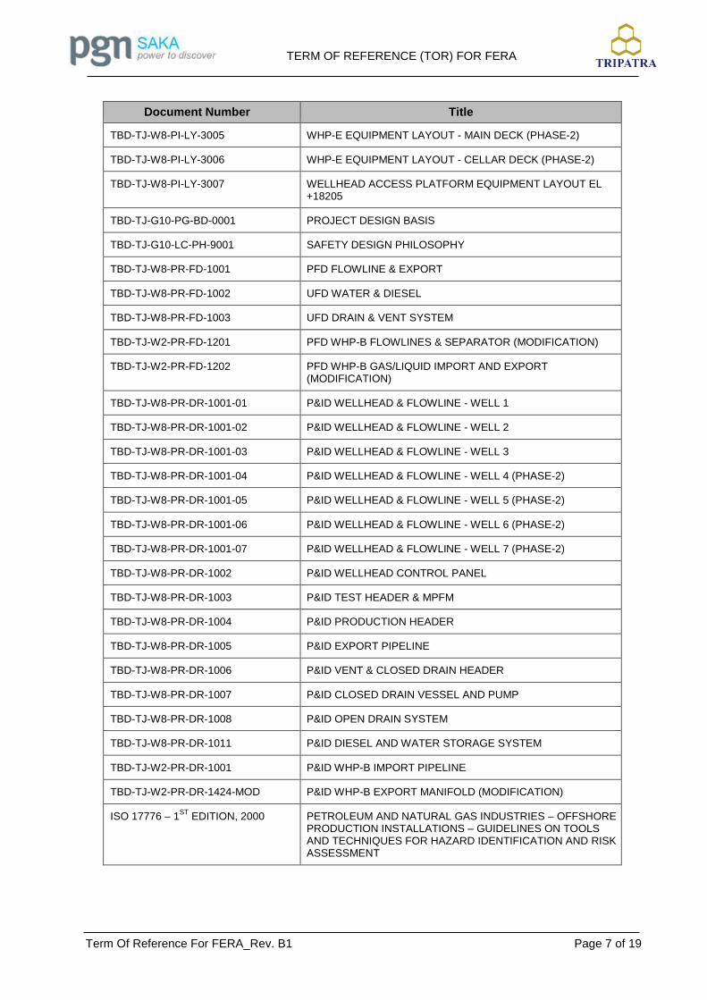
Document Number Title
TBD-TJ-W8-PI-LY-3005 WHP-E EQUIPMENT LAYOUT - MAIN DECK (PHASE-2)
TBD-TJ-W8-PI-LY-3006 WHP-E EQUIPMENT LAYOUT - CELLAR DECK (PHASE-2)
TBD-TJ-W8-PI-LY-3007 WELLHEAD ACCESS PLATFORM EQUIPMENT LAYOUT EL +18205
TBD-TJ-G10-PG-BD-0001 PROJECT DESIGN BASIS
TBD-TJ-G10-LC-PH-9001 SAFETY DESIGN PHILOSOPHY
TBD-TJ-W8-PR-FD-1001 PFD FLOWLINE & EXPORT
TBD-TJ-W8-PR-FD-1002 UFD WATER & DIESEL
TBD-TJ-W8-PR-FD-1003 UFD DRAIN & VENT SYSTEM
TBD-TJ-W2-PR-FD-1201 PFD WHP-B FLOWLINES & SEPARATOR (MODIFICATION)
TBD-TJ-W2-PR-FD-1202 PFD WHP-B GAS/LIQUID IMPORT AND EXPORT (MODIFICATION)
TBD-TJ-W8-PR-DR-1001-01 P&ID WELLHEAD & FLOWLINE - WELL 1
TBD-TJ-W8-PR-DR-1001-02 P&ID WELLHEAD & FLOWLINE - WELL 2
TBD-TJ-W8-PR-DR-1001-03 P&ID WELLHEAD & FLOWLINE - WELL 3
TBD-TJ-W8-PR-DR-1001-04 P&ID WELLHEAD & FLOWLINE - WELL 4 (PHASE-2)
TBD-TJ-W8-PR-DR-1001-05 P&ID WELLHEAD & FLOWLINE - WELL 5 (PHASE-2)
TBD-TJ-W8-PR-DR-1001-06 P&ID WELLHEAD & FLOWLINE - WELL 6 (PHASE-2)
TBD-TJ-W8-PR-DR-1001-07 P&ID WELLHEAD & FLOWLINE - WELL 7 (PHASE-2)
TBD-TJ-W8-PR-DR-1002 P&ID WELLHEAD CONTROL PANEL
TBD-TJ-W8-PR-DR-1003 P&ID TEST HEADER & MPFM
TBD-TJ-W8-PR-DR-1004 P&ID PRODUCTION HEADER
TBD-TJ-W8-PR-DR-1005 P&ID EXPORT PIPELINE
TBD-TJ-W8-PR-DR-1006 P&ID VENT & CLOSED DRAIN HEADER
TBD-TJ-W8-PR-DR-1007 P&ID CLOSED DRAIN VESSEL AND PUMP
TBD-TJ-W8-PR-DR-1008 P&ID OPEN DRAIN SYSTEM
TBD-TJ-W8-PR-DR-1011 P&ID DIESEL AND WATER STORAGE SYSTEM
TBD-TJ-W2-PR-DR-1001 P&ID WHP-B IMPORT PIPELINE
TBD-TJ-W2-PR-DR-1424-MOD P&ID WHP-B EXPORT MANIFOLD (MODIFICATION)
ISO 17776 – 1ST
EDITION, 2000 PETROLEUM AND NATURAL GAS INDUSTRIES – OFFSHORE PRODUCTION INSTALLATIONS – GUIDELINES ON TOOLS AND TECHNIQUES FOR HAZARD IDENTIFICATION AND RISK ASSESSMENT

TERM OF REFERENCE (TOR) FOR FERA
Term Of Reference For FERA_Rev. B1 Page 8 of 19
Abbreviation 1.5
The following abbreviations are used for purpose of this document:
AUP : Accommodation and Utilities Platform
CPP : Compression and Processing Platform
FERA : Fire and Explosion Risk Assessment
IEL : Intermediate Event Likelihood
L : Likelihood
MAE : Major Accident Events
NUI : Normally Unmanned Installation
OPF : Onshore Processing Facilities
P&ID : Piping & Instrumentation Diagram
PFD : Process Flow Diagram
SCE : Safety Critical Element
SIS : Safety Instrument System
TOR : Term of Reference
UFD : Utility Flow Diagram
WHP : Well Head Platform
Definition of Terms 1.6
The following definitions are used for purpose of this document:
COMPANY : Saka Indonesia Pangkah Limited (SIPL)
CONTRACTOR : PT TRIPATRA ENGINEERING
VENDOR : Party which supplies equipment specified and ordered by CONTRACTOR (or COMPANY)
MANUFACTURER : Party which manufactures equipment/materials specified and ordered by CONTRACTOR (or COMPANY)
TERM OF REFERENCE (TOR) FOR FERA
Term Of Reference For FERA_Rev. B1 Page 9 of 19
2. FACILITY DESCRIPTION
The wellhead platform (WHP-E) is designed with minimum facility to support the production. The wellhead platform has one production manifold and one test manifold. Test manifold is equipped with multiphase flowmeter as testing facility.
The fluids produced from Tambakboyo field will be sent to production facility at WHP-B platform prior processing at CPP platform and then commingled with production from other Ujung Pangkah fields to be processed at Onshore Processing Facility (OPF) via18” export pipeline (40 km length).
The subsea cable (power supply and fibre optic) connects WHP-E with Accommodation & Utility Platform (AUP). Subsea cable will penetrate and stop on WHP-B Platform, then continue routing to AUP via cable tray.
At WHP-B, the production fluids from WHP-E will be sent to CPP platform via existing platform bridge. The Tambakboyo fluids will be sent together with production from other Ujung Pangkah fields to existing three-phase MP Separator located at Central Processing Platorm (CPP). Gas from separator will be sent to gas scrubber at compressor package. The oil is routed to MP Oil Pump, while the water will be routed to Produced Water Treatment prior injection to wells.
Process facilities on the Wellhead Platform E will be limited to following systems :
- Wellhead and WHCP,
- Well flowlines and manifold,
- Well test manifold and metering,
- Production subsea pipeline,
- Closed drain system,
- Vent system,
- Open drain system,
- Diesel oil systems,
- Utility water systems.

TERM OF REFERENCE (TOR) FOR FERA
Term Of Reference For FERA_Rev. B1 Page 10 of 19
3. METHODOLOGY
Introduction 3.1
The FERA methodology consists of the following main steps:
1. Identification of credible Major Accident Events (MAE) in terms of fire associated with the
normal operations phase of the facility;
2. Identification of the isolatable sections of the Tambakboyo Field Development, including
determination of physical properties and volumes of each of these Isolatable inventories;
3. Determine of the potential hazardous release scenarios, release type, event outcomes
(e.g. pool, jet fires and explosion) for each identified MAE;
4. Conduct of consequence modelling to determine the extent or magnitude of potential
hazardous outcomes;
5. Calculation of the discharge rate for a number of leak sizes for each release point;
6. Calculation of the effects of the fire scenarios. The effects are described in terms of
distances to damage thresholds generated by the reference release cases;
7. Frequency assessment and Event Tree Analysis;
8. Determination of consequences associated with each event;
9. Assessment of the hydrocarbon hazard impact to the asset, based on the defined
impairment criteria;
10. Summarize conclusion and provide recommendation.
The Fire and Explosion Risk Assessment is a consequence-based study, i.e. no evaluation of the occurrence frequency of the assessed fire scenarios shall be included in the FERA report.
Steps 3.2
The steps required in FERA review is outlined below:
1. Isolatable Section Identification
The process systems within WHP-E are split into Isolatable sections, where in the event
of failure (i.e. leak), the process can be isolated by shutdown valves to minimize the
release inventory. For the purpose of this analysis, the hydrocarbon inventories in the
sections have been treated as either vapor phase (g), or liquid phase (l) inventories.
2. Fire Hazard Identification
The identification of the flammable materials handled in the process streams, and the
relevant fire scenarios which can develop in case of a loss of containment event, shall
be carried out with the process description, PFDs, heat and material balance, etc.
The plant system – including all vessels, piping and equipment that handle flammable
process fluids will be divided into isolatable sections considering isolation provisions. As
a result, a comprehensive list of potential loss of containment sources will be generated
for the subsequent consequence analysis.
Depending on the release conditions, the fire hazards from the hazardous inventories
expected in project facilities are as follows:

TERM OF REFERENCE (TOR) FOR FERA
Term Of Reference For FERA_Rev. B1 Page 11 of 19
Flammable gas inventory
Flammable liquid inventory
3. Consequence Modelling
Consequence modelling is used to predict the size, shape, and orientation of hazard
zones resulting from releases of hazardous material. For each loss of containment
event, the consequence will be evaluated using the software PHAST by DNV-GL.
It will involve the following tasks:
Source Term / Discharge Modelling
Source term or discharge modelling involves determination of the maximum
discharge rate, release duration and other physical properties of the released
material, such as temperature and pressure. These estimated parameters are
then set as the initial conditions for the subsequent dispersion or fire effects
modelling.
For each release point, several leak sizes shall be evaluated, to provide a range of
credible release scenarios, from minor to major.
o Release Rate Calculation
In general the phenomena of discharge is characterized by transient
conditions, as the parameters that govern the discharge dynamics (internal
pressure, temperature, and inventory) are changing in time. The transient
character of the release is more evident in gas releases, due to the compressible
nature of the fluid, whilst in the event of releases from a liquid system, the internal
conditions tend to remain substantially unchanged until the inventory is depleted.
Nevertheless, depending on the leak size, the inventory and the normal flow rate
through the section, also some gas releases may be treated as approximately
steady. For releases downstream pumps, the outflow rate is capped to 130% of the
pumped flowrate.
To the aim of the assessment to be performed in the FERA, the discharge
rate of interest shall be evaluated at different times, depending on the
damage criteria considered. In particular, with reference with the targets and
criteria defined in AS 8, the release rates shall be evaluated at the following
conditions:
- Peak release rate (at the start of the release)
- At 5 minutes
- At 10 minutes
- At 30 minutes
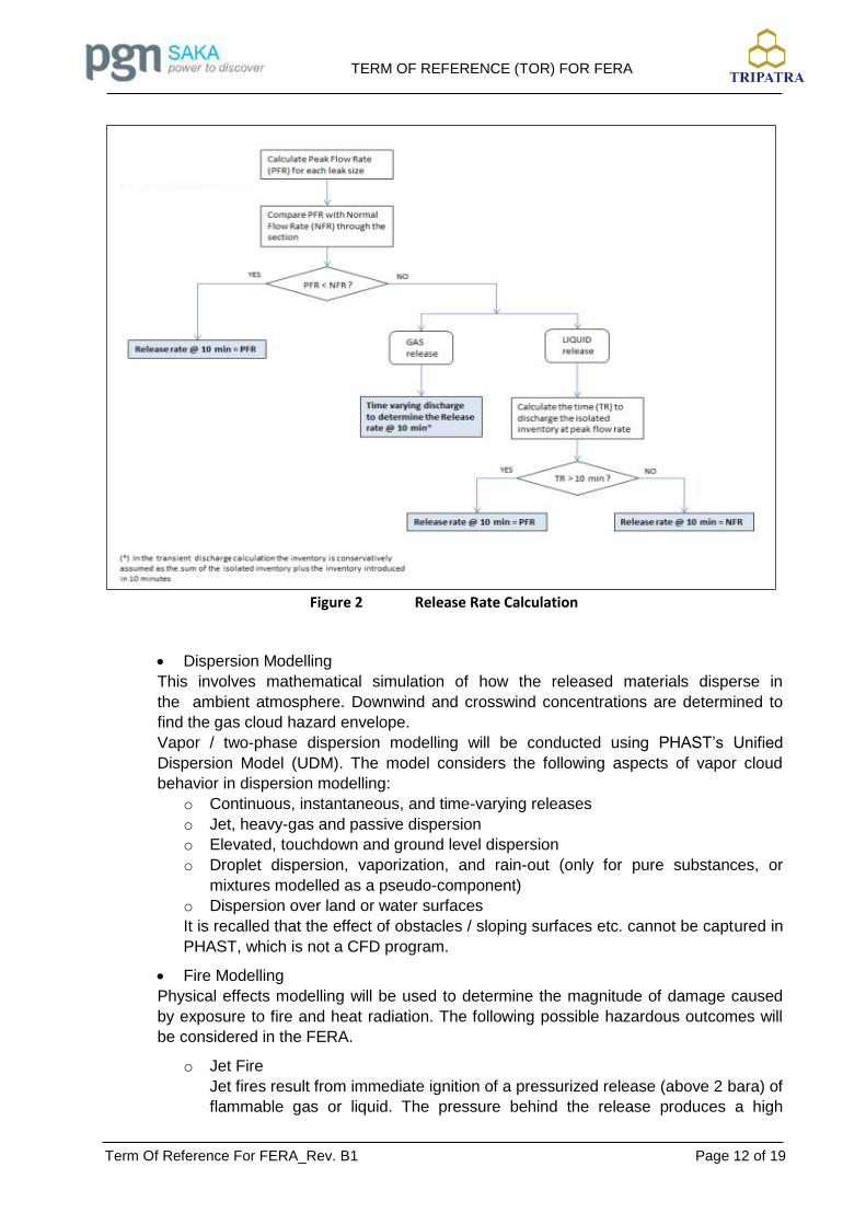
The determination of the discharge rate at different times will take into account the
depressurization of the section, and the ESD considered complete after 10 minutes
from the start of the release. As an example, the procedure followed to determine
the release rate at 10 minutes is illustrated in the flow-chart of Figure 2.
TERM OF REFERENCE (TOR) FOR FERA
Term Of Reference For FERA_Rev. B1 Page 12 of 19
Figure 2 Release Rate Calculation
Dispersion Modelling
This involves mathematical simulation of how the released materials disperse in
the ambient atmosphere. Downwind and crosswind concentrations are determined to
find the gas cloud hazard envelope.
Vapor / two-phase dispersion modelling will be conducted using PHAST’s Unified
Dispersion Model (UDM). The model considers the following aspects of vapor cloud
behavior in dispersion modelling:
o Continuous, instantaneous, and time-varying releases
o Jet, heavy-gas and passive dispersion
o Elevated, touchdown and ground level dispersion
o Droplet dispersion, vaporization, and rain-out (only for pure substances, or
mixtures modelled as a pseudo-component)
o Dispersion over land or water surfaces
It is recalled that the effect of obstacles / sloping surfaces etc. cannot be captured in
PHAST, which is not a CFD program.
Fire Modelling
Physical effects modelling will be used to determine the magnitude of damage caused
by exposure to fire and heat radiation. The following possible hazardous outcomes will
be considered in the FERA.
o Jet Fire
Jet fires result from immediate ignition of a pressurized release (above 2 bara) of
flammable gas or liquid. The pressure behind the release produces a high

TERM OF REFERENCE (TOR) FOR FERA
Term Of Reference For FERA_Rev. B1 Page 13 of 19
velocity jet of gas and/ or liquid which entrains air to form a flammable mixture.
Ignition of this mixture produces a jet fire. In case of two-phase release, only the
release fraction that does not rain-out will feed the jet-fire.
o Pool Fire
A pool fire results from ignition of the vapour over a flammable liquid pool. The
Early Pool-fire model shall be used to estimate the size of the pool, where
the spreading of the pool is limited by the equilibrium between feed rate
and burning rate. In any case, if a bund is provided as a mitigation
measure, the pool fire dimensions shall not exceed the size of the bund area,
which can be modelled either as an equivalent circular area (software PHAST).
o Flash Fire
Following a release, if there is no immediate ignition, the vapour will disperse in
the atmosphere and gradually dilute. Some portion of this vapour cloud will have
a concentration between the upper flammability (UFL) limit and lower
flammability limit (LFL). If this flammable portion of the cloud subsequently
comes in contact with an ignition source, the vapour cloud may ignite and burn
rapidly with a sudden flash. This is termed a flash fire and is distinct from a
vapour cloud explosion in that flame speeds are lower and no significant
overpressure is generated. Due to the extreme short duration of a flash fire, no
damage effect on equipment is expected.
In the FERA context, flash fires will be assessed for the potential effects on
escape ways and muster areas; radiation effects outside the flame are
assumed to be negligible, and damage to people is limited to the flammable
envelope where the flame propagates.
4. Impact Assessment
The main purpose of the FERA is to identify equipment / structures that in case of
fire, may be impaired to the point of losing their containment / support properties or
safety function, thus needing some kind of fire protection.
In particular, the following radiation contours shall be generated, in order to enable
the identification of the items involved, and check whether they are adequately
protected by PFP:
200 kW/m2 and 100 kW/m2 (for certain periods depend on fire scenario and type
of structure): the requirements for the application of Passive Fire Protection to
structures and equipment shall be established following a risk based approach.
TERM OF REFERENCE (TOR) FOR FERA
Term Of Reference For FERA_Rev. B1 Page 14 of 19
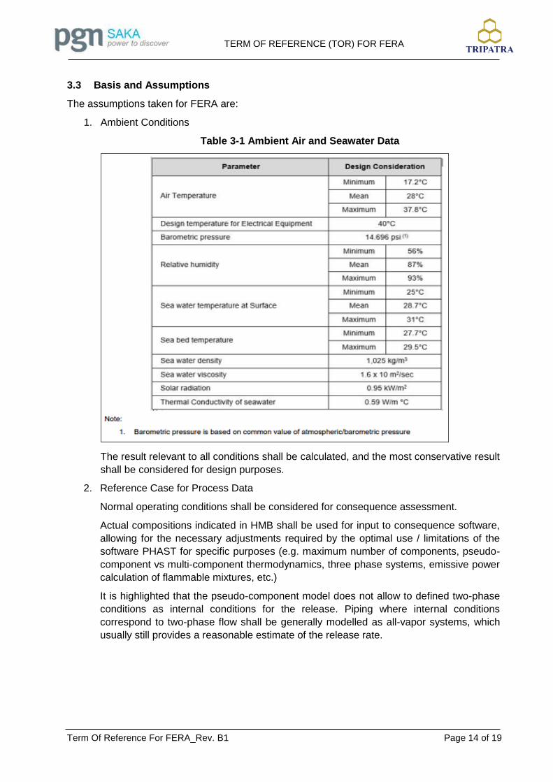
Basis and Assumptions 3.3
The assumptions taken for FERA are:
1. Ambient Conditions
Table 3-1 Ambient Air and Seawater Data
The result relevant to all conditions shall be calculated, and the most conservative result
shall be considered for design purposes.
2. Reference Case for Process Data
Normal operating conditions shall be considered for consequence assessment.
Actual compositions indicated in HMB shall be used for input to consequence software,
allowing for the necessary adjustments required by the optimal use / limitations of the
software PHAST for specific purposes (e.g. maximum number of components, pseudo-
component vs multi-component thermodynamics, three phase systems, emissive power
calculation of flammable mixtures, etc.)
It is highlighted that the pseudo-component model does not allow to defined two-phase
conditions as internal conditions for the release. Piping where internal conditions
correspond to two-phase flow shall be generally modelled as all-vapor systems, which
usually still provides a reasonable estimate of the release rate.
TERM OF REFERENCE (TOR) FOR FERA
Term Of Reference For FERA_Rev. B1 Page 15 of 19
3. Plant Sectionalization
The potentially hazardous systems shall be divided into sections depending on process
conditions such as temperature, pressure, phase etc. and the provision of isolation
elements.
The grouping of process sections and selection of scenarios shall be based on
PFDs/P&IDs, and HMB.
The sectioning exercise will consider the following:
Identification and location of isolation elements: Emergency isolation valves shall
generally be considered for segregating process sections. Other forms of
positive isolation will be reviewed on a case by case basis. In general, blind
flanges, closed spectacle blinds, closed double block and bleed valves or
normally closed valves may be treated as isolations points, while check valves,
process control valves, pumps and compressors usually are not.
Stream Phases: Phase boundaries shall be considered to split two-phase
isolatable sections, in order to assess both gas and liquid releases.
The following systems shall be considered can be seen in Table 2.1.
4. Inventory Estimation
The inventory of the isolated sections is calculated based on the mechanical datasheets
of the equipment, and the diameter and length of the piping.
In case of equipment partially filled with liquids, the liquid fraction shall be evaluated at
the High Alarm Level.
For consistency with the calculations performed by Process, calculated inventory will
include conservatively an additional 20% margin, to allow for uncertainties in pipe
routing, bends, etc.
Gas inventory input in PHAST in case of gas/liquid isolatable section will include also
the fraction of liquid flashed to the atmosphere, to approximately consider the
simultaneous outflow of the vapor and its replacement from the liquid vaporization.
The inventory estimation is used to determine which release rate may be sustained for
the periods considered for the release rate evaluation, i.e. 5 min, 10 min, and 30 min.
The determination of the total inventory released is not of primary interest in the FERA,
however this can be estimated as the sum of the isolated inventory plus a fraction of the
inflow into the section until isolation is achieved: Section inventory + Tisol x MIN [feed
rate, release rate], where Tisol is in all cases 10 minutes.
5. Modelled Leak Sizes
The following hole sizes will be considered in the FERA study:
10 mm
25 mm
50 mm
150 mm

TERM OF REFERENCE (TOR) FOR FERA
Term Of Reference For FERA_Rev. B1 Page 16 of 19
The assessment for active fire protection will be based on the consequence results from
10 mm leaks. The requirements for passive fire protection will be based of the frequency
of exceeding the critical thermal loads defined in item no. 8 (thus the relative
contribution of all the leaks shall be accounted for)
The assessment of the escape routes / muster areas shall be based on the results from
50 mm leaks.
6. Time Required for Detection, Isolation and Blowdown
The following shall be considered in determining the release durations:
Automatic isolation / blowdown is assumed to be achieved within 2 minutes via
the ESD system
Manual isolation / blowdown is assumed to occur after 10 minutes if a
comprehensive fixed detection system is in place
Manual isolation / blowdown is assumed to occur after 15 minutes if no
comprehensive fixed detection system is in place.
7. Parameters for Consequence Modelling
PHAST software by DNV-GL will be used for conducting the consequence modelling for
FERA. The following provides a summary of the key parameters that will be considered
in the consequence modelling.
Release elevation: 1 m above grade shall be considered by default, however minimum
actual release height shall be considered for sections at elevation.
Release direction: Jet Fire / Flash Fire – horizontal non-impinging
Pool Fire / Flash Fire – downward impinging
Surface Roughness: 0.1 m
Averaging time for dispersion modelling: Flammable releases – 18.75s (PHAST default)
Consequence Models:
Jet Fire – Cone Model (DNV recommended)
Pool Fire – No bund: Equilibrium pool diameter (early pool fire)
Bund: Pool fire dimensions limited to the bund area
Solar Radiation Flux: Not included in fire radiation calculations
Height for reporting results: 1 m shall be considered by default, however different
heights may be also evaluated when necessary (e.g. detailed assessment for specific
equipment).
8. Fire Impact Criteria for Structure and Equipment
Fire scenarios may impair, at different heat flux and duration, several plant assets, including structures, equipment, buildings, and escape/muster facilities. The impact criteria considered in the FERA are presented in table below.

TERM OF REFERENCE (TOR) FOR FERA
Term Of Reference For FERA_Rev. B1 Page 17 of 19
Table 3-2 List of Fire Impact Criteria
TYPE OF
SCENARIO THRESHOLD MINIMUM DURATION
REFERENCE HOLE
SIZE FOR DESIGN
PURPOSES
DESIGN REQUIREMENT
Jet Fire 200 kW/m2
5 min for lightweight
structure
10 min for heavyweight
structure
N/A
The requirements for the
application of Passive Fire
Protection to structures and
equipment shall be
established following a risk
based approach.
Jet Fire and
Pool Fire
100 kW/m2 30 min N/A
The requirements for the
application of Passive Fire
Protection to structures and
equipment shall be
established following a risk
based approach
12.5 kW/m2 10 min 10 mm
Impacted items shall be
provided with active fire
protection
6.3 kW/m2 N/A 50 mm Impairment criteria for escape
routes
4.7 kW/m2 N/A 10 mm
Impairment criteria for fire
actuation panel and deluge
valves
3.2 kW/m2 N/A 50 mm Impairment criteria for muster
areas
Flash Fire 90% LEL N/A 50 mm Impairment criteria for escape
routes and muster areas
The output maps relevant to the above mentioned thresholds shall be provided in the
FERA.
Although the actual shape of the impacted areas depends on the type of scenario (jet-
fire, pool-fire, flammable plume) and directional effects (jet direction, wind direction), the
contours reported in the FERA shall represent the distances to radiation uniformly drawn
from the center, or the outline, of the relevant equipment.
The contours shall be grouped as envelope of several scenarios, where appropriate.

TERM OF REFERENCE (TOR) FOR FERA
Term Of Reference For FERA_Rev. B1 Page 18 of 19
9. Explosion Overpressure Criteria
The following explosion overpressure criteria will be reported for the explosion events in
FERA study is shown in Table 3.2.
Table 3-3 Explosion Overpressure Criteria
Explosion Overpressure (bar)
Impact Criteria / Consequence
Human Asset
0.07 Will cause injuries from flying debris (25% fatality)
Limited minor structural damage;
Partial demolition of houses
0.14 50% fatality Partial collapse of wall and roofs of houses
0.28 90% fatality Cladding of light industrial building ruptured
0.35 100% fatality Wooden utility poles snapped
Reporting 3.4
The FERA report should form the basis of the FERA team understanding the completeness of the study and the confidence that can be put in the result. It is an important document and should describe the objective and results of the FERA.
The report should consist the following as minimum:
1. Executive Summary
2. Project background
3. Project Scope and Objective
4. Reference documents
5. Description of Process
6. Methodology including nodes, guideword list
7. Frequency Assessment result
8. Release Rate Assessment Results
9. Consequence Assessment Results
10. Impact Assessment Results
11. FERA Conclusion and Recommendations
12. Document reference list
13. Appendices:
a. Terms of Reference
b. Assumptions Register
c. Isolatable Section Mark-Up
d. Heat and Mas Material Balance

TERM OF REFERENCE (TOR) FOR FERA
Term Of Reference For FERA_Rev. B1 Page 19 of 19
e. Consequences Modelling Result
f. Dispersion, Jet Fire, Explosion and Pool Fire Contour
g. Parts Count Sheet
h. Event Tree Calculation
i. Phast Output
j. Impairment Frequency
Any recommendation arisen from the FERA will be delivered to the relevant discipline who complete and ensure the implementation of the recommendation in the relevant project document and procedure.

FEED Study for Tambakboyo Field Development
TERM OF REFERENCE (TOR) FOR QRA
Client : Saka Indonesia Pangkah Limited
Contract No. / WO No. : 4600012802 (Provision of Engineering
Services for Pangkah Development)
Document No. : Part of TBD-TJ-G10-LC-RQ-9002
Revision Date Description Originator Checker Approver Client
Approval
B 20-09-2021 Issued for Information STF ADM IMS/BAS
B1 28-10-2021 Re-Issued for Information STF ADM IMS/BAS
AAnugrahesa
Stamp

TERM OF REFERENCE (TOR) FOR QRA
Term Of Reference For QRA_Rev. B1 Page 2 of 17
RECORD OF REVISION
Rev. No.
Section Page Company Comment Incorporated
(Y/N) Contractor Response
B 3.4 17
Subsea & Umbilical Cable (Electrical Power & FO) ...
Drop Object
Y Updated. The wording has been added accordingly.

TERM OF REFERENCE (TOR) FOR QRA
Term Of Reference For QRA_Rev. B1 Page 3 of 17
TABLE OF CONTENT
RECORD OF REVISION ............................................................................................................ 2
TABLE OF CONTENT ................................................................................................................ 3
1. INTRODUCTION ................................................................................................................. 5
Project Background ..................................................................................................... 5 1.1
Objectives ................................................................................................................... 6 1.2
Scope .......................................................................................................................... 6 1.3
References.................................................................................................................. 7 1.4
Abbreviation ................................................................................................................ 8 1.5
Definition of Terms ...................................................................................................... 9 1.6
2. FACILITY DESCRIPTION .................................................................................................. 10
3. METHODOLOGY .............................................................................................................. 11
Introduction ............................................................................................................... 11 3.1
Steps ......................................................................................................................... 11 3.2
Basis and Assumptions ............................................................................................. 15 3.3
Reporting .................................................................................................................. 17 3.4
TERM OF REFERENCE (TOR) FOR QRA
Term Of Reference For QRA_Rev. B1 Page 4 of 17
LIST OF TABLES
Table 1-1 List Specification and Documentation ......................................................................... 7
Table 3-1 Ambient Air and Seawater Data ............................................................................... 15
Table 3-2 Risk Acceptance Criteria ..................................................................................... 16
LIST OF FIGURES
Figure 1 Tambakboyo Platform (WHP-E) Location ..................................................................... 5
Figure 2 QRA Methodology ...................................................................................................... 11
Figure 3 ALARP Principle ........................................................................................................ 16

TERM OF REFERENCE (TOR) FOR QRA
Term Of Reference For QRA_Rev. B1 Page 5 of 17
1. INTRODUCTION
Project Background 1.1
SAKA Indonesia Pangkah Limited / SIPL (herein referred as COMPANY) has been commissioned to undertake the operator of Ujung Pangkah Block in East Java since January 2014 from HESS. The Ujung Pangkah field is located offshore of the north coast of East Java approximately 35 km north of Gresik, East Java, Indonesia; lies adjacent to the Bengawan Solo river delta.
The Tambakboyo Field is oil producing field with some associated gas. The Tambakboyo Field is located at 10 km north of Ujung Pangkah Field, in Gresik, East Java with water depths of approx. 30 m from Mean Sea Level (MSL). The location map for Tambakboyo Field is shown below.
Figure 1 Tambakboyo Platform (WHP-E) Location
The production facility at Tambakboyo Field will consist of one (1) unmanned Wellhead Platform (WHP-E) with minimum facilities installed. WHP-E will be connected by subsea pipelines and cables to existing offshore platform (WHP-B, CPP and AUP).
The WHP-E Tambakboyo platform is designed to accommodate the concept of gradual development (phasing) with the first phase is installation of 3 wellheads and the next phase, another 4 wellheads. WHP-E will be designed to accommodate activities such as well intervention and well maintenance using the rig less method, namely with Hydraulic Work Over Units (HWU).
The production results from the Tambakboyo Field well will be sent to the production facility in
the WHP-B platform for further processing at the CPP platform and commingled with the
production from other wells at Ujung Pangkah Fields to the Onshore Processing Facility (OPF)
via 18” export pipeline (40 km length).
Tambakboyo Development FEED can be summarized as below.
Wellhead Platform- E (WHP-E) and associate facilities;

TERM OF REFERENCE (TOR) FOR QRA
Term Of Reference For QRA_Rev. B1 Page 6 of 17
Subsea pipeline from WHP-E to WHP-B;
Subsea Umbilical for Powerline and Fiber Optic Cable penetrate and stop on WHP-B
Platform, then continue routing to AUP via cable tray;
Tie-in and modification of existing facilities (WHP-B, CPP and AUP) to accommodate Tambakboyo’s production.
Objectives 1.2
This Term of Reference (TOR) will produce rule set to be used for QRA Study. The objectives of
the QRA Review are:
Quantify the risk of all personnel from accident events associated with working at the facility;
Identify Major Accident Event (MAE) that could impair WHP-E and/or cause fatality to its personnel during site visit to the platform;
Quantify the process risk which uses frequencies and consequences from FERA study. Furthermore, toxic risk, occupational and transportation risks will also be assessed;
Calculate/quantify the Individual Risk per Annum (IRPA) of WHP-E personnel and Potential Loss of Life (PLL) due to process hydrocarbon hazards and non-hydrocarbon hazards associated with WHP-E platform;
Evaluate the acceptability of these risk levels against the stipulated Risk Acceptance Criteria;
Propose recommendations, if applicable, practical and effective measures to further reduce the risks in line with the As Low As Reasonably Practicable (ALARP) principle;
Provide assistance to facility management in their efforts to manage risks.
Scope 1.3
The scope of Quantitative Risk Assessment (QRA) is to access the risks to personnel due to potential Major Accident Events (MAEs) during normal operation on WHP-E platform including the subsea pipeline connection from WHP-E to existing WHP-B. The risk calculated is the incremental risk to the operator during his time. This is only a fraction of the total working time and the operator will be exposed to different risk level from each of the fatalities visited. The incremental risk calculated for WHP-E platform and pipeline need to be added to the risk level of all assets to determine the overall risk.
The scopes of this QRA are as follows:
Estimation of the event frequency and consequence impact arising from MAEs on WHP-E platform;
Estimation of IRPA and PLL from:
Hydrocarbon hazards (topside and blowout); and
Non-hydrocarbon hazards (ship collisions, structural failures, boat transport risk, dropped objects, occupational hazards and non-process fire).

TERM OF REFERENCE (TOR) FOR QRA
Term Of Reference For QRA_Rev. B1 Page 7 of 17
Generate and Evaluate the LSIR, IRPA and PLL values for personnel working on WHP-E; and
Evaluation of the quantified risk levels against the stipulated Risk Acceptance Criteria to ensure that the risks to personnel are within acceptable levels.
References 1.4
All the Project Documents are listed below shall be formed as Applicable Documents. Unless otherwise specified, the latest edition / revision shall be used.
Table 1-1 List Specification and Documentation
Document Number Title
TBD-TJ-W8-PI-LY-3001 MAIN DECK EQUIPMENT LAYOUT EL +21605
TBD-TJ-W8-PI-LY-3002 CELLAR DECK EQUIPMENT LAYOUT EL +13500
TBD-TJ-W8-PI-LY-3003 SUB-CELLAR DECK EQUIPMENT LAYOUT EL +9500
TBD-TJ-W8-PI-LY-3004 JACKET WALKWAY EQUIPMENT LAYOUT EL +4286
TBD-TJ-W8-PI-LY-3005 WHP-E EQUIPMENT LAYOUT - MAIN DECK (PHASE-2)
TBD-TJ-W8-PI-LY-3006 WHP-E EQUIPMENT LAYOUT - CELLAR DECK (PHASE-2)
TBD-TJ-W8-PI-LY-3007 WELLHEAD ACCESS PLATFORM EQUIPMENT LAYOUT EL +18205
TBD-TJ-G10-PG-BD-0001 PROJECT DESIGN BASIS
TBD-TJ-G10-LC-PH-9001 SAFETY DESIGN PHILOSOPHY
TBD-TJ-W8-PR-FD-1001 PFD FLOWLINE & EXPORT
TBD-TJ-W8-PR-FD-1002 UFD WATER & DIESEL
TBD-TJ-W8-PR-FD-1003 UFD DRAIN & VENT SYSTEM
TBD-TJ-W2-PR-FD-1201 PFD WHP-B FLOWLINES & SEPARATOR (MODIFICATION)
TBD-TJ-W2-PR-FD-1202 PFD WHP-B GAS/LIQUID IMPORT AND EXPORT (MODIFICATION)
TBD-TJ-W8-PR-DR-1001-01 P&ID WELLHEAD & FLOWLINE - WELL 1
TBD-TJ-W8-PR-DR-1001-02 P&ID WELLHEAD & FLOWLINE - WELL 2
TBD-TJ-W8-PR-DR-1001-03 P&ID WELLHEAD & FLOWLINE - WELL 3
TBD-TJ-W8-PR-DR-1001-04 P&ID WELLHEAD & FLOWLINE - WELL 4 (PHASE-2)
TBD-TJ-W8-PR-DR-1001-05 P&ID WELLHEAD & FLOWLINE - WELL 5 (PHASE-2)
TBD-TJ-W8-PR-DR-1001-06 P&ID WELLHEAD & FLOWLINE - WELL 6 (PHASE-2)
TBD-TJ-W8-PR-DR-1001-07 P&ID WELLHEAD & FLOWLINE - WELL 7 (PHASE-2)
TBD-TJ-W8-PR-DR-1002 P&ID WELLHEAD CONTROL PANEL
TBD-TJ-W8-PR-DR-1003 P&ID TEST HEADER & MPFM

TERM OF REFERENCE (TOR) FOR QRA
Term Of Reference For QRA_Rev. B1 Page 8 of 17
Document Number Title
TBD-TJ-W8-PR-DR-1004 P&ID PRODUCTION HEADER
TBD-TJ-W8-PR-DR-1005 P&ID EXPORT PIPELINE
TBD-TJ-W8-PR-DR-1006 P&ID VENT & CLOSED DRAIN HEADER
TBD-TJ-W8-PR-DR-1007 P&ID CLOSED DRAIN VESSEL AND PUMP
TBD-TJ-W8-PR-DR-1008 P&ID OPEN DRAIN SYSTEM
TBD-TJ-W8-PR-DR-1011 P&ID DIESEL AND WATER STORAGE SYSTEM
TBD-TJ-W2-PR-DR-1001 P&ID WHP-B IMPORT PIPELINE
TBD-TJ-W2-PR-DR-1424-MOD P&ID WHP-B EXPORT MANIFOLD (MODIFICATION)
TBD-TJ-G10-LC-RP-9008 FIRE AND EXPLOSION RISK ASSESSMENT REPORT
TBD-TJ-G10-LC-RP-9003 HAZID STUDY REPORT
Abbreviation 1.5
The following abbreviations are used for purpose of this document:
ALARP : As Low As Reasonably Practicable
AUP : Accommodation and Utilities Platform
CPP : Compression and Processing Platform
ETA : Event Tree Analysis
FAR : Fatal Accident Rate
FEED : Front End Engineering Design
FERA : Fire and Explosion Risk Assessment
HAZID : Hazard Identification
IR : Individual Risk
IRPA : Individual Risk Per Annum
LSIR : Location Specific Individual Risk
MAE : Major Accident Events
NHHA : Non Hydrocarbon Hazard Analysis
NUI : Normally Unmanned Installation
OPF : Onshore Processing Facilities
P&ID : Piping & Instrumentation Diagram
PFD : Process Flow Diagram
PLL : Potential Loss of Life
QRA : Quantitative Risk Assessment
RADD : Risk Assessment Data Directory
TOR : Term of Reference
UFD : Utility Flow Diagram
TERM OF REFERENCE (TOR) FOR QRA
Term Of Reference For QRA_Rev. B1 Page 9 of 17
VCE : Vapor Cloud Explosion
WHP : Well Head Platform
Definition of Terms 1.6
The following definitions are used for purpose of this document:
COMPANY : Saka Indonesia Pangkah Limited (SIPL)
CONTRACTOR : PT TRIPATRA ENGINEERING
VENDOR : Party which supplies equipment specified and ordered by CONTRACTOR (or COMPANY)
MANUFACTURER : Party which manufactures equipment/materials specified and ordered by CONTRACTOR (or COMPANY)

TERM OF REFERENCE (TOR) FOR QRA
Term Of Reference For QRA_Rev. B1 Page 10 of 17
2. FACILITY DESCRIPTION
The wellhead platform (WHP-E) is designed with minimum facility to support the production. The wellhead platform has one production manifold and one test manifold. Test manifold is equipped with multiphase flowmeter as testing facility.
The fluids produced from Tambakboyo field will be sent to production facility at WHP-B platform prior processing at CPP platform and then commingled with production from other Ujung Pangkah fields to be processed at Onshore Processing Facility (OPF) via18” export pipeline (40 km length).
The subsea cable (power supply and fibre optic) connects WHP-E with Accommodation & Utility Platform (AUP). Subsea cable will penetrate and stop on WHP-B Platform, then continue routing to AUP via cable tray.
At WHP-B, the production fluids from WHP-E will be sent to CPP platform via existing platform bridge. The Tambakboyo fluids will be sent together with production from other Ujung Pangkah fields to existing three-phase MP Separator located at Central Processing Platorm (CPP). Gas from separator will be sent to gas scrubber at compressor package. The oil is routed to MP Oil Pump, while the water will be routed to Produced Water Treatment prior injection to wells.
Process facilities on the Wellhead Platform E will be limited to following systems :
- Wellhead and WHCP,
- Well flowlines and manifold,
- Well test manifold and metering,
- Production subsea pipeline,
- Closed drain system,
- Vent system,
- Open drain system,
- Diesel oil systems,
- Utility water systems.

TERM OF REFERENCE (TOR) FOR QRA
Term Of Reference For QRA_Rev. B1 Page 11 of 17
3. METHODOLOGY
Introduction 3.1
Quantitative Risk Assessment (QRA) is a systematic method of developing a numerical
estimate of the expected frequency and consequence of potential accidents associated with
normal operations within the platform area, based on engineering evaluation and mathematical
techniques. The logic flow diagram below outlines the general order taken through the QRA
model.
Figure 2 QRA Methodology
Steps 3.2
The steps required in QRA review is outlined below:
1. Data Gathering
The initial activity was to gather all data so that the analysis can be conducted on as
accurate information as possible. Data complied consisted of drawings and relevant
documentation (operating conditions, personnel distribution, etc) related to design of the
WHP-E installation. This included gathering information from the safety studies for
WHP-E installation (FERA report and HAZID study report).

TERM OF REFERENCE (TOR) FOR QRA
Term Of Reference For QRA_Rev. B1 Page 12 of 17
2. Hazard Identification
The MAE scenario selection involves identifying physical situations (failure modes or
initiating events) that could lead to hazardous outcomes with the potential for fatality.
The MAE identification has been performed to evaluate the possible hazardous events
that might lead to loss of life, environment impact and asset. The MAEs shall be
identified from HAZID study report.
MAE such as blowout is typically considered in QRA study. Hence, it is also calculated
in this study. Assessment of the dropped object hazards has not been carried further.
However, the impact of dropped or swinging objects has been included in the leak
frequencies of process hydrocarbons (i.e. dropped object onto process lines) and
personnel occupational hazards (i.e. dropped or swinging object onto personnel).
3. Frequency Analysis
Frequency analysis provides information about how often the hazardous event is likely
to happen.
Frequencies for hydrocarbon hazards and non-hydrocarbon hazards are calculated
using Event Tree Analysis (ETA). ETA involves taking each initiating event through a
defined sequence of conditional outcomes, determining the likelihood that an associated
outcome will occur. ETA takes into account the necessary conditions for the hazardous
outcome to occur – such as ignition – but also the presence of protective systems
identified as safety barriers, which are in place and may prevent the final outcome from
occurring (such as isolation which prevent escalation). By assigning probabilities to
each branch of the event tree, the final frequency of each outcome can be determined.
4. Consequence Modelling
Consequence modelling is used to predict the size, shape, and orientation of hazard
zones resulting from releases of hazardous material. For each loss of containment
event, the consequence will be evaluated using the software PHAST by DNV-GL.
It will involve the following tasks:
Source Term / Discharge Modelling
Source term or discharge modelling involves determination of the maximum
discharge rate, release duration and other physical properties of the released
material, such as temperature and pressure. These estimated parameters are
then set as the initial conditions for the subsequent dispersion or fire effects
modelling.
For each release point, several leak sizes shall be evaluated, to provide a range of
credible release scenarios, from minor to major.
o Release Rate Calculation
In general the phenomena of discharge is characterized by transient
conditions, as the parameters that govern the discharge dynamics (internal
pressure, temperature, and inventory) are changing in time. The transient
character of the release is more evident in gas releases, due to the compressible
nature of the fluid, whilst in the event of releases from a liquid system, the internal
conditions tend to remain substantially unchanged until the inventory is depleted.
Nevertheless, depending on the leak size, the inventory and the normal flow rate
through the section, also some gas releases may be treated as approximately
TERM OF REFERENCE (TOR) FOR QRA
Term Of Reference For QRA_Rev. B1 Page 13 of 17
steady. For releases downstream pumps, the outflow rate is capped to 130% of the
pumped flowrate.
Dispersion Modelling
This involves mathematical simulation of how the released materials disperse in
the ambient atmosphere. Downwind and crosswind concentrations are determined to
find the gas cloud hazard envelope.
Vapor / two-phase dispersion modelling will be conducted using PHAST’s Unified
Dispersion Model (UDM). The model considers the following aspects of vapor cloud
behavior in dispersion modelling:
o Continuous, instantaneous, and time-varying releases
o Jet, heavy-gas and passive dispersion
o Elevated, touchdown and ground level dispersion
o Droplet dispersion, vaporization, and rain-out (only for pure substances, or
mixtures modelled as a pseudo-component)
o Dispersion over land or water surfaces
It is recalled that the effect of obstacles / sloping surfaces etc. cannot be captured in
PHAST, which is not a CFD program.
Fire Modelling
Physical effects modelling will be used to determine the magnitude of damage caused
by exposure to fire and heat radiation. The risk assessment has been carried out using
an integrated set of Excel spreadsheets.
5. Risk Measures
a. Location Specific Individual Risk (LSIR)
The Location Specific Individual Risk (LSIR) expresses the risk exposure to an
individual in a particular area. The risk exposure is calculated for all relevant
hazards and summed to give the overall risk in particular areas of the platform. In the
fatality estimation, the consequences of each outcome from an accidental event
are represented by the probability of death to an individual present in that area at the
onset of the event. The LSIR can be represented as:
LSIR = Outcome Frequency x Probability of death for an individual present all
time in area
LSIR is a useful measure for establishing the most hazardous areas of the platform but
does not consider the likelihood of an individual actually being present at the time of the
incident.
b. Individual Risk per Annum (IRPA)
Individual Risk Per Annum (IRPA) is to compare the risk levels between different worker
groups. IRPA is calculated based on individual basis where personnel with similar tasks
are grouped to the same worker category and spend the same amount of time in
particular location on the facility.
The overall IRPA for specific groups of workers from events on the facility is therefore
the sum over all areas of the Location Specific Individual Risk times the presence factor
in the area; i.e.
IRPA = ∑ LSIR x Presence Factor

TERM OF REFERENCE (TOR) FOR QRA
Term Of Reference For QRA_Rev. B1 Page 14 of 17
where:
∑ = sum for all areas of the facility
The proportion of time in each location on the facility is estimated according to the
nature of the individual’s work.
IRPA is a useful measure because it is essentially independent of the number of people
exposed. In this analysis, IRPA has been applied to different worker groups.
c. Potential Loss of Life
Potential Loss of Life (PLL) is defined as the long term average number of fatalities per
year due to a specific cause and can be expressed mathematically as:
PLL = IRPA x N
where:
PLL = Potential Loss of Life
IRPA = Individual Risk Per Annum
N = number of personnel in each worker group
PLL measures the risk to a group of people as a whole and does not provide details on
whether a particular worker group is more exposed than others.
In measuring the effectiveness of various risk reducing measures, it is most appropriate
to compare the PLL values as this gives a measure of the true benefit taking into
account the potential number of persons affected.

TERM OF REFERENCE (TOR) FOR QRA
Term Of Reference For QRA_Rev. B1 Page 15 of 17
Basis and Assumptions 3.3
The assumptions taken for QRA are:
1. Ambient Conditions
Table 3-1 Ambient Air and Seawater Data
The result relevant to all conditions shall be calculated, and the most conservative result
shall be considered for design purposes.
2. Reference Case for Process Data
Normal operating conditions shall be considered for consequence assessment.
Actual compositions indicated in HMB shall be used for input to consequence software,
allowing for the necessary adjustments required by the optimal use / limitations of the
software PHAST for specific purposes (e.g. maximum number of components, pseudo-
component vs multi-component thermodynamics, three phase systems, emissive power
calculation of flammable mixtures, etc.)
It is highlighted that the pseudo-component model does not allow to defined two-phase
conditions as internal conditions for the release. Piping where internal conditions
correspond to two-phase flow shall be generally modelled as all-vapor systems, which
usually still provides a reasonable estimate of the release rate.
3. Risk Acceptance Criteria
Once the risks have been estimated, they are “benchmarked” against acceptance criteria to see if they place personnel at an unacceptable level of risk. The criteria typically identify three bands. The impact criteria considered in the QRA are presented in table below.

TERM OF REFERENCE (TOR) FOR QRA
Term Of Reference For QRA_Rev. B1 Page 16 of 17
Table 3-2 Risk Acceptance Criteria
RISK CRITERIA IRPA VALUE DESCRIPTION
Unacceptable > 1.00E-03
The risks are considered too high for an individual to bear and need to be reduced in order for the project to go ahead. Efforts must be made to reduce the risk to the level ALARP.
ALARP 1.00E-05 – 1.00E-03
The risks are considered as elevated with respect to the everyday risks faced by an individual but this increase in risk is considered acceptable when placed in the context of benefit to the person and the community as a whole from the project.
Should the risks fall into this band then it needs to be demonstrated that all the risks are understood, control measures are in place and that sufficient mitigation measures are in place consummate with the level of risk posed.
Acceptable < 1.005E-05
The lower level covers the background risk people could typically be exposed to during everyday life. Should the overall risk fall below this level then no additional mitigation measures are considered necessary as the risks are no greater than those faced and accepted by people conducting everyday life.
The framework for risk acceptance criteria defines an upper maximum tolerable and a lower minimum negligible risk level. The risks to personnel shall be As Low As is Reasonably Practicable (ALARP), or in the region of 1.00E-05 – 1.00E-03 as illustrated in Figure 3.
The ALARP demonstration shall be undertaken by means of a systematic process of review, identification, analysis, and evaluation of potential risk reduction measures (risk reduction measures must be applied until the cost of incorporating any additional risk reduction measures in disproportionate to the benefit obtained).
Figure 3 ALARP Principle

TERM OF REFERENCE (TOR) FOR QRA
Term Of Reference For QRA_Rev. B1 Page 17 of 17
Reporting 3.4
The QRA report should form the basis of the QRA team understanding the completeness of the study and the confidence that can be put in the result. It is an important document and should describe the objective and results of the QRA.
The report should consist the following as minimum:
1. Executive Summary
2. Project background
3. Project Scope and Objective
4. Reference documents
5. Description of Process
6. Methodology including nodes, guideword list
7. Process Hydrocarbon Hazard Analysis
8. Non-Hydrocarbon Hazard Analysis
9. Overall Risk Results
10. QRA Conclusion and Recommendations
11. Document reference list
12. Appendices:
a. Terms of Reference
b. Assumptions Register
c. Topside Process Hydrocarbon Calculation
d. Blowout Risk Calculation
e. Ship Collision Risk Calculation
f. Structural Failure Risk Calculation
g. Boat Transport Risk Calculation
h. Occupational Hazard Risk Calculation
i. Non-Process Fire Risk Calculation
j. Subsea & Umbilical Cable (Electrical Power & FO) Risk Calculation
k. Dropped Object Risk Calculation
Any recommendation arisen from the QRA will be delivered to the relevant discipline who complete and ensure the implementation of the recommendation in the relevant project document and procedure.
B1
Related Documents