Saimaa University of Applied Sciences Technology, Lappeenranta Degree Program of Mechanical Engineering and Production Technology Stanislav Ustinov Features of selection of flow measurement methods and devices for flow measuring of liquefied petroleum gas in pipelines Thesis 2016

Welcome message from author
This document is posted to help you gain knowledge. Please leave a comment to let me know what you think about it! Share it to your friends and learn new things together.
Transcript

Saimaa University of Applied Sciences Technology, Lappeenranta Degree Program of Mechanical Engineering and Production Technology Stanislav Ustinov
Features of selection of flow measurement methods and devices for flow measuring of liquefied petroleum gas in pipelines Thesis 2016

2
Abstract Stanislav Ustinov Features of selection of flow measurement methods and devices for flow measuring of liquefied petroleum gas in pipelines, 29 pages Saimaa University of Applied Sciences Faculty of Technology, Lappeenranta Degree Programme of Mechanical Engineering and Production Technology Thesis 2016 Instructors: Lecturer Jukka Nisonen, Saimaa University of Applied Sciences Managing Director Jukka Nisonen, Saimaa University of Applied Sciences
The purpose for the study was to get more knowledge about fluid and gases flow measurement methods and devices and to analyse these methods as well as to identify the advantages and disadvantages of each method for different applications and also to choose the best method and device to measure the flow of liquefied petroleum gas in pipelines.
The work consists of a theoretical part, which describes the principles of flow measurement and, directly, the analysis of the methods and its applications. All the data for this thesis was collected from network, books and lecture notes.
The result of the study shows a selection of the most useful methods and devices of flow measurement that are successfully used for liquefied petroleum gas measuring in the modern world.
Keywords: flow, analysis, methods, applications, liquefied petroleum gas

3
Table of Contents
List of abbreviations and symbols ....................................................................... 4
1. Introduction .................................................................................................. 5
1.1. Basic information about flow and purposes of study. ............................. 5
2. Fluid mechanics (Theory) ............................................................................ 6
2.1. Laminar and turbulent flow ..................................................................... 6
2.2. The dependence of the flow on the Reynolds number ........................... 6
3. Liquefied petroleum gas............................................................................... 7
3.1. Fractional distillation .............................................................................. 7
3.2. Fractions of oil ....................................................................................... 7
3.3. Properties and applications of LPG ....................................................... 9
4. Basic flow measuring methods .................................................................... 9
4.1. Pressure-based flow meters .................................................................. 9
4.1.1. Venturi flow meter ........................................................................... 9
4.1.2. Rotameter ..................................................................................... 11
4.2. Optical (laser) flow meters ................................................................... 12
4.3. Ultrasonic flow meters.......................................................................... 13
4.3.1. Acoustic properties of liquids and gases ....................................... 14
4.3.2. Ultrasonic Doppler flowmeters ...................................................... 15
4.3.3. Transit-time flow meters ................................................................ 17
4.3.4. Advantages and Disadvantages of an Ultrasonic Flow Meter ....... 18
4.4. Vortex flow meters ............................................................................... 18
4.5. Electromagnetic flow meters ................................................................ 20
5. Flow measurement method selection for LPG ........................................... 22
5.1. Selection of type of the flow meter ....................................................... 22
5.2. Selection of the model of selected type of flow meter .......................... 23
5.3. The principle of work of the selected flowmeter ................................... 25
5.4. Summary ............................................................................................. 25
6. Conclusion ................................................................................................. 26
7. References ................................................................................................ 27

4
List of abbreviations and symbols
LPG – Liquefied Petroleum Gas
𝑅𝑒 - Reynolds number
𝑉 - Velocity of fluid
𝑣 - Kinematic viscosity
𝑑 - Diameter of the pipe
𝑓 - Frequency of sound
𝐶 - Velocity of the sound
∆𝑓 - Frequency difference
𝜆 - Wavelength

5
1. Introduction
1.1. Basic information about flow and purposes of study
Flow measurement is widely used in accounting operations, as well as in the
control, regulation and control of technological processes. For example, in the
food industry the optimal management of many technological processes is based
on the mixing of the various components and ingredients that make up the target
product manufactured in strictly defined proportions, the change of which may
impair the progress of processes and the production of low-quality finished
product.
Firstly, it is important to know what is the flow, which is measured. The flow is the
mass or volume of gas or liquid per unit time, which is passing through the section
of the channel of flow measurement device. The flow can be measured with two
flow rates – volumetric and mass flow rates (liters per unit of time or kilograms
per unit of time).
Then, the flow of gas or liquid is measured by flow meters. Many flowmeters are
intended not only to measure the flow rate, but also to measure the mass or
volume of material passing through the measurement device for any chosen
period of time. In this case, they are called flowmeters with counters. The mass
or volume of the substance, which has passed through the counter is determined
from the difference between two consecutive readings of reading device or
integrator after period of time.
Nowadays, flow measurement techniques are developed quite well, but
unfortunately, all the methods, which are used have their own flaws. Alternative
methods of measurement are not reliable in expert’s opinions. Therefore, the aim
of the study is to compare and analyze the performance of gas flow measurement
devices, which are most popular in modern world and to choose the best option
for industrial purposes to measure liquefied petroleum gas in pipelines.

6
2. Fluid mechanics (Theory)
2.1. Laminar and turbulent flow
Laminar and turbulent flow are the two types of flow. Laminar is a flow with parallel
fluid layers without interruptions between these layers (all the particles move to
the same direction) (Wikipedia 2016). Turbulence is a chaotic movement of
particles, schematically, it can looks like vortices in the flow. Turbulent flow is
characterized by the instability of velocity and pressure in different time and space
points in the pipeline. The main difference between laminar and turbulent flow is
velocity. When the flow is laminar, the velocity of flow is the same in different
points of pipeline. When it becomes turbulent – velocity becomes chaotic.
Figure 2.1. Schematic picture of Laminar and turbulent flow (Lorem Ipsum 2010)
2.2. The dependence of the flow on the Reynolds number
Reynolds number (Re) is a quantity without any measurement units, which is
used to predict fluid flow behavior in different cases. Reynolds number defines
which type of flow will occur in the pipeline. (Wikipedia 2016)
Re=2300 is most often used as the critical number to determine what flow it is –
laminar or turbulent.

7
In cases, when Re < 2300 the flow is laminar.
In cases, when Re > 2300 the flow is turbulent.
The short definition of viscosity is ”resistance to flow”. Kinematic viscosity is used
to determine Reynolds number and it is the ratio between dynamic viscosity and
fluid density. (Sinkko, S. Lecture notes 2014)
Reynolds number can be defined from the formula:
𝑅𝑒 =𝑉 𝑑
𝜈 (1)
Where V – velocity of fluid, d – diameter of the pipe, 𝜈 – kinematic viscosity of
fluid
3. Liquefied petroleum gas
3.1. Fractional distillation
Fractional distillation is the process step of cooling the gas (vapor) mixture,
accompanied by sequential condensation of individual components or fractions.
In industry, fractional distillation is used predominantly for low-temperature (less
than 25 °C) separation of gas mixtures to obtain fractions with separate
components. The ultimate cooling temperature of the gas mixture in each stage
is determined by the requirements for the composition of the condensate.
(Wikipedia 2016)
3.2. Fractions of oil
Depending on the temperature the range of boiling all oil fractions (separation of
oil products) is divided into:

8
Petroleum gas
Naphtha
Petrol
Kerosene
Diesel oil
Lubricating oil
Fuel oil
As it can be seen in the figure below, the LPG is the product of one of the oil
fractions.
Figure 3.1. Fractions of oil with its applications (Jim Van Cura 2014)

9
3.3. Properties and applications of LPG
The components of LPG are propane and butane. LPG is a by-product of crude
oil fractional distillation. The propane is colorless and odorless, so the LPG is
colorless and odorless too.
It also evaporates quite quickly and its evaporations are not toxic. On the other
hand, the main danger is that LPG is an extremely flammable and explosive gas
according to its components (propane and butane).
The most common application of LPG is using it as a fuel in internal combustion
engines. Usually this is a mixture of propane and butane. Then, it is used for
cooking by millions of people all over the world. It can be used as an alternative
to the electrical heating and kerosene in rural heating systems. (Wikipedia 2016)
4. Basic flow measuring methods
4.1. Pressure-based flow meters
There is a huge number of flowmeters, whose action is based on the differential
pressure, but the most common pressure-based flow meters are Venturi flow
meter and Rotameter.
4.1.1. Venturi flow meter
A Venturi flow meter is a meter whose work is carried out using a Venturi effect,
which is named after Italian physicist Giovanni Venturi. Venturi flow meter looks
like a restriction or throat in the pipeline with constant cross-section. The velocity
and pressure in the throat are increasing and decreasing correspondingly.
(Wikipedia 2016)

10
Figure 4.1. Principle of Venturi flow meter, which is based on Venturi effect (Wikimedia Commons 2014)
Advantages of Venturi flow meter:
No moving parts
Quite easy to install
Suitable for gases (the main application)
Disadvantages:
Quite large size
More expensive (because of its size)
Density, viscosity and temperature have an influence on accuracy
Applications:
Power plants
The measuring device is used in the pipelines, where the pipe diameter
ranges from 50 to 1400 mm.

11
4.1.2. Rotameter
Rotameter is a device for measuring the flow in closed pipelines. Also these
devices are well-known as “variable area meters” (Thermopedia 2016). It is one
of the simplest devices for measuring the flow of liquids and gases.
The device is mounted on vertical pipelines, the flow in these pipes is directed
upwards. The substance which moves through pipes falls on the float special
grooves arranged in the upper part of the rotameter and causes rotation and
motions up or down - the direction depends on the intensity of the flow.
The float takes a stable position when the power flow becomes equal to the force
acting on a moving element on a conical tube of gravity. A "balancing" is possible
because the width of the gap through which the fluid flow passes varies
depending on what position the float is in the conical tube.
When the balance is reached all readings must be taken from the scale - the
upper section of the float indicates the calibration value corresponding to the flow.
Figure 4.2. Rotameter working system (Thermopedia 2011)
Advantages of rotameter:
The pressure loss is insignificant

12
Simple and reliable device
Does not require complex and expensive materials to manufacture device
The main disadvantage of the rotameter is the ability to use it only for vertical
pipelines. This fact reduces the range of applications for these devices.
Key applications for rotameters are utilities, health, food, petrochemical, gas and
paper industries.
4.2. Optical (laser) flow meters
The work of optical flow meters is based on the use of optical effects depending
on the velocity of liquid or gas. There are several types of these devices:
Doppler flowmeters, which are based on the measurement of the
frequency difference caused by the reflection of the light beam moving
stream of particles. It is rarely used to measure the flow.
Flowmeters based on Fresnel-Fizeau effect, in which a measured
parameter (or a shift of interference fringes shift frequency oscillation light)
associated with the dependence of the speed of light in the transparent
material of the moving speed of the latter. The main purpose of these flow
meters – to measure the flow.
The main advantages of optical flow meters are:
High accuracy
High sensitivity
Wide range of velocity measuring (0,1 m/s to 100m/s)
No contact with the measured substance
But there are also disadvantages of using optical flow meters:
Quite expensive

13
Optical flow meters have quite a big number of applications. They are applied to
optically transparent liquids, which include water, kerosene, gasoline, alcohol,
carbon tetrachloride, solutions of sulfuric and nitric acids, as well as gases.
4.3. Ultrasonic flow meters
To control and measure the flow of liquids and gases in industry from the 1960s
ultrasonic (acoustic) flowmeters are used.
The principle of acting of ultrasonic flow meters is based on measuring the
difference in propagation time. In this case, two ultrasonic sensors are located
diagonally opposite to each other, functioning alternately as a transmitter and a
receiver. Thus, the acoustic signal, generated by both sensors in turn,
accelerates when it is directed with the flow and slows down when it is directed
against the flow. Time difference arising as a result of the signal by measuring
channel in both directions, is directly proportional to the mean flow velocity, from
which it is possible to calculate the flow rate. Usage of several acoustic channels
allows to compensate the distortion of flow profile. (KROHNE 2016)
Figure 4.3. Typical ultrasonic flowmeter. Two ultrasonic sensors are diagonally opposite to each other (transmitter and receiver) (GE Oil & Gas 2016)\
14
There are two basic methods for determining the liquid and gas flow by
ultrasound:
Doppler flowmeters
Transit-time method
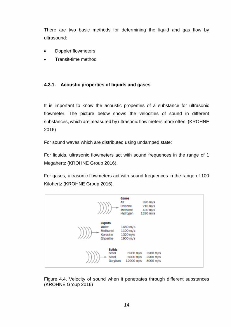
4.3.1. Acoustic properties of liquids and gases
It is important to know the acoustic properties of a substance for ultrasonic
flowmeter. The picture below shows the velocities of sound in different
substances, which are measured by ultrasonic flow meters more often. (KROHNE
2016)
For sound waves which are distributed using undamped state:
For liquids, ultrasonic flowmeters act with sound frequences in the range of 1
Megahertz (KROHNE Group 2016).
For gases, ultrasonic flowmeters act with sound frequences in the range of 100
Kilohertz (KROHNE Group 2016).
Figure 4.4. Velocity of sound when it penetrates through different substances (KROHNE Group 2016)

15
4.3.2. Ultrasonic Doppler flowmeters
To begin with, the work of Doppler ultrasonic flow meter is based on the Doppler
effect, the effect which was discovered by Christian Doppler in 1842. (Wikipedia
2016)
Doppler effect is the change in frequency and, consequently, the emission
wavelength, which is perceived by the observer (or receiver), as a result of
movement of the radiation source and / or the motion of the observer (or receiver).
(Wikipedia 2016)
The wave source moves to the left. Then, the left wave frequency becomes
higher, and the right - lower, in other words, if the wave source is catching waves
emitted by them, the wavelength decreases. If removed - the wavelength
increases.
Figure 4.5. Doppler effect (BU Physics 2006)
The sensor of ultrasonic Doppler flowmeter consists of a transmitter and a
receiver.
The emitter transmits ultrasonic waves of frequency f1 (In formula below) under
an angle in a moving medium (frequency is about 1 ... 5 MHz) (KROHNE Group
2016). The wavelength calculated from the frequency f1 is given by:
𝜆1 =С
𝑓1 (2)

16
Where С – velocity of the sound in medium
Then, because of reflecting particles moving, the receiver will perceive the
reflected wave as a wave-shifted frequency and the wavelength will change as
follows:
𝜆2 =С – 2 • 𝑉 • cos 𝛼
𝑓1 (3)
where V - Velocity of the flow and cosα - the angle of ultrasonic waves
If Vp < C:
𝑓2 =𝑓1 • 𝑐
(𝐶 – 2 • 𝑉𝑝 • 𝑐𝑜𝑠 𝛼) (4)
Frequency difference depends on the velocity of the particles (flow rate):
𝑓2 – 𝑓1 = ∆𝑓 =2 • 𝑉𝑝 • 𝑓1 • cos 𝛼
𝐶 (5)
Figure 4.6. Working principle of Doppler ultrasonic flow meter (KROHNE Group 2016)
Currently, Doppler flowmeters are almost never used, since they have a number
of disadvantages, compared to other ultrasonic flow meters (transit-time method)
17
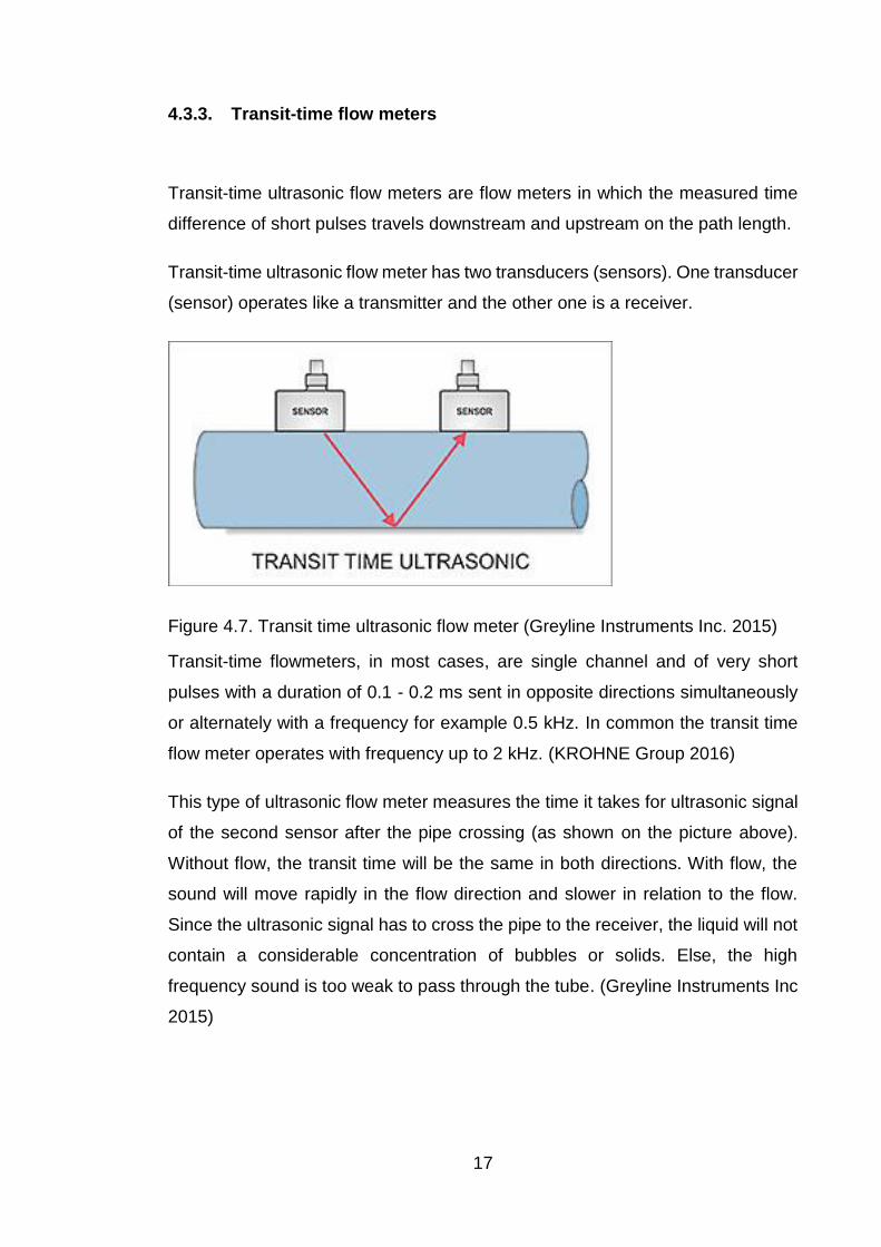
4.3.3. Transit-time flow meters
Transit-time ultrasonic flow meters are flow meters in which the measured time
difference of short pulses travels downstream and upstream on the path length.
Transit-time ultrasonic flow meter has two transducers (sensors). One transducer
(sensor) operates like a transmitter and the other one is a receiver.
Figure 4.7. Transit time ultrasonic flow meter (Greyline Instruments Inc. 2015)
Transit-time flowmeters, in most cases, are single channel and of very short
pulses with a duration of 0.1 - 0.2 ms sent in opposite directions simultaneously
or alternately with a frequency for example 0.5 kHz. In common the transit time
flow meter operates with frequency up to 2 kHz. (KROHNE Group 2016)
This type of ultrasonic flow meter measures the time it takes for ultrasonic signal
of the second sensor after the pipe crossing (as shown on the picture above).
Without flow, the transit time will be the same in both directions. With flow, the
sound will move rapidly in the flow direction and slower in relation to the flow.
Since the ultrasonic signal has to cross the pipe to the receiver, the liquid will not
contain a considerable concentration of bubbles or solids. Else, the high
frequency sound is too weak to pass through the tube. (Greyline Instruments Inc
2015)

18
4.3.4. Advantages and disadvantages of an Ultrasonic Flow Meter
There is a number of advantages and disadvantages for both types of ultrasonic
flow meters.
Advantages of Doppler flow meter:
Negligible pressure drop
Negligible effect of viscosity, temperature, density
Can measure flow of waste liquids
Advantages of transit-time method:
Negligible pressure drop
Negligible effect of viscosity, temperature, density
Can measure both liquids and gases
Very high accuracy
No moving parts
Disadvantages of both flow meters:
Quite expensive compared to other types of flow metering devices
Both types of ultrasonic flow meters have some common advantages, but the
transit-time flow meter is more applicable than Doppler ultrasonic flow meter, also
it provides very high accuracy of measurements.
4.4. Vortex flow meters
Vortex flow meter is the flow meter in which all the measurements occur by
measuring the frequency of the pressure fluctuations. Such pressure fluctuations
occur in the flow during the formation of vortices or oscillation of the jet, by some

19
form of flow barriers, which are installed in the conduit, either by twisting the flow
by other means.
Figure 4.8. Typical vortex flow meter (Emerson 2016)
Fluid or gas flow tries to come through the body installed in a flow meter, as a
result the movement changes its direction and increases speed by reducing the
pressure. (Wikipedia 2016) After passing the obstacle (the body) in the middle
section, the pressure increases and speed decreases. Thus, the front part of the
streamlined body has elevated pressure and at the rear - low pressure. Coming
mid-section, the boundary layer flow separates from the body and under the
influence of pressure difference (from high to low), formed by the body, changes
its direction of movement, creating a vortex. The formation of vortices occur
alternately on both sides of the body.
Figure 4.9. Working principle of vortex flow meter. 1 – Pipeline. 2 – Shedder bar. 3 – Vortices.

20
Vortex flow meter is applicable to different kinds of liquids and gases and also it
is applicable to measure the flow of steam.
Advantages of vortex flow meter:
Reliability
Low installation cost
High accuracy
Digital flow signal
4.5. Electromagnetic flow meters
Electromagnetic Flowmeter or Magmeter is a device which is intended to account
the medium flow and which works through the principle of the interaction of the
flowing fluid through the magnetic field. The basis of this principle is the law of
electromagnetic induction (Faraday’s law). For this reason, a very important
requirement for the environment, which is measured, is good electrical
conductivity.
Figure 4.10. Typical Magmeter (Seametrics 2014)
The Faraday’s law says that the voltage, which is induced across the conductor
as it moves at right angles through a magnetic field is proportional to the velocity

21
of that conductor. The figure below shows the practical application of this law to
measure the flow of electrical conductive fluid.
Figure 4.11. Working principle for electromagnetic flow meter (TN Instrumentation 2016)
The main disadvantage of using an electromagnetic flow meter is the impossibility
of using it to measure the flow of liquids, which have very small electrical
conductivity or non-conductive (different insulators, for example, distilled water),
gases and water vapor. Thus, the use of flowmeters may occur if the specific
electric conductivity of liquid is more than 103 cm/m. So the electromagnetic flow
meters are applicable to liquids, which are under this condition, for example any
kind of water, which is not distilled, various juices, syrups, solutions, wastewater
and also acids and alkalis.
Advantages of electromagnetic flow meter:
High accuracy of flow readings. (Reliability)
No dependence on the viscosity, temperature, density and other parameters
of the medium
No pressure loss in the flow meter
Possibility to use with aggressive, viscous liquids containing abrasives.

22
A special and important advantage of the electromagnetic flow meter is that the
results of measurement of this flow meter in the asymmetric flow and the same
flow rate will be the same in laminar and turbulent flow.
5. Flow measurement method selection for LPG
5.1. Selection of type of the flow meter
The purpose of the study is to select the flow meter, which is the most suitable
for measuring of the flow of liquefied petroleum gas.
From the types of flow meters, which are presented above, the least suitable is
electromagnetic flow measurement method. This is due to the fact that this type
of flow meter is not completely suitable for gas flow measurement according to
very low electrical conductivity of LPG (propane-butane fraction).
There are some types of contact flow meters (Venturi flow meter, Rotameter,
Vortex flow meter), which are suitable for measuring liquids, gases and steam,
but all these flow meters have a significant drawback: the presence of a contact
sensor to the controlled environment and as a result flow pressure loss of the
medium. Because of high flammability and ability to easy evaporation (according
to LPG properties), the presence of a contact sensor in the medium is also
undesirable. Application of separation vessels, manufacture of narrowing devices
made of special materials and the use of other special protection devices make
the use of contact flow meters impractical because of the high cost of materials
and maintenance complexity.
On the other hand, optical and ultrasonic flowmeters do not have the
disadvantages mentioned above. It means that a deeper analysis between these
two types of flow meters must be done. It is necessary to consider all the
advantages provided by these flow measurement methods to choose the best
one for measuring of the flow of LPG.
23
Optical (laser) flow meters have several benefits compared to flow measuring
methods, which are presented above. These flow meters are non-contact, so it
means that the pressure loss is insignificant. The accuracy of optical flow meters
is high. But these flow meters are quite expensive. Also, the LPG is quite
flammable and it is more suitable to use an ultrasonic flow meter to measure the
flow.
The advantages of ultrasonic flowmeters are non-contact measurement, high
accuracy, no pressure loss and no moving parts. All these advantages increase
the service life of the device. In fact, explosion proof ultrasonic flow meters enable
their use in the chemical industry. From an economic point of view, ultrasonic
flowmeters are cost-effective for the customer after a short operating time. The
accuracy of readings of this type of a flow meter depends only on the surface
quality of the pipe walls. Therefore, it is ergonomical and more suitable to use an
ultrasonic flow meter to measure the flow of LPG.
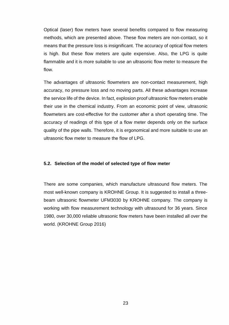
5.2. Selection of the model of selected type of flow meter
There are some companies, which manufacture ultrasound flow meters. The
most well-known company is KROHNE Group. It is suggested to install a three-
beam ultrasonic flowmeter UFM3030 by KROHNE company. The company is
working with flow measurement technology with ultrasound for 36 years. Since
1980, over 30,000 reliable ultrasonic flow meters have been installed all over the
world. (KROHNE Group 2016)

24
Figure 5.1. KROHNE UFM 3030 (KROHNE Group 2016)
Ultrasonic flowmeters KROHNE occupy a leading position in the global market of
flow measuring devices. Three-beam flowmeter UFM 3030 has become a
benchmark for many different applications. UFM 3030 demonstrates reliable and
stable results according to more advanced electronics, digital signal processing
and three-beam measurement technology. UFM 3030 has all the benefits of flow
measurement by using of ultrasonic waves, the measurement accuracy is
independent of the conductivity, viscosity, temperature, density and pressure of
the medium. Transducer is smooth inside and outside, and has no moving parts.
Therefore, there are no additional pressure losses, no need for recalibration of
the device, and the need for maintenance is minimal. (KROHNE Group 2016)
UFM3030 is a universal device for the direct measurement of liquids, both simple
and complex properties. Particularly highlighted is small conductive or non-
conductive medium, such as demineralized water or hydrocarbons. Inorganic
substances from molten sulfur to chlorine and organic compounds such as
liquefied gases (LPG) do not pose problems for UFM 3030.

25
5.3. The principle of work of the selected flowmeter
The operating principle of UFM 3030 ultrasonic flow meter is based on the
differential transit-time flow measurement method. Three pairs of ultrasonic
transducers measured transit time of acoustic signals, which move downstream
and upstream. The difference in transit time is proportional to the average flow
velocity and the output signal is converted into volume and total flow. Measuring
beams form a three-dimensional profile of the velocity distribution of the medium
or fluid flow profile that runs along the measuring tube, through a third measuring
beam. These measurement lines are arranged to minimize the impact of the flow
regime. In combination with the latest technology of digital signal processing, it
gives a stable, reliable and accurate flow measurement. (KROHNE Group 2016)
The third measuring beam allows UFM 3030 to consider the measurement
condition in laminar and turbulent flow.
5.4. Summary
The selected ultrasonic flow meter KROHNE UFM 3030 has a very wide range
of applications. This flow meter is equipped with three measuring beams,
precision electronics and innovative digital signal processing technology that
provides reliable and stable measurement results. The device does not require
any special configuration, because transients do not affect his testimony.
The flowmeter UFM 3030 is a compact device that is easy to install and easy to
operate. It can be installed in tight places, since there is no need to use filters,
isolation from vibrations. The device has no moving parts and no pressure loss
as a result.
The flowmeter UFM 3030 is not classified as a cheap instrument, but among
modern ultrasonic flowmeters its cost is relatively low. The installation cost is
significantly lower compared to similar costs for the installation of mass or vortex
flowmeters.

26
In addition, the flow meter is versatile in terms of selecting the type of the medium.
It is suitable for the oil and gas industry: everything from heavy crude oil to
liquefied gases. It is possible to make a consequence that the given flow meter
is perfectly suited for measuring the flow of LPG.
Considering all the above, it can be argued that the UFM 3030 ultrasonic
flowmeter has excellent technical and metrological performance, a high degree
of reliability and accuracy, and the perfect combination of price and quality. It is
well suited for use in the oil and gas industry.
6. Conclusion
There is a plenty of methods for measuring the flow of liquids and gases under
various conditions. All these methods are upgraded to improve the metrological
and technical characteristics.
The result of the study was achieved – the knowledge about flow measuring
methods was deepened and the most suitable flow measurement method for
measuring the flow of LPG was selected. However, among all the flow
measurement methods, which are presented in this thesis, ultrasound transit-time
flow meters are the most appropriate for LPG flow measuring.
The advantages of ultrasonic transit-time flowmeters are: higher measurement
accuracy, high reliability and no pressure loss (due to lack of moving parts), the
possibility in principle of mass flow measurement and preservation of efficiency
when changing the direction of flow, the ability to measure a large class of
environments from the liquid metal to cryogenic liquids and gases.
All of these advantages can provide reliable results.

27
7. References
Baker, R. C. 2000. Flow measurement handbook. Cambridge, UK: Cambridge
University Press.
Sinkko, S. 2014. Hydraulics. Lecture notes. Saimia University of Applied
Sciences. Mechanical Engineering and Production Technology.
KROHNE Group 2016. KROHNE Product Downloads – UFM 3030 | KROHNE
Group. http://krohne.com/en/dlc/product-related-
downloads/flowmeters/ultrasonic-flowmeters/ufm-3030/. Accessed on 5 May
2016.
Lorem ipsum 2010. Turbulent flow is slower than laminar flow | lorem ipsum.
http://blog.nialbarker.com/252/slow_is_faster. Accessed on 6 April 2016
Jim Van Cura 2014. 10 Reasons to Buy a Diesel Automobile – Jim Van Cura.
http://jimvancura.com/rants/10-reasons-to-buy-a-diesel-automobile. Accessed
on 8 April 2016.
Wikimedia Commons 2014. File:Blende eng.png.
https://commons.wikimedia.org/wiki/File:Blende_eng.png. Accessed on 11 April
2016.
Thermopedia 2011. Thermopedia - A-Z Index.
http://www.thermopedia.com/content/1100/. Accessed on 12 April 2016.
GE Oil & Gas 2016. PanaFlow Integrated Ultrasonic Flow Meter System | GE
Sensing. https://www.gemeasurement.com/flow-measurement/ultrasonic-
liquid/panaflow-integrated-ultrasonic-flow-meter-system. Accessed on 14 April
2016.
KROHNE Group 2016. Ultrasonic Flow Measurement for Industrial Applications.
http://cdn.krohne.com/dlc/BR_ULTRASONIC_en_72.pdf. Accessed on 15 April
2016.

28
BU Physics 2006. The Doppler Effect.
http://physics.bu.edu/~duffy/py105/Doppler.html. Accessed on 17 April 2016.
Greyline Instruments Inc. 2015. Two Technologies – Doppler and Transit Time
Ultrasonic Flowmeter Technologies Explained.
http://www.greyline.com/twotechnologies.htm. Accessed on 19 April 2016.
Emerson 2016. Emerson Process Management - Emerson flowmeter helps
BillerudKorsnäs increase process efficiency and reduce maintenance costs.
http://www2.emersonprocess.com/nl-nl/news/pr/pages/pr_1304-
billerudkorsnas_nl.aspx. Accessed on 21 April 2016.
Seametrics 2014. Seametrics 12-inch Magmeter for Irrigation.
http://www.seametrics.com/blog/news-release-seametrics-releases-a-12-inch-
magmeter-for-irrigation/. Accessed on 24 April 2016.
TN Instrumentation 2016. ELECTROMAGNETIC FLOW METER.
http://tninstrumentation.blogspot.fi/2014/03/electromagnetic-flow-meter.html.
Accessed on 27 April 2016.
Flowoptical.com. 2016. Flow Optical. http://www.flowoptical.com/. Accessed on
12 April 2016.
Wikipedia 2016. Flow measurement – Wikipedia, the free Encyclopedia.
https://en.wikipedia.org/wiki/Flow_measurement. Accessed on 7 May 2016.
Wikipedia 2016. Fractional distillation – Wikipedia, the free Encyclopedia.
https://en.wikipedia.org/wiki/Fractional_distillation. Accessed on 8 April 2016.
Wikipedia 2016. Liquefied petroleum gas – Wikipedia, the free Encyclopedia.
https://en.wikipedia.org/wiki/Liquefied_petroleum_gas. Accessed on 9 April
2016.
Wikipedia 2016. Laminar flow – Wikipedia, the free Encyclopedia.
https://en.wikipedia.org/wiki/Laminar_flow. Accessed on 6 April 2016.
Wikipedia 2016. Doppler effect – Wikipedia, the free Encyclopedia.
https://en.wikipedia.org/wiki/Doppler_effect. Accessed on 17 April 2016.

29
Figure 2.1. Schematic picture of Laminar and turbulent flow (Lorem Ipsum 2010)
............................................................................................................................ 6
Figure 3.1. Fractions of oil with its applications (Jim Van Cura 2014) ................. 8
Figure 4.1. Principle of Venturi flow meter, which is based on Venturi effect
(Wikimedia Commons 2014) ............................................................................. 10
Figure 4.2. Rotameter working system (Thermopedia 2011) ............................ 11
Figure 4.3. Typical ultrasonic flowmeter. Two ultrasonic sensors are diagonally
opposite to each other (transmitter and receiver) (GE Oil & Gas 2016)\ ........... 13
Figure 4.4. Velocity of sound when it penetrates through different substances
(KROHNE Group 2016) .................................................................................... 14
Figure 4.5. Doppler effect (BU Physics 2006) ................................................... 15
Figure 4.6. Working principle of Doppler ultrasonic flow meter (KROHNE Group
2016) ................................................................................................................. 16
Figure 4.7. Transit time ultrasonic flow meter (Greyline Instruments Inc. 2015)17
Figure 4.8. Typical vortex flow meter (Emerson 2016) ...................................... 19
Figure 4.9. Working principle of vortex flow meter. 1 – Pipeline. 2 – Shedder bar.
3 – Vortices. ...................................................................................................... 19
Figure 4.10. Typical Magmeter (Seametrics 2014) ........................................... 20
Figure 4.11. Working principle for electromagnetic flow meter (TN
Instrumentation 2016) ....................................................................................... 21
Figure 5.1. KROHNE UFM 3030 (KROHNE Group 2016) ................................ 24
Related Documents