To Promote the production and application of ductile iron castings Issue 1, 2004 FEATURES • Cover • New Process of DI Production • Ductile Iron and Wind Energy • Melt Cold and Pour Hot • AFS Signs Alliance Agreement with OSHA • AFS Aims to Unite the Metalcasting Industry • Control of Slag and Insoluble Buildup in Ladles, Melting and Pressure Pour Furnaces • Improved Ductile Iron Casting Quality Through Optimized Coating Technology DEPARTMENTS • News Briefs • Advertisers • Back Issues • DIS Home Page American Foundry Society and the Ductile Iron Society Combine to Promote the Use of Castings at the 2004 SAE Show View Ductile Iron Related Publications Located in Strongsville, Ohio, USA 15400 Pearl Road, Suite 234; Strongsville,Ohio 44136 Billing Address: 2802 Fisher Road, Columbus, Ohio 43204 Phone (440) 665-3686; Fax (440) 878-0070 email:[email protected]

Welcome message from author
This document is posted to help you gain knowledge. Please leave a comment to let me know what you think about it! Share it to your friends and learn new things together.
Transcript

The Ductile Iron News
file:///C|/WEBSHARE/062013/magazine/2004_1/index.htm[7/1/2013 10:31:37 AM]
To Promote the production and application of ductile iron castings Issue 1, 2004
FEATURES
• Cover
• New Process of DI Production
• Ductile Iron and Wind Energy
• Melt Cold and Pour Hot
• AFS Signs Alliance Agreementwith OSHA
• AFS Aims to Unite theMetalcasting Industry
•Control of Slag and InsolubleBuildup in Ladles, Melting andPressure Pour Furnaces
•Improved Ductile Iron CastingQuality Through Optimized CoatingTechnology
DEPARTMENTS
• News Briefs
• Advertisers
• Back Issues
• DIS Home Page
American Foundry Society and theDuctile Iron Society Combine to Promote
the Use of Castings at the 2004 SAE Show
View Ductile Iron Related Publications
Located in Strongsville, Ohio, USA15400 Pearl Road, Suite 234; Strongsville,Ohio 44136 Billing Address: 2802 Fisher Road, Columbus, Ohio 43204 Phone (440) 665-3686; Fax (440) 878-0070email:[email protected]
susan
Rectangle

The Ductile Iron News
file:///C|/WEBSHARE/062013/magazine/2004_1/wind-energy.htm[7/1/2013 10:32:03 AM]
To Promote the production and application of ductile iron castings Issue 1, 2004
FEATURES
• Cover
• New Process of DI Production
• Ductile Iron and Wind Energy
• Melt Cold and Pour Hot
• AFS Signs Alliance Agreementwith OSHA
• AFS Aims to Unite theMetalcasting Industry
•Control of Slag and InsolubleBuildup in Ladles, Melting andPressure Pour Furnaces
•Improved Ductile Iron CastingQuality Through Optimized CoatingTechnology
DEPARTMENTS
• News Briefs
• Advertisers
• Back Issues
• DIS Home Page
Ductile Iron and Wind Energy :A Symbiotic Relationship
by Martin Gagne, Manager - Sorelmetal Technical ServicesRio Tinto Iron & Titanium Inc.
This article is in an Adobe Acrobat pdf format
Click here to view the article.
View Ductile Iron Related Publications
Located in Strongsville, Ohio, USA15400 Pearl Road, Suite 234; Strongsville,Ohio 44136 Billing Address: 2802 Fisher Road, Columbus, Ohio 43204 Phone (440) 665-3686; Fax (440) 878-0070email:[email protected]
susan
Rectangle

The Ductile Iron News
file:///C|/WEBSHARE/062013/magazine/2004_1/new_process.htm[7/1/2013 10:32:00 AM]
To Promote the production and application of ductile iron castings Issue 1, 2004
FEATURES
• Cover
• New Process of DI Production
• Ductile Iron and Wind Energy
• Melt Cold and Pour Hot
• AFS Signs Alliance Agreementwith OSHA
• AFS Aims to Unite theMetalcasting Industry
•Control of Slag and InsolubleBuildup in Ladles, Melting andPressure Pour Furnaces
•Improved Ductile Iron CastingQuality Through Optimized CoatingTechnology
DEPARTMENTS
• News Briefs
• Advertisers
• Back Issues
• DIS Home Page
New Process of Ductile Iron Productionwithout Nodulizing Treatment
Yunfeng YANG
Industrial SystemsP.O. Box 1703, FIN-02044 VTT, FinlandE-mail: [email protected]
Since late 1940’s when it was invented, ductile iron is one of thematerials that enjoyed the most rapid growth in industrialapplications because of its attractive combination of the mechanicalproperties and excellent cast-abilities. In commercial practice,ductile iron has always been produced by treating a base iron meltwith nodulizing elements such as magnesium, cerium or other rareearth elements. The conventional production method consumes a lotof natural resources. Tight process control is needed to preventquality fluctuations due to variations of nodularization andinoculation. It has certain difficulties also in producing thick walland thin wall castings.
Recently, VTT (Technical Research Centre of Finland, www.vtt.fi)has discovered that nodular graphite can be obtained fromindustrial grade iron melt by spray forming without adding anynodulizing or inoculation agent. Spray forming is a rapidsolidification process, in which metal melt is atomized by gas intodroplets of 10 - 200 microns in size, flying at subsonic speed onto adeposition substrate. The cooling rates are between 100 to 100,000degrees per second, much greater than those in conventional castingsolidification processes. Such high solidification rates lead tonodular graphite formation from normal grey iron melts.Experiments were carried out with an Osprey type spray formingplant. The plant consists of a 50-kg induction furnace, an opentundish with a melt nozzle at the bottom and protruded into a 2-stage nitrogen atomizer, a spray chamber, and a cyclone forcollecting over-spray powder. In the spray chamber, a horizontalram manoeuvres a substrate, i.e. a ceramic mould to receive thespray deposition, as shown by Fig. 1. The sprayformed iron piecesare about 80 mm thick.
Fig. 1. Principle of sprayforming technology
Wide ranges of melt compositions have been tested, as listed in
susan
Rectangle
The Ductile Iron News
file:///C|/WEBSHARE/062013/magazine/2004_1/new_process.htm[7/1/2013 10:32:00 AM]
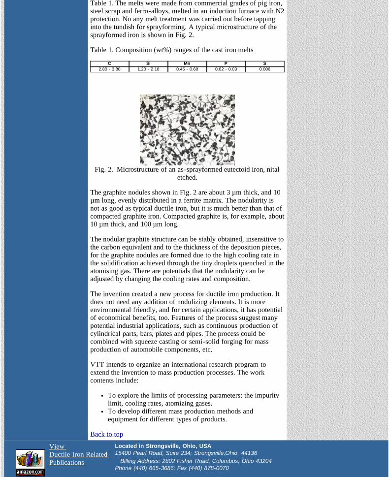
Table 1. The melts were made from commercial grades of pig iron,steel scrap and ferro-alloys, melted in an induction furnace with N2protection. No any melt treatment was carried out before tappinginto the tundish for sprayforming. A typical microstructure of thesprayformed iron is shown in Fig. 2.
Table 1. Composition (wt%) ranges of the cast iron melts
C Si Mn P S2.80 - 3.80 1.20 - 2.10 0.45 - 0.60 0.02 - 0.03 0.006
Fig. 2. Microstructure of an as-sprayformed eutectoid iron, nitaletched.
The graphite nodules shown in Fig. 2 are about 3 µm thick, and 10µm long, evenly distributed in a ferrite matrix. The nodularity isnot as good as typical ductile iron, but it is much better than that ofcompacted graphite iron. Compacted graphite is, for example, about10 µm thick, and 100 µm long.
The nodular graphite structure can be stably obtained, insensitive tothe carbon equivalent and to the thickness of the deposition pieces,for the graphite nodules are formed due to the high cooling rate inthe solidification achieved through the tiny droplets quenched in theatomising gas. There are potentials that the nodularity can beadjusted by changing the cooling rates and composition.
The invention created a new process for ductile iron production. Itdoes not need any addition of nodulizing elements. It is moreenvironmental friendly, and for certain applications, it has potentialof economical benefits, too. Features of the process suggest manypotential industrial applications, such as continuous production ofcylindrical parts, bars, plates and pipes. The process could becombined with squeeze casting or semi-solid forging for massproduction of automobile components, etc.
VTT intends to organize an international research program toextend the invention to mass production processes. The workcontents include:
To explore the limits of processing parameters: the impuritylimit, cooling rates, atomizing gases.To develop different mass production methods andequipment for different types of products.
Back to top
View Ductile Iron Related Publications
Located in Strongsville, Ohio, USA15400 Pearl Road, Suite 234; Strongsville,Ohio 44136 Billing Address: 2802 Fisher Road, Columbus, Ohio 43204 Phone (440) 665-3686; Fax (440) 878-0070

The Ductile Iron News
file:///C|/WEBSHARE/062013/magazine/2004_1/melt-cold.htm[7/1/2013 10:31:59 AM]
To Promote the production and application of ductile iron castings Issue 1, 2004
FEATURES
• Cover
• New Process of DI Production
• Ductile Iron and Wind Energy
• Melt Cold and Pour Hot
• AFS Signs Alliance Agreementwith OSHA
• AFS Aims to Unite theMetalcasting Industry
•Control of Slag and InsolubleBuildup in Ladles, Melting andPressure Pour Furnaces
•Improved Ductile Iron CastingQuality Through Optimized CoatingTechnology
DEPARTMENTS
• News Briefs
• Advertisers
• Back Issues
• DIS Home Page
Melt Cold and Pour Hot - What is This?By James D. MullinsMullins Professional Services
This was a phrase quite frequently used by old time foundry men todescribe the often-misunderstood science of metallurgy andfounding of cast irons. At first glance this seems a contradiction interms, but as one realizes what happens to the metal during meltingand the casting, following these guidelines, it should begin to makegood sense.
How can you melt cold? What this really means is that the metal should never besuperheated any more than necessary to dissolve the carbon,whether it is in the form of a carbon raiser or from virgin chargematerials, and other alloying elements. The reasons for this areseveral; superheating destroys nucleation in the melt, which in turnallows the carbon to form as carbide rather than graphite. Thischanges the nature of a cast iron from a softer graphitic materialwith less shrinkage to one that is more brittle and very sensitive tothe cooling rate (section sensitivity) of the casting. This all happenswithout any appreciable change in the chemistry, so looking atchemistry alone will not give a clue to nucleation changes.Secondly, at higher superheat temperatures oxidizable elements willbe lost, the reaction of the metal to inoculation can be poor orerratic, while refractory and energy costs increase. These samechanges will happen at longer holding times even though the metaltemperature does not seem to be excessively high. Thereforeholding should always be done at as low a temperature as possible,especially over weekend and holiday periods. This holdingtemperature may be as low as 2400 F for some foundries.
Measurement of changes to the nucleation condition should bedone for each heat of metal on a continuous basis. Not only doesthis give information about the melting process, but can alsoindicate changes coming from charge materials and alloy additions.Using chill wedges or some type of thermal analysis formeasurement of the nucleation condition of the melt, should bedone when the chemistry is checked, just prior to readying themetal for pouring. In either case we are looking for is the amount ofundercooling present in the melt. Undercooling is defined ascooling below the normal solidification starting temperature. Evena small amount of undercooling can change the type of graphiteformed, while more will increase the likelihood that carbides mayform. This is easily seen as an increase in chill value of a wedge.Variable undercooling and nucleation values can be the reason whyresponse to inoculation can be erratic. Certainly more undercoolingin the melt requires increased inoculation to achieve the same endresult. Also note that undercooling can be increased, by increasingcertain elements such as Cr, V, etc. in the melt.
So how do we pour hot, when we melt cold? Of course preheating refractory lined ladles is important to pouring
susan
Rectangle

The Ductile Iron News
file:///C|/WEBSHARE/062013/magazine/2004_1/melt-cold.htm[7/1/2013 10:31:59 AM]
hot, but so is removing impediments and other time delays in themetal transfer system. Another way is to use insulated ladle liningsand definitely cover all ladles to retain as much heat as possible.
Pouring hot usually reduces or totally eliminates any cold iron typedefect. These are low fluidity problems like misrun, cold shuts,cold shots, some slag defects, and short pours due to cold metal andbackpressure. Other metal defects aggravated by low pouringtemperature are most gas blows, pinholes and improper feedingfrom risers. Cold metal can trap gases at or near the upper surfaces.Cold metal and gating only into the heavy sections can producelarge temperature gradients in a casting, causing feeding problemsand certainly microstructure variations.
You have probably noticed that the exact temperatures ofsuperheating and pouring have not been defined. This is becausethese temperatures are specific only to a single foundry/line or eveneach separate casting operation in one consolidated foundry.
Back to top
Most of the above discussion has been primarily about gray iron,but the rules certainly apply to most ductile iron operations as well.Additionally, tapping colder (from lower melt temperatures), whenmaking ductile iron, will increase the magnesium recovery from thetreatment reaction and when using MgFeSi, increases the amount ofnucleation sites. The treatment reaction especially with pure Mgremoves many of the nucleating particles and increasesundercooling. This iron is then most often in need of seriousinoculation, so temperatures must be higher to insure dissolvinglarger additions. Lower temperatures have one benefit though andthis is that the fading of the Mg and inoculation is usually reduced.One more issue to keep in mind when making ductile iron is thatcolder pour temperatures invite more slag and dross to form. Thisslag can react with carbon in the iron forming small CO gas holes.
So melting cold and pouring hot requires balancing the good withthe bad. However the benefits of following these rules - increasingquality, while reducing scrap and processing costs are obvious. Seeif your operation is doing all that can be done to follow this oldaxiom.
Back to top
View Ductile Iron Related Publications
Located in Strongsville, Ohio, USA15400 Pearl Road, Suite 234; Strongsville,Ohio 44136 Billing Address: 2802 Fisher Road, Columbus, Ohio 43204 Phone (440) 665-3686; Fax (440) 878-0070email:[email protected]

The Ductile Iron News
file:///C|/WEBSHARE/062013/magazine/2004_1/afs-signs-alliance.htm[7/1/2013 10:31:38 AM]
To Promote the production and application of ductile iron castings Issue 1, 2004
FEATURES
• Cover
• New Process of DI Production
• Ductile Iron and Wind Energy
• Melt Cold and Pour Hot
• AFS Signs Alliance Agreementwith OSHA
• AFS Aims to Unite theMetalcasting Industry
•Control of Slag and InsolubleBuildup in Ladles, Melting andPressure Pour Furnaces
•Improved Ductile Iron CastingQuality Through Optimized CoatingTechnology
DEPARTMENTS
• News Briefs
• Advertisers
• Back Issues
• DIS Home Page
AFS Signs Alliance Agreement with OSHAWashington, D.C. On March 22, leadersfrom the American Foundry Society Inc.(AFS), Des Plaines, Ill., met with leadersfrom the U.S. Department of Labor’s
Occupational Safety and Health Administration (OSHA) inWashington, D.C. and signed a new alliance agreement to continuejoint efforts to promote safer and more healthful workplaces in theU.S. metalcasting industry.
.
Pictured: AFS President Arthur Edge (seated l), OSHA AdministratorJohn Henshaw (seated r) signing the alliance agreement between AFS & OSHA in
front of members of the AFS Environmental, Health & Safety Committee.
The agreement states: “OSHA and AFS hereby form an alliance toprovide AFS members and others, including small businesses in themetalcasting industry, with information, guidance and access totraining resources that will help them protect employees’ health andsafety, particularly focusing on workplace issues, includingpersonal protective equipment, ventilation, and reducing andpreventing exposure to silica.”
According to the agreement, AFS and OSHA will work together toachieve the following training and education goals:
develop training and education programs to address hazardsin the workplace and review and provide input into the AFSSafety in the Foundry seminar;assist OSHA’s Office of Training and Education in providingeducation and training regarding hazards in the foundryworkplace.According to the agreement, OSHA and AFS will worktogether to achieve the following outreach andcommunication goals:develop and disseminate information through print andelectronic media;speak, exhibit and/or appear at OSHA and AFS conferences,local meetings and other events;cross-train OSHA personnel and industry safety and healthprofessionals in metalcasting best practices or effective
susan
Rectangle

The Ductile Iron News
file:///C|/WEBSHARE/062013/magazine/2004_1/afs-signs-alliance.htm[7/1/2013 10:31:38 AM]
approaches;promote and encourage AFS member worksites to participatein OSHA’s cooperative programs;work with other alliance participants on specific issues andprojects regarding silica, personal protective equipment andventilation;encourage AFS chapters and worksites to build relationshipswith OSHA’s regional and area offices.
In addition, AFS and OSHA agreed to work together to raiseothers’ awareness and demonstrate their own commitment toworkplace safety and health whenever AFS leaders address groups.
This agreement is scheduled to remain in effect for two years and isa continuation of a cooperative AFS-OSHA relationship that hasgrown since the 1970s. Other notable cooperative efforts include:professionals from federal and state OSHA groups have beenactive with AFS safety and health committees since the 1970s andstaff from the OSHA Training Institute instructing during AFS’sOSHA Compliance Seminars since 1990.
For more information contact Gary Mosher, AFS vice president-environmental, health and safety, at [email protected] or 800/537-2437. Headquartered in Des Plaines, Ill., AFS is a not-for-profittechnical and management society that has existed since 1896 toprovide and promote knowledge and services that strengthen themetalcasting industry for the ultimate benefit of its customers andsociety.
Back to top
View Ductile Iron Related Publications
Located in Strongsville, Ohio, USA15400 Pearl Road, Suite 234; Strongsville,Ohio 44136 Billing Address: 2802 Fisher Road, Columbus, Ohio 43204 Phone (440) 665-3686; Fax (440) 878-0070email:[email protected]

The Ductile Iron News
file:///C|/WEBSHARE/062013/magazine/2004_1/afs-aims-to-unite.htm[7/1/2013 10:31:38 AM]
To Promote the production and application of ductile iron castings Issue 1, 2004
FEATURES
• Cover
• New Process of DI Production
• Ductile Iron and Wind Energy
• Melt Cold and Pour Hot
• AFS Signs Alliance Agreementwith OSHA
• AFS Aims to Unite theMetalcasting Industry
•Control of Slag and InsolubleBuildup in Ladles, Melting andPressure Pour Furnaces
•Improved Ductile Iron CastingQuality Through Optimized CoatingTechnology
DEPARTMENTS
• News Briefs
• Advertisers
• Back Issues
• DIS Home Page
AFS Aims to Unite Metalcasting IndustryFollowing Rejection of Section 421
Des Plaines, Ill.…In a March announcement to the metalcastingindustry, American Foundry Society Inc. (AFS), Vice PresidentChuck Kurtti, Neenah Foundry, Co. (retired), called onmetalcasting leaders to take an active approach to unite and shapethe future of our industry. Continuing to fight against unfair tradepractices in fragmented, uncoordinated actions will only result indefeats, said Kurtti, who also serves as the chairman of the AFSTrade Commission. The call for unification comes on the heels ofPresident Bush’s determination that import relief against ductileiron waterworks fittings (DIWF) from China was not in thenational economic interest of the U.S. This unification will becritical as AFS continues its push for a Section 332 tradeinvestigation on the metalcasting industry by the InternationalTrade Commission (ITC).
President Bush’s ruling came after the ITC conducted a Section 421investigation that found the DIWF imports from China increasedrapidly and had caused both a market disruption and materialinjury to the domestic metalcasting industry. Despite a 6-0 vote bythe ITC to back a Section 421 (which could result in tariffs againstimported DIWFs), the Bush Administration rejected it.
“We believe the Waterworks 421 met all the criteria for which therule was written by the fact that it received unanimous backing bythe ITC and was passed along to the Administration with arecommendation for relief based on the proven criteria of harm,”Kurtti said. “We, as an industry, must find a way to unite, create abalance and define our future without expecting any support fromnew or existing rules and regulations available to govern our tradeactivities.”
Kurtti called the ruling a “defining decision” and said it sent a clearsignal, “that our trading partners may use any practice necessary togain market penetration without fear of retribution by thisAdministration enforcing new or present agreements, rules orregulations put in place to ensure a level and fair tradeenvironment. The days of just ‘window dressing’ are over, and wenow look to our leaders for positive direction to help us define thefuture and value of not only our industry, but also the critical massof manufacturing in this country.”
In October 2003, the ITC instituted the 421 investigation at therequest of McWane Inc., Birmingham, Ala., to determine whetherDIWF from China were causing a market disruption. If instituted,the 421 would provide relief to U.S. industries if the investigationfinds that Chinese products are imported into the U.S. in suchincreased quantities as to cause a market disruption.
susan
Rectangle

The Ductile Iron News
file:///C|/WEBSHARE/062013/magazine/2004_1/afs-aims-to-unite.htm[7/1/2013 10:31:38 AM]
President Bush’s reason for ruling against the Section 421 wasbased on evidence that concluded U.S. companies would gain littleif tariffs or quotas were placed on Chinese DIWFs because othercountries’ imports would quickly fill the void. President Bushadded that import relief would cost U.S. consumers more than theincreased income that could be realized by domestic producers.
“The circumstances of this case make it clear that the U.S. nationaleconomic interest would not be served by the imposition of importrelief under Section 421,” President Bush said. “I remain fullycommitted to exercising the important authority granted to meunder Section 421 when the circumstances of a particular casewarrant it.”
For more information contact Dwight Barnhard, AFS executivevice president, at [email protected] or 800/537-2437.Headquartered in Des Plaines, Ill., AFS is a not-for-profit technicaland management society that has existed since 1896 to provide andpromote knowledge and services that strengthen the metalcastingindustry for the ultimate benefit of its customers and society.
Back to top
View Ductile Iron Related Publications
Located in Strongsville, Ohio, USA15400 Pearl Road, Suite 234; Strongsville,Ohio 44136 Billing Address: 2802 Fisher Road, Columbus, Ohio 43204 Phone (440) 665-3686; Fax (440) 878-0070email:[email protected]
The Ductile Iron News
file:///C|/WEBSHARE/062013/magazine/2004_1/slag_buildup.htm[7/1/2013 10:32:01 AM]
To Promote the production and application of ductile iron castings Issue 1, 2004
FEATURES
• Cover
• New Process of DI Production
• Ductile Iron and Wind Energy
• Melt Cold and Pour Hot
• AFS Signs Alliance Agreementwith OSHA
• AFS Aims to Unite theMetalcasting Industry
•Control of Slag and InsolubleBuildup in Ladles, Melting andPressure Pour Furnaces
•Improved Ductile Iron CastingQuality Through Optimized CoatingTechnology
DEPARTMENTS
• News Briefs
• Advertisers
• Back Issues
• DIS Home Page
Control of Slag and Insoluble Buildup in Ladles,Melting and Pressure Pour Furnaces
ByR. L. (Rod) Naro, ASI International, Ltd., Cleveland, OhioDave Williams, Allied Mineral Products, Inc., Columbus, OhioPete Satre, Allied Mineral Products, Inc., Columbus, Ohio
Introduction: During the past 30 years, the melting methods andassociated molten metal-handling systems used by the U.S. foundryindustry have changed significantly. During the same period, whileductile iron production has experienced continued growth, thequality of metallic scrap and other iron-unit feed stocks has steadilydeteriorated. The result: slag related melting problems have becomewidespread issues in recent years. Yet, a search of the foundrytechnical literature from the past 30 years about slag control andbuildup will result in only a handful of articles.
A new flux, Redux EF40L, has been developed that controls andminimizes buildup in pouring ladles, melting furnaces, pressurepour furnaces and magnesium treatment vessels with minimal to noadverse effects on refractory linings.
Slag Formation: The formation of slag in the melting of ferrousmetals in the foundry is inevitable. The composition of slag varieswith the type of melting process used and the type of iron or steelbeing melted. The cleanliness of the metallic charge, oftenconsisting of sand-encrusted gates and risers from the castingprocess or rust- and dirt-encrusted scrap, significantly affects thetype of slag formed during the melting operation. Additional oxidesor nonmetallic compounds are formed when liquid metal is treatedwith materials to remove impurities or to change the chemistry ofthe system (inoculation and nodulizing). Because these oxides andnonmetallics are not soluble in iron, they float in the liquid metal asan emulsion. This emulsion of slag particles remains stable if themolten iron is continuously agitated, such as in the case of themagnetic stirring inherent in induction melting. Until the particlesize of the nonmetallic increases to the point where buoyancyeffects countervail the stirring action, the particle will remainsuspended. When flotation effects become great enough,nonmetallics rise to the surface of the molten metal andagglomerate as a slag. Once the nonmetallics coalesce into afloating mass on the liquid metal they can be removed. The use offluxes accelerates these processes.
In some instances, oxides may have a lower melting point than theprevailing metal temperature and a liquid slag is formed. In othercases, where the oxides have a higher melting point than the metaltemperature, a dry, insoluble, solid slag is formed.
When slag makes contact with the refractory lining of a furnacewall (or other areas of the holding vessel) that is colder than themelting point of the slag, the slag is cooled below its freezing pointand adheres to the refractory lining. This adhering material is called
susan
Rectangle

The Ductile Iron News
file:///C|/WEBSHARE/062013/magazine/2004_1/slag_buildup.htm[7/1/2013 10:32:01 AM]
buildup. High-melting point slags are especially prone to promotingbuildup. If not prevented from forming or not removed as it forms,buildup will reduce the overall efficiency of the metal handlingsystem.
Three important physical characteristics of slags are the meltingpoint, the viscosity and the “wetting” ability. Generally, a slagshould remain liquid at temperatures likely to be encounteredduring melting, molten metal treatment, or molten metal handling.The viscosity of the slag needs to be such that removal from themetal surface is easy. At the same time, a fluid slag of low meltingpoint promotes good slagging reactions and prevents buildup inchannel furnace throats and loops as well as coreless furnacesidewalls. Slags must have a high interfacial surface tension toprevent refractory attack (wetting) and to facilitate their removalfrom the surface of the molten metal.
Back to top
Slag Composition: The composition of furnace and ladle slag isoften very complex. The slags that form in electric furnace meltingresult from complex reactions between silica (adhering sand anddirt from casting returns), oxides from scrap, other oxidation by-products from melting and reactions with refractory linings. Theresulting slag will thus consist of a complex liquid phase of oxidesof iron, manganese, magnesium and silicon, silicates and sulfidesplus a host of other complex compounds, which may includealumina, calcium oxides and sulfides, rare earth oxides and sulfides.Examples of these complex compounds include spinels, anorthites,hibonites, oldhamites and fosterites that are predominate in slags ofbase ductile and treated ductile irons. These components tend to bepresent in channel furnace melting and holding applications. Table1 illustrates the chemical analysis of a sample of buildup takenfrom the inductor throat of a 30-ton vertical channel furnace usedto melt base ductile iron.
Table 1: Chemical composition of the slag buildup from a 30-ton vertical channel furnace*
Compound Percent PresentMgO 45.2SiO2 31.0
Al2O3 17.4Fe2O3 3.5
CaO 1.6MnO 0.29
*Ref: DC Williams, Modern Castings, August, 1990
Melting Methods
Coreless Induction Furnaces: The coreless induction furnace is arefractory-lined vessel with electrical current carrying coils thatsurround the refractory crucible. A metallic charge consisting ofscrap, pig iron and ferroalloys are typically melted in such a vessel.Electrical current in the coil forms a magnetic field, which in turncreates thermal energy, melting the charge. The magnetic currentsin the molten metal cause an intense stirring action, thus ensuring ahomogenous liquid.
During the melting process, slag is generated from oxidation, dirt,sand and other impurities. Slag can also be generated from the

The Ductile Iron News
file:///C|/WEBSHARE/062013/magazine/2004_1/slag_buildup.htm[7/1/2013 10:32:01 AM]
scrap, erosion and wear of the refractory lining, oxidizedferroalloys and other sources. In a coreless induction furnace, slagsnormally deposit along the upper portion of the lining or cruciblewalls and above the heating coils. Figure 1 shows typical slagbuildup in a coreless induction-melting furnace.
Figure 1: Typical slag buildup in a coreless induction furnace(gray shaded areas)
Back to top
The hottest area of medium and high frequency coreless furnaces isat the mid-point of the power coil. All areas of slag deposit will beat a much lower temperature than those occurring at the center ofthe coil. Slag can also be deposited in areas midway down thecrucible lining, where insufficient metal turbulence from magneticstirring occurs.
Channel Furnaces: Another type of induction melting furnace isthe channel furnace. The configurations can be either vertical ordrum type furnaces. In a coreless furnace, the power coilcompletely surrounds the crucible. In a channel furnace, a separateloop inductor is attached to the upper-body, which contains themajor portion of the molten metal bath. In a coreless furnace, solidcharge materials are melted using the induction field, whereas in achannel inductor, the induction field is used to superheat coldermolten metal within the channel loop. A vertical channel furnacemay be considered a large bull ladle or crucible with an inductorattached to the bottom. Figure 2 illustrates how insolublecomponents, such as slag, accumulate over time in the inductorloop or throat area. Buildup on the sidewalls of channel furnaces isalso a common occurrence.

The Ductile Iron News
file:///C|/WEBSHARE/062013/magazine/2004_1/slag_buildup.htm[7/1/2013 10:32:01 AM]
Figure 2: Slag buildup in the inductor and throat of a verticalchannel furnace (gray shaded area)
(a) (b)
Figure 3: Circulation and metal flow (shown by the arrows) in a(3a) single loop inductor and (3b) double loop inductor.
Back to top
Figure 3 illustrates circulation and metal flow through both singleand double loop inductors. Not only can buildup occur in theinductor loop and throat areas, but it also occurs in the stagnate orlow metal flow areas immediately above the inductor loops. Whenthis build occurs, insufficient metal flow between the inductor anduppercase limits heat transfer and interferes with the meltingoperation. It is difficult to remove buildup from the inductor loopor throat area. Often a furnace operator will attempt to insert a steelrod or green wooden pole into the throat area even thoughaccessibility is often severely limited. When significantaccumulations of buildup cannot be removed, the furnace is takenout of operation, the throat(s) are scraped clean and a newly linedinductor(s) is (are) installed. Normal inductor life may be as longas 18 months, however, if buildup occurs, the useful life may bereduced to only a few months and in some cases, a few weeks.
Pressure Pour Furnaces: Pressure pour furnaces are sealedholding/pouring furnaces blanketed with either an inert or air

The Ductile Iron News
file:///C|/WEBSHARE/062013/magazine/2004_1/slag_buildup.htm[7/1/2013 10:32:01 AM]
atmosphere and have an inductor attached to the bottom or side.Pressure pour furnaces are designed to hold liquid metal at aconstant temperature for extended periods of time. When thefurnace is pressurized, a stream of molten metal exits the vessel formold filling. These furnaces are not designed to melt metal.Circulation of liquid metal through the inductor loop provides thecontinuous superheating of liquid metal to keep a constanttemperature of the remaining liquid metal in the furnace. Pressurepours are widely used in the processing of magnesium-treatedductile irons; they are usually pressurized with an inert atmosphere.As in a vertical channel furnace, slag often builds up in the inductorloop and throat areas (Figure 4). Slag buildup also occurs along thesidewalls, effectively reducing the capacity of the vessel.Additional buildup in the “fill (receiver) siphon” and “pour (exit)siphon” areas restricts metal flow rates into and out of the vessel.The “choking” or “formation of restrictions” in the siphons often isan ongoing battle that must be maintained throughout each heat orshift. Careful refractory selection and proper back-up insulation canhelp to lessen the degree of build-up that forms.
Figure 4: Traditional throated pressure pour vessel showing slagbuildup in (gray shaded areas)
Back to top
When sufficient buildup forms that prevents adequate heating ofthe metal, the inductor will have to be replaced because it can beextremely difficult to remove the buildup. Attempts to modify thefurnace design with a throatless inductor (Figure 5) have beenpartially successful in eliminating buildup, but a periodic rigorouscleaning procedure is still necessary.
Figure 5: Throatless pressure pour vessel showing slag buildupin (gray shaded areas)
Depressurizing a ductile iron pressure pour vessel and removingthe top hatch for cleaning allows outside air to enter the vessel.This increases metal oxidation and can aggravate buildup problemssince oxygen is introduced into the vessel. The buildup must bescraped from the sidewalls, inductor channel and throat. If the

The Ductile Iron News
file:///C|/WEBSHARE/062013/magazine/2004_1/slag_buildup.htm[7/1/2013 10:32:01 AM]
buildup is hard, it is very difficult to remove. If the buildup is soft,then it is possible that routine maintenance (scraping the sidewallsand rodding the inductor throat area with a metal tool or greenwooden pole) can minimize accumulations. When the buildupbecomes severe, power factor readings of the inductor drop and theefficiency of the pressure pour is dramatically reduced.
Ladles: Slag from the melting methods detailed above, if nottotally removed at the melting furnace, will be transferred to themetal pouring ladles, along with new slag generated during themetal transfer process. Because the walls of the pouring ladle aremuch thinner with little insulation, more heat loss occurs in ladleswhen compared to the furnace refractory lining and thus slagbuildup is inevitable. The task of continually keeping the pouringladles clean requires a significant amount of labor and maintenancematerials. Failure to maintain pouring ladles may result in costlycasting scrap from slag inclusions.
Slag and insoluble buildup formation are usually very troublesomeproblems in the production of ductile irons. Buildup occurs initiallyin treatment ladles and then may continue in downstream holdingvessels.
Buildup is also a major problem in ductile iron treatment vesselsutilizing pure magnesium and in the Flotret® process treatmentchamber.
The pressurized magnesium converter process is very susceptible tobuildup constituents of magnesium oxide and sulfides. These areresidual by-products of the treatment process. Similarly, rare earthmetallic oxides and sulfides can also form. In large convertervessels, significant buildup on inner surfaces can accumulate in justa few days, necessitating converter replacement and re-lining.Premature chamber plate failure due to slag buildup can also result.
Back to top
The Flotret® process utilizes a refractory-lined reaction chamberfor nodulizing. The reaction chamber is filled with a nodulizingalloy such as magnesium ferrosilicon. Slag buildup occurs rapidlyin the reaction flow-through chamber and it tends to clog both theopening of the chamber and exit hole.
Slag Additives and Fluxes: Additives to the melting process thatensure that slags have a melting point below the coldesttemperature in the system are called fluxes. Fluxes can help preventslags and other insolubles from freezing on the cooler refractorysurfaces. The use of a flux allows floatation of the emulsifiedoxides; it also reduces the melting point of the slag to below thelowest temperature encountered in the melting furnace andassociated liquid metal handling system.
Fluxes are widely used throughout the basic steel industry and theirextensive use is considered a science. In the foundry industry,however, there has historically been a reluctance to use fluxes.Refractory suppliers, often without knowledge about the chemistryor potency of fluxes, have convinced foundry men that the use ofany flux will greatly shorten refractory life. Improper use of fluxescan rapidly erode refractory furnace linings, especially if potentfluxes are used. However, if a flux is carefully engineered for

The Ductile Iron News
file:///C|/WEBSHARE/062013/magazine/2004_1/slag_buildup.htm[7/1/2013 10:32:01 AM]
specific applications and used properly, reduced refractory life isn’tan issue. Redux EF40L flux meets these criteria. In fact, some usersof Redux EF40L have reported increased refractory life thatdirectly results from reduced slag buildup. Improved refractory lifeassociated with using Redux EF40L flux results from reductions inlining damage due to mechanical chipping required to removetenacious slag deposits.
Fluxes undergo complex reactions with slags at elevatedtemperatures. They will dissociate into alkaline metal oxides thatdisrupt the silica space lattice structure of almost all slags. Bydisrupting the bonds of the three-dimensional slag space lattice,fluxes reduce slag viscosity. Fluxes also affect the surface tensionof slags. Lastly, fluxes allow for the coalescence of low meltingpoint slag droplets that otherwise may become emulsified in theliquid metal bath of high frequency induction furnaces.
Flux additions produce a nonmetallic liquid to absorb extraneousimpurities. Fluxes assist in producing a liquid slag of absorbednonmetallics, providing the slag is sufficiently low in viscosity atexisting furnace operating temperatures. Fluxes also modify slagsso they will separate readily from iron and facilitate nonmetallicremoval. In ductile iron processing, fluxes assist in the removal ofsilica and metal oxides, such as magnesium oxides and rare earthoxides, all of which have a relatively high melting point. The highmelting point of these nonmetallic materials fosters the formationof a viscous or a pasty constituent in electric melting furnaces.
Back to top
The formation of viscous nonmetallics can negatively affect theoperational efficiencies of any coreless, channel or pressure pourfurnace. For instance, they can cause slag buildup on the furnaceand/or inductor walls. The adhesion of buildup interferes withmelting, thereby decreasing furnace efficiency. Many of thematerials in the slag are acidic. The acidity interferes with theabsorption of sulfur. Iron and steel fluxes normally contain alkalielements that assist in the reduction and removal of sulfur.Fluorspar, a calcium fluoride mineral (CaF2), is a powerfulsupplemental fluxing agent that is commonly used in smallproportions with limestone and lime to improve slag fluidity.Fluorspar is a very aggressive flux and works extremely well inintegrated steel mills as well as cupola operations. Fluorspar,though effective, has serious disadvantages. The overuse offluorspar or fluorspar containing fluxes in electric-melting furnacescan result in severe lining attack and erosion. In addition, asfluorspar decomposes in the furnace, it releases highly reactivegaseous fluorides. In electric melting operations with emissioncontrol systems that use fiberglass bags as a filtration device, thegaseous fluorides attack the glass fibers.
Other supplemental fluxes may include sodium carbonate, calciumcarbide, borates, olivines, sodium chloride (rock salt), calciumaluminates and ilmenite. Again, overuse of any of thesesupplemental fluxing compounds can cause refractory attack.Within the past year, a new flux based on proprietary chemistry(Redux EF40L) been developed specifically for use in electricmelting furnaces, pressure pour furnaces, ladles and for certainductile iron treatment methods. Redux EF40L provides excellentfluxing action comparable with that of fluorspar, however, it is not

The Ductile Iron News
file:///C|/WEBSHARE/062013/magazine/2004_1/slag_buildup.htm[7/1/2013 10:32:01 AM]
aggressive toward furnace linings and is environmentally friendly.This new flux is available in a 50-gram size for ease of use inladles and pressure pour furnaces. A larger size weighing 5.5pounds is available for large furnaces during metal charging. Theaddition of 1 to 2 pounds of flux per ton of molten metal issufficient to cleanse the metal, remove slag, prevent buildup of slagand other insolubles on furnace walls, and in channel furnacethroats and inductors. Figure 6 illustrates the shape and size of thenew flux.
Figure 6: Illustration of Redux EF40L electric furnace, pressurepour and ladle flux.
Back to top
Production Results: To date, many gray and ductile iron foundriesin the United States, Japan, China, the United Kingdom, and Spainare using Redux EF40L flux to solve buildup problems in corelessinduction furnaces, channel furnaces, pressure pour furnaces, Fisherconverters and ductile iron treatment ladles. The productionexperience of seven foundries, each of which has different needs, isdiscussed in detail in this section.
Foundry A is a medium sized foundry that manufactures gray ironand ductile iron valves. Daily production capacity is 150 tons. Thefoundry has historically experienced extensive slag buildup on theupper sidewalls of its three 3 – 15 ton coreless induction furnaces.Each coreless furnace is lined with a silica refractory. Duringoperation, the buildup reduced furnace capacity and contributed toslag-related casting blowholes. In addition, considerable refractoryrepair on weekends was required from buildup removal.
Initially, 12 pounds (approximately 1 pound per ton) of ReduxEF40L flux was added to each 23,000-pound charge. The EF40Lwas placed in the furnace before back charging. After about a week,buildup along the sidewalls and weekend maintenance on pouringladles were virtually eliminated. In addition, slag-related castingdefects were significantly reduced. No evidence of refractory wearor attack was present. However, melting personnel objected to thereduced viscosity of the slag. They had greater difficulty removingthe lower viscosity slag – because of its fluidity – from the furnace.The addition rate was reduced to 0.5 pounds of Redux EF40L fluxper charge; which allowed easier removal of furnace slag.Refractory lining life has been extended mainly because of reducedmechanical damage from slag buildup. The foundry has been usingEF40L fluxes for more than a year and is extremely satisfied withthe results.
The Ductile Iron News
file:///C|/WEBSHARE/062013/magazine/2004_1/slag_buildup.htm[7/1/2013 10:32:01 AM]
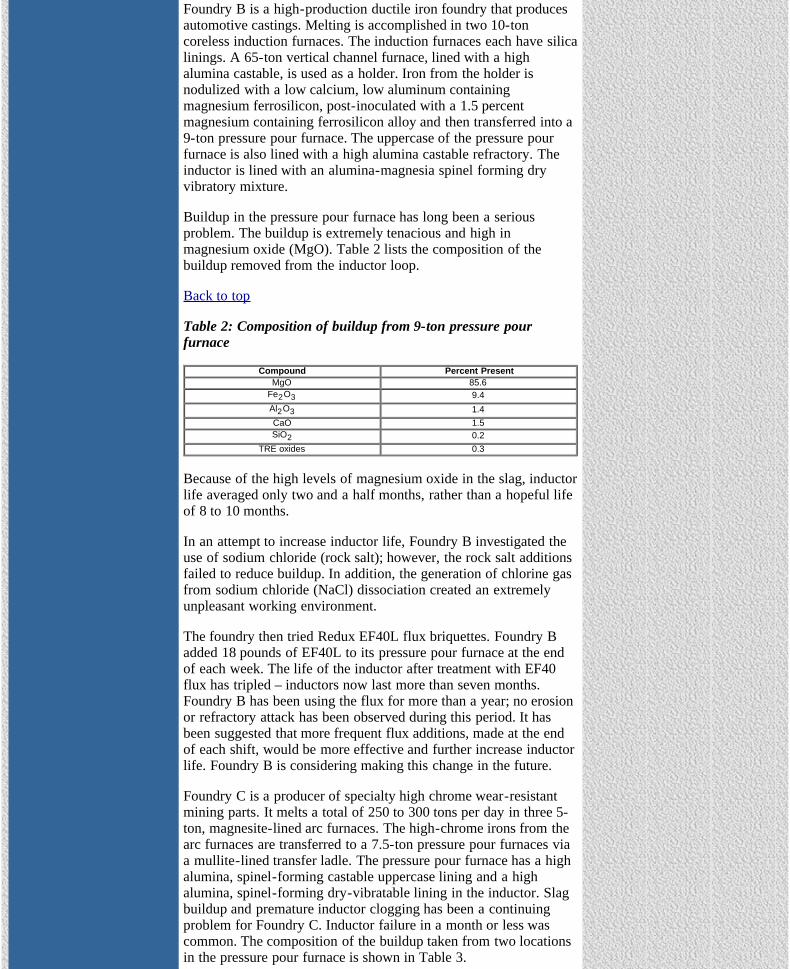
Foundry B is a high-production ductile iron foundry that producesautomotive castings. Melting is accomplished in two 10-toncoreless induction furnaces. The induction furnaces each have silicalinings. A 65-ton vertical channel furnace, lined with a highalumina castable, is used as a holder. Iron from the holder isnodulized with a low calcium, low aluminum containingmagnesium ferrosilicon, post-inoculated with a 1.5 percentmagnesium containing ferrosilicon alloy and then transferred into a9-ton pressure pour furnace. The uppercase of the pressure pourfurnace is also lined with a high alumina castable refractory. Theinductor is lined with an alumina-magnesia spinel forming dryvibratory mixture.
Buildup in the pressure pour furnace has long been a seriousproblem. The buildup is extremely tenacious and high inmagnesium oxide (MgO). Table 2 lists the composition of thebuildup removed from the inductor loop.
Back to top
Table 2: Composition of buildup from 9-ton pressure pourfurnace
Compound Percent PresentMgO 85.6
Fe2O3 9.4Al2O3 1.4CaO 1.5SiO2 0.2
TRE oxides 0.3
Because of the high levels of magnesium oxide in the slag, inductorlife averaged only two and a half months, rather than a hopeful lifeof 8 to 10 months.
In an attempt to increase inductor life, Foundry B investigated theuse of sodium chloride (rock salt); however, the rock salt additionsfailed to reduce buildup. In addition, the generation of chlorine gasfrom sodium chloride (NaCl) dissociation created an extremelyunpleasant working environment.
The foundry then tried Redux EF40L flux briquettes. Foundry Badded 18 pounds of EF40L to its pressure pour furnace at the endof each week. The life of the inductor after treatment with EF40flux has tripled – inductors now last more than seven months.Foundry B has been using the flux for more than a year; no erosionor refractory attack has been observed during this period. It hasbeen suggested that more frequent flux additions, made at the endof each shift, would be more effective and further increase inductorlife. Foundry B is considering making this change in the future.
Foundry C is a producer of specialty high chrome wear-resistantmining parts. It melts a total of 250 to 300 tons per day in three 5-ton, magnesite-lined arc furnaces. The high-chrome irons from thearc furnaces are transferred to a 7.5-ton pressure pour furnaces viaa mullite-lined transfer ladle. The pressure pour furnace has a highalumina, spinel-forming castable uppercase lining and a highalumina, spinel-forming dry-vibratable lining in the inductor. Slagbuildup and premature inductor clogging has been a continuingproblem for Foundry C. Inductor failure in a month or less wascommon. The composition of the buildup taken from two locationsin the pressure pour furnace is shown in Table 3.

The Ductile Iron News
file:///C|/WEBSHARE/062013/magazine/2004_1/slag_buildup.htm[7/1/2013 10:32:01 AM]
Table 3: Composition of samples removed from a 7.5- tonpressure pour furnace
Compound Slag from PP Build-up from PPAl2O3 60.9% 76.5%Fe2O3 9.5 4.6MgO 7.2 4.8
Cr2O3 11.1 5.9SiO2 5.2 5.1MnO 4.8 2.6
After consulting with its refractory supplier, Foundry C purchased2,000 pounds of Redux EF40L flux for a trial. After using theinitial sample, Foundry C found that the slag buildup wasconsiderably softer and could be more easily removed with periodic"rodding" of the inductor channel. Without the flux addition, thebuildup was "rock" hard and almost impossible to scrape loosefrom the walls and inductor throat. The foundry stated that beforethey switched to the Redux EF40L flux, rodding the inductorproduced marginal and inconsistent results. Before the change toRedux EF40L flux, inductor current often dropped to as little as360 amps, from the normal level of 480 amps.
Back to top
Foundry C has been using the Redux EF40L flux for close to oneyear. One pound of Redux EF40L is added per ton of metal melted.The flux briquettes are added into the transfer ladle, the ladle isslagged off and then the molten metal is transferred into the 7.5-tonpressure pour furnace. Flux additions are made to every ladle; asmany as 60 taps of 5 tons each per day are treated with fluxadditions. Foundry C has found that although some buildup remainsin the inductor loop, it is soft and easily removed. Current readingsnow consistently run between 460 to 480 amps. Foundry C'sinductor replacement target is now six to eight months. Thefoundry also plans to modestly increase flux additions to thetransfer ladle in hopes of reducing the amount of soft slag that stillforms in the pressure pour furnace.
Foundry D is a large high production foundry that produces bothgray and ductile automotive and truck castings. Melting isaccomplished in two 121-inch cupolas with a melt capacity of3,000 tons per day. The metal handling system is composed of three150-ton capacity rotary drum channel furnaces, four 15-ton transferladles and four 25-ton tilt pour furnaces on the molding lines.Because of the high volume, slag buildup in the treatment andholding vessels has been a continuous battle. Buildup also occurredin the inductors of all three rotary drum-holding furnaces and, to alesser extent, in transfer ladles. However, the major problem areawas significant buildup in the 12-ton Fisher converters anddownstream tilt pour furnaces.
Buildup in the Fisher converter was severe and converter life beforelining maintenance was two days of operation, or roughly 2,600tons of processing. Buildup between 12 to 18 inches thick in theconverter body was normal, and was of sufficient magnitude toreduce the working volume of the converter by almost 4,000 lbs pertreatment. Chamber plate buildup was also a problem, necessitatingweekly replacement. Emulsified slag carryover from the convertersalso reduced the efficiency of the tilt pour furnaces and inductorclogging became troublesome.

The Ductile Iron News
file:///C|/WEBSHARE/062013/magazine/2004_1/slag_buildup.htm[7/1/2013 10:32:01 AM]
To solve these problems, Foundry D adds 11 pounds of ReduxEF40L flux directly to the body of the Fisher converters prior toeach magnesium treatment. Buildup in the converters has beendrastically reduced. Converter life is now approaching five daysbefore routine refractory maintenance is needed. Buildup is nowonly about an inch in thickness. Foundry D reports that the siliconcarbide refractory chamber plate looks almost brand new after6,500 tons of ductile processing. Further, buildup in the tilt pourfurnaces from magnesium oxide carryover has been greatlyreduced.
Foundry E is a medium size ductile iron foundry producingautomotive castings. Foundry E melts with three 9-ton, mediumfrequency induction furnaces lined with a silica refractory. Dailyproduction is 250 tons. Ductile iron is produced using the sandwichtechnique; treatments are 6,000 pounds. Significant buildup in thetreatment ladle occurred along with slag carryover in the two 8.5-ton pressure pour furnaces. A ladle flux based on a blend ofcalcium fluoride and ferrosilicon fines was initially used as a ladleflux with marginal results. Ladle life was limited to a maximum ofthree shifts before buildup in the ladle and ladle pocket preventedits continued use. Further, slag carryover and buildup in thepressure pour furnaces significantly reduced inductor life. In fact,buildup became so bad that a hot spot in one of the pressure pourfurnace’s inductor caused a serious run-out.
Back to top
To eliminate these problems, Redux EF40L was incorporated intothe magnesium treatment process. The Redux EF40L flux is addedwith the magnesium ferrosilicon at the rate of 0.66 pounds per tonof metal. Incoming ductile treatment temperature is 2,700oF.
Starting with a new ladle lined with a 70 percent alumina castablerefractory, Foundry E quickly discovered that their sandwich ladlesnow last three full days of production or nine shifts beforerefractory maintenance is required.
Redux EF40L flux also has a carryover effect on the pressure pourfurnaces. The pressure pour uppercase is lined with a 90 percentalumina castable refractory and the inductor is lined with a highalumina, spinel-forming dry-vibratable refractory. Slag buildup inthe inductor loop of the pressure pour furnace has beensignificantly reduced.
Foundry F is a captive foundry pouring gray, ductile and high alloyirons for the mining, transportation and oil well industries. FoundryF operates two 55-ton vertical channel furnaces for melting Class30 grey iron. Pouring temperature is 2700oF. Each furnace has one1,750-kilowatt double loop inductor attached to the bottom. Bothuppercases are lined with a zoned lining of dry-vibratablerefractories that include an alumina-based mix in the sidewalls anda chrome-alumina in the floor and throat. Each inductor contains adry vibratable magnesia-based, spinel-forming mix. Average lininglife is approximately 12 to 14 months. Typical conductancereadings from the inductor will be between 72 to 85 percent duringnormal operation after several months of operating.
Recently, Foundry F developed a severe buildup problem in thethroats of both furnaces in a matter of 48 to 72 hours. One of the

The Ductile Iron News
file:///C|/WEBSHARE/062013/magazine/2004_1/slag_buildup.htm[7/1/2013 10:32:01 AM]
furnaces, which was only 3 months into a service campaign, hadthe conductance ratio drop from 80 percent to below 60 percent ina 24-hour period. Continued operation of this furnace caused theconductance ratio to drop below 55 percent. The foundry was readyto take the furnace out of service. The second furnace was showinga similar drop in conductance ratio but not as severe; conductanceratios declined to 65 percent. Foundry F took many slag samplesbefore and after the occurrence and found that the silica andcalcium oxide content of the slag had increased. Many differentmethods of buildup removal were tried including green-poling,periodic superheating of the inductor and oxidized steel additionson a low molten metal level. Nothing reduced the buildup and theconductance ratio continued to drop.
Foundry F contacted their refractory supplier who recommendedthe use of Redux EF40L flux. The foundry decided to try the ReduxEF40L as a last resort before removing both furnaces fromoperation. By this time, the conductance ratio had dropped to lessthan 50 percent on one furnace. Twenty pounds of Redux EF40Lflux was added to 20 tons of molten metal left in the furnace.During this period, furnace operators superheated the molten metalto 2825oF for 2 hours. Furnace charges were reduced by 50 percentto 1,500 pounds and 1.75 pounds of Redux EF40L flux was addedwith each charge. Within the first 24 hours, the conductance ratiohad improved to 65 percent. After 72 hours, the conductance ratioimproved to 73 percent, which was considered acceptable.Recently, the molten metal level within both furnaces was droppedin order to inspect the refractory sidewalls for any sign of erosionfrom the flux and none was observed. This furnace continues tooperate satisfactorily.
Foundry G is a gray and ductile iron producer of continuous-castbar stock. They currently pour between 250 and 300 tons of ironper day. One particular alloy produced at Foundry G generates atremendous amount of ladle slag. The metal pourers know thatwhen this alloy is scheduled for production that it’s going to be adifficult day. Typically, the 1,800-pound ladles will completelybridge with slag at the top of the ladle. This occurs every few hoursand requires constant chipping by the operators as they try tomaintain ladle functionality. The chipping of the slag off thesidewalls and spout is hot, dirty and tedious work and an ongoingbattle during the melting campaign.
Starting with a new 1,800 pound castable alumina-lined ladle, onehalf pound of Redux EF40L flux was added to the pouring ladle.Within the first hour of operation, it was apparent that slag buildupon the sidewalls and spout was virtually eliminated. After 3 hoursof operation, the ladles showed only a slight slag buildup at themetal line and no chipping was required. Foundry G ran an entireshift adding Redux EF40L to their ladles. At the end of the eighthour-shift, the iron pourers needed to chip the ladles just once.Foundry G now uses Redux EF40L on a regular basis.
Other U.S. foundries with coreless induction furnaces havereported similar operating benefits after using Redux EF40L flux.The foundries have stated that using Redux EF40L flux on a dailybasis consistently results in cleaner pouring ladles and reducedmaintenance. One ductile iron producer reported that adding 1pound of EF40L flux to his treatment pocket during the course of aweek resulted in negligible slag and dross buildup.

The Ductile Iron News
file:///C|/WEBSHARE/062013/magazine/2004_1/slag_buildup.htm[7/1/2013 10:32:01 AM]
Back to top
Redux EF40L flux may also help to remove the harmful trampelement boron from ductile base iron. Boron levels as low as 20parts per million (ppm) have been reported to significantly reduceBrinnel Hardness values of pearlitic ductile irons. Theoreticalthermodynamic reactions studied by Martin Gagne from Rio TintoIron and Titanium indicate boron removal with sodium oxide basedfluxes during melting is possible. (see Ductile Iron News, 2003,issue no. 3).
Recent trials by a pearlitic ductile iron producer have producedsome encouraging results. The addition of two pounds of ReduxEF40L flux per ton of molten metal reduced boron levels by 47%.Additional tests using larger quantities of Redux EF40L flux areplanned at this foundry. In addition, research is underway at CaseWestern Reserve University, sponsored by the Ductile Iron Society,to further define the effectiveness of fluxing boron from pearliticductile irons using Redux EF40L flux.
Conclusions: The incorporation of 0.5 to 2.0 pounds of ReduxEF40L flux per ton of metal has significantly improved theinductor life of pressure pour furnaces, coreless induction andvertical channel furnaces. Redux EF40L has been successfully usedin the production of gray and ductile irons as well as high alloyirons and steels to minimize slag buildup on furnace sidewalls andladles. Using recommended addition rates, Redux EF40L fluxeffectively combats slag buildup without the adverse effects ofaggressive refractory attack or emissions of fluorine or chlorinegases. Flux additions can significantly improve furnaceperformance and prolong useful ladle life.
Acknowledgements: The authors would like to thank Ms. Kelly K.Naro for her assistance in editing the manuscript.
Back to top
View Ductile Iron Related Publications
Located in Strongsville, Ohio, USA15400 Pearl Road, Suite 234; Strongsville,Ohio 44136 Billing Address: 2802 Fisher Road, Columbus, Ohio 43204 Phone (440) 665-3686; Fax (440) 878-0070email:[email protected]

The Ductile Iron News
file:///C|/WEBSHARE/062013/magazine/2004_1/coating.htm[7/1/2013 10:31:39 AM]
To Promote the production and application of ductile iron castings Issue 1, 2004
FEATURES
• Cover
• New Process of DI Production
• Ductile Iron and Wind Energy
• Melt Cold and Pour Hot
• AFS Signs Alliance Agreementwith OSHA
• AFS Aims to Unite theMetalcasting Industry
•Control of Slag and InsolubleBuildup in Ladles, Melting andPressure Pour Furnaces
•Improved Ductile Iron CastingQuality Through Optimized CoatingTechnology
DEPARTMENTS
• News Briefs
• Advertisers
• Back Issues
• DIS Home Page
Improved Ductile Iron Casting Quality Through Optimized Coating Technology
Nick Hodgkinson, Marketing Manager,Foseco Metallurgical Inc.
IntroductionAlthough it is possible to produce castings without the use of arefractory mold or core coating, the optimum application of asuitable coating can dramatically improve casting surface finishand overall component quality. Aside from enhancing castingsurface appearance, the utilization of refractory mold and corecoatings can often result in a reduction or elimination of a numberof casting defects, such as :
metal penetrationsand burn-inmold or core erosiongas defectsmetal – mold reactionssand expansion defects, e.g. veiningmetallurgical defects
With the growing need for higher quality casting finish, morecomplex iron casting designs, lower overall process costs, andincreased productivity, the requirement for higher performancecoating technology is becoming increasingly important.
This paper outlines certain coating technology fundamentals andillustrates through example how advanced coating technology canhelp improve ductile iron casting quality.
Coating Application A fundamental objective when using a refractory coating is toapply a uniform coating layer free from surface imperfections -such as runs or drips - which could later replicate on the final castsurface. The dry refractory layer needs to be of sufficient thicknessto prevent any detrimental interaction between the molten metaland the mold or core substrate during pouring.
Obtaining an even, consistent coating layer application is dependantupon the application method utilized and the coating chemistry - itis important that coating properties are designed to suit theapplication method selected. Though brushing or spraying methodscan obtain good coating application, both these techniques areoperator dependent and consequently prone to inconsistency. It iswidely acknowledged that either dipping or flowcoating techniquesshould be used for reproducible coated cores and molds.
Back to top
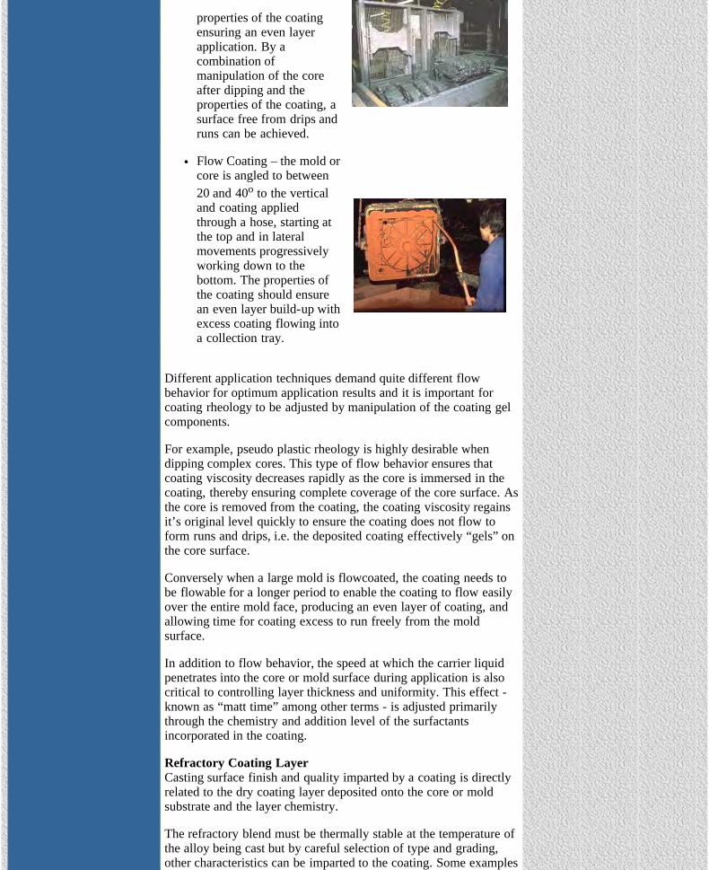
Dipping – the core issubmerged into the coatingand removed within a setperiod of time, the
susan
Rectangle
The Ductile Iron News
file:///C|/WEBSHARE/062013/magazine/2004_1/coating.htm[7/1/2013 10:31:39 AM]
properties of the coatingensuring an even layerapplication. By acombination ofmanipulation of the coreafter dipping and theproperties of the coating, asurface free from drips andruns can be achieved.
Flow Coating – the mold orcore is angled to between20 and 40o to the verticaland coating appliedthrough a hose, starting atthe top and in lateralmovements progressivelyworking down to thebottom. The properties ofthe coating should ensurean even layer build-up withexcess coating flowing intoa collection tray.
Different application techniques demand quite different flowbehavior for optimum application results and it is important forcoating rheology to be adjusted by manipulation of the coating gelcomponents.
For example, pseudo plastic rheology is highly desirable whendipping complex cores. This type of flow behavior ensures thatcoating viscosity decreases rapidly as the core is immersed in thecoating, thereby ensuring complete coverage of the core surface. Asthe core is removed from the coating, the coating viscosity regainsit’s original level quickly to ensure the coating does not flow toform runs and drips, i.e. the deposited coating effectively “gels” onthe core surface.
Conversely when a large mold is flowcoated, the coating needs tobe flowable for a longer period to enable the coating to flow easilyover the entire mold face, producing an even layer of coating, andallowing time for coating excess to run freely from the moldsurface.
In addition to flow behavior, the speed at which the carrier liquidpenetrates into the core or mold surface during application is alsocritical to controlling layer thickness and uniformity. This effect -known as “matt time” among other terms - is adjusted primarilythrough the chemistry and addition level of the surfactantsincorporated in the coating.
Refractory Coating LayerCasting surface finish and quality imparted by a coating is directlyrelated to the dry coating layer deposited onto the core or moldsubstrate and the layer chemistry.
The refractory blend must be thermally stable at the temperature ofthe alloy being cast but by careful selection of type and grading,other characteristics can be imparted to the coating. Some examples

The Ductile Iron News
file:///C|/WEBSHARE/062013/magazine/2004_1/coating.htm[7/1/2013 10:31:39 AM]
are :-
High Insulation – a highly insulating coating layer can delaythe thermal expansion of a silica sand substrate long enoughto prevent sand expansion defects such as veining.Lustrous Carbon – inclusion of lustrous carbon formingagents improve the surface finish of most iron castings.Metallurgical Modifiers – the inclusion of active componentsin the coating can initiate beneficial reactions at the castingsurface e.g. localized grain refinement or the elimination offlake reversion (see later case-study).
Back to top
Coating Process ControlThe main goal in production is to achieve a consistently applied drylayer thickness on each and every coated core or mold. Thisthickness will have been pre-determined through controlled trials togive optimum casting quality. Coating application control is ideallyachieved in two steps - firstly control of the dilute, ready-to-usecoating prior to application and secondly, subsequent measurementof the applied layer thickness on the core or mold surface.
In practice, dry coating layer thickness is often difficult to measureaccurately in a production situation. However for any givencoating, dry layer thickness can be correlated to wet layerthickness, which can be measured easily with a wet thicknessgauge. (Figure 1).
Figure 1 - Measuring the wet thickness layer of a coating
Figure 2 - Measurement of viscosity with a Flow Cup
Figure 3 - Measurement of viscosity with a Baume Stick

The Ductile Iron News
file:///C|/WEBSHARE/062013/magazine/2004_1/coating.htm[7/1/2013 10:31:39 AM]
Back to top
In turn, for a given coating, wet film thickness can be accuratelycorrelated to both flow cup viscosity (Fig 2) and baume (Fig 3)measurements - both these tests can be performed easily andquickly on line and have been found to be adequate in-processcontrol tools.
Case Study: Influence of Coating Chemistry on the Rim-ZoneStructure of a Ductile Iron Casting1
BackgroundThe occurrence of structural anomalies in the casting rim-zone inthe production of ductile iron castings with larger metal cross-sections is not uncommon. Degeneration of the desired spheroidalgraphite structure can occur due to reactions at the metal-moldinterface, which can result in an adverse effect on the resultingcomponent mechanical properties. Under cyclic or dynamicloading, as in the machine or automotive industry, such structuralimperfections can lead to catastrophic failure.
The factors influencing the graphite structure are many2, howeverthe appearance of irregular graphite development has beenobserved notably when using silica sand molds that contain sulfur.
Studies3,4,5 have established that molding sands containing sulfur(i.e. reclaimed sand bonded with furan or phenol binders catalysedby sulfur bearing catalysts ), can be prone to sulfur pick-up in thecast rim-zone, resulting in the presence or promotion of flakegraphite.
Experimental ProcedureFor the tests, a U-shaped test casting was used with dimensions 7”x 8” x 5” approx. and weighing 55 lbs. Wall thickness in the areaof the core was around 2 inches. The casting was simulated todetermine solidification times and in-mold temperatures during thecasting process.
Molds were produced in reclaimed sand with known sulfur content(0.1%), and a furan binder catalysed with PTSA was used.
Coatings with four different combinations of refractory fillermaterials were tested, with an applied dry layer thickness of0.2mm. The properties of the coating refractory filler materials canbe seen in Table 1.
Table 1 : Properties of Coating Refractories Investigated.
BaseMaterial
Densityg/cm3
RawDensityg/cm3
Porosity S content C content
A AluminumSilicate 2.70 1.05 0.611 0.027 1.50
B ZirconiumSilicate 4.36 2.33 0.465 0.013 0.83
C Coke Flour 2.21 1.16 0.475 0.082 25.70
DZirconium &Magnesium
Silicate4.15 2.11 0.491 0.010 2.34
Back to top
Casting Results Metallurgical structure was checked using micrographs of samples

The Ductile Iron News
file:///C|/WEBSHARE/062013/magazine/2004_1/coating.htm[7/1/2013 10:31:39 AM]
taken from an identified “hot spot” location of the casting. Themolds that were coated with Coating A (Figure 4a.) and Coating B(Figure 4b.), showed defective development of the graphitestructure in the casting rim zone, mainly in the form of flakegraphite.
With Coating C (Figure 4c.) no flake graphite was observed but thenodule structure is significantly disturbed. In the rim-zone manyrelatively small nodules can be seen compared to the othercoatings. This effect can be classified as inoculation by the coating.
Best nodule structure results were obtained with Coating D (Figure4d.).
Figure 4 - Casting structures using Coatings A,B,C & D
Further InvestigationTo further assess the effect of coating chemistry, samples ofresidual coating were taken from the surface of the casting at thehot spot area location, and the casting was also machined to 0.5mmand 1.0mm respectively. Coating and metal samples were thentested for sulfur level (see Figures 5 and 6)
Figure 5 - Sulfur % content of Coating samples before and afterpouring

The Ductile Iron News
file:///C|/WEBSHARE/062013/magazine/2004_1/coating.htm[7/1/2013 10:31:39 AM]
Figure 6 - Sulfur % content of casting at different sections
Back to top
In contrast to Coatings A, B,&C, the sulfur content of Coating Dshowed a dramatic increase of approximately twenty times itsinitial value after pouring (Figure 5), while the rim-zone metalsection from the casting produced using Coating D showed agreatly reduced sulfur level compared to the effect of othercoatings (Figure 6).
These results provide strong evidence that the superior graphitestructure observed at the rim-zone when using Coating D is a directresult of the coatings inherent ability to effectively block sulfurmigration from the mold sand through to the metal skin.
To further assess the effectiveness of Coating D, sulfur level withinthe molding sand was manipulated to higher levels by varying thePTSA catalyst and reclaim sand processing parameters. Samples ofmold sand, coating and metal were then assessed for sulfur contentfrom the hot spot location of the casting (Figures 7, 8 and 9.).
Figure 7 - Sulfur % content of furan bonded sand.

The Ductile Iron News
file:///C|/WEBSHARE/062013/magazine/2004_1/coating.htm[7/1/2013 10:31:39 AM]
Figure 8 - Sulfur % content of Coating D
Figure 9 - Sulfur % level of Casting
Back to top
Final ResultsAfter casting, the sulfur content of the molding sand was recordedat between 0.014 and 0.030% (Figure 7), indicating that in all casesthe sulfur in this area of the mold was almost completely burnt out.
The sulfur content in Coating D after casting was approximatelythree times the initial values in the molding sand for the trial M1(S=0.1%) and M2 (S=0.15%). However, when the sulfur content ofthe molding sand was increased to 0.20% (M3) and above, onlyabout twice the sulfur level was measured in the coating (Figure 8).
Sulfur analysis of metal sections taken at a depth of 0.5mm and1.0mm from the cast surface (Figure 9) showed that sulfur level inthese areas was kept below 0.05% when sulfur content was 0.15%or less within the molding sand. The sulfur level at the casting rim-zone increased steadily as the molding sand sulfur level increasedabove 0.20%.
No significant graphite flake reversion was observed with amolding sand sulfur content of up to 0.20%, when using Coating Dat the nominal 0.2mm dry layer thickness. At higher sulfur levels inthe mold or core sand the ability of the coating to absorb sulfur inthe coating layer is progressively less effective and rim-zonegraphite structure degeneration more likely.
It is anticipated that, at molding sand sulfur levels above 0.20%,greater resistance to graphite flake reversion would be achievedthrough the application of a slightly heavier layer of Coating D.
SummaryAside from enhancing casting surface finish quality, refractorymold and core coatings can be used to prevent many differentcasting defects. In all situations a carefully selected refractorycombination and uniform, consistent coating application behavior isvital for quality casting finish and integrity.
Through close attention to the process requirements of the modernfoundry, refractory coatings have been developed which suppressor eliminate totally costly defects such as veining and localisedmetal penetration.
As the case study outlines, inherent casting metallurgical propertiescan also be enhanced. The application of a suitable refractory
The Ductile Iron News
file:///C|/WEBSHARE/062013/magazine/2004_1/coating.htm[7/1/2013 10:31:39 AM]
coating at a nominal 0.20mm thickness can help prevent graphitereversion at the rim-zone of the casting when the molding sandcontains up to 0.2% sulfur content.
Acknowledgements:T.Birch, Foseco Europe.
References:
[1] Sluis J.R. : Giesserei 84 (1997) No.6, p. 9-13[2] Reifferscheidt K. : Dr. – Ing.-Dissertation 1991.[3] Barton R. : Giesserei 65 (1978) No.11, p. 294-301.[4] Bauer W. : Giesserei – Rundschau 28 (1981) No.10, p.11-19[5] Karsay S.J.; Martin F. : Giesserei-Praxis (1981) No.12, p. 218-224.
Back to top
View Ductile Iron Related Publications
Located in Strongsville, Ohio, USA15400 Pearl Road, Suite 234; Strongsville,Ohio 44136 Billing Address: 2802 Fisher Road, Columbus, Ohio 43204 Phone (440) 665-3686; Fax (440) 878-0070email:[email protected]

The Ductile Iron News
file:///C|/WEBSHARE/062013/magazine/2004_1/nbriefs.htm[7/1/2013 10:32:04 AM]
To Promote the production and application of ductile iron castings Issue 1, 2004
FEATURES
• Cover
• New Process of DI Production
• Ductile Iron and Wind Energy
• Melt Cold and Pour Hot
• AFS Signs Alliance Agreementwith OSHA
• AFS Aims to Unite theMetalcasting Industry
•Control of Slag and InsolubleBuildup in Ladles, Melting andPressure Pour Furnaces
•Improved Ductile Iron CastingQuality Through Optimized CoatingTechnology
DEPARTMENTS
• News Briefs
• Advertisers
• Back Issues
• DIS Home Page
News BriefsMEETINGS - BUSINESS - PEOPLE
MEETINGS
Ductile Iron Society 2004 Annual Meeting. June 23-25, 2004 at the DeltaMontreal Hotel in Montreal Quebec Canada. Events include a tour of theQIT Sorel Plant of Rio Tinto.
BUSINESS
Ashland Casting Solutions enters into marketing agreement withDakota International, Inc.
Dublin, Ohio (USA) – Ashland Casting Solutions, a business group ofAshland Specialty Chemical Company, announced today that it hasentered into a global marketing agreement with Dakota International Inc.The agreement will allow Ashland Casting Solutions to market anddistribute Dakota International’s complete line of Dakota scrubber systemsto its worldwide metal casting customer base.
Dakota International, Inc., a leader in cold box scrubber technology in theNorth American metal casting industry, offers turnkey scrubber systemsthat trap and remove amine catalyst gases from the cold box core-makingprocess. Dakota’s scrubber systems are compliant with the emissions,data logging and compliance confirmation aspects of the MACT standardfor iron and steel foundries.
By adding Ashland’s patented ISOCYCLE® recycling program, which isdesigned specifically to handle spent scrubber solution containing aminecatalysts, Casting Solutions can offer its customers a complete packagefor effectively managing the amine catalyst waste stream, and maintainingcompliance with the industry’s environmental requirements.
Ashland’s HOODSTACK® emissions analysis program is also available forcustomers who require assistance in determining emission control andpermit requirements.
“Our agreement with Dakota International is a strategic addition to ourmetal casting product offering that is designed to create value and provideintegrated solutions to the casting industry,” states Mike Swartzlander, vicepresident, Ashland Specialty Chemical Company, and general manager,Ashland Casting Solutions. “The Dakota scrubbers line combined with ourexisting environmental services further strengthens our commitment tohealth, safety and environmental protections at our customers’ facilities aswell as our own.”
About AshlandAshland Casting Solutions, a business group of Ashland SpecialtyChemical Company, is a leader in supplying products, processes andtechnologies to the global metal casting marketplace. The group hasoperations (including licensees and joint ventures) in 21 countries.
Ashland Specialty Chemical Company, a division of Ashland Inc., is aleading, worldwide supplier of specialty chemicals serving industriesincluding adhesives, automotive, composites, metal casting, merchantmarine, paint, paper, plastics, watercraft and water treatment. Visit
susan
Rectangle

The Ductile Iron News
file:///C|/WEBSHARE/062013/magazine/2004_1/nbriefs.htm[7/1/2013 10:32:04 AM]
www.ashspec.com to learn more about these operations.
Ashland Inc. (NYSE:ASH) is a Fortune 500 transportation construction,chemicals and petroleum company providing products, services andcustomer solutions throughout the world. Find us at www.ashland.com.
® Registered trademark, Ashland Inc.
Ashland Purchases Metal Casting Technology from Blackhawk
DUBLIN, Ohio (USA) — Ashland Specialty Chemical Company, adivision of Ashland Inc., has announced it has signed an agreementwith Blackhawk Specialty Products in Rock Island, Ill., to purchaseits metal casting technology over the next three years.
The purchase includes formulations and technology for core andmold release agents, green sand release agents and metal cleaners,which will be incorporated into the Casting Solutions businessgroup. Blackhawk has been producing these mold release agentsand metal cleaners under contract for Ashland since 1992.
“This acquisition strengthens our global position for offeringworld-class, high-performance release agents and metal cleaners tothe marketplace, providing improved productivity for metalcasters,” said Michael W. Swartzlander, vice president of AshlandSpecialty Chemical, and general manager of Casting Solutions.“This is part of the total solution package offered by CastingSolutions, which includes binders, coatings, sleeves, sand additives,core and mold simulation software, and technical support anddesign services. Ashland continues to broaden the scope ofproducts offered to the metal casting industry with investment andcontinuing R&D for metal casting consumables.”
Casting Solutions is pursuing globalization of the technology, withplanned manufacturing start-up projects at its facilities worldwide.
Dear Friends,I am closing Foundry Information Systems in order to reorganizeour services on a less burdensome business model. With the amountof business these last few years it doesn’t make sense to beburdened with the legal requirements of Incorporation or therequired bookkeeping. Most of the services offered by FIS will stillbe available, and paid for service contracts will be honored.
It will take a few weeks to get everything back up to speed. Pleasebear with us.
Sincerely,David Sparkman
Back to top
PEOPLE
Back to top
View Ductile Iron Related Publications
Located in Strongsville, Ohio, USA15400 Pearl Road, Suite 234; Strongsville,Ohio 44136 Billing Address: 2802 Fisher Road, Columbus, Ohio 43204 Phone (440) 665-3686; Fax (440) 878-0070
Related Documents