Welcome message from author
This document is posted to help you gain knowledge. Please leave a comment to let me know what you think about it! Share it to your friends and learn new things together.
Transcript
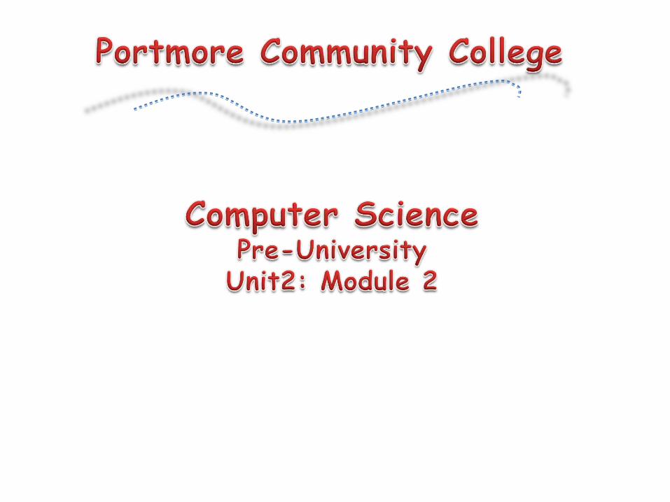
Paper 1: 30% (1 hour and 30 minutes)Examined on each module of syllabus –total 45 marks• Forty-five multiple choice items
Paper 2: 50% (2 hours and 30 minutes)Examined on all sections of syllabus –total 150 marks• Six compulsory structured questions
Section I –two from module I (50 marks) Section II -two from module II (50 marks) Section III –two from module III (50 marks)
Paper 3: 20% (IA)• Examined on modules 1 and 2 –total 60 marks

Software Engineering. Ian Sommerville.Understanding Computer Science for Advanced Level. Ray Bradley.Discovering Computers. Shelly, Cashman, & Vermaat
Skills Ability to...
Knowledge & Comprehension
Identify, recall, match, compare, or explain terms related to general principles, among others
Application & Analysis Use facts, identify and interpret relationships, or formulate conclusions, among others
Synthesis & Evaluation Make judgements and recommendations, use computer to solve problems, justify the use of techniques or apply solutions to problems, among others
Programming –Procedural ‘C’ IDE)1st ENTER THE FOLLOWING IN ADDRESS BAR: http://www.cygwin.com/setup.exe2nd CHOOSE SAVE, THEN EXECUTE/OPEN THE SAVED FILE.3rd ENTER THE FOLLOWING IN ADDRESS BAR: http://www.contexteditor.org/downloads/ConTEXTv0_986.exe4th CHOOSE SAVE, THEN EXECUTE/OPEN THE SAVED FILE.
Note: We will use the Cygwin program, an emulation of a Linux environment on Windows, for compiling our C programs -using the GCC compiler; and we’ll use the ConTEXT program as an editor for writing our source codes.
Although this unit of the syllabus does not build extensively on concepts obtained in Unit 1, it serves the purpose of orienting you to other fields of Computer Science. Specifically, it hones your analytical and applicative skills which are required for Software Engineering. In-depth studies focus on core aspects related to the Software Development Life Cycle; exploration of commonly used SDLC approaches; discussion of concepts related to operating systems, and technologies for constructing computer networks; as well as, implementing search and sort algorithms upon abstract data types. This unit also attempts to develop mastery in program development through use of the C programming language.

Feasibility Study

Software Engineering
A feasibility study is really a small-scale analysis of the system, having found its requirements. It differs from a full analysis only in its level of detail. The study involves analysis in most of the tasks of a full systems analysis, but with a narrower focus and more limited time.
The results of the study help the user to decide whether to proceed, amend, postpone or cancel the project –particularly important when the project is large, complex and costly.
The job of the system analyst/software engineer is to pull all information together and present it to the client in the form of a coherent report. Detailed investigation of operational and procedural activities during a feasibility study is very limited.

Software Engineering
Analysts should concentrate on providing the answers to four key questions:• How much? Addressing the cost of the new system• What? Indicating the objectives of the new system• When? Highlighting the delivery timescale• How? Answering the means/procedures to produce new system
During the feasibility study, a number of structured techniques can be used to record the findings in an effective way, and later to present data in a graphical form.
The feasibility study report has to address three levels of feasibility:• Technical feasibility -Is it going to work?• Economicalfeasibility -Are cost and timescales right for the business?• Functional feasibility -Will the solution satisfy the end users?

Software Engineering
The contents of the study should be as follows:
Software Engineering
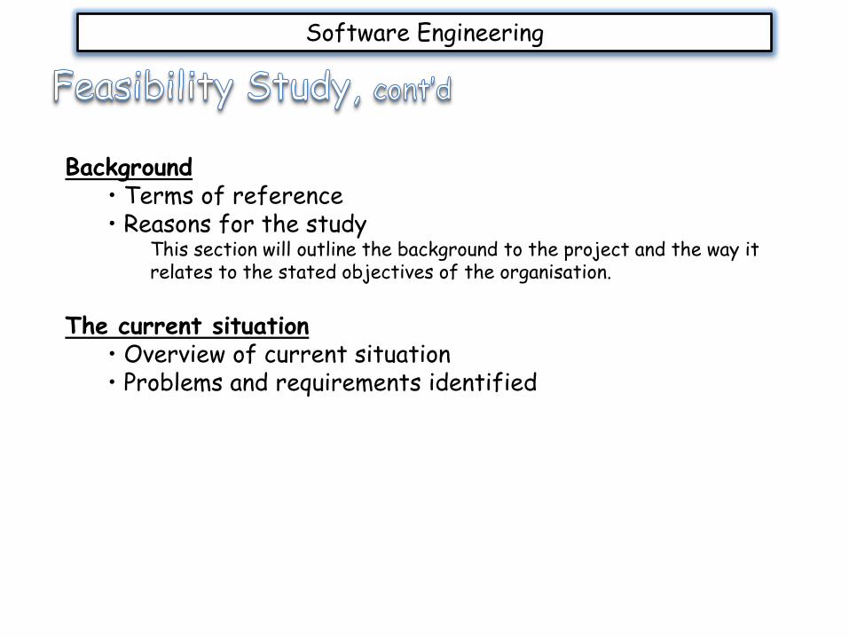
Background• Terms of reference• Reasons for the study
This section will outline the background to the project and the way it relates to the stated objectives of the organisation.
The current situation• Overview of current situation• Problems and requirements identified
Software Engineering
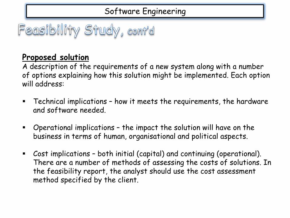
Proposed solutionA description of the requirements of a new system along with a number of options explaining how this solution might be implemented. Each option will address:
Technical implications – how it meets the requirements, the hardware and software needed.
Operational implications – the impact the solution will have on the business in terms of human, organisational and political aspects.
Cost implications – both initial (capital) and continuing (operational). There are a number of methods of assessing the costs of solutions. In the feasibility report, the analyst should use the cost assessment method specified by the client.
Software Engineering
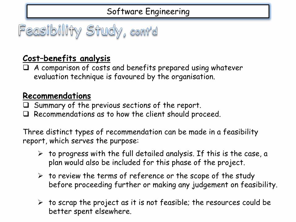
Cost–benefits analysis A comparison of costs and benefits prepared using whatever
evaluation technique is favoured by the organisation.
Recommendations Summary of the previous sections of the report. Recommendations as to how the client should proceed.
Three distinct types of recommendation can be made in a feasibility report, which serves the purpose:
to progress with the full detailed analysis. If this is the case, a plan would also be included for this phase of the project.
to review the terms of reference or the scope of the study before proceeding further or making any judgement on feasibility.
to scrap the project as it is not feasible; the resources could be better spent elsewhere.
Analysis Activities

Software Engineering
Once the user (stakeholder) have agreed to continue with the system’s development, the information gathered from elicitations are then compiled to reflect the current system’s environment and components.
The analyst then use various tool to document their findings to give a graphical modelling of internal and external entities; the common tools used are the:
Data Flow Diagrams Entity-Relationship Diagrams CASE tools Data Dictionaries Decision Table

Software Engineering
Data Flow Diagram: is a graphical representation of how data is processed and how data
flows within a business or organization.
illustrates an overview of the system’s input, output and processes.
Importantly, the data flow diagram (DFD) reflects the logical flow of operations in a system, with the use of four symbols. This logical flow of operation may relate to both the current system and the proposed system.
Usefulness of DFDs: avoids exploration of technical implementation of the system.
gives further understanding of how systems and subsystems are related.A
allows one to share their understanding of how the system works, to the users.
allows analysis of proposed system, determining if necessary data and processes are present.

Software Engineering
DFD Symbols The following are the four basic symbols used to illustrate DFDs. NOTE: No symbol specifies the physical aspect of what has
been/will be implemented.
process entity storage data flow
DFD Rules Data flows should not split into two or more different data flow.
Example A, incorrect Example B, correct

Software Engineering
DFD Rules cont’d All data flows must either originate or terminate at a process. Therefore, the following relationships are incorrect.
DFD Rules cont’d Processes should have at least one input data flow (going to it) and one output data flow (leaving it). Thus, the following are incorrect:
Software Engineering
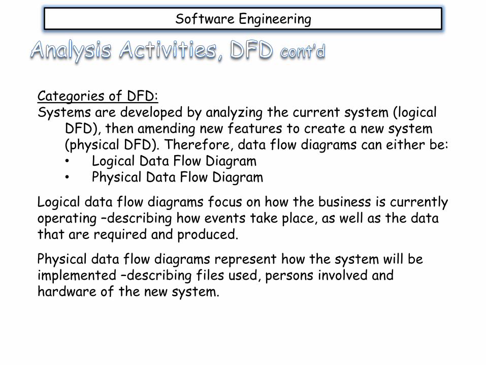
Categories of DFD:Systems are developed by analyzing the current system (logical
DFD), then amending new features to create a new system (physical DFD). Therefore, data flow diagrams can either be:• Logical Data Flow Diagram• Physical Data Flow Diagram
Logical data flow diagrams focus on how the business is currently operating –describing how events take place, as well as the data that are required and produced.
Physical data flow diagrams represent how the system will be implemented –describing files used, persons involved and hardware of the new system.
Software Engineering
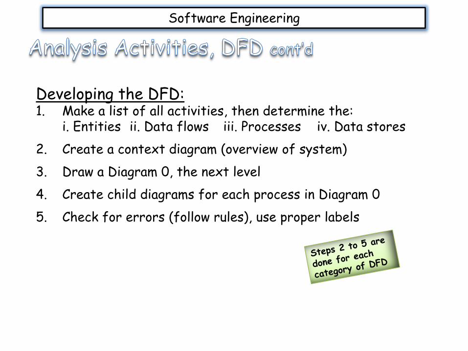
Developing the DFD:1. Make a list of all activities, then determine the:
i. Entities ii. Data flows iii. Processes iv. Data stores
2. Create a context diagram (overview of system)
3. Draw a Diagram 0, the next level
4. Create child diagrams for each process in Diagram 0
5. Check for errors (follow rules), use proper labels

Software Engineering
Creating Context DiagramThese diagrams offer an overview of the data movement in the system.
• It contains one process, that represents the entire system (process zero), along with all external entities
• Data stores are not represented on this diagram
Drawing Diagram 0These diagrams offer a detailed view of the data movement in the system.
• It may contain three to nine processes, that represents the sub-processes of process zero, along with major data stores and all external entities
Creating Child DiagramsThese diagrams offer additional explanation of the sub-processes within Diagram 0; showing that a sub-process cannot produce an output or receive an input that was not received or given
• External entities are not shown; data flows match Diagram 0 data flows; data stores may be represented
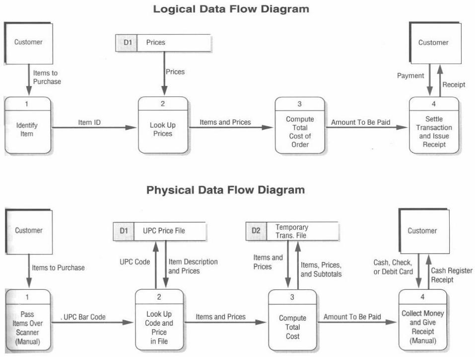
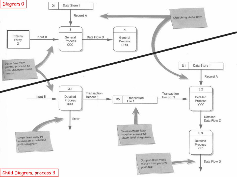
Diagram 0
Child Diagram, process 3
Software Engineering
Entity-Relationship Diagram:These form a model of the user’s environment so that the data are accurate and useful. 1) It is another form of abstraction.2) First and most important step in database design.3) Requires a good understanding of organization being modeled.
Primarily, data modeling is used to specify an external view of the database, whereby modeling the world in terms of:
entities relationships between entities attributes of entities and relationships.
Software Engineering
Key elements of an E-R Diagram:Entity:
A distinguishable thing, person or event.Entity set:
A set of entities of the same type.
Relationship:Representation of the fact that certain entities are related to each other in a specific way.
Relationship set:Set of relationships of a given type.
Attributes:Properties of entities or relationships
Key:An attribute or set of attributes that uniquely identifies each entity in an entity set.
Software Engineering
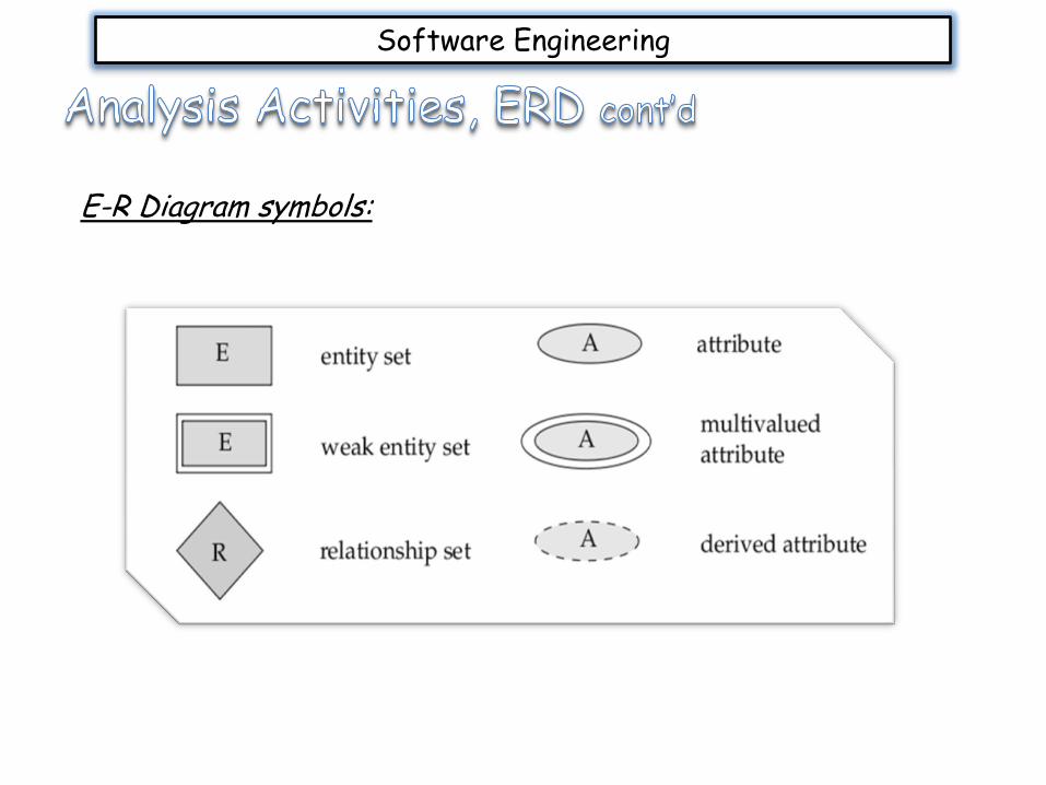
E-R Diagram symbols:
Software Engineering
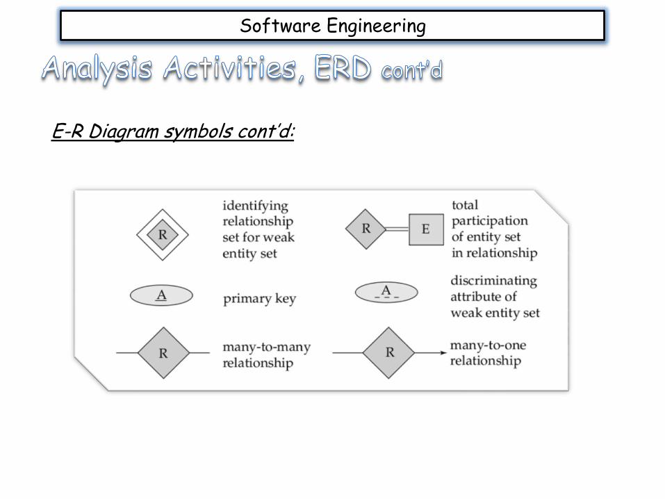
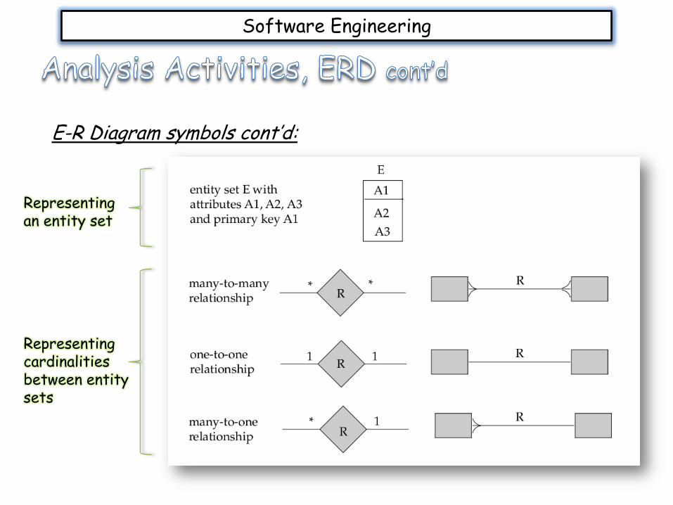
E-R Diagram symbols cont’d:
Software Engineering
E-R Diagram symbols cont’d:
Representing an entity set
Representing cardinalities between entity sets

Software Engineering
Computer-Aided Software Engineering (CASE) is software to support software development and evolution processes.
Activity automation includes: Graphical editors for system model development Data dictionary to manage design entities Graphical UI builder for user interface construction Debuggers to support program fault finding Automated translators to generate new versions of a program
Software Engineering
Case technology has led to significant improvements in the software process. However, these are not the order of magnitude improvements that were once predicted
Software engineering requires creative thought - this is not readily automated;Software engineering is a team activity and, for large projects, much time is spent in team interactions. CASE technology does not really support these type of activities.
Software Engineering
Classification helps us understand the different types of CASE tools and their support for process activities.
Functional perspectiveTools are classified according to their specific function
Process perspectiveTools are classified according to process activities that are supported
Integration perspectiveTools are classified according to their organisation into integrated units

Software Engineering
Functional perspective
Tool type Examples
Planning tools PERT tools, estimation tools, spreadsheets
Editing tools Text editors, diagram editors, word processors
Change management tools Requirements traceability tools, change control systems
Configuration management tools Version management systems, system building tools
Prototyping tools Very high-level languages, user interface generators
Method-support tools Design editors, data dictionaries, code generators
Language-processing tools Compilers, interpreters
Program analysis tools Cross reference generators, static analysers, dynamicanalysers
Testing tools Test data generators, file comparators
Debugging tools Interactive debugging systems
Documentation tools Page layout programs, image editors
Re-engineering tools Cross-reference systems, program re-structuring systems
Software Engineering
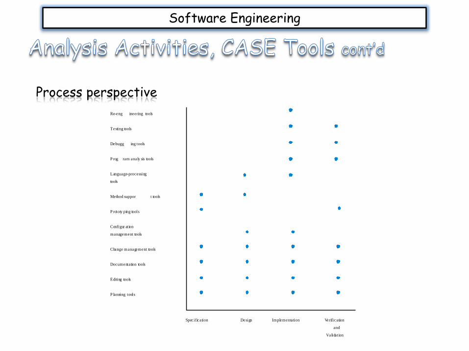
Process perspective
Specification Design Implementation Verification
and
Validation
Re-eng ineering tools
Testing tools
Debugg ing tools
P rog ram analy sis tools
Language-processing
tools
Method suppor t tools
P rototy ping tools
Configur ation
management tools
Change management tools
Documentation tools
Editing tools
P lanning tools
Software Engineering
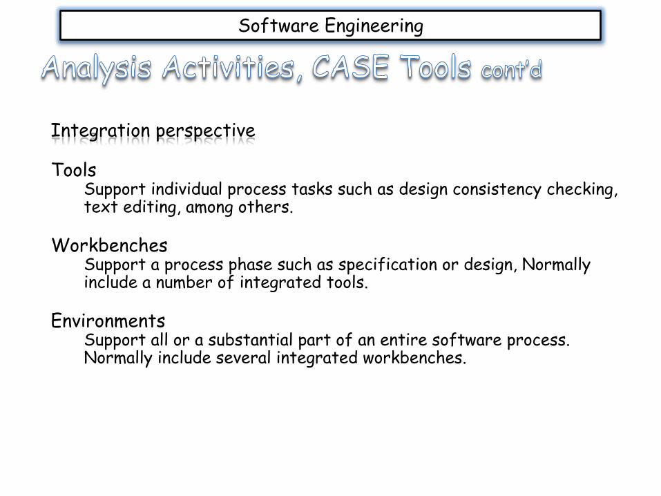
Integration perspective
ToolsSupport individual process tasks such as design consistency checking, text editing, among others.
WorkbenchesSupport a process phase such as specification or design, Normally include a number of integrated tools.
EnvironmentsSupport all or a substantial part of an entire software process. Normally include several integrated workbenches.
Software Engineering
A data dictionary, as its name implies, defines the data used within a system; they are complete and convincing definition of all the data that is used in the system.
In its simplest form, the data dictionary is only a collection of data element that are defined according to a set of descriptions; the descriptions are categorized for the data flow, the data structure, the data element, and the data store.

Software Engineering
Therefore, data dictionaries are developed from:
1. Data flow –are defined based on the system’s input and output
2. Data structure –using a notation to list the composites for a data flow
3. Data elements –members of a data structure that capture the needed information
4. Data stores –the unique record for an entity
Software Engineering
A data dictionary is created by looking closely and then describing the content of the data store, the data flow, and the processes. That is, each data store and each data flow should be described, including the elements that they contain.
Essentially, the data being captured in the data dictionary are those that are stored for future use. However, each data element is defined only once.
Software Engineering
The data dictionary is essentially used to create input and output screens for the system; where the unique names are later used as variables in one’s program.
An important step in creating the data dictionary, is to identify and categorize the system’s input and output data flows; data dictionaries are used along with DFDs to analyse the system’s design, as well as detect flaws and areas that need explanation.
Some explanations, for example, include:
Looking for base elements that must be present on input data flow arrows
Ensuring that derived elements are created by processes
Ensuring elements on data flows, that enter or leave data stores, are contained within the data store

Software Engineering
A data dictionary will include some, if not all of the following, for describing an element:
A unique descriptive name for the data element (the name is a text)
An alias (names that others may use)
A general description of the data element
An indication of whether the element is based (entered into the system, and must be stored) or derived (as a result of a process)
The length, the data type, the input format, as well as the default values of the element
A section for further comments about the data element
Software Engineering
Within the creation of our program, that creates a solution to a problem, it is important for us to understand the logical and structured decisions to be made.
Consequently, we can reduce the ambiguity of our processes; have a clear understanding of what is to be accomplished; as well as validate the design of our computer program.
To therefore design properly structured decisions for our programs we need to know the conditions, the alternatives, actions, as well as actions (rules) to be used in our program.

Software Engineering
To model our decisions, we use decision tables to represent our respective choices.
For example, decision tables are as a result of our if-then-else statements, that associate conditions with actions to be performed.
Typically, decision tables are divided into four quadrants.
Conditions Condition alternatives
Actions Action entries
Software Engineering
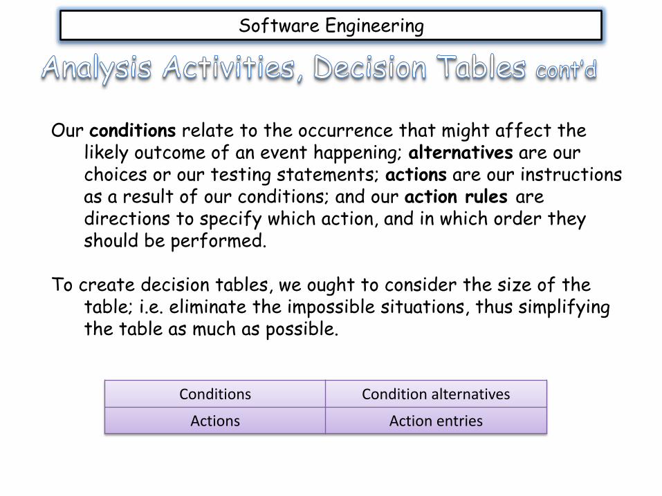
Our conditions relate to the occurrence that might affect the likely outcome of an event happening; alternatives are our choices or our testing statements; actions are our instructions as a result of our conditions; and our action rules are directions to specify which action, and in which order they should be performed.
To create decision tables, we ought to consider the size of the table; i.e. eliminate the impossible situations, thus simplifying the table as much as possible.
Conditions Condition alternatives
Actions Action entries
Software Engineering
The following are steps that can be used to create a decision table:
1. Determine the number of conditions that may affect the decision. The number of conditions becomes the number of rows in the top half of the decision table.
2. Determine the number of possible actions that can be taken. This becomes the number of rows in the lower half of the decision table.
3. Determine the number of alternatives for each condition. In the simplest form of decision table, there would be two alternatives (Y or N) for each condition.
4. Calculate the maximum number of columns in the decision table (for alternatives) by multiplying the number of alternatives for each condition.

Software Engineering
For example, if there were four conditions and two alternatives (Y or N) for each of the conditions, there would be sixteen possibilities (24)
Then divide the number of columns by the number of alternatives for the condition alternatives. Therefore, 16 2 = 8 gives the first set of alternatives.
Condition 1 Y Y Y Y Y Y Y Y N N N N N N N N
Condition 2 Y Y Y Y N N N N Y Y Y Y N N N N
Condition 3 Y Y N N Y Y N N Y Y N N Y Y N N
Condition 4 Y N Y N Y N Y N Y N Y N Y N Y N
Shows the upper half of a decision table, with condition
and condition alternatives
Cashman, T., M. Vermaat, and G. Shelly (2006). Discovering Computer 2007: A Gateway to Information Web Enhanced. Boston: Course Technology Inc .
Sommervile, I. (2007). Software Engineering (Eight Edition). Harlow: Pearson Education, Inc.
Software Engineering
Related Documents