Feasibility Study of Key Components & Algorithm Design for Multi-Material RP&M Machine Syed, I. PhD thesis deposited in Curve June 2015 Original citation: Syed, I. (2011) Feasibility Study of Key Components & Algorithm Design for Multi-Material RP&M Machine. Unpublished Thesis. Coventry: Coventry University Some images have been removed due to third party copyright. There are a number of files also not included with this record. The unabridged version of the thesis can be viewed at the Lanchester Library, Coventry University Copyright © and Moral Rights are retained by the author(s) and/ or other copyright owners. A copy can be downloaded for personal non-commercial research or study, without prior permission or charge. This item cannot be reproduced or quoted extensively from without first obtaining permission in writing from the copyright holder(s). The content must not be changed in any way or sold commercially in any format or medium without the formal permission of the copyright holders. CURVE is the Institutional Repository for Coventry University http://curve.coventry.ac.uk/open

Welcome message from author
This document is posted to help you gain knowledge. Please leave a comment to let me know what you think about it! Share it to your friends and learn new things together.
Transcript

Feasibility Study of Key Components & Algorithm Design for Multi-Material RP&M Machine Syed, I. PhD thesis deposited in Curve June 2015 Original citation: Syed, I. (2011) Feasibility Study of Key Components & Algorithm Design for Multi-Material RP&M Machine. Unpublished Thesis. Coventry: Coventry University Some images have been removed due to third party copyright. There are a number of files also not included with this record. The unabridged version of the thesis can be viewed at the Lanchester Library, Coventry University Copyright © and Moral Rights are retained by the author(s) and/ or other copyright owners. A copy can be downloaded for personal non-commercial research or study, without prior permission or charge. This item cannot be reproduced or quoted extensively from without first obtaining permission in writing from the copyright holder(s). The content must not be changed in any way or sold commercially in any format or medium without the formal permission of the copyright holders.
CURVE is the Institutional Repository for Coventry University
http://curve.coventry.ac.uk/open

Feasibility Study of Key
Components & Algorithm Design
for Multi-Material RP&M Machine
Irtaza Syed
September 2011
The work contained within this document has been submitted
by the student in partial fulfilment of the requirement of their course and award
By

Feasibility Study Of Key Components & Algorithm Design for Multi-Material RP Machine i
ABSTRACT
Sophisticated Rapid Prototyping & Manufacturing (RP&M) systems have been
developed to produce products up to conventional production standards. However,
there are a number of limitations in the current RP&M systems, such as material
choice, component size, software technique, and product quality. Most of the
developed RP&M systems can fabricate objects with one build material and one
support material. There is an increase in demand for an RP&M system which can
fabricate objects with the help of multi-materials (Anderson, 2009). So far there have
been some initial progresses. However, the industry still needs to go a long way until
a complex multi-material RP&M system is developed.
In this dissertation, RP&M technology, its Industrial growth and current development
is reviewed and then critically analysed to develop an understanding of its progress
and issues related to it. Based on the analysis of current research gaps, “Feasibility
Study of Key Components & Algorithm Design for Multi-Material Rapid prototyping
(RP) Machine” is chosen as a proposed research topic. A complete design
methodology is produced to develop a detailed feasibility design for a multi-material
M2-3D Printer nozzle deposition apparatus.
In this dissertation, a multi-material nozzle deposition RP&M system and key
slicing/control algorithms have been designed to handle up to seven materials in a
bid to achieve the flexibility and accuracy during deposition control. Photopolymer is
the material choice which can be deposited in a continuous or drop format.
Deposited material can be fabricated by two UV curing options. The right choice of
UV curing source and its set parameters affect directly the quality of fabrication.
Developed NURBS-based slicing algorithm can maintain the geometrical accuracy of
original CAD model and to support multi-material RP&M technology. In addition, a
nozzle change algorithm is also developed to reduce the build time of fabrication and
to support the design of M2-3D Printer.
Developed multi-material slicing and its nozzle control algorithm will reduce the
processing time, data storage space and overall improve the quality of fabricated
objects in the proposed M2-3D Printer system. Based on that, the design of nozzle
deposition system, its slicing and control algorithms can be further developed to be
used in a future M2-3D Printer system.

Feasibility Study Of Key Components & Algorithm Design for Multi-Material RP Machine ii
ACKNOWLEDGEMENTS
Firstly, I would like to thank God for granting me His strength throughout this project.
I would like to take this opportunity to thank everyone who has helped me with my
chosen project. I would in particularly like to thank Dr Weidong Li my project
supervisor at Coventry University for his direction, help and patience with this
project. I am very appreciative to Dr. Colin Page (late) my second supervisor for his
advice and guidance through out the project. In addition, a special thanks to the
research student Guo-qing Jin and the Jaguar research support centre at the
Coventry University for providing resources to help me at many stages during the
project. A special thanks to Miss Sehar Chaudary for proof reading.
I would also like to thank my beloved mother and my wife Faezah who have always
believed in me, supported me and kept me motivated throughout my studies. I am
also in dept for the prayers and support I have received from my beloved family and
friends.

Feasibility Study Of Key Components & Algorithm Design for Multi-Material RP Machine iii
CONTENTS PAGE
ABSTRACT I
ACKNOWLEDGEMENTS II
CONTENTS PAGE III
GLOSARY VI
LIST OF DIAGRAM VIII
LIST OF TABLES XIII
Chapter 1 – Introduction 1
1.1 Background 1
Rapid Prototyping & Manufacturing (RP&M) techniques 1
Rapid Prototype (RP) 2
Rapid Manufacturing (RM) 3
Development of RP&M 3
Applications 4
1.2 Problem Definition 4
1.3 Working Scope 5
1.4 Rationale 5
1.5 Aims and Objectives 6
1.6 Chapter Organisation 7
Chapter 2 - Literature Review 8 2.1 Historical development of RP&M Technology 8
Historical development 8
Market analysis 8
RP&M material sales 9
RP&M system sales 10
New generation Rapid Manufacturing 11
Application of RP&M 12
2.2 Existing RP Technology 14
2.2.1 Liquid Based RP&M Systems 14
3D Systems’ Stereo lithography Apparatus (SLA) 15
Liquid Bases RP&M System Comparison 16
2.2.2 Solid Based RP&M Systems 17
Stratasys’ Fused Deposition Modelling (FDM) 17
Solid Bases RP&M System Comparison 19
2.2.3 Powder Based RP&M Systems 20
3D Systems’s Selective Laser Sintering (SLS) 20

Feasibility Study Of Key Components & Algorithm Design for Multi-Material RP Machine iv
Powder Bases RP&M System Comparison 21
2.3 Multi Material Fabrication in RP&M 21
Research of Multi Material Fabrication Process 22
2.4 Functionally Graded Material Fabrication 26
Research of Multi Material Fabrication Process for FGM
objects 26
Chapter 3 - Research Gap Analysis 31 3.1 Brief Summary of RP&M Technology and its Industry Growth 31
Challenges Related to RP&M 31
3.2 Major Research Gap 32
Multi material nozzle deposition apparatus design 34
Algorithm design for better slicing & control of the Nozzle system 35
Chapter 4 - Methodology 36
4.1 Information gathering 36
4.2 Project Management 37
4.3 Product Design Process 38
Product planning and clarifying the task 38
Concept design 39
Embodiment design 39
Detail design 40
Chapter 5 - Research & Design Justification 41
5.1 Overview of M2-3D Printer 41
5.2 M2-3D Printer Materials 42
Polymers 42
Properties of polymers 42
Factor affecting polymer properties 42
5.3 Polymers to be used in proposed M2-3DP machine 43
Photopolymer 43
Photo polymerisation 44
UV Curing process and its effects on photopolymers 44
5.4 M2-3D Printer - UV light selection criteria 45
M2-3D Printer - Curing process selection for photo polymers 45
5.5 M2-3D Printer – Design 46
5.5.1 Nozzle Deposition System 47
Material Pressure Plate Assembly 48

Feasibility Study Of Key Components & Algorithm Design for Multi-Material RP Machine v
Deposition Control Assembly 49
UV Curing light 50
5.5.2 M2-3D Printer - Process 53
Pre process 53
Build Process 54
Working Example 57
Post Process 58
5.6 Working Principle and Quality Control 59
Quality Control 59
5.8 Case Study 60
Material selection 60
Curing Process selection 62
Polymerisation Process 62
Fluid Dynamics 63
Chapter 6 - Software Development of M2-3DP 65
6.1 STL Format File and its Problems 65
6.2 NURBS Curve 66
6.3 A NURBS-based slicing algorithm 68
An example to illustrate the developed slicing algorithm 70
6.4 A Nozzle Change Algorithm for Two-material Object 70
Compared with the traditional method 73
CONCLUSION 76
Future work and recommendations 79
LIST OF REFERENCES 81
APPENDIX A: Prototyping 87 APPENDIX B: Literature Review - Extended 89 APPENDIX C: Research Analysis - Extended 110 APPENDIX D M2-3DP - Machine Design 116

Feasibility Study Of Key Components & Algorithm Design for Multi-Material RP Machine vi
GLOSSARY
2D = Two-Dimensional
3D = Three-Dimensional
3DP = Three-Dimensional Printing
ABS = Acrylonitrile Butadiene Styrene
AF = Additive Fabrication
BASS = Break Away Support System
BPM = Ballistic Particle Manufacturing
CAD = Computer Aided Design
CAE = Computer Aided Engineering
CAM = Computer Aided Manufacturing
CNC = Computer Numerical Control
CMB = Controlled Metal Build-Up
DFE = Data Front End
DFMA = Design for Manufacture and Assembly
DLP = Digital light processing
DMD = Direct Metal Deposition
DOE = Design of Experiments
DP = Degree of Polymerisation
DSPC = Direct Shell Production Casting
EBM = Electron Beam Melting
EOS = Electro Optical Systems
FDM = Fused Deposition Modelling
FDMC = Fused Deposition of Multiple Ceramic
FFF = Free-Form Fabrication
IGES = Initial Graphics Exchange Specification
IJD = Ink-Jet Deposition
FGM = Functionally Graded Material
LAM = Laser Additive Manufacturing
LEM = Laminated Engineering Materials
LENS = Laser Engineered Net Shaping
LOM = Laminated Object Manufacturing
M2-3DP = Multi-Material 3D Printer
MEM = Melted Extrusion Modelling
MJM = Multi Jet Modelling system

Feasibility Study Of Key Components & Algorithm Design for Multi-Material RP Machine vii
MJS = Multiphase Jet Solidification
M-RPM = Multi Functional Rapid Prototyping and Manufacturing
NURBS = Non-Uniform Rational B-Spline
PLT = Paper Lamination Technology
POM = Precision Optical Manufacturing
RFP = Rapid Freeze Prototyping
RM = Rapid Manufacturing
RP = Rapid Prototyping
RP&M = Rapid Prototyping and Manufacturing
RTM = Rapid ToolMaker
SAHP = Selective Adhesive and Hot Press
SCS = Solid Creation System
SGC = Solid Ground Curing
SLA = Stereo Lithography Apparatus
SLM = Selective Laser Melting
SLS = Selective Laser Sintering
SOUP = Solid Object Ultraviolet laser plotter
SSM = Slicing Solid Manufacturing
STL = StereoLithography File
UC = ultrasonic consolidation
UV = Ultraviolet

Feasibility Study Of Key Components & Algorithm Design for Multi-Material RP Machine viii
LIST OF DIAGRAMS
Figure. 1.1 Rapid Prototyping Wheel 2
Figure. 1.2 RP&M applications 3
Figure. 1.3 RP&M applications with respect to the industry 4
Figure. 1.4 Framework of thesis organisation 7
Figure. 2.1 Estimated revenues for RP&M Industry 9
Figure. 2.2 Photopolymer Material sales 10
Figure. 2.3 RP&M system unit sales 10
Figure. 2.4 RP&M system market share 11
Figure. 2.5 Ibrahim twins' 13
Figure. 2.6 Applications of RP&M technology 13
Figure. 2.7 Schematic of SLA Process 15
Figure. 2.8 Catalyst XP 18
Figure. 2.9 FDM Process 18
Figure. 2.10 ABSplus material 19
Figure. 2.11 ABSi material 19
Figure. 2.12 PPSF/PPSU (polyphenylsufone) material 19
Figure. 2.13 SLS Process diagram 20
Figure. 2.14 FDMC System over view 22
Figure. 2.15 Schematic of FDMC System 22
Figure. 2.16 Schematic of multi-nozzle FDM system 23
Figure. 2.17 Multi-nozzle print head RP system for Multi-material scaffold fabrication
24
Figure. 2.18 Multi-material fabrication process 25
Figure. 2.19 Modified a 3D Systems SL 250/50 RP machine 25
Figure. 2.20 Schematic of a powder delivery apparatus for FGM fabrication 27
Figure. 2.21 Schematic of a 3D printing process for FGM fabrication 27
Figure. 2.22 Schematic diagram of X graded powder deposition system 28
Figure. 2.23 System for FGM fabrication using laser based direct metal deposition
28
Figure. 2.24 Schematic diagram of X graded powder deposition system 29
Figure. 2.25 Set up of DMD Machine 29
Figure. 2.26 Mapping of CAE result to binder distribution of an FGM part 30
Figure. 4.1 Phases of planning and design process 37
Figure. 4.2 Design process activity chart 37
Figure. 4.3 Design process activities - Product Planning & Clarification of Task
38

Feasibility Study Of Key Components & Algorithm Design for Multi-Material RP Machine ix
Figure. 5.1 M2-3D Printer design 42
Figure. 5.2 UV Curing Process 44
Figure. 5.3 Quality of UV light 45
Figure. 5.4 M2-3D Printer Layout 47
Figure. 5.5 Multi-material deposition apparatus 47
Figure. 5.6 Nozzle & sub assemblies 48
Figure. 5.7 Material Pressure Plate Assembly 48
Figure. 5.8 Working principle of pressure plate 49
Figure. 5.9 Working principle of pressure plate 49
Figure. 5.10 Deposition Control Assembly 50
Figure. 5.11 Main UV source 51
Figure. 5.12 Main UV source 52
Figure. 5.13 Spot UV source 52
Figure. 5.14 Graphical representation of UV-process 53
Figure. 5.15 M2-3D Printer design 53
Figure. 5.16 Feeding process 54
Figure. 5.17 Feeding process 55
Figure. 5.18 Z-Axis 55
Figure. 5.19 Nozzle Apparatus 56
Figure. 5.20 Continuous material deposition 57
Figure. 5.21 Curing process 57
Figure. 5.22 Curing process 58
Figure. 5.23 Curing process 58
Figure. 5.24 Accura 40 deposited material 62
Figure. 6.1 A STL format model of human head 65
Figure. 6.2 The two formats of STL file 66
Figure. 6.3 A NURBS curve with 8 control points 67
Figure. 6.4 The comparison between traditional RP&M process and the developed method
68
Figure. 6.5 The flow of generating the NURBS-based contour curve 68
Figure. 6.6 An example to illustrate the developed slicing algorithm 70
Figure. 6.7 The processing for the two-material objects fabrication in RP&M
71
Figure. 6.8 The flowchart of the nozzle change algorithm 72
Figure. 6.9 An example to illustrate the nozzle change algorithm 73
Figure. 6.10 The fabrication processing for the ball in the nozzle change algorithm
74
Figure. B.1 Viper SLA system 92

Feasibility Study Of Key Components & Algorithm Design for Multi-Material RP Machine x
Figure. B.2 Viper Pro SLA system 92
Figure. B.3 Fabricated object 92
Figure. B.4 Viper System 93
Figure. B.5 Accura 60 SLA material pattern 93
Figure. B.6 final cast model 93
Figure. B.7 Jewellery Design 93
Figure. B.8 Schematic diagram of solid ground curing 94
Figure. B.9 Cubital’s Solimer resin 95
Figure. B.10 Features of Cubital’s Solider of DFE software 95
Figure. B.11 Solider Part Properties 96
Figure. B.12 Cubital’s Solider 5600 96
Figure. B.13 Applications of SGC 97
Figure. B.14 Applications of SGC 97
Figure. B.15 SCS Process 97
Figure. B.16 SCS Process 97
Figure. B.17 Dehumidifier(total 5 parts) 98
Figure. B.18 Aluminum wheel (1/2 plated) 98
Figure. B.19 Lost wax master 98
Figure. B.20 Magics Software 98
Figure. B.21 Solid Ware Software 98
Figure. B.22 Variety of Resins 99
Figure. B.23 Light cover 100
Figure. B.24 Large manifold 100
Figure. B.25 Projector Body 100
Figure. B.26 LOM Process 101
Figure. B.27 Performance and functionality parameters 101
Figure. B.28 Variety of Resins 102
Figure. B.29 The main Lomslice screen 102
Figure. B.30 LOM-1015Plus 102
Figure. B.31 Support Removal process 103
Figure. B.32 LOM-2030H 103
Figure. B.33 Engine Block 103
Figure. B.34 Functional Parts 104
Figure. B.35 Support material 104
Figure. B.36 Material Spool 104
Figure. B.37 3D Production systems 105

Feasibility Study Of Key Components & Algorithm Design for Multi-Material RP Machine xi
Figure. B.38 Conceptualisation and functional Model 105
Figure. C.1 Deposition system of FDMC machine 112
Figure. C.2 Schematic of a powder delivery apparatus for FGM fabrication 112
Figure. C.3 Schematic of multi-nozzle FDM system 113
Figure. C.4 Multi-nozzle print head RP system for Multi-material scaffold fabrication
113
Figure. C.5 Multi-material fabrication process 114
Figure. D.1 M2-3DP Machine Design 116
Figure. D.2 M2-3DP Machine Design 116
Figure. D.3 Machine Design – Front View 116
Figure. D.4 Front Panel Cover Assembly 117
Figure. D.5 Top Body Cover 117
Figure. D.6 Back Panel Cover 117
Figure. D.7 Machine with Body Panel Covers 117
Figure. D.8 Machine without Body Panel Covers 117
Figure. D.9 Machine Structure Panel Assembly 118
Figure. D.10 Machine Structure Panels – Exploded View 118
Figure. D.11 M2-3DP Machine Design Layout – Isometric View 119
Figure. D.12 M2-3DP Machine Design Layout – Front View 119
Figure. D.13 M2-3DP Machine Design Layout – Top View 119
Figure. D.14 M2-3DP Nozzle Deposition System – Isometric View 120
Figure. D.15 M2-3DP Nozzle Deposition System – Exploded View 120
Figure. D.16 M2-3DP Nozzle Deposition System 121
Figure. D.17 Main UV Curing Source 122
Figure. D.18 Deposition System (without housing) – Isometric View 122
Figure. D.19 Deposition System Housing 122
Figure. D.20 Deposition System (without housing) – Side View 122
Figure. D.21 Nozzle Deposition System 123
Figure. D.22 Nozzle Deposition System 124
Figure. D.23 Nozzle Fixing Plate – Exploded View 124
Figure. D.24 UV Spotlight 124
Figure. D.25 Nozzle assembly & its Exploded View 125
Figure. D.26 Nozzle Cover Assembly 125
Figure. D.27 Nozzle Pressure Plate Assembly 125
Figure. D.28 Nozzle Flow Control Assembly 125
Figure. D.29 Wire & Pipe Hanger Assembly 126
Figure. D.30 Wire & Pipe Hanger Exploded View 126

Feasibility Study Of Key Components & Algorithm Design for Multi-Material RP Machine xii
Figure. D.31 Wire & Pipe Hanger Assembly Layout 126
Figure. D.32 Wire & Pipe Hanger Assembly 126
Figure. D.33 M2-3DP Machine Design 127
Figure. D.34 Exploded view of Z-Axis 127
Figure. D.35 Z-Axis Assembly 127
Figure. D.36 M2-3DP Machine Design 128
Figure. D.37 Feeding Apparatus Design 128
Figure. D.38 Feeding Apparatus Design – Isometric View 128
Figure. D.39 M2-3DP Machine Design 128
Figure. D.40 Feeding Apparatus (Without Crankshaft) 129
Figure. D.41 Feeding Pump Assembly 129
Figure. D.42 Feeding Pump Assembly – Exploded View 129

Feasibility Study Of Key Components & Algorithm Design for Multi-Material RP Machine xiii
LIST OF TABLES
Table 2.1 RP&M Market 9
Table 2.2 Significance of Rapid Manufacturing 11
Table 2.3 Categorisation of RP System 14
Table 2.4 Liquid Bases RP System Comparison 16
Table 2.5 Liquid Bases RP&M System Comparison 19
Table 2.6 Powder Bases RP&M System Comparison 21
Table 3.1 Obstacles Faced by RP&M 32
Table 3.2 Multi Material RP&M Technology Comparison 33
Table 5.1 Factor affecting polymer properties 43
Table 5.2 UV light intensity 45
Table 5.3 UV light intensity 53
Table 5.4 Required UV light intensity 53
Table 5.5 Photopolymer material comparison 60
Table 5.6 Accura Stereolithography Material Selection Guide 61
Table 5.7 Selected materials 61
Table 5.8 Energy required for the selected materials 63
Table 5.9 Equation Symbols 63
Table 6.1 The comparison between STL file and NURBS 67
Table 6.2 The steps of slicing algorithm 69
Table 6.3 Build time comparison between traditional processing and the
developed change nozzle algorithm 75
Table 7.1 Multi Material RP&M Technology Comparison with proposed
feasibility model of M2-3D Printer 79
Table B.1 Recent Developments of Rapid Prototyping and related
technologies 89
Table B.2 Applications of SLA 93
Table B.3 Applications of SGC 97
Table B.4 SCS Process Parameters 98
Table B.5 Applications of SCS 100
Table B.6 Applications of LOM 103
Table B.7 Applications of FDM 105
Table B.8 Advantages of SLS 106
Table B.9 Disadvantages of SLS 107
Table B.10 Advantages & Disadvantages of 3DP 108
Table B.11 Advantages & Disadvantages of DSPC 109

Feasibility Study Of Key Components & Algorithm Design for Multi-Material RP&M Machine 1
Chapter 1 – Introduction
Rapid Prototyping & Manufacturing (RP&M), which is also called Free-Form
Fabrication (FFF) or Additive Fabrication (AF), has evolved as a new-generation
manufacturing process and been increasingly used in design and manufacturing
industries, such as automotive, jewellery making and consumer products (Wendel et
al, 2008). The technique eliminates most of the constraints presented in the
conventional manufacturing techniques and enables the component prototyping and
production in a more flexible means (Kruth et al, 2005). The introduction of RP&M has
opened a new horizon for small and medium design and manufacturing companies. It
allows companies to develop new products with reduced design and production cost
especially for low volume customised products (Wohlers Associates, 2008).
On the other hand, RP&M is relatively new and still in the process of development with
respect to manufacturing process, software controlling, material choices & test data,
and most importantly quality benchmarks for material, processes and software
techniques. It is therefore essential to carry out further research and development on
the technology in terms of cost reduction and efficiency improvement. It is also
important to understand the potential of RP&M to be used in wider applications.
1.1 Background
A brief background overview of RP&M, its development and application in the design
and manufacturing industry are explained.
Rapid Prototyping & Manufacturing (RP&M) techniques:
RP&M can be defined as a layer-based fabrication process. This new type of
producing prototypes or components have completely altered the time scales involved
from original conceptual design to actual marketing products. RP&M is also known as
a suitable means for free-form fabrication. Usually, RP&M uses Computer Aided
Design (CAD) data sources to fabricate physical objects. RP&M is unique in that they
add and bond materials in layers to form objects without the need for machining or
tooling (W Sidney, 2008; Ryall & Wimpenny, 2010).

Feasibility Study Of Key Components & Algorithm Design for Multi-Material RP&M Machine 2
RP&M wheel in Figure 1.1 shows an overview of the RP&M processes, features and
applications attached to it. Where input sits on the top of hierarchy, where physical
models are translated into a 3D CAD environment which are later transferred into a file
format which can later pre processed in RP&M environment to translate the model into
slices/layers. The translated model is then fabricated layer by layer by using an
appropriate RP&M method and suitable material which can satisfy the mechanical
physical properties of the desired object. Different RP&M techniques have different
applications with respect to the industry. For example, in automotive industry, it can be
used to produce functional or presentation models, whereas, in biomedical it can be
used as a visual aid or for surgical planning.
Figure 1.1 Rapid Prototyping Wheel (Chua , Leong& Lim , 2010)
RP&M has two primary applications, that is, prototyping and low volume
manufacturing.
Rapid Prototype (RP):
A text book definition of prototype is “a first or preliminary version of a device or vehicle
from which other forms is developed” (oxforddictionaries.com, 2011). In product
development process a prototype can be the concept which can lead to a final design
or product (Chua, Leong& Lim, 2003). Rapid Prototyping provides a mean of making
physical object from CAD data to enable designers to evaluate their initial design in a
quick and cost-effective way.
Note: Please see Appendix A for more details of “Types and Roles of prototypes”
aa0682
Typewritten Text
These images have been removed

Feasibility Study Of Key Components & Algorithm Design for Multi-Material RP&M Machine 3
Rapid Manufacturing (RM):
Direct part production is an emerging application which has led into the evolution of
RM industry. Conventional manufacturing is an economical choice for large scale
production. However, for low volume and/or small batch customised product
production, conventional manufacturing will be time consuming and very expensive.
RM is an excellent alternative to conventional manufacturing when low volume
production is concerned. Recent research in materials and RP&M systems has
increased the confidence of the manufacturing industry in RM. Applications of RP&M
are presented in figure 1.2.
Figure 1.2 RP&M Applications (Wohlers Report, 2011)
Development of RP&M:
In 1987 3D Systems unveiled world’s first RP&M device Stereo Lithography Apparatus
(SLA) and since then many commercial RP&M systems are introduced in the industry
such as:
Selective Laser Sintering (SLS) Solid Object Ultraviolet laser Plotter (SOUP)
Solid Ground Curing (SGC) Selective Adhesive and Hot Press (SAHP)
Laminated Object Manufacturing (LOM) Multi Jet Modelling System (MJM)
3 Dimensional Printing (3DP) Direct Shell Production Casting (DSPC)
Fused Deposition Modelling (FDM) Multiphase Jet Solidification (MJS)
Solid Creation System (SCS) Ballistic Particle Manufacturing (BPM)
aa0682
Typewritten Text
This graph has been removed

Feasibility Study Of Key Components & Algorithm Design for Multi-Material RP&M Machine 4
Applications:
Most manufacturing industries have embraced RP&M at some level (Wohlers Report,
2004). RP&M has mainly been used for research and development, but the improved
quality of fabrication process, better material properties and reduced system costs
have led to an increased demand in various industries. So far consumer products have
been main beneficiaries of developments in RP&M industry. However, improved
processes and material properties have increased the confidence of other industries
like automotive and aerospace engineering (see figure 1.3). Cost of design and
development of low volume and/or customised products has led to the introduction of
RP&M, which is now emerging as an industry.
Figure 1.3 RP&M applications with respect to the industry (Wohlers Report, 2004)
1.2 Problem Definition
There are many features of RP&M but mainly it is being used commercially for product
prototyping and small volume production purposes. Sophisticated RP&M systems
have been developed to produce products up to conventional production standards.
However, there are a number of limitations in the current RP&M systems, such as
material choice, component size, software technique, and product quality.
Most of the developed RP&M systems can fabricate objects with one build material
and one support material. Where build material is the main material choice from which
an object is fabricated, where as support material is used to support the main structure
of the fabricated object during fabrication process. Once the object is fabricated and
aa0682
Typewritten Text
This has been removed

Feasibility Study Of Key Components & Algorithm Design for Multi-Material RP&M Machine 5
cured, support material is removed. With the introduction of RP&M technology, the
product prototyping and small batch production cost can be reduced dramatically.
However, this has led to an increase in demand for an RP&M system which can
fabricate objects with the help of multi-materials (Anderson, 2009). So far there have
been some initial progresses. For instance, in 2007, the first multi-material RP&M
system called “CONNEX 500” was introduced by Object Geometries Ltd, which can
fabricate objects by using two simple build materials (object.com, 2011). However, the
industry still needs to go a long way until a complex multi-material RP&M system is
developed.
CAD and RP&M have made it possible to design and manufacture complex shapes,
however, it still needs further development in the field of multi-material RP&M (Sun et
al, 2005). This dissertation will act as an initial feasibility report, which presents a
design of a multi-material Three-Dimensional (3D) RP&M deposition system, which
can be used to prototype and fabricate objects from more than two materials.
1.3 Working Scope
The scope of the project is to investigate the design and engineering prospect of multi-
material 3D PR&M system, which can be developed into a commercial Multi-Material
3D Printer (“M2-3D Printer”) based on the initial findings of the project.
Based on a review on current single material commercial RP&M systems and research
work done in the field of multi-material RP&M, the key research areas in this
dissertation are to design a multi-material nozzle deposition apparatus, to investigate
the suitability of the deposition system to handle more than two materials, to devise
slicing and controlling algorithms of the multi-material nozzle system, and to explore
the application aspects related to the designed system.
1.4 Rationale
The increase in use of commercial RP&M systems has led into the cost reduction of
RP&M materials and systems. Current commercial RP&M systems used for direct part
production are based on one build material and mostly used for low volume or
customised part production. However, the sophistication of RP&M systems has
increased the confidence of manufactures by improving production quality, and

Feasibility Study Of Key Components & Algorithm Design for Multi-Material RP&M Machine 6
reducing system and manufacturing cost, which increased the use of RP&M systems
to fabricate objects for direct part production. This is resulting into a growing demand
of multi-material 3D RP&M system day by day, as its introduction will revolutionise the
manufacturing process. This dissertation will produce initial grounds for the further
research into the multi-material 3D printer development which can fabricate 3D objects
for commercial use by reducing the manufacturing cost and product development time
significantly.
1.5 Aim and Objectives
The aim of the dissertation is to design a multi-material nozzle deposition apparatus, to
investigate the suitability of the deposition system to handle more than two materials,
to devise slicing and controlling algorithms of the multi-material nozzle system, and to
explore the application aspects related to the designed system. The major focus of the
dissertation is on the feasibility study of developing a unique multi-material nozzle
deposition system which is flexible, accurate and can handle up to seven materials
with controllable deposition. The research can be improved in future research and
development to support a fully functional multi-material 3D printer (“M2-3D Printer”).
In order to achieve the aims the following objectives have been set:
To analyse and evaluate existing commercially available RP&M systems.
To analyse and evaluate existing research on multi-material RP&M systems.
To analyse and evaluate the need of multi-material RP&M system with respect
to related industries.
To review and analyse existing deposition apparatus design.
To produce a research gap analysis.
To produce design specifications for the key components of the proposed
multi-material RP&M machine.
To design a nozzle of “M2-3D Printer” for a controlled and accurate deposition.
To develop detailed design of deposition apparatus for the proposed M2-3D
Printer.
To conduct detailed design of feeding apparatus for the proposed M2-3D
Printer.
To design and develop algorithms for better controlling of the Nozzle system.

Feasibility Study Of Key Components & Algorithm Design for Multi-Material RP&M Machine 7
1.6 Chapter Organisation
The framework of this thesis is shown in figure 1.4. In Chapter 1, the introduction of the
project is presented. In Chapter 2, the technologies, industrial trends, and research
and development of RP&M are reviewed. In Chapter 3, the literature review is critically
analysed and concluded by clearly establishing the proposed research. The research
methodology is developed in Chapter 4. In the following Chapter 5, a detailed research
of multi-material nozzle deposition apparatus is presented. In Chapter 6, software
research of the algorithm design for slicing and Nozzle control is presented. Finally in
Chapter 7, a conclusion was made about the research work and suggestions are given
for the future work. In the last, appendixes are presented which support some
technical details of work done in Chapters 1, 2, 3 and 5.
Figure 1.4 Framework of thesis organisation.
Chapter 1 Introduction
Chapter 2 Literature Review
Chapter 3 Research Analysis
Chapter 4 Methodology
Chapter 5 Multi-Material Nozzle Deposition
Apparatus Design
Chapter 6 Slicing & Nozzle Control Software
Design
Chapter 7 Conclusions
Chapter 8 Appendix A,B,C and D

Feasibility Study Of Key Components & Algorithm Design for Multi-Material RP&M Machine 8
Chapter 2 - Literature Review
In this chapter, the technologies, industrial trends, and research and development of
RP&M will be reviewed in three phases. In the first phase, the background of RP&M
technology, RP&M industry and its growth over the years is reviewed. In the second
phase, RP&M technology development and its commercially available systems are
discussed. In the last phase, current research and development of multi-material
RP&M systems is reviewed. The literature reviewed in this chapter develops an
understanding of RP&M technology, its Industrial growth and current development in
progress.
2.1 Historical Development and Industrial Growth of RP&M Technology
Historical development:
The declining cost and increase in the use of computers has spurred the advancement
in many computer related areas such as CAD, Computer Aided Manufacturing (CAM)
and Computer Numerical Control (CNC) machine tools. The advancements in
CAD/CAM/CNC technologies and fields such as manufacturing systems and materials
have been crucial in the development of RP&M systems (Chua, Leong & Lim, 2003).
Back in 1987, 3D Systems unveiled the world's first RP&M device Stereo Lithography
Apparatus (SLA) (Grimm, 2004). Since the commercialisation of the first RP&M
machine by 3D systems in 1988, the RP&M industry has evolved and matured
throughout the years. Table b2.1 (See appendix B page 88) presents the major
commercial competitors in the development of RP&M systems and the level of maturity
that this industry has achieved from the time of inception. These achievements have
opened many doors for the RP&M industry which is introducing more serious and
competitive ways of product prototyping and manufacturing to suit the demands of
different manufacturers based on their size of production.
Market analysis:
The average annual growth in the RP&M industry in 2008 was estimated to 17.4%,
which was mainly based on the RP&M systems with respect to unit sale (Wohlers
Report, 2008). The RP&M market grew from $983.7 million (generated in 2006) to
16% worth $1.141 billion in 2007. It is reported that sales of RP&M products and

Feasibility Study Of Key Components & Algorithm Design for Multi-Material RP&M Machine 9
services will increase to an estimate of $2.3 billion by 2012 worldwide. Table 2.1
shows the product and services directly associated with the RP&M market across the
world.
Table 2.1 RP&M Market (Wohlers Report, 2009)
Products Services
Additive Systems Parts Production Training Publications
System Upgrades Seminars Conferences Contract Research
Materials Exhibitions Advertising Consulting
After Market Products (Third party Software & Lasers etc)
Publications System Maintenance Contracts
In figure 2.1 estimated revenues for RP&M products and services worldwide are
presented. It is clear that steady increase in the size of RP&M industry is due to its
overall economic impact on countless design and manufacturing organisations across
the world.
Figure 2.1 Estimated revenues for RP&M Industry (Source: Wohlers Associates, 2008)
RP&M material sales:
Average annual estimated $220.9 million was spent on materials for the RP&M
systems in 2007. This is estimated to be 16.6% up from material sales in 2006. The
estimated amount consists of all the material types used for RP&M fabrication i.e.
resins, powders, filaments, sheet materials etc. The rapid increase in the quantity of
RP&M systems using photopolymers (see figure 2.2), increased the photopolymer
aa0682
Typewritten Text
This graph has been removed

Feasibility Study Of Key Components & Algorithm Design for Multi-Material RP&M Machine 10
material sales up to 14.4% in 2007 as compared to 2006, which also represents 46.4%
of the total material sales in 2007 (Wohlers Reports, 2006, 2007, 2008). Following
graph shows the photopolymer material estimated sales in millions from 2002 to 2007
across the world.
RP&M system sales:
Development in the field of RP&M has led to revolutionise the manufacturing industry.
In 2007, estimated 3651 RP&M systems were sold, up 21.7% from 2006 (see figure
2.3). The following graph shows the growth of RP&M system unit sales from 1996
thought 2007.
Figure 2.3 RP&M system unit sales (Source: Wohlers Associates, 2008)
In Figure 2.4 a chart shows the cumulative total of RP&M systems sold by the system
manufactured through the end of 2007.
aa0682
Typewritten Text
These graphs have been removed

Feasibility Study Of Key Components & Algorithm Design for Multi-Material RP&M Machine 11
Figure 2.4 RP&M system market share (Source: Wohlers Associates, 2008)
New generation Rapid Manufacturing (RM):
RM is referred to the manufacturing of end user parts made possible by the advances
made in the field of RP&M technologies and materials for variety of production
applications.
Table 2.2 Significance of Rapid Manufacturing ( Wohlers Associates, 2008)
Sig
nif
ican
ce o
f R
ap
id M
an
ufa
ctu
rin
g
Ma
nu
factu
ring
Be
ne
fits
Possible to Manufacture Parts: With undercuts Highly complex internal and re-entrant features
Allows significant part consolidation and reduces cost of: Tooling Assembly Manufacturing Maintenance Inventory Inspection
Bu
sin
ess
Be
ne
fits
Reduction or elimination of fixed assets: Tooling Fixtures Jigs Cutting Tools
Reduction or elimination of stages in traditional supply chain: Lead times Inventory Supply chain transactions and logistics
aa0682
Typewritten Text
This chart has been removed

Feasibility Study Of Key Components & Algorithm Design for Multi-Material RP&M Machine 12
En
viro
nm
enta
l
Be
ne
fits
RP manufacturing produces little manufacturing waste which reduces carbon footprint of the component and/or manufacturing organisation.
Majority of the waste material can be recycled and reused for manufacturing.
The elimination of need for tooling has made it possible to manufacture products of
small batch sizes economically. Whereas, RM technology has moved product
development away from conventional design for manufacture and assembly (DFMA)
concept to a new concept of manufacture for design. This new concept backed by the
RM technology has made it possible to manufacture the most complex and
complicated part shapes and sizes. However, this new technology has a limit to the
maximum part size and can be inferior in dimensional accuracy, material properties
and surface finish when compared with the conventional manufacturing processes. To
overcome these issues more work needs to be done in the field of materials and
manufacturing processes.
Application of RP&M:
RP&M, according to the "Wohlers Report” published in 2002, is nearly a billion-dollar-
a-year industry with more than 30 system vendors. Wohlers Associates, Inc. also
reports that in 2008,
19.1% of rapid prototype models were used for functional models,
15.3% for visual aids for engineering,
14.9% used for rapid manufacturing,
13.7% for presentation models,
12.5% as patterns for prototype tooling, and
10% for fit/assembly.
Another 14.5% of rapid prototype models were utilized for patterns for casting
metal, tooling components and other industrial needs.
RP&M has already been used:
To generate time and cost savings in fighter aircraft and the Space Shuttle.
For the reproduction of ancient statues,

Feasibility Study Of Key Components & Algorithm Design for Multi-Material RP&M Machine 13
For creation of art,
And the modeling of anatomical structures is a few of the innovative
applications.
Example 1: Rapid prototyping was used in 2001 to help surgeons separate two
Egyptian twins who were born conjoined at the head (see figure 2.5). Through rapid
prototyping, models were created to help surgeons visualize the Ibrahim twins' shared
anatomy, and plan for their separation surgery in 2003. Happily, the twins were
successfully separated late last year after more than a year of planning and a 34-hour-
long operation (Grimm, 2004).
Figure 2.5 Ibrahim twins' (materialise.com, 2011)
Example 2: On the racing scene, rapid prototyping develops metal and plastic
components for NASCAR and Formula 1 cars. In an environment where weight
reduction is critical, race teams have found that rapid prototyping allows them to
produce parts that improve performance (Grimm, 2004). Some of the other
applications of RP&M can be seen in figure 2.6.
Figure 2.6 Applications of RP&M technology
aa0682
Typewritten Text
These images have been removed

Feasibility Study Of Key Components & Algorithm Design for Multi-Material RP&M Machine 14
2.2 Existing RP&M Technology RP&M technology developed over the years has resulted into numerous RP systems,
which are categorised by Kochan and Chua (1995). They presented a simple way of
categorising RP&M systems is with respect to the initial material used in each system
(see table 2.3). With this technique RP&M systems can be categorised into three
groups (Chua, Leong& Lim, 2003):
1. Liquid Based Systems 2. Solid Based Systems
3. Powder Based Systems
Note: Please see appendix B for details on “classification of RP process”.
Table 2.3 Categorisation of RP&M System Liquid Based Systems Solid Based Systems Powder Based Systems
Stereo lithography Apparatus (SLA)
Laminated Object Manufacturing (LOM)
Selective Laser Sintering (SLS)
Solid Ground Curing (SGC) Fused Deposition Modelling
(FDM) EOSINT Systems
Solid Creation System (SCS) Paper Lamination Technology (PLT)
Three Dimensional Printing (3DP)
Solid Object Ultraviolet-Laser Printer (SOUP)
Multi Jet Modelling Systems (MJM)
Laser Engineered Net Shaping (LENS)
E-Darts ModelMaker and
PatternMaster Direct Shell Production
Casting (DSPC)
Soliform System Slicing Solid Manufacturing
(SSM) Multiphase Jet Solidification
(MJS)
Meiko’s RP system Melted Extrusion Modeling
(MEM) Electron Beam Melting
Rapid Freeze Prototyping (RFP)
Multi Functional RPM Systems (M-RPM)
Lasform Technology
Two Laser Beams Laminated Engineering
Materials (LEM) Technology Direct Metal Deposition
(DMD)
Microfabrication Offset Fabbing Technology Prometal 3D Printing Process
2.2.1 Liquid Based RP&M Systems The initial form of the materials used in the Liquid based RP&M systems is liquid which
through a process commonly known as curing is converted into solid state. The RP
systems which fall into this category are listed in table 2.3, whereas, SLA technology
is explained later in detail.
Note: Please see appendix B for an overview of “SGC and SCS systems”.

Feasibility Study Of Key Components & Algorithm Design for Multi-Material RP&M Machine 15
3D Systems’ Stereo lithography Apparatus (SLA):
Patented in 1986, stereo lithography started the rapid prototyping revolution. This
process is probably best known. There has been remarkable improvement made to the
durability and choice of resin materials and the thinness such as rigidity, flexibility, high
temperature resistance, and optical clarity (Chua, Leong& Lim, 2010).
Process: The technique builds 3D models from liquid photosensitive polymers that
solidify when exposed to ultraviolet light (Jafari et al, 2000). Models require a degree of
hand finishing in order to remove residual surface steps, which can be difficult within
small cavities. The SLA process is based fundamentally on the following principles
(McDonald, Ryall, & Wimpenny, 2001):
Parts are built from a photo curable liquid resin that solidifies when sufficiently
exposed to a laser beam which scans across the surface of the resin (see
figure 2.7).
The building is done layer by layer, each layer being scanned by the optical
scanning system and controlled by an elevation mechanism, which lowers at
the completion of each layer.
Figure 2.7 Schematic of SLA Process (within4walls.co.uk, 2011)
Material: SLA systems available commercially use photopolymer resins to build 3D
models. The vast majority of available SLA systems use Ultraviolet (UV) curable
photopolymers. There is a large variety of photopolymer resins available for SLA
systems, which may contain fillers and other chemical modifiers to meet the desired
physical and mechanical properties required for the 3D model.
aa0682
Typewritten Text
This image has been removed

Feasibility Study Of Key Components & Algorithm Design for Multi-Material RP&M Machine 16
Software Model: A 3D model is designed in CAD package, later CAD data is
converted into STL file which is supported by the SLA workstation software. The
control unit slices the model and supports into a series of cross section from 0.025 to
0.5mm thick. The software used by the 3D Systems’ SLA machines is known as 3D
Lightyear, some of its main features include (3Dsystems.com, 2011):
Windows user interface – Easy to learn and use
Z-smoothing option – Slicing routines which can improve slice contours on
certain part geometries.
Parts verify – It confirm the integrity of StereoLithography (STL) files, identifies
and corrects the flaws like gaps between triangles, overlapping triangles etc. It
improves the part quality by eliminating anomalies in STL files.
Fine Point supports – This feature reduces support contact with the part thus
generating better down facing surfaces and increases part yield.
Automatic support generation – This feature includes routines which can
generate support structures that improve support region identification and
support generation of point, line and curved surfaces to the platform when the
part is free floating or its overhanging.
Enclosed Regions – Identifies enclosed regions and avoids creating supports in
those regions.
Support Braces – Algorithm detects when a support brace intersects the part
and eliminates that brace.
Support Projections – Algorithm detects when a support projection intersects
the part and regenerates the projection outside the part.
Liquid Bases RP&M System Comparison:
Table 2.4 Liquid Bases RP&M System Comparison (Chua, Leong& Lim, 2010)
Liquid Based RP&M Systems
Comparison
SL
A
SC
S
SO
UP
E-D
art
s
So
lifo
rm
Me
iko
’s R
P
RF
P
Running Cost 3 3 3 3
Building Speed 3 3
Process Repeatability 3
Build Volumes 3 3

Feasibility Study Of Key Components & Algorithm Design for Multi-Material RP&M Machine 17
Surface Finishes 3
Type of Material Deposition S-M S-M S-M S-M S-M S-M S-M
Range of available materials 5
Accuracy 3 5 4 4 4 4
Real time processing 4 4
Scanning speed 4 5 4
Compact size 5
Portable 5
Requires support structures Y Y Y Y Y Y N
Requires post processing Y Y Y Y Y Y N Requires post curing Y Y Y Y Y Y N Requires a cold environment Y Range (1Low – 5 High) Range increases from 1 low to 5 High
S-M = Single-Material Y = Yes, N = No
Note: Columns are left empty where no information is available from literature sources.
2.2.2 Solid Based RP&M Systems
Solid based RP&M systems are meant to encompass all forms of materials in the solid
state. The solid form can include the shape in the form of wire, a roll, laminates and
pallets. The RP&M systems which fall into this category are shown in table 2.3,
whereas, FDM technology is explained below in detail.
Note: Please see appendix B for an overview of “LOM systems”.
Stratasys’ Fused Deposition Modelling (FDM): FDM technology was introduced in 1992 by Stratasys, which uses an extrusion
process to build 3D models. This process builds using wax, rigid plastic polymer, and
elastomeric materials. The models can be used for quick visualisation of parts, as
replication masters. Hand finishing is required to remove surface steps. The FDM
process consists of three phases:
3D CAD Model is designed and transferred into a FDM workstation, where
FDM software is used to for process planning and support structure generation.
3D model is produced using FDM build process.
Support structures are removed and FDM models are hand finished.
Software Model: In the pre-process stage a 3D model is designed in a CAD
environment and imported in STL or initial graphics exchange specification (IGES)
format into FDM workstation which uses Insight of Catalyst XP software to generate

Feasibility Study Of Key Components & Algorithm Design for Multi-Material RP&M Machine 18
supports automatically. Some of the features of Catalyst software (see figure 2.8)
include:
It generates a precise deposition path that
guides the extrusion head to print model
layer by layer.
It automatically slices, orients and creates
any necessary support structures.
Figure 2.8 Catalyst XP
(virtualmdlab.eng.usf.edu, 2011)
Process: In FDM process, two types of material are used in filament form, support
material and build material. Both materials are fed into a FDM liquefier head where
heating elements melt the material, which is then extruded deposited through the
nozzle in ultra thin layers, one layer at a time in a predetermined tool path generated
by the FDM Insight or Catalyst XP software. Material solidifies on cooling and the
process continues by moving the FDM head to create next layer (shown in figure 2.9).
Figure 2.9 FDM Process (xpress3d.com, 2011)
The parameters which affect the performance and functions of the FDM system are
(Chua, Leong& Lim, 2010):
Material column strength Material flexural modulus
Material viscosity Positioning accuracy
Road widths Deposition speed
Volumetric flow rate Tip diameter
Envelop temperature Part geometry
aa0682
Typewritten Text
These images have been removed
aa0682
Typewritten Text

Feasibility Study Of Key Components & Algorithm Design for Multi-Material RP&M Machine 19
Material: This process builds using wax, rigid plastic polymer, and elastomeric materials. Some of the materials available from fortus are shown in figure 2.10, 2.11 and 2.12.
Figure 2.10 ABSplus material
(fortus.com, 2011)
Figure 2.11 ABSi material
(fortus.com, 2011)
Figure 2.12 PPSF/PPSU
(polyphenylsufone) material (fortus.com, 2011)
Note: Please see appendix B for “Advantages, disadvantages and applications of FDM”.
Solid Bases RP&M System Comparison: Table 2.5 Liquid Bases RP&M System Comparison (Source: Chua, Leong& Lim, 2010)
Solid Based RP&M Systems
Comparison
LO
M
FD
M
PL
T
MJ
M
So
lid
sc
ap
e
SS
M
ME
M
M-R
PM
LE
M
Off
set
Fab
be
rs
Low running cost 5
Building Time 5 2 5 2 5 2 3
Precision 5 5 5 2 2
Build volumes 5 2 2
Surface finishes 3
Type of Material Deposition S-M S-M S-M S-M S-M S-M S-M S-M S-M S-M
Range of available materials 5 2 2 5
Accuracy 1 2 2 2
Office friendly process 3 3 5 5
Minimal wastage 3 3 3 2
Adjustable Build layer 1 5 5
Requires support structures N N N N Y
Requires post processing Y
Requires post curing N N N
Requires Precise Power Adjustment Y Y Y Y
Fabrication of thin walls 1 2
Integrity of prototypes 1 2 1 1 5
Requires Removal of supports Y Y Y Y Y
Unpredictable shrinkage 1 1 1 1 Range (1Low – 5 High) Range increases from 1 low to 5 High
S-M = Single-Material Y = Yes, N = No
Note: Columns are left empty where no information is available from literature sources.
aa0682
Typewritten Text
These images have been removed

Feasibility Study Of Key Components & Algorithm Design for Multi-Material RP&M Machine 20
2.2.3 Powder Based RP&M Systems
Powder is by and large in the solid state but it is intentionally created as a category
outside the solid based RP&M systems to mean powder in grain like form. The RP&M
systems which fall into this category are shown in table 2.3, whereas, SLS technology
is explained below in detail.
Note: Please see appendix 2 for an overview of “3DP, DSPC and MJS systems”.
3D Systems’s Selective Laser Sintering (SLS):
SLS is a process that was patented in 1989. Its advantages over SLA revolve around
material properties. Many varying materials are possible and these materials can
approximate the properties of thermoplastics such as polycarbonate, nylon, or glass
filled nylon.
Software Model: A CAD data file is transferred into sinterstation systems in STL
format, where model is sliced and prepared for the SLS process to begin.
Process: Selective Laser Sintering (SLS) is a free-form fabrication technology
developed by the 3D Systems. It is a layered manufacturing method that creates solid,
3D objects by fusing powdered materials with a CO2 laser. A thin layer of powder
material is laid down and the laser “draws” on the layer, sintering together the particles
hit by the laser (Cindy Hartley, 2011). The layer is then lowered and a new layer of
powder is placed on top. This process is repeated one layer at a time until the part is
complete. Figure 2.13 below shows the system process chamber. The major
distinction between this and other rapid prototyping technologies is the wide variety of
materials that can be utilised. The functionality of materials allows SLS to cross over
into the direct digital manufacturing class (Todd Grimm, 2004).
Figure 2.13 SLS Process diagram (Milwaukee School of Engineering, 2010)
aa0682
Typewritten Text
This image has been removed

Feasibility Study Of Key Components & Algorithm Design for Multi-Material RP&M Machine 21
Material: The main types of materials used in SLS System are safe and non toxic,
easy to use, and can be easily stored, recycled and disposed off. These are as follows
(Chua, Leong& Lim, 2010):
Polyamide Nylon Metal
Ceramics Polycarbonate Thermoplastic elastomer
Note: Please see appendix B for details on “SLS materials”.
Powder Bases RP&M System Comparison:
Table 2.6 Powder Bases RP&M System Comparison (Source: Chua, Leong& Lim, 2010)
Powder Based RP&M Systems
Comparison
SL
S
EO
SIN
T
3D
P
LE
NS
DS
PC
Las
form
MJ
S
Running cost 5 3 2 3 2
Building speed 3 5 3
Process repeatability 5 3 3 3 3 5
Build volumes 3 5 1 1 1 5 3
Surface finishes 1 1 2 2
Type of Material Deposition S-M S-M S-M S-M S-M S-M S-M
Range of available materials 5 5 2 2 1 2 2
Accuracy x xxx x xx Xx
Compact size N N Y N N N
Portable N N Y N N
Requires support structures N N Yes N N N
Requires post processing Min Min Yes Min Yes Yes
Requires post curing N N N Yes N Range (1Low – 5 High) Range increases from 1 low to 5 High
S-M = Single-Material Y = Yes, N = No
Note: Columns are left empty where no information is available from literature sources.
2.3 Multi Material Fabrication in RP&M
RP&M systems reviewed so far are available commercially and most of them are
based on the principle of fabricating a 3D object with a single build material. However,
the sophistication of RP&M systems has increased the demand of new materials and
RP&M systems which can fabricate parts using multi materials. Currently, most of the
major RP&M system manufactures are developing new range of materials with full

Feasibility Study Of Key Components & Algorithm Design for Multi-Material RP&M Machine 22
range of colours and Multi material RP&M systems, with an aim to meet the demand of
industry to produce more functional parts (Anderson, 2009).
Research of Multi Material Fabrication Process:
Jafari and Han et al (2000) developed a fused deposition of multiple ceramic (FDMC)
system for solid free form fabrication (SFF) of multiple for advanced ceramic objects.
Figure 2.14 FDMC System over view (Jafari & Han et al, 2000)
The system is composed of a multi material deposition sub system and a positioning
sub system, as shown in figure 2.14. The positioning system controls the X, Y and Z
axis position, and it keeps the repeatability and the positioning accuracy within 2µm. In
deposition sub system, deposition assembly is assembled for each type of material
which mainly includes a motor, a temperature controller, a slide, a geared roller, a
liquefier and a micro solenoid. In the proposed system, there is only one control unit
controlling both sub systems (see figure 2.15).
Figure 2.15 Schematic of FDMC System (Jafari & Han et al, 2000)
Tool path generated for the CAD model is loaded onto the control unit, which
translates the geometry to a machine specific structure. This structure is then used for
aa0682
Typewritten Text
These images have been removed

Feasibility Study Of Key Components & Algorithm Design for Multi-Material RP&M Machine 23
online tool path simulation and later used for the motion control of both subsystems.
The system is also equipped with a vision unit for online process monitoring, which
captures the image of each built layer to analyse and identify defects in order to
remove them online.
CAD is known best for traditional design and analysis applications but due to the
advancements in software and hardware technologies, it is now being extensively
used in the biomedical engineering (Sun & Lal, 2004). There is an increasing need in
tissue engineering to adopt multi material objects and need RP&M technique to
process the multi material and the relevant products. Khalil and Sun (2005) proposed a
novel multi-nozzle FDM system which can be used for fabrication of heterogeneous
tissue scaffolds, schematic diagram shown in figure 2.16. The system includes four
types of nozzles which are used for biopolymer and living cell deposition for the
construction of tissue scaffolds. Each nozzle can deposit a different material to
fabricate object layer by layer.
Figure 2.16 Schematic of multi-nozzle FDM system (Khalil & Sun et al, 2005)
Above deposition system includes:
Data processing system – Processes the design model to produce a layered
process toolpath.
Motion control System – Controls the motion in x, y and z direction. The
system uses a precise spatial position to fabricate complex tissue constructs
which can be used to control the bioactive, growth factors and the number of
cells.
aa0682
Typewritten Text
This image has been removed
aa0682
Typewritten Text

Feasibility Study Of Key Components & Algorithm Design for Multi-Material RP&M Machine 24
Material deposition system – Deposits the material in extrusion and droplet
mode.
Material Delivery system – Controls the flow rate of material extraction by
adjusting the air pressure.
Weiss and Amon (2005) developed a RP system to fabricate fibrin based scaffolds. It
has four ink jet heads, in which two heads deposit fibrinogen (Fg) and thrombin (Tr),
another two heads deposit growth factors, as shown in figure 2.17. Bayesian surrogate
modelling methodology allows obtaining more accurate models with fewer samples
than required using factorial analysis. The Bayesian method compared to traditional
methods for designing heterogeneous fibrin scaffolds reduced the true surface with in
a mean relative predication error of minimum 6.73% and maximum24.61% compared
to 8.00% and 40.61% for traditional approach.
Figure 2.17 Multi-nozzle print head RP system for Multi-material scaffold fabrication (Weiss &
Amon et al, 2005)
Liew et al (2001 & 2002) proposed a method for fabrication of dual material polymeric
drug delivery devices. Delivery method is composed of two process models of SLS
which can be integrated to form multi material fabrication technique. In the first process
the developed ‘space creation’ technique is used by controlling the density of primary
material, whereas, in the secondary process is designed and developed to deposit the
powder based representative material into the space created during the first process.
Figure 2.18 shows the layer produced by using space creation process (a), then a
secondary process is used to deposit powder based representative material into the
space created (b). After first layer is completed, the subsequent layers can be build
using the two processes (c).
aa0682
Typewritten Text
This image has been removed

Feasibility Study Of Key Components & Algorithm Design for Multi-Material RP&M Machine 25
Figure 2.18 Multi-material fabrication process (Liew et al, 2001 & 2002)
Ram et al (2007) examined the capability of ultrasonic consolidation (UC), which is a
novel additive manufacturing process which can be used to fabricate multi material
parts. It was found that a lot of engineering materials can be bonded to alloy Al 3003
matrix with UC processing. The results suggested SiC fibres and stainless steel wire
mash can be successfully embedded in Al 3003 alloy, whereas, AISI 347 stainless
steel and brass did not weld well.
Yan et al (2009) proposed a multi nozzle deposition manufacturing (MDM) system,
which fabricate porous tissue engineering scaffolds by single nozzle deposition
process, bi nozzle deposition process and tri nozzle deposition process. Arcaute et al
(2009) reported a method for fabricated multi material bioactive poly scaffolds with a
modified SL machine.
Wicker et al (2004) modified a 3D Systems SL 250/50 RP machine, which can be used
to fabricate multi functional, multi material and multi coloured prototypes and models
with some novel apparatus. The implemented design is shown in figure 2.19 which
includes, rotating vat carousel, rotating platform which makes the part and platform
accessible to the vats and the washing, curing and drying unit.
Figure 2.19 Modified a 3D Systems SL 250/50 RP machine (Wicker et al, 2004).
aa0682
Typewritten Text
These images have been removed
aa0682
Typewritten Text
This image has been removed

Feasibility Study Of Key Components & Algorithm Design for Multi-Material RP&M Machine 26
Langrana et al (2001) developed a virtual simulation system to fabricate high quality
multi material objects. It can be used for testing, evaluation and checking process
parameters which enables the best selection of toolpath. The developed simulation
system can be applicable to all fused deposition and many layer manufacturing
techniques, which can provide accurate and detailed information for the selection of
built parameters and appropriate toolpath. This approach can help achieve high quality
multi material parts. Cheung (2007) developed a versatile multi material virtual
prototyping system for modelling, process planning, evaluation and digital fabrication
of multi material and FGM objects. It uses a virtual environment for analysis and
optimisation of multi material fabrication process. Some algorithms are developed for
generation of slice contours, sequential and toolpath planning. A fabrication time
algorithm was also developed in this system to estimate the time of fabrication.
2.4 Functionally Graded Material Fabrication
The possibility to produce highly optimised parts for high performance applications led
to the research development of functionally graded material techniques and material
combinations. Most of the manufacturing processes and graded materials are
geometry depended. However, the advances in the field of Layered Manufacturing
(LM) opened more possibilities for research and development of techniques which
provide possibilities of fabricating FGM parts successfully without any geometry
limitations (Beal et al, 2004).
Research of Multi Material Fabrication Process for FGM objects:
Yang and Evans (2004) developed a unique powder deposition apparatus for
fabrication FGM objects by selective laser sintering. A schematic diagram of powder
delivery apparatus is shown in figure 2.20. The dry powder of CU and H13 are stored
in two hoppers, in which the flow of dry powder is controlled by acoustic flexural
vibration. The flow rate of powder can be controlled by:
On/off vibration Amplitude Frequency
Waveform Capillary diameter Capillary length

Feasibility Study Of Key Components & Algorithm Design for Multi-Material RP&M Machine 27
Whereas, different acoustic vibration will cause different flow rates of Cu and H13
powders in glass capillary.
Figure 2.20 Schematic of a powder delivery apparatus for FGM fabrication (Yang & Evans,
2004)
Jackson (2000) described a 3D printing processing to fabricate a FGM object by
selecting depositing different materials in powder planes (see figure 2.21). It proposed
an information pathway for processing FGM parts. The design, processing and
fabrication of FGM objects are clearly separated by the information pathway. Several
data structures for representing FGM model are described and analysed, the cost of
each data structure is calculated.
Figure 2.21 Schematic of a 3D printing process for FGM fabrication (Jackson, 2000)
Beal et al (2004) developed an X graded powder deposition system to fabricate some
specimens with graded Cu within the H13 matrix. The system uses a multi container
feed hopper which consists of eight compartments for the mixture of powders, shown
in figure 2.22. The FGM powder is spread in layers which are fused by a high power
Nd: YAG pulsed laser by following a specific scanning path.
aa0682
Typewritten Text
These images have been removed
aa0682
Typewritten Text
aa0682
Typewritten Text

Feasibility Study Of Key Components & Algorithm Design for Multi-Material RP&M Machine 28
Figure 2.22 Schematic diagram of X graded powder deposition system (Beal et al, 2004).
Dwivedi et al. (2004 & 2006) developed a method to fabricate FGM objects with
machine called MultiFABTM which integrates various deposition and machining
techniques. MultiFABTM is designed for laser based deposition for fabrication of FGM
parts. Figure 2.23 shows an overall picture of a complete FGM fabrication deposition
system.
Figure 2.23 System for FGM fabrication using laser based direct metal deposition (Dwivedi et
al., 2006).
The MultiFABTM machine in figure 2.24 is composed of several parts, where powder is
stored in the powder feeder which is mounted by a computer based control which
controls the delivery rate. The powder composition is deposited with the help of a
metal deposition head mounted on a 6-axis robot, whereas, the substrate is mounted
aa0682
Typewritten Text
These images have been removed

Feasibility Study Of Key Components & Algorithm Design for Multi-Material RP&M Machine 29
on the platform which can be manipulated in the space. Powder composition control,
motion communication of the deposition head and substrate platform, and Laser
control are all comprehensively controlled by one system.
Figure 2.24 Schematic diagram of X graded powder deposition system (Dwivedi et al., 2004).
Mazumder et al. (2003) proposed a new method for design and fabricate FGM objects
with Direct Meta Deposition (DMD). In this method powder material from different
hopper is fed to powder mix which is then fed to the Nozzle assembly. Powder material
is then melted on the substrate by laser beam which is then deposited to fabricate
FGM objects. DMD set up is shown in figure 2.25, however, the deposition process
quality and precision mainly depends on the powder mixer accuracy, feeding rate,
laser and other process parameters.
Figure 2.25 Set up of DMD Machine (Mazumder et al, 2003)
Fessler developed a Shape Deposition Manufacturing laser deposition system to
fabricate FGM object with mixture of Ni and Cr powders. The proposed process uses
materials which can traditionally alloy to form homogeneous materials, which is used
for single phase deposition. Chiu and Yu (2008) described a direct digital
aa0682
Typewritten Text
These images have been removed

Feasibility Study Of Key Components & Algorithm Design for Multi-Material RP&M Machine 30
manufacturing methodology, which make it possible for fabrication of FGM prototype in
3D printing process. In the proposed method, an FGM object’s mechanical information
is established with the help of Computer Aided Engineering (CAE) analysis, this
information is then converted into colour information which can be used directly in 3D
printing process to fabricate an FGM object (see figure 2.26). In this approach, there is
no need to design a new data format to represent FGM object.
Figure 2.26 Mapping of CAE result to binder distribution of an FGM part (Chiu and Yu, 2008).
Chartoff et al (2003) reported a method to produce functional graded composites by
combining fiber reinforcements or nanosized particulate with a photocurable thermoset
matrix resin which can be incorporated in ink-jet deposition process (IJD) to produce
functionally graded polymeric parts.
Zhang et al (2001) produced TiC-Ni FGM objects with LOM processing. The analysis
of the microstructure and phases of TiC–Ni FGM part showed that there were
continuous component distribution and overall presented anisotropic mechanical
properties. However, test data analysis show that the TiC–Ni FGM part is stronger in
the direction parallel to the thickness than in the direction perpendicular to the
thickness.
aa0682
Typewritten Text
These iumages have been removed
aa0682
Typewritten Text

Feasibility Study Of Key Components & Algorithm Design for Multi-Material RP&M Machine 31
Chapter 3 – Research Gap Analysis
In this chapter, literature review will be critically analysed to develop an understanding
of issues related to the current RP&M technology, its industry trend and current
research and development. The analysis are made and concluded to establish the
current research gaps and topic of proposed research.
3.1 Brief Summary of RP&M Technology and its Industry Growth
In the literature review of Chapter 2, the development of commercially available RP&M
systems, their limitations and advantages are analysed and compared. The RP&M
systems are compared in three categories based on the initial type of material used
(i.e. liquid, solid and powder based). Analysis of the comparisons shows that majority
of the RP&M systems can only fabricate using a single build material, whereas the
issues of accuracy, repeatability and reliability are also identified. Meanwhile, the
analysis shows that the rapid increase in demand of the RP&M systems has reduced
its unit price, which was a major barrier in RP&M industry’s growth. The increased use
of RP&M system has also reduced the running cost and increased the material choice.
Therefore there has been significant development in RP&M industry but it still faces
many challenges.
Challenges Related to RP&M:
There are still issues which need further development before the RP&M systems can
be used as an alternative new generation manufacturing technique. Some of the
challenges which need to be addressed are shown below (Wohlers Report, 2008),
which are explained in detail in appendix C.
Quality Standards Fabrication Process Build Area/ Volume
Process time Quality control AF Materials
For instance, the challenges faced by the RP&M industrial growth are still the material
and equipment cost, whereas the build volume is also a big concern as it limits the
applications of RP&M systems. A collaboration of the conventional manufacturing and
the RP&M techniques can help design and manufacture parts of different sizes,
materials and shapes. However, this collaboration of two manufacturing techniques will

Feasibility Study Of Key Components & Algorithm Design for Multi-Material RP&M Machine 32
affect the speed of production and there are improvement spaces in terms of
fabrication cost.
Table 3.1 Obstacles Faced by RP&M
Obstacles Faced by RP&M
Physical factors of accuracy Surface finish
Repeatability Choice of materials
Currently academic institutions train future engineers to follow the conventional design
and manufacturing tools like design for manufacture, design for assembly and design
for reliability. The introduction of RP&M technologies can enable product developers to
apply the above principles effectively such as evaluating their design in an efficient
way or making low volume components without constraints like tooling. On the other
hand, a product with several components usually consists of two or more materials.
The current RP&M systems are limited in such applications since majority of them can
only support single material build processes. It is imperative to design a multi-material
RP&M system so that more complex products can be supported by the systems.
3.2 Major Research Gap
The literature review of commercial RP&M industry and recent research developments
have indentified its current needs and the challenges faced which need to be
addressed (See Appendix C for Challenges Related to RP&M Industry). The gap
analysis of the industry, available commercial RP&M systems and the current research
done has identified that there is a need of an RP&M system which can fabricate multi-
material components. Currently there is only one commercial RP&M system
(“CONNEX 500” by Object Geometries Ltd) which has the capability to fabricate an
object made from two simple materials. Whereas, the current research widely being
done is focused on fabrication of objects from two materials, although there has been
some development of RP&M manufacturing technology for heterogeneous objects,
some of the heterogeneous RP&M systems only can fabricate two material objects
with simple structure, and the product quality can hardly meet the design and
functionality requirements. The research analyses of multi-material RP systems are
compared in table 3.2.
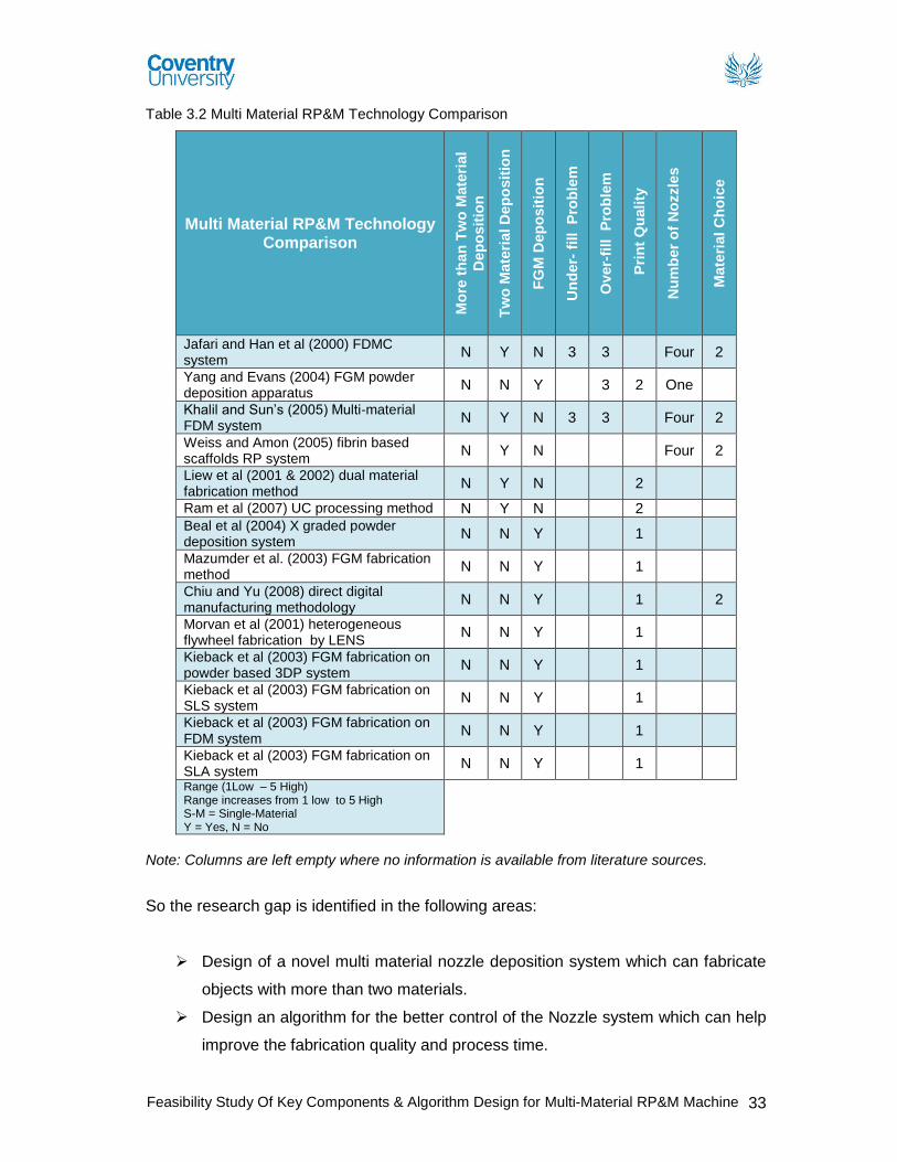
Feasibility Study Of Key Components & Algorithm Design for Multi-Material RP&M Machine 33
Table 3.2 Multi Material RP&M Technology Comparison
Multi Material RP&M Technology Comparison
Mo
re t
han
Tw
o M
ate
rial
Dep
osit
ion
Tw
o M
ate
rial D
ep
osit
ion
FG
M D
ep
osit
ion
Un
der-
fill P
rob
lem
Over-
fill
Pro
ble
m
Pri
nt
Qu
ali
ty
Nu
mb
er
of
No
zzle
s
Mate
rial C
ho
ice
Jafari and Han et al (2000) FDMC system
N Y N 3 3 Four 2
Yang and Evans (2004) FGM powder deposition apparatus
N N Y 3 2 One
Khalil and Sun’s (2005) Multi-material FDM system
N Y N 3 3 Four 2
Weiss and Amon (2005) fibrin based scaffolds RP system
N Y N Four 2
Liew et al (2001 & 2002) dual material fabrication method
N Y N 2
Ram et al (2007) UC processing method N Y N 2 Beal et al (2004) X graded powder deposition system
N N Y 1
Mazumder et al. (2003) FGM fabrication method
N N Y 1
Chiu and Yu (2008) direct digital manufacturing methodology
N N Y 1 2
Morvan et al (2001) heterogeneous flywheel fabrication by LENS
N N Y 1
Kieback et al (2003) FGM fabrication on powder based 3DP system
N N Y 1
Kieback et al (2003) FGM fabrication on SLS system
N N Y 1
Kieback et al (2003) FGM fabrication on FDM system
N N Y 1
Kieback et al (2003) FGM fabrication on SLA system
N N Y 1
Range (1Low – 5 High) Range increases from 1 low to 5 High S-M = Single-Material Y = Yes, N = No
Note: Columns are left empty where no information is available from literature sources.
So the research gap is identified in the following areas:
Design of a novel multi material nozzle deposition system which can fabricate
objects with more than two materials.
Design an algorithm for the better control of the Nozzle system which can help
improve the fabrication quality and process time.

Feasibility Study Of Key Components & Algorithm Design for Multi-Material RP&M Machine 34
Design of Multi material RP&M system with a large build volume so it can
accommodate large batch volume fabrication.
A better statistical quality and control data needs to be developed with respect
to the current RP&M systems which can be used as a benchmark for the
manufacturing industry.
A wide range of materials need to be developed which can be used as an
alternative to the materials used in conventional manufacturing.
A better statistical data with respect to testing and quality needs to be
developed for the available variety of RP&M materials which can be used as a
benchmark for the manufacturing industry.
The mentioned research gaps need further development and research, as all the
topics need in-depth research hence it is not feasible in the current scenario to choose
all as a research topic. The following two research gaps are chosen as a proposed
research topic for the project.
Multi material nozzle deposition apparatus design: Research gap analysis
of the commercial market and the current research being done has clearly
suggested that there is a need of Multi material RP&M system. Although
commercial market of RP&M has no feasible solution available for multi
material fabrication, whereas, current research done in this field has been
focused on developing a multi material deposition apparatus which can be used
to deposit up to two materials or to deposit FGM materials. There has been
some progress in the field of multi material fabrication of an object from two
build materials, however, there is no deposition apparatus designed to deposit
more than two build materials.
Hence, the chosen topic of research is to design a deposition apparatus which
can deposit more than two build materials. To achieve this goal some
specifications need to be established, mainly the choice of material and the
process of fabrication for the chosen materials. The choice of material plays a
critical role in the design of fabrication apparatus and process of fabrication
itself. So before the apparatus design can begin fabrication material type needs
to be identified.

Feasibility Study Of Key Components & Algorithm Design for Multi-Material RP&M Machine 35
Photopolymers: RP&M material sale analysis presented in chapter 2 clearly
identified photopolymers to be the most popular material used for additive
fabrication in the RP&M industry. According to the Wohlers report published in
2008, photopolymer sale in 2007 represented 46.4% of the total RP&M material
sale recorded. Increase in demand of photopolymer materials makes it more
economically feasible as compared to the cost of other RP&M materials. This
also predicts the trend of the industry and its growing confidence, as more
photopolymer materials are introduced by the material providers which can
exhibit material properties of conventional material choices. For this reason
photopolymer materials will be the choice of material for the proposed
deposition system in this project.
Algorithm design for better slicing and control of the Nozzle system: A
detailed literature review of the available RP&M system, its processes and
software has identified many problems such as accuracy, quality and process
repeatability. The review has identified STL to be a de facto standard of many
RP&M systems. However, STL format comes with many issues but in the
current scenario of multi material object representation, STL file format is
designed to represent one material type CAD models, comes with inherent
issues of inaccuracy with respect to dimensional representation and requires
large storage space for complex CAD model representation. Therefore a
NURBS (Non-Uniform Rational B-Spline) based slicing algorithm will be
developed for multi material representation of CAD model to improve the
quality of the RP&M components in terms of better geometrical representation
of multi material objects. The proposed NURBS slicing algorithm will be able to
represent a multi material CAD model, provide accurate geometrical
representation and low storage space requirement for the complex CAD model
representation. To improve the quality and control of better multi material
fabrication a nozzle change algorithm will be developed to help reduce the
process time.

Feasibility Study Of Key Components & Algorithm Design for Multi-Material RP&M Machine 36
Chapter 4 – Methodology
In this chapter, the process to develop a detailed concept design for a multi-material
M2-3D Printer nozzle deposition apparatus will be presented. To achieve the
objectives, a detailed secondary research is done to gather information and to identify
the research gap. A detailed product planning is done to further sub divide the
objectives and to clarify the task. After the task clarification, product design process is
established to develop a detailed design of multi-material M2-3D Printer nozzle
deposition apparatus for proposed M2-3D Printer machine.
4.1 Information Gathering
The first stage of the project is to analyse different RP&M systems, evaluate the
deposition system, fabrication process and the growing needs of RP&M industry. As
the project is of prime importance so it is vital to carry out an in-depth Primary and
Secondary research. The information is gathered using qualitative and quantitative
research methods.
The project has used the secondary data collection technique to provide the basic for
the primary research. For this reason the information will be gathered from relevant
journal, research articles, technical magazines and website. Relevant articles,
research papers and company websites will be used for more authentic and accurate
data. To gain up-to-date knowledge and professional view, informal meetings will be
carried out with relevant people and companies at the exhibitions. The primary and
secondary research methods will help to gather information on the following:
Background of RP&M.
Commercially available RP&M systems, fabrication process and
applications.
Current research on multi material RP&M deposition systems.
Current RP&M market trend and growing needs.
Analysis of the literature review and current research to identify the research
gap.
Design and develop a Multi material RP&M deposition system and
algorithms for accurate deposition.

Feasibility Study Of Key Components & Algorithm Design for Multi-Material RP&M Machine 37
Secondary research will be a major source to develop an understanding and to build a
firm base for the proposed research topic of multi material deposition apparatus and
algorithm design. However, a systematic approach is taken for the design project
which is based on engineering design methodology introduced by Pahl and Beitz
(1996). The approach consists of four phases as shown in figure 4.1:
Figure 4.1 Phases of planning and design process (Pahl & Beitz, 1996)
These four phases are expanded into a complete design process which is derived from
the design activity concept proposed by Stuart Pugh (1990) which is shown in figure
4.2.
Figure 4.2 Design process activity chart
4.2 Project Management
Project Management will be used as a tool to manage and complete the project within
defined scope, quality and time constraints. The key stages of the project which will
require a systematic management will be:
Back ground research Product design and development planning
Literature review Detailed product design
Research analysis
Research Gap Selection
Research conclusion and Future research
Gantt chart will be used for dividing the project into small achievable objectives to
ensure the timely completion of the project.
Product Planning & Clarification
of Task
Concept Design
Embodiment Design
Detail Design
Research Research Gap Specifications
Detail Design Embodiment
Design Concept Design

Feasibility Study Of Key Components & Algorithm Design for Multi-Material RP&M Machine 38
4.3 Product Design Process
Product planning and clarifying the task:
This is the first phase of product design and development process. The established
procedure of product planning and task clarification consists of three phases of design
activity which are shown in figure 4.3.
Figure 4.3 Design process activities - Product Planning & Clarification of Task
A quantitative research is done in the first phase of design process activity to develop
a situation analysis, where a detailed literature review is produced on the background
of RP, its development and research, commercially available RP systems, fabrication
processes, limitations, market trends and challenges.
In this phase the research is evaluated and transition is made from quantitative
research to qualitative research. Based on the findings of literature review, a detailed
research analysis is done where RP&M industry, its needs, challenges and future
trends are established. Whereas, current research and development in the field of
multi material deposition is critically analysed.
Based on the research analysis, a research conclusion is produced where all the
research gaps are identified. From the identified research gaps following two research
gaps are chosen as a research topic for the current research.
Multi material nozzle deposition apparatus design
Multi material fabrication quality and control design
These topics are selected for the current research on the bases of produced literature
review and research analysis where the market trend, challenges and developed
research help identify the problem definition and its scope.
Product Planning & Clarification of Task
Research Research Gap Specifications

Feasibility Study Of Key Components & Algorithm Design for Multi-Material RP&M Machine 39
Key Goals are set in the form of research objectives, which will help produce list of
specifications need to be addressed to achieve the desired objectives. These
specifications will help evaluate and improve the concept design for the multi material
disposition apparatus design.
Concept design:
The conceptual phase of design activity begins as the task is now clearly identified and
a requirement list of the proposed design is established. The conceptual design
process goes through the following steps:
Clarification of task and elaboration of requirement list: In this step key
requirements of the multi material nozzle deposition system are established.
Identification of essential problems: Based on these requirements tasks are
elaborated which help identify the essential problems which need to be
address. Such as, the nozzle deposition system needs to deposit photopolymer
materials, so the nozzle should be designed for chosen material deposition.
Establishing function and sub-function structures: Based on the requirements
and specifications, product functions and sub functions are established.
Working principles and Solutions: Working principles are established after
identifying functions and sub functions of the proposed multi material 3D printer
(M2-3D Printer). With the identification of working principles, the concept design
process beings to identify different concepts and ideas for preliminary layouts
and principle workings of functions and sub-functions.
Evaluation criteria: Proposed solutions are constantly analysed with the
demands of the requirement list which results into an improved design.
Embodiment design:
Embodiment design phase begins after the completion of concept design. In this
phase the over all layout design, preliminary form design and the production
processes, and all auxiliary functions are determined. This phase progresses from the
qualitative to the quantitative detailed design, which is analysed and improved by the
emplaced set guidelines and checks during the embodiment design process.

Feasibility Study Of Key Components & Algorithm Design for Multi-Material RP&M Machine 40
Detail design:
Detail design phases compromises list of steps which can be further divided into three
phases. In the first phase, the definitive layout is finalised, detail drawings of
components are produced, and a detail optimisation of shapes, materials, surfaces,
tolerances and fits are done. In the second phase, the integration of individual
components into assemblies, sub assemblies and a through these a complete product
is produced. In the last phase, documents with parts lists, assemblies, procedures and
operational instructions crucial to the product design are produced which can be
critical for product manufacturing and understanding for the further development in
future.

Feasibility Study Of Key Components & Algorithm Design for Multi-Material RP&M Machine 41
Chapter 5 – Research & Design Justifications
In this chapter, selected RP&M material, its curing process and the design of a multi-
material 3D deposition system for the proposed M2-3D Printer system will be
presented in three phases. In the first phase, the selected RP&M material and its
curing techniques are discussed. In the second phase, the design and fabrication
process of multi-material 3D nozzle deposition system for the proposed M2-3D Printer
system is presented. In the last phase, the concept design of a multi-material 3D
nozzle deposition system and its fabrication technique is supported with the case
studies. The feasibility design of multi-material nozzle deposition system presented in
this research work develops feasibility study for the proposed M2-3D Printer.
5.1 Overview of M2-3D Printer
Proposed M2-3D Printer is a multi-material RP&M system which can fabricate a 3D
model by using more than two build materials. M2-3D Printer shown in figure 5.1
comes with an innovative multiple nozzle deposition apparatus which can fabricate a
3D model by using multiple build materials. Initially a 3D model is designed in a CAD
environment which is transferred into M2-3D Printer workstation in an IGS format.
M2-3D Printer workstation comes with a unique direct slicing algorithm technique,
where a model is sliced into layers to get a closed two-dimensional (2D) cross-section
of the model layer. Direct slicing algorithm then generates a closed NURBS curve to
represent the contour of the cut layer based on Open CASCADE foundation. It
represents the model layer more accurately and requires less storage space as
compare to standard STL model. After Toolpath is generated, a multi-material 3D
model is fabricated layer by layer in the proposed M2-3D Printer.

Feasibility Study Of Key Components & Algorithm Design for Multi-Material RP&M Machine 42
Figure: 5.1 M
2-3D Printer design
5.2 M2-3D Printer Materials
Polymers:
Polymers are large molecules made up of many small, simple chemical joints, joined
together by chemical reactions. The size of polymers is indicated by its molecular
weight, where as another parameter which is used to distinguish the size of a molecule
is called the degree of polymerisation (DP). The term DP refers to the number of
repeat units in the chain. The range of DP in commercial plastics normally falls in the
range of 75 to 750 mers per molecule (Doi, 1996).
Properties of polymers:
Polymers even with high molecular weight are below the resolving power of an optical
microscope therefore the molecular weight determination is usually made indirectly by
calculating physical properties like viscosity, osmotic pressure, or light scattering as all
these properties are affected by the number, size or shape of a molecule (Lindberg,
1990).
Factor affecting polymer properties:
Material properties can be tuned with regards to processability, mechanical and
physical properties by considering components such as basic cross linking, reactive
diluents, fillers and initiators (Liska et al, 2007). However, factors which play a major
role in determining the properties of polymers are shown in table 5.1

Feasibility Study Of Key Components & Algorithm Design for Multi-Material RP&M Machine 43
Table 5.1 Factor affecting polymer properties (Lindberg, 1990)
Factor effecting polymer properties
Molecular weight Heavier molecules are created by adding more carbon atoms
and hydrogen atoms to each new carbon atom in a chain.
Branching The density of a polymer is directly related to the number and
length of the side branches. The greater the branching is, the
less the density.
Copolymerisation A polymer made from two different monomers is called
copolymer, where as their properties main depend on the
percentage of monomer A to monomer B and how they are
arranged along the chain
Compounding polymers Compounders can modify thermoplastics by adding:
Fibers Increased strength and stiffness
Plasticisers Flexibility
Lubricants Easier moulding
Antioxidants Higher temperature stability
Metals Conductivity
UV stabilisers Resistance to sunlight
Dyes Colour
Blending of plastics Different polymers are blended together to create plastic blends
with desired properties with respect to its application.
Factor affecting polymer blends
Choice of polymers
Composition
Compatibility of the polymers
Phase morphology
Method of blend preparation
Source: (Dyson, 1990)
5.3 Polymers to be used in proposed M2-3D Printer machine
Polymers as explained earlier are large molecules with high molecular weight. The
polymers required for the proposed machine are called “photopolymers”, which cure or
become solid when they are exposed to light.
Photopolymer:
Photopolymer resins used will be of low molecular weight materials which will undergo
cross linking to form a 3D network. These materials are in liquid form and during a high
degree of cross linking brought by ultra violet light, causes the liquid system to harden
to a rigid infusible solid (Dyson, 1990).

Feasibility Study Of Key Components & Algorithm Design for Multi-Material RP&M Machine 44
Photo polymerisation:
“Photo polymerisation” is a process of curing or controlled solidification of
photopolymer resins from liquid to solid state. Liquid resin is deposited and cured layer
by layer to form a 3D object. However, there are a lot of different factors which can
affect or improve the result of photo polymerised layer. Generally, factors include the
properties of resins used, especially the curing properties of material, selected process
for curing etc. But the major factor which needs to be controlled is the light source (UV
light). The curing penetration depth (DP) plays a vital role in the quality of the cured
layer. However, this topic will be discussed in detail later in “curing process selection”.
UV Curing process and its effects on photopolymers:
Quality of cured layer depends on many features but with respect to the UV light,
penetration depth for the selected material will be on the top of quality parameter list.
Cure depth can be determined by the energy of the light to which the material is
exposed. However, this energy can be controlled by:
Adjusting the power of light source. Adjusting the exposure time.
Light Source Energy
Layer thickness
Exposure
time
Figure 5.2 UV Curing Process
The parameters like light source power and exposure time also depend on the
properties of the selected material, as shown in figure 5.2. Different composition of
photopolymer will require different curing strength and time. Thus to have control and
improve the quality of the cured layer, it is important to adjust the light parameters for
each layer when different materials are used.

Feasibility Study Of Key Components & Algorithm Design for Multi-Material RP&M Machine 45
If the UV – curing process parameters are not closely monitored or adjusted for
different materials, overexposure will result in over curing into the preceding layer
which may have been intended to remain uncured. This problem can be controlled by
decreasing the penetration depth and increasing the photo-initiator concentration. This
reduced penetration depth will allow most accurate control of the polymerisation
process and minimal over cure, however, this will lead to increased building times (F.
Melchels et al, 2010).
5.4 M2-3D Printer - UV light selection criteria
UV light selection depends mainly on the material properties. During the exposure
process UV light needs to be controlled or its parameters need to be readjusted as
explained earlier, depending on the penetration depth of the material and layer
thickness. So it is important to identify the penetration depth and layer thickness before
the UV exposure strength is calculated. Greater control on the UV laser light will make
the machine more flexible.
Quality of UV light depends on its relative intensity which further depends on the
distance between the UV source and the objects under observation. UV light intensity
decreases as the distance increases between the UV source and the object under
observation. This happens due to the increase in the area covered by the UV light
which is shown in figure 5.3.
Table 5.2 UV light intensity
Figure 5.3: Quality of UV light
M2-3D Printer - Curing process selection for photo polymers:
Development in solid free form fabrication techniques have increased the use of
RP&M technology and has resulted in development of more sophisticated techniques
Distance Intensity %
0 mm 100%
5 mm 69%
10 mm 43%
13 mm 18%
25 mm 6%
5mm
ø 12 mm
ø
UV Spot
Light

Feasibility Study Of Key Components & Algorithm Design for Multi-Material RP&M Machine 46
to produce objects within hours with high resolutions. Each technology may require
different setup for each part produced with respect to its size and shape. However,
each technique has a lower limit in size of the smallest detail it can produce. The
relation in the resolution and the size of item is critical. The higher the resolution with
which a part is build, the smaller will be its maximum size (F. Melchels et al, 2010).
Most of the commercial fabrication techniques can build parts with smallest details
between 50µm to 200µm whereas, commercially available SLA setup can even build
objects with a lower resolution accuracy of 20µm (Maruo, 2002). As mentioned above
the setup of the fabrication techniques and the size of the object can limit the lowest
resolution which can be achieved.
There are number of different curing processes available for curing photopolymers.
Digital light processing (DLP) is one of them, where the material is cured layer by layer
with z-axis moving upwards to cure the next layer. Resolution of 50µm in x-y axis and
30µm in z direction can be achieved using DLP technology. However, UV curing
process involves photo curing of polymers layer by layer by moving laser beam on the
liquid surface and can achieve higher resolutions of 5µm in x-y axis and 10µm in z
direction (Liska et al, 2007).
5.5 M2-3D Printer – Design
M2-3D Printer layout shown in figure 5.4, consists of four major system assemblies,
nozzle deposition apparatus, feeding apparatus, z-axis and pipe hanger. These
component assemblies consist of many sub assemblies which are shown in appendix
D. M2-3D Printer comes with a unique Nozzle deposition system which consists of
seven nozzles designed to support more than two build materials. The nozzle
deposition system is connected with the material feeding apparatus by the material
and pipe hanger. The nozzle system has the ability to move in x-y direction, whereas
the z-axis is lowered by the elevation mechanism after a deposited layer is cured.

Feasibility Study Of Key Components & Algorithm Design for Multi-Material RP&M Machine 47
Figure 5.4: M2-3D Printer Layout
5.5.1 Nozzle Deposition System
Nozzle deposition apparatus is an innovative system which consists of seven nozzles
designed to support more than two build and support materials. Nozzle apparatus also
includes a UV light which is used as a curing device. Complete apparatus is shown in
figure 5.5. Some of the main components of the apparatus are:
Multi-material deposition head is
equipped with seven nozzles.
Nozzle rotation/selection is smooth which
is controlled with one servo motor.
To reduce the curing time an off the shelf
UV light is integrated into the deposition
apparatus.
An off the shelf UV spot light is integrated
to improve the control, accuracy and
precision with regards to curing process.
Figure 5.5 Multi-material deposition
apparatus
Nozzle Deposition Apparatus
Feeding Apparatus
Z-Axis
Material Pipe & Wire Hanger

Feasibility Study Of Key Components & Algorithm Design for Multi-Material RP&M Machine 48
A complete Nozzle is shown in figure 5.6 which consists of three sub assemblies,
which are as following:
Top cover is a snap fit assembly with material
and air pressure tube access. Consists of three
rubber seals which seal the pressure chamber.
Multipurpose Pressure plate assembly design
is used for feeding the material into the tube
chamber and to exert pressure onto the
material during the deposition process.
Pressure plate assembly consists of a material
access door which opens during material
feeding process. Door closes when pressure is
exerted on the pressure plate.
Deposition control assembly consists of an
electro magnet system which when activated
can deposited material continuously or in drop
formation.
Figure 5.6 Nozzle & sub assemblies
Material Pressure Plate Assembly:
Figure 5.7 Material Pressure Plate Assembly
Exploded view of pressure plate assembly can be seen in figure 5.7. Working principle
of pressure plate is to exert pressure on the material during the time of material
deposition. However, pressure is released from the plate assembly when material is
being feed into the nozzle chamber. This process is done in three steps:
Rubber Seal A rubber pressure plate
Flap Door
Flap Door Housing

Feasibility Study Of Key Components & Algorithm Design for Multi-Material RP&M Machine 49
1. Material is pumped into the nozzle from the feeding apparatus through
material pipe which is connected with the nozzle pressure plate as shown in
figure 5.8. This exerts the pressure on the flap door (as shown in figure 5.8),
which opens when the pressure exerted from point “A” is greater than point “B”
as shown in figure 5.8.
Figure 5.8 Working principle of pressure plate
2. When material deposition process begins, feeding apparatus is switched off
which releases the pressure exerted on the door previously. At the same time
air pressure is exerted on the pressure plate from point A as shown in figure
5.9 which builds up an equal pressure in material chamber (at point B).
Pressure developed in material chamber closes the material flab door, which
seals the material feeding tube excess to the material chamber.
Figure 1.7
Figure 5.9 Working principle of pressure plate
Deposition Control Assembly:
Deposition control assembly is a unique deposition controller which is operated
by an electro magnet. Electro magnet is charged to deposit material and in idol
position it works as a stopper. Deposition control consists of seven parts (see
figure 5.10):
A A
B B
B
A
Material
Pressure exerted by material
Exerted air pressure
Pressure produced as a reaction in material chamber
Material in nozzle chamber

Feasibility Study Of Key Components & Algorithm Design for Multi-Material RP&M Machine 50
There are three material access holes one each on
housing cover, main housing and deposition trigger.
Springs push the trigger away from the housing
cover hole when electro magnet is not activated.
When electro magnet is activated trigger moves
towards the magnet. During this process three holes
are aligned and deposition of material occurs.
This control has the ability to perform drop and
continuous deposition accurately and preciously.
Housing Cover
Main Housing
Spring
Deposition Trigger
Electro Magnet
Figure 5.10 Deposition Control Assembly
UV Curing light:
M2-3D Printer’s nozzle deposition apparatus comes with two commercially available,
off the shelf UV curing lights. M2-3D Printer system uses photopolymer materials which
come with different photoinitiator properties. It’s important to understand that when a
3D object is being fabricated with the help of multi-materials, this challenges the curing
capabilities of an AF system.
All though M2-3D Printer is not using functionally graded materials but it has the
capability to deposit more than two build materials in a same layer. This unique feature
of M2-3D Printer challenges its curing capability, especially when material deposition is
done to achieve high resolution. It is important to keep in mind that higher the
resolution size is, smaller will be the deposition material size. To achieve higher
resolution, M2-3D Printer can deposited material as small as 10µm in x-y axis and
10µm in z axis. However, the quality of resolution mainly depends on the parameters
of curing process.
Parameters affecting the quality depend on material properties and their reaction to the
curing source. If the material’s viscosity rating is low then the time of deposition and
curing process needs to be short and efficient. As a delay in curing process with
materials with low viscosity will cause problems of material movement or drag on the
build platform. For this reason the material deposition and curing speed needs to
match.

Feasibility Study Of Key Components & Algorithm Design for Multi-Material RP&M Machine 51
Delay in curing may result in a problem of material movement which may result in
decreased material thickness in z-axis. This problem can be controlled or eliminated
by understanding material properties such as viscosity and photoinitiator strength. This
problem can be removed if the material deposition speed and the time of
polymerisation are significantly reduced so that deposition speed is equal to curing
speed.
Deposition flow Rate = Material polymerisation speed
Material flow rate can be calculated which is explained later however, material
polymerisation speed includes the factor of area of exposure and intensity of UV light.
To increase the curing speed, M2-3D Printer is equipped with two UV light sources
(see figure 5.11). Main UV light source of nozzle deposition apparatus is used to cure
instantly a large about of material volume, as shown in figure 5.12. It can speed up the
curing process when a large amount of a material is deposited and requires an instant
cure. However, in the case of multi-material deposition, each material will have
different UV intensity requirement to cure and can prove difficult to manage the curing
intensity preciously for each material. It is important to understand that if a material
exposure time and intensity is not controlled, issues of over cure will occur.
Figure 5.11 Main UV source
Let’s consider if a layer of single material (Accura 40) is deposited on the build
platform as shown below. UV light intensity is adjusted by considering the materials
photoinitiator value and material thickness. Let’s suppose if 3dsystems “Accura 40”
material is deposited continuously in a straight line. The deposited volume has the
depth or thickness of 10µm, whereas, the commercial UV intensity required for curing
material depth of 0.17mm is 20.9mJ/cm2 approximately.
Main UV Source

Feasibility Study Of Key Components & Algorithm Design for Multi-Material RP&M Machine 52
So the UV intensity required to cure “Accura 40” will be:
𝐿𝑎𝑦𝑒𝑟 𝑡ℎ𝑖𝑐𝑘𝑛𝑒𝑠𝑠 𝑜𝑓 𝑑𝑒𝑝𝑜𝑠𝑖𝑡𝑒𝑑 𝑚𝑎𝑡𝑒𝑟𝑖𝑎𝑙
𝐺𝑖𝑣𝑒𝑛 𝑃𝑒𝑛𝑒𝑡𝑟𝑎𝑡𝑖𝑜𝑛 𝑑𝑒𝑝𝑡ℎ 𝑜𝑓 𝑚𝑎𝑡𝑒𝑟𝑖𝑎𝑙=
𝑅𝑒𝑞𝑢𝑖𝑟𝑒𝑑 𝑒𝑛𝑒𝑟𝑔𝑦 𝑡𝑜 𝑐𝑢𝑟𝑒 𝑑𝑒𝑝𝑜𝑠𝑖𝑡𝑒𝑑 𝑚𝑎𝑡𝑟𝑒𝑖𝑎𝑙
𝐺𝑖𝑣𝑒𝑛 𝐸𝑛𝑒𝑟𝑔𝑦 𝑜𝑓 𝐶𝑟𝑖𝑡𝑖𝑐𝑎𝑙 𝑒𝑥𝑝𝑜𝑠𝑢𝑟𝑒
Layer thickness of deposited material = 𝐿𝑑 = 10µm Required energy to cure deposited material = X
Given Penetration depth of build material = 𝑃𝑑 =17mm Given Energy of critical exposure = E = 20.9mJ/cm2
𝐿𝑑
𝑃𝑑=
𝑋
𝐸
10µm
170µm=
𝑋
20.9mJ/cm2
Required energy = 𝑋 = 1.23mJ/cm2
Figure 5.12 Main UV source
To control the UV curing intensity for multi-materials, M2-3D
Printer nozzle deposition apparatus is also equipped with a spot
UV light source for precision curing of a small volume deposition.
UV spot light is specifically integrated into the nozzle deposition
system to speed up curing process by aiming the curing source
to a specific material volume (see figure 5.13). It is an ideal
curing source when multi-material deposition is done in drop
formation and requires instant curing by adjusting the curing
intensity for each material.
Figure 5.13 Spot UV
source
Let’s consider if a layer of multi-materials (Accura 40, 55 and 60) is deposited on the
build platform as shown below. UV spot light intensity is adjusted by considering the
materials photoinitiator value and material thickness. Let’s suppose if 3dsystems
“Accura 40, 55 and 60” materials are deposited continuously in a straight line for
10mm one after another and have material thickness of 10µm each, whereas, the
Main UV
Curing Light

Feasibility Study Of Key Components & Algorithm Design for Multi-Material RP&M Machine 53
commercial UV intensity required for curing material selected materials are presented
in table 5.3:
Table 5.3 UV light intensity
Material Penetration Depth (Dp) Critical Exposure (Ec) Accura 40 0.168-.173mm 20.1-21.7 mJ/ cm
2
Accura 55 0.132mm 7.4 mJ/ cm2
Accura 60 0.16mm 7.6 mJ/ cm2
And the UV intensity required for curing deposited layer of multi-materials calculated
using the same equation is shown in table 5.4
Table 5.4 Required UV light intensity
Material Penetration Depth (Dp) Critical Exposure Limit (Ec) Accura 40 10µm 1.23 mJ/ cm
2
Accura 55 10µm 0.56 mJ/ cm2
Accura 60 10µm 0.48 mJ/ cm2
UV spot light will be more practical for instant curing a low
volume deposition layer of multi-material with average material
length of 10mm, as it will give more control on preciously
adjusting UV intensity and exposure time for each deposited
material volume one by one. A graphical representation of the
process is shown in figure 5.14.
Figure 5.14 Graphical representation of UV-process
5.5.2 M2-3D Printer - Process
Pre process:
A 3D model is designed in a CAD environment using
engineering drawing software such as CATIA,
SolidWorks or PRO/E, which is saved in a IGS format
(see figure 5.15).
CAD model is then tarnsfered into proposed M2-3D
Printer software, which uses a direct slicing algorithm
technique where the developed slicing algorithm can mix
together all segments of the cut layer by calculate start
and end points of every segments. After finding the
Figure 5.15 M2-3D Printer design

Feasibility Study Of Key Components & Algorithm Design for Multi-Material RP&M Machine 54
sequence of the segments, the algorithm can generate a
closed NURBS curve to represent the contour of the cut
layer based on Open CASCADE foundation.
Build Process:
1. Feeding apparatus is switched on to start pumping the material from the
Feeding tanks to material deposition nozzle chambers. Each feeding pipe is
dedicated to a specific material, its one end is connected to the material source
tank and other is connected to the deposition nozzle pressure plate.
Feeding apparatus pumps the material with the help of a crank shaft attached
to the dedicated pumps. Feeding apparatus is switched off when deposition
material nozzle chamber is full. A graphical representation of the process is
shown in figure 5.16.
Note: The detailed working of feeding apparatus is explained earlier in feeding
apparatus design
Figure 5.16 Feeding process

Feasibility Study Of Key Components & Algorithm Design for Multi-Material RP&M Machine 55
2. Deposition apparatus is initiated to start the deposition process after the
material chambers of each nozzle is filled with the desired multiple materials
and support material.
Air compressor is switched on and a constant pressure on the nozzle pressure
plate is maintained. The required pressure for each nozzle needs to be
controlled and can be calculated by using the following equation derived from
Poiseulle’s law:
𝑃𝑟𝑒𝑠𝑠𝑢𝑟𝑒 = 𝑃 =8𝑉𝜂𝑙
𝜋𝑡𝑟4
The deposition flow rate is controlled by the pressure exerted on the pressure
plate. The pressure of each nozzle depends on the material properties and the
geometry of nozzle tip. So each nozzle‘s pressure is adjusted according to the
required flow rate, as shown in figure 5.17.
Figure 5.17 Feeding process
3. Z axis is adjusted for the first deposition by moving closer to the deposition
nozzle apparatus (see figure 5.18). The movement of z axis is controlled by a
servo motor which moves the z axis upward or downward.
Figure 5.18 Z-Axis

Feasibility Study Of Key Components & Algorithm Design for Multi-Material RP&M Machine 56
4. Nozzle apparatus (see figure 5.19) is adjusted for the first deposition to begin
by selecting the desired material nozzle. Seven nozzles are mounted on a
rotation tray which is connected to a servo motor. The servo motor can rotate
the nozzles 1800 clockwise and anti clockwise. For nozzle selection an
algorithm is developed which is explained in the software chapter.
Figure 5.19 Nozzle Apparatus
5. Deposition control is actuated after the z axis is adjusted and nozzle is selected
for the first material deposition for continues or drop deposition. Deposition
control actuation is predefined when the material tool path is defined during pre
processing.
Deposition control makes it possible to control the material deposition quantity
precisely. It is important to understand the flow rate is controlled by the
pressure exerted by the pressure plate however, the deposition mode
(continuous or drop) is controlled by the deposition control assembly. For
quality and precision, both pressure mechanism and the deposition control
need to work in perfect coordination.
In the figure5.20, material is being deposited continuously in a straight line by
activating the deposition control.

Feasibility Study Of Key Components & Algorithm Design for Multi-Material RP&M Machine 57
Figure 5.20 Continuous material deposition.
6. Material depositing process is followed by the curing process which is done
layer by layer. However, curing process needs to be adjusted for every material
in a layer, when multi-materials are deposited. Material curing process can be
done by using either Main UV source or UV spot light, depending on the
material quantity, geometry and area which need to be cured.
When multi-materials are deposited in small quantity and more frequently then
it is impossible to use a main UV light sure for curing as different materials will
require different UV laser intensity depending on the material properties and
photo initiator strength, so for this reason UV spot light is used. UV spot light
process is slow as compared to Main UV light source but it is more precise and
easy to control (see figure 5.21).
Figure 5.21 Curing process
Working Example:
Scenario in figure 5.22 shows that a single material layer is deposited and cured by
both UV lights. It is clear that the area covered by the Main UV light source is much
bigger as compared to UV spot light so there will be a major difference in time of
curing process in the two approaches.

Feasibility Study Of Key Components & Algorithm Design for Multi-Material RP&M Machine 58
Figure 5.22 Curing process
However, when more than two materials are deposited in a same layer one after
another as shown in figure 5.23 then it will be impossible to use main UV source to
cure as different materials will require different UV intensity to cure. In this case
Main UV cure may result in either over curing a material and at the same time under
cure another material in the same layer. This will result into a layer which is
imperfect and has structural and geometrical defects. To resolve this issue an
integrated UV spot light is used which may increase the time of curing process but
will give better control and accuracy when curing multi materials in a same layer.
Figure 5.23 Curing process
When first layer is cured, z-axis moves downward to allow the next layer deposition
to begin and repeat the cycle until the fabrication of an object is completed, as
shown in figure 5.23.
Post Process:
When the fabrication process is completed, model is removed from the machine for
post processing, which involves chemical cleaning and rinsing, support structure

Feasibility Study Of Key Components & Algorithm Design for Multi-Material RP&M Machine 59
removal and final UV curing. Support structure is used to support the build structure of
the fabricated object where its geometry consists of overhangs and undercuts.
However, structure removal can be a tedious and time consuming process. After the
support structure removal, in some case post curing is down to improve the integrity of
the structure. After the final cure, sometimes hand finishing may need to be done for
appearance and functional purposes.
5.6 Working Principle and Quality Control
The proposed M2-3D Printer system process is more flexible as it is composure of SLA
and FDM technology in principle. However, M2-3D Printer process is fundamentally
based on the same principles as of SLA process. So overall the process is based on
the following principles:
Parts are built from photo curable liquid resins, which are extruded from the
nozzle deposition system onto the build platform one by one and cured when
exposed to the UV light.
The build is done layer by layer, where each layer when cured is lowered by
the elevation mechanism.
Quality Control:
The parameters which influence performance and functionality of the fabricated
objects in M2-3D Printer system include:
Physical and chemical properties of resins
Curing speed and UV intensity
Collaboration between the deposition and curing system
For the better quality and control of fabrication, it’s important to understand the
properties of resins as the curing speed and UV intensity also directly depends on
them. When material properties are known, then the UV intensity can be calculated by
using the following equation presented by EIT, Inc (eit.com, 2011).
𝐼𝑛𝑡𝑒𝑛𝑠𝑖𝑡𝑦 (mW
cm2) =
𝐸𝑛𝑒𝑟𝑔𝑦(mJ
cm2)
𝑇𝑖𝑚𝑒 (𝑠)

Feasibility Study Of Key Components & Algorithm Design for Multi-Material RP&M Machine 60
To increase the collaboration between the deposition and curing system, flow rate,
deposition pressure and volume needs to be controlled precisely. This can be
calculated using following formulas derived from Poiseulle’s equation:
Volume = V= 𝜋𝑡𝑃𝑟4
8ηl Pressure = P =
8𝑉ηl
𝜋𝑡𝑟4 Flow rate = 𝑉
𝑡 =
𝜋𝑃𝑟4
8ηl
5.8 Case Study
Material selection:
Photopolymer materials are selected for the proposed multi-material nozzle system.
There are number of photopolymers available in industry, mainly produced by 3D
Systems, Amber Composites and Huntsman. All photopolymers are in liquid form
however, materials produced by each company are designed for a specific purpose
with different physical and mechanical properties. These materials differ with respect
to their density, viscosity, penetration depth and cured/mechanical properties.
Therefore, a material selection table is formed to compare the selected photopolymer
materials.
Table 5.5 Photopolymer material comparison (3DSystems.com,2010)
Material Colour Density
@ 25 0C
Viscosity
@ 30 0C
Penetration Depth (Dp)
Critical Exposure (Ec)
Accura 10 Clear Amber 1.1 g/cm3 485 cps 0.127mm 13.2mJ/ cm
2
Accura 25 White 1.14 g/cm3 250cps 0.107mm 10.5 mJ/ cm
2
Accura 40 Clear Amber 1.1 g/cm3 485 cps 0.168-.173mm 20.1-21.7 mJ/ cm
2
Accura 45 Clear Amber 1.14 g/cm3 475 cps 0.13mm 7.4 mJ/ cm
2
Accura 50 Opaque natural or Opaque Gray
1.15 g/cm3 600 cps 0.114mm 9.0 mJ/ cm
2
Accura 55 White 1.13 g/cm3 155-185 cps 0.132mm 7.4 mJ/ cm
2
Accura 60 Clear 1.13 g/cm3 150-180 cps 0.16mm 7.6 mJ/ cm
2
Accura Amethyst
Purple 1.1 g/cm3 350cps 0.094mm 14.4 mJ/ cm
2
Accura Bluestone
Opaque Blue 1.7 g/cm3 1200-
1800cps 0.104mm 6.9 mJ/ cm
2
Accura CeraMAX
Opaque White 1.59 g/cm3 1500-
2000cps 0.145mm 7.2 mJ/ cm
2
Accura PEAK
Amber 1.32 g/cm3 605cps 0.142mm 11.5 mJ/ cm
2
Accura Xtreme
Grey 1.13 g/cm3 250-300cps 0.104mm 11.7 mJ/ cm
2
In the above table the penetration depth and critical exposure values will not be
constant and will change depending on the layer thickness, part geometry. It is

Feasibility Study Of Key Components & Algorithm Design for Multi-Material RP&M Machine 61
important to note that materials are compared not on the bases of their applications
but on the sole bases of their general properties which will be later shortlisted after
driving the formulas to identify material compatibility to the selected apparatus. 3D
Systems have proposed a material selection guide which is shown below in table 5.6:
Table 5.6 Accura Stereolithography Material Selection Guide (3DSystems.com, 2010)
For the case study five materials which are selected from the tables 5.6 are presented
in table 5.7:
Table 5.7 Selected materials
Material Colour Density
@ 25 0C
Viscosity
@ 30 0C
Penetration
Depth (Dp)
Critical
Exposure (Ec)
Accura 25 White 1.14 g/cm3 250cps 0.107mm 10.5 mJ/ cm
2
Accura 40 Clear Amber 1.1 g/cm3 485 cps 0.168-.173mm 20.1-21.7 mJ/ cm
2
Accura 55 White 1.13 g/cm3 155-185 cps 0.132mm 7.4 mJ/ cm
2
Accura 60 Clear 1.13 g/cm3 150-180 cps 0.16mm 7.6 mJ/ cm
2
Accura
Xtreme
Grey 1.13 g/cm3 250-300cps 0.104mm 11.7 mJ/ cm
2

Feasibility Study Of Key Components & Algorithm Design for Multi-Material RP&M Machine 62
Curing Process selection:
For the time being the critical parameters (i.e. material flow rate per second, pressure
etc) for deposition are ignored but will be discussed later in fluid dynamics chapter.
With the help of the deposition apparatus four layers of material will be deposited on
top of each other one by one. Each material exhibits different properties of viscosity,
penetration depth and critical exposure limits. So the selected curing process will need
to be adjusted for each layer before the curing process can begin.
UV light curing process is selected for the selected materials. The UV light intensity will
be adjusted for each material. For the purpose of case study, the object is a simple
rectangular block as shown in figure 5.24. With the help of material deposition system
first layer of Accura 40 is deposited.
Figure 5.24 Accura 40 deposited material
Polymerisation Process:
UV light distance is adjusted, considering material thickness. The distance between
the UV light source and the material layer is less than 0.5mm. So the intensity of UV
light is above 98%.
𝐼𝑛𝑡𝑒𝑛𝑠𝑖𝑡𝑦 (mW
cm2) =
𝐸𝑛𝑒𝑟𝑔𝑦(mJ
cm2)
𝑇𝑖𝑚𝑒 (𝑠)
Energy required when layer thickness is 10µm is calculated by using the following
equation:
𝐿𝑎𝑦𝑒𝑟 𝑡ℎ𝑖𝑐𝑘𝑛𝑒𝑠𝑠 𝑜𝑓 𝑑𝑒𝑝𝑜𝑠𝑖𝑡𝑒𝑑 𝑚𝑎𝑡𝑒𝑟𝑖𝑎𝑙
𝐺𝑖𝑣𝑒𝑛 𝑃𝑒𝑛𝑒𝑡𝑟𝑎𝑡𝑖𝑜𝑛 𝑑𝑒𝑝𝑡ℎ 𝑜𝑓 𝑚𝑎𝑡𝑒𝑟𝑖𝑎𝑙=
𝑅𝑒𝑞𝑢𝑖𝑟𝑒𝑑 𝑒𝑛𝑒𝑟𝑔𝑦 𝑡𝑜 𝑐𝑢𝑟𝑒 𝑑𝑒𝑝𝑜𝑠𝑖𝑡𝑒𝑑 𝑚𝑎𝑡𝑟𝑒𝑖𝑎𝑙
𝐺𝑖𝑣𝑒𝑛 𝐸𝑛𝑒𝑟𝑔𝑦 𝑜𝑓 𝐶𝑟𝑖𝑡𝑖𝑐𝑎𝑙 𝑒𝑥𝑝𝑜𝑠𝑢𝑟𝑒
𝐿𝑑
𝑃𝑑=
𝑋
𝐸
10µm
127µm=
𝑋
13.2mJ/cm2
Required energy = 𝑋 = 1.04mJ/cm2
Height: 0.01mm Length: 10 mm Width: 0.01 mm

Feasibility Study Of Key Components & Algorithm Design for Multi-Material RP&M Machine 63
Table 5.8 Energy required for the selected materials
Material Penetration Depth (Dp) Critical Exposure Limit (Ec)
Accura 25 10µm 0.98 mJ/ cm2
Accura 40 10µm 1.23 mJ/ cm2
Accura 55 10µm 0.56 mJ/ cm2
Accura 60 10µm 0.48 mJ/ cm2
Accura Xtreme 10µm 1.13 mJ/ cm2
Fluid Dynamics:
Rate of flow of liquid through a capillary tube of radius “r” and length “l” can be
calculated by using equation 1 derived from Poiseulle’s law:
V= 𝜋𝑡𝑃𝑟4
8ηl =
∆𝑃
8ηl/𝜋𝑡𝑟4 = ∆𝑃
𝑅 Equation 1
P = Pressure difference ∆𝑃
R = Fluid resistance (R =8ηl/𝜋𝑟4)
Rate of flow per second is calculated by changing equation 1.
V= 𝜋∆𝑃𝑡𝑟4
8ηl Equation 2
Table 5.9 Equation Symbols
Symbols Units
Volume V m3(Meter)
Pi 𝜋
Pressure P Pa (Pascal)
Time T S (Second)
Viscosity Η ps (Poise second)
Length L m (Meter)
Radius R m (Meter)
As the fluid or material is going from applied pressure to atmospheric pressure,
therefore, we can ignore the pressure change. So
∆𝑃 = 𝑃
So equation 2 is rearranged to calculate the pressure required to deposit a certain
amount of volume per second.
Volume = V = 𝜋𝑃𝑡𝑟4
8ηl Equation 2
Pressure = P = 8𝑉ηl
𝜋𝑡𝑟4 Equation 3

Feasibility Study Of Key Components & Algorithm Design for Multi-Material RP&M Machine 64
Where as to calculate the flow rate per second equation will become
Flow rate = 𝑉
𝑡 =
𝜋𝑃𝑟4
8ηl Equation 4
Length = l = 8mm = 0.008m
Radius = r = 0.005mm = 5x10⁻⁶m
Viscosity = η = 485cps = 4.85ps = 0.485 Pa.s
If the volume dispensed in a straight line has the following measurements the;
Volume in meter3= V = l x w x h
V = (0.01m) x (1x10⁻⁵m) x (1x10⁻⁵m)
V = 1x10-12m3
As we are dispensing material into atmospheric pressure, so we assume there won’t
be any changes in pressure. So using equation 3;
Pressure = P = 8𝑉ηl
𝜋𝑡𝑟4 Equation 3
P = 8 x (1 x 10-12 m3) x (0.485 Pa.s) x (0.008m)
3.14 x (1 s) x (6.25 x 10⁻¹² m4)
P = 3.104 x 10⁻¹⁴ Pa
1.96 x 10⁻²¹
P = 15836734.69 Pa
Converting Pascal into Bar:
P = 15836734.69 Bar
100,000
P = 158.4 Bar
Material: Accura 40
Length: 8 mm
Diameter: 0.01 mm ø
Height: 0.01mm Length: 10 mm Width: 0.01 mm

Feasibility Study Of Key Components & Algorithm Design for Multi-Material RP&M Machine 65
Chapter 6 – Software Development of M2-3D Printer In this chapter, some algorithms will be developed to support the design of M2-3D
Printer for multi-material RP&M processing. It gives an introduction about STL format
file and NURBS curve. A NURBS-based slicing algorithm is developed to represent the
boundary contours of the sliced layer in RP&M technology to maintain the geometrical
accuracy of original CAD model. In addition, a nozzle change algorithm for fabrication
of two-material object in RP&M technology is also developed in this chapter. The
developed software can be used to reduce the build time of fabrication and guide the
fabrication process of two material objects in the designed M2-3D Printer.
6.1 STL Format File and its Problems
STL format file is the de facto standard widely used in RP systems which was
originated by the 3D Systems Company in USA in 1989. It is a triangular
representation of a 3D surface geometry, where surface is tessellated into a series of
small triangles facets. Each facet is described by a perpendicular direction and three
points representing the vertices of the triangle. Figure 6.1 shows a STL format model
of human head.
Figure 6.1 A STL format model of human head
The STL file has two formats: (a) ASCII format, (b) Binary format (shown in Figure
6.2). Compared with binary format, ASCII format is human readable but the size of file
is larger than binary format.

Feasibility Study Of Key Components & Algorithm Design for Multi-Material RP&M Machine 66
(a) ASCII format solid name facet normal ni nj nk outer loop vertex v1x v1y v1z vertex v2x v2y v2z vertex v3x v3y v3z endloop endfacet … endsolid name
Figure 6.2 The two formats of STL file
STL file provides a simple method to represent the 3D CAD model and has been used
by most single material RP&M systems in recent years. However, there are many
types of errors in STL files such as holes, missing, gaps, overlapping and degenerate
facets, etc. In addition, STL is inherent inaccuracy in terms of geometrical
representation and it does not contain topological data, so it is difficult to represent
accurate CAD models and hard to be used to represent the multi-material object in
RP&M technology (Chua, Leong& Lim, 2010). So, there is a need to develop a method
to support multi-material fabrication in RP&M technology.
6.2 NURBS Curve
NURBS are mathematical representations of 3D geometry that can accurately
describe any shape from a simple 2D line, circle, arc, or curve to the most complex 3D
organic free-form surface or solid. Figure 6.3 shows a NURBS curve with 8 control
points. A NURBS curve is defined by its order, a set of weighted control points, and a
knot vector:
(1) The control points determine the shape of the curve.
(2) The knot vector is a sequence of parameter values that determines where and how
the control points affect the NURBS curve.
(3) The order of a NURBS curve defines the number of nearby control points that
influence any given point on the curve.
(b) Binary format UINT8[80] – Header UINT32 – Number of triangles foreach triangle REAL32[3] – Normal vector REAL32[3] – Vertex 1 REAL32[3] – Vertex 2 REAL32[3] – Vertex 3 UINT16 – Attribute byte count end

Feasibility Study Of Key Components & Algorithm Design for Multi-Material RP&M Machine 67
Figure 6.3 A NURBS curve with 8 control points
Compared with STL format file, NURBS – based curves have some advantages
(showed in Table 6.1):
Table 6.1 The comparison between STL file and NURBS
STL NURBS Large storage space Small storage space
Inherently inaccurate Accurate
Hard to represent multi-material model Can be used to represent multi-material model
Simple Complex
As STL does not contain topological data and only a facet model derived from precise
CAD models. It needs several times large storage space for a complex accuracy CAD
model compared with NURBS. Meanwhile, STL file is inherently inaccurate as it is an
approximate model, but NURBS is a mathematical model which offers great precision
for freeform shape model. In addition, STL file is quite hard to represent multi-material
model, but NURBS can be used to represent multi-material model easy. However,
compared with STL file, NURBS is much more complex.
In this thesis, a method to use NURBS curve instead of STL format file to support
multi-material RP technology is developed. Figure 6.4 shows the comparison between
traditional RP process and the developed method. In the traditional method, it slices a
STL model which transform from the original CAD model to get a 2D cross-section.
This can be used to generate tool-path for the RP&M systems. In the developed
method, it directly sliced the CAD model instead of the STL file conversion and
NURBS (Non-Uniform Rational B-Spline)-based curve are introduced to represent the
boundary contours of the sliced layers in RP&M to maintain the geometrical accuracy
of original CAD model and to support the multi-material RP&M technology.

Feasibility Study Of Key Components & Algorithm Design for Multi-Material RP&M Machine 68
Figure 6.4. The comparison between traditional RP&M process and the developed method
6.3 A NURBS-based slicing algorithm
The developed NURBS-based slicing algorithm is based on the C++ programming
language in an open-source CAD kernel system - the Open CASCADE. Open
CASCADE Technology is a software development platform freely available in open
source, which includes components for 3D surface and solid modelling, visualization,
data exchange and rapid application development (opencascade.org, 2011). Figure
6.5 shows the main process of the developed algorithm.
Figure 6.5 The flow of generating the NURBS-based contour curve.
First, in the developed method, the point cloud data from a complex product model
is reconstructed as an IGES/IGS model using the Quick Surface Reconstruction
(QSR) and Digitized Shape Editor (DSE) modules in CATIA V5™. The
reconstructed model is then read into the developed software platform.
Then, a container is created to envelop the model, and the shortest edge of the
enveloping box is determined as the orientation direction (Z-axis) to minimize the
build time.
After that, a series of sliced layers perpendicular to the orientation direction are set.
Intersected points are generated between the slicing layer and the contour surface
Traditional CAD solid
model STL Slicing
2D cross-section
Tool-path RP&M System
Developed Method
CAD solid
model Slicing NURBS Curve Tool-path
RP&M System

Feasibility Study Of Key Components & Algorithm Design for Multi-Material RP&M Machine 69
of the model. The knot vector and control points are calculated based on the
obtained intersected points.
Finally, in order to establish a NURBS-based contour curve on the boundary
between the sliced layer and the model (Ci,1), formulas (1) and (2) are applied to
generate NURBS-based contour curve (Piegl, et al., 1997).
Ci,j(u) = ∑ wiNi,p(u)C_Pi,jn
i=0 (1)
Ni,0(u) = {1 0
ui≤ u ≤ ui+1otherwise
, and Ni,p(u) = u−ui
ui+p−uiNi,p−1(u) +
ui+p+1−u
ui+p+1−ui+1Ni+1,p−1(u) (2)
Where Ci,j represents the jth contour curve in the ith RP layer; u is the parametric
variable ( ]1,0[u ); iw is the weight associated with control points; jiPC ,_ is the control
point; p is degree. Table 6.2 shows the detailed steps of the developed NURBS-based
slicing algorithm.
Table 6.2. The steps of slicing algorithm
Steps START
1. Read a CAD model (IGS/IGES format)
2. Make a container to accommodate the CAD model
3. Determine the direction of slicing (the longest segment of the CAD model), and set it to be Z-axis
4. Along the Z-axis, slice the model with a uniform thickness, and get all the layers
( 𝑳𝟎 , 𝑳𝟏 , … 𝑳𝒏 ) of the model
5. Get the contour segments of the first layer ( 𝑳𝟎 )
6. Explorer all the segments of the ( 𝑳𝟎 ) to get the number of the segments ( 𝑵𝒎 )
7. Select a segment randomly as the start segment ( 𝑺𝟎 ) and find the start point ( 𝑷𝟎,𝒔 )
and the end point ( 𝑷𝟎,𝒆 ) of ( 𝑺𝟎 )
8. Explorer all the segments ( 𝑺𝒋 ) except the selected one and find a segment with start
point ( 𝑷𝟏,𝒔 ) equals to ( 𝑷𝟎,𝒆 ). Named it as the second segment ( 𝑺𝟏 ) (𝑗 = 0,1,2, … 𝑚)
9. Loop this process of step 8 until all segments along the sequence from start to end of the layer ( 𝑳𝟎 ) are found
10. Join all the segments of the ( 𝑳𝟎 ) to generate a closed NURBS curve (𝑪𝟎,𝟎)
11. Loop the process from step 5 to step 10 to obtain all closed NURBS curves (𝑪𝒊,𝟎) for
the CAD model (𝑖 = 0,1,2, … 𝑛)
END

Feasibility Study Of Key Components & Algorithm Design for Multi-Material RP&M Machine 70
An example to illustrate the developed slicing algorithm:
A tibia model of human right leg is used to illustrate the developed slicing algorithm.
The length, width, height and volume of the tibia model are 405.29mm, 106.96mm,
98.249mm and 471600mm3 respectively. The process for the NURBS-based contour
curve generation is shown in Figure 6.6.
6.4 A Nozzle Change Algorithm for Two-material Object
The normal manufacturing processing for the fabrication of two-material object with
RP&M machines are shown in Figure 6.7. It uses additive manufacturing method from
bottom to top layer by layer to complete the object. For example, in Figure 6.7(c),
firstly, it fabricates material A by nozzle 1 along the tool-path, then nozzle is changed
from 1 to nozzle 2 and its positioned in the right location for the fabrication of material
B. After the layer is finished, nozzle is changed to nozzle 1 to fabricate the material A
on the next layer In Figure 6.7(b), and then its changed back to nozzle 2 to fabricate
material B, layer by layer until the fabrication of an object is completed.
When the object is composed by different materials, the RP&M machine have to
change the different nozzles to fabricate different materials in every layer. This slows
the fabrication process due to the time required for nozzle change and its positioning
at the right location. This also decreases the surface quality because the fabrication
(a) An tibia model for RP tool-path generation
(b) An enveloping box for the model and a sliced layer
(c) The cross-section segments (d) A NURBS-based contour curve generated by the slicing algorithm
Figure 6.6 An example to illustrate the developed slicing algorithm.

Feasibility Study Of Key Components & Algorithm Design for Multi-Material RP&M Machine 71
processing has too many start and end points, which will increase staircase problem
and will cause warpage of the fabrication object (Kou and Tan, 2009). In this project, a
nozzle sequence algorithm is developed based on the C++ programming language
and the Open CASCADE software develop platform. It can be used to control the
above designed M2 – 3DP RP&M machine to fabricate the two-material object with the
least changeover of the nozzles. Figure 6.8 shows the flowchart of the nozzle change
algorithm.
Figure 6.7 The processing for the two-material objects fabrication in RP&M
Material A
Material A
Material B
Material B
Tool-paths

Feasibility Study Of Key Components & Algorithm Design for Multi-Material RP&M Machine 72
Begin
Decide the build direct (df)
Establish x,y axis, and
origin pring O
Find the intersection curve Lc
Along the build direction,
tangent Lc, find the points
which curvature=0 or ±∞
Number the points from 1 to n
(Pn)
Through every point to do
planes (Tn) which parallel with
the x-axis
n>2
Yes
No
Fabricate Ma/Mb
Fabricate Mb/Ma
End
P2 of Ma is
bump point
First fabricate Ma
from T1 to T2
First fabricate Mb
from T1 to T2
Fabricate M2 from
T1 to T3
Parity of Pn
Yes
No
2+2i>n,
i=1, i++
even
odd
Yes
Fabricate M1
from T2i to T1+2i
No
Fabricate M1
from T2 to T2+2i
Fabricate M2
from T3 to T3+2i
3+2i>n,
i=1, i++
Yes
Fabricate M2
from T1+2i to
T2+2i
No
Fabricate M2
from T3 to T3+2i
Fabricate M1
from T4 to T4+2i
Fabricate M1
from T2 to T4
Figure 6.8 The flowchart of the nozzle change algorithm

Feasibility Study Of Key Components & Algorithm Design for Multi-Material RP&M Machine 73
Compared with the traditional method:
The ball showed in Figure 6.9 with two different materials is used in this comparison.
The diameter of the ball is 20cm. The thickness of every layer for RP&M system is
0.2mm. So the ball has 1000 layers totally.
(a) An ball model with two different materials
(b) The two parts of the ball
(c) Slicing the ball for one layer (d) Contour of the layer
(e) Tool-paths generated for the material A (f) Tool-path generated for the material B
Figure 6.9 An example to illustrate the nozzle change algorithm.
Material A
Material B

Feasibility Study Of Key Components & Algorithm Design for Multi-Material RP&M Machine 74
The format to calculate the totally build time is given as follows:
Tt = Tc + Tp + Tf (3)
Where Tc is the total time spent to change different nozzle, Tp is the total time spent for
nozzle positioning, and Tf is the total time spent for fabrication. They can be calculated
using following equations:
Tc = Nc × tc; Tp = Np × tp; Tf = Nf × tf; (4)
Where Nc is the times of the nozzle change, Np is the times of the nozzle positioning,
and Nf is the times of the nozzle fabrication; tc is the time spend to change a nozzle, tp
is the time spend to position a nozzle, and tf is the time spend to fabricate one material
part of the layer.
We assumed that tc = 60 seconds, tp = 45 seconds, tf = 30 seconds. Figure 6.10
shows the fabrication processing for the ball in the developed nozzle change
algorithm. The Table 6.3 shows the build time comparison between traditional
processing and the developed change nozzle algorithm.
Figure 6.10 The fabrication processing for the ball in the nozzle change algorithm
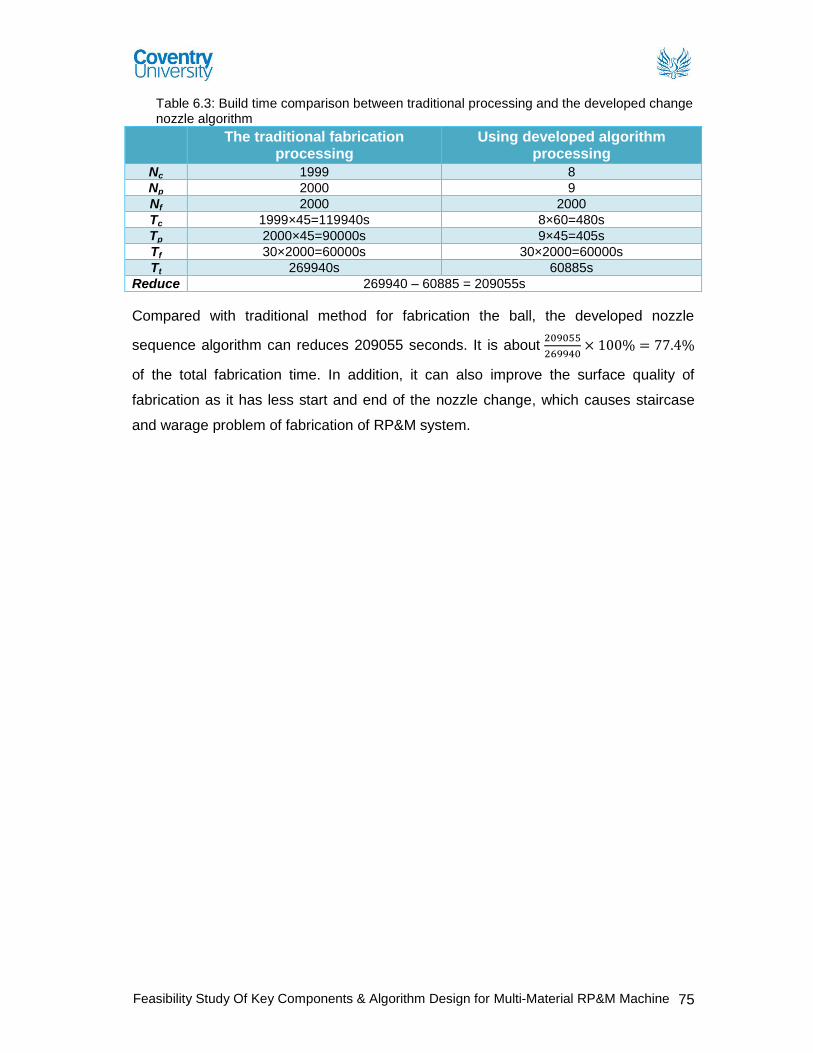
Feasibility Study Of Key Components & Algorithm Design for Multi-Material RP&M Machine 75
Table 6.3: Build time comparison between traditional processing and the developed change nozzle algorithm
The traditional fabrication processing
Using developed algorithm processing
Nc 1999 8
Np 2000 9
Nf 2000 2000
Tc 1999×45=119940s 8×60=480s
Tp 2000×45=90000s 9×45=405s
Tf 30×2000=60000s 30×2000=60000s
Tt 269940s 60885s
Reduce 269940 – 60885 = 209055s
Compared with traditional method for fabrication the ball, the developed nozzle
sequence algorithm can reduces 209055 seconds. It is about 209055
269940× 100% = 77.4%
of the total fabrication time. In addition, it can also improve the surface quality of
fabrication as it has less start and end of the nozzle change, which causes staircase
and warage problem of fabrication of RP&M system.

Feasibility Study Of Key Components & Algorithm Design for Multi-Material RP&M Machine 76
Conclusion The major focus of the dissertation is on the feasibility study of developing a unique
multi-material nozzle deposition system which is flexible, accurate and can handle up
to seven materials with controllable deposition. By evaluating all the findings with
respect to the design of a multi-material nozzle deposition apparatus, its suitability to
handle more than two materials, slicing and controlling algorithms, it is concluded that
the selected proposed multi-material nozzle deposition system design is feasible for
multi-material deposition of more than two materials and can be further developed to
be used in the proposed M2-3D Printer system. Comparison of existing multi material
deposition system research with the proposed feasibility model of M2-3D Printer is
presented in table 7.1 (see page 79). Developed multi-material slicing and its nozzle
control algorithm will reduce the processing time, data storage space and overall
improve the quality of fabricated objects in the proposed M2-3D Printer system. With
the reference to the aims and objectives set out at the start of the project are
completed at the end of the dissertation. The objectives included:
To analyse and evaluate existing commercially available RP&M systems:
RP&M systems research has been carried out mainly with the help of research
papers, articles, reports and company websites. The literature review and its
analysis conclude that applications of the most RP&M systems are either
limited by the material choice and its properties or by its fabrication process
itself.
To analyse and evaluate existing research on multi-material RP&M
systems: Present research on multi-material RP&M systems has been carried
out mainly with the help of research papers, articles, and published reports.
The literature review and its analysis conclude that the current research being
done in this field has been focused on developing a multi-material deposition
apparatus which can be used to deposit up to two materials or to deposit FGM
materials. Most of the RP&M systems presented need further development to
improve the process quality, control and repeatability.
To analyse and evaluate the need of multi-material RP&M system with
respect to related industries: The literature review and its analysis of the
Feasibility Study Of Key Components & Algorithm Design for Multi-Material RP&M Machine 77
technologies, industrial trends, and research and development of RP&M shows
that there is a growing interest from number of industries in multi-material
RP&M system. There is a demand of more capable RP&M systems which can
fabricate functional models from different materials. It will reduce the
manufacturing cost and open doors for more complex, low volume product
design and production.
To review and analyse existing deposition apparatus design: Research
analysis of the commercial market and the current research being done has
clearly suggested that there is a need of Multi material RP&M system. It is
concluded that commercial market of RP&M has no feasible solution available
for multi material fabrication, whereas, recent research has gained some
progress in the field of multi material fabrication of components from two
materials but there is no deposition apparatus designed to deposit more than
two materials.
To produce a research gap analysis: Literature review is critically analysed
to develop an understanding of issues related to the current RP&M technology,
its industry trend and current research and development. The analysis are
made and concluded to establish the current research gaps and topic of
proposed research (See chapter 3 for details).
To produce design specifications for the key components of the
proposed multi-material RP&M machine: The proposed M2-3D Printer
system, consists of four major components, feeding apparatus, material
delivery and flow system, deposition apparatus and build platform. All the
components are designed to work with photopolymers materials. The key
specifications of material disposition system are set by understanding the
photopolymer materials.
To design a nozzle of “M2-3D Printer” for a controlled and accurate
deposition: Nozzle design of deposition apparatus can build objects with a
lower resolution of 10µm. It comes with a unique deposition controller which is
operated by an electro magnet for controlled and accurate deposition.

Feasibility Study Of Key Components & Algorithm Design for Multi-Material RP&M Machine 78
Multi material nozzle deposition apparatus design: A concept model of
multi-material deposition apparatus is designed which can deposit more than
two build materials. Photopolymer is the material choice which can be
deposited in a continuous or drop format from the design apparatus. Flow rate
and volume can be controlled by using the presented formulas for accurate
deposition and to minimise the over/under fill issues. Deposited material can be
fabricated by two UV curing options (Major cure or spot curing). The right
choice of UV curing source and its set parameters affect directly the quality of
fabrication. Formula is used to set UV parameters to gain more control and to
improve its curing quality (See chapter 5 & appendix D for design details).
To conduct detailed design of feeding apparatus for the proposed M2-3D
Printer: Feeding apparatus design comes with seven tanks for different
materials. Material is feed to the Nozzle apparatus by pumping the material
from the tanks, through flow pipes. Off the shelf pressure control valves are
used to control the pressure in the flow pipes See chapter 5 & appendix D for
design details).
Algorithm design for better slicing and control of the Nozzle system: A
detailed literature review of the available RP&M system, its processes and
software has identified many problems such as accuracy, quality and process
repeatability. It is concluded that STL file format is designed to represent one
material type CAD models, comes with inherent issues of inaccuracy with
respect to dimensional representation and requires large storage space for
complex CAD model representation. Therefore a NURBS based slicing
algorithm is developed for multi-material representation of CAD model to
improve the quality of the RP&M components in terms of better geometrical
representation of multi material objects. Developed NURBS-based slicing
algorithm can maintain the geometrical accuracy of original CAD model and to
support multi-material RP technology. In addition, a nozzle change algorithm
was also developed to reduce the build time of fabrication and to support the
design of M2-3D Printer.

Feasibility Study Of Key Components & Algorithm Design for Multi-Material RP&M Machine 79
Table 7.1 Multi Material RP&M Technology Comparison with proposed feasibility model of M2-
3D Printer
Multi Material RP&M Technology Comparison
Mo
re t
han
Tw
o M
ate
rial
Dep
osit
ion
Tw
o M
ate
rial D
ep
osit
ion
FG
M D
ep
osit
ion
Un
der-
fill P
rob
lem
Over-
fill
Pro
ble
m
Pri
nt
Qu
ali
ty
Nu
mb
er
of
No
zzle
s
Mate
rial C
ho
ice
Jafari and Han et al (2000) FDMC system
N Y N 3 3 Four 2
Yang and Evans (2004) FGM powder deposition apparatus
N N Y 3 2 One
Khalil and Sun’s (2005) Multi-material FDM system
N Y N 3 3 Four 2
Weiss and Amon (2005) fibrin based scaffolds RP system
N Y N Four 2
Liew et al (2001 & 2002) dual material fabrication method
N Y N 2
Ram et al (2007) UC processing method N Y N 2 Beal et al (2004) X graded powder deposition system
N N Y 1
Mazumder et al. (2003) FGM fabrication method
N N Y 1
Chiu and Yu (2008) direct digital manufacturing methodology
N N Y 1 2
Morvan et al (2001) heterogeneous flywheel fabrication by LENS
N N Y 1
Kieback et al (2003) FGM fabrication on powder based 3DP system
N N Y 1
Kieback et al (2003) FGM fabrication on SLS system
N N Y 1
Kieback et al (2003) FGM fabrication on FDM system
N N Y 1
Kieback et al (2003) FGM fabrication on SLA system
N N Y 1
Syed I (2011) Feasibility Design of M2-
3D Printer Y Y N 1* 1* 4* Seven 4
Range (1Low – 5 High) Range increases from 1 low to 5 High S-M = Single-Material Y = Yes, N = No * = Needs to be tested physically.
Note: Columns are left empty where no information is available from literature sources.
Future work and recommendations:
The further work should be carried out in future research and development of the
presented concept of multi-material nozzle deposition system to support a fully

Feasibility Study Of Key Components & Algorithm Design for Multi-Material RP&M Machine 80
functional multi-material 3D printer (“M2-3D Printer”). Presented research can be used
as a feasibility study for the proposed M2-3D Printer system so more research needs to
be carried out in implementation of this concept design into a working prototype model.
More research should be carried out in developing algorithms for the multi-nozzle
control and positioning for accurate and precious deposition.
The research areas which need further research and development are:
First prototype needs to be manufactured for the physical testing of multi-
material nozzle deposition system which can fabricate objects with more than
two materials.
Further develop an algorithm for the better control of multiple nozzle system
which can help improve the fabrication quality and process time.
A better statistical quality and control data needs to be developed with respect
to the current RP&M systems which can be used as a benchmark for the
manufacturing industry.
A wide range of materials need to be developed which can be used as an
alternative to the materials used in conventional manufacturing.
A better statistical data with respect to testing and quality needs to be
developed for the available variety of RP&M materials which can be used as a
benchmark for the manufacturing industry.

Feasibility Study Of Key Components & Algorithm Design for Multi-Material RP&M Machine 81
References
_connect (2010) RIM polyurethane MG 453, automotive grill [online] available from <https://ktn.innovateuk.org/web/polymers/articles/-/blogs/ebalta-maintain-the-lowest-viscosity-rim-and-vacuum-casting-materials-for-the-rapid-prototyping-market?ns_33_redirect> [01st September 2011]
3D Systems (2010) ProJet™ 6000 Professional 3D Printer [online] available from <http://printin3d.com/projet-6000> [01st September 2011] 3D Systems (2010) 3D Systems Success Story [online] available from <www.3dsystems.com/products/datafiles/success_stories/Tushino_SLA_XL_CS.pdf> [01st September 2011] Anderson, S. (2009) Pushing rapid prototyping materials to the limit [online] available from <http://www.mmsonline.com/articles/pushing-rapid-prototyping-materials-to-the-limit> [01st September 2011] ALEX DEN OUDEN (2004) Fused deposition modelling [online] available from <http://www.alexdenouden.nl/08/rapprod7.htm> [01st September 2011]
Agentdraw (2010) Prototype [online] available from <http://www.agentdraw.co.uk/prototype.php> [01st September 2011] Anvil Prototype (2009) Digital Design and Manufacturing [online] available from <http://www.anvilprototype.com/StayUpdated/tabid/67/NewsID/29/Default.aspx> [01st September 2011] A. R. Lindberg. (1990) Processes and materials of manufacturing (Fourth edition). Beal, V.E., Erasenthiran, P., Hopkinson, N., Dickens, P. and Ahrens, C.H. (2004) ‘Fabrication of x-graded H13 and Cu powder mix using high power pulsed Nd: YAG laser’. Solid Freeform Fabrication Symposium, Texas 187-197 Chua, C. K., Leong, K. F. & Lim, C. S. (2010) Rapid Prototyping: Applications and Applications (Third Edition). Singapore: World Scientific Chua, C. K., Leong, K. F. & Lim, C. S. (2003) Rapid Prototyping: Applications and Applications (Second Edition). Singapore: World Scientific Cornelius, T. and Leondes. (2003) Computer Aided and Integrated Manufacturing Systems. Singapore: World Scientific Cadem, A.S., (2008) Fused deposition modeling [online] available from <www.additive3d.com/faq/faq220.htm> [01st September 2011] Cubic Technologies (2007) Laminated Object Manufacturing [online] available from <www.cubictechnologies.com/Helisys.htm> [01st September 2011]

Feasibility Study Of Key Components & Algorithm Design for Multi-Material RP&M Machine 82
Chiu, W.K. and Yu, K.M. (2008) ‘Direct digital manufacturing of three-dimensional functionally graded material objects’. Computer-Aided Design 40 (12): 1080-1093 Chartoff, R., McMorrow, B. and Lucas. P. (2003) ‘Functionally graded polymer matrix nano-composites by solid freeform fabrication: apreliminary report’. Proceedings of the 14th SFF symposium, Austin, TX 385-391 Design & manufacturing Laboratory (2009) Reverse Engineering Techniques in Bioengineering [online] available from <http://dml.chania.teicrete.gr/ereuna/3dmedical1_en.html> [01st September 2011] Doi, M. (1996) Introduction to Polymer Physics. Oxford: Oxford university press D-MEC (2005) STL file editing software [online] available from <www.d-mec.co.jp/eng/products/scs/lineup/soft.html> [01st September 2011] Dwivedi, R. and Kovacevic, R. (2004) ‘Morphing based approach for process planning for fabrication of geometries and control of material composition’. In the 15th Solid Freeform Fabrication Symposium, Austin, Texas 553-562 Dwivedi, R., Zekovic, S. and Kovacevic, R. (2006) ‘Field feature detection and morphing-based process planning for fabrication of geometries and composition control for functionally graded materials’. Proc. IMechE Vol. 220 Part B: J. Engineering Manufacture 1647-1661 EIT (1998) Measuring UV Dosage Is Not Enough for Process Control [online] available from <http://www.eit.com/instruments/fu_enough.html>[14th December 2011] Esposito. A. (1998) Fluid mechanics with applications. Prentice Hall F. P. W. Melchels., J. Feijen. and D. W. Gripma. (2010) ‘A review on stereolithography and its applications in biomedical engineering’. Biomaterials 31 (24): 6121-6130 Fessler, J., Nickel, A., Link, G. and Prinz, F., Functional gradient metallic prototypes through shape deposition manufacturing. Stanford University Grimm, T. A. (2004) User’s Guide to Rapid Prototyping. Michigan: Society of Manufacturing Engineers Gizmag (2004) Jewelry Design [online] available from <www.gizmag.com/go/3398/> [01st September 2011] Hart, G. W. (2005) Rapid Prototyping [online] available from <http://www.georgehart.com/rp/rp.html> [01st September 2011] Jafari, M. A., Han, W., Mohammadi, F., Safari, A., Danforth, S. C. and Langrana, N. (2000) ‘A novel system for fused deposition of advanced multiple ceramics’, Rapid Prototyping Journal 6 (3), 161-174 Jafari, M., Han, W., F. Mohammadi., A. Safari., S.C. Danforth. and N. Langrana. (2000) ‘A novel system for fused deposition of advanced multiple ceramics’. Rapid prototyping Journal 6(3): 161-175

Feasibility Study Of Key Components & Algorithm Design for Multi-Material RP&M Machine 83
Jackson, T.R. (2000) Analysis of functionally regarded material object representation methods. Unpublished Ph.D. Thesis. Massachusetts Institute of Technology Kruth, F. P., Mercelis, P., Vaerenbergh, F. V., Froyen, L. and Rombouts, M. (2005) ‘Binding mechanisms in selective laser sintering and selective laser melting’, Rapid Prototyping Journal 11 (1), 26-36 Khalil, S., Nam, J., and Sun, W. (2005) ‘Multi-nozzle deposition for construction of 3D biopolymer tissue scaffolds.’ Rapid Prototyping Journal 11 (1): 9-17 Kieback, B., Neubrand, A. and Riedel, H. (2003) ‘Processing techniques for functionally graded materials’. Materials Science and Engineering A362: 81-105 Kou, X.Y. and Tan, S.T. (2009) ‘Robust and efficient algorithms for rapid prototyping of heterogeneous objects’. Rapid Prototyping Journal 15 (1): 5-18 Lovett, T. (2001) Rapid Prototyping Systems [online] available from <check.itgo.com/> [01st September 2011] Lal, P. and Sun, W. (2004) ‘Computer modelling approach for mircrosphere-packed bone graft.’ Journal of Computer Aided Design 36: 487-97 Liew, C.L., Leong, K.F., Chua, C.K. and Du, Z. (2001) ‘Dual material rapid prototyping techniques for the development of biomedical devices. Part 1: Space Creation’. International Journal of advanced Manufacturing Technology, 18: 717-723 Liew, C.L., Leong, K.F., Chua, C.K. and Du, Z. (2002) ‘Dual material rapid prototyping techniques for the development of biomedical devices. Part 2: Secondary Powder’. International Journal of advanced Manufacturing Technology 19: 679-687 Langrana, N. A., Qui, D., Bossett, E., Danforth. S. C., Jafari, M. and Safari, A. (2000) ‘Virtual simulation and video microscopy for fused deposition’. Materials and Design 21: 75-82 Materialise NV (2011) Materialise SurgiGuide [online] available from <http://www.materialise.com/materialise/view/en/449917-Rapid+Manufacturing.html> [01st September 2011] McDonald, J. A., Ryall, C. J. and Wimpenny, D. I. (2001) Rapid Prototyping Casebook. London: Professional Engineering Publishing Milwaukee School of Engineering ‘n. d.’ Solid Freeform Fabrication [online] available from <www.msoe.edu/academics/research_centers/reu/solid_freeform_fabrication.shtml> [01st September 2011] Multistation (2009) Laminated Object Manufacturing [online] available from <www.multistation.com/en/spip.php?article445> [01st September 2011] Milwaukee School of Engineering ‘n. d.’ SLS Process [online] available from <www.rpc.msoe.edu/cbm/about/images/sls_process.gif> [01st September 2011]

Feasibility Study Of Key Components & Algorithm Design for Multi-Material RP&M Machine 84
Morvan, S., Fadel, G. M., Love, J. and Keicher, D. (2001) ‘Manufacturing of a Heterogeneous Flywheel on a LENS Apparatus’. Proceedings of the 12th solid freeform fabrication symposium, Austin, TX 553-560 Nijman, C. L. (2010) Rapid Manufacturing [online] available from <www.within4walls.co.uk/digital.php> [01st September 2011] National University of Singapore ‘n. d.’ Solid Ground Curing [online] available from <www.eng.nus.edu.sg/LCEL/RP/rpt_sgc.html> [01st September 2011] Oxford dictionaries (2011) Prototype [online] available from <http://oxforddictionaries.com/definition/prototype> [01st September 2011] Object (2011) CONNEX 500 [online] available from <http://www.objet.com/3D-Printer/Objet_connex500/> [01st September 2011] Otto, N. K. and Wood, L. K. (2001) Product Design: Techniques in Reverse Engineering and New Product Development. London: Prentice Hall Open CASCADE (2011) CASCADE Technology [online] available from <http://www.opencascade.org/> [15th March 2011] Palm, W., (2002) Rapid Prototyping [online] available from <www.mne.psu.edu/lamancusa/rapidpro/primer/chapter2.htm#sla> [01st September 2011] PADT Medical (2011) Selective Laser Sintering [online] available from <www.padtinc.com/rm/sls/default.htm> [01st September 2011] Pahl. G. and Beitz. W. (1996) Engineering Design: A Systematic Approach. London: Springer
Piegl, L. and Tiller, W., (1997) The NURBS Book (Second Edition). Germany: Springer
Ryall. C. and Wimpenny. D. ‘n. d.’ Rapid Prototyping technology as used on the Bombe Rebuild Project [online] available from <http://www.jharper.demon.co.uk/rptc01.htm> [01st September 2011]
R. W. Dyson. (1990) Engineering polymers. USA: Chapman & Hall R. Liska., M. Schuster., R. Infu¨ hr, C. Turecek., C. Fritscher., B. Seidl., V. Schmidt., L. Kuna., A. Haase., F. Varga., H. Lichtenegger. and J. Stampfl. (2007) ‘Photopolymers for rapid prototyping. Brief Communication’, J. Coat. Technol. Res 4 (4) 505–510 Ram, G.D., Janaki, R.C., Yang, Y. and Stucker, B.E. (2007) ‘Use of ultrasonic consolidation for fabrication of multi-material structures’. Rapid prototyping Journal 13 (4): 226-235

Feasibility Study Of Key Components & Algorithm Design for Multi-Material RP&M Machine 85
Stratasys (2011) 3D Printers [online] available from <http://www.stratasys.com/Products/3D-Printers.aspx> [01st September 2011] Sun, W., Startly, B., Nam, J. and Darling, A. (2005) ‘Bio-CSD modelling and its applications in computer-aided tissue engineering’, Journal of Computer Aided Design 37, 1097-1114 Stereolithography ‘n. d.’ Solid Ground Curing [online] available from <knowledge.stereolithography.com/activekb/questions/12/Solid+Ground+Curing> [01st September 2011] Stratasys (2011) Fused Deposition Modeling [online] available from <www.xpress3d.com/FDM.aspx> [01st September 2011] Stratasys (2010) SMART Supports [online] available from <www.pddnet.com/news-stratasys-smart-supports-040610/> [01st September 2011] S. Maruo. and K. Ikuta. (2002) ‘Submicron stereilithography for the production of freely moveable mechanisms by using single-photon polymerization’. Sensors and actuators A: Physical 100 (3): 70-76 Sun, W., Darling, A., Starly, B. and Nam, J. (2004) ‘Computer-aided tissue engineering: overview, scope and challenges’. Journal of Biotechnology Applied Biochemistery 39 (1): 29-47 Shin,K.H., Natu, H., Dutta, D. and Mazumder, J. (2003) ‘A method for the design and fabrication of heterogeneous objects’. Material & Design 24: 339-353 Turk CADCAM (2011) Solid Ground Curing [online] available from <www.turkcadcam.net/rapor/autofab/tech-light_curing-masking.html> [01st September 2011] Univeristy of South Florida (2009) Catalyst XP Software [online] available from <virtualmdlab.eng.usf.edu/facilitiessoftware.html> [01st September 2011] Wendel, B., Rietzel, D., Kuhnlein, F., Feulner, R., Hulder, G. and Schmachtenberg, E. (2008) ‘Additive Pricessing of Polymers’. Macromol Mater Eng 293 (10), 799-809
Wohlers, T. (2008) Wohlers Associates 2008: State of the Industry. USA: Wohlers Associates Inc. W, Sidney. (2008) Rapid Prototyping (RP) Technology Introductory Course for ShaTin College [online] available from <http://msc-technology.wikispaces.com/file/view/RP+introduction+for+ShaTin+college+131208.pdf> [01st September 2011]
Wohlers, T. (2011) Wohlers Associates 2011: additive manufacturing and 3D printing State of the Industry. USA: Wohlers Associates Inc.

Feasibility Study Of Key Components & Algorithm Design for Multi-Material RP&M Machine 86
Wohlers, T. (2004) Wohlers Associates 2004: Rapid Prototyping, Tooling & Manufacturing State of the Industry. USA: Wohlers Associates Inc. Weiss, L.E., Amon, C.H., Finger, S., Miller., D. Romero., I. Verdinelli., L.M. Walker. and P.G. Campbell. (2005) ‘Bayesian computer – aided experimental design of heterogeneous scaffolds for tissue engineering’. Computer-aided design 37: 1127-1139 Wicker, R. B., Medina, F. and Elkins, C. (2004) ‘Multiple material micro-fabrication: extending stereolithography to tissue engineering and other novel applications’. Proceeding of the 2004 Solid Freeform Fabrication Symposium Yang, S.F. and Evans, G. (2004) ‘A multi-component powder dispensing system for three dimensional functional gradients’. Materials Science and Engineering 379 (12): 351-359 Zhang, Y., Han, J., Zhang, X., He, X., Li, Z. and Du, S. (2001) ‘Rapid prototyping and combustion synthesis of TiC/Ni functionally gradient materials’. Materials Science and Engineering A229: 218-224

Feasibility Study Of Key Components & Algorithm Design for Multi-Material RP&M Machine 87
Appendix A – Prototyping
A.1 Types of Prototypes
For contemporary product development processes, six general classes of prototypes
are typically used (Otto & Wood, 2001):
1. Proof of concept models: They are usually fabricated from simple, readily
available materials, they focus on a component or subsystem of the product.
They are constructed usually during concept selection and product
embodiment. The general question proof of concept answer is whether the
imagined physics of the concept on the paper indeed actually happen and what
any unforeseen physics might be.
2. Industrial design prototypes: They demonstrate the look and feel of the product.
In general they are initially constructed out of simple materials such as foam or
foam core and seek to demonstrate many options quickly.
3. Design of Experiments (DOE) experimental prototypes: DOE experimental
prototypes are focused physical models where empirical data is sought to
parameterise, layout, or shape aspects of the product.
4. Alpha prototypes: The alpha is the first system construction of the subsystems
that are individually proven in the subsystem DOE prototyping and design.
Alphas also usually include some functional features for testing and
measurements of the product system.
5. Beta prototypes: Beta prototypes are the full scale functional prototypes of a
product, constructed from the actual materials as the final product.
6. Preproduction prototype: These prototypes are used to perform a final part
production and assembly assessments using the actual production tooling.
A.2 Roles of Prototypes
The prototypes play key roles in the product development process which include the
following (Chua, Leong& Lim, 2003):
Experimentation and learning: Prototypes can be used to help the thinking,
planning, experimenting and learning process while designing the product.
Testing and proofing: Prototypes can also be used for testing and proofing of
ideas and concepts relating to the development of the product.

Feasibility Study Of Key Components & Algorithm Design for Multi-Material RP&M Machine 88
Communication and interaction: Prototypes also serve the purpose of
communication information and demonstrating ideas, not just within the product
development team, but also to management and client.
Synthesis and integration: Prototype can also be used to synthesise the entire
product concept by bringing the various components and sub assemblies
together to ensure that they will work together. This helps in the integration of
the product and surface any problems related to putting the product together.
Scheduling and markers: Prototyping also serves to help in the scheduling of
the product development process and is usually used as markers for the end or
start of the various phases of the development effort.

Feasibility Study Of Key Components & Algorithm Design for Multi-Material RP&M Machine 89
Appendix B – Literature Review Extended B.1 Historical development of RP Technology Table B.1 Recent Developments of Rapid Prototyping and related technologies (Wohlers Associates,2008 and Chua, Leong & Lim, 2003).
Years Technology
2008
Solidscape Introduced T76 precision wax printing
Optomec Released its new LENS MR-7 with fiber laser, dual powder feeder & integrated thermal imager for process monitoring
3D Systems introduced iPro 9000 SLA Centre as a replacement to Viper Pro
MTT Technologies released a larger selective laser melting machine SLM 250-300
Z Crop Released 24bit colour printer ZPrinter650
EOS unveiled a new large frame, high temperature, laser sintering platform EOSINT P 800
2007
3D Systems released V-Flash 3D printer & the next version of its Multi-Jet modelling machine, the ProJet HD3000
Stratasys launched the new Dimension Elite 3D printer
Solidscape released to market specific version of T66 Machine
D66 – Digital Dental Modeling system
R66 – For jewellery applications
Z Crop introduced a truly office friendly ZPrinter 450
Arcam introduced its larger build volume A2 electron beam melting (EBM) machine
Stratasys announced its FDM 200mc, FDM 360mc, FDM 400mc & its large frame FDM 900mc
Voxeljet introduced its VX500 system, a smaller version of the VX800
2006
Object Geometries introduced its Eden350/350V platform
3D Systems announced its Vision DP (dental professional) system
Stratasys introduced the Dimension 1200BST and SST systems
EOS introduced Formiga P 100 laser sintering system
EOS also introduced EOSINT P 390 & EOSINT 730
Voxeljet Technology introduced its VX800
MTT Technologies introduced its new SLM ReaLizer 100 selective laser melting machine
2005
Z Corp released its latest colour 3D printing system, the Spectrum Z510
3D systems unveiled the Sinterstation Pro
Object Geometries introduced the Eden500V
MTT Technologies introduced the SLM ReaLizer 100
2004
Stratasys introduced the “Triplets” which consists of three variations of the FDM Vantage machine
Envisiontec introduced the Vanquish photopolymer based system
3D systems introduced its dual-vat Viper HA stereolithography system for hearing aid industry.
Solidscape introduced the T66 Benchtop & T612 Benchtop systems
2003 Z Crop introduced its ZPrinter 310 system

Feasibility Study Of Key Components & Algorithm Design for Multi-Material RP&M Machine 90
Solidscape introduced its T612 system for making wax patterns for investment castings
3D Systems began to sell its In Nision 3D printer
EOS introduced its EOSINT M 270 direct metal laser sintering machine
Trumpf introduced its TrumaForm LF and TrumaForm DMD 505 machines
2002
Stratasys introduced its Dimension product
Envisiontec GmbH began to sell its prefactory & Bioplotter machines
Solidscape introduced its T66 product
Phenix Systems of France sold its first Phenix 900 System
POM began to sell its direct metal deposition machine
Menix, Co., Ltd. Of Korea introduced its first VLM300 variable lamination machines
2001
Object Geometries began to sell a beta version of its Quadra 3D printer
Stratasys began the commercial shipment of its FDM Titan
Z Crop. Introduced its Z810, a system that prints parts in a 500 x 600 x 400 mm build volume.
Generis GmbH of Germany Commercialised its large GS 1500 system used to produce sand cores and molds for metal castings.
EOS announced its DirectSteel 20-V1 peoduct, a steel based powder consisting of particles 20microns
2000
Sanders Design International developed Rapid ToolMaker (RTM)
Object Geometries of Israel announced Quadra
Precision Optical Manufacturing (POM) announced direct metal deposition (DMD)
ZCorp. introduced its Z402C machine, world’s first commercially available mutli-colour 3D printer
Stratasys introduced Prodigy, a machine that produces parts in ABS plastic
1999
3D Systems introduced:
ThermoJet a faster & less expensive version of Actua 2100
SLA 7000 system
Roders began to sell its controlled metal build-up (CMB) machine
1998
Autostrade introduced its E-DARTS stereolithography system
Optomec commercialised its laser-engineered net shaping (LENS) metal powder system.
1997 AeroMet developed a process called laser additive manufacturing (LAM)
1996
Stratasys introduced the Genisys machine, which used an extrusion process similar to FDM
3D Systems sold its first 3D printer Actua 2100
Z Crop. Launched its Z402 3D printer
BPM Technology sold Personal Modeler 2100 commercially
1995 Japan’s Ushio (now called Unirapid Inc.) sold its first stereolithography machine
1994
Solidscape launched ModelMaker machine
EOS commercialised a EOSINT machine based on laser sintering technology
1993 Soligen commercialised direct shell production casting (DSPC)
1992 DTM commercialised Selective laser sintering (SLS)
Teijin Seiki launched Soliform stereolithography system

Feasibility Study Of Key Components & Algorithm Design for Multi-Material RP&M Machine 91
1991
Stratasys commercialised fused deposition modelling (FDM)
Cubital launched solid ground curing (SGC)
Helisys commercialised laminated object manufacturing (LOM)
1990
Electro optical systems (EOS) sold its first Stereos stereolithography system
Quadrax introduced the Mark 1000 SL system
1988 3D Systems commercialised first stereolithography machine SLA-1
B.2 Classification of Rapid Prototyping Processes
Usually RP systems are classified according to different methods used. The three
famous classifications of RP process are given by Burns, Jerome, Kochan and Chua.
Categorisation of RP&M process by Kochan & Chua:
Kochan and Chua (1995) classify RP&M process by the initial form of its material and
method. They have grouped the RP&M processes under solid, liquid and powder.
However under each group the RP&M processes are further classified into the
different methods adopted which includes (Cornelius & Leondes, 2003):
Lamps Holography Masked lamp
And joining Cutting and gluing Melting and solidifying
Single or dual laser beams
Burns Classification:
According to M. Burns (1993) RP processes can be classified into additive and hybrid
processes. Additive process is further characterised under different techniques used
by the RP&M systems such as (Cornelius & Leondes, 2003):
Laser curing,
Masked lamp curing,
Laser sintering, and
Droplet deposition
Adhesion of cut sheet such as laminated object manufacturing (LOM) is characterised
by Burns as a hybrid subtractive/additive process because the contour of the cross
section and unwanted parts are cut by laser after being bonded to the previous layer.
Jerome’s Classification:
Jerome L Johnson (1994) classified the RP&M process according to the method of
controlling layer fabrication. The interaction of raw material mass m and energy W
produces the physical layer in a total variation occurring as (Cornelius & Leondes,
2003):

Feasibility Study Of Key Components & Algorithm Design for Multi-Material RP&M Machine 92
Jerome explains the equation in two terms:
1. *(mW): First term represents a process where a uniform mass m is selectively
activated, removed, or bonded by a variable energy *W controlled by the layer
description. Under this variable energy process molecular bonding, particle
bonding and sheet lamination can be classified.
2. m*W + W*m : Second Term represents process where layer information
controls a variable mass *m acted on by a control energy W. Under this
variable mass process droplet deposition, particle deposition and melt
deposition car classified.
B.3 3D Systems’ Stereo lithography Apparatus (SLA) Advantages of SLA:
Key advantages and features of SLA system are (3Dsystems.com, 2011)
SLA systems can be used continuously and unattended round the clock
Figure B.1 Viper SLA
system (3Dsystems.com, 2011)
SLA systems are available with different build size
configurations:
Small – 250 x 250 x 250 mm Large – 737 x 635 x 533 mm
SLA systems generally have good accuracy and can
achieve excellent part feature details and definition.
SLA can obtain good surface finish with minimum post
process finishing requirements
Figure B.2 Viper Pro
SLA system (3Dsystems.com, 2011)
A wide range of materials are available from general
purpose to specialty materials for specific applications
SLA systems comes with Automatic material refill and
levelling
Disadvantages of SLA:
Requires support structures: Structures which overhang and
undercuts must have supports, however, removing supports is a
time consuming and delicate task (See figure B.3).
Figure B.3
Fabricated object (additive3d.com,
2011)
All SLA fabricated objects require post processing task which
include:
Cleaning Post Curing Finishing
aa0682
Typewritten Text
Images removed

Feasibility Study Of Key Components & Algorithm Design for Multi-Material RP&M Machine 93
Applications of SLA:
Table B.2 Applications of SLA
Mo
de
ls
For conceptualisation
For Packaging
For Presentation
Figure B.4 Viper System (3Dsystems.com, 2011)
Applications of SLA (Chua, Leong& Lim, 2010)
Pro
toty
pes
For Design,
For analysis,
For verification
For functional testing
Pa
rts
For prototype tooling
For low volume production
tooling
To
ols
For fixture design
For tooling design
For production tooling Pa
tte
rns
For investment casting
For sand casting
For molding
Custom Turbines:
3D Systems iPro 9000 SLA capability helped Tushino
Power Machine Tools to convert the design of their
customised turbines into a master pattern casting. This
enabled (Tushino Power Machine Tools) to print QuickCast
patterns that reduced the production cost and time of
customised turbines and improved the operating efficiency
to +20% (Ashrapov, 2010). The QuickCast SL master
pattern, produced with Accura 60 SLA material is a pattern
that weights just 70 Kg (Shown in figure 1.9), while the final
cast model weighs 1990 Kg (shown figure B.5)
(3DSystems.com, 2011).
Figure B.5 Accura 60 SLA material pattern
Figure B.6 final cast
model
SLA technology is now being used in jewellery
manufacturing industry to produce high resolution parts
used for jewellery design validation, communication,
aesthetics and as direct patterns for flask casting
(gizmag.com, 2011).
Figure B.7 Jewellery
Design (gizmag.com, 2011)
aa0682
Typewritten Text
Image removed
aa0682
Typewritten Text
Image removed

Feasibility Study Of Key Components & Algorithm Design for Multi-Material RP&M Machine 94
B.4 Cubital's Solid Ground Curing (SGC)
Cubital’s RP technology creates highly physical models directly from computerised
data files. Solid ground curing (SGC) like SLA use ultraviolet light to selectively harden
photosensitive polymers. But unlike SLA, SGC cures an entire layer at a time. Figure
B.8 depicts solid ground curing, which is also known as the solider process (Palm,
2002).
Figure B.8 Schematic diagram of solid ground curing (stereolithography.com, 2011)
Process:
First, photosensitive resin is sprayed on the build platform.
Then machine develops a photomask of the layer to be built. This photomask is
printed on a glass plate above the build platform using an electrostatic process
similar to that found in photocopiers.
The mask is then exposed to UV light, which only passes through the
transparent portions of the mask to selectively harden the shape of the current
layer (see figure B.8).
After the layer is cured, the machine vacuums up the excess liquid resin and
sprays wax in its place to support the model during the build.
Top surface is milled flat, and then the process repeats to build the next layer.
When the part is complete, it must be de-waxed by immersing it in a solvent
bath.
aa0682
Typewritten Text
This image has been removed

Feasibility Study Of Key Components & Algorithm Design for Multi-Material RP&M Machine 95
Material:
Cubital’s SGC system uses several kinds of resins, as shown in figure B.9:
Liquid and cured photopolymer resins are used as
build or primary materials.
Water soluble wax is used for building support
structure or secondary material.
Figure B.9 Cubital’s
Solimer resin (eng.nus.edu.sg, 2011)
Software:
CAD model is transferred into Cubital’s Solider Data front end (DFE) workstation
mainly in STL format. Cubital’s DFE software has edit and file manipulation capabilities
where CAD model can be rendered for visualisation purpose, searched and corrected
of flows. This software can prepare in adequate STL files for processing on any RP
system. Some of the key features of DFE software are shown in figure B.10
Figure B.10 Features of Cubital’s Solider of DFE software
Advantages of SGC:
Key advantages and features of Cubital Ltd.'s Soldier 5600 stereolithography system
are (3Dsystems.com, 2011):
Parallel Processing: Point by point curing is a slow and time consuming
process, where as Soldier system can cure the whole cross-sectional layer
area instantly, which can help reduce the production time and cost significantly.
aa0682
Typewritten Text
Image removed

Feasibility Study Of Key Components & Algorithm Design for Multi-Material RP&M Machine 96
Self supporting: Unlike the SLA systems, Solider systems’ solid modelling
environment provides an unlimited geometry, where solid wax supports the part
in all dimensions.
Solider systems’ have good fault tolerance, where changeable layers:
Allow job changing during a run.
Make it possible to erase faulty layers.
Instant cure of a whole cross-sectional layer minimises the shrinkage effect and
minimises the development of internal stresses which result in high structural
strength and stability.
Solider system produces parts which exhibit unique properties (shown in figure
B.11).
Figure B.11 Solider Part Properties
Disadvantages of SGC:
Solider system requires large physical space (see
figure B.12).
Solider system generates high noise level.
Sporting wax gets stuck in corners and is difficult
to remove from parts with complex dimensions
Figure B.12 Cubital’s Solider 5600 (eng.nus.edu.sg, 2011)
aa0682
Typewritten Text
aa0682
Typewritten Text
Image removed

Feasibility Study Of Key Components & Algorithm Design for Multi-Material RP&M Machine 97
Applications of SGC:
Table B.3 Applications of SGC M
od
els
For conceptualisation For Presentation
Figure B.13 (turkcadcam.net, 2011)
Figure B.14 (Kasetsart
University, 2011) Applications of SGC
(Chua, Leong& Lim, 2010)
Pro
toty
pes
For Design, For analysis, For verification For functional testing
Pa
rts
For prototype tooling For low volume production tooling
Pa
tte
rns
For investment casting For sand casting For molding
To
ols
For fixture design For tool free manufacturing For production tooling
B.5 D-MEC's Solid Creation System (SCS)
The D-MEC’s solid creation system is based on the principle of polymer curing by
ultraviolet light and manufacturing by layering. The basic operation and techniques
used are very similar to 3D System’s SLA unit.
Process: The complete process cycle of SCS system comprises of five steps, which are:
3D CAD model is generated using available CAD packages.
SCS software is used for CAD model slicing and support
structure generation.
UV laser scans the resin surface to draw the cross sectional
shape based on the data (figure B.15).
After a layer is cured, elevator descends to start the scanning
process for the next layer (figure B.16).
Prototype model is completed after repeating the scanning and
elevating process, and then elevator is raised to start the post
curing treatment.
Figure B.15 SCS
Process (d-mec.co.jp,
2011)
Figure B.16 SCS
Process (d-mec.co.jp,
2011)
aa0682
Typewritten Text
Images removed
aa0682
Typewritten Text
aa0682
Typewritten Text
Images removed

Feasibility Study Of Key Components & Algorithm Design for Multi-Material RP&M Machine 98
The parameters which affect performance and functionality of the machine are: Table B.4 SCS Process Parameters (Source: Chua, Leong& Lim, 2003)
Parameters
Scanning pitch Step period Step size Scanner delay Jump size Jump delay Scanning pattern Resin’s properties
Material: SCS system uses UV curable resins which are initially in liquid state. SCS-
1000HD to SCS-9000 machines use epoxy resins provided D-MEC Corporation, which
are highly recognised by the industry.
High toughness Resins SCR710, SCR720, SCR735, SCR11120 & SCR9120
Figure B.17 Dehumidifier(total 5 parts) Super Heat Resistant Filler Resin SCR802
Figure B.18 Aluminum wheel (1/2
plated) High Precision and High Resolution Resin SCR751 & SCR950
Figure B.19 Lost wax master
Software:
SCS system requires files in D-MEC's slice data format (SCDB) which is prepared by
using Magics and SolidWare software (see figure B.20 and B2.1). Magics software is
produced by Materialise Corporation, which is used:
To display and measure STL
To correct and edit STL
For support creation
To prepare SCDB file format
Figure B.20 Magics Software Figure B.21 Solid Ware Software (d-mec.co.jp/eng, 2005) (d-mec.co.jp/eng, 2005)
aa0682
Typewritten Text
These images have been removed

Feasibility Study Of Key Components & Algorithm Design for Multi-Material RP&M Machine 99
D-MEC’s Solid Ware software requires SCDB file, which offers to:
Browse slice data.
Autometically detect layers with error.
Provides option of adding, combing and delting lines.
Merging two or more models.
Advantages of SCS:
Key advantages and features of D-MEC’s SCS systems are (d-mec.co.jp/eng, 2011):
D-MEC SCS systems come with large build volume which makes it possible to
produce large prototypes.
High accuracy models can be produced with 0.04mm repeatability.
D-MEC system come with a wide range of materials, as shown in figure B.22:
Figure B.22 Variety of Resins (Chua, Leong& Lim, 2010)
Disadvantages of SCS: SCS models requires support structures to support objects
with overhang and undercuts, however, removing supports is a time consuming and
delicate task which leads to a post processing process of cleaning. Some of the object
may also require post curing to ensure structural integrity.
aa0682
Typewritten Text
This image has been removed

Feasibility Study Of Key Components & Algorithm Design for Multi-Material RP&M Machine 100
Applications of SCS:
Table B.5 Applications of SCS M
od
els
For conceptualisation For Presentation For process planning
Figure. B.23 Light cover (d-mec.co.jp/eng, 2011)
Figure. B.24 Large
manifold (d-mec.co.jp/eng, 2011)
Applications of SCS
(Chua, Leong& Lim, 2010)
Pro
toty
pes
For Design, For analysis, For verification For functional testing
Pa
rts
For low volume part production
Figure B.25 Projector Body
(d-mec.co.jp/eng, 2011)
Pa
tte
rns
For investment casting For sand casting For molding
B.6 Cubic Technologies’ Laminated Object Manufacturing (LOM)
This method is often applied to large models that require particularly robust properties.
Surface finishing by hand is needed to remove layer steps. The models can be used
for visualization, replication masters and patterns, particularly sand casting. A variation
on this method permits manufacture of low cost, hand assembled plastic parts using
sheet cutting technology, but necessitates considerable hand finishing to conceal or
remove stepping. The LOM process consists of three phases:
Pre-Processing Building Process Post-Processing
Process: In pre-processing, slice layer data file of STL CAD model is prepared by
using LOMSlice software, this process is explained in detail under the software topic
below (see figure B.26).
The building process consists of following steps (Chua, Leong& Lim, 2010):
LOMSlice creates a cross section of the 3D model by measuring the height of
the horizontal layer. Software then images the crosshatches which define the
out perimeter and convert the excess material into a support structure.
aa0682
Typewritten Text
Images removed

Feasibility Study Of Key Components & Algorithm Design for Multi-Material RP&M Machine 101
Figure B.26 LOM Process (msoe.edu, 2011)
Laser beam then cuts the cross section outline, crosshatches and model’s
perimeter.
Platform then descends with the stack of previously formed layer. Then a new
section of material advances on top of the previous layer and then laminated
with the stack by a headed roller in a single reciprocal motion.
This sequence is repeated until a all the layers are built, which ends up with a
complete prototype in rectangular block.
The main parameters which influence performance and functionality of the parts are
shown in figure B.27:
Figure B.27 Performance and functionality parameters (Chua, Leong& Lim, 2010)
Material: Material in LOM system is used in sheet form, which is cut by a high
precision laser according to the cross section projected for each layer. This ability if
LOM system makes it possible to increase the range of materials which can be used.
The main feature for any material to be used in LOM system is to be available in a
sheet form with adhesive backing. Whereas, Kraft paper with a polyethylene based
heat seal adhesive system is the most popular, cost effective and widely available
aa0682
Typewritten Text
This image has been removed
aa0682
Typewritten Text
This image has been removed

Feasibility Study Of Key Components & Algorithm Design for Multi-Material RP&M Machine 102
material. Other ranges of materials which can be used in sheet form are shown in
figure B.28
Figure B.28 Variety of Resins (Chua, Leong& Lim, 2010)
Software:
A 3D CAD model is generated and transferred into
LOMSlice software provided by the LOM systems (see
figure B.29). LOMSlice is used to pre-process the STL file
and control the LOM machine. Some of the automated
features of LOMSlice include:
View STL Model.
Sorting input data.
Creating secondary data structures.
Figure B.29 The main
Lomslice screen(mne.psu.edu,
2011)
Whereas, following functions have to be done manually on LOMSlice:
Orienting. Mirroring Merging
Translation. Scaling
Advantages of LOM:
Key advantages and features of LOM systems are:
LOM systems come with fast build time as it only scans the
outline cross section of the each layer to be cut. Layers with
considerably large thickness cut as fast as the layers with
small thickness which makes it possible to build large and
bulky parts.
Figure B.30 LOM-
1015Plus (itgo.com, 2011)
aa0682
Typewritten Text
This image has been removed
aa0682
Typewritten Text
aa0682
Typewritten Text
Image removed

Feasibility Study Of Key Components & Algorithm Design for Multi-Material RP&M Machine 103
LOM systems can produce parts with high accuracy and precision (better than
0.127 mm).
LOM system come with a wide range of materials as any material in sheet form
can be used.
LOM can produce parts with no or minimum shrinkage which does not affects the
model.
Disadvantages of LOM:
When different material layers or layers of different thickness are being used
in a model, it is important to adjust the laser power precisely as it can over cut
or under cut a layer.
Fabrication of thin walls: The process is not well suited for building parts with
delicate thin walls.
Integrity of prototype entirely depends on the adhesive strength of the glue
used.
Removal of supports is the most labour intensive process in post processing
as shown in Figure B.31
Figure B.31 Support Removal process (Chua, Leong& Lim, 2010)
Applications of LOM: Table B.6 Applications of LOM
Mo
de
ls
For conceptualisation
For Packaging
For Presentation
Figure B.32 LOM-2030H (multistation.com, 2011)
Applications of LOM (Chua, Leong& Lim, 2010)
Pro
toty
pes
For Design evaluation,
For analysis,
For verification
For basic testing
Pa
tte
rns
For investment
casting
For sand casting
For molding
For injection
Moulding
To
ols
For tooling design
Figure B.33 Engine
Block (cubictechnologies.com
, 2011)
aa0682
Typewritten Text
These images have nbeen removed
aa0682
Typewritten Text
aa0682
Typewritten Text
Images removed

Feasibility Study Of Key Components & Algorithm Design for Multi-Material RP&M Machine 104
B.7 Stratasys’ Fused Deposition Modelling (FDM)
Advantages of FDM:
Key advantages and features of FDM systems are:
Fabrication of functional parts: FDM models made from ABS
and ABSplus materials can be used to produce fully
functional parts which in some cases have the strength of
moulded parts (see figure B.34).
Minimal wastage: FDM models are fabricated by depositing
semi melted material only where build and support material is
required, therefore material wastage is very low.
Ease of support removal: With FDM’s break away support
system (BASS) and WaterWorks Soluble Support System,
support material can be easily broken off or washed away
(see figure B.35).
Ease of material change: Build and support material are
available in spool and cartridge form which can be easily
changed (see figure B.36).
FDM 900mc and Maxum offer a large build volume, which
can be used to fabricate large models or multiple parts at the
same time.
Figure B.34
Functional Parts (itgo.com, 2001)
Figure B.35 Support
material (pddnet.com, 2010)
Figure B.36 Material
Spool (makerbot.com,
2011)
Disadvantages of FDM:
The three most common problems in FDM system are (Chua, Leong& Lim, 2010):
The typical build material comes with a diameter of 1.27mm, which sets a limit
on the part accuracy.
Building speed of FDM is slow as compared to other AF processes, the material
properties of plastics make it difficult to speed up the extrusion process or flow
rate of materials.
Unpredictable shrinkage and distortions caused by rapid freezing is a common
problem in FDM models, which can be limited by controlling the process
parameters.
aa0682
Typewritten Text
Images removed

Feasibility Study Of Key Components & Algorithm Design for Multi-Material RP&M Machine 105
Applications of FDM: Table B.7 Applications of FDM
Mo
de
ls
For conceptualisation
For Presentation
Figure B.37 3D Production
system (stratasys.com, 2011)
Applications of FDM (Chua, Leong& Lim, 2010)
Pro
toty
pes
For Design evaluation,
For analysis,
For verification
For functional testing
Pa
tte
rns
For vacuum foaming
For investment casting
For sand casting
For moulding
Figure B.38 Conceptualisation and
functional Model (dimensionprinting.com,
2011)
B.8 3D Systems’s Selective Laser Sintering (SLS)
SLS Materials:
Polyamide: This material is used to create rigid and rugged plastic parts for
functional engineering environments. The trade name for this material is
“DuraForm”.
Thermoplastic elastomer: Flexible, rubber like parts can be prototyped using
SLS. Trade named “SOMOS 201”, the material produces parts with thigh
elongation. The material is impermeable to water and ideal for sports shoe
applications and engineering seals.
Polycarbonate: These are suitable for creating concept and functional models
and prototypes, investment casting patterns for metal prototypes and cast
tooling, masters for duplication processes, and sand casting patterns.
Nylon: It is one of the most durable rapid prototyping materials currently
available in the industry, and it offers substantial heat and chemical resistance.
It is durable, resistant to heat and chemicals, and is excellent when fine detail
is required.
Metal: This is a material where polymer coated stainless steel powder is
infiltrated with bronze. Trade named “LaserForm ST-100” exhibits high
durability and thermal thermal conductivity and can be used for relatively large
scale production tools.
aa0682
Typewritten Text
Imnages removed

Feasibility Study Of Key Components & Algorithm Design for Multi-Material RP&M Machine 106
Ceramics: Trade named “SandForm Zr” and “SandForm Si”, these use zircon
and silica coated with phenolic binder to produce complex sand cores and
molds for prototype sand castings for metal parts.
Advantages of SLS:
Table B.8 Advantages of SLS (Todd Grimm, 2004, User’s Guide to Rapid Prototyping)
Sta
bilit
y
Plastic material: The plastic prototypes produced in SLS are dimensionally
stable once they are removed from system and cooled. The prototypes will
not shrink, warp, or distort as long as excessive heat is avoided.
Metal material: The parts produced are dimensionally stable once fully
infiltrated. Dimensional accuracy can be degraded if care and caution are not
exercised during the furnace cycle, where binder is burned off and bronze is
infiltrated.
Fea
ture
Defi
nit
ion
For SLS devices the spot size of laser dictates the minimum feature size. The
laser has a diameter of 0.46mm but due to the nature of the technology,
surrounding material often fuses to the part even if the laser does not directly
contact it. This yields a typical minimum feature size of 0.64mm. In terms of
metal parts, from the machine and prior to infiltration, the green part has little
strength. Therefore, evacuating powder that surrounds small features can
easily result in damage. So a minimum feature size for metal part or tool
ranges from 0.76-2.54mm.
Ma
ch
ina
bilit
y
SLS prototypes and tools produced in the thermoplastic and metal materials
can be easily machined. However the machined area can melt if cutting
speeds are too high, with the polyamide based DuraForm.
En
vir
on
me
nta
l
Re
sis
tan
ce
SLS prototypes provide material properties similar to those of the
thermoplastics on which they are based, including resistance to
environmental exposure. The polyamide materials can withstand moisture,
heat up to 163o C, and many SLS materials are reporter to withstand
exposure to chemical agents.

Feasibility Study Of Key Components & Algorithm Design for Multi-Material RP&M Machine 107
Pro
ces
s
Tim
e
The time for the SLS process is dependent on many variables, including part
volume, build height, build style and material. There are gains in speed when
multiple parts are constructed in one machine run. S
up
po
rt
Str
uc
ture
SLS does not require any form of support structure. The powder that
surrounds the sintered material acts a as a fixture by ensuring the prototype
is a “cake”. When a build is complete, brushing, vibrating, or air blasting the
cake will expose the prototype to complete all required processes.
Po
st
Bu
ild
Pro
ces
sin
g
The SLS prototype is enclosed in unsintered powder when removed from the
system. The excess material is removed to yield the finished prototype, in
most cases this process is completed quickly. The metal prototypes and tools
are heated in a furnace over 24 hour period to burn off the binder and
infiltrate with bronze.
Disadvantages of SLS: Table B.9 Disadvantages of SLS (Todd Grimm, 2004, User’s Guide to Rapid Prototyping)
Dim
en
sio
nal
Acc
ura
cy
SLS have reasonable accuracy, but the materials have shrinkages of 3.0 -
4.0%. The SLS process is less predictable and controllable since it relies on
raising the temperature of the powders to just below their melting points. The
results may vary with part geometry, size and operational conditions.
Su
rfac
e
Fin
ish
Surface finish mainly depends on the powder particle size. With the finer
powders, surface finish can be improved. However due to the sintering
process of SLS, all surfaces demonstrate rough and porous qualities.
Fea
ture
De
fin
itio
n
For SLS devices the spot size of laser dictates the minimum feature size. The
laser has a diameter of 0.46mm but due to the nature of the technology,
surrounding material often fuses to the part even if the laser does not directly
contact it. This yields a typical minimum feature size of 0.64mm. In terms of
metal parts, from the machine and prior to infiltration, the green part has little
strength. Therefore, evacuating powder that surrounds small features can
easily result in damage. So a minimum feature size for metal part or tool
ranges from 0.76-2.54mm.

Feasibility Study Of Key Components & Algorithm Design for Multi-Material RP&M Machine 108
Ma
ch
ina
bilit
y
SLS prototypes and tools produced in the thermoplastic and metal materials
can be easily machined. However the machined area can melt if cutting
speeds are too high, with the polyamide based DuraForm.
Ph
ys
ica
l
Siz
e
The Vanguard si2 and its predecessor, the Sinterstation 2500 plus, provides a
usable build envelope of 330 X 279 X 381 mm. However, the physical work
envelope is larger than these specifications, but the usable work volume is
limited by system operating parameters.
B.9 Z Corporation’s three Dimensional Printing (3DP)
3DP creates parts by a layered printing process and adhesive bonding, based on
sliced cross sectional data. Parameters that influence the performance and functions
of the process are:
The properties of the powder,
The binder material and
The accuracy of the XY table and Z-axis controls.
Table B.10 Advantages & Disadvantages of 3DP (Source: Chua, Leong& Lim, 2003)
Z Corporation’s three Dimensional Printing (3DP)
Advantages Disadvantages High speed Limited functional parts
Versatile Limited materials
Simple to operate Poor surface finish
No wastage of materials
Colour: Enables complex colour schemes in rapid prototyped parts
No post curing required
Large parts can be built
B.10 Soligen’s Direct Shell Production Casting (DSPC)
The principle of Soligen’s DSPC is based on three dimensional printing. DSPC
deposits liquid bind onto ceramic powder to form shells for use in the investment
casting process. A technology invented, developed and patented by the MIT.
Parameters that influence performance and function are:
The layer thickness The powder’s properties
The binders pressure The pressure of rollers

Feasibility Study Of Key Components & Algorithm Design for Multi-Material RP&M Machine 109
Table B.11 Advantages & Disadvantages of DSPC (Source: Chua, Leong& Lim, 2003)
Soligen’s Direct Shell Production Casting (DSPC)
Advantages Disadvantages Patternless casting Limited materials
Functional metal parts
Net shaped integral molds
B.11 Fraunhofer’s Multiphase Jet Solidification (MJS)
The basic concept of the MJS process is comparable to the FDM process with regards
to the deposition of low viscosity molten material layer by layer with a nozzle system.
The main difference between the two processes is the raw material used to build the
model and the feeding system. The parameters influence the performance and
functions of this process are:
The layer thickness The feed material
And the variables include:
Chamber pressure Machining speed
Jet specification Material flow
Operating temperature Liquefied alloys or powder binder mixture

Feasibility Study Of Key Components & Algorithm Design for Multi-Material RP&M Machine 110
Appendix C – Research Analysis Extended
C.1 Challenges Related to RP&M Industry
Quality Standards Issues:
Quality or testing standards must be established for the RP&M systems. Specially how
current additive processes and materials vary from system to system or from build to
build, and standards to measure the quality of parts with respect to dimensional
accuracy and material properties as they can be affected by the time lapse from when
the part is build, tested and used. Currently few test results are published but to
increase the confidence of the manufacturers, new testing and quality standards need
to be defined
Fabrication Process Issues:
Mostly the additive processes used in the industry are designed for producing rapid
prototypes. Whereas, same processes are used for the rapid manufacturing which
face the problems like:
Poor surface finish Tolerance control Poor process repeatability
Fabrication capability with respect to material choice, as currently available RP
systems can only fabricate with one build material.
Build Area/ Volume Issues:
RP&M systems produced by the manufacturers are mostly aimed for the prototyping
market where build volume requirement is mostly small. Whereas, when the same
machine is used for part production or RM, the build area limits the build size. Build
volume also affects on the batch size which can be produced. Currently for small parts
can be produced in considerable quantity per batch by using the ideal build
orientations. Currently the largest machine has a build volume of 2100 x 640 x 600mm.
Process time:
Process time as compared to the conventional manufacturing is still considerably
short. However, high speed additive fabrication regardless of build volume is an area
still needs further development. Process time also includes the procedural demands of

Feasibility Study Of Key Components & Algorithm Design for Multi-Material RP&M Machine 111
AF processes, such as support structure removal. The support structure removal can
increase the overall processing time when producing thousands of parts.
Quality control:
Some of the problems faced by the current RP&M systems explained above include
issues with surface finish, tolerance control and process repeatability. Some of these
issues are directly related to the materials used and the process of fabrication. The
need of statistical data requirement for materials has been explained before. However,
the need for in depth statistical data requirement for each system still needs to be
developed. This data can not only identify the best practice to overcome the mentioned
problems but can help identify developing issues.
Currently most of the work done by the researchers is focused on the control rather
than on new processes. Like the conventional manufacturing processes, the principal
for quality control with respect to process depends on the statistical process control
and closed loop feedback subsystems. The development in enhanced process control
will improve the quality of parts produced and boost the industries interest in adopting
RP&M as a serious RM alternative.
RP&M Materials:
RP&M materials have gone through a lot of development in recent years. However,
most of the materials still cannot be used as a possible alternative for majority of
commercial products. Majority of materials are designed with respect to the RP&M
system to produce prototypes.
Materials used for prototyping purpose have less requirements for example, surface
finish, dimensional accuracy, mechanical and thermal properties etc. Whereas, RM
requires more advanced materials which can satisfy the product standards so less
materials can currently be used for commercial manufacturing.
C.2 Analysis of Current Research in Multi Material RP Technology
Jafari and Han et al (2000) developed a FDMC system at Rutgers University, which
includes a novel deposition sub system, which can deposit up to two advanced
ceramic materials. The deposition sub system shown in figure C.1 includes four

Feasibility Study Of Key Components & Algorithm Design for Multi-Material RP&M Machine 112
deposition nozzles assembled for each material specifically, where two nozzles are
used to deposit build material and two are used for support material deposition.
Figure C.1 Deposition system of FDMC machine (Jafari & Han et al, 2000)
Although it’s an advanced deposition system but it still comes with some issues:
The deposition process is an open loop process due to which precise
synchronisation between positioning and deposition sub system is not possible,
the errors relating to this issue can be under-fills and overfills.
Each deposition assembly is designed for a specific material so the material
choice is very limited.
Machine can use only two materials to fabricate an object.
Limited choice of material also limits the use of machine to fabricate objects,
currently it is being used to fabricate ceramic actuators and sensors.
Yang and Evans (2004) developed a unique powder deposition apparatus for
fabrication of FGM objects by selective laser sintering, where the apparatus comes
with only one deposition nozzle. A schematic diagram of powder delivery apparatus is
shown in figure C.2. Overflow mass that continues to fall from the nozzle after vibration
ceases can influence the deposition accuracy.
Figure C.2 Schematic of a powder delivery apparatus for FGM fabrication (Yang & Evans,
2004)
aa0682
Typewritten Text
This image has been removed
aa0682
Typewritten Text
This image has been removed

Feasibility Study Of Key Components & Algorithm Design for Multi-Material RP&M Machine 113
Khalil and Sun’s (2005) proposed Multi-material FDM system concept which
compromises of four unique nozzles that can possibly be used for precious deposition
of biopolymer and living cells, schematic diagram shown in figure C.3. The efficiency of
deposition system is compromised due to the issues like deposition controllability,
material structural and chemical properties. However, this precision can only be
achieved if issues are overcome or minimised by selecting suitable materials, adjusting
key process parameter settings regarding the toolpath and material deposition. Some
general problems of layered manufacturing like under fills and over fills can be
controlled by either designing advanced closed loop motion control or by detecting the
defects at an early stage by analysing the layers online.
Figure C.3 Schematic of multi-nozzle FDM system (Khalil & Sun et al, 2005)
Weiss and Amon (2005) developed a RP system to fabricate fibrin based scaffolds
(see figure C.4). This method can only deposit two materials and is specifically
designed for the bio medical fibrin based scaffold fabrication which needs to be further
developed to be used on an industrial scale to develop new therapies.
Figure C.4 Multi-nozzle print head RP system for Multi-material scaffold fabrication (Weiss &
Amon et al, 2005)
aa0682
Typewritten Text
These images have been removed
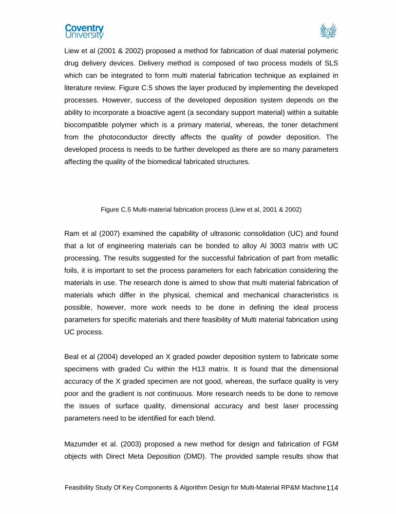
Feasibility Study Of Key Components & Algorithm Design for Multi-Material RP&M Machine 114
Liew et al (2001 & 2002) proposed a method for fabrication of dual material polymeric
drug delivery devices. Delivery method is composed of two process models of SLS
which can be integrated to form multi material fabrication technique as explained in
literature review. Figure C.5 shows the layer produced by implementing the developed
processes. However, success of the developed deposition system depends on the
ability to incorporate a bioactive agent (a secondary support material) within a suitable
biocompatible polymer which is a primary material, whereas, the toner detachment
from the photoconductor directly affects the quality of powder deposition. The
developed process is needs to be further developed as there are so many parameters
affecting the quality of the biomedical fabricated structures.
Figure C.5 Multi-material fabrication process (Liew et al, 2001 & 2002)
Ram et al (2007) examined the capability of ultrasonic consolidation (UC) and found
that a lot of engineering materials can be bonded to alloy Al 3003 matrix with UC
processing. The results suggested for the successful fabrication of part from metallic
foils, it is important to set the process parameters for each fabrication considering the
materials in use. The research done is aimed to show that multi material fabrication of
materials which differ in the physical, chemical and mechanical characteristics is
possible, however, more work needs to be done in defining the ideal process
parameters for specific materials and there feasibility of Multi material fabrication using
UC process.
Beal et al (2004) developed an X graded powder deposition system to fabricate some
specimens with graded Cu within the H13 matrix. It is found that the dimensional
accuracy of the X graded specimen are not good, whereas, the surface quality is very
poor and the gradient is not continuous. More research needs to be done to remove
the issues of surface quality, dimensional accuracy and best laser processing
parameters need to be identified for each blend.
Mazumder et al. (2003) proposed a new method for design and fabrication of FGM
objects with Direct Meta Deposition (DMD). The provided sample results show that
aa0682
Typewritten Text
These images have been removed

Feasibility Study Of Key Components & Algorithm Design for Multi-Material RP&M Machine 115
overall powder mixture concentration is continuous. However, results also suggest that
there are few points where the concentration changes suddenly. It is found that the
surface quality is very poor and the gradient is not continuous. To improve this more
research is need to be done on defining the process parameters for different powders.
The error of powder mixer concentrations also needs to be addressed.
Chiu and Yu (2008) described a direct digital manufacturing methodology, which make
it possible for fabrication of FGM prototype in 3D printing process. In this process, the
binders used in the 3D printing system are diluted to different extents, which makes it
possible to use the 3DP (3D Printing) system for FGM part fabrication with any major
modifications. However, it also proposed that range of the binder concentration at
present is very low which makes it impossible to fabricate an FGM object with a wide
range of mechanical properties. There are also 3DP process performance issues
which can result due to the change in the binder concentrations resulting into different
viscosity values, which can cause problems such as clogging of printer nozzles and
unstable binder droplets generation etc. Therefore, to improve the final quality of an
FGM objects, the technical issues need to be addressed before the methodology can
be implemented commercially.
Morvan et al (2001) fabricated a heterogeneous flywheel by LENS apparatus.
However, the process planning stage was modified for the fabrication of an FGM
object on a LENS apparatus. The fabricated flywheel indentified the quality issues and
constraints such as thermal constraint build up and overheating of previously
deposited layers which need to be addressed.
Kieback et al (2003) reviewed various available RP technologies to make FGM based
products, such as the Powder based 3D Printer (3-DP), Laser Selective Sintering
(SLS), Fused Deposition Modeling (FDM) and Stereolithography (SLA). The review
presents further challenges such as repeatability of production processes when
fabricating FGM parts, reliability of produced FGM parts, cost effectiveness of
production process and the quality control which needs to be addressed to evolve the
FGM applications.

Feasibility Study Of Key Components & Algorithm Design for Multi-Material RP&M Machine 116
Appendix D – Machine Design Snapshots
Figure D.1 M
2-3D Printer Machine Design Figure D.2 M
2-3D Printer Machine Design
Figure D.3 M
2-3D Printer Machine Design – Front View
M2-3DP Machine Design
Control Screen Image (farleylaserlab.com, 2011)
Nozzle Deposition System
Material Feeding System
Z-Axis – Build Area

Feasibility Study Of Key Components & Algorithm Design for Multi-Material RP&M Machine 117
Figure D.4 Front Panel Cover Assembly Figure D.5 Top Body Cover Figure D.6 Back Panel Cover
Figure D.7 Machine with Body Panel Covers Figure D.8 Machine without Body Panel Covers
M2-3DP Machine Design - Body Panels

Feasibility Study Of Key Components & Algorithm Design for Multi-Material RP&M Machine 118
Figure D.9 Machine Structure Panel Assembly Figure D.10 Machine Structure Panels – Exploded View
M2-3DP Machine Design - Body Panels
Top Panel
Back Panel Right Side Panel
Left Side Panel
Base Panel Front Panel

Feasibility Study Of Key Components & Algorithm Design for Multi-Material RP&M Machine 119
Figure D.11 M
2-3D Printer Machine Design Layout – Isometric View
Figure D.12 M
2-3D Printer Machine Design Layout – Front View Figure D.13 M
2-3D Printer Machine Design Layout – Top View
M2-3DP Machine Design - Layout
Z-Axis – Build Area
Material Feeding System
Nozzle Deposition System
X-Y Axis Wire Hanger System
Servo Motor for Y-Axis Movement
Servo Motor for X-Axis Movement

Feasibility Study Of Key Components & Algorithm Design for Multi-Material RP&M Machine 120
Figure D.14 M
2-3D Printer Nozzle Deposition System – Isometric View Figure D.15 M
2-3D Printer Nozzle Deposition System –
Exploded View
M2-3DP Nozzle Deposition Design

Feasibility Study Of Key Components & Algorithm Design for Multi-Material RP&M Machine 121
Figure D.16 M
2-3D Printer Nozzle Deposition System
M2-3DP Nozzle Deposition Design
Ball Bearing Unit Material Pipes
Main UV Curing Source
Nozzle Drive Belt
Nozzle Tube Assembly
Deposition System Housing
Servo Motor for Nozzle Rotation

Feasibility Study Of Key Components & Algorithm Design for Multi-Material RP&M Machine 122
Figure D.17 Main UV Curing Source
Figure D.18 Deposition System (without housing) – Isometric View
Figure D.19 Deposition System Housing
Figure D.20 Deposition System (without housing) – Side View
M2-3DP Nozzle Deposition Design

Feasibility Study Of Key Components & Algorithm Design for Multi-Material RP&M Machine 123
Figure D.21 Nozzle Deposition System
M2-3DP Nozzle Deposition Design
Deposition System (Without extended material pipes)
Exploded View of Assemblies
Deposition System (Without material
pipes)

Feasibility Study Of Key Components & Algorithm Design for Multi-Material RP&M Machine 124
Figure D.22 Nozzle Deposition System Figure D.23 Nozzle Fixing Plate – Exploded View
Figure D.24 UV Spotlight
M2-3DP Nozzle Deposition Design
Nozzle Fixing
UV Spotlight
UV Spotlight

Feasibility Study Of Key Components & Algorithm Design for Multi-Material RP&M Machine 125
Figure D.26 Nozzle Cover Assembly
Figure D.27 Nozzle Pressure Plate Assembly
Figure D.28 Nozzle Flow Control Assembly
Figure D.25 Nozzle assembly & its Exploded View
M2-3DP Nozzle Deposition Design

Feasibility Study Of Key Components & Algorithm Design for Multi-Material RP&M Machine 126
Figure D.29 Wire & Pipe Hanger Assembly Figure D.30 Wire & Pipe Hanger Exploded View
Figure D.31 Wire & Pipe Hanger Assembly Layout Figure D.32 Wire & Pipe Hanger Assembly
M2-3DP Nozzle Deposition Design

Feasibility Study Of Key Components & Algorithm Design for Multi-Material RP&M Machine 127
Figure D.33 M
2-3D Printer Machine Design Figure D.34 Exploded view of Z-Axis
Figure D.35 Z-Axis Assembly
M2-3DP Nozzle Deposition Design

Feasibility Study Of Key Components & Algorithm Design for Multi-Material RP&M Machine 128
. Figure D.36 M
2-3D Printer Machine Design Figure D.37 Feeding Apparatus Design
Figure D.38 Feeding Apparatus Design – Isometric View Figure D.39 M
2-3D Printer Machine Design
M2-3DP Nozzle Deposition Design
Servo Motor
Crank Shaft
Material Pump
Refill Doors
Overflow Valve
Material Pipe

Feasibility Study Of Key Components & Algorithm Design for Multi-Material RP&M Machine 129
Figure D.40 Feeding Apparatus (Without Crankshaft)
Figure D.41 Feeding Pump Assembly Figure D.42 Feeding Pump Assembly – Exploded View
M2-3DP Nozzle Deposition Design

Related Documents