Defence R&D Canada – Atlantic DEFENCE DÉFENSE & Feasibility of normal incidence techniques for use with REA Buoy Douglas J Schillinger GaleForce Scientific Consulting Ltd. GaleForce Scientific Consulting Ltd. 81 Newcastle Street Dartmouth, NS B2Y 3M8 Project Manager: F. Desharnais, (902) 426-3100 ext 219 Contract Number: W7707-03-2132 Contract Scientific Authority: F. Desharnais, (902) 426-3100 ext 219 Contract Report DRDC Atlantic CR 2004-137 January 2005 Copy No.________ Defence Research and Development Canada Recherche et développement pour la défense Canada

Welcome message from author
This document is posted to help you gain knowledge. Please leave a comment to let me know what you think about it! Share it to your friends and learn new things together.
Transcript

Defence R&D Canada – Atlantic
DEFENCE DÉFENSE&
Feasibility of normal incidence techniques
for use with REA Buoy
Douglas J SchillingerGaleForce Scientific Consulting Ltd.
GaleForce Scientific Consulting Ltd.81 Newcastle StreetDartmouth, NS B2Y 3M8
Project Manager: F. Desharnais, (902) 426-3100 ext 219
Contract Number: W7707-03-2132
Contract Scientific Authority: F. Desharnais, (902) 426-3100 ext 219
Contract Report
DRDC Atlantic CR 2004-137
January 2005
Copy No.________
Defence Research andDevelopment Canada
Recherche et développementpour la défense Canada

This page intentionally left blank.

Feasibility of normal incidence techniques for use with REA Buoy Douglas J Schillinger GaleForce Scientific Consulting Ltd.
GaleForce Scientific Consulting Ltd. 81 Newcastle Street Dartmouth, NS B2Y 3M8
Project Manager: F. Desharnais, 902-426-3100 ext 219
Contract Number: W7707-03-2132
Contract Scientific Authority: F. Desharnais, 902-426-3100 ext 219
Defence R&D Canada - Atlantic Contract Report DRDC Atlantic CR 2004-137 January 2005
Abstract
Literature relating to normal incidence techniques for determining geo-acoustic properties of sediment layers in the ocean is reviewed. The techniques outlined in the literature are assessed for use with a Rapid Environmental Assessment (REA) buoy currently under design at DRDC Atlantic. While there is extensive literature on normal incidence techniques for frequencies above 10 kHz and limited literature on experiments at lower frequencies in all cases there are critical differences in geometry of these previous experiments when compared to that of the REA buoy. One technique integrates the bottom and bottom-surface returns to determine roughness and reflection coefficient of the ocean-sediment interface. The frequency range for which this technique has been used (>10 kHz; 1-10 kHz) is not compatible with the current source of the REA buoy. A second technique uses waveform inversion to determine acoustic impedance (or other property) as a function of travel time. Geo-acoustic properties are found using either an iterative layer stripping technique or by minimizing the difference between perturbed models and the measured signal via least squares or simulated annealing. While the waveform inversion techniques have the most promise, the signal must be sampled at least 4 times the Nyquist criteria (or resampled using Fourier techniques if possible). A method for determining the attenuation of sub-surface layers is also reviewed, and a modified version is presented for use with the REA buoy.
Résumé
La documentation sur les techniques à incidence normale pour la détermination des propriétés géo-acoustiques des couches sédimentaires de l'océan est examinée. Les techniques décrites dans la documentation sont évaluées en vue de leur utilisation en conjonction avec une bouée d'analyse rapide de l'environnement (REA) en voie de conception à RDDC Atlantique. Il y a beaucoup de documentation sur les techniques à incidence normale à des fréquences supérieures à 10 kHz et une documentation limitée sur les expériences menées à des fréquences inférieures, mais il y a, dans tous les cas, des différences critiques dans la géométrie de ces expériences par rapport à celle de la bouée REA. Une des techniques intègre les échos du fond et ceux de la surface du fond en vue de la détermination de la rugosité et du coefficient de réflexion de l'interface océan-sédiment. La gamme de fréquences pour laquelle cette technique a été utilisée (fréquences supérieures à 10 kHz, et bande 1-10 kHz) n'est pas compatible avec la source actuelle de la bouée REA. Une seconde technique fait appel à l'inversion de la forme d'onde pour déterminer l'impédance acoustique (ou une autre propriété) en fonction du temps de déplacement. Les propriétés géo-acoustiques sont trouvées soit à l'aide d'une technique de décapage itératif des couches, soit par la réduction de la différence notée entre les modèles perturbés et le signal mesuré à l'aide de la méthode des moindres carrés ou du recuit simulé. Bien que les techniques d'inversion de la forme d'onde soient les plus prometteuses, le signal doit être échantillonné à une fréquence égale à au moins quatre fois le critère de Nyquist (ou ré-
DRDC Atlantic CR 2004-137 i

échantillonné au moyen des techniques de Fourier dans la mesure du possible). Une méthode qui permet de déterminer l'atténuation des couches sous-marines est également examinée, et une version modifiée est présentée pour utilisation avec la bouée REA.
ii DRDC Atlantic CR 2004-137
Executive summary
Introduction
One of the systems under development for the Rapidly Deployable Systems (RDS) Technology Demonstration (TD) project is a buoy (aka CARbuoy) with the three purposes of Communications, Array Element Localization (AEL), and Rapid Environmental Assessment (REA). The buoy is referred to in this report as the REA buoy. Due to logistical constraints, the REA techniques considered for this buoy have to be technologically and computationally simple. The normal incidence technique, which measures the reflectivity of the seabed at normal incidence, answers these requirements.
Results
In this document, literature relating to normal incidence techniques for determining geo-acoustic properties of sediment layers in the ocean is reviewed. The techniques outlined in the literature are assessed for use with the REA buoy currently under design as part of the RDS TD. While there is extensive literature on normal incidence techniques for frequencies above 10 kHz and limited literature on experiments at lower frequencies in all cases there are critical differences in geometry of these previous experiments when compared to that of the REA buoy. One technique integrates the bottom and bottom-surface returns to determine roughness and reflection coefficient of the ocean-sediment interface. The frequency range for which this technique has been used (>10 kHz; 1-10 kHz) is not compatible with the current source of the REA buoy. A second technique uses waveform inversion to determine acoustic impedance (or other property) as a function of travel time. Geo-acoustic properties are found using either an iterative layer stripping technique or by minimizing the difference between perturbed models and the measured signal via least squares or simulated annealing. While the waveform inversion techniques have the most promise, the signal must be sampled at least four times the Nyquist criteria (or resampled using Fourier techniques if possible). A method for determining the attenuation of sub-surface layers is also reviewed, and a modified version is presented for use with the REA buoy.
Military significance
The environmental measurements made by the CARbuoy add significant capability to the detection and localization by the RDS systems that the CARbuoy supports. The normal incidence technique is a powerful tool as it provides essential information on the impedance of the surficial sediment layer.
Future plans
The techniques outlined in this report will be used to select the most appropriate source for the REA buoy, and the optimal sampling frequency for the system.
DRDC Atlantic CR 2004-137 iii

Schillinger, D.J. 2005. Feasibility study of normal incidence techniques for use with REA buoy. DRDC Atlantic CR 2004-137. Defence R&D Canada – Atlantic.
iv DRDC Atlantic CR 2004-137

Sommaire
Introduction
L'un des systèmes en voie de mise au point dans le cadre du projet de démonstration de technologies du système à déploiement rapide (RDS) est une bouée (aussi appelée bouée de recherche acoustique canadienne [CAR]) servant à trois fins : communications, localisation d'éléments de réseau [AEL] et analyse rapide de l'environnement [REA]. Dans le présent rapport, la bouée est appelée « bouée REA ». En raison de contraintes logistiques, les techniques REA examinées pour cette bouée doivent être simples sur les plans de la technique et des calculs. La technique à incidence normale, qui permet de mesurer la réflectivité du fond marin à une incidence normale, répond à ces besoins.
Résultats
Dans le présent rapport, la documentation sur les techniques à incidence normale pour la détermination des propriétés géo-acoustiques des couches sédimentaires de l'océan est examinée. Les techniques décrites dans la documentation sont évaluées en vue de leur utilisation en conjonction avec une bouée REA en voie de conception dans le cadre du projet de démonstration de technologie du système RDS. Il y a beaucoup de documentation sur les techniques à incidence normale à des fréquences supérieures à 10 kHz et une documentation limitée sur les expériences menées à des fréquences inférieures, mais il y a, dans tous les cas, des différences critiques dans la géométrie de ces expériences par rapport à celle de la bouée REA. Une des techniques intègre les échos du fond et ceux de la surface du fond en vue de la détermination de la rugosité et du coefficient de réflexion de l'interface océan-sédiment. La gamme de fréquences pour laquelle cette technique a été utilisée (fréquences supérieures à 10 kHz, et bande 1-10 kHz) n'est pas compatible avec la source actuelle de la bouée REA. Une seconde technique fait appel à l'inversion de la forme d'onde pour déterminer l'impédance acoustique (ou une autre propriété) en fonction du temps de déplacement. Les propriétés géo-acoustiques sont trouvées soit à l'aide d'une technique de décapage itératif des couches, soit par la réduction de la différence notée entre les modèles perturbés et le signal mesuré à l'aide de la méthode des moindres carrés ou du recuit simulé. Bien que les techniques d'inversion de la forme d'onde soient les plus prometteuses, le signal doit être échantillonné à une fréquence égale à au moins quatre fois le critère de Nyquist (ou ré-échantillonné au moyen des techniques de Fourier dans la mesure du possible). Une méthode qui permet de déterminer l'atténuation des couches sous-marines est également examinée, et une version modifiée est présentée pour utilisation avec la bouée REA.
Importance militaire
Les mesures environnementales faites par la bouée REA améliorent de façon significative les fonctions de détection et localisation des systèmes RDS que les bouées REA supportent. La technique à incidence normale est un outil important qui
DRDC Atlantic CR 2004-137 v

donne de l’information essentielle sur l’impédance de la couche superficielle de sédiment.
Recherches futures
Les techniques décrites dans le présent rapport serviront à la sélection de la source la plus appropriée pour la bouée REA et au choix de la fréquence d'échantillonnage optimale pour le système.
Schillinger, D.J. 2005. Étude de faisabilité des techniques d'incidence normale pour utilisation
S asibility study of normal incidence techniques for use with REA buoy. DRDC Atlantic CR 2004-137. Defence R&D Canada – Atlantic.
chillinger, D.J. 2005. Feavec la bouée REA. RDDC Atlantique CR 2004-137. R & D pour la défense Canada - Atlantique.
vi DRDC Atlantic CR 2004-137

Table of contents
Abstract........................................................................................................................................ i
Executive summary ................................................................................................................... iii
Sommaire.................................................................................................................................... v
Table of contents ...................................................................................................................... vii
List of figures ............................................................................................................................ ix
1. Introduction ......................................................................................................................... 1 1.1 The Rapid Environmental Assessment Buoy....................................................... 1 1.2 Annotated Bibliography Summary....................................................................... 2
2. Annotated Bibliography ...................................................................................................... 5 2.1 Waveform inversion, iterative layer stripping...................................................... 5
2.1.1 S. Panda, L.R. LeBlanc, and S.G. Schock, “Sediment classification based on impedance and attenuation estimation,” J. Acoust. Soc. Am. 96, 3022-3055 (1994). ............................................................................................ 5 2.1.2 Discussion ............................................................................................ 6 2.1.3 Related papers ...................................................................................... 6
2.2 Waveform inversion, model................................................................................. 7 2.2.1 S.D. Rajan, “Waveform inversion for the geoacoustic parameters of the ocean bottom,” J. Acoust. Soc. Am. 91, 3228-3241 (1992). ...................... 7 2.2.2 W.T. Wood,and D.A. Lindwall, “Full waveform inversion of field sonar returns for a visco-acoustic Earth; A comparison of linearized and fully non-linear methods,” IEEE J. Ocean. Eng. 21, 423-431 (1996)...................... 8 2.2.3 Related papers ...................................................................................... 9 2.2.4 Discussion ............................................................................................ 9
2.3 Parametric SONAR.............................................................................................. 9 2.3.1 A. Caiti, O. Bergem , J. Dybedal , “Parametric sonars for seafloor characterization,” Meas. Sci. Tech. 10, 1105-1115 (1999). ............................. 9 2.3.2 Discussion .......................................................................................... 10
2.4 Integrated energy of mono- and bi-static returns ............................................... 10
DRDC Atlantic CR 2004-137 vii

2.4.1 J.C. Osler, P.C. Hines, M.V. Trevorrow, “Acoustic and in-situ techniques for measuring the spatial variability of seabed geoacoustic parameters in littoral environments,” Impact of littoral environmental variability on acoustic predictions and SONAR performance,N.G. Pace, and F.B. Jenson eds, 83-90 (2002). ....................................................................... 10 2.4.2 Related Papers.................................................................................... 10 2.4.3 Discussion .......................................................................................... 11
2.5 Biot theory.......................................................................................................... 12 2.5.1 K.L. Williams, D.R. Jackson, E.I. Thorsos, D. Tang, and S.G. Schock, “Comparions of sound speed and attenuation measured in a sandy sediment to predications based on Biot Theory of porous media,” IEEE J. Ocean. Eng. 27, 413-428 (2002) ............................................................................................... 12 2.5.2 Related papers .................................................................................... 12 2.5.3 Discussion .......................................................................................... 12
2.6 Full field inversion ............................................................................................. 12 2.6.1 C.W. Holland, and J. Osler, “High-resolution geoacoustic inversion in shallow water: A joint time- and frequency-domain technique,” J. Acoust. Soc. Am. 107, 1263-1279 (2000). ................................................................. 12 2.6.2 C.W. Holland, “Coupled scattering and reflection measurements in shallow water,” IEEE J. Ocean. Eng. 27, 454-470 (2002). ........................... 13
2.7 Seabed discrimination ........................................................................................ 13
3. REA buoy design considerations ...................................................................................... 14
4. References ......................................................................................................................... 18
Bibliography ............................................................................................................................. 19
Distribution list ......................................................................................................................... 24
viii DRDC Atlantic CR 2004-137

List of figures
Figure 1. Source signal (I) and surface reflection (I) in a. Time gated matched filter signal (b) shows reflections from interfaces (III,IV, V), and the residual signal (modelled – experimental). Source was at 10 m depth, signal length was 5 ms. .................................. 16
List of tables
Table 1 Summary of papers presented in annotated bibliography, c, α, ρ denote speed of sound, attenuation and density. The subscripts s and p denote shear and compressional properties............................................................................................................................. 3
Table 2. Sediment layer model ................................................................................................. 16
Table 3. Experimental results using synthetic data created from a sediment model ................ 17
DRDC Atlantic CR 2004-137 ix

This page intentionally left blank.
x DRDC Atlantic CR 2004-137

1. Introduction
Obtaining geo-acoustic parameters other than impedance from normal incidence experiments is difficult. Unambiguous estimates of both density and the speed of sound in the sediment layers using this limited amount of acoustic information (no angular dependence) are difficult to obtain when compared to full field inversion techniques, where layer thickness can be obtained from shallow angle incidence paths. The ratio of mono- and bi-static normal incidence returns can be used to classify sediment types. Waveform inversion of normal incidence returns is used to estimate impedance as a function of two-way travel time. Conducting normal incidence experiments using broadband sources increases the amount of information available for the geo-acoustic inversion. Also, the attenuation over a sub-bottom layer can be estimated using the shift in peak frequency of a FM pulse.
Ideally buoy geometry and instrument selection would be made to suit the findings of this report. However, the REA buoy is currently under design for other geo-acoustic methods, and the use of normal incidence techniques would simply be a complementary technique for specific environments. Due to this constraint, all possible techniques are presented for review in the annotated bibliography (Section 2) and presented in the context of the REA buoy design in the discussion (Section 3).
1.1 The Rapid Environmental Assessment Buoy
A rapid environmental assessment (REA) buoy is currently under design for the Rapidly Deployable Systems (RDS) Technology Demonstration project. The primary design will use a coherence technique on surface driven ambient sound to invert for the geo-acoustical properties of the seabed. For this purpose the buoy will be equipped with 3 sub-surface hydrophones in a vertical line array (VLA) located at mid depth in the water column. For compatibility with other DRDC equipment (both horizontal and vertical line arrays) the sampling frequency is limited to 2 kHz, and will be equipped with a low pass filter at 800 Hz. For array element localization (AEL) the buoy will also be equipped with an acoustic source with an operating range above 300 Hz. The surface realization of the REA buoy will also be equipped with an acoustic modem for communication with bottom-mounted electronics.
For arctic environments surface driven ambient sound is not a suitable source for geo-acoustical inversion. This annotated bibliography investigates normal incidence techniques using the AEL source rather than the ambient sound generated at the surface as an alternative method of geo-acoustic inversion for this buoy.
Due to design limitations, the AEL source will be at the bottom of a SPAR buoy. The spar buoy will be tethered to the bottom anchor by a line of length three times the bottom depth to reduce wave induced tugging on the mooring. While the VLA will be kept vertical via a top float and bottom weight, the possible distance of the AEL source to the VLA makes them unsuitable for normal incidence techniques and full field
DRDC Atlantic CR 2004-137 1

geometries. To facilitate the normal incidence techniques two hydrophones located directly below the source will be added to the buoy.
1.2 Annotated Bibliography Summary
Full field geometry [1, 2] is the most commonly used technique for estimating the geo-acoustical properties of the ocean bottom. Full field geometry makes use of angular dependence of the reflected signal and sediment layer thickness can be determined using shallow angle ray paths. The limitation of these techniques is the large spatial area required to collect data, thereby limiting the horizontal resolution of the studies.
Quite often it is more desirable to collect only the normal incidence rays (as in the seabed discrimination method). Data collected in this manner produces results with higher horizontal resolution than full field inversion, and the experiment requires less instrumentation. However, the amount of independent variables collected is reduced (no angular dependence). As such, usually only one property can be determined via normal incidence, most commonly impedance as a function of the acoustic travel time.
The simplest means to obtain information about the ocean sediment interface is to integrate the energy of the bottom signal, and the surface bottom signal. The integrated return technique relates the energy of the second return (bi-static or near field) to the plane wave reflection coefficient, and the integrated energy of the first return (monostatic far field) to the roughness of the interface [3]. However, geo-acoustic parameters are extracted empirically and not numerically from this method. This technique is well suited to ship mounted echo sounders for use in underway surveys. The results are better described as seabed discrimination rather than geo-acoustic inversion. There is extensive literature based on the classification of the ocean bottom based on the acoustic return from ship-mounted bottom sounders [see bibliography section seabed discrimination]. In fact there are three off the shelf packages able to perform this classification, one (QTC View) based on statistical qualities of the measured acoustic return from the ocean bottom [4], the other two (Roxanne and EHCOPlus) based on the roughness and reflection coefficient [5,6]. In general the mono- and bi-static integral method is generally limited to frequencies above 10 kHz although the integral method has been extended to 1- 10 kHz [7]. In these applications the directivity of the device excludes interference of the downward travelling surface multiples, while the high frequency used limits the amount of interference from sub-surface returns.
A more complicated normal incidence method produces estimates of acoustic impedance versus two way travel time. Of the normal incidence experiments reviewed, all were conducted in deep water so as to gate out any surface-multiple interference. Geo-acoustic parameters are obtained either via a least squares techniques or using simulated annealing methods. With regard to the least squares technique, either an iterative layer-stripping approach can be used or the bottom can be modeled as a set of iso-velocity layers of equal thickness. In the first technique the return from individual sub-layers are identified, modeled and then removed from the measured signal, while the second technique models the pressure field at the receiver
2 DRDC Atlantic CR 2004-137

via the greens function and minimizes a set of perturbed models. Time domain inversions must be sampled at more than the Nyquist frequency [8]. If the source has a known frequency and form, the recorded signal (or the matched filtered return) can be re-sampled at a higher rate using Fourier techniques [8].
A method for determining the attenuation of sub bottom layers has been reported [8]. In this paper the authors measure the shift in peak frequency of overlapping returns from a FM pulse.
Feasible techniques for the REA buoy are presented in an annotated bibliography and are summarized in Table 1. A more broad range of papers is included in a general bibliography at the end of this document. A discussion section outlining this reports choice of feasible methods is presented in Section 3.
Table 1 Summary of papers presented in annotated bibliography, c, α, ρ denote speed of sound,
attenuation and density. The subscripts s and p denote shear and compressional properties
AUTHORS DATE GEOMETRY TECHNIQUE PARAMETERS LIMITATIONS
Rajan, S.D. 1992 Deep Water (1900m)
S = 125m above bottom
R = 1, 50m above bottom
CW source 220 Hz
synthetic data 50, 75, 100 Hz
drift 0-3000m away
Re (P)
waveform inversion
non-linear optimization algorithm
full field
cp,cs, αp, αs, ρ
source strength can also be an unknown
deep water gates surface returns and multiples (topless model)
dependent on initial guess
errors in source position have significant effects
real-time ??
2m thick layers terminated by half space
Panda, S et al 1994 underway survey
FM pulse 2-16 kHz, 4-24 kHz
full wave form inversion weighted least square fitting with layer stripping
frequency shift of pulse spectrum
biot theory
Z
α
porosity, ρ, mean grain size and cp cs, z
deep water gates bottom-surface
baffle to reduces first surface multiples
a priori knowledge of source wavelet
layers are parallel, laterally homogenous, and reflection coefficients are independent of frequency
phase dispersion
DRDC Atlantic CR 2004-137 3

and pulse spreading can be neglected
acoustic wave at normal incidence
reflection coefficients << 1
Wood, W.T. and Lindwall, D.A.
1996 underway survey
15 kHz 0.22 ms pulse
moon pool mounted source
~240 m water depth
wave form inversion
linearized least squares (LLS)
simulated annealing (SA) with layer stripping
Z versus two way travel time
LLS is a linearized version of Rajan
a priori knowledge of wavelet required
dependent on initial guess for LLS, not SA
no global minimum found for SA when phase is included
Holland C.W and Osler J
2000 towed source, uniboom (0.6-6 kHz)
shallow tow, short duration transmit pulse
one fixed receiver
shallow (150m) water
time domain
frequency domain
feedback
full field
z, cp
α ρ
iterative process, guided by user
not real time
wide angle reflection
Hines P.C., Heald, G.J.
2000 1-10 kHz monostatic and bistatic return
roughness
Z
bistatic return dependent on surface
4 DRDC Atlantic CR 2004-137

2. Annotated Bibliography
2.1 Waveform inversion, iterative layer stripping
2.1.1 S. Panda, L.R. LeBlanc, and S.G. Schock, “Sediment classification based on impedance and attenuation estimation,” J. Acoust. Soc. Am. 96, 3022-3055 (1994).
Estimates of the plane wave reflection coefficient and the attenuation of sub-bottom sediment layers are determined in this paper. In addition, other properties including the porosity, density, mean grain size and sound speed were determined using Biot theory. The impedance is obtained using waveform inversion of an FM pulse swept from 2 to 16 kHz. The following assumptions are made about the seabed:
layers are parallel and laterally homogeneous
interface reflection coefficients are frequency independent
phase dispersion and pulse spreading can be neglected
acoustic wave travels at normal incidence through the layers
reflection coefficients are less than 1
The potential time of arrival of the first reflection is identified (τ). A set of 2n+1 signals each with start times ranging -n*t+τ to n*t+τ are determined and the exact time and amplitude of the measured signal is calculated by minimizing the difference between the observed data and the set of synthetic data. This synthetic signal is used to remove the signal from the first reflector from the observed signal. Arrivals from deeper layers are sequentially identified and removed following the same method as for the first arrival (layer stripping algorithm). A weighting algorithm is employed to aid in resolving overlapping signals from thin sediment layers.
An estimate of attenuation is made from the shift in centre frequency of the returned pulse. This shift arises from the frequency dependence of the attenuation in a sediment layer. The centre frequency is estimated form the instantaneous frequency of the analytic signal. The frequency shift is then converted to a relaxation time for which models exist to relate this quantity to attenuation.
These methods were used on synthetic data, and performed well even in the presence of noise. For experimental data, sampling at the Nyquist frequency was inadequate in resolving phase errors. To overcome this, the data were resampled at four times their original rate using FFT methods.
DRDC Atlantic CR 2004-137 5

Finally sediment type prediction is quantified using Biot theory. Physical properties of sediments (porosity, grain density, bulk density, bulk compressibility and the modulus of rigidity) are related to the acoustical properties (impedance, compressional wave velocity and attenuation).
2.1.2 Discussion
The REA buoy will not be able to produce FM pulses, so the method used to determine attenuation cannot be used. However, a variation of this method is presented in Section 3 of this report, which might be able to produce the attenuation via a means amenable to the AEL source.
The waveform inversion technique requires either a high sampling rate (4 times the Nyquist frequency), or the signal must be able to be accurately resampled using Fourier techniques. Even so, given that the source and receivers of the REA are close to the surface the complication of interference from surface multiples may limit the reliability of the estimates provided by this method. The application of this technique with the proposed geometry of the REA buoy is investigated in Section 3 of this report.
Another alternative is to have the source and one hydrophone co-located in the bottom of the surface buoy. If the buoy is made from syntactic foam, the hydrophone may be shielded from any surface returns.
2.1.3 Related papers
P. Cobo-Parra, and C. Ranz-Guerra, “Impedance profile and overall attenuation estimation of layered sea bottoms from their normal incidence acoustic reflection response,” J. Acoust. Soc. Am. 85, 2388-2393 (1989).
L.R. LeBlanc, L. Mayer, M. Rufino, S.G. Schock, and J. King, “Marine sediment classification using chirp sonar,” J. Acoust. Soc. Am. 91, 107-115 (1992).
L.R. LeBlanc, S. Panda, and S.G. Schock, “Sonar attenuation modeling for classification of marine sediments,” J. Acoust. Soc. Am. 91, 116-126 (1992)
P.S. Hauge, “Measurements of attenuation from vertical seismic profiles,” Geophysics 46, 1548-1558 (1981).
6 DRDC Atlantic CR 2004-137

2.2 Waveform inversion, model
2.2.1 S.D. Rajan, “Waveform inversion for the geoacoustic parameters of the ocean bottom,” J. Acoust. Soc. Am. 91, 3228-3241 (1992).
In this paper, waveform inversions are performed on synthetic data for tonals at 50, 75 and 100 Hz as well as for an experimental 220-Hz source. Parameters obtained in the inversion are density, as well as the attenuation and both compressional and shear sound speeds. The ocean bottom is modelled as a set of iso-velocity layers 2 m thick. A priori information can be included in the model, and an initial guess of the environment is required. In fact, the results are dependent on how close the initial guess is to the actual parameters. The experiment is conducted with the source at ranges from 1 to 6 km, resulting in a full field inversion. The source is towed close (~150 m) to the ocean bottom in deep water (~2000 m) thereby gating out surface returns.
The estimates for the acoustic model come from minimizing the least squares cost function. In this case the solution is constrained by an initial guess of the physical parameters. In the calculation of the forward model, the pressure field is determined using a topless and iso-velocity ocean.
The performance of the technique is evaluated using both the complex pressure field and the magnitude of the pressure field. Performance using only the magnitude is comparable to using the complex data, which is significant for experimental situations where the complex pressure field is more difficult to measure. In the presence of noise, the complex pressure field performs betters than the real pressure field.
Several parameters affecting the quality of the inversion are investigated. These are presence of noise, range error, source height variation, as well as the error associated with modeling the sediment as a fluid. While the algorithm is robust in the presence of noise, errors in range and source depth lead to significant errors in the estimates, with the range error being more critical than the depth error.
Inversion of real data taken in deep water (1907 m) with two hydrophones located 1.17 and 54.55 m off the ocean bottom. The source was suspended from a ship by a cable and suffered from vertical oscillations. Mean source height was 135 m from the bottom. For the experimental data three assumptions were made:
shear effect at 220 Hz is negligible
measured field is most sensitive to compressional wave speed in the sediment.
the density and attenuation were assumed known.
approximate depths of the sediment layers were estimated using 3.5 kHz seismic data.
DRDC Atlantic CR 2004-137 7

2.2.2 W.T. Wood,and D.A. Lindwall, “Full waveform inversion of field sonar returns for a visco-acoustic Earth; A comparison of linearized and fully non-linear methods,” IEEE J. Ocean. Eng. 21, 423-431 (1996).
The experiment described in this paper uses narrow frequency band source with a normal incidence geometry to invert for acoustic impedance as a function of two-way travel time. Short (0.22 ms) mid frequency (15 kHz) pulses are sent and received by a ship-mounted transducer. Two inversion techniques are compared for speed of inversion and experimental limitations. They used an EDO transducer tuned to 15 kHz, which was either omni, or had a 55-degree beam width (EDO makes two transducers which fit the description given in the paper and it is not clear which one they used).
The first technique reduces the inversion to a linear problem by reducing the ocean bottom to a number of layers of constant travel time and is called a Linear Least Squares Inversion (LLSI). The method uses the iterative matrix equation from Tarantola. To solve the inversion problem a starting model must be provided, along with a covariance matrix of both the model and data. This requirement for a priori information may result in a local minimum in optimization if this information is too far from the true values. Also, the data pass band is based on an event-picker, which may fail if there is too much additive noise, too narrow a bandwidth, or if there is interference in the reflections. The event picker is an algorithm similar to Panda et al, where thick layer solutions are assumed. The results from this event picker seed the model for the LLSI. The solution set was found quite quickly using this technique, but the problem will increase geometrically with frequency, and will also require more time if new matrices are required for each ping.
It must be noted that the LLSI method used here is a linearized version of the one used in Rajan. The method used in Rajan is simplified by the normal incidence geometry. In addition, in this paper the model is determined in frequency space so as to reduce the number of data points required. In Rajan, the entire returned signal is considered, while here only time-gated signals corresponding to signals from single reflectors are considered (the event picker).
Simulated annealing (SA) is the second technique used for inversion. In this case the search is conducted over model space by perturbing one variable of the current model, calculating synthetic data with a forward model and comparing this to the measured data using an objective function. The technique is based on the classic Metropolis algorithm, but includes a layer dependence introduced to solve for the upper layers first. Their SA algorithm has elements of the very fast simulated re-annealing (VFSA), while their forward model uses the reflectivity code PNSEB. A convolution method similar to LLSI could have been used, but the reflectivity method had been previously integrated to the authors SA for application to other data. Because only impedance can be recovered from the data presented here the compressional velocity is held constant while solving for density and layer thickness.
8 DRDC Atlantic CR 2004-137

The SA method requires no a priori information, and uses a more sophisticated wave based algorithm for its forward calculations, but at the cost of computing time. Initial attempts to invert synthetic data for layer thickness and impedance failed. By using only the waveform envelope the computation time was reduced, but phase information was lost. A two-pronged SA approach was suggested, where the envelope method finds the events and seeds the model with the layer numbers, followed by a full SA method to refine density estimates (as density is sensitive the phase information).
LSSI will not work for strong interbed multiples, strongly varying Q, or lateral variability.
2.2.3 Related papers
G.S. Pan, R.P Phinney, and R.I.Odum, “Full waveform inversion of plane-wave seismograms in stratified acoustic media: Theory and feasibility,” Geophysics 53, 21-31 (1988).
G.V. Frisk, A.V. Oppenheim, and D.R. Martinez, “A technique for measuring the plane-wave reflection coefficient of the ocean bottom,” J. Acoust. Soc. Am. 68, 602-612 (1980).
S. Mallick, and L. N. Frazer, “Practical aspects of reflectivity modeling,” Geophysics, 52, 1355-1364 (1987).
M.K. Sen, and P.L. Stoffa, “Nonlinear one-dimensional seismic waveform inversion using simulated annealing,” Geophysics, 56, 1624-1638 (1991).
2.2.4 Discussion
Wood and Lindwall are closest to the geometry of the REA buoy, while Rajan uses frequencies more comparable to the REA buoy. Wood and Lindwall claim that their model is effective at identifying large impedance contrasts though their experimental results did not compare well to core data at small scales. They account for their differences by suggesting high lateral variability in small (< 10cm thick features). The impedance at the ocean sediment interface agree with Caiti et. al (see later). The large scale features modelled in Rajan were consistent with those obtained by other investigators.
2.3 Parametric SONAR
2.3.1 A. Caiti, O. Bergem , J. Dybedal , “Parametric sonars for seafloor characterization,” Meas. Sci. Tech. 10, 1105-1115 (1999).
This paper discusses the advantages that parametric sonars represent over traditional sources; that they are narrow beam rather than wide beam. The authors use the BoRIS
DRDC Atlantic CR 2004-137 9

prediction code to model the environment. The geometry is such that source signal is steered at normal incidence and the returned signal is recorded on an omni-directional receiver co-located with the source.
The sound speed in water, water depth and source characteristics are all assumed known. The unknowns are mean acoustic impedance, αp, RMS seabed roughness and the mean volume inhomogeneity.
Experimental results comparing estimated impedance to measured values taken from core samples ‘reveal remarkable agreement’.
This approach can be applied to the uppermost layer of unconsolidated marine sediments with low bioturbation.
2.3.2 Discussion
Since the REA buoy will not be equipped with a parametric SONAR, a detailed analysis of the methods involved are not presented here. However, the results here do support the waveform inversion of Wood and Lindwall.
2.4 Integrated energy of mono- and bi-static returns
The integrated energy from the trailing edge of the direct bottom return and the integrated energy of the bottom-surface return are related to the bottom roughness and the reflection coefficient of the ocean-sediment interface.
2.4.1 J.C. Osler, P.C. Hines, M.V. Trevorrow, “Acoustic and in-situ techniques for measuring the spatial variability of seabed geoacoustic parameters in littoral environments,” Impact of littoral environmental variability on acoustic predictions and SONAR performance,N.G. Pace, and F.B. Jenson eds, 83-90 (2002).
In this experiment a highly directional, downward looking source is used to classify surficial sediment. The ratio of integrated energy of the bottom and bottom surface returns are used to classify sediments. The source frequency is in the 1-10 kHz range where bottom roughness at the seabed is the dominant scattering mechanism.
2.4.2 Related Papers
G.J. Heald, N.G. Pace, ”An analysis of 1st and 2nd backscatter for seabed classification,” 3rd European conference on underwater acoustics Heraklion Greece, J.S Papadakis ed, 649-654 (1996).
10 DRDC Atlantic CR 2004-137

P.C. Hines,G.J. Heald, ”Seabed classification using normal incidence backscatter measurements in the 1-10 kHz frequency band,” Proceedings of the institute of acoustics,T.G. Leighton ed.,Vol 23 part2 (2000).
2.4.3 Discussion
Given the geometry of the REA buoy this technique would likely be the most effective provided the time between the arrival of the bottom signal and the bottom-surface return was longer than the pulse length of the signal. However, only information about the uppermost sediment layer would be retrieved. Also, it is not clear that this technique can be extended to frequencies less than 1 kHz.
DRDC Atlantic CR 2004-137 11

2.5 Biot theory
While not specific to normal incidence techniques, the impedance and attenuation data collected via normal incidence techniques can be expanded on using this theory [8].
2.5.1 K.L. Williams, D.R. Jackson, E.I. Thorsos, D. Tang, and S.G. Schock, “Comparions of sound speed and attenuation measured in a sandy sediment to predications based on Biot Theory of porous media,” IEEE J. Ocean. Eng. 27, 413-428 (2002)
The data presented here are part of a bigger data set, SAX99. This paper deals compares in situ measurements to fast-wave-sound-speed and attenuation estimates using Biot theory.
2.5.2 Related papers
K.L. Williams, “An effective density fluid model for acoustic propagation in sediments derived from Biot theory” J. Acoust. Soc. Am. 110, 2276-2281 (2001).
2.5.3 Discussion
This topic is beyond the scope of this report. This section was included only because Panda et. al used this theory report on grain size and porosity.
2.6 Full field inversion
Many normal incidence techniques use data from other nearby experiments to seed their models. In addition, there will be many REA buoys deployed each using a near surface source and a near bottom receiver for array element localization. In the event that normal incidence is not feasible, a full field experiment using the REA buoys may be necessary.
2.6.1 C.W. Holland, and J. Osler, “High-resolution geoacoustic inversion in shallow water: A joint time- and frequency-domain technique,” J. Acoust. Soc. Am. 107, 1263-1279 (2000).
In this paper a combined time and frequency technique is used to invert for density, absorption, and compressional sound speed from full field inversion of 1-6 kHz pulses. The recorded time series is used to pick out layers, interval velocities and layer thickness. Ray theory and a bottom loss model are used on interval windows (bounding the reflecting surfaces) to invert for the reflection coefficient, density and attenuation. A layer stripping method is employed whereby the properties of the
12 DRDC Atlantic CR 2004-137

water-sediment interfaces are calculated first. I do not think an inversion algorithm was used in this case, but rather the model was fitted to the data ad hoc.
2.6.2 C.W. Holland, “Coupled scattering and reflection measurements in shallow water,” IEEE J. Ocean. Eng. 27, 454-470 (2002).
This paper is an extension of Holland and Osler (2000). In this particular experiment the angle of intromission is observed, and is used with the normal incidence backscatter to provide an unambiguous measurement of density and sound speed. The time and frequency methods of Holland and Osler are used to get sound speed, density and attenuation of the sediment layers.
2.7 Seabed discrimination
There is a large quantity of papers describing seabed discrimination using acoustic means. Three off-the-shelf packages exist to make such discriminations: ECHOplus, RoxAnne, and QTC view. ECHOplus and RoxAnne make use of the direct and bottom-surface returns to discriminate bottom types, while QTC view makes use of statistical properties of the returned signal. The papers are too numerous to list here, but many are listed in the bibliography under seabed discrimination.
DRDC Atlantic CR 2004-137 13

3. REA buoy design considerations
If only surficial sediment discrimination is required from the REA buoy, mounting a standard echo sounder to the surface realization of the buoy would be easy to implement. The mono and bi-static return integral method is simple to implement and collect. However, the equipment for the REA buoy is limited to an acoustic source meant also for array element localization (AEL) with an operating range from 200 to 800 Hz, where the upper range is imposed by a sampling rate limitation of the data acquisition equipment. This frequency range is below that necessary for bottom roughness to be the dominant reflection mechanism. Another reason this method is not suitable for the present design of the REA buoy is that the source will likely be located at the bottom of the surface buoy at a depth equivalent to less than the signal length. This makes interference from surface reflections a problem.
For the waveform inversion methods, the sum of the direct and surface reflection from the source can be used as the source signal in a matched filtered application of the measured data. However, the returns from the bottom also suffer from interference from their reflection off the surface making surface interference a problem for this method as well. One possible means of overcoming this problem are to position the source so that the delay between the direct and surface reflected path is greater than the length of the source signal. In the absence of buoy motion the measured signal would yield three distinct returns per interface. The first to arrive is the direct bottom reflection. The second is the sum of the bottom-surface signal and the surface-bottom signal, both of which have identical path lengths provided the geometry of the instrument remains constant. The final arrival would be the surface-bottom-surface return. The layer-stripping algorithm would then find each of these signals. By setting the algorithm to only compute reflection coefficients for every third signal the two-way travel time to each interface and an estimate of the reflection coefficients at the interface may be obtained.
Following Panda et al., Figure 1 shows theoretical results, using a source frequency of 400 Hz, a sampling rate of 3200 Hz (which could be obtained by sampling at the 2000 Hz possible using the REA instrumentation, and resampling the observed signal at twice that rate using Fourier methods). The source signal (I) and the surface reflection (II) is shown in a, while the time gated matched field signal is shown in b. The direct bottom reflections from each interface are shown as III, IV, V. The residual signal (measured minus modelled) is shown in c. It is clear that even at 4 times the Nyquist frequency the energy from all reflections is not completely modelled. The signal length was 5 ms, and the source was at 10 m depth. The model parameters for the interface are given in Table 2. The results from the synthetic experiment are compared to the model in Table 3.
By reducing the source depth, the direct and surface reflection signals begin to overlap. This results in erroneous estimates of the reflection coefficient R using the layer stripping technique, although the correct two-way travel time is identified. The LLSI may be able to extract the layers and their equivalent mirror surfaces (located at
14 DRDC Atlantic CR 2004-137

a depth deeper than the real surface by the depth of the source) if the model layer thickness could be made small enough, and if close approximations to the actual model could be made in the initial guess.
One problem of the normal incidence technique is the inability to resolve layer thickness. As a result an estimate of attenuation is not possible. However, since in the REA application, all measurements would come from the same site, the REA buoy could ping at different frequencies over its operating range. Using the layer stripping technique the amplitude from each interface could be plotted versus frequency. Since sediment layer thickness, reflection coefficient and spreading losses are frequency independent the slope of the line should give the attenuation while the y-intercept should be the combined effect of spreading losses and reflection.
The ideal geometry for waveform inversion would be to have the source located near the bottom. The hydrophones would need to be at a distance so that the direct signal has completed passed before the arrival of any reflections from sediment layers.
If the problem of surface interference cannot be overcome and the source and hydrophone cannot be located at depth, perhaps a full field experiment can be conducted using several nearby REA buoys and their AEL sources. The recorded signal at each REA buoy of the AEL from one buoy would each provide independent data provided distinct arrivals could be distinguished.
DRDC Atlantic CR 2004-137 15
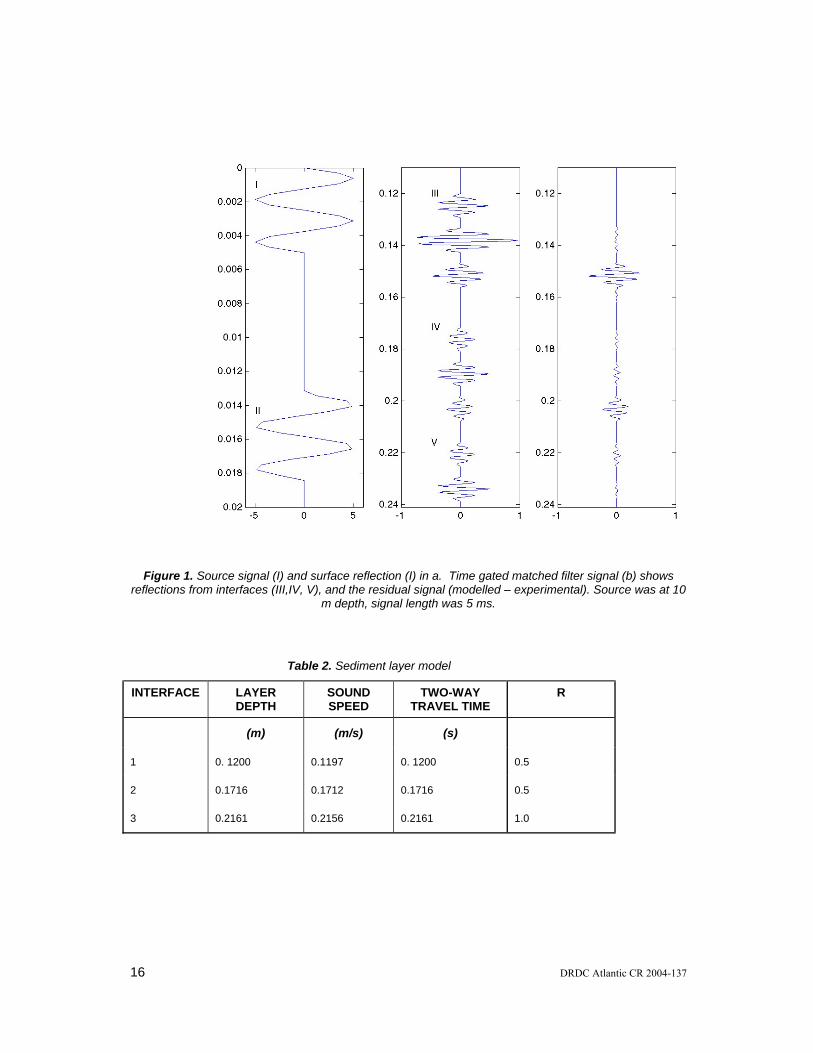
Figure 1. Source signal (I) and surface reflection (I) in a. Time gated matched filter signal (b) shows reflections from interfaces (III,IV, V), and the residual signal (modelled – experimental). Source was at 10
m depth, signal length was 5 ms.
Table 2. Sediment layer model
INTERFACE LAYER DEPTH
SOUND SPEED
TWO-WAY TRAVEL TIME
R
(m) (m/s) (s)
1 0. 1200 0.1197 0. 1200 0.5
2 0.1716 0.1712 0.1716 0.5
3 0.2161 0.2156 0.2161 1.0
16 DRDC Atlantic CR 2004-137

Table 3. Experimental results using synthetic data created from a sediment model
INTERFACE TWO-WAY TRAVEL TIME
R TWO-WAY TRAVEL TIME
R
Model Model Experimental Experimental
1 0. 1200 0.5 0.1197 0.5000
2 0.1716 0.5 0.1712 0.4969
3 0.2161 1.0 0.2156 0.9536
DRDC Atlantic CR 2004-137 17

4. References
1. C.W Holland, “Geoacoustic inversion for fine-grained sediments,” J Acoust Soc Am 111, 1560-1564 (2002).
2. C.W Holland, J Osler, “High-resolution geoacoustic inversion in shallow water: A joint time- and frequency-domain technique,J. Acoust. Soc. Am. 107, 1263-1279 (2002).
3. G.J. Heald, N.G. Pace, ”An analysis of 1st and 2nd backscatter for seabed classification,” 3rd European conference on underwater acoustics, Heraklion Greece, J.S Papadakis ed, 649-654 (1996)
4. K.E. Ellingsen, J.S. Gray, E Bjornbom, “Acoustic classificaiton of seabed habitats using the QTC View (TM) system,” ICES J Marine Science 59, 825-835 (2002).
5. S.P.R Greenstreet, I.D. Tuck, G.H. Grewar, E Armstrong, D.G. Reid, P.J. Wright, “An assessment of the acoustic survey technique, RoxAnn, as a means of mapping seabed habitat,” J Mar Sci 54, 939-959 (1997).
6. C.R. Bates, E.J. Whitehead, “ECHOplus measurements in Hopa,” Sea Technology 42, 34-43 (2001).
7. P.C. Hines,G.J. Heald, ”Seabed classification using normal incidence backscatter measurements in the 1-10 kHz frequency band,” Proceedings of the institute of acoustics,T.G. Leighton ed., Vol 23 part2.
8. S. Panda, L.R. LeBlanc, and S.G. Schock, “Sediment classification based on impedance and attenuation estimation,” J. Acoust. Soc. Am. 96, 3022-3055 (1994).
18 DRDC Atlantic CR 2004-137

Bibliography
A. Caiti, O. Bergem , J. Dybedal , “Parametric sonars for seafloor characterization,” Meas. Sci. Tech. 10, 1105-1115 (1999).
A Turgut, “Determination of sub-bottom sediment properties and their spatial distributions from chrip sonar data,” J. Acoust. Soc. Am. 99, 2451-2457 (1996).
Full Field Inversion
Aredov and Furduev, “Angular and frequency dependence on bottom reflection coefficient from anisotropic characteristics of noise field,” Acoustical Physics 40, 176-180 (1994).
W.M. Carey, J. Doutt, R.B. Evans, L.M. Dillman, “Shallow-water sound transmission measurements on the New Jersey continental shelf,” IEEE Journal of Oceanic Eng 20, 321-336 (1995).
N.R Chapman, C.E. Lindsay, “Matched-field inversion for geoacoustic model parameters in shallow water,” IEEE Journal of Oceanic Eng,21, 347-354 (1996).
K.D. Heaney, H. Cox ,”Rapid geoacoustic characterization for limiting environmental uncertaintiy for SONAR system performance prediction,” Impact of littoral environmental variability on acoustic predicitons and SONAR performance,N.G Pace and F.B. Jenson eds, 163-170 (2002).
J.P. Hermand, P. Gerstoft ,”Inversion of broad-band multi-tone acoustic data from the YELLOW SHARK summer experiments,” IEEE Journal of Oceanic Eng 21,324-X (1996)C.W Holland,”Coupled scattering and reflection measurements in shallow water,” IEEE Journal of Oceanic Eng 27, 454-470 (2002).
C.W Holland, “Geoacoustic inversion for fine-grained sediments,” J Acoust Soc Am 111, 1560-1564 (2002).
C.W Holland, J Osler, “High-resolution geoacoustic inversion in shallow water: A joint time- and frequency-domain technique,J. Acoust. Soc. Am. 107, 1263-1279 (2002).
M Siderius, P.L Nielsen, P Gerstoft, “Range-dependent seabed characterization by inversion of acoustic data from a towed receiver array,” J. Acoust. Soc. Am. 112, 1523-1535 (2002).
T.C. Yang, T.W. Yates,”Acoustic inversion of bottom reflectivity and bottom sound-speed profile,” IEEE Journal of Oceanic Eng 21, 367-376 (1996).
DRDC Atlantic CR 2004-137 19

Ivakin AN, “Models for seafloor roughness and volume scattering,” IEEE Proceedings Oceans 98, 518-521 (1998).
Integrated energy of first and second return
J.C. Osler, P.C. Hines, M.V. Trevorrow, “Acoustic and in-situ techniques for measuring the spatial variability of seabed geoacoustic parameters in littoral environments,” Impact of littoral environmental variability on acoustic predicitons and SONAR performance, N.G. Pace, and F.B. Jenson eds, 83-90 (2002)
G.J. Heald, N.G. Pace, ”An analysis of 1st and 2nd backscatter for seabed classification,” 3rd European conference on underwater acoustics Heriaklion Greece, J.S Papadakis ed, 649-654 (1996).
P.C. Hines,G.J. Heald, ”Seabed classification using normal incidence backscatter measurements in the 1-10 kHz frequency band,” Proceedings of the institute of acoustics,T.G. Leighton ed.,Vol 23 part2.
Holland CW, Neumann P, “Sub-bottom scattering: a modeling approach,” J Acoust. Soc. Am.104, 1363-1373 (1998).
LePage KD, Schmidt H, ”Spectral integral representation of monstatic backscattering from three-dimensional distributions of sediment volume inhomogeneities,“ J. Acoust. Soc. Am. 113, 780-799 (2003).
N.G. Pace, Z.K.S. Al-Hamdani, “The range dependence of normal incidence acoustic backscatter from a rough surface,” J. Acoust. Soc. Am. 77, 101-112 (1985).
Jackson JR, Briggs KB, “High frequency bottom scattering: roughness vs volume scattering,” J. Acoust. Soc. Am. 92, 962-977 (1992).
Normal Incidence EchoSounder seabed discrimination
C.R. Bates, E.J. Whitehead, “ECHOplus measurements in Hopa,” Sea Technology 42, 34-43 (2001).
K.E. Ellingsen, J.S. Gray, E Bjornbom, “Acoustic classificaiton of seabed habitats using the QTC View (TM) system,” ICES J Marine Science 59, 825-835 (2002).
R Freitas, S Silva, V Quintino, “Acoustic seabed classification of marine habitats: studiesin the western coastal shelf area of Portugal”, ICES J Marine Science 60, 599-608 (2003).
20 DRDC Atlantic CR 2004-137

S.P.R Greenstreet, I.D. Tuck, G.H. Grewar, E Armstrong, D.G. Reid, P.J. Wright, “An assessment of the acoustic survey technique, RoxAnn, as a means of mapping seabed habitat,” J Mar Sci 54, 939-959 (1997).
L.J. Hamilton, P.R. Mulhearn, Poeckert R, “Comparison of RoxAnn and QTC-View acoustic bottom classificaiton system performance for the Cairns area, Great Barrier Reef, Australia,” Continental Shelf Research 19, 1577-1597 (1999).
R.J. Kloser, N.J. Bax, T Ryan et al, “Remote sensing of seabed in Australia,” Marine Freshwater Res 52, 475-489 (2001).
M.A. Morrison, S.F. Thrush, R Budd, “Detection of acoustic boundaries in soft sediment systems using the seafloor acoustic discrimination systsem QTC View,” J Sea Res 46, 233-243 (2001).
Foote KG, Knudsen P, Korneliussen RJ et al, “Post processing system for echo sounder data,” J. Acoust. Soc. Am. 90, 37-47 (1991).
A Orlowski, ”Application of multiple echoes,” Oceanologica19 (1984).
V.S. Borshchan, T.A. Viksne, O.D. Sivkova, “Effect of layer,” Acoustical Physics 48, 137-141 (2002).
J. Tegowski, Z. Lubniewski, “The use of fractal properties of echo signals for acoustical classificaiton of bottom sediments,” Acustica 86, 276-282 (2000).
T. VanDung, A. Stepnowski, “Seabottom recognition using multistage fuzzy neural network operation on multi-frequency data,” Acustica 86, 830-837 (2000).
Schock SG, LeBlanc LR, “FM Sonar characteristics for normal-incidence sediment classification,” ASA 128th meeting
Gilbert KE, Kulbago TJ, “The Bragg condition limitation on inversion of normal incidence reflection data”, ASA 129th meeting,(1995).
Kvernevik TI, Zambri Mohd Akhir M, Studholme J, “A low-cost procedure for automatic seafloor mapping, with particular reference to coral reef conservation in developing nations”, Hydrobiologia 474, 67-79 (2002).
Chivers RC, Emerson N, Burns D, “New Acoustic Processing for underway surveying”, Hydrographic Journal 42, 8-17 (1990).
Chivers RC, Meenan CG,Modelling of sea-bed classification,Institute of Physics,,1992Malthus TJ, Mumber PJ, “Remote sensing of the coastal zone: an overview and priorities for future research”, Int J Remote Sensing,24(13), 2805-2815 (2003).
Foster-Smith RL, Sotheran IS, “Mapping benthic marine biotopes using acoustic ground discrimination”, Int J Remote Sensing,24(13), 2761-2784 (2003).
DRDC Atlantic CR 2004-137 21

White WH, Harborne AR, Sotheran IS, Walton R, Foster-Smith RL, “Using an acoustic ground discrimination system to map coral reef benthic classes”, International Journal of Remote Sensing,24(13), 2641-2660 (2003).
R Freitas, Rodrigues AM, V Quintino, “Benthic biotopes remote sensing using acoustics” ,J Exp Mar Biol Ecol 285, 339-353 (2003).
Caiti A, “Seafloor properties determination from acoustic backscattering at normal incidence with a parametric source” ,J of Computation Acoustics,8(2), 365-388 (2000).
Schock SG, “Techniques for estimating sediment properties from chirp sonar data”, J Acous Soc Am,109(5), (2001).
Magorrian BH, Service M, Clarke W, “An acoustic bottom classificaiton survey of Strangford Lough, Northern Ireland”, Journal of the Mairne Biological Association of United Kingom,75,1995,pp987-992 (1995).
Magorrian BH, Service M, Clarke W, “An acoustic bottom classificaiton survey of Strangford Lough, Northern Ireland” ,Journal fo the Mairne Biological Association of United Kingom,75,1995, 987-992 (1995).
Kaiser MJ, Armstrong PJ, Dare PJ, Flatt RP, “Benthic communities associated with a heavily fished scallop groundi n the English Channel”,Journal of the marine biological society,78(4), 1045-1059 (1998).
Lawrence MJ, C.R. Bates, “Acoustic discrimination techniques for submerged archaelogical site investigations”,Marine Techn Soc,35(4), 65-73 (2001).
Lurton X, Puiliquen E, “Automated seabed classification system for echo-sounders,”Oceans 92,Vol 1, 317-321 (1992).
Kavli T, Weyer E, Carlin M,Realtime seabed classificaiton using multifrequency echo sounders,Proceedings of Oceanology International 94, 1-9 (1994).
Collins RC, Gregory R, Anderson J, “A digital approach to seabed classifcation,”Sea Technology, 83-87 (1996).
Geoacoustic Theory
Abraham DA, Lyons AP, ”Novel physical interpretation of k-distributed,” IEEE Journal of Oceanic Eng 27, 800-813 (2002).
Jackson DR, Winebrenner DP, Ishimaru A, “Application of the composite roughness model to high-frequency bottom scattering,” J. Acoust. Soc. Am. 79, 1410-1422 (1986).
22 DRDC Atlantic CR 2004-137

M Siderius, P.L Nielsen, “Range-dependent seabed characterization by inversion of acoustic data from a towed receiver array,” J. Acoust. Soc. Am. 112, 1523-1535 (2002).
M Siderius, P.L Nielsen, J. Sellschopp, M. Snellen, D. Simons, “Experimental study of geoacoustic inversion uncertainty due to ocean sound-speed fluctuations,” J. Acoust. Soc. Am. 110, 769-781 2001
C.H. Harrison, “Noise directionality for surface sources in range-dependent environments,” J. Acoust. Soc. Am. 102, 2655-2662 (1997).
Ambient Noise
C.H. Harrison, “The influence of noise and coherence fluctuations on a new geo-acoustic inversion technique,” Impact of littoral environmental variability on acoustic predictions and SONAR performance, N.G. Pace, and F.B. Jenson eds , 139-146 (2002).
C.H. Harrison, D.G. Simons, “Geoacoustic inversion of ambient noise: a simple method,” J. Acoust. Soc. Am. 112, 1377-1389 (2002).
D. Tang, “Estimating shallow water bottom geo-acoustic parameters using ambient noise,” Impact of littoral environmental variability on acoustic predicitons and SONAR performance,N.G. Pace, and F.B. Jenson eds, 147-154, (2002).
Waveform inverson
G.S. Pan, R.P Phinney, and R.I.Odum, “Full waveform inversion of plane-wave seismograms in stratified acoustic media: Theory and feasibility,” Geophysics 53, 21-31 (1988).
G.V. Frisk, A.V. Oppenheim, and D.R. Martinez, “A technique for measuring the plane-wave reflection coefficient of the ocean bottom,” J. Acoust. Soc. Am. 68, 602-612 (1980).
DRDC Atlantic CR 2004-137 23

Distribution list
NDHQ/DRDKIM 2-2-5 (1)
DRDC Atlantic (6)
GaleForce Scientific Consulting Ltd. 81 Newcastle Street Dartmouth, NS B2Y 3M8
Francine Desharnais DRDC Atlantic
Gordon Ebbeson DRDC Atlantic
Garry Heard DRDC Atlantic
Paul Hines DRDC Atlantic
John Osler DRDC Atlantic
Mark Hazen DRDC Atlantic
H/US DRDC Atlantic
H/TD DRDC Atlantic
LCdr Wayne Renaud, SSO MetOc Maritime Forces Atlantic P.O. Box 99000 Stn Forces Halifax, NS, B3K 5X5
24 DRDC Atlantic CR 2004-137

DRDC Atlantic mod. May 02
DOCUMENT CONTROL DATA(Security classification of title, body of abstract and indexing annotation must be entered when the overall document is classified)
1. ORIGINATOR (the name and address of the organization preparing the document.Organizations for whom the document was prepared, e.g. Centre sponsoring acontractor's report, or tasking agency, are entered in section 8.)
GaleForce Scientific Consulting Ltd, 81 Newcastle Street,Dartmouth, NS B2Y 3M8
2. SECURITY CLASSIFICATION !!(overall security classification of the document including special warning terms if applicable).
UNCLASSIFIED
3. TITLE (the complete document title as indicated on the title page. Its classification should be indicated by the appropriate abbreviation (S,C,R or U) in parentheses after the title).
Feasibility of normal incidence techniques for use with REA buoy
4. AUTHORS (Last name, first name, middle initial. If military, show rank, e.g. Doe, Maj. John E.)
Douglas J. Schillinger
5. DATE OF PUBLICATION (month and year of publication ofdocument)
Jan 2005
6a. NO. OF PAGES (totalcontaining information IncludeAnnexes, Appendices, etc). 33 (approx.)
6b. NO. OF REFS (total citedin document)
8
7. DESCRIPTIVE NOTES (the category of the document, e.g. technical report, technical note or memorandum. If appropriate, enter thetype of report, e.g. interim, progress, summary, annual or final. Give the inclusive dates when a specific reporting period is covered).
CONTRACT REPORT 8. SPONSORING ACTIVITY (the name of the department project office or laboratory sponsoring the research and development. Include address).
Defence R&D Canada – AtlanticPO Box 1012Dartmouth, NS, Canada B2Y 3Z7
9a. PROJECT OR GRANT NO. (if appropriate, the applicable researchand development project or grant number under which the documentwas written. Please specify whether project or grant).
Project 11hb02
9b. CONTRACT NO. (if appropriate, the applicable number underwhich the document was written).
W7707-03-2132 10a ORIGINATOR'S DOCUMENT NUMBER (the official document
number by which the document is identified by the originatingactivity. This number must be unique to this document.)
10b OTHER DOCUMENT NOs. (Any other numbers which may beassigned this document either by the originator or by thesponsor.)
DRDC Atlantic CR 2004-137 11. DOCUMENT AVAILABILITY (any limitations on further dissemination of the document, other than those imposed
by security classification)( X ) Unlimited distribution( ) Defence departments and defence contractors; further distribution only as approved( ) Defence departments and Canadian defence contractors; further distribution only as approved( ) Government departments and agencies; further distribution only as approved( ) Defence departments; further distribution only as approved( ) Other (please specify):
12. DOCUMENT ANNOUNCEMENT (any limitation to the bibliographic announcement of this document. This will normally correspond to theDocument Availability (11). However, where further distribution (beyond the audience specified in (11) is possible, a wider announcementaudience may be selected).
UNLIMITED

DRDC Atlantic mod. May 02
13. ABSTRACT (a brief and factual summary of the document. It may also appear elsewhere in the body of the document itself. Itis highly desirable that the abstract of classified documents be unclassified. Each paragraph of the abstract shall begin with anindication of the security classification of the information in the paragraph (unless the document itself is unclassified) representedas (S), (C), (R), or (U). It is not necessary to include here abstracts in both official languages unless the text is bilingual).
Literature relating to normal incidence techniques for determining geo-acoustic properties ofsediment layers in the ocean is reviewed. The techniques outlined in the literature areassessed for use with a Rapid Environmental Assessment (REA) buoy currently under designat DRDC Atlantic. While there is extensive literature on normal incidence techniques forfrequencies above 10 kHz and limited literature on experiments at lower frequencies in all casesthere are critical differences in geometry of these previous experiments when compared to thatof the REA buoy. One technique integrates the bottom and bottom-surface returns todetermine roughness and reflection coefficient of the ocean-sediment interface. Thefrequency range for which this technique has been used (>10 kHz; 1-10 kHz) is not compatiblewith the current source of the REA buoy. A second technique uses waveform inversion todetermine acoustic impedance (or other property) as a function of travel time. Geo-acousticproperties are found using either an iterative layer stripping technique or by minimizing thedifference between perturbed models and the measured signal via least squares or simulatedannealing. While the waveform inversion techniques have the most promise, the signal mustbe sampled at least 4 times the Nyquist criteria (or resampled using Fourier techniques ifpossible). A method for determining the attenuation of sub-surface layers is also reviewed, anda modified version is presented for use with the REA buoy.
14. KEYWORDS, DESCRIPTORS or IDENTIFIERS (technically meaningful terms or short phrases that characterize adocument and could be helpful in cataloguing the document. They should be selected so that no security classification isrequired. Identifiers, such as equipment model designation, trade name, military project code name, geographic location mayalso be included. If possible keywords should be selected from a published thesaurus. e.g. Thesaurus of Engineering andScientific Terms (TEST) and that thesaurus-identified. If it not possible to select indexing terms which are Unclassified, theclassification of each should be indicated as with the title).
Normal incidenceREARapid Environmental AssessmentFeasibility studyCARbuoy

This page intentionally left blank.

Related Documents