FEASIBILITY EVALUATION OF THE CONVERSION OF THE HOMESTAKE UNDERGROUND MINE TO THE HOMESTAKE UNDERGROUND LABORATORY PREPARED FOR THE HOMESTAKE LABORATORY CONVERSION PROJECT STATE OF SOUTH DAKOTA Proposal No.: E-771 Dynatec Corporation Date: December 20, 2003 9555 Yonge Street, Suite 200 Richmond Hill, Ontario Canada L4C 9M5

Welcome message from author
This document is posted to help you gain knowledge. Please leave a comment to let me know what you think about it! Share it to your friends and learn new things together.
Transcript
FEASIBILITY EVALUATION OF THE CONVERSION
OF THE HOMESTAKE UNDERGROUND MINE
TO
THE HOMESTAKE UNDERGROUND LABORATORY
PREPARED FOR
THE HOMESTAKE LABORATORY CONVERSION PROJECT
STATE OF SOUTH DAKOTA
Proposal No.: E-771 Dynatec Corporation Date: December 20, 2003 9555 Yonge Street, Suite 200 Richmond Hill, Ontario Canada L4C 9M5
Guccifer
http://www-eng.lbl.gov/~lafever/Underground/DynatechStudy/Dynatec%20Feasibility%20Report.pdf
Homestake Laboratory Conversion Project
Dynatec Corporation Feasibility Evaluation of the Conversion of the Homestake
Underground Mine To The
Homestake Underground Laboratory To Become The
World’s Premier Deep Underground Science Laboratory
Prepared for The Honorable M. Michael Rounds
Office of the Governor State of South Dakota
December 19, 2003
1.0 EXECUTIVE SUMMARY
The development of a deep underground laboratory for the study of the physics of neutrinos, protons and other areas of frontier science has been exceptionally well documented and justified by the science community. In October of 2000, Homestake Mining Corporation announced the closure of the 8000 feet deep gold mine in Lead, South Dakota, and leaders of the scientific community proposed the conversion of the mine to a deep laboratory. There have been several other locations proposed for the construction of such a deep laboratory. In May 2003, the NSF identified the Homestake Mine as the preferred choice because of the excellent quality of the available rock and extensive infrastructure. (Estimated value of over $140,000,000 million). The Homestake Mine closed in June 2003 and all operations in the underground mine ceased, including the pumping of the naturally occurring small amount of water that enters, what is essentially a dry mine with over 360 miles of drifts and shafts. In June, 2003, he Governor of the State of South Dakota, M. Michael Rounds, formed the Homestake Laboratory Conversion Project, with State funding authorized by the Legislature, to enable the conversion of the mine to a deep laboratory. The Governor and Homestake Corporation have agreed that the ownership of the mine will be transferred to a new South Dakota authorized Authority when funding for the conversion is available from the National Science Foundation (NSF).
E-771 1

Homestake Laboratory Conversion Project
The original proposal, submitted by scientists, proposed the development of the deep underground laboratory to include the excavation of several large detector experiments as part of the laboratory. This proposal would require funding in excess of $300 million dollars and remains unfunded. However, a new approach became feasible as the extensive capabilities of the mine, as it will be transferred, were reviewed. The mine, as will be transferred, will include extensive infrastructure and operational capabilities that can provide the core support facilities for the Homestake Underground Laboratory with the ability to expedite the addition of various detector experiments as they are proposed, reviewed, and authorized far into the future without disruption of the already operating experiments. Additionally, the core Homestake Underground Laboratory appears to have the potential to accommodate the requirements of the scientists for continued access to their experiments in an environment equivalent to the highest quality university research laboratories. The Homestake Laboratory Conversion Project entered into a contract with the Dynatec Corporation to provide a feasibility study of the ability to convert the mine, as will be transferred, to become the Homestake Underground Laboratory. This feasibility study is intended to demonstrate the ability to accomplish the following specific objectives:
1. Prepare for mine re-entry 2. Refurbish and upgrade the Yates Shaft 3. Refurbish the Ross Shaft 4. Remove water from the mine, refurbish and upgrade the #6 winze 5. Provide the core Homestake Underground Laboratory with the
infrastructure to support future detectors 6. Demonstrate the ability of the Core Laboratory to support the future
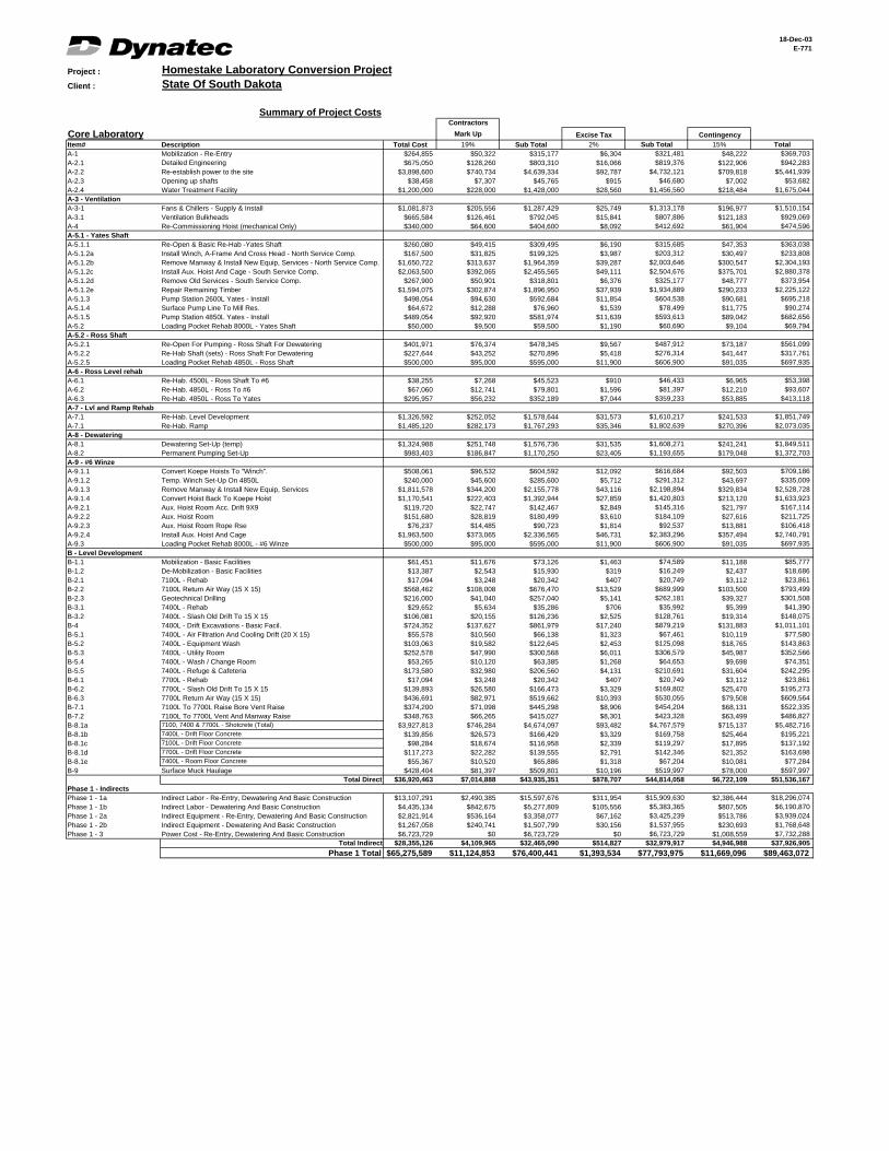
addition of large detector experiments. The objective of this feasibility study is to identify the cost to create the Homestake Underground Laboratory to support the inclusion of future detector experiments without the need for additional infrastructure expense. The study concludes that it is feasible to convert the mine, as will be transferred, into the Homestake Underground Laboratory, with the capability to provide for continual development with the future addition of detector experiments. The cost of the conversion of the Homestake mine to an Underground Laboratory is $78M with a contingency of $11.5M for a total of $89.5M.
E-771 2

Homestake Laboratory Conversion Project
2.0 FEASIBILITY STUDY
The Dynatec Corporation has completed this study using its extensive knowledge supported by information provided by the Homestake Laboratory Conversion Project from the Homestake Mining Corporation and a number of consultants. This report is organized by the analysis and evaluation of the system components of the mine to be used in the conversion to the underground laboratory. The report concludes that it is feasible to convert the mine, as will be transferred, into the Homestake Underground Laboratory, to provide a core facility that fully responds to the requirements for a deep underground research laboratory, while enabling the continual development of the laboratory through the insertion of the large detector experiments without the further expansion of the core facility.
2.1 PREPARE FOR MINE RE-ENTRY 2.1.1 Detailed Engineering
Detailed engineering will ensure that all required materials and equipment will be ready at the time they are needed to prevent interruptions in the mine conversion. Detailed engineering will be required in the following areas:
1. Auxiliary Hoist and Hoist Room for the Yates Shaft 2. Auxiliary Hoist and Hoist Room for the #6 Winze 3. Working Platforms for the Shaft Rehabilitations 4. Ventilation Conversion 5. Hoist Upgrades and Automation 6. Mine Dewatering 7. Loading Pocket upgrades in the Ross Shaft and #6 Winze 8. Conversion of #6 Winze Hoists for Shaft Rehab and back to
production 9. Electrical Upgrades and new Installations 10. Rock Mechanics Evaluations of Proposed Excavations 11. Waste Water Treatment 12. Others as required
2.1.2 Permitting
In order to restart operations, it will be important that all required permitting issues are addressed prior to the start of activities. This will include ensuring that permits are in place for the following:
E-771 3

Homestake Laboratory Conversion Project
1. Water Discharge and Treatment 2. Mine Operations 3. Waste Rock Disposal 4. Discharge of Air Particulates by exhaust fans 5. Others as required
2.2. REFURBISH/UPGRADE YATES SHAFT
The process by which re-entry will be established through the Yates shaft will be as follows:
• Remove the bulkhead on the shaft collar • Perform an inspection of the headframe. • Inspect and test the hoist ropes • Return the elevator units to move people and material to full operation. • Commission the hoists. • Perform a shaft inspection.
From the shaft inspection, it will be determined what timber will need to be replaced in order to safely re-enter the mine. The shaft inspection can be done from the conveyances. Based on historical information from the mine, the timber sets in the Yates Shaft were recently changed down to the 800 feet level. Prior to shutdown, it was planned to complete the remaining sets down to the 1100 feet level. Beyond the 1100 feet level, it is expected that some timber will be changed. It is also expected that there will not be a significant change in the condition of the timber in the Yates Shaft up to the time when the conversion commences. It is assumed that some scaling of loose rock around the sets will be required as well as the installation of some ground support. Once the immediate repairs required for safe shaft operation are completed, the shaft will be put in operation to service access to the 4850 Level. The 4850 level is the major connecting level between the Yates, Ross, and #6 Winze shafts. The permanent upgrade to Yates will include:
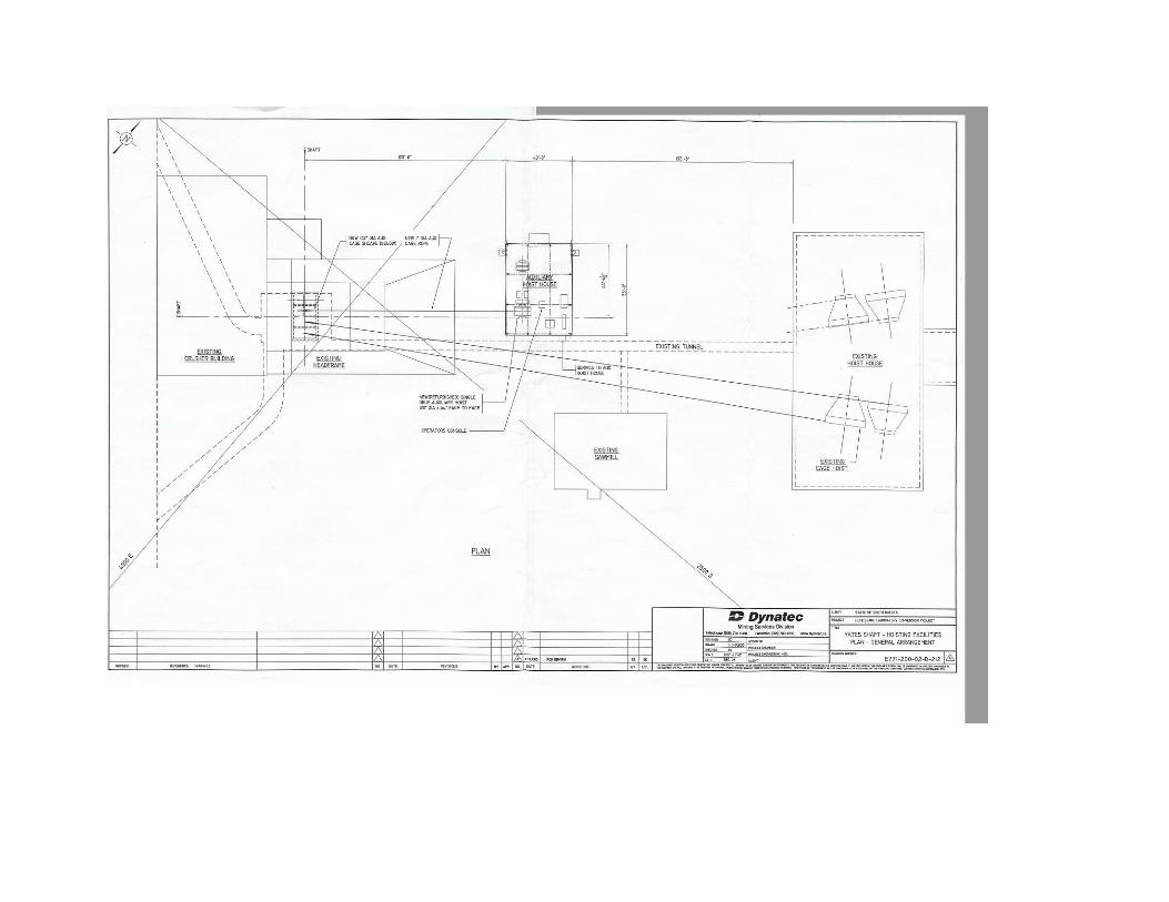
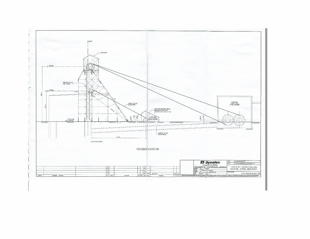
Please reference Drawing: E771-200-02-D-212 and E771-200-02-D-213 for the addition of the Auxiliary Hoist at the Yates Headframe for the high speed scientist’s elevator and Drawing; E771-200-02-D-211 for the Yates Shaft plan showing the relocation of services to the North Service Compartment to enable the New Auxiliary Cage (the high speed elevator) to be installed.
• Removal of existing services in the South Services
Compartment • Installation of Auxiliary Hoist and Cage for the South Services
Compartment. This will become the access which will be used exclusively by the scientists once the Laboratory is in service.
E-771 4

Homestake Laboratory Conversion Project
• Installation of a Winch, A-frame and Cross head in the North Services Compartment
• Removal of the existing manway in the North Services Compartment
• Installation of required pipes and cables in the North Services Compartment, including a new pump line
• Replacement of all the remaining timber between 800 and 1100 feet levels and 150 pieces below the 1100 feet level
• Installation of a new pumping station on 2600L • Recommission the loading pocket on 4850 Level
2.3 REFURBISH ROSS SHAFT
Prior to doing the permanent upgrade to the Yates Shaft, the Ross Shaft will need to be rehabbed sufficiently to allow for dewatering to begin. The process by which re-entry will be established through the Ross Shaft will be as follows:
• Remove the bulkhead on the Shaft collar • Perform an inspection of the headframe and make any repairs
as required • Inspect and test the hoist ropes • Unchair the conveyance • Commission the hoists • Perform a Shaft inspection
From the Shaft inspection, it will be determined what steel, pipes and cables will need to be replaced in order to facilitate the dewatering. The Shaft inspection will be done from the conveyances.
The Production and Service hoists have been properly decommissioned to allow for eventual reuse.
Prior to the shutdown, Homestake had planned on changing out a number of the steel sets and had purchased replacement steel for this task. This steel is on site and is available for future work.
The main 12” discharge pipe will be inspected and pipe sections will be changed out as required. During this activity, the pumps at the various stations will be brought to the surface to be reconditioned. When this is completed, they will be put back underground for dewatering. The pumps, which need to be refurbished and reinstalled, are in the pump stations on 1250L, 2450L, 3650L, and 5000L.
The existing pump line in the Shaft was planned to be changed as well. Until the new pumping system is installed in the Yates Shaft, it is planned to reuse the
E-771 5

Homestake Laboratory Conversion Project
existing line for dewatering and make repairs only as required to service the initial dewatering. Once the Yates Shaft renovations are complete and Yates is back in service, the dewatering operations will be moved to the Yates.
The Ross Shaft will be used for access to the 4500 feet level. It is on this level where access is gained to the hoist room for the #6 Winze and Service Hoists. This is the level where the new host for #6 Winze will be installed to enable the development of the core laboratory while completing the dewatering.
Once the rehab is complete in the Ross Shaft, the loading pocket that carries the work to the elevator for removal to the surface will need to be rehabbed on the 4850 feet level.
2.4 REMOVE WATER FROM MINE, REFURBISH AND UPGRADE #6
WINZE 2.4.1 Level Rehab
The 4850 Level is the main level in the mine. This level will need to be rehabbed as soon as possible. The plan is to rehab the level from both the Ross and Yates Shafts as soon as access is established to each level. The distance between Yates and Ross is approximately 3000 feet. Levels from the #6 Winze will be rehabbed as the #6 Winze is dewatered. The levels will be rehabbed to where they intersect with the ramp. Generally, the distance between the #6 Winze and the ramp at the various levels is approximately 3200 feet.
Rehabilitation of the levels will consist of scaling, mucking and installing ground support as required. Ground conditions are not expected to have deteriorated significantly during the flooding and the installed ground support should still be providing support. An allowance of 1 bolt per 20 feet has been included in the cost of rehabbing the levels. The pipes which are still in place should be usable for water and compressed air requirements. Electrical cables which have been under water will be replaced. Ventilation for the rehabbing work will be provided from a fan which will be installed in a bulkhead, nearest the working level, which will draw fresh air down the #6 Winze. Vent tubing will be installed from the fan as the rehabbing advances along the level. The rehabbing will advance to the point at which the ramp intersects the level. From that point on, further rehab will be performed down the ramp to the next level.
2.4.2 Ramp Rehab
E-771 6
Homestake Laboratory Conversion Project
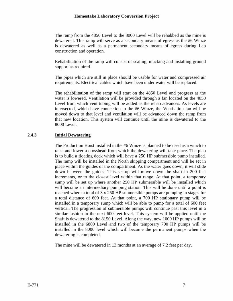
The ramp from the 4850 Level to the 8000 Level will be rehabbed as the mine is dewatered. This ramp will serve as a secondary means of egress as the #6 Winze is dewatered as well as a permanent secondary means of egress during Lab construction and operation. Rehabilitation of the ramp will consist of scaling, mucking and installing ground support as required. The pipes which are still in place should be usable for water and compressed air requirements. Electrical cables which have been under water will be replaced. The rehabilitation of the ramp will start on the 4850 Level and progress as the water is lowered. Ventilation will be provided through a fan located on the 4850 Level from which vent tubing will be added as the rehab advances. As levels are intersected, which have connection to the #6 Winze, the Ventilation fan will be moved down to that level and ventilation will be advanced down the ramp from that new location. This system will continue until the mine is dewatered to the 8000 Level.
2.4.3 Initial Dewatering
The Production Hoist installed in the #6 Winze is planned to be used as a winch to raise and lower a crosshead from which the dewatering will take place. The plan is to build a floating deck which will have a 250 HP submersible pump installed. The ramp will be installed in the North skipping compartment and will be set in place within the guides of the compartment. As the water goes down, it will slide down between the guides. This set up will move down the shaft in 200 feet increments, or to the closest level within that range. At that point, a temporary sump will be set up where another 250 HP submersible will be installed which will become an intermediary pumping station. This will be done until a point is reached where a total of 3 x 250 HP submersible pumps are pumping in stages for a total distance of 600 feet. At that point, a 700 HP stationary pump will be installed in a temporary sump which will be able to pump for a total of 600 feet vertical. The progression of submersible pumps will continue past this level in a similar fashion to the next 600 feet level. This system will be applied until the Shaft is dewatered to the 8150 Level. Along the way, new 1000 HP pumps will be installed in the 6800 Level and two of the temporary 700 HP pumps will be installed in the 8000 level which will become the permanent pumps when the dewatering is completed. The mine will be dewatered in 13 months at an average of 7.2 feet per day.
E-771 7
Homestake Laboratory Conversion Project
2.4.4. #6 Winze Rehab The permanent upgrade to the #6 Winze will include:
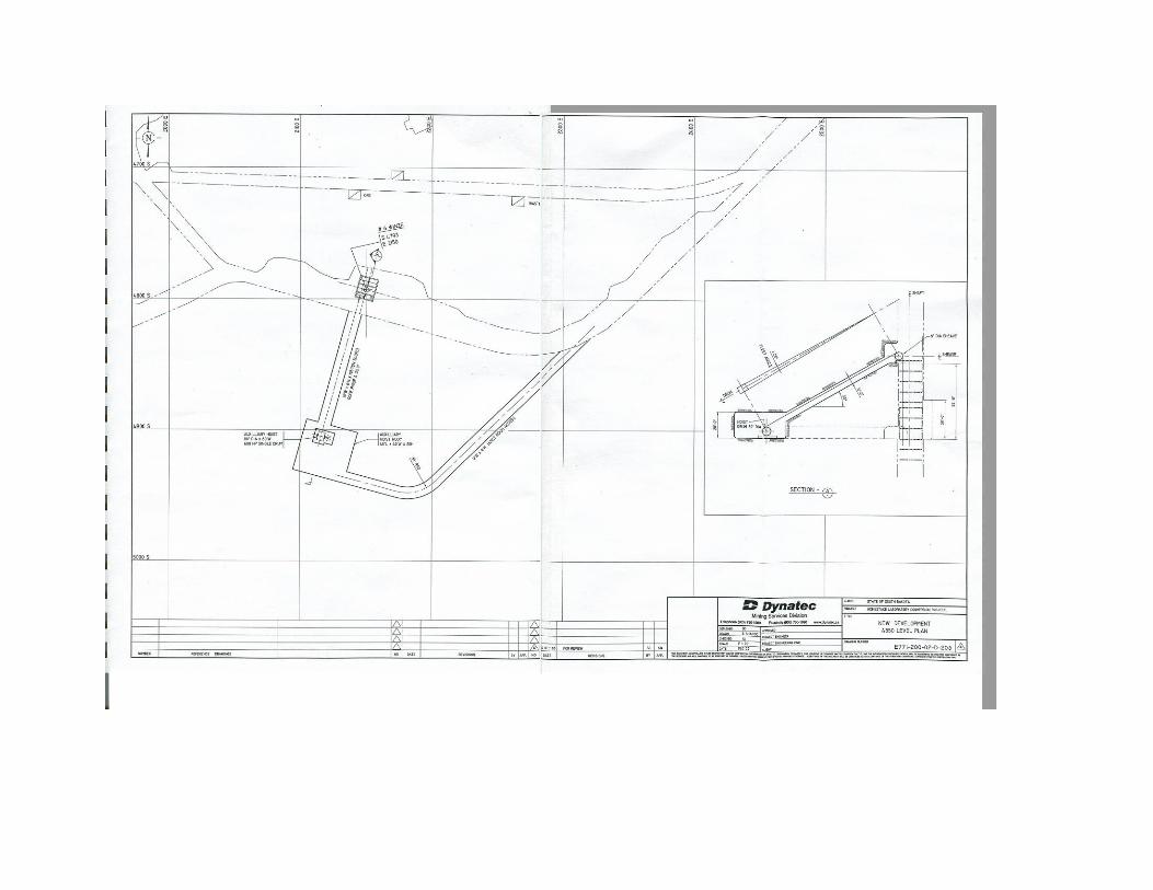
Please reference Drawing: E771-200-02-D-203 for the addition of the Auxiliary Hoist at the #6 Winze Headframe for the high speed scientists’ elevator and Drawing; E771-200-02-D-204 for the #6 Winze Shaft plan showing the relocation of services to enable the New Auxiliary Cage (the high speed elevator) to be installed.
Once access is established to the 4850 Level, work will commence with the excavation of a new hoist room for an Auxiliary 600 HP Hoist. The hoist will be installed complete with a 7-man cage. The cage will be installed in the manway compartment of the #6 Winze and will be automated for 24/7 exclusive use by science personnel. In the #6 Winze it is assumed that all the services that will be under water by the time the conversion begins and will need to be replaced. The Shaft steel sets should be in good condition and should not require significant repairs. The #6 Winze Production and Service hoists are both friction type hoists. They will be converted to a hoist operation to allow them to be used for Shaft rehab and dewatering. The cage is currently chaired (stored) on 4850 level and one skip is chaired on 4550 level. New shells will be attached to the drums and new ropes wound on the drums. In this configuration, the hoists will act as winches. The conveyances will be reattached allowing for a way to access the Shaft for dewatering. It is expected that the general condition of the steel sets in the Shaft will be good. It is not expected that the flooding will result in any excessive corrosion of the Shaft steel above that which would have occurred had the Shaft been kept dry. All the electrical, pumping system, compressed air, communications, potable and industrial water, waste water, and other services will be replaced in the #6 Winze. Additionally, the high speed 7/24 automated elevator will installed in the revamped manway in the #6 Winze as noted in E771-200-02-D-204. The rehab will be done off a platform built over the cage. The manway will be removed and new guides installed in the manway compartment. Once the mine has been dewatered, the loading pocket on 8100 Level will be refurbished.
2.5 PROVIDE THE CORE LAB WITH INFRASTRUCTURE FOR FUTURE
DETECTORS 2.5.1 Services
E-771 8
Homestake Laboratory Conversion Project
The existing utility services will be used as much possible and upgraded as required.
2.5.1.1 Ventilation
The ventilation of the Lab will consist of Fresh Air Intake and Return Air Exhaust. Fresh air will enter into the Yates and Ross Shafts via the Tramway connecting the two Shafts. Due to the significant reduction in ventilation requirements with the new Lab and associated construction activities, new more efficient fans for mine ventilation will be installed. New 200 HP intake fans will be located in the Tramway which connects the Yates and Ross Shafts. These fans will be used to direct fresh air down each Shaft separately. Natural gas fired mine air heating plants will be installed at each air intake location to heat the fresh air as required during the winter months.
Exhaust air will be removed from the lab via a new 350 HP exhaust fan, which will be added at the #5 Shaft. Existing surface ventilation infrastructure including the 3000 HP Oro Hondo Fan and 2 x 700 HP Kirk Fans located at the Kirk Adit will be removed. Bulkheads will be installed at these locations. During the reopening of the mine, construction crews will install shotcrete ventilation bulkheads at each level to provide an airtight seal, preventing fresh air from entering the old workings. This sealing of the unused drifts will both reduce the need for excessive ventilation and will also mitigate the potential for mine fires within the mined out areas. The existing Oro Hondo and Kirk fans will be used for ventilation until the new fans are installed. The new fans will serve as the primary source of ventilation and reduce the ongoing operating cost of ventilation for the core facility. A detailed study of the Ventilation plan and requirements for the conversion has been performed by Cam Seeber, an independent ventilation consultant specializing in mine ventilation, in his study entitled: “Ventilation Requirements for Construction and Operation of a Laboratory on the 7400 Level of the Homestake Mine.”
2.5.1.2 Mine Air Heating
Mine air heating will be kept to a minimum as requirements for cooling at that depth will create a significant energy demand. Heating will be supplied through gas fired heaters located at the Yates and Ross intake areas and will provide heating capacity to raise the air temperature to 34 degrees Fahrenheit. A 7 million Btu heater will be required at the Yates Shaft intake and a 26 million Btu heater will be required at the Ross Shaft.
2.5.1.3 Mine Air Conditioning
E-771 9
Homestake Laboratory Conversion Project
Mine air conditioning will be required below the 4850 level during the Shaft rehab, and level excavation stages. Air conditioning units will also need to be installed for permanent lab operation on the 7400 Level. Based on the Seeber study, it has been determined that the lab will require a 290 ton chilling unit which will provide sufficient capacity for future growth. This will be installed on the 7400 Level and will be the permanent air conditioning equipment for the lab. During construction, a number of 30 ton chillers will be installed and moved as required as the conversion work progresses.
2.5.1.4 Power and Distribution
The source of electricity for the mine is through the Black Hills Power and Light power grid. Underground power is supplied to the Ross & Yates Shafts from three substations located on the surface (East Sub, Ross Sub, Oro Hondo Sub). The Ross and Oro Hondo substations provide power to the Ross Shaft. The East Substation supplies power via the Yates Shaft to a substation at #6 Winze on the 7700 level. The power needs of the converted facility will be considerably less than what was required for the mine while it was in operation. The existing infrastructure provides an excellent base from which required power for the Lab can be directed. The existing surface electrical distribution power system has been maintained for the conversion to the core facility. The existing surface infrastructures including power lines, transformers and switchgears will be utilized for the conversion. Additionally, emergency generator sets will provide for back up power in the event of a failure. The generators will be strategically located to ensure life safety needs are satisfied.
2.5.1.5 Water Treatment
Water Treatment at the mine currently utilizes biological treatment processes to treat mine discharge and tailings runoff before it is discharged into the environment. The facility will require modifications to treat the dewatering process by the addition of a cooling system and a deionization system. Once the mine is dewatered, it is expected that minimal treatment will be required. A water quality investigation of the mine discharge water was performed by Mark Nelson of the SD DENR. Samples were taken from various locations throughout the mine before the mine was shut down. The results of this study conclude that the general quality of the mine water is good. There are, however, three areas of concern:
1. Electrical Conductivity 2. Dissolved and Suspended Solids 3. Water Temperature
E-771 10
Homestake Laboratory Conversion Project
These conditions can be easily treated with the addition of temporary mobile treatment units. By the time the dewatering starts, the water is expected to be at a temperature of approximately 95 degrees F. The maximum allowable discharge temperature limit of 65 degrees F will be accomplished through a combination of cooling and mixing lower temperature waters.
2.5.1.6 Permanent Mine Dewatering and Water Discharge
During initial dewatering, the existing dewatering system will be employed. All the pumps which were used during mine operation are still in place. All the pumps which are located in the Ross Shaft will be reused for the initial dewatering. The pumps will be removed during the initial shaft during re-entry and recondition. These pumps will be reinstalled by the time the dewatering is scheduled to start from the #6 Winze. There are existing pumps which are currently stored on the surface which will also be available for dewatering. Pumps which are submerged below the 5300 Level are not expected to be salvageable. Provisions have been made to install new pumps in the 6800 and 8000 Level pump stations. The Ross Shaft currently has a 12” discharge pipe located in the services compartment. It is expected that there will be some sections of pipes that will need to be changed for the initial mine dewatering. It was noted during the last stage of mine operations that the pipe line in this Shaft is old and in need of replacement, but should be suitable for initial dewatering. The #6 Winze currently has a 12” discharge pipe installed in the services compartment. Although there is a good chance that this pipeline will be serviceable after dewatering, it has been decided to replace this line with a new one which will allow for mine dewatering well into the future life of the lab. The new pipe will be installed during the #6 Winze rehab and mine dewatering. Due to the age of the dewatering system within the Ross Shaft, it has been decided to install a new 12” discharge pipeline in the Yates Shaft. Homestake had made plans to install a new discharge line in this Shaft before the shutdown announcement was made. It is felt that it would be prudent to follow through with this for the conversion. In addition to the installation of a new 12” discharge line in the Yates Shaft, new pumping stations will be constructed on the 4850 and 2600 Levels. Two new 1500 HP pumps will be installed at each of these locations to provide the
E-771 11
Homestake Laboratory Conversion Project
necessary pumping capacity required to operate the mine. A fifth pump will be purchased and placed on standby which will be used as a replacement in the event of a pump failure, and will also create an opportunity for a rotation of the pumps to occur for routine overhauls. Once this system is installed and commissioned, the Ross pump system will be taken out of service.
2.5.1.7 Communication
As a part of the renovation of both the Yates and Roth Shaft and the #6 Winze, the communication systems were reviewed. The number of communication lines which currently feed the mine is listed as follows:
2.5.1.7.1 Voice Communication
Voice communications into the mine are through a telephone system. In the Ross Shaft, there are two 100-pair cables. It is expected that these cables should be reusable in the conversion. In the Yates Shaft there are two 100-pair cables as well. These cables are currently located in the South Services Compartment and will be relocated to the North Services Compartment. In the #6 Winze, there is one 100-pair cable which will be replaced during the Shaft rehab.
2.5.1.7.2 Data Communications
All data communication cables into the mine currently originate from the main computer system in the Mine office building. Until the new Science Administration building is constructed, it is planned to continue with this system. The Fiber Optics cables used are 24 pair, 62.5 micron, multi-mode, T-base 10; cable goes down Yates Shaft to 4850 level electrical shop. From the 4850 electrical shop, the cable goes down the #6 Winze to the 7400 level #6 Winze shop. It is planned to replace the Fiber Optic cable which currently goes down the # 6 Winze during the Shaft rehab. The 24 pair cable currently has 21 available pairs. It is unknown exactly what the needs of the Laboratories will be in operation, but there certainly is capacity in the line for significant data transfer.
2.5.1.7.3 Mine Monitoring
A FIXDMACS Mine monitoring system was used to monitor the entire mine, such as control pumps, fans, etc., including a Carbon monoxide sensor system. It is expected that all equipment relating to this system that has been under water will be replaced. However, there should be a portion that is recoverable that has not been under water.
2.5.1.7.4 Radio
A Leaky Feeder system is installed in the mine from the top to the bottom of all the Shafts for transportation communication. It is also installed in the main ramp
E-771 12

Homestake Laboratory Conversion Project
system from the 6500 to 8000 level and Ross Shaft area from the 2000 to 4450 level. The Leaky Feeder system includes a telephone interface, which provides for communications with any telephone on the surface. As with all other cables, those which have been under water will need to be replaced, but it is planned to recover all the remaining cable not under water.
2.5.1.8 Heating
Most of the surface buildings are heated with steam which originates from natural gas fired boilers. These units have been decommissioned properly. The boilers will be restarted and will be used for heating the existing required buildings during Lab conversion. New heating will be installed in the renovated surface buildings during the conversions phase and the central boilers decommissioned to reduce operating expenses. The main administration building currently is heated with natural gas.
2.5.1.9 Water Supply
The Mine has both potable and industrial water available. 2.5.1.9.1 Potable Water
The Lead-Deadwood District will provide potable (domestic) water to the facility. The potable water system is fed from several storage tanks located in Lead. From these tanks it is pumped through a network of pipes buried on surface to the various buildings in use as well as the Ross Shaft. This system will be used for the conversion. This system will also serve as the main building fire sprinkler reserve. Laboratory operations will require potable water for drinking and washing facilities. Most of the potable water in the Mine is fed through a 4" pipeline that extends from the surface to the 5000 level in the Ross Shaft. This line will be replaced with a new one in the Yates Shaft. From the Yates Shaft, a new 4” line will be installed in the 4850 Level to the #6 Winze. Within the #6 Winze and down to the various levels, a new 2” line will be installed during the Shaft rehab. Capacity of this system will be up to 400 gpm.
2.5.1.9.2 Industrial Water
Industrial water will be provided from the mine dewatering process. Also included is an above ground, 1.2 million gallon, reinforced concrete storage tank. Industrial water will be directed through surface pipelines to the Ross and the Yates Shafts. Industrial water is required for drilling, dust control, and equipment washing. When the mine was in operation, industrial water was sent underground at the
E-771 13
Homestake Laboratory Conversion Project
Ross Shaft in a 6" pipeline and the Yates Shaft in a 4" pipeline. The capacity of this system was 1400 and 400 gpm respectively. It is expected that industrial water required for the conversion can be sourced from water being discharged. However, for the purposes of this study, it is planned to replace the existing 4” line in the Yates Shaft with a 6” line in the North Services Compartment. It is also planned to abandon the line in the Ross Shaft. The resultant capacity of the new system will be 1400 gpm.
With the relocation of the industrial water supply line to the Yates Shaft, a new 6” line will need to be installed in the 4850 level. This will be completed during the 4850 Level rehab. The 6” line currently in the #6 Winze will be replaced with a new line during the Shaft rehab.
2.5.1.9.3 Sewage
The sewage produced from the various surface facilities is directed through sewage pipelines to the City of Lead Sewage Treatment Plant. This system will continue to be used for the conversion.
2.5.1.9.4 Compressed Air
The mine was supplied with compressed air through the Yates compressor station, which has 4 electric compressors capable of providing over 30,000 cfm to the mine. Although the Lab’s compressed air requirements will be significantly less than what was required for the mining operation, the existing plant will be used. Compressed air requirements for Lab operation and construction have been calculated to be approximately 6,000 cfm, which means that only one compressor will need to run at any given time. The existing compressors are old, but have been well maintained and properly decommissioned for future use. The compressed air that enters the mine during operation was produced at the Yates compressor station and fed into the mine via a 12” pipeline in the Yates Shaft. This pipeline is located in the South Services Compartment which is planned to be the compartment for the new Auxiliary Hoist. It is planned to locate the 12” line in the North Services Compartment. A new pipeline will be installed, but it may be possible to relocate the existing line, as it has only recently been installed, and may be suitable for use in the conversion. The #6 Winze currently has a 10” compressed air line installed in the pipe services compartment that is planned to be replaced with a new one during the Shaft rehab and dewatering. This line will be evaluated during the rehab.
2.5.2 CORE LABORATORY DEVELOPMENT AND CONSTRUCTION
E-771 14
Homestake Laboratory Conversion Project
The following is offered as a detailed view of the development and construction of the core laboratory. Prior to the construction of the Laboratories on 7400 Level, excavations are required on 7100 L, 7400 L and 7700 L. These excavations are required in advance of the Laboratory construction, as they will provide the means by which the exploratory geotechnical drilling can be done, as well as create the openings which will provide the services to the Lab.
2.5.2.1 7100 Level Excavation
The excavation on 7100 Level is shown in Drawing A-E771-200-03-D-200 and will consist of a 15’w x 15’ h drift driven northwest from the #6 Winze for a distance of 1047 feet. It is planned to start the excavation of this drift as soon as the water has been pumped to the 7100 L. Access to the level will be through the main ramp from 4850 Level, which should be rehabbed up to this point. This drift will serve two purposes:
1. It will provide access above the 7400 L from which geotechnical drilling can
be performed in the vicinity of the planned locations of the major lab locations. Information from this geotechnical drilling will allow engineers to make adjustments to the final locations of the lab facilities, if required, in addition to specify final ground support requirements.
2. It will provide a level above the labs on 7400 L from which an 11 feet
diameter borehole will be excavated which will be used to draw exhaust ventilation from the lab.
Dewatering and Shaft rehab will continue as the excavation of this drift occurs. It is planned to store the waste produced from the excavation in one of the many available openings on the level. This drift will be driven with standard ground support installed which will include 8’ resin grouted rebars installed on a 5’ x 5’ pattern. Shotcrete and floor concrete will be installed during lab construction.
2.5.2.2 7400 Level Excavation
Once the dewatering has reached the 7400 L, excavation work will follow, which will include the slashing of the existing 9’ x 9’ drift to the Northwest of the # 6 Winze to the required 15’ x 15’ dimensions. This drift will then be extended for approximately 840 feet through the center of the lab facilities. From this point, the drift will be driven an additional 280 feet to the Ventilation raise location.
Additional excavations will include the following which can be seen on drawing B: E771-200-02-D-202
E-771 15

Homestake Laboratory Conversion Project
Name Dimensions (feet) Volume (cu. feet) Length Width Height
Equipment Car Wash 33 26 26 22,308 Air Filtration and Cooling 100 20 15 30,000
Electric Utilities 82 33 26 70,356 Wash/Change Room 33 26 16 13,728
Refuge Station/Cafeteria 66 50 15 49,500 Total 185,892
Ground support in these excavations will be only that which is required during the excavation . This will include 8’ resin grouted rebars installed on a 5’ x 5’ pattern in addition to 20’ cable bolts installed in some of the larger excavations. Final construction will include 4” of shotcrete around the perimeter of the excavation and 12” of shotcrete on the floor. Waste disposal will start with available openings on the 7400 level. Once the dewatering is completed and the loading pocket in #6 Winze refurbished, waste muck will be disposed of through the #6 Winze/Ross hoisting system.
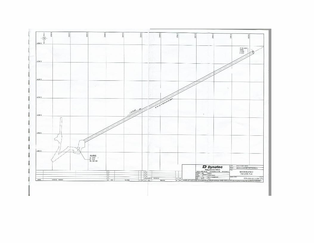
2.5.2.3 Level 7700 Excavation
Excavation on the 7700 Level Drawing; E771-200-02-D-202, will commence following the completion of the excavations on 7100 L along with the dewatering to this elevation. The existing access on 7400 L will be slashed from the existing 9’ x 9’ drift to 15’w x 15’h. This access will then be extended for a distance of 830 feet to reach the location of the base of the ventilation raise. The excavation on the level will serve two purposes:
1. It will allow for the exhaust of heavier than air gases that could be created in the event of a failure within one of the labs.
2. It will serve as a conduit for leaking liquids to be directed towards a containment area on the 7700 level, away from the lab facilities on 7400 L.
This drift will be driven with standard ground support installed which will include 8’ resin grouted rebars installed on a 5’ x 5’ pattern. Shotcrete and floor concrete will be installed during lab construction.
2.5.2.4 Exhaust Raise
Once the 7700 L has been completed, an 11’ diameter raise, Drawing: E771-200-02-D-209, will be excavated from 7700 L to 7100 L. The raise will be driven with a Raise Bore machine which performs the task by first drilling a pilot hole from the 7100 L to intersect the 7700 L. Once the pilot has broken through, an 11’ diameter reaming head is attached at the breakthrough and the pilot is then
E-771 16
Homestake Laboratory Conversion Project
reamed to its final dimensions. Waste muck drawn from the breakthrough location and will be removed from the mine via the #6 Winze/Ross hoisting system. Ground support, shotcrete, manway and services will be installed during lab excavation and construction.
2.5.3 Life Safety Issues
The conversion of the mine must take into consideration a variety of life safety issues. The following areas of concern have been addressed in the report.
2.5.3.1 Fire Prevention and Containment
An important consideration in the planning of the Lab construction will be fire prevention and containment. The water will be supplied through a gravity feed from the reservoir to the 7400 L. through a 6” pipeline in the Exhaust Raise. The Lab will need a sprinkler system installed so that the fire can be contained with a sprinkler system. This pipeline is shown in Drawing; E771-200-02-D-209. The Lab will also need a stench gas warning system installed for release into the fresh air system in the event of a fire in any location within the mine. The mine was required to have this system in place during operation and it is expected that this system will be able to be restored for use in the conversion. The fire containment system will also be accomplished through a series of air-tight ventilation bullheads.
2.5.3.2 Noxious Gas Release and Ventilation
The ventilation system has been designed to supply the Lab with sufficient quantities of fresh air. The design of the Lab has considered that the exhaust for the Lab will always be in the back north side. Therefore, in the event of a fire in the lab or accidental release of a noxious gas related to an experiment, the exit from the lab will be to the south which will always be in fresh air. Evacuation from the mine will always be up the #6 Winze and out the Yates Shaft which will always be in fresh air.
The Exhaust raise has been designed so that exhaust gases can be drawn from the lab either up or down, depending on the relative weight of the gas to the weight of air. At this time it is unknown whether or not there will be a potential for a heavy noxious gas to be released, however the design of the Lab has made a provision for this.
2.5.3.3 Hazardous Material Release, Containment and Removal
E-771 17

Homestake Laboratory Conversion Project
With potentially hazardous fluids used in experiments, provision has been made for released hazardous fluids to be directed towards a containment area on 7700 L. The spill would flow into a sump in the Lab which would direct the fluid through a pipeline to the Exhaust Raise which has a 6” insulated drain line. From the raise, the fluid will be directed to an emergency containment area located in the exhaust way of the level where it would be stored until it had effectively evaporated and was discharged from the mine through the exhaust air system.
2.5.3.4 Emergency Refuge Stations
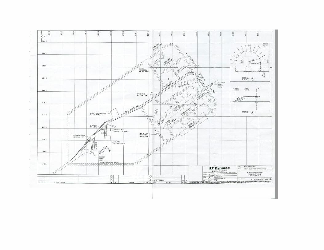
Emergency Refuge Stations will be constructed on the 7400 L at the location shown on Drawing: E771-200-02-D-201. These will be located in fresh air and will be adequately stocked with emergency supplies such as food and fresh water. Communications to the refuge station will be in place and will include telephone, radio and data communication.
2.5.3.5 Mine Rescue
As required by law, a mine rescue team, complete with all necessary mine rescue equipment will need to be put in place for the conversion. It is planned to utilize the existing mine workforce for this purpose. The required number of individuals will be assembled and trained to the level required to be a practicing mine rescue team. The team will need to meet regularly for refresher training and practices to ensure that they can provide effective mine rescue capability for the conversion.
2.5.3.6 Regulatory Issues
For the purposes of this study, it has been assumed that the regulations that govern underground mining as outlined by MSHA will apply. The Lab may operate under OSHA regulations separately, but will likely need to follow the minimum MSHA regulations as well. The construction of the lab has also considered industrial regulations in the design.
2.6 ABILITY OF CORE LABORATORY TO SUPPORT FUTURE
EXPERIMENTS 2.6.1 Laboratory Development and Construction at 7400 Level
Following the completion of the core Laboratory construction, the core facility will be ready for the addition of the first detectors or other experiment at the 7400
E-771 18

Homestake Laboratory Conversion Project
level. For the purposes of this report, the addition has been demonstrated as a Lab opening that will be 252’l x 66’w x 55’h with an arched back. The general configuration of the lab can be seen in plan and section view on Drawing; E771-200-02-D-201A. A three dimensional view has also been created and can be seen in Appendix 2, Datamine Objects. The excavation of the General Purpose Lab would commence with a 15’w x 15’h access drift driven on both the southwest and northeast sides of the Lab. The southwest and northeast sides would then be extended for a distance of 125 feet to the southeast. The lower access would be driven through the center of the lab to the northeast, and will connect with the northeast access close to the vent raise. An incline would be driven from the Main Access drift to the upper elevation of the large Lab. From this incline, an access would be driven along the Northwest side of the Lab from which an entry will branch off into the top of the Lab. The excavation of the top 15 feet will be excavated from the upper access on the Northwest side, and the bottom 40 feet will be benched through the access on the Southeast side. Ground Support installed during the upper level excavation would consist of 8’ resin grouted rebars installed on a 5’ x 5’ pattern with welded wire mesh. Thirty feet long cable bolts would be installed in the back on an 8’ x 8’ pattern and 4” of shotcrete will be installed over the bolts and screen. Rockweb would be applied to the surface of the shotcrete and concrete to provide a barrier against radon gas emission. The bottom wall perimeter would have similar ground support installed with the exception that the cable bolts in the walls will be 20’ in length. The floor of the excavation would be constructed with 12” of reinforced concrete. Before the bottom 40 feet is benched, an overhead crane would be installed for the length of the room and will have a capacity of 10 tons. During the excavation of the Lab on 7400 L, final ground support consisting of 4” of shotcrete and 12” of concrete on the floor would be applied to the excavations completed on 7100 L, 7400 L, and 7700 L. Final construction within the Exhaust Raise would also be performed at this time and would consist of 4” of shotcrete applied around the wall perimeter and a steel manway with pipes and emergency electric cables within its full length. This is shown in detail on drawings E771-216-01-D-208 and 209. Following the completion of excavation with full ground support and concrete floor, the experiment Lab would be ready for Science equipment construction and installation.
2.6.2 Future Expansion – Additional Laboratories
E-771 19
Homestake Laboratory Conversion Project
The excavation of future Labs on the 7400 L would be accomplished by developing new entries from the Southwest side of the #6 Winze on 7400 L that would be driven north to access the Northwest side and East to access the Southeast side. Drawing: E771-200-02-D-201A shows a conceptual layout of future Labs on the 7400 L. All excavation would be done outside the Science area and would not interfere with operating experiments. Concrete bulkheads would be installed to provide a barrier between the Lab and new excavations to prevent interference during breakthrough. The system has been designed to assure that the basic services to the Laboratory can be adjusted to future demands. Variable speed fans will be installed to adjust ventilation quantities as required. Power and utilities will be sized to allow for further expansion. It should also be noted that should additional demands be made to the system, it will be possible to add to the infrastructure without affecting the operation of experiments already in place. It is intended that access for excavation and construction crews will be through the #6 Winze. At this time, the scientists will be using the Auxiliary hoist exclusively and will be disembarking at the 7400 L through the east end of the station. Construction crews will disembark through the west end and should not interfere with the Science personnel.
E-771 20
18-Dec-03E-771
Project : Homestake Laboratory Conversion ProjectClient : State Of South Dakota
Summary of Project CostsContractors
Core Laboratory Mark Up Excise Tax ContingencyItem# Description Total Cost 19% Sub Total 2% Sub Total 15% TotalA-1 Mobilization - Re-Entry $264,855 $50,322 $315,177 $6,304 $321,481 $48,222 $369,703A-2.1 Detailed Engineering $675,050 $128,260 $803,310 $16,066 $819,376 $122,906 $942,283A-2.2 Re-establish power to the site $3,898,600 $740,734 $4,639,334 $92,787 $4,732,121 $709,818 $5,441,939A-2.3 Opening up shafts $38,458 $7,307 $45,765 $915 $46,680 $7,002 $53,682A-2.4 Water Treatment Facility $1,200,000 $228,000 $1,428,000 $28,560 $1,456,560 $218,484 $1,675,044A-3 - VentilationA-3-1 Fans & Chillers - Supply & Install $1,081,873 $205,556 $1,287,429 $25,749 $1,313,178 $196,977 $1,510,154A-3.1 Ventilation Bulkheads $665,584 $126,461 $792,045 $15,841 $807,886 $121,183 $929,069A-4 Re-Commissioning Hoist (mechanical Only) $340,000 $64,600 $404,600 $8,092 $412,692 $61,904 $474,596A-5.1 - Yates ShaftA-5.1.1 Re-Open & Basic Re-Hab -Yates Shaft $260,080 $49,415 $309,495 $6,190 $315,685 $47,353 $363,038A-5.1.2a Install Winch, A-Frame And Cross Head - North Service Comp. $167,500 $31,825 $199,325 $3,987 $203,312 $30,497 $233,808A-5.1.2b Remove Manway & Install New Equip, Services - North Service Comp. $1,650,722 $313,637 $1,964,359 $39,287 $2,003,646 $300,547 $2,304,193A-5.1.2c Install Aux. Hoist And Cage - South Service Comp. $2,063,500 $392,065 $2,455,565 $49,111 $2,504,676 $375,701 $2,880,378A-5.1.2d Remove Old Services - South Service Comp. $267,900 $50,901 $318,801 $6,376 $325,177 $48,777 $373,954A-5.1.2e Repair Remaining Timber $1,594,075 $302,874 $1,896,950 $37,939 $1,934,889 $290,233 $2,225,122A-5.1.3 Pump Station 2600L Yates - Install $498,054 $94,630 $592,684 $11,854 $604,538 $90,681 $695,218A-5.1.4 Surface Pump Line To Mill Res. $64,672 $12,288 $76,960 $1,539 $78,499 $11,775 $90,274A-5.1.5 Pump Station 4850L Yates - Install $489,054 $92,920 $581,974 $11,639 $593,613 $89,042 $682,656A-5.2 Loading Pocket Rehab 8000L - Yates Shaft $50,000 $9,500 $59,500 $1,190 $60,690 $9,104 $69,794A-5.2 - Ross ShaftA-5.2.1 Re-Open For Pumping - Ross Shaft For Dewatering $401,971 $76,374 $478,345 $9,567 $487,912 $73,187 $561,099A-5.2.2 Re-Hab Shaft (sets) - Ross Shaft For Dewatering $227,644 $43,252 $270,896 $5,418 $276,314 $41,447 $317,761A-5.2.5 Loading Pocket Rehab 4850L - Ross Shaft $500,000 $95,000 $595,000 $11,900 $606,900 $91,035 $697,935A-6 - Ross Level rehabA-6.1 Re-Hab. 4500L - Ross Shaft To #6 $38,255 $7,268 $45,523 $910 $46,433 $6,965 $53,398A-6.2 Re-Hab. 4850L - Ross To #6 $67,060 $12,741 $79,801 $1,596 $81,397 $12,210 $93,607A-6.3 Re-Hab. 4850L - Ross To Yates $295,957 $56,232 $352,189 $7,044 $359,233 $53,885 $413,118A-7 - Lvl and Ramp RehabA-7.1 Re-Hab. Level Development $1,326,592 $252,052 $1,578,644 $31,573 $1,610,217 $241,533 $1,851,749A-7.1 Re-Hab. Ramp $1,485,120 $282,173 $1,767,293 $35,346 $1,802,639 $270,396 $2,073,035A-8 - DewateringA-8.1 Dewatering Set-Up (temp) $1,324,988 $251,748 $1,576,736 $31,535 $1,608,271 $241,241 $1,849,511A-8.2 Permanent Pumping Set-Up $983,403 $186,847 $1,170,250 $23,405 $1,193,655 $179,048 $1,372,703A-9 - #6 WinzeA-9.1.1 Convert Koepe Hoists To "Winch". $508,061 $96,532 $604,592 $12,092 $616,684 $92,503 $709,186A-9.1.2 Temp. Winch Set-Up On 4850L $240,000 $45,600 $285,600 $5,712 $291,312 $43,697 $335,009A-9.1.3 Remove Manway & Install New Equip, Services $1,811,578 $344,200 $2,155,778 $43,116 $2,198,894 $329,834 $2,528,728A-9.1.4 Convert Hoist Back To Koepe Hoist $1,170,541 $222,403 $1,392,944 $27,859 $1,420,803 $213,120 $1,633,923A-9.2.1 Aux. Hoist Room Acc. Drift 9X9 $119,720 $22,747 $142,467 $2,849 $145,316 $21,797 $167,114A-9.2.2 Aux. Hoist Room $151,680 $28,819 $180,499 $3,610 $184,109 $27,616 $211,725A-9.2.3 Aux. Hoist Room Rope Rse $76,237 $14,485 $90,723 $1,814 $92,537 $13,881 $106,418A-9.2.4 Install Aux. Hoist And Cage $1,963,500 $373,065 $2,336,565 $46,731 $2,383,296 $357,494 $2,740,791A-9.3 Loading Pocket Rehab 8000L - #6 Winze $500,000 $95,000 $595,000 $11,900 $606,900 $91,035 $697,935B - Level DevelopmentB-1.1 Mobilization - Basic Facilities $61,451 $11,676 $73,126 $1,463 $74,589 $11,188 $85,777B-1.2 De-Mobilization - Basic Facilities $13,387 $2,543 $15,930 $319 $16,249 $2,437 $18,686B-2.1 7100L - Rehab $17,094 $3,248 $20,342 $407 $20,749 $3,112 $23,861B-2.2 7100L Return Air Way (15 X 15) $568,462 $108,008 $676,470 $13,529 $689,999 $103,500 $793,499B-2.3 Geotechnical Drilling $216,000 $41,040 $257,040 $5,141 $262,181 $39,327 $301,508B-3.1 7400L - Rehab $29,652 $5,634 $35,286 $706 $35,992 $5,399 $41,390B-3.2 7400L - Slash Old Drift To 15 X 15 $106,081 $20,155 $126,236 $2,525 $128,761 $19,314 $148,075B-4 7400L - Drift Excavations - Basic Facil. $724,352 $137,627 $861,979 $17,240 $879,219 $131,883 $1,011,101B-5.1 7400L - Air Filtration And Cooling Drift (20 X 15) $55,578 $10,560 $66,138 $1,323 $67,461 $10,119 $77,580B-5.2 7400L - Equipment Wash $103,063 $19,582 $122,645 $2,453 $125,098 $18,765 $143,863B-5.3 7400L - Utility Room $252,578 $47,990 $300,568 $6,011 $306,579 $45,987 $352,566B-5.4 7400L - Wash / Change Room $53,265 $10,120 $63,385 $1,268 $64,653 $9,698 $74,351B-5.5 7400L - Refuge & Cafeteria $173,580 $32,980 $206,560 $4,131 $210,691 $31,604 $242,295B-6.1 7700L - Rehab $17,094 $3,248 $20,342 $407 $20,749 $3,112 $23,861B-6.2 7700L - Slash Old Drift To 15 X 15 $139,893 $26,580 $166,473 $3,329 $169,802 $25,470 $195,273B-6.3 7700L Return Air Way (15 X 15) $436,691 $82,971 $519,662 $10,393 $530,055 $79,508 $609,564B-7.1 7100L To 7700L Raise Bore Vent Raise $374,200 $71,098 $445,298 $8,906 $454,204 $68,131 $522,335B-7.2 7100L To 7700L Vent And Manway Raise $348,763 $66,265 $415,027 $8,301 $423,328 $63,499 $486,827B-8.1a 7100, 7400 & 7700L - Shotcrete (Total) $3,927,813 $746,284 $4,674,097 $93,482 $4,767,579 $715,137 $5,482,716B-8.1b 7400L - Drift Floor Concrete $139,856 $26,573 $166,429 $3,329 $169,758 $25,464 $195,221B-8.1c 7100L - Drift Floor Concrete $98,284 $18,674 $116,958 $2,339 $119,297 $17,895 $137,192B-8.1d 7700L - Drift Floor Concrete $117,273 $22,282 $139,555 $2,791 $142,346 $21,352 $163,698B-8.1e 7400L - Room Floor Concrete $55,367 $10,520 $65,886 $1,318 $67,204 $10,081 $77,284B-9 Surface Muck Haulage $428,404 $81,397 $509,801 $10,196 $519,997 $78,000 $597,997
Total Direct $36,920,463 $7,014,888 $43,935,351 $878,707 $44,814,058 $6,722,109 $51,536,167Phase 1 - IndirectsPhase 1 - 1a Indirect Labor - Re-Entry, Dewatering And Basic Construction $13,107,291 $2,490,385 $15,597,676 $311,954 $15,909,630 $2,386,444 $18,296,074Phase 1 - 1b Indirect Labor - Dewatering And Basic Construction $4,435,134 $842,675 $5,277,809 $105,556 $5,383,365 $807,505 $6,190,870Phase 1 - 2a Indirect Equipment - Re-Entry, Dewatering And Basic Construction $2,821,914 $536,164 $3,358,077 $67,162 $3,425,239 $513,786 $3,939,024Phase 1 - 2b Indirect Equipment - Dewatering And Basic Construction $1,267,058 $240,741 $1,507,799 $30,156 $1,537,955 $230,693 $1,768,648Phase 1 - 3 Power Cost - Re-Entry, Dewatering And Basic Construction $6,723,729 $0 $6,723,729 $0 $6,723,729 $1,008,559 $7,732,288
Total Indirect $28,355,126 $4,109,965 $32,465,090 $514,827 $32,979,917 $4,946,988 $37,926,905Phase 1 Total $65,275,589 $11,124,853 $76,400,441 $1,393,534 $77,793,975 $11,669,096 $89,463,072
ID Text1
1 A-1
2 A-2.1
3 A-2.2
4 A-2.3a
5 A-2.3b
6 A-2.3b
7 A-3-1
8 A-3.1a
9 A-3.1b
10 A-3.1c
11 A-4.1
12 A-4.2
13 A-5.1
14 A-5.1.1
15 A-5.1.2
16 A-5.1.2
17 A-5.1.2
18 A-5.1.2
19 A-5.1.2
20 A-5.1.3
21 A-5.1.4
22 A-5.1.5
23 A-5.2
24 A-5.2
25 A-5.2.1
26 A-5.2.2
27 A-5.2.5
28 A-6.1a
29 A-6.1b
30 A-6.1c
31 A-7.1
32 A-7.1
33 A-8
34 A-8.1
35 A-8.2
36 A-9
37 A-9.1.1
38 A-9.1.2
39 A-9.1.3
40 A-9.1.4
41 A-9.2.1
42 A-9.2.2
43 A-9.2.3
44 A-9.2.4
45 A-9.3
46 B
47 B-1.1
48 B-1.2
49 B-2.1
50 B-2.2
51 B-3.1
52 B-3.2
53 B-4
54 B-5.1
55 B-5.2
56 B-5.3
57 B-5.4
58 B-5.5
59 B-6.1
60 B-6.2
61 B-6.3
62 B-8.1a
63 B-8.1c
64 B-8.1d
65 B-7.1a
66 B-7.1b
67 B-7.2
68 C
69 C-2 &C-3.3
70 C-3.1a
71 C-3.1c
72 C-3.1c
73 C-3.1b
74 C-3.2a&
75 C-3.2c
76 C-3.2c
77 C-4.1&
78 B-8.1b
79 C-4.4
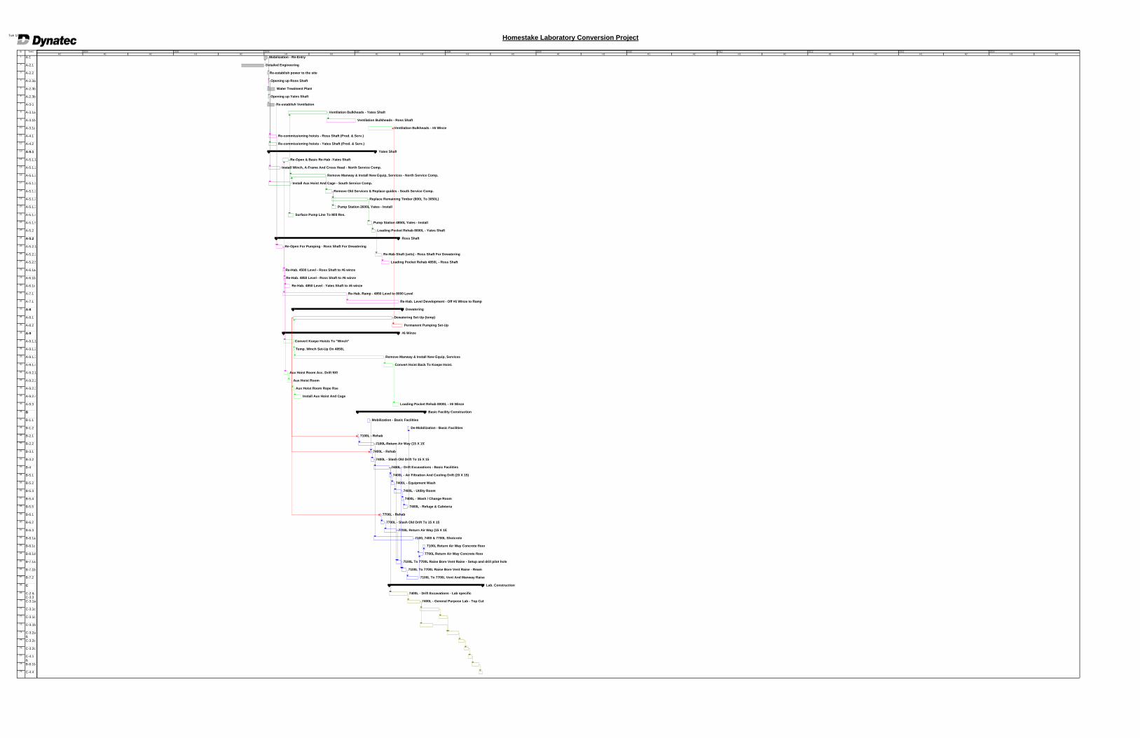
Mobilization - Re-Entry
Detailed Engineering
Re-establish power to the site
Opening up Ross Shaft
Water Treatment Plant
Opening up Yates Shaft
Re-establish Ventilation
Ventilation Bulkheads - Yates Shaft
Ventilation Bulkheads - Ross Shaft
Ventilation Bulkheads - #6 Winze
Re-commissioning hoists - Ross Shaft (Prod. & Serv.)
Re-commissioning hoists - Yates Shaft (Prod. & Serv.)
Yates Shaft
Re-Open & Basic Re-Hab -Yates Shaft
Install Winch, A-Frame And Cross Head - North Service Comp.
Remove Manway & Install New Equip, Services - North Service Comp.
Install Aux Hoist And Cage - South Service Comp.
Remove Old Services & Replace guides - South Service Comp.
Replace Remaining Timber (800L To 3050L)
Pump Station 2600L Yates - Install
Surface Pump Line To Mill Res.
Pump Station 4850L Yates - Install
Loading Pocket Rehab 8000L - Yates Shaft
Ross Shaft
Re-Open For Pumping - Ross Shaft For Dewatering
Re-Hab Shaft (sets) - Ross Shaft For Dewatering
Loading Pocket Rehab 4850L - Ross Shaft
Re-Hab. 4500 Level - Ross Shaft to #6 winze
Re-Hab. 4850 Level - Ross Shaft to #6 winze
Re-Hab. 4850 Level - Yates Shaft to #6 winze
Re-Hab. Ramp - 4850 Level to 8000 Level
Re-Hab. Level Development - Off #6 Winze to Ramp
Dewatering
Dewatering Set-Up (temp)
Permanent Pumping Set-Up
#6 Winze
Convert Koepe Hoists To "Winch"
Temp. Winch Set-Up On 4850L
Remove Manway & Install New Equip, Services
Convert Hoist Back To Koepe Hoist.
Aux Hoist Room Acc. Drift 9X9
Aux Hoist Room
Aux Hoist Room Rope Rse
Install Aux Hoist And Cage
Loading Pocket Rehab 8000L - #6 Winze
Basic Facility Construction
Mobilization - Basic Facilities
De-Mobilization - Basic Facilities
7100L - Rehab
7100L Return Air Way (15 X 15)
7400L - Rehab
7400L - Slash Old Drift To 15 X 15
7400L - Drift Excavations - Basic Facilities
7400L - Air Filtration And Cooling Drift (20 X 15)
7400L - Equipment Wash
7400L - Utility Room
7400L - Wash / Change Room
7400L - Refuge & Cafeteria
7700L - Rehab
7700L - Slash Old Drift To 15 X 15
7700L Return Air Way (15 X 15)
7100, 7400 & 7700L Shotcrete
7100L Return Air Way Concrete floor
7700L Return Air Way Concrete floor
7100L To 7700L Raise Bore Vent Raise - Setup and drill pilot hole
7100L To 7700L Raise Bore Vent Raise - Ream
7100L To 7700L Vent And Manway Raise
Lab. Construction
7400L - Drift Excavations - Lab specific
7400L - General Purpose Lab - Top Cut
H2 H1 H2 H1 H2 H1 H2 H1 H2 H1 H2 H1 H2 H1 H2 H1 H2 H1 H2 H1 H2 H1 H22004 2005 2006 2007 2008 2009 2010 2011 2012 2013 2014
Homestake Laboratory Conversion ProjectTue 1/6/04
Homestake Laboratory Conversion Project
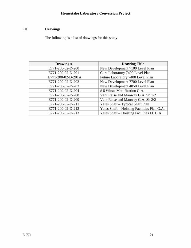
5.0 Drawings
The following is a list of drawings for this study:
Drawing # Drawing Title
E771-200-02-D-200 New Development 7100 Level Plan E771-200-02-D-201 Core Laboratory 7400 Level Plan
E771-200-02-D-201A Future Laboratory 7400 Level Plan E771-200-02-D-202 New Development 7700 Level Plan E771-200-02-D-203 New Development 4850 Level Plan E771-200-02-D-204 # 6 Winze Modification G.A. E771-200-02-D-208 Vent Raise and Manway G.A. Sh 1/2 E771-200-02-D-209 Vent Raise and Manway G.A. Sh 2/2 E771-200-02-D-211 Yates Shaft – Typical Shaft Plan E771-200-02-D-212 Yates Shaft – Hoisting Facilities Plan G.A. E771-200-02-D-213 Yates Shaft – Hoisting Facilities El. G.A.
E-771 21


Homestake Laboratory Conversion Project
6.0 Three Dimensional Objects 1. Water Below 7400 Level. 2. Water Below 7400 Level, Drilling, Development. 3. Water Below 7700 Level, Drilling, Development. 4. Water Pumped Out and Development. 5. Core Homestake Underground Laboratory. 6. Addition of First Detector Experiment. 7. Future Developments.
E-771 22
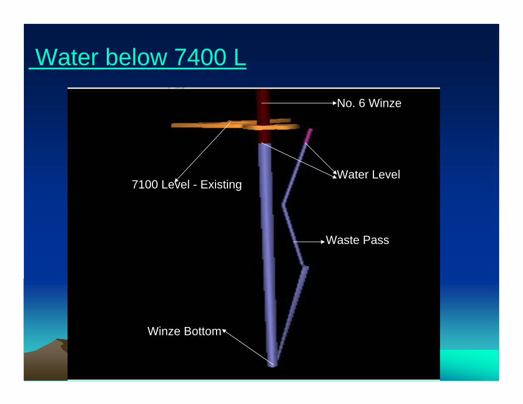
No. 6 Winze
Water Level7100 Level - Existing
Waste Pass
Winze Bottom
Water below 7400 L

New drift development with drill stations
Drilling-Geotechnical
Water level 7400 level
7400 level - Existing
7100 level
No. 6 Winze
Water below 7400l, Drilling, Dev.
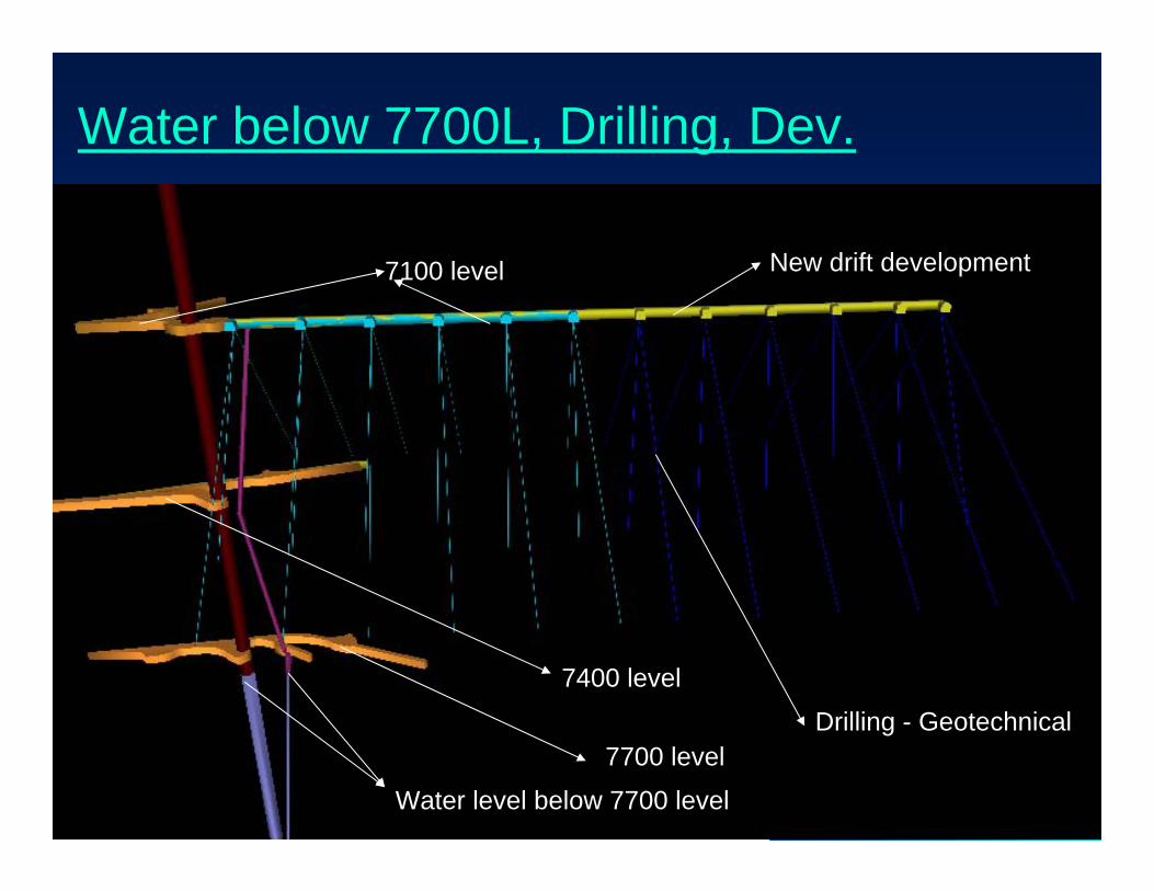
7100 level
7400 level
7700 level
Water level below 7700 level
New drift development
Drilling - Geotechnical
Water below 7700L, Drilling, Dev.
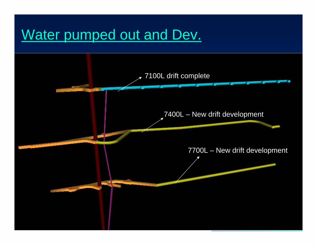
7400L slashing complete
Water pumped out and Dev.
7100L drift complete
7400L – New drift development
7700L – New drift development
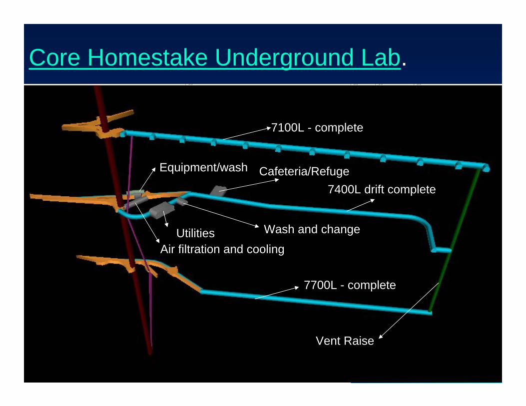
7100L - complete
7400L drift complete
7700L - complete
Vent Raise
Air filtration and coolingUtilities Wash and change
Equipment/wash Cafeteria/Refuge
Core Homestake Underground Lab.
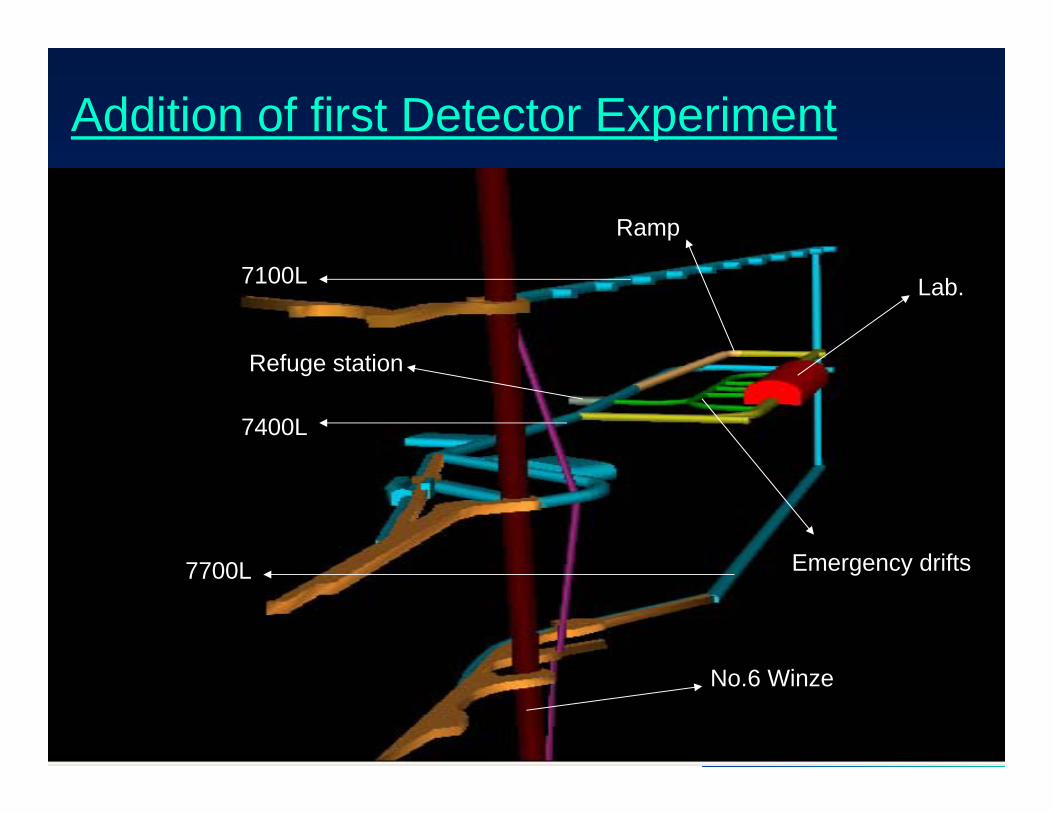
7100L
7400L
7700L
Refuge station
Lab.
Emergency drifts
Ramp
No.6 Winze
Addition of first Detector Experiment
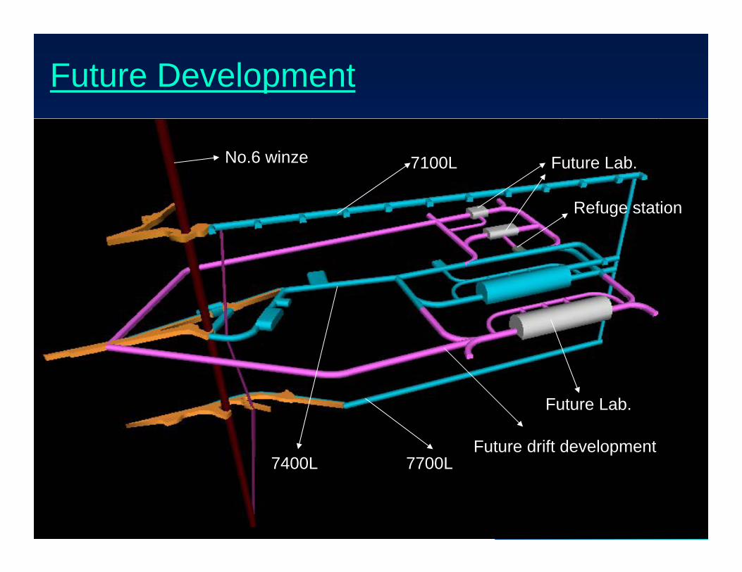
7100L
7400L 7700LFuture drift development
Future Lab.
No.6 winze Future Lab.
Refuge station
Future Development
Related Documents