Dominic Waldorf ME 471 Dr. Pourboghrat March 26 th , 2015 FEA Design PART 1: Mesh Size: 5 mm Mesh Size: 10 mm

Welcome message from author
This document is posted to help you gain knowledge. Please leave a comment to let me know what you think about it! Share it to your friends and learn new things together.
Transcript
Dominic WaldorfME 471Dr. PourboghratMarch 26th, 2015
FEA Design PART 1:
Mesh Size: 5 mm
Mesh Size: 10 mm
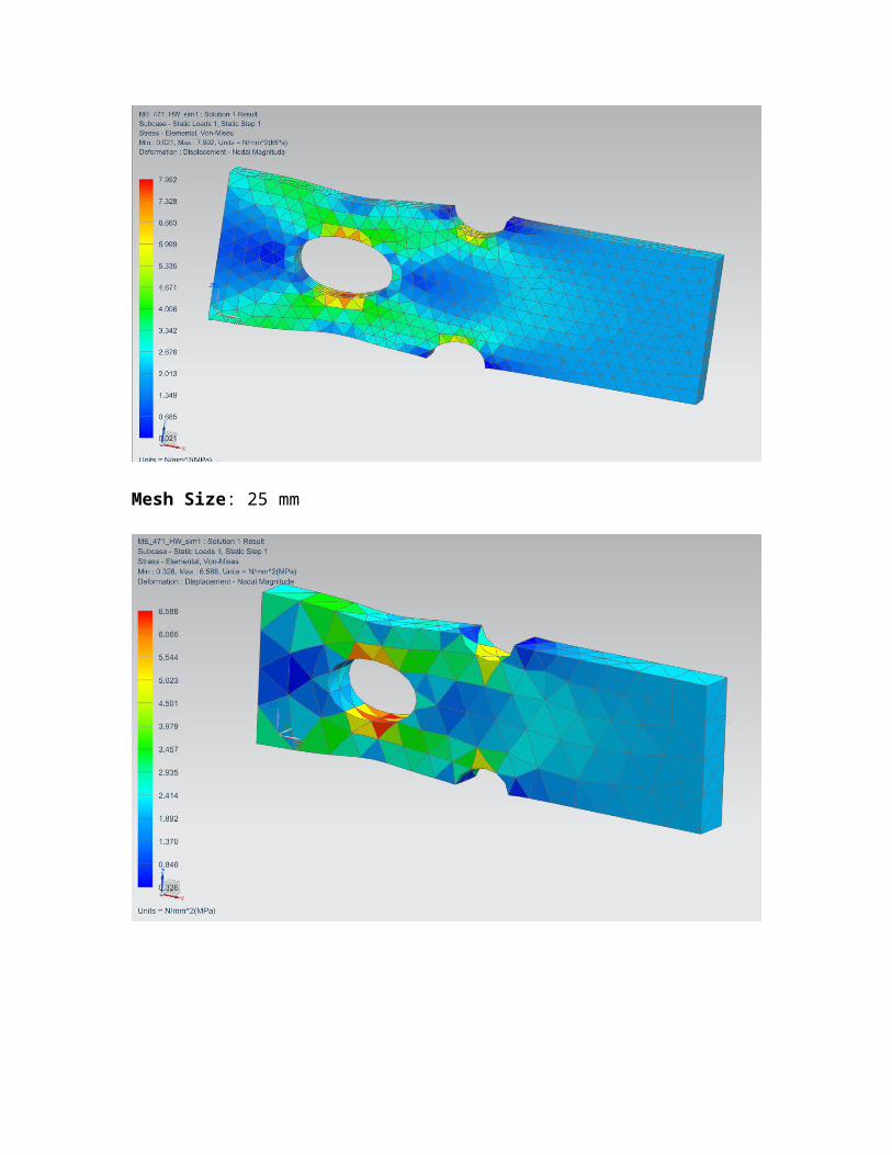
Mesh Size: 25 mm
Element Stress (AISI 1005):
Mesh Size 5 mm: Hole: 8.059 N/mm^2 (MPA) Semi-circle: 6.050 N/mm^2 (MPA)
Mesh Size 10 mm:Hole: 7.328 N/mm^2 (MPA) Semi-circle: 5.999 N/mm^2 (MPA)
Mesh Size 20 mm:Hole: 6.588 N/mm^2 (MPA) Semi-circle: 5.023 N/mm^2 (MPA)
Relationship:
The mesh size and the maximum value of stress are inversely proportional. As mesh size increases, the maximum value of stress decreases.

PART 2:
Mesh Size: 5 mm
Stress Element:
Displacement:

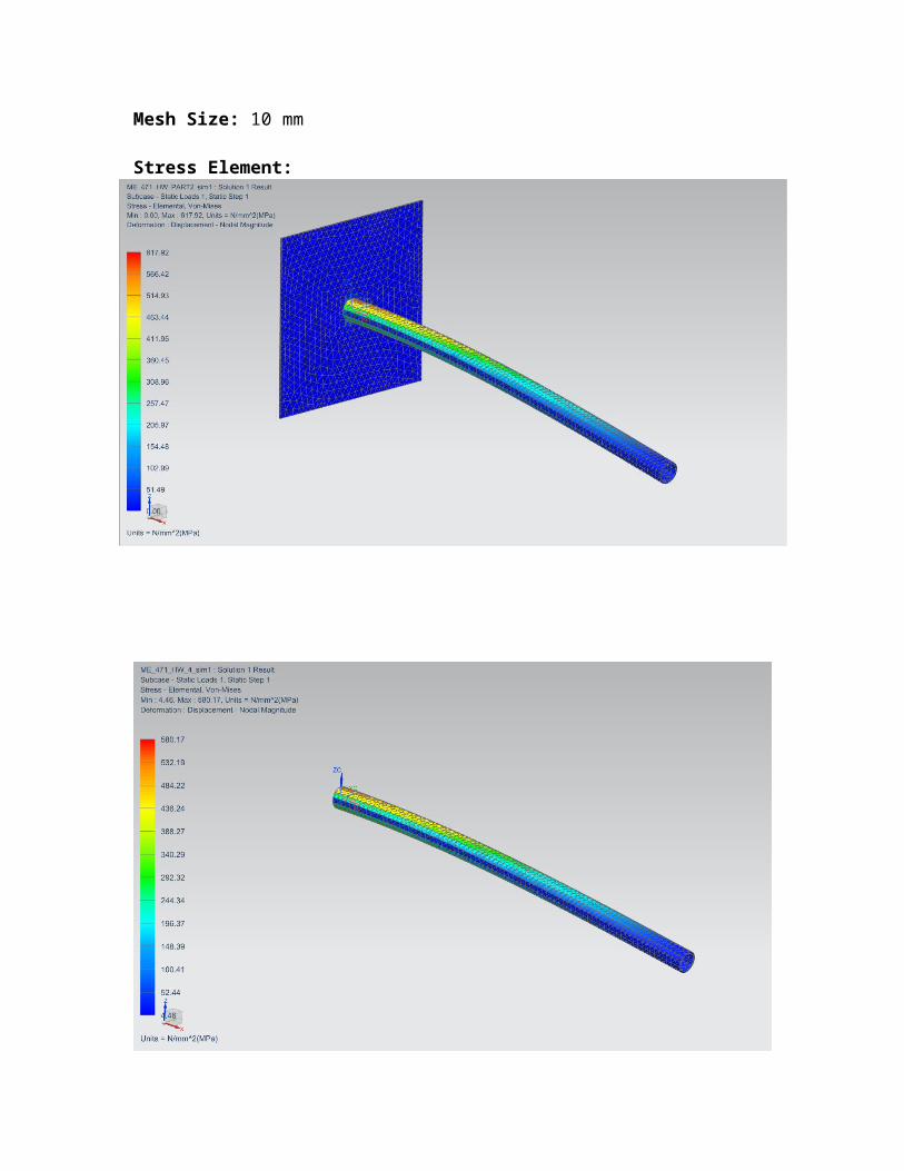
Mesh Size: 10 mm
Stress Element:
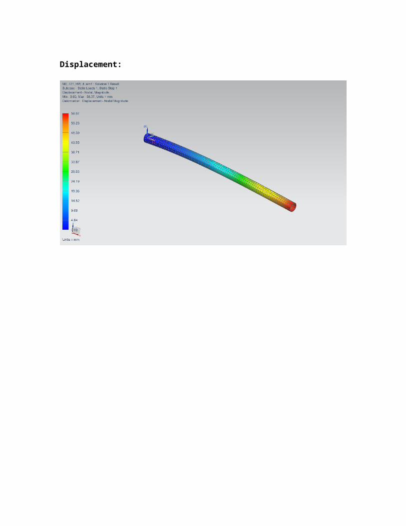
Displacement:

Mesh Size: 20 mm
Stress Element:
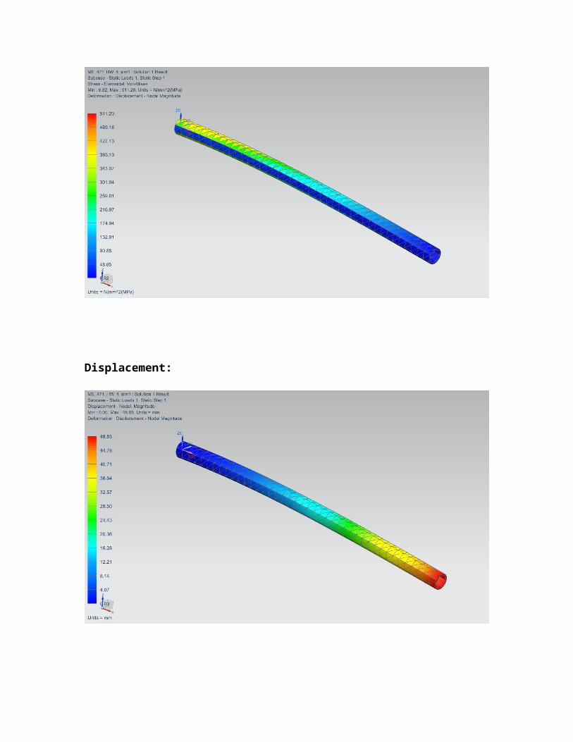
Displacement:
Maximum Stresses and Deflection for Aluminum 6061 bar:
Mesh Size 5 mm:
Max Stress: 778.81 N/mm^2 Deflection: 62.87 mm
Mesh Size 10 mm:
Max Stress: 617.92 N/mm^2 (MPA) Deflection: 58.07 mm
Mesh Size 20 mm:
Max Stress: 446.72 N/mm^2 (MPA) Deflection: 48.85 mm
Relationship:
The mesh size and the maximum value of stress are inversely proportional. As mesh size increases, the maximum value of stress and deflection decreases.
Related Documents