SYSTEM DESCRIPTION, INSTALLATION, AND MAINTENANCE MANUAL MCS-4200/7200 TEMPORARY REVISION NO. 23-1 23-20-35 Page 44 of 53 28 Sep 2009 © Honeywell International Inc. Do not copy without express permission of Honeywell. INSERT PAGE 44 OF 53 FACING PAGE 6-100. Reason: To add a new failure code, 0B, to Table 6-19 between failure codes 0A and 0D. Failure code 0B is added as follows: Table 6-19. Airbus Level I (SDU No. 1) Failure Messages and ATA No. Failure Code SDU/SDU No. 1 – CFDS Normal and Interactive Modes ATA Number 0B HDM 232832

Welcome message from author
This document is posted to help you gain knowledge. Please leave a comment to let me know what you think about it! Share it to your friends and learn new things together.
Transcript

SYSTEM DESCRIPTION, INSTALLATION, AND MAINTENANCE MANUAL
MCS-4200/7200
TEMPORARY REVISION NO. 23-1
23-20-35 Page 44 of 5328 Sep 2009
© Honeywell International Inc. Do not copy without express permission of Honeywell.
INSERT PAGE 44 OF 53 FACING PAGE 6-100.
Reason: To add a new failure code, 0B, to Table 6-19 between failure codes 0A and 0D. Failure code 0B is added as follows:
Table 6-19. Airbus Level I (SDU No. 1) Failure Messages and ATA No.
Failure Code SDU/SDU No. 1 – CFDS Normal and Interactive Modes ATA Number
0B HDM 232832


SYSTEM DESCRIPTION, INSTALLATION, AND MAINTENANCE MANUALMCS--4200/7200 Multi--Channel SATCOM System
23--20--35 15 Jul 2006
Honeywell International Inc. Do not copy without express permission of Honeywell.
Page 6--101
Table 6-19. Airbus Level I (SDU No. 1) Failure Messages and ATA No. (cont)
FailureCode ATA NumberSDU/SDU No. 1 -- CFDS Normal and Interactive Modes
1A ANTENNA1(116RV1)
HI GAIN ANTENNA--TOP(16RV1)
HI GAIN ANTENNA--L(17RV)
[IGA]
[Top Mount]
[Conformal]
232813
232813
232812
1C HI GAIN ANTENNA--R(18RV) [Conformal] 232812
1F LO GAIN ANTENNA(13RV) 232811
21 MCDU1(2CA1) [A330/A340] 228212
MCDU1(3CA1) [A320] 228212
22 MCDU2(2CA2) [A330/A340] 228212
MCDU2(3CA2) [A320] 228212
23 MCDU3(2CA3) [A330/A340] 228212
MCDU3(3CA3) [A320] 228212
33 ATSU1(1TX1) [ATSU] 462134
ACARS MU(1RB) [A320 ACARS] 232434
ACARS MU1(1RB1) [A330/A340 ACARS] 232434
34 ATSU2 (1TX2) [ATSU] 462134
ACARS MU2 [A320 ACARS] 232434
ACARS MU2(1RB2) [A330/A340 ACARS] 232434
35 ADIRU1(1FP1) 341234
36 ADIRU2(1FP2) 341234
37 RESERVED N/A
38 RESERVED N/A
39 RESERVED N/A
3D FMGC1(1CA1)
FMGEC1(1CA1)
[A320]
[A330/A340]
228334
228334
3E FMGC2(1CA2)
FMGEC2(1CA2)
[A320]
[A330/A340]
228334
228334
40 ARINC 429 ICAO N/A

SYSTEM DESCRIPTION, INSTALLATION, AND MAINTENANCE MANUALMCS--4200/7200 Multi--Channel SATCOM System
23--20--35 15 Jul 2006
Honeywell International Inc. Do not copy without express permission of Honeywell.
Page 6--102
Table 6-19. Airbus Level I (SDU No. 1) Failure Messages and ATA No. (cont)
FailureCode ATA NumberSDU/SDU No. 1 -- CFDS Normal and Interactive Modes
42 CTU--CU CEPT--E1 BUS/SDU1 (105RV1)
CTU--CU CEPT--E1 BUS/SDU1 (105RV1)
CTU--CU CEPT--E1 BUS/SDU1 (5RV1)
CTU--CU CEPT--E1 BUS/SDU1 (5RV1)
[IGA A320]
[IGA A330/A340]
[HGA A320]
[HGA A330/A340]
233500
239200
233500
239200
43 IFE 429 BUS/SDU1 (5RV1)
IFE 429 BUS/SDU1 (105RV1)
IFE 429 BUS/SDU1 (105RV1)
IFE 429 BUS/SDU1 (5RV1)
[A330/A340 HGA]
[A330/A340 HGA]
[A320 IGA]
[A320 HGA]
233000
233000
50 HSDU1 (63RV1)/SDU1 (5RV1) 232839
52 IFE 429 BUS/SDU1 (5RV1)
IFE 429 BUS/SDU1 (105RV1)
IFE 429 BUS/SDU1 (105RV1)
IFE 429 BUS/SDU1 (5RV1)
[A330/A340 HGA]
[A330/A340 HGA]
[A320 IGA]
[A320 HGA]
233000
233000
53 ATSU1 (1TX1)/SDU1(105RV1) [IGA ATSU] 462134
ATSU1 (1TX1)/SDU1(5RV1) [HGA ATSU] 462134
ACARS MU (1RB)/SDU1(105RV1) [IGA A320 ACARS] 232434
ACARS MU1 (1RB1)/SDU1(105RV1) [IGA A330/A340 ACARS] 232434
ACARS MU (1RB)/SDU1(5RV1) [HGA A320 ACARS] 232434
ACARS MU1 (1RB1)/SDU1(5RV1) [HGA A330/A340 ACARS] 232434
54 CTU--CU CEPT--E1 BUS/SDU1(105RV1) [IGA A320] 233500
CTU--CU CEPT--E1 BUS/SDU1(105RV1) [IGA A330/A340] 239200
CTU--CU CEPT--E1 BUS/SDU1(5RV1) [HGA A320] 233500
CTU--CU CEPT--E1 BUS/SDU1(5RV1) [HGA A330/A340] 239200
55 MCDU1(2CA1)/SDU1(105RV1)
MCDU1(2CA1)/SDU1(5RV1)
MCDU1(3CA1)/SDU1(105RV1)
MCDU(3CA1)/SDU1(5RV1)
[IGA A330/A340]
[HGA A330/A340]
[IGA A320]
[HGA A320]
228212
228212
228212
228212
56 MCDU2(2CA2)/SDU1(105RV1)
MCDU2(2CA2)/SDU1(5RV1)
MCDU2(3CA2)/SDU1(105RV1)
MCDU2(3CA2)/SDU1(5RV1)
[IGA A330/A340]
[HGA A330/A340]
IGA A320
HGA A320
228212
228212
228212
228212

SYSTEM DESCRIPTION, INSTALLATION, AND MAINTENANCE MANUALMCS--4200/7200 Multi--Channel SATCOM System
23--20--35 15 Jul 2006
Honeywell International Inc. Do not copy without express permission of Honeywell.
Page 6--103
Table 6-19. Airbus Level I (SDU No. 1) Failure Messages and ATA No. (cont)
FailureCode ATA NumberSDU/SDU No. 1 -- CFDS Normal and Interactive Modes
57 ATSU2 (1TX2)/SDU1(105RV1) [IGA ATSU] 462134
ATSU2 (1TX2)/SDU1(5RV1) [HGA ATSU] 462134
ACARS MU2/SDU1(105RV1) [IGA A320 ACARS] 232434
ACARS MU2 (1RB2)/SDU1(105RV1) [IGA A330/A340 ACARS] 232434
ACARS MU2/SDU1(5RV1) [HGA A320 ACARS] 232434
ACARS MU2 (1RB2)/SDU1(5RV1) [HGA A330/A340 ACARS] 232434
59 CFDIU(1TW)/SDU1(105RV1) [IGA A320] 313234
CMC1(1TM1)/SDU1(105RV1) [IGA A330/A340] 451334
CFDIU(1TW)/SDU1(5RV1) [HGA A320] 313234
CMC1(1TM1)/SDU1(5RV1) [HGA A330/A340] 451334
5A ADIRU1(1FP1)/SDU1(105RV1)
ADIRU1(1FP1)/SDU1(5RV1)
[IGA]
[HGA]
341234
341234
5B ADIRU2(1FP2)/SDU1(105RV1)
ADIRU2(1FP2)/SDU1(5RV1)
[IGA]
[HGA]
341234
341234
5C HPA1 (110RV1)/SDU1(105RV1)
HPA--HI GAIN(7RV1)/SDU1(5RV1)
[IGA]
[HGA]
232831
232831
5F HPA--LO GAIN(9RV)/SDU1(5RV1)
HPA--LO GAIN(9RV)/SDU1(105RV1)
[HGA + LGA]
[IGA + LGA]
232835
232835
62 BSU(8RV1)/SDU1(5RV1)
BSU--L(15RV1)/SDU1(5RV1)
[Top Mount]
[Conformal]
232846
232844
64 BSU--R(15RV2)/SDU1(5RV1) [Conformal] 232844
66 MCDU3(2CA3)/SDU1(105RV1)
MCDU3(2CA3)/SDU1(5RV1)
MCDU3(3CA3)/SDU1(105RV1)
MCDU3(CA3)/SDU1(5RV1)
[IGA A330/A340]
[HGA A330/A340]
[IGA A320]
[HGA A320]
228212
228212
228212
228212
67 RESERVED
68 RESERVED
6A RESERVED
6C RESERVED
6D RESERVED

SYSTEM DESCRIPTION, INSTALLATION, AND MAINTENANCE MANUALMCS--4200/7200 Multi--Channel SATCOM System
23--20--35 15 Jul 2006
Honeywell International Inc. Do not copy without express permission of Honeywell.
Page 6--104
Table 6-19. Airbus Level I (SDU No. 1) Failure Messages and ATA No. (cont)
FailureCode ATA NumberSDU/SDU No. 1 -- CFDS Normal and Interactive Modes
6E RESERVED
6F RESERVED
71 SDU2(105RV2)CROSSTALK BUS/SDU1(105RV1)
SDU2(5RV2)CROSSTALK BUS/SDU15RV1)
[IGA]
[HGA]
232834
232834
73 FMGC1(1CA1)/SDU1(105RV1) [IGA A320] 228334
FMGEC1(1CA1)/SDU1(105RV1) [IGA A330/A340] 228334
FMGC1(1CA1)/SDU1(5RV1) [HGA A320] 228334
FMGEC1(1CA1)/SDU1(5RV1) [HGA A330/A340] 228334
74 FMGC2(1CA2)/SDU1(105RV1) [IGA A320] 228334
FMGEC2(1CA2)/SDU1(105RV1) [IGA A330/A340] 228334
FMGC2(1CA2)/SDU1(5RV1) [HGA A320] 228334
FMGEC2(1CA2)/SDU1(5RV1) [HGA A330/A340] 228334
80 RESERVED
82 RESERVED
88 RESERVED
90 SDU1(105RV1) BUS M--CTRL/HPA1(110RV1) [IGA] 232834
SDU1(5RV1) BUS M--CTRL/HPA--HIGAIN(7RV1)
[HGA] 232834
96 SDU1(5RV1) BUS M--CTRL/HPA--LOGAIN(9RV)
[HGA+LGA] 232834
SDU1(105RV1) BUS M--CTRL/HPA--LOGAIN(9RV)
[IGA+LGA] 232834
98 SDU1(5RV1) BUS M--CTRL/BSU(8RV1)
SDU1(5RV1) BUS M--CTRL/BSU--L(15RV1)
[Top Mount]
[Conformal]
232834
232834
9A BSU--R (15RV2) XTALK BUS/BSU--L(15RV1) [Conformal] 232844
9C SDU1(5RV1) BUS M--CTRL/BSU--R(15RV2) [Conformal] 232834
9D BSU--L (15RV1) XTALK BUS/BSU--R(15RV2) [Conformal] 232844
9E SDU1 (5RV1) /HSDU1 (63RV1) 232834
9F Not applicable for package 6.0 and beyond N/A

SYSTEM DESCRIPTION, INSTALLATION, AND MAINTENANCE MANUALMCS--4200/7200 Multi--Channel SATCOM System
23--20--35 15 Jul 2006
Honeywell International Inc. Do not copy without express permission of Honeywell.
Page 6--105
Table 6-19. Airbus Level I (SDU No. 1) Failure Messages and ATA No. (cont)
FailureCode ATA NumberSDU/SDU No. 1 -- CFDS Normal and Interactive Modes
A1 SDU1(105RV1)/MCDU1(2CA1) [IGA] 228212
SDU1(5RV1)/MCDU1(2CA1) [HGA] 228212
A2 SDU1(105RV1).MCDU2(2CA2) [IGA] 228212
SDU1(5RV1)/MCDU2(2CA2) [HGA] 228212
A3 SDU1(105RV1)/MCDU3(2CA3) [IGA] 228212
SDU1(5RV1)/MCDU3(2CA3) [HGA] 228212
A6 ESU(101RF) ETHERNET 1/HSDU1(63RV1) 464131
A7 ESU(101RF) ETHERNET 2/HSDU1(63RV1) 464131
A8 ESU(101RF) ISDN 1/HSDU1(63RV1) 464131
A9 ESU(101RF) ISDN 2/HSDU1(63RV1) 464131
C0 WRG:CONFIG PIN PROG/SDU1(105RV1) [IGA] 232800
WRG:CONFIG PIN PROG/SDU1(5RV1) [HGA] 232800
C1 LGCIU1(5GA1)/LGCIU2(5GA2)/SDU1(105RV1) [IGA] 323171
LGCIU1(5GA1)/LGCIU2(5GA2)/SDU1(5RV1) [HGA] 323171
C2 SDU1(105RV1) SEL--DISABLEDISCRETE/SDU2(105RV2)
[IGA] 232834
SDU1(5RV1) SEL--DISABLEDISCRETE/SDU2(5RV2)
[HGA] 232834
C3 WRG:ICAO ADDRESS PINPROG/SDU1(105RV1)
[IGA] 232800
WRG:ICAO ADDRESS PINPROG/SDU1(5RV1)
[HGA] 232800
C4 HPA1 (110RV1)/VSWR [IGA] 232831
HPA--HI GAIN(7RV1)/VSWR [HGA] 232831
C5 WRG:CONFIG PIN PROG/SDU1(105RV1)OWNER REQS DB
[IGA] 232800
WRG:CONFIG PIN PROG/SDU1(5RV1)OWNER REQS DB
[HGA] 232800
C6 HPA--LO GAIN(9RV)/VSWR 232835
C7 HPA(110RV1)/OVER TEMPERATURE [IGA] 232831
HPA--HI GAIN(7RV1)/OVER TEMPERATURE [HGA] 232831

SYSTEM DESCRIPTION, INSTALLATION, AND MAINTENANCE MANUALMCS--4200/7200 Multi--Channel SATCOM System
23--20--35 15 Jul 2006
Honeywell International Inc. Do not copy without express permission of Honeywell.
Page 6--106
Table 6-19. Airbus Level I (SDU No. 1) Failure Messages and ATA No. (cont)
FailureCode ATA NumberSDU/SDU No. 1 -- CFDS Normal and Interactive Modes
C8 SDU1(105RV1)/BAD DATA FROM GROUNDSTATION
[IGA] 232834
SDU1(5RV1)/BAD DATA FROM GROUNDEARTH STATION
[HGA] 232834
C9 HPA--LO GAIN(9RV)/OVER TEMPERATURE 232835
CA SDU1(5RV1)CTRL DISCRETE/DLNA--LOGAIN(14RV)
[HGA+LGA] 232834
SDU1(105RV1)CTRL DISCRETE/DLNA--LOGAIN(14RV)
[IGA+LGA] 232834
CB WRG:SDI PIN PROG/HPA1(110RV1) [IGA] 232800
WRG:SDI PIN PROG/HPA--HI GAIN(7RV1) [HGA] 232800
CC WRG:SDI PIN PROG/HPA--LO GAIN(9RV) 232800
CD N/A N/A
CE RESERVED
CF N/A N/A
D0 N/A N/A
D1 WRG:SDI PIN PROG/HPA1(110RV1) 232800
WRG:SDI PIN PROG/HPA--HI GAIN(7RV1) 232800
D2 WRG:SDI PIN PROG/HPA--LO GAIN(9RV) 232800
D3 WRG:SDI PIN PROG/BSU(8RV1)
WRG:SDI PIN PROG/BSU--L(15RV1)
[Top Mount]
[Conformal]
232800
232800
D4 WRG:SDI PIN PROG/BSU--R(15RV2) [Conformal] 232800
D5 SDU1(105RV1)/TXCOAX [IGA] 232834
SDU1(5RV1)/TXCOAX [HGA] 232834
D6 SDU1 (105RV1)/TXCOAX [IGA+LGA] 232834
SDU1(5RV1)/TXCOAX [HGA+LGA] 232834
D7 RESERVED
D8 SDU1(105RV1)/RXCOAX
SDU1(5RV1)/RXCOAX
[IGA]
[HGA]
232834
232834
D9 SDU2(5RV1)/RXCOAX 232834
DA SDU1(105RV1)/RXCOAX [IGA+LGA] 232834

SYSTEM DESCRIPTION, INSTALLATION, AND MAINTENANCE MANUALMCS--4200/7200 Multi--Channel SATCOM System
23--20--35 15 Jul 2006
Honeywell International Inc. Do not copy without express permission of Honeywell.
Page 6--107
Table 6-19. Airbus Level I (SDU No. 1) Failure Messages and ATA No. (cont)
FailureCode ATA NumberSDU/SDU No. 1 -- CFDS Normal and Interactive Modes
SDU1(5RV1)/RXCOAX [HGA+LGA] 232834
DB LO GAIN ANTENNA(13RV)LOG ON FAILURE
232811
DC N/A N/A to Airbus
DD SDU1(105RV1) OWNER REQS DB SECUREDPARTITION
[IGA] 232834
SDU1(5RV1) OWNER REQS DB SECUREDPARTITION
[HGA] 232834
DE SDU1(105RV1) OWNER REQS DB USERPARTITION
[IGA] 232834
SDU1(5RV1) OWNER REQS DB USERPARTITION
[HGA] 232834
DF SDU1(105RV1)LOG ON FAILURE
[IGA] 232834
SDU1(5RV1)LOG ON FAILURE
[HGA] 232834
E0 RESERVED
E1 SDU1(5RV1) DISCRETE/HSDU1(63RV1) 232834
E2 N/A N/A
E3 N/A N/A to Airbus
E4 SDU1(5RV1)/HSDU1(63RV1) 232834
E5 N/A N/A to Airbus
E6 HSDU1(63RV1)/TXCOAX 232839
E7 N/A N/A
E8 HSDU1(63RV1)/RXCOAX 232839
E9 N/A N/A
EA N/A N/A to Airbus
EB MCDU1(2CA1)+MCDU2(2CA2)+MCDU3(2CA3)INACTIVE
[RMP only] 228212
EC WRG:CONFIG PIN PROG/HSDU1(63RV1) 232800
ED WRG:CONFIG PIN PROG/HSDU1(63RV1)SDU ORT
232800

SYSTEM DESCRIPTION, INSTALLATION, AND MAINTENANCE MANUALMCS--4200/7200 Multi--Channel SATCOM System
23--20--35 15 Jul 2006
Honeywell International Inc. Do not copy without express permission of Honeywell.
Page 6--108
Table 6-19. Airbus Level I (SDU No. 1) Failure Messages and ATA No. (cont)
FailureCode ATA NumberSDU/SDU No. 1 -- CFDS Normal and Interactive Modes
EE WRG:FWD ID1 ADDRESS PINPROG/HSDU1(63RV1)
232800
FE POWER SUPPLY INTERRUPT 240000
Table 6-20. Airbus Level I (SDU No. 2) Failure Messages and ATA No.
FailureCode SDU/SDU No. 2 -- CFDS Normal and Interactive Modes ATA Number
01 SDU2(105RV2)
SDU2(5RV2)
[IGA]
[HGA]
232834
232834
02 SDU1(105RV1) INCOMPATIBILITY
SDU1(5RV1) INCOMPATIBILITY
[IGA]
[HGA]
232834
232834
03 HSDU2(63RV2) 232839
04 HPA2(110RV2)
HPA--HI GAIN(7RV2)
[IGA]
[HGA]
232831
232831
07 HPA--LO GAIN(9RV) 232835
0A HI POWER RELAY(21RV) 232842
0D DLNA2 (119RV2)
DLNA--TOP(19RV2)
DLNA--L(20RV3)
[IGA]
[Top Mount]
[Conformal]
232838
232838
232837
0F DLNA--R(20RV4) [Conformal] 232837
10 DLNA--LO GAIN(14RV) 232836
13 BSU(8RV2)
BSU--L(15RV3)
[Top Mount]
[Conformal]
232846
232844
15 BSU--R(15RV4) [Conformal] 232844
1A ANTENNA2(116RV2)
HI GAIN ANTENNA--TOP(16RV1)
HI GAIN ANTENNA--L(17RV)
[IGA]
[Top Mount]
[Conformal]
232813
232813
232812
1C HI GAIN ANTENNA--R(18RV) [Conformal] 232812
1F LO GAIN ANTENNA(13RV) 232811
21 MCDU1(2CA1)
MCDU1(3CA1)
[A330/A340]
[A320]
228212
228212

SYSTEM DESCRIPTION, INSTALLATION, AND MAINTENANCE MANUAL
MCS-4200/7200
TEMPORARY REVISION NO. 23-1
23-20-35 Page 45 of 5328 Sep 2009
© Honeywell International Inc. Do not copy without express permission of Honeywell.
INSERT PAGE 45 OF 53 FACING PAGE 6-108.
Reason: To add a new failure code, 0B, to Table 6-20 between failure codes 0A and 0D. Failure code 0B is added as follows:
Table 6-20. Airbus Level I (SDU No. 2) Failure Messages and ATA No.
Failure Code SDU/SDU No. 2 – CFDS Normal and Interactive Modes ATA Number
0B HDM 232832


SYSTEM DESCRIPTION, INSTALLATION, AND MAINTENANCE MANUALMCS--4200/7200 Multi--Channel SATCOM System
23--20--35 15 Jul 2006
Honeywell International Inc. Do not copy without express permission of Honeywell.
Page 6--109
Table 6-20. Airbus Level I (SDU No. 2) Failure Messages and ATA No. (cont)
FailureCode ATA NumberSDU/SDU No. 2 -- CFDS Normal and Interactive Modes
22 MCDU2(2CA2)
MCDU2(3CA2)
[A330/A340]
[A320]
228212
228212
23 MCDU3(2CA3)
MCDU3(3CA3)
[A330/A340]
[A320]
228212
228212
33 ATSU1(1TX1) [ATSU] 462134
ACARS MU(1RB) [A320 ACARS] 232434
ACARS MU1(1RB1) [A330/A340 ACARS] 232434
34 ATSU2 (1TX2) [ATSU] 462134
ACARS MU(1RB) [A320 ACARS] 232434
ACARS MU2(1RB2) [A320/A340 ACARS] 232434
35 ADIRU1(1FP1) 341234
36 ADIRU2(1FP2) 341234
37 RESERVED N/A
38 RESERVED N/A
39 RESERVED N/A
3D FMGC1(1CA1)
FMGEC1(1CA1)
[A320]
[A330/A340]
228334
228334
3E FMGC2(1CA2)
FMGEC2(1CA2)
[A320]
[A330/A340]
228334
228334
40 ARINC 429 ICAO 232800
42 CTU -- CU CEPT--E1 BUS/SDU2(105RV2)
CTU -- CU CEPT--E1 BUS/SDU2(105RV2)
CTU -- CU CEPT--E1 BUS/SDU2(5RV2)
CTU -- CU CEPT--E1 BUS/SDU2(5RV2)
[IGA A320]
[IGA A330/A340]
[HGA A320]
[HGA A330/A340]
233500
239200
233500
239200
43 IFE 429 BUS/SDU2(5RV2)
IFE 429 BUS/SDU2(105RV2)
IFE 429 BUS/SDU2(105RV2)
IFE 429 BUS/SDU2(5RV2)
[A330/A340 HGA]
[A330/A340 IGA]
[A320 IGA]
[A320 HGA]
233000
233000
50 HSDU2(63RV2)/SDU2(5RV2) 232839
51 RESERVED

SYSTEM DESCRIPTION, INSTALLATION, AND MAINTENANCE MANUALMCS--4200/7200 Multi--Channel SATCOM System
23--20--35 15 Jul 2006
Honeywell International Inc. Do not copy without express permission of Honeywell.
Page 6--110
Table 6-20. Airbus Level I (SDU No. 2) Failure Messages and ATA No. (cont)
FailureCode ATA NumberSDU/SDU No. 2 -- CFDS Normal and Interactive Modes
52 IFE 429 BUS/SDU2(5RV2)
IFE 429 BUS/SDU2(105RV2)
IFE 429 BUS/SDU2(105RV2)
IFE 429 BUS/SDU2(5RV2)
[A330/A340 HGA]
[A330/A340 IGA]
[A320 IGA]
[A320 HGA]
233000
233000
53 ATSU1 (1TX1)/SDU2(105RV2) [IGA ATSU] 462134
ATSU1 (1TX1)/SDU2(5RV2) [HGA ATSU] 462134
ACARS MU(1RB1)/SDU2(105RV2) [IGA ACARS A330/A340] 232434
ACARS MU1(1RB1)/SDU2(5RV2) [HGA ACARS A330/A340] 232434
ACARS MU(1RB)/SDU2(105RV2) [IGA ACARS A320] 232434
ACARS MU1(1RB)/SDU2(5RV2) [HGA ACARS A320] 232434
54 CTU -- CU CEPT--E1 BUS/SDU2(105RV2) [IGA A320] 233500
CTU -- CU CEPT--E1 BUS/SDU2(105RV2) [IGA A330/A340] 239200
CTU -- CU CEPT--E1 BUS/SDU2(5RV2) [HGA A320] 233500
CTU -- CU CEPT--E1 BUS/SDU2(5RV2) [HGA A330/A340] 239200
55 MCDU1(2CA1)/SDU2(105RV2)
MCDU1(2CA1)/SDU2(5RV2)
MCDU1(3CA1)/SDU2(105RV2)
MCDU1(3CA1)/SDU2(5RV2)
[IGA A330/A340]
[HGA A330/A340]
[IGA A320]
[HGA A320]
228212
228212
228212
228212
56 MCDU2(2CA2)/SDU2(105RV2)
MCDU2(2CA2)/SDU2(5RV2)
MCDU2(3CA2)/SDU2(105RV2)
MCDU2(3CA2)/SDU2(5RV2)
[IGA]
[HGA]
[IGA A320]
[HGA A320]
228212
228212
228212
228212
57 ATSU2 (1TX2)/SDU2(105RV2) [IGA ATSU] 462134
ATSU2 (1TX2)/SDU2(5RV2) [HGA ATSU] 462134
ACARS MU2/SDU2(105RV2) [IGA A320 ACARS] 232434
ACARS MU2 (1RB2)/SDU2(105RV2) [IGA A330/A340 ACARS] 232434
ACARS MU2/SDU2(5RV2) [HGA A320 ACARS] 232434
ACARS MU2(1RB2)/SDU2(5RV2) [HGA A330/A340 ACARS] 232434

SYSTEM DESCRIPTION, INSTALLATION, AND MAINTENANCE MANUALMCS--4200/7200 Multi--Channel SATCOM System
23--20--35 15 Jul 2006
Honeywell International Inc. Do not copy without express permission of Honeywell.
Page 6--111
Table 6-20. Airbus Level I (SDU No. 2) Failure Messages and ATA No. (cont)
FailureCode ATA NumberSDU/SDU No. 2 -- CFDS Normal and Interactive Modes
59 CFDIU(1TW)/SDU2(105RV2) [IGA A320] 313234
CMC1(1TM1)/SDU2(105RV2) [IGA A330/A340] 451334
CFDIU(1TW)/SDU2(5RV2) [HGA A320] 313234
CMC1(1TM1)/SDU2(5RV2) [HGA A330/A340] 451334
5A ADIRU1(1FP1)/SDU2(105RV2) [IGA] 341234
ADIRU1(1FP1)/SDU2(5RV2) [HGA] 341234
5B ADIRU2(1FP2)/SDU2(105RV2) [IGA] 341234
ADIRU2(1FP2)/SDU2(5RV2) [HGA] 341234
5C HPA2(110RV2)/SDU2(105RV2) [IGA] 232831
HPA--HI GAIN(7RV2)/SDU2(5RV2) [HGA] 232831
5F HPA--LO GAIN(9RV)/SDU2(5RV2)
HPA--LO GAIN(9RV)/SDU2(105RV2)
HGA+LGA
IGA+LGA
232835
232835
62 BSU(8RV2)/SDU2(5RV2)
BSU--L(15RV3)/SDU2(5RV2)
[Top Mount]
[Conformal]
232846
232844
64 BSU--R(15RV4)/SDU2(5RV2) [Conformal] 232844
66 MCDU3(2CA3)/SDU2(105RV2)
MCDU3(2CA3)/SDU2(5RV2)
MCDU3(3CA3)/SDU2(105RV2)
MCDU3(3CA3)/SDU2(5RV2)
[IGA A330/A340]
[HGA A330/A340]
[IGA A320]
[HGA A320]
228212
228212
228212
228212
67 RESERVED
68 RESERVED
6A RESERVED
6C RESERVED
6D RESERVED
6E RESERVED
6F RESERVED
71 SDU1(105RV1)CROSSTALKBUS/SDU2(105RV2)
SDU1(5RV1)CROSSTALK BUS/SDU2(5RV2)
[IGA]
[HGA]
232834
232834

SYSTEM DESCRIPTION, INSTALLATION, AND MAINTENANCE MANUALMCS--4200/7200 Multi--Channel SATCOM System
23--20--35 15 Jul 2006
Honeywell International Inc. Do not copy without express permission of Honeywell.
Page 6--112
Table 6-20. Airbus Level I (SDU No. 2) Failure Messages and ATA No. (cont)
FailureCode ATA NumberSDU/SDU No. 2 -- CFDS Normal and Interactive Modes
73 FMGC1(1CA1)/SDU2(105RV2) [IGA A320] 228334
FMGEC1(1CA1)/SDU2(105RV2) [IGA A330/A340] 228334
FMGC1(1CA1)/SDU2(5RV2) [HGA A320] 228334
FMGEC1(1CA1)/SDU2(5RV2) [HGA A330/A340] 228334
74 FMGC2(1CA2)/SDU2(105RV2) [IGA A320] 228334
FMGEC2(1CA2)/SDU2(105RV2) [IGA A330/A340] 228334
FMGC2(1CA2)/SDU2(5RV2) [HGA A320] 228334
FMGEC2(1CA2)/SDU2(5RV2) [HGA A330/A340] 228334
80 RESERVED
82 RESERVED
88 RESERVED
90 SDU2(105RV2) BUS M--CTRL/HPA2(110RV2) [IGA] 232834
SDU2(5RV2) BUS M--CTRL/HPA--HIGAIN(7RV2)
[HGA] 232834
96 SDU2(5RV2) BUS M--CTRL/HPA--LOGAIN(9RV)
SDU2(105RV2) BUS M--CTRL/HPA--LOGAIN(9RV)
HGA+LGA
IGA+LGA
232834
232834
98 SDU2(5RV2) BUS M--CTRL/BSU(8RV2) [Top Mount] 232834
SDU2(5RV2) BUS M--CTRL/BSU--L(15RV3) [Conformal] 232834
9A BSU--R(15RV4) XTALK/BSU--L(15RV3) [Conformal] 232844
9C SDU2(5RV2) BUS M--CTRL/BSU--R(15RV4) [Conformal] 232834
9D BSU--L(15RV3) XTALK BUS/BSU--R(15RV4) [Conformal] 232844
9E SDU2(5RV2)/HSDU2(63RV2) 232834
9F Not applicable for package 6.0 and beyond N/A
A1 SDU2(105RV2)/MCDU1(2CA1)
SDU2(5RV2)/MCDU1(2CA1)
[IGA]
[HGA]
228212
228212
A2 SDU2(105RV2)/MCDU2(2CA2)
SDU2(RV2)/MCDU2(2CA2)
[IGA]
[HGA]
228212
228212

SYSTEM DESCRIPTION, INSTALLATION, AND MAINTENANCE MANUALMCS--4200/7200 Multi--Channel SATCOM System
23--20--35 15 Jul 2006
Honeywell International Inc. Do not copy without express permission of Honeywell.
Page 6--113
Table 6-20. Airbus Level I (SDU No. 2) Failure Messages and ATA No. (cont)
FailureCode ATA NumberSDU/SDU No. 2 -- CFDS Normal and Interactive Modes
A3 SDU2(105RV2)/MCDU3(2CA3)
SDU2(5RV2)/MCDU3(2CA3)
[IGA]
[HGA]
228212
228212
A6 ESU(101RF) ETHERNET 1/HSDU2(63RV2) 464131
A7 ESU(101RF) ETHERNET 2/HSDU2(63RV2) 464131
A8 ESU(101RF) ISDN 1/HSDU2(63RV2) 464131
A9 ESU(101RF) ISDN 2/HSDU2(63RV2) 464131
C0 WRG:CONFIG PIN PROG/SDU2(105RV2)
WRG:CONFIG PIN PROG/SDU2(5RV2)
[IGA]
[HGA]
232800
232800
C1 LGCIU1(5GA1)/LGCIU2(5GA2)/SDU2(105RV2) [IGA] 323171
LGCIU1(5GA1)/LGCIU2(5GA2)/SDU2(5RV2) [HGA] 323171
C2 SDU2(105RV2) SEL--DISABLEDISCRETE/SDU1(105RV1)
[IGA] 232834
SDU2(5RV2) SELECT--DISABLEDISCRETE/SDU1(5RV1)
[HGA] 232834
C3 WRG:ICAO ADDRESS PIN PROG/SDU2(105RV2)
[IGA] 232800
WRG:ICAO ADDRESS PIN PROG/SDU2(5RV2)
[HGA] 232800
C4 HPA2(110RV2)/COAX [IGA] 232831
HPA--HI GAIN(7RV1)/COAX [HGA] 232831
C5 WRG:CONFIG PIN PROG/SDU2(105RV2)OWNER REQS DB
[IGA] 232800
WRG:CONFIG PIN PROG/SDU2(5RV2)OWNER REQS DB
[HGA] 232800
C6 LPA--LO GAIN(9RV)/COAX 232835
C7 HPA2(110RV2)/OVER TEMPERATURE [IGA] 232831
HPA--HI GAIN(7RV2)/OVER TEMPERATURE [HGA] 232831
C8 SDU2(105RV2)/BAD DATA FROM GROUNDSTATION
[IGA] 232834
SDU2(5RV2)/BAD DATA FROM GROUNDEARTH STATION
[HGA] 232834
C9 HPA--LO GAIN(9RV)/OVER TEMPERATURE 232835

SYSTEM DESCRIPTION, INSTALLATION, AND MAINTENANCE MANUALMCS--4200/7200 Multi--Channel SATCOM System
23--20--35 15 Jul 2006
Honeywell International Inc. Do not copy without express permission of Honeywell.
Page 6--114
Table 6-20. Airbus Level I (SDU No. 2) Failure Messages and ATA No. (cont)
FailureCode ATA NumberSDU/SDU No. 2 -- CFDS Normal and Interactive Modes
CA SDU2(5RV2)CTRL DISCRETE/DLNA--LOGAIN(14RV)
SDU2(105RV2)CTRL DISCRETE/DLNA--LOGAIN(14RV)
[HGA+LGA]
[IGA+LGA]
232834
232834
CB WRG:SDI PIN PROG/HPA2(110RV1) [IGA] 232800
WRG:SDI PIN PROG/HPA--HI GAIN(7RV2) [HGA] 232800
CC WRG:SDI PIN PROG/HPA--LO GAIN(9RV) 232800
CD N/A N/A
CE RESERVED
CF N/A N/A
D0 N/A N/A
D1 WRG:SDI PIN PROG/HPA2(110RV1) [IGA] 232800
WRG:SDI PIN PROG/HPA--HI GAIN(7RV2) [HGA] 232800
D2 WRG:SDI PIN PROG/HPA--LO GAIN(9RV) 232800
D3 WRG:SDI PIN PROG/BSU(8RV2)
WRG:SDI PIN PROG/BSU--L(15RV3)
[Top Mount]
[Conformal]
232800
232800
D4 WRG:SDI PIN PROG/BSU--R(15RV4) [Conformal] 232800
D5 SDU2(105RV2)/TXCOAX [IGA] 232834
SDU2(5RV2)/TXCOAX [HGA] 232834
D6 SDU2(105RV2)/TXCOAX
SDU2(5RV2)/TXCOAX
[LGA]
[HGA or IGA]
232834
232834
D7 RESERVED
D8 SDU2(105RV2)/RXCOAX [IGA] 232834
SDU2(5RV2)/RXCOAX [HGA] 232834
D9 SDU2(5RV2)/RXCOAX [HGA] 232834
DA SDU2(105RV2)/RXCOAX
SDU2(5RV2)/RXCOAX
LGA+(HGA or IGA)
LGA+(HGA or IGA)
232834
232834
DB LO GAIN ANTENNA(13RV) LOG ON FAILURE 232811
DC N/A N/A

SYSTEM DESCRIPTION, INSTALLATION, AND MAINTENANCE MANUALMCS--4200/7200 Multi--Channel SATCOM System
23--20--35 15 Jul 2006
Honeywell International Inc. Do not copy without express permission of Honeywell.
Page 6--115
Table 6-20. Airbus Level I (SDU No. 2) Failure Messages and ATA No. (cont)
FailureCode ATA NumberSDU/SDU No. 2 -- CFDS Normal and Interactive Modes
DD SDU2 (105RV2) OWNER REQS DB SECUREDPARTITION
[IGA] 232834
SDU2 (5RV2) OWNER REQS DB SECUREDPARTITION
[HGA] 232834
DE SDU2 (105RV2) OWNER REQS DB USERPARTITION
[IGA] 232834
SDU2 (5RV2) OWNER REQS DB USERPARTITION
[HGA] 232834
DF SDU2 (105RV2) LOG ON FAILURE [IGA] 232834
SDU2 (5RV2) LOG ON FAILURE [HGA] 232834
E0 RESERVED
E1 SDU2(5RV2) DISCRETE/HSDU2(63RV2) 232834
E2 N/A N/A
E3 N/A N/A
E4 SDU2(5RV2)/HSDU2(63RV2) 232834
E5 N/A N/A
E6 HSDU2(63RV2)/TXCOAX 232839
E7 N/A N/A
E8 HSDU2(63RV2)/RXCOAX 232839
E9 N/A N/A
EA N/A N/A
EB MCDU1(2CA1)+MCDU2(2CA2)+MCDU3(2CA3)INACTIVE
[RMP only] 228212
EC WRG:CONFIG PIN PROG/HSDU2(63RV2) 232800
ED WRG:CONFIG PIN PROG/HSDU2(63RV2)SDU ORT
232800
EE WRG:FWD ID1 ADDRESS PINPROG/HSDU2(63RV2)
232800
FE POWER SUPPLY INTERRUPT 240000

SYSTEM DESCRIPTION, INSTALLATION, AND MAINTENANCE MANUALMCS--4200/7200 Multi--Channel SATCOM System
23--20--35 15 Jul 2006
Honeywell International Inc. Do not copy without express permission of Honeywell.
Page 6--116
Table 6-21. McDonnell Douglas Level I Failures Messages andATA Reference Numbers
FailureCode CFDS Normal and Interactive Modes ATA Number
01 SDU 232610
02 OTHER SDU INCOMPATIBILITY 232611
03 HSU 232664
04 HPA--IN GAIN [IGA] 232600
HPA--HI GAIN [HGA] 232613
07 HPA--LO GAIN 232614
0A HI POWER RELAY 232615
0D DLNA--(TOP/L) 232616
0F DLNA--R 232618
10 DLNA--LO GAIN 232619
13 BSU--(TOP/L) 23261B
15 BSU--R 23261C
1A IN GAIN ANTENNA--TOP [IGA] 232600
HI GAIN ANTENNA--(TOP/L) [HGA] 23261D
1C HI GAIN ANTENNA--R 23261F
1F LO GAIN ANTENNA 232620
21 MCDU1 232635
22 MCDU2 232636
23 MCDU3 232637
33 (ACARS MU/CMU) 23243C
34 (ACARS MU/CMU)2 N/A
35 (IRS/ADIRU)--PRI 23263E
36 (IRS/ADIRU)--SEC 23263F
37 RESERVED
38 RESERVED
39 RESERVED
3D (FMC/VIA)1 232642
3E (FMC/VIA)2 232643

SYSTEM DESCRIPTION, INSTALLATION, AND MAINTENANCE MANUAL
MCS-4200/7200
TEMPORARY REVISION NO. 23-1
23-20-35 Page 46 of 5328 Sep 2009
© Honeywell International Inc. Do not copy without express permission of Honeywell.
INSERT PAGE 46 OF 53 FACING PAGE 6-116.
Reason: To add a new failure code, 0B, to Table 6-21 between failure codes 0A and 0D. Failure code 0B is added as follows:
Table 6-21. McDonnell Douglas Level I Failure Messages and ATA Reference Numbers
Failure Code CFDS Normal and Interactive Modes ATA Number
0B HDM 232664


SYSTEM DESCRIPTION, INSTALLATION, AND MAINTENANCE MANUALMCS--4200/7200 Multi--Channel SATCOM System
23--20--35 15 Jul 2006
Honeywell International Inc. Do not copy without express permission of Honeywell.
Page 6--117
Table 6-21. McDonnell Douglas Level I Failures Messages andATA Reference Numbers (cont)
FailureCode ATA NumberCFDS Normal and Interactive Modes
40 ARINC 429 ICAO ADDRESS N/A
42 CTU 232644
43 (CFS/CPDF) TBD
50 HSU/SDU 232664
52 (CFS/CPDF)/SDU TBD
53 (ACARS MU/CMU)/SDU 23263C
54 CTU/SDU 232644
55 MCDU1/SDU 232635
56 MCDU2/SDU 232636
57 (ACARS MU/CMU)2/SDU N/A
59 CFDIU/SDU 232641
5A (IRS/ADIRU)--PRI/SDU 23263E
5B (IRS/ADIRU)--SEC/SDU 23263F
5C HPA--IN GAIN/SDU [IGA] 232600
HPA--HI GAIN/SDU [HGA] 232600
5F HPA--LO GAIN/SDU 232623
62 BSU--(TOP/L)/SDU 232626
64 BSU--R/SDU 232627
66 MCDU3/SDU 232637
67 RESERVED
68 RESERVED
6A RESERVED
6C RESERVED
6D RESERVED
6E RESERVED
6F RESERVED
71 OTHER SDU/THIS SDU 232600
73 (FMC/VIA)1/SDU 232642

SYSTEM DESCRIPTION, INSTALLATION, AND MAINTENANCE MANUALMCS--4200/7200 Multi--Channel SATCOM System
23--20--35 15 Jul 2006
Honeywell International Inc. Do not copy without express permission of Honeywell.
Page 6--118
Table 6-21. McDonnell Douglas Level I Failures Messages andATA Reference Numbers (cont)
FailureCode ATA NumberCFDS Normal and Interactive Modes
74 (FMC/VIA)2/SDU 232643
80 RESERVED
82 RESERVED
88 RESERVED
90 SDU M--CTRL/HPA--IN GAIN
SDU M--CTRL/HPA--HI GAIN
[IGA]
[HGA]
232600
232600
96 SDU M--CTRL/HPA--LO GAIN 23262D
98 SDU M--CTRL/BSU--(TOP/L) 232600
9A BSU--R XTALK/BSU--L 232600
9C SDU M--CTRL/BSU--R 232630
9D BSU--L XTALK/BSU--R 232600
9E SDU/HSU 232664
9F RESERVED 232664
A6 HSU ETHERNET PORT 1 232664
A7 HSU ETHERNET PORT 2 232664
A8 HSU ISDN PORT 1 232664
A9 HSU ISDN PORT 2 232664
C0 WRG:CONFIG PIN PROG/SDU 232600
C1 SDU WOW MISCOMPARE N/A
C2 SDU/OTHER SDU SELECT--DISABLE DISCRETE 232600
C3 WRG:ICAO ADDRESS PIN PROG/SDU 232631
C4 TX PATH VSWR--IN GAIN
TX PATH VSWR--HI GAIN
[IGA]
[HGA]
232600
232600
C5 WRG:CONFIG PIN PROG/SDU OWNER REQS 232600
C6 TX PATH VSWR--LO GAIN 232600
C7 HPA--IN GAIN/OVER TEMPERATURE
HPA--HI GAIN/OVER TEMPERATURE
[IGA]
[HGA]
232600
23262C
C8 BAD DATA FROM GROUND EARTH STATION None
C9 HPA--LO GAIN/OVER TEMPERATURE 232634

SYSTEM DESCRIPTION, INSTALLATION, AND MAINTENANCE MANUALMCS--4200/7200 Multi--Channel SATCOM System
23--20--35 15 Jul 2006
Honeywell International Inc. Do not copy without express permission of Honeywell.
Page 6--119
Table 6-21. McDonnell Douglas Level I Failures Messages andATA Reference Numbers (cont)
FailureCode ATA NumberCFDS Normal and Interactive Modes
CA SDU/DLNA--LO GAIN 232619
CB WRG:SDI PIN PROG/HPA--IN GAIN
WRG:SDI PIN PROG/HPA--HI GAIN
[IGA]
[HGA]
232600
232600
CC WRG:SDI PIN PROG/HPA--LO GAIN 232600
CD SDU (POC/TOTC) DATA RESET None
CE RESERVED
CF HPA--IN GAIN (POC/TOTC) DATA RESET
HPA--HI GAIN (POC/TOTC) DATA RESET
[IGA]
[HGA]
None
None
D0 HPA--LO GAIN (POC/TOTC) None
D1 WRG:SDI PIN PROG/HPA--IN GAIN
WRG:SDI PIN PROG/HPA--HI GAIN
[IGA]
[HGA]
232600
232600
D2 WRG:SDI PIN PROG/HPA--LO GAIN 232600
D3 WRG:SDI PIN PROG/BSU--(TOP/L) 232600
D4 WRG:SDI PIN PROG/BSU--R 232600
D5 SDU COAX/HPA--IN GAIN
SDU COAX/HPA--HI GAIN
[IGA]
[HGA]
232600
232600
D6 SDU COAX/HPA--LO GAIN 232600
D7 RESERVED
D8 DLNA/(SDU)--(TOP/L) 232600
D9 DLNA/(SDU)--R 232600
DA DLNA/(SDU)--LO GAIN 232600
DB LO GAIN SUBSYSTEM 232600
DC NO ACTIVE ACARS MU/CMU 232400
DD SDU OWNER REQS -- SECURED None
DE SDU OWNER REQS -- USER None
DF IN GAIN SUBSYSTEM
HI GAIN SUBSYSTEM
[IGA]
[HGA]
232600
232600
E0 RESERVED
E1 BAD HSU DISABLE DISCRETE 232664

SYSTEM DESCRIPTION, INSTALLATION, AND MAINTENANCE MANUALMCS--4200/7200 Multi--Channel SATCOM System
23--20--35 15 Jul 2006
Honeywell International Inc. Do not copy without express permission of Honeywell.
Page 6--120
Table 6-21. McDonnell Douglas Level I Failures Messages andATA Reference Numbers (cont)
FailureCode ATA NumberCFDS Normal and Interactive Modes
E2 RESERVED
E3 RESERVED
E4 HSU/SDU INTERFACE VER INCOMPATIBILITY 232664
E5 RESERVED
E6 HSU/HPA TX RF PATH 232664
E7 RESERVED
E8 DLNA/HSU RX RF PATH 232664
E9 RESERVED
EA RESERVED
EC WRG:CONFIG PIN PROG/HSU 232664
ED WRG:CONFIG PIN PROG/HSU SDU OWNER REQS 232664
EE WRG:FWD ID PIN PROG/HSU 232664
FE POWER SUPPLY INTERRUPT None

SYSTEM DESCRIPTION, INSTALLATION, AND MAINTENANCE MANUALMCS--4200/7200 Multi--Channel SATCOM System
23--20--35 15 Jul 2006
Honeywell International Inc. Do not copy without express permission of Honeywell.
Page 6--121
4. SCDU for Dual SATCOM
A. General
(1) The SDU supports SCDU page displays for dual systems. All pages are as specifiedin paragraph 2.D. (SCDU pages) with the following exceptions.
B. SATCOM Logical Channels
(1) The SATCOM channels for HEADSET calls in a dual system can be supplied byseveral combinations of physical channels within both SDUs. These combinations aredetermined by the configuration strap settings for cockpit wiring and ORT itemsregarding the use of SDU channel resources (items vi, vii, and xlviii). The display ofchannel status and selections as reported on menus MAIN, DIRECTORY, andCATEGORY-n reflect the logical channel status.
C. SATCOM (Cross-Talk Bus Failed)
(1) The SDU designated as the slave unit in a dual system must receive most of thesystem status information from the master over the SDU cross-talk bus. If fullcommunication is not established, the slave unit cannot receive the necessary datafor the display pages. The default SATCOM MAIN MENU display page THIS UNITUNAVAILABLE is displayed in this case.
D. SATCOM
(1) The channel status page reflects the physical channels within the SDU that isproviding the display page.
E. SATCOM Menus
(1) The maintenance menus reflect the maintenance data for the SATCOM system thatis providing the display page.
5. Maintenance Panel Assembly
A. General
(1) The maintenance panel assembly interface diagram (Figure 5-17) supplies remotemonitoring of MCS system operation. The maintenance panel assembly is made upof two parts: the cabin telecommunications (CTM) panel and the Commissioning andMaintenance Terminal (CMT) panel. The CTM panel is used for monitoring the cabintelecommunications equipment. The panel contains six lamps to indicate theavailability of the telephone handsets. A keyed on/off switch arms the system whenthe key is turned to the ON position.
(2) The CMT panel is used primarily to debug, detect, isolate software and/or hardwareintegration, LRU and system integration, formal testing, and system access approval,as well as general performance analysis. The CMT data connector supplies anaccess port for a commissioning and maintenance terminal that can be a personalcomputer, a dumb terminal, or a modem. The SDU interface connector on the panelsupplies a remote access port for testing the SDU. The panel also contains lamps toindicate the status of the MCS system. These lamps are defined in Table 6-22.

SYSTEM DESCRIPTION, INSTALLATION, AND MAINTENANCE MANUALMCS--4200/7200 Multi--Channel SATCOM System
23--20--35 15 Jul 2006
Honeywell International Inc. Do not copy without express permission of Honeywell.
Page 6--122
Table 6-22. Commissioning and Maintenance Terminal Panel Lamps
Lamp Definition
IN USE CH--1 (SDU pin TPH1) This lamp lights to show channel 1 is in use.
IN USE CH--2 (SDU pin TPK1) This lamp lights to show channel 2 is in use.
PILOT VCE NOT AVAIL (SDU pin TP3A) This lamp lights to show no additional voice channels can beestablished. This can be because no resources are available, or all availableresources being allocated to existing calls.
LOG OFF (SDU pin TPC3) This lamp lights to show no packet mode data servicecapability exists at any data rate; system not logged on.
CABIN VCE NOT AVAIL (SDU pin TPB3) This lamp lights to show no additional channels can beestablished for analog or digital cabin voice, or circuit--mode data. This can bebecause no resources are available, or all available resources being allocatedto existing calls.
MCS FAIL (SDU pin TPG1) This lamp lights to show a total loss of all SATCOM voice anddata services, and at least one cause can be attributable to the MCS systemLRUs themselves. Replacement of the appropriate LRU (SDU, HPA) isnecessary to restore partial or complete service. It is possible for this indicatorand the MCS inoperable indicator (NON-MCS FAIL) to be activesimultaneously, indicating failure in both the MCS system LRUs and nonsystemLRUs.
NON-MCS FAIL (SDU pin TPE3) This lamp lights to show total loss of all SATCOM voice anddata services, and at least one cause is attributable to the non-MCS systemLRUs, or interfaces to those LRUs. Replacement of the appropriate non MCSLRU(s), or correction of the interface failure is necessary to restore partial orcomplete service. It is possible for this indicator and the SATCOM fail indicator(MCS FAIL) to be active simultaneously, indicating failure in both the MCSsystem LRUs and the nonsystem LRUs or interfaces.
NO SAT LINK (SDU pin TPJ1) This lamp lights to show no SATCOM voice or data servicesare available because of the AES not being successfully logged-on, and thecause is definitely not due to reported failures (MCS or non-MCS). If there is aMCS or non-MCS failure, the NO SAT LINK lamp will not light.
HGA FAIL (SDU pin TPD3) This lamp lights to show packet-mode data service capabilityexists, but only at the lowest channel rates (600 and 1200 bps). This indicatoris assumed to only be present in high gain antennas installations that have alow gain antenna backup system. The lamp indicates an HGA failure due to thereduction from normal high speed capability.

SYSTEM DESCRIPTION, INSTALLATION, AND MAINTENANCE MANUALMCS--4200/7200 Multi--Channel SATCOM System
23--20--35 15 Jul 2006
Honeywell International Inc. Do not copy without express permission of Honeywell.
Page 7--1
SECTION 7MAINTENANCE PRACTICES
1. Overview
A. General
(1) This section supplies instructions for removing, reinstalling, and adjusting each LRUof the MCS that has been installed by the aircraft manufacturer or completion center.Where applicable, instructions for replacing lamps, knobs, and set screws areincluded. Adjustment information is called out as required.
CAUTION: SHOULD ANY INSTALLATION CRITICAL CASES ARISE WITH THEREINSTALLATION OF ANY UNIT, YOU MUST COMPLY 100 PERCENTWITH THE INSTRUCTION.
CAUTION: TO PREVENT DAMAGE TO EQUIPMENT, TURN AIRCRAFT POWER OFFWHEN REMOVING OR INSTALLING LRUS.
2. Equipment and Materials
A. General
CAUTION: DO NOT USE MATERIALS THAT ARE NOT EQUIVALENT TOMATERIALS SPECIFIED BY HONEYWELL. MATERIALS NOTEQUIVALENT CAN CAUSE DAMAGE TO THE EQUIPMENT AND CANMAKE THE WARRANTY NOT APPLICABLE.
(1) Maintenance materials identified with a Honeywell Material Number (HMN) are givenin Table 7-1.
(2) No additional special equipment or materials other than those commonly used in theshop are required to install the units in existing trays and clamps, and to adjust thesystem. Do not over tighten mounting screws. Where torque values are not given, itis acceptable to finger tighten the mounting screws.
Table 7-1. Materials
Item Description Source
HMN 97P5778 RTV silicone, No. 3145,translucent, per MIL--A--46146,Group II, Type I militarydesignation M4614621XTN.
Dow Corning Corp, Midland, MI(05AJ8)
HMN 98C0978 Sealant, corrosion inhibitive(MIL--S--81733, Type II--1/2 -- forextrusion application in the time of1/2 hour) — Pro--Seal 870B--1/2
Courtaulds Aerospace, Glendale,CA (83574)
NOTES: NOTES:1. Equivalent alternatives are permitted for materials in this list.
2. The HMN codes in the list of materials identify the Honeywell Material Number (HMN) given to each material.

SYSTEM DESCRIPTION, INSTALLATION, AND MAINTENANCE MANUALMCS--4200/7200 Multi--Channel SATCOM System
23--20--35 15 Jul 2006
Honeywell International Inc. Do not copy without express permission of Honeywell.
Page 7--2
3. Procedure for Antennas
A. General
(1) The following paragraphs describe general information when removing or installingantennas.
NOTE: For all antennas not supplied by Honeywell, removal and installation shouldbe done according to installation instructions from the manufacturer.
B. Antenna Weather Protection
(1) Some antennas require gaskets and others have O--rings. When reinstallingantennas, new gaskets or O--rings should be used.
(2) A weather sealant should be applied around the periphery of the antenna base toprevent seepage of water and condensation and preclude corrosion. If a sealant oraerodynamic smoother is used around the periphery of the antenna base, it shouldbe applied after the antenna has been bolted down. The sealant used should benonadhering so the antenna can be removed at a later time, if necessary. Chromatictape is recommended.
NOTE: When mounting antennas on a pressurized fuselage, a leveling and sealingcompound like Pro-Seal 870B--1/2 should be used between the entiremounting surface of the antenna and the fuselage. Use of this compound, inaddition to the installation gasket, compensates for surface irregularities andvoids between the antenna and the fuselage. A mold releasing agent can beused on the fuselage prior to installation to prevent the leveling compoundfrom adhering to the fuselage.
(3) To prevent water seepage on top mounted antennas, it can be necessary to applySilastic sealant (RTV--3145 or equivalent) to the mounting screw heads.
C. Antenna Hardware
(1) Clean the airframe at the antenna mounting area to remove any foreign material.
(2) Because of the insulation qualities of gaskets and leveling compounds, the mountingscrews are required to supply the electrical bonding between the antennas and theaircraft (typically 15 milliohms or less is required). The technician doing thereinstallation must be sure any hardware being reused is clean and free of corrosion.If in doubt, use new hardware.
(3) Gaskets and O--rings deform during initial installation. While it is possible to reusegaskets and O--rings, it is highly recommended new gaskets or O--rings be used.

SYSTEM DESCRIPTION, INSTALLATION, AND MAINTENANCE MANUALMCS--4200/7200 Multi--Channel SATCOM System
23--20--35 15 Jul 2006
Honeywell International Inc. Do not copy without express permission of Honeywell.
Page 7--3
D. General Antenna Removal Instructions
NOTE: These procedures apply to all antennas. To prevent damage to theantennas, do not apply pressure to the plastic housings or pry on plastichousings.
(1) Pull the appropriate circuit breakers.
(2) After removing and saving the hardware, cut the bond line of any installer--appliedsealant between the antenna and the aircraft skin.
(3) Pull the antenna away from the aircraft skin far enough to disconnect the cableconnector(s).
4. Procedure for the LRUs
CAUTION: BEFORE AN LRU IS INSTALLED OR REMOVED, PULL THE CIRCUITBREAKERS THAT SUPPLY POWER TO THE LRU TO REMOVE POWER.
CAUTION: MOISTURE AND DIRT CAUSE DAMAGE TO LRUs.
CAUTION: LRU FAILURE RATES INCREASE WITH A RISE IN TEMPERATURE. INSTALLTHE LRUs WITH CLEARANCE; LET THE AIR FLOW ON TOP AND BOTTOMOF LRUS TO PREVENT OVERHEATING.
A. LRU Removal
(1) Remove an LRU as follows:
(a) Disconnect the circuit breakers that supply power to the LRU.
(b) Tag the circuit breakers with DO-NOT-OPERATE identifiers.
(c) Loosen the clamp knobs and let them drop out of the way.
(d) Pull the LRU forward a minimum of 1/2 inch to clear the rear connector pins.
(e) Lift the LRU free of the cooling air-duct gasket on the mounting rack.
B. LRU Installation
(1) Install an LRU as follows:
(a) Determine the location of each LRU in the aircraft.
(b) Check the LRU to be installed and make sure all connector pins are straight andready for connection.
(c) Make sure the index pin coding on the rear connector is correct for the matingconnector.

SYSTEM DESCRIPTION, INSTALLATION, AND MAINTENANCE MANUALMCS--4200/7200 Multi--Channel SATCOM System
23--20--35 15 Jul 2006
Honeywell International Inc. Do not copy without express permission of Honeywell.
Page 7--4
(d) Place the LRU in the appropriate mounting rack and align the connectors. Pushthe LRU back to make contact with the connector pins. Push the LRU into placeand rock the LRU sideways slightly.
CAUTION: DO NOT OVER TIGHTEN THE CLAMP. EXCESSIVE TORQUE CANCAUSE BRACKETS AND CONNECTORS TO WARP AND BEND.
(e) Put the hold-down clamps in place and tighten the knobs finger-tight.
5. Owner Requirements Table Uploading
A. General
(1) When the SDU is replaced, the ORT needs to be uploaded before normal operationcan begin. Refer to SYSTEM OPERATION, for the ORT uploading procedure.

SYSTEM DESCRIPTION, INSTALLATION, AND MAINTENANCE MANUALMCS--4200/7200 Multi--Channel SATCOM System
23--20--35 15 Jul 2006
Honeywell International Inc. Do not copy without express permission of Honeywell.
Page 7--5
6. Instructions for Continued Airworthiness, FAR 25.1529
A. General
(1) Maintenance requirements and instructions for continued airworthiness of the MCScomponents are contained in the paragraphs that follow.
(2) Installation of the MCS on an aircraft by supplemental type certificate or Form 337obligates the aircraft operator to include the maintenance information supplied by thismanual in the operator’s Aircraft Maintenance Manual and the operator’s AircraftScheduled Maintenance Program.
(a) Maintenance information for the MCS (system description, removal, installation,testing, etc.) is contained in this manual.
(b) LRU part numbers and other necessary part numbers contained in this manualshould be placed into the aircraft operator’s appropriate aircraft illustrated partscatalog (IPC).
(c) Wiring diagram information contained in this manual should be placed into theaircraft operator’s appropriate aircraft Wiring Diagram Manuals.
(d) The MCS system components are considered on--condition units and noadditional maintenance is required other than a check for security and operationat normal inspection intervals.
(e) If a system component is inoperative, remove unit, secure cables and wiring,collar applicable switches and circuit breakers, and placard them inoperative.Revise equipment list and weight and balance as applicable prior to flight andmake a log book entry that unit was removed (refer to section 91.213 of the FARor the aircraft’s minimum equipment list (MEL).
(f) The MCS components can be repaired at a factory authorized repair center or anappropriately rated FAA Part 145 repair station.
(g) Once repaired, reinstall the LRU in the aircraft in accordance with the originalForm 337 approved data or instructions in this manual. Do a Return to Servicetest of the system and approve it for return to service with a log book entryrequired by section 43.9.
(h) Scheduled maintenance program tasks to be added to the aircraft operator’sappropriate aircraft maintenance program are as follows:
1 Recommended periodic scheduled servicing tasks: None required.
2 Recommended periodic inspections: None required.
NOTE: The (applicable LRUs) used with this system have test andinspections that are required by FAR 91.413 to be completed every24 calender months.
3 Recommended periodic scheduled preventative maintenance tests (Tests todetermine system condition and/or latent failures): None required.

SYSTEM DESCRIPTION, INSTALLATION, AND MAINTENANCE MANUALMCS--4200/7200 Multi--Channel SATCOM System
23--20--35 15 Jul 2006
Honeywell International Inc. Do not copy without express permission of Honeywell.
Page 7--6
Blank Page

SYSTEM DESCRIPTION, INSTALLATION, AND MAINTENANCE MANUALMCS--4200/7200 Multi--Channel SATCOM System
23--20--35 15 Jul 2006
Honeywell International Inc. Do not copy without express permission of Honeywell.
Page A--1
APPENDIX AVENDOR EQUIPMENT
1. Overview
A. General
(1) Appendix A contains information on vendor-manufactured equipment that can beinstalled on an aircraft configured for MCS system. Installation of this equipmentdepends on the specific requirements of the operator. Therefore, information in thissection is supplied as a courtesy to the MCS equipment operators.
2. Electronic Cable Specialists
A. General
(1) This paragraph contains information on how to select installation provisions offeredby ECS for the Honeywell MCS--4200/7200 system. ECS designs and manufacturesthe installation provisions described here and can supply either individualcomponents or complete installation kits. The address for Electronic CableSpecialists is as follows:
Electronic Cable Specialists5300 W. Franklin DriveFranklin, WI 53132U.S.A.
Telephone: (414) 421--5300FAX: (414) 421--5301
B. Radio Frequency Components
(1) All RF components (cable, connectors, and attenuators) supplied to interface theSATCOM Avionics and Antenna Subsystems have been designed to meet the strictusage and attenuation requirements of the Honeywell MCS--4200/7200 system andARINC 741/761. A selected list of RF components offered by ECS for SATCOMinstallations is shown in Table A--1 and Table A--2.
C. Cable Assembly Fabrication
(1) ECS fabricates cable assemblies guaranteed to meet SATCOM system requirementsand ARINC 741 specifications.
• Each cable assembly is fabricated with an individual part number, which ispermanently affixed to each end of the assembly.
• Each set of cable assemblies is assigned a serial number, which is printed on thepart number label. Serialization makes sure each cable assembly is traceable andrepeatable.

SYSTEM DESCRIPTION, INSTALLATION, AND MAINTENANCE MANUALMCS--4200/7200 Multi--Channel SATCOM System
23--20--35 15 Jul 2006
Honeywell International Inc. Do not copy without express permission of Honeywell.
Page A--2
Table A--1. ECS Cables and Connectors
ECS Cable Part No. 310801 310201 311501 311601 311901 3C142B*
Nominal Attenuation@ 1.6 GHz (dB/100 ft)
4.7 6.9 8.7 10.7 15.5 18.4
Overall Diameter 0.45 in. 0.32 in. 0.245 in. 0.23 in. 0.195 in. 0.195 in.
Pounds/100 ft 15.0 8.6 5.2 5.0 4.3 5.0
Male TNC 180° CTS022 CTS122 CTS922 CTS922 CTS722 CTS722
Male TNC 90° CTR022 CTR122 CTR922 CTR922 CTR722 CTR722
Male N 180° CNS022 CNS122 CNS922 CNS922 CNS722 CNS722
Male N 90° CNR022 CNR122 CNR922 CNR922 CNR722 CNR722
Female N 180° FNS022 FNS122 FNS922 FNS922 FNS722 FNS722
ARINC 600 Size 1 L0122 L1122 L9122 L9122 L7122 L7122
ARINC 600 Size 5 N/A N/A A650922 A650922 225791--2 225791--2
Table A--2. ECS Attenuators
Attenuator (Transmit Path) Attenuator (Receive Path)
Fixed or Variable Fixed or Variable
D. Cable Assembly Testing
(1) Testing is done on Hewlett-Packard 8753 network analyzers to verify insertion lossand VSWR. The results become part of a test database and are shipped with eachcable assembly. Each cable assembly is tested across the SATCOM systemfrequency bandwidth (1530 MHz to 1660.5 MHz). Received path cable assembliesare test swept from 1530 MHz to 1559 MHz. Customers have the option of havingcable assemblies tested with or without attenuators.
E. ARINC 600 Connectors
(1) ECS supplies ARINC 600 connectors for ARINC 741 style avionic electricalinterfaces. The SATCOM rack-side connectors (Figure A--1) are described in thisparagraph. Connector part numbers are:
(2) ECS supplies ARINC 600 Size 1 coaxial connectors with the requisite termination kitand assembly instructions (Figure A--2).

SYSTEM DESCRIPTION, INSTALLATION, AND MAINTENANCE MANUALMCS--4200/7200 Multi--Channel SATCOM System
23--20--35 15 Jul 2006
Honeywell International Inc. Do not copy without express permission of Honeywell.
Page A--3
Figure A--1. ARINC Connectors
Figure A--2. ARINC Assembly

SYSTEM DESCRIPTION, INSTALLATION, AND MAINTENANCE MANUALMCS--4200/7200 Multi--Channel SATCOM System
23--20--35 15 Jul 2006
Honeywell International Inc. Do not copy without express permission of Honeywell.
Page A--4
F. SATCOM Avionics Unit Mounting Hardware
(1) SATCOM avionics mounting hardware is made up of the HPA, SDU, and SCU andwill be mounted in ARINC 600 style tray assemblies. The HPA and SDU each requireforced air cooling during normal operation, whereas the SCU can function properlywith convection cooling alone. Refer to MECHANICAL INSTALLATION, for LRUcooling requirements.
G. SATCOM Hardware Component Kits
(1) This paragraph contains information on how to select SATCOM hardware componentkits offered by ECS for the Honeywell MCS--4200/7200 avionic units in Table A--3thru Table A--8. ECS supplies several options for each kit to accommodate the varietyof mounting requirements specific to each aircraft installation. ECS tray assembliescome with and without independent cooling systems to ensure installation flexibility.
(2) The tray assemblies have been specially designed to meet Honeywell and ARINC600 LRU cooling requirements. Tray assemblies are supplied with insertion/extractionfront hold-downs as standard, but are available with other front hold-down options.For tray assembly dimensions refer to Figure A--3.
(3) The hardware component kits for the HPA, HSU, and SDU are listed in Table A--3thru Table A--8, respectively.

SYSTEM DESCRIPTION, INSTALLATION, AND MAINTENANCE MANUALMCS--4200/7200 Multi--Channel SATCOM System
23--20--35 15 Jul 2006 Honeywell International Inc. Do not copy without express permission of Honeywell.
Page A--5/A--6
Figure A--3. Dimensions for ECS Tray Assemblies

SYSTEM DESCRIPTION, INSTALLATION, AND MAINTENANCE MANUALMCS--4200/7200 Multi--Channel SATCOM System
23--20--35 15 Jul 2006 Honeywell International Inc. Do not copy without express permission of Honeywell.
Page A--7/A--8
Table A--3. SD--720 (120--10141--1XX) Pressurized Hardware Kit
4 4 4 4 4 4 4 4 4 4 4 MS51957--29 6--32 X 7/16 IN. PAN HEAD
4 4 4 4 4 4 4 4 4 4 4 NAS1149DN616J WASHER, FLAT
1 1 1 1 1 1 1 1 1 1 1 NSXN2P201S01 SD--720 ARINC CONNECTOR W/PINS ANDSOCKETS (NOTE 1 AND 2)
1 -- -- -- -- -- -- -- -- -- -- 6028--101 6 MCU TRAY SHORT, RIGHT SIDE DC FAN
-- 1 -- -- -- -- -- -- -- -- -- 6068--101 6 MCU TRAY, SHORT, LEFT SIDE DC FAN
-- -- 1 -- -- -- -- -- -- -- -- 6413--101 6 MCU TRAY, LONG, REAR DC FAN
-- -- -- 1 -- -- -- -- -- -- -- 6013--102 6 MCU TRAY, SHORT, BOTTOM DC FAN
-- -- -- -- 1 -- -- -- -- -- -- 6218--101 6 MCU TRAY, LONG, RIGHT REAR AC FAN
-- -- -- -- -- 1 -- -- -- -- -- 6217--101 6 MCU TRAY, LONG, LEFT REAR AC FAN
-- -- -- -- -- -- 1 -- -- -- -- 6080--101 6 MCU TRAY, LONG, NO FAN
-- -- -- -- -- -- -- 1 -- -- -- 6110--101 6 MCU TRAY, SHORT, RIGHT SIDE AC FAN
-- -- -- -- -- -- -- -- 1 -- -- 6216--101 6 MCU TRAY, SHORT, LEFT SIDE AC FAN
-- -- -- -- -- -- -- -- -- 1 6013--106 6 MCU TRAY, SHORT, BOTTOM AC FAN
-- -- -- -- -- -- -- -- -- -- 1 6035--101 6 MCU TRAY, SHORT, NO FAN
QTYREQ’D
QTYREQ’D
QTYREQ’D
QTYREQ’D
QTYREQ’D
QTYREQ’D
QTYREQ’D
QTYREQ’D
QTYREQ’D
QTYREQ’D
QTYREQ’D COMPONENTS
PART NO NOMENCLATURE--111 --110 --109 --108 --107 --106 --105 --104 --103 --102 --101 PART NO.
OR
NOMENCLATUREOR
DESCRIPTIONASSEMBLYP/N
ASSEMBLYP/N
ASSEMBLYP/N
ASSEMBLYP/N
ASSEMBLYP/N
ASSEMBLYP/N
ASSEMBLYP/N
ASSEMBLYP/N
ASSEMBLYP/N
ASSEMBLYP/N
ASSEMBLYP/N
ORIDENTIFYING NO. DESCRIPTION
NOTES:1. ALTERNATE P/N: AD2--313--3AA00, NIC66H21A00AA0.
2. CONTACTS ARE: 22 AWG PINS, QTY OF 300; 20 AWG SOCKETS, QTY OF 4; 16 AWG SOCKETS. QTY OF 3; 12 AWG SOCKETS, QTY OF 4.

SYSTEM DESCRIPTION, INSTALLATION, AND MAINTENANCE MANUALMCS--4200/7200 Multi--Channel SATCOM System
23--20--35 15 Jul 2006 Honeywell International Inc. Do not copy without express permission of Honeywell.
Page A--9/A--10
Table A--4. SD--720 (120--10142--1XX) Unpressurized Hardware Kit
4 4 4 4 4 4 4 4 4 4 4 MS51957--29 6--32 X 7/16 IN. PAN HEAD
4 4 4 4 4 4 4 4 4 4 4 NAS1149DN616J WASHER, FLAT
1 1 1 1 1 1 1 1 1 1 1 NSXN2P201S01 SD--720 ARINC CONNECTOR W/PINSAND SOCKETS (NOTE 1 AND 2)
1 -- -- -- -- -- -- -- -- -- -- 200--10276--101 6 MCU TRAY SHORT, RIGHT SIDE DC FAN(NOTE 3)
-- 1 -- -- -- -- -- -- -- -- -- 200--85743--101 6 MCU TRAY, SHORT, LEFT SIDE DC FAN
-- -- 1 -- -- -- -- -- -- -- -- 200--93955--101 6 MCU TRAY, LONG, REAR DC FAN
-- -- -- 1 -- -- -- -- -- -- -- 200--93112--101 6 MCU TRAY, SHORT, BOTTOM DC FAN
-- -- -- -- 1 -- -- -- -- -- -- 6281--101 6 MCU TRAY, LONG, RIGHT REAR AC FAN
-- -- -- -- -- 1 -- -- -- -- -- 6045--109 6 MCU TRAY, LONG, LEFT REAR AC FAN
-- -- -- -- -- -- 1 -- -- -- -- 6080--101 6 MCU TRAY, LONG, NO FAN
-- -- -- -- -- -- -- 1 -- -- -- 6282--101 6 MCU TRAY, SHORT, RIGHT SIDE AC FAN
-- -- -- -- -- -- -- -- 1 -- -- 6232--101 6 MCU TRAY, SHORT, LEFT SIDE AC FAN
-- -- -- -- -- -- -- -- -- 1 -- 6283--101 6 MCU TRAY, SHORT, BOTTOM AC FAN
-- -- -- -- -- -- -- -- -- -- 1 6035--101 6 MCU TRAY, SHORT, NO FAN
QTYREQ’D
QTYREQ’D
QTYREQ’D
QTYREQ’D
QTYREQ’D
QTYREQ’D
QTYREQ’D
QTYREQ’D
QTYREQ’D
QTYREQ’D
QTYREQ’D COMPONENTS
PART NO. NOMENCLATURE--111 --110 --109 --108 --107 --106 --105 --104 --103 --102 --101
PART NO.OR
IDENTIFYING
NOMENCLATUREOR
DESCRIPTIONASSEMBLYP/N
ASSEMBLYP/N
ASSEMBLYP/N
ASSEMBLYP/N
ASSEMBLYP/N
ASSEMBLYP/N
ASSEMBLYP/N
ASSEMBLYP/N
ASSEMBLYP/N
ASSEMBLYP/N
ASSEMBLYP/N
IDENTIFYINGNO.
DESCRIPTION
NOTES:1. ALTERNATE P/N: AD2--313--3AA00, NIC66H21A00AA0.
2. CONTACTS ARE: 22 AWG PINS, QTY OF 300; 20 AWG SOCKETS, QTY OF 4; 16 AWG SOCKETS, QTY OF 3; 12 AWG SOCKETS, QTY OF 4.3. 200--10276--101 TRAY NOT CURRENTLY DESIGNED. APPROVED FAN ASSEMBLIES ARE: S0085--125, --134, --135, --138, AND --142.

SYSTEM DESCRIPTION, INSTALLATION, AND MAINTENANCE MANUALMCS--4200/7200 Multi--Channel SATCOM System
23--20--35 15 Jul 2006 Honeywell International Inc. Do not copy without express permission of Honeywell.
Page A--11/A--12
Table A--5. HS--720 (120--10267--1XX) Pressurized Hardware Kit
4 4 4 4 4 4 4 4 4 4 4 MS51957--29 6--32 X 7/16 IN. PAN HEAD
4 4 4 4 4 4 4 4 4 4 4 NAS1149DN616J WASHER, FLAT
1 1 1 1 1 1 1 1 1 1 1 NSXN2P221S01 HS--720 ARINC CONNECTOR W/PINS ANDSOCKETS (NOTE 1 AND 2)
1 -- -- -- -- -- -- -- -- -- -- 200--10510--101 4 MCU TRAY SHORT, RIGHT SIDE DC FAN
-- 1 -- -- -- -- -- -- -- -- -- 200--92609--101 4 MCU TRAY, SHORT, LEFT SIDE DC FAN
-- -- 1 -- -- -- -- -- -- -- -- 200--92893--101 4 MCU TRAY, LONG, REAR DC FAN
-- -- -- 1 -- -- -- -- -- -- -- 200--84977--101 4 MCU TRAY, SHORT, BOTTOM DC FAN
-- -- -- -- 1 1 -- -- -- -- -- 6083--102 4 MCU TRAY, LONG, REAR AC FAN
-- -- -- -- -- -- 1 -- -- -- -- 6026--101 4 MCU TRAY, LONG, NO FAN
-- -- -- -- -- -- -- 1 -- -- -- 6049--102 4 MCU TRAY, SHORT, RIGHT SIDE AC FAN
-- -- -- -- -- -- -- -- 1 -- -- 6049--101 4 MCU TRAY, SHORT, LEFT SIDE AC FAN
-- -- -- -- -- -- -- -- -- 1 -- 6050--101 4 MCU TRAY, SHORT, BOTTOM AC FAN
-- -- -- -- -- -- -- -- -- -- 1 6034--101 4 MCU TRAY, SHORT, NO FAN
QTYREQ’D
QTYREQ’D
QTYREQ’D
QTYREQ’D
QTYREQ’D
QTYREQ’D
QTYREQ’D
QTYREQ’D
QTYREQ’D
QTYREQ’D
QTYREQ’D COMPONENTS
PART NO. NOMENCLATURE--111 --110 --109 --108 --107 --106 --105 --104 --103 --102 --101
PART NO.OR
IDENTIFYING
NOMENCLATUREOR
DESCRIPTIONASSEMBLYP/N
ASSEMBLYP/N
ASSEMBLYP/N
ASSEMBLYP/N
ASSEMBLYP/N
ASSEMBLYP/N
ASSEMBLYP/N
ASSEMBLYP/N
ASSEMBLYP/N
ASSEMBLYP/N
ASSEMBLYP/N
IDENTIFYINGNO.
DESCRIPTION
NOTES:1. ALTERNATE P/N: AD2--155C--3AA00, AD2--155C--30000, NIC66H20A00A00.
2. CONTACTS ARE: 22 AWG PINS, QTY OF 140; 20 AWG SOCKETS, QTY OF 4; 16 AWG SOCKETS, QTY OF 3; 12 AWG SOCKETS, QTY OF 4.

SYSTEM DESCRIPTION, INSTALLATION, AND MAINTENANCE MANUALMCS--4200/7200 Multi--Channel SATCOM System
23--20--35 15 Jul 2006 Honeywell International Inc. Do not copy without express permission of Honeywell.
Page A--13/A--14
Table A--6. HS--720 (120--10268--1XX) Unpressurized Hardware Kit
4 4 4 4 4 4 4 4 4 4 4 MS51957--29 6--32 X 7/16 IN. PAN HEAD
4 4 4 4 4 4 4 4 4 4 4 NAS1149DN616J WASHER, FLAT
1 1 1 1 1 1 1 1 1 1 1 NSXN2P221S01 HS--720 ARINC CONNECTOR W/PINS ANDSOCKETS (NOTE 1 AND 2)
1 -- -- -- -- -- -- -- -- -- -- 200--10684--101 4 MCU TRAY SHORT, RIGHT SIDE DC FAN
-- 1 -- -- -- -- -- -- -- -- -- 200--10683--101 4 MCU TRAY, SHORT, LEFT SIDE DC FAN
-- -- 1 -- -- -- -- -- -- -- -- 200--85588--101 4 MCU TRAY, LONG, REAR DC FAN
-- -- -- 1 -- -- -- -- -- -- -- 200--10682--101 4 MCU TRAY, SHORT, BOTTOM DC FAN
-- -- -- -- 1 1 -- -- -- -- -- 6137--101 4 MCU TRAY, LONG, REAR AC FAN
-- -- -- -- -- -- 1 -- -- -- -- 6026--101 4 MCU TRAY, LONG, NO FAN
-- -- -- -- -- -- -- 1 -- -- -- 200--87190--101 4 MCU TRAY, SHORT, RIGHT SIDE AC FAN
-- -- -- -- -- -- -- -- 1 -- -- 200--84496--101 4 MCU TRAY, SHORT, LEFT SIDE AC FAN
-- -- -- -- -- -- -- -- -- 1 -- 6376--101 4 MCU TRAY, SHORT, BOTTOM AC FAN
-- -- -- -- -- -- -- -- -- -- 1 6034--101 4 MCU TRAY, SHORT, NO FAN
QTYREQ’D
QTYREQ’D
QTYREQ’D
QTYREQ’D
QTYREQ’D
QTYREQ’D
QTYREQ’D
QTYREQ’D
QTYREQ’D
QTYREQ’D
QTYREQ’D COMPONENTS
PART NO. NOMENCLATURE--111 --110 --109 --108 --107 --106 --105 --104 --103 --102 --101
PART NO.OR
IDENTIFYING
NOMENCLATUREOR
DESCRIPTIONASSEMBLYP/N
ASSEMBLYP/N
ASSEMBLYP/N
ASSEMBLYP/N
ASSEMBLYP/N
ASSEMBLYP/N
ASSEMBLYP/N
ASSEMBLYP/N
ASSEMBLYP/N
ASSEMBLYP/N
ASSEMBLYP/N
IDENTIFYINGNO.
DESCRIPTION
NOTES:1. ALTERNATE P/N: AD2--155C--3AA00, AD2--155C--30000, NIC66H20A00A00.
2. CONTACTS ARE: 22 AWG PINS, QTY OF 140; 20 AWG SOCKETS, QTY OF 4; 16 AWG SOCKETS, QTY OF 3; 12 AWG SOCKETS, QTY OF 4.

SYSTEM DESCRIPTION, INSTALLATION, AND MAINTENANCE MANUALMCS--4200/7200 Multi--Channel SATCOM System
23--20--35 15 Jul 2006 Honeywell International Inc. Do not copy without express permission of Honeywell.
Page A--15/A--16
Table A--7. HP--720 (120--99510--1XX) Pressurized Hardware Kit
4 4 4 4 4 4 4 4 4 4 4 MS51957--29 6--32 X 7/16 IN. PAN HEAD
4 4 4 4 4 4 4 4 4 4 4 NAS1149DN616J WASHER, FLAT
1 1 1 1 1 1 1 1 1 1 1 NSXN2P221S01 HSD--128 ARINC CONNECTOR W/CONTACTS(NOTE 1 AND 2)
1 1 1 1 1 1 1 1 1 1 1 MS25083--2BB8 6 INCH GROUNDING STRAP
1 -- -- -- -- -- -- -- -- -- -- 200--96981--101 8 MCU S/S W/RIGHT MOUNTED DC FAN
-- 1 -- -- -- -- -- -- -- -- -- 200--91171--101 8 MCU S/S TRAY W/LEFT MOUNTED DC FAN
-- -- 1 -- -- -- -- -- -- -- -- 200--90568--101 8 MCU S/L W/REAR MOUNTED DC FAN
-- -- -- 1 -- -- -- -- -- -- -- 200--88654--101 8 MCU S/S TRAY W/BOTTOM MOUNTED DCFAN
-- -- -- -- 1 -- -- -- -- -- -- 6117--103 8 MCU S/L TRAY W/RIGHT REAR AC FAN
-- -- -- -- -- 1 -- -- -- -- -- 6117--101 8 MCU S/L TRAY W/LEFT REAR AC FAN
-- -- -- -- -- -- 1 -- -- -- -- 6096--101 8 MCU S/L STANDARD TRAY
-- -- -- -- -- -- -- 1 -- -- -- 6101--101 8 MCU S/S TRAY W/RIGHT SIDE AC FAN
-- -- -- -- -- -- -- -- 1 -- -- 6100--101 8 MCU S/S TRAY W/LEFT SIDE AC FAN
-- -- -- -- -- -- -- -- -- 1 6093--103 8 MCU S/S TRAY W/BOTTOM AC FAN
-- -- -- -- -- -- -- -- -- -- 1 6072--102 8 MCU S/S STANDARD TRAY
QTYREQ’D
QTYREQ’D
QTYREQ’D
QTYREQ’D
QTYREQ’D
QTYREQ’D
QTYREQ’D
QTYREQ’D
QTYREQ’D
QTYREQ’D
QTYREQ’D COMPONENTS
PART NO NOMENCLATURE--111 --110 --109 --108 --107 --106 --105 --104 --103 --102 --101 PART NO.
OR
NOMENCLATUREOR
DESCRIPTIONASSEMBLYP/N
ASSEMBLYP/N
ASSEMBLYP/N
ASSEMBLYP/N
ASSEMBLYP/N
ASSEMBLYP/N
ASSEMBLYP/N
ASSEMBLYP/N
ASSEMBLYP/N
ASSEMBLYP/N
ASSEMBLYP/N
ORIDENTIFYING NO. DESCRIPTION
NOTES:1. ALTERNATE P/N: 4D2--155C--3AA00, AD2--155C--30000, 4D2--155C--38900, BKAD2--V155M--301, NIC66H20A00AA0.
2. CONTACTS ARE: 22 AWG PINS, QTY OF 140; 20 AWG SOCKETS, QTY OF 4; 16 AWG SOCKETS, QTY OF 3; 12 AWG SOCKETS, QTY OF 4.

SYSTEM DESCRIPTION, INSTALLATION, AND MAINTENANCE MANUALMCS--4200/7200 Multi--Channel SATCOM System
23--20--35 15 Jul 2006 Honeywell International Inc. Do not copy without express permission of Honeywell.
Page A--17/A--18
Table A--8. HP--720 (120--99509--1XX) Unpressurized Hardware Kit
4 4 4 4 4 4 4 4 4 4 4 4 MS51957--29 6--32 X 7/16 IN. PAN HEAD
4 4 4 4 4 4 4 4 4 4 4 4 NAS1149DN616J WASHER
1 1 1 1 1 1 1 1 1 1 1 1 NSXN2P221S01 HSD--128 ARINC CONNECTORW/CONTACTS (NOTE 1 AND 2)
1 1 1 1 1 1 1 1 1 1 1 1 MS25083--2BB8 6 INCH GROUNDING STRAP
1 -- -- -- -- -- -- -- -- -- -- -- 200--90568--101 8 MCU S/L W REAR DC FAN
-- 1 -- -- -- -- -- -- -- -- -- -- 200--91171--102 8 MCU S/S W LEFT DC FAN &FINGER GUARD
-- -- 1 -- -- -- -- -- -- -- -- -- 200--91171--101 8 MCU S/S TRAY W/LEFT SIDE DCFAN
-- -- -- 1 -- -- -- -- -- -- -- -- 6--08S1C1C0 8 MCU S/S TRAY W/O COOLING AND#10 MOUNTING HOLES
-- -- -- -- 1 -- -- -- -- -- -- -- 200--91165--101 8 MCU S/S TRAY W/BOTTOM DC FAN
-- -- -- -- -- 1 -- -- -- -- -- -- 6288--101 8 MCU S/S TRAY W/LEFT SIDE ACFAN
-- -- -- -- -- -- 1 -- -- -- -- -- 6269--101 8 MCU S/S TRAY W/BOTTOM ACMOUNTED
-- -- -- -- -- -- -- 1 -- -- -- -- 6286--101 8 MCU S/L TRAY W/RIGHT AC REARFAN
-- -- -- -- -- -- -- -- 1 -- -- -- 6284--101 8 MCU S/L TRAY W/LEFT AC REARFAN
-- -- -- -- -- -- -- -- -- 1 -- -- 6290--101 8 MCU S/S TRAY W/RIGHT AC SIDEFAN
-- -- -- -- -- -- -- -- -- -- 1 200--90202--101 8 MCU S/S TRAY W/LEFT SIDE ACFAN/FILTER
-- -- -- -- -- -- -- -- -- -- -- 1 6292--101 8 MCU S/S TRAY W/BOTTOM FAN
QTYREQ’D
QTYREQ’D
QTYREQ’D
QTYREQ’D
QTYREQ’D
QTYREQ’D
QTYREQ’D
QTYREQ’D
QTYREQ’D
QTYREQ’D
QTYREQ’D
QTYREQ’D COMPONENTS
PART NO. NOMENCLATURE--112 --111 --110 --109 --108 --107 --106 --105 --104 --103 --102 --101
PART NO.OR
IDENTIFYING
NOMENCLATUREOR
DESCRIPTIONASSEMBLYP/N
ASSEMBLYP/N
ASSEMBLYP/N
ASSEMBLYP/N
ASSEMBLYP/N
ASSEMBLYP/N
ASSEMBLYP/N
ASSEMBLYP/N
ASSEMBLYP/N
ASSEMBLYP/N
ASSEMBLYP/N
ASSEMBLYP/N
IDENTIFYINGNO.
DESCRIPTION
NOTES:1. ALTERNATE P/N: 4D2--155C--3AA00, AD2--155C--30000, 4D2--155C--38900, BKAD2--V155M--301, NIC66H20A00AA0.
2. CONTACTS ARE: 22 AWG PINS, QTY OF 140; 20 AWG SOCKETS, QTY OF 4; 16 AWG SOCKETS, QTY OF 3; 12 AWG SOCKETS, QTY OF 4.

SYSTEM DESCRIPTION, INSTALLATION, AND MAINTENANCE MANUALMCS--4200/7200 Multi--Channel SATCOM System
23--20--35 15 Jul 2006
Honeywell International Inc. Do not copy without express permission of Honeywell.
Page A--19
H. Air Filtration Assemblies
(1) ECS can supply air filtration assemblies for the HPA, SDU, and BSU tray assembliesdescribed in Table A--9. These filter assemblies offer protection against airbornecontaminants, such as dust and cigarette smoke. Systemmean--time--between--failures (MTBF) can be significantly increased. Appendix Bsupplies installation procedures for air filtration hardware.
I. SATCOM Shelf Assemblies
(1) ECS supplies customized and standard turnkey plenum shelf assemblies toaccommodate either single or dual SATCOM installations. A shelf assembly canincorporate equipment trays, racking, and additional support structures, such asdisconnect panels, cover plates, and mounting brackets. ECS can supplycomponents that are compatible with all types of air transport aircraft.
NOTE: Some SATCOM system installation locations render the aircraft coolingsystem inadequate. ECS has designed a self-contained cooling system forthe SATCOM shelf assembly that can be used in this type of installation.
J. Additional Avionics Installation Components
(1) ECS supplies a variety of additional components to support a SATCOM installation.These include RF splitters, combiners, high power relays, maintenance panels,placards, circuit breakers, and control annunciator panels.
K. Antenna System Provisions
(1) SATCOM antenna systems are available in numerous configurations. ECS suppliesinstallation provisions for each of these configurations.
• Some high-gain top-mounted antenna systems require a 2-MCU tray assemblyand an ARINC 600 connector for the BSU. Others require mounting bracketry forthe BSU. ECS supplies both BSU 2-MCU tray assembly, and connector andmounting bracketry as required.
• ECS supplies trays and ARINC connectors for various SCUs in the market place.
• ECS supplies other antenna mounting hardware, such as mounting brackets forthe diplexer/low noise amplifier (D/LNA) and high- and low-gain antenna doublers.
L. Cabin Communications System Provisions
(1) ECS supplies ARINC 746 compliant air-to-ground communication systems installationprovisions. These provisions include mounting hardware and connectors, shelves,racks, brackets, placards, cover plates, RF cable, connectors, cable assemblies, andwire harness assemblies.
M. Wire Harnesses
(1) ECS can supply wire harness provisions that interface the SATCOM avionics with thecabin communication units, the cabin communications units with the cabin phones,and both the SATCOM avionics and cabin communication units with other aircraftsystems.

SYSTEM DESCRIPTION, INSTALLATION, AND MAINTENANCE MANUALMCS--4200/7200 Multi--Channel SATCOM System
23--20--35 15 Jul 2006
Honeywell International Inc. Do not copy without express permission of Honeywell.
Page A--20
(2) ECS wire harness assemblies can be custom designed and fabricated to meetsystem installation requirements.
N. Complete Integrated SATCOM Installation Kits
(1) Complete system integration packages are available for ECS for virtually any giveninstallation requirements. These integration packages can include any of theinstallation provisions discussed in this section, along with other customer-specifiedcomponents. ECS can also support Honeywell’s customers with systems installationdesign engineering and certification design data packaging.
3. Hollingsead International
A. General
(1) This information aids you in selecting the engineering services and installationprovisions offered by Hollingsead International for the various MCS systems.Hollingsead International is rapidly transforming into a world-class avionics andaircraft systems integration leader, providing the capability to perform any or all of thefollowing:
• Design and manufacturing of the structural mounting for the MCS and allassociated avionics.
• Design and manufacturing of all wire and cable harness assembly interfaceconnections between the MCS and all associated avionics.
• Development of all engineering design substantiation, documentation, and testingin support of FAA approval.
• Complete on-site support of a full installation team for the entire MCS installationkit.
(2) You can contact them at the following address regarding your specific MCS programrequirements:
Hollingsead International13701 Excelsior DriveSanta Fe Springs, CA 90670U.S.A.
Telephone: (310) 921-3438FAX: (310) 921-6313Telex: 691-462
B. Engineering Services
(1) As addressed in the previous paragraph, Hollingsead International supplies any levelof engineering support from minimal consultation to full turn-key. Full turn-key supportis defined as Hollingsead International undertaking the entire systems integrationfrom initial design through procurement and manufacture of parts to final installationand certification on behalf on the customer.

SYSTEM DESCRIPTION, INSTALLATION, AND MAINTENANCE MANUALMCS--4200/7200 Multi--Channel SATCOM System
23--20--35 15 Jul 2006
Honeywell International Inc. Do not copy without express permission of Honeywell.
Page A--21
C. LRU Mounting Requirements
(1) MCS avionics are made up of the HPA, SDU, and BSU, which are mounted in ARINC600 style tray assemblies. The HPA and SDU each require forced air cooling duringnormal operation. The BSU and CMU, which are mounted in an ARINC 404 tray,function properly with convection cooling alone.
D. Installation Kit Components
(1) General
(a) Complete system installation kits are available from Hollingsead International forvirtually any given installation requirement. These installation kits can include anyof the installation provisions discussed herein along with othercustomer-specified components.
(2) Coaxial Cables
(a) All coaxial cables, connectors, and attenuators have been designed to fulfill theMCS system and the ARINC 741 usage and attenuation requirements.Hollingsead International supplies immediate access to several types andmanufacturers of coaxial cable, appropriate N or TNC connectors, andattenuators to make sure the specific attenuation profiles for each aircraftinstallation is achieved. These cables range in nominal attenuation from 1.27 to16.3 dB per 100 feet at 1.6 GHz. The cable outer diameter range is from 0.206inch to 1.55 inches. Each cable assembly is fabricated with an individual partnumber and, where necessary, is assigned a serial number, which ispermanently affixed to each end. Serialization insures traceability andreproducibility.
(b) Testing of each cable assembly is performed to verify insertion loss and VSWR.The results become part of a test database and are shipped with each cableassembly. Each cable assembly is tested across the MCS system frequencybandwidth. Transmit path cable assemblies are test swept from 1626.5 MHz to1660.5 MHz and receive path cable assemblies are test swept from 1530 MHz to1559 MHz. Customers have the option of having cable assemblies tested with orwithout attenuators.
(3) Connectors
(a) Hollingsead International supplies the appropriate ARINC connectors for ARINCCharacteristic 741 style avionics electrical interfaces. The SATCOM rack-sideconnector blocks are appropriately mounted on each tray assembly. HollingseadInternational supplies ARINC 600 Size 1 coaxial connectors with the necessarytermination kit assembly instructions.

SYSTEM DESCRIPTION, INSTALLATION, AND MAINTENANCE MANUALMCS--4200/7200 Multi--Channel SATCOM System
23--20--35 15 Jul 2006
Honeywell International Inc. Do not copy without express permission of Honeywell.
Page A--22
(b) The connector part numbers are as follows:
• SDU -- C--06B3--0204--0100
• HPA -- C--06B3--0708--0100
• HSU -- C--06B3--0708--0100
• BSU -- C--06B1--0101--0100
• CMU -- DPX2MA--A106PA106P--33B--0001.
(4) Tray Assemblies
(a) Hollingsead International manufactures several tray assemblies for the MCSavionics. These tray assemblies come with or without independent coolingsystems to ensure installation flexibility. Where forced air cooling is required,these tray assemblies have been specially designed to meet the coolingrequirements of each LRU using a single fan. Tray assemblies are supplied withinsertion/extraction front hold-downs as standard, but are available with otherfront hold-down options. Table A--9 identifies the various tray options andFigure A--3 identifies the dimensions for each tray assembly.
Table A--9. Tray Assembly Part Numbers
StandardT a
Assembly Fan Location
TypeTray
Assembly Bottom Left Side Right Side Left Rear Right Rear
8 MCU S/S 1708006--101 1708007--101 1708008--101 1708008--102 N/A N/A
8 MCU S/L 1708006--201 1708007--201 1708008--201 1708008--202 1708009--101 1708009--102
6 MCU S/S 1706007--101 1706008--101 1706009--101 1706009--102 N/A N/A
6 MCU S/L 1706007--201 1706008--201 1706009--201 1706009--202 1706010--101 1706010--102
4 MCU S/S 1704008--101 1704009--101 1704010--101 1704010--102 N/A N/A
4 MCU S/L 1704008--201 1704009--201 1704010--201 1704010--202 1704011--101 1704011--102
2 MCU S/S 1702002--101 1702003--101
2 MCU S/L 1702002--201 1702003--201

SYSTEM DESCRIPTION, INSTALLATION, AND MAINTENANCE MANUALMCS--4200/7200 Multi--Channel SATCOM System
23--20--35 15 Jul 2006 Honeywell International Inc. Do not copy without express permission of Honeywell.
Page A--23/A--24
Figure A--4. Dimensions for Hollingsead Tray Assemblies

SYSTEM DESCRIPTION, INSTALLATION, AND MAINTENANCE MANUALMCS--4200/7200 Multi--Channel SATCOM System
23--20--35 15 Jul 2006
Honeywell International Inc. Do not copy without express permission of Honeywell.
Page A--25
(5) Plenum Shelf Assemblies
(a) Hollingsead International supplies customized and standard turnkey plenumshelf assemblies to accommodate either single or dual MCS system installations.A shelf assembly can incorporate equipment trays, racking, and additionalsupport structures such as disconnect panels, cover plates, and mountingbrackets. Hollingsead International can supply components that are compatiblewith all types of air transport aircraft.
(6) Additional Components
(a) Hollingsead International supplies a variety of additional components to supportan MCS installation, including RF splitters, combiners, high power relays,maintenance panels, placards, circuit breakers, and control enunciator panels.
(7) Antenna System Provisions
(a) The antenna subsystems for the MCS system are available in numerousconfigurations. Hollingsead International supplies installation provisions for eachof these configurations. Some high-gain, top-mounted antenna systems use a2-MCU tray assembly and ARINC 600 connector for the BSU. Others usemounting bracket hardware for the BSU. Hollingsead International supplies bothBSU 2-MCU tray assemblies and mounting bracket hardware as necessary.Hollingsead International supplies other antenna mounting hardware such asmounting brackets for the diplexer/LNA and high-gain and low-gain antennadoublers.
(8) Cabin Communications System Provisions
(a) Hollingsead International supplies ARINC 746 compliant air-to-groundcommunications system installation provisions. These provisions includemounting hardware and connectors, shelves, racks, brackets, placards, coverplates, RF cable, connectors, cable assemblies, and wire harness assemblies.
(9) Wire Harness Assemblies
(a) Hollingsead International wire harness assemblies are custom designed andfabricated to meet each customer’s specific system installation requirements.Hollingsead International supplies wire harness assemblies for the followinginterfaces:
• MCS avionics and cabin communication units
• MCS avionics and flight deck data and voice communication sources
• Cabin communications units and cabin telephones
• Both the SATCOM avionics and cabin communication units with other aircraftsystems.

SYSTEM DESCRIPTION, INSTALLATION, AND MAINTENANCE MANUALMCS--4200/7200 Multi--Channel SATCOM System
23--20--35 15 Jul 2006
Honeywell International Inc. Do not copy without express permission of Honeywell.
Page A--26
4. Signal Conditioning Unit
A. General
(1) The SCU (Part No. 56047--010XX) is manufactured by ATS USA Inc. in the U.S.A.Contact the project manager at the following address for additional information notsupplied in this section:
ATS USA Inc.11410 Isaac Newton SquareSuite 210Reston, VA 20190U.S.A.
Telephone: (800) 709--0172FAX: (888) 325--5808
(2) The MCS system requires ARINC 429 data for antenna pointing, antennastabilization, and Doppler frequency correction. These requirements are defined inTable A--10. If the aircraft does not have an IRS that supplies this ARINC data, theSCU can be used to supply the data.
(3) The SCU is packaged as an ARINC 600 2 MCU and weighs a maximum of 5.95pounds (2.70 kilograms). The outer case of the SCU is constructed from twohalf-shells identical in dimensions, which are made of an aluminum alloy 1.6millimeters thick. The front and rear panels are made of the same alloy 3.3millimeters thick. Both panels attach to the outer half-shells with corner brackets. Twodivider plates mount between the half-shells of the outer case to supply additionalrigidity and electrical shielding.
(4) The SCU translates and consolidates various input data formats into a two-wiredifferential ARINC 429 high speed output for latitude and longitude position, trueheading, track angle, ground speed, and pitch and roll attitude. Program pins definethe particular type of data being received. These pins are interrogated at power on bythe software to determine the required configuration.
(5) The SCU operates from a nominal 115 V ac, 400 Hz single phase supply and/or from28 V dc primary power. Input pins are supplied for both power sources in the ARINC600 connector, and both power inputs can be connected to the aircraft power.Current consumption depends on the input voltage and temperature, but is typically0.25 amperes at 115 V ac or 0.40 amperes at 28 V dc.

SYSTEM DESCRIPTION, INSTALLATION, AND MAINTENANCE MANUALMCS--4200/7200 Multi--Channel SATCOM System
23--20--35 15 Jul 2006
Honeywell International Inc. Do not copy without express permission of Honeywell.
Page A--27
Table A--10. ARINC 429 Data Requirements
Label DefinitionMinimumRate (MS)
MaximumRate (ms)
310 Latitude of present position 334 67
311 Longitude of present position 334 67
312 Ground speed 125 22
313 Track angle 55 22
314 True heading 55 22
324 Pitch 40 8
325 Roll 40 8
B. Operator Functions
(1) The front panel contains six LED indicators to allow monitoring of the SCU status.However, these indicators are intended for use during repair by maintenancepersonnel rather than by the operator during normal flight operation. Discrete outputsrepresenting the state of each LED indicator are also supplied for remote monitoring.The functions of these discretes are defined in Table A--11.
Table A--11. SCU Discrete Functions
Color Nomenclature Function
Green Power Indicates SCU is on and all voltages are correct when lit.
Green SCU Valid Indicates correct operation of the SCU logic and processingcircuits when lit.
Red BIT Fail • Indicates normal operation when off.
• Indicates BIT is running repetitively when flashing slowly.Indicates the SCU has failed BIT when steadily lit.
• Indicates the SCU has failed BIT when steadily lit.
Amber Signal 1 Indicates selection of input channel 1 when lit.
Amber Signal 2 Indicates selection of input channel 2 when lit.
Amber Signal 3 Indicates selection of input channel 3 when lit.
(2) Three amber LED indicators supply an error code that is displayed when the SCUfails in the BIT mode. The red indicator lights and a three-bit code is continuouslydisplayed on the amber LEDs as indicated in Table A--12. BIT is interruptive and allnormal operation ceases during the time when the SCU is in the BIT mode.

SYSTEM DESCRIPTION, INSTALLATION, AND MAINTENANCE MANUALMCS--4200/7200 Multi--Channel SATCOM System
23--20--35 15 Jul 2006
Honeywell International Inc. Do not copy without express permission of Honeywell.
Page A--28
Table A--12. SCU Error Code
Failure Code LED 1 LED 2 LED 3
ARINC 429 translator not programmed 1 ON OFF OFF
RAM read/write failed 2 OFF ON OFF
ARINC 561 translator failed 3 ON ON OFF
PROM checksum failed 4 OFF OFF ON
ARINC 561 translator not programmed 5 ON OFF ON
Discrete input failed 6 OFF ON ON
ARINC 429 translator failed 7 ON ON ON
C. Control Functions
(1) Normal operation of the SCU is fully automatic and does not require operatorintervention. Some control functions are supplied through the main ARINC 600connector. These functions include:
• Remote SCU on/off control
• BIT initiate control
• Signal select A
• Signal select B
• Program pin A
• Program pin B
• Program pin C.
(2) The remote SCU on/off control line enables the operation of the SCU power supply.The control line is active low and must be connected to ground to enable operation ofthe SCU. An open circuit or 28 V dc on this line shuts down operation of the SCU.
(3) The BIT initiate control line is an active low input used to enable BIT in the SCU. TheBIT mode is an optional function that supplies a pre/post-flight confidence check andis intended for use by maintenance personnel as a diagnostic tool. The SCU remainsin the BIT mode as long as the BIT initiate control line is grounded. An open circuit or28 V dc on this control causes the SCU to return to normal operation.
(4) Signal selection is normally an automatic function under control of the internal SCUprogram and is based on the validity of the received data. The signal select controllines supply an override of this automatic function to allow manual selection of oneinput from three available sources. The signal select control lines are active low andare internally pulled high. Manual selection is accomplished by applying a ground tothe control lines as given in Table A--13.

SYSTEM DESCRIPTION, INSTALLATION, AND MAINTENANCE MANUALMCS--4200/7200 Multi--Channel SATCOM System
23--20--35 15 Jul 2006
Honeywell International Inc. Do not copy without express permission of Honeywell.
Page A--29
Table A--13. SCU Manual Signal Selection
Signal Select Control Lines
Function A B
Automatic Selection High High
Select Input No. 1 Low High
Select Input No. 2 High Low
Select Input No. 3 Low Low
D. System Functions
(1) Initialization
(a) Operation begins with BIT when the SCU is activated by applying aircraft powerand grounding the on/off control line. Testing normally takes approximately 0.5second and when BIT passes normal operation begins. If the SCU fails the initialBIT check, the unit latches in the BIT mode and displays an error code with theamber LED indicators.
(2) Automatic Input Selection Mode
(a) There are three available data input channels. Unless a channel is manuallyselected, the input to be used by the SCU is selected automatically. After initiallyselecting Channel 1, the SCU checks for the presence of the required validwords in the input data stream and the status of the attitude warning discretefrom the selected synchro channel. If all validity conditions are met within 1.6seconds from the initial channel selection, the SCU locks on to the currentchannel and continues to operate from that data source. The appropriate amberLED indicator lights to indicate the selected channel to operator. If any of therequired data is invalid, the SCU cycles to the next input channel until a channelproviding a complete frame of valid data is received.
(3) Valid Channel Condition
(a) Conditions that must exist to let the SCU accept the current input channelinclude:
• At least one new data word for each of the required labels is received withinthe specified time period.
• The sign/status matrix (SSM) of all words for all required labels must be valid.
• The primary attitude warning input discrete must be in a valid state to indicatethe synchro inputs for attitude are usable.

SYSTEM DESCRIPTION, INSTALLATION, AND MAINTENANCE MANUALMCS--4200/7200 Multi--Channel SATCOM System
23--20--35 15 Jul 2006
Honeywell International Inc. Do not copy without express permission of Honeywell.
Page A--30
(4) Channel Switching Timing
(a) The SCU allows 1.6 seconds for the selected input channel to receive a validdata frame. However, if 1.6 seconds has passed and the valid channelconditions have not been satisfied, the input channel cycles to the nextsequential channel. If all three input channels have been checked and none arevalid, the SCU prevents further cycling of the input channel selection for 1minute. This prevents the SCU from continuously cycling when the inertialnavigation units or other sources of navigation data have not been initialized.After the 1-minute delay, the SCU again initiates the checking cycle.
(5) Data Input
(a) A data subset made up of present latitude and longitude, true heading, trackangle, and ground speed is received through either the ARINC 561--6 wire inputsor the ARINC 571--2 wire inputs as defined by the program pin selections. Whenused as a selector of ARINC 404 data inputs, pitch and roll labels are alsoincluded. The words are selected from the data stream by their octal labels whileother words are ignored. Program pin selections and associated data formatsand labels are defined in Table A--14 thru Table A--18.
Table A--14. ARINC 561 Binary Data
Program Pin
Octal Label Coded A B C Definition
310 Binary 0 0 0 Latitude of present position
311 Binary 0 0 0 Longitude of present position
212 Binary 0 0 0 Ground speed
213 Binary 0 0 0 Track angle
214 Binary 0 0 0 True heading
Table A--15. ARINC 561 BCD Data
Program Pin
Octal Label Coded A B C Definition
010 BCD 1 0 0 Latitude of present position
011 BCD 1 0 0 Longitude of present position
012 BCD 1 0 0 Ground speed
013 BCD 1 0 0 Track angle
014 BCD 1 0 0 True heading

SYSTEM DESCRIPTION, INSTALLATION, AND MAINTENANCE MANUALMCS--4200/7200 Multi--Channel SATCOM System
23--20--35 15 Jul 2006
Honeywell International Inc. Do not copy without express permission of Honeywell.
Page A--31
Table A--16. ARINC 571 Data, ARINC 429 Format
Program Pin
Octal Label A B C Definition
310 0 1 0 Latitude of present position
311 0 1 0 Longitude of present position
212 0 1 0 Ground speed
213 0 1 0 Track angle
214 0 1 0 True heading
Table A--17. ARINC 571 Data, ARINC 419 Format
Program Pin
Octal Label A B C Definition
210 1 1 0 Latitude of present position
211 1 1 0 Longitude of present position
212 1 1 0 Ground speed
213 1 1 0 Track angle
214 1 1 0 True heading
Table A--18. ARINC 404 Data, ARINC 429 Format
Program Pin
Octal Label A B C Definition
310 0 0 1 Latitude of present position
311 0 0 1 Longitude of present position
312 0 0 1 Ground speed
313 0 0 1 Track angle
314 0 0 1 True heading
324 0 0 1 Pitch
325 0 0 1 Roll
(b) The SSM of each received data word is checked. Valid words are converted toARINC 429 data. Invalid words are discarded.

SYSTEM DESCRIPTION, INSTALLATION, AND MAINTENANCE MANUALMCS--4200/7200 Multi--Channel SATCOM System
23--20--35 15 Jul 2006
Honeywell International Inc. Do not copy without express permission of Honeywell.
Page A--32
(c) With exception of the ARINC 404 input, the SCU also receives attitude data froman associated attitude source. The attitude data is in the form of ARINC 407pitch and roll synchro channels and an attitude warning flag. Attitude data isselected from a source associated with the source selected for digital data. Theattitude inputs used are given in Table A--19.
Table A--19. SCU Attitude Data Inputs
Data Line Function
Roll Synchro X
Roll Synchro Y
Roll Synchro Z
Pitch Synchro X
Pitch Synchro Y
Pitch Synchro Z
Roll/Pitch Reference HI
Roll/Pitch Reference LO
Warning Flag HI Flag (HI = Good)
(d) The pitch and roll synchro inputs are read every 20 milliseconds. The attitudewarning flag is sampled before each computation to check the validity of theinput data before the data is accepted.
(6) Data Output
(a) The SCU transmits ARINC 429 serial words at a rate of one completeseven-word message every 20 milliseconds. The SSMs in the navigation datawords are based on those supplied by the digital input words. The SSM data forthe attitude words is derived from computations and from the primary warningflag.
(b) The data output is in accordance with ARINC 429 high speed data (100 kHzclock speed). The SCU outputs ARINC 429 data on two separate ports operatingin parallel. Data from both ports is identical, but independent output buffers areused to supply redundancy.

SYSTEM DESCRIPTION, INSTALLATION, AND MAINTENANCE MANUALMCS--4200/7200 Multi--Channel SATCOM System
23--20--35 15 Jul 2006
Honeywell International Inc. Do not copy without express permission of Honeywell.
Page A--33
E. ARINC 600 Connector Pin Assignments
(1) The rear connector (ARINC Part No. NIC66F11A00AA0) of the SCU complies withARINC Characteristic 600 as specified in the following:
• ARINC 600 -- Size MCU 2 no. 2 shell
• Type 0X top insert
• Type 0X middle insert
• Type 0X bottom insert
• Index pin code 0X.
(2) The contact arrangements for the connector are specified in Table A--20. An examplepin designation of BC12 for the table is given below.
Pin Designation Example: Pin BC12
Connector Cavity IdentifierTop Cavity = AMiddle Cavity = BBottom Cavity = C
Column Identifier(A, B, C, or D)
Row Identifier(1 thru 15)
B -- C -- 12

SYSTEM DESCRIPTION, INSTALLATION, AND MAINTENANCE MANUALMCS--4200/7200 Multi--Channel SATCOM System
23--20--35 15 Jul 2006
Honeywell International Inc. Do not copy without express permission of Honeywell.
Page A--34
Table A--20. Contact Arrangements for SCU ARINC 600 Connector
Pin Function Remarks
AC1 ARINC 561 Data No. 1 (HI) Note 1.
AD1 ARINC 561 Data No. 1 (LO) Note 1.
AC2 ARINC 561 Clock No. 1 (HI) Note 1.
AD2 ARINC 561 Clock No. 1 (LO) Note 1.
AC3 ARINC 561 Strobe No. 1 (HI) or ARINC 429/419 Data No. 1 (HI) Note 1.
AD3 ARINC 561 Strobe No. 1 (LO) or ARINC 429/419 Data No. 1 (LO) Note 1.
AC4 Spare
AD4 Spare
AC5 Spare
AD5 Spare
AC6 Spare
AD6 Spare
AC7 Spare
AD7 Spare
AC8 Spare
AD8 Spare
AC9 ARINC 561 Data No. 3 (HI) Note 1.
AD9 ARINC 561 Data No. 3 (LO) Note 1.
AC10 ARINC 561 Clock No. 3 (HI) Note 1.
AD10 ARINC 561 Clock No. 3 (LO) Note 1.
AC11 ARINC 561 Strobe No. 3 (HI) or ARINC 429/419 Data No. 3 (HI) Note 1.
AD11 ARINC 561 Strobe No. 3 (LO) or ARINC 429/419 Data No. 3 (LO) Note 1.
AC12 Spare
AD12 Spare
AC13 ARINC 407 Pitch No. 1 X Note 2.
AD13 ARINC 407 Pitch No. 1 Y Note 2.
AC14 ARINC 407 Pitch No. 1 Z Note 2.
AD14 ARINC 407 Heading X Reserved
AC15 ARINC 407 Heading Y Reserved
AD15 ARINC 407 Heading Z Reserved

SYSTEM DESCRIPTION, INSTALLATION, AND MAINTENANCE MANUALMCS--4200/7200 Multi--Channel SATCOM System
23--20--35 15 Jul 2006
Honeywell International Inc. Do not copy without express permission of Honeywell.
Page A--35
Table A--20. Contact Arrangements for SCU ARINC 600 Connector (cont)
Pin RemarksFunction
AA1 ARINC 407 Pitch No. 3 X Note 2.
AB1 ARINC 407 Pitch No. 3 Y Note 2.
AA2 ARINC 407 Pitch No. 3 Z Note 2.
AB2 Attitude Warning No. 1 (From Attitude Source) Note 2.
AA3 ARINC 407 Reference No. 1 (HI)
AB3 ARINC 407 Reference No. 1 (LO)
AA4 ARINC 407 Heading Reference (HI) Reserved
AB4 ARINC 407 Heading Reference (LO) Reserved
AA5 ARINC 407 Reference No. 3 (HI)
AB5 ARINC 407 Reference No. 3 (LO)
AA6 Attitude Warning No. 3 (From Attitude Source) Note 2.
AB6 Spare
AA7 ARINC 407 Roll No. 1 X Note 2.
AB7 ARINC 407 Roll No. 1 Y Note 2.
AA8 ARINC 407 Roll No. 1 Z Note 2.
AB8 Spare
AA9 Spare
AB9 Spare
AA10 Spare
AB10 Spare
AA11 ARINC 407 Roll No. 3 X Note 2.
AB11 ARINC 407 Roll No. 3 Y Note 2.
AA12 ARINC 407 Roll No. 3 Z Note 2.
AB12 Spare
AA13 ARINC 404 Echo (HI) Note 3.
AB13 ARINC 404 Echo (LO) Note 3.
AA14 Spare
AB14 Spare
AA15 Spare
AB15 Spare

SYSTEM DESCRIPTION, INSTALLATION, AND MAINTENANCE MANUALMCS--4200/7200 Multi--Channel SATCOM System
23--20--35 15 Jul 2006
Honeywell International Inc. Do not copy without express permission of Honeywell.
Page A--36
Table A--20. Contact Arrangements for SCU ARINC 600 Connector (cont)
Pin RemarksFunction
BC1 ARINC 407 Pitch No. 2 X Note 2.
BD1 ARINC 407 Pitch No. 2 Y Note 2.
BC2 ARINC 407 Pitch No. 2 Z Note 2.
BD2 Spare
BC3 ARINC 407 Roll No. 2 X Note 2.
BD3 ARINC 407 Roll No. 2 Y Note 2.
BC4 Spare
BD4 ARINC 407 Roll No. 2 Z Note 2.
BC5 Spare
BD5 Attitude Warning No. 2 (From Attitude Source) Note 2.
BC6 ARINC 407 Reference No. 2 (HI)
BD6 ARINC 407 Reference No. 2 (LO)
BC7 Signal Source Select A (Input No. 1) Note 4.
BD7 Signal Source Select (Input No. 2) Note 4.
BC8 BIT initiate (Input No. 3) Note 5.
BD8 Spare
BC9 BIT Failed (Output No. 2) Reserved
BD9 SCU Valid Reserved
BC10 Superflag (+28 V dc = Output Valid) Note 6.
BD10 /Superflag (<1 V dc = Output Valid) Note 6.
BC11 Program Pin A (Input No. 5) Note 7.
BD11 Program Pin B (Input No. 6) Note 7.
BC12 Program Pin C (Input No. 7) Note 7.
BD12 Spare
BC13 Spare
BD13 Spare
BC14 Spare
BD14 Spare
BC15 ARINC 429 Out No. 1 (HI)
BD15 ARINC 429 Out No. 1 (LO)

SYSTEM DESCRIPTION, INSTALLATION, AND MAINTENANCE MANUALMCS--4200/7200 Multi--Channel SATCOM System
23--20--35 15 Jul 2006
Honeywell International Inc. Do not copy without express permission of Honeywell.
Page A--37
Table A--20. Contact Arrangements for SCU ARINC 600 Connector (cont)
Pin RemarksFunction
BA1 Spare
BB1 Spare
BA2 ARINC 429 Out No. 2 (HI)
BB2 ARINC 429 Out No. 2 (LO)
BA3 Spare
BB3 Spare
BA4 Discrete Out No. 3 (Select No. 2 LED) Reserved
BB4 Discrete Out No. 4 (Select No. 3 LED) Reserved
BA5 Discrete Out No. 5 (Select No. 1 LED) Reserved
BB5 Discrete Out No. 6 Reserved
BA6 Discrete Out No. 7 Reserved
BB6 Discrete Out No. 8 Reserved
BA7 ARINC 561 Data No. 2 (HI) Note 1.
BB7 ARINC 561 Data No. 2 (LO) Note 1.
BA8 ARINC 561 Clock No. 2 (HI) Note 1.
BB8 ARINC 561 Clock No. 2 (LO) Note 1.
BA9 ARINC 561 Strobe No. 2 (HI) or ARINC 429/419 Data No. 2 (HI) Note 1.
BB9 ARINC 561 Strobe No. 2 (LO) or ARINC 429/419 Data No. 2 (LO) Note 1.
BA10 +28 V dc Power Aircraft Power (Note 8.)
BB10 +28 V dc Power Aircraft Power (Note 8.)
BA11 0 V dc Power Return Aircraft Power (Note 8.)
BB11 0 V dc Power Return Aircraft Power (Note 8.)
BA12 Chassis Ground
BB12 Remote SCU On/Off Control Note 9.
BA13 Shield return Connected to Chassis
BB13 Shield Return Connected to Chassis
BA14 115 V ac Power 400 Hz (HI) Aircraft Power (Note 8.)
BB14 Chassis Ground
BA15 115 V ac Power 400 Hz (LO) Aircraft Power (Note 8.)

SYSTEM DESCRIPTION, INSTALLATION, AND MAINTENANCE MANUALMCS--4200/7200 Multi--Channel SATCOM System
23--20--35 15 Jul 2006
Honeywell International Inc. Do not copy without express permission of Honeywell.
Page A--38
Table A--20. Contact Arrangements for SCU ARINC 600 Connector (cont)
Pin RemarksFunction
BB15 Chassis Ground
NOTES:1. The 6-wire ARINC 561 or 2-wire ARINC 429/419 (ARINC 571/404) data can be routed from up to three sources.
However, if a single input is supplied, it should be connected to the No. 1 inputs as indicated. Inputs No. 2 and 3should be left open. The type of data being used, either ARINC 561 or ARINC 571/404, must be indicated byselecting the proper program pins as specified in NOTE 7. Also, refer to NOTE 4. for more information on selectinga specific input as the data source.
2. The synchro pitch and roll data can be routed from up to three sources. However, sources of attitude data must bepaired with sources of ARINC 561 or ARINC 571 data. Thus, if only one source of ARINC 561 or ARINC 571 datais available, then only one source of attitude data can be used. An attitude warning flag for each source of attitudethat is active must be supplied. +28 V dc = valid. Ground or open = invalid.
3. When the SCU is used as a selector/controller of multiple ARINC 404 compatible data sources, the receivingequipment should be connected to the ARINC 404 echo outputs. In this configuration, the input as valid by theSCU is routed back out of the unit on these pins. Since attitude data is embedded in the ARINC 404 data stream,no attitude inputs are used.
4. When multiple sources of data are available and routed to the SCU, it automatically searches for an input with validattitude data and ARINC 561/571 data. If only one source of ARINC 561/571 data and attitude data is available, theSCU should be connected to only one input and the signal source select lines should be linked as applicable forthe selected input as given in Table A--21.
5. Grounding the BIT initiate input forces the SCU to enter the interruptive BIT mode and repetitively do its BITroutines until ground is removed. BIT is automatically done at each power-up cycle. This input should be an open, ifnot used.
6. The superflag output is +28 V dc whenever the SCU is operating normally and the output data is valid. If a portionof the input data is invalid or the SCU detects an internal fault, then the superflag output is 0 V dc. The /superflagoutput is the inverse of the superflag output.
7. The data format and characteristics accepted by the SCU are programmable through pins A, B, and C. Thecombinations supported by the SCU are specified in Table A--22.
8. The SCU operates from either +28 V dc or 115 V ac, 400 Hz power. The power source not used should remainunconnected.
9. The remote SCU on/off control can be used to power down the SCU from a remote location. A ground activates theunit and an open switches the unit off. If remote control is not required, this pin should be permanently grounded atthe connector.
Table A--21. Signal Source Select Lines
Signal Source Select A B
Auto Open Open
Input No.1 Ground Open
Input No. 2 Open Ground
Input No. 3 Ground Ground

SYSTEM DESCRIPTION, INSTALLATION, AND MAINTENANCE MANUALMCS--4200/7200 Multi--Channel SATCOM System
23--20--35 15 Jul 2006
Honeywell International Inc. Do not copy without express permission of Honeywell.
Page A--39
Table A--22. SCU Program Pin Combinations
Program Pins
A B C Input Description
0 0 0 ARINC 561 data, binary labels, synchro attitude
1 0 0 ARINC 561 data, BCD labels, synchro attitude
0 1 0 ARINC 571 data with ARINC 429 format, synchro attitude
1 1 0 ARINC 571 data with ARINC 419 format, synchro attitude
NOTE: Ground = 1; open = 0.

SYSTEM DESCRIPTION, INSTALLATION, AND MAINTENANCE MANUALMCS--4200/7200 Multi--Channel SATCOM System
23--20--35 15 Jul 2006
Honeywell International Inc. Do not copy without express permission of Honeywell.
Page A--40
Blank Page

SYSTEM DESCRIPTION, INSTALLATION, AND MAINTENANCE MANUALMCS--4200/7200 Multi--Channel SATCOM System
23--20--35 15 Jul 2006
Honeywell International Inc. Do not copy without express permission of Honeywell.
Page B--1
APPENDIX BINSTALLATION PROCEDURES FOR SATCOM AIR FILTRATION
SYSTEMS
1. Introduction
A. General
(1) Appendix B contains information on the different air filtration systems available for theSATCOM installations. Procedures for installing these air filtration systems are alsosupplied. After you have determined the proper air filtration system for your needs,follow the appropriate procedures in paragraph 4.
(2) The SATCOM system (SDU and HPA) is designed to ARINC 600 standards includingARINC 600 cooling requirements. ARINC 600 calls for the cooling air to contain nocontamination particles in excess of 400 microns. Several installation designs do notsupply cooling air in accordance with ARINC 600. The OEM installation design for theB747, B767, and B777 supply unfiltered cooling air (cabin air) to the SATCOM LRUs.As a result, contaminants in the air tend to accumulate on and inside the LRUssometimes blocking off the cooling air passages. This leads to units operating at ahigher temperature, which can result in decreasing the MTBF of the units.
(3) Filter assemblies have been designed that attach to the SATCOM LRUs or to theLRU trays. These filter assemblies contain filter media that filter out contaminantsbefore entering the LRUs. This design is for installations where the cooling air isdrawn through the LRU top to bottom, and where there is at least 1 inch of clearanceabove the LRUs to allow for the assembly itself. Thus, the air filtration units includedin this appendix are acceptable for installation on the B747 and B777 aircraft, butbecause of clearance problems, are not acceptable for installation on theOEM-provisioned B767 aircraft.
2. Continued Airworthiness
A. General
CAUTION: THE FILTER MEDIA MUST BE REPLACED (OR CLEANED) APPROXIMATELYEVERY 4000 FLIGHT HOURS OR EVERY C CHECK, WHICHEVER COMESFIRST, OR THE EFFECTIVENESS OF THE AIR FILTRATION ASSEMBLY CANBE DEGRADED.
(1) The selection of the type of filter media cartridge is based on the following:
• Effectiveness of the filter media in removing contaminants from the cooling airbefore entering the SATCOM LRUs.
• Impact of the filter media on the cooling air mass flow rate through the units.
• Time between removals.

SYSTEM DESCRIPTION, INSTALLATION, AND MAINTENANCE MANUALMCS--4200/7200 Multi--Channel SATCOM System
23--20--35 15 Jul 2006
Honeywell International Inc. Do not copy without express permission of Honeywell.
Page B--2
3. Equipment and Materials
A. General
CAUTION: DO NOT USE MATERIALS THAT ARE NOT EQUIVALENT TOMATERIALS SPECIFIED BY HONEYWELL. MATERIALS NOTEQUIVALENT CAN CAUSE DAMAGE TO THE EQUIPMENT AND CANMAKE THE WARRANTY NOT APPLICABLE.
(1) Refer to Table B--1 for a list of materials.
Table B--1. Materials
Item Description Source
HMN 9730178 Retaining compound(MIL--S--22473, grade A) — GradeA
Loctite Corp, Rocky Hill, CT(05972)
HMN 9731178 Primer for retaining compound,ready--to--use, quick(MIL--S--22473, grade T, form R)— Locquic Grade T
NOTES: NOTES:1. Equivalent alternatives are permitted for equipment and materials in this list.
2. The HMN codes in the list of materials identify the Honeywell Material Number (HMN) given to each material.
(2) The equipment listed in Table B--2, Table B--3, and Table B--4 supplies the necessaryhardware to install air filtration systems on the aircraft. Find the air filtration systemand filter that best fits your needs and contact the company that manufacturers thatparticular equipment.
Table B--2. Air Filtration Systems from ECS for a Top Mount Assembly
Equipment Quantity LRU Part No. SATCOM System
SATCOM Filter Assembly 1 SDU 10919--101 6--MCU assembly
SATCOM Filter Assembly 1 HPA (20W) 10968--101 4--MCU assembly
SATCOM Filter Assembly 1 HPA (40W) 10923--101 8--MCU assembly
Filter Cartridge Assembly 1 SDU 10907--105 6--MCU assembly
Filter Cartridge Assembly 1 HPA (20W) 10907--104 4--MCU assembly
Filter Cartridge Assembly 1 HPA (40W) 10907--106 8--MCU assembly

SYSTEM DESCRIPTION, INSTALLATION, AND MAINTENANCE MANUALMCS--4200/7200 Multi--Channel SATCOM System
23--20--35 15 Jul 2006
Honeywell International Inc. Do not copy without express permission of Honeywell.
Page B--3
Table B--3. Air Filtration Systems from ECS for a Body--Mounted Design
Equipment Quantity LRU Part No. SATCOM System
SATCOM Filter Assembly 1 SDU P0329--106 6--MCU assembly
SATCOM Filter Assembly 1 HPA (20W) P0329--104 4--MCU assembly
SATCOM Filter Assembly 1 HPA (40W) P0329--108 8--MCU assembly
Filter Cartridge Assembly 1 SDU 20008--05 6--MCU assembly
Filter Cartridge Assembly 1 HPA (20W) 20008--04 4--MCU assembly
Filter Cartridge Assembly 1 HPA (40W) 20008--06 8--MCU assembly
Table B--4. Air Filtration Systems from ECS for a Tray--Mounted Design
Equipment Quantity LRU Part No. SATCOM System
SATCOM Filter Assembly 1 SDU 20005--103 6--MCU assembly
SATCOM Filter Assembly 1 HPA (20W) 20005--102 4--MCU assembly
SATCOM Filter Assembly 1 HPA (40W) 20005--104 8--MCU assembly
Filter Cartridge Assembly 1 SDU 20008--05 6--MCU assembly
Filter Cartridge Assembly 1 HPA (20W) 20008--04 4--MCU assembly
Filter Cartridge Assembly 1 HPA (40W) 20008--06 8--MCU assembly

SYSTEM DESCRIPTION, INSTALLATION, AND MAINTENANCE MANUALMCS--4200/7200 Multi--Channel SATCOM System
23--20--35 15 Jul 2006
Honeywell International Inc. Do not copy without express permission of Honeywell.
Page B--4
4. Installation Instructions
A. Top Mount Assembly
(1) The ECS top mount air filtration assembly is designed to clamp to the top of theSATCOM LRUs so it does not come off the LRU. Once attached to the top of theLRU, it forms a seal letting only filtered air enter the LRU. The assembly is held to thetop of the LRU by friction from the sides of the assembly and by the clamps thatsupply friction to the front and rear panels of the unit. Figure B--1 shows the locationof the components for the following procedures.
(2) Install the filter assembly to an SDU or HPA using the following steps.
(a) Make sure the correct size assembly is selected for the given LRU (refer toTable B--2).
(b) OPTIONAL — Remove the SATCOM LRU from its tray and set it on a securesurface. (The assembly can be installed while the unit is in the rack.)
(c) Install the air filtration media inside the air filtration assembly in the rectangularfilter frame.
(d) Place the filter assembly over the top of the LRU with the clamps in the up(thumb lever over the top of the filter assembly) position and pointing toward you.
(e) Push down on the air filtration unit until it fits over the top of the SATCOM LRU.The sides of the air filtration assembly may need to be spread open slightly priorto sliding over the sides of the LRU.
(f) Once the air filtration unit is firmly seated to the top of the LRU, clamp theassembly to the unit by pushing down on the two thumb levers until they lock intoposition. The thumb levers pass through approximately 180 degrees of rotationfor the clamping process.
(g) Make sure the air filtration assembly remains seated firmly against the top of theLRU to maintain the air seal.
(h) Make sure the air filtration assembly is held tightly to the unit by gently lifting upon the assembly; making sure the assembly does not pull off of the LRU.
(i) OPTIONAL -- Install the SATCOM LRU back into its tray if removed in step4.A.(2)(b).

SYSTEM DESCRIPTION, INSTALLATION, AND MAINTENANCE MANUALMCS--4200/7200 Multi--Channel SATCOM System
23--20--35 15 Jul 2006 Honeywell International Inc. Do not copy without express permission of Honeywell.
Page B--5/B--6
Figure B--1. ECS Top Mount Air Filtration Assembly

SYSTEM DESCRIPTION, INSTALLATION, AND MAINTENANCE MANUALMCS--4200/7200 Multi--Channel SATCOM System
23--20--35 15 Jul 2006
Honeywell International Inc. Do not copy without express permission of Honeywell.
Page B--7
(3) Replace the filter media according to the following steps.
(a) Gain access to the SATCOM LRUs.
(b) Lift up on the two thumb levers (approximately 180 degrees).
(c) Pull up on the air filtration unit until it lifts off the top of the SATCOM LRU. Thesides of the air filtration assembly may need to be spread open slightly prior tosliding up the sides of the LRU.
(d) Remove the air filtration media from the air filtration assembly in the rectangularfilter frame.
(e) Once the assembly is removed, pull the filter assembly out of its retaining fixtureand discard the filter appropriately.
(f) Obtain a new filter.
(g) Make sure the correct size filter assembly is selected for the given LRU (refer toTable B--2).
(h) Install the new filter media into the filter assembly retaining fixture.
(i) OPTIONAL — Remove the SATCOM LRU from its tray and set on a securesurface. (The assembly can be installed while the unit is in the rack.)
(j) Install the air filtration media inside the air filtration assembly in the rectangularfilter frame.
(k) Place the filter assembly over the top of the LRU with the clamps in the up(thumb lever over the top of the filter assembly) position and pointing toward you.
(l) Push down on the air filtration unit until it fits over the top of the SATCOM LRU.The sides of the air filtration assembly may need to be spread open slightly priorto sliding over the sides of the LRU.
(m) Once the air filtration unit is firmly seated to the top of the LRU, clamp theassembly to the unit by pushing down on the two thumb levers until they lock intoposition. The thumb levers will pass through approximately 180 degrees ofrotation for the clamping process.
(n) Make sure the air filtration assembly remains seated firmly against the top of theLRU to maintain the air seal.
(o) Make sure the air filtration assembly is held tightly to the unit by gently lifting upon the assembly to verify the assembly does not pull off the LRU.
(p) OPTIONAL -- Install the SATCOM LRU back into its tray if removed in step4.A.(3)(i).

SYSTEM DESCRIPTION, INSTALLATION, AND MAINTENANCE MANUALMCS--4200/7200 Multi--Channel SATCOM System
23--20--35 15 Jul 2006
Honeywell International Inc. Do not copy without express permission of Honeywell.
Page B--8
B. Body--Mounted Assembly
(1) The ECS body-mounted air filtration assembly is designed to strap around the bodyof the SATCOM LRUs in a way that it will not come off the LRU. Once attached to theLRU, it forms a seal allowing only filtered air to enter the LRU. The assembly is heldto the top of the LRU with a strap that fits securely around the body of the unit. Thefiltration unit sits on top of the SATCOM LRU. The strap runs down the side,underneath, and up the other side of the LRU. By way of a clamping system on top ofthe LRU, the strap is pulled tight, which firmly secures the filter assembly to the top ofthe unit.
(2) Install the filter assembly to an SDU or HPA according to the following steps.
(a) Make sure the correct size assembly is selected for the given LRU(refer to Table B--3).
(b) Remove the SATCOM LRU from its tray and set it on a secure surface.
(c) Slide the filter strap around the front of the LRU so the strap is underneath andcoming up each side of the LRU.
(d) Place the filter assembly on top of the LRU so the back lip of the assembly unitfits over the back of the LRU.
(e) Pull the strap around the top of the filter assembly unit so the two ends of thestrap overlap. The strap should come over the top of the filter assembly on thefront end of the assembly (dog-house end of the LRU). A channel is built into thefilter assembly for the strap.
(f) With the strap in place, latch the strap together by inserting the lips of the strapends together so they latch together. With the LRU facing you, the strap on theleft-hand side should latch over the top of the strap on the right-hand side.
(g) Once the strap is latched, make sure the lip on the rear of the filter assembly isseated firmly just over the rear of the LRU.
(h) Make sure the filter retainer mechanism is latched closed.
(3) Replace the filter media according to the following steps. Figure B--2 shows thelocation of the components used.
(a) Gain access to the SATCOM LRUs.
(b) Locate the filter retaining clips located on the forward end of the filter assemblymechanism.
(c) Slide the retainer clips (one on the left and one on the right) out to disengage theclips from the latching pins.
(d) Lift the filter retaining tray up, (hinged on the rear side) remove the filter mediacartridge and discard the filter appropriately.

SYSTEM DESCRIPTION, INSTALLATION, AND MAINTENANCE MANUALMCS--4200/7200 Multi--Channel SATCOM System
23--20--35 15 Jul 2006
Honeywell International Inc. Do not copy without express permission of Honeywell.
Page B--9
(e) Install the new filter media by placing a new filter media cartridge in the filterretaining tray chamber.
(f) Lower the filter retaining tray down until the locating pins protrude through theclearance holes on the filter retaining tray.
(g) Slide the retaining clips (left and right) in until they latch around the latching pins.
C. Tray--Mounted Assembly
(1) The ECS tray-mounted air filtration assembly is designed as an integral part of theequipment tray and does not attach to the LRU itself. The SATCOM LRU slides intothe tray, sandwiched between the tray and plenum below, and the air filtrationassembly above. Since the air filtration assembly is an integral part of the equipmenttray, in order to install this type of assembly, a modified equipment tray must bepurchased for each LRU.
(2) Replace the filter media according to the following steps. Figure B--2 shows thelocation of the components used.
(a) Gain access to the SATCOM LRUs.
(b) Locate the filter retaining clips located on the forward end of the filter assemblymechanism.
(c) Slide the retainer clips (one on the left and one on the right) out to disengage theclips from the latching pins.
(d) Lift the filter retaining tray up (hinged on the rear side) and remove the filtermedia cartridge. Discard the filter media cartridge appropriately.
(e) Install the new filter media by placing a new filter media cartridge in the filterretaining tray chamber.
(f) Make sure the filter cartridge is supported on the air plenum seals. The directionof airflow through the filter is not important.
(g) Lower the filter retaining tray until the locating pins protrude through theclearance holes on the filter retaining tray.
(h) Slide the retaining clips (left and right) in until they latch around the latching pins.

SYSTEM DESCRIPTION, INSTALLATION, AND MAINTENANCE MANUALMCS--4200/7200 Multi--Channel SATCOM System
23--20--35 15 Jul 2006
Honeywell International Inc. Do not copy without express permission of Honeywell.
Page B--10
Figure B--2. Front and Side Views Showing Filter Removal

SYSTEM DESCRIPTION, INSTALLATION, AND MAINTENANCE MANUALMCS--4200/7200 Multi--Channel SATCOM System
23--20--35 15 Jul 2006
Honeywell International Inc. Do not copy without express permission of Honeywell.
Page C--1
APPENDIX COWNER REQUIREMENTS TABLE
1. Overview
A. General
(1) Appendix C contains information on the ORT and is stored in non--volatile memory inthe SDU. The ORT contains information relating to different areas of functionality,such as log-on and telephony. The ORT does not lose its contents because of theloss of SDU primary power or as a result of PAST. All ORT contents are set to defaultvalues by a factory settings restart. The ORT contains all pilot and aircraft operatorentered information preserved when the SDU is powered-down. The characteristicsof the ORT are specified in Table C--1.
NOTE: Honeywell supplies Windows--based software (ORT editor) that is used togenerate the ORT files for upload. Contact your Honeywell representative fora copy of this software.
Table C--1. ORT Characteristics
ORT Item Characteristic Attributes Description
i Log-On Policy Secured,common
This item defines the log-on procedure. When the SDU haspower applied, the SDU either starts the automatic log-onprocedure at the earliest opportunity (automatic), or the SDUgoes to an inert standby state, even if the SDU is entirelyfailure free, where the SDU then waits for user stimulus tostart logging-on (commanded).
ii Satellite/GESNames
User,common
This item defines associated names for the satellites andGESs. Satellite names are up to five characters long. GESnames are up to 14 characters long. Names made up ofupper case letters, decimal digits, hyphens, and spaces areallowed. A GES name can include satellite and serviceidentifying strings; e.g., GOON A--E SKY takes 12 charactersand identifies Goonhilly, the United Kingdom GES servicingthe Skyphone consortium and using the Atlantic ocean regioneast satellite.
iii GES PreferenceValues
User,common
This item defines the automatic log-on preference values forGESs from 0 to 9, where 9 corresponds to the most preferredGES. The interpretation of preference value 0 is determinedby item lvi, 0 is either the least preferred GES or it is not usedfor automatic log-on. GESs with preference level 0 can still beused for a constrained log-on. When all GESs on a particularsatellite have a preference level of 0 and this satellitebecomes the candidate for logon, the logon processingconsiders all of these GESs to have a preference level of 1 tofacilitate continued SATCOM operation.
iv MaintenancePage Access
User,common
This item defines whether the SCDU maintenance pages areaccessible as: a) never; b) always; or c) only when the aircraftis on the ground.

SYSTEM DESCRIPTION, INSTALLATION, AND MAINTENANCE MANUALMCS--4200/7200 Multi--Channel SATCOM System
23--20--35 15 Jul 2006
Honeywell International Inc. Do not copy without express permission of Honeywell.
Page C--2
Table C--1. ORT Characteristics (cont)
ORT Item DescriptionAttributesCharacteristic
v CockpitTelephoneNumbers
User,common
This item defines up to 100 telephone numbers as follows:
• Each made up of up to 18 numeric characters (includingoptional spaces and/or trailing network ID preceded by aslash)
• Each number having an associated priority value(i.e., 1 thru 4), protection (i.e., protected or unprotected),and a mnemonic of up to 14 characters
• All are located in four user-definable categories of no morethan 25 telephone numbers each.
If configuration pin TP13A is set to the zero state, every entrywith a priority 4 is modified to a priority 3 following an ORTupload or following a POST/PAST where priority 4 numbersexisted prior to TP13A being set to the zero state. In a dualsystem, this modification takes place only if strap TP13A is inthe zero state on both SDU systems. This item includesmanually entered telephones from the SCDU CATEGORYNUMBERS pages.
vi Deleted
vii ResourcesReserved forHeadset
User,common
When enabled, this item reserves the following resources forcockpit headset use at all times: one codec, one modem, andsufficient HPA power to support an extra C--channel in allprevailing circumstances. These resources are capable ofbeing reserved for either of the cockpit audio channels. In adual system, channel refers to logical channel.
viii ResponseCapability toLog-OnInterrogation
N/A This item is not considered part of the MCS ORT, since theAES always supports log-on interrogation. There is alwaysone SDU modem dedicated to P--channel reception andcapable of R--channel and T--channel transmission.
ix Use and Value ofFlightIdentification
N/A This item is not considered part of the MCS ORT since thevalue is dynamic and is obtained from the CFDS/CMC/OMSor SCDU (along with item xxxiv).
x Ground-to-AirCircuit-ModeData
User,common
This item defines the allowing/disallowing of analoginterconnect circuit-mode data on ground-to-air calls. It letsthe AES identify itself to the GES as being data capable andthe owner/operator anticipates receiving ground-to-air callsthat need circuit-mode data service, thereby directing theGES to assign data capable channels to all ground-to-aircalls.
xi Deleted
xii Deleted

SYSTEM DESCRIPTION, INSTALLATION, AND MAINTENANCE MANUALMCS--4200/7200 Multi--Channel SATCOM System
23--20--35 15 Jul 2006
Honeywell International Inc. Do not copy without express permission of Honeywell.
Page C--3
Table C--1. ORT Characteristics (cont)
ORT Item DescriptionAttributesCharacteristic
xiii Ground-to-AirCalls
User,common
This item defines the allowing/disallowing and routing ofground-to-air priority 4 calls. If calls are allowed and if two ormore of the AES voice user interfaces (i.e., digital phones,analog handset, or headset) are fitted, this item specifieswhich destination (digital phone, analog handset, or headset)incoming priority 4 calls are routed. However, routing to theheadset is only possible if configuration pin TP13A is set tothe one state. If TP13A is set to the zero state, the ORTsetting is modified to Disallowed following a factory settingrestart, an ORT upload with headset selected, or aPOST/PAST if headset was selected prior to TP13A being setto the zero state. In a dual system, ground-to-air priority 4calls can be routed to an interface that is installed on at leastone of the SDU systems. Routing to HEADSET is onlypossible if at least one SDU system has a codec wired toAMS with TP13A strap in the one state (on this same SDUsystem).
xiv Call Camp-OnDuration
User,common
This item defines the camp-on duration be either indefinite, ora specified time-out period in the range of 1 to 15 minutes, ora time--out period of zero minutes (immediate time--out).
xv Camp-OnTime-out Action
User,common
This item defines whether the camp-on time-out action is to(a) preempt (if a candidate call exists) or to cancel camp-on(if no candidate call exists), or (b) to cancel camp-on.
xvi Stored APHONE(WH--10)TelephoneNumbers
User,duplicated
This item defines up to 10 stored telephone numbers (9numbers plus last number redial), with each telephonenumber made up of up to 18 digits, for each of the two analog(APHONE) WH--10 channels. All such telephone numbers arepriority 4 and the priority is not modifiable. These two sets ofstored telephone numbers can be separate (distinct) orshared as specified in ORT item xxvi.
xvii Deleted
xviii Noise InsertionLevel
Secured,common
This item defines whether to enable or disable noise insertionon ground-to-air circuit-mode telephone calls. When noiseinsertion is enabled, this item also defines the level, asselected. Noise insertion minimizes annoying noisemodulation when the GES drops the carrier in the forward(to--aircraft) direction during speech pauses.
xix Ground-to-AirPreemption
User,common
This item defines whether or not incoming calls of priority 2and/or 3 automatically preempt (as necessary) a candidatecall as specified in SYSTEM DESCRIPTION. Priority 1ground-to-air calls unconditionally preempt other calls of lowerpriority as necessary.
xx Preferred CockpitCall Routing
User,common
This item defines the routing of ground-initiated cockpit voicecalls to a particular channel when two channels are available.This item does not affect which channel should be preemptedif both channels are not available. In a dual system, channelrefers to logical channel.

SYSTEM DESCRIPTION, INSTALLATION, AND MAINTENANCE MANUALMCS--4200/7200 Multi--Channel SATCOM System
23--20--35 15 Jul 2006
Honeywell International Inc. Do not copy without express permission of Honeywell.
Page C--4
Table C--1. ORT Characteristics (cont)
ORT Item DescriptionAttributesCharacteristic
xxi PreferredAPHONE CallRouting
User,duplicated
When allowed by item xiii, this item defines the routing ofground-to-air priority 4 calls, when allowed in accordance withitem xiii, to a particular channel when two APHONE channelsare available. In a dual system, this item specifies thepreferred physical channel on each SDU system, or Nonewhen there is no channel wired to APHONE on that system.
xxii HGA Tx GainThreshold
Secured,common
This item specifies the threshold on the reported HGA Tx gainfor stimulating log-on renewal at Class 1 or automatichandover.
xxiii Analog telephone(APHONE)SystemManagementCommands
Secured,duplicated
This item defines the allowing/disallowing of systemmanagement commands from the analog phone (APHONE)interface (WH--10 or APBX).
xxiv Analog telephone(APHONE)Outgoing CallBarring Level
User,duplicated
This item defines one of three levels for analog phone callbarring. Level 0 allows all outgoing calls and the Store PhoneNumber Memory command specified in SYSTEMDESCRIPTION, but disallows six-digit numbers between42XXXX and 47XXXX if accompanied by credit card data.Level 1 allows only stored phone numbers, directly dialedshort-code phone numbers, and long dialed numbers from theAPBX accompanied with credit card data to initiate outgoingcalls. Level 1 disallows manually dialed full-length phonenumbers not accompanied with credit card data, six-digitnumbers between 42XXXX and 47XXXX if accompanied bycredit card data, and the Store Phone Number Memorycommand. Level 2 disallows all outgoing calls, both manualand stored numbers, and the Store Phone Number Memorycommand.
NOTE: The six-digit numbers between 42XXXX and47XXXX have been designated air traffic control(ATC) destinations. These numbers may be dialedat any priority and are assigned a network ID of 1.In order to prevent unauthorized use of thesenumbers once they become publicly available, theAES filters these numbers appropriately. Thefiltering specified prohibits these numbers frombeing dialed with credit card data present based onthe assumption anyone making a call to one ofthese numbers using a credit card is not anauthorized user (i.e., a passenger).
xxv Call BarringSecurity Code
User,duplicated
This item defines a four-digit password that, if enteredthrough the analog phone (APHONE), allows call barringcommands (SYSTEM DESCRIPTION) to be accepted.

SYSTEM DESCRIPTION, INSTALLATION, AND MAINTENANCE MANUALMCS--4200/7200 Multi--Channel SATCOM System
23--20--35 15 Jul 2006
Honeywell International Inc. Do not copy without express permission of Honeywell.
Page C--5
Table C--1. ORT Characteristics (cont)
ORT Item DescriptionAttributesCharacteristic
xxvi Shared AnalogTelephone(WH--10)(APHONE)Number Storage
User,duplicated
This item defines whether the 10 stored numbers (9 numbersplus the last number redial) maintained for each of the analogphone (APHONE) channels are separate or shared (i.e.,whether a phone number stored on a channel is accessibleby the dial stored phone number command on the otherchannel).
xxvii Deleted
xxviii Default HPABackoff Limits
Secured,duplicated
This item defines the maximum backoff values for the linearand class C HPAs. The working (volatile) values areautomatically updated by non zero values (i.e., other than16 dB) received in the HPA backoff range fields of valid HPAstatus words. The nonvolatile entries are not modified withthe received values.
xxix HPA MinimumReportableActual PowerOutput
Secured,duplicated
This item defines the minimum values of actual power outputcapable of being reported through the HPA status words bythe linear and class C HPAs. When this value or a lower valueis reported in the HPA status word, calibration is inhibited.
xxx Default AssumedGlobal BeamInitial C--ChannelEIRP
Secured,common
This item defines the default assumed global beam initialC--channel EIRP. This value is used to assess the poweravailability for a C--channel call in the absence of any existingC--channels.
xxxi SCDU TelephoneNumberPreselect
Secured,common
This item defines whether selection of a phone number onone of the CATEGORY NUMBERS pages preselects thephone number or initiates a call using the phone number. Ifthis item is enabled, the selection of a phone number on oneof the CATEGORY NUMBERS pages or manual entry of aphone number on the DIRECTORY page retrieves theselected number to the SATCOM MAIN MENU page(TESTING/FAULT ISOLATION), where the number can thenbe dialed by selecting the MAKE CALL prompt or by any ofthe call initiation methods triggered by activation of an inputdiscrete.

SYSTEM DESCRIPTION, INSTALLATION, AND MAINTENANCE MANUALMCS--4200/7200 Multi--Channel SATCOM System
23--20--35 15 Jul 2006
Honeywell International Inc. Do not copy without express permission of Honeywell.
Page C--6
Table C--1. ORT Characteristics (cont)
ORT Item DescriptionAttributesCharacteristic
xxxii ACP CallInitiation
Secured,common
This item enables/disables ACP call initiation. This item canonly be enabled when item xxxi is enabled. If enabled, one ofthe following two pairs of SDU discretes are capable of beingused for call initiation (when the associated cockpit voice calllight outputs are open), based on the state of program pinTP13K:
• Cockpit voice mic on inputs — if the latched ACPhookswitch signaling method is strapped.
• Place/End call discrete inputs — if the switched PTThookswitch signaling method is strapped.
In either case, this item specifies whether the number dialedshould come from the ATC phone number register rather thanthe SCDU MAIN menu. If the MAIN menu is selected, thephone number displayed on the SATCOM MAIN MENU (3Llabel line for channel 1, or 5L label line for channel 2) is usedfor call initiation. If the ATC menu is selected, the phonenumber displayed on the ATC menu is used for call initiationon either cockpit channel. In a dual system, this item isenabled if the straps of both SDU systems are identical.
xxxiii User (orComposite)Partition ORTDescription
User,common
This item defines the 24-character field to describe the ORT.The ORT description is a 24-character field that annotates aparticular set of options, in order to distinguish one set fromanother (e.g., NORTH PACIFIC ROUTE, SOUTH ATLANTICROUTE, 747--400 ASIAN ROUTE, 777 ASIAN ROUTE).Alternatively, this item could contain a software identification(e.g., a software part number for the ORT as a releasedentity). If the ORT version is for a composite file, thedescription field is for the entire ORT and item liii is not used.See item liii also.
xxxiv Airline Code User,common
This item defines an airline code made up of up to four ISO--5characters to be used with a four-digit BCD flight numberreceived from a McDonnell Douglas CFDIU (SYSTEMDESCRIPTION) in constructing a flight identifier for log-on.This is only used if the CFDS/CMC/OMS does not supply theairline code.
xxxv HeadsetOutgoing CallBarring Level
User,common
This item defines one of two levels for headset call barring.Level 0 allows all outgoing calls. Level 1 allows only storedphone numbers, manually dialed short-code numbers, andmanually dialed numbers with a network ID other than 1. ForLevel 1 call barring, all cockpit stored numbers are treated asprotected (i.e., they cannot be modified from the SCDU).
xxxvi Headset TransitCall
User,common
This item either enables or disables transit calls from theheadset for line select key 4L.

SYSTEM DESCRIPTION, INSTALLATION, AND MAINTENANCE MANUALMCS--4200/7200 Multi--Channel SATCOM System
23--20--35 15 Jul 2006
Honeywell International Inc. Do not copy without express permission of Honeywell.
Page C--7
Table C--1. ORT Characteristics (cont)
ORT Item DescriptionAttributesCharacteristic
xxxvii User ORTPartition ModifiedFlag
User,common
This item indicates whether any item in the nonvolatile copyof the user partition of the ORT partition has been modifiedsince the ORT was created in a configured state by thePC-based off-line ORT editing tool. When any user-partitionORT item is modified in nonvolatile memory by the SDUsoftware, either directly or indirectly, this flag is set tomodified. This value is never set to unmodified by the SDUsoftware. Its value is displayed on the SCDU, on the CFDS,on the front panel display of the SDU, and on the CMT.
xxxviii Failure MaskingData
Secured,common
This item is made up of a list of up to 50 failures (Level Icode, SRU code, and failure code) whose operation ismasked or suppressed. A switch is stored with each specifiedfailure to indicate whether that failure should never be raised(i.e., the failure annunciation and reversion should besuppressed completely), or whether the failure should beannunciated normally (i.e., recorded and reported asspecified in TESTING/FAULT ISOLATION) when declared,but not indict the appropriate functional resource specified forthe failure (i.e., not take any other action in response to thefailure, such as reconfiguring redundant resources). Unusedentries in this table are represented by the Level I code, SRUcode, and failure code all set to zero.
xxxix ElevationHandoverThreshold
Secured,common
This item, ranging in integer degrees between 0° and 90°, isused in combination with calculated elevation of the highestsatellite to determine at what elevation to initiate a handoverfrom the current satellite. This item is also used to determinewhen a satellite is not high enough in elevation to beconsidered in view for acquisition purposes by the automaticlog-on process.
xl High Rate DataTransmit Support
User,common
This item made up of two flags that specify (by being set toenabled or disabled) whether the SDU indicates support for10,500 bps R-- and T--channels in its log-on request of class2, 3, and 4 (i.e., when using a high gain antenna), for theglobal beam and spot beam log-on requests, respectively.

SYSTEM DESCRIPTION, INSTALLATION, AND MAINTENANCE MANUALMCS--4200/7200 Multi--Channel SATCOM System
23--20--35 15 Jul 2006
Honeywell International Inc. Do not copy without express permission of Honeywell.
Page C--8
Table C--1. ORT Characteristics (cont)
ORT Item DescriptionAttributesCharacteristic
xli Automatic TransitCall GES Table
Secured,common
This item indicates the transit GES ID to be specified in anair-to-ground call setup request (SYSTEM DESCRIPTION) ifno transit GES ID has been explicitly specified through theinitiating user interface (APHONE, Headset, DPHONE). If theGES ID in the table is 377 octal (indicating null), then thelog-on GES is used in the call setup request. For eachsatellite ID of 0, 1, 2, and 3, the table stores a GES ID to beused with the following types of calls:
• Any PSTN long number call (i.e., with network ID 1, withbetween 7 and 18 digits, beginning with 00) with countrycode beginning with 1 (i.e., North America)
• Any PSTN long number call with a country code beginningwith 2 (i.e., Africa)
• Any PSTN long number call with a country code beginningwith 3 (i.e., South and West Europe)
• Any PSTN long number call with a country code beginningwith a 4 (i.e., North and East Europe)
• Any PSTN long number call with a country code beginningwith a 5 (i.e., South America)
• Any PSTN long number call with a country code beginningwith a 6 (i.e., South East Asia and Australia)
• Any PSTN long number call with a country code beginningwith a 7 (i.e., Soviet Union)
• Any PSTN long number call with a country code beginningwith an 8 (i.e., Far East)
• Any PSTN long number call with a country code beginningwith a 9 (i.e., India and Middle East)
• Any PSTN short number call (i.e., network ID of 1, withbetween 2 and 6 digits not beginning with 00)
• Any non-PSTN call (i.e., with network ID other than 1).
The geographical region associated with each zone isapproximate; refer to Figure 1--3 for details of individualcountry codes.
xlii Air-to-GroundChime
Secured,common
This item defines one of three chime options. These optionsonly affect air-to-ground chime activation for call annunciationand the setting of SDU-to-ACARS MU/CMU status word bits.The first option is to always chime and always set theappropriate bits. The second option is to chime and set theappropriate bits only if the call was camped-on. The thirdoption is to never chime and never set the bits.

SYSTEM DESCRIPTION, INSTALLATION, AND MAINTENANCE MANUALMCS--4200/7200 Multi--Channel SATCOM System
23--20--35 15 Jul 2006
Honeywell International Inc. Do not copy without express permission of Honeywell.
Page C--9
Table C--1. ORT Characteristics (cont)
ORT Item DescriptionAttributesCharacteristic
xliii SCDU CallPrompts
Secured,common
This item defines one of three levels of SCDU call promptdisplay. Level 0 causes all SCDU call prompts to bedisplayed. Level 1 causes the ANSWER CALL, REJECT, andEND CALL prompts to not be displayed. Level 2 causes theMAKE CALL prompt and the Level 1 prompts to not bedisplayed. Level 2 is selectable only if ORT item xxxii isenabled.
xliv EIRP OverdraftChecking Priority
Secured,common
This item defines the call priority level where at least one callmust be in progress when considering if an EIRP overdraft isallowed.
xlv AnalogTelephone(APHONE)Called TerminalID Assignment
User,duplicated
This item provides for the assignment of a three-digit calledterminal identification (CTid) code to each APHONE channelrouting ground-to-air priority 4 calls to the APHONE interface,based on the called terminal field in the call announcementsignal unit. The CTid assigned can be any decimal valuebetween --1 and 999. A CTid value of --1 represents nospecific routing.
This item also specifies a CTid assignment type of exclusiveor nonexclusive for each channel. The assignment typedefaults to nonexclusive if no CTid is assigned. Anassignment type of exclusive with no CTid assigned isundefined and is not selectable. With a CTid assigned, anassignment type of exclusive inhibits all incoming calls frombeing routed to the associated channel unless the callannouncement contains a CTid that matches the assignedvalue. An assignment type of nonexclusive allows allincoming calls to be routed to the associated channel unlessthe call announcement contains a CTid that matches theassigned value of the other channel. Regardless of theassignment type, an incoming call with a matching CTid isrejected if the associated channel is unavailable.
Modifications of this item through the APHONE or CMT arechecked for duplication with the other APHONE channel inthe SDU and, in a dual system, with the APHONE channels inthe other SDU.
The primary use of this ORT item is to let incoming facsimilecalls be routed to the channel connected to the facsimilemachine.
xlvi Cockpit AudioLevel Settings
Secured,common
This item defines the level settings for the cockpitmicrophone, sidetone, and receive audio.
xlvii HGA RetryPeriod (groundand air)
Secured,common
This item defines the time interval for ground and airbornecases after which SATCOM (when logged on through theLGA) is to make attempts to logon through the HGA. A valueof 0 disables the periodic retry for each case. The timeinterval is in integer minutes ranging from 0 to 255.

SYSTEM DESCRIPTION, INSTALLATION, AND MAINTENANCE MANUALMCS--4200/7200 Multi--Channel SATCOM System
23--20--35 15 Jul 2006
Honeywell International Inc. Do not copy without express permission of Honeywell.
Page C--10
Table C--1. ORT Characteristics (cont)
ORT Item DescriptionAttributesCharacteristic
xlviii Cockpit ChannelInterface Type forDual
Secured,common
This item defines the functional mapping of the one to fourpotentially available physical SDU cockpit voice channels in adual system to the one or two logical cockpit voice channels(as viewed from the perspective of the ACP and SCDU). It isused in combination with ORT item vi and systemconfiguration pins TP13F and TP13J to determine thenumber of logical channels and which physical channel(s)is/are potentially available for each logical channel.
This item is capable of taking on the states of fixed andshared. Fixed interfacing is interfacing each ACP/SCDU(logical) channel to one physical channel on one SDU only.Shared interfacing is interfacing each ACP/SCDU logicalchannel to one physical channel on each of the two SDUs.The fixed or shared interfacing declaration refers to thefunctional channel mapping, and not necessarily to thephysical interwiring, e.g., the interwiring can be independentbut the interface can be effectively shared by virtue ofsplitting/combining/paralleling within the AMS (as in theBoeing 777), or the interwiring can be literally paralleled,forcing the interface type to shared.
In the case of two logical channels, it is assumed the singlevalue for this item applies to both channels (i.e., both fixed orboth shared). For the case of shared (for one or two logicalchannels), it is assumed each logical channel shares thesame numbered physical channel on each SDU.
The state of this item is checked for compatibility with thestate of pins TP13F and TP13J of both SDUs and the state ofORT item vi of both SDUs.

SYSTEM DESCRIPTION, INSTALLATION, AND MAINTENANCE MANUALMCS--4200/7200 Multi--Channel SATCOM System
23--20--35 15 Jul 2006
Honeywell International Inc. Do not copy without express permission of Honeywell.
Page C--11
Table C--1. ORT Characteristics (cont)
ORT Item DescriptionAttributesCharacteristic
il MasteryHandoverAlgorithmWeighting
User,common
This item stores the relative weighting factors for each of thesix functional capability items that form the criteria fordetermining which system should automatically become themaster in a dual system. Each of the six weighting factors is anon-negative integer ranging from 0 to 99. Higher factorsindicate more important criteria; however, only the relativevalues of the factors is significant. Zero is used to indicate acapability factor not installed, not used, or is a don’t care. Thefunctional capability items are as follows:
• CoV -- Cockpit voice (for any number of channels).
• CaV -- Cabin circuit-mode voice/fax/data(any number of channels, any cabin interface).
• CoL -- Cockpit packet-mode data(through [C]MU) at low-rate only.
• CoH -- Cockpit packet-mode data(through [C]MU) at (potentially) high-rate.
• CaL -- Cabin packet-mode data(through CPDF or CTU) at low rate only.
• CaH -- Cabin packet-mode data (through CPDF or CTU) at(potentially) high-rate.
CoL and CoH are mutually exclusive, as are CaL andCaH — i.e., regardless of the weighting factors assigned, nomore than one of the cockpit data (or cabin data) capabilitiescan be true at a time.
The primary practical use of this ORT item is for determiningwhich SDU in a dual system should be the master when thechoice is down to one system which only has voice capabilityvs one which only has data capability, or one with only cockpitservices capabilities vs one with only cabin servicescapabilities.
l Disable/ReenableOther SATCOMSCDU Prompts
Secured,common
This item determines if the disable other SATCOM andre--enable other SATCOM toggling SCDU prompts arepresented or suppressed. The SCDU prompts are usuallysuppressed if the optional external manual switch (thatcontrols the dual system select and disable discretes) issupplied so there is only one means of performing anyfunction at a time and the possibility of inadvertently disablingboth systems is avoided.
li SCDU SATCOMSubsystemPrompts
Secured,duplicated
This item defines up to six ISO--5 characters used for theSCDU main menu SATCOM subsystem selection LSKprompts. The owner/operator is able to select any ISO--5characters and any length up to six characters. Examplecharacter strings would be SAT L and SAT R, or <SDU--1 and<SDU--2.

SYSTEM DESCRIPTION, INSTALLATION, AND MAINTENANCE MANUALMCS--4200/7200 Multi--Channel SATCOM System
23--20--35 15 Jul 2006
Honeywell International Inc. Do not copy without express permission of Honeywell.
Page C--12
Table C--1. ORT Characteristics (cont)
ORT Item DescriptionAttributesCharacteristic
lii SCDU ChannelLabel Suffixes
Secured,common
This item defines the one-character suffix for each cockpitvoice channel label on the SCDU displays. The choices are 1and 2, or L and R for channels 1 and 2, respectively. Thesesuffixes are used for the channel identifiers on the SATCOMMain Menu, Directory, and Category Numbers pages.
liii Secured ORTDescription
Secured,common
This items defines a 24-character (ISO--5) field to describethe secured ORT partition. The description field is used towrite a particular set of secured ORT items to distinguish onefrom another (e.g., B777 DUAL 950901, B747--400 DUAL951001, B747--300 STC 951225). Alternatively, this item cancontain a software identification (e.g., a software part numberfor the ORT as a released entity). If the ORT version is for acomposite file, description field xxxiii is for the entire ORT, soitem liii is not used in that case.
liv Composite ORTFile UploadCapability
Secured,common
This item defines whether or not the uploading of a compositeORT file version is to be allowed. This option is required toprevent the unintentional overwriting of the secured partitionwith a composite ORT file that contains both user andsecured ORT items.
lv Secured ORTModified Flag
Secured,common
This item indicates whether any item in the nonvolatile copyof the secured ORT partition has been modified since theORT was created in a configured state by the PC-basedoff-line ORT editing tool. When any secured ORT item ismodified in nonvolatile memory by the SDU software, directlyor indirectly, this flag is set to Modified. This value is never setto Unmodified by SDU software. Its value is displayed on theSCDU, the CFDS, the front panel display, and the CMT.
lvi Access toZero-PreferenceGESs
Secured,common
This item defines whether automatic log-on is allowed ordisallowed to GESs with preference values set to zero byORT item iii. This is intended to be set to allowed in Essentialcertified systems so at least two GESs are selectable forautomatic log-on on each satellite. It can be set to disallowedin nonessential certified systems to intentionally precludeautomatic log-on to particular GESs, e.g., those with the AESowner/operator have no contractual arrangements. See ORTitem iii for additional information.
lvii L--BandReference OffsetCalibrationThresholds
Secured,common
This item defines (in Hz) the thresholds of the L--Bandreference offset calibration for both the with IRS and withoutIRS cases. These thresholds are used to determine whetherto adjust the L--Band reference offsets. These values aredisplayed on the CMT.
lviii Suppress AESPositionReporting
User,common
This item enables or disables the AES position reporting sentacross each active C--channel.
lix APHONE AudioLevel Setting
Secured,common
This item defines the output level setting for the receiveaudio.

SYSTEM DESCRIPTION, INSTALLATION, AND MAINTENANCE MANUALMCS--4200/7200 Multi--Channel SATCOM System
23--20--35 15 Jul 2006
Honeywell International Inc. Do not copy without express permission of Honeywell.
Page C--13
Table C--1. ORT Characteristics (cont)
ORT Item DescriptionAttributesCharacteristic
lx AERO H OnlyOperation
Secured,common
This item defines the service mode when an HGA is installed.
lxi HSD PreemptionPreferences
user,common
This ORT item defines the preferences to be used indetermining which channel(s)/call(s) will be preemptedwhen one or more HSD channels are among thepreemption candidates. The following preference sets areselectable:Level Retention Preferences0 C--P4 > MPDS/BGAN > ISDN1 C--P4 > ISDN > MPDS/BGAN2 MPDS/BGAN > C--P4 > ISDN3 MPDS/BGAN > ISDN > C--P44 ISDN > C--P4 > MPDS/BGAN5 ISDN > MPDS/BGAN > C--P4
Ixii Ongoing HSDCall EIRP
user,common
This item defines the minimum level of power that theSDU reserves for an ongoing Swift64 M--ISDN HSDcall. If the HSU requested EIRP falls below thisreserved EIRP level, then power reserved for the HSUwill freeze at this level even though the actual powerwill track the EIRP requested by the HSU. The definedrange of this item is 0.0 to 25.0 dBW.
Ixiii WSC ManualDialing
user,
common
This item defines parameter options to be passed toany connected and active Williamsburg SDUcontroller(s) (WSCs), for the WSC’s own optionalusage. It has no other direct functionality within theSDU. It shall be capable of taking on the values“Disabled” and “Enabled”, and for the latter case, itspecifies the priority level (1 through 4, [for ManualDial Enable and Priority for Manual Dial] ) to be usedfor such calls.
Ixiv Minimum HSDCall EIRP
user,common
This item defines the minimum permissible level ofpower that the SDU deems adequate for an ongoingSwift64 M--ISDN HSD call. If the HSU requested EIRPfalls below this level, then the SDU terminates thecall. The defined range of this item is 0.0 to 30.0dBW.
Ixv HSD RegistrationPreference
user,common
This item specifies the type of HSD service(Swift64 or BGAN) which the HSU shall provide by way of thechosen satellite when in a region of both Swift64 andBGAN service coverage. The item defines theregistration preference to be eithera) automatic (i.e. BGAN when in BGAN coverage,otherwise Swift64 if in Swift64 coverage)b) Swift64 onlyc) BGAN only.

SYSTEM DESCRIPTION, INSTALLATION, AND MAINTENANCE MANUALMCS--4200/7200 Multi--Channel SATCOM System
23--20--35 15 Jul 2006
Honeywell International Inc. Do not copy without express permission of Honeywell.
Page C--14
Table C--1. ORT Characteristics (cont)
ORT Item DescriptionAttributesCharacteristic
Ixvi Swift64 M--ISDNLES PreferenceValues
user,common
This item defines automatic log--on preference valuesfor Swift64 M--ISDN LESs in the range of 0 to 9 for useby the HSU, where 0 disallows use for automatic logon and 9 corresponds to most preferred.
Ixvii Swift64 MPDSLES PreferenceValues
user,common
This item defines automatic log--on preference valuesfor Swift64 MPDS LESs in the range of 0 to 9 for useby the HSU, where 0 disallows use for automatic log--on and9 corresponds to most preferred.
Ixviii Ethernet MACAddressAssignment
user,common
This item defines the MAC addresses that will be usedto overwrite the globally unique, IEEE--allocatedaddresses associated with the Ethernet chipsets forHSU port 1 and 2. The defined range for each of thetwo addresses is 00--00--00-- 00--00--00 (i.e., retainchipset value) to FF--FF--FF--FF--FF--FF. If an ORTupload attempts to set the MAC addresses for bothHSU ports to the same non--zero value, then bothaddresses are set to their default values (asspecified in Section 3.3.3.1.4.3.2), the User ORTModified Flag is set and the associated rangecheck failure is declared.
Ixix PPPoE Access--ConcentratorName
user,duplicated
This item defines the Access Concentrator (AC) name,for use in the HSU’s PADO response to a PADIreceived during PPPoE communications. The ACname is up to 15 characters long.Names consisting of upper case letters, decimal digits,hyphens and spaces shall be allowed.In a dual system, this item specifies the AC namefor each SDU system. If an ORT upload attempts toset identical AC names for both SDU #1 and SDU #2,then both names are set to their default values,the User ORT Modified Flag is set and theassociated range check failure is declared.
lxx Telnet ServerAccess
user,common
This item defines whether access to the HSU Telnetclient, by way of the HSU’s Ethernet port 1, is Disallowed orAllowed.
Ixxi DHCP ServerAccess
user,common
This item defines whether access to the HSU DynamicHost Configuration Protocol (DHCP) server, by way of theHSU’s ethernet port 1, is Disallowed or Allowed.
Ixxii Telnet IP AddressAssignment
user,
duplicated
This item defines the base IP address to be used forthe HSU Telnet server on Ethernet port 1. The definedrange for this item is 0.0.0.0 to 255.255.255.255.


SYSTEM DESCRIPTION, INSTALLATION, AND MAINTENANCE MANUAL
MCS-4200/7200
TEMPORARY REVISION NO. 23-1
23-20-35 Page 47 of 5328 Sep 2009
© Honeywell International Inc. Do not copy without express permission of Honeywell.
INSERT PAGE 47 OF 53 THRU N OF N FACING PAGE C-15.
Reason: To change the capitalization of INMARSAT to Inmarsat in the description of ORT Item lxxviii. The description for Item lxxviii is changed as follows:
Table C-1. ORT Characteristics (cont)
ORT Item Characteristic Attributes Description
lxxviii This item defines Psid frequencies that may be used when attempting to acquire a satellite. The item specifies two frequencies and associated system table revision number for a maximum of 10 satellites. The frequencies are specified as Inmarsat channel numbers, with 0000x indicating no frequency stored.

SYSTEM DESCRIPTION, INSTALLATION, AND MAINTENANCE MANUALMCS--4200/7200 Multi--Channel SATCOM System
23--20--35 15 Jul 2006
Honeywell International Inc. Do not copy without express permission of Honeywell.
Page C--15
Table C--1. ORT Characteristics (cont)
ORT Item DescriptionAttributesCharacteristic
lxxiii Telnet SubnetMaskAssignment
user,duplicated
This item defines the subnet mask address to be usedfor the HSU Telnet server on Ethernet port 1. Thedefined range for this item is 0.0.0.0 to255.255.255.255. In a dual system, this itemspecifies the subnet mask address for each SDUsystem.
lxxiv Telnet DefaultGatewayAssignment
user,duplicated
This item defines the default gateway address to beused for the HSU Telnet server on Ethernet port 1. Thedefined range for this item must be 0.0.0.0 to255.255.255.255. In a dual system, this itemspecifies the default gateway address for each SDUsystem.
Ixxv DHCP IPAddressAssignment
user,common
This item defines the base IP address to be used forthe HSU DHCP server on Ethernet port 1. The definedrange for this item is 0.0.0.0 to 255.255.255.255.
Ixxvi DHCP IPAddress PoolAllocation
user,common
This item defines the number of IP addressesallocated for use by the HSU DHCP server on Ethernetport 1. The defined range for this item is 3 to250.
lxxvii BGAN PDPSessionParameters
user,common
This item defines the default values to be used inestablishing a BGAN PDP session when no controlparameter information is passed from the userterminal. The item specifies defaults for the followingparameters: Traffic Class, Maximum Downlink andUplink Bit Rates, Guaranteed Downlink and Uplink BitRates. The item defines the traffic class to beeithera) Conversationalb) Streamingc) Interactived) BackgroundThe defined range of all bit rate parameters is 0to FFFFx kbit/s.
lxxviii PsidSupplementaryFrequencies
user,common
This item defines Psid frequencies that may be usedwhen attempting to acquire a satellite. The itemspecifies two frequencies and associated system tablerevision number for a maximum of 10 satellites. Thefrequencies are specified as INMARSAT channelnumbers, with 0000x indicating no frequency stored.

SYSTEM DESCRIPTION, INSTALLATION, AND MAINTENANCE MANUAL
MCS-4200/7200
TEMPORARY REVISION NO. 23-1
23-20-35 Page 48 of 5328 Sep 2009
© Honeywell International Inc. Do not copy without express permission of Honeywell.
INSERT PAGE 48 OF 53 THRU 51 OF 53 FACING PAGE C-16.
Reason: To add Items lxxix thru cviii to Table C-1, ORT Characteristics. Table C-1 is changed to add new data as follows:
Table C-1. ORT Characteristics (cont)
ORT Item Characteristic Attributes Description
lxxix DHCP Client Activated
User, duplicated
This item defines whether the DHCP client within the HSDU should be enabled or disabled on the two HSDU Ethernet ports.
lxxx Access Point Name
User, common
This item defines the Access Point Name (APN) of an external network that can be accessed by the HSDU. The APN can be up to 40 characters long and can consist of upper case letters, decimal digits and hyphens.
lxxxi Telnet User Name and Password
User, duplicated
This item defines the user name and password to be used when accessing Telnet sessions on the HSDU. The user name and password can each be up to 15 characters long and consist of upper case letters, decimal digits, hyphens and spaces. If the user name is defined as a null string, the HSDU will impose no access restrictions on a Telnet session.
lxxxii Port Host Name
User, duplicated
This item defines the host names for Ethernet ports 1 and 2 for use by the DHCP client in the HSDU for TCP/IP addressing. Each host name can be up to 15 characters long and consist of upper case letters, decimal digits, hyphens, underscores and spaces.
lxxxiii Reserved - - lxxxiv TFTP Software
Upload Enabled
User, common
This item defines whether the TFTP server within the HSDU should be enabled or disabled. If enabled, the upload of an HSDU software image through Ethernet port 1 will be allowed.
lxxxv CHAP/PAP User Name and Password
User, duplicated
This item defines the user name and password to be used when the IP router function is enabled within the HSDU and CHAP/PAP authentication is required. The user name and password can each be up to 15 characters long and consist of upper case letters, decimal digits, hyphens and spaces. If the user name is defined as a null string, the HSDU will impose no access restrictions.
lxxxvi User ORT Part Number
User, common
This item defines the 15-character (ISO-5) ARINC-665 User ORT part number.
lxxxvii Secured ORT Part Number
Secured, common
This item defines the 15-character (ISO-5) ARINC-665 Secured ORT part number.
lxxxviii MIB Self-Test User, common
This item defines whether the HSDU can be reset via the SNMP interface and can be set to either allowed or disallowed.
lxxxix Primary Context Loading
User, duplicated
This item defines the philosophy used by the HSDU for assigning new Primary contexts to available channel cards. The options available are:
a) Share new Primary contexts between channel cards b) Fill channel card 1 before moving onto channel card 2 or c) Fill channel card 2 before moving onto channel card 1.

SYSTEM DESCRIPTION, INSTALLATION, AND MAINTENANCE MANUAL
MCS-4200/7200
TEMPORARY REVISION NO. 23-1
23-20-35 Page 50 of 5328 Sep 2009
© Honeywell International Inc. Do not copy without express permission of Honeywell.
Table C-1. ORT Characteristics (cont) ORT Item Characteristic Attributes Description xcvii Ciphering
Enabled User, common
This item defines whether the data passed over the air should be encrypted as per the 3G specifications. The value can be Enabled or Disabled.
xcviii Ethernet Duplex Mode
User, duplicated
This item shall control the half/full duplex mode applicable to both HSU Ethernet ports. The available options are:
a) Both Ethernet ports operate at half duplex, b) Ethernet Port 1 operates at full duplex, Ethernet Port 2
operates at half duplex, c) Ethernet Port 1 operates at half duplex, Ethernet Port operates
at full duplex or d) Both Ethernet ports operate at full duplex.
ic SwiftBroadband Attachment Mode
User, common
This item shall control the mode of attachment the HSU will use when in SwiftBroadband mode. The available options are:
a) No automatic attachment, b) Automatic attachment for SwiftBroadband Circuit Switched
service, c) Automatic attachment for SwiftBroadband Packet Switched
service or d) Automatic attachment for SwiftBroadband Circuit Switched and
Packet Switched services. c HSD Channel
Preemption Preference
User, common
This item defines the preferred HSD Channel to preempt when more than one HSD channel is among the preemption candidates and the HSU is in SwiftBroadband mode. The available options are:
a) Any Channel, b) HSD Channel Card 1, c) HSD Channel Card 2.
ci LCP Authentication Enabled
User, common
This item defines whether LCP Authentication (using the PAP protocol) should be Enabled or Disabled. The HSU shall only utilize the CHAP/PAP Username and Password if the LCP Authentication Enabled flag indicates ‘Enabled’. If LCP Authentication is enabled, the CHAP/PAP Username and Password shall be compared against the Username and Password provided by the PPPoE client, if they both match, then no authentication parameters are sent in the PDP context activation request to the network. If they do not match, the HSU shall pass the Username and Password parameters provided by the PPPoE client in the PDP context activation request for authentication with the network.

SYSTEM DESCRIPTION, INSTALLATION, AND MAINTENANCE MANUAL
MCS-4200/7200
TEMPORARY REVISION NO. 23-1
23-20-35 Page 49 of 5328 Sep 2009
© Honeywell International Inc. Do not copy without express permission of Honeywell.
Table C-1. ORT Characteristics (cont) ORT Item Characteristic Attributes Description xc BGAN Packet
Data Threshold User, common
This item defines the values to be used as a data threshold value in determining if any active PDP context has sufficient data throughput to deem SwiftBroadband service as being “in use”. This item contains two values, the number of data packets that defines the threshold, and a period value in milliseconds in which the designated number of packets are to be transmitted / received.
xci Satellite Preferences
User, common
This item defines the satellites to be used in the automatic satellite selection algorithm. A satellite can be marked as either 0 (not considered for selection) or 1 (considered for selection).
xcii Service Preferences
User, common
This item defines a preference level associated with a service or combination of services that the system can provide. The preference value ranges from 0 to 3, with 3 being the most preferred service(s) for which to attempt registration and 0 indicating that registration should not be attempted for the service(s).
xciii Satellite Handover based on Service Preferences
User, common
This item defines whether a satellite handover can be initiated due to a higher preference service being available for selection.
xciv HSD Service Recovery Timeout
User, common
This item defines the number of minutes to wait before allowing HSDU services to be available for selection again on a particular satellite after being temporarily marked as unavailable (e.g. as a result of registration rejection). The defined range for the timeout is 1 to 30 minutes.
xcv Satellite Constellation
User, common
This item contains satellite constellation information which includes the satellite identity, satellite longitude and satellite service information. This item can be used to provide data for use in automatic satellite and service selection.
xcvi IP Header Compression
User, common
This item defines whether IP Header Compression of TCP and UDP headers as per RFC 2507 should be disabled or enabled and the amount of memory to reserve for use. The range of values are:
0: IP header compression is disabled 1: IP header compression is enabled, with 512 bytes 2: 1024 bytes 3: 2048 bytes 4: 4096 bytes 5: 8192 bytes 6: 16384 bytes 7: 32768 bytes 8: 65536 bytes 9: 131072 bytes

SYSTEM DESCRIPTION, INSTALLATION, AND MAINTENANCE MANUAL
MCS-4200/7200
TEMPORARY REVISION NO. 23-1
23-20-35 Page 51 of 5328 Sep 2009
© Honeywell International Inc. Do not copy without express permission of Honeywell.
Table C-1. ORT Characteristics (cont)
ORT Item Characteristic Attributes Description cii Maximum
SwiftBroadband Streaming Bandwidth
User, common
This item defines the maximum streaming bandwidth permitted within the HSU when using SwiftBroadband service. The Maximum SwiftBroadband Streaming Bandwidth ORT Item will not be used by the HSU to deny SwiftBroadband service at the interface level. It will instead be used as a basis of populating the ARINC 781 MIB Service Availability Related Sub Branch for information purposes.
ciii PIMBIT Fault Threshold
User, common
Reserved.
civ PIMBIT Fault Threshold for Antenna Beams
User, common
Reserved.
cv PIMBIT Data Invalid Thresholds
User, common
Reserved.
cvi PIMBIT Antenna Beam Angles
User, common
Reserved.
cvii PIMBIT Sample Discard Ratio
User, common
Reserved.
cviii Aero Satellite Recovery Timer
User, common
This item defines the number of minutes to wait before allowing a Aero service to be available for selection again on a particular satellite after being temporarily marked as unavailable (e.g. as a result of P-Channel degradation or failure to acquire a P-Channel or HGA transmit gain below threshold). The defined range for the timeout is 1 to 30 minutes.

SYSTEM DESCRIPTION, INSTALLATION, AND MAINTENANCE MANUALMCS--4200/7200 Multi--Channel SATCOM System
23--20--35 15 Jul 2006
Honeywell International Inc. Do not copy without express permission of Honeywell.
Page C--16
Blank Page

SYSTEM DESCRIPTION, INSTALLATION, AND MAINTENANCE MANUALMCS--4200/7200 Multi--Channel SATCOM System
23--20--35 15 Jul 2006
Honeywell International Inc. Do not copy without express permission of Honeywell.
Page D--1
APPENDIX DCALL EVENTS LOG (CEL)
1. Call Events Log
A. General
(1) A CEL is maintained in non--volatile storage for post--flight analysis of circuit--modecall statistics. The CEL can store at least 300 events. In a dual system, each SDUmaintains its own CEL for the calls it provides through its own antenna subsystem.The slave logs its own calls, and the master does not log calls provided by the slave,even though the master is involved with the establishment of the slave’s calls. Eventsand the associated parameters to be stored are listed in Table D--1.
Table D--1. Call Events Log
Event Parameters
Air to Ground Call Setup Request Current Time/DateInterface (Headset 1 or 2, WH--10 1 or 2, APBX 1 or2, DPHONE)Application Reference NumberCall Precedence (Q)Initial 6 digits of B--Party AddressCredit Card Data Present FlagCalling Terminal NumberGES IdModem NumberSatellite Relative Azimuth and ElevationVoice Channel CharacteristicsRFM Channel IdTranscoder Number
Call Setup Failure Current Time/DateApplication Reference NumberCall Precedence (Q)SLCV and detailed codeGES Id
Ground to Air Call Announcement Current Time/DateApplication Reference NumberCall Precedence (Q)GES IdCalled Terminal NumberModem NumberTranscoder NumberSatellite Relative Azimuth and ElevationSLCV and detailed code (NULL if not rejected)Voice Channel CharacteristicsRFM Channel Id

SYSTEM DESCRIPTION, INSTALLATION, AND MAINTENANCE MANUALMCS--4200/7200 Multi--Channel SATCOM System
23--20--35 15 Jul 2006
Honeywell International Inc. Do not copy without express permission of Honeywell.
Page D--2
Table D--1. Call Events Log (cont)
Event Parameters
Ground to Air Call Answer Current Time/DateApplication Reference NumberCall Precedence (Q)Interface (Headset 1 or 2, WH--10 1 or 2, APBX 1 or2, DPHONE)GES Id
Call Termination Current Time/DateApplication Reference NumberCall Precedence (Q)Satellite Relative Azimuth and ElevationReturn EIRP at end of callClearing SLCV and detailed codeGES IdHighest audio level reported during call
CTU Call Setup Failure Current Time/DateCall Reference NumberCTU Event TypeSLCV and Detailed Code
HSD Air to Ground Call Setup Request HSD channel numberCurrent Time/DateCall Reference NumberService Address (dialed phone number)Service VariantOriginating Terminal IdLES IdSpot Beam Id (package 6.0 and subsequent)Satellite Relative Azimuth and ElevationLatitudeLongitudeHSU Interface (package 6.0 and subsequent)
HSD Ground to Air Call Announcement HSD channel numberCurrent Time/DateCall Reference NumberService VariantDestination Terminal IdLES IdSpot Beam Id (package 6.0 and subsequent)Satellite Relative Azimuth and ElevationLatitudeLongitude
HSD Channel Assignment HSD channel numberCurrent Time/DateCall Reference NumberLES IdSpot Beam Id (package 6.0 and subsequent)Initial call EIRPForward and return channel Id

SYSTEM DESCRIPTION, INSTALLATION, AND MAINTENANCE MANUALMCS--4200/7200 Multi--Channel SATCOM System
23--20--35 15 Jul 2006
Honeywell International Inc. Do not copy without express permission of Honeywell.
Page D--3
Table D--1. Call Events Log (cont)
Event Parameters
HSD Call Termination HSD channel numberCurrent Time/DateCall Reference NumberLES IdSpot Beam Id (package 6.0 and subsequent)Satellite Relative Azimuth and ElevationLatitudeLongitudeEIRP at end of callSLCV and Detailed Termination CodeCarrier to Noise Density at end of callUnique Word Error Count
BGAN Air to Ground Circuit HSD channel numberSwitched Setup RequestCurrent Time/DateCall Reference NumberRadio Network ControllerSpot Beam IdService Address (dialed phone number)Calling Terminal IdService TypeHSU InterfaceSatellite Relative Azimuth and ElevationLatitudeLongitude
BGAN Call Termination HSD channel numberCurrent Time/DateCall Reference NumberRadio Network ControllerSpot Beam IdClearing SLCV and detailed termination codeSatellite Relative Azimuth and ElevationLatitudeLongitude
BGAN Ground to Air Circuit HSD channel numberSwitched Setup RequestCurrent Time/DateCall Reference NumberRadio Network ControllerSpot Beam IdCalling Terminal IdService TypeHSU InterfaceSatellite Relative Azimuth and ElevationLatitudeLongitude

SYSTEM DESCRIPTION, INSTALLATION, AND MAINTENANCE MANUALMCS--4200/7200 Multi--Channel SATCOM System
23--20--35 15 Jul 2006
Honeywell International Inc. Do not copy without express permission of Honeywell.
Page D--4
2. Commentary
A. Most Significant Digit
(1) The DSLCV may be used to determine the type of circuit--mode service in--use whena call terminates. The coding for this digit is as follows:
• 0 Not Answered
• 1 Answered, Voice Call
• 2 2400 bps TIF Fax
• 3 4800 bps TIF Fax
• 4 9600 bps TIF Fax (reserved)
• 5 V.21 only TIF Fax
• 6 1200/2400 bps TIF V.22bis “PC” Data
• 7 4800 (reserved)
• 8 9600 (reserved)
• 9 (reserved)
• A (reserved)
• B 9600 bps CN11 Circuit Mode Data
• C Answered ISDN Call
B. SLCV And Detailed Code Definitions
(1) Table D--2 lists the SLCV and detailed code combinations and associateddescriptions.
Table D--2. SCLV and Detailed Code Descriptions
Code Description
0006 xBx CTU, Chan Unacceptable <state>
0010 x00 Gnd User, Normal Clear
0010 x01 Normal Clear from Handset
0010 x02 Normal Clear from MCDU
0010 x03 Normal Clear from ACP Mic
0010 x04 Normal Clear from Cockpit Disc
0010 xBx CTU, Normal Clear <state>
0012 x81 Incoming Call Not Answered
0012 xBx CTU, No User Responding <state>
0015 x00 Call Rejected from SCDU

SYSTEM DESCRIPTION, INSTALLATION, AND MAINTENANCE MANUALMCS--4200/7200 Multi--Channel SATCOM System
23--20--35 15 Jul 2006
Honeywell International Inc. Do not copy without express permission of Honeywell.
Page D--5
Table D--2. SCLV and Detailed Code Descriptions (cont)
Code Description
0015 xBx CTU, Call Rejected <state>
001d xBx CTU, Req Facility Reject <state>
001e xBx CTU, Respnse to Enquiry <state>
001f xBx CTU, Unspecified Failure <state>
0029 xBx CTU, Temporary Failure <state>
002c xBx CTU, Chan Unavailable <state>
0043 xBx CTU, Incoming APC Barred <state>
0051 xBx CTU, Invalid Call Ref <state>
0060 xBx CTU, Info Elemts Missing <state>
0061 xBx CTU, Invalid Msg Type <state>
0064 xBx CTU, Invalid Info Ctnts <state>
0065 xBx CTU, Inappropriate Msg <state>
0066 xBx CTU, Protocl Timer Expry <state>
006f xBx CTU, Unspec Protocol Err <state>
0106 xBx 931, Chan Unacceptable <state>
0110 xBx 931, Normal Clear <state>
0112 xBx 931, No User Responding <state>
0115 xBx 931, Call Rejected <state>
011d xBx 931, Req Facility Reject <state>
011e xBx 931, Respnse to Enquiry <state>
011f xBx 931, Unspecified Failure <state>
0129 xBx 931, Temporary Failure <state>
012c xBx 931, Chan Unavailable <state>
0143 xBx 931, Incoming APC Barred <state>
0151 xBx 931, Invalid Call Ref <state>
0160 xBx 931, Info Elemts Missing <state>
0161 xBx 931, Invalid Msg Type <state>
0164 xBx 931, Invalid Info Ctnts <state>
0165 xBx 931, Inappropriate Msg <state>
0166 xBx 931, Protocl Timer Expry <state>

SYSTEM DESCRIPTION, INSTALLATION, AND MAINTENANCE MANUALMCS--4200/7200 Multi--Channel SATCOM System
23--20--35 15 Jul 2006
Honeywell International Inc. Do not copy without express permission of Honeywell.
Page D--6
Table D--2. SCLV and Detailed Code Descriptions (cont)
Code Description
016f xBx 931, Unspec Protocol Err <state>
0206 xBx CTU, Chan Unacceptable <state>
0210 xBx CTU, Normal Clear <state>
0212 xBx CTU, No User Responding <state>
0212 xC0 Timer 301, No User Responding
0215 xBx CTU, Call Rejected <state>
021C x40 Invalid B--Party Address
021d xBx CTU, Req Facility Reject <state>
021e xBx CTU, Respnse to Enquiry <state>
021f xBx CTU, Unspecified Failure <state>
0229 xBx CTU, Temporary Failure <state>
022c xBx CTU, Chan Unavailable <state>
0243 xBx CTU, Incoming APC Barred <state>
0251 xBx CTU, Invalid Call Ref <state>
0260 xBx CTU, Info Elemts Missing <state>
0261 xBx CTU, Invalid Msg Type <state>
0264 xBx CTU, Invalid Info Ctnts <state>
0265 xBx CTU, Inappropriate Msg <state>
0266 xBx CTU, Protocl Timer Expry <state>
026f xBx CTU, Unspec Protocol Err <state>
0401 x00 Pub Net, Unassigned Number
0403 x00 Pub Net, No Route to Dest
0411 x00 Pub Net, User Busy
0412 x00 Pub Net, No User Responding
0412 xC0 G-->A Call Not Answered by User
041B x00 Pub Net, Dest Out of Service
041C x00 Pub Net, Invalid Number Format
0422 x00 Pub Net, No Circuit Avail
0426 x00 Pub Net, Network Out of Order
042A x00 Pub Net, Equip Congestion

SYSTEM DESCRIPTION, INSTALLATION, AND MAINTENANCE MANUALMCS--4200/7200 Multi--Channel SATCOM System
23--20--35 15 Jul 2006
Honeywell International Inc. Do not copy without express permission of Honeywell.
Page D--7
Table D--2. SCLV and Detailed Code Descriptions (cont)
Code Description
0442 x00 Pub Net, Chan Type not Implnt’d
046f xC0 Pub Net -- Q.931 Error State I1
046f xC1 Pub Net -- Q.931 Error State I3
046f xC2 Pub Net -- Q.931 Error State I4
046f xC3 Pub Net -- Q.931 Error State I6
046f xC4 Pub Net -- Q.931 Error State I7
046f xC5 Pub Net -- Q.931 Error State I9
046f xC6 Pub Net -- Q.931 Error State I10
0501 x00 Priv Net, Unassigned Number
071F x00 Intn’l, Busy Flash (Unspec’d)
1111 x11 Preempt by Higher Priority
1121 xC0 B--Channel Not Available
1131 xC0 Invalid CCD, No Track 2 Data
1132 xC0 Invalid Address/Call’Party Num
1132 xC1 Number not preselected for cockpit
1141 xC0 Dest Out of Service, Chan Abort
1141 xC1 Dest Out of Service, I/F Abort
1141 xC2 Call Rejected, in Released St
1161 xB0 Credit Card Not Supported
1164 x92 Outgoing call -- GES cannot provide requested voice service
1165 xC0 Invalid Bearer Capability
1165 xC1 Invalid Net Specific Facilities
1221 x20 GES Selective Release
1221 x21 No Power to Sustain Call
1221 x22 Satellite Handover
1221 x23 System Logged--Off
1221 x24 Equipment Failure (loss of min--op)
1221 x25 HGA Failed
1221 x26 HGA Deselected
1221 x27 Modem Revoked

SYSTEM DESCRIPTION, INSTALLATION, AND MAINTENANCE MANUALMCS--4200/7200 Multi--Channel SATCOM System
23--20--35 15 Jul 2006
Honeywell International Inc. Do not copy without express permission of Honeywell.
Page D--8
Table D--2. SCLV and Detailed Code Descriptions (cont)
Code Description
1221 x28 Transcoder Revoked
1221 x29 This SDU Disabled
1221 x2A Cross--Talk Bus Failure
1221 x41 Analog Audio Interface revoked from call
1222 x32 Outgoing call -- Insufficient Power for Setup
1222 x33 Outgoing call -- No Modem for Setup
1222 x34 Outgoing call -- No Transcoder for Setup
1222 x35 Not Logged On
1222 x36 Outgoing call -- Cockpit Camp--On Cancel
1222 x37 Outgoing call -- Call Failed to Preempt
1222 x38 Missing Resource for Setup
1222 x39 Incoming call -- Destination I/F Not Wired
1222 x3A Incoming call -- Internal Equipment Failure
1222 x3B Incoming call -- External Equipment Failure
1222 x3C Incoming call -- Invalid DDI Called Term Id
1222 x3D Incoming call -- No Channel Available
1222 x3E Incoming call -- Master [other_satcom] Not OK
1222 x3F Incoming call -- Cannot Reach CTId on Other SATCOM (e.g., XTB failure)
1222 x40 Outgoing call -- No available analog interface
1242 x90 Outgoing Calls Disallowed (ORT item xxvi)
1243 x50 Incoming Public Calls Barred (ORT item xiii)
1251 x61 C’ty Fail (C--Chan not Received)
1251 x63 C’ty Fail (No C--Chan Assignmnt)
1251 x64 C’ty Fail (No Test SU Received)
1251 x65 C’ty Fail (No S4 or S7 SU Rxed)
1251 x66 C’ty Fail (No Ack to Connect)
1251 x67 C--channel Bit Error Rate Degradation (CN59)
1251 x68 C--channel Inhibited, AES ID or ARN mismatch (CN59)
1264 x91 Incoming call -- Voice Channel Type Not Supported
1265 x70 Not Logged On for Voice

SYSTEM DESCRIPTION, INSTALLATION, AND MAINTENANCE MANUALMCS--4200/7200 Multi--Channel SATCOM System
23--20--35 15 Jul 2006
Honeywell International Inc. Do not copy without express permission of Honeywell.
Page D--9
Table D--2. SCLV and Detailed Code Descriptions (cont)
Code Description
1271 x80 User Busy, Handset Off--Hook
1321 x00 GES, No Channel Avail
1322 x00 GES, No Channel Unit
1323 x00 GES, Analog Equip Unavail
1324 x00 GES, Digital Equip Unavail
1331 x00 GES, Credit Card Number Rejected
1332 x00 GES, Invalid Address
1341 x00 GES, Dest Out Of Service
1342 x00 GES, AES not Authorized
1351 x00 GES, Continuity Failure
1361 x00 GES, Credit Card Type not supported
1362 x00 GES, Analog Rate not Supp
1363 x00 GES, Digital Rate not Supp
1364 x00 GES, Voice Type not Supp
1365 x00 GES, Service not Supported
1374 x00 Spot Beam Handover
NOTE: <STATE> indicates the Q.931 Call STATE, for example, “Active” or “Incoming”. “X” indicates any value.
C. HSD ISDN Call SLCV And Detailed Codes
(1) Table D--3 lists the SLCV and associated descriptions for HSD ISDN callterminations. Table D--4 lists the detailed combinations.
Table D--3. SLCV Description for HSD ISDN Call Terminations
S L V C Description
1 0 0 1 MES is clearing the call as instructed by the relevant MES terminalequipment (that is, normal clearing due to MES terminal “on--hook,” etc.).
1 0 1 1 MES is rejecting the call because the specified MES terminal number iscurrently busy, and MES has not been authorized to divert calls which areaddressed to that number.
1 0 1 2 MES is clearing the fixed--originated call because subsequent to theacceptance of the call and the signaling of the identity of the mobile terminalto which the call will actually be routed, that terminal has become busy andhence cannot be rung.

SYSTEM DESCRIPTION, INSTALLATION, AND MAINTENANCE MANUALMCS--4200/7200 Multi--Channel SATCOM System
23--20--35 15 Jul 2006
Honeywell International Inc. Do not copy without express permission of Honeywell.
Page D--10
Table D--3. SLCV Description for HSD ISDN Call Terminations (cont)
S DescriptionCVL
1 0 2 1 MES is clearing the call because appropriate “off-hook” signaling has notbeen received from the addressed MES terminal (including any authorizeddiversions) within the allowed time limit.
1 0 8 1 MES is rejecting the call because the specified MES terminal number hasnot been installed, and MES has not been authorized to divert calls whichare addressed to that number.
1 0 9 1 MES is rejecting the call because the specified MES terminal number iscurrently out--of--service, and MES has not been authorized to divert callswhich are addressed to that number.
1 0 9 2 MES is clearing the fixed--originated call because subsequent to theacceptance of the call and the signalling of the identity of the mobile terminalto which the call will actually be routed, that terminal has becomeout--of--service and hence cannot be rung.
1 1 4 5 MES is prematurely clearing the mobile--originated call which is in theprocess of being established because the MES user has initiated a call froma terminal which is authorized to automatically preempt an existingmobile--originated call.
1 1 4 6 MES is prematurely clearing the mobile--originated call which is in theprocess of being established because the MES user has abandoned the call(by placing the originating terminal “on--hook”).
1 1 D 1 LES is rejecting the call because the “Service Nature” and/or “Service Type”and/or “Channel parameter” information received from the MES is invalid(eg, not currently defined in the SDM, mutually contradictory, or notapplicable to a MES--originated call).
1 1 D 2 LES is clearing the call because the “service address” information receivedfrom the MES is invalid (ie, less than 2 digits).
1 1 D 3 LES is clearing the call because the “service address” information receivedfrom the MES is a 2--digit address which is either undefined or which iscurrently unavailable at this LES.
1 1 D 5 LES is clearing the call because the “service address” information receivedfrom the MES contains a country code which is regarded (by this LES) asinvalid.
1 1 D 6 LES is clearing the call because the “PID” information received from theMES in the “scrambling vector” message (type 8DH ) is not consistent withthe PID information in the Fixed/MES--Originated (PID) and PID/MESRegistration Tables at the LES as it relates to this call.
1 2 0 2 (Spot Beam Handover): MES is ready to make the transition from thecurrent beam to the next beam.
1 2 8 1 MES is rejecting the call because the MES is not equipped to provide thespecified service.


SYSTEM DESCRIPTION, INSTALLATION, AND MAINTENANCE MANUAL
MCS-4200/7200
TEMPORARY REVISION NO. 23-1
23-20-35 Page 52 of 5328 Sep 2009
© Honeywell International Inc. Do not copy without express permission of Honeywell.
INSERT PAGE 52 OF 53 FACING PAGE D-11.
Reason: To change the capitalization of INMARSAT to Inmarsat in the Description column of Table D-3. The description for SLVC 1-3-6-2 is changed as follows:
Table D-3. ORT Characteristics (cont) S L V C Description
1 3 6 2 MES is clearing the call because a long-term interruption in reception has occurred (the definition of a “long-term interruption” depends upon the service type, See Inmarsat SDM).

SYSTEM DESCRIPTION, INSTALLATION, AND MAINTENANCE MANUALMCS--4200/7200 Multi--Channel SATCOM System
23--20--35 15 Jul 2006
Honeywell International Inc. Do not copy without express permission of Honeywell.
Page D--11
Table D--3. SLCV Description for HSD ISDN Call Terminations (cont)
S DescriptionCVL
1 2 9 1 MES is rejecting the call because although it is equipped to provide thespecified service, it is not currently able to do so.
1 2 B 1 MES is rejecting or clearing the call for a reason which is not covered by anyof the currently defined “Cause” events.
1 2 C 0 Internal HSDU Termination (pertains to HS--720 only, for packages 6.0 andsubsequent). DSLCV codes are “THA” codes that are only available fromEMS.
1 2 C 3 MES is clearing the call because a “LES Connect” message (type 8CH ) hasnot been received by the MES within the allowed time limit.
1 2 C 4 MES is clearing the call because the “authentication query” ISU message(type B4H ) and/or the “authentication query” SSU message (type B5H )have not been received by the MES within the allowed time limit.
1 2 C 5 MES is clearing the call because an expected supplementary services SU(s)has (have) not been received by the MES within the allowed time limit.
1 2 C 6 MES is clearing the call because the “supplementary services interrogation”ISU (type B2H ), and/or “subscriber digits” SSU (type AD H ) messageshave not been received by the MES within the allowed time limit.
1 2 C 7 MES is clearing the call because a “SCPC channel release” SU (type 8A H )has not been received by the MES, in response to the transmission of a“notification acknowledge” message (type BAH) during the supplementaryservices call diversion information retrieval process, within the allowed timelimit.
1 2 C 8 (Spot Beam Handover): MES is clearing the call session in the next beambecause the MES did not detect the LESH carrier on the new frequency.
1 2 D 1 LES is rejecting the call because the “spot--beam ID” information receivedfrom the MES is invalid (ie, ID is not allocated on satellite in use).
1 2 D 2 LES is clearing the call because the “Scrambling Vector” informationreceived from the MES is invalid (ie, 0000 H , 6959 H or 7FFF H ).
1 3 6 1 MES is clearing the call because the Above--decks equipment is about to“cable unwrap”.
1 3 6 2 MES is clearing the call because a long--term interruption in reception hasoccurred (the definition of a “long--term interruption” depends upon theservice type, See INMARSAT SDM).
1 3 9 1 MES is clearing the call because the call has lasted more than 700 km inlinear traveled distance (used for Aero Class MES only). Not used by HSU.
1 3 9 2 MES is clearing the call because it has moved out of spot beam coverage.
1 3 9 3 Aeronautical Class MES only: MES in “cooperative mode” is clearing the callbecause of a preemption request from the master entity. This code is usedby the HSU for any channel release commanded from the SDU when anHSD call is in progress.

SYSTEM DESCRIPTION, INSTALLATION, AND MAINTENANCE MANUALMCS--4200/7200 Multi--Channel SATCOM System
23--20--35 15 Jul 2006
Honeywell International Inc. Do not copy without express permission of Honeywell.
Page D--12
Table D--3. SLCV Description for HSD ISDN Call Terminations (cont)
S DescriptionCVL
1 4 5 1 LES is rejecting the call because an appropriate terrestrial circuit is notcurrently available at this specific LES.
1 4 5 2 LES is rejecting the call because an appropriate channel unit and associatedterrestrial circuit are not currently available at this LES. [This “cause” is onlyutilized when there is a permanent “one--to--one” connection betweenappropriate channel units and their terrestrial circuits].
1 5 0 2 (Spot Beam Handover): LES is ready to make the transition from the currentbeam to the next beam and is clearing the call session in the current beam(normal clear).
1 5 5 1 LES is rejecting the call because an appropriate satellite channel is notcurrently available at this specific LES.
1 5 8 1 LES is rejecting the call because the requested service is not provided bythis specific LES.
1 5 9 1 LES is rejecting the call because the requested service is temporarily notavailable at this specific LES.
1 5 A 1 LES is rejecting the call because the specified MES is not authorized for anyservice at this specific LES.
1 5 A 2 LES is rejecting the call because the specified MES is not authorized to usespecific requested service via this specific LES.
1 5 A 4 LES is clearing the call because the data received from the MES in the“authentication reply” message (type B6H) has been declared “invalid” bythe LES authentication process.
1 5 A 5 LES is rejecting the call because the specified PID is not authorized for anyservice at this specific LES.
1 5 A 6 LES is rejecting the call because the specified PID is not authorized to usespecific requested service via this specific LES.
1 5 A 7 LES is clearing the call because the service address received from the MESis not authorized for the requested priority.
1 5 B 1 LES is rejecting or clearing the call for a reason which is not covered by anyof the currently defined “Cause” events.
1 5 C 1 LES is rejecting the call because an appropriate “Channel Assignment”message has not been received by the LES within the allowed time limit.
1 5 C 2 LES is clearing the call because the “service address” information has notbeen received by the LES within the allowed time limit.
1 5 C 3 LES is clearing the call because a “Scrambling Vector” message (type 8DH)has not been received by the LES within the allowed time limit.
1 5 C 4 LES is clearing the call because neither the “service address” informationnor a “Scrambling Vector” message (type 8DH ) has been received by theLES within the allowed time limit.

SYSTEM DESCRIPTION, INSTALLATION, AND MAINTENANCE MANUALMCS--4200/7200 Multi--Channel SATCOM System
23--20--35 15 Jul 2006
Honeywell International Inc. Do not copy without express permission of Honeywell.
Page D--13
Table D--3. SLCV Description for HSD ISDN Call Terminations (cont)
S DescriptionCVL
1 5 C 7 LES is clearing the call because a “MES Connect” message (type 99H) hasnot been received by the LES within the allowed time limit.
1 5 C 9 LES is clearing the call because a “authentication reply” message (typeB6H) has not been received by the LES within the allowed time limit.
1 5 C A LES is clearing the call because a “notification acknowledge” message (typeBAH ) has not been received by the LES within the allowed time limit.
1 5 C B LES is clearing the call because the request sequence number contained inthe received “notification acknowledge” message (type BA) is not valid (i.e.either not ‘0’ or not the next value in the sequence).
1 5 C C (Spot Beam Handover): LES is terminating the procedure because it did notreceive a response to the Handover Request from the NCS.
1 5 C D (Spot Beam Handover): LES is clearing the call session in the next beambecause the MES did not indicate that it was ready to make the transition(possibly because the MES did not receive the Channel Assignment).
1 5 D 1 LES is rejecting the call because the “Channel Assignment” messagereceived from the NCS contains inappropriate or conflicting information.
1 5 D 2 LES is clearing this MES ID and channel number in the busy lists at LESand NCS because a new call to/from this MES is being set--up (and thusany previous call to/from this MES must have cleared).
1 5 E 1 LES is attempting to clear an MES which has sent an SCPC channelrelease message but is found still to be transmitting 5.12 seconds later.
1 6 5 1 LES is rejecting the call because an appropriate channel unit is not currentlyavailable at this specific LES.
1 6 6 1 LES is clearing the call because of an interruption in reception of the MEScarrier exceeding the allowed time limit.
1 6 C 2 LES is clearing the call because an appropriate SCPC MES carrier has notbeen received by the LES (at the commencement of the call) within theallowed time limit.
1 6 C 3 (Spot Beam Handover): LES is clearing the call session in the next beambecause the LES did not detect the MESH carrier on the new frequency.
1 7 9 1 LES is clearing the call because of a malfunction in the authenticationchecking database or in the communications links thereto.
1 8 1 1 NCS is rejecting the call because the specified MES ID is in the “MES busy”list at the NCS.
1 8 1 2 NCS is rejecting the call because the specified MES is busy with an IPDScall at the NCS.
1 8 5 1 NCS is rejecting the call because an appropriate SCPC channel is notcurrently available.

SYSTEM DESCRIPTION, INSTALLATION, AND MAINTENANCE MANUALMCS--4200/7200 Multi--Channel SATCOM System
23--20--35 15 Jul 2006
Honeywell International Inc. Do not copy without express permission of Honeywell.
Page D--14
Table D--3. SLCV Description for HSD ISDN Call Terminations (cont)
S DescriptionCVL
1 8 5 2 NCS is rejecting the call because no SCPC channel exists at the NCS whichmatches the contents of the Channel Parameters, Service Nature, ServiceType, MES Category, Spot Beam ID and Priority fields contained in theRequest for Channel Assignment.
1 8 5 3 NCS is rejecting the call because no SCPC channel is currently available forthe specified leasemarked MES.
1 8 5 4 NCS is rejecting the call because the MES is outside the spot beamcoverage area.
1 8 5 5 NCS is rejecting the call because an appropriate SCPC channel is notcurrently available and channel pre--emption failed.
1 8 5 6 NCS is rejecting the call because the requested spot beam indicates failedspot beam selection (“FF” ) and an appropriate global SCPC channel is notcurrently available.
1 8 5 7 (Spot Beam Handover) NCS is rejecting the Handover Request because anappropriate SCPC channel is not available in the next beam.
1 8 A 1 NCS is rejecting the call because the specified MES ID was not found in the“Forward and Return MES ID” cross--reference table.
1 8 A 2 NCS is rejecting the call because the specified MES is not authorized forany service (except for Distress calls) at the NCS.
1 8 A 3 NCS is rejecting the call because the specified LES is not authorized for therequested service at the NCS.
1 8 B 1 NCS is rejecting or clearing the call for a reason which is not covered by anyof the currently defined “Cause” events.
1 8 B 2 NCS is rejecting the call because the requested service variant is invalid.
1 8 C 1 NCS is rejecting the call because no message was received from thespecified MES (in reaction to a Call Announcement message) within theallowed time limit.
1 8 C 3 NCS is rejecting the call because the specified MES was busy and the MESpre--emption failed (i.e. no response within the allowed time limit).
1 8 D 1 NCS is rejecting the call because the Request for Call Announcement orRequest for Channel Assignment contains invalid or inappropriateinformation.
1 8 E 1 NCS is rejecting the call because the specified MES ID is in the “MES busy”list at the NCS, and is listed as being busy with a call through the same LESas that now requesting a “call announcement” addressed to that MES.
1 8 E 2 NCS is rejecting the call because the specified MES is busy with an IPDScall through the same LES which is requesting the call announcement.
1 F 0 1 LES is clearing the call because of the receipt of “on--hook” signalling fromthe relevant terrestrial circuit (i.e., normal clearing).

SYSTEM DESCRIPTION, INSTALLATION, AND MAINTENANCE MANUALMCS--4200/7200 Multi--Channel SATCOM System
23--20--35 15 Jul 2006
Honeywell International Inc. Do not copy without express permission of Honeywell.
Page D--15
Table D--3. SLCV Description for HSD ISDN Call Terminations (cont)
S DescriptionCVL
1 F 1 1 LES is clearing the call because the terrestrial called party is engaged(busy).
1 F 2 1 LES is clearing the call because appropriate “off--hook” signalling from theterrestrial called party has not been received by the LES within the allowedtime limit.
1 F 6 1 LES is clearing the call because of the detection of a failure in the relevantterrestrial circuit.
1 F 6 2 The LES is clearing the call because the terrestrial calling party or theterrestrial network has cleared the call before the “MES connect” messagehas been received by the LES.
Table D--4. Detailed Codes
ID Description
0x00 Default value
0x01 Channel out of range
0x04 MES time--out
0x05 Incoming call in progress
0x09 Call spacing restriction not fulfilled
0x0B Timeout on phone number dialing
0x0E Invalid Ocean Region
0x10 Invalid Telephone Interface type
0x11 The terminal id already in use
0x22 Min--op not achieved
0x24 HSU equipment failure
0x30 Cooperative Preempt: High Priority Call
0x31 Cooperative Preempt: Ocean Region Handover
0x32 Cooperative Preempt: System Failure
0x33 Cooperative Preempt: No Power Available
0x34 Cooperative Preempt: Not Logged On
0x35 Cooperative Preempt: GNSS Frequency Check Error
0x36 Cooperative Preempt: Spare
0x37 Cooperative Preempt: Invalid Parameter

SYSTEM DESCRIPTION, INSTALLATION, AND MAINTENANCE MANUALMCS--4200/7200 Multi--Channel SATCOM System
23--20--35 15 Jul 2006
Honeywell International Inc. Do not copy without express permission of Honeywell.
Page D--16
Table D--4. Detailed Codes (cont)
ID Description
0x40 Ruthless Preempt: High Priority Call
0x41 Ruthless Preempt: Ocean Region Handover
0x42 Ruthless Preempt: System Failure
0x43 Ruthless Preempt: No Power Available
0x44 Ruthless Preempt: Not Logged On
0x45 Ruthless Preempt: GNSS Frequency Check Error
0x46 Ruthless Preempt: Spare
0x47 Ruthless Preempt: Invalid Parameter
0x50 EIRP Request Reject: High Priority Call
0x51 EIRP Request Reject: Ocean Region Handover
0x52 EIRP Request Reject: System Failure
0x53 EIRP Request Reject: No Power Available
0x54 EIRP Request Reject: Not Logged On
0x55 Power Not Available (prior to Package 6.0)
0x55 EIRP Request Reject: GNSS Frequency Check Error (Package 6.0 and subsequent)
0x56 EIRP Request Reject: Spare
0x57 EIRP Request Reject: Invalid Parameter

SYSTEM DESCRIPTION, INSTALLATION, AND MAINTENANCE MANUALMCS--4200/7200 Multi--Channel SATCOM System
23--20--35 15 Jul 2006
Honeywell International Inc. Do not copy without express permission of Honeywell.
Page E--1
APPENDIX EMESSAGING
1. PPPoE Messaging
A. General
(1) The following subsections define the format and services for the PPPoE discoverypackets as defined in RFC 2516.
B. PPPoE Active Discovery Offer (PADO)
(1) The HSU will respond to PPPoE Active Discovery Initiation (PADI) packets inaccordance with RFC 2516. If the requested service in not available, the HSU will notprovide a PADO response.
(2) The HSU will support service names of length less than or equal to 64 characters.The conditions for the PADO response and the PADO content are as specified inTable E--1.
Table E--1. PADO Services
PADI Service Name PADO Response Controlling Condition
No service name tag Null terminated, or PacketData, orSwift64
If all services are available or ifSwiftBroadband PS services areavailable or if MPDS services areavailable. This PADI may be usedas a status poll from a server.
PacketData PacketData SwiftBroadband PS services orMPDS services are available on atleast one channel.
BGAN BGAN SwiftBroadband PS servicesavailable on at least one channel.
BGAN--1 BGAN--1 SwiftBroadband PS servicesavailable on Channel Card 1.
BGAN--2 BGAN--2 SwiftBroadband CS and PSservices available on ChannelCard 2.
MPDS MPDS MPDS service available on atleast one channel.
MPDS--1 MPDS--1 MPDS service available on atleast on channel of Channel Card1 (HSU channel 1 or 2).
MPDS--2 MPDS--2 MPDS service available on atleast on channel of Channel Card2 (HSU channel 3 or 4).

SYSTEM DESCRIPTION, INSTALLATION, AND MAINTENANCE MANUALMCS--4200/7200 Multi--Channel SATCOM System
23--20--35 15 Jul 2006
Honeywell International Inc. Do not copy without express permission of Honeywell.
Page E--2
Table E--1. PADO Services (cont)
PADI Service Name Controlling ConditionPADO Response
MPDS--1A MPDS--1A MPDS service available on HSUChannel 1.
MPDS--1B MPDS--1B MPDS service available on HSUChannel 2.
MPDS--2A MPDS--2A MPDS service available on HSUChannel 3.
MPDS--2B MPDS--2B MPDS service available on HSUChannel 4.
MPDS--C1 MPDS--C1 MPDS service is available on HSUChannel 1.
MPDS--C2 MPDS--C2 MPDS service is available on HSUChannel 2.
MPDS--C3 MPDS--C3 MPDS service is available on HSUChannel 3.
MPDS--C4 MPDS--C4 MPDS service is available on HSUChannel 4.
123 123 MPDS service available on atleast one channel.
28# 28# M--ISDN service is available on atleast one channel.
Numeric digits (See below) Numeric digits (See below) SwiftBroadband CS or M--ISDNservice available on at least onechannel.
(3) The PADI response to a series of numeric digits is detailed in the following:
(a) Definitions:
• “Dialed” digits are defined as the set { 0, 1, 2, 3, 4, 5, 6, 7, 8, 9, *}
• “Dial Termination” characters are defined as the set { # (octothorp, ASCII 23x),: (colon, ASCII 3Ax) }
• “Unrecognized” characters are defined as the rest of the ASCII character set.
• “Filtered Service Name” is the service--name with unrecognized charactersremoved, stopping at (but not including) the first dial termination character, ifany.
(b) If the PADI service name contains up to the first dial termination character, nounrecognized characters, and consists of two (2) or more dialed digits, and ifSwiftBroadband CS or Swift64 M--ISDN service is available on a channel, theHSU will respond with a PADO echoing the service name.

SYSTEM DESCRIPTION, INSTALLATION, AND MAINTENANCE MANUALMCS--4200/7200 Multi--Channel SATCOM System
23--20--35 15 Jul 2006
Honeywell International Inc. Do not copy without express permission of Honeywell.
Page E--3
(c) If the PADI filtered service name consists of seven (7) or more dialed digits, andif SwiftBroadband CS or Swift64 M--ISDN service is available on a channel, theHSU will respond with a PADO echoing the service name.
(d) If the PADI service name consists of the specific string “123”, and if MPDSservice is available on any available channel, the HSU will respond with a PADOechoing the service name.
C. PPPoE Active Discovery Request (PADR)
(1) The HSU will respond to PPPoE Active Discovery Request (PADR) packets inaccordance with RFC 2516. If the requested service in not available, the HSU will notinitiate a PPP session and will send a PPPoE active discovery session confirmation(PADS) packet with a service--name error tag.
(2) The HSU will support service names of length less than or equal to 64 characters.
(3) The HSU response to the PADR packet is as specified in Table E--2.
Table E--2. PADR Services
PADR ServiceName HSU response
No service nametag
If SwiftBroadband services are available, a PS session is initiated using the PDPparameters provided by the SDU. If SwiftBroadband services are not available andMPDS services are available, an MPDS session will be initiated.
PacketData If SwiftBroadband services are available, a PS session is initiated using the PDPparameters provided by the SDU. If SwiftBroadband services are not available andMPDS services are available, an MPDS session will be initiated.
BGAN A SwiftBroadband PS session is initiated on an available channel card.
BGAN--1 A SwiftBroadband PS session is initiated on Channel Card 1.
BGAN--2 A SwiftBroadband PS session is initiated on Channel Card 2.
MPDS An MPDS session is initiated on an available channel.
MPDS --1 An MPDS session is initiated on Channel Card 1 (HSU channel 1 or 2).
MPDS --2 An MPDS session is initiated on Channel Card 2 (HSU channel 3 or 4).
MPDS--1A MPDS session is initiated on HSU Channel 1.
MPDS--1B MPDS session is initiated on HSU Channel 2.
MPDS--2A MPDS session is initiated on HSU Channel 3.
MPDS--2B MPDS session is initiated on HSU Channel 4.
MPDS--C1 MPDS session is initiated on HSU Channel 1.
MPDS--C2 MPDS session is initiated on HSU Channel 2.
MPDS--C3 MPDS session is initiated on HSU Channel 3.

SYSTEM DESCRIPTION, INSTALLATION, AND MAINTENANCE MANUALMCS--4200/7200 Multi--Channel SATCOM System
23--20--35 15 Jul 2006
Honeywell International Inc. Do not copy without express permission of Honeywell.
Page E--4
Table E--2. PADR Services (cont)
PADR ServiceName HSU response
MPDS--C4 MPDS session is initiated on HSU Channel 4.
123 MPDS session is initiated on any available channel.
28# M--ISDN 64k UDI session initiated to called party number “28” on any availablechannel.
Numeric digits(See below)
If SwiftBroadband services are available, a CS session is initiated on any availablechannel to the called party number defined below. If SwiftBroadband services are notavailable and M--ISDN service is available, a 64k UDI session is initiated on anyavailable channel to the called party number defined below.
(4) The HSU will determine the called party number from the PADR service name asdetailed in the following:
(a) Definitions:
• “Dialed” digits are defined as the set { 0, 1, 2, 3, 4, 5, 6, 7, 8, 9, *}
• “Dial Termination” characters are defined as the set { # (octothorp, ASCII 23x),: (colon, ASCII 3Ax) }
• “Unrecognized” characters are defined as the rest of the ASCII character set.
• “Filtered Service Name” is the service--name with unrecognized charactersremoved, stopping at (but not including) the first dial termination character, ifany.
(b) If the PADR service name contains up to the first dial termination character, nounrecognized characters, and consists of two (2) or more “dialed” digits, and ifSwiftBroadband CS service is available, the HSU will initiate a SwiftBroadbandCS session on an available channel using the service name as the called partynumber.
(c) If the PADR service name contains up to the first dial termination character, nounrecognized characters, and consists of two (2) or more “dialed” digits, andSwiftBroadband CS service is not available, and Swift64 M--ISDN is available,the HSU will initiate a M--ISDN 64k UDI session on an available channel usingthe service name as the called party number.
(d) If the PADR filtered service name contains up to seven (7) or more “dialed” digits,and if SwiftBroadband CS service is available, the HSU will initiate aSwiftBroadband CS session on an available channel using the filtered servicename as the called party number.
(e) If the PADR filtered service name contains up to seven (7) or more “dialed” digits,and SwiftBroadband CS service is not available, and Swift64 M--ISDN isavailable, the HSU will initiate an M--ISDN 64k UDI session on an availablechannel using the filtered service name as the called party number.

SYSTEM DESCRIPTION, INSTALLATION, AND MAINTENANCE MANUALMCS--4200/7200 Multi--Channel SATCOM System
23--20--35 15 Jul 2006
Honeywell International Inc. Do not copy without express permission of Honeywell.
Page E--5
(f) If the PADR service name consists of the specific string “123”, and if MPDSservice is available on any channel, the HSU will initiate an MPDS session on anavailable channel.
D. PPPoE Active Discovery Session--Confirmation (PADS)
(1) The HSU will provide PPPoE Active Discovery Session--Confirmation (PADS) packetsin response to PADR packets in accordance with RFC 2516.
(2) If the requested service in not available, the HSU will not initiate a PPP session andwill send a PPPoE active discovery session confirmation (PADS) packet with aservice--name error tag as specified in Table E--3.
(3) The HSU may provide a PADS response prior to the establishment of theover--the--satellite call connection.
Table E--3. Service Name Error
PADR Service Name Service--Name Error Tag
No Service--Name tag Missing Service--Name
No Service--Name tag
(and default service is disabled by a HSUconfiguration item)
Default service disabled
Service--Name not recognized
(not from set of Table E--2)
Unrecognized service
Requested Service--Name is disabled or notavailable
Service disabled or unavailable
Requested Service--Name became unavailable afterPADR received, but before PPP session established
Unable to reserve the channel
E. PPPoE Active Discovery Termination (PADT)
(1) The HSU will provide a PPPoE Active Discovery Termination (PADT) packet inresponse to termination of the PPPoE session.
(2) The PPPoE session may be terminated by the HSU or by a PADT from the host.
(3) The HSU will send periodic Echo--Request packets to the host to assess continuedconnectivity.
(4) The HSU will generate a Generic Error tag upon termination of every session,including those that terminate normally. The Generic--Error tag is of the followingformat:

SYSTEM DESCRIPTION, INSTALLATION, AND MAINTENANCE MANUALMCS--4200/7200 Multi--Channel SATCOM System
23--20--35 15 Jul 2006
Honeywell International Inc. Do not copy without express permission of Honeywell.
Page E--6
(a) SLCV – nnnn/dddd: SLCV_cause_string [detailed_cause_string] Where:
• nnnn is the Inmarsat SLCV termination code as defined in Table E--4.
• dddd is the detailed cause code defined in Table E--4.
• SLCV_cause_string is the (modified) Inmarsat standard cause codewording defined in Table E--4.
• detailed_cause_string is extended cause description as defined inTable E--4.
(5) The HSU will generate an AC--System--Error tag upon termination of every session,including those that terminate normally. The AC--System--Error tag is as definedbelow.
(a) If the PPPoE session was a Swift64 64k UDI session, the AC--System--Error tagwill be of the following format:
1 Q850 – qqq: Q.850_string Where:
• qqq is the ISDN Q.850 cause code defined in Table E--5.
• Q.850_string is the Q.850 cause string defined in Table E--5.
(b) If the PPPoE session was a Swift64 MPDS session, the AC--System--Error tagwill be of the following format:
1 MPDS – mmm: +WQ_cause_string defined in Table E--6. Where:
• qqq is the MPDS AT +WQ cause number defined in Table E--6.
• +WQ_cause_string is the MPDS AT +WQ cause string defined inTable E--6.
(c) If the PPPoE session was a SwiftBroadband PS session, the AC--System--Errortag will be of the following format:
1 BGAN – bbb: TBD Where:
• bbb and TBD are not specified.
Table E--4. SLCV Cause Codes and Strings
SLCV dddd SLCV cause string Detailed cause string Comments
1001 0000 call cleared by MES terminal
1011 0000 call failed, MES terminal busy
1012 0000 call cleared, MES terminalbusy
1021 0000 call failed, MES time--out (noanswer)
1081 0000 call failed, MES terminal notinstalled

SYSTEM DESCRIPTION, INSTALLATION, AND MAINTENANCE MANUALMCS--4200/7200 Multi--Channel SATCOM System
23--20--35 15 Jul 2006
Honeywell International Inc. Do not copy without express permission of Honeywell.
Page E--7
Table E--4. SLCV Cause Codes and Strings (cont)
SLCV CommentsDetailed cause stringSLCV cause stringdddd
1091 0000 call failed, MES terminalout--of--service
1092 0000 call cleared, MES terminalout--of--service
1141 0000 MES preempted clear byhigher priority call
1142 0000 MES preempted fixed call byhigher priority call
1143 0000 offered call cleared,pre--empted at MES
1144 0000 call cleared, MES initiatedpreemption
1145 0000 attempted call cleared,pre--empted at MES
1146 0000 attempted call abandoned byMES terminal
1191 0000 MES outside spot beam
11A0 0000 call cleared, credit card notaccepted
11D1 0000 call failed, LES service calltype Incorrect
11D2 0000 call failed, insufficient digits inservice address
11D3 0000 call failed, invalid serviceaddress
11D4 0000 call cleared, credit card datainformation invalid
11D5 0000 call cleared, invalid countrycode
11D6 0000 call cleared, PID information isnot consistent
11D7 0000 call rejected, invalid service forpri. 1 or 2 call
11D8 0000 call cleared, dialed number not2 or 3 digits for pri. 1 or 2 call
11E0 0000 call cleared, invalid credit cardPIN at this LES

SYSTEM DESCRIPTION, INSTALLATION, AND MAINTENANCE MANUALMCS--4200/7200 Multi--Channel SATCOM System
23--20--35 15 Jul 2006
Honeywell International Inc. Do not copy without express permission of Honeywell.
Page E--8
Table E--4. SLCV Cause Codes and Strings (cont)
SLCV CommentsDetailed cause stringSLCV cause stringdddd
11E1 0000 call cleared, too many invalidcredit card call attempts
1202 0000 handover, MES ready
1262 0000 MES distress timeout
1281 0000 call failed, MES cannot accept
1291 0000 call failed, MES cannot acceptat present
1291 0034 call failed, MES cannot acceptat present
Call cleared, SDU not loggedOn
Cooperative Preempt:Not Logged On
1291 0035 call failed, MES cannot acceptat present
Call cleared, GNSS frequencycheck error
Cooperative Preempt:GNSS FrequencyCheck Error
1291 0044 call failed, MES cannot acceptat present
Call cleared, SDU not loggedOn
Ruthless Preempt:Not Logged On
1291 0045 call failed, MES cannot acceptat present
Ruthless Preempt: GNSSFrequency Check Error
Call cleared, GNSSfrequency check error
1291 0054 call failed, MES cannot acceptat present
EIRP Request rejected due to:Not Logged On
Call rejected, SDU notlogged On
1291 0055 call failed, MES cannot acceptat present
Call rejected, GNSSfrequency check error
EIRP Requestrejected due to:GNSS FrequencyCheck Error
12B1 0000 call cleared by MES forunspecified reason
12B1 0024 call cleared by MES forunspecified reason
HSU Equipment Failure
12B1 0032 call cleared by MES forunspecified reason
Call cleared, SDU reportingsystem failure
Cooperative Preempt:System Failure
12B1 0036 call cleared by MES forunspecified reason
Call cleared, pre--empted bySDU for undeclared reason
Cooperative Preempt:Spare
12B1 0037 call cleared by MES forunspecified reason
Call cleared, pre--empted bySDU for invalid parameter
Cooperative Preempt:Invalid Parameter
12B1 0042 call cleared by MES forunspecified reason
Call cleared, SDU reportingsystem failure
Ruthless Preempt:System Failure
12B1 0046 call cleared by MES forunspecified reason
Call cleared, pre--empted bySDU for undeclared reason
Ruthless Preempt:Spare
12B1 0047 call cleared by MES forunspecified reason
Call cleared, pre--empted bySDU for invalid parameter
Ruthless Preempt:Invalid Parameter

SYSTEM DESCRIPTION, INSTALLATION, AND MAINTENANCE MANUALMCS--4200/7200 Multi--Channel SATCOM System
23--20--35 15 Jul 2006
Honeywell International Inc. Do not copy without express permission of Honeywell.
Page E--9
Table E--4. SLCV Cause Codes and Strings (cont)
SLCV CommentsDetailed cause stringSLCV cause stringdddd
12B1 0052 call cleared by MES forunspecified reason
Call rejected, SDU reportingsystem failure
EIRP Requestrejected due to:System Failure
12B1 0056 call cleared by MES forunspecified reason
Call rejected, pre--empted bySDU for undeclared reason
EIRP Requestrejected due to: Spare
12B1 0057 call cleared by MES forunspecified reason
Call rejected, pre--empted bySDU for invalid parameter
EIRP Requestrejected due to:Invalid Parameter
12C2 0000 call cleared, no credit cardvalid message received
12C3 0000 call failed, MES time--out (noterrestrial answer)
12C4 0000 call cleared, authenticationquery not received
12C5 0000 call cleared, MES missing supservice SU
12C6 0000 call cleared, MES missing supservice 2 SU
12C7 0000 call cleared, MES missingSCPC channel release SUsup service
12C8 0000 handover failed, LES notdetected
12D1 0000 call failed, spot beam datainvalid
12D2 0000 call failed, invalid scramblingvector
1351 0000 call cleared, insufficient freememory
1361 0000 call cleared by MES cableunwrap
1362 0000 call cleared, long interruptionin reception at MES
1363 0000 MES secondary clear due torepoint OR
1363 0031 MES secondary clear due torepoint OR
Call cleared, SDU re--pointingantenna to different OceanRegion
Cooperative Preempt:Ocean RegionHandover

SYSTEM DESCRIPTION, INSTALLATION, AND MAINTENANCE MANUALMCS--4200/7200 Multi--Channel SATCOM System
23--20--35 15 Jul 2006
Honeywell International Inc. Do not copy without express permission of Honeywell.
Page E--10
Table E--4. SLCV Cause Codes and Strings (cont)
SLCV CommentsDetailed cause stringSLCV cause stringdddd
1363 0041 MES secondary clear due torepoint OR
Call cleared, SDU re--pointingantenna to different OceanRegion
Ruthless Preempt:Ocean RegionHandover
1363 0051 MES secondary clear due torepoint OR
Call rejected, SDU re--pointingantenna to different OceanRegion
EIRP Requestrejected due to:Ocean RegionHandover
1391 0000 call cleared, traveled distanceexceeds 700km
1392 0000 call cleared, spot beamtransition
1393 0000 call cleared, cooperative mode
1393 0030 call cleared, cooperative mode Call cleared, pre--empted byhigher priority call
Cooperative Preempt:High Priority Call
1393 0033 call cleared, cooperative mode Call cleared, no poweravailable from SDU
Cooperative Preempt:No Power Available
1393 0040 call cleared, cooperative mode Call cleared, pre--empted byhigher priority call
Ruthless Preempt:High Priority Call
1393 0043 call cleared, cooperative mode Call cleared, no poweravailable from SDU
Ruthless Preempt: NoPower Available
1393 0044 call cleared, cooperative mode Channel cleared, SDU notlogged on
Ruthless Preempt:Not Logged On
1393 0050 call cleared, cooperative mode Call rejected, pre--empted byhigher priority call
EIRP Requestrejected due to: HighPriority Call
1393 0053 call cleared, cooperative mode Call rejected, no poweravailable from SDU
EIRP Requestrejected due to: NoPower Available
1451 0000 call failed, terrestrial circuitscongested
1452 0000 call failed, LES congested (nochannel and no circuit)
1502 0000 spotbeam handover, LESready, normal clear
1551 0000 call failed, LES congested (nochannel)
1581 0000 call failed, service notprovided at this LES
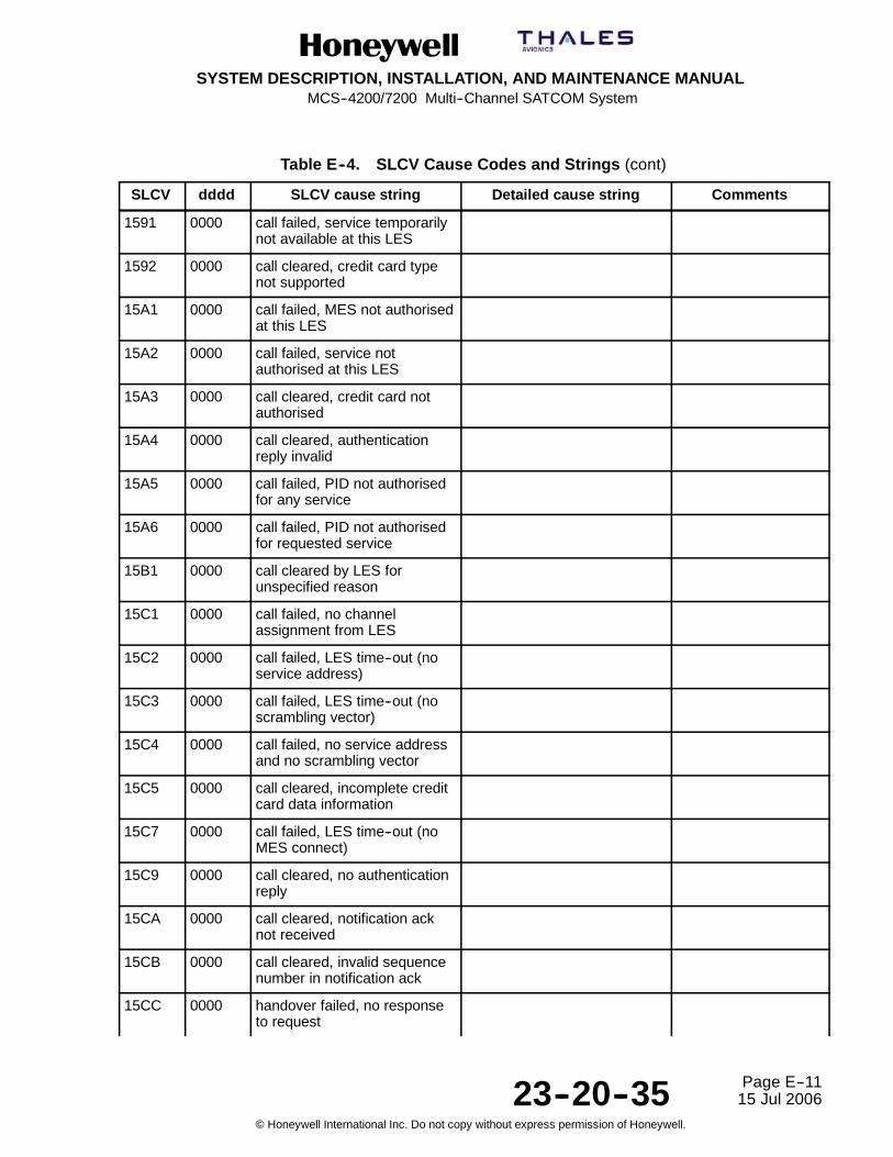
SYSTEM DESCRIPTION, INSTALLATION, AND MAINTENANCE MANUALMCS--4200/7200 Multi--Channel SATCOM System
23--20--35 15 Jul 2006
Honeywell International Inc. Do not copy without express permission of Honeywell.
Page E--11
Table E--4. SLCV Cause Codes and Strings (cont)
SLCV CommentsDetailed cause stringSLCV cause stringdddd
1591 0000 call failed, service temporarilynot available at this LES
1592 0000 call cleared, credit card typenot supported
15A1 0000 call failed, MES not authorisedat this LES
15A2 0000 call failed, service notauthorised at this LES
15A3 0000 call cleared, credit card notauthorised
15A4 0000 call cleared, authenticationreply invalid
15A5 0000 call failed, PID not authorisedfor any service
15A6 0000 call failed, PID not authorisedfor requested service
15B1 0000 call cleared by LES forunspecified reason
15C1 0000 call failed, no channelassignment from LES
15C2 0000 call failed, LES time--out (noservice address)
15C3 0000 call failed, LES time--out (noscrambling vector)
15C4 0000 call failed, no service addressand no scrambling vector
15C5 0000 call cleared, incomplete creditcard data information
15C7 0000 call failed, LES time--out (noMES connect)
15C9 0000 call cleared, no authenticationreply
15CA 0000 call cleared, notification acknot received
15CB 0000 call cleared, invalid sequencenumber in notification ack
15CC 0000 handover failed, no responseto request

SYSTEM DESCRIPTION, INSTALLATION, AND MAINTENANCE MANUALMCS--4200/7200 Multi--Channel SATCOM System
23--20--35 15 Jul 2006
Honeywell International Inc. Do not copy without express permission of Honeywell.
Page E--12
Table E--4. SLCV Cause Codes and Strings (cont)
SLCV CommentsDetailed cause stringSLCV cause stringdddd
15CD 0000 handover failed, MES notready
15D1 0000 call failed, LES time--out(invalid assignment)
15D2 0000 LES MES already busy
15E1 0000 call cleared but MES stilltransmitting (FAULT)
1651 0000 call failed, LES congested (nochannel unit)
1661 0000 call failed, long interruption inreception at LES
1662 0000 LES long term blockage ofSCPC MES
16C2 0000 LES missing MES SCPC
16C3 0000 handover failed, MES notdetected
1790 0000 call cleared, failure credit cardvalidation process
1791 0000 call cleared, failureauthentication process
1811 0000 NCS MES ID busy
1812 0000 NCS MES ID busy MPDS
1813 0000 Call waiting request rejected,MES not accepted call
1814 0000 Call waiting request rejected,RLES shows MES busy
1841 0000 call cleared, NCS initiatedpreemption for incoming pri.1call
1842 0000 call cleared, NCS initiatedpreemption for incoming pri.2call
1843 0000 call cleared, NCS initiatedpreemption for incoming pri.3call
1844 0000 call cleared, NCS initiatedpreemption

SYSTEM DESCRIPTION, INSTALLATION, AND MAINTENANCE MANUALMCS--4200/7200 Multi--Channel SATCOM System
23--20--35 15 Jul 2006
Honeywell International Inc. Do not copy without express permission of Honeywell.
Page E--13
Table E--4. SLCV Cause Codes and Strings (cont)
SLCV CommentsDetailed cause stringSLCV cause stringdddd
1851 0000 call failed, satellite congestionNCS reject no SCPC available
1852 0000 call failed, satellite congestionNCS reject SCPC does notmatch request
1853 0000 call failed, lease channelcongestion
1854 0000 call failed, MES outside spotbeam coverage area
1855 0000 call rejected, preemptionfailed, no channel available
1856 0000 call rejected, spot beamselection failed
1857 0000 handover failed, channel notavailable
185A 0000 NCS Reject Lease--markedMES ---- No Matching SCPCchannel
18A1 0000 NCS MES ID not found
18A2 0000 call failed, MES not authorised
18A3 0000 call failed, LES not authorised
18B1 0000 call failed by NCS forunspecified reason
18B2 0000 call rejected, invalid servicerequested
18C1 0000 NCS MES burst missing
18C3 0000 NCS MES busy preemptionfailed
18D1 0000 call failed, invalid call request
18E1 0000 NCS MES busy already
18E2 0000 NCS MES busy alreadyMPDS
1D61 0000 Call wait failed, fixed line hungup
1F01 0000 call cleared by terrestrialcircuit

SYSTEM DESCRIPTION, INSTALLATION, AND MAINTENANCE MANUALMCS--4200/7200 Multi--Channel SATCOM System
23--20--35 15 Jul 2006
Honeywell International Inc. Do not copy without express permission of Honeywell.
Page E--14
Table E--4. SLCV Cause Codes and Strings (cont)
SLCV CommentsDetailed cause stringSLCV cause stringdddd
1F11 0000 call failed, terrestrial partybusy
1F21 0000 call failed, LES time--out (noanswer)
1F61 0000 call failed, terrestrial circuitfailure
1F62 0000 call failed, early clear byterrestrial circuit
0000 0000 MPDS channel cleared No Inmarsat SLCV fortermination of MPDSsession
0000 0064 MPDS channel cleared MPDS Port error code 100401
0000 01F4 MPDS channel cleared Unknown Error 500
0000 01F5 MPDS channel cleared LES Access Code does notsupport MPDS
0000 01F6 MPDS channel cleared Network does not recogniseMobile ID
0000 01F7 MPDS channel cleared Network does not recogniseSim Card
0000 01F8 MPDS channel cleared Authentication Failed toComplete
0000 01F9 MPDS channel cleared Authentication Failure
0000 01FA MPDS channel cleared Authorisation Failure
0000 01FB MPDS channel cleared Authorisation Failure -- MobileBarred
0000 01FC MPDS channel cleared Authorisation Failure -- MobileBarred on this LES AccessCode
0000 01FD MPDS channel cleared Authorisation Failure -- SIMCard Barred on this LESAccess Code
0000 01FE MPDS channel cleared Authorisation Failure --Temporarily Unable to AcceptCredit Cards
0000 01FF MPDS channel cleared Authorisation Failure -- Unableto Accept Credit Cards

SYSTEM DESCRIPTION, INSTALLATION, AND MAINTENANCE MANUALMCS--4200/7200 Multi--Channel SATCOM System
23--20--35 15 Jul 2006
Honeywell International Inc. Do not copy without express permission of Honeywell.
Page E--15
Table E--4. SLCV Cause Codes and Strings (cont)
SLCV CommentsDetailed cause stringSLCV cause stringdddd
0000 0200 MPDS channel cleared Authorisation Failure -- CreditCard Refused
0000 0201 MPDS channel cleared Authorisation Failure -- ThisService not Allowed
0000 0202 MPDS channel cleared Authorisation Failure -- ServiceOption(s) not Allowed
0000 0203 MPDS channel cleared Authorisation Failure -- QoSnot Allowed
0000 0204 MPDS channel cleared Authorisation Failure --Unsupported ServiceOption(s)
0000 0205 MPDS channel cleared QoS Option(s) UnsupportedBy Mobile
0000 0206 MPDS channel cleared QoS Option(s) UnsupportedBy Network
0000 0207 MPDS channel cleared Satellite Network Congestion
0000 0208 MPDS channel cleared Satellite Network Unavailable
0000 0209 MPDS channel cleared Service Congestion
0000 020A MPDS channel cleared Service Unavailable
0000 020B MPDS channel cleared Terrestrial NetworkCongestion
0000 020C MPDS channel cleared Terrestrial NetworkUnavailable
0000 020D MPDS channel cleared Terrestrial Network Destination-- Busy
0000 020E MPDS channel cleared Terrestrial Network Destination-- No Answer
0000 020F MPDS channel cleared Terrestrial Network Destination-- Unavailable
0000 0210 MPDS channel cleared Terrestrial Network Destination-- No Carrier
0000 0211 MPDS channel cleared Service Timed Out
0000 0212 MPDS channel cleared Terminated by NetworkOperator
0000 0213 MPDS channel cleared Insufficient Resources atMobile
0000 0214 MPDS channel cleared Mobile Failure

SYSTEM DESCRIPTION, INSTALLATION, AND MAINTENANCE MANUALMCS--4200/7200 Multi--Channel SATCOM System
23--20--35 15 Jul 2006
Honeywell International Inc. Do not copy without express permission of Honeywell.
Page E--16
Table E--4. SLCV Cause Codes and Strings (cont)
SLCV CommentsDetailed cause stringSLCV cause stringdddd
0000 0215 MPDS channel cleared Mobile -- Connection to DTELost
0000 0216 MPDS channel cleared Mobile -- Unrecoverable DTEProtocol Error
0000 0217 MPDS channel cleared Mobile Reset
0000 0218 MPDS channel cleared User Cancellation ofConnection Establishment
0000 0258 MPDS channel cleared Unable to Find SatelliteAccess Node
0000 0259 MPDS channel cleared Unable to EstablishCommunication with SatelliteAccess Node
0000 025A MPDS channel cleared Link with Satellite AccessNode Lost
0000 02BC MPDS channel cleared Reason Unspecified
0000 02BD MPDS channel cleared L3 Release
0000 02BE MPDS channel cleared L3 Deregister
0000 02BF MPDS channel cleared L3 Reject
0000 02CC MPDS channel cleared SAN Idle Timer Expiry
0000 02CD MPDS channel cleared MAN Idle Timer Expiry
0000 02CE MPDS channel cleared SAN Connect Timer
0000 02CF MPDS channel cleared SAN Modify Timer
0000 02D0 MPDS channel cleared SAN Handover Timer
0000 02D1 MPDS channel cleared SAN Connection Timer
0000 02D2 MPDS channel cleared MAN Connection Timer
0000 02DC MPDS channel cleared Insufficient operating systemresources at MAN
0000 02DD MPDS channel cleared Insufficient memory at MAN
0000 02EC MPDS channel cleared Invalid L3 Call Ref in EstablishSDU
0000 02ED MPDS channel cleared Invalid L3 Call Ref in ModifySDU
0000 02FC MPDS channel cleared Unsupported MPDS MACversion

SYSTEM DESCRIPTION, INSTALLATION, AND MAINTENANCE MANUALMCS--4200/7200 Multi--Channel SATCOM System
23--20--35 15 Jul 2006
Honeywell International Inc. Do not copy without express permission of Honeywell.
Page E--17
Table E--4. SLCV Cause Codes and Strings (cont)
SLCV CommentsDetailed cause stringSLCV cause stringdddd
0000 02FD MPDS channel cleared Invalid Bearer Connectiontype in Establish SDU
0000 02FE MPDS channel cleared Invalid Bearer Control type inEstablish SDU
0000 02FF MPDS channel cleared Invalid Bearer Connection IDin Establish SDU
0000 0300 MPDS channel cleared Invalid Bearer Connectiontype in Modify SDU
0000 0301 MPDS channel cleared Invalid Bearer Control type inModify SDU
0000 0302 MPDS channel cleared Invalid Bearer Connection IDin Modify SDU
0000 0303 MPDS channel cleared Invalid Handover SDU
0000 0304 MPDS channel cleared Invalid SDU type
0000 0305 MPDS channel cleared SDU Incorrectly Formatted
0000 030C MPDS channel cleared Connection sub--layer protocolfailure (MAN specificsignaling)
0000 030D MPDS channel cleared Connection sub--layer protocolfailure (HDLC signaling)
0000 031C MPDS channel cleared Control sub--layer protocolfailure
0000 032C MPDS channel cleared Channel Unit failure
0000 032D MPDS channel cleared Hardware failure
0000 032E MPDS channel cleared MAN not responding tofrequency corrections
0000 032F MPDS channel cleared MAN not responding to powercorrections
0000 0330 MPDS channel cleared MAN not responding to timingcorrections
0000 033C MPDS channel cleared Internal SAN failure
0000 033D MPDS channel cleared SAN Shutting Down
0000 034C MPDS channel cleared Bearer Control -- No satellitelink
0000 034D MPDS channel cleared Bearer Control -- No suitablecontention slot

SYSTEM DESCRIPTION, INSTALLATION, AND MAINTENANCE MANUALMCS--4200/7200 Multi--Channel SATCOM System
23--20--35 15 Jul 2006
Honeywell International Inc. Do not copy without express permission of Honeywell.
Page E--18
Table E--4. SLCV Cause Codes and Strings (cont)
SLCV CommentsDetailed cause stringSLCV cause stringdddd
0000 034E MPDS channel cleared Bearer Control -- StatusAcknowledgement failure
0000 034F MPDS channel cleared Bearer Control -- IncorrectSAN ID
0000 035C MPDS channel cleared No such MAN
0000 035D MPDS channel cleared Invalid L3 Call Reference
Table E--5. Q.850 Cause Codes and Strings
Q.850 Value(qqq) Q8.50 string
1 Unallocated number
2 No route to specified transit network
3 No route to destination
4 Send special information tone
5 Misdialed trunk prefix
6 Channel unacceptable
7 Call awarded and being delivered in an established channel
8 Preemption
9 Preemption -- circuit reserved for reuse
10 Normal call clearing
16 Normal call clearing
17 User busy
18 No user responding
19 No answer from user
20 Subscriber absent
21 Call rejected
22 Number changed
26 Non--selected user clearing
27 Destination out of order
28 Invalid number format -- address incomplete
29 Facility rejected

SYSTEM DESCRIPTION, INSTALLATION, AND MAINTENANCE MANUALMCS--4200/7200 Multi--Channel SATCOM System
23--20--35 15 Jul 2006
Honeywell International Inc. Do not copy without express permission of Honeywell.
Page E--19
Table E--5. Q.850 Cause Codes and Strings (cont)
Q.850 Value(qqq) Q8.50 string
30 Response to a status enquiry
31 Normal, unspecified
34 No circuit/channel available
38 Network out of order
39 Permanent frame mode connection out--of--service
40 Permanent frame mode connection operational
41 Temporary failure
42 Switching equipment congestion
43 Access information discarded
44 Request channel not available
46 Precedence call blocked
47 Resource not available
49 Quality of service unavailable
50 Requested facility not subscribed
52 Outgoing calls barred
53 Outgoing calls barred within CUG
54 Incoming calls barred
55 Incoming calls barred within CUG
57 Bearer capability not authorized
58 Bearer capability not presently available
62 Inconsistency in designated outgoing access information and subscriber class
63 Service or option not available
65 Bearer capability not implemented
66 Channel type not implemented
69 Request facility not implemented
70 Only restricted digital information bearer capability is available
79 Service or option not implemented, unspecified
81 Invalid call reference value
82 Identified channel does not exist

SYSTEM DESCRIPTION, INSTALLATION, AND MAINTENANCE MANUALMCS--4200/7200 Multi--Channel SATCOM System
23--20--35 15 Jul 2006
Honeywell International Inc. Do not copy without express permission of Honeywell.
Page E--20
Table E--5. Q.850 Cause Codes and Strings (cont)
Q.850 Value(qqq) Q8.50 string
83 Suspended call exists, but call identity does not
84 Call identity in use
85 No call suspended
86 Call with the specified call identity is cleared
87 User not a member of CUG
88 Incompatible destination
90 Non--existent CUG
91 Invalid transit network selection
95 Invalid message, unspecified
96 Mandatory information element is missing
97 Message type non--existent or not implemented
98 Message not compatible with call state or message type non--existent
99 Information element non--existent or not implemented
100 Invalid information element contents
101 Message not compatible with call state
102 Recovery on timer expiry
103 Parameter non--existent or not implemented -- passed on
110 Message with unrecognized parameter, discarded
111 Protocol error, unspecified
127 Internetworking, unspecified
Table E--6. MPDS +WQ Cause Codes and Strings
mmm +WQ cause code string
100 MPDS Port error code 100 401
500 Unknown Error 500
501 LES Access Code does not support MPDS
502 Network does not recognize Mobile ID
503 Network does not recognize Sim Card
504 Authentication Failed to Complete

SYSTEM DESCRIPTION, INSTALLATION, AND MAINTENANCE MANUALMCS--4200/7200 Multi--Channel SATCOM System
23--20--35 15 Jul 2006
Honeywell International Inc. Do not copy without express permission of Honeywell.
Page E--21
Table E--6. MPDS +WQ Cause Codes and Strings (cont)
mmm +WQ cause code string
505 Authentication Failure
506 Authorization Failure
507 Authorization Failure -- Mobile Barred
508 Authorization Failure -- Mobile Barred on this LES Access Code
509 Authorization Failure -- SIM Card Barred on this LES Access Code
510 Authorization Failure -- Temporarily Unable to Accept Credit Cards
511 Authorization Failure -- Unable to Accept Credit Cards
512 Authorization Failure -- Credit Card Refused
513 Authorization Failure -- This Service not Allowed
514 Authorization Failure -- Service Option(s) not Allowed
515 Authorization Failure -- QoS not Allowed
516 Authorization Failure -- Unsupported Service Option(s)
517 QoS Option(s) Unsupported By Mobile
518 QoS Option(s) Unsupported By Network
519 Satellite Network Congestion
520 Satellite Network Unavailable
521 Service Congestion
522 Service Unavailable
523 Terrestrial Network Congestion
524 Terrestrial Network Unavailable
525 Terrestrial Network Destination -- Busy
526 Terrestrial Network Destination -- No Answer
527 Terrestrial Network Destination -- Unavailable
528 Terrestrial Network Destination -- No Carrier
529 Service Timed Out
530 Terminated by Network Operator
531 Insufficient Resources at Mobile
532 Mobile Failure
533 Mobile -- Connection to DTE Lost
534 Mobile -- Unrecoverable DTE Protocol Error

SYSTEM DESCRIPTION, INSTALLATION, AND MAINTENANCE MANUALMCS--4200/7200 Multi--Channel SATCOM System
23--20--35 15 Jul 2006
Honeywell International Inc. Do not copy without express permission of Honeywell.
Page E--22
Table E--6. MPDS +WQ Cause Codes and Strings (cont)
mmm +WQ cause code string
535 Mobile Reset
536 User Cancellation of Connection Establishment
600 Unable to Find Satellite Access Node
601 Unable to Establish Communication with Satellite Access Node
602 Link with Satellite Access Node Lost
700 Reason Unspecified
701 L3 Release
702 L3 Deregister
703 L3 Reject
716 SAN Idle Timer Expiry
717 MAN Idle Timer Expiry
718 SAN Connect Timer
719 SAN Modify Timer
720 SAN Handover Timer
721 SAN Connection Timer
722 MAN Connection Timer
732 Insufficient operating system resources at MAN
733 Insufficient memory at MAN
748 Invalid L3 Call Ref in Establish SDU
749 Invalid L3 Call Ref in Modify SDU
764 Unsupported MPDS MAC version
765 Invalid Bearer Connection type in Establish SDU
766 Invalid Bearer Control type in Establish SDU
767 Invalid Bearer Connection ID in Establish SDU
768 Invalid Bearer Connection type in Modify SDU
769 Invalid Bearer Control type in Modify SDU
770 Invalid Bearer Connection ID in Modify SDU
771 Invalid Handover SDU
772 Invalid SDU type
773 SDU Incorrectly Formatted

SYSTEM DESCRIPTION, INSTALLATION, AND MAINTENANCE MANUALMCS--4200/7200 Multi--Channel SATCOM System
23--20--35 15 Jul 2006
Honeywell International Inc. Do not copy without express permission of Honeywell.
Page E--23
Table E--6. MPDS +WQ Cause Codes and Strings (cont)
mmm +WQ cause code string
780 Connection sub--layer protocol failure (MAN specific signaling)
781 Connection sub--layer protocol failure (HDLC signaling)
796 Control sub--layer protocol failure
812 Channel Unit failure
813 Hardware failure
814 MAN not responding to frequency corrections
815 MAN not responding to power corrections
816 MAN not responding to timing corrections
828 Internal SAN failure
829 SAN Shutting Down
844 Bearer Control -- No satellite link
845 Bearer Control -- No suitable contention slot
846 Bearer Control -- Status Acknowledgement failure
847 Bearer Control -- Incorrect SAN ID
860 No such MAN
861 Invalid L3 Call Reference

SYSTEM DESCRIPTION, INSTALLATION, AND MAINTENANCE MANUALMCS--4200/7200 Multi--Channel SATCOM System
23--20--35 15 Jul 2006
Honeywell International Inc. Do not copy without express permission of Honeywell.
Page E--24
Blank Page

SYSTEM DESCRIPTION, INSTALLATION, AND MAINTENANCE MANUALMCS--4200/7200 Multi--Channel SATCOM System
23--20--35 15 Jul 2006
Honeywell International Inc. Do not copy without express permission of Honeywell.
Page F--1
APPENDIX FFAILURE OVERVIEW
1. Fault Codes
CODE FAILURE DESCRIPTIONUNKNOWN LEVEL 1 UNKNOWN SRU00 0 01 RESERVED
00 0 02 SPARE00 0 03 RESERVED
00 0 04 RESERVED00 0 05 RESERVED
00 0 06 RESERVED00 0 07 RESERVED
00 0 08 RESERVED
SDUUNKNOWN SDU SRU01 0 01 SPARE01 0 02 HMPM HPA CMD WORD (143) UPDATE RATE FAIL
01 0 03 HMPM HPA CMD WORD (143) DATA FAIL01 0 04 RESERVED
01 0 05 RESERVED01 0 06 RESERVED
01 0 07 HSU1--SDU W’BURG DATA TX FAIL01 0 08 HSU1--SDU W’BURG SOLO WORD ACK FAIL
01 0 09 SPARE01 0 0A SPARE
01 0 0B HSU2--SDU W’BURG DATA TX FAIL01 0 0C HSU2--SDU W’BURG SOLO WORD ACK FAIL
01 0 0D SPARE01 0 0E SPARE
01 0 0F SPARE01 0 10 HGA HPA COMMAND WORD (NCD)
01 0 11 SPARE01 0 12 LGA HPA COMMAND WORD (NCD)
01 0 13 RESERVED01 0 14 RESERVED
01 0 15 RESERVED01 0 96 INCOMPLETE ID PROM RESPONSES

SYSTEM DESCRIPTION, INSTALLATION, AND MAINTENANCE MANUALMCS--4200/7200 Multi--Channel SATCOM System
23--20--35 15 Jul 2006
Honeywell International Inc. Do not copy without express permission of Honeywell.
Page F--2
CODE FAILURE DESCRIPTIONSMPM: SDU MAIN PROCESSOR MODULE01 1 81 SDU H/W--S/W COMPATIBILITY FAIL
01 1 82 BATTERY VOLTAGE LOW
01 1 83 WATCHDOG TIMEOUT FAIL
01 1 84 MICRO BOOT ROM FAIL
01 1 85/05 EEPROM FAIL
01 1 86/06 FLASH FAIL
01 1 87/07 SRAM FAIL
01 1 88/08 REAL TIME CLOCK FAIL
01 1 89 QUART FAIL
01 1 0A SOFTWARE ERROR (SYSFAIL)
01 1 0B FLASH--PSRAM MISCOMPARE
01 1 0C FLASH--PSRAM MISCOMPARE EXTENSION
01 1 0D FLASH--PSRAM MISCOMPARE EXTENSION
CODA: SDU VOICE CODEC MODULE A01 2 81/01 <CODEC--A> PROGRAM MEMORY CRC FAIL
01 2 82 <CODEC--A> RESERVED
01 2 83 <CODEC--A> RESERVED
01 2 84 <CODEC--A> RESERVED
01 2 05 <CODEC--A> RESERVED
01 2 86 <CODEC--A> RESERVED
01 2 87/07 <CODEC--A> TIMING GENERATOR FAIL
01 2 88 <CODEC--A> DUAL PORT RAM FAIL CODEC SIDE
01 2 89 <CODEC--A> RESERVED
01 2 8A/0A <CODEC--A> PROGRAM MEMORY W/R FAIL
01 2 8B PP <CODEC--A> DSP INTERNAL MEMORY W/R FAIL
01 2 8C/0C <CODEC--A> DSP COMPREHENSIVE FAIL
01 2 0D <CODEC--A> HEALTH COUNT UPDATE
01 2 8E <CODEC--A> DUAL PORT RAM FAIL SMPM SIDE
01 2 0F <CODEC--A> SPARE
01 2 90 <CODEC--A> BUS ERROR
01 2 91 <CODEC--A> SELF TEST MISOPERATION
01 2 12 <CODEC--A> COMMUNICATION PROBLEM
01 2 93/13 <CODEC--A> RESERVED
01 2 94 <CODEC--A> ST BUS AUDIO LOOPBACK FAIL
01 2 95 <CODEC--A> SW DOWNLOAD FAIL

SYSTEM DESCRIPTION, INSTALLATION, AND MAINTENANCE MANUALMCS--4200/7200 Multi--Channel SATCOM System
23--20--35 15 Jul 2006
Honeywell International Inc. Do not copy without express permission of Honeywell.
Page F--3
CODE FAILURE DESCRIPTIONCODB: SDU VOICE CODEC MODULE B01 3 Same entries as for CODA above except substitute CODB for CODA, SRU code 3 for
code 2, [CODEC_B] for [CODEC_A] and <CODEC--B> for <CODEC--A>.
Fault codes for codecs C--F have Level 2 (SRU) codes E--H. They are listed in the appropriatesection of this table for those SRU codes.
SIOM: SDU INPUT/OUTPUT MODULE (EXCLUSIVE TO SIOM)01 4 81 A429 XMTR LOOP--BACK TO OTHER SDU FAIL01 4 82 A429 XMTR LOOP--BACK TO CFDS FAIL01 4 83 A429 XMTR LOOP--BACK TO ADL FAIL01 4 84 A429 XMTR LOOP--BACK TO PDL FAIL01 4 85 A429 XMTR LOOP--BACK TO (C)MUs FAIL01 4 86 A429 XMTR LOOP--BACK TO SCDUs FAIL01 4 87 A429 XMTR LOOP--BACK TO MULTI--CNTRL FAIL01 4 88 RESERVED01 4 89 A429 XMTR LOOP--BACK TO RMP/CAP FAIL01 4 8A A429 XMTR LOOP--BACK TO SNU/CPDF FAIL01 4 8B A429 XMTR LOOP--BACK TO HSU1 FAIL01 4 8C A429 XMTR LOOP--BACK TO HSU2 FAIL01 4 8D A429 XMTR LOOP--BACK SPARE01 4 8E A429 XMTR LOOP--BACK SPARE01 4 8F A429 XMTR LOOP--BACK SPARE01 4 90 A429 XMTR LOOP--BACK SPARE01 4 91 RESERVED01 4 AB SIOM BUS ERROR01 4 2C A429 TX TO OTHER SDU BUFFER FULL01 4 2D A429 TX TO CFDS BUFFER FULL01 4 2E A429 TX TO ADL BUFFER FULL01 4 2F A429 TX TO PDL BUFFER FULL01 4 30 A429 TX TO (C)MUs BUFFER FULL01 4 31 A429 TX TO SCDUs BUFFER FULL01 4 32 A429 TX TO MULTI--CTRL BUFFER FULL01 4 33 RESERVED01 4 34 A429 TX TO RMP/CAP BUFFER FULL01 4 35 A429 TX TO SNU/CPDF BUFFER FULL01 4 36 A429 TX TO HSU1 BUFFER FULL01 4 37 A429 TX TO HSU2 BUFFER FULL01 4 38 A429 TX BUFFER FULL SPARE01 4 39 A429 TX BUFFER FULL SPARE

SYSTEM DESCRIPTION, INSTALLATION, AND MAINTENANCE MANUALMCS--4200/7200 Multi--Channel SATCOM System
23--20--35 15 Jul 2006
Honeywell International Inc. Do not copy without express permission of Honeywell.
Page F--4
CODE FAILURE DESCRIPTION01 4 3A A429 TX BUFFER FULL SPARE
01 4 3B A429 TX BUFFER FULL SPARE
01 4 BC SIOM INTERRUPT FAIL
01 4 3D IRS ASIC MATCHING PROBLEM
SMDM1: SDU MODEM MODULE #101 5 81 <MODEM--1> PROCESSOR FAIL
01 5 82/02 RESERVED
01 5 83/03 RESERVED
01 5 84/04 <MODEM--1> PROGRAM CRC FAIL
01 5 85/05 RESERVED
01 5 86/06 RESERVED
01 5 87 RESERVED
01 5 88/08 RESERVED
01 5 89/09 RESERVED
01 5 0A <MODEM--1>MODEM TO RFM INTERFACE FAIL
01 5 8B <MODEM--1> TIMER/INTERRUPT FAIL
01 5 8C RESERVED
01 5 8D RESERVED
01 5 8E <MODEM--1> EXTERNAL MEMORY FAIL
01 5 8F/0F RESERVED
01 5 90/10 RESERVED
01 5 91 <MODEM--1> MODEM DPR FAIL
01 5 92 RESERVED
01 5 93/13 RESERVED
01 5 94/14 RESERVED
01 5 95 <MODEM--1> SMPM SIDE DPR FAIL
01 5 16 <MODEM--1> SW DOWNLOAD FAIL
01 5 17 <MODEM--1> HEALTH COUNT UPDATE FAIL
01 5 18 RESERVED
01 5 99 <MODEM--1> BUS ERROR
01 5 9A <MODEM--1> SELF TEST MISOPERATION
01 5 1B <MODEM--1> SOFTWARE FAIL
01 5 1C <MODEM--1> COMMUNICATIONS PROBLEM
01 5 1D RESERVED
01 5 9E <MODEM--1> RFM SSI LOOPBACK FAIL
01 5 9F RESERVED

SYSTEM DESCRIPTION, INSTALLATION, AND MAINTENANCE MANUALMCS--4200/7200 Multi--Channel SATCOM System
23--20--35 15 Jul 2006
Honeywell International Inc. Do not copy without express permission of Honeywell.
Page F--5
CODE FAILURE DESCRIPTIONSMDM2: SDU MODEM MODULE #201 6 Same entries as for SMDM1 above except substitute SMDM2 for SMDM1, SRU code 6
for code 5, [MODEM_2] for [MODEM_1] and <MODEM-- 2> for <MODEM--1>.
SMDM3: SDU MODEM MODULE #301 7 Same entries as for SMDM1 above except substitute SMDM3 for SMDM1, SRU code 7
for code 5, [MODEM_3] for [MODEM_1] and <MODEM-- 3> for <MODEM--1>.
Fault codes for modems 4--7 have Level 2 (SRU) codes J, L, M and N. They are listed in thistable in the appropriate section for those SRU codes.
SRFM: SDU RADIO FREQUENCY MODULE01 8 81 RESERVED01 8 82 RESERVED01 8 83 RESERVED01 8 84 RESERVED01 8 85 RESERVED01 8 86 RESERVED01 8 87 RESERVED01 8 88 RESERVED01 8 89 RESERVED01 8 0A SPARE01 8 0B SPARE01 8 0C SPARE01 8 0D SPARE01 8 8E/0E RF SYNTH CHAN1 LOCK DETECT FAIL01 8 8F/0F RESERVED01 8 90/10 RF SYNTH CHAN2 LOCK DETECT FAIL01 8 91/11 RESERVED01 8 92/12 RF SYNTH CHAN3 LOCK DETECT FAIL01 8 93/13 RESERVED01 8 94/14 RESERVED01 8 95/15 RESERVED01 8 96/16 RF SYNTH CHAN4 LOCK DETECT FAIL01 8 97/17 RF SYNTH CHAN5 LOCK DETECT FAIL01 8 98/18 RF SYNTH CHAN6 LOCK DETECT FAIL01 8 99/19 RF SYNTH CHAN7 LOCK DETECT FAIL01 8 9A/1A RF SYNTH CHAN8 LOCK DETECT FAIL01 8 9B/1B RF SYNTH TX BLOCK PLO LOCK DETECT FAIL01 8 9C/1C RF SYNTH RX BLOCK PLO LOCK DETECT FAIL

SYSTEM DESCRIPTION, INSTALLATION, AND MAINTENANCE MANUALMCS--4200/7200 Multi--Channel SATCOM System
23--20--35 15 Jul 2006
Honeywell International Inc. Do not copy without express permission of Honeywell.
Page F--6
CODE FAILURE DESCRIPTION01 8 9D/1D RF SYNTH RX CHAN PLO LOCK DETECT FAIL01 8 9E/1E RF SYNTH TX DOPPLER PLO LOCK DETECT FAIL01 8 A0 RFM CHAN 1 L--BAND LOOP--BACK (TX) FAIL01 8 A1 RFM CHAN 1 L--BAND LOOP--BACK (RX) FAIL01 8 A2 RFM CHAN 2 L--BAND LOOP--BACK (TX) FAIL01 8 A3 RFM CHAN 2 L--BAND LOOP--BACK (RX) FAIL01 8 A4 RFM CHAN 3 L--BAND LOOP--BACK (TX) FAIL01 8 A5 RFM CHAN 3 L--BAND LOOP--BACK (RX) FAIL01 8 A6 RFM CHAN 4 L--BAND LOOP--BACK (TX) FAIL01 8 A7 RFM CHAN 4 L--BAND LOOP--BACK (RX) FAIL01 8 A8 RFM CHAN 5 L--BAND LOOP--BACK (TX) FAIL01 8 A9 RFM CHAN 5 L--BAND LOOP--BACK (RX) FAIL01 8 AA RFM CHAN 6 L--BAND LOOP--BACK (TX) FAIL01 8 AB RFM CHAN 6 L--BAND LOOP--BACK (RX) FAIL01 8 AC RFM CHAN 7 L--BAND LOOP--BACK (TX) FAIL01 8 AD RFM CHAN 7 L--BAND LOOP--BACK (RX) FAIL01 8 AE RFM CHAN 8 L--BAND LOOP--BACK (TX) FAIL01 8 AF RFM CHAN 8 L--BAND LOOP--BACK (RX) FAIL01 8 30 RFM CHAN 1 TX CALIBRATION ERROR01 8 31 RFM CHAN 2 TX CALIBRATION ERROR01 8 32 RFM CHAN 3 TX CALIBRATION ERROR01 8 33 RFM CHAN 4 TX CALIBRATION ERROR01 8 34 RFM CHAN 5 TX CALIBRATION ERROR01 8 35 RFM CHAN 6 TX CALIBRATION ERROR01 8 36 RFM CHAN 7 TX CALIBRATION ERROR01 8 37 RFM CHAN 8 TX CALIBRATION ERROR01 8 38 RFM CHAN 1 RX CALIBRATION ERROR01 8 39 RFM CHAN 2 RX CALIBRATION ERROR01 8 3A RFM CHAN 3 RX CALIBRATION ERROR01 8 3B RFM CHAN 4 RX CALIBRATION ERROR01 8 3C RFM CHAN 5 RX CALIBRATION ERROR01 8 3D RFM CHAN 6 RX CALIBRATION ERROR01 8 3E RFM CHAN 7 RX CALIBRATION ERROR01 8 3F RFM CHAN 8 RX CALIBRATION ERROR01 8 C0/40 RFM CHAN 1 AGC TELLBACK FAIL01 8 C1/41 RFM CHAN 2 AGC TELLBACK FAIL01 8 C2/42 RFM CHAN 3 AGC TELLBACK FAIL01 8 C3/43 RFM CHAN 4 AGC TELLBACK FAIL01 8 C4/44 RFM CHAN 5 AGC TELLBACK FAIL

SYSTEM DESCRIPTION, INSTALLATION, AND MAINTENANCE MANUALMCS--4200/7200 Multi--Channel SATCOM System
23--20--35 15 Jul 2006
Honeywell International Inc. Do not copy without express permission of Honeywell.
Page F--7
CODE FAILURE DESCRIPTION
01 8 C5/45 RFM CHAN 6 AGC TELLBACK FAIL
01 8 C6/46 RFM CHAN 7 AGC TELLBACK FAIL
01 8 C7/47 RFM CHAN 8 AGC TELLBACK FAIL
01 8 C8/48 RFM BLOCK AGC TELLBACK FAIL
01 8 C9 I/Q CALIBRATION FAIL
01 8 D0 RFM CHAN 1 AGC CALIBRATION ERROR
01 8 D1 RFM CHAN 2 AGC CALIBRATION ERROR
01 8 D2 RFM CHAN 3 AGC CALIBRATION ERROR
01 8 D3 RFM CHAN 4 AGC CALIBRATION ERROR
01 8 D4 RFM CHAN 5 AGC CALIBRATION ERROR
01 8 D5 RFM CHAN 6 AGC CALIBRATION ERROR
01 8 D6 RFM CHAN 7 AGC CALIBRATION ERROR
01 8 D7 RFM CHAN 8 AGC CALIBRATION ERROR
01 8 D8 RFM BLOCK AGC CALIBRATION ERROR
SCFM: SDU CHANNEL FILTER MODULE
01 9 81/01 RESERVED
01 9 82/02 RESERVED
01 9 83/03 RESERVED
01 9 04 RESERVED
01 9 05 RESERVED
01 9 06 RESERVED
01 9 07 RESERVED
01 9 08 RESERVED
01 9 09 RESERVED
01 9 0A RESERVED
OCXO: SDU OVEN CONTROLLED CRYSTAL OSCILLATOR
01 A 01 OVEN READY FAIL
SMB: SDU MOTHER BOARD
01 B NONE
SPSU: SDU AC OR DC POWER SUPPLY UNIT
01 C 01 PSU TEMP LIMITS FAIL
01 C 02 SPARE
01 C 03 PSU SECONDARY VOLTAGE FAIL

SYSTEM DESCRIPTION, INSTALLATION, AND MAINTENANCE MANUALMCS--4200/7200 Multi--Channel SATCOM System
23--20--35 15 Jul 2006
Honeywell International Inc. Do not copy without express permission of Honeywell.
Page F--8
CODE FAILURE DESCRIPTIONSFPDM: SDU FRONT PANEL DISPLAY MODULE01 D 01 TEST (PAST) SWITCH STUCK
01 D 02 MANUAL SCROLL SWITCH STUCK
CODC: SDU VOICE CODEC MODULE C01 E Same entries as for CODA (01 2 xx) above except substitute CODC for CODA, SRU
code E for code 2, [CODEC_C] for [CODEC_A] and <CODEC--C> for <CODEC--A>.
CODD: SDU VOICE CODEC MODULE D01 F Same entries as for CODA (01 2 xx) above except substitute CODD for CODA, SRU
code F for code 2, [CODEC_D] for [CODEC_A] and <CODEC--D> for <CODEC--A>.
CODE: SDU VOICE CODEC MODULE E01 G Same entries as for CODA (01 2 xx) above except substitute CODE for CODA, SRU
code G for code 2, [CODEC_E] for [CODEC_A] and <CODEC--E> for <CODEC--A>.
CODF: SDU VOICE CODEC MODULE F01 H Same entries as for CODA (01 2 xx) above except substitute CODF for CODA, SRU
code H for code 2, [CODEC_F] for [CODEC_A] and <CODEC--F> for <CODEC--A>.
01 I Not used.
SMDM4: SDU MODEM MODULE #401 J Same entries as for SMDM1 (01 5 xx) above except substitute SMDM4 for SMDM1,
SRU code J for code 5, [MODEM_4] for [MODEM_1] and <MODEM--4> for<MODEM--1>.
01 K Not used.
SMDM5: SDU MODEM MODULE #501 L Same entries as for SMDM1 (01 5 xx) above except substitute SMDM5 for SMDM1,
SRU code L for code 5, [MODEM_5] for [MODEM_1] and <MODEM--5> for<MODEM--1>.
SMDM6: SDU MODEM MODULE #601 M Same entries as for SMDM1 (01 5 xx) above except substitute SMDM6 for SMDM1,
SRU code M for code 5, [MODEM_6] for [MODEM_1] and <MODEM--6> for<MODEM--1>.
SMDM7: SDU MODEM MODULE #701 N Same entries as for SMDM1 (01 5 xx) above except substitute SMDM7 for SMDM1,
SRU code N for code 5, [MODEM_7] for [MODEM_1] and <MODEM--7> for<MODEM--1>.

SYSTEM DESCRIPTION, INSTALLATION, AND MAINTENANCE MANUALMCS--4200/7200 Multi--Channel SATCOM System
23--20--35 15 Jul 2006
Honeywell International Inc. Do not copy without express permission of Honeywell.
Page F--9
CODE FAILURE DESCRIPTIONVIM: VOICE INTERFACE MODULE01 P 81 CABIN INTERFACE 1 AUDIO LOOPBACK FAIL01 P 82 CABIN INTERFACE 2 AUDIO LOOPBACK FAIL01 P 83 COCKPIT INTERFACE 1 AUDIO LOOPBACK FAIL01 P 84 COCKPIT INTERFACE 2 AUDIO LOOPBACK FAIL01 P 85 CTU CEPT--E1 AUDIO LOOPBACK FAIL01 P 06 SPARE01 P 07 CABIN AUDIO DISCRETE OUTPUTS LOOPBACK FAIL01 P 08 COCKPIT AUDIO DISCRETE OUTPUTS LOOPBACK FAIL01 P 89 CTU CEPT--E1 HDLC LOOPBACK FAIL
01 P 8A CABIN INTERFACE 1 BUS ERROR01 P 8B CABIN INTERFACE 2 BUS ERROR01 P 8C COCKPIT INTERFACE 1 BUS ERROR01 P 8D COCKPIT INTERFACE 2 BUS ERROR01 P 8E CTU CEPT--E1 BUS ERROR
“OTHER” SATCOM SYSTEM02 0 01 PROTOCOL VERSION NUMBER INCOMPATIBLE02 0 02 SDU/SDU MESSAGE PROTOCOL ERROR
HSUOnly applicable to Package 6.0 and subsequent.
UNKNOWN HSU SRU03 0 01 HSU SELF--DECLARED FAILURE03 0 02 HSU WILLIAMSBURG PROTOCOL ALO/ALR FAIL03 0 03 HSU WILLIAMSBURG PROTOCOL DATA XFER FAIL03 0 84 HSU SELF--TEST MISOPERATION03 0 05 HSU SERIAL PORT MIS--WIRING03 0 86/06 HSU TOTC RESET03 0 87/07 HSU POC RESET
03 0 08 SPARE03 0 09--0B RESERVED03 0 0C HSU CHANNEL 1 FAILURE03 0 0D HSU CHANNEL RELEASE ACKNOWLEDGE FAILURE03 0 8E/0E HSU RF LOOPBACK INHIBIT FAILURE03 0 0F HSU CHANNEL 2 FAILURE03 0 10 HSU CHANNEL 3 FAILURE03 0 11 HSU CHANNEL 4 FAILURE

SYSTEM DESCRIPTION, INSTALLATION, AND MAINTENANCE MANUALMCS--4200/7200 Multi--Channel SATCOM System
23--20--35 15 Jul 2006
Honeywell International Inc. Do not copy without express permission of Honeywell.
Page F--10
CODE FAILURE DESCRIPTIONHSCC1: HSU CHANNEL CARD 103 1 01 HSU CC1 MODEM FAULT
03 1 02 HSU CC1 MODEM FAILURE
03 1 03 HSU CC1 PERIPHERAL ERROR
03 1 04 HSU CC1 PERIPHERAL FAILURE
03 1 05 HSU CC1 CP SW INCOMPATIBILITY
03 1 06 RESERVED
03 1 07 HSU CC1 RF FAULT
03 1 08 HSU CC1 RF FAILURE
03 1 09 HSU CC1 TAL ERROR
03 1 0A HSU CC1 MODEM CALIBRATION MISSING
03 1 0B HSU CC1 TEMPERATURE UNREADABLE
03 1 0C HSU CC1 OVER TEMPERATURE
03 1 0D RESERVED
03 1 0E HSU CC1 TURBO FAULT
03 1 0F HSU CC1 TURBO FAILURE
03 1 10 RESERVED
03 1 11 HSU CC1 VCODEC FAULT|
03 1 12 HSU CC1 VCODEC FAILURE
03 1 93 HSU CC1 APPLICATION CODE ERROR
HSCC2: HSU CHANNEL CARD 203 2 01 HSU CC2 MODEM FAULT
03 2 02 HSU CC2 MODEM FAILURE
03 2 03 HSU CC2 PERIPHERAL ERROR
03 2 04 HSU CC2 PERIPHERAL FAILURE
03 2 05 HSU CC2 CP SW INCOMPATIBILITY
03 2 06 RESERVED
03 2 07 HSU CC2 RF FAULT
03 2 08 HSU CC2 RF FAILURE
03 2 09 HSU CC2 TAL ERROR
03 2 0A HSU CC2 MODEM CALIBRATION MISSING
03 2 0B HSU CC2 TEMPERATURE UNREADABLE
03 2 0C HSU CC2 OVER TEMPERATURE
03 2 0D RESERVED
03 2 0E HSU CC2 TURBO FAULT
03 2 0F HSU CC2 TURBO FAILURE
03 2 10 RESERVED

SYSTEM DESCRIPTION, INSTALLATION, AND MAINTENANCE MANUALMCS--4200/7200 Multi--Channel SATCOM System
23--20--35 15 Jul 2006
Honeywell International Inc. Do not copy without express permission of Honeywell.
Page F--11
CODE FAILURE DESCRIPTION03 2 11 HSU CC2 VCODEC FAULT
03 2 12 HSU CC2 VCODEC FAILURE
03 2 93 HSU CC2 APPLICATION CODE ERROR
HSDIO: HSU DATA I/O CARD03 3 01 RESERVED
03 3 02 HSU UNRECOVERABLE SW / PROTOCOL ERROR
03 3 03 HSU I/O CHANNEL CARD 1 UNSERVICEABLE
03 3 04 HSU I/O CHANNEL CARD 2 UNSERVICEABLE
03 3 85 HSU CONFIGURATION ERROR
03 3 86 HSU I/O PERIPHERAL FAILURE
03 3 07 HSU I/O BOTH CHANNEL CARDS UNSERVICEABLE
03 3 08 HSU I/O RAM FAULT
03 3 09 HSU I/O ROM FAULT
03 3 0A HSU SW CONFIGURATION ERROR
03 3 0B HSU PPPoE SESSION FAILURE
HSCP: HSU CONTROL PROCESSOR03 4 01 RESERVED
03 4 02 RESERVED
03 4 03 RESERVED
03 4 04 RESERVED
03 4 05 RESERVED
03 4 06 RESERVED
03 4 87/07 HSU CP CHANNEL CARD 1 UNRESPONSIVE
03 4 88/08 HSU CP CHANNEL CARD 2 UNRESPONSIVE
03 4 89/09 HSU CP BOTH CHANNEL CARDS UNRESPONSIVE
03 4 8A/0A HSU DATA I/O CARD UNRESPONSIVE
03 4 0B CM HSU CP RAM FAULT
03 4 0C CM HSU CP ROM FAULT
03 4 0D CM HSU OVER TEMPERATURE
03 4 0E CM HSU CHANNEL CARD 1 OVER TEMPERATURE
03 4 0F CM HSU CHANNEL CARD 2 OVER TEMPERATURE
03 4 10 CM HSU BOTH CHANNEL CARDS OVER TEMPERATURE
03 4 91 PP HSU ADL BUS INTERFACE FAILURE
03 4 92 PP HSU PDL BUS INTERFACE FAILURE
03 4 93 PP HSU DATA I/O DUART FAILURE
03 4 94 PP HSU CHANNEL CARD 1 DUART FAILURE

SYSTEM DESCRIPTION, INSTALLATION, AND MAINTENANCE MANUALMCS--4200/7200 Multi--Channel SATCOM System
23--20--35 15 Jul 2006
Honeywell International Inc. Do not copy without express permission of Honeywell.
Page F--12
CODE FAILURE DESCRIPTION03 4 95 PP HSU CHANNEL CARD 2 DUART FAILURE03 4 96 PP HSU BOTH CHANNEL CARDS DUART FAILURE03 4 97 PP HSU MAINTENANCE INTERFACE DUART FAILURE03 4 98 PP HSU DISCRETE OUTPUT FAILURE03 4 99 PP HSU BOARD CONFIGURATION/REVISION FAILURE
HOCXO: HSU OVEN--CONTROLLED 10 MHZ OSCILLATOR03 5 01 HSU OCXO TIMEOUT03 5 02 HSU OCXO TEMPERATURE UNSTABLE
HSPSU: HSU POWER SUPPLY UNIT 103 6 01 HSU POWER SUPPLY FAIL03 6 02 HSU PSU OVER TEMPERATURE
HSCDM: HSU CONFIGURATION DATA MODULE03 7 NONE
HSFP: HSU FRONT PANEL03 8 81 HSU SELF--TEST BUTTON STUCK
HSBP: HSU BACKPLANE03 9 NONE
HGA/IGA HPAThis section lists failure codes inclusive of all HPA designs. Each HPA uses the SRU codesappropriate to its design.
UNKNOWN HGA/IGA HPA SRU04 0 01 <HGA HPA> STATUS WORD (143) UPDATE RATE FAIL04 0 02 <HGA HPA> STATUS WORD (143) DATA FAIL04 0 03 <HGA HPA> MNTNC WORD (350) UPDATE RATE FAIL04 0 04 <HGA HPA> MNTNC WORD (350) DATA FAIL04 0 05 <HGA HPA> SPARE04 0 06 <HGA HPA> SPARE04 0 87 <HGA HPA> SELF--TEST MISOPERATION04 0 08 <HGA HPA> RF OVERDRIVE ERROR04 0 09 <HGA HPA> RF SUPPLY CURRENT FAIL04 0 0A <HGA HPA> OVER TEMP (COMB/DET) SHUTDOWN04 0 0B <HGA HPA> NO RESPONSE TO CARRIER COMMAND04 0 0C <HGA HPA> FAILURE WARNING W/NO DISC’S SET

SYSTEM DESCRIPTION, INSTALLATION, AND MAINTENANCE MANUALMCS--4200/7200 Multi--Channel SATCOM System
23--20--35 15 Jul 2006
Honeywell International Inc. Do not copy without express permission of Honeywell.
Page F--13
CODE FAILURE DESCRIPTION04 0 0D <HGA HPA> 429 MNTNC WORD PSU FAIL (350)04 0 0E <HGA HPA> 429 MNTNC WORD INTERNAL RAM FAIL04 0 0F <HGA HPA> 429 MNTNC WORD INTERNAL ROM FAIL04 0 10 <HGA HPA> CLASS C HPA MAX AVAIL PWR FAIL04 0 40 <HGA HPA> SELF--TEST BUTTON STUCK04 0 41 <HGA HPA> RESERVED (HP--720 “RF Power Input Low”)
HPSU: HPA AC OR DC POWER SUPPLY UNIT04 1 01 <HGA HPA> PSU OVER TEMP SHUTDOWN04 1 02 <HGA HPA> PSU TEMP SENSOR FAIL04 1 03 <HGA HPA> PSU BIAS +5VDC FAIL04 1 04 <HGA HPA> PSU +28/+25.5 VDC FAIL04 1 05 <HGA HPA> PSU +5 VDC FAIL04 1 06 <HGA HPA> PSU +15 VDC FAIL04 1 07 <HGA HPA> PSU --15 VDC FAIL04 1 08 <HGA HPA> PSU --85 VDC FAIL04 1 09 <HGA HPA> PSU +8 VDC FAIL04 1 0A <HGA HPA> PSU +16 VDC FAIL04 1 40 <HGA HPA> INTERNAL POWER SUPPLY FAIL04 1 41 <HGA HPA> PSU OVER TEMP
HMPM: HPA MAIN PROCESSOR MODULE04 2 81 <HGA HPA> H/W--S/W COMPATIBILITY FAIL04 2 02 <HGA HPA> SPARE04 2 83/03 <HGA HPA> BOOT FLASH MEMORY FAIL04 2 04 <HGA HPA> A429 SDU XMTR LOOP--BACK FAIL04 2 05 <HGA HPA> SPARE04 2 06 <HGA HPA> SPARE04 2 87 <HGA HPA> A429 MULTICNT RCVR FAIL04 2 88 <HGA HPA> A429 ADL RCVR FAIL04 2 89 <HGA HPA> A429 PDL--TO--HPA RCVR FAIL04 2 0A <HGA HPA> MAINTENANCE MEMORY CRC FAIL04 2 0B <HGA HPA> MAINTENANCE MEMORY WRITE FAIL04 2 8C/0C <HGA HPA> CALIBRATION MEMORY CRC FAIL04 2 0D <HGA HPA> CALIBRATION MEMORY WRITE FAIL04 2 8E/0E <HGA HPA> PROGRAM FLASH MEMORY FAIL04 2 0F <HGA HPA> SPARE04 2 90 <HGA HPA> RAM FAIL04 2 11 <HGA HPA> CPU OVER TEMP SHUTDOWN

SYSTEM DESCRIPTION, INSTALLATION, AND MAINTENANCE MANUALMCS--4200/7200 Multi--Channel SATCOM System
23--20--35 15 Jul 2006
Honeywell International Inc. Do not copy without express permission of Honeywell.
Page F--14
CODE FAILURE DESCRIPTION04 2 12 <HGA HPA> CPU TEMP SENSOR FAIL04 2 93/13 <HGA HPA> CPU GND REF FAIL04 2 94/14 <HGA HPA> FAN RELAY DRIVER FAIL04 2 95/15 <HGA HPA> BIAS ENABLE LOOPBACK FAIL04 2 96/16 <HGA HPA> VAR ATTN DRIVER FAIL04 2 17 <HGA HPA> FRONT PANEL TEST SWITCH STUCK04 2 98 <HGA HPA> WATCHDOG TIMEOUT FAIL04 2 19 <HGA HPA> DRIVER GND FAIL04 2 1A <HGA HPA> SPARE04 2 1B <HGA HPA> SPARE04 2 9C/1C <HGA HPA> DRIVER TEST -- MUX04 2 9D <HGA HPA> DRIVER TEST -- GREEN LED04 2 9E <HGA HPA> DRIVER TEST -- RED LED04 2 1F <HGA HPA> SPARE04 2 A0 <HGA HPA> DRIVER TEST--MUTE ATTENUATOR04 2 21 <HGA HPA> SPARE -- -- -- -- --04 2 A2 <HGA HPA> DRIVER TEST -- SER DATA CONCATENATE04 2 23 <HGA HPA> SPARE04 2 24 <HGA HPA> SPARE04 2 A5 <HGA HPA> MUTE INPUT TEST04 2 A6 <HGA HPA> CPU DEVICE TEST04 2 A7 <HGA HPA> ACTUAL POWER CALIBRATION04 2 A8 <HGA HPA> VALIDATION OF UPLOAD04 2 29 <HGA HPA> MUTE ATTEN P OUT OF LIMITS04 2 2A <HGA HPA> CODE VPP OUT OF LIMITS04 2 2B <HGA HPA> MAINT LOG VPP OUT OF LIMITS04 2 2C <HGA HPA> CAL MEM VPP OUT OF LIMITS04 2 AD/2D <HGA HPA> ADC REF OUT OF LIMITS04 2 2E <HGA HPA> PWR LO OUT OF LIMITS04 2 2F <HGA HPA> PSU TEMP LO OUT OF LIMITS04 2 30 <HGA HPA> AMPS LO OUT OF LIMITS04 2 31 <HGA HPA> SOFTWARE FAULT04 2 32 <HGA HPA> SPARE04 2 B3/33 <HGA HPA> DISC OUTPUT TEST -- FAN04 2 B4 <HGA HPA> RS--422 INTERNAL LOOPBACK FAIL04 2 35 <HGA HPA> IGA LNA/DIP ON/OFF DISC LOOP FAIL04 2 C0 <HGA HPA> I2C INTERFACE FAILURE04 2 C1/41 <HGA HPA> RAM FAILURE04 2 C2 <HGA HPA> KERNAL CODE ERROR
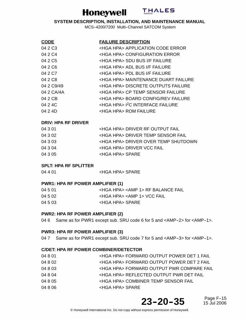
SYSTEM DESCRIPTION, INSTALLATION, AND MAINTENANCE MANUALMCS--4200/7200 Multi--Channel SATCOM System
23--20--35 15 Jul 2006
Honeywell International Inc. Do not copy without express permission of Honeywell.
Page F--15
CODE FAILURE DESCRIPTION04 2 C3 <HGA HPA> APPLICATION CODE ERROR04 2 C4 <HGA HPA> CONFIGURATION ERROR04 2 C5 <HGA HPA> SDU BUS I/F FAILURE04 2 C6 <HGA HPA> ADL BUS I/F FAILURE04 2 C7 <HGA HPA> PDL BUS I/F FAILURE04 2 C8 <HGA HPA> MAINTENANCE DUART FAILURE04 2 C9/49 <HGA HPA> DISCRETE OUTPUTS FAILURE04 2 CA/4A <HGA HPA> CP TEMP SENSOR FAILURE04 2 CB <HGA HPA> BOARD CONFIG/REV FAILURE04 2 4C <HGA HPA> I2C INTERFACE FAILURE04 2 4D <HGA HPA> ROM FAILURE
DRIV: HPA RF DRIVER04 3 01 <HGA HPA> DRIVER RF OUTPUT FAIL04 3 02 <HGA HPA> DRIVER TEMP SENSOR FAIL04 3 03 <HGA HPA> DRIVER OVER TEMP SHUTDOWN04 3 04 <HGA HPA> DRIVER VCC FAIL04 3 05 <HGA HPA> SPARE
SPLT: HPA RF SPLITTER04 4 01 <HGA HPA> SPARE
PWR1: HPA RF POWER AMPLIFIER (1)04 5 01 <HGA HPA> <AMP 1> RF BALANCE FAIL04 5 02 <HGA HPA> <AMP 1> VCC FAIL04 5 03 <HGA HPA> SPARE
PWR2: HPA RF POWER AMPLIFIER (2)04 6 Same as for PWR1 except sub. SRU code 6 for 5 and <AMP--2> for <AMP--1>.
PWR3: HPA RF POWER AMPLIFIER (3)04 7 Same as for PWR1 except sub. SRU code 7 for 5 and <AMP--3> for <AMP--1>.
C/DET: HPA RF POWER COMBINER/DETECTOR04 8 01 <HGA HPA> FORWARD OUTPUT POWER DET 1 FAIL04 8 02 <HGA HPA> FORWARD OUTPUT POWER DET 2 FAIL04 8 03 <HGA HPA> FORWARD OUTPUT PWR COMPARE FAIL04 8 04 <HGA HPA> REFLECTED OUTPUT PWR DET FAIL04 8 05 <HGA HPA> COMBINER TEMP SENSOR FAIL04 8 06 <HGA HPA> SPARE

SYSTEM DESCRIPTION, INSTALLATION, AND MAINTENANCE MANUALMCS--4200/7200 Multi--Channel SATCOM System
23--20--35 15 Jul 2006
Honeywell International Inc. Do not copy without express permission of Honeywell.
Page F--16
CODE FAILURE DESCRIPTIONFPAMP: HPA RF FINAL POWER AMPLIFIER04 9 01 <HGA HPA> FINAL AMP 1 RF BALANCE FAIL04 9 02 <HGA HPA> FINAL AMP 1 VCC FAIL04 9 03 <HGA HPA> SPARE04 9 04 <HGA HPA> FINAL AMP 2 RF BALANCE FAIL04 9 05 <HGA HPA> FINAL AMP 2 VCC FAIL04 9 06 <HGA HPA> SPARE04 9 C0/40 <HGA HPA> PA UNRESPONSIVE04 9 41 <HGA HPA> SPARE04 9 42 <HGA HPA> OVER CURRENT FAILURE04 9 43 <HGA HPA> DRIVER AMPLIFIER DC VOLTAGE FAILURE04 9 44 <HGA HPA> DRIVER AMPLIFIER CURRENT FAILURE04 9 45 <HGA HPA> 12 VDC FAILURE04 9 46 <HGA HPA> PA MUTE FAILURE04 9 47 <HGA HPA> PA OVER TEMP04 9 48 <HGA HPA> PA STATUS FAILURE04 9 49 <HGA HPA> PA TEMP SENSOR FAILURE
HMB: HPA MOTHER BOARD04 A 40 <HGA HPA> BP TEMP SENSOR FAILURE
RFAM: 20W HPA RF AMPLIFIER MODULE04 B 01 <HGA HPA> OVER TEMP SHUTDOWN04 B 02 <HGA HPA> RFAM VCC FAIL04 B 03 <HGA HPA> AMP 1 VCC FAIL04 B 04 <HGA HPA> FORWARD OUTPUT POWER DET 1 FAIL04 B 05 <HGA HPA> FORWARD OUTPUT POWER DET 2 FAIL04 B 06 <HGA HPA> REFLECTED OUTPUT PWR DET FAIL04 B 07 <HGA HPA> TEMP SENSOR FAIL04 B 08 <HGA HPA> FORWARD OUTPUT POWER FAIL04 B 09 <HGA HPA> AMP 2 RF BALANCE FAIL04 B 0A <HGA HPA> AMP 2 VCC FAIL
SPARE Level 1 Codes0506
LGA HPA07 Same entries as for HGA/IGA HPA above except substitute LRU code 7 for code 4,
<LGA HPA> for <HGA HPA>, and [LGA_SUBSYS] for [HGA_SUBSYS]. For the casesof conditional HGA subsystem indictments ([cond_HGA_SUBSYS]), the equivalentLGA HPA failures shall UNconditionally indict [LGA_SUBSYS].

SYSTEM DESCRIPTION, INSTALLATION, AND MAINTENANCE MANUALMCS--4200/7200 Multi--Channel SATCOM System
23--20--35 15 Jul 2006
Honeywell International Inc. Do not copy without express permission of Honeywell.
Page F--17
CODE FAILURE DESCRIPTIONHSU #1Only applicable prior to Package 6.0.
UNKNOWN <HSU1> SRU08 0 01 <HSU1> SELF--DECLARED FAILURE08 0 02 <HSU1> WILLIAMSBURG PROTOCOL ALO/ALR FAIL08 0 03 <HSU1> WILLIAMSBURG PROTOCOL DATA XFER FAIL08 0 84 <HSU1> SELF--TEST MISOPERATION08 0 05 <HSU1> CHANNEL RELEASE ACKNOWLEDGE FAILURE08 0 86/06 <HSU1> RF LOOPBACK INHIBIT FAILURE
HSCPU: <HSU1> CPU08 1 01--79 SPARE08 1 FA <HSU1> ACCESS LEVEL DEVELOPMENT08 1 FB <HSU1> ACCESS LEVEL PRODUCTION08 1 FC <HSU1> ACCESS LEVEL PRODUCTION FAST STARTUP08 1 FD <HSU1> SW VERSIONS INCONSISTENCY08 1 7E SPARE -- -- -- -- --08 1 7F <HSU1> ENVIRONMENT TEMP AT POWER--UP FAIL08 1 80--90 SPARE -- -- -- -- --08 1 91 <HSU1> TEMP SENSOR FAILURE
FDSMP: <HSU1> FRAME DSP (AND INTERFACES)08 2 01--14 SPARE08 2 95 <HSU1> FRAME DSP/CPU INTERFACE FAILURE
VSDPM: <HSU1> VFC DSP (AND INTERFACES)08 3 01--17 SPARE08 3 98 <HSU1> VFC DSP/CPU INTERFACE FAILURE
TFPGA: <HSU1> TURBO FPGA08 4 01--05 SPARE08 4 86 <HSU1> TURBO FPGA FAIL
ISDNT: <HSU1> ISDN TRANSCEIVER08 5 01--06 SPARE08 5 87 <HSU1> ISDN TRANSCEIVER FAILURE
AFPGA: <HSU1> ARINC 429 FPGA08 6 NONE

SYSTEM DESCRIPTION, INSTALLATION, AND MAINTENANCE MANUALMCS--4200/7200 Multi--Channel SATCOM System
23--20--35 15 Jul 2006
Honeywell International Inc. Do not copy without express permission of Honeywell.
Page F--18
CODE FAILURE DESCRIPTIONCPURM: <HSU1> CPU RAM08 7 01--03 SPARE08 7 84 <HSU1> CPU RAM FAILURE
CEM: <HSU1> CONVERTER EEPROM08 8 81 <HSU1> EEPROM FAILURE
FLASH: <HSU1> FLASH08 9 81 SPARE08 9 82 <HSU1> PARAMETER BLOCK CHECKSUM FAILURE08 9 83 <HSU1> CPU BIOS/APPLICATION CRC FAILURE08 9 04--06 SPARE08 9 87 <HSU1> MISSING FILE IN FLASH08 9 88 <HSU1> CORRUPTED FILE IN FLASH/INCORRECT CRC
QUART: <HSU1> QUAD UART08 A 01--10 SPARE08 A 91 <HSU1> EXTERNAL UART FAILURE
ETHER: <HSU1> ETHERNET08 B NONE
PSPCB: <HSU1> POWER SUPPLY PCB08 C 01--0A SPARE08 C 0B <HSU1> POWER FAILURE
ETIME: <HSU1> EXTERNAL TIMER08 D NONE
SPARE08 E NONE
SPARE08 F NONE
HCDMI: <HSU1>/CDM INTERFACE08 G 01--71 SPARE08 G F2 <HSU1> CDM INTERFACE FAILURE08 G 73--7D SPARE08 G FE <HSU1> CDM NOT FITTED

SYSTEM DESCRIPTION, INSTALLATION, AND MAINTENANCE MANUALMCS--4200/7200 Multi--Channel SATCOM System
23--20--35 15 Jul 2006
Honeywell International Inc. Do not copy without express permission of Honeywell.
Page F--19
CODE FAILURE DESCRIPTIONSPARE08 H NONE
SPARE08 I NONE
TDRAM: <HSU1> TURBO DECODER RAM08 J 81--89 SPARE08 J 8A <HSU1> TURBO DECODER RAM FAILURE
BATTM: <HSU1> BATTERY08 K 01--04 SPARE08 K 85 <HSU1> BATTERY CHECK FAILURE
IUART: <HSU1> INTERNAL UART08 L NONE
STAM: <HSU1> STEP ATTENUATOR08 M 01--04 SPARE08 M B5 <HSU1> STEP ATTENUATOR FAILURE
HRFM: <HSU1> RF08 N 81 <HSU1> 1.LO LOCK DETECTOR FAILURE08 N 82 <HSU1> 2.LO LOCK DETECTOR FAILURE08 N 83 <HSU1> 3.LO LOCK DETECTOR FAILURE08 N 04--10 SPARE08 N 91 <HSU1> 1.LO MIN FREQUENCY TEST FAILURE08 N 92 <HSU1> 2.LO MIN FREQUENCY TEST FAILURE08 N 93 <HSU1> 3.LO MIN FREQUENCY TEST FAILURE08 N 14--20 SPARE08 N A1 <HSU1> 1.LO MAX FREQUENCY TEST FAILURE08 N A2 <HSU1> 2.LO MAX FREQUENCY TEST FAILURE08 N A3 <HSU1> 3.LO MAX FREQUENCY TEST FAILURE08 N 24--2F SPARE08 N B0 <HSU1> ALC -- CARRIER OFF FAILURE08 N B1 <HSU1> ALC -- CARRIER ON FAILURE08 N B2 <HSU1> RF LOOPBACK FAILURE08 N B3 <HSU1> AVERAGE AMPLITUDE FAILURE08 N B4 <HSU1> 16QAM SCPC FRAME SYNC FAILURE08 N 35--39 SPARE

SYSTEM DESCRIPTION, INSTALLATION, AND MAINTENANCE MANUALMCS--4200/7200 Multi--Channel SATCOM System
23--20--35 15 Jul 2006
Honeywell International Inc. Do not copy without express permission of Honeywell.
Page F--20
CODE FAILURE DESCRIPTION08 N BA <HSU1> INTERNAL RX COAX CABLE FAILURE
08 N BB <HSU1> TX/RX CHANNEL FREQUENCY ERROR
08 N BC <HSU1> CARRIER_ON OFF CONTROL FAILURE
08 N BD <HSU1> RF LOOP_BACK OFF CONTROL FAILURE
08 N BE <HSU1> TX_ON/OFF CONTROL FAILURE
08 N BF--40 SPARE
08 N 41 <HSU1> AGC LEVEL OUTSIDE LIMITS WARNING
08 N 42 SPARE
08 N C3 <HSU1> LINEARITY OUTSIDE LIMITS WARNING
08 N 44--50 SPARE
08 N 51 <HSU1> 1.LO LOCK FAILURE
08 N 52 <HSU1> 2.LO LOCK FAILURE
08 N 53 <HSU1> 3.LO LOCK FAILURE
REOSM: <HSU1> REFERENCE OSCILLATOR08 O 01--41 SPARE
08 O 42 <HSU1> REF OSC WARNING: SEND HSU TO CAL
08 O 43--62 SPARE
08 O 63 <HSU1> REF OSC FAILURE/VOLTAGE TOO LOW
08 O 64 <HSU1> REF OSC FAILURE/VOLTAGE TOO HIGH
BMONM: <HSU1> BURST DURATION MONITOR08 P 81 <HSU1> BURST DURATION MONITOR CIRCUIT
08 P 02--03 SPARE
08 P 04 <HSU1> TDM BURST DURATION FAILURE
08 P 85 <HSU1> CARRIER ON SIGNALS
DCOMM: <HSU1> DOPPLER COMPENSATION08 Q 01--38 SPARE
08 Q 39 <HSU1> REF OSC COMPENSATION ERROR
FVFCI: <HSU1> FRAME DSP/VFC DSP INTERFACE08 R 01--16 SPARE
08 R 17 <HSU1> FRAME DSP/VFC DSP FAILURE
FDTFI: <HSU1> FRAME DSP/TURBO FPGA INTERFACE08 S 01--15 SPARE
08 S 96 <HSU1> FRAME TURBO FPGA INTERFACE FAILURE


SYSTEM DESCRIPTION, INSTALLATION, AND MAINTENANCE MANUAL MCS-4200/7200
TEMPORARY REVISION NO. 23-1
23-20-35 Page 53 of 5328 Sep 2009
© Honeywell International Inc. Do not copy without express permission of Honeywell.
INSERT PAGE 53 OF 53 FACING PAGE F-21.
Reason: To move 0B from the SPARE code at the bottom of the page and to add 0B to a new code category HDM and applicable failure descriptions.
The SPARE code is changed and the new HDM code and subheading UNKNOWN HDM SRU are added before the SPARE code as follows: HDM UNKNOWN HDM SRU 0B 0 81/01 HSU DATA MODULE ABSENT/REMOVED 0B 0 82 HDM USIM 1 ABSENT 0B 0 83/03 RESERVED 0B 0 84 HDM USIM 3 ABSENT 0B 0 85/05 RESERVED 0B 0 86 HDM USIMS 1 & 3 ABSENT 0B 0 07 HDM ORT FAILURE 0B 0 08 HDM TEMPERATURE UNSTABLE 0B 0 09 HDM TEMPERATURE TIMEOUT 0B 0 8A HDM USIM 1 INVALID 0B 0 8B/0B RESERVED 0B 0 8C HDM USIM 3 INVALID 0B 0 8D/0D RESERVED 0B 0 8E HDM USIM 1 & 3 INVALID 0B 0 8F/0F HDM USIM 1 FAILED 0B 0 90/10 RESERVED 0B 0 91/11 HDM USIM 3 FAILED 0B 0 92/12 RESERVED 0B 0 93/13 HDM USIM 1 & 3 FAILED SPARE 0C

SYSTEM DESCRIPTION, INSTALLATION, AND MAINTENANCE MANUALMCS--4200/7200 Multi--Channel SATCOM System
23--20--35 15 Jul 2006
Honeywell International Inc. Do not copy without express permission of Honeywell.
Page F--21
CODE FAILURE DESCRIPTIONVDTFI: <HSU1> VFC DSP/TURBO FPGA INTERFACE08 T NONE
VDITI: <HSU1> VFC DSP/ISDN TRANSCEIVER INTERFACE08 U NONE
TFTDR: <HSU1> TURBO FPGA/TURBO DECODER RAM INTERFACE08 V NONE
PSIPI: <HSU1> POWER SUPPLY PCB/ISDN PHONE INTERFACE08 W 01--07 SPARE08 W 88 <HSU1> ISDN SUPPLY VOLTAGE FAILURE
CDM: <HSU1> CONFIGURATION DATA MODULE08 X 01--70 SPARE08 X F1 <HSU1> INVALID SERIAL NUMBER08 X 72 SPARE08 X F3 <HSU1> CDM ESSENTIAL DATA FAILURE08 X F4 <HSU1> CDM DATA ACCESS ERROR08 X F5 <HSU1> CDM MISSING WRITE PROTECTION08 X F6 <HSU1> CDM INCORRECT VERSION
SPARE08 Y NONE
ITPSI: <HSU1> ISDN TRANSCEIVER/POWER SUPPLY PCB INTERFACE08 Z 01--08 SPARE08 Z 89 <HSU1> ISDN RX VOLTAGE
HSU #209 Same entries as for HSU #1 above except substitute LRU code 09 for code 08,
<HSU2> for <HSU1>, and [HSU2] for [HSU1]. Only applicable prior to Package 6.0.
HIGH POWER RELAYUNKNOWN HPR SRU0A 0 01 (PORT) MNTNC WORD HPR FAIL0A 0 02 (STBD) MNTNC WORD HPR FAIL
SPARE0B0C
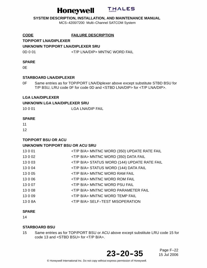
SYSTEM DESCRIPTION, INSTALLATION, AND MAINTENANCE MANUALMCS--4200/7200 Multi--Channel SATCOM System
23--20--35 15 Jul 2006
Honeywell International Inc. Do not copy without express permission of Honeywell.
Page F--22
CODE FAILURE DESCRIPTION
TOP/PORT LNA/DIPLEXER
UNKNOWN TOP/PORT LNA/DIPLEXER SRU
0D 0 01 <T/P LNA/DIP> MNTNC WORD FAIL
SPARE
0E
STARBOARD LNA/DIPLEXER
0F Same entries as for TOP/PORT LNA/Diplexer above except substitute STBD BSU forT/P BSU, LRU code 0F for code 0D and <STBD LNA/DIP> for <T/P LNA/DIP>.
LGA LNA/DIPLEXER
UNKNOWN LGA LNA/DIPLEXER SRU
10 0 01 LGA LNA/DIP FAIL
SPARE
11
12
TOP/PORT BSU OR ACU
UNKNOWN TOP/PORT BSU OR ACU SRU
13 0 01 <T/P B/A> MNTNC WORD (350) UPDATE RATE FAIL
13 0 02 <T/P B/A> MNTNC WORD (350) DATA FAIL
13 0 03 <T/P B/A> STATUS WORD (144) UPDATE RATE FAIL
13 0 04 <T/P B/A> STATUS WORD (144) DATA FAIL
13 0 05 <T/P B/A> MNTNC WORD RAM FAIL
13 0 06 <T/P B/A> MNTNC WORD ROM FAIL
13 0 07 <T/P B/A> MNTNC WORD PSU FAIL
13 0 08 <T/P B/A> MNTNC WORD PARAMETER FAIL
13 0 09 <T/P B/A> MNTNC WORD TEMP FAIL
13 0 8A <T/P B/A> SELF--TEST MISOPERATION
SPARE
14
STARBOARD BSU
15 Same entries as for TOP/PORT BSU or ACU above except substitute LRU code 15 forcode 13 and <STBD BSU> for <T/P B/A>.

SYSTEM DESCRIPTION, INSTALLATION, AND MAINTENANCE MANUALMCS--4200/7200 Multi--Channel SATCOM System
23--20--35 15 Jul 2006
Honeywell International Inc. Do not copy without express permission of Honeywell.
Page F--23
CODE FAILURE DESCRIPTIONSPARE16171819
TOP/PORT HGA/IGAUNKNOWN TOP/PORT HGA/IGA SRU1A 0 01 CM SMPM <T/P HGA/IGA> MNTNC WORD FAIL1A 0 02 CM HMPM IGA FAILURE1A 0 03 CM HMPM IGA RS--422 INPUT BUS LINK FAULT1A 0 04 CM HMPM IGA HPA RS--422 INPUT BUS ERROR/INACTIVE
SPARE1B
STARBOARD HGA1C Same entries as for TOP/PORT HGA above except substitute LRU code 1C for code
1A, <STBD BSU> for <T/P B/A>, and <STBD HGA> for <T/P HGA>.
SPARE1D1E
LGAUNKNOWN LGA SRU1F RESERVED
SPARE20
SCDU/WSC #1UNKNOWN SCDU/WSC #1 SRU21 0 01 <SCDU--1> PROTOCOL ERROR21 0 02 <WSC--1> STATUS (270) BAD SSM21 0 03 <WSC--1> MASTER PROTOCOL ERROR21 0 04 <WSC--1> DATA TRANSMISSION FAILURE21 0 05 SPARE21 0 06 SPARE21 0 07 <WSC--1> MASTER TEST LOOP FAILURE

SYSTEM DESCRIPTION, INSTALLATION, AND MAINTENANCE MANUALMCS--4200/7200 Multi--Channel SATCOM System
23--20--35 15 Jul 2006
Honeywell International Inc. Do not copy without express permission of Honeywell.
Page F--24
CODE FAILURE DESCRIPTION21 0 08 SPARE
SCDU/WSC #222 Same entries as for SCDU/WSC #1 above except substitute LRU code 22 for code 21,
<WSC--2> for <WSC--1>, and <SCDU--2> for <SCDU--1>.
SCDU/WSC #323 Same entries as for SCDU/WSC #1 above except substitute LRU code 23 for code 21,
<WSC--3> for <WSC--1>, and <SCDU--3> for <SCDU--1>.
SPARE24--2F
RMPUNKNOWN RMP SRU30 RESERVED
SPARE3132
(C)MU #1UNKNOWN (C)MU #1 SRU33 0 01 <(C)MU--1> SPARE -- -- -- -- --33 0 02 <(C)MU--1> STATUS (270) BAD SSM33 0 03 <(C)MU--1> MASTER PROTOCOL ERROR33 0 04 <(C)MU--1> DATA TRANSMISSION FAILURE33 0 05 <(C)MU--1> SLAVE PROTOCOL ERROR33 0 06 <(C)MU--1> SELF--DECLARED FAILURE33 0 07 <(C)MU--1> MASTER TEST LOOP FAILURE33 0 08 <(C)MU--1> SLAVE TEST LOOP FAILURE
(C)MU #234 Same entries as for CMU #1 above except substitute LRU code 34 for code 33 and
<(C)MU--2> for <(C)MU--1>.
IRS--PRIUNKNOWN IRS--PRI SRU35 0 01 SPARE35 0 02 <IRS--PRI> LAT DATA (310) FAIL35 0 03 SPARE

SYSTEM DESCRIPTION, INSTALLATION, AND MAINTENANCE MANUALMCS--4200/7200 Multi--Channel SATCOM System
23--20--35 15 Jul 2006
Honeywell International Inc. Do not copy without express permission of Honeywell.
Page F--25
CODE FAILURE DESCRIPTION35 0 04 <IRS--PRI> LON DATA (311) FAIL35 0 05 SPARE35 0 06 <IRS--PRI> GND SPD DATA (312) FAIL35 0 07 SPARE35 0 08 <IRS--PRI> TRK DATA (313) FAIL35 0 09 SPARE35 0 0A <IRS--PRI> TRUE HDG DATA (314) FAIL35 0 0B SPARE35 0 0C <IRS--PRI> PITCH DATA (324) FAIL35 0 0D SPARE35 0 0E <IRS--PRI> ROLL DATA (325) FAIL
IRS--SEC36 Same entries as for IRS--PRI above except substitute LRU code 36 for code 35 and
<IRS--SEC> for <IRS--PRI>.
RESERVED3738
CFDS/CMCUNKNOWN CFDS/CMC SRU39 0 01 INVALID OMS PARAMETER(S) 3 3 E 29,34 NONE
SPARE3A--3C
FMC #1UNKNOWN FMC #1 SRU3D RESERVED
FMC #23E Same entries as for FMC #1 above except substitute LRU code 3E for code 3D and
<FMC--2> for <FMC--1>.
SPARE3F
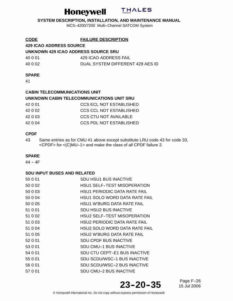
SYSTEM DESCRIPTION, INSTALLATION, AND MAINTENANCE MANUALMCS--4200/7200 Multi--Channel SATCOM System
23--20--35 15 Jul 2006
Honeywell International Inc. Do not copy without express permission of Honeywell.
Page F--26
CODE FAILURE DESCRIPTION429 ICAO ADDRESS SOURCEUNKNOWN 429 ICAO ADDRESS SOURCE SRU40 0 01 429 ICAO ADDRESS FAIL
40 0 02 DUAL SYSTEM DIFFERENT 429 AES ID
SPARE41
CABIN TELECOMMUNICATIONS UNITUNKNOWN CABIN TELECOMMUNICATIONS UNIT SRU42 0 01 CCS ECL NOT ESTABLISHED
42 0 02 CCS CCL NOT ESTABLISHED
42 0 03 CCS CTU NOT AVAILABLE
42 0 04 CCS PDL NOT ESTABLISHED
CPDF43 Same entries as for CMU #1 above except substitute LRU code 43 for code 33,
<CPDF> for <(C)MU--1> and make the class of all CPDF failure 2.
SPARE44 -- 4F
SDU INPUT BUSES AND RELATED50 0 01 SDU HSU1 BUS INACTIVE
50 0 02 HSU1 SELF--TEST MISOPERATION
50 0 03 HSU1 PERIODIC DATA RATE FAIL
50 0 04 HSU1 SOLO WORD DATA RATE FAIL
50 0 05 HSU1 W’BURG DATA RATE FAIL
51 0 01 SDU HSU2 BUS INACTIVE
51 0 02 HSU2 SELF--TEST MISOPERATION
51 0 03 HSU2 PERIODIC DATA RATE FAIL
51 0 04 HSU2 SOLO WORD DATA RATE FAIL
51 0 05 HSU2 W’BURG DATA RATE FAIL
52 0 01 SDU CPDF BUS INACTIVE
53 0 01 SDU CMU--1 BUS INACTIVE
54 0 01 SDU CTU CEPT--E1 BUS INACTIVE
55 0 01 SDU SCDU/WSC--1 BUS INACTIVE
56 0 01 SDU SCDU/WSC--2 BUS INACTIVE
57 0 01 SDU CMU--2 BUS INACTIVE

SYSTEM DESCRIPTION, INSTALLATION, AND MAINTENANCE MANUALMCS--4200/7200 Multi--Channel SATCOM System
23--20--35 15 Jul 2006
Honeywell International Inc. Do not copy without express permission of Honeywell.
Page F--27
CODE FAILURE DESCRIPTION58 0 01 SPARE MP4A/B59 0 01 SDU CFDS BUS INACTIVE
59 0 02 INVALID OMS PARAMETER(S)
5A 0 01 SDU PRI IRS BUS INACTIVE
5B 0 01 SDU SEC IRS BUS INACTIVE
5C 0 01 SDU HGA/IGA HPA BITE BUS INACTIVE
5C 0 02 HGA/IGA HPA SELF--TEST MISOPERATION
5D SPARE5E SPARE MP6G/H
5F 0 01 SDU LGA HPA BITE BUS INACTIVE
5F 0 02 LGA HPA SELF--TEST MISOPERATION
60 SPARE MP7A/B
61 SPARE
62 0 01 SDU TOP/PORT BSU/ACU BITE BUS INACTIVE
62 0 02 TOP/PORT BSU/ACU SELF--TEST MISOPERATION63 SPARE
64 0 01 SDU STBD BSU BITE BUS INACTIVE
64 0 02 STBD BSU/ACU SELF--TEST MISOPERATION
65 0 01 SDU RMP BUS INACTIVE
66 0 01 SDU SCDU/WSC--3 BUS INACTIVE
67 0 01 RESERVED68 0 01 RESERVED
69 SPARE
6A 0 81 RESERVED
6B 0 01 SPARE
6C 0 81 RESERVED
6D 0 81 RESERVED
6E 0 81 RESERVED6F 0 81 RESERVED
70 SPARE
71 0 01 SDU CROSS--TALK BUS INACTIVE 3 2 I -- [OTHER_SATCOM]
72 SPARE MP12E/F
73 0 01 SDU FMC--1 BUS INACTIVE
74 0 01 SDU FMC--2 BUS INACTIVE
75 SPARE76 SPARE
77 SPARE
78 SPARE

SYSTEM DESCRIPTION, INSTALLATION, AND MAINTENANCE MANUALMCS--4200/7200 Multi--Channel SATCOM System
23--20--35 15 Jul 2006
Honeywell International Inc. Do not copy without express permission of Honeywell.
Page F--28
CODE FAILURE DESCRIPTION79 SPARE7A SPARE7B SPARE7C SPARE7D SPARE7E SPARE7F SPARE
RESERVED80--8F
HGA/IGA HPA INPUT BUSES90 0 01 HGA/IGA HPA 429 MNTNC WORD CTL BUS INACTIVE90 0 02 HGA/IGA HPA MULTICONTROL BUS INACTIVE91 SPARE TP2A/B92 SPARE93 SPARE94 SPARE95 SPARE
LGA HPA INPUT BUSES96 0 01 LGA HPA 429 MNTNC WORD CONTROL BUS INACTIVE96 0 02 LGA HPA MULTICONTROL BUS INACTIVE97 SPARE TP2A/B
TOP/PORT BSU/ACU INPUT BUSES98 0 01 MNTNC WORD T/P BSU/ACU MULTICTL BUS INACTIVE99 SPARE
PORT BSU INPUT BUSES9A 0 01 MNTNC WORD PORT BSU CROSSTALK BUS INACTIVE9B SPARE
STARBOARD BSU INPUT BUSES9C 0 01 MNTNC WORD STBD BSU MULTICTL BUS INACTIVE9D 0 01 MNTNC WORD STBD BSU CROSSTALK BUS INACTIVE

SYSTEM DESCRIPTION, INSTALLATION, AND MAINTENANCE MANUALMCS--4200/7200 Multi--Channel SATCOM System
23--20--35 15 Jul 2006
Honeywell International Inc. Do not copy without express permission of Honeywell.
Page F--29
CODE FAILURE DESCRIPTIONHSU #1 INPUT BUS9E 0 01 <HSU1> 429 CONTROL BUS INACTIVE
9E 0 02 <HSU1> ICAO ADDRESS INVALID9E 0 03 <HSU1> POSITION UNAVAILABLE9E 0 04 <HSU1> VELOCITY UNAVAILABLE
HSU #2 INPUT BUS9F Same as entries for HSU #1 above except substitute Level 1 code 9F for code 9E and
<HSU2> for <HSU1>. Only applicable prior to Package 6.0.
SPAREA0 SPARE -- -- -- -- --
WSC INPUT BUSESA1 0 01 WSC1 429 CNTRL BUS FROM THIS SDU INACTIVEA2 0 01 WSC2 429 CNTRL BUS FROM THIS SDU INACTIVEA3 0 01 WSC3 429 CNTRL BUS FROM THIS SDU INACTIVE
SPAREA4--A5
HSU USER INTERFACESA6 0 01 HSU ETHERNET PORT 1 BUS INACTIVEA7 0 01 HSU ETHERNET PORT 2 BUS INACTIVE
A8 0 01 HSU ISDN PORT 1 BUS INACTIVEA9 0 01 HSU ISDN PORT 2 BUS INACTIVE
SPAREAA--BF
MISCELLANEOUS ERRORS, FAILURES AND WARNINGSSDU SYSTEM CONFIGURATION STRAP ERRORSC0 0 81 SDU STRAPS PARITY ERROR
C0 0 82 SDU ANT CONFIG STRAPS ERRORC0 0 83 SDU CFDS CONFIG STRAPS ERRORC0 0 84 SDU STRAPS INCONSISTENCY
C0 0 05 DUAL SYSTEM CONFIG STRAPS ERRORC0 0 06 DUAL REMOTE COCKPIT STRAPS INCOMPATIBLEC0 0 87 MANUFACTURER--SPECIFIC STRAPS PARITY ERROR

SYSTEM DESCRIPTION, INSTALLATION, AND MAINTENANCE MANUALMCS--4200/7200 Multi--Channel SATCOM System
23--20--35 15 Jul 2006
Honeywell International Inc. Do not copy without express permission of Honeywell.
Page F--30
CODE FAILURE DESCRIPTIONMISCC1 0 81/01 SDU WOW MISCOMPARE ERRORC2 0 81 SDU DUAL SYSTEM SELECT/DISABLE TEST ERRORC2 0 82 SDU DUAL SYSTEM SEL/DIS TEST NOT INITIATEDC3 0 81 SDU (ICAO) ADDRESS BITS (STRAPS) ERRORC3 0 02 DUAL SYSTEM DIFFERENT STRAPS AES IDC4 0 01 HGA/IGA HPA 429 MNTNC WORD OUTPUT VSWR BADC4 0 02 HGA/IGA HPA REFLECTED OUTPUT POWER ERRORC5 0 81/01 ORT/LOCAL CONFIG STRAPS INCOMPATIBILITYC5 0 02 DUAL ORT/COMBINED CONFIG STRAPS INCOMPC6 0 01 LGA HPA 429 MNTNC WORD OUTPUT VSWR BADC6 0 02 LGA HPA REFLECTED OUTPUT POWER ERROR
HGA/IGA HPA OVER TEMP WARNINGSC7 0 01 HGA HPA MNTNC WORD LRU OVER TEMPC7 1 01 HGA HPA PSU OVER TEMP WARNINGC7 2 01 HGA HPA CPU OVER TEMP WARNINGC7 2 02 HGA HPA OVER TEMP WARNINGC7 3 01 HGA HPA DRIVER OVER TEMP WARNINGC7 8 01 HGA HPA OVER TEMP (COMBINER) WARNINGC7 B 01 HGA HPA RFAM OVER TEMP WARNING
MISCC8 0 01 INVALID FREQ CMD FROM GESC8 0 02 GNSS INTERFERENCE RISK FROM GES
LGA HPA OVER TEMP WARNINGSC9 0 01 LGA HPA MNTNC WORD LRU OVER TEMPC9 1 01 LGA HPA PSU OVER TEMP WARNINGC9 2 01 LGA HPA CPU OVER TEMP WARNINGC9 2 02 LGA HPA OVER TEMP WARNINGC9 3 01 LGA HPA DRIVER OVER TEMP WARNINGC9 8 01 LGA HPA OVER TEMP (COMBINER) WARNINGC9 B 01 LGA HPA RFAM OVER TEMP WARNING
MISCCA 0 01 LGA LNA CONTROL DRIVER FAILCB 0 01 HGA/IGA HPA INVALID SDI STRAPPINGCC 0 01 LGA HPA INVALID SDI STRAPPING

SYSTEM DESCRIPTION, INSTALLATION, AND MAINTENANCE MANUALMCS--4200/7200 Multi--Channel SATCOM System
23--20--35 15 Jul 2006
Honeywell International Inc. Do not copy without express permission of Honeywell.
Page F--31
CODE FAILURE DESCRIPTIONTOTC/POC RESETSCD 0 81/01 SDU TOTC AUTO/MANUAL RESET
CD 0 82/02 SDU POC AUTO/MANUAL RESET
CE 0 81/01 RESERVED
CE 0 82/02 RESERVED
CF 0 81/01 HGA/IGA HPA TOTC AUTO/MANUAL RESET
CF 0 82/02 HGA/IGA HPA POC AUTO/MANUAL RESET
D0 0 81/01 LGA HPA TOTC AUTO/MANUAL RESET
D0 0 82/02 LGA HPA POC AUTO/MANUAL RESET
WRONG SDI CODES
D1 0 01 HGA/IGA HPA WRONG A429 SDI CODE
D2 0 01 LGA HPA WRONG A429 SDI CODE
D3 0 01 TOP/PORT BSU/ACU WRONG A429 SDI CODE
D4 0 01 STARBOARD BSU WRONG A429 SDI CODE
RF INTER--LRU FAILURES
D5 0 01 SDU TO HGA/IGA HPA CALIBRATION ERROR
D5 0 02 SDU TO LINEAR HGA/IGA HPA RF CONTIN. FAIL
D5 0 03 SDU TO CLASS C HGA/IGA HPA RF CONTIN. FAIL
D5 0 04 SDU TO HGA/IGA HPA ATTEN. CALIBRATION ERROR
D5 0 05 SDU TO LINEAR HGA/IGA HPA ATTEN. RF CONTIN. FAIL
D6 0 01 SDU TO LGA HPA CALIBRATION ERROR
D6 0 02 SDU TO LINEAR LGA HPA RF CONTINUITY FAIL
D6 0 03 SDU TO CLASS C LGA HPA RF CONTINUITY FAIL
D6 0 04 SDU TO LGA HPA ATTEN. CALIBRATION ERROR
D6 0 05 SDU TO LINEAR LGA HPA ATTEN. RF CONTIN. FAIL
D7 0 01 RESERVED
D7 0 82 RESERVED
D8 0 81 T/P HGA LNA TO SDU RF CONTINUITY FAIL
D9 0 81 STBD HGA LNA TO SDU RF CONTINUITY FAIL
DA 0 81 LGA LNA TO SDU RF CONTINUITY FAIL
MISCDB 0 01 LGA LOG--ON TEST FAILURE
DB 0 02 SLAVE LGA LOG--ON TEST NOT INITIATED
DC 0 01 NO DECLARED ACTIVE (C)MU -- 1
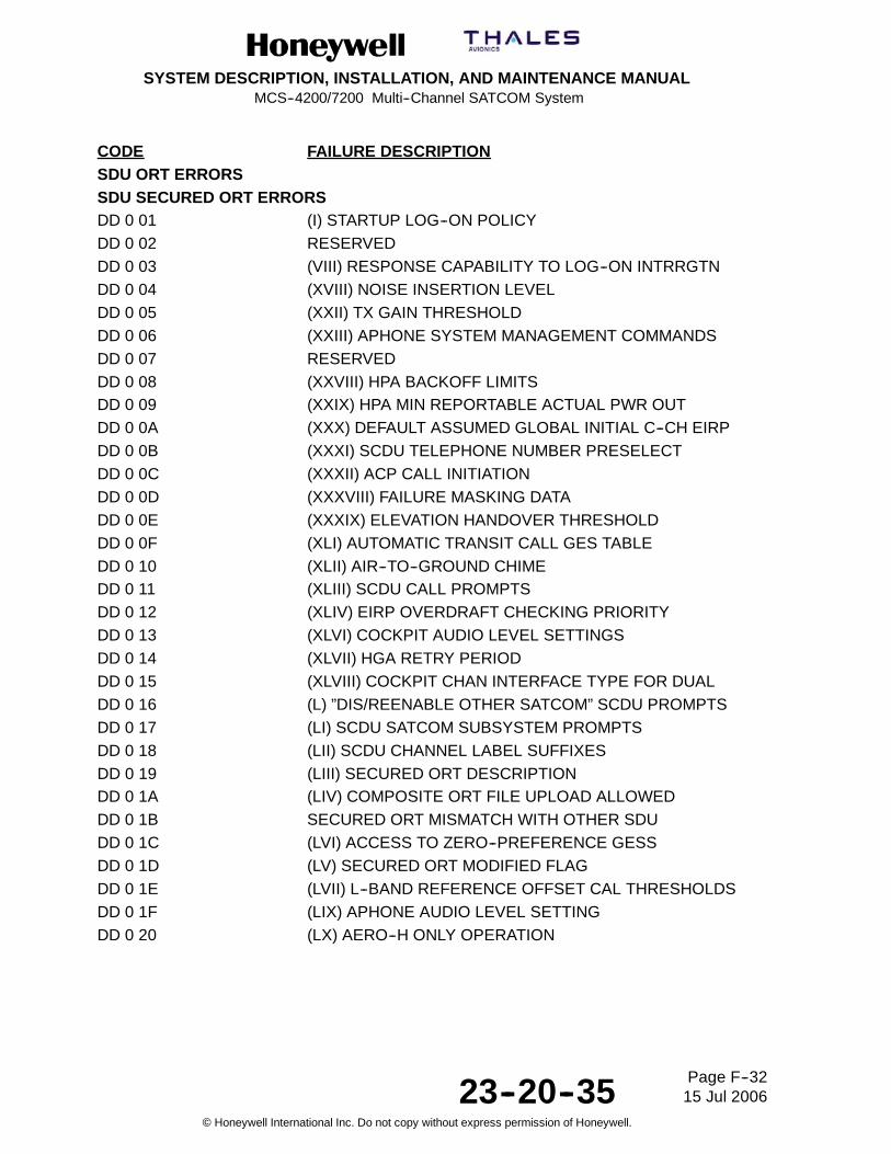
SYSTEM DESCRIPTION, INSTALLATION, AND MAINTENANCE MANUALMCS--4200/7200 Multi--Channel SATCOM System
23--20--35 15 Jul 2006
Honeywell International Inc. Do not copy without express permission of Honeywell.
Page F--32
CODE FAILURE DESCRIPTIONSDU ORT ERRORSSDU SECURED ORT ERRORSDD 0 01 (I) STARTUP LOG--ON POLICYDD 0 02 RESERVEDDD 0 03 (VIII) RESPONSE CAPABILITY TO LOG--ON INTRRGTNDD 0 04 (XVIII) NOISE INSERTION LEVELDD 0 05 (XXII) TX GAIN THRESHOLDDD 0 06 (XXIII) APHONE SYSTEM MANAGEMENT COMMANDSDD 0 07 RESERVEDDD 0 08 (XXVIII) HPA BACKOFF LIMITSDD 0 09 (XXIX) HPA MIN REPORTABLE ACTUAL PWR OUTDD 0 0A (XXX) DEFAULT ASSUMED GLOBAL INITIAL C--CH EIRPDD 0 0B (XXXI) SCDU TELEPHONE NUMBER PRESELECTDD 0 0C (XXXII) ACP CALL INITIATIONDD 0 0D (XXXVIII) FAILURE MASKING DATADD 0 0E (XXXIX) ELEVATION HANDOVER THRESHOLDDD 0 0F (XLI) AUTOMATIC TRANSIT CALL GES TABLEDD 0 10 (XLII) AIR--TO--GROUND CHIMEDD 0 11 (XLIII) SCDU CALL PROMPTSDD 0 12 (XLIV) EIRP OVERDRAFT CHECKING PRIORITYDD 0 13 (XLVI) COCKPIT AUDIO LEVEL SETTINGSDD 0 14 (XLVII) HGA RETRY PERIODDD 0 15 (XLVIII) COCKPIT CHAN INTERFACE TYPE FOR DUALDD 0 16 (L) ”DIS/REENABLE OTHER SATCOM” SCDU PROMPTSDD 0 17 (LI) SCDU SATCOM SUBSYSTEM PROMPTSDD 0 18 (LII) SCDU CHANNEL LABEL SUFFIXESDD 0 19 (LIII) SECURED ORT DESCRIPTIONDD 0 1A (LIV) COMPOSITE ORT FILE UPLOAD ALLOWEDDD 0 1B SECURED ORT MISMATCH WITH OTHER SDUDD 0 1C (LVI) ACCESS TO ZERO--PREFERENCE GESSDD 0 1D (LV) SECURED ORT MODIFIED FLAGDD 0 1E (LVII) L--BAND REFERENCE OFFSET CAL THRESHOLDSDD 0 1F (LIX) APHONE AUDIO LEVEL SETTINGDD 0 20 (LX) AERO--H ONLY OPERATION

SYSTEM DESCRIPTION, INSTALLATION, AND MAINTENANCE MANUALMCS--4200/7200 Multi--Channel SATCOM System
23--20--35 15 Jul 2006
Honeywell International Inc. Do not copy without express permission of Honeywell.
Page F--33
CODE FAILURE DESCRIPTIONSDU USER ORT ERRORSDE 0 01 (II) SATELLITE/GES NAMESDE 0 02 (III) GES PREFERENCE VALUESDE 0 03 (IV) MAINTENANCE PAGE ACCESSDE 0 04 (V) COCKPIT TELEPHONE NUMBERSDE 0 05 (VII) RESOURCES RESERVED FOR HEADSETDE 0 06 SPAREDE 0 07 (X) GROUND--TO--AIR CIRCUIT--MODE DATADE 0 08 (XIII) GROUND--TO--AIR CALLSDE 0 09 (XIV) CALL CAMP--ON DURATIONDE 0 0A (XV) CAMP--ON TIMEOUT ACTIONDE 0 0B (XVI) STORE APHONE TELEPHONE NUMBERSDE 0 0C (XIX) GROUND--TO--AIR CALL PREEMPTIONDE 0 0D (XX) PREFERRED COCKPIT CALL ROUTINGDE 0 0E (XXI) PREFERRED APHONE CALL ROUTINGDE 0 0F (XXIV) APHONE OUTGOING CALL BARRING LEVELDE 0 10 (XXV) CALL BARRING SECURITY CODEDE 0 11 (XXVI) SHARED APHONE PHONE NUMBER STORAGEDE 0 12 (XXXIII) ORT DESCRIPTIONDE 0 13 (XXXIV) AIRLINE CODEDE 0 14 (XXXV) HEADSET OUTGOING CALL BARRING LEVELDE 0 15 (XXXVI) HEADSET TRANSIT CALLDE 0 16 (XL) HIGH RATE DATA TRANSMIT SUPPORTDE 0 17 (XLV) APHONE CALLED TERMINAL ID ASSIGNMENTDE 0 18 (IL) MASTERY HANDOVER ALGORITHM WEIGHTINGDE 0 19 (LVIII) AES POSITION REPORTINGDE 0 1A (LXI) HSD PREEMPTION FOR PRIORITY 4 CALLSDE 0 1B (LXII) ONGOING HSD CALL EIRPDE 0 1C (XXXVII) ORT MODIFIED FLAGDE 0 1D (LXIII) WSC MANUAL DIALINGDE 0 1E (LXIV) MINIMUM HSD CALL EIRPDE 0 1F (LXV) HSD REGISTRATION PREFERENCEDE 0 20 (LXVI) SWIFT64 M--ISDN LES PREFERENCE VALUESDE 0 21 (LXVII) SWIFT64 MPDS LES PREFERENCE VALUESDE 0 22 (LXVIII) ETHERNET MAC ADDRESS ASSIGNMENTDE 0 23 (LXIX) PPPoE ACCESS--CONCENTRATOR NAMEDE 0 24 (LXX) TELNET SERVER ACCESSDE 0 25 (LXXI) DHCP SERVER ACCESSDE 0 26 (LXXII) TELNET IP ADDRESS ASSIGNMENT

SYSTEM DESCRIPTION, INSTALLATION, AND MAINTENANCE MANUALMCS--4200/7200 Multi--Channel SATCOM System
23--20--35 15 Jul 2006
Honeywell International Inc. Do not copy without express permission of Honeywell.
Page F--34
CODE FAILURE DESCRIPTIONDE 0 27 (LXXIII) TELNET SUBNET MASK ASSIGNMENTDE 0 28 (LXXIV) TELNET DEFAULT GATEWAY ASSIGNMENTDE 0 29 (LXXV) DHCP IP ADDRESS ASSIGNMENTDE 0 2A (LXXVI) DHCP IP ADDRESS POOL ALLOCATIONDE 0 2B (LXXVII) BGAN PDP SESSION PARAMETERSDE 0 2C (LXXVIII) PSID SUPPLEMENTARY FREQUENCIES
MISCDF 0 01 SLAVE HGA/IGA LOG--ON TEST FAILUREDF 0 02 SLAVE HGA/IGA LOG--ON TEST NOT INITIATEDE0 0 81 RESERVEDE1 0 01 HSU1 SYSTEM DISABLE DISCRETE FAILUREE1 0 01 HSU SYSTEM DISABLE DISCRETE FAILUREE2 0 01 HSU2 SYSTEM DISABLE DISCRETE FAILUREE3 0 01 UNSUPPORTED HSU1 CONFIGURATIONE3 0 02 UNSUPPORTED HSU2 CONFIGURATIONE4 0 81 HSU1/SDU INTERFACE VERSION INCOMPATIBILITYE5 0 81 HSU2/SDU INTERFACE VERSION INCOMPATIBILITYE6 0 81/01 HSU1/HPA TX RF SIGNAL PATH FAILUREE6 0 02 HSU1 to HGA/IGA HPA CALIBRATION ERRORE6 0 03 HSU2 to HGA/IGA HPA CALIBRATION ERRORE6 0 04 HSU3 to HGA/IGA HPA CALIBRATION ERRORE6 0 05 HSU4 to HGA/IGA HPA CALIBRATION ERRORE7 0 01 HSU2/HPA TX RF SIGNAL PATH FAILUREE8 0 81 DLNA/HSU1 RX RF SIGNAL PATH FAILUREE9 0 81 DLNA/HSU2 RX RF SIGNAL PATH FAILUREEA 0 01 DUAL HSU--700 CONFIG WARNINGEB 0 01 NO DECLARED ACTIVE WSCEC 0 81 HSU CONFIGURATION STRAPS PARITY ERROREC 0 82 HSU CONFIGURATION STRAPS ERRORED 0 01 SDU ORT/HSU CONFIG STRAPS INCOMPATIBILITYEE 0 81 HSU FORWARD ID ADDRESS BITS (STRAPS) ERROREE 0 82 ILLEGAL HSU FORWARD ID ADDRESS

SYSTEM DESCRIPTION, INSTALLATION, AND MAINTENANCE MANUALMCS--4200/7200 Multi--Channel SATCOM System
23--20--35 15 Jul 2006
Honeywell International Inc. Do not copy without express permission of Honeywell.
Page F--35
CODE FAILURE DESCRIPTIONSPAREEF -- FCFD 0 01--16 EXTERNAL PILOT EVENT MARKER TO SDUFE 0 01 EXTERNAL POWER SUPPLY INTERRUPT TO SDU
RESERVEDFF

SYSTEM DESCRIPTION, INSTALLATION, AND MAINTENANCE MANUALMCS--4200/7200 Multi--Channel SATCOM System
23--20--35 15 Jul 2006
Honeywell International Inc. Do not copy without express permission of Honeywell.
Page F--36
Blank Page

SYSTEM DESCRIPTION, INSTALLATION, AND MAINTENANCE MANUALMCS--4200/7200 Multi--Channel SATCOM System
23--20--35 15 Jul 2006
Honeywell International Inc. Do not copy without express permission of Honeywell.
Page INDEX--1
INDEX
A
ACARS, aircraft communications addressing andreporting system, 1--1, 1--11
ACP. See audio control panelactual power out status, 6--57aeronautical administrative communications, 1--1Aeronautical Mobile Satellite Services Document, 1--25aeronautical operational control, 1--1aeronautical passenger communications, 1--1, 3--2Aeronautical Radio, Inc., 1--3, 2--28AFIS, aircraft flight information system, 2--28air filtration systems, B--1
installation instructions, B--4air traffic control, 1--1air traffic services, 1--1Air Transport Association, reference numbers, 6--89
Airbus, 6--94, 6--95, 6--96, 6--98, 6--100, 6--101, 6--103,6--105
Boeing, 6--90, 6--91, 6--92, 6--93McDonnell Douglas, 6--106, 6--107, 6--108, 6--109
air--to--ground calls, 5--69airborne data loader, 1--11, 2--8, 2--11, 2--12, 2--13Airbus, 1--17aircraft avionics, 1--3aircraft communications addressing and reporting system,
peripheral function, 2--28aircraft earth station, 1--2, 1--3, 2--1, 2--2, 2--15, 2--16
identification, 5--57management, 2--1operational modes for log--on, 2--3
aircraft identification, 6--8, 6--68aircraft telecommunications network, 1--1alphanumeric display test, 6--6AMS. See audio management systemAMU. See audio management unitanalog
audio channel, 3--2connected telephone(s), 1--3, 3--1, 3--5, 3--15
call barring level, 3--5, 3--7, C--4handset, 2--5, 2--6, 2--7stored telephone numbers, 3--7, C--5system management commands, 3--8, 3--9, C--4
private branch exchange, 1--10, 3--1, 5--61interfaces, 3--11
trunk lines, 3--2antenna
general removal instructions, 7--3hardware, 7--2removal and installation, 7--2weather protection, 7--2
antenna control unit, 5--63, 6--5, 6--8
antenna subsystem, 1--3, 5--62, 5--63APHONE. See channels, analogAPOS. See actual power out statusARINC, Aeronautical Radio, Inc., 1--11ARINC 600 connector
layouts and contact arrangement, 5--1pin assignments, A--23requirements, 5--3
ATA. See Air Transport Associationaudio control panel, 2--27, 3--14, 5--69audio management system, 2--27audio management unit, 3--14automatic dependent surveillance, 1--1
B
beam steering unit, 1--9, 5--63, 6--5, 6--8, A--4, A--9, A--10,A--15
BIT. See built--in testBoeing, 1--17bootstrap
program, 2--8system table, 2--2
built--in test, 6--88, A--17, A--19built--in test equipment, 1--26, 5--63, 6--3, 6--5, 6--7, 6--89
requirements, 6--1, 6--18system communication, 6--1
bulk data communication, 2--13
C
cabincommunications, 3--1communications system, 1--3, 1--9, 3--1, 5--61, A--9,
A--15packet data function, 2--17, 5--59telecommunications panel, 6--110telecommunications unit, 1--9, 2--17, 3--1voice services, 2--13
cabin/passenger communications equipment, 3--1cable
attenuation, 4--2loss requirements, 4--2
CAIMS. See central aircraft information and maintenancesystem
callinitiation from analog phone, 3--11termination, 2--7, 2--16, 3--5, 3--15
central aircraft information and maintenance system,6--10, 6--88

SYSTEM DESCRIPTION, INSTALLATION, AND MAINTENANCE MANUALMCS--4200/7200 Multi--Channel SATCOM System
23--20--35 15 Jul 2006
Honeywell International Inc. Do not copy without express permission of Honeywell.
Page INDEX--2
central fault display system, 1--11, 5--63, 6--6, 6--7, 6--10,6--16, 6--17, 6--27, 6--38, 6--46, 6--68, 6--71, 6--79, 6--89Airbus, 6--84, 6--87McDonnell--Douglas, 6--84, 6--87pages, 6--10, 6--88
central maintenance computer, 1--11, 5--63, 6--7, 6--10,6--16, 6--17, 6--46, 6--87Boeing 747--400, 6--84to SDU communication, 6--84
centralized fault display interface unit, 6--87, 6--88communication with SDU, 6--87
CFDIU. See centralized fault display interface unitchannels, analog, C--3circuit card assembly, 1--21circuit--mode, 2--16, 2--20
call setup, 2--15, 2--16data, 2--4, 2--13, 2--15, 3--10, 6--111services, 2--13, 2--16voice, 2--7, 2--13
CM. See continuous monitoringCMT. See commissioning and maintenance terminalcockpit
communications, 3--14hookswitch signaling, 5--69voice
call light test, 6--33, 6--34call light/chime, 5--67channels, 2--27configurations, 2--27functionality, 2--27services, 2--13
cockpit voice sources, 1--3codec dedication, 5--68codec--generated
messages, 3--6pacifiers, 3--6, 3--15
commissioning and maintenance terminal, 2--5, 2--7,2--12, 6--6, 6--10, 6--18, 6--72, 6--110interface, 6--17page, 2--11, 6--3panel lamps, 6--111
communications management unit, 1--11, 5--57, 5--58,5--65, A--10
configuration data messages, 6--85configuration pins, 5--21, 5--55, 5--56, 5--58, 5--59, 5--60,
5--61, 5--63, 5--64, 5--65, 5--66, 5--67, 5--68, 6--39, 6--45,6--46, 6--48, 6--49, 6--51, 6--85, 6--88, 6--89
continued airworthiness, 7--5, B--1continuity, 5--21continuous monitoring, 6--4, 6--5, 6--7, 6--8, 6--9, 6--11,
6--30failure, 6--11failure records, 6--8
Control Processor Card, 1--23cooling requirements, 4--3, B--1
coordinated universal time, 6--68, 6--71, 6--75, 6--79, 6--81CPDF. See cabin, packet data functionCRC. See cyclic redundancy checkcross talk, 5--64cross--talk bus, 2--17, 2--18, 2--19, 6--110CTM panel. See cabin, telecommunications panelcyclic redundancy check, 2--9, 6--17
D
D/LNA, Diplexer/ Low Noise Amplifier, 1--9data
interface unit, 2--15set
download, 2--8upload, 2--8
terminal equipment, 2--15digitally connected phones, 3--1diplexer, 5--63, 6--5, 6--8, A--9, A--15Diplexer/ Low Noise Amplifier, 1--9DIU. See data, interface unitDTE. See data, terminal equipmentdual in--line packaging, 1--25dual SATCOM system, 2--10, 2--16, 5--64, 6--27
antenna configurations, 2--19cockpit voice configurations, 2--27control/status, 2--17reversion, 2--18
automatic, 2--18manual, 2--19
SCDU page displays, 6--110wiring diagram, 2--18
dual tone multifrequency, 3--2, 3--6, 3--11, 3--12, 3--15
E
effective isotopic radiated power, 2--5Electronic Cable Specialists
air filtration assemblies, A--8ARINC 600 connectors
beam steering unit, A--2high power amplifier, A--2satellite data unit, A--2signal conditioning unit, A--2
attenuators, A--1, A--2cabin communications system provisions, A--9cable, A--1, A--2connectors, A--1, A--2hardware component kits, A--4, A--7, A--8plenum shelf assemblies, A--9tray assemblies, A--4, A--8
elevation handover threshold, 2--5, 2--7encrypted voice/data communication, 2--13

SYSTEM DESCRIPTION, INSTALLATION, AND MAINTENANCE MANUALMCS--4200/7200 Multi--Channel SATCOM System
23--20--35 15 Jul 2006
Honeywell International Inc. Do not copy without express permission of Honeywell.
Page INDEX--3
F
facsimile, 2--13, 2--15, 3--1failure
detection and reporting level, 6--3memory log, 6--8, 6--18, 6--68, 6--71, 6--75, 6--79, 6--81,
6--83messages in normal mode, 6--87recording, 6--7reporting, 6--8
fault warning processor, 6--89flight
identification number, 2--4leg, 6--8management computer, 5--58plan information, 5--58
FMC. See flight, management computerforward ID, 1--24functional tests, 6--4, 6--5, 6--8, 6--9, 6--11, 6--84
failure, 6--12failure records, 6--8
FWP. See fault warning processor
G
GES--specific data broadcast, 2--16global beam, 2--1, 2--3Global--Wulfsberg Flitephone WH--10, 3--1
commands, 3--7interface, 3--5
Greenwich Mean Time, 6--8ground earth station, 2--1, 2--2, 2--15, 3--9, 3--12, 5--58
preference, 2--5, 2--6, 2--7, 3--9tied preferences, 2--5
ground earth stations, 1--2, 1--12ground speed, 6--77, 6--83ground--to--air calls, 2--4, 3--9, 3--10, 3--14, 5--66, C--3GSDB. See GES--specific data broadcastGSPD. See ground speed
H
handover, 2--1, 2--2, 2--7automatic, 2--1, 2--2, 2--7of mastery, 2--17, 2--18, 2--20user command, 2--1, 2--7
high frequency, 1--1high gain antenna, 1--9, 2--16, 2--19, 2--21, 2--22, 2--23,
2--24, 2--25, 2--26, 2--27, 4--3, 5--63, 6--5, 6--7, 6--16,6--56, 6--58maximum permissible exposure level, INTRO--9
high power amplifier, 1--3, 1--16, 3--17, 5--62, 5--63, 6--1,6--2, 6--5, 6--6, 6--7, 6--9, 6--16, 6--17, 6--19, 6--56, 6--58,6--71, 6--85, 6--88, 6--111, A--4, A--10, B--1, B--4, B--820 watt
front panel connector, 5--1rear connector, 5--1
40 wattARINC 600 connector requirements, 5--3cooling requirements, 4--3front panel connector, 5--1rear connector, 5--1
failure reporting, 6--8front panel
indicators and controls, 6--8light emitting diodes, 6--9
software upload, 2--9software/database updates, 2--8
high power relay, 4--3, 5--63, 6--5, A--9, A--15high speed data unit, 1--1, 1--3, 1--16Hollingsead International, A--10
ARINC 600 connectorsbeam steering unit, A--11communications management unit, A--11high power amplifier, A--11satellite data unit, A--11
cabin communications system provisions, A--15engineering support, A--10installation kit components, A--11
cables, A--11connectors, A--11tray assemblies, A--12
plenum shelf assemblies, A--15HPR. See high power relay
I
inertial reference system, 1--11, 2--5, 5--61, 6--40, A--16initial signal unit, 3--12input/output module, 1--23installation, new, 4--1instructions for continued airworthiness, 7--5integrated services digital network, 1--10interactive data communication, 2--13intermediate gain antenna, 2--19
maximum permissible exposure level, INTRO--9International Civil Aviation Organization, 1--2
address, 2--16, 5--21, 5--57, 6--8, 6--38aircraft identification code, 2--4block strapping, 5--29
International Maritime Satellite Organization, 1--1, 1--9,1--14, 2--1, 2--13, 2--15
International Organization for Standardization, 2--15, 3--13International Telecommunications Union, 1--2ISO. See International Organization for Standardization

SYSTEM DESCRIPTION, INSTALLATION, AND MAINTENANCE MANUALMCS--4200/7200 Multi--Channel SATCOM System
23--20--35 15 Jul 2006
Honeywell International Inc. Do not copy without express permission of Honeywell.
Page INDEX--4
ISU. See initial signal unit
L
level I failure messages, 6--12, 6--13, 6--14, 6--16, 6--89Airbus, 6--94, 6--95, 6--96, 6--98, 6--100, 6--101, 6--103,
6--105Boeing, 6--90, 6--91, 6--92, 6--93McDonnell Douglas, 6--106, 6--107, 6--108, 6--109
light emitting diode, 1--30, 6--8, A--17, A--19test, 6--6, 6--11
line replaceable unit, 2--8, 6--4, 6--5, 6--75, 6--77, 6--81,6--86, 6--88, 6--89, 6--111, 7--1, 7--5, B--1, B--4, B--7, B--8,B--9coverage, 6--3data record, 6--87header record, 2--9identification, 6--16, 6--71installation, 7--3mechanical installation, 4--1removal, 7--3
log--off, 2--1, 2--3, 2--6, 2--7, 6--23log--on, 2--1, 2--2, 2--3, 2--4, 2--5, 2--10, 2--16, 6--27, 6--33,
6--34, 6--65automatic, 2--5, 2--6, 2--7constrained, 2--6, 2--7mode selection, 2--6policy, 2--3, 2--5, 3--8, C--1user command, 2--3
low gain antenna, 1--9, 2--5, 2--16, 2--19, 2--21, 2--23,2--24, 2--25, 2--26, 2--27, 5--63, 6--5, 6--7, 6--16, 6--56,6--58maximum permissible exposure level, INTRO--10
low noise amplifier, 5--63, 6--5, 6--8, A--9, A--15LRU. See line replaceable unit
M
maintenanceactivity log, 6--18, 6--19activity record, 6--19panel assembly, 6--110
management unit, 1--11, 2--17MAR. See maintenance, activity recordmaximum permissible exposure level, INTRO--8
high gain antenna, INTRO--9intermediate gain antenna, INTRO--9low gain antenna, INTRO--10radio frequency energy levels, INTRO--10
MCDU, multifunction control display unit, 1--4MCS SATCOM avionics, 1--3MCU, modular concept unit, 1--25mobile integrated services digital network, 1--10mobile packet--data service, 1--10
MPEL. See maximum permissible exposure levelMulti--Channel SATCOM, 1--1multi--channel SATCOM system
ARINC 429 data requirements, A--16, A--17avionics, 3--1
cooling requirements, 4--3failures, 6--1
multifunction control and display unit, 2--11, 3--14, 5--65,5--67, 6--17, 6--20, 6--21
N
non--volatile memory, 6--89, C--1
O
OCXO. See oven--controlled crystal oscillatoroff--hook, 3--2, 3--5, 3--7, 3--9, 3--11, 3--13, 3--14, 5--69on--board maintenance system, 1--11
Boeing 777, 6--84CAIMS, 6--89
on--hook, 3--6, 3--7, 3--8, 3--9, 3--11, 3--12, 3--15, 5--69operational software, 2--8, 2--9ORT. See owner requirements tableoven--controlled crystal oscillator, 1--23, 1--28, 1--33, 4--3,
6--5, 6--6owner requirements table, 1--4, 1--11, 3--7, 3--8, 3--9,
3--10, 3--15, 3--17, 4--2, 5--66, 5--68, 6--27, 6--64, 6--65,6--110, C--1download/upload diskettes, 2--8, 2--11identification, 6--18, 6--71, 6--74, 6--85, 6--87, 6--88identification message, 6--11upload, 4--2, 7--4upload/download, 2--11
P
packet data, 5--59messages, 2--15services, 2--15, 2--16, 2--20
packet--mode channels, 2--16part number block, 6--17Pd--channel, 2--1, 2--2, 2--3, 2--4
frequency, 2--3person--activated self--test, 2--9, 2--10, 2--12, 2--13, 5--57,
6--4, 6--6, 6--9, 6--29, 6--35, 6--38, 6--87phase--locked oscillator, 6--5, 6--6PMAT. See portable maintenance access terminalPOC. See power--on counterpoint--to--point protocol over Ethernet, 1--23portable data loader, 1--11, 2--8, 2--11, 2--12, 2--13, 5--1portable maintenance access terminal, 6--89power interrupts, 6--4power supply unit, 1--23, 6--6, 6--77, 6--83
Related Documents