SPORTON INTERNATIONAL INC. Page Number : 1 of 74 TEL : 886-3-327-3456 Report Issued Date : Mar. 02, 2015 FAX : 886-3-328-4978 Report Version : Rev. 01 FCC ID : PY7-PM0780 Report Template No.: BU5-FR15CBT Version 1.0 FCC RF Test Report Report No. : FR4D0327A FCC RF Test Report APPLICANT : Sony Mobile Communications Inc EQUIPMENT : PDA Phone BRAND NAME : Sony TYPE NAME : PM-0780-BV FCC ID : PY7-PM0780 STANDARD : FCC Part 15 Subpart C §15.247 CLASSIFICATION : (DSS) Spread Spectrum Transmitter The product was received on Dec. 03, 2014 and testing was completed on Jan. 07, 2015. We, SPORTON INTERNATIONAL INC., would like to declare that the tested sample has been evaluated in accordance with the test procedures and has been in compliance with the applicable technical standards. The test results in this report apply exclusively to the tested model / sample. Without written approval of SPORTON INTERNATIONAL INC., the test report shall not be reproduced except in full. Reviewed by: Joseph Lin / Supervisor Approved by: Jones Tsai / Manager SPORTON INTERNATIONAL INC. No. 52, Hwa Ya 1 st Rd., Hwa Ya Technology Park, Kwei-Shan Hsiang, Tao Yuan Hsien, Taiwan, R.O.C.

Welcome message from author
This document is posted to help you gain knowledge. Please leave a comment to let me know what you think about it! Share it to your friends and learn new things together.
Transcript
SPORTON INTERNATIONAL INC. Page Number : 1 of 74
TEL : 886-3-327-3456 Report Issued Date : Mar. 02, 2015
FAX : 886-3-328-4978 Report Version : Rev. 01
FCC ID : PY7-PM0780 Report Template No.: BU5-FR15CBT Version 1.0
FCC RF Test Report Report No. : FR4D0327A
FCC RF Test Report
APPLICANT : Sony Mobile Communications Inc
EQUIPMENT : PDA Phone
BRAND NAME : Sony
TYPE NAME : PM-0780-BV
FCC ID : PY7-PM0780
STANDARD : FCC Part 15 Subpart C §15.247
CLASSIFICATION : (DSS) Spread Spectrum Transmitter
The product was received on Dec. 03, 2014 and testing was completed on Jan. 07, 2015. We,
SPORTON INTERNATIONAL INC., would like to declare that the tested sample has been
evaluated in accordance with the test procedures and has been in compliance with the
applicable technical standards.
The test results in this report apply exclusively to the tested model / sample. Without written
approval of SPORTON INTERNATIONAL INC., the test report shall not be reproduced except
in full.
Reviewed by: Joseph Lin / Supervisor
Approved by: Jones Tsai / Manager
SPORTON INTERNATIONAL INC. No. 52, Hwa Ya 1
st Rd., Hwa Ya Technology Park, Kwei-Shan Hsiang, Tao Yuan Hsien, Taiwan, R.O.C.
SPORTON INTERNATIONAL INC. Page Number : 2 of 74
TEL : 886-3-327-3456 Report Issued Date : Mar. 02, 2015
FAX : 886-3-328-4978 Report Version : Rev. 01
FCC ID : PY7-PM0780 Report Template No.: BU5-FR15CBT Version 1.0
FCC RF Test Report Report No. : FR4D0327A
TABLE OF CONTENTS
REVISION HISTORY .......................................................................................................................................... 3
SUMMARY OF TEST RESULT ......................................................................................................................... 4
1 GENERAL DESCRIPTION .......................................................................................................................... 5
1.1 Applicant ............................................................................................................................................ 5
1.2 Manufacturer ...................................................................................................................................... 5 1.3 Product Feature of Equipment Under Test ........................................................................................ 5 1.4 Product Specification subjective to this standard .............................................................................. 6 1.5 Modification of EUT ........................................................................................................................... 7 1.6 Testing Location ................................................................................................................................ 7 1.7 Applicable Standards ......................................................................................................................... 7
2 TEST CONFIGURATION OF EQUIPMENT UNDER TEST ........................................................................ 8
2.1 Descriptions of Test Mode ................................................................................................................. 8 2.2 Test Mode .......................................................................................................................................... 9
2.3 Connection Diagram of Test System ............................................................................................... 10 2.4 Support Unit used in test configuration and system ........................................................................ 11 2.5 EUT Operation Test Setup .............................................................................................................. 11 2.6 Measurement Results Explanation Example ................................................................................... 11
3 TEST RESULT .......................................................................................................................................... 12
3.1 Number of Channel Measurement .................................................................................................. 12
3.2 Hopping Channel Separation Measurement ................................................................................... 14 3.3 Dwell Time Measurement ................................................................................................................ 21 3.4 20dB Bandwidth Measurement ....................................................................................................... 24 3.5 Peak Output Power Measurement .................................................................................................. 31
3.6 Conducted Band Edges Measurement............................................................................................ 33 3.7 Conducted Spurious Emission Measurement ................................................................................. 40 3.8 Radiated Band Edges and Spurious Emission Measurement ........................................................ 59 3.9 AC Conducted Emission Measurement........................................................................................... 67 3.10 Antenna Requirements .................................................................................................................... 71
4 LIST OF MEASURING EQUIPMENT ........................................................................................................ 72
5 UNCERTAINTY OF EVALUATION ........................................................................................................... 74
APPENDIX A. TEST RESULT OF RADIATED EMISSION
SPORTON INTERNATIONAL INC. Page Number : 3 of 74
TEL : 886-3-327-3456 Report Issued Date : Mar. 02, 2015
FAX : 886-3-328-4978 Report Version : Rev. 01
FCC ID : PY7-PM0780 Report Template No.: BU5-FR15CBT Version 1.0
FCC RF Test Report Report No. : FR4D0327A
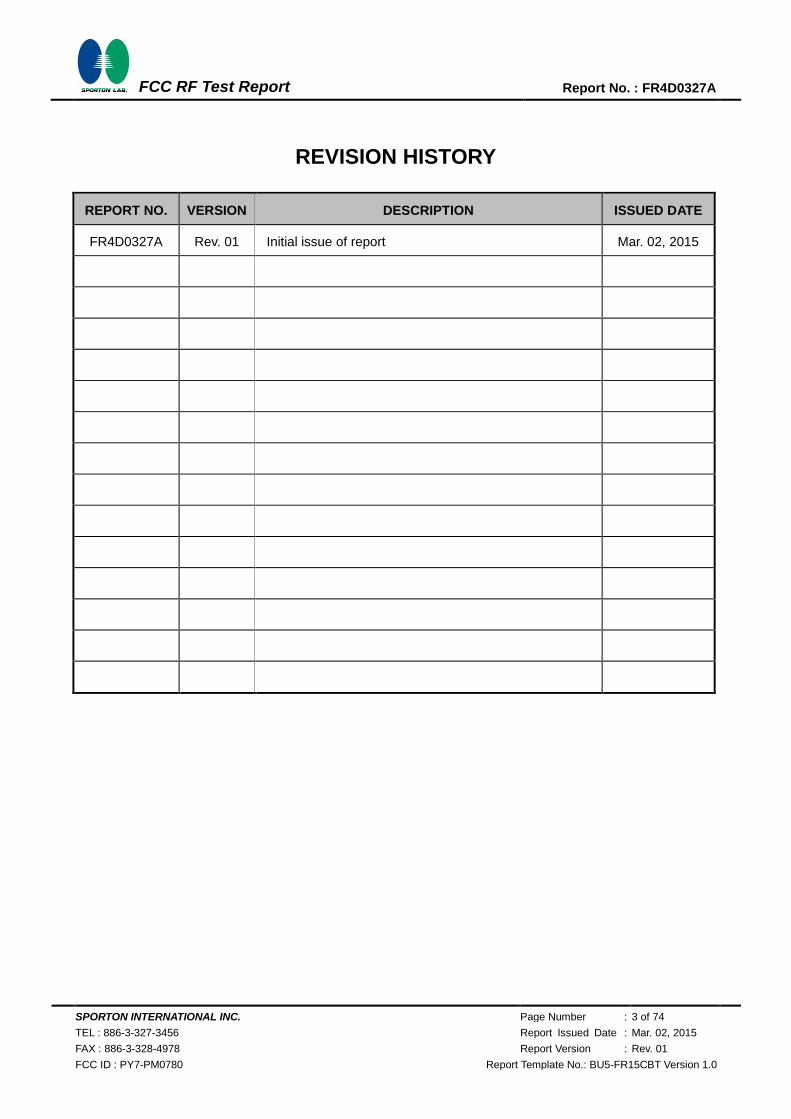
REVISION HISTORY
REPORT NO. VERSION DESCRIPTION ISSUED DATE
FR4D0327A Rev. 01 Initial issue of report Mar. 02, 2015
SPORTON INTERNATIONAL INC. Page Number : 4 of 74
TEL : 886-3-327-3456 Report Issued Date : Mar. 02, 2015
FAX : 886-3-328-4978 Report Version : Rev. 01
FCC ID : PY7-PM0780 Report Template No.: BU5-FR15CBT Version 1.0
FCC RF Test Report Report No. : FR4D0327A
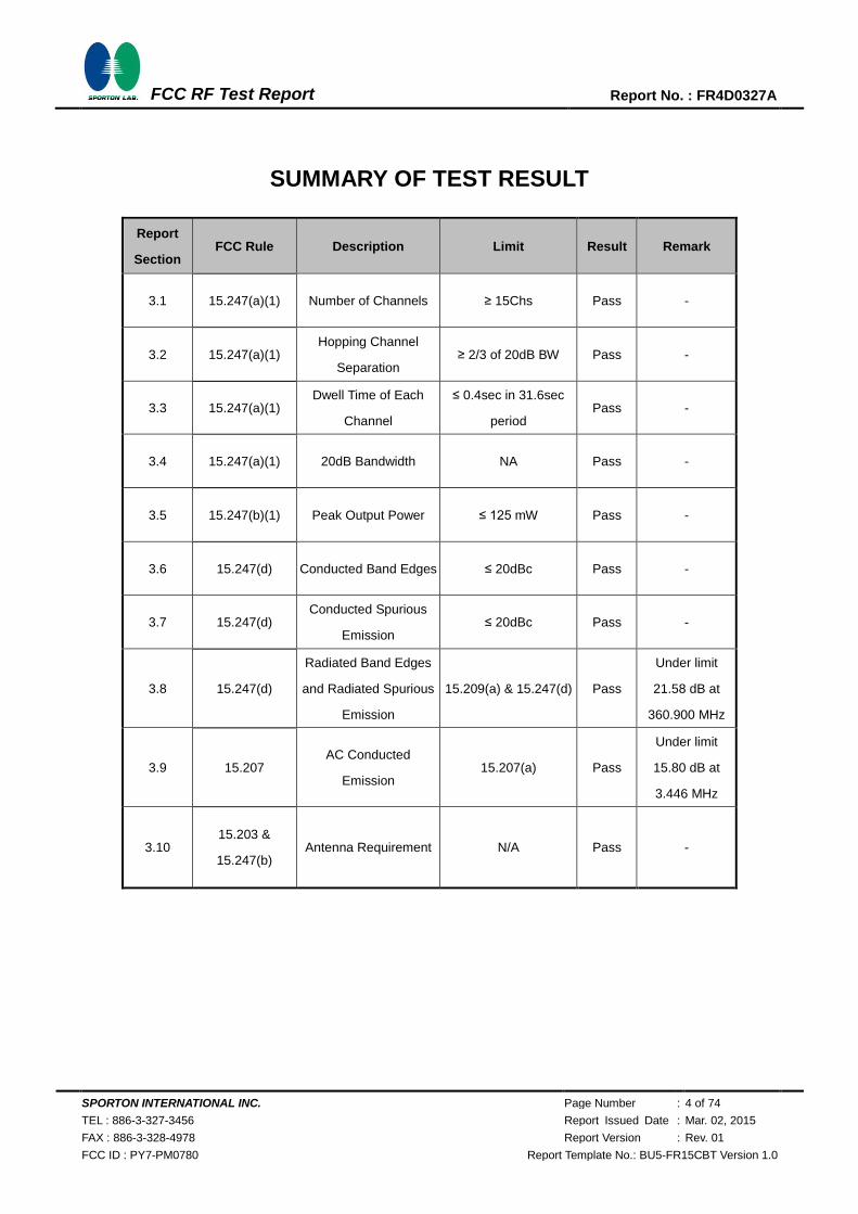
SUMMARY OF TEST RESULT
Report
Section FCC Rule Description Limit Result Remark
3.1 15.247(a)(1) Number of Channels ≥ 15Chs Pass -
3.2 15.247(a)(1) Hopping Channel
Separation ≥ 2/3 of 20dB BW Pass -
3.3 15.247(a)(1) Dwell Time of Each
Channel
≤ 0.4sec in 31.6sec
period Pass -
3.4 15.247(a)(1) 20dB Bandwidth NA Pass -
3.5 15.247(b)(1) Peak Output Power ≤ 125 mW Pass -
3.6 15.247(d) Conducted Band Edges ≤ 20dBc Pass -
3.7 15.247(d) Conducted Spurious
Emission ≤ 20dBc Pass -
3.8 15.247(d)
Radiated Band Edges
and Radiated Spurious
Emission
15.209(a) & 15.247(d) Pass
Under limit
21.58 dB at
360.900 MHz
3.9 15.207 AC Conducted
Emission 15.207(a) Pass
Under limit
15.80 dB at
3.446 MHz
3.10 15.203 &
15.247(b) Antenna Requirement N/A Pass -
SPORTON INTERNATIONAL INC. Page Number : 5 of 74
TEL : 886-3-327-3456 Report Issued Date : Mar. 02, 2015
FAX : 886-3-328-4978 Report Version : Rev. 01
FCC ID : PY7-PM0780 Report Template No.: BU5-FR15CBT Version 1.0
FCC RF Test Report Report No. : FR4D0327A
1 General Description
1.1 Applicant
Sony Mobile Communications Inc
Nya Vattentornet 22188 Lund/Sweden
1.2 Manufacturer
Sony Mobile Communications Inc
Nya Vattentornet 22188 Lund/Sweden
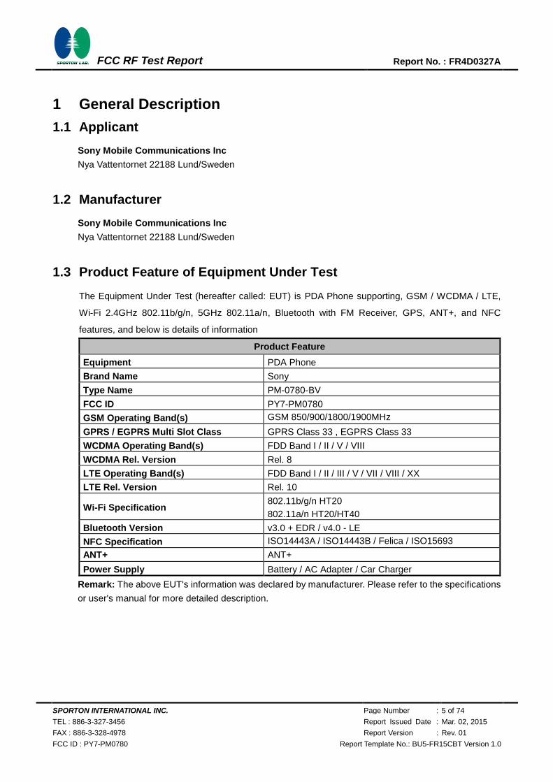
1.3 Product Feature of Equipment Under Test
The Equipment Under Test (hereafter called: EUT) is PDA Phone supporting, GSM / WCDMA / LTE,
Wi-Fi 2.4GHz 802.11b/g/n, 5GHz 802.11a/n, Bluetooth with FM Receiver, GPS, ANT+, and NFC
features, and below is details of information
Product Feature
Equipment PDA Phone
Brand Name Sony
Type Name PM-0780-BV
FCC ID PY7-PM0780
GSM Operating Band(s) GSM 850/900/1800/1900MHz
GPRS / EGPRS Multi Slot Class GPRS Class 33 , EGPRS Class 33
WCDMA Operating Band(s) FDD Band I / II / V / VIII
WCDMA Rel. Version Rel. 8
LTE Operating Band(s) FDD Band I / II / III / V / VII / VIII / XX
LTE Rel. Version Rel. 10
Wi-Fi Specification 802.11b/g/n HT20
802.11a/n HT20/HT40
Bluetooth Version v3.0 + EDR / v4.0 - LE
NFC Specification ISO14443A / ISO14443B / Felica / ISO15693
ANT+ ANT+
Power Supply Battery / AC Adapter / Car Charger
Remark: The above EUT's information was declared by manufacturer. Please refer to the specifications
or user's manual for more detailed description.
SPORTON INTERNATIONAL INC. Page Number : 6 of 74
TEL : 886-3-327-3456 Report Issued Date : Mar. 02, 2015
FAX : 886-3-328-4978 Report Version : Rev. 01
FCC ID : PY7-PM0780 Report Template No.: BU5-FR15CBT Version 1.0
FCC RF Test Report Report No. : FR4D0327A
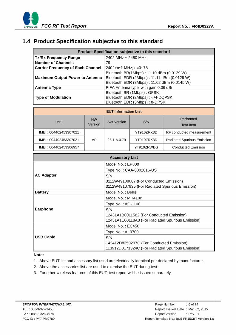
1.4 Product Specification subjective to this standard
Product Specification subjective to this standard
Tx/Rx Frequency Range 2402 MHz ~ 2480 MHz
Number of Channels 79
Carrier Frequency of Each Channel 2402+n*1 MHz; n=0~78
Maximum Output Power to Antenna
Bluetooth BR(1Mbps) : 11.10 dBm (0.0129 W)
Bluetooth EDR (2Mbps) : 11.11 dBm (0.0129 W)
Bluetooth EDR (3Mbps) : 11.62 dBm (0.0145 W)
Antenna Type PIFA Antenna type with gain 0.06 dBi
Type of Modulation
Bluetooth BR (1Mbps) : GFSK
Bluetooth EDR (2Mbps) :π/4-DQPSK
Bluetooth EDR (3Mbps) : 8-DPSK
EUT Information List
IMEI HW
Version SW Version S/N
Performed
Test Item
IMEI : 004402453307021
AP 26.1.A.0.79
YT910ZRX3D RF conducted measurement
IMEI : 004402453307021 YT910ZRX3D Radiated Spurious Emission
IMEI : 004402453306957 YT910ZRWBG Conducted Emission
Accessory List
AC Adapter
Model No. : EP800
Type No. : CAA-0002016-US
S/N :
3112W49108087 (For Conducted Emission)
3112W49107935 (For Radiated Spurious Emission)
Battery Model No. : Bellis
Earphone
Model No. : MH410c
Type No. : AG-1100
S/N :
12431A1B0011582 (For Conducted Emission)
12431A1E00118A8 (For Radiated Spurious Emission)
USB Cable
Model No. : EC450
Type No. : AI-0700
S/N :
142412D8250297C (For Conducted Emission)
113912D0171324C (For Radiated Spurious Emission)
Note:
1. Above EUT list and accessory list used are electrically identical per declared by manufacturer.
2. Above the accessories list are used to exercise the EUT during test.
3. For other wireless features of this EUT, test report will be issued separately.
SPORTON INTERNATIONAL INC. Page Number : 7 of 74
TEL : 886-3-327-3456 Report Issued Date : Mar. 02, 2015
FAX : 886-3-328-4978 Report Version : Rev. 01
FCC ID : PY7-PM0780 Report Template No.: BU5-FR15CBT Version 1.0
FCC RF Test Report Report No. : FR4D0327A
1.5 Modification of EUT
No modifications are made to the EUT during all test items.
1.6 Testing Location
Sporton Lab is accredited to ISO 17025 by Taiwan Accreditation Foundation (TAF code : 1190) and the
FCC designation No. TW1022 under the FCC 2.948(e) by Mutual Recognition Agreement (MRA) in
FCC Test.
Test Site SPORTON INTERNATIONAL INC.
Test Site Location
No. 52, Hwa Ya 1st Rd., Hwa Ya Technology Park,
Kwei-Shan Hsiang, Tao Yuan Hsien, Taiwan, R.O.C.
TEL: +886-3-3273456 / FAX: +886-3-3284978
Test Site No. Sporton Site No.
TH02-HY CO05-HY 03CH07-HY
Note: The test site complies with ANSI C63.4 2009 requirement.
1.7 Applicable Standards
According to the specifications of the manufacturer, the EUT must comply with the requirements of the
following standards:
FCC Part 15 Subpart C §15.247
FCC Public Notice DA 00-705
ANSI C63.10-2013
Remark:
1. All test items were verified and recorded according to the standards and without any deviation
during the test.
2. FCC permits the use of the 1.5 meter table as an alternative in C63.10-2013 through inquiry
tracking number 961829.
3. This EUT has also been tested and complied with the requirements of FCC Part 15, Subpart B,
recorded in a separate test report.
SPORTON INTERNATIONAL INC. Page Number : 8 of 74
TEL : 886-3-327-3456 Report Issued Date : Mar. 02, 2015
FAX : 886-3-328-4978 Report Version : Rev. 01
FCC ID : PY7-PM0780 Report Template No.: BU5-FR15CBT Version 1.0
FCC RF Test Report Report No. : FR4D0327A
2 Test Configuration of Equipment Under Test
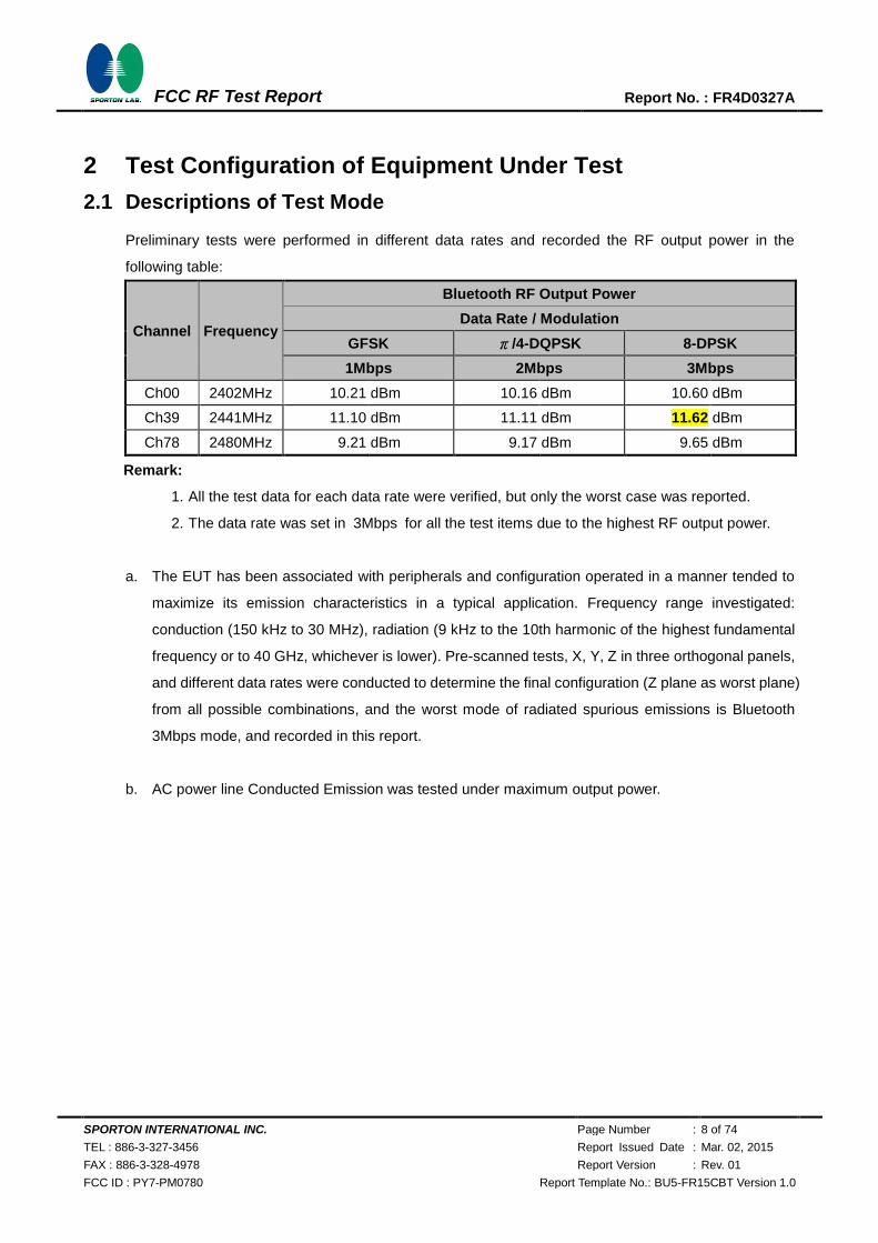
2.1 Descriptions of Test Mode
Preliminary tests were performed in different data rates and recorded the RF output power in the
following table:
Channel Frequency
Bluetooth RF Output Power
Data Rate / Modulation
GFSK π/4-DQPSK 8-DPSK
1Mbps 2Mbps 3Mbps
Ch00 2402MHz 10.21 dBm 10.16 dBm 10.60 dBm
Ch39 2441MHz 11.10 dBm 11.11 dBm 11.62 dBm
Ch78 2480MHz 9.21 dBm 9.17 dBm 9.65 dBm
Remark:
1. All the test data for each data rate were verified, but only the worst case was reported.
2. The data rate was set in 3Mbps for all the test items due to the highest RF output power.
a. The EUT has been associated with peripherals and configuration operated in a manner tended to
maximize its emission characteristics in a typical application. Frequency range investigated:
conduction (150 kHz to 30 MHz), radiation (9 kHz to the 10th harmonic of the highest fundamental
frequency or to 40 GHz, whichever is lower). Pre-scanned tests, X, Y, Z in three orthogonal panels,
and different data rates were conducted to determine the final configuration (Z plane as worst plane)
from all possible combinations, and the worst mode of radiated spurious emissions is Bluetooth
3Mbps mode, and recorded in this report.
b. AC power line Conducted Emission was tested under maximum output power.
SPORTON INTERNATIONAL INC. Page Number : 9 of 74
TEL : 886-3-327-3456 Report Issued Date : Mar. 02, 2015
FAX : 886-3-328-4978 Report Version : Rev. 01
FCC ID : PY7-PM0780 Report Template No.: BU5-FR15CBT Version 1.0
FCC RF Test Report Report No. : FR4D0327A
2.2 Test Mode
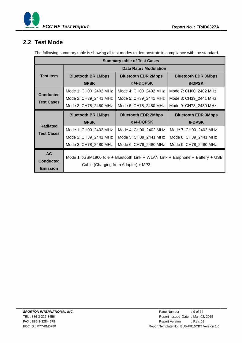
The following summary table is showing all test modes to demonstrate in compliance with the standard.
Summary table of Test Cases
Test Item
Data Rate / Modulation
Bluetooth BR 1Mbps
GFSK
Bluetooth EDR 2Mbps
π/4-DQPSK
Bluetooth EDR 3Mbps
8-DPSK
Conducted
Test Cases
Mode 1: CH00_2402 MHz
Mode 2: CH39_2441 MHz
Mode 3: CH78_2480 MHz
Mode 4: CH00_2402 MHz
Mode 5: CH39_2441 MHz
Mode 6: CH78_2480 MHz
Mode 7: CH00_2402 MHz
Mode 8: CH39_2441 MHz
Mode 9: CH78_2480 MHz
Radiated
Test Cases
Bluetooth BR 1Mbps
GFSK
Bluetooth EDR 2Mbps
π/4-DQPSK
Bluetooth EDR 3Mbps
8-DPSK
Mode 1: CH00_2402 MHz
Mode 2: CH39_2441 MHz
Mode 3: CH78_2480 MHz
Mode 4: CH00_2402 MHz
Mode 5: CH39_2441 MHz
Mode 6: CH78_2480 MHz
Mode 7: CH00_2402 MHz
Mode 8: CH39_2441 MHz
Mode 9: CH78_2480 MHz
AC
Conducted
Emission
Mode 1 : GSM1900 Idle + Bluetooth Link + WLAN Link + Earphone + Battery + USB
Cable (Charging from Adapter) + MP3
SPORTON INTERNATIONAL INC. Page Number : 10 of 74
TEL : 886-3-327-3456 Report Issued Date : Mar. 02, 2015
FAX : 886-3-328-4978 Report Version : Rev. 01
FCC ID : PY7-PM0780 Report Template No.: BU5-FR15CBT Version 1.0
FCC RF Test Report Report No. : FR4D0327A
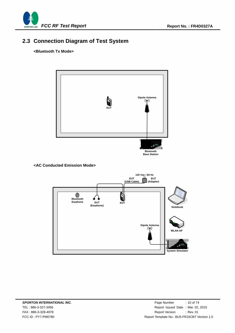
2.3 Connection Diagram of Test System
<Bluetooth Tx Mode>
EUT
Bluetooth
Base Station
Dipole Antenna
<AC Conducted Emission Mode>
System Simulator
Dipole Antenna
WLAN AP
EUT
(Earphone)
Bluetooth
Earphone EUT
EUT
(USB Cable)
EUT
(Adapter)
Notebook
120 Vac / 60 Hz
SPORTON INTERNATIONAL INC. Page Number : 11 of 74
TEL : 886-3-327-3456 Report Issued Date : Mar. 02, 2015
FAX : 886-3-328-4978 Report Version : Rev. 01
FCC ID : PY7-PM0780 Report Template No.: BU5-FR15CBT Version 1.0
FCC RF Test Report Report No. : FR4D0327A
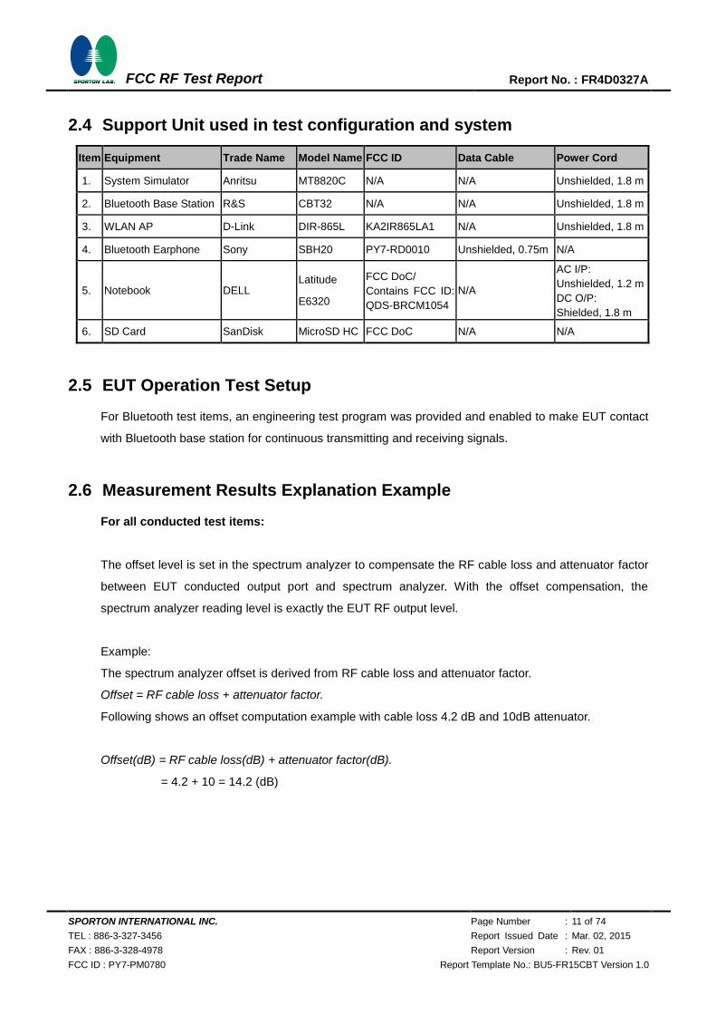
2.4 Support Unit used in test configuration and system
Item Equipment Trade Name Model Name FCC ID Data Cable Power Cord
1. System Simulator Anritsu MT8820C N/A N/A Unshielded, 1.8 m
2. Bluetooth Base Station R&S CBT32 N/A N/A Unshielded, 1.8 m
3. WLAN AP D-Link DIR-865L KA2IR865LA1 N/A Unshielded, 1.8 m
4. Bluetooth Earphone Sony SBH20 PY7-RD0010 Unshielded, 0.75m N/A
5. Notebook DELL Latitude
E6320
FCC DoC/
Contains FCC ID:
QDS-BRCM1054
N/A
AC I/P:
Unshielded, 1.2 m
DC O/P:
Shielded, 1.8 m
6. SD Card SanDisk MicroSD HC FCC DoC N/A N/A
2.5 EUT Operation Test Setup
For Bluetooth test items, an engineering test program was provided and enabled to make EUT contact
with Bluetooth base station for continuous transmitting and receiving signals.
2.6 Measurement Results Explanation Example
For all conducted test items:
The offset level is set in the spectrum analyzer to compensate the RF cable loss and attenuator factor
between EUT conducted output port and spectrum analyzer. With the offset compensation, the
spectrum analyzer reading level is exactly the EUT RF output level.
Example:
The spectrum analyzer offset is derived from RF cable loss and attenuator factor.
Offset = RF cable loss + attenuator factor.
Following shows an offset computation example with cable loss 4.2 dB and 10dB attenuator.
Offset(dB) = RF cable loss(dB) + attenuator factor(dB).
= 4.2 + 10 = 14.2 (dB)
SPORTON INTERNATIONAL INC. Page Number : 12 of 74
TEL : 886-3-327-3456 Report Issued Date : Mar. 02, 2015
FAX : 886-3-328-4978 Report Version : Rev. 01
FCC ID : PY7-PM0780 Report Template No.: BU5-FR15CBT Version 1.0
FCC RF Test Report Report No. : FR4D0327A
3 Test Result
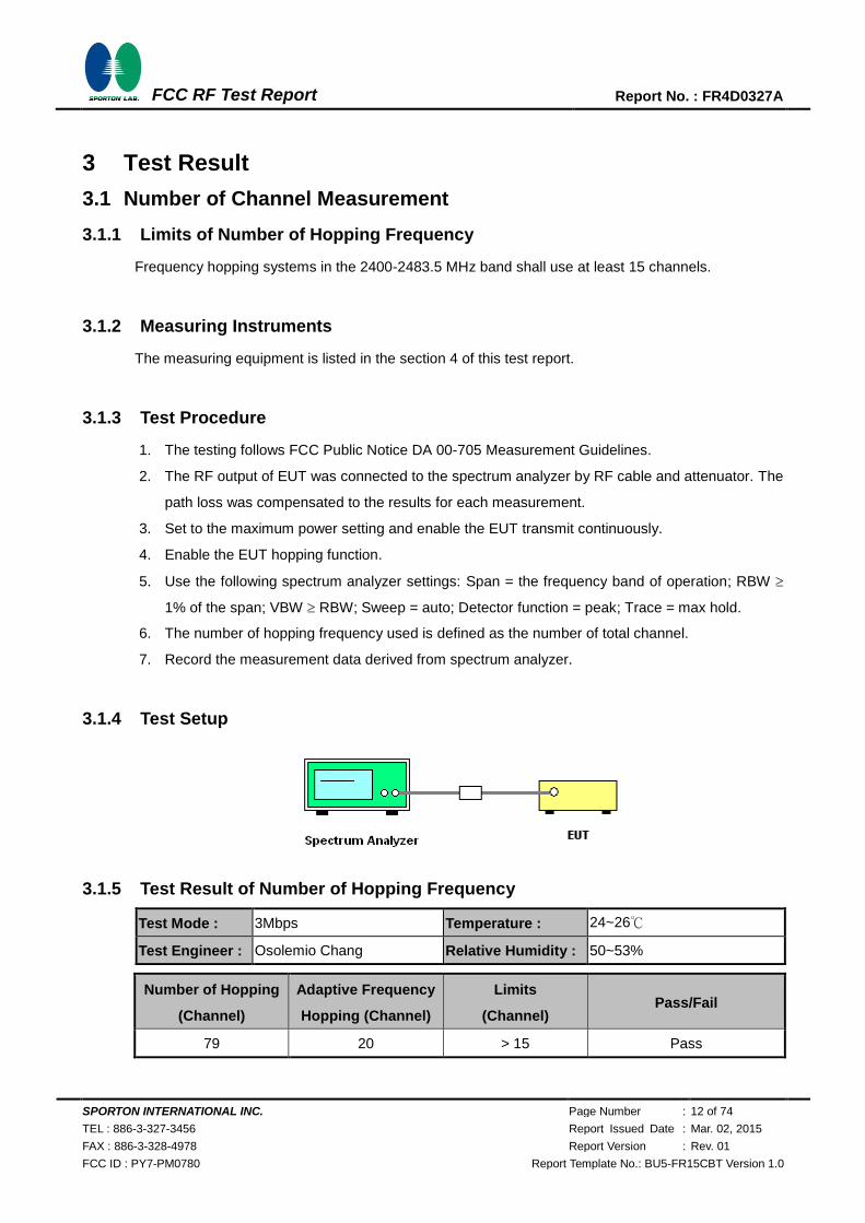
3.1 Number of Channel Measurement
3.1.1 Limits of Number of Hopping Frequency
Frequency hopping systems in the 2400-2483.5 MHz band shall use at least 15 channels.
3.1.2 Measuring Instruments
The measuring equipment is listed in the section 4 of this test report.
3.1.3 Test Procedure
1. The testing follows FCC Public Notice DA 00-705 Measurement Guidelines.
2. The RF output of EUT was connected to the spectrum analyzer by RF cable and attenuator. The
path loss was compensated to the results for each measurement.
3. Set to the maximum power setting and enable the EUT transmit continuously.
4. Enable the EUT hopping function.
5. Use the following spectrum analyzer settings: Span = the frequency band of operation; RBW
1% of the span; VBW RBW; Sweep = auto; Detector function = peak; Trace = max hold.
6. The number of hopping frequency used is defined as the number of total channel.
7. Record the measurement data derived from spectrum analyzer.
3.1.4 Test Setup
3.1.5 Test Result of Number of Hopping Frequency
Test Mode : 3Mbps Temperature : 24~26℃
Test Engineer : Osolemio Chang Relative Humidity : 50~53%
Number of Hopping
(Channel)
Adaptive Frequency
Hopping (Channel)
Limits
(Channel) Pass/Fail
79 20 > 15 Pass
SPORTON INTERNATIONAL INC. Page Number : 13 of 74
TEL : 886-3-327-3456 Report Issued Date : Mar. 02, 2015
FAX : 886-3-328-4978 Report Version : Rev. 01
FCC ID : PY7-PM0780 Report Template No.: BU5-FR15CBT Version 1.0
FCC RF Test Report Report No. : FR4D0327A
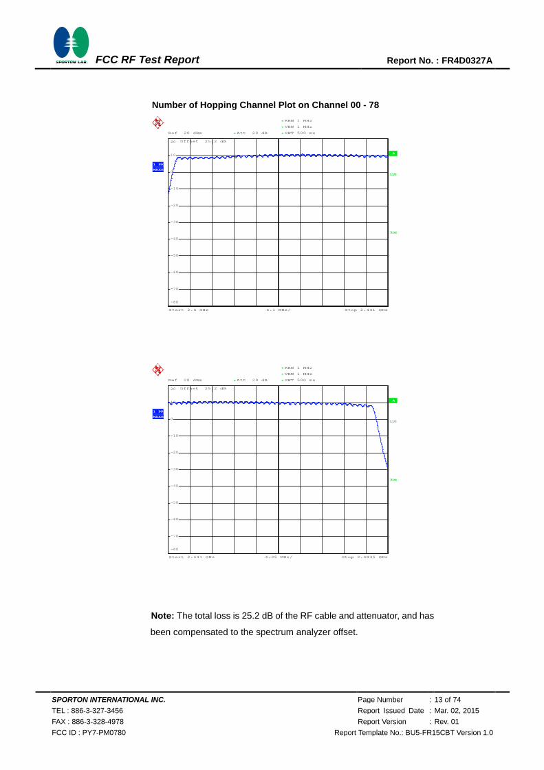
Number of Hopping Channel Plot on Channel 00 - 78
Note: The total loss is 25.2 dB of the RF cable and attenuator, and has
been compensated to the spectrum analyzer offset.
A
Offset 25.2 dB
LVL
Ref 20 dBm Att 20 dB **
4.1 MHz/Start 2.4 GHz Stop 2.441 GHz
*
*
3DB
RBW 1 MHz
VBW 1 MHz
SWT 500 ms*
1 PK
MAXH
-80
-70
-60
-50
-40
-30
-20
-10
0
10
20
Date: 5.NOV.2014 01:45:27
Ref 20 dBm Att 20 dB **
*
Offset 25.2 dB
A
LVL
3DB
RBW 1 MHz
VBW 1 MHz
SWT 500 ms
*
Start 2.441 GHz Stop 2.4835 GHz4.25 MHz/
*
1 PK
MAXH
-80
-70
-60
-50
-40
-30
-20
-10
0
10
20
Date: 5.NOV.2014 01:46:48
720510
SPORTON INTERNATIONAL INC. Page Number : 14 of 74
TEL : 886-3-327-3456 Report Issued Date : Mar. 02, 2015
FAX : 886-3-328-4978 Report Version : Rev. 01
FCC ID : PY7-PM0780 Report Template No.: BU5-FR15CBT Version 1.0
FCC RF Test Report Report No. : FR4D0327A
3.2 Hopping Channel Separation Measurement
3.2.1 Limit of Hopping Channel Separation
Frequency hopping systems operating in the 2400-2483.5 MHz band may have hopping channel
carrier frequencies that are separated by 25 kHz or two-thirds of the 20 dB bandwidth of the hopping
channel, whichever is greater.
3.2.2 Measuring Instruments
The measuring equipment is listed in the section 4 of this test report.
3.2.3 Test Procedures
1. The testing follows FCC Public Notice DA 00-705 Measurement Guidelines.
2. The RF output of EUT was connected to the spectrum analyzer by RF cable and attenuator. The
path loss was compensated to the results for each measurement.
3. Set to the maximum power setting and enable the EUT transmit continuously.
4. Enable the EUT hopping function.
5. Use the following spectrum analyzer settings:
Span = wide enough to capture the peaks of two adjacent channels; RBW 1% of the span;
VBW RBW; Sweep = auto; Detector function = peak; Trace = max hold.
6. Measure and record the results in the test report.
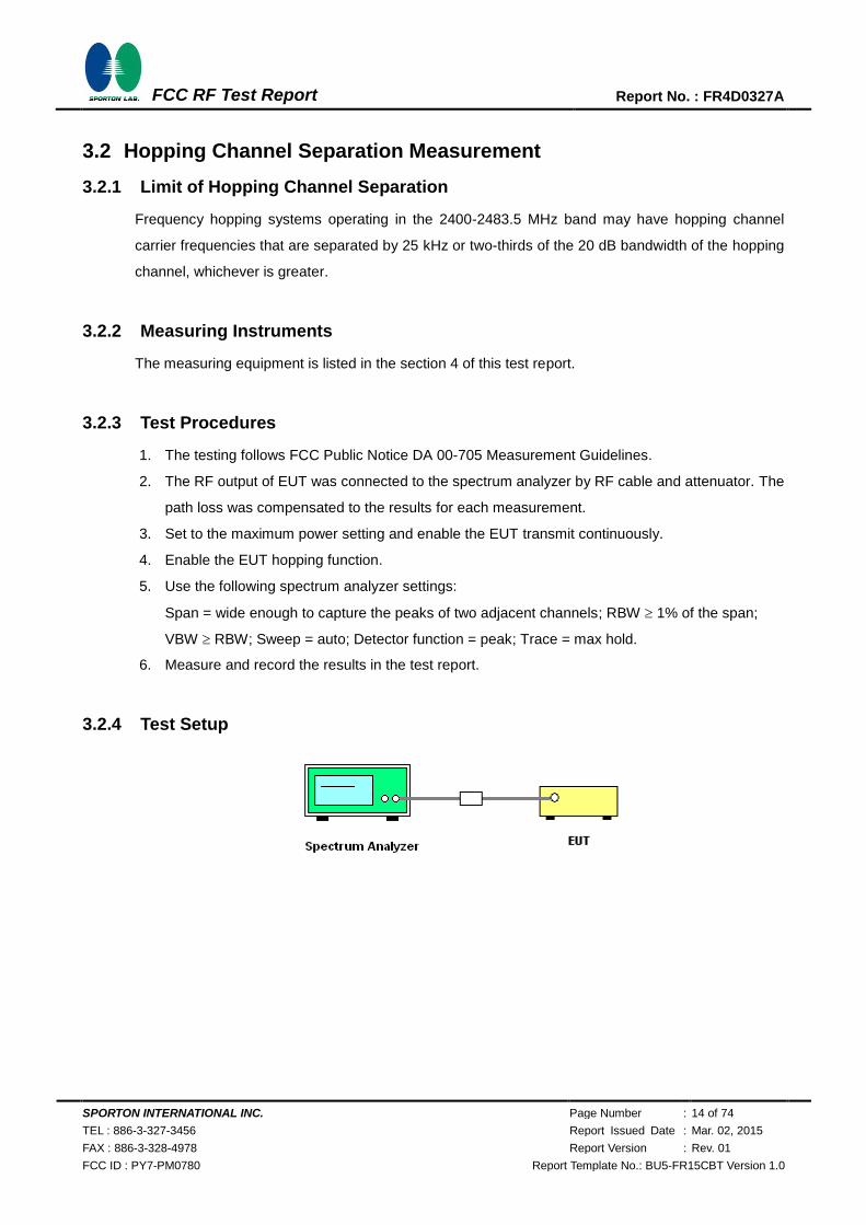
3.2.4 Test Setup
SPORTON INTERNATIONAL INC. Page Number : 15 of 74
TEL : 886-3-327-3456 Report Issued Date : Mar. 02, 2015
FAX : 886-3-328-4978 Report Version : Rev. 01
FCC ID : PY7-PM0780 Report Template No.: BU5-FR15CBT Version 1.0
FCC RF Test Report Report No. : FR4D0327A
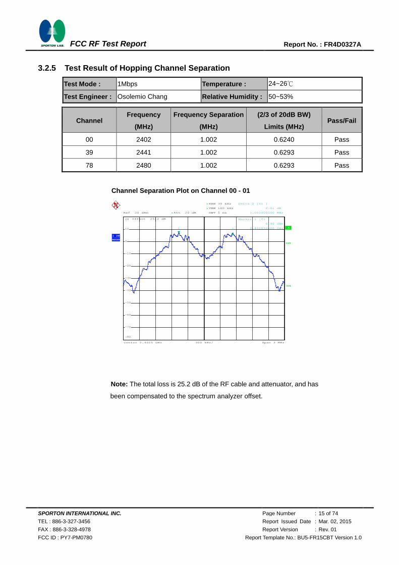
3.2.5 Test Result of Hopping Channel Separation
Test Mode : 1Mbps Temperature : 24~26℃
Test Engineer : Osolemio Chang Relative Humidity : 50~53%
Channel Frequency
(MHz)
Frequency Separation
(MHz)
(2/3 of 20dB BW)
Limits (MHz) Pass/Fail
00 2402 1.002 0.6240 Pass
39 2441 1.002 0.6293 Pass
78 2480 1.002 0.6293 Pass
Channel Separation Plot on Channel 00 - 01
Note: The total loss is 25.2 dB of the RF cable and attenuator, and has
been compensated to the spectrum analyzer offset.
Ref 20 dBm Att 20 dB*
*
*
Offset 25.2 dB
1 PK
MAXH
A
LVL
3DB
RBW 30 kHz
VBW 100 kHz
SWT 5 ms
Center 2.4025 GHz Span 3 MHz300 kHz/
-80
-70
-60
-50
-40
-30
-20
-10
0
10
20
1
Marker 1 [T1 ]
6.90 dBm
2.402032000 GHz2
Delta 2 [T1 ]
0.01 dB
1.002000000 MHz
Date: 5.NOV.2014 01:14:51
720510
SPORTON INTERNATIONAL INC. Page Number : 16 of 74
TEL : 886-3-327-3456 Report Issued Date : Mar. 02, 2015
FAX : 886-3-328-4978 Report Version : Rev. 01
FCC ID : PY7-PM0780 Report Template No.: BU5-FR15CBT Version 1.0
FCC RF Test Report Report No. : FR4D0327A
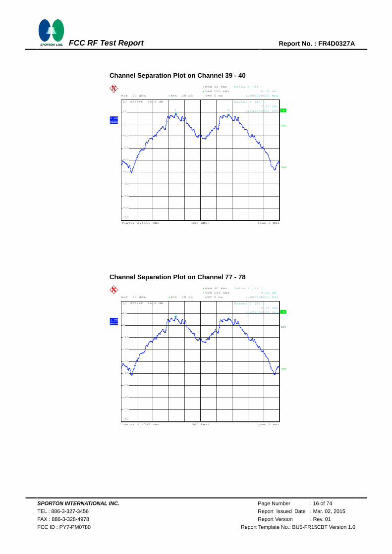
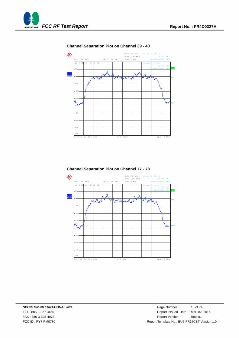
Channel Separation Plot on Channel 39 - 40
Channel Separation Plot on Channel 77 - 78
Ref 20 dBm Att 20 dB*
*
*
Offset 25.2 dB
1 PK
MAXH
A
LVL
3DB
RBW 30 kHz
VBW 100 kHz
SWT 5 ms
Center 2.4415 GHz Span 3 MHz300 kHz/
-80
-70
-60
-50
-40
-30
-20
-10
0
10
20
1
Marker 1 [T1 ]
7.87 dBm
2.441032000 GHz2
Delta 2 [T1 ]
0.08 dB
1.002000000 MHz
Date: 5.NOV.2014 01:13:56
Ref 20 dBm Att 20 dB*
*
*
Offset 25.2 dB
1 PK
MAXH
A
LVL
3DB
RBW 30 kHz
VBW 100 kHz
SWT 5 ms
Center 2.4795 GHz Span 3 MHz300 kHz/
-80
-70
-60
-50
-40
-30
-20
-10
0
10
20
1
Marker 1 [T1 ]
6.23 dBm
2.479032000 GHz2
Delta 2 [T1 ]
-0.22 dB
1.002000000 MHz
Date: 5.NOV.2014 01:15:52
720510
720510
SPORTON INTERNATIONAL INC. Page Number : 17 of 74
TEL : 886-3-327-3456 Report Issued Date : Mar. 02, 2015
FAX : 886-3-328-4978 Report Version : Rev. 01
FCC ID : PY7-PM0780 Report Template No.: BU5-FR15CBT Version 1.0
FCC RF Test Report Report No. : FR4D0327A
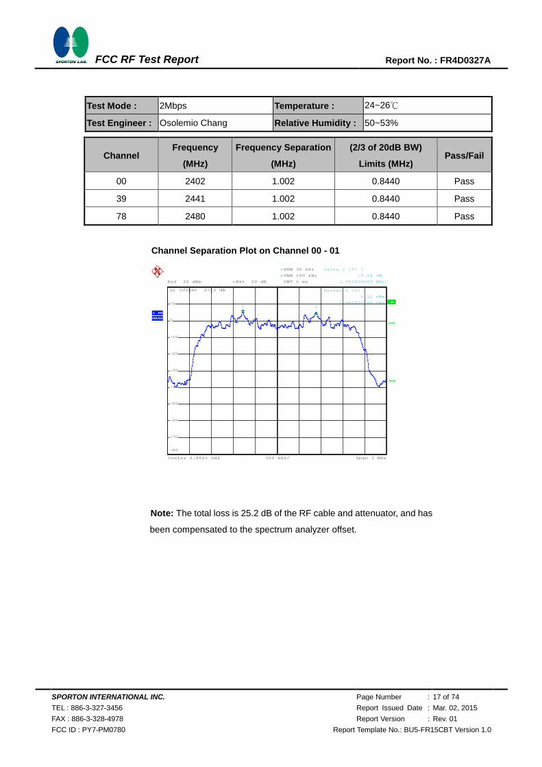
Test Mode : 2Mbps Temperature : 24~26℃
Test Engineer : Osolemio Chang Relative Humidity : 50~53%
Channel Frequency
(MHz)
Frequency Separation
(MHz)
(2/3 of 20dB BW)
Limits (MHz) Pass/Fail
00 2402 1.002 0.8440 Pass
39 2441 1.002 0.8440 Pass
78 2480 1.002 0.8440 Pass
Channel Separation Plot on Channel 00 - 01
Note: The total loss is 25.2 dB of the RF cable and attenuator, and has
been compensated to the spectrum analyzer offset.
Ref 20 dBm Att 20 dB*
*
*
Offset 25.2 dB
1 PK
MAXH
A
LVL
3DB
RBW 30 kHz
VBW 100 kHz
SWT 5 ms
Center 2.4025 GHz Span 3 MHz300 kHz/
-80
-70
-60
-50
-40
-30
-20
-10
0
10
20
1
Marker 1 [T1 ]
5.12 dBm
2.402032000 GHz2
Delta 2 [T1 ]
-0.04 dB
1.002000000 MHz
Date: 5.NOV.2014 01:17:51
720510
SPORTON INTERNATIONAL INC. Page Number : 18 of 74
TEL : 886-3-327-3456 Report Issued Date : Mar. 02, 2015
FAX : 886-3-328-4978 Report Version : Rev. 01
FCC ID : PY7-PM0780 Report Template No.: BU5-FR15CBT Version 1.0
FCC RF Test Report Report No. : FR4D0327A
Channel Separation Plot on Channel 39 - 40
Channel Separation Plot on Channel 77 - 78
Ref 20 dBm Att 20 dB*
*
*
Offset 25.2 dB
1 PK
MAXH
A
LVL
3DB
RBW 30 kHz
VBW 100 kHz
SWT 5 ms
Center 2.4415 GHz Span 3 MHz300 kHz/
-80
-70
-60
-50
-40
-30
-20
-10
0
10
20
1
Marker 1 [T1 ]
6.22 dBm
2.441032000 GHz2
Delta 2 [T1 ]
0.07 dB
1.002000000 MHz
Date: 5.NOV.2014 01:16:57
Ref 20 dBm Att 20 dB*
*
*
Offset 25.2 dB
1 PK
MAXH
A
LVL
3DB
RBW 30 kHz
VBW 100 kHz
SWT 5 ms
Center 2.4795 GHz Span 3 MHz300 kHz/
-80
-70
-60
-50
-40
-30
-20
-10
0
10
20
1
Marker 1 [T1 ]
4.63 dBm
2.479032000 GHz
2
Delta 2 [T1 ]
-0.34 dB
1.002000000 MHz
Date: 5.NOV.2014 01:19:47
720510
720510
SPORTON INTERNATIONAL INC. Page Number : 19 of 74
TEL : 886-3-327-3456 Report Issued Date : Mar. 02, 2015
FAX : 886-3-328-4978 Report Version : Rev. 01
FCC ID : PY7-PM0780 Report Template No.: BU5-FR15CBT Version 1.0
FCC RF Test Report Report No. : FR4D0327A
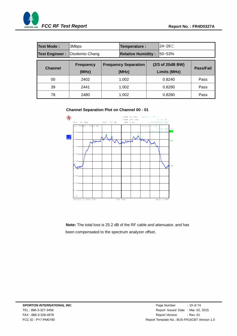
Test Mode : 3Mbps Temperature : 24~26℃
Test Engineer : Osolemio Chang Relative Humidity : 50~53%
Channel Frequency
(MHz)
Frequency Separation
(MHz)
(2/3 of 20dB BW)
Limits (MHz) Pass/Fail
00 2402 1.002 0.8240 Pass
39 2441 1.002 0.8280 Pass
78 2480 1.002 0.8280 Pass
Channel Separation Plot on Channel 00 - 01
Note: The total loss is 25.2 dB of the RF cable and attenuator, and has
been compensated to the spectrum analyzer offset.
Ref 20 dBm Att 20 dB*
*
*
Offset 25.2 dB
1 PK
MAXH
A
LVL
3DB
RBW 30 kHz
VBW 100 kHz
SWT 5 ms
Center 2.4025 GHz Span 3 MHz300 kHz/
-80
-70
-60
-50
-40
-30
-20
-10
0
10
20
1
Marker 1 [T1 ]
5.08 dBm
2.402032000 GHz2
Delta 2 [T1 ]
0.11 dB
1.002000000 MHz
Date: 5.NOV.2014 01:21:54
720510

SPORTON INTERNATIONAL INC. Page Number : 20 of 74
TEL : 886-3-327-3456 Report Issued Date : Mar. 02, 2015
FAX : 886-3-328-4978 Report Version : Rev. 01
FCC ID : PY7-PM0780 Report Template No.: BU5-FR15CBT Version 1.0
FCC RF Test Report Report No. : FR4D0327A
Channel Separation Plot on Channel 39 - 40
Channel Separation Plot on Channel 77 - 78
Ref 20 dBm Att 20 dB*
*
*
Offset 25.2 dB
1 PK
MAXH
A
LVL
3DB
RBW 30 kHz
VBW 100 kHz
SWT 5 ms
Center 2.4415 GHz Span 3 MHz300 kHz/
-80
-70
-60
-50
-40
-30
-20
-10
0
10
20
1
Marker 1 [T1 ]
6.24 dBm
2.441032000 GHz2
Delta 2 [T1 ]
0.03 dB
1.002000000 MHz
Date: 5.NOV.2014 01:20:54
Ref 20 dBm Att 20 dB*
*
*
Offset 25.2 dB
1 PK
MAXH
A
LVL
3DB
RBW 30 kHz
VBW 100 kHz
SWT 5 ms
Center 2.4795 GHz Span 3 MHz300 kHz/
-80
-70
-60
-50
-40
-30
-20
-10
0
10
20
1
Marker 1 [T1 ]
4.60 dBm
2.479032000 GHz
2
Delta 2 [T1 ]
-0.28 dB
1.002000000 MHz
Date: 5.NOV.2014 01:22:51
720510
720510
SPORTON INTERNATIONAL INC. Page Number : 21 of 74
TEL : 886-3-327-3456 Report Issued Date : Mar. 02, 2015
FAX : 886-3-328-4978 Report Version : Rev. 01
FCC ID : PY7-PM0780 Report Template No.: BU5-FR15CBT Version 1.0
FCC RF Test Report Report No. : FR4D0327A
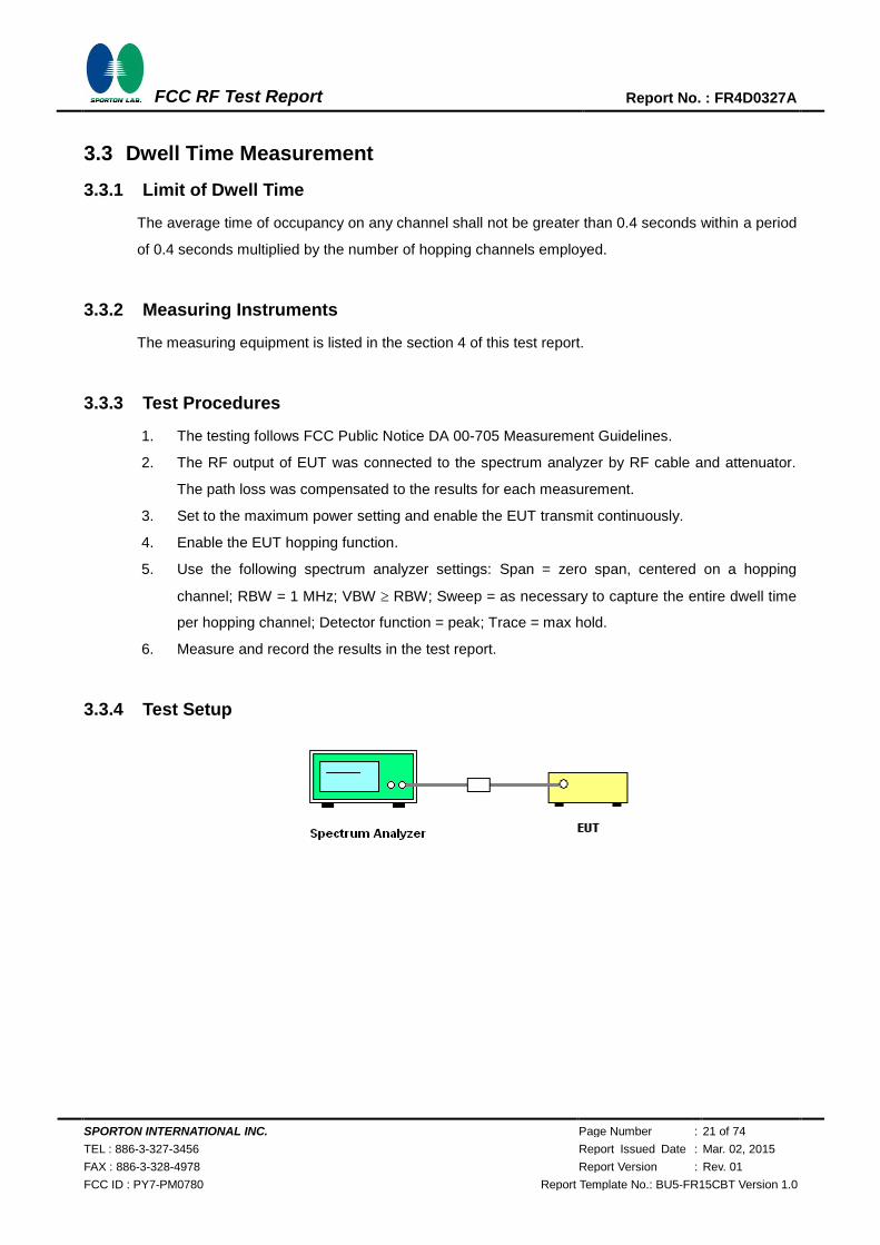
3.3 Dwell Time Measurement
3.3.1 Limit of Dwell Time
The average time of occupancy on any channel shall not be greater than 0.4 seconds within a period
of 0.4 seconds multiplied by the number of hopping channels employed.
3.3.2 Measuring Instruments
The measuring equipment is listed in the section 4 of this test report.
3.3.3 Test Procedures
1. The testing follows FCC Public Notice DA 00-705 Measurement Guidelines.
2. The RF output of EUT was connected to the spectrum analyzer by RF cable and attenuator.
The path loss was compensated to the results for each measurement.
3. Set to the maximum power setting and enable the EUT transmit continuously.
4. Enable the EUT hopping function.
5. Use the following spectrum analyzer settings: Span = zero span, centered on a hopping
channel; RBW = 1 MHz; VBW RBW; Sweep = as necessary to capture the entire dwell time
per hopping channel; Detector function = peak; Trace = max hold.
6. Measure and record the results in the test report.
3.3.4 Test Setup
SPORTON INTERNATIONAL INC. Page Number : 22 of 74
TEL : 886-3-327-3456 Report Issued Date : Mar. 02, 2015
FAX : 886-3-328-4978 Report Version : Rev. 01
FCC ID : PY7-PM0780 Report Template No.: BU5-FR15CBT Version 1.0
FCC RF Test Report Report No. : FR4D0327A
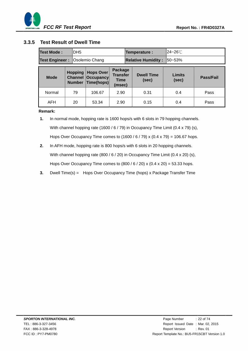
3.3.5 Test Result of Dwell Time
Test Mode : DH5 Temperature : 24~26℃
Test Engineer : Osolemio Chang Relative Humidity : 50~53%
Mode
Hopping
Channel
Number
Hops Over
Occupancy
Time(hops)
Package
Transfer
Time
(msec)
Dwell Time
(sec)
Limits
(sec) Pass/Fail
Normal 79 106.67 2.90 0.31 0.4 Pass
AFH 20 53.34 2.90 0.15 0.4 Pass
Remark:
1. In normal mode, hopping rate is 1600 hops/s with 6 slots in 79 hopping channels.
With channel hopping rate (1600 / 6 / 79) in Occupancy Time Limit (0.4 x 79) (s),
Hops Over Occupancy Time comes to (1600 / 6 / 79) x (0.4 x 79) = 106.67 hops.
2. In AFH mode, hopping rate is 800 hops/s with 6 slots in 20 hopping channels.
With channel hopping rate (800 / 6 / 20) in Occupancy Time Limit (0.4 x 20) (s),
Hops Over Occupancy Time comes to (800 / 6 / 20) x (0.4 x 20) = 53.33 hops.
3. Dwell Time(s) = Hops Over Occupancy Time (hops) x Package Transfer Time

SPORTON INTERNATIONAL INC. Page Number : 23 of 74
TEL : 886-3-327-3456 Report Issued Date : Mar. 02, 2015
FAX : 886-3-328-4978 Report Version : Rev. 01
FCC ID : PY7-PM0780 Report Template No.: BU5-FR15CBT Version 1.0
FCC RF Test Report Report No. : FR4D0327A
Package Transfer Time Plot
Note: The total loss is 25.5 dB of the RF cable and attenuator, and has
been compensated to the spectrum analyzer offset.
Ref 20 dBm Att 20 dB*
*
Offset 25.5 dB
Center 2.441 GHz 1 ms/
1 PK
MAXH
A
SGL
LVL
3DB
RBW 1 MHz
VBW 1 MHz
SWT 10 ms
-80
-70
-60
-50
-40
-30
-20
-10
0
10
20
1
Marker 1 [T1 ]
5.59 dBm
448.717949 µs 2
Delta 2 [T1 ]
1.41 dB
2.903846 ms
3
Delta 3 [T1 ]
1.03 dB
3.769231 ms
Date: 23.DEC.2014 21:57:27
720510
SPORTON INTERNATIONAL INC. Page Number : 24 of 74
TEL : 886-3-327-3456 Report Issued Date : Mar. 02, 2015
FAX : 886-3-328-4978 Report Version : Rev. 01
FCC ID : PY7-PM0780 Report Template No.: BU5-FR15CBT Version 1.0
FCC RF Test Report Report No. : FR4D0327A
3.4 20dB Bandwidth Measurement
3.4.1 Limit of 20dB Bandwidth
Reporting only
3.4.2 Measuring Instruments
The measuring equipment is listed in the section 4 of this test report.
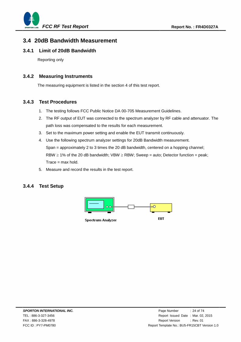
3.4.3 Test Procedures
1. The testing follows FCC Public Notice DA 00-705 Measurement Guidelines.
2. The RF output of EUT was connected to the spectrum analyzer by RF cable and attenuator. The
path loss was compensated to the results for each measurement.
3. Set to the maximum power setting and enable the EUT transmit continuously.
4. Use the following spectrum analyzer settings for 20dB Bandwidth measurement.
Span = approximately 2 to 3 times the 20 dB bandwidth, centered on a hopping channel;
RBW 1% of the 20 dB bandwidth; VBW RBW; Sweep = auto; Detector function = peak;
Trace = max hold.
5. Measure and record the results in the test report.
3.4.4 Test Setup
SPORTON INTERNATIONAL INC. Page Number : 25 of 74
TEL : 886-3-327-3456 Report Issued Date : Mar. 02, 2015
FAX : 886-3-328-4978 Report Version : Rev. 01
FCC ID : PY7-PM0780 Report Template No.: BU5-FR15CBT Version 1.0
FCC RF Test Report Report No. : FR4D0327A
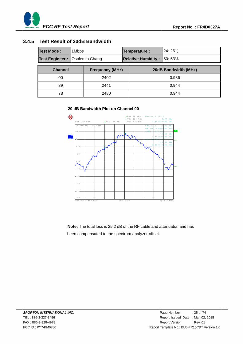
3.4.5 Test Result of 20dB Bandwidth
Test Mode : 1Mbps Temperature : 24~26℃
Test Engineer : Osolemio Chang Relative Humidity : 50~53%
Channel Frequency (MHz) 20dB Bandwidth (MHz)
00 2402 0.936
39 2441 0.944
78 2480 0.944
20 dB Bandwidth Plot on Channel 00
Note: The total loss is 25.2 dB of the RF cable and attenuator, and has
been compensated to the spectrum analyzer offset.
A
Offset 25.2 dB
LVL
Ref 20 dBm
Center 2.402 GHz Span 2 MHz200 kHz/
Att 20 dB*
3DB
RBW 30 kHz
SWT 2.5 ms
*
VBW 300 kHz*
1 PK
MAXH
-80
-70
-60
-50
-40
-30
-20
-10
0
10
20
1
Marker 1 [T1 ]
6.97 dBm
2.402028000 GHz
ndB [T1] 20.00 dB
BW 936.000000000 kHz
T1
Temp 1 [T1 ndB]
-12.63 dBm
2.401596000 GHz
T2
Temp 2 [T1 ndB]
-12.99 dBm
2.402532000 GHz
Date: 5.NOV.2014 01:26:02
720510
SPORTON INTERNATIONAL INC. Page Number : 26 of 74
TEL : 886-3-327-3456 Report Issued Date : Mar. 02, 2015
FAX : 886-3-328-4978 Report Version : Rev. 01
FCC ID : PY7-PM0780 Report Template No.: BU5-FR15CBT Version 1.0
FCC RF Test Report Report No. : FR4D0327A
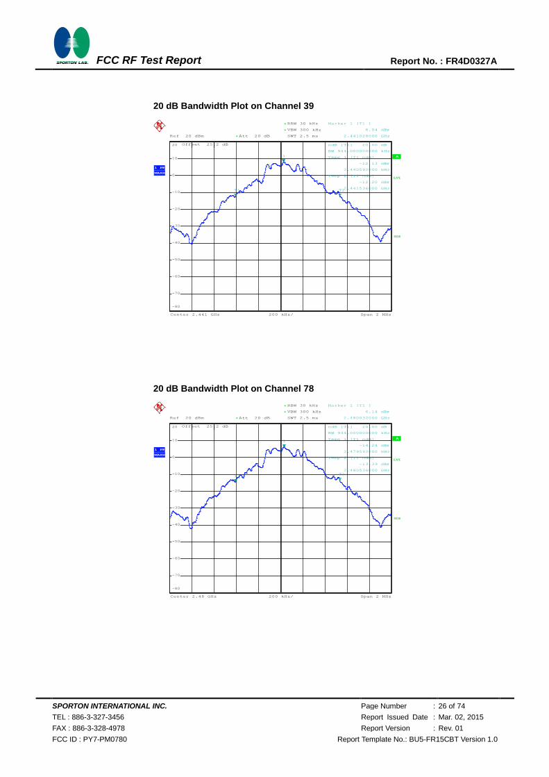
20 dB Bandwidth Plot on Channel 39
20 dB Bandwidth Plot on Channel 78
A
Offset 25.2 dB
LVL
Ref 20 dBm
Center 2.441 GHz Span 2 MHz200 kHz/
Att 20 dB*
3DB
RBW 30 kHz
SWT 2.5 ms
*
VBW 300 kHz*
1 PK
MAXH
-80
-70
-60
-50
-40
-30
-20
-10
0
10
20
1
Marker 1 [T1 ]
8.04 dBm
2.441028000 GHz
ndB [T1] 20.00 dB
BW 944.000000000 kHz
T1
Temp 1 [T1 ndB]
-12.13 dBm
2.440592000 GHz
T2
Temp 2 [T1 ndB]
-12.20 dBm
2.441536000 GHz
Date: 5.NOV.2014 01:24:06
A
Offset 25.2 dB
LVL
Ref 20 dBm
Center 2.48 GHz Span 2 MHz200 kHz/
Att 20 dB*
3DB
RBW 30 kHz
SWT 2.5 ms
*
VBW 300 kHz*
1 PK
MAXH
-80
-70
-60
-50
-40
-30
-20
-10
0
10
20
1
Marker 1 [T1 ]
6.14 dBm
2.480032000 GHz
ndB [T1] 20.00 dB
BW 944.000000000 kHz
T1
Temp 1 [T1 ndB]
-14.24 dBm
2.479592000 GHz
T2
Temp 2 [T1 ndB]
-13.39 dBm
2.480536000 GHz
Date: 5.NOV.2014 01:27:58
720510
720510
SPORTON INTERNATIONAL INC. Page Number : 27 of 74
TEL : 886-3-327-3456 Report Issued Date : Mar. 02, 2015
FAX : 886-3-328-4978 Report Version : Rev. 01
FCC ID : PY7-PM0780 Report Template No.: BU5-FR15CBT Version 1.0
FCC RF Test Report Report No. : FR4D0327A
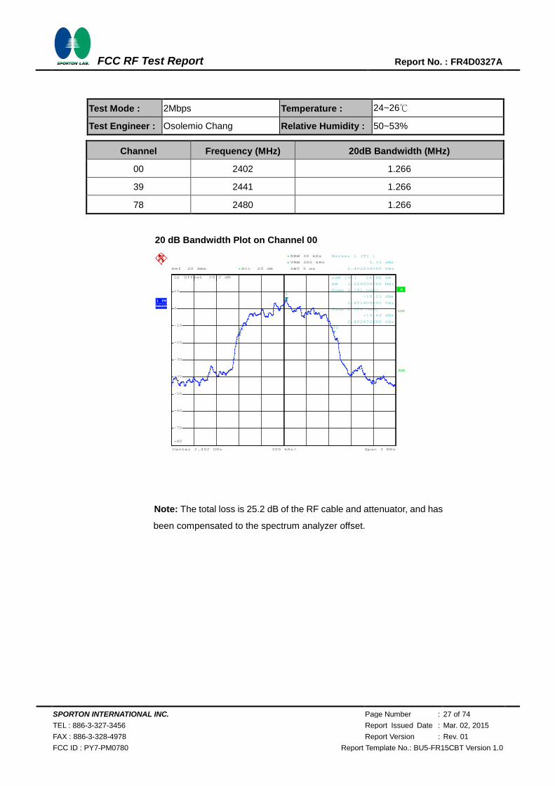
Test Mode : 2Mbps Temperature : 24~26℃
Test Engineer : Osolemio Chang Relative Humidity : 50~53%
Channel Frequency (MHz) 20dB Bandwidth (MHz)
00 2402 1.266
39 2441 1.266
78 2480 1.266
20 dB Bandwidth Plot on Channel 00
Note: The total loss is 25.2 dB of the RF cable and attenuator, and has
been compensated to the spectrum analyzer offset.
A
Offset 25.2 dB
LVL
Ref 20 dBm
Center 2.402 GHz Span 3 MHz300 kHz/
Att 20 dB*
3DB
RBW 30 kHz
SWT 5 ms
*
VBW 300 kHz*
1 PK
MAXH
-80
-70
-60
-50
-40
-30
-20
-10
0
10
20
1
Marker 1 [T1 ]
5.12 dBm
2.402036000 GHz
ndB [T1] 20.00 dB
BW 1.266000000 MHz
T1
Temp 1 [T1 ndB]
-15.23 dBm
2.401406000 GHz
T2
Temp 2 [T1 ndB]
-14.64 dBm
2.402672000 GHz
Date: 5.NOV.2014 01:30:45
720510
SPORTON INTERNATIONAL INC. Page Number : 28 of 74
TEL : 886-3-327-3456 Report Issued Date : Mar. 02, 2015
FAX : 886-3-328-4978 Report Version : Rev. 01
FCC ID : PY7-PM0780 Report Template No.: BU5-FR15CBT Version 1.0
FCC RF Test Report Report No. : FR4D0327A
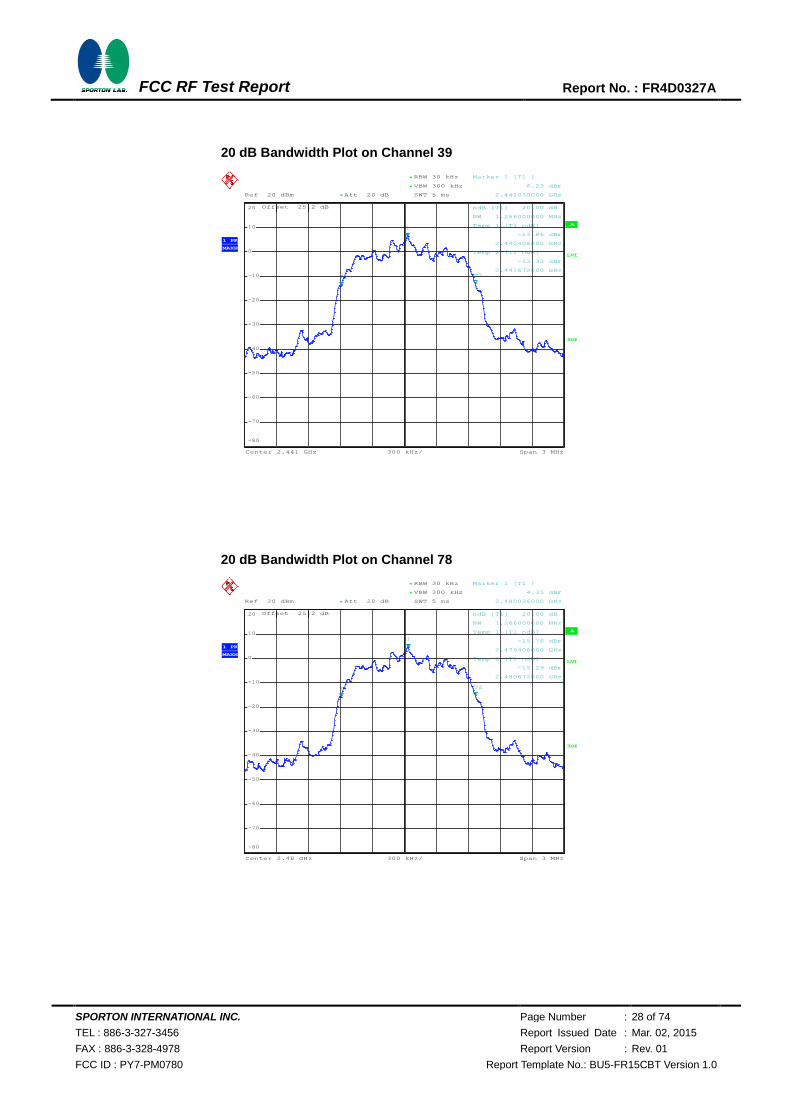
20 dB Bandwidth Plot on Channel 39
20 dB Bandwidth Plot on Channel 78
A
Offset 25.2 dB
LVL
Ref 20 dBm
Center 2.441 GHz Span 3 MHz300 kHz/
Att 20 dB*
3DB
RBW 30 kHz
SWT 5 ms
*
VBW 300 kHz*
1 PK
MAXH
-80
-70
-60
-50
-40
-30
-20
-10
0
10
20
1
Marker 1 [T1 ]
6.23 dBm
2.441030000 GHz
ndB [T1] 20.00 dB
BW 1.266000000 MHz
T1
Temp 1 [T1 ndB]
-13.86 dBm
2.440406000 GHz
T2
Temp 2 [T1 ndB]
-13.33 dBm
2.441672000 GHz
Date: 5.NOV.2014 01:32:40
A
Offset 25.2 dB
LVL
Ref 20 dBm
Center 2.48 GHz Span 3 MHz300 kHz/
Att 20 dB*
3DB
RBW 30 kHz
SWT 5 ms
*
VBW 300 kHz*
1 PK
MAXH
-80
-70
-60
-50
-40
-30
-20
-10
0
10
20
1
Marker 1 [T1 ]
4.35 dBm
2.480036000 GHz
ndB [T1] 20.00 dB
BW 1.266000000 MHz
T1
Temp 1 [T1 ndB]
-15.76 dBm
2.479406000 GHz
T2
Temp 2 [T1 ndB]
-15.29 dBm
2.480672000 GHz
Date: 5.NOV.2014 01:34:39
720510
720510

SPORTON INTERNATIONAL INC. Page Number : 29 of 74
TEL : 886-3-327-3456 Report Issued Date : Mar. 02, 2015
FAX : 886-3-328-4978 Report Version : Rev. 01
FCC ID : PY7-PM0780 Report Template No.: BU5-FR15CBT Version 1.0
FCC RF Test Report Report No. : FR4D0327A
Test Mode : 3Mbps Temperature : 24~26℃
Test Engineer : Osolemio Chang Relative Humidity : 50~53%
Channel Frequency (MHz) 20dB Bandwidth (MHz)
00 2402 1.236
39 2441 1.242
78 2480 1.242
20 dB Bandwidth Plot on Channel 00
Note: The total loss is 25.2 dB of the RF cable and attenuator, and has
been compensated to the spectrum analyzer offset.
A
Offset 25.2 dB
LVL
Ref 20 dBm
Center 2.402 GHz Span 3 MHz300 kHz/
Att 20 dB*
3DB
RBW 30 kHz
SWT 5 ms
*
VBW 300 kHz*
1 PK
MAXH
-80
-70
-60
-50
-40
-30
-20
-10
0
10
20
1
Marker 1 [T1 ]
5.13 dBm
2.402036000 GHz
ndB [T1] 20.00 dB
BW 1.236000000 MHz
T1
Temp 1 [T1 ndB]
-14.61 dBm
2.401442000 GHz
T2
Temp 2 [T1 ndB]
-15.21 dBm
2.402678000 GHz
Date: 5.NOV.2014 01:38:47
720510
SPORTON INTERNATIONAL INC. Page Number : 30 of 74
TEL : 886-3-327-3456 Report Issued Date : Mar. 02, 2015
FAX : 886-3-328-4978 Report Version : Rev. 01
FCC ID : PY7-PM0780 Report Template No.: BU5-FR15CBT Version 1.0
FCC RF Test Report Report No. : FR4D0327A
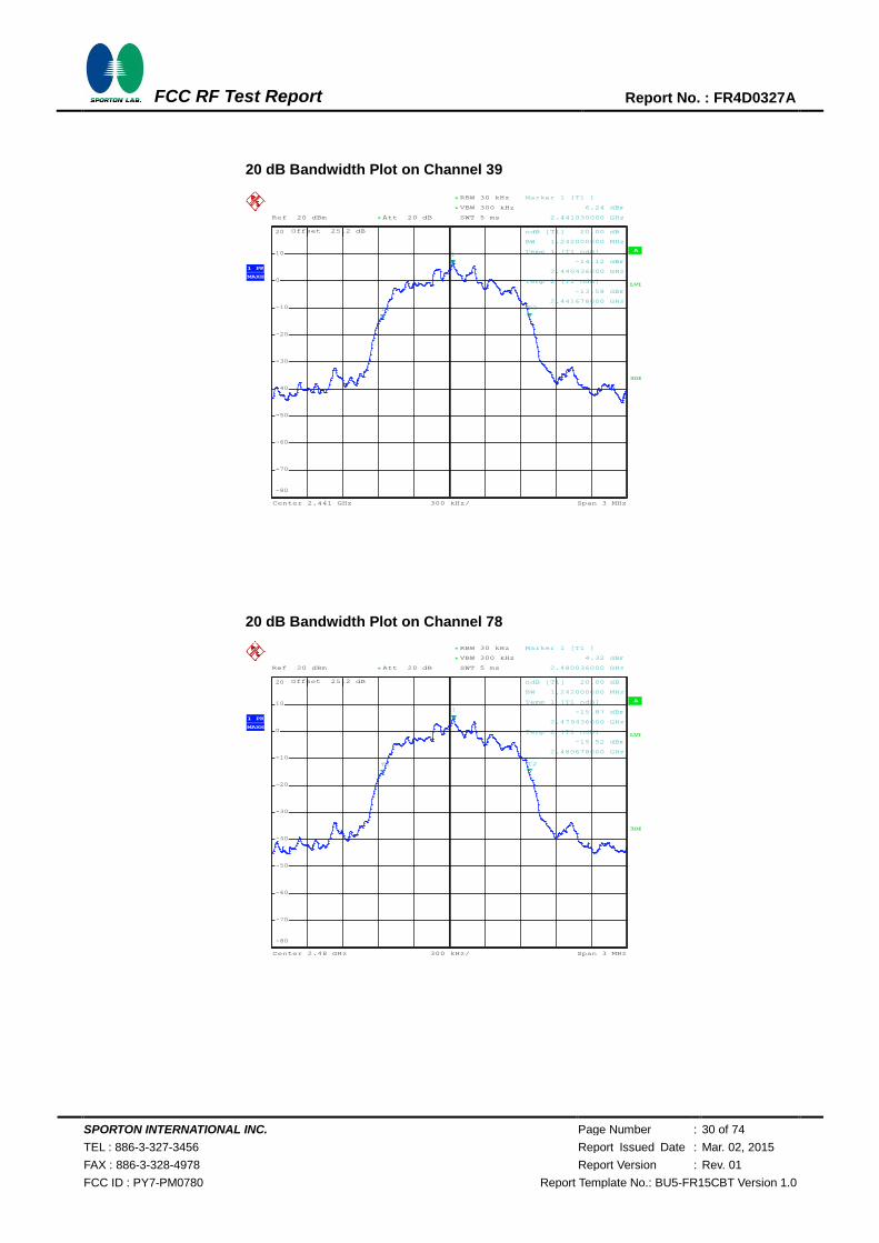
20 dB Bandwidth Plot on Channel 39
20 dB Bandwidth Plot on Channel 78
A
Offset 25.2 dB
LVL
Ref 20 dBm
Center 2.441 GHz Span 3 MHz300 kHz/
Att 20 dB*
3DB
RBW 30 kHz
SWT 5 ms
*
VBW 300 kHz*
1 PK
MAXH
-80
-70
-60
-50
-40
-30
-20
-10
0
10
20
1
Marker 1 [T1 ]
6.24 dBm
2.441030000 GHz
ndB [T1] 20.00 dB
BW 1.242000000 MHz
T1
Temp 1 [T1 ndB]
-14.12 dBm
2.440436000 GHz
T2
Temp 2 [T1 ndB]
-13.58 dBm
2.441678000 GHz
Date: 5.NOV.2014 01:36:46
A
Offset 25.2 dB
LVL
Ref 20 dBm
Center 2.48 GHz Span 3 MHz300 kHz/
Att 20 dB*
3DB
RBW 30 kHz
SWT 5 ms
*
VBW 300 kHz*
1 PK
MAXH
-80
-70
-60
-50
-40
-30
-20
-10
0
10
20
1
Marker 1 [T1 ]
4.32 dBm
2.480036000 GHz
ndB [T1] 20.00 dB
BW 1.242000000 MHz
T1
Temp 1 [T1 ndB]
-15.87 dBm
2.479436000 GHz
T2
Temp 2 [T1 ndB]
-15.52 dBm
2.480678000 GHz
Date: 5.NOV.2014 01:40:51
720510
720510
SPORTON INTERNATIONAL INC. Page Number : 31 of 74
TEL : 886-3-327-3456 Report Issued Date : Mar. 02, 2015
FAX : 886-3-328-4978 Report Version : Rev. 01
FCC ID : PY7-PM0780 Report Template No.: BU5-FR15CBT Version 1.0
FCC RF Test Report Report No. : FR4D0327A
3.5 Peak Output Power Measurement
3.5.1 Limit of Peak Output Power
Section 15.247 (b) The maximum peak conducted output power of the intentional radiator shall not
exceed the following: (1) For frequency hopping systems operating in the 2400-2483.5 MHz band
employing at least 75 non-overlapping hopping channels, and all frequency hopping systems in the
5725-5850 MHz band: 1 watt. For all other frequency hopping systems in the 2400-2483.5 MHz band
0.125 watts. The power limit for 1Mbps is 1watt, and for 2Mbps, 3Mbps and AFH are 0.125 watts.
3.5.2 Measuring Instruments
The measuring equipment is listed in the section 4 of this test report.
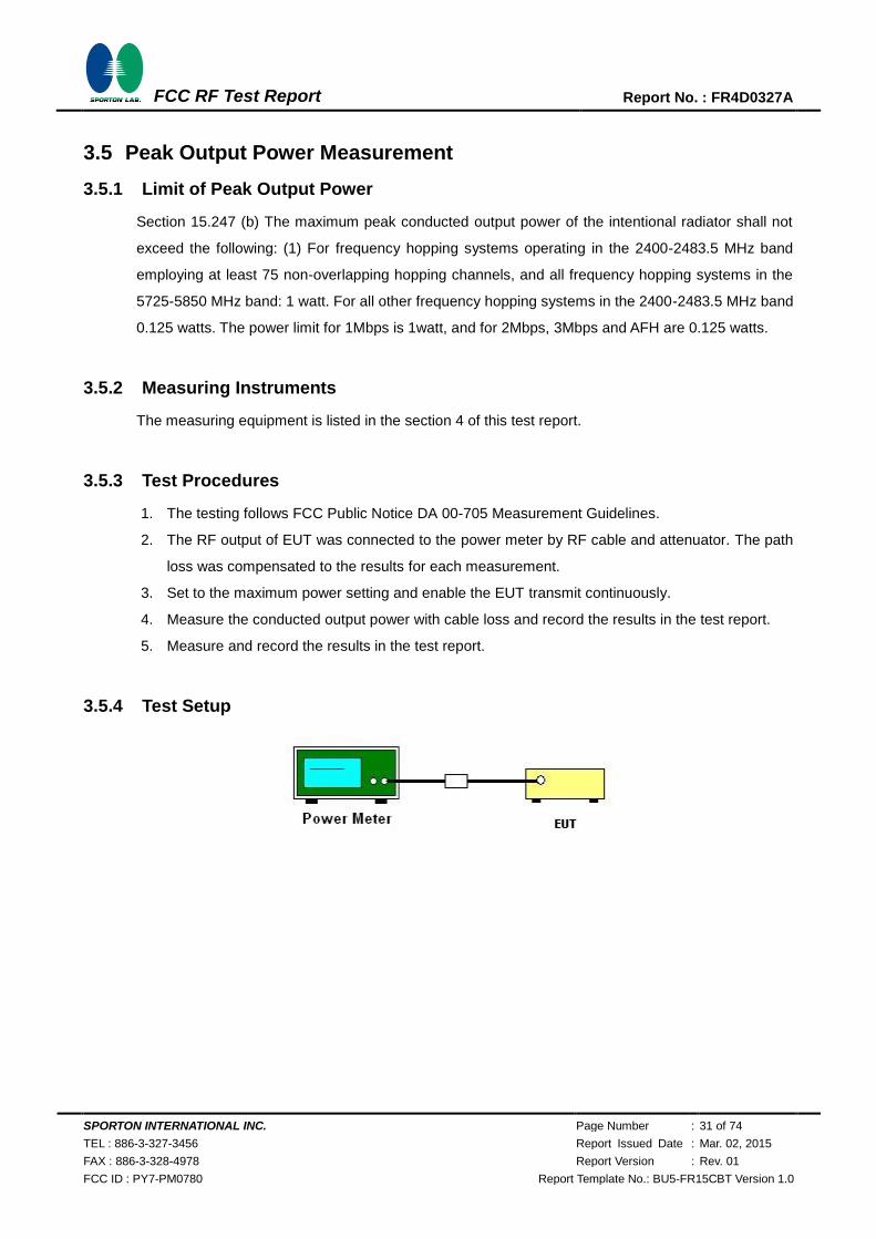
3.5.3 Test Procedures
1. The testing follows FCC Public Notice DA 00-705 Measurement Guidelines.
2. The RF output of EUT was connected to the power meter by RF cable and attenuator. The path
loss was compensated to the results for each measurement.
3. Set to the maximum power setting and enable the EUT transmit continuously.
4. Measure the conducted output power with cable loss and record the results in the test report.
5. Measure and record the results in the test report.
3.5.4 Test Setup
SPORTON INTERNATIONAL INC. Page Number : 32 of 74
TEL : 886-3-327-3456 Report Issued Date : Mar. 02, 2015
FAX : 886-3-328-4978 Report Version : Rev. 01
FCC ID : PY7-PM0780 Report Template No.: BU5-FR15CBT Version 1.0
FCC RF Test Report Report No. : FR4D0327A
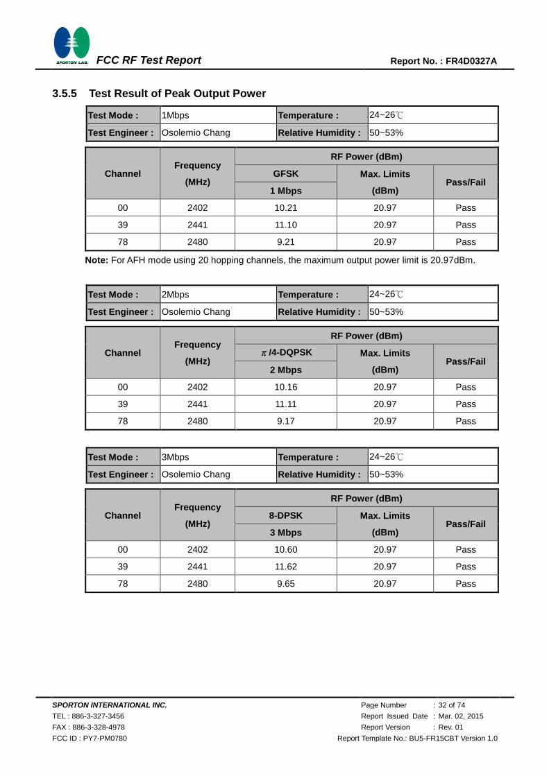
3.5.5 Test Result of Peak Output Power
Test Mode : 1Mbps Temperature : 24~26℃
Test Engineer : Osolemio Chang Relative Humidity : 50~53%
Channel Frequency
(MHz)
RF Power (dBm)
GFSK Max. Limits
(dBm) Pass/Fail
1 Mbps
00 2402 10.21 20.97 Pass
39 2441 11.10 20.97 Pass
78 2480 9.21 20.97 Pass
Note: For AFH mode using 20 hopping channels, the maximum output power limit is 20.97dBm.
Test Mode : 2Mbps Temperature : 24~26℃
Test Engineer : Osolemio Chang Relative Humidity : 50~53%
Channel Frequency
(MHz)
RF Power (dBm)
π/4-DQPSK Max. Limits
(dBm) Pass/Fail
2 Mbps
00 2402 10.16 20.97 Pass
39 2441 11.11 20.97 Pass
78 2480 9.17 20.97 Pass
Test Mode : 3Mbps Temperature : 24~26℃
Test Engineer : Osolemio Chang Relative Humidity : 50~53%
Channel Frequency
(MHz)
RF Power (dBm)
8-DPSK Max. Limits
(dBm) Pass/Fail
3 Mbps
00 2402 10.60 20.97 Pass
39 2441 11.62 20.97 Pass
78 2480 9.65 20.97 Pass
SPORTON INTERNATIONAL INC. Page Number : 33 of 74
TEL : 886-3-327-3456 Report Issued Date : Mar. 02, 2015
FAX : 886-3-328-4978 Report Version : Rev. 01
FCC ID : PY7-PM0780 Report Template No.: BU5-FR15CBT Version 1.0
FCC RF Test Report Report No. : FR4D0327A
3.6 Conducted Band Edges Measurement
3.6.1 Limit of Band Edges
In any 100 kHz bandwidth outside the intentional radiation frequency band, the radio frequency power
shall be at least 20 dB below the highest level of the radiated power. In addition, radiated emissions
which fall in the restricted bands must also comply with the radiated emission limits.
3.6.2 Measuring Instruments
The measuring equipment is listed in the section 4 of this test report.
3.6.3 Test Procedures
1. The testing follows the guidelines in Band-edge Compliance of RF Conducted Emissions of
FCC Public Notice DA 00-705 Measurement Guidelines.
2. Set to the maximum power setting and enable the EUT transmit continuously.
3. Set RBW = 100kHz ( 1% span=10MHz ), VBW = 300kHz ( RBW). Band edge emissions
must be at least 20 dB down from the highest emission level within the authorized band as
measured with a 100kHz RBW. The attenuation shall be 30 dB instead of 20 dB when RMS
conducted output power procedure is used.
4. Enable hopping function of the EUT and then repeat step 2. and 3.
5. Measure and record the results in the test report.
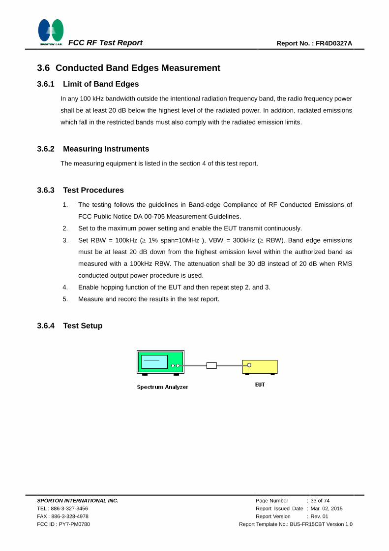
3.6.4 Test Setup
SPORTON INTERNATIONAL INC. Page Number : 34 of 74
TEL : 886-3-327-3456 Report Issued Date : Mar. 02, 2015
FAX : 886-3-328-4978 Report Version : Rev. 01
FCC ID : PY7-PM0780 Report Template No.: BU5-FR15CBT Version 1.0
FCC RF Test Report Report No. : FR4D0327A
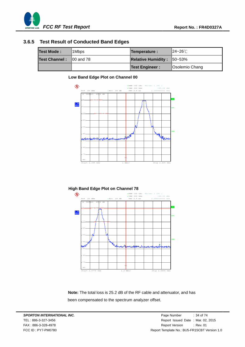
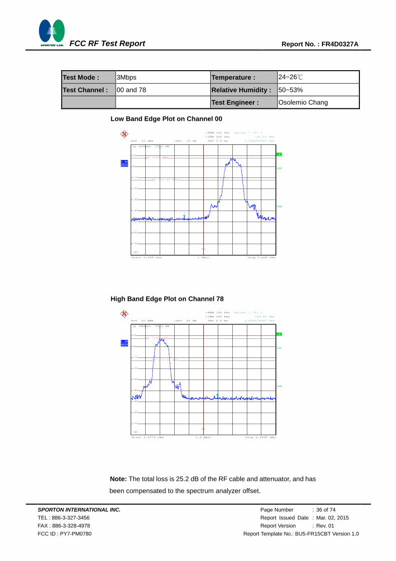
3.6.5 Test Result of Conducted Band Edges
Test Mode : 1Mbps Temperature : 24~26℃
Test Channel : 00 and 78 Relative Humidity : 50~53%
Test Engineer : Osolemio Chang
Low Band Edge Plot on Channel 00
High Band Edge Plot on Channel 78
Note: The total loss is 25.2 dB of the RF cable and attenuator, and has
been compensated to the spectrum analyzer offset.
A
Offset 25.2 dB
LVL
Ref 20 dBm Att 20 dB*
Start 2.395 GHz Stop 2.405 GHz1 MHz/
3DB
RBW 100 kHz
SWT 2.5 ms
*
VBW 300 kHz*
1 PK
MAXH
-80
-70
-60
-50
-40
-30
-20
-10
0
10
20
1
Marker 1 [T1 ]
-45.08 dBm
2.399940000 GHz
D1 9.4 dBm
D2 -10.6 dBm
F1
Date: 5.NOV.2014 01:51:04
A
Offset 25.2 dB
LVL
Ref 20 dBm Att 20 dB*
Start 2.4775 GHz Stop 2.4895 GHz1.2 MHz/
3DB
RBW 100 kHz
SWT 2.5 ms
*
VBW 300 kHz*
1 PK
MAXH
-80
-70
-60
-50
-40
-30
-20
-10
0
10
20
1
Marker 1 [T1 ]
-44.56 dBm
2.488036000 GHz
D1 8.76 dBm
D2 -11.24 dBm
F1
Date: 5.NOV.2014 01:51:32
720510
720510
SPORTON INTERNATIONAL INC. Page Number : 35 of 74
TEL : 886-3-327-3456 Report Issued Date : Mar. 02, 2015
FAX : 886-3-328-4978 Report Version : Rev. 01
FCC ID : PY7-PM0780 Report Template No.: BU5-FR15CBT Version 1.0
FCC RF Test Report Report No. : FR4D0327A
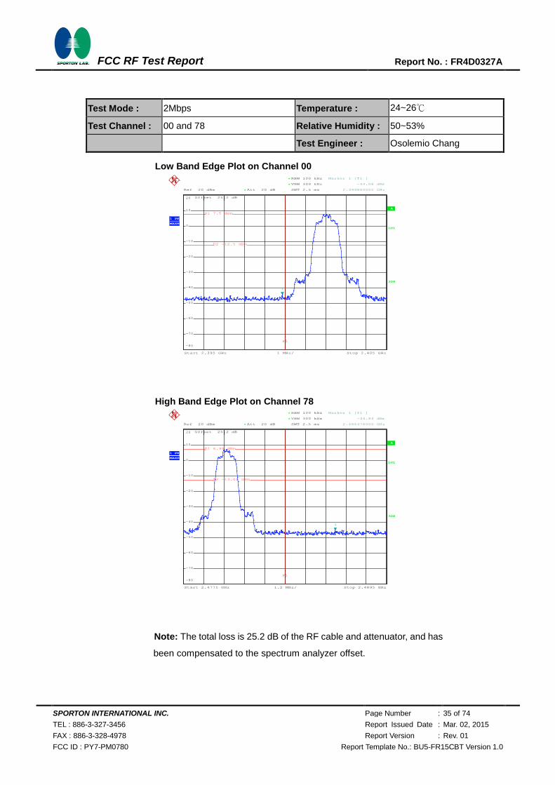
Test Mode : 2Mbps Temperature : 24~26℃
Test Channel : 00 and 78 Relative Humidity : 50~53%
Test Engineer : Osolemio Chang
Low Band Edge Plot on Channel 00
High Band Edge Plot on Channel 78
Note: The total loss is 25.2 dB of the RF cable and attenuator, and has
been compensated to the spectrum analyzer offset.
A
Offset 25.2 dB
LVL
Ref 20 dBm Att 20 dB*
Start 2.395 GHz Stop 2.405 GHz1 MHz/
3DB
RBW 100 kHz
SWT 2.5 ms
*
VBW 300 kHz*
1 PK
MAXH
-80
-70
-60
-50
-40
-30
-20
-10
0
10
20
1
Marker 1 [T1 ]
-44.08 dBm
2.399860000 GHz
D1 7.5 dBm
D2 -12.5 dBm
F1
Date: 5.NOV.2014 01:52:07
A
Offset 25.2 dB
LVL
Ref 20 dBm Att 20 dB*
Start 2.4775 GHz Stop 2.4895 GHz1.2 MHz/
3DB
RBW 100 kHz
SWT 2.5 ms
*
VBW 300 kHz*
1 PK
MAXH
-80
-70
-60
-50
-40
-30
-20
-10
0
10
20
1
Marker 1 [T1 ]
-44.84 dBm
2.486476000 GHz
D1 6.99 dBm
D2 -13.01 dBm
F1
Date: 5.NOV.2014 01:52:33
720510
720510
SPORTON INTERNATIONAL INC. Page Number : 36 of 74
TEL : 886-3-327-3456 Report Issued Date : Mar. 02, 2015
FAX : 886-3-328-4978 Report Version : Rev. 01
FCC ID : PY7-PM0780 Report Template No.: BU5-FR15CBT Version 1.0
FCC RF Test Report Report No. : FR4D0327A
Test Mode : 3Mbps Temperature : 24~26℃
Test Channel : 00 and 78 Relative Humidity : 50~53%
Test Engineer : Osolemio Chang
Low Band Edge Plot on Channel 00
High Band Edge Plot on Channel 78
Note: The total loss is 25.2 dB of the RF cable and attenuator, and has
been compensated to the spectrum analyzer offset.
A
Offset 25.2 dB
LVL
Ref 20 dBm Att 20 dB*
Start 2.395 GHz Stop 2.405 GHz1 MHz/
3DB
RBW 100 kHz
SWT 2.5 ms
*
VBW 300 kHz*
1 PK
MAXH
-80
-70
-60
-50
-40
-30
-20
-10
0
10
20
1
Marker 1 [T1 ]
-45.43 dBm
2.398680000 GHz
D1 7.57 dBm
D2 -12.43 dBm
F1
Date: 5.NOV.2014 01:53:20
A
Offset 25.2 dB
LVL
Ref 20 dBm Att 20 dB*
Start 2.4775 GHz Stop 2.4895 GHz1.2 MHz/
3DB
RBW 100 kHz
SWT 2.5 ms
*
VBW 300 kHz*
1 PK
MAXH
-80
-70
-60
-50
-40
-30
-20
-10
0
10
20
1
Marker 1 [T1 ]
-44.45 dBm
2.484676000 GHz
D1 7.05 dBm
D2 -12.95 dBm
F1
Date: 5.NOV.2014 01:53:46
720510
720510

SPORTON INTERNATIONAL INC. Page Number : 37 of 74
TEL : 886-3-327-3456 Report Issued Date : Mar. 02, 2015
FAX : 886-3-328-4978 Report Version : Rev. 01
FCC ID : PY7-PM0780 Report Template No.: BU5-FR15CBT Version 1.0
FCC RF Test Report Report No. : FR4D0327A
3.6.6 Test Result of Conducted Hopping Mode Band Edges
Test Mode : 1Mbps Temperature : 24~26℃
Test Engineer : Osolemio Chang Relative Humidity : 50~53%
1Mbps Hopping Mode Low Band Edge Plot
1Mbps Hopping Mode High Band Edge Plot
A
Offset 25.2 dB
LVL
Ref 20 dBm Att 20 dB*
Start 2.395 GHz Stop 2.405 GHz1 MHz/
3DB
RBW 100 kHz
SWT 2.5 ms
*
VBW 300 kHz*
1 PK
MAXH
-80
-70
-60
-50
-40
-30
-20
-10
0
10
20
1
Marker 1 [T1 ]
-45.23 dBm
2.395680000 GHz
D1 9.31 dBm
D2 -10.69 dBm
F1
Date: 5.NOV.2014 01:47:49
A
Offset 25.2 dB
LVL
Ref 20 dBm Att 20 dB*
Start 2.4775 GHz Stop 2.4895 GHz1.2 MHz/
3DB
RBW 100 kHz
SWT 2.5 ms
*
VBW 300 kHz*
1 PK
MAXH
-80
-70
-60
-50
-40
-30
-20
-10
0
10
20
1
Marker 1 [T1 ]
-45.05 dBm
2.487940000 GHz
D1 9.31 dBm
D2 -10.69 dBm
F1
Date: 5.NOV.2014 01:48:20
720510
720510
SPORTON INTERNATIONAL INC. Page Number : 38 of 74
TEL : 886-3-327-3456 Report Issued Date : Mar. 02, 2015
FAX : 886-3-328-4978 Report Version : Rev. 01
FCC ID : PY7-PM0780 Report Template No.: BU5-FR15CBT Version 1.0
FCC RF Test Report Report No. : FR4D0327A
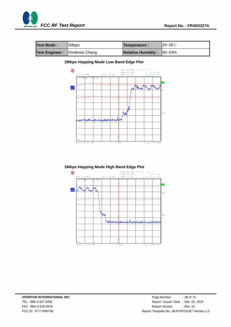
Test Mode : 2Mbps Temperature : 24~26℃
Test Engineer : Osolemio Chang Relative Humidity : 50~53%
2Mbps Hopping Mode Low Band Edge Plot
2Mbps Hopping Mode High Band Edge Plot
A
Offset 25.2 dB
LVL
Ref 20 dBm Att 20 dB*
Start 2.395 GHz Stop 2.405 GHz1 MHz/
3DB
RBW 100 kHz
SWT 2.5 ms
*
VBW 300 kHz*
1 PK
MAXH
-80
-70
-60
-50
-40
-30
-20
-10
0
10
20
1
Marker 1 [T1 ]
-44.49 dBm
2.399840000 GHz
D1 7.53 dBm
D2 -12.47 dBm
F1
Date: 5.NOV.2014 01:48:56
A
Offset 25.2 dB
LVL
Ref 20 dBm Att 20 dB*
Start 2.4775 GHz Stop 2.4895 GHz1.2 MHz/
3DB
RBW 100 kHz
SWT 2.5 ms
*
VBW 300 kHz*
1 PK
MAXH
-80
-70
-60
-50
-40
-30
-20
-10
0
10
20
1
Marker 1 [T1 ]
-45.20 dBm
2.485108000 GHz
D1 7.51 dBm
D2 -12.49 dBm
F1
Date: 5.NOV.2014 01:49:17
720510
720510
SPORTON INTERNATIONAL INC. Page Number : 39 of 74
TEL : 886-3-327-3456 Report Issued Date : Mar. 02, 2015
FAX : 886-3-328-4978 Report Version : Rev. 01
FCC ID : PY7-PM0780 Report Template No.: BU5-FR15CBT Version 1.0
FCC RF Test Report Report No. : FR4D0327A
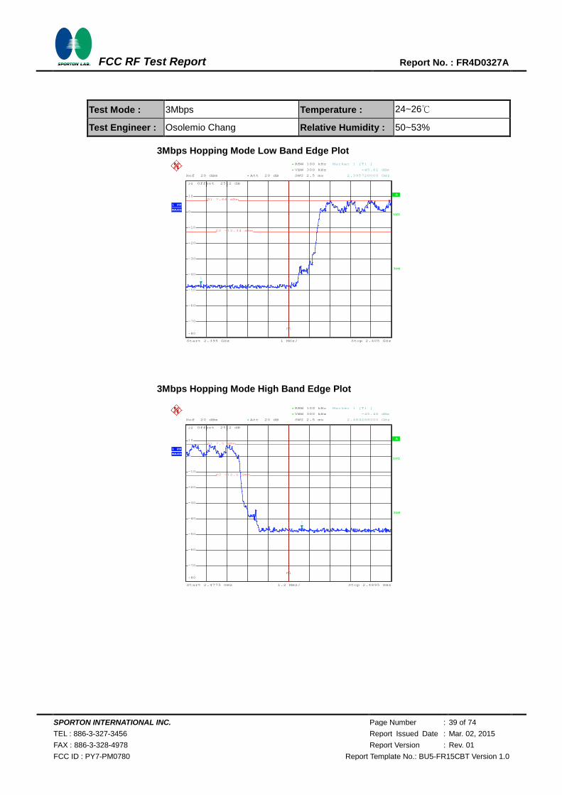
Test Mode : 3Mbps Temperature : 24~26℃
Test Engineer : Osolemio Chang Relative Humidity : 50~53%
3Mbps Hopping Mode Low Band Edge Plot
3Mbps Hopping Mode High Band Edge Plot
A
Offset 25.2 dB
LVL
Ref 20 dBm Att 20 dB*
Start 2.395 GHz Stop 2.405 GHz1 MHz/
3DB
RBW 100 kHz
SWT 2.5 ms
*
VBW 300 kHz*
1 PK
MAXH
-80
-70
-60
-50
-40
-30
-20
-10
0
10
20
1
Marker 1 [T1 ]
-45.61 dBm
2.395720000 GHz
D1 7.66 dBm
D2 -12.34 dBm
F1
Date: 5.NOV.2014 01:49:47
A
Offset 25.2 dB
LVL
Ref 20 dBm Att 20 dB*
Start 2.4775 GHz Stop 2.4895 GHz1.2 MHz/
3DB
RBW 100 kHz
SWT 2.5 ms
*
VBW 300 kHz*
1 PK
MAXH
-80
-70
-60
-50
-40
-30
-20
-10
0
10
20
1
Marker 1 [T1 ]
-45.46 dBm
2.484268000 GHz
D1 7.5 dBm
D2 -12.5 dBm
F1
Date: 5.NOV.2014 01:50:07
720510
720510
SPORTON INTERNATIONAL INC. Page Number : 40 of 74
TEL : 886-3-327-3456 Report Issued Date : Mar. 02, 2015
FAX : 886-3-328-4978 Report Version : Rev. 01
FCC ID : PY7-PM0780 Report Template No.: BU5-FR15CBT Version 1.0
FCC RF Test Report Report No. : FR4D0327A
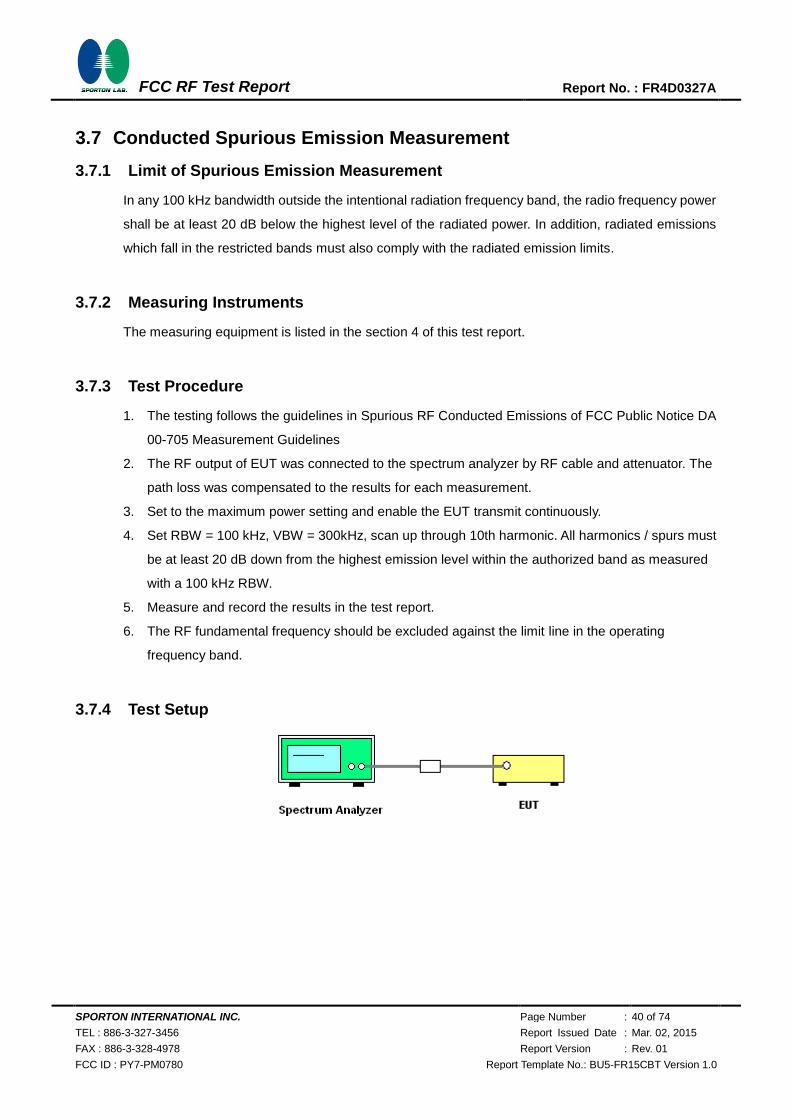
3.7 Conducted Spurious Emission Measurement
3.7.1 Limit of Spurious Emission Measurement
In any 100 kHz bandwidth outside the intentional radiation frequency band, the radio frequency power
shall be at least 20 dB below the highest level of the radiated power. In addition, radiated emissions
which fall in the restricted bands must also comply with the radiated emission limits.
3.7.2 Measuring Instruments
The measuring equipment is listed in the section 4 of this test report.
3.7.3 Test Procedure
1. The testing follows the guidelines in Spurious RF Conducted Emissions of FCC Public Notice DA
00-705 Measurement Guidelines
2. The RF output of EUT was connected to the spectrum analyzer by RF cable and attenuator. The
path loss was compensated to the results for each measurement.
3. Set to the maximum power setting and enable the EUT transmit continuously.
4. Set RBW = 100 kHz, VBW = 300kHz, scan up through 10th harmonic. All harmonics / spurs must
be at least 20 dB down from the highest emission level within the authorized band as measured
with a 100 kHz RBW.
5. Measure and record the results in the test report.
6. The RF fundamental frequency should be excluded against the limit line in the operating
frequency band.
3.7.4 Test Setup
SPORTON INTERNATIONAL INC. Page Number : 41 of 74
TEL : 886-3-327-3456 Report Issued Date : Mar. 02, 2015
FAX : 886-3-328-4978 Report Version : Rev. 01
FCC ID : PY7-PM0780 Report Template No.: BU5-FR15CBT Version 1.0
FCC RF Test Report Report No. : FR4D0327A
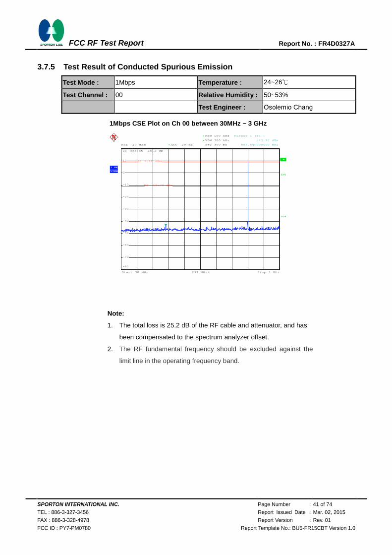
3.7.5 Test Result of Conducted Spurious Emission
Test Mode : 1Mbps Temperature : 24~26℃
Test Channel : 00 Relative Humidity : 50~53%
Test Engineer : Osolemio Chang
1Mbps CSE Plot on Ch 00 between 30MHz ~ 3 GHz
Note:
1. The total loss is 25.2 dB of the RF cable and attenuator, and has
been compensated to the spectrum analyzer offset.
2. The RF fundamental frequency should be excluded against the
limit line in the operating frequency band.
A
Att 20 dB*Ref 20 dBm
Offset 25.2 dB
LVL
297 MHz/Start 30 MHz Stop 3 GHz
*
*
3DB
RBW 100 kHz
VBW 300 kHz
SWT 300 ms
1 PK
VIEW
-80
-70
-60
-50
-40
-30
-20
-10
0
10
20
1
Marker 1 [T1 ]
-43.92 dBm
867.540000000 MHz
D1 9.22 dBm
D2 -10.78 dBm
Date: 5.NOV.2014 01:27:02
720510
SPORTON INTERNATIONAL INC. Page Number : 42 of 74
TEL : 886-3-327-3456 Report Issued Date : Mar. 02, 2015
FAX : 886-3-328-4978 Report Version : Rev. 01
FCC ID : PY7-PM0780 Report Template No.: BU5-FR15CBT Version 1.0
FCC RF Test Report Report No. : FR4D0327A
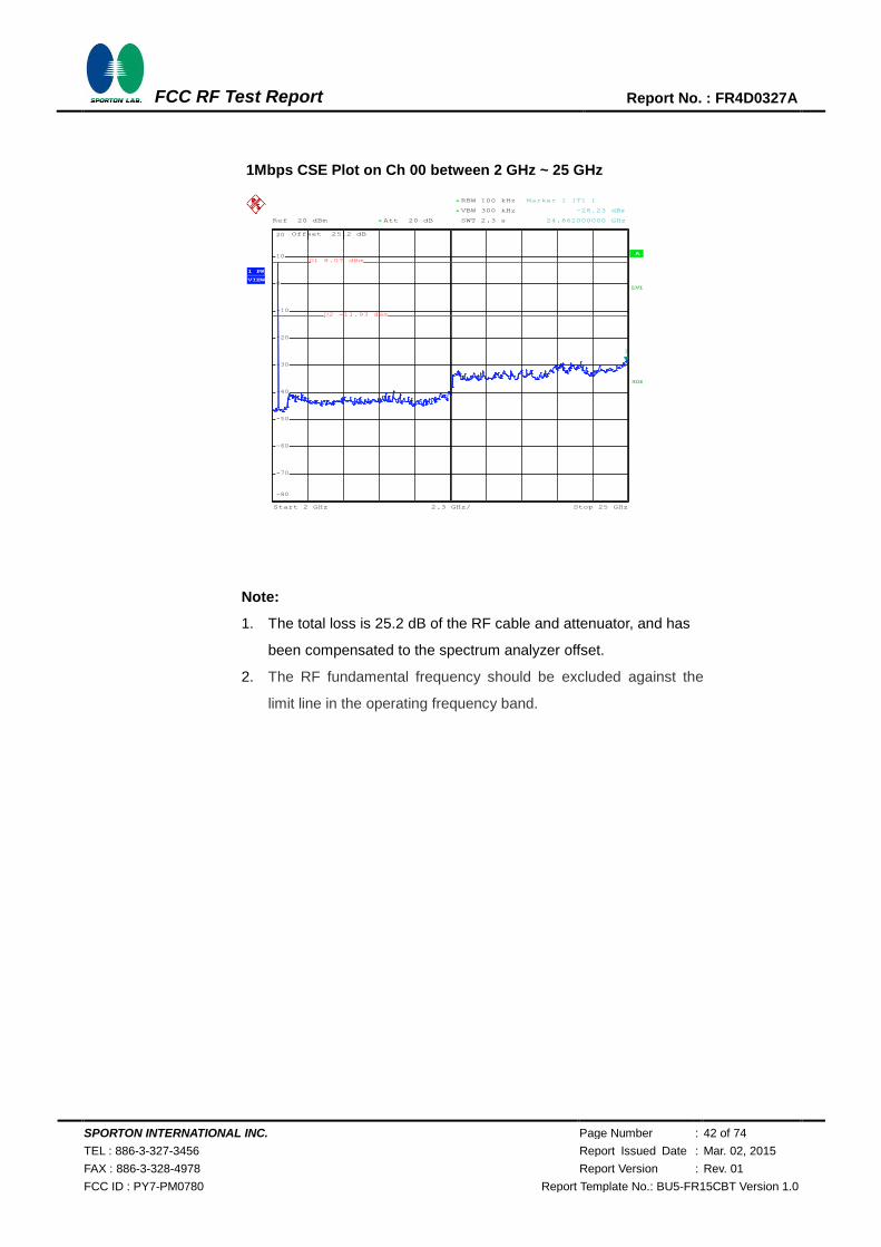
1Mbps CSE Plot on Ch 00 between 2 GHz ~ 25 GHz
Note:
1. The total loss is 25.2 dB of the RF cable and attenuator, and has
been compensated to the spectrum analyzer offset.
2. The RF fundamental frequency should be excluded against the
limit line in the operating frequency band.
A
Att 20 dB*Ref 20 dBm
Offset 25.2 dB
LVL
2.3 GHz/Start 2 GHz Stop 25 GHz
*
*
RBW 100 kHz
VBW 300 kHz
SWT 2.3 s
3DB
1 PK
VIEW
-80
-70
-60
-50
-40
-30
-20
-10
0
10
20
1
Marker 1 [T1 ]
-28.23 dBm
24.862000000 GHz
D1 8.07 dBm
D2 -11.93 dBm
Date: 5.NOV.2014 01:27:24
720510
SPORTON INTERNATIONAL INC. Page Number : 43 of 74
TEL : 886-3-327-3456 Report Issued Date : Mar. 02, 2015
FAX : 886-3-328-4978 Report Version : Rev. 01
FCC ID : PY7-PM0780 Report Template No.: BU5-FR15CBT Version 1.0
FCC RF Test Report Report No. : FR4D0327A
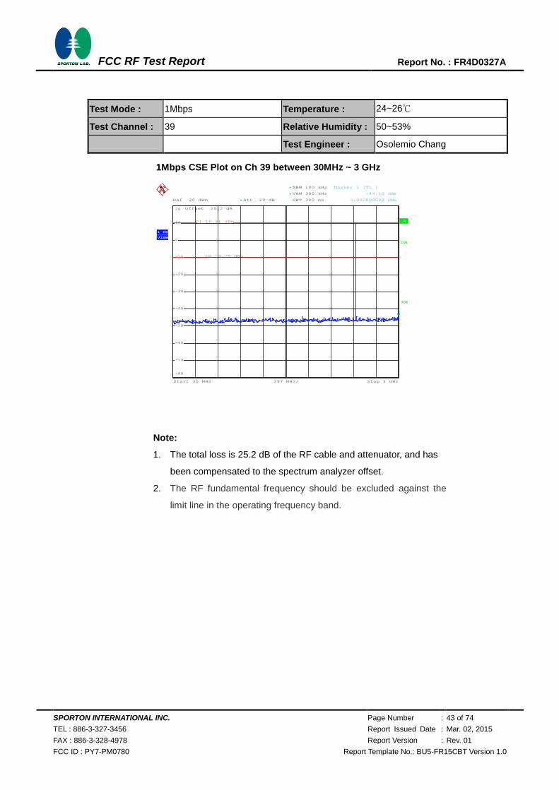
Test Mode : 1Mbps Temperature : 24~26℃
Test Channel : 39 Relative Humidity : 50~53%
Test Engineer : Osolemio Chang
1Mbps CSE Plot on Ch 39 between 30MHz ~ 3 GHz
Note:
1. The total loss is 25.2 dB of the RF cable and attenuator, and has
been compensated to the spectrum analyzer offset.
2. The RF fundamental frequency should be excluded against the
limit line in the operating frequency band.
A
Att 20 dB*Ref 20 dBm
Offset 25.2 dB
LVL
297 MHz/Start 30 MHz Stop 3 GHz
*
*
3DB
RBW 100 kHz
VBW 300 kHz
SWT 300 ms
1 PK
VIEW
-80
-70
-60
-50
-40
-30
-20
-10
0
10
20
1
Marker 1 [T1 ]
-44.10 dBm
3.000000000 GHz
D1 10.21 dBm
D2 -9.79 dBm
Date: 5.NOV.2014 01:25:06
720510
SPORTON INTERNATIONAL INC. Page Number : 44 of 74
TEL : 886-3-327-3456 Report Issued Date : Mar. 02, 2015
FAX : 886-3-328-4978 Report Version : Rev. 01
FCC ID : PY7-PM0780 Report Template No.: BU5-FR15CBT Version 1.0
FCC RF Test Report Report No. : FR4D0327A
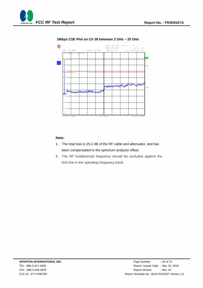
1Mbps CSE Plot on Ch 39 between 2 GHz ~ 25 GHz
Note:
1. The total loss is 25.2 dB of the RF cable and attenuator, and has
been compensated to the spectrum analyzer offset.
2. The RF fundamental frequency should be excluded against the
limit line in the operating frequency band.
A
Att 20 dB*Ref 20 dBm
Offset 25.2 dB
LVL
2.3 GHz/Start 2 GHz Stop 25 GHz
*
*
RBW 100 kHz
VBW 300 kHz
SWT 2.3 s
3DB
1 PK
VIEW
-80
-70
-60
-50
-40
-30
-20
-10
0
10
20
1
Marker 1 [T1 ]
-28.22 dBm
24.908000000 GHz
D1 8.37 dBm
D2 -11.63 dBm
Date: 5.NOV.2014 01:25:27
720510

SPORTON INTERNATIONAL INC. Page Number : 45 of 74
TEL : 886-3-327-3456 Report Issued Date : Mar. 02, 2015
FAX : 886-3-328-4978 Report Version : Rev. 01
FCC ID : PY7-PM0780 Report Template No.: BU5-FR15CBT Version 1.0
FCC RF Test Report Report No. : FR4D0327A
Test Mode : 1Mbps Temperature : 24~26℃
Test Channel : 78 Relative Humidity : 50~53%
Test Engineer : Osolemio Chang
1Mbps CSE Plot on Ch 78 between 30MHz ~ 3 GHz
Note:
1. The total loss is 25.2 dB of the RF cable and attenuator, and has
been compensated to the spectrum analyzer offset.
2. The RF fundamental frequency should be excluded against the
limit line in the operating frequency band.
A
Att 20 dB*Ref 20 dBm
Offset 25.2 dB
LVL
297 MHz/Start 30 MHz Stop 3 GHz
*
*
3DB
RBW 100 kHz
VBW 300 kHz
SWT 300 ms
1 PK
VIEW
-80
-70
-60
-50
-40
-30
-20
-10
0
10
20
1
Marker 1 [T1 ]
-43.38 dBm
2.833680000 GHz
D1 8.75 dBm
D2 -11.25 dBm
Date: 5.NOV.2014 01:28:59
720510

SPORTON INTERNATIONAL INC. Page Number : 46 of 74
TEL : 886-3-327-3456 Report Issued Date : Mar. 02, 2015
FAX : 886-3-328-4978 Report Version : Rev. 01
FCC ID : PY7-PM0780 Report Template No.: BU5-FR15CBT Version 1.0
FCC RF Test Report Report No. : FR4D0327A
1Mbps CSE Plot on Ch 78 between 2 GHz ~ 25 GHz
Note:
1. The total loss is 25.2 dB of the RF cable and attenuator, and has
been compensated to the spectrum analyzer offset.
2. The RF fundamental frequency should be excluded against the
limit line in the operating frequency band.
A
Att 20 dB*Ref 20 dBm
Offset 25.2 dB
LVL
2.3 GHz/Start 2 GHz Stop 25 GHz
*
*
RBW 100 kHz
VBW 300 kHz
SWT 2.3 s
3DB
1 PK
VIEW
-80
-70
-60
-50
-40
-30
-20
-10
0
10
20
1
Marker 1 [T1 ]
-28.60 dBm
24.954000000 GHz
D1 7.42 dBm
D2 -12.58 dBm
Date: 5.NOV.2014 01:29:20
720510
SPORTON INTERNATIONAL INC. Page Number : 47 of 74
TEL : 886-3-327-3456 Report Issued Date : Mar. 02, 2015
FAX : 886-3-328-4978 Report Version : Rev. 01
FCC ID : PY7-PM0780 Report Template No.: BU5-FR15CBT Version 1.0
FCC RF Test Report Report No. : FR4D0327A
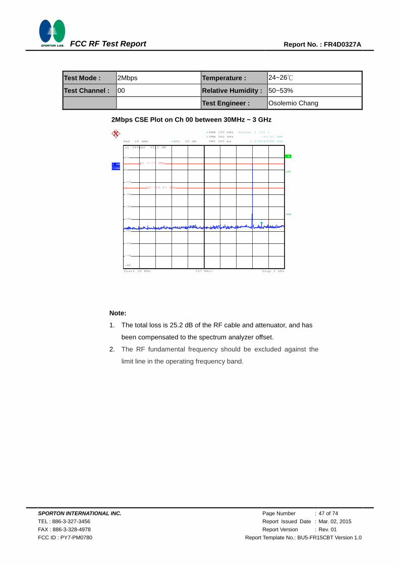
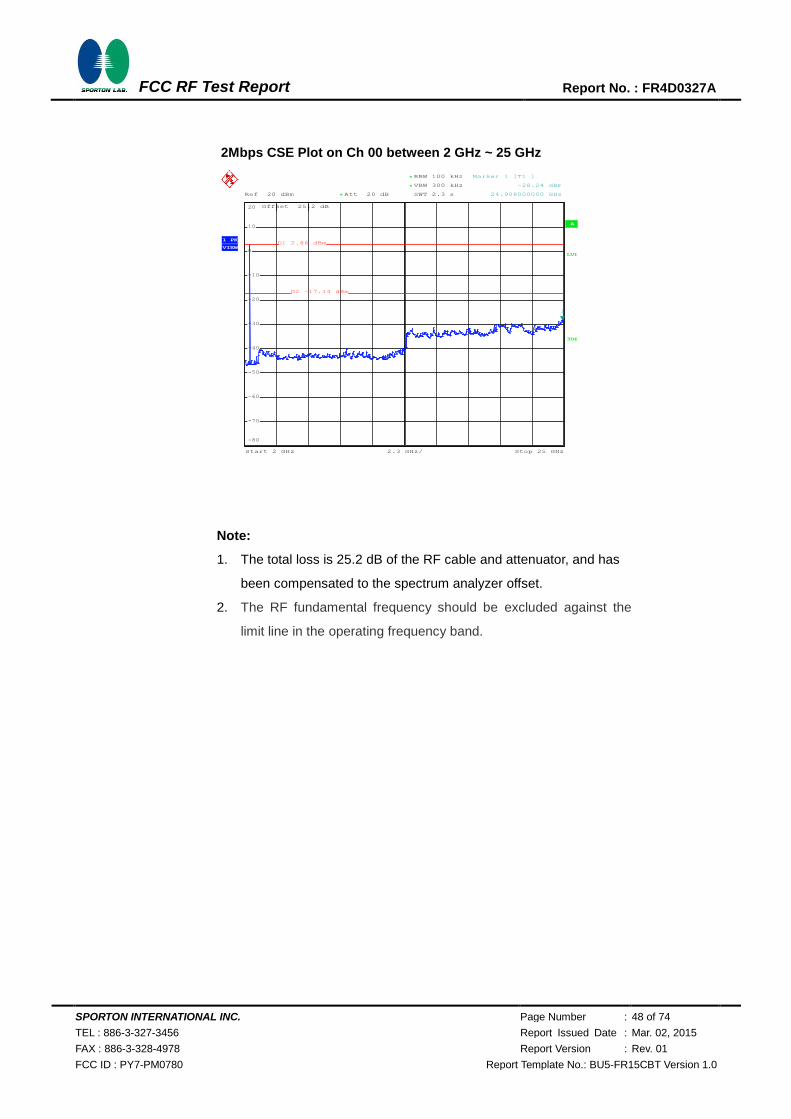
Test Mode : 2Mbps Temperature : 24~26℃
Test Channel : 00 Relative Humidity : 50~53%
Test Engineer : Osolemio Chang
2Mbps CSE Plot on Ch 00 between 30MHz ~ 3 GHz
Note:
1. The total loss is 25.2 dB of the RF cable and attenuator, and has
been compensated to the spectrum analyzer offset.
2. The RF fundamental frequency should be excluded against the
limit line in the operating frequency band.
A
Att 20 dB*Ref 20 dBm
Offset 25.2 dB
LVL
297 MHz/Start 30 MHz Stop 3 GHz
*
*
3DB
RBW 100 kHz
VBW 300 kHz
SWT 300 ms
1 PK
VIEW
-80
-70
-60
-50
-40
-30
-20
-10
0
10
20
1
Marker 1 [T1 ]
-44.01 dBm
2.578260000 GHz
D1 5.17 dBm
D2 -14.83 dBm
Date: 5.NOV.2014 01:31:43
720510
SPORTON INTERNATIONAL INC. Page Number : 48 of 74
TEL : 886-3-327-3456 Report Issued Date : Mar. 02, 2015
FAX : 886-3-328-4978 Report Version : Rev. 01
FCC ID : PY7-PM0780 Report Template No.: BU5-FR15CBT Version 1.0
FCC RF Test Report Report No. : FR4D0327A
2Mbps CSE Plot on Ch 00 between 2 GHz ~ 25 GHz
Note:
1. The total loss is 25.2 dB of the RF cable and attenuator, and has
been compensated to the spectrum analyzer offset.
2. The RF fundamental frequency should be excluded against the
limit line in the operating frequency band.
A
Att 20 dB*Ref 20 dBm
Offset 25.2 dB
LVL
2.3 GHz/Start 2 GHz Stop 25 GHz
*
*
RBW 100 kHz
VBW 300 kHz
SWT 2.3 s
3DB
1 PK
VIEW
-80
-70
-60
-50
-40
-30
-20
-10
0
10
20
1
Marker 1 [T1 ]
-28.24 dBm
24.908000000 GHz
D1 2.86 dBm
D2 -17.14 dBm
Date: 5.NOV.2014 01:32:05
720510

SPORTON INTERNATIONAL INC. Page Number : 49 of 74
TEL : 886-3-327-3456 Report Issued Date : Mar. 02, 2015
FAX : 886-3-328-4978 Report Version : Rev. 01
FCC ID : PY7-PM0780 Report Template No.: BU5-FR15CBT Version 1.0
FCC RF Test Report Report No. : FR4D0327A
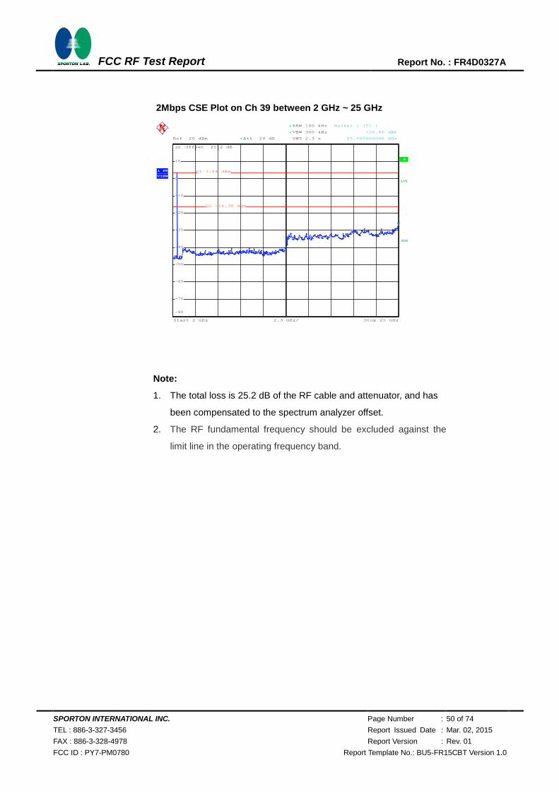
Test Mode : 2Mbps Temperature : 24~26℃
Test Channel : 39 Relative Humidity : 50~53%
Test Engineer : Osolemio Chang
2Mbps CSE Plot on Ch 39 between 30MHz ~ 3 GHz
Note:
1. The total loss is 25.2 dB of the RF cable and attenuator, and has
been compensated to the spectrum analyzer offset.
2. The RF fundamental frequency should be excluded against the
limit line in the operating frequency band.
A
Att 20 dB*Ref 20 dBm
Offset 25.2 dB
LVL
297 MHz/Start 30 MHz Stop 3 GHz
*
*
3DB
RBW 100 kHz
VBW 300 kHz
SWT 300 ms
1 PK
VIEW
-80
-70
-60
-50
-40
-30
-20
-10
0
10
20
1
Marker 1 [T1 ]
-43.82 dBm
2.970300000 GHz
D1 6.49 dBm
D2 -13.51 dBm
Date: 5.NOV.2014 01:33:39
720510
SPORTON INTERNATIONAL INC. Page Number : 50 of 74
TEL : 886-3-327-3456 Report Issued Date : Mar. 02, 2015
FAX : 886-3-328-4978 Report Version : Rev. 01
FCC ID : PY7-PM0780 Report Template No.: BU5-FR15CBT Version 1.0
FCC RF Test Report Report No. : FR4D0327A
2Mbps CSE Plot on Ch 39 between 2 GHz ~ 25 GHz
Note:
1. The total loss is 25.2 dB of the RF cable and attenuator, and has
been compensated to the spectrum analyzer offset.
2. The RF fundamental frequency should be excluded against the
limit line in the operating frequency band.
A
Att 20 dB*Ref 20 dBm
Offset 25.2 dB
LVL
2.3 GHz/Start 2 GHz Stop 25 GHz
*
*
RBW 100 kHz
VBW 300 kHz
SWT 2.3 s
3DB
1 PK
VIEW
-80
-70
-60
-50
-40
-30
-20
-10
0
10
20
1
Marker 1 [T1 ]
-26.86 dBm
25.000000000 GHz
D1 3.64 dBm
D2 -16.36 dBm
Date: 5.NOV.2014 01:34:01
720510

SPORTON INTERNATIONAL INC. Page Number : 51 of 74
TEL : 886-3-327-3456 Report Issued Date : Mar. 02, 2015
FAX : 886-3-328-4978 Report Version : Rev. 01
FCC ID : PY7-PM0780 Report Template No.: BU5-FR15CBT Version 1.0
FCC RF Test Report Report No. : FR4D0327A
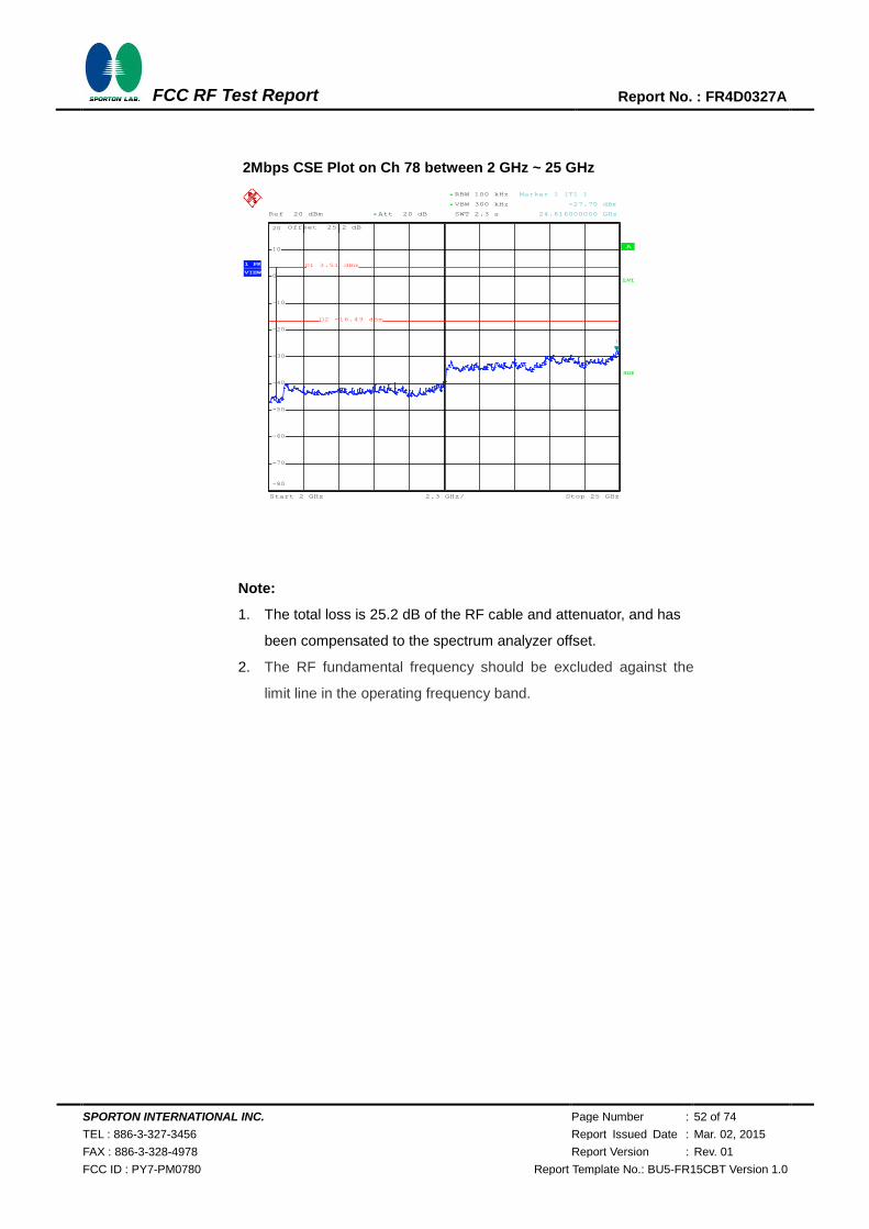
Test Mode : 2Mbps Temperature : 24~26℃
Test Channel : 78 Relative Humidity : 50~53%
Test Engineer : Osolemio Chang
2Mbps CSE Plot on Ch 78 between 30MHz ~ 3 GHz
Note:
1. The total loss is 25.2 dB of the RF cable and attenuator, and has
been compensated to the spectrum analyzer offset.
2. The RF fundamental frequency should be excluded against the
limit line in the operating frequency band.
A
Att 20 dB*Ref 20 dBm
Offset 25.2 dB
LVL
297 MHz/Start 30 MHz Stop 3 GHz
*
*
3DB
RBW 100 kHz
VBW 300 kHz
SWT 300 ms
1 PK
VIEW
-80
-70
-60
-50
-40
-30
-20
-10
0
10
20
1
Marker 1 [T1 ]
-43.72 dBm
1.711020000 GHz
D1 6.09 dBm
D2 -13.91 dBm
Date: 5.NOV.2014 01:35:43
720510
SPORTON INTERNATIONAL INC. Page Number : 52 of 74
TEL : 886-3-327-3456 Report Issued Date : Mar. 02, 2015
FAX : 886-3-328-4978 Report Version : Rev. 01
FCC ID : PY7-PM0780 Report Template No.: BU5-FR15CBT Version 1.0
FCC RF Test Report Report No. : FR4D0327A
2Mbps CSE Plot on Ch 78 between 2 GHz ~ 25 GHz
Note:
1. The total loss is 25.2 dB of the RF cable and attenuator, and has
been compensated to the spectrum analyzer offset.
2. The RF fundamental frequency should be excluded against the
limit line in the operating frequency band.
A
Att 20 dB*Ref 20 dBm
Offset 25.2 dB
LVL
2.3 GHz/Start 2 GHz Stop 25 GHz
*
*
RBW 100 kHz
VBW 300 kHz
SWT 2.3 s
3DB
1 PK
VIEW
-80
-70
-60
-50
-40
-30
-20
-10
0
10
20
1
Marker 1 [T1 ]
-27.70 dBm
24.816000000 GHz
D1 3.51 dBm
D2 -16.49 dBm
Date: 5.NOV.2014 01:36:05
720510
SPORTON INTERNATIONAL INC. Page Number : 53 of 74
TEL : 886-3-327-3456 Report Issued Date : Mar. 02, 2015
FAX : 886-3-328-4978 Report Version : Rev. 01
FCC ID : PY7-PM0780 Report Template No.: BU5-FR15CBT Version 1.0
FCC RF Test Report Report No. : FR4D0327A
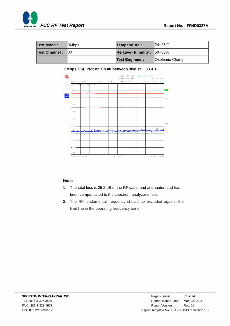
Test Mode : 3Mbps Temperature : 24~26℃
Test Channel : 00 Relative Humidity : 50~53%
Test Engineer : Osolemio Chang
3Mbps CSE Plot on Ch 00 between 30MHz ~ 3 GHz
Note:
1. The total loss is 25.2 dB of the RF cable and attenuator, and has
been compensated to the spectrum analyzer offset.
2. The RF fundamental frequency should be excluded against the
limit line in the operating frequency band.
A
Att 20 dB*Ref 20 dBm
Offset 25.2 dB
LVL
297 MHz/Start 30 MHz Stop 3 GHz
*
*
3DB
RBW 100 kHz
VBW 300 kHz
SWT 300 ms
1 PK
VIEW
-80
-70
-60
-50
-40
-30
-20
-10
0
10
20
1
Marker 1 [T1 ]
-44.60 dBm
2.780220000 GHz
D1 6.27 dBm
D2 -13.73 dBm
Date: 5.NOV.2014 01:39:49
720510
SPORTON INTERNATIONAL INC. Page Number : 54 of 74
TEL : 886-3-327-3456 Report Issued Date : Mar. 02, 2015
FAX : 886-3-328-4978 Report Version : Rev. 01
FCC ID : PY7-PM0780 Report Template No.: BU5-FR15CBT Version 1.0
FCC RF Test Report Report No. : FR4D0327A
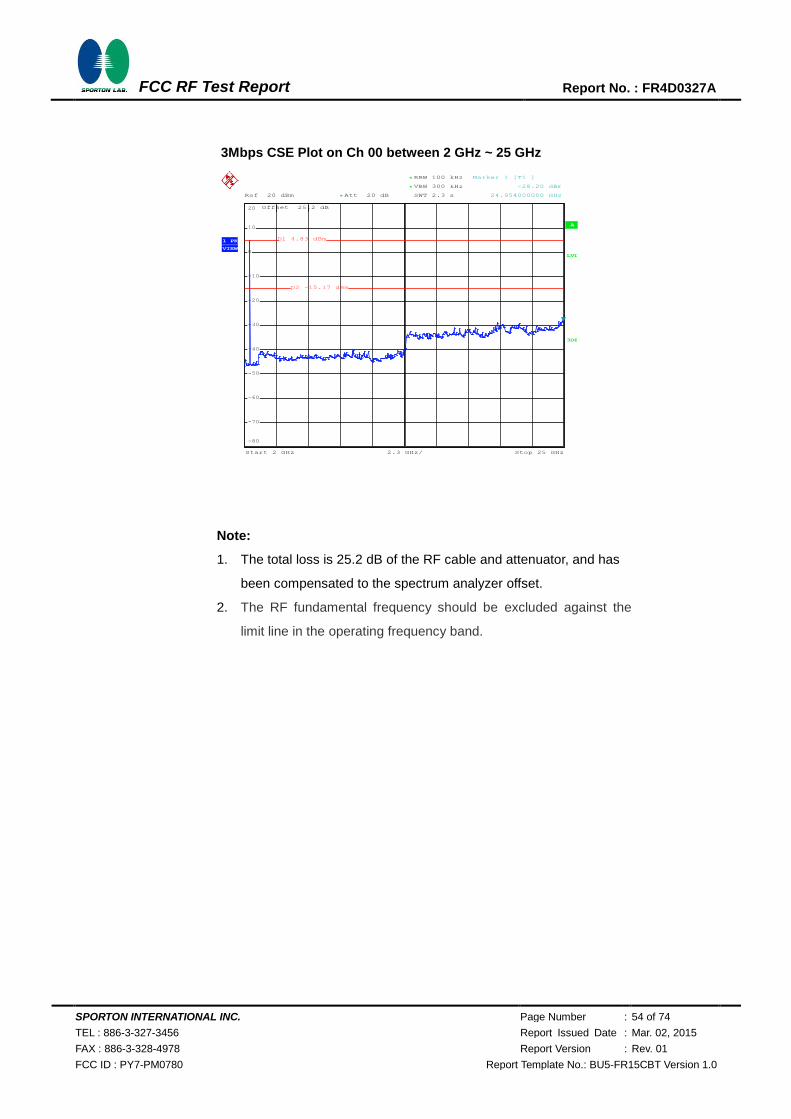
3Mbps CSE Plot on Ch 00 between 2 GHz ~ 25 GHz
Note:
1. The total loss is 25.2 dB of the RF cable and attenuator, and has
been compensated to the spectrum analyzer offset.
2. The RF fundamental frequency should be excluded against the
limit line in the operating frequency band.
A
Att 20 dB*Ref 20 dBm
Offset 25.2 dB
LVL
2.3 GHz/Start 2 GHz Stop 25 GHz
*
*
RBW 100 kHz
VBW 300 kHz
SWT 2.3 s
3DB
1 PK
VIEW
-80
-70
-60
-50
-40
-30
-20
-10
0
10
20
1
Marker 1 [T1 ]
-28.20 dBm
24.954000000 GHz
D1 4.83 dBm
D2 -15.17 dBm
Date: 5.NOV.2014 01:40:10
720510
SPORTON INTERNATIONAL INC. Page Number : 55 of 74
TEL : 886-3-327-3456 Report Issued Date : Mar. 02, 2015
FAX : 886-3-328-4978 Report Version : Rev. 01
FCC ID : PY7-PM0780 Report Template No.: BU5-FR15CBT Version 1.0
FCC RF Test Report Report No. : FR4D0327A
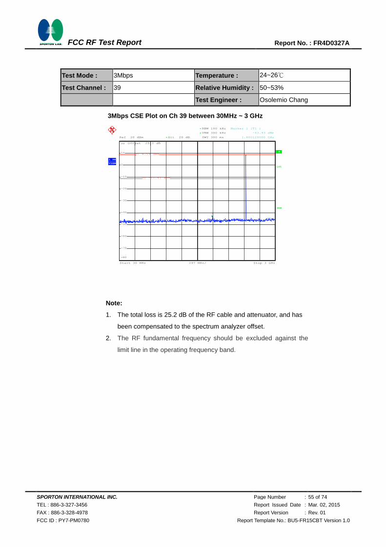
Test Mode : 3Mbps Temperature : 24~26℃
Test Channel : 39 Relative Humidity : 50~53%
Test Engineer : Osolemio Chang
3Mbps CSE Plot on Ch 39 between 30MHz ~ 3 GHz
Note:
1. The total loss is 25.2 dB of the RF cable and attenuator, and has
been compensated to the spectrum analyzer offset.
2. The RF fundamental frequency should be excluded against the
limit line in the operating frequency band.
A
Att 20 dB*Ref 20 dBm
Offset 25.2 dB
LVL
297 MHz/Start 30 MHz Stop 3 GHz
*
*
3DB
RBW 100 kHz
VBW 300 kHz
SWT 300 ms
1 PK
VIEW
-80
-70
-60
-50
-40
-30
-20
-10
0
10
20
1
Marker 1 [T1 ]
-43.93 dBm
1.800120000 GHz
D1 8.59 dBm
D2 -11.41 dBm
Date: 5.NOV.2014 01:37:51
720510
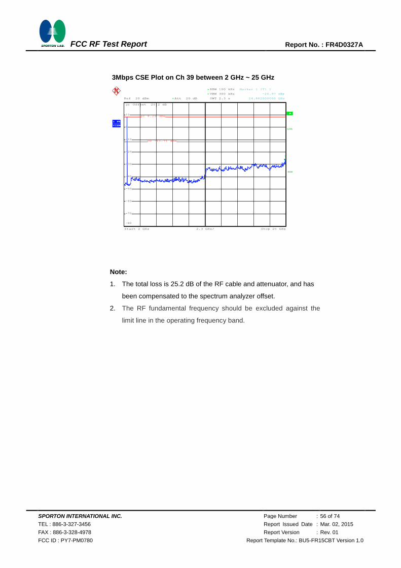
SPORTON INTERNATIONAL INC. Page Number : 56 of 74
TEL : 886-3-327-3456 Report Issued Date : Mar. 02, 2015
FAX : 886-3-328-4978 Report Version : Rev. 01
FCC ID : PY7-PM0780 Report Template No.: BU5-FR15CBT Version 1.0
FCC RF Test Report Report No. : FR4D0327A
3Mbps CSE Plot on Ch 39 between 2 GHz ~ 25 GHz
Note:
1. The total loss is 25.2 dB of the RF cable and attenuator, and has
been compensated to the spectrum analyzer offset.
2. The RF fundamental frequency should be excluded against the
limit line in the operating frequency band.
A
Att 20 dB*Ref 20 dBm
Offset 25.2 dB
LVL
2.3 GHz/Start 2 GHz Stop 25 GHz
*
*
RBW 100 kHz
VBW 300 kHz
SWT 2.3 s
3DB
1 PK
VIEW
-80
-70
-60
-50
-40
-30
-20
-10
0
10
20
1
Marker 1 [T1 ]
-26.97 dBm
24.862000000 GHz
D1 8.29 dBm
D2 -11.71 dBm
Date: 5.NOV.2014 01:38:13
720510
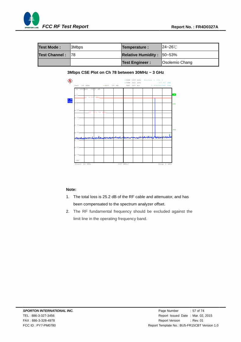
SPORTON INTERNATIONAL INC. Page Number : 57 of 74
TEL : 886-3-327-3456 Report Issued Date : Mar. 02, 2015
FAX : 886-3-328-4978 Report Version : Rev. 01
FCC ID : PY7-PM0780 Report Template No.: BU5-FR15CBT Version 1.0
FCC RF Test Report Report No. : FR4D0327A
Test Mode : 3Mbps Temperature : 24~26℃
Test Channel : 78 Relative Humidity : 50~53%
Test Engineer : Osolemio Chang
3Mbps CSE Plot on Ch 78 between 30MHz ~ 3 GHz
Note:
1. The total loss is 25.2 dB of the RF cable and attenuator, and has
been compensated to the spectrum analyzer offset.
2. The RF fundamental frequency should be excluded against the
limit line in the operating frequency band.
A
Att 20 dB*Ref 20 dBm
Offset 25.2 dB
LVL
297 MHz/Start 30 MHz Stop 3 GHz
*
*
3DB
RBW 100 kHz
VBW 300 kHz
SWT 300 ms
1 PK
VIEW
-80
-70
-60
-50
-40
-30
-20
-10
0
10
20
1
Marker 1 [T1 ]
-44.02 dBm
2.934660000 GHz
D1 6.62 dBm
D2 -13.38 dBm
Date: 5.NOV.2014 01:41:51
720510
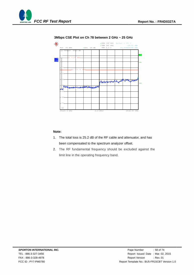
SPORTON INTERNATIONAL INC. Page Number : 58 of 74
TEL : 886-3-327-3456 Report Issued Date : Mar. 02, 2015
FAX : 886-3-328-4978 Report Version : Rev. 01
FCC ID : PY7-PM0780 Report Template No.: BU5-FR15CBT Version 1.0
FCC RF Test Report Report No. : FR4D0327A
3Mbps CSE Plot on Ch 78 between 2 GHz ~ 25 GHz
Note:
1. The total loss is 25.2 dB of the RF cable and attenuator, and has
been compensated to the spectrum analyzer offset.
2. The RF fundamental frequency should be excluded against the
limit line in the operating frequency band.
A
Att 20 dB*Ref 20 dBm
Offset 25.2 dB
LVL
2.3 GHz/Start 2 GHz Stop 25 GHz
*
*
RBW 100 kHz
VBW 300 kHz
SWT 2.3 s
3DB
1 PK
VIEW
-80
-70
-60
-50
-40
-30
-20
-10
0
10
20
1
Marker 1 [T1 ]
-28.50 dBm
24.908000000 GHz
D1 6.28 dBm
D2 -13.72 dBm
Date: 5.NOV.2014 01:42:12
720510
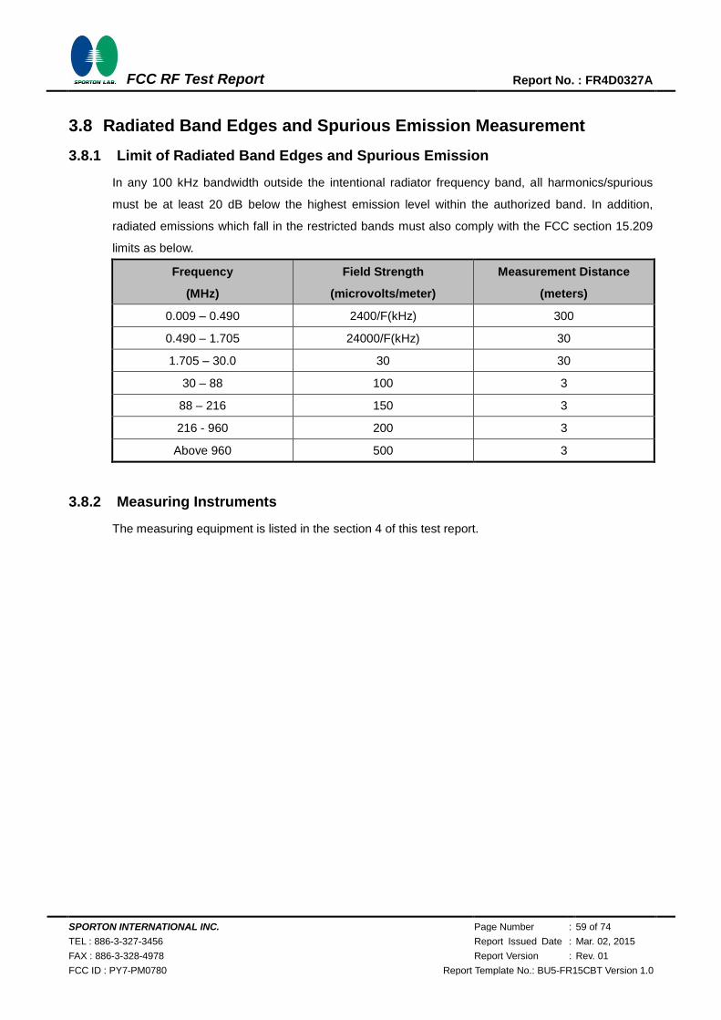
SPORTON INTERNATIONAL INC. Page Number : 59 of 74
TEL : 886-3-327-3456 Report Issued Date : Mar. 02, 2015
FAX : 886-3-328-4978 Report Version : Rev. 01
FCC ID : PY7-PM0780 Report Template No.: BU5-FR15CBT Version 1.0
FCC RF Test Report Report No. : FR4D0327A
3.8 Radiated Band Edges and Spurious Emission Measurement
3.8.1 Limit of Radiated Band Edges and Spurious Emission
In any 100 kHz bandwidth outside the intentional radiator frequency band, all harmonics/spurious
must be at least 20 dB below the highest emission level within the authorized band. In addition,
radiated emissions which fall in the restricted bands must also comply with the FCC section 15.209
limits as below.
Frequency
(MHz)
Field Strength
(microvolts/meter)
Measurement Distance
(meters)
0.009 – 0.490 2400/F(kHz) 300
0.490 – 1.705 24000/F(kHz) 30
1.705 – 30.0 30 30
30 – 88 100 3
88 – 216 150 3
216 - 960 200 3
Above 960 500 3
3.8.2 Measuring Instruments
The measuring equipment is listed in the section 4 of this test report.
SPORTON INTERNATIONAL INC. Page Number : 60 of 74
TEL : 886-3-327-3456 Report Issued Date : Mar. 02, 2015
FAX : 886-3-328-4978 Report Version : Rev. 01
FCC ID : PY7-PM0780 Report Template No.: BU5-FR15CBT Version 1.0
FCC RF Test Report Report No. : FR4D0327A
3.8.3 Test Procedures
1. The testing follows the guidelines in Spurious Radiated Emissions of FCC Public Notice DA
00-705 Measurement Guidelines.
2. The EUT was placed on a turntable with 1.5 meter above ground.
3. The EUT was set 3 meters from the interference receiving antenna, which was mounted on the
top of a variable height antenna tower.
4. For each suspected emission, the EUT was arranged to its worst case and then tune the
Antenna tower (from 1 m to 4 m) and turntable (from 0 degree to 360 degrees) to find the
maximum reading. A pre-amp and a high pass filter are used for the test in order to get better
signal level to comply with the guidelines.
5. Set to the maximum power setting and enable the EUT transmit continuously.
6. Use the following spectrum analyzer settings:
(1) Span shall wide enough to fully capture the emission being measured;
(2) Set RBW=100 kHz for f < 1 GHz, RBW=1MHz for f>1GHz ; VBW RBW; Sweep = auto;
Detector function = peak; Trace = max hold for peak
(3) For average measurement: use duty cycle correction factor method per 15.35(c).
Duty cycle = On time/100 milliseconds
On time = N1*L1+N2*L2+...+Nn-1*LNn-1+Nn*Ln
Where N1 is number of type 1 pulses, L1 is length of type 1 pulses, etc.
Average Emission Level = Peak Emission Level + 20*log(Duty cycle)
7. Corrected Reading: Antenna Factor + Cable Loss + Read Level - Preamp Factor = Level
Note: The average levels were calculated from the peak level corrected with duty cycle correction
factor (-24.79dB for 1Mbps, -24.79dB for 2Mbps, and -24.79dB for 3Mbps, ) derived from 20log (dwell
time/100ms). This correction is only for signals that hop with the fundamental signal, such as
band-edge and harmonic. Other spurious signals that are independent of the hopping signal would
not use this correction.
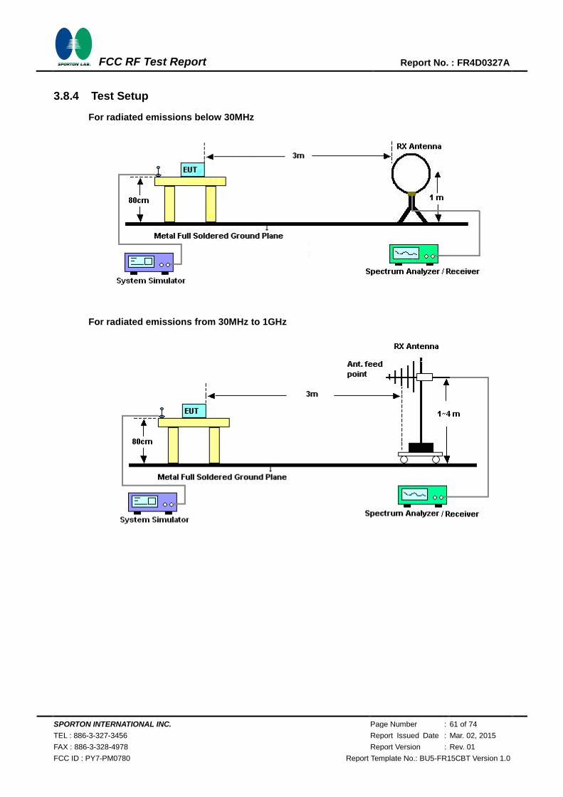
SPORTON INTERNATIONAL INC. Page Number : 61 of 74
TEL : 886-3-327-3456 Report Issued Date : Mar. 02, 2015
FAX : 886-3-328-4978 Report Version : Rev. 01
FCC ID : PY7-PM0780 Report Template No.: BU5-FR15CBT Version 1.0
FCC RF Test Report Report No. : FR4D0327A
3.8.4 Test Setup
For radiated emissions below 30MHz
For radiated emissions from 30MHz to 1GHz
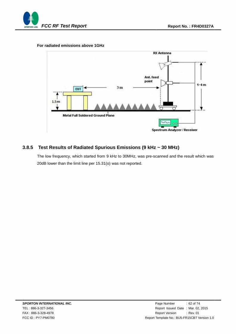
SPORTON INTERNATIONAL INC. Page Number : 62 of 74
TEL : 886-3-327-3456 Report Issued Date : Mar. 02, 2015
FAX : 886-3-328-4978 Report Version : Rev. 01
FCC ID : PY7-PM0780 Report Template No.: BU5-FR15CBT Version 1.0
FCC RF Test Report Report No. : FR4D0327A
For radiated emissions above 1GHz
3.8.5 Test Results of Radiated Spurious Emissions (9 kHz ~ 30 MHz)
The low frequency, which started from 9 kHz to 30MHz, was pre-scanned and the result which was
20dB lower than the limit line per 15.31(o) was not reported.
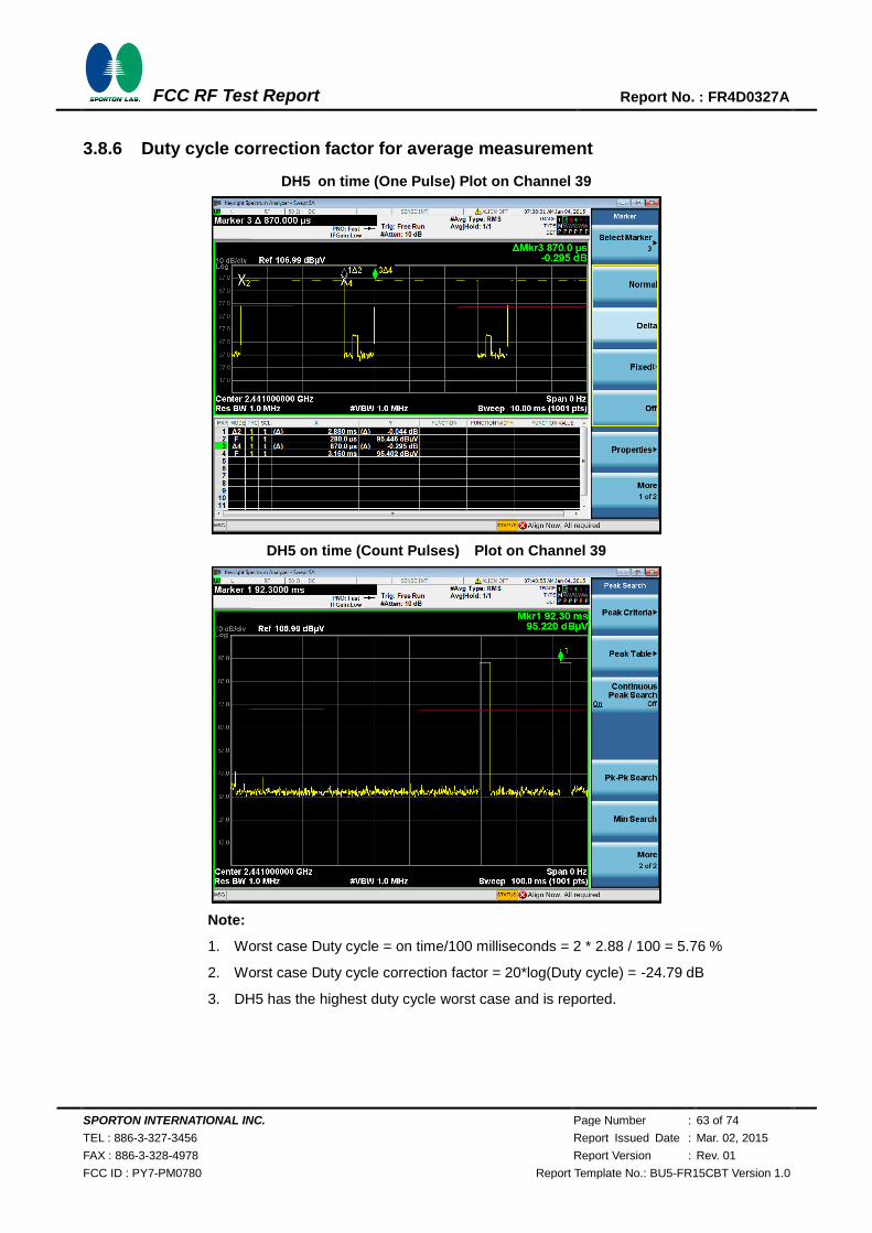
SPORTON INTERNATIONAL INC. Page Number : 63 of 74
TEL : 886-3-327-3456 Report Issued Date : Mar. 02, 2015
FAX : 886-3-328-4978 Report Version : Rev. 01
FCC ID : PY7-PM0780 Report Template No.: BU5-FR15CBT Version 1.0
FCC RF Test Report Report No. : FR4D0327A
3.8.6 Duty cycle correction factor for average measurement
DH5 on time (One Pulse) Plot on Channel 39
DH5 on time (Count Pulses) Plot on Channel 39
Note:
1. Worst case Duty cycle = on time/100 milliseconds = 2 * 2.88 / 100 = 5.76 %
2. Worst case Duty cycle correction factor = 20*log(Duty cycle) = -24.79 dB
3. DH5 has the highest duty cycle worst case and is reported.
720510
720510

SPORTON INTERNATIONAL INC. Page Number : 64 of 74
TEL : 886-3-327-3456 Report Issued Date : Mar. 02, 2015
FAX : 886-3-328-4978 Report Version : Rev. 01
FCC ID : PY7-PM0780 Report Template No.: BU5-FR15CBT Version 1.0
FCC RF Test Report Report No. : FR4D0327A
2DH5 on time (One Pulse) Plot on Channel 39
2DH5 on time (Count Pulses) Plot on Channel 39
Note:
1. Worst case Duty cycle = on time/100 milliseconds = 2 * 2.88 / 100 = 5.76 %
2. Worst case Duty cycle correction factor = 20*log(Duty cycle) = -24.79 dB
3. 2DH5 has the highest duty cycle worst case and is reported.
720510
720510
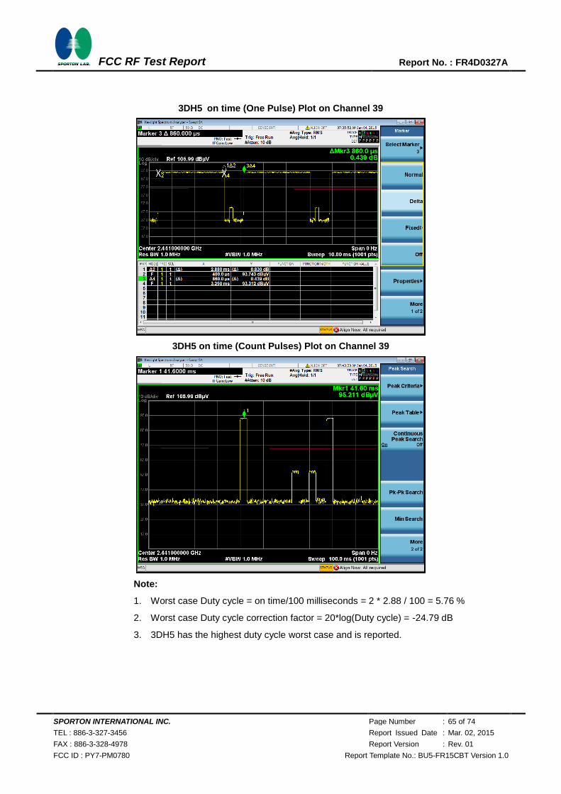
SPORTON INTERNATIONAL INC. Page Number : 65 of 74
TEL : 886-3-327-3456 Report Issued Date : Mar. 02, 2015
FAX : 886-3-328-4978 Report Version : Rev. 01
FCC ID : PY7-PM0780 Report Template No.: BU5-FR15CBT Version 1.0
FCC RF Test Report Report No. : FR4D0327A
3DH5 on time (One Pulse) Plot on Channel 39
3DH5 on time (Count Pulses) Plot on Channel 39
Note:
1. Worst case Duty cycle = on time/100 milliseconds = 2 * 2.88 / 100 = 5.76 %
2. Worst case Duty cycle correction factor = 20*log(Duty cycle) = -24.79 dB
3. 3DH5 has the highest duty cycle worst case and is reported.
SPORTON INTERNATIONAL INC. Page Number : 66 of 74
TEL : 886-3-327-3456 Report Issued Date : Mar. 02, 2015
FAX : 886-3-328-4978 Report Version : Rev. 01
FCC ID : PY7-PM0780 Report Template No.: BU5-FR15CBT Version 1.0
FCC RF Test Report Report No. : FR4D0327A
Duty Cycle Correction Factor Consideration for AFH mode:
Bluetooth normal hopping rate is 1600Hz and reduced to 800Hz in AFH mode; due to the reduced number of
hopping frequencies, with the same packet configuration the dwell time in each channel frequency within
100msec period is longer in AFH mode than normal mode.
In AFH mode, the minimum hopping frequencies are 20, to get the longest dwell time DH5 packet is observed;
the period to have DH5 packet completing one hopping sequence is
2.88 ms x 20 channels = 57.6 ms for 1Mbps, 2Mbps and 3Mbps
There cannot be 2 complete hopping sequences within 100ms period, considering the random hopping
behavior, maximum 2 hops can be possibly observed within the period. [100ms / 57.6ms ] = 2 hops
Thus, the maximum possible ON time:
2.88 ms x 2 = 5.76 ms for 1Mbps, 2Mbps and 3Mbps
Worst case Duty Cycle Correction factor, which is derived from the maximum possible ON time,
20 x log(5.76 ms/100ms) = -24.79 dB for 1Mbps, 2Mbps and 3Mbps
3.8.7 Test Result
Please refer to appendix A as below.
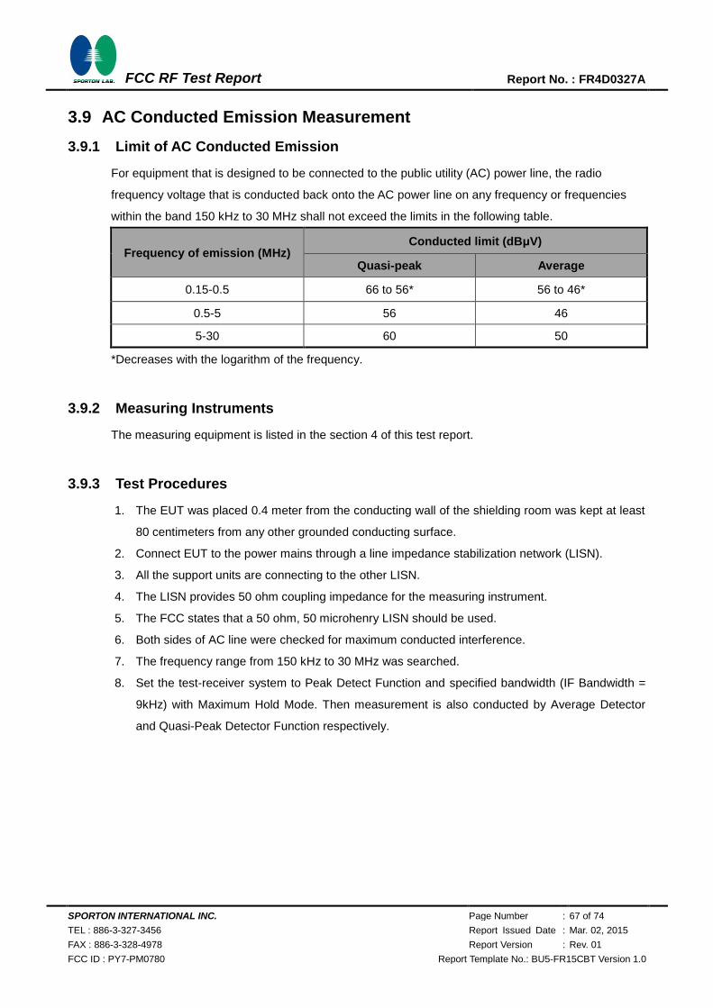
SPORTON INTERNATIONAL INC. Page Number : 67 of 74
TEL : 886-3-327-3456 Report Issued Date : Mar. 02, 2015
FAX : 886-3-328-4978 Report Version : Rev. 01
FCC ID : PY7-PM0780 Report Template No.: BU5-FR15CBT Version 1.0
FCC RF Test Report Report No. : FR4D0327A
3.9 AC Conducted Emission Measurement
3.9.1 Limit of AC Conducted Emission
For equipment that is designed to be connected to the public utility (AC) power line, the radio
frequency voltage that is conducted back onto the AC power line on any frequency or frequencies
within the band 150 kHz to 30 MHz shall not exceed the limits in the following table.
Frequency of emission (MHz) Conducted limit (dBμV)
Quasi-peak Average
0.15-0.5 66 to 56* 56 to 46*
0.5-5 56 46
5-30 60 50
*Decreases with the logarithm of the frequency.
3.9.2 Measuring Instruments
The measuring equipment is listed in the section 4 of this test report.
3.9.3 Test Procedures
1. The EUT was placed 0.4 meter from the conducting wall of the shielding room was kept at least
80 centimeters from any other grounded conducting surface.
2. Connect EUT to the power mains through a line impedance stabilization network (LISN).
3. All the support units are connecting to the other LISN.
4. The LISN provides 50 ohm coupling impedance for the measuring instrument.
5. The FCC states that a 50 ohm, 50 microhenry LISN should be used.
6. Both sides of AC line were checked for maximum conducted interference.
7. The frequency range from 150 kHz to 30 MHz was searched.
8. Set the test-receiver system to Peak Detect Function and specified bandwidth (IF Bandwidth =
9kHz) with Maximum Hold Mode. Then measurement is also conducted by Average Detector
and Quasi-Peak Detector Function respectively.
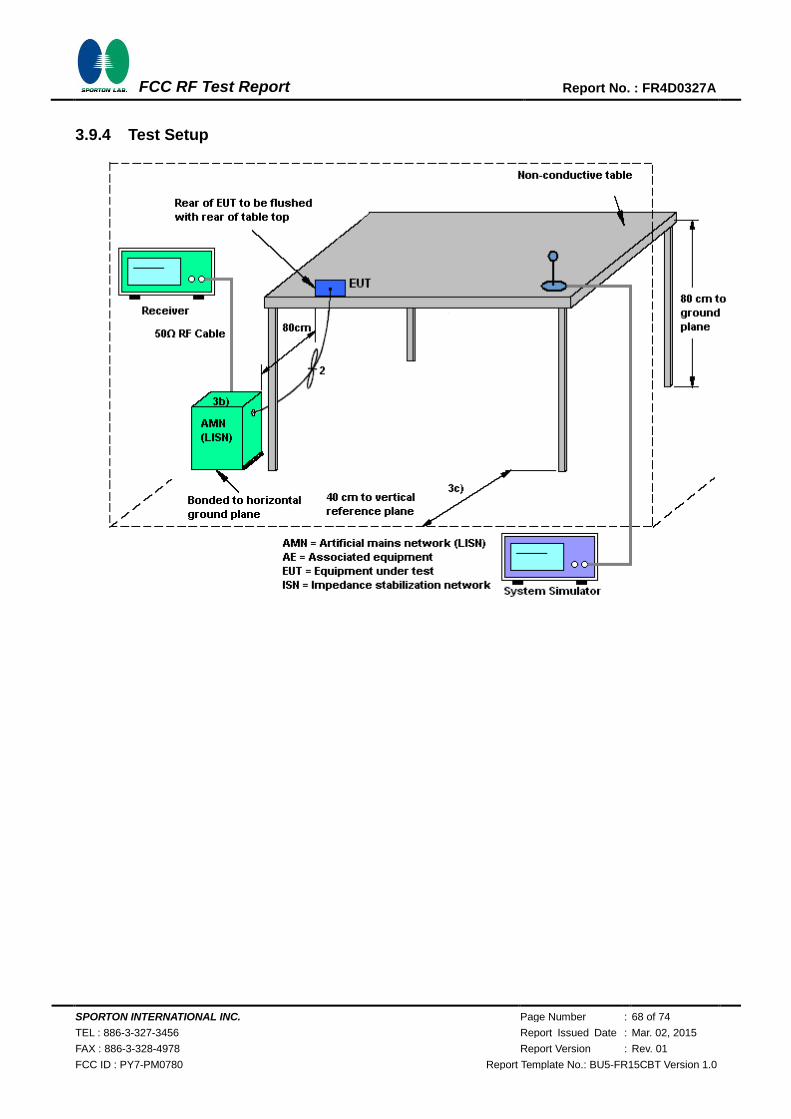
SPORTON INTERNATIONAL INC. Page Number : 68 of 74
TEL : 886-3-327-3456 Report Issued Date : Mar. 02, 2015
FAX : 886-3-328-4978 Report Version : Rev. 01
FCC ID : PY7-PM0780 Report Template No.: BU5-FR15CBT Version 1.0
FCC RF Test Report Report No. : FR4D0327A
3.9.4 Test Setup
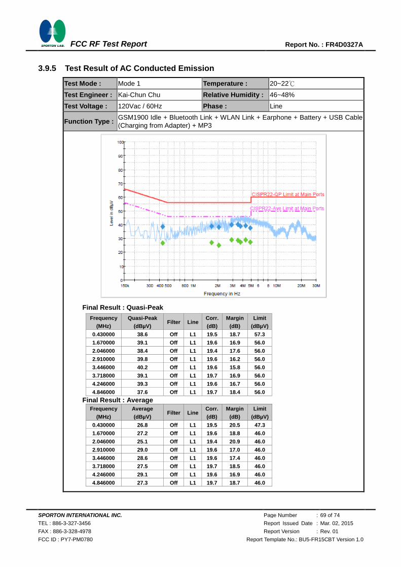
SPORTON INTERNATIONAL INC. Page Number : 69 of 74
TEL : 886-3-327-3456 Report Issued Date : Mar. 02, 2015
FAX : 886-3-328-4978 Report Version : Rev. 01
FCC ID : PY7-PM0780 Report Template No.: BU5-FR15CBT Version 1.0
FCC RF Test Report Report No. : FR4D0327A
3.9.5 Test Result of AC Conducted Emission
Test Mode : Mode 1 Temperature : 20~22℃
Test Engineer : Kai-Chun Chu Relative Humidity : 46~48%
Test Voltage : 120Vac / 60Hz Phase : Line
Function Type : GSM1900 Idle + Bluetooth Link + WLAN Link + Earphone + Battery + USB Cable
(Charging from Adapter) + MP3
Final Result : Quasi-Peak
Frequency
(MHz)
Quasi-Peak
(dBµV) Filter Line
Corr.
(dB)
Margin
(dB)
Limit
(dBµV)
0.430000 38.6 Off L1 19.5 18.7 57.3
1.670000 39.1 Off L1 19.6 16.9 56.0
2.046000 38.4 Off L1 19.4 17.6 56.0
2.910000 39.8 Off L1 19.6 16.2 56.0
3.446000 40.2 Off L1 19.6 15.8 56.0
3.718000 39.1 Off L1 19.7 16.9 56.0
4.246000 39.3 Off L1 19.6 16.7 56.0
4.846000 37.6 Off L1 19.7 18.4 56.0
Final Result : Average
Frequency
(MHz)
Average
(dBµV) Filter Line
Corr.
(dB)
Margin
(dB)
Limit
(dBµV)
0.430000 26.8 Off L1 19.5 20.5 47.3
1.670000 27.2 Off L1 19.6 18.8 46.0
2.046000 25.1 Off L1 19.4 20.9 46.0
2.910000 29.0 Off L1 19.6 17.0 46.0
3.446000 28.6 Off L1 19.6 17.4 46.0
3.718000 27.5 Off L1 19.7 18.5 46.0
4.246000 29.1 Off L1 19.6 16.9 46.0
4.846000 27.3 Off L1 19.7 18.7 46.0
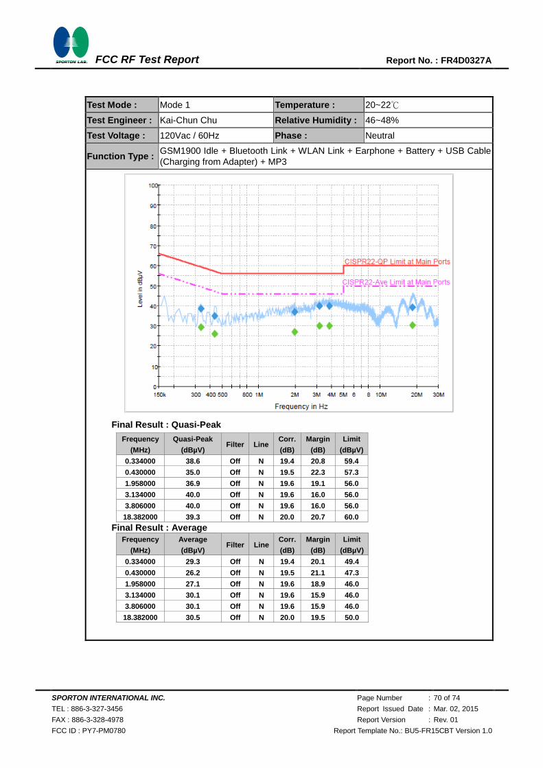
SPORTON INTERNATIONAL INC. Page Number : 70 of 74
TEL : 886-3-327-3456 Report Issued Date : Mar. 02, 2015
FAX : 886-3-328-4978 Report Version : Rev. 01
FCC ID : PY7-PM0780 Report Template No.: BU5-FR15CBT Version 1.0
FCC RF Test Report Report No. : FR4D0327A
Test Mode : Mode 1 Temperature : 20~22℃
Test Engineer : Kai-Chun Chu Relative Humidity : 46~48%
Test Voltage : 120Vac / 60Hz Phase : Neutral
Function Type : GSM1900 Idle + Bluetooth Link + WLAN Link + Earphone + Battery + USB Cable
(Charging from Adapter) + MP3
Final Result : Quasi-Peak
Frequency
(MHz)
Quasi-Peak
(dBµV) Filter Line
Corr.
(dB)
Margin
(dB)
Limit
(dBµV)
0.334000 38.6 Off N 19.4 20.8 59.4
0.430000 35.0 Off N 19.5 22.3 57.3
1.958000 36.9 Off N 19.6 19.1 56.0
3.134000 40.0 Off N 19.6 16.0 56.0
3.806000 40.0 Off N 19.6 16.0 56.0
18.382000 39.3 Off N 20.0 20.7 60.0
Final Result : Average
Frequency
(MHz)
Average
(dBµV) Filter Line
Corr.
(dB)
Margin
(dB)
Limit
(dBµV)
0.334000 29.3 Off N 19.4 20.1 49.4
0.430000 26.2 Off N 19.5 21.1 47.3
1.958000 27.1 Off N 19.6 18.9 46.0
3.134000 30.1 Off N 19.6 15.9 46.0
3.806000 30.1 Off N 19.6 15.9 46.0
18.382000 30.5 Off N 20.0 19.5 50.0
SPORTON INTERNATIONAL INC. Page Number : 71 of 74
TEL : 886-3-327-3456 Report Issued Date : Mar. 02, 2015
FAX : 886-3-328-4978 Report Version : Rev. 01
FCC ID : PY7-PM0780 Report Template No.: BU5-FR15CBT Version 1.0
FCC RF Test Report Report No. : FR4D0327A
3.10 Antenna Requirements
3.10.1 Standard Applicable
If directional gain of transmitting antennas is greater than 6dBi, the power shall be reduced by the
same level in dB comparing to gain minus 6dBi. The use of a permanently attached antenna or of an
antenna that uses a unique coupling to the intentional radiator shall be considered sufficient to
comply with the FCC rule.
3.10.2 Antenna Anti-Replacement Construction
An embedded-in antenna design is used.
3.10.3 Antenna Gain
The antenna peak gain of EUT is less than 6 dBi. Therefore, it is not necessary to reduce maximum
peak output power limit.
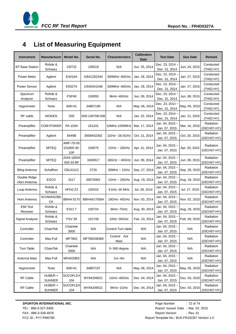
SPORTON INTERNATIONAL INC. Page Number : 72 of 74
TEL : 886-3-327-3456 Report Issued Date : Mar. 02, 2015
FAX : 886-3-328-4978 Report Version : Rev. 01
FCC ID : PY7-PM0780 Report Template No.: BU5-FR15CBT Version 1.0
FCC RF Test Report Report No. : FR4D0327A
4 List of Measuring Equipment
Instrument Manufacturer Model No. Serial No. Characteristics Calibration
Date Test Date Due Date Remark
BT Base Station Rohde &
Schwarz CBT32 100519 N/A Jun. 25, 2014
Dec. 23, 2014 ~
Dec. 31, 2014 Jun. 24, 2015
Conducted
(TH02-HY)
Power Meter Agilent E4416A GB41292344 300MHz~40GHz Jan. 28, 2014 Dec. 23, 2014 ~
Dec. 31, 2014 Jan. 27, 2015
Conducted
(TH02-HY)
Power Sensor Agilent E9327A US40441548 300MHz~40GHz Jan. 28, 2014 Dec. 23, 2014 ~
Dec. 31, 2014 Jan. 27, 2015
Conducted
(TH02-HY)
Spectrum
Analyzer
Rohde &
Schwarz FSP40 100055 9kHz~40GHz Jun. 09, 2014
Dec. 23, 2014 ~
Dec. 31, 2014 Jun. 08, 2015
Conducted
(TH02-HY)
Hygrometer Testo 608-H1 34897199 N/A May. 06, 2014 Dec. 23, 2014 ~
Dec. 31, 2014 May. 05, 2015
Conducted
(TH02-HY)
RF cable WOKEN S05 S05-130708-038 N/A Jan. 22, 2014 Dec. 23, 2014 ~
Dec. 31, 2014 Jan. 21, 2015
Conducted
(TH02-HY)
Preamplifier COM-POWER PA-103A 161241 10MHz-1000MHz Mar. 17, 2014 Jan. 04, 2015 ~
Jan. 07, 2015 Mar. 16, 2015
Radiation
(03CH07-HY)
Preamplifier Agilent 8449B 3008A02362 1GHz~ 26.5GHz Oct. 21, 2014 Jan. 04, 2015 ~
Jan. 07, 2015 Oct. 20, 2015
Radiation
(03CH07-HY)
Preamplifier MITEQ
AMF-7D-00
101800-30-
10P
159075 1GHz ~ 18GHz Apr. 21, 2014 Jan. 04, 2015 ~
Jan. 07, 2015 Apr. 20, 2015
Radiation
(03CH07-HY)
Preamplifier MITEQ JS44-18004
000-33-8P 1840917 18GHz ~ 40GHz Jun. 09, 2014
Jan. 04, 2015 ~
Jan. 07, 2015 Jun. 08, 2015
Radiation
(03CH07-HY)
Bilog Antenna Schaffner CBL6111C 2726 30MHz ~ 1GHz Sep. 27, 2014 Jan. 04, 2015 ~
Jan. 07, 2015 Sep. 26, 2015
Radiation
(03CH07-HY)
Double Ridge
Horn Antenna ESCO 3117 00075962 1GHz ~ 18GHz Aug. 19, 2014
Jan. 04, 2015 ~
Jan. 07, 2015 Aug. 18, 2015
Radiation
(03CH07-HY)
Loop Antenna Rohde &
Schwarz HFH2-Z2 100315 9 kHz~30 MHz Jul. 28, 2014
Jan. 04, 2015 ~
Jan. 07, 2015 Jul. 27, 2015
Radiation
(03CH07-HY)
Horn Antenna SCHWARZBE
CK BBHA 9170 BBHA9170584 18GHz- 40GHz Nov. 03, 2014
Jan. 04, 2015 ~
Jan. 07, 2015 Nov. 02, 2015
Radiation
(03CH07-HY)
EMI Test
Receiver
Rohde &
Schwarz ESCI 7 100724 9kHz~7GHz Aug. 30, 2014
Jan. 04, 2015 ~
Jan. 07, 2015 Aug. 29, 2015
Radiation
(03CH07-HY)
Signal Analyzer Rohde &
Schwarz FSV 30 101749 10Hz~30GHz Feb. 10, 2014
Jan. 04, 2015 ~
Jan. 07, 2015 Feb. 09, 2015
Radiation
(03CH07-HY)
Controller ChainTek Chaintek
3000 N/A Control Turn table N/A
Jan. 04, 2015 ~
Jan. 07, 2015 N/A
Radiation
(03CH07-HY)
Controller Max-Full MF7802 MF780208368 Control Ant
Mast N/A
Jan. 04, 2015 ~
Jan. 07, 2015 N/A
Radiation
(03CH07-HY)
Turn Table ChainTek Chaintek
3000 N/A 0~360 degree N/A
Jan. 04, 2015 ~
Jan. 07, 2015 N/A
Radiation
(03CH07-HY)
Antenna Mast Max-Full MFA520BS N/A 1m~4m N/A Jan. 04, 2015 ~
Jan. 07, 2015 N/A
Radiation
(03CH07-HY)
Hygrometer Testo 608-H1 34897197 N/A May. 06, 2014 Jan. 04, 2015 ~
Jan. 07, 2015 May. 05, 2015
Radiation
(03CH07-HY)
RF Cable HUBER +
SUHNER
SUCOFLEX
104 MY84209521 1GHz~40GHz Dec. 04, 2014
Jan. 04, 2015 ~
Jan. 07, 2015 Dec. 03, 2015
Radiation
(03CH07-HY)
RF Cable HUBER +
SUHNER
SUCOFLEX
104 MY84209521 9KHz~1GHz Dec. 04, 2014
Jan. 04, 2015 ~
Jan. 07, 2015 Dec. 03, 2015
Radiation
(03CH07-HY)
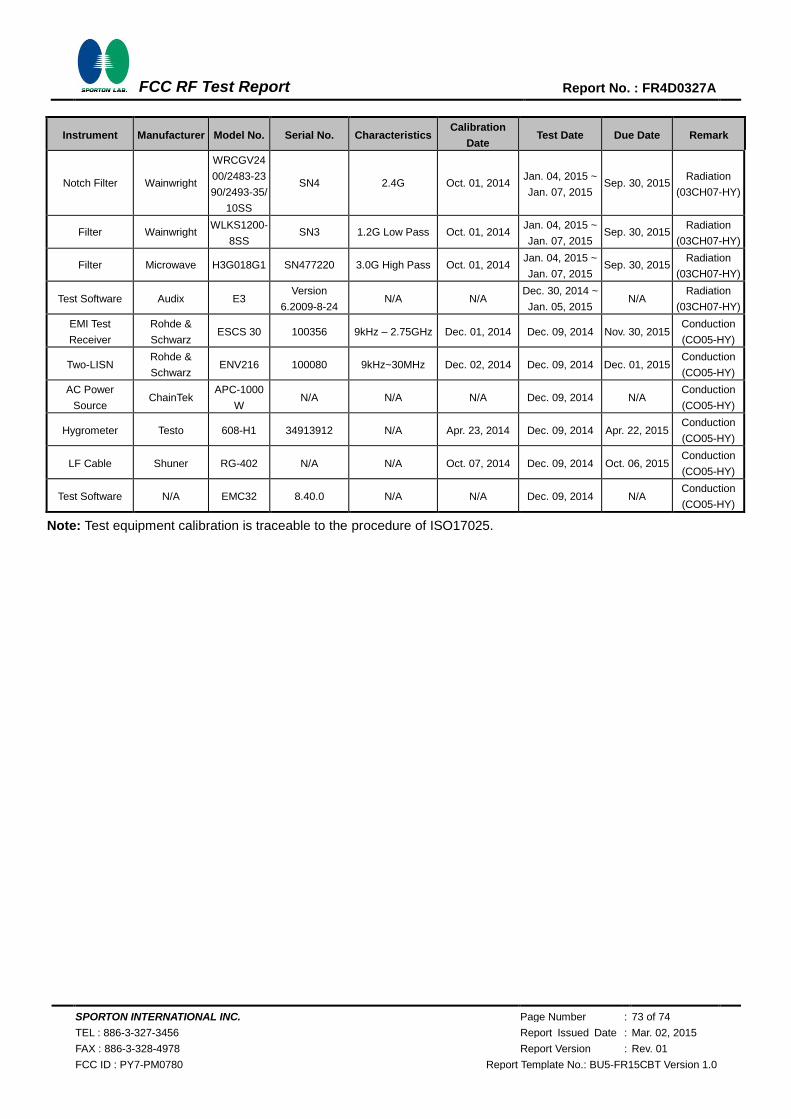
SPORTON INTERNATIONAL INC. Page Number : 73 of 74
TEL : 886-3-327-3456 Report Issued Date : Mar. 02, 2015
FAX : 886-3-328-4978 Report Version : Rev. 01
FCC ID : PY7-PM0780 Report Template No.: BU5-FR15CBT Version 1.0
FCC RF Test Report Report No. : FR4D0327A
Instrument Manufacturer Model No. Serial No. Characteristics Calibration
Date Test Date Due Date Remark
Notch Filter Wainwright
WRCGV24
00/2483-23
90/2493-35/
10SS
SN4 2.4G Oct. 01, 2014 Jan. 04, 2015 ~
Jan. 07, 2015 Sep. 30, 2015
Radiation
(03CH07-HY)
Filter Wainwright WLKS1200-
8SS SN3 1.2G Low Pass Oct. 01, 2014
Jan. 04, 2015 ~
Jan. 07, 2015 Sep. 30, 2015
Radiation
(03CH07-HY)
Filter Microwave H3G018G1 SN477220 3.0G High Pass Oct. 01, 2014 Jan. 04, 2015 ~
Jan. 07, 2015 Sep. 30, 2015
Radiation
(03CH07-HY)
Test Software Audix E3 Version
6.2009-8-24 N/A N/A
Dec. 30, 2014 ~
Jan. 05, 2015 N/A
Radiation
(03CH07-HY)
EMI Test
Receiver
Rohde &
Schwarz ESCS 30 100356 9kHz – 2.75GHz Dec. 01, 2014 Dec. 09, 2014 Nov. 30, 2015
Conduction
(CO05-HY)
Two-LISN Rohde &
Schwarz ENV216 100080 9kHz~30MHz Dec. 02, 2014 Dec. 09, 2014 Dec. 01, 2015
Conduction
(CO05-HY)
AC Power
Source ChainTek
APC-1000
W N/A N/A N/A Dec. 09, 2014 N/A
Conduction
(CO05-HY)
Hygrometer Testo 608-H1 34913912 N/A Apr. 23, 2014 Dec. 09, 2014 Apr. 22, 2015 Conduction
(CO05-HY)
LF Cable Shuner RG-402 N/A N/A Oct. 07, 2014 Dec. 09, 2014 Oct. 06, 2015 Conduction
(CO05-HY)
Test Software N/A EMC32 8.40.0 N/A N/A Dec. 09, 2014 N/A Conduction
(CO05-HY)
Note: Test equipment calibration is traceable to the procedure of ISO17025.
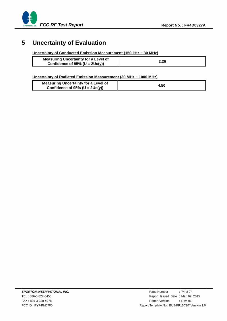
SPORTON INTERNATIONAL INC. Page Number : 74 of 74
TEL : 886-3-327-3456 Report Issued Date : Mar. 02, 2015
FAX : 886-3-328-4978 Report Version : Rev. 01
FCC ID : PY7-PM0780 Report Template No.: BU5-FR15CBT Version 1.0
FCC RF Test Report Report No. : FR4D0327A
5 Uncertainty of Evaluation
Uncertainty of Conducted Emission Measurement (150 kHz ~ 30 MHz)
Measuring Uncertainty for a Level of
Confidence of 95% (U = 2Uc(y)) 2.26
Uncertainty of Radiated Emission Measurement (30 MHz ~ 1000 MHz)
Measuring Uncertainty for a Level of
Confidence of 95% (U = 2Uc(y)) 4.50
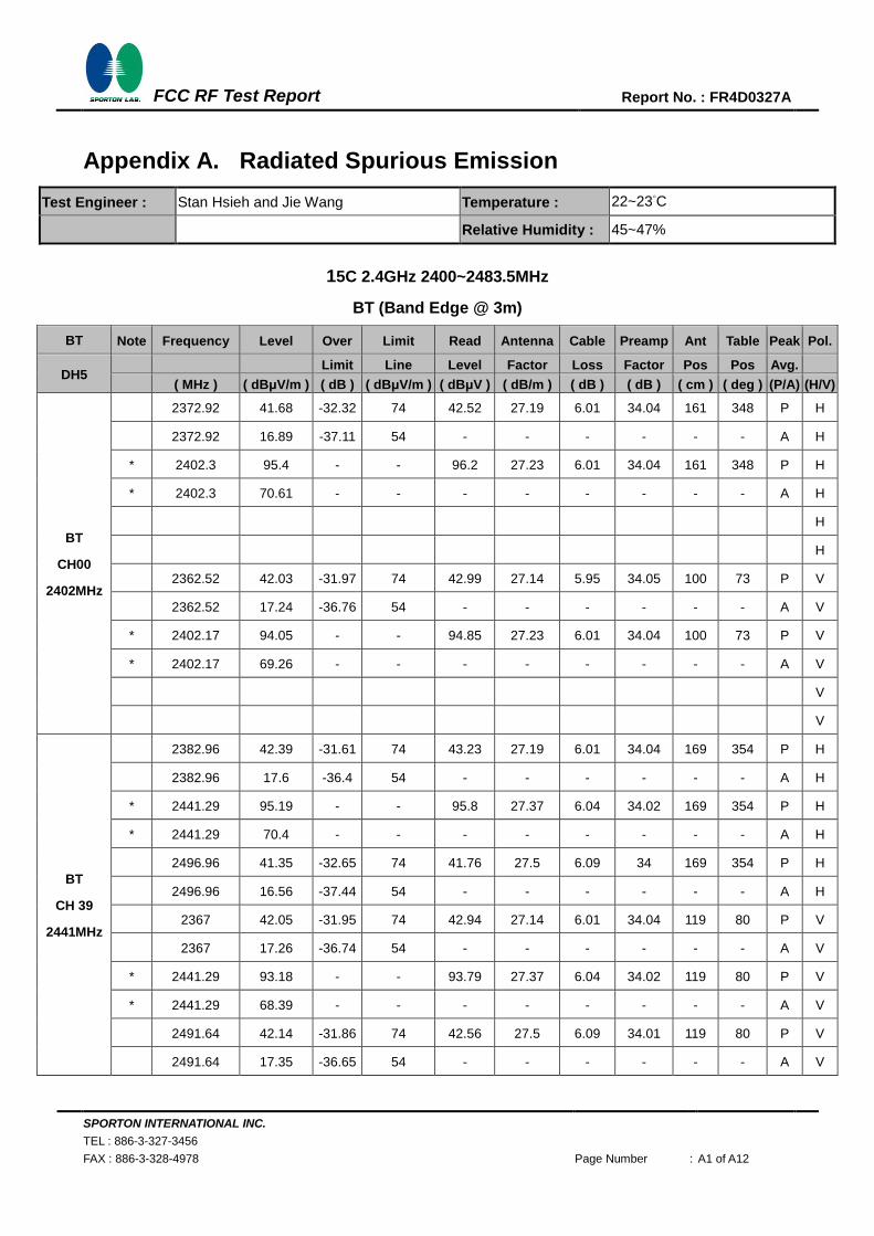
SPORTON INTERNATIONAL INC.
TEL : 886-3-327-3456
FAX : 886-3-328-4978 Page Number : A1 of A12
FCC RF Test Report
Report No. : FR4D0327A
Appendix A. Radiated Spurious Emission
Test Engineer : Stan Hsieh and Jie Wang Temperature : 22~23°C
Relative Humidity : 45~47%
15C 2.4GHz 2400~2483.5MHz
BT (Band Edge @ 3m)
BT Note Frequency Level Over Limit Read Antenna Cable Preamp Ant Table Peak Pol.
DH5 Limit Line Level Factor Loss Factor Pos Pos Avg.
( MHz ) ( dBμV/m ) ( dB ) ( dBμV/m ) ( dBμV ) ( dB/m ) ( dB ) ( dB ) ( cm ) ( deg ) (P/A) (H/V)
BT
CH00
2402MHz
2372.92 41.68 -32.32 74 42.52 27.19 6.01 34.04 161 348 P H
2372.92 16.89 -37.11 54 - - - - - - A H
* 2402.3 95.4 - - 96.2 27.23 6.01 34.04 161 348 P H
* 2402.3 70.61 - - - - - - - - A H
H
H
2362.52 42.03 -31.97 74 42.99 27.14 5.95 34.05 100 73 P V
2362.52 17.24 -36.76 54 - - - - - - A V
* 2402.17 94.05 - - 94.85 27.23 6.01 34.04 100 73 P V
* 2402.17 69.26 - - - - - - - - A V
V
V
BT
CH 39
2441MHz
2382.96 42.39 -31.61 74 43.23 27.19 6.01 34.04 169 354 P H
2382.96 17.6 -36.4 54 - - - - - - A H
* 2441.29 95.19 - - 95.8 27.37 6.04 34.02 169 354 P H
* 2441.29 70.4 - - - - - - - - A H
2496.96 41.35 -32.65 74 41.76 27.5 6.09 34 169 354 P H
2496.96 16.56 -37.44 54 - - - - - - A H
2367 42.05 -31.95 74 42.94 27.14 6.01 34.04 119 80 P V
2367 17.26 -36.74 54 - - - - - - A V
* 2441.29 93.18 - - 93.79 27.37 6.04 34.02 119 80 P V
* 2441.29 68.39 - - - - - - - - A V
2491.64 42.14 -31.86 74 42.56 27.5 6.09 34.01 119 80 P V
2491.64 17.35 -36.65 54 - - - - - - A V

SPORTON INTERNATIONAL INC.
TEL : 886-3-327-3456
FAX : 886-3-328-4978 Page Number : A2 of A12
FCC RF Test Report
Report No. : FR4D0327A
BT
CH 78
2480MHz
* 2479.91 95.42 - - 95.9 27.46 6.07 34.01 225 0 P H
* 2479.91 70.63 - - - - - - - - A H
2483.62 41.94 -32.06 74 42.4 27.46 6.09 34.01 225 0 P H
2483.62 17.15 -36.85 54 - - - - - - A H
H
H
* 2479.91 92.57 - - 93.05 27.46 6.07 34.01 143 78 P V
* 2479.91 67.78 - - - - - - - - A V
2496.92 42.23 -31.77 74 42.64 27.5 6.09 34 143 78 P V
2496.92 17.44 -36.56 54 - - - - - - A V
V
V
Remark 1. No other spurious found.
2. All results are PASS against Peak and Average limit line.
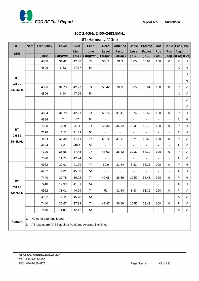
SPORTON INTERNATIONAL INC.
TEL : 886-3-327-3456
FAX : 886-3-328-4978 Page Number : A3 of A12
FCC RF Test Report
Report No. : FR4D0327A
15C 2.4GHz 2400~2483.5MHz
BT (Harmonic @ 3m)
BT Note Frequency Level Over Limit Read Antenna Cable Preamp Ant Table Peak Pol.
DH5 Limit Line Level Factor Loss Factor Pos Pos Avg.
( MHz ) ( dBμV/m ) ( dB ) ( dBμV/m ) ( dBμV ) ( dB/m ) ( dB ) ( dB ) ( cm ) ( deg ) (P/A) (H/V)
BT
CH 00
2402MHz
4806 31.42 -42.58 74 50.11 31.3 8.65 58.64 100 0 P H
4806 6.63 -47.37 54 - - - - - - A H
H
H
4806 31.73 -42.27 74 50.42 31.3 8.65 58.64 100 0 P V
4806 6.94 -47.06 54 - - - - - - A V
V
V
BT
CH 39
2441MHz
4884 31.79 -42.21 74 50.16 31.41 8.74 58.52 100 0 P H
4884 7 -47 54 - - - - - - A H
7320 36.9 -37.1 74 48.38 36.32 10.39 58.19 100 0 P H
7320 12.11 -41.89 54 - - - - - - A H
4884 32.39 -41.61 74 50.76 31.41 8.74 58.52 100 0 P V
4884 7.6 -46.4 54 - - - - - - A V
7320 36.55 -37.45 74 48.03 36.32 10.39 58.19 100 0 P V
7320 11.76 -42.24 54 - - - - - - A V
BT
CH 78
2480MHz
4962 32.91 -41.09 74 50.9 31.54 8.83 58.36 100 0 P H
4962 8.12 -45.88 54 - - - - - - A H
7440 37.78 -36.22 74 49.08 36.59 10.52 58.41 100 0 P H
7440 12.99 -41.01 54 - - - - - - A H
4962 33.01 -40.99 74 51 31.54 8.83 58.36 100 0 P V
4962 8.22 -45.78 54 - - - - - - A V
7440 36.67 -37.33 74 47.97 36.59 10.52 58.41 100 0 P V
7440 11.88 -42.12 54 - - - - - - A V
Remark 1. No other spurious found.
2. All results are PASS against Peak and Average limit line.
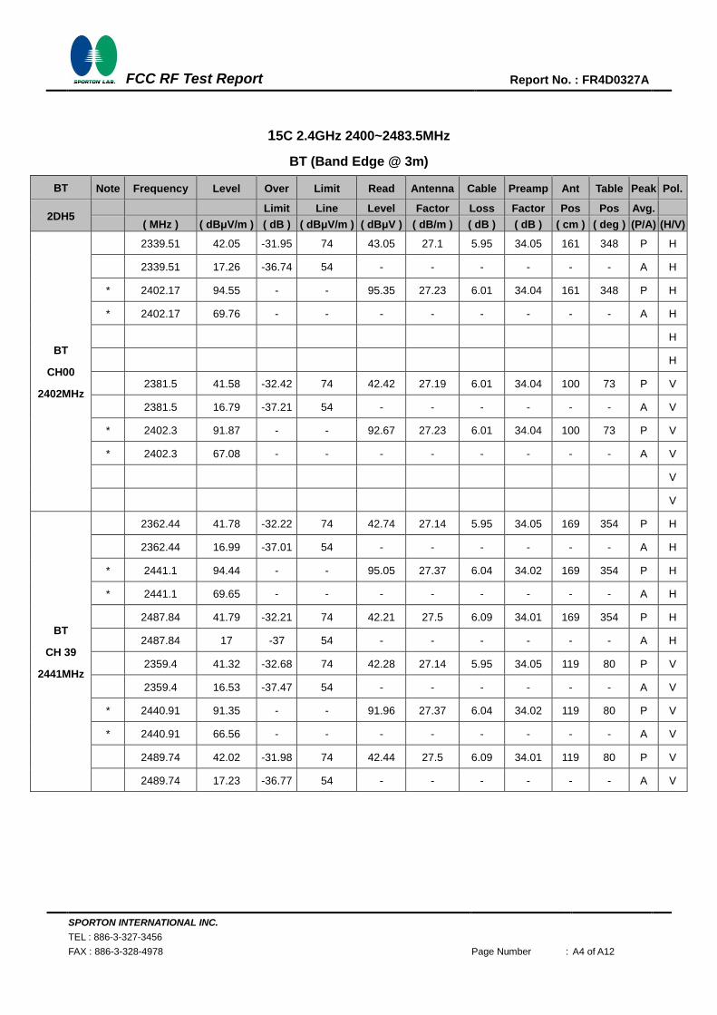
SPORTON INTERNATIONAL INC.
TEL : 886-3-327-3456
FAX : 886-3-328-4978 Page Number : A4 of A12
FCC RF Test Report
Report No. : FR4D0327A
15C 2.4GHz 2400~2483.5MHz
BT (Band Edge @ 3m)
BT Note Frequency Level Over Limit Read Antenna Cable Preamp Ant Table Peak Pol.
2DH5 Limit Line Level Factor Loss Factor Pos Pos Avg.
( MHz ) ( dBμV/m ) ( dB ) ( dBμV/m ) ( dBμV ) ( dB/m ) ( dB ) ( dB ) ( cm ) ( deg ) (P/A) (H/V)
BT
CH00
2402MHz
2339.51 42.05 -31.95 74 43.05 27.1 5.95 34.05 161 348 P H
2339.51 17.26 -36.74 54 - - - - - - A H
* 2402.17 94.55 - - 95.35 27.23 6.01 34.04 161 348 P H
* 2402.17 69.76 - - - - - - - - A H
H
H
2381.5 41.58 -32.42 74 42.42 27.19 6.01 34.04 100 73 P V
2381.5 16.79 -37.21 54 - - - - - - A V
* 2402.3 91.87 - - 92.67 27.23 6.01 34.04 100 73 P V
* 2402.3 67.08 - - - - - - - - A V
V
V
BT
CH 39
2441MHz
2362.44 41.78 -32.22 74 42.74 27.14 5.95 34.05 169 354 P H
2362.44 16.99 -37.01 54 - - - - - - A H
* 2441.1 94.44 - - 95.05 27.37 6.04 34.02 169 354 P H
* 2441.1 69.65 - - - - - - - - A H
2487.84 41.79 -32.21 74 42.21 27.5 6.09 34.01 169 354 P H
2487.84 17 -37 54 - - - - - - A H
2359.4 41.32 -32.68 74 42.28 27.14 5.95 34.05 119 80 P V
2359.4 16.53 -37.47 54 - - - - - - A V
* 2440.91 91.35 - - 91.96 27.37 6.04 34.02 119 80 P V
* 2440.91 66.56 - - - - - - - - A V
2489.74 42.02 -31.98 74 42.44 27.5 6.09 34.01 119 80 P V
2489.74 17.23 -36.77 54 - - - - - - A V
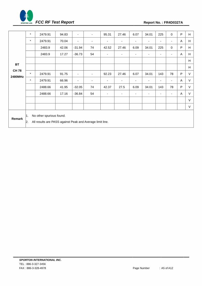
SPORTON INTERNATIONAL INC.
TEL : 886-3-327-3456
FAX : 886-3-328-4978 Page Number : A5 of A12
FCC RF Test Report
Report No. : FR4D0327A
BT
CH 78
2480MHz
* 2479.91 94.83 - - 95.31 27.46 6.07 34.01 225 0 P H
* 2479.91 70.04 - - - - - - - - A H
2483.9 42.06 -31.94 74 42.52 27.46 6.09 34.01 225 0 P H
2483.9 17.27 -36.73 54 - - - - - - A H
H
H
* 2479.91 91.75 - - 92.23 27.46 6.07 34.01 143 78 P V
* 2479.91 66.96 - - - - - - - - A V
2488.66 41.95 -32.05 74 42.37 27.5 6.09 34.01 143 78 P V
2488.66 17.16 -36.84 54 - - - - - - A V
V
V
Remark 1. No other spurious found.
2. All results are PASS against Peak and Average limit line.

SPORTON INTERNATIONAL INC.
TEL : 886-3-327-3456
FAX : 886-3-328-4978 Page Number : A6 of A12
FCC RF Test Report
Report No. : FR4D0327A
15C 2.4GHz 2400~2483.5MHz
BT (Harmonic @ 3m)
BT Note Frequency Level Over Limit Read Antenna Cable Preamp Ant Table Peak Pol.
2DH5 Limit Line Level Factor Loss Factor Pos Pos Avg.
( MHz ) ( dBμV/m ) ( dB ) ( dBμV/m ) ( dBμV ) ( dB/m ) ( dB ) ( dB ) ( cm ) ( deg ) (P/A) (H/V)
BT
CH 00
2402MHz
4806 31.82 -42.18 74 50.51 31.3 8.65 58.64 100 0 P H
4806 7.03 -46.97 54 - - - - - - A H
H
H
4806 32.32 -41.68 74 51.01 31.3 8.65 58.64 100 0 P V
4806 7.53 -46.47 54 - - - - - - A V
V
V
BT
CH 39
2441MHz
4884 31.5 -42.5 74 49.87 31.41 8.74 58.52 100 0 P H
4884 6.71 -47.29 54 - - - - - - A H
7320 35.83 -38.17 74 47.31 36.32 10.39 58.19 100 0 P H
7320 11.04 -42.96 54 - - - - - - A H
4884 31.92 -42.08 74 50.29 31.41 8.74 58.52 100 0 P V
4884 7.13 -46.87 54 - - - - - - A V
7320 36.9 -37.1 74 48.38 36.32 10.39 58.19 100 0 P V
7320 12.11 -41.89 54 - - - - - - A V
BT
CH 78
2480MHz
4962 32.67 -41.33 74 50.66 31.54 8.83 58.36 100 0 P H
4962 7.88 -46.12 54 - - - - - - A H
7440 36.88 -37.12 74 48.18 36.59 10.52 58.41 100 0 P H
7440 12.09 -41.91 54 - - - - - - A H
4962 35.2 -38.8 74 53.19 31.54 8.83 58.36 100 0 P V
4962 10.41 -43.59 54 - - - - - - A V
7440 36.46 -37.54 74 47.76 36.59 10.52 58.41 100 0 P V
7440 11.67 -42.33 54 - - - - - - A V
Remark 1. No other spurious found.
2. All results are PASS against Peak and Average limit line.
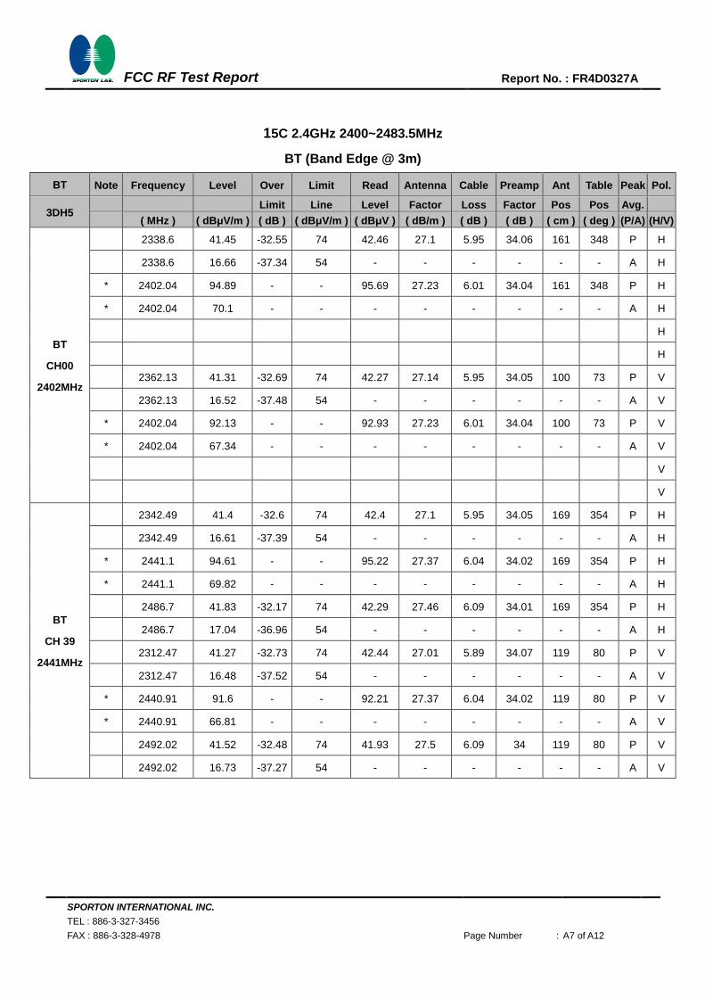
SPORTON INTERNATIONAL INC.
TEL : 886-3-327-3456
FAX : 886-3-328-4978 Page Number : A7 of A12
FCC RF Test Report
Report No. : FR4D0327A
15C 2.4GHz 2400~2483.5MHz
BT (Band Edge @ 3m)
BT Note Frequency Level Over Limit Read Antenna Cable Preamp Ant Table Peak Pol.
3DH5 Limit Line Level Factor Loss Factor Pos Pos Avg.
( MHz ) ( dBμV/m ) ( dB ) ( dBμV/m ) ( dBμV ) ( dB/m ) ( dB ) ( dB ) ( cm ) ( deg ) (P/A) (H/V)
BT
CH00
2402MHz
2338.6 41.45 -32.55 74 42.46 27.1 5.95 34.06 161 348 P H
2338.6 16.66 -37.34 54 - - - - - - A H
* 2402.04 94.89 - - 95.69 27.23 6.01 34.04 161 348 P H
* 2402.04 70.1 - - - - - - - - A H
H
H
2362.13 41.31 -32.69 74 42.27 27.14 5.95 34.05 100 73 P V
2362.13 16.52 -37.48 54 - - - - - - A V
* 2402.04 92.13 - - 92.93 27.23 6.01 34.04 100 73 P V
* 2402.04 67.34 - - - - - - - - A V
V
V
BT
CH 39
2441MHz
2342.49 41.4 -32.6 74 42.4 27.1 5.95 34.05 169 354 P H
2342.49 16.61 -37.39 54 - - - - - - A H
* 2441.1 94.61 - - 95.22 27.37 6.04 34.02 169 354 P H
* 2441.1 69.82 - - - - - - - - A H
2486.7 41.83 -32.17 74 42.29 27.46 6.09 34.01 169 354 P H
2486.7 17.04 -36.96 54 - - - - - - A H
2312.47 41.27 -32.73 74 42.44 27.01 5.89 34.07 119 80 P V
2312.47 16.48 -37.52 54 - - - - - - A V
* 2440.91 91.6 - - 92.21 27.37 6.04 34.02 119 80 P V
* 2440.91 66.81 - - - - - - - - A V
2492.02 41.52 -32.48 74 41.93 27.5 6.09 34 119 80 P V
2492.02 16.73 -37.27 54 - - - - - - A V

SPORTON INTERNATIONAL INC.
TEL : 886-3-327-3456
FAX : 886-3-328-4978 Page Number : A8 of A12
FCC RF Test Report
Report No. : FR4D0327A
BT
CH 78
2480MHz
* 2480.05 95.72 - - 96.2 27.46 6.07 34.01 225 0 P H
* 2480.05 70.93 - - - - - - - - A H
2484.81 41.94 -32.06 74 42.4 27.46 6.09 34.01 225 0 P H
2484.81 17.15 -36.85 54 - - - - - - A H
H
H
* 2479.98 92.33 - - 92.81 27.46 6.07 34.01 143 78 P V
* 2479.98 67.54 - - - - - - - - A V
2496.57 42.75 -31.25 74 43.16 27.5 6.09 34 143 78 P V
2496.57 17.96 -36.04 54 - - - - - - A V
V
V
Remark 1. No other spurious found.
2. All results are PASS against Peak and Average limit line.
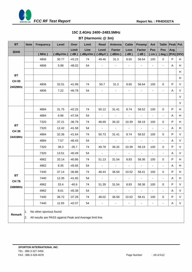
SPORTON INTERNATIONAL INC.
TEL : 886-3-327-3456
FAX : 886-3-328-4978 Page Number : A9 of A12
FCC RF Test Report
Report No. : FR4D0327A
15C 2.4GHz 2400~2483.5MHz
BT (Harmonic @ 3m)
BT Note Frequency Level Over Limit Read Antenna Cable Preamp Ant Table Peak Pol.
3DH5 Limit Line Level Factor Loss Factor Pos Pos Avg.
( MHz ) ( dBμV/m ) ( dB ) ( dBμV/m ) ( dBμV ) ( dB/m ) ( dB ) ( dB ) ( cm ) ( deg ) (P/A) (H/V)
BT
CH 00
2402MHz
4806 30.77 -43.23 74 49.46 31.3 8.65 58.64 100 0 P H
4806 5.98 -48.02 54 - - - - - - A H
H
H
4806 32.01 -41.99 74 50.7 31.3 8.65 58.64 100 0 P V
4806 7.22 -46.78 54 - - - - - - A V
V
V
BT
CH 39
2441MHz
4884 31.75 -42.25 74 50.12 31.41 8.74 58.52 100 0 P H
4884 6.96 -47.04 54 - - - - - - A H
7320 37.21 -36.79 74 48.69 36.32 10.39 58.19 100 0 P H
7320 12.42 -41.58 54 - - - - - - A H
4884 32.36 -41.64 74 50.73 31.41 8.74 58.52 100 0 P V
4884 7.57 -46.43 54 - - - - - - A V
7320 38.3 -35.7 74 49.78 36.32 10.39 58.19 100 0 P V
7320 13.51 -40.49 54 - - - - - - A V
BT
CH 78
2480MHz
4962 33.14 -40.86 74 51.13 31.54 8.83 58.36 100 0 P H
4962 8.35 -45.65 54 - - - - - - A H
7440 37.14 -36.86 74 48.44 36.59 10.52 58.41 100 0 P H
7440 12.35 -41.65 54 - - - - - - A H
4962 33.4 -40.6 74 51.39 31.54 8.83 58.36 100 0 P V
4962 8.61 -45.39 54 - - - - - - A V
7440 36.72 -37.28 74 48.02 36.59 10.52 58.41 100 0 P V
7440 11.93 -42.07 54 - - - - - - A V
Remark 1. No other spurious found.
2. All results are PASS against Peak and Average limit line.
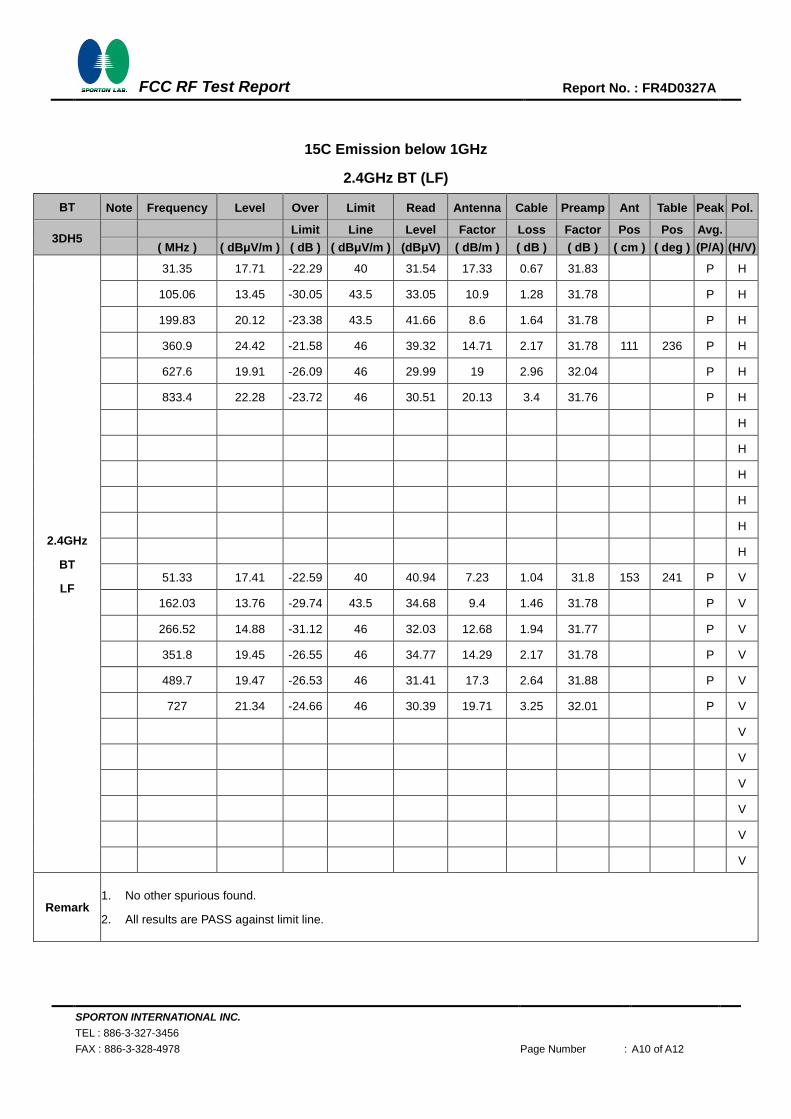
SPORTON INTERNATIONAL INC.
TEL : 886-3-327-3456
FAX : 886-3-328-4978 Page Number : A10 of A12
FCC RF Test Report
Report No. : FR4D0327A
15C Emission below 1GHz
2.4GHz BT (LF)
BT Note Frequency Level Over Limit Read Antenna Cable Preamp Ant Table Peak Pol.
3DH5 Limit Line Level Factor Loss Factor Pos Pos Avg.
( MHz ) ( dBμV/m ) ( dB ) ( dBμV/m ) (dBμV) ( dB/m ) ( dB ) ( dB ) ( cm ) ( deg ) (P/A) (H/V)
2.4GHz
BT
LF
31.35 17.71 -22.29 40 31.54 17.33 0.67 31.83 P H
105.06 13.45 -30.05 43.5 33.05 10.9 1.28 31.78 P H
199.83 20.12 -23.38 43.5 41.66 8.6 1.64 31.78 P H
360.9 24.42 -21.58 46 39.32 14.71 2.17 31.78 111 236 P H
627.6 19.91 -26.09 46 29.99 19 2.96 32.04 P H
833.4 22.28 -23.72 46 30.51 20.13 3.4 31.76 P H
H
H
H
H
H
H
51.33 17.41 -22.59 40 40.94 7.23 1.04 31.8 153 241 P V
162.03 13.76 -29.74 43.5 34.68 9.4 1.46 31.78 P V
266.52 14.88 -31.12 46 32.03 12.68 1.94 31.77 P V
351.8 19.45 -26.55 46 34.77 14.29 2.17 31.78 P V
489.7 19.47 -26.53 46 31.41 17.3 2.64 31.88 P V
727 21.34 -24.66 46 30.39 19.71 3.25 32.01 P V
V
V
V
V
V
V
Remark 1. No other spurious found.
2. All results are PASS against limit line.
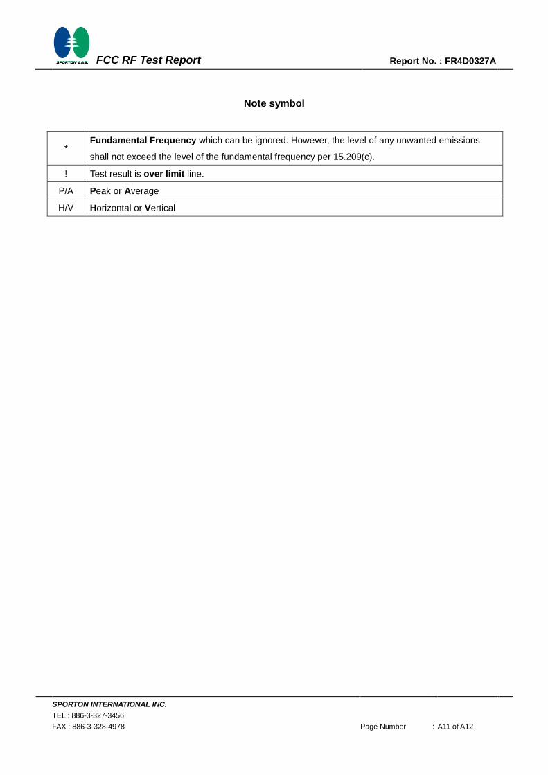
SPORTON INTERNATIONAL INC.
TEL : 886-3-327-3456
FAX : 886-3-328-4978 Page Number : A11 of A12
FCC RF Test Report
Report No. : FR4D0327A
Note symbol
* Fundamental Frequency which can be ignored. However, the level of any unwanted emissions
shall not exceed the level of the fundamental frequency per 15.209(c).
! Test result is over limit line.
P/A Peak or Average
H/V Horizontal or Vertical
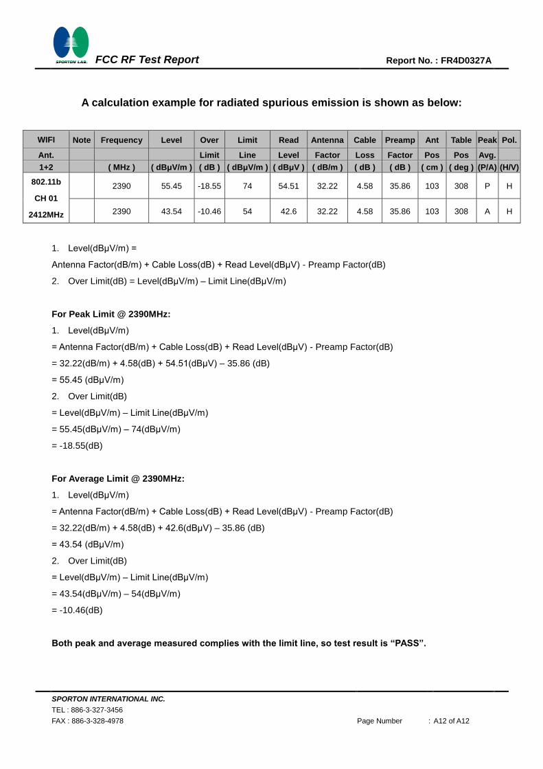
SPORTON INTERNATIONAL INC.
TEL : 886-3-327-3456
FAX : 886-3-328-4978 Page Number : A12 of A12
FCC RF Test Report
Report No. : FR4D0327A
A calculation example for radiated spurious emission is shown as below:
WIFI Note Frequency Level Over Limit Read Antenna Cable Preamp Ant Table Peak Pol.
Ant. Limit Line Level Factor Loss Factor Pos Pos Avg.
1+2 ( MHz ) ( dBμV/m ) ( dB ) ( dBμV/m ) ( dBμV ) ( dB/m ) ( dB ) ( dB ) ( cm ) ( deg ) (P/A) (H/V)
802.11b
CH 01
2412MHz
2390 55.45 -18.55 74 54.51 32.22 4.58 35.86 103 308 P H
2390 43.54 -10.46 54 42.6 32.22 4.58 35.86 103 308 A H
1. Level(dBμV/m) =
Antenna Factor(dB/m) + Cable Loss(dB) + Read Level(dBμV) - Preamp Factor(dB)
2. Over Limit(dB) = Level(dBμV/m) – Limit Line(dBμV/m)
For Peak Limit @ 2390MHz:
1. Level(dBμV/m)
= Antenna Factor(dB/m) + Cable Loss(dB) + Read Level(dBμV) - Preamp Factor(dB)
= 32.22(dB/m) + 4.58(dB) + 54.51(dBμV) – 35.86 (dB)
= 55.45 (dBμV/m)
2. Over Limit(dB)
= Level(dBμV/m) – Limit Line(dBμV/m)
= 55.45(dBμV/m) – 74(dBμV/m)
= -18.55(dB)
For Average Limit @ 2390MHz:
1. Level(dBμV/m)
= Antenna Factor(dB/m) + Cable Loss(dB) + Read Level(dBμV) - Preamp Factor(dB)
= 32.22(dB/m) + 4.58(dB) + 42.6(dBμV) – 35.86 (dB)
= 43.54 (dBμV/m)
2. Over Limit(dB)
= Level(dBμV/m) – Limit Line(dBμV/m)
= 43.54(dBμV/m) – 54(dBμV/m)
= -10.46(dB)
Both peak and average measured complies with the limit line, so test result is “PASS”.
Related Documents