FCC PROCESS FUNDAMENTALS & TECHNOLOGY EVOLUTION June 3, 2013 Debasis Bhattacharyya ([email protected] ) 8 th Summer School on Petroleum Refining & Petrochemicals 3 – 7 June, 2013

FCC PROCESS FUNDAMENTALS & TECHNOLOGY EVOLUTION
Oct 28, 2015
FCC PROCESS FUNDAMENTALS & TECHNOLOGY EVOLUTION:
Process fundamentals Catalytic cracking Fluidization regimes Position in refinery Process flow diagram Mode of catalyst regeneration Heat balance Process variables
Process fundamentals Catalytic cracking Fluidization regimes Position in refinery Process flow diagram Mode of catalyst regeneration Heat balance Process variables
Welcome message from author
This document is posted to help you gain knowledge. Please leave a comment to let me know what you think about it! Share it to your friends and learn new things together.
Transcript

FCC PROCESS FUNDAMENTALS &
TECHNOLOGY EVOLUTION
June 3, 2013
Debasis Bhattacharyya([email protected])
8th Summer School on Petroleum Refining & Petrochemicals 3 – 7 June, 2013

Outline
Process fundamentals
Catalytic cracking
Fluidization regimes
Position in refinery
Process flow diagram
Mode of catalyst regeneration
Heat balance
Process variables
Technology evolution
Reactor-Regenerator configuration
Hardware internals
Catalysts & Additives
Resid processing
Requirement specific developments
Summary2

Refining Processes
Refinery
Crude oil separation
Molecular rearrangement &
combination
Molecular cracking: large
to small
Contaminant removal /
product quality improvement

Cracking of Heavy Hydrocarbons
Cracking : Breaking large molecules by application of heat with or
without catalyst with or without hydrogen
Thermal Catalytic Hydro
Low cokeHigh coke

Fluid Catalytic Cracking (FCC)
Vacuum gas oil (VGO)
Hydro-treated VGO
Hydro-cracker bottom
Coker gas oil (CGO)
De-asphalted oil (DAO)
Reduced crude oil (RCO)
Vacuum residue (VR)
Dry gas
(H2, C1, C2)
LPG
(C3, C4)
Light cracked naphtha (LCN)
(C5-150oC)
Heavy cracked naphtha (HCN)
(150 - 220oC)
Light cycle oil (LCO)
(220 - 370oC)
Clarified oil (CLO) or Decant oil (DO)
……. being continued till todayConversion wt% = (Feed- LCO- CLO)*100/Feed
5

C
R
U
D
E
D
I
S
T
Gasoline
Blending
VACDIST
Gasoline
Crude
Kerosene
Jet fuel
Visbreaker /
Coker
Diesel
S
T
A
BLPG
Gas
Hydro-cracker/
Treater
HDS CCR
Reformate
HDS
HDS
BBU Bitumen
Fuel Oil
Coke
Position of FCC in Refinery
FCC
6

Flue Gas
to WHRU
Air
Products to
Fractionator
SteamRegenerator
Stripper
Reactor
Feed
Riser
Steam
Schematic of FCC
RCSV with Riser outlet temp. SCSV with reactor level
Minimum fluidization
(0.001-0.05 m/s)
Turbulent (0.7-1.1 m/s)
Bubbling
(0.05-0.30 m/s)
Fast fluidization/
Pneumatic transport
(5-20 m/s)
7
RCSV
SCSV

Fluidization Regimes
Increasing Gas Velocity
....
.
...
..
.
...
.
.
.
.
.
..
..
Fixed
bedParticulate
regime
Bubbling
regime
Slug flow
regimeTurbulent
regime
Fast
fluidizationPneumatic
conveying
P
LP
LUmf
UmbUch
.
.
.
..
.
.
.
8

Fluid Catalytic Cracking
Wet gas compressor
Feed surge drum
Pump
Feed pre-heat furnace
DDSV
Orifice chamber
CO boiler
Waste heat recovery section
Flue gas stack

FCC Internals
10
Feed injection nozzles
Riser termination device
Cyclone separator
Cyclone separator
Reactor dome quench nozzle
Stripper internals
Stripping steam
distributor
Spent catalyst
distributorRegenerator air distributor
Regenerator dome
quench nozzle

Cracking Paraffins + Olefins
Cracking LPG Olefins
Cyclization Naphthenes
Isomerization Branched Olefins H Transfer Branched Paraffins
H Transfer Paraffins
Cyclization Coke
Condensation Coke
Dehydrogenation Coke
Cracking Olefins
Dehydrogenation Cyclo-olefins Dehydrogenation Aromatics
Isomerization Naphthenes with different rings
Side chain cracking Unsubstituted aromatics + olefins
Trans alkylation Different alkyl aromatics
Dehydrogenation Polyaromatics Alkylation Coke
Condensation Dehydrogenation
Condensation
Paraffins
Olefins
Naphthenes
Aromatics
Hydrogen transfer Naphthene + Olefin Aromatic + Paraffin
Main Catalytic Cracking Reactions
11
Different Modes of FCC: Comparison
Mode LPG Gasoline Distillate
Typical product yields, wt%
Dry gas 6.5 4 2
LPG 40 18 10
Gasoline (C5-150oC) 25 45 30
TCO (150-370oC) 10 22 44
CLO ( 370oC+ ) 4 6 10
Coke 6.5 5 4
216oC - Conversion 90 81 50
12
Coke deposited on catalyst – blocks the active site – causes temporary
deactivation needs burning to regenerate before circulating to riser
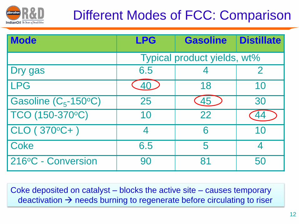
Types of Coke
Coke yield = Feed coke + Catalytic coke + Strippable coke + Contaminant coke
Feed coke = 1 (feed CCR); where, 1 = f1(feed vaporization/distribution)
Catalytic coke = f2 (ROT, Cat/oil ratio, Catalyst/feed quality, Conversion level..)
Strippable coke = f3 (Stripper efficiency, Riser operation- temp.)
Contaminant coke= Coke contributed by the contaminant metals in feed
= f3 (metal level on catalyst, catalyst characteristics, operation severity, use
of metal passivator)
13
Coke deposited on catalyst – blocks the active site – cause temporary
deactivation of the catalysts
Coke on catalyst needs to be burnt to regenerate before circulating to
riser bottom
Balancing coke is the most crucial in design of FCC unit
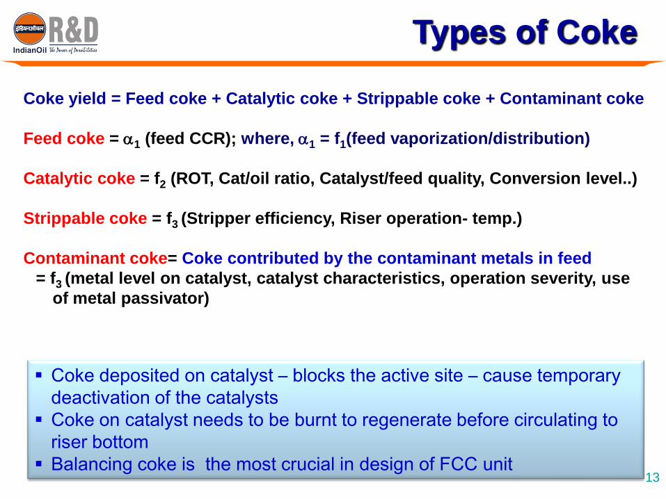
Mode of Catalyst Regeneration
Coke burning reactions
C + 1/2O2 CO (∆H = - 2200 kcal /kg)
CO + 1/2O2 CO2 (∆H = - 5600 kcal /kg)
H2 + 1/2O2 H2O (∆H = - 28900 kcal /kg)
Mode Total
Combustion
Partial
Combustion
Coke on regenerated catalyst, wt% < 0.05 > 0.05
Effective catalyst activity Higher Lower
Regenerator temperature, oC Higher Lower
CO in flue gas, ppm < 1000 > 1000
Requirement of CO Boiler No Yes
Chances of Afterburning Lower Higher
14

FCC Heat Balance
Regenerator ReactorSpent CatalystFlue gas
Heat losses
Regeneration
Air Feed Pre-heater
Recycle
Fresh Feed
Products
Heat LossesHeat of
Coke
Combustion
Heat of
Reaction
Regenerated
Catalyst
15

Coke yield = Wcoke/Wfeed
= Wcat*(CSC-CRC) / Wfeed
= (Cat/Oil)*(Delta Coke)
Delta Coke = (Cpcat / DHcoke )*(Trg-Trc) (Trg-Trc)
Reactor heat demand per unit total feed
Heat of Combustion per unit Coke
= (Cat/Oil)*(Delta Coke)
FCC Heat Balance
Coke yield =
Delta Coke (Trg-Trc)
For a given ROT, more is the Delata coke, more will be the regenerator dense bed temperature
16
17
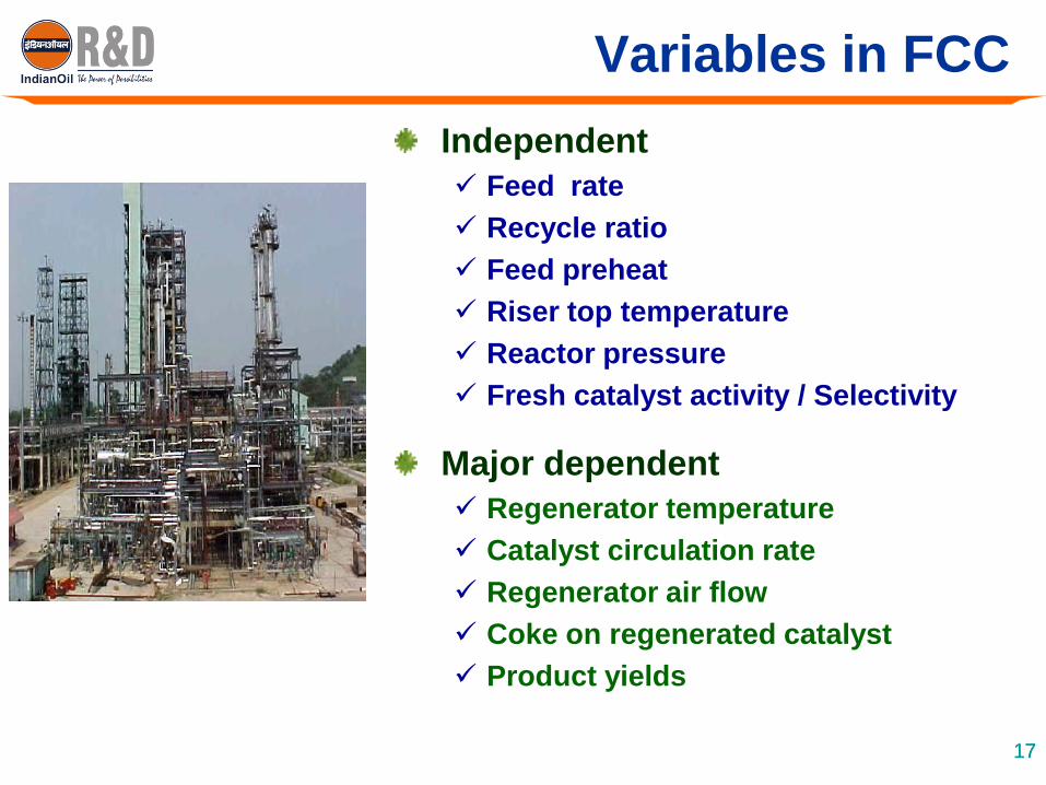
Variables in FCC
Independent
Feed rate
Recycle ratio
Feed preheat
Riser top temperature
Reactor pressure
Fresh catalyst activity / Selectivity
Major dependent
Regenerator temperature
Catalyst circulation rate
Regenerator air flow
Coke on regenerated catalyst
Product yields
17
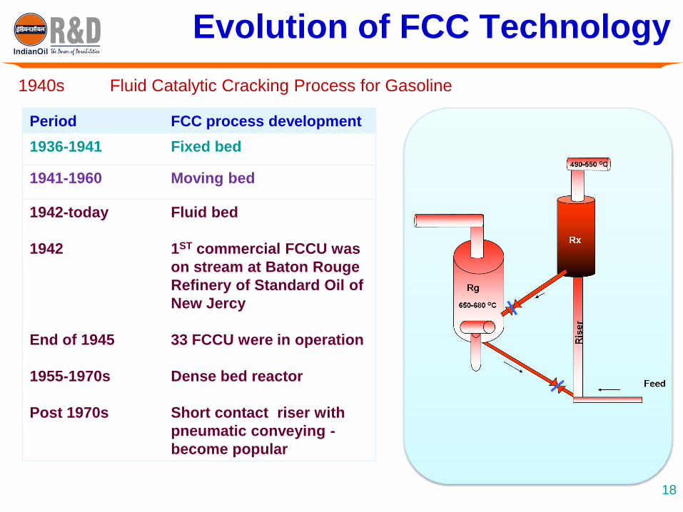
Evolution of FCC Technology
1940s Fluid Catalytic Cracking Process for Gasoline
Period FCC process development
1936-1941 Fixed bed
1941-1960 Moving bed
1942-today
1942
End of 1945
1955-1970s
Post 1970s
Fluid bed
1ST commercial FCCU was
on stream at Baton Rouge
Refinery of Standard Oil of
New Jercy
33 FCCU were in operation
Dense bed reactor
Short contact riser with
pneumatic conveying -
become popular
18

Evolution of FCC Hardware Design
19

Exxon’s Model-IV FCC Unit
Flexi-cracking by ExxonMobil20

Kellogg Orthoflow FCC Converter
Evolution of FCC Hardware Design
Orthoflow Resid FCC Converter 21

UOP RFCC Unit
UOP high efficiency regenerator RFCCU
Resid FCC Units
Fast fluidized
regenerator
Two-stage regenerator
22
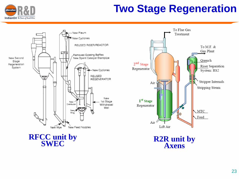
Two Stage Regeneration
RFCC unit by SWEC
R2R unit by Axens
23
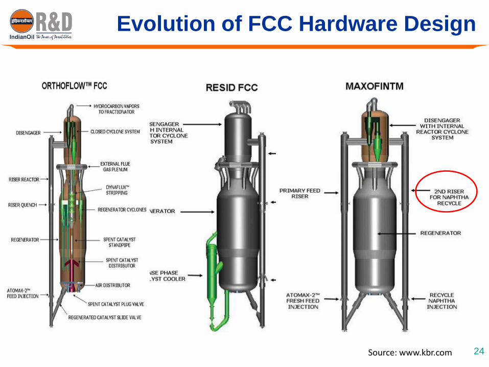
Evolution of FCC Hardware Design
24Source: www.kbr.com

Feed Injection System
Rapid feed vaporization and
uniform mixing with catalyst Reduce non-selective cracking &
thermal reaction
Better feed nozzle design
using dispersion steam
Enhance vaporization
Avoid backmixing of hydrocarbons
Avoid thermal cracking
Reduce hydrocarbon partial pressure
Reduce coke make & improve yieldsFeed coke = 1 (feed CCR)
where, 1 = f1(feed vaporization/distribution)
25

Effect of Feed Atomization
Parameter Case-1 Case-2 Case-3
Oil droplet size, 500 100 30
Relative no. of droplets 1 125 4630
Oil droplets/catalyst particle 0.001 0.11 4
Vaporization time, milisec
at 50% vorization 220 11 4
at 90% vaporization 400 20 8
26

Reactor Riser Disengaging Devices
T-TypeDisengage
r
Down Turned
Arm
VentedRiser
Direct-ConnectedCyclones
27

Vortex Separation System
Reactor Riser Disengaging Devices
Ramshorn type or Linear
Disengaging Device (LD2)
28
Closed Cyclone Riser
Termination
Source: www.kbr.com

Regenerator Cyclone System & Orifice Chamber
Regenerator CyclonesOrifice chamber
Source: www.hason-steel.com
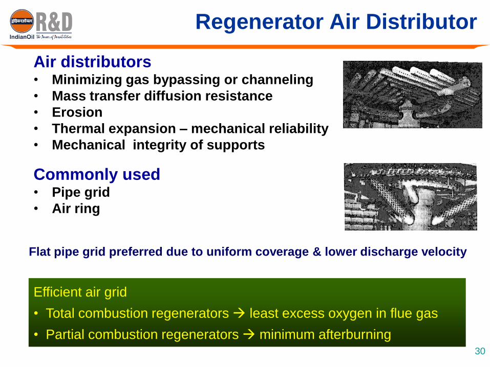
Regenerator Air Distributor
Flat pipe grid preferred due to uniform coverage & lower discharge velocity
Air distributors• Minimizing gas bypassing or channeling
• Mass transfer diffusion resistance
• Erosion
• Thermal expansion – mechanical reliability
• Mechanical integrity of supports
Commonly used• Pipe grid
• Air ring
Efficient air grid
• Total combustion regenerators least excess oxygen in flue gas
• Partial combustion regenerators minimum afterburning30

31
FCC Catalyst Improvement
Zeolite pores
6.5-13. 5A
Matrix pores
10-200A
Interparticle void
1 micron
Colloidal binder
clay
Zeolite: Silica-alumina
Amorphous matrix: Silica, silica-alumina, alumina
Filler clay: Silica-alumina
Other elements: Rare earth, Sodium
Catalysts Heart of FCC process undergone evolutionary changes
1942 Natural clay, Synthetic low alumina catalyst
1948 Micro-spheroidal catalyst (low alumina)
1955 High alumina synthetic catalyst
1961 D5 zeolite TCC bead catalyst
1964 Spray dried fluid Y zeolites
1980 Coke selective Re-HY catalysts
1986 Improvement in Y-zeolites (USY) – low coke selectivity,
Higher octane (low non-framework alumina)
32
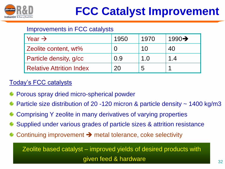
FCC Catalyst Improvement
Today’s FCC catalysts
Porous spray dried micro-spherical powder
Particle size distribution of 20 -120 micron & particle density ~ 1400 kg/m3
Comprising Y zeolite in many derivatives of varying properties
Supplied under various grades of particle sizes & attrition resistance
Continuing improvement metal tolerance, coke selectivity
Year 1950 1970 1990
Zeolite content, wt% 0 10 40
Particle density, g/cc 0.9 1.0 1.4
Relative Attrition Index 20 5 1
Improvements in FCC catalysts
Zeolite based catalyst – improved yields of desired products with
given feed & hardware

ZSM-5 Additive
• Increases yields of LPG / Light olefins
• Improves Gasoline RON
Bottom Cracking Additive
• Upgrades bottom fraction of feed without proportional increase in coke make
GSR Additive
• Reduces Gasoline Sulfur content by ~ 30%
33
CO Promoter
• Enhances CO burning in regenerator dense bed
SOX Control Additive
• Reduces SOx in regenerator flue gas
Ni passivator & V- Trap
• Reduces detrimental effects of metals on product yields & catalyst health
Use of Additives
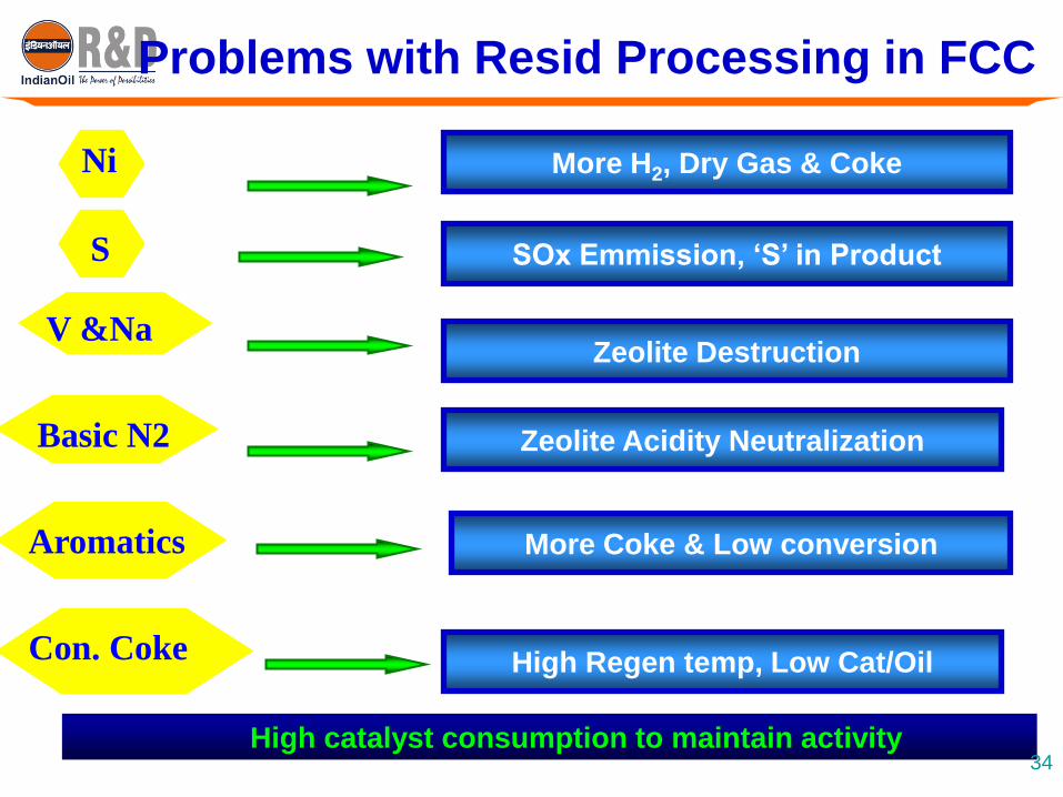
Ni More H2, Dry Gas & Coke
V &NaZeolite Destruction
S SOx Emmission, ‘S’ in Product
Basic N2 Zeolite Acidity Neutralization
Aromatics More Coke & Low conversion
High Regen temp, Low Cat/OilCon. Coke
Problems with Resid Processing in FCC
High catalyst consumption to maintain activity34
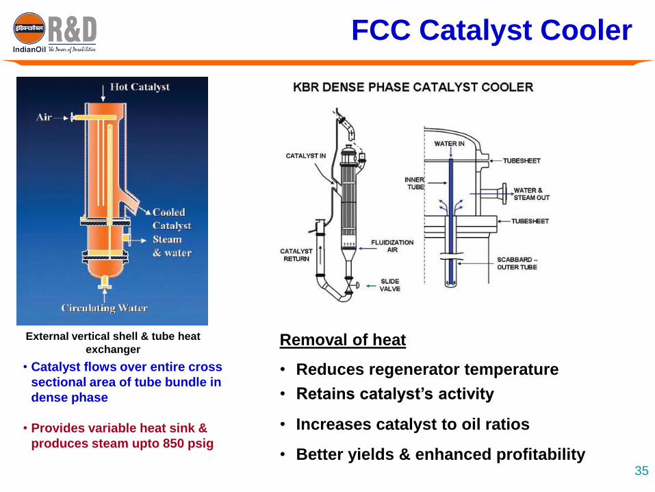
FCC Catalyst Cooler
Removal of heat
• Reduces regenerator temperature
• Retains catalyst’s activity
• Increases catalyst to oil ratios
• Better yields & enhanced profitability
External vertical shell & tube heat
exchanger
• Catalyst flows over entire cross
sectional area of tube bundle in
dense phase
• Provides variable heat sink &
produces steam upto 850 psig
35
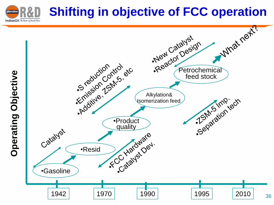
Shifting in objective of FCC operation
•Gasoline
Alkylation& Isomerization feed
•Productquality
•Resid
Petrochemical feed stock
1942 1970 1990 1995 2010
Op
era
tin
g O
bje
cti
ve
36

Technologies Developed by IndianOil
Technology Feed Major products Challenges overcome
INDMAX Heavy feed-
VGO, RCO,
VR (part)
Light olefins, LPG,
high octane
gasoline
• Deep cracking of heavier feed
with lesser Coke & Gas
formation
• Unit heat balance
• Metal deactivation of catalyst
INDALIN Naphtha Light olefins, LPG,
gasoline
• Cracking of low molecular
weight hydrocarbon
• Unit heat balance
INDALIN
Plus
Naphtha Auto-grade LPG
(saturated) & high
octane gasoline
• Cracking of low molecular
weight hydrocarbon
• Unit heat balance
• Saturation of LPG without using
external hydrogen
Dist-Extra Heavy feed-
VGO
Diesel component
with higher cetane
• Optimization of intermediate
fraction with lower yield of
bottom fraction

Indmax Technology – Resid to Olefins
Operational features
High cat/oil ratio (15-25)
Higher riser temperature (>550oC)
High riser steam rate
Relatively lower regen temp.
Benefits
LPG 35-55 wt%
Propylene 17-25 wt% feed
High octane gasoline (95+)
Multifunctional proprietary catalyst
Higher propylene selectivity
Superior metal tolerance
Lower coke make
Indmax can handle high CCR, non-hydrotreated feed
with attractive LPG / light olefins yield
Successfully commissioned at Guwahati refinery in June’03 - Smoothest
commissioning in IOC’s FCC start-up
38

Indmax-FCC Reactor-Regenerator
Micro-Jet Feed
Injection Nozzles
Direct-Coupled
Cyclones
Reaction Riser
(Short Contact Time)
External Regenerated
Catalyst Hopper
Turbulent
Regenerator
Bed
Cyclone
Containment
Vessel (CCV)
MG
Stripper
Direct-Coupled
Cyclones
Turbulent
Regenerator Bed
Cyclone
Containment
Vessel (CCV)
MG
Stripper
39
Being worldwide licensed by Lummus Technology,
USA based on Basic Process Design data/information
& catalyst from IndianOil

INDMAX - Continual Development
Process development &
pilot plant demonstration
Improvement of
light olefins yield
Setting up 85000
BPSD unit
Yields of light olefins
with paraffinic VGO
feed (wt%): Propylene: 27
Butylenes : 15
Ethylene : 14
Scale up &
Commercialization
Collaboration with
Lummus for global
marketing & licensing
INDMAX
40IndianOil’s proven INDMAX technology can meet Refiner’s objectives of propylene maximization &
residue upgradation in cost effective manner
FCC has been the most profitable & flexible refining process for more
than seven decades because of its ability to meet changing demands
FCC technology is still undergoing significant evolution
Beyond certain feed CCR, RFCC becomes too expensive due to
high consumption of catalyst & inferior product yields
Increasing gap in propylene demand & supply drives orientation of
FCC operation towards propylene maximization
Scenario specific tailor made technology can be developed through
proper understanding of fundamentals
IndianOil’s proven INDMAX technology can meet the Refiner’s
objectives of propylene maximization & residue upgradation in an
cost effective manner
Summary
41

Related Documents