Specifications Input Specifications Number of Inputs and Type (1) Single Ended, (1) Common Input Ranges 0-15 VDC, 0-30 VDC, 0-20 mA (DIP Switch Selectable) Input Impedance 100KΩ voltage input / 250Ω current input External DC Power Required 24VAC or 24VDC @ 100mA ±10% Low-pass Filtering -3dB at 100Hz, (-6dB per octave) Set/Release Point Voltage Repeatability 0.05% of full scale Voltage range (Constant temperature) Set/Release Point Current Repeatability 0.1% of full scale Current range (Constant temperature) Output Specifications Relay Contacts 2 SPDT, Form C, non-latching Current Contact Rating 250VAC @ 5A, 30VDC @ 5A (Resistive Load) Relay Operation DIP Switch selectable Relay Trip Point Setting Program Mode enabled by pushbutton Relay Release Point Setting Relay Dead-band = Trip Point ± Release Point 0-15VDC Range: 1.0% minimum deadband (150mV) 0-30VDC Range: 1.0% minimum deadband (300mV) 0-20mA Range: 3.0% minimum deadband (600µA) Terminal Block Specifications Field Wiring Removable Screw Type Terminal Blocks, (included) Number of Positions (2) Two Position (Dinkle: EC350V-02P) (2) Three Position (Dinkle: EC350V-03P) Wire Range 28-14 AWG solid or stranded conductor; wire strip length 1/4” (6-7mm) Screw Torque 1.7 inch-pounds (0.19 Nm) General Specifications Surrounding Air Temperature 0 to 60°C (32 to 140°F) IEC 60068-2-14 (Test Nb, Thermal Shock) Storage Temperature -20 to 70°C (-4 to 158°F) IEC 60068-2-1 (Test Ab, Cold) IEC 60068-2-2 (Test Bb, Dry Heat) IEC 60068-2-14 (Test Na, Thermal Shock) Humidity 5 to 95% (non-condensing) IEC 60068-2-30 (Test Db, Damp Heat) Environmental Air No corrosive gases permitted (EN61131-2 pollution degree 1) Vibration MIL STD 810C 514.2 IEC 60068-2-6 (Test Fc) Shock MIL STD 810C 516.2 IEC 60068-2-27 (Test Ea) Insulation Resistance >10 M Ω@ 500 VDC Noise Immunity NEMA ICS3-304 IEC 61000-4-2 (ESD) Impulse 1000 V @ 1µS pulse IEC 61000-4-4 (FTB) RFI, (145 MHz, 440 MHz 5W @ 15 cm) IEC 61000-4-3 (RFI) Weight 0.3lbs Isolation* 1800VDC Power to Output 1800VDC Input to Output applied for 1 second (100% tested) Agency Approvals UL508**, File Number: E157382, CE * The 0V and COM terminals should be considered the same reference point. There is no isolation between the External Power and Input Terminal blocks. ** In order to comply with UL508, the supplied power must be less than 26VDC and fused at a maximum of 3 amps. Overview This is an Analog to Relay Limit Alarm module that is field configurable for a variety of alarm and control applications. The FC-3RLY2 can be powered by 24VAC or 24VDC and accept input signals of 0-15V, 0-30V, or 0-20mA. Configuration and Trip/Release Point programming is accomplished with DIP Switches, and a single PGM-pushbutton. LED’s provide an indication of operating status and are used during the Trip/Release Point programming. The module can be 35mm DIN rail or side mounted. FC-3RLY2 Analog Input, 2-Relay, Limit Alarm Module UL file E157382 $96.00 Signal Conditioners 1-800-633-0405 tPSC-13 For the latest prices, please check AutomationDirect.com.

Welcome message from author
This document is posted to help you gain knowledge. Please leave a comment to let me know what you think about it! Share it to your friends and learn new things together.
Transcript

SpecificationsInput Specifications
Number of Inputs and Type (1) Single Ended, (1) Common
Input Ranges 0-15 VDC, 0-30 VDC, 0-20 mA (DIP Switch Selectable)
Input Impedance 100KΩ voltage input / 250Ω current input
External DC Power Required 24VAC or 24VDC @ 100mA ±10%
Low-pass Filtering -3dB at 100Hz, (-6dB per octave)
Set/Release Point Voltage Repeatability
0.05% of full scale Voltage range (Constant temperature)
Set/Release Point Current Repeatability
0.1% of full scale Current range (Constant temperature)
Output SpecificationsRelay Contacts 2 SPDT, Form C, non-latching
Current Contact Rating 250VAC @ 5A, 30VDC @ 5A (Resistive Load)
Relay Operation DIP Switch selectable
Relay Trip Point SettingProgram Mode enabled by pushbutton
Relay Release Point SettingRelay Dead-band = Trip Point ± Release Point
0-15VDC Range: 1.0% minimum deadband (150mV) 0-30VDC Range: 1.0% minimum deadband (300mV) 0-20mA Range: 3.0% minimum deadband (600µA)
Terminal Block SpecificationsField Wiring Removable Screw Type Terminal Blocks, (included)
Number of Positions (2) Two Position (Dinkle: EC350V-02P) (2) Three Position (Dinkle: EC350V-03P)
Wire Range 28-14 AWG solid or stranded conductor; wire strip length 1/4” (6-7mm)
Screw Torque 1.7 inch-pounds (0.19 Nm)
General Specifications
Surrounding Air Temperature 0 to 60°C (32 to 140°F)IEC 60068-2-14 (Test Nb, Thermal Shock)
Storage Temperature
-20 to 70°C (-4 to 158°F)IEC 60068-2-1 (Test Ab, Cold)
IEC 60068-2-2 (Test Bb, Dry Heat)IEC 60068-2-14 (Test Na, Thermal Shock)
Humidity 5 to 95% (non-condensing)IEC 60068-2-30 (Test Db, Damp Heat)
Environmental Air No corrosive gases permitted (EN61131-2 pollution degree 1)
Vibration MIL STD 810C 514.2IEC 60068-2-6 (Test Fc)
Shock MIL STD 810C 516.2IEC 60068-2-27 (Test Ea)
Insulation Resistance >10 M Ω@ 500 VDC
Noise Immunity
NEMA ICS3-304IEC 61000-4-2 (ESD)
Impulse 1000 V @ 1µS pulseIEC 61000-4-4 (FTB)
RFI, (145 MHz, 440 MHz 5W @ 15 cm)IEC 61000-4-3 (RFI)
Weight 0.3lbs
Isolation*1800VDC Power to Output1800VDC Input to Output
applied for 1 second (100% tested)
Agency Approvals UL508**, File Number: E157382, CE* The 0V and COM terminals should be considered the same reference point. There is no isolation
between the External Power and Input Terminal blocks.* * In order to comply with UL508, the supplied power must be less than 26VDC and fused at a
maximum of 3 amps.
OverviewThis is an Analog to Relay Limit Alarm module that is field configurable for a variety of alarm and control applications. The FC-3RLY2 can be powered by 24VAC or 24VDC and accept input signals of 0-15V, 0-30V, or 0-20mA. Configuration and Trip/Release Point programming is accomplished with DIP Switches, and a single PGM-pushbutton. LED’s provide an indication of operating status and are used during the Trip/Release Point programming. The module can be 35mm DIN rail or side mounted.
FC-3RLY2 Analog Input, 2-Relay, Limit Alarm Module
UL file E157382
$96.00
Signal Conditioners 1 - 8 0 0 - 6 3 3 - 0 4 0 5tPSC-13
For the latest prices, please check AutomationDirect.com.

FC-3RLY2 Modes of OperationIndependent and Simultaneous Relay Control Modes
Independent Relay Control ModeRelays A and B are controlled with independent Trip Points and Release Points for each relay. Relays A and B can be inde-pendently set to operate in Increasing or Decreasing mode (see next section). This mode can be used to control two loads in sequence, or monitor for multilevel alarm conditions.
Simultaneous Relay Control ModeRelays A and B operate simultaneously, both controlled by Trip Point A and Release Point A settings. Both relays operate in Increasing or Decreasing mode (see next section). This mode can be used where it is desired to have both relays controlled by common Trip and Release points such as using one relay for local alarm indication with a horn or strobe and the other relay for remote alarm monitoring by a PLC.
Relay Trip/Release Point Control Modes Normal (Non-failsafe)
Increasing (INC) Mode The relay will turn ON when the input signal increases to the programmed Trip Point. The relay will remain ON until the input signal decreases below the Release Point. In INC mode, the Trip Point must always be greater than the Release Point (TP > RP).
Decreasing (DEC) Mode The relay will turn ON when the input signal decreases below the programmed Trip Point. The relay will remain ON until the input signal increases above the Release Point. In DEC mode, the Trip Point must always be less than the Release Point (TP < RP).
Failsafe ModeIncreasing (INC) Mode The relay will turn OFF when the input signal increases to the programmed Trip Point. The relay will remain OFF until the input signal decreases below the Release Point. In INC mode, the Trip Point must always be greater than the Release Point (TP > RP).
Signal Conditioners 1 - 8 0 0 - 6 3 3 - 0 4 0 5tPSC-14
For the latest prices, please check AutomationDirect.com.
FC-3RLY2 Modes of Operation (continued)
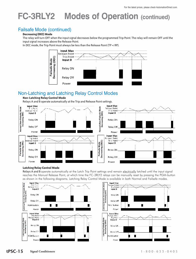
Failsafe Mode (continued)Decreasing (DEC) Mode The relay will turn OFF when the input signal decreases below the programmed Trip Point. The relay will remain OFF until the input signal increases above the Release Point. In DEC mode, the Trip Point must always be less than the Release Point (TP < RP).
Non-Latching and Latching Relay Control ModesNon-Latching Relay Control Mode Relays A and B operate automatically at the Trip and Release Point settings.
Latching Relay Control Mode Relays A and B operate automatically at the Latch Trip Point settings and remain electrically latched until the input signal reaches the Manual Release Point, at which time the FC-3RLY2 relays can be manually reset by pressing the PGM-button as shown in the following diagrams. Latching Relay Control Mode is available in both Normal and Failsafe modes.
Signal Conditioners 1 - 8 0 0 - 6 3 3 - 0 4 0 5tPSC-15
For the latest prices, please check AutomationDirect.com.
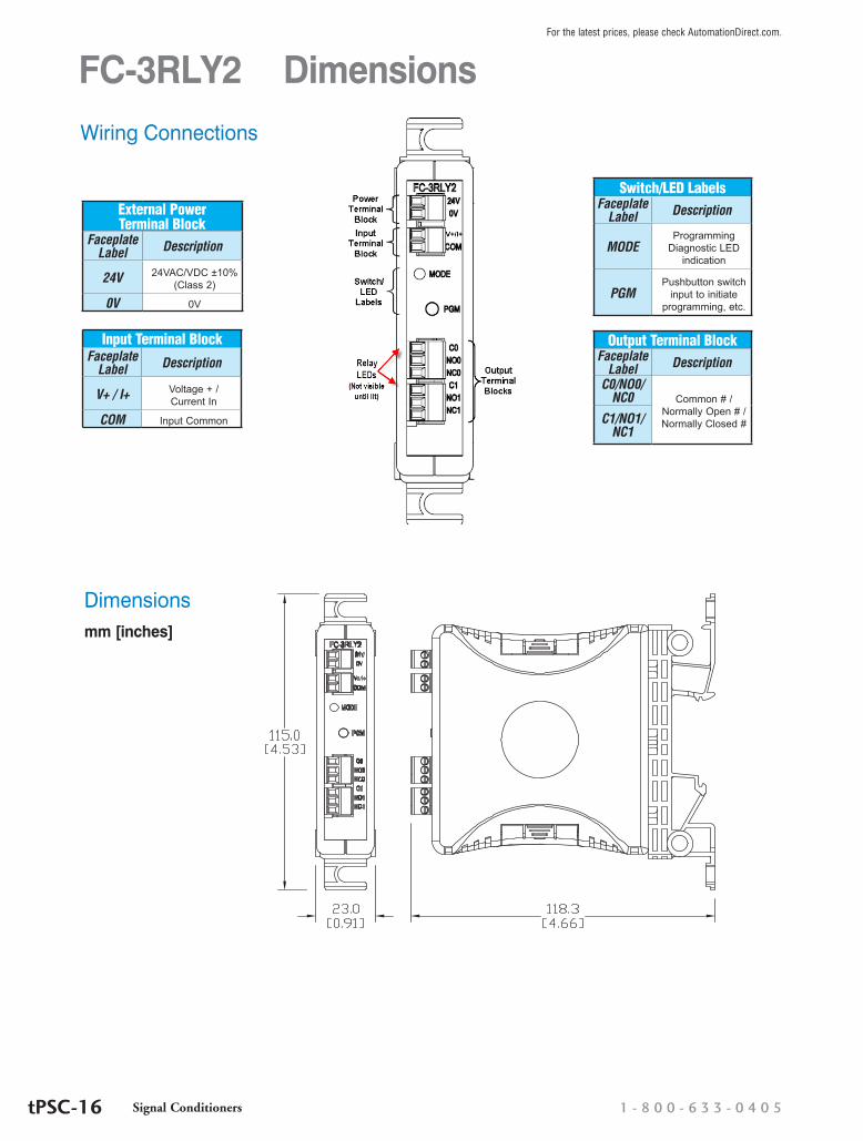
FC-3RLY2 Dimensions
Dimensionsmm [inches]
External Power Terminal Block
Faceplate Label Description
24V 24VAC/VDC ±10% (Class 2)
0V 0V
Input Terminal BlockFaceplate
Label Description
V+ / I+ Voltage + / Current In
COM Input Common
Switch/LED LabelsFaceplate
Label Description
MODEProgramming
Diagnostic LED indication
PGMPushbutton switch
input to initiate programming, etc.
Wiring Connections
Output Terminal BlockFaceplate
Label Description
C0/NO0/NC0 Common # /
Normally Open # / Normally Closed #C1/NO1/
NC1
Signal Conditioners 1 - 8 0 0 - 6 3 3 - 0 4 0 5tPSC-16
For the latest prices, please check AutomationDirect.com.
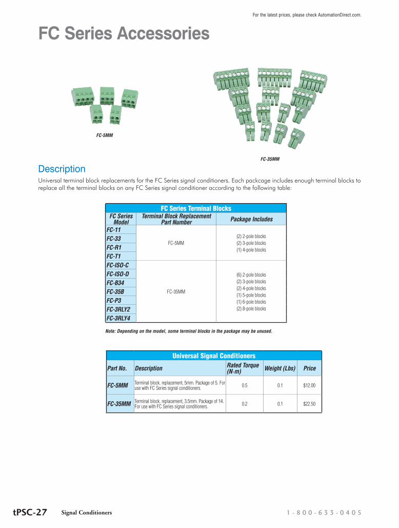
FC Series Accessories
DescriptionUniversal terminal block replacements for the FC Series signal conditioners. Each packcage includes enough terminal blocks to replace all the terminal blocks on any FC Series signal conditioner according to the following table:
FC Series Terminal BlocksFC Series
ModelTerminal Block Replacement
Part Number Package Includes
FC-11
FC-5MM(2) 2-pole blocks(2) 3-pole blocks(1) 4-pole blocks
FC-33FC-R1FC-T1FC-ISO-C
FC-35MM
(6) 2-pole blocks(2) 3-pole blocks(2) 4-pole blocks(1) 5-pole blocks(1) 6-pole blocks(2) 8-pole blocks
FC-ISO-DFC-B34FC-35BFC-P3FC-3RLY2FC-3RLY4
Note: Depending on the model, some terminal blocks in the package may be unused.
FC-5MM
FC-35MM
Universal Signal Conditioners
Part No. Description Rated Torque (N·m) Weight (Lbs) Price
FC-5MM Terminal block, replacement, 5mm. Package of 5. For use with FC Series signal conditioners. 0.5 0.1 $12.00
FC-35MM Terminal block, replacement, 3.5mm. Package of 14. For use with FC Series signal conditioners. 0.2 0.1 $22.50
Signal Conditioners 1 - 8 0 0 - 6 3 3 - 0 4 0 5tPSC-27
For the latest prices, please check AutomationDirect.com.
Signal Conditioners 1 - 8 0 0 - 6 3 3 - 0 4 0 5tPSC-1
For the latest prices, please check AutomationDirect.com.
FC Series Signal ConditionersFC-33DC Selectable Signal Conditioner with 3-way isolation
Field configurable input and output ranges of 0-5V, 0-10 V, 0-20 mA and 4-20 mA with 1500 VDC isolation between input and output, and 1500 VDC isolation from 24 volt power and input/output. LED indicates normal operation and is used in conjunction with the calibration pushbutton for the internal calibration process.
• 3-way 1500 V isolation• Push button calibration
FC-T1 Thermocouple/mV Isolated Signal Conditioner
Field configurable input for type J, K, E, T, R, S, B, N and C thermocouples or ±156.25 mV inputs with 1500 VDC isolation between input and the 4-20 mA output. Cold junction compensa-tion and burnout detection. Alarm/run LED.
• 1500 V isolation• Cold junction compensation (CJC)• Internal diagnostics (burnout detection or calibration errors)
FC-35BUnipolar Voltage or Current to Bipolar Voltage Signal Conditioner
Field configurable input and output, unipolar input ranges of 0-5V, 0-10 V, 0-20 mA or 4-20 mA, and bipolar output ranges of ±100 mV, ±50 mV, ±5V, ±10V, ±15V. Field calibrated with offset and span adjustments.
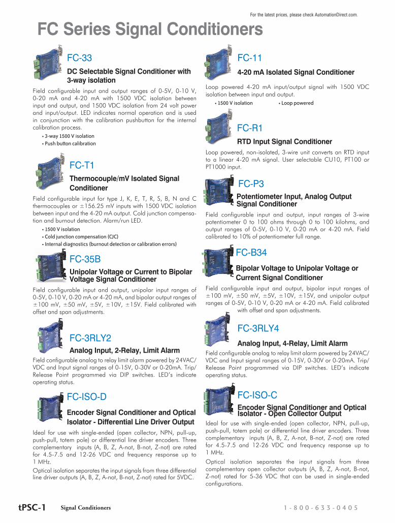
FC-3RLY2Analog Input, 2-Relay, Limit Alarm
Field configurable analog to relay limit alarm powered by 24VAC/VDC and Input signal ranges of 0-15V, 0-30V or 0-20mA. Trip/Release Point programmed via DIP switches. LED’s indicate operating status.
FC-ISO-DEncoder Signal Conditioner and Optical Isolator - Differential Line Driver Output
Ideal for use with single-ended (open collector, NPN, pull-up, push-pull, totem pole) or differential line driver encoders. Three complementary inputs (A, B, Z, A-not, B-not, Z-not) are rated for 4.5-7.5 and 12-26 VDC and frequency response up to 1 MHz.Optical isolation separates the input signals from three differential line driver outputs (A, B, Z, A-not, B-not, Z-not) rated for 5VDC.
FC-114-20 mA Isolated Signal Conditioner
Loop powered 4-20 mA input/output signal with 1500 VDC isolation between input and output.
• 1500 V isolation • Loop powered
FC-R1 RTD Input Signal Conditioner
Loop powered, non-isolated, 3-wire unit converts an RTD input to a linear 4-20 mA signal. User selectable CU10, PT100 or PT1000 input.
FC-P3Potentiometer Input, Analog Output Signal Conditioner
Field configurable input and output, input ranges of 3-wire potentiometer 0 to 100 ohms through 0 to 100 kilohms, and output ranges of 0-5V, 0-10 V, 0-20 mA or 4-20 mA. Field calibrated to 10% of potentiometer full range.
FC-B34Bipolar Voltage to Unipolar Voltage or Current Signal Conditioner
Field configurable input and output, bipolar input ranges of ±100 mV, ±50 mV, ±5V, ±10V, ±15V, and unipolar output ranges of 0-5V, 0-10 V, 0-20 mA or 4-20 mA. Field calibrated
with offset and span adjustments.
FC-3RLY4Analog Input, 4-Relay, Limit Alarm
Field configurable analog to relay limit alarm powered by 24VAC/VDC and Input signal ranges of 0-15V, 0-30V or 0-20mA. Trip/Release Point programmed via DIP switches. LED’s indicate operating status.
FC-ISO-CEncoder Signal Conditioner and Optical Isolator - Open Collector Output
Ideal for use with single-ended (open collector, NPN, pull-up, push-pull, totem pole) or differential line driver encoders. Three complementary inputs (A, B, Z, A-not, B-not, Z-not) are rated for 4.5-7.5 and 12-26 VDC and frequency response up to 1 MHz.
Optical isolation separates the input signals from three complementary open collector outputs (A, B, Z, A-not, B-not, Z-not) rated for 5-36 VDC that can be used in single-ended configurations.
Related Documents