FBG-Based Matched Filters for Optical Processing of RF Signals Volume 4, Number 3, June 2012 Mansour Dastmalchi, Student Member, IEEE Serge Doucet Leslie A. Rusch, Fellow, IEEE Sophie LaRochelle, Member, IEEE DOI: 10.1109/JPHOT.2012.2198805 1943-0655/$31.00 ©2012 IEEE

Welcome message from author
This document is posted to help you gain knowledge. Please leave a comment to let me know what you think about it! Share it to your friends and learn new things together.
Transcript
FBG-Based Matched Filters for Optical Processing of RF SignalsVolume 4, Number 3, June 2012
Mansour Dastmalchi, Student Member, IEEESerge DoucetLeslie A. Rusch, Fellow, IEEESophie LaRochelle, Member, IEEE
DOI: 10.1109/JPHOT.2012.21988051943-0655/$31.00 ©2012 IEEE

FBG-Based Matched Filters for OpticalProcessing of RF Signals
Mansour Dastmalchi, Student Member, IEEE, Serge Doucet,Leslie A. Rusch, Fellow, IEEE, and Sophie LaRochelle, Member, IEEE
COPL, Department of Electrical and Computer Engineering, Universite Laval,Quebec, QC G1V 0A6, Canada
DOI: 10.1109/JPHOT.2012.21988051943-0655/$31.00 �2012 IEEE
Manuscript received April 5, 2012; revised May 1, 2012; accepted May 2, 2012. Date of publicationMay 10, 2012; date of current version May 22, 2012. Corresponding author: M. Dastmalchi (e-mail:[email protected]).
Abstract: We demonstrate the detection of RF pulses using complex matched filtersimplemented in photonics. The optical receiver consists of an intensity Mach–Zehndermodulator (MZM) for electrical-to-optical conversion as well as precisely tailored fiber Bragggrating (FBG) filters performing as matched filters. We examine the performance of thereceiver under two bias conditions of the MZM, namely, quadrature and minimumtransmission. We design the corresponding matched filters for both cases by optimizingthe impulse response of linearly chirped FBGs. We fabricate the FBGs by achieving therequired apodization profiles through a multiple-scan writing procedure. We discuss therelative performance of the two solutions.
Index Terms: Complex matched filters, fiber Bragg gratings (FBGs), microwave photonics,RF signal detection, RF pulse compression, optical signal processing, ultrawideband (UWB).
1. IntroductionLow average-power wideband signals find many applications in diverse fields such as medicine,ranging and communication systems [1]–[6]. In order to serve many users in closely located areaswithout interference, these signal transmissions are regulated by constraints on the averagedpower spectral density [1]. Consequently, the emitted peak pulse power must decrease as the datatransmission rate increases, which makes the design of a simple, power efficient and low costtransceiver a challenging task. Since the generation and processing of wideband signals withnarrow pulse width is difficult when using conventional electronic devices and circuits [7], [8], therehave been several proposals of using microwave photonics to process these signals in the opticaldomain [9]–[18]. By taking advantage of the wide bandwidth and high speed offered by microwavephotonics, good quality pulse shaping has been demonstrated using a variety of programmabletechniques to generate the desired wideband signals [10]–[14]. However, very few studies existregarding the optical processing of wideband signals at the receiver side.
Different techniques have been used to detect microwave signals. In one approach, the decisionis made based on the energy or envelope detection of the received signal [14], [19], [20]. Sinceenergy or envelope receivers are not efficient for detection of low energy signals in noisy systems,correlation or matched filter detection techniques were proposed to improve the performance. In[18], a reference signal was correlated with the signal at the receiver. However, this techniquerequires precise synchronization of the received signal with the reference one. An alternative to thistechnique is to use matched filters.
Vol. 4, No. 3, June 2012 Page 832
IEEE Photonics Journal FBG-Based Matched Filters
The optimal filter for signal detection in the presence of noise is the matched filter, whichmaximizes the output signal-to-noise ratio (SNR) [21]. For any waveform SðtÞ, a filter is matched toSðtÞ if it has an impulse response of the form hðtÞ ¼ k Sðt0 � tÞ where k and t0 are arbitraryconstants [21]. The concept of matched filter for wideband RF signal detection in the electricaldomain was recently proposed but bandwidth limitations of RF components was found to degradethe matched filter performance [22]. In order to overcome these limitations of signal processing inthe electrical domain, we propose to process the signal in the optical domain using optical filterstailored as matched filters.
Very few studies have been done on the concept of matched filters for wideband radio frequencysignals. In [16], [17], phase-only matched filters were demonstrated for chirped microwave signals.In one approach, a chirped fiber Bragg grating (FBG) was used to compensate the quadratic phaseof the single-sideband modulated signal [16]. Optical matched filters can be also implemented usingcommercially available fully programmable filters that can provide arbitrary phase and amplitude, i.e.,complex response. However, these filters are elaborate systems implemented in free space that areunsuitable for many applications due to their high loss, size and cost. Phase-only matched filtering ofa chirped signal with a free-space programmable filter was demonstrated in [17]. Although phase-onlyfilters can be more convenient to implement than complex ones, matched-filtering of an arbitrarysignal requires tailoring of both the amplitude and phase in order to optimize the output SNR andachieve a better tolerance to noise [23].
Optical processing of microwave signals first requires the electrical signal to be modulated overan optical carrier. The modulated optical signal is then processed by the optical filter before beingconverted back into the electrical domain by a photodiode. A Mach–Zehnder modulator (MZM)biased at the quadrature point is usually used to achieve amplitude modulation in a linear regime.But since the optical filter has some limitations in the achievable spectral responses, it can beadvantageous to simultaneously optimize the MZM operating point and the optical filter design.
In this paper, we design a complex matched filter for a wideband RF signal based on using alinearly chirped FBG (LCFBG). FBGs provide a practical solution, i.e., compact and low cost, foroptical systems that require customized amplitude and phase filters. To demonstrate the approach,we consider the specific example of a Gaussian monocycle signal, which is commonly used inultrawideband (UWB) indoor communication systems. We further consider two bias points for theMZM, quadrature and null, and we fabricate optimized FBG filters for both these cases. We presentexperimental results showing the obtained impulse responses and we discuss the performance ofthe receiver in terms of the Q-factor.
The remainder of this paper is organized as follows. In Section 2, we present the proposed opticalreceiver, we discuss the writing procedure to achieve precise apodization of the FBG filters, and weintroduce the experimental setup that includes a UWB waveform generator. In Sections 3 and 4, wepresent the design parameters and the corresponding experimental results of matched filtering forthe two bias points of the MZM. Experimentally detected pulse shapes are compared to simulations.In Section 5, we investigate the performance of the receivers for data transmission by looking at theeye diagrams and measuring the Q-factors. Conclusions follow in Section 6.
2. Experimental Arrangement
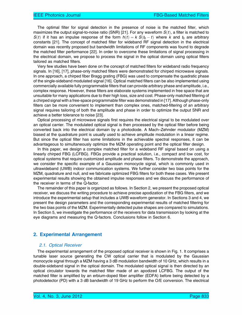
2.1. Optical ReceiverThe experimental arrangement of the proposed optical receiver is shown in Fig. 1. It comprises a
tunable laser source generating the CW optical carrier that is modulated by the Gaussianmonocycle signal through a MZM having a 3 dB modulation bandwidth of 10 GHz, which results in adouble-sideband signal in the optical domain. The modulated optical signal is then directed by anoptical circulator towards the matched filter made of an apodized LCFBG. The output of thematched filter is amplified by an erbium-doped fiber amplifier (EDFA) before being detected by aphotodetector (PD) with a 3 dB bandwidth of 19 GHz to perform the O/E conversion. The electrical
IEEE Photonics Journal FBG-Based Matched Filters
Vol. 4, No. 3, June 2012 Page 833
signal is then measured by a high speed sampling oscilloscope (Agilent DCA-50 GHz) after passingthrough a DC-block.
2.2. FBG Design and FabricationConsidering that SM ðtÞ is the intensity MZM output, we use hGðtÞ ¼ k SM ðt0 � tÞ as the target
impulse response for the FBG filter. Optimization of the grating impulse response is performed bydesigning a suitable apodization profile of the refractive index modulation along the LCFBG. Indesigning the grating we need to optimize not only the impulse response shape but we also aim toachieve the highest reflectivity in order to improve the system power efficiency. For a weak FBG,the impulse response follows the grating apodization profile but for strong gratings this is of courseno longer valid. In our case, we introduce a small grating chirp to cover the whole pulse spectrumand use the appropriate grating length to map the grating impulse response to the desired signalduration. Then, in order to design the LCFBG filter that meets our requirements, we use an iterativeoptimization algorithm to determine the apodization profile [24]. In this method, we first introduce asegmented arbitrary apodization profile and then successively change the amplitude of theapodization for each segment along the grating in order to minimize the relative error between thecalculated FBG impulse response and the desired target. The segment length, or apodizationprofile resolution, is then gradually decreased until convergence is obtained for the minimumsegment length fixed by the experimental limitations. More detail on the technique can be found in[24]. The objective of the design is to match the FBG impulse response to the target impulseresponse with the highest possible reflectivity.
Once the apodization profile has been obtained, we fabricate the FBGs using a writing techniquewith multiple successive scans of the phase mask in order to precisely control the grating impulseresponse, which depends on both the apodization shape and grating strength. By using multiplescans, we can apply corrections to the written apodization profile in order to achieve our targetimpulse response while simultaneously increasing the FBG reflectivity. In this way we can graduallycorrect for effects such as the saturation of the photoinduced index change that results in anonlinear response of the photosensitive fiber as a function of exposure. FBGs are fabricated usinga frequency-doubled Argon ion laser at 244 nm and phase-mask dithering to control the apodizationprofile. Gratings are written in Deuterium-loaded photosensitive fibers (Coractive UVS-INT).Scanning speed and UV laser power are also adjusted for each scan. In order to gradually refine theapodization profile towards the target impulse response, we monitored the FBG impulse responseduring the writing process using a commercial optical frequency-domain reflectometry (OFDR)instrument (OVA, Luna Technologies). From this measurement, we calculate the correspondingapodization profile present in the fiber with the same algorithm that was used in the design process.We then determine the apodization for the next scan from the difference between our designapodization and the apodization imprinted in the fiber. We typically apply six scans to write thegrating. For the first three scans, phase mask dithering is controlled with the original apodization
Fig. 1. Schematic of the proposed optical receiver.
IEEE Photonics Journal FBG-Based Matched Filters
Vol. 4, No. 3, June 2012 Page 834
profile. After the third scan, the impulse response is monitored and the apodization profile isreadjusted for the final three scans.
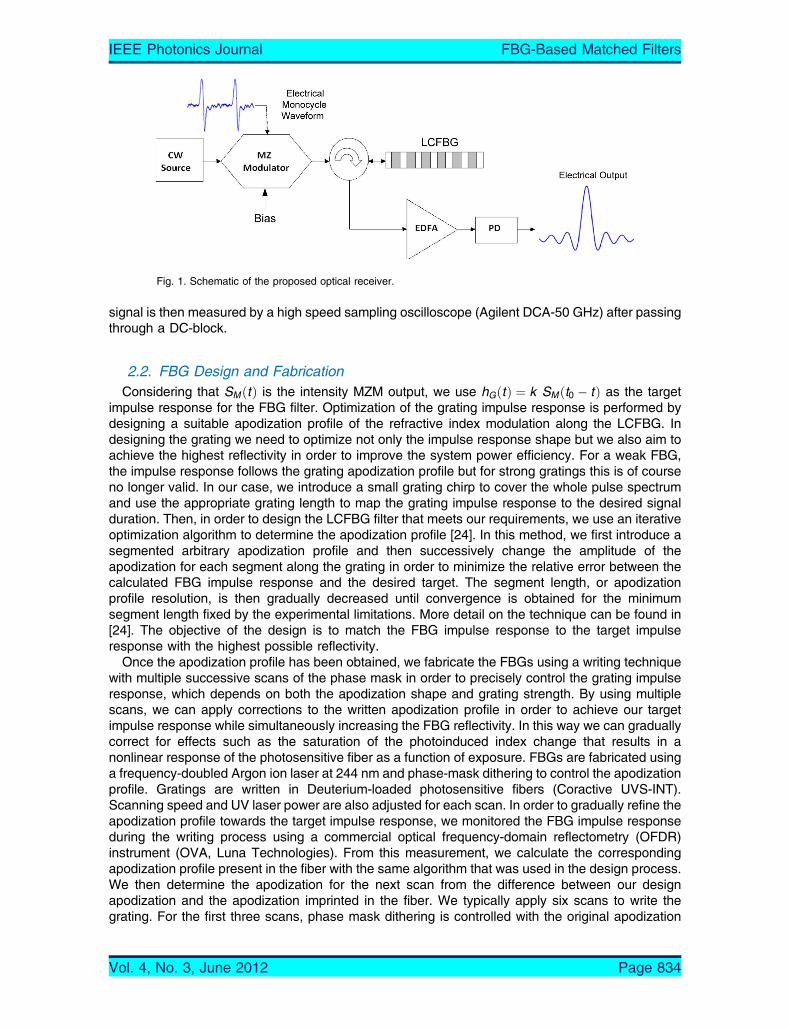
2.3. Reconfigurable Waveform GeneratorVarious optical or electrical pulse generating techniques can be used to generate a wideband RF
pulse with a Gaussian monocycle shape. As shown in Fig. 2, we chose to use the reconfigurablewaveform generator that was available in our laboratory. The signal generator performs spectralshaping of an optical broadband source using two LCFBGs with proper thermal apodization andfrequency-to-time conversion using standard optical fiber G.652 (Corning SMF28) as a dispersiveline to generate arbitrary waveforms. The optical source is a gain-switched laser (GSL) with anoptical bandwidth of 1.3 nm, a pulse FWHM of 15.38 ps, and a repetition rate of 1 GHz. A SMFlength of 15 km is chosen to map the spectrum to the desired RF pulse duration. The series ofresistive heating elements (RHEs) allow us to apply the proper temperature profiles to the LCFBGsplaced in the two arms of a balanced PD (BPD) in order to generate the monocycle signal. Thiswaveform generator is described in detail in [14].
3. Optical Receiver and Matched Filter for RF Signal Modulationwith MZM Biased at Quadrature Point
3.1. Design Parameters and Experimental ResultsWe first examine the matched filter design in the case where the Gaussian monocycle signal from
the waveform generator modulates the optical carrier with the MZM biased at the quadrature point.The experimentally measured optical signal, SM ðtÞ, and the corresponding calculated spectrumaround the carrier frequency are shown in Fig. 3. Note that the linear spectral phase, correspondingto the pulse time delay, is removed from the calculated spectral phase. In order to design the FBGmatched filter, we first determine the required spectral bandwidth of the double-sideband spectrumof the modulated signal shown in the inset of Fig. 3. We found that limiting the spectrum to a windowof �f � 16 GHz introduced negligible distortion on the signal. With a FBG operating in reflection,achieving an impulse response that can be tailored over the desired Gaussian monocycle pulseduration of �t ¼ 267 ps requires a grating length of approximately �z ¼ c�t=2ng ¼ 2:8 cm wherec and ng are respectively the speed of light and the fiber group index. Considering the required16 GHz signal bandwidth and the fiber length specified above, we introduce a small phasemask chirp of CPhM ¼ ��=n�z ¼ 0:032 nm/cm. At the receiver, the Gaussian monocycle is presenton top of a pedestal that has duration of one bit. To match this duration we use a grating length ofz ¼ c=ð2ngRÞ ¼ 10 cm, which corresponds to one bit at a signal repetition rate of R= 1 GHz. Thedesigned apodization profile is shown in Fig. 4 (red) and the corresponding calculated impulseresponse is shown in Fig. 5 (blue).
We wrote the FBG-based matched filter using six UV writing scans over the fiber. After the thirdscan, we measured the FBG impulse response and deduced the error between the target
Fig. 2. Schematic of the reconfigurable waveform generator.
IEEE Photonics Journal FBG-Based Matched Filters
Vol. 4, No. 3, June 2012 Page 835

apodization and the written profile. This error, shown in Fig. 4 (black), became the new apodizationprofile for the last three remaining scans. Fig. 6 shows the measured FBG spectral response inreflection (amplitude and phase) after six scans. The phase value was extracted from the Jonesmatrix elements of the spectral response measured using the OFDR system [25]. Fig. 5 comparesthe measured FBG impulse response to the designed one corresponding to the target apodizationprofile. Fig. 7 shows the comparison between the FBG impulse response and the time-invertedversion of the modulated optical signal where it can be seen that a good match is obtained.Introducing the FBG in the proposed receiver, wemeasured the output signal as shown in Fig. 8 (red).The signal after the matched filter and photodetection was calculated using the measured complexspectral response of Fig. 6 and is also displayed in Fig. 8 (blue). Because the grating was notpackaged, during the experiment the laser wavelength was tuned to find the right operation point. Weperformed the same operation numerically and found a good match with the experimental results
Fig. 4. Target (red) apodization profile of the FBG matched filter designed for the MZM biased atquadrature point. Also shown are the measured apodization profile monitored after the third scan (blue)and the error corresponding to the modified apodization profile (black).
Fig. 3. Measured optical signal with MZM biased at a quadrature point. Inset is the correspondingcalculated spectrum amplitude (blue) and phase (red).
IEEE Photonics Journal FBG-Based Matched Filters
Vol. 4, No. 3, June 2012 Page 836
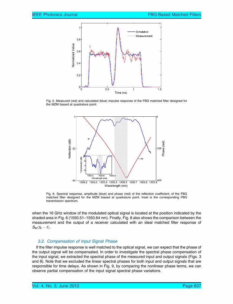
when the 16 GHz window of the modulated optical signal is located at the position indicated by theshaded area in Fig. 6 (1550.51–1550.64 nm). Finally, Fig. 8 also shows the comparison between themeasurement and the output of a receiver calculated with an ideal matched filter response ofSM ðt0 � tÞ.
3.2. Compensation of Input Signal PhaseIf the filter impulse response is well matched to the optical signal, we can expect that the phase of
the output signal will be compensated. In order to investigate the spectral phase compensation ofthe input signal, we extracted the spectral phase of the measured input and output signals (Figs. 3and 8). Note that we excluded the linear spectral phases for both input and output signals that areresponsible for time delays. As shown in Fig. 9, by comparing the nonlinear phase terms, we canobserve partial compensation of the input signal spectral phase variations.
Fig. 6. Spectral response, amplitude (blue) and phase (red) of the reflection coefficient, of the FBGmatched filter designed for the MZM biased at quadrature point. Inset is the corresponding FBGtransmission spectrum.
Fig. 5. Measured (red) and calculated (blue) impulse response of the FBG matched filter designed forthe MZM biased at quadrature point.
IEEE Photonics Journal FBG-Based Matched Filters
Vol. 4, No. 3, June 2012 Page 837
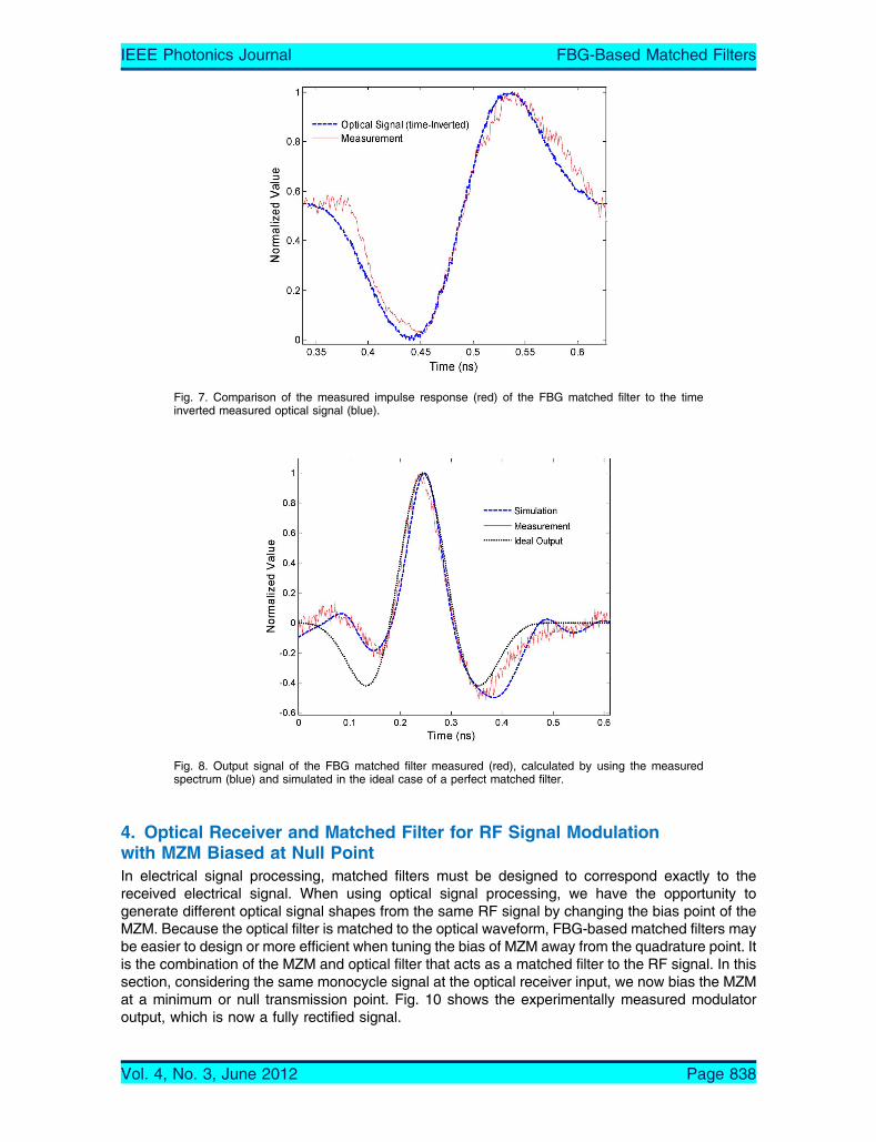
4. Optical Receiver and Matched Filter for RF Signal Modulationwith MZM Biased at Null PointIn electrical signal processing, matched filters must be designed to correspond exactly to thereceived electrical signal. When using optical signal processing, we have the opportunity togenerate different optical signal shapes from the same RF signal by changing the bias point of theMZM. Because the optical filter is matched to the optical waveform, FBG-based matched filters maybe easier to design or more efficient when tuning the bias of MZM away from the quadrature point. Itis the combination of the MZM and optical filter that acts as a matched filter to the RF signal. In thissection, considering the same monocycle signal at the optical receiver input, we now bias the MZMat a minimum or null transmission point. Fig. 10 shows the experimentally measured modulatoroutput, which is now a fully rectified signal.
Fig. 8. Output signal of the FBG matched filter measured (red), calculated by using the measuredspectrum (blue) and simulated in the ideal case of a perfect matched filter.
Fig. 7. Comparison of the measured impulse response (red) of the FBG matched filter to the timeinverted measured optical signal (blue).
IEEE Photonics Journal FBG-Based Matched Filters
Vol. 4, No. 3, June 2012 Page 838

4.1. FBG Design and ResultsIn order to determine the required bandwidth, we calculated the spectrum of the rectified signal
generated by the MZM biased at the null point. This is shown in the inset of Fig. 10. Observing thegenerated signal when windowing the spectrum, we determined that a double sideband bandwidthof �f � 25 GHz introduced negligible distortion. In order to have an impulse response matched tothe signal duration of �t ¼ 210 ps, we need a FBG length of 2.17 cm. Considering the signalbandwidth and fiber length, the required phasemask chirp becomesCPhM ¼ ��=n�z ¼ 0:065 nm/cm.The FBGapodizationwas found using the iterative algorithm and the filter waswritten using themultiple-scan procedure as described above. The measured FBG impulse response and correspondingreflection/transmission spectrums are shown in Figs. 11 and 12. Fig. 11 shows the comparison be-tween the measured FBG impulse response and the time-inverted version of the fully rectified electricalsignal.
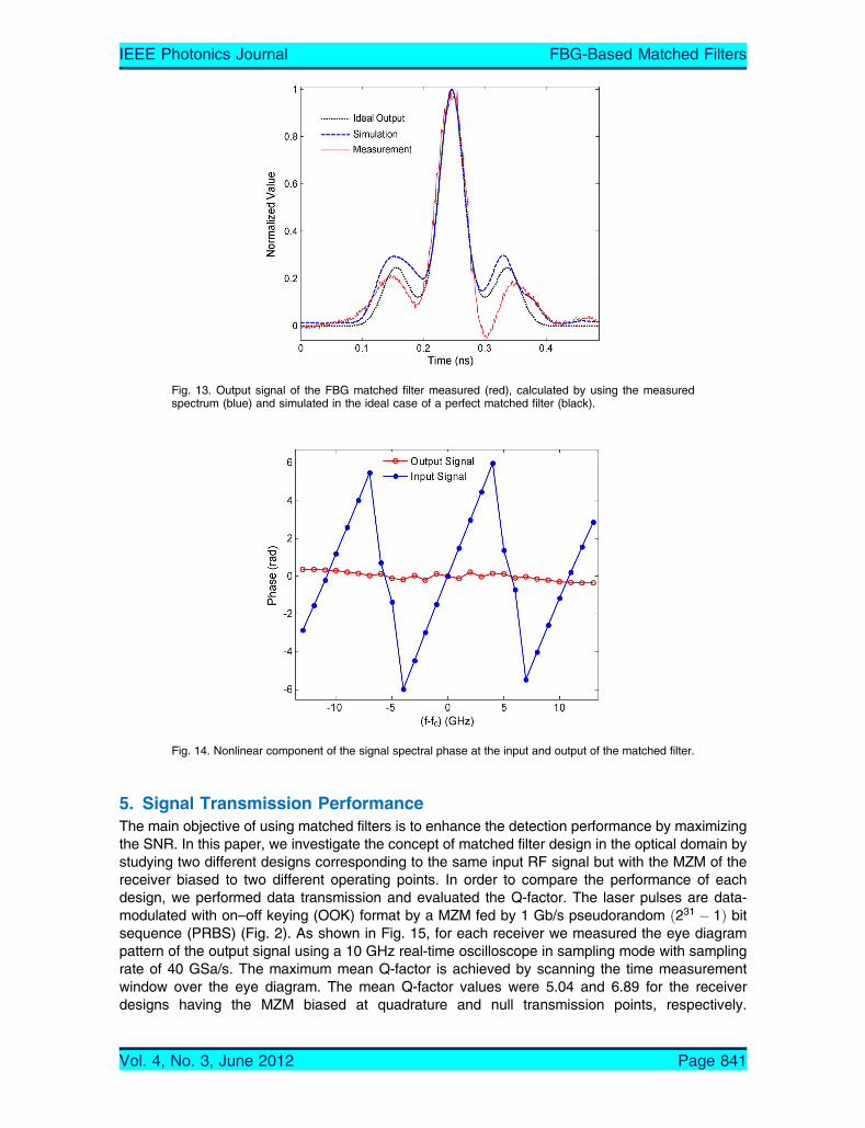
Introducing this FBG in the optical receiver with the MZM biased at the null transmission point(Fig. 2), we measured the output signal. Fig. 13 shows the measured output signal (red) compared
Fig. 10. Fully rectified monocycle measured in the optical domain obtained with the MZM biased at a nullpoint. Inset is the corresponding calculated spectrum (phase and amplitude).
Fig. 9. Nonlinear component of the signal spectral phase at the input and output of the matched filter.
IEEE Photonics Journal FBG-Based Matched Filters
Vol. 4, No. 3, June 2012 Page 839
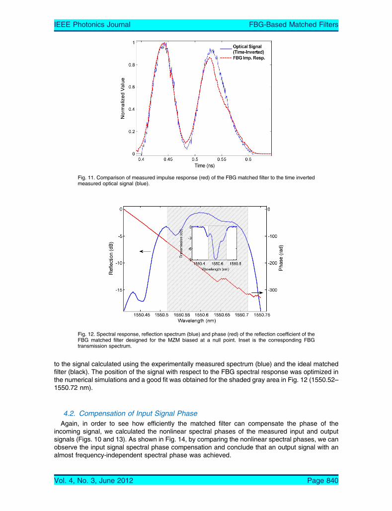
to the signal calculated using the experimentally measured spectrum (blue) and the ideal matchedfilter (black). The position of the signal with respect to the FBG spectral response was optimized inthe numerical simulations and a good fit was obtained for the shaded gray area in Fig. 12 (1550.52–1550.72 nm).
4.2. Compensation of Input Signal PhaseAgain, in order to see how efficiently the matched filter can compensate the phase of the
incoming signal, we calculated the nonlinear spectral phases of the measured input and outputsignals (Figs. 10 and 13). As shown in Fig. 14, by comparing the nonlinear spectral phases, we canobserve the input signal spectral phase compensation and conclude that an output signal with analmost frequency-independent spectral phase was achieved.
Fig. 12. Spectral response, reflection spectrum (blue) and phase (red) of the reflection coefficient of theFBG matched filter designed for the MZM biased at a null point. Inset is the corresponding FBGtransmission spectrum.
Fig. 11. Comparison of measured impulse response (red) of the FBG matched filter to the time invertedmeasured optical signal (blue).
IEEE Photonics Journal FBG-Based Matched Filters
Vol. 4, No. 3, June 2012 Page 840
5. Signal Transmission PerformanceThe main objective of using matched filters is to enhance the detection performance by maximizingthe SNR. In this paper, we investigate the concept of matched filter design in the optical domain bystudying two different designs corresponding to the same input RF signal but with the MZM of thereceiver biased to two different operating points. In order to compare the performance of eachdesign, we performed data transmission and evaluated the Q-factor. The laser pulses are data-modulated with on–off keying (OOK) format by a MZM fed by 1 Gb/s pseudorandom ð231 � 1Þ bitsequence (PRBS) (Fig. 2). As shown in Fig. 15, for each receiver we measured the eye diagrampattern of the output signal using a 10 GHz real-time oscilloscope in sampling mode with samplingrate of 40 GSa/s. The maximum mean Q-factor is achieved by scanning the time measurementwindow over the eye diagram. The mean Q-factor values were 5.04 and 6.89 for the receiverdesigns having the MZM biased at quadrature and null transmission points, respectively.
Fig. 14. Nonlinear component of the signal spectral phase at the input and output of the matched filter.
Fig. 13. Output signal of the FBG matched filter measured (red), calculated by using the measuredspectrum (blue) and simulated in the ideal case of a perfect matched filter (black).
IEEE Photonics Journal FBG-Based Matched Filters
Vol. 4, No. 3, June 2012 Page 841
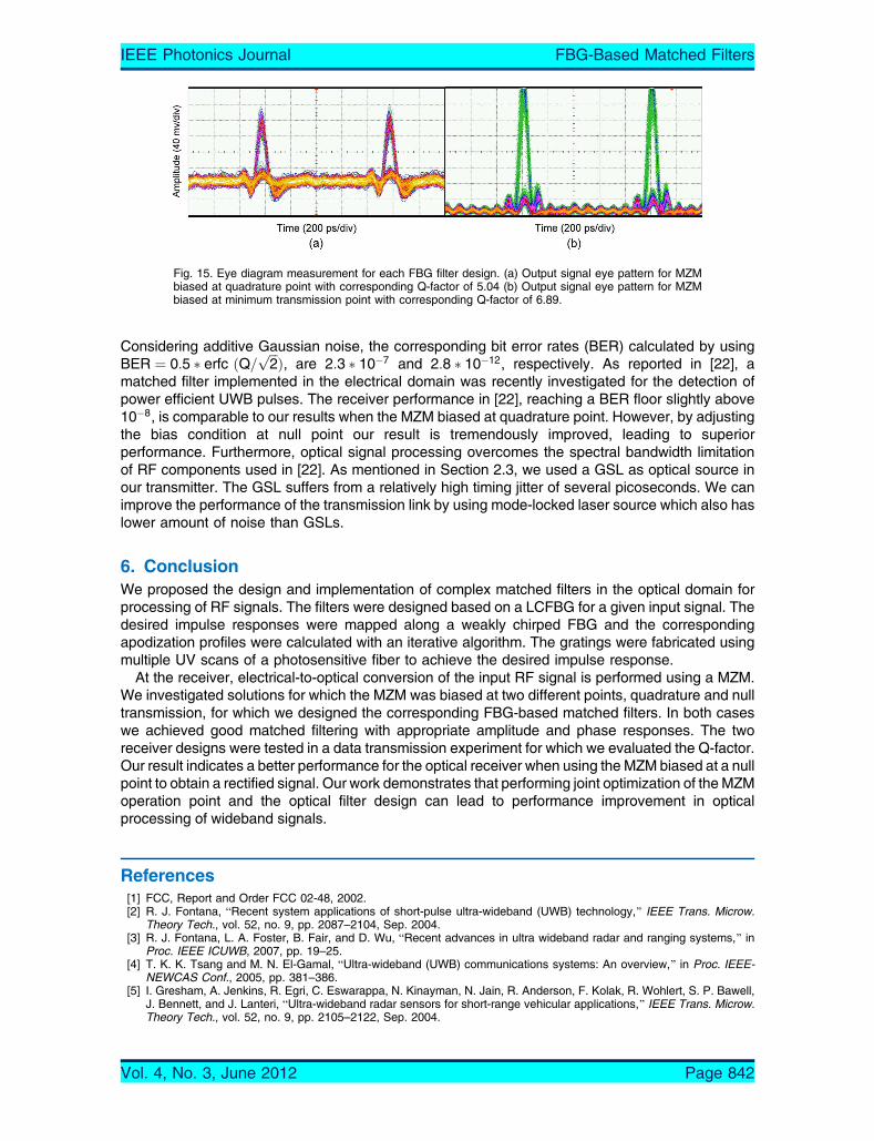
Considering additive Gaussian noise, the corresponding bit error rates (BER) calculated by usingBER ¼ 0:5 � erfc ðQ=
ffiffiffi
2pÞ, are 2:3 � 10�7 and 2:8 � 10�12, respectively. As reported in [22], a
matched filter implemented in the electrical domain was recently investigated for the detection ofpower efficient UWB pulses. The receiver performance in [22], reaching a BER floor slightly above10�8, is comparable to our results when the MZM biased at quadrature point. However, by adjustingthe bias condition at null point our result is tremendously improved, leading to superiorperformance. Furthermore, optical signal processing overcomes the spectral bandwidth limitationof RF components used in [22]. As mentioned in Section 2.3, we used a GSL as optical source inour transmitter. The GSL suffers from a relatively high timing jitter of several picoseconds. We canimprove the performance of the transmission link by using mode-locked laser source which also haslower amount of noise than GSLs.
6. ConclusionWe proposed the design and implementation of complex matched filters in the optical domain forprocessing of RF signals. The filters were designed based on a LCFBG for a given input signal. Thedesired impulse responses were mapped along a weakly chirped FBG and the correspondingapodization profiles were calculated with an iterative algorithm. The gratings were fabricated usingmultiple UV scans of a photosensitive fiber to achieve the desired impulse response.
At the receiver, electrical-to-optical conversion of the input RF signal is performed using a MZM.We investigated solutions for which the MZM was biased at two different points, quadrature and nulltransmission, for which we designed the corresponding FBG-based matched filters. In both caseswe achieved good matched filtering with appropriate amplitude and phase responses. The tworeceiver designs were tested in a data transmission experiment for which we evaluated the Q-factor.Our result indicates a better performance for the optical receiver when using the MZM biased at a nullpoint to obtain a rectified signal. Our work demonstrates that performing joint optimization of the MZMoperation point and the optical filter design can lead to performance improvement in opticalprocessing of wideband signals.
References[1] FCC, Report and Order FCC 02-48, 2002.[2] R. J. Fontana, BRecent system applications of short-pulse ultra-wideband (UWB) technology,[ IEEE Trans. Microw.
Theory Tech., vol. 52, no. 9, pp. 2087–2104, Sep. 2004.[3] R. J. Fontana, L. A. Foster, B. Fair, and D. Wu, BRecent advances in ultra wideband radar and ranging systems,[ in
Proc. IEEE ICUWB, 2007, pp. 19–25.[4] T. K. K. Tsang and M. N. El-Gamal, BUltra-wideband (UWB) communications systems: An overview,[ in Proc. IEEE-
NEWCAS Conf., 2005, pp. 381–386.[5] I. Gresham, A. Jenkins, R. Egri, C. Eswarappa, N. Kinayman, N. Jain, R. Anderson, F. Kolak, R. Wohlert, S. P. Bawell,
J. Bennett, and J. Lanteri, BUltra-wideband radar sensors for short-range vehicular applications,[ IEEE Trans. Microw.Theory Tech., vol. 52, no. 9, pp. 2105–2122, Sep. 2004.
Fig. 15. Eye diagram measurement for each FBG filter design. (a) Output signal eye pattern for MZMbiased at quadrature point with corresponding Q-factor of 5.04 (b) Output signal eye pattern for MZMbiased at minimum transmission point with corresponding Q-factor of 6.89.
IEEE Photonics Journal FBG-Based Matched Filters
Vol. 4, No. 3, June 2012 Page 842

[6] M. Hamalainen, P. Pirinenen, J. Iinatti, and A. Taparugssanagorn, BUWB supporting medical ICT applications,[ in Proc.IEEE ICUWB, 2008, pp. 15–16.
[7] X. Wang, B. Qin, H. Xie, L. Llin, H. Tang, Q. Fang, H. Zhao, S. Wang, A. Wang, H. Chen, B. Zhao, Y. Zhou, L. Yang, andG. Zhang, BFCC-EIRP-aware UWB pulse generator design approach,[ in Proc. IEEE ICUWB, 2009, pp. 592–596.
[8] J. Han, R. Xu, and C. Nguyen, BDevelopment of a low-cost compact planar synchronous receiver for UWB systems,[ inProc. IEEE Antennas Propag. Soc. Int. Symp., 2006, pp. 1287–1290.
[9] A. Seeds, BMicrowave photonics,[ IEEE Trans. Microw. Theory Tech., vol. 50, no. 3, pp. 877–887, Mar. 2002.[10] A. M. Weiner, BFemtosecond pulse shaping using spatial light modulators,[ Rev. Sci. Instrum., vol. 71, no. 5, pp. 1929–
1960, May 2000.[11] I. S. Lin, J. D. McKinney, and A. M. Weiner, BPhotonic synthesis of broadband microwave arbitrary waveforms applicable
to ultra-wideband communication,[ IEEE Microw. Wireless Compon. Lett., vol. 15, no. 4, pp. 226–228, Apr. 2005.[12] B. Bortnik, I. Y. Poberezhskiy, J. Chou, B. Jalali, andH. R. Fetterman, BPredistortion technique for RF-photonic generation
of high-power ultrawideband arbitrary waveforms,[ J. Lightw. Technol., vol. 24, no. 7, pp. 2752–2759, Jul. 2006.[13] M. Abtahi, M. Dastmalchi, S. LaRochelle, and L. A. Rusch, BGeneration of arbitrary UWB waveforms by spectral pulse
shaping and thermally controlled apodized FBGs,[ J. Lightw. Technol., vol. 27, no. 23, pp. 5276–5283, Dec. 2009.[14] M. Dastmalchi, M. Abtahi, D. Lemus, L. A. Rusch, and S. Larochelle, BSimple and efficient UWB pulse generator,[ in
Proc. BGPP, Karlsruhe, Germany, 2010.[15] C. Wang and J. Yao, BPhotonic microwave matched filters for chirped microwave pulse compression,[ in Proc. Int.
Conf. Microw. Photon., 2008, pp. 47–50.[16] C. Wang and J. Yao, BChirped microwave pulse compression using a photonic microwave filter with a nonlinear phase
response,[ IEEE Trans. Microw. Theory Tech., vol. 57, no. 2, pp. 496–504, Feb. 2009.[17] E. Hamidi and A. M. Weiner, BPhased-only matched filtering of ultra-wideband arbitrary microwave waveforms via
optical pulse shaping,[ J. Lightw. Technol., vol. 26, no. 5, pp. 2355–2363, Aug. 2008.[18] I. S. Lin and A. M. Weiner, BSelective correlation detection of photonically generated ultra-wideband RF signals,[ J.
Lightw. Technol., vol. 26, no. 15, pp. 2692–2699, Aug. 2008.[19] M. Beltran, J. B. Jensen, R. Llorente, and I. T. Monroy, BExperimental analysis of 60 GHz VCSEL and ECL photonic
generation and transmission of impulse-radio ultra-wideband signals,[ IEEE Photon. Technol. Lett., vol. 23, no. 15,pp. 1055–1057, Aug. 2011.
[20] M. Beltran, R. Sambaraju, R. Llorente, J. Perez, and A. La Porta, BPhotonic generation and envelope detection ofmillimeter-wave ultra-wideband impulse-radio employing Mach–Zehnder modulators,[ in Proc. IEEE ICUWB, Sep. 2009,pp. 428–432.
[21] G. L. Turin, BAn Introduction to matched filters,[ IRE Trans. Inf. Theory, vol. 6, no. 3, pp. 311–329, Jun. 1960.[22] M. Mirshafiei, J. D. Schwartz, D. V. Plant, and L. A. Rusch, BUWB matched filter reception using and electromagnetic
bandgap structure,[ in Proc. IEEE ICUWB, 2011, pp. 516–520.[23] B. V. K. Vijaya Kumar and L. Hassebrook, BPerformance measures for correlation filters,[ Appl. Opt., vol. 29, no. 20,
pp. 2997–3006, Jul. 1990.[24] Y. Kim, S. Doucet, and M. E. Mousa Pasandi, BOptical multicarrier generator for radio-over-fiber systems,[ Opt. Exp.,
vol. 16, no. 2, pp. 1068–1076, Jan. 2008.[25] LUNA technologies, Optical Vector Analyzer, User guide, ch.7
IEEE Photonics Journal FBG-Based Matched Filters
Vol. 4, No. 3, June 2012 Page 843
Related Documents