Welcome message from author
This document is posted to help you gain knowledge. Please leave a comment to let me know what you think about it! Share it to your friends and learn new things together.
Transcript
����������� ��
���������������
���������������

Important Notice
The information contained herein is subject to change without notice. The only warranties for HP products and services are set forth in the express warranty statements accompanying such products and services. Nothing herein should be construed as constituting an additional warranty. HP shall not be liable for technical or editorial errors or omissions contained herein.
This document is delivered subject to the following conditions and restrictions:
This document contains proprietary information of HP Scitex (the "Company"). Such information is hereby supplied solely for the purpose of assisting authorized users of the HP Scitex FB7600 (the "System").
Without the express prior written permission of HP Scitex, no part of the contents hereof may be used for any other purposes, disclosed to any person or firm, or reproduced by any means.
The text and drawings herein are for the purposes of illustration and reference only. The specifications on which they are based are subject to change without notice.
The names HP and HP Scitex, and the HP logo are registered trademarks or service marks of Hewlett-Packard. The mark HP Scitex FB7600 is a trademark of the Company.
Important Notice i
Other company and brand, product and service names are for identification purposes only and may be trademarks or registered trademarks of their respective holders. Data is subject to change without notice.
Catalog No CC906-90168
Document ID: emr_na-c03101331Copyright © 2013 Hewlett-Packard Development Company, L.P.
All Rights Reserved
Revision D
May 2013
Disclaimer
The Company shall not be liable for any damages, costs and expenses (including, without limitation, damages in connection with bodily injuries, consequential damages and damages for loss of profits), incurred by the customer or by any third party, whether in action, in contract, tort or otherwise, arising out of, or in connection with, the System, its installation and/or operation, and any related accessories, products, parts, components or materials, except as, and to the extent, expressly specified in the applicable purchase contract.
Limited Warranty
The Company does not provide any warranty with respect to the System, its installation and/or operation, and any related accessories, products, parts, components or materials, except as, and to the extent, expressly specified in the applicable purchase contract.
Local Regulations
The customer is required to strictly follow the applicable international, regional, federal and state laws, regulations and standards, and nothing in this guide shall be construed as instructing or otherwise requiring or allowing the customer to violate such laws, regulations and standards. However, if and to
ii HP Scitex FB7600 Operator Manual Rev. D
the extent permitted by law, in case of inconsistency or contradiction between any requirement or procedure contained in this guide and any such laws, regulations and standards, the customer shall follow the stricter between the requirements and procedures specified in this guide and the requirements and procedures specified in any such laws, regulations or standards.
Safety Conventions
The safety hazard caution conventions used in this guide (and supplementary HP Scitex FB7600 documentation) are provided for the identification of safety hazards.
They are used to identify conditions or actions for which a specific hazard is known to exist, and that may, cause personal injury and/or equipment malfunction.
The conventions are classified into the following categories: Danger and Caution. Examples are shown below:
Danger Danger indicates a hazard with a high level of risk which, if not avoided, could result in death or serious injury.
Caution Caution indicates a hazard with a low level of risk which, if not avoided, could result in minor or moderate injury, and/or damage to the equipment.
Other Conventions
The following conventions are used to draw your attention to important points that are beyond or in addition to the regular
Important Notice iii
information in this book:
Note Notes are used to identify an explanation, or provide additional information for purposes of clarification.
Tip Tips provide useful shortcuts or recommendations.
Reference References are provided to refer you to further information in this document or another guide.

Contact Information
European Contact: Hewlett-Packard GmbH, HQ-TRE, Herrenberger Strasse 140, 71034 Boeblingen, Germany
USA Contact: Hewlett-Packard Company, HPCC, 20555 S.H. 249 Houston, Texas, 77070
Australia Contact: Hewlett-Packard Australia Ltd, Product regulations Manger, 31-41 Joseph Street, Blackburn, Victoria, 3130, Australia
iv HP Scitex FB7600 Operator Manual Rev. D

Chapter 1 Safety Instructions 1Safe Operation Guidelines ....................................................................................2
General ........................................................................................................2Electrical Shock Hazards ...............................................................................4Fire Hazards .................................................................................................5Explosion Hazard ..........................................................................................6Provision for an Eye Wash Station .................................................................6Measured Noise Levels .................................................................................7Mechanical Safety .........................................................................................8Handling Inks and Solvent ............................................................................8Cleaning with Solvent and Alcohol ..............................................................10Waste Disposal ...........................................................................................11
Danger Zone and Warning Labels .......................................................................12
UV System Safety ................................................................................................13
Introduction ................................................................................................13High Voltage ..............................................................................................13Fire Risk ......................................................................................................14UV Ink and Generated Products ..................................................................14Noise .........................................................................................................14Safety Precautions While Servicing ..............................................................15
Table of Contents i
Safety UV Curing ........................................................................................16Permissible UV Exposure Levels ...................................................................21Shutting Down the Entire UV System ...........................................................22
Environmental Notices .........................................................................................23
Battery Disposal (California) ........................................................................23Use of Sensitive Receivers ...........................................................................23
First Aid Treatment ..............................................................................................23
Inhalation ...................................................................................................23Eye Contact ................................................................................................23Skin Contact ...............................................................................................23
IEC Symbols ........................................................................................................24
Safety Warning Labels .........................................................................................25
Emergency Safety Devices ................................................................................... 28
PILZ Safety Controller ................................................................................. 28Emergency Stop Buttons ............................................................................. 29Safety Interlocks ......................................................................................... 30SICK .......................................................................................................... 31Service Key ................................................................................................ 32Unloader Lift Safety Frame ......................................................................... 34
Personal Safety — Working with the Printer ......................................................... 35
Declaration of Conformity ................................................................................... 37
Chapter 2 FB7600 Daily Use 39FB7600 System Components ............................................................................... 40
FB7600 Printer Directions and Axes ..................................................................... 41
Print Care ........................................................................................................... 43
System Startup .................................................................................................... 45
Automatic Loading .............................................................................................. 48
Multi-Sheet Loading ............................................................................................ 48
Manual Substrate Loading .................................................................................. 54
Adding a New Job .............................................................................................. 55
Printing a Job ..................................................................................................... 56
ii HP Scitex FB7600 Operator Manual Rev. D
System Shutdown ................................................................................................ 57
Morning Nozzles Health Detector and Print Head Maintenance ........................... 58
Replacing the Ink Container ................................................................................ 61
Adjusting Height of Iron Roller for Different Substrates ........................................ 62
Raising/Lowering the Printing Bridge ................................................................... 65
Chapter 3 Daily Maintenance 67Visual Checks and General Cleaning .................................................................. 68
Checking the Pneumatic System .......................................................................... 69
Monitoring the Ink Level in Ink Containers ........................................................... 70
Emptying the Waste Tank .................................................................................... 70
Testing Earth Leakage in the UV Electrical Cabinet ............................................... 72
Checking the Water Level in the UV System .........................................................73
Chapter 4 Weekly Maintenance 75Cleaning the Printing Table .................................................................................76
Cleaning the Quartz Plates in the UV Lamp Housing ............................................77
Checking the Loading/Unloading Suction Cups ....................................................79
Cleaning the Rising Media Flaps ..........................................................................80
Cleaning the Printing Bridge ................................................................................82
Cleaning the Guards ..................................................................................83Cleaning the Cooling Fans and Surroundings ..............................................86Cleaning the Vacuum Knife .........................................................................87
Emptying the Separator Bath ...............................................................................88
Checking the HT Contactors Counter in the UV System ........................................89
Chapter 5 Monthly Maintenance 91Cleaning the UV Lamp Reflectors .........................................................................92
Cleaning the UV Cooler Water Filter ....................................................................97
Cleaning the UV Cooler Radiators .......................................................................99
Cleaning the UV Lamp Housing Filters ...............................................................100
Checking for Leaks in the UV Cooler ..................................................................102
Table of Contents iii
Chapter 6 Bi-Monthly Maintenance 103Checking the Emergency Stop Safety Devices .....................................................104
Replacing the UV Lamp .....................................................................................105
Lubricating the Linear Bearings ..........................................................................112
Greasing the X-Encoder Bearing ...............................................................117Checking the External Shutter ............................................................................120
Checking the Z-Axis Shaft Coupling ...................................................................122
VCU Preventive Maintenance .............................................................................123
Preparation for Maintenance .....................................................................123Checking Integrity of the VCU Bearings .....................................................124Checking Integrity of VCU Belt and VCU Profile .........................................125
Chapter 7 6-Monthly Maintenance 127Replacing the Ink Filters .................................................................................... 128
Chapter 8 Annual Maintenance 133Checking the Gas Springs ................................................................................. 134
Chapter 9 As-Needed Maintenance 137Missing Nozzles Compensation (MNC) Procedure .............................................. 138
Automatic MNC Procedure ....................................................................... 139Manual MNC Procedure ........................................................................... 139
Manually Wiping the Print Head ........................................................................ 141
Replacing a Print Head ...................................................................................... 145
Replacing the Loading/Unloading Suction Cups ................................................. 153
Appendix 155
iv HP Scitex FB7600 Operator Manual Rev. D

First Aid Treatment ..........................
IEC Symbols....................................
Safety Warning Labels .....................
Emergency Safety Devices ...............
Personal Safety — Working with the
C H A P T E R
1Safety Instructions
Safe Operation Guidelines .................................................. 2
Danger Zone and Warning Labels ..................................... 12
UV System Safety .............................................................. 13
Environmental Notices ...................................................... 23
.................................. 23
.................................. 24
.................................. 25
.................................. 28
Printer........................ 35

Safe Operation GuidelinesThe HP Scitex FB7600 is designed and manufactured to ensure safety of operation. It should be installed, operated, and maintained in strict compliance with the safety precautions, warnings, and operating instructions contained in this guide.
General
• The HP Scitex FB7600 has been designed to meet the safety requirements applicable to printing equipment. However, anyone attempting to operate the system must be fully aware of potential safety hazards. See Personal Safety — Working with the Printer on page 35.
• Installation and disassembly of the machine should be done by HP service personnel only. Recycling and disposal should be done according to the local laws and regulations.
• Although the product has been tested against safety standards that cover the intended use and the reasonably foreseeable misuse, the operator must avoid any misuse and always follow all the safety recommendation contained in this guide.
• Maintenance and replacement of spare parts should be carried out only by HP service personnel, or by a person who has been
2 HP Scitex FB7600 Operator Manual Rev. D
trained and authorized by HP to maintain the machine. An authorized operators list should be maintained. Unauthorized personnel should not be allowed access to the system.
• HP Scitex is not responsible for any injury or damage to the machine caused by use of the machine other than its intended use as described in the manuals supplied by HP Scitex.
• The system in whole, or in part, should not be modified in any way without obtaining the prior written approval of HP Scitex.
• It is important that this, and all other HP Scitex FB7600 guides, should be kept close at hand, studied carefully, and reviewed periodically by the authorized technicians. However, the manufacturer or vendor of the equipment makes no representation that the act of reading this guide – or any other HP Scitex FB7600 guide – renders the reader qualified to operate, test, or calibrate the system.
• Authorized operators should wear buttoned-up shirt sleeves and closed shoes when operating the FB7600 printer.
• The HP Scitex FB7600 must have a dedicated power supply, which must not - under any circumstances - be used for additional equipment.
• Pipes and cables that connect the external components (such as the UV cabinet and the PDU) to the machine must be protected with a secure, metal cover of 170 mm height.
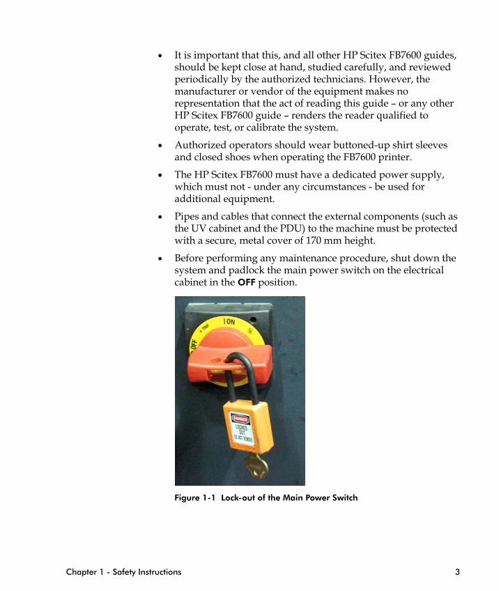
• Before performing any maintenance procedure, shut down the system and padlock the main power switch on the electrical cabinet in the OFF position.
Chapter 1 - Safety Instructions 3
Figure 1-1 Lock-out of the Main Power Switch
Electrical Shock Hazards
Danger Internal circuits use high voltage, capable of causing serious injury. Do NOT dismantle the electrical cabinet, or attempt to remove or open system covers or plugs!
Danger In case a local authorized electrician open the electrical cabinet, he should be aware that after turning off the main power switch on the electrical cabinet, some components inside of it stay energized (main circuit breaker, EMC filters, and distribution box phase connection). In the UV electrical cabinet, after turning off the UV main isolator, the main circuit breaker and EMC filters stay energized.
• Do not connect the printer to the main power switch unless all emergency switches are reset.
• When working with electrical components, make sure the printer is disconnected from the mains power supply.
• Place the printer on clean tiled or concrete floors. Anti-static carpeting or anti-static tiles reduce the hazardous accumulation of static charge near the printer.
• It is the customer responsibility to ensure that electrical works comply with the local electrical code and the relevant laws and regulations. The customer should provide qualified and registered electricians to perform operations as required by these laws and regulations.
4 HP Scitex FB7600 Operator Manual Rev. D
• In general, HP service personnel are authorized to perform maintenance operations in all printer’s parts and subassemblies, but not for the site electrical infrastructure and printer’s connections to this structure. Safe isolation of the printer from power prior to service operations shall be done according to local regulations, and is under the customer’s responsibility.
• When servicing the vacuum pump cabinet or loader cabinet, turn off the main power switch and padlock it (see Figure 6-2 on page 105).
Danger Only a certified electrician is authorized to carry out any electrical work.
Fuses blown within 36 hours of being replaced may indicate malfunctioning electrical circuits within the system. Have qualified service personnel check the system, and do not attempt to replace the fuse again!
Danger An electrical hazard may exist if any light, monitor, or visual indicator stays ON. To prevent possible injury, immediately turn OFF the switch in the mains power supply box on the wall.
Fire Hazards
UV-based inks used with the HP Scitex FB7600 have flammable and irritant properties. Their combustion products include oxides of carbon.
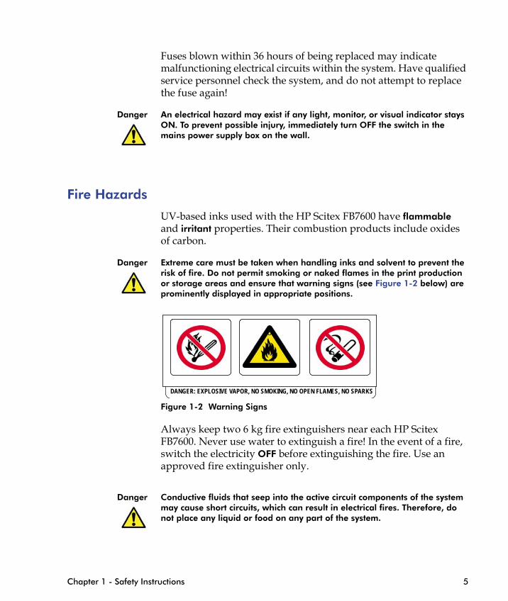
Danger Extreme care must be taken when handling inks and solvent to prevent the risk of fire. Do not permit smoking or naked flames in the print production or storage areas and ensure that warning signs (see Figure 1-2 below) are prominently displayed in appropriate positions.
0
Chapter 1 - Safety Instructions 5
Figure 1-2 Warning Signs
Always keep two 6 kg fire extinguishers near each HP Scitex FB7600. Never use water to extinguish a fire! In the event of a fire, switch the electricity OFF before extinguishing the fire. Use an approved fire extinguisher only.
Danger Conductive fluids that seep into the active circuit components of the system may cause short circuits, which can result in electrical fires. Therefore, do not place any liquid or food on any part of the system.
DANGER: EXPLOSIVE VAPOR, NO SMOKING, NO OPEN FLAMES, NO SPARKS
Explosion Hazard
Do not plug in or turn on power to the system if hazardous substances are detected in the environment. Should these substances be detected after the system has been turned on, do not attempt to unplug it, or turn off power. Evacuate and ventilate the area before turning off power to the system.
Danger Extreme care must be taken when handling inks and solvent, to prevent the risk of explosion. Do not operate the system in the presence of explosive liquids, vapors, or gases. Keep all sources of ignition away from the printer and work area.
Provision for an Eye Wash Station
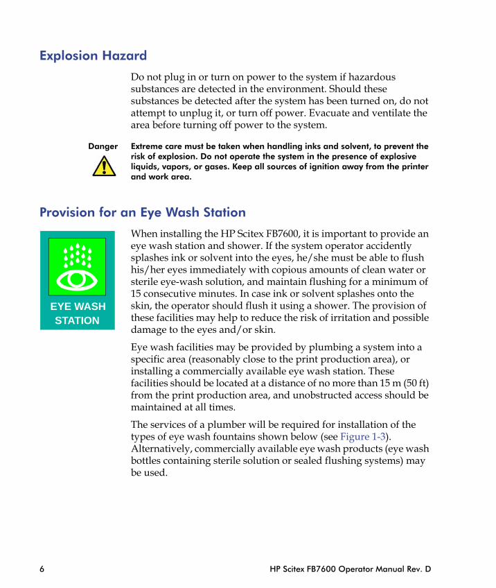
When installing the HP Scitex FB7600, it is important to provide an eye wash station and shower. If the system operator accidently splashes ink or solvent into the eyes, he/she must be able to flush his/her eyes immediately with copious amounts of clean water or sterile eye-wash solution, and maintain flushing for a minimum of 15 consecutive minutes. In case ink or solvent splashes onto the skin, the operator should flush it using a shower. The provision of these facilities may help to reduce the risk of irritation and possible damage to the eyes and/or skin.
Eye wash facilities may be provided by plumbing a system into a
STATIONEYE WASH
6 HP Scitex FB7600 Operator Manual Rev. D
specific area (reasonably close to the print production area), or installing a commercially available eye wash station. These facilities should be located at a distance of no more than 15 m (50 ft) from the print production area, and unobstructed access should be maintained at all times.
The services of a plumber will be required for installation of the types of eye wash fountains shown below (see Figure 1-3). Alternatively, commercially available eye wash products (eye wash bottles containing sterile solution or sealed flushing systems) may be used.
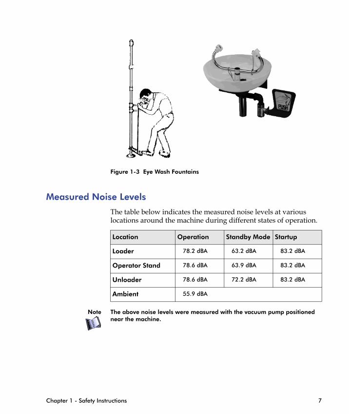
Figure 1-3 Eye Wash Fountains
Measured Noise Levels
The table below indicates the measured noise levels at various locations around the machine during different states of operation.
Location Operation Standby Mode Startup
Chapter 1 - Safety Instructions 7
Note The above noise levels were measured with the vacuum pump positioned near the machine.
Loader 78.2 dBA 63.2 dBA 83.2 dBA
Operator Stand 78.6 dBA 63.9 dBA 83.2 dBA
Unloader 78.6 dBA 72.2 dBA 83.2 dBA
Ambient 55.9 dBA
Mechanical Safety
• Tools and loose parts, as well as loose sheets and paper scraps, must be removed from the machine before operation.
• Make sure no one is within the Danger Zone when operating the FB7600.
• Do not touch any moving parts.
• Do not put your hand in the machine during operation.
• Do not print on reflective materials.
• Do not neutralize or bypass the built-in safety systems, including the interlocks, safety controllers and SICK safety scanner.
• Machine contains moving parts that might cause severe injuries if contacted. Do not open fixed covers, unless authorized to do so and then only after removing the hazards from which the cover is protecting.
• The printing bridge tilt movement is still enabled when the hood covers are open, to allow its service. Bridge up/down command should be activated only after it is verified that there is no person in the nearest area. While the bridge is tilting, the operator should observe and ensure no one is entering the danger zones.
8 HP Scitex FB7600 Operator Manual Rev. D
Handling Inks and Solvent
Danger UV-based inks used with the HP Scitex FB7600 have flammable and irritant properties. Their combustion products include oxides of carbon.
Reference Refer to the MSDS for information on the inks and constituents:http://www8.hp.com/us/en/hp-information/environment/msds-specs.html
Under normal conditions of anticipated use, with appropriate handling and adherence to the safety precautions, the materials used with the HP Scitex FB7600 do not present health hazards.

However, when handling inks and solvents used with the FB7600, operators should always take the following precautions:
• Extreme care must be taken when handling inks and solvent, in order to prevent the risk of explosion.
• Do not operate the system in the presence of explosive liquids, vapors or gases.
• Avoid contact with skin and eyes and wear the safety goggles and gloves provided for protection against splashing. Do not handle inks or solvents when wearing only contact lenses without goggles.
• Wear respiratory protection (active carbon mouth filters) when pouring inks or solvents, or when cleaning the machine, in order to avoid inhalation of solvent fumes and vapors.
• Wear suitable clothing and shoes whenever in the print production and storage areas.
• Keep all sources of ignition far away from the printer and from the print production and storage areas.
• Make sure not to lift heavy loads that can cause you damages, use lifting accessories to avoid the risk. Such loads can be media piles and ink containers.
• Maintain good ventilation in the print production area.
Chapter 1 - Safety Instructions 9
• Ensure that the print production area is kept clean and organized.
• Store inks and solvents in tightly closed, upright containers in normal, cool warehouse conditions.
• Surfaces where any ink spillage or leakage has occurred must be wiped clean immediately.
• Avoid poisoning by washing hands before eating, after smoking, and before leaving the site.
Caution Use only HP Scitex UV inks and solvents approved by HP Scitex.
• Do not plug in or turn on power to the system if hazardous substances are detected in the environment. Should these substances be detected after the system has been turned on, do not attempt to unplug it, or turn off power. Evacuate and ventilate the area before turning off power to the system.
Caution Always make sure that all main ink tank lids are properly closed.
Cleaning with Solvent and Alcohol
In addition to the safety precautions listed above, it is recommended to observe the following precautions when cleaning FB7600 components with solvent (MF10) or alcohol (for example, ethanol):
• Apply solvent and alcohol to wiping paper or a lint-free cloth before starting to clean. Avoid applying solvent or alcohol directly to FB7600 components.
• Close the container and move it out of the vicinity of the FB7600.When a cleaning procedure that includes the use of solvent or alcohol is finished, make sure to do the following before resuming operation:
10 HP Scitex FB7600 Operator Manual Rev. D
• Dispose of any used paper or cloth that may contain traces of solvent or alcohol, according to local environmental regulations.
• Empty the waste bath of any possible traces of solvent or alcohol.
• Verify that all FB7600 components that have been cleaned with solvent or alcohol are completely dry before resuming machine operation.
Note The use of solvent and alcohol is restricted in California, and may be restricted in other areas, due to its high VOC (volatile organic compound) content. Therefore, in these restricted use areas, you must first clean the component using a dry, lint-free cloth and compressed air. If any cured ink remains, it can be cleaned using a lint-free cloth moistened with solvent or alcohol (as specified in the chapters that follow).
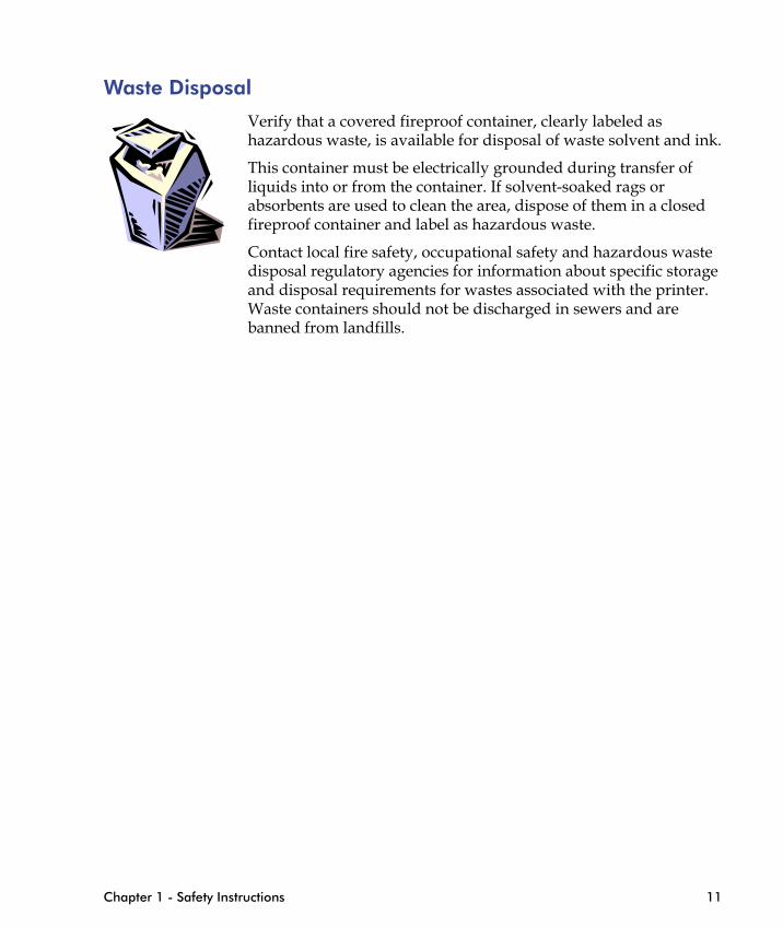
Waste Disposal
Verify that a covered fireproof container, clearly labeled as hazardous waste, is available for disposal of waste solvent and ink.
This container must be electrically grounded during transfer of liquids into or from the container. If solvent-soaked rags or absorbents are used to clean the area, dispose of them in a closed fireproof container and label as hazardous waste.
Contact local fire safety, occupational safety and hazardous waste disposal regulatory agencies for information about specific storage and disposal requirements for wastes associated with the printer. Waste containers should not be discharged in sewers and are banned from landfills.
Chapter 1 - Safety Instructions 11

Danger Zone and Warning LabelsThe Danger Zone around the FB7600 printing table is designated as shown in Figure 1-4 on page 12. Upon installation of the printer, the Danger Zone will be clearly marked with yellow/black striped cautionary adhesive tape.
Danger The Danger Zone is extremely hazardous when the printer is in operation and proper safety guidelines must be followed to ensure a safe work environment.
To prevent possible injury, the SICK programmable safety device (see SICK on page 31) is mounted on the rear left corner of the machine chassis. The SICK scans the Danger Zone and stops the print run and movement of all machine components when someone enters the SICK area during the printer operation.
SICK
12 HP Scitex FB7600 Operator Manual Rev. D
Figure 1-4 FB7600 Danger Zone
Danger To make sure no one enters the SICK area when operating the FB7600, the customer should install the "Do not enter!" warning labels as shown in Figure 1-4 on page 12.
UV System Safety
Introduction
All equipment is designed and manufactured to International Safety Standards to ensure that the health and safety of the operator is protected at all times. This is conditional on equipment being installed correctly by qualified personnel and operating instructions being strictly adhered to.
Everyone who is required to work with the UV system in any way (including installers, operators, service engineers, and so on), must be made familiar with these safety instructions.
The equipment is designed for the curing of UV inks.
This equipment is not designed for use in hazardous areas (i.e. it is not flameproof).
There are certain substances that can represent a safety hazard if not handled correctly.
High Voltage
The UV system works at high voltages. It is therefore essential that
Chapter 1 - Safety Instructions 13
the operator switch the equipment off immediately should any fault develop.
Unless stated otherwise in this manual, the operator should not attempt to service the equipment, but should instead call a qualified electrician who is trained to service this type of equipment.
Fire Risk
With lamps running at 800 degrees Centigrade, there is always a risk of fire should any substrate be under or in the lamp vicinity, or in the event of a build-up of fluff, dirt or powder within the lamp housing.
Should such a situation occur, the operator must:
• Switch off the equipment immediately. If a fire extinguisher is to be used, make sure it is of a type which is suitable for use with electrical equipment, as described in Fire Hazards on page 5.
• A suitable fire extinguisher should be available near the unit.
• The equipment is fitted with high temperature lamps. It is not designed to operate close to low flash point materials (solvents, etc.).
UV Ink and Generated Products
The relevant safety data sheets from the ink manufacturer must be followed when handling UV inks.
The materials used in UV inks and varnishes are of a toxic nature. Before handling, it is essential all operators are conversant with the
14 HP Scitex FB7600 Operator Manual Rev. D
instructions provided by the supplier of these materials as to their safe use and disposal.
During operation, there is a possibility that an odor may be generated.
Noise
When the UV system is functioning, the auxiliary equipment, such as fans and coolers, produce noise. Noise levels can increase when the noise from the printing equipment is included in the readings. For more information, see Measured Noise Levels on page 7.
Safety Precautions While Servicing
Important Information
Danger This equipment operates at high voltage and is therefore potentially dangerous. All precautions must be taken in servicing this equipment. The equipment must be disconnected at the main circuit breakers before opening any of the access doors.
Shutting Down before Servicing
It is compulsory to shut down the UV system before performing the following service procedure:
• Cleaning the UV cooler water filter
In addition, it is compulsory to power down the machine and the UV system before performing the following service procedures:
• Cleaning the quartz plate
• Replacing the UV lamp
• Cleaning the UV lamp housing reflectors
• Replacing the UV lamp housing filters
Note For information about performing these procedures, see the chapters that follow. For information about shutting down the machine, see System
Chapter 1 - Safety Instructions 15
Shutdown on page 57.
Earth Leakage This equipment is fitted with a high voltage leak detector circuit. If high voltage leaks to earth occur due to a fault, the leak detector detects the leak and switches off the equipment immediately.
The fault-finding circuit must be checked regularly, at least once a day, to ensure that it is functioning correctly.
For more information, see Testing Earth Leakage in the UV Electrical Cabinet on page 72.
Control System Cleaning
It is essential that all contactors and relays are kept clean and free of dirt and dust. These should be checked regularly, particularly in extremely dusty or powder-charged working rooms.
High Voltage Connections
Careful checks should be kept on the lamp connections and high voltage connections within the equipment head to make sure that these do not become dirty or coated with powder or other possible conducting material. They should be cleaned regularly (whenever the lamp is changed, and possibly more often in a particularly heavily polluted atmosphere). Also, while changing the lamps, a careful check should be made of the high voltage leads to make sure that no deterioration has occurred. Dirty contacts may cause a potential hazard.
Danger Accessing and cleaning electrical components must be done only after the machine has been shut down and disconnected from mains power.
High Temperatures
It should be noted that the UV system operates at very high temperatures and the inside components become very hot during operation of the machine and the equipment. Therefore, when maintaining the equipment, wait 5 - 10 min. before accessing. Alternatively, precautions should be taken.
16 HP Scitex FB7600 Operator Manual Rev. D
Safety UV Curing
UV Radiation UV radiation is generated from UV lamps and can be harmful if operator exposure exceeds recommended levels (see Permissible UV Exposure Levels on page 21).
Danger To avoid exposure, always work with the UV flaps in the "up" position (see Figure 1-5.

Figure 1-5 UV Flaps in the "Up" Position
All equipment is adequately guarded, shielded and interlocked to prevent accidental operator exposure.
Equipment should be annually checked for UV radiation levels.
Radiation is in the wavelength bands A, B, and C. Exposure to UV
UV flaps
UV lamp housing
Chapter 1 - Safety Instructions 17
radiation can result in:
• Reddening of skin
• Headaches
• Sore eyes
If any symptoms appear, investigations should be carried out.
First Aid
Skin — No treatment can be made immediately. However, soothing cream can be applied to the affected area.
Eyes — For exposure, seek medical attention immediately.
Ozone Gas Ozone is generated by the reaction of short-wave UV radiation with air. Ozone is a gas that readily reverts to oxygen when mixed with atmospheric air as it is removed from the source of UV radiation. The quantity of ozone produced equals 0.001 cu.ft/kWHr.
Note For AquaCure Non Air Extracted Products ozone remains around the UV lamp and does not escape from inside the lamp/reflector housing. For shuttered and QuadCure Systems ozone should be ducted via a sealed duct to atmosphere and discharged according to local regulations. (Height and clearance from pedestrian walkways and open windows, etc.).
Ozone checks using a Draeger measuring device should be carried out every 6 months, or immediately if an operator can smell ozone.
Outlet duct concentration is 0.3 PPM in a typical system. The threshold limit value (TLV) is 0.1 PPM in a working atmosphere.
Precautions
Ozone has an irritant action on the mouth and throat and the Factory Inspectorate recommendation is that the level of ozone in the atmosphere of a factory should not exceed 0.1 PPM (TLV). Most people can smell ozone at about one third of the TLV.
If there is any doubt as to whether the TLV is being exceeded, the company should take measurements to check whether the extraction system is adequate to keep the atmosphere well below
18 HP Scitex FB7600 Operator Manual Rev. D
0.1 PPM.
If ozone is detected:
1 Shut down the system.
2 Check the ducting for leaks.
3 Before restarting, check the working area with an ozone meter.
First Aid
If a person is overcome by ozone, take the following precautions:
1 Remove the patient to a warm uncontaminated atmosphere and loosen tight clothing at the neck and waist.
2 Keep the patient at rest.
3 If the patient has difficulty in breathing, oxygen may be administered provided that suitable apparatus and a trained operator are available.
4 If breathing is weak or has ceased, contact Emergency medical services immediately.
5 Seek medical aid.
Ozone poisoning should be treated symptomatically. This may include bed rest, analgesics to relieve pain, and antibiotics as may be prescribed by a medical practitioner.
Mercury Mercury is a silver colored liquid which is contained in medium pressure mercury arc lamps. Under normal operating conditions mercury presents no hazard as it is contained in the quartz tube of the lamp. Mercury is toxic and must not be consumed or handled directly on the skin. It is recommended that protective gloves and eye protection is worn when handling UV lamps.
In the event of spillage:
1 Use personal protective equipment to protect the eyes and skin, and prevent ingestion and inhalation.
2 Contain the spill with wet sand and clean it up with a dustpan and brush. Do not use a vacuum cleaner, as it will become
Chapter 1 - Safety Instructions 19
contaminated and be a source of mercury vapor.
3 Spread a 50/50 mix of calcium hydroxide and sulphur over the affected area and allow to dry. Repeat until there is no visible trace of mercury. Special attention should be given to cracks and imperfections in the affected surface.
Lamp Disposal
Sensible precautions should be followed when disposing of mercury arc lamps.
1 Insert the old lamp in the tube provided with the new lamp, seal and repack in the box provided.
2 Dispose of the lamp using an approved waste management company or refer to your local authority.
First Aid
• Eyes — Flush with plenty of water for 15 minutes, occasionally lifting the eyelids. OBTAIN MEDICAL ATTENTION.
• Skin — Flush with plenty of soap and water for 15 minutes. Remove contaminated clothes and shoes. OBTAIN MEDICAL ATTENTION.
• Ingestion — OBTAIN MEDICAL ATTENTION.
• Inhalation — OBTAIN MEDICAL ATTENTION.
20 HP Scitex FB7600 Operator Manual Rev. D
Permissible UV Exposure Levels
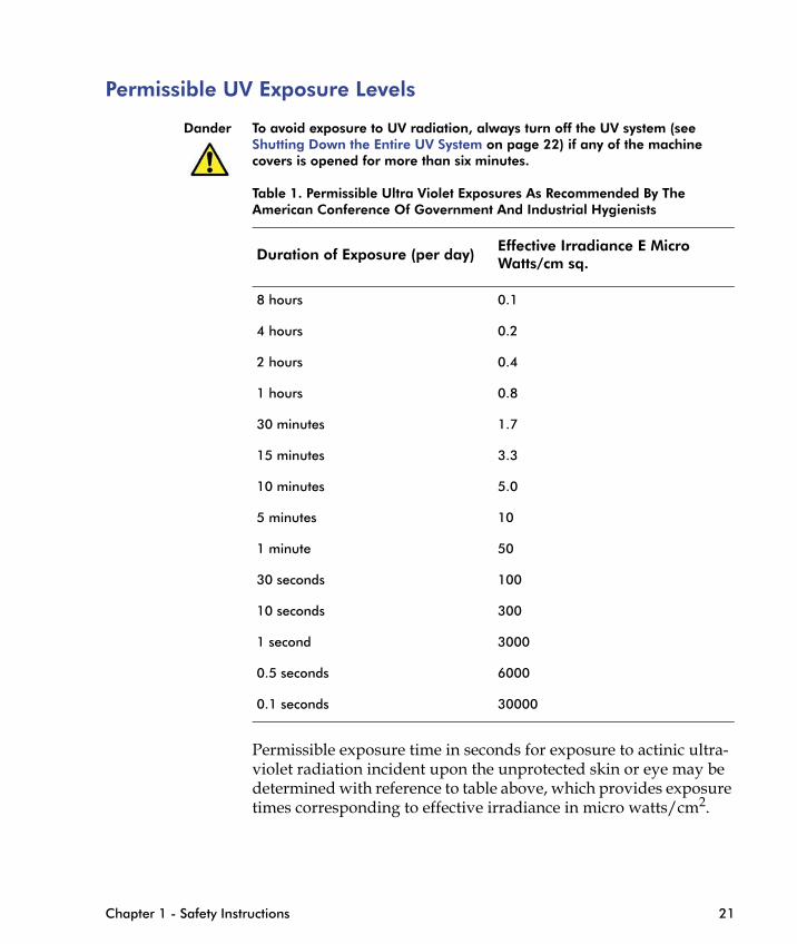
Dander To avoid exposure to UV radiation, always turn off the UV system (see Shutting Down the Entire UV System on page 22) if any of the machine covers is opened for more than six minutes.
Table 1. Permissible Ultra Violet Exposures As Recommended By The American Conference Of Government And Industrial Hygienists
Duration of Exposure (per day) Effective Irradiance E Micro Watts/cm sq.
8 hours 0.1
4 hours 0.2
2 hours 0.4
1 hours 0.8
30 minutes 1.7
15 minutes 3.3
10 minutes 5.0
5 minutes 10
1 minute 50
Chapter 1 - Safety Instructions 21
Permissible exposure time in seconds for exposure to actinic ultra-violet radiation incident upon the unprotected skin or eye may be determined with reference to table above, which provides exposure times corresponding to effective irradiance in micro watts/cm2.
30 seconds 100
10 seconds 300
1 second 3000
0.5 seconds 6000
0.1 seconds 30000

Shutting Down the Entire UV System
The entire UV system must be completely shut down before all procedures which involve exposing internal electrical components.
To perform a complete shut down of the UV system:
1 From the UV electrical cabinet, turn the main isolator to the OFF position.
Figure 1-6 UV Main Isolator turned OFF
2 Padlock the main isolator in the OFF position, as shown in Figure 1-7.
22 HP Scitex FB7600 Operator Manual Rev. D
Figure 1-7 UV Main Isolator locked in the OFF position
Danger To prevent accidental turning on of the main isolator, it is essential to lock the isolator in the OFF position.
Environmental Notices
Battery Disposal (California)
Attention California users: This product’s real-time clock battery or coin-cell battery may contain perchlorate and may require special handling when recycled or disposed of in California.
See http://www.dtsc.ca.gov/hazardouswaste/perchlorate/
Use of Sensitive Receivers
The use of sensitive radio communication devices (receivers) operating in VHF band (180 MHz) should be avoided within 30 meters on all sides of the HP Scitex FB7600 printer.
First Aid TreatmentThe following guidelines are recommended in the event of first aid measures being required:
Inhalation
Chapter 1 - Safety Instructions 23
Move the operator to fresh air immediately. If there is respiratory distress, administer oxygen and seek medical attention.
Eye Contact
Rinse immediately with copious amounts of water. If redness or soreness persists, seek medical advice.
Skin Contact
Wash the affected area with soap and water. Seek medical advice in the event of ensuing dermatological problems.

IEC SymbolsThe system may have labels with one or more of the following symbols attached.
These symbols indicate the IEC standards to which the HP Scitex industrial presses.
Table 1-1 IEC Symbols
Symbol IEC Standard
Alternating Current
Protective Earthing Point
Functional Earth Ground
Danger, Caution - consult accompanying documents
24 HP Scitex FB7600 Operator Manual Rev. D
Electrical Shock Hazard
UV Radiation
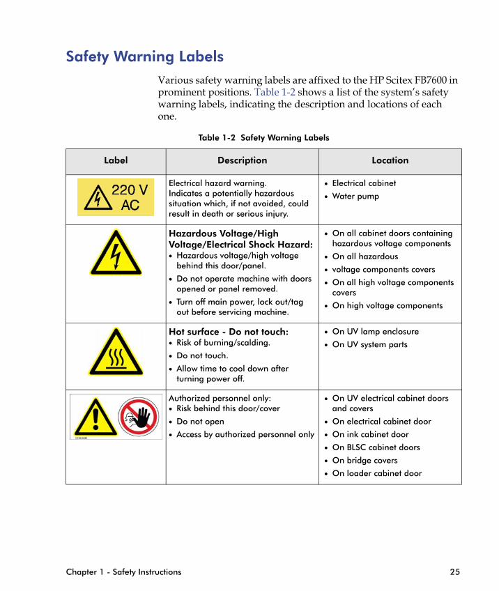
Safety Warning LabelsVarious safety warning labels are affixed to the HP Scitex FB7600 in prominent positions. Table 1-2 shows a list of the system’s safety warning labels, indicating the description and locations of each one.
Table 1-2 Safety Warning Labels
Label Description Location
Electrical hazard warning.Indicates a potentially hazardous situation which, if not avoided, could result in death or serious injury.
• Electrical cabinet
• Water pump
Hazardous Voltage/High Voltage/Electrical Shock Hazard:• Hazardous voltage/high voltage
behind this door/panel.
• Do not operate machine with doors opened or panel removed.
• Turn off main power, lock out/tag out before servicing machine.
• On all cabinet doors containing hazardous voltage components
• On all hazardous
• voltage components covers
• On all high voltage components covers
• On high voltage components
Hot surface - Do not touch:• Risk of burning/scalding.
• On UV lamp enclosure
• On UV system parts
Chapter 1 - Safety Instructions 25
• Do not touch.
• Allow time to cool down after turning power off.
Authorized personnel only:• Risk behind this door/cover
• Do not open
• Access by authorized personnel only
• On UV electrical cabinet doors and covers
• On electrical cabinet door
• On ink cabinet door
• On BLSC cabinet doors
• On bridge covers
• On loader cabinet door
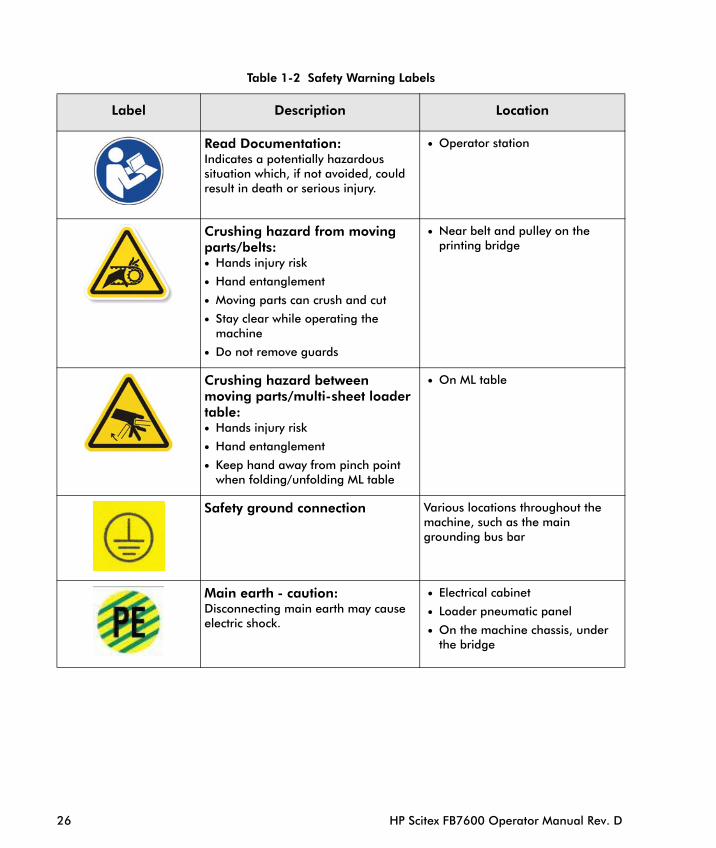
Read Documentation:Indicates a potentially hazardous situation which, if not avoided, could result in death or serious injury.
• Operator station
Crushing hazard from moving parts/belts:• Hands injury risk
• Hand entanglement
• Moving parts can crush and cut
• Stay clear while operating the machine
• Do not remove guards
• Near belt and pulley on the printing bridge
Crushing hazard betweenmoving parts/multi-sheet loader table:• Hands injury risk
• Hand entanglement
• Keep hand away from pinch point when folding/unfolding ML table
• On ML table
Various locations throughout the
Table 1-2 Safety Warning Labels
Label Description Location
26 HP Scitex FB7600 Operator Manual Rev. D
Safety ground connectionmachine, such as the main grounding bus bar
Main earth - caution: Disconnecting main earth may cause electric shock.
• Electrical cabinet
• Loader pneumatic panel
• On the machine chassis, under the bridge
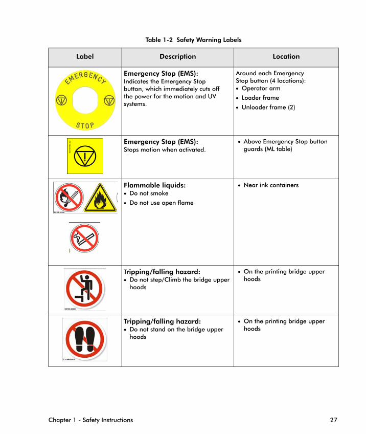
Emergency Stop (EMS):Indicates the Emergency Stopbutton, which immediately cuts offthe power for the motion and UVsystems.
Around each EmergencyStop button (4 locations):• Operator arm
• Loader frame
• Unloader frame (2)
Emergency Stop (EMS):Stops motion when activated.
• Above Emergency Stop button guards (ML table)
Flammable liquids:• Do not smoke
• Do not use open flame
• Near ink containers
Table 1-2 Safety Warning Labels
Label Description Location
Chapter 1 - Safety Instructions 27
Tripping/falling hazard:• Do not step/Climb the bridge upper
hoods
• On the printing bridge upper hoods
Tripping/falling hazard:• Do not stand on the bridge upper
hoods
• On the printing bridge upper hoods
Emergency Safety DevicesThe HP Scitex FB7600 is fitted with the following types of emergency safety devices:
• PILZ safety controller
• Emergency Stop buttons
• Service key
• Safety interlocks
• SICK safety device
• Unloader lift safety frame
The operator must be familiar with the location and operation of each type of safety device. Emergency safety devices must be accessible at all times.
Danger Emergency Stop safety devices must not be connected to the UPS. All safety devices fitted to the HP Scitex FB7600 must be maintained and tested on a regular basis (see Checking the Emergency Stop Safety Devices on page 104).
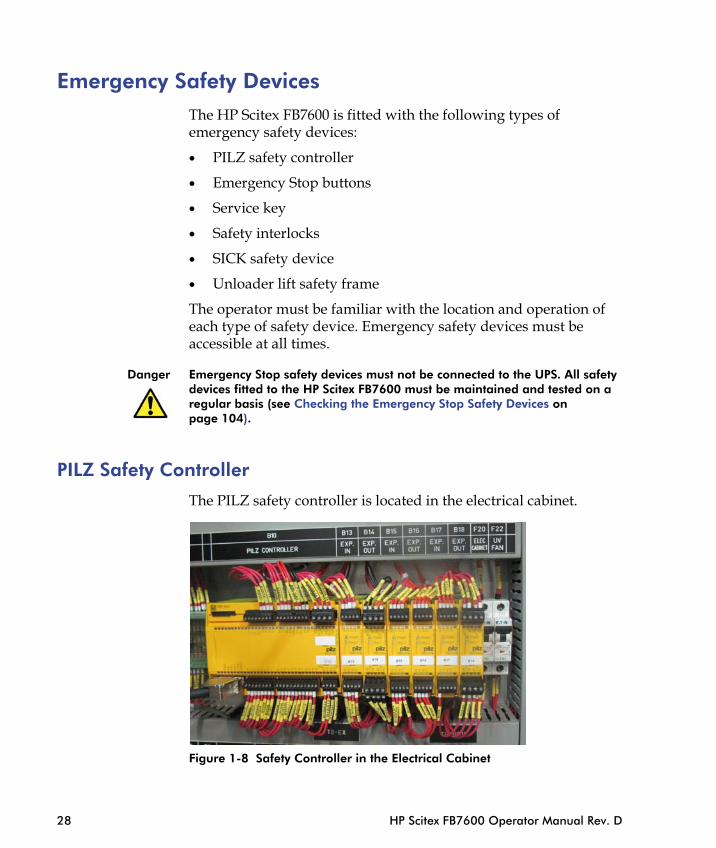
PILZ Safety Controller
The PILZ safety controller is located in the electrical cabinet.
28 HP Scitex FB7600 Operator Manual Rev. D
Figure 1-8 Safety Controller in the Electrical Cabinet
The PILZ monitors the following functions:
• Emergency Stop buttons
• Service key
• Safety interlocks
• SICK
• X-axis limit switches
• Rising media detectors
• Position of the registration pins on the printing table
• Unloader lift release
• NIP interlocks
• Neutralizing phases of the X-axis motor to simplify moving the printing table manually
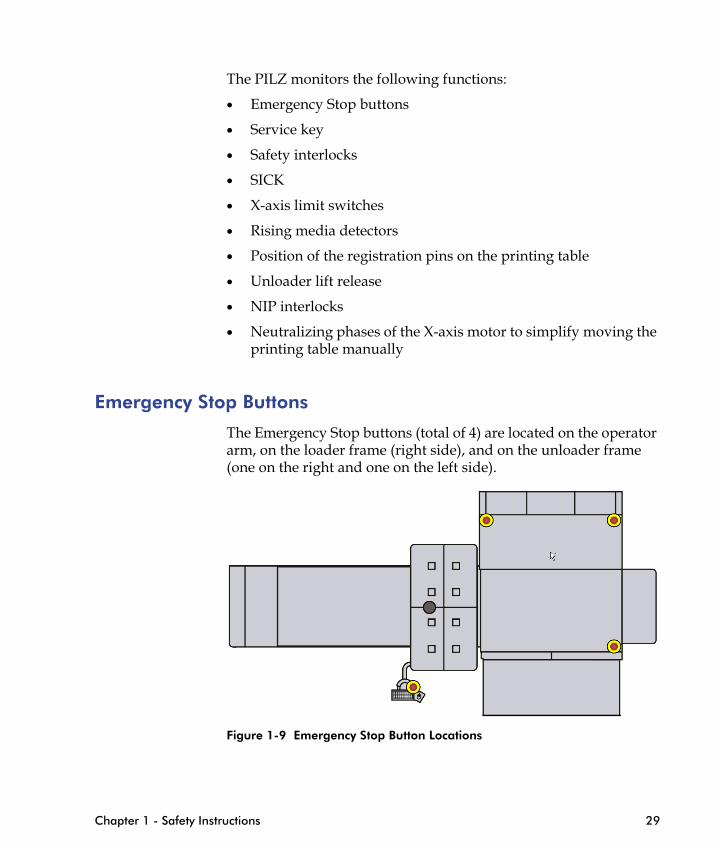
Emergency Stop Buttons
The Emergency Stop buttons (total of 4) are located on the operator arm, on the loader frame (right side), and on the unloader frame (one on the right and one on the left side).
Chapter 1 - Safety Instructions 29
Figure 1-9 Emergency Stop Button Locations
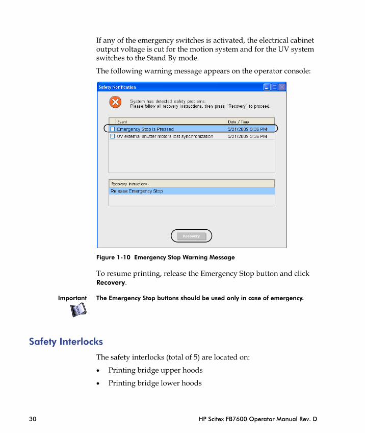
If any of the emergency switches is activated, the electrical cabinet output voltage is cut for the motion system and for the UV system switches to the Stand By mode.
The following warning message appears on the operator console:
Figure 1-10 Emergency Stop Warning Message
30 HP Scitex FB7600 Operator Manual Rev. D
To resume printing, release the Emergency Stop button and click Recovery.
Important The Emergency Stop buttons should be used only in case of emergency.
Safety Interlocks
The safety interlocks (total of 5) are located on:
• Printing bridge upper hoods
• Printing bridge lower hoods
• Printing bridge service doors (in the upper hoods)
• Printing bridge frame
• Loader cover
• Unloader cover
• Multi-sheet loader table (if exist)
Figure 1-11 Safety Interlocks (Pilz)
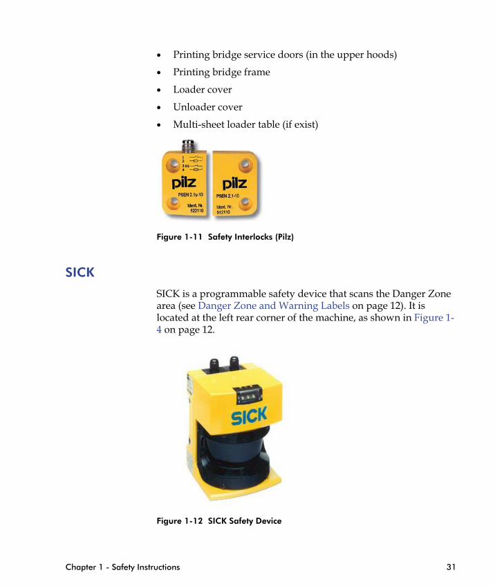
SICK
SICK is a programmable safety device that scans the Danger Zone area (see Danger Zone and Warning Labels on page 12). It is located at the left rear corner of the machine, as shown in Figure 1-4 on page 12.
Chapter 1 - Safety Instructions 31
Figure 1-12 SICK Safety Device

Service Key
The operator station is equipped with the Safety lights, Service key and Reset button are shown in Figure 1-13.
The Service key is an Emergency Stop button with an additional feature. When the key is removed, the emergency mode cannot be canceled accidentally until the key is returned.
Safety lights
Operator control panel
32 HP Scitex FB7600 Operator Manual Rev. D
Figure 1-13 Emergency Safety Devices on the Operator Station
Emergency Stop button
Reset button
Service key
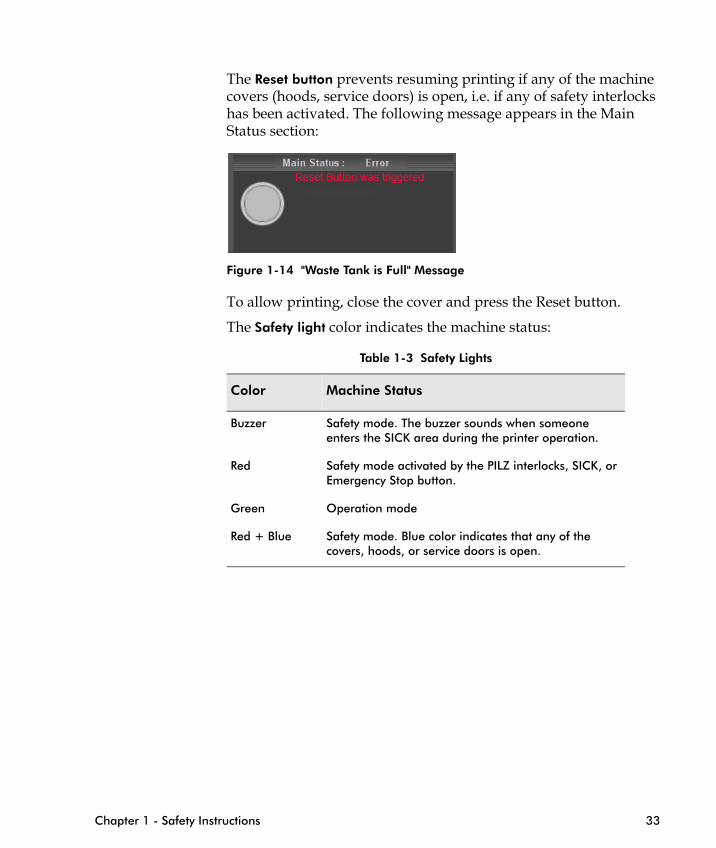
The Reset button prevents resuming printing if any of the machine covers (hoods, service doors) is open, i.e. if any of safety interlocks has been activated. The following message appears in the Main Status section:
Figure 1-14 "Waste Tank is Full" Message
To allow printing, close the cover and press the Reset button.
The Safety light color indicates the machine status:
Table 1-3 Safety Lights
Color Machine Status
Buzzer Safety mode. The buzzer sounds when someone enters the SICK area during the printer operation.
Red Safety mode activated by the PILZ interlocks, SICK, or Emergency Stop button.
Chapter 1 - Safety Instructions 33
Green Operation mode
Red + Blue Safety mode. Blue color indicates that any of the covers, hoods, or service doors is open.

Unloader Lift Safety Frame
The Safety Frame is located in the bottom of the unloader lift, around the perimeter (see Figure 1-15).
Any contact with the Safety Frame activates the safety switch and stops the lift.
34 HP Scitex FB7600 Operator Manual Rev. D
Figure 1-15 Unloader Lift Safety Frame

Personal Safety — Working with the Printer Take the following precautions when working with the printer in order to ensure your personal safety:
• All personnel must read and understand this manual, and be alerted to the potential hazards indicated by the safety labels before operating this printer.
• Only a trained and authorized person is to be permitted to service and operate this printer.
• Training should include instruction in printer operation under normal conditions, and how to stop and turn off the printer in emergency situations.
• Never access the internal parts of the printer for any reason until you have switched off the Service key on the operator station.
• Always turn off and padlock the main power switch while you are on the top or inside the printer. Always place a "Do Not Touch Printer" sign on the operator station when working on the printer.
• Always turn off and padlock the main power switch when servicing the printer’s electrical components.
• When servicing inside the printer (media loading/unloading,
Chapter 1 - Safety Instructions 35
paper jam, or other activities), use the Service key on the operator station.
• Never change or override the function of the printer’s electrical interlocks or other “shutdown” switches.
• Before starting the printer, verify that all persons are outside the Danger Zone of the printer, and that the printer is free of paper scraps, wraps, and jams.
• Do not operate the printer with uncovered long hair, loose clothing, or jewelry, as these may get entangled in the printer.
• Keep the areas around the printer’s loading and unloading points clear of obstructions that could endanger personnel.
• Do not alter the safety characteristics of this equipment under any circumstances.

• Perform routine inspections and corrective/preventive maintenance measures on the printer to ensure proper operation and safety.
• Never clean or service the printer while it is operating.
• Never look directly at the UV light source.
• When servicing the UV lamps, allow the lamps ample time to cool first, as the UV lamp units can burn the skin.
• Avoid smoking, eating, or drinking within the print production area.
• Follow the fire prevention precautionary methods described in this chapter.
• While the printer is operating, always stand at the operator station. Do not approach the printing area, and keep your hands far from all moving parts.
• While the printer is operating, certified operators and HP Scitex FSEs only are permitted in the print production area.
• While loading and unloading heavy materials, wear steel-toed safety boots.
• Do not operate the printer while under the influence of drugs or alcohol.
36 HP Scitex FB7600 Operator Manual Rev. D
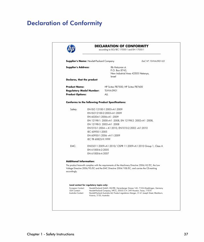
Declaration of Conformity
DECLARATION OF CONFORMITY according to ISO/IEC 17050-1 and EN 17050-1
_____________________________________________________________
Supplier's Name: Hewlett-Packard Company DoC Nº: TLVVA-0901-03 Supplier's Address: 8b Hatzoran st.
P.O. Box 8743, New Industrial Area 42505 Netanya, Israel
Declares, that the product Product Name: HP Scitex FB7500; HP Scitex FB7600 Regulatory Model Number: TLVVA-0901 Product Options: ALL Conforms to the following Product Specifications:
Safety: EN ISO 12100-1:2003+A1:2009
EN ISO12100-2:2003+A1:2009 EN 60204-1:2006+A1 :2009 EN 12198-1: 2000+A1 :2008, EN 12198-2: 2002+A1 :2008, EN 12198-3: 2002+A1 :2008 EN1010-1:2004 + A1:2010, EN1010-2:2002 +A1:2010 IEC 60950-1:2005 EN 60950-1:2006 +A11:2009 IEC TR 60825-9:1999
Chapter 1 - Safety Instructions 37
EMC: EN55011:2009+A1:2010/ CISPR 11:2009+A1:2010 Group 1, Class A EN 61000-6-2:2005 EN 61000-6-4:2007
Additional Information: The product herewith complies with the requirements of the Machinery Directive 2006/42/EC, the Low Voltage Directive 2006/95/EC and the EMC Directive 2004/108/EC, and carries the CE-marking accordingly.
Local contact for regulatory topics only: European Contact: Hewlett-Packard GmbH, HQ-TRE, Herrenberger Strasse 140, 71034 Boeblingen, Germany USA Contact: Hewlett-Packard Company, HPCC, 20555 S.H. 249 Houston, Texas, 77070 Australia Contact: Hewlett-Packard Australia Ltd, Product regulations Manger, 31-41 Joseph Street, Blackburn,
Victoria, 3130, Australia

38 HP Scitex FB7600 Operator Manual Rev. D
Multi-Sheet Loading........................
Manual Substrate Loading...............
Adding a New Job ..........................
System Shutdown............................
Morning Nozzles Health Detector and58
Replacing the Ink Container ............
Adjusting Height of Iron Roller for Di
Raising/Lowering the Printing Bridge
C H A P T E R
2FB7600 Daily Use
FB7600 System Components ............................................. 40
FB7600 Printer Directions and Axes ................................... 41
System Startup .................................................................. 45
Automatic Loading ............................................................ 48
.................................. 48
.................................. 54
.................................. 55
.................................. 57
Print Head Maintenance
.................................. 61
fferent Substrates....... 62
................................. 65
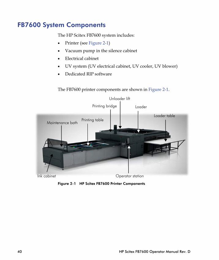
FB7600 System ComponentsThe HP Scitex FB7600 system includes:
• Printer (see Figure 2-1)
• Vacuum pump in the silence cabinet
• Electrical cabinet
• UV system (UV electrical cabinet, UV cooler, UV blower)
• Dedicated RIP software
The FB7600 printer components are shown in Figure 2-1.
Loader table
Loader
Unloader lift
Printing bridge
Printing tableMaintenance bath
40 HP Scitex FB7600 Operator Manual Rev. D
Figure 2-1 HP Scitex FB7600 Printer Components
Ink cabinet Operator station

FB7600 Printer Directions and Axes
Figure 2-2 FB7600 Directions
The FB7600 printer has 7 motor-driven axes. The function of each axis is described in Table 2-1.
Left
(Ink)
sid
e
Rear side
Front (Operator) side Righ
t (Lo
ader
) sid
e
Chapter 2 - FB7600 Daily Use 41
Figure 2-3 FB7600 Axes
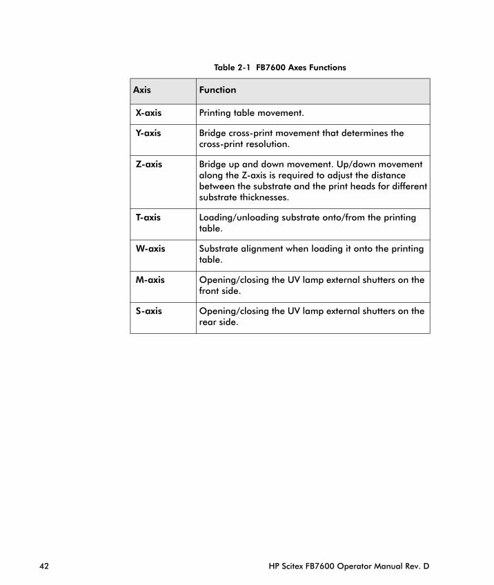
Table 2-1 FB7600 Axes Functions
Axis Function
X-axis Printing table movement.
Y-axis Bridge cross-print movement that determines the cross-print resolution.
Z-axis Bridge up and down movement. Up/down movement along the Z-axis is required to adjust the distance between the substrate and the print heads for differentsubstrate thicknesses.
T-axis Loading/unloading substrate onto/from the printing table.
W-axis Substrate alignment when loading it onto the printing table.
M-axis Opening/closing the UV lamp external shutters on the front side.
S-axis Opening/closing the UV lamp external shutters on the rear side.
42 HP Scitex FB7600 Operator Manual Rev. D
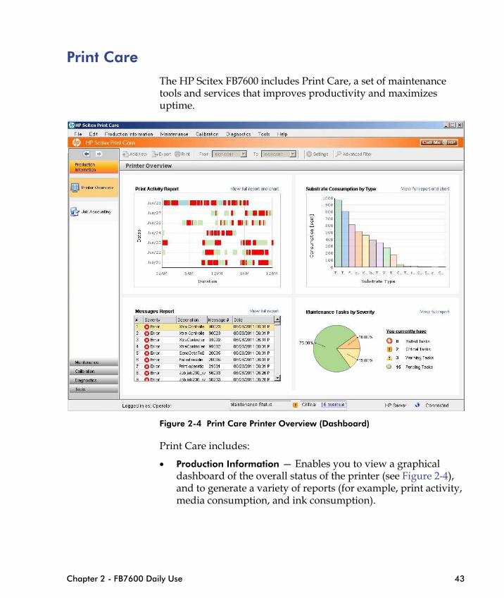
Print CareThe HP Scitex FB7600 includes Print Care, a set of maintenance tools and services that improves productivity and maximizes uptime.
Chapter 2 - FB7600 Daily Use 43
Figure 2-4 Print Care Printer Overview (Dashboard)
Print Care includes:
• Production Information — Enables you to view a graphical dashboard of the overall status of the printer (see Figure 2-4), and to generate a variety of reports (for example, print activity, media consumption, and ink consumption).
• Maintenance — Schedules future maintenance tasks and provides prompts when the time comes to perform them. Wizards provide step-by-step instructions for completing the tasks.
You can also view a history of tasks that have already been performed and a log of messages that have been generated during printing.
• Diagnostics —Enables you to check for failures and malfunctions by running functional tests on printer systems and components. Each diagnostics run generates a report that provides detailed results and troubleshooting instructions.
• Calibration — Enables you to perform calibration procedures, such as trimming, fine-tuning, XY calibration (drop velocity), and nozzle mapping (missing nozzles).
• Tools — Enables you to back up essential printer files and restore them in the event of a system failure.
• CallMe@HP — Enables you to contact an HP support agent directly from the printer, including chat, remote desktop access, and the sharing of files, images, and video.
Note Not all Print Care features are supported on all machines. For detailed instructions about using Print Care, see the Print Care online help.
44 HP Scitex FB7600 Operator Manual Rev. D
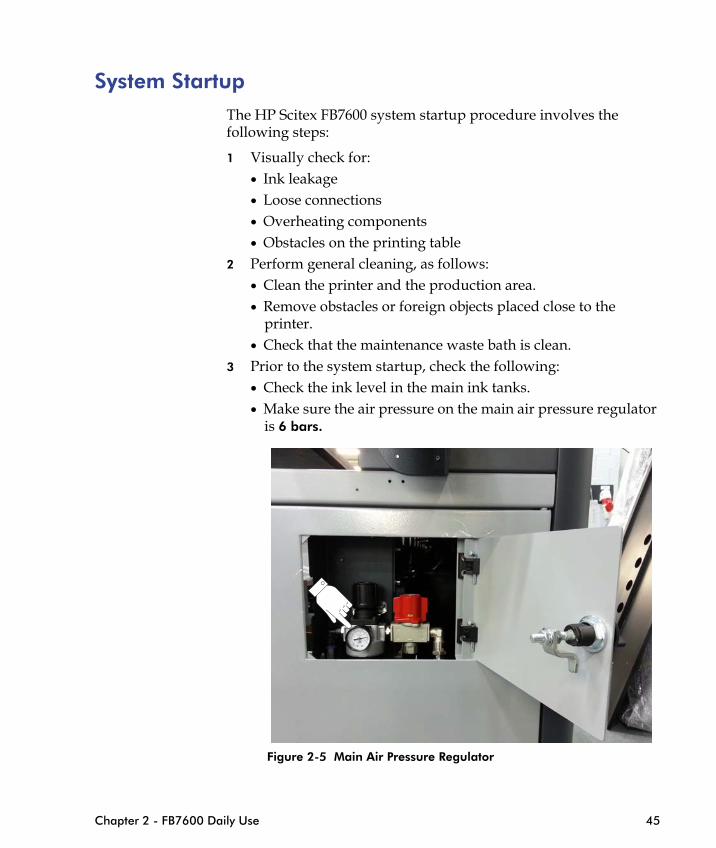
System StartupThe HP Scitex FB7600 system startup procedure involves the following steps:
1 Visually check for:• Ink leakage• Loose connections• Overheating components • Obstacles on the printing table
2 Perform general cleaning, as follows: • Clean the printer and the production area.• Remove obstacles or foreign objects placed close to the
printer.• Check that the maintenance waste bath is clean.
3 Prior to the system startup, check the following:• Check the ink level in the main ink tanks.• Make sure the air pressure on the main air pressure regulator
is 6 bars.
Chapter 2 - FB7600 Daily Use 45
Figure 2-5 Main Air Pressure Regulator
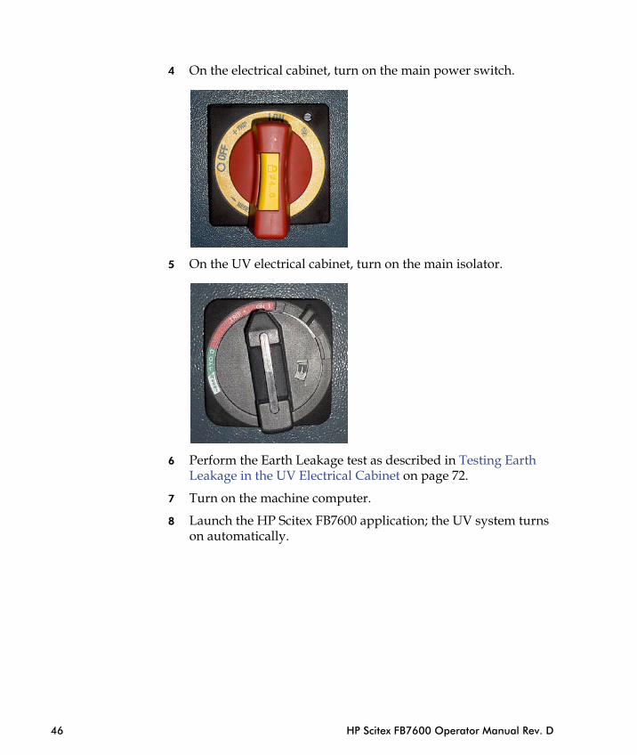
4 On the electrical cabinet, turn on the main power switch.
5 On the UV electrical cabinet, turn on the main isolator.
46 HP Scitex FB7600 Operator Manual Rev. D
6 Perform the Earth Leakage test as described in Testing Earth Leakage in the UV Electrical Cabinet on page 72.
7 Turn on the machine computer.
8 Launch the HP Scitex FB7600 application; the UV system turns on automatically.

9 Wait until the Main Status and UV Lamp have Ready status and the indicators are green.
Note Heating the water for the print heads takes up to 10 minutes.
10 Perform a full print head maintenance cycle: Maintenance -> Full Cycle.
Chapter 2 - FB7600 Daily Use 47
11 Print the Nozzles Health Detector to evaluate the status of the nozzles. Follow the instructions in Morning Nozzles Health Detector and Print Head Maintenance on page 58).

Automatic Loading In 3/4 automatic loading, place the substrates on the loader table one by one and push them towards the loader entrance. The loader aligns and feeds the substrates onto the printing table.
If there is more than one copy, you may place the second substrate immediately after the loader has returned to its home position, even if the first substrate is still being printed.
When the printing cycle is complete, the system automatically unloads the first substrate and stacks it on the unloader lift. Simultaneously, it feeds the second substrate onto the printing table.
Multi-Sheet Loading1 Turn on the machine and the machine computer.
2 Start the machine application.
3 Open the flap of the multi-sheet loader table (ML table).
48 HP Scitex FB7600 Operator Manual Rev. D
Figure 2-6 Flap on the ML table

Danger Be careful not to put your hand between the moving flap and the loader table. Your fingers may get caught!
4 In the Job Properties window, select the following:
Job Name: The image you wish to print; the predefined number of sheets appears in the Sheets per Load box.
Method: Multiload
Align sheet to: Select Left or Right.
Desired Copies: Select the number of copies; the actual sheets
Chapter 2 - FB7600 Daily Use 49
number will automatically appear in the Actual Sheets box.

50 HP Scitex FB7600 Operator Manual Rev. D
Figure 2-7 Job Properties Window
5 Click Save.
6 Place 4 sheets (in this example) on the ML table.
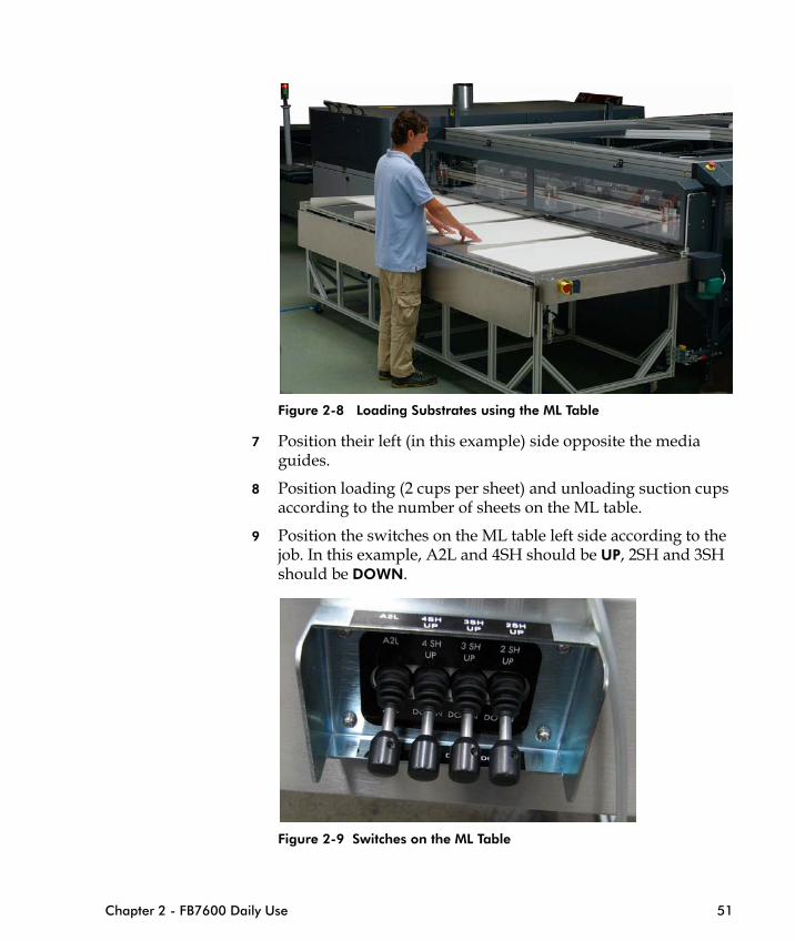
Figure 2-8 Loading Substrates using the ML Table
7 Position their left (in this example) side opposite the media guides.
8 Position loading (2 cups per sheet) and unloading suction cups according to the number of sheets on the ML table.
9 Position the switches on the ML table left side according to the job. In this example, A2L and 4SH should be UP, 2SH and 3SH
Chapter 2 - FB7600 Daily Use 51
should be DOWN.
Figure 2-9 Switches on the ML Table
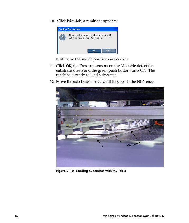
10 Click Print Job; a reminder appears:
Make sure the switch positions are correct.
11 Click OK; the Presence sensors on the ML table detect the substrate sheets and the green push button turns ON. The machine is ready to load substrates.
12 Move the substrates forward till they reach the NIP fence.
52 HP Scitex FB7600 Operator Manual Rev. D
Figure 2-10 Loading Substrates with ML Table
NIP fence
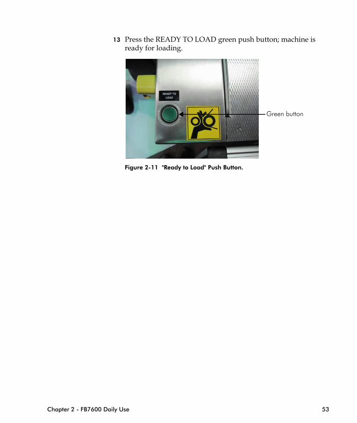
13 Press the READY TO LOAD green push button; machine is ready for loading.
Figure 2-11 "Ready to Load" Push Button.
Green button
Chapter 2 - FB7600 Daily Use 53
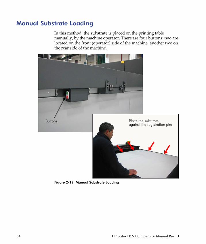
Manual Substrate LoadingIn this method, the substrate is placed on the printing table manually, by the machine operator. There are four buttons: two are located on the front (operator) side of the machine, another two on the rear side of the machine.
Place the substrateagainst the registration pins
Buttons
54 HP Scitex FB7600 Operator Manual Rev. D
Figure 2-12 Manual Substrate Loading

To load the substrate manually:
1 In the FB7600 main window, select Manual Loading.
2 Select the desired job and click Print Job; the printing table moves to the left; the "Loading media" message appears on the screen.
3 Press the green button; the registration pins move up and vacuum is deactivated.
4 Place the substrate on the printing table against the registration pins (see Figure 2-12 on page 54).
5 Press the red button; the system activates the vacuum to the printing table and lowers the registration pins. A message appears, asking you to confirm that the substrate is loaded properly.
6 Click Yes to start the printing process.
7 If the substrate is not loaded properly, click No and return to step 3.
Adding a New Job
Reference For detailed instructions on how to define print parameters and print a job refer to HP Scitex FB7600 Online Manual.
Chapter 2 - FB7600 Daily Use 55
1 In the File menu, select Add New Job; the Job Properties window appears (see Figure 2-7 on page 50).
2 Click the browser button next to the Image box; the Choose Image File window appears.
3 Click Folder Browser; the Browse window appears.
4 Select the folder that contains the file separations and click OK; the Job Properties window appears again displaying the file’s preview and information.
5 The Job name is named the same as the image by default, but you may change it to a different name at this stage.
6 From the Print Mode list box, select the desired print mode.
7 From the Saturation list box, select the desired saturation.
8 From the Substrate list box, select the substrate on which you want to print your file.
Upon selecting a specific substrate, the relevant information about it appears on the right side of the window: length, width, thickness, print heads height, and UV power.
9 From the Method list box, select the printing method: Simple, Step&Repeat, or MultiLoad.
10 Under the Layout tab, enter the number of copies and the margins’ values.
11 From the Align Sheet to box, select Left or Right. This feature is used for multi-sheet loading.
12 If needed, select the Job Notes box and enter the notes. These notes will be printed aside the printed image.
13 Click the Job Info tab and select the desired options.
14 Click the Media tab; the parameters of the selected substrate are displayed. Select the desired options.
15 Click Save As and enter the job name.
16 Click Save and then Yes to save the job.
The job is displayed in the Jobs List with the Not Ready status.
56 HP Scitex FB7600 Operator Manual Rev. D
Printing a Job1 Set the loading/unloading system parameters for the selected
substrate as described in "How to Set Up Loading/Unloading System" in FB7600 Advanced Printer Guide. (To access it, click Advance Printer Guide from the Help menu).
2 Add a new job as described in Adding a New Job on page 55; the job appears in the Jobs List with the Not Ready status.
3 Select the job and click the Prepare Job Offline icon on the toolbar; the job status changes to Ready.
4 Load the substrate sheet as described in Automatic Loading on page 48.
5 Click the Print Job button to start printing.
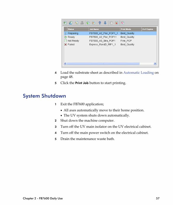
System Shutdown1 Exit the FB7600 application;
• All axes automatically move to their home position.• The UV system shuts down automatically.
2 Shut down the machine computer.
Chapter 2 - FB7600 Daily Use 57
3 Turn off the UV main isolator on the UV electrical cabinet.
4 Turn off the main power switch on the electrical cabinet.
5 Drain the maintenance waste bath.
Morning Nozzles Health Detector and Print Head Maintenance
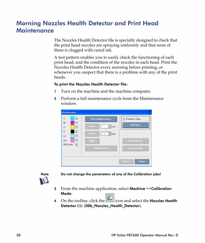
The Nozzles Health Detector file is specially designed to check that the print head nozzles are spraying uniformly and that none of them is clogged with cured ink.
A test pattern enables you to easily check the functioning of each print head, and the condition of the nozzles in each head. Print the Nozzles Health Detector every morning before printing, or whenever you suspect that there is a problem with any of the print heads.
To print the Nozzles Health Detector file:
1 Turn on the machine and the machine computer.
2 Perform a full maintenance cycle from the Maintenance window.
58 HP Scitex FB7600 Operator Manual Rev. D
Note Do not change the parameters of any of the Calibration jobs!
3 From the machine application, select Machine =>Calibration Mode.
4 On the toolbar, click the icon and select the Nozzles Health Detector file (00b_Nozzles_Health_Detector).

5 Click the icon to prepare the file and then click Print.
Chapter 2 - FB7600 Daily Use 59
Figure 2-13 Nozzles Health Detector Print Result
Note Do not forget to cancel the Calibration Mode before printing regular files.
The print result contains the small rectangular segments that are printed by each nozzle. A missing segment indicates a missing nozzle. As each nozzle prints, it is possible to trace misfiring nozzles, since their corresponding segments are missing (see Figure 2-14 on page 60).
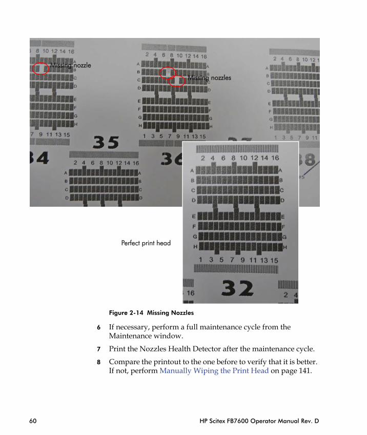
Perfect print head
Missing nozzles
Missing nozzle
60 HP Scitex FB7600 Operator Manual Rev. D
Figure 2-14 Missing Nozzles
6 If necessary, perform a full maintenance cycle from the Maintenance window.
7 Print the Nozzles Health Detector after the maintenance cycle.
8 Compare the printout to the one before to verify that it is better. If not, perform Manually Wiping the Print Head on page 141.
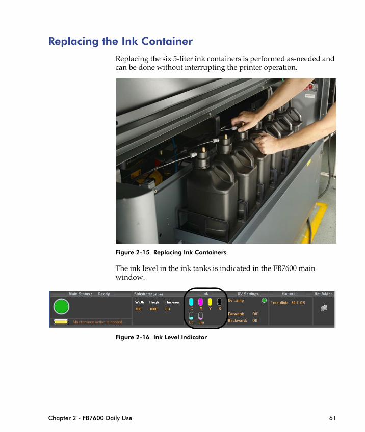
Replacing the Ink ContainerReplacing the six 5-liter ink containers is performed as-needed and can be done without interrupting the printer operation.
Figure 2-15 Replacing Ink Containers
Chapter 2 - FB7600 Daily Use 61
The ink level in the ink tanks is indicated in the FB7600 main window.
Figure 2-16 Ink Level Indicator
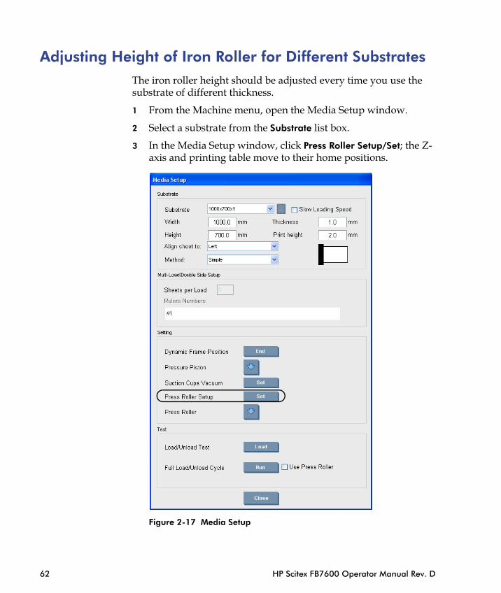
Adjusting Height of Iron Roller for Different SubstratesThe iron roller height should be adjusted every time you use the substrate of different thickness.
1 From the Machine menu, open the Media Setup window.
2 Select a substrate from the Substrate list box.
3 In the Media Setup window, click Press Roller Setup/Set; the Z-axis and printing table move to their home positions.
62 HP Scitex FB7600 Operator Manual Rev. D
Figure 2-17 Media Setup
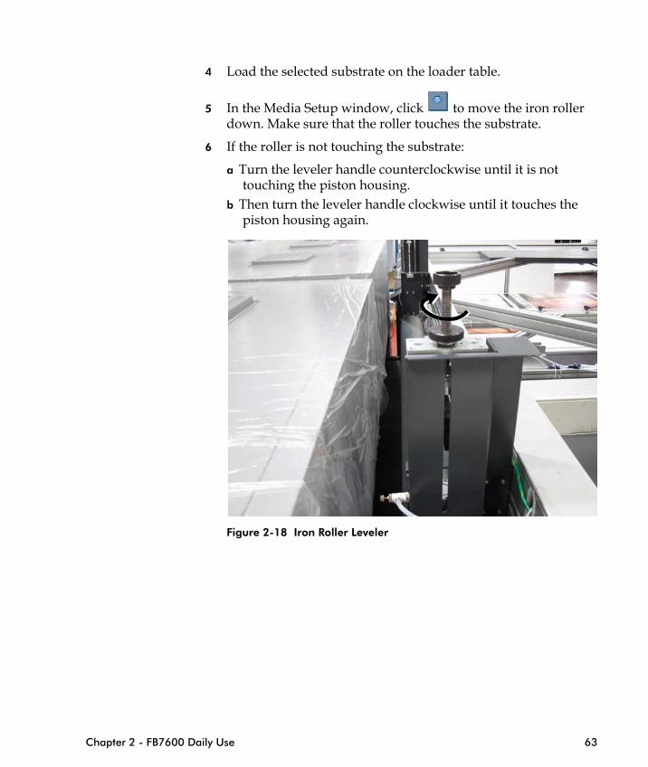
4 Load the selected substrate on the loader table.
5 In the Media Setup window, click to move the iron roller down. Make sure that the roller touches the substrate.
6 If the roller is not touching the substrate:
a Turn the leveler handle counterclockwise until it is not touching the piston housing.
b Then turn the leveler handle clockwise until it touches the piston housing again.
Chapter 2 - FB7600 Daily Use 63
Figure 2-18 Iron Roller Leveler
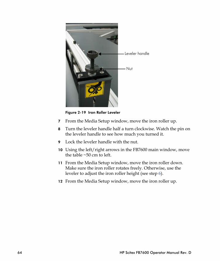
Figure 2-19 Iron Roller Leveler
7 From the Media Setup window, move the iron roller up.
8 Turn the leveler handle half a turn clockwise. Watch the pin on the leveler handle to see how much you turned it.
9 Lock the leveler handle with the nut.
10 Using the left/right arrows in the FB7600 main window, move the table ~50 cm to left.
Nut
Leveler handle
64 HP Scitex FB7600 Operator Manual Rev. D
11 From the Media Setup window, move the iron roller down. Make sure the iron roller rotates freely. Otherwise, use the leveler to adjust the iron roller height (see step 6).
12 From the Media Setup window, move the iron roller up.

Raising/Lowering the Printing BridgeSome of the maintenance procedures require to raise the bridge and to lower it when the procedure is complete.
1 To raise the bridge, press the OPEN green button, as shown in Figure 2-20.
Figure 2-20 Raising the Bridge
Chapter 2 - FB7600 Daily Use 65
2 To lower the bridge:
a Pull the handle towards you to access the CLOSE button (see Figure 2-21 on page 66).
b While holding the handle, press and hold for a few seconds the CLOSE black button.
Note If you quickly press the CLOSE button and release it, the bridge will return to its upper position.
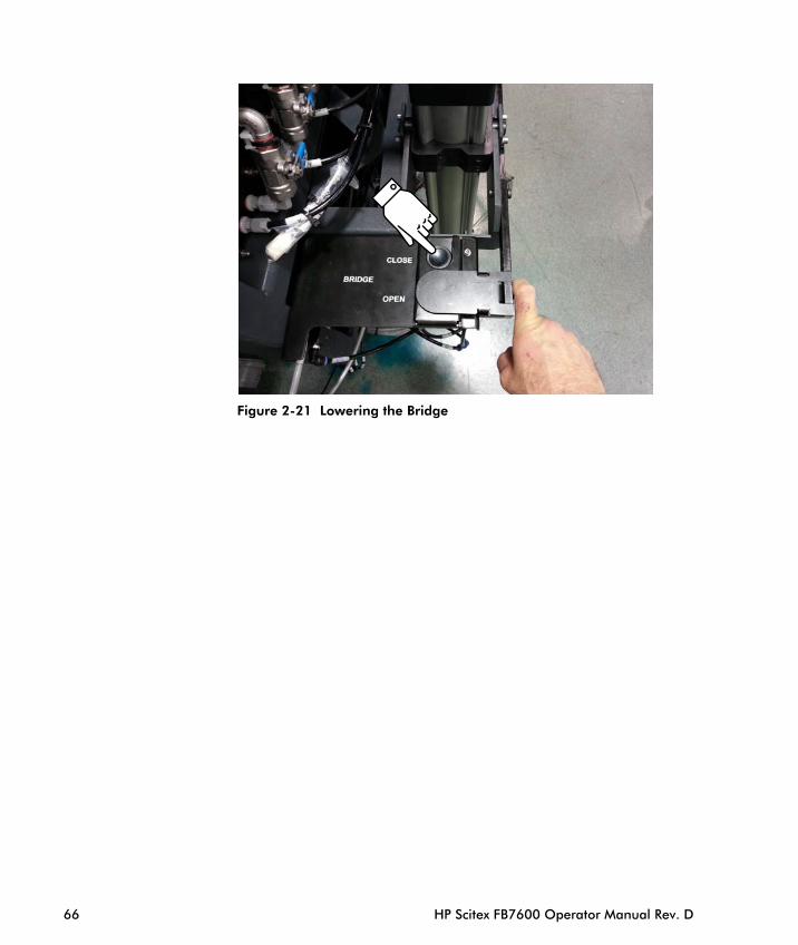
Figure 2-21 Lowering the Bridge
66 HP Scitex FB7600 Operator Manual Rev. D
Testing Earth Leakage in the UV Elec
Checking the Water Level in the UV S
C H A P T E R
3Daily Maintenance
Visual Checks and General Cleaning................................. 68
Checking the Pneumatic System ........................................ 69
Monitoring the Ink Level in Ink Containers......................... 70
Emptying the Waste Tank................................................... 70
trical Cabinet ............. 72
ystem ....................... 73
Visual Checks and General CleaningIn order to maintain the FB7600 printer in good working order, it is recommended to perform a visual inspection of the system every day. This helps to identify signs of general wear or possible component malfunction.
When visually inspecting the system, pay special attention to:
• Ink leakage in the ink system area: • Ink pumps• Ink filters • Fittings• Circulation valves
• Ink leakage in printing bridge area: • Switch valves• Secondary ink tanks• Fittings• Print heads’ nozzles plate
• Water leakage in the main water tank area:• Water tank• Water pump• Fittings
68 HP Scitex FB7600 Operator Manual Rev. D
• Water leakage in the printing bridge area: • Water manifold• Water reservoir• Fittings
• Leakage in the UV water system and all tubes:• UV cooler• Quick connectors on the printing bridge
• UV cooler water level — at least 3/4 full
• Water level in the ink heating system (water reservoir)
• Quartz filter cleanliness (see Cleaning the Quartz Plates in the UV Lamp Housing on page 77)
Note Daily general cleaning of the printer, as well as the production area, will help to eliminate the build up of dust, dried ink and dirt. Removal of obstacles or foreign objects which may have been placed close to the printer will eliminate the risk of possible safety hazards.
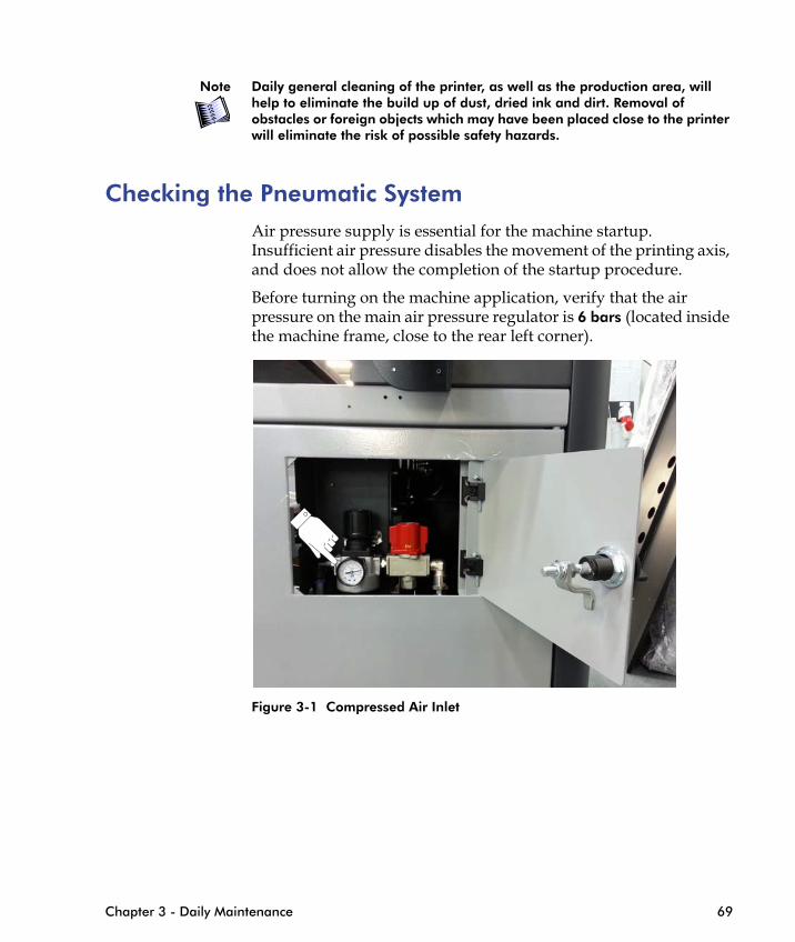
Checking the Pneumatic SystemAir pressure supply is essential for the machine startup. Insufficient air pressure disables the movement of the printing axis, and does not allow the completion of the startup procedure.
Before turning on the machine application, verify that the air pressure on the main air pressure regulator is 6 bars (located inside the machine frame, close to the rear left corner).
Chapter 3 - Daily Maintenance 69
Figure 3-1 Compressed Air Inlet
Monitoring the Ink Level in Ink ContainersThe ink level in the six 5-liter ink containers is indicated in the FB7600 main window and must be checked:
• At the beginning of each workday
• Throughout the workday during normal printer operation
Emptying the Waste Tank
Note Handling ink or ink-related elements requires wearing protective gloves.
During head cleaning and purging procedures, surplus ink, dried particles, solvent, and debris collect in the waste tank located at the rear of the printer.
The waste tank should be emptied to eliminate the risk of the tank overflowing and also to prevent the build-up of excess dried ink. During heavy print runs, it may be required to empty the waste tank every day.
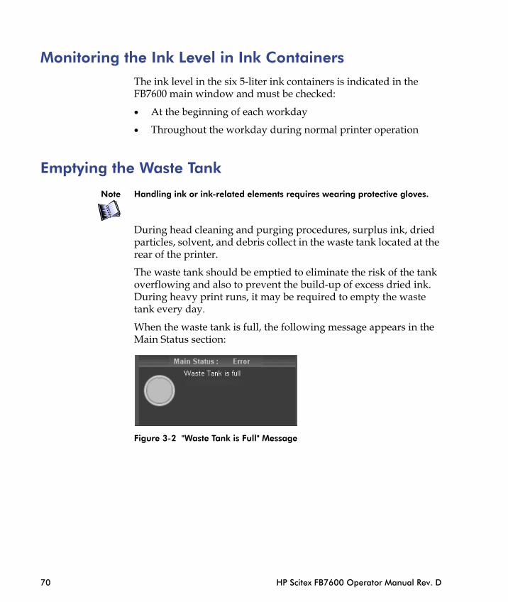
When the waste tank is full, the following message appears in the Main Status section:
70 HP Scitex FB7600 Operator Manual Rev. D
Figure 3-2 "Waste Tank is Full" Message
To empty the waste tank:
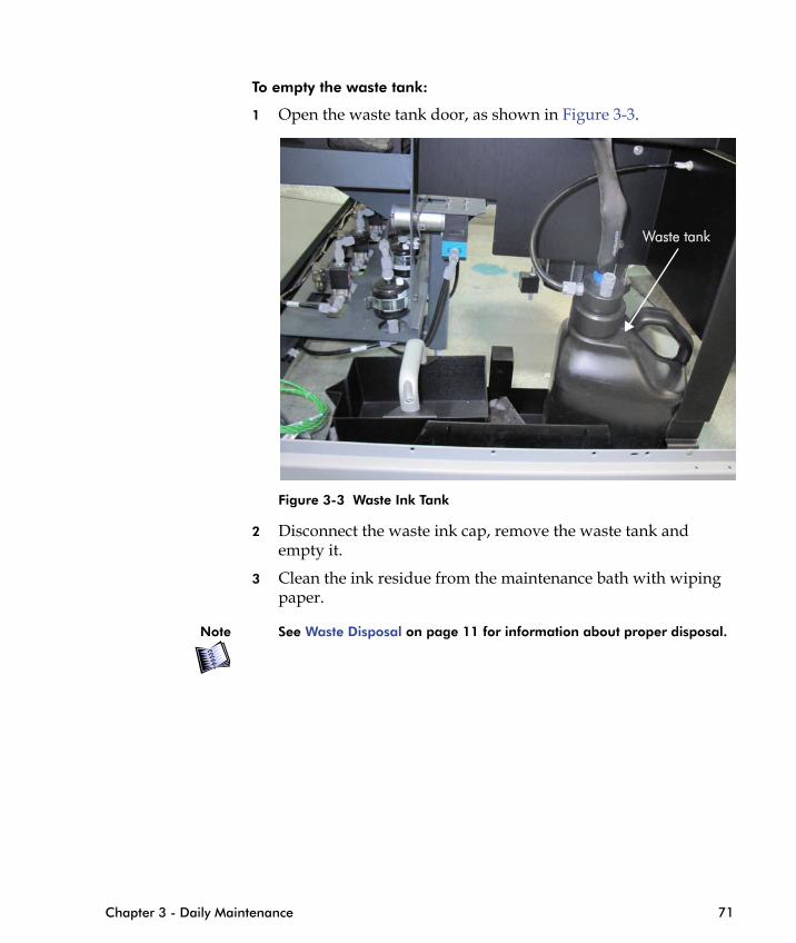
1 Open the waste tank door, as shown in Figure 3-3.
Figure 3-3 Waste Ink Tank
2 Disconnect the waste ink cap, remove the waste tank and empty it.
Waste tank
Chapter 3 - Daily Maintenance 71
3 Clean the ink residue from the maintenance bath with wiping paper.
Note See Waste Disposal on page 11 for information about proper disposal.

Testing Earth Leakage in the UV Electrical CabinetTesting the earth leakage must be performed at the beginning of each work day, before starting the FB7600 application.
To test the earth leakage:
1 From the UV electrical cabinet, press the earth leakage Test button (see Figure 3-4); the main isolator switches to Trip position, meaning there is simulated earth leakage.
Earth Leakage Test Button
Main Isolator
72 HP Scitex FB7600 Operator Manual Rev. D
Figure 3-4 UV Electrical Cabinet
Danger If the main isolator does not trip, there is an earth leakage in the system. In this case, turn the isolator to the OFF position immediately and call Service. Do not use the machine until the problem is solved.
2 Turn the isolator to the OFF position.
3 Turn the isolator back to the Reset position.
4 Turn the isolator to the ON position.

Checking the Water Level in the UV SystemVisually check the water level in the UV cooler. The water level indicator is located on the side door of the UV cooler (see Figure 3-5).
The water level should not be lower than the minimum and not higher than the maximum level marks.
Max. level
Min. level
Chapter 3 - Daily Maintenance 73
Figure 3-5 UV Cooler Side Door

74 HP Scitex FB7600 Operator Manual Rev. D

Cleaning the Printing Bridge............
Emptying the Separator Bath ...........
Checking the HT Contactors Counter
C H A P T E R
4Weekly Maintenance
Cleaning the Printing Table ............................................... 76
Cleaning the Quartz Plates in the UV Lamp Housing.......... 77
Checking the Loading/Unloading Suction Cups ................. 79
Cleaning the Rising Media Flaps........................................ 80
.................................. 82
.................................. 88
in the UV System ...... 89

Cleaning the Printing TableTo ensure good vacuum performance, the vacuum printing table should be clean of ink residue and its holes should be open and clean.
1 To clean the printing table, move the table to the Manual Loading position, switch off the Service key and remove it.
Danger Do not step on the table during the cleaning procedure.
76 HP Scitex FB7600 Operator Manual Rev. D
Figure 4-1 Printing Table in the "Manual Loading" position
2 Punch the clogged holes using the special tool P/N 39500006 supplied in the Accessories Kit with inserted drill bit.
Figure 4-2 Tool for cleaning table holes

Cleaning the Quartz Plates in the UV Lamp HousingIt is recommended to clean the quartz plates inside and outside before turning on the machine. If you want to clean them while the machine is working:
1 Turn off the entire UV system, as described in Shutting Down the Entire UV System on page 22.
2 Wait 15 minutes for the system to cool down.
Danger UV system operates at very high temperatures and the inside components become very hot during machine operation, which may cause personal injury. Therefore, when maintaining the equipment, a reasonable time (15 minutes) should be allowed before access is attempted.
3 Switch off the Service key and remove it.
4 Open the bridge upper hoods, using the handles, as shown in Figure 4-3.
Chapter 4 - Weekly Maintenance 77
Figure 4-3 Opening the Bridge Upper Hoods
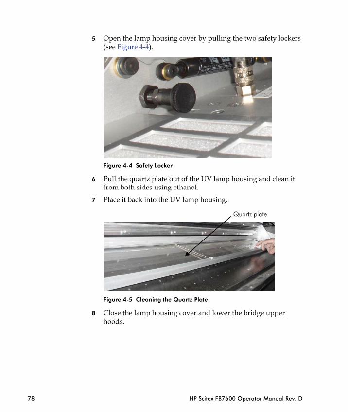
5 Open the lamp housing cover by pulling the two safety lockers (see Figure 4-4).
Figure 4-4 Safety Locker
6 Pull the quartz plate out of the UV lamp housing and clean it from both sides using ethanol.
7 Place it back into the UV lamp housing.
Quartz plate
78 HP Scitex FB7600 Operator Manual Rev. D
Figure 4-5 Cleaning the Quartz Plate
8 Close the lamp housing cover and lower the bridge upper hoods.
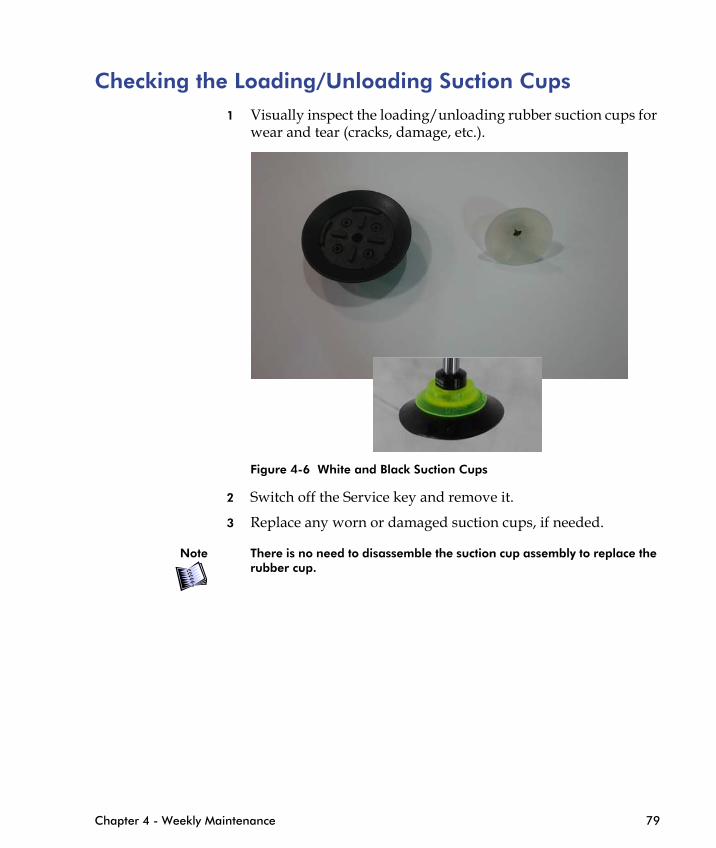
Checking the Loading/Unloading Suction Cups 1 Visually inspect the loading/unloading rubber suction cups for
wear and tear (cracks, damage, etc.).
Figure 4-6 White and Black Suction Cups
2 Switch off the Service key and remove it.
Chapter 4 - Weekly Maintenance 79
3 Replace any worn or damaged suction cups, if needed.
Note There is no need to disassemble the suction cup assembly to replace the rubber cup.
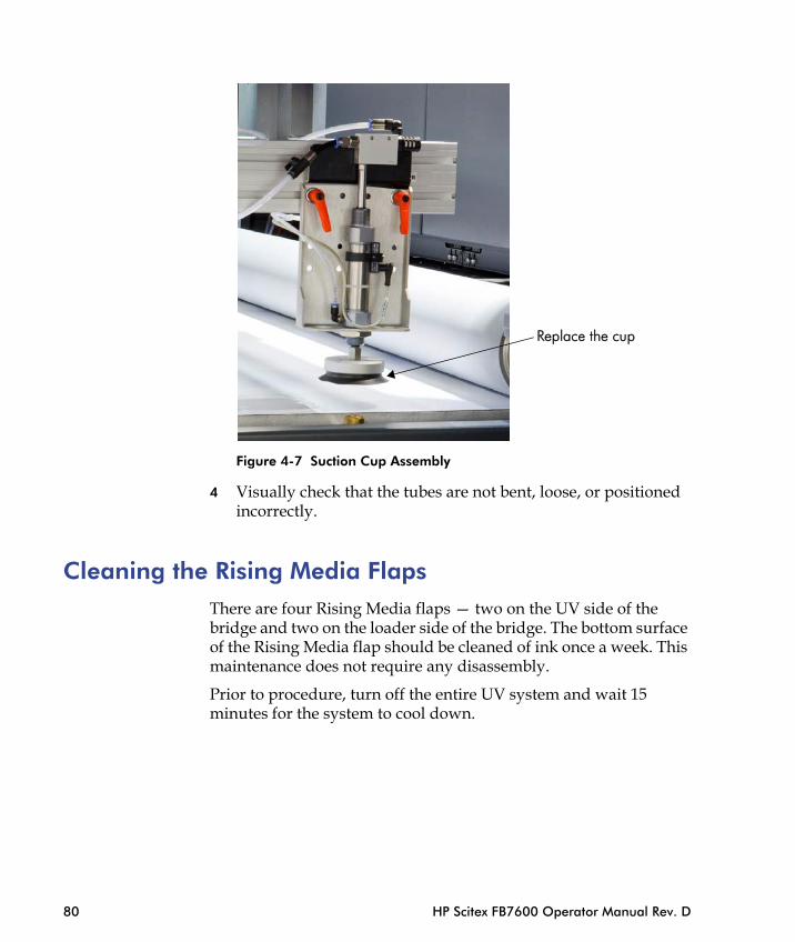
Figure 4-7 Suction Cup Assembly
4 Visually check that the tubes are not bent, loose, or positioned incorrectly.
Replace the cup
80 HP Scitex FB7600 Operator Manual Rev. D
Cleaning the Rising Media FlapsThere are four Rising Media flaps — two on the UV side of the bridge and two on the loader side of the bridge. The bottom surface of the Rising Media flap should be cleaned of ink once a week. This maintenance does not require any disassembly.
Prior to procedure, turn off the entire UV system and wait 15 minutes for the system to cool down.

Rising Media beam
Rising Media flaps
Chapter 4 - Weekly Maintenance 81
Figure 4-8 Rising Media Flaps
Rising Media flaps

Cleaning the Printing Bridge Preventive maintenance of the printing bridge should be performed on a weekly basis.
After a certain period or after a certain number of prints, you may see a build-up of dust, dried ink, and dirt on the nozzles plate of the print heads and surrounding parts of the bridge. This may negatively affect print quality as well as the functioning of different systems on the bridge. Cleaning the printing bridge weekly will help maintain good print quality and prevent the print heads and bridge components from damage.
Dirt on the printing bridge may be caused by the following:
• Dirty substrates, fiber residues
• Dirty and dusty environment
• Ink spraying
• Ink dripping between the ink bars when lifting the bridge for maintenance purposes
• Malfunction of the vacuum knife
• Dirt from the printing table
To clean the printing bridge:
1 Move the table to its home position.
82 HP Scitex FB7600 Operator Manual Rev. D
2 Shut down the system and padlock the main power switch on the electrical cabinet in the OFF position, as shown in Figure 6-2 on page 105.
3 Close the taps on the secondary ink tanks on both sides of the bridge.
4 Open the upper hoods of the printing bridge.
5 Raise the bridge as described in Raising/Lowering the Printing Bridge on page 65.
6 Visually inspect the bridge components to identify the dirty areas.
7 Clean the dirty components, as described in the following sections.
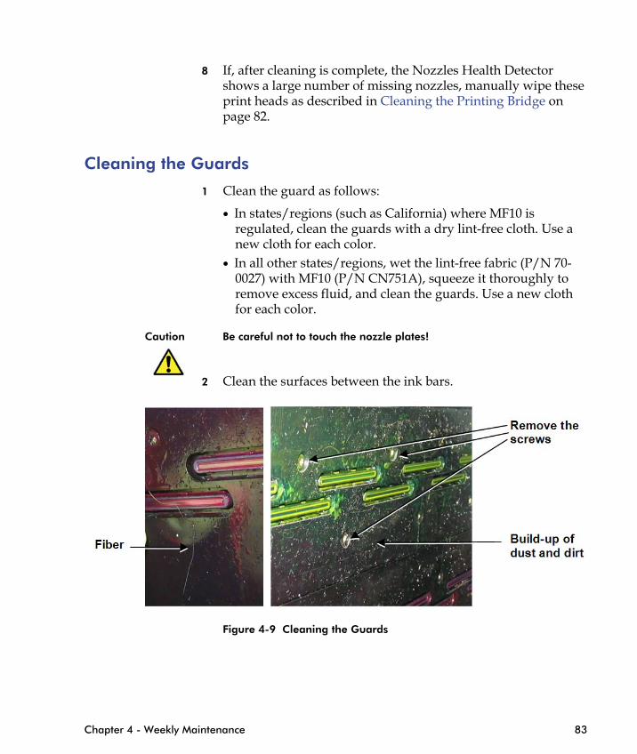
8 If, after cleaning is complete, the Nozzles Health Detector shows a large number of missing nozzles, manually wipe these print heads as described in Cleaning the Printing Bridge on page 82.
Cleaning the Guards
1 Clean the guard as follows:
• In states/regions (such as California) where MF10 is regulated, clean the guards with a dry lint-free cloth. Use a new cloth for each color.
• In all other states/regions, wet the lint-free fabric (P/N 70-0027) with MF10 (P/N CN751A), squeeze it thoroughly to remove excess fluid, and clean the guards. Use a new cloth for each color.
Caution Be careful not to touch the nozzle plates!
2 Clean the surfaces between the ink bars.
Chapter 4 - Weekly Maintenance 83
Figure 4-9 Cleaning the Guards

Figure 4-10 Guards after Cleaning
If the guard is very dirty and there is ink spillage between the nozzle plate and the guard, dismantle the guard and do the following:
• In states/regions (such as California) where MF10 is regulated, clean around the nozzle plate and the guard with a dry lint-free cloth.
84 HP Scitex FB7600 Operator Manual Rev. D
• In all other states/regions, wet the lint-free fabric (P/N 70-0027) with MF10 (P/N CN751A) and clean around the nozzle plate and the guard.
Figure 4-11 Ink Spillage around the Nozzle Plate

Figure 4-12 Cleaning the Guards
Guard before cleaning
Guard after cleaning
Chapter 4 - Weekly Maintenance 85

Cleaning the Cooling Fans and Surroundings
Clean the cooling fans and their surroundings with a wet cloth.
Caution Do not use compressed air for cleaning the cooling fans.
Figure 4-13 Cooling Fans
Dirty areas
86 HP Scitex FB7600 Operator Manual Rev. D
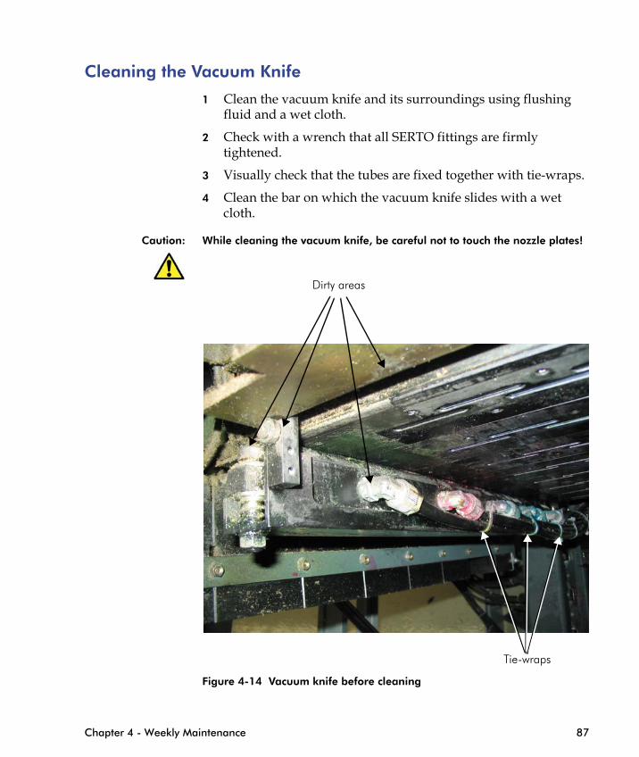
Cleaning the Vacuum Knife
1 Clean the vacuum knife and its surroundings using flushing fluid and a wet cloth.
2 Check with a wrench that all SERTO fittings are firmly tightened.
3 Visually check that the tubes are fixed together with tie-wraps.
4 Clean the bar on which the vacuum knife slides with a wet cloth.
Caution: While cleaning the vacuum knife, be careful not to touch the nozzle plates!
Dirty areas
Chapter 4 - Weekly Maintenance 87
Figure 4-14 Vacuum knife before cleaning
Tie-wraps
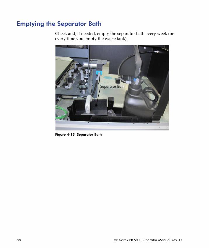
Emptying the Separator BathCheck and, if needed, empty the separator bath every week (or every time you empty the waste tank).
Figure 4-15 Separator Bath
Separator Bath
88 HP Scitex FB7600 Operator Manual Rev. D
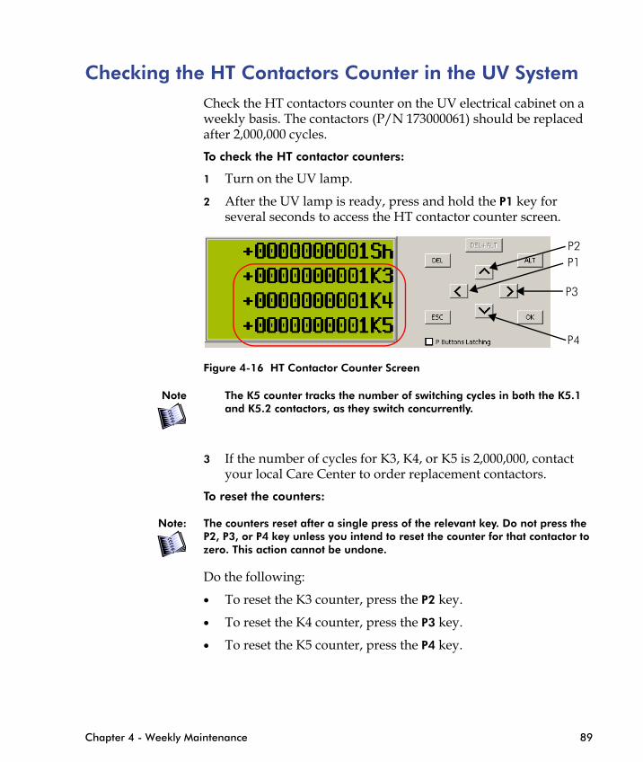
Checking the HT Contactors Counter in the UV SystemCheck the HT contactors counter on the UV electrical cabinet on a weekly basis. The contactors (P/N 173000061) should be replaced after 2,000,000 cycles.
To check the HT contactor counters:
1 Turn on the UV lamp.
2 After the UV lamp is ready, press and hold the P1 key for several seconds to access the HT contactor counter screen.
Figure 4-16 HT Contactor Counter Screen
Note The K5 counter tracks the number of switching cycles in both the K5.1 and K5.2 contactors, as they switch concurrently.
P1P2
P3
P4
Chapter 4 - Weekly Maintenance 89
3 If the number of cycles for K3, K4, or K5 is 2,000,000, contact your local Care Center to order replacement contactors.
To reset the counters:
Note: The counters reset after a single press of the relevant key. Do not press the P2, P3, or P4 key unless you intend to reset the counter for that contactor to zero. This action cannot be undone.
Do the following:
• To reset the K3 counter, press the P2 key.
• To reset the K4 counter, press the P3 key.
• To reset the K5 counter, press the P4 key.

90 HP Scitex FB7600 Operator Manual Rev. D

Checking for Leaks in the UV Cooler
C H A P T E R
5Monthly Maintenance
Cleaning the UV Lamp Reflectors....................................... 92
Cleaning the UV Cooler Water Filter.................................. 97
Cleaning the UV Cooler Radiators ..................................... 99
Cleaning the UV Lamp Housing Filters............................. 100
............................... 102
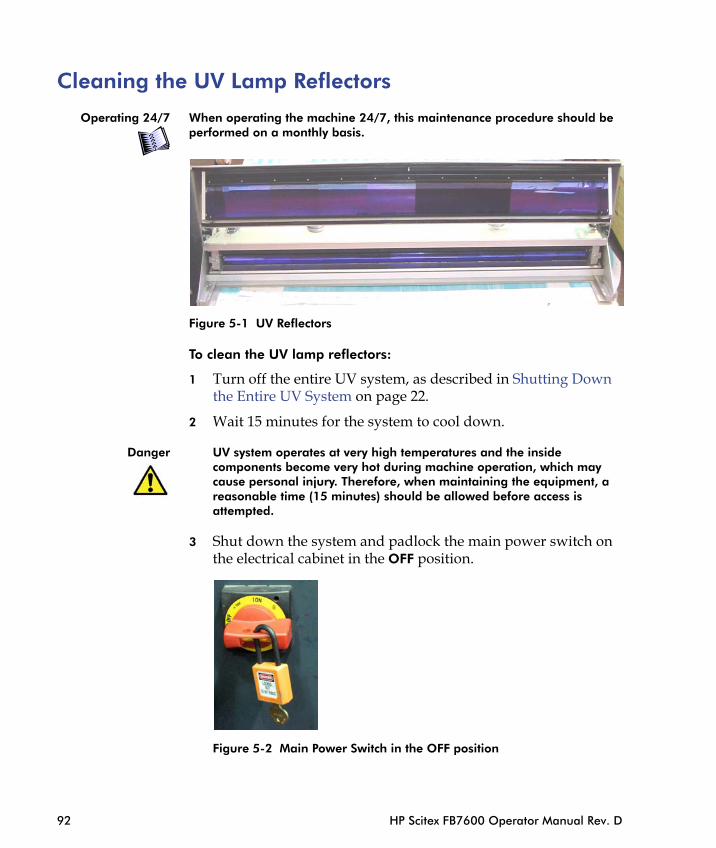
Cleaning the UV Lamp Reflectors
Operating 24/7 When operating the machine 24/7, this maintenance procedure should be performed on a monthly basis.
Figure 5-1 UV Reflectors
To clean the UV lamp reflectors:
1 Turn off the entire UV system, as described in Shutting Down the Entire UV System on page 22.
2 Wait 15 minutes for the system to cool down.
Danger UV system operates at very high temperatures and the inside components become very hot during machine operation, which may cause personal injury. Therefore, when maintaining the equipment, a reasonable time (15 minutes) should be allowed before access is
92 HP Scitex FB7600 Operator Manual Rev. D
attempted.
3 Shut down the system and padlock the main power switch on the electrical cabinet in the OFF position.
Figure 5-2 Main Power Switch in the OFF position

4 Open the bridge upper hoods (see Figure 4-3 on page 77).
5 Disconnect the air pressure to the UV housing.
Figure 5-3 Disconnecting air pressure to the UV housing
6 Pull the safety locker that fastens the lamp assembly cover, and lift up the cover on its hinge to expose the reflectors.
Chapter 5 - Monthly Maintenance 93
Figure 5-4 Pulling Safety Locker on UV Lamp Housing Cover
7 Clean the cold mirror reflector with a lint-free cloth moistened with ethanol. Do not apply ethanol directly to the reflector.
Note In places that restrict the use of solvents and alcohol (such as, California), see Cleaning with Solvent and Alcohol on page 10 for additional instructions.
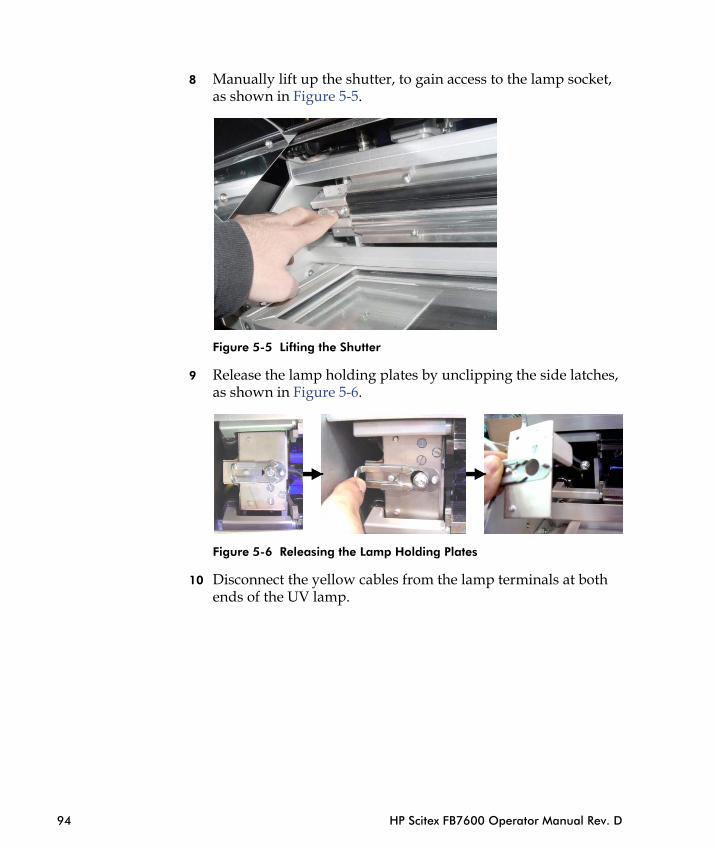
8 Manually lift up the shutter, to gain access to the lamp socket, as shown in Figure 5-5.
Figure 5-5 Lifting the Shutter
9 Release the lamp holding plates by unclipping the side latches, as shown in Figure 5-6.
94 HP Scitex FB7600 Operator Manual Rev. D
Figure 5-6 Releasing the Lamp Holding Plates
10 Disconnect the yellow cables from the lamp terminals at both ends of the UV lamp.

Figure 5-7 Disconnecting the Yellow Cables
11 Carefully remove the UV lamp. Place the lamp in a secure location.
Caution Do not touch the UV lamp with bare hands, as skin acids will permanently mark the quartz sleeve.
It is recommended to wear cotton gloves when handling the UV lamp.
12 Clean the UV reflectors behind the UV lamp with a lint-free cloth moistened with ethanol. Do not apply ethanol directly to the reflectors.
Note In places that restrict the use of solvents and alcohol (such as, California), see Cleaning with Solvent and Alcohol on page 10 for additional instructions.
13 Return the UV lamp to the UV lamp housing.
Chapter 5 - Monthly Maintenance 95
14 Reconnect the yellow cables to the lamp terminals at both ends of the UV lamp, and secure them tightly, as shown in Figure 5-8.
Figure 5-8 Connecting the Yellow Cable
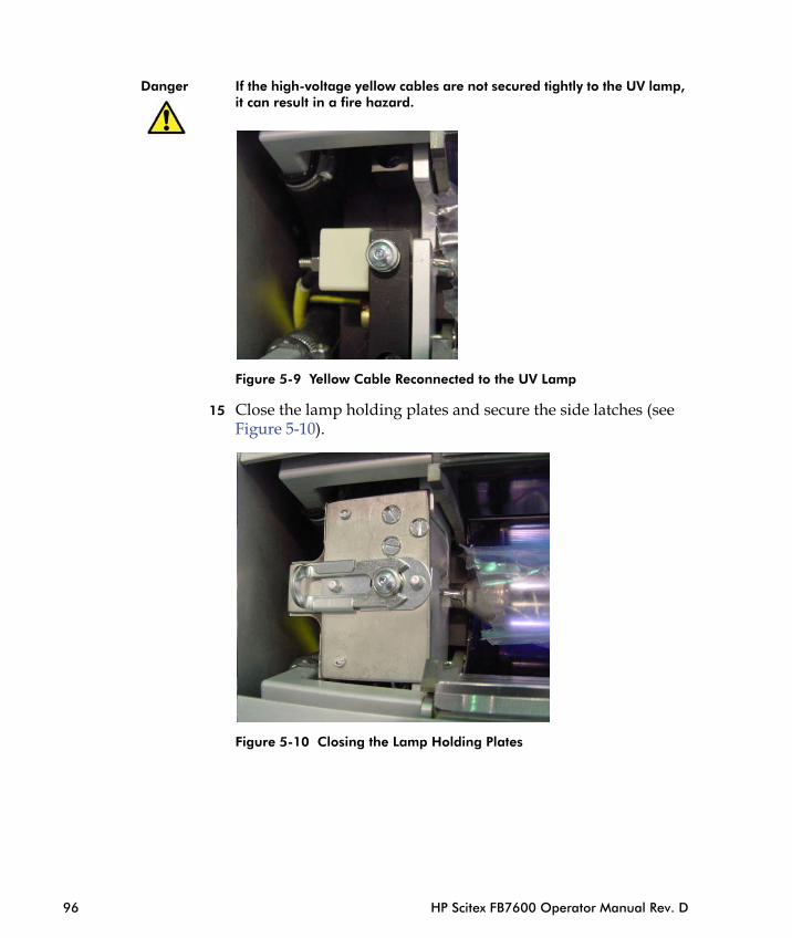
Danger If the high-voltage yellow cables are not secured tightly to the UV lamp, it can result in a fire hazard.
Figure 5-9 Yellow Cable Reconnected to the UV Lamp
15 Close the lamp holding plates and secure the side latches (see Figure 5-10).
96 HP Scitex FB7600 Operator Manual Rev. D
Figure 5-10 Closing the Lamp Holding Plates

16 Verify that the lamp can move freely (a few millimeters to the sides).
Note The lamp expands towards the sides during operation.
17 Manually close the internal shutter.
18 Close the lamp housing cover.
19 Fasten the safety lockers.
20 Reconnect the air pressure tube to the UV lamp housing.
Cleaning the UV Cooler Water FilterTo clean the UV cooler water filter:
1 Turn off the entire UV system, as described in Shutting Down the Entire UV System on page 22.
2 Remove the back cover of the UV cooler (see Figure 5-11).
Cooler top cover
Chapter 5 - Monthly Maintenance 97
Figure 5-11 Cooler Back Cover
Back cover
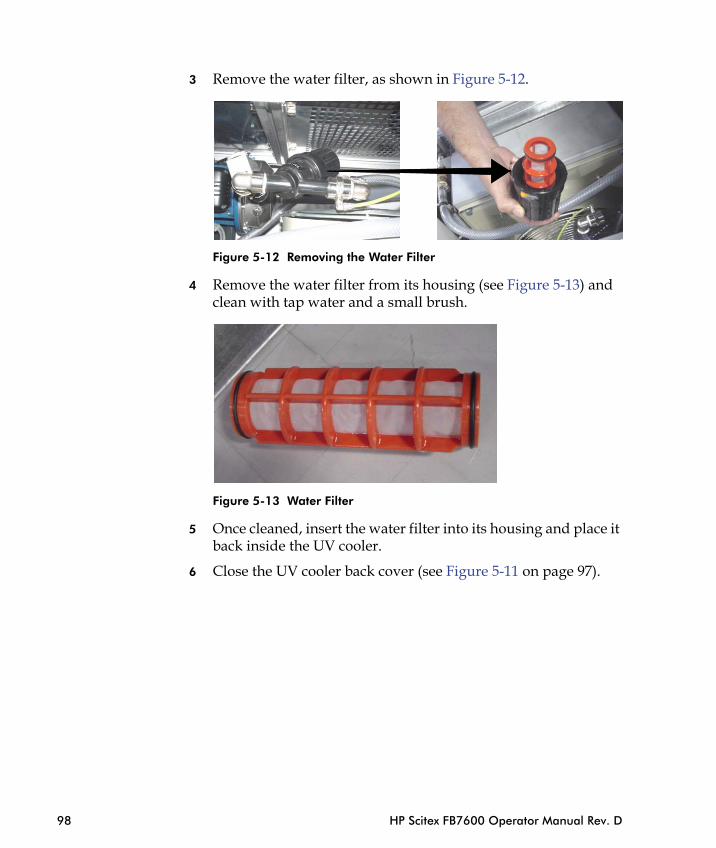
3 Remove the water filter, as shown in Figure 5-12.
Figure 5-12 Removing the Water Filter
4 Remove the water filter from its housing (see Figure 5-13) and clean with tap water and a small brush.
Figure 5-13 Water Filter
98 HP Scitex FB7600 Operator Manual Rev. D
5 Once cleaned, insert the water filter into its housing and place it back inside the UV cooler.
6 Close the UV cooler back cover (see Figure 5-11 on page 97).
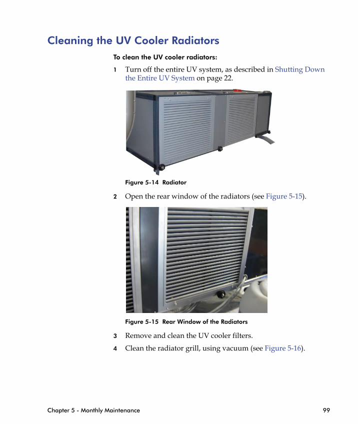
Cleaning the UV Cooler RadiatorsTo clean the UV cooler radiators:
1 Turn off the entire UV system, as described in Shutting Down the Entire UV System on page 22.
Figure 5-14 Radiator
2 Open the rear window of the radiators (see Figure 5-15).
Chapter 5 - Monthly Maintenance 99
Figure 5-15 Rear Window of the Radiators
3 Remove and clean the UV cooler filters.
4 Clean the radiator grill, using vacuum (see Figure 5-16).
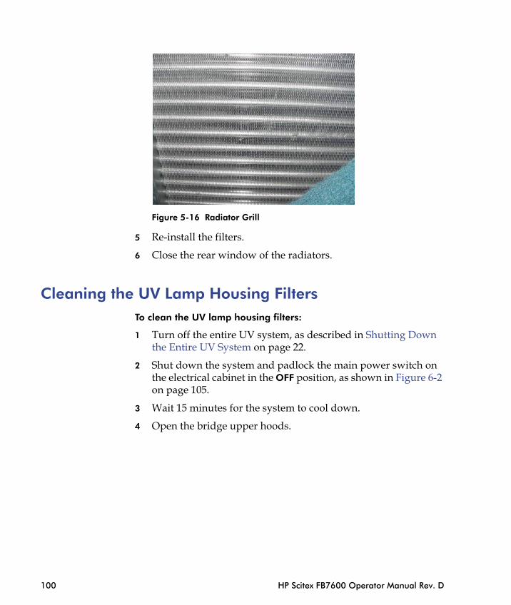
Figure 5-16 Radiator Grill
5 Re-install the filters.
6 Close the rear window of the radiators.
Cleaning the UV Lamp Housing FiltersTo clean the UV lamp housing filters:
1 Turn off the entire UV system, as described in Shutting Down the Entire UV System on page 22.
100 HP Scitex FB7600 Operator Manual Rev. D
2 Shut down the system and padlock the main power switch on the electrical cabinet in the OFF position, as shown in Figure 6-2 on page 105.
3 Wait 15 minutes for the system to cool down.
4 Open the bridge upper hoods.

5 Using a flat screwdriver, remove the four screws of the UV lamp housing filter (see Figure 5-17).
Figure 5-17 Removing the UV Lamp Housing Filter Screws
6 Lift and remove the two filters (see Figure 5-18).
Chapter 5 - Monthly Maintenance 101
Figure 5-18 Removing the UV Lamp Housing Filters
7 Clean the filters with air pressure.
8 Re-install the filters and tighten the four screws.
9 Close the bridge upper hoods.
Checking for Leaks in the UV CoolerTo check for leaks:
1 Inspect all plumbing and connections inside the UV cooler. Repair any faulty parts.
2 Check all water hoses and tighten the hose clamps if necessary.
3 Check the ducting for any blockages, damages and leaks.
4 Repair any faulty parts.
102 HP Scitex FB7600 Operator Manual Rev. D

Checking the External Shutter..........
VCU Preventive Maintenance ..........
C H A P T E R
6Bi-Monthly
Maintenance
Checking the Emergency Stop Safety Devices................... 104
Replacing the UV Lamp ................................................... 105
Lubricating the Linear Bearings ....................................... 112
................................ 120
................................ 123
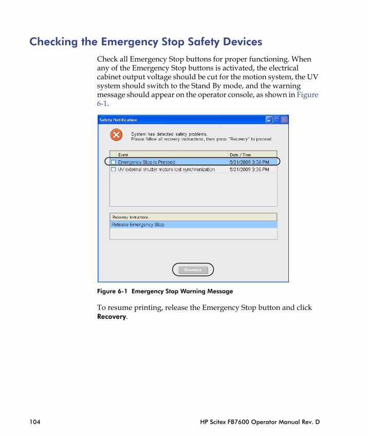
Checking the Emergency Stop Safety DevicesCheck all Emergency Stop buttons for proper functioning. When any of the Emergency Stop buttons is activated, the electrical cabinet output voltage should be cut for the motion system, the UV system should switch to the Stand By mode, and the warning message should appear on the operator console, as shown in Figure 6-1.
104 HP Scitex FB7600 Operator Manual Rev. D
Figure 6-1 Emergency Stop Warning Message
To resume printing, release the Emergency Stop button and click Recovery.

Replacing the UV LampThe UV lamp has a limited lifetime and must be replaced when drying efficiency starts to deteriorate.
The usual life time of the UV lamp is approximately 1500 hours. When operating the machine for one work shift per day (approx. 8 hours), the lamp should be changed once every 4 months. However, this may vary according to individual working conditions.
Operating 24/7 When operating the machine 24/7, this maintenance procedure should be performed every 2 months.
To replace the UV lamp:
1 Turn off the entire UV system, as described in Shutting Down the Entire UV System on page 22.
2 Wait 15 minutes for the system to cool down.
Danger UV system operates at very high temperatures and the inside components become very hot during machine operation, which may cause personal injury. Therefore, when maintaining the equipment, a reasonable time (15 minutes) should be allowed before access is attempted.
3 Shut down the system and padlock the main power switch on
Chapter 6 - Bi-Monthly Maintenance 105
the electrical cabinet in the OFF position.
Figure 6-2 Main Power Switch in the OFF position
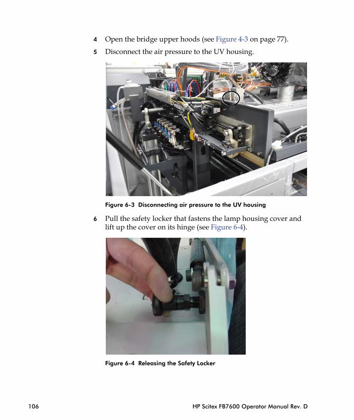
4 Open the bridge upper hoods (see Figure 4-3 on page 77).
5 Disconnect the air pressure to the UV housing.
Figure 6-3 Disconnecting air pressure to the UV housing
6 Pull the safety locker that fastens the lamp housing cover and lift up the cover on its hinge (see Figure 6-4).
106 HP Scitex FB7600 Operator Manual Rev. D
Figure 6-4 Releasing the Safety Locker
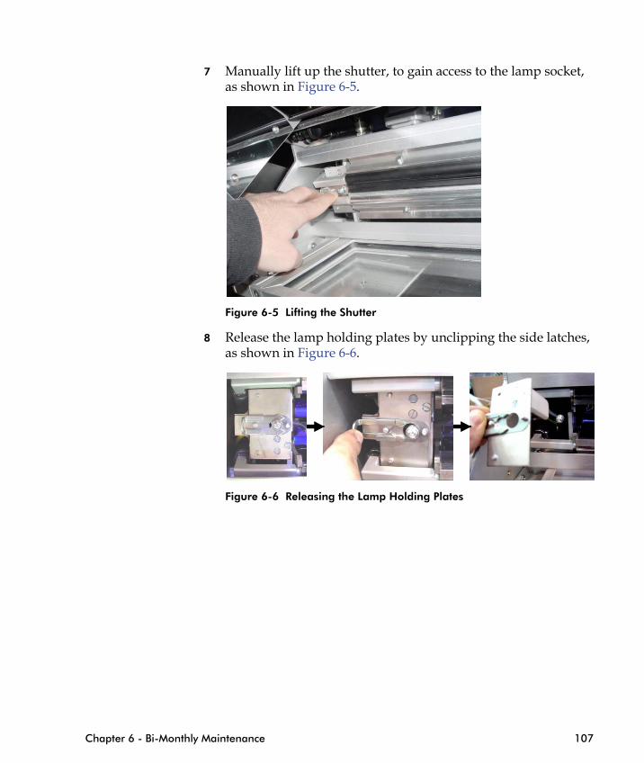
7 Manually lift up the shutter, to gain access to the lamp socket, as shown in Figure 6-5.
Figure 6-5 Lifting the Shutter
8 Release the lamp holding plates by unclipping the side latches, as shown in Figure 6-6.
Chapter 6 - Bi-Monthly Maintenance 107
Figure 6-6 Releasing the Lamp Holding Plates
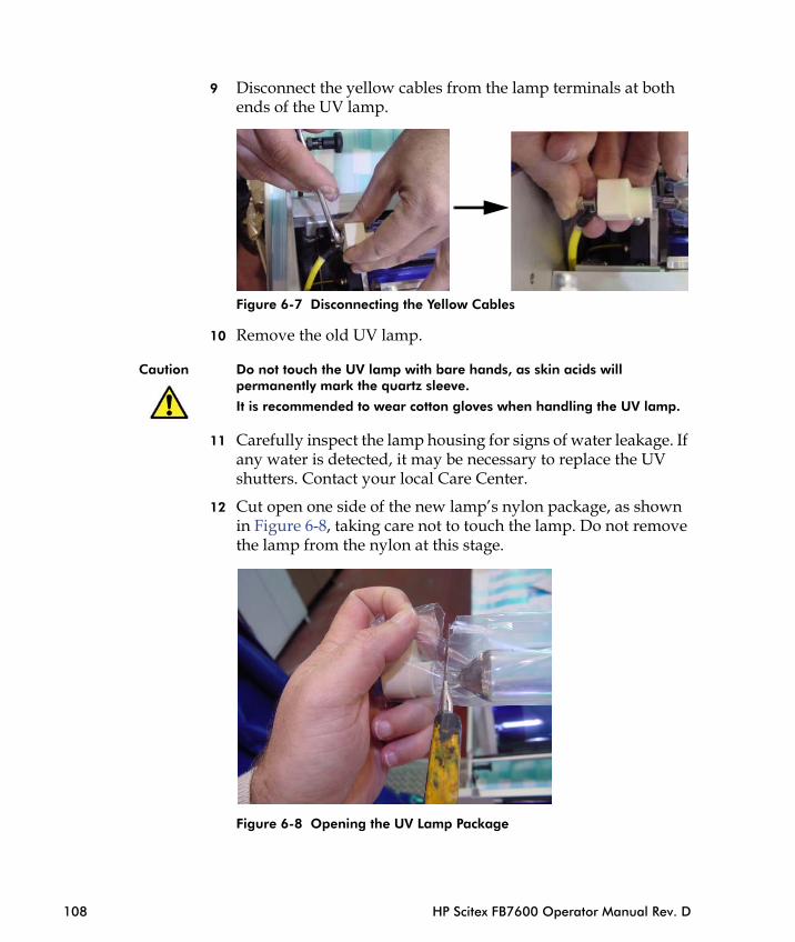
9 Disconnect the yellow cables from the lamp terminals at both ends of the UV lamp.
Figure 6-7 Disconnecting the Yellow Cables
10 Remove the old UV lamp.
Caution Do not touch the UV lamp with bare hands, as skin acids will permanently mark the quartz sleeve.
It is recommended to wear cotton gloves when handling the UV lamp.
11 Carefully inspect the lamp housing for signs of water leakage. If any water is detected, it may be necessary to replace the UV shutters. Contact your local Care Center.
12 Cut open one side of the new lamp’s nylon package, as shown in Figure 6-8, taking care not to touch the lamp. Do not remove the lamp from the nylon at this stage.
108 HP Scitex FB7600 Operator Manual Rev. D
Figure 6-8 Opening the UV Lamp Package
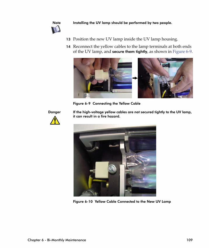
Note Installing the UV lamp should be performed by two people.
13 Position the new UV lamp inside the UV lamp housing.
14 Reconnect the yellow cables to the lamp terminals at both ends of the UV lamp, and secure them tightly, as shown in Figure 6-9.
Figure 6-9 Connecting the Yellow Cable
Danger If the high-voltage yellow cables are not secured tightly to the UV lamp, it can result in a fire hazard.
Chapter 6 - Bi-Monthly Maintenance 109
Figure 6-10 Yellow Cable Connected to the New UV Lamp
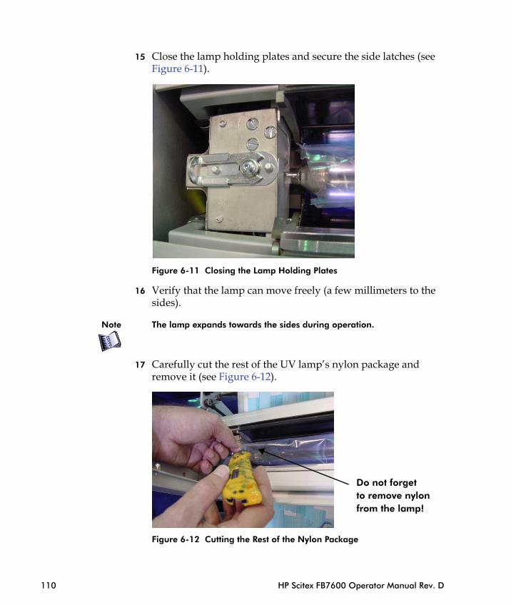
15 Close the lamp holding plates and secure the side latches (see Figure 6-11).
Figure 6-11 Closing the Lamp Holding Plates
16 Verify that the lamp can move freely (a few millimeters to the sides).
Note The lamp expands towards the sides during operation.
110 HP Scitex FB7600 Operator Manual Rev. D
17 Carefully cut the rest of the UV lamp’s nylon package and remove it (see Figure 6-12).
Figure 6-12 Cutting the Rest of the Nylon Package
Do not forget to remove nylon from the lamp!

18 Manually close the internal shutter.
19 Close the lamp housing cover.
20 Fasten the safety lockers.
21 Reconnect the air pressure tube for the UV shutters.
22 Turn on the UV system.
23 In Standby mode, press and hold the down arrow (P4) on the UV control panel to reset the counter for the new UV lamp.
Figure 6-13 Resetting the UV Lamp Counter
Check the operation of the UV lamp housing.
Chapter 6 - Bi-Monthly Maintenance 111
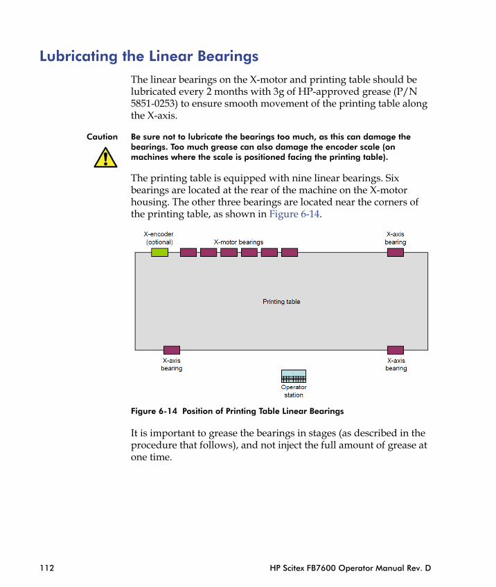
Lubricating the Linear Bearings The linear bearings on the X-motor and printing table should be lubricated every 2 months with 3g of HP-approved grease (P/N 5851-0253) to ensure smooth movement of the printing table along the X-axis.
Caution Be sure not to lubricate the bearings too much, as this can damage the bearings. Too much grease can also damage the encoder scale (on machines where the scale is positioned facing the printing table).
The printing table is equipped with nine linear bearings. Six bearings are located at the rear of the machine on the X-motor housing. The other three bearings are located near the corners of the printing table, as shown in Figure 6-14.
112 HP Scitex FB7600 Operator Manual Rev. D
Figure 6-14 Position of Printing Table Linear Bearings
It is important to grease the bearings in stages (as described in the procedure that follows), and not inject the full amount of grease at one time.
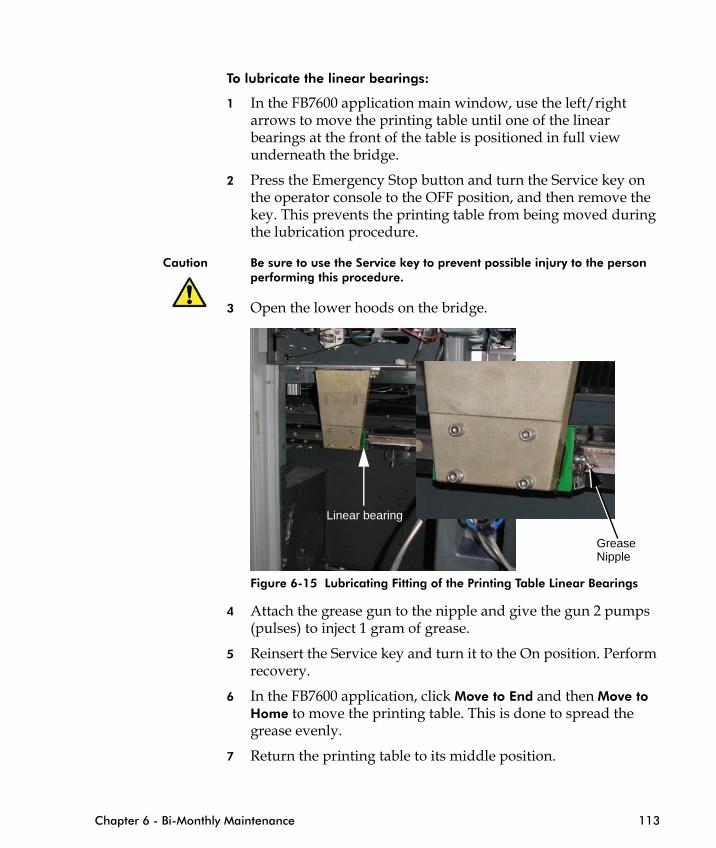
To lubricate the linear bearings:
1 In the FB7600 application main window, use the left/right arrows to move the printing table until one of the linear bearings at the front of the table is positioned in full view underneath the bridge.
2 Press the Emergency Stop button and turn the Service key on the operator console to the OFF position, and then remove the key. This prevents the printing table from being moved during the lubrication procedure.
Caution Be sure to use the Service key to prevent possible injury to the person performing this procedure.
3 Open the lower hoods on the bridge.
Chapter 6 - Bi-Monthly Maintenance 113
Figure 6-15 Lubricating Fitting of the Printing Table Linear Bearings
4 Attach the grease gun to the nipple and give the gun 2 pumps (pulses) to inject 1 gram of grease.
5 Reinsert the Service key and turn it to the On position. Perform recovery.
6 In the FB7600 application, click Move to End and then Move to Home to move the printing table. This is done to spread the grease evenly.
7 Return the printing table to its middle position.
Linear bearing
GreaseNipple
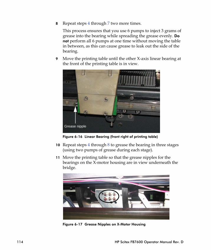
8 Repeat steps 4 through 7 two more times.
This process ensures that you use 6 pumps to inject 3 grams of grease into the bearing while spreading the grease evenly. Do not perform all 6 pumps at one time without moving the table in between, as this can cause grease to leak out the side of the bearing.
9 Move the printing table until the other X-axis linear bearing at the front of the printing table is in view.
Figure 6-16 Linear Bearing (front right of printing table)
10 Repeat steps 4 through 8 to grease the bearing in three stages
Grease nipple
114 HP Scitex FB7600 Operator Manual Rev. D
(using two pumps of grease during each stage).
11 Move the printing table so that the grease nipples for the bearings on the X-motor housing are in view underneath the bridge.
Figure 6-17 Grease Nipples on X-Motor Housing

12 Repeat steps 4 through 8 to grease the bearing in three stages. During each stage, inject two pumps of grease in all 6 nipples on the panel, and then move the table back and forth, as described in step 6.
13 In the FB7600 application, click Move to Home to move the printing table to its home position.
14 Turn the Service key on the operator console to the OFF position, and then remove the key.
15 Open the cabinet at the right side of the machine, alongside the loader.
Opencabinet
Chapter 6 - Bi-Monthly Maintenance 115
Figure 6-18 Opening Cabinet at Right Side of Machine
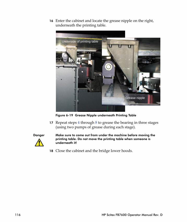
16 Enter the cabinet and locate the grease nipple on the right, underneath the printing table.
Figure 6-19 Grease Nipple underneath Printing Table
17 Repeat steps 4 through 8 to grease the bearing in three stages (using two pumps of grease during each stage).
Grease nipple
Underside of printing table
116 HP Scitex FB7600 Operator Manual Rev. D
Danger Make sure to come out from under the machine before moving the printing table. Do not move the printing table when someone is underneath it!
18 Close the cabinet and the bridge lower hoods.
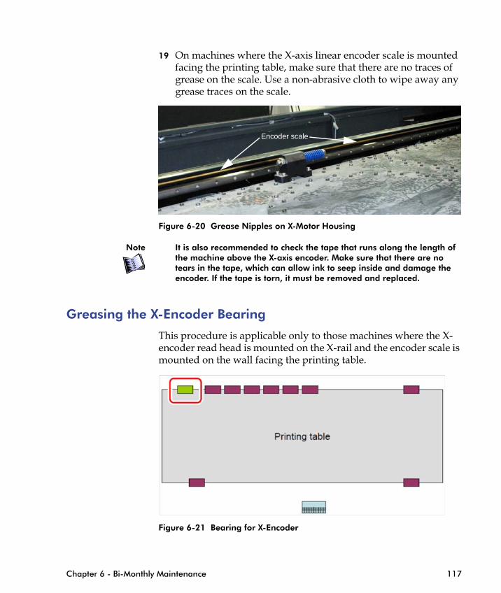
19 On machines where the X-axis linear encoder scale is mounted facing the printing table, make sure that there are no traces of grease on the scale. Use a non-abrasive cloth to wipe away any grease traces on the scale.
Figure 6-20 Grease Nipples on X-Motor Housing
Note It is also recommended to check the tape that runs along the length of the machine above the X-axis encoder. Make sure that there are no tears in the tape, which can allow ink to seep inside and damage the encoder. If the tape is torn, it must be removed and replaced.
Greasing the X-Encoder Bearing
This procedure is applicable only to those machines where the X-encoder read head is mounted on the X-rail and the encoder scale is
Encoder scale
Chapter 6 - Bi-Monthly Maintenance 117
mounted on the wall facing the printing table.
Figure 6-21 Bearing for X-Encoder
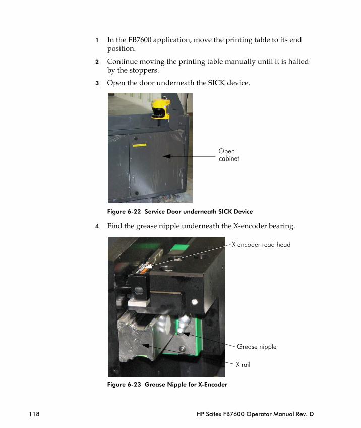
1 In the FB7600 application, move the printing table to its end position.
2 Continue moving the printing table manually until it is halted by the stoppers.
3 Open the door underneath the SICK device.
Figure 6-22 Service Door underneath SICK Device
4 Find the grease nipple underneath the X-encoder bearing.
Opencabinet
X encoder read head
118 HP Scitex FB7600 Operator Manual Rev. D
Figure 6-23 Grease Nipple for X-Encoder
Grease nipple
X rail

5 Grease the bearing, as described in steps 3 - 8 in Lubricating the Linear Bearings.
6 Close the service door.
7 Make sure that there are no traces of grease on the scale. Use a non-abrasive cloth to wipe away any grease traces on the scale.
Figure 6-24 Checking X-Axis Encoder Scale for Grease
Note It is also recommended to check the tape that runs along the length of the machine above the X-axis encoder. Make sure there are no tears in the tape, which can allow ink to seep inside and damage the encoder. If the tape is torn it must be removed and replaced.
Encoder scale
Chapter 6 - Bi-Monthly Maintenance 119
Figure 6-25 Checking Tape above X-Axis Encoder Scale
Encoder scale
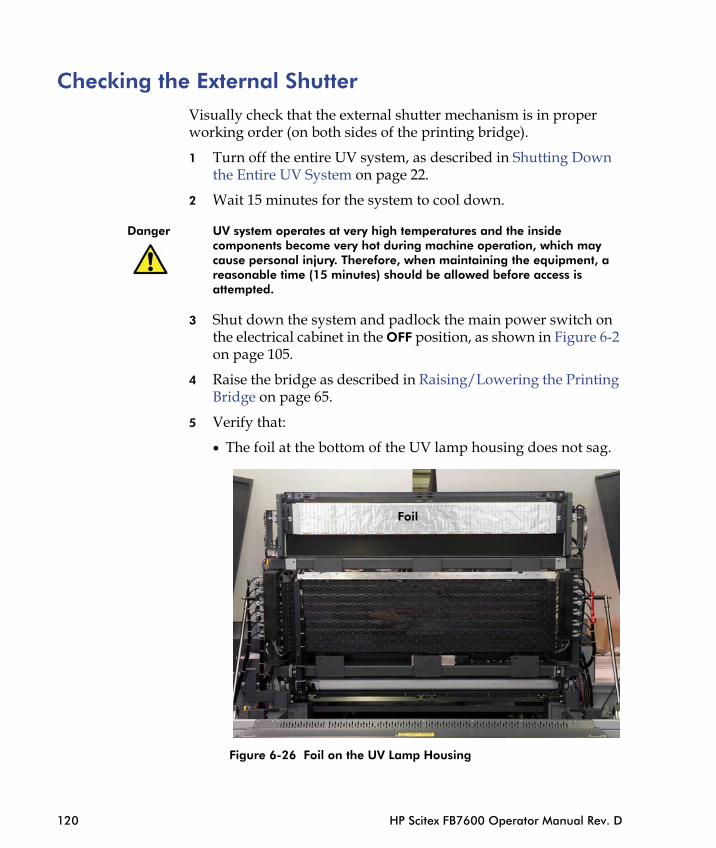
Checking the External Shutter Visually check that the external shutter mechanism is in proper working order (on both sides of the printing bridge).
1 Turn off the entire UV system, as described in Shutting Down the Entire UV System on page 22.
2 Wait 15 minutes for the system to cool down.
Danger UV system operates at very high temperatures and the inside components become very hot during machine operation, which may cause personal injury. Therefore, when maintaining the equipment, a reasonable time (15 minutes) should be allowed before access is attempted.
3 Shut down the system and padlock the main power switch on the electrical cabinet in the OFF position, as shown in Figure 6-2 on page 105.
4 Raise the bridge as described in Raising/Lowering the Printing Bridge on page 65.
5 Verify that:
• The foil at the bottom of the UV lamp housing does not sag.
120 HP Scitex FB7600 Operator Manual Rev. D
Figure 6-26 Foil on the UV Lamp Housing
Foil

• The leading screw and its bearings are not damaged.• The belt is not broken.• Check whether the screw on the pulley has loosened.
Bearing BearingLeading screw
Sensors
Belt andpulleys
Chapter 6 - Bi-Monthly Maintenance 121
Figure 6-27 External Shutter Mechanism
6 Start up the system.
7 Check that the sensors function properly. The best way to check the sensors is to simply insert a piece of paper (or another small object) between the transmitter and receiver and see whether the LED lights up.
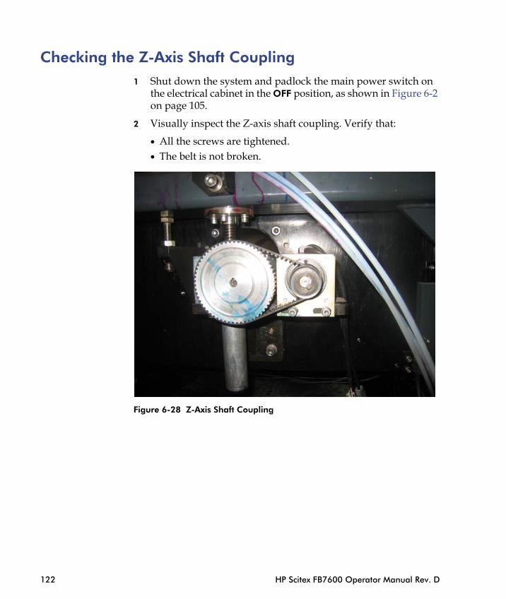
Checking the Z-Axis Shaft Coupling1 Shut down the system and padlock the main power switch on
the electrical cabinet in the OFF position, as shown in Figure 6-2 on page 105.
2 Visually inspect the Z-axis shaft coupling. Verify that:
• All the screws are tightened.• The belt is not broken.
122 HP Scitex FB7600 Operator Manual Rev. D
Figure 6-28 Z-Axis Shaft Coupling
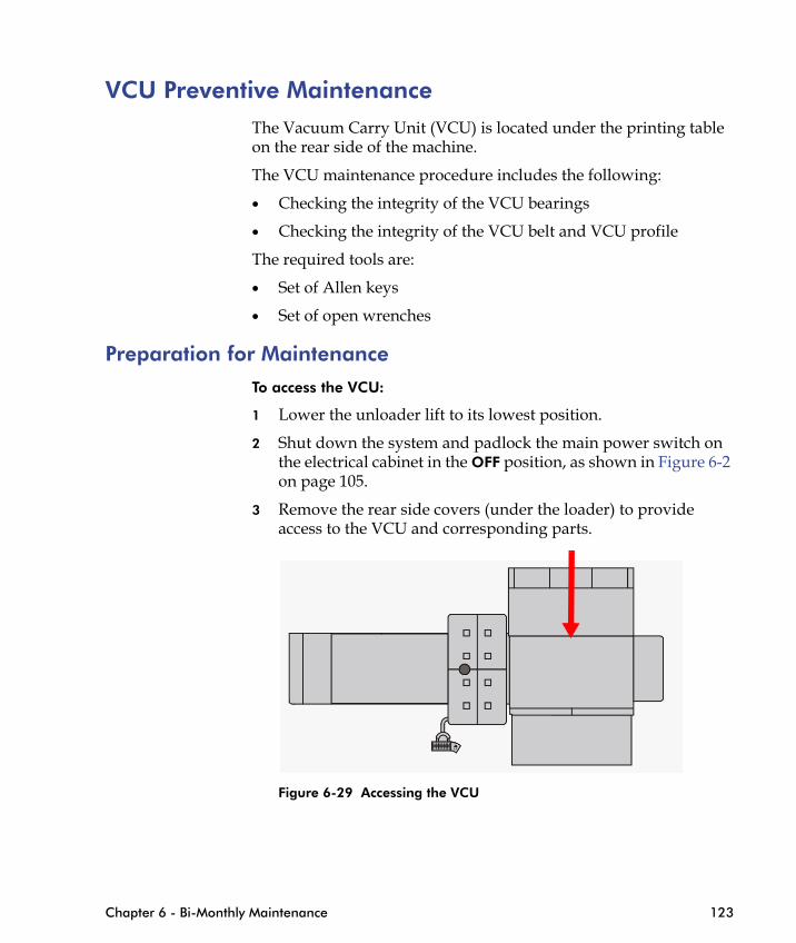
VCU Preventive MaintenanceThe Vacuum Carry Unit (VCU) is located under the printing table on the rear side of the machine.
The VCU maintenance procedure includes the following:
• Checking the integrity of the VCU bearings
• Checking the integrity of the VCU belt and VCU profile
The required tools are:
• Set of Allen keys
• Set of open wrenches
Preparation for Maintenance
To access the VCU:
1 Lower the unloader lift to its lowest position.
2 Shut down the system and padlock the main power switch on the electrical cabinet in the OFF position, as shown in Figure 6-2 on page 105.
3 Remove the rear side covers (under the loader) to provide access to the VCU and corresponding parts.
Chapter 6 - Bi-Monthly Maintenance 123
Figure 6-29 Accessing the VCU

Figure 6-30 Vacuum Carry Unit
4 Manually move the printing table to its home position.
5 Access the VCU from the right side.
Checking Integrity of the VCU Bearings
VCU
124 HP Scitex FB7600 Operator Manual Rev. D
1 Check that the urethane outer rings are not worn out.
2 Remove any ink residue along the perimeters of the bearings.

Figure 6-31 Checking the Bearings
Checking Integrity of VCU Belt and VCU Profile
1 Clean any ink residues or dirt from the top surface of the VCU profile.
Upper bearings
Bottom bearings
Side bearings
VCU profile top surface
Chapter 6 - Bi-Monthly Maintenance 125
Figure 6-32 VCU Profile
2 Make sure that the VCU belt is stretched enough.

126 HP Scitex FB7600 Operator Manual Rev. D

C H A P T E R
76-Monthly
Maintenance
Replacing the Ink Filters .................................................. 128

Replacing the Ink Filters
Danger Handling printing and UV equipment, inks, liquids, and media can be hazardous. Follow all the safety instructions provided in Handling Inks and Solvent on page 8. Always wear suitable protective equipment and clothing when maintaining or operating the printer.
Replace all ink filters every 6 months to ensure that ink is properly filtered before reaching the print heads. Replacing filters regularly helps to prevent clogging of the print head nozzles.
Ink filter
Circulationvalve
Ink pump
128 HP Scitex FB7600 Operator Manual Rev. D
Figure 7-1 Ink System Components
To replace the ink filter:
1 Shut down the system and padlock the main power switch on the electrical cabinet in OFF position, as shown in Figure 6-2 on page 105.
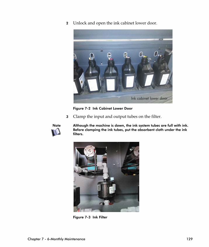
2 Unlock and open the ink cabinet lower door.
Figure 7-2 Ink Cabinet Lower Door
3 Clamp the input and output tubes on the filter.
Note Although the machine is down, the ink system tubes are full with ink. Before clamping the ink tubes, put the absorbent cloth under the ink filters.
Ink cabinet lower door
Chapter 7 - 6-Monthly Maintenance 129
Figure 7-3 Ink Filter
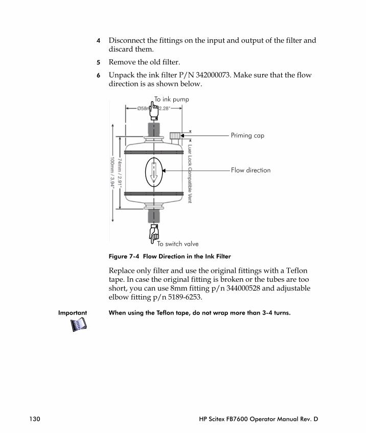
4 Disconnect the fittings on the input and output of the filter and discard them.
5 Remove the old filter.
6 Unpack the ink filter P/N 342000073. Make sure that the flow direction is as shown below.
Figure 7-4 Flow Direction in the Ink Filter
Priming cap
To switch valve
Flow direction
To ink pump
130 HP Scitex FB7600 Operator Manual Rev. D
Replace only filter and use the original fittings with a Teflon tape. In case the original fitting is broken or the tubes are too short, you can use 8mm fitting p/n 344000528 and adjustable elbow fitting p/n 5189-6253.
Important When using the Teflon tape, do not wrap more than 3-4 turns.

Figure 7-5 Ink Filter
7 Unclamp the input and output tubes on the filter.
8 Power on the machine and start the machine application.
Note The following step should be performed by two people.
Elbow
8mm fitting
Chapter 7 - 6-Monthly Maintenance 131
9 From the Maintenance window, perform a 1-second purge. When the ink pump start working, the second person should release the priming cap to let the air come out. As soon as the ink starts coming out of the priming air output, close the priming cap immediately.

132 HP Scitex FB7600 Operator Manual Rev. D

C H A P T E R
8Annual Maintenance
Checking the Gas Springs ............................................... 134
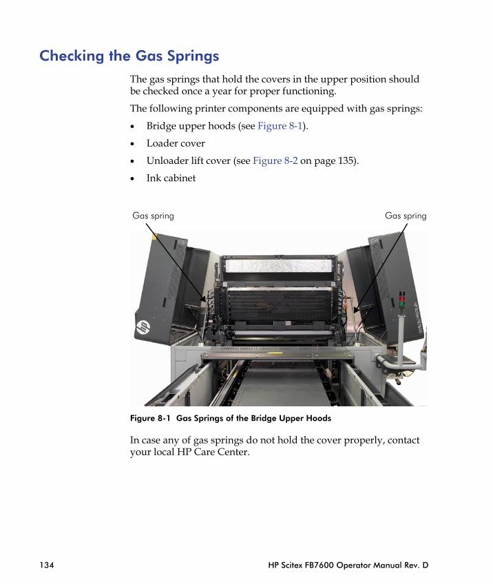
Checking the Gas SpringsThe gas springs that hold the covers in the upper position should be checked once a year for proper functioning.
The following printer components are equipped with gas springs:
• Bridge upper hoods (see Figure 8-1).
• Loader cover
• Unloader lift cover (see Figure 8-2 on page 135).
• Ink cabinet
Gas springGas spring
134 HP Scitex FB7600 Operator Manual Rev. D
Figure 8-1 Gas Springs of the Bridge Upper Hoods
In case any of gas springs do not hold the cover properly, contact your local HP Care Center.
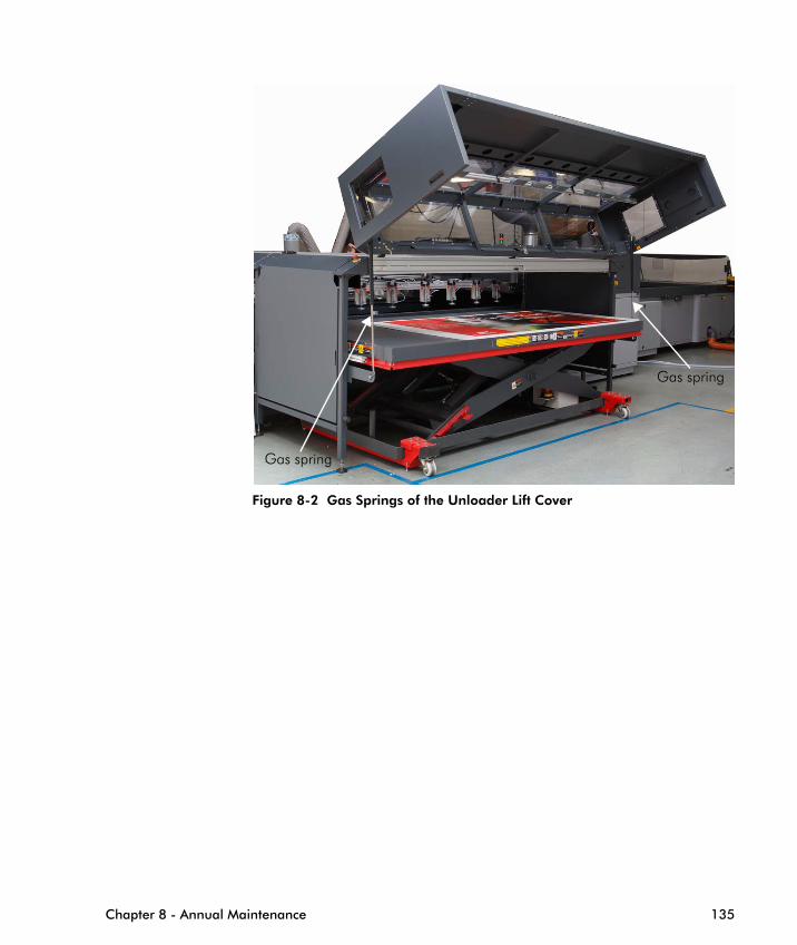
Figure 8-2 Gas Springs of the Unloader Lift Cover
Gas spring
Gas spring
Chapter 8 - Annual Maintenance 135

136 HP Scitex FB7600 Operator Manual Rev. D
Replacing the Loading/Unloading Su
C H A P T E R
9As-Needed
Maintenance
Missing Nozzles Compensation (MNC) Procedure ............ 138
Manually Wiping the Print Head ...................................... 141
Replacing a Print Head.................................................... 145
ction Cups............... 153

Missing Nozzles Compensation (MNC) ProcedureThe Missing Nozzles Compensation procedure (MNC) should be performed in case of bad printing quality and after replacing the print heads.
The reason for bad quality could be clogged nozzles, nozzles firing to one side (shifting), or unstable nozzles. These problems create quality problems such as micro banding. MNC eliminates these nozzles and compensates with others while printing.
A limitation of this method is that no more than 3 consecutive nozzles or 9 nozzles total per print head may be compensated. For example, the print head shown in Figure 9-1 has 7 missing nozzles, and can be compensated using MNC but not efficiently.
If you choose to replace such print heads, refer to "Print Head Replacement Criteria" in the Appendix.
138 HP Scitex FB7600 Operator Manual Rev. D
Figure 9-1 Problematic Print Head

Automatic MNC Procedure
HP Scitex recommends performing the MNC procedure using the Calibration tool in the Print Care software.
Note This procedure will reset the missing nozzles list to ensure that nozzles that were missing and now function properly will not be detected.
Manual MNC Procedure
The MNC procedure can be performed by entering the data manually into the Nozzles Compensation window.
To compensate for missing nozzles:
1 Make sure that in the Tools => Preferences => Quality tab, the Use Quality Enhancements and Nozzles Compensation options are selected (should be done once during the printer installation).
Chapter 9 - As-Needed Maintenance 139
Figure 9-2 Quality Tab

2 Print the Nozzles Health Detector file (see Morning Nozzles Health Detector and Print Head Maintenance on page 58) and analyze the print result.
3 Select Tools => Calibration Settings => Nozzles Compensation.
1
2
3
4
11
22
3
4
140 HP Scitex FB7600 Operator Manual Rev. D
Figure 9-3 Nozzles Compensation Tab
4 Mark all missing/problematic nozzles and click Apply.
Note Make sure to remove marks for nozzles that now function properly.
For those print heads that have more than 5 missing nozzles, refer to "Print Head Replacement Criteria" in the Appendix.
5 To evaluate the effectiveness of the whole MNC procedure, from the CalPack select the file that represents the print mode most commonly used at your site. The file name should be:
MNC_Detector_<print mode> _One_Color (or _All_Colors)
6 Print the file.
Note Set the margins to 0 on both axes (horizontal and vertical).
7 Perform steps 2 - 7 for all print heads.
8 Update the Nozzles Compensation tab accordingly.
Note If there are additional missing nozzles, add them in the Nozzle Compensation tab.
9 After updating the Nozzles Compensation tab, your current jobs should be prepared again (via the Prepare Job Offline).
Manually Wiping the Print Head
Note If, after printing the diagnostic pages in Missing Nozzles Compensation (MNC) Procedure on page 138, there continues to be print quality defects, perform this procedure to remove any dried ink from the nozzles.
Manual wiping of a specific print head should be performed if, after two full maintenance cycles, the Nozzles Health Detector and Fine Tuning printouts still show missing nozzles or misfiring in this problematic print head.
Chapter 9 - As-Needed Maintenance 141
Manual wiping should be carried out only if this specific print head is a candidate for replacement due to the strong "misdirectionality" or a large number of missing nozzles, as a last attempt to recover it (see "Print Head Replacement Criteria" in the Appendix).
To wipe print heads manually:
1 Print the Nozzles Health Detector file for reference as described in Morning Nozzles Health Detector and Print Head Maintenance on page 58.
2 Shut down the system and padlock the main power switch on the electrical cabinet in OFF position, as shown in Figure 6-2 on page 105.
3 Open the bridge upper hood, as shown on Figure 9-6 on page 146.
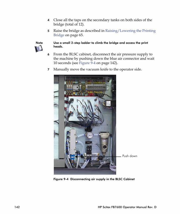
4 Close all the taps on the secondary tanks on both sides of the bridge (total of 12).
5 Raise the bridge as described in Raising/Lowering the Printing Bridge on page 65.
Note Use a small 2-step ladder to climb the bridge and access the print heads.
6 From the BLSC cabinet, disconnect the air pressure supply to the machine by pushing down the blue air connector and wait 10 seconds (see Figure 9-4 on page 142).
7 Manually move the vacuum knife to the operator side.
142 HP Scitex FB7600 Operator Manual Rev. D
Figure 9-4 Disconnecting air supply in the BLSC Cabinet
Push down

8 Proceed as follows:
• In states/regions (such as California) where MF10 is regulated, proceed to Step 9.
• In all other states/regions, skip Steps 9 to 11 and proceed to Step 12.
9 Manually wipe the suspect print heads with a lint-free cloth. Wipe them gently in one direction, using one cloth per print head and color.
Note Do not use the same cloth for different colors and print heads.
10 If the guards are dirty with ink, wipe them with another lint-free cloth. Do not use the same cloth for the print heads and the guards!
11 If dried, cured ink still remains, proceed to Step 12. If not, proceed to Step 14.
12 Wet the lint-free fabric (P/N 70-0027) with MF10 (P/N CN751A).
13 Wipe the problematic print heads once, and in one direction only.
Important For each print head use a clean area of the lint-free fabric.
Chapter 9 - As-Needed Maintenance 143
14 Restore the air supply to the machine. For this, push up the blue air connector in the BLSC cabinet (see Figure 9-4 on page 142) and make sure that the vacuum knife returns to the home position.
15 Lower the bridge.
16 Open the taps of the secondary ink tanks.
17 Close the bridge upper hoods.
18 Power on the machine.
19 From the Maintenance window, press the Bath to Maintenance button.
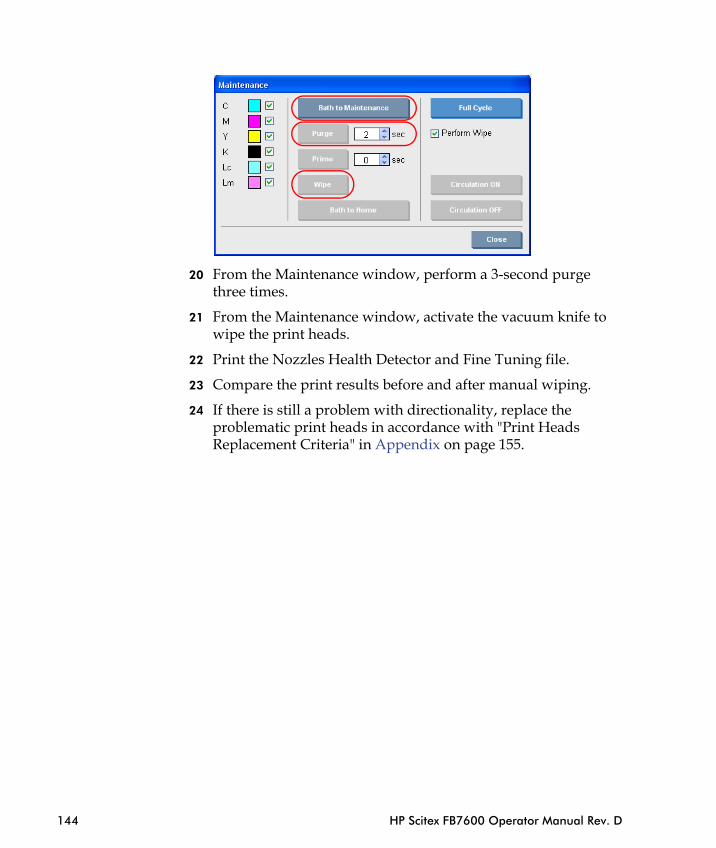
20 From the Maintenance window, perform a 3-second purge three times.
21 From the Maintenance window, activate the vacuum knife to wipe the print heads.
22 Print the Nozzles Health Detector and Fine Tuning file.
23 Compare the print results before and after manual wiping.
24 If there is still a problem with directionality, replace the problematic print heads in accordance with "Print Heads Replacement Criteria" in Appendix on page 155.
144 HP Scitex FB7600 Operator Manual Rev. D
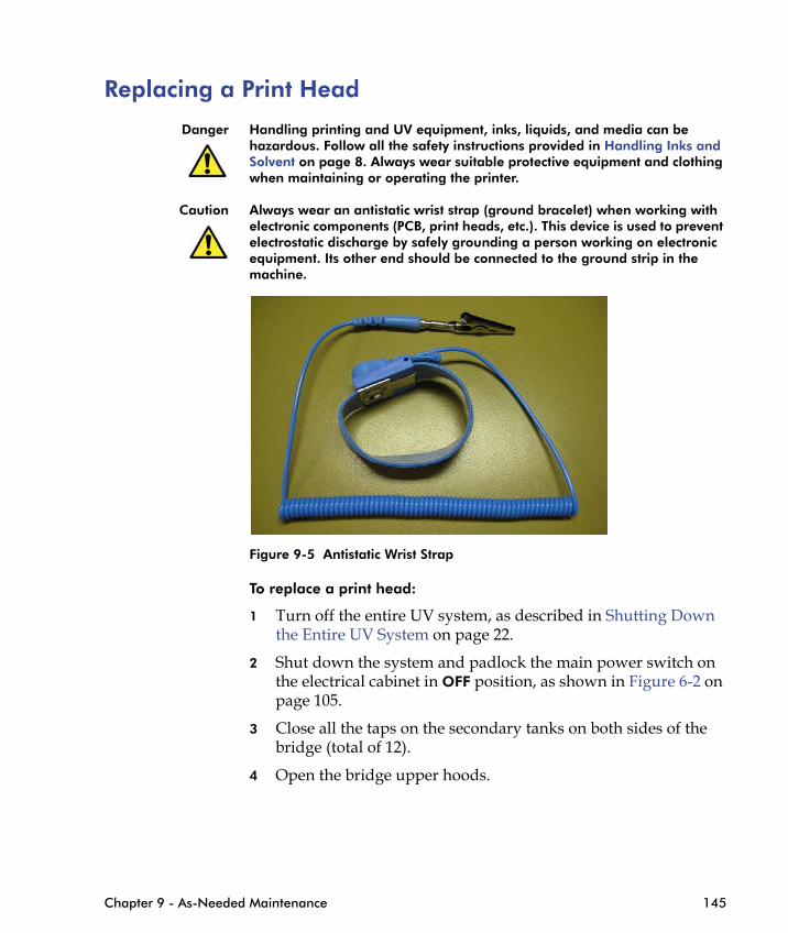
Replacing a Print Head
Danger Handling printing and UV equipment, inks, liquids, and media can be hazardous. Follow all the safety instructions provided in Handling Inks and Solvent on page 8. Always wear suitable protective equipment and clothing when maintaining or operating the printer.
Caution Always wear an antistatic wrist strap (ground bracelet) when working with electronic components (PCB, print heads, etc.). This device is used to prevent electrostatic discharge by safely grounding a person working on electronic equipment. Its other end should be connected to the ground strip in the machine.
Figure 9-5 Antistatic Wrist Strap
Chapter 9 - As-Needed Maintenance 145
To replace a print head:
1 Turn off the entire UV system, as described in Shutting Down the Entire UV System on page 22.
2 Shut down the system and padlock the main power switch on the electrical cabinet in OFF position, as shown in Figure 6-2 on page 105.
3 Close all the taps on the secondary tanks on both sides of the bridge (total of 12).
4 Open the bridge upper hoods.
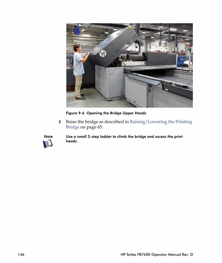
Figure 9-6 Opening the Bridge Upper Hoods
5 Raise the bridge as described in Raising/Lowering the Printing Bridge on page 65.
Note Use a small 2-step ladder to climb the bridge and access the print heads.
146 HP Scitex FB7600 Operator Manual Rev. D

6 Gently remove the print head guards using a Torx wrench No. 9.
2-step ladder
Print heads
Correct positionof the machine operator
Chapter 9 - As-Needed Maintenance 147
7 Remove one head at a time for replacement, using a Torque meter 0.6 N/m (p/n 5189-6368).

Ink inlet
Positioning pin
Catalog
Notch
number
O-ring
148 HP Scitex FB7600 Operator Manual Rev. D
Figure 9-7 Print Head Structure
A1
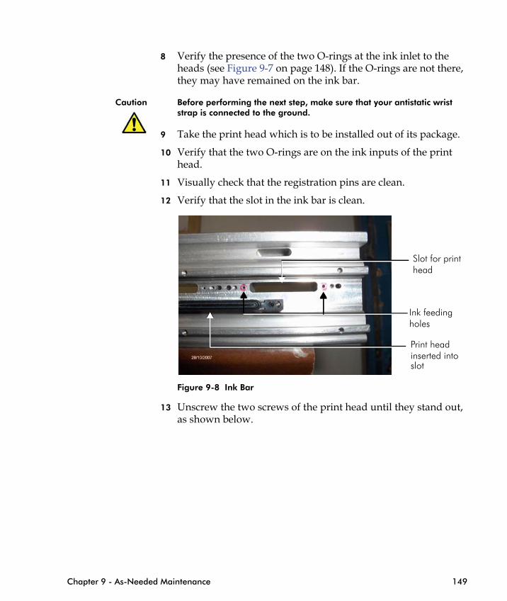
8 Verify the presence of the two O-rings at the ink inlet to the heads (see Figure 9-7 on page 148). If the O-rings are not there, they may have remained on the ink bar.
Caution Before performing the next step, make sure that your antistatic wrist strap is connected to the ground.
9 Take the print head which is to be installed out of its package.
10 Verify that the two O-rings are on the ink inputs of the print head.
11 Visually check that the registration pins are clean.
12 Verify that the slot in the ink bar is clean.
Slot for printhead
Ink feedingholes
inserted into Print head
Chapter 9 - As-Needed Maintenance 149
Figure 9-8 Ink Bar
13 Unscrew the two screws of the print head until they stand out, as shown below.
slot

Figure 9-9 Screws
14 Wrap the print head connector with the protective polyethylene strip, as shown in Figure 9-10 (supplied in the Accessories Kit).
The protective strip is used to protect print head electronic parts from ink contamination whenever performing print head replacement.
150 HP Scitex FB7600 Operator Manual Rev. D
Figure 9-10 Protective Polyethylene Strip
Protective strip
15 Before inserting the print head, verify that it is correctly oriented, as follows:
• The catalog number is facing up on a legible and clear label: PZFXXXXXX-XX-RXXCXX.
• The print head 26-pin connector has a notch. This notch should face upward when inserting it into the slot.
• The print head is connected to the ink bar with two screws. These screws look identical, but the left one is marked as "A1" (see Figure 9-7 on page 148) and serves for precise positioning of the print head.
• The "A1" mark must be on the left.16 Hold the print head parallel to the ink bar and carefully insert it
into its slot (with the protective strip). When the head is almost inside, hold the first screw with one hand and with your other hand pull the strip out. Then hold the second screw with this hand and continue to insert the head until its connector reaches the connector on the PIC board.
17 When you feel that the head’s connector is fixed properly to the PIC’s connector, turn the first screw 2 turns, then turn the second screw 2 turns.
Note Do not tighten the first screw leaving the second screw open. This may cause bending of the head’s connector and damage to the pins.
Chapter 9 - As-Needed Maintenance 151
18 Repeat step 18 until the ink input surface touches the ink bar surface and the print head is fixed perfectly in place.
19 Turn the A1 bolt using a Torque meter 0.6 N/m and only then turn the right screw.
20 Repeat steps 10 - 18 for the other print heads to be replaced.
21 Document the Heads Signature printout before removal in the "Heads Dismantling Form" along with the following data:
• Print head catalog number• Machine number• Print head location• Date of installation
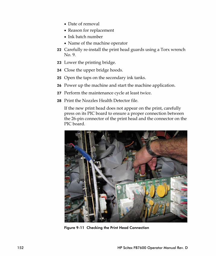
• Date of removal• Reason for replacement• Ink batch number• Name of the machine operator
22 Carefully re-install the print head guards using a Torx wrench No. 9.
23 Lower the printing bridge.
24 Close the upper bridge hoods.
25 Open the taps on the secondary ink tanks.
26 Power up the machine and start the machine application.
27 Perform the maintenance cycle at least twice.
28 Print the Nozzles Health Detector file.
If the new print head does not appear on the print, carefully press on its PIC board to ensure a proper connection between the 26-pin connector of the print head and the connector on the PIC board.
152 HP Scitex FB7600 Operator Manual Rev. D
Figure 9-11 Checking the Print Head Connection

29 Perform the calibration procedure using the Print Care software.
Note If you replace print heads ##1-8, from the BLSC cabinet, disconnect the air pressure supply to the machine by pushing down the blue air connector, wait 10 seconds (see Figure 9-4 on page 142), and manually move the vacuum knife to the operator side.
Chapter 9 - As-Needed Maintenance 153
Replacing the Loading/Unloading Suction Cups See Checking the Loading/Unloading Suction Cups on page 79.
Push down

154 HP Scitex FB7600 Operator Manual Rev. D

Appendix


1/8
HP Scitex FB7600
Print Head Replacement Criteria
General
▪ The customer can replace print heads only after receiving authorization from the HP Product Specialist.
▪ The buyer must replace the print heads according to the authorized replacement procedure described in this manual.
▪ The buyer must replace print heads according to the “Print Head Replacement Criteria” described in this Appendix.
▪ HP Scitex representatives may replace print heads for analysis and evaluation.
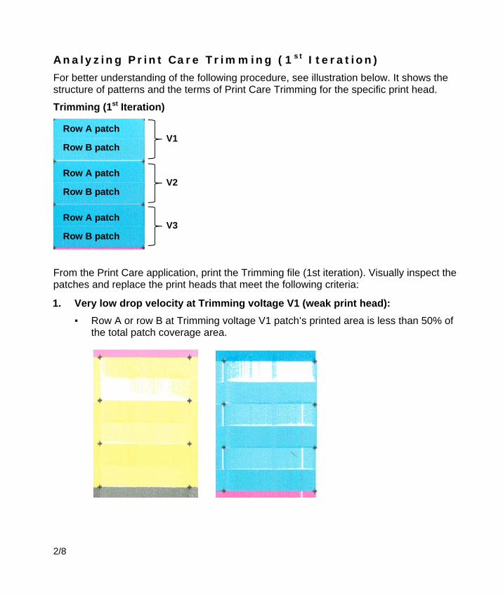
2/8
Analyzing Print Care Trimming (1st Iteration)
For better understanding of the following procedure, see illustration below. It shows the structure of patterns and the terms of Print Care Trimming for the specific print head.
Trimming (1st Iteration)
From the Print Care application, print the Trimming file (1st iteration). Visually inspect the patches and replace the print heads that meet the following criteria:
1. Very low drop velocity at Trimming voltage V1 (weak print head):
▪ Row A or row B at Trimming voltage V1 patch’s printed area is less than 50% of the total patch coverage area.
V1 Row A patch
Row B patch
V2
V3
Row A patch
Row B patch
Row A patch
Row B patch
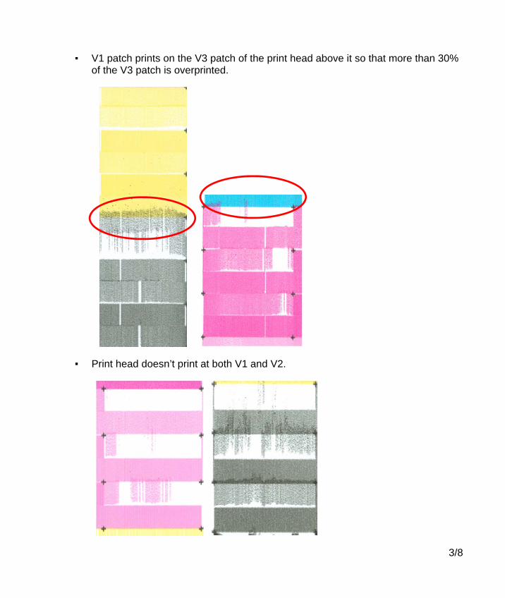
3/8
▪ V1 patch prints on the V3 patch of the print head above it so that more than 30% of the V3 patch is overprinted.
▪ Print head doesn’t print at both V1 and V2.
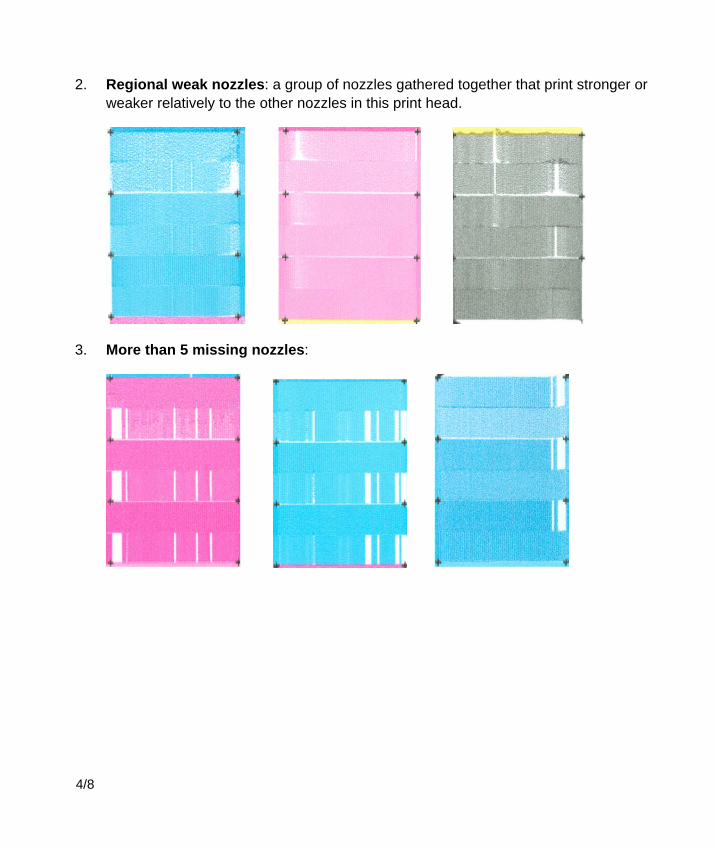
4/8
2. Regional weak nozzles: a group of nozzles gathered together that print stronger or weaker relatively to the other nozzles in this print head.
3. More than 5 missing nozzles:
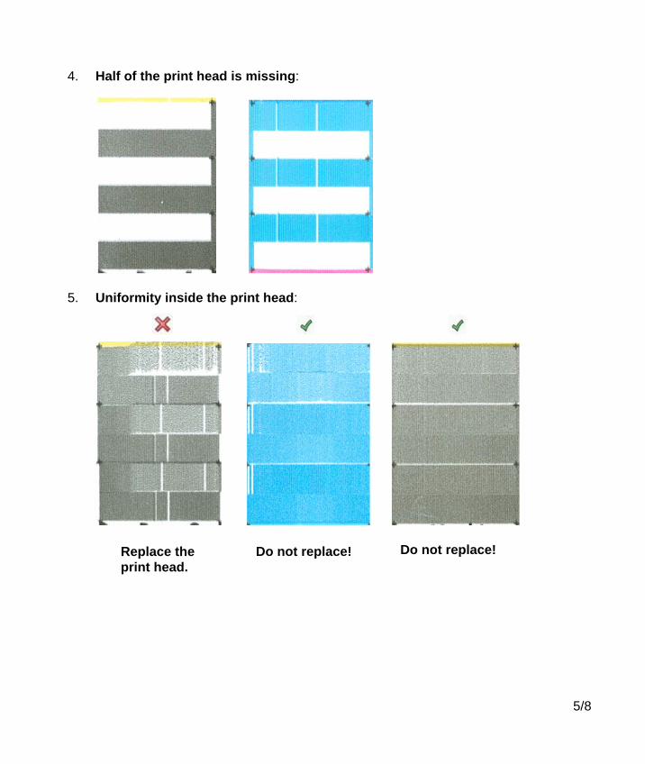
5/8
4. Half of the print head is missing:
5. Uniformity inside the print head:
Do not replace! Replace the print head.
Do not replace!

6/8
Analyzing PrintCare Fine Tuning (2nd Iteration)
For better understanding of the following procedure, see illustration below. It shows structure of patterns and terms of Print Care Fine Tuning for the specific print head.
Fine Tuning (2nd Iteration)
Print the Fine Tuning (2nd iteration) test file and examine it using the following criteria:
1. Misdirectionality: the print heads suffer from the “misdirectionality” phenomena, especially in black and yellow colors (do not confuse with the missing nozzles!).
Row A patch
Row B patch
C - Combined
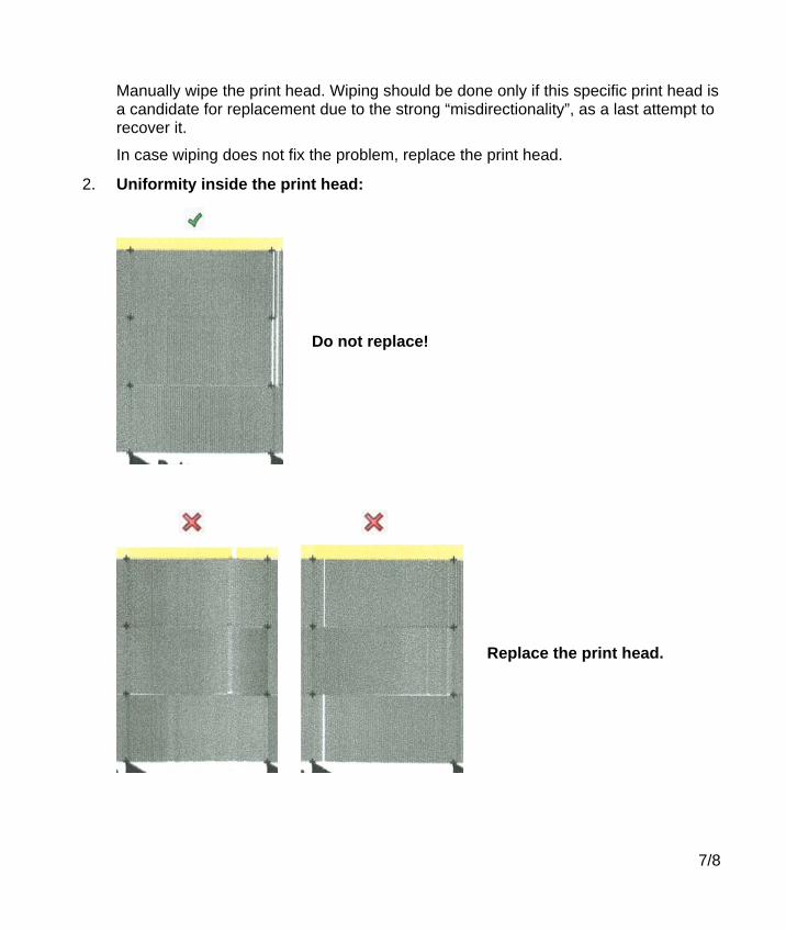
7/8
Manually wipe the print head. Wiping should be done only if this specific print head is a candidate for replacement due to the strong “misdirectionality”, as a last attempt to recover it.
In case wiping does not fix the problem, replace the print head.
2. Uniformity inside the print head:
Do not replace!
Replace the print head.

8/8
3. More than 5 missing nozzles:
4. Half of the print head is missing:
If after replacing the print head the printout looks the same, contact your local Care Center.


Related Documents