Welcome message from author
This document is posted to help you gain knowledge. Please leave a comment to let me know what you think about it! Share it to your friends and learn new things together.
Transcript


Fault-Tolerant Satellite Computingwith Modern Semiconductors

ISBN: 978-94-028-1766-9

Fault-Tolerant Satellite Computingwith Modern Semiconductors
Proefschrift
ter verkrijging vande graad van Doctor aan de Universiteit Leiden,
op gezag van Rector Magnificus prof.mr. C.J.J.M. Stolker,volgens besluit van het College voor Promotieste verdedigen op dinsdag, 17 december 2019
klokke 11:15 uurdoor
Christian Martin Fuchs
Geboren te Linz, Oostenrijk in 1984

Promotor: Prof. Dr. A. Plaat
Promotiecommissie:
Dr. H. Quinn Los Alamos National Laboratory,Los Alamos, USA
Prof. Dr. X. Wen Kyushu Institute of Technology, Japan
Dr. M.S. Gorbunov Scientific Research Institute of System Analysis,Russian Academy of Sciences, Moscow, Russia
Prof. Dr. J.J. Liou National Tsing Hua University,Hsinchu, Taiwan
Prof. Dr. S. Wu Shanghai Jiao Tong University,Shanghai, China
Dr. M. Kenworthy
Prof. Dr. S. Manegold
Dr. E. Bakker
Prof. Dr. H. Wijshoff

For taking these first steps into a new frontier.

Front & Back cover: Illustrations by Dr. Nadia M. Murillo Mejías. Image ofEuropa taken by the Galileo spacecraft during its second orbit around Jupiter.Copyright by NASA/JPL/DLR, in the public domain.

Contents
Preface 1
Space: The Final Frontier . . . . . . . . . . . . . . . . . . . . . . . . . . . . 1
1 Introduction 3
1.1 Problem Statement . . . . . . . . . . . . . . . . . . . . . . . . . . . . . 51.2 Research Questions . . . . . . . . . . . . . . . . . . . . . . . . . . . . . 61.3 Thesis Organization . . . . . . . . . . . . . . . . . . . . . . . . . . . . 7
2 A Brief Introduction to Spaceflight and Fault Tolerance
Thesis Motivation and Legitimization 11
2.1 Spacecraft and Satellite Miniaturization . . . . . . . . . . . . . . . . . 122.2 Early CubeSat Reliability and Motivation . . . . . . . . . . . . . . . . 172.3 Nanosatellites Today and Legitimization . . . . . . . . . . . . . . . . . 192.4 Fault-Tolerant Computer Architecture . . . . . . . . . . . . . . . . . . 21
3 The Space Environment
Physical Fault Profile and Operational Considerations 31
3.1 The Impact of the Space Environment on Electronics . . . . . . . . . . 323.2 Technology Readiness and Standardization . . . . . . . . . . . . . . . 393.3 Operational Constraints for Satellite Computers . . . . . . . . . . . . 41
4 A Fault Tolerance Architecture for Modern Semiconductors
Stage 1 & Architecture Overview 47
4.1 Introduction . . . . . . . . . . . . . . . . . . . . . . . . . . . . . . . . . 484.2 Related Work . . . . . . . . . . . . . . . . . . . . . . . . . . . . . . . . 494.3 Fault Tolerance through Software . . . . . . . . . . . . . . . . . . . . . 514.4 Stage 1: Short-Term Fault Mitigation . . . . . . . . . . . . . . . . . . 544.5 Stage 2: MPSoC Reconfiguration & Repair . . . . . . . . . . . . . . . 594.6 Stage 3: Applied Mixed Criticality . . . . . . . . . . . . . . . . . . . . 614.7 Platform Architecture . . . . . . . . . . . . . . . . . . . . . . . . . . . 624.8 Discussions . . . . . . . . . . . . . . . . . . . . . . . . . . . . . . . . . 674.9 Conclusions . . . . . . . . . . . . . . . . . . . . . . . . . . . . . . . . . 684.10 Annex: Worst-Case Performance Estimation . . . . . . . . . . . . . . . 69
5 MPSoC Management and Reconfiguration
Stage 2 73
5.1 Introduction . . . . . . . . . . . . . . . . . . . . . . . . . . . . . . . . . 74
i

ii CONTENTS
5.2 Debugging and Reliability . . . . . . . . . . . . . . . . . . . . . . . . . 755.3 Implementation Details . . . . . . . . . . . . . . . . . . . . . . . . . . 765.4 Use Cases beyond Debugging . . . . . . . . . . . . . . . . . . . . . . . 825.5 Discussions . . . . . . . . . . . . . . . . . . . . . . . . . . . . . . . . . 875.6 Conclusions . . . . . . . . . . . . . . . . . . . . . . . . . . . . . . . . . 87
6 Mixed Criticality and Resource Pooling
Stage 3 89
6.1 Introduction . . . . . . . . . . . . . . . . . . . . . . . . . . . . . . . . . 906.2 Background . . . . . . . . . . . . . . . . . . . . . . . . . . . . . . . . . 906.3 Related Work . . . . . . . . . . . . . . . . . . . . . . . . . . . . . . . . 916.4 System Overview & Requirements . . . . . . . . . . . . . . . . . . . . 926.5 System Architecture Review . . . . . . . . . . . . . . . . . . . . . . . . 946.6 Spare Resource Pooling . . . . . . . . . . . . . . . . . . . . . . . . . . 976.7 Adapting to Varying Mission Requirements . . . . . . . . . . . . . . . 986.8 Discussions . . . . . . . . . . . . . . . . . . . . . . . . . . . . . . . . . 1036.9 Conclusions . . . . . . . . . . . . . . . . . . . . . . . . . . . . . . . . . 104
7 Reliable Data Storage for Miniaturized Satellites
Memory Fault Tolerance 105
7.1 Introduction . . . . . . . . . . . . . . . . . . . . . . . . . . . . . . . . . 1067.2 Data Integrity as Foundation of Fault Tolerance . . . . . . . . . . . . . 1077.3 Volatile Memory Consistency . . . . . . . . . . . . . . . . . . . . . . . 1097.4 A Radiation-Robust Filesystem for Space Use . . . . . . . . . . . . . . 1147.5 High-Performance Flash Memory Integrity . . . . . . . . . . . . . . . . 1217.6 Conclusions . . . . . . . . . . . . . . . . . . . . . . . . . . . . . . . . . 131
8 Validating Software-Implemented Fault Tolerance
Systematic Fault Injection 133
8.1 Introduction . . . . . . . . . . . . . . . . . . . . . . . . . . . . . . . . . 1348.2 Related Work . . . . . . . . . . . . . . . . . . . . . . . . . . . . . . . . 1368.3 Target Implementation . . . . . . . . . . . . . . . . . . . . . . . . . . . 1388.4 Obtaining a Practical Fault Model . . . . . . . . . . . . . . . . . . . . 1398.5 Suitable Fault-Injection Techniques . . . . . . . . . . . . . . . . . . . . 1408.6 Test Campaign Setup . . . . . . . . . . . . . . . . . . . . . . . . . . . 1428.7 Executing a Test Campaign . . . . . . . . . . . . . . . . . . . . . . . . 1438.8 Results & Interpretation . . . . . . . . . . . . . . . . . . . . . . . . . . 1508.9 ArchC MPSoC vs. FIES Result Comparison . . . . . . . . . . . . . . . 1538.10 Comparison to Literature . . . . . . . . . . . . . . . . . . . . . . . . . 1548.11 Discussions . . . . . . . . . . . . . . . . . . . . . . . . . . . . . . . . . 1558.12 Conclusions . . . . . . . . . . . . . . . . . . . . . . . . . . . . . . . . . 157
9 Combining Hardware and Software Fault Tolerance
High-Level System Design 159
9.1 Introduction . . . . . . . . . . . . . . . . . . . . . . . . . . . . . . . . . 1609.2 Background & Related Work . . . . . . . . . . . . . . . . . . . . . . . 1609.3 A Hybrid Fault Tolerance Approach . . . . . . . . . . . . . . . . . . . 1619.4 The MPSoC Architecture . . . . . . . . . . . . . . . . . . . . . . . . . 1639.5 Subsystem Connectivity and Peripheral I/O . . . . . . . . . . . . . . . 167

CONTENTS iii
9.6 Implementation Considerations . . . . . . . . . . . . . . . . . . . . . . 1699.7 Conclusions . . . . . . . . . . . . . . . . . . . . . . . . . . . . . . . . . 170
10 On-Board Computer Integration and MPSoC Implementation
Practical Design Verification on FPGA 171
10.1 Introduction . . . . . . . . . . . . . . . . . . . . . . . . . . . . . . . . . 17210.2 Related Work . . . . . . . . . . . . . . . . . . . . . . . . . . . . . . . . 17310.3 A Reliable CubeSat On-Board Computer . . . . . . . . . . . . . . . . 17510.4 Handling Chip-Level SEFIs and Failure . . . . . . . . . . . . . . . . . 18710.5 Utilization and Power Comparison . . . . . . . . . . . . . . . . . . . . 18910.6 Experimental Results and Testing . . . . . . . . . . . . . . . . . . . . 19210.7 Conclusions . . . . . . . . . . . . . . . . . . . . . . . . . . . . . . . . . 192
11 Conclusions and Outlook 195
11.1 Conclusions . . . . . . . . . . . . . . . . . . . . . . . . . . . . . . . . . 19511.2 Discussions . . . . . . . . . . . . . . . . . . . . . . . . . . . . . . . . . 19711.3 Outlook and Future Work . . . . . . . . . . . . . . . . . . . . . . . . . 199
Bibliography 202
Nederlandse Samenvatting 229
中中中文文文摘摘摘要要要 235
中中中文文文摘摘摘要要要(((繁繁繁體體體))) 239
日日日本本本語語語ののの要要要約約約 243
Resumen en Español 247
Резюме на Русском Языке 253
English Summary 259
List of Selected Publications 263
Curriculum Vitae 265
Acknowledgments 269


vi CONTENTS

Preface
Space: The Final Frontier
Humankind has been fascinated by the stars, and planets of our solar system, probablysince before our species developed complex language. Many cultures have consideredthem to be ancestors, spirits of nature, and deities guiding our life and influencing ourworld. As humankind developed, people chose to see their heroes in the constellations,and these curious objects in the sky sometimes even were considered gods. Knowingwhat these gods wanted or liked could help a society prosper, or could doom it. Evenmore were we intrigued by the Sun, our neighboring planets, the Moon.
Technology has always been critical in our quest to understand our environment,and our world. Today, we are dependent upon the availability and correct functioningof our technology. It has enabled us to transform nature, but also to damage it andmost likely change it for generations. And we are using technology even in our attemptsto repair some of that same damage we inflict through it. Without technology, modernsocieties and our every day life would be unthinkable.
Humans are curious, and using our technology, we began exploring space justrecently, considering the timescale of human existence. We operate vast telescopes onthe ground and in space, which help us answer the most fundamental questions abouthow we came to be and where we are going. A few decades ago, we began launchingsatellites into space, which we today use for science, commerce, and education. Twosuperpowers conducted a great race to the Moon just a few decades ago, arrived there,took pictures, and then returned home. Today, this race is being rerun with moreparticipants, resulting maybe in an extension to Mars, or better and more productively,to the Galilean Moons of Jupiter.
Satellites allow us to communicate with any point on the surface of the Earthin real-time, and with Mars with more than 10 minutes delay. Weather forecasts,communication services, flight information, and geolocation systems today are possibleonly due to information transmitted, or relayed by satellites. In many aspects, ourmodern life would be unimaginable without them.
We have outgrown our homeworld and its limited pool of resource already in manyaspects, and most likely we even have to go to space to survive, like a young birdleaving its nest. Within the next few generations, we will reach out into space, beginto understand whatever we may find there, and utilize the vast resources which wemay find within our solar system for the benefit of all. To design, construct, test,and operate the spacecraft that we will require we depend upon modern computertechnology and electronics.
Electronics and semiconductor technology are indispensable in spacecraft design,
1

2 CONTENTS
and microprocessors can be found in all major satellite subsystems. Spacecraft andcomputers represent the peak of our technology, the application of all our skills inengineering, and the result of all the combined interdisciplinary scientific knowledgewe have as a species. The reliability of these components is mission critical; anddirectly or indirectly, lives depend upon them, even in unmanned spaceflight. Scientistsand engineers therefore seek to invent, develop, and utilize computer designs whichcan guarantee sufficient robustness and reliability for a space mission. The topic ofthis thesis is to enable the use of modern computer technology manufactured in finetechnology nodes, which at the time of writing can not be used aboard spacecraft ina reliable manner.

Chapter 1
Introduction
Brief Abstract
Modern semiconductor technology has enabled the development of miniaturized satel-lites, which are cheap to launch, low-cost platforms for a broad variety of scientific andcommercial instruments. Especially very small satellites (<100kg) can enable spacemissions which previously were technically infeasible, impractical or simply uneconom-ical. However, as discussed in Chapter 2, they suffer from low reliability. Especially thesmallest such satellites are typically not considered suitable for critical and complexmulti-phased missions, as well as for high-priority science missions for solar-systemexploration and astronomical applications [1]. The on-board computer (OBC) andrelated electronics constitute a significant part of such spacecraft, and in related work,e.g., [2], were responsible for a majority of post-deployment failures, which are furtherdiscussed also in Chapter 3.
Indeed, the modern embedded and mobile-market semiconductors used aboardnanosatellites lack the fault tolerance (FT) capabilities of computer-architectures forlarger spacecraft. Due to budget, energy, mass, and volume restrictions in miniatur-ized satellites, existing FT solutions developed for such larger spacecraft can not beadopted. Today, there exist no fault-tolerant computer architectures that could beused aboard nanosatellites powered by embedded and mobile-market semiconductors,without breaking the fundamental concept of a cheap, simple, energy-efficient, andlight satellite that can be manufactured en-mass and launched at low cost [3].
To overcome this limitation, in this thesis, we develop a new approach to achievefault tolerance for miniaturized satellite computers based upon modern semiconduc-tors. The method we use to approach this challenge is to first consider protectivemeasures proposed by science as theoretical concepts, as well as measures that arein use today in the space industry and other industries in Chapters 2, 3, and 4. Weconsider how these can be utilized to systematically protect each component of aspacecraft’s OBC, as well as the software run on it.
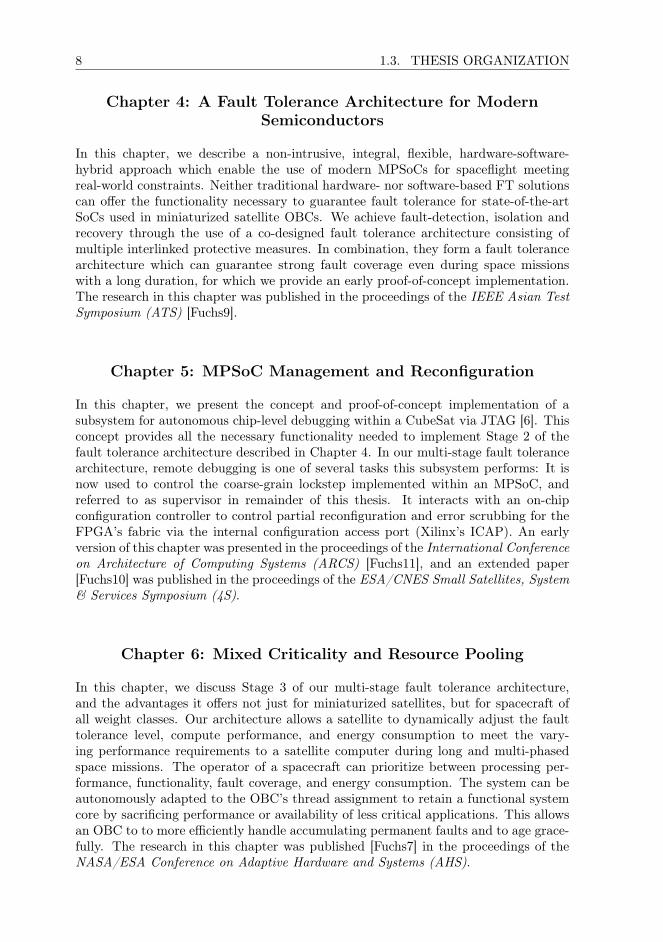
A high-level schematic of the components making up a satellite on-board computeris depicted in Figure 1. For each OBC component indicated in this figure, we developfault tolerance measures that can be used to protect them and describe them in thedifferent chapters of this thesis. To assure that these concepts are effective, we de-velop them specifically considering the application constraints and requirements of a
3


CHAPTER 1 5
of spares, scrubbing periods, and error correction coding strength.The MPSoC requires no custom-written IP-cores (library logic) and can be as-
sembled from well tested commercial-off-the-shelf (COTS) components, and powerfulembedded and mobile-market processor cores, yielding a non-proprietary, and opensystem architecture. The resulting computer architecture consists only of conventionalconsumer-grade hardware, commodity processor cores, standard parts, and openlyavailable standard library IP.
In the final chapter of this thesis, we provide a proof-of-concept implementationof this MPSoC for three FPGAs, the Xilinx Kintex Ultrascale+ KU3P (the smallestof its class), KU11P, and the Xilinx Kintex Ultrascale KU60. Our implementation forKU3P requires only 1.94W total power consumption, which is well within the powerbudget range achievable aboard 2U CubeSats. To our understanding, this is the firstscalable and COTS-based, widely reproducible OBC solution which can offer strongfault tolerance even for 2U CubeSats.
1.1 Problem Statement
Hardware-based fault tolerance measures for large satellites are effective for older,large-feature-size technology nodes which have fallen out of use in the mobile-marketand the IT industry decades ago [4]. Modern mobile-market COTS processors dependupon manufacturing in low-feature size technology nodes, and can not be manufac-tured anymore using old technology nodes. Traditional hardware-implemented faulttolerance techniques diminish in effectiveness and efficiency with shrinking featuresize [5]. This has left a protective gap due to a lack of fault-tolerant solutions, andthe reliability of such miniaturized satellites is insufficient for critical missions, whichis further discussed in Chapter 3.
Countless novel academic fault tolerance concepts have been proposed over theyears, which, in theory, could be used to protect modern computer systems. But atthe time of writing, there is a significant gap between fault tolerance research, and itsapplications to spacecraft of all classes, as discussed as part of related work in Chapters4, 6, and 8. Many of the concepts mentioned there have low technological maturityand do not meet practical application constraints for a use within a real computersystem, regardless of the intended operating environment [1]. Software-implementedfault tolerance concepts have thus until today been ignored by the space industrydue to lacking maturity, perceived complexity, doubts about their effectiveness andtestability [1].
In this thesis we therefore explore how fault tolerance can be achieved for computersystems manufactured in state-of-the-art technology nodes with low power-usage, andsmall feature-size through scientific means. We do this in collaboration with theEuropean Space Agency, supported by a Networking Partnership Program grant. Inthis thesis we address the following problem:
RQ0 Can a fault tolerance computer architecture be achieved with modern embeddedand mobile-market technology, without breaking the mass, size, complexity, andbudget constraints of miniaturized satellite applications?

6 1.2. RESEARCH QUESTIONS
1.2 Research Questions
To show that it is indeed possible to address the problem stated in RQ0 in an affirma-tive way, we develop a fault-tolerant system architecture which can do exactly that.Systematically for each component in a satellite’s on-board computer, we develop spe-cific measures to address challenges regarding fault tolerance. These components arealso depicted in Figure 1. However, we do not try to apply fault tolerance everywherein the system as, as this would inflate system complexity and fault potential. Instead,we place fault tolerance measures strategically within the system to handle and coverfaults where these can be addressed best at a system level.
In this thesis, we investigate the following research questions throughout the dif-ferent chapters:
RQ1 Considering the design constraints of nanosatellites, can a fault-tolerant com-puter architecture be achieved with COTS components?(Chapter 4)
RQ2 How can the correct functionality of a CubeSat’s FPGA-based on-board com-puter be assured and verified, and its lifetime extended?(Chapter 5)
RQ3 Can a satellite computer architecture enable novel functionality for a satellitecomputer, that improves satellite computing beyond just offering better faulttolerance and an increased lifetime?(Chapter 6)
RQ4 Can commercial memories be retrofitted with error detection and correction insoftware, to substitute for hardware measures, and to what extent?(Chapter 7)
RQ5 How can its software-implemented fault tolerance measures of a hardware- soft-ware hybrid architecture be tested and validated?(Chapter 8)
RQ6 Can such a computer architecture be practically implemented within the size,energy, and budget constraints of nanosatellite applications?(Chapters 9 & 10)
These questions are discussed in this thesis. To do so, we develop a fault-tolerantcomputer architecture for irradiated environments which can offer protection for on-board computer systems based upon modern semiconductors. Through implementa-tion, testing via fault-injection, and the construction of a proof-of-concept implemen-tation on FPGA, we show that this approach is technically feasible with contemporarytechnology.
The key contribution of this thesis is a computing concept that can allow futurecritical commercial and high-priority science missions to be done at low cost, to enableREAL progress in satellite miniaturization to take us as a species to the stars. Myhope is that this thesis is the beginning of something new and significant, and inthe coming years I plan to advance this technology from its current proof-of-conceptstate to maturity. To do so, radiation testing, long-term testing, as well as on-orbitdemonstration aboard a CubeSat will be necessary.

8 1.3. THESIS ORGANIZATION
Chapter 4: A Fault Tolerance Architecture for Modern
Semiconductors
In this chapter, we describe a non-intrusive, integral, flexible, hardware-software-hybrid approach which enable the use of modern MPSoCs for spaceflight meetingreal-world constraints. Neither traditional hardware- nor software-based FT solutionscan offer the functionality necessary to guarantee fault tolerance for state-of-the-artSoCs used in miniaturized satellite OBCs. We achieve fault-detection, isolation andrecovery through the use of a co-designed fault tolerance architecture consisting ofmultiple interlinked protective measures. In combination, they form a fault tolerancearchitecture which can guarantee strong fault coverage even during space missionswith a long duration, for which we provide an early proof-of-concept implementation.The research in this chapter was published in the proceedings of the IEEE Asian TestSymposium (ATS) [Fuchs9].
Chapter 5: MPSoC Management and Reconfiguration
In this chapter, we present the concept and proof-of-concept implementation of asubsystem for autonomous chip-level debugging within a CubeSat via JTAG [6]. Thisconcept provides all the necessary functionality needed to implement Stage 2 of thefault tolerance architecture described in Chapter 4. In our multi-stage fault tolerancearchitecture, remote debugging is one of several tasks this subsystem performs: It isnow used to control the coarse-grain lockstep implemented within an MPSoC, andreferred to as supervisor in remainder of this thesis. It interacts with an on-chipconfiguration controller to control partial reconfiguration and error scrubbing for theFPGA’s fabric via the internal configuration access port (Xilinx’s ICAP). An earlyversion of this chapter was presented in the proceedings of the International Conferenceon Architecture of Computing Systems (ARCS) [Fuchs11], and an extended paper[Fuchs10] was published in the proceedings of the ESA/CNES Small Satellites, System& Services Symposium (4S).
Chapter 6: Mixed Criticality and Resource Pooling
In this chapter, we discuss Stage 3 of our multi-stage fault tolerance architecture,and the advantages it offers not just for miniaturized satellites, but for spacecraft ofall weight classes. Our architecture allows a satellite to dynamically adjust the faulttolerance level, compute performance, and energy consumption to meet the vary-ing performance requirements to a satellite computer during long and multi-phasedspace missions. The operator of a spacecraft can prioritize between processing per-formance, functionality, fault coverage, and energy consumption. The system can beautonomously adapted to the OBC’s thread assignment to retain a functional systemcore by sacrificing performance or availability of less critical applications. This allowsan OBC to to more efficiently handle accumulating permanent faults and to age grace-fully. The research in this chapter was published [Fuchs7] in the proceedings of theNASA/ESA Conference on Adaptive Hardware and Systems (AHS).

CHAPTER 1 9
Chapter 7: Reliable Data Storage for Miniaturized Satellites
Reliable operation of an OBC can only be guaranteed if the integrity of the OBC’soperating system, applications, as well as payload data can be safeguarded. Chapter7 is therefore dedicated to discussing fault tolerance for the various volatile and non-volatile memories used aboard miniaturized satellites and within our architecture. Theresearch presented in this chapter was published as finalist paper [Fuchs15] in the pro-ceedings of the AIAA/USU Conference on Small Satellites (SmallSat). It was awardedsecond place and a research grant in the Annual Frank J. Redd Student Competition.We describe the implementation of FTRFS, a fault-tolerant radiation-robust filesys-tem for space use. It was published [Fuchs18] in the proceedings of the InternationalConference on Architecture of Computing Systems (ARCS). Furthermore, a protectiveconcept for flash memory and phase change memory is described in the second part ofthis chapter. It was published [Fuchs16] in the proceedings of the International SpaceSystem Engineering Conference Data Systems In Aerospace (DASIA).
Chapter 8: Validating Software-Implemented Fault Tolerance
In this chapter, we test and validate the software-mechanisms that are the foundationof our fault tolerance architecture by injecting faults into an RTEMS implementationof Stage 1. Traditional computer architectures for space applications are validatedusing system-level testing. This is viable for systems relying on hardware measures,but unsuitable for testing software due to a lack of test coverage and the expandedtest-space. For testing software-based FT measures, a realistic test-setup is consideredgood practice and required to deliver representative fault-injection results. Therefore,a fault-injection campaign was conducted using system emulation through QEMUinto a representative ARMv7a-SoC matching our architecture target, ARM’s Cortex-A53, and into a RISC-V-based SystemC-model. Our results show that our lockstepimplementation is effective and efficient, and we provide a direct comparison to relatedwork. An early version of this chapter was published in the proceedings of the IEEEAsian Test Symposium (ATS) [Fuchs5].
Chapter 9: Combining Hardware and Software Fault Tolerance
As optimal platform for our architecture, we developed a compartmentalized MPSoCdesign for FPGA, where Stage 2’s partial reconfiguration functionality can be utilizedto recover defective parts of the MPSoC. This architecture is designed to satisfy thehigh performance requirements of current and future scientific and commercial spacemissions at very low cost, while offering the strong fault coverage guarantees necessaryfor missions with a long duration. We describe the topology of our multiprocessorSystem-on-Chip (MPSoC), and show how it can be assembled in its entirety from onlywell tested COTS components with commodity processor cores. The MPSoC can beimplemented using only COTS hardware and extensively validated library IP, requiringno custom logic or space-proprietary processor cores. The research in this chapter waspublished [Fuchs6] in the proceedings of the IEEE Conference on Radiation and ItsEffects on Components and Systems (RADECS).

10 1.3. THESIS ORGANIZATION
Chapter 10: On-Board Computer Integration and MPSoC
Implementation
In the final research chapter of this thesis, we discuss practical implementation resultsfor our MPSoC design. We provide detailed resource utilization results for this MPSoCfor 3 different FPGAs: Xilinx Kintex Ultrascale+ KU3P (the smallest of its class),KU11P, and the Xilinx Kintex Ultrascale KU60, for which we are collaborating withinthe Xilinx Radiation Testing Consortium to achieve a suitable device-test platformfor radiation testing in the future. We provide statistics on power consumption, andshow that even between two FPGA generations power consumption can be reduceddrastically through the use of more modern and efficient technology nodes. This servesas proof-of-concept for our architecture. This chapter is based on two publications[Fuchs1,Fuchs2] in the proceedings of to the IEEE International Symposium on Defectand Fault Tolerance in VLSI and Nanotechnology Systems (DFT) and the AIAA/USUConference on Small Satellites (SmallSat).

12 2.1. SPACECRAFT AND SATELLITE MINIATURIZATION
2.1 Spacecraft and Satellite Miniaturization
In this section, a brief introduction into the different kinds of satellites and satelliteminiaturization itself is given, to provide general understanding for readers who arenot familiar with this field. This section is meant as to give sufficient backgroundinformation on the application for the research discussed in this thesis.
Satellites can be differentiated by mass in several classes.When thinking of spacestations, satellites, and deep-space probes, we usually imagine large structures float-ing in space, weighing multiple tons, powered by vast solar panel arrays, radioisotopethermoelectric generators, or fission reactors [7]. Certainly, many early scientific, com-mercial, and military satellites were very large spacecraft. These are sometimes de-signed to operate for several decades in space. However, today, modern semiconductortechnology, more efficient battery and photovoltaics, novel propulsion technologies,and robust lightweight materials enable the construction of much smaller, lighter, andcheaper spacecraft.
Spacecraft with a wet mass1 of less than 500kg are therefore referred to as “minia-turized satellites”, and can be constructed dramatically faster than large satellites. InTable 1, an overview over satellite classes and capabilities is given.
At the time of writing, several companies have achieved commercial success byoperating large groups of miniaturized satellites in orbit. They have been successfullyused to providing real-time earth observation data and help in disaster recovery [8],and in safety- and life-critical services [9] such as airplane traffic tracking and maritimeshipping [10]. A broad variety of biological and chemical experiments [11] has beencarried out using CubeSat platforms, which are also rather popular for testing andvalidating novel technologies in space [12, 13]. Several pico- and nanosatellite-basedspace-observatories [14, 15] have been launched, and nanosatellites were deployed bythe Hayabusa 2 space probe at the asteroid 162173 Ryugu [16]. In 2018, 2 inter-planetary CubeSats traveled to the planet Mars as part of the MarCO mission [17],
1The mass of the spacecraft including payload and all consumables such as propellant.
Weight Minia- Build as Classical Propulsion Mission
Class Max Min turized CubeSat Tech Usable Available Lengths
Large - 1t No Absurd Yes Yes Decades
Medium 1t 500kg No Absurd Yes Yes Decades
Small 500kg 100kg Yes Limiting Most Yes 10 years
Micro 100kg 10kg Yes Common Little Yes years
Nano 10kg 1kg Yes Standard No Yes 1 year
Picro 1kg 100g Yes Standard No Limited months
Femto 100g - Yes Inefficient No No -
Table 1: Satellites can be classified in a variety of ways, with each type of spacecraft havingdifferent capabilities, technological limitations, and the capability to achieve different missiondurations. In principle, almost any satellite could be manufactured to be a CubeSat, but onlyfor some this makes sense due to the constraints of this form factor standard.

CHAPTER 2 13
providing real-time telemetry during the arrival-phase of NASA’s InSight Mars Lander.Several miniaturized satellite constellations for technology demonstration, and Earthobservation, and positioning, and data relay purposes have been developed [18–21]and launched [8, 22, 23]. At the time of writing, scientists and engineers have evenbegun to develop CubeSat-based interferometers and composite space telescopes [13]that could outperform even the largest conventional space-observatories, and there areplan to use Nanosatellites even for gravitational-wave measurement [15].
2.1.1 Large Satellites based on Traditional Design Principles
Satellites with a wet mass above 500kg are at this point in time constructed in largeprojects with vast budgets quasi artisanally. Most “big-space” applications rely uponsuch satellites. Satellites of 500kg – 1000k are usually classified as medium-sized satel-lites, heavier spacecraft are designated as a large satellites. Development of such satel-lites is challenging, system architectures are complex, resulting in long developmenttimes, and the need to utilize well tested, proven technology, that is available over avery long period of time. This technology is usually space industry proprietary. Tech-nology readiness, design maturity, and space heritage of a technology through prioruse aboard other spacecraft are essential, and often seen a prerequisite for consideringa technology for use within this satellite class.
Construction of these satellites in practice often takes many years [24], sometimeseven decades [25]. To provide an example, the James Webb Space Telescope (JWST)is designed to have a wet mass of approximately 6620kg. It is a multinational projectinvolving hundreds of stakeholders, and has been in construction for more than 25years at the time of writing, and its precise date of completion and launch has notbeen announced yet. The cost of the electronics used aboard such a spacecraft issmall compared to the funds required to meet legal requirements, for salaries, tooling,testing, management, certification, insurance, and launch. Spacecraft testing alsorequires access to specialized facilities [26, 27] including:
• thermal/vacuum chambers to analyze the behavior of the spacecraft in a space-like environment at high or low temperatures (often 173K and 373K) [28],
• radiation testing facilities using radiogenic sources or particle accelerator to sim-ulate the radiation environment a satellite’s components have to operate in, andto verify their correct behavior and, if available, effectiveness of fault tolerancemeasures, and
• a broad variety of other heavy machinery, e.g., to perform mechanical stress andvibration tests.
Most modern major launch vehicles can carry much heavier and bulkier loads thanjust one satellite [29, 30]. Often a substantial amount of volume and mass remainsavailable which in the early days of spaceflight remained vacant to not endanger theprimary payload [31]. To reduce costs, organizations often either sell this excess ca-pacity, or hand the entire launch process over to a “launch broker”, which then cancombine multiple satellite launches into one “ride-share” launch [29]. An example ofa ride-share launch with multiple satellites of various classes is depicted in Figure3. The main spacecraft launched on a launch vehicle is then referred to as “primarypayload”, with other, often smaller satellites becoming “secondary payloads”. Today

14 2.1. SPACECRAFT AND SATELLITE MINIATURIZATION
Figure 3: A ride-share satellite launch with the Earth observation SmallSat DubaiSat-2 (topcenter) being the primary payload. Secondary payloads were 4 microsatellites (top left andright, 2 bottom center) and 26 other nanosatellites which are located in the blue deployerboxes. The CubeSat First-MOVE (see Section 2.1.4) is located in the top right deployer.Image copyright: C. Olthoff at al., Yasny Launch Base, Russian Federation, usage and reprint permissions granted.
even small start-up companies, and universities can bring their spacecraft into orbitat comparably low cost.
2.1.2 Small Satellites
SmallSats, or Minisatellites, weigh between 500 and 100kg, and traditionally wereused for brief science and commercial missions. Historically, SmallSat missions usedto be shorter than those realized with large satellites [32]. They can be constructedand launched at drastically lower cost, and in general also more quickly. The termSmallSat is colloquially also used to refer to all satellites lighter than 500kg in thisfield. Due to technological evolution in recent decades, the capabilities of the SmallSatshave increased, and today they increasingly much replace larger satellites.
2.1.3 Microsatellites
MicroSats between 100kg and 10kg are today widely used for a variety of low costcommercial and novel scientific missions. The upper and lower boundaries betweenNanosatellites, MicroSats, and SmallSats are fluent. MicroSats with a wet mass ap-proaching 100kg differ little from lighter SmallSats, and usually carry fewer or lighterpayloads and lighter components (e.g., smaller batteries, lighter and smaller solar cellarray structures, ...) [33]. Light MicroSats become similar to a Nanosatellite and mayeven utilize Nanosatellite form factor standards, while larger ones can offer very similarcapabilities to SmallSats. Many missions that a few decades ago required SmallSatscan today be performed by MicroSats, which can be manufactured more rapidly and
CHAPTER 2 15
launched at lower cost. Compare also [34] for a market assessment for a corporateview on this increasing down-scaling trend.
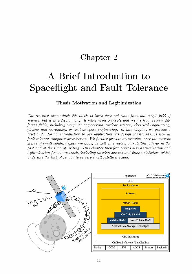
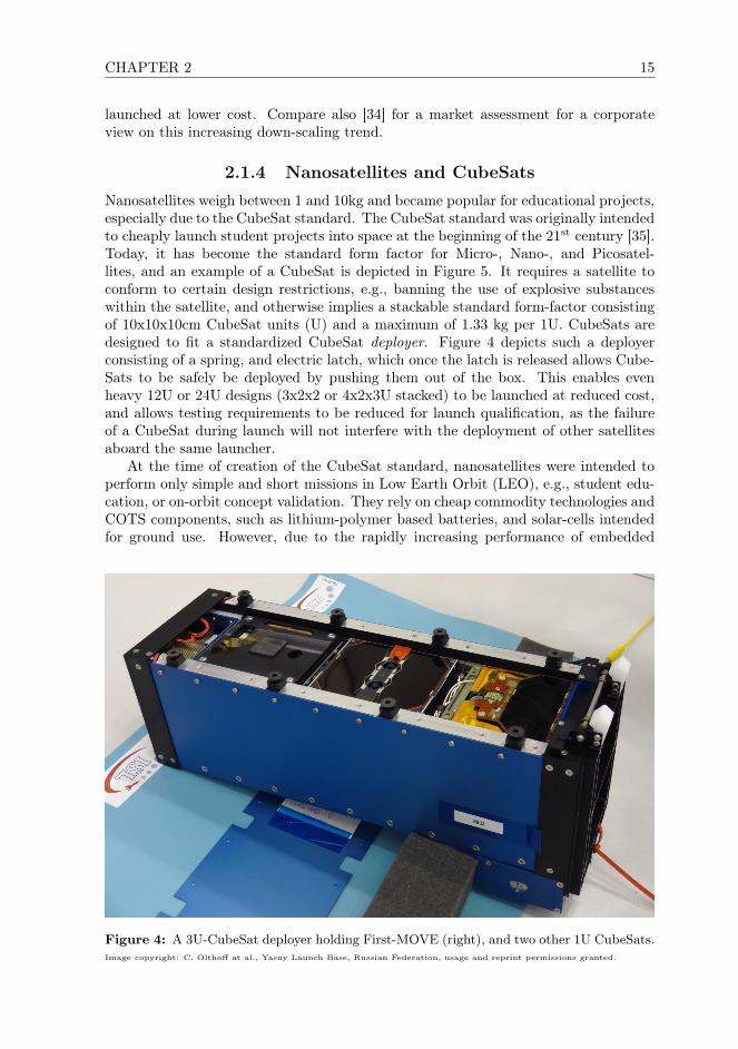
2.1.4 Nanosatellites and CubeSats
Nanosatellites weigh between 1 and 10kg and became popular for educational projects,especially due to the CubeSat standard. The CubeSat standard was originally intendedto cheaply launch student projects into space at the beginning of the 21st century [35].Today, it has become the standard form factor for Micro-, Nano-, and Picosatel-lites, and an example of a CubeSat is depicted in Figure 5. It requires a satellite toconform to certain design restrictions, e.g., banning the use of explosive substanceswithin the satellite, and otherwise implies a stackable standard form-factor consistingof 10x10x10cm CubeSat units (U) and a maximum of 1.33 kg per 1U. CubeSats aredesigned to fit a standardized CubeSat deployer. Figure 4 depicts such a deployerconsisting of a spring, and electric latch, which once the latch is released allows Cube-Sats to be safely be deployed by pushing them out of the box. This enables evenheavy 12U or 24U designs (3x2x2 or 4x2x3U stacked) to be launched at reduced cost,and allows testing requirements to be reduced for launch qualification, as the failureof a CubeSat during launch will not interfere with the deployment of other satellitesaboard the same launcher.
At the time of creation of the CubeSat standard, nanosatellites were intended toperform only simple and short missions in Low Earth Orbit (LEO), e.g., student edu-cation, or on-orbit concept validation. They rely on cheap commodity technologies andCOTS components, such as lithium-polymer based batteries, and solar-cells intendedfor ground use. However, due to the rapidly increasing performance of embedded
Figure 4: A 3U-CubeSat deployer holding First-MOVE (right), and two other 1U CubeSats.Image copyright: C. Olthoff at al., Yasny Launch Base, Russian Federation, usage and reprint permissions granted.

16 2.1. SPACECRAFT AND SATELLITE MINIATURIZATION
Figure 5: The 1U-CubeSat First-MOVE.
and mobile-market hardware since the early 2000s, the capabilities of nanosatelliteshave evolved considerably. At the time of writing, a diverse ecosystem of ready-to-useCubeSat components has developed. A variety of commercial companies of varyingtechnical capabilities provide a customizable solutions of mixed quality, with amplelaunch opportunities into different orbits being available for 1–12U CubeSats.
The CubeSat First-MOVE (depicted in Figure 5) was one of these educationalprojects [36]. In 2013, I joined a research group developing this satellite at TechnicalUniversity Munich, Germany, as a master student. Like many other first-generationeducational CubeSats, First-MOVE was designed, constructed, and tested primarilyby university students at the PhD, Master, and Bachelor levels. Planning of the First-MOVE mission began in 2006, a time when modern smartphones had just arrived inthe consumer market, and construction in earnest began around 2010. It was launchedinto LEO on November 21st, 2013, and its malfunction, which is further described inSection 2.2, was the origin of the author’s research on satellite fault tolerance.
2.1.5 Picosatellites and PocketQubes
PicoSats range in weight from between 0.1 to 1kg, and are today used for education orvery brief proof-of-concepts. The PocketQube form factor and many 1U CubeSats fallinto this category, and the electrical architecture of such PicoSats is often similar oreven identical to that of light Nanosatellites. The main difference is lower mechanicalcomplexity, and a further constrained power budget due to reduced solar cell surface(often ranging around or below 5W). In practice, this implies limitations especiallyfor transceivers and payload, which are the main power consumers aboard modernminiaturized spacecraft.

CHAPTER 2 17
2.1.6 Femtosatellites
FemtoSats are the smallest miniaturized satellite form factor and weigh less than 0.1kg.The concept of FemtoSats was theoretical until recently without allowing productivesatellite designs that can take a productive role in a space mission. However, in the2010s, first proof-of-concepts and practical applications have emerged [37]. FemtoSatsusually consist of a single PCB using wireless energy harvesting or carrying a singlesolar cell on one side of the PCB, and electronics on the other [38]. With the emergenceof more advanced energy harvesting and battery technologies in the future and anincreasing level of semiconductor miniaturization, the basic character of FemtoSatscould therefore change. Future FemtoSats will therefore find new niche use-cases, forwhich these lightest, cheapest, and expendable spacecraft will be optimal.
2.2 Early CubeSat Reliability and Motivation
Miniaturized satellite design is driven by the principle of designing a “good enough”spacecraft to do a job. Most Nanosatellites utilize COTS microcontrollers and appli-cation processor SoCs, FPGAs, and combinations thereof [39–41]. These componentscan offer one to two orders of magnitude more processing performance, are equippedwith up to three orders of magnitude more memory, and an abundance of non-volatilestorage capacity in comparison to classical space-proprietary components intended forlarger satellites, while requiring less energy. Therefore, even a 5kg CubeSats can sup-port a broad variety of commercial payloads and sophisticated scientific instruments,if these can be be fit into a smaller satellite chassis.
However, miniaturized satellites suffer from lower reliability, which discouragestheir use in long or critical missions, and for high-priority science. Most nanosatelliteslaunched in the first two decades of the 21st Century (until the time of writing) stillexperience failure within the first months of their missions [39]. As depicted in Figure6, even in late 2018 satellite malfunctions and early mission failures are widespread.The First-MOVE CubeSat is also representative in this regard, and we will use it asa case study to showcase the problems that still plaque this field.
First-MOVE: A Case Study
As a stereotypical late first-generation CubeSat, First-MOVE’s design consisted ofseveral microcontrollers. Its OBC was driven by a ARM926 based ATMEL micropro-cessor, utilized SDRAM, MRAM and NAND-flash memory, and is overall similar toa contemporary embedded device or smartphone. This fragile system architecture isrepresentative for an entire generation of CubeSats built at that time.
At the time First-MOVE was designed little information was available on whichcomponents were expected to perform well in space, and which were likely to fail earlyon. During the actual construction phase, considerable information on these aspectsbecame available continuously, and so its OBC was adjusted and retrofitted severaltimes. E.g., the introduction MRAM was a retrofit to the original NAND-flash baseddesign, as commercial MRAM was discovered to perform well aboard several earlierfirst-generation CubeSats. Further information on this First-MOVE’s OBC is availablein [Fuchs17].
First-MOVE successfully conducted its mission in LEO for two months after launch.


CHAPTER 2 19
lem in academic satellite and instrumentation projects. A majority of first-generationNanosatellite failures back then [43] could be attributed to design issues and manu-facturing flaws due to developer inexperience (e.g., negative power budgets or dys-functional communication channels) [39]. At the time of writing, failures caused byinexperience and design flaws have reduced drastically due to project professionaliza-tion and an increased staff of full-time developers in small-scale professional projectsand academia.
2.3 Nanosatellites Today and Legitimization
Development on a second satellite, MOVE-II, began in late 2014 and the finishedflight model is depicted in Figure 7. Since work on First-MOVE began in 2006,miniaturized satellite development has professionalized and fewer satellites fail due topractical design problems. Instead, the main source of failure aboard CubeSats todayare environmental effects encountered in the space environment: radiation, thermalstress, and launch issues [2].
Mission result data shows that technological limitations are the main limiting factorregarding miniaturized satellite reliability at the end of 2018. Figure 6 shows thateven experienced, traditional space industry actors who design such satellites “by thebook” with quasi-infinite budgets struggle to reach 30% mission success. This lack ofreliability and brief mission lifetimes curtails miniaturized satellite usage for criticaland long-term space missions, as well as for high-priority science missions for solarsystem exploration, deep-space probes, and space observatories. During development
Figure 7: The MOVE-II CubeSat, which was part of the author’s master thesis researchand the design challenges faced during development initiated the research in this thesis.Image copyright: Langer et al., MOVE-II Team.

20 2.3. NANOSATELLITES TODAY AND LEGITIMIZATION
of MOVE-II, it became clear to us as spacecraft designers that there were simply nofault-tolerant OBC solutions that could be used to achieve a more reliable satellitedesign within the constraints of a CubeSat.
Fault-tolerant computer design for spacecraft still relies upon radiation tolerantspecial purpose hardware These designs primarily rely upon proprietary fault-tolerantchip designs manufactured in technology nodes with a large feature size (radiation-hardening by design – RHBD) [44] and specialized manufacturing techniques andmaterials (radiation-hardening by manufacturing and process – RHBM/RHBP) [45].Often, both of these techniques are combined and a RHBD chip design is manufac-tured in a RHBD process based with much more coarse feature size than commercialtechnology. Due to the lower energy efficiency and larger size of and greater distancebetween transistors, as well as less refined electrical properties, these components alsorequire more energy, and offer less compute power compared to consumer hardwaredue to decreased clock frequencies and smaller memory sizes.
The use of traditional RHBM/RHBD components at the time of writing is limitedto the civilian and military atmospheric aerospace industries, laboratory instrumenta-tion for very large particle experiments run by well funded organizations (e.g., parti-cle accelerators, radiation-testing sites) and traditional space-industry applications inlong-term projects where cost considerations are not of primary concern. Especiallyin nanosatellites, the energy consumption, physical size, and cost of these componentsare prohibitive, making their use technically impossible and usually uneconomical.Therefore, nanosatellite computing has historically taken two paths: very simple on-board computers (OBCs) based on one single or few microcontrollers and very complexcustom-tailored systems. This approach works to a certain extent, as there are a hand-ful of COTS microcontrollers which are designed and manufactured in a way so thatthey unexpectedly turned out to be radiation hard (radiation-hard by serendipity –RHBS) [46].
At the time of writing, sophisticated fault tolerance capabilities are still absentin Nanosatellites. Instead CubeSat designers try to mitigate faults at the systemlevel using custom mitigation circuitry [47], and thereby achieve “workarounds” to stillsomehow handle faults encountered in the space environment. The practical effect ofthis lack of viable fault tolerance techniques and the use of workarounds is reflected inthe mission success statistics for miniaturized satellites depicted in Figure 6. However,a few CubeSats have also operated successfully in space for a decade or longer [48]. Inpractice, this shows that there is no hard technological limitation that would preventthe use of COTS technology in satellite missions with a much longer duration.
Many issues in other fields of spacecraft design can be overcome through engineering-based solutions. Such solutions work well, e.g., for addressing resonance issues, assur-ing a suitable thermal design and heat-distribution, and for deployable mechanicalstructures. Engineers therefore attempted to solve the lack of reliability of CubeSatssimilarly, by constructing custom fault tolerance computer design through component-level redundancy with commodity components. Practical flight results showed thatsuch designs are fragile due to high complexity [39, 49], and tend to perform worsethan much simpler designs without fault tolerance capabilities.
Today, nanosatellite designers have to forego fault tolerance in the hope of mini-mizing failure potential and thereby meeting satellite lifetime requirements for a givenspace missions by chance [50]. Designers are aware that such satellites may fail at anygiven point in time during a mission.


22 2.4. FAULT-TOLERANT COMPUTER ARCHITECTURE
design. In the remainder of this section, we discuss fault tolerance modes, measures,and testing from the perspective of computer architecture for spaceflight applicationsto provide the necessary background for this thesis. A more complete look on the dif-ferent aspects and sub-fields of fault tolerance are available in literature, e.g., in [52].
Considering fault-tolerant computer architecture, the faults we must protect asystem from depend on the application, the environment it operates in, as well aspractical operating conditions (e.g., temperature and system load). Besides that,faults can occur due to technological wear and aging, and sometimes by chance. Manyprotective measures can be used to achieve fault tolerance for computer systems [53,54].Often, the practical purpose for the application of these techniques is often not faulttolerance itself, but the need to increase scalability [55,56], manufacturing yield [57,58],higher clock frequencies and data throughput [59–61].
Different industries apply different fault tolerance techniques due to a variety ofpractical reasons, and today often maintain their own, proprietary implementationsto tackle their domain-specific challenges. For proprietary fault tolerance implemen-tations in different industrial applications, there is usually no immediate incentive toshare and generalize such fault tolerance techniques by themselves, unless they can bepatented, commercialized, and thereby protected [62]. This gap in turn is covered byscientists and researchers in industry and academia.
Today there is an entire field of science that tries to generalize application specificfault tolerance techniques, to produce new fault tolerance concepts through recom-bination. Unfortunately, this recombination is often done without considering theoriginal application and its boundary conditions. As we show in Chapters 4 and 6,academic research and publications covering this topic are kept very abstract anddo not consider a specific real-world application anymore. This works well for cer-tain fields of science and even some fault tolerance topics2. However, for practicalapplications to system-architecture this is not the case, as generic solutions withoutproper boundary conditions and a realistic fault profile, can usually not be appliedanymore to a real system. Today, academic fault tolerance research has produced avast amount of publications and generated many theoretical concepts. But, only ahandful of fault tolerance concepts envisioned by academic fault tolerance researchhave been implemented and tested in practice, and most have been ignored entirelyby the industry. One could argue that this is the way science works, but knowinglypublishing invalid and research without validation can also be seen as dishonest andonly hinders publication of actually valuable research.
The path to validate such concepts is long, time-consuming, costly, and requireslarge amounts of engineering work [64–66]. The obtained validation results are oftennot considered publishable by academics, as they require a high degree of labor justto achieve one brief paper, while multiple theoretical journal publications could beproduced in their stead. Industrial users are aware of such research [67], but are oftenskeptical. In the space industry, for example, concerns regarding validity, testability,verifyability and a perceived general lack of maturity of academic research has causedan entire industry to conservatively use very old technology [1].
When designing fault-tolerant systems, we must consider an application’s operatingenvironment, its fault profile, and system design constraints [68]. Generic fault tol-
2E.g.: erasure codes and performance overhead calculations to achieve quality of service underfaults [63] can largely be discussed without a specific application in mind, as long as key parametersmatch.
CHAPTER 2 23
erance concepts can serve as building blocks to design a comprehensive fault-tolerantarchitecture, assuming they are validated in a realistic manner.
2.4.1 Terminology and Fault Tolerance Objectives
Today, scientists and engineers use the terms ECC, EDAC, FDIR, and error correctionalmost interchangeably, while reliability, redundancy, fault tolerance, and robustnessare surrounded by a shroud of marketing. In practice, error detection and correction(EDAC), fault-detection, isolation, and recovery (FDIR), redundancy, and failover allare distinct tools. They can be applied to achieve different kinds of fault tolerance,e.g., computational correctness, continuous non-stop operation, failover, and simpleerror correction.
Error detection and correction (EDAC) implementations usually utilize one ormultiple erasure codes [69] to implement error correction coding (ECC), which allowserrors in stored and transmitted data to be corrected. EDAC is efficient only forprotecting the integrity of frequently access data, and may do so passively in thebackground without requiring a computer system to actively handle a fault in software.These limitations can be mitigated only in combination with other design measuressuch as error scrubbing and by generating error syndromes to notify the system abouta fault [70].
FDIR instead assures that a fault-induced error is not just detected and corrected,but also that side-effects are isolated and resolved (e.g. discussed in [71] for spaceapplications). In contrast, in case EDAC logic encounters errors when decoding data,it may inform the system about the result through an ECC syndrome and correctsdata passing through. FDIR does not necessarily imply computation correctness,usually utilizes fault tolerance measures to achieve error detection and correction, butotherwise implies only that a fault is corrected and the system is restored to a workingstate.
Fail-over, in contrast, can be implemented as one-shot measure, e.g., with simpleredundancy as discussed in [72], by falling from a primary to a secondary system in-stance and do not have to assess correctness, but only need be capable to detect faults.One of the most common applications for this approach is RAID1 with 2 memoriesor disks [72], but similar applications exist for avionics and network architecture inspaceflight and atmospheric aerospace applications [73].
2.4.2 Fault Detection and Correctness
To facilitate fault detection, we can exploit algorithmic measures as well as resultcomparison achieved through component replication (spatial redundancy) or repeat-execution (temporal redundancy). With algorithmic approaches detected errors canbe reconstructed using parity data (informational redundancy) information, or by uti-lizing an alternative result generated through spatial or temporal redundancy. Werefer to this type or error correction as forward error correction (FEC) [74]. Alterna-tively, backwards error correction (BEC) can be achieved with temporal redundancyand algorithmic measures, and implies message retransmission or re-execution of afailed operations [75].

24 2.4. FAULT-TOLERANT COMPUTER ARCHITECTURE
Algorithmic Fault Detection and Informational Redundancy
The algorithmic approach exploits an inherent property of a system to detect faults.It can only be used if there is an inherent property in a system or protected data thatcan be used to judge the occurrence of a fault [76, 77]. Fault detection then does notimply the ability of the system to determine a correct result, but only the ability toasses if the protected data or system is faulty.
Algorithmic fault detection often exploits informational redundancy, but it mayalso use other inherent mathematical properties of data or logic-design properties ofa system [77]. To a limited extent, algorithmic fault-detection can also be used toprotect a program’s data and control flow, e.g., by computing or modifying checksumsfor each executed instruction passing through a CPU’s pipeline [78]. However, thisrequires a non-standard processor pipeline [79], a custom compiler toolchain [80], andtherefore is feasible only for embedded software with a very specific structure.
ECC
RepairAlgorithm
CheckAlgorithm
Output
ProtectedInput
Error SyndromeFail
Figure 9: An example of algorithmic redundancy where extra algorithmic information isindicated separately as ECC. This extra information could also be an inherent property ofthe input data, instead of separate.
Spatial Redundancy
When utilizing spatial redundancy, we can realize fault-detection by comparing theoutput of multiple redundantly implemented system modules or equivalent but differ-ently implemented variants of a subsystem run in parallel. Spatial redundancy can beimplemented at all scales: for individual transistors and circuits, sets of logic, logicblocks, IP-cores, IP-core groups, ICs, components, to even an entire computer. At
Module 3
Module 1
Module 2 VoterInput Output
Figure 10: An example of spatial redundancy with 3 replicated modules in a TMR setup.


26 2.4. FAULT-TOLERANT COMPUTER ARCHITECTURE
Most systems implementing spatial redundancy in use today implement instructionor clock-cycle bound lockstep for processor cores or larger system components [54].This allows rapid error detection and correction without requiring the software orsoftware to actively participate in fault handling [88]. Usually, the voter logic iscombined with state-synchronization logic, to assure that all modules in a redundantset utilize the same input data. For more sophisticated computer designs, the levelof complexity necessary to realize voting and state synchronization in hardware isnon-trivial. Thus, such systems are limited to low clock frequencies than conventionaldesigns [54].
As with temporal redundancy, we can also utilize software to realize lockstep func-tionality in spatial redundancy using checkpoints triggered through scheduling [89],or an external signal [90]. As we show in this thesis, lockstep-concepts implementedin software can enable more powerful dynamic, and runtime-configurable voting inconjunction with spatial redundancy to achieve FEC.
2.4.3 Effect Isolation
To achieve side-effect-freeness, the effect induced by a faults must be isolated, sothey can not propagate within the rest of the system at large. However, the scopeand way in which fault isolation can be implemented depends on the fault-detectionmeasure, on the protected component, the high-level system architecture, as well as onthe specific application scenario. For pure software-based measures utilizing temporalredundancy, this can be achieved by buffering results [91] and outputting a correctresult after correctness has been assured.
Not all fault-tolerant systems require fault-isolation. The emission of incorrect datadue to a fault can also be mitigated through a system architecture and instruction-set means [92], topological measures [93], or network-side [94]. Hence, a computeroperating in such an environment does not have to be equipped with fault-isolationproperties, as the overall system setup can already guarantee fault isolation.
2.4.4 Fault Recovery
In conjunction with or subsequent to effect isolation, the effects of a fault induced intoa system should be resolved to prevent bit-rot and voter degradation due to transientfaults [95]. It also reduces the need for over-provisioning redundant instances andparity data. For data storage, this can be achieved through parity in RAID- [72] orRAIF-like [96] systems, which can again be combined well with erasure coding [97]. Itcan make a system more robust especially if it has to operate for extended periods oftime, or without maintenance.
Fault-recovery capabilities, thus, are not necessary for all applications, and maysometimes even be undesirable. For applications where maintenance can be performedfrequently and the failure probability is low, simpler failover implementations can beof advantage since they are simpler, and therefore have a reduced failure potential.Examples include atmospheric aerospace applications for civilian use [98] or marineshipping [99]. This can allow a component to be implemented with lower complexity,thereby reducing overall failure potential, cost, and weight.
Depending on application requirements and if service interruption is acceptable,hot, cold, or warm [100] stand-by can be used to achieve failover [101]. Hot redundancyrequires at least one redundant module executing in parallel to the primary module, to
CHAPTER 2 27
allow the system to switch to failover without service interruption. Warm redundancyjust implies a second module to be in standby mode, e.g., so it can rapidly take overoperation by loading a correct application state. With cold redundancy, a redundantmodule is kept available but inactive, and has to be brought up when needed. This canallow energy saving and reduce wear in redundant module, but implies a time delayuntil regular operation can resume. In this thesis, we utilize warm standby whenmigrating applications from a permanently failed processor core to a new location.
Fault Recovery with Temporal Redundancy
In systems utilizing temporal redundancy to achieve backwards error correction, thegenerated incorrect application state of a failed operation has to be reverted. Astemporal redundancy implementations usually require operations to be isolated orself-contained already, no further steps beyond discarding faulty data are necessary.By design, changes in the operating system state due to faults in temporal redundancyprotected software will in practice be detected and subsequently not propagated.
Fault Recovery with Informational Redundancy
With informational redundancy, data containing a fault should be corrected and re-written. In most memory-access based EDAC implementations, this step has to beperformed independently from error correct, e.g., in software by an ECC syndrome orin hardware suitable error scrubber logic. In case of non-correctable erasure codingerrors, or if backward error correction is used, data or a messages have to be retrans-mitted or rewritten. In memory-access based EDAC systems, non-correctable ECCerrors can only be resolved with more redundancy and additional parity information,or through replacement and blacklisting.
Composite erasure coding systems combine multiple layers of erasure codes, toachieve the advantages of multiple different types of codes or parameter configurations[102]. These enable us to achieve overall stronger protection and mitigate weaknessesof individual erasure codes, e.g., symbol based block-codes are vulnerable to singlebit-rot degrading their performance [103]. We describe the practical implementationof a composite erasure coding system combined with RAID-like features in Chapter 7.
Fault Recovery with Spatial Redundancy
In systems exploiting spatial redundancy, a fault may cause a failure of a redundantmodule, resulting in redundant system to become degraded.
To recover from transient faults, a failed module can be recovered using data fromanother module [104]. For voters replicating processor cores or larger system struc-tures, this can be done with or without performing a reboot. For some cases, justcopying the application or software state from a healthy module is insufficient, requir-ing a reboot to recover from a transient fault.
Conventional semiconductors affected by permanent faults can become dysfunc-tional, or may ceasing to function completely. To allow a system to tolerate ad-ditional, subsequent faults, additional spare modules are needed. We refer to thismeasure as over-provisioning. In practice, this can lead to large and very complexvoter designs with high energy usage and large logic footprint [54]. With ASICs, theneed for over-provisioning can only be alleviated through hardened manufacturing,

28 2.4. FAULT-TOLERANT COMPUTER ARCHITECTURE
which is expensive [44]. This approach today is widely used in spaceflight applicationsto reduce the impact of transient and permanent faults. By design, such systems stillbecome defunct once no further spare resources are available and a fault has occurredin system with only two intact modules.
Programmable logic devices such as FPGAs allow more refined permanent faulthandling: permanent faults in the FPGA fabric can be mitigated by utilizing a config-uration variant where no functionality-critical logic is placed in defective regions [105].This can be used to restore a redundant module to a functional state. In practice,this approach can be exploited to allow a system to age gracefully by adapting toaccumulating permanent faults over time, instead of failing spontaneously.
2.4.5 Fault Tolerance in the Real-World
Individual fault tolerance measures can be combined, allowing a vast amount of pos-sible combinations. However, not all possible combinations are effective and efficientfor protecting a system operating in a specific application environment and threatprofile [106]. Certain combinations can even reduce reliability, or cause an increasedfailure potential [107]. However, if done right, fault tolerance measures deployed sys-tematically in appropriate locations across a system [108], can allow for certain adefense-in-depth effect [109,110].
Many fault-tolerant systems in use today are meant to isolate and recover fromfaults within the bounds of what their design constraints specified. However, thismeans that most fault-tolerant systems are not actually tolerant to faults, but thatthey are systems that can not fail so long as faults adhere to the specifications and“obey the rules set by the designer.” In practical system design, these systems are theninstead often treated not as robust and reliable, but as infallible systems that alwayswork correctly and do not malfunction [111].
Validating Fault Tolerance Measures
To assess the effectiveness and strength of a fault tolerance architecture for a specificapplication, it must be validated in a realistic setup with a representative fault pro-file [112]. Such a profile is not just a statistical distribution over time, but shouldconsider the impact of all relevant expected fault types (transient, intermittent, andpermanent).
A variety of different test methods are available to analyze fault tolerance measuresimplemented at different scales and levels in hardware, in software, and both [52]. His-torically, these methods included fault injection into hardware and software at differentscales [65, 66], circuit simulation [64], mathematical correctness-proofs [113], statisti-cal modeling [114], and even prototype experimentation for technology validation in arepresentative environment [115]. However, mathematical and logical proofs for mod-ern processor based computer systems are non-trivial [116] and have been done onlyfor individual algorithms, simple software, protocol state machines, and for simplecircuits [113], but not for complex, OS-scale applications.
However, properly testing and validating software- and hardware-implementedfault tolerance measures is not trivial, requiring considerable time and developmenteffort. Due to these challenges practical applications in industry tend to rely upon justa few widely used standard measures and combinations thereof, and disregard science.

CHAPTER 2 29
Applied Fault Tolerance
Memory-access based EDAC through ECC is widely used in critical and always-onapplications [117] due to its scalability, simplicity and low cost [118]. Due to tech-nology scaling effects, technological reasons, and for the sake of yield enhancement, ithas also become increasingly popular in consumer products [119]. All popular conven-tional high-speed interface and connector standards such as USB3 [120], SATA [121],Ethernet [122], and PCIexpress [123] rely upon powerful erasure coding systems toachieve high clock frequencies on serial channels [124]. Traditionally, ECC has beenapplied widely to protect non-volatile data storage solutions (e.g., nvRAM, memorycards) [125]. However, to increase yield in microfabrication, ECC has become com-mon also to protect on-chip memories with a short data lifetime such as BlockRAM,caches, registers and the various scratchpad memories [126]. Designing systems forhigh-performance computing or critical applications without it would be impossiblewithout erasure coding.
Today, most space-borne systems rely strongly upon spatial redundancy [54]. Mostsuch systems rely upon hardware-voting, and only since the turn of the century hasthere been an increasing drive to realize FDIR functionality in software [127, 128]and using network topology and functionality [94]. This is an ongoing development,and this thesis should be read in context of this shift from traditional hardware tosoftware and co-designed fault tolerance concepts [129]. Software-implemented faulttolerance concepts, however, have existed since the emergence of mainframes [130].Even for space applications, they identified as promising already in the early days ofmicrocomputers [131], but it was considered technically infeasible and inefficient untilrecently.
Technological Evolution and Heritage
The high stakes involved in operating critical systems in different fields, encouragesthe use of old and less efficient, but well understood architectures instead of more mod-ern, and more powerful ones [54]. Hence, different industries progressed in developingfault tolerance concepts at different paces. While some innovated rapidly to achievefunctional systems (e.g., the industrial and high-performance computing market, andthe new space industry), others try to maintain a balance between old and new (e.g.,automotive and medical embedded applications). Some chose to remain very conser-vative, preferring to re-use decades old concepts at extreme cost over using cheaperbut more novel designs (e.g., the traditional space industry [54,104,132]).
Ultimately, however, all of industries are pressed hard to innovate, as technologyprogresses. An illustration of this need to innovate is the beginning adoption of theCAN bus standard [55], which was widely used by the automotive industry. Thetraditional space industry has just begun to adopt this standard few years ago andwill benefit from its advantages over older standards considerably, though the interfaceand protocol are is currently being replaced in automotive industry by Flexray [56]and the use of high-speed computer network standards such as Ethernet [73].
However, the risky but fast-paced transfer of cutting edge technology from theembedded- and mobile market to spaceflight has resulted in the emergence of an en-tirely different, “new space industry”. Relevant industrial players try hard to utilizemodern technology which can enable innovative space mission concepts that were com-pletely unrealistic and often unimaginable just a few years ago. To do so, this industry
30 2.4. FAULT-TOLERANT COMPUTER ARCHITECTURE
accepts an increased level of risk for failure. At the time of writing, the reduced cost ofthis engineering approach and the thereby produced designed spacecraft designs hassucceeded and left a mark on the industry as a whole.


CHAPTER 3 37
negatively charged particle. Such a particle can cause a storage cell to change its stateby depositing electrons in the floating gate as it passes through the structure. Figure17d depicts the inverse effect with a positively charged particle, which changes the netcharge of the floating gate. The particle event may cause the charge in the floatinggate to rise or drop one rise above or drop below a volatile threshold of the cell andthereby change the value represented by the storage cell.
Particles may also alter the structural integrity of different parts of the memorycell, e.g., draining the gate, or causing permanent damage [153]. Due to a shiftingvoltage threshold in floating gate cells caused by the total ionizing dose, flash memoriesbecome more susceptible to data degradation due to leakage. Modern multi-levelcell flash memories manufactured in fine technology nodes are more prone to SEUscausing shifts in the threshold voltage profile of one or more storage cells [153]. Flashcells can also store more than a bit of data, and then also become susceptible to
Control Gate
9
Oxide
7Drain
9
Floating Gate
Value: 0
Oxide
7Source -- -- -- -- - - -- --
(a) Flash memory cell in erased state
9
7
9
1
7
--- -
--
-- --
-- --(b) Flash memory cell in programmed state
9
7
9
0 → 1?
7 -- -- -- -- - - -- --
-- -
-- -
- --
--
(c) Erased cell hit by a negatively charged particle
9
7
9
1 → 0?
7
--- -
- -
-- --
+ +
--
--
+
(d) Cell reset by a positively charged particle
Figure 17: The structure of a Flash memory cell in erased (a) and programmed state (b),inspired by a figure from Zandwijk et al. [152]. Data is stored as charge in a floating gateattached to a controlling field effect transistor. Radiation can induce a variety of differenteffects in charge-based memory [153], and in Figures (c) and (d) we depict two opposingeffects induced by particles with a positive and negative charge [154].
38 3.1. THE IMPACT OF THE SPACE ENVIRONMENT ON ELECTRONICS
MBUs: radiation may cause a state change across multiple voltage levels [155]. Thesemiconductor’s temperature and particle events can also influence the leakage currentof a these memory cells, thereby reducing the charge stored within the floating gateover time [156]. The radiation-induced effects depicted in Figure 17 are representativefor the entire class of charge-based memories, even though other memory technologiesstore data as charge in electrically different ways [157].
Physical shielding using aluminum and other materials can reduce certain radiationeffects [158]. The necessary shielding strength depends on the physical propertiesof the material used for shielding [159]. This approach has been used extensivelyin classical space applications in the early time of spaceflight. However, the levelof shielding needed to protect modern semiconductors from radiation effects wouldrequire a miniaturized spacecraft to dedicate an unreasonable additional mass andvolume to shielding [159]. For very large satellites, the use of strong shielding is stilla viable (but costly and inefficient) option [160].
Weak shielding can introduce scattering effects, while offering nearly no addedprotection [161]. These can occur due to interaction of a highly charged particle withshielding material, which can cause a shower of charged secondary particles. Thissecondary particle radiation takes the shape of a cone from between the point of impactof the original particle and the underlying semiconductor [161]. Particle scatteringcan therefore cause multiple particles with lower charge to penetrate a semiconductor,instead of just one. Hence, very thin shielding such as aluminium-RF-cages commonlyfound in consumer electronics offer usually no radiation protection [159].
3.1.2 Design Constraints for Space Electronics
The success of a satellite missions depends on designer’s ability to develop a systemthat can withstand operation in the space environment, and can cope with the designconstraints that are in place aboard a satellite. In the remainder of this section, wetherefore provide a brief overview of satellite design constraints.
Solar cells are the main power source aboard modern spacecraft in the inner regionsof the solar system [7]. A spacecraft’s orbit, location and orientation (attitude) relativeto the Sun, and the solar array’s temperature all influence the efficiency of its solararray. Miniaturized satellite’s have small solar arrays with varying output, and theirOBCs are limited to a few Watts of power-budget (power consumption averaged overtime).
Operation in the space environment outside planetary atmospheres means thata satellite will operate in vacuum [162]. In turn, this implies the absence of theheat-transfer medium necessary for thermal convection, and hence also air cooling.Depending on the specific chip design implemented within a semiconductor, this cancause a chip and its packages to exhibit different or even anomalous thermal proper-ties, potentially causing hot-spots and impact performance and lifetime [163]. Heatgenerated within a spacecraft therefore has to be transferred to the exterior and isthen emitted as infrared radiation. A variety of engineering measures are available tohelp create a stable spacecraft-internal temperature environment [164].
Operation in vacuum and the low temperatures encountered in the space environ-ment, can cause rapid material aging. The extreme temperature deltas when operatingin a planetary orbit in direct sunlight and darkness can furthermore cause out-gassing,e.g., of chemical softeners present in materials such as plastics [165]. Gassed-out chem-

CHAPTER 3 39
icals may interact with other components of a spacecraft, especially sensors, and maycause folded solar cell arrays to stick together, fold incorrectly, and fail to deploy fromstowage [166]. This effect is a major problem for spacecraft equipped with opticalpayloads, e.g. astronomical observatories: out-gassed chemicals may then accumulateover time on sensors, mirrors, and lenses, and degrade an instruments performance. Inlarge spacecraft projects, components are therefore often baked at high temperaturesor exposed hot-cold cycles to reduce this effect in space as much as possible.
Upon launch, satellites have to withstand considerable physical stress and mayexperience vibration-induced resonance effects [167]. To a certain extent, these can besimulated through mechanical means (shakers) and acoustics on the ground, and thenmitigated through engineering and a wise choice of materials. To design computer sys-tems to better cope with launch stress and the extreme temperature changes that maybe encountered in the space environment, electronics can be packaged in more suitablematerials than the usual plastic packages used on the ground. However, electronicsin ceramics and metal-based packages are at the time of writing significantly moreexpensive than conventional consumer parts, and usually non-options for CubeSat ap-plications. Specialized materials can also be used in the different layers of a PCB, andcan help optimize electrical, structural, and thermal properties, which today is alsoused aboard miniaturized spacecraft, e.g., aboard the MOVE-II CubeSat.
3.2 Technology Readiness and Standardization
Satellite missions can last from several months up to many decades, and thereforesatellite designers may encounter hard technological barriers such as data retention[168]. Examples include, but are not limited to, issues with using electronics storagetechnologies due to limited data retention periods, solar cell degradation, and materialdegradation due to long-term thermal stress and out-gassing.
Traditional space companies and organizations are very cautious when consider-ing new technology with little or no space heritage. Often, they modify and adaptexisting, foreign industry standards to their own needs instead of reusing them, anddevelop their own standards [169]. Several sets of space related quality and designstandards exist, which are administered by committees consisting of space agencies,governmental bodies, military and major industrial actors. Some of these standardlibraries are published, while others remain proprietary (e.g., ARINC) or are evenkept confidential (military standards). Currently, the most relevant publicly availableand widely adopted standards are published by the Consultative Committee for SpaceData Systems (CCSDS), the European Cooperation on Space Standardization (ECSS),and the NASA Technical Standards Program. Standards popular in the IT-industryin general do influence avionics design (e.g., Ethernet/IEEE 802.3 is today the tech-nological base for AFDX [94], but adoption of this technology has taken more than30 years), but mostly indirectly due to a technological lag between IT-industry andspace-avionics that ranges from between 10 to 40 years [170].
Avionics (thus, Aerospace and Spaceflight electronics) development relies not justupon specialized and tested components. Instead, technological maturity has to beproven in practice to demonstrate that a component or technology is ready for ap-plication in the space environment. Thereby, the quality and heritage of a solutionare assessed based on a standardized set of indicators resulting in a classification intechnological readiness levels (TRLs) [171], see Figure 18. For some types of chips the
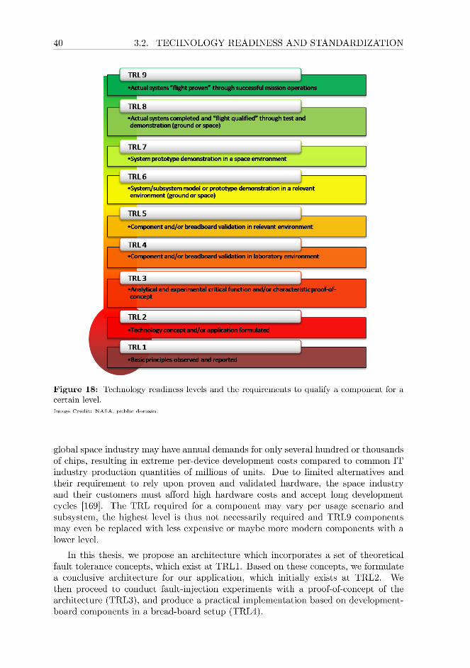

CHAPTER 3 41
3.3 Operational Constraints for Satellite Computers
In contrast to most earth-bound computing, it is not possible to physically access aspacecraft in orbit [172] to diagnose or resolve faults. However, this does not meanthat they can not be repaired, refueled, upgraded, or otherwise serviced during amission. In fact, most spacecraft are designed to be service friendly, as this makesthem easier to assemble and test on the ground. This is especially important astesting of a spacecraft as a whole and its individual subsystems is a complex andcostly undertaking. Component-level as well as testing of a full avionics system makesup a significant share of the time needed for the design and construction process.
Hands-on maintenance or diagnostics on-orbit are uncommon today, and servicingmissions have been conducted only on a few occasions. All of these spacecraft werelarge satellites and space-stations in LEO with outstanding significance to science,society, or driven by national interests. Prominent examples include the Hubble SpaceTelescope [173] and several space stations [172,174,175], where servicing was requiredto resolve faults. For most modern non-agency and non-governmental satellites, andespecially smaller and cheaper spacecraft, hands on maintenance is not feasible, andusually also not economical [173]. Hence, an on-board computer has to operate andhandle faults autonomously over the entire duration of a spacecraft’s mission, whichmay last for several decades.
Diagnostics of computerized systems therefore have to be conducted remotelyand in a scripted manner locally aboard a satellite. Considering the journey ofCassini/Huygens depicted in Figure 19, this implies differences in link behavior andcommunication bandwidth during a mission. Even in earth orbit, a satellite’s teleme-try and telecommand (TMTC) link is lossy, and offers very low bandwidth comparedto ground-based communication (in the low kbps range). As depicted in Table 2,signal travel times in LEO and Geostationary Earth Orbit (GEO) still allow widelyused network communication protocols for ground use to be utilized, if aspects suchas Doppler-Shift are compensated for [178].
All CubeSats launched until 2018 operated in a LEO [17], and most utilize a com-bination of UHF and VHF frequency bands to realize their commandeering channel.LEO communication windows between a ground station and a satellite are limitedto between 5 and 20 minutes in ideal weather conditions, and reduced by equipmentdampening, environmental effects, and atmospheric conditions [179]. Only part ofthis communication window allows actual communication with a spacecraft due tolink-quality issues. The actual duration varies depending on the satellite’s orbit andthe environment the ground station operates in: buildings, natural obstacles and fad-ing signal quality with declining elevation angle when approaching the horizon allaffect a link’s signal-to-noise ratio [180]. For comparison, while commandeering theFirstMOVE CubeSat, actual link availability during communication windows neverexceeded 12 minutes.
LEO-link availability can be increased through the use of satellite-relays (e.g.,TDRS [181]) and ground-station networks [182]. However, these are currently largelyunavailable to miniaturized satellites due to economical considerations on the opera-tor’s side and form-factor and cost constraints for miniaturized satellites. In practice,this curtails remote debugging capabilities of spacecraft. It prevents the direct re-useof, e.g., all low-level testing protocols which are today widely used on the ground appli-cation such as JTAG or ICE, and prevents remote-debugging using standard debugging


CHAPTER 3 43
tools.When communicating with spacecraft orbiting other planets in our solar system,
signal travel times and thus link latency grow rapidly. With space probes travelingbeyond the Earth/Moon system, the available link rates decrease sharply and oftenonly few hundred bps can be achieved. Unidirectional signal travel times to neighbor-ing planets make real-time bi-direction communication concepts as used on the Earthtechnically impossible. At the time of writing, the mars rover Curiosity can achieve adata rate of between 500 bps up to a theoretical maximum of 32 kbps and round-triptimes of at least 8 minutes under ideal circumstances [183]. The TMTC link of theVoyager probes [184] can achieve a maximum of 160 bps at the edge of the solar systemvia the Deep-Space Network [185] with signal travel times approaching a duration ofa day.
As depicted in Figure 19, a spacecraft may have to travel within our solar systemfor years, before actually arriving at its destination, where it can then begin to performits actual mission. During such missions, the performance requirements to a satellitecomputer can vary. In Figure 20, we depict a simplified version of the orbit/workschedule of NASA’s Enceladus Life Finder (ELF) probe, which will conduct scienceon Saturn’s sixth largest moon. Travel to the Saturn system will take years, but once
Communication Distance from Earth Signal Travel Time
Endpoint Min. Max. Min. Max.
LEO 400 km 2,000 km 3 ms 18 ms
GEO 35,786 km - ∼250 ms -
Moon 356,400 km 406,700 km 2.4 s 2.7 s
Mercury 0.62 AU 1.39 AU 5 min 12 min
Venus 0.28 AU 1.72 AU 2 min 14 min
Mars 0.53 AU 2.52 AU 4 min 21 min
Jupiter 4.21 AU 6.21 AU 35 min 52 min
Saturn 8.54 AU 10.54 AU 1:11 h 1:28 h
Uranus 18.23 AU 20.23 AU 2:32 h 2:48 h
Neptune 29.06 AU 31.06 AU 4:02 h 4:18 h
Voyager 2 ∼121 AU - ∼16:50 h -
Voyager 1 ∼147 AU - ∼20:22 h -
Table 2: Unidirectional signal travel times for radio communication in vacuum betweena ground station and a spacecraft at a particular location in the solar system. Distancesbetween the Earth and different planets in the solar system vary due to celestial mechanics.In practice, the signal latency even for LEO communication is drastically larger than thetheoretical signal travel speeds indicated here due to latency in the signal processing chain.Data for the Voyager probes based on https://voyager.jpl.nasa.gov/mission/status,accurate as of September 2019.


CHAPTER 3 45
ELF has entered orbit around Enceladus, it will have to handle a variety of differenttasks with very different system requirements (indicated in color). We utilize thissatellite’s mission operations schedule to highlight how requirements to a satellite’son-board computer can shift during a mission.
During the yellow-outlined communication phases, reliability of the satellite com-puter is crucial, as communication windows are brief and the available link-rate islow. Any lost communication time could directly impact the satellite’s mission andsubsequently executed tasks. Ideally, during this time a satellite’s computer shouldoffer increased fault tolerance capabilities at the expense of other system parameters,if such capabilities were available.
The red- and purple highlighted orbit segments indicate times when ELF willperform maneuvers through its propulsion subsystem and adjust the orientation of it’ssolar panel array. When performing maneuvers, precise timing and therefore the abilityfor real-time operations are crucial, while overall compute performance requirementswill be comparably low. Finally, in the green-market science phase, performance iscritical, and during this phase, spending extra energy to increase the satellite’s overallcompute and data-storage capacity may allow the spacecraft to conduct more andbetter science within its brief mission. With the computer architectures used aboardspacecraft today, little adaptivity is possible. However, future satellite computersbased on modern mobile-market and embedded computer architectures could very wellsupport such functionality if fault tolerance capabilities can be adjusted at runtime.
46 3.3. OPERATIONAL CONSTRAINTS FOR SATELLITE COMPUTERS


48 4.1. INTRODUCTION
4.1 Introduction
Modern embedded technology is a driving force in satellite miniaturization, contribut-ing to a massive boom in satellite launches and a rapidly evolving new space industry.Micro- and nanosatellites (100-1kg) have become increasingly popular platforms fora variety of commercial and scientific applications, due to an excellent balance ofperformance and cost. However, this class of spacecraft suffers from low reliability,discouraging its use in long, complex, or high-priority missions. The OBC related elec-tronics constitute a much larger share of a miniaturized satellite than they do in largersatellites. Thus, per component, they must deliver better performance and consumeless energy. Therefore, due to cost considerations, miniaturized satellite OBCs aregenerally based upon processors manufactured in fine-feature-size technology nodes,such as those used in mobile embedded devices.
Traditional hardware-based fault tolerance (FT) concepts for general-purpose com-puting, however, are ineffective for modern, highly scaled systems-on-chip (SoCs),becoming a prime source of malfunctions aboard miniaturized satellites [2]. Largersatellites, too, are limited by the constraints of traditional ways to achieve fault tol-erance for space applications, as these prevent larger satellites from harnessing thebenefits of modern processor designs, and multiprocessor-SoCs (MPSoCs). Also, thesehardware-based FT-measures can not handle varying performance requirements dur-ing multi-phased missions and mega-constellations [187]. Software-based FT measuresrapidly evolved due to efforts of the scientific community, and are effective for modernembedded hardware. However, these advances have largely been ignored by the spaceindustry, as well as closely related fields such as atmospheric aerospace, as they wereresearched only in theory, but rarely meant for implementation. While many of theseconcepts include innovative ideas, major implementation obstacles and fundamentalissues remain unaddressed. Often, prior research makes impractical assumptions to-wards the platform or application environment, ignores fault detection, recovery fromfailover, or other real-world constraints. Many concepts also attempt to uphold safetyand availability, e.g., for atmospheric aerospace use, but not computational correctness.To the best of our knowledge, no integral and practical solution to utilizing modernMPSoC-based systems within high-priority space missions has been developed to date.
There is a wide gap between academic research towards novel FT concepts and theirpractical application in spacecraft OBCs. Satellite computers for control purposes arestill largely based upon architectures developed decades ago, while theoretical researchhas not achieved the level of maturity necessary to bridge this gap. Thus, neithertraditional hardware- nor software-based FT solutions could offer all the functionalitynecessary to improve the reliability of state-of-the-art embedded SoCs in miniaturizedsatellite OBCs. Other concepts promise excellent FT guarantees in theory, but requirecomplex architectures that often do not address the specific challenges of computersflying in space. Innovations are especially needed in general-purpose computing, asOBCs must execute a broad variety of applications efficiently.
This approach was developed for a 4-year European Space Agency (ESA) projectwith two industrial partners. Due to the interdisciplinary nature of this project, otheraspects of this approach and its hardware implementation are described further inChapters 5 – 10.
In the next section, we discuss related work, and how the design constraints andchallenges outlined in Chapter 3 are up until the time of writing are addressed in fault-

CHAPTER 4 49
tolerant OBC design. Section 4.3 contains a brief overview of the multi-stage approach,its limitations, terminology, as well as the application model and requirements. Eachstage is described in the subsequent sections, with the supervision concept explained inSection 4.4.4. Section 4.7 then introduces briefly an MPSoC architecture specificallydesigned as a platform for this FT concept. Performance and checkpoint reliabilityare discussed in Section 4.8, followed by conclusions.
4.2 Related Work
Radiation challenges OBC fault coverage constantly and throughout a mission andaffects all of an OBC’s components depicted in Figure 21. Traditionally, FT is enabledthrough circuit-, RTL-, core-, and OBC-level voting, which is costly to develop, difficultto validate, maintain, and slow to evolve [88,104,132,188–190]. Software takes no activepart in fault-mitigation, as faults are suppressed at the circuit level, preventing theeffective assessment of a processor’s health. Circuit- and RTL-voting are effective formicrocontrollers and very small SoCs, while core-level voting requires logic unavailablein COTS systems. Modern embedded COTS MPSoCs consume very little energy. Butto achieve FT using hardware-side measures, arrays of synchronized high-frequencyvoters or core-lockstep in hardware are necessary. As voting and core-level lockstep atGigaHertz clock rates are non-trivial, it has been implemented only at considerablylower frequencies with non-COTS hardware [88,190–192].
In general, hardware-voting based MPSoC designs are static and non-adaptive,as the entire design’s fault coverage properties are highly chip-specific [193]. Allthese components are single-vendor solutions, often with walled-garden ecosystemswith vendor lock-in. FT MPSoCs for space use contain retrofitted TMRed single-coreprocessors, e.g., [104], or are unique, experimental solutions for specific satellite mis-sions [194,195]. In contrast to these solutions, modern MPSoCs also allow considerablymore software design freedom due to the available compute resources, thereby reducingthe required development time and complexity. For scientific instrumentation and low-priority CubeSat missions, COTS-based MPSoCs and FPGA-SoC-hybrids have beenutilized, but these are not suitable for critical satellite control applications withinminiaturized satellites [196]. Ground-based FT applications do not consider the spe-cific threat-scenario and application environment, physical constraints, and thermaldesign constraints [5, 197]. Instead, we propose to use software-side functionality toassure FT for conventional, non-fault-tolerant processor cores.
First concepts involving coarse-grain lockstep are promising [198–200], but do notaddress the specific challenges to FT in space [201]. FT using thread-level very-long-instruction word architectures [202,203] has also been explored, though the approachstill requires pipeline-level voters in hardware. Most implement checkpoint & rollbackor restart, which makes them unsuitable for spacecraft command & control applica-tions [204], others ignore fault-detection [205, 206], or require external, infallible faultdetection entities with deep knowledge about application-intrinsics [207] but no con-cept of how this could be obtained. Often, faults are assumed to be isolated, side-effectfree and local to an application [208] and/or transient [199,200,205], which voids theireffectiveness for space applications. Many prior concepts entail high performance-[209], resource-overhead [210,211], or impose severe design constraints on applicationsand the OS [198,199]. To be effective in the space environment, an FT approach mustbe based upon forward-error-correction and the implementation complexity must be


CHAPTER 4 51
4.3 Fault Tolerance through Software
This approach consists of three fault-mitigation stages:
Stage 1 is implemented entirely in software and provides fault-detection throughcoarse-grain lockstep to enable self-testing, and can be implemented inCOTS MPSoCs.
Stage 2 improves medium-term reliability through FPGA reconfiguration, and en-ables long-term fault coverage using alternative configuration variants. Itutilizes Stage 1’s fault detection capabilities.
Stage 3 extends the lifetime of a degraded OBC by utilizing mixed criticality to as-sure fault coverage for high-criticality threads. It enables the OBC to auto-matically sacrifice performance or fault coverage of lower-criticality threadsin favor of higher-critical applications, thereby maintaining a stable coresystem.
The presented concept is flexible and the individual stages are modular, as Stage 2or 3 can be omitted depending on the OBC and mission. Our approach is designedfor generic COTS MPSoCs, as these are readily available in a variety of performanceclasses at low cost. In the architecture described in Section 4.7, we place processorcores within isolated compartments. We consider it an ideal platform for our approach.In MPSoCs without a compartments, compartment can be substituted for processorcore, and the differences in fault coverage are discussed in Section 4.7.
Terminology
Fault detection in our approach is based upon sets of compartments running two ormore lockstepped copies of application threads. We refer to such a group of locksteppedthreads as a thread group. Timing-compatible thread groups can be combined andexecuted on the same set of compartments, and are then referred to as a compartmentgroup.
The relation between these is visualized in Figure 22. A thread group can realizea varying level of replication to achieve majority voting (thread 0 in the figure), errordetection (thread 1), or even individual execution. One compartment may be host to
ThreadGroup 0
ThreadGroup 1
Compartment 1 Compartment 2Compartment 0
Thread 0 Thread 0 Thread 0
Thread 1 Thread 1
Compartment Group 1Thread 3
Thread 2
Figure 22: Schematic illustration of the relation between compartments running applicationsas threads, thread groups, replication, and timing-compatible compartment groups.
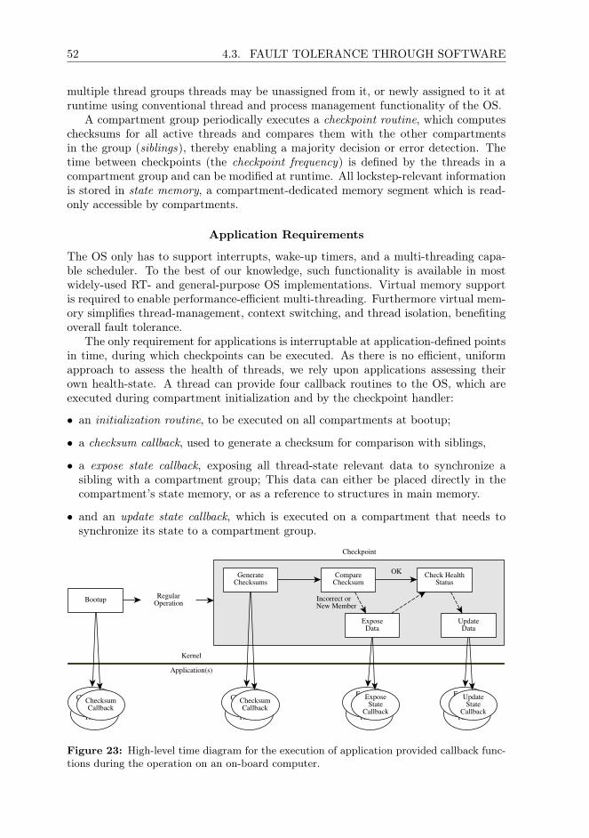
52 4.3. FAULT TOLERANCE THROUGH SOFTWARE
multiple thread groups threads may be unassigned from it, or newly assigned to it atruntime using conventional thread and process management functionality of the OS.
A compartment group periodically executes a checkpoint routine, which computeschecksums for all active threads and compares them with the other compartmentsin the group (siblings), thereby enabling a majority decision or error detection. Thetime between checkpoints (the checkpoint frequency) is defined by the threads in acompartment group and can be modified at runtime. All lockstep-relevant informationis stored in state memory, a compartment-dedicated memory segment which is read-only accessible by compartments.
Application Requirements
The OS only has to support interrupts, wake-up timers, and a multi-threading capa-ble scheduler. To the best of our knowledge, such functionality is available in mostwidely-used RT- and general-purpose OS implementations. Virtual memory supportis required to enable performance-efficient multi-threading. Furthermore virtual mem-ory simplifies thread-management, context switching, and thread isolation, benefitingoverall fault tolerance.
The only requirement for applications is interruptable at application-defined pointsin time, during which checkpoints can be executed. As there is no efficient, uniformapproach to assess the health of threads, we rely upon applications assessing theirown health-state. A thread can provide four callback routines to the OS, which areexecuted during compartment initialization and by the checkpoint handler:
• an initialization routine, to be executed on all compartments at bootup;
• a checksum callback, used to generate a checksum for comparison with siblings,
• a expose state callback, exposing all thread-state relevant data to synchronize asibling with a compartment group; This data can either be placed directly in thecompartment’s state memory, or as a reference to structures in main memory.
• and an update state callback, which is executed on a compartment that needs tosynchronize its state to a compartment group.
RegularOperation
Checkpoint
GenerateChecksums
CompareChecksum
ApplicationThread
ChecksumCallbackChecksum
Callback
ExposeData
ApplicationThread
ExposeState
Callback
ExposeState
Callback
Check HealthStatus
UpdateData
ApplicationThread
ExposeState
Callback
UpdateState
Callback
Kernel
Application(s)
Bootup
ApplicationThread
ChecksumCallbackChecksum
Callback
Incorrect or New Member
OK
Figure 23: High-level time diagram for the execution of application provided callback func-tions during the operation on an on-board computer.
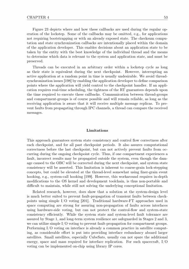
CHAPTER 4 53
Figure 23 depicts where and how these callbacks are used during the regular op-eration of the lockstep. Some of the callbacks may be omitted, e.g., for applicationsnot requiring bootstrapping or with an already exposed state. The checksum compu-tation and state synchronization callbacks are intentionally placed within the domainof the application developer. This enables decisions about an application state to betaken by the entity with the best knowledge of the individual thread and the meansto determine which data is relevant to the system and application state, and must bepreserved.
Threads can be executed in an arbitrary order within a lockstep cycle as longas their state is equivalent during the next checkpoint. However, interrupting anactive application at a random point in time is usually undesirable. We avoid thread-synchronization issues [198] by enabling the application developer to define comparisonpoints where the application will yield control to the checkpoint handler. If an appli-cation requires real-time scheduling, the tightness of the RT guarantees depends uponthe time required to execute these callbacks. Communication between thread-groupsand compartment-groups is of course possible and will remain reliable, as long as thereceiving application is aware that it will receive multiple message replicas. To pre-vent faults from propagating through IPC channels, a thread can compare the receivedmessages.
Limitations
This approach guarantees system state consistency and control flow correctness aftereach checkpoint, and for all past checkpoint periods. It also assures computationalcorrectness before the last checkpoint, but can not actively prevent faults from oc-curring during the ongoing checkpoint cycle. Thus, if one compartment experiences afault, incorrect results may be propagated outside the system, even though the dam-age caused to the OBC will be corrected during the next checkpoint, and system stateconsistency will be asserted. This limitation is inherent to coarse-grain lock-steppingconcepts, but could be elevated at the thread-level somewhat using finer-grain eventhooking, e.g., system-call hooking [199]. However, this workaround requires in-depthmodifications to the OS kernel and development toolchain, is thus non-portable anddifficult to maintain, while still not solving the underlying conceptional limitation.
Related research, however, does show that a solution at the system-design levelis much better suited to prevent fault-propagation of transient faults between check-points using simple I/O voting [201]. Traditional hardware-FT approaches used inspace computing are strong for assuring non-propagation of faults across interfacesusing hardware-side voting, but can not protect the control-flow and system-stateconsistency efficiently. While the system state and system-level fault tolerance areassured by Stage 1, and long-term system resilience are safeguarded in Stages 2 and 3,we can utilize simple I/O voting to prevent fault-propagation for compartment groups.Performing I/O voting on interface is already a common practice in satellite comput-ing, as considerable effort is put into providing interface redundancy aboard largersatellites. Small satellites, especially CubeSats, usually can not spare the additionalenergy, space and mass required for interface replication. For such spacecraft, I/Ovoting can be implemented on-chip using library IP cores.

54 4.4. STAGE 1: SHORT-TERM FAULT MITIGATION
4.4 Stage 1: Short-Term Fault Mitigation
Stage 1 offers software-controlled, thread-level, distributed majority voting and fine-grain fault logging within any COTS MPSoC with three or more processor cores. Theobjective of Stage 1 is to detect and correct faults at each checkpoint to assure compu-tational correctness, control-flow consistency, and a consistent system state after eachcheckpoint. To do so, Stage 1 requires a processor guaranteeing sequential consistency.
Instead of exerting direct control over the MPSoC, a supervisor can assure FTindirectly, as fault coverage and control are distributed and enforced by the compart-ments themselves. In consequence, the supervisor does not require any knowledgeabout the executed application threads, an individual compartment’s state, or otherOBC intrinsics. The thread group assignment within an MPSoC can be reconfiguredfreely at runtime to implement different voting configurations. Thus, the describedapproach can exploit parallelization to improve reliability, throughput, or minimizepower consumption, thereby allowing the system to adapt to multi-phased missionswith varying performance requirements.
4.4.1 Thread-Based Self-Testing
The program flow of this stage is depicted in Figure 24 and described subsequently.It can be implemented within an existing scheduler and an interrupt service rou-tine (ISR). A practical example for compartment fault handling and recovery, and anoverview over how the supervisor interacts with the system are provided at the end ofthis section.
Bootup & Initialization
After bootup, a compartment first executes basic self-test functionality to assure in-tegrity of compartment-local IP-cores and memory. Each thread’s initialization routineis executed on all compartments to allow faster state-update in case a new thread-groupis added to a compartment. When being assigned to a compartment, a thread willregister its desired checkpoint frequency and its checksum, expose/update callbackroutines. After the threads have been initialized, each compartment will set a periodictimer to initiate checkpoints. As depicted in Figure 24, a compartment will execute itsfirst checkpoint immediately after the MPSoC has been fully rebooted, to assure thatapplication and OS initialization were successful. If only this individual compartmentwas rebooted, it can thus return to the spare compartment pool to replace a faultycore in the future.
Checkpoint Start
A checkpoint is triggered by a timer interrupt or externally by the supervisor. A threadcan delay a checkpoint until it has reached a viable state for checksum comparison bydisabling interrupts, thereby deferring interrupt processing. The checkpoint ISR savesthe existing system state, loads the actual checkpoint handler, performs a contextswitch to kernel mode, and invokes the checkpoint handler.


56 4.4. STAGE 1: SHORT-TERM FAULT MITIGATION
Checksum Computation
The checkpoint handler invokes each active thread’s checksum callback scheduled forchecking. As not all threads in a compartment group require the same checking fre-quencies, not all active threads will be validated during each checkpoint. This check-sum callback returns a representation of the application thread’s internal state aschecksum or hash generated from thread-private variables and other internal applica-tion state. The checksum format is compile-time defined, and must be chosen basedon FT needs. The algorithm used to generate this checksum is up to the applica-tion developer. Each checksum is stored in the compartment’s local state memory andthereby exposed to the other compartments. If no checkpoint routine can be provided,a checksum is computed by the checkpoint handler for an application-defined memoryrange. This memory range can be utilized by the application to deposit state-relevantdata passively, e.g., through linker scripts or pre-processor macros. A non-continuouslyrunning application can also deposit its results in state memory or return a checksumupon exit.
Prior concepts required deep modifications to the OS to allow a proprietary centralhealth-management entity to retrieve this information directly [198,205], or utilized noapplication-internal information [200, 201, 211]. Instead, this approach enables us toutilize application-intrinsics to assess the health-state of the system, without requiringany knowledge on the applications. The time required to generate checksums can beminimized by adapting the application code, e.g., by retaining computational by-products which would usually be discarded.
Checksum Comparison
Once all checksum callbacks have been executed, a compartment will monitor its groupmembers’ state memory segments until another compartment is ready for comparison.It will do so until it has compared its checksums with all siblings, or the systemdesigner’s compartment-group deadline expired. Compartments will usually begincomparing its checksums with siblings immediately or wait only briefly, as delays aremainly induced due to varying memory latency or malfunctions. If it detects a check-sum mismatch or a sibling violated the deadline, the compartment will stop comparingchecksums and report disagreement with that compartment to the supervisor.
Thread Disagreement & State Propagation
If a compartment detected a checksum mismatch, it executes the expose state callbackroutine of all threads in the affected compartment group. This callback can be omittedif all state-relevant data is already in state memory, e.g., for non-continuous runningapplications. The checkpoint routine will adjust the checkpoint’s timer if a new threadgroup was added to the compartment group, and return control to the scheduler.
State Update and Thread Execution
The scheduler will check three conditions during regular operation: if any thread-groupis active, the compartment was newly added to a compartment group, or requires anupdate. Idle compartments sleep until the next checkpoint and can be woken up by thesupervisor to reduce energy consumption and fault-potential. In case a compartmentmust update a thread-group’s state from a sibling, the relevant update callback will be
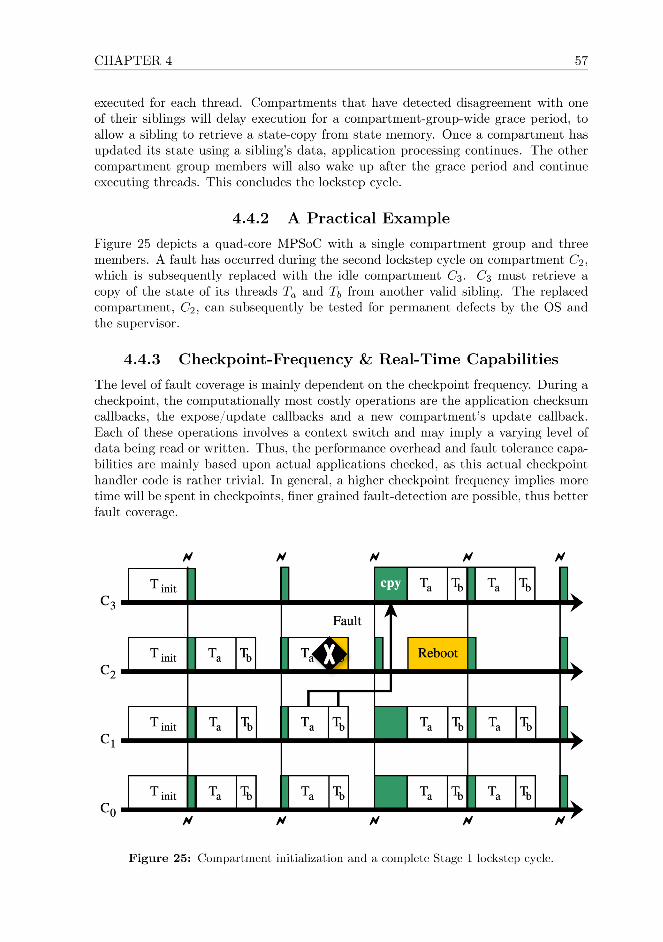

58 4.4. STAGE 1: SHORT-TERM FAULT MITIGATION
In our implementation, interrupts are deferred during a checkpoint, thus applica-tions are not serviced and will not process I/O, thereby affecting the level of real-timecapabilities the MPSoC can offer. However, though this can be worked around us-ing a more elaborate interrupt handling concept, e.g., using interrupt prioritizationor filtering. Real-time capabilities are thus directly dependent on the MPSoC, andapplication implementation characteristics, with the OS infrastructure playing a mi-nor role. For complex applications with a large state, a lower checkpoint frequency,however, also implies a larger difference in state. Hence, more data must be copiedbetween compartments to achieve thread-synchronization requiring additional time.Thus, a larger state also requires more time for execution, potentially more complexdata structures, thereby implying longer expose- and update-callback.
Overall, the performance of OBCs executing less complex applications with littlestate will improve with lower checking frequencies. For such OBCs, more checkpointsimply more computational overhead. With more complex applications, there is con-siderable optimization potential to find a sweet-spot between checkpoint frequencyand application-state size. However, performance is strongly dependent assuring thathigh-quality callback-routines are provided by the application developer.
4.4.4 Supervision
The supervisor is connected to the MPSoC through a multiplexed bus-interface, whereeach line signals agreement with another compartment. Fine grained disagreementreporting does not significantly improve fault coverage and constrains scalability ofthe MPSoC. As depicted in Figure 26, the supervisor only reacts to disagreementbetween compartments, otherwise remaining passive. It maintains a fault-counterfor each compartment, and acts as a system-reset inducing watchdog timer for theMPSoC. To resolve transient faults within a compartment, it increments the faultcounter and induces a state update through a low-level debug interface. After repeatedfaults, the supervisor will replace the compartment by adjusting the thread-mappingof a spare compartment, activating it, and rebooting the faulty compartment. Incase a system developer indicated threshold is exceeded, the disagreeing compartmentis assumed permanently defunct and not re-used as a spare. Stage 1 alone can notreclaim defective compartments beyond programmatically avoiding the use of defectiveperipherals, memory pages or processor functionality. Thus, Stage 2 will attempt torepair compartments to prevent resource exhaustion.
In contrast to existing FT solutions, faults can be reported by each compartmentindividually, because fault detection is decentralized. As this functionality is imple-mented at the kernel level, we can utilize the OS’s powerful logging and diagnosticsfacilities, instead of relying upon the supervisor to provide a minimal useful level of log-ging. Diagnostics can thus be enriched with application-level information. Thereby,defect assessment accuracy can be improved compared to prior FT-approaches, en-abling more sophisticated debugging without requiring live-interaction.
Our lockstep is effective with very low checkpoint frequencies, requiring few checksin second intervals. Hence the supervisor is no performance bottleneck for the sys-tem as a whole. Therefore, high-performance MPSoCs can be well supervised usingpre-existing discrete COTS supervisors. COTS MPSoCs will utilize an external su-pervisor, while ASIC, FPGA and FPGA-SoC-hybrid based MPSoCs can implementthis functionality in reconfigurable logic. An off-chip supervisor can be used for ac-
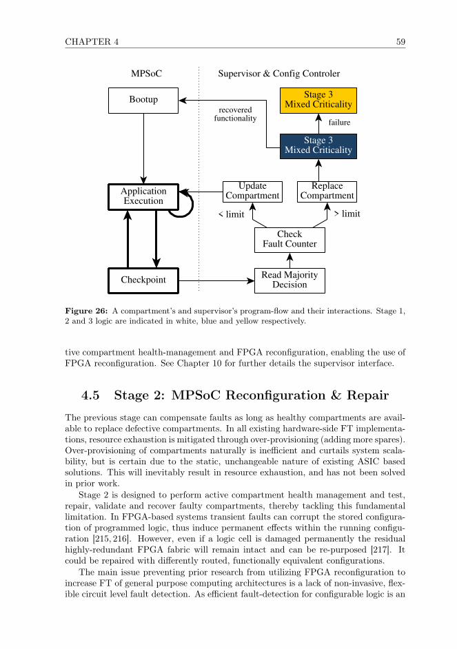
CHAPTER 4 59
MPSoC Supervisor & Config Controler
Bootup
Checkpoint
ApplicationExecution
Read MajorityDecision
CheckFault Counter
UpdateCompartment
Stage 3Mixed Criticality
ReplaceCompartment
Stage 3Mixed Criticality
< limit > limit
recoveredfunctionality failure
Figure 26: A compartment’s and supervisor’s program-flow and their interactions. Stage 1,2 and 3 logic are indicated in white, blue and yellow respectively.
tive compartment health-management and FPGA reconfiguration, enabling the use ofFPGA reconfiguration. See Chapter 10 for further details the supervisor interface.
4.5 Stage 2: MPSoC Reconfiguration & Repair
The previous stage can compensate faults as long as healthy compartments are avail-able to replace defective compartments. In all existing hardware-side FT implementa-tions, resource exhaustion is mitigated through over-provisioning (adding more spares).Over-provisioning of compartments naturally is inefficient and curtails system scala-bility, but is certain due to the static, unchangeable nature of existing ASIC basedsolutions. This will inevitably result in resource exhaustion, and has not been solvedin prior work.
Stage 2 is designed to perform active compartment health management and test,repair, validate and recover faulty compartments, thereby tackling this fundamentallimitation. In FPGA-based systems transient faults can corrupt the stored configura-tion of programmed logic, thus induce permanent effects within the running configu-ration [215, 216]. However, even if a logic cell is damaged permanently the residualhighly-redundant FPGA fabric will remain intact and can be re-purposed [217]. Itcould be repaired with differently routed, functionally equivalent configurations.
The main issue preventing prior research from utilizing FPGA reconfiguration toincrease FT of general purpose computing architectures is a lack of non-invasive, flex-ible circuit level fault detection. As efficient fault-detection for configurable logic is an
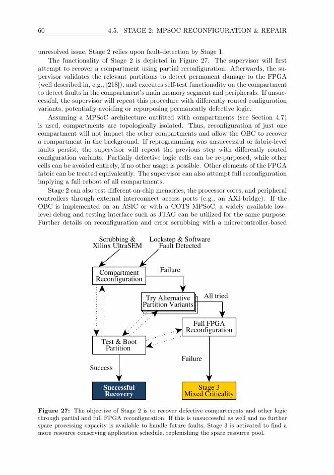
60 4.5. STAGE 2: MPSOC RECONFIGURATION & REPAIR
unresolved issue, Stage 2 relies upon fault-detection by Stage 1.The functionality of Stage 2 is depicted in Figure 27. The supervisor will first
attempt to recover a compartment using partial reconfiguration. Afterwards, the su-pervisor validates the relevant partitions to detect permanent damage to the FPGA(well described in, e.g., [218]), and executes self-test functionality on the compartmentto detect faults in the compartment’s main memory segment and peripherals. If unsuc-cessful, the supervisor will repeat this procedure with differently routed configurationvariants, potentially avoiding or repurposing permanently defective logic.
Assuming a MPSoC architecture outfitted with compartments (see Section 4.7)is used, compartments are topologically isolated. Thus, reconfiguration of just onecompartment will not impact the other compartments and allow the OBC to recovera compartment in the background. If reprogramming was unsuccessful or fabric-levelfaults persist, the supervisor will repeat the previous step with differently routedconfiguration variants. Partially defective logic cells can be re-purposed, while othercells can be avoided entirely, if no other usage is possible. Other elements of the FPGAfabric can be treated equivalently. The supervisor can also attempt full reconfigurationimplying a full reboot of all compartments.
Stage 2 can also test different on-chip memories, the processor cores, and peripheralcontrollers through external interconnect access ports (e.g., an AXI-bridge). If theOBC is implemented on an ASIC or with a COTS MPSoC, a widely available low-level debug and testing interface such as JTAG can be utilized for the same purpose.Further details on reconfiguration and error scrubbing with a microcontroller-based
Try AlternativePartition VariantsTry Alternative
Partition Variants
Lockstep & SoftwareFault Detected
CompartmentReconfiguration
Test & BootPartition
Try AlternativePartition Variants
SuccessfulRecovery
Full FPGAReconfiguration
Stage 3Mixed Criticality
Scrubbing &Xilinx UltraSEM
Failure
Success
All tried
Failure
Figure 27: The objective of Stage 2 is to recover defective compartments and other logicthrough partial and full FPGA reconfiguration. If this is unsuccessful as well and no furtherspare processing capacity is available to handle future faults, Stage 3 is activated to find amore resource conserving application schedule, replenishing the spare resource pool.

CHAPTER 4 61
proof-of-concept implementation for a nanosatellite are available in Chapter 5.If a defunct compartment can not be repaired through automated reconfiguration,
additional diagnostic information can be used for further analysis. The operator canutilize this information to conduct fault analysis on the ground, to craft a suitablereplacement configuration to avoid these areas. Of course, this implies extreme de-velopment effort but for many higher-priority space missions, the loss of a spacecraftmay be more costly than the engineering costs for saving the mission.
4.6 Stage 3: Applied Mixed Criticality
Stage 3 utilizes thread-level mixed criticality to extend an OBC’s lifetime once theprevious stages have depleted all spare resources. Its primary objective is to au-tonomously maintain system stability of an aged or degraded OBC at short notice toavert loss-of-mission and loss-of-subsystem, even if an OBC approaches the end of itslifetime. The operator can then define a more resource conserving satellite operationsschedule, sacrifice link capacity, or on-board storage space. Thus, dependability forhigh-criticality threads can be maintained by reducing compute performance, through-put, or increasing latency of lower-criticality applications.
The criticality of applications executed on an OBC can be differentiated by the im-portance of the controlled subsystem or relevance for commandeering the spacecraft.Performance degradation or even a loss of lower-criticality tasks aboard a satelliteis in general preferable to a loss of system stability for key applications. As threadgroups can be added and removed from compartment groups, and multiple compart-ment groups can coexist in the same MPSoC, individual threads can also be migratedbetween compartment groups [206]. Furthermore, the checkpoint frequency of a com-partment group can be reduced to increase a compartment’s computational capacity,or it can cease servicing low-priority interfaces.
The supervision logic is extended to reallocate thread-groups across the systembased upon the thread’s priority. Hence, if Stage 2 failed to reconfigure the OBC,the supervisor can generate new compartment-group assignments for threads withhigh priority and will attempt to retain existing assignments. Eventually, all healthycompartments will be saturated with threads, and no further assignments will bepossible. Then, it can either allocate more mappings, providing lower-priority threadswith less processing time to maintain availability, reduce the checking frequency, orleave them inactive. The OBC developer can decide at design time, which applicationswould benefit most from continuous operation with reduced performance or reliability,and which can be forgone.
In practice a satellite operator can use this functionality also to dynamically adjustthe performance of the MPSoC mid mission. This is achieved by adapting the dis-tribution of applications across compartments, the level of replication of applicationthreads, and the processing time allocated to individual application threads. The threeproperties, thus, are in competition to each other, as depicted in Figure 28. This ca-pability is analogous to the powersaving capabilities present in today’s mobile devicesand consumer desktop computers, where performance and energy consumption objec-tive compete. An optimal combination of these objectives exists only in theory, but inpractice would be very costly to obtain. For practical use, a set of “good enough butnon-optimal” can be achieved as at runtime autonomously using heuristics. Furtherinformation on Stage 3 including dynamic thread-mapping, as well as performance,

62 4.7. PLATFORM ARCHITECTURE
Figure 28: Our architecture allows the system properties of fault tolerance, performance,and energy consumption of an OBC to be adjusted at runtime. The spacecraft operator canprioritize one of these objectives, e.g., to achieve minimum energy consumption by sacrificingprocessing speed, while maintaining a given level of fault tolerance.
energy and robustness optimization at run-time is available in Chapter 6.In Figure 29, initially two compartment groups are executed on one MPSoC with 6
compartments. The first group consists of Ta and Tb executed on C0 – C2, to performhighly-critical platform management and control tasks. The second group performspayload data handling tasks and is initially run on C3 – C5, and runs its lockstep athalf the frequency as the higher critical group mentioned before. It consists of twothreads, with Tc acting as payload subsystem driver task of medium criticality, and acomputationally expensive low-criticality application Td performing data compression.In the first checkpoint cycle, a fault occurs on C5 which is detected after this groupexecutes its first checkpoint. No spare processing capacity is left to replace the failedcore with directly. C2, however, still has sufficient spare capacity to accommodateTc, but not Td. Tc is migrated to a separate, new compartment group and executedon compartments 2 – 4, thereby maintaining strong FT. The lower-criticality task Td
remains degraded. Therefore, Td will continue to run in DMR mode on the intactcores C3 and C4, which only allows fault-detection in the future.
4.7 Platform Architecture
Our multi-stage FT-approach is in principle platform independent and can be im-plemented within any multi-threading capable OS supporting interrupts and timers.For most COTS-MPSoC based nanosatellites in a LEO orbit, stage 1-3 alone offersufficient fault coverage. Aboard such spacecraft, MPSoC interfaces are either unpro-tected or protected programmatically and outside the MPSoC (e.g., using EDAC chipsor by resolving SEFIs through power cycling). Aboard larger, more critical spacecraft


64 4.7. PLATFORM ARCHITECTURE
is meant to be implemented within an FPGA to counter resource exhaustion whenmitigating faults in Stage 1. It utilizes simple redundancy to compensate for SEFIs,but does not contain radiation-hard or FT processor cores or custom logic. Eachcompartment is equipped with a processor core, an interrupt controller (IRQ in thefigure), a dedicated on-chip memory slice used as state memory, and several peripheralinterfaces through the local interconnect. Compartments are connected through anI/O memory management unit (IOMMU) and a global interconnect to main- and non-volatile memory. They can not access the local interconnect of other compartments toprevent interference and minimize shared logic. This compartmentalized architecturebenefits from partial reconfiguration, as compartments can be placed strategically onan FPGA’s fabric along partition borders. Our approach and this architecture supportmulti-FPGA and -ASIC MPSoCs without adaptation, thereby improving scalabilityand resilience against FPGA-level SEFIs.
The ECC-protected dual-port state memory in each compartment holds the currentcompartment-status, thread assignments, as well as the checksums and state informa-tion. One interface is connected to the compartment’s local interconnect, while thesecond port is read-only accessible via the global interconnect. The state memoryis inherently redundant, as threads are executed on at least two compartments. The
MPSoC
Compartment
MEMSCRUB
MCTLR
MCTLR
DebugBridge MMU
X
DDRMemory
MemoryScrubber
Non-VolatileMemory
X
StateMemory
MemoryScrubber
Core IRQInterfaces
Off-ChipSupervisor
Core 0 Core 1 Core 2
Core 7Core 4 Core 5 Core 6
Core 3
RO
Figure 30: A simplified representation of the presented MPSoC with memory controllershighlighted in yellow, scrubbers in green, and interconnect in blue. A dedicated interface oneach compartment allows supervisor access.
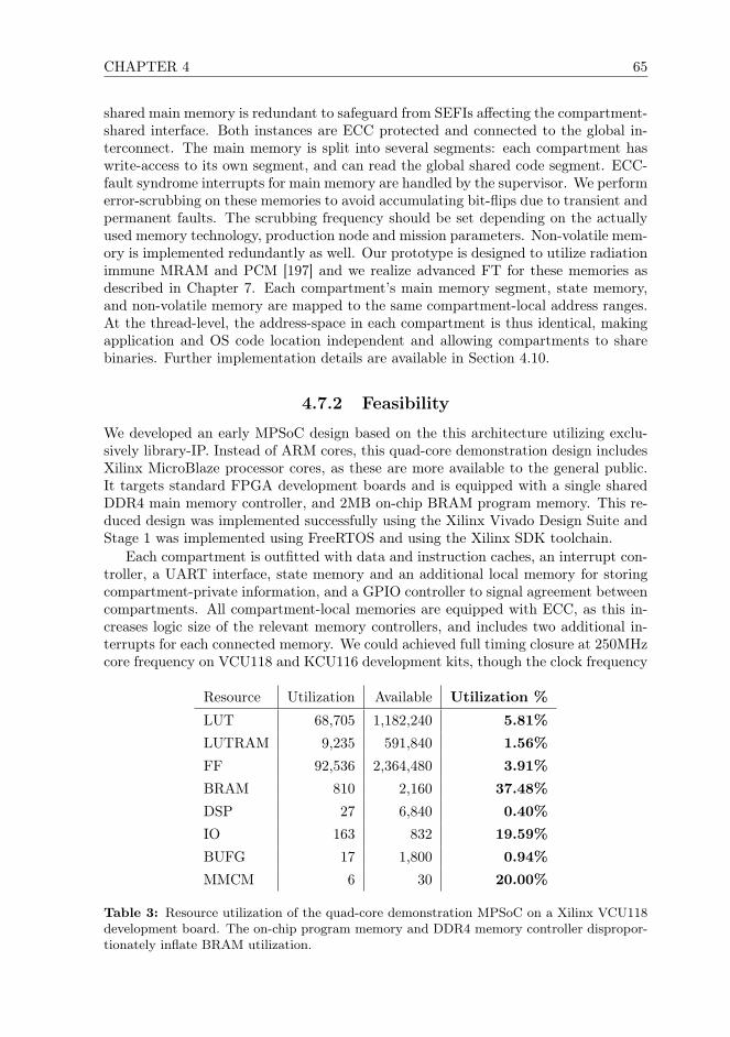
CHAPTER 4 65
shared main memory is redundant to safeguard from SEFIs affecting the compartment-shared interface. Both instances are ECC protected and connected to the global in-terconnect. The main memory is split into several segments: each compartment haswrite-access to its own segment, and can read the global shared code segment. ECC-fault syndrome interrupts for main memory are handled by the supervisor. We performerror-scrubbing on these memories to avoid accumulating bit-flips due to transient andpermanent faults. The scrubbing frequency should be set depending on the actuallyused memory technology, production node and mission parameters. Non-volatile mem-ory is implemented redundantly as well. Our prototype is designed to utilize radiationimmune MRAM and PCM [197] and we realize advanced FT for these memories asdescribed in Chapter 7. Each compartment’s main memory segment, state memory,and non-volatile memory are mapped to the same compartment-local address ranges.At the thread-level, the address-space in each compartment is thus identical, makingapplication and OS code location independent and allowing compartments to sharebinaries. Further implementation details are available in Section 4.10.
4.7.2 Feasibility
We developed an early MPSoC design based on the this architecture utilizing exclu-sively library-IP. Instead of ARM cores, this quad-core demonstration design includesXilinx MicroBlaze processor cores, as these are more available to the general public.It targets standard FPGA development boards and is equipped with a single sharedDDR4 main memory controller, and 2MB on-chip BRAM program memory. This re-duced design was implemented successfully using the Xilinx Vivado Design Suite andStage 1 was implemented using FreeRTOS and using the Xilinx SDK toolchain.
Each compartment is outfitted with data and instruction caches, an interrupt con-troller, a UART interface, state memory and an additional local memory for storingcompartment-private information, and a GPIO controller to signal agreement betweencompartments. All compartment-local memories are equipped with ECC, as this in-creases logic size of the relevant memory controllers, and includes two additional in-terrupts for each connected memory. We could achieved full timing closure at 250MHzcore frequency on VCU118 and KCU116 development kits, though the clock frequency
Resource Utilization Available Utilization %
LUT 68,705 1,182,240 5.81%
LUTRAM 9,235 591,840 1.56%
FF 92,536 2,364,480 3.91%
BRAM 810 2,160 37.48%
DSP 27 6,840 0.40%
IO 163 832 19.59%
BUFG 17 1,800 0.94%
MMCM 6 30 20.00%
Table 3: Resource utilization of the quad-core demonstration MPSoC on a Xilinx VCU118development board. The on-chip program memory and DDR4 memory controller dispropor-tionately inflate BRAM utilization.


CHAPTER 4 67
Resource utilization is indicated in Table 3, with more details given in Section 4.10.Stage 2 and 3 do not require additional FPGA logic.
This design’s very low logic usage shows that the architecture itself can be scaled to8 and more compartments comfortably, and most current-generation FPGAs offer anabundance of unused resources for Stage 2. With current-generation FPGA platforms,Stage 2 will thus not only be able to recover defective compartments using spareresources, but could even place multiple compartments as cold or hot spares. TheMicroblaze cores utilized here for demonstration purposes can directly be replacedwith more powerful processor cores, assuming the necessary peripheral IP is added aswell (e.g., an ARM GIC instead of the MicroBlaze Interrupt Controller).
4.8 Discussions
The reliability of each individual compartment’s voting decision can be weak, and anindividual compartment can report false (dis)agreement with its siblings. Our ap-proach takes into account that any software or hardware component associated withina compartment can fail arbitrarily. Such failure is mitigated through a distributed de-cision, which is taken based on each compartment’s perspective of its siblings. Thus,this approach does not require the checksum logic to compute correctly, and we as-sume that faults may occur at any time during the lifetime of a compartment. Ascompartment groups usually consist of three or more compartments, the likelihoodof false-disagreements or non-reported disagreement is insignificant. To mask such afault, multiple faults would have to coincide in a majority of compartments within thesame compartment group during a single checking period and induce the same fault.The probability for such an event is extremely low, except at very high radiation levels.Even in such situations, such faults would be detected after the subsequent checkpointwith near certainty.
Prior research proves the conceptual effectiveness of thread-based FT [88,200] andsoftware-based FT combined with simple I/O voting [201]. Also, the detailed FTcapabilities of a platform utilizing our approach are influenced by the actually usedFPGA, ASIC or COTS-MPSoC design. These imply mainly design decisions and avarying acceptance of single-points-of-failure. Schedulability, timing conformity, anddeadlock-avoidance have been extensively researched in literature, e.g., in [210]. Thus,what remains to be shown is the runtime performance overhead induced by the pre-sented approach, as the main objective of our research is to enable the efficient useof high-performance mobile-market COTS MPSoCs within satellite computers. Toachieve worst-case performance estimations, we developed a naive, unoptimized im-plementation of the Stage 1 of our approach, as the others do not affect the runtimeperformance of the MPSoC. This naive implementation shows a median-best perfor-mance degradation of 9% and median-worst degradation of 26% on compartmentswith a single processor core. Further information on the conducted tests is availablein Section 4.10, as well as performance measurements for 6 different application scenar-ios modeled after the NASA/James Webb Space Telescope’s Mid-Infrared Instrument(MIRI) [219].
As prior thread-level FT implementations [199, 200, 208] are based upon funda-mentally different concepts, only address transient faults within a very limited scope,and are deeply embedded into proprietary OS, their fault coverage and performancecan not be directly compared. However, the measured performance overhead does fall
68 4.9. CONCLUSIONS
within the same range as measured in [199], and we also observe comparable average-case performance. To put these measurements into context, even a 50% slowdownon modern MPSoCs will offer a factor-of-5 performance increase over state-of-the-art radiation-hardened processor designs, thereby showing a favorable cost-vs-benefittrade-off.
4.9 Conclusions
In this chapter, we presented the first practical and integral multi-stage approachto fault-tolerant (FT) general purpose computing for spaceflight use. The approachexplicitly does not utilize radiation-hardened or hardware-FT processor cores and uti-lizes no central MPSoC-internal voting logic. It can thus be implemented within COTSMPSoCs or alternatively entirely with non-FT, standard library IP-cores available inFPGA or ASIC design software. In contrast to prior research, the presented approachconsiders the full and realistic fault-model for space computing, and operates withinreal-world constraints. The approach does not require failure-free components withinan MPSoC or in the OS, and does not leave conceptual gaps, e.g., regarding faultdetection and recovery. It is not based upon traditional radiation-hardened processorcores and does not achieve fault tolerance through hardware-measures.
We showed that our approach is programmatically simple and requires little cus-tom code, which can also be implemented in most pre-existing multi-threading capableOS. Faults can be detected and mitigated using application provided routines, enablingdecisions about an application’s integrity to be taken by the application developersthemselves. As a consequence, the system designer no longer must struggle to assessthe health of each individual application’s state, and instead can focus on determiningan optimal solution to problems at hand. It allows flexible fault-detection, mitigationand recovery within COTS MPSoCs, laying the foundations for FT computing aboardminiaturized satellites, and helping to bridge the gap between theoretical embeddedresearch and practical implementation in the space industry. While remaining flex-ible, and inducing only a minimal performance overhead, the presented multi-stageapproach offers time-bounded real-time guarantees.
The approach can be well complemented with several other reliability-improvingmeasures which were integrated into the outlined reference MPSoC architecture. Pre-liminary benchmark results of an unoptimized implementation show a low performanceoverhead, suggesting a beyond factor-of-5 performance increase over state-of-the-artradiation-hardened processors for space use. Our approach allows the host platform toscale vertically (more powerful processor cores and more interfaces per compartment)as well as horizontally (more compartments), with virtually any modern processorcore. Thereby, we aim to increase acceptance for software-side FT approaches in thespace industry, building trust in hybrid hardware-software architectures. Thus, ourapproach is the first integral, real-world solution to enable the fault-tolerant appli-cation with modern MPSoC designs for critical satellite control applications, therebyenabling the use of such SoCs in future high-priority space missions.

CHAPTER 4 69
4.10 Annex: Worst-Case Performance Estimation
To achieve worst-case performance estimations, we developed an unoptimized imple-mentation of the first stage of our approach in C to be run in user-space. The providedbenchmark results were generated based on code derived off a special CCD readoutprogram used for space-based astronomical instrumentation. The application was ex-ecuted with a varying amount of data processing runs in a compartment group at theindicated checking frequencies, and without protection for reference.
4.10.1 Implementation Outline
This implementation was written in approximately 800 lines of user-space C-code in-cluding benchmark facilities. It utilizes system calls and the POSIX threading libraryto simulate compartments and thread management. Thread-management at this levelis computationally much more expensive than if performed bare-metal or in kernel-code. A bare-metal implementation within an operating system reduces this perfor-mance overhead drastically. This implementation therefore allows very pessimisticbenchmarking, which can yield a baseline for the lockstep’s performance cost. Theimplementation also serves as an excellent simulator to validate the correctness of thedescribed logic, and allows better debugging than on the actual MPSoC implementa-tion.
4.10.2 Test Application
Synthetic, widely used benchmark suites are unsuitable to benchmark OS-level func-tionality. Thus, we derived a demo-application off an astronomical instrumentationapplication. We chose to utilize the background scenario of scientific computing, asdevices for scientific instrumentation are usually better documented. The programflow of our demo application is based on the NASA/James Webb Space Telescope’sMid-Infrared Instrument (MIRI) described in [219]. This program continuously readsthree 16-bit 1024x1024 false-color sensor arrays, stores, and processes the results. Itaverages multiple captured frames to optimize the instruments exposure time andavoid pixel saturation, or to capture faint astronomical sources [219].
4.10.3 Methodology and Test Setup
The setup simulates an MPSoC three compartments executing the described demoapplication, and measures performance of the application executing within a com-partment. For each plot in Figure 32, 100 measurements were taken of the real-timenecessary to process 600 1-Megapixel frames with subsequent processing runs. Dataheavy modes indicate a high amount of post-processing runs, whereas compute-heavymodes indicate lower per-thread workload.
• Very Compute Heavy: 60000 Postprocessing Runs
• Compute Heavy: 75000 Postprocessing Runs
• Balanced Compute Heavy: 90000 Postprocessing Runs
• Balanced Data Heavy: 105000 Postprocessing Runs
70 4.10. ANNEX: WORST-CASE PERFORMANCE ESTIMATION
• Data Heavy: 135000 Postprocessing Runs
• Very Data Heavy: 150000 Postprocessing Runs
Benchmark results were generated on a Intel Core I7-2600K Sandy Bridge-basedsystem with a host kernel’s scheduling frequency of 1kHz (CONFIG_HZ_1000). Hyper-Threading and SpeedStep was disable to avoid interference between threads. Binarieswere compiled with GCC 6.3.1 (20161221) without compiler optimization (-O0).
4.10.4 Results
This naive implementation of our approach at the application level on Linux showsmedian-best performance degradation of 9% and median-worst degradation of 26%,which are also indicated in Figure 32a and e in bold. Across all test runs, we measuredon average 80% worst-case and 95% best-case performance compared to the unpro-tected reference runtime. The violin plots – shadows around the box-plots – indicatethe distribution of the measurements to depict the accumulation of the individualmeasurements.
As expected, the performance varies depending on workload, with data-heavy tasksa-c showing better performance. This too was expected as Stage 1’s code consistsmainly of integer operations, binary comparisons, load/stores, and jumps. Betterperformance can be expected in a more optimized implementation at the kernel leveldue to a reduced computational cost of operations that in userland require systemcalls. To put these measurements into context, even a 50% performance degradationon modern MPSoCs will offer a factor-of-5 performance increase over state-of-the-artradiation-hardened processor designs.
Assuming an average performance degradation between 10% and 20% at such ex-treme checking frequencies, our approach can thus allow a modern MPSoC to performbetter than comparable state-of-the-art hardware-voting based processor solutions,while requiring no proprietary processor design, offering full software-control at afraction of the development effort and costs. And in contrast to existing hardware-based fault tolerance solutions, our architecture does not struggle against feature-sizereduction, but scales up with technology and benefits from more modern productionnodes.
The lockstep was run with very high checkpoint frequencies (20hz, 2.5hz and1.25hz) which during normal operation will most likely never be used. For most LEOapplications, we expect that checkpoints would be run only every 5 to 10 seconds. Fur-thermore, system calls and thread-management on high-performance mobile-marketprocessor cores can be much less costly than when run on desktop hardware. Real-istically, this would implying very little performance cost ranging from 0.5% to 2%overhead.

CHAPTER 4 71
(a) Data-Heavy (b) Very Data-Heavy
(c) Balanced Compute-Heavy (d) Balanced Data-Heavy
(e) Very Compute-Heavy (f) Compute-Heavy
Figure 32: Performance measurements of 6000 runs for processing 100 1024x1024 pixel CCDframes with different checkpoint frequencies and workloads.

72 4.10. ANNEX: WORST-CASE PERFORMANCE ESTIMATION

74 5.1. INTRODUCTION
5.1 Introduction
Nano- and microsatellites have evolved from purely educational projects to fit a diverserange of commercial and scientific use-cases. This class of satellites can do so by com-bining rapid development, reduced design complexity, low manpower requirements,and minimal cost through a reliance on commercial off-the-shelf components (COTS).Modern embedded technology enables a high level of compute performance at the costof little energy. Miniaturized satellite development has begun to rely upon conven-tional application processor architectures as well as FPGAs. Hence these satellites cannowadays offer an abundance of storage capacity and compute performance [220].
CubeSats have proven to be both versatile and efficient for various use cases. Theyhave also become platforms for an increasing variety of scientific payloads and com-mercial applications [32]. However, such missions require an increased level of depend-ability in all subsystems compared to educational vessels, especially to enable their usewithin critical missions and for such with prolonged lifetime requirements. Currently,miniaturized satellites are plagued by low dependability, and will be requiring failuretolerance and reliability enhancing measures in the future. Due to the limited bud-get, mass and volume restrictions within miniaturized satellite projects, such measuresusually must be achieved using means beyond replication and redundancy.
Data storage and processing applications can be protected using architectural andsoftware side approaches, combining them into hybrid solutions. However, even utiliz-ing such hybrid concepts, component level failure tolerance remains limited using onlyCOTS hardware. Acceptance of eventual failure of an on-board computer (OBC) dueto issues beyond the control of the deployed flight software without a viable recoverystrategy in place is a tolerable approach for educational satellites. However, especiallywhen deployed in larger quantities (e.g., constellations), failure diagnostics and recov-ery measures that do not require the active cooperation of an OBC or its operatingsystem should be available.
In contrast to larger vessels, the use of chip-level debug functionality aboard minia-turized satellites has up until now largely been restricted to the development and test-ing phases. During system development and testing on the ground, low-level debuginterfaces are usually used for diagnostics, debugging and failure analysis, providingchip-level access to satellite hardware. However, such functionality often lays dor-mant once the satellite has been deployed or is not even activated in a satellite OBC’sflight model. Thus, debugging functionality has rarely been utilized in-orbit aboardCubeSats, as the necessary protocols could not be implemented over the unreliablelow-bandwidth links without major effort.
Few nanosatellite projects possess the manpower and time to implement sophisti-cated failover functionality and testing effort until a very late phase during develop-ment when facing non-trivial bugs. Many CubeSat developers also are unaware of thechallenges of hardware development, and therefore ignore low-level debug functional-ity in satellite design altogether. In contrast to debugging capabilities, flight softwarereprogramming functionality is usually desired aboard nanosatellites. Hence, severalCubeSats were equipped with simple proprietary update solutions [221–223]. Eventhough the capabilities of these concepts were limited with little re-use potential, theyunderlined the importance of software-independent chip-level debug functionality suchas JTAG [6].
Hence, began exploring how a miniaturized satellite’s saving subsystem could be
CHAPTER 5 75
outfitted with chip-level debugging capabilities in late 2014, and developed a conciseconcept in early 2015 and implemented the prototype described in this chapter inlate 2015. We designed this subsystem to enable extensive debugging and analysissupport for the MOVE-II CubeSat [Fuchs13], as prior experiences in the field andespecially in the FirstMOVE predecessor CubeSat showed that this functionality iscritical [Fuchs17]. It is designed to support testing, verification, and debugging onthe ground as well during a space mission. It offers scripting support through theuse of STAPL [224] bytecode which is then translated into JTAG operations using aSTAPL virtual machine, thereby offering near universal test-target support. Hence,the subsystem’s software can remain static at run-time and does not need to be changedthroughout a space mission. The multi-stage fault tolerance architecture describedin Chapter 4 is a direct evolution of the concept described in this chapter. In theremainder of this thesis, this saving subsystem also takes on the role of the MPSoC’ssupervisor, integrating most of the usage concepts described in Section 5.4.
In the next section, we will analyze how and why debugging at chip level canhelp improve dependability. We outline why this functionality up until now is largelyunavailable aboard miniaturized satellites, and what functionality is required to im-plement such a saving subsystem. Section 5.3 then contains a description of our workand offers insight into several key aspects of the developed concept. Afterwards, usecases beyond mid-mission debugging are presented in Section 5.4. We discuss plansfor future work and present our conclusions in the final two sections.
5.2 Debugging and Reliability
Testing and error diagnostics are critical tasks during hardware development, and thusalso when developing nanosatellites. While larger spacecrafts’ OBCs have extensivedebugging support, CubeSats usually offer no equivalent functionality and, if at all, re-sort to creative ad-hoc testing solutions. Most such solutions can not deliver equivalentfunctionality to the comprehensive set of testing and debugging features often encoun-tered within COTS hardware or aboard larger spacecrafts. Besides functionality, thereliability and universal usability of these solutions is often insufficient, resulting in fewCubeSats fielding any form of software-independent mid-mission capable fault analysisfunctionality. In consequence, few CubeSats nowadays offer sufficient fault detection,isolation and recovery functionality (FDIR) to reliably detect and recover from hard-or software malfunctions.
Most system-on-chip architectures, FPGAs, and many other ICs provide JTAG testaccess ports (TAPs) [6]. Originally developed for circuit testing, JTAG nowadays is thede-facto standard chip-level debugging interface and is widely used in electronics forlarger satellites. Hence, JTAG is an ideal interface for sophisticated fault detection,isolation and recovery in case of component failure. In addition, it can be utilizedto update an OBC’s software, firmware, as well as to control and reconfigure theprogrammable logic of an FPGA. We argue that chip-level debugging is currently notwidely used because there are no readily available CubeSat-compatible solutions thatcan be adapted to a wide variety of different designs.
The properties of the communication bands utilized for commandeering aboardcontemporary CubeSats (usually UHF and VHF, see Chapter 3), the constrained up-and downlink availability, and the low bandwidth make mid-mission debugging chal-lenging. As discussed in Chapter 3, these restrictions result in constrained data rates

76 5.3. IMPLEMENTATION DETAILS
around tens of kbps, even if strong error correction is utilized. As ground stationnetworks and satellite relay systems at the time of writing are not accessible to ordi-nary nanosatellites, debugging and error diagnostics must be conducted fully remotely.JTAG requires bi-directional real-time communication and is sensitive to timing is-sues, aspects which are not suitable for satellite links in general and especially thelinks available aboard miniaturized satellites. Hence, the chip-level debugging mustbe decoupled from the satellite link, so that live-interaction during debug sessions onlyhappens locally within the spacecraft.
STAPL scripts can be executed autonomously and perform all timing-critical oper-ations locally within the space segment. Thereby, we can terminate the timing-criticalaspects of chip-level debugging while minimizing link congestion. The saving subsys-tem described in this chapter can, thus, efficiently operate even via a lossy, unreliablevery-low-bandwidth communication channel. It can operate even in environments withelevated radiation levels, requires little PCB space, low power and entails minimal cost.
5.3 Implementation Details
The main objective of the research described in this chapter is to improve overallreliability and survivability of a spacecraft. Hardware complexity has been a majorissue in CubeSat projects, often resulting in oversimplified systems due to lack ofexperience and sometimes even in overly complex systems due to uncontrolled featurecreep. Due to the absence of sophisticated FDIR functionality, even minor hardwareand software may cause a CubeSat to become unrecoverable.
In the remainder of this section, we will discuss the MOVE-II CubeSat specificimplementing of our saving subsystem using an Microchip/Atmel SAM7SE MCU.However, it should be noted that besides the hardware choices outlined in this chapter,there are numerous other MCUs which could be utilize instead. Originally, the thissaving subsystem was intended to integrate into an existing Spartan 6 LX45 FPGAon MOVE-II’s transceiver module. However, due to the densely populated transceiverboard and insufficient FPGA resources on the LX45, a microcontroller (MCU) basedimplementation was developed instead.
In the context of this thesis, we instead chose to utilize a radiation-robust TIMSP430FR MCU, as we describe further in Chapters 9 and 10. A SAM7SE offersconsiderably more performance than an MSP430FR MCU. However, the tasks thissaving subsystem is meant to perform within the architecture described in Chapter4 require little performance, and MSP430FR MCUs have been shown to performexceptionally well under radiation [225].
5.3.1 Hardware Requirements
The saving subsystem can be implemented with comparably basic hardware, however,we must also consider assuring integrity of the subsystem itself. MRAM [150] andphase-change memory (PCM) [226] both are ideal technologies for holding saving sub-system’s code and stack segments, as their storage cells are radiation immune. At thetime of this writing, no affordable highly-reliable nanosatellite-compatible hardwarethat could be used to implement the presented saving subsystem is available. Thus,we have to resort to utilizing COTS MCUs and minimize fault potential. This MCUmust provide the following functionality:

CHAPTER 5 77
• an external memory interface to attach a parallel magnetoresistive RAM (MRAM[150]) to contain the saving subsystem’s code, or an MCU with internal MRAM.However, we are unaware of the existence of COTS MCUs equipped with suffi-cient MRAM.
• A second memory interface will be needed to access flash memory to store largerchunks of data such as FPGA configurations operating system updates. OncePCM or STT-MRAM with larger capacities [227] becomes widely available, thesaving subsystem could also be implemented using just one large memory IC.
• The saving subsystem does not require a real-time clock, as we intended thesaving subsystem to be as static and stateless as possible. However, we still mustassure precise timing for certain operations requiring at least a counter/timer.
• We also must be able to interface with at least one JTAG chain which we canbest achieve using a set of general-purpose I/O pins. The capability to accessadditional JTAG chains enables more advanced usage scenarios.
The program code of the saving subsystem resides in a write-protected MRAMregion, whereas the stack segment will be kept within a separate writable region.Thus, faults in the running system’s state can be resolved through a reboot in manycases. In consequence, it can then resolve or remove leftover information from the(corrupted) previous system state and thereby recover to a consistent system state.The saving subsystem’s (runtime-static) firmware, in turn, can be protected fromcorruption through erasure coding as described in Chapter 7. Redundancies for MCUand memories can be added as necessary, and are omitted from this chapter for thesake of briefness.
5.3.2 STAPL Scripts and Commandeering Interface
The subsystem offers extensive scripting support through the use of the STAPL script-ing language, which is then translated into JTAG operations using a STAPL virtualmachine [6, 224]. Hence, the saving subsystem’s program code can remain static atrun-time requiring no modification to the virtual machine’s code. As the STAPLscripting language is Turing-complete1, it can be utilized to implement arbitrary se-quences of JTAG operations in the form of STAPL scripts, achieving code separationand time triggered execution. By using STAPL scripts, we can thus avoid timing crit-ical aspects of chip-level debugging aboard the satellite while minimizing link conges-tion. Thereby, the saving subsystem can be efficiently operated even over a unreliablevery-low-bandwidth communication channel, which would otherwise make chip-leveldebugging infeasible.
We chose to utilize the STAPL bytecode format [224] to minimize script- and code-size while retaining flexibility. These scripts as well as all relevant program code andstate information must reside within radiation tolerant MRAM. Even though STAPLbytecode is more compact than the text based equivalent, experiments have shownthat more complex scripts can still become as large as 50kB.
Due to the limited memory capacity in MRAM, only few scripts can be uploadedto and stored permanently within the STAPL machine. For the sake of simplicity, we
1in our context it most importantly supports recursion and jumps

78 5.3. IMPLEMENTATION DETAILS
ProcessReceiveQueue
Sleep
EvaluatePacket
InitializeSlot
Check PendingPackets
CheckChunk
Integrity
WriteChunk to
Slot
VerifyScript
Integrity
PurgeState
CheckBlock
Integrity
WriteBlock to
Flash
VerifyBlock
Integrity
Check SlotContent
Add toPendingQueue
Verifyall SlotsIntegrity
ExecuteScript
EnqueueReturnData
Check PendingScripts
CheckPacket
Integrity
RebootOutputSlot IDs
AttemptTransmit
ProcessTransmit
Queue
Interrupt
UploadScript
MultipartScript Chunk
Reset UploadData Block
Slot toQueue
IdentifySlots
Figure 33: A visualization of the saving subsystem’s program flow and commandeeringprotocol we developed around the Altera JAM player.
utilize a compile-time space distribution, creating a fixed number of identically sizedscript slots. Each slot can only hold one script, even if the script does not utilize entireentire capacity of a slot. The original implementation of this saving subsystem utilized2MB of MRAM, and we implemented 10 x 50kB sized slots leaving 1.5MB of MRAMfor the stack and code segments.
In the current implementation, slot allocation is managed at the ground segmentby the satellite operator and we currently support only equally sized slots. A poten-tial future optimization would be to utilize differently sized slots (e.g., 5×10kB slots,5×50kB slots, 2×100kB slots), to achieve better resource utilization. We implementedstatic slot management to minimize code-complexity and failure potential.
Slots are identified by a CRC16 checksum used as reference for commandeering,and also for integrity checking of an individual script. This checksum is uploaded witheach new script, and verified once the transfer of all script-parts has been concluded.
An additional identifier beyond this checksum is unnecessary. The low number ofscripts minimizes the chance of checksum-collisions due to the birthday paradox [228],Operators can avoid collisions altogether through padding scripts on the ground.
Scripts are directly committed to a slot and then checked for integrity to mini-mize data duplication and resource usage. Hence, we can assure that only uniquelyidentified, correctly and completely uploaded scripts will be executed.

CHAPTER 5 79
5.3.3 Transfer of Large Scripts and Data Housekeeping
The maximum frame size supported by the communication modules of most nanosatel-lites is considerably smaller than the script size, hence the saving subsystem supportsmultipart transfers for scripts and other data. A multipart script transfer initializationpacket contains the intended slot ID to be overwritten, the expected script checksumand size, as well as the chunk size. The initialization packet also provides a nullterminated array of checksums for each to be expected chunk.
For each active multipart transfer, the saving subsystem retains a list of missingframes. It notifies the ground station in case the final missing chunk has been received,or upon command. For slots, this information is stored within the slot header. Laterpackets indicate the chunk-offset, to facilitate simple retransmission.
FPGA configuration variants and software updates for the OBC can be as largeas several megabytes. Hence, they must be stored in dedicated heap memory andmultipart transfers of such data is conducted akin to multi-part scripts. We decidedto perform allocation and data management on the ground, instead of implementingdynamic heap memory management. Again, this implementation decision was madeto minimize software complexity and failure potential. As all operations executed bythe saving subsystem must be pre-planned by the operator, more advanced allocationmechanisms do not result in operational advantages.
We utilize flash memory to store larger data volumes outside of the script-slots asneither PCM nor larger MRAM chips are currently widely available. As this data isnot executed, we can utilize flash memory and store the data using erasure coding insoftware. However, in STAPL scripts all payload-data is usually encoded inline andcannot be omitted without modifications to the scripting language syntax.
For this purpose, we extended the STAPL syntax to also support references toexternal data. We replace inline data with a reference to data in flash, which can thenbe uploaded independently. Therefore, the STAPL Bytecode player was modified tomake it capable of side-loading auxiliary data.
The results of scripts, e.g., kernel dumps, system state information and other di-agnostics data, are thus also held in flash memory until they can be transmitted tothe ground station. Script execution can be triggered in bulk, hence outgoing packetsare being stored in a FIFO queue for transmission. A more detailed representation ofthe saving subsystem’s program flow is provided in Figure 33.
To safeguard against data corruption due to space radiation effects (single- andmulti-event upsets), coarse symbol level Reed-Solomon erasure coding [229] will beapplied when writing to flash memory [230]. As flash memory with comparably lowdensity is utilized, no additional layers of erasure coding are necessary but could beimplemented, see Chapter 7. Reasons for utilizing higher-density flash memory maybe the requirement for storing more partial reconfiguration partition variants to coverthe increased number of permanent faults that can be expected in space missions withlonger duration, or to provide feature-diversity as described in Section 5.4.3.
5.3.4 Integration into an On-Board Computer
Our current saving subsystem implementation consists of an ARM7TDMI MCU withan OBC-independent communication channel toward the CubeSats transceiver or sav-ing subsystem as depicted in Figure 34. We chose to utilize an interrupt-driven bi-directional SPI-based interface to implement this channel due to its flexibility and

80 5.3. IMPLEMENTATION DETAILS
simplicity. Also, this interface is less prone to implementation issues than I2C, how-ever there are many other alternatives and the saving subsystem’s concept does notforesee a specific interface. The saving subsystem is attached to a single four pinnedJTAG chain, containing all to be debugged JTAG enabled devices. Due to abundantlyavailable GPIO pins, additional JTAG chains could be attached with ease once thesoftware has been adapted.
The Microchip/Atmel SAM7SE MCU is able to boot from memory attached to itsexternal interface, has excellent toolchain support, documentation and minimal energyconsumption. Attached to the external memory interface are an Everspin 2MB MRAMmemory chip as well as 16MB of NAND Flash. The MRAM chip is connected to the16-bit memory interface and used to store the program code, scripts, and also servesas main memory. The use of the SAM7SE’s internal memories is avoided wheneverpossible since radiation hardness cannot be achieved here. Only the MRAM addressranges used as main memory and for STAPL scripts and the stack segment are writableby software, all the rest of the memory is set read-only through the ARM7TDMI’sMPU.
Microcontroller
OBCCOM/Redwave
MRAM Module Flash Module
Auxiliary Data
• Firmware Updates • FPGA Configurations• Fallback Configuration
Debugger Output
• Return Data• Script Output• Error Log
Program Code and State
• Code (RO)• Global Variables• Stack
Script Handling
• Script Slots• Multipart Session Data• Sideloading References
JTAG
16 Bit EBI SPI
Figure 34: A component-level view of the saving subsystem.


82 5.4. USE CASES BEYOND DEBUGGING
5.4 Use Cases beyond Debugging
While the presented subsystem was developed primarily for FDIR reasons, there areseveral additional use-cases that were considered during design. The saving subsystemcould be extended with additional functionality or may even be used outside of itsoriginally intended usage scenario aboard a spacecraft. Hence, we dedicate this sectionto discuss other use cases for this saving subsystem beyond traditional LEO CubeSatapplications.
The main limitation of the saving subsystem within a CubeSat application scenariois storage capacity and buffer size to return data via a satellite link. However, theselimitations mainly affect the following capabilities:
• size and number of slots available within the saving subsystem,
• storage space for referenced data such as FPGA configurations and
• to-be-returned information and logs, and finally the
• total size of FPGA configurations.
For ground applications and even aboard vessels only slightly larger than 1U Cube-Sats, these restrictions can easily be lifted.
5.4.1 Watchdog Integration
The saving subsystem can be interfaced with a watchdog to achieve extended func-tionality. This watchdog could notify the saving subsystem about malfunctions withinother components of the OBC. The saving subsystem could then begin recovery mea-sures, enabling considerably better fault-recovery and logging possibilities than theusual reset triggered by CubeSat watchdogs. Instead of directly rebooting the OBCinto a (presumably) safe mode, the saving subsystem can first collect relevant log in-formation (i.e. retrieve register contents and a stack-trace). Once this information hasbeen stored, it can then be directly reported to the ground station. Also, this func-tionality could be adapted, e.g., to take into account known permanent faults thatmay have occurred in a previous mission phase.
We have not yet implemented this functionality, as the described logic first wouldhave to be written as STAPL script and is highly hardware and software dependent.To avoid the saving subsystem’s return-buffer from being flooded with crash-logs incase of frequent or repeated crashes, additional logic must be implemented. A simplemitigation method would be a message queue implemented as a ring buffer. Then onlya fixed number of diagnostics messages would be retained at any given time, assuringthat only the most recent logs are retained and transmitted to the ground.
As watchdog functionality is usually rather simple, it could also be provided by thesaving subsystem itself. Integrated watchdog functionality would only require minimaladditional code and could be combined more efficiently with the script-driven statemachine. However, such functionality is usually considered critical and malfunctionsof the watchdog code within the saving subsystem could cripple the rest of the OBC.Hence, watchdog functionality should only be integrated if a suitable interface setupcan be achieved, as described see Chapter 10).
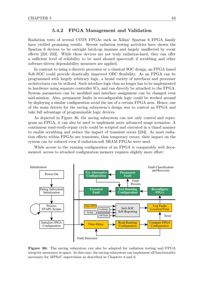
CHAPTER 5 83
5.4.2 FPGA Management and Validation
Radiation tests of several COTS FPGAs such as Xilinx’ Spartan 6 FPGA familyhave yielded promising results. Recent radiation testing activities have shown theSpartan 6 devices to be outright latch-up immune and largely unaffected by eventeffects [231–233]. While these devices are not truly radiation-hard, they can offera sufficient level of reliability to be used aboard spacecraft if scrubbing and othersoftware-driven dependability measures are applied.
In contrast to using a discrete processor or a classical SOC design, an FPGA basedSoft-SOC could provide drastically improved OBC flexibility. As an FPGA can beprogrammed with largely arbitrary logic, a broad variety of interfaces and processorarchitectures can be utilized. Such interface logic thus no longer has to be implementedin hardware using separate controller ICs, and can directly be attached to the FPGA.System parameters can be modified and interface assignment can be changed evenmid-mission. Also, permanent faults in reconfigurable logic could be worked aroundby deploying a similar configuration avoid the use of a certain FPGA area. Hence, oneof the main drivers for the saving subsystem’s design was to control an FPGA andtake full advantage of programmable logic devices.
As depicted in Figure 36, the saving subsystem can not only control and repro-gram an FPGA, it can also be used to implement more advanced usage scenarios: Acontinuous read-verify-repair cycle could be scripted and executed in a timed mannerto enable scrubbing and reduce the impact of transient errors [234]. As most radia-tion effects within FPGAs are transients, thus temporary errors, their impact on thesystem can be reduced even if radiation-soft SRAM FPGAs were used.
While access to the running configuration of an FPGA is comparably well docu-mented, access to attached configuration memory requires slightly more effort:
Initialization Fault Classificationand Recovery
Fault Detection
Power-On
ProcessSTAPL Scripts
Initialize FPGAConfiguration
Read RunningConfiguration
Compare FPGAConfigurationTime-Delay
Log FaultsLocation/Time
Xilinx SEM
Debug SubsystemInitialization
ReconfigureFPGA
Test RunningConfiguration
PermanentFault
TransientFault
Try AlternativeConfiguration
Lockstep Soft-SOCSelf-ReportingSyslog
OS Crash Error
FaultPersists
Figure 36: The saving subsystem can also be adapted for radiation testing and FPGAintegrity assurance in space. In this case, the saving subsystem can implement all functionalitynecessary for MPSoC supervision as described in Chapters 4 and 6.

84 5.4. USE CASES BEYOND DEBUGGING
• In case the running configuration is still functional, the saving subsystem canaccess such memory via the system bus through a separate JTAG bridge.ourSuch bridges are standard IP-cores and readily available for many platforms (e.g.,AMBA/AHB, AXI, ...) and often are even foreseen in the platform specificationfor system debugging (i.e. GRLIB). In Chapter 10 we realize this functionalitythrough an SPI2AXI bridge.
• For simple interfaces such as SPI, a multi-master setup with both the FPGAand the saving subsystem driving configuration memory can be realized. Again,we utilize such a setup in Chapter 10.
• Otherwise, a separate FPGA configuration must be uploaded to function as aJTAG bridge.
On some FPGA platforms, the second approach is being performed using nested con-figurations (nested bit-files). An FPGA configuration implementing a JTAG to SPIinterface is used to transfer the actual configuration bit file into the configurationmemory. Even though this interface requires minimal logic and usually covers onlyfew slices on an FPGA, the total size of an FPGA configuration is still determinedby the size of the FPGA. Compression can be used to reduce this dead-space, thusthe JAM player foresees ACA [224] compression. However, the saving subsystem thenstill has to store multiple bit-files.
5.4.3 Flexible OBC Provisioning for Advanced Missions
The saving subsystem can also reconfigure an OBC with several different FPGA con-figurations for reasons beyond FDIR. More complex space missions consist of severaldifferent phases with varying duration and requirements towards the OBC as depictedin color in Figure 37. Using traditional discrete processing components or write-onceanti-fuse FPGAs, the properties of a system are static and can not be modified lateron. An n+1-voting circuit can deliver a fixed amount of compute performance and acertain level of dependability. Thus, if the OBC must be able to handle an increasedcompute burden or provide stronger integrity assurance guarantees for a certain mis-sion phase, the system design as a whole has to be adapted.
To fulfill varying requirements, systems engineers usually resort to over-provisioningto assure system performance and failover capabilities. Thus, if additional computeperformance was required for a voted SOC setup, system properties such as clock fre-quency and the number of processing cores being part of the voter could be increased.If this is insufficient, then a second, identical setup would have to be added to allowthe system to scale with these requirements. Of course, the resulting system’s efficientwill thereby be reduced.
Additional compute resources or redundancy thus remain unused throughout mostof a mission, increasing overall power consumption and system complexity. DynamicFPGA configuration management based on mission phase requirements could dras-tically improve overall performance and reliability of an OBC design. As shown inFigure 37, the saving subsystem could provision different SOC variants with a varyingnumber of processing cores and TMR strength depending. Provisioning could be con-ducted automatically based on the requirements of different mission phases. Thereby,instead of over-provisioning, an OBC design could be adapted to deliver a near-optimallevel of performance, reliability, latency and power saving for each mission phase.
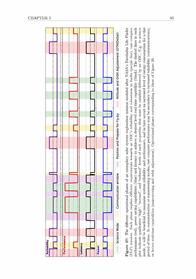

86 5.4. USE CASES BEYOND DEBUGGING
As an example, a regular TMRed system consisting of three active cores and onespare could be slit into two independent DMRed SOC pairs using a different SoftSoCconfiguration. As shown in the figure as well, during some phases of the mission, notall interfaces to other subsystems of the spacecraft are necessary. A separate FPGAconfiguration could be deployed which does not drive these interfaces to help conserveenergy. Hence, the same chip on an unaltered OBC board could fulfill its role in aconsiderably more efficient way, resulting in efficiency improvements in all regards.
5.4.4 Radiation Testing and Profiling
There are also use cases for this concept on the ground, e.g., to substitute for equipmentusually used for radiation testing and profiling of programmable logic or processordesigns. To improve the quality of results on a device’s behavior undergoing radiationtesting, the subject device or FPGA should be continuously probed to log the type ofradiation-induced errors when they occur. A post-mortem analysis hereby would onlyreduce the quality of information obtained and may even mask errors.
As outlined in Section 5.4.2, the saving subsystem can maintain a configurationscrubbing and reprogramming cycle. While the necessary hardware to do so has beendeveloped in the past already, the saving subsystem allows improved flexibility whilereducing the need for support equipment. To do so, the saving subsystem must beimplemented using radiation hardened components, and the simple design and lowperformance requirements allow the use of primitive electrical components.
Instead of counteracting the effects of radiation events, the saving subsystem canlog upsets within the running configuration of the subject device. Later on, this infor-mation can be forwarded to perform forensic analysis and look up which region of theconfiguration was affected and in what way. If combined with watchdog functionalityas outlined in Section 5.4.1, the setup can also help assess the severity and impactof event upsets and can help to map critical logic. The saving subsystem can auto-matically determine information about which of the most recent upsets could triggersystem failure within, e.g., Soft-SOC configurations. Of course, the saving subsystemcan also make use of more advanced integrity control functionality and can thereforeimprove logging. It can directly utilize other information sources such as crash logs,information about software-handled errors, and faults detected by specialized IP (e.g.,Xilinx Soft Error Mitigation [235]).
The saving subsystem can also perform scrubbing on an FPGA configuration, whichallows further classification into transient and permanent errors, refining testing re-sults. Hence, fault analysis can then be conducted using high-quality information andthe results obtained can also be fed-back into the testing cycle, see Figure 36. Thisinformation could ultimately also be introduced into an FPGA design’s testbench andcan help simulate the impact of changes to design based on realistic information with-out performing additional radiation tests. Analysis suites such as SETA [236] couldfurther help automate this process and may be used to obtain additional informationfrom saving subsystem traces. The saving subsystem can thus drastically improve thequality of radiation testing results when working with FPGAs and can substitute amajor part of the otherwise required testing infrastructure.
CHAPTER 5 87
5.5 Discussions
Development of the saving subsystem currently is in the prototype stage and a suc-cessful proof-of-concept has been implemented. Therefore the next step is to integrateit with other components of a CubeSat on-board Computer. The protocol to interfacewith the communication module via SPI has to be implemented and tested thoroughly.Once the API has been adapted to this protocol, a custom hardware prototype withthe respective memories can be implemented.
Also, the saving subsystem is currently based upon a set of development boardsmeant for rapid prototyping. It therefore must be condensed to a CubeSat compatibleform factor. Testing in this case also requires a broad variety of STAPL scripts tobe developed to assure code coverage during testing. These additional scripts willthen also be utilized to support development of other subsystems and testing of theattached OBC. Performance measurements, including power consumption under load,execution speed of different debugging operations must be performed as well.
There are also several extensions to the current saving subsystem implementationthat should be added, such as support for multiple JTAG chains. The current im-plementation relies on using only one JTAG chain for all devices connected to thedebugger, subjecting it to the risk of failure. In case one of the JTAG chain membersmalfunctions and can not transport the test data signal, the chain is rendered uselessand debug operations can not be performed. Support for more than one JTAG chainwould allow access to, e.g., a SoftSOC to be implemented in parallel to controllingthe FPGA itself. The to-be-executed script could then also select the correct JTAGchain, requiring only minimal modifications to the STAPL logic. This also opens upadditional usage scenarios especially when combined with FPGA/SOC hybrids suchas Xilinx’s Zynq family and the more powerful FPGAs utilized to realize the proof-of-concept MPSoC described in Chapters 9 and 10.
5.6 Conclusions
In this chapter we presented a subsystem enabling autonomous chip-level debuggingfor nanosatellite OBCs. Until now, chip-level debug functionality had not been read-ily available aboard miniaturized satellites. If at all present aboard CubeSats, suchfunctionality had largely been restricted to the development and testing phases. Weare convinced that the low survivability of many earlier CubeSats can be attributed,among other causes, to low per system dependability and a lack of FDIR functional-ity. Hence, we developed this concept to provide a readily usable CubeSat compatiblemid-mission FDIR solution for the nanosatellite audience.
We developed two prototype implementations up until now:
1. an initial proof-of-concept based upon a Raspberry-Pi to demonstrate the generalfeasibility of the saving subsystem and to determine requirements for furtherdevelopment.
2. An embedded implementation for an ARM7TDMI MCU in preparation to mi-grating the design to CubeSat compatible form factor.
The saving subsystem can be integrated into most CubeSat architectures requiringonly a JTAG interface towards to-be-controlled devices. It is based upon a minimal set

88 5.6. CONCLUSIONS
of components to retain simplicity, utilizing smart technological choices and erasurecoding where necessary to achieve dependability using affordable COTS hardware. Thepresented design utilizes the STAPL scripting language and therefore can support awide variety of devices. Due to its flexibility, several other use cases beyond debuggingare imaginable, both in space and on the ground. The setup has been implementedsuccessfully and thoroughly tested by controlling several ARM SoCs as well as FPGAs.
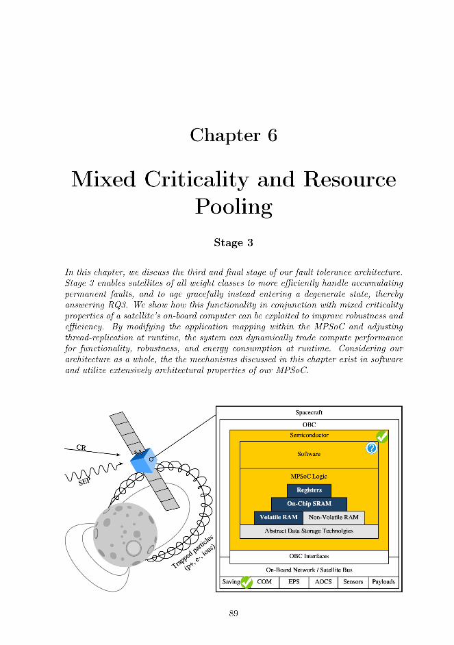

90 6.1. INTRODUCTION
6.1 Introduction
Satellite miniaturization has enabled a broad variety of scientific and commercial spacemissions, which previously were technically infeasible, impractical or simply uneco-nomical. However, very small satellites such as nanosatellites and sometimes evenmicrosatellites (≤100kg) are currently not considered suitable for critical and complexmulti-phased missions, as well as high-priority science applications, due to their lowreliability. On-board computer (OBC) and related electronics constitute a large partof such a spacecraft’s mass, yet these components lack often even basic fault tolerance(FT) functionality. Due to budget, energy, mass and volume restrictions, existingFT solutions originally developed for larger spacecraft can in general not be adopted.Nanosatellite OBCs also have to cope with drastically varying workload throughouta mission, which traditional FT solutions can not handle efficiently. Therefore, wedeveloped a novel FT approach offering strong fault coverage, which was implementedfully using only a single FPGA with commodity processor designs, and library IP.
This architecture can protect generic applications with an arbitrary structure, canadapt to varying performance requirements in longer multi-phased missions, and canadapt to a shrinking pool of processing capacity similar to a biological system, ef-ficiently handling aging effects and accumulating permanent faults. As major partsof our approach are implemented in or directly controlled by software, a spacecraftoperator can configure the OBC to deliver the desired combination of performance,robustness, functionality, or to meet a specific power budget. To offer strong faultdetection, isolation and recovery (FDIR), we combine software-side fault detectionand mitigation and configuration scrubbing with various other FT measures acrossthe embedded stack, enabling strong, low-cost FT with commodity hardware, whileexploiting FPGA reconfiguration to mitigate permanent faults.
The next two sections contain background information, and a discussion of relatedwork. In Section 6.4 a brief overview over the three stages of our approach is provided.Our proof-of-concept OBC-design is described in Section 6.5, with the functionalityof each FT-stage outlined in the subsequent sections. How this approach can improveefficiency of OBC in spacecraft of all weight classes, spare resource utilization andfault coverage, is discussed in Section 6.6. Section 6.7, introduces performance profilesallowing a system-on-chips (SoC) to trade compute performance for energy efficiency,robustness, and functionality at runtime. Our approach provides advantages to space-craft of all weight classes, and can be implemented also within distributed systems,for which further applications and improvements are discussed in Section 6.8.
6.2 Background
Tasks which would be handled by multiple dedicated payload and subsystem process-ing systems aboard a larger satellite, are usually handled by just one COTS-basedcommand & data handling system in nanosatellites. These utilize mobile-market andembedded SoCs with one or more cores (MPSoCs), SDSoCs [40], or FPGAs [237]. Dueto manufacturing in fine technology nodes, such chips offer superior efficiency and per-formance as compared to space-grade OBC designs, but are also non-FT1. These SoCsconsist mostly of extensively tested and optimized standard logic, reused, supported,
1Exceptions to this rule received uncommonly abundant funding, are technology demonstrationfor FT concepts, or custom failover designs.

CHAPTER 6 91
and evolved continuously by several industries and used daily by countless develop-ers. In contrast, most radiation-hard-by-design (RHBD) processors cores, and SoCsmanufactured in more robust manufacturing processed (RHBM) are crafted almostartisanally at high cost by few designers with little commercial stimulus for optimiza-tion. Their cost, energy consumption and mass often exceed such a spacecraft’s globalpower budget, total mass, and almost always its overall project budget. Therefore, wedeveloped a hybrid FT-approach based upon only COTS components, library IP, andexisting software, instead of artisanal processor designs and proprietary instructionset architectures.
Existing hardware voting based FT solutions are design-time static and can toleratea fixed number of failures within a voter setup, which can not be changed at runtime.Critical biological systems instead consist of independent, cooperating cells or clustersof similar functionality with a high degree of inherent redundancy and self-healingcapabilities. Damage to a single cell is compensated by the remaining cells, and acomplete breakdown of functionality occurs only due severe damage to the systemat a broader scale. Our approach combines various FT techniques to mimic suchbehavior at the logic and SoC level, through FPGA reconfiguration and software-controlled thread migration within a globally share pool of processor cores, enablinggraceful aging. The replication level, hence fault coverage capabilities, and variousother parameters can be adjusted at runtime, while spare capacity can be reused torun background and lower-criticality applications instead of remaining idle.
In small feature-size chips, the energy threshold above which highly charged par-ticles can induce faults in digital logic (single event effects - SEE) decreases, whilethe ratio of events inducing multi-bit upsets (MBU), and the likelihood of permanentfaults in logic and memory increases. Increased fault coverage of hardware-FT basedconcepts on such chips through additional FT-circuitry therefore implies diminishingreturns, preventing an application of traditional RHBD/RHBM concepts [104, 132]to mobile-market SoCs. Total ionizing dose, however, becomes less of a problem withfiner technology nodes, and recent generation FPGAs also show decent latch-up perfor-mance [142,143]. FPGAs have drastically improved FDIR potential [238] despite beingmore vulnerable to transients, as radiation-induced upsets in the running configurationcan be corrected via reconfiguration with alternative configuration variants [105].
6.3 Related Work
Fine-grained, non-invasive, and scalable fault detection in FPGA fabric is challeng-ing, and subject of ongoing research [239, 240], and often is simply ignored in sci-entific publications [241]. Most FPGA-based FT-concepts rely on error scrubbing,which has scalability limitations for complex logic [239, 242], unless special-purposeoffline testing is utilized [243]. In the future, memory-based reconfigurable logic de-vices (MRLDs) [244] may allow programmed logic to be protected like conventionalmemory, and thus would drastically simplify fault detection. If manufactured usingphase/polarity-change memory instead of charge-based technologies, MRLDs couldfurther increase robustness, but the memory technologies themselves are only emerg-ing at the time of writing. In this chapter, we thus present an approach to general-purpose FT computing that compensates for faults across the embedded stack andthrough partial FPGA reconfiguration. We realize fine-grained fault detection at thesoftware level, and perform scrubbing only as an auxiliary measure in the background

92 6.4. SYSTEM OVERVIEW & REQUIREMENTS
to increase robustness of our SRAM-based FPGA platform.Hardware voting today is used exclusively for protecting simpler FT processor
cores at the microcontroller level [88,104], and for accelerators [245] supporting appli-cation code with tightly constrained program structure. Hence, the application of thishardware-centered approach has become a technical dead-end for protecting widelyused application processor designs intended for general-purpose computing, while ac-celerators by themselves would only assure FT for computation and data offloadedto such a device. In our research, however, we seek to deliver strong fault coveragefor general purpose computing, and aim to efficiently protect even larger and morecomplex modern application processors, such as those widely used in mobile marketand embedded devices.
Mobile market processors can run at gigahertz clock rates, for which hardware-sidevoting or instruction-level lockstep are non-trivial, hence, hardware voting approacheshave been implemented only at lower clock rates [88,191,192]. For comparison, today’shighly optimized COTS library IP achieves clock speeds comparable to traditional FT-processor designs on ASIC even on an FPGA, without requiring manual fine-tuning.We instead utilize software-driven coarse-grain lockstep to achieve fault detection, andmaintain consistency between cores, requiring no vast arrays of synchronized voters,while utilizing COTS IP.
Thread migration has been shown to be a powerful tool for assuring FT, but priorresearch ignores fault detection, and imposed tight constraints on an application’stype and structure (e.g., video streaming and image processing [241]). However, toimplement sophisticated and efficient thread migration, fault-detection must be facil-itated at the OS or application-level without falling back to design space exploration.Coarse-grain lockstep of weakly coupled cores can do just that, and in the past hasalready been used for high availability, non-stop service, and error resilience con-cepts. However, in prior research, faults are usually assumed to be isolated, side effectfree and local to an individual application thread [208] or transient [199, 205], andentail high performance [209] or resource overhead [210, 211]. More advanced proof-of-concepts [198,199], however, attempt to address these limitations, and even show amodest performance overhead between 3% and 25%, but utilize checkpoint & rollbackor restart mechanisms [199], which make them unsuitable for spacecraft command &control applications.
6.4 System Overview & Requirements
Coarse-grain lockstep is one among several measures used in our hybrid FT approachto facilitate forward-error-correction (FEC) and deliver strong fault coverage. Ourapproach consists of three fault mitigation stages:
Stage 1 utilizes coarse-grain lockstep for fault detection. It generate a distributedmajority decision between processor cores.
Stage 1 utilizes time-triggered checkpoints to autonomously resolved faultscorrupting the state of applications. It facilitates re-synchronization andthread migration in case of repeated faults, enabling strong short-termfault coverage.
Stage 2 assures the integrity of programmed logic by interfacing with Stage 1 andfunctionality such as Xilinx SEM. Its objective is to assure and recover
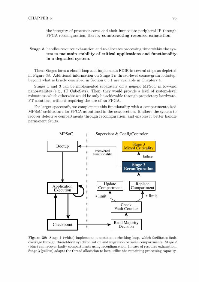
CHAPTER 6 93
the integrity of processor cores and their immediate peripheral IP throughFPGA reconfiguration, thereby counteracting resource exhaustion.
Stage 3 handles resource exhaustion and re-allocates processing time within the sys-tem to maintain stability of critical applications and functionalityin a degraded system.
These Stages form a closed loop and implements FDIR in several steps as depictedin Figure 38. Additional information on Stage 1’s thread-level coarse-grain lockstep,beyond what is briefly described in Section 6.5.1 are available in Chapters 4.
Stages 1 and 3 can be implemented separately on a generic MPSoC in low-endnanosatellites (e.g., 1U CubeSats). Then, they would provide a level of system-levelrobustness which otherwise would be only be achievable through proprietary hardware-FT solutions, without requiring the use of an FPGA.
For larger spacecraft, we complement this functionality with a compartmentalizedMPSoC architecture for FPGA as outlined in the next section. It allows the system torecover defective compartments through reconfiguration, and enables it better handlepermanent faults.
MPSoC Supervisor & ConfigControler
Bootup
Checkpoint
ApplicationExecution
Read MajorityDecision
CheckFault Counter
UpdateCompartment
Stage 3Mixed Criticality
ReplaceCompartment
Stage 2Reconfiguration
< limit > limit
failure
recoveredfunctionality
Figure 38: Stage 1 (white) implements a continuous checking loop, which facilitates faultcoverage through thread-level synchronization and migration between compartments. Stage 2(blue) can recover faulty compartments using reconfiguration. In case of resource exhaustion,Stage 3 (yellow) adapts the thread allocation to best utilize the remaining processing capacity.
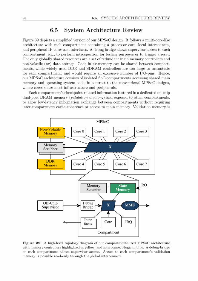
94 6.5. SYSTEM ARCHITECTURE REVIEW
6.5 System Architecture Review
Figure 39 depicts a simplified version of our MPSoC design. It follows a multi-core-likearchitecture with each compartment containing a processor core, local interconnect,and peripheral IP-cores and interfaces. A debug bridge allows supervisor access to eachcompartment, e.g., to perform introspection for testing purposes or to trigger a reset.The only globally shared resources are a set of redundant main memory controllers andnon-volatile (nv) data storage. Code in nv-memory can be shared between compart-ments, while widely used DDR and SDRAM controllers are too large to instantiatefor each compartment, and would require an excessive number of I/O-pins. Hence,our MPSoC architecture consists of isolated SoC-compartments accessing shared mainmemory and operating system code, in contrast to the conventional MPSoC designs,where cores share most infrastructure and peripherals.
Each compartment’s checkpoint-related information is stored in a dedicated on-chipdual-port BRAM memory (validation memory) and exposed to other compartments,to allow low-latency information exchange between compartments without requiringinter-compartment cache-coherence or access to main memory. Validation memory is
MPSoC
Compartment
MEMSCRUB
MCTLR
MCTLR
DebugBridge MMU
X
DDRMemory
MemoryScrubber
Non-VolatileMemory
X
StateMemory
MemoryScrubber
Core IRQInterfaces
Off-ChipSupervisor
Core 0 Core 1 Core 2
Core 7Core 4 Core 5 Core 6
Core 3
RO
Figure 39: A high-level topology diagram of our compartmentalized MPSoC architecturewith memory controllers highlighted in yellow, and interconnect-logic in blue. A debug-bridgeon each compartment allows supervisor access. Access to each compartment’s validationmemory is possible read-only through the global interconnect.

CHAPTER 6 95
writable through the compartment-local interconnect, and is read-only accessible byother compartments.
The address space layout on each compartment, including mapping of peripheralsand interfaces within the address space are identical. Each compartment can accessits own main memory address segment, which is mapped to the same address rangeon all compartments. Additionally, main memory in its entirety (all memory seg-ments) is read-only accessible system wide, to simplify state synchronization betweencompartments.
During a checkpoint, the state of all threads mapped to a compartment is com-pared and synchronized with its siblings. To do so, the checkpoint handler executes anapplication-provided callback function for all pending threads, producing checksumsgenerated from thread-private data structures. Checksums are stored in the compart-ment’s local validation memory and thereby exposed to the other compartments, andthen compared with the other compartments in the system. In case of disagreement,the compartment signals disagreement with that sibling and executes synchronizationcallbacks for all affected threads. If necessary, it then also executes relevant updatecallbacks and then resumes application execution. An more detailed description ofthese mechanisms as well as benchmark results for an astronomical application aredescribed in Chapter 4.
6.5.1 Stage 1: Short-Term Fault Mitigation
The objective of Stage 1 is to detect and correct faults within a compartment, andassure a consistent system state through checkpoint-based FEC. It is implemented assets of compartments running two or more copies of application threads (siblings) inlock step. Checkpoints interrupt execution, facilitating the lockstep and enforcing syn-chronization, allowing thread assignment within the system to be adjusted if required,as depicted in Figure 38.
This approach enables us to utilize application intrinsics to assess the health stateof the system without requiring in-depth knowledge about the application code. Thesupervisor just reads out the results of the compartments’ decentralized consistencydecision. Threads can be scheduled and executed in an arbitrary order between twocheckpoints, as long as their state is equivalent upon the next checkpoint.
We avoid thread synchronization issues due to invasive lockstep mechanisms [198]by merely reusing existing OS functionality without breaking existing ABI contracts.Therefore, we can continue relying upon pre-existing synchronization mechanics suchas POSIX cancellation points2 and their bare-metal equivalents (e.g., in RTEMSRTEMS_NO_PREEMPT or the POSIX API). Stage 1 can even deliver real-timeguarantees, and the tightness of the RT guarantees depends upon the time required toexecute application callbacks. In our RTEMS/POSIX-based implementation, we uti-lize priority-based, preemptive scheduling with timeslicing, allowing threads to delaycheckpoints until they reach a viable state for checksum comparison.
Checkpoints are time triggered, but can also be induced by the supervisor throughan interrupt, e.g., to signal that new threads have been assigned. Thus, the OS onlyhas to support interrupts, timers, and a multi-threading capable scheduler. To the bestof our knowledge, such functionality is available in all widely used RT- and generalpurpose OS implementations.
2E.g., sleep, yield, pause, for further details, see IEEE Std 1003.1-2017 p517

96 6.5. SYSTEM ARCHITECTURE REVIEW
A fault resolved during a checkpoint may cause the affected compartment to emitincorrect data through I/O interfaces, an inherent limitation to coarse-grain lock-step [199]. For many very small nanosatellite missions this is acceptable, as the use ofCOTS components requires incorrect I/O to be sanitized anyway. In contrast, largerspacecraft already utilize interface replications or even voting, usually requiring consid-erable effort at the interface level to facilitate this replication. Our approach combinedwith the previously described MPSoC architecture inherently provides interface-levelreplications by design, no longer requiring extra measures to be taken. Additionalprotection is therefore only needed for space applications where non-propagation ofincorrect I/O is required but interface replication is undesirable, i.e., due to PCB-spaceconstraints aboard CubeSats or unchangeable subsystem requirements. For packet-based interfaces such as Spacewire, AFDX, CAN, or Ethernet, no hardware-side solu-tion is necessary, as data duplication can be managed more efficiently at OSI layer 2+.This approach today is widely used as part of real-time capable FT-networking [94].Other interfaces like I2C and SPI allow a simple majority decision per I/O line, whichcan be implemented on-chip through FIFO buffers, as the remaining on-compartmentinterfaces have low pin count and run at relatively low clock frequencies.
6.5.2 Stage 2: Tile Repair & Recovery
Stage 1 can not reclaim defective compartments, eventually resulting in resource ex-haustion. Therefore, in Stage 2, we recover defective compartments through recon-figuration to counter transients in FPGA fabric. To do so, the supervisor will firstattempt to recover a compartment using partial reconfiguration. Afterwards, the su-pervisor validates the relevant partitions to detect permanent damage to the FPGA(well described in, e.g., [218]), and executes self-test functionality on the compartmentto detect faults in the compartment’s main memory segment and peripherals. If unsuc-cessful, the supervisor can repeat this procedure with differently routed configurationvariants, potentially avoiding or repurposing permanently defective logic.
As compartments are placed along partition borders in our MPSoC architecture,compartments can be recovered in the background without interrupting the rest of thesystem. The supervisor can also attempt full reconfiguration implying a full rebootof all compartments. Further details on reconfiguration and error scrubbing with amicrocontroller-based proof-of-concept implementation for a nanosatellite are availablein Chapter 5. If both partial- and full-reconfiguration are unsuccessful and all spareresources have been exhausted, Stage 3 is utilized to assure a stable system core toenable operator intervention.
6.5.3 Stage 3: Applied Mixed Criticality
Stage 3 autonomously maintains system stability of an aged or degraded OBC. Whenconsidering a miniaturized satellite’s OBC, we can differentiate individual applicationsor parts of flight software by criticality. At the very least, we will find software essentialto a satellite’s operation, e.g., platform control and commandeering, as well as otherapplications of various levels of lower criticality. If the previous stages no longerhave enough spare processing capacity or compartments to compensate the loss of acompartment, this stage utilizes thread-level mixed criticality to assure stability of coreOBC functions. To do so, it can sacrifice lower criticality tasks in favor of providingcompute resources to reach the desired replication level for critical threads.

CHAPTER 6 97
Dependability for higher-criticality threads can efficiently be maintained by re-ducing compute performance or reliability of lower-criticality applications. Lower-criticality tasks may be executed less frequently or on fewer compartments, therebyreducing functionality or fault coverage for these tasks, retaining resources for higher-criticality threads. This decision is taken autonomously, and the operator can thendefine a more resource conserving satellite operation schedule at a spacecraft level,e.g., sacrifice link capacity, or on-board storage space, to make best use of the OBCin its degraded state.
6.6 Spare Resource Pooling
This FT approach enables FT even for very small satellites, but provides benefits forspacecraft of all weight classes. To increase fault coverage in traditional hardwarevoting FT systems, additional cores and spares must be provisioned, while computeperformance can be increased by utilizing higher-performance processor cores andadding more hardware voting instances. This is done at design time, requiring over-provisioning, and can not be changed throughout a mission. Cores are hardwired toa specific instance, therefore, an instance will degrade once its spares are exhausted,even if idle spares were available elsewhere.
In contrast, our approach is not based on hardwired voting instances, as appli-cations are mapped to a global pool of compartments with a given replication level.Our approach does utilize spare resources too, but spare compartments and conven-tional compartments are identical. Hence, spare compartments do not have to remainidle, and unused processor capacity becomes a spare resource that can be re-purposed.Thus, the fault coverage capabilities of the system are no longer dependent on thedistribution and location of permanent faults within the system, increasing overallrobustness.
As applications can be migrated between compartments, low criticality threads andbackground tasks can be assigned to utilize free spare capacity. These lower-criticalitythreads can be de-scheduled in favor of higher-criticality applications, if needed. Sparecapacity can also be used to increase FT for threads, which usually would be executedwithout majority voting or separately due to resource constraints. We can distributea defective compartment’s workload to other compartments, to best take advantageof the remaining system resources.
The best target compartments and to-be-evicted threads are not determined ad-hoc, but before a fault actually occurs, to reduce the time spent in a checkpoint.We can maintain one replacement strategy for every compartment, due to the lowcompartment and thread counts common in space applications today3. Subsequentto a fault, these strategies are recomputed to consider the now reduced processingcapacity of the system. As thread assignments are not controlled by the supervisor, butonly adjusted, threads may exit, fork or create new child threads. Therefore, an updateto adjust these strategies to the currently running threads is also triggered based onthe fault counter of Stage 2. Even if a fault occurs immediately after the current
3The main application for our architecture is platform control. ManyCore-systems with hundredsof cores would allow too many combinations, but they will not be applied to satellite platform controlin the foreseeable future. For dedicated payload data processing, this may be different, but our interestin this thesis is mainly platform control and unified satellite data handling aboard miniaturizedsatellites.

98 6.7. ADAPTING TO VARYING MISSION REQUIREMENTS
checkpoint, these strategies will only be needed at the next checkpoint. Therefore,this is a background operation which can be handled by the supervisor, allowing theOBC to resume processing immediately.
Figure 40 depicts a six compartment MPSoC running four applications of differ-ent criticality. A fault has occurred in compartment 3, which has been marked aspermanently defective, and there are multiple recovery solutions:
• Affected threads could be relocated to a compartment running lower-criticality ap-plications, replacing them as depicted in Figure 40a. For example, the threadspreviously run on compartment 3 can be migrated to compartment 6, replacinglower criticality thread-copies previously run there. This requires compartment 6 tocopy the state of its newly assigned threads from compartment 1 or 2, at the costof executing the lower-criticality applications redundantly instead of with majorityvoting.
• Instead of entirely de-scheduling one instance of each lower criticality threads, theclock frequency on two compartments could be increased, allowing one of each high-criticality thread to be migrated. In Figure 40b, this is depicted by moving thethreads from the failed compartment to compartments 5 and 6 without de-schedulinginstances of the low criticality threads. This is possible as coarse-grain lockstep onlyrequires an equivalent state between siblings upon reaching a checkpoint and nocycle-accurate synchronization. Most modern embedded and mobile-market coressupport frequency scaling.
• Another possibility would be to instead increase the clock frequency of just onecompartment, if sufficient additional processing capacity can be made available thatway.
• Finally, in contrast to increasing the clock frequencies of individual compartments,compartment 4-6’s schedulers could also assign less processing time to the lower-criticality tasks as shown in Figure 40c. Due to timing implications for real-timeapplications, this may only be possible for sporadic tasks, and background appli-cations, which do not require a fixed amount of processing time. Also, to guaran-tee equivalent work is conducted for the medium and lower-criticality threads, theschedulers on 3 instead of just 2 compartments would require adjustment, wastingprocessing capacity in Tile 4 and 6. However, during this idle time, Tile 4 could bedeactivated to reduce energy consumption.
The ideal recovery strategy depends on the current performance requirements towardsthe OBC. Additional thoughts on this aspect are discussed, e.g., in [241], where dif-ferent replacement strategies are described at a more mathematical level for videostreaming applications. In the next section, we therefore discuss a heuristic approachto find near-best solutions to calculate this decision autonomously and rapidly, con-sidering different performance requirements.
6.7 Adapting to Varying Mission Requirements
The approach described in the previous sections allows an OBC to meet a desired powerbudget, maximize fault coverage, processing power, or even functionality. Hence,the spacecraft can better fulfill its scientific or commercial mission, and increase the
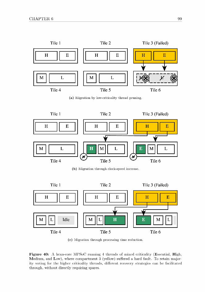
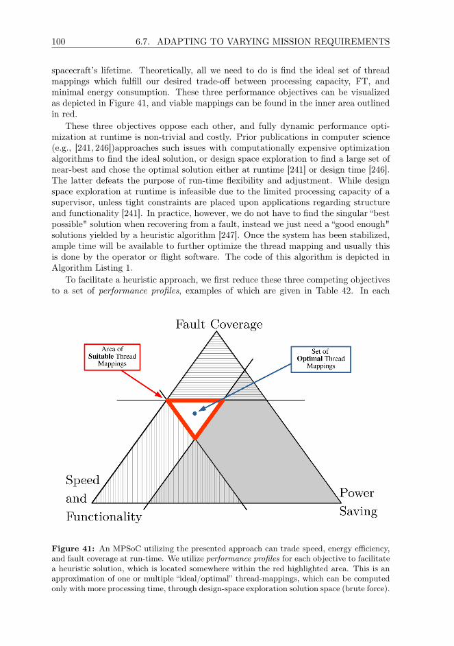
100 6.7. ADAPTING TO VARYING MISSION REQUIREMENTS
spacecraft’s lifetime. Theoretically, all we need to do is find the ideal set of threadmappings which fulfill our desired trade-off between processing capacity, FT, andminimal energy consumption. These three performance objectives can be visualizedas depicted in Figure 41, and viable mappings can be found in the inner area outlinedin red.
These three objectives oppose each other, and fully dynamic performance opti-mization at runtime is non-trivial and costly. Prior publications in computer science(e.g., [241, 246])approaches such issues with computationally expensive optimizationalgorithms to find the ideal solution, or design space exploration to find a large set ofnear-best and chose the optimal solution either at runtime [241] or design time [246].The latter defeats the purpose of run-time flexibility and adjustment. While designspace exploration at runtime is infeasible due to the limited processing capacity of asupervisor, unless tight constraints are placed upon applications regarding structureand functionality [241]. In practice, however, we do not have to find the singular “bestpossible" solution when recovering from a fault, instead we just need a “good enough"solutions yielded by a heuristic algorithm [247]. Once the system has been stabilized,ample time will be available to further optimize the thread mapping and usually thisis done by the operator or flight software. The code of this algorithm is depicted inAlgorithm Listing 1.
To facilitate a heuristic approach, we first reduce these three competing objectivesto a set of performance profiles, examples of which are given in Table 42. In each
Figure 41: An MPSoC utilizing the presented approach can trade speed, energy efficiency,and fault coverage at run-time. We utilize performance profiles for each objective to facilitatea heuristic solution, which is located somewhere within the red highlighted area. This is anapproximation of one or multiple “ideal/optimal” thread-mappings, which can be computedonly with more processing time, through design-space exploration solution space (brute force).
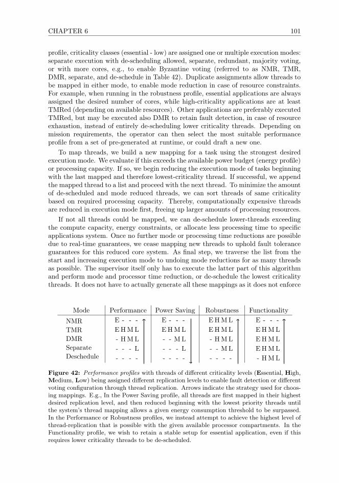
CHAPTER 6 101
profile, criticality classes (essential - low) are assigned one or multiple execution modes:separate execution with de-scheduling allowed, separate, redundant, majority voting,or with more cores, e.g., to enable Byzantine voting (referred to as NMR, TMR,DMR, separate, and de-schedule in Table 42). Duplicate assignments allow threads tobe mapped in either mode, to enable mode reduction in case of resource constraints.For example, when running in the robustness profile, essential applications are alwaysassigned the desired number of cores, while high-criticality applications are at leastTMRed (depending on available resources). Other applications are preferably executedTMRed, but may be executed also DMR to retain fault detection, in case of resourceexhaustion, instead of entirely de-scheduling lower criticality threads. Depending onmission requirements, the operator can then select the most suitable performanceprofile from a set of pre-generated at runtime, or could draft a new one.
To map threads, we build a new mapping for a task using the strongest desiredexecution mode. We evaluate if this exceeds the available power budget (energy profile)or processing capacity. If so, we begin reducing the execution mode of tasks beginningwith the last mapped and therefore lowest-criticality thread. If successful, we appendthe mapped thread to a list and proceed with the next thread. To minimize the amountof de-scheduled and mode reduced threads, we can sort threads of same criticalitybased on required processing capacity. Thereby, computationally expensive threadsare reduced in execution mode first, freeing up larger amounts of processing resources.
If not all threads could be mapped, we can de-schedule lower-threads exceedingthe compute capacity, energy constraints, or allocate less processing time to specificapplications system. Once no further mode or processing time reductions are possibledue to real-time guarantees, we cease mapping new threads to uphold fault toleranceguarantees for this reduced core system. As final step, we traverse the list from thestart and increasing execution mode to undoing mode reductions for as many threadsas possible. The supervisor itself only has to execute the latter part of this algorithmand perform mode and processor time reduction, or de-schedule the lowest criticalitythreads. It does not have to actually generate all these mappings as it does not enforce
Mode Performance Power Saving Robustness Functionality
NMRTMRDMRSeparateDeschedule
E - - -E H M L- H M L- - - L- - - -
E - - -E H M L- - M L- - - L- - - -
E H M LE H M L- H M L- - M L- - - -
E - - -E H M LE H M LE H M L- H M L
Figure 42: Performance profiles with threads of different criticality levels (Essential, High,Medium, Low) being assigned different replication levels to enable fault detection or differentvoting configuration through thread replication. Arrows indicate the strategy used for choos-ing mappings. E.g., In the Power Saving profile, all threads are first mapped in their highestdesired replication level, and then reduced beginning with the lowest priority threads untilthe system’s thread mapping allows a given energy consumption threshold to be surpassed.In the Performance or Robustness profiles, we instead attempt to achieve the highest level ofthread-replication that is possible with the given available processor compartments. In theFunctionality profile, we wish to retain a stable setup for essential application, even if thisrequires lower criticality threads to be de-scheduled.

102 6.7. ADAPTING TO VARYING MISSION REQUIREMENTS
ALGORITHM 1: Pseudo-Code of the Thread-Allocation HeuristicsInput: Ti: List of Threads, P : performance profile, C: Set healthy CoresOutput: M : List of mapped thread-groups
1 for Ti from T0 to Tn do
// Attempt to create a mapping for the thread
2 replication_level = getDesiredReplication(P , Ti)3 thread_group = makeGroup(Ti, replication_level, C)4 thread_mapping = getTargetCores(thread_group, C)
5 if isValid(thread_mapping) then
6 AppendGroup(M , thread_group, targets)
7 else
// Failure, try to map with lower replication
8 lowest_replication = getLowestAllowedReplication(P , Ti)
9 while replication_level is not lowest_replication do
// reduce replication level and retry
10 replication_level = getLowerReplication(P , Ti)11 thread_group = makeGroup(Ti, replication_level, C)12 thread_mapping = getTargetCores(thread_group, C)
13 if isValid(thread_mapping) then
14 AppendGroup(M , thread_group, thread_mapping)15 goto line 1 // break out of nested loop and continue
/* Insufficient compute capacity available in the system. E.g., too many
compartments failed. Attept to reduce the replication level of an early
mapped higher priority application to free compute capacity. */
16 for Mi from Mi to M0 do
17 t = getThread(Mi)18 others_replication = getCurrentReplication(P , t)19 lowest_replication = getLowestAllowedReplication(P , t)
20 while others_replication is not lowest_replication do
// Reduce replication for next higher priority group and retry
21 tryReduceReplication(P , M , Mi, others_replication, C)22 thread_mapping = getTargetCores(thread_group, C)
23 if isValid(thread_mapping) then
24 AppendGroup(M , thread_group, targets)25 break
// Can not reduce mapping, try to reduce earlier mapped thread
// Too-few compute resources, de-schedule and try to map next thread
CHAPTER 6 103
thread assignment in the system and only intervenes if necessary.This algorithm also provides all mechanisms necessary to minimize the amount of
active processor cores, and as threads can be concentrated to as few compartmentsas possible, maximizing the number of clock-gated cores. Individual tasks could alsosignal preference for reduced processing instead of a mode reduction as the approachitself is computationally inexpensive.
6.8 Discussions
We implemented the MPSoC architecture described in Section 6.5 using Xilinx Kintexand Virtex FPGAs as well as the Zynq SDSoC platform [40], as these are relevantfor our target missions. However, for larger satellite platforms, this approach andarchitecture could very well be implemented on ASIC, and we see this as a “big-space" variant of our approach. An ASIC implementation would have lower energyconsumption, and allow higher clock rates due to tighter timing and shorter paths,and be less susceptible to transient faults. If manufactured in an inherently radiationhardened technology such as FD-SoI [144], the system as a whole would be considerablymore resistant to transient faults. Stage 2 would then be reduced to testing andvalidate compartments, while no longer being able to recover faulty compartmentscontaining defective logic, but strong fault coverage of SEEs would be improved dueto RHBM.
Overall, an FPGA implementation offers stronger FDIR capabilities, better cover-age for permanent faults, and high flexibility at low cost, while the ASIC variant couldoffer better system performance and radiation tolerance due to RHBM. Custom ASICdevelopment of course is expensive and time-consuming, thus, the resulting implemen-tation would not be a viable solution for most miniaturized satellite applications, andtherefore not in the scope of this technology development project.
The relaxed cost, energy, and size constraints aboard larger spacecraft allow animplementation of our approach spanning multiple FPGAs. Compared to a single-chip implementation, a multi-FPGA MPSoC variant offers better scalability due toeasier routing, can tolerate chip-level defects, and SEFIs to the globally shared memorycontrollers, these can be distributed to different FPGAs. Replicated thread-instancescould then also be distributed across FPGAs, offering non-stop operation while one ofthe FPGAs undergoes full reconfiguration. However, our proof-of-concept is focusedon a single-FPGA based prototype for nanosatellite use.
Our project is focused on payload data handling and platform control for miniatur-ized spacecraft, and therefore accelerator cores supporting computational offloadingare outside the scope of our research. Nonetheless, it is possible to also protect accel-erator systems using this approach, yielding at least similar benefits. The structureand type of applications usually executed on accelerators is tightly constrained ascompared to general purpose platform control, simplifying lockstep replication andthread-mapping. Especially synchronization for real-time applications and the impactof live-migration between compartments or state-updates on a faulty compartment,become much simpler if fully deterministic application behavior is assumed, as wouldbe the case for computational offloading.
Our existing MPSoC design utilizes an AXI interconnect, but we plan to rework ourMPSoC to instead use a NoC between compartments and shared memory controllers.The existing interconnect implementation allows low-latency communication, but has

104 6.9. CONCLUSIONS
a large footprint, and is difficult to route4 for larger compartment counts (withoutoptimization, we successfully placed 8 compartments). A NoC instead allows not onlybetter scalability and easier routing, but also enables the implementation of a broadvariety of FT concepts such as [93].
Tiles have direct read-only access to another compartment’s memory segment toallow rapid thread migration and allow real-time capacity. However, direct access toshared main memory is not necessary to facilitate Stages 1-3. The data exchangerequired to facilitate thread migration could very well be implemented using IPC orthrough sockets, when considering complex networked architectures. In distributedsystems, our approach could thus manage threads across multiple nodes sharing datawhen required, at the cost of higher latency.
We developed this approach to guarantee FT for opaque threaded applications onPOSIX-compatible RTOS and general purpose operating systems such as RTEMS andLinux. However, the same functionality can also be applied to virtualized, voted sys-tems and to runtime based platforms. It would be very well imaginable to implementStage 1 within MicroPython or a hypervisor, and instead vote on Python scripts orvirtual machines.
6.9 Conclusions
To the best of our knowledge, the on-board computer (OBC) design presented inthis chapter is the first practical, non-proprietary, and affordable fault tolerance (FT)approach suitable even for very small spacecraft. It offers strong fault coverage, usingjust commercial-off-the-shelf hardware, library IP, and commodity processor cores,requiring only a single FPGA and a microcontroller based supervisor. The software-side FT approach outlined in Stage 1 is non-invasive to applications and the OS,therefore existing software can be reused and extended easily, while retaining real-time capabilities. The research presented in this chapter covers the entire FDIR loop,and does not ignore or make unrealistic assumptions regarding fault detection.
Our approach enables the re-use of existing development tools and IP designed formass-produced mobile-market applications, taking an important step towards depart-ing from the artisanal development approach in today’s space computing. Instead ofrequiring new technologies to be re-invented constantly and maintained at high cost,the FT mechanisms presented in this chapter are flexible, which can adapt and growwith the development of computer and processor technology.
We do not just enable FT for a satellite class which so far has been consideredunreliable, but also enhance the fault coverage capabilities of OBCs in larger space-craft, and other applications with similar constraints and fault profile. Our approachfacilitates majority voting through dynamic, replicated thread groups mapped to theavailable processor cores dynamically at runtime, instead of hardwiring them. Thus,all processing capacity, including spares, are part of a shared resource pool. Therefore,spare resources can be used more efficiently, and allowing idle compute capacity to beused productively until it is needed for fault coverage. An OBC running the presentedhybrid hardware-software FT approach can adapt to varying mission requirements re-garding adjusting the OBC transparently at run-time, trading processing capacity forreduced energy consumption or increased fault coverage.
4We can still achieve a functional implementation meeting timing constraints at several hundredmegahertz, but the interconnect PBlock becomes disproportionately large.
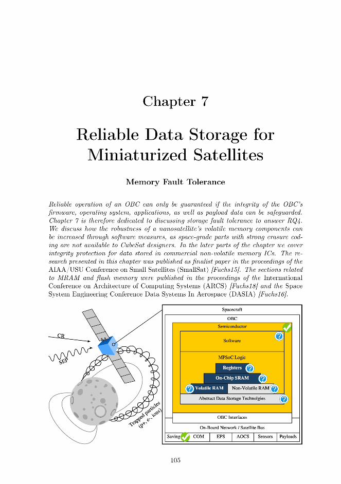

106 7.1. INTRODUCTION
7.1 Introduction
Recent miniaturized satellite development shows a rapid increase in available com-pute performance and storage capacity, but also in system complexity. CubeSats haveproven to be both versatile and efficient for various use-cases, thus have also becomeplatforms for an increasing variety of scientific payloads and even commercial appli-cations. Such satellites also require an increased level of reliability in all subsystemscompared to educational satellites, due to prolonged mission duration and computingburden. Nanosatellite computing will therefore evolve away from federated clusters ofmicrocontrollers towards more powerful, general purpose computers; a developmentthat could also be observed with larger spacecraft in the past. Certainly, an increasedcomputing burden also requires more sophisticated operating system (OS) or software,making software-reuse a crucial aspect in future nanosatellite design. In commercialand agency spaceflight, a concentration on few major OSs (e.g., RTEMS [248]) andprocessors (e.g., LEON3 and RAD750) has therefore occurred. A similar evolution,albeit much faster, can also be observed for miniaturized satellites.
To satisfy scientific and commercial objectives, miniaturized satellites will alsorequire increased data storage capacity for scientific data. Thus, many such satel-lites have begun fielding a small but integrity-critical core system storage for soft-ware, and a dedicated mass-memory for pre-processing and caching payload-generateddata. Unfortunately, traditional hardware-centered approaches to fault tolerance, alsoincrease costs, weight, complexity and energy consumption while decreasing over-all performance. Therefore, such solutions (shielding, simple- and triple-modular-redundancy – TMR) are often infeasible for miniaturized satellite design and unsuit-able for nanosatellites. Also, hardware-based error detection and correction (EDAC)becomes increasingly less effective if applied to modern high-density electronics dueto diminishing returns with fine structural widths. As a result of these concepts’ lim-ited applicability, nanosatellite design is challenged by ever increasing long-term faultcoverage requirements.
7.1.1 Context and Application
Neither component level, nor hardware or software measures alone can guarantee suffi-cient system consistency. However, hybrid solutions can increase reliability drasticallyintroducing negligible or no additional complexity. Software driven fault detection, iso-lation and recovery from (hardware) errors (FDIR) is a proven approach also withinspace-borne computing, though it is seldom implemented on nanosatellites. A broadvariety of measures capable of enhancing or enabling FDIR for on-board electronicsexists, especially for data storage. Combined hard- and software measures can stronglyincrease reliability.
This research was conducted as part of the MOVE-II CubeSat project based uponan ARM-Cortex processor as a platform for scientific payloads. To fulfill this role, thetraditional CubeSat approach to reliability, risk acceptance, does not suffice. Hence,we designed MOVE-II’s on-board computer (OBC) to guarantee data integrity usingsoftware side measures and affordable standard hardware where necessary. The capa-bility to assure data integrity for program code and data is essential to then achievefault-tolerance for data processing elements and at the system level.
After a detailed evaluation of potential OSs for use aboard MOVE-II, we chosethe Linux kernel due to its adaptability, extensive soft-/hardware support and vast
CHAPTER 7 107
community. We decided against utilizing RTEMS mainly due to our limited softwaredevelopment manpower, the intended application aboard our nanosatellite MOVE-II,and the abundant compute power of recent OBCs.
7.1.2 Chapter Organization
Often, fault tolerance aboard spacecraft is only assured for processing components,while the integrity of program code is neglected. In the next section, we thus outlinethe importance of memory integrity as a foundation for fault-tolerant satellite comput-ing and provide a view on the topic at a high level. To protect data stored in volatilememory, we present a minimalist yet efficient approach to combine error scrubbing,blacklisting, and error correction encoded (ECC) memory in Section 7.3. MOVE-II will utilize magnetoresistive random access memory (MRAM) [147] as firmwarestorage, hence, we developed a POSIX-compatible filesystem offering memory protec-tion, checksumming and forward error correction. This filesystem is being presentedin Section 7.4, can efficiently protect an OS- or firmware image and supports hard-ware acceleration. Finally, a high performance dependable storage concept combiningblock-level redundancy and composite erasure coding for highly scaled flash memorywas implemented to assure payload data integrity, the resulting concept is outlined inSection 7.5. The final section of this chapter is used to discuss and wrap up the resultsobtained herein.
7.2 Data Integrity as Foundation of Fault Tolerance
The increasing professionalization, prolonged mission duration, and a broader spec-trum of scientific and commercial applications have resulted in many different propri-etary on-board computer concepts for miniaturized satellites. Therefore, miniaturizedsatellite development has not only seen a rapid increase in available compute powerand storage capacity, but also in system complexity. However, while system sophis-tication has continuously increased, re-usability, reliability remained quite low [249].Recent studies of all previously launched CubeSats show an overall launch success rateof only 40% [41]. Such low reliability rates are unacceptable for missions with morerefined or long-term objectives, especially with commercial interests involved.
As nanosatellites consist mainly of electronics, connected to and controlled by theOBC, achieving fault tolerance must begin with this component. Hence, an OBC’ssoftware and hardware must be designed to handle faults throughout a space mission,not if, but when they occur. fault tolerance can only be assured if program codeand required supplementary data can be stored consistently and reliably aboard aspacecraft. Thus, data storage integrity must be assured first and foremost, withoutresorting to expensive, proprietary space-grade components that realize fault tolerancein hardware.
To enable meaningful fault tolerance, data consistency must be assured both withinvolatile and non-volatile memory, see Figure 43. Data is usually classified as eithersystem data or payload data stored in volatile or non-volatile memory. The storagecapacity required for system data may vary from few kilobytes (firmware images storedwithin a microcontroller) to several megabytes (an OS kernel, its and accompanyingsoftware). Very large OS installations and applications are uncommon aboard space-craft and thus not considered in this chapter. Payload data storage on the other hand


CHAPTER 7 109
7.3 Volatile Memory Consistency
Inevitably, data stored will at least temporarily reside within an OBC’s volatile mem-ory and all current widely used memory technologies (e.g., SRAM, SDRAM) are proneto radiation effects [250]. As a straightforwards solution, some OBCs were built toutilize only (non-volatile) MRAM as system memory which is inherently immune toSEUs and therefore allows OBC engineers to bypass additional integrity assuranceguarantees for RAM. However, MRAM currently can not be scaled to capacities largeenough to accommodate more complex OSs. Thus, while miniaturized satellites oftenutilize custom firmware optimized for very low RAM usage, larger spacecraft as wellas most current and future nanosatellites do utilize DDR or SDRAM. For simplicity,we will refer to these technologies as RAM in this chapter. However, it is not to beconfused with the use of the term RAM in Sections 7.4 and 7.5 of this chapter, as inMRAM.
Radiation induced errors alongside device failover is often assured using error cor-recting codes (ECC), which have been in use in space engineering for decades. How-ever, a miniaturized satellite’s OS must take an active role in volatile memory integrityassurance by reacting to ECC errors and testing the relevant memory areas for per-manent faults. To avoid accumulating errors over time in less frequently accessedmemory, an OS must periodically perform scrubbing. In case of permanent errors,software should cease utilizing such memory segments for future computation andblacklist them to reduce the strain on the used erasure code. Assuming these FDIRmeasures are implemented, a consistency regime based on memory validation, errorscrubbing and blacklisting can be established.
7.3.1 DRAM Corruption and Countermeasures
The fault profile for DRAM aboard CubeSats mainly includes two types of graduallyaccumulating errors: soft-errors (bit-rot) and permanent (hard) errors. Depending onthe amount of data residing in RAM, even few hard errors can cripple an on-boardcomputer: the likelihood for the corruption of critical instructions increases drasticallyover time. Therefore, to compensate for both hard and soft errors, ECC should beintroduced [158].
Modern DRAM chips benefit strongly from feature size reduction and run at veryhigh clock frequency, as a vast majority of a memory IC consists of memory cells. Softerrors there occur on the Earth as well as in orbit, due to electrical effects and highlycharged particles originating from beyond our solar system. In case of such an error,data is corrupted temporarily but, and once the relevant memory has been re-written,consistency can be re-established. The likelihood of these events on the ground isusually negligible as the Earth’s magnetic field and the atmosphere provide significantprotection from these events, thus weak or no erasure coding at all is applied.
Hard errors generally occur due to manufacturing flaws, ESD, thermal- and agingeffects. Thus, they may also occur or surface during an ongoing mission, furtherinformation on the causes for hard-faults in RAM is described in detail in [251].
By utilizing ECC, integrity of the memory can be assured starting at boot-up,though in contrast to other approaches ECC can not efficiently be applied in soft-ware [252]. Due to the high performance requirements towards RAM, weak but fasterasure codes such as single error correction Hamming codes with a word length of8 bits are used [253, 254]. ECC modules for space-use usually offer two or more

110 7.3. VOLATILE MEMORY CONSISTENCY
bit-errors-per-word correction. These codes require additional storage space, therebyreducing available net memory, and increase access latency due to the higher compu-tational burden. Single-bit error correcting EDAC ASICs are available off-the-shelf atminimal cost, whereas multi-bit error correcting ones are somewhat less common andexpensive. While such economical aspects are usually less pressing for miniaturizedsatellites beyond the 10kg range, nanosatellite budgets usually are much more con-strained prompting for alternative, lightweight low-budget-compatible solutions. Inthe remainder of this section, we thus present a software driven approach to achieve ahigh level of RAM fault-coverage. We do so using commercial ECC paired with soft-ware measures, without expensive and comparably slow space-grade multi-bit-errorcorrecting logic.
Ultimately, strong ECC is not a satisfying final solution to RAM consistency re-quirements due to inherent weaknesses of this approach to controller-faults, chip-levelfailure, and data-economical reasons in prolonged operation. Highly charged parti-cles impacting the silicon of RAM chips can also permanently damage the circuitryof controller logic. In consequence, radiation can induce faults in control logic andother infrastructure elements of a memory IC, which there can causing SEFIs [255].In contrast to hard and soft error in memory logic, SEFIs and permanent faults incontroller logic can not be mitigated effectively through ECC. Instead, these should bemitigated at the system level, if this is possible. In Chapter 9, we show how this canbe facilitated with commercial components. Otherwise, if no system-level mitigationis possible, the OBC remains prone to chip-level faults.
7.3.2 A Software-Driven Memory Consistency Concept
When utilizing ECC, memory consistency is only assured at access time, unless spe-cialized self-checking RAM concepts are applied in hardware [256, 257]. Rarely useddata and code residing within memory will over time accumulate errors without theOS being aware of this fact, unless scrubbing is performed regularly to detect and cor-rect bit-errors before they can accumulate. The scrubbing frequency must be chosenbased on the amount of memory attached to the OBC, the expected system load andthe duration required for one full scrubbing-run [258]. Resource conserving scrubbingintervals for common memory sizes aboard nanosatellites range from several minutesup to an hour. Also, if a spacecraft were to pass through a region of space with ele-vated radiation levels (e.g., the SAA), scrubbing should be performed directly beforeand after passing through such regions.
As depicted in Figure 44, the DRAM integrity assurance measures usually real-ized in hardware in traditional space-grade components can be also be facilitated insoftware. We can construct a DRAM-integrity assurance regime using allocation-timememory testing, software-realized error scrubbing, and OS-side blacklisting of memorypages with defective blocks. All these elements can be realized in software using stan-dard functionality, while a scrubbing tasks can be implemented within the OS’s kernel,or even in userland. The specific implementation details therefore vary depending onwhat level this functionality is realized in.
Concept Overview
At a high level, this concept can be described as follows:

CHAPTER 7 111
Power Up
AllocateMemory
Test PageIntegrity
ECC SyndromeInterrupt
Issue Page(s)to Application
Scrubbing
Bootloader
ApplicationExecution
Blacklist Page
ScrubbingScheduled Task
Read Page BlacklistKernel Initialization
Check forHard Fault
OS Initialization
Scrubbing TaskInitialization
Blacklist KnownBad Memory
ApplicaationInitialization
Write to Page Blacklist
permanent faultdetected
Figure 44: Integrity of volatile memory can be guaranteed if memory checking and ECC(yellow), as well as memory blacklisting (blue) are combined. Scrubbing must be performedperiodically to avoid accumulating errors in rarely used code or data.
112 7.3. VOLATILE MEMORY CONSISTENCY
Bootup: During operating system bootup, the second stage bootloader or OS Ker-nel itself will execute platform bring-up code, may relocate the Kernel or RTOS codefrom storage into faster main memory. Subsequently, it will then prepare key OS datastructure, and initialize core system functionality such as virtual memory, memoryprotection, a kernel console and logging, if available. All of these operations occurlinearly, and require very little memory to be allocated. More memory intensive op-erations will occur past this point.
Blacklist: We add functionality to read a matrix of bad memory pages, where pagescontaining defective hard errors are marked. We can elegantly blacklist these memorypages by simply reserving them, thereby preventing them from being issued at a laterstage. This is being done for performance and simplicity reasons, to avoid trigger-ing ECC syndromes for known bad memory pages during operation, and performancecosts. As the integrity of this bit-matrix is critical, it should reside in radiation-immunememory that does not suffer wear. Both FRAM and MRAM are viable technologies,due to small size of this memory, and simply redundancy for this memory can berealized as described in Chapter 9.
Operation: Once the bootup is completed, the Kernel will setup a suitable scrubbingtask to periodically perform error scrubbing on main-memory associated memory re-gions. the OS will initialize flight software applications, and allocate memory for them.
Allocation: During operation of the flight software, whenever an application allo-cated memory, the OS will test the integrity of a memory page before issuing it to theconsuming application. Should a memory page be discovered to be permanently de-fective, it will be left allocated but not issued. As we assume the availability of virtualmemory, fragmentation of the memory map is a non issue. Memory allocation in mostoperating systems is an atomic operation, with interrupts being disabled during theoperation. Hence, for the duration of memory allocation, no ECC syndromes will beprocessed. At the end of allocation, in case an ECC syndrome interrupt is pending,syndromes for bad memory pages will be discarded.
Scrubbing: Periodically, the scrubbing task set up during OS initialization will readthe entire DRAM address space, if hardware scrubbing is unavailable. This causesrarely accessed memory regions to be refreshed, preventing bit-upsets to accumulatethere. The scrubbing application itself will not attempt to test if a page containspermanent faults, it just triggers ECC syndromes. It can be implemented in a varietyof different ways, as described in Section 7.3.2.
Syndromes: We extend the functionality of the ECC syndrome handler, to not onlydetermine if the ECC error was recoverable or not, and to respond to it in a suitablemanner. Instead, we add functionality to test the relevant piece of memory to detectif the ECC error was caused by a soft or hard fault. In case of a hard fault, the rele-vant bit of the bad-memory matrix is flipped, and the page should no longer be used,as far as this is possible for already issued in-use memory. If desired, the syndromehandler can therefore consider ECC parameters in case multi-bit correcting ECC orReed-Solomon block coding are used. Then, a minimum delta between hard errors inmemory word and error correction capacity can be defined. This can help slow down

CHAPTER 7 113
the pace at which pages are discarded that contain faulty memory words.
Software-Implemented Scrubbing
In the case of a Linux Kernel and a GNU userland, a scrubbing task can most conve-niently be implemented as a cron-job reading the OBC’s physical memory. For thispurpose, the device node /dev/mem is offered by the Linux Kernel as a character de-vice. /dev/mem allows access to physical memory where scrubbing must begin at thedevice specific SDRAM base address to which the RAM is mapped. Technically, evencommon Unix programs like dd(1) could perform this task without requiring customwritten application software.
Another possibility would be to implement a Linux kernel module using timers toperform the same task directly within kernel space. In this case, the scrubbing-modulecould also directly react to detected faults by manipulating page table mappings orinitiating further checks to assure consistency. Execution within kernel mode wouldalso increase scrubbing speed, allowing more precise and reliable timing.
Memory Checking and Blacklisting
Unless very strong multi-bit-error correcting ECC (> 2 bit error correction) and scrub-bing are utilized, ECC can not sufficiently protect a spacecraft’s RAM due to in-word-collisions of soft- and hard errors as depicted in Figure 45. To avoid such collisions,memory words containing hard faults should no longer be utilized, as any furtherbit-flip would make the word non-recoverable [228]. Even when using multi-bit ECC,memory should be blacklisted in case of grouped permanent defects which may beinduced due to radiation effects or manufacturing flaws as well.
Memory must also be validated upon allocation before being issued to a process.Validation can be implemented either in hardware or software, with the hardwarevariant offering superior testing performance over the software approach. However,memory testing in hardware requires complex logic and circuitry, whereas the softwarevariant can be kept extremely simple. The Linux kernel offers the possibility to performthese steps within the memory management subsystem for newly allocated pages foria32 processors already, and are currently porting this functionality to the ARMv7MMU-code. In case the Linux kernel detects a fault in memory, the affected memorypage is reserved, thereby blacklisted from future use, and another validated and healthypage is issued to the process. Therefore, we chose to rely upon this proven and muchsimpler software-side approach.
The ia32 implementation does not retain this list of blacklisted memory regionsbeyond a restart of the OS, though doing so is an important feature for use aboard asatellite. As memory checking takes place at a very low kernel-level (MMU code es-sentially works on registers directly and in part must be written in assembly), textuallogging is impossible and persistent storage would have to be realized in hardware.An external logging facility implemented at this level would entail rather complex andthus slow and error prone logic, thus, a logging based implementation is infeasible.However, at this stage we can still utilize other functionality of the memory manage-ment subsystem to access directly mapped non-volatile RAM, in which we can retainthis information beyond a reboot. Due to the small size required to store a pagebitmap, it can be stored within a small dedicated FRAM/MRAM module, read bythe bootloader and passed on to the kernel upon startup. This implementation can
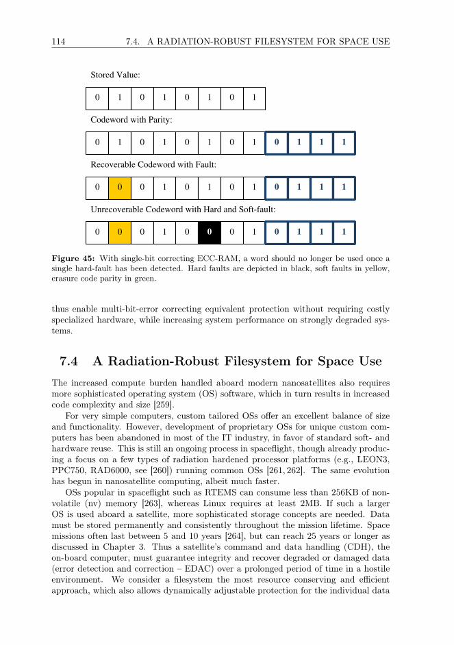
114 7.4. A RADIATION-ROBUST FILESYSTEM FOR SPACE USE
0 1 0 1 0 1 0 1 0 1 1 1
0 0 1 1 0 101
0 0 0 1 0 1 0 1 0 1 1 1
0 0 0 1 0 0 0 1 0 1 1 1
Unrecoverable Codeword with Hard and Soft-fault:
Stored Value:
Codeword with Parity:
Recoverable Codeword with Fault:
Figure 45: With single-bit correcting ECC-RAM, a word should no longer be used once asingle hard-fault has been detected. Hard faults are depicted in black, soft faults in yellow,erasure code parity in green.
thus enable multi-bit-error correcting equivalent protection without requiring costlyspecialized hardware, while increasing system performance on strongly degraded sys-tems.
7.4 A Radiation-Robust Filesystem for Space Use
The increased compute burden handled aboard modern nanosatellites also requiresmore sophisticated operating system (OS) software, which in turn results in increasedcode complexity and size [259].
For very simple computers, custom tailored OSs offer an excellent balance of sizeand functionality. However, development of proprietary OSs for unique custom com-puters has been abandoned in most of the IT industry, in favor of standard soft- andhardware reuse. This is still an ongoing process in spaceflight, though already produc-ing a focus on a few types of radiation hardened processor platforms (e.g., LEON3,PPC750, RAD6000, see [260]) running common OSs [261, 262]. The same evolutionhas begun in nanosatellite computing, albeit much faster.
OSs popular in spaceflight such as RTEMS can consume less than 256KB of non-volatile (nv) memory [263], whereas Linux requires at least 2MB. If such a largerOS is used aboard a satellite, more sophisticated storage concepts are needed. Datamust be stored permanently and consistently throughout the mission lifetime. Spacemissions often last between 5 and 10 years [264], but can reach 25 years or longer asdiscussed in Chapter 3. Thus a satellite’s command and data handling (CDH), theon-board computer, must guarantee integrity and recover degraded or damaged data(error detection and correction – EDAC) over a prolonged period of time in a hostileenvironment. We consider a filesystem the most resource conserving and efficientapproach, which also allows dynamically adjustable protection for the individual data

CHAPTER 7 115
structures. As Magnetoresistive Random-Access Memory (MRAM) [147] is widelyused for radiation resistant data storage in nanosatellites, and therefore we developedFTRFS specifically for this technology.
7.4.1 Related Work and Preexisting File Systems
Filesystems often include performance optimizations such as disk head tracking, uti-lization of data locality and caching. However, most of these enhancements do notapply to storage technologies used in spaceflight. In fact, such optimizations add sig-nificant code overhead, possibly resulting in a more error prone filesystem and mayeven reduce performance.
Next-generation Filesystems, e.g., BTRFS, F2FS, and ZFS, are designed tohandle many-terabyte sized devices and RAID-pools. Silent data corruption has be-come a practical issue with such large volumes [265]. Thus, these filesystems canmaintain checksums for data blocks and metadata. Due to their intended use in largedisk pools, they do also offer integrated multi-device functionality.
Multi-device functionality would certainly be advantageous, but neither ZFS norBTRFS scale to small storage volumes. Minimum volume sizes are far beyond whatcurrent nanosatellite CDHs can offer. Technology scaling for the technologies stronglydrives development of these file systems continuously towards larger volumes Hence,future development of these filesystems will require design decisions the conflict withthe needs for spaceflight applications.
Filesystems for flash devices, similar to the memory technology itself, haveevolved considerably over the past decade [266, 267]. Upcoming filesystems alreadyhandle challenges concerning potentially negative compression rates [268] or eraseblock abstraction, offer proper wear leveling and interact with device EDAC func-tionality (checksumming, spare handling and recovery). UFFS even offers integrityprotection for data and metadata using erasure codes.
Most new flash-filesystems interact directly with memory1, thereby are incom-patible with other memory technologies unless flash properties are emulated. Thisintroduces further IO and may result in unnecessary data loss, as flash memory is ofcourse block oriented.
RAM filesystems are usually optimized for throughput or simplicity, often re-sulting in a relatively slim codebase. If designed for volatile RAM, these filesystemare optimized for simplicity and do not necessarily require a nondestructive unmountprocedure. Non-volatile RAM filesystems access data in memory directly avoidingmany of the indirection and abstraction layers required for more abstract memorytechnologies [269], while some even utilize in-line compression to increase storage ca-pacity [269].
Except for PRAMFS [270], none of these filesystems consider memory protectionto increase dependability. PRAMFS offers execute-in-place (XIP) support [271] andis POSIX-compatible, but offers no data integrity protection.
In contrast to flash memories RAM filesystems are not block based, but benefitfrom the ability to access data arbitrarily. Thereby, no intermediate block manage-ment is required and read-erase-update cycles are unnecessary. While simple block-layer EDAC would certainly be possible, structures within a RAM filesystem can beprotected individually allowing for stronger protection.
1in the case of Linux through the memory technology device subsystem (MTD)

116 7.4. A RADIATION-ROBUST FILESYSTEM FOR SPACE USE
Open source space engineering and CDH research is directed mainly to-wards testing radiation related properties of memory technologies [272, 273] and onNAND-flash in particular [274, 275]. At the time of this writing, we are unaware ofadvanced software-side non-flash driven storage concepts for space use.
7.4.2 FTRFS
We designed FTRFS as Fault-Tolerant Radiation-robust Filesystem for Space use. Itis intended to operate efficiently with small volumes(≤4MB) and assure data integrityfor critical firmware-related data stored within COTS MRAM components. To fulfillits purpose for storing a firmware image, it was designed to be bootable, and alsoto allow for the capacity to scale much to larger volumes than can be achieved withtoggle-MRAM at the time of writing.
As base for this filesystem’s fault model, we assume that computational correctnesswithin the OBC itself can be assured. Furthermore, we assume that within the OBC,ECC is applied to CPU-caches and RAM so that upsets in in-transit data can bedetected and mitigated before they are written to memory. A CPU running FTRFSmust be equipped with a memory management unit with its page-table residing inECC protected volatile memory. All other elements (e.g., periphery and ALUs), othermemories (e.g., registers and buffers) and in-transit data are considered potential errorsources.
Memory protection has been largely ignored in RAM-filesystem design. In part,this can be attributed to a misconception of memory protection as a pure security-measure against malware. However, for directly mapped nv-memory, memory protec-tion introduces the memory management unit as a safeguard against data corruptiondue to upsets in the system [276]. Thus, only in-use memory pages will be writableeven from kernel space, whereas the vast majority of memory is kept read-only, pro-tected from misdirected write access i.e. due to SEUs in a register used for addressingduring a store operation.
FS-level data compression has been popular in size constrained filesystems. How-ever, in our use case, well-compressible data, e.g., textual or binary log data, wouldreside in flash or PCM. Hence for a satellite’s flight software firmware image will yieldlittle gain, a and we therefore do not realize data compression as part of FTRFS,thereby allowing reduced code complexity and increasing performance.
After a detailed OS evaluation which was presented in [Fuchs12], we chose the Linuxkernel as the base for our filesystem due to its adaptability, extensive soft/hardwaresupport and vast community. We decided against utilizing RTEMS mainly due to ourlimited software development manpower. Further details on this evaluation includingscoring data and a detailed description of the used criteria is available in [Fuchs12].
A loss of components has to be compensated at the software- or hardware levelthrough voting or simple redundancy. Multi-device capability was considered for thisfilesystem, however it should rather be implemented below the filesystem level (e.g.,via majority voting in hardware [277]) or as an overlay, e.g., RAIF [96].
The capability to detect and correct metadata and data errors was consideredcrucial during development. Based on the mission duration, destination or the orbit aspacecraft operates in, different levels of protection will be necessary. The protectiveguarantees offered can be adjusted at format time or later through the use of additionaltools.
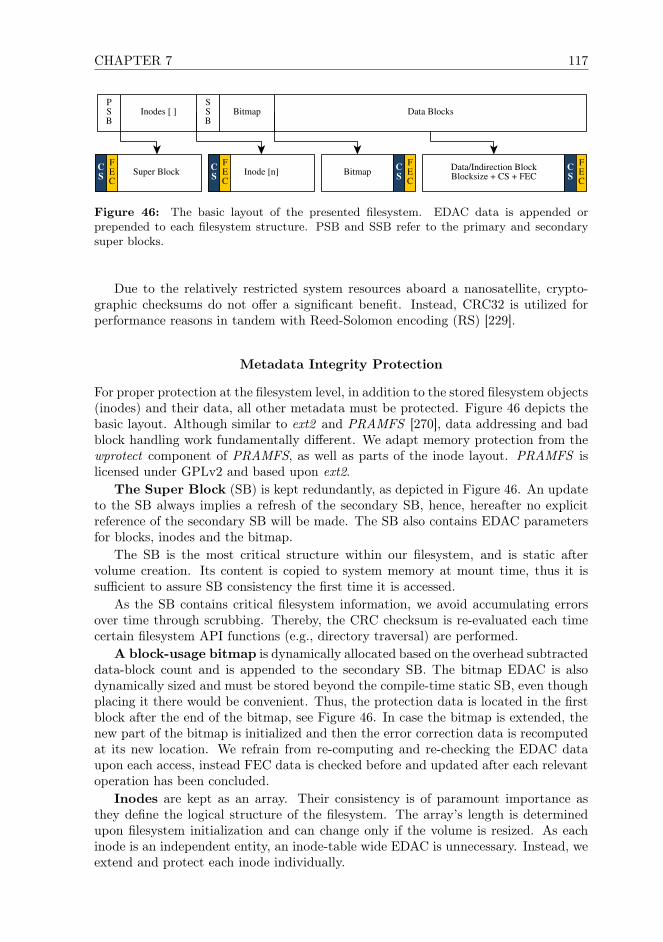
CHAPTER 7 117
Inodes [ ] Bitmap Data BlocksPSB
SSB
Inode [n] Super BlockCS
FEC
Bitmap Data/Indirection BlockBlocksize + CS + FEC
CS
FEC
CS
FEC
CS
FEC
Figure 46: The basic layout of the presented filesystem. EDAC data is appended orprepended to each filesystem structure. PSB and SSB refer to the primary and secondarysuper blocks.
Due to the relatively restricted system resources aboard a nanosatellite, crypto-graphic checksums do not offer a significant benefit. Instead, CRC32 is utilized forperformance reasons in tandem with Reed-Solomon encoding (RS) [229].
Metadata Integrity Protection
For proper protection at the filesystem level, in addition to the stored filesystem objects(inodes) and their data, all other metadata must be protected. Figure 46 depicts thebasic layout. Although similar to ext2 and PRAMFS [270], data addressing and badblock handling work fundamentally different. We adapt memory protection from thewprotect component of PRAMFS, as well as parts of the inode layout. PRAMFS islicensed under GPLv2 and based upon ext2.
The Super Block (SB) is kept redundantly, as depicted in Figure 46. An updateto the SB always implies a refresh of the secondary SB, hence, hereafter no explicitreference of the secondary SB will be made. The SB also contains EDAC parametersfor blocks, inodes and the bitmap.
The SB is the most critical structure within our filesystem, and is static aftervolume creation. Its content is copied to system memory at mount time, thus it issufficient to assure SB consistency the first time it is accessed.
As the SB contains critical filesystem information, we avoid accumulating errorsover time through scrubbing. Thereby, the CRC checksum is re-evaluated each timecertain filesystem API functions (e.g., directory traversal) are performed.
A block-usage bitmap is dynamically allocated based on the overhead subtracteddata-block count and is appended to the secondary SB. The bitmap EDAC is alsodynamically sized and must be stored beyond the compile-time static SB, even thoughplacing it there would be convenient. Thus, the protection data is located in the firstblock after the end of the bitmap, see Figure 46. In case the bitmap is extended, thenew part of the bitmap is initialized and then the error correction data is recomputedat its new location. We refrain from re-computing and re-checking the EDAC dataupon each access, instead FEC data is checked before and updated after each relevantoperation has been concluded.
Inodes are kept as an array. Their consistency is of paramount importance asthey define the logical structure of the filesystem. The array’s length is determinedupon filesystem initialization and can change only if the volume is resized. As eachinode is an independent entity, an inode-table wide EDAC is unnecessary. Instead, weextend and protect each inode individually.

118 7.4. A RADIATION-ROBUST FILESYSTEM FOR SPACE USE
Inode [x]
2x Indir. Block orSingle Data Block
xattr
1x Indir. Blocks [ ]
Data Blocks [ ]
FEC
CS
FEC
CS
FEC
CS
FEC
CS
FEC
CS
First Inodein Directory
CS
FEC
Last Inodein Directory
CS
FEC
ParentDirectory
CS
FEC
prev
next
...RootInode
CS
FEC
...
...
First
Last
First
Last
...
...
Figure 47: Each inode can either utilize direct addressing or double indirection. Extendedattributes are always addressed directly.
Data Consistency and Organization
To optimize the filesystem towards both larger (e.g., a kernel image, a database) andvery small (e.g., scripts) files, direct and double indirect data addressing are supported,as depicted in Figure 47. The filesystem selects automatically which method is used.Data protection requirements vary depending on block size, and use case. Thus FTRFSallows the user to adjust the protection strength for data blocks, as will be describedin the next section.
Data block size cannot be arbitrarily decreased, as some Linux kernel subsystemsassume them to be sized to a power of two. Instead, the filesystem internally utilizeslarger blocks to include EDAC data, see Figure 48.
Extended attributes (xattr) are deduplicated and referenced by one or moreinodes, as depicted in Figure 47. Like in PRAMFS, xattrs are stored as data blocks,thereby we can treat these identically to regular data.
Nanosatellites, at least the non-classified ones, are not yet considered security crit-ical devices. However, the application area of nanosatellites will expand considerablyin the future [220]. An increasing professionalization will introduce enhanced require-ments regarding dependability and security. Shared-satellite usage scenarios as wellas technology testing satellites will certainly also require stronger security measures,which can be implemented using xattrs.
An xattr block’s integrity is verified once its reference is resolved. Once all writeaccess (in bulk) has been concluded, the EDAC data is updated.
Algorithm Details and Performance
Our primary design objective was to create a filesystem which could be used to store afull size-optimized Linux root FS including a kernel image safely over a long period oftime within an 8MB volume. There are numerous erasure codes available that couldbe used to protect our filesystem, as discussed also by Wylie et al. in [102]. Aftercareful consideration, RS was chosen due to the following reasons:
• The algorithm is well analyzed, and widely used in various embedded scenarios,including spacecraft.

CHAPTER 7 119
Word 1(205 Byte)
S = 8b, t = 16S
Word 2 Word 3 Word 4 Word 5
RS1 + CS
RS2 + CS
RS3 + CS
RS4 + CS
RS5 + CS
Total Block Size: 1212B
k = 1024BOverhead180B+8B
Figure 48: A data block subdivided into 5 subblocks. Separate checksums for the entiredata block, EDAC data and each subblock are depicted in blue, which EDAC data is depictedin yellow.
• Highly optimized software implementations of RS encoder and decoder are avail-able as part of standard libraries free of charge and are present in the Linuxkernel.
• Open-source and commercial IP-cores are available to achieve hardware accel-erations in an FPGA-based system, e.g. from opencores, from Xilinx, and viaGRLIB.
• MRAM, while being SEU immune, is still prone to stray-writes, controller errorsand in-transit data corruption. Misdirected access within a page evades memoryprotection and can then corrupt the filesystem, thus corrupted single-byte, 2, 4and 8B runs will occur. RS relies upon symbol level error correction and cansupport symbols longer than 8 bit to then allow much larger codewords. Thiscovers well the practical effects of faults will induce in commercial MRAM ICs.
RS decoding is computationally expensive, thus we split protected data into sub-blocks sized to 128B plus the user specified error number of correction-roots simplifyingaddressing and guaranteeing data alignment for power-of-two correction-root counts.Inodes and SBs can be fit into one single RS-code, while data block length does notresult in extreme checking times. To skip the expensive RS decoding step duringregular operation, a CRC32 checksum allows high-performance checking. The RS-code is only read in case the checksum is invalid.
Data blocks are divided into subblocks so the filesystem can make optimal use ofthe RS code length. For common block-sizes and error correction strengths, 5 to 19 RScodes are necessary, see Table 4 for information on expected overhead. The correctiondata is accumulated at the end of the data block. Checksums across the entire block’sdata, each subblock and the error correction data are also retained. The resulting dataformat is depicted in Figure 48. Protection can be enhanced further by performingsymbol interleaving for the RS codes and the block data, at the cost of performance.
Filesystem traversal and data access will eventually slow down for strongly de-graded storage volumes. As we immediately commit corrected data to memory, per-formance degradation is only temporary, assuming soft-faults.

120 7.4. A RADIATION-ROBUST FILESYSTEM FOR SPACE USE
Results and Current Status
FTRFS has been implemented for the Linux kernel. Due to its POSIX-compliance, itcould easily be ported to other platforms. The memory protection functionality hasbeen inherited from PRAMFS, the filesystem structure from ext2. We utilize the RSimplementation of the Linux kernel, as its API also supports hardware acceleration.
Several components of the filesystem should undergo an optimization process,which will increase fault coverage capacity and read/write performance. Even thoughwe have not yet conducted long-term benchmarking and performance analysis, thethroughput degradation during regular operations is minimal: most modern mobile-market CPU cores can compute CRC32 within a few clock cycles due to hardwareacceleration. We intend to publish additional performance and energy consumptionmetrics, once testing has been concluded and basic optimizations have been appliedand the OBC computer has been finalized.
Data is read and written once per access. It is good practice in critical scenarios andespecially spaceflight to read and write data multiple times, or deploy more advancedconsistency checking techniques [278]. These changes could be applied in bulk, througha macro, or compiler side.
The level of protection offered by FTRFS is adjustable during volume creation, orlater by using a proprietary filesystem-tuning tool. RS has a long record of space usein CDH and communications. Thus, we know the algorithm offers efficient protectionregarding our threat scenario. Once testing has been concluded, we will perform long-term performance analysis in a degraded environment. To benchmark the filesystem,data degradation can be introduced through fault injection.
Limitations and Advanced Applications
It is debatable whether journaling would increase FTRFS’s reliability, as it usuallyhelps safeguard filesystem consistency with slow storage media [279] due to power lossor disconnect. Spontaneous power loss for an OBC could also occur aboard a spacecraftdue to EPS malfunction, but in most cases the practical effects of such an event can behandled differently at the design side. Spacecraft are battery backed and can utilizepower electronics with a sufficient hold-back time to notify and gracefully shut downan OBC in case of EPS failure. All access in our filesystem happens synchronously,
Data Size EC-Symbols Words Parity Overhead OverheadStructure (B) per Word per Block (B) (B) (%)Super Block 128 32 1 32 68 53.13%Inode 160 32 1 32 68 42.50%
Data Blocks 1024 4 5 20 68 5.86%1024 16 5 80 188 17.58%
4096 4 17 68 212 4.98%4096 16 19 304 692 16.70%
Bitmap 1773 32 10 320 688 38.80%
Table 4: EDAC overhead for FS structures. 16MB volume size, 5% inodes, 1024B bock size

CHAPTER 7 121
and MRAM still allows rapid access unlike classical mechanical disks. Hence, FTRFScan thus either conclude a pending write operation within the remaining active time,or the OS will have sufficient time to cancel pending writes in case the system hassufficient warning time. We therefore do not implement journaling.
Our filesystem implementation can currently not handle the failure of entire mem-ory ICs holding the volume, or component-level SEFIs. However, FTRFS could beextended to support RAID-like features to compensate for device failure [277].
If data is stored with RS-symbol interleaving, an XIP mapping would technicallybe impossible. XIP could still perform mappings for non-interleaved data though,but thereby only the clear-text part of each RS code would be mapped and read.Via this memory mapping, integrity protection for stored file data would be ignored,unless we accept that a potential XIP mapping would allow program code to beloaded/executed without any integrity checking. Thereby, the integrity assumptionsupon which FTRFS’s concept is based would be violated and integrity could not beguaranteed for any executed program stored on the filesystem. Theoretically, dataintegrity could also be checked each time a mapping is established for a block. Toperform these checks however, this data would have to be read in full, obsoleting theperformance advantage and RAM conserving properties of XIP. XIP and filesystem-level data integrity protection can thus be considered mutually exclusive.
Permanent faults would cause fault effects to be corrected upon every access toa memory word, which is inefficient Fault in frequently accessed file system compo-nents (e.g., int the root inode), could therefore degrade the performance of FTRFS. Inthe current filesystem implementation, there is no functionality to avoid this behav-ior completely. Bad-block relocation is implemented within the filesystem, but onlyapplied during file data write, truncate and allocation operations. This functionalitycould also be applied to file data read operations as well as for accessed inodes toincrease robustness.
FTRFS could also operate on different memory technologies than MRAM, as longas data in this memory is directly addressable RAM or mapped through OS-kernelmeans (mmap). For more abstract memory technologies such as Flash, FTRFS isnot an optimal solution and a block-based approach as described in the next sectionshould be used.
7.5 High-Performance Flash Memory Integrity
Scientific and future commercial space missions as well as miniaturized satellites im-pose increasing demands on their on-board computer (OBC) systems, especially datastorage devices [280]. They may require vast amounts of data to be stored, highthroughput, and the possibility for concurrent access of multiple threads, programsor devices. While satisfying these requirements, storage systems must guarantee dataintegrity and the recovery of degraded or damaged data (error detection and correc-tion – EDAC) over a prolonged period of time in a hostile environment. Consistentdata storage becomes even more crucial for long-term missions (e.g., JUICE [281] andEuclid [282]) or in cases where highly scaled memory is used.
Legacy memory technologies can not be scaled for modern storage applicationsdue to mass and energy restrictions or result in high complex storage systems. Thus,single-level cell NAND-flash memories (SLC), have become popular for high perfor-mance mass memory scenarios as they offer reasonably high packing density, and can

122 7.5. HIGH-PERFORMANCE FLASH MEMORY INTEGRITY
be manufactured sufficiently radiation hardened. The chip-industry has moved onfrom SLC to multi-level cell flash memories (MLC) due to economical reasons. There-fore, SLC will become unavailable and will force future spacecraft storage conceptsto rely upon MLC or entirely different memory technologies. While there are promis-ing candidates [283] to fill this role in the long run, technological evolution does notyet allow, for example, non-volatile magnetoresistive RAM (MRAM) to be used asmass storage [272]. Phase change [284] or charge-trap based memory both would atpresent be usable as mass storage, but are not yet widely available in high densityversions [157].
Traditionally, single-bit error correction, shielding, specialized manufacturing tech-niques, coarse structure width and redundancy are combined to enable radiation tol-erant flash [285]. However, the protective level offered by such solutions is staticand fixed at design-time and can result in high cost and low overall efficiency. Forminiaturized satellites, cost and efficiency are crucial, thus, countermeasures must beimplemented at a different level. With modern MLC-flash single bit error correction isinsufficient and all-in-one solutions, such as file systems, tend to become very complexand difficult to debug. For future prolonged missions and larger storage arrays, moresophisticated and efficient EDAC concepts are required. Thus, we present an advancedhigh performance dependable storage concept based on composite erasure coding. AsMLC-flash is also widely used aboard miniaturized satellites, and the authors are in-volved in developing such a satellite, MOVE-II, development was originally driven bynanosatellite requirements. However, the approach can be applied more efficiently tocommercial applications where miniaturization imposed limitations do not apply. Theconcept could be implemented even more efficiently with very large volumes commonin commercial spaceflight applications. It can be implemented entirely in software,with or without hardware acceleration, but also partially or fully in hardware.
Single- and Multi-Level Cell Flash
Each flash memory cell contains a single field effect transistor with an additionalfloating gate, the basic functionality of which is described further in Chapter 3. Thestate of a flash memory cell depends on whether the charge stored in the floating gateexceeds a specific threshold voltage (Vt). Hence, a flash memory cell is dependent onthe capability of the memory cell structure to retain a charge. If the voltage exceedsthe threshold, a cell can be read as programmed (0), else as erased (1), see Figure 49a.Single Level Cell Flash (SLC) cells can store one bit per cell.
The charge in an MLC cell can represent more than two states by introducing
t
1 0
EraseVerify
ProgramVerify
Cell Voltage
V
Cell D
istribution
(a)
01 0011 10t3t2t1
Cell D
istribution
Cell Voltage
VVV
(b)
111
100 101 000
110
001
010011
Cell D
istribution
Cell Voltage
(c)
Figure 49: The voltage reference and threshold levels of SLC- flash cells (a) and MLC cellswith 4 (b) and 8 voltage levels (c).
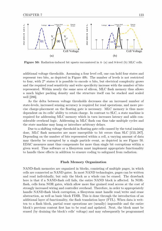
CHAPTER 7 123
00t3t2
Voltage Driftdue to
1001
Cell D
istributio
n
Cell Voltage
VV
Leakage ParticleEvents
(a)
Voltage Driftdue to
110010
101
Cell D
istributio
n
Cell Voltage
Leakage ParticleEvents
(b)
Figure 50: Radiation-induced bit upsets encountered in 4- (a) and 8-level (b) MLC cells.
additional voltage thresholds. Assuming a four level cell, one can hold four states andrepresent two bits, as depicted in Figure 49b. The number of levels is not restrictedto four, with 2n states it is possible to encode n bits, but electrical complexity growsand the required read sensitivity and write specificity increase with the number of bitsrepresented. Within nearly the same area of silicon, MLC flash memory thus allowsa much higher packing density and the structure itself can be stacked and scaledwell [286].
As the delta between voltage thresholds decreases due an increased number ofstate-levels, increased sensing accuracy is required for read operations, and more pre-cise charge-placement on the floating gate is necessary. MLC memory is thus moredependent on its cells’ ability to retain charge. In contrast to SLC, a state machine isrequired for addressing MLC memory which in turn increases latency and adds con-siderable overhead logic. Addressing in MLC flash can thus take multiple cycles andthe state machine may hang or introduce arbitrary delays.
Due to a shifting voltage threshold in floating gate cells caused by the total ionizingdose, MLC flash memories are more susceptible to bit errors than SLC [153, 287].Depending on the number of bits represented within a cell, a varying amount of datamay thereby be corrupted by a single particle event, as depicted in see Figure 50.EDAC measures must thus compensate for more than single bit corruptions within agiven word. Thus software or a filesystem must implement appropriate functionalityto handle these effects in addition to erasure coding to safeguard from radiation.
Flash Memory Organization
NAND-flash memories are organized in blocks, consisting of multiple pages, in whichcells are connected as NAND gates. In most NAND technologies, pages can be writtenand read individually, but only the block as a whole can be erased. The drawbackhere is that if a NAND-flash cell fails, the entire NAND block is affected. In NOR-flash, cells form NOR gates, which allow more fine grained read access at the cost ofstrongly increased wiring and controller overhead. Therefore, in order to appropriatelyhandle NAND-flash block corruption, a filesystem must handle read/write and eraseabstraction, as well as basic block FDIR. This is done through the introduction of anadditional layer of functionality, the flash translation layer (FTL). When data is writ-ten to a flash block, partial erase operations are (usually) impossible and the entireblock’s previous content first has to be read and updated. Next, the block must beerased (by draining the block’s cells’ voltage) and may subsequently be programmed

124 7.5. HIGH-PERFORMANCE FLASH MEMORY INTEGRITY
anew per page. Thus, read and write operations introduce different latency and makeaccess to MLC flash much more complicated than to SLC due to the required address-ing state machine.
To access data and handle special properties of flash efficiently, a filesystem hasto interact with the memory device directly or via the OS’s FTL. A flash filesystemmust implement all functionality necessary to perform block wear leveling, read anderase block abstraction, bad-block relocation and garbage collection (depicted in bluein Figure 51) to prevent premature degradation and failure of a bank. The FTL actsas an interface between hardware specific device drivers and the filesystem, and canprovide part of this FDIR functionality instead of the filesystem. In commercial SSDapplications, this is handled by the SSD’s controller and hidden from the OBC.
Over time, a flash memory bank will accumulate defective pages and blocks hve toand utilize spare pages and blocks to compensate. Traditionally, simple erasure coding(usually some form of cyclic block codes with large symbol sizes) is applied in softwareor by the controller to counter wear and charge leakage. Eventually, the pool of spareswill be depleted, in which case the FTL or filesystem will begin recycling less defectiveblocks and compensate with erasure coding only, thereby sacrificing performance toa certain degree. For space use, the erasure codes’ symbol size is usually reducedto support one or two bit correcting erasure coding, as corruption will mostly resultfrom radiation effects. However, if this solution is applied for MLC-NAND-flash,block EDAC becomes very inefficient due to the occurrence of both single bit- andgrouped errors, the latter being induced by SEUs affecting multiple cells in highlyscaled memory.
Majority Voting for Flash Memories
While voting is technically still possible for MLC-flash, it is severely constrained bythe additional circuitry, logic and strongly varying timing behavior. Voting wouldhave to be implemented for the addressing state machine as well, otherwise it couldstall the entire voting circuit or permanently disable its memory bank. Due to thevarying timing behavior of NAND-flash and the more complex logic, the resultingvoter-circuit thus becomes more error prone. The added logic also requires moreenergy and reduces overall performance. Of course the slowest memory bank or blockalso dictates performance of the voting circuit.
7.5.1 The MTD-mirror Middleware Layer
As outlined in the previous sections, error correction is crucial for current data storagebased on NAND-flash. To enable future dependable MLC-NAND-flash based datastorage solutions for space flight applications, existing EDAC functionality can beadapted and improvements added where necessary. Thus, we developed a storagesystem to satisfy the following requirements:
1. Efficient, fast data storage on MLC mass-memory.
2. Integrity protection and error correction with adjustable strength, to allow op-timization according to mission duration, environment and type.
3. Efficient handling of direct and indirect radiation effects on the memory as wellas the control logic.

CHAPTER 7 125
4. Protection against device failure.
5. Low soft- and hardware complexity: While a certain level of complexity is ac-ceptable for commercial spaceflight applications, it is crucial in microsatellitedesign.
6. Universal filesystem support and interactivity.
We consider these requirements to be met best through enhanced EDAC function-ality as FTL-middleware. At this level, RAID-like features and checksumming can becombined most effectively with a composite erasure coding system. As our use caseincludes a Linux based OBC, we implemented MTD-mirror on the memory technologydevice (MTD) FTL subsystem of the Linux Kernel. The solution is depicted in Figure51. Any unmodified flash-aware filesystem can be deployed on top of the MTD-mirrorset. By utilizing mirroring (RAID1) and distributed parity (RAID5/6) we can there-fore protect against device, bank and block failure. Within this section we focus onmirroring, as the basic concept is very similar to distributed parity sets.
To safeguard against permanent block defects, single event functional interrupts,radiation induced programmatic errors and logic related problems, we apply coarsesymbol level erasure coding. As this is insufficient to compensate for radiation effects,silent data corruption and bit flips are compensated using bit-wise error correction.The solution was implemented in the FTL, as the required logic can still be keptabstract and device independent while it can profit significantly from hardware ac-celeration. The FTL-middleware also provides enhanced diagnostics, as no furtherabstraction is introduced.
MTD-SubsystemMTD-mirror
NAND-Flash
API
Pre-Existing Flash File System
Virtual File System
Read BlockAbstraction
Bad BlockRelocation
GarbageCollection
BlockEDAC
WearLeveling
Erase BlockAbstraction
Figure 51: Memory access hierarchy for an MTD-Mirror set. Flash-memory specific logic isdepicted in blue and partially resides within the FTL. Required modifications to enable theconcept are depicted in yellow.

126 7.5. HIGH-PERFORMANCE FLASH MEMORY INTEGRITY
Alternative Approaches
EDAC and device independence could also be provided by an filesystem directly, whichwe showed for MRAM with FTRFS in Section 7.4. A Flash filesystem such as UFFScould be extended to handle multiple memory devices and EDAC, or FTRFS couldbe modified to handle flash memory. Even though possible to implement, such anall-in-one filesystem would be complex and error prone.
Device independence could also be added on top of an existing flash filesystem as aseparate layer of software [96], see Figure 52. Within a RAIF set, increased protectiverequirements could be satisfied with additional redundant copies of the filesystemcontent. The underlying individual filesystems would then have to handle all EDACfunctionality and escalate fatal errors and unrecoverable file issues to the set, as RAIFby itself does not offer any integrity guarantees beyond filesystem or file failure.
Since RAIF only reads from underlying filesystems, it is prone to filesystem-metadata corruption which can result in single block errors failing entire filesystems.Additionally, Flash-filesystems usually rely upon parameter-fixed block based errorcorrection and do not offer configurable protection for different filesystem structures,which is at best sub-optimal for space use.
A file damaged in different locations across the set’s filesystems would becomeunrecoverable as RAIF would discard information regarding the location of damage toa file and in the best case would forward a defective copy to the application. It wouldtherefore inhibit error correction and may even cripple recovery of larger files. WhileRAIF could be adapted to handle these issues, the resulting storage architecture wouldagain become very complex, difficult to validate and debug. As RAIF implementsfilesystem redundancy, its storage efficiency will furthermore be inferior to distributedparity concepts such as the more advanced variants of the presented concept. As
NAND-Flash
Virtual File System
API
RAIF
Flash File SystemFile EDAC
GarbageCollection
Read BlockAbstraction
BlockRelocation
Erase BlockAbstraction
BlockEDAC
WearLeveling
MetaData
EDAC
Flash Translation Layer
Figure 52: Memory access hierarchy for an enhanced RAIF based concept with addedfilesystem level error correction.

CHAPTER 7 127
a pure software layer without the possibility to interact with the devices, hardwareacceleration of RAIF would be impossible.
Device Failure and SEFI Protection
In contrast to RAIF, RAID can been applied efficiently to storage architectures andhas been used previously aboard spacecraft (e.g., in the GAIA mission) [288]. However,these were based on SLC (see Section 7.5) and only relied on RAID to achieve devicefailover through data mirroring (RAID1) and distributed parity (RAID5/6) [288,289].As RAID itself does not offer any integrity guarantees beyond protection against readdevice failure, designs usually rely upon the block level hardware error correctionprovided by the flash memory or controller or implement simple parity only.
The main issue encountered with plain RAID setups is the absence of validationfor a block or group of blocks. RAID merely retains redundant copies of data – parity– which can be used to restore lost data. RAID foresees that a data block is eitherunrecoverably lost (signaled by a read error) or fully intact; it is thereby prone tosilent data corruption encountered in flash memory [72]. As the basic RAID conceptsdo not utilize checksumming to verify integrity, corrupted data will be read and usedeven if sufficient parity or valid copies were available. However, once checksummingand forward error correction is added to RAID levels, they can be utilized aboardspacecraft efficiently.
The even distribution of bit-errors would be troublesome for symbol based erasure
RAID1
NAND-Flash
FEC
API
Memory Technology Device Subsystem
Flash File System
MTD-blockdev
Virtual File System
Read BlockAbstraction
BlockRelocation
GarbageCollection
BlockEDAC
WearLeveling
Erase BlockAbstraction
Figure 53: RAID prevents EDAC and wear leveling functionality withing a flash-filesystemfrom being implemented. Affected elements are colorized in gray.

128 7.5. HIGH-PERFORMANCE FLASH MEMORY INTEGRITY
Layer 1RSPage Data Layer 2
LDPC
CRCE
CRCD
Covered by LDPC Coding
Covered by Reed-Solomon Coding
Included in Data Checksum (CRC-D) Erasure Checksum (CRC-E)
Figure 54: The layout of an MTD-mirror page. Added erasure code correction informationis depicted in yellow, checksums in blue.
codes traditionally applied for flash block EDAC. Utilizing RAID on top of block basederasure coding is thus insufficient for protecting MLC-NAND-flash.
RAID functionality usually would be implemented as a block layer. This is certainlypossible also for flash memory, however it would hinder the file system from performingblock EDAC and wear leveling. While block abstraction would still be possible even ontop of a block layer on-top of the FTL, other high-level filesystem functionality wouldbe denied device access, depicted in red in Figure 53. These functions would thenhave to be implemented at a much lower level within the access hierarchy, introducingfurther code overhead and reducing EDAC efficiency.
RAID-like functionality could however also be implemented as a middleware withinthe FTL as depicted in Figure 51. As such, it can interact both with the underlyingflash memory as well as the filesystem and the rest of the FTL, without requiringalterations to either. Such middleware can remain previous to filesystem operationsrequiring direct interactivity with the underlying flash and at the same time allowdevice failure protection to be combined with enhanced erasure coding. RAID cantherein be implemented with comparably little effort. Validation, testing and analysiscan thus be simplified as all implementation work can be concentrated into an FTLmiddleware module.
Block-Level Consistency
MTD-mirror’s block consistency protection is depicted in Figure 54 and includes twochecksums and error encoding layers. Thus, it implements a concatenated/compositeerasure code system. The data checksum allows bypassing decoding of intact data,which will often be the optimistic default case. The second checksum can be usedfor error-scrubbing of erasure data and prevents symbol drift of the RS-layer. Eventhough CRC16 could be considered sufficient for most common page and block sizes,we utilize a 32-bit checksum to further minimize collision probability at a minimalcompute overhead.
Protection against Multi-Bit Upsets
The first layer of erasure coding is based on relatively coarse symbols and protectsagainst data corruption induced by stray writes, controller issues and multi-bit errors.As data on NAND-flash is stored in pages and blocks of fixed length and the codinglayer should protect against corruption up to 8 byte length (int64_t), Reed-Solomon(RS) erasure coding [103] was selected. We chose to rely on the RS block code as thealgorithm is well analyzed, and widely used with NAND-flash memory and in variousembedded scenarios, including spacecraft. Optimized software implementations, IP-cores and hardware acceleration are available.

CHAPTER 7 129
Erasure coding with coarse symbols is efficient if symbols are largely or entirelycorrupted, but shows weak performance when compensating radiation-induced bit-rot, to which MLC is comparably prone. SEUs will be evenly distributed across thememory and will thus equally degrade all data of a code word, corrupting multiple codesymbols with comparably few bit errors. Therefore, RS is applied at the page level,instead of the block level to allow more efficient reads and avoid access to other pageswithin the same block to retrieve erasure coding parity. RS parity is therefore storedwithin each page, together with a checksum for the page and the parity. RS encodingand decoding can be should parallelized due to the small word sizes in hardware.
Bit-Level Erasure Coding
Previous radiation-tolerant OBC storage concepts often relied upon convolution codesas these allow efficient single-bit error correction. However, as error-models becomemore complex (2-bit errors as in MLC), codes complexity increases and efficiencydiminishes. Therefore, a second level of erasure coding using Low-Density ParityCheck Codes (LDPC) [290] was added to counter single or double bit-flips withinindividual code symbols of the first level RS code. LDPC was chosen as it is efficientwith very small symbol sizes (1 or two bit), offers superior performance comparedto convolution codes [291], and allows iterative decoding [292]. Only if RS decodingfails, the set resorts to LDPC. LCPC can then support recovery of slightly corruptedRS-symbols and parity. Thereby otherwise unrecoverable data can be repaired bysalvaging damaged symbols which can drastically increase recovery rates on radiation-degraded memories.
Although LDPC codes benefit from longer code word lengths, Morita et al. [293]show that the gain from a 4KB code to a 32KB code can be negligible. For systemswhere buffer memory is scarce, it may therefore be of advantage to use comparablysmall codes and sacrifice a bit of LDPC performance. Thus, an LDPC word sizebetween 3 and 4KB offers solid LDPC performance without requiring very large wordsand thereby enable fast iterative decoding.
Joint Iterative Decoding using Soft-Output Shorter code words also enablejoint iterative decoding [294] using soft-output for both LDPC and RS codes. LDPCcan be adjusted to output not only plain copy of the expected original code word,but can also yield the decoder’s certainty about each bit’s value. Equally, an RSdecoder could be extended to handle such soft-input. Then, it could attempt decodingto decode multiple variants of a corrupted word using different uncertain positionalvalues from the LDPC soft-output.
In practice, this allows us to produce linear composite erasure coding system,which we depict in Figure 55. However, decoding does not have to happen linearly:A hardware-implemented LDPC decoder has a considerable logic footprint, while RSdecoding can be parallelized. Hence, it may be desirable to construct such a compositesystem by paralellizing RS decoding.
As depicted in Figure 55, a closed feedback-loop that inputs the soft message outputR(Y ) of the LDPC decoder into RS can be constructed. The system iterates betweenRS and LDPC decoding until either decoder can reconstruct a valid code word. Totackle the issue of the thereby variable timing behavior, the number of iterations canbe limited or a timeout can be defined.

130 7.5. HIGH-PERFORMANCE FLASH MEMORY INTEGRITY
Error Handling Runtime Behavior In case the checksum does not match theplain block data, an MTD-mirror set will first attempt to retrieve an intact copy of thedata from another memory of the RAID-set. If this fails, or all other blocks are invalidas well, erasure decoding for the damaged block is attempted. As multiple copies ofthe erasure code parity data and checksums are available, the set can also attemptrepair using fields of different blocks in the hope of obtaining a consistent combinationof block-data. This behavior can allow recovery even of strongly degraded data orpermanently defective blocks.
As RS hardware-acceleration is readily available in our use-case, we apply the twoFEC layers in order (Figure 54). However, the sequence can be chosen based on theindividual system design, the used algorithmic parameters, the available accelerationpossibilities and phase of the mission. An important aspect for this decision is theexpected level of degradation of the utilized flash memory due to radiation, thus theoccurrence of single bit errors. If severe bit-rot is expected or higher order densityMLC is used, the LDPC-layer should be applied prior to RS decoding. Thereby, theincreased probability of the second FEC layer failing to recover data is accepted in thehope of achieving a sufficiently high amount of intact code symbols.
7.5.2 Advanced Applications
In this section, we focused on describing a storage solution based on RAID1 forsimplicity reasons. While the logic required to implement this storage solution isrelatively simple, more advanced distributed parity RAID concepts offer increasedmass/cost/energy efficiency due to overhead reduction. Thus, we have been workingto adapt and expand MTD-mirror to benefit from such more advanced architectures.
There has been prior research on adding checksumming support to RAID5 in [288,289], though utilizing RAID5 directly would introduce certain problematic aspects.
RS decodingRS decoding
RS encodingRS encoding
Page n
LDPC decoding RS decoding
Page n+1Page n-1
RS encoding LDPC encoding
Check Integrity
GenerateChecksums
Write Access:
Read Access:Soft Output with P(RS-Word Bits)
Fault
Input
Error in
Page
Valid
Page Data
Error Corrected
Page Data
page not
correctable
Figure 55: Joint iterative decoding using LDPC soft-output with added parallelization(triple-arrows). RS encoding can be parallelized to increase write-throughput. SpeculativeRS-decoding could be utilized to reduce LDPC iterations by performing multiple parallelRS-decoding attempts with different values for low-certainty bits.

CHAPTER 7 131
Error correction information in RAID5C can either be stored redundantly with eachblock, introducing unnecessary overhead, or as single copy within the parity-block.While this would increase the net storage capacity, a single point of failure would beintroduced for each block group. If the parity block was lost, the integrity of datawhich was protected by this block could no longer be verified. Instead, RAID5 canbe applied to data and error correction information independently, only requiring oneextra checksum to be stored with each block.
RAID6, however, can be implemented almost as-is, with error correction data andchecksums being stored directly on the two or more parity blocks associated with eachgroup. There are also promising concepts for utilizing erasure coding for generatingparity blocks by themselves, thereby obsoleting simple hamming-distance based paritycoding [97,295]. Further research on this topic is required and may enable optimizationfor flash memory and radiation aspects similar to the ones described in this paper.
7.6 Conclusions
In this chapter we presented three software-driven concepts to assure storage consis-tency, each specifically designed towards protecting key OBC components: a systemfor volatile memory protection, FTRFS to protect firmware or OS images and MTD-mirror to safeguard payload data. All outlined solutions can be applied to differentOBC designs and do not require the OBC to be specifically designed for them. Theycan be used universally in miniaturized satellite architectures for both long and short-term missions, thereby laying the foundation to fault tolerance at the system level. Incontrast to earlier concepts, none of the approaches requires or enforces design-timefixed protection parameters. Both can be implemented either completely in software,or as hardware accelerated hybrids. The protective guarantees offered are fully run-time configurable.
Assuring integrity of core system storage up to a size of several gigabytes, FTRFSenables a software-side protective scheme against data degradation. Thereby, we havedemonstrated the feasibility of a simple bootable, POSIX-compatible filesystem whichcan efficiently protect a full OS image. The MTD-mirror middleware enables reliablehigh-performance MLC-NAND-flash usage with a minimal set of software and logic.MTD-mirror is independent of the particular memory devices and can be entirelybased on nanosatellite-compatible flash chips by utilizing FEC enabled RAID1 andchecksumming.
Neither traditional hardware nor pure software measures individually can guaranteesufficiently strong system consistency for long-term missions. Traditionally, strongerEDAC and component-redundancy are used to compensate for radiation effects inspace systems, which does not scale for complex systems and results in increased en-ergy consumption. While redundancy and hardware-side voting can protect well fromdevice failure, data integrity protection is difficult at this level. A combination of hard-ware and software measures, as outlined in this chapter, thus can increase robustness,especially for missions with a very long duration. Thereby, a low-complexity satellitearchitecture can be maintained, thereby error sources reduced, while testability andthroughput can be increased.

132 7.6. CONCLUSIONS

134 8.1. INTRODUCTION
8.1 Introduction
Modern embedded technology is a driving factor in satellite miniaturization, whichtoday enables an entire class of smaller, lighter, and cheaper class of spacecraft. Thesemicro- and nanosatellites (100kg-1kg mass) have become increasingly popular for avariety of commercial and scientific missions, which were considered infeasible in thepast. They are drivers of a massive boom in satellite launches, new scientific andcommercial space missions, laying the foundation for a rapidly evolving new spaceindustry. However, these spacecraft suffer from low reliability, discouraging their usein long or critical missions, and for high-priority science.
For larger spacecraft, various protective concepts are available to assure fault toler-ance (FT) through hardware measures. However, these concepts are effective only fortraditional semiconductors manufactured in technology nodes with a large feature size.Such hardware can not be utilized aboard miniaturized spacecraft due to tight energy,mass, volume constraints, and high cost. Conventional embedded and mobile-marketsystems-on-chip (SoCs) are deployed in their stead, which only utilize error correctionto handle wear and aging effects encountered on the ground. A significant share ofpost-deployment issues aboard nanosatellites can be attributed directly to the failureof these components and peripheral electronics [2], which caused usually by designfailures and effects induced by the space environment, e.g., [296].
Therefore, we developed a non-intrusive, flexible, hybrid hardware/software archi-tecture (see Chapter 4) to assure FT with commercial-off-the-shelf (COTS) mobile-market technology based on an FPGA-implemented MPSoC design. Our architectureutilizes multiple FT measures across the embedded stack, and runs software in coarse-grain thread-level lockstep to assure computation correctness through replication. Itcan offer strong fault coverage without relying upon any space-proprietary logic, cus-tom processor cores, or other radiation-hardening measures in hardware.
The utilized lockstep concept facilitates state synchronization and forward errorcorrection between otherwise independent processor cores. It also provides fault de-tection capabilities for other FT stages which otherwise would lack fault detectioncapabilities: FPGA reconfiguration and dynamic thread-replication and relocationbased on mixed criticality. Therefore, it not only offers fault coverage, but also trig-gers other protective features of our architecture, requiring thorough validation beforea custom-PCB based prototype can be constructed.
Validation of such FT measures requires systematic testing of the actual conceptimplementation, a realistic fault model, a consistent fault model definition, and asuitable test setup. As our lockstep is part of the operating system kernel, system-level fault injection and application-level testing do not offer a sufficient level of test-coverage, and instead a variety of fault injection techniques for software are available.While validation using fault injection using a realistic test-setup is best practice in faulttolerance research and space-hardware development, very few coarse-grain lockstepconcepts have been implemented and validated in this way. Most concepts describedin academic publications today, instead are validated only using mathematical modelsonly, but were not actually implemented or practically validated.
At the time of writing the 2018 – 2019 period, careful study of journals and con-ference proceedings yields only a single coarse-grain lockstep concept [199] that waspractically implemented, and validated based on a realistic fault profile. Practicalimplementation and the possibility to compare an implementation’s performance to

CHAPTER 8 135
literature, however, is seen as a prerequisite by industrial users to consider an FTconcept mature enough for practical application. This situation has resulted in a gapbetween theory and application, with industry often dismissing software-implementedFT concepts due to a (perceived?) lack of maturity and an (assumed?) tendencyto ignore practical implementation obstacles. The research results of an entire fieldof research, dependable computing through software measures, are thus practicallybarred from application for an entire industry segment even though there would be apressing technological need and a lack of viable alternatives. For critical applicationslike in the space industry, practical concept validation is then just the first of manyvalidation and testing steps: eventually system-level testing is conducted with a hard-ware/software prototype. For space application, this prototype is then subjected toradiation testing followed by on-orbit demonstration.
8.1.1 Contributions
In this chapter, we show how software-implemented FT concepts can be validated forspace applications in a realistic and representative manner, and fields with a similarfault profile, e.g., critical and irradiated environments. We do so by example of a fault-injection campaign we conducted to validate a novel thread-level coarse grain lockstepconcept we developed for space applications, described in detail in Chapter 4. Weutilize ISA-level fault injection into an ARM Cortex-A system through virtualization,and fault injection into a 3-core SystemC-implemented MPSoC. This chapter includesnot only concept validation but is meant as a template for other researchers whowish to validate their own software-implemented FT concepts. We provide a detaileddescription of the fault profile in the space environment, and a through description ofthe utilized tools and scripts, which have been made available to the public. Thereby,we hope to increase acceptance of software implemented FT concepts by industry, andthe share of concepts which are validated in a practically meaningful way.
A single set of data points is insufficient to judge the performance and effectivenessof the entire coarse-grain lockstep concept class. Thus, it is of great importance tooffer a second set of validation results to allow fellow researchers to compare theirforthcoming results to more than just one single paper. We document a variety oflessons learned as part of this campaign, which have allowed us to develop a betterunderstand the practical behavior and protective properties of coarse-grained lockstepin critical systems.
Few software-implemented FT concepts proposed today have been implemented,and only a handful have been validated in a realistic and meaningful way. Thereforethis chapter serves as practical guide for fellow researchers that can be used as walk-through to make proper testing of fault tolerance techniques a less challenging andtime consuming task in an academic environment. The strategy which we describethroughout the remainder of this chapter is depicted in Figure 56, and described brieflybelow.
8.1.2 Chapter Organization
In the next section, we discuss how the challenges of the space environment describedin Chapter 3 are met today in the industry, outline which solutions currently areavailable, and how these are tested. We then derive a practical fault model for an RTOSimplementation of this approach (Section 8.4), and analyze which testing techniques

136 8.2. RELATED WORK
9
Abstract Fault Model(Chapter 2 & 3)
Target Application & Scope(Section 8.3)
Practical Fault Model Definition(Section 8.4)
Test Technique Selection(Section 8.5)
Test Tool Selection andTest Campaign Setup
(Section 8.6)
Execute Test Campaign(Section 8.7)
Result Analysis &Comparison to Literature
(Section 8.8 - 8.11)
Target Binary Implementation(Section 8.7.2)
Test Space Definition(Section 8.7.3)
Adequate? Parametrization?
Rework Required?
Bugfixing
Figure 56: The top-down step-by-step testing strategy described in this chapter, withindications in which section each step is discussed.
are available to verify the lockstep in Section 8.5. Having chosen the most suitable faultinjection techniques for our architecture, in Section 8.7 we describe the automated testtoolchain we developed to systematically conduct our test campaign. We utilize a set offault-templates to inject the different faults types described in Section 8.7.3, which wederive from our fault model. The results of our fault injection campaign are presentedin Section 8.8, and we compare them to related work in 8.10. Before presentingconclusions, we document pitfalls encountered while preparing and conducting ourcampaign in Section 8.11, and describe changes made due to lessons learned duringvalidation.
8.2 Related Work
Computer architectures for space-use usually undergo radiation testing or laser faultinjection, as the state of the art in the field today is focused on hardware-level FT
CHAPTER 8 137
measures or specialized manufacturing (RHBD and RHBM – radiation hardened bydesign/manufacturing). FT is traditionally implemented through circuit-, RTL-, core-, and OBC-level majority voting [104, 132, 188] using space-proprietary IP, which isdifficult and costly to maintain and test. Circuit-, RTL-, and core-level voting areeffective for small SoCs such as microcontrollers, but this does not scale for the morepotent processor cores used in modern mobile-market MPSoCs [88, 191]. Softwaretakes no active part in fault mitigation within such systems, as faults are suppressedat the circuit level and usually only indicated using hardware fault counters, withouta direct feedback between fault-mitigation and software. Hence, testing is stronglyfocused on the pure hardware with software functionality during tests often beingreduced to stub implementations to assert basic functionality.
The characterization of the effects induced by radiation within a semiconductor isof major concern when implementing traditional hardware-FT based systems. Today,radiation testing is the only practical way to evaluate them, with radiation modelsoffering useful but tentative and often inaccurate high-level fault estimates. Radiationtest results for different components including memory and watchdog/supervisor-µCsare available in databases such as ESCIES, NASA’s NEPP1 and the IEEE REDWRecords. Relevant radiation tests have been conducted for the FPGAs utilized in ourproject, among others by Lee et al. in [297] and Berg et al. in [143], or are currentlyongoing (Glorieux et al. [298,299]).
Radiation testing can occur only at a very late stage in development, and the resultsmay vary even for identical chip-designs manufactured in different fabs and fabricationlines. This form of testing effectively yields heritage and increases a system’s technol-ogy readiness level, instead of verifying the effectiveness of a specific FT mechanism.For our architecture, radiation tests yield device-specific data, which enabling us toestimate fault frequencies, types, and effects on the FPGA on which our MPSoC isimplemented. We require this information to choose an appropriate checkpoint fre-quency and frame times for our coarse-grain lockstep approach. By itself, however,radiation tests do not allow an assessment of the capabilities of software-implementedFT measures.
While transient random bit-flips are often considered in academic literature, theotherwise different fault model [5] prevents the re-use of many FT approaches devel-oped for ground applications. Also, the form factor constraints aboard miniaturizedsatellites [197] prevent the re-use of most high-availability and failover concepts forcritical terrestrial control applications. Even for atmospheric aerospace applications,dependable computing usually considers availability, non-stop operation, and safety,but rarely computational correctness in a fully isolated and autonomous system.
Prior research on software-implemented FT often considers faults to be isolated,side effect free and local to an individual application thread [208] or purely tran-sient [199,205]. Many practical application obstacles could be uncovered and resolvedbefore publication by implementing these concepts [198]. However, implementation ofa measure and fault injection are time consuming tasks [300]. They often require notonly software to be implemented, but also suitable tools and hardware or a represen-tative substitute, as outlined among others by Sangchoolie et al. in [301]. Especiallyfault injection for entire OS instances is non-trivial [302], as thorough preparationand careful test-tool selection is necessary to obtain representative results from a faultinjection experiment [303]. Therefore, a sizable share of FT concepts exists at a theo-
1see https://escies.org and https://nepp.nasa.gov

138 8.3. TARGET IMPLEMENTATION
retical level [212–214], instead of having undergone fault injection or hardware testing.To still achieve some degree of validation, many publications thus resort to statisticalmodeling using different fault distributions. This is a viable approach for validatingFT concepts directed towards, e.g., yield maximization [58] and aging [304], but notfor software-implemented FT measures for critical environments.
In this chapter, we conduct systematic validation of our coarse-grain lockstep ap-proach using fault injection to verify the effectiveness and efficiency of our coarse-grainlockstep FDIR mechanisms under stress. Specifically, we must assure voter stabilityand a sufficient level of fault detection to avoid accumulating silent data corruptionand excessively brief frame times, while helping assess the amount of spare resourcesneeded. Together with FPGA-level fault-information obtained from radiation testsoutlined earlier in this section, and information on the mission specific target environ-ment, we can then calculate the appropriate fault-frequency for a specific mission andspacecraft.
8.3 Target Implementation
The high-level logic of our architecture is depicted in Figure 57, and consists of threeinterlinked fault mitigation stages implemented across the embedded stack. It is de-scribed in detail in Chapters 4 through 6. At the core of this architecture is a coarse-grain thread-level lockstep implemented within the kernel of an OS, which we refer toas Stage 1. It implements forward error correction and utilizes coarse-grain lockstepto generate a distributed majority decision for an operating system. The thread-level
MPSoC Supervisor & Config Controler
Bootup
Checkpoint
ApplicationExecution
Read MajorityDecision
CheckFault Counter
UpdateCompartment
Stage 3Mixed Criticality
ReplaceCompartment
Stage 3Mixed Criticality
< limit > limit
recoveredfunctionality failure
Figure 57: Stage 1 (white) assures fault detection (bold) and fault coverage, Stage 2 (blue)and 3 (yellow) counter resource exhaustion and adapt to reduced system resources.

CHAPTER 8 139
lockstep assures the integrity of software replicas run on a set of otherwise isolated,weakly coupled processor cores. Fault detection is facilitated through application-provided callback functions, requiring no knowledge about application intrinsics andalso no modifications to the application structure. Faults are resolved through statere-synchronization and thread migration to processors with spare processing capac-ity. Stage 1 is described in further in Chapter 4, where we also establish an upperbound for the performance cost of the lockstep. This coarse-grain lockstep is validatedin this chapter, and provides fault-detection capacity for the subsequent stages andshort-term fault-recovery.
8.4 Obtaining a Practical Fault Model
To properly validate software-implemented FT measures, information on the physicalfault model is required. This information is necessary to choose a fault-injectiontechnique and the right tools to inject the faults. In the remainder of this section,we show how to deduct a practical fault model from our operating environment. Thisenables us to subsequently determine the most suitable fault injection technique aswell as to build a concrete test-space for our fault injection campaign.
To validate our lockstep implementation, we must specifically test how well ourlockstep implementation can detect faults. We need to verify this not only at thesystem level, following a majority decision by all involved compartments, but alsolocally by an individual lockstepped compartment into which a fault has been injected.Besides fault detection and the possibility for recovery, it is necessary to determinehow stable or unstable a lockstep will behave. For space applications, a software-implemented FT concept must be subjected to transient faults, permanent faults,faults that are neither (intermittent faults). The effect of a radiation induced faultdepends on the particular effected chip region, logic, and microfabrication technologyused [5].
Our coarse-grain lockstep exists as part of the scheduler and utilizes a set of ap-plication callbacks. Therefore, we must consider the actual effect and impact of faultson the system from a programmatic perspective. Radiation induced faults will, thus,have the following effects on the software executed within one of our MPSoC’s com-partments:
• Data corruption associated with access to main memory, caches, registers andscratchpad memory due to non-correctable ECC words caused by SEEs.
• Bit upsets, new-value, and zero-value faults due to SEEs and SEFIs in addressand control logic of peripheral IP due.
• Incorrect or non-execution of instructions in the processor pipeline during the en-tire sequence of processing, i.e. from instruction fetch, execute to write-back, aswell as incorrect decoding of instructions and execution of different instructionswith the given parameters.
• Control-flow deviations and data corruption due to failure of interfaces and com-partment I/O peripherals, due to faults in controller logic of FPGA’s I/O com-ponents.

140 8.5. SUITABLE FAULT-INJECTION TECHNIQUES
To properly represent these faults, we should inject both bit-flips and new-values.Random fuzzing or type-fault injection are widely used for finding exploits and vul-nerabilities in software, as well as logic bugs, but are not useful for our purposes dueto the different physical fault scenario. Proper validation for software must be sys-tematic [305], which can not be achieved at the system-level when testing a physicalhardware prototype. Software must be tested separately and systematically, so thatthen a prototype can be developed that can undergo system-level testing.
A broad variety of synthetic, theoretical failure types are well described in liter-ature, e.g., in [303]. In practice these do emerge as one of the described fault types.As discussed among others in [306], most of these synthetic failure modes [303] ac-tually emerge as one of the aforementioned effects. To validate the fault-detectionand mitigation capabilities of our lockstep to radiation effects, we are only interestedin the practical effects of a fault, not its theoretical origin, as discussed further bySangchoolie et al. in [301].
Radiation can induce subtle effects into logic and may affect the OBC at a systemlevel (e.g., full component failure or reset) [143]. Such faults emerge disguised asone of the aforementioned ones in case their effects are transient or intermittent.Furthermore, we also need to test the lockstep’s behavior under permanent faults.
Faults with a permanent effect are either fatal to a compartment, therefore directlydetectable by other compartments by majority decision, or affect the system as awhole. Our lockstep is not designed to recover the system from large-scale system-level permanent faults, and utilizes spare resources to cover the permanent failure ofindividual compartments. These are covered by Stage 2 and, if necessary, escalated toor detected by the on-board computer’s external supervisor through time-out.
8.5 Suitable Fault-Injection Techniques
Fault injection into a live hardware-system or an FPGA (e.g., using JTAG or ICAP)would be most straight forward way of conducting fault injection. As research bud-gets are finite, this naive approach does not allow a meaningful level of test coveragefrom being achieved, as systematic test coverage is potentially destructive [115], timeconsuming, and would require a high degree of parallelization. [307]
As our architecture is designed for FPGA, fault injection using netlist simula-tion [64] or directly into the FPGA [115, 308] could be facilitated with comparably2
little development effort, as we already utilize a development-board based MPSoCdesign implementation. This technique would grant precise control over the type andeffect of faults and the simulation could be conducted with a system closely correspond-ing to the real one. Several proprietary partially [115, 308, 309] and fully automatedtest frameworks [310] as well as commercial applications [64] have been developed forthis purpose. Unfortunately, netlist simulation of a full MPSoC is computationallydisproportionately expensive. Therefore, netlist simulation, too, does not allow us toachieve meaningful level of test coverage.
Faults could also be injected via widely available standard software debug tools(e.g., GDB) into software running in userland. This is only representative for testsconsidering only the effects of transient faults in simple userland applications [199].The effects of faults on a full OS implementation and permanent component damage
2as compared to developing a new FPGA design from scratch for the purpose of testing.

CHAPTER 8 141
cannot be simulated [311]. Furthermore, validation of embedded software for low-power ARM or RISC-V SoCs using desktop-grade ia32/amd64 hosts may bias theoutcome of a fault injection experiment, as the platforms and their ABIs are fun-damentally different. Fault injection into kernel functionality emulated in userlandmay also result in a different run-time behavior than when running bare-metal. Thistechnique can therefore only yield meaningful validation results for pure applicationlevel FT concepts [303]. Debugger-driven fault injection into a virtual machine canalleviate these constraints by allowing an actual OS to be tested. However, this tech-nique is unable to correctly simulate permanent and intermittent faults in componentsother than memory and the current execution context. In consequence, the fault injec-tion using debug tools is significantly constrained [303] and insufficient for validatingour lockstep. This is an inherent limitation of that can only be alleviated throughcooperation of a virtual machine monitor without hardware acceleration [302].
ISA-level binary instrumentation has been shown powerful and efficient for con-ducting black- and grey-box fault injection [301], and is today widely used for reverseengineering, security and malware analysis purposes. Though most of these tools aretuned towards reverse engineering, not fault injection. Fault-injection capable toolsdiscussed today in relevant publications are mostly proprietary to individual researchgroups [301, 312]. Without exception, they are rather experimental and tuned to-wards single applications, and often also simply not publicly available [312]. To becomparable however, proprietary tools unavailable to all but a research group are notrelevant.
Fault-injection into a virtual machine (VM), in contrast, allows considerable codeand tool reuse: a VM can be constructed using pre-existing virtualized hardwareavailable in widely used standard tools. Due to the considerable optimization effortinvested into virtual machine monitors, this technique is computationally relativelycheap. Depending on the used VM technology, it no changes are to a victim applicationand the emulated machine be can resemble the actual intended target system ratherclosely. Several test frameworks implementing this approach have emerged in recentyears, though most are still custom tailored for specific usecases or have not beenreleased to the public [300, 305]. Notable exceptions here are the two open sourceframeworks FAIL [306] and FIES [313]. These are publicly and freely available asopen source software and reasonably mature, and therefore we began to conduct ourfault-injection campaign using this technique. However, these tools are only capableof injecting faults into a single core of an MPSoC, even though they can simulate aVM with multiple processor cores.
Fault injection using system simulation can combine many of the advantages ofthe aforementioned techniques. In prior research, actual MPSoC architectures weresimulated using SystemC to demonstrate architectural features. This could also beused as compromise between the level of detail and extreme computational cost offault injection using netlist simulation, and limitations of fault-injection using systememulation when targeting an multicore system. Until recently, however, modelingand implementation of an MPSoC capable of running real software software usingSystemC required an excessive amount of development effort. With the emergence ofmodern architecture description languages such as ArchC and in combination with theemergence of more open processor core designs such as RISC-V, the development effortnecessary to do so has been reduced to a more realistic level. We therefore conductedfurther testing of our implementation for with an ArchC implemented SystemC model

142 8.6. TEST CAMPAIGN SETUP
our our MPSoC to validate our lockstep in a true multi-core environment without theconstraints of system-emulation-based fault injection.
8.6 Test Campaign Setup
Having determined a fault-injection techniques and knowing what kind of faults needto be injected, we must prepare a suitable test environment to properly To achieve sys-tematic test coverage, manual fault injection or injection relying upon manual binaryintrospection are unsuitable. Instead, an automated campaign setup is needed. Inthis environment, we can then subject our lockstep implementation to fault injectionin bulk. This process can then be paralleled to achieve the desired test coverage. Inthis section, we therefore describe how such a test setup can be realized with limiteddevelopment manpower, and pre-existing standard software based on our own setup.
Our fault injection toolchain performs the following steps implemented as a set ofpython scripts:
1. Result harvesting: obtain the victim application’s process state, results andcorrect lockstep checksums for each payload application. We run the emulationwithout fault injection and tracing, outputting the application and OS state forcomparison during later steps. This allows us to e.g., include additional debugoutput or otherwise alter the victim-binary’s code for our golden run. Thereby,we can obtain a correct victim OS state without distorting the actual golden-run.
2. Fault-free simulation: we execute a golden run of our target implementation andgenerate traces for executed instructions, register and memory access with theactual binary used for fault injection.
3. Filter the traces to constrain fault injection to application relevant code anddata (e.g., omitting platform bring-up, OS, and shutdown code).
4. Remove duplicates, and annotate each trace-entry with the number of occurrencein the trace, generating the test-campaign input data.
5. For each address and occurrence, we generate a fault definition based on a tem-plate and launch an instance of our fault injection tool.
6. Based on a comparison to the known-correct results obtained in the first step, wedetermine the impact of the injected fault (e.g., OS crash, incorrect checksum,SDC, etc.) and log the result to an sqlite3 database. Besides collecting andinterpreting the results of a fault injection run, we also retain compartmentstate information to enable manual analysis in the future if necessary. Thisincludes a compartment’s human readable output to each compartments’ serialport, CPU and qemu processor context dumps, as well as the logs generated byFIES during the fault injection, as well as its exit code.
Steps 1-3 are executed once at the beginning of a test campaign, whereas steps 4and 5 are computationally comparably expensive but can be parallelized. As sqlitestores a run’s database in an individual file, result databases from different systems
3Any database would work, but we want to keep the results portable so they can be combinedlater one.

CHAPTER 8 143
can be merged, and each test record includes information about the precise injectedfault.
Long fault injection campaigns place considerable strain on host a computer’sfilesystem. While running our test campaigns, we discovered that this can cause inducesignificant wear in SSD-based storage device. When replicating this setup, the avidreader may wish to instead conduct fault injection fully in memory to avoid damagethe host computer’s SSD. This can be achieved by running experiments in a ramdisk,e.g., by mounting tmpfs on the experiment directory.
8.7 Executing a Test Campaign
We conducted our fault-injection campaign using both system emulation with theFIES fault injection framework and through SystemC simulation with a 3-core MPSoCmodel.
8.7.1 Tool Selection
The available emulation-based FI tools which were available at the time of initiatingvalidation for our lockstep were not functionally equivalent. They differ regardingthe target environment, test setup and intended test subject scope, and the way inwhich they inject faults. The FAIL-framework utilizes a powerful C++ based testcontroller for thoroughly analyzing small binaries in a fully automated test campaign.While the test itself is therefore fully automatic, the development of a test-specificcontroller application requires deep knowledge of victim binary intrinsics and programstructure. This information is target binary and concept dependent, and is hardcodedwithin a dedicated experiment controller binary 4. The development of FAIL is mainlyfocused on the Intel platform. ARM support less mature and only available throughGEM5 [314] or through into hard silicon, neither of which are viable for our purposesas discussed earlier.
FIES by Höller et al. [313] was developed specifically to validate ARM-basedCOTS-based critical systems. It is based upon the much faster and more maturevirtual machine monitor QEMU, thereby supporting a broad variety of SoCs and vir-tual hardware. However, there is no not support for conducting fully automated testcampaigns, but allows rule-based and systematic fault injection into opaque binariesduring each run. Its fault injection engine utilizes a fault library which can be gener-ated automatically using compiler-toolchain functionality and instruction and memoryaccess traces. We can therefore efficiently test a full OS including its kernel, withoutrequiring a test monitor with knowledge about application intrinsics. The test cam-paign described in the remainder of this section is thus carried out using an automatedtest toolchain incorporating FIES.
FIES does not guarantee timing and strict time determinism. Hence, when vali-dating more timing-sensitive algorithms however, special care must be taken to assurethe golden run and fault injection runs are equivalent [312,313]. However, our lockstepimplementation also does not require strict time determinism during simulation runs.It only requires that a comparable level of work is conducted between checkpoints.
In the process of developing our test toolchain, we extended FIES’ functionalityto better support different tracing techniques and added functional improvements.
4See the src/experiments directory at https://github.com/danceos/fail
144 8.7. EXECUTING A TEST CAMPAIGN
Initially, this began as bugfixing effort, but over the course of several months, we inpractice rewrote most fault-injection triggering related code, as well as a major part ofFIES’ state machine. FIES originally was also based on QEMU 1.17, and therefore werebased the heavily modified FIES code to QEMU-git 2.12 (qemu-head in December2017). We also added support for the THUMB2 instruction set as FIES originally onlycould inject faults into ARM instructions, and only used those as fault-triggers, as mostcommon software use both ARM and THUMB2 assembly intermixed. At this point,we had rewritten major parts of FIES, and we therefore made not just patches for FIESavailable, but released the entire tool as “FIESer – FIES Extended and Reworked” tothe public. It is source code is available at https://fieser.dependable.space andon https://github.com/dependableDOTspace/FIESer.
To realized fault injection via SystemC, we first had to develop a suitable MPSoCimplementation. Most SystemC MPSoC models described in literature, however, atclose inspection turn out to only be capable of running brief instruction sequencesto validate parts of, e.g., an instruction set, or a specific low-level functionality of anMPSoC. Hence, they are incapable and often not even intended to run run actualapplication software, which we require to test our lockstep implementation. This isno problem for emulation-based fault injection, where only the high-level behaviorof a system is emulation, but challenging for more close-to-hardware SystemC-basedsimulation. Hence, as part of an ongoing international inter-university collaboration,we implemented a true multi-core model of our MPSoC. We implemented this MPSoCthrough the use of the open RISC-V platform, for which preexisting ArchC modelswere available. Each processor core existed in its own compartment with dedicated I/Ocapabilities as described in Chapter 4, and have access to a shared memory segmentused to exchange and compare lockstep state information.
8.7.2 Target Implementation and Payload
When conducting fault injection it may seem obvious that these tests should be con-ducted against a realistic target implementation. However, this is only feasible if theright tools were chosen as described in the previous sections. A majority of publica-tions today does not do so, and often researchers seemingly try to force-use unsuitablefault injection tools to validate their implementation. In the remainder of this section,we thus describe the fault injection target implementation of our lockstep, and outlinehow and why it is representative for our purposes.
A simplified function flow graph of our lockstep implementation is depicted inFigure 58 for reference, and in full described in Chapter 4. As payload application,we utilized two applications:
• The ESA Next Generation DSP benchmark5 run as POSIX threads withinRTEMS. This is a space-industry standard benchmark application used to mea-sure and compare system performance.
• An application alike the NASA/James Webb Space Telescope Mid-Infrared In-strument readout software6 [219].
While this choice represents satellite computing workloads reasonably well, test cam-paigns for other application should utilize representative software. If no specific target
5Source code publicly available at https://essr.esa.int6See https://github.com/spacetelescope


146 8.7. EXECUTING A TEST CAMPAIGN
application code is available, synthetic algorithm suites such as the SPEC performancetests7 can be utilized at a loss of realism due to the limited scope and low complexity.
Our fault injection experiments using system emulation were conducted againstan implementation of our approach in RTEMS 4.11.2 using the ARMv7a-Zynq board-support-package, which closely resembles the compartments of our MPSoC. RTEMSis a real-time OS running bare-metal, and is used in a broad variety of space applica-tions. We chose not to utilize the Linux kernel for our fault injection experiments tomaximize the level of control over our experiment and reduce the test time overhead.We cross-compiled the kernel image from Fedora 28 x86_64 with standard compileflags (-marm -mfpu=neon -mfloat-abi=hard -O2) in RTEMS GCC 4.9.3. Note thatRTEMS does not utilize privilege separation, enforces no separate between a userlandand kernel code, and has no virtual memory support. All these features would makefaults more easily detectable and the OS as a whole more robust. Hence, faults in ap-plication code can directly interfere with kernel data structures. However, the absenceof such functionality is representative for today’s space computing even aboard largerspacecraft.
For SystemC-based fault injection, the model used was implemented using Sys-temC version 2.3.1 and ArchC 2.4.1 with custom patches to enable fault injection.Instruction instrumentation was realized using nightly builds of AspectC++, as thelatest released version of AspectC++ is outdated8. The excessive amount of computetime necessary for fault injection into the MPSoC prevented the re-use of the samelockstep implementation used as for emulation-based fault injection [315]. Initially, weattempted to re-use the same test application setup we developed for emulation-basedfault injection, but a single fault-injection run with this application in our ArchC modelon just one processor core would have taken more than 8 hours. Therefore, instead ofrunning a full RTEMS implementation of our lockstep, we constrained our implementa-tion to run bare-metal code without thread-management, interrupts, and timers. Thisimplementation was cross-compiled using the RISC-V toolchain released and main-tained by the Andes Technology Corporation at https://github.com/andestech/
riscv-llvm-toolchain against the ilp32 ABI of the rv32ima RISC-V architecturevariant. At the time of writing and conducting these fault injection experiments, thetoolchain uses GCC 7.1.1. Naturally, this curtails the fault tolerance capabilities thisimplementation can achieve, but it allows the test time to be reduced to approximately1 minute of real-time per injected fault.
8.7.3 Test Space and Target Components
We prepare a set of fault definition templates, which our fault injection toolchaincombines with information from the previously generated traces. These templatesdefine the test-space of our campaign. However, choosing the right test-space fortesting an OS-scale fault tolerance measure is non-trivial. A test-space as described inliterature [316] as ideal for testing software in practice is usually not achievable [317],and stands in stark contrast to the best practices in system-level testing in industry[318, 319]. Even fault injection with state-of-the-art tools requires a carefully chosencompromise between realism and test-coverage to avoid runaway test-times and highcost.
7see https://www.spec.org/cpu8At the time of writing AspectC++’s latest released 2.2 is more than 2 years out of date and its
functionality is no longer comparable to those of the nightly development builds

CHAPTER 8 147
Transient Fault Injection
Transients are injected as bit-flips and new-value errors into registers and the proces-sor pipeline using the program counter as trigger. Simple time triggered injection isinsufficient, as the available tools do not assure clock-cycle accurate timing. For in-structions which are visited more than once, we trigger faults after the n-th occurrence,which is enabled by an extension of the FIES framework’s fault definition language.Our SystemC implementation is designed to allow fault injection also with cycle accu-racy in different parts of the processor pipeline, though we consider this functionalityto be too unreliable to use it for fault-injection yet. With FIES, we inject faults alsointo memory access operations based on physical memory addresses. This allows usto approximate the effect of faults in caches and main memory, as well as faults inbuffers. To better simulate non-correctable upsets in ECC words and faults in theaddress logic, we can also directly replace accessed data or replace the address of theoperation.
Permanent Fault Injection
Permanent faults should be injected into accessed main memory and devices addressspace. However, they should not be injected into general purpose registers, spe-cial registers, and the CPU pipeline provided little added value for testing software-implemented fault tolerance measures. This is due to the fact that the effects of faultsin these components are fatal at the latest after a few clock cycles. Hence, they willinterrupt operation of a processor core, and this can be detected through our lockstepby other compartments in the MPSoC, as well as by the supervisor. While it is impor-tant to not ignore parts of our fault model, testing with faults with a predeterminedand known result would needlessly inflate the test space and time.
Functional Interrupts and Intermittent Faults
Radiation may also cause fault-effects which are neither transient nor permanent. Tosimulate SEFIs with FIES, FIES’ fault types of periodic and intermittent faults canbe used. For these, fault effects persist for a user-described period of time and areresolved by the injection framework afterwards.
In our tests, we chose 100ns as fault-duration for SEFIs, the period-equivalent to10 clock cycles at 100MHz, the frequency emulated by QEMU for the Zynq MPSoC.This represents the interruption effect and the reset-induced outage of specific circuitgroups due to SEFIs reasonably well. However, we are not aware of radiation-testdata further analyzing the actual timing and detailed interruption behavior SEFIs inprocessor logic and FPGA fabric.
Fault Placement during Execution
After executing bring-up code and OS initialization, our victim binary executes pay-load software for 3 lockstep cycles on FIES and 5 lockstep cycles on ArchC, and thenterminates. The test sequence is depicted in Figure 59, and faults are injected duringthe first checkpoint cycle or frame of execution. This allows faults to propagate withinthe system, to corrupt the application state, without requiring excessive experimenttime. During the first checkpoint executed after fault injection, corruption of the ap-plication state should be recovered. Upon reaching the second checkpoint after fault

CHAPTER 8 149
state update from another compartment. To reduce the test space, we do not injectfaults into platform code, bring-up, an shutdown-related code.
Limitations
We chose the length of a fault injection run to allow our victim binary to exhibit theentire FDIR circle. As we are testing a full OS instead of just code snipplets or briefinstruction sequences, this is necessary. In contrast to related work, the runtime ofour fault injection campaign is therefore already excessively long, e.g., extended bymore than an order of magnitude as compared to Amarnath et al. [305]. However,such a brief run still does not allow dormant or latent faults to be discovered, e.g.,such affecting OS data structures and logic resulting time-delayed regressions. Onlycertain fault will produce immediate effects, and it is infeasible to extend our targetbinary’s runtime even further. Therefore, it is impossible to observe or even determineif a fault results in no effect, silent data corruption, or time-delayed effects. The timeallotted to each fault injection run therefore is a direct trade-off between achievingsufficient test-coverage to judge the fault-detection capacity of our lockstep, and toobserve long-term effects.
In our ArchC system model, simulate RISC-V processor cores. This instruction setoffers a large quantity of general purpose registers, which would inflate the test spaceas compared to our FIES ARM target (30 general-purpose registers as compared to 12on the ARM platform). Therefore, we conduct an Architectural Vulnerability Factor(AVF) analysis [320] for the traces used in our fault injection campaign. AVF allowsus to reduce the test space to avoid injecting faults into locations which would subse-quently be overwritten, reducing masked faults and the overall test space. However,as discussed further by Maniaktakos et al. in [321] AVF overestimates vulnerabilityby more than 70%, and can not properly model the impact of multi-bit upsets insemiconductors manufactured in technology nodes less than 65nm feature size. In ourcampaign, we utilize AVF to constrain potential fault location (register address), butnot to determine which bits are vulnerable and instead inject faults in each bit of a32-bit word.
Our need for systematic testing also induces another limitation: Being constrainedto running only a few lockstep cycles after fault injection, we also can not makingmore long-term observations regarding fault recovery. The fault recovery potential ofcoarse-grain lockstep also are heavily influenced by the protected applications and OSstructure. Any fault-recovery statistics obtained for very short term fault recoverythus would be unreliable. Instead, this information should better be obtained throughsystem-level testing with actual on-board data handling software on a prototype.
It would be feasible to inject faults in QEMU’s emulated virtual hardware and intothe infrastructure of our SystemC-MPSoC model. This would allow faults to be injec-tion more realistically for each emulated or simulated device and MPSoC component.However, this is not supported in FIES and our SystemC-MPSoC model today. Toour understanding FIES was also never developed with such functionality in mind.Hence, while technically possible, fault injection in qemu virtual devices would requireconsiderable development effort even for only one set of virtual devices relevant forvalidating our target architecture. Due to a lack of tools, we can instead approximatethe practical effects of radiation by injecting faults during access to memories anddevice address space, as well as into the CPSR on FIES.
For our SystemC-MPSoC, there is no structural limitation to fault injection as with

150 8.8. RESULTS & INTERPRETATION
FIES, and in the coming months we plan to expand the fault-injection capabilities ofthis model. At this point in time, have begun adding cycle accurate fault injectionsupport, instead of instruction-based fault injection which is possible with FIES andour ArchC model today. Once this has been accomplished, we plan to inject faultsalso into the MPSoC’s interconnect, as well as CPU peripherals and interfaces thatare part of a compartment.
8.8 Results & Interpretation
To test our toolchain and verify its correct functionality, we conducted manual faultinjection into specific application structures using FIES. We injected such faults intointeresting data and logic which could cause an incorrect application state, or couldotherwise alter the run-time behavior of a compartment. This allows us to analyzethe practical behavior of our lockstep under faults, and enabled us to directly comparethe impact of a fault in a specific location when injected as transient, permanent andintermittent faults. Table 5 shows the behavior of our lockstep under faults, andwe subsequently expanded our fault injection campaign in the described automatizedway with FIES and our ArchC model. In Table 6, we provide statistics observed whenconducting fault-injection with FIES and ArchC.
In payload-application code, a majority of the injected transient faults resulted ina corruption to the payload applications’ state. With less than 20% of all faults, theapplication of the entire OS crashed or terminated prematurely (compartment resetswere treated as early termination). Faults affecting the lockstep mechanisms (e.g.,resulting in false comparison or incorrectly generated checksums from correct data)were rare due to the minimal time spent executing lockstep mechanisms, as its lowcode and data footprint.
A comparable share of bit-flips with permanent effects resulted in a corruptedthread state and thus checksum-comparison mismatch, as was the case with transientfaults. However, this number alone is misleading, as the amount of masked upsetswithout noticeable effects plummeted to just 19%, while the share of thread- or OS-crashes increased. Therefore, we can deduct that a number of faults which due totransient faults would have resulted in just thread state corruption, now instead result
Detection by Recovery Recovery Method
Result Victim System Trigger State Update Reboot
Corrupted State yes yes lockstep yes yes
Thread Crash yes timing only lockstep yes yes
Lockstep Failure no yes supervisor no yes
Crash/Hangup no yes victim core no yes
No Effect/SDC no no supervisor sometimes yes
Table 5: Behavior of our RTOS implementation under faults, considering fault detectionat the system level, as well when considering victim-processor core itself. Notice that ourlockstep implementation can not detect silent data corruption with no immediate impact onthe thread state.
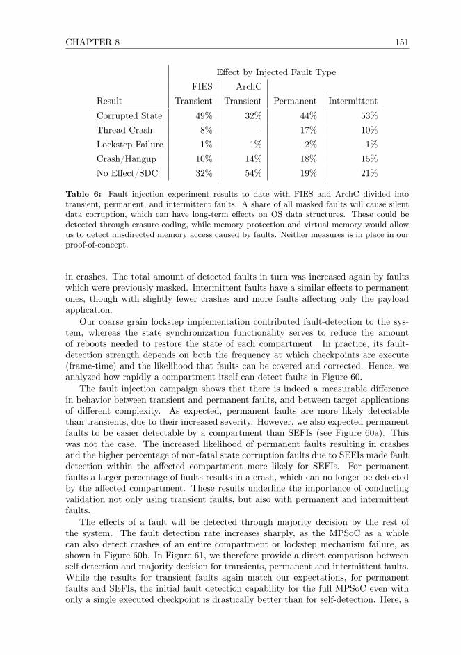
CHAPTER 8 151
Effect by Injected Fault Type
FIES ArchC
Result Transient Transient Permanent Intermittent
Corrupted State 49% 32% 44% 53%
Thread Crash 8% - 17% 10%
Lockstep Failure 1% 1% 2% 1%
Crash/Hangup 10% 14% 18% 15%
No Effect/SDC 32% 54% 19% 21%
Table 6: Fault injection experiment results to date with FIES and ArchC divided intotransient, permanent, and intermittent faults. A share of all masked faults will cause silentdata corruption, which can have long-term effects on OS data structures. These could bedetected through erasure coding, while memory protection and virtual memory would allowus to detect misdirected memory access caused by faults. Neither measures is in place in ourproof-of-concept.
in crashes. The total amount of detected faults in turn was increased again by faultswhich were previously masked. Intermittent faults have a similar effects to permanentones, though with slightly fewer crashes and more faults affecting only the payloadapplication.
Our coarse grain lockstep implementation contributed fault-detection to the sys-tem, whereas the state synchronization functionality serves to reduce the amountof reboots needed to restore the state of each compartment. In practice, its fault-detection strength depends on both the frequency at which checkpoints are execute(frame-time) and the likelihood that faults can be covered and corrected. Hence, weanalyzed how rapidly a compartment itself can detect faults in Figure 60.
The fault injection campaign shows that there is indeed a measurable differencein behavior between transient and permanent faults, and between target applicationsof different complexity. As expected, permanent faults are more likely detectablethan transients, due to their increased severity. However, we also expected permanentfaults to be easier detectable by a compartment than SEFIs (see Figure 60a). Thiswas not the case. The increased likelihood of permanent faults resulting in crashesand the higher percentage of non-fatal state corruption faults due to SEFIs made faultdetection within the affected compartment more likely for SEFIs. For permanentfaults a larger percentage of faults results in a crash, which can no longer be detectedby the affected compartment. These results underline the importance of conductingvalidation not only using transient faults, but also with permanent and intermittentfaults.
The effects of a fault will be detected through majority decision by the rest ofthe system. The fault detection rate increases sharply, as the MPSoC as a wholecan also detect crashes of an entire compartment or lockstep mechanism failure, asshown in Figure 60b. In Figure 61, we therefore provide a direct comparison betweenself detection and majority decision for transients, permanent and intermittent faults.While the results for transient faults again match our expectations, for permanentfaults and SEFIs, the initial fault detection capability for the full MPSoC even withonly a single executed checkpoint is drastically better than for self-detection. Here, a
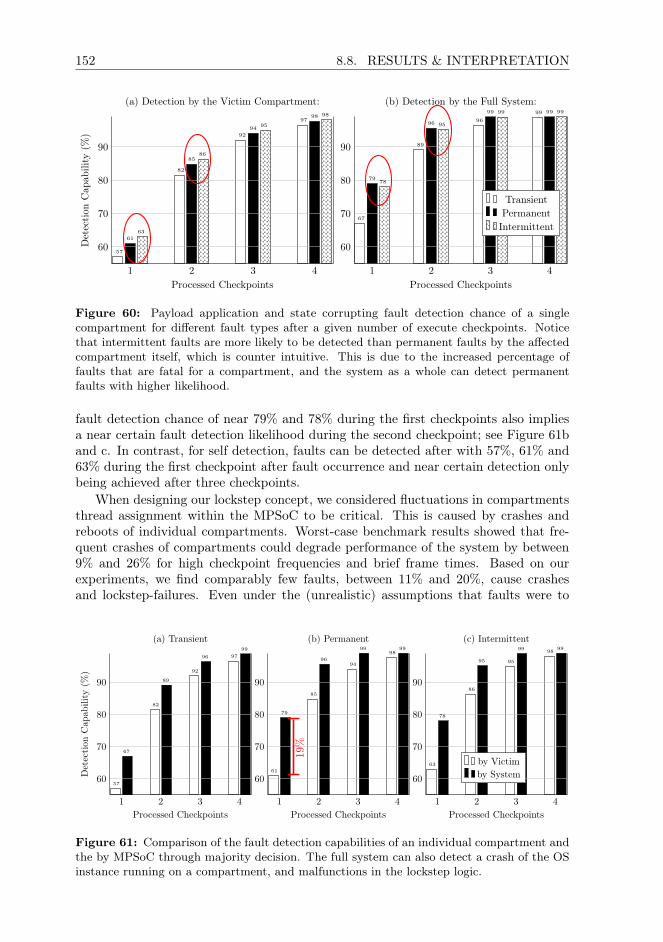
152 8.8. RESULTS & INTERPRETATION
1 2 3 4
60
70
80
90
57
82
92
97
61
85
94
98
63
86
95
98
Processed Checkpoints
Det
ecti
onC
apab
ility
(%)
(a) Detection by the Victim Compartment:
1 2 3 4
60
70
80
90
67
89
96
99
79
96
99 99
78
95
99 99
Processed Checkpoints
(b) Detection by the Full System:
TransientPermanentIntermittent
Figure 60: Payload application and state corrupting fault detection chance of a singlecompartment for different fault types after a given number of execute checkpoints. Noticethat intermittent faults are more likely to be detected than permanent faults by the affectedcompartment itself, which is counter intuitive. This is due to the increased percentage offaults that are fatal for a compartment, and the system as a whole can detect permanentfaults with higher likelihood.
fault detection chance of near 79% and 78% during the first checkpoints also impliesa near certain fault detection likelihood during the second checkpoint; see Figure 61band c. In contrast, for self detection, faults can be detected after with 57%, 61% and63% during the first checkpoint after fault occurrence and near certain detection onlybeing achieved after three checkpoints.
When designing our lockstep concept, we considered fluctuations in compartmentsthread assignment within the MPSoC to be critical. This is caused by crashes andreboots of individual compartments. Worst-case benchmark results showed that fre-quent crashes of compartments could degrade performance of the system by between9% and 26% for high checkpoint frequencies and brief frame times. Based on ourexperiments, we find comparably few faults, between 11% and 20%, cause crashesand lockstep-failures. Even under the (unrealistic) assumptions that faults were to
1 2 3 4
60
70
80
90
57
82
92
97
67
89
96
99
Processed Checkpoints
Det
ecti
onC
apab
ility
(%)
(a) Transient
1 2 3 4
60
70
80
90
61
85
94
98
79
96
99 99
Processed Checkpoints
(b) Permanent
19%
1 2 3 4
60
70
80
90
63
86
95
98
78
95
99 99
Processed Checkpoints
(c) Intermittent
by Victimby System
Figure 61: Comparison of the fault detection capabilities of an individual compartment andthe by MPSoC through majority decision. The full system can also detect a crash of the OSinstance running on a compartment, and malfunctions in the lockstep logic.

CHAPTER 8 153
Number Immediate Lockstep Reboot
Effect of Faults % Thereof: Recovery Timeout Required
Non-Masked 47526 46% 22004 10915 14607
46% 23% 31%
Masked 57379 54%
All 104905
Table 7: Fault Recovery statistics for SystemC fault injection.
occur in each checkpoint period, many faults could still be resolved through a stateupdate and do not require a reboot. Hence, our lockstep implementation can providesthe necessary degree of voter stability to making application reassignments betweencompartments rare.
A majority of faults that resulted in no observable effect on our implementation mayindeed be masked and require no measures to be taken, as they may have no impact onthe application state [322]. This is a limitation of our fault injection toolchain, as faultsare also injected into registers and memory which may be overwritten by subsequentinstructions, or faults that cause self-masking control flow deviations. Such situationsoccur e.g., due to faults in branch or comparison instructions triggering the sameiteration of a loop more than once. They have no practical impact on the applicationstate while, and also cause only minor timing deviations which do not impact the workconducted until to the next checkpoint.
8.9 ArchC MPSoC vs. FIES Result Comparison
Comparing our transient results between ArchC and FIES, we notice that the resultsare mostly comparable. The share of faults without noticeable effect are increasedby approximately 20%, which seems reasonable considering the different lockstep im-plementations tested: part of this difference can be attributed to the vulnerabilityoverestimation remaining due to limitations of our AVF analysis. Furthermore, thelockstep implementation on ArchC can not exploit the powerful exception handlingfunction available in a proper operating system implementation, as we are here run-ning the test implementation bare-metal. Instead, our FIES implementation existsas part of RTEMS, which allows more precise fault analysis, and overall reduces thechance that a fault will crash the entire OS instead of just the test application thread.
To allow better comparison of the fault effect ratios between system emulationand SystemC fault injection, we have to normalize the results obtained with bothtechniques. To do so, we apply normalization to the 54% of masked faults to alleffect ratios obtained with FIES, where we encountered just 32% masked faults. Acomparison between normalized FIES fault effect ratios and ArchC is depicted in Table8. As depicted, after normalizing the result data, we receive almost identical fault effectratios with both techniques, with our RTOS implementation showing 6% higher datacorruption likelihood than our bare-metal implementation. In our ArchC lockstepimplementation, 15% of all faults cause a crash or hangup effect, while in our RTOSimplementation 14% of cause such an effect. As our FIES implementation utilizes

154 8.10. COMPARISON TO LITERATURE
threading 6.5% of all crashes remain isolated to the crashed application software, orthe lockstep, while our ArchC implementation knows no such separation. In practice,this shows that the additional OS and application isolation functionality implementedwithin a modern OS also has a positive impact on suitability. In turn, the increasedamount of code an data required for an OS-scale implementation also shows that theratio of faults causing data corruption is slightly higher than when running the sameapplication bare-metal.
In Figure 7, we provide fault effect and recovery statistics obtained from our ArchCMPSoC model. After observing 105905 fault injection runs into our ArchC MPSoCmodel using AVF-filtered golden run traces, we can observe that: in 46% of cases a cor-rupted thread-state could immediately be recovered through a state update, requiredno reboot of the faulty MPSoC core. In further 23% of cases, faults could have beenrecovered if the lockstep had allowed for more wait time during checkpoint voting,which was severely constrained in our test campaign to assure sufficient test coverage.Only in 31% of cases, fault resolution was unsuccessful, requiring a reboot of the af-fected processor core. Overall, these statistics are very positive, considering especiallythe much reduced fault-recovery potential that a bare-metal lockstep implementationhas as compared to a full OS implementation.
Considering the different scale and detection capabilities of the two different lock-step implementations analyzed, this different is in line with our expectations: Thetarget implementation we used for ArchC fault injection does not utilize a threadedscheduler, and therefore thread-management and scheduling is eliminated as potentialfailure source. Overall, injected faults in a threaded RTOS implementation shouldlocally also impact OS-level control logic, and infrastructure data structures, and in-duce secondary fault effects there. At the same time, the this also means that faultswhich in an RTOS implementation caused a thread to crash, now would only causedata corruption in the protected application.
8.10 Comparison to Literature
To place these results in context with results from other lockstep concepts, we soughtto compare our results to literature. Unfortunately, few coarse-grain lockstep conceptshave been implemented in practice and tested using means beyond modeling. At thetime of writing, we are aware of only one publicly released validation report by Dobel
FIES
Ref. @ 54% SDC ArchC ∆
Corrupted State 49% 38.22% 31.72% -6.5%
Thread Crash 8% 6.24% 0% -6.24%
Lockstep Failure 1% 1% 1% 0%
Crash/Hangup 10% 7.8% 14.54% +7.66%
∆ Total 5.08%
Table 8: Transient fault effect comparison between system emulation and SystemC faultinjection, normalized to equivalent SDC ratios.

CHAPTER 8 155
et al. [199] considering practical fault injection with real software and faults, insteadof statistical estimation.
When directly comparing our results to Dobel et al.’s transient fault injection re-port [199], the share of faults causing application, thread, and OS crashes with ourapproach is noticably increased. For transient faults, this can at least in part be ex-plained with the different capabilities of Dobel et al.’s proposed lockstep mechanisms.In their contribution, lockstep is facilitated through application intrusive functioncall hooking. Thereby, Dobel et al.’s lockstep can offer more fine-grained protectionthan our approach. However, it also require considerable code, deep and non-portablechanges in the target OS, has a high performance overhead, and constrains the tar-get OS and application structure. The measured detection differences are consistentacross all effect categories: we measure a higher amount of masked faults, a decreasedamount of detected state deviations, and an increased amount of crashes with ourapproach.
Dobel et al. consider their fault injection measurements overly optimistic, as theyutilized payload applications “of little complexity (leading to few potential candidatesfor fault injection)” [199]. Their validation and lockstep implementation is constrainedto handling transient faults, while SEFIs or permanent effects are not covered as thesefaults were injected into a user-land application of their approach through a debugger.Dobel et al. assume the OS, system libraries, and kernel to be fault-free, while weinstead inject faults into a full OS including POSIX libraries with payload applications.In light of this bias, we consider our results are in line with Dobel et al.’s, and ourlockstep implementation to function as desired.
The results we obtained with SystemC fault injection into our ArchC MPSoCconfirms this further. There, we can in practice reproduce exactly this same scenariobetween the two lockstep implementations we have been utilizing for testing withFIES and for our ArchC MPSoC-model. The lockstep implementation there is overallsimpler, has fewer calls to critical infrastructure functionality that could break, andtherefore offers less overall failure potential than our full RTEMS-implementation.Furthermore, in this MPSoC we utilize RISC-V processor cores with a much simplerand less powerful instruction set than that offered by a full Cortex-A processor coreimplementing the ARMv7a instruction set, which not only supports one instructionset, but uses two instruction sets in combination (ARM and THUMB).
8.11 Discussions
Fault injection today can be conducted for different reasons, such as to detect secu-rity vulnerabilities in software, memory leaks, or to assure test coverage when testingfor functional correctness. However, fault injection for validating the correction func-tionality of a fault-detection and lockstep technique is very different from, e.g., faultinjection conducted for security purposes. Applying the same assumptions or testtools to both, while attractive, does not result allow for proper validation. The usedfault injection techniques, target implementations, and payload software will influencethe obtained results. Validation using an overly simplistic target implementation willbias the results obtained. Comparing our results to Dobel et al.’s underlines that it isimportant to conduct fault injection into a realistic implementation with non-trivialpayload software, but also that more lockstep concepts must be validated.
Our coarse-grain lockstep can detect faults resulting in a crash or in corruption of
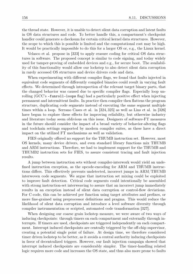
156 8.11. DISCUSSIONS
the thread state. However, it is unable to detect silent data corruption and latent faultsin OS data structures and code. To better handle this, a compartment’s checkpointhandler could generate a checksum for certain critical kernel data structures. However,the scope to which this is possible is limited and the computational cost may be high.It would be practically impossible to do this for a larger OS or, e.g., the Linux kernel.
Velasco et al. propose in [323] to apply erasure coding for critical OS data struc-tures in software. The proposed concept is similar to code signing, and today widelyused for tamper-proving of embedded devices and e.g., for secure boot. The availabil-ity of this functionality would allow our lockstep to also detect silent data corruptionin rarely accessed OS structures and device drivers code and data.
When experimenting with different compiler flags, we found that faults injected inequivalent code segments of differently compiled binaries could result in varying faulteffects. We determined through introspection of the relevant target binary parts, thatthe changed behavior was caused due to specific compiler flags. Especially loop un-rolling (GCC’s -funroll-loops flag) had a particularly positive effect when injectingpermanent and intermittent faults. In practice then compiler then flattens the programstructure, duplicating code segments instead of executing the same segment multipletimes within a loop. Serrano Cases et al. in [324, 325] as well as Lins et al. in [326]have begun to explore these effects for improving reliability, but otherwise industryand literature today seem oblivious on this issue. Designers of software-FT measuresin the future should consider the impact of a broad variety of behavior-altering flagsand toolchain settings supported by modern compiler suites, as these have a directimpact on the utilized FT mechanisms as well as validation.
FIES originally offered no support for the THUMB instruction set. However, mostOS kernels, many device drivers, and even standard library functions mix THUMBand ARM instructions. Therefore, we had to implement support for the THUMB andTHUMB2 instruction sets for FIES, to assure consistent tracing and fault injectionresults.
A jump between instruction sets without compiler-interwork would yield an unde-fined instruction exception, as the opcode-encoding for ARM and THUMB instruc-tions differs. This effectively prevents undetected, incorrect jumps in ARM/THUMBinterwoven code segments. We argue that instruction set mixing could be exploitedto improve fault detection. Critical code segments could intentionally be assembledwith strong instruction-set interweaving to assure that an incorrect jump immediatelyresults in an exception instead of silent data corruption or control-flow deviations.For C-code, this can be achieved per function using target attributes and prefixes, ormore fine-grained using preprocessor definitions and pragma. This would reduce thelikelihood of silent data corruption and introduce a level software diversity throughcompiler instrumentation or scripted, automated code transformation [327].
When designing our coarse grain lockstep measure, we were aware of two ways ofinducing checkpoints: through timers on each compartment and externally through in-terrupts. If timers are used, checkpoints are triggered independently on each compart-ment. Interrupt induced checkpoints are centrally triggered by the off-chip supervisor,creating a potential single point of failure. At design time, we therefore consideredtimer driven lockstep to be better, as it avoids a central authority inducing checkpointsin favor of decentralized triggers. However, our fault injection campaign showed thatinterrupt induced checkpoints are considerably simpler. The timer-handling relatedlogic requires more code and increases the OS state, and thus also more prone to faults
CHAPTER 8 157
than a simple interrupt handler. Hence, in future work we decided to use interruptdriven checkpoints instead of timed checkpoints.
8.12 Conclusions
In this chapter, we presented an automated fault injection toolchain, and validationresults of the software-implemented fault tolerance (FT) concept described in Chapter4. Few software-implemented FT concepts proposed today have been validated, andtherefore this chapter also serves as practical guide for fellow research, to make propertesting of fault tolerance techniques a less challenging and time consuming task. Today,a broad variety of fault injection techniques and tools are available for finding bugsor security vulnerabilities, to assure logical correctness of a concept, or to validateFT concepts. Validation of software-implemented FT concepts requires a realisticimplementation, and in-depth knowledge on the tested mechanisms and tools. Hence,not all tools and techniques are suitable for all purposes, and validating FT conceptsin the same way as fault injection is conducted for, e.g., software security purposes,does not work.
Proper validation thus is non-trivial, is time consuming and requires considerableresearch. In consequence, developers of coarse-grain lockstep concepts often forego thepractical concept implementation and validation, resorting instead to modeling. Prac-tical validation, however, is a prerequisite to even consider a concept for application inmission critical systems, which then can be subjected to system-level validation andprototype development. This has resulted in a large gap between academic theoryand practical application, with researchers proposing powerful concepts but industrialusers disregarding them out of hand due to a perceived lack of maturity and timepressure due deliver results.
The lockstep implementation validated in this publication and is the key element ofa hardware-software-hybrid system architecture which combines different FT measuresacross the embedded stack within an FPGA-based MPSoC design. Validation of suchconcepts has to be conducted differently than for traditional hardware-voting basedsystems, and requires systematic fault injection. Hence, we developed an automatedfault injection toolchain, which enables systematical testing using system emulationto validate the complete FDIR cycle. To place our results into context, we comparedthem to literature and discuss lessons learned and knowledge obtained throughoutour fault injection campaign beyond analyzing raw numbers. The overall results ofour fault injection campaign are positive and the thread-level coarse grain lockstep’sperformance meets our requirements.
As the other parts of our architecture have been verified separately in relatedwork, our test campaign represent the final step in validating our current development-board based proof-of-concept. In practice, through this testing, we have exhausted alltechnically feasible testing techniques for software that are possible today to validatea fault tolerance measure of the scale of our lockstep. The positive outcome of our testenables us to now produce a prototype OBC implementation, which then allows us tothen subject it to laser fault injection, radiation testing, and trials on-orbit. Systematicvalidation of our coarse-grain lockstep implementation is therefore an intermediatestep. To further test our architecture, a prototype system must be implemented tothen conduct radiation testing.

158 8.12. CONCLUSIONS

160 9.1. INTRODUCTION
9.1 Introduction
Satellite miniaturization has enabled a broad variety of scientific and commercial spacemissions, which previously were technically infeasible, impractical or simply uneconom-ical. However, due to their low reliability, nanosatellites, as well as light microsatellites,are typically not considered suitable for critical and complex multi-phased missionsand high-priority science. The on-board computer (OBC) and related electronics con-stitute a large part of such spacecraft, and were shown to be responsible for a significantshare of post-deployment failure [2]. Indeed, these components often lack even basicfault tolerance (FT) capabilities.
Due to budget, energy, mass, and volume restrictions, existing FT solutions origi-nally developed for larger spacecraft can not be adopted. In this chapter we describe anmultiprocessor System-on-Chip (MPSoC) that utilizes conventional hardware, provid-ing FT for miniaturized satellites. The MPSoC is assembled from well tested COTScomponents, library logic (IP), and powerful embedded and mobile-market proces-sor cores, yielding a non-proprietary, open architecture. Our key contribution is afault-tolerant OBC architecture for CubeSat use that consists only of extensively val-idated standard parts, and can be reproduced with minimal manpower and financialresources.
9.2 Background & Related Work
Aboard nanosatellites, subsystems are controlled by just one command & data han-dling system, whereas aboard a larger satellite these tasks are distributed across mul-tiple dedicated payload and subsystem computers. This implies a varying OBC work-load throughout a nanosatellites mission, which traditional FT solutions only handlethrough over-provisioning. The MPSoC design presented in this chapter can efficientlyhandle faults through thread migration and partial reconfiguration. Major parts of ourapproach are implemented in software, allowing the OBC to deliver the desired com-bination of performance, robustness, functionality, or to meet a specific power budget.To enable strong FT with low-cost commodity hardware, we combine fault detection,isolation and recovery in software, FPGA configuration scrubbing with other faultdetection, isolation and recovery (FDIR) measures across the embedded stack.
Nanosatellites today utilize almost exclusively COTS microcontrollers and appli-cation processors-SoCs, FPGAs, and combinations thereof [40,237]. Due to manufac-turing in fine technology nodes, and the use of extensively optimized standard IP, theyoffer superior efficiency and performance as compared to space-grade OBC designs.The energy threshold above which highly charged particles can induce faults (SEE –single event effects) in such components decreases, while the ratio of events inducingmulti-bit upsets (MBU), and the likelihood of permanent faults, increase. To adaptsuch hardware-FT based concepts additional FT-circuitry is required, inflating logicsize and producing diminishing returns, resulting in limited scalability and low clockfrequencies [188, 190, 192]. We can observe that traditional FT-concepts applied tomodern COTS hardware yield no nanosatellite compatible architectures.
While more sensitive to transient faults than ASICs [142, 143], FPGA-based Soft-SoCs have been shown to offer excellent FDIR potential for miniaturized satellites[238]. Transients in critical parts of the FPGA fabric can be scrubbed [242], whilepermanent faults may be compensated through reconfiguration with differently routed

CHAPTER 9 161
configuration variants [105]. Fine-grained, non-invasive fault detection in FPGA fab-ric, however, is challenging, and subject of ongoing research [239, 240]. Relevant FT-concepts thus rely on error scrubbing, which has scalability limitations and cover onlyparts of the fabric [239, 242]. We overcome these limitations by implementing fault-detection in software through thread-replication and coarse-grain lockstep within anMPSoC using weakly coupled cores.
Tiled architectures [246,328] are often used for well paralellizable applications withmany low-performance processor cores. Among others, [329] and [328] showed thatthis topology can also be exploited to achieve FT for image processing applicationswith a very specific structure. We combine a compartmentalized topology with acoarse-grained lockstep described in Chapter 4, enabling FDIR without constrainingthe application type or system architecture. Thus, the architecture presented in thischapter is well suited for platform control and can be used as a template, allowing ahigh level of OBC design freedom, and enabling a considerable amount of testing tobe inherited from COTS components and logic.
Thread migration has been shown to be a powerful tool for assuring FT, but priorresearch ignores fault detection, and imposed tight constraints on an application’s typeand structure (e.g., video streaming and image processing [241]). Thread-level coarse-grain lockstep of weakly coupled cores instead supports general purpose computing,and in the past, has already been used for high availability, non-stop service, anderror resilience concepts. However, in prior research, faults are usually assumed to beisolated, side effect free, and local to an individual application thread [208] or transient[199, 205], entailing high performance [209] or resource overhead [210, 211]. Moreadvanced proof-of-concepts [198, 199], however, attempt to address these limitations,and even show a modest performance overhead between 3% and 25%, but utilizecheckpoint & rollback or restart mechanisms [199], which make them unsuitable forspacecraft command & control applications.
Many of these limitations and obstacles ultimately can be attributed to low ma-turity, as a majority of software-FT concepts are published as a concept TRL1 butremain unvalidated. Hence, they could be uncovered, and in many cases, can be po-tentially resolved through implementation and practical validation [198], increasingmaturity to TRL2 or TRL3. However, development of a testable proof-of-concept is atime consuming and costly undertaking [300], as outlined among others by Sangchoolieet al. [301] with limited immediate yield for academic publication. Fault injection forentire OS instances is especially non-trivial [302], as thorough preparation and care-ful tool-selection is necessary to obtain representative results from a fault injectionexperiment [303]. Therefore, a broad variety of TRL1 software-FT concepts existtoday at a theoretical level [212–214], for which validation was only conducted statis-tically using modeling with different fault distributions or not a all. In this chapter,we therefore conduct validation of our coarse-grain lockstep approach using system-atic fault-injection. Thereby we verify the effectiveness of our coarse-grain lockstepFDIR mechanisms under stress using a RTOS-based proof-of-concept implementation,increasing maturity to TRL3.
9.3 A Hybrid Fault Tolerance Approach
Conventional FT architectures require proprietary logic in hardware to facilitate faultdetection and coverage. In contrast, the architecture described in this chapter can

162 9.3. A HYBRID FAULT TOLERANCE APPROACH
offer strong FT using just COTS components and proven standard library logic. Thisis made possible through the use of the FT approach we presented in Chapter 4. Thehigh-level functionality of this approach is depicted in Figure 62, and consists of threeinterlinked fault mitigation stages implemented across the embedded stack:
Stage 1 implements forward error correction and utilizes coarse-grain lockstep ofweakly coupled cores to generate a distributed majority decision across compartments.Fault detection is facilitated through application callback functions, without requiringdeep modifications to an application or knowledge about intrinsics.
Stage 2 recovers failed compartments through reconfiguration and self-testing.It assures the integrity of programmed logic and deploys configuration scrubbing, aswell as Xilinx Soft-Error-Mitigation (SEM), to correct transients in FPGA fabric. Itsobjective is to assure and recover the integrity of processor cores and their immediateperipheral IP through FPGA reconfiguration and the use of differently routed andplaced alternative configuration variants, thereby counteracting resource exhaustion.
Stage 3 engages when too few healthy compartments are available, and re-allocatesprocessing time to maintain reliability. To do so, thread-level mixed criticality is ex-ploited, assuring sufficient compute resources are available to high-criticality applica-tions by sacrificing performance or availability of lower-criticality threads.
Further details including benchmark results are available in Chapter 4. The maintarget in our project is the ARM Cortex-A53 application processor, which is todaywidely used in embedded and mobile-market devices. However, this research is pro-cessor and ISA independent. In this chapter, we describe an MPSoC design and
MPSoC Supervisor & Config Controler
Bootup
Checkpoint
ApplicationExecution
Read MajorityDecision
CheckFault Counter
UpdateCompartment
Stage 3Mixed Criticality
ReplaceCompartment
Stage 3Mixed Criticality
< limit > limit
recoveredfunctionality failure
Figure 62: Stage 1 (white) assures fault detection (bold) and fault coverage. Stages 2 (blue)and 3 (yellow) counter resource exhaustion and adapt the on-board computer applicationschedule to reduced system resources.

CHAPTER 9 163
architecture template, which is enabled by this approach and can be reproduced inXilinx Vivado 2017.1 and later.
9.4 The MPSoC Architecture
We developed our software-FT architecture for use on top of an MPSoC consistingonly of COTS technology. The main target in our project is the ARM Cortex-A53application processor. For many size-optimized space applications, smaller cores suchas the Cortex-A32, A35 and A5 may also offer a better balance between performance,universal platform support, and logic utilization. The Cortex-A53 core was chosen asit is today widely used in a variety of industrial and mobile-market devices, thoughour architecture is processor and instruction set architecture (ISA) independent.
In this section, we describe a publicly reproducible MPSoC design variant imple-menting our architecture, which can be designed in full using Xilinx library IP andMicroblaze processor cores. The architecture minimizes shared logic, compartmental-izes compartments, and offers a clearly defined access channel between compartmentsand the supervisor, and is depicted in Figure 63.
9.4.1 Supervision & Reconfiguration
Stage 1 can be implemented on a single chip, but we utilize an off-chip supervisorto facilitate FPGA reconfiguration and transient fault scrubbing in the running con-figuration. The outlined multi-stage FT approach puts only minimal load on thesupervisor, and it can thus be again implemented using a traditional radiation hard-ened or tolerant microcontroller. The FeRAM-based TI-MSP430FR family would be asolid somewhat radiation-tolerant but non-FT substitute, which is today widely usedaboard a broad variety of CubeSats and low-performance COTS products designed fornanosatellite use. The level of performance offered by such microcontrollers is usuallysufficient only for educational CubeSats and federated systems. However, a supervisor
SPI CTRL MCTLR
MCTLRMain
Memory
FeRAM(OS Code)
Tile 3
Tile 1 MMU
MMU
MCTLRMRAM
(App Code)
SPI ctlr
SPI CTRLDDR ctlr+ ECC
SM
SM
X X
X
MemoryScrubberDDR
Scrubber
Tile 4 MMU
SM
Tile 2 MMU
SM
MCTLRNAND Flash
(Payload Data)
Xs
r/o
SEM
ICAP
CLK
CLK
CLK
CLK
CLKCLK
CLK
Figure 63: The topology of our compartmentd MPSoC design. Each compartment existsin its own reconfiguration partition and therefore also clock domain, simplifying routing andlogic placement. Reconfiguration partitions are indicated with dashed lines.

164 9.4. THE MPSOC ARCHITECTURE
in our architecture only receives the majority voting results from the coarse grain lock-step, controls the FPGA, and facilitates reconfiguration through an ICAP controllerin static logic. Hence, the low level of performance of an MSP430FR, for example, issufficient, and allows an ultra-low-cost implementation of our approach for academicCubeSat projects and scientific instrumentation.
We deployed configuration error mitigation through Xilinx SEM in combinationwith supervisor-side scrubbing to safeguard logic integrity. However, SEM and scrub-bing only detect faults in specific components of the FPGA fabric (e.g., not in BRAM),leaving significant parts of the design unprotected unless logic-side ECC is used.
These measures alone do not provide sufficient protection for fine-feature size FP-GAs. Thus, our software-FT functionality can locate faults in the partition of a specificcompartment, allowing the supervisor to resolve them using reconfiguration. We placecompartments in separate configuration partitions to enable partial reconfiguration ofindividual compartments, without affecting the rest of the system.
As depicted in Figure 62, the supervisor only reacts to disagreement between com-partments, otherwise remaining passive. It maintains a fault-counter for each compart-ment and acts as a watchdog. When resolving transient faults within a compartment,it increments the fault-counter and induces a state update through a low-level debuginterface. After repeated faults, the supervisor will replace the compartment by ad-justing the thread-mapping of a spare compartment, activating it, and rebooting thefaulty compartment. In case a system developer indicated threshold is exceeded, thedisagreeing compartment is assumed permanently defunct and not re-used as a spare.
To allow supervisor access to a compartment and its address space, each compart-ment is equipped with an AXI debug-bridge (Figure 64). The supervisor can triggerexecution of self-test functionality within a compartment to detect faults in periph-erals. It can also trigger an adjustment of a compartment’s thread allocation as partof Stages 1 and 3, making the MPSoC’s computational performance, robustness andenergy consumption adjustable at runtime.
Majority voting between compartments can be implemented as distributed major-ity decision [330], then requiring no direct intervention of the supervisor during regularoperation. If this is not desired, or lockstep through interrupt triggered checkpointsis implemented, then the supervisor should also take care of receiving the voting re-sults generated on each compartment. In that case, the supervisor can access eachcompartment’s thread mapping via each compartment’s debug interface, and if nec-essary induce a reset or otherwise manipulate a compartment without requiring itscooperation.
9.4.2 Tile Architecture
Our MPSoC design implements multiple isolated SoC-compartments accessing sharedmain memory and OS code. Even though the purpose and function of these compart-ments is different, the topology resembles a compartmentalized architecture insteadof a conventional MPSoC design, in which cores share infrastructure and peripherals.This topology increases Stage 1’s fault coverage capacity and allows task mappingfor general-purpose software. Each such compartment contains a processor core, localinterconnect, and peripheral IP-cores and interfaces as depicted in Figure 64, residesin its own clock domain, and can be reset independently. Allocating a clock domainto each compartment improves timing, and reduces logic-overlap and interdependence
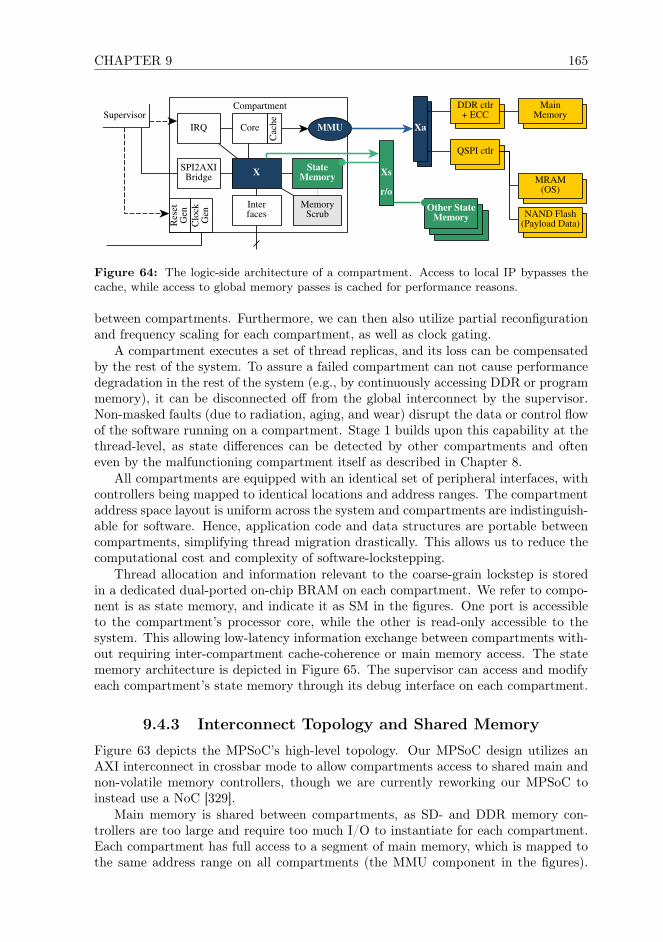
CHAPTER 9 165
StateMemory
StateMemory
Compartment
SPI2AXIBridge
MMU
X StateMemory
MemoryScrub
CoreIRQ
Interfaces
Supervisor
Res
etG
en
Cac
he
Clo
ckG
en
Xs
r/o
MainMemory
MRAM(OS)
NAND Flash(Payload Data)
QSPI ctlr
Xa
DDR ctlr+ ECC
Other StateMemory
Figure 64: The logic-side architecture of a compartment. Access to local IP bypasses thecache, while access to global memory passes is cached for performance reasons.
between compartments. Furthermore, we can then also utilize partial reconfigurationand frequency scaling for each compartment, as well as clock gating.
A compartment executes a set of thread replicas, and its loss can be compensatedby the rest of the system. To assure a failed compartment can not cause performancedegradation in the rest of the system (e.g., by continuously accessing DDR or programmemory), it can be disconnected off from the global interconnect by the supervisor.Non-masked faults (due to radiation, aging, and wear) disrupt the data or control flowof the software running on a compartment. Stage 1 builds upon this capability at thethread-level, as state differences can be detected by other compartments and ofteneven by the malfunctioning compartment itself as described in Chapter 8.
All compartments are equipped with an identical set of peripheral interfaces, withcontrollers being mapped to identical locations and address ranges. The compartmentaddress space layout is uniform across the system and compartments are indistinguish-able for software. Hence, application code and data structures are portable betweencompartments, simplifying thread migration drastically. This allows us to reduce thecomputational cost and complexity of software-lockstepping.
Thread allocation and information relevant to the coarse-grain lockstep is storedin a dedicated dual-ported on-chip BRAM on each compartment. We refer to compo-nent is as state memory, and indicate it as SM in the figures. One port is accessibleto the compartment’s processor core, while the other is read-only accessible to thesystem. This allowing low-latency information exchange between compartments with-out requiring inter-compartment cache-coherence or main memory access. The statememory architecture is depicted in Figure 65. The supervisor can access and modifyeach compartment’s state memory through its debug interface on each compartment.
9.4.3 Interconnect Topology and Shared Memory
Figure 63 depicts the MPSoC’s high-level topology. Our MPSoC design utilizes anAXI interconnect in crossbar mode to allow compartments access to shared main andnon-volatile memory controllers, though we are currently reworking our MPSoC toinstead use a NoC [329].
Main memory is shared between compartments, as SD- and DDR memory con-trollers are too large and require too much I/O to instantiate for each compartment.Each compartment has full access to a segment of main memory, which is mapped tothe same address range on all compartments (the MMU component in the figures).

166 9.4. THE MPSOC ARCHITECTURE
Tile
Tile
MMU
SM
DBG
Xs
IF
X
$Core
SM
X
IF
DBG
MMU$Core
TileSM
X
IF
DBG
MMU $ Core
TileSM
X
IF
DBG
MMU $ Core
Figure 65: A compartment’s state memory is accessible to all other compartments in thesystem. It provides a write protected, high-speed on-chip possibility to expose state-relevantdata to the MPSoC as a while.
All compartments can access main memory read-only to simplify state synchronizationand IPC. The supervisor can access each set of main memory controllers directly.
For nanosatellite missions to LEO, often only SECDED ECC support is requiredand readily available in library IP already [331], while basic error scrubbing can befacilitated in software. For critical, deep-space, and long-term missions, block codingshould be used instead to compensate for the increased impact of SEEs and higherlikelihood of MBUs in high-density SDRAM. Reed-Solomon ECC as well as errorscrubbers are available commercially, or can be assembled from open-source IP. Themain memory scrubbers are controlled by the supervisor to avoid potential interferenceby malfunctioning compartments. ARM Cortex-A53 as well as Microblaze caches andseveral local memories and buffers offer ECC support as basic functionality [331].
To safeguard main memory, FeRAM [332], MRAM [150], and mass memory fromSEFIs, as well as permanent failure, these memories are implemented redundantly toenable failover. To allow non-stop operation during FPGA reconfiguration, we alsoimplement their controllers, and the AXI interconnects they are attached to redun-dantly. This also enables further protective measures which we described in Chapter7, and allows load distribution for timing critical main memory through segment inter-leaving. Thereby the available DDR memory bandwidth is increased and the overalllatency for memory access can be reduced. This also enables us to recover an instanceof a memory controller on short notice without requiring the full system to be halted1.
Tiles compete for DDR memory access. As our architecture is implemented onFPGA, the clock frequency of each compartment’s processor core is lower as on ASICimplemented MPSoCs. In consequence, the global interconnect as well as DDR mem-ory controllers offer abundant throughput at drastically higher clock frequencies. Eachprocessor core caches access to shared memory, drastically reducing the strain on thememory subsystem. Access to a compartment’s state memory still bypasses the cache,but this is implemented directly in high-speed, low-latency on-chip BRAM. Hence,
1Note that depending on the used OS, a reboot of a compartment may be required. Linux sup-ports modifications to the memory layout and relocation, while simpler OS, such as RTEMS, do notcurrently know such functionality.

CHAPTER 9 167
while in principle competing for memory bandwidth, even an 8-compartment systemcan not saturate the two available DDR4 channels in our current MPSoC design. Ide-ally however, our architecture should be implemented using a NoC instead of a globalAXI-interconnect crossbar, which would offer drastically better scalability, more effec-tive caching and buffering, and also a degree of FT.
9.5 Subsystem Connectivity and Peripheral I/O
A fault resolved in Stage 1 may cause incorrect data to be emitted through I/Ointerfaces. This is an inherent limitation of coarse-grain lockstep concepts, and canonly be slightly alleviated through additional application-intrusive work-around asdescribed, for example, in [199]. Instead, this limitation is better solved at the logiclevel through interface-level voting, which is possible with minimal extra logic. Formost CubeSats, most nanosatellites, and less critical microsatellite missions, however,this is usually foregone.
Larger spacecraft already utilize interface replication or even voting to assure fullhardware TMR, usually requiring considerable effort in hardware or logic to facilitatethis replication. Our MPSoC architecture inherently provides interface replicationsby design, requiring no extra measures to be taken, as the individual compartment-interfaces can be directly used for TMRed architecture. Further safeguards are neces-sary for very small CubeSats where interface replication is undesirable, for example,due to PCB-space constraints.
Partition Tile 1
Partition Tile n
InterfaceController
InterfaceController
I/O
OutputFIFO
InputFIFO
Buffer
OutputFIFO
InputFIFO
. . . MUXVoter
active
active
Figure 66: An activation-driven, buffered output voter with input de-multiplexer can beconstructed for low-pin-count CubeSat interfaces. Note that an additional re-sampling stepwould be required in case of different thread scheduling on lock-stepped compartments.

168 9.5. SUBSYSTEM CONNECTIVITY AND PERIPHERAL I/O
9.5.1 Electrical- and Logic-level Interface Voting
For simple embedded interfaces like I2C and SPI connected to “dumb” sensors oractuators with no user configurable firmware, a simple majority decision per I/O lineis possible. While hardware voting is challenging for large arrays of voters runningsynchronized at very high frequencies, the CubeSat-relevant interfaces are electricallysimple, have a very low pin count, and run at relatively low clock frequencies. Hence,voting for these interfaces can efficiently be implemented on-chip through simple votersassuming compartments signals interface activity.
Our coarse grain lockstep mechanisms allow software to be executed with slighttiming variations. These may be caused by clock-domain interactions, competition ofcompartments for global interconnect DDR4 and QSPI access, as well as differences incompartment partition routing and or I/O pin placement. In general, these variationswill be limited to few clock cycle duration. I/O on these interfaces must be buffered,which can be done within the FPGA as discussed further also by Li et al. in [333]. Forsimplicity, compartments should also indicate that an interface is active, and we candouble-use the chip-select pins present in almost all I2C and SPI implementations.The voter can use activity on these pins as indication that the interfaces is active,and delay voting for a given amount of clock cycles using a set of FIFO buffers. Thedepth of these FIFOs thereby determines the maximum delay compensated by thevoter [334]. In our design we can utilize a combination of re-sampling majority voterand MUX as depicted in Figure 66.
Note that larger MPSoC variants with 6 or more compartments can host multipleindependent lockstep sets as described in Chapter 6. In this case, simple buffered vot-ing is insufficient, as compartments could then also run mixed lockstep groups wherethreads may be scheduled with much larger time differentials. This differential willalways be shorter than the duration of a lockstep cycle or the frame time, but in LEOthese may extend to up to several seconds. It would be uneconomical and, dependingon the application, even technically infeasible to buffer I/O for long duration. How-ever, we consider the design-combination of a low-end CubeSats that can not affordsubsystem TMR, packet-based communication, with a high-performance 6-core MP-SoC not very attractive and therefore a corner case. If this combination was stilldeemed necessary, a straight forward solution would be to maintain multiple isolatedthread-assignment groups.
9.5.2 Simple Inter-Subsystem and Controller Networks
Many SPI and I2C implementations support multi-master shared bus operation, andit is possible to even create large and complex CAN-bus networks [335]. CubeSatsoften use these interface standards for low-speed inter-subsystem communication insimple CubeSat designs [39,336]. While packet based interfaces offer far better scala-bility, reliability, and fault-mitigation properties for this purpose [337], in reality theseconcepts will remain in use aboard CubeSats for the foreseeable future. However, incontrast to interfacing with “dumb” endpoints ICs, these networks2 usually consist ofmicrocontrollers running satellite developer provided software. In this case, a bettersolution to de-replicating and obtain consensus within the system of our MPSoC’scompartments is to make the subsystems aware of the replication.
2In CubeSat jargon often referred to as “buses”.

CHAPTER 9 169
A subsystem controller then can await receiving a second replica of a commandsequence from a different master. Of course this does not solve the issue of a singlecompartment/master jamming or saturating the bus due to malfunction. However,most CubeSats using these interfaces as subsystem-bus currently usually also do nottake actual meaningful countermeasures in this regard. This is technically possible, butrequires entirely different network topologies [335,337] than the simplistic single-levelbus concepts used aboard CubeSats today [39].
9.5.3 Packet Switching and Routing On-Board Networks
For packet-based interfaces such as Spacewire [338], AFDX [94], CAN [55], or Ethernet[73], no hardware- or logic-side solution is necessary. There, packet duplication andintegrity checking can be managed efficiently at the data link, network and transportlayers (OSI layers 2 – 4 [339]). At the physical layer, Ethernet and thereof derivedtechnologies such as AFDX [94] and TTEthernet [340] perform shared medium throughcollision detection and micro-segmentation with frame switching. Then, packet routing(L3) and de-duplication in software at the higher OSI layers can be deployed, e.g., insoftware. Today, this is common practice in relevant industrial applications such asAFDX and TTEthernet used in related fields such as atmospheric aerospace or safetycritical automotive applications.
The FPGAs considered in our research provide an abundance of high-speed MGTtransceivers. These are intended to support high-performance serial interfaces such asPCIe, or USB3 host interfaces [341], which may become attractive for CubeSat use inthe future and have built in error correction support. Even the smallest XCKU3P partfields 16 such interfaces, and the location of these interfaces is in very attractive loca-tions for using 2-3 of them isolated within each of our MPSoC’s compartments [342].In practice, this would allow for a very scalable, high-performance CubeSat inter-subsystem communication architecture [343] at little cost assuming a the satellite’shigh-level design takes this into account.
9.6 Implementation Considerations
The MPSoC architecture described in this chapter was developed for miniaturizedsatellite use, as an ideal platform for the software-FT approach described in Chapter4. This architecture is not specifically dependent on utilizing ARM processor cores,but can be implemented with any FPGA-implementable soft-core. Our choice of theARM platform was taken in part to allow thread migration between soft- and hard-cores (e.g., on Zynq Ultrascale+), maximum comparability to COTS mobile-marketand embedded MPSoCs with secondary use aboard a major share of CubeSats. Espe-cially for low-budget CubeSat users in research or university projects, standard vendorlibrary cores such as Xilinx Microblaze may be an excellent alternative to our Cortex-A choice. These cores offer erasure coding and other basic fault tolerance features outof the box already, and performed rather well in radiation tests [331]. They are readilyavailable and often even free of charge, especially to academics and non-commercialscientific research users.
We implemented a proof-of-concept on a Xilinx XCKU5P FPGA with modest re-source utilization (28% LUTs, 33% BRAMs, 16% FFs, 5% DSPs) and 1.92W total

170 9.7. CONCLUSIONS
power consumption with Microblaze cores. In this 4-compartment design, each com-partment was equipped each with one peripheral I2C master controller, one SPI mas-ter, as well as a dual-channel GPIO controller. Such an interface configuration is rep-resentative for most CubeSat applications, while AFDX, TTEthernet, and Spacewireare today not widely used aboard CubeSats.
This approach and architecture could very well be implemented on ASIC withoutreconfiguration and Stage 2, and we see this as a “big-space” variant of our approach.An ASIC implementation offers lower energy consumption, and allows higher clockrates due to reduced timing and shorter paths. If manufactured in an inherently radi-ation hard technology such as FD-SoI [144], it would be less susceptible to transientsand more robust to permanent faults. Due to the drastically increased developmentcost and required manpower, the resulting OBC would not be viable for most minia-turized satellite applications (not anymore “on a budget”).
9.7 Conclusions
The 3-stage FT approach combined with its MPSoC host system presented in thischapter is the first practical, non-proprietary, affordable architecture suitable for FTgeneral-purpose computing aboard nanosatellites. It utilizes FT measures across theembedded stack, and combines topological with software functionality, utilizing onlyextensively validated standard parts. Thereby, we enable the use of nanosatellites incritical space missions, while the architecture allows trading processing capacity forreduced energy consumption or fault coverage.
An OBC relying upon this architecture can be facilitated with the minimal man-power and financial resources. The MPSoC can be implemented using only COTShardware and extensively validated, and widely available library IP, requiring no pro-prietary logic or costly, custom space-grade processor cores. It offers a high level ofresource isolation for each processor, utilizing architectural features originally con-ceived for ManyCore systems to achieve FT.
Each compartment functions as a stand-alone processing compartment with ded-icated I/O, existing in its own clock domain and reconfiguration partition, therebyminimizing shared resources and reducing routing complexity. Compartments werepurposefully designed to best support thread-level coarse-grain lockstep of weaklycoupled cores, while allowing partial reconfiguration without stalling the rest of thesystem. The architecture was implemented successfully, and tested on current gen-eration Xilinx Zynq/Kintex and Virtex FPGAs with 4, 6 and 8 compartments, andvalidated through fault-injection into RTEMS.


172 10.1. INTRODUCTION
10.1 Introduction
Cheap, CTOS electronics designed for the embedded and mobile-markets are the foun-dation of modern nanosatellite design. They offer an excellent combination of lowenergy-consumption, minimal cost, and broad availability. However, such componentsare not designed for reliability, and include only rudimentary fault tolerance capabili-ties. Due to the elevated risk of loosing a satellite due to failure of these components,CubeSat missions today are kept brief or up-scaled to larger, more expensive satelliteform factors.
Low-complexity, low-performance satellite on-board computer (OBC) designs haveallowed a variety of successful CubeSat missions, with a few missions even operatingsuccessfully for as long as 10 years. This demonstrates that there is no fundamental,hard technological barrier that could prevent the use of modern semiconductors inspace missions. However, these designs are sufficient only for missions with very lowperformance requirements, e.g., for educational missions and brief technology demon-stration experiments.
Many sophisticated scientific and commercial applications can today also be fit intoa CubeSat form factor, which make a much longer mission duration desirable. To flythese payloads, a CubeSat has to process and store drastically more data, and at alllevels requires increased performance. Therefore, all advanced CubeSats today utilizeindustrial embedded and mobile-market derived systems-on-chip (SoC), which offer anabundance of performance. However, these SoCs in turn are manufactured in moderntechnology nodes with a fine feature size. They are drastically more susceptible tothe effects of the space environment than simple but robust low-performance micro-controllers. Hence, proper fault tolerance capabilities are needed to ensure success foradvanced long-term CubeSat missions, as gambling against time and radiation can berisky.
Radiation hardening for big-space applications can not be adopted, as this ap-proach is only effective for very old or very proprietary and costly manufacturingprocesses. Budget, energy, and size constraints prevent the use of traditional space-grade components used aboard large satellites, while component-level fault tolerancesignificantly inflate CubeSat system complexity and failure potential. Today, no fault-tolerant computer architectures exist that could be used aboard nanosatellites poweredby embedded and mobile-market semiconductors, without breaking the fundamentalconcept of a cheap, simple, energy-efficient, and light satellite that can be manufac-tured en-mass and launched at low cost. Hence, we developed a scalable, yet simpleOBC architecture that allows high-performance MPSoCs to be used in space, and issuitable for even small 2U CubeSats.
Our proof-of-concept OBC utilizes Microblaze processors on a low-power FPGA,exploits partial reconfiguration and software-implemented fault tolerance to handlesystem failure. It is assembled only from COTS components available on the openmarket, standard vendor library IP, and runs standard operating system and software.To protect our system, we utilize a combination of runtime reconfigurable FPGA logicand software-implemented fault tolerance mechanisms, in addition to well understoodand widely available EDAC measures. We facilitate fault tolerance in software, whichenables our system to guarantee strong fault coverage without introducing the harddesign limitations of traditional hardware-TMR based solutions.
Our OBC architectures can efficiently and effectively handle permanent faults in
CHAPTER 10 173
the FPGA fabric by utilizing alternative FPGA configuration variants. It ages grace-fully over time by adapting to an increasing level semiconductor degradation, insteadof just failing spontaneously. The performance of the OBC itself is adjustable, allow-ing spacecraft operator to modify system parameters during the mission. An operatorcan trade processing-capacity and functionality to achieve increased fault coverage orreduced energy consumption, without interrupting satellite operations. Thereby, wecan maintain strong fault coverage for missions with a long duration, while adjustingthe OBC to best meet the requirements of complex multi-phased space missions.
To our understanding, this is the first scalable and COTS-based, widely repro-ducible OBC solution which can offer strong fault coverage even for 2U CubeSats. Weprovide an in-depth description of our proof-of-concept MPSoC, which requires only1.94W total power consumption, which is well within the power budget range achiev-able aboard 2U CubeSats. In the next section, we provide a brief overview over thestatus-quo in fault-tolerant computer system design for large spacecraft, CubeSats,and ground use. Subsequently in Section 10.3, we describe our OBC’s component-level architecture, the MPSoC used, as well as the interplay between the differentcomponents of the OBC. Before providing conclusions, we present our implementa-tion results and details about how this MPSoC was tested and validated in Section10.5. Finally, we discuss advanced applications of our proof-of-concept with multipleFPGAs, Network-on-Chip usage and resistance to full-chip SEFIs in Section 10.4. Allcomponents required to re-implement this OBC design are available at low cost toscientists and engineers in an academic environment. The necessary IP and standarddesign are available free of charge from the relevant vendors, e.g., through Xilinx’suniversity program for academics and scientific users.
10.2 Related Work
In contrast to the initial generation of educational CubeSats, today fewer satellitesfail due to practical design problems caused by inexperience [39]. Instead, Langer etal. in [2] showed that a majority of these failures can be attributed to electronicsheavy subsystems. Even experienced, traditional space industry actors with years ofexperience in large satellite design, who develop CubeSats satellites “by the traditionalbook” with quasi-infinite budgets today struggle to reach just 30% mission success [42].
The main source of failure are environmental effects encountered in the space en-vironment: radiation, thermal stress, and corruption of critical software componentsthat can not be recovered from the ground, and failures caused by power electronics.Considering again Langer et al., [2], with increasing age mission duration, a broadmajority of documented failures aboard CubeSats originate from OBCs, transceivers,and the electrical power subsystem. While functionally disjunct, these subsystems allhave in common that they are heavily computerized and architecturally rather similar,built around one or multiple microcontrollers and memories.
Fault tolerance concepts targeting generic commercial ground-based computingapplications usually cover only a small subset of our fault model: transient faults,material aging, and occasionally gradual wear. Such assumptions are valid for crit-ical applications for ground applications, but not for space applications. Often, theintroduction of permanent faults breaks fault tolerance concepts for ground applica-tions, weaken their protective capabilities strongly, or limit their protection to onlya brief period of time. Most ground-based and atmospheric aerospace fault tolerance

174 10.2. RELATED WORK
concepts also aim to guarantee reliable operation from the point in time a fault occursuntil maintenance can be performed. This is a problematic assumption for CubeSatuse, as servicing missions have only been performed on rare occasions for spacecraftof outstanding scientific, national, and international significance such as the Interna-tional Space Station or the Hubble Space Telescope. But certainly not for low-costCubeSats.
These limitations, however, by using a combination of different additional faulttolerance measures across the embedded stack. Fault tolerance concepts for groundand atmospheric aerospace applications can therefor serve as building blocks to designa fault-tolerant architecture for space applications.
10.2.1 Fault Tolerance for Large Spacecraft
Traditional OBCs for large satellites realize fault tolerance using circuit-, RTL- [344],IP-block- [104, 132], and OBC-level TMR [90] through costly, space-proprietary IP.They make heavy use of over-provisioning and tries to include idle spare resources(processor cores, components, memory, ...) where necessary. Naturally, this is doneat the cost of performance and storage capacity, increases system complexity, andpower consumption. Circuit-, RTL-, and core-level measures are effective for smallmicrocontroller-SoCs [88,345], if they are manufactured in large feature-size technologynodes. More and more error correction and voting circuitry is needed to compensate forthe increased severity of radiation effects with modern technology nodes [345]. This inturn again inflates the fault-potential, requiring even more protective circuitry, makingthis approach ineffective for modern semiconductors.
Processor lockstep implemented in hardware lacks flexibility, limits scalability, andis feasible only for very small MSoCs with few cores [88, 346]. Timing and logicplacement becomes increasingly difficult for more sophisticated processor designs, andbecomes infeasible for SoCs running at higher clock frequencies. Practical applicationsrun at very low clock frequencies [347] with two or three very simple processor cores,even for ASIC implementations [88, 132]. Common to all these solutions is that theyare proprietary to a single vendor, implying a hefty price tag and tight functional con-straints. Especially the space-proprietary single-vendor solutions available are oftendifficult to develop for, have in many cases no publicly available developer documen-tation, have no open-source software communities which could provide support indevelopment, and usually imply vendor lock-in into a walled garden ecosystem.
To design nanosatellites, we instead utilize the energy efficient, cheap modern elec-tronics [41], for which traditional radiation-hardening concepts become ineffective.Specifically, CubeSats utilize COTS microcontrollers and application processor SoCs,FPGAs, and combinations thereof [40, 41]. Some of these were shown to performingwell in space, and others poorly. On-orbit flight experiences varying drastically evenbetween different controller models of the same family and brand [39]. Specifically,components that were discovered to perform well are very simple microcontrollerswith a minimal logic footprint and low complexity. These are manufactured in coarsefeature-size technology nodes, and were by coincidence designed to be rather tolerantto radiation (radiation-hard by serendipity) [46]. Examples of such parts are the PICcontroller family, which are logically extremely simple, and controllers that include in-herently radiation-tolerant functionality such as the Ferroelectric RAM (FeRAM) [332]based MSP430FR family [225]. Unfortunately, these “well behaved” components also

CHAPTER 10 175
offer very limited performance, which is sufficient only for simple educational missions,technology demonstration, and short low-data rate science missions.
Computer designs for nanosatellites utilized about 10 years ago began to heavilyutilize redundancy at the component level to achieve failover, to provide at leastsome protection from failure. However, practical flight results show that such designsare complex and fragile, as compared to entirely unprotected ones [39, 41]. Entirelyunprotected OBC designs, in turn, may fail at any given point in time. However, todaysatellite designers are usually forced to simply accept this risk, leaving the hope thata satellite will by chance not experience critical faults before its mission is concluded.Risk acceptance is viable only for educational, and uncritical, low-priority missionswith a very brief duration.
10.2.2 Fault Tolerance Concepts for COTS Technology
FPGAs have become popular for miniaturized satellite applications as they allow areduction of custom logic and component complexity. FPGA-based SoCs can offerincreased FDIR potential in space over ASICs manufactured in the same technologynodes [40] due to the possibility to recover from faults through reconfiguration. Tran-sients in configuration memory (CRAM) can usually be recovered right away throughreconfiguration [105], while permanent faults may be mitigated using alternative con-figuration variants. However, fine-grained, non-invasive fault detection in FPGA fabricis challenging [345], and is a subject of ongoing research [239,240]. Applications thusrely on error scrubbing, which has scalability limitations and covers only parts of thefabric.
Software implemented fault tolerance concepts for multi-core systems were identi-fied as promising already in the early days of microcomputers [131], but was technicallyunfeasible and inefficient until few years ago. Modern semiconductor technology al-lows us to overcome these limitations and recent research [348,349] shows that modernMultiCore-MPSoC architectures can theoretically be exploited to achieve fault toler-ance. However, these are incapable of general-purpose computing, and instead coverdeeply embedded applications with a very specific software structure [241,350]. Theyrequire custom processor designs [348], or programming models which are suitablefor accelerator applications [349]. The fundamental concept of software-implementedcoarse-grain lockstep, however, is flexible and can be applied, e.g., to MPSoCs forsafety-critical applications [348, 351], networked, distributed, and virtualized systems[201].
10.3 A Reliable CubeSat On-Board Computer
A system designed for robustness must avoid single-points of failure and assist in fault-detection. It should also support non-stop operation. Ideally, it should be capable oftolerating the failure of entire block and individual attached component. The OBCarchitecture presented in this chapter consists of an FPGA and a microcontroller intandem, which is used for test and diagnostic purposes. Within the FPGA, we im-plement an MPSoC architecture, which is then made fault-tolerant using softwaremeasures, while its robustness is increased using memory EDAC and FPGA reconfig-uration.

176 10.3. A RELIABLE CUBESAT ON-BOARD COMPUTER
Redundant M
emory S
et B
Redundant M
emory S
et A
On-B
oardN
etwork
(S
atellite Bus)
AD
CS
OC
S
Payload
EP
S
CO
M
Payload
Transceiver
QS
PI ctlr
DD
R ctlr
+ E
CC
DD
R ctlr
+ E
CC
QS
PI ctlr
OB
C F
PG
A(X
CK
U3P
)
MR
AM
(OS
)F
lash/PC
M(P
ayload Data)
DD
R4
Main
Mem
ory
DD
R4
Main
Mem
ory
MR
AM
(OS
)F
lash/PC
M(P
ayload Data)
CF
G M
em
JTA
G
Diag
no
sisan
dC
on
trol
Su
perv
isor
(M
SP
43
0F
R)
FP
GA
Co
nfig
uratio
nM
emo
ry
CA
N
Ethernet
etc...
Red
wav
e
GP
IO
SP
I
QS
PI
Fig
ure
67:
Aco
mponen
t-level
dia
gra
mof
our
OB
Carch
itecture.
This
arch
itecture
isin
tended
as
an
in-p
lace
substitu
tefo
ra
conven
tional
ASIC
-based
System
-on-C
hip
,and
only
adds
aseco
nd
setofm
emory
ICs
toco
unter
com
ponen
t-level
failu
re.

CHAPTER 10 177
However, conventional MPSoCs follow a centralist architecture with processor coressharing functionality where possible to minimize footprint, optimize access delays,improve routing [238]. There, processor cores share memory in full, and have full accessto all controllers operating within this address space, to maximize system functionalityand code portability. In consequence, conventional high-performance computer designsoffer only weak isolation for application running on different processor cores for thesake of performance. Faults in one core may therefore compromise the functionalityof other cores and the MPSoC as a whole. This increases the overall failure-potentialsharply as compared to very small microcontroller SoCs, as an MPSoC’s logic doesnot have only a larger footprint, but also more components that can independentlycause such a system to fail.
From a fault tolerance perspective this is undesirable, and in our OBC we follow adifferent approach. Designers of fault-tolerant processors for traditional space applica-tions handle this issue by utilizing custom fault-tolerant processor cores, to assure thatfaults occurring within a core are mitigated and covered before they could propagate.For miniaturized satellite use, this is not feasible, and instead we must achieve fault-isolation and non-propagation through system-, software-, and design-level measures.In the remainder of this section, we show how this can be done with only commodityCOTS components and tools that are available to academic CubeSat designers.
10.3.1 System- and Component-Level Architecture
We designed out architecture as in-place replacement for a conventional MPSoC-drivenOBC design and utilize a commodity FPGA. The component-level topology of ourOBC design is depicted in Figure 67.
We utilize an FPGA to realize an MPSoC that offers strong isolation betweenthe individual processor cores, and to enable recovery from permanent faults. ThisFPGA serves as main processing platform for our OBC, and capable of running a fullgeneral-purpose OS such as Linux. We implemented a proof-of-concept of our OBCarchitecture using Xilinx Kintex and Virtex Ultrascale+ FPGAs, as well as the ear-lier generation Kintex Ultrascale FPGAs. For CubeSat use, only Kintex Ultrascale+FPGAs are relevant at this point due to drastically reduced power consumption ascompared to older generation and Virtex FPGAs. We provide further details on thisMPSoC in the second to next subsection.
To store the FPGA’s configuration memory is attached to the FPGA via SPI. TheFPGA by default acts as SPI-master for this memory and automatically loads its con-figuration from there. In our proof-of-concept implementation, we utilize conventionalNOR-flash [153] for this purpose, which also is included on most commercial FPGAdevelopment platforms. However, NOR-flash is inherently prone to radiation [153],and phase-change memory (PCM [284]) is much better suited for this task as its mem-ory cells are inherently radiation-immune. Thus, in future applications and in ourprototype, we will utilize a PCM IC instead of serial-NOR-flash.
Like most CubeSat OBCs, our OBC includes an additional microcontroller whichacts as watchdog, and performs debug and diagnostic tasks. However, as we areutilizing an FPGA as the main processing platform, it only controls the FPGA and theMPSoC implemented within it. Hence, it acts as a saving subsystem (redwave/hard-command-unit), and can resolve failures within the MPSoC its peripheral ICs fordiagnostics purposes in case the MPSoC became dysfunctional. To reflect this role,
178 10.3. A RELIABLE CUBESAT ON-BOARD COMPUTER
we refer to it as “supervisor”.As depicted in Figure 71, the supervisor is connected to the FPGA through GPIO
and SPI. The SPI interface allows low level diagnostic access to different parts ofthe MPSoC, as well as facilitate low-level test access to FPGA-attached components.Through the GPIO interface, the supervisor controls the FPGA’s JTAG interface andcan reset the FPGA as well as different parts of the MPSoC. The FPGA also has accessto the FPGA’s configuration memory, and shares this SPI bus with the FPGA in amulti-master, so that in case of failure, it can independently reconfigure the FPGA.
The supervisor itself is not connected to other satellite subsystems, and can notcontrol other parts of the satellite beyond the OBC itself. During regular operation, ittakes no part in the normal data processing operations of the OBC and only receivescorrectness information from the MPSoC, which is further described in Chapter 4.However, for failure diagnostics the supervisor can be used to reprogram the OBCFPGA to access the rest of the satellite through its interfaces for debug purposes.Therefore, the supervisor requires very little processing power, and we utilize a robustlow-performance MSP430FR5969 microcontroller. The MSP430FR controller familyis manufactured with inherently radiation-tolerant FeRAM instead of flash, and hasbecome popular in low-performance COTS CubeSat products due to its good perfor-mance under radiation and in space [225]. A space-grade substitute is available in theform of the MSP430FR5969-SP.
10.3.2 Memory Components
Besides the FPGA, configuration memory, the supervisor, and the usual power elec-tronics, our OBC architecture includes two redundant sets of memory ICs for useby the MPSoC implemented on the FPGA. Each memory set includes DDR memoryused as main working memory by the MPSOC, magnetoresistive-RAM [150] (MRAM)used to store the operating system and flight software, as well as PCM for holdingpayload data. In our development-board based proof-of-concept, we are constrainedto substituting MRAM and PCM with NAND-flash due to hardware constraints.
DDR-SDRAM is prone to radiation-induced faults [250], though with modern high-density components manufactured in fine technology nodes, the likelihood to experi-ence bit-upsets is low [255, 352]. Hence, for most nanosatellite missions single-bitcorrecting error correction coding (ECC) [254] is sufficient to protect the integrity ofdata stored [251] as long as error scrubbing is implemented [353]. In LEO, scrubbingintervals can be kept very low, e.g., once per orbit, as the particle flux and likelihoodto receive bit-flips with modern DDR memory is minimal. This can be realized usingsoftware-measures as we showed in Chapter 7. ECC can be implemented using stan-dard Xilinx Library IP [331], as well as free open-source cores from OpenCores, and theGPL version of GRLIB. Specifically, standard Xilinx design software out-of-the-boxincludes the necessary library IP for Hsiao and Hamming coding.
For CubeSats venturing to areas in the solar system with more intensive radiationbombardment, continuous memory scrubbing can be implemented in logic within theMPSoC. Then, stronger EDAC with longer code-words and larger code-symbols shouldbe used, instead of the weaker coding that can be assembled using Xilinx libraryIP. Symbol-based ECC can compensate better for the effects of radiation in modernDDR-SDRAM: despite occurring less frequently overall, highly charged particles havean increased likelihood to cause multi-bit upsets instead of changing the state of just

CHAPTER 10 179
a single DRAM cell. EDAC using Reed-Solomon ECC as well as interconnect errorscrubber IP cores are available commercially, e.g., via Xilinx or from the commercialGRLIB library. Alternatively, they can be assembled from open-source IP, availablefrom OpenCores, and a broad variety of other open-source code repositories. However,the quality of such cores is often uncertain, and even a good part of the IP availablethrough the curated OpenCores catalog is known to be defunct. Memory scrubbingcan be assembled on the FPGA from standard library IP, while ready-made scrubbersare available commercially (e.g., the “memscrub” IP core from commercial GRLIB).
To store the OBC’s OS and its data, COTS MRAM ICs are available at low cost onthe open market today and flight experience with the parts inside earlier CubeSats hasbeen overwhelmingly positive. However, only the memory cells of these memories areradiation immune. Without further measures, they are still susceptible to misdirectedread- or write access, and SEFIs. We showed in Chapter 7 that these issues can bemitigated in software, through ECC, and redundancy. We also showed that this can beachieved with minimal overhead through the use of a bootable file-system with Reed-Solomon erasure coding. FeRAM would be more power efficient than MRAM, and isalso inherently radiation tolerant, but its low storage density makes it insufficient forour use-case.
For storing applications and payload data, memory technologies with a much higherstorage density than MRAM are necessary. In practice, this limits us to use NAND-flash and PCM, of which only the latter is radiation-immune. The storage cells ofboth have a limited lifetime, and therefore are subject to wear. However, high-densityPCM has not become widely available on the open market, and so we currently have toresort to using NAND-flash. Fault tolerance for these memories can again be realizedin software. As both these memories suffer from use-induced wear, the necessaryfunctionality to handle wear is needed to efficiently safeguard their long-term use.Therefore in Chapter 7, we presented MTD-mirror, which combines LDPC and Reed-Solomon erasure coding into a composite erasure coding system.
One of the main causes for failures in commercial memory ICs of all memorytechnologies are faults in control logic and other infrastructure elements, causing SEFIs[255]. These may cause temporary or permanent failure of memory ICs, regardless ofthe memory technology used, which can not efficiently be mitigated through erasurecoding. Instead, redundancy for these devices is needed, which we can realize byplacing two memory sets. However, we do not implement failover in hardware, butmerely connect the two memory sets to the FPGA. All failover functionality is realizedthrough the topology of our MPSoC and in software.
10.3.3 The OBC Multiprocessor System-on-Chip
To realize fault tolerance for our OBC architecture, we isolate software run withinour OBC as much as possible and without constraining software design. To do so, weco-designed an MPSoC as platform for the software functionality described in Chapter4. Its logic placement is depicted in Figure 68, and we will describe its compositionhere.
We place each processor core within a separate compartment. Applications and theenvironment in which they are executed are strongly isolated through the topology ofthe MPSoC. The MPSoC version described in this chapter has 4 Xilinx Microblazeprocessor cores, and therefore 4 compartments, which are depicted in brown, green,


CHAPTER 10 181
blue and purple. Compartments have access to two independent memory controllersets through an FPGA-internal high-speed interconnect. The two memory controllersets are depicted in the Figure in red and yellow.
The final, pink-colorized logic segment contains infrastructure IP responsible forFPGA housekeeping, as well as an on-chip configuration controller with access to theFPGA’s internal configuration access port (ICAP). As depicted in Figure 69, severalMPSoC components related to FPGA housekeeping are placed in static logic:
• the configuration controller makes up only a minor part of the pink-indicatedlogic,
• the supervisor’s debug interface (further described in Section 10.3.4),
• as well as a library IP core facilitating CRAM-frame ECC for the detectionand correction errors in the FPGA’s running configuration (Xilinx Soft ErrorMitigation IP – SEM [354]).
Researchers showed in related work [355, 356] that faults within an FPGA can ef-fectively be resolved through reconfiguration, or mitigated using alternatively routedand placed configuration variants [105]. Usually, full FPGA reconfiguration wouldinterrupt the operation of the MPSoC, and depending on the configuration memoryused, can require considerable time. By using partial reconfiguration, we can insteadsplit the MPSoC into separate partitions, which can then be independently reconfig-ured. The use of an on-chip reconfiguration controller drastically improves the re-configuration speed, but also allows fine-grained fault analysis and configuration errorscrubbing. Multiple alternative partition designs can be provided for each compart-ment and memory controller set, which can then be reconfigured independently. Thisnot only allows non-stop operation, but also increases the likelihood that a suitablecombination of partition variants can be found to mitigate permanent faults presentin the FPGA fabric [105].
Compartments and memory controller sets are placed in dedicated partial recon-figuration partitions. Partial reconfiguration allows us to test and repair individualcompartments, and to reprogram one memory controller set transparently in the back-ground, without affecting the remaining system. We have implemented this conceptin prior research in Chapter 5 for the MOVE-II CubeSat.
Placement in static logic instead of a partition implies that infrastructure logicis not part of any partial reconfiguration partition, which is required both for SEMand logic utilizing ICAP. In practice approximately 90% of the fabric’s area is partof the reconfiguration partitions, of which 75% is quadruple-redundant and part ofa compartment supporting TMR operation through software. The other 25% of thelogic holds the shared memory controllers, which offers simple redundancy and can berecovered transparently using partial reconfiguration. Only 10% of the fabric holdsstatic logic, which can be still be recovered through reconfiguration.
Large clock trees and reset networks are known to be problematic in space ap-plications [357]. The logic in each compartment resides in a separate clock domain,and a memory controller set in 3 – one each for DDR4 backend, memory controllerfront-ends, and AXI-interconnects. Therefore, clock trees are isolated from each otherand are de-coupled on the AXI interconnects of the memory controller sets. Thisminimizes clock skew and its impact, as well as temperature-related effects, whileimproving timing and logic routing.

182 10.3. A RELIABLE CUBESAT ON-BOARD COMPUTER
SharedMemory
Set B
SharedMemory
Set A
Compartment 4
Compartment 1
Compartment 3
Compartment 2
MemoryScrubber
Xa
MMU
MMU
DDR ctlr+ ECC
SM
SM
MMU
SM
MMU
SM
MemoryScrubber
DDR ctlr+ ECC
QSPI ctlr
QSPI ctlr
DBG
DBG
DBG
DBG
Xb
IF
IF
IF
IF
Xs
SEM
SupervisorAccess
Port
ICAP
Config.Controller
CLK
CLK
CLK
CLK
CLK
CLK
CLK
CLK CLK
CLK
Figure 69: Block-level layout in our MPSoC including clock-placement. Partial reconfigu-ration partitions are indicated with dashed lines. Compartment and memory controller sets(Xa/b) can be reconfigured without interruption. The state-exchange interconnect (Xs) re-sides in a dedicated configuration partition, but during reconfiguration compartments can noaccess state information. In practice, this results in an interruption of the MPSoC, whichcan be avoided using a NoC instead of a AXI interconnect.
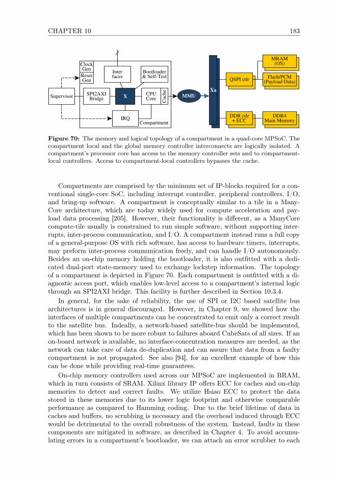
CHAPTER 10 183
Compartment
SPI2AXIBridge
MMUX CPUCore
IRQ
Interfaces
Supervisor
Cac
he
ClockGen
DDR4Main Memory
MRAM(OS)
Flash/PCM(Payload Data)QSPI ctlr
Xa
DDR ctlr+ ECC
ResetGen
Bootloader& Self-Test
Figure 70: The memory and logical topology of a compartment in a quad-core MPSoC. Thecompartment local and the global memory controller interconnects are logically isolated. Acompartment’s processor core has access to the memory controller sets and to compartment-local controllers. Access to compartment-local controllers bypasses the cache.
Compartments are comprised by the minimum set of IP-blocks required for a con-ventional single-core SoC, including interrupt controller, peripheral controllers, I/O,and bring-up software. A compartment is conceptually similar to a tile in a Many-Core architecture, which are today widely used for compute acceleration and pay-load data processing [205]. However, their functionality is different, as a ManyCorecompute-tile usually is constrained to run simple software, without supporting inter-rupts, inter-process communication, and I/O. A compartment instead runs a full copyof a general-purpose OS with rich software, has access to hardware timers, interrupts,may preform inter-process communication freely, and can handle I/O autonomously.Besides an on-chip memory holding the bootloader, it is also outfitted with a dedi-cated dual-port state-memory used to exchange lockstep information. The topologyof a compartment is depicted in Figure 70. Each compartment is outfitted with a di-agnostic access port, which enables low-level access to a compartment’s internal logicthrough an SPI2AXI bridge. This facility is further described in Section 10.3.4.
In general, for the sake of reliability, the use of SPI or I2C based satellite busarchitectures is in general discouraged. However, in Chapter 9, we showed how theinterfaces of multiple compartments can be concentrated to emit only a correct resultto the satellite bus. Indeally, a network-based satellite-bus should be implemented,which has been shown to be more robust to failures aboard CubeSats of all sizes. If anon-board network is available, no interface-concentration measures are needed, as thenetwork can take care of data de-duplication and can assure that data from a faultycompartment is not propagated. See also [94], for an excellent example of how thiscan be done while providing real-time guarantees.
On-chip memory controllers used across our MPSoC are implemented in BRAM,which in turn consists of SRAM. Xilinx library IP offers ECC for caches and on-chipmemories to detect and correct faults. We utilize Hsiao ECC to protect the datastored in these memories due to its lower logic footprint and otherwise comparableperformance as compared to Hamming coding. Due to the brief lifetime of data incaches and buffers, no scrubbing is necessary and the overhead induced through ECCwould be detrimental to the overall robustness of the system. Instead, faults in thesecomponents are mitigated in software, as described in Chapter 4. To avoid accumu-lating errors in a compartment’s bootloader, we can attach an error scrubber to each

184 10.3. A RELIABLE CUBESAT ON-BOARD COMPUTER
compartment’s local interconnect, which is managed by each compartment.To protect the running configuration of our SRAM-based FPGA, we implement
CRAM-frame ECC using the Xilinx Soft Error Mitigation IP (SEM [354]). However,configuration-level erasure coding and scrubbing can still only detect faults in specificcomponents of the FPGA fabric (e.g., not in BlockRAM). We address this limitationat the system level: Our coarse grain lockstep functionality enables us to detect faultsin the fabric with compartment granularity within 1-3 lockstep cycles, which is furtherdiscussed in Chapters 4 and 5. In practice, this closes the fault-detection gap left byscrubbing and configuration erasure coding.
Each memory controller set consists of a DDR4 memory controller, a QSPI con-troller, a set of clock and reset generators, as well as an optional memory scrubber coreand the top-level AXI crossbar. The optional memory scrubber cores can be controlledby the supervisor to avoid potential interference by malfunctioning compartments.
Each compartment has full write access to a segment DDR memory, while it canaccess the DDR memory in its entirety read-only. We construct the interconnectused by compartments to access a controller set from an AXI crossbar and four AXIswitches, one for each compartment. The top-level crossbar is connected to the area-optimized AXI interconnect attached to each compartment, which makes up the secondlevel of the MPSoC’s interconnect. In each interconnect, we realize memory protectionfor the address space of the relevant compartment to avoid a single point of failurecausing misdirected write access. Thereby, we create a topology that strongly isolatescompartments from each other, and assures non-interference between compartments.
The address space of all compartments is uniform, enabling memory structures tobe migrated between compartments and re-used. Through the MMU component indi-cated in Figures 70 and 69, we perform the necessary address translation operations.
In case one memory controller set fails, MPSoC compartments that were using thisset will switch to failover through a reboot. Compartments that are already utilizingthe secondary set can continue executing correctly and provide non-stop operation.Hence, it is desirable to run two of the MPSoC’s compartments off the A-controllerset, and the rest off the B-set. This allows the software-implemented fault tolerancefunctionality to guarantee non-stop operation even if an entire memory set would fail.In our proof-of-concept, we realize this functionality by outfitting compartments to beable to use two kernel variants, of which one booting into with main memory in theA set, and the second one into the B set. However, there are more elegant ways toaccomplish this, e.g., using position-independent firmware images [358].
To efficiently perform lockstep state comparison and synchronization between com-partments, an MPSoC has to provide adequate means of exchanging state-data, asdiscussed also in Chapters 4 and 9. For small MPSoCs with less than 6 cores, thisis realized in DDR/SDRAM memory. For larger designs, a dedicated state-exchangenetwork improves performance and offers stronger isolation. These components aredepicted in green in the figures. Access to state memory then takes place entirelyon-chip without passing through caches, and the global interconnect.
10.3.4 The Supervisor-FPGA Interface
The supervisor can access the FPGA through the FPGA’s JTAG interface. JTAG inprinciple is powerful which can be used as a universal tool to interact with the FPGAand its MPSoC, and manipulate it in a variety of ways. However, JTAG TAPs can be

CHAPTER 10 185
very complex, and the protocol does not assure the integrity of transferred data, whilebinary data transfer via JTAG can be very slow. Hence, we only use it to reconfigurethe FPGA in case the on-chip configuration controller fails.
The supervisor can trigger an interrupt or permanently disable a compartment, andcan induce a reset in compartments, memory controller sets, for the configuration con-troller, and for the FPGA itself. This is realized through a set of GPIO pins attachedto the supervisor. The supervisor can conduct low-level diagnostics and has accessto each compartment’s address space, without having to rely upon a compartment’sprocessor core.
We realize high-speed interconnect access through SPI, as the CubeSat communityis already familiar with this type of interface. As we just required a direct point-to-point between the FPGA and the supervisor without chip select, this interface setupon the PCB-side is very simple. We attach an SPI2AXI bridge to each compartment’slocal interconnect, and additionally to each memory controller set. This SPI-bridgecan be assembled entirely from well tested, free, open-source IP available in the GPLversion of GRLIB, using the SPI2AHB and AHB2AXI IP cores. Alternatively, avariety of open-source SPI2AXI cores are available, e.g., on gitlab, but the quality ofthese cores is uncertain. Xilinx and other vendors offer a selection of commercial IPcores.
The supervisor also communicates with the FPGA-internal configuration con-troller, which is outfitted with a conventional SPI-slave interface. In contrast to theSPI-diagnostics setup used for accessing the interconnect of compartments and mem-ory controller sets, the configuration controller actively collaborates with the supervi-sor. The configuration controller communicates with SEM and can be deactivated bythe supervisor in case of failure. During normal operation, it will notify the supervisorabout faults in the FPGA fabric. It can then perform reconfiguration via ICAP. Thesatellite developer can therefore deposit multiple differently placed designs for eachpartition in configuration memory, which the configuration controller can attempt touse to resolve a fault. Finally, the configuration controller will report outcome of therepair attempt to the supervisor.
Architecturally, the configuration controller resembles a stripped-down compart-ment design, but is constrained to a minimal logic footprint in the following way:
• It can run only baremetal code or an RTOS, not a general-purpose OS, therebyreducing the controller’s logic footprint.
• This software is stored directly in on-chip BRAM which is part of the reconfig-urable fabric.
• It has no access to the memory controller sets, to prevent interdependence be-tween static logic and partial-reconfiguration partitions.
• Besides its SPI master connected to configuration memory, the configurationcontroller has no other external interfaces.
In case of failure, the supervisor can substitute the full set of the configuration con-troller’s functionality through JTAG, and can recover it through full-FPGA reconfig-uration.
As depicted in Figure 71, the supervisor can utilize it’s SPI interface to access thedifferent components of the MPSoC in a controlled and performance-efficient manner.

186 10.3. A RELIABLE CUBESAT ON-BOARD COMPUTER
XKCU3P
Reconf.Controller
PartitionSelect Reg
MSP
430FR5969
SPI-Slave
FPGA TAP
SPIMaster
FPGAConfiguration
MemoryICAP
Memory Sets
Compartments
SPI2AXI
MMU
XDDR ctlr+ ECC
MemoryScrubber
SPI2AXI
IF
InterruptReset
Diagnosisand
Control
SEM
DEMUX
GPIO[3]
JTAG
BSY/CL
SPI
SPI
GPIO[2]
Figure 71: The design of our supervisor-FPGA control and diagnostic interface includingthe debug-facilities used by the supervisor to access different compartments of the MPSoC.

CHAPTER 10 187
It can disable individual compartments in case of failure by using existing circuitryrequired for partial reconfiguration, as indicated in Figure 70. However, instantiatingthe combination of SPI, reset, and interrupt lines for each compartment, memory set,and the reconfiguration controller would require a large amount of IO-pins. In practice,the supervisor will only communicate one MPSoC component at any given time, andnever with multiple concurrently. Hence, we de-multiplex (DEMUX) this interface,thereby reducing the need for I/O resources to just an SPI interface and 5 GPIO lines.
10.4 Handling Chip-Level SEFIs and Failure
Our proof-of-concept MPSoC design spans only of a single FPGA and is not designedto withstand component-wide SEFIs affecting the entire FPGA. However, it can beimplemented to tolerate such faults and even full component failure.
Figure 72a depicts an idealized traditional A/B-failover system with I/O switching.Such a system can tolerate the failure of components in either the A or the B side,but fails if an additional fault occurs elsewhere in the system. The B-side of thesystem remains inactive until a fault has been detected and isolated, and can beused productively without further design measures in hardware. Due to failover beingimplemented at the component level in hardware, additional glue logic required forswitching between the A and B-system. It is usually not possible to test the failedside without further design measures, and tests can only be conducted if the systemis taken offline. These limitations can be worked around with more glue logic and amore complex failover implementation, but even then the relevant logic can usuallynot just be be turned off and bypassed. Instead, it remains a potential failure source.
The system depicted in Figure 72b implements our architecture on two FPGAsand does not suffer these limitations: Instead of implementing all compartments andshared memory controller sets on a single FPGA, they can be distributed across multi-ple FPGAs. The chip-to-chip AXI IP used to connect two or more FPGAs is availablein the Vivado IP library. The failure of, e.g., a memory component connected toone FPGA, does not cause the failure of an entire redundant system side. Compart-ments on one FPGA connected to a failed component can still access componentson the B-side. The supervisor and platform controller on the faulty side can thenreconfigure the relevant FPGA partitions, and conduct further analysis on the failedcomponents. The system can thus continue thus support non-stop operation in caseof severe component failure, if threads-replicas are distributed so that not all replicasof a thread are executed on the same FPGA. In a TMR setup, this enables non-stopoperating, e.g., with the A-side running 2 replicas on one FPPGA and the B siderunning the third replica on the other. In NMR setups, two replicas can be assignedto each side, allowing fault-detection even if one of the FPGAs has failed during thesame lockstep cycle. For diagnostic purposes, thread-replication and therefore faulttolerance can also be constrained temporarily or even fully disabled. Even a severelydegraded system implementing our architecture that has suffered multiple componentfailures can thus still operate correctly and support non-stop operation. In contrast toa traditional OBC based on component-redundancy, our architecture thus can deliversstronger fault tolerance capabilities than traditional OBCs. As compartments on dif-ferent FPGA can share resources, this allows for increased efficiency and performanceas compared to traditional systems.
To support larger MPSoCs with more than 8 compartments efficiently, a more

188 10.4. HANDLING CHIP-LEVEL SEFIS AND FAILURE
scalable interface between compartments and memory controller sets should be used.This can be achieved with a Network-on-Chip (NoC). A NoC allows drastically largerMPSoC designs [329] due to improved scalability, but also enables fault-tolerant rout-ing [349], backwards error correction (re-transmission), and quality-of-service sup-port [359]. When implementing our architecture with a NoC, the shared memorycontroller sets would be implemented as one NoC layer, while the state-exchange net-work forms a second layer. In contrast to conventional interconnects typologies, a NoCcan also utilize error correction for NoC routers [93].
On-Board Network
OBC SoC
A
DDRB
Transceiver + RedWave
OBC SoC
B FlashB
DDRA
FlashA
A/B Switch
(a) A traditional redundant system where there A-side failed due to malfunc-tion in one memory components, which will fail once a fault occurs on the Bside.
On-Board Network
FPGAA DDR
B
Transceiver + RedWave
FPGAB
FlashB
DDRA
FlashA
C1 C2
C3 C4
C5 C6
C7 C8
(b) Our architecture, which is still functional and not degraded, even thoughmultiple components have failed on both sides.)
Figure 72: Fault tolerance examples of a traditional OBC and our architecture, whichshows that our architecture can tolerate a much increased number of faults than a traditionalsystem.
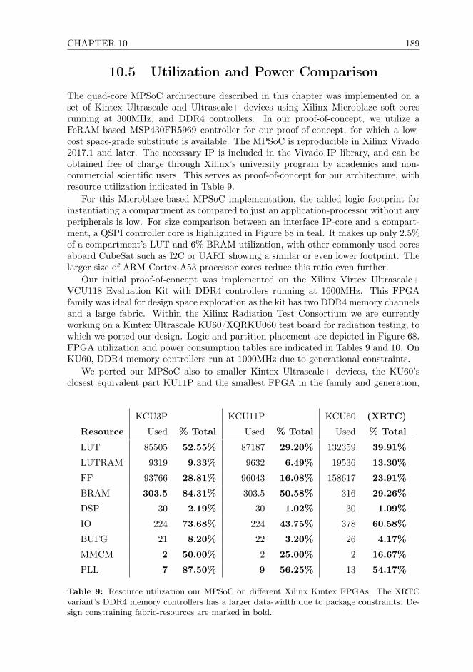
CHAPTER 10 189
10.5 Utilization and Power Comparison
The quad-core MPSoC architecture described in this chapter was implemented on aset of Kintex Ultrascale and Ultrascale+ devices using Xilinx Microblaze soft-coresrunning at 300MHz, and DDR4 controllers. In our proof-of-concept, we utilize aFeRAM-based MSP430FR5969 controller for our proof-of-concept, for which a low-cost space-grade substitute is available. The MPSoC is reproducible in Xilinx Vivado2017.1 and later. The necessary IP is included in the Vivado IP library, and can beobtained free of charge through Xilinx’s university program by academics and non-commercial scientific users. This serves as proof-of-concept for our architecture, withresource utilization indicated in Table 9.
For this Microblaze-based MPSoC implementation, the added logic footprint forinstantiating a compartment as compared to just an application-processor without anyperipherals is low. For size comparison between an interface IP-core and a compart-ment, a QSPI controller core is highlighted in Figure 68 in teal. It makes up only 2.5%of a compartment’s LUT and 6% BRAM utilization, with other commonly used coresaboard CubeSat such as I2C or UART showing a similar or even lower footprint. Thelarger size of ARM Cortex-A53 processor cores reduce this ratio even further.
Our initial proof-of-concept was implemented on the Xilinx Virtex Ultrascale+VCU118 Evaluation Kit with DDR4 controllers running at 1600MHz. This FPGAfamily was ideal for design space exploration as the kit has two DDR4 memory channelsand a large fabric. Within the Xilinx Radiation Test Consortium we are currentlyworking on a Kintex Ultrascale KU60/XQRKU060 test board for radiation testing, towhich we ported our design. Logic and partition placement are depicted in Figure 68.FPGA utilization and power consumption tables are indicated in Tables 9 and 10. OnKU60, DDR4 memory controllers run at 1000MHz due to generational constraints.
We ported our MPSoC also to smaller Kintex Ultrascale+ devices, the KU60’sclosest equivalent part KU11P and the smallest FPGA in the family and generation,
KCU3P KCU11P KCU60 (XRTC)
Resource Used % Total Used % Total Used % Total
LUT 85505 52.55% 87187 29.20% 132359 39.91%
LUTRAM 9319 9.33% 9632 6.49% 19536 13.30%
FF 93766 28.81% 96043 16.08% 158617 23.91%
BRAM 303.5 84.31% 303.5 50.58% 316 29.26%
DSP 30 2.19% 30 1.02% 30 1.09%
IO 224 73.68% 224 43.75% 378 60.58%
BUFG 21 8.20% 22 3.20% 26 4.17%
MMCM 2 50.00% 2 25.00% 2 16.67%
PLL 7 87.50% 9 56.25% 13 54.17%
Table 9: Resource utilization our MPSoC on different Xilinx Kintex FPGAs. The XRTCvariant’s DDR4 memory controllers has a larger data-width due to package constraints. De-sign constraining fabric-resources are marked in bold.
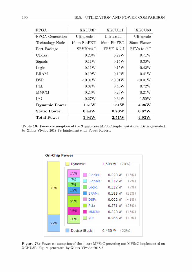
190 10.5. UTILIZATION AND POWER COMPARISON
FPGA XKCU3P XKCU11P XKCU60
FPGA Generation Ultrascale+ Ultrascale+ Ultrascale
Technology Node 16nm FinFET 16nm FinFET 20nm Planar
Part Package SFVB784-I FFVE1517-I FFVA1517-I
Clocks 0.23W 0.29W 0.71W
Signals 0.11W 0.15W 0.30W
Logic 0.11W 0.15W 0.42W
BRAM 0.19W 0.19W 0.41W
DSP <0.01W <0.01W <0.01W
PLL 0.37W 0.46W 0.72W
MMCM 0.23W 0.23W 0.21W
I/O 0.27W 0.34W 1.50W
Dynamic Power 1.51W 1.81W 4.26W
Static Power 0.44W 0.70W 0.67W
Total Power 1.94W 2.51W 4.93W
Table 10: Power consumption of the 3 quad-core MPSoC implementations. Data generatedby Xilinx Vivado 2018.3’s Implementation Power Report.
Figure 73: Power consumption of the 4-core MPSoC powering our MPSoC implemented onXCKU3P. Figure generated by Xilinx Vivado 2018.3.
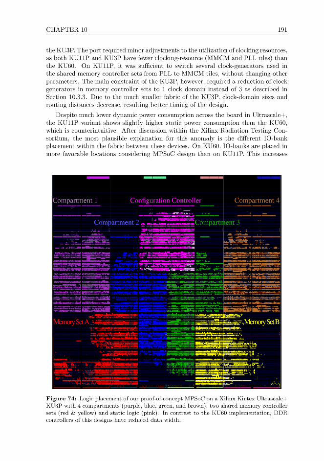

192 10.6. EXPERIMENTAL RESULTS AND TESTING
logic-spread, leaving less fully inactive fabric sections, which could explain an increasein static power consumption due to infrastructure on KU60.
The resulting Ultrascale+ MPSoC implementations, while functionally equivalent,show a 50% lower power consumption than the previous generation. This is due tomanufacturing in a 16nm FinFET technology node instead of 20nm planar. Powersavings mainly come from a reduced dynamic power consumption of this design, dueto an increased degree of logic concentration in a smaller of FPGA-fabric area. ForCubeSat-use, the Kintex Ultrascale+ family is therefore more attractive, despite thepotential risk of IO-pin latch-up is acceptable [299] which today is mitigated in thisfield through the system-level measures [39]. On the the smallest Ultrascale+ partand most compact BGA package xcku3p-sfvb784 available at the time of writing, weachieved 1.94W total power consumption. This is well within the power budget rangeof 2U CubeSats. Vivado’s power report for this design is depicted in Figure 73.
Synthesis was run in “Alternative Routability” mode, while implementation waswith the “Performance-Explore” strategy with post-route placement & power optimiza-tion, as the resulting implementations showed consistently better timing and powerutilization.
10.6 Experimental Results and Testing
We have tested our proof-of-concept OBC on Xilinx VCU118 (with 2 DDR memorychannels) and KCU116 boards (with 1 channel due to board constraints), and con-structed a breadboard setup in conjunction with an MSP430FR development board.Further information on this designs is available in Chapter 9, with an MPSoC im-plementation paper currently undergoing peer review. The actual platform for ourresearch has been the ARM Cortex-A53 application processor, which is today widelyused in a variety of mobile-market devices and certain COTS CubeSat OBCs. Thearchitecture we presented in this chapter is processor and platform independent, withthe MPSoC presented here implemented using Xilinx Microblaze processor cores.
To test our implementation, we have conducted fault injection through system em-ulation into an RTEMS implementation of Stage 1 running on a Cortex-A processor.In 2019, we also constructed a multi-core model of our MPSoC also in ArchC/SystemCon RISC-V to conduct further fault-injection close-to-hardware. The results of thisfault-injection campaign are documented in Chapter 8. They show that with near sta-tistical certainty, a fault affecting a compartment can be detected within 1–3 lockstepcycles, demonstrating that Stage 1 is effective and works efficiently.
10.7 Conclusions
In this chapter, we presented a CubeSat compatible on-board computer (OBC) ar-chitecture that offers strong fault tolerance to enable the use of such spacecraft incritical and long-term missions. It is the result of a hardware-software co-design pro-cess, and utilizes fault tolerance measures across the embedded stack. We describedin detail the design of our OBC’s breadboard layout, describing its composition fromthe component-level, to the MPSoC implementation used, all the way down to thesoftware level. We implement fault tolerance not through radiation hardening of thehardware, but realize it in software and exploit partial FPGA-reconfiguration and

CHAPTER 10 193
mixed criticality. To implement and reproduce this OBC architecture, no custom-written, proprietary, or protected IP is needed. All COTS components required toconstruct this architecture can be purchased on the open market, and are affordableeven for academic and scientific CubeSat developers. The needed designs are avail-able in standard FPGA-vendor library logic (IP), which in most cases is available toacademic developers free of charge through university donation programs.
Overall, our OBC architecture is non-proprietary, easily extendable, and scaleswell to larger satellites where slightly more abundant power budget is available. Wesuccessfully implemented a proof-of-concept of our MPSoC for a variety of XilinxKintex and Virtex Ultrascale and Ultrascale+ FPGA. This MPSoC was implementableeven for the smallest Kintex Ultrascale+ FPGA, KU3P, and we achieved 1.94W totalpower consumption. This puts it well within the power budget range available aboardcurrent 2U CubeSats, which currently offer no strong fault tolerance.
A comparison to existing traditional space-grade solutions as well as those availableto CubeSat developers seems unfair. Today, miniaturized satellite computing can useonly low-performance microcontrollers and unreliable MPSoCs in ASIC or FPGA with-out proper fault tolerance capabilities. Using the same type of commercial technology,our OBC can assure long-term fault coverage through a multi-stage fault tolerancearchitecture, without requiring fragile and complex component-level replication. Con-sidering the few more robust, low-performance CubeSat compatible microcontrollers,our implementation can offer beyond a factor-of-10 performance improvement eventoday. Considering traditional space-grade fault-tolerant OBC architectures for largerspacecraft, our current breadboard proof-of-concept implemented on FPGA exceedsthe single-core performance of the latest generation of space-grade SoC-ASICS such asan GR740. However, it does so at a fraction of the cost of such components, and with-out the tight technological constraints of traditional or ITAR protected space-gradesolutions.
Traditional fault-tolerant computer architectures intended for space applicationsstruggle against technology, and are ineffective for embedded and mobile-market com-ponents. Instead, we designed a software-based fault tolerance architecture and thisMPSoC specifically to enable the use of commercial modern semiconductors in spaceapplications. We do not require any space-grade components, fault-tolerant processordesigns, other custom, or proprietary logic. It can be replicated with just standarddesign tools and library IP, which is available free of charge to many designers inacademic and research organizations.
Our architecture scales with technology, instead of struggling against it. It bene-fits from performance and energy efficiency improvements that can be achieved withmodern mobile-market hardware, and can be scaled up to include more, and morepowerful processor cores. At the time of writing, Xilinx has begun to introduce a newgeneration of FPGA-equipped devices manufactured in a 7nm FinFET+ technologynode, in which the design issue causing latch-up in Ultrascale+ could also have beenmitigated [299]. Xilinx’s foundry TSMC expects this manufacturing process to offerapproximately 65% reduction power consumption as compared to the 16nm FinFETnode used for Ultrascale+ FPGAs [360]. Even if only half of this expected power reduc-tion would manifests, in combination with FPGA-fabric optimizations, we can expectto achieve approximately 1W power consumption with our MPSoC implemented ona next-gen Xilinx FPGA. While these expectations based on experiences with thecurrent 20nm Planar and 16nm FinFET manufactured Xilinx FPGAs, future FPGA

194 10.7. CONCLUSIONS
generations released within the next decade will, with near certainty [361], allow ourarchitecture to even become usable aboard 1U CubeSats.
At the time of writing, each component of our OBC architecture has been imple-mented and validated experimentally to TRL3 in a 1-person PhD student project.From each individual component, we have assembled a development-board basedbreadboard setup. As next step in validating this new OBC architecture, we willconstruct a prototype for radiation testing. Since 2018, we have therefore contributedto the Xilinx Radiation Testing Consortium to develop a suitable Kintex Ultrascale-equipped device-test board. This will bring our architecture to TRL4, and is an in-termediate step before developing a custom-PCB based prototype for on-orbit demon-stration. Once this has been achieved, we intend to perform the final step in validationof this technology aboard a CubeSat.

Chapter 11
Conclusions and Outlook
11.1 Conclusions
RQ1 In this thesis, we presented a satellite on-board computer (OBC) ar-chitecture that can offer strong fault tolerance with conventional, low-cost, modernsemiconductors manufactured in small feature-size technology nodes. The correctfunctionality of this architecture is safeguarded through a set of inter-linked software-implemented fault tolerance measures combined with FPGA reconfiguration, whichwe described in Chapter 4. These concepts allow us to assure fault tolerance even forsatellites with a very small form factor, which today can only utilize primitive or nofault tolerance measures at all, as traditional radiation-hardened satellite computer so-lutions can not be utilized due to volume, mass and power restrictions. We showed thatthrough lockstep implemented in software, we can efficiently protect a system consist-ing of embedded and mobile-market components, and should ideally be implementedwithin an FPGA to exploit reconfiguration. We demonstrate that the performancecost of this lockstep mechanics is economical, and that its implementation is possiblein a non-invasive manner. Its protective guarantees are run-time configurable, andfault tolerance can even be entirely deactivated at runtime if so desired.
RQ2 In Chapters 4 and 5, we showed that the logic of an FPGA-implementedMPSoC can be protected well from radiation effects through smart configuration man-agement and off-chip diagnostics. We closed the fault-detection gap which prior re-search struggles to close through the multi-stage fault tolerance architecture describedin Chapter 4. To safeguard an FPGA from transient faults, we showed that errorscrubbing and FPGA reconfiguration can be used to detect and correct bit-upsets inthe CRAM of an FPGA. As described in Chapter 4, permanent faults can then bemitigated through reconfiguration with alternative partition variants. This not onlyincreases the capability to cover permanent faults, but as we show in Chapter 5, it alsoallows an OBC to adapted to the specific requirements during each phase of complex,multi-phased space missions. This allows a reduction of overall system complexity,reduces the need for spare processor cores and MPSoC infrastructure logic, and candrastically extend the lifetime of a COTS FPGA-based OBC.
RQ3 In space missions with a very long duration, parts of an FPGA’s fab-ric will eventually no longer be recoverable through reconfiguration. This is due toaccumulating permanent faults in the semiconductor the FPGA, and thus also the
195
196 11.1. CONCLUSIONS
MPSoC, are implemented in. Over time, this will result in an increasing number ofthe MPSoC’s processor cores becoming unusable, gradually reducing the amount ofprocessing time available to the lockstep, and the level of replication it can achievefor all applications. In Chapter 6, we showed that the run-time configurable natureof software-implemented fault tolerance enables an OBC to respond to this behaviorin a way that can best be described as “graceful aging”. By exploiting mixed criti-cality, it is possible to autonomously reallocate processing time between the differentapplications that are part of an OBC’s flight software, allowing us to safeguard fault-tolerant operation for the flight software’s core functionality. We showed that stabilityand availability of critical applications can be maintained by sacrificing performanceof less important applications. In practice, this allows an OBC to age gracefully andadapt to a shrinking set of intact processor cores, instead of failing spontaneouslyas traditional systems do. A satellite operator can use this functionality to priori-tize and dynamically trade system performance for increased fault coverage, powersaving, or to maximize an OBC’s functionality. Spare processor cores in traditionalhardware-voting based systems remain idle until a fault occurs, but our lockstep canuse them actively to run less critical parts of the flight software, until they are neededin practice to replace a failed processor core. This allow spare processor cores availablethroughout an MPSoC to be pooled and used more efficiently, thereby to overcomingthe static nature of traditional static hardware-implemented fault tolerance measures.This allows an OBC to offer stronger fault coverage, and to more efficiently meet thechanging performance requirements throughout complex multi-phased solar systemexploration missions with much reduced over-provisioning and without requiring idlespares.
RQ5 All these operational and system-design improvements are possible dueto the coarse-grain lockstep concept described in Chapter 4, which we utilize to achieveforward error correction. We implement this lockstep within the OS kernel of an op-erating system (RTEMS, FreeRTOS, and experimentally also on Linux) or as part ofbaremetal software, where it assures synchronization between multiple thread-replicasrun on the processor cores of an MPSoC. To test and validate our architecture, inChapter 8, we conduct fault-injection into an emulated system and into a SystemC-implemented MPSoC model. In this chapter we describe the two fault injection cam-paigns we conducted against implementations of our lockstep: In the first campaign,we utilized the QEMU-based FIES fault injection framework to inject faults into anRTEMS implemented variant of our lockstep run on a Cortex-A system. In the sec-ond campaign, we modeled a triple-core model of our MPSoC using RISC-V coresin ArchC, and injected faults using SystemC simulation. Few software-implementedfault tolerance concepts described in literature have been practically implemented andvalidated. Therefore this chapter is also intended as practical guide for fellow re-searchers, to make proper testing of software-implemented fault tolerance measuresless challenging and time consuming.
RQ4 Relying on software-implemented fault tolerance measures also requirespecial care to be taken to assure the integrity of the flight-software in which they areimplemented. Hence, in Chapter 7, we explored how unprotected volatile and non-volatile COTS memory can be retrofitted with strong error correction and protectedfrom bit-upsets and SEFIs in control logic. We showed that error scrubbing for volatilememory can be combined with allocation-time integrity checking and blacklisting fordefective pages in widely-used operating systems such as Linux. To safeguard the logic

CHAPTER 11 197
of our lockstep and a full firmware image, we showed that a file system can be equippedsymbol-based erasure coding and can use memory protection to mitigate the impactof faults in control logic. To protect payload data, we described that a compositeerasure coding system can be combined with RAID-like functionality to efficientlyprotect data stored within high-density NAND-flash and phase change memory. Weshowed that software measures can guarantee strong fault tolerance, the NAND-flashindustry has in even begun to adopt the same erasure coding systems we proposedin this paper as part of a solid-state drives embedded software-stack, e.g., in [286].Simple erasure coding for caches and other on-chip memories at the time of writing isa standard feature in Xilinx library IP, and supported in all currently available model-market devices [119]. Security vulnerabilities such as Rowhammer and an increasedneed for yield enhancement have prompted the adoption of ECC also for protectingmain memory [362], and in combined with software-implemented memory testing andscrubbing described in this chapter, sufficient protection can be assured even for LEOCubeSat missions with an extended duration of 2-5 years.
RQ6 Much of today’s fault tolerance research proposes interesting and novelconcepts. But in practice, the majority of these concepts can not be applied to protecta critical system as it exists in the real world. To show that our architecture iseffective in practice, in Chapter 9 we developed an MPSoC design which providesan ideal platform for the software-mechanics used to assure fault tolerance. It isthe result of a hardware-software co-design process and assures a high-degree of logicand data isolation for software run on the individual processor cores of the OBCwithin compartments. It can be implemented with just currently available COTShardware and extensively validated FPGA-vendor library IP, requiring no proprietarylogic or costly, custom space-grade processor cores. This design demonstrates that ourarchitecture can not just protect a satellite OBC in theory, but also that a suitablecomputer architecture is feasible, and that no space-proprietary logic or IP is required.
In Chapter 10, we described the practical implementation of this MPSoC for avariety of Xilinx Ultrascale and Ultrascale+ FPGAs as proof-of-concept. To show howa practical OBC implementation for this MPSoC can look like, we developed a seriesof MPSoC implementations and a breadboard proof-of-concept of this architecture onXilinx VCU118 (with 2 DDR memory channels) and KCU116 boards (with 1 channelsdue to board constraints) in conjunction with TI-MSP430FR development boards. Wedescribed the component-level setup of this architecture for CubeSat-use, for whichan MPSoC implementation on a KU3P FPGA is possible with just 1.94W total powerconsumption. This demonstrates that a practical implementation of our architecturecan be achieved, which stays well within the power budget range available aboardcurrent 2U CubeSats.
11.2 Discussions
Traditional fault-tolerant computer architectures intended for space applications strug-gle against technology, and are ineffective for embedded and mobile-market compo-nents manufactured in technology nodes with a fine feature size. In this thesis weshowed that the solution to this limitation is the use of software-implemented faulttolerance measures, which can be utilized to systematically protect each componentof an OBC as depicted in Figure 75. Through the architecture we developed orig-inally as OBC for the MOVE-II satellite, we show that it is possible to efficiently


CHAPTER 11 199
A comparison of our OBC architecture to traditional space-grade solutions andcontemporary CubeSat computing seems unfair. Today, miniaturized satellite devel-opers are limited to use low-performance microcontrollers and MPSoCs implementedin ASIC or FPGA. Considering the few CubeSat compatible low-performance micro-controllers that have been shown robust under radiation, our implementation can offerdrastically more performance. At the time of writing Chapter 4, we estimated thatour architecture run on modern MPSoC and FPGAs can offer a beyond factor-of-5performance improvement as compared to these microcontrollers. Since 2017, within atime-span of just two years, mobile market MPSoCs have advanced drastically, and abeyond factor-of-10 improvement seems more realistic. At the time of writing in mid-2019, most mobile-market devices can offer almost twice the clock speed and a betterperformance per clock cycle as compared to their counterparts in 2017. Same ap-plies to the upcoming generation of FPGA which will benefit greatly from technologyscaling.
Mobile-market MPSoCs used aboard CubeSats today seldom include any fault tol-erance capabilities. Only sometimes to CubeSat designers implement custom home-brew component-level failover concepts, which has been shown to inflate complexityand failure potential. Our OBC architecture is based upon the same type of commer-cial technology, but through software-measures and a smart MPSoC design, we assurelong-term fault coverage with a component-wise simple setup. Comparing this OBCarchitecture with traditional solutions for larger spacecraft, even our current FPGA-based proof-of-concept exceeds the single-core performance of the latest generation ofspace-grade ASICS-SoCs such as an GR740 (250MHz vs 300MHz+). On top of that,our architecture can offer fault tolerance at a fraction of the cost. It can do so withoutsuffering from the tight technological constraints of this classical technology and thearchaic development tools used there. All this is possible while still using COTS hard-ware, without being impacted by the legal constraints of components that are subjectto ITAR or other export control laws.
11.3 Outlook and Future Work
As of early 2019, Xilinx has began to introduce a new generation of FPGA-equippeddevices manufactured in a 7nm FinFET+ technology node, in which the design issuecausing latch-up in Ultrascale+ should be mitigated [299]. With this node, Xilinx’sfoundry TSMC expects an around 65% reduction power consumption as comparedto the 16nm FinFET node used for Ultrascale+ FPGAs [360]. Even if only half ofthis expected power reduction would manifests, in combination with FPGA-fabricoptimizations, we can expect to achieve approximately 1W power consumption withour MPSoC implemented on a next-gen Xilinx FPGA. While these expectations basedon experiences with the current 20nm Planar and 16nm FinFET manufactured XilinxFPGAs, future FPGA generations released within the next decade will, with nearcertainty, allow our architecture to even become usable aboard 1U CubeSats.
At this point in time, I have validated this OBC architecture to the extent thatthis is possible for a single researcher in an academic environment. As next stepto validate it, I therefore plan to develop a prototype implementation. Since 2018,I have therefore collaborated with and contributed to the Xilinx Radiation TestingConsortium in the creation of a Kintex Ultrascale KU60 device-test card to reducethe cost and time required for constructing this prototype. As of 12.09.2019, we, the

200 11.3. OUTLOOK AND FUTURE WORK
XRTC infrastructure team, have finalized the KU60 card’s design and schematics, andafter routing and a final review pass, the KU60 DuT-card will go into production laterthis year.
Once the XRTC KU60 DuT-card becomes available, I plan to implement a match-ing daughterboard carrying DDR-SDRAM, MRAM, and PCM components as well asa supervisor MSP430FR, to then conduct radiation testing. Radiation testing willthen increase the maturity of this architecture to TRL4, and also serves as intermedi-ate step to then realize a full custom-PCB based prototype. This prototype can thenfor the first time be used to demonstrate the full capabilities of this architecture atTRL5, without the constraints present in a development-based breadboard setup.
There is considerable potential for improvements considering the proof-of-conceptthat I have developed before and during my PhD: The relaxed cost, energy, and sizeconstraints aboard microsatellites and larger spacecraft would allow an implementationof this OBC architecture spanning multiple FPGAs and with a drastically highernumber of compartments. Such an OBC would not only offer better scalability andfault-isolation than a single-FPGA system, but can then also tolerate chip-level defectsand SEFIs. Application replicas in lockstep could then be distributed across multipleFPGAs, allowing non-stop operation even if an individual FPGA would have to bereset, if or full reconfiguration is necessary.
To support larger MPSoCs with more than 8 compartments efficiently, a morescalable interface between compartments and memory controller sets should be used.This can be achieved by replacing the 2-level AXI crossbar the MPSoC is built aroundtoday with a Network-on-Chip (NoC). A NoC offers improved scalability [329], canalso be used to enable fault-tolerant routing [349], backwards error correction throughre-transmission, and quality-of-service support [359]. When implementing this archi-tecture with a NoC, the shared memory controller sets would be implemented on oneNoC layer, while the state-exchange network described in Chapter 9 would exist assecond layer. NoC routers can also be outfitted with error correction themselves [93].Unfortunately, the few NoC-specialized experts I encountered while conducting thisresearch had little interest in implementing their research practically. Hence I hopeincorporate NoC into this MPSoC design in the future in collaboration with those whoare willing to do so.
I designed this OBC architecture specifically to utilize and exploit the powerfulfault-recovery capabilities of modern FPGAs. However, this OBC architecture couldvery well be realized also on ASICs manufactured in radiation-robust COTS man-ufacturing processes such as FD-SoI [144]. This would allow much reduced energyconsumption, and drastically higher clock speeds to be achieved. An ASIC variantwould be less susceptible to transients and more robust to permanent faults, whileloosing the capability to mitigate permanent faults through FPGA reconfiguration.However, due to the drastically increased development costs of an ASIC implemen-tation, the resulting OBC would not be viable for miniaturized satellite applicationsanymore. We see this as a “big-space” variant of this approach with its own advantages,but it would no longer offer fault tolerance “on a budget”.
This research began as a one-person project, but towards the end of my PhD, ithas become clear that it has today outgrown the capacity of just a single researcher. Inall regards, the end of my PhD is actually the beginning of something new, and moreimportant. I know that in the coming years, I must gather a research group to advancethis research and develop it further in a suitable environment. Where I will do this

CHAPTER 11 201
remains yet to be seen. At the end of the second year and the beginning of the final yearof my time as PhD researcher, I therefore began to explore ways for conducting long-term testing for this OBC architecture to appropriately consider the time-componentthat is introduced in testing hardware-software-hybrid systems. In this processes,I have had the pleasure collaborate with several international experts in the fieldsof radiation testing, space engineering, and semiconductor testing. Promising testenvironments for long-term testing include the close proximity of a radiation source,the Exposed Facility aboard the ISS (JEM-EF), or the vicinity of the FukushimaDaiichi site. Naturally, all these test setups require considerable preparation time,and preparing a prototype for deployed, e.g., aboard ISS is a highly competitive andcertification-heavy undertaking. Therefore, I aim to conduct in parallel to long-termtesting also on-orbit validation aboard a CubeSat, which is possible more rapidly andat reduced cost than e.g., through an ISS experiment. After all, on-orbit technologydemonstration and validation is one of the prime use-cases for CubeSats today, andalso one of their most successful applications.
On-orbit validation aboard a CubeSat also closes a circle that began with the earlyfailure of the FirstMOVE CubeSat, and that initiated my satellite fault toleranceresearch. I started this research, searching for a way to realize a better, fault-tolerantsatellite bus architecture for the MOVE-II CubeSat project. Back then, it became clearthat there were simply no fault-tolerant OBC architectures or products in existencethat could even theoretically be used to assure fault tolerance and guarantee reliableoperation for long-term CubeSat mission. At the start of this thesis, we raised thequestion:
RQ0 Can a fault tolerance computer architecture be achieved with modern embeddedand mobile-market technology, without breaking the mass, size, complexity, andbudget constraints of miniaturized satellite applications?
This hard question arrose at the beginning of the development process of the MOVE-II CubeSat. I approached this research without a specific architecture or solution inmind, and even briefly considered a highly experimental, academic VLIW platform.Three years, many published research papers, and several catastrophes later, it is nowpossible to answer this question in the following way:
RQ0 Yes. A fault-tolerant computer architecture for miniaturized satellites is tech-nically feasible with contemporary COTS technology. Once fully implementedas a prototype, it can be used to expand the reliable lifetime of modern dayCubeSats drastically, thereby enabling their use in critical and long-term spacemissions. With contemporary COTS components, this OBC architecture canbe applied to satellites as small as 2U CubeSats. Advances in semiconductormanufacturing in the upcoming generation of FPGAs will make this approachalso usable for smaller spacecraft, and even more appealing as it scales withtechnology. It can improve efficiency and scalability when implemented aboardheavier spacecraft that we use today for high-priority science and solar systemexploration. And maybe in the future, hopefully, we can explore even what liesbeyond its boundaries.

202 11.3. OUTLOOK AND FUTURE WORK
Bibliography
[1] Directorate of Technical and Quality Management, ESA/NPI 497-2016: EfficientDependable Space-Borne Computing through Advanced Reconfigurability Concepts.ESA, December 2016.
[2] M. Langer and J. Bouwmeester, “Reliability of CubeSats-statistical data, develop-ers’ beliefs and the way forward,” in AIAA/USU Conference on Small Satellites(SmallSat), 2016.
[3] M. Swartwout, “The first one hundred CubeSats: A statistical look,” Journal ofSmall Satellites, vol. 2, no. 2, pp. 213–233, 2013.
[4] E. Stassinopoulos and J. P. Raymond, “The space radiation environment for elec-tronics,” Proceedings of the IEEE, vol. 76, no. 11, pp. 1423–1442, 1988.
[5] J. R. Schwank, M. R. Shaneyfelt, and P. E. Dodd, “Radiation Hardness AssuranceTesting of Microelectronic Devices and Integrated Circuits,” IEEE Transactionson Nuclear Science, 2013.
[6] L. Whetsel, “An IEEE 1149.1-based test access architecture for ICs with embeddedcores,” in International Test Conference (ITC). IEEE, 1997.
[7] M. R. Patel, Spacecraft power systems. CRC press, 2004.
[8] C. Boshuizen, J. Mason, P. Klupar, and S. Spanhake, “Results from the planetlabs flock constellation,” in AIAA/USU Conference on Small Satellites (SmallSat),2014.
[9] A. Poghosyan and A. Golkar, “CubeSat evolution: Analyzing CubeSat capabilitiesfor conducting science missions,” Progress in Aerospace Sciences, Elsevier, vol. 88,pp. 59–83, 2017.
[10] T. Wahl, G. K. Høye, A. Lyngvi, and B. T. Narheim, “New possible roles of smallsatellites in maritime surveillance,” Acta Astronautica, Elsevier, vol. 56, no. 1-2,pp. 273–277, 2005.
[11] M. Parra, A. J. Ricco, B. Yost, M. R. McGinnis, and J. W. Hines, “Studyingspace effects on microorganisms autonomously: genesat, pharmasat and the futureof bio-nanosatellites,” Gravitational and Space Biology Bulletin, vol. 21, pp. 9–17,2008.
203

204 BIBLIOGRAPHY
[12] Q. Schiller, D. Gerhardt, L. Blum, X. Li, and S. Palo, “Design and scientific returnof a miniaturized particle telescope onboard the colorado student space weatherexperiment (CSSWE) CubeSat,” in IEEE Aerospace Conference. IEEE, 2014.
[13] C. Underwood, S. Pellegrino, V. J. Lappas, C. P. Bridges, and J. Baker, “UsingCubeSat/micro-satellite technology to demonstrate the autonomous assembly of areconfigurable space telescope (AAReST),” Acta Astronautica, Elsevier, vol. 114,pp. 112–122, 2015.
[14] W. Weiss, S. Rucinski, A. Moffat, A. Schwarzenberg-Czerny, O. Koudelka,C. Grant, R. Zee, R. Kuschnig, J. Matthews, P. Orleanski et al., “Brite-constellation: nanosatellites for precision photometry of bright stars,” Publicationsof the Astronomical Society of the Pacific, vol. 126, no. 940, p. 573, 2014.
[15] S. Lacour, M. Nowak, P. Bourget, F. Vincent, A. Kellerer, V. Lapeyrère, L. David,A. Le Tiec, O. Straub, and J. Woillez, “Sage: using CubeSats for gravitational wavedetection,” in Space Telescopes and Instrumentation 2018: Ultraviolet to GammaRay, vol. 10699. International Society for Optics and Photonics, 2018, p. 106992R.
[16] S.-i. Watanabe, Y. Tsuda, M. Yoshikawa, S. Tanaka, T. Saiki, and S. Nakazawa,“Hayabusa2 mission overview,” Space Science Reviews, Springer, vol. 208, no. 1-4,pp. 3–16, 2017.
[17] J. Schoolcraft, A. T. Klesh, and T. Werne, “Marco: interplanetary mission devel-opment on a CubeSat scale,” in Space Operations: Contributions from the GlobalCommunity. Springer, 2017.
[18] I. F. Akyildiz and A. Kak, “The internet of space things/cubesats: A ubiquitouscyber-physical system for the connected world,” Computer Networks, Elsevier, vol.150, pp. 134–149, 2019.
[19] M. Cappella, “The principle of equitable access in the age of mega-constellations,”in Legal Aspects Around Satellite Constellations. Springer, 2019, pp. 11–23.
[20] L. Wang, R. Chen, B. Xu, X. Zhang, T. Li, and C. Wu, “The challenges of LEObased navigation augmentation system–lessons learned from Luojia-1a satellite,”in China Satellite Navigation Conference. Springer, 2019, pp. 298–310.
[21] M. Harris, “Tech giants race to build orbital internet [news],” IEEE Spectrum,vol. 55, no. 6, pp. 10–11, 2018.
[22] H. Bedon, C. Negron, J. Llantoy, C. M. Nieto, and C. O. Asma, “Preliminaryinternetworking simulation of the qb50 CubeSat constellation,” in IEEE Latin-American Conference on Communications. IEEE, 2010, pp. 1–6.
[23] V. L. Foreman, A. Siddiqi, and O. De Weck, “Large satellite constellation orbitaldebris impacts: case studies of oneweb and spacex proposals,” in AIAA SPACEand Astronautics Forum and Exposition, 2017, p. 5200.
[24] T. Hiriart and J. H. Saleh, “Observations on the evolution of satellite launchvolume and cyclicality in the space industry,” Space Policy, Elsevier, vol. 26, no. 1,pp. 53–60, 2010.

BIBLIOGRAPHY 205
[25] L. D. Feinberg, “Engineering history of the james webb space telescope (JWST)optical telescope element,” 2018, nASA Goddard Space Flight Center.
[26] F. Lura and D. Hagelschuer, “System conditioning-our ways and testing toolsfor the development of reliability for spaceborne components and small satellites,”in Digest of the First International Symposium of the International Academy ofAstronautics (IAA), Berlin, November, 1999, pp. 4–8.
[27] S. Vinod et al., “Satellite ground testing-objectives and implementation,” GroundTesting of Aerospace Vehicles Including Engines, Allied Publishers, p. 223, 1994.
[28] R. Haefer, “Vacuum and cryotechniques in space research,” Vacuum, Elsevier,vol. 22, no. 8, pp. 303–314, 1972.
[29] D. Koelle, “Specific transportation costs to GEO – past, present and future,” ActaAstronautica, Elsevier, vol. 53, no. 4, pp. 797–803, 2003.
[30] J. N. Pelton, “Launch vehicles and launch sites,” in Handbook of Satellite Appli-cations. Springer, 2013, pp. 1131–1144.
[31] A. L. Weigel and D. E. Hastings, “Evaluating the cost and risk impacts of launchchoices,” Journal of Spacecraft and Rockets, AIAA, vol. 41, no. 1, pp. 103–110,2004.
[32] H. Helvajian and S. Janson, Small satellites: past, present, and future. AIAA,2009.
[33] J. Depasquale, A. Charania, H. Kanamaya, and S. Matsuda, “Analysis of theearth-to-orbit launch market for nano and microsatellites,” in AIAA SPACE 2010Conference & Exposition, 2010, p. 8602.
[34] D. DePasquale and J. Bradford, “Nano/microsatellite market assessment,” PublicRelease, Revision A, SpaceWorks, 2013.
[35] B. Twiggs, S. Lee, A. Hutputanasin, A. Toorian, W. Lan, R. Munakata, J. Car-nahan, D. Pignatelli, A. Mehrparvar et al., “CubeSat design specification rev. 13,”Cal Poly SLO, Standard, 2015.
[36] M. Czech, A. Fleischner, and U. Walter, “A first-move in satellite developmentat the tu-münchen,” in Small Satellite Missions for Earth Observation. Springer,2010, pp. 235–245.
[37] D. J. Barnhart, T. Vladimirova, A. M. Baker, and M. N. Sweeting, “A low-costfemtosatellite to enable distributed space missions,” Acta Astronautica, Elsevier,vol. 64, no. 11-12, pp. 1123–1143, 2009.
[38] J. Tristancho and J. Gutierrez-Cabello, “A probe of concept for femto-satellitesbased on commercial-of-the-shelf,” in IEEE/AIAA Digital Avionics Systems Con-ference. IEEE, 2011, pp. 8A2–1.
[39] J. Bouwmeester, M. Langer, and E. Gill, “Survey on the implementation andreliability of CubeSat electrical bus interfaces,” CEAS Space Journal, Springer,vol. 9, no. 2, pp. 163–173, 2017.

206 BIBLIOGRAPHY
[40] R. Carlson, K. Hand, and E. Ozer, “On the use of System-on-Chip technologyin next-generation instruments avionics for space exploration,” in IFIP/IEEE In-ternational Conference on Very Large Scale Integration-System on a Chip (VLSI-SoC), revised paper. Springer, 2016.
[41] M. Swartwout, “The first one hundred CubeSats: A statistical look,” Journal ofSmall Satellites, 2014.
[42] M. Swartwout, “You say “PicoSat”, i say “CubeSat”: Developing a better taxon-omy for secondary spacecraft,” in IEEE Aerospace Conference, 2018.
[43] M. Swartwout, “Cubesats and mission success: A look at the numbers,” in CubeSatDevelopers Workshop. CalPoly, 2016.
[44] R. Trivedi and U. S. Mehta, “A survey of radiation hardening by design (RHBD)techniques for electronic systems for space application,” International Journal ofElectronics and Communication Engineering & Technology (IJECET), vol. 7, no. 1,p. 75, 2016.
[45] P. Roche, J.-L. Autran, G. Gasiot, and D. Munteanu, “Technology downscalingworsening radiation effects in bulk: SOI to the rescue,” in IEEE InternationalElectron Devices Meeting. IEEE, 2013, pp. 31–1.
[46] S. M. Guertin, M. Amrbar, and S. Vartanian, “Radiation test results for commonCubeSat microcontrollers and microprocessors,” in IEEE Radiation Effects DataWorkshop (REDW). IEEE, 2015, pp. 1–9.
[47] D. Selčan, G. Kirbiš, and I. Kramberger, “Low level radiation and fault protectiontechniques suitable for nanosatellite missions,” in Conference on Radiation and itsEffects on Components and Systems (RADECS). IEEE, 2017.
[48] M. Swartwout, “Secondary spacecraft in 2016: Why some succeed (and too manydo not),” in IEEE Aerospace Conference. IEEE, 2016, pp. 1–13.
[49] M. Williamson, “Commercial space risks, spacecraft insurance, and the fragilefrontier,” in Frontiers of Space Risk. CRC Press, 2018, pp. 143–163.
[50] J. R. Samson, “Update on dependable multiprocessor CubeSat technology devel-opment,” in 2012 IEEE Aerospace Conference. IEEE, 2012, pp. 1–12.
[51] B. S. Dhillon, Human reliability: with human factors. Elsevier, 2013.
[52] R. Isermann, Fault-diagnosis systems: an introduction from fault detection to faulttolerance. Springer Science & Business Media, 2006.
[53] I. P. Egwutuoha, D. Levy, B. Selic, and S. Chen, “A survey of fault tolerance mech-anisms and checkpoint/restart implementations for high performance computingsystems,” Journal of Supercomputing, vol. 65, no. 3, pp. 1302–1326, 2013.
[54] R. Ginosar, “Survey of processors for space,” Eurospace Data Systems InAerospace (DASIA), 2012.
[55] K. Tindell, H. Hanssmon, and A. J. Wellings, “Analysing real-time communica-tions: Controller area network (CAN).” in Real Time System Symposium (RTSS).IEEE, 1994, pp. 259–263.

BIBLIOGRAPHY 207
[56] R. Makowitz and C. Temple, “Flexray–a communication network for automotivecontrol systems,” in IEEE International Workshop on Factory Communication Sys-tems. IEEE, 2006, pp. 207–212.
[57] W. R. Moore, “A review of fault-tolerant techniques for the enhancement of inte-grated circuit yield,” Proceedings of the IEEE, vol. 74, no. 5, pp. 684–698, 1986.
[58] L. Jiang, R. Ye, and Q. Xu, “Yield enhancement for 3d-stacked memory by redun-dancy sharing across dies,” in IEEE/ACM International Conference on Computer-Aided Design (ICCAD). IEEE, 2010, pp. 230–234.
[59] P. A. Buckland, J. R. Herring, G. M. Nordstrom, and W. A. Thompson, “Cableredundancy and failover for multi-lane pci express io interconnections,” Mar. 182014, US Patent 8,677,176.
[60] B. Vucetic and J. Yuan, Turbo codes: principles and applications. SpringerScience & Business Media, 2012, vol. 559.
[61] Z. Zhang, V. Anantharam, M. J. Wainwright, and B. Nikolic, “An efficient10gbase-t ethernet ldpc decoder design with low error floors,” IEEE Journal ofSolid-State Circuits, vol. 45, no. 4, pp. 843–855, 2010.
[62] Y. Furukawa, “Intellectual property protection and innovation: An inverted-urelationship,” Economics Letters, Elsevier, vol. 109, no. 2, pp. 99–101, 2010.
[63] M. Fidler and A. Rizk, “A guide to the stochastic network calculus,” IEEE Com-munications Surveys & Tutorials, vol. 17, no. 1, pp. 92–105, 2014.
[64] K. Suresh, C. W. Selvidge, S. Gupta, and A. Jain, “Debug environment for amulti user hardware assisted verification system,” Feb. 1 2018, US Patent App.15/646,003.
[65] M. Kooli and G. Di Natale, “A survey on simulation-based fault injection toolsfor complex systems,” in International Conference on Design & Technology of In-tegrated Systems in Nanoscale Era (DTIS). IEEE, 2014.
[66] H. Ziade, R. A. Ayoubi, R. Velazco et al., “A survey on fault injection techniques,”Int. Arab J. Inf. Technol., vol. 1, no. 2, pp. 171–186, 2004.
[67] M. M. Hassan, W. Afzal, M. Blom, B. Lindström, S. F. Andler, and S. Eldh,“Testability and software robustness: A systematic literature review,” in EuromicroConference on Software Engineering and Advanced Applications. IEEE, 2015.
[68] J. W. Bennett, G. J. Atkinson, B. C. Mecrow, and D. J. Atkinson, “Fault-tolerantdesign considerations and control strategies for aerospace drives,” IEEE Transac-tions on Industrial Electronics, vol. 59, no. 5, pp. 2049–2058, 2011.
[69] G. C. Clark Jr and J. B. Cain, Error-correction coding for digital communications.Springer Science & Business Media, 2013.
[70] P. W. Coteus, H. C. Hunter, C. A. Kilmer, K.-h. Kim, L. A. Lastras-Montano,W. E. Maule, and V. Patel, “Error feedback and logging with memory on-chip errorchecking and correcting (ECC),” Jan. 30 2018, US Patent 9,880,896.
208 BIBLIOGRAPHY
[71] M. Tipaldi and B. Bruenjes, “Survey on fault detection, isolation, and recoverystrategies in the space domain,” Journal of Aerospace Information Systems, vol. 12,no. 2, pp. 235–256, 2015.
[72] D. A. Patterson, G. Gibson, and R. H. Katz, A case for redundant arrays ofinexpensive disks (RAID). ACM, 1988, vol. 17, no. 3.
[73] P. R. Grams, “Ethernet for aerospace applications-ethernet heads for the skies,”in IEEE Ethernet Technology Summit. NASA, 2015.
[74] M. Luby, L. Vicisano, J. Gemmell, L. Rizzo, M. Handley, and J. Crowcroft, “RFC5052: Forward error correction (FEC) building block,” IETF, Tech. Rep., 2007.
[75] D. Boley, G. H. Golub, S. Makar, N. Saxena, and E. J. McCluskey, “Floating pointfault tolerance with backward error assertions,” IEEE Transactions on Computers,vol. 44, no. 2, pp. 302–311, 1995.
[76] R. C. Aitken, “Modeling the unmodelable: Algorithmic fault diagnosis,” IEEEDesign & Test of Computers, vol. 14, no. 3, pp. 98–103, 1997.
[77] J. Sloan, R. Kumar, and G. Bronevetsky, “Algorithmic approaches to low overheadfault detection for sparse linear algebra,” in Conference on Dependable Systems andNetworks (DSN). IEEE, 2012.
[78] N. R. Saxena and E. J. McCluskey, “Control-flow checking using watchdog assistsand extended-precision checksums,” IEEE Transactions on Computers, vol. 39,no. 4, pp. 554–559, 1990.
[79] S. Z. Shazli and M. B. Tahoori, “Transient error detection and recovery in proces-sor pipelines,” in IEEE International Symposium on Defect and Fault Tolerance inVLSI Systems (DFT). IEEE, 2009, pp. 304–312.
[80] J. Gaisler, “Concurrent error-detection and modular fault-tolerance in a 32-bitprocessing core for embedded space flight applications,” in IEEE InternationalSymposium on Fault-Tolerant Computing (FTCS). IEEE, 1994, pp. 128–130.
[81] S. Agrawal and K. Daudjee, “A performance comparison of algorithms for byzan-tine agreement in distributed systems,” in European Dependable Computing Con-ference (EDCC). IEEE, 2016.
[82] M. Barborak, A. Dahbura, and M. Malek, “The consensus problem in fault-tolerant computing,” ACM Computing Surveys (CSur), vol. 25, no. 2, pp. 171–220,1993.
[83] T. Jackson, B. Salamat, A. Homescu, K. Manivannan, G. Wagner, A. Gal,S. Brunthaler, C. Wimmer, and M. Franz, “Compiler-generated software diver-sity,” in Moving Target Defense. Springer, 2011, pp. 77–98.
[84] S. Punnekkat, A. Burns, and R. Davis, “Analysis of checkpointing for real-timesystems,” Real-Time Systems, Springer, vol. 20, no. 1, pp. 83–102, 2001.
[85] A. Thekkilakattil, R. Dobrin, and S. Punnekkat, “Fault tolerant scheduling ofmixed criticality real-time tasks under error bursts,” Procedia Computer Science,Elsevier, vol. 46, pp. 1148–1155, 2015.
BIBLIOGRAPHY 209
[86] ——, “Bounding the effectiveness of temporal redundancy in fault-tolerant real-time scheduling under error bursts,” in IEEE Emerging Technology and FactoryAutomation (ETFA). IEEE, 2014, pp. 1–8.
[87] M. Short and J. Proenza, “Towards efficient probabilistic scheduling guaranteesfor real-time systems subject to random errors and random bursts of errors,” inEuromicro Conference on Real-Time Systems. IEEE, 2013, pp. 259–268.
[88] X. Iturbe, B. Venu, E. Ozer, and S. Das, “A triple core lock-step (TCLS) ARMCortex-R5 processor for safety-critical and ultra-reliable applications,” in Confer-ence on Dependable Systems and Networks Workshop (DSN-W). IEEE, 2016.
[89] J. Arm, Z. Bradac, and R. Stohl, “Increasing safety and reliability of roll-back androll-forward lockstep technique for use in real-time systems,” IFAC Conference onProgrammable Devices and Embedded Systems (PDES), Elsevier, vol. 49, no. 25,pp. 413–418, 2016.
[90] K. D. Safford, D. C. Soltis Jr, and E. R. Delano, “Off-chip lockstep checking,”Jun. 26 2007, US Patent 7,237,144.
[91] B. H. Meyer, B. H. Calhoun, J. Lach, and K. Skadron, “Cost-effective safetyand fault localization using distributed temporal redundancy,” in InternationalConference on Compilers, architectures and synthesis for embedded systems. ACM,2011, pp. 125–134.
[92] Y. Zhou, X. Wang, Y. Chen, and Z. Wang, “Armlock: Hardware-based faultisolation for arm,” in ACM SIGSAC conference on computer and communicationssecurity. ACM, 2014, pp. 558–569.
[93] J. Zhou, H. Li, T. Wang, and X. Li, “Loft: A low-overhead fault-tolerant routingscheme for 3D NoCs,” Integration, the VLSI Journal, 2016.
[94] Aeronautical Radio, INC, ARINC Specification 664: Avionics Full DuplexSwitched Ethernet (AFDX), 2005.
[95] Y. Li, E. L. Miller, and D. D. Long, “Understanding data survivability in archivalstorage systems,” in International Systems and Storage Conference. ACM, 2012.
[96] N. Joukov, A. M. Krishnakumar, C. Patti, A. Rai, S. Satnur, A. Traeger, andE. Zadok, “RAIF: Redundant array of independent filesystems,” in Conference onMass Storage Systems and Technologies (MSST). IEEE, 2007, pp. 199–214.
[97] M.-A. Song, S.-Y. Kuo, and I.-F. Lan, “A low complexity design of Reed-Solomoncode algorithm for advanced RAID system,” IEEE Transactions on ConsumerElectronics (TCE), vol. 53, 2007.
[98] R. L. Alena, J. P. Ossenfort, K. I. Laws, A. Goforth, and F. Figueroa, “Commu-nications for integrated modular avionics,” in IEEE Aerospace Conference. IEEE,2007, pp. 1–18.
[99] M. Roa, W. Cantrell, D. Cartes, and M. Nelson, “Requirements for deterministiccontrol systems,” in IEEE Electric Ship Technologies Symposium. IEEE, 2011,pp. 439–445.

210 BIBLIOGRAPHY
[100] S. V. Amari and G. Dill, “Redundancy optimization problem with warm-standbyredundancy,” in Reliability and Maintainability Symposium (RAMS). IEEE, 2010.
[101] ——, “A new method for reliability analysis of standby systems,” in Reliabilityand Maintainability Symposium (RAMS). IEEE, 2009.
[102] J. J. Wylie and R. Swaminathan, “Selecting erasure codes for a fault tolerantsystem,” Aug. 21 2012, US Patent 8,250,427.
[103] J. S. Plank, “A tutorial on reed–solomon coding for fault-tolerance in raid-likesystems,” Software: Practice and Experience, vol. 27, no. 9, pp. 995–1012, 1997.
[104] M. Hijorth, M. Aberg, N.-J. Wessman, J. Andersson, R. Chevallier, R. Forsyth,R. Weigand, and L. Fossati, “GR740: Rad-hard quad-core LEON4FT system-on-chip,” in Eurospace Data Systems In Aerospace (DASIA), 2015.
[105] L. Bozzoli and L. Sterpone, “Self rerouting of dynamically reconfigurable SRAM-based FPGAs,” in NASA/ESA Conference on Adaptive Hardware and Systems(AHS). IEEE, 2017.
[106] R. Baheti and H. Gill, “Cyber-physical systems,” The impact of control technol-ogy, IEEE Control Systems Society, vol. 12, no. 1, pp. 161–166, 2011.
[107] M. D. Berg, H. S. Kim, A. M. Phan, C. M. Seidleck, K. A. LaBel, J. A. Pellish,and M. J. Campola, “The effects of race conditions when implementing single-source redundant clock trees in triple modular redundant synchronous architec-tures,” in Conference on Radiation and its Effects on Components and Systems(RADECS). IEEE, 2016.
[108] M. Berg, K. LaBel, M. Campola, and M. Xapsos, “Analyzing system on a chipsingle event upset responses using single event upset data, classical reliability mod-els, and space environment data,” in Conference on Radiation and its Effects onComponents and Systems (RADECS). IEEE, 2017.
[109] G. G. Preckshot, Method for performing diversity and defense-in-depth analysesof reactor protection systems. Division of Reactor Controls and Human Factors,Office of Nuclear Reactor Regulation, US Nuclear Regulatory Commission, 1994.
[110] D. K. Nilsson and U. Larson, “A defense-in-depth approach to securing the wire-less vehicle infrastructure,” Journal of Networks (JNW), vol. 4, no. 7, pp. 552–564,2009.
[111] T. G. Rauscher, “Raid system with multiple controllers and proof against anysingle point of failure,” Mar. 29 2005, US Patent 6,874,100.
[112] H. Madeira, R. R. Some, F. Moreira, D. Costa, and D. Rennels, “Experimentalevaluation of a cots system for space applications,” in Proceedings InternationalConference on Dependable Systems and Networks. IEEE, 2002, pp. 325–330.
[113] J. Hammarberg and S. Nadjm-Tehrani, “Formal verification of fault tolerance insafety-critical reconfigurable modules,” Journal on Software Tools for TechnologyTransfer, Springer, vol. 7, no. 3, pp. 268–279, 2005.

BIBLIOGRAPHY 211
[114] X. Cai and M. R. Lyu, “Software reliability modeling with test coverage: Ex-perimentation and measurement with a fault-tolerant software project,” in IEEEInternational Symposium on Software Reliability (ISSRE). IEEE, 2007, pp. 17–26.
[115] J. L. Nunes, T. Pecserke, J. C. Cunha, and M. Zenha-Rela, “FIRED–fault in-jector for reconfigurable embedded devices,” in IEEE Pacific Rim InternationalSymposium on Dependable Computing (PRDC). IEEE, 2015.
[116] I. Sommerville, “Software engineering (10th edition),” ISBN-10, vol. 0133943038,2015.
[117] B. Schroeder, E. Pinheiro, and W.-D. Weber, “DRAM errors in the wild: alarge-scale field study,” Communications of the ACM, vol. 54, no. 2, pp. 100–107,2011.
[118] A. Mukati, “A survey of memory error correcting techniques for improved reli-ability,” Journal of Network and Computer Applications, Elsevier, vol. 34, no. 2,pp. 517–522, 2011.
[119] T. Lanier, “Exploring the design of the cortex-a15 processor,” https://www.arm.com/files/ pdf/AT-Exploring_the_Design_of_the_Cortex-A15.pdf , 2011.
[120] USB-IF, “Universal serial bus revision 3.1 specification,” 2011.
[121] K. Deyring et al., “Serial ATA: High speed serialized at attachment,” Jan, vol. 7,pp. 1–22, 2003.
[122] P. Savio, A. Nespola, S. Straullu, S. Abrate, and R. Gaudino, “A physical codingsublayer for gigabit ethernet over POF,” in International Conference on PlasticOptical Fibers (POF). International Cooperative of Plastic Optical Fibers, 2010.
[123] A. Goldhammer and J. Ayer Jr, “Understanding performance of pci expresssystems,” Xilinx WP350, Sept, vol. 4, 2008.
[124] H. Zhang, S. Krooswyk, and J. Ou, High Speed Digital Design: Design of HighSpeed Interconnects and Signaling. Elsevier, 2015.
[125] R. Micheloni, A. Marelli, and K. Eshghi, Inside solid state drives (SSDs).Springer, 2013.
[126] C. W. Slayman, “Cache and memory error detection, correction, and reductiontechniques for terrestrial servers and workstations,” IEEE Transactions on Deviceand Materials Reliability, vol. 5, no. 3, pp. 397–404, 2005.
[127] L. L. Pullum, Software fault tolerance techniques and implementation. ArtechHouse, 2001.
[128] N. Diniz and J. Rufino, “ARINC 653 in space,” in Eurospace Data Systems InAerospace (DASIA), 2005.
[129] J. Teich, “Hardware/software codesign: The past, the present, and predictingthe future,” Proceedings of the IEEE, vol. 100, no. Special Centennial Issue, pp.1411–1430, 2012.
212 BIBLIOGRAPHY
[130] W. Bartlett and L. Spainhower, “Commercial fault tolerance: A tale of twosystems,” IEEE Transactions on dependable and secure computing, vol. 1, no. 1,pp. 87–96, 2004.
[131] T. Slivinski, C. Broglio, C. Wild, J. Goldberg, K. Levitt, E. Hitt, and J. Webb,“Study of fault-tolerant software technology,” NASA, Technical Report, 1984.
[132] K. Reick, P. N. Sanda, S. Swaney, J. W. Kellington, M. Mack, M. Floyd, andD. Henderson, “Fault-tolerant design of the ibm power6 microprocessor,” IEEEmicro, vol. 28, no. 2, pp. 30–38, 2008.
[133] C. C. Reed, R. Briët, M. Begert, and T. Newbauer, “Esd detection, location andmitigation, and why they are important for satellite development,” in SpacecraftCharging Technology Conference, 2014.
[134] S. Bourdarie and M. Xapsos, “The Near-Earth Space Radiation Environment,”IEEE Transactions on Nuclear Science, 2008.
[135] Xapsos, O’Neill, and T. P. O’Brien, “Near-Earth Space Radiation Models,” IEEETransactions on Nuclear Science, 2013.
[136] J. Heirtzler, “The future of the south atlantic anomaly and implications forradiation damage in space,” Journal of Atmospheric and Solar-Terrestrial Physics,Elsevier, 2002.
[137] ECSS, “Calculation of radiation and its effects and margin policy handbook,”2010.
[138] T. Amort, “Radiation-hardening by design phase 3,” in Microectronics Reliabilityand Qualification Workshop (MRQW). The Aerospace Corporation, 2013.
[139] P. Mishra, A. Muttreja, and N. K. Jha, “FinFET circuit design,” in Nanoelec-tronic Circuit Design. Springer, 2011, pp. 23–54.
[140] S. A. Vitale, P. W. Wyatt, N. Checka, J. Kedzierski, and C. L. Keast, “FDSOIprocess technology for subthreshold-operation ultralow-power electronics,” Pro-ceedings of the IEEE, vol. 98, no. 2, pp. 333–342, 2010.
[141] M. Alles, R. Schrimpf, R. Reed, L. Massengill, R. Weller, M. Mendenhall, D. Ball,K. Warren, T. Loveless, J. Kauppila et al., “Radiation hardness of FDSOI andFinFET technologies,” in IEEE International SOI Conference. IEEE, 2011.
[142] L. A. Tambara, F. L. Kastensmidt, N. H. Medina, N. Added, V. A. Aguiar,F. Aguirre, E. L. Macchione, and M. A. Silveira, “Heavy ions induced single eventupsets testing of the 28 nm Xilinx Zynq-7000 all programmable SoC,” in IEEERadiation Effects Data Workshop (REDW), 2015.
[143] M. D. Berg, K. A. LaBel, and J. Pellish, “Single event effects in FPGA devices2014-2015,” in NASA NEPP Electronics Technology Workshop, 2015.
[144] M. Kochiyama, T. Sega, K. Hara, Y. Arai, T. Miyoshi, Y. Ikegami, S. Terada,Y. Unno, K. Fukuda, and M. Okihara, “Radiation effects in Silicon-on-Insulatortransistors with back-gate control method fabricated with OKI semiconductor 0.20µm FD-SOI technology,” Nuclear Instruments and Methods in Physics Research,Elsevier, 2011.

BIBLIOGRAPHY 213
[145] H. Hayat, K. Kohary, and C. D. Wright, “Can conventional phase-change memorydevices be scaled down to single-nanometre dimensions?” Nanotechnology, IOPPublishing, 2016.
[146] A. Fert, J.-M. George, H. Jaffrès, R. Mattana, and P. Seneor, “The new era ofspintronics,” Europhysics news, EDP Sciences, vol. 34, no. 6, pp. 227–229, 2003.
[147] J.-C. Wu, H. L. Stadler, and R. R. Katti, “High speed magneto-resistive randomaccess memory,” Dec. 22 1992, US Patent 5,173,873.
[148] D. Chen, H. Kim, A. Phan, E. Wilcox, K. LaBel, S. Buchner, A. Khachatrian,and N. Roche, “Single-event effect performance of a commercial embedded reram,”IEEE Transactions on Nuclear Science, vol. 61, no. 6, pp. 3088–3094, 2014.
[149] F. Chen, “Phase-change memory,” Feb. 26 2014, US Patent App. 14/191,016.
[150] G. Tsiligiannis, L. Dilillo, A. Bosio, P. Girard, A. Todri, A. Virazel, S. McClure,A. Touboul, F. Wrobel, and F. Saigné, “Testing a Commercial MRAM UnderNeutron and Alpha Radiation in Dynamic Mode,” IEEE Transactions on NuclearScience, 2013.
[151] J. Maimon, K. Hunt, J. Rodgers, L. Burcin, and K. Knowles, “Results of ra-diation effects on a chalcogenide non-volatile memory array,” in IEEE AerospaceConference, 2004.
[152] J. P. van Zandwijk and A. Fukami, “NAND flash memory forensic analysis andthe growing challenge of bit errors,” IEEE Security & Privacy, vol. 15, no. 6, pp.82–87, 2017.
[153] S. Gerardin, M. Bagatin, A. Paccagnella, K. Grürmann, F. Gliem, T. Oldham,F. Irom, and D. N. Nguyen, “Radiation Effects in Flash Memories,” IEEE Trans-actions on Nuclear Science, 2013.
[154] C. Poivey, “Total ionizing dose (TID) and total non ionizing dose (TNID) effectsin electronic parts,” Lecture Notes of the School on the Effects of Radiation onEmbedded Systems for Space Applications (SERESSA), 2018.
[155] T. Oldham, M. Suhail, M. Friendlich, M. Carts, R. Ladbury, H. Kim, M. Berg,C. Poivey, S. Buchner, A. Sanders et al., “TID and SEE response of advanced4g NAND flash memories,” in IEEE Radiation Effects Data Workshop (REDW).IEEE, 2008, pp. 31–37.
[156] K. Young et al., “SLC vs. MLC: An analysis of flash memory,” Whitepaper, SuperTalent Technology, Inc., 3 2008.
[157] S. Gerardin and A. Paccagnella, “Present and future non-volatile memories forspace,” IEEE Transactions on Nuclear Science, vol. 57, 2010.
[158] K. Gupta and K. Kirby, “Mitigation of high altitude and low earth orbit radiationeffects on microelectronics via shielding or error detection and correction systems,”NASA, Tech. Rep., 2004.

214 BIBLIOGRAPHY
[159] B. Klamm, “Passive space radiation shielding: Mass and volume optimization oftungsten-doped polyphenolic and polyethylene resins,” in AIAA/USU Conferenceon Small Satellites (SmallSat), 2015.
[160] E. Benton and E. Benton, “A survey of radiation measurements made aboardrussian spacecraft in low-earth orbit,” NASA, Tech. Rep., 1999.
[161] M. Poizat, M. Sauvagnac, A. Samaras, Y. Padie, P. Garcia, B. Renaud,L. Gouyet, J. P. Abadi, F. Widmeer, E. Le Goulven et al., “Compendium of totalionizing dose, displacement damage and single event transient test data of variousoptocouplers for esa,” in IEEE Radiation Effects Data Workshop (REDW). IEEE,2013, pp. 1–6.
[162] A. E. Bergles, “Evolution of cooling technology for electrical, electronic, andmicroelectronic equipment,” IEEE Transactions on Components and PackagingTechnologies, 2003.
[163] K. Puttaswamy and G. H. Loh, “Thermal herding: Microarchitecture techniquesfor controlling hotspots in high-performance 3d-integrated processors,” in Interna-tional Symposium on High Performance Computer Architecture (HPCA). IEEE,2007.
[164] D. G. Gilmore and M. Donabedian, Spacecraft thermal control handbook: cryo-genics. AIAA, 2003, vol. 2.
[165] B. Wood, W. Bertrand, R. Bryson, B. Seiber, and P. M. FALCO, “Surfaceeffects of satellite material outgassing products,” Journal of Thermophysics andHeat Transfer, AIAA, vol. 2, no. 4, pp. 289–295, 1988.
[166] B. R. Spence, S. White, M. LaPointe, S. Kiefer, P. LaCorte, J. Banik, D. Chap-man, and J. Merrill, “International space station (ISS) roll-out solar array (ROSA)spaceflight experiment mission and results,” in IEEE World Conference on Photo-voltaic Energy Conversion (WCPEC). IEEE, 2018, pp. 3522–3529.
[167] R. Gubby and J. Evans, “Space environment effects and satellite design,” Journalof Atmospheric and Solar-Terrestrial Physics, Elsevier, vol. 64, no. 16, pp. 1723–1733, 2002.
[168] A. Driskill-Smith, D. Apalkov, V. Nikitin, X. Tang, S. Watts, D. Lottis, K. Moon,A. Khvalkovskiy, R. Kawakami, X. Luo et al., “Latest advances and roadmap forin-plane and perpendicular STT-RAM,” in IEEE International Memory Workshop(IMW). IEEE, 2011, pp. 1–3.
[169] V. Dos Santos Paulino, “Influence of risk on technology adoption: inertia strategyin the space industry,” European Journal of Innovation Management, vol. 17, no. 1,pp. 41–60, 2014.
[170] C. Boshuizen, W. Marshall, C. Bridges, S. Kenyon, and P. Klupar, “Learning tofollow: Embracing commercial technologies and open source for space missions,”in International Astronautical Congress (IAC’11), no. IAC-11, 2011.
[171] G. Dubos, J. Saleh, and R. Braun, “Technology readiness level, schedule risk andslippage in spacecraft design: Data analysis and modeling,” in AIAA SPACE 2007conference & exposition, 2007, p. 6020.

BIBLIOGRAPHY 215
[172] D. M. Waltz, On-orbit servicing of space systems. Krieger Pub Co, 1993.
[173] D. E. Hastings and C. Joppin, “On-orbit upgrade and repair: The hubble spacetelescope example,” Journal of spacecraft and rockets, AIAA, vol. 43, no. 3, pp.614–625, 2006.
[174] A. Long, M. Richards, and D. E. Hastings, “On-orbit servicing: a new valueproposition for satellite design and operation,” Journal of Spacecraft and Rockets,vol. 44, no. 4, pp. 964–976, 2007.
[175] L. Crane, “Crunch time in orbit,” 2018, elsevier.
[176] J. L. Webster, “Cassini spacecraft engineering tutorial,” 2006, nASA/Jet Propul-sion Lab.
[177] R. D. Lange, “Cassini-huygens mission overview and recent science results,” inIEEE Aerospace Conference. IEEE, 2008, pp. 1–10.
[178] G. Maral and M. Bousquet, Satellite communications systems: systems, tech-niques and technology. John Wiley & Sons, 2011.
[179] W. Larson, J. Wertz, and B. D’Souza, SMAD III: Space Mission Analysis andDesign, 3rd Edition: Workbook, ser. Space technology library. Microcosm Press,2005.
[180] S. Cakaj, W. Keim, and K. Malarić, “Communications duration with low earthorbiting satellites,” in IASTED International Conference on Antennas, Radar andWave Propagation (ARP). ACTA Press, 2007.
[181] S. H. Schaire, S. Altunc, G. Bussey, H. Shaw, B. Horne, and J. Schier, “NASAnear earth network (NEN), deep space network (DSN) and space network (SN)support of CubeSat communications,” in NASA SpaceOps Workshop. NASA,2015.
[182] Y. Nakamura, S. Nakasuka, and Y. Oda, “Low-cost and reliable ground stationnetwork to improve operation efficiency for micro/nano-satellites,” in InternationalAstronautical Congress (IAC), 2005.
[183] R. Welch, D. Limonadi, and R. Manning, “Systems engineering the curiosityrover: A retrospective,” in International Conference on System of Systems Engi-neering. IEEE, 2013, pp. 70–75.
[184] R. Ludwig and J. Taylor, Voyager telecommunications. John Wiley and Sons,Inc, 2016.
[185] J. Taylor, Deep Space Communications. John Wiley & Sons, 2016.
[186] K. Reh, L. Spilker, J. I. Lunine, J. H. Waite, M. L. Cable, F. Postberg, andK. Clark, “Enceladus life finder: the search for life in a habitable moon,” in IEEEAerospace Conference. IEEE, 2016, pp. 1–8.
[187] B. Bastida Virgili and H. Krag, “Mega-constellations issues,” in COSPAR Sci-entific Assembly, 2016.
216 BIBLIOGRAPHY
[188] A. S. Jackson, “Implementation of the configurable fault tolerant system ex-periment on NPSAT-1,” Ph.D. dissertation, Naval Postgraduate School Monterey,2016.
[189] D. Lüdtke, K. Westerdorff, K. Stohlmann, A. Börner, O. Maibaum, T. Peng,B. Weps, G. Fey, and A. Gerndt, “OBC-NG: towards a reconfigurable on-boardcomputing architecture for spacecraft,” in IEEE Aerospace, 2014.
[190] S. Gupta, N. Gala, G. Madhusudan, and V. Kamakoti, “SHAKTI-F: A fault tol-erant microprocessor architecture,” in IEEE Asian Test Symposium (ATS), 2015.
[191] R. DeCoursey, R. Melton, and R. R. Estes, “Non-radiation hardened micro-processors in space-based remote sensing systems,” in Sensors, Systems, and Next-Generation Satellites X, vol. 6361. International Society for Optics and Photonics,2006, p. 63611M.
[192] M. Pigno et al., “A testbench for validation of DST fault-tolerant architectureson PowerPC G4 COTS microprocessors,” in Eurospace Data Systems In Aerospace(DASIA), 2011.
[193] M. Pignol, “DMT and DT2,” in IEEE International Symposium on On-LineTesting and Robust System Design (IOLTS), 2006.
[194] C. A. Hulme, H. H. Loomis, A. A. Ross, and R. Yuan, “Configurable fault-tolerant processor (CFTP) for spacecraft onboard processing,” in IEEE AerospaceConference, 2004.
[195] J. R. Samson, “Implementation of a dependable multiprocessor CubeSat,” inIEEE Aerospace, 2011.
[196] X. Iturbe, D. Keymeulen, P. Yiu, D. Berisford, R. Carlson, K. Hand, and E. Ozer,“On the use of system-on-chip technology in next-generation instruments avionicsfor space exploration,” in IFIP/IEEE International Conference on Very Large ScaleIntegration-System on a Chip (VLSI-SoC). Springer, 2015, pp. 1–22.
[197] M. Marinella and H. Barnaby, “Total ionizing dose and displacement damageeffects in embedded memory technologies,” Sandia National Laboratories, Tech.Rep., 2013.
[198] U. Kretzschmar, J. Gomez-Cornejo, A. Astarloa, U. Bidarte, and J. Del Ser,“Synchronization of faulty processors in coarse-grained TMR protected partiallyreconfigurable FPGA designs,” Reliability Engineering & System Safety, Elsevier,vol. 151, pp. 1–9, 2016.
[199] B. Döbel, “Operating system support for redundant multithreading,” Ph.D. dis-sertation, Dresden University, 2014.
[200] A. Shye, T. Moseley, V. J. Reddi, J. Blomstedt, and D. A. Connors, “Usingprocess-level redundancy to exploit multiple cores for transient fault tolerance,” inConference on Dependable Systems and Networks (DSN). IEEE, 2007.
[201] Y. Dong, W. Ye, Y. Jiang, I. Pratt, S. Ma, J. Li, and H. Guan, “COLO: COarse-grained LOck-stepping virtual machines for non-stop service,” in Symposium onCloud Computing (SoCC). ACM, 2013.

BIBLIOGRAPHY 217
[202] A. L. Sartor, A. F. Lorenzon, L. Carro, F. Kastensmidt, S. Wong, and A. Beck,“Exploiting idle hardware to provide low overhead fault tolerance for VLIW pro-cessors,” ACM Journal on Emerging Technologies in Computing Systems (JETC),2017.
[203] F. Anjam and S. Wong, “Configurable fault-tolerance for a configurable VLIWprocessor,” in International Symposium on Applied Reconfigurable Computing(ARC), Springer, 2013.
[204] J. Hursey, J. M. Squyres, T. I. Mattox, and A. Lumsdaine, “The design andimplementation of checkpoint/restart process fault tolerance for Open MPI,” inIEEE International Parallel and Distributed Processing Symposium. IEEE, 2007,pp. 1–8.
[205] P. Munk, M. S. Alhakeem, R. Lisicki, H. Parzyjegla, J. Richling, and H.-U. Heiss,“Toward a fault-tolerance framework for COTS many-core systems,” in EuropeanDependable Computing Conference (EDCC). IEEE, 2015.
[206] L. Zeng, P. Huang, and L. Thiele, “Towards the design of fault-tolerant mixed-criticality systems on multicores,” in International Conference on Compilers, Ar-chitectures and Synthesis for Embedded Systems (CASES), ACM, 2016.
[207] S. P. Azad, B. Niazmand, J. Raik, G. Jervan, and T. Hollstein, “Holistic approachfor fault-tolerant network-on-chip based many-core systems,” HiPEAC DREAM-Cloud, ACM, 2016.
[208] A. Höller, T. Rauter, J. Iber, G. Macher, and C. Kreiner, “Software-basedfault recovery via adaptive diversity for COTS multi-core processors,” 2015,arXiv:1511.03528.
[209] A. D. Santangelo, “An open source space hypervisor for small satellites,” in AIAASPACE, 2013.
[210] E. Missimer, R. West, and Y. Li, “Distributed real-time fault tolerance ona virtualized multi-core system,” Euromicro Conference on Real-Time Systems(ECRTS/OSPERT), 2014.
[211] Z. Al-bayati, B. H. Meyer, and H. Zeng, “Fault-tolerant scheduling of multi-core mixed-criticality systems under permanent failures,” in IEEE InternationalSymposium on Defect and Fault Tolerance in VLSI and Nanotechnology Systems(DFT), 2016.
[212] S. Malik and F. Huet, “Adaptive fault tolerance in real time cloud computing,”in IEEE World Congress on Services (SERVICES), 2011.
[213] K. Smiri, S. Bekri, and H. Smei, “Fault-tolerant in embedded systems (MPSoC):Performance estimation and dynamic migration tasks,” in IEEE International De-sign & Test Symposium (IDT), 2016.
[214] Z. Al-bayati, J. Caplan, B. H. Meyer, and H. Zeng, “A four-mode model forefficient fault-tolerant mixed-criticality systems,” in Conference on Design, Au-tomation and Test in Europe (DATE), 2016.

218 BIBLIOGRAPHY
[215] S. Azimi, B. Du, and L. Sterpone, “On the prediction of radiation-induced SETsin flash-based FPGAs,” Microelectronics Reliability, Elsevier, 2016.
[216] H. Zhang, L. Bauer, M. A. Kochte, E. Schneider, H.-J. Wunderlich, andJ. Henkel, “Aging resilience and fault tolerance in runtime reconfigurable archi-tectures,” IEEE Transactions on Computers, 2016.
[217] F. Siegle, T. Vladimirova, J. Ilstad, and O. Emam, “Mitigation of radiationeffects in SRAM-based FPGAs for space applications,” ACM Computing Surveys,2015.
[218] N. T. H. Nguyen, “Repairing FPGA configuration memory errors using dynamicpartial reconfiguration,” Ph.D. dissertation, The University of New South Wales,2017.
[219] G. Rieke, M. Ressler, J. E. Morrison, L. Bergeron, P. Bouchet, M. García-Marín,T. Greene, M. Regan, K. Sukhatme, and H. Walker, “The mid-infrared instrumentfor the james webb space telescope, VII: the MIRI detectors,” Publications of theAstronomical Society of the Pacific, vol. 127, no. 953, p. 665, 2015.
[220] D. Evans and M. Merri, “OPS-SAT: An ESA nanosatellite for accelerating in-novation in satellite control,” in SpaceOps Conference. ESA, 2014.
[221] H. Kayal, F. Baumann, K. Briess, and S. Montenegro, “Beesat: A pico satellitefor the on orbit verification of micro wheels,” in IEEE International Conference onRecent Advances in Space Technologies (RAST). IEEE, 2007, pp. 497–502.
[222] S. Fitzsimmons, “Reliable software updates for on-orbit CubeSat satellites,”Ph.D. dissertation, Master Thesis, California Polytechnic State University, 2012,2012.
[223] S. Busch and K. Schilling, “UWE-3: a modular system design for the nextgeneration of very small satellites,” in Small Satellites Systems and Services–The4S Symposium, ESA Press, 2012.
[224] A. Corporation, “Arria GX device handbook, volume 2: Jam STAPL,” 2008.
[225] S. M. Guertin, “CubeSat and mobile processors,” in NASA Electronics Technol-ogy Workshop, 2015, pp. 23–26.
[226] A. Pirovano, A. Lacaita, A. Benvenuti, F. Pellizzer, S. Hudgens, and R. Bez,“Scaling analysis of phase-change memory technology,” in International ElectronDevices Meeting (IEDM). IEEE, 2003, pp. 29–6.
[227] Y. Huai, “Spin-transfer torque MRAM (STT-MRAM): Challenges andprospects,” AAPPS Bulletin, Association of Asia Pacific Physical Societies, vol. 18,no. 6, pp. 33–40, 2008.
[228] K. Suzuki, D. Tonien, K. Kurosawa, and K. Toyota, “Birthday paradox for multi-collisions,” in International Conference on Information Security and Cryptology(ICISC), Springer, 2006.
[229] S. Wicker and V. Bhargava, Reed-Solomon codes and their applications. JohnWiley & Sons, 1999.

BIBLIOGRAPHY 219
[230] F. Irom et al., “SEEs and TID results of highly scaled flash memories,” in IEEERadiation Effects Data Workshop (REDW), 2013.
[231] CNES, “Utilisation DSP FPGA Xilinx Spartan 6 pour application spatiale,”2013, dCT/AQ/EC-2012/0019591.
[232] ——, “Fiabilité d’un module de processing haute performance à base de FPGACMP Xilinx Spartan 6,” 2014, dCT/AQ/EC-2014/01646.
[233] ——, “Spécification technique de besoin pour évaluation en dose cumulée d’unFPGA CMP en Co60,” 2015, dCT/AQ/EC-2015/01158.
[234] J. Heiner, B. Sellers, M. Wirthlin, and J. Kalb, “FPGA partial reconfigurationvia configuration scrubbing,” in International Conference on Field ProgrammableLogic and Applications (FPL). IEEE, 2009, pp. 99–104.
[235] J. D. Corbett, “The xilinx isolation design flow for fault-tolerant systems,” XilinxWhite Paper WP412, vol. 53, 2012.
[236] L. Sterpone and B. Du, “SET-PAR: place and route tools for the mitigation ofsingle event transients on flash-based FPGAs,” in Applied Reconfigurable Comput-ing. Springer, 2015, pp. 129–140.
[237] F. Kastensmidt and P. Rech, FPGAs and Parallel Architectures for AerospaceApplications: Soft Errors and Fault-Tolerant Design. Springer, 2016.
[238] M. Wirthlin, “High-reliability FPGA-based systems: space, high-energy physics,and beyond,” Proceedings of the IEEE, vol. 103, no. 3, 2015.
[239] M. Ebrahimi, P. M. B. Rao, R. Seyyedi, and M. B. Tahoori, “Low-cost multiplebit upset correction in SRAM-based FPGA configuration frames,” IEEE Transac-tions on VLSI Systems, 2016.
[240] F. Rittner, M. Ristic, R. Glein, and A. Heuberger, “Automated test procedure todetect permanent faults inside SRAM-based FPGAs,” in NASA/ESA Conferenceon Adaptive Hardware and Systems (AHS). IEEE, 2017.
[241] U. Martinez-Corral and K. Basterretxea, “A fully configurable and scalable neu-ral coprocessor ip for soc implementations of machine learning applications,” inNASA/ESA Conference on Adaptive Hardware and Systems (AHS). IEEE, 2017.
[242] A. Stoddard, A. Gruwell, P. Zabriskie, and M. J. Wirthlin, “A hybrid approachto FPGA configuration scrubbing,” IEEE Transactions on Nuclear Science, 2017.
[243] F. Siegle, T. Vladimirova, J. Ilstad, and O. Emam, “Availability analysis forsatellite data processing systems based on SRAM FPGAs,” IEEE Transactions onAerospace and Electronic Systems, vol. 52, no. 3, pp. 977–989, 2016.
[244] S. Wang, Y. Higami, H. Takahashi, M. Sato, M. Katsu, and S. Sekiguchi, “Testingof interconnect defects in memory based reconfigurable logic device (MRLD),” inIEEE Asian Test Symposium (ATS), 2017.
[245] A. Guerrieri, B. Belhadj, P. Lombardi, P. Ienne, and S. Kashani Akhavan,“FPGA based multithreading for on-board processing,” in SpacE FPGA UsersWorkshop, 2018, ESA/CNES.
220 BIBLIOGRAPHY
[246] A. K. Singh, M. Shafique, A. Kumar, and J. Henkel, “Mapping on multi/many-core systems: survey of current and emerging trends,” in ACM/EDAC/IEEE De-sign Automation Conference (DAC). ACM, 2013.
[247] E. Carvalho, N. Calazans, and F. Moraes, “Heuristics for dynamic task mappingin NoC-based heterogeneous MPSoCs,” in IEEE/IFIP International Workshop onRapid System Prototyping (RSP). IEEE, 2007.
[248] RTEMS Development Team, “The real-time executive for multiprocessor systemsRTOS,” project website: www.rtems.org.
[249] J. Bouwmeester and J. Guo, “Survey of worldwide pico-and nanosatellitemissions, distributions and subsystem technology,” Acta Astronautica, Elsevier,vol. 67, no. 7, 2010.
[250] L. Z. Scheick, S. M. Guertin, and G. M. Swift, “Analysis of radiation effects onindividual DRAM cells,” IEEE Transactions on Nuclear Science, 2000.
[251] A. A. Hwang, I. A. Stefanovici, and B. Schroeder, “Cosmic rays don’t striketwice: understanding the nature of DRAM errors and the implications for systemdesign,” ACM SIGPLAN Notices, 2012.
[252] D. Dopson, “SoftECC: A system for software memory integrity checking,” Ph.D.dissertation, Massachusetts Institute of Technology, 2005.
[253] R. Goodman and M. Sayano, “On-chip ECC for multi-level random access mem-ories,” in IEEE/CAM Information Theory Workshop at Cornell. IEEE, 1989.
[254] D. Bhattacharryya and S. Nandi, “An efficient class of SEC-DED-AUED codes,”in International Symposium on Parallel Architectures, Algorithms and Networks(I-SPAN). IEEE, 1997.
[255] A. Samaras, F. Bezerra, E. Lorfevre, and R. Ecoffet, “Carmen-2: In flight obser-vation of non destructive single event phenomena on memories,” in Conference onRadiation and its Effects on Components and Systems (RADECS). IEEE, 2011.
[256] Y. You and J. Hayes, “A self-testing dynamic RAM chip,” IEEE Transactionson Electron Devices, 1985.
[257] D. Callaghan, “Self-testing RAM system and method,” 2008, US Patent7,334,159.
[258] J. Foley, “Adaptive memory scrub rate,” 2012, US Patent 8,255,772.
[259] M. Stringfellow, N. Leveson, and B. Owens, “Safety-driven design for software-intensive aerospace and automotive systems,” Proceedings of the IEEE, vol. 98,no. 4, pp. 515–525, 2010.
[260] K. Ryu, E. Shin, and V. Mooney, “A comparison of five different multiprocessorsoc bus architectures,” in Euromicro Symposium on Digital Systems Design. IEEE,2001.
[261] D. McComas, “NASA/GSFC’s flight software core flight system,” NASA, 2012.

BIBLIOGRAPHY 221
[262] J. Williams and N. Bergmann, “Reconfigurable linux for spaceflight applica-tions,” Single Event Effects Symposium (SEE) & Military and Aerospace Pro-grammable Logic Devices (MAPLD), 2004.
[263] D. Atienza, J. Mendias, S. Mamagkakis, D. Soudris, and F. Catthoor, “Sys-tematic dynamic memory management design methodology for reduced memoryfootprint,” ACM Transactions on Design Automation of Electronic Systems (TO-DAES), vol. 11, no. 2, pp. 465–489, 2006.
[264] J. Saleh, D. Hastings, and D. Newman, “Weaving time into system architecture:satellite cost per operational day and optimal design lifetime,” Acta Astronautica,Elsevier, vol. 54, no. 6, pp. 413–431, 2004.
[265] M. Baker, M. Shah, D. Rosenthal, M. Roussopoulos, P. Maniatis, T. Giuli, andP. Bungale, “A fresh look at the reliability of long-term digital storage,” in ACMSIGOPS Operating Systems Review, vol. 40. ACM, 2006, pp. 221–234.
[266] J. Engel and R. Mertens, “LogFS-finally a scalable flash file system,” in Inter-national Linux System Technology Conference (LinuxCon). Linux Foundation,2005.
[267] S. Qiu and N. Reddy, “NVMFS: A hybrid file system for improving random writein NAND-flash SSD,” in Symposium on Mass Storage Systems and Technologies(MSST). IEEE, 2013.
[268] W. Liangzhu, “The investigation of JFFS2 storage,” Microcomputer Information,vol. 8, p. 030, 2008.
[269] N. K. Edel, D. Tuteja, E. L. Miller, and S. A. Brandt, “MRAMFS: A compress-ing file system for non-volatile RAM,” in Symposium on Modeling, Analysis, andSimulation of Computer and Telecommunications Systems (MASCOTS). IEEE,2004, pp. 596–603.
[270] M. Stornelli, “Protected and persistent RAM filesystem,” pramfs.sourceforge.net.
[271] J. Hulbert, “The Advanced XIP file system,” in Linux Symposium (OLS). LinuxFoundation, 2008, p. 211.
[272] D. Nguyen and F. Irom, “Radiation effects on MRAM,” in Conference on Radi-ation and its Effects on Components and Systems (RADECS). IEEE, 2007.
[273] M. Elghefari and S. McClure, “Radiation effects assessment of MRAM devices,”NASA/JPL, Tech. Rep., 2008.
[274] M. Cassel, D. Walter, H. Schmidt, F. Gliem, H. Michalik, M. Stähle, K. Vögele,and P. Roos, “NAND-flash memory technology in mass memory systems for spaceapplications,” in Eurospace Data Systems In Aerospace (DASIA), 2008.
[275] H. Herpel, M. Stähle, U. Lonsdorfer, and N. Binzer, “Next generation massmemory architecture,” in Eurospace Data Systems In Aerospace (DASIA), 2010.
[276] S. Suzuki and K. Shin, “On memory protection in real-time os for small embeddedsystems,” in Workshop Real-Time Computing Systems and Applications (RTCSA).IEEE, 1997.

222 BIBLIOGRAPHY
[277] S. Su and E. DuCasse, “A hardware redundancy reconfiguration scheme for toler-ating multiple module failures,” IEEE Transactions on Computers, vol. 100, no. 3,pp. 254–258, 1980.
[278] B. Cagno, J. Elliott, R. Kubo, and G. Lucas, “Verifying data integrity of anon-volatile memory system during data caching process,” US Patent 8,037,380.
[279] V. Prabhakaran, A. Arpaci-Dusseau, and R. Arpaci-Dusseau, “Analysis and evo-lution of journaling file systems.” in USENIX Annual Technical Conference, 2005.
[280] M. Cropper et al., “VIS: the visible imager for Euclid,” in SPIE AstronomicalTelescopes + Instrumentation, 2012.
[281] ESA/SRE, JUICE Definition Study Report. ESA, September 2014.
[282] ——, EUCLID Definition Study Report. ESA, July 2011.
[283] K. F. Strauss and T. Daud, “Overview of radiation tolerant unlimited write cyclenon-volatile memory,” in IEEE Aerospace Conference, 2000.
[284] A. P. Ferreira, B. Childers, R. Melhem, D. Mossé, and M. Yousif, “Using PCMin next-generation embedded space applications,” in RTAS. IEEE, 2010.
[285] N. Gupta, B. Vermeire, H. Barnaby, M. Goksel, E. Li, and D. Czajkowski, “De-sign of a 1 Gb radiation hardened NAND flash memory,” in Non-Volatile MemoryTechnology Symposium. IEEE, 2007.
[286] S. Suzuki, Y. Deguchi, T. Nakamura, K. Mizoguchi, and K. Takeuchi, “Errorelimination ECC by horizontal error detection and vertical-LDPC ECC to increasedata-retention time by 230% and acceptable bit-error rate by 90% for 3D-NANDflash SSDs,” in IEEE International Reliability Physics Symposium (IRPS). IEEE,2018, pp. P–MY.
[287] F. Irom, D. N. Nguyen, M. L. Underwood, and A. Virtanen, “Effects of scaling inSEE and TID response of high density NAND flash memories,” IEEE Transactionson Nuclear Science, vol. 57, no. 6, pp. 3329–3335, 2010.
[288] S. Zertal, “A reliability enhancing mechanism for a large flash embedded satellitestorage system,” in IEEE International Conference on Systems (ICONS), 2008.
[289] B. Kroth and S. Yang, “Checksumming RAID,” 2010, university of Wisconsin-Madison, unpublished manuscript.
[290] E. M. Kurtas, A. V. Kuznetsov, and I. Djurdjevic, “System perspectives for theapplication of structured LDPC codes to data storage,” IEEE Transactions onMagnetics, vol. 42, 2006.
[291] K. S. Andrews, D. Divsalar, S. Dolinar, J. Hamkins, C. R. Jones, and F. Pol-lara, “The development of Turbo and LDPC codes for deep-space applications,”Proceedings of the IEEE, vol. 95, no. 11, 2007.
[292] M. Lentmaier, A. Sridharan, D. J. Costello, and K. S. Zigangirov, “Iterativedecoding threshold analysis for LDPC convolutional codes,” IEEE Transactionson Information Theory, 2010.
BIBLIOGRAPHY 223
[293] T. Morita, M. Ohta, and T. Sugawara, “Efficiency of short LDPC codes combinedwith long reed-solomon codes for magnetic recording channels,” IEEE Transactionson Magnetics, vol. 40, no. 4, pp. 3078–3080, 2004.
[294] Z. Shi, C. Fu, and S. Li, “Serial concatenation and joint iterative decoding ofLDPC codes and Reed-Solomon codes,” National Laboratory of Communication,UESTC, Chengdu, China, vol. 610054, 2006.
[295] P. Sobe, “Reliability modeling of fault-tolerant storage system-covering MDS-codes and regenerating codes,” in International Conference on Architecture ofComputing Systems (ARCS), 2013.
[296] M. Nowak, S. Lacour, A. Crouzier, L. David, V. Lapeyrère, and G. Schworer,“Short life and abrupt death of picsat, a small 3u CubeSat dreaming of exoplanetdetection,” in Space Telescopes and Instrumentation 2018: Optical, Infrared, andMillimeter Wave, vol. 10698. International Society for Optics and Photonics,2018, p. 1069821.
[297] D. S. Lee, G. R. Allen, G. Swift, M. Cannon, M. Wirthlin, J. S. George, R. Koga,and K. Huey, “Single-event characterization of the 20 nm Xilinx Kintex Ultrascalefield-programmable gate array under heavy ion irradiation,” in IEEE RadiationEffects Data Workshop (REDW). IEEE, 2015.
[298] M. Glorieux, A. Evans, T. Lange, A.-D. In, D. Alexandrescu, C. Boatella-Polo,R. G. Alía, M. Tali, C. U. Ortega, M. Kastriotou et al., “Single-event characteriza-tion of Xilinx UltraScale+ MPSoC under standard and ultra-high energy heavy-ion irradiation,” in IEEE Nuclear & Space Radiation Effects Conference (NSREC).IEEE, 2018, pp. 1–5.
[299] D. S. Lee, M. King, W. Evans, M. Cannon, A. Pérez-Celis, J. Anderson,M. Wirthlin, and W. Rice, “Single-event characterization of 16 nm FinFET XilinxUltraScale+ devices with heavy ion and neutron irradiation,” in IEEE Nuclear &Space Radiation Effects Conference (NSREC). IEEE, 2018.
[300] R. Natella, D. Cotroneo, and H. S. Madeira, “Assessing dependability with soft-ware fault injection: A survey,” ACM Computing Surveys, 2016.
[301] B. Sangchoolie, R. Johansson, and J. Karlsson, “Light-weight techniques forimproving the controllability and efficiency of isa-level fault injection tools,” inIEEE Pacific Rim International Symposium on Dependable Computing (PRDC).IEEE, 2017.
[302] D. Cotroneo, A. Lanzaro, R. Natella, and R. Barbosa, “Experimental analysis ofbinary-level software fault injection in complex software,” in European DependableComputing Conference (EDCC). IEEE, 2012.
[303] R. Natella, D. Cotroneo, J. A. Duraes, and H. S. Madeira, “On fault representa-tiveness of software fault injection,” IEEE Transactions on Software Engineering,vol. 39, no. 1, pp. 80–96, 2013.
[304] L. Leem, H. Cho, J. Bau, Q. A. Jacobson, and S. Mitra, “ERSA: Error resilientsystem architecture for probabilistic applications,” in Conference on Design, Au-tomation and Test in Europe (DATE). EDAA, 2010.
224 BIBLIOGRAPHY
[305] R. Amarnath, S. N. Bhat, P. Munk, and E. Thaden, “A fault injection approachto evaluate soft-error dependability of system calls,” in IEEE International Sym-posium on Software Reliability Engineering Workshops (ISSREW). IEEE, 2018,pp. 71–76.
[306] H. Schirmeier, M. Hoffmann, C. Dietrich, M. Lenz, D. Lohmann, andO. Spinczyk, “FAIL: An open and versatile fault-injection framework for the assess-ment of software-implemented hardware fault tolerance,” in European DependableComputing Conference (EDCC). IEEE, 2015.
[307] J. Isaza-González, A. Serrano-Cases, F. Restrepo-Calle, S. Cuenca-Asensi, andA. Martínez-Álvarez, “Dependability evaluation of cots microprocessors via on-chipdebugging facilities,” in IEEE Latin American Test Symposium (LATS), 2016.
[308] D. Cozzi, “Run-time reconfigurable, fault-tolerant FPGA systems for space ap-plications,” Ph.D. dissertation, Universität Bielefeld, 2016.
[309] M. Alderighi, F. Casini, S. D’Angelo, S. Pastore, G. Sechi, and R. Weigand,“Evaluation of single event upset mitigation schemes for SRAM based FPGAsusing the FLIPPER fault injection platform,” in IEEE International Symposium onDefect and Fault Tolerance in VLSI and Nanotechnology Systems (DFT). IEEE,2007.
[310] W. Mansour and R. Velazco, “An automated SEU fault-injection method andtool for HDL-based designs,” IEEE Transactions on Nuclear Science, 2013.
[311] D. Cotroneo and R. Natella, “Software fault injection for software certification,”IEEE Security & Privacy, 2013.
[312] M. Kooli, P. Benoit, G. Di Natale, L. Torres, and V. Sieh, “Fault injectiontools based on virtual machines,” in Reconfigurable and Communication-CentricSystems-on-Chip (ReCoSoC). IEEE, 2014.
[313] A. Höller, G. Schönfelder, N. Kajtazovic, T. Rauter, and C. Kreiner, “FIES: afault injection framework for the evaluation of self-tests for COTS-based safety-critical systems,” in International Microprocessor Test and Verification Workshop(MTV). IEEE, 2014.
[314] J. Power, J. Hestness, M. S. Orr, M. D. Hill, and D. A. Wood, “gem5-gpu: Aheterogeneous cpu-gpu simulator,” IEEE Computer Architecture Letters, vol. 14,no. 1, pp. 34–36, 2015.
[315] P. Lisherness and K.-T. T. Cheng, “SCEMIT: A SystemC error and mutationinjection tool,” in Design Automation Conference (DAC). ACM, 2010.
[316] R. Natella, S. Winter, D. Cotroneo, and N. Suri, “Analyzing the effects of bugson software interfaces,” IEEE Transactions on Software Engineering, 2018.
[317] D. Sinclair and J. Dyer, “Radiation effects and cots parts in smallsats,” inAIAA/USU Conference on Small Satellites (SmallSat), 2013.
[318] R. L. Pease, A. H. Johnston, and J. L. Azarewicz, “Radiation testing of semi-conductor devices for space electronics,” Proceedings of the IEEE, vol. 76, no. 11,pp. 1510–1526, 1988.

BIBLIOGRAPHY 225
[319] M. A. McMahan, E. Blackmore, E. W. Cascio, C. Castaneda, B. von Przewoski,and H. Eisen, “Standard practice for dosimetry of proton beams for use in radiationeffects testing of electronics,” in IEEE Radiation Effects Data Workshop (REDW).IEEE, 2008, pp. 135–141.
[320] V. Sridharan and D. R. Kaeli, “Using hardware vulnerability factors to enhanceavf analysis,” in ACM SIGARCH Computer Architecture News, vol. 38, no. 3.ACM, 2010, pp. 461–472.
[321] M. Maniatakos, M. K. Michael, and Y. Makris, “Investigating the limits of avfanalysis in the presence of multiple bit errors,” in IEEE International Symposiumon On-Line Testing and Robust System Design (IOLTS). IEEE, 2013, pp. 49–54.
[322] X. Li and D. Yeung, “Application-level correctness and its impact on fault tol-erance,” in International Symposium on High Performance Computer Architecture(HPCA). IEEE, 2007.
[323] A. o. Velasco, “A hardening approach for the scheduler’s kernel data structures,”in International Conference on Architecture of Computing Systems (ARCS), 2017.
[324] A. Serrano-Cases, Y. Morilla, P. Martın-Holgado, S. Cuenca-Asensi, andA. Martınez-Álvarez, “Automatic compiler-guided reliability improvement of em-bedded processors under proton irradiation,” in Conference on Radiation and itsEffects on Components and Systems (RADECS). IEEE, 2018.
[325] A. Serrano-Cases, J. Isaza-González, S. Cuenca-Asensi, and A. Martínez-Álvarez, “On the influence of compiler optimizations in the fault tolerance ofembedded systems,” in IEEE International Symposium on On-Line Testing andRobust System Design (IOLTS). IEEE, 2016.
[326] F. M. Lins, L. A. Tambara, F. L. Kastensmidt, and P. Rech, “Register file crit-icality and compiler optimization effects on embedded microprocessor reliability,”IEEE Transactions on Nuclear Science, 2017.
[327] P. Larsen, A. Homescu, S. Brunthaler, and M. Franz, “Sok: Automated softwarediversity,” in IEEE Symposium on Security and Privacy (SP). IEEE, 2014, pp.276–291.
[328] P. Meloni et al., “System adaptivity and fault-tolerance in NoC-based MPSoCs:the MADNESS project approach,” in IEEE DSD, 2012.
[329] N. K. R. Beechu, V. M. Harishchandra, and N. K. Y. Balachandra, “Hardwareimplementation of fault tolerance NoC core mapping,” Springer TelecommunicationSystems, 2017.
[330] N. Katta, H. Zhang, M. Freedman, and J. Rexford, “Ravana: Controller fault-tolerance in software-defined networking,” in ACM SIGCOMM. ACM, 2015.
[331] Z. K. Baker and H. M. Quinn, “Design and test of Xilinx embedded ECC for Mi-croBlaze processors,” in IEEE Radiation Effects Data Workshop (REDW). IEEE,2016, pp. 1–7.

226 BIBLIOGRAPHY
[332] Z. Zhang, Z. Lei, Z. Yang, X. Wang, B. Wang, J. Liu, Y. En, H. Chen, and B. Li,“Single event effects in COTS ferroelectric RAM technologies,” in IEEE RadiationEffects Data Workshop (REDW). IEEE, 2015.
[333] Y. Li, B. Nelson, and M. Wirthlin, “Synchronization techniques for crossingmultiple clock domains in FPGA-based TMR circuits,” IEEE Transactions onNuclear Science, vol. 57, no. 6, pp. 3506–3514, 2010.
[334] J. Standeven, M. J. Colley, and D. Lyons, “Hardware voter for fault-toleranttransputer systems,” Microprocessors and Microsystems, Elsevier, vol. 13, no. 9,pp. 588–596, 1989.
[335] A. T. Tai, S. N. Chau, and L. Alkalai, “COTS-based fault tolerance in deepspace: Qualitative and quantitative analyses of a bus network architecture,” in In-ternational Symposium on High-Assurance Systems Engineering (HASE). IEEE,1999.
[336] H. Kimm and M. Jarrell, “Controller area network for fault tolerant small satellitesystem design,” in IEEE International Symposium on Industrial Electronics (ISIE).IEEE, 2014, pp. 81–86.
[337] C. Wilson, J. MacKinnon, P. Gauvin, S. Sabogal, A. D. George, G. Crum, andT. Flatley, “µcsp: A diminutive, hybrid, space processor for smart modules andCubeSats,” in AIAA/USU Conference on Small Satellites (SmallSat), 2016.
[338] S. Parkes and P. Armbruster, “SpaceWire: a spacecraft onboard network forreal-time communications,” in IEEE-NPSS Real Time Conference (RT). IEEE,2005.
[339] H. Zimmermann, “OSI reference model–the ISO model of architecture for opensystems interconnection,” IEEE Transactions on communications, 1980.
[340] V. Gavrilut, B. Zarrin, P. Pop, and S. Samii, “Fault-tolerant topology and rout-ing synthesis for IEEE time-sensitive networking,” in International Conference onReal-Time Networks and Systems (RTNS). ACM, 2017.
[341] G. J. Brebner, “Reconfigurable computing for high performance networking ap-plications.” ARC, vol. 1, 2011.
[342] J. Anderson, K. Bauer, A. Borga, H. Boterenbrood, H. Chen, K. Chen, G. Drake,M. Dönszelmann, D. Francis, D. Guest et al., “Felix: a pcie based high-throughputapproach for interfacing front-end and trigger electronics in the atlas upgradeframework,” Journal of Instrumentation, IOP Publishing, 2016.
[343] M. Dreschmann, J. Heisswolf, M. Geiger, J. Becker, and M. HauBecker, “Aframework for multi-FPGA interconnection using multi gigabit transceivers,” inSymposium on Integrated Circuits and Systems Design (SBCCI). IEEE, 2015.
[344] C. Carmichael, “Triple module redundancy design techniques for Virtex FPGAs,”Xilinx Application Note XAPP197, 2001.

BIBLIOGRAPHY 227
[345] A. Fedi, M. Ottavi, G. Furano, A. Bruno, R. Senesi, C. Andreani, and C. Caz-zaniga, “High-energy neutrons characterization of a safety critical computing sys-tem,” in IEEE International Symposium on Defect and Fault Tolerance in VLSIand Nanotechnology Systems (DFT). IEEE, 2017, pp. 1–4.
[346] Á. B. de Oliveira, L. A. Tambara, and F. L. Kastensmidt, “Applying lockstepin dual-core ARM Cortex-A9 to mitigate radiation-induced soft errors,” in IEEELatin American Symposium on Circuits & Systems (LASCAS). IEEE, 2017.
[347] R. V. Kshirsagar and R. M. Patrikar, “Design of a novel fault-tolerant votercircuit for TMR implementation to improve reliability in digital circuits,” Micro-electronics Reliability, Elsevier, 2009.
[348] M. Liu and B. H. Meyer, “Bounding error detection latency in safety criticalsystems with enhanced execution fingerprinting,” in IEEE International Sympo-sium on Defect and Fault Tolerance in VLSI and Nanotechnology Systems (DFT).IEEE, 2016.
[349] E. Wachter, V. Fochi, F. Barreto, A. Amory, and F. Moraes, “A hierarchical anddistributed fault tolerant proposal for NoC-based MPSoCs,” IEEE Transactionson Emerging Topics in Computing, 2016.
[350] W. Liu, W. Zhang, X. Wang, and J. Xu, “Distributed sensor network-on-chipfor performance optimization of soft-error-tolerant multiprocessor system-on-chip,”IEEE Transactions on Very Large Scale Integration (VLSI) Systems, vol. 24, no. 4,pp. 1546–1559, 2016.
[351] S. S. Sahoo, B. Veeravalli, and A. Kumar, “Cross-layer fault-tolerant design ofreal-time systems,” in IEEE International Symposium on Defect and Fault Toler-ance in VLSI and Nanotechnology Systems (DFT). IEEE, 2016.
[352] E. Benton and E. Benton, “Space radiation dosimetry in low-earth orbit andbeyond,” Nuclear Instruments and Methods in Physics Research, Elsevier, 2001.
[353] V. Sridharan and D. Liberty, “A study of DRAM failures in the field,” in Con-ference on High Performance Computing, Networking, Storage and Analysis (SC).IEEE, 2012.
[354] P. Maillard, M. Hart, J. Barton, P. Chang, M. Welter, R. Le, R. Ismail, andE. Crabill, “Single-event upsets characterization & evaluation of Xilinx UltraScalesoft error mitigation (SEM IP) tool,” in IEEE Radiation Effects Data Workshop(REDW). IEEE, 2016, pp. 1–4.
[355] C. Bolchini, A. Miele, and M. D. Santambrogio, “TMR and partial dynamicreconfiguration to mitigate SEU faults in FPGAs,” in IEEE International Sympo-sium on Defect and Fault Tolerance in VLSI and Nanotechnology Systems (DFT).IEEE, 2007, pp. 87–95.
[356] G. Durrieu, G. Fohler, G. Gala, S. Girbal, D. G. Pérez, E. Noulard, C. Pagetti,and S. Pérez, “Dreams about reconfiguration and adaptation in avionics,” EmbeddedReal Time Software and Systems Congress (ERTS), 2016.

228 BIBLIOGRAPHY
[357] M. Darvishi, Y. Audet, Y. Blaquière, C. Thibeault, and S. Pichette, “On thesusceptibility of SRAM-based FPGA routing network to delay changes induced byionizing radiation,” IEEE Transactions on Nuclear Science, 2019.
[358] M. Payer, “Too much PIE is bad for performance,” ETH Zurich Technical Report,vol. 766, 2012.
[359] J. W. Lee, M. C. Ng, and K. Asanovic, “Globally-synchronized frames for guar-anteed quality-of-service in on-chip networks,” in ACM SIGARCH Computer Ar-chitecture News, vol. 36, no. 3. IEEE Computer Society, 2008, pp. 89–100.
[360] TSMC’s industry-first and leading 7nm technology enters vol-ume production. [Online]. Available: https://www.tsmc.com/csr/en/update/innovationAndService/caseStudy/9/index.html
[361] S.-D. Kim, M. Guillorn, I. Lauer, P. Oldiges, T. Hook, and M.-H. Na, “Perfor-mance trade-offs in FinFET and gate-all-around device architectures for 7nm-nodeand beyond,” in IEEE SOI-3D-Subthreshold Microelectronics Technology UnifiedConference (S3S). IEEE, 2015, pp. 1–3.
[362] Z. Zhang, Z. Zhan, D. Balasubramanian, X. Koutsoukos, and G. Karsai, “Trig-gering rowhammer hardware faults on arm: A revisit,” in Workshop on Attacksand Solutions in Hardware Security. ACM, 2018, pp. 24–33.

Nederlandse Samenvatting
Moderne semiconductortechnologie maakt het mogelijk om geminiaturiseerde satellie-ten te bouwen, die goedkoop zijn om te lanceren en een betaalbaar platform biedenvoor vele verschillende wetenschappelijke en commerciële instrumenten. Vooral dekleinste en lichtste satellieten maken ruimtemissies mogelijk die voorheen technischniet haalbaar, onpraktisch of simpelweg oneconomisch te duur waren. Vooral zoge-naamde CubeSats kunnen snel tegen lage kosten gebouwd worden, met beperkte hulp-middelen in een academische omgeving. Dit soort satellieten heeft echter te makenmet een lage betrouwbaarheid. Daarom zijn ze tot op heden voornamelijk gebruiktvoor minder kritieke missies en missies met een laag budget, waar risico’s genomenkunnen worden.
Vele geavanceerde wetenschappelijke en commerciële toepassingen passen tegen-woordig in een geminiaturiseerde satelliet, waarvoor een lange missieduur wenselijkis. Theoretisch kunnen zulke ruimtevaartuigen gebruikt worden voor verscheidene kri-tieke en complexe missies, waaronder wetenschappelijke hoge-prioriteitsmissies binnenhet Zonnestelsel of voor astronomische toepassingen. Echter, door hun lage betrouw-baarheid zijn dit soort ruimtevaartuigen tot nu toe alleen gebruikt op ruimtemissiesvoor secundaire taken.
Miniatuursatellieten bestaan voor een groot gedeelte uit elektronica welke zijn ver-antwoordelijk voor een groot gedeelte van de kritieke subsystemen. Gezien het lagegewicht van de satelliet, moet deze elektronica lichter, kleiner en energiezuiniger zijndan traditionele ruimtevaartcomponenten. Daarom gebruiken alle geavanceerde Cu-beSats tegenwoordig hoogwaardige computerontwerpen die gebaseerd zijn op commer-ciëel verkrijgbare ontwerpen voor de ingebed systemen en de mobiele markt. Tegenminimale kosten geeft dit soort elektronica hoge prestaties, verbruikt het minder ener-gie en is het makkelijker om mee te werken dan hun tegenhangers die historisch voorruimtemissies zijn ontwikkeld.
Conventionele computers die gebaseerd zijn op het System-on-chip-principe, missenechter de fouttolerantie van computerontwerpen op grotere ruimtevaartuigen. Subsys-temen die draaien op dit soort componenten zijn verantwoordelijk voor de meeste sto-ringen nadat miniatuur satellieten gelanceerd zijn en ingezet zijn in de ruimte. Doorbudget-, energie-, massa- en volumebeperkingen van miniatuursatellieten kunnen fout-tolerantiesystemen van bestaande grotere ruimtevaartuigen niet toegepast worden.
Op het moment van schrijven bestaat er geen fouttolerante computerarchitectuur,bestaand uit halfgeleiders uit de mobiele markt, die aan boord van miniatuursatellietengebruikt kan worden zonder te breken met het fundamentele concept van goedkope,simpele, energiezuinige en lichtgewicht satellieten die op grote schaal geproduceerden tegen lage kosten gelanceerd kunnen worden. Ontwerpers van miniatuursatellieten
229

230 NEDERLANDSE SAMENVATTING
hebben daarom de volgende opties:
Vergroten: Gebruik maken van traditionele ruimtevaartcomponenten. Dit gaatmeestal samen met het vergroten van het ontwerp van het ruimtevaar-tuig, aangezien zulke componenten meer energie gebruiken en minderfunctionaliteit, flexibiliteit en rekenkracht bieden. In de praktijk ver-hoogt dit de kosten, benodigde mankracht en ontwikkelingstijd dras-tisch. Daarom is deze aanpak niet praktisch voor de meeste nieuweruimtemissieconcepten, die juist gebruik willen maken van ruimtevaar-tuigen die snel ontwikkeld kunnen worden of die klein of goedkoopmoeten zijn.
SpareSats: Het risico van vroege uitval verminderen door één of meerdere Spa-reSats te bouwen die een CubeSat vervangen zodra deze een storingheeft. In de praktijk verhoogt dit niet alleen de kosten, maar wordenstoringen ook waarschijnlijker aangezien het aantal componenten datwordt gelanceerd nam drastisch toe. Daarom wordt deze aanpak alleenrendabel zodra systemen robuust genoeg zijn. Op dit moment heeftdeze aanpak alleen nut voor satellietnetwerken, waarbij satellieten inhoog tempo en continue vervangen worden (bijv. Planet Lab) en indi-viduele satellieten die werken met een uitzonderlijk groot budget (bijv.MarCo).
Accepteren: Het gebrek aan betrouwbaarheid accepteren. De ruimtemissie is be-wust van korte duur, in de hoop dat alle missiedoelen gehaald wordenvoordat de satelliet uitvalt. Voor toekomstige langdurige missies metminiatuursatellieten, kan geluk geen factor zijn waarop het systeem isgebaseerd.
Op het moment van schrijven van deze thesis, zijn de meeste ontwikkelaars vanminiatuursatellieten gedwongen om de derde optie te volgen. Voor simpele en korteCubeSatmissies resulteert deze aanpak meestal in succes, maar ook in vele vroegestoringen. Gokken tegen tijd en hopen dat een satelliet niet beïnvloed zal wordendoor processen in de ruimte is echter onacceptabel en wordt steeds minder getolereerddoor overheden, ruimtevaartorganisaties en investeerders. Om success te garanderenvoor geavanceerde en langdurige CubeSat missies, zijn betere en betrouwbaarderesysteemontwerpen nodig. Daarom zijn fouttolerante concepten nodig die geschikt zijnvoor computers, gebaseerd op moderne commerciële halfgeleiders, in CubeSats.
De resultaten van deze thesis
Om de technologische tekortkomingen van kleine satellieten te overwinnen wordt indeze thesis een nieuw fouttolerante computer architectuur gepresenteerd. Deze archi-tectuur is geschikt om in lichte wetenschappelijke CubeSats ingebouwd te worden, diegebruik maken van moderne commerciële halfgeleiders.
Om de architectuur die gepresenteerd wordt in deze thesis te ontwikkelen, wor-den resultaten en concepten uit verschillende wetenschappelijke vakgebieden en hetingenieurswezen gebruikt, waarbij de ontwikkeling van deze architectuur beide vakge-bieden overstijgt. Daarom combineren wij het beste van twee werelden: we integreren

NEDERLANDSE SAMENVATTING 231
wetenschappelijke vooruitgang, conceptuele en theoretische kennis met een praktischeimplementatie en de grondige tests die standaard zijn in het vakgebied van ruimte- enelektronische bouwkunde.
Om de resultaten van dit onderzoek toegankelijk te maken voor zowel wetenschap-pers en ingenieurs, zijn Hoofdstukken 2 en 3 bedoeld als informele introductie endefinitie van het foutmodel dat gepresenteerd wordt in deze thesis. Hoofdstuk 2 bevateen kort overzicht van essentiële aspecten van hedendaagse ruimtevaart, voor lezersdie onbekend zijn met dit onderwerp. Dit hoofdstuk fungeert als motivatie voor dezethesis, en introduceert ook concepten die gerelateerd zijn aan fouttolerante computer-ontwerpen. Om een effectief en efficient fouttolerant computersysteem te ontwerpen enontwikkelen, is het essentieel om het effect van de ruimte op een computer te begrijpen.Hoofdstuk 3 behandelt deze effecten in detail, beperkingen voor ruimteelektronica enoverwegingen gedurende de ruimtemissie, zoals communicatietijd en hemelmechanica.
Gebaseerd op de voorgaande hoofdstukken, presenteren we in Hoofdstuk 4 eenfouttolerante computer architectuur, die softwarematige fouttolerantieconcepten com-bineert met FPGA1 herconfiguratie en mixed criticality. Dit wordt verder aange-vuld met verscheidene conventionele fouttolerantietechnieken en correctiemaatregelen.Fouttolerantie in deze architectuur wordt geïmplementeerd in verschillende, onder-ling gelinkte, stappen, die een lange levensduur van computers aan boord van kleinesatellieten garanderen.
Voor deze functionaliteit gebruiken we een softwarematige coarse grain lockstep,die in detail wordt beschreven in Hoofdstuk 4. Deze functionaliteit alleen biedt uit-stekende fouttolerantie, maar niet genoeg voor langdurige ruimtemissies. Daarom be-schrijven we in Hoofdstuk 5 hoe herconfigureerbare logica gebruikt kan worden om veleverschillende systeemfouten te herstellen. Wij gebruiken FPGA herconfiguratie om deintegriteit van een system-on-chipontwerp te garanderen, zodat de bruikbare levens-duur van de computer verlengd kan worden. Op den duur zullen tijdens een langdurigeruimtemissie defecte onderdelen van een FPGA niet meer te herstellen zijn. Daaromzal de hoeveelheid intacte programmeerbare logica die beschikbaar is in een computermet de tijd afnemen. In Hoofdstuk 6 tonen we hoe mixed criticality een computerkan helpen zich aan te passen aan systeemfouten, in plaats van spontaan uit te vallenzoals traditionele systemen doen. Wij kunnen deze functionaliteit gebruiken om au-tonoom systeemprestatie in te ruilen voor energiezuinigheid en robuustheid tijdens deruntime. Dit zorgt er voor dat de kernfunctionaliteit van de computer bewaard blijften het maximaliseert de overlevingskansen van de satelliet.
Al deze functionaliteit bestaat als software die draait op een multiprocessor system-on-chip die geïmplementeerd is in FPGA. Software, ladinginformatie en logica ge-programmeerd in een FPGA zijn data waarvan de integriteit bewaard moet blijvengedurende de gehele ruimtemissie. In Hoofdstuk 7 worden beschermende conceptenvoor verschillende soorten geheugentechnologiën aan boord van moderne satellietenbeschreven.
De voorgaande, op software gebaseerde, fouttolerantieconcepten die toegepast kun-nen worden op moderne halfgeleiders klinken vaak goed in theorie, maar blijken inrealiteit onpraktisch te zijn. Op het moment van schrijven is er nog geen fouttole-rante architectuur geïmplementeerd en getest, terwijl dit wel een kritieke stap is. InHoofdstuk 8 tot 10 van deze thesis nemen wij deze kritieke stap.
De lockstepfunctionaliteit die gebruikt wordt in onze architectuur wordt getest
1field-programmable gate array

232 NEDERLANDSE SAMENVATTING
door middel van foutinjectie in Hoofdstuk 8. In Hoofdstuk 9 beschrijven wij eenpraktisch multiprocessor system-on-chipontwerp dat geïmplementeerd kan worden ineen FPGA, wat een ideaal platform is voor deze architectuur. Hoofdstuk 10 is gewijdaan de praktische implementatie van de concepten en ontwerpen die beschreven wordenin voorgaande hoofdstukken. Hierdoor kunnen we laten zien hoe een computer metdeze architectuur aan boord van een miniatuursatelliet er in het echt uitziet, door eentest opstelling te bouwen met ontwikkelingskit. Dit werdt gedaan met de volgende zesXilinx FPGAs:
• Kintex UltraScale KU60,
• Kintex UltraScale+ KU11p, KU3p, de KU5p van een Xilinx KCU116 ontwikke-lingskit en het
• Virtex UltraScale+ VU9P of a Xilinx VCU118 ontwikkelingskit.
Voor drie van deze FPGAs, de KU60, KU11p en KU3p, geven we gedetailleerdegebruiks- en stroomverbruikdata.
Conclusies
Aan het begin van deze thesis begonnen we met de volgende vraag:
Kan een fouttolerante computerarchitectuur gemaakt worden met moderne, mobiele-markttechnologie, zonder over de massa-, ruimte-, complexiteit- en budgetbeperkingenvan miniatuursatellieten te gaan?
En PhD, vele gepubliceerde onderzoeksartikelen en verschillende ongelukken later,is het nu mogelijk om deze vraag op de volgende manier te beantwoorden:
Ja. Een fouttolerante computerarchitectuur voor miniatuursatellieten is technischmogelijk met bestaande commerciële en industriële technologie. Zodra alle componen-ten samengevoegd zijn tot een prototype, kan deze architectuur gebruikt worden omde levensduur van moderne CubeSats drastisch te verlengen, waardoor ze bruikbaarworden voor kritieke en langetermijn ruimtemissies.
De softwarecomponenten van de architectuur die gepresenteerd wordt in deze thesiskunnen zonder grote ingrepen geïmplementeerd worden. Ze bieden bescherming voorbestaande toepassingen, zonder dat deze programma’s herschreven moeten worden.Met bestaande software tonen wij aan dat deze mechanismes fouten snel kunnen de-tecteren en met hoge zekerheid en nauwkeurigheid en dat succesvol van fouten hersteldkan worden, tegen in de meeste gevallen lage computationele kosten. We demonstrerendat de prestaties van deze architectuur economisch zijn en effectief blijven, zelfs wan-neer ze gebruikt worden in gebieden van de ruimte met uitzonderlijk hoge hoeveelhedenstraling.
Met bestaande commerciële componenten kan een system-on-chipontwerp, datgeldt als ideaal platform voor deze architectuur, zelfs geïmplementeerd worden in dekleinste Ultrascale+ FPGA die slechts 1.94W aan energie verbruikt. Daarom kan dezecomputerarchitectuur toegepast worden op satellieten ter grootte van 2U CubeSats.

NEDERLANDSE SAMENVATTING 233
Aangezien de grootte van een systeem bepaald wordt door technologie, zal voor-uitgang in halfgeleiderproductie in de volgende generatie FPGAs deze aanpak nogaantrekkelijker maken en bruikbaar voor nog kleinere ruimtevaartuigen. Ook kan hetde efficiëntie en schaalbaarheid aan boord van zwaardere ruimtevaartuigen verbeteren.Hopelijk kunnen we op deze manier in de toekomst de gebieden ver buiten de grenzenvan het zonnestelsel onderzoeken.

234
中中中文文文摘摘摘要要要(((简简简体体体)))
现代半导体科技让小型卫星的建造不再是梦想。 其低廉的发射成本,能够在有限的预算情况下,实现多样的科学及商业途用。 也就是说,这些小而且轻的卫星可以实现过去技术无法完成,或过于昂贵的太空任务。 这些小型卫星,尤其是立方卫星(CubeSats),其的造价便宜,而且可以快速生产,这使得即使在有限的学术资源环境下也能够进行卫星的研究。 但是由于其可靠性较低,当今这种小型卫星只能够应用于对安全系数要求不高且预算较低的任务。
现代许多成熟的科学及商业应用可以适用于这种小型卫星。 这就使得小型卫星的持久续性越来越受到重视。 理论上来说,这种小型卫星也可以完成许多极关键且复杂的多面任务,比如太阳系的探勘以及天文学的应用。 然而正如前文所言,由于低可靠性,这种小型卫星只能够执行一些次要任务。小型卫星的关键子系统的建造依赖于电子制造工业,因此电子工业在这种小型卫
星中扮演极其重要的角色。 由于小型卫星的整体必须轻巧,所以相关电子零件必须更轻、更小,还要具有比传统太空等级零件更好的效能功耗比。 因此,所有先进的立方卫星都使用了最尖端的工业级嵌入式以及商业通信系统。 这些零件不仅价格低廉,而且能够提供充足的效能,消耗更少的能源,同时相对于传统的太空等级元件更容易使用。
然而,传统基于片上系统(System-on-Chip-based)的计算机并不具备较大型的太空船所另有的容错能力。 相关的研究表明,使用这种基于片上系统的组件是太空船在发射和部署过程中主要的故障起原因。 而且,由于受到预算、能耗、重量及空间的限制,当今应用于较大型太空船的电脑容错技术,仍无法应用小型卫星。截至2019年,尚没有任何一个可容错的计算机架构,可以在不破坏低价、简单、
轻盈、节能的原则下,将嵌入式及商业手机中的半导体应用在这类可被大量生产且易于发射的小型卫星上。 因此,这些小型卫星的设计者有以下三个选择:
尺尺尺度度度提提提升升升::: 采用传统的太空零件。 这通常需要将整个太空船的设计变大,而且这种零件的功耗较高、功能较少,还缺少设计弹性,甚至计算效能也较低。实际上,这会大幅增加开发成本、人力开销以及卫星的开发时间。 因此,这种方法对于那些要求开发迅速、太空船体积要小、价格便宜或可支付的起的先进设计理念来说,是不可行的。
备备备用用用卫卫卫星星星::: 部署一或多个备用卫星(SpareSats)以缓解立方卫星在早期发生错误的风险。 实际上,随着发射上去的零件数量的增加,不仅增加成本,还会让错误发生几率升高。 因此,这个方法只能在系统达到一定的稳定性之后才能使用。 现在这个方法只能用在卫星世代频繁更替的星座计划(Constellation Missions),例如Planet Lab,以及具有超多预算的卫星,例如Marco。
接接接受受受::: 接受其不可靠的事实。 让任务保持精简,希望它可以在太空船发生故障
235

236 中文总结
前完成所有主要工作。 而对于未来那些需要较长持续时间的小型卫星,它们的系统工程不应该基于任何不切实际的期望和侥幸。
在本论文中,大部分小型卫星任务的开发人员都只能遵照第三个选项。 对于那些立方卫星任务,这个方法通常都会成功,但有时也会发生早期的错误。 然而,去赌何时卫星会出错或者迷信器件不会受环境的影响是不能被接受的,更不用说政府、太空局或是投资者了。 为了保证可长期执行任务的立方卫星任务成功,必须要有更好的、更可靠的系统架构。 因此,适用于基于现代商业半导体的机载电脑的容错概念就显得尤为重要。
本本本论论论文文文书书书及及及其其其结结结果果果
为解决现代科技对于超小卫星的技术缺陷,本论文提出了一个全新的容错计算机架构。 这个架构甚至可以整合进使用现代半导体产业技术制造的立方卫星。
为了开发本论文所提出的架构,我们使用了来自各种科学和工程领域的方法和概念,而且我们所涉及到的专业技术超越了现有的科学和工程技术。 我们利用实际可行的操作方式与电机工程领域最严谨的测试方式将两个不同领域最先进的技术、概念与理论结合在一起。
为了使科学家和工程师更容易理解本文的工作,第二章和第三章简单介绍论文所涉及到的容错定义与技术。 第二章会为不熟悉该领域的读者介绍与当代航太技术相
关的要点以及容错计算机设计的概念,阐述本论文的研究动机。 为在航天装置上设计有效的容错架构,我们必须要清楚宇宙环境对于电脑装置的影响,所以第三章会介绍这些宇宙射线的影响、太空电路设计的限制以及太空任务中时常考量的的因素等(如:天体力学以及通讯时间)。第四章将介绍本论文所提出的容错机载计算机架构。 我们的架构结合了FPGA可
重新组态的容错概念以及混合关键系统的技术,这进一步完善了传统错误容错检测与错误恢复的方法。 我们提出的方法被设计成多个不同但相关的过程,这使得我们的机载计算机能更稳定的老化。
在第四章中,为了实现以上功能,我们利用软件模拟出的一个简化版的锁步技术。 仅使用这个模式就可以有非常强大的容错能力,但它不能满足宇宙任务中长期运行的需求。 因此,第五章介绍可重新组态的逻辑如何协助修复各式各样的错误。我们利用FPGA的可重新组态特性来确保系统单晶片的完整性。 这将帮助我们延长整台计算机的寿命,并且尽可能地妥善利用备用资源。 然而,对于长期的太空任务,那些损坏的FPGA部件终究无法再次利用重新组态来修复,可以被可重新编写的程序逻辑将会随着时间越来越少。 因此在第六章中,我们将展示如何混合关键技术使得一台计算机慢慢被降级而不是像传统的计算机立即无法使用。 我们可利用这样的技术使得计算机自动将效能的损失转换为电力上的节约以及整体完善性。 这使得即便有错误的发生,我们在航天上的核心功能还是可以安全地被维持住,达到整体寿命的延长以及备用资源利用的最大化。
我们将上述全部的功能安装在一个FPGA多核的单片系统上。 软件、负载通信以及逻辑程序对于FPGA来说都是重要的数据。 在整个太空任务的过程中,这些信息都必须要保持完整性。 为此在第七章中,我们将介绍在现代的卫星中,如何保护各种不同存储介质中的资料。
在现有基于软件方面的容错技术,理论上应用于现代的半导体制程技术也都很合适。 然而事实上,这些技术对于现实中的应用需求是不切实际的。 目前为止还没有人成功把那些技术实现并验证。 为此,在本研究中,第八章至第十章阐述我们的实现方法。
中文总结 237
第八章中,我们利用错误注入(Fault Injection)的方式来验证我们所提出的锁步系统模式。 在第九章,针对前面提出的架构,我们提出一个实际可行的多核的单晶片系统设计。 而在第十章中,我们说明前面章节所提到的观念以及设计和实现方法。 更进一步,我们用开发板以及概念验证的方式展现出采用这种架构的机载计算机在现实生活当中可能的样子。 我们利用以下六种Xilinx的FPGA来展示我们设计:
• Kintex UltraScale KU60,
• Kintex UltraScale+ KU11p, KU3p, KU5p 开发板 Xilinx KCU116, 和
• Virtex UltraScale+ VU9P 开发板 Xilinx VCU118.
对于 KU60、 KU11p 与 KU3p 这三种FPGAs,我们提供完整详细的功耗与利用率数据。
结结结论论论
在本论文的开始,我们提出过这样的疑问:
”我们能否在不打破小型卫星应用所需要的质量、大小、预算与复杂度的前提下,利用现代的嵌入式技术与移动装置技术完成具容错功能的架构?”
依照近三年的研究文献以及一些重大事故的纪录,我们或许可以使用下面的说法来回答这个问题:
“是的,利用现代一般用户级或是工业级技术确实可以达到这样的容错计算机结构。 一旦能完成雏形,我们就可以大幅度延长现代立方卫星的寿命,从而使其可被用来完成重大或长期的太空任务。”
本论文提出的架构能用非侵入的方式运行完成。 我们的架构支持目前已经存在的
应用,并不需要针对那些服务重新设计来符合这个架构。我们提出的机制可以快速且准确的检测出实际应用软件的故障问题,并且在大多
处状况下,仅需要很低的计算量就能将错误更正。 我们展示了这种架构的高成本效益,且即使长期运行在高太阳直射的太空区域,也能维持正常的工作。利用现代的元件,我们提出的架构甚至可以运行在耗电仅有1.94瓦的Ultrascale+
FPGA上。 因此,这样的机载电脑架构可以被应用在许多小型卫星上 (如: 2U 立方卫星)。随着科技的发展,下一代FPGAs的半导体制造程技术会使得我们的方法更具有应
用前景。 利用新的制成技术,我们可以更有效地制造那些被用来协助科学与太阳系探索的太空飞船。 在未来,我们将有机会探索更广阔、未知的宇宙。

238

中中中文文文摘摘摘要要要(((繁繁繁體體體)))
現代的半導體科技讓小型衛星的建造不再是夢想,其發射之成本低廉,能夠在預算有限的情況之下作為多樣化的科學以及商業的用途。 也就是說,這些小且輕的衛星可以達到過去科技無法完成或是過於昂貴的太空任務。 尤其是一些衛星像立方衛星(CubeSats),它們的造價便宜,而且還可以被快速地生產,這使得資源有限的學術環境也能夠跨足衛星的研究。 然而,現在它們的可靠性還是太低。 因此,截至目前
為止,它們主要還是被用在較無安全疑慮且低預算的任務。如今,許多複雜的科學以及商業應用也適合在這種小型衛星上面運作,這使得太
空任務的持續性越來越受到重視。 理論上來說,這種衛星也可以用來完成許多極關鍵與複雜的多面向任務,像是太陽系的探勘以及一些天文學的應用。 然而,正如前文所言,它們的可靠性尚且不足,所以現在只能執行一些次要任務。現代電子工業在這種小型衛星中扮演極其重要的角色,造就了小型衛星內的一些
關鍵子系統。 由於整體重量必須要輕巧,所以相關的電子零件必須更輕、更小,還要能夠比傳統的太空等級零件具有更好的效能功耗比。 是故,所有先進的立方衛星都使用了最尖端的工業級嵌入式及行動通訊市場導向的電腦設計技術。 在造價十分低廉的情況下,這些零件不僅提供足夠的效能,耗費更少的能源,同時比其已經有長期使用歷史之太空等級的對應元件更容易使用。然而,傳統基於單晶片系統(SoCs)的電腦也缺少較大型的太空船所需要的容錯
能力。 在相關的研究報告成果中,使用這種單晶片的子系統被認為是太空船發射並部署在太空中發生故障的主因。由於小型衛星具有預算、能量、重量及空間的限制,當今被設計用來符合較大型太空船的電腦容錯技術,仍無法被採納。時至西元2019年,還是沒有任何一個可容錯的計算機架構,在不破壞低價、簡
單、輕盈、節能的原則之下,成功地將嵌入式及行動市場中的半導體應用在可以被大量生產且易於發射的小型衛星上。 因此,這些小型衛星的設計者有以下三個選項:
元元元件件件提提提升升升::: 採用傳統的太空零件。 這通常會需要把整個太空船的設計變大,而且這種零件的功耗較高、功能較少,還缺少設計彈性,甚至連計算效能也較為低落。 在實務上來說,這會大幅地增加成本、人力以及衛星的開發時
間。 因此,這種方法對於那些要求開發迅速、太空船要小、便宜或可支付的起的先進設計理念來說,是沒有建設性的。
備備備用用用衛衛衛星星星::: 部署一或多個備用衛星(SpareSats)以緩解立方衛星在早期發生錯誤的風險。 實際上,這不僅增加成本,還會讓錯誤更可能發生,因為發射上去的零件數量倍增了。 因此,這個方法只能在系統達到一定的穩固性之
後才能使用。 現在這個方法只能用在衛星世代頻繁更替的星座任務,例
如Planet Lab,以及一顆具有超多預算的衛星,例如MarCo。
接接接受受受::: 接受其不可靠的事實。 讓任務保持精簡,期望它可以在太空船意外故障前完成所有主要工作。 而對於未來那些需要較長持續性的小型衛星任務,它們的系統工程不應該基於任何不切實際的期望、信仰以及僥倖。
239

240 中文總結
當這篇論文在撰寫的時候,大部分小型衛星任務的開發人員都只能遵照第三個選項。 對於那些簡單扼要的立方衛星任務,這個方法通常都會成功,但有時候也會發生早期的錯誤。然而,去賭衛星不會在錯誤的時間被環境影響理應是不能被接受的,更不用說是政府、太空局或是投資者了。 為了保證進階且長期的立方衛星任務可以成功,更好的、更可靠的系統架構是必須存在的。 因此,適合現代商業半導體所組成之機載電腦的容錯概念,是一定要有的。
本本本書書書及及及其其其結結結果果果
為解決現代科技對於超小衛星的技術缺陷,本論文提出了一個全新的容錯計算機架構。 這個架構甚至可以被整合進使用現代半導體產業技術製造的立方衛星。
為了開發出本論文所提出的架構,我們使用了來自各種科學和工程領域的方法和概念,而且 我們所涉及到的專業技術分別超越了現在的科學和工程技術。 我們利用實務上可行的實作方式與電機工程領域最嚴謹的測試方式將兩個不同領域最先進的技術、概念與理論結合在一起。
此外,我們希望能讓這篇研究同時也可以輕易地被科學與工程人員理解,章節二與三的重點會簡單介紹這篇文章所涉及到的容錯定義與技術。 為了讓那些不熟悉這
個領域的讀者可以更完整地理解本文的核心理念與動機,章節二大致會介紹與當代航太技術相關的要點以及容錯計算機設計的概念。 而如果要能在航太裝置上設計有效的容錯架構,我們必須要很清楚知道宇宙環境對於電腦裝置的影響。 所以章節三會介紹這些宇宙射線的影響、太空電路設計的限制以及太空任務中時常被考量的的因素等(如:天體力學以及通訊時間)。第四章將介紹我們所提出的容錯機載計算機架構。 我們的架構結合了FPGA可重
新組態的容錯概念以及混合關鍵系統的技術,這進一步的協助了其他傳統的錯誤容錯
與錯誤更正的方法。 我們提出的方法被設計成了許多不同且環環相扣的過程,這使得我們的機載計算機能更穩定的老化。
在第四章中也會提到為了實現以上功能,我們利用軟體模擬出的一個簡化版鎖步系統模式。 僅使用這個模式就可以有非常強大的錯誤容忍能力,但它不能滿足宇宙任務中需要長期運行的需求。 因此,我們在第五章中介紹可重新組態的邏輯如何協助我們將各式各樣的錯誤修復。 我們利用FPGA的可重新組態特性來確保系統單晶片的完整性。 這將幫助我們延長整台計算機的壽命,並且盡可能地妥善利用備用資源。 然而,在十分長久的太空任務中,那些損壞的FPGA區塊終究無法再次利用重新組態來修復。 因此,可以被重新編寫的程式邏輯將會隨著時間越來越少。 在第六章中,我們將展示如何利用混合關鍵技術來使得一台計算機慢慢被降級而不是像傳統的計算機一瞬間就整台無法使用。 我們可利用這樣的技術使得計算機自動地將效能的損失轉換為電力上的節約以及整體的完善性。 這使得即便有錯誤的發生,我們在航太上的核心功能還是可以安全地被維持住,達到整體壽命的延長以及備用資源利用的最大化。
我們將上述全部的功能,使用軟體實作在一個FPGA多執行序的單晶片系統上。軟體、負載資訊以及邏輯程式對於FPGA來說都是重要的資料,在一整個太空任務的過程之中,這些東西都必須要保持其完整性。 在第七章中,我們介紹在現代的衛星之中,如何保護各種不同記憶體中資料。
在以往基於軟體方面的容錯技術,理論上應用於現代的半導體製程技術也都很適合。 然而這些技術事實上對於真實世界中的應用需求都是不切實際的。 到現在為止還沒有人成功地把那些技術實作出來並驗證,因此這將會是很困難的一步。 於本篇研究中,我們接受這個挑戰,並在第八章節至第十章節說明我們是如何達成的。
第八章中,我們利用錯誤注入的方式來驗證我們所提出的鎖步系統模式。 於第九章中,我們針對前面提出的架構提出一個實務上可行的多處理器的單晶片系統設計。
中文總結 241
而於第十章節中,我們專注在說明前面章節所提到的觀念以及設計是如何實作的。更進一步,我們用開發板以及概念驗證的方式展現出採用這種架構的機載計算機在現實生活當中可能會長成甚麼樣子。 我們利用以下六種Xilinx的FPGA來展示我們設計:
• Kintex UltraScale KU60,
• Kintex UltraScale+ KU11p, KU3p, KU5p 開發板 Xilinx KCU116, 和
• Virtex UltraScale+ VU9P 開發板 Xilinx VCU118.
對於 KU60、 KU11p 與 KU3p 這三種FPGAs,我們提供完整詳細的功耗與利用狀況數據。
結結結論論論
於文章開頭,我們提出過這樣的疑問:
「我們能否在不打破小型衛星應用所需要的質量、大小、預算與複雜度的前提下,利用現代的嵌入式技術與行動裝置技術完成具容錯功能的架構?」
依照近三年的研究文獻以及ㄧ些重大的災害紀錄,我們或許可以使用下面的說法
來回答這個問題:
「是的的的。。。 利用現代一般用戶級或是工業級技術確實可以達到這樣的容錯計算機結
構。 一旦能完成雛形,我們就可以用來大幅度延長現代立方衛星的壽命,從而使其可被用來完成重大或長期的太空任務。」
本文提出的架構能用非侵入的方式實作完成。 我們的架構都有支援那些已經存在的應用服務,完全不需要針對那些服務重新設計來符合這個架構。我們提出的機制可以快速且準確的檢測出實際應用軟體的故障問題,並且在大多
處的狀況下,僅需要很低的計算量就能將錯誤更正。 我們也展示出這種架構的成本效益很高,且即使長期運行在高太陽直射的太空區域,也能維持正常的工作。利用現代的元件,我們提出的架構甚至可以實作在耗電僅有1.94瓦的Ultrascale+
FPGA之上。 因此,這樣的機載電腦架構肯定可以被應用在許多小型衛星上 (如: 2U立方衛星)。隨著科技的發展,下一代FPGAs的半導體製程技術會使得我們的方法更加受到重
視。 利用新的製成技術,我們可以更有效地製造那些被用來協助科學與太陽系探索的太空梭。 在未來,我們將有機會可以探索更廣大且未知的宇宙。

242

日日日本本本語語語ののの要要要約約約
現代の半導体技術により、衛星の小型化が可能になっている。 安価な打ち上げを特徴とする小型衛星は、様々な科学・商業機器を搭載できる低コストなプラットフォームである。 特に、最も小さくて軽い衛星は、今までは技術的に実行不可能、非実用的、または単に不経済であった宇宙ミッションを可能にしている。 特に、CubeSatとして作られた衛星は、限られたリソースしかない学術環境でも、低コストで迅速に製造できる。 しかし今、そのような宇宙船は低い信頼性という問題に直面している。 そのため、これまでは主に、リスクを許容できるような、重要性の低い低予算ミッションに利用されてきた。
今日、多くの洗練された科学・商用アプリケーションを目的として、小型衛星を利用する事も可能である。この様な場合、ミッション期間をできるだけ長くすることが望まれる。 理論的には、このような宇宙船は今日、様々な重要かつ複雑な多段階ミッションや、太陽系内探査や天文学の観測への応用といった高優先度の科学ミッションにも利用できる。 しかし、これらの宇宙船は信頼性が低いため、これまで副次的なタスクを達成するための助けとしてのみ利用されてきた。
現代の電子機器はそのような宇宙船の重要な部分や、最も重要なサブシステムのいくつかを構成している。 これらの電子機器は、宇宙船自体が軽量であることを考慮すると、従来の宇宙用コンポーネントよりも軽く、小さく、ワットあたりの性能が優れている必要がある。 従って、今日の全ての高度なCubeSatは、産業用組込み機器やモバイル機器にも使われる最先端のコンピューター設計を利用している。 これによって、最小限のコストで豊富なパフォーマンスを提供できる他、消費エネルギーが少なく、長年使用されてきた宇宙級同等品よりも操作が簡単である。
しかし、従来のSoCを使用したコンピューターには、大型宇宙船に搭載されているコンピューターアーキテクチャのフォールトトレランス機能がない。 従来研究では、これらの部品を使用したサブシステムは、宇宙船が打ち上げられて配備された後の大部分の障害の原因であると判断されている。 小型衛星の予算、エネルギー、重量、及び体積の制限により、大型宇宙船用に開発された既存のフォールトトレラントコンピュータソリューションは採用できない。
2019年現在、産業用組込み機器やモバイル機器にも使われる半導体を搭載したナノサテライトで利用できるフォールトトレランス機能を備えたコンピューターアーキテクチャは存在していない。 従って、小型衛星開発者には、次のような選択肢が残されている。
アアアッッップププスススケケケーーーリリリンンングググ::: 従来の宇宙級部品を利用する。 これには通常、宇宙船の設計をより大きなフォームファクターにアップスケールする必要がある。 そのような部品はより多くのエネルギーを必要とし、機能性、柔軟性、処理性能が低いためである。 実際には、これにより、コスト、人件費、および衛星開発時間が大幅に増える。 従って、このアプローチは、短開発期間化、小型化、拡張可能化、低維持費を特徴とする宇宙船の利用を中心としたほとんどの新しいミッション
243

244 日本語の要約
構想に対して建設的ではない。
予予予備備備衛衛衛星星星利利利用用用::: 1つまたは複数の予備衛星を投入して、障害が発生したCubeSatを代替することにより、早期障害のリスクを軽減する。 実際には、これによりコストが増加するだけでなく、使用した部品の総数が倍増するため、障害発生の可能性が高くなる。 従って、このアプローチは、十分なレベルの堅牢性が達成された後にのみ実行可能になる。現在、このアプローチは、衛星世代が急速なペースで継続的に交換される星座ミッション(例えば、Planet Lab)、及び非常に豊富な予算を持つ個別の衛星プログラム(例えば、MarCo)でのみ実行可能である。
受受受けけけ入入入れれれ::: 信頼性の欠如を受け入れる。 宇宙船が最終的に偶然に失敗する前に、すべての主要な目的を達成することを期待して、ミッションの簡潔化を図る。 しかし、将来の長運用期間の小型衛星ミッションの場合、希望、信仰、幸運をシステムエンジニアリングの基盤とすることは避けるべきである。
この論文が書かれたとき、ほとんどの小型衛星ミッションの開発者はこの3番目の選択肢に従うことを余儀なくされた。 非常にシンプルで運用期間の短いCubeSatミッションの場合、このアプローチは多くの場合成功したが、多くの初期の失敗ももたらした。 しかし、時間に賭けて、悪いタイミングで環境効果の影響を受けない様との希望に固執することは、政府、宇宙機関、及び投資家から益々容認されなくなってきている。 それは、より優れた、より信頼性の高いシステムアーキテクチャが必要とされる高度な長期CubeSatミッションの成功を確実にするためである。従って、現代の商用半導体に基づいたオン・ボード・コンピューターに適したフォールトトレラントの概念が必要です。
本本本論論論文文文とととそそそののの成成成果果果
本論文では、今日の小型衛星の利用に影響を与える技術的欠陥を克服するために、新しいフォールトトレランス機能を備えたコンピュータアーキテクチャについて詳述する。 これは最新の市販半導体を用いた科学用途の軽量CubeSatにも適用できる。本論文で詳述されるアーキテクチャを開発するには、幅広い科学および工学分
野の成果と概念が利用された。 また、このアーキテクチャの開発に関わる専門知識は、科学と工学の両方を個別に超えている。 代わりに、これらの両方の長所を組み合わせて、科学の進歩、概念的知識、理論的概念を、宇宙および電気工学の分野で実用的な実装と徹底的なテストを通じて統合している。本論文の研究内容を科学者と技術者の両方にとって分かりやすいものにするた
めに、第2章と第3章では、この論文で対象とされる故障モデルの紹介と定義について述べる。 第2章は、このトピックに精通していない読者のために、今日の宇宙飛行の重要な側面について概述している内容が含まれており、本論文の動機づけとなっている。 第2章では、フォールトトレラントコンピューターの設計に関連する概念についても紹介する。 効果的かつ効率的なフォールトトレラントオンボードコンピューターアーキテクチャの設計および開発を行うために、コンピューターの宇宙環境の影響に関して把握することが重要である。 従って、第3章では、これらの効果、宇宙電子機器の設計上の制約、通信時間や天体力学などの宇宙ミッション中の運用上の考慮事項について詳しく説明する。

日本語の要約 245
第4章では、ソフトウェアで実装されたフォールトトレランスの概念とFPGAの再構成および混合重要度を組み合わせたフォールトトレラントオンボードコンピューターアーキテクチャについて述べる。 これは、他のいくつかの従来のフォールトトレランスおよびエラー修正手法でさらに補完される。 このアーキテクチャのフォールトトレランスは、オンボードコンピューターの無害劣化を可能にするいくつかの相互リンクされたステージとして実装される。これらの全ての機能を有効にするために、ソフトウェアで実装された粗粒
度lockstepロックを利用する。 これについては、第4章で詳述する。 この機能だけでも強力なフォールトトレランス機能を提供できるが、長期的なミッションには不十分である。 従って、第5章では、様々な障害から欠陥のあるシステムを回復するために再構成可能なロジックを使用する方法について述べる。 FPGAの再構成を利用して、システムオンチップ設計の整合性を確保し、オンボードコンピューターの耐用年数を延ばし、スペアリソースのフォールトカバレッジの可能性を最大化する。 非常に長期の宇宙ミッションでは、FPGAの欠陥部分は最終的には再構成によって回復できなくなる。 従って、オンボードコンピューター内で利用可能な正常プログラマブルロジックの量は、時間の経過とともに減少する。 第5章では、従来のシステムのように自然に失敗するのではなく、混合重要度によりコンピュータが劣化に適応させる方法を示す。 この機能を使用して、実行時に性能を節電と堅牢性と自律的にトレードオフすることができる。 これにより、障害が発生したときにフライトソフトウェアのコア機能を保護し、無害劣化を実現し、予備リソースをプールして、存続可能性を最大化できる。この機能はすべてソフトウェアとして存在する。 FPGA内に実装されているマ
ルチプロセッサシステムオンチップで実行される。 ソフトウェア、ペイロード情報、及びFPGAにプログラムされたロジックはデータであり、宇宙ミッション全体を通してその整合性を保護する必要がある。 第7章では、最新の衛星に搭載されている様々なメモリテクノロジー保護の概念について説明する。 現代の半導体に適用可能な以前のソフトウェアベースのフォールトトレラントの概念は、多くの場合理論的には良さそうである。 しかし、これらは実際のアプリケーションでは実用的ではない。 これまで、このようなフォールトトレランスアーキテクチャは実際に実装および検証されていないが、そうすることは重要である。 本論文の第8章から第10章の内容はこのような実装と検証に関するものである。アーキテクチャで使用されるlockstep機能は、第8章の故障挿入を用いて検証す
る。 第9章では、FPGAに実装するための実用的なマルチプロセッサシステムオンチップ設計について説明する。 この設計は、上記のアーキテクチャの理想的なプラットフォームとして機能する。 第9章は、前章で説明した概念と設計の実用的な実装について述べる。 これにより、開発ボードから構築されたブレッドボードベースの概念実証を使用して、このアーキテクチャを備えたオンボードコンピューターが実際にどのように見えるかを示す。 これは、次の6つのXilinx FPGAに対して行われた。
• Kintex UltraScale KU60、
• Kintex UltraScale + KU11p、KU3p、Xilinx KCU116開発ボードのKU5p、
• Xilinx VCU118開発ボードのVirtex UltraScale + VU9P。
これらのFPGAのうち、KU60、KU11p、およびKU3pの3つについて、詳細な電力および使用率データを提供する。

246 日本語の要約
結結結論論論
本研究が始まったとき、私は次の質問を提起した。
「 小型衛星アプリケーションの重さ、大きさ、複雑さ、および予算の制約を解消することなく、最新の組込みおよびモバイル市場向けの半導体技術でフォールトトレランスコンピューターアーキテクチャを実現できるか? 」
その後の3年間、多くの研究論文が発表され、またいくつかの大惨事が発生したが、次のようにこの質問に答えることができた。
「 はははいいい。。。 小型衛星用のフォールトトレラントコンピュータアーキテクチャは、現代の消費者や産業向けのテクノロジで技術的に実現可能である。 プロトタイプとして完全に実装されると、現代のCubeSatの寿命を大幅に延長するために使用できるため、重要かつ長期的な宇宙ミッションでの使用が可能になる。 」
本論文で提案されたアーキテクチャのソフトウェアコンポーネントは、非侵襲的な方法で実装できる。 これらは、既存のアプリケーションを保護し、このアーキテクチャをサポートするためにアプリケーションをカスタム作成する必要はない。 実際のソフトウェアを使用して、これらのメカニズムが障害を迅速かつ高い確率で検出でき、ほとんどの場合、低計算コストで障害から正常に回復できることが示された。 このアーキテクチャのパフォーマンスコストは経済的であり、非常に放射線量の高い空間領域で動作する場合でも効果的であることも実証されている。最新の商用部品を使用すると、このアーキテクチャの理想的なプラットフォー
ムとして機能するシステムオンチップ設計を、わずか1.94Wの消費電力で最小のUltrascale + FPGAに実装することができる。 従って、このオンボードコンピューターアーキテクチャは、2U CubeSatほどの小さい衛星に適用できる。技術に合わせて拡張できるため、次世代FPGAの半導体製造の進歩により、こ
のアプローチはさらに魅力的になり、小型宇宙船の保護にも使用できるようになるだろう。 現在、私たちが高優先度の科学と太陽系の探査に使用しているより重い宇宙船に実装されると、効率とスケーラビリティを改善できる。 そして、おそらく将来的には、その境界を越えて何が存在するのかを探ることが期待できる。
Resumen en Español
La tecnología de semiconductores modernos permite la construcción de satélites mi-niaturizados, los cuales son económicos para lanzar y sirven como plataformas de bajocosto para una amplia variedad de instrumentos científicos y comerciales. Los satélitesmás pequeños y livianos están especialmente situados para realizar misiones espacialesque previamente eran técnicamente imposibles, imprácticas, o simplemente costosas.Particularmente, los satélites construidos como CubeSats pueden ser fabricados rápi-damente a bajo costo con los limitados recursos en ámbitos académicos. Sin embargo,en la actualidad estas naves espaciales presentan baja fiabilidad. Por ello se han utili-zado principalmente para misiones de bajo presupuesto y menos críticas en donde losriesgos son aceptables.
Muchas aplicaciones sofisticadas, tanto de tipo científicas como comerciales, seprestan para el formato de los satélites miniaturizados, lo cual hace misiones de máslarga duración deseables. Teoréticamente, dichas naves espaciales pueden ser utilizadasactualmente en una variedad de misiones críticas y polifacéticas complejas, al igualque para misiones científicas de alta prioridad como para la exploración del sistemasolar y aplicaciones astronómicas. Sin embargo, debido a su baja fiabilidad, estas navesespaciales han sido utilizadas hasta ahora para realizar tareas secundarias.
Los electrónicos modernos constituyen una parte significativa de dichas naves espa-ciales, y componen varias partes de los subsistemas más críticos de la nave. Tomandoen cuenta el restringido peso de estas, los electrónicos deben ser más livianos, pequeños,y además deben ofrecer mejor rendimiento por watt que los tradicionales componentescon resistencia a radiación. Por ende, los CubeSats avanzados en la actualidad uti-lizan arquitecturas de computadoras derivadas de tecnologias móviles e industrialesinnovadoras. Con un costo mínimo, estos ofrecen alto rendimiento, requieren menosenergía, y son más fáciles de trabajar que sus contrapartes con resistencia a radiación,las cuales tienen un largo legado de uso en el espacio.
Sin embargo, las computadoras basadas en sistemas en chip convencionales tambiéncarecen de la capacidad para la tolerancia a fallos de las arquitecturas de computado-ras a bordo de naves espaciales grandes. El análisis de naves espaciales lanzadas ydesplegadas en el espacio determinaron que los sistemas en chip eran los responsablesde la mayoria de fallas en las misiones. Debido a restricciones de presupuesto, energía,masa y volumen en satélites miniaturizados, las actuales técnicas de tolerancia a fallos,originalmente desarrolladas para naves espaciales grandes, no pueden ser adoptadas yaplicadas.
Hasta la fecha de esta tesis, no existen arquitecturas de computadoras con tole-rancia a fallos que se puedan utilizar a bordo de nanosatélites con semiconductoresintegrados y móviles sin que se quiebre con el concepto de satélites de bajo costo,simples, energéticamente eficientes y livianos que puedan ser fabricados en masa ylanzados a bajo costo. Por consiguiente, los siguientes métodos existen para desarro-
247

248 RESUMEN EN ESPAÑOL
llar satélites miniaturizados:
Escalamiento: Utilización de componentes tradicionales para uso espacial. Esto re-quiere incrementar las dimensiones del diseño de la nave espacial,ya que estos componentes requieren más energía y ofrecen menosfuncionalidad, flexibilidad, y rendimiento. En práctica, esta opciónincrementa drásticamente el costo, mano de obra, y tiempo de desa-rrollo requerido. Como tal, esta opción no es constructiva para lamayoria de misiones con el objetivo de mantener las naves espacialespequeñas, con bajo presupuesto, y de rápido desarrollo.
SpareSats: Reducir y mitigar el riesgo de fallos tempranos mediante el desplega-miento de SpareSats para reemplazar un CubeSat que ha fallado. Enpráctica, este método no solo incrementa el presupuesto necesario,pero también incrementa la posibilidad de fallos ya que el númerode componentes lanzados y desplegados se duplica. Debido a las li-mitaciones mencionadas, este método se convierte en una soluciónviable solo cuando se ha logrado suficiente robustez. Por ello, Spa-reSats es principalmente viable para misiones de constelación dondegeneraciones de satélites son reemplazados continuamente a un pa-so acelerado (por ejemplo, Planet Lab), y para satélites individualescon un prosupuesto abundante (por ejemplo, MarCo).
Aceptación: Aceptar el riesgo de baja fiabilidad. Este método se basa en que lamisión sea de corta duración con la esperanza de alcanzar los objeti-vos principales antes que la nave espacial eventualmente falle. Parafuturas misiones de satélites miniaturizados con una larga duración,esperanza, fe y suerte no deberian ser factores sobre los cuales estebasada la ingeniería.
Cuando se escribio esta tesis, la mayoria de satélites miniaturizados tuvieron queseguir la tercera opción, aceptación, durante el desarrollo de la misión. Para misionesde CubeSats sencillas y breves, este método resultó en exito más amenudo de lo es-perado, pero también llevo a fallos en etapas tempranas de la misión. No obstante,jugarse contra el tiempo y aferrarse a la esperanza que los efectos ambientales en elespacio no impacten la misión en el momento equivocado es inaceptable, y, cada vezmás, menos tolerado por gobiernos, agencias espaciales e inversionistas. Para asegurarque las misiones avanzadas de larga duración con CubeSats sean exitosas, mejores ar-quitecturas de sistemas con alta fiabilidad son indispensables. Por ello son necesariosconceptos de tolerancia a fallos que sean adecuados para las computadoras a bordo desatélites basadas en semiconductores comerciales modernos.
Esta Tesis y sus Resultados
Para superar los déficits tecnológicos que impactan el uso de satélites muy pequeñosen la actualidad, esta tesis detalla una novedosa arquitectura de computadoras contolerancia a fallos. El método y enfoque presentado en esta tesis es adecuado paraintegración en satélites de todo tamaño, incluyendo los CubeSats livianos para misionescientíficas, los cuales estan basados en semiconductores comerciales modernos.
RESUMEN EN ESPAÑOL 249
Para desarrollar la arquitectura presentada en esta tesis, resultados y conceptos devarias areas de ciencias e ingienerias son utilizados. La experiencia necesaria para desa-rrollar esta arquitectura trasciende la ciencia e ingieneria individualmente. Lo mejor deambos campos es combinado: avances científicos, conocimiento conceptual y nocionesteoréticas son combinadas con la implementación práctica y pruebas minuciosas queson estándar en el ámbito de ingeniería espacial y eléctrica.
Con el objetivo de hacer esta tesis más accesible para ambos cientéficos e ingenie-ros, el segundo y tercer capítulo introducen el tema a tratar y definen el modelo detolerancia a fallos tratado en esta tesis. El segundo capítulo sirve como motivaciónde la tesis, y presenta un resumen breve sobre aspectos claves del vuelo espacial yconceptos relacionados a la arquitectura de computadoras con tolerancia a fallos. Parapoder diseñar y desarrollar efectivas y eficientes computadoras a bordo de satélites contolerancia a fallos, se necesita entender los efectos del ambiente espacial en compu-tadoras. Por ello, el tercer capitulo detalla estos efectos, las restricciones en el diseñode dispositivos electrónicos para el espacio, y las consideraciones necesarias durantemisiones espaciales, tales como tiempos de comunicación y mecánica celeste.
Con base en los capítulos anteriores, el cuarto capítulo presenta una arquitecturade computadora que combina conceptos de tolerancia a fallos implementados via soft-ware junto con reconfiguración de arreglo de compuertas programables en el campo,o FPGA2 y criticalidad mixta. A esto se le agrega otras medidas más convencionalesde tolerancia a fallos y corrección de errores. Tolerancia a fallos en esta arquitecturaes implementada mediante varias etapas entrelazadas que permiten una computadoraa bordo de una nave espacial envejecer con elegancia.
Para hacer posible toda esta funcionalidad, se utiliza la ejecución sincronizada pe-riódicamente (coarse-grained lockstep) implementada mediante software, lo cual estádescrito en detalle en el cuarto capítulo. Esta funcionalidad por si sola ofrece unafuerte capacidad para tolerancia a fallos, pero sería insuficiente para recuperar mi-siones de larga duración. Por ello, en el quinto capítulo, se describe como la lógicareconfigurable puede ser utilizada para reuperar un sistema defectuoso causado poruna variedad de fallas. Se utiliza un FPGA reconfigurable para asegurar la integridaddel diseño del sistema en chip, con el objetivo de extender la vida útil de una compu-tadora a bordo de una nave espacial, y maximizar la cobertura contra fallos de losrecursos de repuesto. En misiones espaciales de larga duración, partes defectivas deun FPGA eventualmente no podrán ser recuperables mediante reconfiguración. Porende, la cantidad disponible de lógica programable intacta dentro de los sistemas abordo disminuye con el tiempo. En el sexto capítulo, se demuestra como la criticali-dad mixta permite a una computadora adaptarse a la degradación, en lugar de fallarespontáneamente como lo hacen sistemas tradicionales. Esta funcionalidad se puedeutilizar para intercambiar rendimiento con ahorro de energía y robustez autónomadurante el tiempo de ejecución. Esto permite que la funcionalidad central del softwarede vuelo sea protegida cuando fallos ocurren, logrando envejecimiento con elegancia yreuniendo recursos de repuesto para maximizar supervivencia.
Toda esta funcionalidad existe como software, y es ejecutada en un sistema en chipcon un multiprocesador implementado dentro de un FPGA. El software, informaciónsobre la carga útil, y la lógica programada dentro de un FPGA son datos, la inte-gridad de los cuales debe ser protegida durante la duración de la misión. El sétimocapítulo describe conceptos para la protección de las diferentes tecnologias de memoria
2Arreglo de compuertas programable en el campo, o FPGA por sus siglas en inglés.

250 RESUMEN EN ESPAÑOL
presentes a bordo de un satélite moderno.Conceptos previos de tolerancia a fallos basados en software que se pueden aplicar a
semiconductores modernos parecen funcionar en teoría. Sin embargo, estos resultan serimprácticos para aplicaciones reales. Hasta la fecha de esta tesis no se ha implementadoy validado tales conceptos en práctica, pero esto es un paso crítico y necesario. Loscapítulos del ocho al diez detallan la implementación y validació del método de laarquitectura presentada en esta tesis.
La funcionalidad de lockstep utilizada en la arquitectura de esta tesis es validadamediante el método de injección de fallas en el octavo capítulo. En el noveno capítulo,se describe un diseño de un sistema en chip con multi-procesador implementado enun FPGA que sirve como plataforma ideal para la arquitectura presentada en estatesis. El décimo capítulo se dedica a la implementación práctica de los conceptos ydiseños descritos en los capítulos anteriores. De esta manera, se demuestra como unacomputadora a bordo de una nave espacial con esta arquitectura puede ser en larealidad, con la prueba de concepto construida a base de placas de desarrollo. Estofue hecho con seis FPGA de Xilinx:
• Kintex UltraScale KU60,
• Kintex UltraScale+ KU11p, KU3p, el KU5p de la placa de desarrollo XilinxKCU116, y el
• Virtex UltraScale+ VU9P de la placa de desarrollo Xilinx VCU118.
Para tres de estos FPGA, KU60, KU11p, y KU3p, datos detallados sobre utilizacióny consumo de energía son proporcionados.
Conclusiones
La pregunta principal de esta tesis es:
¿Se puede lograr una arquitectura de computadora con tolerancia a fallos utilizandotecnologias modernas integradas y móviles, sin quebrar las restricciones de masa, di-mensiones, complejidad y presupuesto para aplicaciones con satélites miniaturizados?
Un doctorado, varios artículos publicados, y varias catástrofes después, ahora esposible responder esta pregunta de la siguiente manera:
Sí. Una arquitectura de computadora con tolerancia a fallos para satélites miniaturi-zados es técnicamente factible con tecnología contemporánea de nivel industrial y parael consumidor. Cuando el prototipo esté completamente implementado, se podrá utili-zar para extender drásticamente la vida de CubeSats modernos, y así permitir su usoen misiones espaciales críticas y de larga duración.
Los componentes de software para la arquitectura presentada en esta tesis puedenser implementados de manera no invasiva. Estos proveen protección para las aplica-ciones pre-existentes sin la necesidad de escribir software específicamente para estaarquitectura. Utilizando software se demuestra que estos mecanismos pueden detectarfallos rápidamente y con alta probabilidad, y que se puede recuperar exitósamente defallos con bajos costos computacionales en la mayoria de casos. Se demuestra que el

RESUMEN EN ESPAÑOL 251
costo de rendimiento de esta arquitectura es económico, y permanence efectivo aúncuando opera en ambientes espaciales con fuerte irradiación.
Con componentes comerciales contemporáneos, un diseño de sistema en chip quefunciona como plataforma ideal para esta arquitectura puede ser implementado aúnen el FPGA Ultrascale+ más pequeño, con solo un consumo de 1.94 W de energía.Por ello, esta arquitectura de computadora a bordo de una nave espacial puede seraplicada a CubeSats con dimensiones mínimas de 2U.
A medida que escala con la tecnología, avances en fabricación de semiconductoresen la siguiente generación de FPGA hara el método presentado en esta tesis aúnmás atractivo, y también podra proteger naves espaciales aún más pequeñas que 2U.La eficacia y escalabilidad pueden ser mejoradas cuando se implementa a bordo denaves espaciales más grandes y pesadas que se utilizan en la actualidad para cienciay exploración espacial. En un futuro, quizás podamos explorar más alla de los límitesdel sistema solar.

252

Резюме на Русском Языке
Современные полупроводниковые технологии позволяют создавать миниатюри-зированные спутники, запуск которых дёшев, и недорогие платформы для ши-рокого круга научных и коммерческих инструментов. В особенности это каса-ется наименьших и легчайших спутников, позволяющих организовать космиче-ские миссии, которые ранее были технически невозможны, непрактичны и про-сто неэкономичны. Спутники, сконструированные как Кубсат, могут создаватьсябыстро и дёшево, в условиях ограниченных ресурсов, характерных для академи-ческой среды. Однако такие спутники в настоящее время характеризуются низкойнадёжностью. Следовательно, вплоть до последнего времени их использовали восновном для некритичных и малобюджетных миссий, где такие риски приемле-мы.
Сегодня многие сложные научные и коммерческие применения могут бытьреализованы в форм-факторе миниатюризированных спутников, желательно снамного большей длительностью активного существования. Теоретически, в на-стоящее время такой спутник мог бы быть использован в критических и сложныхмногофазных миссиях, а также в высокоприоритетных научных проектах по изу-чению Солнечной системы и астрономических применениях. Однако из-за своейнизкой надёжности эти аппараты до сих пор использовались только как сопут-ствующие системы для выполнения вторичных задач.
Современная электроника составляет значительную часть таких космическихаппаратов и определяет несколько их наиболее критических подсистем. Учитываяих меньший вес, электроника должна быть легче, меньше и предоставлять лучшеесоотношение производительности на 1 Ватт мощности, по сравнению с традицион-ными компонентами космического класса. Таким образом, все наиболее сложныеспутники Кубсат сегодня используют передовые промышленные разработки, при-шедшие с рынков встроенных систем и мобильных устройств. При минимальнойстоимости обеспечивается избыток производительности, малое энергопотребле-ние и лёгкость использования, по сравнению с электроникой космического класса,имеющей длительную историю применения.
Однако для обычных вычислителей на базе систем на кристалле также тре-буется сбое- и отказоустойчивость, как и для бортовых систем больших косми-ческих аппаратов. В соответствующих работах подсистемы, использовавшие этикомпоненты признаны ответственными за большинство отказов после того, какаппарат был запущен и выведен на заданную орбиту. Из-за требований ограни-ченных бюджета миссии, массы, энергии и объёма миниатюризированных спут-ников существующие решения со сбоеустойчивыми вычислителями для большихаппаратов не могут быть приняты.
253

254 РЕЗЮМЕ НА РУССКОМ ЯЗЫКЕ
По состоянию на 2019 год, не существует архитектур сбоеустойчивых вычис-лителей, которые могли бы быть использованы в наноспутниках, использующихэлектронную компонентную базу из применений на мобильных рынках и рын-ках встроенных систем без нарушений фундаментальной концепции дешёвого,простого, энергоэффективного и лёгкого спутника, который может серийно про-изводится и имеет низкую стоимость запуска. Разработчики малых аппаратов,таким образом, имеют только следующие варианты:
Апскейлинг: (повышение качества) использование традиционных компонентовкосмического класса. Обычно это приводит к созданию спутникабольшего форм-фактора, т.к. компонентам нужно больше энергиии они обеспечивают меньшую функциональность, гибкость и про-изводительность. На практике такой подход резко повышает сто-имость, требования к рабочей силе и время разработки спутника.Таким образом, этот подход является неконструктивным для боль-шинства концепций новых миссий, концентрирующихся на спут-никах, которые разрабатываются быстро, имеют малый размер,способность к расширению и низкую стоимость.
SpareSats: (Спаренные спутники) Уменьшение риска раннего отказа с помо-щью выведения одного или нескольких SpareSat для замены Куб-сат, как только тот отказал. На практике это не только увеличи-вает стоимость, но и также увеличивает вероятность отказа, по-скольку общее количество запущенных компонентов удваивается.Таким образом, данный подход становится реализуемым толькоесли достигнут достаточный уровень надёжности. На сегодняш-ний день подход может быть реализован только для спутниковыхсозвездий, где поколения спутников постоянно заменяются в быст-ром темпе (например, Planet Lab), и для индивидуальных спутни-ков с исключительно большим бюджетом (например, MarCo).
Принятие: Принять недостаток надёжности. Оставить миссию скоротечнойв надежде достичь всех главных задач до того, как космическийаппарат в произвольный момент откажет. Для будущих миниатю-ризированных космических миссий с большими сроками активно-го существования такие факторы как надежда, вера и удача недолжны использоваться в качестве инженерной базы.
Когда была написана эта диссертация, разработчики большинства миниатюризи-рованных спутников были вынуждены следовать этому третьему варианту. Дляочень простых и быстрых Кубсат миссий этот подход приводил к успеху чаще,чем к неудаче, но тем не менее – к большому числу ранних отказов. Однако, иг-ры со временем и попытки зацепиться за надежду «авось в этот раз пронесёт»— неприемлемы и вызывают всё меньше понимания у правительств, космическихагентств и инвесторов. Для обеспечения успеха современных долгоиграющих Куб-сат миссий требуются лучшие и более надёжные системные архитектуры. Такимобразом, нужны те сбое- и отказоустойчивые концепции, которые подходят длябортовых компьютеров на основе современных полупроводниковых приборов.

РЕЗЮМЕ НА РУССКОМ ЯЗЫКЕ 255
Настоящая диссертация и её результаты
В данной диссертации представлена в деталях новая архитектура сбоеустойчивоговычислителя, призванная преодолеть технологический дефицит, который сегоднявлияет на использование очень маленьких спутников. Эта технология подходитдля интеграции даже в лёгкие научные Кубсат, базирующиеся на современнойкоммерческой электронной компонентной базе.
Для развития архитектуры, представленной в этой диссертации, использованырезультаты и концепции из широкого круга научных и инженерных областей, ипотребовавшийся опыт лежит за пределами только науки или только инженерии.Вместо этого мы объединяем лучшее из обоих этих миров: мы интегрируем на-учные достижения, концептуальное знание и теоретические изыскания с практи-ческой реализацией и тщательным тестированием, являющимся стандартом дляобластей космоса и электронного машиностроения.
Чтобы сделать материалы диссертации доступными для учёных и инженеров,Главы 2 и 3 посвящены неформальному введению и определению рассматривае-мой модели сбоев. В Главе 2 содержится краткий обзор сегодняшних ключевыхаспектов космического полёта для читателей, незнакомых с данной темой. Онслужит в качестве мотивации для данной диссертации. Глава также представля-ет концепции, относящиеся к проектированию сбоеустойчивого компьютера. Дляразработки и развития действительно эффективной и действенной архитектурысбоеустойчивого бортового компьютера необходимо понимать, как космическоепространство влияет на вычислитель. Глава 3 детализирует эти эффекты, огра-ничения для разработчика космической электроники, операционные вопросы кос-мических миссий, такие как времена коммуникации, и небесная механика.
В Главе 4, основываясь на материале предыдущих глав, мы представляем ар-хитектуру сбоеустойчивого бортового компьютера, которая включает программно-реализованные концепции на ПЛИС с реконфигурацией и смешанной критично-стью. Далее это объединяется с несколькими другими, более традиционными спо-собами обеспечения сбоеустойчивости и исправления ошибок. Сбоеустойчивостьв этой архитектуре реализована как несколько взаимосвязанных стадий, позво-ляющих бортовому компьютеру «стареть изящно».
Для обеспечения этой функциональности мы используем программно-реали-зованное синхронизированное пошаговое выполнение, описанное в Главе 4. Этафункциональность сама по себе предоставляет широкие возможности обеспечениясбоеустойчивости, но может быть недостаточной для долгих миссий, поэтому вГлаве 5 мы описываем, как реконфигурируемая логика может использоваться длявосстановления дефективной системы из широкого круга возможных сбоев. Мыиспользуем реконфигурацию ПЛИС для гарантии целостности проекта системына кристалле, чтобы увеличить сроки функционирования бортового компьюте-ра и максимизировать потенциальное покрытие сбоев и совместно используемыересурсы.
В космических миссиях с очень долгим сроком выполнения дефективные бло-ки ПЛИС в конечном счёте перестанут восстанавливаться с помощью реконфи-гурации, т.е. количество доступной неиспорченной программируемой логики вбортовом компьютере со временем уменьшается. В Главе 6 мы показываем, каксмешанная критичность может помочь вычислителю адаптироваться к деграда-ции, вместо того, чтобы внезапно отказывать, как это происходит в традицион-

256 РЕЗЮМЕ НА РУССКОМ ЯЗЫКЕ
ных системах. Мы можем использовать эту функциональность для того, чтобывыторговать производительность за энергосбережение и надёжность автономново время работы. Это позволяет сберечь ядро бортовой программной функцио-нальности при возникновении сбоя, достигая «изящного старения» и используясовместные ресурсы для максимизации выживаемости.
Вся эта функциональность присутствует в виде программного обеспечения.Оно исполняется на мультипроцессорной системе на кристалле, реализованнойна ПЛИС. Программное обеспечение, информация о полезной нагрузке и логи-ка, программируемая в ПЛИС, — это данные, целостность которых должна бытьобеспечена в течение всей космической миссии. В Главе 7 представлены концеп-ции защиты для различных технологий памяти, используемой на борту совре-менных спутников. Ранее предложенные программные концепции обеспечениясбоеустойчивости, применимые к современным полупроводниковым технологи-ям, часто звучат привлекательно в теории, однако оказываются непрактичнымидля реализации в реальном мире. На сегодняшний день не существует такой сбо-еустойчивой архитектуры, реализованной и верифицированной на практике, хотяэто критический шаг. Мы делаем этот критический шаг в Главах с 8 по 10 даннойдиссертации.
Функциональность синхронизированного пошагового выполнения, использу-емого в нашей архитектуре, верифицирована с помощью инжекции (внесения)сбоев в Главе 8. В Главе 9 мы описываем проект мультипроцессорной системы накристалле, реализованный в ПЛИС, которая служит идеальной платформой дляданной архитектуры. Глава 10 посвящена практической реализации концепцийи проектов, описанных в предыдущих главах. Таким образом, мы показываем,как может выглядеть бортовой компьютер с этой архитектурой в реальном мире,используя для проверки концепции макеты, сконструированные на основе отла-дочных плат. Это было сделано для следующих 6-ти ПЛИС фирмы Xilinx:
• Kintex UltraScale KU60,
• Kintex UltraScale+ KU11p, KU3p, KU5p из отладочной платы KCU116 и
• Virtex UltraScale+ VU9P из отладочной платы VCU118.
Для трёх из этих ПЛИС: KU60, KU11p и KU3p – мы представили детальныеданные по мощности и утилизации.
Заключение
В начале этой диссертации мы поставили вопрос:
«Может ли архитектура сбое- и отказоустойчивого компьютера основыватьсяна технологиях современного рынка встроенных и мобильных применений, безнарушения ограничений массы, размера, сложности и бюджета, характерныхдля миниатюризированных спутников?»
Спустя три года, множество опубликованных исследовательских статей и несколь-ко катастроф, можно ответить на этот вопрос следующим образом:
РЕЗЮМЕ НА РУССКОМ ЯЗЫКЕ 257
«Да. Сбое- и отказоустойчивая архитектура для миниатюризированных спут-ников технически реализуема с помощью современных технологий потребитель-ского и промышленного уровня. Будучи однажды полностью реализована в каче-стве прототипа, она может быть использована для значительного увеличениясроков активного существования современных Кубсат, позволяя тем самым ис-пользовать их для длительных космических миссий.»
Программные компоненты архитектуры, представленные в настоящей диссер-тации, могут быть реализованы «неинвазивным» способом. Они предоставляютзащиту существующих применений без необходимости специализированных изме-нений в них для поддержки этой архитектуры. Используя обычное программноеобеспечение, мы показываем, что эти механизмы могут детектировать сбои и отка-зы быстро и с большой вероятностью и что мы можем успешно восстанавливатьсяпосле сбоев, в большинстве случаев – при малых вычислительных потерях. Мыдемонстрируем, что вычислительная стоимость этой архитектуры экономична иостаётся эффективной даже при работе в исключительно жёстких радиационныхусловиях космоса.
С современными коммерческими электронными компонентами проект систе-мы на кристалле, который служит идеальной платформой для этой архитектуры,может быть реализован даже на наименьшей Ultrascale+ ПЛИС с потреблениемвсего лишь 1,94 Вт. Следовательно, архитектура бортового компьютера можетбыть применена к спутникам размером с 2U Кубсат.
При технологическом масштабировании, прогресс в полупроводниковой тех-нологии в следующем поколении ПЛИС сделает этот подход даже более жела-тельным и удобным для защиты меньших космических аппаратов. Он можетповысить эффективность и масштабируемость при применении на борту болеетяжёлого космического аппарата, который мы используем сегодня для высоко-приоритетных научных задач и для исследования Солнечной системы. И можновыразить надежду на то, что когда-нибудь в будущем мы сможем исследовать ито, что находится за её пределами.

258

English Summary
Modern semiconductor technology allows the construction of miniaturized satellites,which are cheap to launch, low-cost platforms for a broad variety of scientific and com-mercial instruments. Especially the smallest and lightest satellites can enable spacemissions which previously were technically infeasible, impractical or simply uneconom-ical. In particular satellites constructed as CubeSats can be manufactured rapidly atlow cost, with the limited resources available in academic environments. However, to-day such spacecraft suffers from low reliability. Hence, they have up until now mainlybeen used for less critical and low-budget missions, where risks can be taken.
Many sophisticated scientific and commercial applications can today also be fitinto a miniaturized satellite form factor, which make a much longer mission durationdesirable. Theoretically, such spacecraft could also be used in a variety of criticaland complex multi-phased missions, as well as for high-priority science missions forsolar system exploration and astronomical applications. However, due to their lowreliability, these spacecraft have until now been used only as companions to accomplishsecondary tasks.
Modern electronics constitute a significant part of such spacecraft, and make upseveral of their most critical subsystems. Considering their lower weight, these elec-tronics must be lighter, smaller, and offer a better performance-per-watt ratio than tra-ditional space-grade components. Thus, all advanced CubeSats today utilize cutting-edge industrial embedded and mobile-market derived computer designs. At minimalcost, these offer an abundance of performance, require less energy, and are easier towork with than their space-grade counterparts that have a long legacy of use.
However, conventional systems-on-chip-based computers also lack the fault toler-ance capabilities of computer-architectures aboard larger spacecraft. In related work,subsystems using these components were determined responsible for a majority offailures after spacecraft were launched and deployed in space. Due to budget, en-ergy, mass, and volume restrictions in miniaturized satellites, existing fault-tolerantcomputer solutions developed for such larger spacecraft can not be adopted.
As of 2019, there exists no fault-tolerant computer architectures that could be usedaboard nanosatellites powered by embedded and mobile-market semiconductors, with-out breaking the fundamental concept of a cheap, simple, energy-efficient, and lightsatellite that can be manufactured en-mass and launched at low cost. Miniaturizedsatellite developers are, thus, left with the following options:
Upscaling: Resort to utilize traditional space-grade components. This usually re-quires upscaling of the spacecraft design to a larger form factor, as suchcomponents require more energy and offer less functionality, flexibility,and processing performance. In practice, this drastically increases cost,manpower requirements, and satellite development times. Hence, thisapproach is not constructive for most novel mission concepts centered
259

260 ENGLISH SUMMARY
around utilizing specifically spacecraft that can be developed rapidly,or which have to be kept small, expendable, or cheap.
SpareSats: Mitigate the risk of early failure by deploying one or multiple SpareSatsto replace a CubeSat once it has failed. In practice, this not only in-creases costs, but also makes failures more likely as the total number ofcomponents launched is increased. Hence, this approach only becomesviable after a sufficient level of robustness can be achieved. Today thisapproach is only viable for constellation missions where satellite gen-erations are replaced continuously at a rapid pace (e.g., Planet Lab),and individual satellites with an exceptionally abundant budget (e.g.,MarCo).
Acceptance: Accept the lack of reliability. Keep the mission brief in the hope ofachieving all main objectives, before the spacecraft eventually fails bychance. For future miniaturized satellite missions with a longer dura-tion, hope, faith, and luck should not be factors upon which systemsengineering is based.
When this thesis was written, developers of most miniaturized satellite missionswere forced to follow this third option. For very simple and brief CubeSat missions,this approach resulted in success more often than not, but also in many early failures.However, gambling against time and clinging to hope to not be impacted by environ-mental effects in the wrong moment is unacceptable, and increasingly less tolerated bygovernments, space agencies, and investors. To ensure success for advanced long-termCubeSat missions, better, more reliable system architectures are required. Hence,fault-tolerant concepts are needed that are suitable for on-board computers based onmodern commercial semiconductors.
This Thesis and its Results
To overcome the technological deficits that impact the use of very small satellites today,in this thesis a new fault-tolerant computer architecture is detailed. It is suitable forintegration even into light scientific CubeSats, which are based on modern commercialsemiconductors.
To develop the architecture presented in this thesis, results and concepts from awide range of science and engineering fields are used. The expertise involved in devel-oping this architecture transcends both science and engineering individually. Instead,we combine the best of both of these worlds: we integrate scientific advances, con-ceptual knowledge, and theoretical notions, with the practical implementation andthorough testing that is standard in the fields of space and electrical engineering.
To make the research contained within this thesis accessible to both scientists andengineers, Chapters 2 and 3 are intended as an informal introduction and definitionof the fault-model considered in this thesis. Chapter 2 contains a brief overview overkey aspects of spaceflight today, for readers who are unfamiliar with this topic. Itserves as motivation for this thesis. The chapter also introduces concepts relatedto fault-tolerant computer design. In order to design and develop a fault-toleranton-board computer architecture that is actually effective and efficient, it is crucial tounderstand the effects of the space environment on a computer. Chapter 3 thus details

ENGLISH SUMMARY 261
these effects, design constraints for space electronics, and operational considerationsduring space missions, such as communication times, and celestial mechanics.
Based on the preceding chapters, in Chapter 4 we present a fault-tolerant on-boardcomputer architecture which combines software implemented fault tolerance conceptswith FPGA reconfiguration and mixed criticality. This is further complemented withseveral other, more conventional fault tolerance and error correction measures. Faulttolerance in this architecture is implemented as several interlinked stages that allowan on-board computer to age gracefully.
To enable all this functionality, we utilize a software-implemented coarse grainlockstep, which is described in detail in Chapter 4. This functionality alone offersstrong fault tolerance capabilities, but would be insufficient for long term missions.Therefore, in Chapter 5, we describe how reconfigurable logic can be used to recovera defective system from a broad variety of faults. We utilize FPGA reconfiguration toassure the integrity of a system-on-chip design, in order to extend the useful lifespanof an on-board computer, and to maximize the fault coverage potential of spare re-sources. In space missions with a very long duration, defective parts of an FPGA willeventually no longer be recoverable through reconfiguration. Hence, the amount of in-tact programmable logic available within an on-board computer diminishes overtime.In Chapter 6, we show how mixed criticality can enable a computer to adapt to degra-dation, instead of failing spontaneously as traditional systems do. We can use thisfunctionality to trade performance for power-saving and robustness autonomously atruntime. This allows the flight software core functionality to be safeguarded as faultsoccur, achieving graceful aging and pooling spare resources to maximize survivability.
All of this functionality exists as software. It is run on a multi-processor system-on-chip that is implemented within an FPGA. Software, payload information, and thelogic programmed into an FPGA are data, the integrity of which must be safeguardedduring the entirety of a space mission. In Chapter 7, protective concepts for thedifferent memory technologies present aboard a modern satellite are described.
Previous software-based fault-tolerant concepts applicable to modern semiconduc-tors often sound nice in theory. However, these turn out to be impractical for real-worldapplication. To date no such fault tolerance architecture has been practically imple-mented and validated, but doing so is a critical step. We take this critical step inChapters 8 through 10 of this thesis.
The lockstep functionality used in our architecture is validated using Fault Injectionin Chapter 8. In Chapter 9, we describe a practical multi-processor system-on-chipdesign for implementation on an FPGA that serves as an ideal platform for saidarchitecture. We then dedicate Chapter 10 to the practical implementation of theconcepts and designs described in the previous chapters. Thereby, we show how anon-board computer with this architecture can look like in the real-world, using abreadboard-based proof-of-concept constructed from development boards. This wasdone for the following 6 Xilinx FPGAs:
• Kintex UltraScale KU60,
• Kintex UltraScale+ KU11p, KU3p, the KU5p of a Xilinx KCU116 developmentboard, and the
• Virtex UltraScale+ VU9P of a Xilinx VCU118 development board.
For three of these FPGAs, KU60, KU11p, and KU3p, we provide detailed power andutilization data.

262 ENGLISH SUMMARY
Conclusions
At the start of this thesis, we raised the question:
Can a fault tolerance computer architecture be achieved with modern embedded andmobile-market technology, without breaking the mass, size, complexity, and budget con-straints of miniaturized satellite applications?
A PhD, many published research papers, and several catastrophes later, it is nowpossible to answer this question in the following way:
Yes. A fault-tolerant computer architecture for miniaturized satellites is technicallyfeasible with contemporary consumer- and industrial-grade technology. Once fully im-plemented as a prototype, it can be used to expand the lifetime of modern day CubeSatsdrastically, thereby enabling their use in critical and long-term space missions.
The software-components of the architecture presented in this thesis can be imple-mented in a non-invasive manner. They provide protection for preexisting applications,without the need to custom-write them to support this architecture. Using real-worldsoftware, we show that these mechanisms can detect faults rapidly and with a highprobability, and that we can successfully recover from faults at low computational costin most cases. We demonstrate that the performance cost of this architecture is eco-nomical, and remains effective even when operating in exceptionally heavily irradiatedregions of space.
With contemporary commercial components, a system-on-chip design that servesas ideal platform for this architecture can be implemented even on the smallest Ultra-scale+ FPGA with just 1.94W power consumption. Hence, this on-board computerarchitecture can be applied to satellites as small as 2U CubeSats.
As the architecture scales with technology, advances in semiconductor manufac-turing in the next generation of FPGAs will make this approach even more appealing,and also usable to protect smaller spacecraft. It can improve efficiency and scalabilitywhen implemented aboard heavier spacecraft that we use today for high-priority sci-ence and solar system exploration. And maybe in the future, hopefully, we can exploreeven what lies beyond its boundaries.

List of Selected Publications
[Fuchs1] C. M. Fuchs, P. Chou, X. Wen, N. M. Murillo, G. Furano, S. Holst,A. Tavoularis, S.-K. Lu, A. Plaat, and K. Marinis. A Fault-TolerantMPSoC For CubeSats. In IEEE International Symposium on Defectand Fault Tolerance in VLSI and Nanotechnology Systems. IEEE, 2019.
[Fuchs2] C. M. Fuchs, N. M. Murillo, P. Chou, J.-J. Liou, Y.-M. Cheng, X. Wen,S. Holst, A. Tavoularis, G. Furano, G. Magistrati, K. Marinis, S.-K. Lu,and A. Plaat. Fault Tolerant Nanosatellite Computing on a Budget.In AIAA/USU Conference on Small Satellites. AIAA, 2019.
[Fuchs3] C. M. Fuchs, N. M. Murillo, A. Plaat, E. van der Kouwe, D. Harsono, andP. Wang. Software-Defined Dependable Computing for Spacecraft.In IEEE Pacific Rim International Symposium on Dependable Computing.IEEE, 2018.
[Fuchs4] R. Perea-Tamayo, Fuchs, C. M., E. Ergetu, and B.-X. Li. Design andEvaluation of a Low-Cost CubeSat Communication Relay Con-stellation. In IEEE Microwave Theory and Techniques Society LatinAmerica Microwave Conference. IEEE, 2018.
[Fuchs5] C. M. Fuchs, Nadia M Murillo, A. Plaat, E. van der Kouwe, andP. Wang. Towards Affordable Fault-Tolerant Nanosatellite Com-puting with Commodity Hardware. In IEEE Asian Test Symposium.IEEE, 2018.
[Fuchs6] C. M. Fuchs, N. M. Murillo, A. Plaat, E. van der Kouwe, D. Harsono,and T. P. Stefanov. Fault-Tolerant Nanosatellite Computing on aBudget. In Conference on Radiation and its Effects on Components andSystems. IEEE, 2018.
[Fuchs7] C. M. Fuchs, N. M. Murillo, A. Plaat, E. van der Kouwe, and T. P. Ste-fanov. Dynamic Fault Tolerance Through Resource Pooling. InNASA/ESA Conference on Adaptive Hardware and Systems. IEEE, 2018.
[Fuchs8] C. M. Fuchs, T. P. Stefanov, N. M. Murillo, and A. Plaat. BoostingFault-Tolerance in High-Performance COTS-based MiniaturizedSatellite Computers. In COSPAR Symposium. ISC, 2017.
[Fuchs9] C. M. Fuchs, T. P. Stefanov, N. M. Murillo, and A. Plaat. BringingFault-Tolerant Gigahertz-Computing to Space. In IEEE Asian TestSymposium. IEEE, 2017.
263

264
[Fuchs10] C. M. Fuchs, N. Dafinger, M. Langer, and C. Trinitis. EnhancingNanosatellite Dependability Through Autonomous Chip-LevelDebug Capabilities. In ESA/CNES 4S: Small Satellites, System & Ser-vices Symposium. ESA Press, 2016.
[Fuchs11] C. M. Fuchs, N. Dafinger, M. Langer, and C. Trinitis. EnhancingNanosatellite Dependability Through Autonomous Chip-LevelDebug Capabilities. In International Conference on Architecture ofComputing Systems. Springer, 2016.
[Fuchs12] C. M. Fuchs. Dependable Computer Architectures and SoftwareConcepts for Next-Generation Nanosatellites. Master’s thesis, Tech-nical University Munich, 2015.
[Fuchs13] M. Langer, N. Appel, M. Dziura, Fuchs, C. M., P. Günzel, J. Gutsmiedl,M. Losekamm, D. Meßmann, T. Pöschl, and C. Trinitis. MOVE-II - derzweite Nanosatellit der Technischen Universität München. In Ger-man Aerospace Congress. Deutsche Gesellschaft für Luft-und Raumfahrt-Lilienthal-Oberth eV, 2015.
[Fuchs14] N. M. Murillo, S. Bruderer, E. F. van Dishoeck, C. Walsh, D. Harsono,S.-P. Lai, and Fuchs, C. M. A low-mass protostar’s disk-envelopeinterface: disk-shadowing evidence from ALMA DCO+ observa-tions of VLA1623. Astronomy & Astrophysics, 579, 2015.
[Fuchs15] C. M. Fuchs. Enabling Dependable Data Storage for MiniaturizedSatellites. In AIAA/USU Conference on Small Satellites. AIAA, 2015.
[Fuchs16] C. M. Fuchs, C. Trinitis, N. Appel, and M. Langer. A fault-tolerantradiation-robust mass storage concept for highly scaled flashmemory. In Data Systems In Aerospace. Eurospace, 2015.
[Fuchs17] M. Langer, C. Olthoff, J. Harder, Fuchs, C. M., M. Dziura, A. Hoehn, andU. Walter. Results and lessons learned from the CubeSat missionFirst-MOVE. In Symposium on Small Satellites for Earth Observation.IAA, 2015.
[Fuchs18] C. M. Fuchs, M. Langer, and C. Trinitis. FTRFS: A fault-tolerantradiation-robust filesystem for space use. In International Confer-ence on Architecture of Computing Systems. Springer, 2015.
[Fuchs19] C. M. Fuchs. The evolution of avionics networks from ARINC429to AFDX. In Innovative Internet Technologies, Mobile Communications,and Aerospace Networks, volume 65, 2012.
[Fuchs20] M. Brunner, Fuchs, C. M., and S. Todt. Integrated Honeypot BasedMalware Collection and Analysis. In P. Schoo, M. Zeilinger, andE. Herrmann, editors, Advances in IT Early Warning. Fraunhofer IRBVerlag, Germany, 2013.

Curriculum Vitae
I was born on May 22nd 1984 as first child of a computer engineer and a teacherin Linz, Austria. I remember my early childhood full of adventures out in nature,exploring forests, climbing mountains, mobile-home trips all across Western Europe,and mysterious castles and fortresses. As Austria was a nonaligned country duringthe Cold War, we also undertook frequent trips across the border to the Eastern Blockduring the 1980s. During these good times, I for the first time witnessed physicssimulations running on my dad’s computer, which fascinated me and made me curiousabout how computers can do such a thing.
In primary school, I spent countless hours reading science books, drawing spacecraftand rockets, and later constructing ship-, aircraft- and spacecraft models from plasticand wood. And I passionately watched science fiction TV-series and movies, especiallyStar Trek, appreciating the values of curiosity, exploration, collaboration, and peacefulcooperation it conveyed.
In middle school, I discovered that the repetitive, memorization-based teachingstyle used in Austrian schools was not conductive for me. However, I did very well inscience, history, and geography, enjoying lengthy discussions beyond what was taughtin class with my teachers. With these teachers, I enjoyed doing advanced physics-and chemistry lab experiments, and learned a lot about the time periods on which myhistory teachers were specialized.
I finally came into the possession of a my first hand-me-down computer in 1994,which enabled me to ... do difficult calculations! I certainly conducted those, butmostly experimented, learned how computers work, traded software with neighbors,and I played computer games. At that time, one of my mother’s students becamemy first mentor, passing on some of his computer-science knowledge. I began tospend countless after-class hours in my middle school’s computer lab, exploring “TheInternet”, a newfangled curiosity that had just recently arrived in mid-1990’s Austria.I witnessed the beginning of the Dot-com era, and became an avid user of InternetRelay Chat (IRC) networks and various Bulletin Board Systems (BBS). In 1997, Igained access to “The Internet” also at home. Subsequently, I got in touch witha group of people in my region to organize LAN parties, share knowledge, modifycomputer hardware and software, build special purpose servers, and experiment withnew technology.
By the time my school career came to an end, I had achieved an advanced level ofunderstanding of computer architecture, operating systems, and network security. Ibegan to read scientific papers, and surrounded myself with people working in the techindustry, academia, and the open source community, but pursuing academic studieswas impossible. Subsequently, I briefly worked on a google-maps like web service,
265

266 CURRICULUM VITAE
and in 2002 began doing consulting as a freelancer next to working as consultant fora computer company, formally completing apprenticeship in computer engineering aswell.
The tech sector evolved rapidly during the 2000’s, and so did my consulting job.Supporting corporate clients, governmental organizations, and hospitals on computerand network security, failure analysis, and technical advise, I became departmentleader in 2005. In retrospect, it was a busy and exciting time, and I learned on thejob how important good systems engineering and management can be.
In 2007, I joined Ars Electronica as computer and network security expert. In-dustrial R&D took up more and more of my time, as I gradually replaced the agingcorporate servers and network architecture with a modern failure- and fault-tolerantone. I helped organize large-scale events for tens of thousands of participants. In thistruly international and interdisciplinary environment I worked with artists on realiz-ing experimental “cyberarts” showcases, for who hard limitations of technology werejust minor obstacles that had to be overcome for the sake of art, science, and pub-lic outreach. Working there showed me that interdisciplinary collaborations betweenscientists, engineers, and artists can achieve much. Many Ars Electronica membersactually were scientists, and in part this motivated me to finally pursue academicstudies.
After obtaining university qualification through evening school, I began to study atthe University of Applied Science Upper Austria, Hagenberg, for my Bachelors degree,which felt like holidays compared to evening school. As part of a research project inthe curriculum, I began to work at the Fraunhofer Institute for Secure InformationTechnology (SIT) and Applied and Integrated Security (AISEC) in Germany. I con-tinued my research there for several years on industrial-scale malware analysis, reverseengineering, and classification. Upon receiving my Bachelor’s degree in Austria, Imoved back to Germany and pursued a Master’s degree at the Technical UniversityMunich (TUM). Between 2010 and 2012, I and my colleagues at AISEC established afully automated malware collection, analysis, and classification environment, exploit-ing virtualization and machine learning. Several research papers and a book chapterwere published on this research.
I began to work for the GNU project and therefore moved on from AISEC, andthen had the opportunity to conduct a research project with and for Airbus (EADS atthat time). In this project, I conducted research on Airbus’ then newly standardizedfault-tolerant avionics network technology ARINC664/AFDX, and provided feedbackon potential future improvements. This project exposed me to avionics for the firsttime, and I became interested in their spaceflight applications. I learned about astudent-run CubeSat project ongoing at the Institute for Astronautics of Prof. UlrichWalter (DLR/STS-55). Hence, I left the open source project I was professionallyinvolved in at that time, and began to work on the FirstMOVE satellite.
After launching FirstMOVE into space in late 2013, we conducted on-orbit opera-tions and solar cell validation for Airbus Space & Defense for two months. Then we lostour ability to control the satellite. The next half year, we conducted a truly rigorouspost-mortem analysis for the funding agency DLR, the German space agency, whichmany considered complete overkill, but for us was incredibly valuable. We reviewedand analyzed all available documentation generated throughout the years, checked allhardware designs used in FirstMOVE, including historical ones and alternations madeto them. We spent many hours conducting face-to-face and remote interviews with

CURRICULUM VITAE 267
current and prior project members, most of who had at that time begun to work inthe industry and were dispersed all across the globe. This analysis indicated that theon-board computer was the cause for FirstMOVE’s failure, and a lack of suitable di-agnostics functionality prevented recovery of the spacecraft. We published a redactedversion of these results and lessons-learned.
By the end of the post-mortem, a group of students had formed to begin workingon a successor satellite – MOVE-II. I took on the supervisor role of the on-boardcomputing team, which initially included all computerized subsystems, including alsoCOM, and payload data handling. As one of the main designers, I began to develop afault-tolerant system architecture for this satellite, just to discover that there exists nosuitable technology to enable it. This astonished me and my colleagues, and I soughtadvice from the European Space Agency’s technical directorate (ESA TEC-EDD),looking for clues to solutions that, I assumed, surely had to exist. It became clearthat there was simply no technology which could enable robust and reliable on-boardcomputer consisting of CubeSat-style hardware, and no suitable protective concepts,or ready made solutions existed. On the positive side, I henceforth was in contactwith the right people at ESA, who initially gave me many requirements to work with.This kickstarted my on-board computer fault tolerance research, the results of whichare described in this PhD thesis.
I have been pursuing research on satellite computer architecture and fault toler-ance ever since we began working on MOVE-II. And together with my colleagues inMunich, Nadia, and her colleagues in astronomy in Leiden, we published several re-search papers and journal articles in the different fields my research is connected to.During some of these conferences, my contacts at ESA encouraged me to expand myresearch and offered support in pursuing research grants. In 2015, my research onfault-tolerance and computer architecture had outgrown the MOVE satellite program,and I established ties and made preparations for proposing for funding. At the end of2015, my first proposal was awarded funding through the Networking and PartnershipProgram of the European Space Agency.
My Master’s thesis essentially was a summary of my work within the MOVE-IIsatellite project at that time, and the main challenge was to compress 3 publishedscientific papers and two additional research projects reports into a single Master’sthesis. For this work, I was awarded the first prize of the ZARM Award for YoungScientists, as well as monetary grant from the Center of Applied Space Technology andMicrogravity in Bremen, Germany. I also presented my results at the Conference onSmall Satellites of the American Institute of Aeronautics and Astronautics organizedat Utah State University (AIAA/USU SmallSat), where I participated in the FrankJ. Redd Student Competition of the AIAA and won the second prize. SmallSat trulyhas been a remarkable and inspiring experience every since I attended it the first timeback then.
In early 2016, I moved to The Netherlands, into close proximity to ESTEC, ESA’stechnical research center and satellite testing facility. My PhD research began inJuly 2016 at Leiden University, and in November of the same year I received an-other ESA/NPI grant for my research. While deepening my research, I also soughtto expand the scope of my research through collaboration. Together with a groupof researchers from Singapore, Peru and Ethiopia through the Committee on SpaceResearch (COSPAR), we developed an ultra-low cost satellite relay constellation. Wewon the COSPAR Small Satellite Design Competition in 2017 with this concept, and

268 CURRICULUM VITAE
published a paper on it. In the second half of my PhD I had the privilege of givingtalks and lectures at institutions in East Asia, the Americas, and in Europe. Finally,I spent a good part of 2019 as guest researcher at National Tsing Hua University, inTaiwan. Most of my successful and productive collaborations today are international.
Acknowledgments
First, I would like to express my gratitude to Ewine van Dishoeck and Tim de Zeeuwfor their help, support, and occasional advise throughout the past years.
Dear Daniel, Hello! Phyllis and Stanley, thank you! Irene, I understand how youfelt after your PhD.
Thanks to Robert Perea Tamayo, Eyoas Ergetu, Li BingXuan, and Percy CastroMejia for our collaboration! Thank you, Pai Chou, for the opportunity to learn fromyou. Lai Shih-Ping, thank you for all the times you have been our host. Chang Hsiang-Kuang, thank you for your kind advise! King Chung-Ta, thank you very much for theguest researcher stay and the introductions you made.
Best regards to the PADS students, especially to Cheng Yu-Min and Ho Chikai forthe Mandarin translation! Lu Shyue-Kung, thank you for your advise, and proofread-ing! Thanks to Stefan Holst and Unknown for the Japanese translation, and to NotsuShota for editing. Thanks to Dazhi and Peng for the Chinese summary. Credits toNiels and Sierk for the dutch translation!
Jelena & Di, thanks for warning me back in 2016 the only way you could.Gary Swift, it has been a truly remarkable experience to learn from you. Best
regards to the XRTC community. To Melanie Berg, a kindred spirit.Thanks to Prof. Walter at TUM for being introduced into the field of spaceflight,
to Prof. Schmucker for his excellent rocket-technology lecture, to Martin for askingthe right first questions in 2012, and to Carsten. Nico, it has been a pleasure to workwith you on MOVE-II, do not let the huge egos dishearten you.
Gianluca, I will always remember your first email. Giorgio, thank you for takingan interest in my work, and for listening at the right time in 2016. Thank you forgetting me started on a journey that could not be more exciting. I hope that theseresults proof useful to ESA in the coming decades.
Thank you, Niki, for being my first Mentor! Prof. Gil & Phyllis Moore, you arean inspiration to me. Thanks Marianne Sidwell, Stan Kennedy, and those involved inthe SmallSat student competition.
To the makers of Star Trek: TNG and of The Expanse: you have created the mostoutstanding science outreach ever.
Finally, Nadia, thank you for being with me all these years! Thank you for standingwith me through our time in Holland, and for encouraging me.
269

Related Documents