This article has been accepted for publication in a future issue of this journal, but has not been fully edited. Content may change prior to final publication. 1 Abstract— Asymmetric multilevel converters can optimize the number of levels by using H bridges scaled in power of three. The shortcoming of this topology is that the H bridges are not interchangeable and then, under certain faulty conditions, the converter cannot operate. A reconfiguration system based on bi- directional electronic valves has been designed for 3-phase cascaded H-bridge inverters. Once a fault is detected in any of the IGBTs of any H-bridge, the control is capable to reconfigure the hardware keeping the higher power bridges in operation. In this way, the faulty phase can continue working at the same voltage level by adjusting its gating signals. Some simulations and experiments with a 27-level inverter, to show the operation of the system under a faulty condition, are displayed. Index Terms— Fault tolerance, power conversion, multilevel systems. I. INTRODUCTION oday, multilevel converters have become to be very popular, because they are able to generate voltage waveforms with less distortion than conventional inverters based on two-level topologies [1-4]. One step ahead has been the new multi-stage converter technology [5, 6], which allows to generate much more levels of voltage with less power semiconductors. When the number of levels is high enough (over 20), multi-level inverters are able to produce current waveforms with negligible THD. Besides, they can work using both, amplitude modulation and pulse width modulation strategies. This way of operation allows almost perfect currents, and very good voltage waveforms, eliminating most of the undesirable harmonics. One of the multi-stage technologies that allow producing many levels of voltage with a low number of transistors is the one based on cascaded H- Manuscript received February 25, 2008. Accepted for publication August 15, 2008. This work was supported by CONICYT through Project Fondecyt 1050067, and Millenium Project number P-04-048-F. Copyright © 2007 IEEE. Personal use of this material is permitted. However, permission to use this material for any other purposes must be obtained from the IEEE by sending a request to [email protected] Pablo Barriuso is with CDEC-SIC, Santiago, Chile, e-mail: [email protected] Juan Dixon (corresponding author), email: [email protected] , and Patricio Flores, e-mail: [email protected], are with the Department of Electrical Engineering, Pontificia Universidad Catolica de Chile, Vicuña Mackenna 4860, Santiago, Chile, fax 56-2-552-2563. Luis Morán is with the Department of Electrical Engineering, Universidad de Concepción, Concepción, Chile, e-mail: [email protected] bridges [6-8]. Topologies using H-bridges use relatively few power devices, and each one of the bridges work at a very low switching frequency, which gives the possibility to work at high power levels with low speed semiconductors, and to generate low switching frequency losses. The objective of this paper is to show the performance of a reconfiguration technique that allows a cascaded H-bridge inverter to keep working even with a faulty bridge. This is of much importance on a multi-stage converter used for critical loads, like active power generators from fuel cells in a hospital or where a failure may cost thousands of dollars of losses. The topology of the reconfiguration system is described and simulations and experimental results are exposed. There are some authors that have covered the fault tolerant control in some types of multilevel inverters, but very different from the one addressed in this paper [9-17], and some others more alike [18-19], but this work is a more hardware oriented proposal that provides a very good solution to the problem under study. II. OPERATION CHARACTERISTICS A. Basic Topology The circuit of Fig.1 shows the basic topology of one converter used for the implementation of multi-stage high- level inverters. It is based on the simple, four switches device (“H” converter), used for single phase inverters. These converters are able to produce three levels of voltage at the AC side: +Vdc, -Vdc, and zero. + _ V AC V DC Driver Fig. 1. Three-level module for building multi-stage converters. Reference [20] has proposed a per phase power conversion scheme for synthesizing multilevel waveforms, connecting many converters like the one shown in figure 1 in series, but with all the dc voltages equal to “Vdc”. Fault Tolerant Reconfiguration System for Asymmetric Multilevel Converters Using Bi-Directional Power Switches Pablo Barriuso, Juan Dixon, Senior Member, IEEE, Patricio Flores, and Luis Morán, Fellow, IEEE T Authorized licensed use limited to: IEEE Xplore. Downloaded on March 16, 2009 at 16:54 from IEEE Xplore. Restrictions apply.

Welcome message from author
This document is posted to help you gain knowledge. Please leave a comment to let me know what you think about it! Share it to your friends and learn new things together.
Transcript
This article has been accepted for publication in a future issue of this journal, but has not been fully edited. Content may change prior to final publication.
1
Abstract— Asymmetric multilevel converters can optimize the
number of levels by using H bridges scaled in power of three. The shortcoming of this topology is that the H bridges are not interchangeable and then, under certain faulty conditions, the converter cannot operate. A reconfiguration system based on bi-directional electronic valves has been designed for 3-phase cascaded H-bridge inverters. Once a fault is detected in any of the IGBTs of any H-bridge, the control is capable to reconfigure the hardware keeping the higher power bridges in operation. In this way, the faulty phase can continue working at the same voltage level by adjusting its gating signals. Some simulations and experiments with a 27-level inverter, to show the operation of the system under a faulty condition, are displayed.
Index Terms— Fault tolerance, power conversion, multilevel systems.
I. INTRODUCTION
oday, multilevel converters have become to be very popular, because they are able to generate voltage
waveforms with less distortion than conventional inverters based on two-level topologies [1-4]. One step ahead has been the new multi-stage converter technology [5, 6], which allows to generate much more levels of voltage with less power semiconductors. When the number of levels is high enough (over 20), multi-level inverters are able to produce current waveforms with negligible THD. Besides, they can work using both, amplitude modulation and pulse width modulation strategies. This way of operation allows almost perfect currents, and very good voltage waveforms, eliminating most of the undesirable harmonics. One of the multi-stage technologies that allow producing many levels of voltage with a low number of transistors is the one based on cascaded H-
Manuscript received February 25, 2008. Accepted for publication August
15, 2008. This work was supported by CONICYT through Project Fondecyt 1050067, and Millenium Project number P-04-048-F.
Copyright © 2007 IEEE. Personal use of this material is permitted. However, permission to use this material for any other purposes must be obtained from the IEEE by sending a request to [email protected]
Pablo Barriuso is with CDEC-SIC, Santiago, Chile, e-mail: [email protected]
Juan Dixon (corresponding author), email: [email protected], and Patricio Flores, e-mail: [email protected], are with the Department of Electrical Engineering, Pontificia Universidad Catolica de Chile, Vicuña Mackenna 4860, Santiago, Chile, fax 56-2-552-2563.
Luis Morán is with the Department of Electrical Engineering, Universidad de Concepción, Concepción, Chile, e-mail: [email protected]
bridges [6-8]. Topologies using H-bridges use relatively few power devices, and each one of the bridges work at a very low switching frequency, which gives the possibility to work at high power levels with low speed semiconductors, and to generate low switching frequency losses.
The objective of this paper is to show the performance of a reconfiguration technique that allows a cascaded H-bridge inverter to keep working even with a faulty bridge. This is of much importance on a multi-stage converter used for critical loads, like active power generators from fuel cells in a hospital or where a failure may cost thousands of dollars of losses. The topology of the reconfiguration system is described and simulations and experimental results are exposed. There are some authors that have covered the fault tolerant control in some types of multilevel inverters, but very different from the one addressed in this paper [9-17], and some others more alike [18-19], but this work is a more hardware oriented proposal that provides a very good solution to the problem under study.
II. OPERATION CHARACTERISTICS
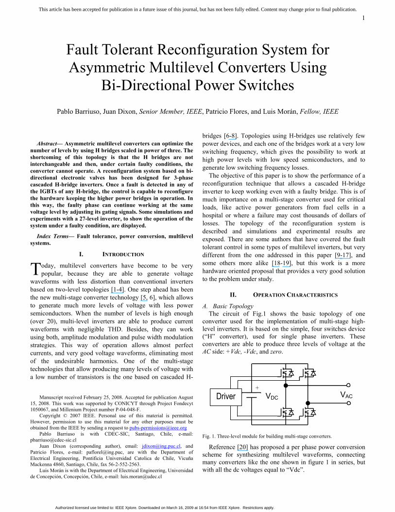
A. Basic Topology The circuit of Fig.1 shows the basic topology of one
converter used for the implementation of multi-stage high-level inverters. It is based on the simple, four switches device (“H” converter), used for single phase inverters. These converters are able to produce three levels of voltage at the AC side: +Vdc, -Vdc, and zero.
+ _
VACVDC Driver
Fig. 1. Three-level module for building multi-stage converters.
Reference [20] has proposed a per phase power conversion scheme for synthesizing multilevel waveforms, connecting many converters like the one shown in figure 1 in series, but with all the dc voltages equal to “Vdc”.
Fault Tolerant Reconfiguration System for Asymmetric Multilevel Converters Using
Bi-Directional Power Switches Pablo Barriuso, Juan Dixon, Senior Member, IEEE, Patricio Flores, and Luis Morán, Fellow, IEEE
T
Authorized licensed use limited to: IEEE Xplore. Downloaded on March 16, 2009 at 16:54 from IEEE Xplore. Restrictions apply.
This article has been accepted for publication in a future issue of this journal, but has not been fully edited. Content may change prior to final publication.
2
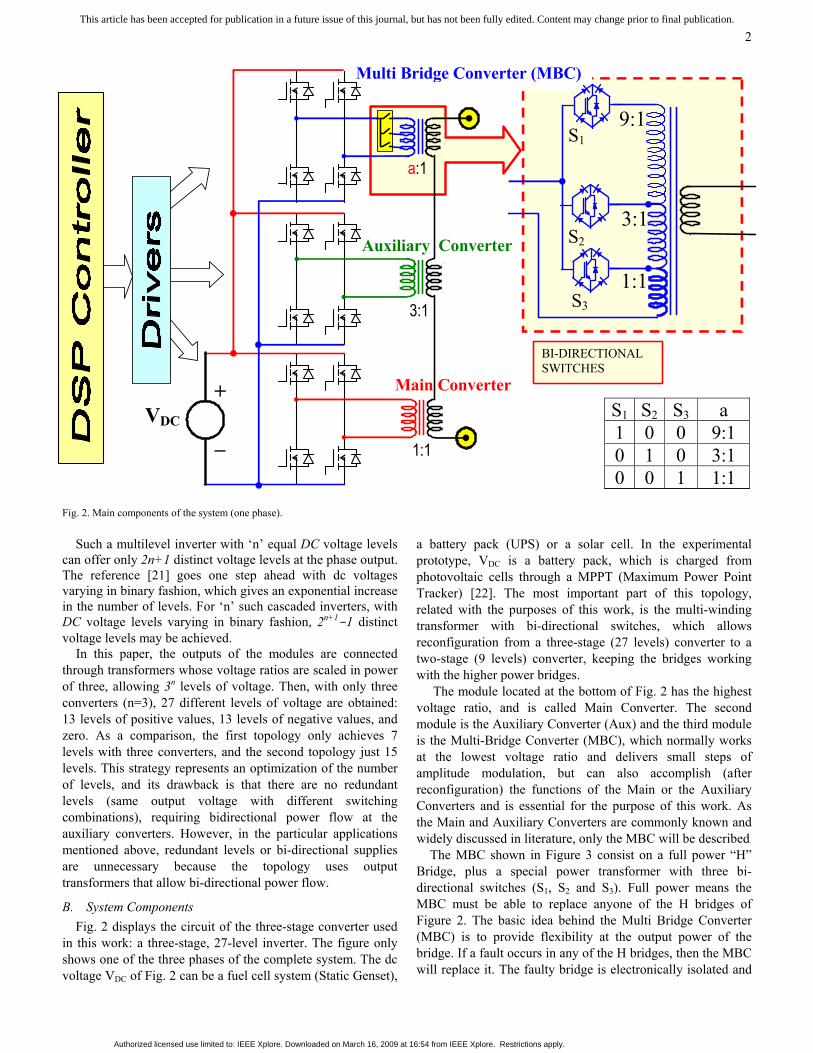
S1 S2 S3 a 1 0 0 9:1 0 1 0 3:1 0 0 1 1:1
a:1
3:1
Auxiliary Converter
Multi Bridge Converter (MBC)
+
_
Main Converter
1:1
VDC
BI-DIRECTIONAL SWITCHES
S3
S2
9:1 S1
3:1
1:1
Fig. 2. Main components of the system (one phase).
Such a multilevel inverter with ‘n’ equal DC voltage levels can offer only 2n+1 distinct voltage levels at the phase output. The reference [21] goes one step ahead with dc voltages varying in binary fashion, which gives an exponential increase in the number of levels. For ‘n’ such cascaded inverters, with DC voltage levels varying in binary fashion, 2n+1-1 distinct voltage levels may be achieved.
In this paper, the outputs of the modules are connected through transformers whose voltage ratios are scaled in power of three, allowing 3n levels of voltage. Then, with only three converters (n=3), 27 different levels of voltage are obtained: 13 levels of positive values, 13 levels of negative values, and zero. As a comparison, the first topology only achieves 7 levels with three converters, and the second topology just 15 levels. This strategy represents an optimization of the number of levels, and its drawback is that there are no redundant levels (same output voltage with different switching combinations), requiring bidirectional power flow at the auxiliary converters. However, in the particular applications mentioned above, redundant levels or bi-directional supplies are unnecessary because the topology uses output transformers that allow bi-directional power flow.
B. System Components Fig. 2 displays the circuit of the three-stage converter used
in this work: a three-stage, 27-level inverter. The figure only shows one of the three phases of the complete system. The dc voltage VDC of Fig. 2 can be a fuel cell system (Static Genset),
a battery pack (UPS) or a solar cell. In the experimental prototype, VDC is a battery pack, which is charged from photovoltaic cells through a MPPT (Maximum Power Point Tracker) [22]. The most important part of this topology, related with the purposes of this work, is the multi-winding transformer with bi-directional switches, which allows reconfiguration from a three-stage (27 levels) converter to a two-stage (9 levels) converter, keeping the bridges working with the higher power bridges.
The module located at the bottom of Fig. 2 has the highest voltage ratio, and is called Main Converter. The second module is the Auxiliary Converter (Aux) and the third module is the Multi-Bridge Converter (MBC), which normally works at the lowest voltage ratio and delivers small steps of amplitude modulation, but can also accomplish (after reconfiguration) the functions of the Main or the Auxiliary Converters and is essential for the purpose of this work. As the Main and Auxiliary Converters are commonly known and widely discussed in literature, only the MBC will be described
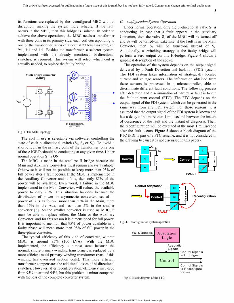
The MBC shown in Figure 3 consist on a full power “H” Bridge, plus a special power transformer with three bi-directional switches (S1, S2 and S3). Full power means the MBC must be able to replace anyone of the H bridges of Figure 2. The basic idea behind the Multi Bridge Converter (MBC) is to provide flexibility at the output power of the bridge. If a fault occurs in any of the H bridges, then the MBC will replace it. The faulty bridge is electronically isolated and
Authorized licensed use limited to: IEEE Xplore. Downloaded on March 16, 2009 at 16:54 from IEEE Xplore. Restrictions apply.
This article has been accepted for publication in a future issue of this journal, but has not been fully edited. Content may change prior to final publication.
3
its functions are replaced by the reconfigured MBC without disruption, making the system more reliable. If the fault occurs in the MBC, then this bridge is isolated. In order to achieve the above operations, the MBC needs a transformer with three coils in its primary side, each coil corresponding to one of the transformer ratios of a normal 27 level inverter, i.e, 9:1, 3:1 and 1:1. Besides the transformer, a selector system, implemented with the already mentioned bi-directional switches, is required. This system will select which coil is actually needed, to replace the faulty bridge.
Fig. 3. The MBC topology.
The coil in use is selectable via software, controlling the state of each bi-directional switch (S1, S2 or S3). To avoid a short-circuit in the primary coils of the transformer, only one of these IGBTs should be conducting at any given time. Under normal operation S1 is ON.
The MBC is made in the smallest H bridge because the Main and Auxiliary Converters must remain always available. Otherwise it will not be possible to keep more than 95% of full power after a fault occurs. If the MBC is implemented in the Auxiliary Converter and it fails, then only 85% of the power will be available. Even worst, a failure in the MBC implemented in the Main Converter, will reduce the available power to only 20%. This situation happens because the distribution of power in asymmetric converters scaled in power of 3 is as follow: more than 80% in the Main, more than 15% in the Aux, and less than 5% in the smaller converter [8]. As the smaller converter is used as MBC, it must be able to replace either, the Main or the Auxiliary Converter, and for this reason it is dimensioned for full power. It is important to mention that 95% of power available in a faulty phase will mean more than 98% of full power in the three-phase converter.
The typical efficiency of this kind of converter, without MBC, is around 95% (100 kVA). With the MBC implemented, the efficiency is almost same because the normal, single-primary-winding transformer, is replaced by a more efficient multi-primary-winding transformer (part of this winding has oversized section coils). This more efficient transformer compensates the additional losses of bi-directional switches. However, after reconfiguration, efficiency may drop from 95% to around 94%, but this problem is minor compared with the loss of the complete converter system.
C. configuration System Operation Under normal operation, only the bi-directional valve S1 is
conducting. In case that a fault appears in the Auxiliary Converter, then the valve S1 of the MBC will be turned-off and S2 will be turned-on. Likewise, if the fault is in the Main Converter, then S3 will be turned-on instead of S2. Additionally, a switching strategy at the faulty bridge will perform a zero output on this H-bridge. Figure 4 shows a graphical description of the above.
The operation of the system depends on the output signal delivered by a Fault Detection and Isolation (FDI) system. The FDI system takes information of strategically located current and voltage sensors. The information obtained from these sensors is processed in a microcontroller, able to discriminate different fault conditions. The following process after detection and discrimination of particular fault is to run the fault tolerant control (FTC). The FTC depends on the output signal of the FDI system, which can be generated in the same way from any FDI system. For those reasons, it is assumed that the output signal of the FDI system is known and has a delay of no more than 1 millisecond between the instant of occurrence of the fault and the instant of diagnosis. Then, the reconfiguration will be executed at the most 1 millisecond after the fault occurs. Figure 5 shows a block diagram of the FTC (FDI is part of a FTC scheme, and it is not considered in the drawing because it is not discussed in this paper).
LOAD
H1
H2
H3
LOAD
H1
H2
H3
Control
FAULT
L O A D
H1
H2
H3
Control
FAULT
Reconfiguration
Control Adaptation
Control
Control
S1 S2 S3
Fig. 4. Reconfiguration system operation
Adaptation Logic
Adaptation Signals
FDI Diagnosis
Control Signalsto Reconfigure Valves
Control Signalsto H Bridges
Control
Fig. 5. Block diagram of the FTC.
Authorized licensed use limited to: IEEE Xplore. Downloaded on March 16, 2009 at 16:54 from IEEE Xplore. Restrictions apply.
This article has been accepted for publication in a future issue of this journal, but has not been fully edited. Content may change prior to final publication.
4
III. FAULT TOLERANT CONTROL SCHEME (FTC) A. Faults Considered
For this study, faults in any IGBT, including the bi-directional valves have been considered, these faults correspond to:
1. Short Circuit Fault (SCF). It is the most dangerous fault because it leads to short-circuit at the battery terminals, inducing the circulation of very high currents through the switches. The FTC must be able to clear this fault as soon as it is detected, by using the IGBTs drivers capabilities, like desaturation method and soft turn-off, to switch it off before short-circuit currents go to destructive levels. After the faulty bridge is isolated, the MBC Bridge replaces it. If the fault occurs in the MBC, or any of their bi-directional valves, then the MBC is isolated.
2. Open Circuit Fault (OCF). This fault affects the output voltage of the inverter and is not quite harmful. However, it causes a disturbance in the signal, because one of the active levels (positive or negative) will become inoperative. Depending on the bridge affected by a faulty IGBT, its symptoms could vary from a little distortion, to a mayor voltage drop on the output wave. Faults in the Main or on the Auxiliary converters must be immediately cleared.
Taking into account both faults, and that there are twelve IGBTs on the H-bridges for each phase, twenty-four different faults may occur. Adding the three faults on the bi-directional valves, a total of twenty-seven possible faults per phase are possible.
B. FTC procedure Due to the nature of the SCF, it is imperative to clear this
fault as soon as possible, mainly when it occurs in one of the H bridges. This action totally depends on the accuracy and speed of the FDI system. Once the fault has been accurately detected and isolated, the FTC must proceed according to the following procedure:
Step 1. Isolate the faulty bridge by applying to its IGBTs the firing signals that render zero-volt output at that bridge.
Step 2. Reconfigure the MBC, to keep the faulty phase working with their higher level bridges. If the fault occurs in the MBC (including any of their bi-directional valves), then that bridge is isolated.
Step 3. Modify gating control in order to substitute the firing signals and keep that phase working with its high level bridges.
Step 3 of the procedure is not necessary if the fault occurs in the MBC or in one of its bi-directional valves.
IV. SIMULATION RESULTS To see the performance of the reconfiguration scheme, a
fault in the Main Bridge of phase A is simulated. The problem is solved by electronically inhibiting the faulty bridge and replacing its function with the MBC Bridge. After
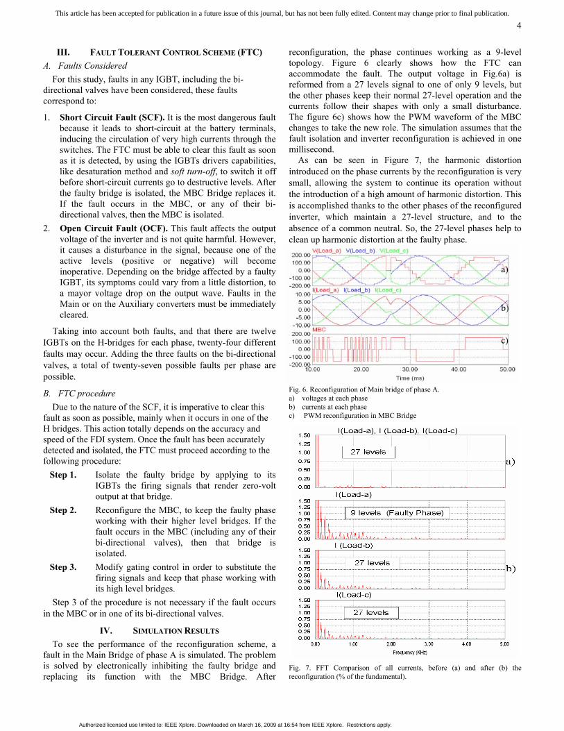
reconfiguration, the phase continues working as a 9-level topology. Figure 6 clearly shows how the FTC can accommodate the fault. The output voltage in Fig.6a) is reformed from a 27 levels signal to one of only 9 levels, but the other phases keep their normal 27-level operation and the currents follow their shapes with only a small disturbance. The figure 6c) shows how the PWM waveform of the MBC changes to take the new role. The simulation assumes that the fault isolation and inverter reconfiguration is achieved in one millisecond.
As can be seen in Figure 7, the harmonic distortion introduced on the phase currents by the reconfiguration is very small, allowing the system to continue its operation without the introduction of a high amount of harmonic distortion. This is accomplished thanks to the other phases of the reconfigured inverter, which maintain a 27-level structure, and to the absence of a common neutral. So, the 27-level phases help to clean up harmonic distortion at the faulty phase.
Fig. 6. Reconfiguration of Main bridge of phase A. a) voltages at each phase b) currents at each phase c) PWM reconfiguration in MBC Bridge
Fig. 7. FFT Comparison of all currents, before (a) and after (b) the reconfiguration (% of the fundamental).
a)
b) c)
Authorized licensed use limited to: IEEE Xplore. Downloaded on March 16, 2009 at 16:54 from IEEE Xplore. Restrictions apply.
This article has been accepted for publication in a future issue of this journal, but has not been fully edited. Content may change prior to final publication.
5
V. EXPERIMENTAL RESULTS
To test the overall performance of the system, a low power experimental prototype, was assembled. The inverter generates a three-phase 27-level voltage waveform at 50 Hz, which feeds a wye connected load with floating neutral, from a voltage source of series connected lead-acid batteries. This configuration generates a current of approximately 1.8 [Arms] with 9º lag on the load; the voltage and current waveform under normal conditions are shown in figure 8.
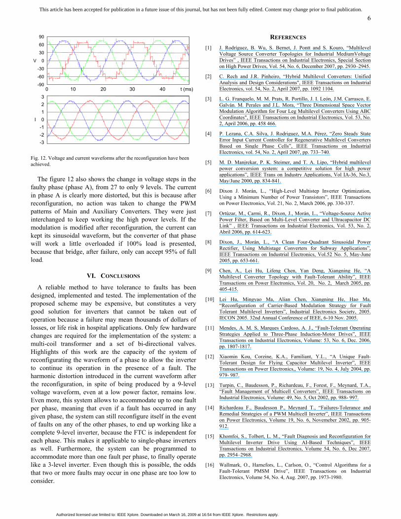
The figure 9 shows the frequency spectrum of each phase currents. It can be seen the low harmonic distortion that these type of inverter generates.
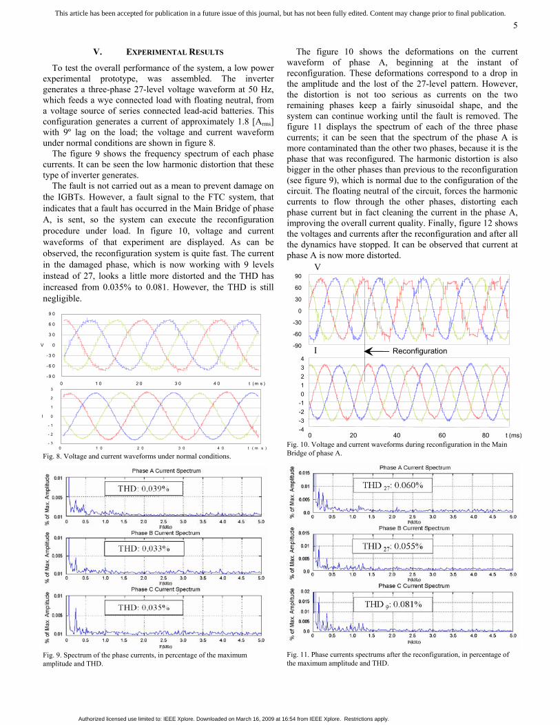
The fault is not carried out as a mean to prevent damage on the IGBTs. However, a fault signal to the FTC system, that indicates that a fault has occurred in the Main Bridge of phase A, is sent, so the system can execute the reconfiguration procedure under load. In figure 10, voltage and current waveforms of that experiment are displayed. As can be observed, the reconfiguration system is quite fast. The current in the damaged phase, which is now working with 9 levels instead of 27, looks a little more distorted and the THD has increased from 0.035% to 0.081. However, the THD is still negligible.
Fig. 8. Voltage and current waveforms under normal conditions.
Fig. 9. Spectrum of the phase currents, in percentage of the maximum amplitude and THD.
The figure 10 shows the deformations on the current waveform of phase A, beginning at the instant of reconfiguration. These deformations correspond to a drop in the amplitude and the lost of the 27-level pattern. However, the distortion is not too serious as currents on the two remaining phases keep a fairly sinusoidal shape, and the system can continue working until the fault is removed. The figure 11 displays the spectrum of each of the three phase currents; it can be seen that the spectrum of the phase A is more contaminated than the other two phases, because it is the phase that was reconfigured. The harmonic distortion is also bigger in the other phases than previous to the reconfiguration (see figure 9), which is normal due to the configuration of the circuit. The floating neutral of the circuit, forces the harmonic currents to flow through the other phases, distorting each phase current but in fact cleaning the current in the phase A, improving the overall current quality. Finally, figure 12 shows the voltages and currents after the reconfiguration and after all the dynamics have stopped. It can be observed that current at phase A is now more distorted.
Fig. 10. Voltage and current waveforms during reconfiguration in the Main Bridge of phase A.
Fig. 11. Phase currents spectrums after the reconfiguration, in percentage of the maximum amplitude and THD.
0 20 40 60 80 t (ms)
V
I
90
60
30
0
-30
-60
-90
43210
-1-2-3-4
Reconfiguration
9 0
6 0
3 0
V 0
- 3 0
- 6 0
- 9 0 0 1 0 2 0 3 0 4 0 t ( m s )
3
2
1
I 0
- 1
- 2
- 3 0 1 0 2 0 3 0 4 0 t ( m s )
Authorized licensed use limited to: IEEE Xplore. Downloaded on March 16, 2009 at 16:54 from IEEE Xplore. Restrictions apply.
This article has been accepted for publication in a future issue of this journal, but has not been fully edited. Content may change prior to final publication.
6
Fig. 12. Voltage and current waveforms after the reconfiguration have been achieved.
The figure 12 also shows the change in voltage steps in the faulty phase (phase A), from 27 to only 9 levels. The current in phase A is clearly more distorted, but this is because after reconfiguration, no action was taken to change the PWM patterns of Main and Auxiliary Converters. They were just interchanged to keep working the high power levels. If the modulation is modified after reconfiguration, the current can kept its sinusoidal waveform, but the converter of that phase will work a little overloaded if 100% load is presented, because that bridge, after failure, only can accept 95% of full load.
VI. CONCLUSIONS
A reliable method to have tolerance to faults has been designed, implemented and tested. The implementation of the proposed scheme may be expensive, but constitutes a very good solution for inverters that cannot be taken out of operation because a failure may mean thousands of dollars of losses, or life risk in hospital applications. Only few hardware changes are required for the implementation of the system: a multi-coil transformer and a set of bi-directional valves. Highlights of this work are the capacity of the system of reconfigurating the waveform of a phase to allow the inverter to continue its operation in the presence of a fault. The harmonic distortion introduced in the current waveform after the reconfiguration, in spite of being produced by a 9-level voltage waveform, even at a low power factor, remains low. Even more, this system allows to accommodate up to one fault per phase, meaning that even if a fault has occurred in any given phase, the system can still reconfigure itself in the event of faults on any of the other phases, to end up working like a complete 9-level inverter, because the FTC is independent for each phase. This makes it applicable to single-phase inverters as well. Furthermore, the system can be programmed to accommodate more than one fault per phase, to finally operate like a 3-level inverter. Even though this is possible, the odds that two or more faults may occur in one phase are too low to consider.
REFERENCES [1] J. Rodríguez, B. Wu, S. Bernet, J. Pontt and S. Kouro, “Multilevel
Voltage Source Converter Topologies for Industrial MediumVoltage Drives” , IEEE Transactions on Industrial Electronics, Special Section on High Power Drives, Vol. 54, No. 6, December 2007, pp. 2930–2945.
[2] C. Rech and J.R. Pinheiro, “Hybrid Multilevel Converters: Unified Analysis and Design Considerations", IEEE Transactions on Industrial Electronics, vol. 54, No. 2, April 2007, pp. 1092 1104.
[3] L. G. Franquelo, M. M. Prats, R. Portillo, J. I. León, J.M. Carrasco, E. Galván. M. Perales and J.L. Mora, “Three Dimensional Space Vector Modulation Algorithm for Four Leg Multilevel Converters Using ABC Coordinates", IEEE Transactions on Industrial Electronics, Vol. 53, No. 2, April 2006, pp. 458 466.
[4] P. Lezana, C.A. Silva, J. Rodriguez, M.A. Pérez, “Zero Steady State Error Input Current Controller for Regenerative Multilevel Converters Based on Single Phase Cells”, IEEE Transactions on Industrial Electronics, vol. 54, No. 2, April 2007, pp. 733–740.
[5] M. D. Manjrekar, P. K. Steimer, and T. A. Lipo, “Hybrid multilevel power conversion system: a competitive solution for high power applications”, IEEE Trans on Industry Applications, Vol IA-36, No.3, May/June 2000, pp. 834-841.
[6] Dixon J. Morán, L., “High-Level Multistep Inverter Optimization, Using a Minimum Number of Power Transistors”, IEEE Transactions on Power Electronics, Vol. 21, No. 2, March 2006, pp. 330-337.
[7] Ortúzar, M., Carmi, R., Dixon, J., Morán, L., “Voltage-Source Active Power Filter, Based on Multi-Level Converter and Ultracapacitor DC Link” , IEEE Transactions on Industrial Electronics, Vol. 53, No. 2, Abril 2006, pp. 614-623.
[8] Dixon, J., Morán, L., “A Clean Four-Quadrant Sinusoidal Power Rectifier, Using Multistage Converters for Subway Applications”, IEEE Transactions on Industrial Electronics, Vol.52 No. 5, May-June 2005, pp. 653-661.
[9] Chen, A., Lei Hu, Lifeng Chen, Yan Deng, Xiangning He, “A Multilevel Converter Topology with Fault-Tolerant Ability”, IEEE Transactions on Power Electronics, Vol. 20, No. 2, March 2005, pp. 405-415.
[10] Lei Hu, Mingyao Ma, Alian Chen, Xiangning He, Hao Ma, “Reconfiguration of Carrier-Based Modulation Strategy for Fault Tolerant Multilevel Inverters”, Industrial Electronics Society, 2005. IECON 2005. 32nd Annual Conference of IEEE, 6-10 Nov. 2005.
[11] Mendes, A. M. S, Marques Cardoso, A. J., “Fault-Tolerant Operating Strategies Applied to Three-Phase Induction-Motor Drives”, IEEE Transactions on Industrial Electronics, Volume: 53, No. 6, Dec. 2006, pp. 1807-1817.
[12] Xiaomin Kou, Corzine, K.A., Familiant, Y.L., “A Unique Fault-Tolerant Design for Flying Capacitor Multilevel Inverter”, IEEE Transactions on Power Electronics,, Volume: 19, No. 4, July 2004, pp. 979- 987.
[13] Turpin, C., Baudesson, P., Richardeau, F., Forest, F., Meynard, T.A., “Fault Management of Multicell Converters”, IEEE Transactions on Industrial Electronics, Volume: 49, No. 5, Oct 2002, pp. 988- 997.
[14] Richardeau F., Baudesson P., Meynard T., “Failures-Tolerance and Remedial Strategies of a PWM Multicell Inverter”, IEEE Transactions on Power Electronics, Volume 19, No. 6, Novemeber 2002, pp. 905-912.
[15] Khomfoi, S., Tolbert, L. M., “Fault Diagnosis and Reconfiguration for Multilevel Inverter Drive Using AI-Based Techniques”, IEEE Transactions on Industrial Electronics, Volume 54, No. 6, Dec 2007, pp. 2954–2968.
[16] Wallmark, O., Harnefors, L., Carlson, O., “Control Algorithms for a Fault-Tolerant PMSM Drive”, IEEE Transactions on Industrial Electronics, Volume 54, No. 4, Aug. 2007, pp. 1973-1980.
0 10 20 30 40 t (ms)
90
60
30
V 0
-30
-60
-90
3 2 1
I 0 -1 -2 -3
Authorized licensed use limited to: IEEE Xplore. Downloaded on March 16, 2009 at 16:54 from IEEE Xplore. Restrictions apply.

This article has been accepted for publication in a future issue of this journal, but has not been fully edited. Content may change prior to final publication.
7
[17] Shengming Li, Xu, L., “Strategies of Fault Tolerant Operation for Three-Level PWM Inverters”¸ IEEE Transactions on Power Electronics, Volume 21, No. 4, July 2006, pp. 933-940.
[18] Correa, P., Pacas, M., Rodríguez, J., “Modulation Strategies for Fault-Tolerant Operation of H-Bridge Multilevel Inverters”, IEEE International Symposium on Industrial Electronics, ISIE 2006, 9-13 July 2006, Volume 2, pp. 1589 – 1594.
[19] Correa, P., Rodríguez, J., “Control Strategy Reconfiguration for a Multilevel Inverter Operating with Bypassed Cells”, IEEE International Symposium on Industrial Electronics, ISIE 2007, 4-7 June 2007, pp. 3162 – 3167.
[20] F.Z. Peng, J.S. Lai, J. McKeever, J. Van Coevering, “A Multilevel Voltage Source Inverter with Separate DC Sources for Static Var Generation”, Conference Record of the IEEE-IAS Annual Meeting, 1995, pp. 2541-2548.
[21] N. Mohan and G. Kamath, A novel per phase approach of power electronic interface for power system applications, Proceedings of the NAPS, 1995, pp. 457–461.
[22] Brusa: Maximum Power Tracking model MPT-N15 Brusa Elektronik AG, Postfach 55, 9466 Sennwald, http://www.brusa.li/products/g_mpt_n15207.htm
Pablo Barriuso got his Electrical Engineering and M.Sc degree from Pontificia Universidad Católica de Chile in 2008. Currently he is an engineer at CDEC-SIC, the ISO of the Chilean electrical interconnected system. During his M.Sc preparation was involved with the design and application of power electronics devices and studied the fields of photovoltaic generation, harmonic filtering, and fault tolerant control.
Juan Dixon (SM) was born in Santiago, Chile. He received the Ms. Eng. and the Ph.D. degrees from McGill University, Montreal, PQ, Canada in 1986, and 1988 respectively. Since 1979, he has been with the Electrical Engineering Department, Pontificia Universidad Católica de Chile, where he is presently Professor. He has presented more than 70 works in International Conferences and has published more than 30 papers related with Power Electronics in IEEE
Transactions and IEE Proceedings. His main areas of interest are in Electric Traction, PWM Rectifiers, Active Filters, Power Factor Compensators and Multilevel converters. He has created an Electric Vehicle Laboratory, where state-of-the-art vehicles are investigated.
Patricio Flores was born in Santiago, Chile. He got his Electrical Engineering and M.Sc degree from Pontificia Universidad Católica de Chile in 2008. He currently works in the same University as research assistant in the Power Electronics and Electric Vehicle Lab. He helps new graduate students who are working on active power filters, electric power generation or electric vehicles research.
Luis Morán (F) was born in Concepción, Chile. He received the Ph.D. degree from Concordia University, Montreal, PQ, Canada in 1990. Since 1990, he has been with the Electrical Engineering Department, University of Concepción, where he is a Professor. He has written and published more than 30 papers in Active Power Filters and Static Var Compensators in IEEE Transactions. He is the principal author of the paper that got the IEEE Outstanding Paper Award from the
Industrial Electronics Society for the best paper published in the Transaction on Industrial Electronics during 1995, and the co-author of the paper that was awarded in 2002 by the IAS Static Power Converter Committee. Since January 2005 he is a Fellow of IEEE. His main areas of interests are in AC drives, Power Quality, Active Power Filters, FACTS and Power Protection Systems.
Authorized licensed use limited to: IEEE Xplore. Downloaded on March 16, 2009 at 16:54 from IEEE Xplore. Restrictions apply.
Related Documents