Place your chosen image here. The four corners must just cover the arrow tips. For covers, the three pictures should be the same size and in a straight line. Fault Ride Through Workgroup Background to Workgroup and Workshop Conclusions Antony Johnson National Grid – TNS Technical Policy

Welcome message from author
This document is posted to help you gain knowledge. Please leave a comment to let me know what you think about it! Share it to your friends and learn new things together.
Transcript
Place your chosen
image here. The four
corners must just
cover the arrow tips.
For covers, the three
pictures should be the
same size and in a
straight line.
Fault Ride Through WorkgroupBackground to Workgroup and Workshop Conclusions
Antony JohnsonNational Grid – TNS Technical Policy
2
Background
� Background and summary of Workshop findings
� Why Fault Ride Through is Required
� Conclusions of the Workshops
3
Issues identified as part of the
Fault Ride Through Workshops
� Three workshops were held in September and November 2012 and January 2013 to address the issues raised in GCRP Paper Reference PP12/04.
� Issues mainly associated with Synchronous Plant
� Workshop participants acknowledged that whilst there were still issues with Asynchronous Generation, they were broadly happy with the GB fault ride through requirements and would not wish to undergo a full set of additional research and type tests ahead of the European ENTSO-E requirements
� The Workshops identified issues with Asynchronous Plant but these do not fall within the scope of this Workgroup
� The workshops proposed a formal Grid Code Work Group to be established to examine the implications of early adoption of theENTSO-E (RfG) fault ride through requirements for Synchronous Generation including specification of the GB Parameters.
4
Ride Through CapabilityWhy is it Required?
�Introduced into the Grid Code in June 2005 following
consultation H/04
�Justification and need for fault ride through covered in
Section 5.1 - Appendix 2 of the H/04 Consultation Document
available at:-
�http://www.nationalgrid.com/NR/rdonlyres/3DD7D7C7-6460-4257-BF99-E168D794C13E/7027/aacp_h04.pdf
�Applies to Synchronous and Asynchronous Generating Plant
5
Ride Through Capability
Introduction
�Fault Ride Through is a requirement necessary for Generators to remain connected to healthy Transmission circuits until the faulted element of Plant and Apparatus has been cleared from the Transmission System
� If Fault Ride Through Capability is not installed, Generation would be susceptible to tripping when subject to a voltage dip (typically below 90% of nominal) even when connected to a healthy circuit for less than normal protection operating times (eg 80ms or 100ms).
� If left unchecked, the consequences would be significant resulting in loss of Generation and frequency collapse followed by a Blackout.
� Initially identified as an issue with Wind Generation employing Power Electronic Converters but the concept equally applies to all Generation Types
6
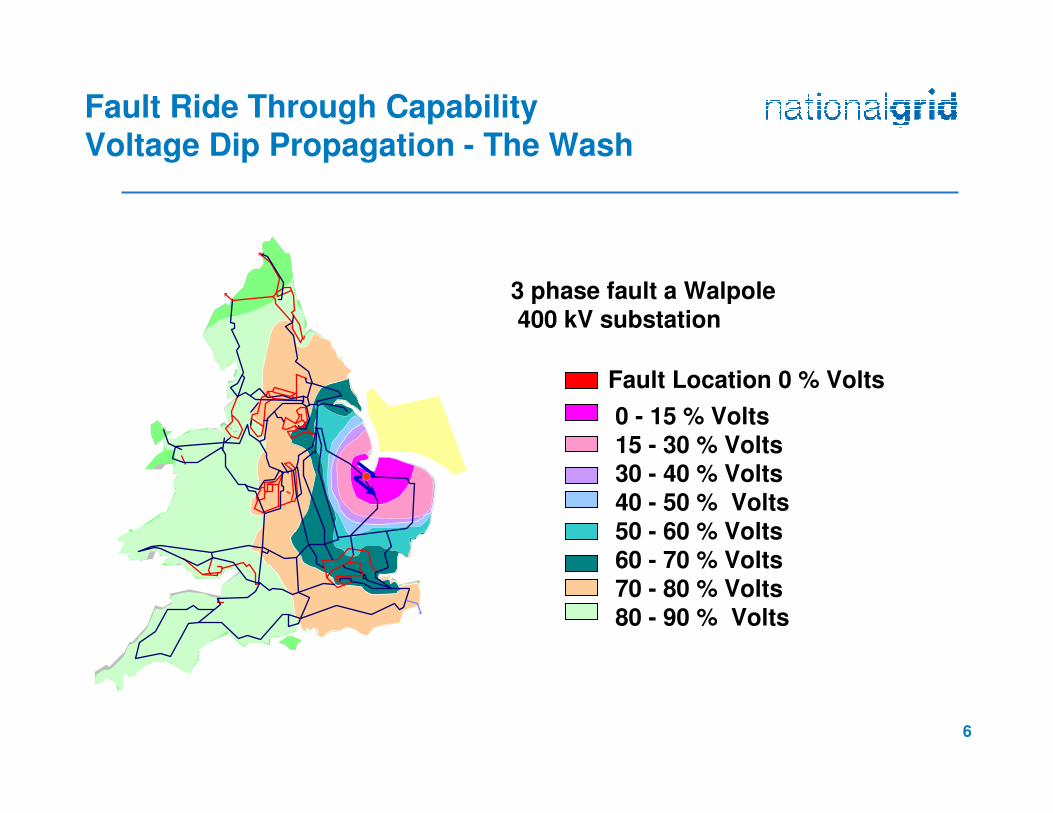
Fault Ride Through Capability Voltage Dip Propagation - The Wash
France
3 phase fault a Walpole
400 kV substation
Fault Location 0 % Volts
0 - 15 % Volts15 - 30 % Volts
30 - 40 % Volts
40 - 50 % Volts
50 - 60 % Volts
60 - 70 % Volts
70 - 80 % Volts
80 - 90 % Volts
Scotland
7
Fault Ride Through
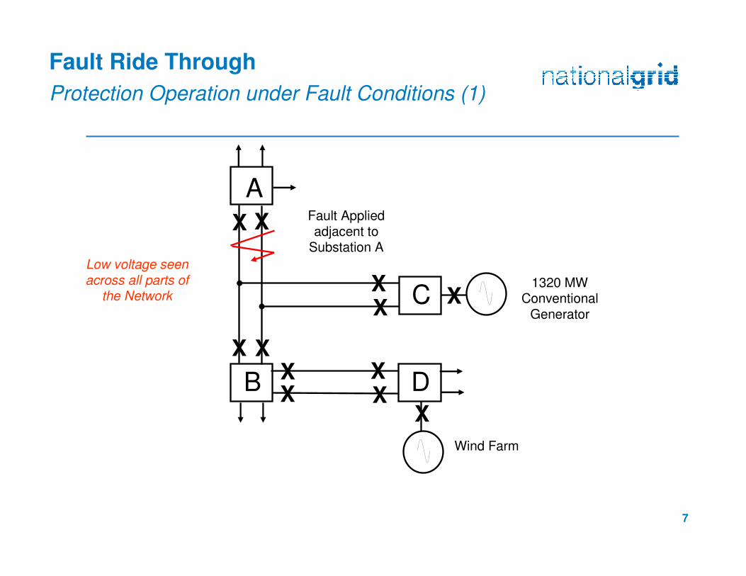
Protection Operation under Fault Conditions (1)
A
B
X X
X X
Fault Applied adjacent to
Substation A
CXX
1320 MW Conventional
Generator
DXX
XX
Wind Farm
X
X
Low voltage seen across all parts of
the Network

8
Fault Ride Through
Protection Operation under Fault Conditions (2)
A
B
X X
X X
CXX
1320 MW Conventional
GeneratorX
Fault cleared adjacent to
Substation A in typically 100ms
DXX
XX
Wind Farm
X
9
Fault Ride Through
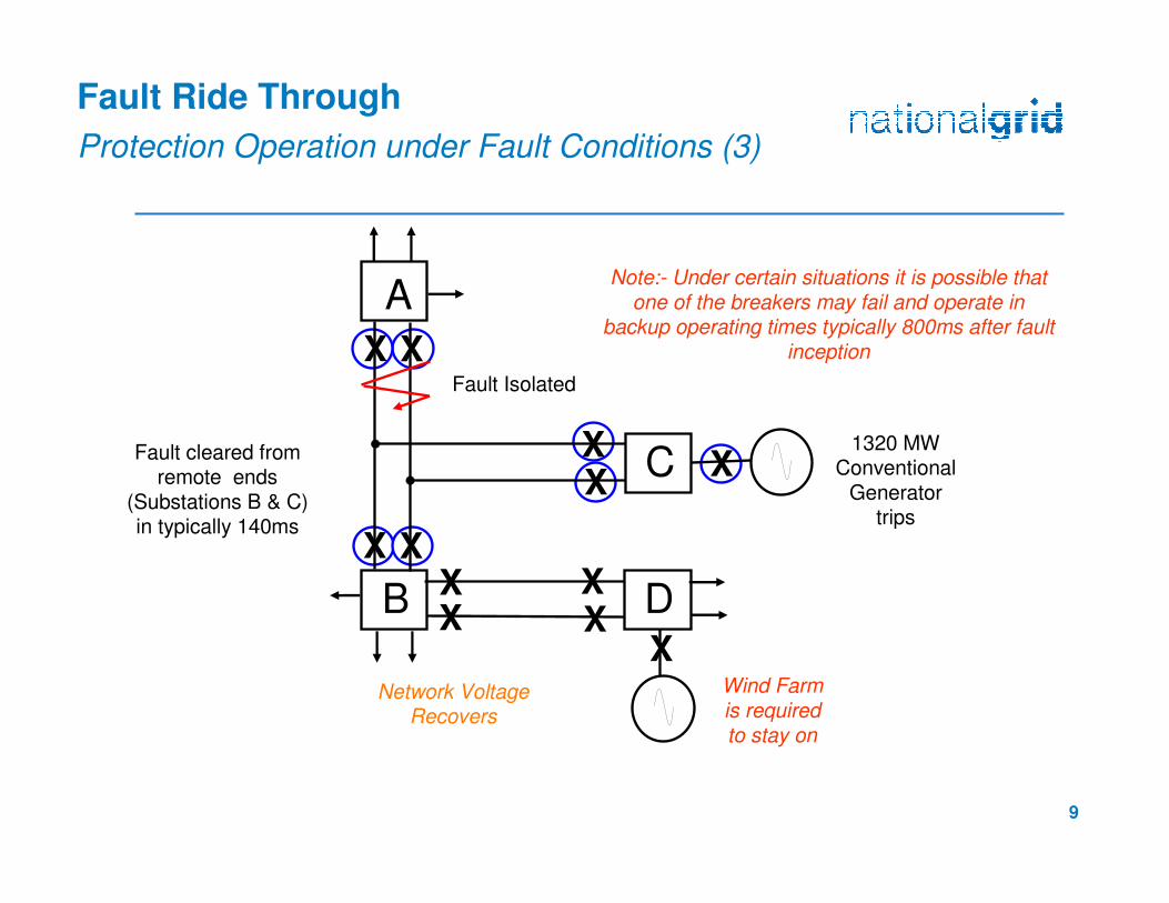
Protection Operation under Fault Conditions (3)
A
B
X X
X X
CXX
1320 MW Conventional
Generator trips
Wind Farm is required to stay on
XFault cleared from remote ends
(Substations B & C) in typically 140ms
Fault Isolated
Network Voltage Recovers
Note:- Under certain situations it is possible that one of the breakers may fail and operate in
backup operating times typically 800ms after fault inception
DXX
XX
X
10
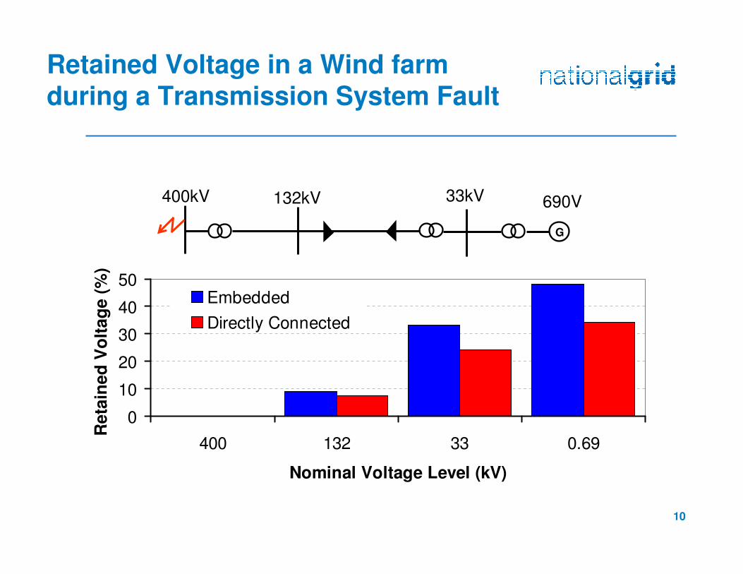
Retained Voltage in a Wind farm
during a Transmission System Fault
400kV 690V132kV 33kV
G
0
10
20
30
40
50
400 132 33 0.69
Nominal Voltage Level (kV)
Reta
ined
Vo
ltag
e (
%)
Embedded
Directly Connected
11
Ride Through Capability
(CC.6.3.15)
�Under the Grid Code fault ride through defines:
�The requirements for Generating Plant to remain connected
and stable for balanced and unbalanced faults up to 140ms
in duration (CC.6.3.15.1(a)).
�The requirements for Generating Plant to remain connected and stable for balanced voltage dips in excess of 140ms
(CC.6.3.15.1(b)).
12
Ride Through Capability
Faults up to 140ms in duration (CC.6.3.15.1(a))
� Generating Units and Power Park Modules are required to remain stable and connected for any balanced or unbalanced fault on the Transmission System operating at 200kV or above and lasting for up to 140ms.
� Each Generating Unit and Power Park Module is required to generate maximum reactive power without exceeding its transient rating limit.
� Active Power output should be restored to at least 90% of the level available immediately before the fault and within 0.5 seconds ofrestoration of the voltage at the Connection Point
� Active Power Oscillations are acceptable provided:-
� The total energy delivered during the period of the oscillations is at least that if the Active Energy was constant and
� The Oscillations are adequately damped
� Examples provided in Connection Conditions – Appendix 4.
13
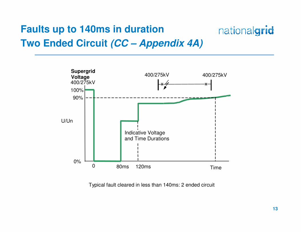
Faults up to 140ms in duration
Two Ended Circuit (CC – Appendix 4A)
xx
0
U/Un
80ms Time
100%
90%
SupergridVoltage400/275kV
0%120ms
400/275kV 400/275kV
Typical fault cleared in less than 140ms: 2 ended circuit
Indicative Voltageand Time Durations
14
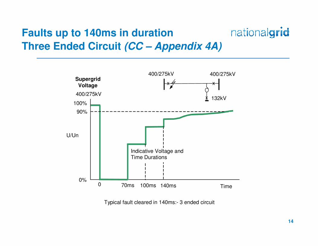
Faults up to 140ms in duration
Three Ended Circuit (CC – Appendix 4A)
x
xx
0
U/Un
70ms Time
100%
90%
SupergridVoltage
0%100ms
400/275kV 400/275kV
Typical fault cleared in 140ms:- 3 ended circuit
132kV
140ms
400/275kV
Indicative Voltage andTime Durations
15
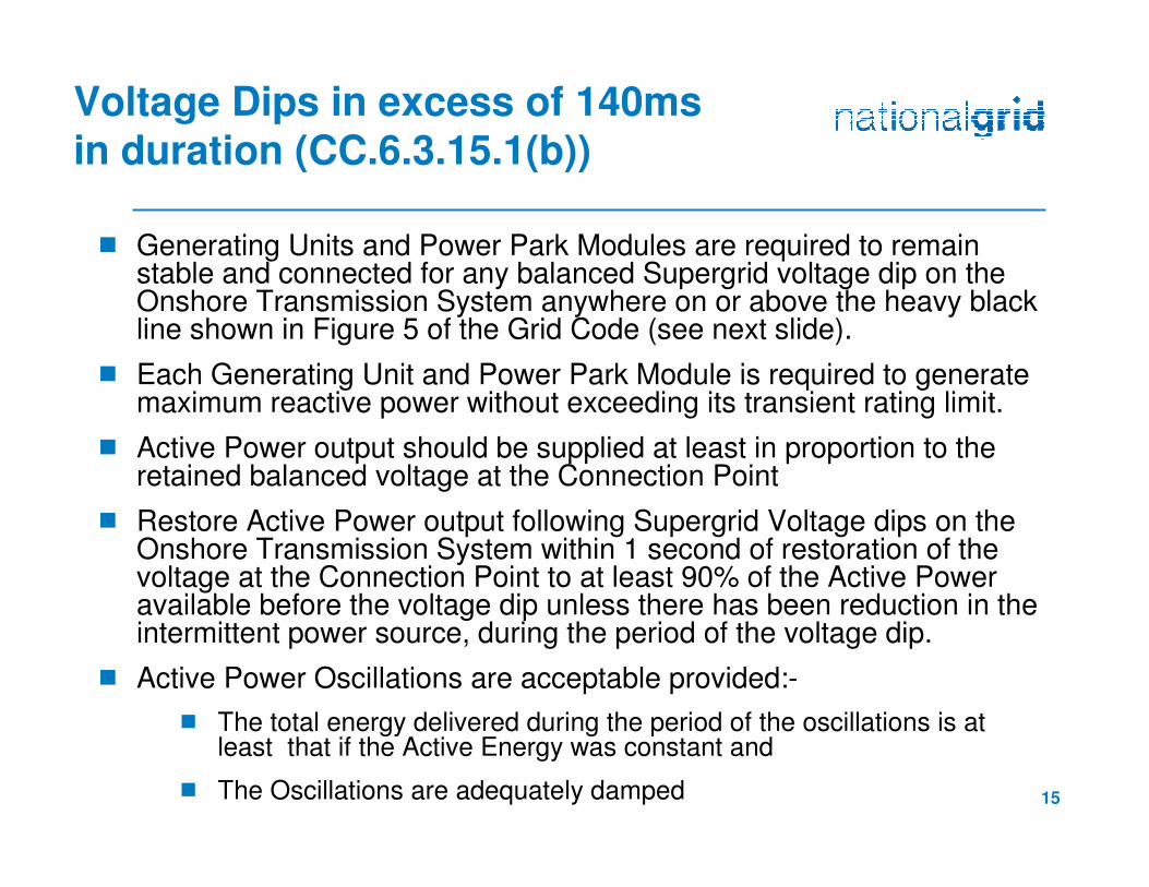
Voltage Dips in excess of 140ms
in duration (CC.6.3.15.1(b))
� Generating Units and Power Park Modules are required to remain stable and connected for any balanced Supergrid voltage dip on the Onshore Transmission System anywhere on or above the heavy blackline shown in Figure 5 of the Grid Code (see next slide).
� Each Generating Unit and Power Park Module is required to generate maximum reactive power without exceeding its transient rating limit.
� Active Power output should be supplied at least in proportion to the retained balanced voltage at the Connection Point
� Restore Active Power output following Supergrid Voltage dips on the Onshore Transmission System within 1 second of restoration of the voltage at the Connection Point to at least 90% of the Active Power available before the voltage dip unless there has been reduction in the intermittent power source, during the period of the voltage dip.
� Active Power Oscillations are acceptable provided:-
� The total energy delivered during the period of the oscillations is at least that if the Active Energy was constant and
� The Oscillations are adequately damped
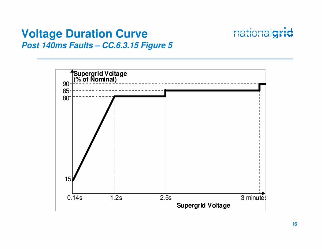
16
Supergrid Voltage Duration
Supergrid Voltage Level (% of Nominal)
90
15
80 85
0.14s 2.5s 1.2s 3 minutes
Voltage Duration CurvePost 140ms Faults – CC.6.3.15 Figure 5
17
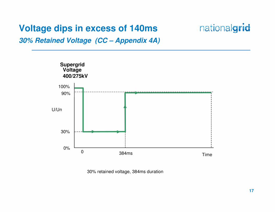
Voltage dips in excess of 140ms
30% Retained Voltage (CC – Appendix 4A)
0
U/Un
Time
100%
90%
SupergridVoltage400/275kV
0%
30% retained voltage, 384ms duration
30%
384ms
18
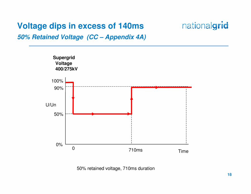
Voltage dips in excess of 140ms
50% Retained Voltage (CC – Appendix 4A)
0
U/Un
Time
100%
90%
Supergrid
Voltage400/275kV
0%
50% retained voltage, 710ms duration
50%
710ms
19
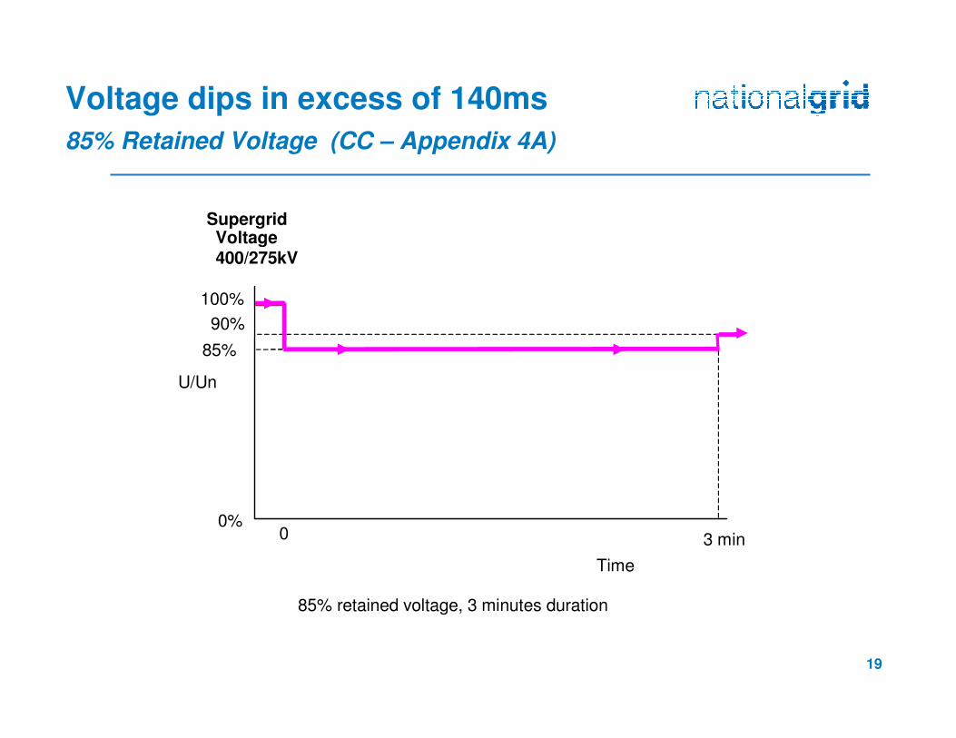
Voltage dips in excess of 140ms
85% Retained Voltage (CC – Appendix 4A)
0
U/Un
Time
100%
90%
85%
SupergridVoltage400/275kV
0%
85% retained voltage, 3 minutes duration
3 min
20
Issues
� In GB the Fault Ride Through requirements are the same for both Synchronous Generation and Power Park Modules
� Synchronous Generating Units have struggled to meet the requirements especially for longer duration voltage dips
�Grid Code Review Panel Paper Ref PP12/04
�Ongoing issues for future connecting Synchronous generation
�Compliance issues ?
� The introduction of the ENTSO-E Requirements for Generators (RfG) proposes a range of new voltage against time curves subject to National choice and unlike the GB Grid Code defines differentrequirements between synchronous and asynchronous generation
21
Summary
�Background to Fault Ride Through
�Why fault ride through is required
� Faults up to 140ms in duration
�Voltage dips in excess of 140ms in duration
� Issues
Related Documents


![Reactive Power Allocation Method in a Wind Farm for ... · voltage ride through and low voltage ride through during grid fault [4-5]. From the viewpoint of system operation, reactive](https://static.cupdf.com/doc/110x72/6042fd6e4b184f0f2a3431db/reactive-power-allocation-method-in-a-wind-farm-for-voltage-ride-through-and.jpg)
![Electrical Power and Energy Systemstarjomehrooz.com/wp-content/uploads/2018/03/main-reference.pdf · Fault Current Limiter (CR-FCL) is proposed in [12] for fault ride through (FRT)](https://static.cupdf.com/doc/110x72/60320a084a22a42c51272008/electrical-power-and-energy-fault-current-limiter-cr-fcl-is-proposed-in-12-for.jpg)