Egyptian Journal of Geology, v.58, 2014, p255-270 1 FAULT DAMAGE ZONES, CASE STUDY, ABU ROASH AREA, SOUTHWEST CAIRO, EGYPT MOUSTAFA*, A. R., ABDEL-TAWAB*, S. AND ABDELHAMY**, M. *Ain Shams University, Faculty of Science, Department of Geology **Dar Al-Handasah Consultants (Shair and Partners) ABSTRACT The study area covers Abu Roash area (southwest of Cairo), a new urban development area with old quarrying activity leaving behind several rock cliffs. Fortunately, these vertical rock cuts are perpendicular to two major faults in the area, giving an excellent opportunity to study the damage zones of these faults. Two main faults have been studied in detail. The first one, is a normal fault that extends for 1 km and is oriented NW-SE. The second fault is oblique-slip with dextral strike-slip component and is oriented WNW-ESE. It extends for 3 km. Both faults and their damage zones are well-exposed through the vertical rock cuts. The main points emerging from the present study are: The half width of the damage zones of faults may reach up to 12 m. Factors affecting the fracture pattern of the fault damage zones include the fault type, length of the fault, amount of throw, and the existence of other nearby structures (e.g. folds). A new fracture model is proposed based on the field observations and data analysis for the fracture patterns. In this model, two intersected fracture patterns were encountered in the fault damage zone due to the occurrence of two structures (the fault itself in addition to the nearby folds). Such damage zones are called in this paper ‘’Fracture Interference Zones’’. Key Words: fault damage zone, fracture interference zone, Abu Roash area.

Welcome message from author
This document is posted to help you gain knowledge. Please leave a comment to let me know what you think about it! Share it to your friends and learn new things together.
Transcript

Egyptian Journal of Geology, v.58, 2014, p255-270
1
FAULT DAMAGE ZONES, CASE STUDY, ABU ROASH AREA, SOUTHWEST CAIRO, EGYPT
MOUSTAFA*, A. R., ABDEL-TAWAB*, S. AND ABDELHAMY**, M.
*Ain Shams University, Faculty of Science, Department of Geology **Dar Al-Handasah Consultants (Shair and Partners)
ABSTRACT
The study area covers Abu Roash area (southwest of Cairo), a new urban development area with old quarrying activity leaving behind several rock cliffs. Fortunately, these vertical rock cuts are perpendicular to two major faults in the area, giving an excellent opportunity to study the damage zones of these faults.
Two main faults have been studied in detail. The first one, is a normal fault that extends for 1 km and is oriented NW-SE. The second fault is oblique-slip with dextral strike-slip component and is oriented WNW-ESE. It extends for 3 km. Both faults and their damage zones are well-exposed through the vertical rock cuts.
The main points emerging from the present study are: The half width of the damage zones of faults may reach up to 12 m. Factors affecting the fracture pattern of the fault damage zones include the fault type, length of the fault, amount of throw, and the existence of other nearby structures (e.g. folds).
A new fracture model is proposed based on the field observations and data analysis for the fracture patterns. In this model, two intersected fracture patterns were encountered in the fault damage zone due to the occurrence of two structures (the fault itself in addition to the nearby folds). Such damage zones are called in this paper ‘’Fracture Interference Zones’’.
Key Words: fault damage zone, fracture interference zone, Abu Roash area.

Egyptian Journal of Geology, v.58, 2014, p255-270
2
INTRODUCTION
The Abu Roash area is located a few kilometers to the southwest of Cairo where Upper Cretaceous rocks are exposed (Fig. 1). This area is bounded on the north by the Mehwar Highway and the 6th of October City, on the south by the Fayum-Wahat Road, and the West of the 6th of October City Road. Rock cuts within this area are related to the recent urban development and previous quarrying works. Auspiciously, these rock cuts led to good exposure of the damage zones of two main faults. However, there is no data about the hanging wall of the two faults as they are covered by recent sediments.
Fig. 1: Map showing the location of the study area.
Fault zones commonly consist of a complex array of anastomosed fault surfaces that isolate lenses of fractured and crushed rocks (Davis and Reynolds, 1996).Many authors have discussed the fault damage zones (e.g. Caine et al., 1996; Evans et al., 1997; Odling, 1997;Braathen and Gabrielsen, 1998 and 2000; Berg and Skar, 2005; and Noda and Shimamoto, 2005). The fault zone is divided into a core and surrounding damage zones (Caine et al., 1996) which has been further subdivided into distinct fracture sets and systems (Braathen and Gabrielsen, 1998 and 2000).

Egyptian Journal of Geology, v.58, 2014, p255-270
3
Braathen and Gabrielsen (1998 and2000) introduced a model for the fault damage zone (Fig. 2). This model,which is applied in this study, summarizes thearchitecture of fault zones with surrounding fracture halos (damage zones). It divides the fault zone into five classes of different properties. These are:
• Zone A is the fault core consisting of fault rocks that are assumed to be basically impermeable.
• Zone B which represents a part of the fault core solely or together with zone A and consists of a high density of short fractures, revealing good fracture porosity.
• Zone C which is characterized by long, parallel fractures and is regarded as the zone with highest hydraulic conductivity.
• Zone D which is characterized by two sets of long fractures, and has fairly low permeability due to low fracture frequency and thereby connectivity.
• Zone E which is a transition zone towards background fracturing in the host rock.
Fig. 2: Braathen and Gabrielsen’s(2000) fault zone model. In this model the fault zone is divided into five different sections with different characteristics, based on fracture frequency, orientation, connectivity and fault rock permeability.

Egyptian Journal of Geology, v.58, 2014, p255-270
4
STRATIGRAPHY OF THE STUDY AREA
The exposed rocks in the Abu Roash area were discussed by Faris(1948) and range in age from Late Cretaceous to Recent. They are about 395 m thick, excluding the Oligocene and younger rocks (Fig. 3).The lowermost and uppermost parts of the section are not exposed in the study area.
Fig.3: Composite stratigraphic section of the study area, modified after Moustafa, 1988.
Turonian rocks
The Turonian rocks in the study area include three rock units. These are the Limestone Series, the Acteonella Series and the Flint Series. The limestone Series consists of alternating limestone, dolomite, and

Egyptian Journal of Geology, v.58, 2014, p255-270
5
dolomitic limestone beds. It is 105 m thick at El Gaa. The Acteonella Series conformably overlies the Limestone Series and is 30 m thick. It includes a slope-forming marl and limestone unit overlain by a thick, hard, ledge-forming limestone unit. The Flint Series conformably overlies the Acteonella Series and is 55 m thick. It has a slope-forming unit at base and a cliff-forming unit at the top. The lower unit consists predominantly of marl and some shale, while the upper unit consists of chalky limestone beds with thin chert bands.
Senonian rocks
The Senonian section of the study area includes the Plicatula Series and a chalk unit. The Plicatula Series conformably overlies the Flint Series and has low relief. Faris(1948) assigned this unit a Coniacian-Santonian age; while Said (1962) considered it Santonian in age. The Plicatula Series is conformably overlain by the lower part of the Senonian chalk. In some places, e.g. north and west of G. Abu Roash, the Plicatulla Series is unconformably overlain by the chalk (Moustafa, 1988).The age of the chalk of the Abu Roash area is controversial. Faris(1948) considered it of Campanian age while Said (1962) assigned it Campanian to Maastrichtian age.
The total thickness of the chalk cannot be measured in the Abu Roash area. The maximum exposed thickness of 78 m at Sudr El Khamis, where the chalk is unconformably overlain by Middle Eocene rocks with a thin conglomerate bed between the two units.
STRUCTURAL SETTING OF ABU ROASH AREA
During the Late Cretaceous time, the Abu Roash area was affected bythe Syrian arc folding. Syrian arc folding refers to a fold belt that extends from Syria to Egypt passing through north Sinai and the north Eastern Desert of Egypt. According to Said (1962)these folds are situated on the stable-unstable shelves contact in Egypt. The major folds are NE oriented,while the faults have preferred orientations such as; WNW, ENE, E-W, NNW to NS, and NW (Moustafa, 2013)
The Upper Cretaceous rocks of Abu Roash area are intensely faulted by strike-slip, normal, and reverse faults. Good exposures in the area
Egyptian Journal of Geology, v.58, 2014, p255-270
6
have facilitated the determination of the sense of slip of the faults through observation of slip indicators (Moustafa, 1988).
Field Data
Damage zone data were collected using detailed scan line survey method. The detail line survey (DLS) method was performed by mapping each geologic feature that intercepts the scan line. The scan line measurements were done by a 60-ft (20 m) tape placed across the outcrop. In all cases, the alignment of the scan line and the location of both ends are determined by the alignment and location of the damage zone. The scan line is aligned perpendicular to the damage zone and it starts from the fault trace. Every geologic feature along the scan line is mapped and its orientation and location are recorded in the field notebook. Feature locations are projected along strike to the tape, and the distance is recorded. The orientation of the discontinuity is recorded as strike and dip direction and magnitude. This recording method was used consistently throughout the survey. Due to rock cut limitations, the damage zones were studied on the footwall blocks of the studied faults.
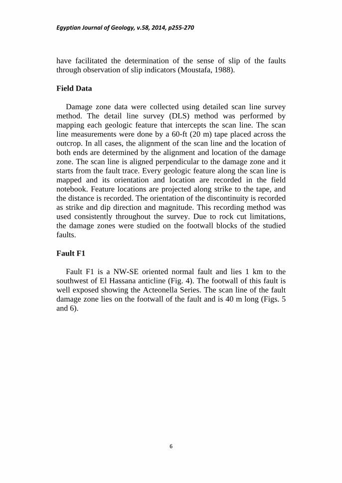
Fault F1
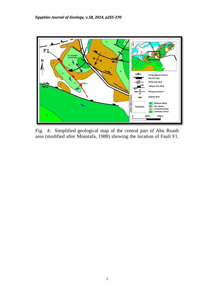
Fault F1 is a NW-SE oriented normal fault and lies 1 km to the southwest of El Hassana anticline (Fig. 4). The footwall of this fault is well exposed showing the Acteonella Series. The scan line of the fault damage zone lies on the footwall of the fault and is 40 m long (Figs. 5 and 6).
Egyptian Journal of Geology, v.58, 2014, p255-270
7
Fig. 4: Simplified geological map of the central part of Abu Roash area (modified after Moustafa, 1988) showing the location of Fault F1.
Egyptian Journal of Geology, v.58, 2014, p255-270
8
Fig. 5: A- Rock cut showing the damage zone of Fault F1. B- Sketch showing the fractures in the rock cut.
Egyptian Journal of Geology, v.58, 2014, p255-270
9
Description of the Damage Zone of Fault F1
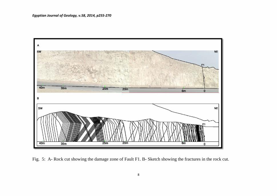
The first five meters of the fault damage zone are characterized by high density of fractures (5 to 7 fractures/meter, Table 1). These fractures are parallel and sub-parallel to the W (Fig. 7-A). Clayey material is the dominant fill of the fractures (1cm to 10 cm fracture aperture) at this part of the damage zone. These 5 meters are part of the fault core.
0 to 5m from the fault
Five meters away from the fault, the density of the fractures decreases to 3 fractures/meter and these fractures are long parallel fractures. They are exactly parallel to the fault (Fig. 7-B).
5 to 20 m from the fault
In this zone, the orientations of the fractures change dramatically to four different sets instead of the one major set parallel to the fault. These are N50-60˚, N 90-100˚, N110-120˚ and N130-140˚ (Fig. 7-c). These new orientations most probably represent the fractures associated with nearby El Hassana fold. This highly fractured zone includes NE-SW fractures parallel to the fold axis (Fig. 4) and fractures parallel to Fault F1, forming what is named in this study the fracture interference zone.
20 to 40 m from the fault
Fig. 6: Scan line for Fault F1 showing the orientations of the measured fractures.

Egyptian Journal of Geology, v.58, 2014, p255-270
10
A: 0 – 5 m from the fault
B: 5 – 20 m from the fault
C: 20 – 40 m from the fault
Fig. 7: Lower hemisphere, equal-area stereograms and rose diagrams for the fractures in the damage zone of Fault F1.

Egyptian Journal of Geology, v.58, 2014, p255-270
11
Table 1: Summary of the fracture characteristics of Fault F1. Fault plane
(Dip/DipDirection) Fracture
major trends Average density (fractures/meter)
Filling material
62/050
320-350 310-320
7 3
Clayey material
Fault F2
Fault F2 is a WNW-ESE oriented oblique-slip fault with normal dip-slip component and right-lateral strike-slip component. The fault extends for 3 km through the exposed Upper Cretaceous rocks. The damage zone of the fault is encountered and seen at two rock cuts (A and B),Fig. 8 and Tables 2 and 3.
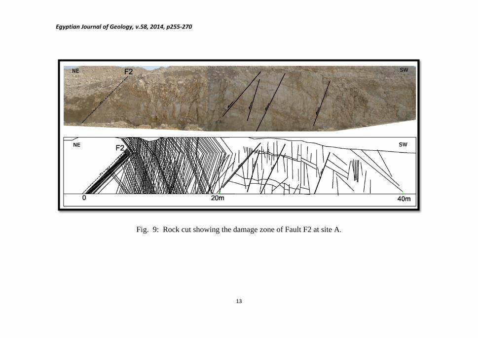
Site A:
The footwall of the fault is exposed at site A along a road cut, and the damage zone can be clearly seen (Fig. 9) and is characterized by numerous synthetic minor faults. Two major trends of fractures are encountered along the rock cut. These two sets are oriented NW-SE (parallel to the fault) and NE-SW. According to Moustafa (1988) wrench deformation affected the Abu Roash area leading to the development of simultaneous folds and faults. The NE-SW fractures in site A are parallel to the nearby fold axis (Fig. 8). The intensity of small-scale faulting in the fault damage zone, particularly in close proximity to the fault, is enormous. Theoretically, once a smooth, thoroughgoing fault is developed in the fault core, slip on the fault will relieve stress buildup before differential stress required for a new fault is reached, and continued reactivation of the main fault will occur instead of formation of new small faults.
Description of the Damage Zone of Fault F2 at Site A
Highly fractured rocks are encountered in the areas lying between the minor normal faults inside the damage zone of F2 Fault (Fig. 10). These fractures are probably associated with relay ramps lying between these normal faults. After 25m from the fault and up to 60 m along the road cut these synthetic normal faults are located.

Egyptian Journal of Geology, v.58, 2014, p255-270
12
Fig. 8: Simplified geological map of the area of Fault F2 (modified after Moustafa, 1988).
Egyptian Journal of Geology, v.58, 2014, p255-270
13
Fig. 9: Rock cut showing the damage zone of Fault F2 at site A.
Egyptian Journal of Geology, v.58, 2014, p255-270
14
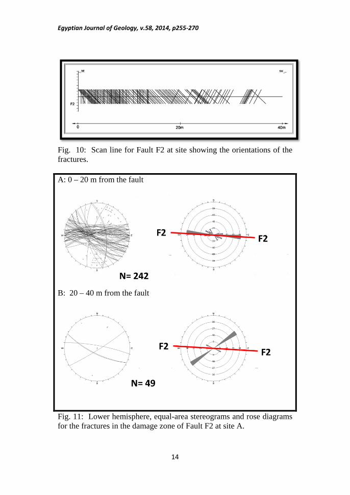
Fig. 10: Scan line for Fault F2 at site showing the orientations of the fractures.
A: 0 – 20 m from the fault
B: 20 – 40 m from the fault
Fig. 11: Lower hemisphere, equal-area stereograms and rose diagrams for the fractures in the damage zone of Fault F2 at site A.
Egyptian Journal of Geology, v.58, 2014, p255-270
15
Table 2: Summary of the fracture characteristics of Fault F2 at site A. Fault plane
(Dip/Dip Direction) Fracture major
Trends Average density (fractures/meter)
Filling material
60/002 270-280 280-300
11 5
Clayey material
Site B:
The exposure of the Fault F2 at site B is an old quarry in the Limestone Series where the fault is concealed at the edge of the rock cut. However, the fault damage zone of the footwall block is well exposed in the quarry face. The first seven meters of the damage zone are covered with Quaternary alluvium. A portion of site B belongs to the hinge area of the nearby NE-SW oriented anticline (Fig. 8), where more than 100 fractures parallel to the foldaxis are prsent (Fig. 12).
Description of the Damage Zone of Fault F2 at Site B.
This part of the damage zone is covered with Quaternary alluvium.
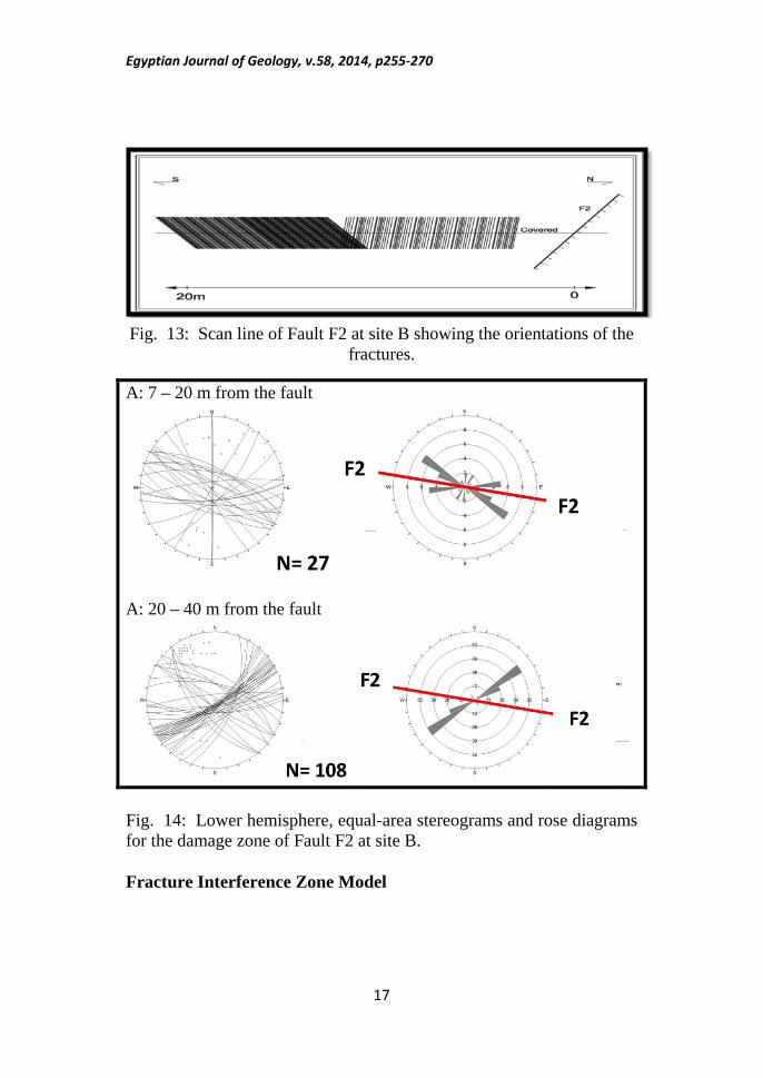
0 to 7m from the fault
Most of the fractures in this zone are oriented sub-parallel to the main fault (NW-SE), with density of 10 fractures/meter (Figs. 13 and 14-A)
7 to 20 m from the fault
In this area, two fracture sets are recorded; NE-SW and NW-SE but the NE-SW oriented fractures, which are parallel to the nearby fold axis are dominant (Fig. 14-B). The density of fractures at this area is 10 fractures/meter.
20 to 40 m from the fault (fracture interference zone)
Table 3: Summary of the fracture characteristics of Fault F2 at site B Fault plane
(Dip/DipDirection) Fracture major
trends Average density (fractures/meter)
Filling material
65/10 260-270 300-310 50-70
10
Clayey material

Egyptian Journal of Geology, v.58, 2014, p255-270
16
Fig. 12: Field photograph and sketch showing the damage zone of Fault F2 at site B.
Egyptian Journal of Geology, v.58, 2014, p255-270
17
Fig. 13: Scan line of Fault F2 at site B showing the orientations of the fractures.
A: 7 – 20 m from the fault
A: 20 – 40 m from the fault
Fig. 14: Lower hemisphere, equal-area stereograms and rose diagrams for the damage zone of Fault F2 at site B.
Fracture Interference Zone Model
Egyptian Journal of Geology, v.58, 2014, p255-270
18
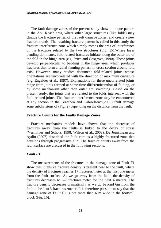
The fault damage zones of the present study show a unique pattern in the Abu Roash area, where other large structures (like folds) may change the fracture patternof the fault damage zones, and create a new fracture trends. The resulting fracture pattern is called in this study the fracture interference zone which simply means the area of interference of the fractures related to the two structures (Fig. 15).Where layer bending dominates, fold-related fractures initiate along the outer arc of the fold in the hinge area (e.g. Price and Cosgrove, 1990). These joints develop perpendicular to bedding in the hinge area, which produces fractures that form a radial fanning pattern in cross section around fold axis. However, many studies document fold-related joints whose orientations are uncorrelated with the direction of maximum curvature (e.g. Engelder et al., 1997). Explanations for these uncorrelated joints range from joints formed at some time differentfromthat of folding, or by some mechanism other than outer arc stretching. Based on the present study, the joints that are related to the folds intersect with the fault-related joints. The fracture interference zone may be encountered at any section in the Braathen and Gabrielsen’s(2000) fault damage zone subdivisions of (Fig. 2) depending on the distance from the fault.
Fracture Counts for the Faults Damage Zones
Fracture mechanics models have shown that the decrease of fractures away from the faults is linked to the decay of stress (Vermilyer and Scholz, 1998; Wilson et al., 2003). De Joussineau and Aydin (2007) described the fault core as a highly fractured zone that develops through progressive slip. The fracture counts away from the fault surface are discussed in the following sections.
Fault F1
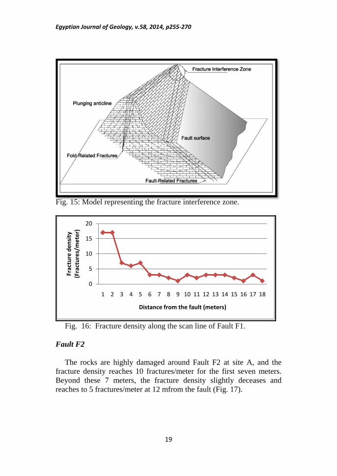
The measurements of the fractures in the damage zone of Fault F1 show that intensive fracture density is present near to the fault, where the density of fractures reaches 17 fractures/meter at the first one meter from the fault surface. As we go away from the fault, the density of fractures decreases to 6-7 fractures/meter for the next 4 meters. The fracture density decreases dramatically as we go beyond 6m from the fault to be 1 to 3 fractures /meter. It is therefore possible to say that the damage zone of Fault F1 is not more than 6 m wide in the footwall block (Fig. 16).
Egyptian Journal of Geology, v.58, 2014, p255-270
19
Fig. 15: Model representing the fracture interference zone.
Fig. 16: Fracture density along the scan line of Fault F1.
Fault F2
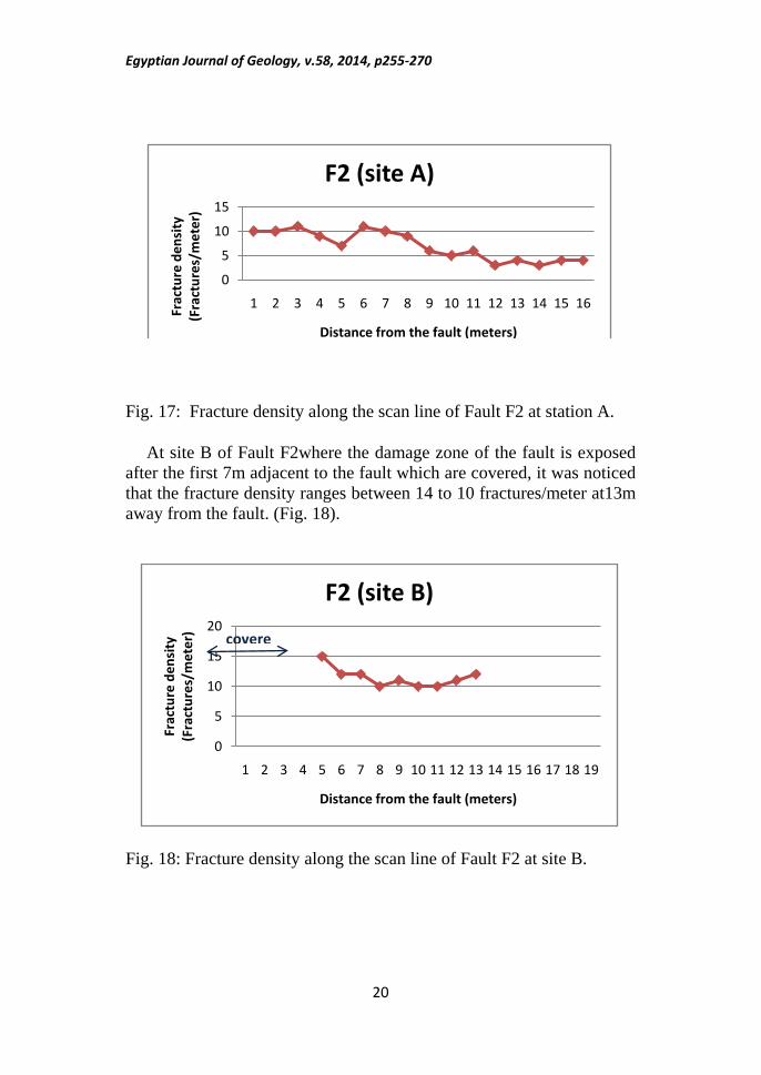
The rocks are highly damaged around Fault F2 at site A, and the fracture density reaches 10 fractures/meter for the first seven meters. Beyond these 7 meters, the fracture density slightly deceases and reaches to 5 fractures/meter at 12 mfrom the fault (Fig. 17).
0
5
10
15
20
1 2 3 4 5 6 7 8 9 10 11 12 13 14 15 16 17 18
Frac
ture
den
sity
(F
ract
ures
/met
er)
Distance from the fault (meters)
Egyptian Journal of Geology, v.58, 2014, p255-270
20
Fig. 17: Fracture density along the scan line of Fault F2 at station A.
At site B of Fault F2where the damage zone of the fault is exposed after the first 7m adjacent to the fault which are covered, it was noticed that the fracture density ranges between 14 to 10 fractures/meter at13m away from the fault. (Fig. 18).
Fig. 18: Fracture density along the scan line of Fault F2 at site B.
0
5
10
15
1 2 3 4 5 6 7 8 9 10 11 12 13 14 15 16Frac
ture
den
sity
(F
ract
ures
/met
er)
Distance from the fault (meters)
F2 (site A)
0
5
10
15
20
1 2 3 4 5 6 7 8 9 10 11 12 13 14 15 16 17 18 19
Frac
ture
den
sity
(F
ract
ures
/met
er)
Distance from the fault (meters)
F2 (site B)
covere

Egyptian Journal of Geology, v.58, 2014, p255-270
21
DISCUSSION AND CONCLUSIONS
According to this study, the half width of the damage zones of the two studied faults may reach up to 12 m. However other factors may affect the fracture pattern of the fault damage zones. These include the fault type, length of the fault, the amount of throw, and the existence of other structures (e.g. folds).
In the present study, a new fracture model is proposed based on the field observations and data analysis for the fracture patterns. In this model, two intersected fracture sets are encountered in the fault damage zone due to the occurrence of two structures (the fault itself in addition to nearby folds). Such fracture zones are called Fracture Interference Zones, representing the areas of interference of the fractures related to both faults and folds.According to the fracture count curves, both of the two studied faults have the same rate of cumulative fracture count curves growing until 12 m from the fault. However, after the 12 m distance from the fault, the curve attitude became different, as each fault lies near to a fold (a smaller fold for the first fault and a larger fold for the second fault), accounting for the large number of fractures for fault no. 2 at site B.
It is also clear that the density of the extension fractures related to folding ishigher than the density of fractures related to the faultingitself. It was clearly seen that the fault core includes clayey materials, smear, and faultbreccias.
Folds in the Abu Roash area have one major trend (NE), while faults have more than three trends (normal faults: NW and NE, thrust faults: NNE/ENE, right lateral faults: WNW and ENE to E-W, and left lateral: N and NNW) and accordingly the fracture pattern of fold can be recognized easily, but the fracture pattern of faults may change depending on the trend of the fault. According to the present study, it was essential to not intermix between the fault damage zone and the associated fracture pattern of any other structure like folds.
Egyptian Journal of Geology, v.58, 2014, p255-270
22
REFERENCES Berg, S. S. and Skar, T.(2005): Controls on damage zone asymmetry of
a normal fault zone: outcrop analyses of a segment of the Moab fault, SE Utah. J.Struct.l Geol.. 27(10),1803-1822.
Braathen, A. and Gabrielsen, R.H. (1998): Lineament architecture and fracture distribution in metamorphic and sedimentary rocks with application to Norway. Geol.Surv.Norway Report, No. 98.43.
Braathen, A. and Gabrielsen, R. H. (2000): Bruddsonerifjell – oppbygningogdefinisjoner.Norgesgeologiskeundersøkelse.Gråstein.v.7, p. 1-20.
Caine, J. S., Evans, J. P. and Forster, C. B. (1996): Fault zone architecture and permeability structure. Geology. 24(11). p.1025-1028.
Davis, G.H., and Reynolds, S.J. (1996): Structural Geology of Rocks and Regions, Wiley, New York.p.776.
De Joussineau, G. and Aydin, A. (2007): The evolution of the damage zone with fault growth in sandstone and its multiscale characteristics. Journal of Geophysical Research. v. 112, p.12.
Evans, J.P., Forster, C.B. and Goddard, J.V. (1997): Permeability of fault-related rocks, and implications for hydraulic structure of fault zones. Journal of Structural Geology.19, (11), p.1393–1404.
Engelder, T., Gross, M.R. and Pinkerton, P. (1997): Joint development in clastic rocks of the Elk Basin anticline, Montana-Wyoming. In: Hoak T, Klawitter A, Blomquist P (eds) An analysis of fracture spacing versus bed thickness in a basement-involved Laramide structure. Rocky Mountain Association Geol. 1997 Guidebook. Denver. p.1-18.
Faris, M.I., (1948): Contribution to the stratigraphy of Abu Rauwash and the history of the Upper Cretaceous in Egypt.– Bull. Fac. Sc. Cairo Univ. v. 27, p. 221–239.
Moustafa, A. R. (1988): Wrench tectonics in the north Western Desert of Egypt (Abu Roash area, southwest of Cairo). Mid. East Res. Center, AinShams Univ., Earth Sci. Ser. 2, p. 1-16.
Moustafa, A.R., (2013): Fold-related faults in the Syrian Arc belt of northern Egypt, Marine and Petroleum Geology. v. 48, p.441-454.
Noda, H. and Shimamoto, T. (2005): Thermal pressurization and slip weakening distance of a fault: An example of the Hanore fault, southwest Japan,Bull. Seismol.Soc. Am. 95, (4), p.1224–1233.
Egyptian Journal of Geology, v.58, 2014, p255-270
23
Odling, N. E. (1997): Scaling and connectivity of joint systems in sandstone from western Norway. J. Struct. Geol. 19(10),p.1257–1271.
Price, N. J. and Cosgrove, J. W. (1990): Analysis of Geological Structures, Cambridge university press, p.502.
Said, R. (1962): The Geology of Egypt. Elsevier.Amsterdam, London, New York.p.377.
Vermilyer, J. M. and Scholz, C. H. (1998): The process zone: amicrostructural view. Journal of Geophysical Research.103, p.12223-12237.
Wilson, J. E., Chester, J. S. and Chester, F. M. (2003): Microfracture analysis of fault growth and wear processes, Punchbowl Fault, San Andreas System, California. J. Struct. Geol. 25, p.1855–1873.
Related Documents