APPLICATIONNOTE 155 13.12.2017 page 1 of 15 Support of Third Party BLDC motors Summary Overview of supported / required characteristics of third party BLDC motors. Step by step instruction of setting up: • a third party BLDC motor with digital hall sensors (+ incremental encoder) • to operate with a MC3 Motion Controller • using Motion Manager 6.3 Applies To Faulhaber Motion Controller MC5004, MC5005 and MC5010

Welcome message from author
This document is posted to help you gain knowledge. Please leave a comment to let me know what you think about it! Share it to your friends and learn new things together.
Transcript
APPLICATIONNOTE 155
13.12.2017 page 1 of 15
Support of Third Party BLDC motors
Summary
Overview of supported / required characteristics of third party BLDC motors. Step by step instruction of setting up: • a third party BLDC motor with digital hall sensors (+ incremental encoder) • to operate with a MC3 Motion Controller • using Motion Manager 6.3
Applies To
Faulhaber Motion Controller MC5004, MC5005 and MC5010
Faulhaber Application Note 155 page 2 of 15
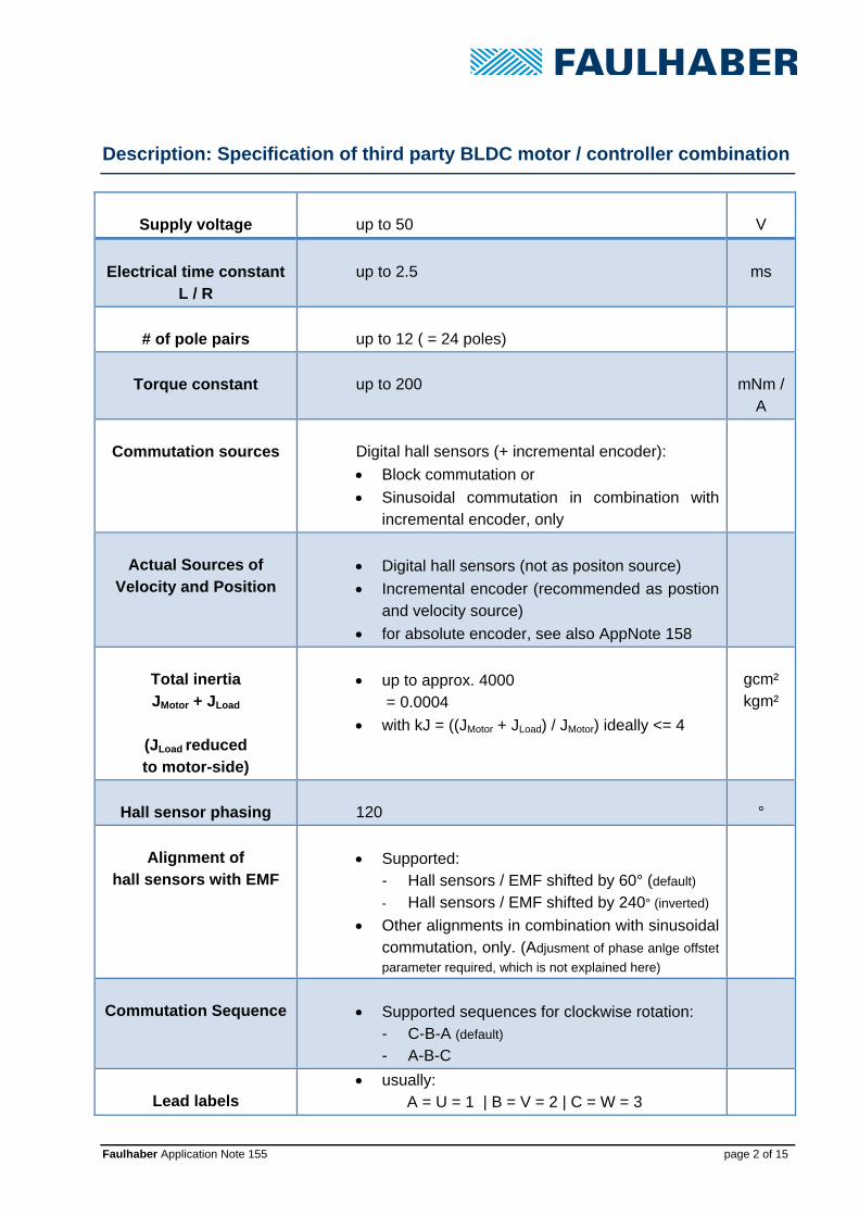
Description: Specification of third party BLDC motor / controller combination
Supply voltage
up to 50
V
Electrical time constant
L / R
up to 2.5
ms
# of pole pairs
up to 12 ( = 24 poles)
Torque constant
up to 200
mNm /
A
Commutation sources
Digital hall sensors (+ incremental encoder):
Block commutation or
Sinusoidal commutation in combination with incremental encoder, only
Actual Sources of
Velocity and Position
Digital hall sensors (not as positon source)
Incremental encoder (recommended as postion and velocity source)
for absolute encoder, see also AppNote 158
Total inertia JMotor + JLoad
(JLoad reduced to motor-side)
up to approx. 4000 = 0.0004
with kJ = ((JMotor + JLoad) / JMotor) ideally <= 4
gcm² kgm²
Hall sensor phasing
120
°
Alignment of
hall sensors with EMF
Supported: - Hall sensors / EMF shifted by 60° (default) - Hall sensors / EMF shifted by 240° (inverted)
Other alignments in combination with sinusoidal commutation, only. (Adjusment of phase anlge offstet
parameter required, which is not explained here)
Commutation Sequence
Supported sequences for clockwise rotation: - C-B-A (default) - A-B-C
Lead labels
usually: A = U = 1 | B = V = 2 | C = W = 3

Faulhaber Application Note 155 page 3 of 15
Step by Step instruction 1. Carefully compare the motor datasheet with the specification on page 2 and the
following tables and diagrams to identify if your third party motor is supported and which use case applies. Contact your motor supplier if the datasheet does not pro-vide any comparable information.
Excitation sequences and hall sensor output tables of major use cases for clockwise (cw) rotation:
(1) Default settings for FAULHABER motors Commutation Sequence: C-B-A Alignment of hall sensors with EMF - shifted by +60°
Sensors Phases
Electrical Degrees A B C A B C
0 - 60° 1 0 0 High x Low
60 - 120° 1 0 1 High Low x
120 - 180° 0 0 1 x Low High
180 - 240° 0 1 1 Low x High
240 - 300° 0 1 0 Low High x
300 - 360° 1 1 0 x High Low
Hall sensor outputs and excitation sequence
Phase-Voltages, Back-EMF and Hall-Sensor-Signals

Faulhaber Application Note 155 page 4 of 15
(2) Commutation Sequence A-B-C Alignment of hall sensors with EMF - shifted by -60°
Sensors Phases
Electrical Degrees A B C A B C
0 - 60° 1 0 1 High Low x
60 - 120° 1 0 0 High x Low
120 - 180° 1 1 0 x High Low
180 - 240° 0 1 0 Low High x
240 - 300° 0 1 1 Low x High
300 - 360° 0 0 1 x Low High
Hall sensor outputs and excitation sequence
Phase-Voltages, Back-EMF and Hall-Sensor-Signals
Motion Manager Settings

Faulhaber Application Note 155 page 5 of 15
(3) Commutation Sequence C-B-A Alignment of hall sensors with EMF - shifted by +240° ( = inverted to use case 1)
Sensors Phases
Electrical Degrees A B C A B C
0 - 60° 0 1 1 High x Low
60 - 120° 0 1 0 High Low x
120 - 180° 1 1 0 x Low High
180 - 240° 1 0 0 Low x High
240 - 300° 1 0 1 Low High x
300 - 360° 0 0 1 x High Low Hall sensor outputs and excitation sequence
Phase-Voltages, Back-EMF and Hall-Sensor-Signals
Motion Manager Settings

Faulhaber Application Note 155 page 6 of 15
2. Connect the motor phases and sensor wires. Faulhaber Controllers use the labels A, B and C. Usually this can be directly transferred to:
Phases Hall Sensors Controller Mot-A Mot-B Mot-C Sens-A Sens-B Sens-C
Motor Phase_U Phase_V Phase_W Hall_U Hall_V Hall_W
or Motor Phase_1 Phase_2 Phase_3 Hall_1 Hall_2 Hall_3
Some motors offer positive and negative digital hall sensor signals. Connect the positive ones to the controller, the negative ones are not used.
It is likely that the motor will have an additional incremental encoder. Connect it to the Encoder input M3, making sure that Channel_A and Channel_B are not mixed up. (Using an encoder index or a line driver is optional.)
Naming of the controller connectors (MC5005 + MC5010)
3. Connect the power supply to the controller (Up and Umot)
and establish communication

Faulhaber Application Note 155 page 7 of 15
4. Create a new motor using the motor select wizard of Motion Manager 6.3
When creating the motor make sure that especially the red marked parameters are correctly entered.

Faulhaber Application Note 155 page 8 of 15
If the values for friction and thermal parameters are not available, choose the values of a similar Faulhaber motor instead (of course the thermal motor model will not be precise in this case). Then click save.
5. Choose the newly created motor by clicking next. 6. Configure the sensors, following the “select motor wizard”
Choose Digital Hall sensors as Sensor input. If present enter an Incremental En-coder as encoder input, as well as the number of Pulses/Rev. (The value entered here will be internally multiplied by 4 to reflect the 4-edge evaluation of the control-ler).

Faulhaber Application Note 155 page 9 of 15
7. Choose block commutation by assigning digital hall sensors for commutation. If present select an incremental encoder as source for velocity and position. Even if sinusoidal commutation shall be used in the application it is highly rec-ommended to first select block commutation. Then follow the steps 8..11 for con-figuration and verification, and only afterwards come back to the “motor selection wizard” and choose sinusoidal commutation by assigning “digital hall sensors + in-cremental encoder” to the commutation angle. (Otherwise verification of the correct settings gets difficult).
8. Transfer the configuration to the controller and save it.
If the configuration cannot be transferred, contact your FAULHABER sales partner and provide the data which was entered during motor creation, so FAULHABER can check for compatibility with the controller.
Faulhaber Application Note 155 page 10 of 15
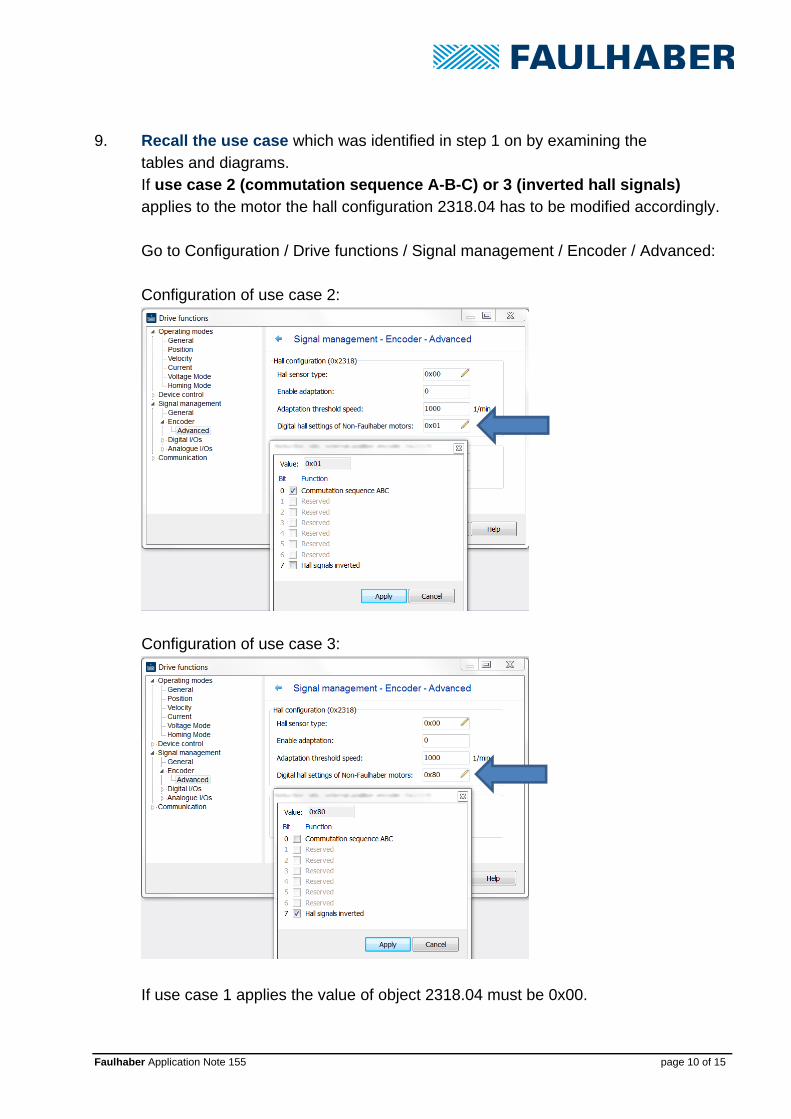
9. Recall the use case which was identified in step 1 on by examining the tables and diagrams. If use case 2 (commutation sequence A-B-C) or 3 (inverted hall signals) applies to the motor the hall configuration 2318.04 has to be modified accordingly. Go to Configuration / Drive functions / Signal management / Encoder / Advanced: Configuration of use case 2:
Configuration of use case 3:
If use case 1 applies the value of object 2318.04 must be 0x00.

Faulhaber Application Note 155 page 11 of 15
10. Testing the configuration - in voltage mode, via graphical analysis
Open the Motion Cockpit
Choose the voltage mode and switch the power stage on.
Command a voltage of 1 V by tipping 100 into the “Setpoint 1” field.
Then push the Motion Cockpit button “Go!”
Faulhaber Application Note 155 page 12 of 15
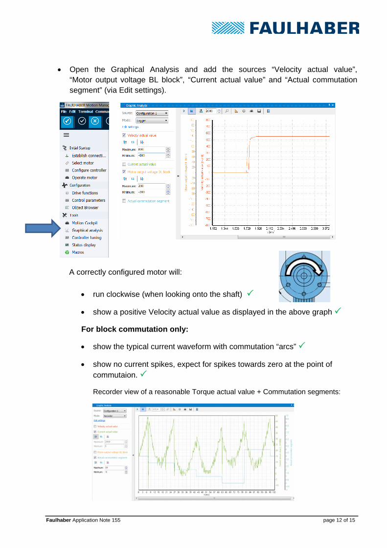
Open the Graphical Analysis and add the sources “Velocity actual value”, “Motor output voltage BL block”, “Current actual value” and “Actual commutation segment” (via Edit settings).
A correctly configured motor will:
run clockwise (when looking onto the shaft)
show a positive Velocity actual value as displayed in the above graph
For block commutation only:
show the typical current waveform with commutation “arcs”
show no current spikes, expect for spikes towards zero at the point of commutaion.
Recorder view of a reasonable Torque actual value + Commutation segments:
Faulhaber Application Note 155 page 13 of 15
11. Troubleshooting
The Velocity actual value is negative, when commanding a positive voltage
if an incremental encoder is used, swap the encoder channels A and B if only digital hall sensors are used, it is likely that the hall sensor config-
uration is incorrect, see step 9, page 10.
The motor is not running at all or not running smoothly
Check if the number of pole pairs (object 0x2329.07) was entered
correctly (see object browser, or select motor edit motor data)
Check if the correct hall sensor configuration was chosen (object
2318.04), see step 9, page 10.
Check the wiring, see step 2, page 6
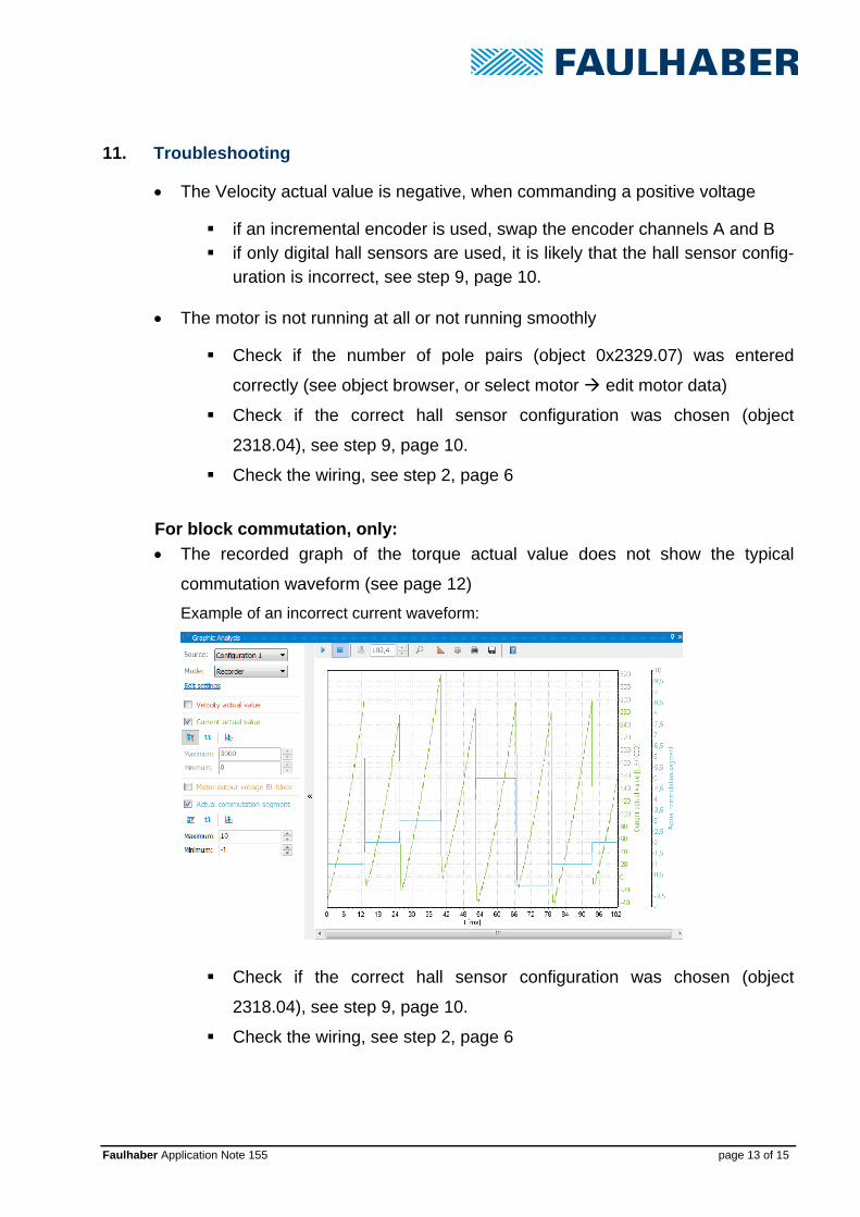
For block commutation, only:
The recorded graph of the torque actual value does not show the typical
commutation waveform (see page 12)
Example of an incorrect current waveform:
Check if the correct hall sensor configuration was chosen (object
2318.04), see step 9, page 10.
Check the wiring, see step 2, page 6

Faulhaber Application Note 155 page 14 of 15
The recorded graph of the torque actual value shows spikes which are not related to the point of commutation (= when a commutation segment changes)
Check if the correct hall sensor configuration was chosen (object
2318.04), see step 9, page 10.
Check the wiring, see step 2, page 6 12. Further Steps for starting up the system
Proceed with the controller configuration wizard. There the parameters of the feedback control system will be set according to the inertia of the system. In order to identify the inertia, the complete system including the load must be available. Be aware that the automatic system identification was designed for slotless motors; it might not work with some slotted motors.

Faulhaber Application Note 155 page 15 of 15
Rechtliche Hinweise Urheberrechte. Alle Rechte vorbehalten. Ohne vorherige ausdrückliche schriftliche Genehmigung der Dr. Fritz Faulhaber & Co. KG darf insbesondere kein Teil dieser Application Note vervielfältigt, reproduziert, in einem Informationssystem gespeichert oder be- oder verarbeitet werden. Gewerbliche Schutzrechte. Mit der Veröffentlichung der Application Note werden weder ausdrücklich noch konkludent Rechte an gewerblichen Schutzrechten, die mittelbar oder unmittelbar den beschriebenen An-wendungen und Funktionen der Application Note zugrunde liegen, übertragen noch Nutzungsrechte daran eingeräumt. Kein Vertragsbestandteil; Unverbindlichkeit der Application Note. Die Application Note ist nicht Ver-tragsbestandteil von Verträgen, die die Dr. Fritz Faulhaber GmbH & Co. KG abschließt, soweit sich aus solchen Verträgen nicht etwas anderes ergibt. Die Application Note beschreibt unverbindlich ein mögliches Anwendungsbeispiel. Die Dr. Fritz Faulhaber GmbH & Co. KG übernimmt insbesondere keine Garantie dafür und steht insbesondere nicht dafür ein, dass die in der Application Note illustrierten Abläufe und Funk-tionen stets wie beschrieben aus- und durchgeführt werden können und dass die in der Application Note beschriebenen Abläufe und Funktionen in anderen Zusammenhängen und Umgebungen ohne zusätzliche Tests oder Modifikationen mit demselben Ergebnis umgesetzt werden können. Keine Haftung. Die Dr. Fritz Faulhaber GmbH & Co. KG weist darauf hin, dass aufgrund der Unverbind-lichkeit der Application Note keine Haftung für Schäden übernommen wird, die auf die Application Note zurückgehen. Änderungen der Application Note. Änderungen der Application Note sind vorbehalten. Die jeweils aktuel-le Version dieser Application Note erhalten Sie von Dr. Fritz Faulhaber GmbH & Co. KG unter der Telefon-nummer +49 7031 638 688 oder per Mail von [email protected]. Legal notices Copyrights. All rights reserved. No part of this Application Note may be copied, reproduced, saved in an information system, altered or processed in any way without the express prior written consent of Dr. Fritz Faulhaber & Co. KG. Industrial property rights. In publishing the Application Note Dr. Fritz Faulhaber & Co. KG does not ex-pressly or implicitly grant any rights in industrial property rights on which the applications and functions of the Application Note described are directly or indirectly based nor does it transfer rights of use in such in-dustrial property rights. No part of contract; non-binding character of the Application Note. Unless otherwise stated the Appli-cation Note is not a constituent part of contracts concluded by Dr. Fritz Faulhaber & Co. KG. The Applica-tion Note is a non-binding description of a possible application. In particular Dr. Fritz Faulhaber & Co. KG does not guarantee and makes no representation that the processes and functions illustrated in the Applica-tion Note can always be executed and implemented as described and that they can be used in other con-texts and environments with the same result without additional tests or modifications. No liability. Owing to the non-binding character of the Application Note Dr. Fritz Faulhaber & Co. KG will not accept any liability for losses arising in connection with it. Amendments to the Application Note. Dr. Fritz Faulhaber & Co. KG reserves the right to amend Applica-tion Notes. The current version of this Application Note may be obtained from Dr. Fritz Faulhaber & Co. KG by calling +49 7031 638 688 or sending an e-mail to [email protected].
Related Documents