Available online at www.sciencedirect.com ScienceDirect Procedia Materials Science (2014) 000–000 www.elsevier.com/locate/procedia 2211-8128 © 2014 The Authors. Published by Elsevier Ltd. Selection and peer-review under responsibility of the Norwegian University of Science and Technology (NTNU), Department of Structural Engineering. 20th European Conference on Fracture (ECF20) Fatigue life of layered metallic and ceramic plasma sprayed coatings Ondřej Kovářík a , Petr Haušild a , Jan Siegl a , Jiří Matějíček b , Vadim Davydov c a Czech Technical University in Prague, Faculty of Nuclear Sciences and Physical Engineering, Trojanova 13, Prague 2, 120 00, Czech Republic b Institute of Plasma Physics, Academy of Sciences of the Czech Republic, Za Slovankou 1782/3, Prague 8, 182 00, Czech Republic c Paul Scherrer Institut, Villigen, 5232, Switzerland Abstract The application of thermally sprayed coatings can significantly enhance properties of coated parts such as thermal and wear resistance or biocompatibility. For example coatings prepared by HVOF are used for airplane landing gear parts and plasma sprayed coatings form heat shield on surface of turbine blades and vanes, several types of coatings are used in bone implants. In these application fields the fatigue behavior of coated components is of a paramount importance. The intrinsic properties of the deposited coating (modulus, microstructure, porosity etc.) play an important role. At the same time, the coating process can influence fatigue live through defects and residual stresses introduced to the substrate during spraying and associated preparation steps such as grit-blasting. The influence of substrate surface preconditioning and effect of individual layers of composite coatings on fatigue life were characterized. Plain substrates, grit-blasted substrates, and plasma sprayed specimens with one to three layers of coating were studies. The layered coatings were composed of alternating sequence of ceramic (Cr 2 O 3 ) and metallic (Ni10wt%Al) layers. Deflection controlled resonance bending (R = -1) fatigue test of flat specimens was performed. The deformation amplitude was 1.3 milistrain in crack initiation site and loading frequency was around 80Hz. The significance of the effect of surface treatment on fatigue properties was examined statistically using Wilcoxon test. From the obtained data the effect of individual layers was deduced. In order to explain the observed fatigue behavior, the fractographic analysis and other means of coating and substrate characterization were performed. Strain hardening in substrate was characterized by micro/nanohardness measurement and EBSD analysis. Residual stress in substrate was measured using neutron diffraction. © 2014 The Authors. Published by Elsevier Ltd. Selection and peer-review under responsibility of the Norwegian University of Science and Technology (NTNU), Department of Structural Engineering. Keywords: functionally graded materials; fatigue life; neutron diffraction; grit blasting. 1. Introduction Thermally sprayed coatings can significantly enhance properties of coated parts - such as thermal and wear resistance or biocompatibility. Both ceramic and metallic coatings and their combinations are commonly used to

Welcome message from author
This document is posted to help you gain knowledge. Please leave a comment to let me know what you think about it! Share it to your friends and learn new things together.
Transcript
Available online at www.sciencedirect.com
ScienceDirect
Procedia Materials Science (2014) 000–000
www.elsevier.com/locate/procedia
2211-8128 © 2014 The Authors. Published by Elsevier Ltd.
Selection and peer-review under responsibility of the Norwegian University of Science and Technology (NTNU), Department of Structural
Engineering.
20th European Conference on Fracture (ECF20)
Fatigue life of layered metallic and ceramic plasma sprayed coatings
Ondřej Kováříka, Petr Haušild
a, Jan Siegl
a, Jiří Matějíček
b, Vadim Davydov
c
aCzech Technical University in Prague, Faculty of Nuclear Sciences and Physical Engineering, Trojanova 13, Prague 2, 120 00, Czech Republic bInstitute of Plasma Physics, Academy of Sciences of the Czech Republic, Za Slovankou 1782/3, Prague 8, 182 00, Czech Republic
c Paul Scherrer Institut, Villigen, 5232, Switzerland
Abstract
The application of thermally sprayed coatings can significantly enhance properties of coated parts such as thermal and wear
resistance or biocompatibility. For example coatings prepared by HVOF are used for airplane landing gear parts and plasma
sprayed coatings form heat shield on surface of turbine blades and vanes, several types of coatings are used in bone implants. In
these application fields the fatigue behavior of coated components is of a paramount importance. The intrinsic properties of the
deposited coating (modulus, microstructure, porosity etc.) play an important role. At the same time, the coating process can
influence fatigue live through defects and residual stresses introduced to the substrate during spraying and associated preparation
steps such as grit-blasting. The influence of substrate surface preconditioning and effect of individual layers of composite
coatings on fatigue life were characterized. Plain substrates, grit-blasted substrates, and plasma sprayed specimens with one to
three layers of coating were studies. The layered coatings were composed of alternating sequence of ceramic (Cr2O3) and metallic
(Ni10wt%Al) layers. Deflection controlled resonance bending (R = -1) fatigue test of flat specimens was performed. The
deformation amplitude was 1.3 milistrain in crack initiation site and loading frequency was around 80Hz. The significance of the
effect of surface treatment on fatigue properties was examined statistically using Wilcoxon test. From the obtained data the effect
of individual layers was deduced. In order to explain the observed fatigue behavior, the fractographic analysis and other means of
coating and substrate characterization were performed. Strain hardening in substrate was characterized by micro/nanohardness
measurement and EBSD analysis. Residual stress in substrate was measured using neutron diffraction.
© 2014 The Authors. Published by Elsevier Ltd.
Selection and peer-review under responsibility of the Norwegian University of Science and Technology (NTNU), Department of
Structural Engineering.
Keywords: functionally graded materials; fatigue life; neutron diffraction; grit blasting.
1. Introduction
Thermally sprayed coatings can significantly enhance properties of coated parts - such as thermal and wear
resistance or biocompatibility. Both ceramic and metallic coatings and their combinations are commonly used to
2 Author name / Procedia Materials Science 00 (2014) 000–000
achieve the desired surface properties. A classic example of ceramo-metallic composite is the thermal barrier
coating (TBC) of yttria stabilized zirconia sprayed on top of NiCoCrAlY bondcoat, used at various parts of the
aircraft engines. Another example is WC-Co wear resistant cermet coating used on airplane landing gear parts.
Obviously, the fatigue behavior of both mentioned examples is of paramount importance. For better understanding
of fatigue processes in these composite structures, the fatigue behavior of their ceramic and metallic components
should be investigated. This can be accomplished by study the industrial composite coatings, or by testing simpler
model composite coatings with different choice of ceramic and metallic components.
Many researchers investigated the fatigue properties of WC-Co and similar wear resistant coatings at room
temperature, for an example see Ibrahim (2007). The mechanical fatigue properties of YSZ TBC's were studied by
fewer authors, for example Rejda (1997) and Waki (2008). There are many other thermally sprayed materials that
were fatigue tested, some of them in our laboratory. In the work of Musalek (2010) FeAl intermetallics tests are
presented. Ti coatings for medical applications were studied by Cizek (2013), various metallic and ceramic deposits
were tested by Kovarik (2008). In the papers on coating fatigue, the fatigue life of a coated part is attributed to the
properties of the deposited coating such as its residual stress, elastic modulus, fracture toughness, hardness,
adhesion, cohesion etc. At the same time, the coating process is expected to influence the fatigue life through defects
and residual stresses introduced to the substrate during spraying, cooling and associated preparation steps.
The results obtained in our previous research on fatigue of metallic and ceramic deposits (see Kovarik (2004) and
Kovarik (2008)) indicate that the effect of metallic and ceramic deposits on fatigue life differs significantly. The
ceramic deposits lead to fatigue life increase in the majority of case, whereas the effect of metallic deposits strongly
depended on the spray technology. Plasma spray and wire arc usually led to fatigue life decrease, whereas
techniques with high peening stresses such as HVOF resulted in fatigue life increase. As an attempt to characterize
the influence of ceramic and metallic layers in composite coatings on fatigue life, we performed a series of fatigue
test of specimens at different phases of the coating process and characterized various properties of the tested
deposits. The influence of grit-blasting, single material coatings and layered composites was tested. Two types of
deposits were selected from Kovarik (2008), namely the fatigue life decreasing metallic deposit of Ni10wt%Al and
fatigue life increasing ceramic deposit of Cr2O3.
The first step in coating application is grit blasting. It is used to clean and increase the roughness of the substrate.
Abrasive particles are often implanted into the substrate during grit blasting. Together with the increased roughness,
these particles act as stress concentrators. On the other hand, the impacting grit can induce compressive peening
stress and deformation hardening below the substrate surface can improvement of the fatigue behavior.
During thermal spray deposition, significant heat is transferred to the substrate-coating composite and thermal
gradients occur possibly leading to annealing of peening stress or to stress redistribution due to thermal mismatch
stress and quenching stress. Both thermal mismatch and quenching stresses are superimposed on deformation
induced stresses during fatigue test and may affect all stages of crack nucleation and propagation.
In this paper, we try to relate the fatigue life of ceramic and metallic coatings and their layered composites, to
changes introduced during deposition as discussed above.
2. Experimental
The layered deposits were prepared at IPP, CAS, Prague, using a WSP PAL 160 torch. The substrate material
was cold rolled sheet of mild steel (S235JRC, 4mm thickness), the as received specimens formed set P. The
substrate was grit blasted by alumina particles prior to spraying, the grit blasted and not sprayed specimens formed
set GB. Single layer coatings and layered deposits were prepared by alternating metal layers of Ni10wt%Al
(denoted by M) and ceramic layers of Cr2O3 (denoted by C). Various combinations of sprayed M and C layers can
be found in Table 2. The process conditions used for the deposition are summarized in Table 1.
The fatigue tests were carried out on an in-house developed resonance fatigue test device ”SF-Test”. The flat
specimens with both sides coated were loaded by symmetrical (R = -1) cyclical bending (as cantilever beams) with a
free end deflection amplitude fixed at u=4 mm at room temperature and with the loading frequency corresponding to
the first natural frequency of the mounted specimens (70 - 100) Hz. The longitudinal strain at the crack initiation on
the substrate surface was approximately 1.3×10⁻³
as indicated by strain gage measurement. The excitation frequency
fr was maintained using a phase locked loop technique. The crack growth in the specimens leads to decrease of
Author name / Procedia Materials Science 00 (2014) 000–000 3
resonance frequency. The frequency decrease is then used as a stopping condition of the experiment at approx. 30%
cross-sectional damage. The corresponding number of fatigue cycles is denoted N.
Table 1. Deposition parameters for investigated coatings.
Parameter Cr2O3 (C) Ni10wt%Al (M)
Torch PAL WSP® 160 PAL WSP® 160
Powder Cr2O3, #2097 Ni10wt%Al
powder size 46-90 µm 100-140 µm feed rate 300 g/min 417 g/min
spray distance 300 mm 350 mm
feed distance 32 mm 65 mm
Power 160 kW 160 kW
Table 2. Nomenclature and thicknesses of tested specimen sets, Rf denotes mean fatigue life relative to the as-received set.
Set Description coating thickness (µm) N(cycles) Rf
P as-received - 266487 1.00
GB grit-blasted - 229131 0.86 M Ni10wt%Al-single 325 180756 0.68
MC Cr2O3on Ni10wt%Al 98(M)+88(C) 293298 1.10
MCM Ni10wt%Al on Cr2O3 on Ni10wt%Al 89(M)+140(C)+108(M) 254270 0.95 C Cr2O3-single 598 383608 1.44
CM Ni10wt%Al on Cr2O3 141(C)+113(M) 414308 1.55
CMC Cr2O3 on Ni10wt%Al on Cr2O3 140(C)+199(M)+132(C) 417971 1.57
The coating microstructures were investigated on polished cross-sections. The fracture morphology was studied
on fracture surfaces made available by fracturing the sample at cryogenic temperature. The JEOL JSM-840 (JEOL
Ltd., Tokyo, Japan) scanning electron microscope (SEM) was used for the investigation of both fracture surfaces
and microstructure. The energy dispersive X-ray microanalysis (EDX) was performed on SEM JEOL 5510LV
equipped by IXRF 500 analyzer.
Phase composition of the deposits was investigated using X-ray diffraction (XRD). Vertical theta-theta
diffractometer X’Pert PRO (PANalytical B.V., Almelo, The Netherlands) with Bragg-Brentano geometry and
filtered CoKα radiation was used.
Strain hardening in substrate was characterized with help of Meyer hardness and EBSD. Meyer hardness was
measured using NanoTest (Micro Materials Ltd., Wrecsham, U.K.) hardness tester with Berkovich indentor.
Loading of 30 mN was applied. The indents were positioned on a line perpendicular to substrate-coating interface
with 20 µm distance between the imprints. Electron back scatter diffraction (EBSD) study of substrate hardening
was performed on a Jeol JSM-7600F SEM equipped with a HKL EBSD (Oxford Instruments PLC, Abingdon, UK)
analyzer. The band slope (BS) signal was used. The BS signal represents electron backscattering pattern (EBSP)
quality factor derived from the Hough transform that describes the maximum intensity gradient at the margins of the
Kikuchi bands in an EBSP. High band slope signal means defect free homogeneous lattice with low number of
defects. Strain hardening is a process connected with an increase of dislocation density and a decrease in the
mobility of the dislocations in the adjacent material. It can thus be expected that strain hardened material will exhibit
lower values of BS as compared to recovered material.
The residual stress depth profile in the substrate was measured using POLDI instrument at Swiss spallation
neutron source (SINQ). The measurement of stress in the coating were also attempted, however the intensity of the
diffracted signal was too low for residual stress determination. The Z-scan geometry as described by Ahmed (2008)
was used with irradiated volume 19×19×dslit mm3. The height of the irradiated volume dslit changed from 0.3 to
2 mm. The reflection on {110} planes was selected for strain estimation. Strain-free lattice spacing was determined
from the measurement in the center of the specimen. The stress in longitudinal direction of the samples, which
corresponded to the rolling direction, was computed by the relation σ = ε(E110/(1-ν110)). Elastic modulus E110 and
Poisson ratio ν110 were computed from elastic constants measured by Kim (2007).
4 Author name / Procedia Materials Science 00 (2014) 000–000
3. Results
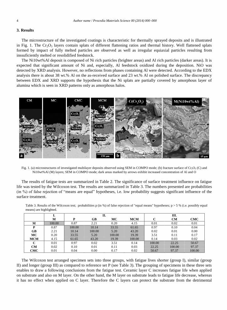
The microstructure of the investigated coatings is characteristic for thermally sprayed deposits and is illustrated
in Fig. 1. The Cr2O3 layers contain splats of different flattening ratios and thermal history. Well flattened splats
formed by impact of fully melted particles are observed as well as irregular equiaxial particles resulting from
inssuficiently melted or resolidified feedstock.
The Ni10wt%Al deposit is composed of Ni rich particles (brighter areas) and Al rich particles (darker areas). It is
expected that significant amount of Ni and, especially, Al feedstock oxidized during the deposition. NiO was
detected by XRD analysis. However, no reflections from phases containing Al were detected. According to the EDX
analysis there is about 38 wt.% Al on the as-received surface and 23 wt.% Al on polished surface. The discrepancy
between EDX and XRD supports the hypothesis that the Ni splats are partially covered by amorphous layer of
alumina which is seen in XRD patterns only as amorphous halos.
Fig. 1. (a) microstructures of investigated multilayer deposits observed using SEM in COMPO mode; (b) fracture surface of Cr2O3 (C) and
Ni10wt%Al (M) layers; SEM in COMPO mode; dark areas marked by arrows exhibit increased concentration of Al and O
The results of fatigue tests are summarized in Table 2. The significance of surface treatment influence on fatigue
life was tested by the Wilcoxon test. The results are summarized in Table 3. The numbers presented are probabilities
(in %) of false rejection of “means are equal” hypotheses, i.e. low probability suggests significant influence of the
surface treatment.
Table 3. Results of the Wilcoxon test; probabilities p (in %) of false rejection of "equal means" hypotheses; p > 5 % (i.e. possibly equal
means) are highlighted.
I. II. III.
M P GB MC MCM C CM CMC
M 100.00 0.87 2.21 0.20 4.15 0.01 0.02 0.01
P 0.87 100.00 10.14 33.55 61.65 0.97 0.10 0.04
GB 2.21 10.14 100.00 5.20 43.20 0.02 0.01 0.00
MC 0.20 33.55 5.20 100.00 19.39 3.51 0.11 0.17
MCM 4.15 61.65 43.20 19.39 100.00 0.14 0.03 0.02
C 0.01 0.97 0.02 3.51 0.14 100.00 22.25 50.67
CM 0.02 0.10 0.01 0.11 0.03 22.25 100.00 97.37
CMC 0.01 0.04 0.00 0.17 0.02 50.67 97.37 100.00
The Wilcoxon test arranged specimen sets into three groups, with fatigue lives shorter (group I), similar (group
II) and longer (group III) as compared to reference set P (see Table 3). The grouping of specimens in these three sets
enables to draw a following conclusions from the fatigue test. Ceramic layer C increases fatigue life when applied
on substrate and also on M layer. On the other hand, the M layer on substrate leads to fatigue life decrease, whereas
it has no effect when applied on C layer. Therefore the C layers can protect the substrate from the detrimental

Author name / Procedia Materials Science 00 (2014) 000–000 5
influence of subsequent M layer. To suggest a mechanism which leads to the observed behavior of C and M layers,
the results of the performed characterization have to be evaluated.
The fractographic analysis of specimens after final static cryogenic rupture was performed. The coating fracture
morphology did not provide enough fractographical features for analysis (for illustration of coating fracture
morphology see Fig1b). On the other hand, the crack initiation sites and crack propagation directions can be
identified in the low carbon steel substrate despite the symmetrical nature of the fatigue loading. The imprints of grit
blasted particles were often found to provide stress concentrators for crack initiation or re-initiation (in case the
crack would start in coating). The cracks in the substrates grew by striation mechanism as 1/2 or 1/4 elliptical
cracks. The cracks initiation sites location differs for the three observed specimen groups. For specimens in group I
with fatigue lives decrease multiple crack initiations were located uniformly below the coated surface. The
developed fatigue cracks were found in multiple parallel planes. This indicates significant number of stress
concentration sites introduced by the coating process. For specimens in group II with neutral lives the cracks
initiations were located close to specimen edges and the number of crack initiations was significantly lower. For
specimens in group III with increased fatigue lives, there was only few initiations located mostly on uncoated
surfaces. The coatings failed by mechanisms of intrasplat cracking and/or intersplat decohesion as described i.e. in
Kovarik (2008).
The stress profile obtained by neutron diffraction is presented in Fig. 2. The compressive rolling stresses (see e,g,
Dixit (1997)) were detected in as received specimens. The grit blasting process increased the magnitude of
compressive stresses below the substrate surface. The deposition of the MC coating led to a decrease in compressive
stress in the surface layer. The question is, however, whether deposition resulted in the peening stress annealing or
whether it added additional tensile stress to the stress field. The stress redistribution in CM specimen as compared to
GB specimens was detected, however the compressive stress with beneficial effect on the fatigue life was retained.
The compressive stress below substrate surface appears as a necessary condition for fatigue life increase, however
additional factors must be causing a difference between GB and CM fatigue lives.
Fig. 2. Residual stress measured using neutron diffraction, vertical error bars mark the measurement error, horizontal error bats mark the
measured area, i.e. the height of the neutron beam.
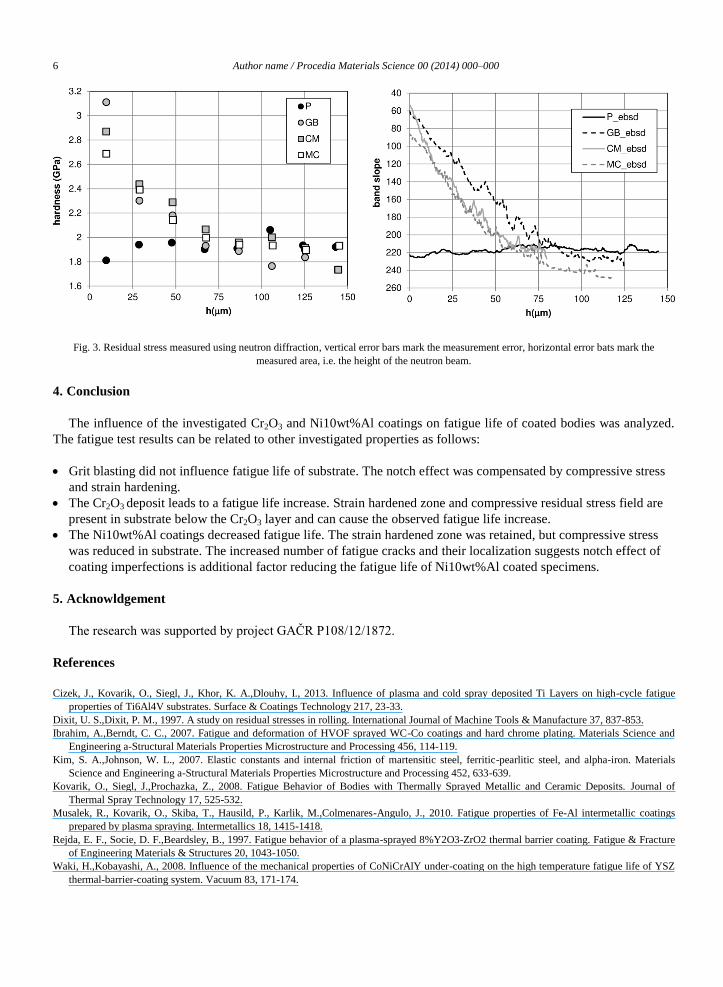
Fatigue resistance of the substrate depends also on work hardening introduced by the grit blasting. The obtained
Meyer hardness profiles are summarized in Fig. 3 and clearly indicate work hardening up to a depth of approx. 70-
100 µm. In contrast to residual stress, the hardened layer was preserved after the deposition for all coating types. In
order to obtain higher depth resolution, an EBSD study was performed based on the band slope (BS) signal. The
results of EBSD study are included in Fig. 3 and confirmed the profile obtained by microhardness measurement.
6 Author name / Procedia Materials Science 00 (2014) 000–000
Fig. 3. Residual stress measured using neutron diffraction, vertical error bars mark the measurement error, horizontal error bats mark the
measured area, i.e. the height of the neutron beam.
4. Conclusion
The influence of the investigated Cr2O3 and Ni10wt%Al coatings on fatigue life of coated bodies was analyzed.
The fatigue test results can be related to other investigated properties as follows:
Grit blasting did not influence fatigue life of substrate. The notch effect was compensated by compressive stress
and strain hardening.
The Cr2O3 deposit leads to a fatigue life increase. Strain hardened zone and compressive residual stress field are
present in substrate below the Cr2O3 layer and can cause the observed fatigue life increase.
The Ni10wt%Al coatings decreased fatigue life. The strain hardened zone was retained, but compressive stress
was reduced in substrate. The increased number of fatigue cracks and their localization suggests notch effect of
coating imperfections is additional factor reducing the fatigue life of Ni10wt%Al coated specimens.
5. Acknowldgement
The research was supported by project GAČR P108/12/1872.
References
Cizek, J., Kovarik, O., Siegl, J., Khor, K. A.,Dlouhy, I., 2013. Influence of plasma and cold spray deposited Ti Layers on high-cycle fatigue
properties of Ti6Al4V substrates. Surface & Coatings Technology 217, 23-33.
Dixit, U. S.,Dixit, P. M., 1997. A study on residual stresses in rolling. International Journal of Machine Tools & Manufacture 37, 837-853.
Ibrahim, A.,Berndt, C. C., 2007. Fatigue and deformation of HVOF sprayed WC-Co coatings and hard chrome plating. Materials Science and
Engineering a-Structural Materials Properties Microstructure and Processing 456, 114-119.
Kim, S. A.,Johnson, W. L., 2007. Elastic constants and internal friction of martensitic steel, ferritic-pearlitic steel, and alpha-iron. Materials
Science and Engineering a-Structural Materials Properties Microstructure and Processing 452, 633-639.
Kovarik, O., Siegl, J.,Prochazka, Z., 2008. Fatigue Behavior of Bodies with Thermally Sprayed Metallic and Ceramic Deposits. Journal of
Thermal Spray Technology 17, 525-532.
Musalek, R., Kovarik, O., Skiba, T., Hausild, P., Karlik, M.,Colmenares-Angulo, J., 2010. Fatigue properties of Fe-Al intermetallic coatings
prepared by plasma spraying. Intermetallics 18, 1415-1418.
Rejda, E. F., Socie, D. F.,Beardsley, B., 1997. Fatigue behavior of a plasma-sprayed 8%Y2O3-ZrO2 thermal barrier coating. Fatigue & Fracture
of Engineering Materials & Structures 20, 1043-1050.
Waki, H.,Kobayashi, A., 2008. Influence of the mechanical properties of CoNiCrAlY under-coating on the high temperature fatigue life of YSZ
thermal-barrier-coating system. Vacuum 83, 171-174.
Related Documents

![Metallic MoS2 for High Performance Energy Storage and ...€¦ · tageous for electrochemical energy storage.[23,24] However, ... Layered transition metal dichalcogenides (TMD) have](https://static.cupdf.com/doc/110x72/6061b9421f44fb1e590c1577/metallic-mos2-for-high-performance-energy-storage-and-tageous-for-electrochemical.jpg)