Fatigue Assessment of Complex Welded Steel Structures Johan Martinsson

Welcome message from author
This document is posted to help you gain knowledge. Please leave a comment to let me know what you think about it! Share it to your friends and learn new things together.
Transcript
Fatigue Assessment of Complex Welded
Steel Structures
Johan Martinsson


Fatigue Assessment of Complex Welded
Steel Structures
Johan Martinsson Division of Lightweight Structures
Department Aeronautical and Vehicle Engineering Royal Institute of Technology
SE-100 44 Stockholm
TRITA-AVE 2005:02 ISBN 91-2783-968-6


Fatigue Assessment of Complex Welded Steel Structures
i
PREFACE The work in this doctoral thesis has been carried out at the Division of Lightweight Structures at the Department of Aeronautical and Vehicle Engineering at the Royal Institute of Technology between February 2000 and October 2004. The work done in this thesis is a part of the Nordic R&D project FE-Design 2000 - Improved Usage of High Strength Steel by an Effective FEA (Finite Element Analysis) based Design Methodology for Fatigue Loaded Complex Welded Structures. The project, which involved cooperation of 24 Nordic organisations from Sweden, Finland, Denmark, Iceland and Norway, had the aim of improving lead-time, accuracy and material utilisation of fatigue loaded complex welded structures such as construction machinery, busses, forest machines, robots, cranes and ship structures. The consortium also included three steel suppliers, four engineering consulting firms, three research organisations and four universities. Some of the work has also regularly been presented and discussed within Commission XIII (Fatigue of welded components) in International Institute of Welding (IIW) during different Annual Assemblies. The work in this thesis has mainly been funded by Volvo Construction Equipment (Volvo CE), SSAB, The Swedish Vehicle Research Program (PFF) and the Nordic Innovation Centre (NiCe). First of all, I would like to express my sincere thanks to my advisor Prof. Jack Samuelsson (Volvo CE and KTH) for initiating and supervising the work. Special thanks to Gert Petterson, Bertil Jonsson, Göran Kronmar at Volvo Articulated Haulers, Magnus Byggnevi and Stefan Forsberg at Volvo Wheel Loaders and Mats Gustafsson at SSAB, whom I have been working with during the research project. I would also like to thank the people within the Division of Lightweight Structures. Special acknowledgements are also due to Björn Palmberg and Dr. Geng Sheng at Swedish Defence Research Agency (FOI) and Dr. Dan Holm at Alfgam Optimisation AB for discussions about weight functions and FEA. Hans Broström at Volvo Wheel Loader manufactured test pieces, Nenad Mrden at Volvo Construction Equipment Components performed fatigue tests, Dr Torbjörn Narström SSAB contributed with many fruitful discussions and Dr Anders Hansen and Dr Jan Langkjaer at MAN B&W Diesel A/S supported me with CAD geometries and residual stress calculations which are much appreciated. I also gratefully acknowledge the staff within Volvo CE for their co-operation during the work, e. g. Björn Portström and Kjell Eriksson. Finally, I would like to thank my dear Lisa, my parents, Elisabeth and Jan and brothers Henrik and Niklas for all encouragement and support during these years of hard work. Stockholm, January 2005 Johan Martinsson


Fatigue Assessment of Complex Welded Steel Structures
iii
ABSTRACT To improve the usage of material in fatigue loaded complex welded structures a better calculation method (based on FEA) is needed than what is available on the market and an improved management of weld quality. Improved FE-procedures are directly applicable to design of generic structural components within virtually all industries using CAD and FE-tools, irrespective of industrial sector. More and more welded structures are created as 3D models from the design offices and the FE-work will be easier but the requirement of being accurate from the beginning and the reduction of lead times create a great need to substantially reduce calculation time. The main objectives in this thesis is to develop novel procedures to extract design data from finite element stress analyses of complex fatigue loaded welded structures, to achieve a better understanding of the limits of the different fatigue design methods and to investigate the influence of fatigue strength due to the weld quality. An investigation of how weld geometry and different type of defects influence fatigue life of the weld has been made on a non-load carrying cruciform joint. The weld geometries were measured and the stress distributions were computed using FEA. Fatigue tests have been performed and the initial defects were analysed. Life predictions with LEFM based on the stress distributions and defects were performed with good agreement with the test results. The different fatigue design methods Nominal stress, Structural stress, Effective Notch stress and LEFM proposed by the International Institute of Welding (IIW) have been investigated and applied on a welded link. In order to verify the accuracy of the prediction methods, fatigue tests of the link were made. Structural optimisations based FEA, using different objectives regarding the fatigue properties of the welded link were also carried out to increase the performance of the link. Comparison and investigations of the advantages and disadvantage of the two different LEFM approaches, weight function technique and FEA solutions is made on welded structures. Based on the conclusions of the investigations an automatic 3D FE based LEFM program was developed. The program was successfully implemented and verified on two welded structures.


Fatigue Assessment of Complex Welded Steel Structures
v
DISSERTATION Paper A Martinsson, J., Fatigue Testing of Welded Cruciform Joint with Cold laps, Proc. Design and Analysis of Welded High Strength Steel Structures, Stockholm June 2002, ed. J. Samuelsson, EMAS 2002. This paper was also presented and discussed within Commission XIII (Fatigue of welded components) in International Institute of Welding (IIW) during Annual Assembly, Copenhagen 2002. Paper B Martinsson, J. Fatigue Assessment of a Welded Component in a Construction Machinery Based on Different Methods, Proc. Design and Analysis of Welded High Strength Steel Structures, Stockholm June 2002, ed. J. Samuelsson, EMAS 2002. This paper was also presented and discussed within Commission XIII (Fatigue of welded components) in International Institute of Welding (IIW) during Annual Assembly, Ljubljana 2001. Paper C Martinsson, J. and Öhnström, M., Fatigue Life and Weight Optimisation of a Welded Component, Dept. of Aeronautical and Vehicle Engineering, Report No. 2002-22, The Royal Institute of Technology, Stockholm 2002. Paper D Martinsson, J., Fatigue Crack Paths in a Welded Structure, International Conference on Fatigue Crack Path (FCP 2003), September 2003, Parma, Italy. Paper E Martinsson, J., Automatic 3D Crack Growth in Welded Structures, To be published in ‘Scandinavian Journal of Metallurgy’. This paper was also presented and discussed within Commission XIII (Fatigue of welded components) in International Institute of Welding (IIW) during Annual Assembly, Osaka 2004. DIVISION OF WORK BETWEEN AUTHORS Paper C Öhnström performed the structural optimisation and Martinsson performed the sub-models, fatigue predictions and wrote the paper.


Fatigue Assessment of Complex Welded Steel Structures
vii
CONTENTS PREFACE ................................................................................................................................... i ABSTRACT.............................................................................................................................. iii DISSERTATION ....................................................................................................................... v DIVISION OF WORK BETWEEN AUTHORS....................................................................... v INTRODUCTION...................................................................................................................... 1
Background ............................................................................................................................ 1 Objective ................................................................................................................................ 3 Research approach.................................................................................................................. 3
LIFE PREDICTIONS METHODS ............................................................................................ 4 Nominal Stress ....................................................................................................................... 4 Structural Stress...................................................................................................................... 5 Effective Notch Stress............................................................................................................ 6 Linear Elastic Fracture Mechanics (LEFM)........................................................................... 7 Application of different life prediction methods.................................................................... 7
COMPUTATIONAL ASPECTS IN FATIGUE ANALYSIS ................................................... 8 APPLICATION OF LEFM TO WELDED STRUCTURES ..................................................... 9
Background ............................................................................................................................ 9 Stress Intensity Factor Solutions ............................................................................................ 9 Crack Growth in Complex Welded Structure ...................................................................... 11 Mixed Mode I and Mode III Crack Growth......................................................................... 12
RESIDUAL STRESS............................................................................................................... 13 WELD DEFECTS .................................................................................................................... 13 OPTIMISATION ..................................................................................................................... 14 CONCLUSIONS...................................................................................................................... 15 SUMMARY OF APPENDED PAPER.................................................................................... 15 REFERENCES......................................................................................................................... 18


Fatigue Assessment of Complex Welded Steel Structures
1
INTRODUCTION
Background Failures due to fatigue in welded structures lead to loss of life and substantial costs each year all over the world. Remedies to this situation include the introduction of various standards and fatigue design codes. The foundation of such codes rely, in some cases, on old concepts that do not easily translate to the output from modern computer programmes and are also limited to rather simplified structures. The development of new generations of products means, in general, increased capacity, increased speed and increased demands on life. For construction equipment such as haulers and Wheel Loaders, the introduction of improved drive train and suspension systems also increases the speed and, as a consequence, increases the number of fatigue cycles at higher load levels. Improved maintenance and higher utilisation place additional demands on the supporting structures. The requirements in society towards improved functionality and minimising of Life Cycle Cost (LCC) force companies to design structures with reduced weights and ”optimum” fatigue resistance. Actions to meet these demands are to introduce high strength steel, weld and/or surface improvement technologies and high productivity manufacturing technologies. The introduction of high strength steel in structures normally means higher stress levels and, hence, an increased sensitivity to defects, deviations in weld geometry (e.g. penetration, throat thickness, undercuts) and variations in material strength. Expertise in developing and manufacturing fatigue loaded welded structures with low LCC is a key aspect in order to stay competitive. Shorter development time for new products means that it is important to make the correct design and fatigue assessment early on in the project. A better understanding of the limits of the different fatigue design methods and the influence of fatigue strength due to the weld quality will improve the development of new fatigue loaded products. The understanding of the link between weld quality and the welding process would enable manufacturers to increase the utilisation of high strength steel in fatigue loaded welded structures. A complete fatigue design of a complex welded structure requires knowledge of the following activities:
• Load time histories from field measurements • Stress analysis by FEA and/or strain measurements • Fatigue testing of components • Material, weld quality and defects • Influence from the manufacturing process • Fatigue life prediction methods
The modern development of fatigue life predictions of welded structures in Sweden started more than 35 years ago when the nominal stress approach was introduced by the introduction of the Swedish Fatigue Design Code for Welded Structures, STBK-N1 [1]. The nominal stress of the welded component was calculated by hand or with handbooks and the fatigue strength

J. Martinsson
2
was taken from tabulated S-N curves for a variety of welded joints. The fatigue structural life was estimated by the linear damage rule. For complex welded components the nominal stress can be difficult to define even if the stress distribution is very well described with FEA. Therefore new improved methods to predict fatigue have been developed. Today there are mainly four methods to predict fatigue on welded components [2]:
• Nominal Stress • Structural Stress • Effective Notch Stress • Linear Elastic Fracture Mechanics (LEFM)
These methods will be described later in the thesis. Fatigue resistance of complex welded components based on stress analysis performed with FEA can be assessed in many different ways with varying degrees of time consumption and accuracy. Samuelsson [3] made an overview of the methods, see Table 1. A large model will increase both the model preparation and the computational time. Large and complex FEA models may include several critical locations and complex boundary conditions e.g. concentrated load in bearings requiring complex contact formulations, see Fig. 1. These models will be extensive and technically demanding. There is a great need from companies developing complex welded structures, irrespective of business area, to obtain access to an improved fatigue design methodology.
Table 1. Different methods to analyse welded structures with FEA [3].
Method Mesh size
Possible Design Methods
Accur. Remarks
Part structure coarse Nom. Stress Weak Better accuracy in beam type structures. coarse Struc. Stress Weak Sensitive to element type and size fine Struc. Stress Average Lack of design data. Cannot identify root cracking. Notch Stress Good LEFM can be applied. LEFM Good Require assumption of initial flaw size Assembled coarse Nom. Stress Weak structure coarse Struc. Stress Weak See part structure fine Struc. Stress Average See part structure. Large models. Notch Stress Good LEFM can be applied. Large models LEFM Good See part structure. Large models Assembled coarse/ Nom. Stress Weak Several ”smaller models” structure with fine Struc. Stress Average -”- -”- -”- , see part struc. sub-modelling Notch Stress Good -”- -”- -”- -”- - ”- LEFM Good -”- -”- -”- -”- - ”-

Fatigue Assessment of Complex Welded Steel Structures
3
Fig. 1. Examples of complex fatigue loaded welded structures in a Wheel Loader. The main areas for the NI-project FE-Design 2000 were:
• To design complex welded steel structures with reduced weight and optimum fatigue resistance.
• To reduce lead time in the design process.
The project was divided into several subprojects such as modelling and analysing of structures or details. A majority of the structures considered represented actual components from the participating industries. Different modelling strategies are considered and some commercial systems are evaluated. Results are further verified based on static strain gage and displacement measurements. Alternate life prediction strategies are used and, when possible, compared to measured fatigue lives. During dynamic testing of structures, both the fatigue life and the location and orientation of cracks are compared. Fatigue tests of small-scale test pieces manufactured with different weld quality, strength level and thickness are performed. The project has been primarily conducted in Sweden, Finland and Denmark.
Objective The work performed herein focuses on:
• Investigation of accuracy of life predictions • LEFM • Investigation of weld toe defects • Develop procedures to make fatigue predictions as efficient as possible • Increase the performance of welded components
Research approach The thesis consists of five papers. All papers include FEA and fatigue predictions on welded components. Paper A includes fatigue testing and predictions of welds with different geometry and defects. Paper B covers fatigue testing and predictions of a welded link based on the four design methods described in IIW. Paper C includes structural optimisation of the

J. Martinsson
4
welded link in paper B with fatigue life as the objective function. In paper D a crack growth study in 2D of the welded link is performed using the FE-code FRANC2D [4]. In paper E a 3D crack growth study is performed with an owned developed program. The major efforts in this thesis are on FEA, fatigue assessment, crack growth and weld quality issues.
LIFE PREDICTIONS METHODS As mentioned earlier there are mainly four methods to predict fatigue of welded components [2]:
• Nominal Stress • Structural Stress • Effective Notch Stress • Linear Elastic Fracture Mechanics (LEFM)
Below, brief descriptions of the methods as recommended by IIW are given. More detailed description of the methods can be found in Fricke [5], Radaj and Sonsino [6]. The effects of welding residual stresses, R-ratio, wall thickness and improvement techniques are included in the IIW recommendations. In case of variable amplitude loading, Palmgren-Miner´s linear damage rule is used when the design methods Nominal, Structural and Effective Notch stress are applied. In connection with LEFM and variable amplitude, the equivalent stress is used in this thesis.
Nominal Stress In non complex components the Nominal stress can be calculated using elementary theories of structural mechanics. Fig. 2 shows the variation of the Nominal stress in a beam-like component. The effect of the weld is ignored.
Fig. 2. Nominal Stress in a beam-like component [2].
In more complex structures the Nominal stress can be difficult to determine. In IIW and in other fatigue design rules, S-N curves for a large number of different welded joints are compiled. The S-N curve is identified by its FAT-value which is the characteristic strength of the detail at 2 million load cycles. Fig. 3 shows a welded joint and the corresponding FAT values.
Fatigue Assessment of Complex Welded Steel Structures
5
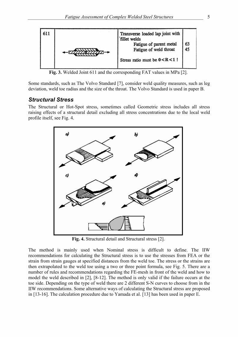
Fig. 3. Welded Joint 611 and the corresponding FAT values in MPa [2].
Some standards, such as The Volvo Standard [7], consider weld quality measures, such as leg deviation, weld toe radius and the size of the throat. The Volvo Standard is used in paper B.
Structural Stress The Structural or Hot-Spot stress, sometimes called Geometric stress includes all stress raising effects of a structural detail excluding all stress concentrations due to the local weld profile itself, see Fig. 4.
Fig. 4. Structural detail and Structural stress [2].
The method is mainly used when Nominal stress is difficult to define. The IIW recommendations for calculating the Structural stress is to use the stresses from FEA or the strain from strain gauges at specified distances from the weld toe. The stress or the strains are then extrapolated to the weld toe using a two or three point formula, see Fig. 5. There are a number of rules and recommendations regarding the FE-mesh in front of the weld and how to model the weld described in [2], [8-12]. The method is only valid if the failure occurs at the toe side. Depending on the type of weld there are 2 different S-N curves to choose from in the IIW recommendations. Some alternative ways of calculating the Structural stress are proposed in [13-16]. The calculation procedure due to Yamada et al. [13] has been used in paper E.

J. Martinsson
6
Fig. 5. Definition of Structural stress and the extrapolation points [2].
Effective Notch Stress Effective Notch stress is the total stress at the root of a notch, obtained assuming linear-elastic material behaviour. To take account of the statistical nature and scatter of weld shape parameters, as well as of the non-linear material behaviour at the notch root, the real weld contour is replaced by an effective one. For structural steels an effective notch root radius of r = 1 mm has been verified to give consistent results. Fig. 6 shows the principle of applying a notch radius of 1 mm on weld toes and roots. When a geometrical notch root radius can be defined, as in case of post weld improvement, the geometrical radius +1 mm should be used [2].
Fig. 6. Principle of applying a notch radius of 1 mm on weld toes and roots [2].
The method is very powerful when a comparison study of different weld geometries and unconventional welded joints is carried out. The Effective Notch stress method can handle failure from both toe and root side but the method is restricted to medium and high cycle fatigue (N>105 cycles). In the case of low cycle fatigue the notch strain theory should be used. The method is limited to thicknesses t > 5 mm. For fatigue assessment, the Effective Notch stress is compared to a common S-N curve. Petershagen [17] successfully showed that the Effective Notch stress approach correctly classifies simple welded joints due to the IIW FAT-value recommendations of the Nominal stress approach.

Fatigue Assessment of Complex Welded Steel Structures
7
Linear Elastic Fracture Mechanics (LEFM) Normally there are imperfections like flaws, slag intrusions or microcracks resulting from the manufacturing process of the welds. This means that the crack initiation period is only a fraction of the total life of a welded joint and the majority of the life is spent during the crack propagation. In order to estimate the fatigue life, an initial size, ai and a final size, af, or a critical stress intensity factor range, Kc, has to be defined. Stress intensity factors can be achieved using handbook solutions, weight functions or numerical (FEA or BEM) solutions [6, 18-22]. When using weight functions the stress in the remaining ligament normal to the unbroken assumed crack path is used. This method will save a lot of time compared to a FEA of the crack. To avoid stress singularities at the weld toe and weld root they have to be fictitiously rounded according to the Effective Notch stress theory. This means that if an Effective Notch stress fatigue calculation is performed it is easy to perform a fracture mechanics analysis. Paris law is used to predict life. Weld quality may be introduced into this method by analysing different weld geometries and initial crack sizes based on acceptance limits and postulated design defects.
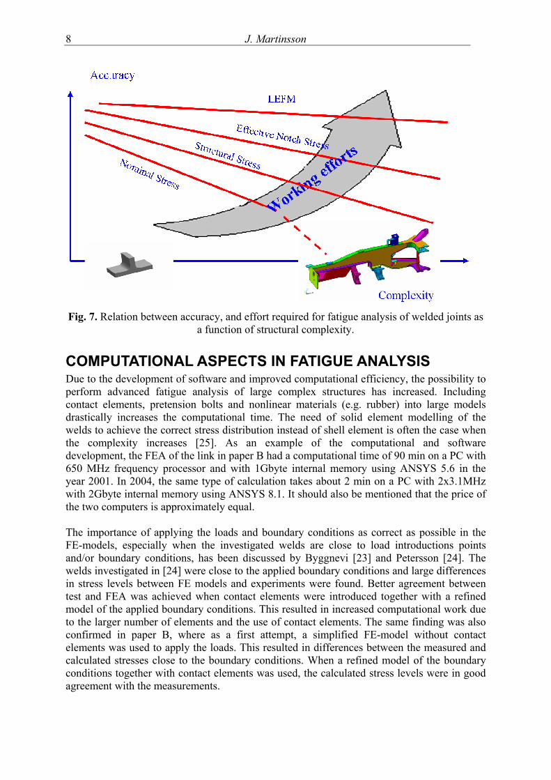
Application of different life prediction methods Byggnevi [23] and Petterson [24] compared and evaluated the four different fatigue design methods from IIW on complex frame structures. The scatter in results for the different design methods was large. The more time consuming methods like Effective Notch stress and LEFM showed better agreement with experimental results performed tests than the Nominal and Structural stress methods. The former two methods also give a better physical understanding of the fatigue behaviour of the fatigue loaded weld. If the residual stress field is known, these two methods have the capability to estimating where the crack growth may start, weld toe or root. Complex structures in construction machinery often show nonlinear behaviour. This combined with overlay simplified life prediction methods may lead to highly inaccurate life predictions with no general trend if the inaccuracy is in the conservative or non-conservative direction. Fig. 7 summarise experiences from several design analysis departments within Volvo CE and similar organisations and the trend is confirmed of many investigations within the FE-2000 project.
J. Martinsson
8
Fig. 7. Relation between accuracy, and effort required for fatigue analysis of welded joints as a function of structural complexity.
COMPUTATIONAL ASPECTS IN FATIGUE ANALYSIS Due to the development of software and improved computational efficiency, the possibility to perform advanced fatigue analysis of large complex structures has increased. Including contact elements, pretension bolts and nonlinear materials (e.g. rubber) into large models drastically increases the computational time. The need of solid element modelling of the welds to achieve the correct stress distribution instead of shell element is often the case when the complexity increases [25]. As an example of the computational and software development, the FEA of the link in paper B had a computational time of 90 min on a PC with 650 MHz frequency processor and with 1Gbyte internal memory using ANSYS 5.6 in the year 2001. In 2004, the same type of calculation takes about 2 min on a PC with 2x3.1MHz with 2Gbyte internal memory using ANSYS 8.1. It should also be mentioned that the price of the two computers is approximately equal. The importance of applying the loads and boundary conditions as correct as possible in the FE-models, especially when the investigated welds are close to load introductions points and/or boundary conditions, has been discussed by Byggnevi [23] and Petersson [24]. The welds investigated in [24] were close to the applied boundary conditions and large differences in stress levels between FE models and experiments were found. Better agreement between test and FEA was achieved when contact elements were introduced together with a refined model of the applied boundary conditions. This resulted in increased computational work due to the larger number of elements and the use of contact elements. The same finding was also confirmed in paper B, where as a first attempt, a simplified FE-model without contact elements was used to apply the loads. This resulted in differences between the measured and calculated stresses close to the boundary conditions. When a refined model of the boundary conditions together with contact elements was used, the calculated stress levels were in good agreement with the measurements.

Fatigue Assessment of Complex Welded Steel Structures
9
Normally, analysis of Nominal and Structural stresses requires only a rather coarse mesh which is preferred in large FE-models. When the Effective Notch stress analysis or LEFM method are used, a finer mesh around critical regions is needed. This can be accomplished by using the sub-modelling technique. In the case of modelling the crack growth in a FE mesh, the user should be aware of the limitations in using a traditional sub-modelling technique [24]. Due to the crack growth the geometry and stiffness of both the global- and the sub-models are change. This means that both the global- and the sub-model geometries have to be updated. This is a very time consuming task and sometimes very difficult to perform on complex welded structures. But it also means that both the sub-model and the global model have to be solved, i.e. two FEA calculations for every step of the crack growth process, leading to an increased computational effort. An alternative method to the traditionally sub-modelling technique is presented in paper E. The method removes the intersecting elements between the global- and the sub-model and generates constraint equations between the two models. This means that only the sub-model has to be updated through the crack growth process and one FEA calculation for every step.
APPLICATION OF LEFM TO WELDED STRUCTURES
Background Linear Elastic Fracture Mechanics (LEFM) has been used in all the papers presented in this thesis. The possibilities with this method are superior for more complex welded structures as compared to S-N based methods. A number of parameters and effects that influence the fatigue life can be taken into consideration e.g. penetration depth, a-measure, structural redundancy etc. The predictions and tests of different complex welded structures made by the authors Byggnevi [23], Pettersson [24], Hansen & Agerskov [26], and in paper B & C also verified benefits of using LEFM. Common in all of the author’s investigations were, thick plates (20-60mm), long design cracks, failures from the root side and the need of an automatic 3D FEA crack growth program. In general, industry has not been using LEFM as an engineering tool in the development of new products. The method has often seen to be very time consuming and computational demanding and the knowledge within the area is often small. However, with the evolution of new software [4, 27-33] and improved computational efficiency, the use of LEFM in industry has increased and will probably continue to increase even more in the future.
Stress Intensity Factor Solutions There are three different types of stress intensity factors, mode I, II & III, see Fig. 8.
Fig. 8. Different modus.
J. Martinsson
10
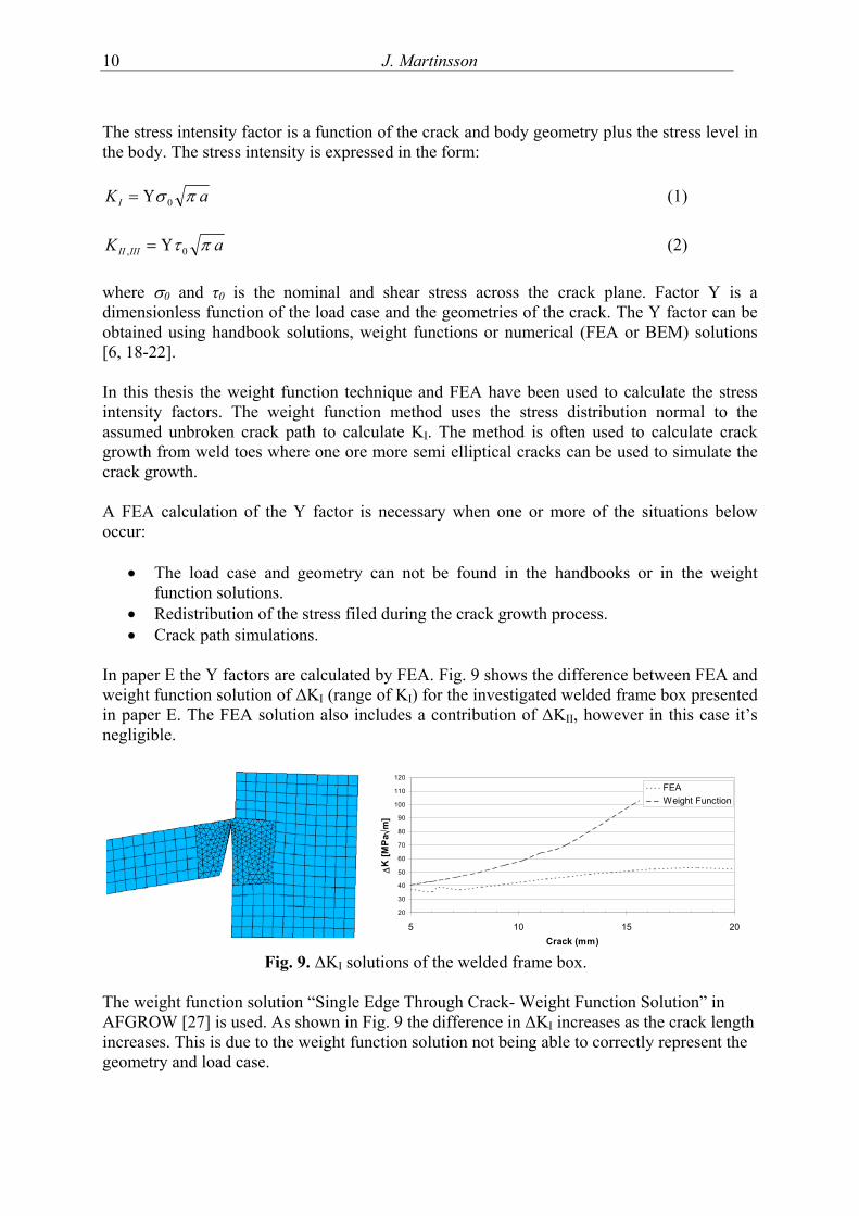
The stress intensity factor is a function of the crack and body geometry plus the stress level in the body. The stress intensity is expressed in the form:
aKI πσ 0Υ= (1)
aK IIIII πτ 0, Υ= (2) where σ0 and τ0 is the nominal and shear stress across the crack plane. Factor Υ is a dimensionless function of the load case and the geometries of the crack. The Y factor can be obtained using handbook solutions, weight functions or numerical (FEA or BEM) solutions [6, 18-22]. In this thesis the weight function technique and FEA have been used to calculate the stress intensity factors. The weight function method uses the stress distribution normal to the assumed unbroken crack path to calculate KI. The method is often used to calculate crack growth from weld toes where one ore more semi elliptical cracks can be used to simulate the crack growth. A FEA calculation of the Y factor is necessary when one or more of the situations below occur:
• The load case and geometry can not be found in the handbooks or in the weight function solutions.
• Redistribution of the stress filed during the crack growth process. • Crack path simulations.
In paper E the Y factors are calculated by FEA. Fig. 9 shows the difference between FEA and weight function solution of ∆KI (range of KI) for the investigated welded frame box presented in paper E. The FEA solution also includes a contribution of ∆KII, however in this case it’s negligible.
20
30
40
50
60
70
80
90
100
110
120
5 10 15 20Crack (mm)
∆K
[MPa
√m]
FEAWeight Function
Fig. 9. ∆KI solutions of the welded frame box.
The weight function solution “Single Edge Through Crack- Weight Function Solution” in AFGROW [27] is used. As shown in Fig. 9 the difference in ∆KI increases as the crack length increases. This is due to the weight function solution not being able to correctly represent the geometry and load case.

Fatigue Assessment of Complex Welded Steel Structures
11
Crack Growth in Complex Welded Structure In fatigue tests of simple specimens, e.g., cruciform joints, tests normally run until complete separation of the specimen. For simple components, e.g., out-of-plane gussets the test normally stops after a crack detecting gauge shows sign of fatigue damage [6, 34, 35] or a visible crack. In case of fatigue tests of complex welded structures load redistribution and interaction between cracks may occur leading to crack growth retardation and longer life. The crack growth direction is also an important parameter in the fatigue life prediction. These phenomena can only be taking into consideration when using the FEA solution of LEFM. The following example shows the importance of using the FEA solution of LEFM on complex welded structures. In Fig. 10a, a complex welded frame structure exposed to fatigue loading is shown. The investigated weld is a fillet weld with throat thickness of 5 mm and a root gap of ~1 mm, see Fig. 10b. The weld is located within the rectangle shown in Fig. 10a.
a) b) Fig. 10. Complex welded frame structure.
A crack growth simulation from the root side of the critical weld was performed in the LEFM based program presented in paper E. Figure 11a shows the weld sub-model inserted into the global model. It should be mentioned that the global FE-model does not include the weld. The weld itself is only modelled in the sub-model. This is often the case for complex welded CAD models. The throat thickness and penetration depth can favourably be changed in the weld sub-model to optimise the weld fatigue performance.
b)
Viewing direction in Fig. 11b & c
Simulated Crack Growth

J. Martinsson
12
a) c) Fig. 11. Crack growth in the welded frame structure
The circles in Fig. 11a show the locations of the crack growth in the structure. In Fig. 11b the crack growth normal to the root gap is shown after a certain number of cycles. Fig. 11c shows the crack after additional number of cycles. As can been seen in Fig. 11c the two crack fronts interact and two additional crack fronts arise at the location of the arrows due to redistribution of the load during the crack growth process. This process will slow down the crack growth process and result in a longer life.
Mixed Mode I and Mode III Crack Growth The stress intensity factors along a root crack front of a complex welded structure almost always contribute to a mixed mode condition. For example, fatigue damage to welded joints in steel bridges [36, 37], the investigated link in the this thesis, the welded frame structure in Fig. 10a and several other complex welded objects that have been investigated with the LEFM program presented in paper E. In case of mixed mode I/II the crack growth struggle to grow normal to the principal stress direction, meaning that the contribution of modus II decreases while modus I increases. The crack growth data for modus I is well documented and is rather easy to apply. The mode I/III crack growth data is much more complicated and is very depending on the ratio of modes I and III. For mixed mode I/III fatigue loading, experimental studies have been performed on tension plates with an inclined slit [38, 39], bending beams with an inclined slit [40–42], and torsion round bars with a circumferential slit [43, 44]. These studies were concerned with the initiation of fatigue cracks, and proposed fatigue threshold conditions and crack initiation directions. In-Tae [44] performed crack propagation in butt welded joints with root cracks under mixed mode I/III. The tests showed that an increasing mode I loading increased the modus III crack growth rate. Tschegg [45, 46] investigated the influence of a superimposed static mode I load and of different mode III mean torques on mode III fatigue crack growth (antiplane shear mode) in cylindrical circumferentially notched steel specimens. The test showed that the crack growth rate was not influenced by small axial loads (a resulting KI value of 0–3 mMPa ). For higher values of KI, 4–9 mMPa , the modus III crack growth rate was increased. The increased mode I lead to reduced sliding crack closure influence (friction, abrasion and mutual support between the fracture surfaces). This was also verified in ongoing fatigue test of welded tube-to-plate specimens within Volvo CE. The specimens were exposed to a combination of torsion and internal pressure, leading to mixed mode I/III crack growth. In Tjernberg et al. [47] and Olsson et al. [48] crack growth data for Paris Law based on fatigue loaded welded specimens failing from the root side was proposed. The slope m was set to 5 and the C value between 0.7E-14 and 1.7E-14 (units in MPa and meters). Tanaka et al. [49] showed that the crack growth rate of modus III depends on the crack length. The crack growth rate is not uniquely correlated to the cyclic stress intensity factor as it is in mode I. The decrease in growth rate with crack length is attributed to increases in crack closure and interlocking forces as the crack grows. The rough branched crack surface will produce increased closure forces as the crack length becomes larger. Ritchie et al. [50] showed that an overload of modus III increases the crack growth rate. This is due to the rubbing and eliminating of the branch crack growth in modus III growth. This effect is vice versa compared to overloads in modus I.

Fatigue Assessment of Complex Welded Steel Structures
13
RESIDUAL STRESS Residual stress originate from production, in e.g. plastic moulding, welding or heat treatment is frequently found in structures as well as during loadings that cause plastic deformation of some part of the structure [51]. The residual stress may have a large influence on the fatigue life. Residual stresses in tension will reduce the fatigue life and residual stresses in compression may increase life. In case of welding the residual stress can be as high as the yield limit at the weld toe [52-54], while the residual stress distribution at the weld root can be favourable due to compressive stress [55-57]. Welding simulations on the link in paper B (not presented in this thesis) and the crack shaft house in paper E showed beneficial compressive residual stresses at the weld root. In spectrum loading the high peaks in tension or the low troughs in compression may relax the residual stress field and hence its influence [52, 58, 59]. When using residual stresses distribution in combination with fracture mechanics there are mainly two methods available:
a) The superposition method. The method is based on the superposition of the stress intensity factors achieved from the crack growth and by the residual stress field. The method does not take into consideration the redistribution of the residual stress field during the crack growth process. However the initial relaxation due to the loading condition can be simulated by an elastic-plastic FEA. This makes this method rather limited in case of cracks exposed to pressure e.g. root cracks, which was confirmed in paper E. In case of cracks propagating from the surface the validity of the method is decreasing with increased crack growth due to the redistribution of the stress field.
b) FEA of the crack growth process. In this type of calculation the crack will growth
within the simulated residual stress field. By using an elastic-plastic FEA the relaxation and redistribution of the residual stress field during the crack growth process can be simulated [60].
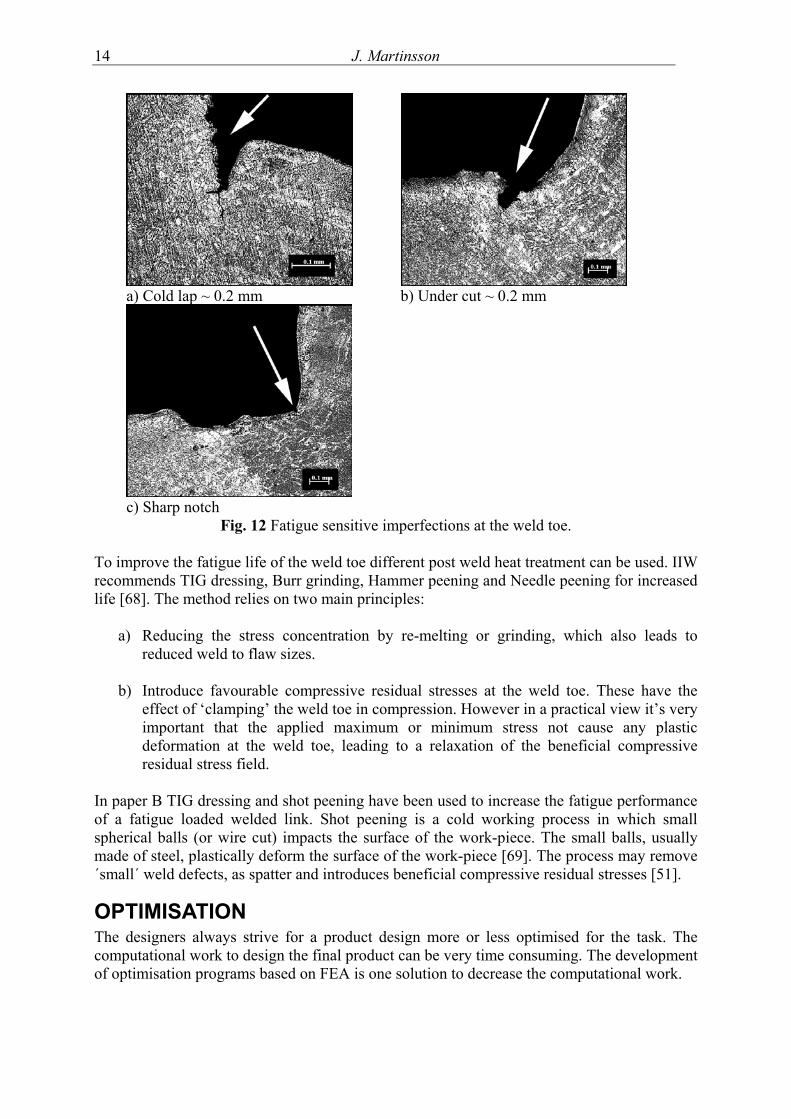
WELD DEFECTS It is well documented that the local weld geometry and different type of imperfections strongly influence the fatigue strength [61-64]. The local weld geometry affect the stress concentration factor and the welding process create crack like defects, which together cause a large scatter in fatigue life depending on differences in these factors. Fig. 12 shows some examples of fatigue sensitive imperfections and bad weld toe geometry. An investigation carried out by Lopez & Korsgren [65] showed that 80% of all discovered weld defects in MAG-weld were cold laps. Typical sizes of cold laps are between 0.01-1.4 mm [64, 65], which was also confirmed in paper A. In Barsoum & Samulesson [66] and Samuelsson [67] a comparison between solid wire and flux core wire were performed on fatigue loaded cruciform joints. The flux core wire showed lower stress concentration (Kt) and none or very small visible defects were found at the weld toe. This also led to increased fatigue strength of ~30% compared to solid wire.
J. Martinsson
14
a) Cold lap ~ 0.2 mm b) Under cut ~ 0.2 mm
c) Sharp notch Fig. 12 Fatigue sensitive imperfections at the weld toe.
To improve the fatigue life of the weld toe different post weld heat treatment can be used. IIW recommends TIG dressing, Burr grinding, Hammer peening and Needle peening for increased life [68]. The method relies on two main principles:
a) Reducing the stress concentration by re-melting or grinding, which also leads to reduced weld to flaw sizes.
b) Introduce favourable compressive residual stresses at the weld toe. These have the
effect of ‘clamping’ the weld toe in compression. However in a practical view it’s very important that the applied maximum or minimum stress not cause any plastic deformation at the weld toe, leading to a relaxation of the beneficial compressive residual stress field.
In paper B TIG dressing and shot peening have been used to increase the fatigue performance of a fatigue loaded welded link. Shot peening is a cold working process in which small spherical balls (or wire cut) impacts the surface of the work-piece. The small balls, usually made of steel, plastically deform the surface of the work-piece [69]. The process may remove ´small´ weld defects, as spatter and introduces beneficial compressive residual stresses [51].
OPTIMISATION The designers always strive for a product design more or less optimised for the task. The computational work to design the final product can be very time consuming. The development of optimisation programs based on FEA is one solution to decrease the computational work.

Fatigue Assessment of Complex Welded Steel Structures
15
Samuelsson et al. [51] and Carlgren et al. [70] have successfully decreased the effective stress intensity factors of a critical weld in a hydraulic cylinder respective excavator boom with approximately 40% by using optimisation tools. The optimisation was performed using a rapid optimisation program called (ROpt). The optimisation engine in ROpt is based on the Method of Moving Asymptotes (MMA) [71]. In paper C the investigated link in paper A & E is subjected to weight optimisation as well as fatigue life optimisation. Fatigue optimisation using higher strength steel was also performed.
CONCLUSIONS The main conclusions from this work are the following:
• Weld geometry and defect strongly influences the fatigue life of the welds.
• Flux core wire gives smaller and less amounts of defects compared to solid wire.
• The importance of applying boundary conditions correctly increases when the fatigue critical locations are close to the boundary.
• LEFM is a very powerful tool for simulating crack growth and fatigue life of complex welded structures.
• LEFM is the only fatigue life prediction method that can take load redistribution into account.
• Weight functions technique takes no consideration to load redistribution.
• Full crack modelling is to be preferred for crack growth simulations on the root side of the weld.
SUMMARY OF APPENDED PAPER Paper A investigates how weld geometry and different types of defects influence the fatigue life of the welds. Four batches of non-load carrying cruciform joints welded in a robotic cell with different weld data were fatigue tested. The majority of the test pieces contained cold laps, see Fig. 13.
Fig. 13. Cold laps. The weld geometry and cold lap size were measured and FE-calculations based on the measured values were used to predict fatigue life using LEFM. The stress intensity factors were calculated using isoparametric quarter point elements (QPE). Life predictions were made with both linear and bilinear da/dN data. Comparisons with earlier investigations were also performed. The investigation showed that the weld geometry and defects influenced the

J. Martinsson
16
fatigue life of the weld. It was also shown that LEFM could be used to predict fatigue life for different combinations of geometries and defects of the weld. In Paper B different fatigue design methods from the IIW recommendations of welded structures were implemented and evaluated by using a FE-model of a welded link from a wheel loader as shown in Fig. 14a. The investigated methods were Nominal stress, Structural stress, Effective Notch stress and LEFM. The link is exposed to a variable amplitude load between +879 - -647 kN and has 18 different critical locations, as toes, roots and edges, where a fatigue crack can start. The results from the different fatigue design methods are compiled and some explanations to the deviations between the different methods are suggested. In order to verify the numerical results, five links were fatigue tested in a laboratory. The analyses showed better agreement to the test results for the more time consuming design methods, Effective Notch stress and LEFM.
Fig. 14 Welded link.
Paper C covers a structural optimisation and fatigue predictions of the welded link in paper B. The FE-model of the link was optimised for better performance using a new optimisation concept. The link was subjected to weight optimisation as well as fatigue life optimisation. Fatigue optimisation using higher strength steel was also performed. The optimisation constraints included the evaluation of stress intensity factors in a weld root crack, coupled with extensive stress constraints. The life of the optimised structures was then compared with the non optimised structure using Effective Notch stress and LEFM. The min weight optimisation of the link is shown in Fig. 14b. The weight decreased about 10% while the fatigue properties were maintained or improved. In Paper D fatigue crack paths and properties in the welded link in paper B & C have been investigated. The automatic 2D crack propagation program FRANC2D has been used to simulate crack paths. The investigation covers cracks growth from weld toes, roots and base material. Fatigue tests were performed to verify life and crack paths. The crack path simulations showed good agreement with the test results, see Fig. 15, while the fatigue life showed some deviations between predicted and obtained in tests.
b) a)

Fatigue Assessment of Complex Welded Steel Structures
17
Fig. 15. Comparison between simulated and test of crack paths.
In Paper E an automatic LEFM crack propagation program using the FEM program ANSYS is developed. The program is developed for fatigue design of welded joints. The program automatically calculates the stress intensity factors and updates the size and shape of the crack front, see Fig. 16. Two simulation examples of how to apply the program to welded components and fatigue test of the components are given at the end of the paper. The first object is a welded crankshaft housing of a large two-stroke diesel engine. The crankshaft housing is subjected to constant amplitude loading and designed for infinite life. The second investigated object is the link.
Fig. 16. Tested and predicted crack growth of the link.
Predicted Crack Front
Predicted Crack Front

J. Martinsson
18
REFERENCES
[1] Swedish Regulations for Welded Steel Structures, StBK-N2, National Swedish Committee for Steel structures, 1974.
[2] Hobbacher A., Fatigue design of welded joints and components, IIW doc. XIII-1539-
96.
[3] Samuelsson J., Performance of Dynamically Loaded Welded Structures, IIW International Conference, San Francisco, July 1997.
[4] FRANC2D (www.cfg.cornell.edu/)
[5] Fricke W., Fatigue analysis of welded joints: state of development, Marine Structures
16, p. 185-200, 2003.
[6] Radaj D., Sonsino C M, Fatigue assessment of welded joints by local approaches., Abington Publishing, 1998.
[7] Volvo Svetshandbok, Volvo 1989.
[8] Niemi E., Stress Determination for fatigue analysis of welded components, IIW doc.
XIII-1221-93.
[9] Niemi E., Recommendations of modelling, Stress Evaluation and design, IIW doc. XIII WG3-06-00, May 2000.
[10] Fricke W., Recommended Hot-Spot Analysis Procedure for Structural Details of
FPSO’s and Ships Based on Round-Robin FE Analysis, ISOPE Proceedings, Stavanger, Noway, June 2001.
[11] Healy B.E., “A Case Study Comparison of Surface Extrapolation and Battelle
Structural Stress Methodologies,” to appear in Proceedings of the 23rd International conference on Offshore Mechanics and Arctic Engineering, June 20-25, 2004, Vancouver, British Columbia, Canada.
[12] Poutiainen L., Niemi E., The determination of hot spot stress in gusset structures
using a coarse element mesh, IIW doc. XIII-1820-00.
[13] Yamada K., Xiao Z., A New Method of Evaluating Fatigue Strength of Welded Toe Failures, IIW doc. XIII-2022-04.
[14] Dong P., Kyuba H., Equilibrium-Equivalent Structural Stress Approach to Fatigue
Analysis of a Tubular Joint, IIW doc. XIII-1993-03.
[15] Poutiainen I., Marquis G., A single-point structural stress assessment procedure for load-carrying fillet welds, IIW doc. XIII-2012-04.

Fatigue Assessment of Complex Welded Steel Structures
19
[16] Nihei K. et al., Study on Unified Fatigue Strength Estimation Method for Fillet Welded Plate Structures (1st Report) Simplified Calculating Method of Hot Spot Stress, J. of Kansai Soc.N.A.,Japan, No.220, September, 1993.
[17] Petershagen H., A comparison of two different approaches to the fatigue strength
assessment of cruciform joints, IIW doc. XIII-1410-91. [18] Anderson T. L., Fracture Mechanics, CRC Press, 1995, ISBN 0-8493-4260-0.
[19] Fett T., Munz D., Neumann J, Local stress intensity factors for surface cracks in
plates under power-shaped stress disturbing, Engineering Fracture Mechanics vol.36, no.4, pp. 647-651, 1990.
[20] Tada H., Paris P., Irwin G., The stress analysis of cracks handbook, Second Edition,
Del Research Corporation, 1985.
[21] Barsoum R. S., Int. J. numer. Meth. Engng. Vol. 10, pp. 25-37 (1976).
[22] Shih, C. F., deLorenzi H. G. and German, M. D., Int. J. of Fracture Vol 12, pp. 647-651 (1976).
[23] Byggnevi M., Life Predictions of a Complex Welded Structure Using Different
Methods, Proc. Design and Analysis of Welded high Strength Steel Structures, Stockholm June 2002, ed. J. Samuelsson, EMAS 2002.
[24] Petterson G., Fatigue Assessment of Welded Structures with Non-Linear Boundary
Conditions, Dept. of Aeronautical and Vehicle Engineering, TRITA-AVE 2004-50, The Royal Institute of Technology, Stockholm 2004
[25] Hisatada S. et al., Identification of cause of fatigue damage in an orthotropic steel
bridge structure with box grider, IIW doc. XIII-1973-03.
[26] Hansen A. V., Agerskov H., Fatigue Assessment of Root Defects in the Welded Structure of a Diesel Engine, Proc. Design and Analysis of Welded High Strength Steel Structures, Stockholm June 2002, 373-404, ed. Samuelsson J., EMAS Ltd. 2002.
[27] AFGROW (http://afgrow.wpafb.af.mil/about/history.php)
[28] NASGRO (http://www.swri.org/)
[29] ZENCRACK (http://www.zentech.co.uk/)
[30] FRANC3D (www.cfg.cornell.edu/)
[31] ADAPCRACK 3D (fam.uni-paderborn.de/English_Version/Research/adapcrack-3d.html)
[32] BEASY (http://www.beasy.com/)
[33] FASTRAN II (http://www.openchannelfoundation.org/projects/FASTRAN_II)
J. Martinsson
20
[34] Miki C., Sugimoto M., A study on U-shaped rib configuration with high fatigue
resistance, IIW doc. XIII-1885-01, 2001.
[35] Kentaro Y., Zhi-Gang X., A New Method of Evaluating Fatigue Strength of Weld Toe Failures, IIW doc. XII-2022-04, 2004.
[36] Yamada K., Miki C., Recent research on fatigue of bridge structures in Japan. J
Construct Steel Res 1989; 13:211–22.
[37] Fisher JW. et al., Fatigue strength of steel beams with welded stiffeners and attachments, NCHRP Report 147, Transportation Research Board, 1974.
[38] Yoshioka S. et al., Fatigue crack growth threshold (DKth) under Mode III (the e.ect
of stress ratio and mixed mode). JSME (Ser A) 1984;50(454):1267–74 [in Japanese].
[39] Makabe C. et al., Fatigue crack propagation under mixed mode of Mode I, II and III started from notch inclined in thickness direction. JSME (Ser A) 1993;59(562):1421–8 [in Japanese].
[40] Pook LP. The fatigue crack direction and threshold behaviour of mild steel under
mixed modes I and III loading. Int J Fatigue 1985;7:21–30.
[41] Yates JR., Miller KJ., Mixed mode (I+III) fatigue threshold in a forging steel. Fatigue Fract Engng Mater Struct 1989;12:259–70.
[42] Yates JR., Mohammed RA., The effect of mean stress on mixed Mode (I+III) fatigue
thresholds. Fatigue Fract Engng Mater Struct 1993;12:1355–63.
[43] YatesJR, Mohammed RA. Crack propagation under mixed Mode (I+III) loading. Fatigue Fract Engng Mater Struct 1996;19:1285–90.
[44] In-Tae K., Weld root crack propagation under mixed mode I and III cyclic loading,
Engineering Fracture Mechanics 72 (2005) 523–534.
[45] Tschegg E.K., Mode III and Mode I fatigue crack propagation behaviour under torsional loading, Journal of Material Science 18, 1604-14.
[46] Tschegg E.K., Sliding mode crack closure and mode III fatigue crack growth in mild
steel, Acta Metallurgica, 1323-30.
[47] Olsson, K.E et al., In Welded High-Strength Steel Structures, edited by A. F. Blom, EMAS, Stockholm, 1997, 179-187.
[48] Tjernberg, A. et al., In Welded High-Strength Steel Structures, edited by A. F. Blom,
EMAS, Stockholm, 1997, 85-109.
[49] Tanaka K., Akiniwa Y., Yu H.C., Near-Threshold of Circumferential Fatigue Cracks in Steel Bars Under Torsional Loading, Fatigue Fract Engng Mater Struct, Vol. 7, No. 4, 1988, pp. 195-211.

Fatigue Assessment of Complex Welded Steel Structures
21
[50] Ritchie R.O. et al., Mode III Fatigue Crack Growth Under Combined Torsional and
Axial Loading, ASTM STP 853, West Conshohocken, PA, 1985 pp. 203-227.
[51] Samuelsson J., Fatigue design of vehicle components methodology and applications, Dept. of Aeronautical Structures and Materials, Report No. 88-23, The Royal Institute of Technology, Stockholm 1988.
[52] Wang G.S, Lin R., Blom A.F, M., Lopez Martinez, Investigation of Residual Stresses
In As-Welded and TIG-Dressed Specimens Subjected to Static/Spectrum Loading, Proceedings “Welded High-Strength Steel Structures Stockholm oct. 1997, ed A.F, Blom EMAS, pp. 377-390.
[53] Masubuchi K., Analysis of Welded Structures, Pergamon Press,1980 Oxford, ISBN
0-08-022714-7.
[54] Ohta A., Maeda Y., Suzuki N., Residual Stress Effect on Fatigue Strength of Non-Load-Carrying Cruciform Welded Joints of SM570Q Steel for Welded Structures, IIW doc. XIII-1921-02.
[55] Hansen J. L.,, Residual Stress from Welding of Large Diesel Engine Structures ,
Proc. Design and Analysis of Welded High Strength Steel Structures, Stockholm June 2002, 345-372, ed. Samuelsson J., EMAS Ltd. 2002.
[56] Murthy Y.V.L.N, Venkata Rao G. and Krishna Iyer P., Numerical simulation of
welding and quenching process using transient thermal and thermo-elasto-plastic formulations, Computers and Structures, Volume 60, No.1, pp. 131-154, 1996.
[57] Free J.A., Porter Goff R.F., Predicting residual stress in multipass weldments with
the finite element method, Computer and Structures, Volume 32, No.2, pp. 365-378, 1989.
[58] Lopez Martinez L., Fatigue Behaviour of Steels with Strength Levels Between 350
and 900 MPa – Influence of Post Weld Treatment Under Spectrum Loading, Proceedings “Welded High-Strength Steel Structures Stockholm oct. 1997, ed A.F, Blom EMAS.
[59] Ljustell P., Blomquist T., Relaxation of Residual stresses in Butt-Welded Plates,
Dept. of Aeronautical Structures and Materials, Report No. 2002-10, The Royal Institute of Technology, Stockholm 2002.
[60] Lundin M., Lopez Martinez L., Hedegård J., Weman K., High Productive Welding-
Fatigue Properties of Weldments, Proceedings “Welded High-Strength Steel Structures Stockholm oct. 1997, ed A.F, Blom EMAS.
[61] Michaleris P. et al., Incoperation of Residual Stress Effects into Fracture
Assessments via the Finite Element Method, Fatigue and Fracture Mechanics: 28th Vol.,pp. 499-514, ASTM STP 1321, 1997.

J. Martinsson
22
[62] Lawrence F.V., Dimitrakis S.D., Munse W.H., Factors Influencing Weldment Fatigue, ASM Handbook, Volume 19, Fatigue and Fracture, 1996, pp. 274-286.
[63] Koettgen V B., Oliver R., Seeger T., Fatigue Analysis of Welded Connections Based
on Local Stresses, IIW-Document XIII-1408-91.
[64] Lassen T., The Effect of the Welding Process on the Fatigue Crack Growth, Welding Research Supplement, pp. 75-81, February 1990.
[65] Lopez Martinez L., and Korsgren P., Characterization of Welded Defect Distribution
and Weld Geometry in Welded Fatigue Test Specimens, Blom, A.F, (ed.) Fatigue under Spectrum Loading and in Corrosive environments, EMAS Ltd, Warley, UK, 1993.
[66] Barsoum Z., Samuelsson J., Fatigue Assessment of Hybrid Laser and MAG Welded
Non-Load Carrying Cruciform Joint, Not Published.
[67] Samuelsson J., Cold Laps and Weld Quality Acceptance Limits, Proc. Design and Analysis of Welded high Strength Steel Structures, Stockholm June 2002, ed. J. Samuelsson, EMAS 2002.
[68] Haagensen P. J., Maddox S J., IIW Recommendations on Post Weld Improvement of
Steel and Aluminium Structures, IIW-Document XIII-1815-00.
[69] Meo M., Vignjevic R., Finite element analysis of residual stress induced by shot peening process, Advances in Engineering Software 34, pp. 569-575, 2003.
[70] Carlgren P., Lindström P., MackAldener M., Holm D., Optimisation Of Welded
Component In Excavator Boom, Proceedings “Welded High-Strength Steel Structures Stockholm Oct. 1997, ed. A.F, Blom EMAS.
[71] Svanberg, K., MMA - Method of Moving Asymptotes - A New Method for
Structural Optimization, Int Journal for Numerical Methods in Engineering, Vol. 24, 359-373, 1987.
Related Documents


![[Elsevier] Review of Fatigue Assessment Procedures for Welded Aluminium Structures](https://static.cupdf.com/doc/110x72/577cc2d01a28aba711948efd/elsevier-review-of-fatigue-assessment-procedures-for-welded-aluminium-structures.jpg)


