FASTER: Facilitating Analysis and Synthesis Technologies for Effective Reconfiguration D. Pnevmatikatos a,⇑ , K. Papadimitriou a , T. Becker b , P. Böhm b , A. Brokalakis h , K. Bruneel c , C. Ciobanu d , T. Davidson c , G. Gaydadjiev d , K. Heyse c , W. Luk b , X. Niu b , I. Papaefstathiou h , D. Pau g , O. Pell f , C. Pilato e , M.D. Santambrogio e , D. Sciuto e , D. Stroobandt c , T. Todman b , E. Vansteenkiste c a Foundation for Research and Technology-Hellas, Heraklion, Greece b Imperial College London, London, UK c Ghent University, Ghent, Belgium d Chalmers University of Technology, Göteborg, Sweden e Politecnico di Milano, Milan, Italy f Maxeler Technologies, London, UK g STMicroelectronics, Agrate, Italy h Synelixis, Chalkida, Greece article info Article history: Available online xxxx Keywords: Reconfigurable computing Partial reconfiguration Dynamic reconfiguration Micro-reconfiguration Verification Runtime system abstract The FASTER (Facilitating Analysis and Synthesis Technologies for Effective Reconfiguration) EU FP7 pro- ject, aims to ease the design and implementation of dynamically changing hardware systems. Our moti- vation stems from the promise reconfigurable systems hold for achieving high performance and extending product functionality and lifetime via the addition of new features that operate at hardware speed. However, designing a changing hardware system is both challenging and time-consuming. FASTER facilitates the use of reconfigurable technology by providing a complete methodology enabling designers to easily specify, analyze, implement and verify applications on platforms with general-pur- pose processors and acceleration modules implemented in the latest reconfigurable technology. Our tool-chain supports both coarse- and fine-grain FPGA reconfiguration, while during execution a flexible run-time system manages the reconfigurable resources. We target three applications from different domains. We explore the way each application benefits from reconfiguration, and then we asses them and the FASTER tools, in terms of performance, area consumption and accuracy of analysis. Ó 2014 Elsevier B.V. All rights reserved. 1. Introduction Extending product functionality and lifetime requires constant addition of new features to satisfy the growing customer needs and the evolving market and technology trends. Software compo- nent adaptivity is straightforward, but in many cases it is not enough. Recent products incorporate hardware accelerators to sat- isfy performance and energy requirements. These accelerators also need to adapt to the new requirements. Reconfigurable logic allows the definition of new functions to be implemented in dynamically instantiated hardware units, combining adaptivity with hardware speed and efficiency. However, designing a hardware system that changes over time is a challenging and time-consuming task. We propose a methodology enabling designers to easily imple- ment applications on platforms with one or more general-purpose processors and multiple acceleration modules implemented in reconfigurable hardware. Our main contribution is that we intro- duce partial reconfiguration from the initial design stage all the way down to the runtime use of the system. Fig. 1 depicts the tool-chain of FASTER project [1]. Its input is the description of the application in a high-level programming language; the initial decomposition into tasks is described in OpenMP. The correspond- ing task graph is then partitioned in space and time to identify can- didates for reconfiguration. FASTER supports coarse-grain reconfiguration and fine-grain reconfiguration. The former allows for swapping the hardware modules identified at design time as reconfigurable ones in/out of FPGA regions; this is called region- based reconfiguration. The latter allows for reconfiguring small parts of the FPGA with circuits synthesized at run-time; this tech- nique is called micro-reconfiguration and enables the creation of specialized circuits containing infrequently changing parameters. We also address the verification of static and dynamic aspects of http://dx.doi.org/10.1016/j.micpro.2014.09.006 0141-9331/Ó 2014 Elsevier B.V. All rights reserved. ⇑ Corresponding author. Microprocessors and Microsystems xxx (2014) xxx–xxx Contents lists available at ScienceDirect Microprocessors and Microsystems journal homepage: www.elsevier.com/locate/micpro Please cite this article in press as: D. Pnevmatikatos et al., FASTER: Facilitating Analysis and Synthesis Technologies for Effective Reconfiguration, Micro- process. Microsyst. (2014), http://dx.doi.org/10.1016/j.micpro.2014.09.006

Welcome message from author
This document is posted to help you gain knowledge. Please leave a comment to let me know what you think about it! Share it to your friends and learn new things together.
Transcript
Microprocessors and Microsystems xxx (2014) xxx–xxx
Contents lists available at ScienceDirect
Microprocessors and Microsystems
journal homepage: www.elsevier .com/locate /micpro
FASTER: Facilitating Analysis and Synthesis Technologies for EffectiveReconfiguration
http://dx.doi.org/10.1016/j.micpro.2014.09.0060141-9331/� 2014 Elsevier B.V. All rights reserved.
⇑ Corresponding author.
Please cite this article in press as: D. Pnevmatikatos et al., FASTER: Facilitating Analysis and Synthesis Technologies for Effective Reconfiguration,process. Microsyst. (2014), http://dx.doi.org/10.1016/j.micpro.2014.09.006
D. Pnevmatikatos a,⇑, K. Papadimitriou a, T. Becker b, P. Böhm b, A. Brokalakis h, K. Bruneel c, C. Ciobanu d,T. Davidson c, G. Gaydadjiev d, K. Heyse c, W. Luk b, X. Niu b, I. Papaefstathiou h, D. Pau g, O. Pell f,C. Pilato e, M.D. Santambrogio e, D. Sciuto e, D. Stroobandt c, T. Todman b, E. Vansteenkiste c
a Foundation for Research and Technology-Hellas, Heraklion, Greeceb Imperial College London, London, UKc Ghent University, Ghent, Belgiumd Chalmers University of Technology, Göteborg, Swedene Politecnico di Milano, Milan, Italyf Maxeler Technologies, London, UKg STMicroelectronics, Agrate, Italyh Synelixis, Chalkida, Greece
a r t i c l e i n f o
Article history:Available online xxxx
Keywords:Reconfigurable computingPartial reconfigurationDynamic reconfigurationMicro-reconfigurationVerificationRuntime system
a b s t r a c t
The FASTER (Facilitating Analysis and Synthesis Technologies for Effective Reconfiguration) EU FP7 pro-ject, aims to ease the design and implementation of dynamically changing hardware systems. Our moti-vation stems from the promise reconfigurable systems hold for achieving high performance andextending product functionality and lifetime via the addition of new features that operate at hardwarespeed. However, designing a changing hardware system is both challenging and time-consuming.
FASTER facilitates the use of reconfigurable technology by providing a complete methodology enablingdesigners to easily specify, analyze, implement and verify applications on platforms with general-pur-pose processors and acceleration modules implemented in the latest reconfigurable technology. Ourtool-chain supports both coarse- and fine-grain FPGA reconfiguration, while during execution a flexiblerun-time system manages the reconfigurable resources. We target three applications from differentdomains. We explore the way each application benefits from reconfiguration, and then we asses themand the FASTER tools, in terms of performance, area consumption and accuracy of analysis.
� 2014 Elsevier B.V. All rights reserved.
1. Introduction
Extending product functionality and lifetime requires constantaddition of new features to satisfy the growing customer needsand the evolving market and technology trends. Software compo-nent adaptivity is straightforward, but in many cases it is notenough. Recent products incorporate hardware accelerators to sat-isfy performance and energy requirements. These accelerators alsoneed to adapt to the new requirements. Reconfigurable logic allowsthe definition of new functions to be implemented in dynamicallyinstantiated hardware units, combining adaptivity with hardwarespeed and efficiency. However, designing a hardware system thatchanges over time is a challenging and time-consuming task.
We propose a methodology enabling designers to easily imple-ment applications on platforms with one or more general-purpose
processors and multiple acceleration modules implemented inreconfigurable hardware. Our main contribution is that we intro-duce partial reconfiguration from the initial design stage all theway down to the runtime use of the system. Fig. 1 depicts thetool-chain of FASTER project [1]. Its input is the description ofthe application in a high-level programming language; the initialdecomposition into tasks is described in OpenMP. The correspond-ing task graph is then partitioned in space and time to identify can-didates for reconfiguration. FASTER supports coarse-grainreconfiguration and fine-grain reconfiguration. The former allowsfor swapping the hardware modules identified at design time asreconfigurable ones in/out of FPGA regions; this is called region-based reconfiguration. The latter allows for reconfiguring smallparts of the FPGA with circuits synthesized at run-time; this tech-nique is called micro-reconfiguration and enables the creation ofspecialized circuits containing infrequently changing parameters.We also address the verification of static and dynamic aspects of
Micro-

Fig. 1. Abstract view of FASTER tool-chain.
2 D. Pnevmatikatos et al. / Microprocessors and Microsystems xxx (2014) xxx–xxx
a reconfigurable design while minimizing run-time overheads onspeed, area and power consumption. Finally, we developed arun-time system for managing the various aspects of parallelismand adaptivity of an application by taking into account the run-time availability of reconfigurable resources. To test our methodol-ogy we employ applications from the embedded, desktop andhigh-performance computing domains, using as metrics perfor-mance, area consumption and accuracy of analysis at an early stageof the development cycle.
This paper extends our previous work in [2], providing moredetails on all the parts of FASTER project. It is structured as follows:Section 2 overviews previous works on methods and tools for recon-figurable system design, and exposes the relevance and novelty ofthe FASTER project. In Section 3 we delve into the details of thefront-end tool-chain by presenting the connections between the dif-ferent stages, and discussing the XML exchange format. Section 4describes briefly region-based reconfiguration supported by FPGAvendors, and extends our previous work on micro-reconfigurationwith reconfiguration of routing and with a profiler to assist thedesigner prior to taking decisions. Section 5 discusses our verifica-tion approach, and Section 6 presents the runtime system operationand its input requirements at design- and run-time. Section 7 dis-cusses the target applications coming from the industrial side, theway we design them to explore reconfiguration capabilities, theirperformance evaluation, and evaluates some of our tools. Section 8summarizes our contributions, and Section 9 concludes the paper.
2. Related work and motivation
Reconfigurable computing has been extensively studied in theacademic literature. The authors in [3] presented a survey coveringreconfigurable architectures and design methods. The FASTER pro-ject targets two system-level architectures; the stand-alone recon-figurable logic, and the organization that embeds the processor inthe reconfigurable fabric. Regarding design methods, we focus onrun-time customization using partial reconfiguration. Wedeveloped a run-time system to hide low-level system detailsfrom the designer, which handles scheduling, placement, and
Please cite this article in press as: D. Pnevmatikatos et al., FASTER: Facilitatingprocess. Microsyst. (2014), http://dx.doi.org/10.1016/j.micpro.2014.09.006
communication with the reconfiguration port. In addition, thework in [3] identified the compilation tool-chain as an importantchallenge in reconfigurable systems. Towards this direction, wepropose tools that assist the designer in deciding which part ofthe application should be mapped to the reconfigurable hardwareand when reconfiguration should occur. In specific, we offer asemi-automatic approach to leverage designer’s familiarity withthe application to ensure high quality of results.
A detailed survey in [4] summarizes research on compilationtechniques for reconfigurable architectures and categorizes thembased on their features and target platforms. The authors focusmainly on High Level Synthesis (HLS) tools both for fine- andcoarse-grained reconfigurable hardware. Furthermore, they pres-ent a generic compilation flow, highlighting the interactionbetween the various transformations and optimization stages,and discussing hardware-software partitioning. That work catego-rizes relevant research according to the supported programminglanguages and the intermediate representations. Also, it providesa classification of the most important code transformations at dif-ferent levels (bit, instruction, loops, etc.), as well as insights in bothtemporal and spatial partitioning techniques. Temporal partition-ing is relevant in the context of dynamic partial reconfiguration,using time-multiplexing when hardware resources are insufficientwhile minimizing the reconfiguration overhead. In addition, theauthors state that the adoption of reconfigurable computing is lim-ited by the cumbersome process of programming these platforms.Similarly, the work in [5] points out the lack of adequate develop-ment methodologies and EDA tools for reconfigurable systems. Ourwork address this issue by providing easy-to-use and flexible tools.
Further information related to reconfigurable architectures anddevices, application development and tools is discussed in [6],while [7] studies the above aspects concentrating on dynamicallyreconfigurable systems only.
Different frameworks have been proposed to address the con-current development of architecture and application for heteroge-neous systems. For example, Ptolemy [8] is an environment forsimulating and prototyping heterogeneous systems with mecha-nisms for modeling multiple abstraction levels and heterogeneousmixtures of models of computation. Daedalus [9] is a system-level
Analysis and Synthesis Technologies for Effective Reconfiguration, Micro-

D. Pnevmatikatos et al. / Microprocessors and Microsystems xxx (2014) xxx–xxx 3
design framework, composed of several tools that range from auto-matic parallelization for Kahn Process Networks to design spaceexploration of both the architectural and platform levels, and tothe synthesis of the candidate platform architecture. The differentcomponents are interfaced through XML files. Within hArtesproject [10] an integrated methodology from the automaticparallelization to the generation of heterogeneous systems wasdeveloped, but without considering the reconfiguration aspects.FASTER extends this approach by adopting different estimationtools and partitioning algorithms (interfaced with XML files), whilethe task partitioning of the input application is specified by means ofOpenMP pragmas proposed by [11] as produced by the partitioningmethods in hArtes. Another framework for programming heteroge-neous platforms is OpenCL [12], an open royalty-free standard forcross-platform, parallel programming of modern processors foundin personal computers, servers and handheld/embedded devices.
EU-funded projects such as hArtes [10], REFLECT [13], ACOTES[14], ANDRES [15], and Morpheus, conducted research on thenecessary stages of a tool-chain and addressed similar issues withFASTER, but they focused more on system-level or architecturalaspects of reconfiguration. Moreover, they do not explicitlyemphasize on the design and runtime aspects of partial anddynamic reconfiguration, or, on choosing the best reconfigurationgrain-size. On the contrary, we introduce partial and dynamicreconfiguration from the initial design of the system all the waydown to its runtime use.
To the best of our knowledge, the existing approaches do notabstract from the designer complex manipulations needed tocontrol effectively hardware accelerators, in particular when theseare designed as dynamically reconfigurable modules. Towards thisdirection, we aim at providing a general formulation capable todeal with different multiprocessor systems and different hardwareimplementations for the tasks (also by exploiting micro-architec-tural optimizations), and proposing a tool-chain that efficientlysupports partitioning of the application, while performing explora-tion on the possible solutions for the problem. In addition, we con-sider reconfiguration from the early stages of the design process,hiding most of the implementation details from the user.
3. The FASTER front-end
The present Section discusses the discrete stages and the waywe interconnected them to form the FASTER tool-chain. Then itexplains the structure of the XML exchange format we use to passinformation amongst the stages.
3.1. The front-end tool-chain
The input of the FASTER front-end is an application in C – gccC11 – whose initial decomposition is described with OpenMP prag-mas, and an XML file containing information about the target archi-tecture, such as the number of HW/SW processing elements,characteristics of reconfigurable regions, and the different imple-mentations of hardware accelerators. The corresponding task graphis partitioned to determine which processing element will executeeach application task. Every hardware task is treated as a static IPcore, a region-based reconfigurable module, or a micro-reconfigu-rable module. We do not focus on the automatic generation of theHDL implementations for the hardware cores; these are providedby the user either using traditional HDL design or high-level syn-thesis tools. We target systems with partially reconfigurable FPGAs,either in a single-FPGA or a multi-FPGA environment. In order tosupport the analysis for region-based and micro-reconfigurableactions we include additional steps. Note that the solution isrepresented by the mapping of each task not only to a processing
Please cite this article in press as: D. Pnevmatikatos et al., FASTER: Facilitatingprocess. Microsyst. (2014), http://dx.doi.org/10.1016/j.micpro.2014.09.006
element, but also to one of its available implementations; thisallows for exploring alternative trade-offs between performanceand usage of resources. The methodology is outlined in Fig. 2, andis organized in four phases: Application profiling and identificationof reconfigurable cores, High-level analysis, Optimizations for region-and micro-reconfiguration, and Compile-time scheduling and mappingonto reconfigurable regions.
The Application profiling and identification of reconfigurable coresbased on the initial source code of the application and the descrip-tion of the target architecture, decomposes the application into tasksand assigns them to the different components of the architecture. Itcan also use information about the performance of the current tasks,and feedback after the execution of the schedule, e.g. how thepartitioning affects the computed schedule, in order to iterate andimprove gradually the solution. In addition, it determines (i) theproper level of reconfiguration, i.e. none, region-based, or micro-reconfiguration, for each of the hardware cores by including differ-ent analyses (either static or dynamic), and (ii) the properties ofthe identified tasks, such as the frequency of call functions, the fre-quency of micro-reconfiguration parameter change, the resourcesrequired for each implementation, and the execution performance.
The scope of the High-level analysis phase is to explore variousimplementation options for applications (or parts of applications)that target reconfigurable hardware and to automatically identifyopportunities for run-time reconfiguration. The analysis is basedon an application description in the form of a hierarchical DataFlow Graph (DFG), application parameters such as input data size,and physical design constraints such as available area and memorybandwidth. The high-level analysis relies on DFGs for functions toestimate implementation attributes such as area, computationtime and reconfiguration time, in order to avoid time-consumingiterations in the design implementation process. The hierarchicalDFG contains function DFGs to represent algorithm details in appli-cation functions. For a function DFG, arithmetic nodes are mappedas data-paths, and data access nodes are mapped as memory archi-tectures. The area and the bandwidth attributes are estimatedbased on the mapped nodes. The computation time is calculatedby relying on data-path performance and data size, and the recon-figuration time is calculated using area consumption and reconfig-uration throughput. These estimations are used as input to theprevious processing step, i.e. Application profiling and identificationof reconfigurable cores, to perform design optimizations includingarithmetic operations presentation, computational precision, andparallelism in the implementation. Compared with Design SpaceExploration (DSE) process, our high-level analysis relies on hard-ware design models to actively estimate design properties. Oncefunction properties are estimated, the high-level analysis examinesthe interaction between application functions to suggest opportu-nities for reconfiguration. Application functions are partitionedinto several reconfigurable components, to separate functions thatare active at different time. Inside a reconfigurable component,previously idle functions are removed. This can increase thethroughput while using the same area, or, reduce the area whileproviding the same throughput. As depicted in Fig. 2,, high-levelanalysis interacts with Application profiling and identification ofreconfigurable cores, as it provides key information for the overalldesign partitioning and hardware/software co-design process.Several iterations of these two processing steps might be needed.Information between them is exchanged through an XML file.
The third phase, the Optimizations for region- and micro-reconfiguration, receives the descriptions of the tasks, i.e. sourcecode, that could benefit from the reconfiguration and producesnew and optimized implementations for them to be consideredduring task mapping. This analysis also profiles the applicationtasks to determine the slow-changing parameters for themicro-reconfiguration.
Analysis and Synthesis Technologies for Effective Reconfiguration, Micro-

Fig. 2. Front-end of tool-chain.
4 D. Pnevmatikatos et al. / Microprocessors and Microsystems xxx (2014) xxx–xxx
Finally, the Compile-time scheduling and mapping onto reconfigu-rable regions phase receives information about the application andthe architecture from the two previous processing steps, focusingon the tasks assigned to the reconfigurable hardware and it deter-mines the task schedule, along with the mapping of the cores ontothe reconfigurable regions. It also determines the number andcharacteristics of these regions, e.g. size, the number and size ofeach input/output point, and also takes into account the intercon-nection infrastructure of the system, e.g. bus size. Finally, it anno-tates the tasks with information about the feasibility of theimplementation where the solution is specified (i.e. if the reconfig-urable region can satisfy the resource requirements), and it pro-vides feedback to the partitioning methodology to further refinethe solution.
Application Architecture
ApplicationAnalysis and
Profiling
Partitioningand
Optimization
Partitions
High-LevelAnalysis
Library
Fig. 3. Interaction between the initial steps of the FASTER tool-chain through theXML file structure.
3.2. The XML exchange format
We adopt an exchange format based on the Extensible MarkupLanguage (currently XML v2.0 is supported), which allows to easilyintegrate the different methodologies developed in parallel, as wellas the manual decisions performed by the designer. Below wedescribe the interfaces between the different activities. The FASTERXML has a modular format and contains four independent butrelated sections that can be processed by different modules:
� tag <architecture>: the architecture is defined here inadvance, at least in terms of the number of processing elementsand area dedicated to hardware cores, either reconfigurable ornot. Communication architecture and memory hierarchy arealso provided here;� tag <application>: this part describes high-level information
about the application, e.g. source code files, profiling informa-tion, workload or data input characterization, without any con-nection with the architecture or its implementation;� tag <library>: it contains the available implementations for
the application tasks, along with the performance and corre-sponding resource requirements. It takes into account theimplementations derived from the application, e.g. producedby the partitioning methodology along with the high-level anal-ysis methods, and the ones from external sources, e.g. obtainedthrough external tools and provided by the designer to themethodology;� tag <partitions>: the structure of the partitioned application
in terms of tasks and data transfers, along with the correspond-ing static schedule and mapping solutions, both for hardwareand software tasks.
Please cite this article in press as: D. Pnevmatikatos et al., FASTER: Facilitatingprocess. Microsyst. (2014), http://dx.doi.org/10.1016/j.micpro.2014.09.006
The architecture and application parts are independent of eachother, while the library brings together information from the par-titions (this tag contains info on the tasks) and the architecture(this tag contains info on the processing elements) by means ofthe description of the available implementations. Fig. 3 highlightshow the different parts of the FASTER tool-chain interact throughthe XML file format; it reflects to the first two processes of Fig. 2and illustrates how different parts of the XML file structure areanalyzed, generated or updated:
� Application analysis and profiling: it corresponds to the analysisperformed on the initial application code. It includes the profil-ing of the call graph and the function call parameters toimprove the HW/SW partitioning and the identification of coresthat can benefit from micro-reconfiguration.� Partitioning and optimization: it includes the HW/SW partition-
ing stage, along with the optimization of the task implementa-tions, especially for exploiting micro-reconfiguration.� High-level analysis: it produces estimates for hardware imple-
mentations of tasks such as area and computation time. Thisis based on analyzing the application, its input data and designconstraints. The estimates are used for partitioning andoptimization.
Analysis and Synthesis Technologies for Effective Reconfiguration, Micro-

D. Pnevmatikatos et al. / Microprocessors and Microsystems xxx (2014) xxx–xxx 5
4. Region-based and micro-reconfiguration support
FASTER supports both region-based and micro-reconfiguration.Each of these two options offers advantages in different conditions.
4.1. Region-based reconfiguration
Region-based reconfiguration describes the concept of instanti-ating a new function in a particular region of the FPGA. The gener-ation of configuration bitstreams takes place at design time. Thedesigner marks a certain functionality as reconfigurable and con-fines its logic to a dedicated region on the FPGA by means of floor-planning. This is shown in Fig. 4a, while Fig. 4b illustrates that anumber of different reconfigurable functions can be implementedtargeting the same region. This region can be reconfigured atrun-time with the desired functionality while the rest of the chipremains operational. An FPGA design can contain multiple recon-figurable regions, and in general, reconfigurable functions areloaded only into the region they were originally implemented for.
The challenge when designing such systems is identifying func-tionality that can be reconfigured, effectively allocating them todedicated regions and floorplanning the entire design. The problemof floorplanning in the domain of partially reconfigurable FPGAssteadily attracts the interest of researchers [16,17]. In FASTER pro-ject we use the floorplanning published in [18], while for support-ing region-based reconfiguration we rely mainly on vendor’s tools.
4.2. Micro-reconfiguration
One or more of the aforementioned regions can also be recon-figured in a finer granularity to implement Runtime Circuit Special-ization (RCS) [19,20]. RCS is a technique for specializing an FPGAconfiguration at runtime according to the values of a set of param-eters. The main idea is that before a task is deployed on the FPGA, aconfiguration that is specialized for the new parameter values isgenerated. Specialized configurations are smaller and faster thantheir generic counterpart, hence RCS can potentially result in amore efficient implementation. Currently, the design tools of FPGAmanufacturers support region-based reconfiguration only, where alimited number of functionalities are time-shared on the samepiece of FPGA region.
The problem of mapping a hardware specification to FPGAresources is NP-complete [21], and a specialization process couldgenerate sub-optimal solutions. There is a trade-off between theresources used for the specialization process and the quality ofthe resulted specialized FPGA configuration; the more resourcesspent on generating the specialized functionality, the fewerresources needed to implement the specialized functionality. Theextent to which an optimal implementation can be achieveddepends on the design specification. RCS could be realized using
FPGA
RR
STATIC
Off-line
A B C
(a) (b)
Fig. 4. (a) FPGA fabric with a pre-defined Reconfigurable Region (RR) and (b) A, B, Cfunctions are generated off-line and each one can be loaded during run-time intothe RR.
Please cite this article in press as: D. Pnevmatikatos et al., FASTER: Facilitatingprocess. Microsyst. (2014), http://dx.doi.org/10.1016/j.micpro.2014.09.006
the vendor region-based tool-chain, but this is adequate only ifthe number of reconfigured circuits is limited. In RCS the numberof parameter values grows exponentially with the number of bitsneeded to represent the parameter data; generating all configura-tions off-line and storing them in a repository becomes infeasiblefor real-life applications. Instead, in FASTER project we use special-ization at run-time, i.e. on-line generation of partial configurations.We do this using the method of parameterized configurationsdescribed in [22] that relies on a simplified low-overhead run-timetool-chain. Using parameterized configurations, RCS implementa-tions having similar properties to handcrafted applications arebuilt automatically. We build on the observation that specializa-tion process actually implements a multivalued Boolean function,which is called Parameterized Configuration (PC). In fact, boththe input, i.e. a parameter value, and the output, i.e. a specializedconfiguration, of the specialization process are bit vectors.
We use the staged compilation illustrated in Fig. 5. First, aparameterized configuration is constructed and represented in aclosed form starting from a parameterized HDL description, shownin Fig. 5(a). This is executed at compile time, when the parametervalues are unknown. Then, a specialized configuration is producedby evaluating the parameterized configuration given a parametervalue, which is shown in Fig. 5(b). This is executed at run-timeafter the parameter values have become available. The specializedconfiguration is then used to reconfigure the FPGA.
Fig. 6 represents the results of each stage of micro-reconfigura-tion. The parameterized configuration generated off-line, is firstloaded to the RR shown in Fig. 4(a). It includes a number of staticbits, i.e. the rectangle with the missing circles, and a number ofparameter dependent bits, i.e. the circles; this is illustrated onthe left side of Fig. 6. The PC evaluation step of the on-line stagedetermines the values of the parameter dependent bits. Then, theRR is reconfigured at run-time with these values, by overwritingthe parameter dependent bits without disrupting the static bitsof RR. Fig. 6 shows that different parameter dependent bits aregenerated, as a result of evaluating on-line the parameter values.
Fig. 5. Staged compilation in RCS techniques using parameterized configurations:(a) off-line stage of the tool-chain and (b) on-line stage.
Off-line On-lineParameter-values:
Fig. 6. Off-line and on-line results of micro-reconfiguration.
Analysis and Synthesis Technologies for Effective Reconfiguration, Micro-

6 D. Pnevmatikatos et al. / Microprocessors and Microsystems xxx (2014) xxx–xxx
It is important to notice that the parameterized HDL descriptionof off-line stage is an HDL description that distinguishes regularinput ports from parameter input ports. The parameter inputsare not inputs of the final specialized configurations. Instead, theywill be bound to a constant value during the specialization stage.
The early version of micro-reconfiguration flow in [22] was ableto support reconfiguration of LUTs only. Within the context ofFASTER project we extended it so as to support reconfigurationof the routing architecture as well. In particular, in [23] weextended a technology mapping algorithm so as to use the run-time reconfigurability of the routing infrastructure, which led tolarger area gains as compared to the initial version [22]. Then in[24], we proposed an efficient router for handling connections thatare reconfigured at run-time.
Another limitation of the initial micro-reconfiguration flow wasthe difficulty in determining at an early design stage whether anapplication will benefit from a micro-reconfigurable implementa-tion. To this direction we developed an RTL profiler that analyzesthe RTL description of the application and uses a metric calledfunctional density in order to compare different micro-reconfigu-rable implementations. Functional density was introduced in [20]for measuring the amount of computation that can be placedwithin a certain logic area. Our RTL profiler aims at finding themost interesting parameters and estimate the functional densityof the corresponding implementations. The designer then evalu-ates the most interesting parameter choice, and the extent towhich the design will benefit from micro-reconfiguration. We alsostudied the feasibility of a high-level profiler able to explore thepotential gains from micro-reconfiguration earlier in the designcycle. This profiler focuses on the data path of the high-leveldescriptions. Our case study comes from the domain of multi-mode applications, and in a recent work we discuss the bestparameter candidates for micro-reconfiguration in this specificdomain [25]. In our tool-chain, after the high-level profiling takesplace, the part of the design that get gains from micro-reconfigura-tion is annotated in the XML file.
5. Verification of changing systems
Verification ensures that an optimized, reconfiguring designpreserves the original behavior. In the FASTER workflow, thereare two complementary aspects to validate and verify reconfigur-ing designs: first, given a set of configurations, ensuring the correctone is loaded, verifying the correctness of reconfiguration at run-time; second, verifying the correctness of a reconfigurable designcompared to a traditional design. The novelty of our approach liesin (i) verifying streaming designs including metaprogramming; (ii)verifying designs using run-time reconfiguration; and (iii) verifyingco-design of systems containing hardware and software.
Section 5.1 outlines our approach to the first challenge usingtraditional approaches such as checksums; the rest of the Sec-tion deals with the remaining challenges by combining symbolicsimulation and equivalence checking.
Fig. 7. Verification design flow.
5.1. Micro-architectural support for run-time signature validation
At run-time, FASTER-based systems may change due to region-based reconfiguration, micro-reconfiguration, or Custom Comput-ing Unit (CCU) relocation. To this end, the FASTER system matcheseach CCU with its corresponding signature to check integrity andvalidity. The signature type is chosen to suit available resourcesand validation requirements: for simple signatures (checksums orcryptographic hashes), validation checks that the signature matchesthe CCU. For complex signatures (proof traces or complete symbolicproofs), signature validation also verifies functional correctness.
Please cite this article in press as: D. Pnevmatikatos et al., FASTER: Facilitatingprocess. Microsyst. (2014), http://dx.doi.org/10.1016/j.micpro.2014.09.006
On loading a new partial reconfiguration, the system first vali-dates its bitstream using the signature. For complex signatures,the system also verifies functional correctness of the CCU usingthe signature. The bitstream will be loaded into the target deviceonly if this process succeeds.
The FASTER tool-chain provides hardware support to the run-time system for signature validation and verification. Basic supportincludes, but is not limited to:
� dedicated storage space for previous verification points;� a signature checker to verify that CCUs and signatures match;� counters to track the number of verifications and verification
results statistics.
5.2. Equivalence checking of reconfigurable streaming designs
Our work concerns the correctness of reconfigurable designsrather than the correctness of the reconfiguration process. Tradi-tional approaches to design validation simulate reference and opti-mized designs with test inputs, comparing the outputs. Suchapproaches, e.g. Universal Verification Methodology [26], use ver-ification goals and automation to improve coverage; however,there is always a danger that the test inputs do not cover all cases,or that outputs are only coincidentally correct.
Instead of numerical or logical simulation, our approach com-bines symbolic simulation with equivalence checking. Symbolic sim-ulation uses symbolic rather than numeric or logical inputs; theoutputs are functions of these symbolic inputs. For example, sym-bolically simulating an adder with inputs a and b could result inaþ b. For larger designs, it is hard to distinguish different butequivalent outputs (bþ a instead of aþ b) from incorrect ones.The equivalence checker tests if the outputs of transformed designsare equivalent to those of the reference design.
Previous work: Industrial tools for formal verification includeFormality [27], working with existing hardware flows to ensurethe equivalence of RTL designs with optimized and synthesized net-lists. An academic approach published in [28], verifies equivalenceof FPGA cores using a model checker, and proposes run-time verifi-cation by model checking at run-time, which is necessarilyrestricted to small designs such as adders. Another approach in[29] verifies run-time reconfigurable optimizations using a theo-rem prover. Other researchers have considered verification of prop-erties of discrete event systems (such as deadlock freedom) bymodel checking [30], verifying programs running on FPGA-basedsoft processors [31], verifying declarative parameterized hardwaredesigns with placement information using higher-order logic [32],and verifying that hardware requested at run time implements aparticular function using proof-carrying code [33,34].
Our approach relates to work on design validation of imagingoperations using symbolic simulation and equivalence checking[35]. This work embeds a subset of a C-like language for FPGA design
Analysis and Synthesis Technologies for Effective Reconfiguration, Micro-

Fig. 8. System model showing the components of the run-time system.
D. Pnevmatikatos et al. / Microprocessors and Microsystems xxx (2014) xxx–xxx 7
into a theorem prover, using symbolic simulation and an equiva-lence checker to verify the correctness of transformed designs.Unlike that work, we verify optimizations of streaming designs,with our implementation using Maxeler MaxCompiler. This meansthat we must (i) preserve the order of inputs to and outputs fromthe design and (ii) allow for user metaprogramming, since Maxelerdesigns are Java programs. Furthermore, we extend our approach tohardware-software co-design and run-time reconfiguration.
Fig. 7 shows our approach, comparing a reference design (thesource) with a transformed design (the target). For the FASTER pro-ject, we compare designs implemented as Maxeler MaxJ kernels;our approach could apply to other hardware design descriptions,or to software. The verification happens in four phases:
� Design optimization: the rest of the FASTER design flow trans-forms a source design to a target;� Compilation for simulation: compile the MaxJ kernel for the sym-
bolic simulator in two steps: (i) interpret the program to unrollany compile-time loops in the MaxJ design, and (ii) compile thedesign to a symbolic simulation input using a syntax-directedcompile scheme;� Symbolic simulation: a symbolic simulator applies symbolic
inputs to source and target designs;� Validation: the Yices equivalence checker [36] compares the
outputs of source and target, resulting in either success (sourceand target designs match), or failure, with a counter exampleshowing why the designs are not equivalent.
5.3. Verifying dynamic aspects of the design
The FASTER tool-chain generates run-time reconfigurabledesigns that are not supported by symbolic simulators or equiva-lence checkers. Rather than modifying these tools, we adapt anapproach modeling run-time reconfiguration using virtual multi-plexers [37], enclosing mutually-exclusive configurations withinvirtual multiplexer-demultiplexer pairs. We compile the run-timereconfigurable parts of designs to be enclosed by such pairs. Wemodify the configuration controller to generate the control inputsto the multiplexers to choose the appropriate configuration. Ourapproach applies equally to static, region-based reconfiguration,or micro-reconfiguration.
5.4. Hardware-software co-design
Hardware designs are rarely developed in isolation; often, soft-ware is a part of an overall design. Furthermore, designers oftenstart with a software reference design, (e.g. a textbook algorithmimplementation), which they accelerate with reconfigurable hard-ware. Hence, we extend our approach to verify hardware-softwareco-designs.
We model hardware-software codesign by compiling from soft-ware to the symbolic simulator. We adapt a syntax-directed hard-ware compilation scheme, which has the advantage that thenumber of simulation cycles is statically determinate, making iteasier to compare software and hardware simulation outputs. Tointerface hardware and software, we use a synchronous API (appli-cation programming interface); this limits parallelism but simpli-fies software design. The API contains three calls:
� load: loads a streaming hardware design compiled with ourhardware compiler,� run: runs a previously-loaded hardware design for a given cycle
count, with one or more input or output arrays, which mustmatch stream inputs and outputs on the hardware design,� set_scalar: sets a scalar hardware input value, which will apply
to the hardware design on the next call to run.
Please cite this article in press as: D. Pnevmatikatos et al., FASTER: Facilitatingprocess. Microsyst. (2014), http://dx.doi.org/10.1016/j.micpro.2014.09.006
To model runtime reconfiguration, we add an API call to loadmultiple streaming hardware designs and switch between themby writing to a particular scalar input, whose value controls thevirtual multiplexers selecting which design is configured into thereconfigurable region.
6. Run-time system support
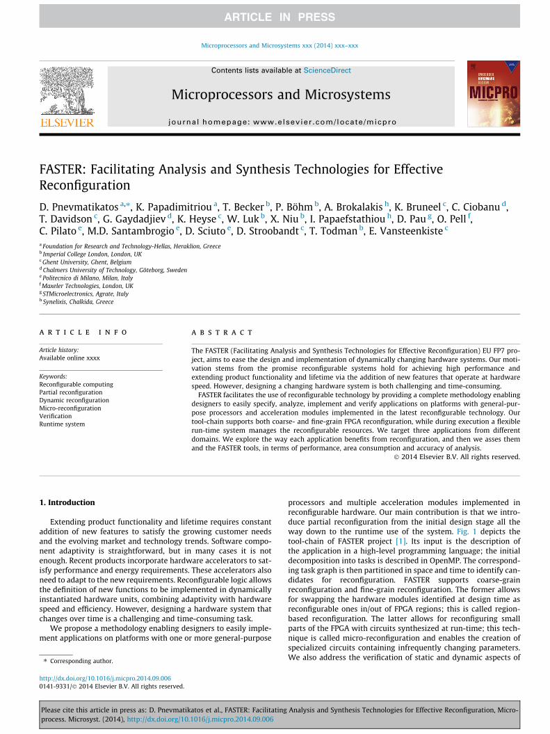
The Run-Time System Manager (RTSM) is a software compo-nent controlling the execution of application workloads. It under-takes low-level operations so as to offload the programmer frommanually handling fine grain operations such as scheduling,resource management, memory savings and power consumption.In a partially reconfigurable FPGA-based system, in order to man-age dynamically the HW tasks, the RTSM needs to support specificoperations [38]. Fig. 8 illustrates our target system model alongwith the components participating in run-time system operation[39]. The FPGA is managed as a 2D area with regard to the HW taskplacement (a HW task corresponds to a HW module). Loading oftasks is controlled by a General Purpose Processor (GPP), whileprogramming of FPGA configuration memory is done through theICAP configuration port. All tasks can have both SW and HW ver-sions available. HW tasks are synthesized at compile time, andstored as partial bitstreams in a repository (omitted from Fig. 8for clarity), which accords with the restrictions of Xilinx FPGAtechnology. Each task is characterized by three parameters: taskarea (width and height), reconfiguration time, and execution time.In Fig. 8, four distinct components implemented outside the recon-figurable area participate in the control of tasks:
� Placer (P): responsible for finding the best location for the taskin the FPGA.� Scheduler (S): finds the time slot in which a task is loaded/starts
execution.� Translator (T): resolves the task coordinates by transforming a
technology independent representation of the available areainto the low-level commands for the specific FPGA.� Loader (L): communicates directly with the configuration port
for FPGA programming.
The system of Fig. 8 is general enough to describe similar sys-tems. Hence, instead of ICAP, external configuration ports can beemployed such as the SelectMAP or JTAG. The GPP can be a power-ful host processor (implementing Placer, Scheduler and Translator)communicating with the FPGA device through a PCI bus (e.g. desk-top computing with OS), or, it can be an embedded processor (with/
Analysis and Synthesis Technologies for Effective Reconfiguration, Micro-
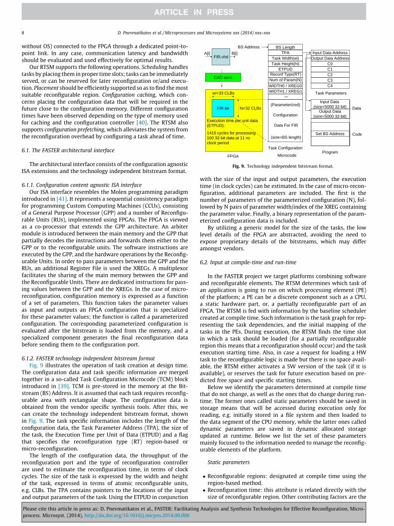
Fig. 9. Technology independent bitstream format.
8 D. Pnevmatikatos et al. / Microprocessors and Microsystems xxx (2014) xxx–xxx
without OS) connected to the FPGA through a dedicated point-to-point link. In any case, communication latency and bandwidthshould be evaluated and used effectively for optimal results.
Our RTSM supports the following operations. Scheduling handlestasks by placing them in proper time slots; tasks can be immediatelyserved, or can be reserved for later reconfiguration or/and execu-tion. Placement should be efficiently supported so as to find the mostsuitable reconfigurable region. Configuration caching, which con-cerns placing the configuration data that will be required in thefuture close to the configuration memory. Different configurationtimes have been observed depending on the type of memory usedfor caching and the configuration controller [40]. The RTSM alsosupports configuration prefetching, which alleviates the system fromthe reconfiguration overhead by configuring a task ahead of time.
6.1. The FASTER architectural interface
The architectural interface consists of the configuration agnosticISA extensions and the technology independent bitstream format.
6.1.1. Configuration content agnostic ISA interfaceOur ISA interface resembles the Molen programming paradigm
introduced in [41]. It represents a sequential consistency paradigmfor programming Custom Computing Machines (CCUs), consistingof a General Purpose Processor (GPP) and a number of Reconfigu-rable Units (RUs), implemented using FPGAs. The FPGA is viewedas a co-processor that extends the GPP architecture. An arbitermodule is introduced between the main memory and the GPP thatpartially decodes the instructions and forwards them either to theGPP or to the reconfigurable units. The software instructions areexecuted by the GPP, and the hardware operations by the Reconfig-urable Units. In order to pass parameters between the GPP and theRUs, an additional Register File is used the XREGs. A multiplexorfacilitates the sharing of the main memory between the GPP andthe Reconfigurable Units. There are dedicated instructions for pass-ing values between the GPP and the XREGs. In the case of micro-reconfiguration, configuration memory is expressed as a functionof a set of parameters. This function takes the parameter valuesas input and outputs an FPGA configuration that is specializedfor these parameter values; the function is called a parameterizedconfiguration. The corresponding parameterized configuration isevaluated after the bitstream is loaded from the memory, and aspecialized component generates the final reconfiguration databefore sending them to the configuration port.
6.1.2. FASTER technology independent bitstream formatFig. 9 illustrates the operation of task creation at design time.
The configuration data and task specific information are mergedtogether in a so-called Task Configuration Microcode (TCM) blockintroduced in [39]. TCM is pre-stored in the memory at the Bit-stream (BS) Address. It is assumed that each task requires reconfig-urable area with rectangular shape. The configuration data isobtained from the vendor specific synthesis tools. After this, wecan create the technology independent bitstream format, shownin Fig. 9. The task specific information includes the length of theconfiguration data, the Task Parameter Address (TPA), the size ofthe task, the Execution Time per Unit of Data (ETPUD) and a flagthat specifies the reconfiguration type (RT) region-based ormicro-reconfiguration.
The length of the configuration data, the throughput of thereconfiguration port and the type of reconfiguration controllerare used to estimate the reconfiguration time, in terms of clockcycles. The size of the task is expressed by the width and heightof the task, expressed in terms of atomic reconfigurable units,e.g. CLBs. The TPA contains pointers to the locations of the inputand output parameters of the task. Using the ETPUD in conjunction
Please cite this article in press as: D. Pnevmatikatos et al., FASTER: Facilitatingprocess. Microsyst. (2014), http://dx.doi.org/10.1016/j.micpro.2014.09.006
with the size of the input and output parameters, the executiontime (in clock cycles) can be estimated. In the case of micro-recon-figuration, additional parameters are included. The first is thenumber of parameters of the parameterized configuration (N), fol-lowed by N pairs of parameter width/index of the XREG containingthe parameter value. Finally, a binary representation of the param-eterized configuration data is included.
By utilizing a generic model for the size of the tasks, the lowlevel details of the FPGA are abstracted, avoiding the need toexpose proprietary details of the bitstreams, which may differamongst vendors.
6.2. Input at compile-time and run-time
In the FASTER project we target platforms combining softwareand reconfigurable elements. The RTSM determines which task ofan application is going to run on which processing element (PE)of the platform; a PE can be a discrete component such as a CPU,a static hardware part, or, a partially reconfigurable part of anFPGA. The RTSM is fed with information by the baseline schedulercreated at compile time. Such information is the task graph for rep-resenting the task dependencies, and the initial mapping of thetasks in the PEs. During execution, the RTSM finds the time slotin which a task should be loaded (for a partially reconfigurableregion this means that a reconfiguration should occur) and the taskexecution starting time. Also, in case a request for loading a HWtask to the reconfigurable logic is made but there is no space avail-able, the RTSM either activates a SW version of the task (if it isavailable), or reserves the task for future execution based on pre-dicted free space and specific starting times.
Below we identify the parameters determined at compile timethat do not change, as well as the ones that do change during run-time. The former ones called static parameters should be saved instorage means that will be accessed during execution only forreading, e.g. initially stored in a file system and then loaded tothe data segment of the CPU memory, while the latter ones calleddynamic parameters are saved in dynamic allocated storageupdated at runtime. Below we list the set of these parametersmainly focused to the information needed to manage the reconfig-urable elements of the platform.
Static parameters
� Reconfigurable regions: designated at compile time using theregion-based method.� Reconfiguration time: this attribute is related directly with the
size of reconfigurable region. Other contributing factors are the
Analysis and Synthesis Technologies for Effective Reconfiguration, Micro-

D. Pnevmatikatos et al. / Microprocessors and Microsystems xxx (2014) xxx–xxx 9
throughput of reconfiguration port, the memory storing the bit-stream, and the reconfiguration controller.� ETPUD (Execution Time Per Unit of Data): it is fixed, as it con-
cerns the time elapsed to process a specific amount of data,and affects the task overall execution time. However, the taskoverall execution time can be also influenced by the overall sizeof the data to be processed, which might not be fixed, and bythe nature of the data to be processed.� Tasks that at compile time are assigned to be executed in fixed
PEs, i.e. CPU or static HW taks and tasks assigned to certainreconfigurable areas.
Dynamic parameters
� The current status of each reconfigurable region. Possible condi-tions are: empty, (re)configuring, busy executing, not empty butidle, the ID of the task placed on the reconfigurable region.� The current status of each task. Possible conditions are: already
placed in a reconfigurable region and ready for execution,(re)configuring, running, to be executed in a partially reconfig-urable region but not yet configured, the reconfigurable regionin which the task is loaded.� Task execution time. It can depend on: (i) the amount of data to
be processed, such as real-time data entering the systemthrough a network link, or, (ii) the nature of data to be pro-cessed, or, (iii) the amount of times a loop iterates before com-pleting data processing.
7. Evaluating FASTER tools on industrial applications
To asses FASTER applicability we used our tools and exploredreconfiguration capabilities on three industrial applications.Beyond describing the applications, the contributions of presentSection are:
� identification of the application functions to be accelerated inhardware;� the way each application benefits from reconfiguration and
identification of application parts that worth to be reconfigured;� potential parallelism of applications and profiling;� use of FASTER tools for analyzing and implementing the
applications;� qualitative and quantitative analysis of performance and area
consumption results and their trade-offs;� evaluation of the high-level analysis tool of Section 3; and� overhead of the run-time system of Section 6.
The FASTER project aims at serving different applicationdomains, i.e. high-performance computing, desktop and low-costembedded, thus our tools target different platforms.
7.1. Reverse time migration
We employed FASTER tools to implement Reverse Time Migra-tion (RTM), a seismic imaging technique used in oil and gas indus-try to detect terrain images of geological structures based onEarth’s response to injected acoustic waves [42].
7.1.1. Application descriptionThe objective of RTM is to create images of the subsurface of
Earth from acoustic measurements performed at the surface. Thisis done by activating a low frequency acoustic source on the sur-face, and recording the reflected sound waves with tens of thou-sands of receivers for several seconds (typically 8–16 s). This
Please cite this article in press as: D. Pnevmatikatos et al., FASTER: Facilitatingprocess. Microsyst. (2014), http://dx.doi.org/10.1016/j.micpro.2014.09.006
process is called a ‘‘shot’’ and is repeated many thousands of timeswhile the source and/or receivers are moved to illuminate differentareas of the subsurface. The resulting dataset is dozens or hun-dreds of terabytes in size, and the problem of transforming it intoan image is computationally intensive.
The concept behind RTM operation is simple. It starts with aknown ‘‘earth model’’, which is the best known approximation tothe subsurface geology, indicatively represented with acousticvelocity data. Scientists conduct simultaneously two computationalmodeling experiments through the earth model, both attempting tosimulate the seismic experiment conducted in the field – one fromsources perspective and one from receivers perspective. The sourceexperiment involves injecting our estimated source wavelet intothe earth and propagating it from t0 to our maximum recordingtime tmax, creating a 4D source field sðx; y; z; tÞ; typical values forx; y; z; t are 1000–10000. At the same time, we conduct the receiverexperiment; we inject and propagate the recorded data startingfrom tmax to t0, creating a similar 4D volume rðx; y; z; tÞ. We have areflection where the energy propagated from the source and recei-ver is located at the same position at the same time, thus an imagecan be obtained by summing the correlation of the source and recei-ver wavefield at every time point and every ‘‘shot’’.
7.1.2. Application analysis and parallelismA 3D subsurface image is generated by simultaneously propa-
gating two waves through a model of the earth, and correlatingthe results of the simulations. These operations are carried outby the propagate and image kernel respectively. The propagatekernel computes the wavefield state at the next timestep basedon the current and previous timesteps. The image kernel performsthe cross-correlation of the source and receiver wavefields. Theseform the main computational kernels of RTM.
Propagating source and receiver in opposite directions in timeleads to high memory requirements as two state fields at differentpoints in time must be maintained. In our implementation, toavoid storing full 4D data volumes (can be many terabytes in size),we compute the source wavefield fully forward in time and thenback in time in parallel to the receiver field. This approach propa-gates the source twice, and thus requires 50% more computationthan the naive approach, but avoids the data management problemand reduces the memory footprint. Algorithm 1 shows the pseudo-code for running RTM algorithm on a single ‘‘shot’’.
Algorithm 1. RTM pseudo-code for a single ‘‘shot’’.
migrate_shot(shot_id) {src_curr = zeros(nx,ny,nz); src_prev = zeros(nx,ny,nz);rcv_curr = zeros(nx,ny,nz); rcv_prev = zeros(nx,ny,nz);image = zeros(nx,ny,nz,nh);model = load_earthmodel(shot_id);for t = 0 . . . tmax {
add_stimulus(shot_id, t, src_curr);propagate(src_curr, src_prev, model);
}swap(curr_src, prev_src); // reverse time directionfor t = tmax . . . 0 {
propagate(src_curr, src_prev, model);add_receiver_data(shot_id, t, rcv_prev)propagate(rcv_curr, rcv_prev, model);if (i % image_step == 0); // typically every 5–10
stepsimage (src_curr, rcv_curr, image);
}}
Analysis and Synthesis Technologies for Effective Reconfiguration, Micro-

10 D. Pnevmatikatos et al. / Microprocessors and Microsystems xxx (2014) xxx–xxx
A typical RTM has tens of thousands of ‘‘shots’’, with each ‘‘shot’’taking minutes, hours or days to compute, and this axis is almostembarrassingly parallel. Each ‘‘shot’’ can be computed indepen-dently from any other ‘‘shot’’, and eventually all ‘‘shots’’ are com-bined with a simple addition to form the final image result.Going into further details of the application is out of the scope ofpresent work; more information is available in [43]. Ideally weopt to parallelize ‘‘shots’’ over multiple nodes in a cluster. For per-formance purposes (and when considering the potential impact ofreconfiguration) it makes sense to consider only the ‘‘shot’’ compu-tation since this dominates the runtime, and examine a single‘‘shot’’ as a test case. Thus, in the context of the FASTER projectwe restrict the RTM test case to the single shot/single node case.
7.1.3. Reconfiguration opportunitiesWe focused on implementing the propagate and image kernels
as distinct partially reconfigurable modules sharing the samereconfigurable region within an FPGA. There is no feedback of val-ues within a single timestep, thus we implemented both kernels asa streaming datapath with a feed-forward pipeline. The two ker-nels are amenable to time-multiplexing using partial reconfigura-tion because they run sequentially and perform fundamentallydifferent computations; stating otherwise the two kernels aremutually exclusive, i.e. when propagate kernel executes, theimaging kernel is idle and vice versa. Imaging typically runs lessfrequently than propagation. This is observed in the abovepseudo-code, which shows that the propagate calculation runsfor all timesteps and the imaging runs only every N timesteps.Time-multiplexing allows for saving FPGA resources, which caninstead be used to increase the parallelism of the individual kernelsand potentially improve the runtime performance.
7.1.4. ImplementationWe implemented the RTM on a platform from Maxeler
Technologies targeting HPC applications. It provides fully inte-grated computer systems containing FPGA-based dataflow engines(DFEs), conventional CPUs and large storage means. We target oneof the standard compute nodes within such platforms, the MPC-Cseries MaxNode containing 12 Intel Xeon CPUs, 144 GB of mainmemory, and 4 DFEs. Each DFE utilizes a large Xilinx Virtex-6 FPGAattached to 48 GB of DDR3 DRAM. DFEs are connected to the CPUvia PCI Express, and in addition have a high-bandwidth low-latency direct interconnect called MaxRing for communicatingbetween neighboring engines. The system architecture is shownin Fig. 10. Maxeler nodes run standard Red Hat/CentOS operatingsystems and provide management tools for debugging and eventlogging of both the CPU and DFE subsystems. The MaxelerOS run-time software includes a kernel device driver, status monitoringdaemon and runtime libraries for use by individual applications.
Fig. 10. Maxeler system architecture.
Please cite this article in press as: D. Pnevmatikatos et al., FASTER: Facilitatingprocess. Microsyst. (2014), http://dx.doi.org/10.1016/j.micpro.2014.09.006
The MaxelerOS management daemon coordinates resource use,scheduling and data movement including automatic configurationof the FPGAs and allocation to different CPU processes.
We broke the RTM application code down into a DFE and a CPUpart. The DFE part executes the RTM kernels. The CPU part isresponsible to load the configuration onto a DFE, transfer data toand from the DFE, and run the kernels. The CPU program runs onthe main processor calling simple functions to execute operationson the DFE. Initially, we implemented a static design as baseline forcomparing it with the partially reconfigurable design; in thisdesign the propagate and image kernels co-exist and the properkernel is enabled as needed. On the other hand, in the reconfigura-ble version the CPU controls swapping in and out the two kernelsinto the same region according to the phase of execution. Reconfig-uration occurs relatively rarely and it is triggered from the CPU,which streams the corresponding partial bitstream from CPU mainmemory to the DFE as needed.
Below we discuss the important findings from implementingand executing the partial reconfiguration version of RTM:
� Due to the nature of application, during reconfiguration the restof the FPGA does not function. The host is also idle, waiting forimaging data, making it impossible to hide the reconfigurationtime under any useful operations. Our findings show that forsmall problems this has a significant impact on performance,while for larger problem sizes it becomes negligible. Indica-tively, for a small problem in which 100� 100� 100 adjacentspatial points are computed, 71% of the total end-to-end run-time was spent in reconfiguration. This was drastically reduceddown to 0.75% for computing a problem size of 800� 800� 800adjacent spatial points. Commercially interesting problem sizesscale up from the tested sizes up to several thousand cubed. Lar-ger problem sizes increase the compute time, rendering thereconfiguration time a less significant portion of the overall wallclock time.� Compared to the baseline non-reconfigurable implementation,
performance in the partially reconfigurable design was reduceddue to that designing with PR affected the clock. In addition,although in PR design the two kernels share the same region,while in the non-reconfigurable version they co-exist in thechip, we found that the overhead from the resources addedfrom the PR flow is considerable, especially for relatively smallproblem sizes. Thus, we obtained a modest reduction of theresources required for the propagate and image reconfigura-tions. This is mainly due to the increased static resource usagefrom the extra logic being introduced to perform partial recon-figuration, and to the additional dummy inputs and outputsneeded for both kernels to maintain a stable IO interface.� Huge amount of data must be preserved during reconfiguration.
In the first implementation we used the FPGA’s attached DRAMmemories to store the seismic wavefields and earth model vol-umes during the computation of a ‘‘shot’’. If the FPGA is partiallyreconfigured during the execution of a ‘‘shot’’ computation, it isimportant to preserve the DRAM contents in order to enable thecomputation to proceed with the correct data.� A major trade-off between performance and area comes from
the instantiation of a DRAM controller in the same FPGA thathosts the RTM kernels. In specific, in the first version we imple-mented a DRAM memory controller using the FPGA resources.Holding data, i.e. earth model, current states of the wavefieldpropagations and accumulated image, in the on-card memoryconnected directly to the FPGA on the DFE card is more efficientsince the DFE memory provides much greater bandwidth thanthe PCI Express link. However, we discovered that the DRAMmemory controller consumes a large amount of chip area,which restricts the area that can be used for implementing
Analysis and Synthesis Technologies for Effective Reconfiguration, Micro-

D. Pnevmatikatos et al. / Microprocessors and Microsystems xxx (2014) xxx–xxx 11
the application kernels and reduces the possible gains from uti-lizing reconfiguration. In the second implementation we movedthe storage from the on-card memory to the CPU, and conse-quently omitted the memory controller. Now, we store the datain the host CPU memory and thus all transactions between CPUand FPGA are performed through the PCIe. This reduces theachievable throughput, but it also relieves the FPGA resources,thus allowing for more space in designing either more modules,or more parallelism within the module, or more pipelining ormore parallelized modules running.
7.1.5. Using FASTER high-level analysis tool on RTMRTSM is based on Earth’s response to injected acoustic waves.
The wave propagation within the tested media is simulated for-ward, and calculated backward, forming a closed loop to correctthe velocity model, i.e. the terrain image. The propagation ofinjected waves is modeled with the isotropic acoustic waveequation:
d2pðr; tÞdt2 þ dvvðrÞ252pðr; tÞ ¼ f ðr; tÞ ð1Þ
The propagation involves stencil computation, as the partial differ-ential equation is approximated with the Taylor expansion. In ourimplementation, the propagation is approximated with a fifth-orderTaylor expansion in space, and first-order Taylor expansion in time.The constant coefficients are calculated using finite differencemethods. In this part, we focus on the forward propagation functionof an RTM application.
The high-level analysis results and the measured results forRTM are compared in Table 1. For the target RTM application,design properties are estimated with high-level analyses, and cus-tomized designs are developed with MaxCompiler version 2012.1to a Xilinx Virtex-6 SX475T FPGA hosted by a MAX3424A card fromMaxeler Technologies. As shown in Table 1, the design parallelism(i.e. the number of duplicated data-paths) is limited by LUT andBRAM resource usage. In current experiments, we set the availableresources to be 90% of the available FPGA resources, to reduce thedesign routing complexity. In terms of estimation accuracy, theresource usage and execution time are more than 90% accurate.This indicates that the high-level analysis captures the designproperties without going through the time-consuming synthesistool chain. Moreover, this implies the efficiency of the RTM design.The listed execution time consists of the execution and reconfigu-ration time of RTM design. The high-level analysis estimates thedesign execution time based on the theoretical peak performance:all implemented data-paths are assumed to be running full speedin parallel. In other words, with the analytical model taking careof application and circuit details, the applications are running withalmost the theoretical performance.
7.2. Ray tracing
In modern graphic applications it is important to achieve photo-realistic rendering in a coherent manner in order to improve pic-ture quality with increased scene complexity, and visualizeaccurately characteristics such as real reflection, soft shadows, arealight source, and indirect illumination. Rendering in 3D graphic
Table 1Estimated and analyzed design properties for RTM. The usage of a resource type isdivided by the amount of available FPGA resources of the specific type.
RTM Frequency (GHz) LUT FF DSP BRAM Time (s)
Estimated 0.1 0.86 0.53 0.4 0.89 33.02Measured 0.1 0.91 0.54 0.41 0.887 36.05
Please cite this article in press as: D. Pnevmatikatos et al., FASTER: Facilitatingprocess. Microsyst. (2014), http://dx.doi.org/10.1016/j.micpro.2014.09.006
design is the process of generating an image from a model (or mod-els in what collectively can be called a scene file), by means of com-puter programs; this adds shading, color and lamination to a 2D or3D wireframe to create life-like images of a screen. A scene filecontains objects in a strictly defined language or data structure;it can include geometry, viewpoint, texture, lighting, and shadinginformation as a description of the virtual scene. The problem ofperforming 3D rendering effectively is important due to the contin-uous strive for realistic images in several domains, as for instancein movies and video games. In this context we study the ray tracingscheme, which belongs to the global illumination group of algo-rithms [44] that aim to add more realistic lighting in 3D scenes.
7.2.1. Application descriptionRay tracing simulates the physics of a light ray to produce real-
istic results. Its classical implementation consists in defining a ren-dering point in a 3D scene and shooting light rays from that point,simulating their reflections and refractions when these rays inter-sect objects in the scene. The objects are described as a composi-tion of geometric primitives (2D or 3D) such as triangles,polygons, spheres, cones and other shapes. The computationalcomplexity of a rendering scene is proportional to the numberand the nature of these primitives, along with their positions inthe scene itself.
The ray tracing algorithm we use as benchmark in FASTER startsfrom a description of the scene as a composition of certain geomet-ric 2D/3D primitives: triangles, spheres, cylinders, cones, toruses,and polygons. Each primitive is described by a set of geometricproperties such as position in the scene, orientation, scale, heightof the primitive or rays of the circles composing the primitive.The algorithm then performs the following steps:
1. the scene is divided in blocks, called voxels, and the number ofthese voxels is one of the contributors to determine the com-plexity of the algorithm; the more the voxels are, the moreintersections between rays and primitives have to becomputed;
2. the algorithm generates a certain amount of rays from the cur-rent rendering point of the image, and it computes the set ofvoxels traversed for each of these rays;
3. it then iterates all over these voxels and computes the intersec-tion between the primitives in the voxel and the current ray;
4. the nearest intersection, if any, is considered and the algorithmcomputes the reflection and refraction of the light ray on thesurface of the object;
5. the rays generated by this physic simulation continue to bepropagated into the image until a maximum number of inter-section (an input parameter of the application) is reached orno intersection is found at all.
Ray tracing operation can be thought of as by having a virtualcamera placed into the scene, an image is rendered by casting rayssimulating the reverse path of ray of lights, from the origin of thecamera through every pixel of its virtual focal plane. The color ofa pixel is determined by the potential intersections of the primaryray cast through it, with the 3D scene. Photorealistic results can beachieved when sufficient rays are cast, simulating with fidelity thebehavior of light. Realistic description of the objects of the sceneand proper simulation of the materials’ behavior is important forcorrect results.
During rendering, the camera creates a single primary ray orig-inating at the camera location, and pointing in the direction of asingle sample inside a given pixel of a virtual focal plane. The 3Dscene is interrogated for potential intersection with this primaryray, using a structure that contains the geometric primitives. Theclosest intersection to the camera between the ray and the scene
Analysis and Synthesis Technologies for Effective Reconfiguration, Micro-

0
1
2
3
4
5
6
7
8
9
1 2 3 4 5 6 7 8
Spe
edup
(ref
eren
ce is
1 th
read
)
# threads
Ideal Speedup Real Speedup Log. (Real Speedup)
Fig. 11. Ideal and measured speedup from the execution of ray tracing in a multi-threaded environment in a 4-core Intel CPU. Graph includes a rough estimation ofthe expected (or logical) speedup for up to 8 threads.
12 D. Pnevmatikatos et al. / Microprocessors and Microsystems xxx (2014) xxx–xxx
is determined by computing the intersection with all the primi-tives of the scene. If an intersection with a primitive is found, itsshading is computed using the material of the corresponding prim-itive. Shading computation may generate additional rays, cast inturn into the scene following a similar process. The result ofshading stage is a color associated with the intersection point.For a primary ray, this color is used to compute the color of the ori-ginal pixel by the camera. For a secondary ray (or shadow ray), thiscolor is used to compute the color of the surface hit by the primaryray. More specifically, several rays (shadow rays) are shot from theintersection point in the direction of the light sources. For arealight sources, a random sample is computed over the surface andchosen as direction of the corresponding shadow ray. If a shadowray reaches its target without occlusion, then the considered pointis receiving direct light from that source; otherwise, the point is inshadow. The accumulation of contributions of shadow rays permitsthe rendering of soft shadows and penumbras. Reflections aretaken into account by casting a new ray (secondary ray or reflectedray) in the reflection direction, and the process starts again for thatray. Its contribution is accumulated to its corresponding primaryray for the final result.
7.2.2. Parallelism and profilingTo study the potential for parallelism we optimized the soft-
ware code by exploiting multithreaded rendering on a symmetricmultiprocessor architecture. Ray tracing is embarrassingly parallel,but the level of parallelism that can be exploited depends on plat-form capabilities. On a multi-processor/multi-threaded platformthe image can be decomposed in independent sub-areas, and eachsub-area can be rendered independently by a single-processor/thread. Indicatively, we divided the screen in tiles, e.g. 8 � 8, andused one thread per tile for accessing shared scene data. Table 2has the execution time for processing a 800� 800 image size in a4-core Intel CPU using different number of threads, and Fig. 11shows the achieved speedup in each case. The results indicate thatray tracing application benefits considerably from deploymentonto parallel processing elements.
Due to the complexity of application, before proceeding withthe hardware implementation we profiled it to identify themost-time consuming functions that worth to be accelerated. Weanalyzed it using a profile data visualization tool [45]. Tests werecarried out on a fixed scene by varying the number of lights (oneor three) and shadow sampling and reflection depth values (fromtwo to ten), obtaining 26 profiles. We then compared the 26 pro-files to identify the 10 most time-consuming functions and thefraction of execution time spent in each of them. Fig. 12 showsthe profiling results.
We examine the self cost of each function without taking intoaccount their callers. Results can be better explained referring tothe mean value and to the variance of the fraction of executiontime spent by each function. The chart in Fig. 12 depicts the frac-tion of time per function over the total execution time. Weobtained that the most demanding function is Intersect with anaverage value of 21;49%. Variance has a negligible value for allselected functions except for the three (3) most expensive ones.This behavior is due to the algorithm operation; Intersect,
Table 2Performance of ray tracing executed in different numberof threads.
Thread count Time (ms)
1 9674.012 5092.783 3709.034 3195.60
Please cite this article in press as: D. Pnevmatikatos et al., FASTER: Facilitatingprocess. Microsyst. (2014), http://dx.doi.org/10.1016/j.micpro.2014.09.006
Ispointinsidepolygon and Intersectcone show a dependence on thetotal amount of generated rays, while the remaining seven (7)functions keep closer to the mean value. In general, variancebecomes negligible as the number of rays increases; this keepsconstant for different scenes and different settings, and no big vari-ations in the values can be seen.
A basic ray tracing application must compute the intersectionsbetween a ray and the complete synthetic scene in order to evalu-ate visibility. It should be noted here that for primary and second-ary rays, only the intersection closest to the source of the ray mustbe found, while for shadow rays, it is sufficient to determine ifthere is any intersection between the source and the destinationof the ray. However, in order to find the proper intersection a con-siderable amount of such computations might be performed. Infact, an important finding of the profiling was that the most com-putational intensive part is related to the computation of ray inter-sections within the voxels, i.e. the 3D partition grid we adopted toreduce the computational cost. The intersection functions arecalled potentially hundreds of time per ray, for hundreds of thou-sands or millions of rays. Ray tracing spends a lot of time in com-puting intersections between a ray and a geometric primitive ofthe scene, as the rendering of an image requires casting raysthrough each pixel. Hence, we decided to accelerate the intersec-tion functions by implementing them in hardware. On the otherhand the complexity of intersection computation depends itselfon the nature of the primitive, e.g. intersection ray-sphere ischeaper to compute than ray-polygon.
7.2.3. Reconfiguration opportunitiesThe ten functions in Fig. 12 are the best candidates to be imple-
mented as hardware IPs. Opportunities for reconfiguration arise ifwe consider that most of them cannot run in parallel with others,i.e. they are mutually exclusive. For this reason, it is possible toassign all hardware implementations of these functions to a singlereconfigurable region (or a few of them) and reconfigure the func-tions so as to keep the execution time in line with that of a designin which all functions co-exist implemented as static cores, butwith far fewer resources. This is beneficial in two scenarios:
� The first one is when the target device does not fit the wholearchitecture. This is useful when ray tracing is ported to smallembedded devices for wearable solutions running for exampleaugmented reality tasks. The device is reconfigured at runtimeon the basis of type of intersections needed at a certain pointin the computation of final image. This solution has been eval-uated with our current implementation.
Analysis and Synthesis Technologies for Effective Reconfiguration, Micro-

Fig. 12. Profiling of the 10 most CPU-time intensive functions of ray tracing. They consume most of the total execution time.
D. Pnevmatikatos et al. / Microprocessors and Microsystems xxx (2014) xxx–xxx 13
� The second scenario comes from altering the mix of HW coresused to speed up the computation at runtime, in order to adapttheir type and number to the current processing needs. In thiscase, with a change to the SW of our current implementation,it is possible to detect at runtime if it is beneficial to parallelizethe computation of a certain number of intersections on multi-ple HW cores.
The benefit from this type of reconfiguration is similar to that inReverse Time Migration application described above, i.e. time-mul-tiplexing kernels for saving resources. Different levels of reconfig-uration can be considered to address adaptable aspects of raytracing in terms of performance or flexibility, such as reconfiguringthe type of supported geometric primitives, or, the complexity ofprimitives for trading-off intersection computation-cost, or, theshading complexity with the computation of color at intersectionpoint for trading-off the level of realism with computation-cost.
7.2.4. ImplementationWe created a reconfigurable design based on the first scenario
described previously targeting the low-cost Zedboard, which isbased on the Xilinx Zynq platform. Zynq is an ARM-based SoC withlimited reconfigurable logic. We used our tools for analyzing andimplementing the application in HW, in particular the mapper,scheduler and floorplanning. Initially, we restructured the originalcode so as to become more parallelizable; this way multiple inter-sections can be computed at the same time. We then encoded thetask graph along with the related profiling information in the FAS-TER XML format. The mapper and scheduler tool determined thatthe application can benefit in terms of performance by implement-ing the intersections in HW instead of SW. Then we used the floor-planning tool to build the partially reconfigurable system. Weshould note here that we put considerable effort to better under-stand how to efficiently manipulate the ray tracing data structuresfor hardware implementation.
The partially reconfigurable system alters at run-time the mixof cores available to compute intersections. At design time weexplored the solution space by varying the number of reconfigura-ble regions. From a preliminary study this seems to vary from 1 upto 4, but these boundaries depend also on the underlying physicalarchitecture, mainly on the amount of reconfigurable resources.The interface to the reconfigurable regions is fixed and theirresource occupation must be enough so as to serve every corethe designer plans to load into the reconfigurable region. In ourcase, for sake of flexibility we mapped all intersection cores in all
Please cite this article in press as: D. Pnevmatikatos et al., FASTER: Facilitatingprocess. Microsyst. (2014), http://dx.doi.org/10.1016/j.micpro.2014.09.006
reconfigurable regions, i.e. for every intersection we created onebitstream for every reconfigurable region.
7.3. Network intrusion detection
Network Intrusion Detection Systems (NIDS) are widelyadopted, as high-speed and always-on network access demandmore sophisticated packet processing and increased network secu-rity [46].
7.3.1. System descriptionInstead of checking only the header of incoming packets (as for
example firewalls typically do), NIDS also scan the payload todetect suspicious contents. The latter are described as signaturesor patterns and intrusion signature databases are made availablethat include known attacks. The databases are regularly updatedand an NIDS should be able to provide a certain degree of flexibilityto incorporate the updated security information. In the past, NIDSused mostly static patterns to scan packet payload. Recently, regu-lar expressions have also been adopted as a more efficient way todescribe hazardous contents. As such, modern rulesets consist ofboth static patterns and regular expressions.
The general requirements of NIDS involve high processingthroughput, flexibility in modifying and updating the contentdescriptions and scalability as the number of the content descrip-tions increases. The performance requirements are fundamental tothe correct functioning of an NIDS system, as if it cannot meetthem, the system itself is susceptible to specific types of attacks,i.e. overload and algorithmic attacks. However, equally crucial isthe ability of the NIDS to adapt to updated rules and contentdescriptions. This is why software NIDS systems have been widelyused, however they require substantial hardware resources (interms of general-purpose CPUs) to achieve link-speedperformance.
NIDS implemented in reconfigurable hardware have the poten-tial to combine the high performance of hardware-based systemswith the flexibility of software solutions. Specific rules can bemapped to custom logic for maximum performance and rulechanges/updates can be reconfigured into the device. Typically, aNIDS has to deal with: (i) small incremental updates may berequired to add, change or expand certain IP addresses or addressranges that appear in detection rules, (ii) new static pattern rulesmay have to be added to the static rule set or changes to the cur-rent patterns included in the rule set may have to be applied, (iii)updates in the regular expressions to cover more cases or correct
Analysis and Synthesis Technologies for Effective Reconfiguration, Micro-

Local Memory
MicroBlaze Soft-Core Processor
Hardware ICAP
LMB BUS
14 D. Pnevmatikatos et al. / Microprocessors and Microsystems xxx (2014) xxx–xxx
mishandling of certain detection rules, (iv) new regular expres-sions may have to be added, and (v) overall updates to the systemmight needed in case of new policies or large scale update to theoperation of the NIDS system.
Physical Layer
Main NIDS System
CustomConnection
PLB
Fig. 14. Micro-reconfigurable NIDS system.
7.3.2. Reconfiguration opportunitiesDepending on the nature of the update (incremental versus
more extensive ones), different reconfiguration approaches canbe used. If a new rule is added in the system (the usual case),micro-reconfiguration can dedicate free resources to this new rule.Furthermore, micro-reconfiguration could be used in the caseswhere small changes to certain patterns or rules are required,e.g. changes in an IP address or address range or maybe updatesto certain rules defined by a specific regular expression. Since thesechanges/updates are expected to be frequent, micro-reconfigura-tion is a very promising approach as it can be applied quicklyand minimize system down-time. On the other hand, for majorrestructuring of the rules used in the NIDS (either as initial setup,a major upgrade, or to respond to new requirements of the organi-zation), partial or even full reconfiguration is needed. The ability tosupport large-scale changes to the operation of the NIDS provideshigh value to the system, prolongs system life and protects theinvestment of the customer.
7.3.3. ImplementationThe NIDS system has been tuned to support micro-reconfigura-
tion for updating static rules related to IP checking. The originalNIDS was a static hardwired implementation of a subset of theSnort rules, without any software programmable units. Fig. 13overviews the main modules of the system. The use of micro-reconfiguration mandates the use of a processor for certain tasksrelated to reconfiguration and calculation of parameters, thereforea number of changes were made to the system. Fig. 14 has themicro-reconfigurable version of NIDS. The main NIDS System unitis practically the original implementation of the hardwired NIDSsystem; however it comes with several changes that include theinterface to the PLB bus, and the use of micro-reconfigurableparameters for the IP checking rules.
The performance of the original non-reconfigurable system andthe micro-reconfigurable system is identical and set at wire-speed,thus both systems produce results at the same rate as they receivepackets from the gigabit ethernet interface. Also, the micro-recon-figurable system operates under the same timing constraints as theoriginal. It should be noted that the main NIDS of Fig. 14 operateson a separate clock domain than the rest of the system (PLB buses,MicroBlaze processor and hardware ICAP).
Fig. 13. Overview of the h
Please cite this article in press as: D. Pnevmatikatos et al., FASTER: Facilitatingprocess. Microsyst. (2014), http://dx.doi.org/10.1016/j.micpro.2014.09.006
As expected, there is an impact on the physical resources thatthe micro-reconfigurable system needs compared to the originalimplementation. For a Xilinx Virtex-5 XC5VLX110T device, theoverhead is almost 6% for Slice LUTs and 11% for BlockRAMs.Although these are not negligible values, they can be consideredsmall.
7.4. Overhead of the run-time system manager
We used the RTSM described in Section 6 to control a partiallyreconfigurable design. In specific, we used it to execute an edgedetection application implemented on an FPGA platform with XilinxVirtex-5. Initially, we evaluated it on a x86 desktop system con-nected with a serial interface to the FPGA platform. The desktop sys-tem was a linux PC with an i3 [email protected] GHz, 3 MB cache, and 2 GBDDR3. The time we measured per call of RTSMs main core was1.3us on average, while the best and worst times were 0.9us and2us respectively. These values correspond to the overhead of theRTSM itself, i.e. the time it takes to perform one scheduling decisionand update the internal structures representing the status of thetasks and the FPGA. This measurement excludes the times for taskreconfiguration and execution, and communication between theCPU and the FPGA. We then transited to a completely embeddedversion implemented on the same FPGA platform by altering theRTSM code so as to port it on a Microblaze, running at 100 MHz,32 KB cache. In that case the RTSM overhead is 520us, thus 2 ordersof magnitude larger as compared to the x86 implementation. In bothcases the RTSM itself is very low overhead; it is the reconfigurationand execution time of the tasks that dominate the total time forcarrying out the application execution.
ardware NIDS system.
Analysis and Synthesis Technologies for Effective Reconfiguration, Micro-

D. Pnevmatikatos et al. / Microprocessors and Microsystems xxx (2014) xxx–xxx 15
8. Summary of contributions
This section consolidates the project novelties and exposes itsdifferences over previous related efforts discussed in Section 2.Our contributions are:
� The interaction amongst the front-end stages of the tool-chain,which is performed through the XML file. During this operationdifferent segments of the XML structure are automatically ana-lyzed and updated. Several solutions are explored requiring lim-ited-to-none intervention from the user, while details andimplications related with dynamic reconfiguration remain hid-den. XML format offers a convenient representation and hasbeen used by similar projects in the past [10]. However, the typeof information contained into FASTER XML that is then extractedfor feeding the different stages of the tool-chain is new, e.g. base-line scheduler provided in XML format that is then used as inputto the run-time system manager. A new feature of the proposedXML is that it contains attributes characterizing the HW and SWtasks, which are used as input to the other FASTER tools for mak-ing decisions. Such attributes are execution time, reconfigura-tion time, and power consumption per task; the way these arebalanced at compile time affects the system implemented atthe first place, but also affects the run-time decisions. This fea-ture is unique as compared to previous research projects, notonly due to the information contained in XML, but also due tothat it affects both compile- and run-time decisions.� Micro-reconfiguration is a technique released some time ago,
but we study for the first time its integration into a tool-chain.We are also extending it so as to support routing resources; pre-vious version of micro-reconfiguration was targeting Look-Up-Tables only. Moreover, we developed a profiler to assist the userin determining whether an application will benefit from amicro-reconfigurable implementation. Finally, we evaluatedmicro-reconfiguration by employing it for the first time in oneof the target applications, i.e. Network Intrusion Detection.� The proposed tool-chain supports different implementation
options, static or reconfigurable; for the latter case two optionsare available, either region-based reconfiguration or micro-reconfiguration. Putting these sub-flows into work under a uni-fied environment targeting heterogeneous reconfigurable plat-forms constitutes itself a challenging problem in terms ofcomplexity. To the best of our knowledge existing integratedsolutions do not support such feature, i.e. analyzing and identi-fying within the tool-chain which option serves better the givenapplication/platform, and enabling accordingly the proper sub-flow.� A verification approach that applies equally to static,
region-based, or micro-reconfiguration without modification.The novelty of this approach lies into three aspects: (i) verifyingstreaming designs using meta-programming; (ii) verifying run-time reconfigurable designs; and (iii) verifying co-design ofHW/SW systems. Sections 5 discusses these aspects in detail,including an extensive comparison over the dominant solutions.� We implemented a Run-Time System Manager (RTSM) and
evaluated it on an embedded and a desktop platform. We stud-ied the extent to which it is feasible to develop a generic librarythat can support different platforms. For the transition from thedesktop implementation to the embedded one only a fewchanges were needed in the RTSM code. Our code has beenstructured in a way that can be extended to support differentscheduling policies. The RTSM basic operation is driven by thebaseline scheduler represented in XML.� We explored the reconfiguration aspects of three applications,
which are of great interest to the industrial partners. We
Please cite this article in press as: D. Pnevmatikatos et al., FASTER: Facilitatingprocess. Microsyst. (2014), http://dx.doi.org/10.1016/j.micpro.2014.09.006
gathered significant insights by progressively re-designing andimplementing the partially reconfigurable versions on certainplatforms, and assessed two of them in terms of performanceand resource savings. Our experience showed that this consti-tutes a time-consuming task; important role played the plat-forms that our tool-chain targets, and the initial availableimplementations of the target applications (static HW or SWonly). In addition, we employed our tools for analyzing andimplementing the applications. In particular, we used theHigh-level analysis tool for analyzing the Reverse Time Migra-tion and we found that the user can rely on its output in orderto estimate the expected performance and resource consump-tion, without going through the time-consuming synthesis tools.We used our mapper, scheduler and floorplanning tools to ana-lyze and implement the ray tracing application. Prior to this weprofiled the application, and encoded its task graph along withthe related profiling information in the FASTER XML format.Finally, we designed and evaluated the micro-reconfigurableversion of the Network Intrusion Detection System.
Recapitulating, the FASTER project is novel both from researchand practice points of view. The basic functionality for some ofthe described tools was provided by the partners already, but weare continuously modifying them so as to integrate all under a uni-fied tool-chain. Furthermore, FASTER tools support the analysisand design of applications from different domains.
9. Conclusion
Creating a changing hardware system is a challenging processrequiring considerable effort in specification, design, implementa-tion, verification, as well as support from a run-time system. Weattempt to alleviate this effort and streamline the design and imple-mentation process by providing a new design environment friendlyto reconfiguration. Our contributions span the analysis phase andthe reconfigurable system definition, the support for multi-grainreconfiguration, the verification for the changing system, and therun-time system to handle the reconfiguration requirements.
Acknowledgement
This work was supported by the European Commission - Bel-gium in the context of FP7 FASTER project (#287804).
References
[1] FASTER, <http://www.fp7-faster.eu/> (accessed 2014).[2] D. Pnevmatikatos, T. Becker, A. Brokalakis, K. Bruneel, G. Gaydadjiev, W. Luk, K.
Papadimitriou, I. Papaefstathiou, O. Pell, C. Pilato, M. Robart, M.D.Santambrogio, D. Sciuto, D. Stroobandt, T. Todman, FASTER: FacilitatingAnalysis and Synthesis Technologies for Effective Reconfiguration, in:Euromicro Conference on Digital System Design (DSD), 2012.
[3] T. Todman, G. Constantinides, S.J.E. Wilton, O. Mencer, W. Luk, P.Y.K. Cheung,Reconfigurable computing: architectures and design methods, Comput. DigitalTech., IEE Proc. 152 (2) (2005) 193–207.
[4] J. a. M.P. Cardoso, P.C. Diniz, M. Weinhardt, Compiling for reconfigurablecomputing: a survey, ACM Comput. Surv. 42 (4) (2010) 13:1–13:65.
[5] L. Jówiak, N. Nedjah, M. Figueroa, Modern development methods and tools forembedded reconfigurable systems: a survey, Integr. VLSI J. 43 (1) (2010) 1–33.
[6] S. Hauck, A. DeHon, Reconfigurable Computing: The Theory and Practice ofFPGA-Based Computation, Morgan Kaufmann Publishers Inc., San Francisco,CA, USA, 2007.
[7] M. Platzner, J. Teich, N. Wehn (Eds.), Dynamically Reconfigurable Systems –Architectures, Design Methods and Applications, Springer, 2010.
[8] PTOLEMY, <http://ptolemy.eecs.berkeley.edu/> (accessed 2012).[9] DAEDALUS, <http://daedalus.liacs.nl/> (accessed 2012).
[10] hArtes, <http://hartes.org/hArtes/> (accessed 2012).[11] M. Sato, OpenMP: parallel programming API for shared memory
multiprocessors and on-chip multiprocessors, in: Proceedings of the 15thInternational Symposium on System Synthesis, 2002, pp. 109–111.
Analysis and Synthesis Technologies for Effective Reconfiguration, Micro-

16 D. Pnevmatikatos et al. / Microprocessors and Microsystems xxx (2014) xxx–xxx
[12] OpenCL, <http://www.khronos.org/opencl/> (accessed 2012).[13] REFLECT, <http://www.reflect-project.eu/> (accessed 2012).[14] ACOTES, <http://www.hitech-projects.com/euprojects/ACOTES/> (accessed
2012).[15] ANDRES, <http://andres.offis.de/> (accessed 2012).[16] A. Montone, M.D. Santambrogio, F. Redaelli, D. Sciuto, Floorplacement for
partial reconfigurable FPGA-based systems, Int. J. Reconf. Comput. 2011 (2)(2011) 12.
[17] C. Bolchini, A. Miele, C. Sandionigi, Automated resource-aware floorplanning ofreconfigurable areas in partially-reconfigurable FPGA systems, in: Proceedingsof the IEEE International Conference on Field Programmable Logic andApplications (FPL), 2011, pp. 532–538.
[18] M. Rabozzi, J. Lillis, M.D. Santambrogio, Floorplanning for partially-reconfigurable FPGA systems via mixed-integer linear programming, in:Proc. of the IEEE International Symposium on Field-Programmable CustomComputing Machines (FCCM), 2014.
[19] P.W. Foulk, Data-folding in SRAM configurable FPGAs, in: Proceedings of theIEEE Workshop on FPGAs for Custom Computing Machines (FCCM), 1993, pp.163–171.
[20] M.J. Wirthlin, B.L. Hutchings, Improving functional density through run-timeconstant propagation, in: Proc. of the ACM/SIGDA International Symposium onField Programmable Gate Arrays (FPGA), 1997, pp. 86–92.
[21] K. Shahookar, P. Mazumder, VLSI cell placement techniques, Comput. Surv.(1991) 143–220.
[22] K. Bruneel, Efficient Circuit Specialization for Dynamic Reconfiguration ofFPGAs, PhD thesis, Ghent University, 2011.
[23] K. Heyse, K. Bruneel, D. Stroobandt, Mapping logic to reconfigurable FPGArouting, in: Proceedings of the International Conference on FieldProgrammable Logic and Applications (FPL), 2012, pp. 315–321.
[24] E. Vansteenkiste, K. Bruneel, D. Stroobandt, Maximizing the reuse of routingresources in a reconfiguration-aware connection router, in: Proceedings of theInternational Conference on Field Programmable Logic and Applications (FPL),2012, pp. 322–329.
[25] B.A. Farisi, K. Bruneel, J.M.P. Cardoso, D. Stroobandt, An automatic tool flow for thecombined implementation of multi-mode circuits, in: Proceedings of the Design,Automation, and Test in Europe Conference and Exhibition, 2013, pp. 821–826.
[26] Accellera, Universal Verification Methodology (UVM) 1.1 user’s guide. <http://www.accellera.org/downloads/standards/uvm>.
[27] Synopsis, Formality: equivalence checking for DC Ultra, Tech. rep., 2012.[28] S. Singh, C.J. Lillieroth, Formal verification of reconfigurable cores, in:
Proceedings of FCCM, 1999, pp. 25–32.[29] K.W. Susanto, T.F. Melham, Formally analyzed dynamic synthesis of hardware,
J. Supercomput. 19 (1) (2001) 7–22.[30] F. Madlener, J. Weingart, S.A. Huss, Verification of dynamically reconfigurable
embedded systems by model transformation rules (2010) 33–40.[31] K.W. Susanto, W. Luk, Automating formal verification of customized soft-
processors, in: FPT, 2011, pp. 1–8.[32] O. Pell, Verification of FPGA layout generators in higher-order logic, J. Autom.
Reason. 37 (1–2) (2006) 117–152.[33] S. Drzevitzky, U. Kastens, M. Platzner, Proof-carrying hardware: towards runtime
verification of reconfigurable modules, in: ReConFig. 2009, pp. 189–194.[34] S. Drzevitzky, Proof-carrying hardware: runtime formal verification for secure
dynamic reconfiguration, in: FPL, 2010, pp. 255–258.[35] K.W. Susanto, T. Todman, J.G.F. Coutinho, W. Luk, Design validation by
symbolic simulation and equivalence checking: a case study in memoryoptimization for image manipulation, in: SOFSEM, 2009, pp. 509–520.
[36] B. Dutertre, L. de Moura, The YICES SMT Solver, Tech. rep., Computer ScienceLaboratory, SRI International, 333 Ravenswood Avenue, Menlo Park, CA 94025,USA, 2006.
[37] W. Luk, N. Shirazi, P.Y.K. Cheung, Modelling and optimising run-timereconfigurable systems, in: Proceedings IEEE Symposium on FPGAs forCustom Computing Machines (FCCM), 1996, pp. 167–176.
[38] C. Steiger, H. Walder, M. Platzner, Operating systems for reconfigurableembedded platforms: online scheduling of real-time tasks, IEEE Trans.Comput. 53 (11) (2004) 1393–1407.
[39] T. Marconi, Efficient Runtime Management of Reconfigurable HardwareResources, PhD thesis, TU Delft, 2011.
[40] K. Papadimitriou, A. Dollas, S. Hauck, Performance of partial reconfiguration inFPGA systems: a survey and a cost model, ACM Trans. Reconf. Technol.Syst.(TRETS) 4 (4) (2011) 36:1–36:24.
[41] S. Vassiliadis, S. Wong, G. Gaydadjiev, K. Bertels, G. Kuzmanov, E. Panainte, TheMOLEN polymorphic processor, IEEE Trans. Comput. 53 (11) (2004) 1363–1375.
[42] E. Baysal, D.D. Kosloff, J.W.C. Sherwood, Reverse time migration, SEG-Geophysics 48 (11) (1983) 1514–1524.
[43] X. Niu, Q. Jin, W. Luk, Q. Liu, O. Pell, Exploiting run-time reconfiguration instencil computation, in: Proc. of the 22nd IEEE International Conference onField Programmable Logic and Applications (FPL), 2012.
[44] K. Myszkowski, T. Tawara, H. Akamine, H.-P. Seidel, Perception-guided globalillumination solution for animation rendering, in: Proceedings of the ACMConference on Computer Graphics and Interactive Techniques (SIGGRAPH),2001, pp. 221–330.
[45] KCachegrind, <http://kcachegrind.sourceforge.net/html/Home.html> (accessed2014).
[46] I. Sourdis, D. Pnevmatikatos, S. Vassiliadis, Scalable multi-gigabit patternmatching for packet inspection, IEEE Trans. Very Large Scale Integr. (VLSI) Syst.16 (2) (2008) 156–166.
Please cite this article in press as: D. Pnevmatikatos et al., FASTER: Facilitatingprocess. Microsyst. (2014), http://dx.doi.org/10.1016/j.micpro.2014.09.006
Dionisios Pnevmatikatos is a Professor and formerChair of the Electronic and Computing EngineeringDepartment, Technical University of Crete and aResearcher at the Computer Architecture and VLSI Sys-tems (CARV) Laboratory of the Institute of ComputerScience, FORTH in Greece. He received his B.Sc. degreein Computer Science from the Department of ComputerScience, University of Crete in 1989 and M.Sc. and Ph.D.degrees in Computer Science from the Department ofComputer Science, University of Wisconsin-Madison in1991 and 1995 respectively. His research interests arein the broader area of Computer Architecture, where he
investigates the Design and Implementation of High-Performance and Cost-Effec-tive Systems, Reliable System Design, and Reconfigurable Computing. He is cur-rently the Coordinator of the FASTER project (ICT, STREP) and has participated in
numerous national and European research projects.Kyprianos Papadimitriou is a Research Associate at theComputer Architecture and VLSI Systems (CARV) Labo-ratory, FORTH-ICS, and Scientific Staff at the School ofElectronic and Computer Enginneering, Technical Uni-versity of Crete, in Greece. He received his Diploma andM.Sc. in Electronic and Computer Engineering fromTechnical University of Crete, Greece, in 1998 and 2003respectively. During 1998–1999 he was with the R&Ddepartment of ATMEL working on hardware imple-mentation of wireless protocols. In 2003 he co-initiatedan effort to establish a spin-off company involved withmotion recognition technology. In 2012 he was granted
with a Ph.D from the Electronic and Computer Engineering Department, TechnicalUniversity of Crete, with a special focus on reconfigurable computing. He has par-ticipated in several European and national reserarch projects.
Tobias Becker received a Dipl. Ing. degree in ElectricalEngineering from the University of Karlsruhe, Germanyin 2005 and a PhD in computer science from ImperialCollege London, UK in 2011. He is currently a researchassociate in the Department of Computing at ImperialCollege London. His research includes work on recon-figurable computing and high-performance computing.He has extensive experience on FPGA design and he hasworked in collaboration with several industrial partnersincluding Xilinx and Nokia.
Peter Böhm received his Ph.D. from the Department ofComputer Science at Oxford University, UK, and hisM.Sc. (Honour’s) degree from the Department of Com-puter Science at Saarland University, Germany. Cur-rently, he is a research associate at Imperial CollegeLondon. His academic background is in formal verifica-tion and specification of hardware and communicationarchitectures. At Imperial College, his research focuseson the formal verification of re-configurable hardwaredesigns.
Andreas Brokalakis is a Senior Computer Engineer atSynelixis Solutions Ltd. He graduated from the Com-puter Engineering and Informatics Department, Uni-versity of Patras (Greece) in 2004 and received hismaster’s degree from the same department in 2007.Since 2008 he has been working on several EuropeanResearch projects through his affiliation with the Tele-communication Systems Institute (Technical Universityof Crete) and Synelixis Solutions. His focus is on hard-ware design for reconfigurable systems or ASICs as wellas computer architecture.
Analysis and Synthesis Technologies for Effective Reconfiguration, Micro-

D. Pnevmatikatos et al. / Microprocessors and Microsystems xxx (2014) xxx–xxx 17
Karel Bruneel (Ph.D. Ghent University, 2011) is apostdoctoral researcher at Ghent University, affiliatedwith the Department of Electronics and InformationSystems (ELIS), Computer Systems Lab (CSL), Hardwareand Embedded Systems (HES) group. His research issituated in the domain of EDA tools for FPGAs with astrong focus on dynamic reconfiguration. He is inter-ested in a large number of topic including synthesis,technology mapping, placement and routing.
Catalin Ciobanu is a researcher in the Computer Scienceand Engineering department at Chalmers University ofTechnology, Sweden. His research interests includecomputer architecture, reconfigurable computing andparallel processing. He has an M.Sc. in Computer Engi-neering from Delft University of Technology, and a Ph.D.on customizable vector register files.
Tom Davidson (Master of Applied Science – Electronics,Ghent University, 2009) is a Ph.D. researcher at GhentUniversity, affiliated with the Department of Electronicsand Information Systems (ELIS), Computer Systems Lab(CSL), Hardware and Embedded Systems (HES) group.He works on run-time reconfiguration of FPGAs, morespecifically Dynamic Circuit Specialization. He has pre-sented and published several papers on this subject. Hiscurrent research focus is on identifying opportunitiesfor DCS from higher abstraction levels, such as System-Cor C.
Georgi Gaydadjiev is a professor at the Department ofComputer Science and Engineering at Chalmers Uni-versity of Technology. His research interests includecomputer systems design, advanced computer archi-tecture and micro architecture, reconfigurable comput-ing, hardware/software co-design and computersystems testing. He is a Senior IEEE and ACM member.
Karel Heyse (Master of Applied Science – ComputerScience, Ghent University, 2011) is a Ph.D. researcher atGhent University, affiliated with the Department ofElectronics and Information Systems (ELIS), ComputerSystems Lab (CSL), Hardware and Embedded Systems(HES) group. His research is about run-time reconfigu-ration of FPGAs and in particular the synthesis tools thatmake it possible to use run-time reconfiguration toincrease performance and functional density of digitalcircuits. His other research interests are in coarse grainarchitectures and regular expression matching onFPGAs.
Please cite this article in press as: D. Pnevmatikatos et al., FASTER: Facilitatingprocess. Microsyst. (2014), http://dx.doi.org/10.1016/j.micpro.2014.09.006
Wayne Luk is Professor of Computer Engineering atImperial College London. He was a visiting professorwith Stanford University, California, and with Queen’sUniversity Belfast, United Kingdom. His researchincludes theory and practice of customizing hardwareand software for specific application domains, such asmultimedia, financial modeling, and medical comput-ing. His current work involves high-level compilationtechniques and tools for high-performance computersand embedded systems, particularly those containingaccelerators such as FPGAs and GPUs. He received aResearch Excellence Award from Imperial College, and
12 awards for his publications from various international conferences. He is a fellowof the IEEE, the BCS, and the Royal Academy of Engineering.
Xinyu Niu received his B.Sc. degree in School of Infor-mation Science and Technology from Fudan University,and obtained his M.Sc. degree from Department ofElectrical and Electronic Engineering at Imperial CollegeLondon. He is currently completing his Ph.D. studies inthe Department of Computing, Imperial College London.His research interests include run-time reconfiguration,heterogeneous computing, high performance comput-ing and computer-aided design (CAD) tools for hard-ware design optimization.
Ioannis Papaefstathiou is the Manager of the SystemsResearch Groups of Synelixis Solutions Ltd and anAssociate Professor at the ECE Department at theTechnical University of Crete. He was granted a Ph.D.degree in computer science at the University of Cam-bridge UK, in 2001, an M.Sc. (Ranked 1st) from HarvardUniversity, USA, in 1996 and a B.Sc. (Ranked 2nd) fromthe University of Crete, Greece in 1996. He has pub-lished more than 70 papers in IEEE-sponsored journalsand conferences. He has been the prime Guest Editor foran issue of IEEE Micro Magazine and for one in IEEEDesign & Test Magazine.
Danilo Pietro Pau received the Electronic Engineeringdegree from Politecnico of Milano in 1992. He has, since1991, joined STMicroelectronics Advanced SystemTechnology working on digital video processing algo-rithms and architectures for Set Top Box and Mobileapplication processors. He moved to STMicroelectronicsLtd, Bristol (UK) for a period of 1 year, in 2004, where heworked mainly on algorithms and architectural studiesin the field of 3D graphics for mobile processors com-pliant with the worldwide standard OpenGL-ES. He thenmoved back to Agrate, where he continued to manage3D graphics developments and started 2D scalable
graphics algorithms and architectural studies for Set Top Box and Thin Clients. He iscurrently managing 3 teams based in UK, Italy and China. During his career he hasauthored or co-authored many European, U.S. and Japan granted patents, as well as
international publications in conferences or technical journals.Oliver Pell is Vice President of Engineering at MaxelerTechnologies. His experience ranges from acceleratingReverse Time Migration and Lattice-Boltzmann simu-lations to credit derivatives pricing. He is currentlyresponsible for Maxeler’s technology research anddevelopment as well as the technical architecture andproject management of acceleration efforts for clientsincluding Tier 1 oil companies and investment banks.He has an M.Sc. in advanced computing from ImperialCollege London. He’s a member of IEEE and the ACM.
Analysis and Synthesis Technologies for Effective Reconfiguration, Micro-

18 D. Pnevmatikatos et al. / Microprocessors and Microsystems xxx (2014) xxx–xxx
Christian Pilato is a research assistant at Politecnico diMilano. His research interests include high-level syn-thesis, evolutionary algorithms for design space explo-ration and multi-objective optimization, and design ofheterogeneous and multiprocessor embedded systems.He has an M.Sc. in Computing Systems Engineering fromPolitecnico di Milano, received in 2007, and a Ph.D. inInformation Technology received from the same Uni-versity in 2011. He is a member of the IEEE and amember of the IEEE Computer Society.
Marco D. Santambrogio received his laurea (M.Sc.equivalent) degree in Computer Engineering from thePolitecnico di Milano in 2004, his second M.Sc. degree inComputer Science from the University of Illinois atChicago (UIC) in 2005 and his Ph.D. degree in ComputerEngineering from the Politecnico di Milano in 2008. Hewas at the Computer Science and Artificial IntelligenceLaboratory (CSAIL) at MIT as postdoc fellow and he isnow assistant professor at Politecnico di Milano,research affiliate at MIT and adjunct professor at UIC. Hehas also held visiting positions at the EECS Departmentof the Northwestern University (2006 and 2007) and
Heinz Nixdorf Institut (2006). He is a member of the IEEE, the IEEE ComputerSociety (CS) and the IEEE Circuits and Systems Society (CAS). He has been with theMicro Architectures Laboratory at the Politecnico di Milano, where he founded the
Dynamic Reconfigurability in Embedded System Design (DRESD) project in 2004and the CHANGE project (Self-Aware and Adaptive Computing Systems) in 2010. Heconducts research and teaches in the areas of reconfigurable computing, computerarchitecture, operating system, hardware/software codesign, embedded systems,and high performance processors and systems.Donatella Sciuto is a full professor in Computer Scienceand Engineering at the Politecnico di Milano, where sheholds also the position of Vice Rector of the University.She is a Fellow of IEEE and currently President of theCouncil of EDA. Her main research interests cover themethodologies for the design of embedded systems andmulticore systems, from the specification level down tothe implementation of both the hardware and softwarecomponents, including reconfigurable and adaptivesystems. She has published more than 200 papers. She isor has been member of different program committees ofACM and IEEE EDA conferences and workshops. She has
served as Associate Editor of the IEEE Transactions on Computers, and serves now asassociate editor to the IEEE Embedded Systems Letters for the design methodologiestopic area and as associate editor for the Journal of Design Automation of Embedded
Systems, Springer. She is in the executive committee of DATE for the past ten yearsPlease cite this article in press as: D. Pnevmatikatos et al., FASTER: Facilitatingprocess. Microsyst. (2014), http://dx.doi.org/10.1016/j.micpro.2014.09.006
and she has been Technical Program Chair in 2006 and General Chair in 2008. Shehas been General Co-Chair for 2009 and 2010 of ESWEEK. She is Technical ProgramCo-Chair of DAC 2012 and 2013.
Dirk Stroobandt (Ph.D. Ghent University, 1998) is aprofessor at Ghent University, affiliated with theDepartment of Electronics and Information Systems(ELIS), Computer Systems Lab (CSL). He currently leadsthe research group HES (Hardware and Embedded Sys-tems) of about 10 people with interests in semi-auto-matic hardware design methodologies and tools, run-time reconfiguration, and reconfigurable multiprocessornetworks. He is the inaugural winner of the ACM/SIGDAOutstanding Doctoral Thesis Award in Design Automa-tion (1999), and he initiated and co-organized theInternational Workshop on System-Level Interconnect
Prediction (SLIP) since 1999. He is also lead editor of a special issue of the Inter-national Journal of Reconfigurable Computing and he has been associate editor ofACM’s TODAES for three years.
Tim Todman received the B.Sc. degree from the Uni-versity of North London, and the M.Sc. and Ph.D. degreesfrom Imperial College London, in 1997, 1998 and 2004,respectively. He is currently a research associate in theDepartment of Computing, Imperial College London,London, UK. His research interests include hardwarecompilation, verification and implementation of graph-ics algorithms on reconfigurable architectures.
Elias Vansteenkiste (Master of Applied Science – Elec-tronics, Ghent University, 2011) is a Ph.D. researcher atGhent University, affiliated with the Department ofElectronics and Information Systems (ELIS), ComputerSystems Lab (CSL), Hardware and Embedded Systems(HES) group. His research is focused on a new tool flowfor the dynamic reconfiguration that will allow run-time reconfiguration of the FPGA’s interconnect net-work, in order to increase performance and functionaldensity of digital circuits. He targets the back end of thetool flow. Placement and routing algorithms and con-figuration bitstream generation are his main interests.
Analysis and Synthesis Technologies for Effective Reconfiguration, Micro-
Related Documents