FASTENING SYSTEMS FOR AEROSPACE TOOL CATALOG

Welcome message from author
This document is posted to help you gain knowledge. Please leave a comment to let me know what you think about it! Share it to your friends and learn new things together.
Transcript
FASTENING SYSTEMS FOR AEROSPACETOOL CATALOG
JR
Typewritten text
Production Tool & Technology 8410 Feagin Rd Macon, Ga 31216 Toll Free: 1-866-546-4663 Local Number: 478-781-8415 Fax: 478-781-0850
TABLE OF CONTENTS
INTRODUCTION
How to use this catalog/Tool Selection Guide ......................................................................................................1Ergonomic Tool Selection Guide ...........................................................................................................................2
SECTION 1 – SINGLE ACTION RIVETERS FOR INSTALLING BLIND RIVETS & BLIND BOLTS
G702A Lightweight Nut-Plate Riveter ...................................................................................................................3G704B Lightweight CherryMAX® Riveter ..............................................................................................................4G704B-SR and G704B-40SH Split Power Riveters ................................................................................................4G746A CherryMAX® Riveter ..................................................................................................................................5G747 Lightweight CherryMAX® Riveter .................................................................................................................5Pulling Heads ........................................................................................................................................................6
SECTION 2 – HYDRAULIC RETURN RIVETERS FOR LOCKBOLT AND BLIND-BOLT/MAXIBOLT INSTALLATION
G83A Lightweight Lockbolt Riveter .......................................................................................................................7G84 Medium Duty Lockbolt Riveter ......................................................................................................................7Pulling Heads for G83A and G84 Riveters .............................................................................................................8G84-LS Split Riveter ..............................................................................................................................................9G87D Lockbolt Riveter ........................................................................................................................................10G85D-S Split Lockbolt Riveter .............................................................................................................................11
SECTION 3 – DOUBLE ACTION RIVETERS FOR INSTALLING STANDARD CHERRYLOCK® FASTENERS
G700 Lightweight Double Action CherryLOCK® Riveter ......................................................................................12G784 Double Action CherryLOCK® Riveter ..........................................................................................................13G689 Double Action CherryLOCK® Riveter ..........................................................................................................14G686B-S Split Double Action CherryLOCK® Riveter ............................................................................................15G695B Right Angle Double Action CherryLOCK® Riveter ....................................................................................16
SECTION 4 – MECHANICAL HAND POWERED RIVETERS
G27 CherryMAX® Hand Powered Riveter ............................................................................................................17G29 Nut Plate Hand Powered Riveter .................................................................................................................18G30 CherryLOCK® ‘A’ Hand Powered Riveter ......................................................................................................18G800 Lightweight Hand Riveter ..........................................................................................................................19
SECTION 5 – TOOL KITS
CherryMAX® Tool Kits .........................................................................................................................................20CherryLOCK® Tool Kits ......................................................................................................................................21Cherry Tool Accessories ......................................................................................................................................21
SECTION 6 ADAPTERS & EXTENSIONS
Riveter Adapters .................................................................................................................................................22Extensions ..........................................................................................................................................................22
SECTION 7 – TOOL SELECTION
Product Expert: www.cherryaerospace.com .......................................................................................................23
SECTION 8 – WARRANTY INFORMATION
Limited Warranty ................................................................................................................................................25
JR
Typewritten text
Production Tool & Technology 8410 Feagin Rd Macon, Ga 31216 Toll Free: 1-866-546-4663 Local Number: 478-781-8415 Fax: 478-781-0850
INTR
OD
UCTIO
N
1
YOUR ADVANTAGEFor over 60 years, our tools have been specified and used by aircraft manufacturers and repair facilities throughout the world. Each fastening system is combined with a full range of tools to provide an overall systems approach that ensures optimum compatibility and consistent installation performance.
Used worldwide, our tools are CE Certified and manuals are currently available in multi-language versions. With our large global sales force, we can provide fastener and tool training at customer locations, training centers, etc.
HOW TO USE THIS CATALOGThe first sections of this catalog (1 through 4) provide detailed technical information on our riveters. They are grouped by their capability and by their mounting system. All Riveters found in one Section may be used with any of the pulling heads listed at the end of the Section, giving the user many choices to cover a wide variety of fastener installations. For quick reference information, please refer to Section 6. Cross-reference guides allow easy selection of the appropriate tooling for each fastener product. If you already know which tool you need, simply go to the appropriate tool page in sections 1–4.
TO INSTALL: USE TOOL:
CherryMAX® type blind rivetsG747, G704B, G746A, G800, G27, G83A, G84, G744*
SST® blind rivets G747, G704B, G746A, G800, G27, G83A, G84
CherryMAX® ‘AB’ type blind rivets G747, G704B, G746A, G800, G27, G83A, G84
CherryLOCK® rivets G700, G784, G689, G686B-S, G695B*
CherryLOCK® ‘A’ rivets G746A, G704B, G747, G800, G30
MBC® and MBC® lock creator rivets G746A, G704B, G747, G800
MS type blind rivetsG704B, G746A, G747, G784, G689, G686B-S, G29
Nut-plate blind rivets G747, G704B, G29, G746A, G702A
MAXIBOLT® blind boltsG83A, G84, G84-LS, G87D, G800, G85D-S, G744*
Lockbolts G83A, G84, G84-LS, G87D, G85D-S
* Special order product.
JR
Typewritten text
Production Tool & Technology 8410 Feagin Rd Macon, Ga 31216 Toll Free: 1-866-546-4663 Local Number: 478-781-8415 Fax: 478-781-0850
INTR
OD
UCT
ION
2
REAL PERFORMANCEErgonomics is a leading issue in employee health. The design of installation tools from Cherry® Aerospace goes beyond simplistic labels. They offer real alternatives to heavy and/or bulky tools, providing safe and effective performance. The Cherry riveters have an all metallic construction using the best high strength materials available, able to operate reliably in the harshest environments. They are designed for long life, optimum productivity and ease of use. With easy air removal from the hydraulic system (bleeding), fully serviceable, our riveters will provide many years of reliable operation.
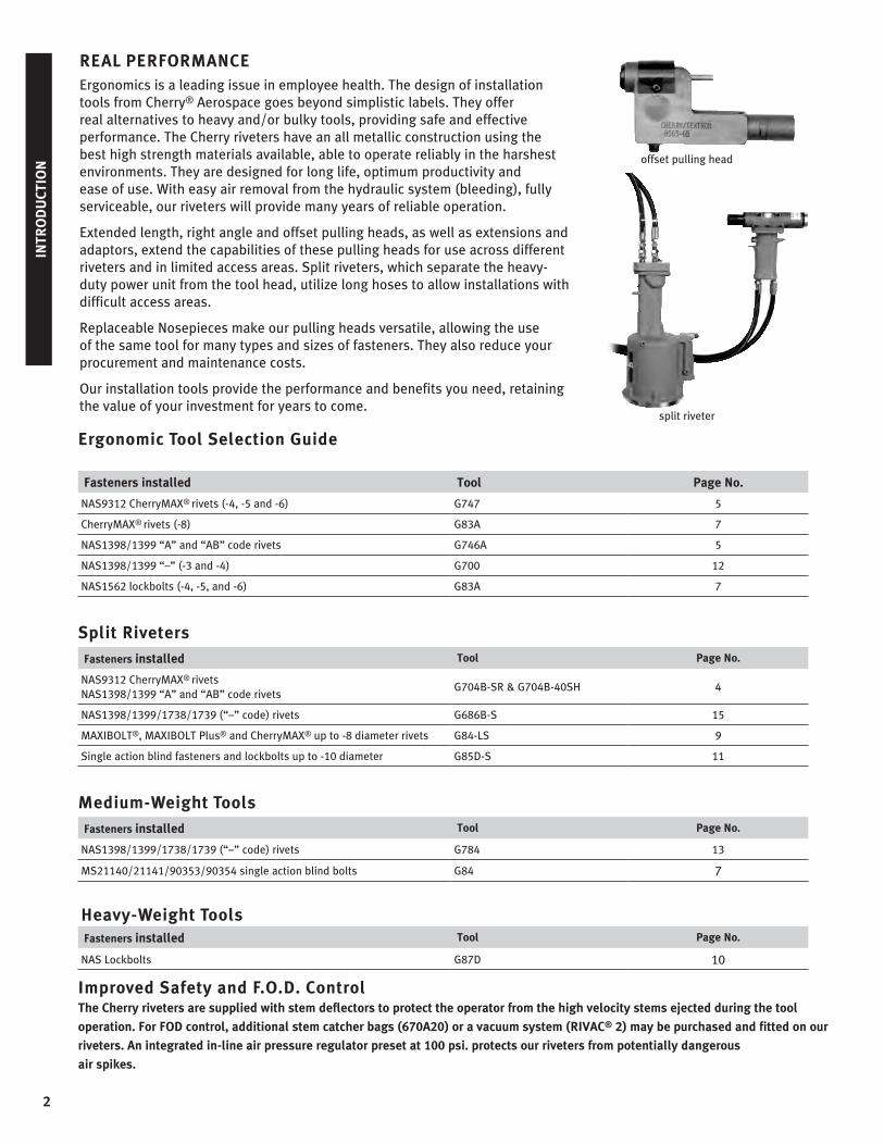
Extended length, right angle and offset pulling heads, as well as extensions and adaptors, extend the capabilities of these pulling heads for use across different riveters and in limited access areas. Split riveters, which separate the heavy-duty power unit from the tool head, utilize long hoses to allow installations with difficult access areas.
Replaceable Nosepieces make our pulling heads versatile, allowing the use of the same tool for many types and sizes of fasteners. They also reduce your procurement and maintenance costs.
Our installation tools provide the performance and benefits you need, retaining the value of your investment for years to come.
split riveter
offset pulling head
Ergonomic Tool Selection Guide
Fasteners installed Tool Page No.
NAS9312 CherryMAX® rivets (-4, -5 and -6) G747 5
CherryMAX® rivets (-8) G83A 7
NAS1398/1399 “A” and “AB” code rivets G746A 5
NAS1398/1399 “–” (-3 and -4) G700 12
NAS1562 lockbolts (-4, -5, and -6) G83A 7
Split Riveters
Fasteners installed Tool Page No.
NAS9312 CherryMAX® rivetsNAS1398/1399 “A” and “AB” code rivets
G704B-SR & G704B-40SH 4
NAS1398/1399/1738/1739 (“–” code) rivets G686B-S 15
MAXIBOLT®, MAXIBOLT Plus® and CherryMAX® up to -8 diameter rivets G84-LS 9
Single action blind fasteners and lockbolts up to -10 diameter G85D-S 11
Medium-Weight Tools
Fasteners installed Tool Page No.
NAS1398/1399/1738/1739 (“–” code) rivets G784 13
MS21140/21141/90353/90354 single action blind bolts G84 7
Heavy-Weight ToolsFasteners installed Tool Page No.
NAS Lockbolts G87D 10
Improved Safety and F.O.D. ControlThe Cherry riveters are supplied with stem deflectors to protect the operator from the high velocity stems ejected during the tool
operation. For FOD control, additional stem catcher bags (670A20) or a vacuum system (RIVAC® 2) may be purchased and fitted on our
riveters. An integrated in-line air pressure regulator preset at 100 psi. protects our riveters from potentially dangerous
air spikes.
3
SECTIO
N 1 – S
ING
LE ACTIO
N TO
OLS
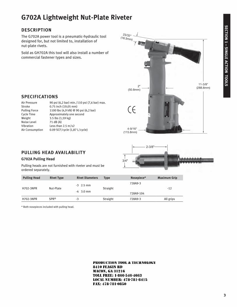
G702A Lightweight Nut-Plate Riveter
DESCRIPTIONThe G702A power tool is a pneumatic-hydraulic tool designed for, but not limited to, installation of nut-plate rivets.
Sold as GH702A this tool will also install a number of commercial fastener types and sizes.
SPECIFICATIONSAir Pressure 90 psi (6,2 bar) min./110 psi (7,6 bar) max.Stroke 0.75 inch (19,05 mm)Pulling Force 1100 lbs (4,9 kN) @ 90 psi (6,2 bar)Cycle Time Approximately one secondWeight 3.5 lbs (1,59 kg)Noise Level 71 dB (A)Vibration Less than 2.5 m/s2Air Consumption 0.09 SCF/cycle (1,87 L/cycle)
PULLING HEAD AVAILABILITYG702A Pulling Head
Pulling heads are not furnished with riveter and must be ordered separately.
Pulling Head Rivet Type Rivet Diameters Type Nosepiece* Maximum Grip
H702-3NPR Nut-Plate-3 2.5 mm
-4 3.0 mmStraight
728A9-3
728A9-104
-12
H702-3NPR SPR® -3 Straight 728A9-3 All grips
* Both nosepieces included with pulling head.
11-3/8"(288.8mm)
4-9/16"(115.8mm)
23/32"(18.3mm)
JR
Typewritten text
Production Tool & Technology 8410 Feagin Rd Macon, Ga 31216 Toll Free: 1-866-546-4663 Local Number: 478-781-8415 Fax: 478-781-0850
4
SEC
TIO
N 1
– S
ING
LE A
CTIO
N T
OO
LS
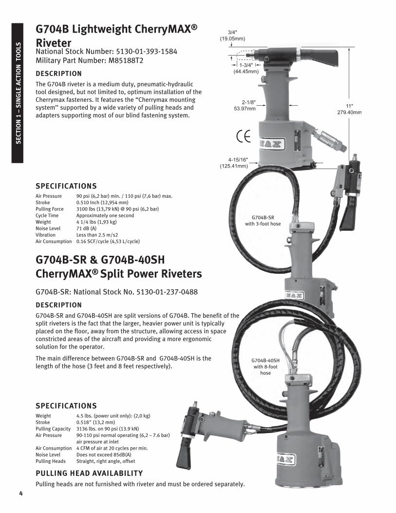
National Stock Number: 5130-01-393-1584 Military Part Number: M85188T2
DESCRIPTION
The G704B riveter is a medium duty, pneumatic-hydraulic tool designed, but not limited to, optimum installation of the Cherrymax fasteners. It features the “Cherrymax mounting system’’ supported by a wide variety of pulling heads and adapters supporting most of our blind fastening system.
SPECIFICATIONSAir Pressure 90 psi (6,2 bar) min. / 110 psi (7,6 bar) max.Stroke 0.510 Inch (12,954 mm)Pulling Force 3100 lbs (13,79 kN) @ 90 psi (6,2 bar)Cycle Time Approximately one secondWeight 4 1/4 lbs (1,93 kg)Noise Level 71 dB (A)Vibration Less than 2.5 m/s2Air Consumption 0.16 SCF/cycle (4,53 L/cycle)
G704B-SR & G704B-40SH CherryMAX® Split Power Riveters
G704B-SR: National Stock No. 5130-01-237-0488
DESCRIPTION
G704B-SR and G704B-40SH are split versions of G704B. The benefit of the split riveters is the fact that the larger, heavier power unit is typically placed on the floor, away from the structure, allowing access in space constricted areas of the aircraft and providing a more ergonomic solution for the operator.
The main difference between G704B-SR and G704B-40SH is the length of the hose (3 feet and 8 feet respectively).
SPECIFICATIONSWeight 4.5 lbs. (power unit only): (2,0 kg)Stroke 0.518" (13,2 mm)Pulling Capacity 3136 lbs. on 90 psi (13.9 kN)Air Pressure 90-110 psi normal operating (6,2 – 7.6 bar)
air pressure at inletAir Consumption 4 CFM of air at 20 cycles per min.Noise Level Does not exceed 85dB(A)Pulling Heads Straight, right angle, offset
PULLING HEAD AVAILABILITYPulling heads are not furnished with riveter and must be ordered separately.
G704B Lightweight CherryMAX®
Riveter
G704B-SRwith 3-foot hose
G704B-40SHwith 8-foot
hose
5
SECTIO
N 1 – S
ING
LE ACTIO
N TO
OLS
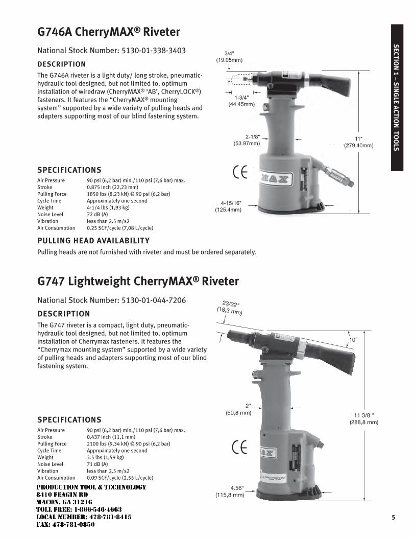
National Stock Number: 5130-01-338-3403
DESCRIPTION
The G746A riveter is a light duty/ long stroke, pneumatic-hydraulic tool designed, but not limited to, optimum installation of wiredraw (CherryMAX® ‘AB’, CherryLOCK®) fasteners. It features the “CherryMAX® mounting system” supported by a wide variety of pulling heads and adapters supporting most of our blind fastening system.
SPECIFICATIONSAir Pressure 90 psi (6,2 bar) min./110 psi (7,6 bar) max.Stroke 0.875 inch (22,23 mm)Pulling Force 1850 lbs (8,23 kN) @ 90 psi (6,2 bar)Cycle Time Approximately one secondWeight 4-1/4 lbs (1,93 kg)Noise Level 72 dB (A)Vibration less than 2.5 m/s2Air Consumption 0.25 SCF/cycle (7,08 L/cycle)
PULLING HEAD AVAILABILITYPulling heads are not furnished with riveter and must be ordered separately.
G747 Lightweight CherryMAX® Riveter
National Stock Number: 5130-01-044-7206
DESCRIPTIONThe G747 riveter is a compact, light duty, pneumatic-hydraulic tool designed, but not limited to, optimum installation of Cherrymax fasteners. It features the “Cherrymax mounting system” supported by a wide variety of pulling heads and adapters supporting most of our blind fastening system.
SPECIFICATIONSAir Pressure 90 psi (6,2 bar) min./110 psi (7,6 bar) max.Stroke 0.437 inch (11,1 mm)Pulling Force 2100 lbs (9,34 kN) @ 90 psi (6,2 bar)Cycle Time Approximately one second Weight 3.5 lbs (1,59 kg)Noise Level 71 dB (A)Vibration less than 2.5 m/s2Air Consumption 0.09 SCF/cycle (2,55 L/cycle)
G746A CherryMAX® Riveter
11 3/8 "(288,8 mm)
4.56"(115,8 mm)
2"(50,8 mm)
23/32"(18,3 mm)
JR
Typewritten text
Production Tool & Technology 8410 Feagin Rd Macon, Ga 31216 Toll Free: 1-866-546-4663 Local Number: 478-781-8415 Fax: 478-781-0850
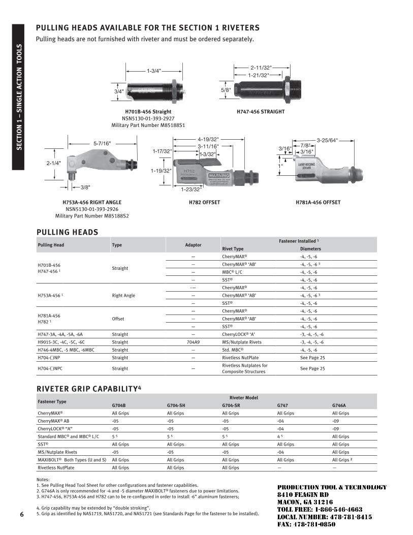
PULLING HEADS AVAILABLE FOR THE SECTION 1 RIVETERSPulling heads are not furnished with riveter and must be ordered separately.
2-11/32"1-21/32"
5/8"
H701B-456 Straight NSN5130-01-393-2927
Military Part Number M85188S1
H747-456 STRAIGHT
4-19/32"3-11/16"
1-17/32"
1-19/32"
1-3/32"
1-23/32"
1"
3/16"3-25/64"
7/8"3/16"
H753A-456 RIGHT ANGLE NSN5130-01-393-2926
Military Part Number M85188S2
H782 OFFSET H781A-456 OFFSET
PULLING HEADSPulling Head Type Adaptor
Fastener Installed 1
Rivet Type Diameters
H701B-456 H747-456 1
Straight
— CherryMAX® -4, -5, -6
— CherryMAX® ‘AB’ -4, -5, -6 3
— MBC® L/C -4, -5, -6
— SST® -4, -5, -6
H753A-456 1 Right Angle
-— CherryMAX® -4, -5, -6
— CherryMAX® ‘AB’ -4, -5, -6 3
— SST® -4, -5, -6
H781A-456 H782 1
Offset
— CherryMAX® -4, -5, -6
— CherryMAX® ‘AB’ -4, -5, -6
— SST® -4, -5, -6
H747-3A, -4A, -5A, -6A Straight — CherryLOCK® ‘A’ -3, -4, -5, -6
H9015-3C, -4C, -5C, -6C Straight 704A9 MS/Nutplate Rivets -3, -4, -5, -6
H746-4MBC, -5 MBC, -6MBC Straight — Std. MBC® -4, -5, -6
H704-( )NP Straight — Rivetless NutPlate See Page 25
H704-( )NPC Straight —Rivetless Nutplates for Composite Structures
See Page 25
RIVETER GRIP CAPABILITY4
Fastener TypeRiveter Model
G704B G704-SH G704-SR G747 G746A
CherryMAX® All Grips All Grips All Grips All Grips All Grips
CherryMAX® AB -05 -05 -05 -04 -09
CherryLOCK® “A” -05 -05 -05 -04 -09
Standard MBC® and MBC® L/C 5 5 5 5 5 5 4 5 All Grips
SST® All Grips All Grips All Grips All Grips All Grips
MS/Nutplate Rivets -05 -05 -05 -04 All Grips
MAXIBOLT® Both Types (U and S) All Grips All Grips All Grips All Grips All Grips 2
Rivetless NutPlate All Grips All Grips All Grips — —
Notes: 1. See Pulling Head Tool Sheet for other configurations and fastener capabilities.2. G746A is only recommended for -4 and -5 diameter MAXIBOLT® fasteners due to power limitations.3. H747-456, H753A-456 and H782 can to be re-configured in order to install -6” aluminum fasteners;
4. Grip capability may be extended by “double stroking”.5. Grip as identified by NAS1719, NAS1720, and NAS1721 (see Standards Page for the fastener to be installed).6
SEC
TIO
N 1
– S
ING
LE A
CTIO
N T
OO
LS
JR
Typewritten text
Production Tool & Technology 8410 Feagin Rd Macon, Ga 31216 Toll Free: 1-866-546-4663 Local Number: 478-781-8415 Fax: 478-781-0850
SECTIO
N 2 – LO
CKB
OLT TO
OLS
7
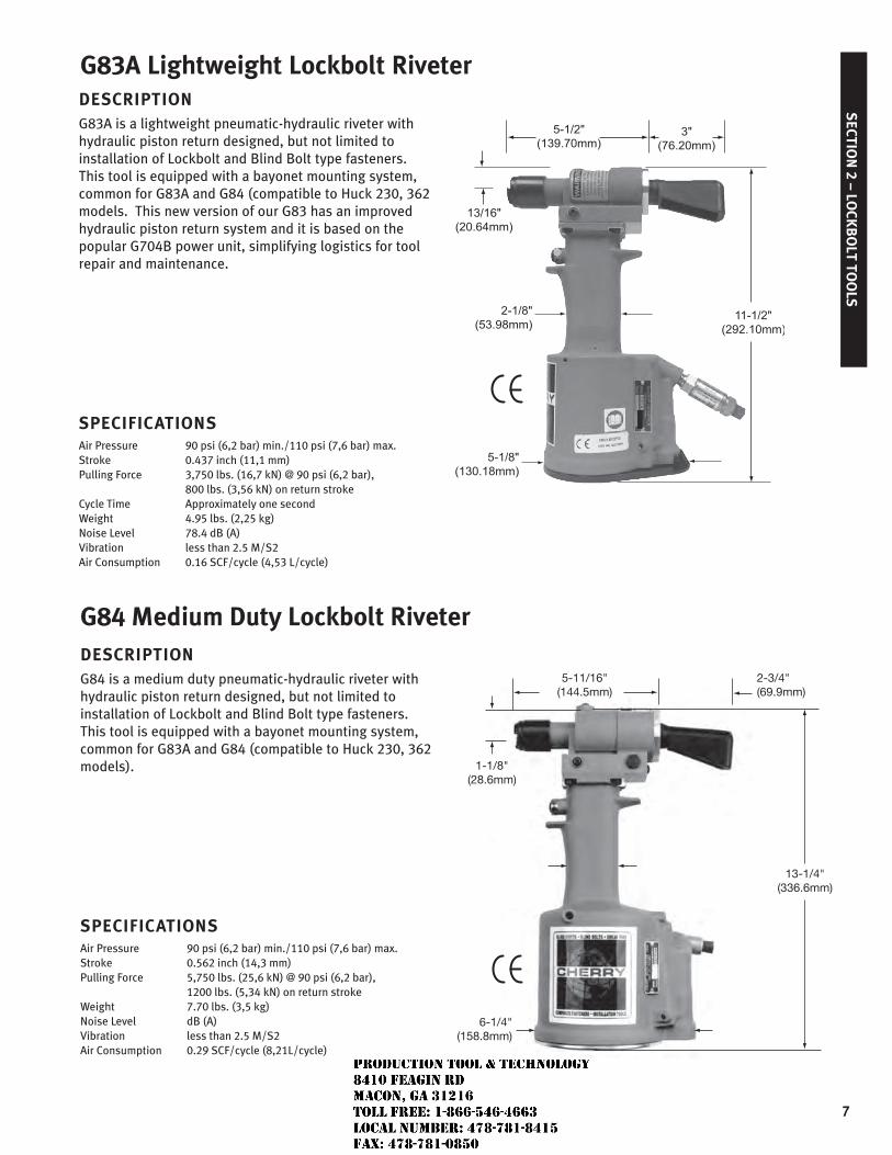
DESCRIPTIONG83A is a lightweight pneumatic-hydraulic riveter with hydraulic piston return designed, but not limited to installation of Lockbolt and Blind Bolt type fasteners. This tool is equipped with a bayonet mounting system, common for G83A and G84 (compatible to Huck 230, 362 models. This new version of our G83 has an improved hydraulic piston return system and it is based on the popular G704B power unit, simplifying logistics for tool repair and maintenance.
SPECIFICATIONSAir Pressure 90 psi (6,2 bar) min./110 psi (7,6 bar) max.Stroke 0.437 inch (11,1 mm)Pulling Force 3,750 lbs. (16,7 kN) @ 90 psi (6,2 bar), 800 lbs. (3,56 kN) on return strokeCycle Time Approximately one secondWeight 4.95 lbs. (2,25 kg)Noise Level 78.4 dB (A)Vibration less than 2.5 M/S2Air Consumption 0.16 SCF/cycle (4,53 L/cycle)
G83A Lightweight Lockbolt Riveter
G84 Medium Duty Lockbolt Riveter DESCRIPTIONG84 is a medium duty pneumatic-hydraulic riveter with hydraulic piston return designed, but not limited to installation of Lockbolt and Blind Bolt type fasteners. This tool is equipped with a bayonet mounting system, common for G83A and G84 (compatible to Huck 230, 362 models).
SPECIFICATIONSAir Pressure 90 psi (6,2 bar) min./110 psi (7,6 bar) max.Stroke 0.562 inch (14,3 mm)Pulling Force 5,750 lbs. (25,6 kN) @ 90 psi (6,2 bar), 1200 lbs. (5,34 kN) on return strokeWeight 7.70 lbs. (3,5 kg)Noise Level dB (A)Vibration less than 2.5 M/S2Air Consumption 0.29 SCF/cycle (8,21L/cycle)
13-1/4"(336.6mm)
1-1/8"(28.6mm)
5-11/16"(144.5mm)
2-3/4"(69.9mm)
6-1/4"(158.8mm)
JR
Typewritten text
Production Tool & Technology 8410 Feagin Rd Macon, Ga 31216 Toll Free: 1-866-546-4663 Local Number: 478-781-8415 Fax: 478-781-0850
SEC
TIO
N 2
– L
OCK
BO
LT T
OO
LS
8
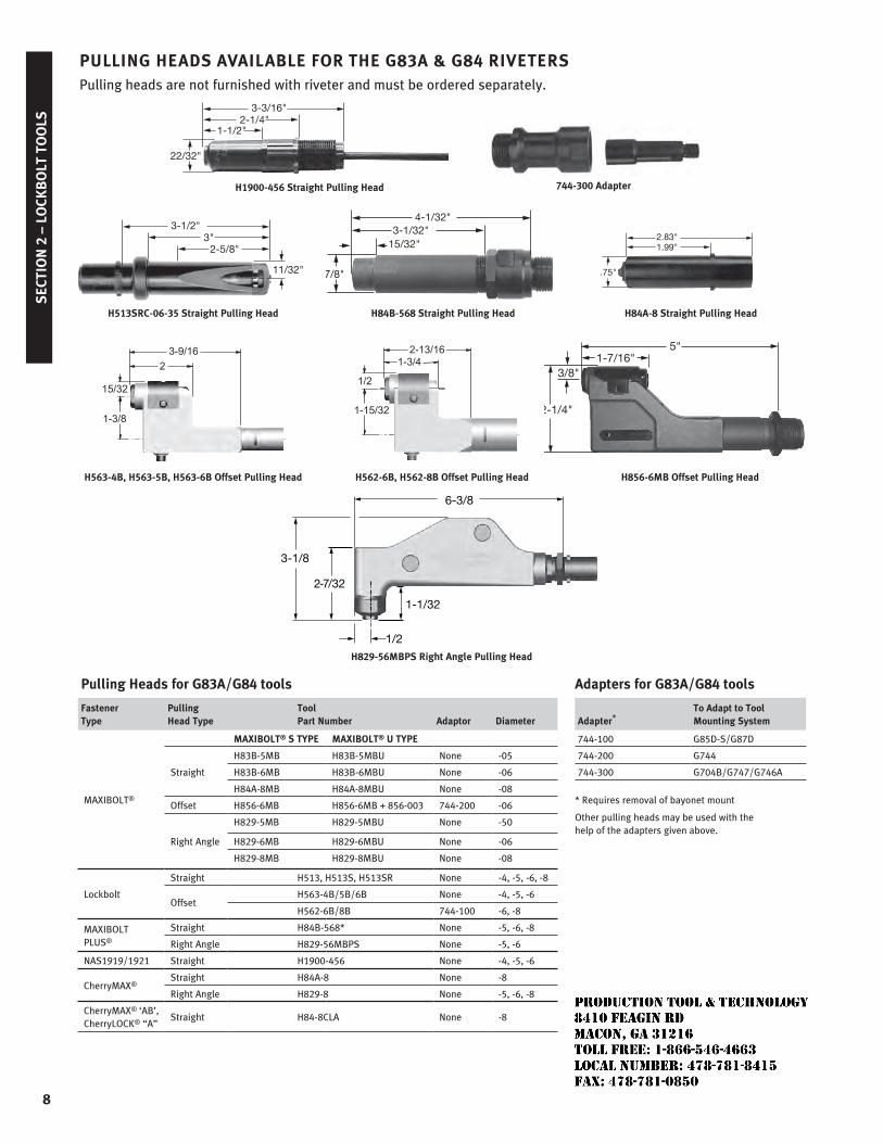
PULLING HEADS AVAILABLE FOR THE G83A & G84 RIVETERSPulling heads are not furnished with riveter and must be ordered separately.
Adapters for G83A/G84 tools
Adapter*To Adapt to ToolMounting System
744-100 G85D-S/G87D
744-200 G744
744-300 G704B/G747/G746A
* Requires removal of bayonet mount
Other pulling heads may be used with the help of the adapters given above.
Pulling Heads for G83A/G84 tools
Fastener Type
Pulling Head Type
Tool Part Number Adaptor Diameter
MAXIBOLT®
MAXIBOLT® S TYPE MAXIBOLT® U TYPE
Straight
H83B-5MB H83B-5MBU None -05
H83B-6MB H83B-6MBU None -06
H84A-8MB H84A-8MBU None -08
Offset H856-6MB H856-6MB + 856-003 744-200 -06
Right Angle
H829-5MB H829-5MBU None -50
H829-6MB H829-6MBU None -06
H829-8MB H829-8MBU None -08
Lockbolt
Straight H513, H513S, H513SR None -4, -5, -6, -8
OffsetH563-4B/5B/6B None -4, -5, -6
H562-6B/8B 744-100 -6, -8
MAXIBOLT PLUS®
Straight H84B-568* None -5, -6, -8
Right Angle H829-56MBPS None -5, -6
NAS1919/1921 Straight H1900-456 None -4, -5, -6
CherryMAX®Straight H84A-8 None -8
Right Angle H829-8 None -5, -6, -8
CherryMAX® ‘AB’, CherryLOCK® “A”
Straight H84-8CLA None -8
744-300 AdapterH1900-456 Straight Pulling Head
22/32"
2-1/4"3-3/16"
1-1/2"
H829-56MBPS Right Angle Pulling Head
1-1/32
6-3/8
2-7/32
3-1/8
1/2
H563-4B, H563-5B, H563-6B Offset Pulling Head H562-6B, H562-8B Offset Pulling Head H856-6MB Offset Pulling Head
1-15/32
2-13/16
1/2
1-3/4
H562
1-3/8
15/32
23-9/16
H563
2-1/4"
3/8"
5"1-7/16"
H84B-568 Straight Pulling Head
7/8"
3-1/32"15/32"
4-1/32"
H84A-8 Straight Pulling Head
.75"
1.99"2.83"
H513SRC-06-35 Straight Pulling Head
11/32"
3"3-1/2"
2-5/8"
JR
Typewritten text
Production Tool & Technology 8410 Feagin Rd Macon, Ga 31216 Toll Free: 1-866-546-4663 Local Number: 478-781-8415 Fax: 478-781-0850
SECTIO
N 2 – LO
CKB
OLT TO
OLS
9
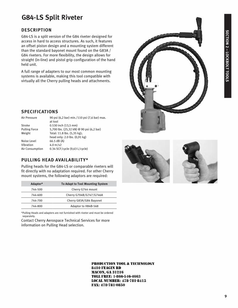
G84-LS Split Riveter
DESCRIPTION G84-LS is a split version of the G84 riveter designed for access in hard to access structures. As such, it features an offset piston design and a mounting system different than the standard bayonet mount found on the G83A / G84 riveters. For more flexibility, the design allows for straight (in-line) and pistol grip configuration of the hand held unit.
A full range of adapters to our most common mounting systems is available, making this tool compatible with virtually all the Cherry pulling heads and attachments.
SPECIFICATIONSAir Pressure 90 psi (6,2 bar) min./110 psi (7,6 bar) max. at toolStroke 0.530 inch (13,5 mm)Pulling Force 5,700 lbs. (25,32 kN) @ 90 psi (6,2 bar)Weight Total: 11.8 lbs. (5,35 kg);
head only: 2.0 lbs. (0,91 kg)Noise Level 66.5 dB (A)Vibration 4.0 m/s2Air Consumption 0.34 SCF/cycle (9,63 L/cycle)
PULLING HEAD AVAILABILITY*Pulling heads for the G84-LS or comparable riveters will fit directly with no adaptation required. For other Cherry mount systems, the following adaptors are required:
Adapter* To Adapt to Tool Mounting System
744-500 Cherry G744 mount
744-600 Cherry G704B/G747/G746A
744-700 Cherry G83A/G84 Bayonet
744-800 Adaptor to H84B-568
* Pulling Heads and adapters are not furnished with riveter and must be ordered separately.
Contact Cherry Aerospace Technical Services for more information on Pulling Head selection.
JR
Typewritten text
Production Tool & Technology 8410 Feagin Rd Macon, Ga 31216 Toll Free: 1-866-546-4663 Local Number: 478-781-8415 Fax: 478-781-0850
SEC
TIO
N 2
– L
OCK
BO
LT T
OO
LS
10
CherryMAX®
Pulling Heads & Adapter**
PartNo.
CherryMAX®
Diameter Adapter
Straight H84A-8 -8 552
Offset H827-8 -8 560-070
Right Angle H829-8 -8 552
MAXIBOLT® Pulling Heads & Adapter
Part No.
MAXIBOLT® Diameter Adapter
Straight
Pulling
Head
H652-8MBH83B-5MB H83B-5MBUH83B-6MB H83B-6MBUH84A-8MBH84A-8MBUH744-5MBH744-6MB
-8-5-5-6-6-8-8-5-6
—552552 552 552 552552560-070560-070
Offset H856-6MB -6 560-070
Right Angle
H829-5MBH829-5MBUH829-6MB, H829-6MBUH829-8MBH829-8MBU
-5-5-6-6-8-8
552552552552552552
** CherryMAX® adapter and pulling heads can install CherryMAX®, CherryMAX® ‘AB’, and SST®rivets.
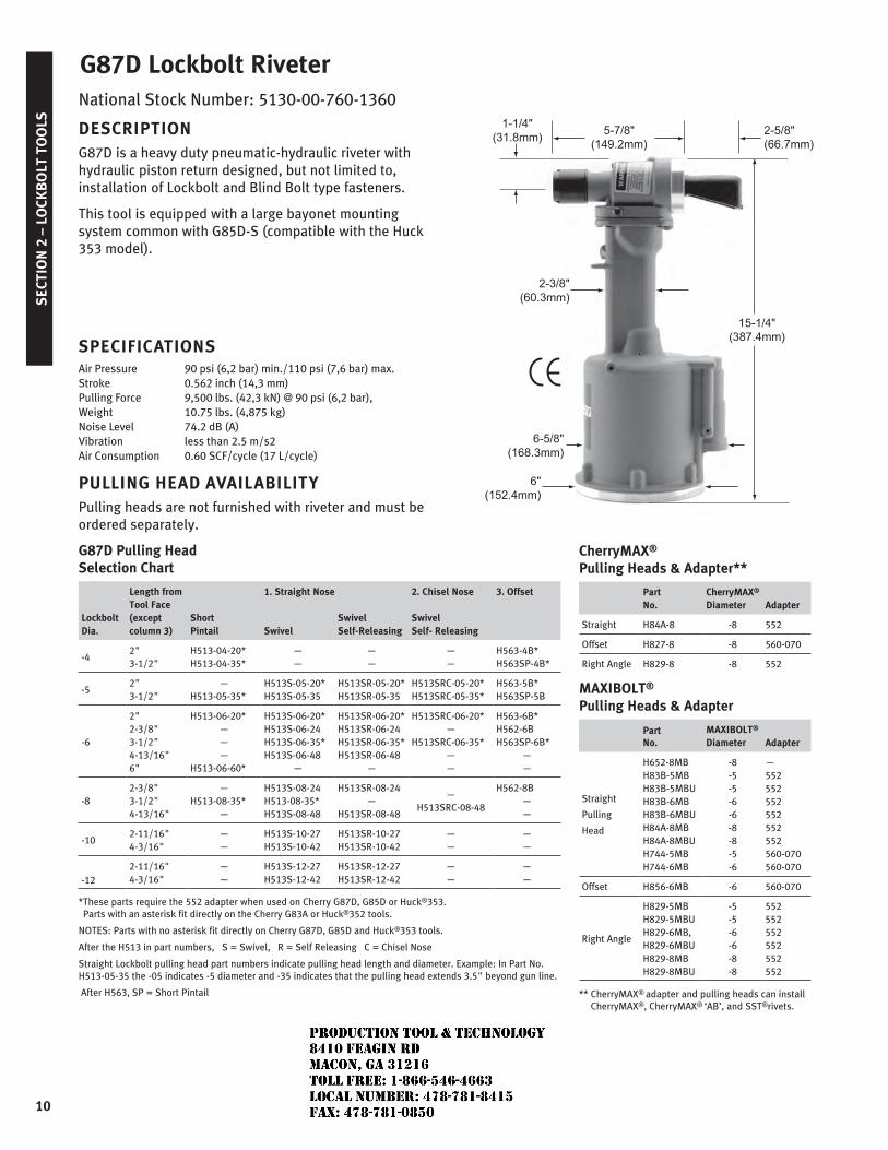
G87D Lockbolt RiveterNational Stock Number: 5130-00-760-1360
DESCRIPTIONG87D is a heavy duty pneumatic-hydraulic riveter with hydraulic piston return designed, but not limited to, installation of Lockbolt and Blind Bolt type fasteners.
This tool is equipped with a large bayonet mounting system common with G85D-S (compatible with the Huck 353 model).
SPECIFICATIONSAir Pressure 90 psi (6,2 bar) min./110 psi (7,6 bar) max.Stroke 0.562 inch (14,3 mm)Pulling Force 9,500 lbs. (42,3 kN) @ 90 psi (6,2 bar), Weight 10.75 lbs. (4,875 kg)Noise Level 74.2 dB (A)Vibration less than 2.5 m/s2Air Consumption 0.60 SCF/cycle (17 L/cycle)
PULLING HEAD AVAILABILITYPulling heads are not furnished with riveter and must be ordered separately.
G87D Pulling Head Selection Chart
LockboltDia.
Length from Tool Face (except column 3)
ShortPintail
1. Straight Nose 2. Chisel Nose 3. Offset
SwivelSwivelSelf-Releasing
SwivelSelf- Releasing
-42"3-1/2"
H513-04-20*H513-04-35*
——
——
——
H563-4B*H563SP-4B*
-52"3-1/2"
—H513-05-35*
H513S-05-20*H513S-05-35
H513SR-05-20*H513SR-05-35
H513SRC-05-20*H513SRC-05-35*
H563-5B*H563SP-5B
-6
2"2-3/8"3-1/2"4-13/16"6"
H513-06-20*———
H513-06-60*
H513S-06-20*H513S-06-24H513S-06-35*H513S-06-48
—
H513SR-06-20*H513SR-06-24H513SR-06-35*H513SR-06-48
—
H513SRC-06-20*—
H513SRC-06-35*——
H563-6B*H562-6BH563SP-6B*
——
-82-3/8"3-1/2"4-13/16"
—H513-08-35*
—
H513S-08-24H513-08-35*H513S-08-48
H513SR-08-24—
H513SR-08-48
—H513SRC-08-48
H562-8B——
-102-11/16"4-3/16"
——
H513S-10-27H513S-10-42
H513SR-10-27H513SR-10-42
——
——
-122-11/16"4-3/16"
——
H513S-12-27H513S-12-42
H513SR-12-27H513SR-12-42
——
——
* These parts require the 552 adapter when used on Cherry G87D, G85D or Huck®353. Parts with an asterisk fit directly on the Cherry G83A or Huck®352 tools.
NOTES: Parts with no asterisk fit directly on Cherry G87D, G85D and Huck®353 tools.
After the H513 in part numbers, S = Swivel, R = Self Releasing C = Chisel Nose
Straight Lockbolt pulling head part numbers indicate pulling head length and diameter. Example: In Part No. H513-05-35 the -05 indicates -5 diameter and -35 indicates that the pulling head extends 3.5" beyond gun line.
After H563, SP = Short Pintail
JR
Typewritten text
Production Tool & Technology 8410 Feagin Rd Macon, Ga 31216 Toll Free: 1-866-546-4663 Local Number: 478-781-8415 Fax: 478-781-0850
SECTIO
N 2 – LO
CKB
OLT TO
OLS
11
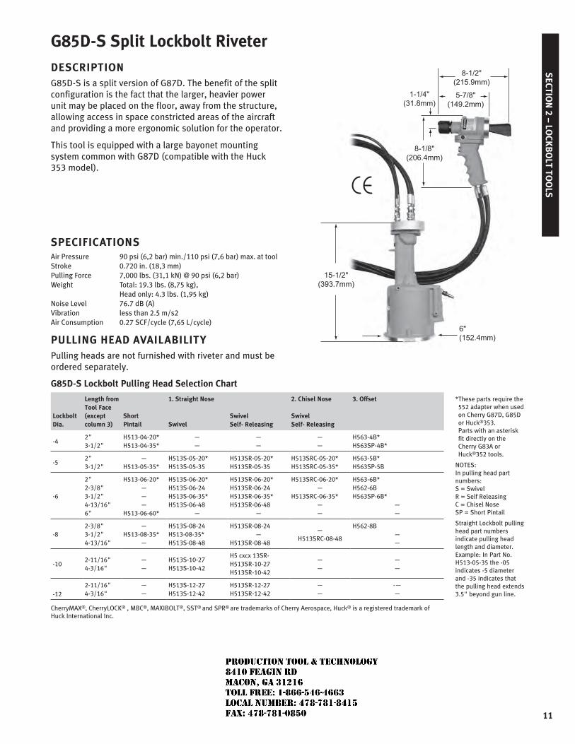
G85D-S Split Lockbolt Riveter
DESCRIPTIONG85D-S is a split version of G87D. The benefit of the split configuration is the fact that the larger, heavier power unit may be placed on the floor, away from the structure, allowing access in space constricted areas of the aircraft and providing a more ergonomic solution for the operator.
This tool is equipped with a large bayonet mounting system common with G87D (compatible with the Huck 353 model).
SPECIFICATIONSAir Pressure 90 psi (6,2 bar) min./110 psi (7,6 bar) max. at toolStroke 0.720 in. (18,3 mm)Pulling Force 7,000 lbs. (31,1 kN) @ 90 psi (6,2 bar) Weight Total: 19.3 lbs. (8,75 kg), Head only: 4.3 lbs. (1,95 kg)Noise Level 76.7 dB (A)Vibration less than 2.5 m/s2Air Consumption 0.27 SCF/cycle (7,65 L/cycle)
PULLING HEAD AVAILABILITYPulling heads are not furnished with riveter and must be ordered separately.
G85D-S Lockbolt Pulling Head Selection Chart
LockboltDia.
Length from Tool Face (except column 3)
ShortPintail
1. Straight Nose 2. Chisel Nose 3. Offset * These parts require the 552 adapter when used on Cherry G87D, G85D or Huck®353. Parts with an asterisk fit directly on the Cherry G83A or Huck®352 tools.
NOTES: In pulling head part numbers: S = Swivel R = Self Releasing C = Chisel Nose SP = Short Pintail
Straight Lockbolt pulling head part numbers indicate pulling head length and diameter. Example: In Part No. H513-05-35 the -05 indicates -5 diameter and -35 indicates that the pulling head extends 3.5" beyond gun line.
SwivelSwivelSelf- Releasing
SwivelSelf- Releasing
-42"3-1/2"
H513-04-20*H513-04-35*
——
——
——
H563-4B*H563SP-4B*
-52"3-1/2"
—H513-05-35*
H513S-05-20*H513S-05-35
H513SR-05-20*H513SR-05-35
H513SRC-05-20*H513SRC-05-35*
H563-5B*H563SP-5B
-6
2"2-3/8"3-1/2"4-13/16"6"
H513-06-20*———
H513-06-60*
H513S-06-20*H513S-06-24H513S-06-35*H513S-06-48
—
H513SR-06-20*H513SR-06-24H513SR-06-35*H513SR-06-48
—
H513SRC-06-20*—
H513SRC-06-35*——
H563-6B*H562-6BH563SP-6B*
——
-82-3/8"3-1/2"4-13/16"
—H513-08-35*
—
H513S-08-24H513-08-35*H513S-08-48
H513SR-08-24—
H513SR-08-48
—H513SRC-08-48
H562-8B——
-102-11/16"4-3/16"
——
H513S-10-27H513S-10-42
H5 cxcx 13SR-H513SR-10-27H513SR-10-42
——
——
-122-11/16"4-3/16"
——
H513S-12-27H513S-12-42
H513SR-12-27H513SR-12-42
——
-——
CherryMAX®, CherryLOCK® , MBC®, MAXIBOLT®, SST® and SPR® are trademarks of Cherry Aerospace, Huck® is a registered trademark of Huck International Inc.
JR
Typewritten text
Production Tool & Technology 8410 Feagin Rd Macon, Ga 31216 Toll Free: 1-866-546-4663 Local Number: 478-781-8415 Fax: 478-781-0850
SEC
TIO
N 3
– D
OU
BLE
ACT
ION
TO
OLS
12
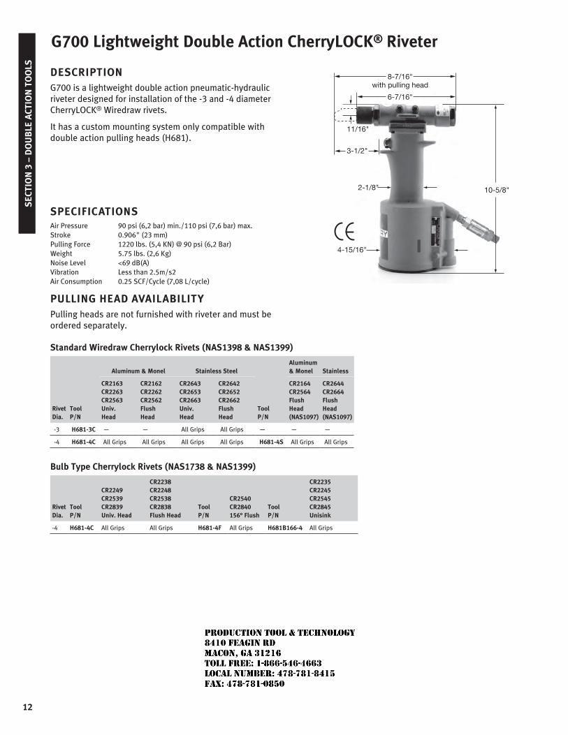
G700 Lightweight Double Action CherryLOCK® Riveter
DESCRIPTIONG700 is a lightweight double action pneumatic-hydraulic riveter designed for installation of the -3 and -4 diameter CherryLOCK® Wiredraw rivets.
It has a custom mounting system only compatible with double action pulling heads (H681).
SPECIFICATIONSAir Pressure 90 psi (6,2 bar) min./110 psi (7,6 bar) max.Stroke 0.906" (23 mm) Pulling Force 1220 lbs. (5,4 KN) @ 90 psi (6,2 Bar)Weight 5.75 lbs. (2,6 Kg) Noise Level <69 dB(A)Vibration Less than 2.5m/s2Air Consumption 0.25 SCF/Cycle (7,08 L/cycle)
PULLING HEAD AVAILABILITYPulling heads are not furnished with riveter and must be ordered separately.
Standard Wiredraw Cherrylock Rivets (NAS1398 & NAS1399)
Rivet Dia.
Tool P/N
Aluminum & Monel Stainless Steel
Tool P/N
Aluminum & Monel Stainless
CR2163CR2263CR2563Univ. Head
CR2162CR2262CR2562Flush Head
CR2643CR2653CR2663Univ. Head
CR2642CR2652CR2662Flush Head
CR2164CR2564Flush Head(NAS1097)
CR2644CR2664Flush Head(NAS1097)
-3 H681-3C — — All Grips All Grips — — —
-4 H681-4C All Grips All Grips All Grips All Grips H681-4S All Grips All Grips
Bulb Type Cherrylock Rivets (NAS1738 & NAS1399)
Rivet Dia.
Tool P/N
CR2249CR2539CR2839Univ. Head
CR2238CR2248CR2538CR2838Flush Head
Tool P/N
CR2540CR2840156° Flush
Tool P/N
CR2235CR2245CR2545CR2845Unisink
-4 H681-4C All Grips All Grips H681-4F All Grips H681B166-4 All Grips
10-5/8"
8-7/16"with pulling head
2-1/8"
3-1/2"
11/16"
4-15/16"
6-7/16"
JR
Typewritten text
Production Tool & Technology 8410 Feagin Rd Macon, Ga 31216 Toll Free: 1-866-546-4663 Local Number: 478-781-8415 Fax: 478-781-0850
SECTIO
N 3 – D
OU
BLE A
CTION
TOO
LS
13
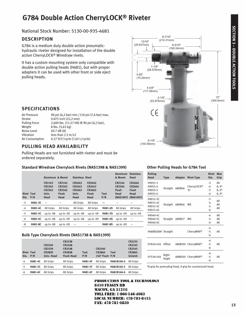
National Stock Number: 5130-00-935-4681
DESCRIPTIONG784 is a medium duty double action pneumatic-hydraulic riveter designed for installation of the double action CherryLOCK® Wiredraw rivets.
It has a custom mounting system only compatible with double action pulling heads (H681), but with proper adapters it can be used with other front or side eject pulling heads.
SPECIFICATIONSAir Pressure 90 psi (6,2 bar) min./110 psi (7,6 bar) max.Stroke 0.875 inch (22,2 mm)Pulling Force 2,600 lbs. (11,57 kN) @ 90 psi (6,2 bar), Weight 8 lbs. (3,63 kg)Noise Level 69.7 dB (A)Vibration less than 2.5 m/s2Air Consumption 0.27 SCF/cycle (7,65 L/cycle)
PULLING HEAD AVAILABILITYPulling Heads are not furnished with riveter and must be ordered separately.
Standard Wiredraw Cherrylock Rivets (NAS1398 & NAS1399)
Rivet Dia.
Tool P/N
Aluminum & Monel Stainless Steel
Tool P/N
Aluminum & Monel
Stainless Steel
CR2163CR2263CR2563Univ. Head
CR2162CR2262CR2562Flush Head
CR2643CR2653CR2663Univ. Head
CR2642CR2652CR2662Flush Head
CR2164CR2564Flush Head(NAS1097)
CR2644CR2664Flush Head(NAS1097)
-3 H681-3C — — All Grips All Grips — — —
-4 H681-4C All Grips All Grips All Grips All Grips H681-4S All Grips All Grips
-5 H681-5C up to -08 up to -09 up to -08 up to -09 H681-5S up to -09 up to -09
-6 H681-6C up to -08 up to -09 up to -08 up to -09 H681-6S up to -09 —
-8 H681-8C up to -08 up to -09 — — H681-8S up to -09 —
Bulb Type Cherrylock Rivets (NAS1738 & NAS1399)
Rivet Dia.
Tool P/N
CR2249CR2539CR2839Univ. Head
CR2238CR2248CR2538CR2838Flush Head
Tool P/N
CR2540CR2840156° Flush
Tool P/N
CR2235CR2245CR2545CR2845Unisink
-4 H681-4C All Grips All Grips H681-4F All Grips H681B166-4 All Grips
-5 H681-5C All Grips All Grips H681-5F All Grips H681B166-5 All Grips
-6 H681-6C All Grips All Grips H681-6F All Grips H681B166-6 All Grips
G784 Double Action CherryLOCK® Riveter
Other Pulling Heads for G784 Tool
PullingHead Type Adapter Rivet Type
RivetDia.
MaxGrip
H9055-3H9055-4H9055-5H9055-6
Straight 680B46CherryLOCK®
‘A’
-3-4-5-6
All8, 9*8, 9*8, 9*
H9015-3CH9015-4CH9015-5CH9015-6C
Straight 680B46 MS
-3-4-5-6
AllAllAll
H9040-4CH9040-5CH9040-6C
Straight 680B57 MS-4-5-6
AllAllAll
H680B200A Straight CherryMAX®
-4-5-6
All
H781A-456 Offset 680B205 CherryMAX®
-4-5-6
All
H753A-456Right Angle
680B205 CherryMAX®
-4-5-6
All
*8 grip for protruding head, 9 grip for countersunk head.
JR
Typewritten text
Production Tool & Technology 8410 Feagin Rd Macon, Ga 31216 Toll Free: 1-866-546-4663 Local Number: 478-781-8415 Fax: 478-781-0850
SEC
TIO
N 3
– D
OU
BLE
ACT
ION
TO
OLS
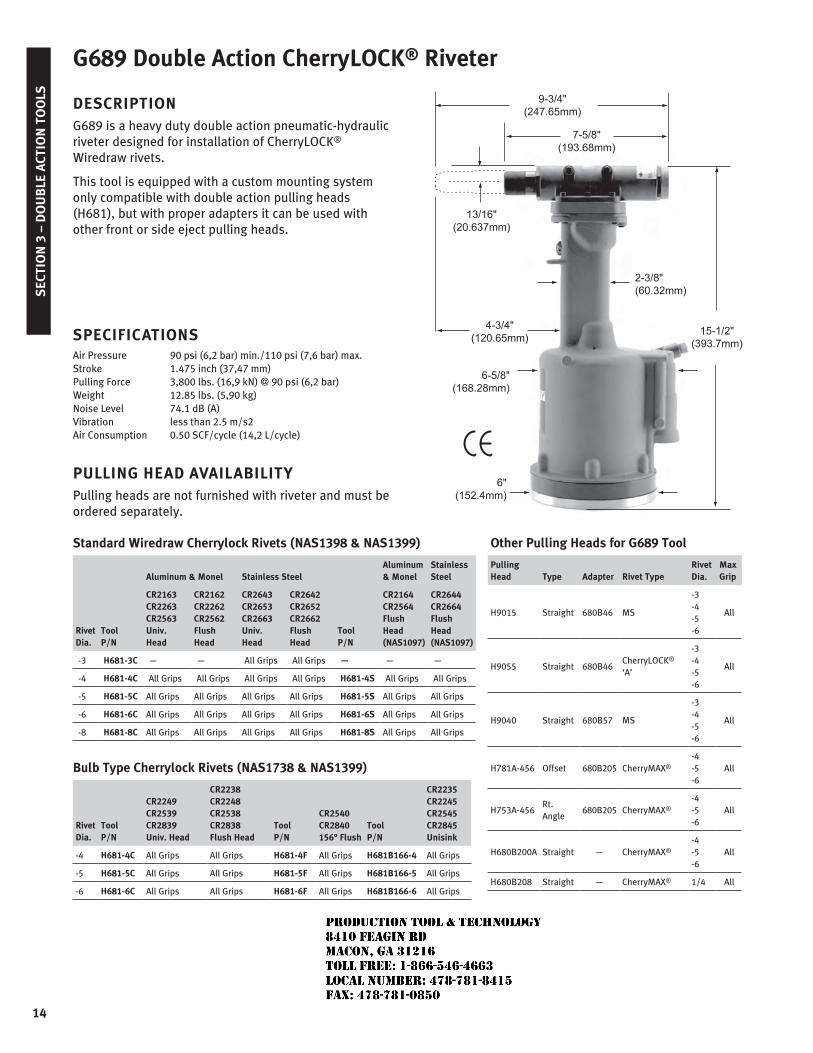
14
DESCRIPTIONG689 is a heavy duty double action pneumatic-hydraulic riveter designed for installation of CherryLOCK® Wiredraw rivets.
This tool is equipped with a custom mounting system only compatible with double action pulling heads (H681), but with proper adapters it can be used with other front or side eject pulling heads.
SPECIFICATIONSAir Pressure 90 psi (6,2 bar) min./110 psi (7,6 bar) max.Stroke 1.475 inch (37,47 mm)Pulling Force 3,800 lbs. (16,9 kN) @ 90 psi (6,2 bar)Weight 12.85 lbs. (5,90 kg)Noise Level 74.1 dB (A)Vibration less than 2.5 m/s2Air Consumption 0.50 SCF/cycle (14,2 L/cycle)
PULLING HEAD AVAILABILITYPulling heads are not furnished with riveter and must be ordered separately.
Standard Wiredraw Cherrylock Rivets (NAS1398 & NAS1399)
Rivet Dia.
Tool P/N
Aluminum & Monel Stainless Steel
Tool P/N
Aluminum & Monel
Stainless Steel
CR2163CR2263CR2563Univ. Head
CR2162CR2262CR2562Flush Head
CR2643CR2653CR2663Univ. Head
CR2642CR2652CR2662Flush Head
CR2164CR2564Flush Head(NAS1097)
CR2644CR2664Flush Head(NAS1097)
-3 H681-3C — — All Grips All Grips — — —
-4 H681-4C All Grips All Grips All Grips All Grips H681-4S All Grips All Grips
-5 H681-5C All Grips All Grips All Grips All Grips H681-5S All Grips All Grips
-6 H681-6C All Grips All Grips All Grips All Grips H681-6S All Grips All Grips
-8 H681-8C All Grips All Grips All Grips All Grips H681-8S All Grips All Grips
Bulb Type Cherrylock Rivets (NAS1738 & NAS1399)
Rivet Dia.
Tool P/N
CR2249CR2539CR2839Univ. Head
CR2238CR2248CR2538CR2838Flush Head
Tool P/N
CR2540CR2840156° Flush
Tool P/N
CR2235CR2245CR2545CR2845Unisink
-4 H681-4C All Grips All Grips H681-4F All Grips H681B166-4 All Grips
-5 H681-5C All Grips All Grips H681-5F All Grips H681B166-5 All Grips
-6 H681-6C All Grips All Grips H681-6F All Grips H681B166-6 All Grips
Other Pulling Heads for G689 Tool
PullingHead Type Adapter Rivet Type
RivetDia.
MaxGrip
H9015 Straight 680B46 MS
-3-4-5-6
All
H9055 Straight 680B46CherryLOCK® ‘A’
-3-4-5-6
All
H9040 Straight 680B57 MS
-3-4-5-6
All
H781A-456 Offset 680B205 CherryMAX®
-4-5-6
All
H753A-456Rt. Angle
680B205 CherryMAX®
-4-5-6
All
H680B200A Straight — CherryMAX®
-4-5-6
All
H680B208 Straight — CherryMAX® 1/4 All
G689 Double Action CherryLOCK® Riveter
JR
Typewritten text
Production Tool & Technology 8410 Feagin Rd Macon, Ga 31216 Toll Free: 1-866-546-4663 Local Number: 478-781-8415 Fax: 478-781-0850
SECTIO
N 3 – D
OU
BLE A
CTION
TOO
LS
15
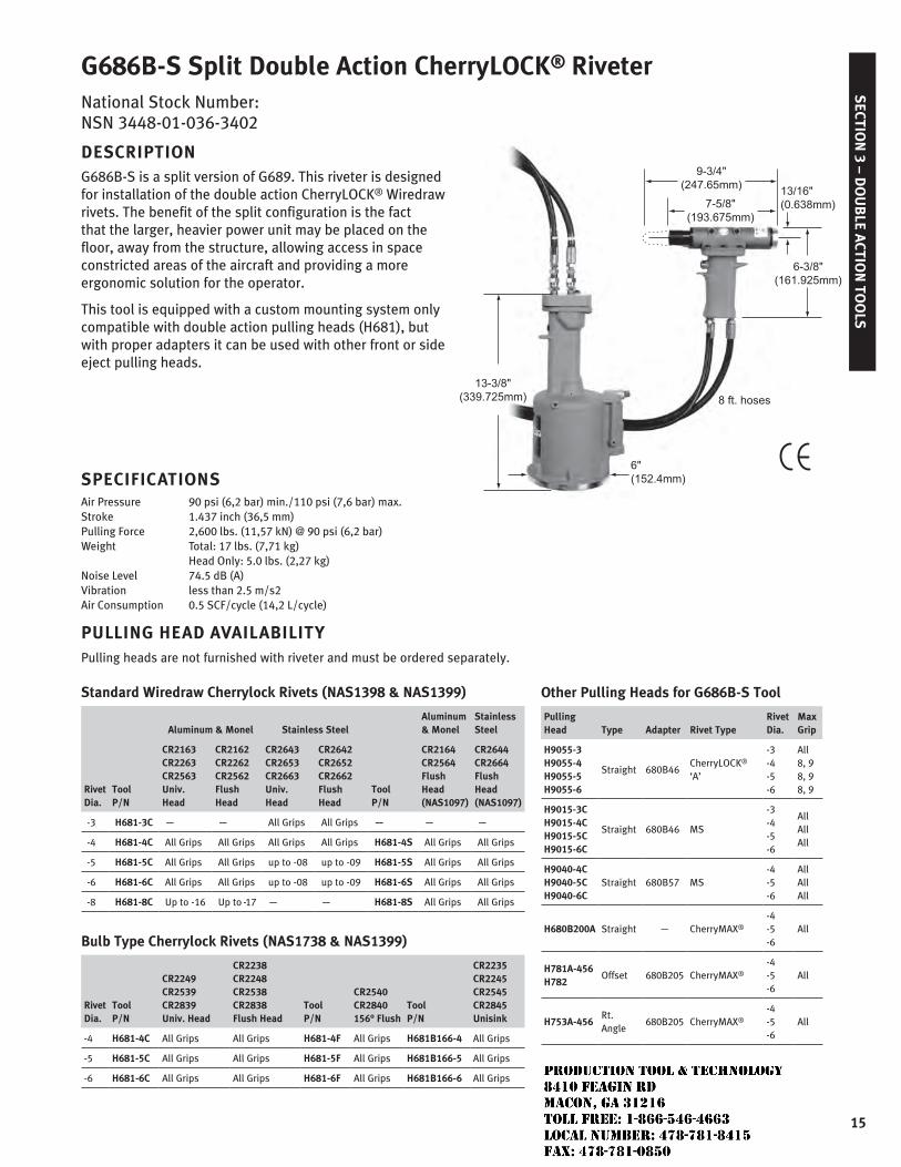
G686B-S Split Double Action CherryLOCK® RiveterNational Stock Number: NSN 3448-01-036-3402
DESCRIPTIONG686B-S is a split version of G689. This riveter is designed for installation of the double action CherryLOCK® Wiredraw rivets. The benefit of the split configuration is the fact that the larger, heavier power unit may be placed on the floor, away from the structure, allowing access in space constricted areas of the aircraft and providing a more ergonomic solution for the operator.
This tool is equipped with a custom mounting system only compatible with double action pulling heads (H681), but with proper adapters it can be used with other front or side eject pulling heads.
SPECIFICATIONSAir Pressure 90 psi (6,2 bar) min./110 psi (7,6 bar) max.Stroke 1.437 inch (36,5 mm)Pulling Force 2,600 lbs. (11,57 kN) @ 90 psi (6,2 bar)Weight Total: 17 lbs. (7,71 kg) Head Only: 5.0 lbs. (2,27 kg)Noise Level 74.5 dB (A)Vibration less than 2.5 m/s2Air Consumption 0.5 SCF/cycle (14,2 L/cycle)
PULLING HEAD AVAILABILITYPulling heads are not furnished with riveter and must be ordered separately.
Standard Wiredraw Cherrylock Rivets (NAS1398 & NAS1399)
Rivet Dia.
Tool P/N
Aluminum & Monel Stainless Steel
Tool P/N
Aluminum & Monel
Stainless Steel
CR2163CR2263CR2563Univ. Head
CR2162CR2262CR2562Flush Head
CR2643CR2653CR2663Univ. Head
CR2642CR2652CR2662Flush Head
CR2164CR2564Flush Head(NAS1097)
CR2644CR2664Flush Head(NAS1097)
-3 H681-3C — — All Grips All Grips — — —
-4 H681-4C All Grips All Grips All Grips All Grips H681-4S All Grips All Grips
-5 H681-5C All Grips All Grips up to -08 up to -09 H681-5S All Grips All Grips
-6 H681-6C All Grips All Grips up to -08 up to -09 H681-6S All Grips All Grips
-8 H681-8C Up to -16 Up to -17 — — H681-8S All Grips All Grips
Bulb Type Cherrylock Rivets (NAS1738 & NAS1399)
Rivet Dia.
Tool P/N
CR2249CR2539CR2839Univ. Head
CR2238CR2248CR2538CR2838Flush Head
Tool P/N
CR2540CR2840156° Flush
Tool P/N
CR2235CR2245CR2545CR2845Unisink
-4 H681-4C All Grips All Grips H681-4F All Grips H681B166-4 All Grips
-5 H681-5C All Grips All Grips H681-5F All Grips H681B166-5 All Grips
-6 H681-6C All Grips All Grips H681-6F All Grips H681B166-6 All Grips
Other Pulling Heads for G686B-S Tool
PullingHead Type Adapter Rivet Type
RivetDia.
MaxGrip
H9055-3H9055-4H9055-5H9055-6
Straight 680B46CherryLOCK® ‘A’
-3-4-5-6
All8, 98, 9
8, 9
H9015-3CH9015-4CH9015-5CH9015-6C
Straight 680B46 MS
-3-4-5-6
AllAllAll
H9040-4CH9040-5CH9040-6C
Straight 680B57 MS-4-5-6
AllAllAll
H680B200A Straight — CherryMAX®
-4-5-6
All
H781A-456 H782
Offset 680B205 CherryMAX®
-4-5-6
All
H753A-456Rt. Angle
680B205 CherryMAX®
-4-5-6
All
JR
Typewritten text
Production Tool & Technology 8410 Feagin Rd Macon, Ga 31216 Toll Free: 1-866-546-4663 Local Number: 478-781-8415 Fax: 478-781-0850
SEC
TIO
N 3
– D
OU
BLE
ACT
ION
TO
OLS
16
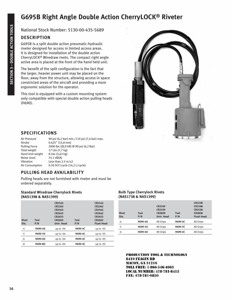
G695B Right Angle Double Action CherryLOCK® Riveter
National Stock Number: 5130-00-435-5689
DESCRIPTIONG695B is a split double action pneumatic-hydraulic riveter designed for access in limited access areas. It is designed for installation of the double action CherryLOCK® Wiredraw rivets. The compact right angle active area is placed at the front of the hand held unit.
The benefit of the split configuration is the fact that the larger, heavier power unit may be placed on the floor, away from the structure, allowing access in space constricted areas of the aircraft and providing a more ergonomic solution for the operator.
This tool is equipped with a custom mounting system only compatible with special double action pulling heads (H690).
SPECIFICATIONSAir Pressure 90 psi (6,2 bar) min./110 psi (7,6 bar) max.Stroke 0.625" (15,8 mm)Pulling Force 2000 lbs ((8,9 kN) @ 90 psi (6,2 Bar)Total weight 17 Lbs (7,7 kg)Hand Unit weight 8 Lbs (3,63 kg)Noise Level 74.1 dB(A)Vibration Less than 2.5 m/s2Air Consumption 0.50 SCF/cycle (14,2 L/cycle)
PULLING HEAD AVAILABILITYPulling heads are not furnished with riveter and must be ordered separately.
Standard Wiredraw Cherrylock Rivets (NAS1398 & NAS1399)
Rivet Dia.
Tool P/N
CR2163CR2263CR2563CR2643CR2653CR2663Univ. Head
Tool P/N
CR2162CR2262CR2562CR2642CR2652CR2662Flush Head
-4 H690-4U up to -04 H690-4C up to -05
-5 H690-5U up to -04 H690-4C up to -05
-6 H690-6U up to -04 H690-4C up to -05
-8 H690-8U up to -04 H690-4C up to -05
Bulb Type Cherrylock Rivets (NAS1738 & NAS1399)
Rivet Dia.
Tool P/N
CR2249CR2539CR2839Univ. Head
Tool P/N
CR2238CR2248CR2538CR2838Flush Head
-4 H690-4U All Grips H690-4C All Grips
-5 H690-5U All Grips H690-5C All Grips
-6 H690-6U All Grips H690-6C All Grips
JR
Typewritten text
Production Tool & Technology 8410 Feagin Rd Macon, Ga 31216 Toll Free: 1-866-546-4663 Local Number: 478-781-8415 Fax: 478-781-0850
SECTIO
N 4 – H
AN
D P
OW
ERED
TOO
LS
17
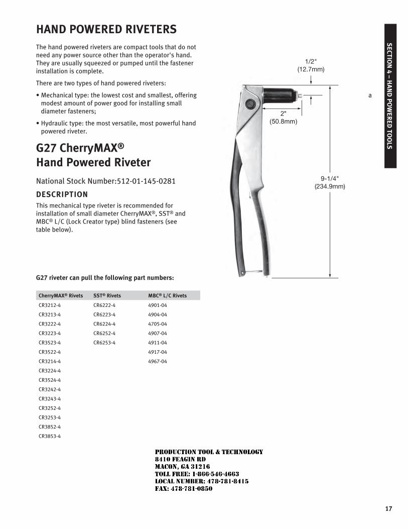
HAND POWERED RIVETERSThe hand powered riveters are compact tools that do not need any power source other than the operator's hand. They are usually squeezed or pumped until the fastener installation is complete.
There are two types of hand powered riveters:
• Mechanical type: the lowest cost and smallest, offering a modest amount of power good for installing small diameter fasteners;
• Hydraulic type: the most versatile, most powerful hand powered riveter.
G27 CherryMAX® Hand Powered Riveter
National Stock Number:512-01-145-0281
DESCRIPTIONThis mechanical type riveter is recommended for installation of small diameter CherryMAX®, SST® and MBC® L/C (Lock Creator type) blind fasteners (see table below).
G27 riveter can pull the following part numbers:
CherryMAX® Rivets SST® Rivets MBC® L/C Rivets
CR3212-4
CR3213-4
CR3222-4
CR3223-4
CR3523-4
CR3522-4
CR3214-4
CR3224-4
CR3524-4
CR3242-4
CR3243-4
CR3252-4
CR3253-4
CR3852-4
CR3853-4
CR6222-4
CR6223-4
CR6224-4
CR6252-4
CR6253-4
4901-04
4904-04
4705-04
4907-04
4911-04
4917-04
4967-04
9-1/4"(234.9mm)
1/2"(12.7mm)
JR
Typewritten text
Production Tool & Technology 8410 Feagin Rd Macon, Ga 31216 Toll Free: 1-866-546-4663 Local Number: 478-781-8415 Fax: 478-781-0850
SEC
TIO
N 4
– H
AN
D P
OW
ERED
TO
OLS
18
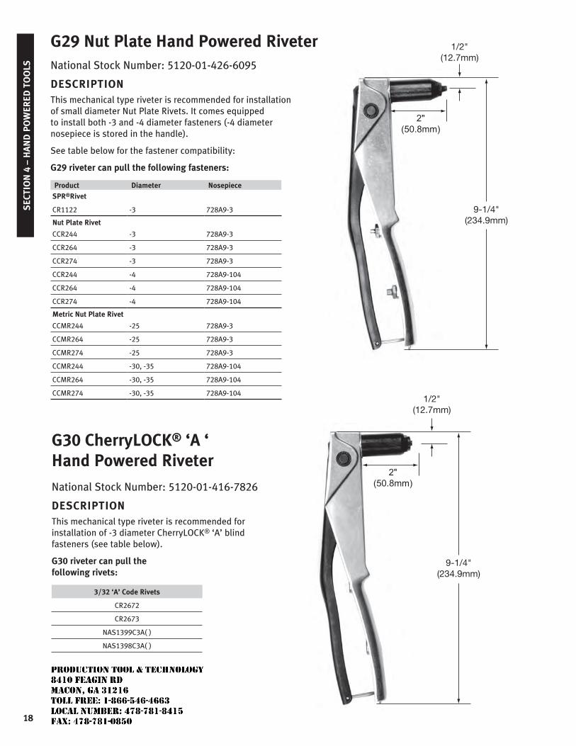
National Stock Number: 5120-01-426-6095
DESCRIPTIONThis mechanical type riveter is recommended for installation of small diameter Nut Plate Rivets. It comes equipped to install both -3 and -4 diameter fasteners (-4 diameter nosepiece is stored in the handle).
See table below for the fastener compatibility:
G29 riveter can pull the following fasteners:
Product Diameter Nosepiece
SPR®Rivet
CR1122 -3 728A9-3
Nut Plate Rivet
CCR244 -3 728A9-3
CCR264 -3 728A9-3
CCR274 -3 728A9-3
CCR244 -4 728A9-104
CCR264 -4 728A9-104
CCR274 -4 728A9-104
Metric Nut Plate Rivet
CCMR244 -25 728A9-3
CCMR264 -25 728A9-3
CCMR274 -25 728A9-3
CCMR244 -30, -35 728A9-104
CCMR264 -30, -35 728A9-104
CCMR274 -30, -35 728A9-104
1/2"(12.7mm)
9-1/4"(234.9mm)
G29 Nut Plate Hand Powered Riveter
G30 CherryLOCK® ‘A ‘ Hand Powered Riveter
National Stock Number: 5120-01-416-7826
DESCRIPTIONThis mechanical type riveter is recommended for installation of -3 diameter CherryLOCK® ‘A’ blind fasteners (see table below).
G30 riveter can pull the following rivets:
3/32 ‘A’ Code Rivets
CR2672
CR2673
NAS1399C3A( )
NAS1398C3A( )
1/2"(12.7mm)
9-1/4"(234.9mm)
JR
Typewritten text
Production Tool & Technology 8410 Feagin Rd Macon, Ga 31216 Toll Free: 1-866-546-4663 Local Number: 478-781-8415 Fax: 478-781-0850
SECTIO
N 4 – H
AN
D P
OW
ERED
TOO
LS
19
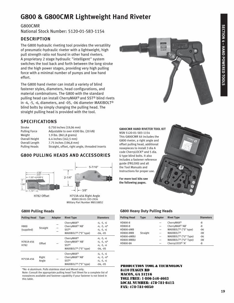
G800 & G800CMR Lightweight Hand RiveterG800CMR National Stock Number: 5120-01-583-1154
DESCRIPTIONThe G800 hydraulic riveting tool provides the versatility of pneumatic-hydraulic riveter with a lightweight, high pull strength ratio not found in other hand riveters. A proprietary 2 stage hydraulic "intelligent" system switches the tool back and forth between the long stroke and the high power stages, providing very high pulling force with a minimal number of pumps and low hand effort.
The G800 hand riveter can install a variety of blind fastener styles, diameters, head configurations, and material combinations. The G800 with the standard pulling head can install CherryMAX® and SST® blind rivets in -4, -5, -6, diameters, and -05, -06 diameter MAXIBOLT® blind bolts by simply changing the pulling head. The straight pulling head is provided with the tool.
SPECIFICATIONSStroke 0.750 inches (19,06 mm)Pulling Force Adjustable to over 4500 lbs. (20 kN)Weight 1.9 lbs. (861,8 grams)Overall Height 6.4 inches (162,5 mm)Overall Length 7.75 inches (196,8 mm)Pulling Heads Straight, offset, right angle, threaded inserts
G800 PULLING HEADS AND ACCESSORIES
4.59"3.67"
1.53"
1.60"
1.09"
1.72"
H782 Offset H753A-456 Right Angle NSN5130-01-393-2926
Military Part Number M85188S2
G800 Pulling Heads
Pulling Head Type Adapter Rivet Type Diameters
H800 (supplied)
Straight———
CherryMAX®
CherryMAX® ‘AB’SST®
MAXIBOLT® (“S” type)
-4, -5, -6-4, -5, -6*-4, -5, -6-04, -05
H781A-456 H782
Offset —
CherryMAX®
CherryMAX® ‘AB’SST®
MAXIBOLT® (“S” type)
-4, -5, -6-4, -5, -6*-4, -5, -6-04, -05
H753A-456Right Angle
—
CherryMAX®
CherryMAX® ‘AB’SST®
MAXIBOLT® (“S” type)
-4, -5, -6-4, -5, -6*-4, -5, -6-04, -05
*No -6 aluminum. Pulls stainless steel and Monel only. Note: Consult the appropriate pulling head Tool Sheet for a complete list of nosepieces available and fastener capability if your fastener is not listed in this table.
G800CMR HAND RIVETER TOOL KITNSN 5120-01-583-1154This G800CMR kit includes the G800 riveter, a right angle and offset pulling head, additional nosepieces to install 3 dia A code CherryLOCK® and 5 dia. U type blind bolts. It also includes a fastener reference guide (FRG200) and all the Tool Manuals and Instructions for proper use.
For more tool kits see the following pages.
G800 Heavy Duty Pulling Heads
Pulling Head Type Adapter Rivet Type Diameters
HD800-8HD800-8HD800-6MBHD800-8MBHD800-6MBUHD800-8MBUHD800-8A
Straight
———————
CherryMAX®
CherryMAX® ‘AB’MAXIBOLT® (“S” type)MAXIBOLT® MAXIBOLT® (“U” Type)MAXIBOLT® (“U” Type)CherryLOCK® ‘A’
-8-8-06-08-06-08-8
JR
Typewritten text
Production Tool & Technology 8410 Feagin Rd Macon, Ga 31216 Toll Free: 1-866-546-4663 Local Number: 478-781-8415 Fax: 478-781-0850
20
SEC
TIO
N 1
– S
ING
LE A
CTIO
N T
OO
LSS
ECTI
ON
5 –
TOO
L K
ITS
& A
CCES
SO
RIE
S
CherryMAX® Tool Kits
Tool Kit Part No. Description
Items Included
QtyPart Number Description
G704BCMR
G704B CherryMAX®
Tool Kit
Process Manuals, Reference Card, and Tool Documentation are included
G704B Medium Duty, Single Action Riveter 1
H701B-456 Straight Pulling Head (-4,-5 & -6 dia) 1
H781A-456 Offset Pulling Head (-4,-5 & -6 dia) 1
H753A-456 Right Angle Pulling Head (-4,-5 & -6 dia) 1
269C3 CherryMAX®/CherryLOCK® Grip Selector Gage 1
700A77 Hydraulic Air Bleeder 1
670A20 Stem Catcher Bag 1
P-1393 Plastic Casing 1
G747CMR
G747CherryMAX® Tool Kit
Process Manuals, Reference Card, and Tool Documentation are included
G747 Compact, Single Action Riveter 1
H701B-456 Straight Pulling Head (-4,-5 & -6 dia) 1
H781A-456 Offset Pulling Head (-4,-5 & -6 dia) 1
H747-3NPR 3/32 Nut Plate Rivet P.H. 1
H753A-456 Right Angle Pulling Head (-4,-5 & -6 dia) 1
269C3 CherryMAX®/CherryLOCK® Grip Selector Gage 1
700A77 Hydraulic Air Bleeder 1
670A20 Stem Catcher Bag 1
P-1393 Plastic Casing 1
G746ACMR
G746ACherryMAX®
Tool Kit
Process Manuals, Reference Card, and Tool Documentation are included
G746A Compact, Single Action Riveter 1
H701B-456 Straight Pulling Head (-4,-5 & -6 dia) 1
H781A-456 Offset Pulling Head (-4,-5 & -6 dia) 1
H753A-456 Right Angle Pulling Head (-4,-5 & -6 dia) 1
269C3 CherryMAX®/CherryLOCK® Grip Selector Gage 1
700A77 Hydraulic Air Bleeder 1
670A20 Stem Catcher Bag 1
P-1393 Plastic Casing 1
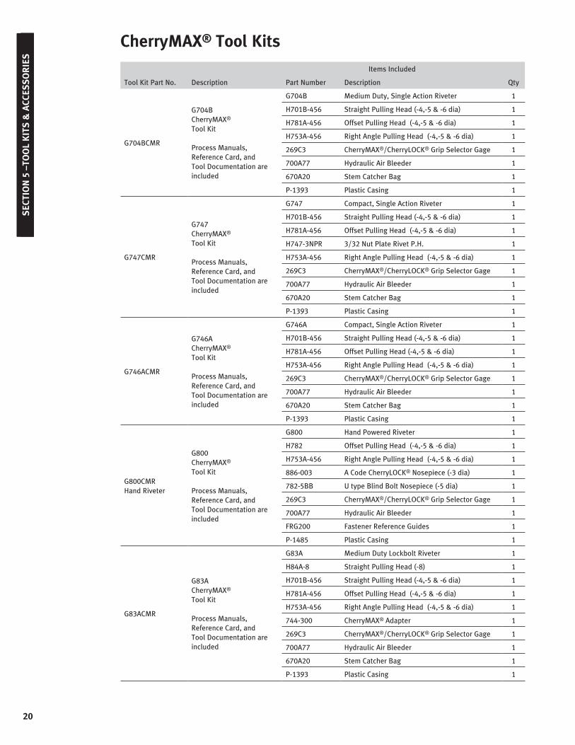
G800CMRHand Riveter
G800CherryMAX®
Tool Kit
Process Manuals, Reference Card, and Tool Documentation are included
G800 Hand Powered Riveter 1
H782 Offset Pulling Head (-4,-5 & -6 dia) 1
H753A-456 Right Angle Pulling Head (-4,-5 & -6 dia) 1
886-003 A Code CherryLOCK® Nosepiece (-3 dia) 1
782-5BB U type Blind Bolt Nosepiece (-5 dia) 1
269C3 CherryMAX®/CherryLOCK® Grip Selector Gage 1
700A77 Hydraulic Air Bleeder 1
FRG200 Fastener Reference Guides 1
P-1485 Plastic Casing 1
G83ACMR
G83ACherryMAX® Tool Kit
Process Manuals, Reference Card, and Tool Documentation are included
G83A Medium Duty Lockbolt Riveter 1
H84A-8 Straight Pulling Head (-8) 1
H701B-456 Straight Pulling Head (-4,-5 & -6 dia) 1
H781A-456 Offset Pulling Head (-4,-5 & -6 dia) 1
H753A-456 Right Angle Pulling Head (-4,-5 & -6 dia) 1
744-300 CherryMAX® Adapter 1
269C3 CherryMAX®/CherryLOCK® Grip Selector Gage 1
700A77 Hydraulic Air Bleeder 1
670A20 Stem Catcher Bag 1
P-1393 Plastic Casing 1
21
SECTIO
N 1 – S
ING
LE ACTIO
N TO
OLS
SECTIO
N 5 –TO
OL K
ITS &
ACCES
SO
RIES
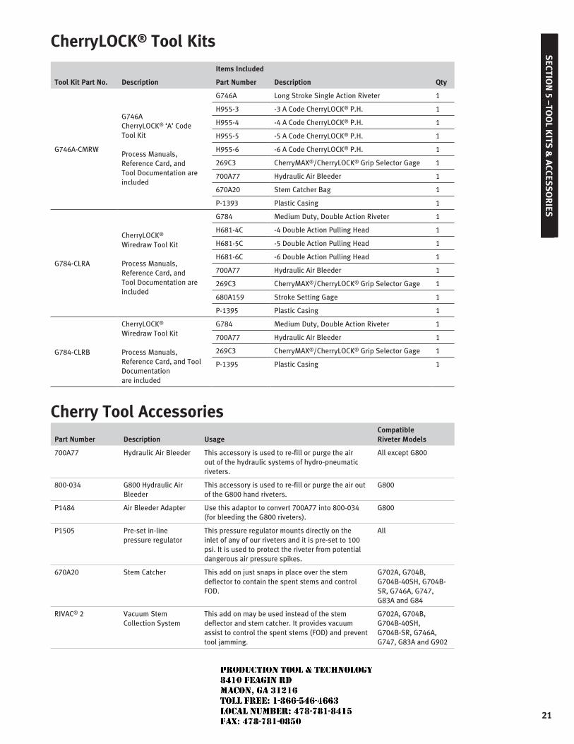
CherryLOCK® Tool Kits
Tool Kit Part No. Description
Items Included
QtyPart Number Description
G746A-CMRW
G746A CherryLOCK® ‘A’ Code Tool Kit
Process Manuals, Reference Card, and Tool Documentation are included
G746A Long Stroke Single Action Riveter 1
H955-3 -3 A Code CherryLOCK® P.H. 1
H955-4 -4 A Code CherryLOCK® P.H. 1
H955-5 -5 A Code CherryLOCK® P.H. 1
H955-6 -6 A Code CherryLOCK® P.H. 1
269C3 CherryMAX®/CherryLOCK® Grip Selector Gage 1
700A77 Hydraulic Air Bleeder 1
670A20 Stem Catcher Bag 1
P-1393 Plastic Casing 1
G784-CLRA
CherryLOCK® Wiredraw Tool Kit
Process Manuals, Reference Card, and Tool Documentation are included
G784 Medium Duty, Double Action Riveter 1
H681-4C -4 Double Action Pulling Head 1
H681-5C -5 Double Action Pulling Head 1
H681-6C -6 Double Action Pulling Head 1
700A77 Hydraulic Air Bleeder 1
269C3 CherryMAX®/CherryLOCK® Grip Selector Gage 1
680A159 Stroke Setting Gage 1
P-1395 Plastic Casing 1
G784-CLRB
CherryLOCK® Wiredraw Tool Kit
Process Manuals, Reference Card, and Tool Documentation are included
G784 Medium Duty, Double Action Riveter 1
700A77 Hydraulic Air Bleeder 1
269C3 CherryMAX®/CherryLOCK® Grip Selector Gage 1
P-1395 Plastic Casing 1
Cherry Tool Accessories
Part Number Description UsageCompatible Riveter Models
700A77 Hydraulic Air Bleeder This accessory is used to re-fill or purge the air out of the hydraulic systems of hydro-pneumatic riveters.
All except G800
800-034 G800 Hydraulic Air Bleeder
This accessory is used to re-fill or purge the air out of the G800 hand riveters.
G800
P1484 Air Bleeder Adapter Use this adaptor to convert 700A77 into 800-034 (for bleeding the G800 riveters).
G800
P1505 Pre-set in-line pressure regulator
This pressure regulator mounts directly on the inlet of any of our riveters and it is pre-set to 100 psi. It is used to protect the riveter from potential dangerous air pressure spikes.
All
670A20 Stem Catcher This add on just snaps in place over the stem deflector to contain the spent stems and control FOD.
G702A, G704B, G704B-40SH, G704B-SR, G746A, G747, G83A and G84
RIVAC® 2 Vacuum Stem Collection System
This add on may be used instead of the stem deflector and stem catcher. It provides vacuum assist to control the spent stems (FOD) and prevent tool jamming.
G702A, G704B, G704B-40SH, G704B-SR, G746A, G747, G83A and G902
JR
Typewritten text
Production Tool & Technology 8410 Feagin Rd Macon, Ga 31216 Toll Free: 1-866-546-4663 Local Number: 478-781-8415 Fax: 478-781-0850
22
SEC
TIO
N 6
– A
DA
PTE
RS
& E
XTE
NS
ION
S
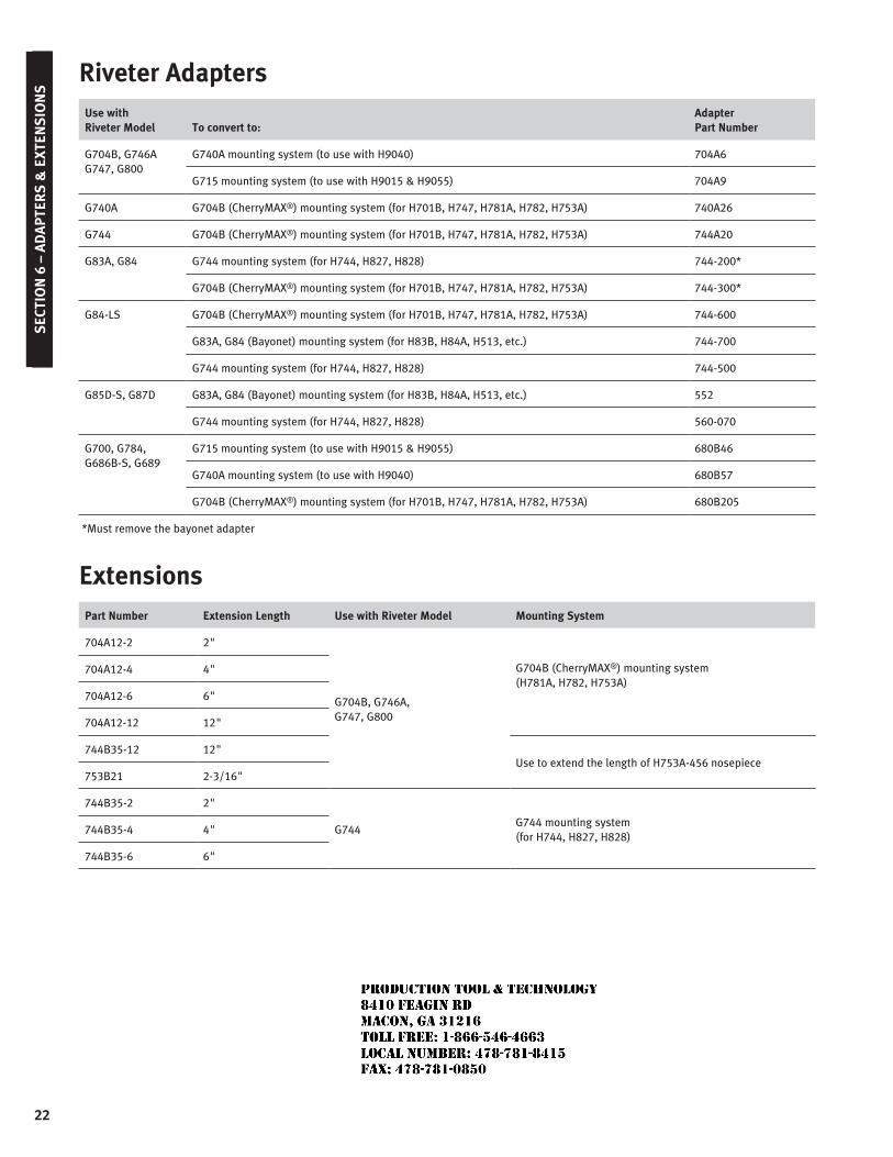
Riveter AdaptersUse with Riveter Model To convert to:
Adapter Part Number
G704B, G746AG747, G800
G740A mounting system (to use with H9040) 704A6
G715 mounting system (to use with H9015 & H9055) 704A9
G740A G704B (CherryMAX®) mounting system (for H701B, H747, H781A, H782, H753A) 740A26
G744 G704B (CherryMAX®) mounting system (for H701B, H747, H781A, H782, H753A) 744A20
G83A, G84 G744 mounting system (for H744, H827, H828) 744-200*
G704B (CherryMAX®) mounting system (for H701B, H747, H781A, H782, H753A) 744-300*
G84-LS G704B (CherryMAX®) mounting system (for H701B, H747, H781A, H782, H753A) 744-600
G83A, G84 (Bayonet) mounting system (for H83B, H84A, H513, etc.) 744-700
G744 mounting system (for H744, H827, H828) 744-500
G85D-S, G87D G83A, G84 (Bayonet) mounting system (for H83B, H84A, H513, etc.) 552
G744 mounting system (for H744, H827, H828) 560-070
G700, G784, G686B-S, G689
G715 mounting system (to use with H9015 & H9055) 680B46
G740A mounting system (to use with H9040) 680B57
G704B (CherryMAX®) mounting system (for H701B, H747, H781A, H782, H753A) 680B205
*Must remove the bayonet adapter
ExtensionsPart Number Extension Length Use with Riveter Model Mounting System
704A12-2 2"
G704B, G746A, G747, G800
G704B (CherryMAX®) mounting system (H781A, H782, H753A)
704A12-4 4"
704A12-6 6"
704A12-12 12"
744B35-12 12"Use to extend the length of H753A-456 nosepiece
753B21 2-3/16"
744B35-2 2"
G744G744 mounting system (for H744, H827, H828)
744B35-4 4"
744B35-6 6"
JR
Typewritten text
Production Tool & Technology 8410 Feagin Rd Macon, Ga 31216 Toll Free: 1-866-546-4663 Local Number: 478-781-8415 Fax: 478-781-0850
Cherry TiTanium maxibolT®
blind bolT
JR
Typewritten text
Production Tool & Technology 8410 Feagin Rd Macon, Ga 31216 Toll Free: 1-866-546-4663 Local Number: 478-781-8415 Fax: 478-781-0850
Cherry TiTanium maxibolT®
limiTed WarranTy
Seller warrants the goods conform to applicable specifications and drawings and will be manufactured and inspected according to generally accepted practices of companies manufacturing industrial or aerospace fasteners. In the event of any breach of the foregoing warranty, Buyer’s sole remedy shall be to return defective goods (after receiving authorization from Seller) for replacement or refund of the purchase price, at the Seller’s option. Seller agrees to any freight costs in connection with the return of any defective goods, but any costs relating to removal of the defective or nonconforming goods or installation of replacement goods shall be Buyer’s responsibility. SELLER’S WARRANTY DOES NOT APPLY WHEN ANY PHYSICAL OR CHEMICAL CHANGE IN THE FORM OF THE PRODUCT IS MADE BY BUYER. THE FOREGOING EXPRESS WARRANTY AND REMEDY ARE EXCLUSIVE AND ARE IN LIEU OF ALL OTHER WARRANTIES AND REMEDIES; ANY IMPLIED WARRANTY AS TO QUALITY, FITNESS FOR PURPOSE, OR MERCHANTABILITY IS HEREBY SPECIFICALLY DISCLAIMED AND EXCLUDED BY SELLER. This warranty is void if seller is not notified in writing of any rejection of the goods within ninety (90) days after receipt of the goods by buyer.
Seller shall not be liable under any circumstances for incidental, special or consequential damages arising in whole or in part from any breach by Seller, AND SUCH INCIDENTAL, SPECIAL, OR CONSEQUENTIAL DAMAGES ARE HEREBY EXPRESSLY EXCLUDED.
Our policy is one of continuous development. Specifications shown in this document may be subject to changes introduced after publication.
CHERRY® , MAXIBOLT® are trademarks of Cherry Aerospace.
noTeThe properties, strengths, dimensions, installed characteristics and all other information in this catalog is for guidance only to aid in the correct selection of the products described herein and is not intended or implied as part of the warranty. All applications should be evaluated for functional suitability and available samples of the described parts can be requested for installed tests, suitability and evaluations.
aTTenTionBlind fasteners are not always a suitable substitute for solid shank fasteners. Maintenance personnel are reminded that AC 43.13-1A chapter 2, section 3, stipulates: “Do not substitute hollow rivets for solid rivets in load carrying members without specific approval of the application by a representative of the Federal Aviation Administration. Blind rivets may be used in blind locations in accordance with the conditions listed in Chapter 5, provided the edge distances and spacings are not less that the minimum listed in paragraph 99d.”
ConTenTS
Titanium MAXIBOLT Introduction, Features and Benefits .......................................................1 Titanium MAXIBOLT Installation Sequence.............................................................................2 Titanium MAXIBOLT Installed Weights ...................................................................................3
Standard Pages 100° Flush Head - CR7770S .................................................................................................4-5 Protruding Head - CR7771S .................................................................................................6-7 Protruding Head - CR7773S .................................................................................................8-9 130° Flush Head - CR7774S .............................................................................................10-11
Tooling Tool Selection .......................................................................................................................12 Installation Tooling ...............................................................................................................13
JR
Typewritten text
Production Tool & Technology 8410 Feagin Rd Macon, Ga 31216 Toll Free: 1-866-546-4663 Local Number: 478-781-8415 Fax: 478-781-0850
1
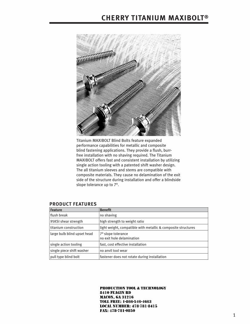
Titanium MAXIBOLT Blind Bolts feature expanded performance capabilities for metallic and composite blind fastening applications. They provide a flush, burr-free installation with no shaving required. The Titanium MAXIBOLT offers fast and consistent installation by utilizing single action tooling with a patented shift washer design. The all titanium sleeves and stems are compatible with composite materials. They cause no delamination of the exit side of the structure during installation and offer a blindside slope tolerance up to 7°.
ProduCT feaTureSfeature benefit
flush break no shaving
95KSI shear strength high strength to weight ratio
titanium construction light weight, compatible with metallic & composite structures
large bulb blind upset head 7° slope tolerance no exit hole delamination
single action tooling fast, cost effective installation
single piece shift washer no anvil tool wear
pull type blind bolt fastener does not rotate during installation
Cherry TiTanium maxibolT®
JR
Typewritten text
Production Tool & Technology 8410 Feagin Rd Macon, Ga 31216 Toll Free: 1-866-546-4663 Local Number: 478-781-8415 Fax: 478-781-0850
2
Cherry TiTanium maxibolT® inSTallaTion SequenCe
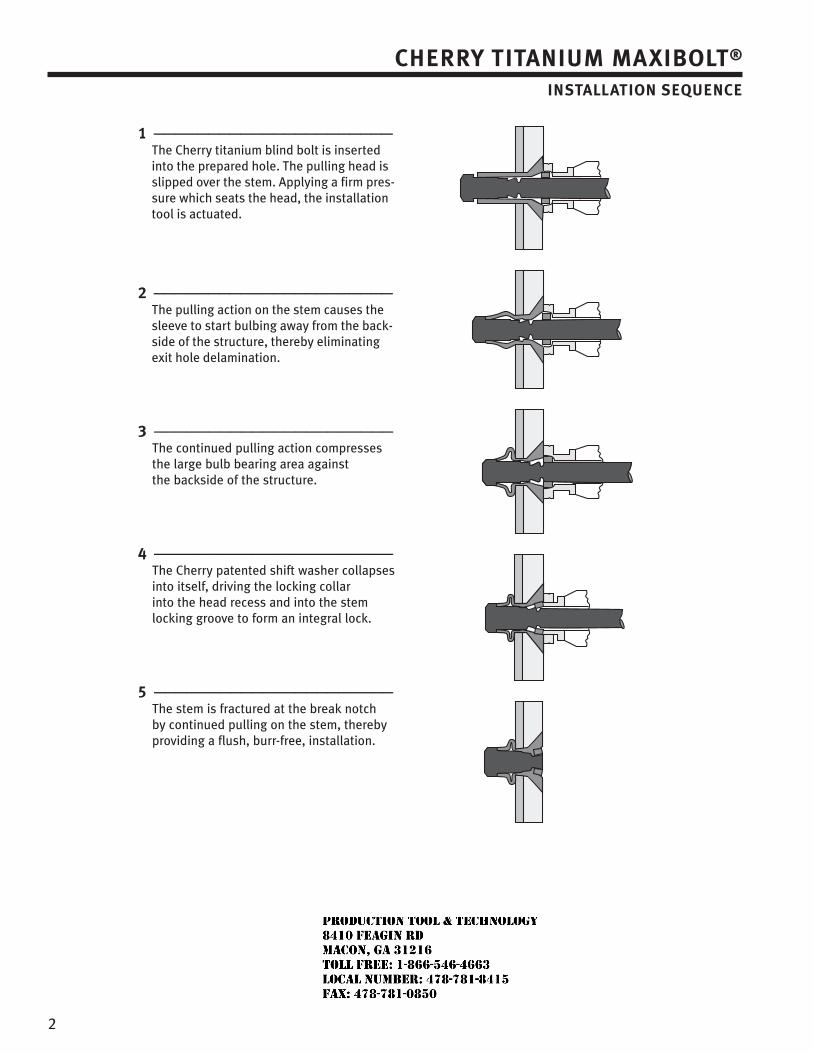
1 —————————————————————— The Cherry titanium blind bolt is inserted into the prepared hole. The pulling head is slipped over the stem. Applying a firm pres-sure which seats the head, the installation tool is actuated.
2 —————————————————————— The pulling action on the stem causes the sleeve to start bulbing away from the back-side of the structure, thereby eliminating exit hole delamination.
3 —————————————————————— The continued pulling action compresses the large bulb bearing area against the backside of the structure.
4 —————————————————————— The Cherry patented shift washer collapses into itself, driving the locking collar into the head recess and into the stem locking groove to form an integral lock.
5 —————————————————————— The stem is fractured at the break notch by continued pulling on the stem, thereby providing a flush, burr-free, installation.
JR
Typewritten text
Production Tool & Technology 8410 Feagin Rd Macon, Ga 31216 Toll Free: 1-866-546-4663 Local Number: 478-781-8415 Fax: 478-781-0850
3
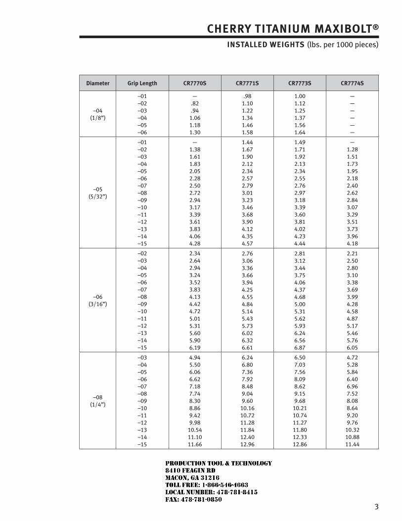
Cherry TiTanium maxibolT® inSTalled WeiGhTS (lbs. per 1000 pieces)
diameter Grip length Cr7770S Cr7771S Cr7773S Cr7774S
–04(1/8”)
–01–02–03–04–05–06
—.82.94
1.061.181.30
.981.101.221.341.461.58
1.001.121.251.371.561.64
——————
–05(5/32”)
–01–02–03–04–05–06–07–08–09–10–11–12–13–14–15
—1.381.611.832.052.282.502.722.943.173.393.613.834.064.28
1.441.671.902.122.342.572.793.013.233.463.683.904.124.354.57
1.491.711.922.132.342.552.762.973.183.393.603.814.024.234.44
—1.281.511.731.952.182.402.622.843.073.293.513.733.964.18
–06(3/16”)
–02–03–04–05–06–07–08–09–10–11–12–13–14–15
2.342.642.943.243.523.834.134.424.725.015.315.605.906.19
2.763.063.363.663.944.254.554.845.145.435.736.026.326.61
2.81 3.12 3.44 3.75 4.06 4.37 4.68 5.00 5.31 5.62 5.93 6.24 6.56 6.87
2.212.502.803.103.383.693.994.284.584.875.175.465.766.05
–08(1/4”)
–03–04–05–06–07–08–09–10–11–12–13–14–15
4.945.506.066.627.187.748.308.869.429.98
10.5411.1011.66
6.246.807.367.928.489.049.60
10.1610.7211.2811.8412.4012.96
6.50 7.03 7.56 8.09 8.62 9.15 9.68
10.21 10.74 11.27 11.80 12.33 12.86
4.725.285.846.406.967.528.088.649.209.76
10.3210.8811.44
JR
Typewritten text
Production Tool & Technology 8410 Feagin Rd Macon, Ga 31216 Toll Free: 1-866-546-4663 Local Number: 478-781-8415 Fax: 478-781-0850
4
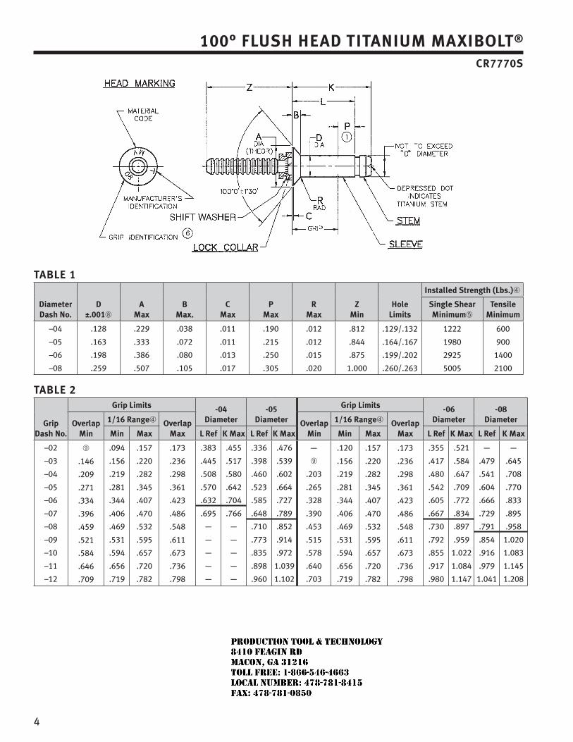
100° fluSh head TiTanium maxibolT® Cr7770S
Table 1
diameter dash no.
d ±.001➇
amax
bmax.
Cmax
Pmax
rmax
Zmin
holelimits
installed Strength (lbs.)➃
Single Shearminimum➄
Tensile minimum
–04
–05
–06
–08
.128
.163
.198
.259
.229
.333
.386
.507
.038
.072
.080
.105
.011
.011
.013
.017
.190
.215
.250
.305
.012
.012
.015
.020
.812
.844
.875
1.000
.129/.132
.164/.167
.199/.202
.260/.263
1222
1980
2925
5005
600
900
1400
2100
Table 2
Grip dash no.
Grip limits -04 diameter
-05 diameter
Grip limits -06 diameter
-08 diameteroverlap
min
1/16 range➃ overlap max
overlap min
1/16 range➃ overlap maxmin max l ref K max l ref K max min max l ref K max l ref K max
–02
–03
–04
–05
–06
–07
–08
–09
–10
–11
–12
➈
.146
.209
.271
.334
.396
.459
.521
.584
.646
.709
.094
.156
.219
.281
.344
.406
.469
.531
.594
.656
.719
.157
.220
.282
.345
.407
.470
.532
.595
.657
.720
.782
.173
.236
.298
.361
.423
.486
.548
.611
.673
.736
.798
.383
.445
.508
.570
.632
.695
—
—
—
—
—
.455
.517
.580
.642
.704
.766
—
—
—
—
—
.336
.398
.460
.523
.585
.648
.710
.773
.835
.898
.960
.476
.539
.602
.664
.727
.789
.852
.914
.972
1.039
1.102
—
➈
.203
.265
.328
.390
.453
.515
.578
.640
.703
.120
.156
.219
.281
.344
.406
.469
.531
.594
.656
.719
.157
.220
.282
.345
.407
.470
.532
.595
.657
.720
.782
.173
.236
.298
.361
.423
.486
.548
.611
.673
.736
.798
.355
.417
.480
.542
.605
.667
.730
.792
.855
.917
.980
.521
.584
.647
.709
.772
.834
.897
.959
1.022
1.084
1.147
—
.479
.541
.604
.666
.729
.791
.854
.916
.979
1.041
—
.645
.708
.770
.833
.895
.958
1.020
1.083
1.145
1.208
JR
Typewritten text
Production Tool & Technology 8410 Feagin Rd Macon, Ga 31216 Toll Free: 1-866-546-4663 Local Number: 478-781-8415 Fax: 478-781-0850
5
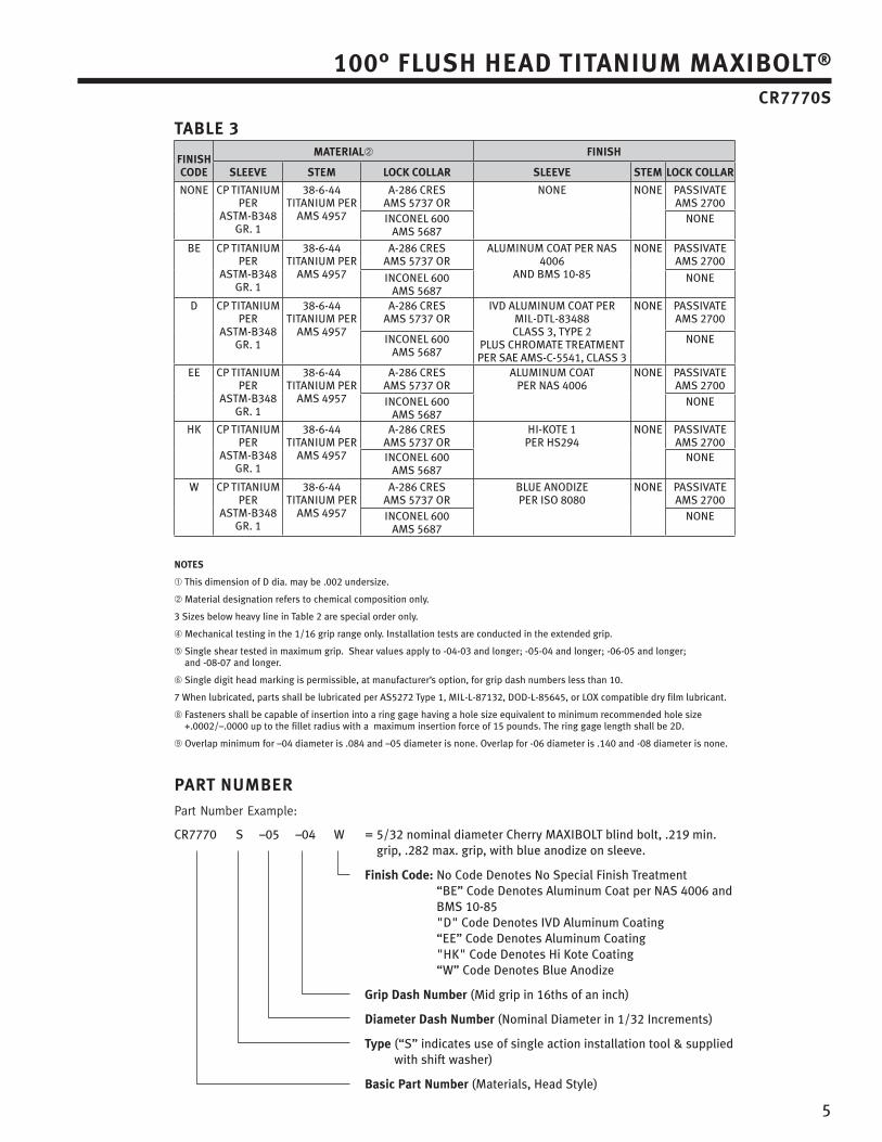
100° fluSh head TiTanium maxibolT® Cr7770S
ParT numberPart Number Example:
CR7770 S –05 –04 W = 5/32 nominal diameter Cherry MAXIBOLT blind bolt, .219 min. grip, .282 max. grip, with blue anodize on sleeve.
finish Code: No Code Denotes No Special Finish Treatment “BE” Code Denotes Aluminum Coat per NAS 4006 and BMS 10-85 "D" Code Denotes IVD Aluminum Coating “EE” Code Denotes Aluminum Coating "HK" Code Denotes Hi Kote Coating “W” Code Denotes Blue Anodize
Grip dash number (Mid grip in 16ths of an inch)
diameter dash number (Nominal Diameter in 1/32 Increments)
Type (“S” indicates use of single action installation tool & supplied with shift washer)
basic Part number (Materials, Head Style)
Table 3
finiSh Code
maTerial➁ finiSh
Sleeve STem loCK Collar Sleeve STem loCK Collar
NONE CP TITANIUM PER
ASTM-B348 GR. 1
38-6-44 TITANIUM PER
AMS 4957
A-286 CRES AMS 5737 OR
NONE NONE PASSIVATE AMS 2700
INCONEL 600 AMS 5687
NONE
BE CP TITANIUM PER
ASTM-B348 GR. 1
38-6-44 TITANIUM PER
AMS 4957
A-286 CRES AMS 5737 OR
ALUMINUM COAT PER NAS 4006
AND BMS 10-85
NONE PASSIVATE AMS 2700
INCONEL 600 AMS 5687
NONE
D CP TITANIUM PER
ASTM-B348 GR. 1
38-6-44 TITANIUM PER
AMS 4957
A-286 CRES AMS 5737 OR
IVD ALUMINUM COAT PER MIL-DTL-83488 CLASS 3, TYPE 2
PLUS CHROMATE TREATMENT PER SAE AMS-C-5541, CLASS 3
NONE PASSIVATE AMS 2700
INCONEL 600 AMS 5687
NONE
EE CP TITANIUM PER
ASTM-B348 GR. 1
38-6-44 TITANIUM PER
AMS 4957
A-286 CRES AMS 5737 OR
ALUMINUM COAT PER NAS 4006
NONE PASSIVATE AMS 2700
INCONEL 600 AMS 5687
NONE
HK CP TITANIUM PER
ASTM-B348 GR. 1
38-6-44 TITANIUM PER
AMS 4957
A-286 CRES AMS 5737 OR
HI-KOTE 1 PER HS294
NONE PASSIVATE AMS 2700
INCONEL 600 AMS 5687
NONE
W CP TITANIUM PER
ASTM-B348 GR. 1
38-6-44 TITANIUM PER
AMS 4957
A-286 CRES AMS 5737 OR
BLUE ANODIzEPER ISO 8080
NONE PASSIVATE AMS 2700
INCONEL 600 AMS 5687
NONE
noTeS
➀ This dimension of D dia. may be .002 undersize.
➁ Material designation refers to chemical composition only.
3 Sizes below heavy line in Table 2 are special order only.
➃ Mechanical testing in the 1/16 grip range only. Installation tests are conducted in the extended grip.
➄ Single shear tested in maximum grip. Shear values apply to -04-03 and longer; -05-04 and longer; -06-05 and longer; and -08-07 and longer.
➅ Single digit head marking is permissible, at manufacturer’s option, for grip dash numbers less than 10.
7 When lubricated, parts shall be lubricated per AS5272 Type 1, MIL-L-87132, DOD-L-85645, or LOX compatible dry film lubricant.
➇ Fasteners shall be capable of insertion into a ring gage having a hole size equivalent to minimum recommended hole size +.0002/–.0000 up to the fillet radius with a maximum insertion force of 15 pounds. The ring gage length shall be 2D.
➈ Overlap minimum for –04 diameter is .084 and –05 diameter is none. Overlap for -06 diameter is .140 and -08 diameter is none.
6
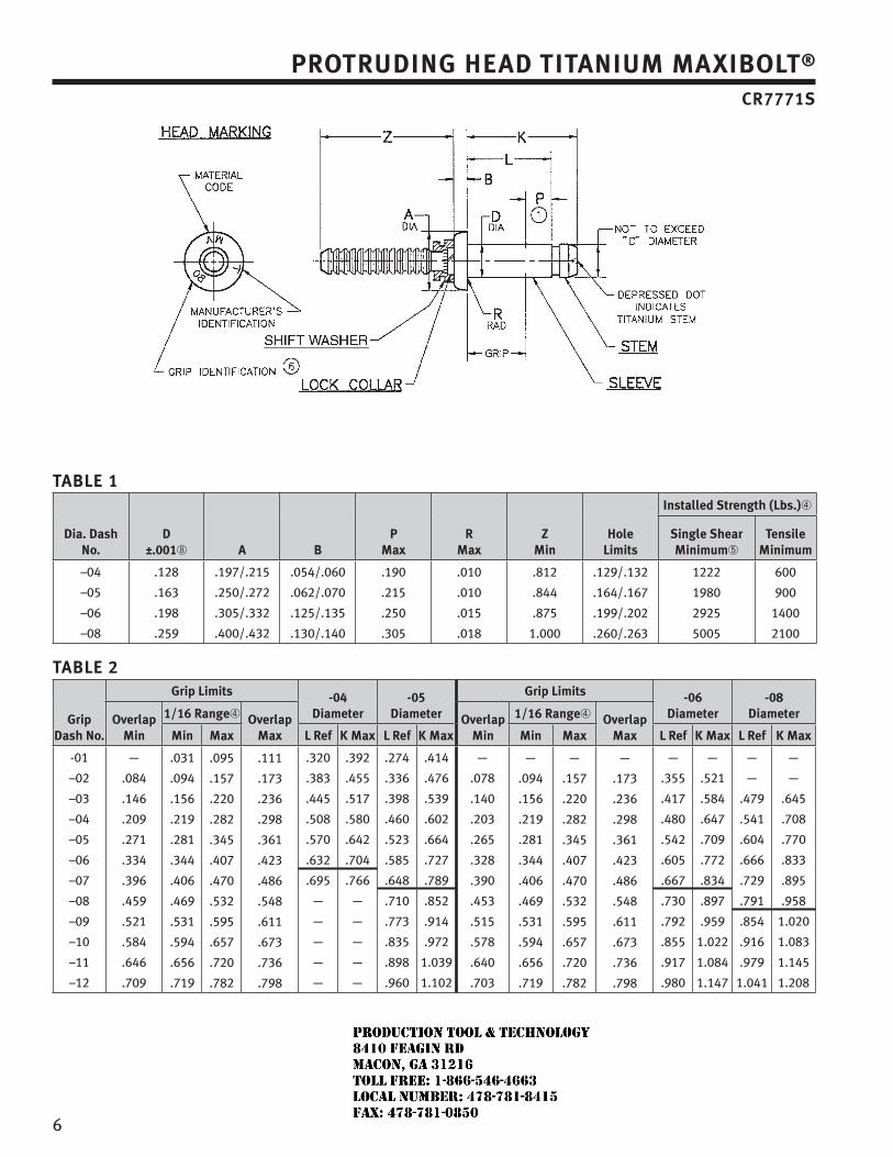
ProTrudinG head TiTanium maxibolT®
Cr7771S
Table 1
dia. dash no.
d ±.001➇ a b
Pmax
rmax
Zmin
holelimits
installed Strength (lbs.)➃
Single Shearminimum➄
Tensile minimum
–04
–05
–06
–08
.128
.163
.198
.259
.197/.215
.250/.272
.305/.332
.400/.432
.054/.060
.062/.070
.125/.135
.130/.140
.190
.215
.250
.305
.010
.010
.015
.018
.812
.844
.875
1.000
.129/.132
.164/.167
.199/.202
.260/.263
1222
1980
2925
5005
600
900
1400
2100
Table 2
Grip dash no.
Grip limits -04 diameter
-05 diameter
Grip limits -06 diameter
-08 diameteroverlap
min
1/16 range➃ overlap max
overlap min
1/16 range➃ overlap maxmin max l ref K max l ref K max min max l ref K max l ref K max
-01
–02
–03
–04
–05
–06
–07
–08
–09
–10
–11
–12
—
.084
.146
.209
.271
.334
.396
.459
.521
.584
.646
.709
.031
.094
.156
.219
.281
.344
.406
.469
.531
.594
.656
.719
.095
.157
.220
.282
.345
.407
.470
.532
.595
.657
.720
.782
.111
.173
.236
.298
.361
.423
.486
.548
.611
.673
.736
.798
.320
.383
.445
.508
.570
.632
.695
—
—
—
—
—
.392
.455
.517
.580
.642
.704
.766
—
—
—
—
—
.274
.336
.398
.460
.523
.585
.648
.710
.773
.835
.898
.960
.414
.476
.539
.602
.664
.727
.789
.852
.914
.972
1.039
1.102
—
.078
.140
.203
.265
.328
.390
.453
.515
.578
.640
.703
—
.094
.156
.219
.281
.344
.406
.469
.531
.594
.656
.719
—
.157
.220
.282
.345
.407
.470
.532
.595
.657
.720
.782
—
.173
.236
.298
.361
.423
.486
.548
.611
.673
.736
.798
—
.355
.417
.480
.542
.605
.667
.730
.792
.855
.917
.980
—
.521
.584
.647
.709
.772
.834
.897
.959
1.022
1.084
1.147
—
—
.479
.541
.604
.666
.729
.791
.854
.916
.979
1.041
—
—
.645
.708
.770
.833
.895
.958
1.020
1.083
1.145
1.208
JR
Typewritten text
Production Tool & Technology 8410 Feagin Rd Macon, Ga 31216 Toll Free: 1-866-546-4663 Local Number: 478-781-8415 Fax: 478-781-0850

7
ProTrudinG head TiTanium maxibolT® Cr7771S
ParT numberPart Number Example:
CR7771 S –05 –04 W = 5/32 nominal diameter Cherry MAXIBOLT blind bolt, .219 min. grip, .282 max. grip, with blue anodize on sleeve.
finish Code: No Code Denotes No Special Finish Treatment “BE” Code Denotes Aluminum Coat per NAS 4006 and BMS 10-85 "D" Code Denotes IVD Aluminum Coating “EE” Code Denotes Aluminum Coating "HK" Code Denotes Hi Kote Coating “W” Code Denotes Blue Anodize
Grip dash number (Mid grip in 16ths of an inch)
diameter dash number (Nominal Diameter in 1/32 Increments)
Type (“S” indicates use of single action installation tool & supplied with shift washer)
basic Part number (Materials, Head Style)
Table 3
finiSh Code
maTerial➁ finiSh
Sleeve STem loCK Collar Sleeve STem loCK Collar
NONE CP TITANIUM PER
ASTM-B348 GR. 1
38-6-44 TITANIUM PER AMS
4957
A-286 CRES AMS 5737 OR
NONE NONE PASSIVATE AMS 2700
INCONEL 600 AMS 5687
NONE
BE CP TITANIUM PER
ASTM-B348 GR. 1
38-6-44 TITANIUM PER AMS
4957
A-286 CRES AMS 5737 OR
ALUMINUM COAT PER NAS 4006
AND BMS 10-85
NONE PASSIVATE AMS 2700
INCONEL 600 AMS 5687
NONE
D CP TITANIUM PER
ASTM-B348 GR. 1
38-6-44 TITANIUM PER AMS
4957
A-286 CRES AMS 5737 OR
IVD ALUMINUM COAT PER MIL-DTL-83488 CLASS 3, TYPE 2
PLUS CHROMATE TREATMENT PER SAE AMS-C-5541, CLASS 3
NONE PASSIVATE AMS 2700
INCONEL 600 AMS 5687
NONE
EE CP TITANIUM PER
ASTM-B348 GR. 1
38-6-44 TITANIUM PER AMS
4957
A-286 CRES AMS 5737 OR
ALUMINUM COAT PER NAS 4006
NONE PASSIVATE AMS 2700
INCONEL 600 AMS 5687
NONE
HK CP TITANIUM PER
ASTM-B348 GR. 1
38-6-44 TITANIUM PER AMS
4957
A-286 CRES AMS 5737 OR
HI-KOTE 1 PER HS294
NONE PASSIVATE AMS 2700
INCONEL 600 AMS 5687
NONE
W CP TITANIUM PER
ASTM-B348 GR. 1
38-6-44 TITANIUM PER AMS
4957
A-286 CRES AMS 5737 OR
BLUE ANODIzEPER ISO 8080
NONE PASSIVATE AMS 2700
INCONEL 600 AMS 5687
NONE
noTeS
➀ This dimension of D dia. may be .002 undersize.
➁ Material designation refers to chemical composition only.
3 Sizes below heavy line in Table 2 are special order only.
➃ Mechanical testing in the 1/16 grip range only. Installation tests are conducted in the extended grip.
➄ Single shear tested in maximum grip. Shear values apply to -04-03 and longer; -05-03 and longer; -06-04 and longer; and -08-07 and longer.
➅ Single digit head marking is permissible, at manufacturer’s option, for grip dash numbers less than 10.
7 When lubricated, parts shall be lubricated per AS5272 Type 1, MIL-L-87132, DOD-L-85645, or LOX compatible dry film lubricant.
➇ Fasteners shall be capable of insertion into a ring gage having a hole size equivalent to minimum recommended hole size +.0002/–.0000 up to the fillet radius with a maximum insertion force of 15 pounds. The ring gage length shall be 2D.
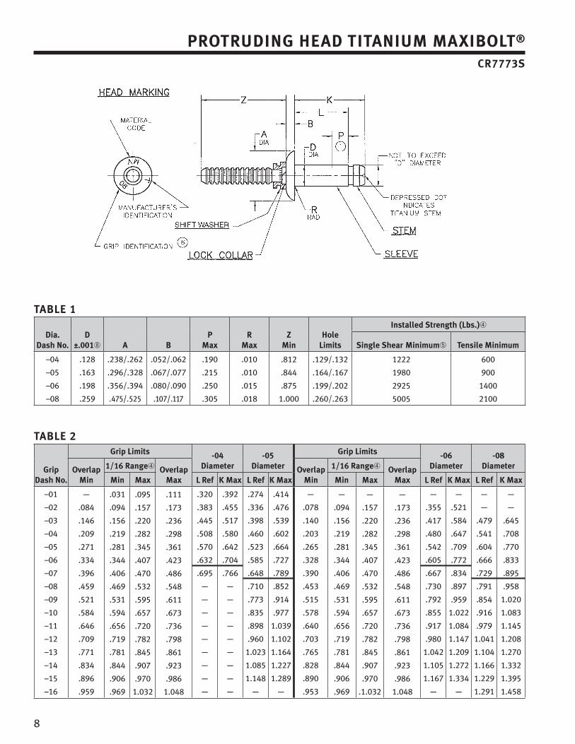
8
Table 1
dia. dash no.
d ±.001➇ a b
Pmax
rmax
Zmin
holelimits
installed Strength (lbs.)➃
Single Shear minimum➄ Tensile minimum
–04
–05
–06
–08
.128
.163
.198
.259
.238/.262
.296/.328
.356/.394
.475/.525
.052/.062
.067/.077
.080/.090
.107/.117
.190
.215
.250
.305
.010
.010
.015
.018
.812
.844
.875
1.000
.129/.132
.164/.167
.199/.202
.260/.263
1222
1980
2925
5005
600
900
1400
2100
Table 2
Grip dash no.
Grip limits -04 diameter
-05 diameter
Grip limits -06 diameter
-08 diameteroverlap
min
1/16 range➃ overlap max
overlap min
1/16 range➃ overlap maxmin max l ref K max l ref K max min max l ref K max l ref K max
–01
–02
–03
–04
–05
–06
–07
–08
–09
–10
–11
–12
–13
–14
–15
–16
—
.084
.146
.209
.271
.334
.396
.459
.521
.584
.646
.709
.771
.834
.896
.959
.031
.094
.156
.219
.281
.344
.406
.469
.531
.594
.656
.719
.781
.844
.906
.969
.095
.157
.220
.282
.345
.407
.470
.532
.595
.657
.720
.782
.845
.907
.970
1.032
.111
.173
.236
.298
.361
.423
.486
.548
.611
.673
.736
.798
.861
.923
.986
1.048
.320
.383
.445
.508
.570
.632
.695
—
—
—
—
—
—
—
—
—
.392
.455
.517
.580
.642
.704
.766
—
—
—
—
—
—
—
—
—
.274
.336
.398
.460
.523
.585
.648
.710
.773
.835
.898
.960
1.023
1.085
1.148
—
.414
.476
.539
.602
.664
.727
.789
.852
.914
.977
1.039
1.102
1.164
1.227
1.289
—
—
.078
.140
.203
.265
.328
.390
.453
.515
.578
.640
.703
.765
.828
.890
.953
—
.094
.156
.219
.281
.344
.406
.469
.531
.594
.656
.719
.781
.844
.906
.969
—
.157
.220
.282
.345
.407
.470
.532
.595
.657
.720
.782
.845
.907
.970
.1.032
—
.173
.236
.298
.361
.423
.486
.548
.611
.673
.736
.798
.861
.923
.986
1.048
—
.355
.417
.480
.542
.605
.667
.730
.792
.855
.917
.980
1.042
1.105
1.167
—
—
.521
.584
.647
.709
.772
.834
.897
.959
1.022
1.084
1.147
1.209
1.272
1.334
—
—
—
.479
.541
.604
.666
.729
.791
.854
.916
.979
1.041
1.104
1.166
1.229
1.291
—
—
.645
.708
.770
.833
.895
.958
1.020
1.083
1.145
1.208
1.270
1.332
1.395
1.458
ProTrudinG head TiTanium maxibolT® Cr7773S
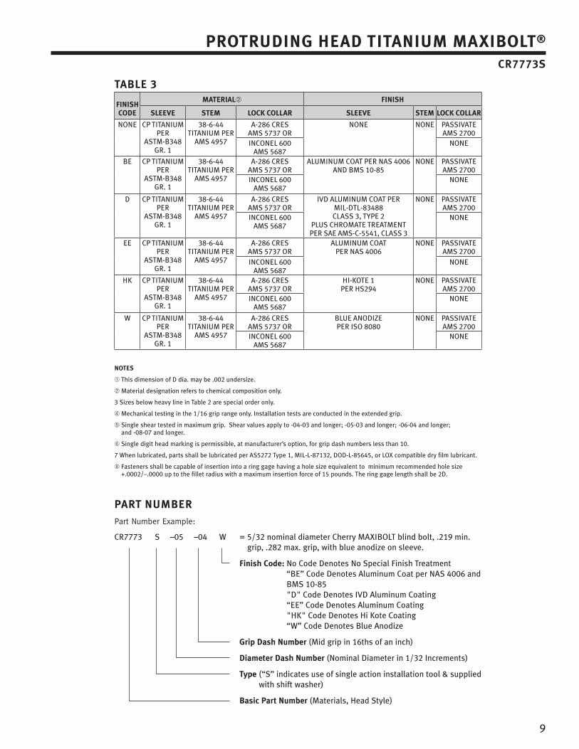
9
ProTrudinG head TiTanium maxibolT® Cr7773S
ParT numberPart Number Example:
CR7773 S –05 –04 W = 5/32 nominal diameter Cherry MAXIBOLT blind bolt, .219 min. grip, .282 max. grip, with blue anodize on sleeve.
finish Code: No Code Denotes No Special Finish Treatment “BE” Code Denotes Aluminum Coat per NAS 4006 and BMS 10-85 "D" Code Denotes IVD Aluminum Coating “EE” Code Denotes Aluminum Coating "HK" Code Denotes Hi Kote Coating “W” Code Denotes Blue Anodize
Grip dash number (Mid grip in 16ths of an inch)
diameter dash number (Nominal Diameter in 1/32 Increments)
Type (“S” indicates use of single action installation tool & supplied with shift washer)
basic Part number (Materials, Head Style)
Table 3
finiSh Code
maTerial➁ finiSh
Sleeve STem loCK Collar Sleeve STem loCK Collar
NONE CP TITANIUM PER
ASTM-B348 GR. 1
38-6-44 TITANIUM PER
AMS 4957
A-286 CRES AMS 5737 OR
NONE NONE PASSIVATE AMS 2700
INCONEL 600 AMS 5687
NONE
BE CP TITANIUM PER
ASTM-B348 GR. 1
38-6-44 TITANIUM PER
AMS 4957
A-286 CRES AMS 5737 OR
ALUMINUM COAT PER NAS 4006AND BMS 10-85
NONE PASSIVATE AMS 2700
INCONEL 600 AMS 5687
NONE
D CP TITANIUM PER
ASTM-B348 GR. 1
38-6-44 TITANIUM PER
AMS 4957
A-286 CRES AMS 5737 OR
IVD ALUMINUM COAT PER MIL-DTL-83488 CLASS 3, TYPE 2
PLUS CHROMATE TREATMENT PER SAE AMS-C-5541, CLASS 3
NONE PASSIVATE AMS 2700
INCONEL 600 AMS 5687
NONE
EE CP TITANIUM PER
ASTM-B348 GR. 1
38-6-44 TITANIUM PER
AMS 4957
A-286 CRES AMS 5737 OR
ALUMINUM COAT PER NAS 4006
NONE PASSIVATE AMS 2700
INCONEL 600 AMS 5687
NONE
HK CP TITANIUM PER
ASTM-B348 GR. 1
38-6-44 TITANIUM PER
AMS 4957
A-286 CRES AMS 5737 OR
HI-KOTE 1 PER HS294
NONE PASSIVATE AMS 2700
INCONEL 600 AMS 5687
NONE
W CP TITANIUM PER
ASTM-B348 GR. 1
38-6-44 TITANIUM PER
AMS 4957
A-286 CRES AMS 5737 OR
BLUE ANODIzEPER ISO 8080
NONE PASSIVATE AMS 2700
INCONEL 600 AMS 5687
NONE
noTeS
➀ This dimension of D dia. may be .002 undersize.
➁ Material designation refers to chemical composition only.
3 Sizes below heavy line in Table 2 are special order only.
➃ Mechanical testing in the 1/16 grip range only. Installation tests are conducted in the extended grip.
➄ Single shear tested in maximum grip. Shear values apply to -04-03 and longer; -05-03 and longer; -06-04 and longer; and -08-07 and longer.
➅ Single digit head marking is permissible, at manufacturer’s option, for grip dash numbers less than 10.
7 When lubricated, parts shall be lubricated per AS5272 Type 1, MIL-L-87132, DOD-L-85645, or LOX compatible dry film lubricant.
➇ Fasteners shall be capable of insertion into a ring gage having a hole size equivalent to minimum recommended hole size +.0002/–.0000 up to the fillet radius with a maximum insertion force of 15 pounds. The ring gage length shall be 2D.
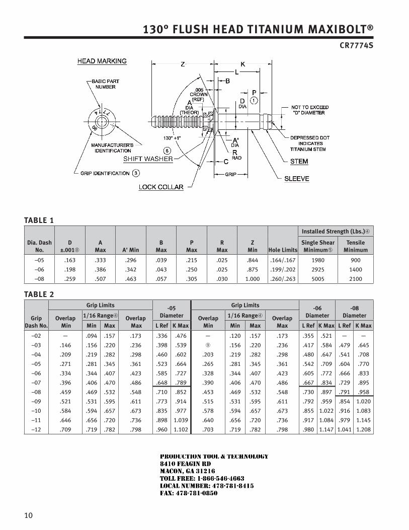
10
130° fluSh head TiTanium maxibolT® Cr7774S
Table 1
dia. dash no.
d ±.001➇
amax a' min
bmax
Pmax
rmax
Zmin hole limits
installed Strength (lbs.)➃
Single Shear minimum➄
Tensile minimum
–05
–06
–08
.163
.198
.259
.333
.386
.507
.296
.342
.463
.039
.043
.057
.215
.250
.305
.025
.025
.030
.844
.875
1.000
.164/.167
.199/.202
.260/.263
1980
2925
5005
900
1400
2100
Table 2
Grip dash no.
Grip limits -05 diameter
Grip limits -06 diameter
-08 diameteroverlap
min
1/16 range➃ overlap max
overlap min
1/16 range➃ overlap maxmin max l ref K max min max l ref K max l ref K max
–02
–03
–04
–05
–06
–07
–08
–09
–10
–11
–12
—
.146
.209
.271
.334
.396
.459
.521
.584
.646
.709
.094
.156
.219
.281
.344
.406
.469
.531
.594
.656
.719
.157
.220
.282
.345
.407
.470
.532
.595
.657
.720
.782
.173
.236
.298
.361
.423
.486
.548
.611
.673
.736
.798
.336
.398
.460
.523
.585
.648
.710
.773
.835
.898
.960
.476
.539
.602
.664
.727
.789
.852
.914
.977
1.039
1.102
—
➈
.203
.265
.328
.390
.453
.515
.578
.640
.703
.120
.156
.219
.281
.344
.406
.469
.531
.594
.656
.719
.157
.220
.282
.345
.407
.470
.532
.595
.657
.720
.782
.173
.236
.298
.361
.423
.486
.548
.611
.673
.736
.798
.355
.417
.480
.542
.605
.667
.730
.792
.855
.917
.980
.521
.584
.647
.709
.772
.834
.897
.959
1.022
1.084
1.147
—
.479
.541
.604
.666
.729
.791
.854
.916
.979
1.041
—
.645
.708
.770
.833
.895
.958
1.020
1.083
1.145
1.208
JR
Typewritten text
Production Tool & Technology 8410 Feagin Rd Macon, Ga 31216 Toll Free: 1-866-546-4663 Local Number: 478-781-8415 Fax: 478-781-0850
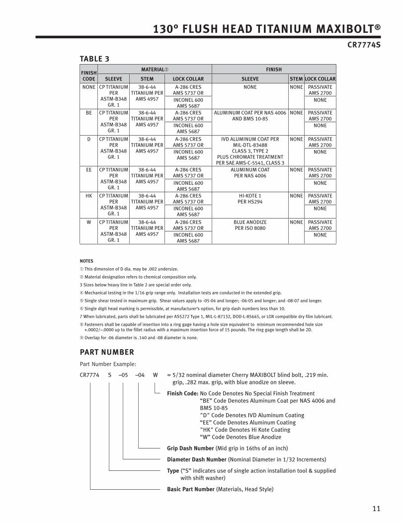
11
130° fluSh head TiTanium maxibolT® Cr7774S
ParT numberPart Number Example:
CR7774 S –05 –04 W = 5/32 nominal diameter Cherry MAXIBOLT blind bolt, .219 min. grip, .282 max. grip, with blue anodize on sleeve.
finish Code: No Code Denotes No Special Finish Treatment “BE” Code Denotes Aluminum Coat per NAS 4006 and BMS 10-85 "D" Code Denotes IVD Aluminum Coating “EE” Code Denotes Aluminum Coating "HK" Code Denotes Hi Kote Coating “W” Code Denotes Blue Anodize
Grip dash number (Mid grip in 16ths of an inch)
diameter dash number (Nominal Diameter in 1/32 Increments)
Type (“S” indicates use of single action installation tool & supplied with shift washer)
basic Part number (Materials, Head Style)
Table 3
finiSh Code
maTerial➁ finiSh
Sleeve STem loCK Collar Sleeve STem loCK Collar
NONE CP TITANIUM PER
ASTM-B348 GR. 1
38-6-44 TITANIUM PER
AMS 4957
A-286 CRES AMS 5737 OR
NONE NONE PASSIVATE AMS 2700
INCONEL 600 AMS 5687
NONE
BE CP TITANIUM PER
ASTM-B348 GR. 1
38-6-44 TITANIUM PER
AMS 4957
A-286 CRES AMS 5737 OR
ALUMINUM COAT PER NAS 4006AND BMS 10-85
NONE PASSIVATE AMS 2700
INCONEL 600 AMS 5687
NONE
D CP TITANIUM PER
ASTM-B348 GR. 1
38-6-44 TITANIUM PER
AMS 4957
A-286 CRES AMS 5737 OR
IVD ALUMINUM COAT PER MIL-DTL-83488 CLASS 3, TYPE 2
PLUS CHROMATE TREATMENT PER SAE AMS-C-5541, CLASS 3
NONE PASSIVATE AMS 2700
INCONEL 600 AMS 5687
NONE
EE CP TITANIUM PER
ASTM-B348 GR. 1
38-6-44 TITANIUM PER
AMS 4957
A-286 CRES AMS 5737 OR
ALUMINUM COAT PER NAS 4006
NONE PASSIVATE AMS 2700
INCONEL 600 AMS 5687
NONE
HK CP TITANIUM PER
ASTM-B348 GR. 1
38-6-44 TITANIUM PER
AMS 4957
A-286 CRES AMS 5737 OR
HI-KOTE 1 PER HS294
NONE PASSIVATE AMS 2700
INCONEL 600 AMS 5687
NONE
W CP TITANIUM PER
ASTM-B348 GR. 1
38-6-44 TITANIUM PER
AMS 4957
A-286 CRES AMS 5737 OR
BLUE ANODIzEPER ISO 8080
NONE PASSIVATE AMS 2700
INCONEL 600 AMS 5687
NONE
noTeS
➀ This dimension of D dia. may be .002 undersize.
➁ Material designation refers to chemical composition only.
3 Sizes below heavy line in Table 2 are special order only.
➃ Mechanical testing in the 1/16 grip range only. Installation tests are conducted in the extended grip.
➄ Single shear tested in maximum grip. Shear values apply to -05-04 and longer; -06-05 and longer; and -08-07 and longer.
➅ Single digit head marking is permissible, at manufacturer’s option, for grip dash numbers less than 10.
7 When lubricated, parts shall be lubricated per AS5272 Type 1, MIL-L-87132, DOD-L-85645, or LOX compatible dry film lubricant.
➇ Fasteners shall be capable of insertion into a ring gage having a hole size equivalent to minimum recommended hole size +.0002/–.0000 up to the fillet radius with a maximum insertion force of 15 pounds. The ring gage length shall be 2D.
➈ Overlap for -06 diameter is .140 and -08 diameter is none.
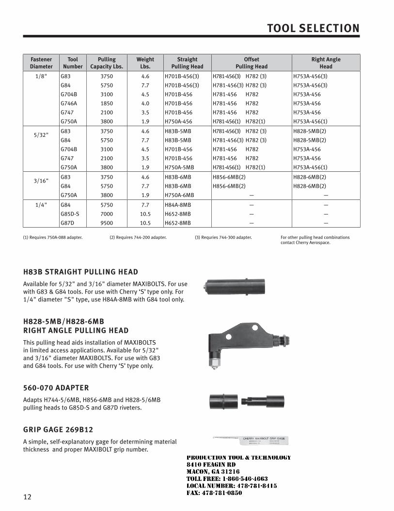
12
h83b STraiGhT PullinG head
Available for 5/32" and 3/16" diameter MAXIBOLTS. For use with G83 & G84 tools. For use with Cherry ‘S’ type only. For 1/4" diameter "S" type, use H84A-8MB with G84 tool only.
h828-5mb/h828-6mb riGhT anGle PullinG head
This pulling head aids installation of MAXIBOLTS in limited access applications. Available for 5/32" and 3/16" diameter MAXIBOLTS. For use with G83 and G84 tools. For use with Cherry ‘S’ type only.
560-070 adaPTer
Adapts H744-5/6MB, H856-6MB and H828-5/6MB pulling heads to G85D-S and G87D riveters.
GriP GaGe 269b12
A simple, self-explanatory gage for determining material thickness and proper MAXIBOLT grip number.
Tool SeleCTion
fastenerdiameter
Toolnumber
Pulling Capacity lbs.
Weightlbs.
StraightPulling head
offset Pulling head
right angle head
1/8" G83
G84
G704B
G746A
G747
G750A
3750
5750
3100
1850
2100
3800
4.6
7.7
4.5
4.0
3.5
1.9
H701B-456(3)
H701B-456(3)
H701B-456
H701B-456
H701B-456
H750A-456
H781-456(3) H782 (3)
H781-456(3) H782 (3)
H781-456 H782
H781-456 H782
H781-456 H782
H781-456(1) H782(1)
H753A-456(3)
H753A-456(3)
H753A-456
H753A-456
H753A-456
H753A-456(1)
5/32"G83
G84
G704B
G747
G750A
3750
5750
3100
2100
3800
4.6
7.7
4.5
3.5
1.9
H83B-5MB
H83B-5MB
H701B-456
H701B-456
H750A-5MB
H781-456(3) H782 (3)
H781-456(3) H782 (3)
H781-456 H782
H781-456 H782
H781-456(1) H782(1)
H828-5MB(2)
H828-5MB(2)
H753A-456
H753A-456
H753A-456(1)
3/16"G83
G84
G750A
3750
5750
3800
4.6
7.7
1.9
H83B-6MB
H83B-6MB
H750A-6MB
H856-6MB(2)
H856-6MB(2)
—
H828-6MB(2)
H828-6MB(2)
—
1/4" G84
G85D-S
G87D
5750
7000
9500
7.7
10.5
10.5
H84A-8MB
H652-8MB
H652-8MB
—
—
—
—
—
—
(1) Requires 750A-088 adapter. (2) Requires 744-200 adapter. (3) Requries 744-300 adapter. For other pulling head combinations contact Cherry Aerospace.
JR
Typewritten text
Production Tool & Technology 8410 Feagin Rd Macon, Ga 31216 Toll Free: 1-866-546-4663 Local Number: 478-781-8415 Fax: 478-781-0850
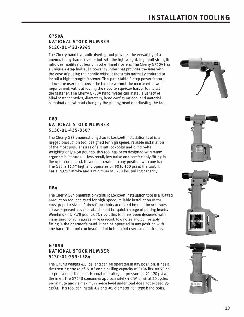
13
G750a naTional SToCK number 5120-01-432-9361
The Cherry hand hydraulic riveting tool provides the versatility of a pneumatic-hydraulic riveter, but with the lightweight, high pull strength ratio desirability not found in other hand riveters. The Cherry G750A has a unique 2-step hydraulic power cylinder that provides the user with the ease of pulling the handle without the strain normally endured to install a high strength fastener. This patentable 2-step power feature allows the user to squeeze the handle without the increased power requirement, without feeling the need to squeeze harder to install the fastener. The Cherry G750A hand riveter can install a variety of blind fastener styles, diameters, head configurations, and material combinations without changing the pulling head or adjusting the tool.
G83 naTional SToCK number 5130-01-435-3507
The Cherry G83 pneumatic-hydraulic Lockbolt installation tool is a rugged production tool designed for high speed, reliable installation of the most popular sizes of aircraft lockbolts and blind bolts.Weighing only 4.58 pounds, this tool has been designed with many ergonomic features — less recoil, low noise and comfortably fitting in the operator's hand. It can be operated in any position with one hand.The G83 is 11.5" high and operates on 90 to 100 psi at the tool. It has a .4375" stroke and a minimum of 3750 lbs. pulling capacity.
G84
The Cherry G84 pneumatic-hydraulic Lockbolt installation tool is a rugged production tool designed for high speed, reliable installation of the most popular sizes of aircraft lockbolts and blind bolts. It incorporates a new improved bayonet attachment for quick change of pulling heads.Weighing only 7.70 pounds (3.5 kg), this tool has been designed with many ergonomic features — less recoil, low noise and confortably fitting in the operator's hand. It can be operated in any position with one hand. The tool can install blind bolts, blind rivets and Lockbolts.
G704b naTional SToCK number 5130-01-393-1584
The G704B weighs 4.5 lbs. and can be operated in any position. It has a rivet setting stroke of .518" and a pulling capacity of 3136 lbs. on 90 psi air pressure at the inlet. Normal operating air pressure is 90-120 psi at the inlet. The G704B consumes approximately 4 CFM of air at 20 cycles per minute and its maximum noise level under load does not exceed 85 dB(A). This tool can install -04 and -05 diameter "S" type blind bolts.
inSTallaTion ToolinG
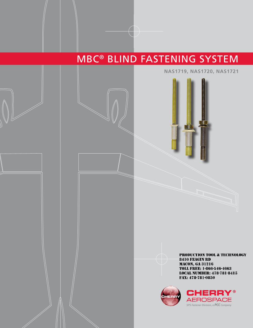
1
MBC® BLIND FASTENING SYSTEM
SPS Fastener Division, a PCC Company
NAS1719, NAS1720, NAS1721
JR
Typewritten text
Production Tool & Technology 8410 Feagin Rd Macon, Ga 31216 Toll Free: 1-866-546-4663 Local Number: 478-781-8415 Fax: 478-781-0850
MBC® Features & Benefits ........................................................................................1–2
MBC® Rivet SelectionProduct Numbering & NAS Conversion ............................................................................3Installed Weight, Grip Advantages & Part Conversion ..................................................4–5
MBC® Rivet Standards PagesMBC® Locked Stem Rivet NAS1719: 100° Reduced Flush Head Nominal Diameter ..........6MBC® Locked Stem Rivet NAS1720: Nominal Diameter Protruding Head .........................7MBC® Locked Stem Rivet NAS1721: Nominal Diameter 100° Flush Head .........................8
MBC® Installation Tooling ......................................................................................9–11
LIMITED WARRANTY
Seller warrants the goods conform to applicable specifications and drawings and will be manufactured and inspected according to generally accepted practices of companies manufacturing industrial or aerospace fasteners. In the event of any breach of the foregoing warranty, Buyer’s sole remedy shall be to return defective goods (after receiving authorization from Seller) for replacement or refund of the purchase price, at the Seller’s option. Seller agrees to any freight costs in connection with the return of any defective goods, but any costs relating to removal of the defective or nonconforming goods or installation of replacement goods shall be Buyer’s responsibility. SELLER’S WARRANTY DOES NOT APPLY WHEN ANY PHYSICAL OR CHEMICAL CHANGE IN THE FORM OF THE PRODUCT IS MADE BY BUYER. THE FOREGOING EXPRESS WARRANTY AND REMEDY ARE EXCLUSIVE AND ARE IN LIEU OF ALL OTHER WARRANTIES AND REMEDIES; ANY IMPLIED WARRANTY AS TO QUALITY, FITNESS FOR PURPOSE, OR MERCHANTABILITY IS HEREBY SPECIFICALLY DISCLAIMED AND EXCLUDED BY SELLER. This warranty is void if seller is not notified in writing of any rejection of the goods within one (1) Year after initial use by buyer of any power Riveter or ninety (90) days after initial use of any other product. Seller shall not be liable under any circumstances for incidental, special or consequential damages arising in whole or in part from any breach by Seller, AND SUCH INCIDENTAL, SPECIAL, OR CONSEQUENTIAL DAMAGES ARE HEREBY EXPRESSLY EXCLUDED.
Our policy is one of continuous development. Specifications shown in this document may be subject to changes introduced after publication.
CHERRY® and MBC® are trademarks of Cherry Aerospace.
NOTE: The properties, strengths, dimensions, installed characteristics and all other information in this catalog is for guidance only to aid in the correct selection of the products described herein and is not intended or implied as part of the warranty. All applications should be evaluated for functional suitability and available samples of the described parts can be requested for installed tests, suitability and evaluations.
ATTENTION: Blind rivets are not always a suitable substitute for solid rivets. Maintenance personnel are reminded that AC 43.13-1A chapter 2, section 3, stipulates: “Do not substitute hollow rivets for solid rivets in load carrying members without specific approval of the application by a representative of the Federal Aviation Administration. Blind rivets may be used in blind locations in accordance with the conditions listed in Chapter 5, provided the edge distances and spacings are not less that the minimum listed in paragraph 99d.”
INDEX
JR
Typewritten text
Production Tool & Technology 8410 Feagin Rd Macon, Ga 31216 Toll Free: 1-866-546-4663 Local Number: 478-781-8415 Fax: 478-781-0850
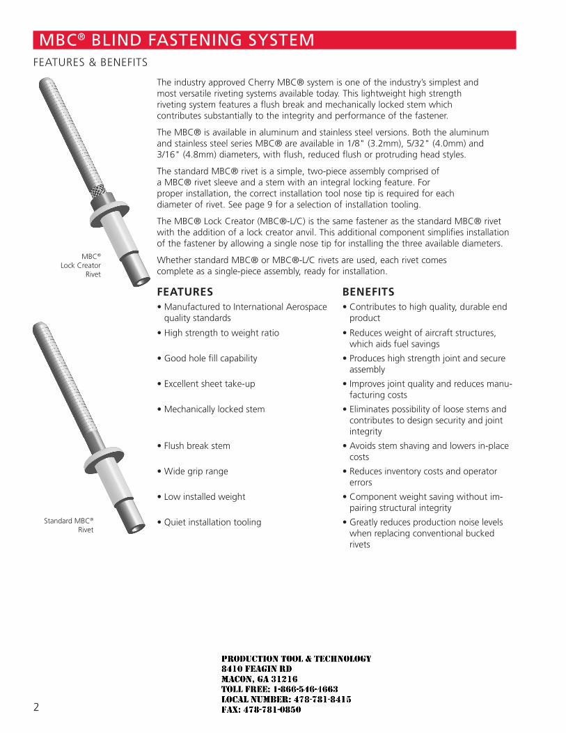
Standard MBC® Rivet
The industry approved Cherry MBC® system is one of the industry’s simplest and most versatile riveting systems available today. This lightweight high strength riveting system features a flush break and mechanically locked stem which contributes substantially to the integrity and performance of the fastener.
The MBC® is available in aluminum and stainless steel versions. Both the aluminum and stainless steel series MBC® are available in 1/8" (3.2mm), 5/32" (4.0mm) and 3/16" (4.8mm) diameters, with flush, reduced flush or protruding head styles.
The standard MBC® rivet is a simple, two-piece assembly comprised of a MBC® rivet sleeve and a stem with an integral locking feature. For proper installation, the correct installation tool nose tip is required for each diameter of rivet. See page 9 for a selection of installation tooling.
The MBC® Lock Creator (MBC®-L/C) is the same fastener as the standard MBC® rivet with the addition of a lock creator anvil. This additional component simplifies installation of the fastener by allowing a single nose tip for installing the three available diameters.
Whether standard MBC® or MBC®-L/C rivets are used, each rivet comes complete as a single-piece assembly, ready for installation.
FEATURES BENEFITS• Manufactured to International Aerospace
quality standards• Contributes to high quality, durable end
product
• High strength to weight ratio • Reduces weight of aircraft structures, which aids fuel savings
• Good hole fill capability • Produces high strength joint and secure assembly
• Excellent sheet take-up • Improves joint quality and reduces manu-facturing costs
• Mechanically locked stem • Eliminates possibility of loose stems and contributes to design security and joint integrity
• Flush break stem • Avoids stem shaving and lowers in-place costs
• Wide grip range • Reduces inventory costs and operator errors
• Low installed weight • Component weight saving without im-pairing structural integrity
• Quiet installation tooling • Greatly reduces production noise levels when replacing conventional bucked rivets
MBC®
Lock CreatorRivet
MBC® BLIND FASTENING SYSTEMFEATURES & BENEFITS
2
JR
Typewritten text
Production Tool & Technology 8410 Feagin Rd Macon, Ga 31216 Toll Free: 1-866-546-4663 Local Number: 478-781-8415 Fax: 478-781-0850
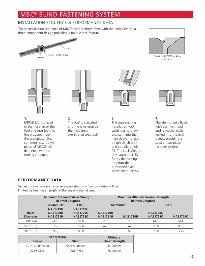
MBC® BLIND FASTENING SYSTEMINSTALLATION SEQUENCE & PERFORMANCE DATA
Typical installation sequence of MBC® rivets is shown here with the Lock Creator, a three-component design providing a unique lock feature.
sleeveLock Creator anvil
stem
1. MBC® L/C is placed in the nose tip of the tool and inserted into the prepared hole in the workpiece. One common nose tip will place all MBC® L/C diameters without tooling changes.
2. The tool is activated and the jaws engage the rivet stem, exerting an axial pull.
3. The single-acting installation tool continues to draw the stem into the rivet sleeve, to give a high clinch joint and complete hole fill. The Lock Creator anvil automatically forms the locking ring into the preformed rivet sleeve head recess.
4. The stem breaks flush with the rivet head and is mechanically locked into the rivet sleeve, providing a secure, two-piece fastener system.
PERFORMANCE DATA
Values shown here are fastener capabilities only. Design values will be limited by bearing strength of the sheet material used.
RivetDiameter
Minimum Ultimate Shear Strength in Steel Coupons
Minimum Ultimate Tension Strength in Steel Coupons
Aluminum CRES Aluminum CRESNAS1719H NAS1720HNAS1721H
NAS1719CNAS1720CNAS1721C
NAS1720HNAS1721H NAS1719H
NAS1720CNAS1721C NAS1719C
1/8" (-4) 450 1000 280 238 640 544
5/32" (-5) 700 1500 475 425 1100 935
3/16" (-6) 950 2200 700 595 1500 1275
Rivet Material Ultimate Shear StrengthSleeve Stem
2014A Aluminum 7075 Aluminum 34,000 psi
A286 CRES A286 CRES 78,000 psi
Detail of MBC® locking element
3
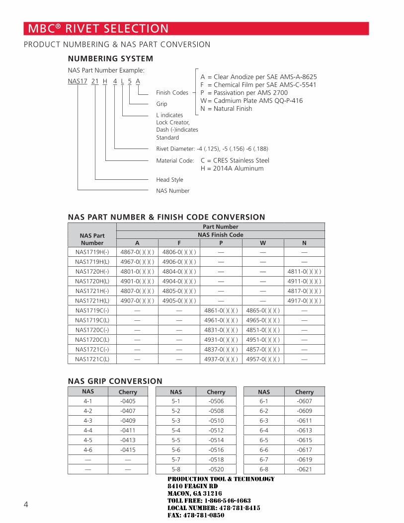
NAS PART NUMBER & FINISH CODE CONVERSION
NAS Part Number
Part NumberNAS Finish Code
A F P W N
NAS1719H(-) 4867-0( )( )( ) 4806-0( )( )( ) — — —
NAS1719H(L) 4967-0( )( )( ) 4906-0( )( )( ) — — —
NAS1720H(-) 4801-0( )( )( ) 4804-0( )( )( ) — — 4811-0( )( )( )
NAS1720H(L) 4901-0( )( )( ) 4904-0( )( )( ) — — 4911-0( )( )( )
NAS1721H(-) 4807-0( )( )( ) 4805-0( )( )( ) — — 4817-0( )( )( )
NAS1721H(L) 4907-0( )( )( ) 4905-0( )( )( ) — — 4917-0( )( )( )
NAS1719C(-) — — 4861-0( )( )( ) 4865-0( )( )( ) —
NAS1719C(L) — — 4961-0( )( )( ) 4965-0( )( )( ) —
NAS1720C(-) — — 4831-0( )( )( ) 4851-0( )( )( ) —
NAS1720C(L) — — 4931-0( )( )( ) 4951-0( )( )( ) —
NAS1721C(-) — — 4837-0( )( )( ) 4857-0( )( )( ) —
NAS1721C(L) — — 4937-0( )( )( ) 4957-0( )( )( ) —
NAS GRIP CONVERSION NAS Cherry NAS Cherry NAS Cherry
4-1 -0405 5-1 -0506 6-1 -0607
4-2 -0407 5-2 -0508 6-2 -0609
4-3 -0409 5-3 -0510 6-3 -0611
4-4 -0411 5-4 -0512 6-4 -0613
4-5 -0413 5-5 -0514 6-5 -0615
4-6 -0415 5-6 -0516 6-6 -0617
— — 5-7 -0518 6-7 -0619
— — 5-8 -0520 6-8 -0621
MBC® RIVET SELECTIONPRODUCT NUMBERING & NAS PART CONVERSION
NUMBERING SYSTEMNAS Part Number Example:
NAS17 21 H 4 L 5 A
Finish Codes
Grip
L indicates Lock Creator, Dash (-)indicates Standard
Rivet Diameter: -4 (.125), -5 (.156) -6 (.188)
Material Code: C = CRES Stainless Steel H = 2014A Aluminum
Head Style
NAS Number
A = Clear Anodize per SAE AMS-A-8625 F = Chemical Film per SAE AMS-C-5541 P = Passivation per AMS 2700 W = Cadmium Plate AMS QQ-P-416 N = Natural Finish
4
JR
Typewritten text
Production Tool & Technology 8410 Feagin Rd Macon, Ga 31216 Toll Free: 1-866-546-4663 Local Number: 478-781-8415 Fax: 478-781-0850
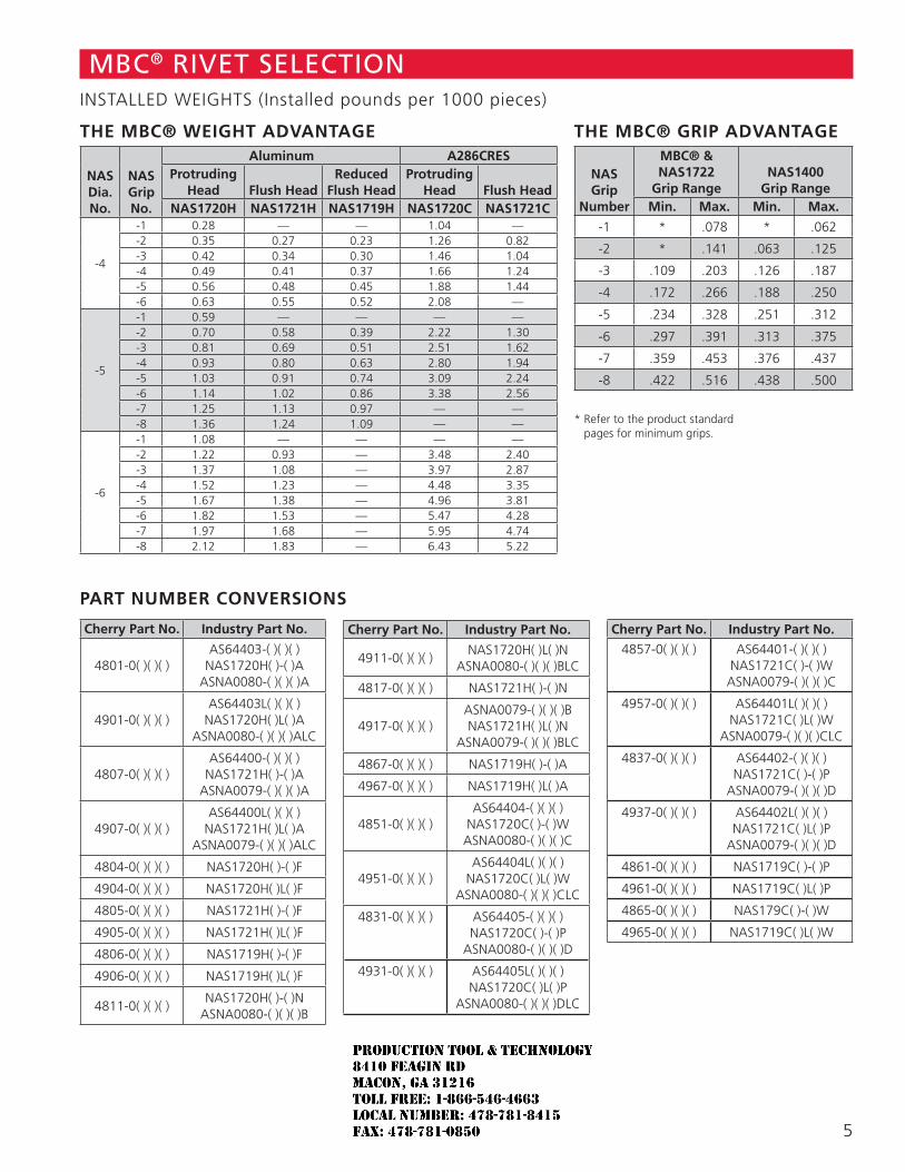
THE MBC® WEIGHT ADVANTAGE
NASDia.No.
NASGripNo.
Aluminum A286CRESProtruding
Head Flush HeadReduced
Flush HeadProtruding
Head Flush HeadNAS1720H NAS1721H NAS1719H NAS1720C NAS1721C
-4
-1 0.28 — — 1.04 —-2 0.35 0.27 0.23 1.26 0.82-3 0.42 0.34 0.30 1.46 1.04-4 0.49 0.41 0.37 1.66 1.24-5 0.56 0.48 0.45 1.88 1.44-6 0.63 0.55 0.52 2.08 —
-5
-1 0.59 — — — —-2 0.70 0.58 0.39 2.22 1.30-3 0.81 0.69 0.51 2.51 1.62-4 0.93 0.80 0.63 2.80 1.94-5 1.03 0.91 0.74 3.09 2.24-6 1.14 1.02 0.86 3.38 2.56-7 1.25 1.13 0.97 — —-8 1.36 1.24 1.09 — —
-6
-1 1.08 — — — —-2 1.22 0.93 — 3.48 2.40-3 1.37 1.08 — 3.97 2.87-4 1.52 1.23 — 4.48 3.35-5 1.67 1.38 — 4.96 3.81-6 1.82 1.53 — 5.47 4.28-7 1.97 1.68 — 5.95 4.74-8 2.12 1.83 — 6.43 5.22
THE MBC® GRIP ADVANTAGE
NASGrip
Number
MBC® & NAS1722
Grip RangeNAS1400
Grip RangeMin. Max. Min. Max.
-1 * .078 * .062
-2 * .141 .063 .125
-3 .109 .203 .126 .187
-4 .172 .266 .188 .250
-5 .234 .328 .251 .312
-6 .297 .391 .313 .375
-7 .359 .453 .376 .437
-8 .422 .516 .438 .500
* Refer to the product standard pages for minimum grips.
MBC® RIVET SELECTIONINSTALLED WEIGHTS (Installed pounds per 1000 pieces)
PART NUMBER CONVERSIONS
Cherry Part No. Industry Part No.
4801-0( )( )( )AS64403-( )( )( )
NAS1720H( )-( )AASNA0080-( )( )( )A
4901-0( )( )( )AS64403L( )( )( )
NAS1720H( )L( )AASNA0080-( )( )( )ALC
4807-0( )( )( )AS64400-( )( )( )
NAS1721H( )-( )AASNA0079-( )( )( )A
4907-0( )( )( )AS64400L( )( )( )
NAS1721H( )L( )AASNA0079-( )( )( )ALC
4804-0( )( )( ) NAS1720H( )-( )F
4904-0( )( )( ) NAS1720H( )L( )F
4805-0( )( )( ) NAS1721H( )-( )F
4905-0( )( )( ) NAS1721H( )L( )F
4806-0( )( )( ) NAS1719H( )-( )F
4906-0( )( )( ) NAS1719H( )L( )F
4811-0( )( )( )NAS1720H( )-( )N
ASNA0080-( )( )( )B
Cherry Part No. Industry Part No.
4911-0( )( )( )NAS1720H( )L( )N
ASNA0080-( )( )( )BLC
4817-0( )( )( ) NAS1721H( )-( )N
4917-0( )( )( )ASNA0079-( )( )( )BNAS1721H( )L( )N
ASNA0079-( )( )( )BLC
4867-0( )( )( ) NAS1719H( )-( )A
4967-0( )( )( ) NAS1719H( )L( )A
4851-0( )( )( )AS64404-( )( )( )
NAS1720C( )-( )WASNA0080-( )( )( )C
4951-0( )( )( )AS64404L( )( )( )
NAS1720C( )L( )WASNA0080-( )( )( )CLC
4831-0( )( )( ) AS64405-( )( )( )NAS1720C( )-( )P
ASNA0080-( )( )( )D
4931-0( )( )( ) AS64405L( )( )( )NAS1720C( )L( )P
ASNA0080-( )( )( )DLC
Cherry Part No. Industry Part No.
4857-0( )( )( ) AS64401-( )( )( )NAS1721C( )-( )W
ASNA0079-( )( )( )C
4957-0( )( )( ) AS64401L( )( )( )NAS1721C( )L( )W
ASNA0079-( )( )( )CLC
4837-0( )( )( ) AS64402-( )( )( )NAS1721C( )-( )P
ASNA0079-( )( )( )D
4937-0( )( )( ) AS64402L( )( )( )NAS1721C( )L( )P
ASNA0079-( )( )( )D
4861-0( )( )( ) NAS1719C( )-( )P
4961-0( )( )( ) NAS1719C( )L( )P
4865-0( )( )( ) NAS179C( )-( )W
4965-0( )( )( ) NAS1719C( )L( )W
5
JR
Typewritten text
Production Tool & Technology 8410 Feagin Rd Macon, Ga 31216 Toll Free: 1-866-546-4663 Local Number: 478-781-8415 Fax: 478-781-0850
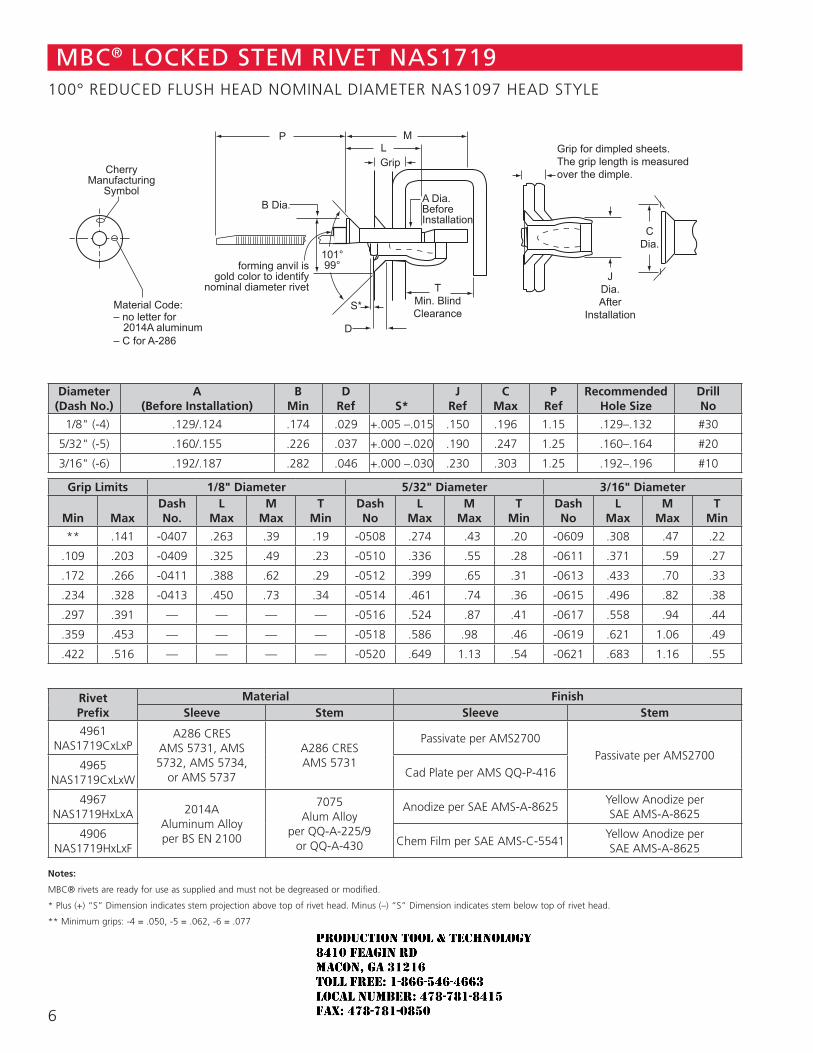
JDia.After
Installation
Grip for dimpled sheets. The grip length is measured over the dimple.
C Dia.
T Min. Blind Clearance
M L Grip
S*
A Dia.BeforeInstallation
D
P
B Dia.
101° 99° forming anvil is
gold color to identify nominal diameter rivet
CherryManufacturing
Symbol
Material Code: – no letter for
2014A aluminum – C for A-286
Diameter(Dash No.)
A(Before Installation)
BMin
DRef S*
JRef
CMax
PRef
RecommendedHole Size
DrillNo
1/8" (-4) .129/.124 .174 .029 +.005 –.015 .150 .196 1.15 .129–.132 #30
5/32" (-5) .160/.155 .226 .037 +.000 –.020 .190 .247 1.25 .160–.164 #20
3/16" (-6) .192/.187 .282 .046 +.000 –.030 .230 .303 1.25 .192–.196 #10
Grip Limits 1/8" Diameter 5/32" Diameter 3/16" Diameter
Min MaxDashNo.
LMax
MMax
TMin
DashNo
LMax
MMax
TMin
DashNo
LMax
MMax
TMin
** .141 -0407 .263 .39 .19 -0508 .274 .43 .20 -0609 .308 .47 .22
.109 .203 -0409 .325 .49 .23 -0510 .336 .55 .28 -0611 .371 .59 .27
.172 .266 -0411 .388 .62 .29 -0512 .399 .65 .31 -0613 .433 .70 .33
.234 .328 -0413 .450 .73 .34 -0514 .461 .74 .36 -0615 .496 .82 .38
.297 .391 — — — — -0516 .524 .87 .41 -0617 .558 .94 .44
.359 .453 — — — — -0518 .586 .98 .46 -0619 .621 1.06 .49
.422 .516 — — — — -0520 .649 1.13 .54 -0621 .683 1.16 .55
RivetPrefix
Material FinishSleeve Stem Sleeve Stem
4961NAS1719CxLxP
A286 CRESAMS 5731, AMS 5732, AMS 5734,
or AMS 5737
A286 CRESAMS 5731
Passivate per AMS2700Passivate per AMS2700
4965NAS1719CxLxW
Cad Plate per AMS QQ-P-416
4967NAS1719HxLxA 2014A
Aluminum Alloyper BS EN 2100
7075 Alum Alloy
per QQ-A-225/9 or QQ-A-430
Anodize per SAE AMS-A-8625Yellow Anodize per SAE AMS-A-8625
4906NAS1719HxLxF
Chem Film per SAE AMS-C-5541Yellow Anodize per SAE AMS-A-8625
Notes:
MBC® rivets are ready for use as supplied and must not be degreased or modified.
* Plus (+) “S” Dimension indicates stem projection above top of rivet head. Minus (–) “S” Dimension indicates stem below top of rivet head.
** Minimum grips: -4 = .050, -5 = .062, -6 = .077
MBC® LOCKED STEM RIVET NAS1719100° REDUCED FLUSH HEAD NOMINAL DIAMETER NAS1097 HEAD STYLE
6
JR
Typewritten text
Production Tool & Technology 8410 Feagin Rd Macon, Ga 31216 Toll Free: 1-866-546-4663 Local Number: 478-781-8415 Fax: 478-781-0850
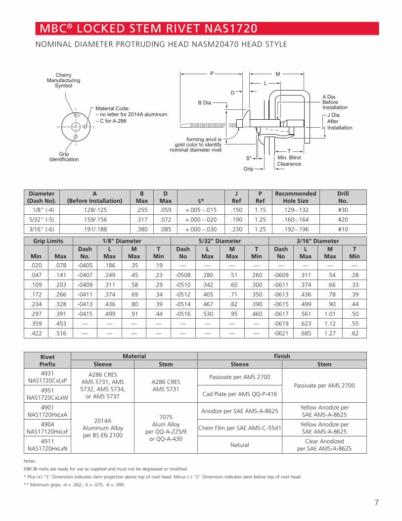
J Dia.AfterInstallation
T Min. Blind Clearance
M
L
Grip
S*
A Dia.BeforeInstallation
D
P
B Dia.
forming anvil is gold color to identify
nominal diameter rivet
CherryManufacturing
Symbol
Grip Identification
Material Code: – no letter for 2014A aluminum – C for A-286
MBC® LOCKED STEM RIVET NAS1720NOMINAL DIAMETER PROTRUDING HEAD NASM20470 HEAD STYLE
Diameter(Dash No).
A(Before Installation)
BMax
DMax S*
JRef
PRef
RecommendedHole Size
DrillNo.
1/8" (-4) .128/.125 .255 .059 +.005 –.015 .150 1.15 .129–.132 #30
5/32" (-5) .159/.156 .317 .072 +.000 –.020 .190 1.25 .160–.164 #20
3/16" (-6) .191/.188 .380 .085 +.000 –.030 .230 1.25 .192–.196 #10
Grip Limits 1/8" Diameter 5/32" Diameter 3/16" Diameter
Min MaxDashNo.
LMax
MMax
TMin
DashNo
LMax
MMax
TMin
DashNo
LMax
MMax
TMin
.020 .078 -0405 .186 .35 .19 — — — — — — — —
.047 .141 -0407 .249 .45 .23 -0508 .280 .51 .260 -0609 .311 .54 .28
.109 .203 -0409 .311 .58 .29 -0510 .342 .60 .300 -0611 .374 .66 .33
.172 .266 -0411 .374 .69 .34 -0512 .405 .71 .350 -0613 .436 .78 .39
.234 .328 -0413 .436 .80 .39 -0514 .467 .82 .390 -0615 .499 .90 .44
.297 .391 -0415 .499 .91 .44 -0516 .530 .95 .460 -0617 .561 1.01 .50
.359 .453 — — — — — — — — -0619 .623 1.12 .55
.422 .516 — — — — — — — — -0621 .685 1.27 .62
RivetPrefix
Material FinishSleeve Stem Sleeve Stem
4931NAS1720CxLxP
A286 CRESAMS 5731, AMS 5732, AMS 5734,
or AMS 5737
A286 CRESAMS 5731
Passivate per AMS 2700Passivate per AMS 2700
4951NAS1720CxLxW
Cad Plate per AMS QQ-P-416
4901NAS1720HxLxA
2014A Aluminum Alloyper BS EN 2100
7075 Alum Alloy
per QQ-A-225/9 or QQ-A-430
Anodize per SAE AMS-A-8625Yellow Anodize per SAE AMS-A-8625
4904NAS17120HxLxF
Chem Film per SAE AMS-C-5541Yellow Anodize per SAE AMS-A-8625
4911NAS1720HxLxN
NaturalClear Anodized
per SAE AMS-A-8625
Notes:
MBC® rivets are ready for use as supplied and must not be degreased or modified.
* Plus (+) “S” Dimension indicates stem projection above top of rivet head. Minus (–) “S” Dimension indicates stem below top of rivet head.
** Minimum grips: -4 = .062, -5 = .075, -6 = .090
7
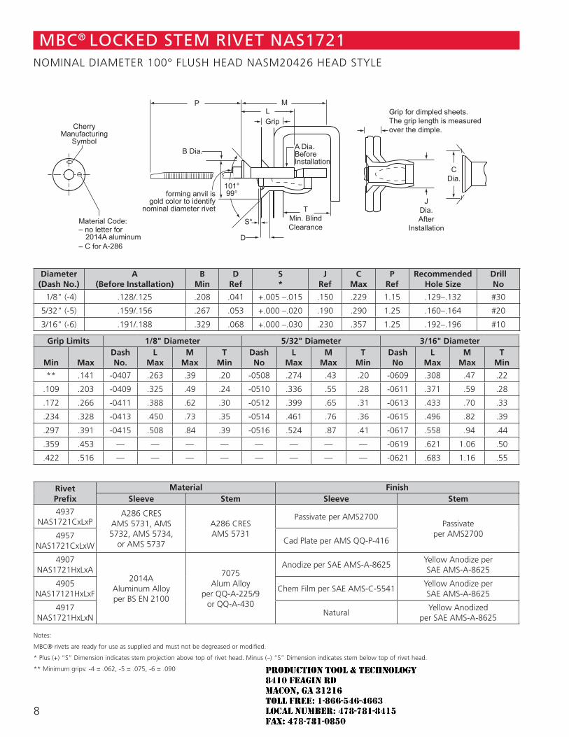
JDia.After
Installation
Grip for dimpled sheets. The grip length is measured over the dimple.
C Dia.
T Min. Blind Clearance
M L Grip
S*
A Dia.BeforeInstallation
D
P
B Dia.
101° 99° forming anvil is
gold color to identify nominal diameter rivet
CherryManufacturing
Symbol
Material Code: – no letter for
2014A aluminum – C for A-286
MBC® LOCKED STEM RIVET NAS1721NOMINAL DIAMETER 100° FLUSH HEAD NASM20426 HEAD STYLE
Diameter(Dash No.)
A(Before Installation)
BMin
DRef
S *
JRef
CMax
PRef
RecommendedHole Size
DrillNo
1/8" (-4) .128/.125 .208 .041 +.005 –.015 .150 .229 1.15 .129–.132 #30
5/32" (-5) .159/.156 .267 .053 +.000 –.020 .190 .290 1.25 .160–.164 #20
3/16" (-6) .191/.188 .329 .068 +.000 –.030 .230 .357 1.25 .192–.196 #10
Grip Limits 1/8" Diameter 5/32" Diameter 3/16" Diameter
Min MaxDashNo.
LMax
MMax
TMin
DashNo
LMax
MMax
TMin
DashNo
LMax
MMax
TMin
** .141 -0407 .263 .39 .20 -0508 .274 .43 .20 -0609 .308 .47 .22
.109 .203 -0409 .325 .49 .24 -0510 .336 .55 .28 -0611 .371 .59 .28
.172 .266 -0411 .388 .62 .30 -0512 .399 .65 .31 -0613 .433 .70 .33
.234 .328 -0413 .450 .73 .35 -0514 .461 .76 .36 -0615 .496 .82 .39
.297 .391 -0415 .508 .84 .39 -0516 .524 .87 .41 -0617 .558 .94 .44
.359 .453 — — — — — — — — -0619 .621 1.06 .50
.422 .516 — — — — — — — — -0621 .683 1.16 .55
RivetPrefix
Material FinishSleeve Stem Sleeve Stem
4937NAS1721CxLxP
A286 CRESAMS 5731, AMS 5732, AMS 5734,
or AMS 5737
A286 CRESAMS 5731
Passivate per AMS2700Passivate
per AMS27004957NAS1721CxLxW
Cad Plate per AMS QQ-P-416
4907NAS1721HxLxA
2014A Aluminum Alloyper BS EN 2100
7075 Alum Alloy
per QQ-A-225/9 or QQ-A-430
Anodize per SAE AMS-A-8625Yellow Anodize per SAE AMS-A-8625
4905NAS17121HxLxF
Chem Film per SAE AMS-C-5541Yellow Anodize per SAE AMS-A-8625
4917NAS1721HxLxN
NaturalYellow Anodized
per SAE AMS-A-8625
Notes:
MBC® rivets are ready for use as supplied and must not be degreased or modified.
* Plus (+) “S” Dimension indicates stem projection above top of rivet head. Minus (–) “S” Dimension indicates stem below top of rivet head.
** Minimum grips: -4 = .062, -5 = .075, -6 = .090
8
JR
Typewritten text
Production Tool & Technology 8410 Feagin Rd Macon, Ga 31216 Toll Free: 1-866-546-4663 Local Number: 478-781-8415 Fax: 478-781-0850
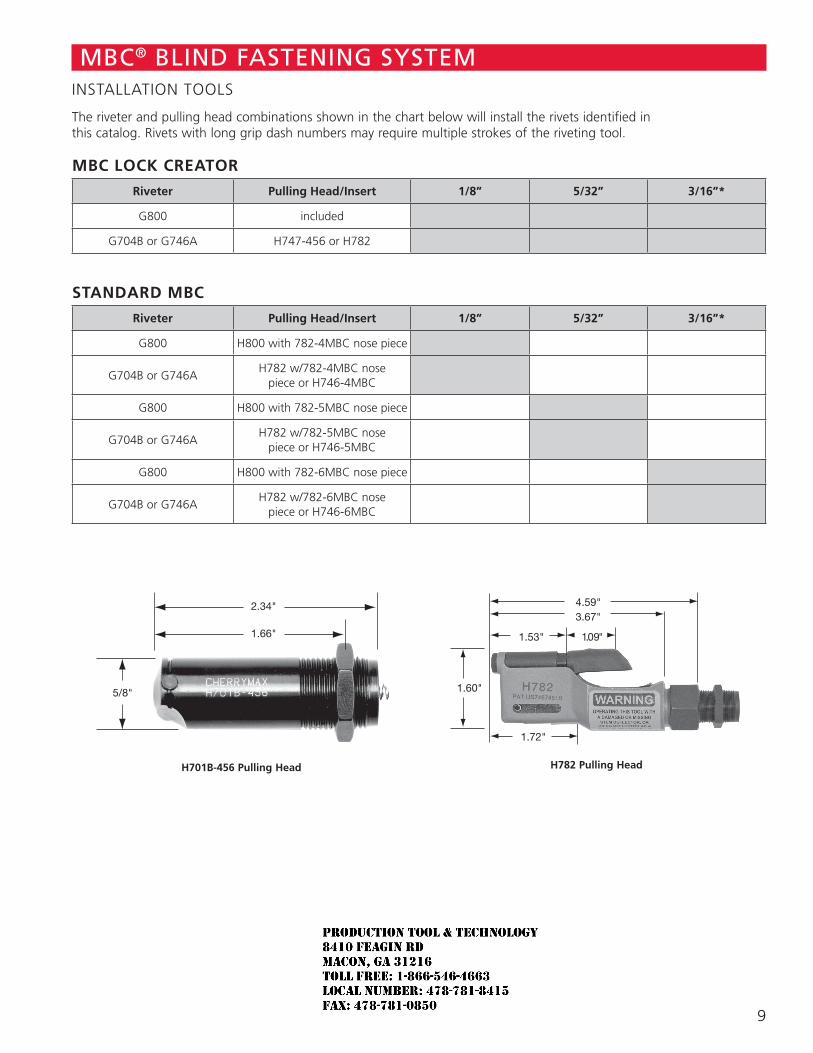
The riveter and pulling head combinations shown in the chart below will install the rivets identified in this catalog. Rivets with long grip dash numbers may require multiple strokes of the riveting tool.
MBC LOCK CREATOR
Riveter Pulling Head/Insert 1/8” 5/32” 3/16”*
G800 included
G704B or G746A H747-456 or H782
STANDARD MBC
Riveter Pulling Head/Insert 1/8” 5/32” 3/16”*
G800 H800 with 782-4MBC nose piece
G704B or G746AH782 w/782-4MBC nose
piece or H746-4MBC
G800 H800 with 782-5MBC nose piece
G704B or G746AH782 w/782-5MBC nose
piece or H746-5MBC
G800 H800 with 782-6MBC nose piece
G704B or G746AH782 w/782-6MBC nose
piece or H746-6MBC
MBC® BLIND FASTENING SYSTEMINSTALLATION TOOLS
2.34"
1.66"
5/8"
H701B-456 Pulling Head
4.59"3.67"
1.53"
1.60"
1.09"
1.72"
H782 Pulling Head
9
JR
Typewritten text
Production Tool & Technology 8410 Feagin Rd Macon, Ga 31216 Toll Free: 1-866-546-4663 Local Number: 478-781-8415 Fax: 478-781-0850
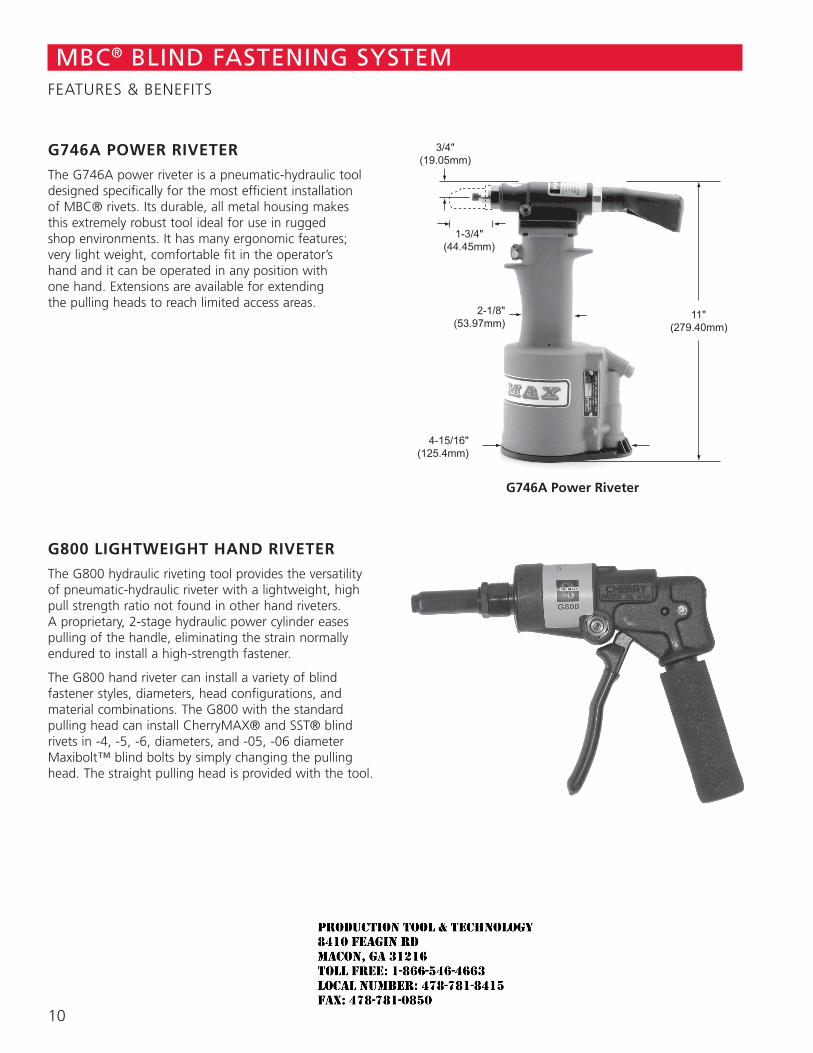
G746A POWER RIVETER
The G746A power riveter is a pneumatic-hydraulic tool designed specifically for the most efficient installation of MBC® rivets. Its durable, all metal housing makes this extremely robust tool ideal for use in rugged shop environments. It has many ergonomic features; very light weight, comfortable fit in the operator’s hand and it can be operated in any position with one hand. Extensions are available for extending the pulling heads to reach limited access areas.
G800 LIGHTWEIGHT HAND RIVETER
The G800 hydraulic riveting tool provides the versatility of pneumatic-hydraulic riveter with a lightweight, high pull strength ratio not found in other hand riveters. A proprietary, 2-stage hydraulic power cylinder eases pulling of the handle, eliminating the strain normally endured to install a high-strength fastener.
The G800 hand riveter can install a variety of blind fastener styles, diameters, head configurations, and material combinations. The G800 with the standard pulling head can install CherryMAX® and SST® blind rivets in -4, -5, -6, diameters, and -05, -06 diameter Maxibolt™ blind bolts by simply changing the pulling head. The straight pulling head is provided with the tool.
G746A Power Riveter
MBC® BLIND FASTENING SYSTEMFEATURES & BENEFITS
10
JR
Typewritten text
Production Tool & Technology 8410 Feagin Rd Macon, Ga 31216 Toll Free: 1-866-546-4663 Local Number: 478-781-8415 Fax: 478-781-0850
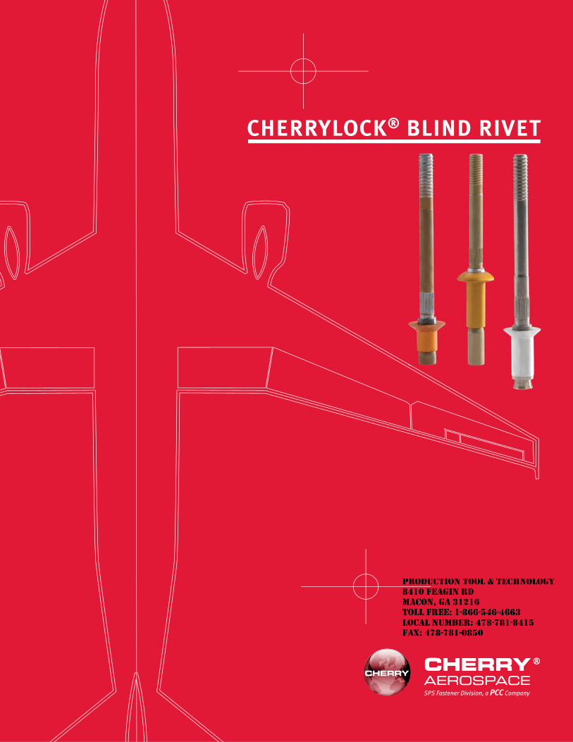
1 1
CHERRYLOCK® BLIND RIVET
SPS Fastener Division, a PCC Company
JR
Typewritten text
Production Tool & Technology 8410 Feagin Rd Macon, Ga 31216 Toll Free: 1-866-546-4663 Local Number: 478-781-8415 Fax: 478-781-0850

JR
Typewritten text
Production Tool & Technology 8410 Feagin Rd Macon, Ga 31216 Toll Free: 1-866-546-4663 Local Number: 478-781-8415 Fax: 478-781-0850
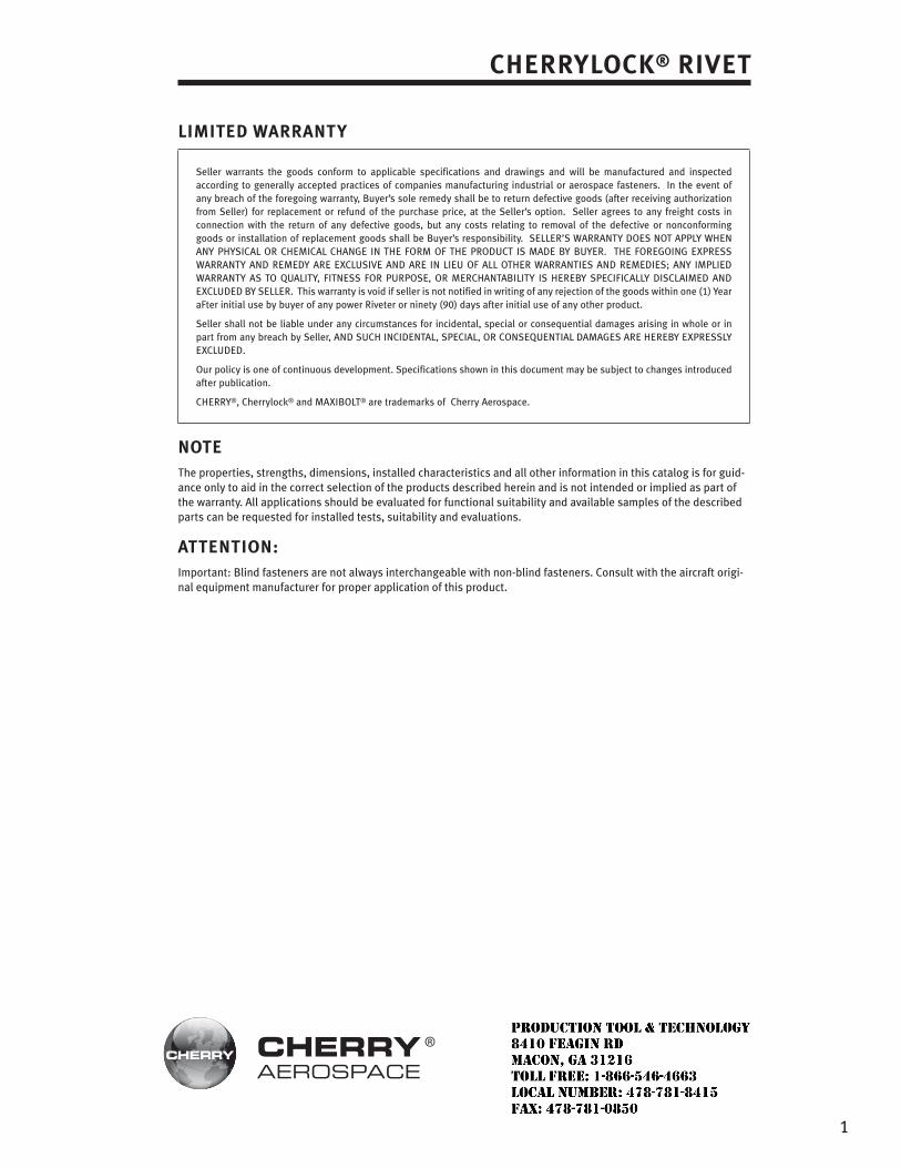
CHERRYLOCK® RIVET
LIMITED WARRANTY
Seller warrants the goods conform to applicable specifications and drawings and will be manufactured and inspected according to generally accepted practices of companies manufacturing industrial or aerospace fasteners. In the event of any breach of the foregoing warranty, Buyer’s sole remedy shall be to return defective goods (after receiving authorization from Seller) for replacement or refund of the purchase price, at the Seller’s option. Seller agrees to any freight costs in connection with the return of any defective goods, but any costs relating to removal of the defective or nonconforming goods or installation of replacement goods shall be Buyer’s responsibility. SELLER’S WARRANTY DOES NOT APPLY WHEN ANY PHYSICAL OR CHEMICAL CHANGE IN THE FORM OF THE PRODUCT IS MADE BY BUYER. THE FOREGOING EXPRESS WARRANTY AND REMEDY ARE EXCLUSIVE AND ARE IN LIEU OF ALL OTHER WARRANTIES AND REMEDIES; ANY IMPLIED WARRANTY AS TO QUALITY, FITNESS FOR PURPOSE, OR MERCHANTABILITY IS HEREBY SPECIFICALLY DISCLAIMED AND EXCLUDED BY SELLER. This warranty is void if seller is not notified in writing of any rejection of the goods within one (1) Year aFter initial use by buyer of any power Riveter or ninety (90) days after initial use of any other product.
Seller shall not be liable under any circumstances for incidental, special or consequential damages arising in whole or in part from any breach by Seller, AND SUCH INCIDENTAL, SPECIAL, OR CONSEQUENTIAL DAMAGES ARE HEREBY EXPRESSLY EXCLUDED.
Our policy is one of continuous development. Specifications shown in this document may be subject to changes introduced after publication.
CHERRY®, Cherrylock® and MAXIBOLT® are trademarks of Cherry Aerospace.
NOTEThe properties, strengths, dimensions, installed characteristics and all other information in this catalog is for guid-ance only to aid in the correct selection of the products described herein and is not intended or implied as part of the warranty. All applications should be evaluated for functional suitability and available samples of the described parts can be requested for installed tests, suitability and evaluations.
ATTENTION:Important: Blind fasteners are not always interchangeable with non-blind fasteners. Consult with the aircraft origi-nal equipment manufacturer for proper application of this product.
1
JR
Typewritten text
Production Tool & Technology 8410 Feagin Rd Macon, Ga 31216 Toll Free: 1-866-546-4663 Local Number: 478-781-8415 Fax: 478-781-0850
2
CONTENTS
BULBED CHERRYLOCK® RIVETS
Rivet SelectionDesign Features & Installation Sequence ............................................................................. 3Numbering System & Head Styles ........................................................................................ 4Grip Lengths & Materials ...................................................................................................... 5Strength & Installed Weights ................................................................................................ 6Conversion Table: NAS to Cherry Numbers ........................................................................... 7
Standards PagesNAS1738 Universal Head ..................................................................................................... 8NAS1739 Countersunk Head ................................................................................................ 9Unisink Head ...................................................................................................................... 10156° Countersunk Head ...................................................................................................... 11
WIREDRAW CHERRYLOCK® RIVETSRivet SelectionDesign Features & Installation Sequence ........................................................................... 12Numbering System, Materials & Strength .......................................................................... 13Installed Weights ................................................................................................................ 14Conversion Table: NAS to Cherry Numbers ......................................................................... 15
Standards PagesNAS1398 Universal Head .................................................................................................... 16NAS1399 Countersunk Head .............................................................................................. 18NAS1097 Reduced Flush Head ........................................................................................... 20
Rivet Installation & InspectionHole Preparation ................................................................................................................. 22Rivet Installation ................................................................................................................. 23Troubleshooting .................................................................................................................. 24Rivet Removal ..................................................................................................................... 25
Installation ToolingOverview ............................................................................................................................. 26Tool Selection Chart ............................................................................................................ 27Installation Tools G700 ............................................................................................................................ 28 G784............................................................................................................................ 29 G686B-S ...................................................................................................................... 30 G689 ........................................................................................................................... 31 G695B ......................................................................................................................... 32Pulling Heads...................................................................................................................... 33Adapters & Extensions ....................................................................................................... 34Maintenance Items ............................................................................................................. 34Service Kits ......................................................................................................................... 35
JR
Typewritten text
Production Tool & Technology 8410 Feagin Rd Macon, Ga 31216 Toll Free: 1-866-546-4663 Local Number: 478-781-8415 Fax: 478-781-0850
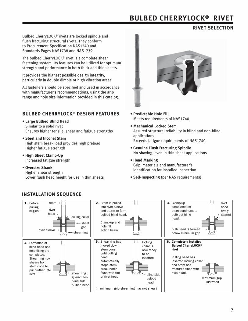
3
BULBED CHERRYLOCK® RIVETRIVET SELECTION
Bulbed CherryLOCK® rivets are locked spindle and flush fracturing structural rivets. They conform to Procurement Specification NAS1740 and Standards Pages NAS1738 and NAS1739.
The bulbed CherryLOCK® rivet is a complete shear fastening system. Its features can be utilized for optimum strength and performance in both thick and thin sheets.
It provides the highest possible design integrity, particularly in double dimple or high vibration areas.
All fasteners should be specified and used in accordance with manufacturer’s recommendations, using the grip range and hole size information provided in this catalog.
BULBED CHERRYLOCK® DESIGN FEATURES
• Large Bulbed Blind HeadSimilar to a solid rivetEnsures higher tensile, shear and fatigue strengths
• Steel and Inconel StemHigh stem break load provides high preload Higher fatigue strength
• High Sheet Clamp-UpIncreased fatigue strength
• Oversize ShankHigher shear strengthLower flush head height for use in thin sheets
• Predictable Hole FillMeets requirements of NAS1740
• Mechanical Locked StemAssured structural reliability in blind and non-blind applicationsExceeds fatigue requirements of NAS1740
• Genuine Flush Fracturing SpindleNo shaving, even in thin sheet applications
• Head MarkingGrip, materials and manufacturer’s identification for installed inspection
• Self-Inspecting (per NAS requirements)
INSTALLATION SEQUENCE
locking collar
stem
rivethead
rivet sleeveshear ring
sheetgap
bulb head is formedbelow minimum grip
rivet headfirmly seated
shear ringguaranteesblind sidebulbed head
locking collar isnow ready to beinserted
blind sidebulbed head
maximum gripillustrated
1. Before pulling begins.
2. Stem is pulled into rivet sleeve and starts to form bulbed blind head.
Clamp-up and hole fill action begin.
3. Clamp-up completed as stem continues to bulb out blind head.
4. Formation of blind head and hole filling are completed. Shear ring now shears from stem cone to pull further into rivet.
5. Shear ring has moved down stem cone until pulling head automatically stops stem break notch flush with top of rivet head.
6. Completely installed Bulbed CherryLOCK® rivet
Pulling head has inserted locking collar and stem has fractured flush with rivet head.
(In minimum grip shear ring may not shear)

NUMBERING SYSTEM
NAS173 8 B 5 -4
Maximum Grip Length in 16ths of an inch (-4 = 4/16"= .250)
Shank Diameter -4(.140), -5(.173), -6(.201)
Rivet Type & Material Combination
Head Style: Odd number = CountersinkEven number = Protruding
NAS Number
CR® 224 9 -5 -04
Maximum Grip Length in 16ths of an inch (-04 = 4/16"= .250)
Shank Diameter -4(.140), -5(.173), -6(.201)
Head Style Odd number = ProtrudingEven number = Countersink
Rivet Type & Material Combination
Cherry Number
4
BULBED CHERRYLOCK® RIVETRIVET SELECTION
HEAD STYLES
Universal(MS20470)
For protruding head applications
100° Countersunk(MS20426)
For countersunk applications
Unisink
A combination flush and protruding head for use in very thin top sheets. Eliminates need for double-dimpling. Not covered by NAS Standard.
156° Countersunk
A large diameter, shallow countershunk head providing a wide bearing area for honeycomb applications. Not covered by NAS Standard.
DIAMETERS
Bulbed CherryLOCK® rivets are available in three diameters: -4(.140), -5(.173) and -6(.201).
Bulbed CherryLOCK® rivet sleeve is 1/64" over nominal size. In most cases, the increased bearing area and high strength stem enables excellent performance in double-dimple and thin sheet applications.NOTE: Standard drills are used to prepare installation holes.
JR
Typewritten text
Production Tool & Technology 8410 Feagin Rd Macon, Ga 31216 Toll Free: 1-866-546-4663 Local Number: 478-781-8415 Fax: 478-781-0850
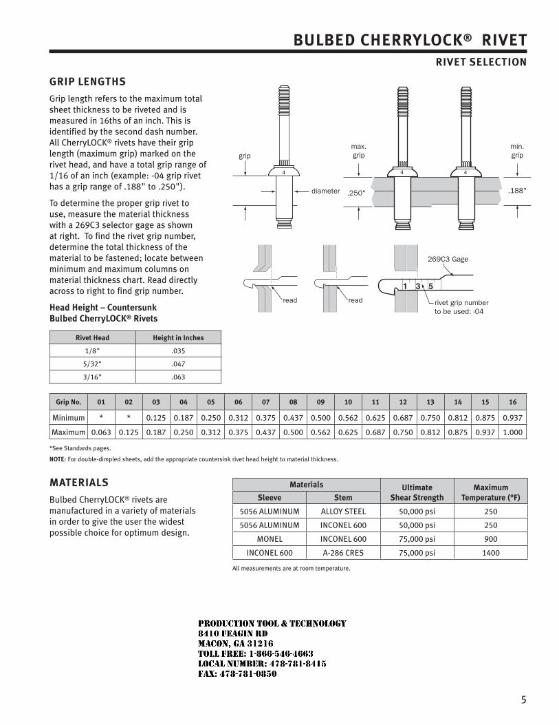
5
BULBED CHERRYLOCK® RIVETRIVET SELECTION
GRIP LENGTHS
Grip length refers to the maximum total sheet thickness to be riveted and is measured in 16ths of an inch. This is identified by the second dash number. All CherryLOCK® rivets have their grip length (maximum grip) marked on the rivet head, and have a total grip range of 1/16 of an inch (example: -04 grip rivet has a grip range of .188" to .250").
To determine the proper grip rivet to use, measure the material thickness with a 269C3 selector gage as shown at right. To find the rivet grip number, determine the total thickness of the material to be fastened; locate between minimum and maximum columns on material thickness chart. Read directly across to right to find grip number.
Head Height – Countersunk Bulbed CherryLOCK® Rivets
Rivet Head Height in Inches
1/8" .035
5/32" .047
3/16" .063
Grip No. 01 02 03 04 05 06 07 08 09 10 11 12 13 14 15 16
Minimum * * 0.125 0.187 0.250 0.312 0.375 0.437 0.500 0.562 0.625 0.687 0.750 0.812 0.875 0.937
Maximum 0.063 0.125 0.187 0.250 0.312 0.375 0.437 0.500 0.562 0.625 0.687 0.750 0.812 0.875 0.937 1.000
*See Standards pages.
NOTE: For double-dimpled sheets, add the appropriate countersink rivet head height to material thickness.
MATERIALS
Bulbed CherryLOCK® rivets are manufactured in a variety of materials in order to give the user the widest possible choice for optimum design.
Materials Ultimate Shear Strength
MaximumTemperature (°F)Sleeve Stem
5056 ALUMINUM ALLOY STEEL 50,000 psi 250
5056 ALUMINUM INCONEL 600 50,000 psi 250
MONEL INCONEL 600 75,000 psi 900
INCONEL 600 A-286 CRES 75,000 psi 1400
All measurements are at room temperature.
.250" .188"
max.grip
min.grip
read read
269C3 Gage
rivet grip numberto be used: -04
grip
diameter
JR
Typewritten text
Production Tool & Technology 8410 Feagin Rd Macon, Ga 31216 Toll Free: 1-866-546-4663 Local Number: 478-781-8415 Fax: 478-781-0850
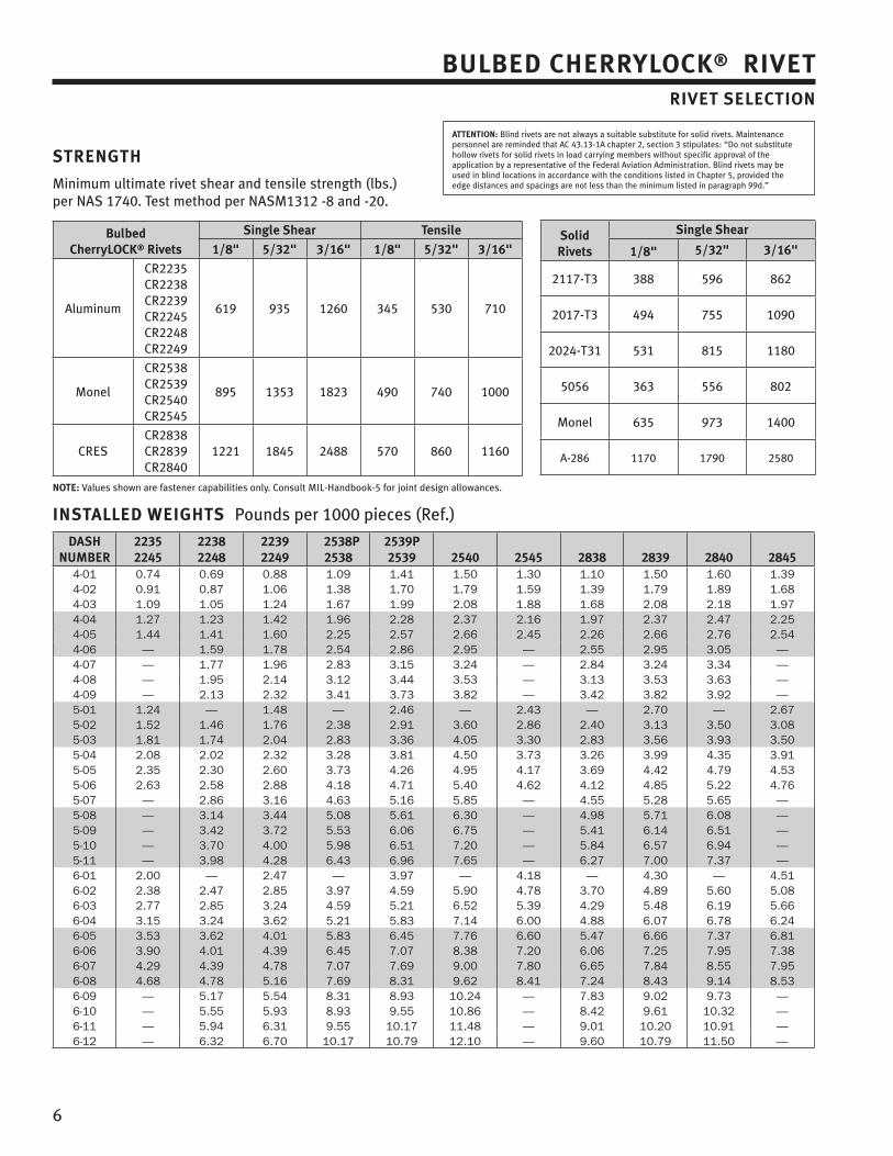
6
BULBED CHERRYLOCK® RIVETRIVET SELECTION
STRENGTH
Minimum ultimate rivet shear and tensile strength (lbs.) per NAS 1740. Test method per NASM1312 -8 and -20.
Bulbed CherryLOCK® Rivets
Single Shear Tensile
1/8" 5/32" 3/16" 1/8" 5/32" 3/16"
Aluminum
CR2235CR2238CR2239CR2245CR2248CR2249
619 935 1260 345 530 710
Monel
CR2538CR2539CR2540CR2545
895 1353 1823 490 740 1000
CRESCR2838CR2839CR2840
1221 1845 2488 570 860 1160
NOTE: Values shown are fastener capabilities only. Consult MIL-Handbook-5 for joint design allowances.
INSTALLED WEIGHTS Pounds per 1000 pieces (Ref.)
DASHNUMBER
22352245
22382248
22392249
2538P2538
2539P2539 2540 2545 2838 2839 2840 2845
4-01 0.74 0.69 0.88 1.09 1.41 1.50 1.30 1.10 1.50 1.60 1.394-02 0.91 0.87 1.06 1.38 1.70 1.79 1.59 1.39 1.79 1.89 1.684-03 1.09 1.05 1.24 1.67 1.99 2.08 1.88 1.68 2.08 2.18 1.974-04 1.27 1.23 1.42 1.96 2.28 2.37 2.16 1.97 2.37 2.47 2.254-05 1.44 1.41 1.60 2.25 2.57 2.66 2.45 2.26 2.66 2.76 2.544-06 — 1.59 1.78 2.54 2.86 2.95 — 2.55 2.95 3.05 —4-07 — 1.77 1.96 2.83 3.15 3.24 — 2.84 3.24 3.34 —4-08 — 1.95 2.14 3.12 3.44 3.53 — 3.13 3.53 3.63 —4-09 — 2.13 2.32 3.41 3.73 3.82 — 3.42 3.82 3.92 —5-01 1.24 — 1.48 — 2.46 — 2.43 — 2.70 — 2.675-02 1.52 1.46 1.76 2.38 2.91 3.60 2.86 2.40 3.13 3.50 3.085-03 1.81 1.74 2.04 2.83 3.36 4.05 3.30 2.83 3.56 3.93 3.505-04 2.08 2.02 2.32 3.28 3.81 4.50 3.73 3.26 3.99 4.35 3.915-05 2.35 2.30 2.60 3.73 4.26 4.95 4.17 3.69 4.42 4.79 4.535-06 2.63 2.58 2.88 4.18 4.71 5.40 4.62 4.12 4.85 5.22 4.765-07 — 2.86 3.16 4.63 5.16 5.85 — 4.55 5.28 5.65 —5-08 — 3.14 3.44 5.08 5.61 6.30 — 4.98 5.71 6.08 —5-09 — 3.42 3.72 5.53 6.06 6.75 — 5.41 6.14 6.51 —5-10 — 3.70 4.00 5.98 6.51 7.20 — 5.84 6.57 6.94 —5-11 — 3.98 4.28 6.43 6.96 7.65 — 6.27 7.00 7.37 —6-01 2.00 — 2.47 — 3.97 — 4.18 — 4.30 — 4.516-02 2.38 2.47 2.85 3.97 4.59 5.90 4.78 3.70 4.89 5.60 5.086-03 2.77 2.85 3.24 4.59 5.21 6.52 5.39 4.29 5.48 6.19 5.666-04 3.15 3.24 3.62 5.21 5.83 7.14 6.00 4.88 6.07 6.78 6.246-05 3.53 3.62 4.01 5.83 6.45 7.76 6.60 5.47 6.66 7.37 6.816-06 3.90 4.01 4.39 6.45 7.07 8.38 7.20 6.06 7.25 7.95 7.386-07 4.29 4.39 4.78 7.07 7.69 9.00 7.80 6.65 7.84 8.55 7.956-08 4.68 4.78 5.16 7.69 8.31 9.62 8.41 7.24 8.43 9.14 8.536-09 — 5.17 5.54 8.31 8.93 10.24 — 7.83 9.02 9.73 —6-10 — 5.55 5.93 8.93 9.55 10.86 — 8.42 9.61 10.32 —6-11 — 5.94 6.31 9.55 10.17 11.48 — 9.01 10.20 10.91 —6-12 — 6.32 6.70 10.17 10.79 12.10 — 9.60 10.79 11.50 —
ATTENTION: Blind rivets are not always a suitable substitute for solid rivets. Maintenance personnel are reminded that AC 43.13-1A chapter 2, section 3 stipulates: “Do not substitute hollow rivets for solid rivets in load carrying members without specific approval of the application by a representative of the Federal Aviation Administration. Blind rivets may be used in blind locations in accordance with the conditions listed in Chapter 5, provided the edge distances and spacings are not less than the minimum listed in paragraph 99d.”
SolidRivets
Single Shear
1/8" 5/32" 3/16"
2117-T3 388 596 862
2017-T3 494 755 1090
2024-T31 531 815 1180
5056 363 556 802
Monel 635 973 1400
A-286 1170 1790 2580
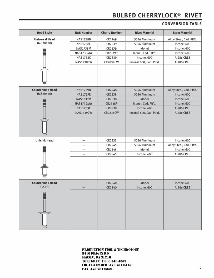
7
BULBED CHERRYLOCK® RIVETCONVERSION TABLE
Head Style NAS Number Cherry Number Rivet Material Stem Material
Universal Head (MS20470)
NAS1738B
NAS1738E
NAS1738M
NAS1738MW
NAS1738C
NAS1738CW
CR2249
CR2239
CR2539
CR2539P
CR2839
CR2839CW
5056 Aluminum
5056 Aluminum
Monel
Monel, Cad. Plt’d.
Inconel 600
lnconel 600, Cad. Plt’d.
Alloy Steel, Cad. Plt’d.
Inconel 600
Inconel 600
Inconel 600
A-286 CRES
A-286 CRES
Countersunk Head (MS20426)
NAS1739B
NAS1739E
NAS1739M
NAS1739MW
NAS1739C
NAS1739CW
CR2248
CR2238
CR2538
CR2538P
CR2838
CR2838CW
5056 Aluminum
5056 Aluminum
Monel
Monel, Cad. Plt’d.
Inconel 600
lnconel 600, Cad. Plt’d.
Alloy Steel, Cad. Plt’d.
Inconel 600
Inconel 600
Inconel 600
A-286 CRES
A-286 CRES
Unisink Head —
—
—
—
CR2235
CR2245
CR2545
CR2845
5056 Aluminum
5056 Aluminum
Monel
Inconel 600
Inconel 600
Alloy Steel, Cad. Plt’d.
Inconel 600
A-286 CRES
Countersunk Head (156°)
—
—
CR2540
CR2840
Monel
Inconel 600
Inconel 600
A-286 CRES
JR
Typewritten text
Production Tool & Technology 8410 Feagin Rd Macon, Ga 31216 Toll Free: 1-866-546-4663 Local Number: 478-781-8415 Fax: 478-781-0850
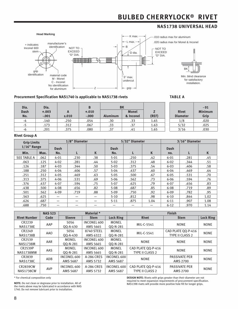
8
BULBED CHERRYLOCK® RIVETNAS1738 UNIVERSAL HEAD
Procurement Specification NAS1740 is applicable to NAS1738 rivets TABLE A
Dia. DashNo.
Dia. +.003-.001
A±.010
B+.010-.000
BKZ
(REF)Rivet
Diameter
- 01Minimum
GripAluminumMonel
& Inconel-4 .140 .250 .054 .30 .33 1.65 1/8 .020-5 .173 .312 .067 .33 .37 1.63 5/32 .025-6 .201 .375 .080 .37 .41 1.65 3/16 .030
Rivet Group A
Grip Limits1/16" Range
1/8" Diameter 5/32" Diameter 3/16" Diameter
DashNo. L K
DashNo. L K
Dashno. L KMin. Max.
SEE TABLE A .062 4-01 .230 .38 5-01 .250 .42 6-01 .281 .45.063 .125 4-02 .281 .44 5-02 .312 .48 6-02 .344 .51.126 .187 4-03 .344 .50 5-03 .375 .54 6-03 .406 .58.188 .250 4-04 .406 .57 5-04 .437 .60 6-04 .469 .64.251 .312 4-05 .469 .63 5-05 .500 .67 6-05 .531 .70.313 .375 4-06 .531 .69 5-06 .562 .73 6-06 .594 .76.376 .437 4-07 .594 .75 5-07 .625 .79 6-07 .656 .83.438 .500 4-08 .656 .82 5-08 .687 .85 6-08 .719 .89.501 .562 4-09 .719 .88 5-09 .750 .92 6-09 .782 .95.563 .625 — — — 5-10 .812 .98 6-10 .844 1.02.626 .687 — — — 5-11 .875 1.04 6-11 .907 1.08.688 .750 — — — — — — 6-12 .970 1.14
Rivet NumberNAS 523
CodeMaterial * Finish
Sleeve Stem Lock Ring Rivet Stem Lock RingCR2239
NAS1738EAAP
5056 QQ-A-430
INCONEL 600AMS 5665
MONELQQ-N-281
MIL-C-5541 NONE NONE
CR2249NAS1738B
AAO5056
QQ-A-4308740 STEELAMS 6322
MONELQQ-N-281
MIL-C-5541CAD PLATE QQ-P-416
TYPE II CLASS 2NONE
CR2539NAS1738M
AARMONEL
QQ-N-281INCONEL 600
AMS 5665MONEL
QQ-N-281NONE NONE NONE
CR2539PNAS1738MW
AASMONEL
QQ-N-281INCONEL 600
AMS 5665MONEL
QQ-N-281CAD PLATE QQ-P-416
TYPE II CLASS 2NONE NONE
CR2839NAS1738C
ADBINCONEL 600
AMS 5687A-286 CRESAMS 5732
INCONEL 600AMS 5687
NONEPASSIVATE PER
AMS 2700NONE
CR2839CWNAS1738CW
AVPINCONEL 600
AMS 5687A-286 CRESAMS 5732
INCONEL 600AMS 5687
CAD PLATE QQ-P-416TYPE II CLASS 2
PASSIVATE PER AMS 2700
NONE
* For chemical composition only
NOTE: Do not clean or degrease prior to installation. All of the rivets above may be lubricated in accordance with NAS 1740. Do not remove lubricant prior to installation.
DESIGN NOTE: Rivets with grips greater than their diameter are not required to meet expansion requirements of procurement specification. NAS1398 rivets will provide more positive hole fill for longer grips.
L max.
K max.Head Marking
manufacturer’sidentification
gripidentification
B
D dia.
NOT TOEXCEED“D” DIA.
NOT TOEXCEED“D” DIA.
Z grip
BK
Min. blind clearancefor satisfactory
installation.
material codeM - MonelC - Inconel
No identification for aluminum
.010 radius max for aluminum
.020 radius max for Monel & Inconel+ indicates
Inconel 600stem
5° max.undercut
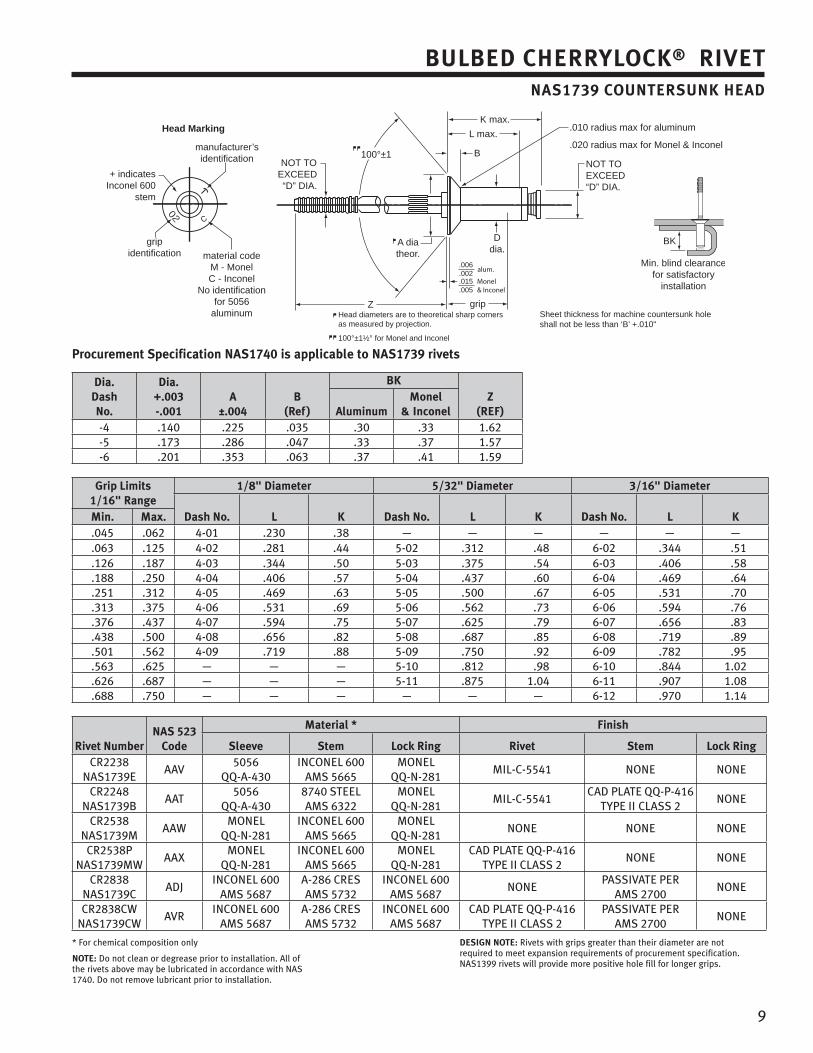
9
BULBED CHERRYLOCK® RIVETNAS1739 COUNTERSUNK HEAD
Head Marking
manufacturer’sidentification
gripidentification
K max.
L max.
B
Ddia.
A diatheor.
100°±1NOT TO
EXCEED“D” DIA.
NOT TOEXCEED“D” DIA.
Z grip
BK
Min. blind clearancefor satisfactory
installation
Head diameters are to theoretical sharp cornersas measured by projection.
100°±1½° for Monel and Inconel
Sheet thickness for machine countersunk hole shall not be less than ‘B’ +.010"
material codeM - MonelC - Inconel
No identification for 5056
aluminum
.006
.002alum.
.015
.005Monel& Inconel
.010 radius max for aluminum
.020 radius max for Monel & Inconel
+ indicatesInconel 600
stem
Procurement Specification NAS1740 is applicable to NAS1739 rivets
Dia. DashNo.
Dia. +.003-.001
A±.004
B(Ref)
BKZ
(REF)AluminumMonel
& Inconel-4 .140 .225 .035 .30 .33 1.62-5 .173 .286 .047 .33 .37 1.57-6 .201 .353 .063 .37 .41 1.59
Grip Limits1/16" Range
1/8" Diameter 5/32" Diameter 3/16" Diameter
Dash No. L K Dash No. L K Dash No. L KMin. Max..045 .062 4-01 .230 .38 — — — — — —.063 .125 4-02 .281 .44 5-02 .312 .48 6-02 .344 .51.126 .187 4-03 .344 .50 5-03 .375 .54 6-03 .406 .58.188 .250 4-04 .406 .57 5-04 .437 .60 6-04 .469 .64.251 .312 4-05 .469 .63 5-05 .500 .67 6-05 .531 .70.313 .375 4-06 .531 .69 5-06 .562 .73 6-06 .594 .76.376 .437 4-07 .594 .75 5-07 .625 .79 6-07 .656 .83.438 .500 4-08 .656 .82 5-08 .687 .85 6-08 .719 .89.501 .562 4-09 .719 .88 5-09 .750 .92 6-09 .782 .95.563 .625 — — — 5-10 .812 .98 6-10 .844 1.02.626 .687 — — — 5-11 .875 1.04 6-11 .907 1.08.688 .750 — — — — — — 6-12 .970 1.14
Rivet NumberNAS 523
Code
Material * Finish
Sleeve Stem Lock Ring Rivet Stem Lock RingCR2238
NAS1739EAAV
5056QQ-A-430
INCONEL 600AMS 5665
MONELQQ-N-281
MIL-C-5541 NONE NONE
CR2248NAS1739B
AAT5056
QQ-A-4308740 STEELAMS 6322
MONELQQ-N-281
MIL-C-5541CAD PLATE QQ-P-416
TYPE II CLASS 2NONE
CR2538NAS1739M
AAWMONEL
QQ-N-281INCONEL 600
AMS 5665MONEL
QQ-N-281NONE NONE NONE
CR2538PNAS1739MW
AAXMONEL
QQ-N-281INCONEL 600
AMS 5665MONEL
QQ-N-281CAD PLATE QQ-P-416
TYPE II CLASS 2NONE NONE
CR2838NAS1739C
ADJINCONEL 600
AMS 5687A-286 CRESAMS 5732
INCONEL 600AMS 5687
NONEPASSIVATE PER
AMS 2700NONE
CR2838CWNAS1739CW
AVRINCONEL 600
AMS 5687A-286 CRESAMS 5732
INCONEL 600AMS 5687
CAD PLATE QQ-P-416TYPE II CLASS 2
PASSIVATE PER AMS 2700
NONE
* For chemical composition only
NOTE: Do not clean or degrease prior to installation. All of the rivets above may be lubricated in accordance with NAS 1740. Do not remove lubricant prior to installation.
DESIGN NOTE: Rivets with grips greater than their diameter are not required to meet expansion requirements of procurement specification. NAS1399 rivets will provide more positive hole fill for longer grips.
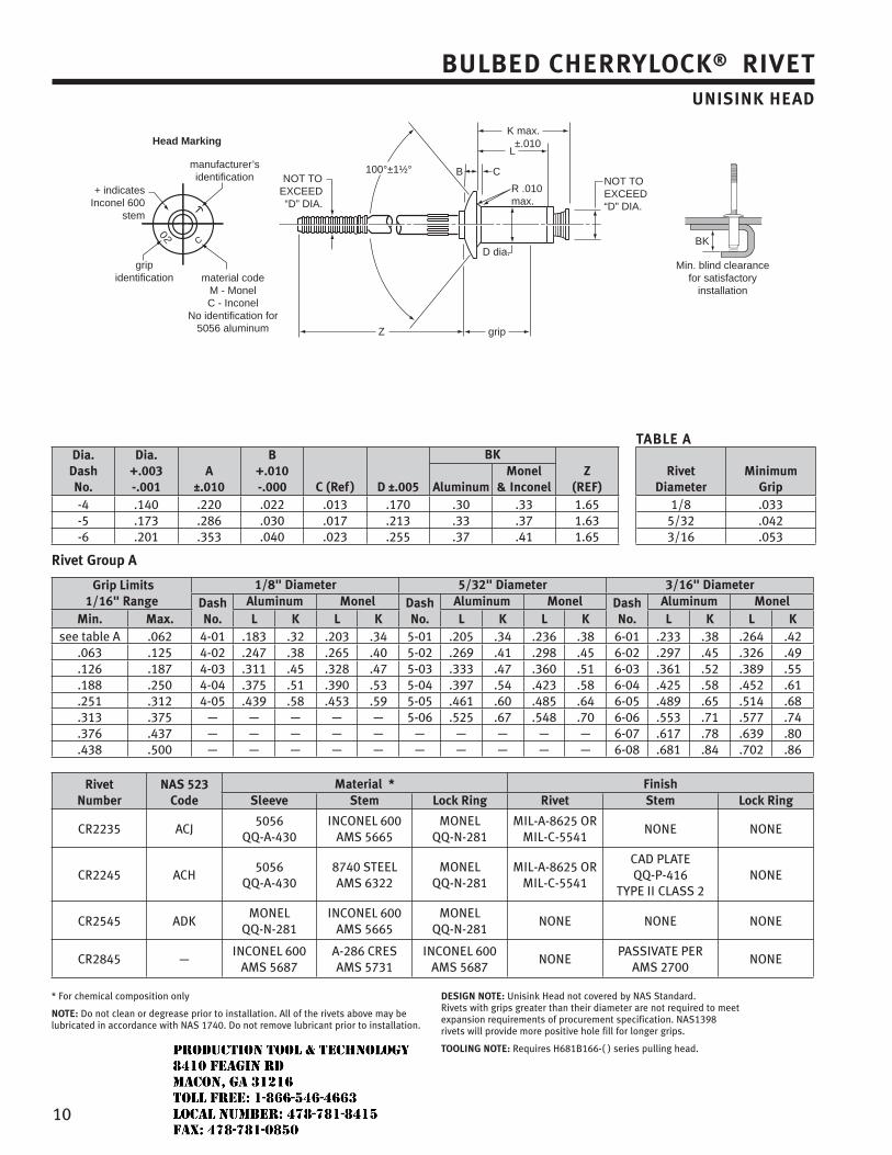
10
BULBED CHERRYLOCK® RIVETUNISINK HEAD
Head Marking
manufacturer’sidentification
gripidentification
K max.
L
B C
D dia.
100°±1½°NOT TO
EXCEED“D” DIA.
NOT TOEXCEED“D” DIA.
Z
BK
Min. blind clearancefor satisfactory
installationmaterial code
M - MonelC - Inconel
No identification for 5056 aluminum
+ indicatesInconel 600
stem
grip
±.010
R .010max.
TABLE ADia.
DashNo.
Dia. +.003-.001
A±.010
B+.010-.000 C (Ref) D ±.005
BKZ
(REF)Rivet
DiameterMinimum
GripAluminumMonel
& Inconel-4 .140 .220 .022 .013 .170 .30 .33 1.65 1/8 .033-5 .173 .286 .030 .017 .213 .33 .37 1.63 5/32 .042-6 .201 .353 .040 .023 .255 .37 .41 1.65 3/16 .053
Rivet Group A
Grip Limits1/16" Range
1/8" Diameter 5/32" Diameter 3/16" DiameterDash No.
Aluminum Monel Dash No.
Aluminum Monel Dash No.
Aluminum MonelMin. Max. L K L K L K L K L K L K
see table A .062 4-01 .183 .32 .203 .34 5-01 .205 .34 .236 .38 6-01 .233 .38 .264 .42.063 .125 4-02 .247 .38 .265 .40 5-02 .269 .41 .298 .45 6-02 .297 .45 .326 .49.126 .187 4-03 .311 .45 .328 .47 5-03 .333 .47 .360 .51 6-03 .361 .52 .389 .55.188 .250 4-04 .375 .51 .390 .53 5-04 .397 .54 .423 .58 6-04 .425 .58 .452 .61.251 .312 4-05 .439 .58 .453 .59 5-05 .461 .60 .485 .64 6-05 .489 .65 .514 .68.313 .375 — — — — — 5-06 .525 .67 .548 .70 6-06 .553 .71 .577 .74.376 .437 — — — — — — — — — — 6-07 .617 .78 .639 .80.438 .500 — — — — — — — — — — 6-08 .681 .84 .702 .86
RivetNumber
NAS 523Code
Material * FinishSleeve Stem Lock Ring Rivet Stem Lock Ring
CR2235 ACJ5056
QQ-A-430INCONEL 600
AMS 5665MONEL
QQ-N-281MIL-A-8625 OR
MIL-C-5541NONE NONE
CR2245 ACH5056
QQ-A-4308740 STEELAMS 6322
MONELQQ-N-281
MIL-A-8625 ORMIL-C-5541
CAD PLATE QQ-P-416
TYPE II CLASS 2NONE
CR2545 ADKMONEL
QQ-N-281INCONEL 600
AMS 5665MONEL
QQ-N-281NONE NONE NONE
CR2845 —INCONEL 600
AMS 5687A-286 CRESAMS 5731
INCONEL 600AMS 5687
NONEPASSIVATE PER
AMS 2700NONE
* For chemical composition only
NOTE: Do not clean or degrease prior to installation. All of the rivets above may be lubricated in accordance with NAS 1740. Do not remove lubricant prior to installation.
DESIGN NOTE: Unisink Head not covered by NAS Standard.Rivets with grips greater than their diameter are not required to meet expansion requirements of procurement specification. NAS1398 rivets will provide more positive hole fill for longer grips.
TOOLING NOTE: Requires H681B166-( ) series pulling head.
JR
Typewritten text
Production Tool & Technology 8410 Feagin Rd Macon, Ga 31216 Toll Free: 1-866-546-4663 Local Number: 478-781-8415 Fax: 478-781-0850
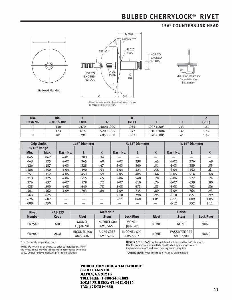
11
BULBED CHERRYLOCK® RIVET156° COUNTERSUNK HEAD
Dia. Dash No.
Dia. +.003/-.001
A±.004 A'
B(REF) C BK
Z(REF)
-4 .140 .470 .400 ± .020 .035 .007 ± .003 .33 1.62-5 .173 .615 .520 ± .025 .047 .010 ± .004 .37 1.57-6 .201 .794 .605 ± .030 .063 .020 ± .005 .41 1.59
Grip Limits1/16" Range
1/8" Diameter 5/32" Diameter 3/16" Diameter
Dash No. L K Dash No. L K Dash No. L KMin. Max..045 .062 4-01 .203 .34 — — — — — —.063 .125 4-02 .265 .40 5-02 .298 .45 6-02 .326 .49.126 .187 4-03 .328 .47 5-03 .360 .51 6-03 .389 .55.188 .250 4-04 .390 .53 5-04 .423 .58 6-04 .452 .61.251 .312 4-05 .453 .59 5-05 .485 .64 6-05 .514 .68.313 .375 4-06 .515 .65 5-06 .548 .70 6-06 .577 .74.376 .437 4-07 .578 .72 5-07 .610 .76 6-07 .639 .80.438 .500 4-08 .640 .78 5-08 .673 .83 6-08 .702 .86.501 .562 4-09 .703 .84 5-09 .735 .89 6-09 .764 .93.563 .625 — — — 5-10 .798 .95 6-10 .827 .99.626 .687 — — — 5-11 .860 1.01 6-11 .889 1.05.688 .750 — — — — — — 6-12 .952 1.11
RivetNumber
NAS 523Code
Material* FinishRivet Stem Lock Ring Rivet Stem Lock Ring
CR2540 ADLMONEL
QQ-N-281INCONEL 600
AMS 5665MONEL
QQ-N-281NONE NONE NONE
CR2840 ADMINCONEL 600
AMS 5687A-286 CRES AMS 5732
INCONEL 600 AMS 5687
NONE PASSIVATE PER
AMS 2700NONE
*For chemical composition only
NOTE: Do not clean or degrease prior to installation. All of the rivets above may be lubricated in accordance with NAS 1740. Do not remove lubricant prior to installation.
DESIGN NOTE: 156° Countersunk head not covered by NAS standard. Use for honeycomb or similarly constructed applications where improved manufactured head bearing area is required.
TOOLING NOTE: Requires H681-( )F series pulling head.
No Head Marking
K max.
L ±.010B
C
Ddia.
156°±2°
NOT TOEXCEED“D” DIA.
NOT TOEXCEED“D” DIA.
Z
BK
Min. blind clearancefor satisfactory
installation
grip
R.020max.
A'
A diatheor.
Head diameters are to theoretical sharp cornersas measured by projection.
JR
Typewritten text
Production Tool & Technology 8410 Feagin Rd Macon, Ga 31216 Toll Free: 1-866-546-4663 Local Number: 478-781-8415 Fax: 478-781-0850
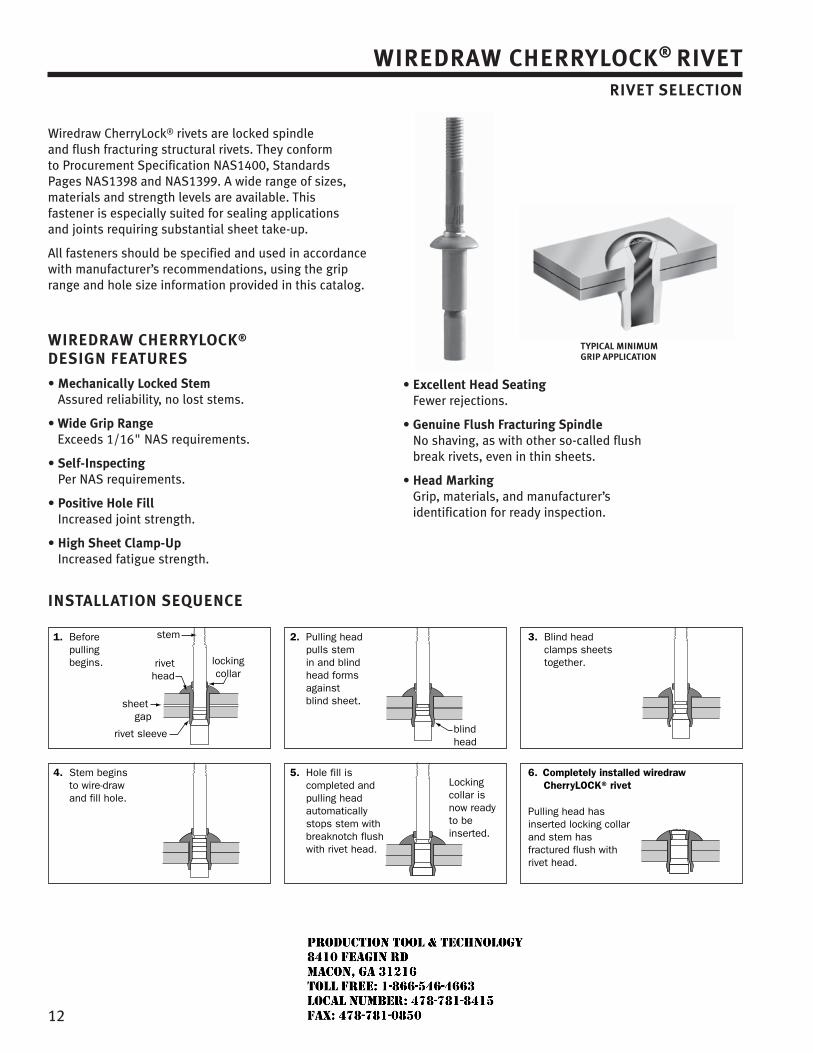
12
Wiredraw CherryLock® rivets are locked spindle and flush fracturing structural rivets. They conform to Procurement Specification NAS1400, Standards Pages NAS1398 and NAS1399. A wide range of sizes, materials and strength levels are available. This fastener is especially suited for sealing applications and joints requiring substantial sheet take-up.
All fasteners should be specified and used in accordance with manufacturer’s recommendations, using the grip range and hole size information provided in this catalog.
WIREDRAW CHERRYLOCK® DESIGN FEATURES
• Mechanically Locked Stem Assured reliability, no lost stems.
• Wide Grip Range Exceeds 1/16" NAS requirements.
• Self-Inspecting Per NAS requirements.
• Positive Hole Fill Increased joint strength.
• High Sheet Clamp-Up Increased fatigue strength.
• Excellent Head Seating Fewer rejections.
• Genuine Flush Fracturing Spindle No shaving, as with other so-called flush break rivets, even in thin sheets.
• Head Marking Grip, materials, and manufacturer’s identification for ready inspection.
WIREDRAW CHERRYLOCK® RIVETRIVET SELECTION
INSTALLATION SEQUENCE
4. Stem begins to wire-draw and fill hole.
stem
rivethead
lockingcollar
sheet gap
rivet sleeve blind head
Locking collar is now ready to be inserted.
1. Before pulling begins.
5. Hole fill is completed and pulling head automatically stops stem with breaknotch flush with rivet head.
6. Completely installed wiredraw CherryLOCK® rivet
2. Pulling head pulls stem in and blind head forms against blind sheet.
3. Blind head clamps sheets together.
Pulling head has inserted locking collar and stem has fractured flush with rivet head.
TYPICAL MINIMUM GRIP APPLICATION
JR
Typewritten text
Production Tool & Technology 8410 Feagin Rd Macon, Ga 31216 Toll Free: 1-866-546-4663 Local Number: 478-781-8415 Fax: 478-781-0850
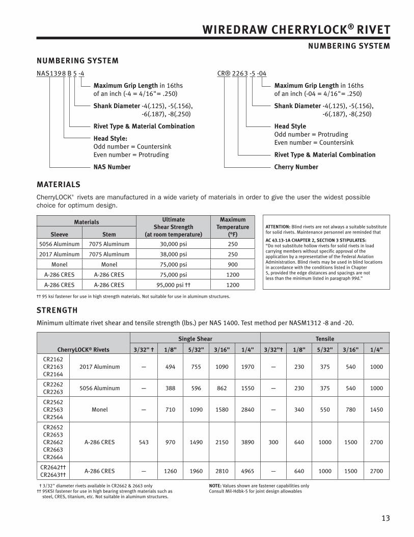
13
WIREDRAW CHERRYLOCK® RIVETNUMBERING SYSTEM
MATERIALS
CherryLOCK® rivets are manufactured in a wide variety of materials in order to give the user the widest possible choice for optimum design.
Materials Ultimate Shear Strength
(at room temperature)
MaximumTemperature
(°F)Sleeve Stem
5056 Aluminum 7075 Aluminum 30,000 psi 250
2017 Aluminum 7075 Aluminum 38,000 psi 250
Monel Monel 75,000 psi 900
A-286 CRES A-286 CRES 75,000 psi 1200
A-286 CRES A-286 CRES 95,000 psi †† 1200
†† 95 ksi fastener for use in high strength materials. Not suitable for use in aluminum structures.
STRENGTH
Minimum ultimate rivet shear and tensile strength (lbs.) per NAS 1400. Test method per NASM1312 -8 and -20.
CherryLOCK® Rivets
Single Shear Tensile
3/32" † 1/8" 5/32" 3/16" 1/4" 3/32"† 1/8" 5/32" 3/16" 1/4"
CR2162CR2163CR2164
2017 Aluminum — 494 755 1090 1970 — 230 375 540 1000
CR2262CR2263
5056 Aluminum — 388 596 862 1550 — 230 375 540 1000
CR2562CR2563CR2564
Monel — 710 1090 1580 2840 — 340 550 780 1450
CR2652CR2653CR2662CR2663CR2664
A-286 CRES 543 970 1490 2150 3890 300 640 1000 1500 2700
CR2642††CR2643††
A-286 CRES — 1260 1960 2810 4965 — 640 1000 1500 2700
† 3/32" diameter rivets available in CR2662 & 2663 only†† 95KSI fastener for use in high bearing strength materials such as
steel, CRES, titanium, etc. Not suitable in aluminum structures.
NOTE: Values shown are fastener capabilities onlyConsult Mil-Hdbk-5 for joint design allowables
ATTENTION: Blind rivets are not always a suitable substitute for solid rivets. Maintenance personnel are reminded that
AC 43.13-1A CHAPTER 2, SECTION 3 STIPULATES: “Do not substitute hollow rivets for solid rivets in load carrying members without specific approval of the application by a representative of the Federal Aviation Administration. Blind rivets may be used in blind locations in accordance with the conditions listed in Chapter 5, provided the edge distances and spacings are not less than the minimum listed in paragraph 99d.”
NUMBERING SYSTEM
NAS139 8 B 5 -4
Maximum Grip Length in 16ths of an inch (-4 = 4/16"= .250)
Shank Diameter -4(.125), -5(.156), -6(.187), -8(.250)
Rivet Type & Material Combination
Head Style: Odd number = CountersinkEven number = Protruding
NAS Number
CR® 226 3 -5 -04
Maximum Grip Length in 16ths of an inch (-04 = 4/16"= .250)
Shank Diameter -4(.125), -5(.156), -6(.187), -8(.250)
Head Style Odd number = ProtrudingEven number = Countersink
Rivet Type & Material Combination
Cherry Number
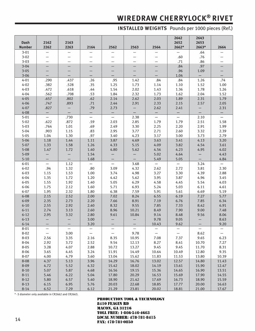
14
WIREDRAW CHERRYLOCK® RIVETINSTALLED WEIGHTS Pounds per 1000 pieces (Ref.)
DashNumber
21622262
21632263 2164 2562 2563 2564
26422652
2662*
26432653
2663* 26643-01 — — — — — — — .64 —3-02 — — — — — — .60 .76 —3-03 — — — — — — .71 .86 —3-04 — — — — — — .84 .97 —3-05 — — — — — — .96 1.09 —3-06 — — — — — — 1.04 — —4-01 .290 .437 .26 .95 1.42 .84 .84 1.26 .744-02 .382 .528 .35 1.25 1.73 1.14 1.10 1.52 1.004-03 .472 .618 .44 1.54 2.02 1.43 1.36 1.78 1.264-04 .562 .708 .53 1.84 2.32 1.73 1.62 2.04 1.524-05 .657 .802 .62 2.14 2.62 2.03 1.89 2.31 1.794-06 .747 .893 .71 2.44 2.91 2.33 2.15 2.57 2.054-07 .827 — .79 2.73 — 2.62 2.41 — 2.314-08 — — — — — — — — —5-01 — .730 — — 2.38 — — 2.10 —5-02 .622 .872 .59 2.03 2.85 1.79 1.79 2.51 1.585-03 .764 1.01 .69 2.49 3.30 2.25 2.20 2.91 1.995-04 .903 1.15 .83 2.95 3.77 2.71 2.60 3.32 2.395-05 1.04 1.30 .97 3.40 4.23 3.17 3.00 3.73 2.795-06 1.18 1.44 1.11 3.87 4.69 3.63 3.41 4.13 3.205-07 1.33 1.58 1.26 4.33 5.15 4.09 3.82 4.54 3.615-08 1.47 1.72 1.40 4.80 5.62 4.56 4.23 4.95 4.025-09 — — 1.54 — — 5.02 4.64 — 4.435-10 — — 1.68 — — 5.49 5.05 — 4.846-01 — 1.12 — — 3.68 — — 3.24 —6-02 .94 1.32 .80 3.09 4.32 2.62 2.72 3.81 2.306-03 1.15 1.53 1.00 3.74 4.98 3.27 3.30 4.39 2.886-04 1.35 1.72 1.20 4.42 5.62 3.95 3.87 4.96 3.456-05 1.55 1.92 1.40 5.05 6.29 4.58 4.45 5.54 4.036-06 1.75 2.12 1.60 5.71 6.93 5.24 5.03 6.11 4.616-07 1.95 2.32 1.80 6.38 7.59 5.91 5.61 6.69 5.196-08 2.15 2.52 2.00 7.02 8.24 6.55 6.19 7.27 5.776-09 2.35 2.73 2.20 7.66 8.91 7.19 6.76 7.85 6.346-10 2.55 2.92 2.40 8.32 9.55 7.85 7.33 8.42 6.916-11 2.74 3.13 2.60 8.96 10.21 8.49 7.90 9.00 7.486-12 2.95 3.32 2.80 9.61 10.84 9.14 8.48 9.56 8.066-13 — — 3.00 — — 9.78 9.05 — 8.636-14 — — 3.20 — — 10.43 9.62 — 9.208-01 — — — — — — — — —8-02 — 3.00 — — 9.78 — — 8.62 —8-03 2.56 3.35 2.16 8.35 10.95 7.08 7.37 9.65 6.238-04 2.92 3.72 2.52 9.54 12.13 8.27 8.41 10.70 7.278-05 3.28 4.07 2.88 10.72 13.27 9.45 9.45 11.70 8.318-06 3.65 4.45 3.24 11.91 14.49 10.64 10.49 12.80 9.358-07 4.00 4.79 3.60 13.04 15.62 11.83 11.53 13.80 10.398-08 4.37 5.13 3.96 14.29 16.76 13.02 12.57 14.80 11.438-09 4.72 5.52 4.32 15.42 18.02 14.19 13.61 15.90 12.478-10 5.07 5.87 4.68 16.56 19.15 15.36 14.65 16.90 13.518-11 5.46 6.22 5.04 17.80 20.29 16.53 15.69 17.90 14.558-12 5.80 6.57 5.40 18.90 21.42 17.69 16.73 18.90 15.598-13 6.15 6.95 5.76 20.03 22.68 18.85 17.77 20.00 16.638-14 6.52 7.29 6.12 21.29 23.81 20.02 18.81 21.00 17.67
* -3 diameter only available in CR2662 and CR2663.
JR
Typewritten text
Production Tool & Technology 8410 Feagin Rd Macon, Ga 31216 Toll Free: 1-866-546-4663 Local Number: 478-781-8415 Fax: 478-781-0850
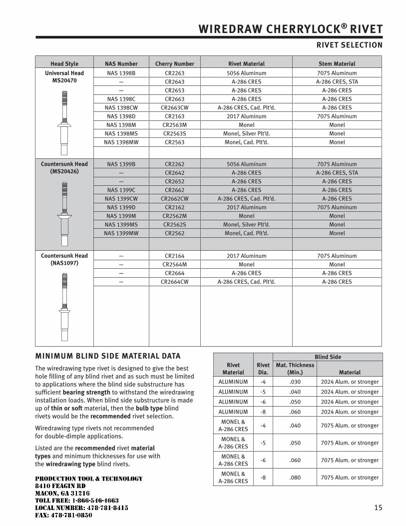
15
WIREDRAW CHERRYLOCK® RIVETRIVET SELECTION
Head Style NAS Number Cherry Number Rivet Material Stem Material
Universal HeadMS20470
NAS 1398B
—
—
NAS 1398C
NAS 1398CW
NAS 1398D
NAS 1398M
NAS 1398MS
NAS 1398MW
CR2263
CR2643
CR2653
CR2663
CR2663CW
CR2163
CR2563M
CR2563S
CR2563
5056 Aluminum
A-286 CRES
A-286 CRES
A-286 CRES
A-286 CRES, Cad. Plt’d.
2017 Aluminum
Monel
Monel, Silver Plt’d.
Monel, Cad. Plt’d.
7075 Aluminum
A-286 CRES, STA
A-286 CRES
A-286 CRES
A-286 CRES
7075 Aluminum
Monel
Monel
Monel
Countersunk Head(MS20426)
NAS 1399B
—
—
NAS 1399C
NAS 1399CW
NAS 1399D
NAS 1399M
NAS 1399MS
NAS 1399MW
CR2262
CR2642
CR2652
CR2662
CR2662CW
CR2162
CR2562M
CR2562S
CR2562
5056 Aluminum
A-286 CRES
A-286 CRES
A-286 CRES
A-286 CRES, Cad. Plt’d.
2017 Aluminum
Monel
Monel, Silver Plt’d.
Monel, Cad. Plt’d.
7075 Aluminum
A-286 CRES, STA
A-286 CRES
A-286 CRES
A-286 CRES
7075 Aluminum
Monel
Monel
Monel
Countersunk Head(NAS1097)
—
—
—
—
CR2164
CR2564M
CR2664
CR2664CW
2017 Aluminum
Monel
A-286 CRES
A-286 CRES, Cad. Plt’d.
7075 Aluminum
Monel
A-286 CRES
A-286 CRES
MINIMUM BLIND SIDE MATERIAL DATA
The wiredrawing type rivet is designed to give the best hole filling of any blind rivet and as such must be limited to applications where the blind side substructure has sufficient bearing strength to withstand the wiredrawing installation loads. When blind side substructure is made up of thin or soft material, then the bulb type blind rivets would be the recommended rivet selection.
Wiredrawing type rivets not recommended for double-dimple applications.
Listed are the recommended rivet material types and minimum thicknesses for use with the wiredrawing type blind rivets.
RivetMaterial
RivetDia.
Blind SideMat. Thickness
(Min.) Material
ALUMINUM -4 .030 2024 Alum. or stronger
ALUMINUM -5 .040 2024 Alum. or stronger
ALUMINUM -6 .050 2024 Alum. or stronger
ALUMINUM -8 .060 2024 Alum. or stronger
MONEL & A-286 CRES
-4 .040 7075 Alum. or stronger
MONEL & A-286 CRES
-5 .050 7075 Alum. or stronger
MONEL & A-286 CRES
-6 .060 7075 Alum. or stronger
MONEL & A-286 CRES
-8 .080 7075 Alum. or stronger
JR
Typewritten text
Production Tool & Technology 8410 Feagin Rd Macon, Ga 31216 Toll Free: 1-866-546-4663 Local Number: 478-781-8415 Fax: 478-781-0850
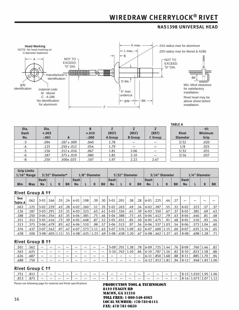
16
WIREDRAW CHERRYLOCK® RIVETNAS1398 UNIVERSAL HEAD
Head MarkingNOTE: No head marking on
-3 diameter fasteners
manufacturer’sidentification
gripidentification
B
D dia.
5° max.undercut
NOT TOEXCEED“D” DIA.
NOT TOEXCEED“D” DIA.
Z
grip BK
BK
Min. blind clearancefor satisfactory installation.
Rivet head may be above sheet before installation.
material codeM - MonelC - A-286
No identification for aluminum
.010 radius max for aluminum
.020 radius max for Monel & A286
K max.
L max.
A
TABLE ADia.
DashNo.
Dia. +.003-.001 A
B+.010-.000
Z(REF)
A Group
Z(REF)
B Group
Z(REF)
C GroupRivet
Diameter
-01Minimum
Grip-3 .094 .187 ± .009 .040 1.78 — — 3/32 .020-4 .125 .250 ± .012 .054 1.79 — — 1/8 .025-5 .156 .312 ± .016 .067 1.81 2.06 — 5/32 .031-6 .187 .375 ± .019 .080 1.85 2.10 — 3/16 .037-8 .250 .500± .025 .107 1.97 2.22 2.47
Grip Limits1/16" Range 3/32" Diameter* 1/8" Diameter 5/32" Diameter 3/16" Diameter 1/4" Diameter
Min MaxDash
No L K BKDash
No L K BKDash
No L K BKDash
No L K BKDash
No L K BK
Rivet Group A ††See
Table A.062 3-01 .166 .33 .24 4-01 .198 .39 .30 5-01 .201 .38 .28 6-01 .225 .44 .27 — — — —
.063 .125 3-02 .229 .43 .28 4-02 .260 .51 .35 5-02 .263 .49 .34 6-02 .287 .55 .32 8-02 .323 .57 .37
.126 .187 3-03 .291 .53 .31 4-03 .323 .63 .41 5-03 .326 .61 .39 6-03 .350 .67 .37 8-03 .385 .69 .43
.188 .250 3-04 .354 .63 .35 4-04 .385 .75 .46 5-04 .388 .73 .45 6-04 .412 .79 .43 8-04 .446 .81 .48
.251 .312 3-05 .416 .73 .39 4-05 .448 .87 .52 5-05 .451 .85 .50 6-05 .475 .91 .48 8-05 .510 .93 .54
.313 .375 3-06 .479 .83 .42 4-06 .510 .98 .57 5-06 .513 .97 .56 6-06 .537 1.03 .54 8-06 .573 1.04 .60
.376 .437 3-07 .542 .97 .47 4-07 .573 1.11 .63 5-07 .576 1.09 .62 6-07 .600 1.15 .60 8-07 .635 1.16 .65
.438 .500 3-08 .605 1.11 .51 4-08 .635 1.23 .69 5-08 .638 1.20 .67 6-08 .662 1.27 .65 8-08 .698 1.28 .71
Rivet Group B ††.501 .562 — — — — — — — — 5-09 .701 1.38 .78 6-09 .725 1.44 .76 8-09 .760 1.46 .82.563 .625 — — — — — — — — 5-10 .763 1.50 .84 6-10 .787 1.56 .82 8-10 .823 1.58 .88.626 .687 — — — — — — — — — — — — 6-11 .850 1.68 .88 8-11 .885 1.70 .94.688 .750 — — — — — — — — — — — — 6-12 .912 1.81 .94 8-12 .948 1.83 1.00
Rivet Group C ††.751 .812 — — — — — — — — — — — — — — — — 8-13 1.010 1.95 1.06.813 .875 — — — — — — — — — — — — — — — — 8-14 1.073 2.07 1.12
Please see following page for material and finish specifications
JR
Typewritten text
Production Tool & Technology 8410 Feagin Rd Macon, Ga 31216 Toll Free: 1-866-546-4663 Local Number: 478-781-8415 Fax: 478-781-0850
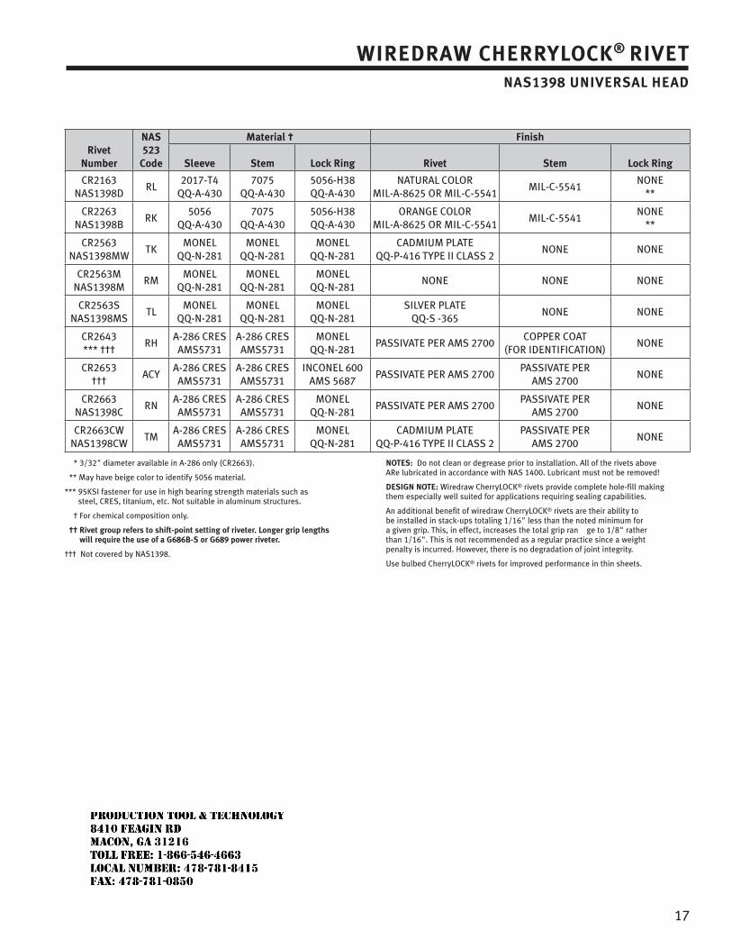
17
WIREDRAW CHERRYLOCK® RIVETNAS1398 UNIVERSAL HEAD
RivetNumber
NAS 523
Code
Material † Finish
Sleeve Stem Lock Ring Rivet Stem Lock Ring
CR2163NAS1398D
RL2017-T4
QQ-A-4307075
QQ-A-4305056-H38QQ-A-430
NATURAL COLORMIL-A-8625 OR MIL-C-5541
MIL-C-5541NONE
**
CR2263NAS1398B
RK5056
QQ-A-4307075
QQ-A-4305056-H38QQ-A-430
ORANGE COLORMIL-A-8625 OR MIL-C-5541
MIL-C-5541NONE
**
CR2563NAS1398MW
TKMONEL
QQ-N-281MONEL
QQ-N-281MONEL
QQ-N-281CADMIUM PLATE
QQ-P-416 TYPE II CLASS 2NONE NONE
CR2563MNAS1398M
RMMONEL
QQ-N-281MONEL
QQ-N-281MONEL
QQ-N-281NONE NONE NONE
CR2563SNAS1398MS
TLMONEL
QQ-N-281MONEL
QQ-N-281MONEL
QQ-N-281SILVER PLATE
QQ-S -365NONE NONE
CR2643*** †††
RHA-286 CRESAMS5731
A-286 CRESAMS5731
MONELQQ-N-281
PASSIVATE PER AMS 2700 COPPER COAT
(FOR IDENTIFICATION)NONE
CR2653†††
ACYA-286 CRESAMS5731
A-286 CRESAMS5731
INCONEL 600AMS 5687
PASSIVATE PER AMS 2700PASSIVATE PER
AMS 2700 NONE
CR2663NAS1398C
RNA-286 CRESAMS5731
A-286 CRESAMS5731
MONELQQ-N-281
PASSIVATE PER AMS 2700PASSIVATE PER
AMS 2700 NONE
CR2663CWNAS1398CW
TMA-286 CRESAMS5731
A-286 CRESAMS5731
MONELQQ-N-281
CADMIUM PLATE QQ-P-416 TYPE II CLASS 2
PASSIVATE PER AMS 2700
NONE
* 3/32" diameter available in A-286 only (CR2663).
** May have beige color to identify 5056 material.
*** 95KSI fastener for use in high bearing strength materials such as steel, CRES, titanium, etc. Not suitable in aluminum structures.
† For chemical composition only.
†† Rivet group refers to shift-point setting of riveter. Longer grip lengths will require the use of a G686B-S or G689 power riveter.
††† Not covered by NAS1398.
NOTES: Do not clean or degrease prior to installation. All of the rivets above ARe lubricated in accordance with NAS 1400. Lubricant must not be removed!
DESIGN NOTE: Wiredraw CherryLOCK® rivets provide complete hole-fill making them especially well suited for applications requiring sealing capabilities.
An additional benefit of wiredraw CherryLOCK® rivets are their ability to be installed in stack-ups totaling 1/16" less than the noted minimum for a given grip. This, in effect, increases the total grip ran ge to 1/8" rather than 1/16". This is not recommended as a regular practice since a weight penalty is incurred. However, there is no degradation of joint integrity.
Use bulbed CherryLOCK® rivets for improved performance in thin sheets.
JR
Typewritten text
Production Tool & Technology 8410 Feagin Rd Macon, Ga 31216 Toll Free: 1-866-546-4663 Local Number: 478-781-8415 Fax: 478-781-0850
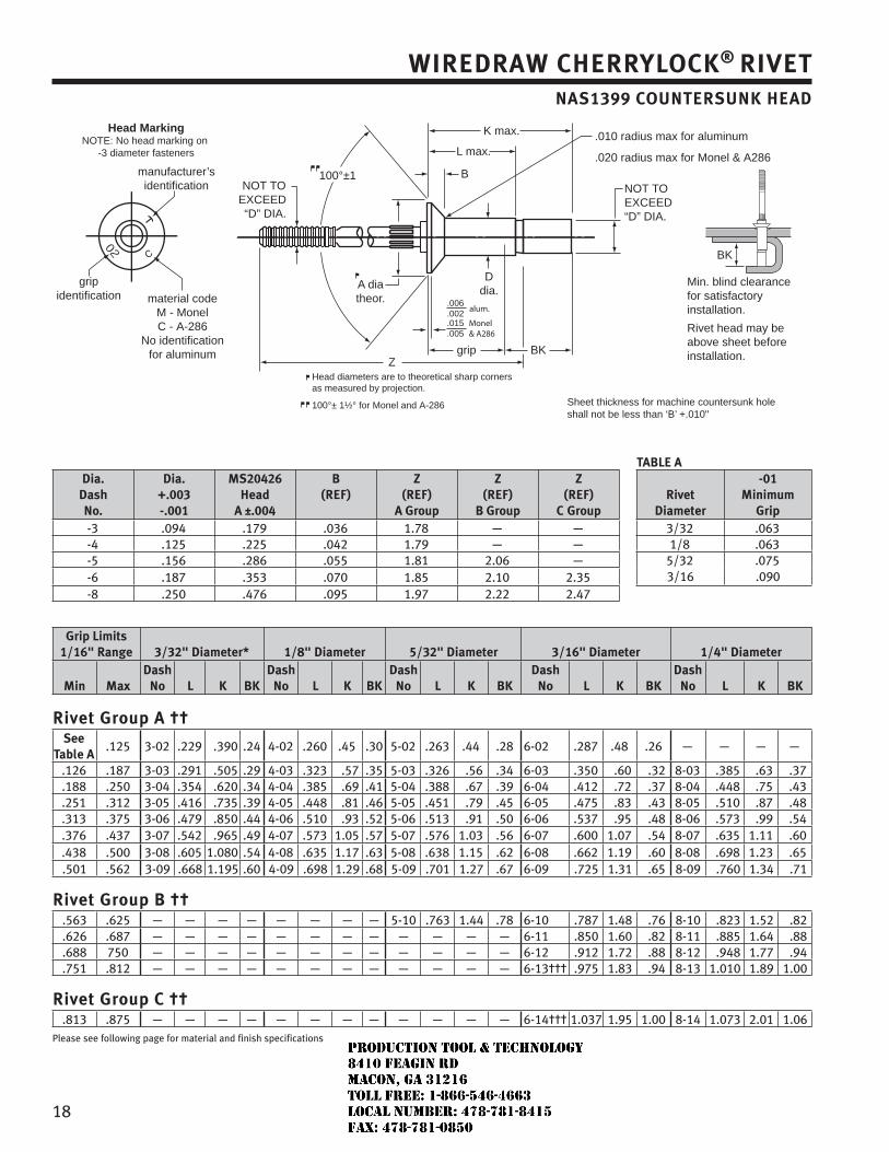
18
WIREDRAW CHERRYLOCK® RIVETNAS1399 COUNTERSUNK HEAD
Head MarkingNOTE: No head marking on
-3 diameter fasteners
manufacturer’sidentification
gripidentification
K max.
L max.
B
Ddia.A dia
theor.
100°±1NOT TO
EXCEED“D” DIA.
NOT TOEXCEED“D” DIA.
Zgrip BK
BK
Min. blind clearancefor satisfactory installation.
Rivet head may be above sheet before installation.
Head diameters are to theoretical sharp cornersas measured by projection.
100°± 1½° for Monel and A-286 Sheet thickness for machine countersunk hole shall not be less than ‘B’ +.010"
material codeM - MonelC - A-286
No identification for aluminum
.006
.002alum.
.015
.005Monel& A286
.010 radius max for aluminum
.020 radius max for Monel & A286
TABLE ADia.
DashNo.
Dia. +.003-.001
MS20426 Head
A ±.004
B(REF)
Z(REF)
A Group
Z(REF)
B Group
Z(REF)
C GroupRivet
Diameter
-01Minimum
Grip-3 .094 .179 .036 1.78 — — 3/32 .063-4 .125 .225 .042 1.79 — — 1/8 .063-5 .156 .286 .055 1.81 2.06 — 5/32 .075-6 .187 .353 .070 1.85 2.10 2.35 3/16 .090-8 .250 .476 .095 1.97 2.22 2.47
Grip Limits1/16" Range 3/32" Diameter* 1/8" Diameter 5/32" Diameter 3/16" Diameter 1/4" Diameter
Min MaxDash
No L K BKDash
No L K BKDash
No L K BKDash
No L K BKDash
No L K BK
Rivet Group A ††See
Table A.125 3-02 .229 .390 .24 4-02 .260 .45 .30 5-02 .263 .44 .28 6-02 .287 .48 .26 — — — —
.126 .187 3-03 .291 .505 .29 4-03 .323 .57 .35 5-03 .326 .56 .34 6-03 .350 .60 .32 8-03 .385 .63 .37
.188 .250 3-04 .354 .620 .34 4-04 .385 .69 .41 5-04 .388 .67 .39 6-04 .412 .72 .37 8-04 .448 .75 .43
.251 .312 3-05 .416 .735 .39 4-05 .448 .81 .46 5-05 .451 .79 .45 6-05 .475 .83 .43 8-05 .510 .87 .48
.313 .375 3-06 .479 .850 .44 4-06 .510 .93 .52 5-06 .513 .91 .50 6-06 .537 .95 .48 8-06 .573 .99 .54
.376 .437 3-07 .542 .965 .49 4-07 .573 1.05 .57 5-07 .576 1.03 .56 6-07 .600 1.07 .54 8-07 .635 1.11 .60
.438 .500 3-08 .605 1.080 .54 4-08 .635 1.17 .63 5-08 .638 1.15 .62 6-08 .662 1.19 .60 8-08 .698 1.23 .65
.501 .562 3-09 .668 1.195 .60 4-09 .698 1.29 .68 5-09 .701 1.27 .67 6-09 .725 1.31 .65 8-09 .760 1.34 .71
Rivet Group B ††.563 .625 — — — — — — — — 5-10 .763 1.44 .78 6-10 .787 1.48 .76 8-10 .823 1.52 .82.626 .687 — — — — — — — — — — — — 6-11 .850 1.60 .82 8-11 .885 1.64 .88.688 750 — — — — — — — — — — — — 6-12 .912 1.72 .88 8-12 .948 1.77 .94.751 .812 — — — — — — — — — — — — 6-13††† .975 1.83 .94 8-13 1.010 1.89 1.00
Rivet Group C ††.813 .875 — — — — — — — — — — — — 6-14††† 1.037 1.95 1.00 8-14 1.073 2.01 1.06
Please see following page for material and finish specifications
JR
Typewritten text
Production Tool & Technology 8410 Feagin Rd Macon, Ga 31216 Toll Free: 1-866-546-4663 Local Number: 478-781-8415 Fax: 478-781-0850
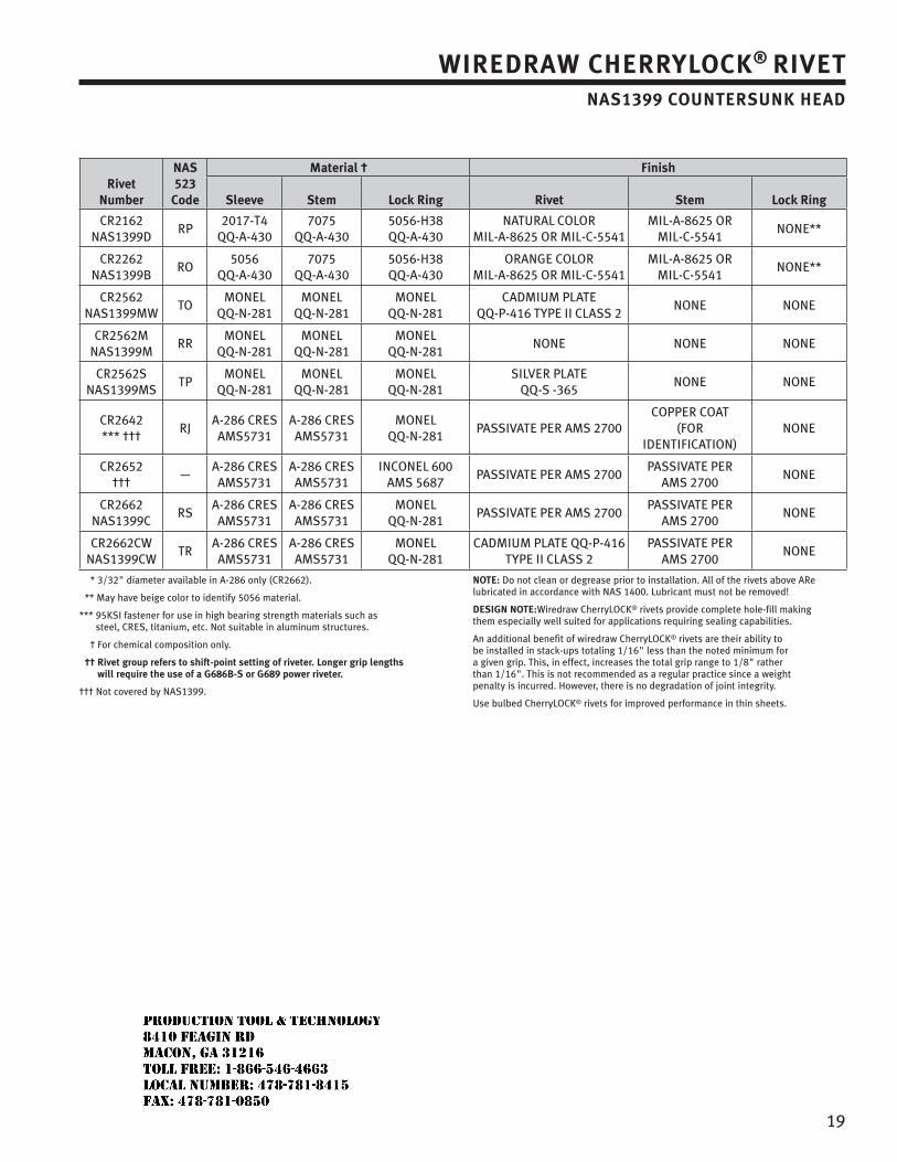
19
WIREDRAW CHERRYLOCK® RIVETNAS1399 COUNTERSUNK HEAD
RivetNumber
NAS 523
Code
Material † Finish
Sleeve Stem Lock Ring Rivet Stem Lock Ring
CR2162NAS1399D
RP2017-T4
QQ-A-4307075
QQ-A-4305056-H38QQ-A-430
NATURAL COLORMIL-A-8625 OR MIL-C-5541
MIL-A-8625 OR MIL-C-5541
NONE**
CR2262NAS1399B
RO5056
QQ-A-4307075
QQ-A-4305056-H38QQ-A-430
ORANGE COLORMIL-A-8625 OR MIL-C-5541
MIL-A-8625 OR MIL-C-5541
NONE**
CR2562NAS1399MW
TOMONEL
QQ-N-281MONEL
QQ-N-281MONEL
QQ-N-281CADMIUM PLATE
QQ-P-416 TYPE II CLASS 2NONE NONE
CR2562MNAS1399M
RRMONEL
QQ-N-281MONEL
QQ-N-281MONEL
QQ-N-281NONE NONE NONE
CR2562SNAS1399MS
TPMONEL
QQ-N-281MONEL
QQ-N-281MONEL
QQ-N-281SILVER PLATE
QQ-S -365NONE NONE
CR2642*** †††
RJA-286 CRESAMS5731
A-286 CRESAMS5731
MONELQQ-N-281
PASSIVATE PER AMS 2700 COPPER COAT
(FOR IDENTIFICATION)
NONE
CR2652†††
—A-286 CRESAMS5731
A-286 CRESAMS5731
INCONEL 600AMS 5687
PASSIVATE PER AMS 2700 PASSIVATE PER
AMS 2700 NONE
CR2662NAS1399C
RSA-286 CRESAMS5731
A-286 CRESAMS5731
MONELQQ-N-281
PASSIVATE PER AMS 2700 PASSIVATE PER
AMS 2700 NONE
CR2662CWNAS1399CW
TRA-286 CRESAMS5731
A-286 CRESAMS5731
MONELQQ-N-281
CADMIUM PLATE QQ-P-416TYPE II CLASS 2
PASSIVATE PER AMS 2700
NONE
* 3/32" diameter available in A-286 only (CR2662).
** May have beige color to identify 5056 material.
*** 95KSI fastener for use in high bearing strength materials such as steel, CRES, titanium, etc. Not suitable in aluminum structures.
† For chemical composition only.
†† Rivet group refers to shift-point setting of riveter. Longer grip lengths will require the use of a G686B-S or G689 power riveter.
††† Not covered by NAS1399.
NOTE: Do not clean or degrease prior to installation. All of the rivets above ARe lubricated in accordance with NAS 1400. Lubricant must not be removed!
DESIGN NOTE:Wiredraw CherryLOCK® rivets provide complete hole-fill making them especially well suited for applications requiring sealing capabilities.
An additional benefit of wiredraw CherryLOCK® rivets are their ability to be installed in stack-ups totaling 1/16" less than the noted minimum for a given grip. This, in effect, increases the total grip range to 1/8" rather than 1/16". This is not recommended as a regular practice since a weight penalty is incurred. However, there is no degradation of joint integrity.
Use bulbed CherryLOCK® rivets for improved performance in thin sheets.
JR
Typewritten text
Production Tool & Technology 8410 Feagin Rd Macon, Ga 31216 Toll Free: 1-866-546-4663 Local Number: 478-781-8415 Fax: 478-781-0850
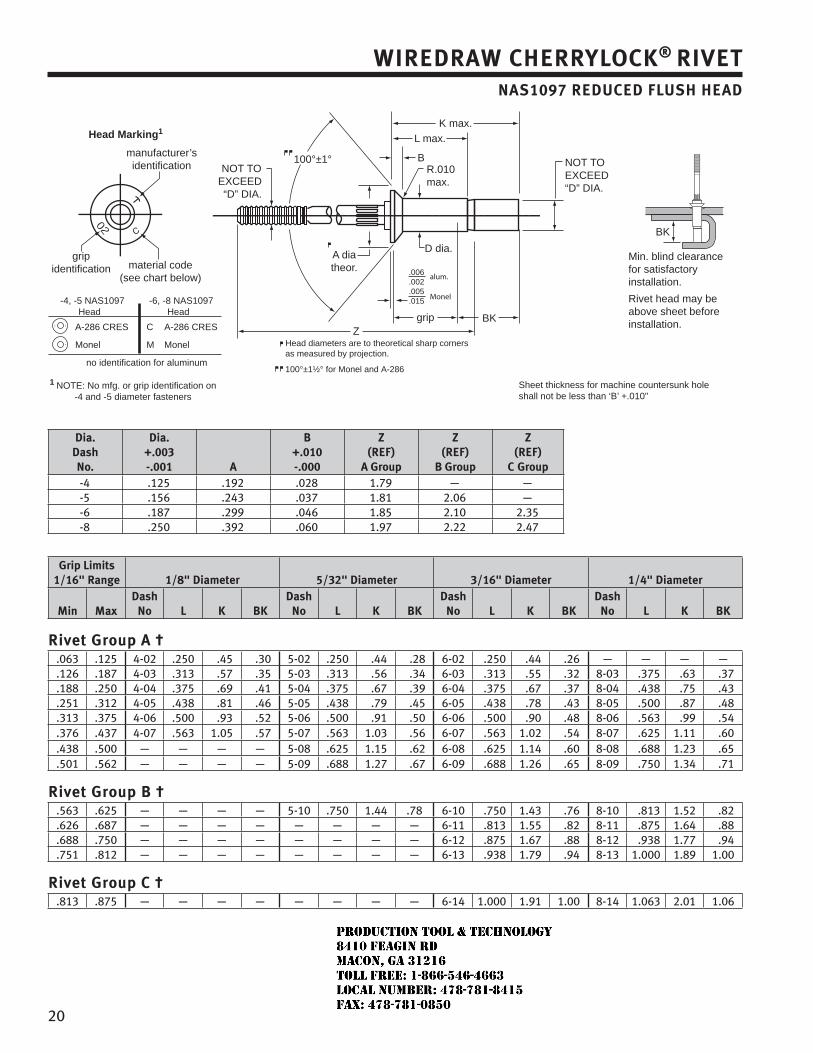
20
WIREDRAW CHERRYLOCK® RIVETNAS1097 REDUCED FLUSH HEAD
-4, -5 NAS1097 -6, -8 NAS1097 Head Head
A-286 CRES C A-286 CRES
Monel M Monel
no identification for aluminum
Head Marking1
manufacturer’sidentification
gripidentification material code
(see chart below)
K max.
L max.
BR.010max.
D dia.A diatheor.
100°±1°NOT TO
EXCEED“D” DIA.
NOT TOEXCEED“D” DIA.
Zgrip BK
BK
Min. blind clearancefor satisfactory installation.
Rivet head may be above sheet before installation.
Head diameters are to theoretical sharp cornersas measured by projection.
100°±1½° for Monel and A-286
1 NOTE: No mfg. or grip identification on -4 and -5 diameter fasteners
Sheet thickness for machine countersunk hole shall not be less than ‘B’ +.010"
.006
.002
.005
.015
alum.
Monel
Dia. DashNo.
Dia. +.003-.001 A
B+.010-.000
Z(REF)
A Group
Z(REF)
B Group
Z(REF)
C Group-4 .125 .192 .028 1.79 — —-5 .156 .243 .037 1.81 2.06 —-6 .187 .299 .046 1.85 2.10 2.35-8 .250 .392 .060 1.97 2.22 2.47
Grip Limits1/16" Range 1/8" Diameter 5/32" Diameter 3/16" Diameter 1/4" Diameter
Min MaxDash
No L K BKDash
No L K BKDash
No L K BKDash
No L K BK
Rivet Group A †.063 .125 4-02 .250 .45 .30 5-02 .250 .44 .28 6-02 .250 .44 .26 — — — —.126 .187 4-03 .313 .57 .35 5-03 .313 .56 .34 6-03 .313 .55 .32 8-03 .375 .63 .37.188 .250 4-04 .375 .69 .41 5-04 .375 .67 .39 6-04 .375 .67 .37 8-04 .438 .75 .43.251 .312 4-05 .438 .81 .46 5-05 .438 .79 .45 6-05 .438 .78 .43 8-05 .500 .87 .48.313 .375 4-06 .500 .93 .52 5-06 .500 .91 .50 6-06 .500 .90 .48 8-06 .563 .99 .54.376 .437 4-07 .563 1.05 .57 5-07 .563 1.03 .56 6-07 .563 1.02 .54 8-07 .625 1.11 .60.438 .500 — — — — 5-08 .625 1.15 .62 6-08 .625 1.14 .60 8-08 .688 1.23 .65.501 .562 — — — — 5-09 .688 1.27 .67 6-09 .688 1.26 .65 8-09 .750 1.34 .71
Rivet Group B †.563 .625 — — — — 5-10 .750 1.44 .78 6-10 .750 1.43 .76 8-10 .813 1.52 .82.626 .687 — — — — — — — — 6-11 .813 1.55 .82 8-11 .875 1.64 .88.688 .750 — — — — — — — — 6-12 .875 1.67 .88 8-12 .938 1.77 .94.751 .812 — — — — — — — — 6-13 .938 1.79 .94 8-13 1.000 1.89 1.00
Rivet Group C †.813 .875 — — — — — — — — 6-14 1.000 1.91 1.00 8-14 1.063 2.01 1.06
JR
Typewritten text
Production Tool & Technology 8410 Feagin Rd Macon, Ga 31216 Toll Free: 1-866-546-4663 Local Number: 478-781-8415 Fax: 478-781-0850
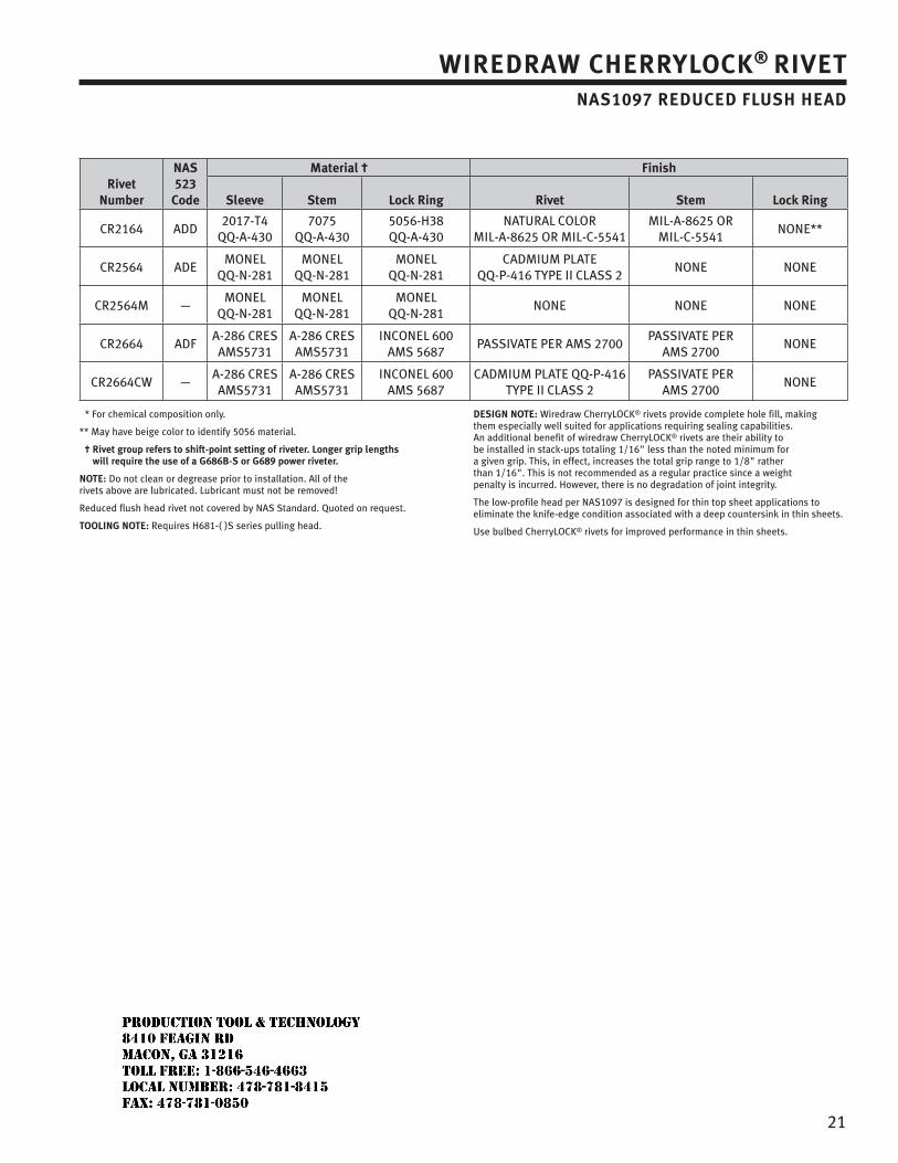
21
WIREDRAW CHERRYLOCK® RIVETNAS1097 REDUCED FLUSH HEAD
RivetNumber
NAS 523
Code
Material † Finish
Sleeve Stem Lock Ring Rivet Stem Lock Ring
CR2164 ADD2017-T4
QQ-A-4307075
QQ-A-4305056-H38QQ-A-430
NATURAL COLORMIL-A-8625 OR MIL-C-5541
MIL-A-8625 OR MIL-C-5541
NONE**
CR2564 ADEMONEL
QQ-N-281MONEL
QQ-N-281MONEL
QQ-N-281CADMIUM PLATE
QQ-P-416 TYPE II CLASS 2NONE NONE
CR2564M —MONEL
QQ-N-281MONEL
QQ-N-281MONEL
QQ-N-281NONE NONE NONE
CR2664 ADFA-286 CRESAMS5731
A-286 CRESAMS5731
INCONEL 600AMS 5687
PASSIVATE PER AMS 2700 PASSIVATE PER
AMS 2700 NONE
CR2664CW —A-286 CRESAMS5731
A-286 CRESAMS5731
INCONEL 600AMS 5687
CADMIUM PLATE QQ-P-416TYPE II CLASS 2
PASSIVATE PER AMS 2700
NONE
* For chemical composition only.
** May have beige color to identify 5056 material.
† Rivet group refers to shift-point setting of riveter. Longer grip lengths will require the use of a G686B-S or G689 power riveter.
NOTE: Do not clean or degrease prior to installation. All of the rivets above are lubricated. Lubricant must not be removed!
Reduced flush head rivet not covered by NAS Standard. Quoted on request.
TOOLING NOTE: Requires H681-( )S series pulling head.
DESIGN NOTE: Wiredraw CherryLOCK® rivets provide complete hole fill, making them especially well suited for applications requiring sealing capabilities. An additional benefit of wiredraw CherryLOCK® rivets are their ability to be installed in stack-ups totaling 1/16" less than the noted minimum for a given grip. This, in effect, increases the total grip range to 1/8" rather than 1/16". This is not recommended as a regular practice since a weight penalty is incurred. However, there is no degradation of joint integrity.
The low-profile head per NAS1097 is designed for thin top sheet applications to eliminate the knife-edge condition associated with a deep countersink in thin sheets.
Use bulbed CherryLOCK® rivets for improved performance in thin sheets.
JR
Typewritten text
Production Tool & Technology 8410 Feagin Rd Macon, Ga 31216 Toll Free: 1-866-546-4663 Local Number: 478-781-8415 Fax: 478-781-0850
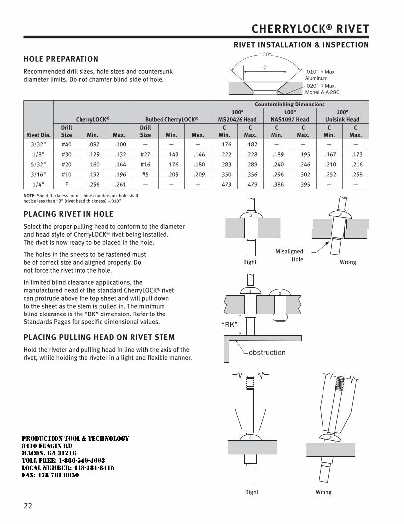
22
CHERRYLOCK® RIVETRIVET INSTALLATION & INSPECTION
HOLE PREPARATION
Recommended drill sizes, hole sizes and countersunk diameter limits. Do not chamfer blind side of hole.
Rivet Dia.
CherryLOCK® Bulbed CherryLOCK®
Countersinking Dimensions100°
MS20426 Head100°
NAS1097 Head100°
Unisink HeadDrillSize Min. Max.
DrillSize Min. Max.
CMin.
CMax.
CMin.
CMax.
CMin.
CMax.
3/32" #40 .097 .100 — — — .176 .182 — — — —
1/8" #30 .129 .132 #27 .143 .146 .222 .228 .189 .195 .167 .173
5/32" #20 .160 .164 #16 .176 .180 .283 .289 .240 .246 .210 .216
3/16" #10 .192 .196 #5 .205 .209 .350 .356 .296 .302 .252 .258
1/4" F .256 .261 — — — .473 .479 .386 .395 — —
NOTE: Sheet thickness for machine countersunk hole shall not be less than “B” (rivet head thickness) +.010".
PLACING RIVET IN HOLE
Select the proper pulling head to conform to the diameter and head style of CherryLOCK® rivet being installed. The rivet is now ready to be placed in the hole.
The holes in the sheets to be fastened must be of correct size and aligned properly. Do not force the rivet into the hole.
In limited blind clearance applications, the manufactured head of the standard CherryLOCK® rivet can protrude above the top sheet and will pull down to the sheet as the stem is pulled in. The minimum blind clearance is the “BK” dimension. Refer to the Standards Pages for specific dimensional values.
PLACING PULLING HEAD ON RIVET STEM
Hold the riveter and pulling head in line with the axis of the rivet, while holding the riveter in a light and flexible manner.
Right Wrong
Right Wrong
Misaligned Hole
“BK”
obstruction
C
100°
.010" R Max Aluminum.020" R Max. Monel & A-286
JR
Typewritten text
Production Tool & Technology 8410 Feagin Rd Macon, Ga 31216 Toll Free: 1-866-546-4663 Local Number: 478-781-8415 Fax: 478-781-0850
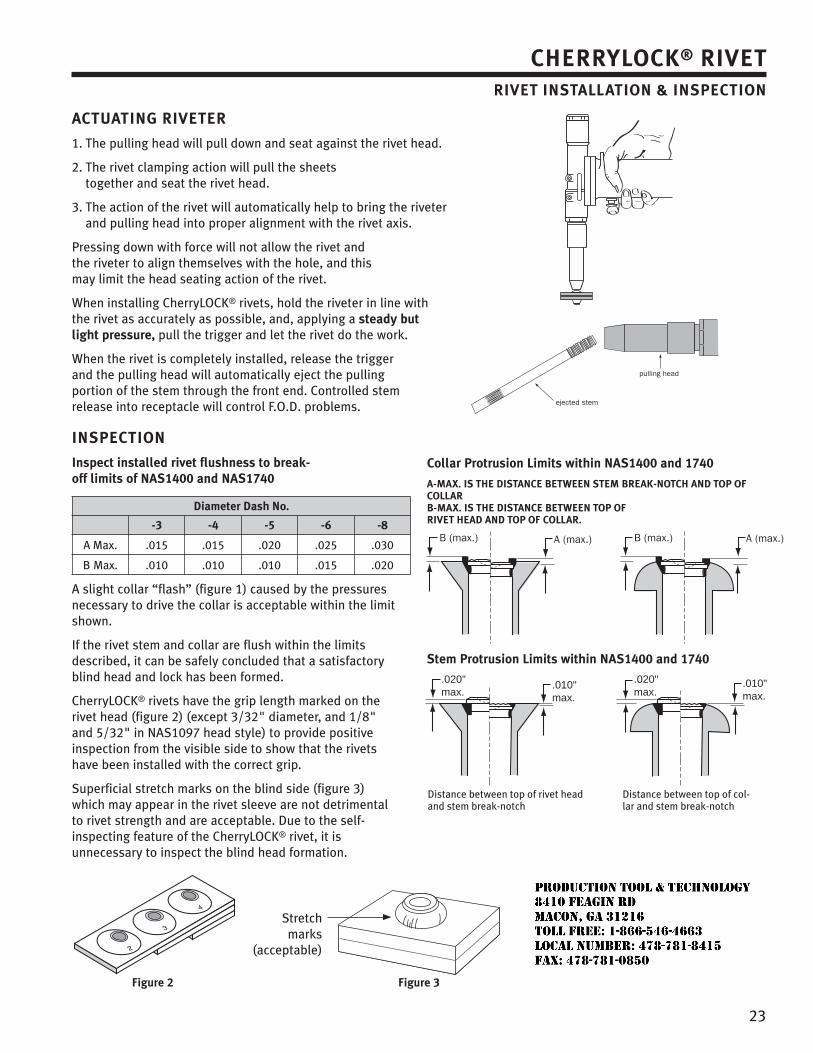
23
ACTUATING RIVETER
1. The pulling head will pull down and seat against the rivet head.
2. The rivet clamping action will pull the sheets together and seat the rivet head.
3. The action of the rivet will automatically help to bring the riveter and pulling head into proper alignment with the rivet axis.
Pressing down with force will not allow the rivet and the riveter to align themselves with the hole, and this may limit the head seating action of the rivet.
When installing CherryLOCK® rivets, hold the riveter in line with the rivet as accurately as possible, and, applying a steady but light pressure, pull the trigger and let the rivet do the work.
When the rivet is completely installed, release the trigger and the pulling head will automatically eject the pulling portion of the stem through the front end. Controlled stem release into receptacle will control F.O.D. problems.
INSPECTION
Inspect installed rivet flushness to break-off limits of NAS1400 and NAS1740
Diameter Dash No.
-3 -4 -5 -6 -8
A Max. .015 .015 .020 .025 .030
B Max. .010 .010 .010 .015 .020
A slight collar “flash” (figure 1) caused by the pressures necessary to drive the collar is acceptable within the limit shown.
If the rivet stem and collar are flush within the limits described, it can be safely concluded that a satisfactory blind head and lock has been formed.
CherryLOCK® rivets have the grip length marked on the rivet head (figure 2) (except 3/32" diameter, and 1/8" and 5/32" in NAS1097 head style) to provide positive inspection from the visible side to show that the rivets have been installed with the correct grip.
Superficial stretch marks on the blind side (figure 3) which may appear in the rivet sleeve are not detrimental to rivet strength and are acceptable. Due to the self-inspecting feature of the CherryLOCK® rivet, it is unnecessary to inspect the blind head formation.
CHERRYLOCK® RIVETRIVET INSTALLATION & INSPECTION
ejected stem
pulling head
Collar Protrusion Limits within NAS1400 and 1740
A-MAX. IS THE DISTANCE BETWEEN STEM BREAK-NOTCH AND TOP OF COLLARB-MAX. IS THE DISTANCE BETWEEN TOP OF RIVET HEAD AND TOP OF COLLAR.
Stem Protrusion Limits within NAS1400 and 1740
.020"max.
.020"max.
.010"max.
.010"max.
Distance between top of rivet head and stem break-notch
Distance between top of col-lar and stem break-notch
Figure 3
Stretch marks
(acceptable)
Figure 2
JR
Typewritten text
Production Tool & Technology 8410 Feagin Rd Macon, Ga 31216 Toll Free: 1-866-546-4663 Local Number: 478-781-8415 Fax: 478-781-0850
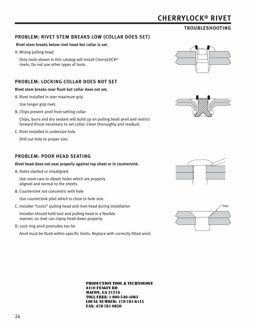
24
CHERRYLOCK® RIVETTROUBLESHOOTING
PROBLEM: RIVET STEM BREAKS LOW (COLLAR DOES SET)
Rivet stem breaks below rivet head but collar is set.
A. Wrong pulling head
Only tools shown in this catalog will install CherryLOCK® rivets. Do not use other types of tools.
PROBLEM: LOCKING COLLAR DOES NOT SET
Rivet stem breaks near flush but collar does not set.
A. Rivet installed in over maximum grip
Use longer grip rivet.
B. Chips prevent anvil from setting collar
Chips, burrs and dry sealant will build up on pulling head anvil and restrict forward thrust necessary to set collar. Clean thoroughly and readjust.
C. Rivet installed in undersize hole
Drill out hole to proper size.
PROBLEM: POOR HEAD SEATING
Rivet head does not seat properly against top sheet or in countersink.
A. Holes slanted or misaligned
Use more care to obtain holes which are properly aligned and normal to the sheets.
B. Countersink not concentric with hole
Use countersink pilot which is close to hole size.
C. Installer “cocks” pulling head and rivet head during installation
Installer should hold tool and pulling head in a flexible manner, so rivet can clamp head down properly.
D. Lock ring anvil protrudes too far
Anvil must be flush within specific limits. Replace with correctly fitted anvil.
JR
Typewritten text
Production Tool & Technology 8410 Feagin Rd Macon, Ga 31216 Toll Free: 1-866-546-4663 Local Number: 478-781-8415 Fax: 478-781-0850
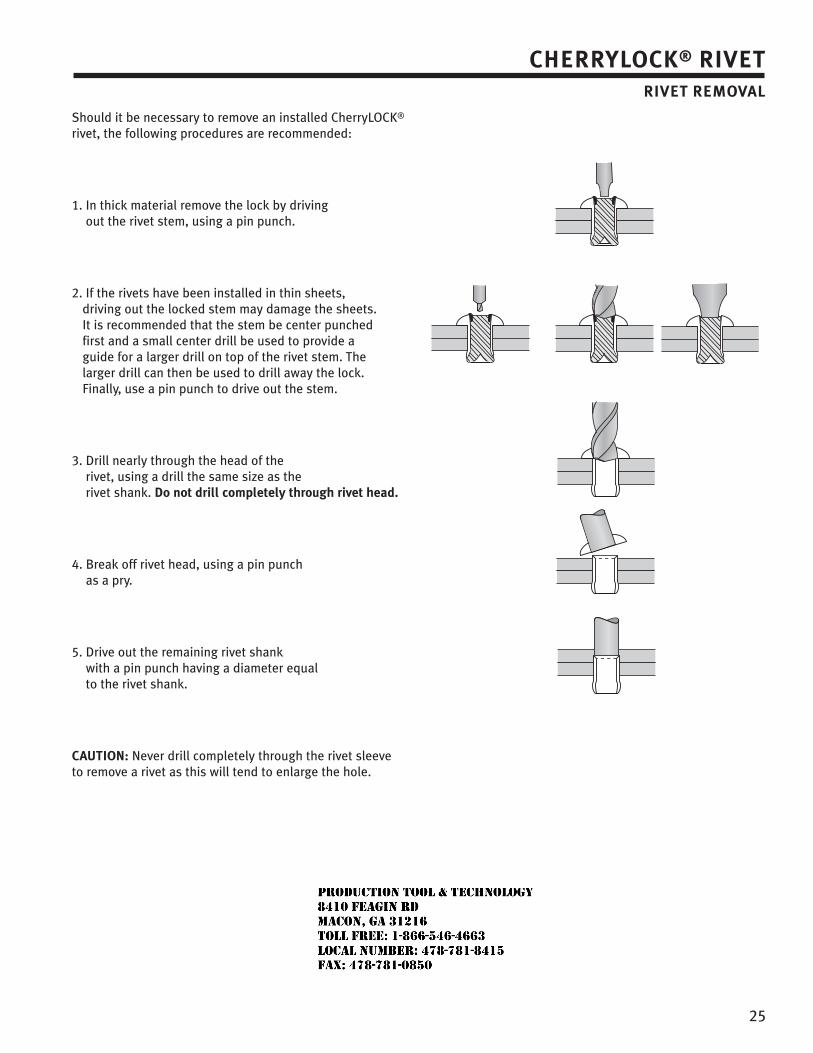
25
CHERRYLOCK® RIVETRIVET REMOVAL
Should it be necessary to remove an installed CherryLOCK® rivet, the following procedures are recommended:
1. In thick material remove the lock by driving out the rivet stem, using a pin punch.
2. If the rivets have been installed in thin sheets, driving out the locked stem may damage the sheets. It is recommended that the stem be center punched first and a small center drill be used to provide a guide for a larger drill on top of the rivet stem. The larger drill can then be used to drill away the lock. Finally, use a pin punch to drive out the stem.
3. Drill nearly through the head of the rivet, using a drill the same size as the rivet shank. Do not drill completely through rivet head.
4. Break off rivet head, using a pin punchas a pry.
5. Drive out the remaining rivet shank with a pin punch having a diameter equal to the rivet shank.
CAUTION: Never drill completely through the rivet sleeve to remove a rivet as this will tend to enlarge the hole.
JR
Typewritten text
Production Tool & Technology 8410 Feagin Rd Macon, Ga 31216 Toll Free: 1-866-546-4663 Local Number: 478-781-8415 Fax: 478-781-0850
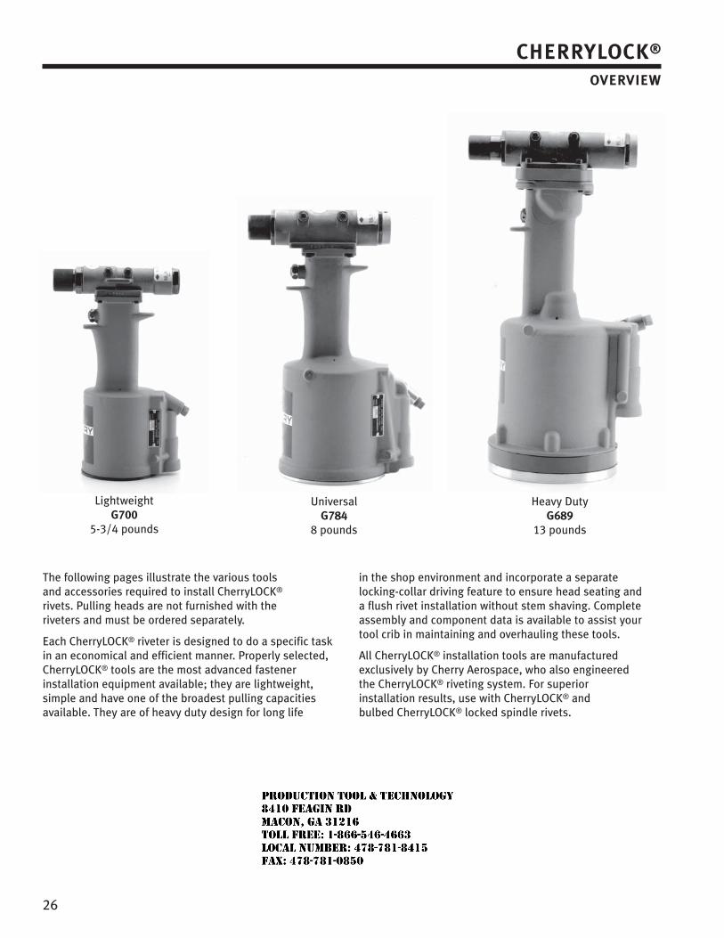
26
The following pages illustrate the various tools and accessories required to install CherryLOCK® rivets. Pulling heads are not furnished with the riveters and must be ordered separately.
Each CherryLOCK® riveter is designed to do a specific task in an economical and efficient manner. Properly selected, CherryLOCK® tools are the most advanced fastener installation equipment available; they are lightweight, simple and have one of the broadest pulling capacities available. They are of heavy duty design for long life
in the shop environment and incorporate a separate locking-collar driving feature to ensure head seating and a flush rivet installation without stem shaving. Complete assembly and component data is available to assist your tool crib in maintaining and overhauling these tools.
All CherryLOCK® installation tools are manufactured exclusively by Cherry Aerospace, who also engineered the CherryLOCK® riveting system. For superior installation results, use with CherryLOCK® and bulbed CherryLOCK® locked spindle rivets.
Lightweight G700
5-3/4 pounds
Universal G784
8 pounds
Heavy Duty G689
13 pounds
CHERRYLOCK®
OVERVIEW
JR
Typewritten text
Production Tool & Technology 8410 Feagin Rd Macon, Ga 31216 Toll Free: 1-866-546-4663 Local Number: 478-781-8415 Fax: 478-781-0850
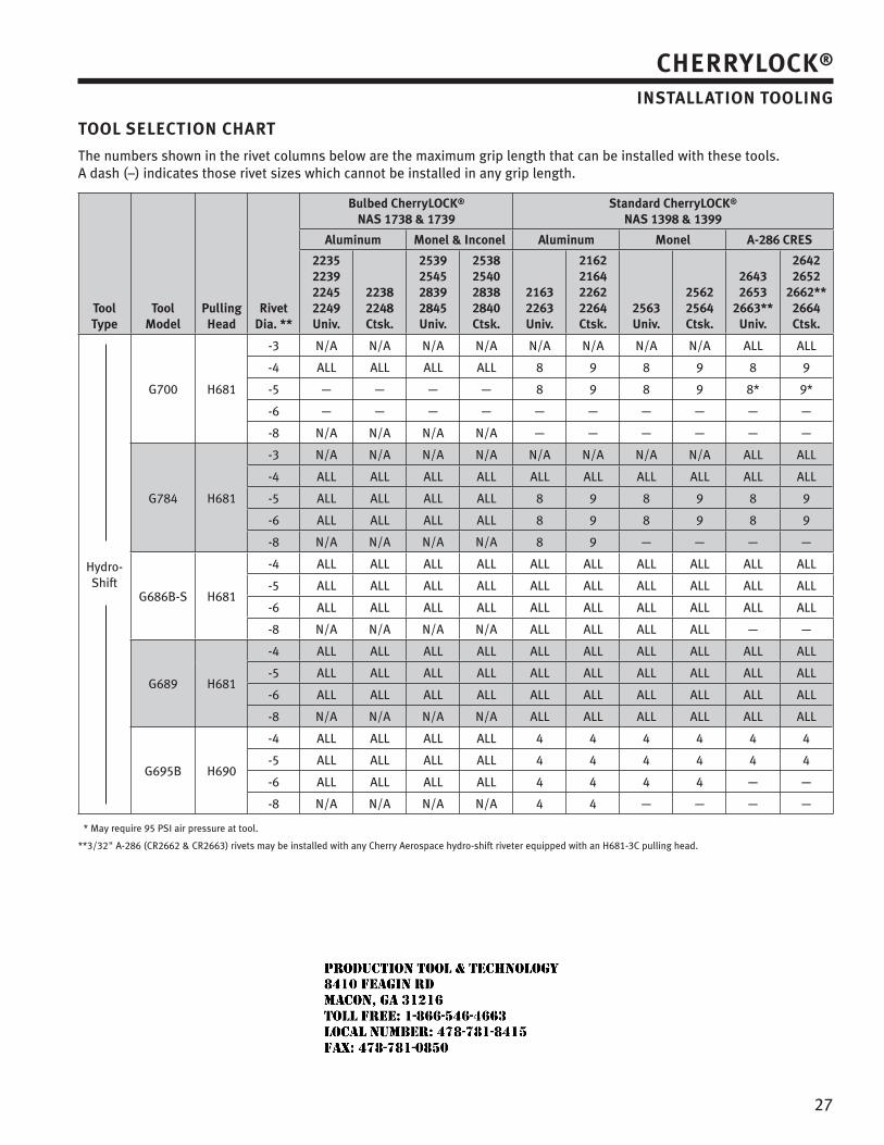
27
TOOL SELECTION CHART
The numbers shown in the rivet columns below are the maximum grip length that can be installed with these tools.A dash (–) indicates those rivet sizes which cannot be installed in any grip length.
ToolType
ToolModel
PullingHead
RivetDia. **
Bulbed CherryLOCK® NAS 1738 & 1739
Standard CherryLOCK® NAS 1398 & 1399
Aluminum Monel & Inconel Aluminum Monel A-286 CRES
2235223922452249Univ.
22382248Ctsk.
2539254528392845Univ.
2538254028382840Ctsk.
21632263Univ.
2162216422622264Ctsk.
2563Univ.
25622564Ctsk.
26432653
2663**Univ.
26422652
2662**2664Ctsk.
Hydro-Shift
G700 H681
-3 N/A N/A N/A N/A N/A N/A N/A N/A ALL ALL
-4 ALL ALL ALL ALL 8 9 8 9 8 9
-5 — — — — 8 9 8 9 8* 9*
-6 — — — — — — — — — —
-8 N/A N/A N/A N/A — — — — — —
G784 H681
-3 N/A N/A N/A N/A N/A N/A N/A N/A ALL ALL
-4 ALL ALL ALL ALL ALL ALL ALL ALL ALL ALL
-5 ALL ALL ALL ALL 8 9 8 9 8 9
-6 ALL ALL ALL ALL 8 9 8 9 8 9
-8 N/A N/A N/A N/A 8 9 — — — —
G686B-S H681
-4 ALL ALL ALL ALL ALL ALL ALL ALL ALL ALL
-5 ALL ALL ALL ALL ALL ALL ALL ALL ALL ALL
-6 ALL ALL ALL ALL ALL ALL ALL ALL ALL ALL
-8 N/A N/A N/A N/A ALL ALL ALL ALL — —
G689 H681
-4 ALL ALL ALL ALL ALL ALL ALL ALL ALL ALL
-5 ALL ALL ALL ALL ALL ALL ALL ALL ALL ALL
-6 ALL ALL ALL ALL ALL ALL ALL ALL ALL ALL
-8 N/A N/A N/A N/A ALL ALL ALL ALL ALL ALL
G695B H690
-4 ALL ALL ALL ALL 4 4 4 4 4 4
-5 ALL ALL ALL ALL 4 4 4 4 4 4
-6 ALL ALL ALL ALL 4 4 4 4 — —
-8 N/A N/A N/A N/A 4 4 — — — —
* May require 95 PSI air pressure at tool.
** 3/32" A-286 (CR2662 & CR2663) rivets may be installed with any Cherry Aerospace hydro-shift riveter equipped with an H681-3C pulling head.
CHERRYLOCK®
INSTALLATION TOOLING
JR
Typewritten text
Production Tool & Technology 8410 Feagin Rd Macon, Ga 31216 Toll Free: 1-866-546-4663 Local Number: 478-781-8415 Fax: 478-781-0850
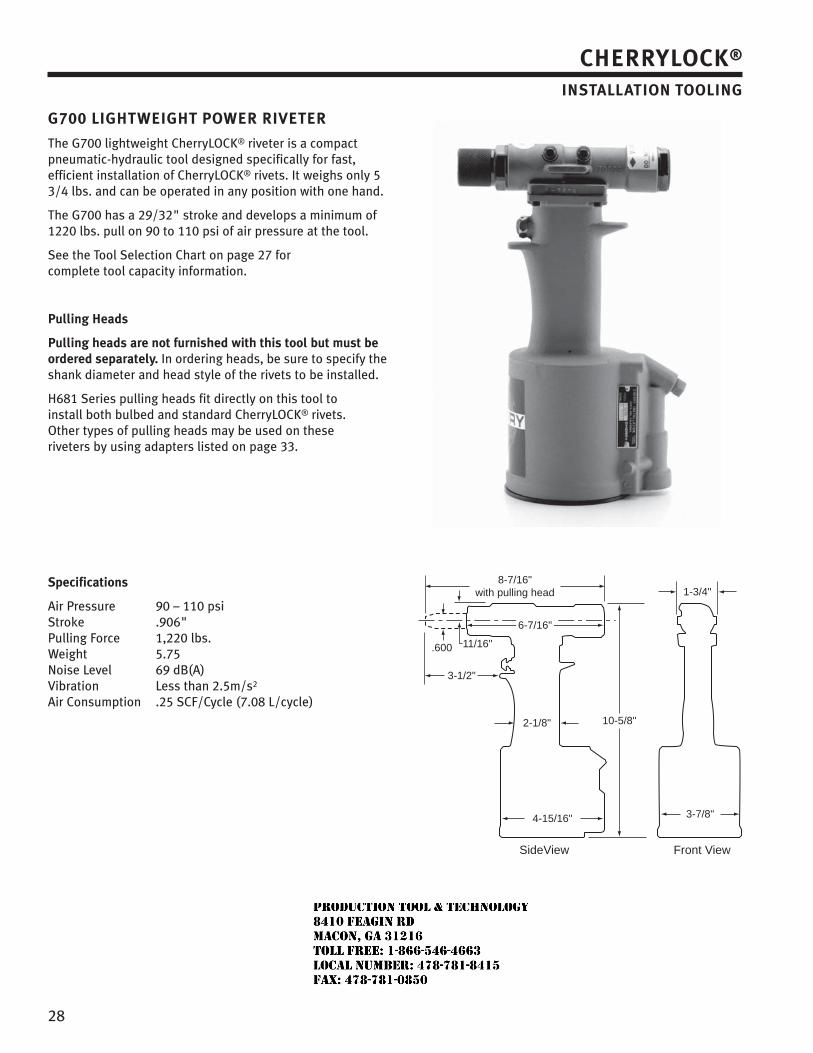
28
G700 LIGHTWEIGHT POWER RIVETER
The G700 lightweight CherryLOCK® riveter is a compact pneumatic-hydraulic tool designed specifically for fast, efficient installation of CherryLOCK® rivets. It weighs only 5 3/4 lbs. and can be operated in any position with one hand.
The G700 has a 29/32" stroke and develops a minimum of 1220 lbs. pull on 90 to 110 psi of air pressure at the tool.
See the Tool Selection Chart on page 27 for complete tool capacity information.
Pulling Heads
Pulling heads are not furnished with this tool but must be ordered separately. In ordering heads, be sure to specify the shank diameter and head style of the rivets to be installed.
H681 Series pulling heads fit directly on this tool to install both bulbed and standard CherryLOCK® rivets. Other types of pulling heads may be used on these riveters by using adapters listed on page 33.
Specifications
Air Pressure 90 – 110 psi Stroke .906" Pulling Force 1,220 lbs.Weight 5.75 Noise Level 69 dB(A)Vibration Less than 2.5m/s2
Air Consumption .25 SCF/Cycle (7.08 L/cycle)
11/16".600
3-7/8"
8-7/16"with pulling head
2-1/8"
3-1/2"
10-5/8"
1-3/4"
4-15/16"
6-7/16"
Front ViewSideView
CHERRYLOCK®
INSTALLATION TOOLING
JR
Typewritten text
Production Tool & Technology 8410 Feagin Rd Macon, Ga 31216 Toll Free: 1-866-546-4663 Local Number: 478-781-8415 Fax: 478-781-0850
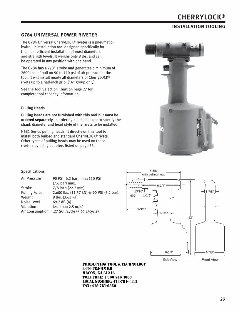
29
G784 UNIVERSAL POWER RIVETER
The G784 Universal CherryLOCK® riveter is a pneumatic-hydraulic installation tool designed specifically for the most efficient installation of most diameters and strength levels. It weighs only 8 lbs. and can be operated in any position with one hand.
The G784 has a 7/8" stroke and generates a minimum of 2600 lbs. of pull on 90 to 110 psi of air pressure at the tool. It will install nearly all diameters of CherryLOCK® rivets up to a half-inch grip. (”A” group only).
See the Tool Selection Chart on page 27 for complete tool capacity information.
Pulling Heads
Pulling heads are not furnished with this tool but must be ordered separately. In ordering heads, be sure to specify the shank diameter and head style of the rivets to be installed.
H681 Series pulling heads fit directly on this tool to install both bulbed and standard CherryLOCK® rivets. Other types of pulling heads may be used on these riveters by using adapters listed on page 33.
Specifications
Air Pressure 90 PSI (6.2 bar) min./110 PSI (7.6 bar) max.Stroke 7/8 inch (22.2 mm)Pulling Force 2,600 lbs. (11.57 kN) @ 90 PSI (6.2 bar), Weight 8 lbs. (3.63 kg)Noise Level 69.7 dB (A)Vibration less than 2.5 m/s2
Air Consumption .27 SCF/cycle (7.65 L/cycle)
1-1/8"13/16"
.600
3-3/4"
6-1/4"
8-3/8"with pulling head
1-7/8"
4-7/8"6-1/4"
2-1/8"12"
Front ViewSideView
CHERRYLOCK®
INSTALLATION TOOLING
JR
Typewritten text
Production Tool & Technology 8410 Feagin Rd Macon, Ga 31216 Toll Free: 1-866-546-4663 Local Number: 478-781-8415 Fax: 478-781-0850
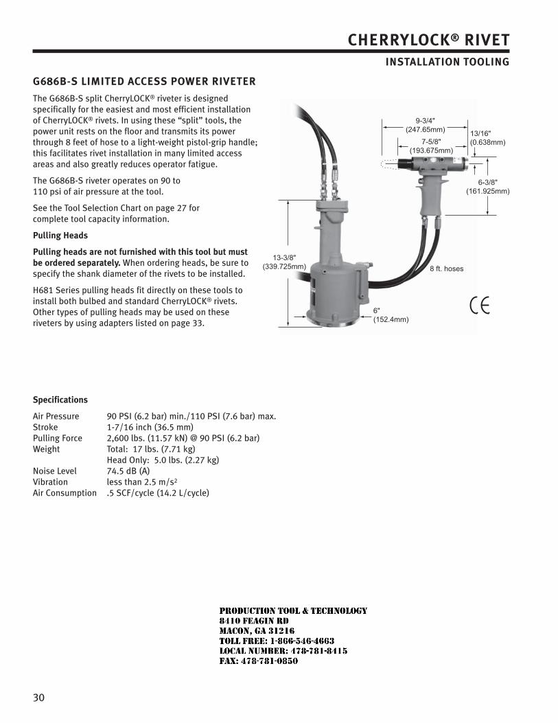
30
G686B-S LIMITED ACCESS POWER RIVETER
The G686B-S split CherryLOCK® riveter is designed specifically for the easiest and most efficient installation of CherryLOCK® rivets. In using these “split” tools, the power unit rests on the floor and transmits its power through 8 feet of hose to a light-weight pistol-grip handle; this facilitates rivet installation in many limited access areas and also greatly reduces operator fatigue.
The G686B-S riveter operates on 90 to 110 psi of air pressure at the tool.
See the Tool Selection Chart on page 27 for complete tool capacity information.
Pulling Heads
Pulling heads are not furnished with this tool but must be ordered separately. When ordering heads, be sure to specify the shank diameter of the rivets to be installed.
H681 Series pulling heads fit directly on these tools to install both bulbed and standard CherryLOCK® rivets. Other types of pulling heads may be used on these riveters by using adapters listed on page 33.
Specifications
Air Pressure 90 PSI (6.2 bar) min./110 PSI (7.6 bar) max.Stroke 1-7/16 inch (36.5 mm)Pulling Force 2,600 lbs. (11.57 kN) @ 90 PSI (6.2 bar)Weight Total: 17 lbs. (7.71 kg) Head Only: 5.0 lbs. (2.27 kg)Noise Level 74.5 dB (A)Vibration less than 2.5 m/s2
Air Consumption .5 SCF/cycle (14.2 L/cycle)
CHERRYLOCK® RIVETINSTALLATION TOOLING
JR
Typewritten text
Production Tool & Technology 8410 Feagin Rd Macon, Ga 31216 Toll Free: 1-866-546-4663 Local Number: 478-781-8415 Fax: 478-781-0850
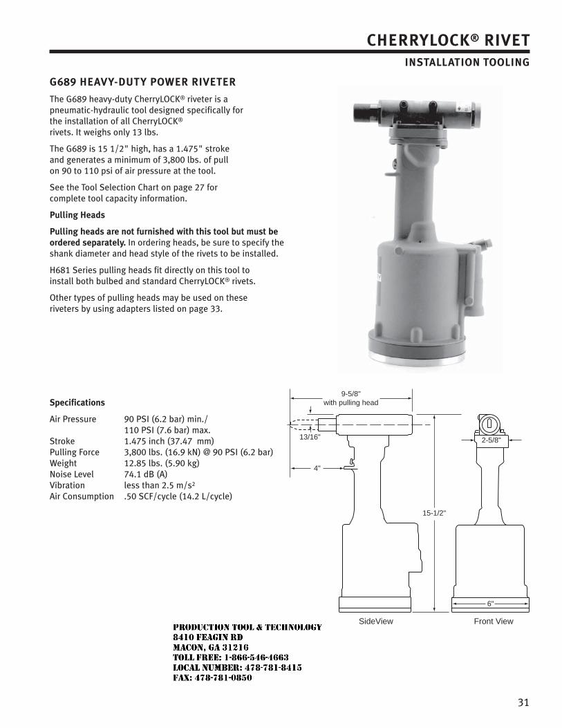
31
G689 HEAVY-DUTY POWER RIVETER
The G689 heavy-duty CherryLOCK® riveter is a pneumatic-hydraulic tool designed specifically for the installation of all CherryLOCK® rivets. It weighs only 13 lbs.
The G689 is 15 1/2" high, has a 1.475" stroke and generates a minimum of 3,800 lbs. of pull on 90 to 110 psi of air pressure at the tool.
See the Tool Selection Chart on page 27 for complete tool capacity information.
Pulling Heads
Pulling heads are not furnished with this tool but must be ordered separately. In ordering heads, be sure to specify the shank diameter and head style of the rivets to be installed.
H681 Series pulling heads fit directly on this tool to install both bulbed and standard CherryLOCK® rivets.
Other types of pulling heads may be used on these riveters by using adapters listed on page 33.
Specifications
Air Pressure 90 PSI (6.2 bar) min./ 110 PSI (7.6 bar) max.Stroke 1.475 inch (37.47 mm)Pulling Force 3,800 lbs. (16.9 kN) @ 90 PSI (6.2 bar)Weight 12.85 lbs. (5.90 kg)Noise Level 74.1 dB (A)Vibration less than 2.5 m/s2
Air Consumption .50 SCF/cycle (14.2 L/cycle)
13/16"
4"
2-5/8"
6"
15-1/2"
9-5/8"with pulling head
Front ViewSideView
CHERRYLOCK® RIVETINSTALLATION TOOLING
JR
Typewritten text
Production Tool & Technology 8410 Feagin Rd Macon, Ga 31216 Toll Free: 1-866-546-4663 Local Number: 478-781-8415 Fax: 478-781-0850
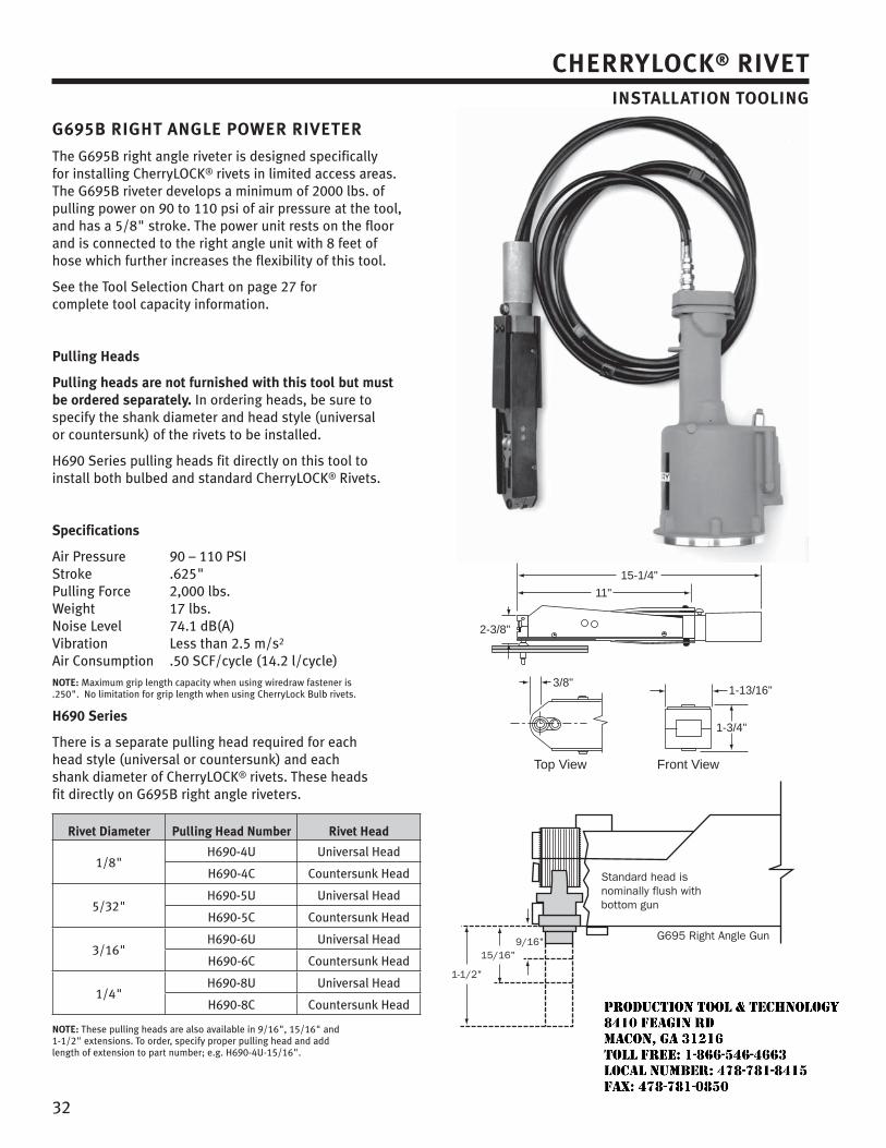
32
G695B RIGHT ANGLE POWER RIVETER
The G695B right angle riveter is designed specifically for installing CherryLOCK® rivets in limited access areas. The G695B riveter develops a minimum of 2000 lbs. of pulling power on 90 to 110 psi of air pressure at the tool, and has a 5/8" stroke. The power unit rests on the floor and is connected to the right angle unit with 8 feet of hose which further increases the flexibility of this tool.
See the Tool Selection Chart on page 27 for complete tool capacity information.
Pulling Heads
Pulling heads are not furnished with this tool but must be ordered separately. In ordering heads, be sure to specify the shank diameter and head style (universal or countersunk) of the rivets to be installed.
H690 Series pulling heads fit directly on this tool to install both bulbed and standard CherryLOCK® Rivets.
Specifications
Air Pressure 90 – 110 PSIStroke .625"Pulling Force 2,000 lbs.Weight 17 lbs.Noise Level 74.1 dB(A)Vibration Less than 2.5 m/s2
Air Consumption .50 SCF/cycle (14.2 l/cycle)NOTE: Maximum grip length capacity when using wiredraw fastener is .250". No limitation for grip length when using CherryLock Bulb rivets.
H690 Series
There is a separate pulling head required for each head style (universal or countersunk) and each shank diameter of CherryLOCK® rivets. These heads fit directly on G695B right angle riveters.
Rivet Diameter Pulling Head Number Rivet Head
1/8"H690-4U Universal Head
H690-4C Countersunk Head
5/32"H690-5U Universal Head
H690-5C Countersunk Head
3/16"H690-6U Universal Head
H690-6C Countersunk Head
1/4" H690-8U Universal Head
H690-8C Countersunk Head
NOTE: These pulling heads are also available in 9/16", 15/16" and 1-1/2" extensions. To order, specify proper pulling head and add length of extension to part number; e.g. H690-4U-15/16".
1-3/4"
1-13/16"3/8"
2-3/8"
11"
15-1/4"
Front ViewTop View
CHERRYLOCK® RIVETINSTALLATION TOOLING
JR
Typewritten text
Production Tool & Technology 8410 Feagin Rd Macon, Ga 31216 Toll Free: 1-866-546-4663 Local Number: 478-781-8415 Fax: 478-781-0850
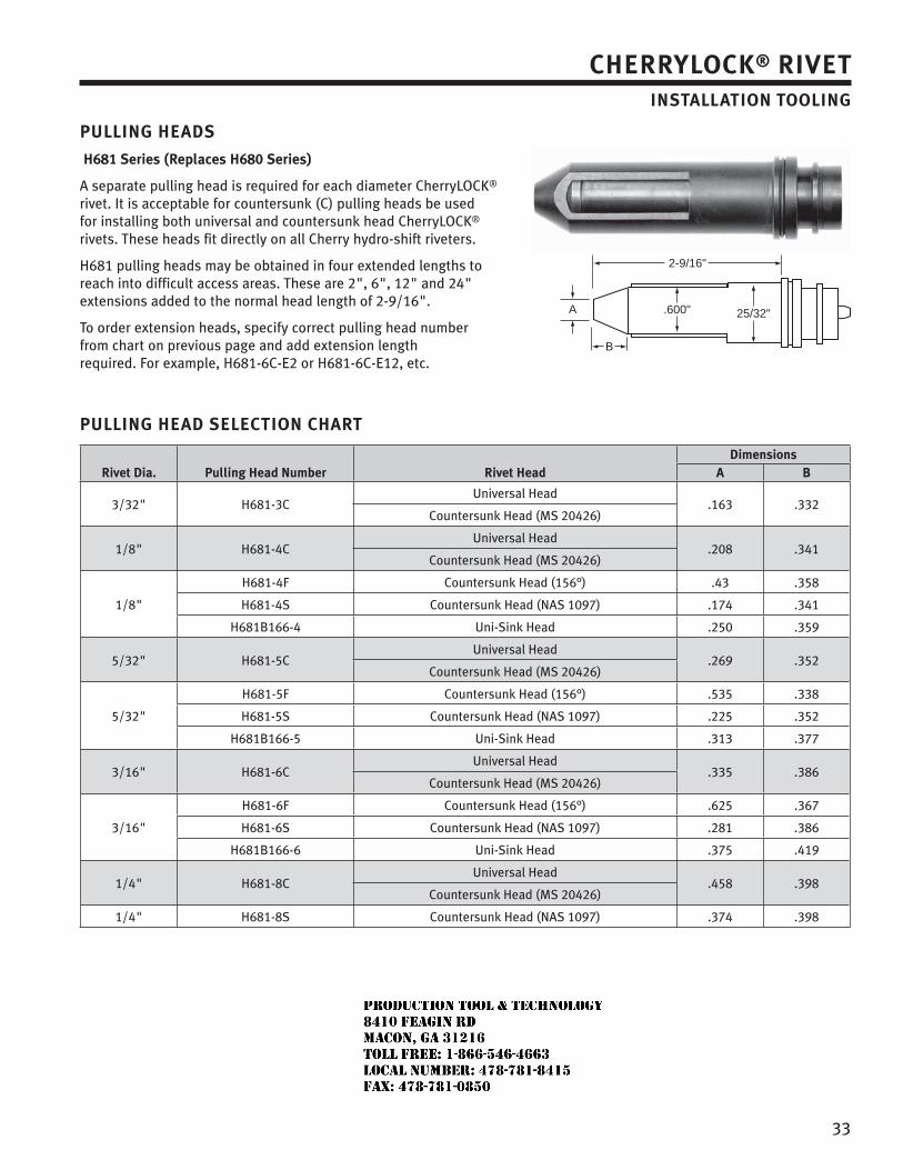
33
PULLING HEADS
H681 Series (Replaces H680 Series)
A separate pulling head is required for each diameter CherryLOCK® rivet. It is acceptable for countersunk (C) pulling heads be used for installing both universal and countersunk head CherryLOCK® rivets. These heads fit directly on all Cherry hydro-shift riveters.
H681 pulling heads may be obtained in four extended lengths to reach into difficult access areas. These are 2", 6", 12" and 24" extensions added to the normal head length of 2-9/16".
To order extension heads, specify correct pulling head number from chart on previous page and add extension length required. For example, H681-6C-E2 or H681-6C-E12, etc.
PULLING HEAD SELECTION CHART
Rivet Dia. Pulling Head Number Rivet HeadDimensions
A B
3/32" H681-3CUniversal Head
.163 .332Countersunk Head (MS 20426)
1/8" H681-4CUniversal Head
.208 .341Countersunk Head (MS 20426)
1/8"
H681-4F Countersunk Head (156°) .43 .358
H681-4S Countersunk Head (NAS 1097) .174 .341
H681B166-4 Uni-Sink Head .250 .359
5/32" H681-5CUniversal Head
.269 .352Countersunk Head (MS 20426)
5/32"
H681-5F Countersunk Head (156°) .535 .338
H681-5S Countersunk Head (NAS 1097) .225 .352
H681B166-5 Uni-Sink Head .313 .377
3/16" H681-6CUniversal Head
.335 .386Countersunk Head (MS 20426)
3/16"
H681-6F Countersunk Head (156°) .625 .367
H681-6S Countersunk Head (NAS 1097) .281 .386
H681B166-6 Uni-Sink Head .375 .419
1/4" H681-8CUniversal Head
.458 .398Countersunk Head (MS 20426)
1/4" H681-8S Countersunk Head (NAS 1097) .374 .398
2-9/16"
A
B
.600" 25/32"
CHERRYLOCK® RIVETINSTALLATION TOOLING
JR
Typewritten text
Production Tool & Technology 8410 Feagin Rd Macon, Ga 31216 Toll Free: 1-866-546-4663 Local Number: 478-781-8415 Fax: 478-781-0850
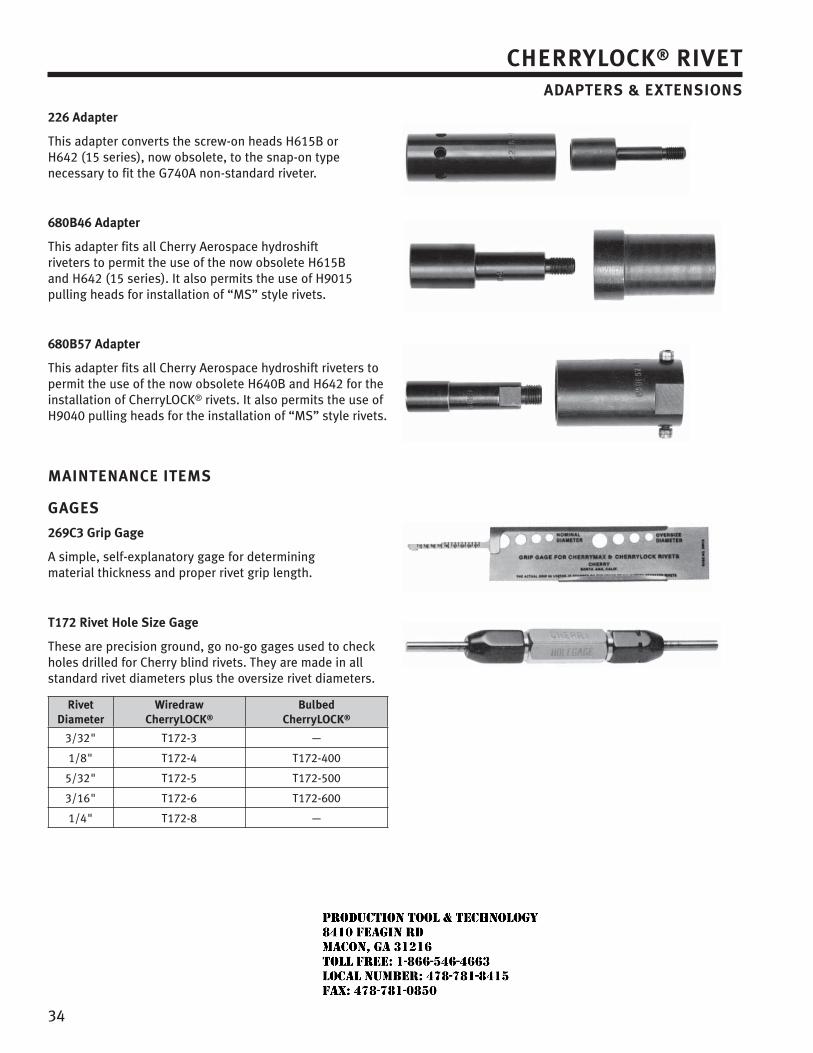
34
226 Adapter
This adapter converts the screw-on heads H615B or H642 (15 series), now obsolete, to the snap-on type necessary to fit the G740A non-standard riveter.
680B46 Adapter
This adapter fits all Cherry Aerospace hydroshift riveters to permit the use of the now obsolete H615B and H642 (15 series). It also permits the use of H9015 pulling heads for installation of “MS” style rivets.
680B57 Adapter
This adapter fits all Cherry Aerospace hydroshift riveters to permit the use of the now obsolete H640B and H642 for the installation of CherryLOCK® rivets. It also permits the use of H9040 pulling heads for the installation of “MS” style rivets.
MAINTENANCE ITEMS
GAGES
269C3 Grip Gage
A simple, self-explanatory gage for determining material thickness and proper rivet grip length.
T172 Rivet Hole Size Gage
These are precision ground, go no-go gages used to check holes drilled for Cherry blind rivets. They are made in all standard rivet diameters plus the oversize rivet diameters.
Rivet Diameter
Wiredraw CherryLOCK®
Bulbed CherryLOCK®
3/32" T172-3 —
1/8" T172-4 T172-400
5/32" T172-5 T172-500
3/16" T172-6 T172-600
1/4" T172-8 —
CHERRYLOCK® RIVETADAPTERS & EXTENSIONS
JR
Typewritten text
Production Tool & Technology 8410 Feagin Rd Macon, Ga 31216 Toll Free: 1-866-546-4663 Local Number: 478-781-8415 Fax: 478-781-0850
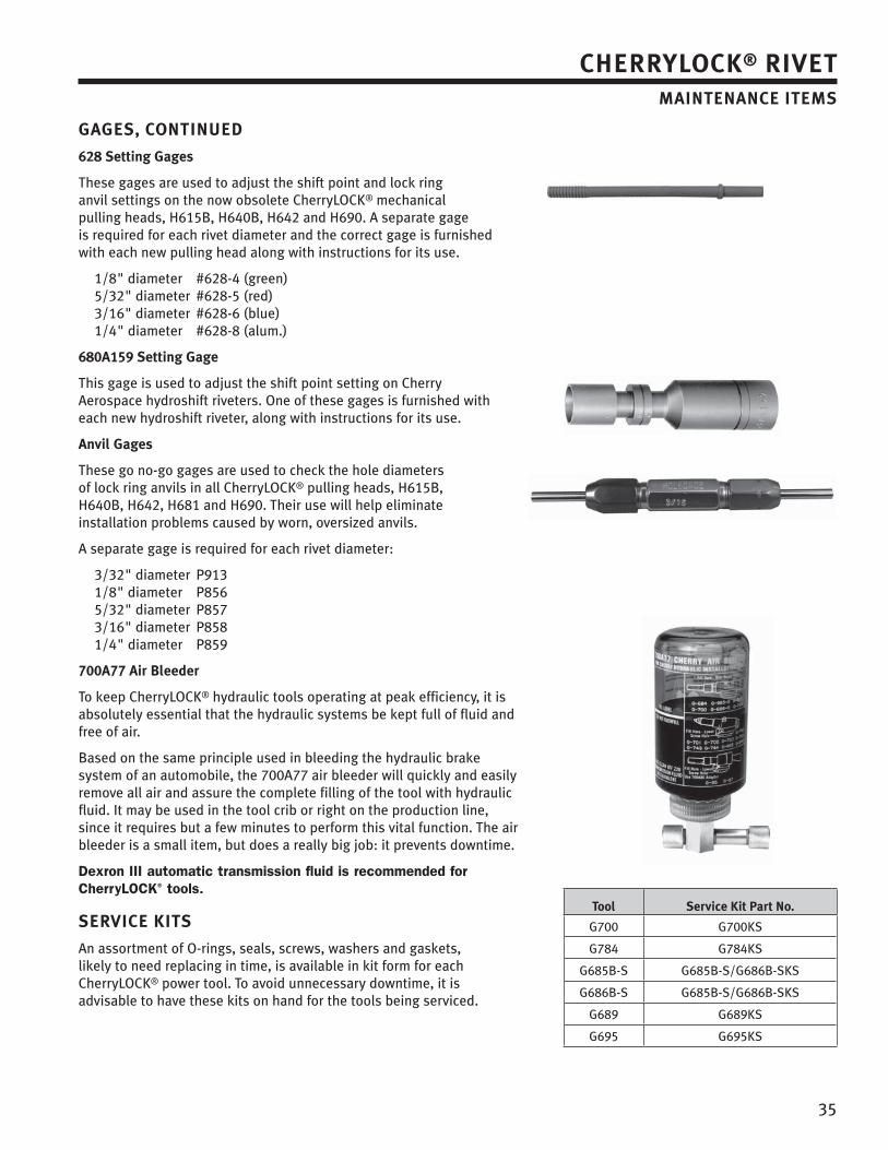
35
GAGES, CONTINUED
628 Setting Gages
These gages are used to adjust the shift point and lock ring anvil settings on the now obsolete CherryLOCK® mechanical pulling heads, H615B, H640B, H642 and H690. A separate gage is required for each rivet diameter and the correct gage is furnished with each new pulling head along with instructions for its use.
1/8" diameter #628-4 (green) 5/32" diameter #628-5 (red) 3/16" diameter #628-6 (blue) 1/4" diameter #628-8 (alum.)
680A159 Setting Gage
This gage is used to adjust the shift point setting on Cherry Aerospace hydroshift riveters. One of these gages is furnished with each new hydroshift riveter, along with instructions for its use.
Anvil Gages
These go no-go gages are used to check the hole diameters of lock ring anvils in all CherryLOCK® pulling heads, H615B, H640B, H642, H681 and H690. Their use will help eliminate installation problems caused by worn, oversized anvils.
A separate gage is required for each rivet diameter:
3/32" diameter P913 1/8" diameter P856 5/32" diameter P857 3/16" diameter P858 1/4" diameter P859
700A77 Air Bleeder
To keep CherryLOCK® hydraulic tools operating at peak efficiency, it is absolutely essential that the hydraulic systems be kept full of fluid and free of air.
Based on the same principle used in bleeding the hydraulic brake system of an automobile, the 700A77 air bleeder will quickly and easily remove all air and assure the complete filling of the tool with hydraulic fluid. It may be used in the tool crib or right on the production line, since it requires but a few minutes to perform this vital function. The air bleeder is a small item, but does a really big job: it prevents downtime.
Dexron III automatic transmission fluid is recommended for CherryLOCK® tools.
SERVICE KITS
An assortment of O-rings, seals, screws, washers and gaskets, likely to need replacing in time, is available in kit form for each CherryLOCK® power tool. To avoid unnecessary downtime, it is advisable to have these kits on hand for the tools being serviced.
Tool Service Kit Part No.
G700 G700KS
G784 G784KS
G685B-S G685B-S/G686B-SKS
G686B-S G685B-S/G686B-SKS
G689 G689KS
G695 G695KS
CHERRYLOCK® RIVET MAINTENANCE ITEMS
Cherry Maxibolt®
blind bolt
JR
Typewritten text
Production Tool & Technology 8410 Feagin Rd Macon, Ga 31216 Toll Free: 1-866-546-4663 Local Number: 478-781-8415 Fax: 478-781-0850
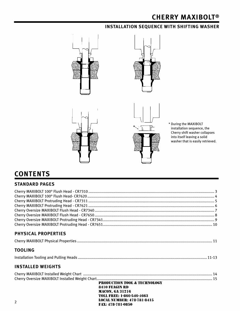
�
Cherry Maxibolt®
installation sequenCe with shifting washer
Contentsstandard Pages
Cherry MAXIBOLT 100° Flush Head - CR7310 ......................................................................................................................... 3 Cherry MAXIBOLT 100° Flush Head- CR76�0 .......................................................................................................................... 4 Cherry MAXIBOLT Protruding Head - CR7311 ......................................................................................................................... 5 Cherry MAXIBOLT Protruding Head - CR76�1 ......................................................................................................................... 6 Cherry Oversize MAXIBOLT Flush Head - CR7340 ................................................................................................................... 7 Cherry Oversize MAXIBOLT Flush Head - CR7650 ................................................................................................................... 8 Cherry Oversize MAXIBOLT Protruding Head - CR7341 ........................................................................................................... 9 Cherry Oversize MAXIBOLT Protruding Head - CR7651 ......................................................................................................... 10
PhysiCal ProPerties
Cherry MAXIBOLT Physical Properties .................................................................................................................................. 11
tooling
Installation Tooling and Pulling Heads ............................................................................................................................ 11-13
installed weights
Cherry MAXIBOLT Installed Weight Chart ............................................................................................................................ 14 Cherry Oversize MAXIBOLT Installed Weight Chart ............................................................................................................... 15
* During the MAXIBOLT installation sequence, the Cherry shift washer collapses into itself leaving a solid washer that is easily retrieved.
JR
Typewritten text
Production Tool & Technology 8410 Feagin Rd Macon, Ga 31216 Toll Free: 1-866-546-4663 Local Number: 478-781-8415 Fax: 478-781-0850
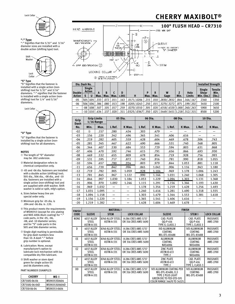
3
Lock Collar
“-” type“-” Signifies that the 5/3�" and 3/16" diameter sizes are installed with a double action (shifting type) tool.
Shift Washer
Lock Collar
“s” type “S” Signifies that the fastener is installed with a single action (non-shifting) tool for 5/3�" and 3/16" diameters. “-” signifies that the fastener is installed with a single action (non-shifting) tool for 1/4" and 5/16" diameters.
Lock Collar
“u” type
“U” Signifies that the fastener is installed by a single action (non-shifting) tool for all diameters.
notes➀ The length of “D” diameter
may be .00� undersize.
➁ Material designation refers to chemical composition only.
➂ -05 and -06 dia. fasteners are installed with a double action (shifting) tool; S05 dia., S06 dia., -08 dia., and -10 dia. fasteners are installed with a single action (non-shifting) tool and are supplied with shift washer. Shift washer is solid or split, mfg’s option.
4. Sizes below heavy line are special order only.
➄ Minimum grip for -05 dia. is .094 and -06 dia. is .1�0.
➅ This product meets the requirements of MS90353 (except for zinc plating and NAS 4006 Alum coating) for “-” code parts, in the -05, -06, -08, and -10 diameter series; and for “S” code parts in the S05 and S06 diameter series.
➆ Single digit marking is permissible for grip dash numbers less than 10. A dash “-” before grip number is optional.
8. Lubrication: None, except manufacturer’s option to lubricate lock mechanism with lox compatible dry film lubricant.
➈ Shift washer or stem dyed green for single action 05 and 06 diameters only.
PART NUMBER EXAMPLES
Cherry Ms ➅CR7310S-06-04 MS90353S0604CR7310U-06-04D MS90353U0604DCR7310-06-04 MS90353-0604
Cherry Maxibolt®
100° flush head – Cr7310
➂
dia. dash no.
aMax.
bMax.
CMax.
d±.001 h
PMax.
rMax.
wgage
ZMin.
holelimits
installed strength
doubleaction
singleaction single
shearMin. (lbs.)
tensileMin. (lbs.)s u
-05 S05 U05 .333 .07� .011 .163 .0171/.0�06 .�15 .010 .�830/.�83� .844 .164/.167 �340 1350-06 S06 U06 .386 .080 .013 .198 .0�05/.0�43 .�50 .015 .3�70/.3�7� .875 .199/.�0� 3450 �100— -08 U08 .507 .105 .017 .�59 .0�70/.0310 .305 .0�0 .4318/.43�0 1.000 .�60/.�63 5900 3650— -10 U10 .634 .137 .0�0 .311 .03�5/.0367 .350 .0�5 .5449/.5451 1.�18 .31�/.315 8500 5�00
grip dashno.
grip limits 1/16 range
05 dia. 06 dia. 08 dia. 10 dia.
l ref. K Max. l ref. K Max. l ref. K Max. l ref. K Max.Min. Max.-0� ➄ .157 .�80 .434 .303 .479 — — — —-03 .156 .��0 .34� .496 .365 .541 .406 .616 — —-04 .�19 .�8� .405 .559 .4�8 .604 .469 .678 .506 .743-05 .�81 .345 .467 .6�� .490 .666 .531 .740 .568 .805-06 .344 .407 .530 .684 .553 .7�9 .594 .803 .631 .868-07 .406 .470 .59� .746 .615 .791 .656 .866 .693 .930-08 .469 .53� .655 .809 .678 .854 .719 .9�8 .756 .993-09 .531 .595 .717 .87� .740 .916 .781 .990 .818 1.055-10 .594 .657 .780 .934 .803 .979 .844 1.053 .881 1.118-11 .656 .7�0 .84� .996 .865 1.041 .906 1.116 .943 1.180-1� .719 .78� .905 1.059 .9�8 1.104 .969 1.178 1.006 1.�43-13 .781 .845 .967 1.1�� .990 1.166 1.031 1.�40 1.068 1.305-14 .844 .907 1.030 1.184 1.053 1.��9 1.094 1.303 1.131 1.368-15 .906 .970 1.09� 1.�46 1.115 1.�91 1.156 1.366 1.193 1.430-16 .969 1.03� — — 1.178 1.354 1.�19 1.4�8 1.�56 1.493-17 1.031 1.095 — — 1.�40 1.416 1.�81 1.490 1.318 1.555-18 1.094 1.158 — — 1.303 1.479 1.344 1.553 1.381 1.618-19 1.156 1.��0 — — 1.365 1.541 1.406 1.616 — —-�0 1.�19 1.�8� — — 1.4�8 1.604 1.469 1.678 — —
FinishCode
Material➁ Finishsleeve steM loCk Collar sleeve steM➈ loCk Collar
NoNe 4037 ALLoy SteeL
AStM-A-331
8740 ALLoy SteeLAStM-A-331
A-286 CReS AMS 5737oR 316 CReS AMS 5690
CAD. PLAteQQ-P-416
tyPe II, CLASS 2
CAD. PLAteQQ-P-416
tyPe I, CLASS 3
PASSIvAteAMS 2700
D 4037 ALLoy SteeL
AStM-A-331
8740 ALLoy SteeLAStM-A-331
A-286 CReS AMS 5737 oR 316 CReS AMS 5690
IvD ALUMINUMCoAtINg
MIL-DtL-83488
IvD ALUMINUMCoAtINg
MIL-DtL-83488
PASSIvAteAMS 2700
ee 4037 ALLoy SteeL
AStM-A-331
8740 ALLoy SteeLAStM-A-331
A-286 CReS AMS 5737 oR 316 CReS AMS 5690
ALUMINUMCoAtINgNAS4006
ALUMINUMCoAtINgNAS4006
PASSIvAteAMS 2700
eZ 4037 ALLoy SteeL
AStM-A-331
8740 ALLoy SteeLAStM-A-331
A-286-CReS AMS 5737oR 316 CReS AMS 5690
ZINC PLAteAStM-B-633
tyPe 2
ALUMINUMCoAtINgNAS4006
PASSIvAteAMS 2700
Z 4037 ALLoy SteeL
AStM-A-331
8740 ALLoy SteeLAStM-A-331
A-286 CReS AMS 5737 oR 316 CReS AMS 5690
ZINC PLAteAStM-B-633
tyPe 2
CAD. PLAteQQ-P-416
tyPe 1, CLASS 3
PASSIvAteAMS 2700
DD 4037 ALLoy SteeL
AStM-A-331
8740 ALLoy SteeLAStM-A-331
A-286 CReS AMS 5737 oR 316 CReS AMS 5690
IvD ALUMINUM CoAtINg PeR MIL-DtL-83488, CL3 tyPe 2 PLUS LIght
gReeN DIe to FeD-StD-595CoLoR RANge 34670 to 34325
IvD ALUMINUMCoAtINg
MIL-DtL-83488
PASSIvAteAMS 2700
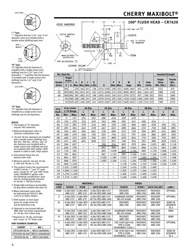
4
Cherry Maxibolt®
100° flush head – Cr7620
dia. dash no.
aMax.
bMax.
CMax.
d±.001 h
PMax.
rMax.
wgage
ZMin.
holelimits
installed strength
doubleaction
singleaction single
shearMin. (lbs.)
tensileMin. (lbs.)s u
— S04 — .��9 . 04� .011 .1�8 .0155/.0185 .190 .01� .1839/.1841 .81� .1�9/.13� 1��� 675-05 S05 U05 .334 .074 .011 .163 .0171/.0�06 .�15 .010 .�830/.�83� .844 .164/.167 1980 1150-06 S06 U06 .387 .08� .013 .198 .0�05/.0�43 .�50 .015 .3�70/.3�7� .875 .199/.�0� �9�5 1690— -08 U08 .508 .108 .017 .�59 .0�70/.0310 .305 .0�0 . 4318/.43�0 1.000 .�60/.�63 5000 �900— -10 U10 .635 .140 .0�0 .311 .03�5/.0367 .350 .0�5 .5449/.5451 1.�18 .31�/.315 7�00 4170
gripdashno.
grip limits 1/16 range
04 dia. 05 dia. 06 dia. 08 dia. 10 dia.
lref.
KMax.
lref.
KMax.
lref.
KMax.
lref.
KMax.
lref.
KMax.Min. Max.
-0� ➄ .157 .�54 .391 .�80 .434 .3�9 .479 — — — —-03 .156 .��0 .316 .453 .34� .496 .365 .541 .406 .616 — —-04 .�19 .�8� .379 .516 .405 .559 .4�8 .604 .469 .678 .506 .743-05 .�81 .345 .441 .578 .467 .6�� .490 .666 .531 .740 .568 .805-06 .344 .407 .504 .641 .530 .684 .553 .7�9 .594 .803 .631 .868-07 .406 .470 .566 .703 .59� .746 .615 .791 .656 .866 .693 .930-08 .469 .53� .6�9 .766 .655 .809 .678 .854 .719 .9�8 .756 .993-09 .531 .595 .691 .8�8 .717 .87� .740 .916 .781 .990 .818 1.055-10 .594 .657 — — .780 .934 .803 .979 .844 1.053 .881 1.118-11 .656 .7�0 — — .84� .996 .865 1.041 .906 1.116 .943 1.180-1� .719 .78� — — .905 1.059 .9�8 1.104 .969 1.178 1.006 1.�43-13 .781 .845 — — .967 1.1�� .990 1.166 1.031 1.�40 1.068 1.305-14 .844 .907 — — 1.030 1.184 1.053 1.��9 1.094 1.303 1.131 1.368-15 .906 .970 — — 1.09� 1.�46 1.115 1.�91 1.156 1.366 1.193 1.430-16 .969 1.03� — — — — 1.178 1.354 1.�19 1.4�8 1.�56 1.493-17 1.031 1.095 — — — — 1.�40 1.416 1.�81 1.490 — —-18 1.094 1.158 — — — — 1.303 1.479 1.344 1.553 — —-19 1.156 1.��0 — — — — 1.366 1.541 1.406 1.616 — —-�0 1.�19 1.�8� — — — — 1.4�8 1.604 1.468 1.678 — —
finishCode
Material➁ finish
lube➇sleeve steM loCK Collar➉ sleeve steM➈ loCK Collar➉
NoNe A-286 CReSAMS 5737
A-286 CReSAMS 5737
A-286 CReS AMS 5737oR 316 CReS AMS 5690
PASSIvAteAMS 2700
PASSIvAteAMS 2700
PASSIvAteAMS 2700
oPtIoNAL
D A-286 CReSAMS 5737
A-286 CReSAMS 5737
A-286 CReS AMS 5737oR 316 CReS AMS 5690
ALUMINUM CoAtINgMIL-DtL-83488
PASSIvAteAMS 2700
PASSIvAteAMS 2700
oPtIoNAL
DL A-286 CReSAMS 5737
A-286 CReSAMS 5737
A-286 CReS AMS 5737 oR 316 CReS AMS 5690
PASSIvAteAMS 2700
PASSIvAteAMS 2700
PASSIvAteAMS 2700
NoNe oRDICRoNIte
DL-5DN A-286 CReS
AMS 5737A-286 CReSAMS 5737
A-286 CReS AMS 5737 oR 316 CReS AMS 5690
ALUMINUM CoAtINgMIL-DtL-83488
PASSIvAteAMS 2700
PASSIvAteAMS 2700
NoNe
N A-286 CReSAMS 5737
A-286 CReSAMS 5737
A-286 CReS AMS 5737 oR 316 CReS AMS 5690
PASSIvAteAMS 2700
PASSIvAteAMS 2700
PASSIvAteAMS 2700
NoNe
P A-286 CReSAMS 5737
A-286 CReSAMS 5737
A-286 CReS AMS 5737 oR 316 CReS AMS 5690
CAD. PLAte QQ-P-416tyPe II CLeAR
DIChRoMAte, CLASS 2
PASSIvAteAMS 2700
PASSIvAteAMS 2700
oPtIoNAL
PDL A-286 CReSAMS 5737
A-286 CReSAMS 5737
A-286 CReS AMS 5737 oR 316 CReS AMS 5690
CAD. PLAte QQ-P-416tyPe II CLeAR
DIChRoMAte, CLASS 2
PASSIvAteAMS 2700
PASSIvAteAMS 2700
NoNe oRDICRoNIte
DL-5
➂
Lock Collar
“-” type “-” Signifies that the 5/3�" and 3/16" diameter sizes are installed with a double action (shifting type) tool.
Shift Washer
Lock Collar
“s” type “S” Signifies that the fastener is installed with a single action (non-shifting) tool for 5/3�" and 3/16" diameters. “-” signifies that the fastener is installed with a single action (non-shifting) tool for 1/4" and 5/16" diameters.
Lock Collar
“u” type “U” Signifies that the fastener is installed by a single action (non-shifting) tool for all diameters.
notes ➀ The length of “D” diameter
may be .00� undersize.
➁ Material designation refers to chemical composition only.
➂ -05 and -06 dia. fasteners are installed with a double action (shifting) tool; S05 dia., S06 dia., -08 dia., and -10 dia. fasteners are installed with a single action (non-shifting) tool and are supplied with shift washer. Shift washer is solid or split, mfg’s option.
4. Sizes below heavy line are special order only.
➄ Minimum grip for -04 and -05 dia. is .094 and -06 dia. is .1�0.
➅ This product meets the requirements of MS�1140 for “-” and “S” code parts, except for “D” and “DN” finish codes. NASM8975 applies with the following consideration: load rate for testing spindle retention of -04 dia. = 700 lbs/minute.
➆ Single digit marking is permissible for grip dash numbers less than 10.
➇ When lubricated, parts shall be lubricated per AS5�7�, MIL-L-8713� or DOD-L-85645.
➈ Shift washer or stem dyed green for single action 05 and 06 diameters only.
➉ Optional to use Inconel 600 per AMS 5687 (no finish requirement) on -04 dia. lock collars only.
11 Required on -05 dia. and larger with “none” or “P” finish code.
Part nuMber exaMPles
Cherry Ms ➅
CR76�0S-06-04 MS�1140S0604CR76�0U-06-04D MS�1140U0604D
CR76�0-06-04 MS�1140-0604
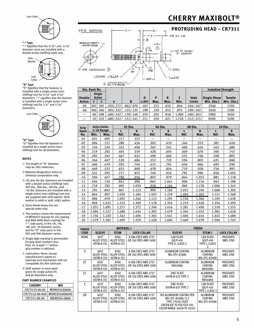
5
Cherry Maxibolt®
Protruding head – Cr7311
Lock Collar
“-” type “-” Signifies that the 5/3�" and 3/16" diameter sizes are installed with a double action (shifting type) tool.
Shift Washer
Lock Collar
“s” type “S” Signifies that the fastener is installed with a single action (non-shifting) tool for 5/3�" and 3/16" diameters. “-” signifies that the fastener is installed with a single action (non-shifting) tool for 1/4" and 5/16" diameters.
Lock Collar
“u” type “U” Signifies that the fastener is installed by a single action (non-shifting) tool for all diameters.
notes
➀ The length of “D” diameter may be .00� undersize.
➁ Material designation refers to chemical composition only.
➂ -05 and -06 dia. fasteners are installed with a double action (shifting) tool; S05 dia., S06 dia., -08 dia., and -10 dia. fasteners are installed with a single action (non-shifting) tool and are supplied with shift washer. Shift washer is solid or split, mfg’s option.
4. Sizes below heavy line are special order only.
5. This product meets the requirements of MS90353 (except for zinc plating and NAS 4006 Alum coating) for “-” code parts, in the -05, -06, -08, and -10 diameter series; and for “S” code parts in the S05 and S06 diameter series.
➅ Single digit marking is permissible for grip dash numbers less than 10. A dash “-” before grip number is optional.
7. Lubrication: None, except manufacturer’s option to lubricate lock mechanism with lox compatible dry film lubricant.
➇ Shift washer or stem dyed green for single action 05 and 06 diameters only.
Part nuMber exaMPles
Cherry MsCR7311S-06-04 MS90354S0604
CR7311U-06-04D MS90354U0604DCR7311-06-04 MS90354-0604
➂
dia. dash no.
a bd
±.001P
Max.r
Max.Z
Min.hole
limits
installed strength
doubleaction
single action single shear
Min. (lbs.)tensile
Min. (lbs.)s u
-05 S05 U05 .�50/.�7� .06�/.070 .163 .�15 .010 .844 .164/.167 �340 1350-06 S06 U06 .305/.33� .1�5/.135 .198 .�50 .015 .875 .199/.�0� 3450 �100— -08 U08 .400/.43� .130/.140 .�59 .305 .018 1.000 .�60/.�63 5900 3650— -10 U10 .480/.5�� .131/.141 .311 .350 .0�1 1.�18 .31�/.315 8500 5�00
gripdashno.
grip limits 1/16 range
05 dia. 06 dia. 08 dia. 10 dia.l
ref.K
Max.l
ref.K
Max.l
ref.K
Max.l
ref.K
Max.Min. Max.-01 .031 .095 .�17 .37� — — — — — —-0� .094 .157 .�80 .434 .303 .479 .344 .553 .381 .618-03 .156 .��0 .34� .496 .365 .541 .406 .616 .443 .680-04 .�19 .�8� .405 .559 .4�8 .604 .469 .678 .506 .743-05 .�81 .345 .467 .6�� .490 .666 .531 .740 .568 .805-06 .344 .407 .530 .684 .553 .7�9 .594 .803 .631 .868-07 .406 .470 .59� .746 .615 .791 .656 .866 .693 .930-08 .469 .53� .655 .809 .678 .854 .719 .9�8 .756 .993-09 .531 .595 .717 .87� .740 .916 .781 .990 .818 1.055-10 .594 .657 .780 .934 .803 .979 .844 1.053 .881 1.118-11 .656 .7�0 .84� .996 .865 1.041 .906 1.116 .943 1.180-1� .719 .78� .905 1.059 .9�8 1.104 .969 1.178 1.006 1.�43-13 .781 .845 .967 1.1�� .990 1.166 1.031 1.�40 1.068 1.305-14 .844 .907 1.030 1.184 1.503 1.��9 1.094 1.303 1.131 1.368-15 .906 .970 1.09� 1.�46 1.115 1.�91 1.156 1.366 1.193 1.430-16 .969 1.03� 1.155 1.309 1.178 1.354 1.�19 1.4�8 1.�56 1.493-17 1.031 1.095 1.�17 1.37� 1.�40 1.416 1.�81 1.490 1.318 1.555-18 1.094 1.157 1.�80 1.434 1.303 1.479 1.344 1.553 1.381 1.618-19 1.156 1.��0 1.34� 1.496 1.365 1.541 1.406 1.616 1.443 1.680-�0 1.�19 1.�8� 1.405 1.559 1.4�8 1.604 1.469 1.678 1.506 1.743
finishCode
Material➁ finishsleeve steM loCK Collar sleeve steM➇ loCK Collar
NoNe 4037 ALLoy SteeL AStM-A-331
8740 ALLoy SteeLAStM-A-331
A-286 CReS AMS 5737oR 316 CReS AMS 5690
CAD PLAte QQ-P-416
tyPe II, CLASS 2
CAD PLAteQQ-P-416
tyPe 1, CLASS 3
PASSIvAteAMS 2700
D 4037 ALLoy SteeL AStM-A-331
8740 ALLoy SteeLAStM-A-331
A-286 CReS AMS 5737oR 316 CReS AMS 5690
ALUMINUM CoAtINgMIL-DtL-83488
ALUMINUM CoAtINg
MIL-DtL-83488
PASSIvAteAMS 2700
ee 4037 ALLoy SteeL AStM-A-331
8740 ALLoy SteeLAStM-A-331
A-286 CReS AMS 5737 oR 316 CReS AMS 5690
ALUMINUM CoAtINgNAS4006
ALUMINUM CoAtINgNAS4006
PASSIvAteAMS 2700
eZ 4037 ALLoy SteeL AStM-A-331
8740 ALLoy SteeLAStM-A-331
A-286 CReS AMS 5737 oR 316 CReS AMS 5690
ZINC PLAte AStM-B-633 tyPe 2
ALUMINUM CoAtINgNAS4006
PASSIvAteAMS 2700
Z 4037 ALLoy SteeL AStM-A-331
8740 ALLoy SteeLAStM-A-331
A-286 CReS AMS 5737 oR 316 CReS AMS 5690
ZINC PLAte AStM-B-633 tyPe 2
CAD PLAte QQ-P-416
tyPe I, CLASS 3
PASSIvAteAMS 2700
DD 4037 ALLoy SteeL AStM-A-331
8740 ALLoy SteeLAStM-A-331
A-286 CReS AMS 5737 oR 316 CReS AMS 5690
IvD ALUMINUM CoAtINg PeR MIL-DtL-83488, CL3 tyPe 2 PLUS LIght
gReeN DIe to FeD-StD-595CoLoR RANge 34670 to 34325
ALUMINUM CoAtINg
MIL-DtL-83488
PASSIvAteAMS 2700
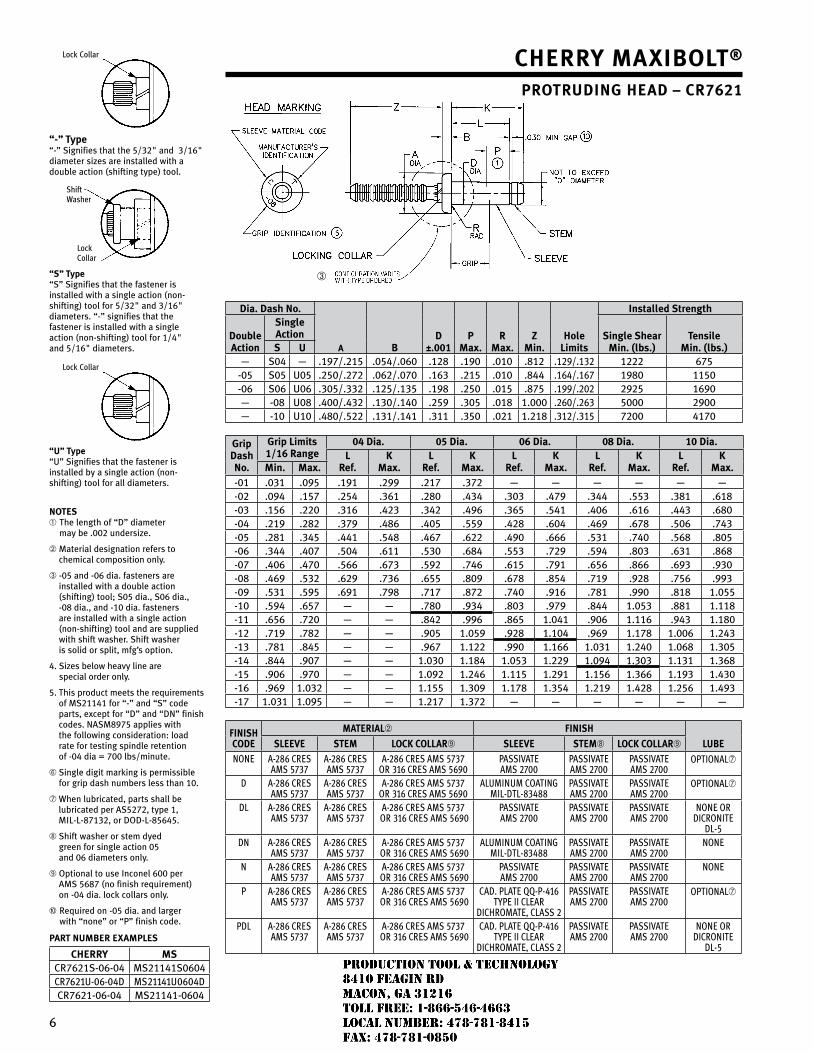
6
Cherry Maxibolt®
Protruding head – Cr7621
Lock Collar
“-” type“-” Signifies that the 5/3�" and 3/16" diameter sizes are installed with a double action (shifting type) tool.
Shift Washer
Lock Collar
“s” type “S” Signifies that the fastener is installed with a single action (non-shifting) tool for 5/3�" and 3/16" diameters. “-” signifies that the fastener is installed with a single action (non-shifting) tool for 1/4" and 5/16" diameters.
Lock Collar
“u” type “U” Signifies that the fastener is installed by a single action (non-shifting) tool for all diameters.
notes➀ The length of “D” diameter
may be .00� undersize.
➁ Material designation refers to chemical composition only.
➂ -05 and -06 dia. fasteners are installed with a double action (shifting) tool; S05 dia., S06 dia., -08 dia., and -10 dia. fasteners are installed with a single action (non-shifting) tool and are supplied with shift washer. Shift washer is solid or split, mfg’s option.
4. Sizes below heavy line are special order only.
5. This product meets the requirements of MS�1141 for “-” and “S” code parts, except for “D” and “DN” finish codes. NASM8975 applies with the following consideration: load rate for testing spindle retention of -04 dia = 700 lbs/minute.
➅ Single digit marking is permissible for grip dash numbers less than 10.
➆ When lubricated, parts shall be lubricated per AS5�7�, type 1, MIL-L-8713�, or DOD-L-85645.
➇ Shift washer or stem dyed green for single action 05 and 06 diameters only.
➈ Optional to use Inconel 600 per AMS 5687 (no finish requirement) on -04 dia. lock collars only.
➉ Required on -05 dia. and larger with “none” or “P” finish code.
Part nuMber exaMPles
Cherry MsCR76�1S-06-04 MS�1141S0604CR7621U-06-04D MS21141U0604DCR76�1-06-04 MS�1141-0604
➂
dia. dash no.
a bd
±.001P
Max.r
Max.Z
Min.hole
limits
installed strength
doubleaction
singleaction single shear
Min. (lbs.)tensile
Min. (lbs.)s u— S04 — .197/.�15 .054/.060 .1�8 .190 .010 .81� .1�9/.13� 1��� 675-05 S05 U05 .�50/.�7� .06�/.070 .163 .�15 .010 .844 .164/.167 1980 1150-06 S06 U06 .305/.33� .1�5/.135 .198 .�50 .015 .875 .199/.�0� �9�5 1690— -08 U08 .400/.43� .130/.140 .�59 .305 .018 1.000 .�60/.�63 5000 �900— -10 U10 .480/.5�� .131/.141 .311 .350 .0�1 1.�18 .31�/.315 7�00 4170
gripdashno.
grip limits 1/16 range
04 dia. 05 dia. 06 dia. 08 dia. 10 dia.l
ref.K
Max.l
ref.K
Max.l
ref.K
Max.l
ref.K
Max.l
ref.K
Max.Min. Max.-01 .031 .095 .191 .�99 .�17 .37� — — — — — —-0� .094 .157 .�54 .361 .�80 .434 .303 .479 .344 .553 .381 .618-03 .156 .��0 .316 .4�3 .34� .496 .365 .541 .406 .616 .443 .680-04 .�19 .�8� .379 .486 .405 .559 .4�8 .604 .469 .678 .506 .743-05 .�81 .345 .441 .548 .467 .6�� .490 .666 .531 .740 .568 .805-06 .344 .407 .504 .611 .530 .684 .553 .7�9 .594 .803 .631 .868-07 .406 .470 .566 .673 .59� .746 .615 .791 .656 .866 .693 .930-08 .469 .53� .6�9 .736 .655 .809 .678 .854 .719 .9�8 .756 .993-09 .531 .595 .691 .798 .717 .87� .740 .916 .781 .990 .818 1.055-10 .594 .657 — — .780 .934 .803 .979 .844 1.053 .881 1.118-11 .656 .7�0 — — .84� .996 .865 1.041 .906 1.116 .943 1.180-1� .719 .78� — — .905 1.059 .9�8 1.104 .969 1.178 1.006 1.�43-13 .781 .845 — — .967 1.1�� .990 1.166 1.031 1.�40 1.068 1.305-14 .844 .907 — — 1.030 1.184 1.053 1.��9 1.094 1.303 1.131 1.368-15 .906 .970 — — 1.09� 1.�46 1.115 1.�91 1.156 1.366 1.193 1.430-16 .969 1.03� — — 1.155 1.309 1.178 1.354 1.�19 1.4�8 1.�56 1.493-17 1.031 1.095 — — 1.�17 1.37� — — — — — —
finishCode
Material➁ finish
lubesleeve steM loCK Collar➈ sleeve steM➇ loCK Collar➈
NoNe A-286 CReSAMS 5737
A-286 CReSAMS 5737
A-286 CReS AMS 5737oR 316 CReS AMS 5690
PASSIvAteAMS 2700
PASSIvAteAMS 2700
PASSIvAteAMS 2700
oPtIoNAL➆
D A-286 CReSAMS 5737
A-286 CReSAMS 5737
A-286 CReS AMS 5737oR 316 CReS AMS 5690
ALUMINUM CoAtINgMIL-DtL-83488
PASSIvAteAMS 2700
PASSIvAteAMS 2700
oPtIoNAL➆
DL A-286 CReSAMS 5737
A-286 CReSAMS 5737
A-286 CReS AMS 5737 oR 316 CReS AMS 5690
PASSIvAteAMS 2700
PASSIvAteAMS 2700
PASSIvAteAMS 2700
NoNe oRDICRoNIte
DL-5DN A-286 CReS
AMS 5737A-286 CReSAMS 5737
A-286 CReS AMS 5737 oR 316 CReS AMS 5690
ALUMINUM CoAtINgMIL-DtL-83488
PASSIvAteAMS 2700
PASSIvAteAMS 2700
NoNe
N A-286 CReSAMS 5737
A-286 CReSAMS 5737
A-286 CReS AMS 5737 oR 316 CReS AMS 5690
PASSIvAteAMS 2700
PASSIvAteAMS 2700
PASSIvAteAMS 2700
NoNe
P A-286 CReSAMS 5737
A-286 CReSAMS 5737
A-286 CReS AMS 5737 oR 316 CReS AMS 5690
CAD. PLAte QQ-P-416tyPe II CLeAR
DIChRoMAte, CLASS 2
PASSIvAteAMS 2700
PASSIvAteAMS 2700
oPtIoNAL➆
PDL A-286 CReSAMS 5737
A-286 CReSAMS 5737
A-286 CReS AMS 5737 oR 316 CReS AMS 5690
CAD. PLAte QQ-P-416tyPe II CLeAR
DIChRoMAte, CLASS 2
PASSIvAteAMS 2700
PASSIvAteAMS 2700
NoNe oRDICRoNIte
DL-5
JR
Typewritten text
Production Tool & Technology 8410 Feagin Rd Macon, Ga 31216 Toll Free: 1-866-546-4663 Local Number: 478-781-8415 Fax: 478-781-0850
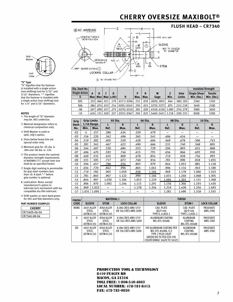
7
➂
Shift Washer
Lock Collar
“s” type “S” Signifies that the fastener is installed with a single action (non-shifting) tool for 5/3�" and 3/16" diameters. “-” signifies that the fastener is installed with a single action (non-shifting) tool for 1/4" and 5/16" diameters.
notes➀ The length of “D” diameter
may be .00� undersize.
➁ Material designation refers to chemical composition only.
➂ Shift Washer is solid or split, mfg's option.
4. Sizes below heavy line are special order only.
➄ Minimum grip for -05 dia. is .094 and -06 dia. is .1�0.
➅ This product meets the nominal diameter strength requirements of NASM81177, except hole size shall be as specified herein.
➆ Single digit marking is permissible for grip dash numbers less than 10. A dash “-” before grip number is optional.
8. Lubrication: None, except manufacturer’s option to lubricate lock mechanism with lox compatible dry film lubricant.
➈ Shift washer or stem dyed green for S05 and S06 diameters only.
Part nUMBer eXaMPles
CherryCR7340S-06-04CR7340-08-04
Cherry oversiZe Maxibolt®
flush head – Cr7340
dia. dash no.
aMax
bMax
CMax
d±.001 h
PMax.
rMax.
w gage
ZMin.
holelimits
installed strengthsingle action single shear
Min. (lbs.)tensile
Min. (lbs.)sS05 .333 .066 .011 .179 .0171/.0�06 .�15 .010 .�830/.�83� .844 .180/.183 �340 1350S06 .386 .074 .013 .�14 0�05/.0�43 .�50 .015 .3�70/.3�7� .875 .�15/.�18 3450 �100-08 .507 .099 .017 .�75 .0�70/.0310 .305 .0�0 .4318/.43�0 1.000 .�76/.�79 5900 3650-10 .634 .131 .0�0 .3�7 .03�5/.0367 .350 .0�5 .5449/.5451 1.�18 .3�8/.331 8500 5�00
gripdashno.
grip limits 1/16 range
05 dia. 06 dia. 08 dia. 10 dia.l
ref.K
Max.l
ref.K
Max.l
ref.K
Max.l
ref.K
Max.Min. Max.-0� ➄ .157 .�80 .434 .3�9 .479 — — — —-03 .156 .��0 .34� .496 .365 .541 .406 .616 — —-04 .�19 .�8� .405 .559 .4�8 .604 .469 .678 .506 .743-05 .�81 .345 .467 .6�� .490 .666 .531 .740 .568 .805-06 .344 .407 .530 .684 .553 .7�9 .594 .803 .631 .868-07 .406 .470 .59� .746 .615 .791 .656 .866 .693 .930-08 .469 .53� .655 .809 .678 .854 .719 .9�8 .756 .993-09 .531 .595 .717 .87� .740 .916 .781 .990 .818 1.055-10 .594 .657 .780 .934 .803 .979 .844 1.053 .881 1.118-11 .656 .7�0 .84� .996 .865 1.041 .906 1.116 .943 1.180-1� .719 .78� .905 1.059 .9�8 1.104 .969 1.178 1.006 1.�43-13 .781 .845 .967 1.1�� .990 1.166 1.031 1.�40 1.068 1.305-14 .844 .907 1.030 1.184 1.053 1.��9 1.094 1.303 1.131 1.368-15 .906 .970 1.09� 1.�46 1.115 1.�91 1.156 1.366 1.193 1.430-16 .969 1.03� — — 1.178 1.354 1.�19 1.4�8 1.�56 1.493-17 1.031 1.095 — — — — 1.�81 1.490 1.318 1.555
finishCode
Material➁ finish
sleeve steM loCK Collar sleeve steM➈ loCK CollarNoNe 4037 ALLoy
SteeLAStM-A-331
8740 ALLoy SteeL
AStM-A-331
A-286 CReS AMS 5737oR 316 CReS AMS 5690
CAD. PLAteQQ-P-416
tyPe II, CLASS 2
CAD. PLAteQQ-P-416
tyPe I, CLASS 3
PASSIvAteAMS 2700
D 4037 ALLoy SteeL
AStM-A-331
8740 ALLoy SteeL
AStM-A-331
A-286 CReS AMS 5737 oR 316 CReS AMS 5690
ALUMINUM CoAtINg MIL-DtL-83488
ALUMINUMCoAtINg
MIL-DtL-83488
PASSIvAteAMS 2700
DD 4037 ALLoy SteeL
AStM-A-331
8740 ALLoy SteeL
AStM-A-331
A-286 CReS AMS 5737 oR 316 CReS AMS 5690
IvD ALUMINUM CoAtINg PeR MIL-DtL-83488, CL3 tyPe 2 PLUS LIght
gReeN DIe to FeD-StD-595CoLoR RANge 34670 to 34325
ALUMINUMCoAtINg
MIL-DtL-83488
PASSIvAteAMS 2700
JR
Typewritten text
Production Tool & Technology 8410 Feagin Rd Macon, Ga 31216 Toll Free: 1-866-546-4663 Local Number: 478-781-8415 Fax: 478-781-0850
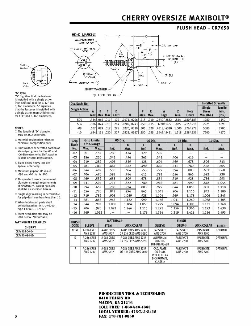
8
Shift Washer
Lock Collar
“s” type “S” Signifies that the fastener is installed with a single action (non-shifting) tool for 5/3�" and 3/16" diameters. “-” signifies that the fastener is installed with a single action (non-shifting) tool for 1/4" and 5/16" diameters.
notes➀ The length of “D” diameter
may be .00� undersize.
➁ Material designation refers to chemical composition only.
➂ Shift washer or serrated portion of stem dyed green for the -05 and -06 diameters only. Shift washer is solid or split, mfg’s option.
4. Sizes below heavy line are special order only.
➄ Minimum grip for -05 dia. is .094 and -06 dia. is .100.
➅ This product meets the nominal diameter strength requirements of NASM8975, except hole size shall be as specified herein.
➆ Single digit marking is permissible for grip dash numbers less than 10.
➇ When lubricated, parts shall be lubricated per MIL-L-46010, type 1 or MIL-L-8713�.
➈ Stem head diameter may be .00� below “D Dia” Min.
Part nUMBer eXaMPles
CherryCR7650S-06-04CR7650-08-04D
Cherry oversiZe Maxibolt® flush head – Cr7650
➂
dia. dash no.
aMax
bMax
CMax
d±.001 h
PMax.
rMax.
w gage
ZMin.
holelimits
installed strength
single action single shear
Min. (lbs.)
tensileMin. (lbs.)s
S05 .334 .066 .011 .179 .0171/.0�06 .�15 .010 .�830/.�83� .844 .180/.183 1980 1150S06 .386 .074 .013 .�14 .0�05/.0�43 .�50 .015 .3�70/3�7� .875 .�15/.�18 �9�5 1690-08 .507 .099 .017 .�75 .0�70/.0310 .305 .0�0 .4318/.43�0 1.000 .�76/.�79 5000 �900-10 .634 .131 .0�0 .3�7 .03�5/.0367 .350 .0�5 .5449/.5451 1.�18 .3�8/.331 7�00 4170
gripdashno.
grip limits 1/16 range
05 dia. 06 dia. 08 dia. 10 dia.l
ref.K
Max.l
ref.K
Max.l
ref.K
Max.l
ref.K
Max.Min. Max.-0� ➄ .157 .�80 .434 .3�9 .505 — — — —-03 .156 .��0 .34� .496 .365 .541 .406 .616 — —-04 .�19 .�8� .405 .559 .4�8 .604 .469 .678 .506 .743-05 .�81 .345 .467 .6�� .490 .666 .531 .740 .568 .805-06 .344 .407 .530 .684 .553 .7�9 .594 .803 .631 .868-07 .406 .470 .59� .746 .615 .791 .656 .866 .693 .930-08 .469 .53� .655 .809 .678 .854 .719 .9�8 .756 .993-09 .531 .595 .717 .87� .740 .916 .781 .990 .818 1.055-10 .594 .657 .780 .934 .803 .979 .844 1.053 .881 1.118-11 .656 .7�0 .84� .996 .865 1.041 .906 1.116 .943 1.180-1� .719 .78� .905 1.059 .9�8 1.104 .969 1.178 1.006 1.�43-13 .781 .845 .967 1.1�� .990 1.166 1.031 1.�40 1.068 1.305-14 .844 .907 1.030 1.184 1.053 1.��9 1.094 1.303 1.131 1.368-15 .906 .970 1.09� 1.�46 1.115 1.�91 1.156 1.366 1.193 1.430-16 .969 1.03� . — . — 1.178 1.354 1.�19 1.4�8 1.�56 1.493
finishCode
Material➁ finish
lube➇sleeve steM loCK Collar sleeve steM➂ loCK CollarNoNe A-286 CReS
AMS 5737A-286 CReSAMS 5737
A-286 CReS AMS 5737oR 316 CReS AMS 5690
PASSIvAteAMS 2700
PASSIvAteAMS 2700
PASSIvAteAMS 2700
oPtIoNAL
D A-286 CReSAMS 5737
A-286 CReSAMS 5737
A-286 CReS AMS 5737oR 316 CReS AMS 5690
ALUMINUMCoAtINg
MIL-DtL-83488
PASSIvAteAMS 2700
PASSIvAteAMS 2700
oPtIoNAL
P A-286 CReSAMS 5737
A-286 CReSAMS 5737
A-286 CReS AMS 5737 oR 316 CReS AMS 5690
CAD. PLAte QQ-P-416
tyPe II, CLeARDIChRoMAte,
CLASS 2
PASSIvAteAMS 2700
PASSIvAteAMS 2700
oPtIoNAL
JR
Typewritten text
Production Tool & Technology 8410 Feagin Rd Macon, Ga 31216 Toll Free: 1-866-546-4663 Local Number: 478-781-8415 Fax: 478-781-0850
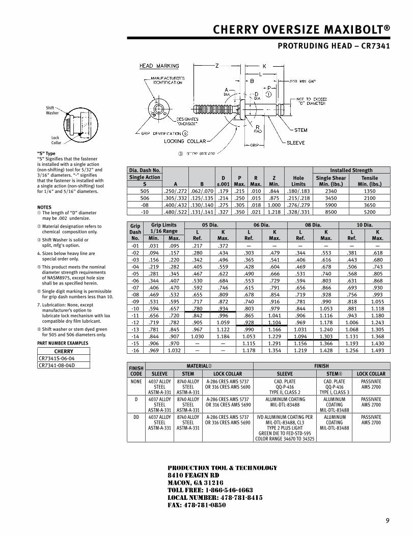
9
Shift Washer
Lock Collar
“s” type “S” Signifies that the fastener is installed with a single action (non-shifting) tool for 5/3�" and 3/16" diameters. “-” signifies that the fastener is installed with a single action (non-shifting) tool for 1/4" and 5/16" diameters.
notes➀ The length of “D” diameter
may be .00� undersize.
➁ Material designation refers to chemical composition only.
➂ Shift Washer is solid or split, mfg's option.
4. Sizes below heavy line are special order only.
➄ This product meets the nominal diameter strength requirements of NASM8975, except hole size shall be as specified herein.
➅ Single digit marking is permissible for grip dash numbers less than 10.
7. Lubrication: None, except manufacturer’s option to lubricate lock mechanism with lox compatible dry film lubricant.
➇ Shift washer or stem dyed green for S05 and S06 diameters only.
Part nUMBer eXaMPles
CherryCR7341S-06-04CR7341-08-04D
Cherry oversiZe Maxibolt®
Protruding head – Cr7341
➂
dia. dash no.
a bd
±.001P
Max.r
Max.Z
Min.hole
limits
installed strengthsingle action single shear
Min. (lbs.)tensile
Min. (lbs.)sS05 .�50/.�7� .06�/.070 .179 .�15 .010 .844 .180/.183 �340 1350S06 .305/.33� .1�5/.135 .�14 .�50 .015 .875 .�15/.�18 3450 �100-08 .400/.43� .130/.140 .�75 .305 .018 1.000 .�76/.�79 5900 3650-10 .480/.5�� .131/.141 .3�7 .350 .0�1 1.�18 .3�8/.331 8500 5�00
gripdashno.
grip limits 1/16 range
05 dia. 06 dia. 08 dia. 10 dia.l
ref.K
Max.l
ref.K
Max.l
ref.K
Max.l
ref.K
Max.Min. Max.-01 .031 .095 .�17 .37� — — — — — —-0� .094 .157 .�80 .434 .303 .479 .344 .553 .381 .618-03 .156 .��0 .34� .496 .365 .541 .406 .616 .443 .680-04 .�19 .�8� .405 .559 .4�8 .604 .469 .678 .506 .743-05 .�81 .345 .467 .6�� .490 .666 .531 .740 .568 .805-06 .344 .407 .530 .684 .553 .7�9 .594 .803 .631 .868-07 .406 .470 .59� .746 .615 .791 .656 .866 .693 .930-08 .469 .53� .655 .809 .678 .854 .719 .9�8 .756 .993-09 .531 .595 .717 .87� .740 .916 .781 .990 .818 1.055-10 .594 .657 .780 .934 .803 .979 .844 1.053 .881 1.118-11 .656 .7�0 .84� .996 .865 1.041 .906 1.116 .943 1.180-1� .719 .78� .905 1.059 .9�8 1.104 .969 1.178 1.006 1.�43-13 .781 .845 .967 1.1�� .990 1.166 1.031 1.�40 1.068 1.305-14 .844 .907 1.030 1.184 1.053 1.��9 1.094 1.303 1.131 1.368-15 .906 .970 — — 1.115 1.�91 1.156 1.366 1.193 1.430-16 .969 1.03� — — 1.178 1.354 1.�19 1.4�8 1.�56 1.493
finishCode
Material➁ finish
sleeve steM loCK Collar sleeve steM➇ loCK CollarNoNe 4037 ALLoy
SteeLAStM-A-331
8740 ALLoy SteeL
AStM-A-331
A-286 CReS AMS 5737oR 316 CReS AMS 5690
CAD. PLAteQQ-P-416
tyPe II, CLASS 2
CAD. PLAteQQ-P-416
tyPe I, CLASS 3
PASSIvAteAMS 2700
D 4037 ALLoy SteeL
AStM-A-331
8740 ALLoy SteeL
AStM-A-331
A-286 CReS AMS 5737 oR 316 CReS AMS 5690
ALUMINUM CoAtINg MIL-DtL-83488
ALUMINUMCoAtINg
MIL-DtL-83488
PASSIvAteAMS 2700
DD 4037 ALLoy SteeL
AStM-A-331
8740 ALLoy SteeL
AStM-A-331
A-286 CReS AMS 5737 oR 316 CReS AMS 5690
IvD ALUMINUM CoAtINg PeR MIL-DtL-83488, CL3 tyPe 2 PLUS LIght
gReeN DIe to FeD-StD-595CoLoR RANge 34670 to 34325
ALUMINUMCoAtINg
MIL-DtL-83488
PASSIvAteAMS 2700
JR
Typewritten text
Production Tool & Technology 8410 Feagin Rd Macon, Ga 31216 Toll Free: 1-866-546-4663 Local Number: 478-781-8415 Fax: 478-781-0850
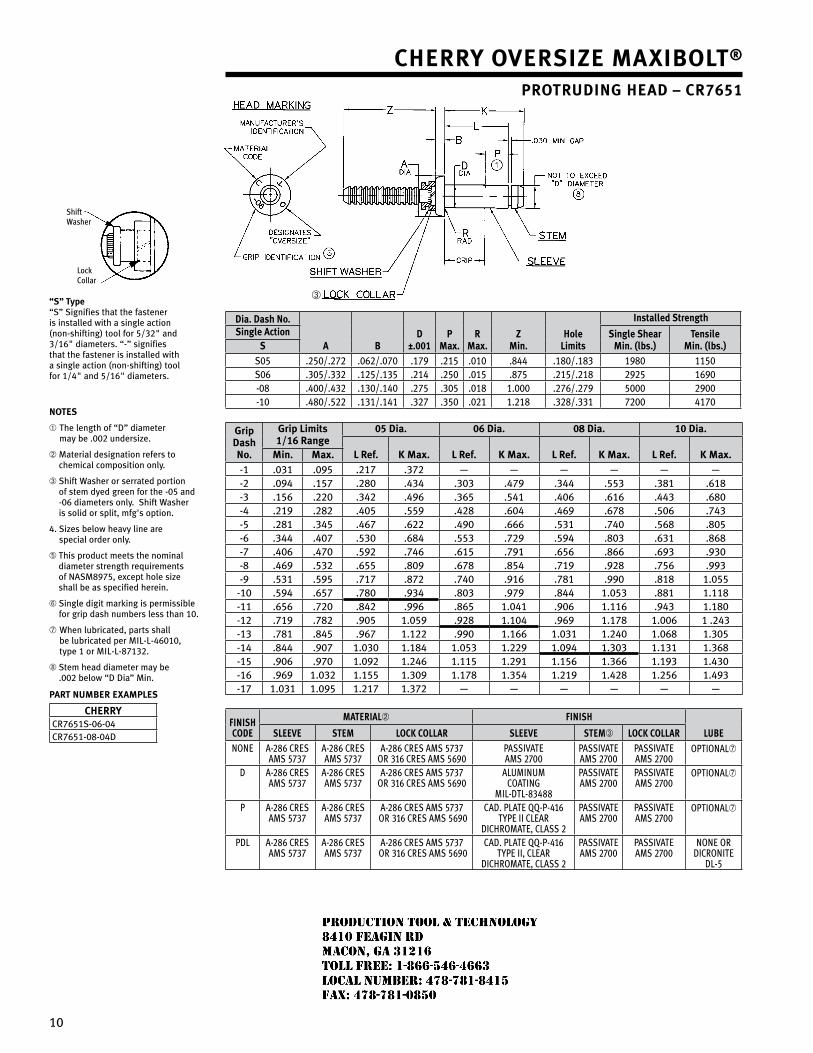
10
Shift Washer
Lock Collar
“s” type “S” Signifies that the fastener is installed with a single action (non-shifting) tool for 5/3�" and 3/16" diameters. “-” signifies that the fastener is installed with a single action (non-shifting) tool for 1/4" and 5/16" diameters.
notes
➀ The length of “D” diameter may be .00� undersize.
➁ Material designation refers to chemical composition only.
➂ Shift Washer or serrated portion of stem dyed green for the -05 and -06 diameters only. Shift Washer is solid or split, mfg's option.
4. Sizes below heavy line are special order only.
➄ This product meets the nominal diameter strength requirements of NASM8975, except hole size shall be as specified herein.
➅ Single digit marking is permissible for grip dash numbers less than 10.
➆ When lubricated, parts shall be lubricated per MIL-L-46010, type 1 or MIL-L-8713�.
➇ Stem head diameter may be .00� below “D Dia” Min.
Part nuMber exaMPles
CherryCR7651S-06-04CR7651-08-04D
Cherry oversiZe Maxibolt®
Protruding head – Cr7651
➂
dia. dash no.
a bd
±.001P
Max.r
Max.Z
Min.hole
limits
installed strengthsingle action single shear
Min. (lbs.)tensile
Min. (lbs.)sS05 .�50/.�7� .06�/.070 .179 .�15 .010 .844 .180/.183 1980 1150S06 .305/.33� .1�5/.135 .�14 .�50 .015 .875 .�15/.�18 �9�5 1690-08 .400/.43� .130/.140 .�75 .305 .018 1.000 .�76/.�79 5000 �900-10 .480/.5�� .131/.141 .3�7 .350 .0�1 1.�18 .3�8/.331 7�00 4170
gripdashno.
grip limits1/16 range
05 dia. 06 dia. 08 dia. 10 dia.
l ref. K Max. l ref. K Max. l ref. K Max. l ref. K Max.Min. Max.-1 .031 .095 .�17 .37� — — — — — —-� .094 .157 .�80 .434 .303 .479 .344 .553 .381 .618-3 .156 .��0 .34� .496 .365 .541 .406 .616 .443 .680-4 .�19 .�8� .405 .559 .4�8 .604 .469 .678 .506 .743-5 .�81 .345 .467 .6�� .490 .666 .531 .740 .568 .805-6 .344 .407 .530 .684 .553 .7�9 .594 .803 .631 .868-7 .406 .470 .59� .746 .615 .791 .656 .866 .693 .930-8 .469 .53� .655 .809 .678 .854 .719 .9�8 .756 .993-9 .531 .595 .717 .87� .740 .916 .781 .990 .818 1.055
-10 .594 .657 .780 .934 .803 .979 .844 1.053 .881 1.118-11 .656 .7�0 .84� .996 .865 1.041 .906 1.116 .943 1.180-1� .719 .78� .905 1.059 .9�8 1.104 .969 1.178 1.006 1 .�43-13 .781 .845 .967 1.1�� .990 1.166 1.031 1.�40 1.068 1.305-14 .844 .907 1.030 1.184 1.053 1.��9 1.094 1.303 1.131 1.368-15 .906 .970 1.09� 1.�46 1.115 1.�91 1.156 1.366 1.193 1.430-16 .969 1.03� 1.155 1.309 1.178 1.354 1.�19 1.4�8 1.�56 1.493-17 1.031 1.095 1.�17 1.37� — — — — — —
FinishCode
Material➁ Finish
lUBesleeve steM loCk Collar sleeve steM➂ loCk CollarNoNe A-286 CReS
AMS 5737A-286 CReSAMS 5737
A-286 CReS AMS 5737oR 316 CReS AMS 5690
PASSIvAteAMS 2700
PASSIvAteAMS 2700
PASSIvAteAMS 2700
oPtIoNAL➆
D A-286 CReSAMS 5737
A-286 CReSAMS 5737
A-286 CReS AMS 5737oR 316 CReS AMS 5690
ALUMINUMCoAtINg
MIL-DtL-83488
PASSIvAteAMS 2700
PASSIvAteAMS 2700
oPtIoNAL➆
P A-286 CReSAMS 5737
A-286 CReSAMS 5737
A-286 CReS AMS 5737 oR 316 CReS AMS 5690
CAD. PLAte QQ-P-416tyPe II CLeAR
DIChRoMAte, CLASS 2
PASSIvAteAMS 2700
PASSIvAteAMS 2700
oPtIoNAL➆
PDL A-286 CReSAMS 5737
A-286 CReSAMS 5737
A-286 CReS AMS 5737 oR 316 CReS AMS 5690
CAD. PLAte QQ-P-416tyPe II, CLeAR
DIChRoMAte, CLASS 2
PASSIvAteAMS 2700
PASSIvAteAMS 2700
NoNe oRDICRoNIte
DL-5
JR
Typewritten text
Production Tool & Technology 8410 Feagin Rd Macon, Ga 31216 Toll Free: 1-866-546-4663 Local Number: 478-781-8415 Fax: 478-781-0850
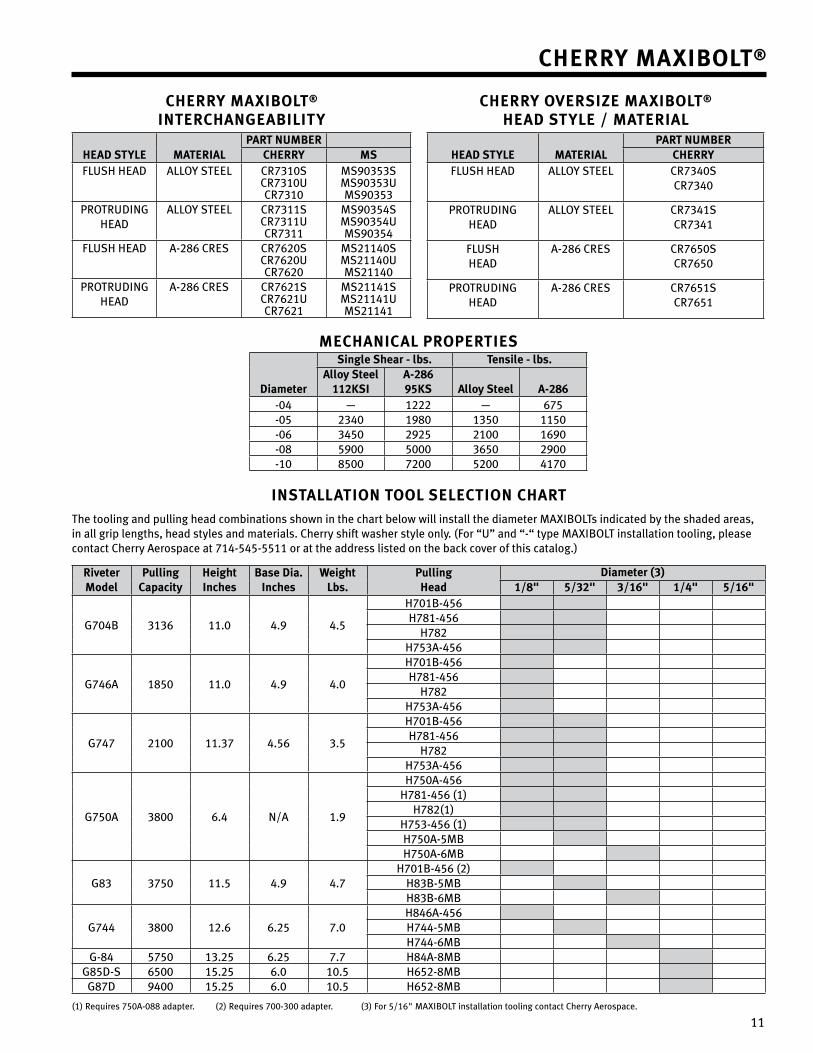
11
Cherry Maxibolt® interChangeability
head style MaterialPart nuMber
Cherry MsFLUSH HEAD ALLOy STEEL CR7310S
CR7310UCR7310
MS90353SMS90353UMS90353
PROTRUDINg HEAD
ALLOy STEEL CR7311SCR7311UCR7311
MS90354SMS90354UMS90354
FLUSH HEAD A-�86 CRES CR76�0SCR76�0UCR76�0
MS�1140SMS�1140UMS�1140
PROTRUDINg HEAD
A-�86 CRES CR76�1SCR76�1UCR76�1
MS�1141SMS�1141UMS�1141
MeChaniCal ProPerties
diameter
single shear - lbs. tensile - lbs.alloy steel
112Ksia-28695Ks alloy steel a-286
-04 — 1��� — 675-05 �340 1980 1350 1150-06 3450 �9�5 �100 1690-08 5900 5000 3650 �900-10 8500 7�00 5�00 4170
Cherry Maxibolt®
installation tool seleCtion ChartThe tooling and pulling head combinations shown in the chart below will install the diameter MAXIBOLTs indicated by the shaded areas, in all grip lengths, head styles and materials. Cherry shift washer style only. (For “U” and “-“ type MAXIBOLT installation tooling, please contact Cherry Aerospace at 714-545-5511 or at the address listed on the back cover of this catalog.)
riveter Model
PullingCapacity
heightinches
base dia.inches
weightlbs.
Pullinghead
diameter (3)1/8" 5/32" 3/16" 1/4" 5/16"
g704B 3136 11.0 4.9 4.5
H701B-456H781-456
H78�H753A-456
g746A 1850 11.0 4.9 4.0
H701B-456H781-456
H78�H753A-456
g747 �100 11.37 4.56 3.5
H701B-456H781-456
H78�H753A-456
g750A 3800 6.4 N/A 1.9
H750A-456H781-456 (1)
H78�(1)H753-456 (1)H750A-5MBH750A-6MB
g83 3750 11.5 4.9 4.7H701B-456 (�)
H83B-5MBH83B-6MB
g744 3800 1�.6 6.�5 7.0H846A-456H744-5MBH744-6MB
g-84 5750 13.�5 6.�5 7.7 H84A-8MBg85D-S 6500 15.�5 6.0 10.5 H65�-8MBg87D 9400 15.�5 6.0 10.5 H65�-8MB
(1) Requires 750A-088 adapter. (�) Requires 700-300 adapter. (3) For 5/16" MAXIBOLT installation tooling contact Cherry Aerospace.
Cherry oversiZe Maxibolt® head style / Material
head style MaterialPart nuMber
CherryFLUSH HEAD ALLOy STEEL CR7340S
CR7340
PROTRUDINg HEAD
ALLOy STEEL CR7341SCR7341
FLUSH HEAD
A-�86 CRES CR7650SCR7650
PROTRUDINg HEAD
A-�86 CRES CR7651SCR7651
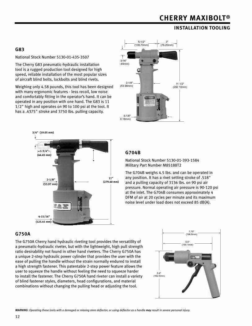
1�
g83
National Stock Number 5130-01-435-3507
The Cherry g83 pneumatic-hydraulic installation tool is a rugged production tool designed for high speed, reliable installation of the most popular sizes of aircraft blind bolts, lockbolts and blind rivets.
Weighing only 4.58 pounds, this tool has been designed with many ergonomic features - less recoil, low noise and comfortably fitting in the operator’s hand. It can be operated in any position with one hand. The g83 is 11 1/�" high and operates on 90 to 100 psi at the tool. It has a .4375" stroke and 3750 lbs. pulling capacity.
g704b
National Stock Number 5130-01-393-1584 Military Part Number M85188T�
The g704B weighs 4.5 lbs. and can be operated in any position. It has a rivet setting stroke of .518" and a pulling capacity of 3136 lbs. on 90 psi air pressure. Normal operating air pressure is 90-1�0 psi at the inlet. The g704B consumes approximately 4 DFM of air at �0 cycles per minute and its maximum noise level under load does not exceed 85 dB(A).
g750a
The g750A Cherry hand hydraulic riveting tool provides the versatility of a pneumatic-hydraulic riveter, but with the lightweight, high pull strength ratio desirability not found in other hand riveters. The Cherry g750A has a unique �-step hydraulic power cylinder that provides the user with the ease of pulling the handle without the strain normally endured to install a high strength fastener. This patentable �-step power feature allows the user to squeeze the handle without feeling the need to squeeze harder to install the fastener. The Cherry g750A hand riveter can install a variety of blind fastener styles, diameters, head configurations, and material combinations without changing the pulling head or adjusting the tool.
WARNING: Operating these tools with a damaged or missing stem deflector, or using deflector as a handle may result in severe personal injury.
?
?
*
2-1/8"
(53.97 mm)
3/4" (19.05 mm)
1-3/4"(44.45 mm)
4-15/16"
(125.41 mm)
11"(279.40 mm)
Cherry Maxibolt® installation tooling
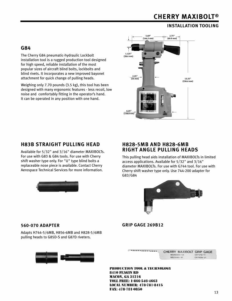
13
g84The Cherry g84 pneumatic-hydraulic Lockbolt installation tool is a rugged production tool designed for high speed, reliable installation of the most popular sizes of aircraft blind bolts, lockbolts and blind rivets. It incorporates a new improved bayonet attachment for quick change of pulling heads.
Weighing only 7.70 pounds (3.5 kg), this tool has been designed with many ergonomic features - less recoil, low noise and comfortably fitting in the operator’s hand. It can be operated in any position with one hand.
h83b straight Pulling headAvailable for 5/3�" and 3/16" diameter MAXIBOLTs. For use with g83 & g84 tools. For use with Cherry shift washer type only. For "U" type blind bolts a replaceable nose piece is available. Contact Cherry Aerospace Technical Services for more information.
h828-5Mb and h828-6Mb right angle Pulling headsThis pulling head aids installation of MAXIBOLTs in limited access applications. Available for 5/3�" and 3/16" diameter MAXIBOLTs. For use with g744 tool. For use with Cherry shift washer type only. Use 744-�00 adapter for g83/g84
560-070 adaPter
Adapts H744-5/6MB, H856-6MB and H8�8-5/6MB pulling heads to g85D-S and g87D riveters.
griP gage 269b12
?
?
13.25"(336.6 mm)
6.25"(158.8 mm)
2.25"(54 mm)
1.125"(28.6 mm)
5.69"(144.5 mm)
2.75"(69.9 mm)
Cherry Maxibolt® installation tooling
JR
Typewritten text
Production Tool & Technology 8410 Feagin Rd Macon, Ga 31216 Toll Free: 1-866-546-4663 Local Number: 478-781-8415 Fax: 478-781-0850
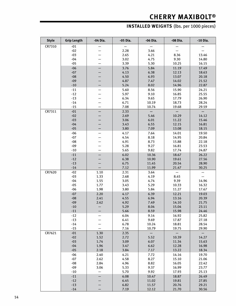
14
style grip length -04 dia. -05 dia. -06 dia. -08 dia. -10 dia.
CR7310 -01-0�-03-04-05
—————
—�.�8�.653.0�3.39
—3.664.�14.755.30
——
8.369.30
10.�5
——
13.4614.8016.15
-06-07-08-09-10
—————
3.764.134.504.875.�4
5.846.386.937.478.0�
11.191�.1313.0714.0�14.96
17.4918.63�0.18�1.5���.87
-11-1�-13-14-15
—————
5.605.976.346.717.08
8.569.109.65
10.1910.74
15.9016.8517.7918.7319.68
�4.�1�5.55�6.90�8.�4�9.59
CR7311 -01-0�-03-04-05
—————
�.33�.693.063.433.80
—5.466.016.557.09
—10.�911.��1�.1513.08
—14.1�15.4616.8118.15
-06-07-08-09-10
—————
4.174.544.915.�85.65
7.648.188.739.�79.8�
14.0114.9515.8816.8117.74
19.50�0.84��.18�3.53�4.87
-11-1�-13-14
————
6.0�6.386.757.1�
10.3610.9011.4511.99
18.6719.61�0.54�1.47
�6.���7.56�8.9030.�5
CR76�0 -0�-03-04-05-06
1.101.331.551.771.98
�.31�.683.053.433.80
3.644.194.745.�95.84
—8.459.39
10.3311.�7
——
14.9616.3�17.67
-07-08-09-10-11
�.�0�.41�.6�
——
4.174.554.9�5.�95.66
6.396.947.498.048.59
1�.�113.1614.1015.0415.98
19.03�0.39�1.75�3.11�4.46
-1�-13-14-15
————
6.046.416.787.16
9.149.69
10.�410.79
16.9�17.8718.8119.75
�5.8��7.18�8.54�9.90
CR76�1 -01-0�-03-04-05
1.301.5�1.741.96�.18
�.35�.7�3.093.473.84
—5.5�6.076.6�7.17
—10.3911.341�.�813.��
—14.�715.6316.9818.34
-06-07-08-09-10
�.40�.6��.843.06
—
4.�14.584.965.335.70
7.7�8.�78.8�9.379.9�
14.1615.1016.0516.9917.93
19.70�1.06��.4��3.77�5.13
-11-1�-13-14
————
6.086.456.8�7.19
10.4711.0�11.571�.1�
18.8719.81�0.76�1.70
�6.49�7.85�9.�130.56
Cherry Maxibolt®
installed weights (lbs. per 1000 pieces)
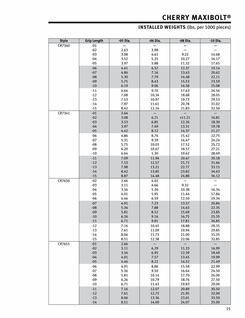
15
Cherry Maxibolt®
installed weights (lbs. per 1000 pieces)
style grip length -05 dia. -06 dia. -08 dia. -10 dia.CR7340 -01
-0�-03-04-05
—�.633.083.5�3.97
—3.984.615.�55.88
——
9.��10.�711.3�
——
14.6816.1717.65
-06-07-08-09-10
4.414.865.305.756.19
6.5�7.167.798.439.06
1�.3713.4314.4815.5316.58
19.14�0.6���.11�3.59�5.08
-11-1�-13-14-15
6.647.087.537.978.4�
9.7010.3410.9711.611�.�4
17.6318.6819.73�0.78�1.83
�6.56�8.05�9.5331.0�3�.50
CR7341 -01-0�-03-04-05
�.643.083.533.974.4�
—6.�16.857.498.1�
—v11.�11�.�613.3114.37
—16.8118.3019.78�1.�7
-06-07-08-09-10
4.865.315.756.�06.64
8.769.39
10.0310.671.30
15.4�16.4717.5�18.5719.6�
��.75�4.�4�5.7��7.�1�8.69
-11-1�-13-14-15
7.097.537.988.4�8.87
11.941�.5713.�113.8514.48
�0.67�1.7���.77�3.8��4.88
30.1831.6633.1534.6336.1�
CR7650 -0�-03-04-05-06
�.663.113.564.014.46
4.0�4.665.305.956.59
—9.3�
10.3811.441�.50
——
16.3417.8419.34
-07-08-09-10-11
4.915.365.816.�66.71
7.�37.888.5�9.169.81
13.5714.6315.6916.7517.81
�0.84��.35�3.85�5.35�6.85
-1�-13-14-15
7.167.618.068.51
10.4511.0911.731�.38
18.8819.94�1.00��.06
�8.35�9.8531.353�.85
CR7651 -01-0�-03-04-05
�.663.113.564.014.46
—6.�96.937.578.��
—11.331�.3913.4514.5�
—16.9918.4919.99�1.49
-06-07-08-09-10
4.915.365.816.�66.71
8.869.50
10.1410.7911.43
15.5816.6417.7018.7619.83
��.99�4.50�6.00�7.50�9.00
-11-1�-13-14
7.167.618.068.51
1�.071�.7�13.3614.00
�0.89�1.95�3.01�4.07
30.503�.0033.5035.00
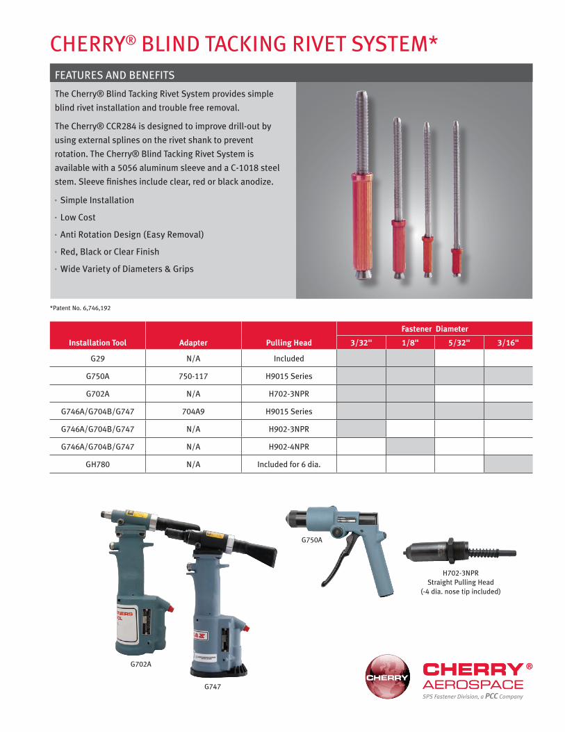
G702A
Cherry® Blind TACkinG riveT SySTem*
*Patent no. 6,746,192
FeATureS And BeneFiTS
The Cherry® Blind Tacking rivet System provides simple
blind rivet installation and trouble free removal.
The Cherry® CCr284 is designed to improve drill-out by
using external splines on the rivet shank to prevent
rotation. The Cherry® Blind Tacking rivet System is
available with a 5056 aluminum sleeve and a C-1018 steel
stem. Sleeve finishes include clear, red or black anodize.
Simple installation °
low Cost °
Anti rotation design (easy removal) °
red, Black or Clear Finish °
Wide variety of diameters & Grips °
Installation Tool Adapter Pulling Head
Fastener Diameter
3/32" 1/8" 5/32" 3/16"
G29 n/A included
G750A 750-117 h9015 Series
G702A n/A h702-3nPr
G746A/G704B/G747 704A9 h9015 Series
G746A/G704B/G747 n/A h902-3nPr
G746A/G704B/G747 n/A h902-4nPr
Gh780 n/A included for 6 dia.
G750A
h702-3nPr Straight Pulling head
(-4 dia. nose tip included)
G747SPS Fastener Division, a PCC Company
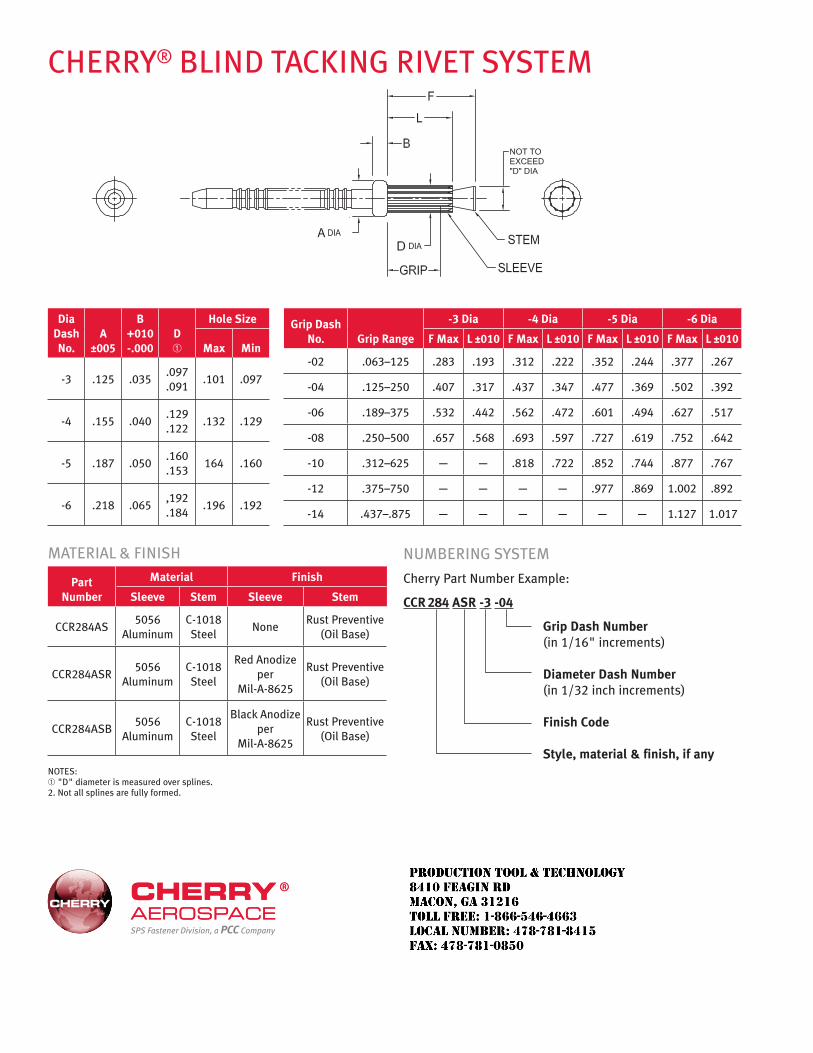
Cherry® Blind TACkinG riveT SySTem
SPS Fastener Division, a PCC Company
Dia Dash No.
A ±005
B +010 -.000
D ➀
Hole Size
Max Min
-3 .125 .035.097 .091
.101 .097
-4 .155 .040.129 .122
.132 .129
-5 .187 .050.160 .153
164 .160
-6 .218 .065,192 .184
.196 .192
mATeriAl & FiniSh
Part Number
Material Finish
Sleeve Stem Sleeve Stem
CCr284AS5056
AluminumC-1018 Steel
nonerust Preventive
(Oil Base)
CCr284ASr5056
AluminumC-1018 Steel
red Anodize per
mil-A-8625
rust Preventive (Oil Base)
CCr284ASB5056
AluminumC-1018 Steel
Black Anodize per
mil-A-8625
rust Preventive (Oil Base)
nOTeS:➀ "d" diameter is measured over splines. 2. not all splines are fully formed.
Grip Dash No. Grip Range
-3 Dia -4 Dia -5 Dia -6 Dia
F Max L ±010 F Max L ±010 F Max L ±010 F Max L ±010
-02 .063–125 .283 .193 .312 .222 .352 .244 .377 .267
-04 .125–250 .407 .317 .437 .347 .477 .369 .502 .392
-06 .189–375 .532 .442 .562 .472 .601 .494 .627 .517
-08 .250–500 .657 .568 .693 .597 .727 .619 .752 .642
-10 .312–625 — — .818 .722 .852 .744 .877 .767
-12 .375–750 — — — — .977 .869 1.002 .892
-14 .437–.875 — — — — — — 1.127 1.017
numBerinG SySTem
Cherry Part number example:
CCR 284 ASR -3 -04
Grip Dash Number (in 1/16" increments) Diameter Dash Number (in 1/32 inch increments) Finish Code Style, material & finish, if any
JR
Typewritten text
Production Tool & Technology 8410 Feagin Rd Macon, Ga 31216 Toll Free: 1-866-546-4663 Local Number: 478-781-8415 Fax: 478-781-0850
1 1
CHERRYBUCK® TITANIUM SHEAR PIN
SPS Fastener Division, a PCC Company
95KSI LIGHTWEIGHT TITANIUM SHEAR PIN
JR
Typewritten text
Production Tool & Technology 8410 Feagin Rd Macon, Ga 31216 Toll Free: 1-866-546-4663 Local Number: 478-781-8415 Fax: 478-781-0850
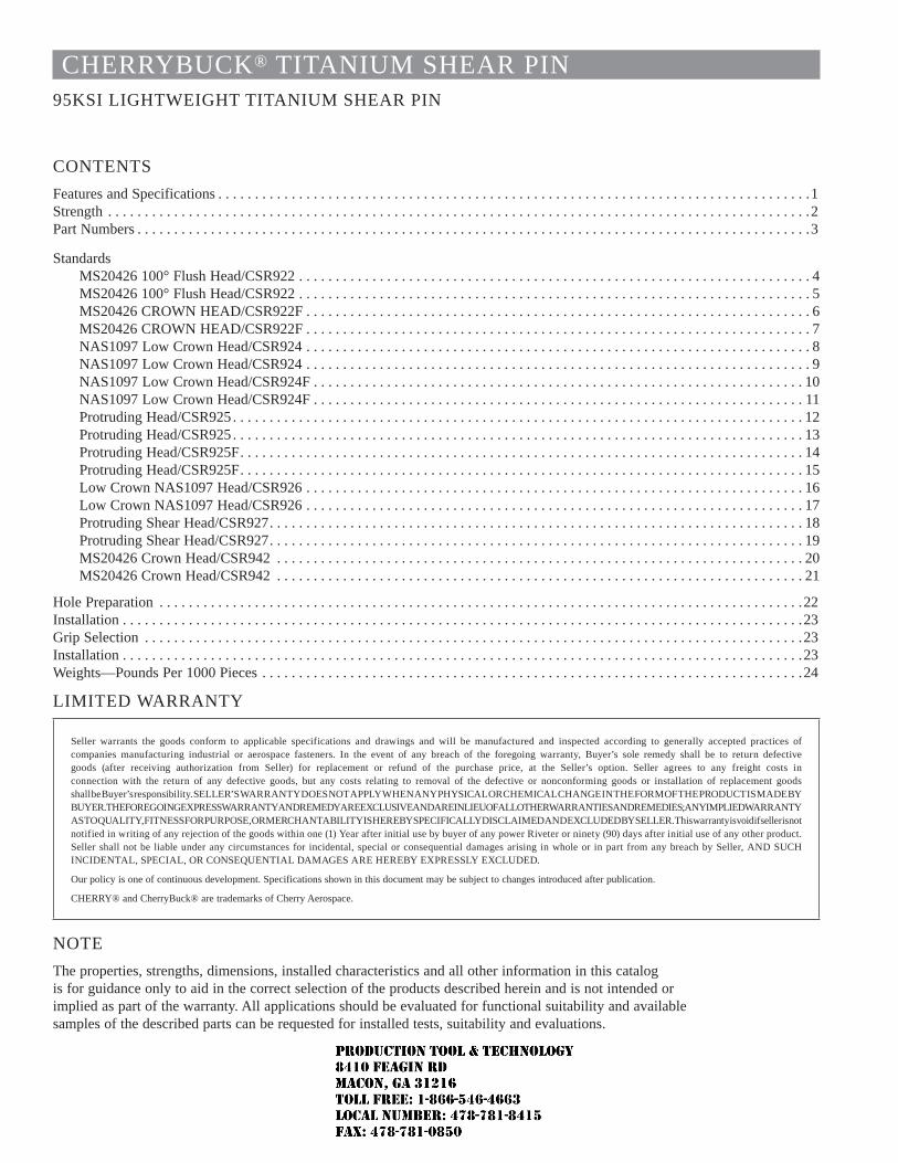
CHERRYBUCK® TITANIUM SHEAR PIN95KSI LIGHTWEIGHT TITANIUM SHEAR PIN
CONTENTSFeatures and Specifications . . . . . . . . . . . . . . . . . . . . . . . . . . . . . . . . . . . . . . . . . . . . . . . . . . . . . . . . . . . . . . . . . . . . . . . . . . . . . . . . .1Strength . . . . . . . . . . . . . . . . . . . . . . . . . . . . . . . . . . . . . . . . . . . . . . . . . . . . . . . . . . . . . . . . . . . . . . . . . . . . . . . . . . . . . . . . . . . . . . . .2Part Numbers . . . . . . . . . . . . . . . . . . . . . . . . . . . . . . . . . . . . . . . . . . . . . . . . . . . . . . . . . . . . . . . . . . . . . . . . . . . . . . . . . . . . . . . . . . . .3
StandardsMS20426 100° Flush Head/CSR922 . . . . . . . . . . . . . . . . . . . . . . . . . . . . . . . . . . . . . . . . . . . . . . . . . . . . . . . . . . . . . . . . . . . . . . 4MS20426 100° Flush Head/CSR922 . . . . . . . . . . . . . . . . . . . . . . . . . . . . . . . . . . . . . . . . . . . . . . . . . . . . . . . . . . . . . . . . . . . . . . 5MS20426 CROWN HEAD/CSR922F . . . . . . . . . . . . . . . . . . . . . . . . . . . . . . . . . . . . . . . . . . . . . . . . . . . . . . . . . . . . . . . . . . . . . 6MS20426 CROWN HEAD/CSR922F . . . . . . . . . . . . . . . . . . . . . . . . . . . . . . . . . . . . . . . . . . . . . . . . . . . . . . . . . . . . . . . . . . . . . 7NAS1097 Low Crown Head/CSR924 . . . . . . . . . . . . . . . . . . . . . . . . . . . . . . . . . . . . . . . . . . . . . . . . . . . . . . . . . . . . . . . . . . . . . 8NAS1097 Low Crown Head/CSR924 . . . . . . . . . . . . . . . . . . . . . . . . . . . . . . . . . . . . . . . . . . . . . . . . . . . . . . . . . . . . . . . . . . . . . 9NAS1097 Low Crown Head/CSR924F . . . . . . . . . . . . . . . . . . . . . . . . . . . . . . . . . . . . . . . . . . . . . . . . . . . . . . . . . . . . . . . . . . . 10NAS1097 Low Crown Head/CSR924F . . . . . . . . . . . . . . . . . . . . . . . . . . . . . . . . . . . . . . . . . . . . . . . . . . . . . . . . . . . . . . . . . . . 11Protruding Head/CSR925 . . . . . . . . . . . . . . . . . . . . . . . . . . . . . . . . . . . . . . . . . . . . . . . . . . . . . . . . . . . . . . . . . . . . . . . . . . . . . . 12Protruding Head/CSR925 . . . . . . . . . . . . . . . . . . . . . . . . . . . . . . . . . . . . . . . . . . . . . . . . . . . . . . . . . . . . . . . . . . . . . . . . . . . . . . 13Protruding Head/CSR925F. . . . . . . . . . . . . . . . . . . . . . . . . . . . . . . . . . . . . . . . . . . . . . . . . . . . . . . . . . . . . . . . . . . . . . . . . . . . . 14Protruding Head/CSR925F. . . . . . . . . . . . . . . . . . . . . . . . . . . . . . . . . . . . . . . . . . . . . . . . . . . . . . . . . . . . . . . . . . . . . . . . . . . . . 15Low Crown NAS1097 Head/CSR926 . . . . . . . . . . . . . . . . . . . . . . . . . . . . . . . . . . . . . . . . . . . . . . . . . . . . . . . . . . . . . . . . . . . . 16Low Crown NAS1097 Head/CSR926 . . . . . . . . . . . . . . . . . . . . . . . . . . . . . . . . . . . . . . . . . . . . . . . . . . . . . . . . . . . . . . . . . . . . 17Protruding Shear Head/CSR927. . . . . . . . . . . . . . . . . . . . . . . . . . . . . . . . . . . . . . . . . . . . . . . . . . . . . . . . . . . . . . . . . . . . . . . . . 18Protruding Shear Head/CSR927. . . . . . . . . . . . . . . . . . . . . . . . . . . . . . . . . . . . . . . . . . . . . . . . . . . . . . . . . . . . . . . . . . . . . . . . . 19MS20426 Crown Head/CSR942 . . . . . . . . . . . . . . . . . . . . . . . . . . . . . . . . . . . . . . . . . . . . . . . . . . . . . . . . . . . . . . . . . . . . . . . . 20MS20426 Crown Head/CSR942 . . . . . . . . . . . . . . . . . . . . . . . . . . . . . . . . . . . . . . . . . . . . . . . . . . . . . . . . . . . . . . . . . . . . . . . . 21
Hole Preparation . . . . . . . . . . . . . . . . . . . . . . . . . . . . . . . . . . . . . . . . . . . . . . . . . . . . . . . . . . . . . . . . . . . . . . . . . . . . . . . . . . . . . . . .22Installation . . . . . . . . . . . . . . . . . . . . . . . . . . . . . . . . . . . . . . . . . . . . . . . . . . . . . . . . . . . . . . . . . . . . . . . . . . . . . . . . . . . . . . . . . . . . .23Grip Selection . . . . . . . . . . . . . . . . . . . . . . . . . . . . . . . . . . . . . . . . . . . . . . . . . . . . . . . . . . . . . . . . . . . . . . . . . . . . . . . . . . . . . . . . . .23Installation . . . . . . . . . . . . . . . . . . . . . . . . . . . . . . . . . . . . . . . . . . . . . . . . . . . . . . . . . . . . . . . . . . . . . . . . . . . . . . . . . . . . . . . . . . . . .23Weights—Pounds Per 1000 Pieces . . . . . . . . . . . . . . . . . . . . . . . . . . . . . . . . . . . . . . . . . . . . . . . . . . . . . . . . . . . . . . . . . . . . . . . . . .24
LIMITED WARRANTY
Seller warrants the goods conform to applicable specifications and drawings and will be manufactured and inspected according to generally accepted practices of companies manufacturing industrial or aerospace fasteners. In the event of any breach of the foregoing warranty, Buyer’s sole remedy shall be to return defective goods (after receiving authorization from Seller) for replacement or refund of the purchase price, at the Seller’s option. Seller agrees to any freight costs in connection with the return of any defective goods, but any costs relating to removal of the defective or nonconforming goods or installation of replacement goods shall be Buyer’s responsibility. SELLER’S WARRANTY DOES NOT APPLY WHEN ANY PHYSICAL OR CHEMICAL CHANGE IN THE FORM OF THE PRODUCT IS MADE BY BUYER. THE FOREGOING EXPRESS WARRANTY AND REMEDY ARE EXCLUSIVE AND ARE IN LIEU OF ALL OTHER WARRANTIES AND REMEDIES; ANY IMPLIED WARRANTY AS TO QUALITY, FITNESS FOR PURPOSE, OR MERCHANTABILITY IS HEREBY SPECIFICALLY DISCLAIMED AND EXCLUDED BY SELLER. This warranty is void if seller is not notified in writing of any rejection of the goods within one (1) Year after initial use by buyer of any power Riveter or ninety (90) days after initial use of any other product.Seller shall not be liable under any circumstances for incidental, special or consequential damages arising in whole or in part from any breach by Seller, AND SUCH INCIDENTAL, SPECIAL, OR CONSEQUENTIAL DAMAGES ARE HEREBY EXPRESSLY EXCLUDED.
Our policy is one of continuous development. Specifications shown in this document may be subject to changes introduced after publication.
CHERRY® and CherryBuck® are trademarks of Cherry Aerospace.
NOTEThe properties, strengths, dimensions, installed characteristics and all other information in this catalog is for guidance only to aid in the correct selection of the products described herein and is not intended or implied as part of the warranty. All applications should be evaluated for functional suitability and available samples of the described parts can be requested for installed tests, suitability and evaluations.
JR
Typewritten text
Production Tool & Technology 8410 Feagin Rd Macon, Ga 31216 Toll Free: 1-866-546-4663 Local Number: 478-781-8415 Fax: 478-781-0850
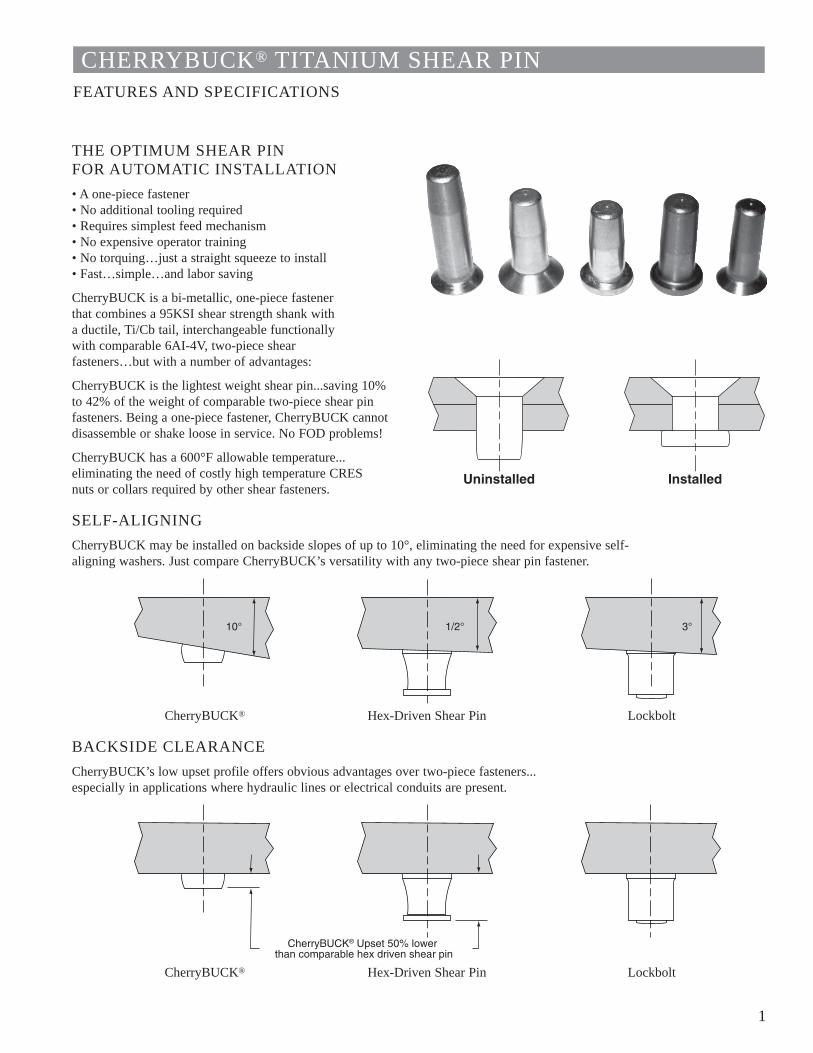
1
CHERRYBUCK® TITANIUM SHEAR PINFEATURES AND SPECIFICATIONS
THE OPTIMUM SHEAR PIN FOR AUTOMATIC INSTALLATION• A one-piece fastener • No additional tooling required• Requires simplest feed mechanism • No expensive operator training• No torquing…just a straight squeeze to install • Fast…simple…and labor saving
CherryBUCK is a bi-metallic, one-piece fastener that combines a 95KSI shear strength shank with a ductile, Ti/Cb tail, interchangeable functionally with comparable 6AI-4V, two-piece shear fasteners…but with a number of advantages:
CherryBUCK is the lightest weight shear pin...saving 10% to 42% of the weight of comparable two-piece shear pin fasteners. Being a one-piece fastener, CherryBUCK cannot disassemble or shake loose in service. No FOD problems!
CherryBUCK has a 600°F allowable temperature...eliminating the need of costly high temperature CRES nuts or collars required by other shear fasteners.
SELF-ALIGNINGCherryBUCK may be installed on backside slopes of up to 10°, eliminating the need for expensive self-aligning washers. Just compare CherryBUCK’s versatility with any two-piece shear pin fastener.
CherryBUCK® Hex-Driven Shear Pin Lockbolt
BACKSIDE CLEARANCECherryBUCK’s low upset profile offers obvious advantages over two-piece fasteners... especially in applications where hydraulic lines or electrical conduits are present.
CherryBUCK® Hex-Driven Shear Pin Lockbolt
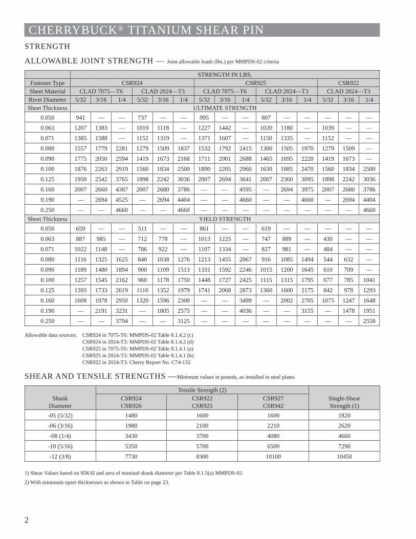
2
CHERRYBUCK® TITANIUM SHEAR PINSTRENGTH
ALLOWABLE JOINT STRENGTH — Joint allowable loads (lbs.) per MMPDS-02 criteria
STRENGTH IN LBS.Fastener Type CSR924 CSR925 CSR922Sheet Material CLAD 7075—T6 CLAD 2024—T3 CLAD 7075—T6 CLAD 2024—T3 CLAD 2024—T3Rivet Diameter 5/32 3/16 1/4 5/32 3/16 1/4 5/32 3/16 1/4 5/32 3/16 1/4 5/32 3/16 1/4Sheet Thickness ULTIMATE STRENGTH
0.050 941 — — 737 — — 995 — — 807 — — — — —
0.063 1207 1383 — 1019 1118 — 1227 1442 — 1020 1180 — 1039 — —
0.071 1385 1588 — 1152 1319 — 1371 1607 — 1150 1335 — 1152 — —
0.080 1557 1779 2281 1279 1509 1837 1532 1792 2415 1300 1505 1970 1279 1509 —
0.090 1775 2050 2594 1419 1673 2168 1711 2001 2688 1465 1695 2220 1419 1673 —
0.100 1876 2263 2919 1560 1834 2500 1890 2205 2960 1630 1885 2470 1560 1834 2500
0.125 1950 2542 3765 1898 2242 3036 2007 2694 3641 2007 2360 3095 1898 2242 3036
0.160 2007 2660 4387 2007 2680 3786 — — 4595 — 2694 3975 2007 2680 3786
0.190 — 2694 4525 — 2694 4404 — — 4660 — — 4660 — 2694 4404
0.250 — — 4660 — — 4660 — — — — — — — — 4660Sheet Thickness YIELD STRENGTH
0.050 659 — — 511 — — 861 — — 619 — — — — —
0.063 887 985 — 712 778 — 1013 1225 — 747 889 — 430 — —
0.071 1022 1148 — 786 922 — 1107 1334 — 827 981 — 484 — —
0.080 1116 1325 1625 840 1038 1276 1213 1455 2067 916 1085 1494 544 632 —
0.090 1189 1480 1894 900 1109 1513 1331 1592 2246 1015 1200 1645 610 709 —
0.100 1257 1545 2162 960 1178 1750 1448 1727 2425 1115 1315 1795 677 785 1041
0.125 1393 1733 2619 1110 1352 1979 1741 2068 2873 1360 1600 2175 842 978 1293
0.160 1608 1978 2950 1320 1596 2300 — — 3499 — 2002 2705 1075 1247 1648
0.190 — 2191 3231 — 1805 2575 — — 4036 — — 3155 — 1478 1951
0.250 — — 3794 — — 3125 — — — — — — — — 2558
Allowable data sources: CSR924 in 7075-T6: MMPDS-02 Table 8.1.4.2 (c)CSR924 in 2024-T3: MMPDS-02 Table 8.1.4.2 (d) CSR925 in 7075-T6: MMPDS-02 Table 8.1.4.1 (a) CSR925 in 2024-T3: MMPDS-02 Table 8.1.4.1 (b) CSR922 in 2024-T3: Cherry Report No. C74-132
SHEAR AND TENSILE STRENGTHS —Minimum values in pounds, as installed in steel plates
ShankDiameter
Tensile Strength (2)Single-ShearStrength (1)
CSR924CSR926
CSR922CSR925
CSR927CSR942
-05 (5/32) 1480 1600 1600 1820
-06 (3/16) 1980 2100 2210 2620
-08 (1/4) 3430 3700 4080 4660
-10 (5/16) 5350 5700 6500 7290
-12 (3/8) 7730 8300 10100 10450
1) Shear Values based on 95KSI and area of nominal shank diameter per Table 8.1.5(a) MMPDS-02.
2) With minimum upset thicknesses as shown in Table on page 23.
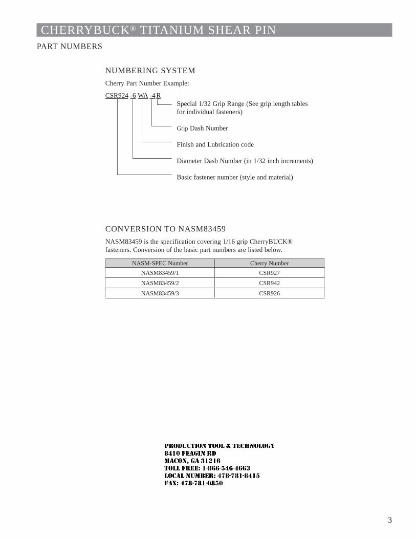
3
CHERRYBUCK® TITANIUM SHEAR PINPART NUMBERS
NUMBERING SYSTEMCherry Part Number Example:
CSR924 -6 WA -4 R Special 1/32 Grip Range (See grip length tables
for individual fasteners)
Grip Dash Number
Finish and Lubrication code
Diameter Dash Number (in 1/32 inch increments)
Basic fastener number (style and material)
CONVERSION TO NASM83459NASM83459 is the specification covering 1/16 grip CherryBUCK® fasteners. Conversion of the basic part numbers are listed below.
NASM-SPEC Number Cherry NumberNASM83459/1 CSR927
NASM83459/2 CSR942
NASM83459/3 CSR926
JR
Typewritten text
Production Tool & Technology 8410 Feagin Rd Macon, Ga 31216 Toll Free: 1-866-546-4663 Local Number: 478-781-8415 Fax: 478-781-0850
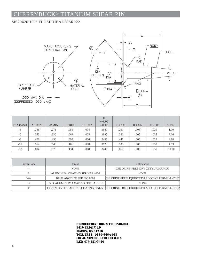
4
CHERRYBUCK® TITANIUM SHEAR PINMS20426 100° FLUSH HEAD/CSR922
DIA DASH A ±.0025 A' MIN B REF C ±.002
D +.0000 –.0005 F ±.005 H ±.002 R ±.005 T REF
-5 .286 .271 .051 .004 .1640 .261 .005 .020 1.70
-6 .353 .336 .069 .005 .1895 .326 .005 .025 2.66
-8 .476 .456 .095 .006 .2495 .446 .005 .025 4.98
-10 .564 .540 .106 .008 .3120 .530 .005 .035 7.03
-12 .694 .670 .134 .008 .3745 .660 .005 .035 10.90
Finish Code Finish Lubrication— NONE CHLORINE-FREE DRY CETYL ALCOHOL
E ALUMINUM COATING PER NAS 4006 NONE
WA BLUE ANODIZE PER ISO 8080 CHLORINE-FREE LIQUID CETYL ALCOHOL PER MIL-L-87132
D I.V.D. ALUMINUM COATING PER BAC5315 NONE
T TIODIZE TYPE II ANODIC COATING, TAL 58 CHLORINE-FREE LIQUID CETYL ALCOHOL PER MIL-L-87132
JR
Typewritten text
Production Tool & Technology 8410 Feagin Rd Macon, Ga 31216 Toll Free: 1-866-546-4663 Local Number: 478-781-8415 Fax: 478-781-0850
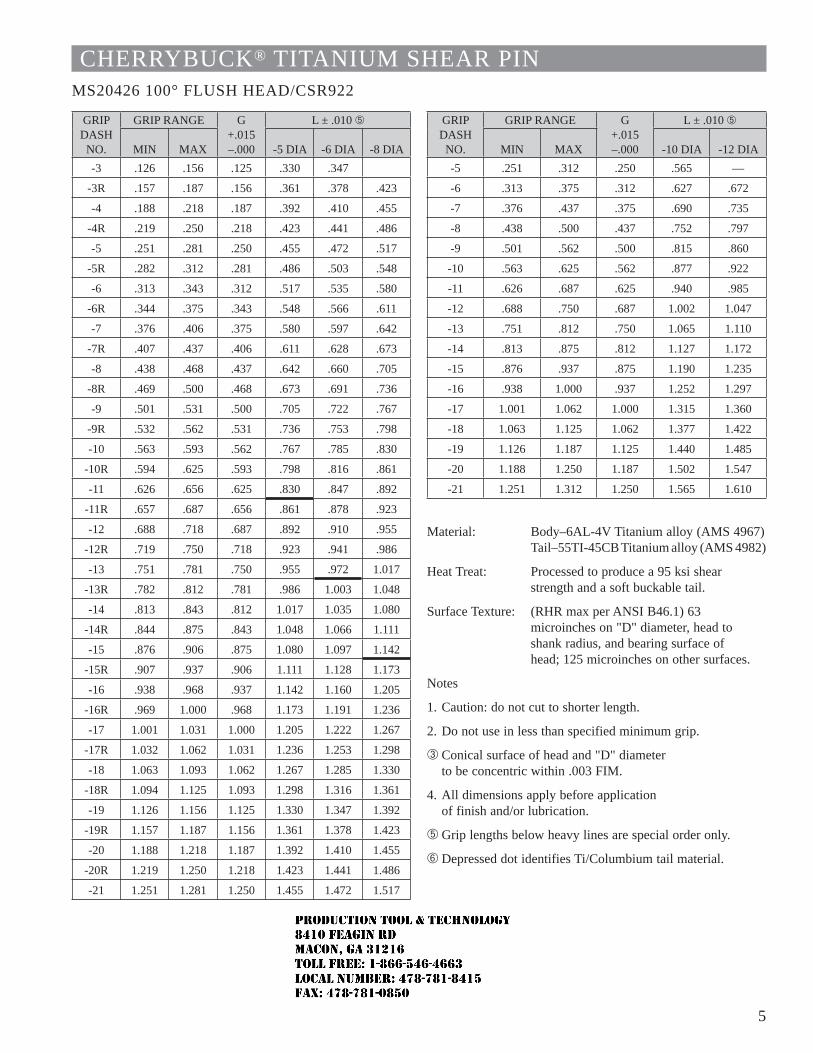
5
CHERRYBUCK® TITANIUM SHEAR PINMS20426 100° FLUSH HEAD/CSR922
GRIP DASH
NO.
GRIP RANGE G+.015–.000
L ± .010 Ä
MIN MAX -5 DIA -6 DIA -8 DIA-3 .126 .156 .125 .330 .347
-3R .157 .187 .156 .361 .378 .423
-4 .188 .218 .187 .392 .410 .455
-4R .219 .250 .218 .423 .441 .486
-5 .251 .281 .250 .455 .472 .517
-5R .282 .312 .281 .486 .503 .548
-6 .313 .343 .312 .517 .535 .580
-6R .344 .375 .343 .548 .566 .611
-7 .376 .406 .375 .580 .597 .642
-7R .407 .437 .406 .611 .628 .673
-8 .438 .468 .437 .642 .660 .705
-8R .469 .500 .468 .673 .691 .736
-9 .501 .531 .500 .705 .722 .767
-9R .532 .562 .531 .736 .753 .798
-10 .563 .593 .562 .767 .785 .830
-10R .594 .625 .593 .798 .816 .861
-11 .626 .656 .625 .830 .847 .892
-11R .657 .687 .656 .861 .878 .923
-12 .688 .718 .687 .892 .910 .955
-12R .719 .750 .718 .923 .941 .986
-13 .751 .781 .750 .955 .972 1.017
-13R .782 .812 .781 .986 1.003 1.048
-14 .813 .843 .812 1.017 1.035 1.080
-14R .844 .875 .843 1.048 1.066 1.111
-15 .876 .906 .875 1.080 1.097 1.142
-15R .907 .937 .906 1.111 1.128 1.173
-16 .938 .968 .937 1.142 1.160 1.205
-16R .969 1.000 .968 1.173 1.191 1.236
-17 1.001 1.031 1.000 1.205 1.222 1.267
-17R 1.032 1.062 1.031 1.236 1.253 1.298
-18 1.063 1.093 1.062 1.267 1.285 1.330
-18R 1.094 1.125 1.093 1.298 1.316 1.361
-19 1.126 1.156 1.125 1.330 1.347 1.392
-19R 1.157 1.187 1.156 1.361 1.378 1.423
-20 1.188 1.218 1.187 1.392 1.410 1.455
-20R 1.219 1.250 1.218 1.423 1.441 1.486
-21 1.251 1.281 1.250 1.455 1.472 1.517
Material: Body–6AL-4V Titanium alloy (AMS 4967)Tail–55TI-45CB Titanium alloy (AMS 4982)
Heat Treat: Processed to produce a 95 ksi shear strength and a soft buckable tail.
Surface Texture: (RHR max per ANSI B46.1) 63 microinches on "D" diameter, head to shank radius, and bearing surface of head; 125 microinches on other surfaces.
Notes
1. Caution: do not cut to shorter length.
2. Do not use in less than specified minimum grip.
 Conical surface of head and "D" diameter to be concentric within .003 FIM.
4. All dimensions apply before application of finish and/or lubrication.
Ä Grip lengths below heavy lines are special order only.
Å Depressed dot identifies Ti/Columbium tail material.
GRIP DASH
NO.
GRIP RANGE G+.015 –.000
L ± .010 Ä
MIN MAX -10 DIA -12 DIA-5 .251 .312 .250 .565 —
-6 .313 .375 .312 .627 .672
-7 .376 .437 .375 .690 .735
-8 .438 .500 .437 .752 .797
-9 .501 .562 .500 .815 .860
-10 .563 .625 .562 .877 .922
-11 .626 .687 .625 .940 .985
-12 .688 .750 .687 1.002 1.047
-13 .751 .812 .750 1.065 1.110
-14 .813 .875 .812 1.127 1.172
-15 .876 .937 .875 1.190 1.235
-16 .938 1.000 .937 1.252 1.297
-17 1.001 1.062 1.000 1.315 1.360
-18 1.063 1.125 1.062 1.377 1.422
-19 1.126 1.187 1.125 1.440 1.485
-20 1.188 1.250 1.187 1.502 1.547
-21 1.251 1.312 1.250 1.565 1.610
JR
Typewritten text
Production Tool & Technology 8410 Feagin Rd Macon, Ga 31216 Toll Free: 1-866-546-4663 Local Number: 478-781-8415 Fax: 478-781-0850
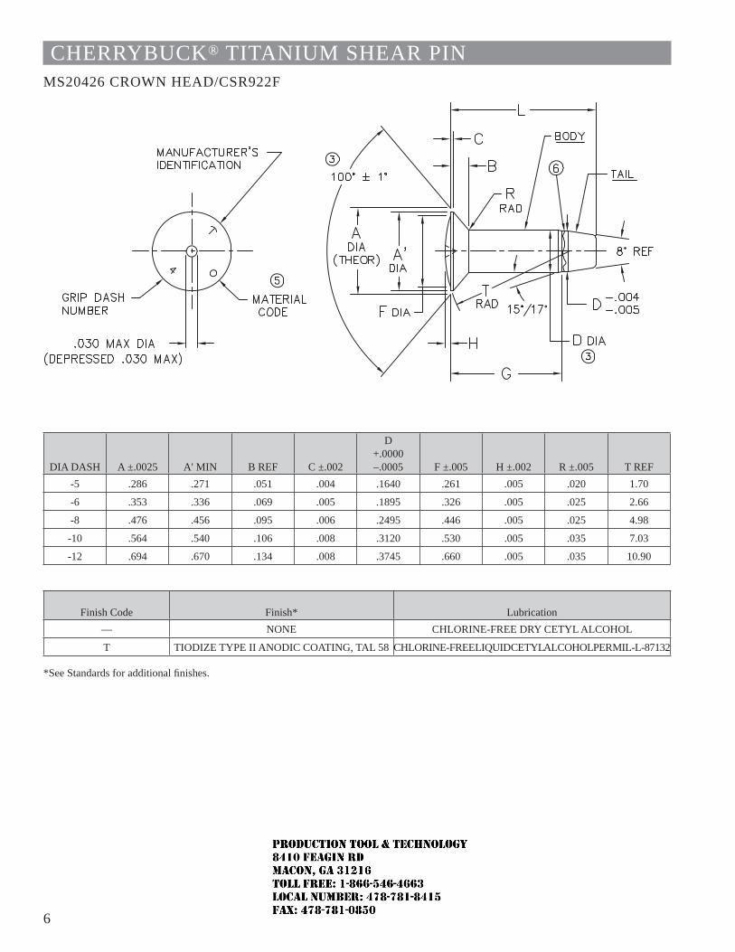
6
CHERRYBUCK® TITANIUM SHEAR PINMS20426 CROWN HEAD/CSR922F
DIA DASH A ±.0025 A' MIN B REF C ±.002
D +.0000 –.0005 F ±.005 H ±.002 R ±.005 T REF
-5 .286 .271 .051 .004 .1640 .261 .005 .020 1.70
-6 .353 .336 .069 .005 .1895 .326 .005 .025 2.66
-8 .476 .456 .095 .006 .2495 .446 .005 .025 4.98
-10 .564 .540 .106 .008 .3120 .530 .005 .035 7.03
-12 .694 .670 .134 .008 .3745 .660 .005 .035 10.90
Finish Code Finish* Lubrication— NONE CHLORINE-FREE DRY CETYL ALCOHOL
T TIODIZE TYPE II ANODIC COATING, TAL 58 CHLORINE-FREE LIQUID CETYL ALCOHOL PER MIL-L-87132
*See Standards for additional fi nishes.
JR
Typewritten text
Production Tool & Technology 8410 Feagin Rd Macon, Ga 31216 Toll Free: 1-866-546-4663 Local Number: 478-781-8415 Fax: 478-781-0850
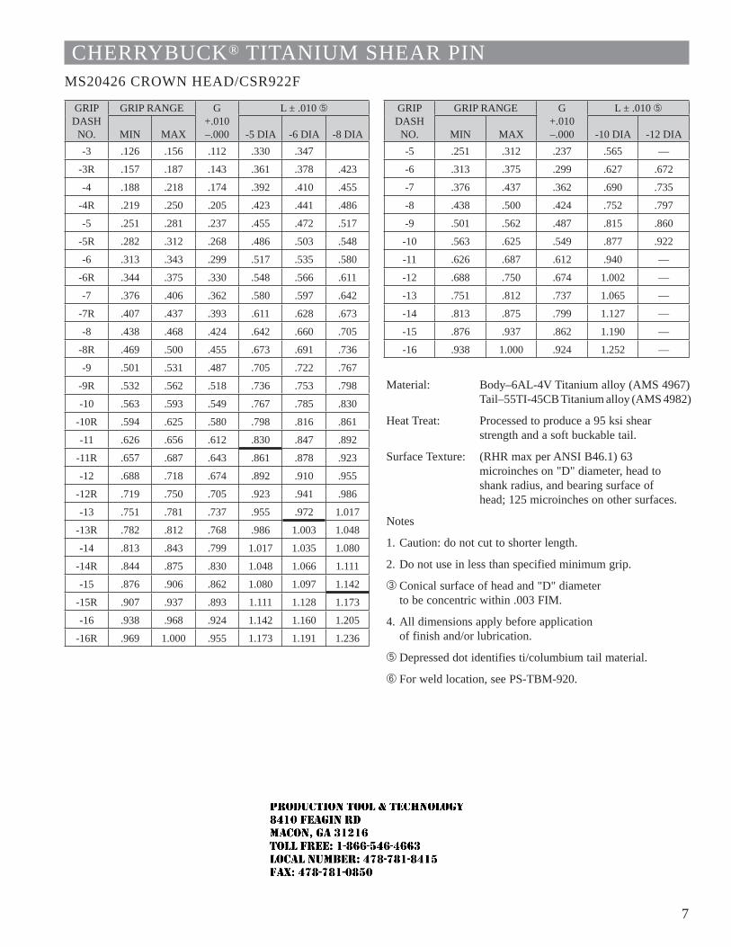
7
CHERRYBUCK® TITANIUM SHEAR PINMS20426 CROWN HEAD/CSR922F
GRIP DASH
NO.
GRIP RANGE G+.010 –.000
L ± .010 Ä
MIN MAX -5 DIA -6 DIA -8 DIA-3 .126 .156 .112 .330 .347
-3R .157 .187 .143 .361 .378 .423
-4 .188 .218 .174 .392 .410 .455
-4R .219 .250 .205 .423 .441 .486
-5 .251 .281 .237 .455 .472 .517
-5R .282 .312 .268 .486 .503 .548
-6 .313 .343 .299 .517 .535 .580
-6R .344 .375 .330 .548 .566 .611
-7 .376 .406 .362 .580 .597 .642
-7R .407 .437 .393 .611 .628 .673
-8 .438 .468 .424 .642 .660 .705
-8R .469 .500 .455 .673 .691 .736
-9 .501 .531 .487 .705 .722 .767
-9R .532 .562 .518 .736 .753 .798
-10 .563 .593 .549 .767 .785 .830
-10R .594 .625 .580 .798 .816 .861
-11 .626 .656 .612 .830 .847 .892
-11R .657 .687 .643 .861 .878 .923
-12 .688 .718 .674 .892 .910 .955
-12R .719 .750 .705 .923 .941 .986
-13 .751 .781 .737 .955 .972 1.017
-13R .782 .812 .768 .986 1.003 1.048
-14 .813 .843 .799 1.017 1.035 1.080
-14R .844 .875 .830 1.048 1.066 1.111
-15 .876 .906 .862 1.080 1.097 1.142
-15R .907 .937 .893 1.111 1.128 1.173
-16 .938 .968 .924 1.142 1.160 1.205
-16R .969 1.000 .955 1.173 1.191 1.236
GRIP DASH
NO.
GRIP RANGE G+.010 –.000
L ± .010 Ä
MIN MAX -10 DIA -12 DIA-5 .251 .312 .237 .565 —
-6 .313 .375 .299 .627 .672
-7 .376 .437 .362 .690 .735
-8 .438 .500 .424 .752 .797
-9 .501 .562 .487 .815 .860
-10 .563 .625 .549 .877 .922
-11 .626 .687 .612 .940 —
-12 .688 .750 .674 1.002 —
-13 .751 .812 .737 1.065 —
-14 .813 .875 .799 1.127 —
-15 .876 .937 .862 1.190 —
-16 .938 1.000 .924 1.252 —
Material: Body–6AL-4V Titanium alloy (AMS 4967)Tail–55TI-45CB Titanium alloy (AMS 4982)
Heat Treat: Processed to produce a 95 ksi shear strength and a soft buckable tail.
Surface Texture: (RHR max per ANSI B46.1) 63 microinches on "D" diameter, head to shank radius, and bearing surface of head; 125 microinches on other surfaces.
Notes
1. Caution: do not cut to shorter length.
2. Do not use in less than specified minimum grip.
 Conical surface of head and "D" diameter to be concentric within .003 FIM.
4. All dimensions apply before application of finish and/or lubrication.
Ä Depressed dot identifies ti/columbium tail material.
Å For weld location, see PS-TBM-920.
JR
Typewritten text
Production Tool & Technology 8410 Feagin Rd Macon, Ga 31216 Toll Free: 1-866-546-4663 Local Number: 478-781-8415 Fax: 478-781-0850
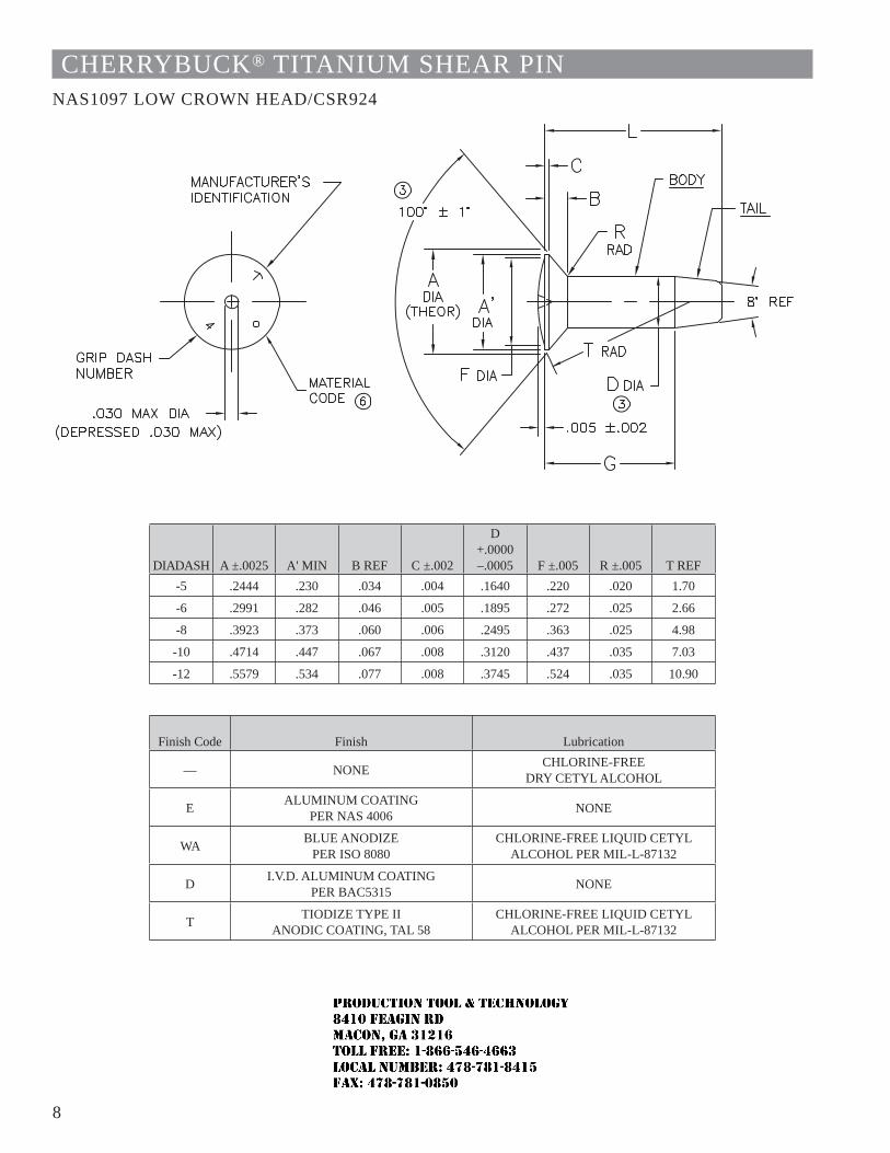
8
CHERRYBUCK® TITANIUM SHEAR PINNAS1097 LOW CROWN HEAD/CSR924
DIA DASH A ±.0025 A' MIN B REF C ±.002
D +.0000 –.0005 F ±.005 R ±.005 T REF
-5 .2444 .230 .034 .004 .1640 .220 .020 1.70
-6 .2991 .282 .046 .005 .1895 .272 .025 2.66
-8 .3923 .373 .060 .006 .2495 .363 .025 4.98
-10 .4714 .447 .067 .008 .3120 .437 .035 7.03
-12 .5579 .534 .077 .008 .3745 .524 .035 10.90
Finish Code Finish Lubrication
— NONE CHLORINE-FREE DRY CETYL ALCOHOL
E ALUMINUM COATING PER NAS 4006 NONE
WA BLUE ANODIZE PER ISO 8080
CHLORINE-FREE LIQUID CETYL ALCOHOL PER MIL-L-87132
D I.V.D. ALUMINUM COATING PER BAC5315 NONE
T TIODIZE TYPE II ANODIC COATING, TAL 58
CHLORINE-FREE LIQUID CETYL ALCOHOL PER MIL-L-87132
JR
Typewritten text
Production Tool & Technology 8410 Feagin Rd Macon, Ga 31216 Toll Free: 1-866-546-4663 Local Number: 478-781-8415 Fax: 478-781-0850
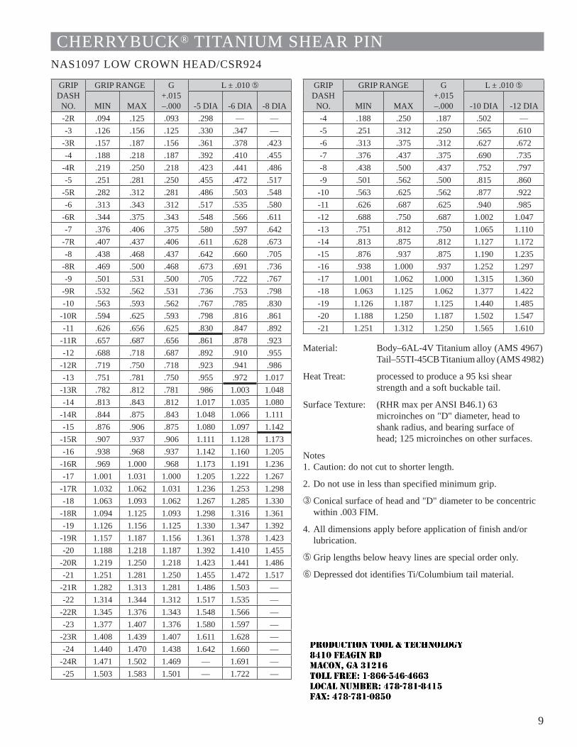
9
CHERRYBUCK® TITANIUM SHEAR PINNAS1097 LOW CROWN HEAD/CSR924
GRIP DASH
NO.
GRIP RANGE G+.015 –.000
L ± .010 Ä
MIN MAX -5 DIA -6 DIA -8 DIA-2R .094 .125 .093 .298 — —-3 .126 .156 .125 .330 .347 —
-3R .157 .187 .156 .361 .378 .423-4 .188 .218 .187 .392 .410 .455
-4R .219 .250 .218 .423 .441 .486-5 .251 .281 .250 .455 .472 .517
-5R .282 .312 .281 .486 .503 .548-6 .313 .343 .312 .517 .535 .580
-6R .344 .375 .343 .548 .566 .611-7 .376 .406 .375 .580 .597 .642
-7R .407 .437 .406 .611 .628 .673-8 .438 .468 .437 .642 .660 .705
-8R .469 .500 .468 .673 .691 .736-9 .501 .531 .500 .705 .722 .767
-9R .532 .562 .531 .736 .753 .798-10 .563 .593 .562 .767 .785 .830
-10R .594 .625 .593 .798 .816 .861-11 .626 .656 .625 .830 .847 .892
-11R .657 .687 .656 .861 .878 .923-12 .688 .718 .687 .892 .910 .955
-12R .719 .750 .718 .923 .941 .986-13 .751 .781 .750 .955 .972 1.017
-13R .782 .812 .781 .986 1.003 1.048-14 .813 .843 .812 1.017 1.035 1.080
-14R .844 .875 .843 1.048 1.066 1.111-15 .876 .906 .875 1.080 1.097 1.142
-15R .907 .937 .906 1.111 1.128 1.173-16 .938 .968 .937 1.142 1.160 1.205
-16R .969 1.000 .968 1.173 1.191 1.236-17 1.001 1.031 1.000 1.205 1.222 1.267
-17R 1.032 1.062 1.031 1.236 1.253 1.298-18 1.063 1.093 1.062 1.267 1.285 1.330
-18R 1.094 1.125 1.093 1.298 1.316 1.361-19 1.126 1.156 1.125 1.330 1.347 1.392
-19R 1.157 1.187 1.156 1.361 1.378 1.423-20 1.188 1.218 1.187 1.392 1.410 1.455
-20R 1.219 1.250 1.218 1.423 1.441 1.486-21 1.251 1.281 1.250 1.455 1.472 1.517
-21R 1.282 1.313 1.281 1.486 1.503 —-22 1.314 1.344 1.312 1.517 1.535 —
-22R 1.345 1.376 1.343 1.548 1.566 — -23 1.377 1.407 1.376 1.580 1.597 —
-23R 1.408 1.439 1.407 1.611 1.628 — -24 1.440 1.470 1.438 1.642 1.660 —
-24R 1.471 1.502 1.469 — 1.691 —-25 1.503 1.583 1.501 — 1.722 —
GRIP DASH
NO.
GRIP RANGE G+.015 –.000
L ± .010 Ä
MIN MAX -10 DIA -12 DIA-4 .188 .250 .187 .502 —-5 .251 .312 .250 .565 .610-6 .313 .375 .312 .627 .672-7 .376 .437 .375 .690 .735-8 .438 .500 .437 .752 .797-9 .501 .562 .500 .815 .860-10 .563 .625 .562 .877 .922-11 .626 .687 .625 .940 .985-12 .688 .750 .687 1.002 1.047-13 .751 .812 .750 1.065 1.110-14 .813 .875 .812 1.127 1.172-15 .876 .937 .875 1.190 1.235-16 .938 1.000 .937 1.252 1.297-17 1.001 1.062 1.000 1.315 1.360-18 1.063 1.125 1.062 1.377 1.422-19 1.126 1.187 1.125 1.440 1.485-20 1.188 1.250 1.187 1.502 1.547-21 1.251 1.312 1.250 1.565 1.610
Material: Body–6AL-4V Titanium alloy (AMS 4967)Tail–55TI-45CB Titanium alloy (AMS 4982)
Heat Treat: processed to produce a 95 ksi shear strength and a soft buckable tail.
Surface Texture: (RHR max per ANSI B46.1) 63 microinches on "D" diameter, head to shank radius, and bearing surface of head; 125 microinches on other surfaces.
Notes1. Caution: do not cut to shorter length.
2. Do not use in less than specified minimum grip.
 Conical surface of head and "D" diameter to be concentric within .003 FIM.
4. All dimensions apply before application of finish and/or lubrication.
Ä Grip lengths below heavy lines are special order only.
Å Depressed dot identifies Ti/Columbium tail material.
JR
Typewritten text
Production Tool & Technology 8410 Feagin Rd Macon, Ga 31216 Toll Free: 1-866-546-4663 Local Number: 478-781-8415 Fax: 478-781-0850
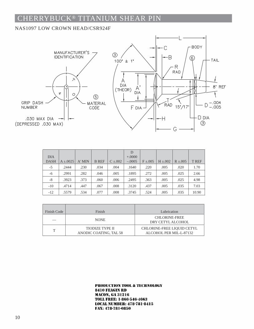
10
CHERRYBUCK® TITANIUM SHEAR PINNAS1097 LOW CROWN HEAD/CSR924F
DIA DASH A ±.0025 A' MIN B REF C ±.002
D +.0000 –.0005 F ±.005 H ±.002 R ±.005 T REF
-5 .2444 .230 .034 .004 .1640 .220 .005 .020 1.70
-6 .2991 .282 .046 .005 .1895 .272 .005 .025 2.66
-8 .3923 .373 .060 .006 .2495 .363 .005 .025 4.98
-10 .4714 .447 .067 .008 .3120 .437 .005 .035 7.03
-12 .5579 .534 .077 .008 .3745 .524 .005 .035 10.90
Finish Code Finish Lubrication
— NONE CHLORINE-FREE DRY CETYL ALCOHOL
T TIODIZE TYPE II ANODIC COATING, TAL 58
CHLORINE-FREE LIQUID CETYL ALCOHOL PER MIL-L-87132
JR
Typewritten text
Production Tool & Technology 8410 Feagin Rd Macon, Ga 31216 Toll Free: 1-866-546-4663 Local Number: 478-781-8415 Fax: 478-781-0850
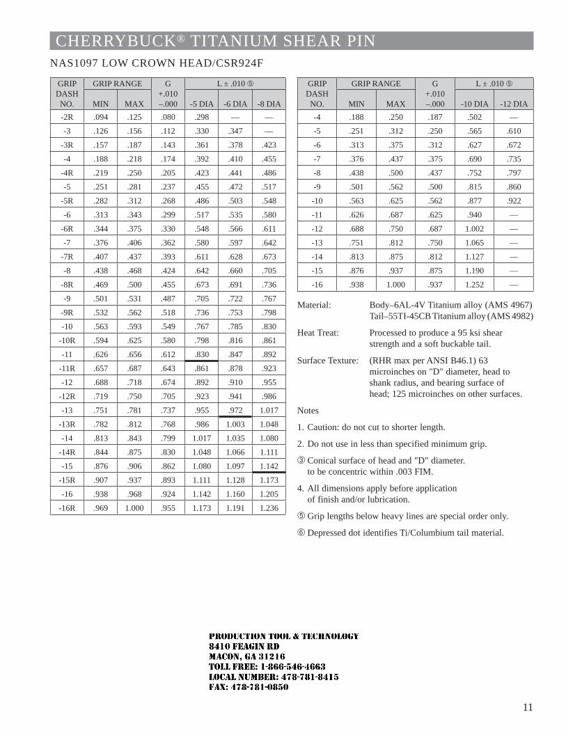
11
CHERRYBUCK® TITANIUM SHEAR PINNAS1097 LOW CROWN HEAD/CSR924F
GRIP DASH
NO.
GRIP RANGE G+.010 –.000
L ± .010 Ä
MIN MAX -5 DIA -6 DIA -8 DIA-2R .094 .125 .080 .298 — —
-3 .126 .156 .112 .330 .347 —
-3R .157 .187 .143 .361 .378 .423
-4 .188 .218 .174 .392 .410 .455
-4R .219 .250 .205 .423 .441 .486
-5 .251 .281 .237 .455 .472 .517
-5R .282 .312 .268 .486 .503 .548
-6 .313 .343 .299 .517 .535 .580
-6R .344 .375 .330 .548 .566 .611
-7 .376 .406 .362 .580 .597 .642
-7R .407 .437 .393 .611 .628 .673
-8 .438 .468 .424 .642 .660 .705
-8R .469 .500 .455 .673 .691 .736
-9 .501 .531 .487 .705 .722 .767
-9R .532 .562 .518 .736 .753 .798
-10 .563 .593 .549 .767 .785 .830
-10R .594 .625 .580 .798 .816 .861
-11 .626 .656 .612 .830 .847 .892
-11R .657 .687 .643 .861 .878 .923
-12 .688 .718 .674 .892 .910 .955
-12R .719 .750 .705 .923 .941 .986
-13 .751 .781 .737 .955 .972 1.017
-13R .782 .812 .768 .986 1.003 1.048
-14 .813 .843 .799 1.017 1.035 1.080
-14R .844 .875 .830 1.048 1.066 1.111
-15 .876 .906 .862 1.080 1.097 1.142
-15R .907 .937 .893 1.111 1.128 1.173
-16 .938 .968 .924 1.142 1.160 1.205
-16R .969 1.000 .955 1.173 1.191 1.236
GRIP DASH
NO.
GRIP RANGE G+.010 –.000
L ± .010 Ä
MIN MAX -10 DIA -12 DIA-4 .188 .250 .187 .502 —
-5 .251 .312 .250 .565 .610
-6 .313 .375 .312 .627 .672
-7 .376 .437 .375 .690 .735
-8 .438 .500 .437 .752 .797
-9 .501 .562 .500 .815 .860
-10 .563 .625 .562 .877 .922
-11 .626 .687 .625 .940 —
-12 .688 .750 .687 1.002 —
-13 .751 .812 .750 1.065 —
-14 .813 .875 .812 1.127 —
-15 .876 .937 .875 1.190 —
-16 .938 1.000 .937 1.252 —
Material: Body–6AL-4V Titanium alloy (AMS 4967)Tail–55TI-45CB Titanium alloy (AMS 4982)
Heat Treat: Processed to produce a 95 ksi shear strength and a soft buckable tail.
Surface Texture: (RHR max per ANSI B46.1) 63 microinches on "D" diameter, head to shank radius, and bearing surface of head; 125 microinches on other surfaces.
Notes
1. Caution: do not cut to shorter length.
2. Do not use in less than specified minimum grip.
 Conical surface of head and "D" diameter. to be concentric within .003 FIM.
4. All dimensions apply before application of finish and/or lubrication.
Ä Grip lengths below heavy lines are special order only.
Å Depressed dot identifies Ti/Columbium tail material.
JR
Typewritten text
Production Tool & Technology 8410 Feagin Rd Macon, Ga 31216 Toll Free: 1-866-546-4663 Local Number: 478-781-8415 Fax: 478-781-0850
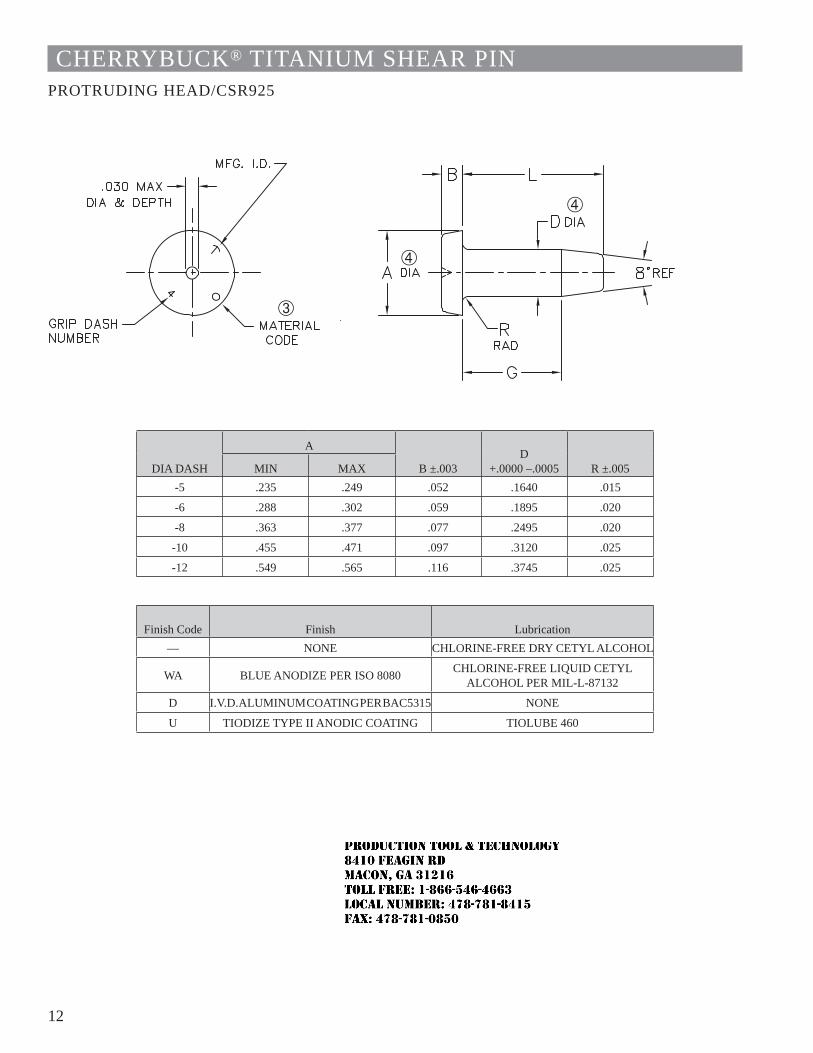
12
CHERRYBUCK® TITANIUM SHEAR PINPROTRUDING HEAD/CSR925
DIA DASH
A
B ±.003D
+.0000 –.0005 R ±.005MIN MAX-5 .235 .249 .052 .1640 .015
-6 .288 .302 .059 .1895 .020
-8 .363 .377 .077 .2495 .020
-10 .455 .471 .097 .3120 .025
-12 .549 .565 .116 .3745 .025
Finish Code Finish Lubrication— NONE CHLORINE-FREE DRY CETYL ALCOHOL
WA BLUE ANODIZE PER ISO 8080 CHLORINE-FREE LIQUID CETYL ALCOHOL PER MIL-L-87132
D I.V.D. ALUMINUM COATING PER BAC5315 NONE
U TIODIZE TYPE II ANODIC COATING TIOLUBE 460
JR
Typewritten text
Production Tool & Technology 8410 Feagin Rd Macon, Ga 31216 Toll Free: 1-866-546-4663 Local Number: 478-781-8415 Fax: 478-781-0850
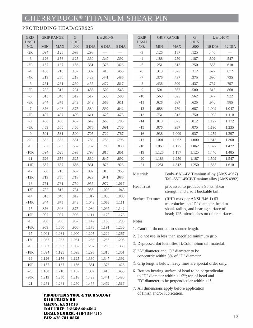
13
CHERRYBUCK® TITANIUM SHEAR PINPROTRUDING HEAD/CSR925
GRIP DASH
NO.
GRIP RANGE G+.015 –.000
L ± .010 Ä
MIN MAX -5 DIA -6 DIA -8 DIA-2R .094 .125 .093 .298 — —
-3 .126 .156 .125 .330 .347 .392
-3R .157 .187 .156 .361 .378 .423
-4 .188 .218 .187 .392 .410 .455
-4R .219 .250 .218 .423 .441 .486
-5 .251 .281 .250 .455 .472 .517
-5R .282 .312 .281 .486 .503 .548
-6 .313 .343 .312 .517 .535 .580
-6R .344 .375 .343 .548 .566 .611
-7 .376 .406 .375 .580 .597 .642
-7R .407 .437 .406 .611 .628 .673
-8 .438 .468 .437 .642 .660 .705
-8R .469 .500 .468 .673 .691 .736
-9 .501 .531 .500 .705 .722 .767
-9R .532 .562 .531 .736 .753 .798
-10 .563 .593 .562 .767 .785 .830
-10R .594 .625 .593 .798 .816 .861
-11 .626 .656 .625 .830 .847 .892
-11R .657 .687 .656 .861 .878 .923
-12 .688 .718 .687 .892 .910 .955
-12R .719 .750 .718 .923 .941 .986
-13 .751 .781 .750 .955 .972 1.017
-13R .782 .812 .781 .986 1.003 1.048
-14 .813 .843 .812 1.017 1.035 1.080
-14R .844 .875 .843 1.048 1.066 1.111
-15 .876 .906 .875 1.080 1.097 1.142
-15R .907 .937 .906 1.111 1.128 1.173
-16 .938 .968 .937 1.142 1.160 1.205
-16R .969 1.000 .968 1.173 1.191 1.236
-17 1.001 1.031 1.000 1.205 1.222 1.267
-17R 1.032 1.062 1.031 1.236 1.253 1.298
-18 1.063 1.093 1.062 1.267 1.285 1.330
-18R 1.094 1.125 1.093 1.298 1.316 1.361
-19 1.126 1.156 1.125 1.330 1.347 1.392
-19R 1.157 1.187 1.156 1.361 1.378 1.423
-20 1.188 1.218 1.187 1.392 1.410 1.455
-20R 1.219 1.250 1.218 1.423 1.441 1.486
-21 1.251 1.281 1.250 1.455 1.472 1.517
GRIP DASH
NO.
GRIP RANGE G+.015 –.000
L ± .010 Ä
MIN MAX -10 DIA -12 DIA-3 .126 .187 .125 .440 —
-4 .188 .250 .187 .502 .547
-5 .251 .312 .250 .565 .610
-6 .313 .375 .312 .627 .672
-7 .376 .437 .375 .690 .735
-8 .438 .500 .437 .752 .797
-9 .501 .562 .500 .815 .860
-10 .563 .625 .562 .877 .922
-11 .626 .687 .625 .940 .985
-12 .688 .750 .687 1.002 1.047
-13 .751 .812 .750 1.065 1.110
-14 .813 .875 .812 1.127 1.172
-15 .876 .937 .875 1.190 1.235
-16 .938 1.000 .937 1.252 1.297
-17 1.001 1.062 1.000 1.315 1.360
-18 1.063 1.125 1.062 1.377 1.422
-19 1.126 1.187 1.125 1.440 1.485
-20 1.188 1.250 1.187 1.502 1.547
-21 1.251 1.312 1.250 1.565 1.610
Material: Body–6AL-4V Titanium alloy (AMS 4967)Tail–55TI-45CB Titanium alloy (AMS 4982)
Heat Treat: processed to produce a 95 ksi shear strength and a soft buckable tail.
Surface Texture: (RHR max per ANSI B46.1) 63 microinches on "D" diameter, head to shank radius, and bearing surface of head; 125 microinches on other surfaces.
Notes
1. Caution: do not cut to shorter length.
2. Do not use in less than specified minimum grip.
 Depressed dot identifies Ti/Columbium tail material.
à "A" diameter and "D" diameter to be concentric within 5% of "D" diameter.
Ä Grip lengths below heavy lines are special order only.
6. Bottom bearing surface of head to be perpendicular to "D" diameter within ±1/2°; top of head and "D" diameter to be perpendicular within ±1°.
7. All dimensions apply before application of finish and/or lubrication.
JR
Typewritten text
Production Tool & Technology 8410 Feagin Rd Macon, Ga 31216 Toll Free: 1-866-546-4663 Local Number: 478-781-8415 Fax: 478-781-0850
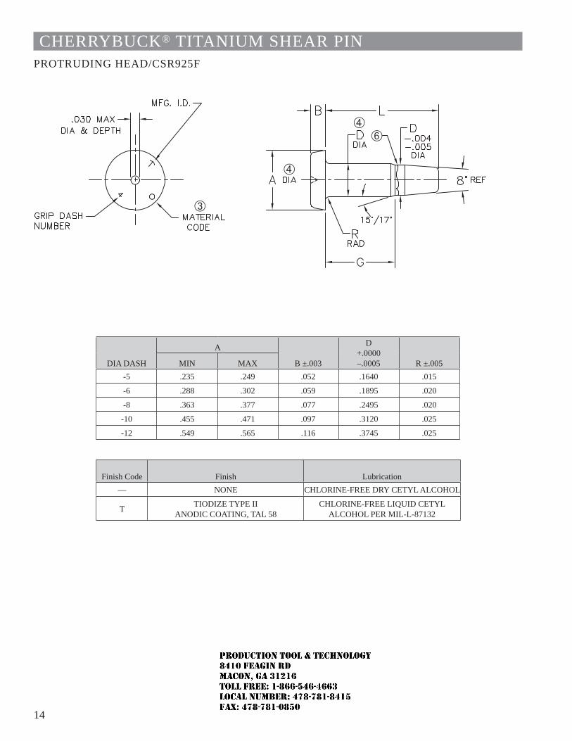
14
CHERRYBUCK® TITANIUM SHEAR PINPROTRUDING HEAD/CSR925F
DIA DASH
A
B ±.003
D +.0000 –.0005 R ±.005MIN MAX
-5 .235 .249 .052 .1640 .015
-6 .288 .302 .059 .1895 .020
-8 .363 .377 .077 .2495 .020
-10 .455 .471 .097 .3120 .025
-12 .549 .565 .116 .3745 .025
Finish Code Finish Lubrication— NONE CHLORINE-FREE DRY CETYL ALCOHOL
T TIODIZE TYPE II ANODIC COATING, TAL 58
CHLORINE-FREE LIQUID CETYL ALCOHOL PER MIL-L-87132
JR
Typewritten text
Production Tool & Technology 8410 Feagin Rd Macon, Ga 31216 Toll Free: 1-866-546-4663 Local Number: 478-781-8415 Fax: 478-781-0850
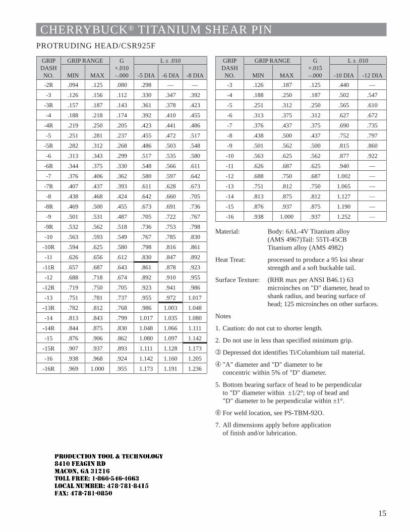
15
CHERRYBUCK® TITANIUM SHEAR PINPROTRUDING HEAD/CSR925F
GRIP DASH
NO.
GRIP RANGE G+.010 –.000
L ± .010
MIN MAX -5 DIA -6 DIA -8 DIA-2R .094 .125 .080 .298 — —
-3 .126 .156 .112 .330 .347 .392
-3R .157 .187 .143 .361 .378 .423
-4 .188 .218 .174 .392 .410 .455
-4R .219 .250 .205 .423 .441 .486
-5 .251 .281 .237 .455 .472 .517
-5R .282 .312 .268 .486 .503 .548
-6 .313 .343 .299 .517 .535 .580
-6R .344 .375 .330 .548 .566 .611
-7 .376 .406 .362 .580 .597 .642
-7R .407 .437 .393 .611 .628 .673
-8 .438 .468 .424 .642 .660 .705
-8R .469 .500 .455 .673 .691 .736
-9 .501 .531 .487 .705 .722 .767
-9R .532 .562 .518 .736 .753 .798
-10 .563 .593 .549 .767 .785 .830
-10R .594 .625 .580 .798 .816 .861
-11 .626 .656 .612 .830 .847 .892
-11R .657 .687 .643 .861 .878 .923
-12 .688 .718 .674 .892 .910 .955
-12R .719 .750 .705 .923 .941 .986
-13 .751 .781 .737 .955 .972 1.017
-13R .782 .812 .768 .986 1.003 1.048
-14 .813 .843 .799 1.017 1.035 1.080
-14R .844 .875 .830 1.048 1.066 1.111
-15 .876 .906 .862 1.080 1.097 1.142
-15R .907 .937 .893 1.111 1.128 1.173
-16 .938 .968 .924 1.142 1.160 1.205
-16R .969 1.000 .955 1.173 1.191 1.236
GRIP DASH
NO.
GRIP RANGE G+.015 –.000
L ± .010
MIN MAX -10 DIA -12 DIA-3 .126 .187 .125 .440 —
-4 .188 .250 .187 .502 .547
-5 .251 .312 .250 .565 .610
-6 .313 .375 .312 .627 .672
-7 .376 .437 .375 .690 .735
-8 .438 .500 .437 .752 .797
-9 .501 .562 .500 .815 .860
-10 .563 .625 .562 .877 .922
-11 .626 .687 .625 .940 —
-12 .688 .750 .687 1.002 —
-13 .751 .812 .750 1.065 —
-14 .813 .875 .812 1.127 —
-15 .876 .937 .875 1.190 —
-16 .938 1.000 .937 1.252 —
Material: Body: 6AL-4V Titanium alloy (AMS 4967)Tail: 55TI-45CB Titanium alloy (AMS 4982)
Heat Treat: processed to produce a 95 ksi shear strength and a soft buckable tail.
Surface Texture: (RHR max per ANSI B46.1) 63 microinches on "D" diameter, head to shank radius, and bearing surface of head; 125 microinches on other surfaces.
Notes
1. Caution: do not cut to shorter length.
2. Do not use in less than specified minimum grip.
 Depressed dot identifies Ti/Columbium tail material.
à "A" diameter and "D" diameter to be concentric within 5% of "D" diameter.
5. Bottom bearing surface of head to be perpendicular to "D" diameter within ±1/2°; top of head and "D" diameter to be perpendicular within ±1°.
Å For weld location, see PS-TBM-92O.
7. All dimensions apply before application of finish and/or lubrication.
JR
Typewritten text
Production Tool & Technology 8410 Feagin Rd Macon, Ga 31216 Toll Free: 1-866-546-4663 Local Number: 478-781-8415 Fax: 478-781-0850
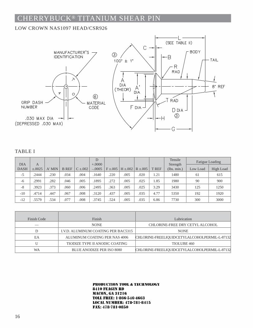
16
CHERRYBUCK® TITANIUM SHEAR PINLOW CROWN NAS1097 HEAD/CSR926
TABLE I
DIA DASH
A ±.0025 A' MIN B REF C ±.002
D +.0000 –.0005 F ±.005 H ±.002 R ±.005 T REF
Tensile Strength
(lbs. min.)
Fatigue Loading
Low Load High Load-5 .2444 .230 .034 .004 .1640 .220 .005 .020 1.21 1480 61 615
-6 .2991 .282 .046 .005 .1895 .272 .005 .025 1.85 1980 90 900
-8 .3923 .373 .060 .006 .2495 .363 .005 .025 3.29 3430 125 1250
-10 .4714 .447 .067 .008 .3120 .437 .005 .035 4.77 5350 192 1920
-12 .5579 .534 .077 .008 .3745 .524 .005 .035 6.86 7730 300 3000
Finish Code Finish Lubrication— NONE CHLORINE-FREE DRY CETYL ALCOHOL
D I.V.D. ALUMINUM COATING PER BAC5315 NONE
EA ALUMINUM COATING PER NAS 4006 CHLORINE-FREE LIQUID CETYL ALCOHOL PER MIL-L-87132
U TIODIZE TYPE II ANODIC COATING TIOLUBE 460
WA BLUE ANODIZE PER ISO 8080 CHLORINE-FREE LIQUID CETYL ALCOHOL PER MIL-L-87132
JR
Typewritten text
Production Tool & Technology 8410 Feagin Rd Macon, Ga 31216 Toll Free: 1-866-546-4663 Local Number: 478-781-8415 Fax: 478-781-0850
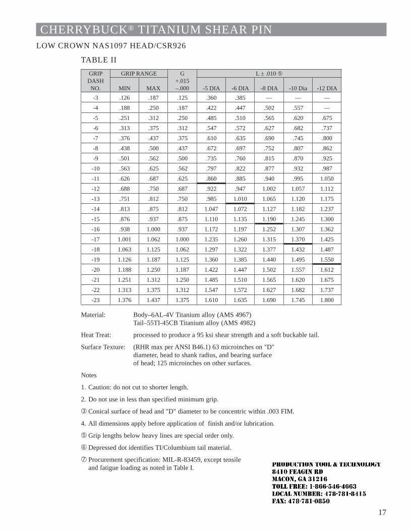
17
CHERRYBUCK® TITANIUM SHEAR PINLOW CROWN NAS1097 HEAD/CSR926
TABLE IIGRIP DASH
NO.
GRIP RANGE G+.015 –.000
L ± .010 Ä
MIN MAX -5 DIA -6 DIA -8 DIA -10 Dia -12 DIA-3 .126 .187 .125 .360 .385 — — —
-4 .188 .250 .187 .422 .447 .502 .557 —
-5 .251 .312 .250 .485 .510 .565 .620 .675
-6 .313 .375 .312 .547 .572 .627 .682 .737
-7 .376 .437 .375 .610 .635 .690 .745 .800
-8 .438 .500 .437 .672 .697 .752 .807 .862
-9 .501 .562 .500 .735 .760 .815 .870 .925
-10 .563 .625 .562 .797 .822 .877 .932 .987
-11 .626 .687 .625 .860 .885 .940 .995 1.050
-12 .688 .750 .687 .922 .947 1.002 1.057 1.112
-13 .751 .812 .750 .985 1.010 1.065 1.120 1.175
-14 .813 .875 .812 1.047 1.072 1.127 1.182 1.237
-15 .876 .937 .875 1.110 1.135 1.190 1.245 1.300
-16 .938 1.000 .937 1.172 1.197 1.252 1.307 1.362
-17 1.001 1.062 1.000 1.235 1.260 1.315 1.370 1.425
-18 1.063 1.125 1.062 1.297 1.322 1.377 1.432 1.487
-19 1.126 1.187 1.125 1.360 1.385 1.440 1.495 1.550
-20 1.188 1.250 1.187 1.422 1.447 1.502 1.557 1.612
-21 1.251 1.312 1.250 1.485 1.510 1.565 1.620 1.675
-22 1.313 1.375 1.312 1.547 1.572 1.627 1.682 1.737
-23 1.376 1.437 1.375 1.610 1.635 1.690 1.745 1.800
Material: Body–6AL-4V Titanium alloy (AMS 4967)Tail–55TI-45CB Titanium alloy (AMS 4982)
Heat Treat: processed to produce a 95 ksi shear strength and a soft buckable tail.
Surface Texture: (RHR max per ANSI B46.1) 63 microinches on "D" diameter, head to shank radius, and bearing surface of head; 125 microinches on other surfaces.
Notes
1. Caution: do not cut to shorter length.
2. Do not use in less than specified minimum grip.
 Conical surface of head and "D" diameter to be concentric within .003 FIM.
4. All dimensions apply before application of finish and/or lubrication.
Ä Grip lengths below heavy lines are special order only.
Å Depressed dot identifies TI/Columbium tail material.
Æ Procurement specification: MIL-R-83459, except tensile and fatigue loading as noted in Table I.
JR
Typewritten text
Production Tool & Technology 8410 Feagin Rd Macon, Ga 31216 Toll Free: 1-866-546-4663 Local Number: 478-781-8415 Fax: 478-781-0850
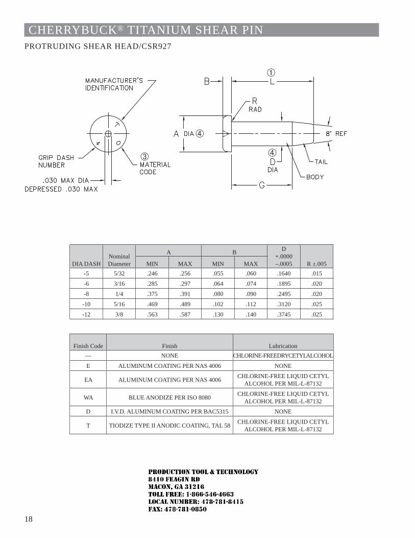
18
CHERRYBUCK® TITANIUM SHEAR PINPROTRUDING SHEAR HEAD/CSR927
DIA DASHNominal Diameter
A B D +.0000 –.0005 R ±.005MIN MAX MIN MAX
-5 5/32 .246 .256 .055 .060 .1640 .015
-6 3/16 .285 .297 .064 .074 .1895 .020
-8 1/4 .375 .391 .080 .090 .2495 .020
-10 5/16 .469 .489 .102 .112 .3120 .025
-12 3/8 .563 .587 .130 .140 .3745 .025
Finish Code Finish Lubrication— NONE CHLORINE-FREE DRY CETYL ALCOHOL
E ALUMINUM COATING PER NAS 4006 NONE
EA ALUMINUM COATING PER NAS 4006 CHLORINE-FREE LIQUID CETYL ALCOHOL PER MIL-L-87132
WA BLUE ANODIZE PER ISO 8080 CHLORINE-FREE LIQUID CETYL ALCOHOL PER MIL-L-87132
D I.V.D. ALUMINUM COATING PER BAC5315 NONE
T TIODIZE TYPE II ANODIC COATING, TAL 58 CHLORINE-FREE LIQUID CETYL ALCOHOL PER MIL-L-87132
JR
Typewritten text
Production Tool & Technology 8410 Feagin Rd Macon, Ga 31216 Toll Free: 1-866-546-4663 Local Number: 478-781-8415 Fax: 478-781-0850
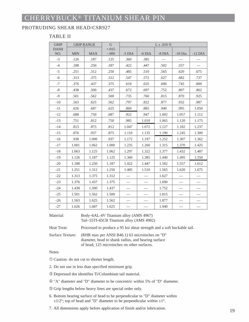
19
CHERRYBUCK® TITANIUM SHEAR PINPROTRUDING SHEAR HEAD/CSR927
TABLE IIGRIP DASH
NO.
GRIP RANGE G+.015 –.000
L ± .010 Ä
MIN MAX -5 DIA -6 DIA -8 DIA -10 Dia -12 DIA-3 .126 .187 .125 .360 .385 — — —
-4 .188 .250 .187 .422 .447 .502 .557 —
-5 .251 .312 .250 .485 .510 .565 .620 .675
-6 .313 .375 .312 .547 .572 .627 .682 .737
-7 .376 .437 .375 .610 .635 .690 .745 .800
-8 .438 .500 .437 .672 .697 .752 .807 .862
-9 .501 .562 .500 .735 .760 .815 .870 .925
-10 .563 .625 .562 .797 .822 .877 .932 .987
-11 .626 .687 .625 .860 .885 .940 .995 1.050
-12 .688 .750 .687 .922 .947 1.002 1.057 1.112
-13 .751 .812 .750 .985 1.010 1.065 1.120 1.175
-14 .813 .875 .812 1.047 1.072 1.127 1.182 1.237
-15 .876 .937 .875 1.110 1.135 1.190 1.245 1.300
-16 .938 1.000 .937 1.172 1.197 1.252 1.307 1.362
-17 1.001 1.062 1.000 1.235 1.260 1.315 1.370 1.425
-18 1.063 1.125 1.062 1.297 1.322 1.377 1.432 1.487
-19 1.126 1.187 1.125 1.360 1.385 1.440 1.495 1.550
-20 1.188 1.250 1.187 1.422 1.447 1.502 1.557 1.612
-21 1.251 1.312 1.250 1.485 1.510 1.565 1.620 1.675
-22 1.313 1.375 1.312 — — 1.627 — —
-23 1.376 1.437 1.375 — — 1.690 — —
-24 1.438 1.500 1.437 — — 1.752 — —
-25 1.501 1.562 1.500 — — 1.815 — —
-26 1.563 1.625 1.562 — — 1.877 — —
-27 1.626 1.687 1.625 — — 1.940 — —
Material: Body–6AL-4V Titanium alloy (AMS 4967)Tail–55TI-45CB Titanium alloy (AMS 4982)
Heat Treat: Processed to produce a 95 ksi shear strength and a soft buckable tail.
Surface Texture: (RHR max per ANSI B46.1) 63 microinches on "D" diameter, head to shank radius, and bearing surface of head; 125 microinches on other surfaces.
Notes
À Caution: do not cut to shorter length.
2. Do not use in less than specified minimum grip.
 Depressed dot identifies Ti/Columbium tail material.
à "A" diameter and "D" diameter to be concentric within 5% of "D" diameter.
Ä Grip lengths below heavy lines are special order only.
6. Bottom bearing surface of head to be perpendicular to "D" diameter within ±1/2°; top of head and "D" diameter to be perpendicular within ±1°.
7. All dimensions apply before application of finish and/or lubrication.
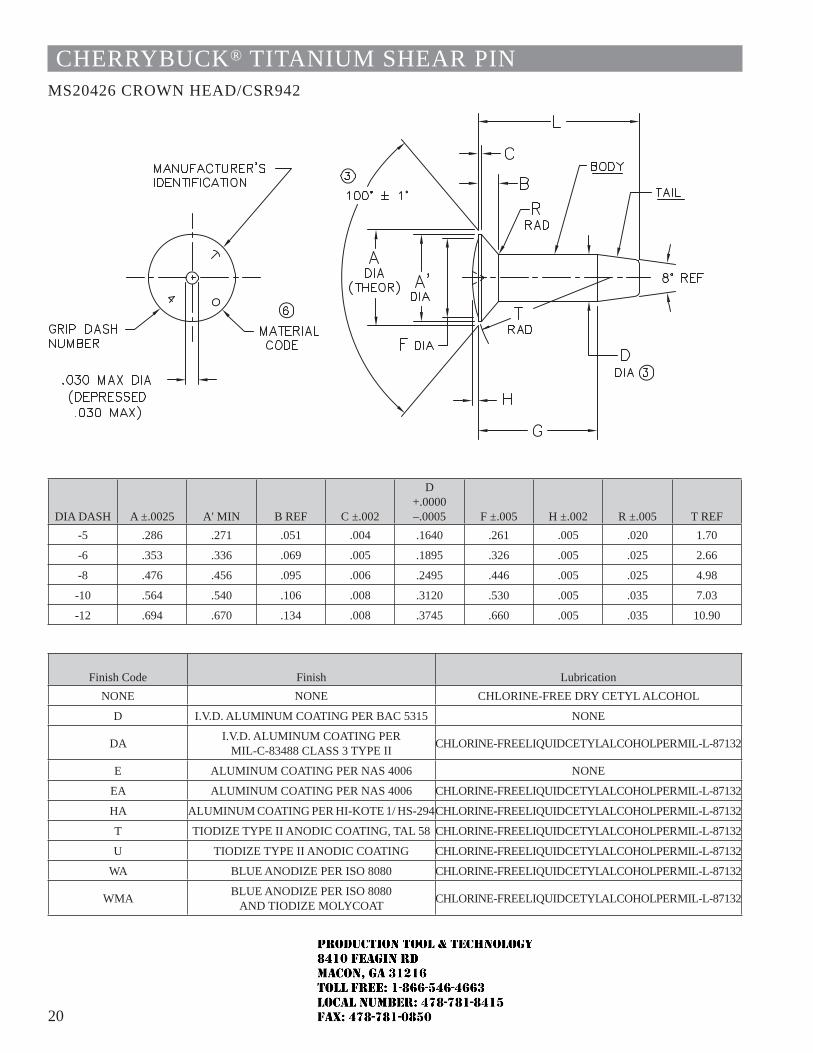
20
CHERRYBUCK® TITANIUM SHEAR PINMS20426 CROWN HEAD/CSR942
DIA DASH A ±.0025 A' MIN B REF C ±.002
D +.0000 –.0005 F ±.005 H ±.002 R ±.005 T REF
-5 .286 .271 .051 .004 .1640 .261 .005 .020 1.70
-6 .353 .336 .069 .005 .1895 .326 .005 .025 2.66
-8 .476 .456 .095 .006 .2495 .446 .005 .025 4.98
-10 .564 .540 .106 .008 .3120 .530 .005 .035 7.03
-12 .694 .670 .134 .008 .3745 .660 .005 .035 10.90
Finish Code Finish LubricationNONE NONE CHLORINE-FREE DRY CETYL ALCOHOL
D I.V.D. ALUMINUM COATING PER BAC 5315 NONE
DA I.V.D. ALUMINUM COATING PER MIL-C-83488 CLASS 3 TYPE II CHLORINE-FREE LIQUID CETYL ALCOHOL PER MIL-L-87132
E ALUMINUM COATING PER NAS 4006 NONE
EA ALUMINUM COATING PER NAS 4006 CHLORINE-FREE LIQUID CETYL ALCOHOL PER MIL-L-87132
HA ALUMINUM COATING PER HI-KOTE 1/ HS-294CHLORINE-FREE LIQUID CETYL ALCOHOL PER MIL-L-87132
T TIODIZE TYPE II ANODIC COATING, TAL 58 CHLORINE-FREE LIQUID CETYL ALCOHOL PER MIL-L-87132
U TIODIZE TYPE II ANODIC COATING CHLORINE-FREE LIQUID CETYL ALCOHOL PER MIL-L-87132
WA BLUE ANODIZE PER ISO 8080 CHLORINE-FREE LIQUID CETYL ALCOHOL PER MIL-L-87132
WMA BLUE ANODIZE PER ISO 8080 AND TIODIZE MOLYCOAT CHLORINE-FREE LIQUID CETYL ALCOHOL PER MIL-L-87132
JR
Typewritten text
Production Tool & Technology 8410 Feagin Rd Macon, Ga 31216 Toll Free: 1-866-546-4663 Local Number: 478-781-8415 Fax: 478-781-0850
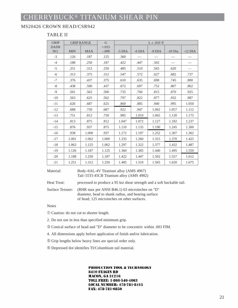
21
CHERRYBUCK® TITANIUM SHEAR PINMS20426 CROWN HEAD/CSR942
TABLE IIGRIP DASH
NO.
GRIP RANGE G+.015 –.000
L ± .010 Ä
MIN MAX -5 DIA -6 DIA -8 DIA -10 Dia -12 DIA-3 .126 .187 .125 .360 — — — —
-4 .188 .250 .187 .422 .447 .502 — —
-5 .251 .312 .250 .485 .510 .565 .620 —
-6 .313 .375 .312 .547 .572 .627 .682 .737
-7 .376 .437 .375 .610 .635 .690 .745 .800
-8 .438 .500 .437 .672 .697 .752 .807 .862
-9 .501 .562 .500 .735 .760 .815 .870 .925
-10 .563 .625 .562 .797 .822 .877 .932 .987
-11 .626 .687 .625 .860 .885 .940 .995 1.050
-12 .688 .750 .687 .922 .947 1.002 1.057 1.112
-13 .751 .812 .750 .985 1.010 1.065 1.120 1.175
-14 .813 .875 .812 1.047 1.072 1.127 1.182 1.237
-15 .876 .937 .875 1.110 1.135 1.190 1.245 1.300
-16 .938 1.000 .937 1.172 1.197 1.252 1.307 1.362
-17 1.001 1.062 1.000 1.235 1.260 1.315 1.370 1.425
-18 1.063 1.125 1.062 1.297 1.322 1.377 1.432 1.487
-19 1.126 1.187 1.125 1.360 1.385 1.440 1.495 1.550
-20 1.188 1.250 1.187 1.422 1.447 1.502 1.557 1.612
-21 1.251 1.312 1.250 1.485 1.510 1.565 1.620 1.675
Material: Body–6AL-4V Titanium alloy (AMS 4967)Tail–55TI-45CB Titanium alloy (AMS 4982)
Heat Treat: processed to produce a 95 ksi shear strength and a soft buckable tail.
Surface Texture: (RHR max per ANSI B46.1) 63 microinches on "D" diameter, head to shank radius, and bearing surface of head; 125 microinches on other surfaces.
Notes
À Caution: do not cut to shorter length.
2. Do not use in less than specified minimum grip.
 Conical surface of head and "D" diameter to be concentric within .003 FIM.
4. All dimensions apply before application of finish and/or lubrication.
Ä Grip lengths below heavy lines are special order only.
Å Depressed dot identifies TI/Columbium tail material.
JR
Typewritten text
Production Tool & Technology 8410 Feagin Rd Macon, Ga 31216 Toll Free: 1-866-546-4663 Local Number: 478-781-8415 Fax: 478-781-0850
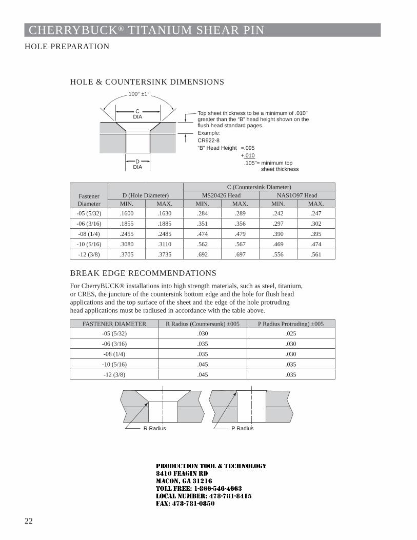
22
CHERRYBUCK® TITANIUM SHEAR PINHOLE PREPARATION
HOLE & COUNTERSINK DIMENSIONS100° ±1°
Top sheet thickness to be a minimum of .010" greater than the “B” head height shown on the flush head standard pages.Example:CR922-8“B” Head Height =.095 +.010 .105"= minimum top sheet thickness
CDIA
DDIA
FastenerDiameter
D (Hole Diameter)C (Countersink Diameter)
MS20426 Head NAS1O97 HeadMIN. MAX. MIN. MAX. MIN. MAX.
-05 (5/32) .1600 .1630 .284 .289 .242 .247
-06 (3/16) .1855 .1885 .351 .356 .297 .302
-08 (1/4) .2455 .2485 .474 .479 .390 .395
-10 (5/16) .3080 .3110 .562 .567 .469 .474
-12 (3/8) .3705 .3735 .692 .697 .556 .561
BREAK EDGE RECOMMENDATIONSFor CherryBUCK® installations into high strength materials, such as steel, titanium, or CRES, the juncture of the countersink bottom edge and the hole for flush head applications and the top surface of the sheet and the edge of the hole protruding head applications must be radiused in accordance with the table above.
FASTENER DIAMETER R Radius (Countersunk) ±005 P Radius Protruding) ±005-05 (5/32) .030 .025
-06 (3/16) .035 .030
-08 (1/4) .035 .030
-10 (5/16) .045 .035
-12 (3/8) .045 .035
P Radius R Radius
JR
Typewritten text
Production Tool & Technology 8410 Feagin Rd Macon, Ga 31216 Toll Free: 1-866-546-4663 Local Number: 478-781-8415 Fax: 478-781-0850
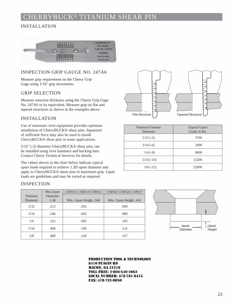
23
CHERRYBUCK® TITANIUM SHEAR PININSTALLATION
INSPECTION GRIP GAUGE NO. 247A6Measure grip requirement on the Cherry Grip Gage using 1/16" grip increments.
GRIP SELECTIONMeasure structure thickness using the Cherry Grip Gage No. 247A6 or its equivalent. Measure grip on flat and tapered structures as shown in the examples above.
INSTALLATIONUse of automatic rivet equipment provides optimum installation of CherryBUCK® shear pins. Squeezers of sufficient force may also be used to install CherryBUCK® shear pins in some applications.
5/32" (-5) diameter CherryBUCK® shear pins can be installed using rivet hammers and bucking bars. Contact Cherry Technical Services for details.
The values shown in the chart below indicate typical upset loads required to achieve 1.3D upset diameter and apply to CherryBUCK® shear pins in maximum grip. Upset loads are guidelines and may be varied as required.
INSPECTION
Nominal Diameter
Min.Upset Diameter
1.3d
CSR922 CSR924 CSR925 CSR942 CSR926 CSR927
Min. Upset Height .34d Min. Upset Height .42d
5/32 .213 .056 .069
3/16 .246 .065 .080
1/4 .325 .085 .105
5/16 .408 .106 .131
3/8 .488 .128 .157
Nominal FastenerDiameter
Typical UpsetLoads in lbs.
5/32 (-5) 3700
3/16 (-6) 5000
1/4 (-8) 8600
5/16 (-10) 15200
3/8 (-12) 22000
JR
Typewritten text
Production Tool & Technology 8410 Feagin Rd Macon, Ga 31216 Toll Free: 1-866-546-4663 Local Number: 478-781-8415 Fax: 478-781-0850
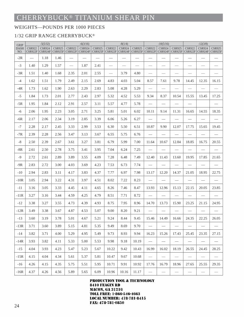
24
CHERRYBUCK® TITANIUM SHEAR PINWEIGHTS—POUNDS PER 1000 PIECES
1/32 GRIP RANGE CHERRYBUCK®
GRIPDASH
NO.
-5(5/32) -6(3/16) -8(1/4) -10(5/16) -12(3/8)CSR922
CSR922FCSR924
CSR924FCSR925
CSR925FCSR922
CSR922FCSR924
CSR924FCSR925
CSR925FCSR922
CSR922FCSR924
CSR924FCSR925
CSR925FCSR922
CSR922FCSR924
CSR924FCSR925
CSR925FCSR922
CSR922FCSR924
CSR924FCSR925
CSR925F
-2R — 1.18 1.46 — — — — — — — — — — — —
-3 1.40 1.29 1.57 — 1.87 2.41 — — — — — — — — —
-3R 1.51 1.40 1.68 2.35 2.01 2.55 — 3.79 4.80 — — — — — —
-4 1.62 1.51 1.79 2.49 2.15 2.69 4.83 4.03 5.04 8.57 7.61 9.78 14.45 12.35 16.15
-4R 1.73 1.62 1.90 2.63 2.29 2.83 5.08 4.28 5.29 — — — — — —
-5 1.84 1.73 2.01 2.77 2.43 2.97 5.32 4.52 5.53 9.34 8.37 10.54 15.55 13.45 17.25
-5R 1.95 1.84 2.12 2.91 2.57 3.11 5.57 4.77 5.78 — — — — —
-6 2.06 1.95 2.23 3.05 2.71 3.25 5.81 5.01 6.02 10.11 9.14 11.31 16.65 14.55 18.35
-6R 2.17 2.06 2.34 3.19 2.85 3.39 6.06 5.26 6.27 — — — — — —
-7 2.28 2.17 2.45 3.33 2.99 3.53 6.30 5.50 6.51 10.87 9.90 12.07 17.75 15.65 19.45
-7R 2.39 2.28 2.56 3.47 3.13 3.67 6.55 5.75 6.76 — — — — — —
-8 2.50 2.39 2.67 3.61 3.27 3.81 6.79 5.99 7.00 11.64 10.67 12.84 18.85 16.75 20.55
-8R 2.61 2.50 2.78 3.75 3.41 3.95 7.04 6.24 7.25 — — — — — —
-9 2.72 2.61 2.89 3.89 3.55 4.09 7.28 6.48 7.49 12.40 11.43 13.60 19.95 17.85 21.65
-9R 2.83 2.72 3.00 4.03 3.69 4.23 7.53 6.73 7.74 — — — — — —
-10 2.94 2.83 3.11 4.17 3.83 4.37 7.77 6.97 7.98 13.17 12.20 14.37 21.05 18.95 22.75
-10R 3.05 2.94 3.22 4.31 3.97 4.51 8.02 7.22 8.23 — — — — — —
-11 3.16 3.05 3.33 4.45 4.11 4.65 8.26 7.46 8.47 13.93 12.96 15.13 22.15 20.05 23.85
-11R 3.27 3.16 3.44 4.59 4.25 4.79 8.51 7.71 8.72 — — — — — —
-12 3.38 3.27 3.55 4.73 4.39 4.93 8.75 7.95 8.96 14.70 13.73 15.90 23.25 21.15 24.95
-12R 3.49 3.38 3.67 4.87 4.53 5.07 9.00 8.20 9.21 — — — — — —
-13 3.60 3.19 3.78 5.01 4.67 5.21 9.24 8.44 9.45 15.46 14.49 16.66 24.35 22.25 26.05
-13R 3.71 3.60 3.89 5.15 4.81 5.35 9.49 8.69 9.70 — — — — — —
-14 3.82 3.71 4.00 5.29 4.95 5.49 9.73 8.93 9.94 16.23 15.26 17.43 25.45 23.35 27.15
-14R 3.93 3.82 4.11 5.33 5.00 5.53 9.98 9.18 10.19 — — — — — —
-15 4.04 3.93 4.23 5.47 5.23 5.67 10.22 9.42 10.43 16.99 16.02 18.19 26.55 24.45 28.25
-15R 4.15 4.04 4.34 5.61 5.37 5.81 10.47 9.67 10.68 — — — — — —
-16 4.26 4.15 4.35 5.75 5.51 5.95 10.71 9.91 10.92 17.76 16.79 18.96 27.65 25.55 29.35
-16R 4.37 4.26 4.56 5.89 5.65 6.09 10.96 10.16 11.17 — — — — — —
JR
Typewritten text
Production Tool & Technology 8410 Feagin Rd Macon, Ga 31216 Toll Free: 1-866-546-4663 Local Number: 478-781-8415 Fax: 478-781-0850
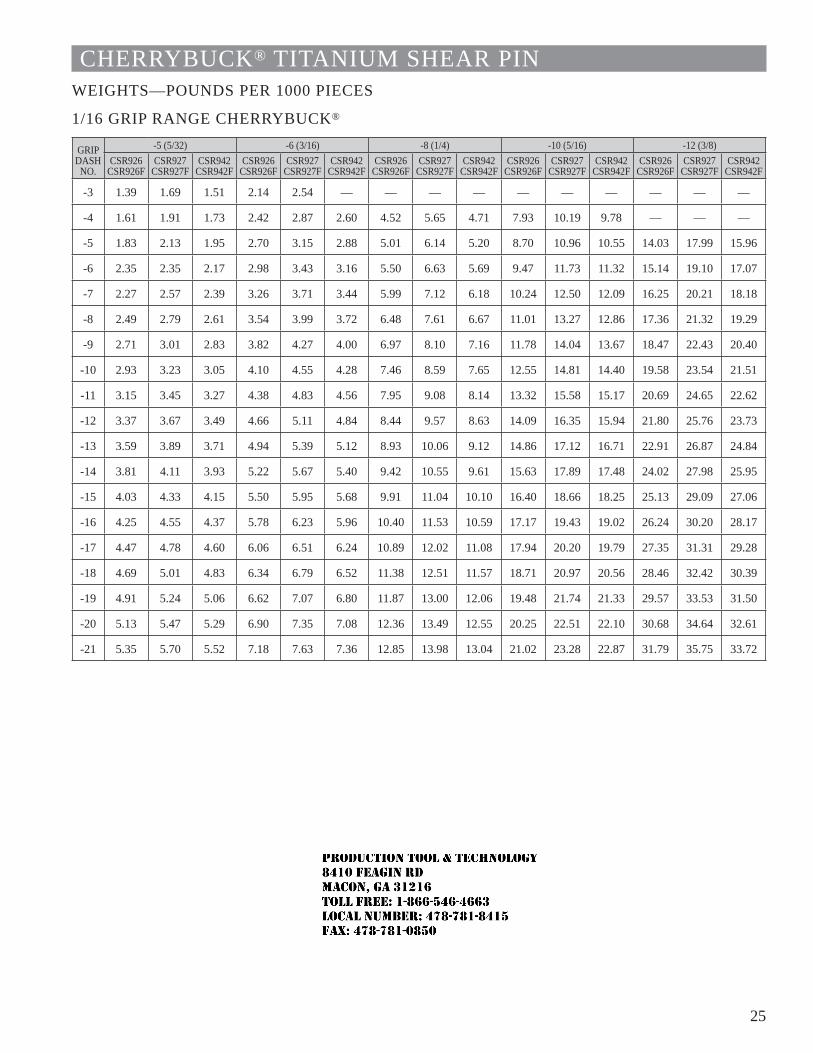
25
CHERRYBUCK® TITANIUM SHEAR PINWEIGHTS—POUNDS PER 1000 PIECES
1/16 GRIP RANGE CHERRYBUCK®
GRIPDASH
NO.
-5 (5/32) -6 (3/16) -8 (1/4) -10 (5/16) -12 (3/8)CSR926
CSR926FCSR927
CSR927FCSR942
CSR942FCSR926
CSR926FCSR927
CSR927FCSR942
CSR942FCSR926
CSR926FCSR927
CSR927FCSR942
CSR942FCSR926
CSR926FCSR927
CSR927FCSR942
CSR942FCSR926
CSR926FCSR927
CSR927FCSR942
CSR942F
-3 1.39 1.69 1.51 2.14 2.54 — — — — — — — — — —
-4 1.61 1.91 1.73 2.42 2.87 2.60 4.52 5.65 4.71 7.93 10.19 9.78 — — —
-5 1.83 2.13 1.95 2.70 3.15 2.88 5.01 6.14 5.20 8.70 10.96 10.55 14.03 17.99 15.96
-6 2.35 2.35 2.17 2.98 3.43 3.16 5.50 6.63 5.69 9.47 11.73 11.32 15.14 19.10 17.07
-7 2.27 2.57 2.39 3.26 3.71 3.44 5.99 7.12 6.18 10.24 12.50 12.09 16.25 20.21 18.18
-8 2.49 2.79 2.61 3.54 3.99 3.72 6.48 7.61 6.67 11.01 13.27 12.86 17.36 21.32 19.29
-9 2.71 3.01 2.83 3.82 4.27 4.00 6.97 8.10 7.16 11.78 14.04 13.67 18.47 22.43 20.40
-10 2.93 3.23 3.05 4.10 4.55 4.28 7.46 8.59 7.65 12.55 14.81 14.40 19.58 23.54 21.51
-11 3.15 3.45 3.27 4.38 4.83 4.56 7.95 9.08 8.14 13.32 15.58 15.17 20.69 24.65 22.62
-12 3.37 3.67 3.49 4.66 5.11 4.84 8.44 9.57 8.63 14.09 16.35 15.94 21.80 25.76 23.73
-13 3.59 3.89 3.71 4.94 5.39 5.12 8.93 10.06 9.12 14.86 17.12 16.71 22.91 26.87 24.84
-14 3.81 4.11 3.93 5.22 5.67 5.40 9.42 10.55 9.61 15.63 17.89 17.48 24.02 27.98 25.95
-15 4.03 4.33 4.15 5.50 5.95 5.68 9.91 11.04 10.10 16.40 18.66 18.25 25.13 29.09 27.06
-16 4.25 4.55 4.37 5.78 6.23 5.96 10.40 11.53 10.59 17.17 19.43 19.02 26.24 30.20 28.17
-17 4.47 4.78 4.60 6.06 6.51 6.24 10.89 12.02 11.08 17.94 20.20 19.79 27.35 31.31 29.28
-18 4.69 5.01 4.83 6.34 6.79 6.52 11.38 12.51 11.57 18.71 20.97 20.56 28.46 32.42 30.39
-19 4.91 5.24 5.06 6.62 7.07 6.80 11.87 13.00 12.06 19.48 21.74 21.33 29.57 33.53 31.50
-20 5.13 5.47 5.29 6.90 7.35 7.08 12.36 13.49 12.55 20.25 22.51 22.10 30.68 34.64 32.61
-21 5.35 5.70 5.52 7.18 7.63 7.36 12.85 13.98 13.04 21.02 23.28 22.87 31.79 35.75 33.72
JR
Typewritten text
Production Tool & Technology 8410 Feagin Rd Macon, Ga 31216 Toll Free: 1-866-546-4663 Local Number: 478-781-8415 Fax: 478-781-0850
1 1
CHERRYMAX® RIVET
SPS Fastener Division, a PCC Company
JR
Typewritten text
Production Tool & Technology 8410 Feagin Rd Macon, Ga 31216 Toll Free: 1-866-546-4663 Local Number: 478-781-8415 Fax: 478-781-0850
2
INDEX
CherryMAX® Rivet Features and Benefits .............................................................................. 3–4
CherryMAX® Rivet Selection Numbering System / Head Styles ..................................................................................................... 5 Diameter/grip System ...................................................................................................................... 6 Mechanical Properties / Gages ........................................................................................................ 7 Weight Per 1000 Pieces by Rivet Size .............................................................................................. 8
CherryMAX® Rivet Standards Pages Nominal Shank Universal Head ................................................................................................................................ 9 100° Flush Head ........................................................................................................................... 10 100° Flush Shear Head (NAS 1097) ............................................................................................... 11 Oversize Shank Diameter Universal Head ............................................................................................................................. 12 100° Flush Head ........................................................................................................................... 13 Unisink Head ................................................................................................................................ 14 120° Flush Head ........................................................................................................................... 15
CherryMAX® Rivet Installation & Inspection.......................................................................16-18
CherryMAX® Rivet Installation Tooling
Tool Selection ......................................................................................................................... 19–27
LIMITED WARRANTY
Seller warrants the goods conform to applicable specifications and drawings and will be manufactured and inspected according to generally accepted practices of companies manufacturing industrial or aerospace fasteners. In the event of any breach of the foregoing warranty, Buyer’s sole remedy shall be to return defective goods (after receiving authorization from Seller) for replacement or refund of the purchase price, at the Seller’s option. Seller agrees to any freight costs in connection with the return of any defective goods, but any costs relating to removal of the defective or nonconforming goods or installation of replacement goods shall be Buyer’s responsibility. SELLER’S WARRANTY DOES NOT APPLY WHEN ANY PHYSICAL OR CHEMICAL CHANGE IN THE FORM OF THE PRODUCT IS MADE BY BUYER. THE FOREGOING EXPRESS WARRANTY AND REMEDY ARE EXCLUSIVE AND ARE IN LIEU OF ALL OTHER WARRANTIES AND REMEDIES; ANY IMPLIED WARRANTY AS TO QUALITY, FITNESS FOR PURPOSE, OR MERCHANTABILITY IS HEREBY SPECIFICALLY DISCLAIMED AND EXCLUDED BY SELLER. This warranty is void if seller is not notified in writing of any rejection of the goods within one (1) Year aFter initial use by buyer of any power Riveter or ninety (90) days after initial use of any other product.
Seller shall not be liable under any circumstances for incidental, special or consequential damages arising in whole or in part from any breach by Seller, AND SUCH INCIDENTAL, SPECIAL, OR CONSEQUENTIAL DAMAGES ARE HEREBY EXPRESSLY EXCLUDED.
Our policy is one of continuous development. Specifications shown in this document may be subject to changes introduced after publication.
CHERRY®, CHERRYMAX® and MAXIBOLT® are trademarks of Cherry Aerospace.
NOTEThe properties, strengths, dimensions, installed characteristics and all other information in this catalog is for guid-ance only to aid in the correct selection of the products described herein and is not intended or implied as part of the warranty. All applications should be evaluated for functional suitability and available samples of the described parts can be requested for installed tests, suitability and evaluations.
ATTENTION:Important: Blind fasteners are not always interchangeable with non-blind fasteners. Consult with the aircraft original equipment manufacturer for proper application of this product.
JR
Typewritten text
Production Tool & Technology 8410 Feagin Rd Macon, Ga 31216 Toll Free: 1-866-546-4663 Local Number: 478-781-8415 Fax: 478-781-0850
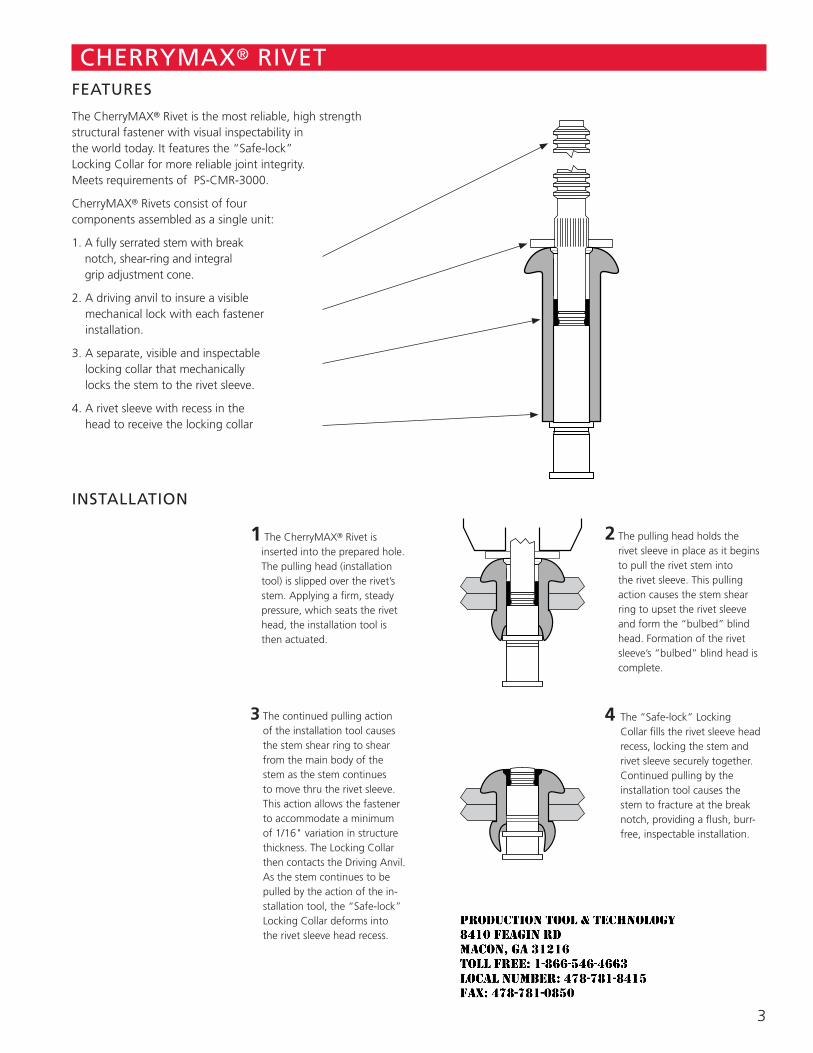
3
CHERRYMAX® RIVET FEATURES
The CherryMAX® Rivet is the most reliable, high strength structural fastener with visual inspectability in the world today. It features the “Safe-lock” Locking Collar for more reliable joint integrity. Meets requirements of PS-CMR-3000.
CherryMAX® Rivets consist of four components assembled as a single unit:
1. A fully serrated stem with break notch, shear-ring and integral grip adjustment cone.
2. A driving anvil to insure a visible mechanical lock with each fastener installation.
3. A separate, visible and inspectable locking collar that mechanically locks the stem to the rivet sleeve.
4. A rivet sleeve with recess in the head to receive the locking collar
INSTALLATION
1 The CherryMAX® Rivet is inserted into the prepared hole. The pulling head (installation tool) is slipped over the rivet’s stem. Applying a firm, steady pressure, which seats the rivet head, the installation tool is then actuated.
2 The pulling head holds the rivet sleeve in place as it begins to pull the rivet stem into the rivet sleeve. This pulling action causes the stem shear ring to upset the rivet sleeve and form the “bulbed” blind head. Formation of the rivet sleeve’s “bulbed” blind head is complete.
3 The continued pulling action of the installation tool causes the stem shear ring to shear from the main body of the stem as the stem continues to move thru the rivet sleeve. This action allows the fastener to accommodate a minimum of 1/16" variation in structure thickness. The Locking Collar then contacts the Driving Anvil. As the stem continues to be pulled by the action of the in-stallation tool, the “Safe-lock” Locking Collar deforms into the rivet sleeve head recess.
4 The “Safe-lock” Locking Collar fills the rivet sleeve head recess, locking the stem and rivet sleeve securely together. Continued pulling by the installation tool causes the stem to fracture at the break notch, providing a flush, burr-free, inspectable installation.
JR
Typewritten text
Production Tool & Technology 8410 Feagin Rd Macon, Ga 31216 Toll Free: 1-866-546-4663 Local Number: 478-781-8415 Fax: 478-781-0850
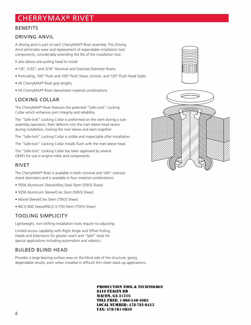
4
CHERRYMAX® RIVET BENEFITS
DRIVING ANVIL
A driving anvil is part of each CherryMAX® Rivet assembly. This Driving Anvil eliminates wear and replacement of expendable installation tool components, considerably extending the life of the installation tool.
It also allows one pulling head to install:
• 1/8", 5/32", and 3/16" Nominal and Oversize Diameter Rivets.
• Protruding, 100° Flush and 100° Flush Shear, Unisink, and 120° Flush Head Styles
• All CherryMAX® Rivet grip lengths
• All CherryMAX® Rivet sleeve/stem material combinations
LOCKING COLLAR
The CherryMAX® Rivet features the patented “Safe-Lock” Locking Collar which enhances joint integrity and reliability.
The “Safe-lock” Locking Collar is preformed on the stem during a sub-assembly operation, then deforms into the rivet sleeve head recess during installation, locking the rivet sleeve and stem together.
The “Safe-lock” Locking Collar is visible and inspectable after installation.
The “Safe-lock” Locking Collar installs flush with the rivet sleeve head.
The “Safe-lock” Locking Collar has been approved by several OEM’s for use in engine inlets and components.
RIVET
The CherryMAX® Rivet is available in both nominal and 1⁄64" oversize shank diameters and is available in four material combinations:
• 5056 Aluminum Sleeve/Alloy Steel Stem (50KSI Shear)
• 5056 Aluminum Sleeve/Cres Stem (50KSI Shear)
• Monel Sleeve/Cres Stem (75KSI Shear)
• INCO 600 Sleeve/INCO X-750 Stem (75KSI Shear)
TOOLING SIMPLICITY
Lightweight, non-shifting installation tools require no adjusting.
Limited access capability with Right Angle and Offset Pulling Heads and Extensions for greater reach and “Split” tools for special applications including automation and robotics.
BULBED BLIND HEAD
Provides a large bearing surface area on the blind side of the structure, giving dependable results, even when installed in difficult thin sheet stack-up applications.
JR
Typewritten text
Production Tool & Technology 8410 Feagin Rd Macon, Ga 31216 Toll Free: 1-866-546-4663 Local Number: 478-781-8415 Fax: 478-781-0850
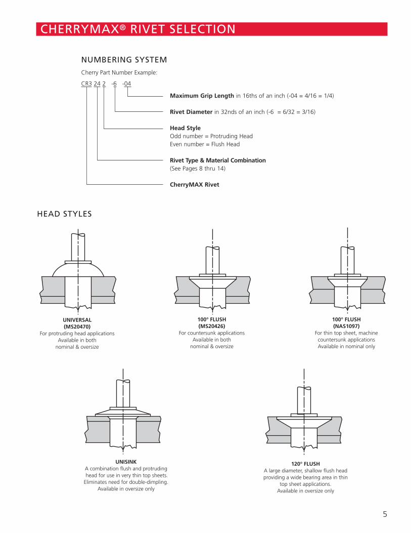
5
CHERRYMAX® RIVET SELECTION
HEAD STYLES
NUMBERING SYSTEM
Cherry Part Number Example:
CR3 24 2 -6 -04
Maximum Grip Length in 16ths of an inch (-04 = 4/16 = 1/4) Rivet Diameter in 32nds of an inch (-6 = 6/32 = 3/16) Head Style Odd number = Protruding Head Even number = Flush Head Rivet Type & Material Combination (See Pages 8 thru 14) CherryMAX Rivet
156 COUNTERSINK 156 COUNTERSINK 156 COUNTERSINK 156 COUNTERSINK 156 COUNTERSINK
UNIVERSAL (MS20470)
For protruding head applications Available in both
nominal & oversize
100° FLUSH (MS20426)
For countersunk applications Available in both
nominal & oversize
100° FLUSH (NAS1097)
For thin top sheet, machine countersunk applications Available in nominal only
UNISINK A combination flush and protruding head for use in very thin top sheets. Eliminates need for double-dimpling.
Available in oversize only
120° FLUSH A large diameter, shallow flush head providing a wide bearing area in thin
top sheet applications. Available in oversize only
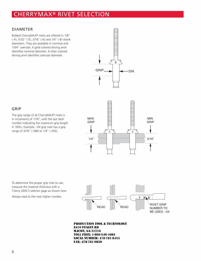
6
DIAMETER
Bulbed CherryMAX® rivets are offered in 1⁄8" (-4), 5/32" (-5), 3/16" (-6) and 1⁄4" (-8) shank diameters. They are available in nominal and 1/64" oversize. A gold colored driving anvil identifies nominal diameter. A silver colored driving anvil identifies oversize diameter.
GRIP
The grip range of all CherryMAX® rivets is in increments of 1/16", with the last dash number indicating the maximum grip length in 16ths. Example: -04 grip rivet has a grip range of 3/16" (.188) to 1/4" (.250).
To determine the proper grip rivet to use, measure the material thickness with a Cherry 269C3 selector gage as shown here.
Always read to the next higher number.
CHERRYMAX® RIVET SELECTION
1/4"
MAX.GRIP
3/16"
MIN.GRIP
DIAGRIP
4
READ READRIVET GRIPNUMBER TOBE USED: –04
4 4
JR
Typewritten text
Production Tool & Technology 8410 Feagin Rd Macon, Ga 31216 Toll Free: 1-866-546-4663 Local Number: 478-781-8415 Fax: 478-781-0850
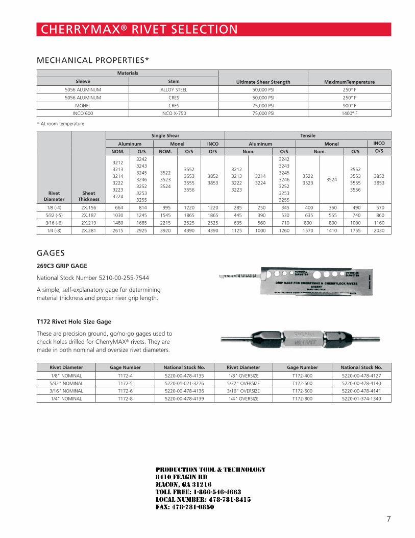
7
MECHANICAL PROPERTIES*Materials
Ultimate Shear Strength MaximumTemperatureSleeve Stem
5056 ALUMINUM ALLOY STEEL 50,000 PSI 250° F
5056 ALUMINUM CRES 50,000 PSI 250° F
MONEL CRES 75,000 PSI 900° F
INCO 600 INCO X-750 75,000 PSI 1400° F
* At room temperature
RivetDiameter
SheetThickness
Single Shear Tensile
Aluminum Monel INCO Aluminum Monel INCO
NOM. O/S NOM. O/S O/S Nom. O/S Nom. O/S O/S
321232133214322232233224
3242324332453246325232533255
352235233524
3552355335553556
38523853
3212321332223223
32143224
3242324332453246325232533255
35223523
3524
3552355335553556
38523853
1⁄8 (-4) 2X.156 664 814 995 1220 1220 285 250 345 400 360 490 570
5⁄32 (-5) 2X.187 1030 1245 1545 1865 1865 445 390 530 635 555 740 860
3⁄16 (-6) 2X.219 1480 1685 2215 2525 2525 635 560 710 890 800 1000 1160
1⁄4 (-8) 2X.281 2615 2925 3920 4390 4390 1125 1000 1260 1570 1410 1755 2030
GAGES
269C3 GRIP GAGE
National Stock Number 5210-00-255-7544
A simple, self-explanatory gage for determining material thickness and proper river grip length.
T172 Rivet Hole Size Gage
These are precision ground, go/no-go gages used to check holes drilled for CherryMAX® rivets. They are made in both nominal and oversize rivet diameters.
Rivet Diameter Gage Number National Stock No. Rivet Diameter Gage Number National Stock No.
1/8" NOMINAL T172-4 5220-00-478-4135 1/8" OVERSIZE T172-400 5220-00-478-4127
5/32" NOMINAL T172-5 5220-01-021-3276 5/32" OVERSIZE T172-500 5220-00-478-4140
3/16" NOMINAL T172-6 5220-00-478-4136 3/16" OVERSIZE T172-600 5220-00-478-4141
1/4" NOMINAL T172-8 5220-00-478-4139 1/4" OVERSIZE T172-800 5220-01-374-1340
CHERRYMAX® RIVET SELECTION
JR
Typewritten text
Production Tool & Technology 8410 Feagin Rd Macon, Ga 31216 Toll Free: 1-866-546-4663 Local Number: 478-781-8415 Fax: 478-781-0850
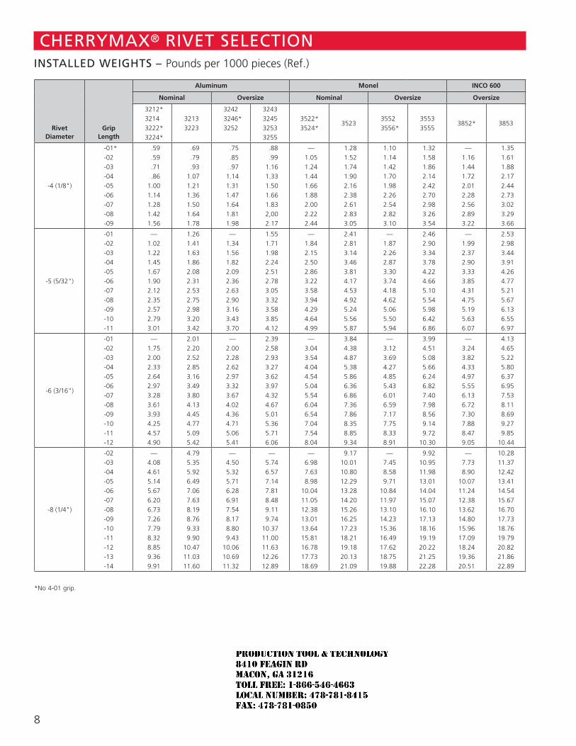
8
Rivet Diameter
Grip Length
Aluminum Monel INCO 600
Nominal Oversize Nominal Oversize Oversize
3212*3214
3222* 3224*
32133223
3242 3246*3252
3243324532533255
3522*3524*
35233552
3556*35533555
3852* 3853
-4 (1/8")
-01*-02-03-04-05-06-07-08-09
.59 .59 .71 .86 1.00 1.14 1.28 1.42 1.56
.69 .79 .93 1.07 1.21 1.36 1.50 1.64 1.78
.75 .85 .97 1.14 1.31 1.47 1.64 1.81 1.98
.88 .99 1.16 1.33 1.50 1.66 1.83 2,00 2.17
— 1.05 1.24 1.44 1.66 1.88 2.00 2.22 2.44
1.28 1.52 1.74 1.90 2.16 2.38 2.61 2.83 3.05
1.10 1.14 1.42 1.70 1.98 2.26 2.54 2.82 3.10
1.32 1.58 1.86 2.14 2.42 2.70 2.98 3.26 3.54
— 1.16 1.44 1.72 2.01 2.28 2.56 2.89 3.22
1.35 1.61 1.88 2.17 2.44 2.73 3.02 3.29 3.66
-5 (5/32")
-01-02-03-04-05-06-07-08-09-10-11
— 1.02 1.22 1.45 1.67 1.90 2.12 2.35 2.57 2.79 3.01
1.26 1.41 1.63 1.86 2.08 2.31 2.53 2.75 2.98 3.20 3.42
— 1.34 1.56 1.82 2.09 2.36 2.63 2.90 3.16 3.43 3.70
1.55 1.71 1.98 2.24 2.51 2.78 3.05 3.32 3.58 3.85 4.12
— 1.84 2.15 2.50 2.86 3.22 3.58 3.94 4.29 4.64 4.99
2.41 2.81 3.14 3.46 3.81 4.17 4.53 4.92 5.24 5.56 5.87
— 1.87 2.26 2.87 3.30 3.74 4.18 4.62 5.06 5.50 5.94
2.46 2.90 3.34 3.78 4.22 4.66 5.10 5.54 5.98 6.42 6.86
— 1.99 2.37 2.90 3.33 3.85 4.31 4.75 5.19 5.63 6.07
2.53 2.98 3.44 3.91 4.26 4.77 5.21 5.67 6.13 6.55 6.97
-6 (3/16")
-01-02-03-04-05-06-07-08-09-10-11-12
— 1.75 2.00 2.33 2.64 2.97 3.28 3.61 3.93 4.25 4.57 4.90
2.01 2.20 2.52 2.85 3.16 3.49 3.80 4.13 4.45 4.77 5.09 5.42
— 2.00 2.28 2.62 2.97 3.32 3.67 4.02 4.36 4.71 5.06 5.41
2.39 2.58 2.93 3.27 3.62 3.97 4.32 4.67 5.01 5.36 5.71 6.06
— 3.04 3.54 4.04 4.54 5.04 5.54 6.04 6.54 7.04 7.54 8.04
3.84 4.38 4.87 5.38 5.86 6.36 6.86 7.36 7.86 8.35 8.85 9.34
— 3.12 3.69 4.27 4.85 5.43 6.01 6.59 7.17 7.75 8.33 8.91
3.99 4.51 5.08 5.66 6.24 6.82 7.40 7.98 8.56 9.14 9.7210.30
— 3.24 3.82 4.33 4.97 5.55 6.13 6.72 7.30 7.88 8.47 9.05
4.13 4.65 5.22 5.80 6.37 6.95 7.53 8.11 8.69 9.27 9.8510.44
-8 (1/4")
-02-03-04-05-06-07-08-09-10-11-12-13-14
— 4.08 4.61 5.14 5.67 6.20 6.73 7.26 7.79 8.32 8.85 9.36 9.91
4.79 5.35 5.92 6.49 7.06 7.63 8.19 8.76 9.33 9.9010.4711.0311.60
— 4.50 5.32 5.71 6.28 6.91 7.54 8.17 8.80 9.4310.0610.6911.32
— 5.74 6.57 7.14 7.81 8.48 9.11 9.7410.3711.0011.6312.2612.89
— 6.98 7.63 8.9810.0411.0512.3813.0113.6415.8116.7817.7318.69
9.1710.0110.8012.2913.2814.2015.2616.2517.2318.2119.1820.1321.09
— 7.45 8.58 9.7110.8411.9713.1014.2315.3616.4917.6218.7519.88
9.9210.9511.9813.0114.0415.0716.1017.1318.1619.1920.2221.2522.28
— 7.73 8.9010.0711.2412.3813.6214.8015.9617.0918.2419.3620.51
10.2811.3712.4213.4114.5415.6716.7017.7318.7619.7920.8221.8622.89
*No 4-01 grip.
CHERRYMAX® RIVET SELECTIONINSTALLED WEIGHTS – Pounds per 1000 pieces (Ref.)
JR
Typewritten text
Production Tool & Technology 8410 Feagin Rd Macon, Ga 31216 Toll Free: 1-866-546-4663 Local Number: 478-781-8415 Fax: 478-781-0850
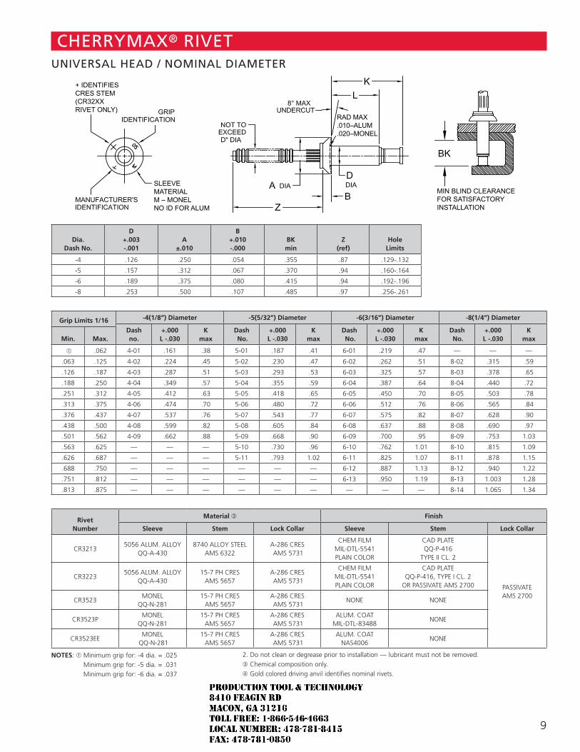
9
Dia. Dash No.
D +.003 -.001
A ±.010
B +.010 -.000
BK min
Z (ref)
Hole Limits
-4 .126 .250 .054 .355 .87 .129-.132
-5 .157 .312 .067 .370 .94 .160-.164
-6 .189 .375 .080 .415 .94 .192-.196
-8 .253 .500 .107 .485 .97 .256-.261
Grip Limits 1/16 -4(1/8”) Diameter -5(5/32”) Diameter -6(3/16”) Diameter -8(1/4”) Diameter
Dash no.
+.000 L -.030
K max
Dash No.
+.000 L -.030
K max
Dash No.
+.000 L -.030
K max
Dash No.
+.000 L -.030
K maxMin. Max.
➀ .062 4-01 .161 .38 5-01 .187 .41 6-01 .219 .47 — — —
.063 .125 4-02 .224 .45 5-02 .230 .47 6-02 .262 .51 8-02 .315 .59
.126 .187 4-03 .287 .51 5-03 .293 .53 6-03 .325 .57 8-03 .378 .65
.188 .250 4-04 .349 .57 5-04 .355 .59 6-04 .387 .64 8-04 .440 .72
.251 .312 4-05 .412 .63 5-05 .418 .65 6-05 .450 .70 8-05 .503 .78
.313 .375 4-06 .474 .70 5-06 .480 .72 6-06 .512 .76 8-06 .565 .84
.376 .437 4-07 .537 .76 5-07 .543 .77 6-07 .575 .82 8-07 .628 .90
.438 .500 4-08 .599 .82 5-08 .605 .84 6-08 .637 .88 8-08 .690 .97
.501 .562 4-09 .662 .88 5-09 .668 .90 6-09 .700 .95 8-09 .753 1.03
.563 .625 — — — 5-10 .730 .96 6-10 .762 1.01 8-10 .815 1.09
.626 .687 — — — 5-11 .793 1.02 6-11 .825 1.07 8-11 .878 1.15
.688 .750 — — — — — — 6-12 .887 1.13 8-12 .940 1.22
.751 .812 — — — — — — 6-13 .950 1.19 8-13 1.003 1.28
.813 .875 — — — — — — — — — 8-14 1.065 1.34
Rivet Number
Material ➂ Finish
Sleeve Stem Lock Collar Sleeve Stem Lock Collar
CR32135056 ALUM. ALLOY
QQ-A-4308740 ALLOY STEEL
AMS 6322A-286 CRES AMS 5731
CHEM FILM MIL-DTL-5541 PLAIN COLOR
CAD PLATE QQ-P-416
TYPE II CL. 2
PASSIVATE AMS 2700
CR32235056 ALUM. ALLOY
QQ-A-43015-7 PH CRES
AMS 5657A-286 CRES AMS 5731
CHEM FILM MIL-DTL-5541 PLAIN COLOR
CAD PLATE QQ-P-416, TYPE I CL. 2
OR PASSIVATE AMS 2700
CR3523MONEL
QQ-N-28115-7 PH CRES
AMS 5657A-286 CRES AMS 5731
NONE NONE
CR3523PMONEL
QQ-N-28115-7 PH CRES
AMS 5657A-286 CRES AMS 5731
ALUM. COAT MIL-DTL-83488
NONE
CR3523EEMONEL
QQ-N-28115-7 PH CRES
AMS 5657A-286 CRES AMS 5731
ALUM. COAT NAS4006
NONE
NOTES: ➀ Minimum grip for: -4 dia. = .025 Minimum grip for: -5 dia. = .031 Minimum grip for: -6 dia. = .037
2. Do not clean or degrease prior to installation — lubricant must not be removed.➂ Chemical composition only.➃ Gold colored driving anvil identifies nominal rivets.
CHERRYMAX® RIVETUNIVERSAL HEAD / NOMINAL DIAMETER
SLEEVE MATERIALM – MONELNO ID FOR ALUM
SLEEVE MATERIALM – MONEL+ – INCO 600NO ID FOR ALUMINUM
+ IDENTIFIESCRES STEM(CR32XXRIVET ONLY)
+ IDENTIFIESCRES STEM(CR32XXRIVET ONLY)
RAD MAX.010–ALUM.020–MONEL
OPTIONAL CONFIGURATIONFOR CRES STEMS
MIN BLIND CLEARANCEFOR SATISFACTORYINSTALLATION
MIN BLIND CLEARANCEFOR SATISFACTORYINSTALLATION
JR
Typewritten text
Production Tool & Technology 8410 Feagin Rd Macon, Ga 31216 Toll Free: 1-866-546-4663 Local Number: 478-781-8415 Fax: 478-781-0850
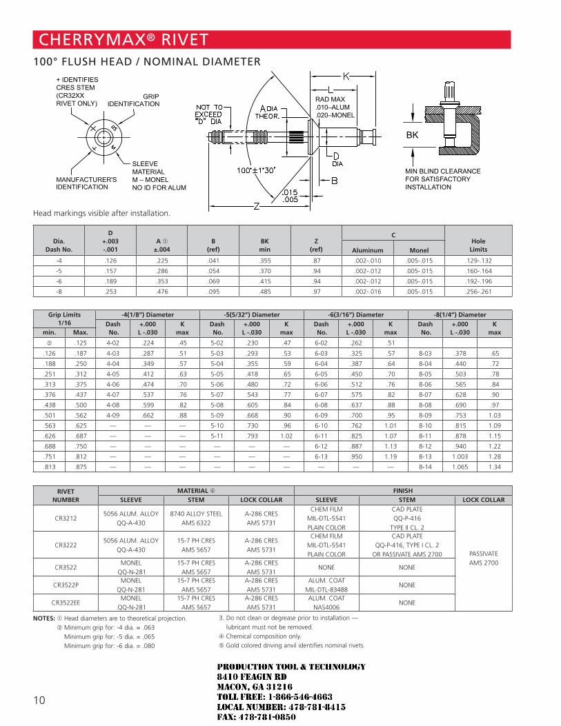
10
Head markings visible after installation.
Dia. Dash No.
D +.003 -.001
A ➀ ±.004
B (ref)
BK min
Z (ref)
CHole
LimitsAluminum Monel
-4 .126 .225 .041 .355 .87 .002-.010 .005-.015 .129-.132
-5 .157 .286 .054 .370 .94 .002-.012 .005-.015 .160-.164
-6 .189 .353 .069 .415 .94 .002-.012 .005-.015 .192-.196
-8 .253 .476 .095 .485 .97 .002-.016 .005-.015 .256-.261
Grip Limits
1/16-4(1/8”) Diameter -5(5/32”) Diameter -6(3/16”) Diameter -8(1/4”) Diameter
Dash No.
+.000 L -.030
K max
Dash No.
+.000 L -.030
K max
Dash No.
+.000 L -.030
K max
Dash No.
+.000 L -.030
K maxmin. Max.
➁ .125 4-02 .224 .45 5-02 .230 .47 6-02 .262 .51
.126 .187 4-03 .287 .51 5-03 .293 .53 6-03 .325 .57 8-03 .378 .65
.188 .250 4-04 .349 .57 5-04 .355 .59 6-04 .387 .64 8-04 .440 .72
.251 .312 4-05 .412 .63 5-05 .418 .65 6-05 .450 .70 8-05 .503 .78
.313 .375 4-06 .474 .70 5-06 .480 .72 6-06 .512 .76 8-06 .565 .84
.376 .437 4-07 .537 .76 5-07 .543 .77 6-07 .575 .82 8-07 .628 .90
.438 .500 4-08 .599 .82 5-08 .605 .84 6-08 .637 .88 8-08 .690 .97
.501 .562 4-09 .662 .88 5-09 .668 .90 6-09 .700 .95 8-09 .753 1.03
.563 .625 — — — 5-10 .730 .96 6-10 .762 1.01 8-10 .815 1.09
.626 .687 — — — 5-11 .793 1.02 6-11 .825 1.07 8-11 .878 1.15
.688 .750 — — — — — — 6-12 .887 1.13 8-12 .940 1.22
.751 .812 — — — — — — 6-13 .950 1.19 8-13 1.003 1.28
.813 .875 — — — — — — — — — 8-14 1.065 1.34
RIVET
NUMBERMATERIAL ➃ FINISH
SLEEVE STEM LOCK COLLAR SLEEVE STEM LOCK COLLAR
CR32125056 ALUM. ALLOY
QQ-A-4308740 ALLOY STEEL
AMS 6322A-286 CRES AMS 5731
CHEM FILM MIL-DTL-5541 PLAIN COLOR
CAD PLATE QQ-P-416
TYPE II CL. 2
PASSIVATE AMS 2700
CR32225056 ALUM. ALLOY
QQ-A-43015-7 PH CRES
AMS 5657A-286 CRES AMS 5731
CHEM FILM MIL-DTL-5541 PLAIN COLOR
CAD PLATE QQ-P-416, TYPE I CL. 2
OR PASSIVATE AMS 2700
CR3522MONEL
QQ-N-28115-7 PH CRES
AMS 5657A-286 CRES AMS 5731
NONE NONE
CR3522PMONEL
QQ-N-28115-7 PH CRES
AMS 5657A-286 CRES AMS 5731
ALUM. COAT MIL-DTL-83488
NONE
CR3522EEMONEL
QQ-N-28115-7 PH CRES
AMS 5657A-286 CRES AMS 5731
ALUM. COAT NAS4006
NONE
NOTES: ➀ Head diameters are to theoretical projection. ➁ Minimum grip for: -4 dia. = .063
Minimum grip for: -5 dia. = .065 Minimum grip for: -6 dia. = .080
3. Do not clean or degrease prior to installation — lubricant must not be removed.
➃ Chemical composition only.➄ Gold colored driving anvil identifies nominal rivets.
SLEEVE MATERIALM – MONEL+ – INCO 600NO ID FOR ALUMINUM
+ IDENTIFIESCRES STEM(CR32XXRIVET ONLY)
RAD MAX.010–ALUM.020–MONEL
RAD MAX.010–ALUM.020–MONEL
OPTIONAL CONFIGURATIONFOR CRES STEMS
MIN BLIND CLEARANCEFOR SATISFACTORYINSTALLATION
MIN BLIND CLEARANCEFOR SATISFACTORYINSTALLATION
SLEEVE MATERIALM – MONELNO ID FOR ALUM
+ IDENTIFIESCRES STEM(CR32XXRIVET ONLY)
CHERRYMAX® RIVET100° FLUSH HEAD / NOMINAL DIAMETER
JR
Typewritten text
Production Tool & Technology 8410 Feagin Rd Macon, Ga 31216 Toll Free: 1-866-546-4663 Local Number: 478-781-8415 Fax: 478-781-0850
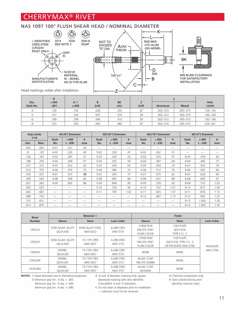
11
CHERRYMAX® RIVETNAS 1097 100° FLUSH SHEAR HEAD / NOMINAL DIAMETER
Head markings visible after installation.
Dia. Dash No.
D +.003 -.001
A ➀ ±.004
B (ref)
BK min
Z (ref)
CHole
LimitsAluminum Monel
-4 .126 .192 .028 .355 .87 .002-.010 .005-.015 .129-.132
-5 .157 .243 .037 .370 .94 .002-.012 .005-.015 .160-.164
-6 .189 .299 .046 .415 .94 .002-.012 .005-.015 .192-.196
-8 .253 .392 .060 .485 .97 .002-.016 .005-.015 .256-.261
Grip Limits
1/16-4(1/8”) Diameter -5(5/32”) Diameter -6(3/16”) Diameter -8(1/4”) Diameter
Dash No.
+.000 L -.030
K max
Dash No.
+.000 L -.030
K max
Dash No.
+.000 L -.030
K max
Dash No.
+.000 L -.030
K maxmin. Max.
.045 .062 4-01 .221 .45 — — — — — — — — —
➁ .125 4-02 .224 .45 5-02 .230 .47 6-02 .262 .51 — — —
.126 .187 4-03 .287 .51 5-03 .293 .53 6-03 .325 .57 8-03 .378 .65
.188 .250 4-04 .349 .57 5-04 .355 .59 6-04 .387 .64 8-04 .440 .72
.251 .312 4-05 .412 .63 5-05 .418 .65 6-05 .450 .70 8-05 .503 .78
.313 .375 4-06 .474 .70 5-06 .480 .72 6-06 .512 .76 8-06 .565 .84
.376 .437 4-07 .537 .76 5-07 .543 .77 6-07 .575 .82 8-07 .628 .90
.438 .500 4-08 .599 .82 5-08 .605 .84 6-08 .637 .88 8-08 .690 .97
.501 .562 4-09 .662 .88 5-09 .668 .90 6-09 .700 .95 8-09 .753 1.03
.563 .625 — — — 5-10 .730 .96 6-10 .762 1.01 8-10 .815 1.09
.626 .687 — — — 5-11 .793 1.02 6-11 .825 1.07 8-11 .878 1.15
.688 .750 — — — — — — 6-12 .887 1.13 8-12 .940 1.22
.751 .812 — — — — — — — — — 8-13 1.003 1.28
.813 .875 — — — — — — — — — 8-14 1.065 1.34
Rivet Number
Material ➄ Finish
Sleeve Stem Lock Collar Sleeve Stem Lock Collar
CR32145056 ALUM. ALLOY
QQ-A-4308740 ALLOY STEEL
AMS 6322A-286 CRES AMS 5731
CHEM FILM MIL-DTL-5541 PLAIN COLOR
CAD PLATE QQ-P-416
TYPE II CL. 2
PASSIVATE AMS 2700
CR32245056 ALUM. ALLOY
QQ-A-43015-7 PH CRES
AMS 5657A-286 CRES AMS 5731
CHEM FILM MIL-DTL-5541 PLAIN COLOR
CAD PLATE QQ-P-416, TYPE I CL. 2
OR PASSIVATE AMS 2700
CR3524MONEL
QQ-N-28115-7 PH CRES
AMS 5657A-286 CRES AMS 5731
NONE NONE
CR3524PMONEL
QQ-N-28115-7 PH CRES
AMS 5657A-286 CRES AMS 5731
ALUM. COAT MIL-DTL-83488
NONE
CR3524EEMONEL
QQ-N-28115-7 PH CRES
AMS 5657A-286 CRES AMS 5731
ALUM. COAT NAS4006
NONE
NOTES: ➀ Head diameters are to theoretical projection. ➁ Minimum grip for: -4 dia. = .063
Minimum grip for: -5 dia. = .065 Minimum grip for: -6 dia. = .080
➂ -6 and -8 diameter marking only; square depressed marking with dots identifies CherryMAX -4 and -5 diameters.
4. Do not clean or degrease prior to installation — lubricant must not be removed.
➄ Chemical composition only.➅ Gold colored driving anvil
identifies nominal rivets.
RAD MAX.010–ALUM.020–MONEL
3214SEE NOTE 3
3224 3524 &3524P
SLEEVE MATERIALM – MONELNO ID FOR ALUM
+ IDENTIFIESCRES STEM(CR32XXRIVET ONLY)
MIN BLIND CLEARANCEFOR SATISFACTORYINSTALLATION
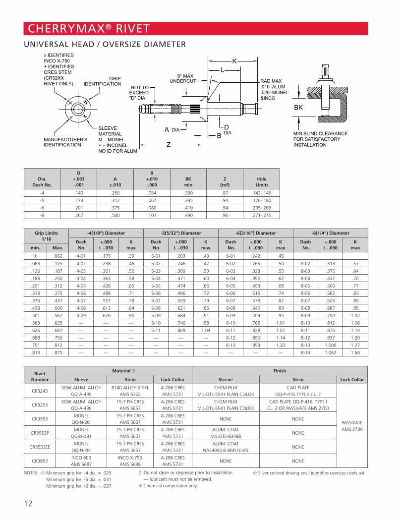
12
RAD MAX.010–ALUM.020–MONEL&INCO
SLEEVE MATERIALM – MONEL+ – INCONELNO ID FOR ALUM
X IDENTIFIES INCO X-750+ IDENTIFIESCRES STEM(CR32XXRIVET ONLY)
MIN BLIND CLEARANCEFOR SATISFACTORYINSTALLATION
CHERRYMAX® RIVETUNIVERSAL HEAD / OVERSIZE DIAMETER
Dia. Dash No.
D +.003 -.001
A ±.010
B +.010 -.000
BK min
Z (ref)
Hole Limits
-4 .140 .250 .054 .390 .87 .143-.146
-5 .173 .312 .067 .395 .94 .176-.180
-6 .201 .375 .080 .410 .94 .205-.209
-8 .267 .500 .107 .490 .96 .271-.275
Grip Limits
1/16-4(1/8”) Diameter -5(5/32”) Diameter -6(3/16”) Diameter -8(1/4”) Diameter
Dash No.
+.000 L -.030
K max
Dash No.
+.000 L -.030
K max
Dash No.
+.000 L -.030
K max
Dash No.
+.000 L -.030
K maxmin. Max.
➀ .062 4-01 .175 .39 5-01 .203 .43 6-01 .242 .45
.063 .125 4-02 .238 .46 5-02 .246 .47 6-02 .265 .50 8-02 .313 .57
.126 .187 4-03 .301 .52 5-03 .309 .53 6-03 .328 .55 8-03 .375 .64
.188 .250 4-04 .363 .58 5-04 .371 .60 6-04 .390 .62 8-04 .437 .70
.251 .312 4-05 .426 .65 5-05 .434 .66 6-05 .453 .68 8-05 .500 .77
.313 .375 4-06 .488 .71 5-06 .496 .72 6-06 .515 .74 8-06 .562 .83
.376 .437 4-07 .551 .78 5-07 .559 .79 6-07 .578 .82 8-07 .625 .89
.438 .500 4-08 .613 .84 5-08 .621 .85 6-08 .640 .89 8-08 .687 .95
.501 .562 4-09 .676 .90 5-09 .684 .91 6-09 .703 .95 8-09 .750 1.02
.563 .625 — — — 5-10 .746 .98 6-10 .765 1.01 8-10 .812 1.08
.626 .687 — — — 5-11 .809 1.04 6-11 .828 1.07 8-11 .875 1.14
.688 .750 — — — — — — 6-12 .890 1.14 8-12 .937 1.20
.751 .812 — — — — — — 6-13 .953 1.20 8-13 1.000 1.27
.813 .875 — — — — — — — — — 8-14 1.062 1.60
Rivet Number
Material ➂ Finish
Sleeve Stem Lock Collar Sleeve Stem Lock Collar
CR32435056 ALUM. ALLOY
QQ-A-4308740 ALLOY STEEL
AMS 6322A-286 CRES AMS 5731
CHEM FILM MIL-DTL-5541 PLAIN COLOR
CAD PLATE QQ-P-416 TYPE II CL. 2
PASSIVATE AMS 2700
CR32535056 ALUM. ALLOY
QQ-A-43015-7 PH CRES
AMS 5657A-286 CRES AMS 5731
CHEM FILM MIL-DTL-5541 PLAIN COLOR
CAD PLATE QQ-P-416, TYPE I CL. 2 OR PASSIVATE AMS 2700
CR3553MONEL
QQ-N-28115-7 PH CRES
AMS 5657A-286 CRES AMS 5731
NONE NONE
CR3553PMONEL
QQ-N-28115-7 PH CRES
AMS 5657A-286 CRES AMS 5731
ALUM. COAT MIL-DTL-83488
NONE
CR3553EEMONEL
QQ-N-28115-7 PH CRES
AMS 5657A-286 CRES AMS 5731
ALUM. COAT NAS4006 & BMS10-85
NONE
CR3853INCO 600 AMS 5687
INCO X-750 AMS 5698
A-286 CRES AMS 5731
NONE NONE
NOTES: ➀ Minimum grip for: -4 dia. = .025 Minimum grip for: -5 dia. = .031 Minimum grip for: -6 dia. = .037
2. Do not clean or degrease prior to installation — lubricant must not be removed.
➂ Chemical composition only.
➃ Silver colored driving anvil identifies oversize rivets.avt
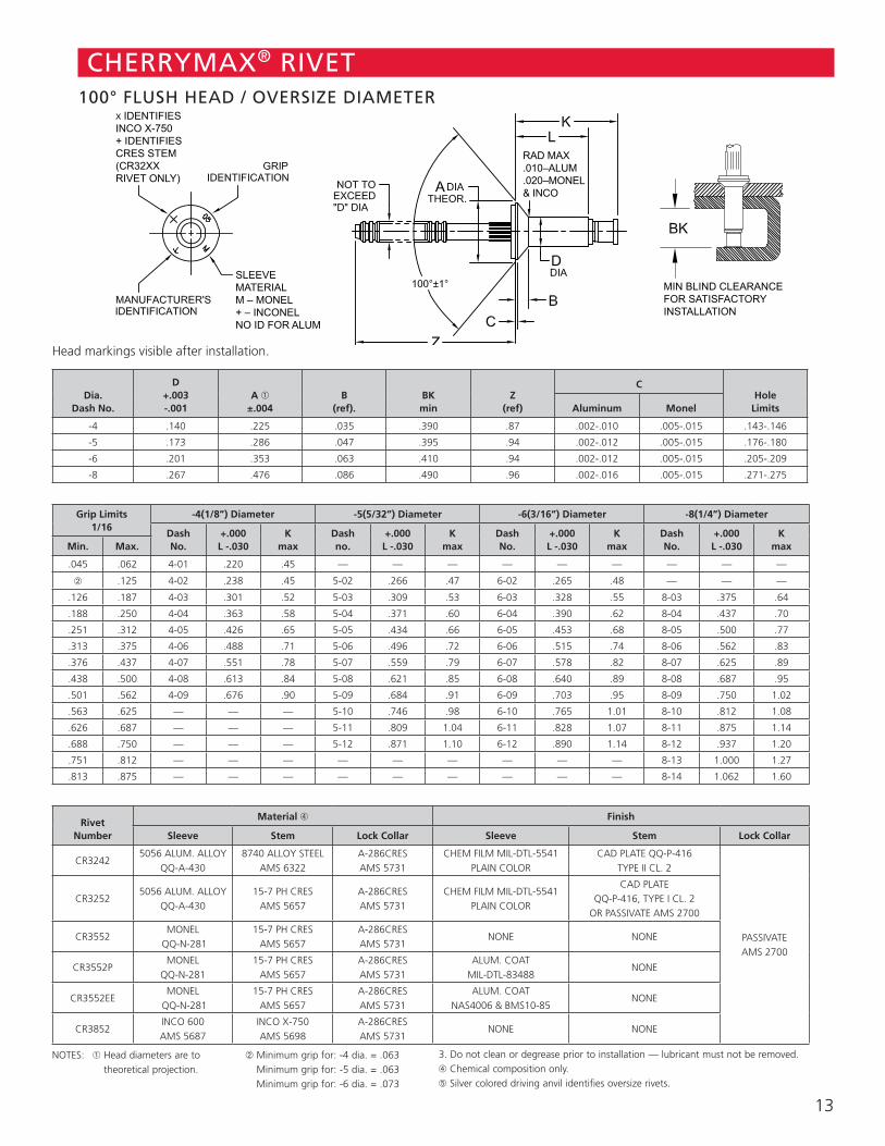
13
RAD MAX.010–ALUM.020–MONEL& INCO
SLEEVE MATERIALM – MONEL+ – INCONELNO ID FOR ALUM
X IDENTIFIES INCO X-750+ IDENTIFIESCRES STEM(CR32XXRIVET ONLY)
MIN BLIND CLEARANCEFOR SATISFACTORYINSTALLATION
CHERRYMAX® RIVET100° FLUSH HEAD / OVERSIZE DIAMETER
Head markings visible after installation.
Dia. Dash No.
D +.003 -.001
A ➀ ±.004
B (ref).
BK min
Z (ref)
CHole
LimitsAluminum Monel
-4 .140 .225 .035 .390 .87 .002-.010 .005-.015 .143-.146
-5 .173 .286 .047 .395 .94 .002-.012 .005-.015 .176-.180
-6 .201 .353 .063 .410 .94 .002-.012 .005-.015 .205-.209
-8 .267 .476 .086 .490 .96 .002-.016 .005-.015 .271-.275
Grip Limits
1/16-4(1/8”) Diameter -5(5/32”) Diameter -6(3/16”) Diameter -8(1/4”) Diameter
Dash No.
+.000 L -.030
K max
Dash no.
+.000 L -.030
K max
Dash No.
+.000 L -.030
K max
Dash No.
+.000 L -.030
K maxMin. Max.
.045 .062 4-01 .220 .45 — — — — — — — — —
➁ .125 4-02 .238 .45 5-02 .266 .47 6-02 .265 .48 — — —
.126 .187 4-03 .301 .52 5-03 .309 .53 6-03 .328 .55 8-03 .375 .64
.188 .250 4-04 .363 .58 5-04 .371 .60 6-04 .390 .62 8-04 .437 .70
.251 .312 4-05 .426 .65 5-05 .434 .66 6-05 .453 .68 8-05 .500 .77
.313 .375 4-06 .488 .71 5-06 .496 .72 6-06 .515 .74 8-06 .562 .83
.376 .437 4-07 .551 .78 5-07 .559 .79 6-07 .578 .82 8-07 .625 .89
.438 .500 4-08 .613 .84 5-08 .621 .85 6-08 .640 .89 8-08 .687 .95
.501 .562 4-09 .676 .90 5-09 .684 .91 6-09 .703 .95 8-09 .750 1.02
.563 .625 — — — 5-10 .746 .98 6-10 .765 1.01 8-10 .812 1.08
.626 .687 — — — 5-11 .809 1.04 6-11 .828 1.07 8-11 .875 1.14
.688 .750 — — — 5-12 .871 1.10 6-12 .890 1.14 8-12 .937 1.20
.751 .812 — — — — — — — — — 8-13 1.000 1.27
.813 .875 — — — — — — — — — 8-14 1.062 1.60
Rivet Number
Material ➃ Finish
Sleeve Stem Lock Collar Sleeve Stem Lock Collar
CR32425056 ALUM. ALLOY
QQ-A-4308740 ALLOY STEEL
AMS 6322A-286CRES AMS 5731
CHEM FILM MIL-DTL-5541 PLAIN COLOR
CAD PLATE QQ-P-416 TYPE II CL. 2
PASSIVATE AMS 2700
CR32525056 ALUM. ALLOY
QQ-A-43015-7 PH CRES
AMS 5657A-286CRES AMS 5731
CHEM FILM MIL-DTL-5541 PLAIN COLOR
CAD PLATE QQ-P-416, TYPE I CL. 2
OR PASSIVATE AMS 2700
CR3552MONEL
QQ-N-28115-7 PH CRES
AMS 5657A-286CRES AMS 5731
NONE NONE
CR3552PMONEL
QQ-N-28115-7 PH CRES
AMS 5657A-286CRES AMS 5731
ALUM. COAT MIL-DTL-83488
NONE
CR3552EEMONEL
QQ-N-28115-7 PH CRES
AMS 5657A-286CRES AMS 5731
ALUM. COAT NAS4006 & BMS10-85
NONE
CR3852INCO 600 AMS 5687
INCO X-750 AMS 5698
A-286CRES AMS 5731
NONE NONE
NOTES: ➀ Head diameters are to theoretical projection.
➁ Minimum grip for: -4 dia. = .063 Minimum grip for: -5 dia. = .063 Minimum grip for: -6 dia. = .073
3. Do not clean or degrease prior to installation — lubricant must not be removed. ➃ Chemical composition only.➄ Silver colored driving anvil identifies oversize rivets.
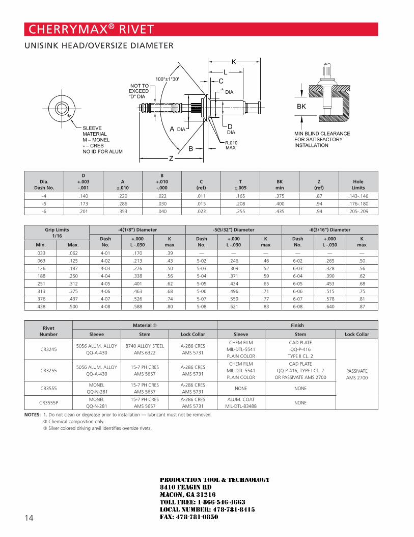
14
SLEEVE MATERIALM – MONEL+ – INCO 600NO ID FOR ALUMINUM
RAD MAX.010–ALUM.020–MONEL& INCO
OPTIONAL CONFIGURATIONFOR CRES STEMS
MIN BLIND CLEARANCEFOR SATISFACTORYINSTALLATION
SLEEVE MATERIALM – MONEL° – CRES NO ID FOR ALUM
MIN BLIND CLEARANCEFOR SATISFACTORYINSTALLATION
CHERRYMAX® RIVETUNISINK HEAD/OVERSIZE DIAMETER
Dia. Dash No.
D +.003 -.001
A ±.010
B +.010 -.000
C (ref)
T ±.005
BK min
Z (ref)
Hole Limits
-4 .140 .220 .022 .011 .165 .375 .87 .143-.146
-5 .173 .286 .030 .015 .208 .400 .94 .176-.180
-6 .201 .353 .040 .023 .255 .435 .94 .205-.209
Grip Limits
1/16-4(1/8”) Diameter -5(5/32”) Diameter -6(3/16”) Diameter
Dash No.
+.000 L -.030
K max
Dash No.
+.000 L -.030
K max
Dash No.
+.000 L -.030
K maxMin. Max.
.033 .062 4-01 .170 .39 — — — — — —
.063 .125 4-02 .213 .43 5-02 .246 .46 6-02 .265 .50
.126 .187 4-03 .276 .50 5-03 .309 .52 6-03 .328 .56
.188 .250 4-04 .338 .56 5-04 .371 .59 6-04 .390 .62
.251 .312 4-05 .401 .62 5-05 .434 .65 6-05 .453 .68
.313 .375 4-06 .463 .68 5-06 .496 .71 6-06 .515 .75
.376 .437 4-07 .526 .74 5-07 .559 .77 6-07 .578 .81
.438 .500 4-08 .588 .80 5-08 .621 .83 6-08 .640 .87
Rivet Number
Material ➁ Finish
Sleeve Stem Lock Collar Sleeve Stem Lock Collar
CR32455056 ALUM. ALLOY
QQ-A-4308740 ALLOY STEEL
AMS 6322A-286 CRES AMS 5731
CHEM FILM MIL-DTL-5541 PLAIN COLOR
CAD PLATE QQ-P-416
TYPE II CL. 2
PASSIVATE AMS 2700
CR32555056 ALUM. ALLOY
QQ-A-43015-7 PH CRES
AMS 5657A-286 CRES AMS 5731
CHEM FILM MIL-DTL-5541 PLAIN COLOR
CAD PLATE QQ-P-416, TYPE I CL. 2
OR PASSIVATE AMS 2700
CR3555MONEL
QQ-N-28115-7 PH CRES
AMS 5657A-286 CRES AMS 5731
NONE NONE
CR3555PMONEL
QQ-N-28115-7 PH CRES
AMS 5657A-286 CRES AMS 5731
ALUM. COAT MIL-DTL-83488
NONE
NOTES: 1. Do not clean or degrease prior to installation — lubricant must not be removed. ➁ Chemical composition only. ➂ Silver colored driving anvil identifies oversize rivets.
JR
Typewritten text
Production Tool & Technology 8410 Feagin Rd Macon, Ga 31216 Toll Free: 1-866-546-4663 Local Number: 478-781-8415 Fax: 478-781-0850
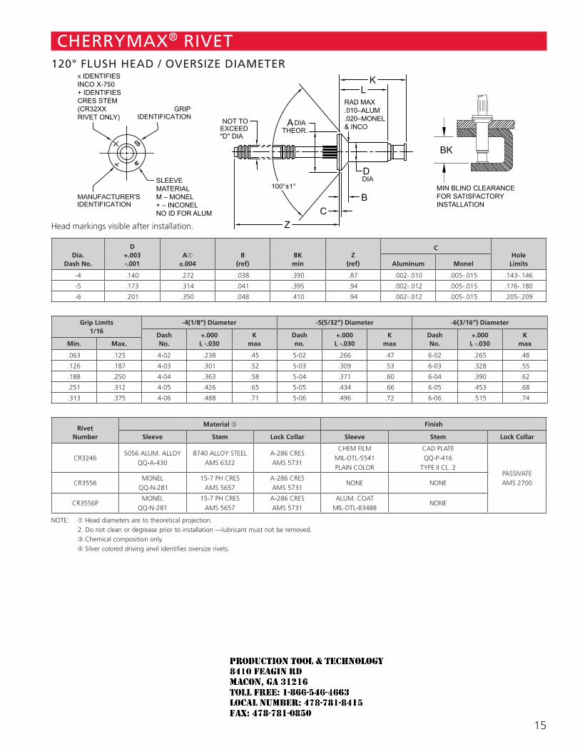
15
RAD MAX.010–ALUM.020–MONEL& INCO
SLEEVE MATERIALM – MONEL+ – INCONELNO ID FOR ALUM
X IDENTIFIES INCO X-750+ IDENTIFIESCRES STEM(CR32XXRIVET ONLY)
MIN BLIND CLEARANCEFOR SATISFACTORYINSTALLATION
CHERRYMAX® RIVET120° FLUSH HEAD / OVERSIZE DIAMETER
Head markings visible after installation.
Dia. Dash No.
D +.003 -.001
A➀ ±.004
B (ref)
BK min
Z (ref)
CHole
LimitsAluminum Monel
-4 .140 .272 .038 .390 .87 .002-.010 .005-.015 .143-.146
-5 .173 .314 .041 .395 .94 .002-.012 .005-.015 .176-.180
-6 .201 .350 .048 .410 .94 .002-.012 .005-.015 .205-.209
Grip Limits
1/16-4(1/8”) Diameter -5(5/32”) Diameter -6(3/16”) Diameter
Dash No.
+.000 L -.030
K max
Dash no.
+.000 L -.030
K max
Dash No.
+.000 L -.030
K maxMin. Max.
.063 .125 4-02 .238 .45 5-02 .266 .47 6-02 .265 .48
.126 .187 4-03 .301 .52 5-03 .309 .53 6-03 .328 .55
.188 .250 4-04 .363 .58 5-04 .371 .60 6-04 .390 .62
.251 .312 4-05 .426 .65 5-05 .434 .66 6-05 .453 .68
.313 .375 4-06 .488 .71 5-06 .496 .72 6-06 .515 .74
Rivet Number
Material ➂ Finish
Sleeve Stem Lock Collar Sleeve Stem Lock Collar
CR32465056 ALUM. ALLOY
QQ-A-4308740 ALLOY STEEL
AMS 6322A-286 CRES AMS 5731
CHEM FILM MIL-DTL-5541 PLAIN COLOR
CAD PLATE QQ-P-416
TYPE II CL. 2PASSIVATE AMS 2700CR3556
MONEL QQ-N-281
15-7 PH CRES AMS 5657
A-286 CRES AMS 5731
NONE NONE
CR3556PMONEL
QQ-N-28115-7 PH CRES
AMS 5657A-286 CRES AMS 5731
ALUM. COAT MIL-DTL-83488
NONE
NOTE: ➀ Head diameters are to theoretical projection. 2. Do not clean or degrease prior to installation —lubricant must not be removed. ➂ Chemical composition only. ➃ Silver colored driving anvil identifies oversize rivets.
JR
Typewritten text
Production Tool & Technology 8410 Feagin Rd Macon, Ga 31216 Toll Free: 1-866-546-4663 Local Number: 478-781-8415 Fax: 478-781-0850
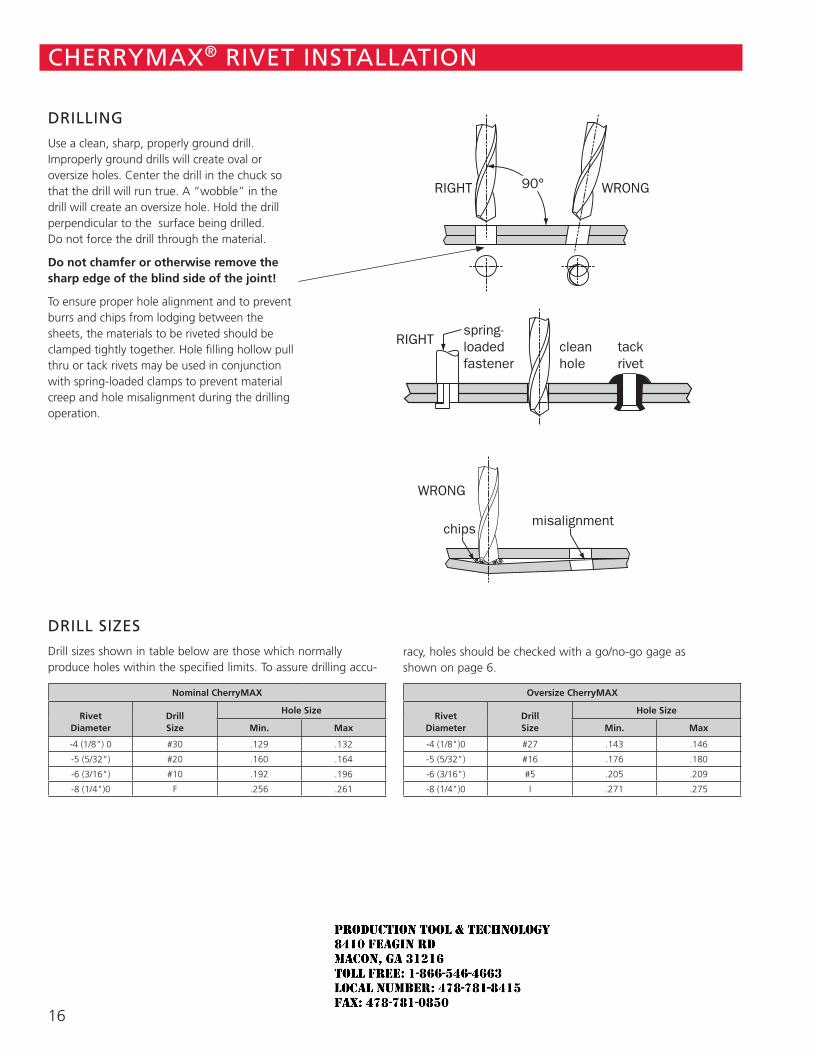
16
DRILLING
Use a clean, sharp, properly ground drill. Improperly ground drills will create oval or oversize holes. Center the drill in the chuck so that the drill will run true. A “wobble” in the drill will create an oversize hole. Hold the drill perpendicular to the surface being drilled. Do not force the drill through the material.
Do not chamfer or otherwise remove the sharp edge of the blind side of the joint!
To ensure proper hole alignment and to prevent burrs and chips from lodging between the sheets, the materials to be riveted should be clamped tightly together. Hole filling hollow pull thru or tack rivets may be used in conjunction with spring-loaded clamps to prevent material creep and hole misalignment during the drilling operation.
CHERRYMAX® RIVET INSTALLATION
Nominal CherryMAX
Rivet Diameter
Drill Size
Hole Size
Min. Max
-4 (1/8") 0 #30 .129 .132
-5 (5/32") #20 .160 .164
-6 (3/16") #10 .192 .196
-8 (1/4")0 F .256 .261
DRILL SIZES
Drill sizes shown in table below are those which normally produce holes within the specified limits. To assure drilling accu-
racy, holes should be checked with a go/no-go gage as shown on page 6.
Oversize CherryMAX
Rivet Diameter
Drill Size
Hole Size
Min. Max
-4 (1/8")0 #27 .143 .146
-5 (5/32") #16 .176 .180
-6 (3/16") #5 .205 .209
-8 (1/4")0 I .271 .275
RIGHT WRONG
Properly Ground
ImproperlyGround
chipsmisalignment
drill “wobble”
RIGHTspring-loadedfastener
cleanhole
tackrivet
90°
WRONG
JR
Typewritten text
Production Tool & Technology 8410 Feagin Rd Macon, Ga 31216 Toll Free: 1-866-546-4663 Local Number: 478-781-8415 Fax: 478-781-0850
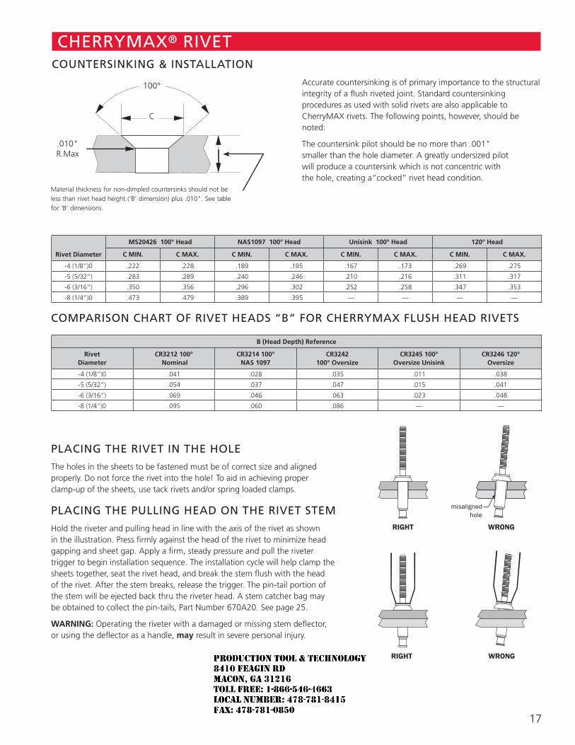
17
CHERRYMAX® RIVET COUNTERSINKING & INSTALLATION
Accurate countersinking is of primary importance to the structural integrity of a flush riveted joint. Standard countersinking procedures as used with solid rivets are also applicable to CherryMAX rivets. The following points, however, should be noted:
The countersink pilot should be no more than .001" smaller than the hole diameter. A greatly undersized pilot will produce a countersink which is not concentric with the hole, creating a“cocked” rivet head condition.
Rivet Diameter
MS20426 100° Head NAS1097 100° Head Unisink 100° Head 120° Head
C MIN. C MAX. C MIN. C MAX. C MIN. C MAX. C MIN. C MAX.
-4 (1/8”)0 .222 .228 .189 .195 .167 .173 .269 .275
-5 (5/32”) .283 .289 .240 .246 .210 .216 .311 .317
-6 (3/16”) .350 .356 .296 .302 .252 .258 .347 .353
-8 (1/4”)0 .473 .479 .389 .395 — — — —
COMPARISON CHART OF RIVET HEADS “B” FOR CHERRYMAX FLUSH HEAD RIVETS
B (Head Depth) Reference
Rivet Diameter
CR3212 100° Nominal
CR3214 100° NAS 1097
CR3242 100° Oversize
CR3245 100° Oversize Unisink
CR3246 120° Oversize
-4 (1/8”)0 .041 .028 .035 .011 .038
-5 (5/32”) .054 .037 .047 .015 .041
-6 (3/16”) .069 .046 .063 .023 .048
-8 (1/4”)0 .095 .060 .086 — —
PLACING THE RIVET IN THE HOLE
The holes in the sheets to be fastened must be of correct size and aligned properly. Do not force the rivet into the hole! To aid in achieving proper clamp-up of the sheets, use tack rivets and/or spring loaded clamps.
PLACING THE PULLING HEAD ON THE RIVET STEM
Hold the riveter and pulling head in line with the axis of the rivet as shown in the illustration. Press firmly against the head of the rivet to minimize head gapping and sheet gap. Apply a firm, steady pressure and pull the riveter trigger to begin installation sequence. The installation cycle will help clamp the sheets together, seat the rivet head, and break the stem flush with the head of the rivet. After the stem breaks, release the trigger. The pin-tail portion of the stem will be ejected back thru the riveter head. A stem catcher bag may be obtained to collect the pin-tails, Part Number 670A20. See page 25.
WARNING: Operating the riveter with a damaged or missing stem deflector, or using the deflector as a handle, may result in severe personal injury.
Material thickness for non-dimpled countersinks should not be less than rivet head height (‘B’ dimension) plus .010". See table for ‘B’ dimensions.
100°
C
.010" R.Max
RIGHT WRONG
misalignedhole
RIGHT WRONG
JR
Typewritten text
Production Tool & Technology 8410 Feagin Rd Macon, Ga 31216 Toll Free: 1-866-546-4663 Local Number: 478-781-8415 Fax: 478-781-0850
18
CHERRYMAX® RIVET RIVET INSPECTION
Shown is typical installed fastener flushness acceptance criteria. Locking element shall be flush with top surface of rivet head within ±.005. Slight element flash permissible .010 maximum from top of rivet head.
Rivet Diameter A Max. B Max.
-4 (1/8")0 .010” .015”
-5 (5/32") .010” .020”
-6 (3/16") .010” .020”
-8 (1/4")0 .015” .025”
ACCEPTABLE BLIND HEAD FORMATIONS
Typical Min. Grip Irregular Formation Min. Grip
Typical Max. Grip
JR
Typewritten text
Production Tool & Technology 8410 Feagin Rd Macon, Ga 31216 Toll Free: 1-866-546-4663 Local Number: 478-781-8415 Fax: 478-781-0850
19
CHERRYMAX® RIVET TOOLING SELECTION CHART
CherryRiveterModel
PullingHead
Number
All Grip Lengths, Head Styles & Materials Except As Noted
Nominal Diameter Oversize Diameter
-4 -5 -6 -8 -4 -5 -6 -8
G27 INCLUDED
G83
H701B-456 ➂
H753A-456 ➂
H781-456 ➂
H782 ➂H84A-8
H827-8 ➁
H828-8 ➁
G84
H84A-8
H827-8 ➁
H828-8 ➁
H701B-456 ➂
H753A-456 ➂
H781-456 ➂
H782 ➂G686B-S H680B200A
G689H680B200AH680B208
G700 H680B200A
G747
H701B-456H753A-456H781-456
H782
G746A ➀
H701B-456H753A-456H781-456
H782
G704B
G704B-40SH
G704B-SR
H701B-456H753A-456H781-456
H782
G744➃
H744A-8H827-8H828-8
H846A-465
G750AINCLUDEDH750A-8
G784 H680B200A ➀ Will not install Monel or Inconel -6 dia. fasteners ➁ Requires use of 744-200 adapter ➂ Requires use of 744-300 adapter ➃ Non standard tool
The tooling and pulling head combinations shown in the chart below
will install the diameter rivets indicated by the shaded areas, in all grip
lengths, and materials, .
For more information regarding installation tooling combinations, please
contact Cherry Aerospace Technical Service, 714-850-6045.
JR
Typewritten text
Production Tool & Technology 8410 Feagin Rd Macon, Ga 31216 Toll Free: 1-866-546-4663 Local Number: 478-781-8415 Fax: 478-781-0850
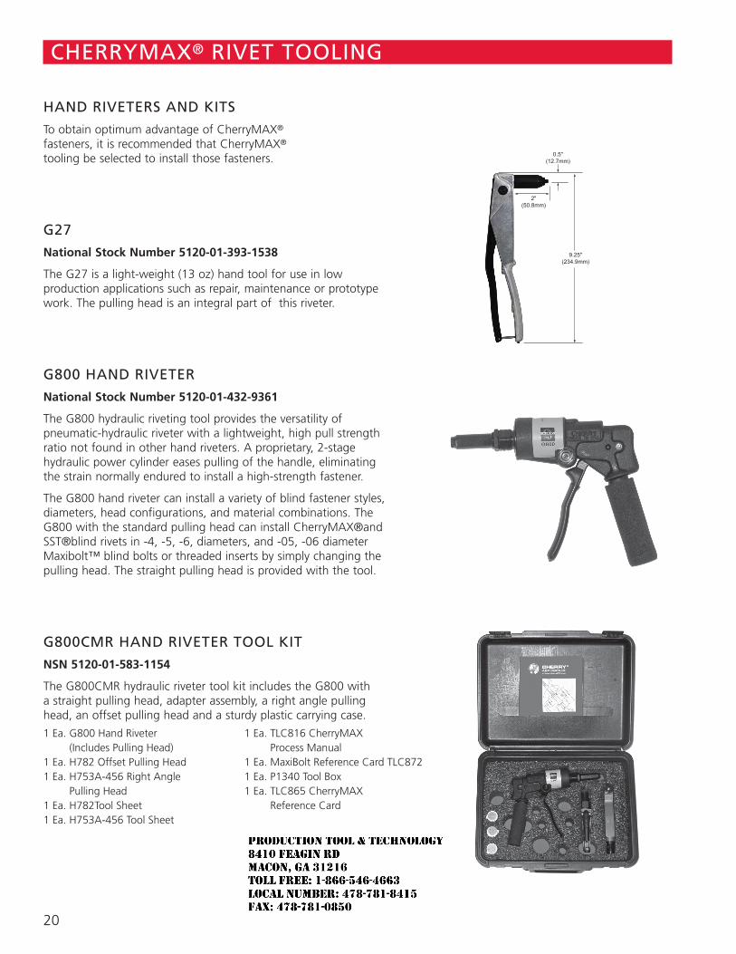
20
CHERRYMAX® RIVET TOOLING
HAND RIVETERS AND KITS
To obtain optimum advantage of CherryMAX® fasteners, it is recommended that CherryMAX® tooling be selected to install those fasteners.
G27
National Stock Number 5120-01-393-1538
The G27 is a light-weight (13 oz) hand tool for use in low production applications such as repair, maintenance or prototype work. The pulling head is an integral part of this riveter.
G800 HAND RIVETER
National Stock Number 5120-01-432-9361
The G800 hydraulic riveting tool provides the versatility of pneumatic-hydraulic riveter with a lightweight, high pull strength ratio not found in other hand riveters. A proprietary, 2-stage hydraulic power cylinder eases pulling of the handle, eliminating the strain normally endured to install a high-strength fastener.
The G800 hand riveter can install a variety of blind fastener styles, diameters, head configurations, and material combinations. The G800 with the standard pulling head can install CherryMAX®and SST®blind rivets in -4, -5, -6, diameters, and -05, -06 diameter Maxibolt™ blind bolts or threaded inserts by simply changing the pulling head. The straight pulling head is provided with the tool.
G800CMR HAND RIVETER TOOL KIT
NSN 5120-01-583-1154
The G800CMR hydraulic riveter tool kit includes the G800 with a straight pulling head, adapter assembly, a right angle pulling head, an offset pulling head and a sturdy plastic carrying case.
1 Ea. G800 Hand Riveter (Includes Pulling Head)
1 Ea. H782 Offset Pulling Head1 Ea. H753A-456 Right Angle
Pulling Head1 Ea. H782Tool Sheet1 Ea. H753A-456 Tool Sheet
1 Ea. TLC816 CherryMAX Process Manual
1 Ea. MaxiBolt Reference Card TLC872 1 Ea. P1340 Tool Box 1 Ea. TLC865 CherryMAX
Reference Card
JR
Typewritten text
Production Tool & Technology 8410 Feagin Rd Macon, Ga 31216 Toll Free: 1-866-546-4663 Local Number: 478-781-8415 Fax: 478-781-0850
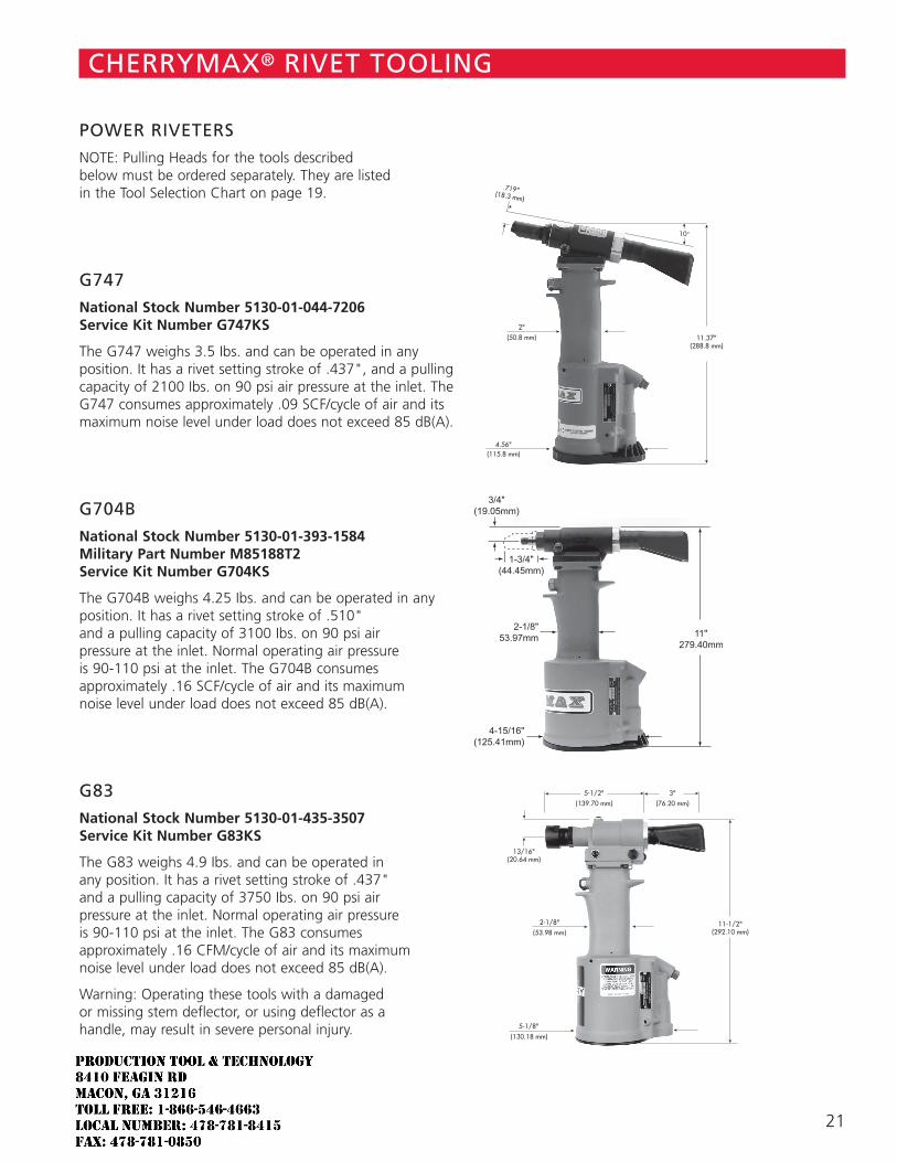
21
CHERRYMAX® RIVET TOOLING
POWER RIVETERS
NOTE: Pulling Heads for the tools described below must be ordered separately. They are listed in the Tool Selection Chart on page 19.
G747
National Stock Number 5130-01-044-7206 Service Kit Number G747KS
The G747 weighs 3.5 Ibs. and can be operated in any position. It has a rivet setting stroke of .437", and a pulling capacity of 2100 Ibs. on 90 psi air pressure at the inlet. The G747 consumes approximately .09 SCF/cycle of air and its maximum noise level under load does not exceed 85 dB(A).
G704B
National Stock Number 5130-01-393-1584 Military Part Number M85188T2 Service Kit Number G704KS
The G704B weighs 4.25 Ibs. and can be operated in any position. It has a rivet setting stroke of .510" and a pulling capacity of 3100 Ibs. on 90 psi air pressure at the inlet. Normal operating air pressure is 90-110 psi at the inlet. The G704B consumes approximately .16 SCF/cycle of air and its maximum noise level under load does not exceed 85 dB(A).
G83
National Stock Number 5130-01-435-3507 Service Kit Number G83KS
The G83 weighs 4.9 Ibs. and can be operated in any position. It has a rivet setting stroke of .437" and a pulling capacity of 3750 Ibs. on 90 psi air pressure at the inlet. Normal operating air pressure is 90-110 psi at the inlet. The G83 consumes approximately .16 CFM/cycle of air and its maximum noise level under load does not exceed 85 dB(A).
Warning: Operating these tools with a damaged or missing stem deflector, or using deflector as a handle, may result in severe personal injury.
.719"(18.3 mm)
➤➤2"
(50.8 mm)
➤
➤
➤
➤➤
➤
11.37"(288.8 mm)
10°
4.56"(115.8 mm)
➤
➤
➤
➤
13/16"(20.64 mm)
➤ ➤
➤➤
➤➤2-1/8"
(53.98 mm)
5-1/2"(139.70 mm)
3"(76.20 mm)
➤
➤
11-1/2"(292.10 mm)
5-1/8" ➤
➤
(130.18 mm)
JR
Typewritten text
Production Tool & Technology 8410 Feagin Rd Macon, Ga 31216 Toll Free: 1-866-546-4663 Local Number: 478-781-8415 Fax: 478-781-0850
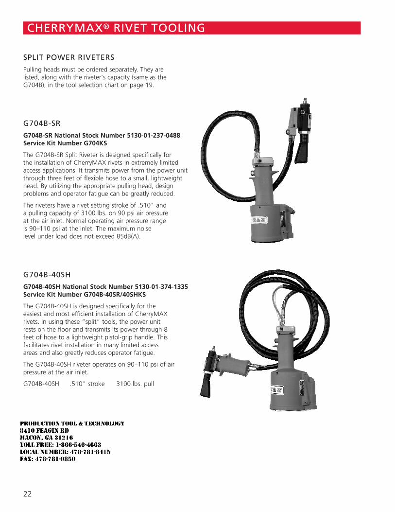
22
SPLIT POWER RIVETERS
Pulling heads must be ordered separately. They are listed, along with the riveter's capacity (same as the G704B), in the tool selection chart on page 19.
G704B-SR
G704B-SR National Stock Number 5130-01-237-0488 Service Kit Number G704KS
The G704B-SR Split Riveter is designed specifically for the installation of CherryMAX rivets in extremely limited access applications. It transmits power from the power unit through three feet of flexible hose to a small, lightweight head. By utilizing the appropriate pulling head, design problems and operator fatigue can be greatly reduced.
The riveters have a rivet setting stroke of .510" and a pulling capacity of 3100 lbs. on 90 psi air pressure at the air inlet. Normal operating air pressure range is 90–110 psi at the inlet. The maximum noise level under load does not exceed 85dB(A).
G704B-40SH
G704B-40SH National Stock Number 5130-01-374-1335 Service Kit Number G704B-40SR/40SHKS
The G704B-40SH is designed specifically for the easiest and most efficient installation of CherryMAX rivets. In using these “split” tools, the power unit rests on the floor and transmits its power through 8 feet of hose to a lightweight pistol-grip handle. This facilitates rivet installation in many limited access areas and also greatly reduces operator fatigue.
The G704B-40SH riveter operates on 90–110 psi of air pressure at the air inlet.
G704B-40SH .510" stroke 3100 lbs. pull
CHERRYMAX® RIVET TOOLING
JR
Typewritten text
Production Tool & Technology 8410 Feagin Rd Macon, Ga 31216 Toll Free: 1-866-546-4663 Local Number: 478-781-8415 Fax: 478-781-0850
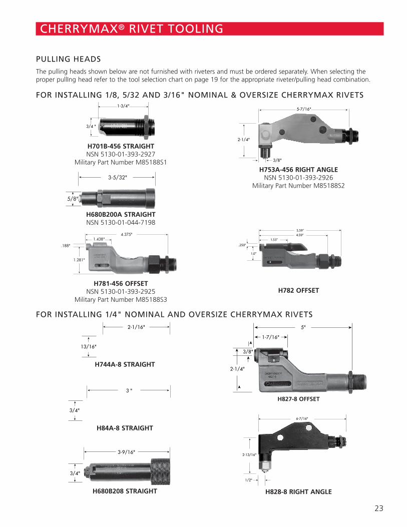
23
CHERRYMAX® RIVET TOOLING
H828-8 RIGHT ANGLEH680B208 STRAIGHT
PULLING HEADS
The pulling heads shown below are not furnished with riveters and must be ordered separately. When selecting the proper pullIng head refer to the tool selection chart on page 19 for the appropriate riveter/pulling head combination.
FOR INSTALLING 1/8, 5/32 AND 3/16" NOMINAL & OVERSIZE CHERRYMAX RIVETS
➤
➤➤
➤
➤
➤
➤
➤
1-7/16"
5"
2-1/4"
3/8"
➤
➤
➤
6-7/16"
➤
2-13/16"
1/2"
➤
➤
➤➤2-1/16"
➤
➤
13/16"
➤➤3 "
➤
➤
3/4"
➤➤3-9/16"
➤
➤
3/4"
FOR INSTALLING 1/4" NOMINAL AND OVERSIZE CHERRYMAX RIVETS
H827-8 OFFSET
H84A-8 STRAIGHT
H744A-8 STRAIGHT
➤
➤➤
➤
3/4 "
1-3/4"
H701B-456 STRAIGHT NSN 5130-01-393-2927
Military Part Number M85188S1
��3-5/32"
�
�
5/8"
H680B200A STRAIGHT NSN 5130-01-044-7198
��
� �
4.375"1.438"
�
�
1.281"
.188"
H781-456 OFFSET NSN 5130-01-393-2925
Military Part Number M85188S3
➤
➤
➤
➤
➤
➤5-7/16"
2-1/4"
3/8"
H753A-456 RIGHT ANGLE NSN 5130-01-393-2926
Military Part Number M85188S2
➤➤
➤ ➤
5.59"5.59"4.59"
➤ 1.53"
➤
➤
1.0"
.250"
H782 OFFSET
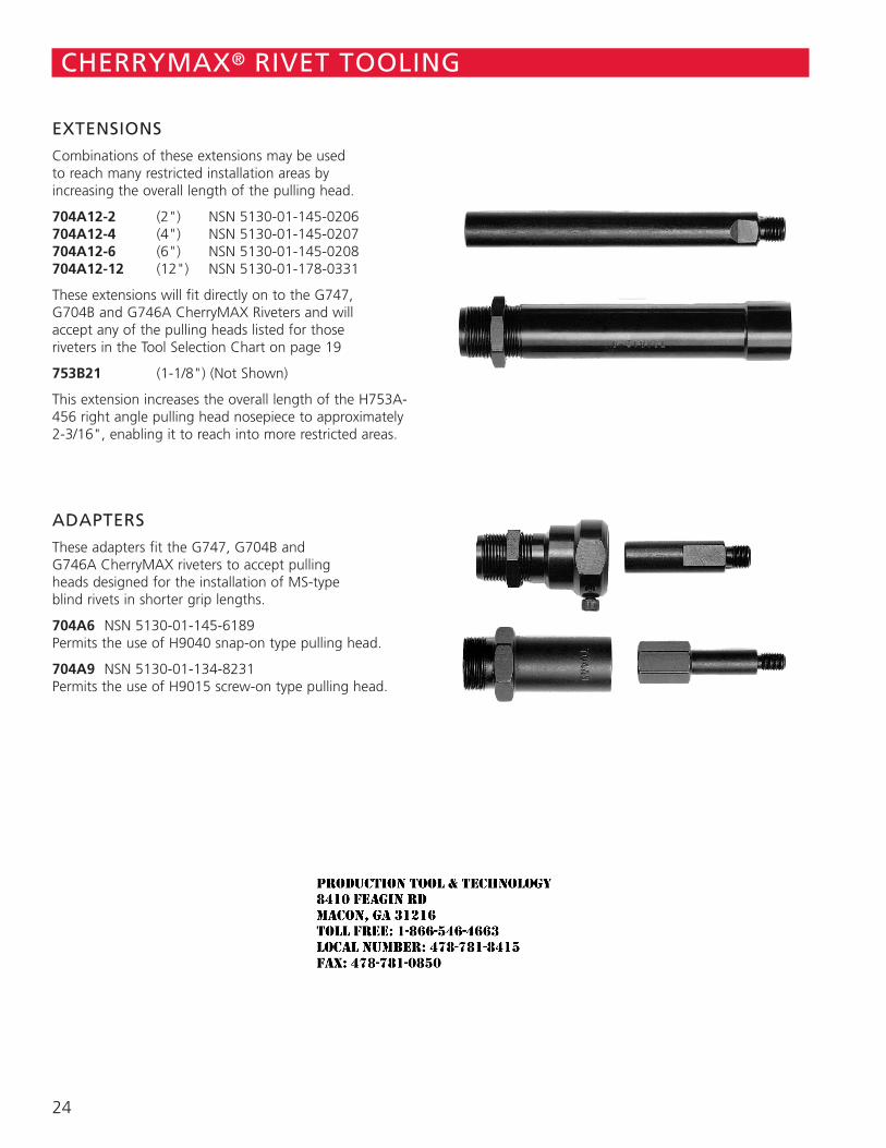
24
CHERRYMAX® RIVET TOOLING
EXTENSIONS
Combinations of these extensions may be used to reach many restricted installation areas by increasing the overall length of the pulling head.
704A12-2 (2") NSN 5130-01-145-0206 704A12-4 (4") NSN 5130-01-145-0207 704A12-6 (6") NSN 5130-01-145-0208 704A12-12 (12") NSN 5130-01-178-0331
These extensions will fit directly on to the G747, G704B and G746A CherryMAX Riveters and will accept any of the pulling heads listed for those riveters in the Tool Selection Chart on page 19
753B21 (1-1/8") (Not Shown)
This extension increases the overall length of the H753A-456 right angle pulling head nosepiece to approximately 2-3/16", enabling it to reach into more restricted areas.
ADAPTERS
These adapters fit the G747, G704B and G746A CherryMAX riveters to accept pulling heads designed for the installation of MS-type blind rivets in shorter grip lengths.
704A6 NSN 5130-01-145-6189 Permits the use of H9040 snap-on type pulling head.
704A9 NSN 5130-01-134-8231 Permits the use of H9015 screw-on type pulling head.
JR
Typewritten text
Production Tool & Technology 8410 Feagin Rd Macon, Ga 31216 Toll Free: 1-866-546-4663 Local Number: 478-781-8415 Fax: 478-781-0850

25
CHERRYMAX® RIVET TOOLING
ADAPTERS
These adapters permit various Cherry riveters to accept pulling heads for the installation of CherryMAX rivets that the riveters were not originally intended to pull.
680B205 NSN 5130-01-175-4015 Permits the G686B-S, G689, G700 and G784 to accept the H753A-456 and H781-456 pulling heads for installing 1/8, 5/32 and 3/16" CherryMAX rivets.
744-300 Permits the G83 and G84 riveters to accept the H701B-456, H753A-456 and H781-456 pulling heads for installing 1/8, 5/32 and 3/16" CherryMAX rivets.
744-200 Permits the G83 and G84 riveters to accept the H827-8 (offset), and H828-8 (right angle) pulling heads for installing 1/4" diameter CherryMAX rivets
ACCESSORIES
701B32 MAGNETIC DRIVING ANVIL CATCHER
The 701B32 magnetic driving anvil catcher provides a method to catch and hold the driving anvils as they fall away after rivet installation. This anvil catcher slips onto the nose of the pulling head without any need for permanent attachment.
670A20 STEM CATCHER BAG NSN 5130-01-154-1141
The 670A20 stem catcher bag is a convenient accessory which helps eliminate litter from the shop floor. This bag snaps over the stem deflector of the G701A, G704B, G746A, G747, G83 and G84 CherryMAX riveters to catch the spent stems as they are ejected from the rear of the riveter head.
JR
Typewritten text
Production Tool & Technology 8410 Feagin Rd Macon, Ga 31216 Toll Free: 1-866-546-4663 Local Number: 478-781-8415 Fax: 478-781-0850
CHERRYMAX® 'AB' RIVETLOCKED SPINDLE STRUCTURAL RIVETS
SPS Fastener Division, a PCC Company
JR
Typewritten text
Production Tool & Technology 8410 Feagin Rd Macon, Ga 31216 Toll Free: 1-866-546-4663 Local Number: 478-781-8415 Fax: 478-781-0850
1
CHERRYMAX 'AB'
CONTENTS
Features and Installation Sequence ..................................................................................... 2Rivet Selection...................................................................................................................... 3Installed Weights.................................................................................................................. 4Universal Head Nominal Diameter........................................................................................ 5100° Flush Head Nominal Diameter...................................................................................... 6NAS1097 100° Reduced Flush Head Nominal Diameter ....................................................... 7Universal Head Oversize Diameter ....................................................................................... 8100° Flush Head Oversize Diameter ..................................................................................... 9Installation Tooling ............................................................................................................. 10
LIMITED WARRANTY
Seller warrants the goods conform to applicable specifications and drawings and will be manufactured and inspected according to generally accepted practices of companies manufacturing industrial or aerospace fasteners. In the event of any breach of the foregoing warranty, Buyer’s sole remedy shall be to return defective goods (after receiving authorization from Seller) for replacement or refund of the purchase price, at the Seller’s option. Seller agrees to any freight costs in connection with the return of any defective goods, but any costs relating to removal of the defective or nonconforming goods or installation of replacement goods shall be Buyer’s responsibility. SELLER’S WARRANTY DOES NOT APPLY WHEN ANY PHYSICAL OR CHEMICAL CHANGE IN THE FORM OF THE PRODUCT IS MADE BY BUYER. THE FOREGOING EXPRESS WARRANTY AND REMEDY ARE EXCLUSIVE AND ARE IN LIEU OF ALL OTHER WARRANTIES AND REMEDIES; ANY IMPLIED WARRANTY AS TO QUALITY, FITNESS FOR PURPOSE, OR MERCHANTABILITY IS HEREBY SPECIFICALLY DISCLAIMED AND EXCLUDED BY SELLER. This warranty is void if seller is not notified in writing of any rejection of the goods within one (1) Year aFter initial use by buyer of any power Riveter or ninety (90) days after initial use of any other product.
Seller shall not be liable under any circumstances for incidental, special or consequential damages arising in whole or in part from any breach by Seller, AND SUCH INCIDENTAL, SPECIAL, OR CONSEQUENTIAL DAMAGES ARE HEREBY EXPRESSLY EXCLUDED.
Our policy is one of continuous development. Specifications shown in this document may be subject to changes introduced after publication.
CHERRY®, CHERRYMAX® and MAXIBOLT® are trademarks of Cherry Aerospace.
NOTE
ATTENTION
JR
Typewritten text
Production Tool & Technology 8410 Feagin Rd Macon, Ga 31216 Toll Free: 1-866-546-4663 Local Number: 478-781-8415 Fax: 478-781-0850
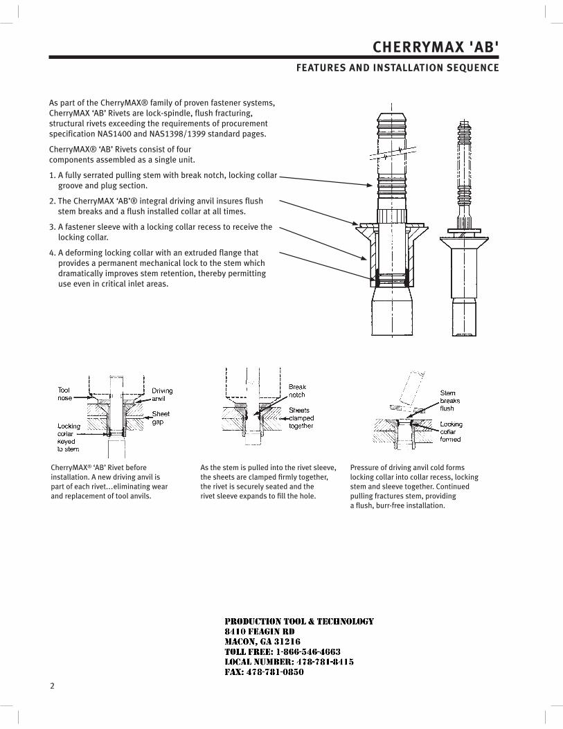
2
CHERRYMAX 'AB'FEATURES AND INSTALLATION SEQUENCE
As part of the CherryMAX® family of proven fastener systems, CherryMAX ‘AB’ Rivets are lock-spindle, flush fracturing, structural rivets exceeding the requirements of procurement specification NAS1400 and NAS1398/1399 standard pages.
CherryMAX® ‘AB’ Rivets consist of four components assembled as a single unit.
1. A fully serrated pulling stem with break notch, locking collar groove and plug section.
2. The CherryMAX ‘AB’® integral driving anvil insures flush stem breaks and a flush installed collar at all times.
3. A fastener sleeve with a locking collar recess to receive the locking collar.
4. A deforming locking collar with an extruded flange that provides a permanent mechanical lock to the stem which dramatically improves stem retention, thereby permitting use even in critical inlet areas.
CherryMAX® ‘AB’ Rivet before installation. A new driving anvil is part of each rivet...eliminating wear and replacement of tool anvils.
As the stem is pulled into the rivet sleeve, the sheets are clamped firmly together, the rivet is securely seated and the rivet sleeve expands to fill the hole.
Pressure of driving anvil cold forms locking collar into collar recess, locking stem and sleeve together. Continued pulling fractures stem, providing a flush, burr-free installation.
JR
Typewritten text
Production Tool & Technology 8410 Feagin Rd Macon, Ga 31216 Toll Free: 1-866-546-4663 Local Number: 478-781-8415 Fax: 478-781-0850
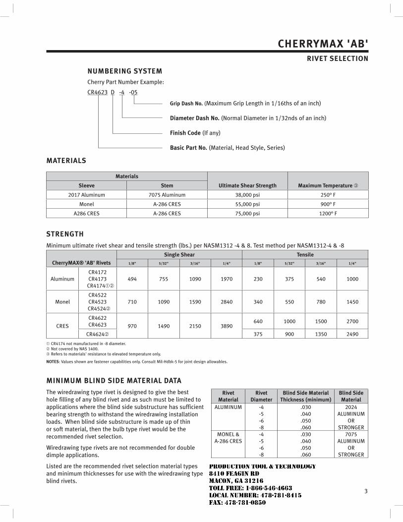
3
MATERIALS
Materials
Ultimate Shear Strength Maximum Temperature Sleeve Stem
2017 Aluminum 7075 Aluminum 38,000 psi 250° F
Monel A-286 CRES 55,000 psi 900° F
A286 CRES A-286 CRES 75,000 psi 1200° F
STRENGTH
Minimum ultimate rivet shear and tensile strength (lbs.) per NASM1312 -4 & 8. Test method per NASM1312-4 & -8
CherryMAX® 'AB' Rivets
Single Shear Tensile
1/8" 5/32" 3/16" 1/4" 1/8" 5/32" 3/16" 1/4"
AluminumCR4172CR4173
CR4174494 755 1090 1970 230 375 540 1000
MonelCR4522CR4523CR4524
710 1090 1590 2840 340 550 780 1450
CRES
CR4622CR4623 970 1490 2150 3890
640 1000 1500 2700
CR4624 375 900 1350 2490
CR4174 not manufactured in -8 diameter.Not covered by NAS 1400.Refers to materials' resistance to elevated temperature only.
NOTES: Values shown are fastener capabilities only. Consult Mil-Hdbk-5 for joint design allowables.
MINIMUM BLIND SIDE MATERIAL DATA
The wiredrawing type rivet is designed to give the best hole filling of any blind rivet and as such must be limited to applications where the blind side substructure has sufficient bearing strength to withstand the wiredrawing installation loads. When blind side substructure is made up of thin or soft material, then the bulb type rivet would be the recommended rivet selection.
Wiredrawing type rivets are not recommended for double dimple applications.
Listed are the recommended rivet selection material types and minimum thicknesses for use with the wiredrawing type blind rivets.
Rivet Material
Rivet Diameter
Blind Side Material Thickness (minimum)
Blind Side Material
ALUMINUM -4-5-6-8
.030
.040
.050
.060
2024ALUMINUM
ORSTRONGER
MONEL & A-286 CRES
-4-5-6-8
.030
.040
.050
.060
7075ALUMINUM
ORSTRONGER
NUMBERING SYSTEMCherry Part Number Example:
CR4623 D -4 -05
Grip Dash No. (Maximum Grip Length in 1/16ths of an inch)
Diameter Dash No. (Normal Diameter in 1/32nds of an inch)
Finish Code (If any)
Basic Part No. (Material, Head Style, Series)
CHERRYMAX 'AB'RIVET SELECTION
JR
Typewritten text
Production Tool & Technology 8410 Feagin Rd Macon, Ga 31216 Toll Free: 1-866-546-4663 Local Number: 478-781-8415 Fax: 478-781-0850
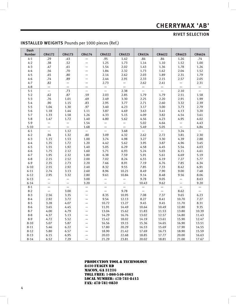
4
CHERRYMAX 'AB'RIVET SELECTION
INSTALLED WEIGHTS Pounds per 1000 pieces (Ref.)
DashNumber CR4172 CR4173 CR4174 CR4522 CR4523 CR4524 CR4622 CR4623 CR4624
4-1 .29 .43 — .95 1.42 .84 .84 1.26 .744-2 .38 .52 — 1.25 1.73 1.14 1.10 1.52 1.004-3 .47 .61 — 1.54 2.02 1.43 1.36 1.78 1.264-4 .56 .70 — 1.84 2.32 1.73 1.62 2.04 1.524-5 .65 .80 — 2.14 2.62 2.03 1.89 2.31 1.794-6 .74 .89 — 2.44 2.91 2.33 2.15 2.57 2.054-7 .82 — — 2.73 — 2.62 2.41 — 2.314-8 — — — — — — — — —5-1 — .73 — — 2.38 — — 2.10 —5-2 .62 .87 .59 2.03 2.85 1.79 1.79 2.51 1.585-3 .76 1.01 .69 2.49 3.30 2.25 2.20 2.91 1.995-4 .90 1.15 .83 2.95 3.77 2.71 2.60 3.32 2.395-5 1.04 1.30 .97 3.40 4.23 3.17 3.00 3.73 2.795-6 1.18 1.44 1.11 3.87 4.69 3.63 3.41 4.13 3.205-7 1.33 1.58 1.26 4.33 5.15 4.09 3.82 4.54 3.615-8 1.47 1.72 1.40 4.80 5.62 4.56 4.23 4.95 4.025-9 — — 1.54 — — 5.02 4.64 — 4.43
5-10 — — 1.68 — — 5.49 5.05 — 4.846-1 — 1.12 — — 3.68 — — 3.24 —6-2 .94 1.32 .80 3.09 4.32 2.62 2.72 3.81 2.306-3 1.15 1.53 1.00 3.74 4.98 3.27 3.30 4.39 2.886-4 1.35 1.72 1.20 4.42 5.62 3.95 3.87 4.96 3.456-5 1.55 1.92 1.40 5.05 6.29 4.58 4.45 5.54 4.036-6 1.75 2.12 1.60 5.71 6.93 5.24 5.03 6.11 4.616-7 1.95 2.32 1.80 6.38 7.59 5.91 5.61 6.69 5.196-8 2.15 2.52 2.00 7.02 8.24 6.55 6.19 7.27 5.776-9 2.35 2.73 2.20 7.66 8.91 7.19 6.76 7.85 6.34
6-10 2.55 2.92 2.40 8.32 9.55 7.85 7.33 8.42 6.916-11 2.74 3.13 2.60 8.96 10.21 8.49 7.90 9.00 7.486-12 2.95 3.32 2.80 9.61 10.84 9.14 8.48 9.56 8.066-13 — — 3.00 — — 9.78 9.05 — 8.636-14 — — 3.20 — — 10.43 9.62 — 9.208-1 — — — — — — — — —8-2 — 3.00 — — 9.78 — — 8.62 —8-3 2.56 3.35 — 8.35 10.95 7.08 7.37 9.65 6.238-4 2.92 3.72 — 9.54 12.13 8.27 8.41 10.70 7.278-5 3.28 4.07 — 10.72 13.27 9.45 9.45 11.70 8.318-6 3.65 4.45 — 11.91 14.49 10.64 10.49 12.80 9.358-7 4.00 4.79 — 13.04 15.62 11.83 11.53 13.80 10.398-8 4.37 5.13 — 14.29 16.76 13.02 12.57 14.80 11.438-9 4.72 5.52 — 15.42 18.02 14.19 13.61 15.90 12.47
8-10 5.07 5.87 — 16.56 19.15 15.36 14.65 16.90 13.518-11 5.46 6.22 — 17.80 20.29 16.53 15.69 17.90 14.558-12 5.80 6.57 — 18.90 21.42 17.69 16.73 18.90 15.598-13 6.15 6.95 — 20.03 22.68 18.85 17.77 20.00 16.638-14 6.52 7.29 — 21.29 23.81 20.02 18.81 21.00 17.67
JR
Typewritten text
Production Tool & Technology 8410 Feagin Rd Macon, Ga 31216 Toll Free: 1-866-546-4663 Local Number: 478-781-8415 Fax: 478-781-0850
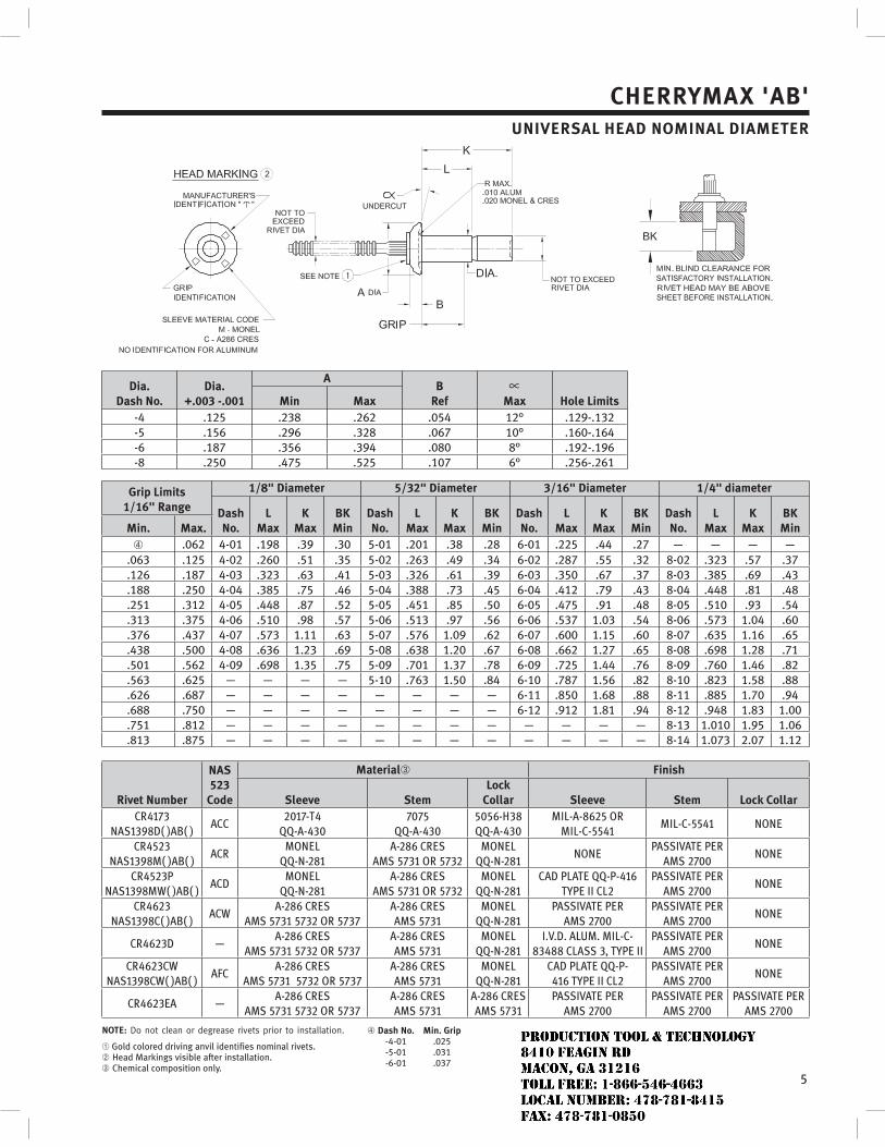
5
CHERRYMAX 'AB'UNIVERSAL HEAD NOMINAL DIAMETER
Dia.Dash No.
Dia.+.003 -.001
AB
Ref Max Hole LimitsMin Max-4 .125 .238 .262 .054 12° .129-.132-5 .156 .296 .328 .067 10° .160-.164-6 .187 .356 .394 .080 8° .192-.196-8 .250 .475 .525 .107 6° .256-.261
Grip Limits1/16" Range
1/8" Diameter 5/32" Diameter 3/16" Diameter 1/4" diameter
DashNo.
LMax
KMax
BKMin
DashNo.
LMax
KMax
BKMin
DashNo.
LMax
KMax
BKMin
DashNo.
LMax
KMax
BKMinMin. Max.
.062 4-01 .198 .39 .30 5-01 .201 .38 .28 6-01 .225 .44 .27 — — — —.063 .125 4-02 .260 .51 .35 5-02 .263 .49 .34 6-02 .287 .55 .32 8-02 .323 .57 .37.126 .187 4-03 .323 .63 .41 5-03 .326 .61 .39 6-03 .350 .67 .37 8-03 .385 .69 .43.188 .250 4-04 .385 .75 .46 5-04 .388 .73 .45 6-04 .412 .79 .43 8-04 .448 .81 .48.251 .312 4-05 .448 .87 .52 5-05 .451 .85 .50 6-05 .475 .91 .48 8-05 .510 .93 .54.313 .375 4-06 .510 .98 .57 5-06 .513 .97 .56 6-06 .537 1.03 .54 8-06 .573 1.04 .60.376 .437 4-07 .573 1.11 .63 5-07 .576 1.09 .62 6-07 .600 1.15 .60 8-07 .635 1.16 .65.438 .500 4-08 .636 1.23 .69 5-08 .638 1.20 .67 6-08 .662 1.27 .65 8-08 .698 1.28 .71.501 .562 4-09 .698 1.35 .75 5-09 .701 1.37 .78 6-09 .725 1.44 .76 8-09 .760 1.46 .82.563 .625 — — — — 5-10 .763 1.50 .84 6-10 .787 1.56 .82 8-10 .823 1.58 .88.626 .687 — — — — — — — — 6-11 .850 1.68 .88 8-11 .885 1.70 .94.688 .750 — — — — — — — — 6-12 .912 1.81 .94 8-12 .948 1.83 1.00.751 .812 — — — — — — — — — — — — 8-13 1.010 1.95 1.06.813 .875 — — — — — — — — — — — — 8-14 1.073 2.07 1.12
Rivet Number
NAS 523
Code
Material Finish
Sleeve StemLock
Collar Sleeve Stem Lock Collar
NOTE:
Gold colored driving anvil identifies nominal rivets.Head Markings visible after installation.Chemical composition only.
Dash No. Min. Grip-4-01 .025-5-01 .031-6-01 .037
JR
Typewritten text
Production Tool & Technology 8410 Feagin Rd Macon, Ga 31216 Toll Free: 1-866-546-4663 Local Number: 478-781-8415 Fax: 478-781-0850
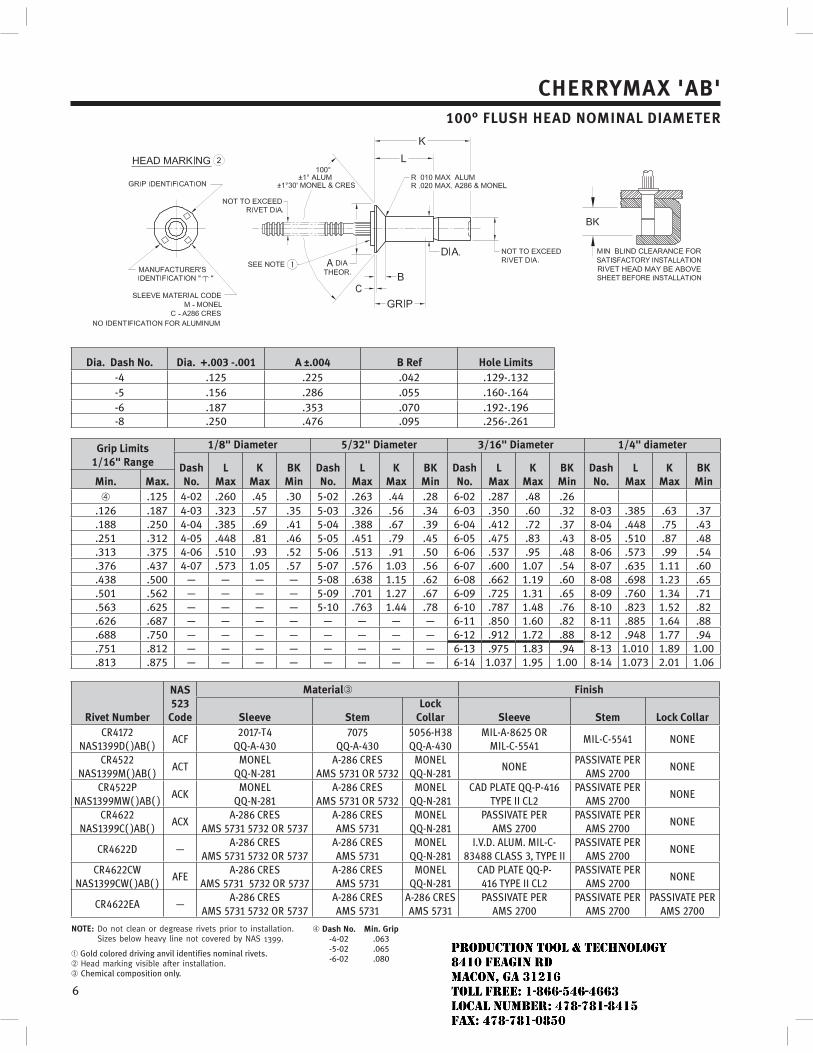
6
CHERRYMAX 'AB'100° FLUSH HEAD NOMINAL DIAMETER
Dia. Dash No. Dia. +.003 -.001 A ±.004 B Ref Hole Limits-4 .125 .225 .042 .129-.132-5 .156 .286 .055 .160-.164-6 .187 .353 .070 .192-.196-8 .250 .476 .095 .256-.261
Grip Limits1/16" Range
1/8" Diameter 5/32" Diameter 3/16" Diameter 1/4" diameter
DashNo.
LMax
KMax
BKMin
DashNo.
LMax
KMax
BKMin
DashNo.
LMax
KMax
BKMin
DashNo.
LMax
KMax
BKMinMin. Max.
.125 4-02 .260 .45 .30 5-02 .263 .44 .28 6-02 .287 .48 .26.126 .187 4-03 .323 .57 .35 5-03 .326 .56 .34 6-03 .350 .60 .32 8-03 .385 .63 .37.188 .250 4-04 .385 .69 .41 5-04 .388 .67 .39 6-04 .412 .72 .37 8-04 .448 .75 .43.251 .312 4-05 .448 .81 .46 5-05 .451 .79 .45 6-05 .475 .83 .43 8-05 .510 .87 .48.313 .375 4-06 .510 .93 .52 5-06 .513 .91 .50 6-06 .537 .95 .48 8-06 .573 .99 .54.376 .437 4-07 .573 1.05 .57 5-07 .576 1.03 .56 6-07 .600 1.07 .54 8-07 .635 1.11 .60.438 .500 — — — — 5-08 .638 1.15 .62 6-08 .662 1.19 .60 8-08 .698 1.23 .65.501 .562 — — — — 5-09 .701 1.27 .67 6-09 .725 1.31 .65 8-09 .760 1.34 .71.563 .625 — — — — 5-10 .763 1.44 .78 6-10 .787 1.48 .76 8-10 .823 1.52 .82.626 .687 — — — — — — — — 6-11 .850 1.60 .82 8-11 .885 1.64 .88.688 .750 — — — — — — — — 6-12 .912 1.72 .88 8-12 .948 1.77 .94.751 .812 — — — — — — — — 6-13 .975 1.83 .94 8-13 1.010 1.89 1.00.813 .875 — — — — — — — — 6-14 1.037 1.95 1.00 8-14 1.073 2.01 1.06
Rivet Number
NAS 523
Code
Material Finish
Sleeve StemLock
Collar Sleeve Stem Lock Collar
NOTE:
Gold colored driving anvil identifies nominal rivets.
Chemical composition only.
Dash No. Min. Grip-4-02 .063-5-02 .065-6-02 .080
JR
Typewritten text
Production Tool & Technology 8410 Feagin Rd Macon, Ga 31216 Toll Free: 1-866-546-4663 Local Number: 478-781-8415 Fax: 478-781-0850
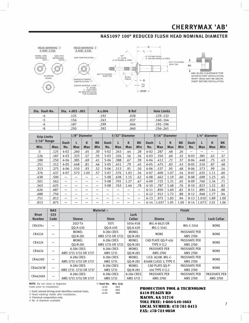
7
CHERRYMAX 'AB'NAS1097 100° REDUCED FLUSH HEAD NOMINAL DIAMETER
Dia. Dash No. Dia. +.003 -.001 A ±.004 B Ref Hole Limits-4 .125 .192 .028 .129-.132-5 .156 .243 .037 .160-.164-6 .187 .299 .046 .192-.196-8 .250 .392 .060 .256-.261
Grip Limits1/16" Range
1/8" Diameter 5/32" Diameter 3/16" Diameter 1/4" diameter
DashNo.
LMax
KMax
BKMin
DashNo.
LMax
KMax
BKMin
DashNo.
LMax
KMax
BKMin
DashNo.
LMax
KMax
BKMinMin. Max.
.125 4-02 .260 .45 .30 5-02 .263 .44 .28 6-02 .287 .48 .26 — — — —.126 .187 4-03 .323 .57 .35 5-03 .326 .56 .34 6-03 .350 .60 .32 8-03 .385 .63 .37.188 .250 4-04 .385 .69 .41 5-04 .388 .67 .39 6-04 .412 .72 .37 8-04 .448 .75 .43.251 .312 4-05 .448 .81 .46 5-05 .451 .79 .45 6-05 .475 .83 .43 8-05 .510 .87 .48.313 .375 4-06 .510 .93 .52 5-06 .513 .91 .50 6-06 .537 .95 .48 8-06 .573 .99 .54.376 .437 4-07 .573 1.05 .57 5-07 .576 1.03 .56 6-07 .600 1.07 .54 8-07 .635 1.11 .60.438 .500 — — — — 5-08 .638 1.15 .62 6-08 .662 1.19 .60 8-08 .698 1.23 .65.501 .562 — — — — 5-08 .701 1.27 .67 6-09 .725 1.31 .65 8-09 .760 1.34 .71.563 .625 — — — — 5-08 .763 1.44 .78 6-10 .787 1.48 .76 8-10 .823 1.52 .82.626 .687 — — — — — — — — 6-11 .850 1.60 .82 8-11 .885 1.64 .88.688 .750 — — — — — — — — 6-12 .912 1.72 .88 8-12 .948 1.77 .94.751 .812 — — — — — — — — 6-13 .975 1.83 .94 8-13 1.010 1.89 1.00.813 .875 — — — — — — — — 6-14 1.037 1.95 1.00 8-14 1.073 2.01 1.06
Rivet Number
NAS 523
Code
Material Finish
Sleeve StemLock
Collar Sleeve Stem Lock Collar
NOTE:
Gold colored driving anvil identifies nominal rivets.
Chemical composition only.
Dash No. Min. Grip-4-02 .063-5-02 .065-6-02 .080
JR
Typewritten text
Production Tool & Technology 8410 Feagin Rd Macon, Ga 31216 Toll Free: 1-866-546-4663 Local Number: 478-781-8415 Fax: 478-781-0850
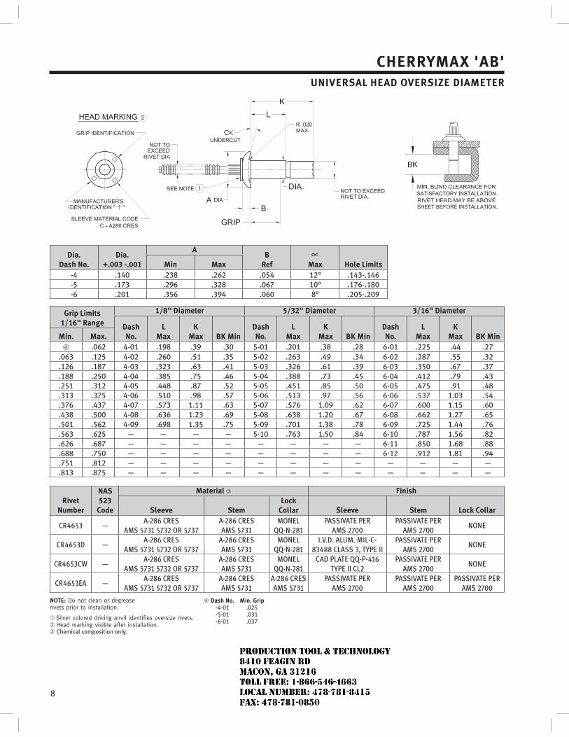
8
CHERRYMAX 'AB'UNIVERSAL HEAD OVERSIZE DIAMETER
Dia.Dash No.
Dia.+.003 -.001
AB
Ref Max Hole LimitsMin Max-4 .140 .238 .262 .054 12° .143-.146-5 .173 .296 .328 .067 10° .176-.180-6 .201 .356 .394 .060 8° .205-.209
Grip Limits1/16" Range
1/8" Diameter 5/32" Diameter 3/16" Diameter
DashNo.
LMax
KMax BK Min
DashNo.
LMax
KMax BK Min
DashNo.
LMax
KMax BK MinMin. Max.
.062 4-01 .198 .39 .30 5-01 .201 .38 .28 6-01 .225 .44 .27.063 .125 4-02 .260 .51 .35 5-02 .263 .49 .34 6-02 .287 .55 .32.126 .187 4-03 .323 .63 .41 5-03 .326 .61 .39 6-03 .350 .67 .37.188 .250 4-04 .385 .75 .46 5-04 .388 .73 .45 6-04 .412 .79 .43.251 .312 4-05 .448 .87 .52 5-05 .451 .85 .50 6-05 .475 .91 .48.313 .375 4-06 .510 .98 .57 5-06 .513 .97 .56 6-06 .537 1.03 .54.376 .437 4-07 .573 1.11 .63 5-07 .576 1.09 .62 6-07 .600 1.15 .60.438 .500 4-08 .636 1.23 .69 5-08 .638 1.20 .67 6-08 .662 1.27 .65.501 .562 4-09 .698 1.35 .75 5-09 .701 1.38 .78 6-09 .725 1.44 .76.563 .625 — — — — 5-10 .763 1.50 .84 6-10 .787 1.56 .82.626 .687 — — — — — — — — 6-11 .850 1.68 .88.688 .750 — — — — — — — — 6-12 .912 1.81 .94.751 .812 — — — — — — — — — — — —.813 .875 — — — — — — — — — — — —
Rivet Number
NAS 523
Code
Material Finish
Sleeve StemLock
Collar Sleeve Stem Lock Collar
NOTE:
Chemical composition only.
Dash No. Min. Grip-4-01 .025-5-01 .031-6-01 .037
JR
Typewritten text
Production Tool & Technology 8410 Feagin Rd Macon, Ga 31216 Toll Free: 1-866-546-4663 Local Number: 478-781-8415 Fax: 478-781-0850
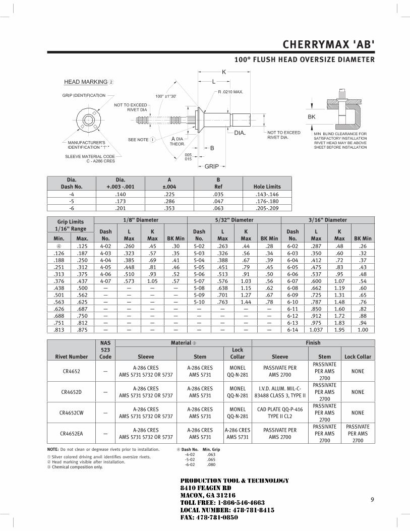
9
CHERRYMAX 'AB'100° FLUSH HEAD OVERSIZE DIAMETER
Dia.Dash No.
Dia.+.003 -.001
A±.004
BRef Hole Limits
-4 .140 .225 .035 .143-.146-5 .173 .286 .047 .176-.180-6 .201 .353 .063 .205-.209
Grip Limits1/16" Range
1/8" Diameter 5/32" Diameter 3/16" Diameter
DashNo.
LMax
KMax BK Min
DashNo.
LMax
KMax BK Min
DashNo.
LMax
KMax BK MinMin. Max.
.125 4-02 .260 .45 .30 5-02 .263 .44 .28 6-02 .287 .48 .26.126 .187 4-03 .323 .57 .35 5-03 .326 .56 .34 6-03 .350 .60 .32.188 .250 4-04 .385 .69 .41 5-04 .388 .67 .39 6-04 .412 .72 .37.251 .312 4-05 .448 .81 .46 5-05 .451 .79 .45 6-05 .475 .83 .43.313 .375 4-06 .510 .93 .52 5-06 .513 .91 .50 6-06 .537 .95 .48.376 .437 4-07 .573 1.05 .57 5-07 .576 1.03 .56 6-07 .600 1.07 .54.438 .500 — — — — 5-08 .638 1.15 .62 6-08 .662 1.19 .60.501 .562 — — — — 5-09 .701 1.27 .67 6-09 .725 1.31 .65.563 .625 — — — — 5-10 .763 1.44 .78 6-10 .787 1.48 .76.626 .687 — — — — — — — — 6-11 .850 1.60 .82.688 .750 — — — — — — — — 6-12 .912 1.72 .88.751 .812 — — — — — — — — 6-13 .975 1.83 .94.813 .875 — — — — — — — — 6-14 1.037 1.95 1.00
Rivet Number
NAS 523
Code
Material Finish
Sleeve StemLock
Collar Sleeve Stem Lock Collar
NOTE:
Chemical composition only.
Dash No. Min. Grip-4-02 .063-5-02 .065-6-02 .080
JR
Typewritten text
Production Tool & Technology 8410 Feagin Rd Macon, Ga 31216 Toll Free: 1-866-546-4663 Local Number: 478-781-8415 Fax: 478-781-0850
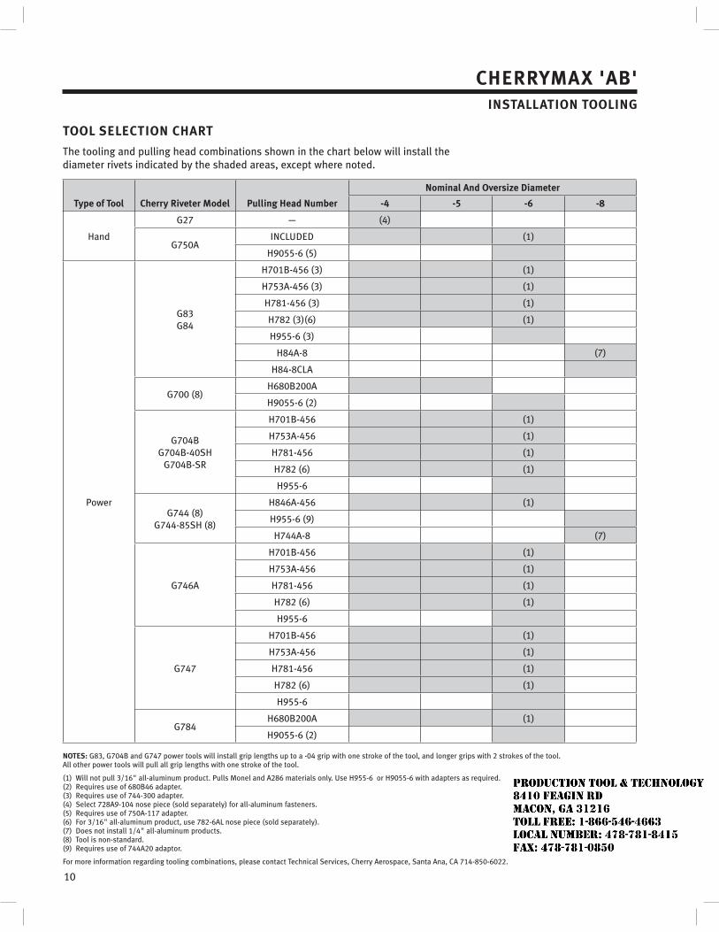
10
CHERRYMAX 'AB'INSTALLATION TOOLING
TOOL SELECTION CHART
The tooling and pulling head combinations shown in the chart below will install the diameter rivets indicated by the shaded areas, except where noted.
Type of Tool Cherry Riveter Model Pulling Head Number
Nominal And Oversize Diameter
-4 -5 -6 -8
Hand
G27 — (4)
G750AINCLUDED (1)
H9055-6 (5)
Power
G83G84
H701B-456 (3) (1)
H753A-456 (3) (1)
H781-456 (3) (1)
H782 (3)(6) (1)
H955-6 (3)
H84A-8 (7)
H84-8CLA
G700 (8)H680B200A
H9055-6 (2)
G704BG704B-40SH
G704B-SR
H701B-456 (1)
H753A-456 (1)
H781-456 (1)
H782 (6) (1)
H955-6
G744 (8)G744-85SH (8)
H846A-456 (1)
H955-6 (9)
H744A-8 (7)
G746A
H701B-456 (1)
H753A-456 (1)
H781-456 (1)
H782 (6) (1)
H955-6
G747
H701B-456 (1)
H753A-456 (1)
H781-456 (1)
H782 (6) (1)
H955-6
G784H680B200A (1)
H9055-6 (2)
NOTES: G83, G704B and G747 power tools will install grip lengths up to a -04 grip with one stroke of the tool, and longer grips with 2 strokes of the tool.All other power tools will pull all grip lengths with one stroke of the tool.
(1) Will not pull 3/16" all-aluminum product. Pulls Monel and A286 materials only. Use H955-6 or H9055-6 with adapters as required.(2) Requires use of 680B46 adapter.(3) Requires use of 744-300 adapter.(4) Select 728A9-104 nose piece (sold separately) for all-aluminum fasteners.(5) Requires use of 750A-117 adapter.(6) For 3/16" all-aluminum product, use 782-6AL nose piece (sold separately).(7) Does not install 1/4" all-aluminum products.(8) Tool is non-standard.(9) Requires use of 744A20 adaptor.
For more information regarding tooling combinations, please contact Technical Services, Cherry Aerospace, Santa Ana, CA 714-850-6022.
JR
Typewritten text
Production Tool & Technology 8410 Feagin Rd Macon, Ga 31216 Toll Free: 1-866-546-4663 Local Number: 478-781-8415 Fax: 478-781-0850
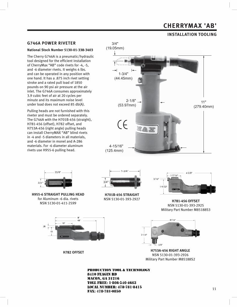
11
3/4 "
2 3/8"
H955-6 STRAIGHT PULLING HEADfor Aluminum -6 dia. rivets
NSN 5130-01-411-2599
H701B-456 STRAIGHTNSN 5130-01-393-2927
4-3/8"1-7/16"
1-9/32"
3/16"
H781-456 OFFSETNSN 5130-01-393-2925
Military Part Number M85188S3
CHERRYMAX 'AB'INSTALLATION TOOLING
G746A POWER RIVETER
National Stock Number 5130-01-338-3403
The Cherry G746A is a pneumatic/hydraulic tool designed for the efficient installation of CherryMax “AB” code rivets for -4, -5, and -6 diameter rivets. It weighs 4 lbs. and can be operated in any position with one hand. It has a .875 inch rivet setting stroke and a rated pull load of 1850 pounds on 90 psi air pressure at the air inlet. The G746A consumes approximately 3.9 cubic feet of air at 20 cycles per minute and its maximum noise level under load does not exceed 85 db(A).
Pulling heads are not furnished with this riveter and must be ordered separately. The G746A with the H701B-456 (straight), H781-456 (offset), H782 offset, and H753A-456 (right angle) pulling heads can install CherryMAX “AB” blind rivets in -4 and -5 diameters in all materials, and -6 diameter in monel and A-286 materials. For -6 diameter aluminum rivets use H955-6 pulling head.
5.59"4.59"
1.53"
1.0"
.250"
H782 OFFSET
5-7/16"
2-1/4"
3/8"
H753A-456 RIGHT ANGLENSN 5130-01-393-2926
Military Part Number M85188S2
JR
Typewritten text
Production Tool & Technology 8410 Feagin Rd Macon, Ga 31216 Toll Free: 1-866-546-4663 Local Number: 478-781-8415 Fax: 478-781-0850
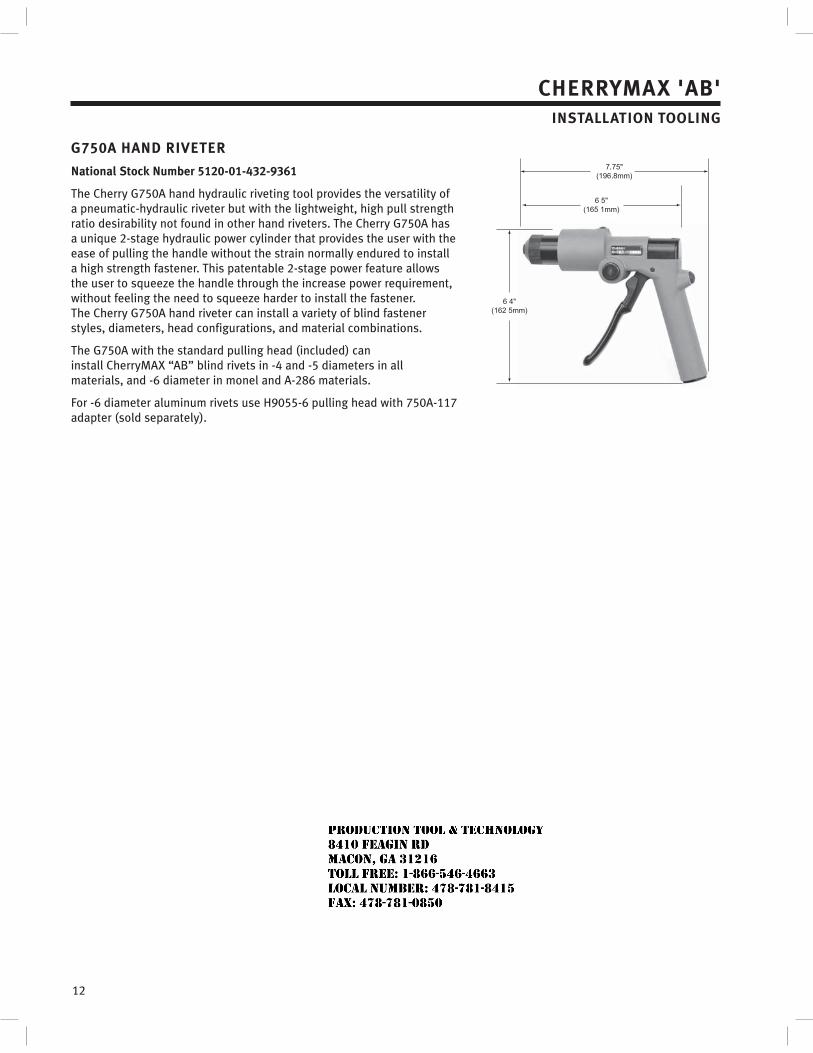
12
CHERRYMAX 'AB'INSTALLATION TOOLING
G750A HAND RIVETER
National Stock Number 5120-01-432-9361
The Cherry G750A hand hydraulic riveting tool provides the versatility of a pneumatic-hydraulic riveter but with the lightweight, high pull strength ratio desirability not found in other hand riveters. The Cherry G750A has a unique 2-stage hydraulic power cylinder that provides the user with the ease of pulling the handle without the strain normally endured to install a high strength fastener. This patentable 2-stage power feature allows the user to squeeze the handle through the increase power requirement, without feeling the need to squeeze harder to install the fastener. The Cherry G750A hand riveter can install a variety of blind fastener styles, diameters, head configurations, and material combinations.
The G750A with the standard pulling head (included) can install CherryMAX “AB” blind rivets in -4 and -5 diameters in all materials, and -6 diameter in monel and A-286 materials.
For -6 diameter aluminum rivets use H9055-6 pulling head with 750A-117 adapter (sold separately).
JR
Typewritten text
Production Tool & Technology 8410 Feagin Rd Macon, Ga 31216 Toll Free: 1-866-546-4663 Local Number: 478-781-8415 Fax: 478-781-0850
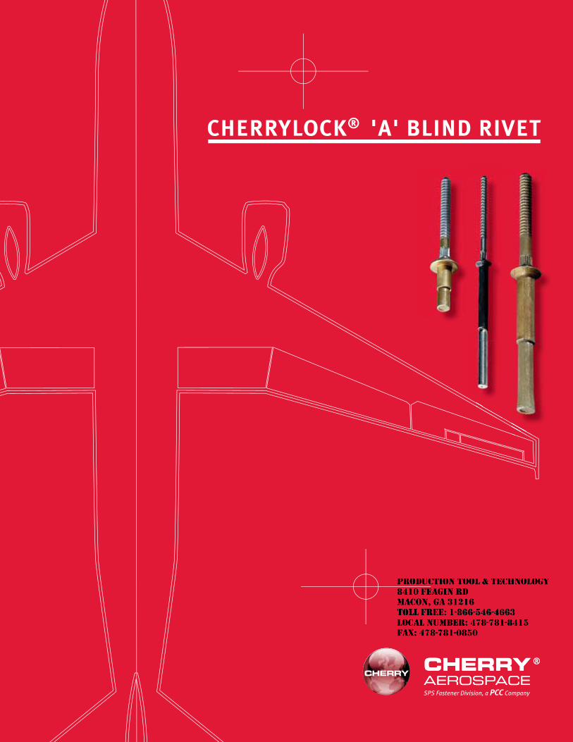
CHERRYLOCK® 'A' BLIND RIVET
SPS Fastener Division, a PCC Company
JR
Typewritten text
Production Tool & Technology 8410 Feagin Rd Macon, Ga 31216 Toll Free: 1-866-546-4663 Local Number: 478-781-8415 Fax: 478-781-0850
CHERRYLOCK® 'A' RIVETNAS1398/1399(A) CODE
CR2172/73 ALUMINUM CR2572/73 MONEL
CR2672/73 A-286CONTENTS
Features................................................................................................................................ 1Installation............................................................................................................................ 1Physical Properties ............................................................................................................... 2
Numbering System........................................................................................................ 2Materials ....................................................................................................................... 2Strength ........................................................................................................................ 2
Installed Weights – Pounds per 1000 pieces........................................................................ 3Wiredraw Nominal NAS1399 100° Flush Head ..................................................................... 4Wiredraw Nominal NAS1398 Universal Head ....................................................................... 5Installation Tooling ............................................................................................................... 6
Power Riveters .............................................................................................................. 7Hand Riveters................................................................................................................ 8Pulling Heads ................................................................................................................ 9
LIMITED WARRANTY
Seller warrants the goods conform to applicable specifications and drawings and will be manufactured and inspected according to generally accepted practices of companies manufacturing industrial or aerospace fasteners. In the event of any breach of the foregoing warranty, Buyer’s sole remedy shall be to return defective goods (after receiving authorization from Seller) for replacement or refund of the purchase price, at the Seller’s option. Seller agrees to any freight costs in connection with the return of any defective goods, but any costs relating to removal of the defective or nonconforming goods or installation of replacement goods shall be Buyer’s responsibility. SELLER’S WARRANTY DOES NOT APPLY WHEN ANY PHYSICAL OR CHEMICAL CHANGE IN THE FORM OF THE PRODUCT IS MADE BY BUYER. THE FOREGOING EXPRESS WARRANTY AND REMEDY ARE EXCLUSIVE AND ARE IN LIEU OF ALL OTHER WARRANTIES AND REMEDIES; ANY IMPLIED WARRANTY AS TO QUALITY, FITNESS FOR PURPOSE, OR MERCHANTABILITY IS HEREBY SPECIFICALLY DISCLAIMED AND EXCLUDED BY SELLER. This warranty is void if seller is not notified in writing of any rejection of the goods within one (1) Year aFter initial use by buyer of any power Riveter or ninety (90) days after initial use of any other product.
Seller shall not be liable under any circumstances for incidental, special or consequential damages arising in whole or in part from any breach by Seller, AND SUCH INCIDENTAL, SPECIAL, OR CONSEQUENTIAL DAMAGES ARE HEREBY EXPRESSLY EXCLUDED.
Our policy is one of continuous development. Specifications shown in this document may be subject to changes introduced after publication.
CHERRY®, Cherrylock® and MAXIBOLT® are trademarks of Cherry Aerospace.
NOTEThe properties, strengths, dimensions, installed characteristics and all other information in this catalog is for guid-ance only to aid in the correct selection of the products described herein and is not intended or implied as part of the warranty. All applications should be evaluated for functional suitability and available samples of the described parts can be requested for installed tests, suitability and evaluations.
ATTENTIONBlind rivets are not always a suitable substitute for solid rivets. Maintenance personnel are reminded that AC 43.13-1A chapter 2, section 3, stipulates: “Do not substitute hollow rivets for solid rivets in load carrying members without specific approval of the application by a representative of the Federal Aviation Administration. Blind rivets may be used in blind locations in accordance with the conditions listed in Chapter 5, provided the edge distances and spacings are not less that the minimum listed in paragraph 99d.”
JR
Typewritten text
Production Tool & Technology 8410 Feagin Rd Macon, Ga 31216 Toll Free: 1-866-546-4663 Local Number: 478-781-8415 Fax: 478-781-0850
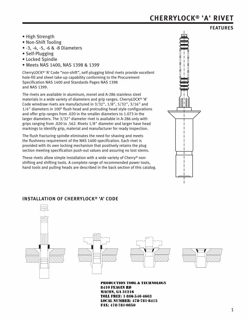
1
CHERRYLOCK® 'A' RIVETFEATURES
CherryLOCK® ‘A’ Code “non-shift”, self-plugging blind rivets provide excellent hole-fill and sheet take-up capability conforming to the Procurement Specification NAS 1400 and Standards Pages NAS 1398 and NAS 1399.
The rivets are available in aluminum, monel and A-286 stainless steel materials in a wide variety of diameters and grip ranges. CherryLOCK® ‘A’ Code wiredraw rivets are manufactured in 3/32", 1/8", 5/32", 3/16" and 1/4" diameters in 100° flush head and protruding head style configurations and offer grip ranges from .020 in the smaller diameters to 1.073 in the larger diameters. The 3/32" diameter rivet is available in A-286 only with grips ranging from .020 to .562. Rivets 1/8" diameter and larger have head markings to identify grip, material and manufacturer for ready inspection.
The flush fracturing spindle eliminates the need for shaving and meets the flushness requirement of the NAS 1400 specification. Each rivet is provided with its own locking mechanism that positively retains the plug section meeting specification push-out values and assuring no lost stems.
These rivets allow simple installation with a wide variety of Cherry® non-shifting and shifting tools. A complete range of recommended power tools, hand tools and pulling heads are described in the back section of this catalog.
INSTALLATION OF CHERRYLOCK® ‘A’ CODE
JR
Typewritten text
Production Tool & Technology 8410 Feagin Rd Macon, Ga 31216 Toll Free: 1-866-546-4663 Local Number: 478-781-8415 Fax: 478-781-0850
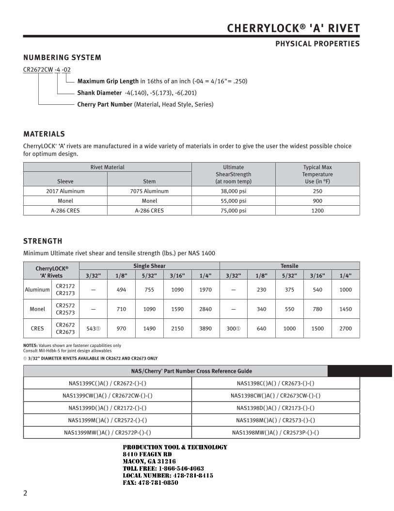
2
CHERRYLOCK® 'A' RIVETPHYSICAL PROPERTIES
MATERIALS
CherryLOCK® ‘A’ rivets are manufactured in a wide variety of materials in order to give the user the widest possible choice for optimum design.
Rivet Material UltimateShearStrength(at room temp)
Typical MaxTemperature
Use (in °F)Sleeve Stem
2017 Aluminum 7075 Aluminum 38,000 psi 250
Monel Monel 55,000 psi 900
A-286 CRES A-286 CRES 75,000 psi 1200
STRENGTH
Minimum Ultimate rivet shear and tensile strength (lbs.) per NAS 1400
CherryLOCK®
‘A’ Rivets
Single Shear Tensile
3/32" 1/8" 5/32" 3/16" 1/4" 3/32" 1/8" 5/32" 3/16" 1/4"
AluminumCR2172CR2173
— 494 755 1090 1970 — 230 375 540 1000
MonelCR2572CR2573
— 710 1090 1590 2840 — 340 550 780 1450
CRESCR2672CR2673
543 970 1490 2150 3890 300 640 1000 1500 2700
NOTES: Values shown are fastener capabilities onlyConsult Mil-Hdbk-5 for joint design allowables
3/32" DIAMETER RIVETS AVAILABLE IN CR2672 AND CR2673 ONLY
NAS/Cherry® Part Number Cross Reference Guide
NAS1399C( )A( ) / CR2672-( )-( ) NAS1398C( )A( ) / CR2673-( )-( )
NAS1399CW( )A( ) / CR2672CW-( )-( ) NAS1398CW( )A( ) / CR2673CW-( )-( )
NAS1399D( )A( ) / CR2172-( )-( ) NAS1398D( )A( ) / CR2173-( )-( )
NAS1399M( )A( ) / CR2572-( )-( ) NAS1398M( )A( ) / CR2573-( )-( )
NAS1399MW( )A( ) / CR2572P-( )-( ) NAS1398MW( )A( ) / CR2573P-( )-( )
NUMBERING SYSTEM
CR2672CW -4 -02
Maximum Grip Length in 16ths of an inch (-04 = 4/16"= .250)
Shank Diameter -4(.140), -5(.173), -6(.201)
Cherry Part Number (Material, Head Style, Series)
JR
Typewritten text
Production Tool & Technology 8410 Feagin Rd Macon, Ga 31216 Toll Free: 1-866-546-4663 Local Number: 478-781-8415 Fax: 478-781-0850
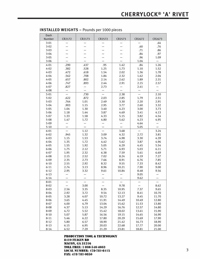
3
CHERRYLOCK® 'A' RIVET
INSTALLED WEIGHTS – Pounds per 1000 piecesDash
Number CR2172 CR2173 CR2572 CR2573 CR2672 CR26733-01 — — — — — .643-02 — — — — .60 .763-03 — — — — .71 .863-04 — — — — .84 .973-05 — — — — .96 1.093-06 — — — — 1.04 —4-01 .290 .437 .95 1.42 .84 1.264-02 .382 .528 1.25 1.73 1.10 1.524-03 .472 .618 1.54 2.02 1.36 1.784-04 .562 .708 1.84 2.32 1.62 2.044-05 .657 .802 2.14 2.62 1.89 2.314-06 .747 .893 2.44 2.91 2.15 2.574-07 .827 — 2.73 — 2.41 —4-08 — — — — — —5-01 — .730 — 2.38 — 2.105-02 .622 .872 2.03 2.85 1.79 2.515-03 .764 1.01 2.49 3.30 2.20 2.915-04 .903 1.15 2.95 3.77 2.60 3.325-05 1.04 1.30 3.40 4.23 3.00 3.735-06 1.18 1.44 3.87 4.69 3.41 4.135-07 1.33 1.58 4.33 5.15 3.82 4.545-08 1.47 1.72 4.80 5.62 4.23 4.955-09 — — — — 4.64 —5-10 — — — — 5.05 —6-01 — 1.12 — 3.68 — 3.246-02 .945 1.32 3.09 4.32 2.72 3.816-03 1.15 1.53 3.74 4.98 3.30 4.396-04 1.35 1.72 4.42 5.62 3.87 4.966-05 1.55 1.92 5.05 6.29 4.45 5.546-06 1.75 2.12 5.71 6.93 5.03 6.116-07 1.95 2.32 6.38 7.59 5.61 6.696-08 2.15 2.52 7.02 8.24 6.19 7.276-09 2.35 2.73 7.66 8.91 6.76 7.856-10 2.55 2.92 8.32 9.55 7.33 8.426-11 2.74 3.13 8.96 10.21 7.90 9.006-12 2.95 3.32 9.61 10.84 8.48 9.566-13 — — — — 9.05 —6-14 — — — — 9.62 —8-01 — — — — — —8-02 — 3.00 — 9.78 — 8.628-03 2.56 3.35 8.35 10.95 7.37 9.658-04 2.92 3.72 9.54 12.13 8.41 10.708-05 3.28 4.07 10.72 13.27 9.45 11.708-06 3.65 4.45 11.91 14.49 10.49 12.808-07 4.00 4.79 13.04 15.62 11.53 13.808-08 4.37 5.13 14.29 16.76 12.57 14.808-09 4.72 5.52 15.42 18.02 13.61 15.908-10 5.07 5.87 16.56 19.15 14.65 16.908-11 5.46 6.22 17.80 20.29 15.69 17.908-12 5.80 6.57 18.90 21.42 16.73 18.908-13 6.15 6.95 20.03 22.68 17.77 20.008-14 6.52 7.29 21.29 23.81 18.81 21.00
JR
Typewritten text
Production Tool & Technology 8410 Feagin Rd Macon, Ga 31216 Toll Free: 1-866-546-4663 Local Number: 478-781-8415 Fax: 478-781-0850
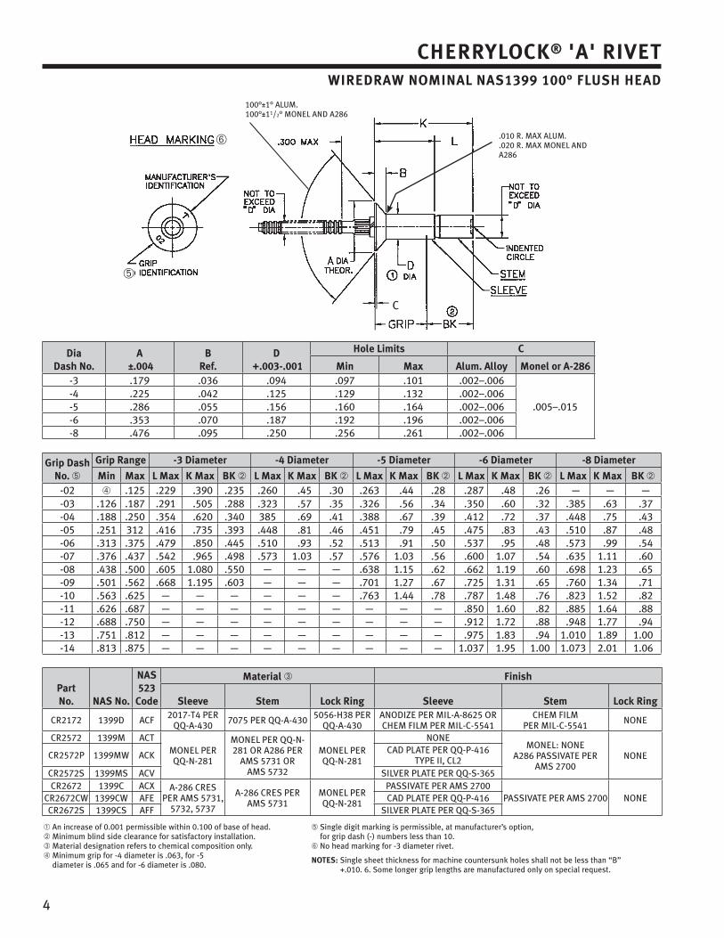
4
CHERRYLOCK® 'A' RIVETWIREDRAW NOMINAL NAS1399 100° FLUSH HEAD
100°±1° ALUM.100°±11/2° MONEL AND A286
.010 R. MAX ALUM.
.020 R. MAX MONEL AND A286
C
DiaDash No.
A ±.004
BRef.
D +.003-.001
Hole Limits C
Min Max Alum. Alloy Monel or A-286-3 .179 .036 .094 .097 .101 .002–.006
.005–.015-4 .225 .042 .125 .129 .132 .002–.006-5 .286 .055 .156 .160 .164 .002–.006-6 .353 .070 .187 .192 .196 .002–.006-8 .476 .095 .250 .256 .261 .002–.006
Grip DashNo.
Grip Range -3 Diameter -4 Diameter -5 Diameter -6 Diameter -8 Diameter
Min Max L Max K Max BK L Max K Max BK L Max K Max BK L Max K Max BK L Max K Max BK-02 .125 .229 .390 .235 .260 .45 .30 .263 .44 .28 .287 .48 .26 — — —-03 .126 .187 .291 .505 .288 .323 .57 .35 .326 .56 .34 .350 .60 .32 .385 .63 .37-04 .188 .250 .354 .620 .340 385 .69 .41 .388 .67 .39 .412 .72 .37 .448 .75 .43-05 .251 312 .416 .735 .393 .448 .81 .46 .451 .79 .45 .475 .83 .43 .510 .87 .48-06 .313 .375 .479 .850 .445 .510 .93 .52 .513 .91 .50 .537 .95 .48 .573 .99 .54-07 .376 .437 .542 .965 .498 .573 1.03 .57 .576 1.03 .56 .600 1.07 .54 .635 1.11 .60-08 .438 .500 .605 1.080 .550 — — — .638 1.15 .62 .662 1.19 .60 .698 1.23 .65-09 .501 .562 .668 1.195 .603 — — — .701 1.27 .67 .725 1.31 .65 .760 1.34 .71-10 .563 .625 — — — — — — .763 1.44 .78 .787 1.48 .76 .823 1.52 .82-11 .626 .687 — — — — — — — — — .850 1.60 .82 .885 1.64 .88-12 .688 .750 — — — — — — — — — .912 1.72 .88 .948 1.77 .94-13 .751 .812 — — — — — — — — — .975 1.83 .94 1.010 1.89 1.00-14 .813 .875 — — — — — — — — — 1.037 1.95 1.00 1.073 2.01 1.06
Part No. NAS No.
NAS 523
Code
Material Finish
Sleeve Stem Lock Ring Sleeve Stem Lock Ring
CR2172 1399D ACF 2017-T4 PERQQ-A-430 7075 PER QQ-A-430 5056-H38 PER
QQ-A-430ANODIZE PER MIL-A-8625 ORCHEM FILM PER MIL-C-5541
CHEM FILMPER MIL-C-5541 NONE
CR2572 1399M ACTMONEL PERQQ-N-281
MONEL PER QQ-N-281 OR A286 PER
AMS 5731 ORAMS 5732
MONEL PERQQ-N-281
NONEMONEL: NONE
A286 PASSIVATE PERAMS 2700
NONECR2572P 1399MW ACK CAD PLATE PER QQ-P-416TYPE II, CL2
CR2572S 1399MS ACV SILVER PLATE PER QQ-S-365CR2672 1399C ACX A-286 CRES
PER AMS 5731, 5732, 5737
A-286 CRES PERAMS 5731
MONEL PERQQ-N-281
PASSIVATE PER AMS 2700PASSIVATE PER AMS 2700 NONECR2672CW 1399CW AFE CAD PLATE PER QQ-P-416
CR2672S 1399CS AFF SILVER PLATE PER QQ-S-365
An increase of 0.001 permissible within 0.100 of base of head. Minimum blind side clearance for satisfactory installation. Material designation refers to chemical composition only.Minimum grip for -4 diameter is .063, for -5diameter is .065 and for -6 diameter is .080.
Single digit marking is permissible, at manufacturer’s option, for grip dash (-) numbers less than 10.
No head marking for -3 diameter rivet.
NOTES: Single sheet thickness for machine countersunk holes shall not be less than “B” +.010. 6. Some longer grip lengths are manufactured only on special request.
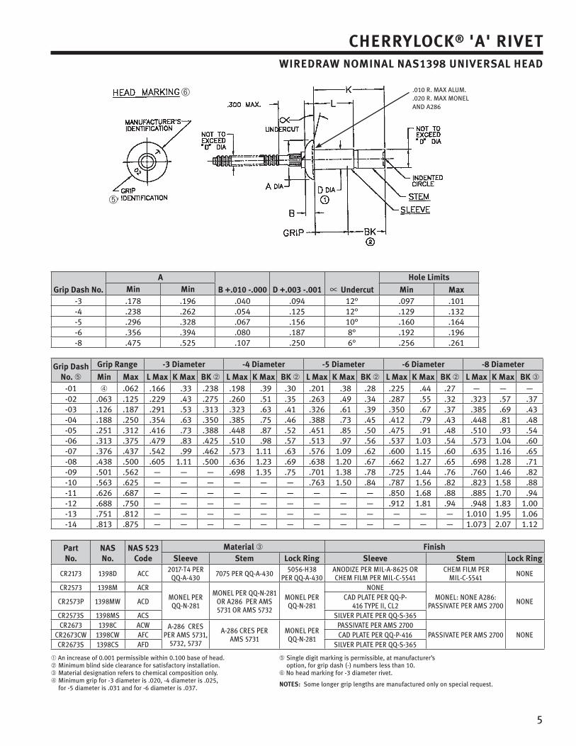
5
CHERRYLOCK® 'A' RIVETWIREDRAW NOMINAL NAS1398 UNIVERSAL HEAD
.010 R. MAX ALUM.
.020 R. MAX MONEL AND A286
Grip Dash No.
A
B +.010 -.000 D +.003 -.001 Undercut
Hole LimitsMin Min Min Max
-3 .178 .196 .040 .094 12° .097 .101-4 .238 .262 .054 .125 12° .129 .132-5 .296 .328 .067 .156 10° .160 .164-6 .356 .394 .080 .187 8° .192 .196-8 .475 .525 .107 .250 6° .256 .261
Grip DashNo.
Grip Range -3 Diameter -4 Diameter -5 Diameter -6 Diameter -8 Diameter
Min Max L Max K Max BK L Max K Max BK L Max K Max BK L Max K Max BK L Max K Max BK-01 .062 .166 .33 .238 .198 .39 .30 .201 .38 .28 .225 .44 .27 — — —-02 .063 .125 .229 .43 .275 .260 .51 .35 .263 .49 .34 .287 .55 .32 .323 .57 .37-03 .126 .187 .291 .53 .313 .323 .63 .41 .326 .61 .39 .350 .67 .37 .385 .69 .43-04 .188 .250 .354 .63 .350 .385 .75 .46 .388 .73 .45 .412 .79 .43 .448 .81 .48-05 .251 .312 .416 .73 .388 .448 .87 .52 .451 .85 .50 .475 .91 .48 .510 .93 .54-06 .313 .375 .479 .83 .425 .510 .98 .57 .513 .97 .56 .537 1.03 .54 .573 1.04 .60-07 .376 .437 .542 .99 .462 .573 1.11 .63 .576 1.09 .62 .600 1.15 .60 .635 1.16 .65-08 .438 .500 .605 1.11 .500 .636 1.23 .69 .638 1.20 .67 .662 1.27 .65 .698 1.28 .71-09 .501 .562 — — — .698 1.35 .75 .701 1.38 .78 .725 1.44 .76 .760 1.46 .82-10 .563 .625 — — — — — — .763 1.50 .84 .787 1.56 .82 .823 1.58 .88-11 .626 .687 — — — — — — — — — .850 1.68 .88 .885 1.70 .94-12 .688 .750 — — — — — — — — — .912 1.81 .94 .948 1.83 1.00-13 .751 .812 — — — — — — — — — — — — 1.010 1.95 1.06-14 .813 .875 — — — — — — — — — — — — 1.073 2.07 1.12
Part No.
NASNo.
NAS 523 Code
Material FinishSleeve Stem Lock Ring Sleeve Stem Lock Ring
An increase of 0.001 permissible within 0.100 base of head.Minimum blind side clearance for satisfactory installation.Material designation refers to chemical composition only.Minimum grip for -3 diameter is .020, -4 diameter is .025, for -5 diameter is .031 and for -6 diameter is .037.
Single digit marking is permissible, at manufacturer’s option, for grip dash (-) numbers less than 10.No head marking for -3 diameter rivet.
NOTES: Some longer grip lengths are manufactured only on special request.
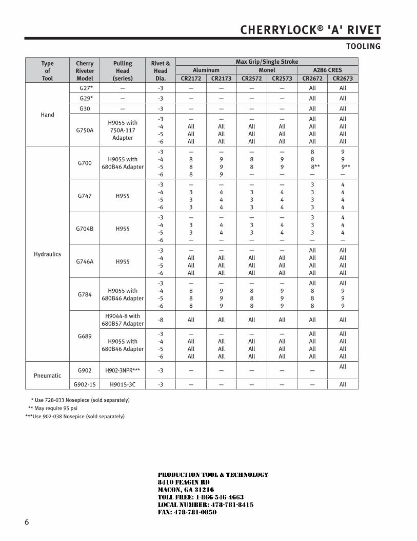
6
CHERRYLOCK® 'A' RIVETTOOLING
Typeof
Tool
CherryRiveterModel
PullingHead
(series)
Rivet &HeadDia.
Max Grip/Single StrokeAluminum Monel A286 CRES
CR2172 CR2173 CR2572 CR2573 CR2672 CR2673
Hand
G27* — -3 — — — — All All
G29* — -3 — — — — All All
G30 — -3 — — — — All All
G750AH9055 with750A-117Adapter
-3-4-5-6
—AllAllAll
—AllAllAll
—AllAllAll
—AllAllAll
AllAllAllAll
AllAllAllAll
Hydraulics
G700H9055 with
680B46 Adapter
-3-4-5-6
—888
—999
—88—
—99—
88
8**—
99
9**—
G747 H955
-3-4-5-6
—333
—444
—333
—444
3333
4444
G704B H955
-3-4-5-6
—33—
—44—
—33—
—44—
333—
444—
G746A H955
-3-4-5-6
—AllAllAll
—AllAllAll
—AllAllAll
—AllAllAll
AllAllAllAll
AllAllAllAll
G784H9055 with
680B46 Adapter
-3-4-5-6
—888
—999
—888
—999
All888
All999
G689
H9044-8 with680B57 Adapter
-8 All All All All All All
H9055 with680B46 Adapter
-3-4-5-6
—AllAllAll
—AllAllAll
—AllAllAll
—AllAllAll
AllAllAllAll
AllAllAllAll
PneumaticG902 H902-3NPR*** -3 — — — — —
All
G902-15 H9015-3C -3 — — — — — All
* Use 728-033 Nosepiece (sold separately)
** May require 95 psi
***Use 902-038 Nosepice (sold separately)
JR
Typewritten text
Production Tool & Technology 8410 Feagin Rd Macon, Ga 31216 Toll Free: 1-866-546-4663 Local Number: 478-781-8415 Fax: 478-781-0850
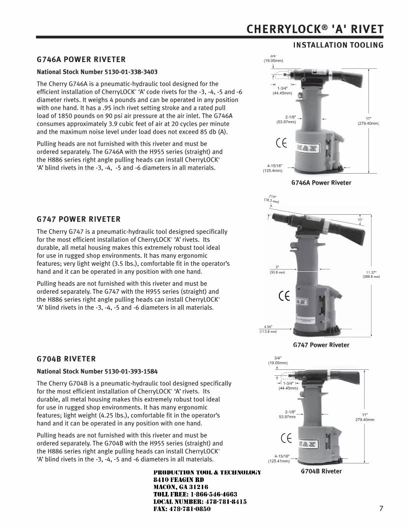
77
CHERRYLOCK® 'A' RIVETINSTATT LLATION TOOLING
G746A POWER RIVETER
National Stock Number 5130-01-338-3403
The Cherry G746A is a pneumatic-hydraulic tool designed for theefficient installation of CherryLOCK® ‘A’ code rivets for the -3, -4, -5 and -6diameter rivets. It weighs 4 pounds and can be operated in any positionwith one hand. It has a .95 inch rivet setting stroke and a rated pullload of 1850 pounds on 90 psi air pressure at the air inlet. The G746Aconsumes approximately 3.9 cubic feet of air at 20 cycles per minuteand the maximum noise level under load does not exceed 85 db (A).
Pulling heads are not furnished with this riveter and must beordered separately. The G746A with the H955 series (straight) andthe H886 series right angle pulling heads can install CherryLOCK®
‘A’ blind rivets in the -3, -4, -5 and -6 diameters in all materials.
G747 POWER RIVETER
The Cherry G747 is a pneumatic-hydraulic tool designed specificallyfor the most efficient installation of CherryLOCK® ‘A’ rivets. Itsdurable, all metal housing makes this extremely robust tool idealfor use in rugged shop environments. It has many ergonomicfeatures; very light weight (3.5 lbs.), comfortable fit in the operator’shand and it can be operated in any position with one hand.
Pulling heads are not furnished with this riveter and must beordered separately. The G747 with the H955 series (straight) andthe H886 series right angle pulling heads can install CherryLOCK®
‘A’ blind rivets in the -3, -4, -5 and -6 diameters in all materials.
G704B RIVETER
National Stock Number 5130-01-393-1584
The Cherry G704B is a pneumatic-hydraulic tool designed specificallyfor the most efficient installation of CherryLOCK® ‘A’ rivets. Itsdurable, all metal housing makes this extremely robust tool idealfor use in rugged shop environments. It has many ergonomicfeatures; light weight (4.25 lbs.), comfortable fit in the operator’shand and it can be operated in any position with one hand.
Pulling heads are not furnished with this riveter and must beordered separately. The G704B with the H955 series (straight) andthe H886 series right angle pulling heads can install CherryLOCK®
‘A’ blind rivets in the -3, -4, -5 and -6 diameters in all materials.
746A Power Riveter
.719"(18.3 mm)
2"(50.8 mm) 11.37"
(288.8 mm)
10
4.56"(115.8 mm)
G747 Power Riveter
704B Riveter
JR
Typewritten text
Production Tool & Technology 8410 Feagin Rd Macon, Ga 31216 Toll Free: 1-866-546-4663 Local Number: 478-781-8415 Fax: 478-781-0850
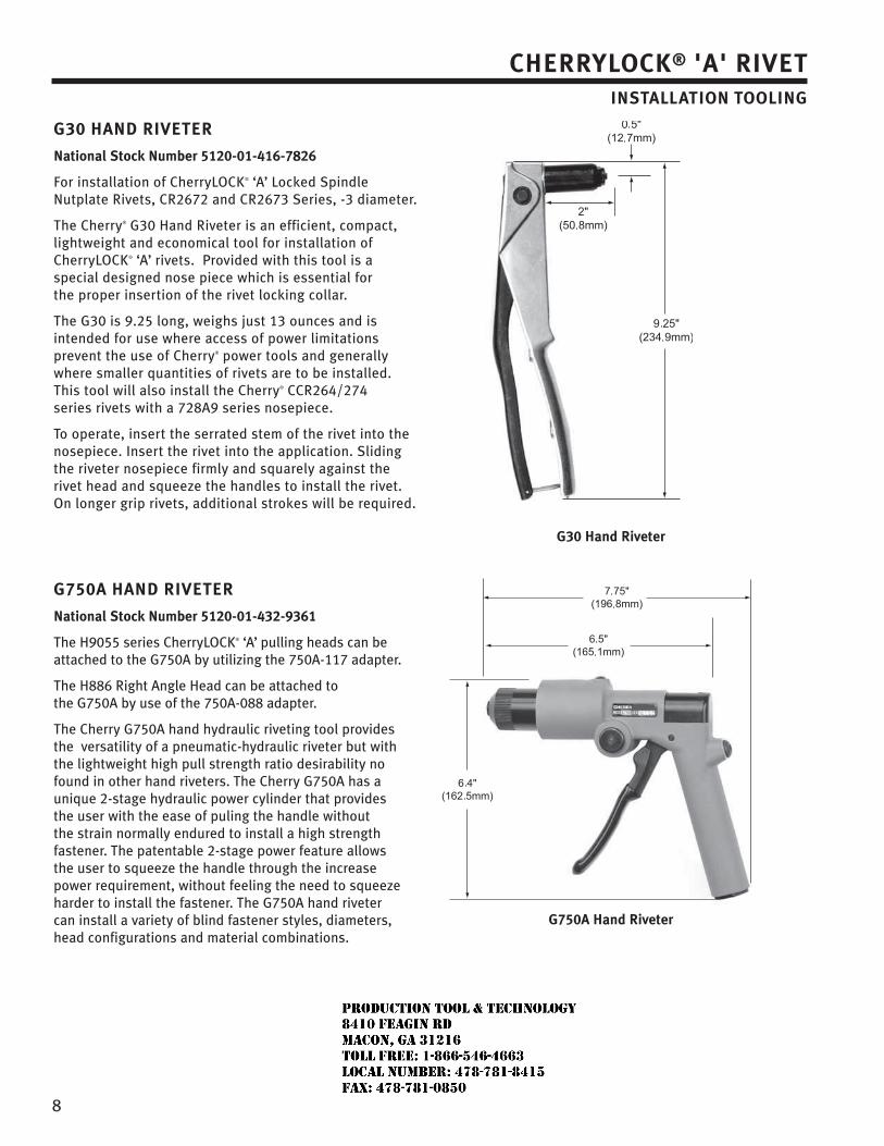
8
CHERRYLOCK® 'A' RIVETINSTALLATION TOOLING
G30 HAND RIVETER
National Stock Number 5120-01-416-7826
For installation of CherryLOCK® ‘A’ Locked Spindle Nutplate Rivets, CR2672 and CR2673 Series, -3 diameter.
The Cherry® G30 Hand Riveter is an efficient, compact, lightweight and economical tool for installation of CherryLOCK® ‘A’ rivets. Provided with this tool is a special designed nose piece which is essential for the proper insertion of the rivet locking collar.
The G30 is 9.25 long, weighs just 13 ounces and is intended for use where access of power limitations prevent the use of Cherry® power tools and generally where smaller quantities of rivets are to be installed. This tool will also install the Cherry® CCR264/274 series rivets with a 728A9 series nosepiece.
To operate, insert the serrated stem of the rivet into the nosepiece. Insert the rivet into the application. Sliding the riveter nosepiece firmly and squarely against the rivet head and squeeze the handles to install the rivet. On longer grip rivets, additional strokes will be required.
G750A HAND RIVETER
National Stock Number 5120-01-432-9361
The H9055 series CherryLOCK® ‘A’ pulling heads can be attached to the G750A by utilizing the 750A-117 adapter.
The H886 Right Angle Head can be attached to the G750A by use of the 750A-088 adapter.
The Cherry G750A hand hydraulic riveting tool provides the versatility of a pneumatic-hydraulic riveter but with the lightweight high pull strength ratio desirability no found in other hand riveters. The Cherry G750A has a unique 2-stage hydraulic power cylinder that provides the user with the ease of puling the handle without the strain normally endured to install a high strength fastener. The patentable 2-stage power feature allows the user to squeeze the handle through the increase power requirement, without feeling the need to squeeze harder to install the fastener. The G750A hand riveter can install a variety of blind fastener styles, diameters, head configurations and material combinations.
G30 Hand Riveter
G750A Hand Riveter
JR
Typewritten text
Production Tool & Technology 8410 Feagin Rd Macon, Ga 31216 Toll Free: 1-866-546-4663 Local Number: 478-781-8415 Fax: 478-781-0850
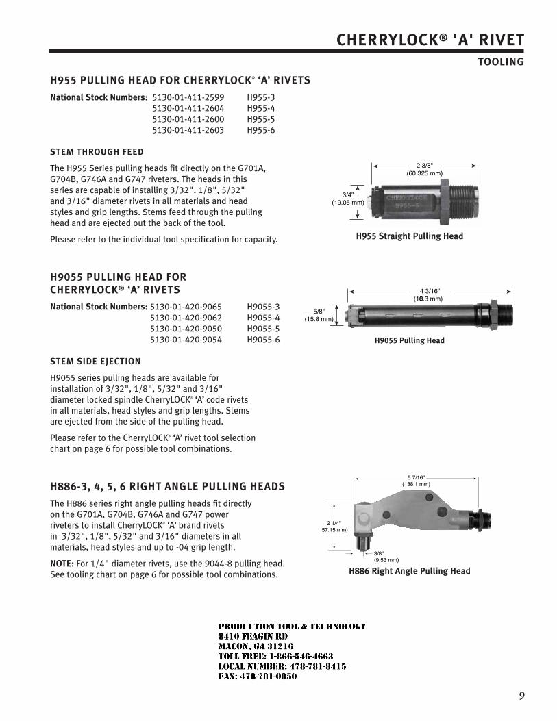
9
CHERRYLOCK® 'A' RIVETTOOLING
H955 PULLING HEAD FOR CHERRYLOCK® ‘A’ RIVETS
National Stock Numbers: 5130-01-411-2599 H955-35130-01-411-2604 H955-45130-01-411-2600 H955-55130-01-411-2603 H955-6
STEM THROUGH FEED
The H955 Series pulling heads fit directly on the G701A, G704B, G746A and G747 riveters. The heads in this series are capable of installing 3/32", 1/8", 5/32" and 3/16" diameter rivets in all materials and head styles and grip lengths. Stems feed through the pulling head and are ejected out the back of the tool.
Please refer to the individual tool specification for capacity.
H9055 PULLING HEAD FOR CHERRYLOCK® ‘A’ RIVETS
National Stock Numbers: 5130-01-420-9065 H9055-35130-01-420-9062 H9055-45130-01-420-9050 H9055-55130-01-420-9054 H9055-6
STEM SIDE EJECTION
H9055 series pulling heads are available for installation of 3/32", 1/8", 5/32" and 3/16" diameter locked spindle CherryLOCK® ‘A’ code rivets in all materials, head styles and grip lengths. Stems are ejected from the side of the pulling head.
Please refer to the CherryLOCK® ‘A’ rivet tool selection chart on page 6 for possible tool combinations.
H886-3, 4, 5, 6 RIGHT ANGLE PULLING HEADS
The H886 series right angle pulling heads fit directly on the G701A, G704B, G746A and G747 power riveters to install CherryLOCK® ‘A’ brand rivets in 3/32", 1/8", 5/32" and 3/16" diameters in all materials, head styles and up to -04 grip length.
NOTE: For 1/4" diameter rivets, use the 9044-8 pulling head. See tooling chart on page 6 for possible tool combinations.
2 3/8"(60.325 mm)
3/4"(19.05 mm)
H955 Straight Pulling Head
4 3/16"(106.3 mm)
5/8"(15.8 mm)
H9055 Pulling Head
5 7/16"(138.1 mm)
2 1/4"57.15 mm)
3/8"(9.53 mm)
H886 Right Angle Pulling Head
JR
Typewritten text
Production Tool & Technology 8410 Feagin Rd Macon, Ga 31216 Toll Free: 1-866-546-4663 Local Number: 478-781-8415 Fax: 478-781-0850
LIMITED WARRANTY
Seller warrants the goods conform to applicable specifications and drawings and will be manufactured and inspected according to generally accepted practices of companies manufacturing industrial or aerospace fasteners. In the event of any breach of the foregoing warranty, Buyer’s sole remedy shall be to return defective goods (after receiving authorization from Seller) for replacement or refund of the purchase price, at the Seller’s option. Seller agrees to any freight costs in connection with the return of any defective goods, but any costs relating to removal of the defective or nonconforming goods or installation of replacement goods shall be Buyer’s responsibility. SELLER’S WARRANTY DOES NOT APPLY WHEN ANY PHYSICAL OR CHEMICAL CHANGE IN THE FORM OF THE PRODUCT IS MADE BY BUYER. THE FOREGOING EXPRESS WARRANTY AND REMEDY ARE EXCLUSIVE AND ARE IN LIEU OF ALL OTHER WARRANTIES AND REMEDIES; ANY IMPLIED WARRANTY AS TO QUALITY, FITNESS FOR PURPOSE, OR MERCHANTABILITY IS HEREBY SPECIFICALLY DISCLAIMED AND EXCLUDED BY SELLER. This warranty is void if seller is not notified in writing of any rejection of the goods within one (1) Year aFter initial use by buyer of any power Riveter or ninety (90) days after initial use of any other product.
Seller shall not be liable under any circumstances for incidental, special or consequential damages arising in whole or in part from any breach by Seller, AND SUCH INCIDENTAL, SPECIAL, OR CONSEQUENTIAL DAMAGES ARE HEREBY EXPRESSLY EXCLUDED.
Our policy is one of continuous development. Specifications shown in this document may be subject to changes introduced after publication.
CHERRY® and SPR® are trademarks of Cherry Aerospace.
NoTEThe properties, strengths, dimensions, installed characteristics and all other information in this catalog is for guid-ance only to aid in the correct selection of the products described herein and is not intended or implied as part of the warranty. All applications should be evaluated for functional suitability and available samples of the described parts can be requested for installed tests, suitability and evaluations.
ATTENTIoNBlind rivets are not always a suitable substitute for solid rivets. Maintenance personnel are reminded that AC 43.13-1A chapter 2, section 3, stipulates: “Do not substitute hollow rivets for solid rivets in load carrying members without specific approval of the application by a representative of the Federal Aviation Administration. Blind rivets may be used in blind locations in accordance with the conditions listed in Chapter 5, provided the edge distances and spacings are not less that the minimum listed in paragraph 99d.”
SPS Fastener Division, a PCC Company
REMovAL PRocEDuRE
The SPR fastener may be removed by following this procedure:1. Using a .062” pin punch, knock out the stem2. Using a #41 (.095”) drill bit, centered on the
stem hole, drill down no more than .030”3. Use a 3/32" pin punch inserted into
the hole to pry the head off
4. Remove the tail section with the 3/32" pin punch
TooLINg
HAND TooLS G29 Pulling head included
PoWER TooLSG746A H747-3NPR pulling headG747 H747-3NPR pulling headG702A H702-3NPR pulling headG902 H902-3NPR pulling headG902-15 H9015-3C pulling head
CHERRY® 3/32" SPR® SELF PLUGGING RIVET
JR
Typewritten text
Production Tool & Technology 8410 Feagin Rd Macon, Ga 31216 Toll Free: 1-866-546-4663 Local Number: 478-781-8415 Fax: 478-781-0850
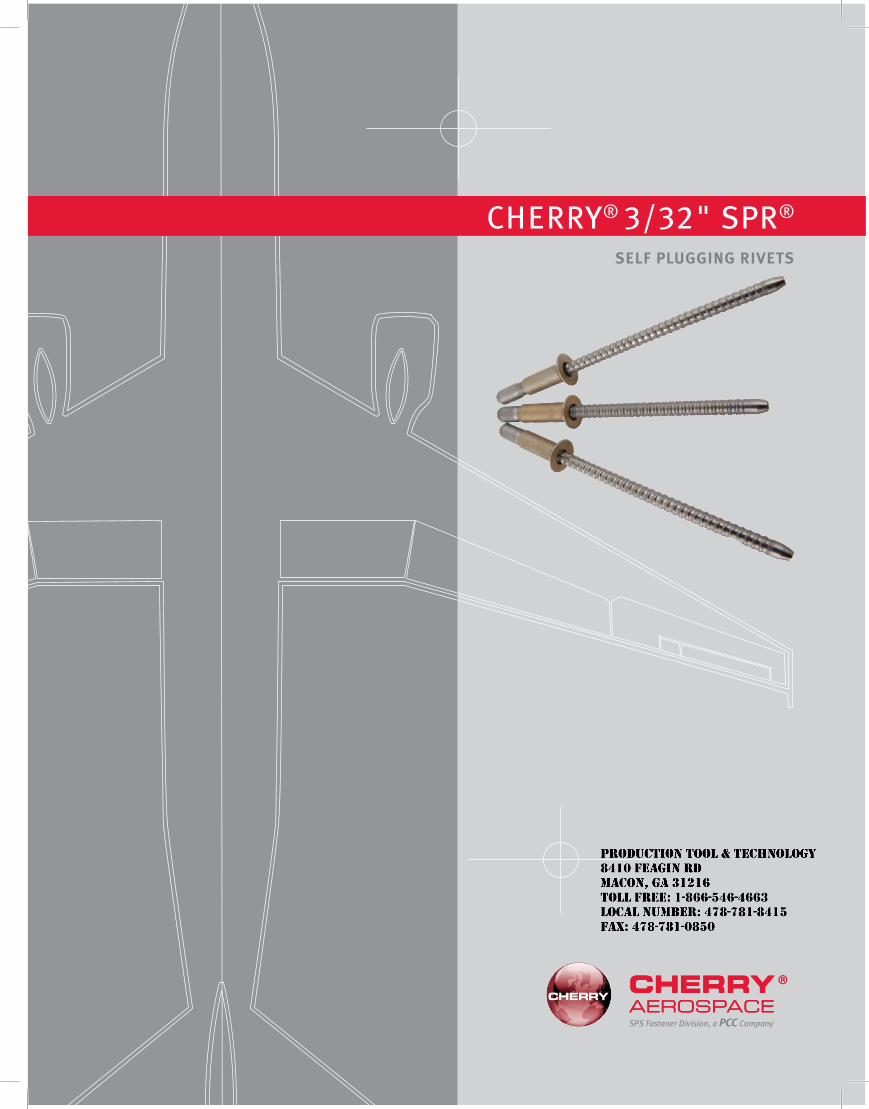
SPS Fastener Division, a PCC Company
CHERRY® 3/32" SPR®
SELf PLuggINg RIvETS
JR
Typewritten text
Production Tool & Technology 8410 Feagin Rd Macon, Ga 31216 Toll Free: 1-866-546-4663 Local Number: 478-781-8415 Fax: 478-781-0850
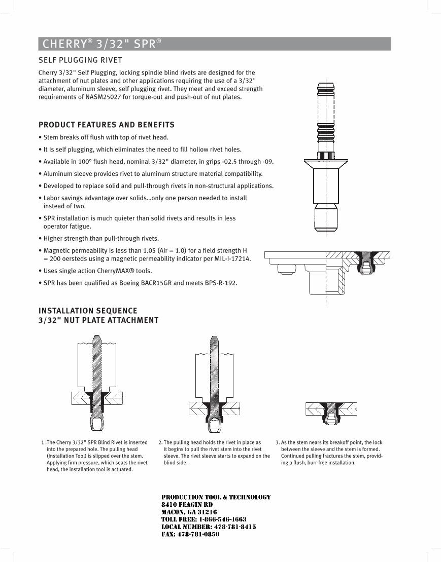
CHERRY® 3/32" SPR® SELF PLUGGING RIVET
Cherry 3/32" Self Plugging, locking spindle blind rivets are designed for the attachment of nut plates and other applications requiring the use of a 3/32" diameter, aluminum sleeve, self plugging rivet. They meet and exceed strength requirements of NASM25027 for torque-out and push-out of nut plates.
PRoDucT fEATuRES AND BENEfITS
• Stem breaks off flush with top of rivet head.
• It is self plugging, which eliminates the need to fill hollow rivet holes.
• Available in 100° flush head, nominal 3/32" diameter, in grips -02.5 through -09.
• Aluminum sleeve provides rivet to aluminum structure material compatibility.
• Developed to replace solid and pull-through rivets in non-structural applications.
• Labor savings advantage over solids…only one person needed to install instead of two.
• SPR installation is much quieter than solid rivets and results in less operator fatigue.
• Higher strength than pull-through rivets.
• Magnetic permeability is less than 1.05 (Air = 1.0) for a field strength H = 200 oersteds using a magnetic permeability indicator per MIL-I-17214.
• Uses single action CherryMAX® tools.
• SPR has been qualified as Boeing BACR15GR and meets BPS-R-192.
INSTALLATIoN SEQuENcE 3/32" NuT PLATE ATTAcHMENT
1 . The Cherry 3/32" SPR Blind Rivet is inserted into the prepared hole. The pulling head (Installation Tool) is slipped over the stem. Applying firm pressure, which seats the rivet head, the installation tool is actuated.
2. The pulling head holds the rivet in place as it begins to pull the rivet stem into the rivet sleeve. The rivet sleeve starts to expand on the blind side.
3. As the stem nears its breakoff point, the lock between the sleeve and the stem is formed. Continued pulling fractures the stem, provid-ing a flush, burr-free installation.
JR
Typewritten text
Production Tool & Technology 8410 Feagin Rd Macon, Ga 31216 Toll Free: 1-866-546-4663 Local Number: 478-781-8415 Fax: 478-781-0850
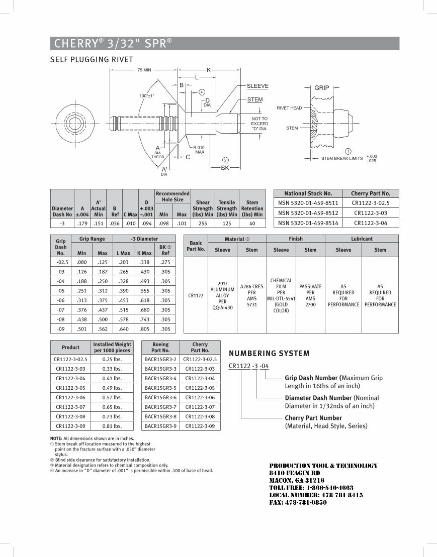
CHERRY® 3/32" SPR® SELF PLUGGING RIVET
Diameter Dash No
A ±.004
A' Actual
MinB
Ref c Max
D +.003 –.001
Recommended Hole Size Shear
Strength (lbs) Min
Tensile Strength (lbs) Min
Stem Retention (lbs) Min
National Stock No. cherry Part No.
NSN 5320-01-459-8511 CR1122-3-02.5
NSN 5320-01-459-8512 CR1122-3-03
NSN 5320-01-459-8514 CR1122-3-04
Min Max
-3 .179 .151 .036 .010 .094 .098 .101 255 125 40
grip Dash No.
grip Range -3 DiameterBasic
Part No.
Material ➂ finish Lubricant
Min Max L Max K MaxBK ➁ Ref
Sleeve Stem Sleeve Stem Sleeve Stem
-02.5 .080 .125 .203 .338 .275
CR1122
2017 Aluminum
Alloy peR
QQ-A-430
A286 CReS peR AmS 5731
ChemiCAl Film peR
mil-DTl-5541 (GolD
ColoR)
pASSivATe peR AmS 2700
AS ReQuiReD
FoR peRFoRmAnCe
AS ReQuiReD
FoR peRFoRmAnCe
-03 .126 .187 .265 .430 .305
-04 .188 .250 .328 .493 .305
-05 .251 .312 .390 .555 .305
-06 .313 .375 .453 .618 .305
-07 .376 .437 .515 .680 .305
-08 .438 .500 .578 .743 .305
-09 .501 .562 .640 .805 .305
Product Installed Weight per 1000 pieces
Boeing Part No.
cherry Part No.
CR1122-3-02.5 0.25 lbs. BACR15GR3-2 CR1122-3-02.5
CR1122-3-03 0.33 lbs. BACR15GR3-3 CR1122-3-03
CR1122-3-04 0.41 lbs. BACR15GR3-4 CR1122-3-04
CR1122-3-05 0.49 lbs. BACR15GR3-5 CR1122-3-05
CR1122-3-06 0.57 lbs. BACR15GR3-6 CR1122-3-06
CR1122-3-07 0.65 lbs. BACR15GR3-7 CR1122-3-07
CR1122-3-08 0.73 lbs. BACR15GR3-8 CR1122-3-08
CR1122-3-09 0.81 lbs. BACR15GR3-9 CR1122-3-09
NoTE: All dimensions shown are in inches.➀ Stem break off location measured to the highest
point on the fracture surface with a .050” diameter stylus.
➁ Blind side clearance for satisfactory installation.➂ Material designation refers to chemical composition only.➃ An increase in "D" diameter of .001" is permissible within .100 of base of head.
NuMBERINg SYSTEM
CR1122 -3 -04
grip Dash Number (Maximum Grip Length in 16ths of an inch)
Diameter Dash Number (Nominal Diameter in 1/32nds of an inch)
cherry Part Number (Material, Head Style, Series)
JR
Typewritten text
Production Tool & Technology 8410 Feagin Rd Macon, Ga 31216 Toll Free: 1-866-546-4663 Local Number: 478-781-8415 Fax: 478-781-0850
Cherry® hollow end e-Z BuCk®
SPS Fastener Division, a PCC Company
40KSI Shear Strength ColumbIum/tItanIum
one PIeCe FaStener For Double FluSh SeCurIng oF ComPoSIte StruCtureS
JR
Typewritten text
Production Tool & Technology 8410 Feagin Rd Macon, Ga 31216 Toll Free: 1-866-546-4663 Local Number: 478-781-8415 Fax: 478-781-0850
Cherry® hollow enD e-Z buCK®
40KSI Shear Strength ColumbIum/tItanIum one PIeCe FaStener For Double FluSh SeCurIng oF ComPoSIte StruCtureS
ContentS
Features and Specifications � � � � � � � � � � � � � � � � � � � � � � � � � � � � � � � � � � � � � � � � � � � � � � � � � � � � � � 1 Standards � � � � � � � � � � � � � � � � � � � � � � � � � � � � � � � � � � � � � � � � � � � � � � � � � � � � � � � � � � � � � � � � � � � � � 2 hole Preparation � � � � � � � � � � � � � � � � � � � � � � � � � � � � � � � � � � � � � � � � � � � � � � � � � � � � � � � � � � � � � � � 3 Grip Selection � � � � � � � � � � � � � � � � � � � � � � � � � � � � � � � � � � � � � � � � � � � � � � � � � � � � � � � � � � � � � � � � � �4 Installation � � � � � � � � � � � � � � � � � � � � � � � � � � � � � � � � � � � � � � � � � � � � � � � � � � � � � � � � � � � � � � � � � � � � 5 Inspection � � � � � � � � � � � � � � � � � � � � � � � � � � � � � � � � � � � � � � � � � � � � � � � � � � � � � � � � � � � � � � � � � � � � � 5
lImIteD warranty
Seller warrants the goods conform to applicable specifications and drawings and will be manufactured and inspected according to generally accepted practices of companies manufacturing industrial or aerospace fasteners� In the event of any breach of the foregoing warranty, Buyer’s sole remedy shall be to return defective goods (after receiving authorization from Seller) for replacement or refund of the purchase price, at the Seller’s option� Seller agrees to any freight costs in connection with the return of any defective goods, but any costs relating to removal of the defective or nonconforming goods or installation of replacement goods shall be Buyer’s responsibility� Seller’S wArrAnTy doeS noT APPly when Any PhySICAl or CheMICAl ChAnGe In The ForM oF The ProduCT IS MAde By Buyer� The ForeGoInG eXPreSS wArrAnTy And reMedy Are eXCluSIVe And Are In lIeu oF All oTher wArrAnTIeS And reMedIeS; Any IMPlIed wArrAnTy AS To QuAlITy, FITneSS For PurPoSe, or MerChAnTABIlITy IS hereBy SPeCIFICAlly dISClAIMed And eXCluded By Seller� This warranty is void if seller is not notified in writing of any rejection of the goods within one (1) year after initial use by buyer of any power riveter or ninety (90) days after initial use of any other product� Seller shall not be liable under any circumstances for incidental, special or consequential damages arising in whole or in part from any breach by Seller, And SuCh InCIdenTAl, SPeCIAl, or ConSeQuenTIAl dAMAGeS Are hereBy eXPreSSly eXCluded�
our policy is one of continuous development� Specifications shown in this document may be subject to changes introduced after publication�
e-Z Buck® is a trademark of Cherry Aerospace�
note
The properties, strengths, dimensions, installed characteristics and all other information in this catalog is for guidance only to aid in the correct selection of the products described herein and is not intended or implied as part of the warranty� All applications should be evaluated for functional suitability and available samples of the described parts can be requested for installed tests, suitability and evaluations�
JR
Typewritten text
Production Tool & Technology 8410 Feagin Rd Macon, Ga 31216 Toll Free: 1-866-546-4663 Local Number: 478-781-8415 Fax: 478-781-0850
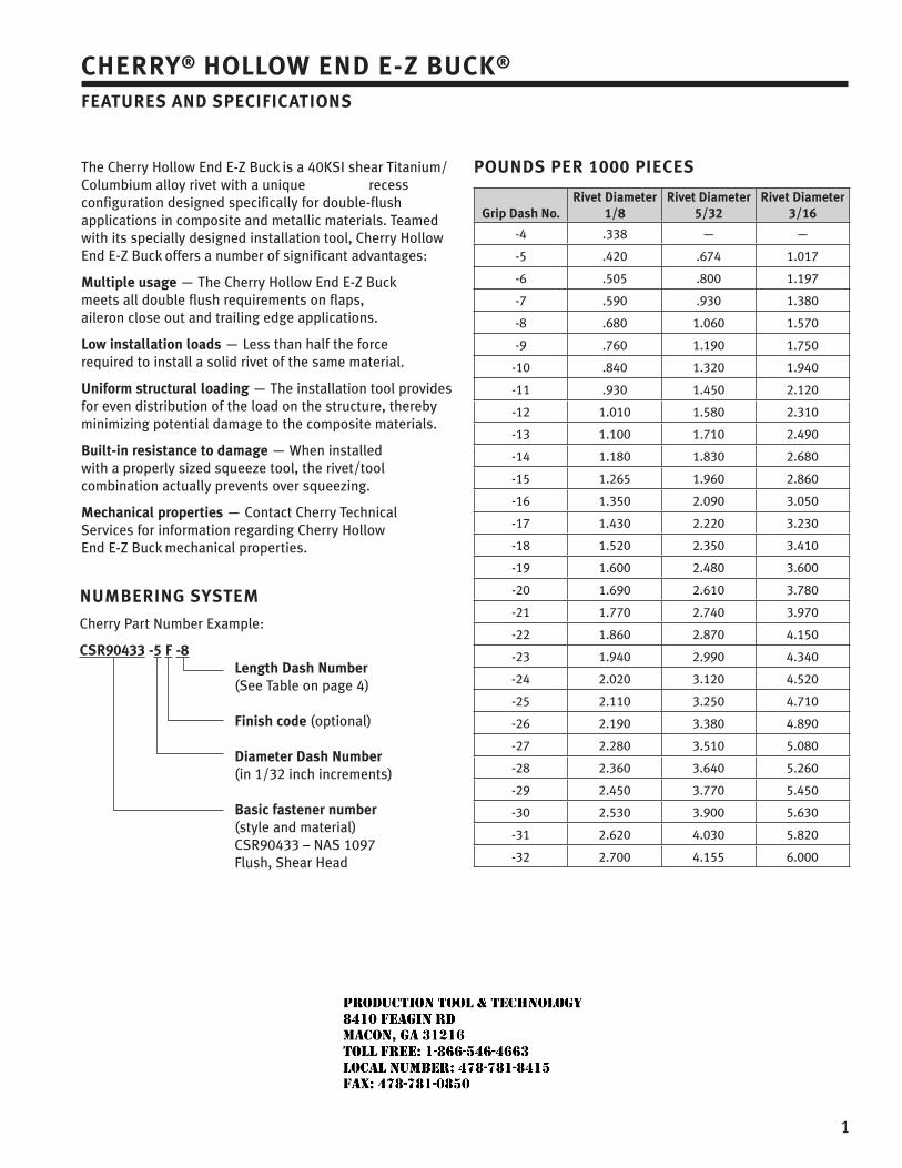
1
Cherry® hollow enD e-Z buCK®
FeatureS anD SPeCIFICatIonS
The Cherry hollow end e-Z Buck is a 40kSI shear Titanium/Columbium alloy rivet with a unique recess configuration designed specifically for double-flush applications in composite and metallic materials� Teamed with its specially designed installation tool, Cherry hollow end e-Z Buck offers a number of significant advantages:
multiple usage — The Cherry hollow end e-Z Buck
meets all double flush requirements on flaps, aileron close out and trailing edge applications�
low installation loads — less than half the force required to install a solid rivet of the same material�
uniform structural loading — The installation tool provides for even distribution of the load on the structure, thereby minimizing potential damage to the composite materials�
built-in resistance to damage — when installed with a properly sized squeeze tool, the rivet/tool combination actually prevents over squeezing�
mechanical properties — Contact Cherry Technical Services for information regarding Cherry hollow end e-Z Buck mechanical properties�
PounDS Per 1000 PIeCeS
grip Dash no.rivet Diameter
1/8rivet Diameter
5/32rivet Diameter
3/16
-4 �338 — —
-5 �420 �674 1�017
-6 �505 �800 1�197
-7 �590 �930 1�380
-8 �680 1�060 1�570
-9 �760 1�190 1�750
-10 �840 1�320 1�940
-11 �930 1�450 2�120
-12 1�010 1�580 2�310
-13 1�100 1�710 2�490
-14 1�180 1�830 2�680
-15 1�265 1�960 2�860
-16 1�350 2�090 3�050
-17 1�430 2�220 3�230
-18 1�520 2�350 3�410
-19 1�600 2�480 3�600
-20 1�690 2�610 3�780
-21 1�770 2�740 3�970
-22 1�860 2�870 4�150
-23 1�940 2�990 4�340
-24 2�020 3�120 4�520
-25 2�110 3�250 4�710
-26 2�190 3�380 4�890
-27 2�280 3�510 5�080
-28 2�360 3�640 5�260
-29 2�450 3�770 5�450
-30 2�530 3�900 5�630
-31 2�620 4�030 5�820
-32 2�700 4�155 6�000
numberIng SyStem
Cherry Part number example:
CSr90433 -5 F -8 length Dash number
(See Table on page 4) Finish code (optional) Diameter Dash number (in 1/32 inch increments) basic fastener number (style and material) CSr90433 – nAS 1097 Flush, Shear head
JR
Typewritten text
Production Tool & Technology 8410 Feagin Rd Macon, Ga 31216 Toll Free: 1-866-546-4663 Local Number: 478-781-8415 Fax: 478-781-0850
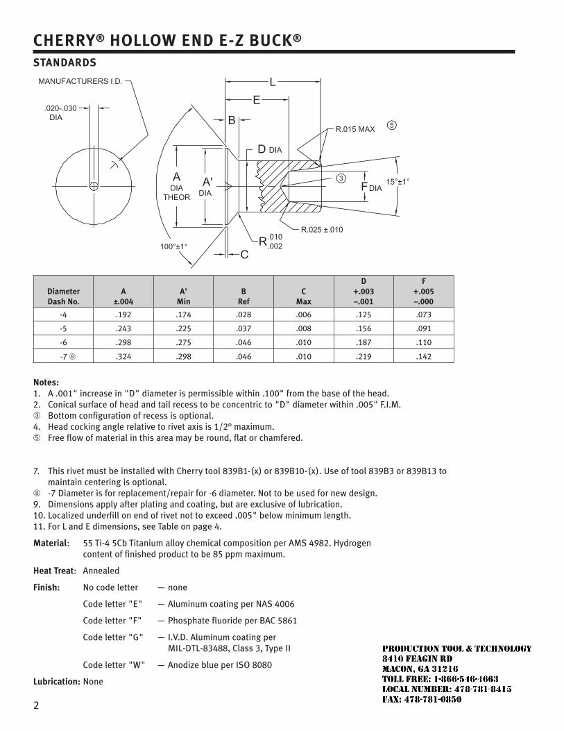
2
Cherry® hollow enD e-Z buCK®
StanDarDS
Diameter Dash no.
a ±.004
a' min
b ref
C max
D +.003 –.001
F +.005 –.000
-4 �192 �174 �028 �006 �125 �073
-5 �243 �225 �037 �008 �156 �091
-6 �298 �275 �046 �010 �187 �110
-7 ➇ �324 �298 �046 �010 �219 �142
notes:1� A �001" increase in "d" diameter is permissible within �100" from the base of the head� 2� Conical surface of head and tail recess to be concentric to "d" diameter within �005" F�I�M� ➂ Bottom configuration of recess is optional� 4� head cocking angle relative to rivet axis is 1/2° maximum� ➄ Free flow of material in this area may be round, flat or chamfered�
7� This rivet must be installed with Cherry tool 839B1-(x) or 839B10-(x)� use of tool 839B3 or 839B13 to maintain centering is optional� ➇ -7 diameter is for replacement/repair for -6 diameter� not to be used for new design� 9� dimensions apply after plating and coating, but are exclusive of lubrication� 10� localized underfill on end of rivet not to exceed �005" below minimum length� 11� For l and e dimensions, see Table on page 4�
material: 55 Ti-4 5Cb Titanium alloy chemical composition per AMS 4982� hydrogen content of finished product to be 85 ppm maximum�
heat treat: Annealed
Finish: no code letter — none
Code letter "e" — Aluminum coating per nAS 4006
Code letter "F" — Phosphate fluoride per BAC 5861
Code letter "G" — I�V�d� Aluminum coating per MIl-dTl-83488, Class 3, Type II
Code letter "w" — Anodize blue per ISo 8080
lubrication: none
JR
Typewritten text
Production Tool & Technology 8410 Feagin Rd Macon, Ga 31216 Toll Free: 1-866-546-4663 Local Number: 478-781-8415 Fax: 478-781-0850
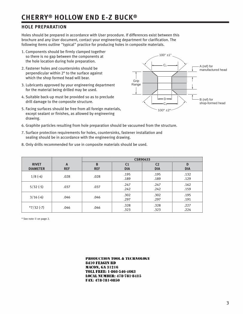
3
Cherry® hollow enD e-Z buCK®
hole PreParatIon
holes should be prepared in accordance with user procedure� If differences exist between this brochure and any user document, contact your engineering department for clarification� The following items outline "typical" practice for producing holes in composite materials�
1� Components should be firmly clamped together so there is no gap between the components at the hole location during hole preparation�
2� Fastener holes and countersinks should be perpendicular within 2° to the surface against which the shop formed head will bear�
3� lubricants approved by your engineering department for the material being drilled may be used�
4� Suitable back-up must be provided so as to preclude drill damage to the composite structure�
5� Facing surfaces should be free from all foreign materials, except sealant or finishes, as allowed by engineering drawing�
6� Graphite particles resulting from hole preparation should be vacuumed from the structure�
7� Surface protection requirements for holes, countersinks, fastener installation and sealing should be in accordance with the engineering drawing�
8� only drills recommended for use in composite materials should be used�
rIVet DIameter
a reF
CSr90433b
reFC1 DIa
C2 DIa
DDIa
1/8 (-4) �028 �028�195�189
�195�189
�132�129
5/32 (-5) �037 �037�247�242
�247�242
�162�159
3/16 (-6) �046 �046�302�297
�302�297
�195�191
*7/32 (-7) �046 �046�328�323
�328�323
�227�224
* See note ➇ on page 2�
100° ±1°
A (ref) formanufactured head
B (ref) forshop-formed head
C2
GripRange
D
C1
JR
Typewritten text
Production Tool & Technology 8410 Feagin Rd Macon, Ga 31216 Toll Free: 1-866-546-4663 Local Number: 478-781-8415 Fax: 478-781-0850
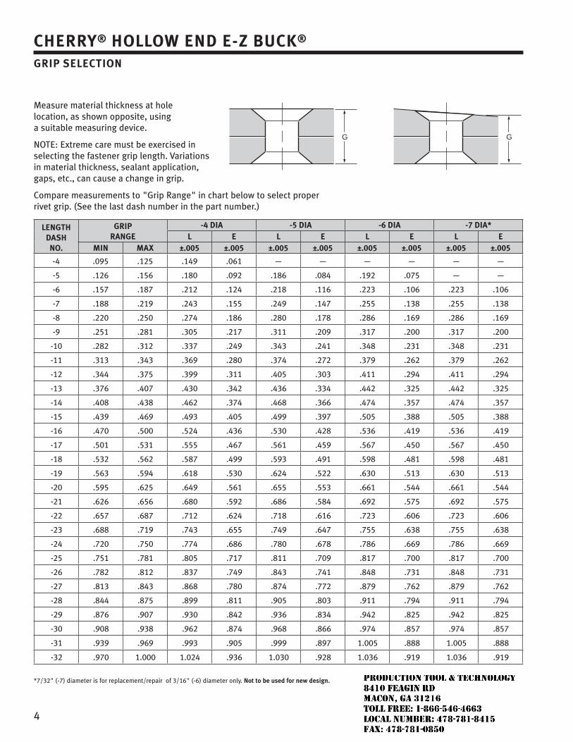
4
Cherry® hollow enD e-Z buCK®
grIP SeleCtIon
Measure material thickness at hole location, as shown opposite, using a suitable measuring device�
noTe: extreme care must be exercised in selecting the fastener grip length� Variations in material thickness, sealant application, gaps, etc�, can cause a change in grip�
Compare measurements to "Grip range" in chart below to select proper rivet grip� (See the last dash number in the part number�)
lengthDaShno.
grIP range
-4 DIa -5 DIa -6 DIa -7 DIa*l e l e l e l e
mIn maX ±.005 ±.005 ±.005 ±.005 ±.005 ±.005 ±.005 ±.005
-4 �095 �125 �149 �061 — — — — — —
-5 �126 �156 �180 �092 �186 �084 �192 �075 — —
-6 �157 �187 �212 �124 �218 �116 �223 �106 �223 �106
-7 �188 �219 �243 �155 �249 �147 �255 �138 �255 �138
-8 �220 �250 �274 �186 �280 �178 �286 �169 �286 �169
-9 �251 �281 �305 �217 �311 �209 �317 �200 �317 �200
-10 �282 �312 �337 �249 �343 �241 �348 �231 �348 �231
-11 �313 �343 �369 �280 �374 �272 �379 �262 �379 �262
-12 �344 �375 �399 �311 �405 �303 �411 �294 �411 �294
-13 �376 �407 �430 �342 �436 �334 �442 �325 �442 �325
-14 �408 �438 �462 �374 �468 �366 �474 �357 �474 �357
-15 �439 �469 �493 �405 �499 �397 �505 �388 �505 �388
-16 �470 �500 �524 �436 �530 �428 �536 �419 �536 �419
-17 �501 �531 �555 �467 �561 �459 �567 �450 �567 �450
-18 �532 �562 �587 �499 �593 �491 �598 �481 �598 �481
-19 �563 �594 �618 �530 �624 �522 �630 �513 �630 �513
-20 �595 �625 �649 �561 �655 �553 �661 �544 �661 �544
-21 �626 �656 �680 �592 �686 �584 �692 �575 �692 �575
-22 �657 �687 �712 �624 �718 �616 �723 �606 �723 �606
-23 �688 �719 �743 �655 �749 �647 �755 �638 �755 �638
-24 �720 �750 �774 �686 �780 �678 �786 �669 �786 �669
-25 �751 �781 �805 �717 �811 �709 �817 �700 �817 �700
-26 �782 �812 �837 �749 �843 �741 �848 �731 �848 �731
-27 �813 �843 �868 �780 �874 �772 �879 �762 �879 �762
-28 �844 �875 �899 �811 �905 �803 �911 �794 �911 �794
-29 �876 �907 �930 �842 �936 �834 �942 �825 �942 �825
-30 �908 �938 �962 �874 �968 �866 �974 �857 �974 �857
-31 �939 .969 .993 .905 .999 .897 1.005 .888 1.005 .888
-32 .970 1.000 1.024 .936 1.030 .928 1.036 .919 1.036 .919
*7/32" (-7) diameter is for replacement/repair of 3/16" (-6) diameter only� not to be used for new design.
G G
JR
Typewritten text
Production Tool & Technology 8410 Feagin Rd Macon, Ga 31216 Toll Free: 1-866-546-4663 Local Number: 478-781-8415 Fax: 478-781-0850
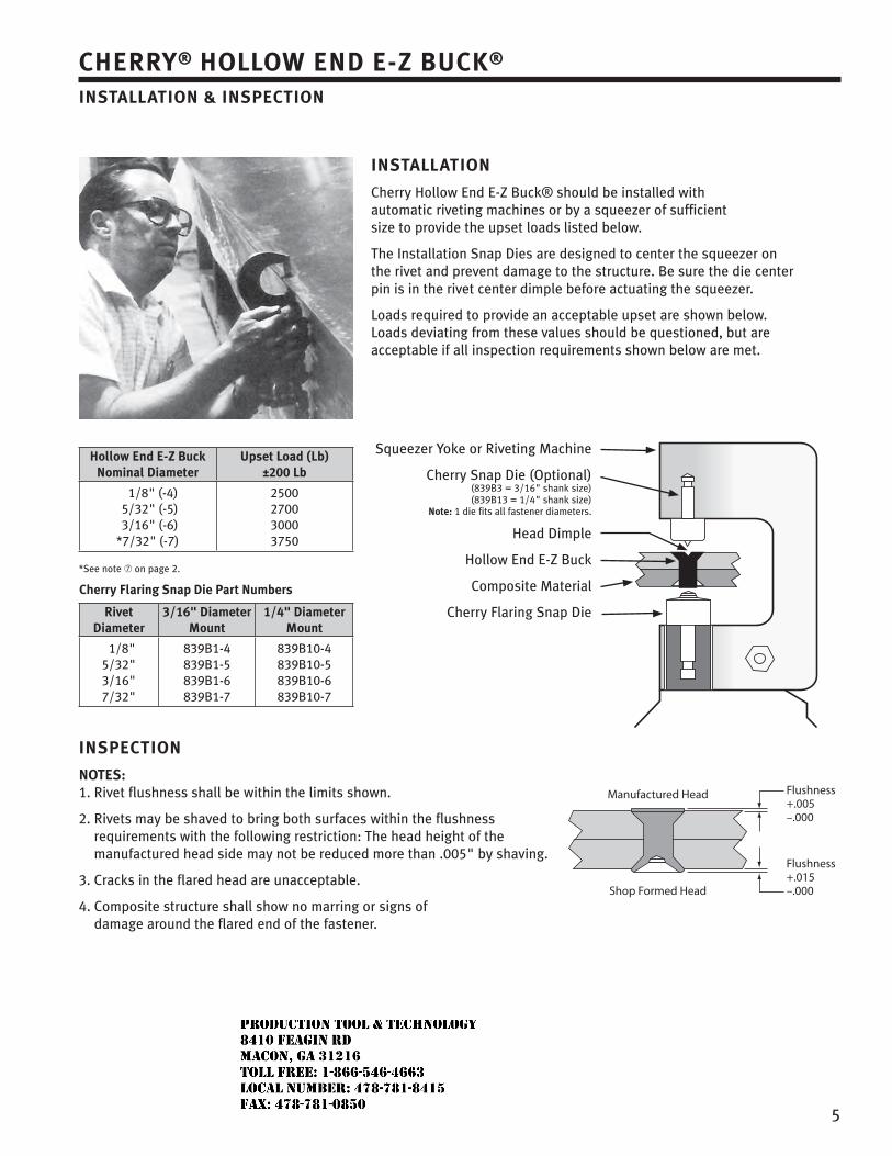
5
Cherry® hollow enD e-Z buCK®
InStallatIon & InSPeCtIon
Squeezer yoke or riveting Machine
Cherry Snap die (optional)(839B3 = 3/16" shank size) (839B13 = 1/4" shank size)
note: 1 die fits all fastener diameters�
head dimple
hollow end e-Z Buck
Composite Material
Cherry Flaring Snap die
InSPeCtIon
noteS: 1� rivet flushness shall be within the limits shown�
2� rivets may be shaved to bring both surfaces within the flushness requirements with the following restriction: The head height of the manufactured head side may not be reduced more than �005" by shaving�
3� Cracks in the flared head are unacceptable�
4� Composite structure shall show no marring or signs of damage around the flared end of the fastener�
InStallatIon
Cherry hollow end e-Z Buck® should be installed with automatic riveting machines or by a squeezer of sufficient size to provide the upset loads listed below�
The Installation Snap dies are designed to center the squeezer on the rivet and prevent damage to the structure� Be sure the die center pin is in the rivet center dimple before actuating the squeezer�
loads required to provide an acceptable upset are shown below� loads deviating from these values should be questioned, but are acceptable if all inspection requirements shown below are met�
hollow end e-Z buck nominal Diameter
upset load (lb) ±200 lb
1/8" (-4) 5/32" (-5) 3/16" (-6)*7/32" (-7)
2500270030003750
*See note ➆ on page 2�
Cherry Flaring Snap Die Part numbers
rivet Diameter
3/16" Diameter mount
1/4" Diameter mount
1/8"5/32"3/16"7/32"
839B1-4839B1-5839B1-6839B1-7
839B10-4839B10-5839B10-6839B10-7
Flushness+.005–.000
Manufactured Head
Shop Formed Head
Flushness+.015–.000
JR
Typewritten text
Production Tool & Technology 8410 Feagin Rd Macon, Ga 31216 Toll Free: 1-866-546-4663 Local Number: 478-781-8415 Fax: 478-781-0850
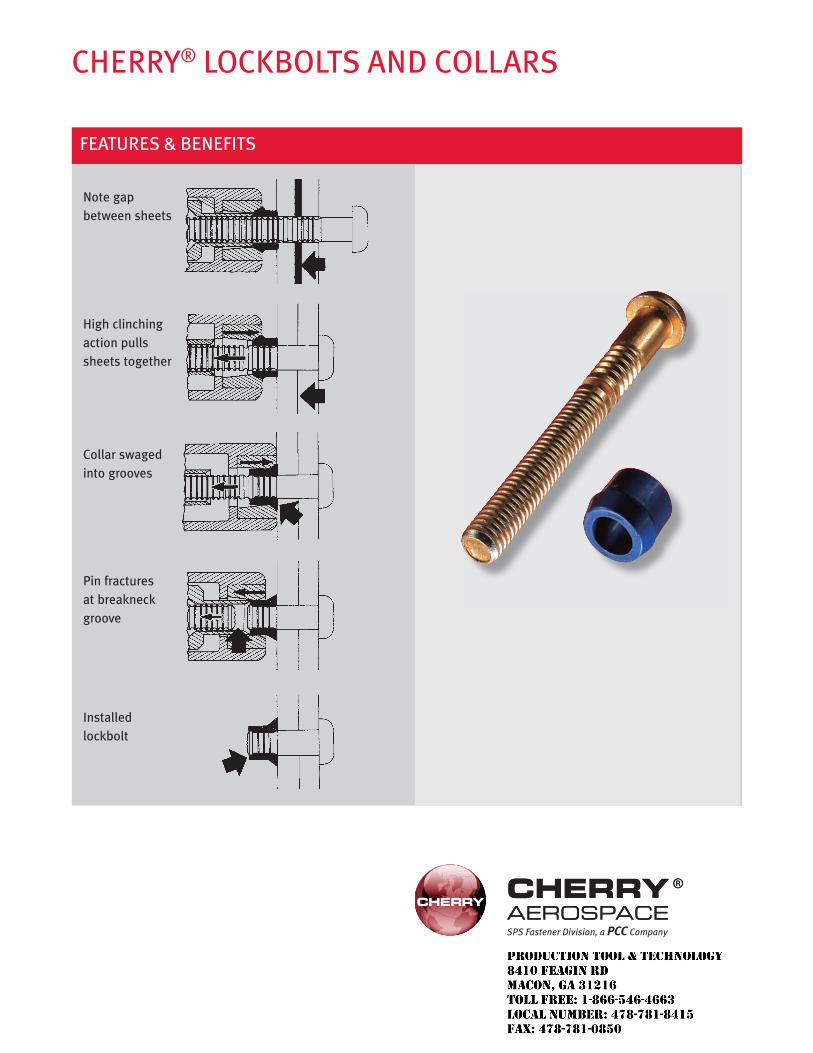
CHERRY® LOCKBOLTS AND COLLARS
FEATURES & BENEFITS
Note gap between sheets
High clinching action pulls sheets together
Collar swaged into grooves
Pin fractures at breakneck groove
Installed lockbolt
SPS Fastener Division, a PCC Company
JR
Typewritten text
Production Tool & Technology 8410 Feagin Rd Macon, Ga 31216 Toll Free: 1-866-546-4663 Local Number: 478-781-8415 Fax: 478-781-0850
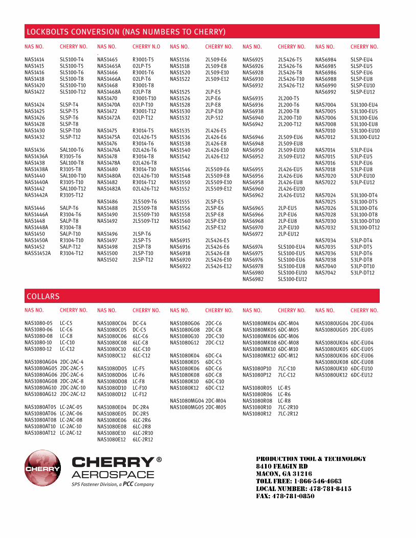
LOCKBOLTS CONVERSION (NAS NUMBERS TO CHERRY)
COLLARS
NAS No. Cherry No.
NAS1080-05 LC-C5NAS1080-06 LC-C6NAS1080-08 LC-C8NAS1080-10 LC-C10NAS1080-12 LC-C12
NAS1080AG04 2DC-2AC-4NAS1080AG05 2DC-2AC-5NAS1080AG06 2DC-2AC-6NAS1080AG08 2DC-2AC-8NAS1080AG10 2DC-2AC-10NAS1080AG12 2DC-2AC-12
NAS1080AT05 LC-2AC-05NAS1080AT06 LC-2AC-06NAS1080AT08 LC-2AC-08NAS1080AT10 LC-2AC-10NAS1080AT12 LC-2AC-12
NAS No. Cherry No.
NAS1414 SLS100-T4NAS1415 SLS100-T5NAS1416 SLS100-T6NAS1418 SLS100-T8NAS1420 SLS100-T10NAS1422 SLS100-T12
NAS1424 SLSP-T4NAS1425 SLSP-T5NAS1426 SLSP-T6NAS1428 SLSP-T8NAS1430 SLSP-T10NAS1432 SLSP-T12
NAS1436 SAL100-T6NAS1436A r3105-T6NAS1438 SAL100-T8NAS1438A r3105-T8NAS1440 SAL100-T10NAS1440A r3105-T10NAS1442 SAL100-T12NAS1442A r3105-T12
NAS1446 SALP-T6NAS1446A r3104-T6NAS1448 SALP-T8NAS1448A r3104-T8NAS1450 SALP-T10NAS1450A r3104-T10NAS1452 SALP-T12NASS1452A r3104-T12
NAS No. Cherry N.o.NAS1465 r3001-T5NAS1465A 02LP-T5NAS1466 r3001-T6NAS1466A 02LP-T6NAS1468 r3001-T8NAS1468A 02LP-T8NAS1470 r3001-T10NAS1470A 02LP-T10NAS1472 r3001-T12NAS1472A 02LP-T12
NAS1475 r3014-T5NAS1475A 02L426-T5NAS1476 r3014-T6NAS1476A 02L426-T6NAS1478 r3014-T8NAS1478A 02L426-T8NAS1480 r3014-T10NAS1480A 02L426-T10NAS1482 r3014-T12NAS1482A 02L426-T12
NAS1486 2LS509-T6NAS1488 2LS509-T8NAS1490 2LS509-T10NAS1492 2LS509-T12
NAS1496 2LSP-T6NAS1497 2LSP-T5NAS1498 2LSP-T8NAS1500 2LSP-T10NAS1502 2LSP-T12
NAS No. Cherry No.
NAS1516 2L509-e6NAS1518 2L509-e8NAS1520 2L509-e10NAS1522 2L509-e12
NAS1525 2LP-e5NAS1526 2LP-e6NAS1528 2LP-e8NAS1530 2LP-e10NAS1532 2LP-512
NAS1535 2L426-e5NAS1536 2L426-e6NAS1538 2L426-e8NAS1540 2L426-e10NAS1542 2L426-e12
NAS1546 2LS509-e6NAS1548 2LS509-e8NAS1550 2LS509-e10NAS1552 2LS509-e12
NAS1555 2LSP-e5NAS1556 2LSP-e6NAS1558 2LSP-e8NAS1560 2LSP-e10NAS1562 2LSP-e12
NAS6915 2LS426-e5NAS6916 2LS426-e6NAS6918 2LS426-e8NAS6920 2LS426-e10NAS6922 2LS426-e12
NAS No. Cherry No.
NAS6925 2LS426-T5NAS6926 2LS426-T6NAS6928 2LS426-T8NAS6930 2LS426-T10NAS6932 2LS426-T12
NAS6935 2L200-T5NAS6936 2L200-T6NAS6938 2L200-T8NAS6940 2L200-T10NAS6942 2L200-T12
NAS6946 2L509-eU6NAS6948 2L509-eU8NAS6950 2L509-eU10NAS6952 2L509-eU12
NAS6955 2L426-eU5NAS6956 2L426-eU6NAS6958 2L426-eU8NAS6960 2L426-eU10NAS6962 2L426-eU12
NAS6965 2LP-eU5NAS6966 2LP-eU6NAS6968 2LP-eU8NAS6970 2LP-eU10NAS6972 2LP-eU12
NAS6974 SLS100-eU4NAS6975 SLS100-eU5NAS6976 SLS100-eU6NAS6978 SLS100-eU8NAS6980 SLS100-eU10NAS6982 SLS100-eU12
NAS No. Cherry No.
NAS6984 SLSP-eU4NAS6985 SLSP-eU5NAS6986 SLSP-eU6NAS6988 SLSP-eU8NAS6990 SLSP-eU10NAS6992 SLSP-eU12
NAS7004 S3L100-eU4NAS7005 S3L100-eU5NAS7006 S3L100-eU6NAS7008 S3L100-eU8NAS7010 S3L100-eU10NAS7012 S3L100-eU12
NAS7014 S3LP-eU4NAS7015 S3LP-eU5NAS7016 S3LP-eU6NAS7018 S3LP-eU8NAS7020 S3LP-eU10NAS7022 S3LP-eU12
NAS7024 S3L100-DT4NAS7025 S3L100-DT5NAS7026 S3L100-DT6NAS7028 S3L100-DT8NAS7030 S3L100-DT10NAS7032 S3L100-DT12
NAS7034 S3LP-DT4NAS7035 S3LP-DT5NAS7036 S3LP-DT6NAS7038 S3LP-DT8NAS7040 S3LP-DT10NAS7042 S3LP-DT12
NAS No. Cherry No.
NAS1080C04 DC-C4NAS1080C05 DC-C5NAS1080C06 6LC-C6NAS1080C08 6LC-C8NAS1080C10 6LC-C10NAS1080C12 6LC-C12
NAS1080D05 LC-F5NAS1080D06 LC-F6NAS1080D08 LC-F8NAS1080D10 LC-F10NAS1080D12 LC-F12
NAS1080e04 DC-2r4NAS1080e05 DC-2r5NAS1080e06 6LC-2r6NAS1080e08 6LC-2r8NAS1080e10 6LC-2r10NAS1080e12 6LC-2r12
NAS No. Cherry No.
NAS1080G06 2DC-C6NAS1080G08 2DC-C8NAS1080G10 2DC-C10NAS1080G12 2DC-C12
NAS1080K04 6DC-C4NAS1080K05 6DC-C5NAS1080K06 6DC-C6NAS1080K08 6DC-C8NAS1080K10 6DC-C10NAS1080K12 6DC-C12
NAS1080MG04 2DC-M04NAS1080MG05 2DC-M05
NAS No. Cherry No.
NAS1080MK04 6DC-M04NAS1080MK05 6DC-M05NAS1080MK06 6DC-M06NAS1080MK08 6DC-M08NAS1080MK10 6DC-M10NAS1080MK12 6DC-M12
NAS1080P10 7LC-C10NAS1080P12 7LC-C12
NAS1080r05 LC-r5NAS1080r06 LC-r6NAS1080r08 LC-r8NAS1080r10 7LC-2r10NAS1080r12 7LC-2r12
NAS No. Cherry No.
NAS1080UG04 2DC-eU04NAS1080UG05 2DC-eU05
NAS1080UK04 6DC-eU04NAS1080UK05 6DC-eU05NAS1080UK06 6DC-eU06NAS1080UK08 6DC-eU08NAS1080UK10 6DC-eU10NAS1080UK12 6DC-eU12
SPS Fastener Division, a PCC Company
JR
Typewritten text
Production Tool & Technology 8410 Feagin Rd Macon, Ga 31216 Toll Free: 1-866-546-4663 Local Number: 478-781-8415 Fax: 478-781-0850
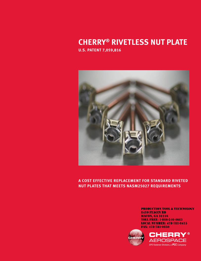
CHERRY® RIVETLESS NUT PLATEU.S. PATENT 7,059,816
A COST EFFECTIVE REPLACEMENT FOR STANDARD RIVETED NUT PLATES THAT MEETS NASM25027 REQUIREMENTS
SPS Fastener Division, a PCC Company
JR
Typewritten text
Production Tool & Technology 8410 Feagin Rd Macon, Ga 31216 Toll Free: 1-866-546-4663 Local Number: 478-781-8415 Fax: 478-781-0850
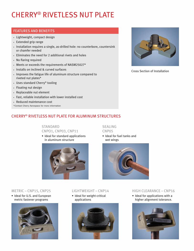
CHERRY® RIVETLESS NUT PLATE
CHERRY® RIVETLESS NUT PLATE FOR ALUMINUM STRUCTURES
• Lightweight, compact design
• Extended grip range
• Installation requires a single, as-drilled hole: no counterbore, countersink or chamfer needed
• Eliminates the need for 2 additional rivets and holes
• No flaring required
• Meets or exceeds the requirements of NASM25027*
• Installs on inclined & curved surfaces
• Improves the fatigue life of aluminum structure compared to riveted nut plates*
• Uses standard Cherry® tooling
• Floating nut design
• Replaceable nut element
• Fast, reliable installation with lower installed cost
• Reduced maintenance cost*Contact Cherry Aerospace for more information
FEATURES AND BENEFITS
Cross Section of Installation
LIGHTWEIGHT – CNP14• Idealforweight-critical
applications
HIGH CLEARANCE – CNP16• Idealforapplicationswitha
higher alignment tolerance.
METRIC – CNP15, CNP25• IdealforU.S.andEuropean
metric fastener programs
SEALING CNP05• Idealforfueltanksand
wet wings
STANDARD CNPO1, CNP03, CNP11• Idealforstandardapplications
in aluminum structure
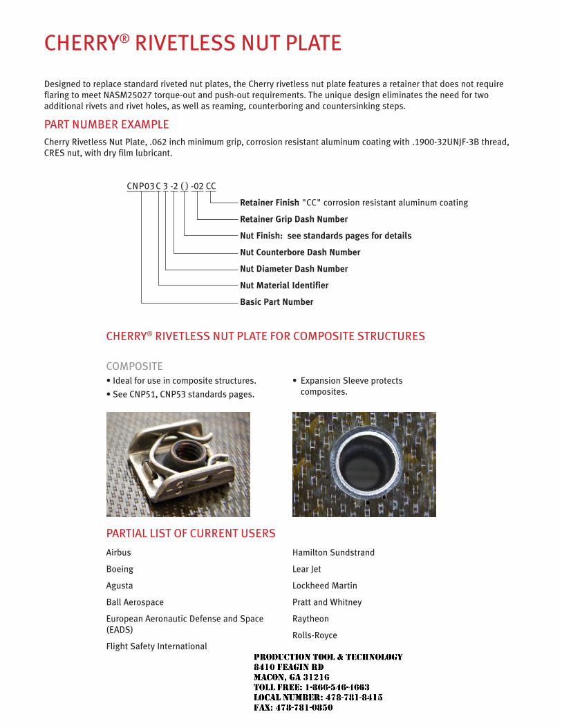
CHERRY® RIVETLESS NUT PLATE
Designed to replace standard riveted nut plates, the Cherry rivetless nut plate features a retainer that does not require flaring to meet NASM25027 torque-out and push-out requirements. The unique design eliminates the need for two additional rivets and rivet holes, as well as reaming, counterboring and countersinking steps.
PART NUMBER EXAMPLECherry Rivetless Nut Plate, .062 inch minimum grip, corrosion resistant aluminum coating with .1900-32UNJF-3B thread, CRES nut, with dry film lubricant.
CNP03 C 3 -2 ( ) -02 CC
Retainer Finish "CC" corrosion resistant aluminum coating
Retainer Grip Dash Number
Nut Finish: see standards pages for details
Nut Counterbore Dash Number
Nut Diameter Dash Number
Nut Material Identifier
Basic Part Number
CHERRY® RIVETLESS NUT PLATE FOR COMPOSITE STRUCTURES
COMPOSITE•Idealforuseincompositestructures.
•SeeCNP51,CNP53standardspages.
• ExpansionSleeveprotects composites.
PARTIAL LIST OF CURRENT USERS
Airbus
Boeing
Agusta
Ball Aerospace
European Aeronautic Defense and Space (EADS)
Flight Safety International
Hamilton Sundstrand
Lear Jet
Lockheed Martin
Pratt and Whitney
Raytheon
Rolls-Royce
JR
Typewritten text
Production Tool & Technology 8410 Feagin Rd Macon, Ga 31216 Toll Free: 1-866-546-4663 Local Number: 478-781-8415 Fax: 478-781-0850
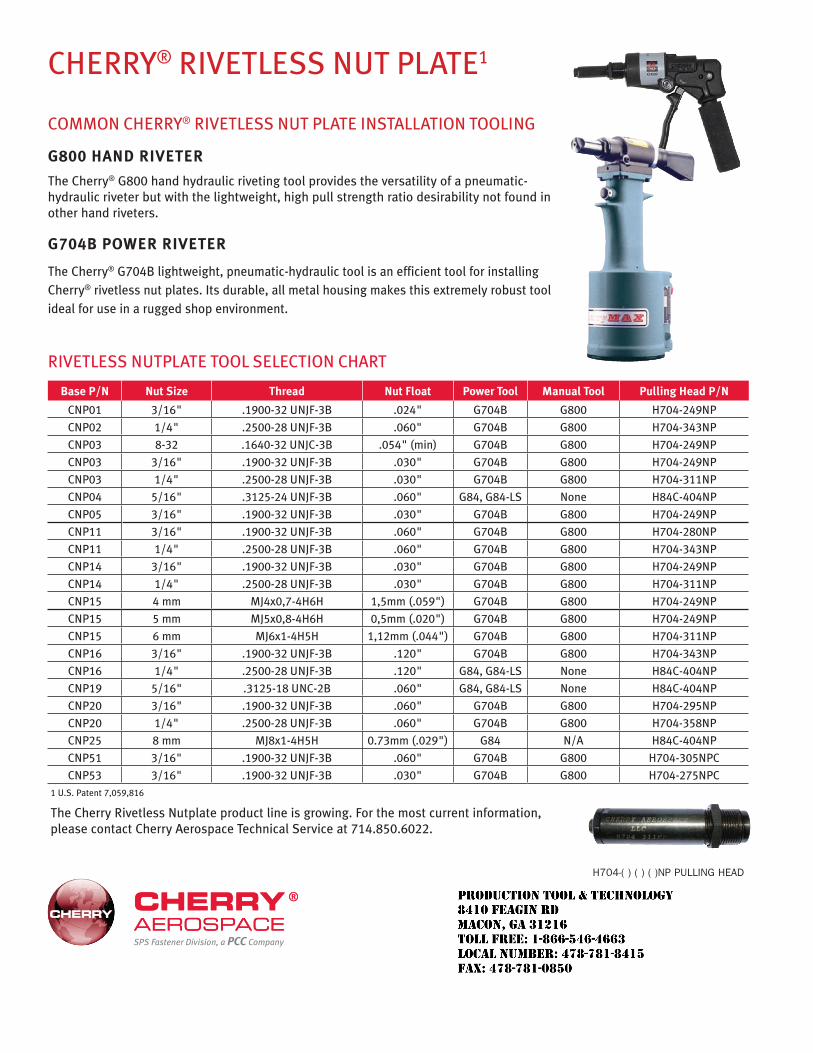
COMMON CHERRY® RIVETLESS NUT PLATE INSTALLATION TOOLING
G800 HAND RIVETER
The Cherry® G800 hand hydraulic riveting tool provides the versatility of a pneumatic-hydraulic riveter but with the lightweight, high pull strength ratio desirability not found in other hand riveters.
G704B POWER RIVETER
The Cherry® G704B lightweight, pneumatic-hydraulic tool is an efficient tool for installing Cherry® rivetless nut plates. Its durable, all metal housing makes this extremely robust tool ideal for use in a rugged shop environment.
CHERRY® RIVETLESS NUT PLATE1
RIVETLESS NUTPLATE TOOL SELECTION CHART
Base P/N Nut Size Thread Nut Float Power Tool Manual Tool Pulling Head P/N
CNP01 3/16" .1900-32 UNJF-3B .024" G704B G800 H704-249NP
CNP02 1/4" .2500-28 UNJF-3B .060" G704B G800 H704-343NP
CNP03 8-32 .1640-32 UNJC-3B .054" (min) G704B G800 H704-249NP
CNP03 3/16" .1900-32 UNJF-3B .030" G704B G800 H704-249NP
CNP03 1/4" .2500-28 UNJF-3B .030" G704B G800 H704-311NP
CNP04 5/16" .3125-24 UNJF-3B .060" G84, G84-LS None H84C-404NP
CNP05 3/16" .1900-32 UNJF-3B .030" G704B G800 H704-249NP
CNP11 3/16" .1900-32 UNJF-3B .060" G704B G800 H704-280NP
CNP11 1/4" .2500-28 UNJF-3B .060" G704B G800 H704-343NP
CNP14 3/16" .1900-32 UNJF-3B .030" G704B G800 H704-249NP
CNP14 1/4" .2500-28 UNJF-3B .030" G704B G800 H704-311NP
CNP15 4 mm MJ4x0,7-4H6H 1,5mm (.059") G704B G800 H704-249NP
CNP15 5 mm MJ5x0,8-4H6H 0,5mm (.020") G704B G800 H704-249NP
CNP15 6 mm MJ6x1-4H5H 1,12mm (.044") G704B G800 H704-311NP
CNP16 3/16" .1900-32 UNJF-3B .120" G704B G800 H704-343NP
CNP16 1/4" .2500-28 UNJF-3B .120" G84, G84-LS None H84C-404NP
CNP19 5/16" .3125-18 UNC-2B .060" G84, G84-LS None H84C-404NP
CNP20 3/16" .1900-32 UNJF-3B .060" G704B G800 H704-295NP
CNP20 1/4" .2500-28 UNJF-3B .060" G704B G800 H704-358NP
CNP25 8 mm MJ8x1-4H5H 0.73mm (.029") G84 N/A H84C-404NP
CNP51 3/16" .1900-32 UNJF-3B .060" G704B G800 H704-305NPC
CNP53 3/16" .1900-32 UNJF-3B .030" G704B G800 H704-275NPC1 U.S. Patent 7,059,816
The Cherry Rivetless Nutplate product line is growing. For the most current information, please contact Cherry Aerospace Technical Service at 714.850.6022.
SPS Fastener Division, a PCC Company
H704-( ) ( ) ( )NP PULLING HEAD
JR
Typewritten text
Production Tool & Technology 8410 Feagin Rd Macon, Ga 31216 Toll Free: 1-866-546-4663 Local Number: 478-781-8415 Fax: 478-781-0850
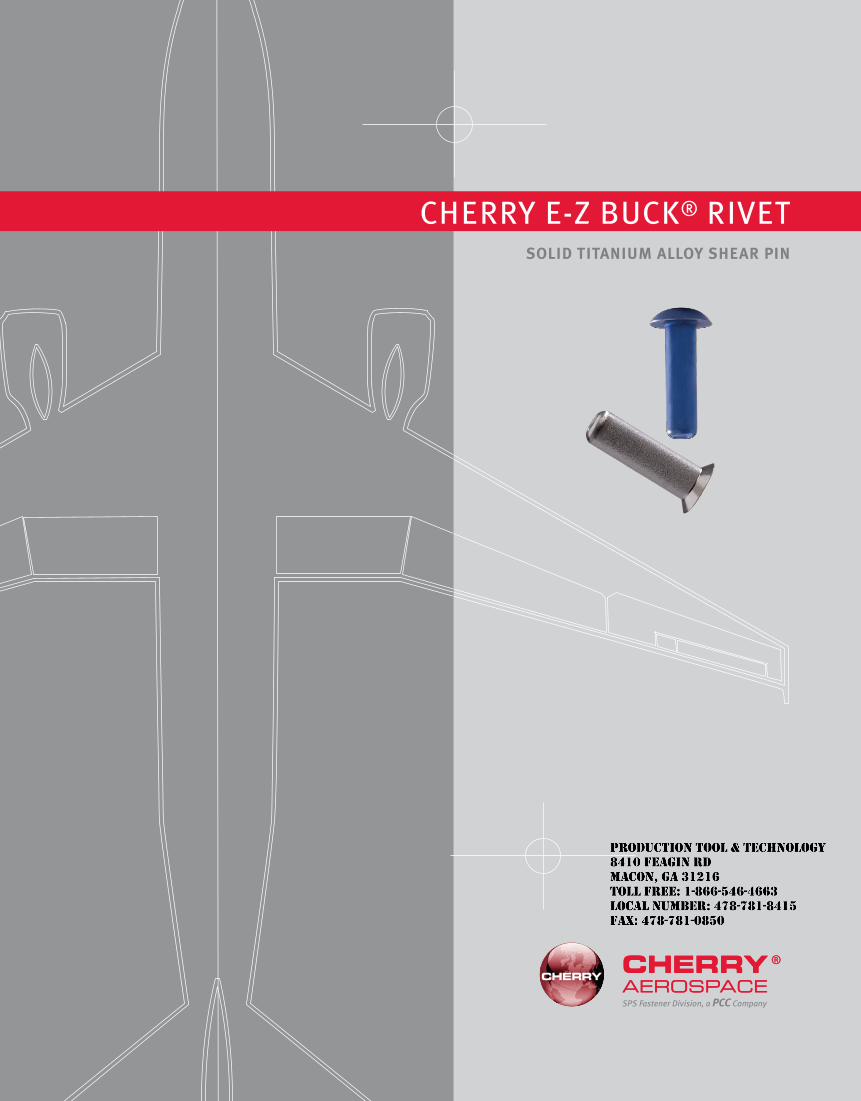
SPS Fastener Division, a PCC Company
Solid TiTanium alloy Shear Pin
Cherry e-Z BuCk® rivet
JR
Typewritten text
Production Tool & Technology 8410 Feagin Rd Macon, Ga 31216 Toll Free: 1-866-546-4663 Local Number: 478-781-8415 Fax: 478-781-0850
1
ConTenTS
introduction .......................................................................................................................... 2Ductility ................................................................................................................................ 3Strength Data ...................................................................................................................... 3Allowables ............................................................................................................................ 3Standards
CSr902B/CSr902t .......................................................................................................... 4CSr903B/CSr903t ......................................................................................................... 6CSr904B/CSr904D .......................................................................................................... 8
hole Preparation ................................................................................................................. 10tool Selection ..................................................................................................................... 10inspection ........................................................................................................................... 10rivet Grip Selection ........................................................................................................... 11Weights ............................................................................................................................... 12
limiTed WarranTy
Seller warrants the goods conform to applicable specifications and drawings and will be manufactured and inspected according to generally accepted practices of companies manufacturing industrial or aerospace fasteners. in the event of any breach of the foregoing warranty, Buyer’s sole remedy shall be to return defective goods (after receiving authorization from Seller) for replacement or refund of the purchase price, at the Seller’s option. Seller agrees to any freight costs in connection with the return of any defective goods, but any costs relating to removal of the defective or nonconforming goods or installation of replacement goods shall be Buyer’s responsibility. SeLLer’S WArrANty DOeS NOt APPLy WheN ANy PhySiCAL Or CheMiCAL ChANGe iN the FOrM OF the PrODuCt iS MADe By Buyer. the FOreGOiNG eXPreSS WArrANty AND reMeDy Are eXCLuSive AND Are iN Lieu OF ALL Other WArrANtieS AND reMeDieS; ANy iMPLieD WArrANty AS tO QuALity, FitNeSS FOr PurPOSe, Or MerChANtABiLity iS hereBy SPeCiFiCALLy DiSCLAiMeD AND eXCLuDeD By SeLLer. this warranty is void if seller is not notified in writing of any rejection of the goods within one (1) year after initial use by buyer of any power riveter or ninety (90) days after initial use of any other product. Seller shall not be liable under any circumstances for incidental, special or consequential damages arising in whole or in part from any breach by Seller, AND SuCh iNCiDeNtAL, SPeCiAL, Or CONSeQueNtiAL DAMAGeS Are hereBy eXPreSSLy eXCLuDeD.
Our policy is one of continuous development. Specifications shown in this document may be subject to changes introduced after publication.
Cherry® and e-Z Buck® are trademarks of Cherry Aerospace.
noTe
the properties, strengths, dimensions, installed characteristics and all other information in this catalog is for guidance only to aid in the correct selection of the products described herein and is not intended or implied as part of the warranty. All applications should be evaluated for functional suitability and available samples of the described parts can be requested for installed tests, suitability and evaluations.
Cherry e-Z BuCk® rivet
JR
Typewritten text
Production Tool & Technology 8410 Feagin Rd Macon, Ga 31216 Toll Free: 1-866-546-4663 Local Number: 478-781-8415 Fax: 478-781-0850
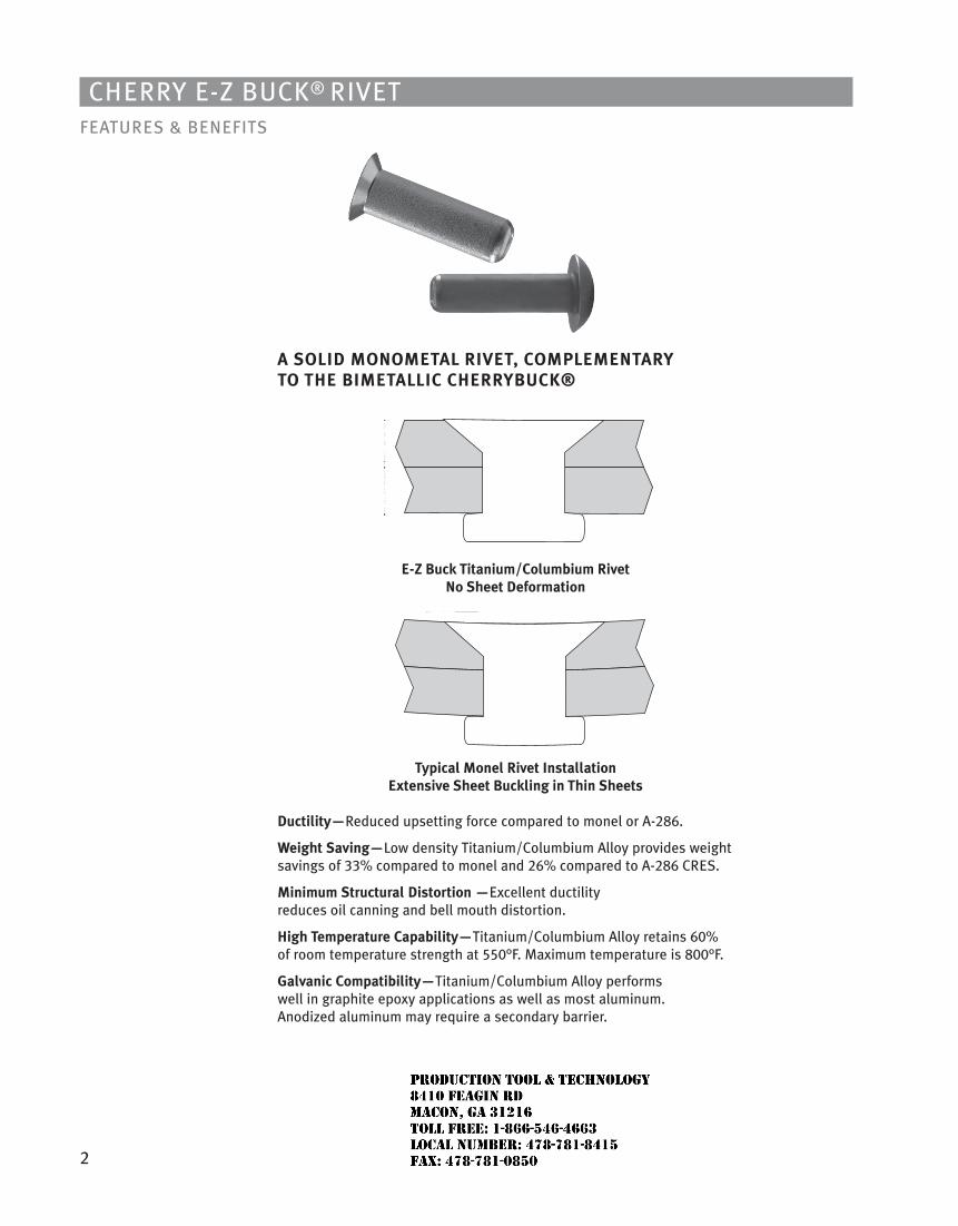
2
Cherry e-Z BuCk® rivetFeAtureS & BeNeFitS
a Solid monomeTal riVeT, ComPlemenTary To The BimeTalliC CherryBuCK®
e-Z Buck Titanium/Columbium rivet no Sheet deformation
Typical monel rivet installation extensive Sheet Buckling in Thin Sheets
ductility—reduced upsetting force compared to monel or A-286.
Weight Saving—Low density titanium/Columbium Alloy provides weight savings of 33% compared to monel and 26% compared to A-286 CreS.
minimum Structural distortion —excellent ductility reduces oil canning and bell mouth distortion.
high Temperature Capability—titanium/Columbium Alloy retains 60% of room temperature strength at 550°F. Maximum temperature is 800°F.
Galvanic Compatibility—titanium/Columbium Alloy performs well in graphite epoxy applications as well as most aluminum. Anodized aluminum may require a secondary barrier.
JR
Typewritten text
Production Tool & Technology 8410 Feagin Rd Macon, Ga 31216 Toll Free: 1-866-546-4663 Local Number: 478-781-8415 Fax: 478-781-0850
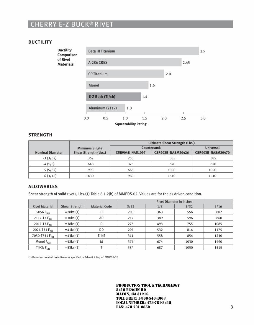
3
Cherry e-Z BuCk® rivet
duCTiliTy
ductility Comparison of rivet materials
0.0 0.5 1.0 1.5 2.0 2.5 3.0
Beta III Titanium 2.9
A-286 CRES 2.45
Monel
E-Z Buck (Ti/cb)
Aluminum (2117)
CP Titanium
1.6
1.4
1.0
2.0
Squeezability rating
STrenGTh
nominal diameterminimum Single
Shear Strength (lbs.)
ultimate Shear Strength (lbs.)Countersunk universal
CSr904B naS1097 CSr902B naSm20426 CSr903B naSm20470
-3 (3/32) 362 250 385 385
-4 (1/8) 648 375 620 620
-5 (5/32) 993 665 1050 1050
-6 (3/16) 1430 960 1510 1510
alloWaBleS
Shear strength of solid rivets, Lbs.(1) table 8.1.2(b) of MMPDS-02. values are for the as driven condition.
rivet Material Shear Strength Material Coderivet Diameter in inches
3/32 1/8 5/32 3/16
5056 Fsu =28ksi(1) B 203 363 556 802
2117-t3 Fsu =30ksi(1) AD 217 389 596 860
2017-t3 Fsu =38ksi(1) D 275 493 755 1085
2024-t31 Fsu =41ksi(1) DD 297 532 814 1175
7050-t731 Fsu =43ksi(1) e, ke 311 558 854 1230
Monel Fsu =52ksi(1) M 376 674 1030 1490
ti/Cb Fsu =53ksi(1) t 384 687 1050 1515
(1) Based on nominal hole diameter specified in table 8.1.2(a) of MMPDS-02.
JR
Typewritten text
Production Tool & Technology 8410 Feagin Rd Macon, Ga 31216 Toll Free: 1-866-546-4663 Local Number: 478-781-8415 Fax: 478-781-0850
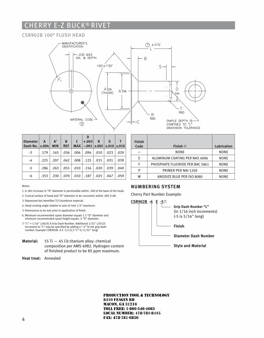
4
Cherry e-Z BuCk® rivetCSr902B 100° FLuSh heAD
diameter dash no.
a ±.004
a' min
B reF
C maX
d +.003 –.001
r ±.005
S ±.010
T ±.010
-3 .179 .165 .036 .006 .094 .010 .023 .029
-4 .225 .207 .042 .008 .125 .015 .031 .039
-5 .286 .263 .055 .010 .156 .020 .039 .049
-6 .353 .330 .070 .010 .187 .025 .047 .059
Notes:
1. A .001 increase in “D” diameter is permissible within .100 of the base of the head.
2. Conical surface of head and “D” diameter to be concentric within .005 F.i.M.
➂ Depressed dot identifies ti/Columbium material.
4. head cocking angle relative to axis of rivet 1/2° maximum.
➄ Dimensions to be met prior to application of finish.
6. Minimum recommended upset diameter equals 1.3 “D” diameter and minimum recommended upset height equals .3 “D” diameter.
➆ “L” = 1/16" (.0625) X Grip Dash Number. Additional 1/32" (.0312) increment to “L” may be specified by adding a “.5” to the grip dash number. example CSr9O2B -6 e -5.5 (5.5 “L” is 11/32" long)
material: 55 ti — 45 Cb titanium alloy: chemical composition per AMS 4982. hydrogen content of finished product to be 85 ppm maximum.
heat treat: Annealed
Finish Code Finish ➄ lubrication
— NONe NONe
e ALuMiNuM COAtiNG Per NAS 4006 NONe
F PhOSPhAte FLuOriDe Per BAC 5861 NONe
P PriMer Per NAi-1269 NONe
W ANODiZe BLue Per iSO 8080 NONe
numBerinG SySTem
Cherry Part Number example:
CSr902B -6 e -5➆ Grip dash number “l”
(in 1/16 inch increments) (-5 is 5/16" long) Finish diameter dash number Style and material
JR
Typewritten text
Production Tool & Technology 8410 Feagin Rd Macon, Ga 31216 Toll Free: 1-866-546-4663 Local Number: 478-781-8415 Fax: 478-781-0850
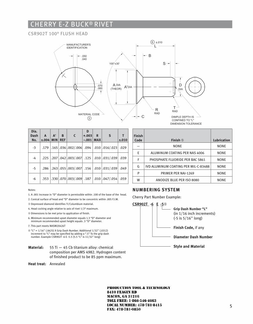
5
Cherry e-Z BuCk® rivetCSr902t 100° FLuSh heAD
dia. dash no.
a ±.004
a' min
B reF
C d
+.003 –.001
r maX
S T ±.010
-3 .179 .165 .036 .002/.006 .094 .010 .016/.023 .029
-4 .225 .207 .042 .003/.007 .125 .010 .031/.039 .039
-5 .286 .263 .055 .003/.007 .156 .010 .031/.039 .049
-6 .353 .330 .070 .003/.009 .187 .010 .047/.054 .059
Notes:
1. A .001 increase in “D” diameter is permissible within .100 of the base of the head.
2. Conical surface of head and “D” diameter to be concentric within .005 F.i.M.
➂ Depressed diamond identifies ti/Columbium material.
4. head cocking angle relative to axis of rivet 1/2° maximum.
➄ Dimensions to be met prior to application of finish.
6. Minimum recommended upset diameter equals 1.3 “D” diameter and minimum recommended upset height equals .3 “D” diameter.
7. this part meets NASM20426t
➇ “L” = 1/16" (.0625) X Grip Dash Number. Additional 1/32" (.0312) increment to “L” may be specified by adding a “.5” to the grip dash number. example CSr902t -6 e -5.5 (5.5 “L” is 11/32" long)
material: 55 ti — 45 Cb titanium alloy: chemical composition per AMS 4982. hydrogen content of finished product to be 85 ppm maximum.
heat treat: Annealed
Finish Code Finish ➄ lubrication
— NONe NONe
e ALuMiNuM COAtiNG Per NAS 4006 NONe
F PhOSPhAte FLuOriDe Per BAC 5861 NONe
G ivD ALuMiNuM COAtiNG Per MiL-C-83488 NONe
P PriMer Per NAi-1269 NONe
W ANODiZe BLue Per iSO 8080 NONe
numBerinG SySTem
Cherry Part Number example:
CSr902T -6 e -5➇ Grip dash number “l”
(in 1/16 inch increments) (-5 is 5/16" long) Finish Code, if any diameter dash number Style and material
JR
Typewritten text
Production Tool & Technology 8410 Feagin Rd Macon, Ga 31216 Toll Free: 1-866-546-4663 Local Number: 478-781-8415 Fax: 478-781-0850
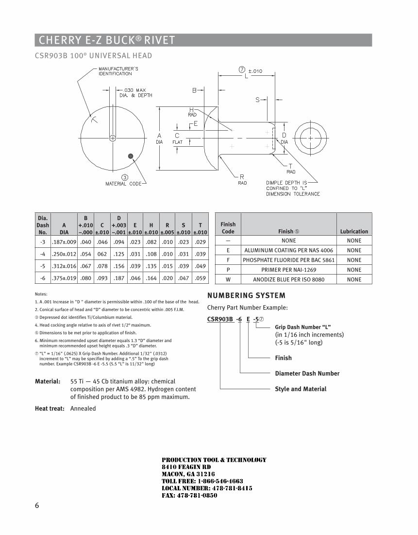
6
Cherry e-Z BuCk® rivetCSr903B 100° uNiverSAL heAD
dia. dash no.
a dia
B +.010 –.000
C ±.010
d +.003 –.001
e ±.010
h ±.010
r ±.005
S ±.010
T ±.010
-3 .187±.009 .040 .046 .094 .023 .082 .010 .023 .029
-4 .250±.012 .054 062 .125 .031 .108 .010 .031 .039
-5 .312±.016 .067 .078 .156 .039 .135 .015 .039 .049
-6 .375±.019 .080 .093 .187 .046 .164 .020 .047 .059
Notes:
1. A .001 increase in "D " diameter is permissible within .100 of the base of the head.
2. Conical surface of head and “D” diameter to be concentric within .005 F.i.M.
➂ Depressed dot identifies ti/Columbium material.
4. head cocking angle relative to axis of rivet 1/2° maximum.
➄ Dimensions to be met prior to application of finish.
6. Minimum recommended upset diameter equals 1.3 “D” diameter and minimum recommended upset height equals .3 “D” diameter.
➆ “L” = 1/16" (.0625) X Grip Dash Number. Additional 1/32" (.0312) increment to “L” may be specified by adding a “.5” to the grip dash number. example CSr903B -6 e -5.5 (5.5 “L” is 11/32" long)
material: 55 ti — 45 Cb titanium alloy: chemical composition per AMS 4982. hydrogen content of finished product to be 85 ppm maximum.
heat treat: Annealed
Finish Code Finish ➄ lubrication
— NONe NONe
e ALuMiNuM COAtiNG Per NAS 4006 NONe
F PhOSPhAte FLuOriDe Per BAC 5861 NONe
P PriMer Per NAi-1269 NONe
W ANODiZe BLue Per iSO 8080 NONe
numBerinG SySTem
Cherry Part Number example:
CSr903B -6 e -5➆ Grip dash number “l”
(in 1/16 inch increments) (-5 is 5/16" long) Finish diameter dash number Style and material
JR
Typewritten text
Production Tool & Technology 8410 Feagin Rd Macon, Ga 31216 Toll Free: 1-866-546-4663 Local Number: 478-781-8415 Fax: 478-781-0850
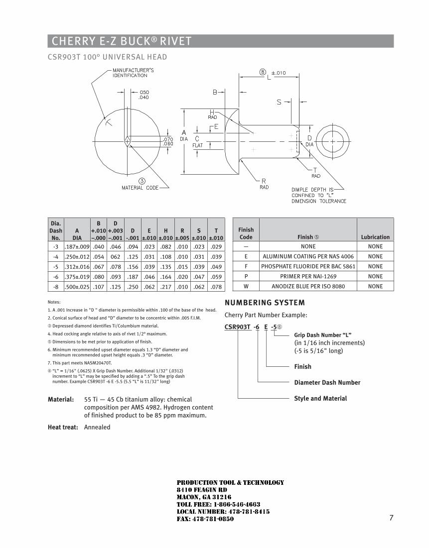
7
Cherry e-Z BuCk® rivetCSr903t 100° uNiverSAL heAD
dia. dash no.
a dia
B +.010 –.000
d +.003 –.001
d -.001
e ±.010
h ±.010
r ±.005
S ±.010
T ±.010
-3 .187±.009 .040 .046 .094 .023 .082 .010 .023 .029
-4 .250±.012 .054 062 .125 .031 .108 .010 .031 .039
-5 .312±.016 .067 .078 .156 .039 .135 .015 .039 .049
-6 .375±.019 .080 .093 .187 .046 .164 .020 .047 .059
-8 .500±.025 .107 .125 .250 .062 .217 .010 .062 .078
Notes:
1. A .001 increase in "D " diameter is permissible within .100 of the base of the head.
2. Conical surface of head and “D” diameter to be concentric within .005 F.i.M.
➂ Depressed diamond identifies ti/Columbium material.
4. head cocking angle relative to axis of rivet 1/2° maximum.
➄ Dimensions to be met prior to application of finish.
6. Minimum recommended upset diameter equals 1.3 “D” diameter and minimum recommended upset height equals .3 “D” diameter.
7. this part meets NASM20470t.
➇ “L” = 1/16" (.0625) X Grip Dash Number. Additional 1/32" (.0312) increment to “L” may be specified by adding a “.5” to the grip dash number. example CSr903t -6 e -5.5 (5.5 “L” is 11/32" long)
material: 55 ti — 45 Cb titanium alloy: chemical composition per AMS 4982. hydrogen content of finished product to be 85 ppm maximum.
heat treat: Annealed
Finish Code Finish ➄ lubrication
— NONe NONe
e ALuMiNuM COAtiNG Per NAS 4006 NONe
F PhOSPhAte FLuOriDe Per BAC 5861 NONe
P PriMer Per NAi-1269 NONe
W ANODiZe BLue Per iSO 8080 NONe
numBerinG SySTem
Cherry Part Number example:
CSr903T -6 e -5➇ Grip dash number “l”
(in 1/16 inch increments) (-5 is 5/16" long) Finish diameter dash number Style and material
JR
Typewritten text
Production Tool & Technology 8410 Feagin Rd Macon, Ga 31216 Toll Free: 1-866-546-4663 Local Number: 478-781-8415 Fax: 478-781-0850
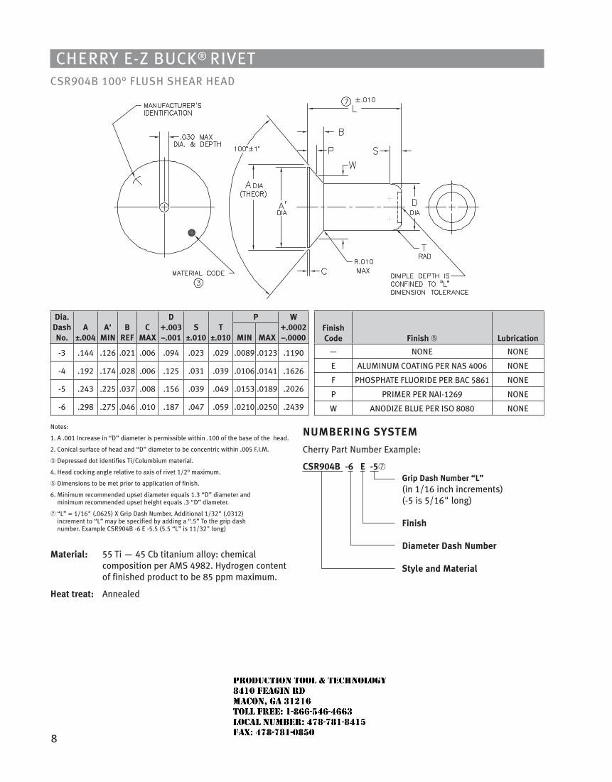
8
Cherry e-Z BuCk® rivetCSr904B 100° FLuSh SheAr heAD
dia.dash no.
a±.004
a' min
BreF
CmaX
d+.003 –.001
S±.010
T±.010
P W+.0002 –.0000min maX
-3 .144 .126 .021 .006 .094 .023 .029 .0089 .0123 .1190
-4 .192 .174 .028 .006 .125 .031 .039 .0106 .0141 .1626
-5 .243 .225 .037 .008 .156 .039 .049 .0153 .0189 .2026
-6 .298 .275 .046 .010 .187 .047 .059 .0210 .0250 .2439
Notes:
1. A .001 increase in “D” diameter is permissible within .100 of the base of the head.
2. Conical surface of head and “D” diameter to be concentric within .005 F.i.M.
➂ Depressed dot identifies ti/Columbium material.
4. head cocking angle relative to axis of rivet 1/2° maximum.
➄ Dimensions to be met prior to application of finish.
6. Minimum recommended upset diameter equals 1.3 “D” diameter and minimum recommended upset height equals .3 “D” diameter.
➆ “L” = 1/16" (.0625) X Grip Dash Number. Additional 1/32" (.0312) increment to “L” may be specified by adding a “.5” to the grip dash number. example CSr904B -6 e -5.5 (5.5 “L” is 11/32" long)
material: 55 ti — 45 Cb titanium alloy: chemical composition per AMS 4982. hydrogen content of finished product to be 85 ppm maximum.
heat treat: Annealed
Finish Code Finish ➄ lubrication
— NONe NONe
e ALuMiNuM COAtiNG Per NAS 4006 NONe
F PhOSPhAte FLuOriDe Per BAC 5861 NONe
P PriMer Per NAi-1269 NONe
W ANODiZe BLue Per iSO 8080 NONe
numBerinG SySTem
Cherry Part Number example:
CSr904B -6 e -5➆ Grip dash number “l”
(in 1/16 inch increments) (-5 is 5/16" long) Finish diameter dash number Style and material
JR
Typewritten text
Production Tool & Technology 8410 Feagin Rd Macon, Ga 31216 Toll Free: 1-866-546-4663 Local Number: 478-781-8415 Fax: 478-781-0850
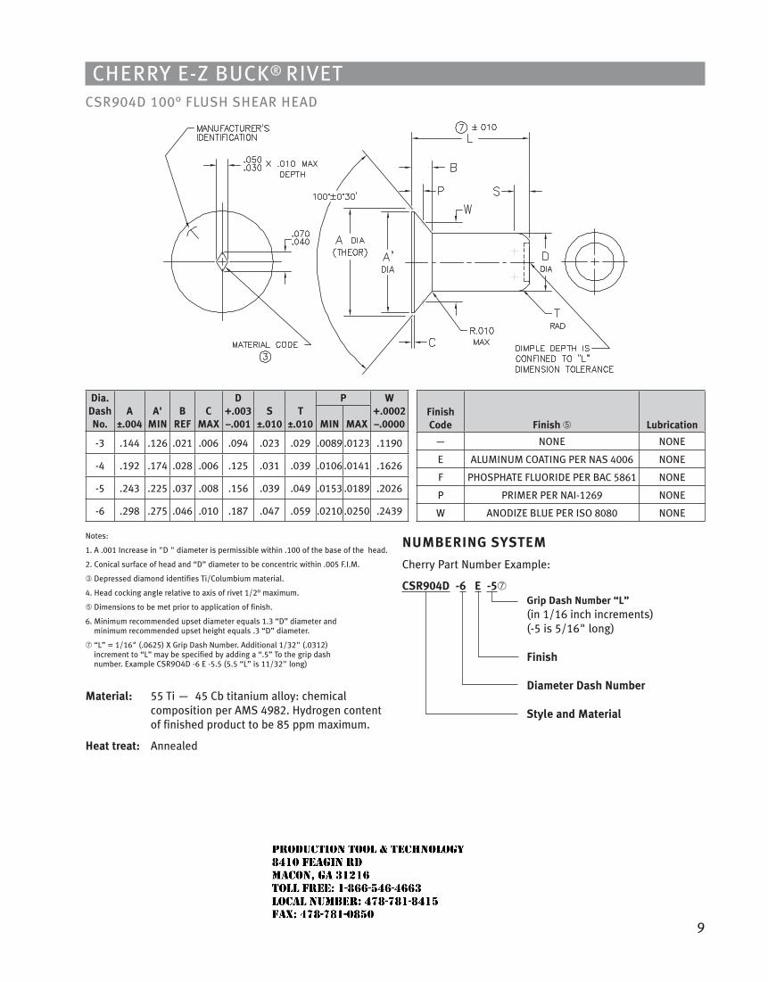
9
Cherry e-Z BuCk® rivetCSr904D 100° FLuSh SheAr heAD
dia.dash no.
a±.004
a' min
BreF
CmaX
d+.003 –.001
S±.010
T±.010
P W+.0002 –.0000min maX
-3 .144 .126 .021 .006 .094 .023 .029 .0089 .0123 .1190
-4 .192 .174 .028 .006 .125 .031 .039 .0106 .0141 .1626
-5 .243 .225 .037 .008 .156 .039 .049 .0153 .0189 .2026
-6 .298 .275 .046 .010 .187 .047 .059 .0210 .0250 .2439
Notes:
1. A .001 increase in "D " diameter is permissible within .100 of the base of the head.
2. Conical surface of head and “D” diameter to be concentric within .005 F.i.M.
➂ Depressed diamond identifies ti/Columbium material.
4. head cocking angle relative to axis of rivet 1/2° maximum.
➄ Dimensions to be met prior to application of finish.
6. Minimum recommended upset diameter equals 1.3 “D” diameter and minimum recommended upset height equals .3 “D” diameter.
➆ “L” = 1/16" (.0625) X Grip Dash Number. Additional 1/32" (.0312) increment to “L” may be specified by adding a “.5” to the grip dash number. example CSr9O4D -6 e -5.5 (5.5 “L” is 11/32" long)
material: 55 ti — 45 Cb titanium alloy: chemical composition per AMS 4982. hydrogen content of finished product to be 85 ppm maximum.
heat treat: Annealed
Finish Code Finish ➄ lubrication
— NONe NONe
e ALuMiNuM COAtiNG Per NAS 4006 NONe
F PhOSPhAte FLuOriDe Per BAC 5861 NONe
P PriMer Per NAi-1269 NONe
W ANODiZe BLue Per iSO 8080 NONe
numBerinG SySTem
Cherry Part Number example:
CSr904d -6 e -5➆ Grip dash number “l”
(in 1/16 inch increments) (-5 is 5/16" long) Finish diameter dash number Style and material
JR
Typewritten text
Production Tool & Technology 8410 Feagin Rd Macon, Ga 31216 Toll Free: 1-866-546-4663 Local Number: 478-781-8415 Fax: 478-781-0850
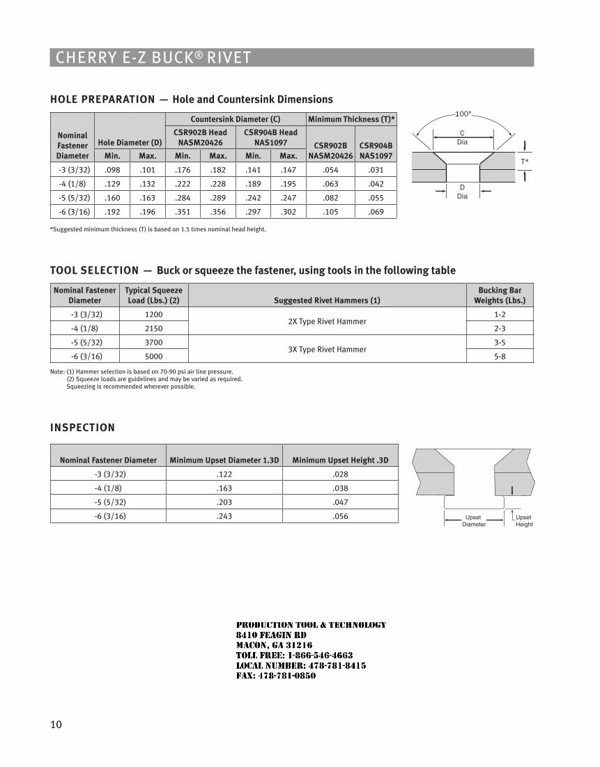
10
Cherry e-Z BuCk® rivet
hole PreParaTion — hole and Countersink dimensions
nominalFastenerdiameter
hole diameter (d)
Countersink diameter (C) minimum Thickness (T)*
CSr902B head naSm20426
CSr904B head naS1097 CSr902B
naSm20426CSr904B naS1097min. max. min. max. min. max.
-3 (3/32) .098 .101 .176 .182 .141 .147 .054 .031
-4 (1/8) .129 .132 .222 .228 .189 .195 .063 .042
-5 (5/32) .160 .163 .284 .289 .242 .247 .082 .055
-6 (3/16) .192 .196 .351 .356 .297 .302 .105 .069
*Suggested minimum thickness (t) is based on 1.5 times nominal head height.
Tool SeleCTion — Buck or squeeze the fastener, using tools in the following table
nominal Fastener diameter
Typical Squeeze load (lbs.) (2) Suggested rivet hammers (1)
Bucking Bar Weights (lbs.)
-3 (3/32) 12002X type rivet hammer
1-2
-4 (1/8) 2150 2-3
-5 (5/32) 37003X type rivet hammer
3-5
-6 (3/16) 5000 5-8
Note: (1) hammer selection is based on 70-90 psi air line pressure. (2) Squeeze loads are guidelines and may be varied as required. Squeezing is recommended wherever possible.
inSPeCTion
nominal Fastener diameter minimum upset diameter 1.3d minimum upset height .3d
-3 (3/32) .122 .028
-4 (1/8) .163 .038
-5 (5/32) .203 .047
-6 (3/16) .243 .056
CDia
DDia
T*
100°
JR
Typewritten text
Production Tool & Technology 8410 Feagin Rd Macon, Ga 31216 Toll Free: 1-866-546-4663 Local Number: 478-781-8415 Fax: 478-781-0850
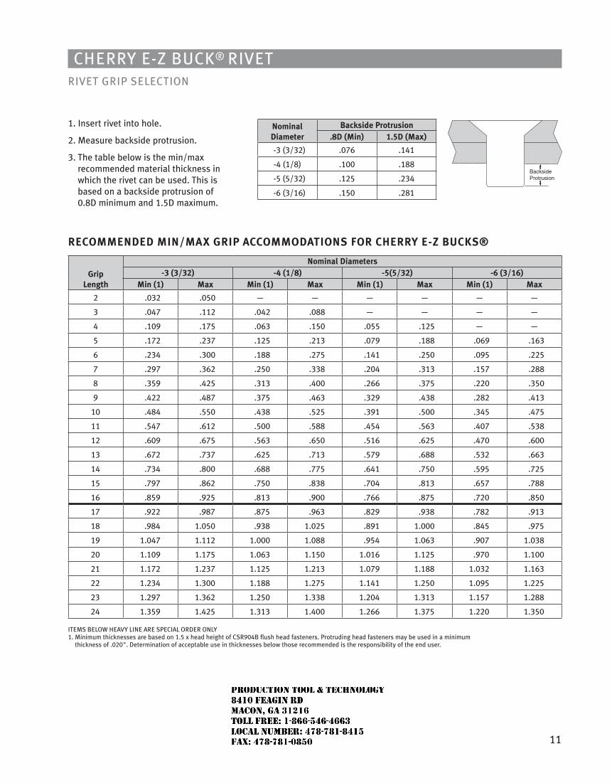
11
Cherry e-Z BuCk® rivetrivet GriP SeLeCtiON
1. insert rivet into hole.
2. Measure backside protrusion.
3. the table below is the min/max recommended material thickness in which the rivet can be used. this is based on a backside protrusion of 0.8D minimum and 1.5D maximum.
reCommended min/maX GriP aCCommodaTionS For Cherry e-Z BuCKS®
Griplength
nominal diameters-3 (3/32) -4 (1/8) -5(5/32) -6 (3/16)
min (1) max min (1) max min (1) max min (1) max
2 .032 .050 — — — — — —
3 .047 .112 .042 .088 — — — —
4 .109 .175 .063 .150 .055 .125 — —
5 .172 .237 .125 .213 .079 .188 .069 .163
6 .234 .300 .188 .275 .141 .250 .095 .225
7 .297 .362 .250 .338 .204 .313 .157 .288
8 .359 .425 .313 .400 .266 .375 .220 .350
9 .422 .487 .375 .463 .329 .438 .282 .413
10 .484 .550 .438 .525 .391 .500 .345 .475
11 .547 .612 .500 .588 .454 .563 .407 .538
12 .609 .675 .563 .650 .516 .625 .470 .600
13 .672 .737 .625 .713 .579 .688 .532 .663
14 .734 .800 .688 .775 .641 .750 .595 .725
15 .797 .862 .750 .838 .704 .813 .657 .788
16 .859 .925 .813 .900 .766 .875 .720 .850
17 .922 .987 .875 .963 .829 .938 .782 .913
18 .984 1.050 .938 1.025 .891 1.000 .845 .975
19 1.047 1.112 1.000 1.088 .954 1.063 .907 1.038
20 1.109 1.175 1.063 1.150 1.016 1.125 .970 1.100
21 1.172 1.237 1.125 1.213 1.079 1.188 1.032 1.163
22 1.234 1.300 1.188 1.275 1.141 1.250 1.095 1.225
23 1.297 1.362 1.250 1.338 1.204 1.313 1.157 1.288
24 1.359 1.425 1.313 1.400 1.266 1.375 1.220 1.350
iteMS BeLOW heAvy LiNe Are SPeCiAL OrDer ONLy1. Minimum thicknesses are based on 1.5 x head height of CSr904B flush head fasteners. Protruding head fasteners may be used in a minimum
thickness of .020". Determination of acceptable use in thicknesses below those recommended is the responsibility of the end user.
nominaldiameter
Backside Protrusion.8d (min) 1.5d (max)
-3 (3/32) .076 .141
-4 (1/8) .100 .188
-5 (5/32) .125 .234
-6 (3/16) .150 .281
JR
Typewritten text
Production Tool & Technology 8410 Feagin Rd Macon, Ga 31216 Toll Free: 1-866-546-4663 Local Number: 478-781-8415 Fax: 478-781-0850
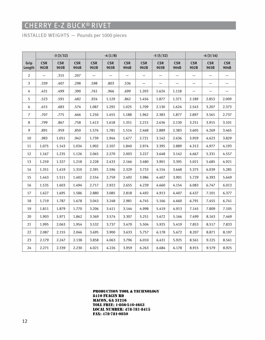
12
Cherry e-Z BuCk® rivetiNStALLeD WeiGhtS — Pounds per 1000 pieces
Griplength
-3 (3/32) -4 (1/8) -5 (5/32) -6 (3/16)
CSr 902B
CSr 903B
CSr 904B
CSr 902B
CSr 903B
CSr 904B
CSr 902B
CSr 903B
CSr 904B
CSr 902B
CSr 903B
CSr904B
2 — .315 .207 — — — — — — — — —
3 .339 .407 .298 .598 .803 .536 — — — — — —
4 .431 .499 .390 .761 .966 .699 1.203 1.624 1.118 — — —
5 .523 .591 .482 .924 1.129 .862 1.456 1.877 1.371 2.189 2.853 2.009
6 .615 .683 .574 1.087 1.292 1.025 1.709 2.130 1.624 2.543 3.207 2.373
7 .707 .775 .666 1.250 1.455 1.188 1.962 2.383 1.877 2.897 3.561 2.737
8 .799 .867 .758 1.413 1.618 1.351 2.215 2.636 2.130 3.251 3.915 3.101
9 .891 .959 .850 1.576 1.781 1.514 2.468 2.889 2.383 3.605 4.269 3.465
10 .983 1.051 .942 1.739 1.944 1.677 2.721 3.142 2.636 3.959 4.623 3.829
11 1.075 1.143 1.034 1.902 2.107 1.840 2.974 3.395 2.889 4.313 4.977 4.193
12 1.167 1.235 1.126 2.065 2.270 2.003 3.227 3.648 3.142 4.667 5.331 4.557
13 1.259 1.327 1.218 2.228 2.433 2.166 3.480 3.901 3.395 5.021 5.685 4.921
14 1.351 1.419 1.310 2.391 2.596 2.329 3.733 4.154 3.648 5.375 6.039 5.285
15 1.443 1.511 1.402 2.554 2.759 2.492 3.986 4.407 3.901 5.729 6.393 5.649
16 1.535 1.603 1.494 2.717 2.922 2.655 4.239 4.660 4.154 6.083 6.747 6.013
17 1.627 1.695 1.586 2.880 3.085 2.818 4.492 4.913 4.407 6.437 7.101 6.377
18 1.719 1.787 1.678 3.043 3.248 2.981 4.745 5.166 4.660 6.791 7.455 6.741
19 1.811 1.879 1.770 3.206 3.411 3.144 4.998 5.419 4.913 7.145 7.809 7.105
20 1.903 1.971 1.862 3.369 3.574 3.307 5.251 5.672 5.166 7.499 8.163 7.469
21 1.995 2.063 1.954 3.532 3.737 3.470 5.504 5.925 5.419 7.853 8.517 7.833
22 2.087 2.155 2.046 3.695 3.900 3.633 5.757 6.178 5.672 8.207 8.871 8.197
23 2.179 2.247 2.138 3.858 4.063 3.796 6.010 6.431 5.925 8.561 9.225 8.561
24 2.271 2.339 2.230 4.021 4.226 3.959 6.263 6.684 6.178 8.915 9.579 8.925
JR
Typewritten text
Production Tool & Technology 8410 Feagin Rd Macon, Ga 31216 Toll Free: 1-866-546-4663 Local Number: 478-781-8415 Fax: 478-781-0850
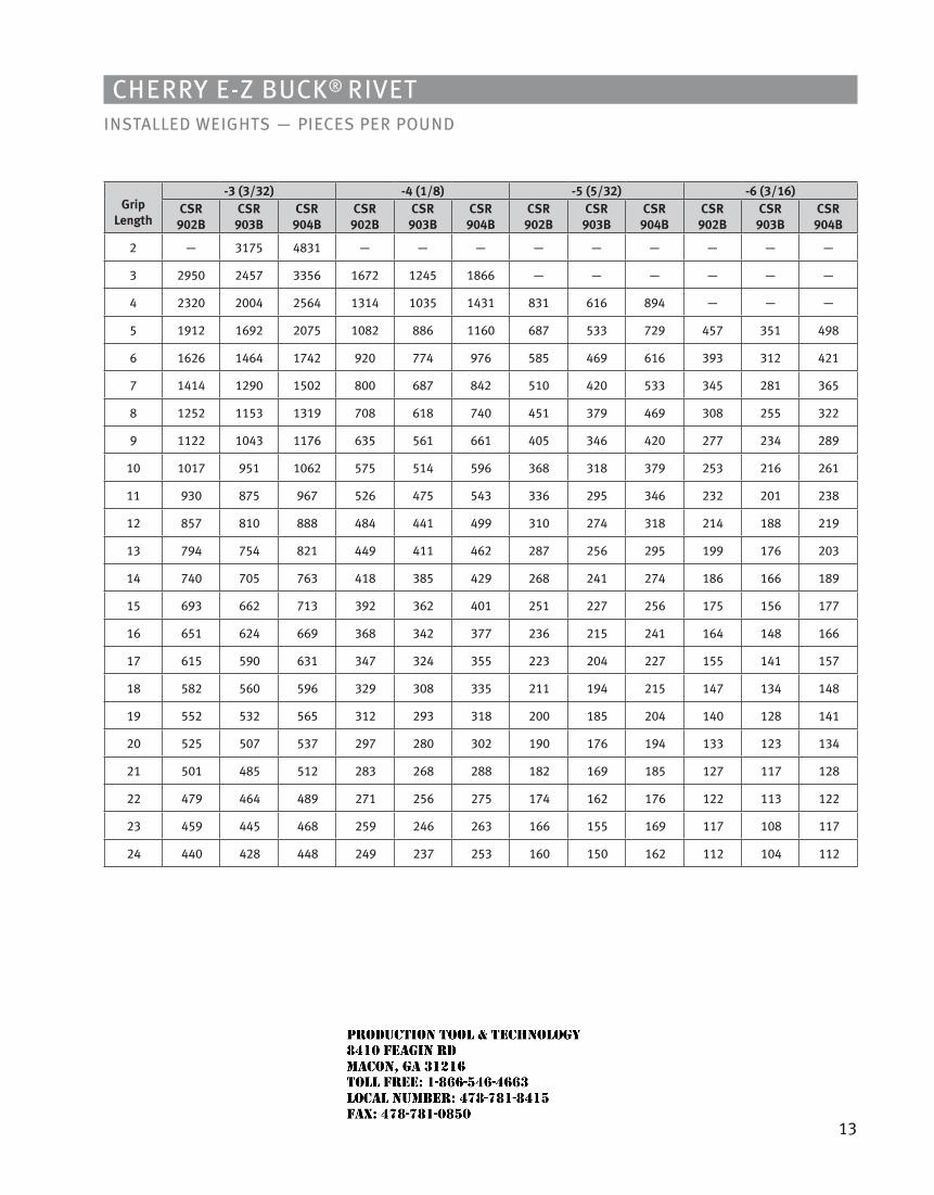
13
Cherry e-Z BuCk® rivetiNStALLeD WeiGhtS — PieCeS Per POuND
Griplength
-3 (3/32) -4 (1/8) -5 (5/32) -6 (3/16)CSr
902BCSr
903BCSr
904BCSr
902BCSr
903BCSr
904BCSr
902BCSr
903BCSr
904BCSr
902BCSr
903BCSr
904B
2 — 3175 4831 — — — — — — — — —
3 2950 2457 3356 1672 1245 1866 — — — — — —
4 2320 2004 2564 1314 1035 1431 831 616 894 — — —
5 1912 1692 2075 1082 886 1160 687 533 729 457 351 498
6 1626 1464 1742 920 774 976 585 469 616 393 312 421
7 1414 1290 1502 800 687 842 510 420 533 345 281 365
8 1252 1153 1319 708 618 740 451 379 469 308 255 322
9 1122 1043 1176 635 561 661 405 346 420 277 234 289
10 1017 951 1062 575 514 596 368 318 379 253 216 261
11 930 875 967 526 475 543 336 295 346 232 201 238
12 857 810 888 484 441 499 310 274 318 214 188 219
13 794 754 821 449 411 462 287 256 295 199 176 203
14 740 705 763 418 385 429 268 241 274 186 166 189
15 693 662 713 392 362 401 251 227 256 175 156 177
16 651 624 669 368 342 377 236 215 241 164 148 166
17 615 590 631 347 324 355 223 204 227 155 141 157
18 582 560 596 329 308 335 211 194 215 147 134 148
19 552 532 565 312 293 318 200 185 204 140 128 141
20 525 507 537 297 280 302 190 176 194 133 123 134
21 501 485 512 283 268 288 182 169 185 127 117 128
22 479 464 489 271 256 275 174 162 176 122 113 122
23 459 445 468 259 246 263 166 155 169 117 108 117
24 440 428 448 249 237 253 160 150 162 112 104 112
JR
Typewritten text
Production Tool & Technology 8410 Feagin Rd Macon, Ga 31216 Toll Free: 1-866-546-4663 Local Number: 478-781-8415 Fax: 478-781-0850
CHERRY® 1900 BULBING BLIND RIVET
SPS Fastener Division, a PCC Company
JR
Typewritten text
Production Tool & Technology 8410 Feagin Rd Macon, Ga 31216 Toll Free: 1-866-546-4663 Local Number: 478-781-8415 Fax: 478-781-0850
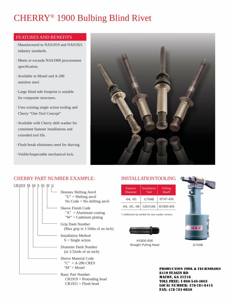
CHERRY® 1900 Bulbing Blind Rivet
· Manufactured to NAS1919 and NAS1921 industry standards.
· Meets or exceeds NAS1900 procurement specification.
· Available in Monel and A-286 stainless steel.
· Large blind side footprint is suitable for composite structures.
· Uses existing single action tooling and Cherry “One Tool Concept”
· Available with Cherry shift washer for consistent fastener installations and extended tool life.
· Flush break eliminates need for shaving.
· Visible/Inspectable mechanical lock.
G704B
FEATURES AND BENEFITS
H1900-456Straight Pulling Head
CHERRY PART NUMBER EXAMPLE:CR1919 M 04 S 05 W U
Denotes Shifting Anvil "U" = Shifting anvil No Code = No shifting anvil
Sleeve Finish Code "A" = Aluminum coating "W" = Cadmium plating
Grip Dash Number (Max grip in 1/16ths of an inch)
Installation Method S = Single action
Diameter Dash Number (in 1/32nds of an inch)
Sleeve Material Code "C" = A-286 CRES "M" = Monel
Basic Part Number CR1919 = Protruding head CR1921 = Flush head
INSTALLATION TOOLING
Fastener Diameter
Installation Tool
Pulling Head†
-04, -05 G704B H747-456
-04, -05, -06 G83/G84 H1900-456
† Additional tip needed for non-washer version.
JR
Typewritten text
Production Tool & Technology 8410 Feagin Rd Macon, Ga 31216 Toll Free: 1-866-546-4663 Local Number: 478-781-8415 Fax: 478-781-0850
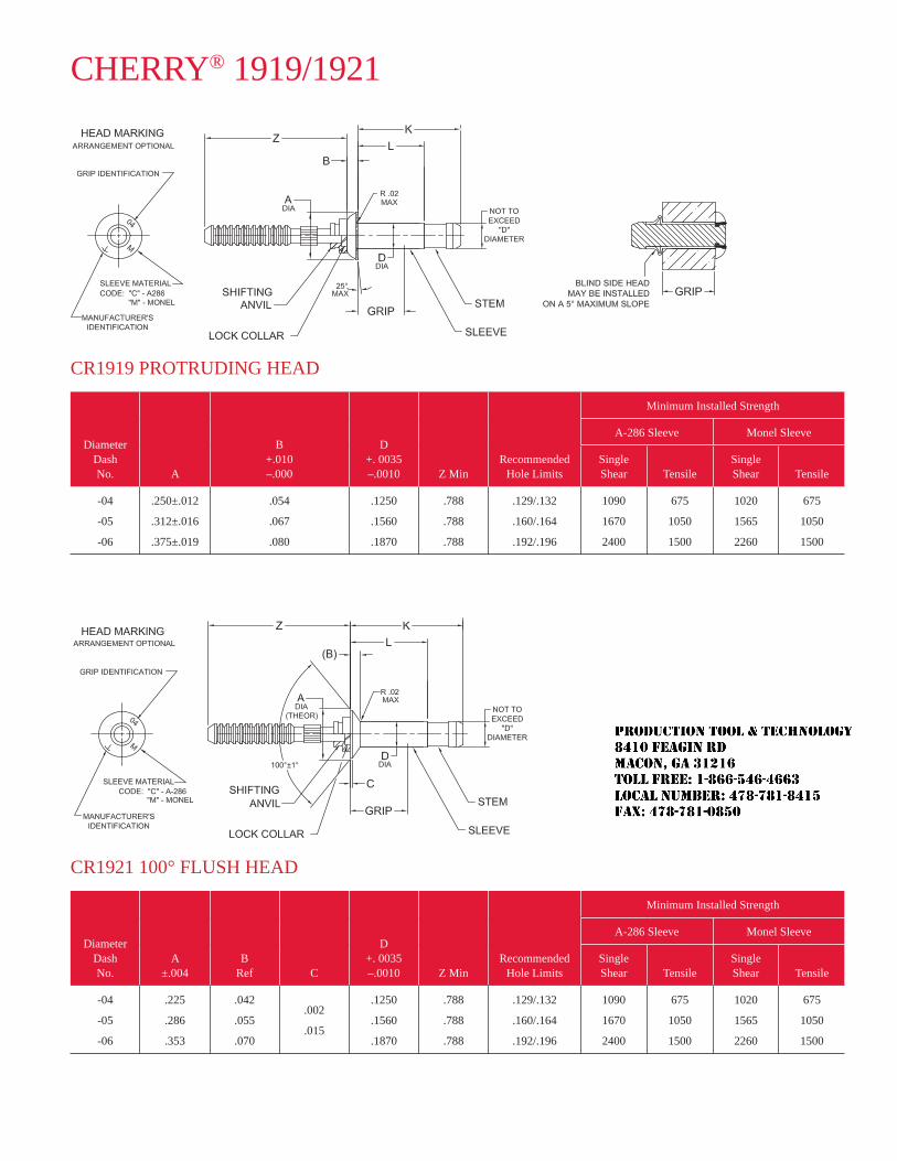
CHERRY® 1919/1921
CR1919 PROTRUDING HEAD
Diameter Dash No. A
B+.010 –.000
D+. 0035 –.0010 Z Min
RecommendedHole Limits
Minimum Installed Strength
A-286 Sleeve Monel Sleeve
Single Shear Tensile
Single Shear Tensile
-04
-05
-06
.250±.012
.312±.016
.375±.019
.054
.067
.080
.1250
.1560
.1870
.788
.788
.788
.129/.132
.160/.164
.192/.196
1090
1670
2400
675
1050
1500
1020
1565
2260
675
1050
1500
CR1921 100° FLUSH HEAD
Diameter Dash No.
A±.004
BRef C
D+. 0035 –.0010 Z Min
RecommendedHole Limits
Minimum Installed Strength
A-286 Sleeve Monel Sleeve
Single Shear Tensile
Single Shear Tensile
-04
-05
-06
.225
.286
.353
.042
.055
.070
.002
.015
.1250
.1560
.1870
.788
.788
.788
.129/.132
.160/.164
.192/.196
1090
1670
2400
675
1050
1500
1020
1565
2260
675
1050
1500
JR
Typewritten text
Production Tool & Technology 8410 Feagin Rd Macon, Ga 31216 Toll Free: 1-866-546-4663 Local Number: 478-781-8415 Fax: 478-781-0850
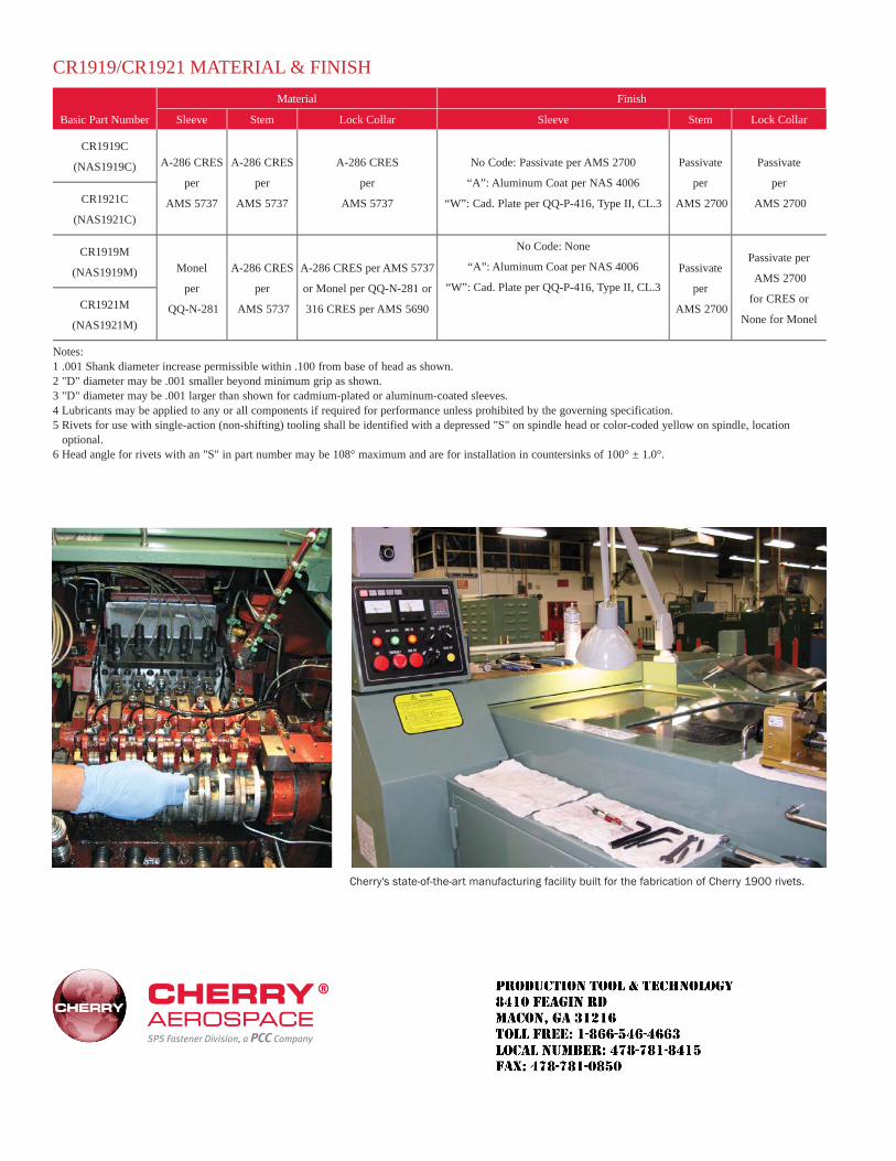
SPS Fastener Division, a PCC Company
CR1919/CR1921 MATERIAL & FINISH
Basic Part Number
Material Finish
Sleeve Stem Lock Collar Sleeve Stem Lock Collar
CR1919C
(NAS1919C) A-286 CRES
per
AMS 5737
A-286 CRES
per
AMS 5737
A-286 CRES
per
AMS 5737
No Code: Passivate per AMS 2700
“A”: Aluminum Coat per NAS 4006
“W”: Cad. Plate per QQ-P-416, Type II, CL.3
Passivate
per
AMS 2700
Passivate
per
AMS 2700CR1921C
(NAS1921C)
CR1919M
(NAS1919M) Monel
per
QQ-N-281
A-286 CRES
per
AMS 5737
A-286 CRES per AMS 5737
or Monel per QQ-N-281 or
316 CRES per AMS 5690
No Code: None
“A”: Aluminum Coat per NAS 4006
“W”: Cad. Plate per QQ-P-416, Type II, CL.3
Passivate
per
AMS 2700
Passivate per
AMS 2700
for CRES or
None for MonelCR1921M
(NAS1921M)
Notes: 1 .001 Shank diameter increase permissible within .100 from base of head as shown.2 "D" diameter may be .001 smaller beyond minimum grip as shown.3 "D" diameter may be .001 larger than shown for cadmium-plated or aluminum-coated sleeves.4 Lubricants may be applied to any or all components if required for performance unless prohibited by the governing specification.5 Rivets for use with single-action (non-shifting) tooling shall be identified with a depressed "S" on spindle head or color-coded yellow on spindle, location
optional.6 Head angle for rivets with an "S" in part number may be 108° maximum and are for installation in countersinks of 100° ± 1.0°.
Cherry's state-of-the-art manufacturing facility built for the fabrication of Cherry 1900 rivets.
JR
Typewritten text
Production Tool & Technology 8410 Feagin Rd Macon, Ga 31216 Toll Free: 1-866-546-4663 Local Number: 478-781-8415 Fax: 478-781-0850
Cherry® Nut Plate rivets
SPS Fastener Division, a PCC Company
JR
Typewritten text
Production Tool & Technology 8410 Feagin Rd Macon, Ga 31216 Toll Free: 1-866-546-4663 Local Number: 478-781-8415 Fax: 478-781-0850
LIMITED WARRANTY
seller warrants that the goods conform to applicable specifications and drawings and will be manufactured and inspected according to generally accepted practices of companies manufacturing industrial or aerospace fasteners. in the event of any breach of the foregoing warranty, Buyer’s sole remedy shall be to return defective goods (after receiving authorization from seller) for replacement or refund of the purchase price, at the seller’s option. seller agrees to any freight costs in connection with the return of any defective goods, but any costs relating to removal of the defective or nonconforming goods or installation of replacement goods shall be Buyer’s responsibility. seller’s WarraNty DOes NOt aPPly WheN aNy PhysiCal Or CheMiCal ChaNGe iN the FOrM OF the PrODuCt is MaDe By Buyer. the FOreGOiNG eXPress WarraNty aND reMeDy are eXClusive aND are iN lieu OF all Other WarraNties aND reMeDies; aNy iMPlieD WarraNty as tO Quality, FitNess FOr PurPOse, Or MerChaNtaBility is hereBy sPeCiFiCally DisClaiMeD aND eXCluDeD By seller. this warranty is void if seller is not notified in writing of any rejection of the goods within one (1) year aFter initial use by buyer of any power riveter or ninety (90) days after initial use of any other product. seller shall not be liable under any circumstances for incidental, special or consequential damages arising in whole or in part from any breach by seller, aND suCh iNCiDeNtal, sPeCial, Or CONseQueNtial DaMaGes are hereBy eXPressly eXCluDeD.
Our policy is one of continuous development. specifications shown in this document may be subject to changes introduced after publication.
Cherry® is a trademark of Cherry aerospace.
JR
Typewritten text
Production Tool & Technology 8410 Feagin Rd Macon, Ga 31216 Toll Free: 1-866-546-4663 Local Number: 478-781-8415 Fax: 478-781-0850
1
Cherry® Nut Plate rivetsCCr244/264/274 (iNCh) CCMr244/264/274 (MetriC)
CoNTENTs
Features and specifications Cherry Nut-Plate Blind rivet Description ...................................................................... 2 technical Data ............................................................................................................... 3
standard Pages Inches universal head .............................................................................................................. 4 100° Flush head ............................................................................................................ 5 Nas1097 100° Flush head ............................................................................................ 6 Metric universal head .............................................................................................................. 7 100° Flush head ............................................................................................................ 8 Nas1097 100° Flush head ............................................................................................ 9
Tooling hole Preparation and tool selection ........................................................................... 10 installation tooling ...................................................................................................... 11 Pulling heads .............................................................................................................. 12
NoTE
the properties, strengths, dimensions, installed characteristics and all other information in this catalog is for guidance only to aid in the correct selection of the products described herein and is not intended or implied as part of the warranty. all applications should be evaluated for functional suitability and available samples of the described parts can be requested for installed tests, suitability and evaluations.
ATTENTIoN
Blind rivets are not always a suitable substitute for solid rivets. Maintenance personnel are reminded that aC 43.13-1a chapter 2, section 3, stipulates: “Do not substitute hollow rivets for solid rivets in load carrying members without specific approval of the application by a representative of the Federal aviation administration. Blind rivets may be used in blind locations in accordance with the conditions listed in Chapter 5, provided the edge distances and spacings are not less that the minimum listed in paragraph 99d.”
JR
Typewritten text
Production Tool & Technology 8410 Feagin Rd Macon, Ga 31216 Toll Free: 1-866-546-4663 Local Number: 478-781-8415 Fax: 478-781-0850
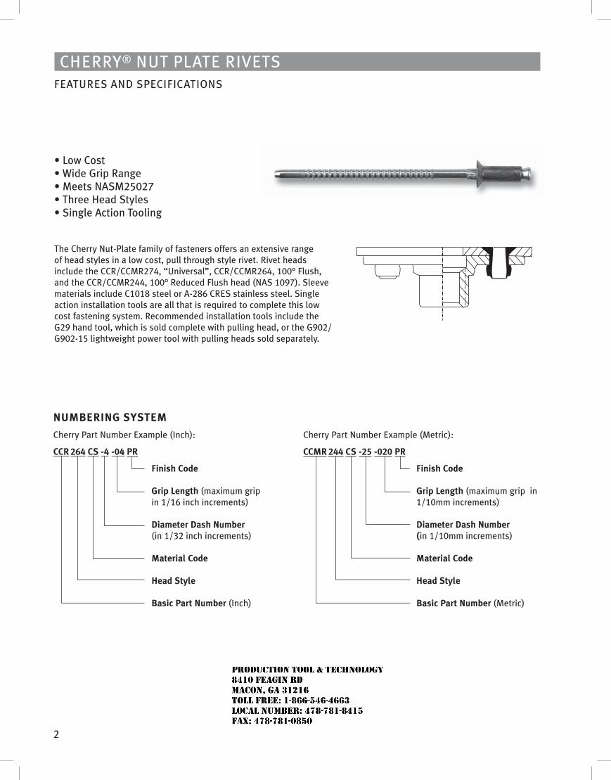
2
Cherry® Nut Plate rivetsFeatures aND sPeCiFiCatiONs
• Low Cost • Wide Grip Range • Meets NASM25027 • Three Head Styles • Single Action Tooling
the Cherry Nut-Plate family of fasteners offers an extensive range of head styles in a low cost, pull through style rivet. rivet heads include the CCr/CCMr274, “universal”, CCr/CCMr264, 100° Flush, and the CCr/CCMr244, 100° reduced Flush head (Nas 1097). sleeve materials include C1018 steel or a-286 Cres stainless steel. single action installation tools are all that is required to complete this low cost fastening system. recommended installation tools include the G29 hand tool, which is sold complete with pulling head, or the G902/G902-15 lightweight power tool with pulling heads sold separately.
Cherry Part Number example (Metric):
CCMR 244 Cs -25 -020 PR
Finish Code Grip Length (maximum grip in 1/10mm increments) Diameter Dash Number (in 1/10mm increments) Material Code Head style Basic Part Number (Metric)
NuMBERING sYsTEM
Cherry Part Number example (inch):
CCR 264 Cs -4 -04 PR
Finish Code Grip Length (maximum grip in 1/16 inch increments) Diameter Dash Number (in 1/32 inch increments) Material Code Head style Basic Part Number (inch)
JR
Typewritten text
Production Tool & Technology 8410 Feagin Rd Macon, Ga 31216 Toll Free: 1-866-546-4663 Local Number: 478-781-8415 Fax: 478-781-0850
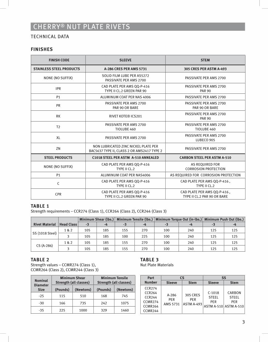
3
Cherry® Nut Plate rivetsteChNiCal Data
FINIsHEs
FINIsH CoDE sLEEvE sTEM
sTAINLEss sTEEL PRoDuCTs A-286 CREs PER AMs 5731 305 CREs PER AsTM A-493
NONe (NO suFFiX)sOliD FilM luBe Per as5272
Passivate Per aMs 2700Passivate Per aMs 2700
iPrCaD Plate Per aMs QQ-P-416
tyPe ii Cl.2 GreeN Par 90Passivate Per aMs 2700
Par 90
P1 aluMiNuM COat Per Nas 4006 Passivate Per aMs 2700
PrPassivate Per aMs 2700
Par 90 Or BarePassivate Per aMs 2700
Par 90 Or Bare
rK rivet KOte® iCs201Passivate Per aMs 2700
Par 90
t2Passivate Per aMs 2700
tiOluBe 460Passivate Per aMs 2700
tiOluBe 460
Xl Passivate Per aMs 2700Passivate Per aMs 2700
luBeCO 905
ZNNON luBriCateD ZiNC NiCKel Plate Per
BaC5637 tyPe ii, Class 2 Or aMs2417 tyPe 2Passivate Per aMs 2700
sTEEL PRoDuCTs C1018 sTEEL PER AsTM A-510 ANNEALED CARBoN sTEEL PER AsTM A-510
NONe (NO suFFiX)CaD Plate Per aMs QQ-P-416
tyPe ii Cl.2as reQuireD FOr
COrrOsiON PrOteCtiON
P1 aluMiNuM COat Per Nas4006 as reQuireD FOr COrrOsiON PrOteCtiON
CCaD Plate Per aMs QQ-P-416
tyPe ii Cl.2CaD Plate Per aMs QQ-P-416 ,
tyPe ii Cl.2
CPrCaD Plate Per aMs QQ-P-416
tyPe ii Cl.2 GreeN Par 90CaD Plate Per aMs QQ-P-416 ,
tyPe ii Cl.2 Par 90 Or Bare
TABLE 1 strength requirements – CCr274 (Class 1), CCr264 (Class 2), CCr244 (Class 3)
Rivet Material Head ClassMinimum shear (lbs.) Minimum Tensile (lbs.) Minimum Torque out (in-lbs.) Minimum Push out (lbs.)
-3 -4 -3 -4 -3 -4 -3 -4
ss (1018 steel)1 & 2 105 185 155 270 100 240 125 125
3 105 185 100 225 100 240 125 125
Cs (a-286)1 & 2 105 185 155 270 100 240 125 125
3 105 185 155 270 100 240 125 125
TABLE 3Nut Plate Materials
Part Number
Cs sssleeve stem sleeve stem
CCr274CCr264CCr244
CCMr274CCMr264CCMr244
a-286 Per
aMs 5731
305 Cres Per
astM a-493
C-1018 steel Per
astM a-510
CarBON steel Per
astM a-510
TABLE 2strength values – CCMr274 (Class 1), CCMr264 (Class 2), CCMr244 (Class 3)
Nominal Diameter
size
Minimum shear strength (all classes)
Minimum Tensile strength (all classes)
(Pounds) (Newtons) (Pounds) (Newtons)
-25 115 510 168 745
-30 166 735 242 1075
-35 225 1000 329 1460
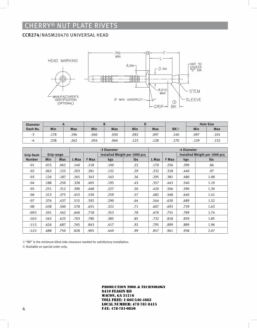
4
Cherry® Nut Plate rivetsCCR274/NasM20470 uNiversal heaD
Diameter Dash No.
A B DBK➀
Hole sizeMin Max Min Max Min Max Min Max
-3 .178 .196 .040 .050 .092 .097 .140 .097 .101
-4 .238 .262 .054 .064 .123 .128 .170 .129 .132
Grip Dash Number
Grip range-3 Diameter -4 Diameter
L Max F MaxInstalled Weight per 1000 pcs
L Max F MaxInstalled Weight per 1000 pcs
Min Max kgs lbs kgs lbs
-01 .015 .062 .140 .218 .100 .22 .170 .256 .390 .86
-02 .063 .125 .203 .281 .132 .29 .232 .318 .440 .97
-03 .126 .187 .265 .343 .163 .36 .295 .381 .480 1.08
-04 .188 .250 .328 .405 .195 .43 .357 .443 .540 1.19
-05 .251 .312 .390 .468 .227 .50 .420 .506 .590 1.30
-06 .313 .375 .453 .530 .259 .57 .482 .568 .640 1.41
-07 .376 .437 .515 .592 .290 .64 .544 .630 .689 1.52
-08 .438 .500 .578 .655 .322 .71 .607 .693 .739 1.63
-09➁ .501 .562 .640 .718 .353 .78 .670 .755 .789 1.74
-10➁ .563 .625 .703 .780 .385 .85 .732 .818 .839 1.85
-11➁ .626 .687 .765 .843 .417 .92 .795 .899 .889 1.96
-12➁ .688 .750 .828 .905 .449 .99 .857 .961 .938 2.07
➀ “BK” is the minimum blind side clearance needed for satisfactory installation.
➁ available on special order only.
JR
Typewritten text
Production Tool & Technology 8410 Feagin Rd Macon, Ga 31216 Toll Free: 1-866-546-4663 Local Number: 478-781-8415 Fax: 478-781-0850
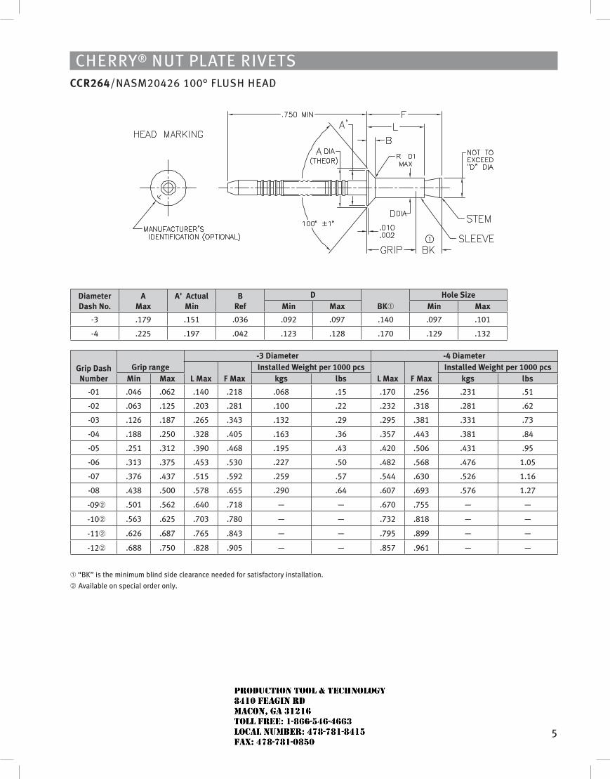
5
Diameter Dash No.
A Max
A' Actual Min
B Ref
DBK➀
Hole sizeMin Max Min Max
-3 .179 .151 .036 .092 .097 .140 .097 .101
-4 .225 .197 .042 .123 .128 .170 .129 .132
Grip Dash Number
Grip range-3 Diameter -4 Diameter
L Max F MaxInstalled Weight per 1000 pcs
L Max F MaxInstalled Weight per 1000 pcs
Min Max kgs lbs kgs lbs
-01 .046 .062 .140 .218 .068 .15 .170 .256 .231 .51
-02 .063 .125 .203 .281 .100 .22 .232 .318 .281 .62
-03 .126 .187 .265 .343 .132 .29 .295 .381 .331 .73
-04 .188 .250 .328 .405 .163 .36 .357 .443 .381 .84
-05 .251 .312 .390 .468 .195 .43 .420 .506 .431 .95
-06 .313 .375 .453 .530 .227 .50 .482 .568 .476 1.05
-07 .376 .437 .515 .592 .259 .57 .544 .630 .526 1.16
-08 .438 .500 .578 .655 .290 .64 .607 .693 .576 1.27
-09➁ .501 .562 .640 .718 — — .670 .755 — —
-10➁ .563 .625 .703 .780 — — .732 .818 — —
-11➁ .626 .687 .765 .843 — — .795 .899 — —
-12➁ .688 .750 .828 .905 — — .857 .961 — —
➀ “BK” is the minimum blind side clearance needed for satisfactory installation.
➁ available on special order only.
Cherry® Nut Plate rivetsCCR264/NasM20426 100° Flush heaD
JR
Typewritten text
Production Tool & Technology 8410 Feagin Rd Macon, Ga 31216 Toll Free: 1-866-546-4663 Local Number: 478-781-8415 Fax: 478-781-0850
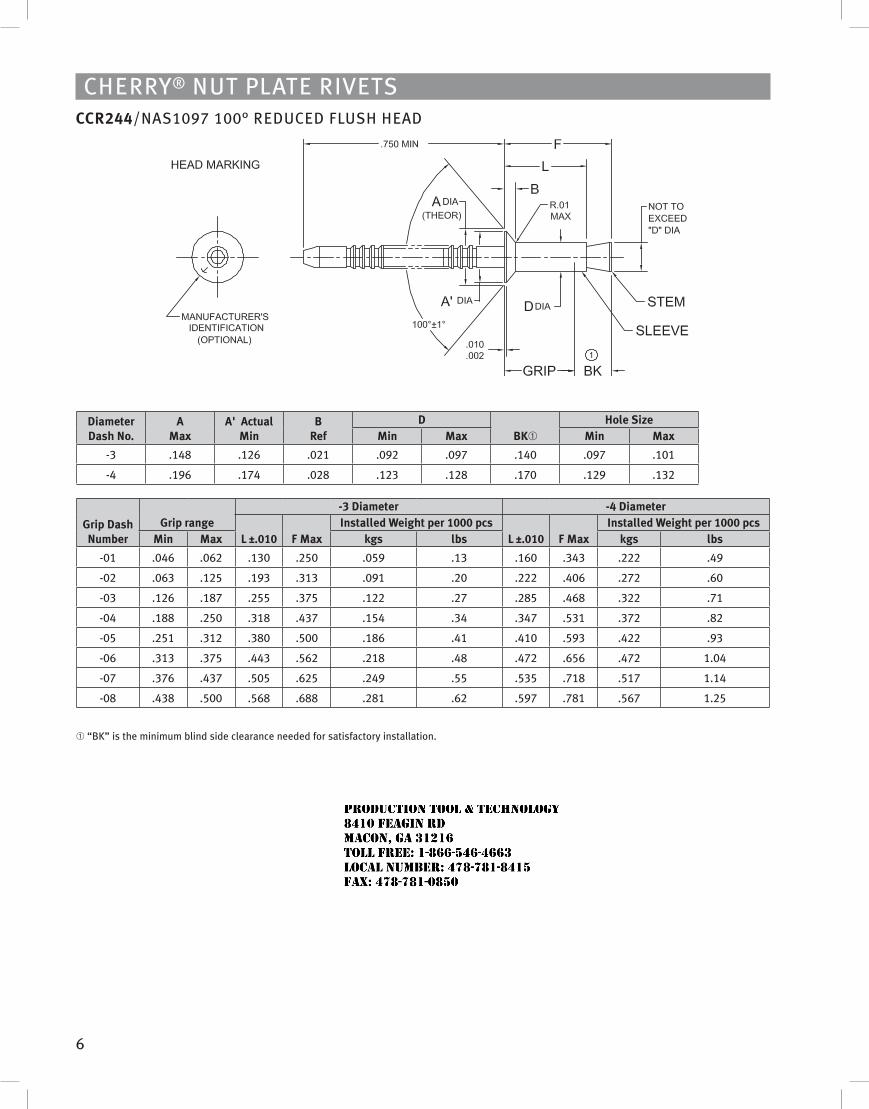
6
Cherry® Nut Plate rivetsCCR244/Nas1097 100° reDuCeD Flush heaD
Diameter Dash No.
A Max
A' Actual Min
B Ref
DBK➀
Hole sizeMin Max Min Max
-3 .148 .126 .021 .092 .097 .140 .097 .101
-4 .196 .174 .028 .123 .128 .170 .129 .132
Grip Dash Number
Grip range-3 Diameter -4 Diameter
L ±.010 F MaxInstalled Weight per 1000 pcs
L ±.010 F MaxInstalled Weight per 1000 pcs
Min Max kgs lbs kgs lbs
-01 .046 .062 .130 .250 .059 .13 .160 .343 .222 .49
-02 .063 .125 .193 .313 .091 .20 .222 .406 .272 .60
-03 .126 .187 .255 .375 .122 .27 .285 .468 .322 .71
-04 .188 .250 .318 .437 .154 .34 .347 .531 .372 .82
-05 .251 .312 .380 .500 .186 .41 .410 .593 .422 .93
-06 .313 .375 .443 .562 .218 .48 .472 .656 .472 1.04
-07 .376 .437 .505 .625 .249 .55 .535 .718 .517 1.14
-08 .438 .500 .568 .688 .281 .62 .597 .781 .567 1.25
➀ “BK” is the minimum blind side clearance needed for satisfactory installation.
JR
Typewritten text
Production Tool & Technology 8410 Feagin Rd Macon, Ga 31216 Toll Free: 1-866-546-4663 Local Number: 478-781-8415 Fax: 478-781-0850
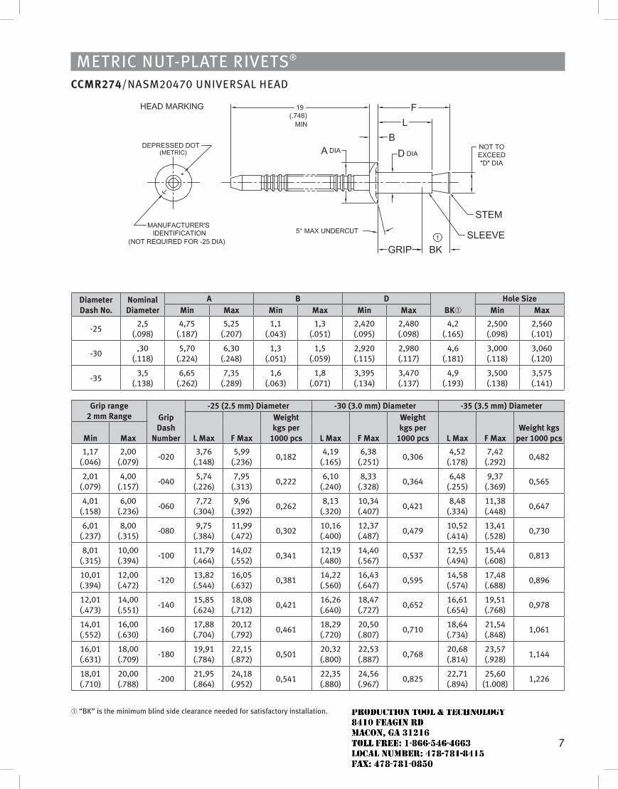
7
MetriC Nut-Plate rivets®
CCMR274/NasM20470 uNiversal heaD
Diameter Dash No.
Nominal Diameter
A B DBK➀
Hole sizeMin Max Min Max Min Max Min Max
-252,5
(.098)4,75
(.187)5,25
(.207)1,1
(.043)1,3
(.051)2,420 (.095)
2,480 (.098)
4,2 (.165)
2,500 (.098)
2,560 (.101)
-30,30
(.118)5,70
(.224)6,30
(.248)1,3
(.051)1,5
(.059)2,920 (.115)
2,980 (.117)
4,6 (.181)
3,000 (.118)
3,060 (.120)
-353,5
(.138)6,65
(.262)7,35
(.289)1,6
(.063)1,8
(.071)3,395 (.134)
3,470 (.137)
4,9 (.193)
3,500 (.138)
3,575 (.141)
Grip range 2 mm Range Grip
Dash Number
-25 (2.5 mm) Diameter -30 (3.0 mm) Diameter -35 (3.5 mm) Diameter
L Max F Max
Weight kgs per
1000 pcs L Max F Max
Weight kgs per
1000 pcs L Max F MaxWeight kgs
per 1000 pcsMin Max
1,17 (.046)
2,00 (.079)
-0203,76
(.148)5,99
(.236)0,182
4,19 (.165)
6,38 (.251)
0,3064,52
(.178)7,42
(.292)0,482
2,01 (.079)
4,00 (.157)
-0405,74
(.226)7,95
(.313)0,222
6,10 (.240)
8,33 (.328)
0,3646,48
(.255)9,37
(.369)0,565
4,01 (.158)
6,00 (.236)
-0607,72
(.304)9,96
(.392)0,262
8,13 (.320)
10,34 (.407)
0,4218,48
(.334)11,38 (.448)
0,647
6,01 (.237)
8,00 (.315)
-0809,75
(.384)11,99 (.472)
0,30210,16 (.400)
12,37 (.487)
0,47910,52 (.414)
13,41 (.528)
0,730
8,01 (.315)
10,00 (.394)
-10011,79 (.464)
14,02 (.552)
0,34112,19 (.480)
14,40 (.567)
0,53712,55 (.494)
15,44 (.608)
0,813
10,01 (.394)
12,00 (.472)
-12013,82 (.544)
16,05 (.632)
0,38114,22 (.560)
16,43 (.647)
0,59514,58 (.574)
17,48 (.688)
0,896
12,01 (.473)
14,00 (.551)
-14015,85 (.624)
18,08 (.712)
0,42116,26 (.640)
18,47 (.727)
0,65216,61 (.654)
19,51 (.768)
0,978
14,01 (.552)
16,00 (.630)
-16017,88 (.704)
20,12 (.792)
0,46118,29 (.720)
20,50 (.807)
0,71018,64 (.734)
21,54 (.848)
1,061
16,01 (.631)
18,00 (.709)
-18019,91 (.784)
22,15 (.872)
0,50120,32 (.800)
22,53 (.887)
0,76820,68 (.814)
23,57 (.928)
1,144
18,01 (.710)
20,00 (.788)
-20021,95 (.864)
24,18 (.952)
0,54122,35 (.880)
24,56 (.967)
0,82522,71 (.894)
25,60 (1.008)
1,226
➀ “BK” is the minimum blind side clearance needed for satisfactory installation.
JR
Typewritten text
Production Tool & Technology 8410 Feagin Rd Macon, Ga 31216 Toll Free: 1-866-546-4663 Local Number: 478-781-8415 Fax: 478-781-0850
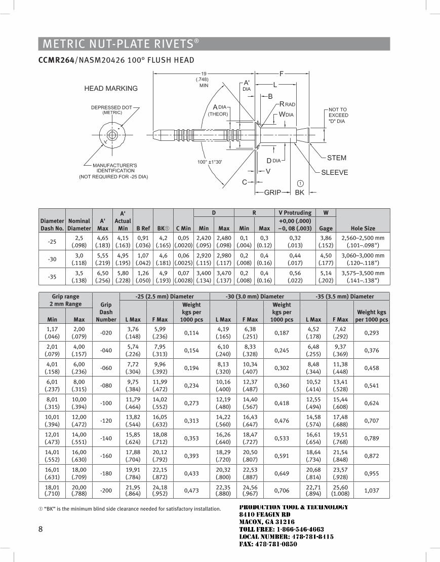
8
MetriC Nut-Plate rivets®
CCMR264/NasM20426 100° Flush heaD
Diameter Dash No.
Nominal Diameter
A' Max
A' Actual
Min B Ref BK➀ C Min
D R v Protruding W
Hole sizeMin Max Min Max+0,00 (.000) – 0, 08 (.003) Gage
-252,5
(.098)4,65
(.183)4,15
(.163)0,91
(.036)4,2
(.165)0,05
(.0020)2,420 (.095)
2,480 (.098)
0,1 (.004)
0,3 (0.12)
0,32 (.013)
3,86 (.152)
2,560–2,500 mm (.101–.098")
-303,0
(.118)5,55
(.219)4,95
(.195)1,07
(.042)4,6
(.181)0,06
(.0025)2,920 (.115)
2,980 (.117)
0,2 (.008)
0,4 (0.16)
0,44 (.017)
4,50 (.177)
3,060–3,000 mm (.120–.118")
-353,5
(.138)6,50
(.256)5,80
(.228)1,26
(.050)4,9
(.193)0,07
(.0028)3,400 (.134)
3,470 (.137)
0,2 (.008)
0,4 (0.16)
0,56 (.022)
5,14 (.202)
3,575–3,500 mm (.141–.138")
Grip range 2 mm Range Grip
Dash Number
-25 (2.5 mm) Diameter -30 (3.0 mm) Diameter -35 (3.5 mm) Diameter
L Max F Max
Weight kgs per
1000 pcs L Max F Max
Weight kgs per
1000 pcs L Max F MaxWeight kgs
per 1000 pcsMin Max
1,17 (.046)
2,00 (.079)
-0203,76
(.148)5,99
(.236)0,114
4,19 (.165)
6,38 (.251)
0,1874,52
(.178)7,42
(.292)0,293
2,01 (.079)
4,00 (.157)
-0405,74
(.226)7,95
(.313)0,154
6,10 (.240)
8,33 (.328)
0,2456,48
(.255)9,37
(.369)0,376
4,01 (.158)
6,00 (.236)
-0607,72
(.304)9,96
(.392)0,194
8,13 (.320)
10,34 (.407)
0,3028,48
(.344)11,38 (.448)
0,458
6,01 (.237)
8,00 (.315)
-0809,75
(.384)11,99 (.472)
0,23410,16 (.400)
12,37 (.487)
0,36010,52 (.414)
13,41 (.528)
0,541
8,01 (.315)
10,00 (.394)
-10011,79 (.464)
14,02 (.552)
0,27312,19 (.480)
14,40 (.567)
0,41812,55 (.494)
15,44 (.608)
0,624
10,01 (.394)
12,00 (.472)
-12013,82 (.544)
16,05 (.632)
0,31314,22 (.560)
16,43 (.647)
0,47614,58 (.574)
17,48 (.688)
0,707
12,01 (.473)
14,00 (.551)
-14015,85 (.624)
18,08 (.712)
0,35316,26 (.640)
18,47 (.727)
0,53316,61 (.654)
19,51 (.768)
0,789
14,01 (.552)
16,00 (.630)
-16017,88 (.704)
20,12 (.792)
0,39318,29 (.720)
20,50 (.807)
0,59118,64 (.734)
21,54 (.848)
0,872
16,01 (.631)
18,00 (.709)
-18019,91 (.784)
22,15 (.872)
0,43320,32 (.800)
22,53 (.887)
0,64920,68 (.814)
23,57 (.928)
0,955
18,01 (.710)
20,00 (.788) -200 21,95
(.864)24,18 (.952) 0,473 22,35
(.880)24,56 (.967) 0,706 22,71
(.894)25,60
(1.008) 1,037
➀ “BK” is the minimum blind side clearance needed for satisfactory installation.
JR
Typewritten text
Production Tool & Technology 8410 Feagin Rd Macon, Ga 31216 Toll Free: 1-866-546-4663 Local Number: 478-781-8415 Fax: 478-781-0850
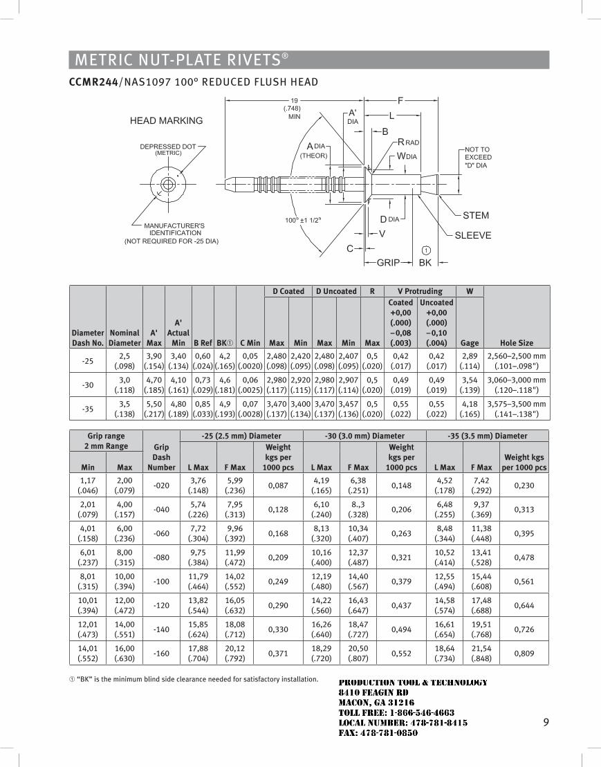
9
MetriC Nut-Plate rivets®
CCMR244/Nas1097 100° reDuCeD Flush heaD
Diameter Dash No.
Nominal Diameter
A' Max
A' Actual
Min B Ref BK➀ C Min
D Coated D uncoated R v Protruding W
Hole sizeMax Min Max Min Max
Coated +0,00 (.000) – 0,08 (.003)
uncoated +0,00 (.000) – 0,10 (.004) Gage
-252,5
(.098)3,90
(.154)3,40
(.134)0,60
(.024)4,2
(.165)0,05
(.0020)2,480 (.098)
2,420 (.095)
2,480 (.098)
2,407 (.095)
0,5 (.020)
0,42 (.017)
0,42 (.017)
2,89 (.114)
2,560–2,500 mm (.101–.098")
-303,0
(.118)4,70
(.185)4,10
(.161)0,73
(.029)4,6
(.181)0,06
(.0025)2,980 (.117)
2,920 (.115)
2,980 (.117)
2,907 (.114)
0,5 (.020)
0,49 (.019)
0,49 (.019)
3,54 (.139)
3,060–3,000 mm (.120–.118")
-353,5
(.138)5,50
(.217)4,80
(.189)0,85
(.033)4,9
(.193)0,07
(.0028)3,470 (.137)
3,400 (.134)
3,470 (.137)
3,457 (.136)
0,5 (.020)
0,55 (.022)
0,55 (.022)
4,18 (.165)
3,575–3,500 mm (.141–.138")
Grip range 2 mm Range Grip
Dash Number
-25 (2.5 mm) Diameter -30 (3.0 mm) Diameter -35 (3.5 mm) Diameter
L Max F Max
Weight kgs per
1000 pcs L Max F Max
Weight kgs per
1000 pcs L Max F MaxWeight kgs
per 1000 pcsMin Max
1,17 (.046)
2,00 (.079)
-0203,76
(.148)5,99
(.236)0,087
4,19 (.165)
6,38 (.251)
0,1484,52
(.178)7,42
(.292)0,230
2,01 (.079)
4,00 (.157)
-0405,74
(.226)7,95
(.313)0,128
6,10 (.240)
8.,3 (.328)
0,2066,48
(.255)9,37
(.369)0,313
4,01 (.158)
6,00 (.236)
-0607,72
(.304)9,96
(.392)0,168
8,13 (.320)
10,34 (.407)
0,2638,48
(.344)11,38 (.448)
0,395
6,01 (.237)
8,00 (.315)
-0809,75
(.384)11,99 (.472)
0,20910,16 (.400)
12,37 (.487)
0,32110,52 (.414)
13,41 (.528)
0,478
8,01 (.315)
10,00 (.394)
-10011,79 (.464)
14,02 (.552)
0,24912,19 (.480)
14,40 (.567)
0,37912,55 (.494)
15,44 (.608)
0,561
10,01 (.394)
12,00 (.472)
-12013,82 (.544)
16,05 (.632)
0,29014,22 (.560)
16,43 (.647)
0,43714,58 (.574)
17,48 (.688)
0,644
12,01 (.473)
14,00 (.551)
-14015,85 (.624)
18,08 (.712)
0,33016,26 (.640)
18,47 (.727)
0,49416,61 (.654)
19,51 (.768)
0,726
14,01 (.552)
16,00 (.630)
-16017,88 (.704)
20,12 (.792)
0,37118,29 (.720)
20,50 (.807)
0,55218,64 (.734)
21,54 (.848)
0,809
➀ “BK” is the minimum blind side clearance needed for satisfactory installation.
JR
Typewritten text
Production Tool & Technology 8410 Feagin Rd Macon, Ga 31216 Toll Free: 1-866-546-4663 Local Number: 478-781-8415 Fax: 478-781-0850
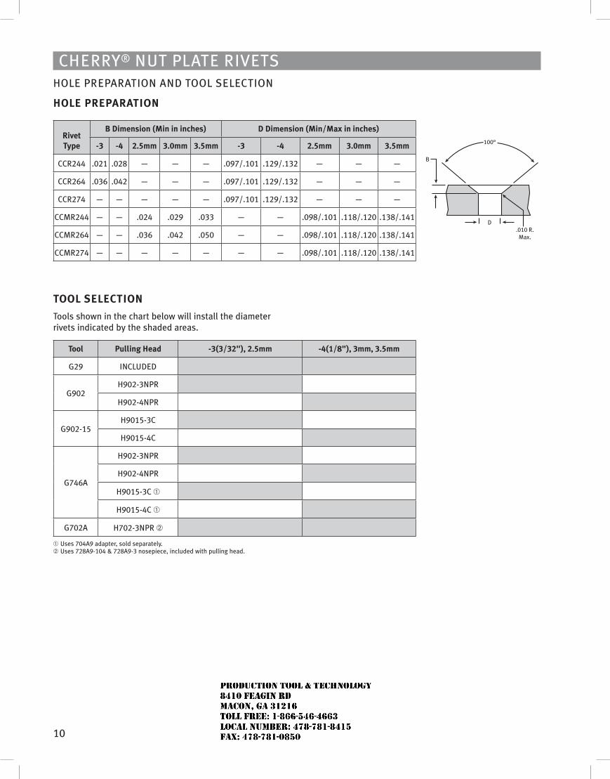
10
Cherry® Nut Plate rivetshOle PreParatiON aND tOOl seleCtiON
HoLE PREPARATIoN
Rivet Type
B Dimension (Min in inches) D Dimension (Min/Max in inches)
-3 -4 2.5mm 3.0mm 3.5mm -3 -4 2.5mm 3.0mm 3.5mm
CCr244 .021 .028 — — — .097/.101 .129/.132 — — —
CCr264 .036 .042 — — — .097/.101 .129/.132 — — —
CCr274 — — — — — .097/.101 .129/.132 — — —
CCMr244 — — .024 .029 .033 — — .098/.101 .118/.120 .138/.141
CCMr264 — — .036 .042 .050 — — .098/.101 .118/.120 .138/.141
CCMr274 — — — — — — — .098/.101 .118/.120 .138/.141
TooL sELECTIoN
tools shown in the chart below will install the diameter rivets indicated by the shaded areas.
Tool Pulling Head -3(3/32"), 2.5mm -4(1/8"), 3mm, 3.5mm
G29 iNCluDeD
G902h902-3NPr
h902-4NPr
G902-15h9015-3C
h9015-4C
G746a
h902-3NPr
h902-4NPr
h9015-3C ➀
h9015-4C ➀
G702a h702-3NPr ➁
➀ uses 704a9 adapter, sold separately. ➁ uses 728a9-104 & 728a9-3 nosepiece, included with pulling head.
100°
D.010 R.Max.
B
JR
Typewritten text
Production Tool & Technology 8410 Feagin Rd Macon, Ga 31216 Toll Free: 1-866-546-4663 Local Number: 478-781-8415 Fax: 478-781-0850
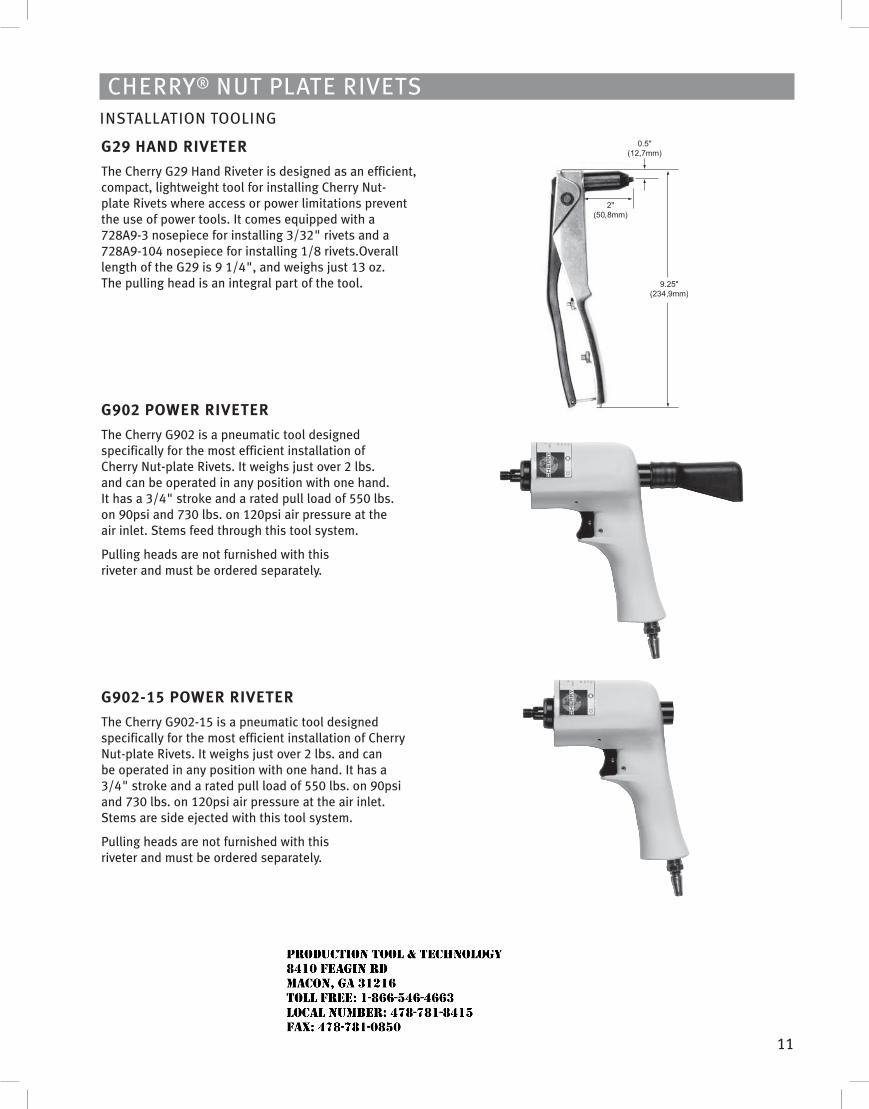
11
Cherry® Nut Plate rivetsiNstallatiON tOOliNG
G29 HAND RIvETER
the Cherry G29 hand riveter is designed as an efficient, compact, lightweight tool for installing Cherry Nut-plate rivets where access or power limitations prevent the use of power tools. it comes equipped with a 728a9-3 nosepiece for installing 3/32" rivets and a 728a9-104 nosepiece for installing 1/8 rivets.Overall length of the G29 is 9 1/4", and weighs just 13 oz. the pulling head is an integral part of the tool.
G902 PoWER RIvETER
the Cherry G902 is a pneumatic tool designed specifically for the most efficient installation of Cherry Nut-plate rivets. it weighs just over 2 lbs. and can be operated in any position with one hand. it has a 3/4" stroke and a rated pull load of 550 lbs. on 90psi and 730 lbs. on 120psi air pressure at the air inlet. stems feed through this tool system.
Pulling heads are not furnished with this riveter and must be ordered separately.
G902-15 PoWER RIvETER
the Cherry G902-15 is a pneumatic tool designed specifically for the most efficient installation of Cherry Nut-plate rivets. it weighs just over 2 lbs. and can be operated in any position with one hand. it has a 3/4" stroke and a rated pull load of 550 lbs. on 90psi and 730 lbs. on 120psi air pressure at the air inlet. stems are side ejected with this tool system.
Pulling heads are not furnished with this riveter and must be ordered separately.
JR
Typewritten text
Production Tool & Technology 8410 Feagin Rd Macon, Ga 31216 Toll Free: 1-866-546-4663 Local Number: 478-781-8415 Fax: 478-781-0850
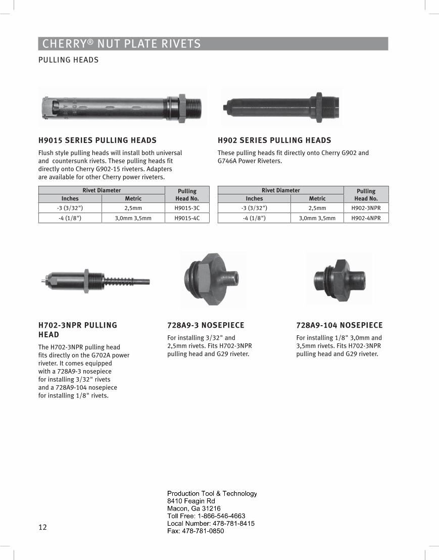
12
Cherry® Nut Plate rivetsPulliNG heaDs
H9015 sERIEs PuLLING HEADs
Flush style pulling heads will install both universal and countersunk rivets. these pulling heads fit directly onto Cherry G902-15 riveters. adapters are available for other Cherry power riveters.
Rivet Diameter Pulling Head No.Inches Metric
-3 (3/32") 2,5mm h9015-3C
-4 (1/8") 3,0mm 3,5mm h9015-4C
H902 sERIEs PuLLING HEADs
these pulling heads fit directly onto Cherry G902 and G746a Power riveters.
Rivet Diameter Pulling Head No.Inches Metric
-3 (3/32") 2,5mm h902-3NPr
-4 (1/8") 3,0mm 3,5mm h902-4NPr
H702-3NPR PuLLING HEAD
the h702-3NPr pulling head fits directly on the G702a power riveter. it comes equipped with a 728a9-3 nosepiece for installing 3/32" rivets and a 728a9-104 nosepiece for installing 1/8" rivets.
728A9-3 NosEPIECE
For installing 3/32" and 2,5mm rivets. Fits h702-3NPr pulling head and G29 riveter.
728A9-104 NosEPIECE
For installing 1/8" 3,0mm and 3,5mm rivets. Fits h702-3NPr pulling head and G29 riveter.
JR
Typewritten text
Production Tool & Technology 8410 Feagin Rd Macon, Ga 31216 Toll Free: 1-866-546-4663 Local Number: 478-781-8415 Fax: 478-781-0850
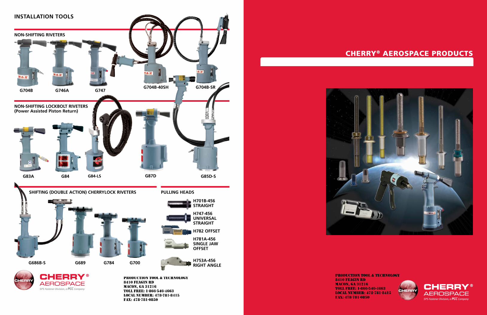
G689
1
Cherry® AerospACe produCts
SPS Fastener Division, a PCC Company
SPS Fastener Division, a PCC Company
InstallatIon tools
non-shIftInG RIveteRs
non-shIftInG lockbolt RIveteRs (Power assisted Piston Return)
shIftInG (Double actIon) cheRRylock RIveteRs PullInG heaDs
G704b G746a G747G704b-40sh
G83a
G686b-s G784 G700
G84 G84-ls G87D G85D-s
h701b-456 stRaIGht
h747-456 unIveRsal stRaIGht
h782 offset
h781a-456 sInGle Jaw offset
h753a-456 RIGht anGle
G704b-sR
JR
Typewritten text
Production Tool & Technology 8410 Feagin Rd Macon, Ga 31216 Toll Free: 1-866-546-4663 Local Number: 478-781-8415 Fax: 478-781-0850
JR
Typewritten text
Production Tool & Technology 8410 Feagin Rd Macon, Ga 31216 Toll Free: 1-866-546-4663 Local Number: 478-781-8415 Fax: 478-781-0850
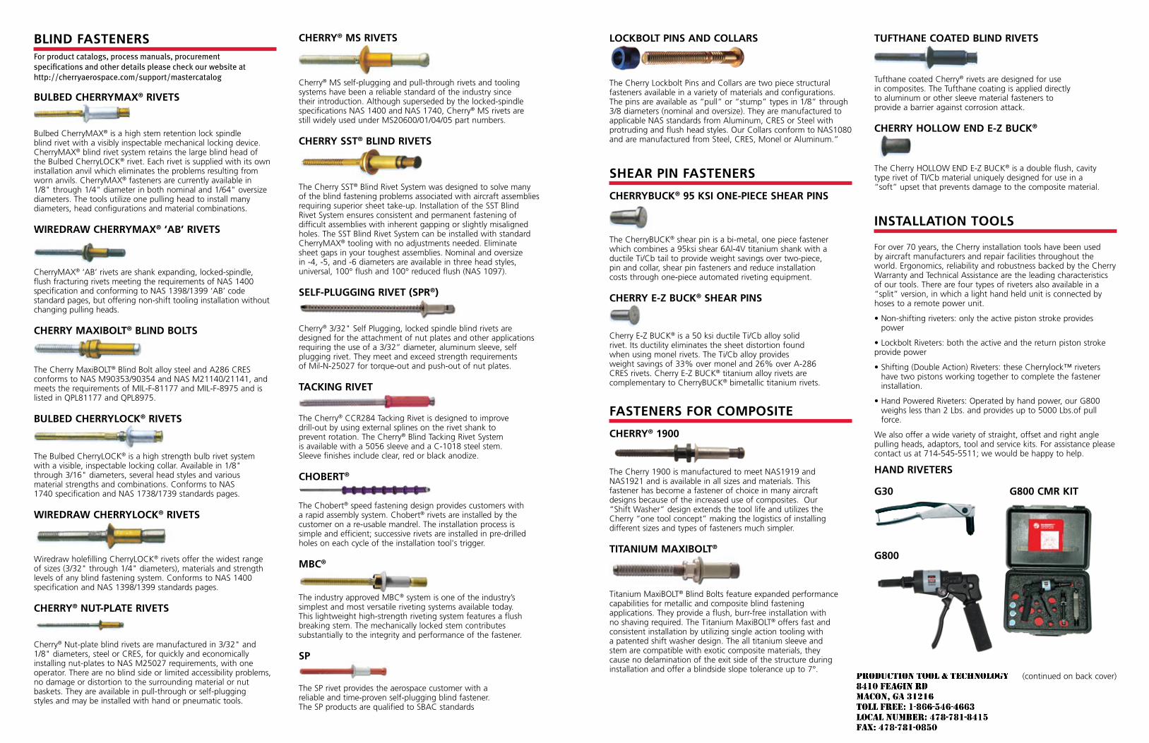
lockbolt PIns anD collaRs
The Cherry Lockbolt Pins and Collars are two piece structural fasteners available in a variety of materials and configurations. The pins are available as “pull” or “stump” types in 1/8” through 3/8 diameters (nominal and oversize). They are manufactured to applicable NAS standards from Aluminum, CRES or Steel with protruding and flush head styles. Our Collars conform to NAS1080 and are manufactured from Steel, CRES, Monel or Aluminum.”
sheaR PIn fasteneRs
cheRRybuck® 95 ksI one-PIece sheaR PIns
The CherryBUCK® shear pin is a bi-metal, one piece fastener which combines a 95ksi shear 6Al-4V titanium shank with a ductile Ti/Cb tail to provide weight savings over two-piece, pin and collar, shear pin fasteners and reduce installation costs through one-piece automated riveting equipment.
cheRRy e-z buck® sheaR PIns
Cherry E-Z BUCK® is a 50 ksi ductile Ti/Cb alloy solid rivet. Its ductility eliminates the sheet distortion found when using monel rivets. The Ti/Cb alloy provides weight savings of 33% over monel and 26% over A-286 CRES rivets. Cherry E-Z BUCK® titanium alloy rivets are complementary to CherryBUCK® bimetallic titanium rivets.
fasteneRs foR comPosIte
cheRRy® 1900
The Cherry 1900 is manufactured to meet NAS1919 and NAS1921 and is available in all sizes and materials. This fastener has become a fastener of choice in many aircraft designs because of the increased use of composites. Our “Shift Washer” design extends the tool life and utilizes the Cherry “one tool concept” making the logistics of installing different sizes and types of fasteners much simpler.
tItanIum maxIbolt®
Titanium MaxiBOLT® Blind Bolts feature expanded performance capabilities for metallic and composite blind fastening applications. They provide a flush, burr-free installation with no shaving required. The Titanium MaxiBOLT® offers fast and consistent installation by utilizing single action tooling with a patented shift washer design. The all titanium sleeve and stem are compatible with exotic composite materials, they cause no delamination of the exit side of the structure during installation and offer a blindside slope tolerance up to 7°.
tufthane coateD blInD RIvets
Tufthane coated Cherry® rivets are designed for use in composites. The Tufthane coating is applied directly to aluminum or other sleeve material fasteners to provide a barrier against corrosion attack.
cheRRy hollow enD e-z buck®
The Cherry HOLLOW END E-Z BUCK® is a double flush, cavity type rivet of TI/Cb material uniquely designed for use in a “soft” upset that prevents damage to the composite material.
InstallatIon tools For over 70 years, the Cherry installation tools have been used by aircraft manufacturers and repair facilities throughout the world. Ergonomics, reliability and robustness backed by the Cherry Warranty and Technical Assistance are the leading characteristics of our tools. There are four types of riveters also available in a “split” version, in which a light hand held unit is connected by hoses to a remote power unit.
• Non-shifting riveters: only the active piston stroke provides power
• Lockbolt Riveters: both the active and the return piston stroke provide power
• Shifting (Double Action) Riveters: these Cherrylock™ riveters have two pistons working together to complete the fastener installation.
• Hand Powered Riveters: Operated by hand power, our G800 weighs less than 2 Lbs. and provides up to 5000 Lbs.of pull force.
We also offer a wide variety of straight, offset and right angle pulling heads, adaptors, tool and service kits. For assistance please contact us at 714-545-5511; we would be happy to help.
hanD RIveteRs
G30 G800 cmR kIt
G800
(continued on back cover)
blInD fasteneRsFor product catalogs, process manuals, procurement specifications and other details please check our website at http://cherryaerospace.com/support/mastercatalog
bulbeD cheRRymax® RIvets
Bulbed CherryMAX® is a high stem retention lock spindle blind rivet with a visibly inspectable mechanical locking device. CherryMAX® blind rivet system retains the large blind head of the Bulbed CherryLOCK® rivet. Each rivet is supplied with its own installation anvil which eliminates the problems resulting from worn anvils. CherryMAX® fasteners are currently available in 1/8" through 1/4" diameter in both nominal and 1/64" oversize diameters. The tools utilize one pulling head to install many diameters, head configurations and material combinations.
wIReDRaw cheRRymax® ‘ab’ RIvets
CherryMAX® ‘AB’ rivets are shank expanding, locked-spindle, flush fracturing rivets meeting the requirements of NAS 1400 specification and conforming to NAS 1398/1399 ‘AB’ code standard pages, but offering non-shift tooling installation without changing pulling heads.
cheRRy maxIbolt® blInD bolts
The Cherry MaxiBOLT® Blind Bolt alloy steel and A286 CRES conforms to NAS M90353/90354 and NAS M21140/21141, and meets the requirements of MIL-F-81177 and MIL-F-8975 and is listed in QPL81177 and QPL8975.
bulbeD cheRRylock® RIvets
The Bulbed CherryLOCK® is a high strength bulb rivet system with a visible, inspectable locking collar. Available in 1/8" through 3/16" diameters, several head styles and various material strengths and combinations. Conforms to NAS 1740 specification and NAS 1738/1739 standards pages.
wIReDRaw cheRRylock® RIvets
Wiredraw holefilling CherryLOCK® rivets offer the widest range of sizes (3/32" through 1/4" diameters), materials and strength levels of any blind fastening system. Conforms to NAS 1400 specification and NAS 1398/1399 standards pages.
cheRRy® nut-Plate RIvets
Cherry® Nut-plate blind rivets are manufactured in 3/32" and 1/8" diameters, steel or CRES, for quickly and economically installing nut-plates to NAS M25027 requirements, with one operator. There are no blind side or limited accessibility problems, no damage or distortion to the surrounding material or nut baskets. They are available in pull-through or self-plugging styles and may be installed with hand or pneumatic tools.
cheRRy® ms RIvets
Cherry® MS self-plugging and pull-through rivets and tooling systems have been a reliable standard of the industry since their introduction. Although superseded by the locked-spindle specifications NAS 1400 and NAS 1740, Cherry® MS rivets are still widely used under MS20600/01/04/05 part numbers.
cheRRy sst® blInD RIvets
The Cherry SST® Blind Rivet System was designed to solve many of the blind fastening problems associated with aircraft assemblies requiring superior sheet take-up. Installation of the SST Blind Rivet System ensures consistent and permanent fastening of difficult assemblies with inherent gapping or slightly misaligned holes. The SST Blind Rivet System can be installed with standard CherryMAX® tooling with no adjustments needed. Eliminate sheet gaps in your toughest assemblies. Nominal and oversize in -4, -5, and -6 diameters are available in three head styles, universal, 100° flush and 100° reduced flush (NAS 1097).
self-PluGGInG RIvet (sPR®)
Cherry® 3/32" Self Plugging, locked spindle blind rivets are designed for the attachment of nut plates and other applications requiring the use of a 3/32” diameter, aluminum sleeve, self plugging rivet. They meet and exceed strength requirements of Mil-N-25027 for torque-out and push-out of nut plates.
tackInG RIvet
The Cherry® CCR284 Tacking Rivet is designed to improve drill-out by using external splines on the rivet shank to prevent rotation. The Cherry® Blind Tacking Rivet System is available with a 5056 sleeve and a C-1018 steel stem. Sleeve finishes include clear, red or black anodize.
chobeRt®
The Chobert® speed fastening design provides customers with a rapid assembly system. Chobert® rivets are installed by the customer on a re-usable mandrel. The installation process is simple and efficient; successive rivets are installed in pre-drilled holes on each cycle of the installation tool's trigger.
mbc®
The industry approved MBC® system is one of the industry’s simplest and most versatile riveting systems available today. This lightweight high-strength riveting system features a flush breaking stem. The mechanically locked stem contributes substantially to the integrity and performance of the fastener.
sP
The SP rivet provides the aerospace customer with a reliable and time-proven self-plugging blind fastener. The SP products are qualified to SBAC standards
JR
Typewritten text
Production Tool & Technology 8410 Feagin Rd Macon, Ga 31216 Toll Free: 1-866-546-4663 Local Number: 478-781-8415 Fax: 478-781-0850
Related Documents


