A I R B U S T E C H N I C A L M A G A Z I N E F A S T 4 5 45 DECEMBER 2009 FLIGHT AIRWORTHINESS SUPPORT TECHNOLOGY FAST

Welcome message from author
This document is posted to help you gain knowledge. Please leave a comment to let me know what you think about it! Share it to your friends and learn new things together.
Transcript

AI
RB
US
TE
CH
NI
CA
LM
AG
AZ
IN
EF
AS
T4
5
45D E C E M B E R 2 0 0 9
F L I G H T
A I R W O R T H I N E S S
S U P P O R T
T E C H N O L O G Y FAST

Publisher: Bruno PIQUET
Editor: Lucas BLUMENFELD
Page layout: Quat’coul
Cover:Parts suspended on racks after TSA anodizing
(courtesy of AEROLIA FRANCE)Photo by Chromo Ouest
Authorization for reprint of FAST magazine articles should be requestedfrom the editor at the FAST magazine e-mail address given below
Customer Services CommunicationsTel: +33 (0)5 61 93 43 88Fax: +33 (0)5 61 93 47 73
e-mail: [email protected]: Amadio
FAST magazine may be read on Internethttp://www.airbus.com/en/services/publications/
ISSN 1293-5476
© AIRBUS S.A.S. 2009. AN EADS COMPANYAll rights reserved. Proprietary document
By taking delivery of this magazine (hereafter “magazine”), you accept on behalf ofyour company to comply with the following. No other property rights are granted by thedelivery of this magazine than the right to read it, for the sole purpose of information.This magazine, its content, illustrations and photos shall not be modified norreproduced without prior written consent of Airbus S.A.S. This magazine and thematerials it contains shall not, in whole or in part, be sold, rented, or licensed to anythird party subject to payment or not. This magazine may contain market-sensitive orother information that is correct at the time of going to press. This information involvesa number of factors which could change over time, affecting the true publicrepresentation. Airbus assumes no obligation to update any information contained inthis document or with respect to the information described herein. The statementsmade herein do not constitute an offer or form part of any contract. They are based onAirbus information and are expressed in good faith but no warranty or representationis given as to their accuracy. When additional information is required, Airbus S.A.S canbe contacted to provide further details. Airbus S.A.S shall assume no liability for anydamage in connection with the use of this magazine and the materials it contains, evenif Airbus S.A.S has been advised of the likelihood of such damages. This licence isgoverned by French law and exclusive jurisdiction is given to the courts and tribunals ofToulouse (France) without prejudice to the right of Airbus to bring proceedings forinfringement of copyright or any other intellectual property right in any other court ofcompetent jurisdiction.
Airbus, its logo, A300, A310, A318, A319, A320, A321, A330,A340, A350, A380 and A400M are registered trademarks.
F L I G H T
A I R W O R T H I N E S S
S U P P O R T
T E C H N O L O G Y
J U L Y 2 0 0 7
40D E C E M B E R 2 0 0 9
45
Introducing more eco-efficientchemical treatments for aircraft structureTowards a chromate-free AirbusFrançois MUSEUXRalf THEILMANN
Airbus new Auto Pilot/Flight DirectorTCAS modeEnhancing flight safety during TCAS manoeuvresPaule BOTARGUES
A320 Family Air & Bleedworking group activitiesFrom engineering to airline cultureGilles JUANClaire AMSELLEM
A300-600 Extended Service GoalEnabling longer lasting operationAndré DELANNOYJean-Michel PASCUAL
A300First roll-out
Customer ServicesEvents
Customer Services WorldwideAround the clock... Around the world
AI
RB
US
TE
CH
NI
CA
LM
AG
AZ
IN
E
FAST
45
1
2
10
16
22
31
32
33
This issue of FAST magazine has been printedon paper produced without using chlorine, to reducewaste and help conserve natural resources.Every little helps!
Photo copyright AirbusPhoto credits:
Airbus Photographic Library, exm company, Airbus Operations S.A.S.

FAST
45
2
MORE ECO-EFFICIENT CHEMICAL TREATMENTS FOR AIRCRAFT STRUCTURE - TOWARDS A CHROMATE-FREE AIRBUS
François MUSEUXExpert
Materials and TechnologiesAirbus Customer Services
Ralf THEILMANNACF Project ManagerEngineering StructureMaterials and ProcessesAirbus Engineering
Introducingmore eco-efficient
chemical treatments foraircraft structure
Towards a chromate-free AirbusThe future of the aircraft industry’s impact on theenvironment is paramount to Airbus, continuouslysearching for more eco-efficient values, from thefirst step of the design and throughout the aircraft’sentire life cycle (see figure 1). Airbus integratedeco-efficiency values into its core strategy and wasthe first aeronautical company to obtain the ISO14001 environmental certification for all itsEuropean Union (EU) manufacturing sites andproduct related activities. Proactive approach,
anticipating the future regulatory framework at theearliest possible stage in design, rather thanimplementing reactive solutions, has proved to bethe most appropriate response to the variousgrowing environmental challenges. Therefore,Airbus has launched initiatives to progressivelyreplace the most hazardous substances and proces-ses. This article introduces the Airbus roadmap forreplacing chromate containing materials and pro-cesses with more environmentally friendly ones.

FAST
45
3
MORE ECO-EFFICIENT CHEMICAL TREATMENTS FOR AIRCRAFT STRUCTURE - TOWARDS A CHROMATE-FREE AIRBUS
ACF roadmap
decrease of chromates use
2006 2007 2008 2009 2010 2011
Aircraft life cycle
n o t e s
Chromium is a chemicalelement that has the symbol Crand atomic number 24. It isa steely-grey, lustrous, hard metalthat takes a high polish and hasa high melting point. The nameof the element is derived fromthe Greek word ‘chroma’ meaningcolour; many of its compoundsbeing intensely coloured.
Hexavalent chromium refersto chemical compounds thatcontain the element chromiumin the +6 oxidation state. Usuallysuch compounds are chromiumtrioxide or the chromic acidor dichromic acid. Chromate saltshave a yellowish colour,dichromate salts are orange.Chromium VI compoundsare a synonym for ChromiumHexavalent: Cr(VI).
figure 2
figure 1
Managing thesupply chainfor a shared visionof environmentalresponsibility
Optimizingaircraft operationsand maintenance for enhancedenvironmental performance
Inventing new best practicesto disassemble and recycleend-of-lifeaircraft
Mitigating the impact ofmanufacturingon the environment thanksto cleaner technologiesand processes
Investing in research todesigncleaner aircraft
Chromate usageAmong a number of initiatives inthat respect, the Airbus Chromate-Free (ACF) project aims toprogressively develop new eco-efficient alternatives to all appli-cations and processes usingchromates (see figure 2) and offerthese new solutions widely,bringing an overall benefitthroughout the life cycle of theaircraft, including for maintenanceoperations.
The ACF project involves allstakeholders and the milestonesfor elimination of chromates.Comprehensive research studieshave been conducted for years.The ACF project was initiated in2006 to ensure that maturealternative options and technicalsolutions be available for allAirbus programmes withoutcompromising technical perfor-mance and quality.
For over 50 years, hexavalentchromium has been used ascorrosion-inhibiting compoundswith the protection of metallicsurfaces as one of its mostimportant applications. Thanks tochromates, the protection wasensured for the 30-year aircraftlifespan without compromisingflight safety, even in extremelysevere conditions. Chromates(such as strontium chromate,
chromium trioxide, zinc and po-tassium chromate), are often foundin numerous processes such as:• Surface treatment applications:- Chromic acid anodising,- Acidic etching (pickling),- Conversion coatings,- Hard chrome plating.
• Painting and bonding processes:- External and internal painting,- Bonding primer,- Sealants.
• And other additionalapplications:- Electrical and electronicapplications.
The hazardous properties of thesesubstances and the resultantregulatory pressure for repla-cement have recently reinforcedthe need to replace them with lesshazardous substances.

FAST
45
4
MORE ECO-EFFICIENT CHEMICAL TREATMENTS FOR AIRCRAFT STRUCTURE - TOWARDS A CHROMATE-FREE AIRBUS
i n f o r m a t i o n
* REACH (Registration,Evaluation, Authorisationand restrictionof Chemicals- EC n°1907/2006)This new regulation aims to improvehealth and environment protectionwhile maintaining competitiveness, andenhancing the innovative capability ofthe EU chemicals industry. REACH willfurthermore give greater responsibilityto industry to manage the risks fromchemicals and to provide safetyinformation that will be passeddown the supply chain.REACH web site:http://ec.europa.eu/environment/chemicals/reach/reach_intro.htmAirbus REACH guidelines:http://www.airbus.com/en/corporate/ethics/environment/
* OSHA(Occupational Safetyand Health Administration)The United States OSHA is an agencyof the United States Departmentof Labor. Its mission is to preventwork-related injuries, illnesses,and deaths by issuing and enforcingrules (called standards) for workplacesafety and health.Cal/OSHA regulation:http://www.dir.ca.gov/OSHA web site:http://www.osha.gov/index.htmlhttp://www.osha.gov/SLTC/hexavalentchromium/index.htmlOSHA Hexavalent Chromium:http://www.osha.gov/SLTC/hexavalentchromium/index.html
The mainregulatoryframeworkNumerous regulations in variouscountries and regions now strictlyrestrict the use, production,storage, elimination or marketingof chromates.
In Europe, most of the chromatesare considered as highlyhazardous, with very high con-cerns according to the newlyadopted REACH* Europeanregulation (EC n°1907/2006).Chromate compounds willcertainly be subject to formal andtime limited authorization forfurther use (sodium chromate hasrecently been introduced in theREACH* candidate list by theEuropean Chemicals Agency).
They are already subject to aformal ban under the EuropeanDirective 2002/95/EC so calledRoHS (Restriction of HazardousSubstances) for electronic andelectrical equipment, even if on-board equipment is today excludedfrom the scope of RoHS. Stringentoccupational health and safetyrequirements also regulate expo-sure to these chemicals. Chromatesare already banned within theautomotive sector.
Since 2006, the new OccupationalSafety and Health Administration(OSHA*) regulation introduced inthe USA regarding hexavalentchromium, has considerably low-ered the Permissible ExposureLimit (PEL) for airborne exposureinducing very strict controls of theexposure to this chemical.

FAST
45
5
MORE ECO-EFFICIENT CHEMICAL TREATMENTS FOR AIRCRAFT STRUCTURE - TOWARDS A CHROMATE-FREE AIRBUS
Towardseliminationof chromates:The AirbusChromate-Free(ACF) projectAirbus, jointly with all concernedstakeholders, is introducing newchromate-free applications, whilemaintaining compliance withapplicable regulations and imple-menting the most efficientmeasures to control emissions andprotect against exposure tochromates. Actions are alsomanaging the transition for aircraftmaintenance operations to bemade during the complete lifecycle of all existing fleets in fullcompliance with regulations.
GENERAL OVERVIEW OF ACF
ACF is organized in several topicsfor the different fields oftechnologies (applications ortechnologies) concerned by thereplacement. An overview of thedifferent ACF topics and theircurrent status is given in the righthand side table.
Airbus is covering all the differentapplications, with a special focuson those with the highestpercentage of chromates, whichare used in production or appliedon the aircraft. The main topicsChromate Acid Anodising (CAA),basic primer and external paints,represent approximately 90% ofchromate use within Airbus asshown in figure 3.
The following describes CAA,basic primer and external paintswith their current status in detailsand the effort necessary to developalternative solutions.
Applications or Technologies The status is reflecting mainly research anddevelopment activities - qualification andindustrialization time frames are dependingon the subject and are currently under planning.
Pickling of Aluminium Chromate-free solution already in use since 2006:Chromic Acid Anodising (CAA) • For corrosion protection Tartaric Sulphuric Acid (TSA) anodising
has been already implemented as the new standard in severalAirbus plants and is being successfully deployedwithin the supply chain,
• Phosphoric Sulphuric Acid (PSA) anodising as pre-treatment priorto structural metal bonding is ready for qualification by Airbus.
Chemical Conversion Coating (CCC) Chromium trivalent based products have been identifiedas the most promising technology to replacecurrent chromium-loaded CCC processes.
Basic primer To ensure the integrity of the aircraft, structural primerBonding primer and bonding primer have challenging requirements
for long-term stability.Major improvements have been achievedover the last 2-4 years.
External paint Chromate-free external paint systems were developed for A380application and are already state-of-the-art for external paintin the aerospace industry.
Pickling of steel Chromate-free pickling process is available to ensure corrosionresistance for austenitic and martensitic steel, includingthe most sensitive above 0.8% carbon.
Hard-chrome replacement Several coatings are available to replace hard-chrome.A first batch of parts is close to implementation in production.
Sealants and jointing compounds Chromate-free products are available and currently tested underoperational conditions. Airbus qualification is finalized.
Fastener coatings A batch of alternative solutions is under screening to identifythe best performing solution. Technical maturity (selectionof the best candidate) is expected beginning of 2010.
System items Airbus with stakeholders is analysing standard parts and equipmentto evaluate possible substitution solutions.
1%31% CAA replacement
2%
33%2%
31%
1%31%
2%2%
3333%%%2%%2%
%%
CCC replacementBasic primerBonding primerExternal paintsOthers topics
Breakdown of parts with chromateper application or technology
figure 3

FAST
45
6
MORE ECO-EFFICIENT CHEMICAL TREATMENTS FOR AIRCRAFT STRUCTURE - TOWARDS A CHROMATE-FREE AIRBUS
Corrosion
Adhesion
FatigueMorphology
Film thickness
Key technical requirementsfor anodising processes
CHROMIC ACID ANODISING(CAA) REPLACEMENT
The Chromic Acid Anodisingprocess will result in theelectrochemical growth of analuminium oxide/hydroxide layerby interaction of a clean aluminiumsurface with a chromic acid basedimmersion bath and an appliedvoltage between the parts and asuitable cathode.
The oxide layer produced by theprocess has a good corrosionresistance when sealed or primed,providing a good paint andadhesive adhesion in unsealedconditions.
Within Airbus Chromate-Free,Airbus developed two alternativeprocesses of the aluminium surfacetreatment:• TSA - Tartaric Sulphuric acidAnodising for corrosionprotection,
• PSA - Phosphoric Sulphuric acidAnodising for structuralbonding.
TSA and CAA are similarprocesses. They are an elec-trochemical process used for bothgenerating an aluminium oxidelayer for corrosion protection and
surface treatment prior to appli-cation of a corrosion-inhibitingprimer.
The PSA process is similar to theCAA and TSA process with amodified morphology specific forbonding applications.
The main managed properties arecorrosion resistance, paint adhe-sion, fatigue, and quality of thecoating.
As shown in figure 6, the keytechnical requirement for theanodising processes of aluminiumis a balance between three criteria:• The adhesion with ahomogeneous porosity,
• The corrosion resistancedepending on the porosity,
• The fatigue properties.
The morphology of TSA, CAA andPSA surfaces are pointed out onfigure 8.
Fatigue properties are a genericrequirement for structural alumi-nium parts. As already knownfor CAA the anodising and/orrelevant pre-treatment processesreduce the fatigue performancein comparison to non-treatedaluminium parts.
figure 6
TSA treated parts - figure 5Surface treatment baths - figure 4
7
FAST
45
7
MORE ECO-EFFICIENT CHEMICAL TREATMENTS FOR AIRCRAFT STRUCTURE - TOWARDS A CHROMATE-FREE AIRBUS
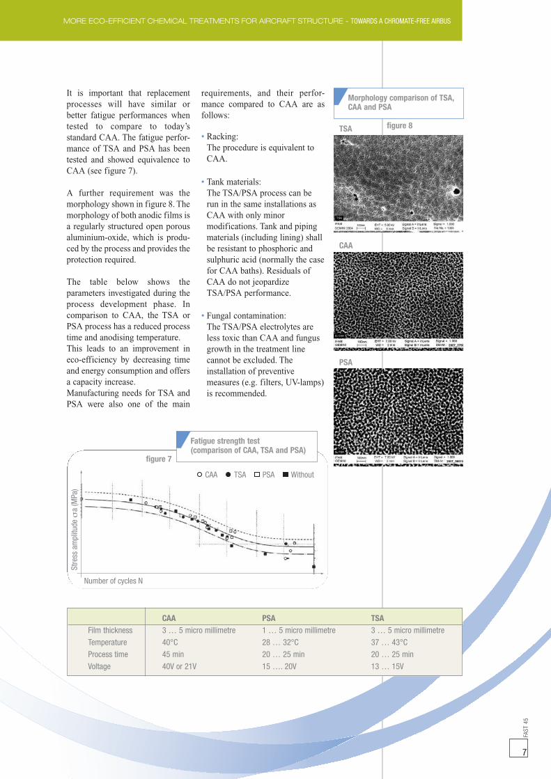
It is important that replacementprocesses will have similar orbetter fatigue performances whentested to compare to today’sstandard CAA. The fatigue perfor-mance of TSA and PSA has beentested and showed equivalence toCAA (see figure 7).
A further requirement was themorphology shown in figure 8. Themorphology of both anodic films isa regularly structured open porousaluminium-oxide, which is produ-ced by the process and provides theprotection required.
The table below shows theparameters investigated during theprocess development phase. Incomparison to CAA, the TSA orPSA process has a reduced processtime and anodising temperature.This leads to an improvement ineco-efficiency by decreasing timeand energy consumption and offersa capacity increase.Manufacturing needs for TSA andPSA were also one of the main
requirements, and their perfor-mance compared to CAA are asfollows:
• Racking:The procedure is equivalent toCAA.
• Tank materials:The TSA/PSA process can berun in the same installations asCAA with only minormodifications. Tank and pipingmaterials (including lining) shallbe resistant to phosphoric andsulphuric acid (normally the casefor CAA baths). Residuals ofCAA do not jeopardizeTSA/PSA performance.
• Fungal contamination:The TSA/PSA electrolytes areless toxic than CAA and fungusgrowth in the treatment linecannot be excluded. Theinstallation of preventivemeasures (e.g. filters, UV-lamps)is recommended.
CAA PSA TSAFilm thickness 3 … 5 micro millimetre 1 … 5 micro millimetre 3 … 5 micro millimetre
Temperature 40°C 28 … 32°C 37 … 43°C
Process time 45 min 20 … 25 min 20 … 25 min
Voltage 40V or 21V 15 …. 20V 13 … 15V
CAA TSA PSA Without
Number of cycles N
Stre
ssam
plitu
dea
(MPa
)
Fatigue strength test(comparison of CAA, TSA and PSA)
figure 7
Morphology comparison of TSA,CAA and PSA
TSA
CAA
PSA
figure 8

FAST
45
8
MORE ECO-EFFICIENT CHEMICAL TREATMENTS FOR AIRCRAFT STRUCTURE - TOWARDS A CHROMATE-FREE AIRBUS
BASIC PRIMER
A common effort between Airbusand its paint suppliers has led tosignificant progress in the struc-tural protection system in the lasttwo years. This topic has thehighest priority in the AirbusChromate-Free project.
To ensure integrity of the aircraftstructure, structural primer haschallenging requirements for long-term stability. It is planned to havechromate-free basic primerproducts ready for qualification bythe end of 2010.
The structural protection system isdivided into basic protection and atopcoat. The basic protection isperformed with TSA and a basicprimer (figure 9).
EXTERNAL PAINT
The external paint is applied onthe basic protection. chromate-freeexternal paint systems weredeveloped and qualified for A380application and are already state-of-the-art in the aerospaceindustry.The new Airbus technique bringsadditional environmental benefitsdue to the use of less solvents andfewer coats. This technique whichis similar to the one used in the car
Basic primer Internal top coatTSA
Internal top coatBasic primer
Anodising (TSA)
Structural primer + anodising (TSA) = basic protection
Aluminium alloy
Intermediate coat
External top coat
External primer
External top coatIntermediate coat (optional)
External primer
figure 9
figure 10
Structural basicprotection system
External paint systemon customized area

FAST
45
9
industry, requires just two coatswith dramatically reduced paintvolumes, and drying times downfrom 12 to two hours.A colour coat and a clear coat orvarnish, are applied onto achromate-free primer.
The process also reduces theamount of repainting and cleaningrequired during the lifetime of in-service aircraft(http://www.airbus.com/en/presscentre/pressreleases/pressreleases_items/07_12_14_eco_efficient_painting.html).
Airbus is applying the mostmodern and best eco-efficienttechniques for its aircraft paintingprocess better than the Bestavailable REFerence Technologies(BREF) defined under theEuropean Integrated PollutionPrevention and Control (IPPC)directive(http://eippcb.jrc.ec.europa.eu/).
MORE ECO-EFFICIENT CHEMICAL TREATMENTS FOR AIRCRAFT STRUCTURE - TOWARDS A CHROMATE-FREE AIRBUS
Airbus approach to introduce moreeco-efficient chemicals and processesis part of its commitment to environmentalprotection and sustainability as aresponsible leading industry. Airbusbelieves that research and implementationof more environmentally friendly optionsare not only better for the environmentitself but must be seen as a realopportunity to bring additional valuesto companies, and additionalcharacteristics for the productswe deliver to our customers.A significant step towards chromate-freehas been achieved with the replacementof Chromium VI for surface treatmentapplications: Using the new developedTSA/PSA processes, Chromium VI couldbe already reduced by approximately30%. This solution offers an improvementin eco-efficiency by decreasing timeand energy consumption and may offercapacity increase.
Taking into account the results alreadyimplemented of another 30% reductionfor the external paints, Airbus has reducedthe use of hexavalent chromium byapproximately 60% (see figure 3). Airbusroadmap to eliminate Chrome VI is on
track either in the production processesor the product involved.Thanks to major investments andmobilisation of all stakeholders, anyrelevant actions and necessary effortsto achieve its final goal to delivera completely Chrome VI free aircraftwill be undertaken through this ambitiousACF project.
Airbus will offer all newly developedchromate-free materials and processesto its suppliers, progressivelyas soon as qualified. Information as wellas required support are being consideredto help the supply chain to take all actionsfor a successful implementation withintheir own facilities.
All decided replacements would beimplemented for all aircraft and sparesto be delivered. For the A350XWB relevantsolutions will be taken into account forthe new design as appropriate. As furtherprogress will be made, Airbus will regularlyinform the customer community of thesethrough any relevant Customer Servicespublication and web site(http://www.airbus.com/en/corporate/ethics/environment/eco-news/).
Conclusion
CONTACT DETAILS
François MUSEUXExpertMaterials and TechnologiesAirbus Customer ServicesTel: +33 (0) 5 62 11 80 [email protected]
Ralf THEILMANNACF Project ManagerEngineering StructureMaterials and ProcessesAirbus EngineeringTel: +49 (42) 15 38 36 [email protected]
AIRBUS NEW AUTO PILOT/FLIGHT DIRECTOR TCAS MODE - ENHANCING FLIGHT SAFETY DURING TCAS MANOEUVRESFA
ST45
10
Paule BOTARGUESAP/FD TCAS Project Leader
Auto Flight System Research & DevelopmentMulti-Programme Project Leader
Flight Control & Automatic Flight Control systems
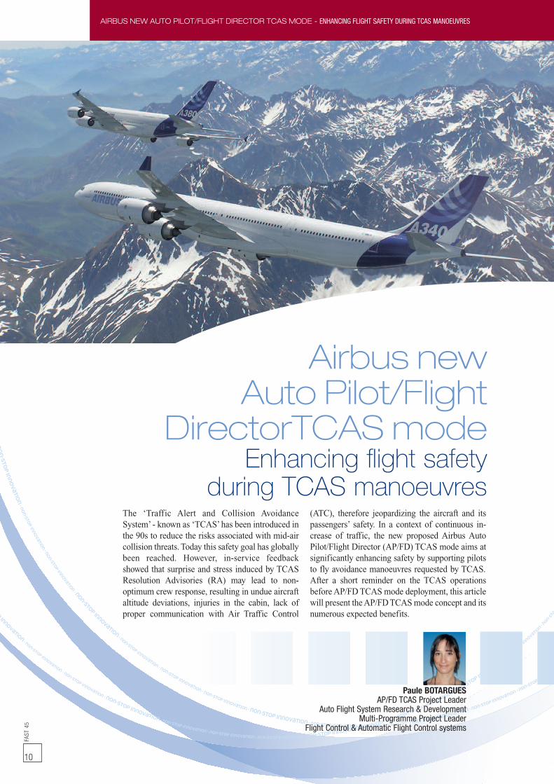
The ‘Traffic Alert and Collision AvoidanceSystem’ - known as ‘TCAS’has been introduced inthe 90s to reduce the risks associated with mid-aircollision threats. Today this safety goal has globallybeen reached. However, in-service feedbackshowed that surprise and stress induced by TCASResolution Advisories (RA) may lead to non-optimum crew response, resulting in undue aircraftaltitude deviations, injuries in the cabin, lack ofproper communication with Air Traffic Control
(ATC), therefore jeopardizing the aircraft and itspassengers’ safety. In a context of continuous in-crease of traffic, the new proposed Airbus AutoPilot/Flight Director (AP/FD) TCAS mode aims atsignificantly enhancing safety by supporting pilotsto fly avoidance manoeuvres requested by TCAS.After a short reminder on the TCAS operationsbeforeAP/FDTCAS mode deployment, this articlewill present theAP/FDTCASmode concept and itsnumerous expected benefits.
Airbus newAuto Pilot/Flight
DirectorTCASmodeEnhancing flight safety
during TCAS manoeuvres
FAST
45
11
AIRBUS NEW AUTO PILOT/FLIGHT DIRECTOR TCAS MODE - ENHANCING FLIGHT SAFETY DURING TCAS MANOEUVRES
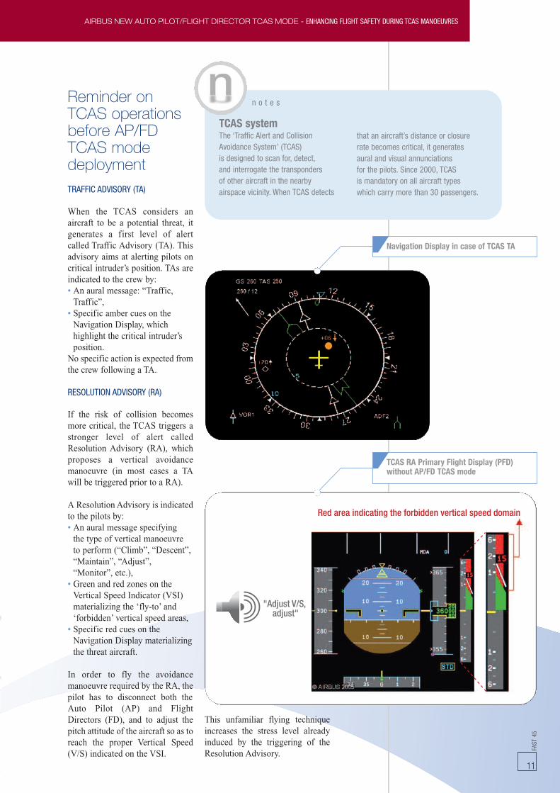
Reminder onTCAS operationsbefore AP/FDTCAS modedeploymentTRAFFIC ADVISORY (TA)
When the TCAS considers anaircraft to be a potential threat, itgenerates a first level of alertcalled Traffic Advisory (TA). Thisadvisory aims at alerting pilots oncritical intruder’s position. TAs areindicated to the crew by:• An aural message: “Traffic,Traffic”,
• Specific amber cues on theNavigation Display, whichhighlight the critical intruder’sposition.
No specific action is expected fromthe crew following a TA.
RESOLUTION ADVISORY (RA)
If the risk of collision becomesmore critical, the TCAS triggers astronger level of alert calledResolution Advisory (RA), whichproposes a vertical avoidancemanoeuvre (in most cases a TAwill be triggered prior to a RA).
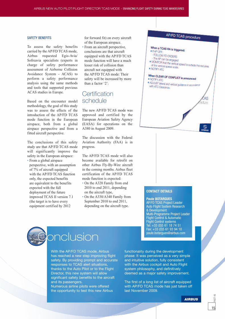
A Resolution Advisory is indicatedto the pilots by:• An aural message specifyingthe type of vertical manoeuvreto perform (“Climb”, “Descent”,“Maintain”, “Adjust”,“Monitor”, etc.),
• Green and red zones on theVertical Speed Indicator (VSI)materializing the ‘fly-to’ and‘forbidden’ vertical speed areas,
• Specific red cues on theNavigation Display materializingthe threat aircraft.
In order to fly the avoidancemanoeuvre required by the RA, thepilot has to disconnect both theAuto Pilot (AP) and FlightDirectors (FD), and to adjust thepitch attitude of the aircraft so as toreach the proper Vertical Speed(V/S) indicated on the VSI.
This unfamiliar flying techniqueincreases the stress level alreadyinduced by the triggering of theResolution Advisory.
"Adjust V/S,adjust"
Red area indicating the forbidden vertical speed domain
n o t e s
that an aircraft’s distance or closurerate becomes critical, it generatesaural and visual annunciationsfor the pilots. Since 2000, TCASis mandatory on all aircraft typeswhich carry more than 30 passengers.
TCAS systemThe ‘Traffic Alert and CollisionAvoidance System’ (TCAS)is designed to scan for, detect,and interrogate the transpondersof other aircraft in the nearbyairspace vicinity. When TCAS detects
Navigation Display in case of TCAS TA
TCAS RA Primary Flight Display (PFD)without AP/FD TCAS mode

AIRBUS NEW AUTO PILOT/FLIGHT DIRECTOR TCAS MODE - ENHANCING FLIGHT SAFETY DURING TCAS MANOEUVRESFA
ST45
12
AP/FD TCASmode conceptThe AP/FD TCAS mode conceptwas born following an in-depthanalysis of needs expressed byairline pilots, human factor studieslinked to the TCAS system andrecommendations given by airwor-thiness authorities, which high-lighted the relevance of a newmeans to support pilots flyingTCAS RA.The new AP/FD TCAS modecompletes the existing TCASfunctionality by implementing aTCAS vertical guidance featureinto the Auto Flight computer. Thisnew mode controls the VerticalSpeed (V/S) of the aircraft on avertical speed target - acquiredfrom TCAS - adapted to each RA.• With the Auto Pilot (AP)engaged, it allows the pilot to flythe TCAS RA manoeuvreautomatically,
• With the AP disengaged, thepilot can manually fly the TCASRA manoeuvre by following theFlight Director (FD) pitch barguidance.
It has to be considered as an add-on to the existing TCAS features(traffic on Navigation Display,aural alerts, vertical speed green/red zones materializing the RA onthe Vertical Speed Indicator).
In case of a TCAS RA, the AP/FDTCAS mode will automaticallytrigger:• If both AP and FD are engaged,the AP/FD vertical mode revertsto TCAS mode, which providesthe necessary guidance for theAP to automatically fly theTCAS manoeuvre,
• If the AP is disengaged and FDare engaged, the TCAS modeautomatically engages as thenew FD guidance. The FDpitch bar provides anunambiguous order to the pilot,who simply has to centre thepitch bar, to bring the V/Sof the aircraft on the V/S target(green zone),
• If both AP and FD are OFF,the FD bars will automaticallyreappear with TCAS modeguiding as above.
Depending on the kind of alerttriggered by the TCAS, the AP/FDTCAS mode will have thefollowing behaviour:
• In case of Traffic Advisory (TA),the AP/FD TCAS mode isautomatically armed, in orderto bring crew awareness on theTCAS mode engagement if theTA would turn into an RA.
• In case of corrective RA(“CLIMB”, “DESCEND”,“ADJUST”, etc. aural alerts), theaircraft vertical speed is initiallywithin the red VSI zone. Therequirement is then to fly out ofthis red zone to reach the boundaryof the red/green V/S zone.Consequently:- The TCAS vertical modeengages. It ensures a verticalguidance to a vertical speedtarget equal to the red/greenboundary value on VSI (tominimize altitude deviation)± 200 ft/min within the greenvertical speed zone, witha pitch authority increasedup to 0.3g load factor,
- All previously armed verticalmodes are automaticallydisarmed, except the altitudecapture mode (ALT*) whenthe altitude capture is compliantwith the RA (i.e. when 0 ft/mnis not within the red VSI zone,as for ‘ADJUST V/S’ RA). Inthose cases, if the altitudecapture conditions are metwhile in TCAS mode,it will allow safely capturingthe targeted flight level(see figure page 14 - Safealtitude capture with AP/FDTCAS mode),
- The Auto Thrust engagesin speed control mode(SPEED/MACH) to ensurea safe speed duringthe manoeuvre,
- The current lateral trajectoryis maintained.
n o t e s
At any time, the crew keepsthe capability to disconnectthe AP and the FD, to respondmanually to the RA by flyingaccording to the ‘conventional’TCAS procedure (i.e. manuallycontrolling the vertical speedby referring to TCAS indicationson the vertical speed scale).

FAST
45
13
AIRBUS NEW AUTO PILOT/FLIGHT DIRECTOR TCAS MODE - ENHANCING FLIGHT SAFETY DURING TCAS MANOEUVRES
• In case of preventive RA(e.g. “MONITOR V/S” auralalert), the aircraft vertical speedis initially out of the red VSIzone. The requirement is then tomaintain the current verticalspeed.Consequently:- The TCAS vertical modeengages to maintain the safecurrent aircraft vertical speedtarget,
- All previously armed verticalmodes are automaticallydisarmed, except the altitudecapture mode (ALT*).Indeed, levelling-off duringa preventive RA will alwaysmaintain the vertical speedoutside of the red VSI area.So, if the altitude captureconditions are met while theTCAS mode is engaged, it willallow to safely capture thetargeted level, thus preventingan undue altitude excursion,
- The Auto Thrust engagesin speed control mode(SPEED/MACH) to ensurea safe speed during themanoeuvre,
- The current lateral trajectoryis maintained.
• Once clear of conflict, verticalnavigation is resumed as follows:- The AP/FD vertical modereverts to the vertical speed(V/S) mode, with a smoothvertical speed target towardsthe Flight Control Unit (FCU)target altitude. The ALT(altitude) mode is armedto reach the FCU targetaltitude (Air Traffic Controlcleared altitude),
- If an altitude capture occurredin the course of a TCAS RAevent, once ‘clear of conflict’,the AP/FD vertical modereverts to the altitude capturemode (ALT*) or to the altitudehold mode (ALT),
- the current lateral trajectoryis maintained.
"Adjust V/S,adjust"
PFD upon a corrective TCAS RA with AP/FD TCAS mode
TrafficTraffic
ALT CRZ ALT CRZ
TCAS
TCAS TCAS V/S - 1000ALT
0 0 00 0 0 0
ClimbClimb
AdjustV/S
Clear ofconflict
Flight Mode Annunciator and Vertical Speed Indicatorduring a TCAS sequence with AP/FD TCAS mode

AIRBUS NEW AUTO PILOT/FLIGHT DIRECTOR TCAS MODE - ENHANCING FLIGHT SAFETY DURING TCAS MANOEUVRESFA
ST45
14
Operational andsafety benefits
OPERATIONAL BENEFITS
The operational benefits of theAP/FD TCAS mode solution arenumerous. The system addressesmost of the concerns raised by in-line experience feedback such as:• It provides an unambiguousflying order to the pilot,
• The flying order is adjusted tothe severity of the RA; it thusreduces the risks of overreactionby the crew, minimizes thedeviations from trajectoriesinitially cleared by Air TrafficControl (ATC) - preventing therisk of a new RA triggered withanother aircraft and adapts theload factor of the manoeuvre,
• It prevents undue altitudecrossing when altitude captureis compliant with the RA(see figure below),
• The availability of the AP/FDTCAS mode makes it possibleto define simple proceduresfor the aircrews, eliminating anydisruption in their flying
technique when a RA isreceived. Indeed the pilotno longer needs to disengagethe Auto Pilot or Flight Directorsbefore conducting the TCASmanoeuvres.When the TCAS mode engages,the procedure simply consists inletting the Auto Pilot conduct theavoidance manoeuvre (if AutoPilot engaged) or in manualflying the FD bars, whichsmoothly guides on the propervertical speed target. The VSIbecoming in both cases a‘monitoring’ device, it allowschecking that the proposedTCAS guidance properly leads ormaintains the aircraft’s verticalspeed outside the red VSI zone.
By reducing the crew’s workloadand stress level, the AP/FD TCASmode should therefore significantlyreduce:• Inappropriate reactions in caseof RA (late, over, or oppositereactions),
• Misbehaviours when ‘clear ofconflict’,
• Lack of adequate communicationswith ATC.
CLBALT
CLBALT
TCAS
TCASALT
TCASALT
ALT*
0 0
0
Clear ofconflict
Adjust V/S
Safety margin increased
Sub-mode ALT*
TCAS mode initially reduces the V/Sand then captures the ALT level selected
FL 260 (selected level)
FL 270
TrafficTraffic
n o t e s
For Air Traffic Controllers (ATC)the AP/FD TCAS modeis totally transparent in termsof expected aircraft reactions.
Safe altitude capturewith AP/FD TCAS mode
15
FAST
45
15
With the AP/FD TCAS mode, Airbushas reached a new step improving flightsafety. By providing prompt and accurateresponses to TCAS alert situations,thanks to the Auto Pilot or to the FlightDirector, this new system will allowsignificant safety benefits to the aircraftand its passengers.Numerous airline pilots were offeredthe opportunity to test this new Airbus
functionality during the developmentphase: It was perceived as a very simpleand intuitive solution, fully consistentwith the Airbus cockpit and Auto Flightsystem philosophy, and definitivelydeemed as a major safety improvement.
The first of a long list of aircraft equippedwith AP/FD TCAS mode has just taken offlast November 2009.
Conclusion
CONTACT DETAILS
Paule BOTARGUESAP/FD TCAS Project LeaderAuto Flight System Research& DevelopmentMulti-Programme Project LeaderFlight Control & AutomaticFlight Control systemsTel: +33 (0)5 61 18 74 51Fax: +33 (0)5 61 93 94 [email protected]
AIRBUS NEW AUTO PILOT/FLIGHT DIRECTOR TCAS MODE - ENHANCING FLIGHT SAFETY DURING TCAS MANOEUVRES
SAFETY BENEFITS
To assess the safety benefitscarried by the AP/FD TCAS mode,Airbus requested Egis-Avia/Sofreavia specialists (experts incharge of safety performanceassessment of Airborne CollisionAvoidance System - ACAS) toperform a safety performanceanalysis using the same methodsand tools that supported previousACAS studies in Europe.
Based on the encounter modelmethodology, the goal of this studywas to assess the effects of theintroduction of the AP/FD TCASmode function in the Europeanairspace, both from a globalairspace perspective and from afitted aircraft perspective.
The conclusions of this safetystudy are that AP/FD TCAS modewill significantly improve thesafety in the European airspace:• From a global airspaceperspective, with an assumptionof 7% of aircraft equippedwith the AP/FD TCAS functiononly, the expected benefitsare equivalent to the benefitsexpected with the fulldeployment of the futureimproved TCAS II version 7.1(the target is to have everyequipment certified by 2012
for forward fit) on every aircraftof the European airspace.
• From an aircraft perspective,conclusions are that aircraftequipped with the AP/FD TCASmode function will have a muchlesser risk of collision thanaircraft not equipped withthe AP/FD TCAS mode: Theirsafety will be increased by morethan a factor ‘2’.
CertificationscheduleThe new AP/FD TCAS mode wasapproved and certified by theEuropean Aviation Safety Agency(EASA) for operations on theA380 in August 2009.
The discussion with the FederalAviation Authority (FAA) is inprogress.
The AP/FD TCAS mode will alsobecome available for retrofit onother Airbus Fly-By-Wire aircraftin the coming months. Airbus fleetcertification of the AP/FD TCASmode function is expected:• On the A320 Family from end2010 to end 2011, dependingon the aircraft type,
• On the A330/A340 Family fromSeptember 2010 to end 2011,depending on the aircraft type.

A320 FAMILY AIR & BLEED WORKING GROUP ACTIVITIES - FROM ENGINEERING TO AIRLINE CULTUREFA
ST45
16
Gilles JUANGroup Manager
Air Conditioning Systems/EngineeringAirbus Customer Services
Claire AMSELLEMEngineerPneumatics, Ice and FireProtection SystemsAirbus Customer Services
A320 FamilyAir & Bleed working
group activitiesFrom engineering to airline cultureThe bleed air and the air conditioning systems areamong the drivers of Operational Interruptions(OI). Improving their respective reliabilityperformances was the A320 Family main issuepriority set by the operators to Airbus. Thisobjective was achieved thanks to the 3D concept“Discuss, Decide, Deliver” and to the associated“work together” which involved suppliers, Airbusand the aircraft operators (including aircraftmaintenance). The discussion was expected toonly be technical but it quickly appeared that theparamount need of the airlines was the ability to
quantify the returns on their investments, andabove all, the ability to assess the impacts. Thanksto these working groups, the airlines are now ableto use economic assessments from Airbus basedon rates of OI as a decision tool for solutionselections. This clearly shows the Airbus movefrom an engineering culture to an airline culture.The following article describes the work achieved toselect the best solutions and describes what hasbeen learnt from this very pragmatic, innovative andcollaborative approach praised by Airbusoperators.

FAST
45
17
A320 FAMILY AIR & BLEED WORKING GROUP ACTIVITIES - FROM ENGINEERING TO AIRLINE CULTURE
To aircraft systems
BMC
PCE
OVERBOARD
TCT
FAVOPV
TO STARTERVALVE
pylonNacelle
PRV
IPCV
FAN
IPHP
HPV
TLTTemp
Bleed air systemdescriptionThe bleed air system gets air fromthe pneumatic air sources (aircraftengines, Auxiliary Power UnitAPU and ground air source) andsupplies the air regulated inpressure and temperature throughducts to the user systems (wing iceprotection, air conditioning, enginestarting, hydraulic reservoirpressurization and pressurizedwater). The bleed air system isinstalled in the nacelle and pylon ofeach engine as decribed in figure 1.
Air Conditioning System description
g l o s s a r y
For the pressure regulation:IPCV: Intermediate Pressure bleedCheck Valve (IPCV)HPV: High Pressure bleed ValveOPV: Over Pressure ValvePRV: Pressure Regulator bleed Valvecommanded by a TLT (TemperatureLimitation Thermostat)
For the temperature regulation:PCE: Pre-Cooler ExchangerFAV: Fan Air Valvecommanded by a TCT (TemperatureControl Thermostat)
For the system monitoring:BMC: Bleed Monitoring Computer
figure 1
A320 FAMILY AIR & BLEED WORKING GROUP ACTIVITIES - FROM ENGINEERING TO AIRLINE CULTURE
The reason forthese workinggroup activitiesThe air conditioning system(ATA21) and the bleed air system(ATA36) are subject to a highnumber of Operational Inter-ruptions (OI).
An OI is a technical delay that isgreater than 15 minutes. It includesflight diversions, in-flight turnbacks and aborted take-offs.Since the A320 Family Entry-Into-Service in 1988, many efforts havebeen made and the benefits of newtechnologies have been taken intoconsideration to design more robustand simplified systems. This isreflected in the positive OI trend ataircraft level, but can still beimproved at some systems’ levelwhich was the purpose of theworking group.
Engineeringculture versusairline culture fora better OI trendWith an engineering approach,each time an in-service issue arisesand requires an improvement, thenecessary engineering work aimsat proposing the best technicalsolution. Some of the keyquestions such as “What is thecost?”, “What are the realbenefits?” that an airline will haveare not fully answered. Manysolutions which would help toimprove the systems’ reliabilityperformances are then not selectedby the airlines. Time and moneyare spent by Airbus and thesuppliers for poor benefits.
A ‘working together’ approachwhich encompasses all aspects(technical, economical, etc.) hasbeen required to satisfy all of theinvolved parties and it is presentlywhat this working group hashighlighted.
Working processThe first innovation consisted ininvolving aircraft operators, morethan ever, in the setting of theworking group objectives, as wellas defining and validating theperformance objectives.
An important step was theacknowledgement that improvingthe systems’ performance was notonly a matter of upgrading thesystem components, under thesuppliers’ responsibility, but alsoimproving the system integrationin the aircraft, under Airbusleadership, in the manner thesystem is operated and maintainedby the aircraft operators. It wassoon understood that sharingexperience and combining effortsof the three main stakeholders(airlines, suppliers andAirbus) wasa key condition of success.
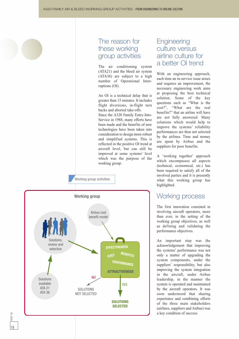
Working group
Solutions,review andselection EFFECTIVENESS
COSTBENEFITS
PERFORMANCE
ATTRACTIVENESS
Airbus costbenefit model
SolutionsavailableATA 21ATA 36
NO
YES
SOLUTIONSSELECTED
SOLUTIONSNOT SELECTED
Working group activities
FAST
45
18
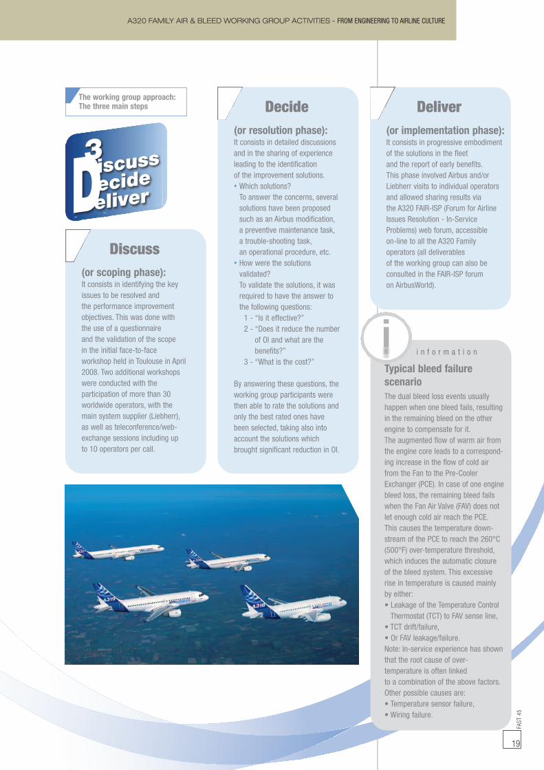
(or implementation phase):It consists in progressive embodimentof the solutions in the fleetand the report of early benefits.This phase involved Airbus and/orLiebherr visits to individual operatorsand allowed sharing results viathe A320 FAIR-ISP (Forum for AirlineIssues Resolution - In-ServiceProblems) web forum, accessibleon-line to all the A320 Familyoperators (all deliverablesof the working group can also beconsulted in the FAIR-ISP forumon AirbusWorld).
A320 FAMILY AIR & BLEED WORKING GROUP ACTIVITIES - FROM ENGINEERING TO AIRLINE CULTURE
(or scoping phase):It consists in identifying the keyissues to be resolved andthe performance improvementobjectives. This was done withthe use of a questionnaireand the validation of the scopein the initial face-to-faceworkshop held in Toulouse in April2008. Two additional workshopswere conducted with theparticipation of more than 30worldwide operators, with themain system supplier (Liebherr),as well as teleconference/web-exchange sessions including upto 10 operators per call.
(or resolution phase):It consists in detailed discussionsand in the sharing of experienceleading to the identificationof the improvement solutions.• Which solutions?To answer the concerns, severalsolutions have been proposedsuch as an Airbus modification,a preventive maintenance task,a trouble-shooting task,an operational procedure, etc.
• How were the solutionsvalidated?To validate the solutions, it wasrequired to have the answer tothe following questions:1 - “Is it effective?”2 - “Does it reduce the number
of OI and what are thebenefits?”
3 - “What is the cost?”
By answering these questions, theworking group participants werethen able to rate the solutions andonly the best rated ones havebeen selected, taking also intoaccount the solutions whichbrought significant reduction in OI.
Discuss
Decide DeliverThe working group approach:The three main steps
i n f o r m a t i o n
The dual bleed loss events usuallyhappen when one bleed fails, resultingin the remaining bleed on the otherengine to compensate for it.The augmented flow of warm air fromthe engine core leads to a correspond-ing increase in the flow of cold airfrom the Fan to the Pre-CoolerExchanger (PCE). In case of one enginebleed loss, the remaining bleed failswhen the Fan Air Valve (FAV) does notlet enough cold air reach the PCE.This causes the temperature down-stream of the PCE to reach the 260°C(500°F) over-temperature threshold,which induces the automatic closureof the bleed system. This excessiverise in temperature is caused mainlyby either:• Leakage of the Temperature ControlThermostat (TCT) to FAV sense line,
• TCT drift/failure,• Or FAV leakage/failure.Note: In-service experience has shownthat the root cause of over-temperature is often linkedto a combination of the above factors.Other possible causes are:• Temperature sensor failure,• Wiring failure.
Typical bleed failurescenario
FAST
45
19

A320 FAMILY AIR & BLEED WORKING GROUP ACTIVITIES - FROM ENGINEERING TO AIRLINE CULTUREFA
ST45
20
Solution
OI gain %(ROM)
Root cause
Consequence
Modificationcontents
1 3
Preventivemaintenance
FCV 751 seriesoverhaul/softime
2
Request forpreventive maintenance
to anticipateFCV failure
If failure beforetake-off deactivation
of the valvein closed position
Different intervals forpreventive maintenancedefined with associatedbenefits. Choice given
to select the mostappropriate interval
1
2
Operationalprocedure
AEVC circuitbreaker procedure
2 to 3
AVNCS SYS FAULTon ground
without failure messageduring electricalpower transfer
Aircraft return to gatefor trouble-shooting
to allowaircraft dispatch
C/B reset from cockpitas per FCOM to avoidaircraft return to gate.
Procedure only applicableon ground
4
Airbusdocumentation
Preventivebleed system health check
monitoring procedure
10
Procedureto anticipate bleedfailure in order toperform preventive
maintenance
Aircraft return to gatefor trouble-shooting
to allow aircraft dispatchOperational restrictions
for next flight
AMM and TSM tasksfor detailed testingof each component
of the EBAS includingthe sense lines for
minor leakage
Aircraftmodification
TAPRV pressuretapping port modification
2
Presence of waterinside the valvedue to wateraccumulationinto the duct.
Valve cannot open
Inability to regulatean optimized cabin
temperaturewith possibility of
passengers discomfort
Modification developedby one operator and
proven effective. Modificationof the tapping port to avoid
valve water ingress
Liquid water
Solutions selectedThe solutions selected by theworking group fall into four maincategories:• Airbus modification,• Components preventivemaintenance,
• Airbus documentation,• Operational procedure.
SOME EXAMPLES OF SELECTEDSOLUTIONS:
g l o s s a r y
AEVC: Avionics Equipment Ventilation ControllerAVNCS SYS FAULT: Avionics System FaultAMM: Aircraft Maintenance ManualC/B: Circuit BreakerEBAS: Engine Bleed Air SystemFCOM: Flight Crew Operation Manual
FCV: Flow Control ValveOI: Operational InterruptionROM: Rough Order of MagnitudeTAPRV: Trim Air Pressure Regulating ValveTSM: Trouble-Shooting Manual

21
FAST
45
21
To reduce the number of OperationalInterruptions (OI) caused by bleed airand air conditioning systems, solutionpackages are proposed taking intoaccount technical and economicembodiment decision data. This has beenachieved thanks to the combinationof an innovative way of working altogetherwith airlines, suppliers and Airbus, whileimplementing an innovative approachto in-service issues. The working grouppackages allow individual customization
of solutions for a given operator.All individual solutions are documented(SIL 21-152 and SIL 36-057) and Airbushas the capability to perform customizedcomputation of the cost/benefit resultsfor each individual situation, upon request.These positive results have led customersto request Airbus to launch similarinitiatives in other aircraft areas. Workinggroups on ATA 27 (Flight Controls)and ATA 29 (Hydraulics) were such aslaunched in December 2009.
Conclusion
A320 FAMILY AIR & BLEED WORKING GROUP ACTIVITIES - FROM ENGINEERING TO AIRLINE CULTURE
Bleed air system packages
CONTACT DETAILS
Gilles JUANGroup ManagerAir ConditioningSystems/EngineeringAirbus Customer ServicesTel: +33 (0)5 52 11 02 90Fax: +33 (0)5 61 93 44 [email protected]
Achievementsand deliverablesThird significant innovation wasthe idea of packaging the solutions.This was done for two reasons.The first reason is technical: Somesolutions complement each otherand embodying them all at onceprovides more benefits than withthe simple sum of each solution.The second reason is all aboutdecision making: The ‘Air & BleedWorking Group’ packages aredefined in such way that operatorscan decide for a small effort andcan hope a reasonable performanceimprovement with a short paybackperiod, or they can go for a largereffort and expect a greaterperformance improvement with alonger ‘payback’ period (seepackages in chart).
Lessons learntand added valueBefore the launch of the workinggroup, activities were alreadyrunning between airlines andAirbus to find the proper means toinform about the cost and thebenefits of a given solution.‘WISE Main Adopted Solutionsand Tips’, also called MASTER,has been developed and is nowavailable to the airlines throughAirbusWorld.
MASTER provides ‘Top FleetSolutions’ that increase aircraftavailability and reduce operatingcosts. These MASTER solutionsare:• Technically proven:Demonstrated by actualin-service experience,
• Economically efficient:Demonstrated through a costbenefit model with a paybackperiod of less than five years,
• Widely applicable:Embodiment possible on a largenumber of aircraft.
50
30
40
60
20
10
70
Less than 1 year
13.7 %
29.7 %
42 %
64.5 %
Operational Interruptionsreduction level(fleet average)
ATA36 configuration 1(MSN below #900)
LOW
MEDIUM LOW
MEDIUM HIGH
HIGH
TARGET
Between 2 to 4 years
PAYBACK PERIOD
More than 5 years
PRV upgrade, PRV graphite seals, HPV upgrade, PRV graphite seals,TCT upgrade (DBL), TLT shifting (DBL), Maintenance procedures
HPV and PRVscheduled
maintenance
New bleedsystem
HPV solenoid change, Bleed system trainingHealth check monitoring
PRV: Pressure Regulating ValveHPV: High Pressure ValveTCT: Temperature Control ThermostatTLT: Temperature Limitation ThermostatDBL: Dual Bleed Loss
A300-600 EXTENDED SERVICE GOAL - ENABLING LONGER LASTING OPERATIONFA
ST45
22
Jean-Michel PASCUALPart 2: SystemsDeputy Head of SystemsA300/A310 Family ProgrammeAirbus Engineering
André DELANNOYPart 1: Structures
Manager Design and AnalysisA300/A310 & A330/A340 Families
Programmes/CoC StructureAirbus Engineering
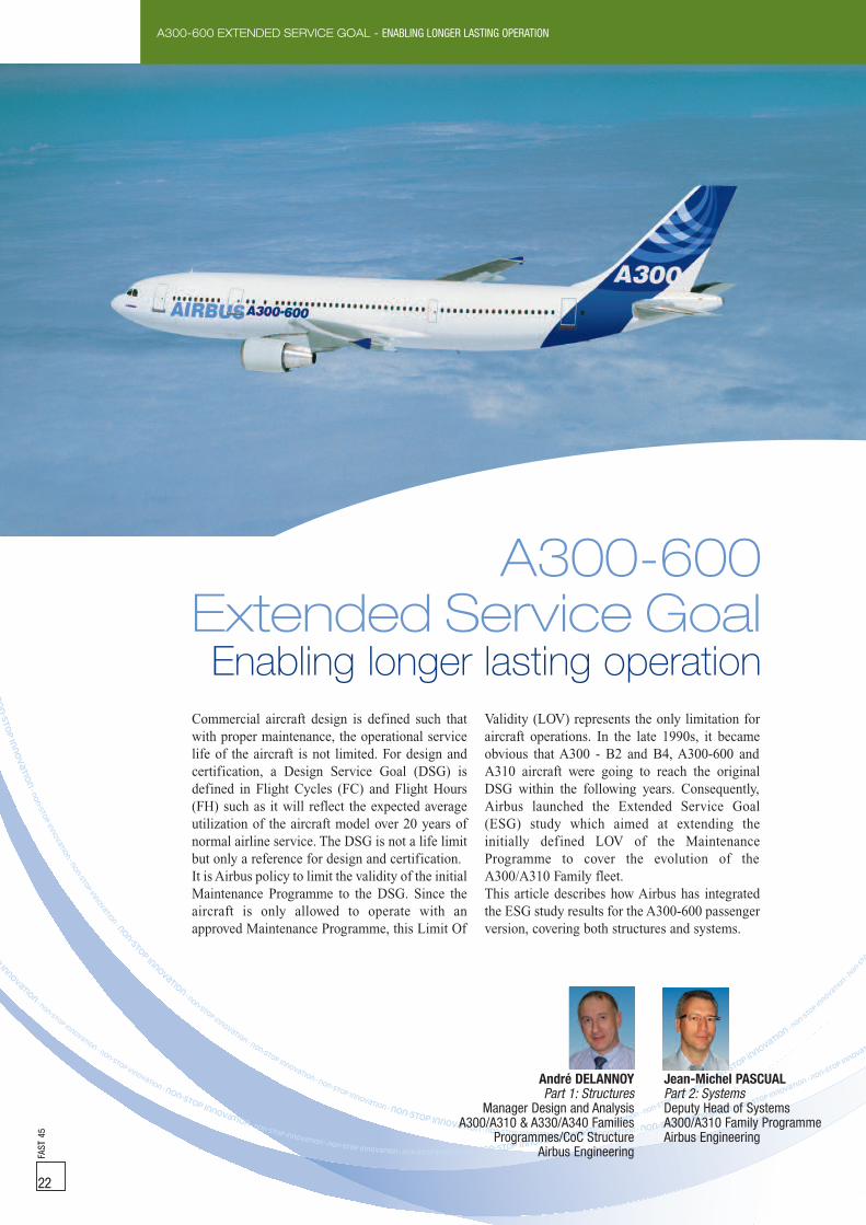
Commercial aircraft design is defined such thatwith proper maintenance, the operational servicelife of the aircraft is not limited. For design andcertification, a Design Service Goal (DSG) isdefined in Flight Cycles (FC) and Flight Hours(FH) such as it will reflect the expected averageutilization of the aircraft model over 20 years ofnormal airline service. The DSG is not a life limitbut only a reference for design and certification.It is Airbus policy to limit the validity of the initialMaintenance Programme to the DSG. Since theaircraft is only allowed to operate with anapproved Maintenance Programme, this Limit Of
Validity (LOV) represents the only limitation foraircraft operations. In the late 1990s, it becameobvious that A300 - B2 and B4, A300-600 andA310 aircraft were going to reach the originalDSG within the following years. Consequently,Airbus launched the Extended Service Goal(ESG) study which aimed at extending theinitially defined LOV of the MaintenanceProgramme to cover the evolution of theA300/A310 Family fleet.This article describes how Airbus has integratedthe ESG study results for the A300-600 passengerversion, covering both structures and systems.
A300-600Extended Service Goal
Enabling longer lasting operation
FAST
45
22
A300-600 EXTENDED SERVICE GOAL - ENABLING LONGER LASTING OPERATION
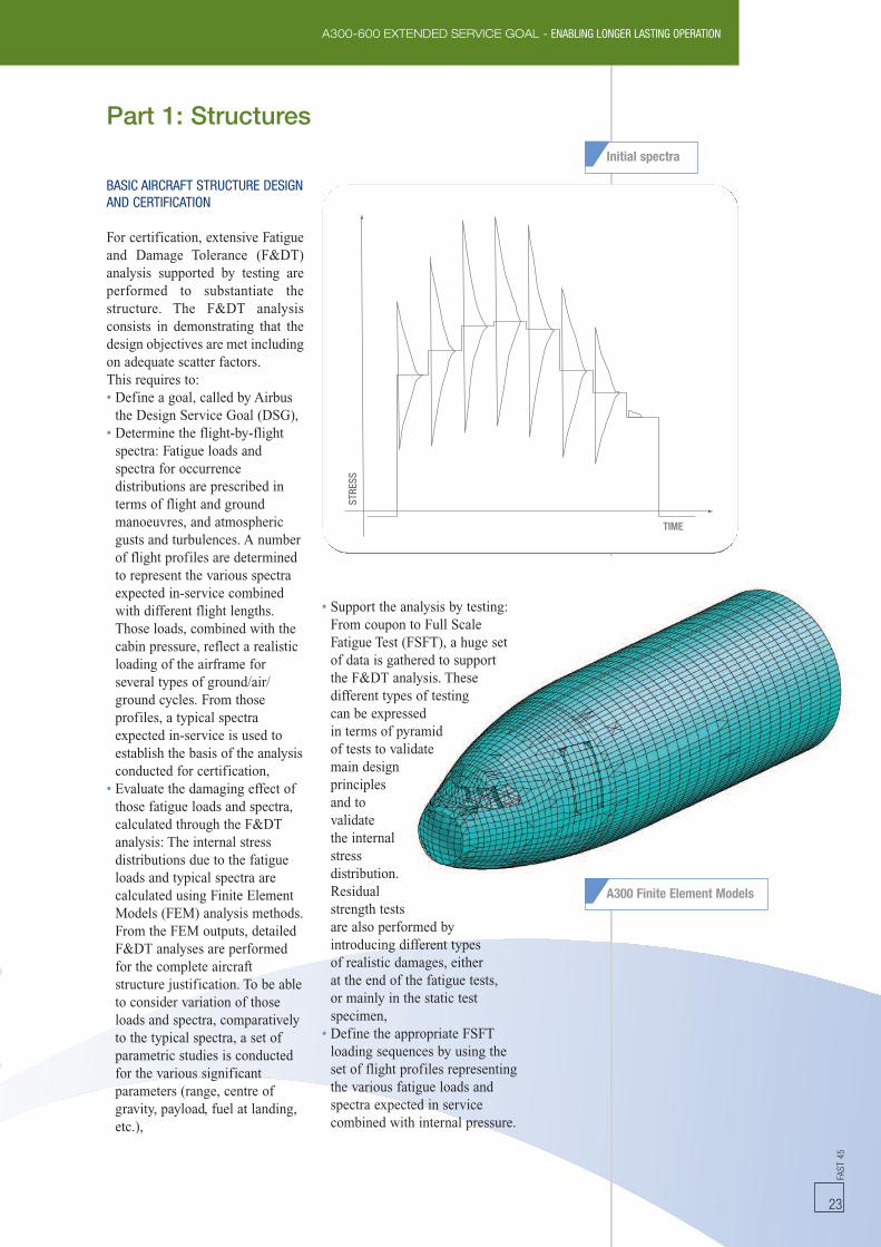
Initial spectra
Part 1: Structures
STRE
SS
TIME
FAST
45
23
BASIC AIRCRAFT STRUCTURE DESIGNAND CERTIFICATION
For certification, extensive Fatigueand Damage Tolerance (F&DT)analysis supported by testing areperformed to substantiate thestructure. The F&DT analysisconsists in demonstrating that thedesign objectives are met includingon adequate scatter factors.This requires to:• Define a goal, called by Airbusthe Design Service Goal (DSG),
• Determine the flight-by-flightspectra: Fatigue loads andspectra for occurrencedistributions are prescribed interms of flight and groundmanoeuvres, and atmosphericgusts and turbulences. A numberof flight profiles are determinedto represent the various spectraexpected in-service combinedwith different flight lengths.Those loads, combined with thecabin pressure, reflect a realisticloading of the airframe forseveral types of ground/air/ground cycles. From thoseprofiles, a typical spectraexpected in-service is used toestablish the basis of the analysisconducted for certification,
• Evaluate the damaging effect ofthose fatigue loads and spectra,calculated through the F&DTanalysis: The internal stressdistributions due to the fatigueloads and typical spectra arecalculated using Finite ElementModels (FEM) analysis methods.From the FEM outputs, detailedF&DT analyses are performedfor the complete aircraftstructure justification. To be ableto consider variation of thoseloads and spectra, comparativelyto the typical spectra, a set ofparametric studies is conductedfor the various significantparameters (range, centre ofgravity, payload, fuel at landing,etc.),
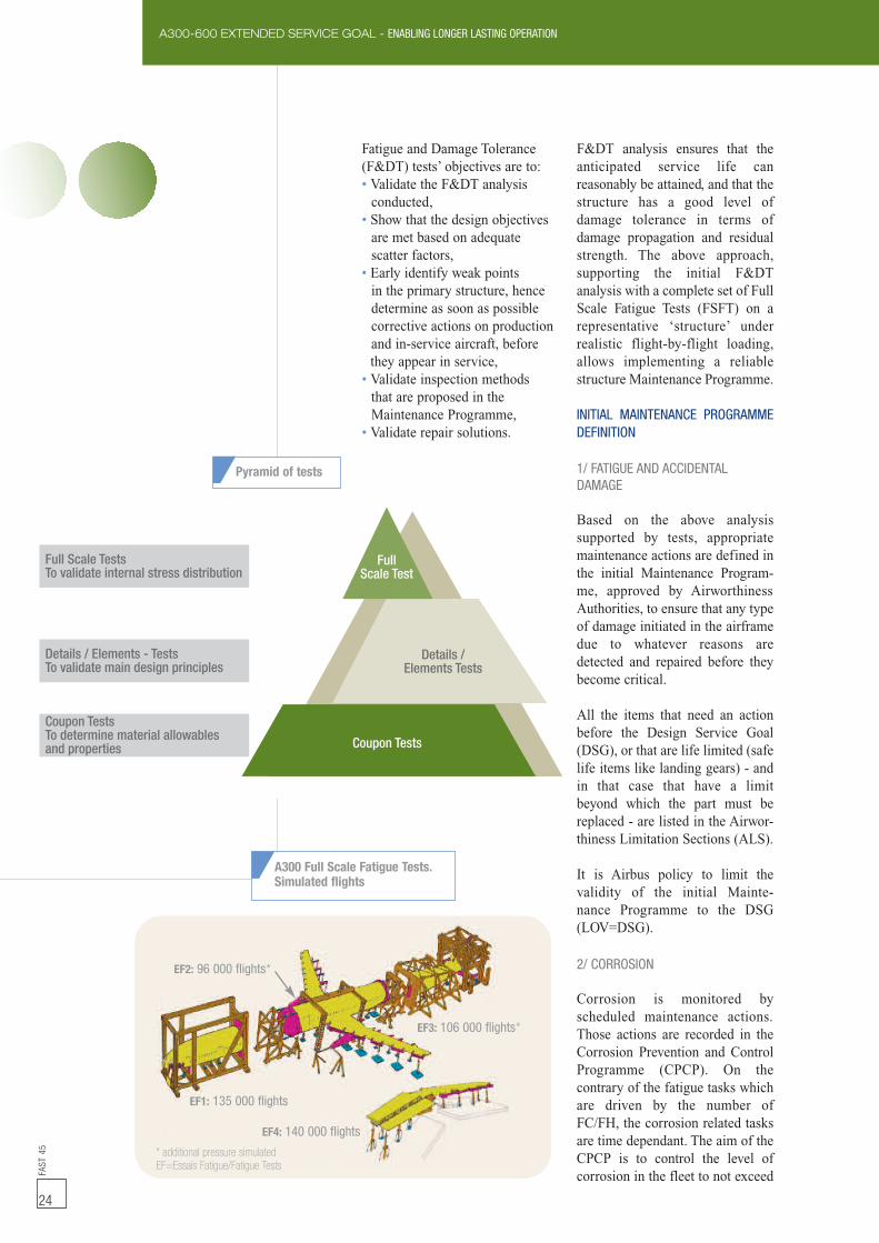
• Support the analysis by testing:From coupon to Full ScaleFatigue Test (FSFT), a huge setof data is gathered to supportthe F&DT analysis. Thesedifferent types of testingcan be expressedin terms of pyramidof tests to validatemain designprinciplesand tovalidatethe internalstressdistribution.Residualstrength testsare also performed byintroducing different typesof realistic damages, eitherat the end of the fatigue tests,or mainly in the static testspecimen,
• Define the appropriate FSFTloading sequences by using theset of flight profiles representingthe various fatigue loads andspectra expected in servicecombined with internal pressure.
A300 Finite Element Models
FAST
45
24
A300-600 EXTENDED SERVICE GOAL - ENABLING LONGER LASTING OPERATION
Fatigue and Damage Tolerance(F&DT) tests’ objectives are to:• Validate the F&DT analysisconducted,
• Show that the design objectivesare met based on adequatescatter factors,
• Early identify weak pointsin the primary structure, hencedetermine as soon as possiblecorrective actions on productionand in-service aircraft, beforethey appear in service,
• Validate inspection methodsthat are proposed in theMaintenance Programme,
• Validate repair solutions.
F&DT analysis ensures that theanticipated service life canreasonably be attained, and that thestructure has a good level ofdamage tolerance in terms ofdamage propagation and residualstrength. The above approach,supporting the initial F&DTanalysis with a complete set of FullScale Fatigue Tests (FSFT) on arepresentative ‘structure’ underrealistic flight-by-flight loading,allows implementing a reliablestructure Maintenance Programme.
INITIAL MAINTENANCE PROGRAMMEDEFINITION
1/ FATIGUE AND ACCIDENTALDAMAGE
Based on the above analysissupported by tests, appropriatemaintenance actions are defined inthe initial Maintenance Program-me, approved by AirworthinessAuthorities, to ensure that any typeof damage initiated in the airframedue to whatever reasons aredetected and repaired before theybecome critical.
All the items that need an actionbefore the Design Service Goal(DSG), or that are life limited (safelife items like landing gears) - andin that case that have a limitbeyond which the part must bereplaced - are listed in the Airwor-thiness Limitation Sections (ALS).
It is Airbus policy to limit thevalidity of the initial Mainte-nance Programme to the DSG(LOV=DSG).
2/ CORROSION
Corrosion is monitored byscheduled maintenance actions.Those actions are recorded in theCorrosion Prevention and ControlProgramme (CPCP). On thecontrary of the fatigue tasks whichare driven by the number ofFC/FH, the corrosion related tasksare time dependant. The aim of theCPCP is to control the level ofcorrosion in the fleet to not exceed
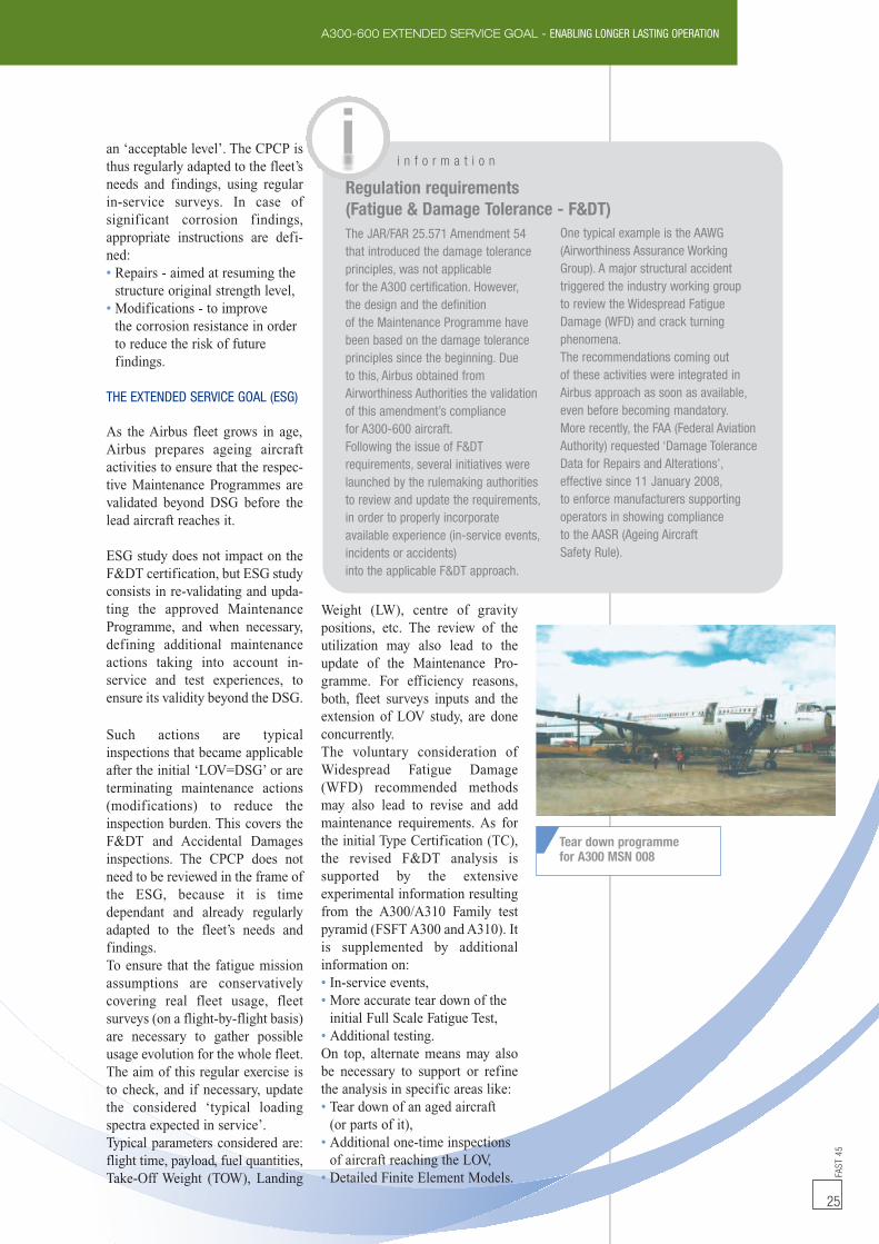
EF2: 96 000 flights*
EF3: 106 000 flights*
EF4: 140 000 flights
EF1: 135 000 flights
* additional pressure simulatedEF=Essais Fatigue/Fatigue Tests
A300 Full Scale Fatigue Tests.Simulated flights
FullScale Test
Details /Elements Tests
Coupon Tests
Full Scale TestsTo validate internal stress distribution
Details / Elements - TestsTo validate main design principles
Coupon TestsTo determine material allowablesand properties
Pyramid of tests
FAST
45
25
A300-600 EXTENDED SERVICE GOAL - ENABLING LONGER LASTING OPERATION
Tear down programmefor A300 MSN 008
i n f o r m a t i o n
The JAR/FAR 25.571 Amendment 54that introduced the damage toleranceprinciples, was not applicablefor the A300 certification. However,the design and the definitionof the Maintenance Programme havebeen based on the damage toleranceprinciples since the beginning. Dueto this, Airbus obtained fromAirworthiness Authorities the validationof this amendment’s compliancefor A300-600 aircraft.Following the issue of F&DTrequirements, several initiatives werelaunched by the rulemaking authoritiesto review and update the requirements,in order to properly incorporateavailable experience (in-service events,incidents or accidents)into the applicable F&DT approach.
One typical example is the AAWG(Airworthiness Assurance WorkingGroup). A major structural accidenttriggered the industry working groupto review the Widespread FatigueDamage (WFD) and crack turningphenomena.The recommendations coming outof these activities were integrated inAirbus approach as soon as available,even before becoming mandatory.More recently, the FAA (Federal AviationAuthority) requested ‘Damage ToleranceData for Repairs and Alterations’,effective since 11 January 2008,to enforce manufacturers supportingoperators in showing complianceto the AASR (Ageing AircraftSafety Rule).
Regulation requirements(Fatigue & Damage Tolerance - F&DT)
an ‘acceptable level’. The CPCP isthus regularly adapted to the fleet’sneeds and findings, using regularin-service surveys. In case ofsignificant corrosion findings,appropriate instructions are defi-ned:• Repairs - aimed at resuming thestructure original strength level,
• Modifications - to improvethe corrosion resistance in orderto reduce the risk of futurefindings.
THE EXTENDED SERVICE GOAL (ESG)
As the Airbus fleet grows in age,Airbus prepares ageing aircraftactivities to ensure that the respec-tive Maintenance Programmes arevalidated beyond DSG before thelead aircraft reaches it.
ESG study does not impact on theF&DT certification, but ESG studyconsists in re-validating and upda-ting the approved MaintenanceProgramme, and when necessary,defining additional maintenanceactions taking into account in-service and test experiences, toensure its validity beyond the DSG.
Such actions are typicalinspections that became applicableafter the initial ‘LOV=DSG’ or areterminating maintenance actions(modifications) to reduce theinspection burden. This covers theF&DT and Accidental Damagesinspections. The CPCP does notneed to be reviewed in the frame ofthe ESG, because it is timedependant and already regularlyadapted to the fleet’s needs andfindings.To ensure that the fatigue missionassumptions are conservativelycovering real fleet usage, fleetsurveys (on a flight-by-flight basis)are necessary to gather possibleusage evolution for the whole fleet.The aim of this regular exercise isto check, and if necessary, updatethe considered ‘typical loadingspectra expected in service’.Typical parameters considered are:flight time, payload, fuel quantities,Take-Off Weight (TOW), Landing
Weight (LW), centre of gravitypositions, etc. The review of theutilization may also lead to theupdate of the Maintenance Pro-gramme. For efficiency reasons,both, fleet surveys inputs and theextension of LOV study, are doneconcurrently.The voluntary consideration ofWidespread Fatigue Damage(WFD) recommended methodsmay also lead to revise and addmaintenance requirements. As forthe initial Type Certification (TC),the revised F&DT analysis issupported by the extensiveexperimental information resultingfrom the A300/A310 Family testpyramid (FSFTA300 andA310). Itis supplemented by additionalinformation on:• In-service events,• More accurate tear down of theinitial Full Scale Fatigue Test,
• Additional testing.On top, alternate means may alsobe necessary to support or refinethe analysis in specific areas like:• Tear down of an aged aircraft(or parts of it),
• Additional one-time inspectionsof aircraft reaching the LOV,
• Detailed Finite Element Models.

UPS: United Parcel Services - FDX: Federal Express - GF: General Freighter * ESGFAST
45
26
A300-600 EXTENDED SERVICE GOAL - ENABLING LONGER LASTING OPERATION
Centre section tear down - example: Landing gear attachment
Current approved LOV basedon F&DT analysis and testing
Aircraft type series DSG Limit of Validity (LOV)
A300 B2 48,000FC / 51,840FH 60,000FC / 65,000FH*
B4-100 40,000FC / 53,200FH 57,000FC / 76,000FH*
B4-200 34,000FC / 70,720FH 57,000FC / 118,000FH*
A310 -200 30,000FC / 67,500FH 45,000FC / 105,000FH*
-300 40,000FC / 60,000FH 40,000FC / 116,000FH
A300B4-600/B4-600 R (passenger aircraft) 35,000FC / 60000FH 42,500FC / 89,000FH*
A300-600 pax + C4-600, C4-600R variant F, 30,000FC / 67,500FH 42,500FC / 89,000FH*F4-605R Pre mod 12699 (FDX1)
A300F4-600R EIS > 2000 (UPS, GF & FDX2) 30,000FC / 67,500FH 30,000FC / 67,500FH*
For operations beyond the DesignService Goal (DSG), Airbuscommitted to demonstrate:• The continuous validity of theMaintenance Programme,
• That Widespread FatigueDamage (WFD) is not expectedto occur, following therecommendations of theAirworthiness AssuranceWorking Group (AAWG) anddraft NPA20-10/AC91-56B, andin anticipation of regulatorytexts.
The first Extended Service Goal(ESG1) study was launched in thelate 1990s, with the aim to protectthe A300 and A300-600 fleetbeyond 2002. Results of this studywere presented to the operators in2002. A310 ESG has beendeveloped, and presented to theope-rators in 2005.
All these life extension activitiesconducted on the variousA300/A310 Family models allo-wed to increase the Limit ofValidity (LOV) of the certifiedMaintenance Programmes beyondthe initial DSG.
ESG2 activity has been launchedfor the A300-600 passenger modelto preserve fleet operations beyond2011. It aims at extending thecurrent LOV to 1000FC/89000FH.Existing F&DT analysis, FSFTtear down findings, additionaltesting and tear down of retiredaircraft parts, refined FiniteElement Models, together with in-service experience, were used tosupport the refined analysisconducted to validate and updatethe Maintenance Programme de-monstration up to the new LOV=ESG2.

A300-600 EXTENDED SERVICE GOAL - ENABLING LONGER LASTING OPERATION
FAST
45
27
STRE
SS
TIME
REVISED LOADS AND REFINEDSPECTRA
New fleet surveys have beencarried out resulting in particularin an increase of fuel at landing of2.5 tons on passenger aircraft. Animproved spectra has been defined,with the aim to refine Fatigue andDamage Tolerance (F&DT) analy-sis of ground perturbations, lateralgust and dynamic landings,especially on Centre Wing Box,consi-dering experience fromrecent other programmes.
ADDITIONAL TESTING ANDSTRUCTURAL PARTS TEAR DOWN
ESG2 study takes obviously benefitof the ESG1 analyses, which arecomplemented by means of:• Additional stress analyses takinginto account new in-service dataand an improved fatigue spectra,
• Coupon tests,• Tear down inspection of an oldaircraft, following parts’recoveries of MSN 341.
THE MSN 341 TEAR DOWN AIMS
ESG2 F&DT analysis covers thewhole structure but the dedicatedapproach may differ in function ofthe areas:
1) Areas well known becauseof existing FSFT or in-servicecrack/deep stress analysis anddetailed inspection programmes.Data are sufficient to extend theanalysis in the frame of ESG2.
2) Areas with no experienceof crack initiation, neither in theFSFT (even post tear down),nor in-service and not yet adedicated/detailed inspection itemin the Maintenance Programme.
For some second category areas,detailed inspections of a high timein-service aircraft are performedin order to better validate andconsolidate the stress analysis.MSN 341 tear down is used ascomplementary data to thetheoretical stress analysis.
Additional tear down and refinedFinite Element Analysis
Refined spectra STRE
SS
TIME
Initial spectra
A300/A310 Family wingand center fuselage FEM

FAST
45
28
A300-600 EXTENDED SERVICE GOAL - ENABLING LONGER LASTING OPERATION
DESIGN SERVICE GOAL EXTENSION
For the system’s certification,extensive analyses and testing wereperformed to substantiate theDesign Service Goal (DSG) at twodifferent levels:• Firstly, during the qualificationof the components or the systemat supplier level,
• Secondly, during the integrationof those components within thesystem at aircraft level.
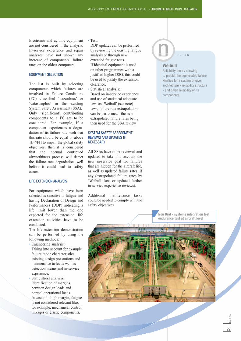
For the qualification of thecomponent, endurance and fatiguetests are performed to support thetheoretical analyses which havebeen used at the beginning of thedesign phase to develop thecomponent.At aircraft level, all thesecomponents are integrated withinthe system and are tested. Endu-rance tests are performed on theIron Bird (aircraft zero) in order tocheck the good behaviour of all thesystems working together. ThisIron Bird is fully representative ofthe aircraft and includes also all thecomponents fitted within theengines and the landing gears.At Entry-Into-Service, all thesystems are qualified for a DSG of20 years according to the Main-tenance Programme. Appropriatemaintenance actions are definedwithin the Maintenance PlanningDocument (MPD) in order toguaranty the safety and reliabilityobjectives. All the componentswhich are life limited are definedin the Airworthiness LimitationSections (ALS) and must bereplaced in that case.
For operation beyond DSG, Airbuscommitted:• To ensure that operating beyondthe original certified Limit OfValidity (LOV) does not impacton the compliance with therequirements as defined by theType Certification (TC) basis(JAR/FAR 25.1309 andJAR/FAR 25.1529 mainly),
• To provide a policy for theestablishment of the systems’justification for the ageingaircraft to maintain compliancewith applicable requirements.
The goal of this ESG study is todemonstrate, for the systems, closeto twice the original DSG in termsof Flight Hours (FH) and FlightCycles (FC). A summary is givenin the systems DSG/ESG chartbelow.
SYSTEM POLICY DESCRIPTION
This system policy has beendefined in 1990, at the beginningof the ESG for the A300/A310Family programme and is also usedto extend the DSG to all otherAirbus programmes.
An agreement has been found withthe European airworthiness autho-rities on three ageing parameters tobe addressed as part of the ESGstudy for mechanical and forhydraulic-mechanical components:• Corrosion,• Wear or erosion,• Fatigue.The two first ones (corrosion, wearand erosion) can be adequatelymonitored by scheduled mainte-nance actions like MaintenanceReview Board (MRB) tasks, TimeBetween Overhaul (TBO) items,zone inspections or functionaltests. These maintenance actionsare regularly performed and whencorrosion or wear is detected, thecomponent is replaced. In theopposite, fatigue damages cannotbe monitored. Therefore, a specificstudy has been performed in orderto select the equipment which aresensitive to fatigue.
Systems DSG/ESG
Aircraft DSG ESG
A300 B2/B4 FC 26,000 57,000
FH 40,000 118,000
A310 FC 26,000 45,000
FH 40,000 116,000
A300-600 FC 26,000 51,000FH 40,000 89,000
Hydraulic test benchendurance tests at system level
Part 2: Systems
Spoiler Actuator fatigue test
FAST
45
29
A300-600 EXTENDED SERVICE GOAL - ENABLING LONGER LASTING OPERATION
n o t e s
WeibullReliability theory allowingto predict the age-related failurekinetics for a system of givenarchitecture - reliability structure- and given reliability of itscomponents.
Iron Bird - systems integration testendurance test at aircraft level
Electronic and avionic equipmentare not considered in the analysis.In-service experience and repairanalyses have not shown anyincrease of components’ failurerates on the oldest computers.
EQUIPMENT SELECTION
The list is built by selectingcomponents which failures areinvolved in Failure Conditions(FC) classified ‘hazardous’ or‘catastrophic’ in the existingSystem Safety Assessment (SSA).Only ‘significant’ contributingcomponents to a FC are to beconsidered. For example, if acomponent experiences a degra-dation of its failure rate such thatthis rate should be equal or above1E-²/FH to impair the global safetyobjectives, then it is consideredthat the normal continuedairworthiness process will detectthe failure rate degradation, wellbefore it could lead to safetyissues.
LIFE EXTENSION ANALYSIS
For equipment which have beenselected as sensitive to fatigue andhaving Declaration of Design andPerformances (DDP) indicating alife limit lower than the oneexpected for the extension, lifeextension activities have to beconducted.The life extension demonstrationcan be performed by using thefollowing methods:• Engineering analysis:Taking into account for examplefailure mode characteristics,existing design precautions andmaintenance tasks as well asdetection means and in-serviceexperience,
• Static stress analysis:Identification of marginsbetween design loads andnormal operational loads.In case of a high margin, fatigueis not considered relevant like,for example, mechanical controllinkages or elastic components,
• Test:DDP updates can be performedby reviewing the existing fatigueanalysis or through newextended fatigue tests.If identical equipment is usedon other programmes with ajustified higher DSG, this couldbe used to justify the extensionclearance,
• Statistical analysis:Based on in-service experienceand use of statistical adequatelaws as ‘Weibull’ (see note)laws, failure rate extrapolationcan be performed - the newextrapolated failure rates beingthen used for the SSA review.
SYSTEM SAFETY ASSESSMENTREVIEWS AND UPDATES IFNECESSARY
All SSAs have to be reviewed andupdated to take into account thenew in-service goal for failuresthat are hidden for the aircraft life,as well as updated failure rates, ifany (extrapolated failure rates by‘Weibull’ law, or updated furtherin-service experience reviews).
Additional maintenance taskscould be needed to comply with thesafety objectives.

FAST
45
30
A300-600 EXTENDED SERVICE GOAL - ENABLING LONGER LASTING OPERATION
OUTCOME OF THE LIFE EXTENSIONANALYSIS
If the analysis exercise points outthat some equipment are affectedby a life limit at aircraft level, or ifadditional maintenance tasks are
found necessary to be added toensure safety objectives, this willbe introduced in AirworthinessLimitation Sections (ALS) Part 4.
The analysis could be summarizedas follows:
Considerable efforts have been spentin terms of analysis/testing and evaluationof the in-service experience to defineand incorporate the results of theExtended Service Goal 2 study into theMaintenance Programme of the A300-600.The incorporation of latest available usageinformation, together with the reviewof the Full Scale Fatigue Test, additionaltear down, in-service findings were usedas inputs for the ESG2 study.Thanks to Airbus continuous involvementto improve its products, our customers
will be able to continue operatingtheir A300B4-600/B4-600R aircraftbeyond the first Extended Service Goal,enabling them to take benefit from theadditional revenue that can be generatedfrom ESG1 to ESG2. The Structure TaskGroup (STG) is working as an active forumfor ageing aircraft activities. The resultsof ESG2 analyses and their consequenceson the Maintenance Programme will bepresented to the operators during the STGmeeting which will be held in April 2010.
Conclusion
CONTACT DETAILS
For Structures:André DELANNOYManager Design and AnalysisA300/A310 & A330/A340 FamiliesProgrammes/CoC StructureAirbus EngineeringTel: +33 (0)5 61 93 30 74Fax: +33 (0)5 61 93 38 [email protected]
For Systems:Jean-Michel PASCUALDeputy Head of SystemsA300/A310 Family ProgrammeAirbus EngineeringTel: +33 (0)5 61 18 56 58Fax: +33 (0)5 61 93 48 [email protected]
List of equipment, Part Number, Supplier, Design Assurance Level (DAL)
Segregation of equipment by types: Mechanical / Hydromechanical or Electronic / Avionic / Electrical
Not ageingsensitive
Yes = a degradation:- That is not detectable by an
existing test or maintenance action- Which impairs safety objectives
when the failure rate is lowerthan 1E-02
No
No
No
Yes
Yes Yes
SSA: System Safety AssessmentDAL: Development Assurance Level- The Development Assurance Level defines the required activitiesto give adequate confidence that the design will satisfy the purchaserrequirements.
- The Development Assurance Level of the equipment is determinedonly by the aircraft manufacturer.
The chosen level is based on safety classification.Classification applicable to the relevant system or equipment:DAL A if failure condition classification = Catastrophic (CAT)DAL B if failure condition classification = Hazardous (HAZ) / Severe MajorDAL C if failure condition classification = Major (MAJ)
Life extension analysis(tests, statistical analysis, etc.)
SSA review with extended aircraft life & failure rates update, if any. Verification of compliance with safety objectives
List of equipment to consider
Equipment for whichfailure mode is involvedin HAZ or CAT FailureCondition (SSA check)
Equipment (whatever DAL) for which failure ratedegradation could impair safety objectives of
HAZ or CAT FC (SSA check)
Mechanical / Hydromechanical
DAL A or B*
Electronic / Avionic / Electrical

The first A300
A300 - FIRST ROLL-OUT
FAST
45
31
The Airbus A300 is a short to medium-range widebodyaircraft. It was the first product of the Airbus consortiumof European aerospace companies, wholly owned today byEADS.The construction of the A300 began in September 1969. Thefirst two aircraft were designated A300B1 and the first(F-WUAB) made its maiden flight on 28 October 1972, thesecond following on 5 February 1973. These were followedby the first pair of A300B2s, considered as the productionmodel.Complete aircraft sections were manufactured byconsortium partners all over Europe. These were airliftedto the final assembly line at Toulouse-Blagnac by theAeroSpace Super Guppy aircraft. The General Electric CF6turbo-fan was chosen as the main powerplant, but anyengine in the same class could be substituted onproduction models according to the customer wishes. Thecylindrical fuselage could accommodate seating layoutsfrom 220 to a maximum of 336 passengers.The European certification was granted on 15 March 1974,followed by the U.S. certification on 30 May. Air Francethen started the first airline service between Parisand London. The A300-600 first flew in July 1983, and hasbeen the major production version since, the last A300B4leaving the production line late 1984. Versions includethe A300-600R with increased take-off weight and tailplane trim tank for long-range operations, and the A300-600 Convertible passenger/cargo version.The A300 ceased production in July 2007, along with thesmaller A310. Today, the evolution of the A300/A310 FamilyMaintenance Programme through the Extended Service Goal(see article page 22) enables the operators to benefit fromthe addition revenue that can be generated from theextended life of the aircraft.
Courtesy
of
EADS
Corporate
Heritage
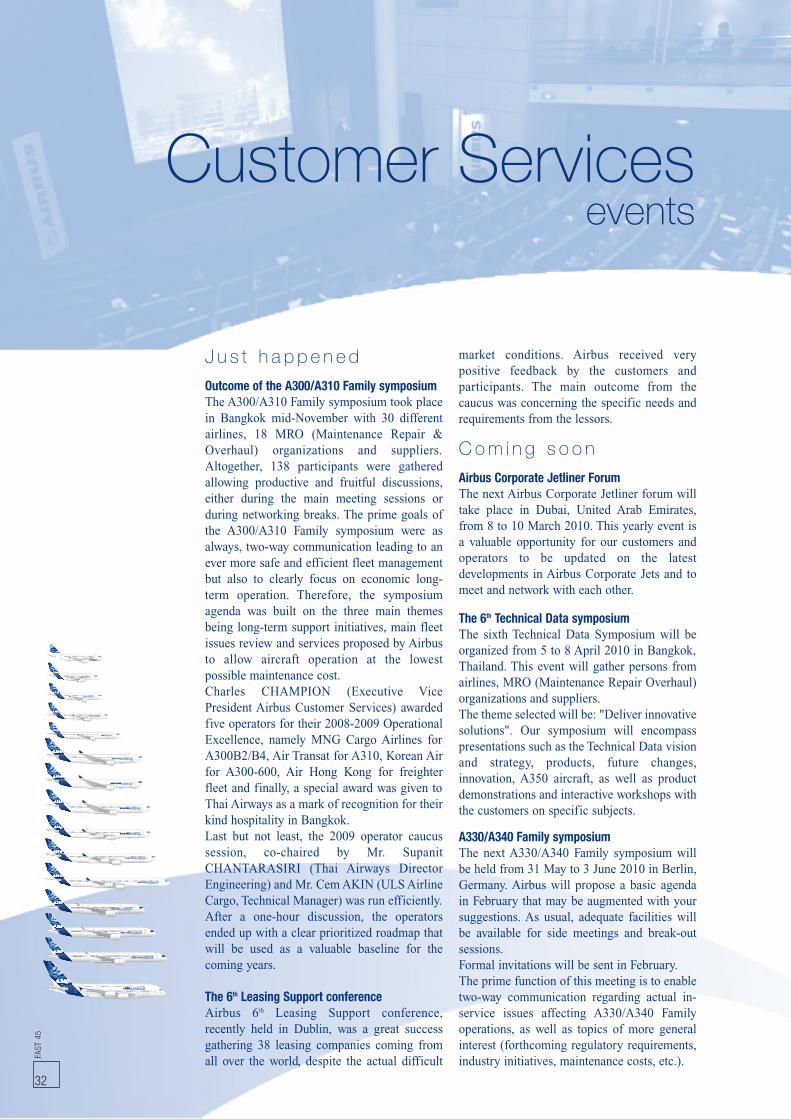
Customer Servicesevents
J u s t h a p p e n e d
Outcome of the A300/A310 Family symposiumThe A300/A310 Family symposium took placein Bangkok mid-November with 30 differentairlines, 18 MRO (Maintenance Repair &Overhaul) organizations and suppliers.Altogether, 138 participants were gatheredallowing productive and fruitful discussions,either during the main meeting sessions orduring networking breaks. The prime goals ofthe A300/A310 Family symposium were asalways, two-way communication leading to anever more safe and efficient fleet managementbut also to clearly focus on economic long-term operation. Therefore, the symposiumagenda was built on the three main themesbeing long-term support initiatives, main fleetissues review and services proposed by Airbusto allow aircraft operation at the lowestpossible maintenance cost.Charles CHAMPION (Executive VicePresident Airbus Customer Services) awardedfive operators for their 2008-2009 OperationalExcellence, namely MNG Cargo Airlines forA300B2/B4, Air Transat for A310, Korean Airfor A300-600, Air Hong Kong for freighterfleet and finally, a special award was given toThai Airways as a mark of recognition for theirkind hospitality in Bangkok.Last but not least, the 2009 operator caucussession, co-chaired by Mr. SupanitCHANTARASIRI (Thai Airways DirectorEngineering) and Mr. CemAKIN (ULSAirlineCargo, Technical Manager) was run efficiently.After a one-hour discussion, the operatorsended up with a clear prioritized roadmap thatwill be used as a valuable baseline for thecoming years.
The 6th Leasing Support conferenceAirbus 6th Leasing Support conference,recently held in Dublin, was a great successgathering 38 leasing companies coming fromall over the world, despite the actual difficult
market conditions. Airbus received verypositive feedback by the customers andparticipants. The main outcome from thecaucus was concerning the specific needs andrequirements from the lessors.
C o m i n g s o o n
Airbus Corporate Jetliner ForumThe next Airbus Corporate Jetliner forum willtake place in Dubai, United Arab Emirates,from 8 to 10 March 2010. This yearly event isa valuable opportunity for our customers andoperators to be updated on the latestdevelopments in Airbus Corporate Jets and tomeet and network with each other.
The 6th Technical Data symposiumThe sixth Technical Data Symposium will beorganized from 5 to 8 April 2010 in Bangkok,Thailand. This event will gather persons fromairlines, MRO (Maintenance Repair Overhaul)organizations and suppliers.The theme selected will be: "Deliver innovativesolutions". Our symposium will encompasspresentations such as the Technical Data visionand strategy, products, future changes,innovation, A350 aircraft, as well as productdemonstrations and interactive workshops withthe customers on specific subjects.
A330/A340 Family symposiumThe next A330/A340 Family symposium willbe held from 31 May to 3 June 2010 in Berlin,Germany. Airbus will propose a basic agendain February that may be augmented with yoursuggestions. As usual, adequate facilities willbe available for side meetings and break-outsessions.Formal invitations will be sent in February.The prime function of this meeting is to enabletwo-way communication regarding actual in-service issues affecting A330/A340 Familyoperations, as well as topics of more generalinterest (forthcoming regulatory requirements,industry initiatives, maintenance costs, etc.).FA
ST45
32

FAST
45
33
Bangalore
Services and Customer Support centresTraining centresMaterial Logistics centres / Regional warehousesResident Customer Support Managers (RCSM)
RCSM location CountryLos Angeles United States of AmericaLouisville United States of AmericaLuton United KingdomLuxembourg LuxembourgMacau S.A.R. ChinaMadrid SpainManchester United KingdomManilla PhilippinesMarrakech MoroccoMauritius MauritiusMelbourne AustraliaMemphis United States of AmericaMexico City MexicoMiami United States of AmericaMilan ItalyMinneapolis United States of AmericaMontreal CanadaMoscow RussiaMumbai IndiaMuscat OmanNanjing ChinaNew York United States of AmericaNoumea New CaledoniaPalma de Mallorca SpainParis FranceParo BhutanPhiladelphia United States of AmericaPhoenix United States of AmericaPrague Czech RepublicRiyadh Saudi ArabiaRoma ItalySan Francisco United States of AmericaSan Salvador El SalvadorSana’a YemenSantiago ChileSao Paulo BrazilSeoul South KoreaShanghai ChinaSharjah United Arab EmiratesShenyang ChinaShenzhen ChinaSingapore SingaporeSofia BulgariaSydney AustraliaTaipei TaiwanTashkent UzbekistanTehran IranTel Aviv IsraelTirana AlbaniaTokyo JapanToluca MexicoToronto CanadaTripoli LibyaTunis TunisiaVienna AustriaWashington United States of AmericaWuhan ChinaXi'an ChinaYekaterinburg RussiaZurich Switzerland
RCSM location CountryAbu Dhabi United Arab EmiratesAlgiers AlgeriaAl-Manamah BahrainAlmaty KazakhstanAmman JordanAmsterdam NetherlandsAthens GreeceAtlanta United States of AmericaAuckland New ZealandBangkok ThailandBarcelona SpainBeijing ChinaBeirut LebanonBerlin GermanyBogota ColombiaBratislava SlovakiaBucharest RomaniaBudapest HungaryBuenos Aires ArgentinaCairo EgyptCasablanca MoroccoChangchun ChinaCharlotte United States of AmericaChengdu ChinaChicago United States of AmericaCologne GermanyColombo Sri LankaCopenhagen DenmarkDamascus SyriaDelhi IndiaDenver United States of AmericaDhaka BangladeshDoha QatarDubai United Arab EmiratesDublin IrelandDusseldorf GermanyFort Lauderdale United States of AmericaFrankfurt GermanyGuangzhou ChinaGuayaquil EcuadorHaikou ChinaHamburg GermanyHangzhou ChinaHanoi VietnamHelsinki FinlandHong Kong S.A.R. ChinaHonolulu United States of AmericaIndianapolis United States of AmericaIstanbul TurkeyJakarta IndonesiaJeddah Saudi ArabiaJohannesburg South AfricaKarachi PakistanKita-Kyushu JapanKuala Lumpur MalaysiaKuwait City KuwaitLagos NigeriaLanzhou ChinaLarnaca CyprusLisbon PortugalLondon United Kingdom
WORLDWIDEBruce JONESSenior Vice PresidentServices & Customer SupportCustomer ServicesTel: +33 (0)5 67 19 19 80Fax:+33 (0)5 61 93 18 18
USA/CANADATom ANDERSONSenior Vice PresidentCustomer ServicesTel: +1 (703) 834 3484Fax:+1 (703) 834 3464
CHINAPierre STEFFENSenior Vice PresidentCustomer Services & Internal OperationsTel: +86 10 8048 6161 Ext 5020Fax:+86 10 8048 6162
RESIDENT CUSTOMER SUPPORT ADMINISTRATIONJean-Bernard GALY,Director Resident Customer Support AdministrationTel: +33 (0)5 67 19 04 13Fax:+33 (0)5 61 93 49 64
TECHNICAL, MATERIAL LOGISTICS& TRAINING SUPPORTAirbus has its main Material Logistics centrein Hamburg, and regional warehousesin Frankfurt, Washington D.C., Dubai, Beijing,Shanghai and Singapore.
Airbus operates 24 hours a day every day.
Airbus Technical AOG Centre (AIRTAC)Tel: +33 (0)5 61 93 34 00Fax:+33 (0)5 61 93 35 [email protected]
Spares AOGs in North America should beaddressed to:Tel: +1 (703) 729 9000Fax:+1 (703) 729 4373
Spares AOGs outside North Americashould be addressed to:Tel: +49 (40) 50 76 4001Fax:+49 (40) 50 76 [email protected]
Spares related HMV issues outsideNorth America should be addressed to:Tel: +49 (40) 50 76 4003Fax:+49 (40) 50 76 [email protected]
Airbus Training Centre Toulouse, FranceTel: +33 (0)5 61 93 33 33Fax:+33 (0)5 61 93 20 94
Airbus Maintenance Training CentreHamburg, GermanyTel: +49 (40) 74 38 8288Fax: +49 (40) 74 38 8588
Airbus Training subsidiariesMiami, Florida - U.S.A.Tel: +1 (305) 871 36 55Fax:+1 (305) 871 46 49
Beijing, ChinaTel: +86 10 80 48 63 40Fax:+86 10 80 48 65 76
Bangalore, India (Maintenance training)Tel: +33 (0)5 61 93 33 33Fax: +33 (0)5 61 93 20 94
CUSTOMER SERVICES WORLDWIDE AROUND THE CLOCK... AROUND THE WORLD
Related Documents