FAST FLUX TEST FACILITY PLANT OPERATION AND CONTROL January 9, 1969 PACIFIC NORTHWEST LABORATORY Richland, Washington 99352 Operated by Battelle Memorial Institute for the U.S. Atomic Energy Commission under Contract No. AT(45

Welcome message from author
This document is posted to help you gain knowledge. Please leave a comment to let me know what you think about it! Share it to your friends and learn new things together.
Transcript

FAST FLUX TEST FACILITY
PLANT OPERATION AND CONTROL
J a n u a r y 9 , 1969
PACIFIC NORTHWEST LABORATORY R i c h l a n d , Washing ton 99352
O p e r a t e d by B a t t e l l e Memoria l I n s t i t u t e
f o r t h e U.S. Atomic Energy Commission u n d e r C o n t r a c t No. AT(45

BNWL- 1 0 2 3
P r e p a r e d by @ , x u cd#- Ad&, Date 11-13-68
Recommended by Date 1 -9 -69 E v a l u a t i o n
w E v a l u a t i o n Board D i r e c t i v e No. A-0107

FFTF PLANT OPERATION AND CONTROL
ABSTRACT
A d ~ s c u s s i o n o f p l a n t o p e r a t i o n and a concep t f o r c o n t r o l
and p r o t e c t i o n o f t h e FFTF a r e p r e s e n t e d . The f i r s t s s e c t i o n o f t h e document d i s c u s s e s p l a n t o p e r a t i o n i n c l u d i n g
o p e r a t i o n o f t e s t s , t h e r e a c t o r , and h e a t removal sys t ems
d u r i n g s t a r t u p , s t e a d y - s t a t e o p e r a t i o n , and normal shutdown.
The second s e c t i o n p r e s e n t s a concep t f o r p l a n t c o n t r o l
inc1udin.g n u c l e a r s y s t e m s , main h e a t removal s y s t e m s , and
c l o s e d loop h e a t removal sys t ems . The t h i r d s e c t i o n d i s -
c u s s e s abnormal and emergency p l a n t c o n t r o l , i n c l u d i n g a
concep t f o r c o n t r o l l e d power r e d u c t i o n and p l a n t p r o t e c t i o n .

TABLE OF CONTENTS
LIST OF FIGURES . . . . . . . . . . . INTRODUCTION. . . . . . . . . . . . SUMMARY AND CONCLUSIONS . a . . ,
PLANT OPERATIONAL PHILOSOPHY ,
TEST OBJECTIVES . a . . a . .,
OPERATING THE TESTS a a . . Closed Loops . . , . . . . . . . . . Open Test Positions . . . a
Axial Positioners . a a
Package Loops <, = . . Short-TermFacility . a
Capsule Irradiation Positions a a a
PLANTOPERATION, a a *
Reactcr Operation * a
Heat Removal System Operation
PLANT CONTROL SYSTEMS . a ., a
GENERAL CONTROL ORGANIZATION . OVERALL PLANT CONTROL . a . . REACTOR NUCLEAR POWER CONTROL . PRIMARY HEAT REMOVAL CONTROL SYSTEM ., .,
Primary Coolant Flow Control . Primary Level and Pressure Control SECONDARY HEAT REMOVAL CONTROL SYSTEM a
Secondary Coolant Flow Control . . Secondary Level and Pressure Control . TERTIARY HEAT REMOVAL CONTROL . a
CLOSED TEST LOOP CONTROL . ABNORMAL AND EMERGENCY PLANT CONTROL . CONTROLLED POWER REDUCTION INSTRUMENTATION . a
Need and Requirements for CPR Instrumentation . Controlled Power Reduction Analysis and Concept o ~ o ~ ~ ~ o ~ e ~ ~ ~ e
vi viii
X
1 - 1
1-1
1-3
1 - 3
1-10
1-12
1-14
1-15
1-16
1-17
1-18
1- 26
2-1
2- 1
2- 5
2-9
2-12
2-12
2-14
2-16
2-16
2 - 17 2-19 2-21
3-1
3-1
3 - 3

3.2 PLANT PROTECTION INSTRUMENTATION . . . 3-12
3,Z.l Concept for Scram Trips . . . . 3-13
3.2,2 Response to Scram Trips . . . . . 3-16
3 , 2 . 3 Engineered Safeguards . . . . 3-23
Appendix A References . , . , . . A-1
Appendix B Evaluation of Plant Control with HybridSimulation. . . . B-1
Appendix C Preliminary Analysis of Controlled Power Reduction . . . . C - 1
Appendix D Events Requiring Protective Action and/or Controlled Power Reduction D-1
AppendixE Glossary. . . . . E-1

LIST OF FIGURES
Schematic Diagram of Reactor and Heat Transport System Relations . . . l - 1 9
Heat Transport System Startup Response, Spreading Core AT at Low Power . . . 1-29 Heat Transport System Startup Response, Holding Core Center Temperature Constant . 1-30 Heat Transport System Startup Response with Constant Flow and Inlet Temperature . . 1-31 Heat Transport System Shutdown Response with Constant Flow and Inlet Temperature . . . . 1-37 Heat Transport System Shutdown Response by Holding Core AT to Low Power . . . 1-38 Plant and Process Control Hierarchy; Functions of Each Level . . . . 2-2 Simplified Overall Plant Control System . . 2-6 Reactor Nuclear Power Level Control . . . 2-10 Main Heat Transport System Primary Coolant Flow Control , . , . , , , , . . , . 2-13 Heat Transport System Primary Coolant Level Control . , 2-15
Heat Transport System Secondary Coolant Flow and Level Control . . . . . . . . . 2-18 Tertiary Na-Air Heat Dump Control . . . 2-20 Closed Test Loop Control Configuration . . . . 2-22 Automatic FFTF Power Reductions . . 3-9 Containment Isolation Control . . 3-25 Schematic of Process Control Simulation . B-2 System Response to Power Ramp, 4 0 0 - 3 0 0 M W t j . . B - 5
System Response to Power Ramp, 300-200MWt. . . B - 6
System Response to Power Ramp, 200-100 MWt, 50% Flow . B-7

System Response to Power Ramp, 1 0 0 - 5 0 M W t , 5 0 % F l o w . . . . . . . . Effect of Scram Reactivity on Power Level After 10 Seconds
Effect of Scram Reactivity on Power Level After5Minutes
Full Flow Scram: Effect of Scram Reactivity on Tube Outlet Temperature (Maximum Rate of Change) a a a a
Full Flow Scram: Effect of Scram Reactivity on Tube Outlet Temperature (Temperature Change in 10 sec) , a .,
Programmed Shutdown Insertion Rates Effect on Reactor Power Tube Outlet Temperature Held Constant by Reducing Primary Flow (min- 20%) . . . . . . . . . . . Rod Insertion Rate Versus Maximum Rate-of- Change Tube Outlet Temperature Full Primary
. . . . . . . . . . . . . Flow
Effect of Rod Insertion Rate on Tube Outlet Temperature . a a
Effect of Rod Insertion Rate on Reactor
vii

INTRODUCTION
I n o r d e r t o e s t a b l i s h t h e p r o p e r f u n c t i o n a l and d e s i g n c r i -
t e r i a f o r each c o n t r o l sys t em of t h e F a s t F lux T e s t F a c i l i t y
(FFTF), a s y s t e m a t i c p l a n f o r t h e o v e r a l l p l a n t o p e r a t i o n
% and c o n t r o l i s needed. The d e s i r e d approach t o p l a n t o p e r a - t i o n may b e d e s c r i b e d a s a " p l a n t o p e r a t i o n a l p h i l o s o p h y , "
and o u t l i n e s t h e o p e r a t i o n o f t h e r e a c t o r and main h e a t
t r a n s p o r t sys t ems and t h e v a r i o u s t e s t f a c i l i t i e s . From
t h e p l a n t o p e r a t i o n a l p h i l o s o p h y one may t h e n deve lop a con-
c e p t f o r o v e r a l l c o n t r o l and a l s o f o r each s e p a r a t e c o n t r o l
sys t em,
A c c o r d i n g l y , w i t h i n t h e l i m i t a t i o n s of FFTF c o n c e p t u a l
d e s i g n , t h e pu rpose o f t h i s document i s t o p r e s e n t t h e
c u r r e n t approaches t o : (1) normal o p e r a t i o n o f t h e t e s t
f a c i l i t i e s , (2 ) normal o p e r a t i o n o f t h e F a s t T e s t R e a c t o r
(FTR) and i t s h e a t t r a n s p o r t s y s t e m s , ( 3 ) c o n t r o l of t h e
r e a c t o r , h e a t t r a n s p o r t and c l o s e d t e s t l oop s y s t e m s , and
( 4 ) p r o t e c t i o n o f t h e p l a n t a g a i n s t m a l f u n c t i o n s and f a i l u r e s ,
I n t e r a c t i o n s between p r o t e c t i o n sys t ems and c o n t r o l sys t ems
a r e a l s o c o n s i d e r e d ( e . g . , h e a t t r a n s p o r t s y s tem c o n t r o l
r e s p o n s e t o r e a c t o r s c r a m ) .
Th i s document p r o v i d e s s u p p o r t i n f o r m a t i o n f o r t h e Conceptua l
System Design D e s c r i p t i o n s (CSDD) f o r C e n t r a l C o n t r o l and
Data Handl ing System No. 91 and P l a n t P r o t e c t i o n System
No. 99 . S p e c i f i c a l l y , i t s e r v e s t o i l l u s t r a t e (1) c o n t r o l . and o p e r a t i o n c o o r d i n a t i o n and i n t e g r a t i o n , and (2) s a f e t y
c o o r d i n a t i o n . The i n s t r u m e n t a t i o n and c o n t r o l CSDD' s , 2
1. Refe r t o R e f e r e n c e s , Appendix A , I tem 1, See F i g u r e i . 2 . R e f e r t o R e f e r e n c e s , Appendix A , I tems 1, 2 , 3 , 4 , 5 ,
6 , and 7 .
v i i i

BNWL- 1023
is a d d i t i o n t o t h i s r e p o r t , p r o v i d e a s u f f i c i e n t l y comple te
view o f p l a n t o p e r a t i o n and c o n t r o l f o r t h e P l a n t Des igner
t o move from c o n c e p t u a l d e s i g n i n t o p r e l i m i n a r y d e s i g n of
c o n t r o l f o r t h e r e a c t o r and h e a t t r a n s p o r t s y s t e m s . A u x i l i a r y
sys tems ( e . g . , f u e l h a n d l i n g ) a r e n o t c o n s i d e r e d a t t h i s t ime . b
Where p o s s i b l e , e s t i m a t e s a r e p r o v i d e d f o r n u m e r i c a l v a l u e s
which may prove u s e f u l d u r i n g d e s i g n . I t i s u n d e r s t o o d t h a t
such v a l u e s r e q u i r e u p d a t i n g a s t h e d e s i g n p r o g r e s s e s .

SUMMARY AND CONCLUSIONS
I n d e v e l o p i n g an FFTF p l a n t c o n t r o l concep t f o r t h e con-
c e p t u a l d e s i g n , t h e p l a n t o p e r a t i o n a l p h i l o s o p h y i s f i r s t
c o n s i d e r e d . The r e a c t o r and i t s h e a t t r a n s p o r t sys t ems
b p l u s t h e t e s t f a c i l i t i e s a r e of p r i m a r y i n t e r e s t ; a u x i l i a r y
and s u p p o r t s y s t e m o p e r a t i o n and c o n t r o l a r e d e f e r r e d f o r
l a t e r s t u d y . T e s t i n g o b j e c t i v e s and o p e r a t i n g d e s i r e s l e a d
t o t h e f o l l o w i n g g e n e r a l c o n c l u s i o n s a b o u t p l a n t c o n t r o l :
1. C o n t r o l of c l o s e d t e s t l oops s h o u l d b e v e r s a t i l e i n
o r d e r t o meet d i f f e r i n g t e s t o b j e c t i v e s . For example,
c l o s e c o n t r o l o f i n l e t t e m p e r a t u r e may be r e q u i r e d f o r
one t e s t , w h i l e c l o s e c o n t r o l of t e s t s e c t i o n AT may be
r e q u i r e d f o r a n o t h e r . C o n t r o l sys t em p a r a m e t e r s ( g a i n ,
r e s e t ) s h o u l d be v a r i a b l e t o accommodate t h e d i f f e r e n t
t e s t s .
2 . C o n t r o l o f t h e r e a c t o r and main h e a t t r a n s p o r t l oops
s h o u l d be based on s i m p l i c i t y and s a f e t y . S a f e t y of
s t a r t u p o p e r a t i o n i s enhanced when a minimum number o f
o p e r a t i n g p a r a m e t e r s a r e changing ( e , g . , c o n s t a n t f low
s t a r t u p ) , f r e e i n g t h e o p e r a t o r s t o c o n c e n t r a t e on
s a f e t y - r e l a t e d i n f o r m a t i o n .
A t p r e s e n t , d i r e c t d i g i t a l computer c o n t r o l i s n o t p roposed
f o r i n i t i a l o p e r a t i o n . However, as t h e FFTF becomes more
e s t a b l i s h e d i n i t s o p e r a t i o n , i n c r e a s e d c o n f i d e n c e i n t h e
p l a n t w i l l a l l o w t h e computer t o pe r fo rm more c o m p l i c a t e d s t a r t u p and shutdown r o u t i n e s .
The p l a n t c o n t r o l concep t has t h e f o l l o w i n g f e a t u r e s :
1. R e a c t o r c o n t r o l b a s e d on n e u t r o n f l u x l e v e l w i t h con-
t i n u o u s c a l i b r a t i o n a g a i n s t r e a c t o r t h e r m a l power. The
f l u x l e v e l s e t p o i n t w i l l be s e t m a n u a l l y , w i t h t h e
o p t i o n o f d i r e c t manual c o n t r o l of t h e r o d s .

2 . Heat t r a n s p o r t sys t em c o n t r o l b a s e d on c o n t r o l of p r imary
c o o l a n t t e m p e r a t u r e by a i r f l o w a t t h e DHX. The s e t
p o i n t f o r c o n t r o l o f a i r f low may be d e r i v e d from IHX
p r i m a r y o u t l e t t e m p e r a t u r e and r e a c t o r power. C o n t r o l
of sodium f lows i s accompl ished by e q u a l i z i n g p r imary
loop f lows w l t h a common manual s e t p o i n t and by matching
secondary f lows t o t h e i r r e s p e c t i v e p r i m a r y f l o w s .
3. Closed t e s t l o o p c o n t r o l based on c o n t r o l o f t e s t i n l e t
and o u t l e t t e m p e r a t u r e s by sodium and a i r f l o w s , Flow
s e t p o i n t s w i l l be p r o v i d e d from t h e t e s t c o o l a n t tempera
t u r e s by an a n a l o g c o n t r o l c i r c u l t which w i l l be e a s i l y
reprogrammed t o meet t e s t o b j e c t i v e s [ c o n s t a n t t e s t AT,
c o n s t a n t i n l e t t e m p e r a t u r e , e t c . ) . C o r r e c t i v e a c t i o n w i l l be b a s e d on two approaches : t h e f u l l
emergency shutdown (scram) and a c o n t r o l l e d power r e d u c t i o n
[CPR). The scram w i l l be t h e f a s t e s t shutdown p o s s i b l e of
t h e r e a c t o r power, w i t h t h e p r imary purpose o f p r o t e c t i n g
t h e FTR and t h e t e s t s , and w i l l be i n i t i a t e d by t h e P l a n t
P r o t e c t i v e System. A l l s a f e t y rods w i l l be i n s e r t e d , and
h e a t t r a n s p o r t sys t ems w i l l r e spond by r e d u c i n g sodium f lows
t o minimize t h e r m a l t r a n s i e n t s . CPR a c t l o n w i l l be d e s i g n e d
i n t o t h e normal c o n t r o l sys t em and w i l l t a k e two fo rms :
(1) s e t b a c k , i n which o n l y t h e power i s r educed by t h e
r e a c t o r f l u x c o n t r o l sys t em i n a manner c o r r e s p o n d i n g t o t h e
i n c i d e n t ( e . g . , a p e r c e n t a g e power r e d u c t i o n f o r t h e DHX . module o r a c o n t i n u e d c o n t r o l r o d i n s e r t i o n u n t i l a r e a c t o r
overpower c o n d i t i o n i s c o r r e c t e d , and ( 2 ) programmed s h u t -
down, i n which power and f low a r e r educed t o g e t h e r t o t h e
decay h e a t r a n g e , i n o r d e r t o r educe t h e r m a l t r a n s i e n t s
below t h o s e due a scram. These c o r r e c t i v e a c t i o n s w i l l be
s u f f i c i e n t t o p r o t e c t t h e FFTF r e a c t o r and a s s o c i a t e d
sys tems f o r t h e f u l l spec t rum o f a n t i c i p a t e d i n c i d e n t s .

SECTION 1 . 0 PLANT OPERATIONAL PHILOSOPHY
The f o l l o w i n g s e c t i o n o f t h i s document i s o r g a n i z e d a s
f o l l o w s : ( 1 ) t h e o b j e c t i v e s f o r e ach t y p e o f t e s t a r e s t a t e d ,
( 2 ) t h e o p e r a t i o n a l a s p e c t s o f e a c h t y p e o f t e s t f a c i l i t y a r e
d e s c r i b e d f rom s t a r t u p t h r o u g h shu tdown , w i t h a d i s c u s s i o n o f
t h e p a r a m e t e r s which w i l l r e q u i r e m o n i t o r i n g and c o n t r o l , and
( 3 ) o p e r a t i o n o f t h e r e a c t o r and h e a t t r a n s p o r t s y s t e m s i s
d i s c u s s e d .
1.1 TEST OBJECTIVES
The m i s s i o n o f t h e FFTF i s t o p r o v i d e e x p e r i m e n t e r s w i t h t h e
d e s i r e d c o n t r o l l e d e n v i r o n m e n t s f o r t h e t e s t i n g o f f u e l s and
m a t e r i a l s f o r f u t u r e l i q u i d m e t a l f a s t b r e e d e r r e a c t o r s
(LMFBR). S p e c i f i c o b j e c t i v e s a r e h i g h n e u t r o n f l u x i n t h e
h i g h - e n e r g y s p e c t r u m , e l e v a t e d c o o l a n t t e m p e r a t u r e s (up t o
1400 OF sod ium i n c l o s e d t e s t l o o p s ) , and c o n t r o l l e d c o o l a n t
c h e m i s t r y . O p e r a t i o n o f t h e FTR and t h e t e s t s t h e m s e l v e s
m u s t , t h e r e f o r e , b e matched t o t h e s e o b j e c t i v e s .
S e v e r a l d i f f e r e n t t e s t i n g f a c i l i t i e s a r e b e i n g p l a n n e d f o r
u s e i n t h e FTR and a r e f u l l y d e s c r i b e d e l s e w h e r e . ' A l though
t h e s e f a c i l i t i e s may change a s t h e p l a n t d e s i g n p r o g r e s s e s
beyond t h e c u r r e n t c o n c e p t u a l s t a g e , i t i s p o s s i b l e t o s t a t e
a t this t i m e t h e g e n e r a l o p e r a t i o n o f t h e t e s t s , b a s e d upon
t h e p r o j e c t e d d e s i r e s o f e x p e r i m e n t e r s . C o n c e p t u a l d e s i g n
o f c o n t r o l s y s t e m s f rom t h e s t a n d p o i n t o f t e s t i n g n e e d s may
t h e n be d e v e l o p e d f rom t h e d e s i r e d t e s t o p e r a t i o n . A summary
o f p l a n n e d FFTF t e s t i n g c a p a b i l i t y i s shown i n T a b l e 1-1.
1. R e f e r t o R e f e r e n c e s , Appendix A , I t em 8 .

TABLE 1 - 1 , FFTF T e s t i n g C a p a b i l i t i e s and O b ~ e c t i v e s
F a c i l i t y T e s t s O b j e c t i v e s
Closed Loops P r o t o t y p e o r p a r t i a l Burnup, b r e e d i n g p a r a m e t e r s ; f u e l e l e m e n t s ; t h e r m a l - h y d r a u l i c c h a r a c - m a t e r i a l s t e s t s t e r i s t i c s ; c l a d c o r r o s i o n a n d *
mass t r a n s f e r ; f u e l f a i l u r e c h a r a c t e r i s t i c s ; v e n t e d f u e l pe r fo rmance ; f i s s i o n p r o d u c t d e p o s i t i o n ; m a t e r i a l s damage and p r o p e r t y changes .
Open T e s t P o s i t i o n s P r o t o t y p e o r p a r t i a l Burnup, b r e e d i n g p a r a m e t e r s ; (Core and R e f l e c t o r ) f u e l e l e m e n t s ; s i n g l e t h e r m a l - h y d r a u l i c c h a r a c -
p i n t e s t s ; m a t e r i a l s t e r i s t i c s ; f i s s i o n g a s i r r a d i a t i o n ; i n s t r u - r e l e a s e ; m a t e r i a l s damage and ment i r r a d i a t i o n p r o p e r t y changes ; i n s t r u m e n t
i n t e g r i t y and r e s p o n s e .
A x i a l P o s i t i o n e r s
Package Loops (Not s u p p l i e d a s p a r t o f t h e FFTF.)
Short-Term F a c i l i t i e s
P ( T r a i l Cable) I
T e s t s i n c l o s e d l o o p s Fuel and c l a d d i n g c h a r a c - o r open t e s t p o s i t i o n s t e r i s t i c s a s f u n c t i o n s o f
f l u x o r t h e r m a l c y c l i n g ; i n s t r u m e n t r e s p o n s e and i n t e g - r i t y a s f u n c t i o n s o f f l u x o r t h e r m a l c y c l i n g .
P a r t i a l f u e l e l e m e n t s ; Burnup, b r e e d i n g p a r a m e t e r s ; s i n g l e p i n t e s t s ; f u e l f i s s i o n gas r e l e a s e ; ma te - and m a t e r i a l s c a p s u l e r i a l s damage and p r o p e r t y i r r a d i a t i o n ( P l a c e d i n c h a n g e s ; c l a d c o r r o s i o n and open t e s t p o s i t i o n s . ) mass t r a n s f e r .
F u e l and m a t e r i a l damage W Fue l and m a t e r i a l s c a p - z s u l e i r r a d i a t i o n ; s i n g l e ("Screening") =Z r and m u l t i p l e p i n t e s t s I
I-' 0 P3 W

A s shown i n T a b l e 1-1, t e s t i n g f a c i l i t i e s may s e r v e t h e
needs o f e x p e r i m e n t s w i t h d i f f e r e n t t e s t o b j e c t i v e s . There -
f o r e , o p e r a t i o n of t h e FTR must c o n s i d e r t h e o p e r a t i o n o f
each t e s t f a c i l i t y and i t s n e e d s , which may t h e n r e q u i r e
v e r s a t i l e c o n t r o l sys t ems t o s e r v e d i f f e r e n t p u r p o s e s .
1 . 2 OPERATING THE TESTS
Each t e s t f a c i l i t y w i l l have i t s own o p e r a t i o n a l needs and
problems b a s e d b o t h on i t s d e s i g n and on t h e e n c l o s e d t e s t
a t any p a r t i c u l a r t i m e . For example, a t - p o w e r o p e r a t i o n of
a c l o s e d l o o p w i l l r e q u i r e p r e c i s e c o n t r o l o f c o o l a n t p u r i t y
and i n l e t t e m p e r a t u r e f o r c o r r o s i o n and mass t r a n s f e r s t u d i e s ,
whereas f o r p r o t o t y p e f u e l c l u s t e r per formance t e s t s , c o o l a n t
p u r i t y may r e c e i v e l e s s emphasis t h a n w i l l p r e c i s e f l u x
c o n t r o l . I n o r d e r t o deve lop a c o n c e p t f o r c o n t r o l o f t h e
r e a c t o r , t h e o p e r a t i n g p h i l o s o p h y must be o u t l i n e d f o r each
t e s t f a c i l i t y and i t s e x p e c t e d t e s t s f o r a l l l e v e l s o f o p e r a -
t i o n , from s t a r t u p th rough shutdown.
1 . 2 . 1 Closed Loops
Both f u e l and m a t e r i a l s may be t e s t e d i n c l o s e d l o o p s , i n
which i s o l a t i o n from t h e main h e a t removal sys t em sodium
i s a c h i e v e d . ' Flow, t e m p e r a t u r e , and c o o l a n t c h e m i s t r y w i l l
b e i n d e p e n d e n t o f t h e main l o o p sodium. The t y p e of t e s t
w i l l i n f l u e n c e some a s p e c t s of o p e r a t i o n , a s n o t e d .
P r e s t a r t
P r e h e a t i n g of t h e sodium s u p p l y and loops w i l l p r o c e e d i n
t h e same manner a s f o r t h e main loops u n t i l s u i t a b l e tem-
p e r a t u r e s f o r f i l l i n g a r e e s t a b l i s h e d . Normal e l e c t r i c a l
1. Refe r t o R e f e r e n c e s , Appendix A , I t em 9 .
p r e h e a t i n g r a t e s w i l l be l i m i t e d by component d e s i g n s ( e s t i -
mated t o be a b o u t 5 t o 10 OF/hr f o r d r y p r e h e a t - - e m p t y of
sodium, and abou t 50 t o 100 OF/hr f o r we t p r e h e a t ) . Auto-
m a t i c c o n t r o l of p r e h e a t i n g i s p r e f e r r e d i n o r d e r t o p r o v i d e
c l o s e c o n t r o l and conse rve manpower d u r i n g s t a r t u p , T h i s
approach may be accompl ished th rough p r o p e r programming o f
t h e d i g i t a l d a t a - l o g g i n g computer . Manual c o n t r o l o f p r e -
h e a t i n g w i l l a l s o be a v a i l a b l e . The loops w i l l t h e n be
f i l l e d t o a l e v e l s u f f i c i e n t l y above pump b e a r i n g s f o r a d e -
q u a t e l u b r i c a t i o n , b u t l i m i t e d i n o r d e r t o a l l o w f o r t h e r m a l
e x p a n s i o n . F i l l i n g o f t h e loops may be done manua l ly , s i n c e
t h e loops have a r e l a t i v e l y s m a l l sodium i n v e n t o r y .
Flow w i l l be e s t a b l i s h e d u s i n g b o t h r edundan t pumps i n t h e
p r imary and secondary of each c l o s e d - l o o p sys t em a s a f u n c -
t i o n check f o r each pump. P r e h e a t i n g o f t h e loops (by e l e c -
t r i c a l p i p e h e a t e r s , t e s t i n l e t h e a t e r s , pump ene rgy and
shim h e a t i n g mounted i n t h e t e s t package , i f a v a i l a b l e ) t o
t h e d e s i r e d i s o t h e r m a l c o o l a n t t e m p e r a t u r e f o r s t a r t u p w i l l
c o n t i n u e th rough t h e s t a r t u p s t a g e , i n c o n j u n c t i o n w i t h t h e
main s y s tem p r e h e a t i n g . T e s t assembly d e s i g n may i n f l u e n c e
h e a t u p r a t e s , though i t i s more l i k e l y t h a t t h e t e s t s w i l l
be r e q u i r e d t o conform t o p r e d e t e r m i n e d maximum h e a t u p r a t e s
b a s e d on c l o s e d - l o o p d e s i g n .
Sodium p u r i f i c a t i o n w i l l be e s t a b l i s h e d and i m p u r i t i e s con-
t r o l l e d t o t h e d e s i r e d s t a r t u p l e v e l s . I t s h o u l d be n o t e d
t h a t some t e s t s may r e q u i r e a p a r t i c u l a r i m p u r i t y l e v e l
b e f o r e t h e t e s t i s i n s e r t e d i n t h e l o o p . The c a p a b i l i t y f o r
p u r i f i c a t i o n o f t h e c l o s e d loop sodium, independen t of t h e
r e a c t o r t e s t s e c t i o n ( i . e . , f rom t h e f i l l t a n k s ) , i s a l s o
d e s i r a b l e s o t h a t p u r i f i c a t i o n may c o n t i n u e (p robab ly a t a
r educed sodium f low) d u r i n g t e s t h a n d l i n g o r p r i m a r y sys t em

main tenance . Cold t r a p p i n g w i l l be u s e d f o r removal o f
oxides1 w h i l e h o t t r a p p i n g w i l l be used f o r removal of c a r -
bon and oxygen. Oxygen c o n t e n t w i l l be r educed t o a l e v e l
such t h a t t h e p l u g g i n g t e m p e r a t u r e ( o x i d e p r e c i p i t a t i o n tem-
p e r a t u r e ) i s a t l e a s t 100 O F below t h e s t a r t u p t e m p e r a t u r e .
Al lowable ca rbon i n sodium i s dependent on t h e e x p e c t e d t e s t
s u r f a c e t e m p e r a t u r e , and c a r b u r i z i n g e f f e c t s a r e mon i to red
by a n a l y z i n g m a t e r i a l s specimens exposed t o t h e c o o l a n t .
S t a r t u p
P r e h e a t i n g w i l l c o n t i n u e u n t i l t h e d e s i r e d s t a r t u p tempera-
t u r e i s a c h i e v e d . I n g e n e r a l , t h e p r e h e a t g o a l f o r t h e
c l o s e d loop w i l l be t h e o p e r a t i n g c o l d - l e g t e m p e r a t u r e f o r
t h e l o o p . However, s p e c i a l t e s t s may r e q u i r e a s h i g h a b u l k
t e m p e r a t u r e a s p o s s i b l e t h r o u g h o u t t h e t e s t i n g p e r i o d
( i n c l u d i n g s h u t d o w n - r e s t a r t ) . Thus, t h e p r e h e a t g o a l c o u l d
be t h e d e s i r e d h o t - l e g t e m p e r a t u r e and t h e t e s t A T " sp read"
downward from t h e h i g h e r t e m p e r a t u r e a s t h e FTR i s b r o u g h t
t o o p e r a t i n g power. The maximum h o t - l e g t e m p e r a t u r e w i l l
be 1200 O F .
Flow w i l l be e s t a b l i s h e d a t a v a l u e c o n s i s t e n t w i t h p r o t e c -
t i o n a g a i n s t a s t a r t u p i n c i d e n t , h i g h enough t o e n s u r e good
thermocouple r e s p o n s e and a d e q u a t e h e a t removal i n t h e e v e n t
o f a s t a r t u p r e a c t i v i t y i n c i d e n t ( e s t i m a t e d minimum o f 20 t o
50% f u l l f l o w ) . C l o s e d - l o o p t e m p e r a t u r e and f low i n s t r u m e n -
t a t i o n w i l l be obse rved d u r i n g t h e approach t o c r i t i c a l i t y
o f t h e FTR. Both pumps i n each loop (p r imary and s e c o n d a r y )
w i l l be o p e r a t i n g .
1. Cold t r a p p i n g may a l s o be an i m p o r t a n t means f o r f i s s i o n p r o d u c t removal f o l l o w i n g t e s t s t o r u p t u r e . However, f l u s h i n g t h e sys t em i s e x p e c t e d t o be more e f f e c t i v e .

To Power
In g e n e r a l , c l o s e d - l o o p f low and r e a c t o r power w i l l b e
i n c r e a s e d from t h e minimum f l o w i n such a manner a s t o m i n i -
mize t h e r m a l t r a n s i e n t s on t h e t e s t s e c t i o n and c l o s e d - l o o p
sys t em. The e x t e n t o f p o s s i b l e r i s e - i n - p o w e r sequences i s
shown w i t h t h e f o l l o w i n g two examples . The a c t u a l s equence
used w i l l r e f l e c t t h e needs o f t h e t e s t and p r o v i s i o n may
be r e q u i r e d f o r a v a r i e t y o f sequences t o s a t i s f y d i f f e r e n t
t e s t s . 1. With f u l l f low and t h e c l o s e d t e s t l oop p r e h e a t e d t o t h e
d e s i r e d c o l d - l e g t e m p e r a t u r e , t h e t e s t AT i s t h e n
i n c r e a s e d by a l l o w i n g o u t l e t t e m p e r a t u r e t o r i s e a s t h e
FTR power r i s e s . The c l o s e d t e s t l oop c o l d - l e g tempera-
t u r e i s m a i n t a i n e d by a i r f low c o n t r o l a t t h e l o o p D H X .
2 . With t h e c l o s e d loop p r e h e a t e d t o t h e d e s i r e d h o t - l e g
o p e r a t i n g t e m p e r a t u r e , t h e t e s t AT i s t h e n i n c r e a s e d by
a l l o w i n g c o l d - l e g t e m p e r a t u r e t o f a l l a s FTR power
r i s e s , t h rough h e a t l o s s e s a t t h e DHX and by d e c r e a s i n g
e l e c t r i c a l h e a t .
The f i r s t approach i s p r e f e r r e d a s i t i s s i m p l e s t f rom an
o p e r a t i o n s s t a n d p o i n t , and p a r a l l e l s o p e r a t i o n o f t h e FTR.
The l a t t e r approach may be d e s i r a b l e f o r t e s t s which r e q u i r e
c o n t i n u i n g h i g h t e m p e r a t u r e s , even d u r i n g shutdown ( e . g . ,
m a t e r i a l s t e s t s f o r c o r r o s i o n and mass t r a n s f e r ) . Thus,
v e r s a t i l i t y i s needed i n c l o s e d - l o o p approaches t o power.
A s t e m p e r a t u r e i n c r e a s e s , sodium p u r i f i c a t i o n and i m p u r i t y
m o n i t o r i n g may c o n t i n u e s i n c e a d d i t i o n a l s econd-phase ( s o l i d )
i m p u r i t i e s would go i n t o s o l u t i o n . Coo lan t p u r i t y w i l l b e
e s t a b l i s h e d a t t h e l e v e l d e s i r e d f o r a t -power o p e r a t i o n .
Oxide p l u g g i n g t e m p e r a t u r e s s h o u l d be below 300 OF i n o r d e r

t o e n s u r e c o n t i n u e d f low even a t low t e m p e r a t u r e s ( p a r t i c u -
l a r l y i n DHX t u b e s ) . C o r r o s i o n and mass t r a n s f e r s t u d i e s a s
w e l l a s f i s s i o n p r o d u c t d e p o s i t i o n s t u d i e s may r e q u i r e a d d i -
t i o n o f i m p u r i t i e s . Such a d d i t i o n s c o u l d be made b e f o r e
s t a r t u p , o r d u r i n g o p e r a t i o n w i t h t h e a i d of s u i t a b l e
r e m o t e l y - o p e r a t e d d e v i c e s .
A t Power
I n l e t and o u t l e t c o o l a n t t e m p e r a t u r e s w i l l be c o n t r o l l e d
w i t h i n t h e l i m i t s s p e c i f i e d by t h e t e s t . A s an example,
mass t r a n s f e r t e s t d a t a may r e q u i r e i n l e t and o u t l e t tem-
p e r a t u r e s t o be c o n t r o l l e d w i t h i n 510 O F . C o n t r o l sys t em
p a r a m e t e r s w i l l be a d j u s t a b l e i n o r d e r t o s e r v e t h e p u r p o s e s
of d i f f e r e n t e x p e r i m e n t s . I t i s e x p e c t e d t h a t i n l e t tem-
p e r a t u r e w i l l be c o n t r o l l e d by DHX h e a t d i s s i p a t i o n and
i n l e t h e a t e r a d j u s t m e n t , and o u t l e t t e m p e r a t u r e by p r imary
f low a d j us tments i n r e s p o n s e t o power changes . However,
s i m u l a t i o n s t u d i e s ( s i m i l a r t o t h o s e r e p o r t e d i n Appendix B )
w i l l d e t e r m i n e t h e b e s t method o f c o n t r o l , p a r t i c u l a r l y from
t h e s t a n d p o i n t o f s t a b i l i t y .
Both of t h e two c o o l a n t pumps i n each h e a t t r a n s p o r t l oop
w i l l have c o n t r o l c a p a b i l i t y s o t h a t s h o u l d one b e g i n t o
f a i l , i t may be s h u t down w h i l e t h e o t h e r p i c k s up t h e t o t a l
l o a d . A t s t e a d y - s t a t e t h e pumps w i l l be o p e r a t e d a t e q u a l
l o a d .
T e s t AT and b u l k c o o l a n t t e m p e r a t u r e s may be o p e r a t e d a t
d i f f e r e n t v a l u e s from t h e FTR d r i v e r f u e l , f o r b o t h f u e l s
and m a t e r i a l s t e s t s . T e s t s e c t i o n o u t l e t t e m p e r a t u r e may
exceed d e s i g n t e m p e r a t u r e s o f t h e c l o s e d - l o o p p r o c e s s sys t ems
(up t o 1400 O F ) w i t h t h e u s e of bypass s t r e a m s around t h e
t e s t s e c t i o n . E l e c t r i c a l h e a t i n g , b o t h i n t h e t e s t s e c t i o n

BNWL- 1023
and i n t h e p r o c e s s sys t em, may be r e q u i r e d f o r e l e v a t e d tem-
p e r a t u r e s ( p a r t i c u l a r l y i n m a t e r i a l s t e s t s ) , i n o r d e r t o
make up f o r t h e l i m i t e d h e a t g e n e r a t i o n i n t h e t e s t spec imen.
Coolant p u r i t y w i l l be m a i n t a i n e d a t t h e d e s i r e d l e v e l s f o r
e a c h l o o p by p e r i o d i c o r c o n t i n u o u s m o n i t o r i n g and o p e r a -
t i o n o f p u r i f i c a t i o n s y s tems, a s r e q u i r e d . I m p u r i t y l e v e l s
r e q u i r e d by t h e t e s t s w i l l be s u p e r s e d e d o n l y by t h e r e q u i r e -
ment f o r an o x i d e p l u g g i n g t e m p e r a t u r e a t l e a s t 100 O F lower
t h a n t h e c o l d e s t c o o l a n t t e m p e r a t u r e i n t h e h e a t t r a n s p o r t
c i r c u i t s .
C a p a b i l i t y f o r t h e a n a l y s i s o f c l o s e d - l o o p c o v e r gas i s p r o -
v i d e d f o r m o n i t o r i n g v e n t e d f u e l t e s t s and t e s t s t o f a i l u r e .
Flow and t e m p e r a t u r e s w i l l be mon i to red a t a l l t i m e s .
Shut down
Normal shutdown w i l l p r o c e e d w i t h minimal t h e r m a l t r a n s i e n t s
a s r e q u i r e d by t h e t e s t s , d e c r e a s i n g sodium c o o l a n t and a i r
f lows a l o n g w i t h r e a c t o r power. The turndown l i m i t o f a
s i n g l e pump i s e x p e c t e d t o be a t a b o u t 15% t o 20% of f u l l
f low. Thus, one p r i m a r y pump g r a d u a l l y w i l l be t a k e n o f f -
l i n e w i t h t h e o t h e r pump p r o v i d i n g decay h e a t removal .
Emergency shutdown (scram) o f t h e FTR w i l l b e accompanied
by a f a s t turndown o f t h e t e s t l oop pumps i n o r d e r t o m i n i -
mize t h e r m a l t r a n s i e n t s on t h e f u e l t e s t s e c t i o n . Should
pump d e s i g n p r e c l u d e a f a s t turndown t o t h e d e s i r e d s p e e d ,
t h e pumps w i l l be f u l l y s h u t down and t h e emergency e l e c t r o -
magne t i c pump w i l l t h e n p r o v i d e decay h e a t removal . I f t h e
t e s t i s f o r n o n f u e l m a t e r i a l s , f low may be m a i n t a i n e d a t
f u l l v a l u e , a s t h e r e i s l i t t l e c o o l a n t AT t o c o l l a p s e .
Fol lowing scram, f l o w w i l l be a d j u s t e d t o m a i n t a i n a AT on
t h e f u e l t e s t c o o l a n t a s c l o s e t o t h e o p e r a t i n g A T a s p o s -
s i b l e , i n p r e p a r a t i o n f o r a r e s t a r t . For a t o t a l shutdown
between o p e r a t i n g c y c l e s , t h e t e s t c o o l a n t A T may be c o l -
l a p s e d f o r t h e pu rpose of a l l o w i n g h i g h e r , more c o n t r o l l a b l e
f l o w d u r i n g shutdown. The p h i l o s o p h y of emergency ( p r o t e c -
t i v e ) a c t i o n s , f o r b o t h t h e t e s t s and t h e r e a c t o r , i s more
f u l l y d i s c u s s e d i n S e c t i o n 3 .0 o f t h i s r e p o r t .
E l e c t r i c a l h e a t i n g and pump e n e r g y w i l l be used t o m a i n t a i n
t h e d e s i r a b l e i s o t h e r m a l c o o l a n t t e m p e r a t u r e f o r shutdown
and t h e n e x t s t a r t u p . The d e s i r e d shutdown t e m p e r a t u r e f o r
c l o s e d - l o o p t e s t s may be any v a l u e between c o l d - and h o t - l e g
t e m p e r a t u r e s (500 t o 1200 OF). For example, t e s t s i n v e s t i -
g a t i n g t h e e f f e c t o f i r r a d i a t i o n o r c o o l a n t AT on mass
t r a n s f e r may r e q u i r e a low t e m p e r a t u r e w i t h t h e r e a c t o r
s h u t down, i n o r d e r t o a v o i d d i f f u s i o n e f f e c t s d u r i n g s h u t -
down. C o n v e r s e l y , m a t e r i a l s t r e n g t h p r o p e r t i e s t e s t s may
r e q u i r e h i g h t e m p e r a t u r e s d u r i n g shutdown i n o r d e r t o a v o i d
m e t a l l u r g i c a l changes due t o t h e r m a l quench ing .
Handling o p e r a t i o n s d u r i n g shutdown w i l l p r e v e n t mixing o f
t h e loop c o o l a n t w i t h t h e main c o o l a n t th rough p r o p e r u s e
o f sodium l e v e l c o n t r o l sys t ems f o r b o t h main and c l o s e d - l o o p
sodium. C l o s e d - l o o p f low w i l l be r educed o r i n t e r r u p t e d f o r
loop r e f u e l i n g o p e r a t i o n s . O v e r h e a t i n g o f t h e t e s t specimen
( i . e . , t e s t specimen s u r f a c e t e m p e r a t u r e above i n - r e a c t o r
o p e r a t i n g t e m p e r a t u r e ) w i l l b e p r e v e n t e d d u r i n g h a n d l i n g
o p e r a t i o n s by p r o v i d i n g a d e q u a t e c o o l i n g d u r i n g a l l p h a s e s
of f u e l h a n d l i n g .
I f d e s i g n r e q u i r e s c l o s e d - l o o p c o v e r gas i n t h e r e a c t o r
s e c t i o n , t h e gas must be purged o r p u r i f i e d t o an a c c e p t a b l e
i m p u r i t y l e v e l ( w i t h p a r t i c u l a r r e g a r d t o f i s s i o n p r o d u c t s )
b e f o r e t h e l o o p may be opened.
1 - 9

1 . 2 . 2 Open T e s t P o s i t i o n s
F u e l , m a t e r i a l s , and i n s t r u m e n t s may be t e s t e d i n t h e
open p o s i t i o n s , bo th i n t h e c o r e and r e f l e c t o r r e g i o n s .
Coolant c h e m i s t r y i s e n t i r e l y dependent on t h e main sodium
sys tem, w h i l e t e m p e r a t u r e and f low may be v a r i a b l e w i t h
r e s p e c t t o t h e main sys tem by t h e u s e of e l e c t r i c a l h e a t i n g
o r v a r i a b l e o r i f i c e s i n t h e t e s t s e c t i o n (such d e v i c e s a r e
dependent on s u c c e s s f u l development p rograms) . D r i v e r f u e l
e l emen t s w i l l be used i n i n - c o r e p o s i t i o n s where no t e s t s
a r e i n s e r t e d . The f o l l o w i n g pa rag raphs c o n s i d e r t h e t e s t i n g
a s p e c t s o f o p e r a t i o n ; i n a l l o t h e r r e s p e c t s , t h e open t e s t
p o s i t i o n s may be c o n s i d e r e d a s a normal p a r t of t h e FTR
( i . e n , a s a d r i v e r e l e m e n t ) .
P r e s t a r t
V a r i a b l e f low mechanisms w i l l be t h o r o u g h l y f u n c t i o n - c h e c k e d .
Such f low c o n t r o l d e v i c e s w i l l be under t h e d i r e c t c o n t r o l
of p l a n t o p e r a t i o n s , r a t h e r t h a n t h e e x p e r i m e n t e r , i n s p i t e
of t h e i r i n c o r p o r a t i o n i n t o t h e t e s t assembly . T e s t i n s t r u -
men ta t ion and e l e c t r i c a l h e a t i n g i n t h e t e s t s e c t i o n w i l l
a l s o be f u n c t i o n - c h e c k e d .
T e s t i n g d e s i r e s may i n f l u e n c e t h e main sys t em c o o l a n t
c h e m i s t r y , a l t h o u g h t e s t s w i t h s t r i n g e n t c o o l a n t p u r i t y
r e q u i r e m e n t s ( e . g . , l e s s t h a n 5 ppm o x i d e ) w i l l be p l a c e d i n
c l o s e d t e s t l o o p s . T e s t d e s i g n may i n f l u e n c e t h e sys tem
p r e h e a t r a t e s though i t i s more l i k e l y t h a t t e s t s w i l l be
d e s i g n e d t o w i t h s t a n d t h e e x p e c t e d t r a n s i e n t s .
S t a r t u p
Flow w i l l be a v a i l a b l e i n each t e s t channe l a t i t s maximum
v a l u e w i t h r e s p e c t t o t h e main sys tem ( i . e . , v a r i a b l e o r i -
f i c e s w i l l be a t f u l l f low c o n d i t i o n s ) , c o n s i s t e n t w i t h t h e
p r o t e c t i v e ph i losophy f o r g u a r d i n g a g a i n s t s t a r t u p a c c i d e n t s .

The p r e s e n c e o f t e s t s i n open p o s i t i o n s w i l l i n f l u e n c e t h e
approach t o c r i t i c a l o n l y i n c a l c u l a t i o n s f o r p r e d i c t i n g
t h e i n v e r s e m u l t i p l i c a t i o n c u r v e . The p r o c e d u r e f o r t h e
approach t o c r i t i c a l w i l l remain unchanged.
To Power
V a r i a b l e f l o w mechanisms may be used t o minimize t h e r m a l
t r a n s i e n t s on t h e t e s t . Th i s may be accompl i shed by
r e s t r i c t i n g t h e t e s t f low once c r i t i c a l i t y i s a c h i e v e d and
t h e n i n c r e a s i n g t e s t f low ( a p a r t from r e a c t o r f low) a s
r e a c t o r power i s i n c r e a s e d . I t i s recommended, however,
t h a t approach- to -power o p e r a t i o n be s i m p l i f i e d by l i m i t i n g
f low changes . Thus, t h e open p o s i t i o n s w i l l f o l l o w t h e
d r i v e r c o r e i n te rms o f s p r e a d i n g AT f o r f u l l power
o p e r a t i o n .
A t Power ~- -
I n l e t and o u t l e t t e m p e r a t u r e s w i l l be c o n t r o l l e d t o t h e
d e s i r e d v a l u e s w i t h i n l i m i t s s p e c i f i e d by t h e t e s t s ( e s t i -
mated t o be w i t h i n + l o O F ) . E x t r a e l e c t r i c a l h e a t i n g may
be b u i l t i n t o t h e t e s t assembly t o b o o s t t h e i n l e t tempera-
t u r e t o t h e t e s t s e c t i o n i t s e l f .
Flow v a r i a t i o n s w i t h r e s p e c t t o t h e main p r imary f low may
be made t o a c h i e v e t e s t o b j e c t i v e s ( f o r t h o s e t e s t s with
b u i l t - i n f low r e s t r i c t o r s ) w i t h i n t h e r m a l s t r e s s l i m i t s o f
t h e open p o s i t i o n r e a c t o r t u b e s . Pr imary u s e r s f o r such a
c a p a b i l i t y may be m a t e r i a l s t e s t e r s , a s c o r r o s i o n and mass
t r a n s f e r t e s t s a r e a f f e c t e d by c o o l a n t v e l o c i t y . M a i n t a i n -
i n g a r e l a t i v e l y c o n s t a n t v e l o c i t y , however, may be p e r -
formed manual ly s i n c e q u i c k r e s p o n s e t o main loop f low
changes i s n o t n e c e s s a r y . L i m i t s on t h e amount of f l o w
r e s t r i c t i o n w i l l b e b u i l t - i n t o a v o i d s t a r v i n g t h e channe l
of c o o l a n t .

Flow and t e m p e r a t u r e s w i l l be mon i to red a t a l l t i m e s . Con-
t r o l e l emen t s a d j a c e n t t o t e s t s may be moved t o change f l u x
l e v e l and t o examine t e s t i n s t r u m e n t r e s p o n s e .
Shutdown
Before normal shutdown, t e s t f low d e v i a t i o n s w i t h r e s p e c t t o
t h e main p r imary w i l l be r e t u r n e d t o normal , depending on
t e s t d e s i r e s . Open t e s t p o s i t i o n s w i l l o t h e r w i s e f o l l o w
main p r i m a r y f low and t e m p e r a t u r e c h a n g e s , i n c l u d i n g scram
r e s p o n s e . Flow r e s t r i c t o r s w i l l n o t be o p e r a t e d d u r i n g t h e
shutdown p e r i o d i t s e l f , i n o r d e r t o s i m p l i f y shutdown
a c t i v i t y of t h e o p e r a t o r s . E l e v a t e d t e m p e r a t u r e s may be
p r o v i d e d d u r i n g shutdown by e x t r a e l e c t r i c a l h e a t i n g i n o r
below t h e t e s t s e c t i o n , p r i m a r i l y f o r m a t e r i a l s t e s t s .
1 . 2 . 3 A x i a l P o s i t i o n e r s
A x i a l p o s i t i o n e r s w i l l b e d e s i g n e d t o r a i s e and lower t e s t s -! I i n a s i n g l e c l o s e d loop and a s i n g l e open t e s t p o s i t i o n .
The b a s i c o b j e c t i v e i s t o c o n t r o l t h e l e v e l and r a t e - o f -
change o f t e m p e r a t u r e and n e u t r o n f l u x i n t h e t e s t s e c t i o n
independen t of t h e r e a c t o r . Thermal and f l u x c y c l e s may be
per formed a t a g r e a t e r f r e q u e n c y t h a n p r o v i d e d by t h e normal
o p e r a t i n g r o u t i n e . Except f o r t h e f o l l o w i n g i t e m s , o p e r a t i o n
w i l l be t h e same a s f o r t h e c l o s e d l o o p o r open p o s i t i o n .
T e s t s w i l l be f u e l s , m a t e r i a l s , o r i n s t r u m e n t s .
P r e s t a r t
Flow and t e m p e r a t u r e i n s t r u m e n t a t i o n and t h e p o s i t i o n i n g
mechanism w i l l be t h o r o u g h l y f u n c t i o n - c h e c k e d .
1. R e f e r t o R e f e r e n c e s , Appendix A , I tem 8 .

The following interlock for rod withdrawal will be estab-
lished: positioner inoperative.
To Power
The axial positioner will remain inoperative until steady-
state power is achieved.
At Power -- Test motions will be performed only at steady-state power
operation, Many startup and shutdown thermal cycles and
flux cycles may be simulated with proper positioner speed.
The rate of motion may be variable to accomplish differing
experimental objectives such as a slow rate (on the order
of 1 ft/hr) for simulating operational thermal transients,
and a fast rate (on the order of several inches per minute)
for simulating many operating flux cycles and testing instru-
ment response. Motion of the tests depends on their reac-
tivity worth and will be restricted to speeds producing
reactivity changes easily handled by the nuclear control
system (on the order of cents per minute as contrasted to
cents per second). However, reactivity variations will be
minimized by design of followers.
Shutdown
During normal shutdown, the positioner will be inoperative
in order to assist in an orderly shutdown. In the event of
a scram, the test will remain at its prescram position,
Motion of the test may resume after full shutdown is
achieved, in order to position the test for a restart.

BNWL- 1023
Package loops (not provided by the FFTF) will be designed to
be compatible with FTR open test positions. Fuel and mate-
rials specimens with small cooling requirements may be tested
independently of main system coolant chemistry.
Prestart
Instrumentation will be function-checked. If a pumping
unit is built into the test package, flow will be established.
Sufficient main coolant flow through the open test position
for heat removal from the package will be verified.
The test will not be treated in any special manner.
To Power
Temperatures will be monitored to check for adequate heat
removal from the package. Internal flow may be adjusted to
achieve the desired startup thermal transient on the test
section. Flow control may be achieved by a built-in pumping
unit or control valve for natural circulation, and will be
operated independent of the main control system. Experiment
design will preclude excessive temperatures (e.g., fuel
melting) in the event of pumping unit or valve failure, by
adequate natural circulation,
At Power
Internal flow may be adjusted to achieve the desired testing
temperatures. Open position channel flow (the secondary
coolant for the package loop) will most likely not be
variable with respect to main primary flow. Neutron flux
at the test may be adjusted by repositioning the control rod
adjacent to the test. Flow and temperature will be monitored
at all times.
1-14

Shutdown
Internal flow and/or electrical heating may be adjusted to
keep test temperatures elevated during shutdown. Decay
heating from the tests will probably be small. Internal
flow control will not be related to the plant protective
system and will not respond to a scram signal.
1.2,s Short-Term Facilitv
The short-term facility will be of the "trail cable" type,
and will be used for fuel and materials capsule testing at 1
times less than an operating cycle. I
Prestart
The short-term test facility will be function-checked for
operability of instrumentation, test transport mechanism,
and cooling system.
Startup; To Power
Test specimens utilizing the trail cable facility may be in
or out of the core region. Tests will not be moved until
steady-state power operation of the FTR is achieved, with
one exception: foils for power-flux calibration may be
moved at intermediate power levels.
At Power
After steady-state operation of the FTR is achieved, short-
term facility tests are transported to the core region,
Allowable speed of motion is dependent on reactivity worth
of the specimen and the response characteristics of the
1. Refer to References, Appendix A, Item 10,

nuclear control system, which will compensate for the test
insertion and withdrawal (current estimates of user needs in
terms of fast insertion of tests give a maximum expected
reactivity change rate of 1-2$/sec).
The trail cable facility will be cooled by FTR sodium.
Interaction between the trail cable channel and the remain-
ing FTR channels (e.g., flow diversion with the test speci-
men recovered) is expected to be negligible. The test will
be transported from the core region at the end of its
required irradiation period (generally prior to shutdown)
either automatically or manually. Manual control will have
priority, i.e., the operator has the option of taking con-
trol away from the automatic control system.
Shutdown
Test specimens will not be moved during normal shutdown so
that an orderly power decrease may be performed. In the
event of a scram, cooling to the test will be decreased as
reactor cooling is decreased in response to the scram.
1.2,6 Capsule Irradiation Positions
Additional capsules may be irradiated in the nosepieces of
the FTR control and safety rods and in the axial reflector
regions of the driver fuel. Requirements for instrumenta-
tion or cooling for these capsules are not expected to affect
overall control. The only area of influence of these tests
on FTR operation will occur at power with capsules located
in the tips of control rods. It may become desirable to
1. Refer to References, Appendix A, Item 8 .

reposition the rods vertically, in order to maintain the
flux at a prescribed level for the test. However, control
requirements as to rod positioning will take precedence
over test objectives (e.g., positioning rod at the point of
maximum differential reactivity worth for controllability
reasons), In addition, specimen design will have no
influence on speed-of-control requirements. Rather, tests
will be designed as to reactivity worth in order to meet
requirements already set by speed-of-control.
1.3 PLANT OPERATION
The following discussions are based on the assumption that
all equipment and facilities are operating normally and
that no serious malfunctions are present. Responses to
equipment failures or to corrective control actions, such
as scram or controlled shutdown of the reactor, are dis-
cussed in a later section of this report.
Current approaches to plant operation could change somewhat
as the design evolves. For example, the determination of
the normal mode of operation of the FTR (e.g., automatic or
manual control at power) and its associated heat dissipation
systems must consider the following:
Coolant transport time in the primary and secondary
sys terns,
Interactions between heat transport systems and the
reactor.
Thermal stress limitations imposed by design and
safeguards.
However, testing objectives and conceptual design are suffi-
ciently firm for defining an operating philosophy with
confidence.

Figure 1-1 shows the relationship of the process variables
of the reactor and the heat transport systems. Only a single
heat transport circuit is shown, as each circuit should
respond to plant control in an identical manner. The basic
problem of control design then becomes defining what control
loops are needed between the operational objectives and the
controlled process variables. In the following discussions,
reactor and heat transport system operations are considered
in order to define operational objectives. Operation of
auxiliary systems (such as sodium and gas purification) and
support systems (such as fuel handling) will not be empha-
sized except where they affect operation of the reactor and
the heat removal systems.
1.3.1 Reactor Operation 1 - Prestart
During shutdown operation, the prime efforts will be refuel-
ing, maintenance, and plant modifications. Fuel handling
will require most of the shutdown cycle to complete the
required changeout and rotation of driver fuel, as well as
removing and installing test assemblies. The refueling
sequence will proceed at its own pace and other activities
will generally defer to the fuel handling needs. During
this period, the following conditions will be maintained:
The primary flux instrument at this time will be a sub-
critical neutron monitor (fission chamber) that will have
an on scale reading at all times.
1. Refer to References, Appendix A, Item 11, for reactor concept description.

I 4 F L U X CORE NEUTRON F T R I N L E T F T F CORE
S H A P I N G 6 K F L U X T E M P . I I + . A T 44 AAA k - - - - - - . - . - . - - - - - - - - - - - - - - - - - - - - - - - - - - - - - - - - - - - - - - - - - - - - - - - - - - - - - - - - - - - - - - - - -, -
CONTROL ROD - P R I . S E C . A I R
P O S I T I O N S FLOW FLOW FLOW
- - - - - - - - - - - - - - - - - -- - - - - - - - - - - - - - - - - - - - - - - - - - - - - - - - - - - - - - - - - - --- - - - - - - - -
L N a T E M P .
A- - I % - I N L E T DHX N a DHX N a ' DHX A I R 6 K 4 I - b P L E N U M I N L E T 4- O U T L E T I N L E T
4 M I X T E M P . T E M P . TEMP.
CORE EXPANS. ? ? 4 6 K
A A - T R A N S P . T R A N S P . . .. , T R A N S P .
I I D E L A Y D E L A Y D E L A Y
B O W I N G 4 ? 4 6 K I H X S E C . I H X S E C .
A O U T L E T -1 I N L E T
D O P P L E R T E M P . TEMP.
6 K
t - dW\ \ -
I - I
1 CORE O U T L E T V E S S E L -+ O U T L E T P L E N U M j O U T L E T -+ D E L A Y + TEMP. M I X T E M P .
0 o w w m L W
m D n+
+- -0
< z m D m r
< n D V O W W Z - 0 4 D m W m m o r w r m m r V, m
0
< D W w w - 0 D O
m m r V,
m V, w
FIGURE 1 - 1 . Schemat i c Diagram o f R e a c t o r and Heat T r a n s p o r t System R e l a t i o n s

The period circuit will provide an alarm if the period
exceeds the shutdown period set point,
The flux monitoring circuit will provide an alarm if the
flux level exceeds the shutdown flux set point.
The subcritical reactivity will be calculated from the
subcritical neutron monitoring signal, and will be dis-
played for continuous observation by the operator,
The safety circuit will be tripped (the state for ini-
tiating a reactor scram).
All nuclear control rods (safety, shim, shim-safety, and
regulatory) will be fully inserted.
The main heat transport systems will be adjusted to main
tain the primary and secondary coolant temperatures
constant between 350 and 400 OF.
It is expected that a number of control elements will be
withdrawn occasionally during the refueling cycle to cali-
brate the subcritical reactivity monitor and to assure that
the monitor is operational. This will require the capa-
bility and circuitry to withdraw individual poison rods
during this interval of time. A desirable alternative to
this procedure is to use a direct, on-line monitor of the
shutdown reactivity, allowing poison rods to remain inserted
t h r o u g h o u t shutdown. The feasibility of obtaining such a
device before initial plant startup is small.
The reactor will be preheated by electrical heating on
piping and pumping power in the primary loops, in addition
to vessel heating by circulating hot gas exterior of the
vessel. Electrical immersion heaters may also be employed.
Heatup rates for the core will be limited (estimated to be
50 to 100 OF/hr) to minimize thermal stresses on fuel and
core components, Preheating will continue to the desired

startup temperature. This temperature will be the reactor
inlet temperature for the next test run (as high as 900 O F )
in order that a maximum amount of thermal expansion of
reactor and systems may take place before control rods are
withdrawn.
Startup
Before the approach to criticality is made, the values of
the important process variables are checked to assure that
equipment and instruments are in good operating condition.
During this period the plant protection systems are reset
to satisfy all interlocks for withdrawing control rods.
Most of the status checks for interlocks and process
variables will be accomplished using computer-programmed
sequences to determine that all equipment is in proper con-
dition for operation. Means for performing these checks
manually will also be provided.
As the checks proceed, discrepancies will be alarmed and
require either operator acknowledgement or correction
before the checkout procedure continues. When the entire
check has been completed, the check procedure may be rerun,
possibly on a limited basis, to assure that no changes have
occurred on critical parameters or devices. With all
systems information being available in the control room,
the digital data handling equipment will provide this service,
The approach to critical will follow the sequence below:
1. The safety rods will be withdrawn singly at a pre-
determined rate of motion.
2. The rod which will be used during normal operation as
the regulating rod will be withdrawn at a predetermined
speed to its predetermined initial operating position,

3. The shim-safety rods will be individually withdrawn to
their predetermined initial operating positions.
4. The proper number of peripheral shim rods will be
individually withdrawn in a predetermined sequence
designed to result in a balanced core flux.
5. During the above rod withdrawals, the rod positions and
subcritical reactivity (derived from the neutron flux
level) will be correlated by a computer program. A
significant lack of correlation will be annunciated
and the sequence will be halted,
6. The withdrawal of the peripheral shims will continue
until the desired true period is obtained. This period
will be on the order of 30 to 100 sec and will be main-
tained until the reactor power level is approximately
1/2% of full power (approximately 2 MW).
7 . At this point, a peripheral shim rod will be inserted
and the power will be stabilized at about 1% of full
power (approximately 4 MW). A full systems checkout will then be made to determine the readiness for power
increase.
During startup, the controlling variables to be observed
will be the low level (subcritical) flux and the apparent
reactor period until the reactor goes critical, After the
reactor goes critical, the intermediate range flux period
and level will become the controlling parameters. At the
time of transfer from the low level instrumentation to the
intermediate range instruments, both instrument sets must
have on-scale readings and must agree with each other.
At 1% of full power, the linear power range instruments
must also be on-scale and in agreement.

Ascent to Power
Following the full systems checkout, the regulating rod is
withdrawn to establish a reactor period between 50 and
200 sec. As reactor power increases, the heat transport
systems for main and closed test loops will respond to the
increased heat by changes in DHX air flow rate in order to
dissipate the heat and maintain proper temperatures. As
reactor power approaches full power, the period will be
increased to limit the magnitude of the power change with
time, All reactivity adjustments will be made with the
selected regulating rod.
The ascent to power from roughly 1 to 100% of operating
power requires a reactor power increase that does not exceed
the limit of either the minimum acceptable period (estimated
operational limit at 30 sec) or the maximum acceptable
operational thermal transient (estimated at 100 OF/hr for
bulk sodium temperature). Within the overall bulk thermal
transient, a maximum rate of change will also be specified
(estimated at +30 OF/min for the fuel coolant outlet tem-
perature of the initial core), based on the large number of
startup-shutdown transients expected over the plant life
(estimated at 2000). Period and thermal transient limits
will be reevaluated as reactor design progresses.
In order to limit the rate of temperature increase, it may
be necessary to have holding points (e.g., at 25% increments
of full power). For example, with three heat transport cir-
cuits in operation at full flow, the full power conditions
for the initial FTR core are 400 MW and 300 OF AT. If full t flow is maintained during the rise to power, 3 hr are needed
to spread the AT to meet a thermal transient limit of

100 "F/hr at the core outlet. Since the power would be
increased from 4 MWt to 400 MWt in 15 min while on a 200-sec
period, holding points appear to be needed unless thermal
transient limits are relaxed.
Initially, the approach to power will be performed manually.
However, provision should be made for automatic rise to
power based on preprogrammed power and flow control.
At-Power - Operation While at power, a single regulating rod will continually be
positioned to maintain the reactor at the desired power
level. Neutron flux will be controlled to within a speci-
fied deadband (estimated at 5 2 % maximum) about the mean
level, to achieve testing flux goals, and to provide ease
of control for the entire heat transport system. Larger
variations will not be desirable because of the resulting
temperature variations and their effects on coolant flow
control. Linear power range flux instrumentation, entirely
apart from the protective instrumentation, will provide the
feedback for this control loop. Automatic flux control will
be provided as well as manual control, with manual control
having priority (i.e., the operator may switch to manual at
any time) . Neutron flux for any test loop will not be allowed to vary
more than 215% from the testing goal during the operating
cycle, These are long-term local variations, due to burnup
and the resulting control repositioning, as contrasted to
oscillatory behavior of the average reactor flux about a
mean value. Neutron flux may be changed at a test location
by multiple control rod position adjustments. Although
such rod positionings have a limited effect on the flux at

adjacent lattice positions (estimated at 5 to 10% change for
a rod full-in to full-out for the FTR), the effect is suffi-
ciently strong to be considered in the design stage. Since
the regulating rod should not be fully withdrawn, the resul-
tant need is for regulating ability on each shim control rod,
as opposed to choosing a single rod for exclusive regulating
duty.
As fuel burns up, the regulating rod must be further with-
drawn to maintain criticality. When the regulating rod
approaches its upper operating elevation limit, a shim rod
will be raised in order to allow the regulating rod to be
returned to the lower elevation part of its operating range.
The desired operating range for the regulating rod is esti-
mated to be between 20 and 80% withdrawn, based on limits at
one-half the peak differential rod worth, Any of the in-core
shim rods or regulating rods on the periphery of the core
may be used as the regulating rod.
As an additional operator aid, reactivity changes with
respect to a reference core condition will be continuously
computed from the appropriate temperatures, flows, and power,
and compared to that computed from control rod positions
with respect to reference rod positions. Deviations between
the two values will be alarmed so that the operator may be
made aware of reactivity anomalies (e.g., shifting of fuel).
Normal Shutdown
The reactor is shut down to replace fuel, to reposition
fuel, to replace or check experiments, to replace poison
rods, or to perform scheduled or emergency maintenance.
Normally, the power level is reduced to about 1% of full
neutron power. The reactor may then be scrammed as a check
on the safety system, with minimal thermal transients,
The shutdown sequence will be roughly the reverse of the
rise-to-power procedure. Holding points in the power
descent may again be prescribed to ease thermal stresses.
The shutdown sequence will normally proceed according to a
programmed plan and any variations from expected limits will
be alarmed and displayed. Flux instrumentation will be
phased from the power range to the intermediate range
monitors.
1.3.2 Heat Removal Svstem O~eration
The heat transport systems for the reactor driver core con-
sist of three complete circuits, each having a primary
coolant loop, a secondary coolant loop, and a sodium-air
tertiary heat dump (DHX). Each DHX will have four modules
operating in parallel, each with its own air blower. 1
Precise control configurations f o ~ the control of individual
flows or temperatures in the heat removal system are not
well defined at this time because of the early design stage
for FFTF. It is possible, however, to discuss desired
operating techniques and point out special problem areas.
Conceptual control configurations may then be developed
(see Section 2.0) ,
Prestart
All heat transport systems and components will be function-
checked for operability and control (e.g., check of pumps
over expected flow range). Preheating of the systems will
proceed up to the desired operating cold-leg temperature,
1. Refer to References, Appendix A, Item 12.

in order to achieve as much of the expected thermal expan-
sion as possible before starting the plant, Preheating will
be automatically controlled, utilizing the digital data log-
ging system, in order to conserve operator time and effort
during the busy startup period. Electrical pipe heaters and
coolant pump energy will both be used. During this period,
DHX air flow will be restricted to conserve power, speed pre- heating, and minimize DHX sodium cold spots. System preheat
rates will be limited (estimated at 100 OF/hr).
Startup
All of the primary loops that are to be utilized during the
run are on-line and flows and temperatures are stabilized
by adjusting air flow and electrical heating throughout the
sys tem.
Minimum flow through the core (suggested as 50% full flow)
will be established and maintained throughout reactor
startup, consistent with protective requirements for a
startup reactivity incident and with the capabilities of
FTR individual channel flowmeters. l Each reactor channel
will be monitored for adequate flow before reactor startup.
All interlocks pertaining to the heat transport systems
will be satisfied: minimum flows, component operability,
The heat transport systems will remain on manual control
throughout the reactor startup and up to 1% of full power.
At this power level, the heat transport systems may be
placed on automatic control for the approach to full power.
1. Refer to References, Appendix A, Item 2, p. 35.

Ascent to Power
The ascent to power from roughly 1 to 100% of operating
power requires that the heat transport system respond to the
reactor power increase within the limits of the acceptable
thermal transients (present estimate at 100 OF/hr). This
applies to the closed test loop heat transport systems as
well as the main systems, Sodium and air flows may be con-
trolled to achieve full power conditions in a variety of
ways. Several will be considered here.
Figures 1-2 through 1-4 show three ascent-to-power approaches
which might be used to meet the system startup goals. The
goal of any of these combinations is to start at the condi-
tions of coolant flow and temperature which exist at very
low nuclear power levels and obtain the required coolant and
flow conditions at full nuclear power with minimum time and
thermal stress and maximum ease of operation and safety.
Figure 1-2 shows a sequence in which the core AT is developed
at a relatively low power level. Initially, the primary
coolant flow is at about 50% of rated flow and by means of
pipe heating the inlet temperature is adjusted to the desired
cold-leg operating temperature. As reactor power is increased,
the core AT increases proportionally with power. Core inlet
temperature is held constant by DHX air flow, and the
increase in core AT raises outlet temperature. When outlet
temperature is at the desired operating value, then the
coolant flow is increased in proportion to power to hold the
outlet temperature constant,
An advantage of such an approach is that all core thermal
expansion would occur at a low power level, A disadvantage
is that power and flow must be increased simultaneously,


Temp. - (100% F U ~ 1 A T)
-
-
-
I I I I I I I I I I I I I I I l l I I I I 1
100
80
60
40
20
0 0.1 1.0 10 100
Po w e r ( % Full) I
P 0 N
FIGURE 1-3. Heat Transport System Startup Response, w ---- Holding Core Center Temperature Constant.
-
Flow ( % Full) -
td z
- Flow
-
I I I I I I I I I l l I I l l I I I I I l l 1


increasing control complexity. Outlet temperature changes
will be limited (estimated at 100 OF/hr), requiring a rela-
tively long time period (3 to 4 hr) to increase power to 50%
of full value.
Figure 1-3 shows a sequence basically the same as described
in Figure 1-2. The goal of this sequence is to hold the
core coolant average temperature constant. As reactor power
increases, inlet temperature has to be controlled downward
as outlet temperature increases, by increasing DHX air flow.
Again, the initial sodium flow would not be changed until
the core AT is established.
This sequence subjects the core outlet to thermal transients
that are less than the transients of the sequence of Fig-
ure 1-2 for a comparable rate of power increase. Therefore,
for the estimated limit of 100 "F/hr, the approach to full
AT may be performed in half the time. Core inlet tempera-
ture, however, will experience a thermal transient equiva-
lent to that at the outlet. The reactivity effects due to
heating in the upper core are partially offset by reactivity
changes due to cooling in the lower portion of the core.
The chief disadvantage is that one must control two variables
(inlet and outlet temperature) as a function of power level
from approximately 1 to 50% of power level.
The sequence of Figure 1-4 provides for rated coolant flow
at the beginning of the approach to full power. The core AT
is allowed to increase in proportion to reactor power. The
desired core AT is not attained until the desired reactor
power is achieved.
The advantage of this sequence is the simplicity of control,
as the core inlet temperature is maintained constant by the
DHX and the flow is held constant. From the standpoint of

ease of operation, this sequence is preferred as the operators
are free of routine matters in order to be more vigilant of
safety concerns. It is assumed that the secondary coolant
loop has a similar sequence with constant secondary flow at
full value. Therefore, the coolant transport delay time
between the dump heat exchanger and the primary cold-leg
temperature is reduced to a minimum. Control stability of
the reactor inlet temperature is a function of this transport
delay time, and is greatly enhanced.
The recommended approach to power for the FTR is that of
spreading AT with power, while maintaining constant full
sodium flows and constant inlet temperature (Figure 1-4).
Ease of operation and control stability are the chief advan-
tages of this scheme. Should testing desires dictate, a
different approach (e.g., that of Figure 1-3) may be employed
for the closed test loop heat transport systems.
The most difficult problem in approaching full power opera-
tion is getting the Na-air heat dumps on-line. At the
start of the approach to full power, DHX air flow is limited
(fans off, fan outlet dampers closed, stack outlet dampers
closed) in order to minimize heat losses and reach the
desired operating temperatures. When the desired cold-leg
temperature is achieved, the heat dumps must be put in opera-
tion to maintain that temperature,
Current DHX design calls for constant-speed fans; therefore,
startup of a DHX fan must precede opening of dampers. Con-
trol will be effected by changing fan inlet vane angle, The
best approach to power is by starting all four fans of the
DHX, with full sodium flow through each module, with all
dampers closed and with inlet vanes in the lowest flow posi-
tion. Stack outlet dampers will be opened first on all

modules. Next, blower outlet dampers will be opened gradually
in response to heat load (up to an estimated heat load of 5
to 10% full load). Finally, inlet vanes will be adjusted as
heat load increases to full power. In this way, all DHX
modules would be brought on-line simultaneously. Should such
an approach prove to be unsuitable because of coarse control
steps, one module at a time could be brought on-line by
employing the block valves on the sodium side, As each suc-
ceeding module is started, however, care must be taken in
starting sodium flow through the module in order to avoid
thermal shock at the inlet header. At the desired operating
power, the modules will be adjusted to carry an equal portion
of the heat load.
Normal O~eration at Power
After steady-state operating conditions have been achieved,
the control and data handling system will begin a set of
routine checks and calculations designed to assure the
desired plant status. Included in these calculations are
heat balances at key points in the heat removal system
(vessel, IHX, DHX), and checking each test environment to
see that it falls within the range required by the indi-
vidual experiment. Secondary flow of each heat transport
circuit will be nearly equal to its corresponding primary
flow in order to minimize IHX tube sheet thermal stresses.
At the IHX, secondary sodium pressure must be greater than
primary sodium pressure under all circumstances of operation,
Normal at-power operation of the heat transport systems
(both main and closed test loops) is expected to proceed
with the following objectives: constant power, constant
core inlet temperature, and constant outlet temperature.

User requirements for open test position temperatures are
estimated to be on the order of 210 OF as a maximum devia-
tion from test specifications. The integrated process system
controls will meet at least this requirement for all rea-
sonable perturbations expected during operation (excluding
those produced by incidents such as equipment failure),
Example perturbations to be analyzed during preliminary
design are as follows: (1) DHX air inlet temperature change
of 920 O F in 2 min, (2) DHX fan voltage changes of +2% at
1 to 5 Hz, and (3) coolant pump voltage fluctuations of
52% at 1 to 5 Hz. This list will be expanded as the FFTF
system design progresses.
The control system will allow the operator to put on manual
control any control loop or system that requires special
attention due to nontypical operations. All such systems
would continue to be monitored by the control and data
system with all alarms and diagnostics in service. During
this period of manual operation, the operator would have
all such data displayed to him but all decisions for action
remain with the operator. Operator actions will be recorded
as permanent record.
Special transients or variations in plant thermal-hydraulic
conditions, either short-term (hours) or long-term (days or
weeks) will be accommodated as a special programmed operating
sequence. Such special experiments, however, will mostly be
restricted to the closed test loop systems. It is expected
that the main systems will generally maintain constant
system parameters (temperature, flow) over the operating
cycle, except in response to desired reactor power changes.

Shutdown
Shutdown of the systems will follow roughly the reverse of
an ascent-to-power sequence. The typical shutdown of reactor
power will involve reducing the nuclear power of the reactor
and bringing coolant temperatures and flows to the conditions
compatible with the shutdown operations scheduled. Fig-
ures 1-5 and 1-6 show example sequences for variable during
shutdown.
Figure 1-5 shows the outlet temperature decreasing as a
function of power until the power level is between 1 and lo%,
At this point, the reactor may be scrammed with full flow,
as the resultant transient is relatively minor (10% full AT
produces about -30 OF in 10 sec at the core outlet for the
initial core). The reactor AT is then effectively collapsed,
and bulk temperature is maintained by electrical heating and
pump energy. This shutdown sequence will require the reactor
to experience thermal transients while the reactor is still
at appreciable power levels, but is simple and stable from
the control standpoint.
Figure 1-6 shows the coolant flow decreasing as a function of
reactor power in order to maintain the core AT at a constant
value. Under these conditions the core is not subjected to
thermal transients until the reactor is at a very low nuclear
power, although two variables must be controlled.
The recommended shutdown from full power is that of collapsing
the core AT with power (Figure 1-5), essentially the inverse
of the approach to power. The same justifications of opera-
tional simplicity and control stability hold true.

c, m 3 h O m r l
F4 t' kc, 0 c Dl6 VI C, c rn crt G k 0 b U
cd C,


SECTION 2.0 PLANT CONTROL SYSTEMS
Section 2 , O of this document draws on the information pre-
sented in Section 1.0 to present a preferred concept for
overall plant control and for individual system control.
The various levels of control are defined first. This is
followed by a simplified diagram of the complete plant con-
trol scheme. Additional discussions and diagrams are then
presented on control of individual systems including reactor
flux, main heat transport primary heat removal, secondary
heat removal, tertiary heat removal, and closed test loop
control systems.
2.1 GENERAL CONTROL ORGANIZATION
Overall control of the FFTF will make use of multiple-level
control coordinated in such a way that the functions of each
level of control are clearly described, Such a control
hierarchy is shown in Figure 2-1 where three levels of con-
trol are defined.
Parameter control defines the requirements and configurations
to control a given process variable within operational limits
for that variable. The measured variable and the process
control actuator for each variable will generally be deter-
mined at this level. System control defines configurations
and procedures related to a given process system that is
not provided when individual parameters are considered by
themselves. Interactions between system variables and
methods for using them to best advantage would be defined
and recommended at this level of control coordination.
Plant control, in turn, provides control coordination
between the various process systems and defines the plans

D e f i n e s O p e r a t i n g C o n d i t i o n s a s R e q u i r e d t o A c h i e v e P l a n t G o a l s a n d O b j e c t i v e s
I
e . g . , D e f i n e s t h e D e s i r e d C o o l a n t T e m p e r a t u r e a s a F u n c t i o n o f R e a c t o r P o w e r .
D e f i n e s P a r a m e t e r S e t P o i n t s t o M e e t S y s t e m R e q u i r e m e n t s
4 e . g . , D e f i n e s Pump S p e e d S e t P o i n t a s a F u n c t i o n o f C o o l a n t T e m p e r a t u r e .
M a i n t a i n s P a r a m e t e r a t S e t P o i n t
e . g . , M a i n t a i n s Pump S p e e d a t D e s i r e d V a l ue.

BNWL- 1023
or procedures to be used by the facility to achieve operat-
ing and testing goals. Examples of each control level may
be outlined as follows.
In parameter control, the individual parameters are sensed
and compared to set points for those parameters. These
comparisons provide error signals which are used to posi-
tion process control actuators so as to reduce the errors
between the parameters and their set points. The adjust-
ment of DHX dampers so that air flow matches the flow set
point is an example of parameter control,
System control considers all the individual parameter con-
trol loops within a given process system and determines how
each loop shall operate to attain the needs of the process
system, For example, the heat transport primary system
temperature measurement is the input to a controller whose
output is the set point of an air dump temperature con-
troller. The feedback control loop on the air heat dump
provides a relatively fast response to local disturbances.
The primary system temperature controller, which adjusts
the air heat dump set point, then assures that the tertiary
cooling responds rapidly to changes in the plant heat
removal requirements as indicated by the primary system
temperature measurement. This is an example of a multiple-
level (cascade) control confined to a single process system
or system group. In its simplest form, system control
would be accomplished by direct operator action. In a more
sophisticated form, system control would be automated to
some degree.
At the plant control level, system controls and, therefore,
the parameter controls of the various systems will be

coordinated as required to achieve plant objectives. For
example, the main heat removal rates must respond to changes
in the nuclear power level so that temperature changes which
would damage plant components or disturb plant operation do
not occur. The desired flow and temperature set points of
the main heat removal systems will probably be functions of
reactor power level. These set point variations may be made
manually by plant operators using operating charts or tables,
to determine required set point changes, or calculations made
by computers. They may also be made automatically by
computer-based or other special program controllers. In
like manner, the nuclear flux level must be constrained to
given rates of rise or periods because of safety, operating
and testing requirements and, possibly,'because of tempera-
ture rise rate limitations. While the individual parameter
control loops and system controls act to maintain selected
measured variables at their set point values (i.e., to move
rods to adjust flux or change pump speed to control flow
and/or temperature), the set points to these local controls
will be determined at the plant control level as a function
of the current facility testing requirements and the corre-
sponding required operating conditions.
Thus, plant control is defined by the testing and operating
philosophy and is implemented by integrating the various
control systems, either by operator action or by computer.
An overall functional control picture is developed in the next section. Succeeding sections examine the individual
control systems.

2.2 OVERALL PLANT CONTROL
The overall plant control system is functionally diagrammed
in Figure 2-2. Neutron flux level of the reactor is adjusted
to meet the requirements of a particular testing cycle by
control rod manipulation. Main primary and secondary loop
flows and levels are regulated to be within design restric-
tions, Tertiary (air) flows are maintained at proper values
to provide the required heat dissipation. Closed test loops
are controlled in much the same manner, with the ability to
achieve different temperature and coolant velocity objec-
tives than for the driver core. Other test facilities are
controlled for their special requirements (e-g., required
speed of insertion for short-term specimens).
The physical arrangement of the main heat transport system
results in large transport lags in the coolant loops. The
primary coolant loops are entirely within the containment
sphere and have transport delays in the order of seconds.
The secondary coolant loops span the distance from within
the containment sphere to the air heat dumps. This loop
has delay times of the order of tens of seconds. At low
flow rates the delay times present temperature control
stability problems that may require the use of dead time
compensation techniques. Even at high flow rates this type
of control appears to be desirable to achieve precise con-
trol of reactor and test specimen temperatures and to per-
mit orderly changes in operating temperatures over a
minimum time interval.
The use of four parallel air heat dumps on each main heat
removal loop presents a complex control problem since sodium


freezing and oxide plugging are to be avoided. Heat dump
characteristics which must be considered in the control of
these units are:
The units must be designed for efficient heat dissipation
and, therefore, at low power operation they can overcool.
Air leakage through control dampers when they are in the
closed position will impose heating requirements.
Large changes in seasonal ambient temperatures (summer to
winter) will probably require changes in operating
procedures.
Procedures for control of the air heat dump units must include
auxiliary heating of the air dumps until reactor power is high
enough to provide a sufficient heat source. When the reactor
power is reduced for shutdown, the sequence for removing heat
dump units will generally be in the reverse order to that
followed for the startup sequence.
Operation of the heat dump units following a reactor scram
may have to be preprogrammed and automatically initiated,
It is planned to develop these operational control require-
ments using a comprehensive dynamic simulation of the process
as a major analytical tool.
Sodium pipe heating will be necessary to get from a shutdown
or refueling condition to the desired reactor startup con-
ditions. A large number of zone heaters and temperatures
must be monitored and controlled to bring the system tempera-
ture up uniformly and to keep temperature gradients within
permissible limits.
Operation of the closed test loop heat removal loops
involves essentially the same problems described for the

main heat removal system. The control methods used in the
main heat removal loops are expected to be applicable to
the closed test loops. The checkpoints and actual operating
conditions for the closed test loops will be defined on the
basis of their physical characteristics and upon the require-
ments of the tests to be run.
Plant availability goals must be considered in the design to
ensure that maintenance and access restrictions due to heat,
radiation, and sodium hazards are adequately accommodated,
All critical instrumentation or operational tasks will be
designed for remote operation or be located such that access
is available whenever required,
The plant control configuration of Figure 2-2 is examined in
greater detail at the system control level in the following
sections. It must be stressed that control designs recom-
mended at the current stage of conceptual design are likely
to be changed as design progresses. Such configurations are
presented here to show some prospective solutions to the
design problem of how to move from an operating philosophy
to a control design. Initial analysis of overall plant con-
trol is presented in Appendix B, In this study (utilizing
a "hybrid" computer model of the FTR and heat transport
systems), several process control schemes were evaluated
for response to expected operational transients, The best
scheme is presented in Appendix A and represents a possible approach for uniting the control loops of Figure 2-2 into a
unified plant control; further simulation studies will be
performed as FFTF design progresses.

2 . 3 REACTOR NUCLEAR POWER CONTROL
Nuclear power control' is achieved by sensing flux level and
moving control rods to maintain power level at the set point
value. The control console equipment consists of flux
parameter displays (reactivity, power level, period) and
manual and automatic control capabilities. The flux sensors
cover the nuclear flux from the low level range to
through intermediate range (lo-' to 100%) to the '
linear full power range (1 to 300%). The intermediate range
and linear power range channels are separate and independent
of similar sensors used in the protective system. The rod
control logic provides automatic sequencing of rod drives
during controlled power reductions and interlock functions
to meet reactivity insertion rates during normal operation.
The rod drive is the powered unit that positions the control
element. Rod position transducers are considered to be part
of the rod and drive assembly. Figure 2 - 3 shows schematically
the major hardware features of the nuclear power level control.
In manual control, the operator observes on the displays the
power level and period and adjusts control rod positions to
achieve and maintain the desired power level. The operator
has direct access through the rod control logic to the rod
drive actuators when in manual control. In automatic con-
trol, the operator selects the feedback loop to control the
regulating rod position. When controlling with flux as a
feedback signal, it is possible to calibrate the steady
state flux signal against calculated thermal power to give
1. Refer to References, Appendix A, Item 5.


the system the response capability of flux control and the
accuracy of thermal power control. The rod to be driven
and its speed are selected by the operator by means of the
rod control logic the same as in manual control except that
under certain conditions, a change of rod or rod speed or
a transfer from auto to manual might be required auto-
matically, When the designated control rod reaches the
end of its defined operating zone and a backup rod has been
designated, transfer of the control function to the backup
rod can be automatic. Rod drive speed may be one value
if the rod is moved in (i.e., reactivity decreased), and a
different speed if the rod is to move out (i.e., reactivity
increase), In the event of a nonmovement of a rod in
response to a control signal, an alarm will sound and the
system will transfer to manual mode for operator action,
Power setback is a controlled reduction in power level and
is not considered to be accompanied by programmed changes
in other process variables such as flow. The other process
variables respond to the power change in such a manner that
they maintain the established set points. Power setback
will have two modes: percent reduction of power, and cDn-
tinued power reduction until the initiating condition clears.
The first mode is operational during periods of automatic
neutron power control, and is initiated in response to a
process failure such as the loss of a DHX module. It is
accamplished by automatically setting the neutron level
set point to a predetermined lower value corresponding to
the incident. The reactor control system then seeks the
new level automatically. The second mode (continued power
reduction) is initiated in response to reactor overpower
conditions, and continues driving control rod(s) in until
the overpower condition is corrected.

The programmed shutdown is a timed and sequenced event that
is intended to completely shut down the reactor and asso-
ciated processes. This is performed by the central control
equipment and takes precedence over any normal control effort
of either an automatic or a manual nature. The controlled
shutdown is intended to provide a slower shutdown with
reduced thermal transients in lieu of a reactor scram.
During a controlled shutdown, the protective system can still
initiate a reactor scram and override the controlled shutdown,
The power setback and the programmed shutdown are briefly
described here to provide a more complete picture of the
reactor flux control. These two modes of operation are more
thoroughly discussed in Section 3.0.
2.4 PRIMARY HEAT REMOVAL CONTROL SYSTEM
2.4.1 Primary Coolant Flow Control
The coolant flow control for the main heat removal system
primary loop1 is designed to provide the necessary coolant
flow to the reactor and, at the same time, assure flow
balance among the loops.
Figure 2-4 shows a controller arrangement whereby the total
coolant flow rate is adjusted as a function of power level or in response to other inputs such as core AT or operator
judgment. The flow control for each individual loop receives
its set point from the total flow controller and provides an
increase or decrease in flow together with the other loops.
Balance between the individual loops is achieved by fine
adjustment of set point bias controls on each loop controller.
1. Refer to References, Appendix A, Item 12.


The flow control bias inputs have manual capability or auto- I
matic response to calculated system heat balance, The total
flow controller set point is manually or automatically
adjusted in response to operators' requests or computer
supervisory control. The actual relationship of this set
point is not defined at this time, but could be a function
of system temperature, reactor power, etc.
The coolant flow response to emergency conditions is provided
either by transfer of control set point to an emergency set
point source or by transfer of the pump speed controller
input to a separately generated controller signal. A pro- grammed shutdown would be accomplished by transfer of the
total flow set point input to the programmed shutdown
sequences. A scram would use a direct input to the pump
speed controller to reduce the flow so that failures of the
normal control hardware would not prevent a flow reduction.
2 , 4 . 2 Primary Level and Pressure Control
Figure 2-5 shows the main heat loop primary coolant level
and cover gas pressure control configuration, Level control
in the reactor vessel is accomplished by means of an over-
flow in the reactor vessel and continuous Na fill for the
system to the reactor vessel. The sodium inventory is main-
tained by spilling any increase in volume due to temperature
Increase during startup and providing sodium-fill flow to
compensate for volume contraction during a normal plant
shutdown.
The sodium level in the primary coolant pumps will change
as a function of primary coolant flow. This change of
static head in the pump is an offset to the changing

I
I-' 0 N W
N I
I-' VI FIGURE 2-5. Heat Transport System Primary Coolant Level Control.

flow-induced pressure drop between the reactor vessel and
the coolant pump. The primary coolant pump is basically a
Fermi type with the pump barrel on the suction side of the
Pump a
The sodium level change in the pump barrel due to rated loop
flow is operationally acceptable. In the event of pipe rup-
ture in the primary loop the sodium level in the pump barrel
will drop far enough to prevent siphoning the sodium from
the reactor vessel.
The cover gas pressure for the pump and the reactor vessel
are equalized by means of a gas header connecting the two
volumes. The cover gas pressure will be controlled using
gas inlet and vent. If the gas pressure is to be main-
tained at or near zero psig, the gas vent must be to a
vacuum to facilitate adequate gas flow.
2.5 SECONDARY HEAT REMOVAL CONTROL SYSTEM
2.5.1 Secondary Coolant Flow Control
The secondary heat removal loops on the main heat transport
system1 are separate from each other except for the sodium
purification system. Each secondary loop consists of the
secondary side of the intermediate heat exchanger, the pri-
mary side of the sodium-air heat exchanger, the secondary
coolant pump, and interconnecting piping,
The independent secondary coolant loops normally will be
balanced so that each loop is transporting the same amount
of heat. The heat balance will be checked using power
1. Refer to References, Appendix A, Item 12.

calculations and system temperature profiles. The control
of the individual secondary loops, however, must be so
arranged that each secondary loop can respond individually
to transients in its own primary or tertiary coolant loops.
Figure 2-6 presents schematically the secondary heat removal
loop and the flow control configuration. Included also on
this diagram are the sodium level control features. Flow
control is obtained by sensing the loop flow and referencing
this to the flow set point, Pump speed is adjusted by the
flow controller to achieve the desired flow rate. The set
points for the individual secondary flow controllers will be
generally equal in value but independent from each other.
The set point for the secondary loop flow control will be
proportional to the coolant flow set point on the primary
loop with which the secondary loop is associated. Such a
configuration of flow control would provide for a consis-
tent AT throughout the heat removal system. The source of
the secondary loop flow set points can be the primary loop
master flow set point or the individual primary coolant
flows.
The coolant flow response to a controlled shutdown will be
programmed by transfer of the flow set point from the normal
source to the programmed shutdown sequences. Scram response
will be provided by means of a direct input from the scram
circuitry to the pump speed controller.
2 . 5 . 2 Secondary Level and Pressure Control
The secondary coolant system has only one free sodium sur-
face, and this is in the coolant pump surge tank. The IHX and the sodium-air heat dumps will be filled containers;


however, they may have gas return lines (not shown on dia-
gram) to the surge vessel to prevent gas spaces developing
in these components.
Figure 2-6 includes the level control configuration. The
secondary loop surge tank accommodates sodium volume changes
when the system temperature changes. The system pressure
and the pump suction pressure is controlled by means of the
pump surge tank cover gas pressure. The pressure is sensed
and gas admitted or vented from the cover gas space to maintain
the desired system pressure. If cover gas pressures near zero
psi gage are required, the cover gas vent must be to a vacuum
system to assure venting of gas for pressure control.
2.6 TERTIARY HEAT REMOVAL CONTROL (SODIUM-AIR HEAT DUMPS)
The tertiary system consists of finned sodium piping, a
blower which forces air across the heat dissipation fins,
and the housing and exhaust stack that confines and directs
the air flow. 1
Figure 2-7 is a hardware and control configuration of the
tertiary air dumps. The variable vanes on the air blower
are controlled to maintain the desired air flow to the dump
heat exchangers. The actual air flow is determined as a
function of DHX sodium outlet temperature so air flow is
adjusted to maintain the desired outlet temperature. The
reactor vessel outlet or IHX primary outlet temperature
will provide the DHX outlet sodium temperature set point
during automatic control.
1. Refer to References, Appendix A, Item 12.
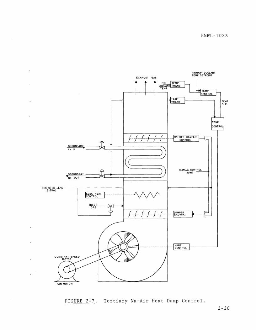
EXHAUST GAS
PRIMARY COOLANT TEMP SETPOINT
I
FIGURE 2-7. Tertiary N a - A i r Heat Dump Control.
2-20

A fire or a sodium leak in the tertiary air dump would ini-
tiate the closing of both the upper and lower dampers, and
the heat transfer space would be filled with inert gas.
Valves on the secondary sodium piping provide flow balance
between the four parallel air dumps, and in the event of a
sodium leak, will provide isolation capability. During
reactor shutdown, the dampers will be closed and the space
heated to prevent freezing of sodium in the secondary piping.
Control or operation of the sodium-air heat dumps in
response to scram or programmed shutdown will be sequenced
in a predetermined manner by transferring set points or
actuator inputs from the normal source to a special circuit
or sequence for the particular corrective action. Defini-
tions of startup and shutdown or scram sequences are depen-
dent upon DHX design and are not covered at this time.
Possible requirements for determining the sequencing are
developed in Section 3.0.
2.7 CLOSED TEST LOOP CONTROL
A closed test loop consists of an in-reactor test loop, a parallel out-of-reactor test chamber and the pumps, piping,
and heat exchangers needed to provide a single heat trans-
port system with a primary and a secondary coolant loop. 1
Each coolant loop uses two parallel pumps to assure coolant
flow in the event of a single pump failure. The sodium-air
heat dump uses parallel air blowers to a single stack for
heat dump backup. The closed test loop control concept as
shown in Figure 2-8 is to treat the test section AT and the
1. Refer to References, Appendix A, Item 9.


test inlet temperature as the basic controlled variables.
The method is to control inlet temperature constant by DHX
air flow and then control test AT by variations in Na coolant
flow. For any given test assembly at a constant heat genera-
tion rate, once a desired AT is specified the coolant flow
rate is also determined.
The inlet temperature to the test section is controlled by
adjusting the heat dissipation rate (air flow rate) in the
sodium-air heat dump. In addition a separate electrical
heater is used on the inlet to the test section for fine
temperature control and for additional heat input if the
desired inlet temperature is higher than can be tolerated
by the primary loop component design.
The test outlet temperature is controlled by using the out-
let temperature to provide a primary coolant flow set point.
Such an arrangement of AT control by adjusting coolant flow
rate requires a convenient means of scaling the controller
and signal ranges to accommodate the various AT coolant flow
combinations for tests of various heat generation capabilities.
The out-of-reactor test chamber is intended to permit a
second test assembly to be run at the same time with coolant
flow and AT the same as the in-reactor test. The two assem-
blies can be evaluated to separate irradiation effects from
temperature and flow-induced changes.
Control for the out-of-reactor test chamber consists of a
flow sensor and control valve that are independent of the
coolant pumps and an electrical heater in the test chamber
to produce the desired test AT. Control interactions between
the out-of-reactor test chamber and the closed test loop
primary system are not considered to be significant, as the
out-of-reactor flow is about 10% of the total.

The parallel primary coolant pumps operate together from a
common control signal which uses loop flow as the control
variable. In the event of a primary pump failure a check
valve prevents backflow through the failed pump, and the
remaining pump continues to supply coolant to the test
assembly. An electromagnetic pump provides backup in the
event of failure of both of the centrifugal primary coolant
pumps.
The surge tanks for the two parallel primary pumps are con-
nected with headers to provide a single cover gas volume
and a single sodium volume. Primary loop pressure is main-
tained by controlling cover gas pressure in the pump surge
tanks. Sodium inventory for the primary system is main-
tained during operation by a high level overflow in the
pump surge tanks, and by make-up sodium injected into the
surge tanks. Sodium fill is also available during shutdown
on the discharge side of the pumps near the inlet to the
in-reactor test section. This sodium makeup line also
serves as emergency cooling in the event of a loss of all
primary pumping capability or a primary pipe rupture.
The secondary has a pump and surge tank arrangement similar
to the primary system. System pressure is controlled by
adjusting cover gas pressure. Sodium inventory is main-
tained by permitting volume contraction or expansion to
change the level of the sodium in the surge tank. Sodium
makeup capability is provided to the surge tank but this
would be used primarily to replace the coolant which is
drained from the system for purification.
Secondary flow is sensed and this signal used to control the
two parallel pumps. The two pumps assure coolant flow in
the event of a single pump failure. The secondary coolant

flow can be adjusted as a function of primary coolant flow.
This capability provides for more uniform temperature
increase or decrease throughout the system.
An electromagnetic pump provides a minimum coolant capability
in the event of failure of both centrifugal pumps. The
electromagnetic pump would also provide low flows for decay
heat removal.
The sodium-air heat dump has two parallel air blowers feeding
a single stack, to assure cooling. Each blower has a butter-
fly valve on the inlet and outlet of the blower. The valves
on the blower outlets are on-off valves to provide isolation
and permit maintenance on the isolated blower. The valves on
the blower inlet, along with adjustable vane pitch, provide
for continuous coolant flow control.
The heat dump sodium outlet temperature is sensed and com-
pared to a set point derived from the test loop inlet tempera-
ture and this error signal used to provide a control signal
to the blower inlet air control valves.
During reactor scram or programmed shutdown, position of the
air control valves will be determined by a special scram or
shutdown sequence. For periods of very low heat removal,
dampers above the cooling fins would be closed and an elec-
trical heater operated to maintain sodium outlet temperature
from the heat dump. This may be required to prevent freezing
or cold trapping due to overcooling in the air dump.

SECTION 3.0 ABNORMAL AND EMERGENCY PLANT CONTROL
When t h e r e a c t o r and p r o c e s s sys t ems a r e pe r fo rming normal ly
a t power, a wide c l a s s of sys tem p e r t u r b a t i o n s ( e . g . , a i r
i n l e t t e m p e r a t u r e , pump v o l t a g e s ) w i l l be h a n d l e d a d e q u a t e l y
by t h e normal r e a c t o r and p l a n t c o n t r o l sys t ems a s d i s c u s s e d
i n t h e p r e v i o u s s e c t i o n s . Those i n c i d e n t s i n v o l v i n g ma l func -
t i o n o r l o s s of components , however, w i l l r e q u i r e more
d r a s t i c a c t i o n t o c o r r e c t t h e a b n o r m a l i t y . Two b a s i c l e v e l s
of c o r r e c t i o n a r e proposed f o r t h e F F T F : (1) C o n t r o l l e d
Power Reduc t ion , which w i l l r educe r e a c t o r power i n r e s p o n s e
t o s e l e c t e d abnormal c o n d i t i o n s when t h e normal c o n t r o l
sys t ems a r e u n a b l e t o r e a c t , and ( 2 ) P l a n t P r o t e c t i o n , which
w i l l sc ram t h e r e a c t o r i n r e s p o n s e t o any s e r i o u s abnormal
c o n d i t i o n o r i n t h e e v e n t t h a t t h e normal c o n t r o l o r
C o n t r o l l e d Power Reduct ion I n s t r u m e n t a t i o n f a i l s t o a c t .
The f o l l o w i n g s e c t i o n o f t h i s document i s o r g a n i z e d a s f o l l o w s :
(1) C o n t r o l l e d Power Reduct ion I n s t r u m e n t a t i o n i s d i s c u s s e d
w i t h r e s p e c t t o i t e m s such a s t h e need f o r t h i s i n s t r u m e n t a -
t i o n , t h e r e s u l t s of p r e l i m i n a r y a n a l y s i s , and t h e p r e f e r r e d
c o n c e p t s proposed f o r c o n c e p t u a l d e s i g n , (2) P l a n t P r o t e c t i o n
I n s t r u m e n t a t i o n i s d e f i n e d and a c o n c e p t i s p r e s e n t e d o u t -
l i n i n g t h e scram t r i p s needed f o r r e a c t o r p r o t e c t i o n , and
( 3 ) Engineered Sa feguards C o n t r o l i s d i s c u s s e d .
3 .1 CONTROLLED POWER REDUCTION INSTRUMENTATION
I n s t r u m e n t a t i o n must b e p r o v i d e d t o d e t e c t abnormal s i t u a t i o n s
which might a r i s e d u r i n g o p e r a t i o n of t h e f a c i l i t y and which
may l e a d t o damage i f l e f t u n c o r r e c t e d . The s t a n d a r d method
of p r o v i d i n g t h i s d e t e c t i o n i s by t h e u s e of a P r o t e c t i o n
System which i n i t i a t e s a r e a c t o r scram. I n most power r e a c t o r s ,
r e a c t o r scram i s t h e o n l y form of c o r r e c t i o n a p p l i e d t o

abnormal o p e r a t i o n o t h e r t h a n t h e normal c o n t r o l r e s t r a i n t s .
The FFTF w i l l , o f c o u r s e , have a p r o t e c t i o n sys t em which w i l l
i n i t i a t e a r e a c t o r scram. T h i s sys t em i s covered i n S e c t i o n
3.2 of t h i s document.
I n a d d i t i o n t o a p r o t e c t i v e sys tem which i n i t i a t e s a r e a c t o r
scram, t h e FFTF s h o u l d have an i n s t r u m e n t a t i o n sys t em which
i n i t i a t e s c o r r e c t i v e a c t i o n somewhat l e s s s e v e r e t h a n t h e
scram, The a c t i o n t a k e n c o u l d i n c l u d e i t e m s such a s :
(1) i n d i v i d u a l rod s c r a m s , (2) a l l rod i n s e r t i o n s a t a p r e -
d e t e r m i n e d r a t e a n d / o r ( 3 ) r e g u l a t i n g r o d i n s e r t i o n a t i t s
normal r a t e of t r a v e l . The i n s t r u m e n t a t i o n p r o v i d e d f o r t h i s
pu rpose w i l l be c a l l e d C o n t r o l l e d Power Reduct ion (CPR)
I n s t r u m e n t a t i o n . The p h i l o s o p h y g o v e r n i n g t h e u s e of CPR
i n s t r u m e n t a t i o n i s o u t l i n e d a s f o l l o w s :
A. The C P R I n s t r u m e n t a t i o n i s t o be s e p a r a t e from t h e P ro -
t e c t i v e I n s t r u m e n t a t i o n . Every e f f o r t w i l l b e made t o
p r o v i d e s e p a r a t e and d i s t i n c t c h a n n e l s (from t h e s e n s o r
t o t h e a c t u a t i o n d e v i c e i n p u t t e r m i n a l s ) f o r t h e P r o t e c -
t i v e I n s t r u m e n t a t i o n . The C P R I n s t r u m e n t a t i o n w i l l u s e
s e n s o r s , a m p l i f i e r s , e t c . , p r o v i d e d by t h e C o n t r o l
I n s t r u m e n t a t i o n o r t h o s e p r o v i d e d e x c l u s i v e l y f o r CPR
u s e ,
B. The C P R I n s t r u m e n t a t i o n w i l l b e d e s i g n e d and used o n l y
where i t i s backed up by P r o t e c t i v e I n s t r u m e n t a t i o n . I f
any C P R channe l s h o u l d f a i l t o f u n c t i o n , t h e r e a c t o r must
s t i l l be p r o t e c t e d by r e a c t o r scram. I t i s e x p e c t e d t h a t
i n many c a s e s t h e backup w i l l be p r o v i d e d b y a r e l a t e d
v a r i a b l e . For example: t h e CPR I n s t r u m e n t a t i o n c o u l d
p r o v i d e power s e t b a c k on low f low i n a secondary l o o p
w i t h t h e P r o t e c t i v e I n s t r u m e n t a t i o n p r o v i d i n g backup by
r e a c t o r scram upon abnormal ly h i g h t e m p e r a t u r e i n t h e p r i -
mary c o l d l e g i n a d d i t i o n t o h i g h c o r e o u t l e t t e m p e r a t u r e .

3.1.1 Need and Requirements for CPR Instrumentation
CPR Instrumentation is desirable for the following reasons:
A. Since the FTR is a test reactor, the events which will
require some form of corrective action will be more
frequent than for a nontest reactor. With the all-rod
scram as the only form of correction, this could lead
to a large number of scram trips. As shown in Columns 1
and 2 of Table 3-1, for example, SEFOR and EBR-I1 have
approximately 24 and 31 trips, respectively, which cause
a reactor scram during full power operation. If equiva-
lent protection is applied to the FTR, excluding
individual channel temperatures, the number of scram
trips would be greater than 100, as shown in Columns 3
and 4 of Table 3.1. A large number of these trips (70
for the FTR-SEFOR extrapolated case and 95 for the
FTR-EBR-I1 extrapolated case) are due to the abnormal
behavior of process variables (flow, level, and tempera-
ture) in the closed loops. The selected use of CPR
instrumentation in areas where analysis shows it to be
adequate (secondary and heat dump systems) will provide
a significant reduction in the number of scram trips.
B e The characteristics of the tests irradiated in the FTR
over its design life will be varied and the detailed
needs of the tests will be unknown during design and
initial operation. With a CPR system, future experi-
menters have a selection of automatic corrections avail-
able for use as their needs warrant. When CPR is not
available, one is forced into a decision of scramming
the reactor because of one experiment with the resultant
consequences of scram forced on all other experiments in
the reactor.

TABLE 3-1. F u l l Power Scram T r i p Comparison
T r i ~ Source SEFOR' EBR- I I F T R - S E F O R ~ FTR-EBR- I I 4
Neutron F l u x
R e a c t o r Pr imary Sodium
2 4 4 4
9 19 2 1 ( 3 l o o p s ) 39 ( 3 l o o p s )
C losed Loop Primary Sodium 0 0 45 (5 l o o p s ) 95 (5 l o o p s )
Secondary Sodium 6 0 1 5 ( 3 l o o p s ) 0
C l o s e d Loop Secondary Sodium 0 0 25 ( 5 l o o p s ) 0
O t h e r (main e l e c t r i c a l power, r a d i a t i o n , m i s c e l l a n e o u s p r e s s u r e , e t c . ) 1 3 6 5
I n d i v i d u a l Channel Temperature 0 2 76 ( d r i v e r and 76 open t e s t p o s i t i o n s )
T o t a l Scrams Excluding I n d i v i d u a l Channel Tempera ture 24 29 115 143
T o t a l Scrams 24 31 191 219
1. R e f e r t o Refe rences , Appendix A , I tem 14.
2 . ANL 1)rawing ID-2C-11142, EBR-I1 R e a c t o r Shutdown S c h e m a t i c - O p e r a t e Mode, February 1967.
3. P r o t e c t i o n e q u i v a l e n t t o t h a t u sed i n SEFOR a p p l i e d t o FTR h e a t t r a n s p o r t s y s tems. W
Z =z
4. P r o t e c t i o n e q u i v a l e n t t o t h a t u sed a t EBR-I1 a p p l i e d t o FTR h e a t F I
t r a n s p o r t s y s tems.

The FTR, b e i n g a t e s t r e a c t o r , w i l l o p e r a t e i n a r e a s
where t h e t echno logy and t h e consequen t approach t o
u n s a f e c o n d i t i o n s a r e r e l a t i v e l y unknown. T h i s i s
e s p e c i a l l y t r u e f o r t h e c l o s e d t e s t l o o p s . I f an a l l -
r o d r e a c t o r scram i s t h e o n l y form o f c o r r e c t i o n a v a i l -
a b l e , t h i s can l e a d t o an abundance of s p u r i o u s scrams
due t o o p e r a t i o n a l d r i f t s , minor i n s t r u m e n t n o i s e , e t c .
I f CPR c o r r e c t i o n can b e imposed around t h e o p e r a t i o n a l
band , p l a n t a v a i l a b i l i t y can be s i g n i f i c a n t l y improved.
D. The t h e r m a l t r a n s i e n t s imposed on t h e r e a c t o r i n t e r n a l s
and t h e v e s s e l a f t e r a r e a c t o r scram a r e e x p e c t e d t o b e
s e v e r e b e c a u s e of t h e l a r g e t e m p e r a t u r e r i s e t h r o u g h t h e
c o r e . The u s e of a l e s s s e v e r e form of shutdown, when
t ime i s a v a i l a b l e , w i l l r educe t h e magni tude of t h e
t r a n s i e n t s and p r o v i d e a d d i t i o n a l c o n s e r v a t i s m t o t h e
c o r e d e s i g n .
E . The t h e r m a l r e a c t o r s (MTR, E T R , A T R ) ~ l o c a t e d a t t h e
N a t i o n a l R e a c t o r T e s t i n g S t a t i o n (NRTS) i n Idaho , make
e x t e n s i v e u s e of C P R I n s t r u m e n t a t i o n . The s e r i e s of
c o r r e c t i o n s which t h e y a p p l y f o r abnormal o p e r a t i o n
(s low s e t b a c k , f a s t s e t b a c k , a l l - r o d rundown, j u n i o r
scram, s low scram, and f a s t sc ram) has p roved t o be v e r y
f l e x i b l e i n a l l o w i n g d i f f e r e n t t y p e s of power r e d u c t i o n s
a c c o r d i n g t o t h e needs of t h e p a r t i c u l a r expe r imen t s i n
t h e r e a c t o r .
F. The u s e of C P R I n s t r u m e n t a t i o n s h o u l d be c o n s i d e r e d t o
t a k e advan tage of t h e t r a n s p o r t d e l a y t i m e s i n t h e Main
Heat T r a n s p o r t and Closed Loop Heat T r a n s p o r t Systems.
Upon l o s s of secondary f l o w w i t h t h e p r e s e n t d e s i g n , f o r
example, t h e t ime r e q u i r e d f o r t h e i n c r e a s e d p r imary
1. R e f e r t o R e f e r e n c e s , Appendix A , I tem 15.

c o l d - l e g t e m p e r a t u r e t o r e a c h t h e r e a c t o r c o r e i s
a p p r o x i m a t e l y 1 3 s e c . A c t i o n can be t a k e n by t h e CPR
I n s t r u m e n t a t i o n t o r educe r e a c t o r power a t a p r e d e t e r -
mined r a t e , t h e r e b y t a k i n g f u l l advan tage of t h i s t ime .
The t r a n s p o r t d e l a y t ime f o r abnormal o p e r a t i o n i n t h e
t e r t i a r y sys t em t o p r o p a g a t e t o t h e r e a c t o r c o r e i s
e x p e c t e d t o be a b o u t 2 5 t o 30 s e c . Here a g a i n , some
form o f CPR a c t i o n seems t o be i n o r d e r .
G . CPR I n s t r u m e n t a t i o n may be u s e d t o good a d v a n t a g e t o
p r o t e c t p l a n t equipment o t h e r t h a n t h e r e a c t o r c o r e such
a s h e a t exchanger s and p i p i n g i n t h e secondary and
t e r t i a r y sys t ems . The u s e of CPR I n s t r u m e n t a t i o n f o r
t h i s pu rpose p r e v e n t s u n n e c e s s a r y scrams and a t t h e
same t ime a l l o w s CPR I n s t r u m e n t a t i o n t o be c o n s i d e r e d
n o n p r o t e c t i v e .
I f CPR I n s t r u m e n t a t i o n i s t o p r o v i d e a v a l u a b l e c o n t r i b u t i o n
t o c o n t r o l o f t h e r e a c t o r , i t must be a b l e t o meet some
g e n e r a l r e q u i r e m e n t s . The c o m p l i c a t i o n t h a t t h i s i n s t r u m e n t a -
t i o n adds t o t h e c o n t r o l sys t em must b e j u s t i f i e d by l e s s
s e v e r e t h e r m a l t r a n s i e n t s , and i n c r e a s e d p l a n t a v a i l a b i l i t y .
The g e n e r a l r e q u i r e m e n t s a r e s t a t e d below.
A. CPR I n s t r u m e n t a t i o n must p r o v i d e a s i g n i f i c a n t d e c r e a s e
i n t h e t h e r m a l t r a n s i e n t s r e s u l t i n g from i t s u s e when
compared t o a r e a c t o r scram. Reduc t ions i n power by u s e
of CPR I n s t r u m e n t a t i o n w i l l be s l o w e r , a l l o w i n g more
t ime f o r t h e f low c o n t r o l i n s t r u m e n t a t i o n t o a d j u s t t h e
f low t o a g i v e n power l e v e l . I n t h e i d e a l s i t u a t i o n ,
f low w i l l be reduced t o h o l d t h e c o r e AT and t h e r e b y
p r o v i d e t h e c a p a b i l i t y of a h o t s t a r t u p and r e t u r n t o
power.

B e CPR I n s t r u m e n t a t i o n must p r o v i d e a v a r i e d r e s p o n s e t o
i n d i v i d u a l abnormal s i t u a t i o n s . One of t h e d i s a d v a n t a g e s
of P r o t e c t i v e I n s t r u m e n t a t i o n i s t h a t i t i s d e s i g n e d t o
r e d u c e r e a c t o r power a s r a p i d l y a s p o s s i b l e from t h e
o p e r a t i n g t r i p p o i n t t o decay h e a t l e v e l w i t h no i n t e r -
med ia t e s t o p p i n g p o i n t . CPR I n s t r u m e n t a t i o n w i l l b e
d e s i g n e d t o p r o v i d e s l o w e r power r e d u c t i o n s i n power t o
i n t e r m e d i a t e l e v e l s s u f f i c i e n t t o a l l e v i a t e t h e
p a r t i c u l a r abnormal s i t u a t i o n .
C . C P R I n s t r u m e n t a t i o n mus t p r o v i d e i n c r e a s e d p l a n t a v a i l -
a b i l i t y ove r and above t h a t of a sys t em which employs
o n l y a n n u n c i a t o r s , normal c o n t r o l l o o p s , manual o p e r a t o r
c o n t r o l , and p r o t e c t i v e a c t i o n .
D . CPR I n s t r u m e n t a t i o n must s i g n i f i c a n t l y r educe t h e number
o f scrams by p r e v e n t i n g s e l e c t e d p r o c e s s v a r i a b l e s from
r e a c h i n g scram t r i p p o i n t s .
3.1.2 C o n t r o l l e d Power Reduct ion A n a l y s i s and Concept
P r e l i m i n a r y a n a l y s i s has been comple ted t o d e t e r m i n e t h e r e a c -
t o r r e s p o n s e t o v a r i o u s r e a c t i v i t y r e d u c t i o n s . These r e s u l t s
a r e i n c l u d e d a s p a r t of Appendix C . The f i r s t g e n e r a l c l a s s
o f r e a c t i v i t y r e d u c t i o n s c o n s i d e r e d was f o r s i n g l e and p a r t i a l
rod scrams o f 504 t o 15$ i n s e r t e d o v e r 1 s e c , w i t h no p r imary
f low r e d u c t i o n . The second c l a s s of r e a c t i v i t y r e d u c t i o n s
c o n s i d e r e d was f o r c o n t i n u o u s r e a c t i v i t y r e d u c t i o n s w i t h
r a t e s between 1 and 75Q/sec and w i t h t h e p o s s i b i l i t y of p r imary
f low r e d u c t i o n .
The s t u d i e s of s i n g l e and p a r t i a l rod scrams i n d i c a t e t h a t
f a s t r e a c t i v i t y r e d u c t i o n s of l e s s t h a n $1 .50 a r e r e q u i r e d t o
h o l d t h e r a t e - o f - c h a n g e of t u b e o u t l e t t e m p e r a t u r e below
45 "F / sec . For t h i s r a n g e o f r e a c t i v i t y r e d u c t i o n s (below

$ 1 . 5 0 ) , i t would b e d i f f i c u l t t o p r e d i c t t h e p r o p e r rod i n s e r - .
t i o n r e q u i r e d w i t h o u t t h e u s e of e x t e n s i v e d i g i t a l c o n t r o l ,
I t was concluded t h a t t h i s form of r e a c t i v i t y r e d u c t i o n s h o u l d
n o t be c o n s i d e r e d f u r t h e r a t t h i s t ime .
The second c l a s s of r e a c t i v i t y r e d u c t i o n s , c o n t i n u o u s r o d
i n s e r t i o n s , p r o v i d e s a much more f l e x i b l e method of r e d u c i n g
power. Rod i n s e r t i o n s up t o lOQ/sec c o u l d be used w i t h no
r e d u c t i o n i n p r imary f l o w w i t h a maximum r a t e - o f - c h a n g e of
t u b e o u t l e t t e m p e r a t u r e of a b o u t 16 " F / s e c . Rod i n s e r t i o n s
g r e a t e r t h a n 1 0 Q / s e c c o u l d be combined w i t h f low r e d u c t i o n s
t o minimize o u t l e t t e m p e r a t u r e t r a n s i e n t s . F u r t h e r a n a l y s i s
i s r e q u i r e d t o d e f i n e t h e optimum method of r e d u c i n g p r imary
f low and t o c o o r d i n a t e t h e r e s p o n s e o f t h e secondary and
t e r t i a r y p o r t i o n s of t h e main h e a t t r a n s p o r t sys tem.
Two c a t e g o r i e s of C P R a c t i o n have been s e l e c t e d f o r f u r t h e r
s t u d y and a n a l y s i s . These a c t i o n s a r e c a l l e d Programmed Shu t -
down and Power S e t b a c k . Programmed Shutdown i s accompl i shed
by an a l l - r o d i n s e r t i o n w i t h p r imary f l o w a d j u s t m e n t t o l i m i t
Thermal t r a n s i e n t s . The e x a c t r a t e of shutdown has n o t been
d e t e r m i n e d , b u t i s e x p e c t e d t o b e g r e a t e r t h a n 1 0 Q / s e c nega -
t i v e r e a c t i v i t y i n s e r t i o n which c o r r e s p o n d s t o a power r educ -
t i o n from 100% t o 5% power i n 60 s e c a s shown i n F i g u r e 3-1.
C o n d i t i o n s t o b e a n a l y z e d f o r i n i t i a t i n g programmed shutdown
a r e l i s t e d a s f o l l o w s :
A. High R a d i o n u c l i d e Concen t ra t ion -Con ta inmen t Exhaus t ,
Upon d e t e c t i o n of e x c e s s a c t i v i t y i n t h e con ta inmen t
e x h a u s t , t h e r e a c t o r w i l l be s h u t down u n t i l t h e s o u r c e
of a c t i v i t y can be l o c a t e d and i d e n t i f i e d , The shutdown
does n o t have t o be r a p i d and t h e r m a l t r a n s i e n t s s h o u l d
be minimized.

T i m e , S e c o n d s
FIGURE 3-1. Automat ic FFTF Power Reduc t ions

B e S u s t a i n e d Loss of One of t h e Two Main Sources o f
E l e c t r i c a l Power. Upon d e t e c t i o n of l o s s o f one of t h e
two main s o u r c e s of o u t s i d e power, t h e r e a c t o r w i l l be
s h u t down u n t i l power i s r e s t o r e d . Thermal t r a n s i e n t s
s h o u l d b e minimized d u r i n g shutdown. The shutdown r a t e
must b e s u f f i c i e n t t o p r e v e n t sodium b o i l i n g due t o l o s s
of power t o t h e a f f e c t e d main h e a t t r a n s p o r t l o o p ( s ) ,
C . Low Flow - Each Closed T e s t loo^ Secondarv Sodium
C i r c u i t . Upon d e t e c t i o n of t h i s c o n d i t i o n , t h e r e a c t o r
power s h o u l d be r educed t o a v o i d t h e o c c u r r e n c e of a
r e a c t o r scram upon d e t e c t i o n of h i g h sodium t e m p e r a t u r e
i n t h e c l o s e d t e s t l o o p p r imary c o l d l e g . The r a t e o f
power r e d u c t i o n s h o u l d be f a s t enough t o a v o i d a r e a c t o r
scram i f one of t h e two secondary c l o s e d l o o p sodium
pumps i s l o s t .
D, High Temperature i n Closed T e s t Loop Secondary Cold Leg,
T h i s c o n d i t i o n i n d i c a t e s t h e l o s s o r m a l f u n c t i o n of t h e
h e a t dump sys tem f o r a c l o s e d loop . The r e a c t o r power
i s r educed b e f o r e t h e t e m p e r a t u r e u n b a l a n c e can p r o p a g a t e
back t o t h e p r imary sys t em, t h e r e b y t a k i n g advan tage of
t r a n s p o r t t ime d e l a y s .
The second a c t i o n s e l e c t e d w i l l b e c a l l e d Power S e t b a c k . Power
Se tback i s accompl ished by a s i n g l e rod i n s e r t i o n t o r educe
r e a c t o r power t o a p r e d e t e r m i n e d l e v e l . S e t b a c k i s a l s o used
t o r educe r e a c t o r power u n t i l t h e c o n d i t i o n which i n i t i a t e d
t h e s e t b a c k h a s c l e a r e d . Pr imary f l o w r e d u c t i o n would n o t be
r e q u i r e d f o r a l l i n i t i a t i n g e v e n t s . The r a t e of power r e d u c -
t i o n i s e x p e c t e d t o b e l e s s t h a n t h a t f o r t h e n e g a t i v e 1 0 Q / s e c
which c o r r e s p o n d s t o a r a t e - o f - c h a n g e of c o r e o u t l e t tempera-
t u r e o f -16 " F / s e c w i t h no p r imary f l o w r e d u c t i o n . C o n d i t i o n s
t o be c o n s i d e r e d f o r i n i t i a t i o n of Power Se tback and l i s t e d
below.
3-10

A. Low Flow - Each Main Heat T r a n s p o r t Secondary Loop,
R e a c t o r power w i l l b e reduced i n o r d e r t o a v o i d a r e a c -
t o r scram upon d e t e c t i o n of h i g h t e m p e r a t u r e i n t h e
p r imary c o l d l e g . D e t e c t i o n of t h i s c o n d i t i o n c o u l d
a l s o i n i t i a t e a program t o t a k e t h e a f f e c t e d l o o p o u t
of s e r v i c e a u t o m a t i c a l l y w h i l e o p e r a t i o n c o n t i n u e d a t
a r educed r e a c t o r power.
B. High Tempera ture - Main Heat T r a n s p o r t Secondary Cold Leg,
T h i s c o n d i t i o n i n d i c a t e s a m a l f u n c t i o n of t h e h e a t dump
sys tem f o r one of t h e main h e a t t r a n s p o r t l o o p s . The
r e a c t o r power s h o u l d b e r educed b e f o r e t h e e f f e c t of t h i s
d i s t u r b a n c e can p r o p a g a t e back t o t h e p r imary sys t em
c a u s i n g a r e a c t o r scram. The l o o p c o u l d a l s o be t a k e n
o f f - l i n e w h i l e t h e r e a c t o r c o n t i n u e s t o o p e r a t e a t a
r educed r e a c t o r power, u s i n g t h e u n a f f e c t e d l o o p s .
C. High Neutron F l u x - Power Range C o n t r o l Channels . T h i s
c o n d i t i o n would b e d e t e c t e d by t h e power r a n g e c o n t r o l
c h a n n e l s and would i n i t i a t e a power r e d u c t i o n t o a v o i d
t h e o c c u r r e n c e of a r e a c t o r scram. The s e t p o i n t f o r t h i s
power r e d u c t i o n , f o r example, might be s e t a t 105% power
w i t h t h e scram s e t p o i n t a t 110% power on t h e p r o t e c t i v e
c h a n n e l s . The power r e d u c t i o n w i l l c o r r e c t m o d e r a t e l y
f a s t changes i n power l e v e l b e f o r e t h e scram s e t p o i n t i s
r e a c h e d .
D. High Tempera ture - Core O u t l e t . Upon d e t e c t i o n of h i g h
t e m p e r a t u r e a t t h e c o r e o u t l e t , r e a c t o r power would be
r educed t o a v o i d a t e m p e r a t u r e i n c r e a s e t o t h e scram
s e t p o i n t . C o n t r o l c h a n n e l s would moni to r t e m p e r a t u r e and
c a u s e a power r e d u c t i o n , f o r example, a t 815 'F, and p r o -
t e c t i v e c h a n n e l s would m o n i t o r t e m p e r a t u r e and i n i t i a t e

BNWL- 102 3
a r e a c t o r scram a t 830 OF, For t h e power r e d u c t i o n , i t
w i l l n o t b e d e s i r a b l e t o r educe p r imary f low a s t h i s
would o n l y compound t h e o v e r t e m p e r a t u r e problem.
E. High Tempera ture - I n d i v i d u a l D r i v e r and Open T e s t
P o s i t i o n Channels . A c t i o n i n r e s p o n s e t o t h i s c o n d i t i o n
i s now p lanned a s p r o t e c t i v e , r e q u i r i n g a r e a c t o r scram.
P r o t e c t i v e a c t i o n would have t h e advan tage o f a s s u r i n g
t h a t t h e r e a c t o r i s s h u t down i n t h e f a s t e s t p o s s i b l e
manner , b u t w i t h 352 p r o t e c t i v e c h a n n e l s ( 4 / r e a c t o r
c h a n n e l ) i n t h e sys t em, p l a n t a v a i l a b i l i t y c o u l d be
a f f e c t e d , The d e s i g n s h o u l d i n c l u d e t h e o p t i o n of
changing from p r o t e c t i o n t o power s e t b a c k , i f f u t u r e
a n a l y s i s and deve lopmenta l r e s u l t s s o i n d i c a t e , Power
s e t b a c k would have t h e a d v a n t a g e of r e d u c i n g power t o
an i n t e r m e d i a t e l e v e l w h i l e h o l d i n g f low a t a c o n s t a n t
l e v e l , The i n s t r u m e n t a t i o n f o r i n d i v i d u a l c h a n n e l o v e r -
t e m p e r a t u r e d e t e c t i o n s h o u l d be d e s i g n e d t o meet a l l 1 I p r o t e c t i v e r e q u i r e m e n t s . The f i n a l t r i p o u t p u t could
t h e n b e u s e d f o r e i t h e r P r o t e c t i o n o r Power S e t b a c k a s
r e q u i r e d .
3 , 2 PLANT PROTECTION INSTRUMENTATION
The FFTF P l a n t P r o t e c t i o n I n s t r u m e n t a t i o n i s d e f i n e d a s a l l
e l e c t r i c a l and mechan ica l d e v i c e s and c i r c u i t r y (from, and
i n c l u d i n g s e n s o r s t o a c t u a t i o n d e v i c e i n p u t t e r m i n a l s )
i n v o l v e d i n g e n e r a t i n g t h o s e t r i p s i g n a l s a s s o c i a t e d w i t h t h e
p r o t e c t i v e f u n c t i o n , I n c l u d e d a r e t h o s e s i g n a l s which
a c t u a t e r e a c t o r scram and which , i n t h e e v e n t of a s e r i o u s
r e a c t o r a c c i d e n t , a c t u a t e e n g i n e e r e d s a f e g u a r d s ,
1. R e f e r t o R e f e r e n c e s , Appendix A , I tem 1 6 , pages 31-16.

The d i s c u s s i o n h e r e w i l l be d i v i d e d i n t o t h r e e s e c t i o n s ,
The f i r s t s e c t i o n w i l l d i s c u s s p r o t e c t i v e i n s t r u m e n t a t i o n t o
be u s e d t o scram t h e r e a c t o r i n t h e e v e n t of abnormal o p e r a -
t i o n i n t h e n u c l e a r and p r o c e s s s y s t e m s , The second s e c t i o n
w i l l d i s c u s s r e s p o n s e of p r o c e s s sys t ems t o scram a c t i o n ,
F i n a l l y , t h e a c t u a t i o n and o p e r a t i o n o f e n g i n e e r e d s a f e g u a r d s
a r e d i s c u s s e d ,
3 , 2 , 1 C o n c e ~ t For Scram T r i ~ s
I n o r d e r t o d e f i n e t h e i n s t r u m e n t a t i o n needed f o r FFTF p l a n t
p r o t e c t i o n a P i s t o f abnormal n u c l e a r and p r o c e s s e v e n t s was
compi led w i t h t h e a i d of t h e FTR f a u l t t r e e . ' T h i s l i s t i s
i n c l u d e d i n Appendix D of t h i s document. A c o n c e p t f o r scram
p r o t e c t i o n o f t h e FTR i s o u t l i n e d below,
A , P o s i t i v e R e a c t i v i t y I n s e r t i o n s , P e r i o d t r i p s a r e used
t o gua rd a g a i n s t t h e e f f e c t s of p o s i t i v e r e a c t i v i t y
i n s e r t i o n s from t h e a l l - r o d s - i n s e r t e d c o n d i t i o n t o
a p p r o x i m a t e l y 1% power, by low r a n g e and i n t e r m e d i a t e
r ange c h a n n e l s . High l e v e l t r i p s a r e a l s o p r o v i d e d
e v e r y f i v e decades i n power l e v e l a s a backup t o p e r i o d
p r o t e c t i o n . P r o t e c t i o n a g a i n s t overpower i n t h e r a n g e
between a p p r o x i m a t e l y 1% and 150% power i s p r o v i d e d by
power r a n g e n u c l e a r c h a n n e l s which w i l l scram t h e r e a c -
t o r on b o t h h i g h l e v e l and h i g h r a t e - o f - c h a n g e of l e v e l ,
Two a d d i t i o n a l t r i p s may b e p r o v i d e d t o g u a r d a g a i n s t
s e l e c t e d p o s i t i v e r e a c t i v i t y i n s e r t i o n s ; namely,
h y d r a u l i c holddown n P t o p r e v e n t r e a c t i v i t y i n c r e a s e s
due t o f u e l movement, and sodium l e v e l i n a l l p r imary
pumps t o p r e v e n t v o i d i n g of t h e c o r e by g a s e n t r a i n m e n t
1, R e f e r t o R e f e r e n c e s , Appendix A , I tem 1 7 ,

i n t h e sodium. A backup t o t h e above scram t r i p s i s
p rov ided by h i g h b u l k c o r e o u t l e t t e m p e r a t u r e .
B . Nega t ive R e a c t i v i t y I n s e r t i o n s . P r o t e c t i o n a g a i n s t
l a r g e unexpec ted d e c r e a s e s i n power i s p r o v i d e d by a
n e g a t i v e r a t e - o f - c h a n g e scram. This scram p r o t e c t s
a g a i n s t n e g a t i v e r e a c t i v i t y i n s e r t i o n s due t o sodium
b o i l i n g i n t h e o u t e r c o r e r e g i o n s and f u e l meltdown ,
where f u e l moves t o a r e g i o n of lower r e a c t i v i t y wor th .
C . Loss of Primary Heat T r a n s p o r t Systems - Main and Closed
loo^. P r o t e c t i o n i s i n i t i a t e d f o r l o s s of l e v e l i n t h e
FTR v e s s e l a s a r e s u l t of sodium l e a k a g e from t h e pr imary
sys tem. Low l e v e l i n each p r imary pump w i l l a l s o scram
t h e r e a c t o r t o p r o t e c t a g a i n s t v o i d i n s e r t i o n s . P r o t e c -
t i o n o f t h e r e a c t o r i n t h e e v e n t of l o s s of p r imary f low
w i l l be p rov ided by a h igh / low f low t r i p i n each main
h e a t t r a n s p o r t sys t em pr imary l o o p , a s i n g l e t r i p i n
r e s p o n s e t o low sodium i n l e t plenum p r e s s u r e , and a
s i n g l e power/f low compara tor f o r t h e main p r imary sys tem.
The power/f low compara tor u t i l i z e s t h e s i g n a l from t h e
power r ange f l u x c h a n n e l s and a t o t a l p r imary f l o w s i g n a l
t o gua rd a g a i n s t l o s s of f low d u r i n g t r a n s i e n t p e r i o d s
when f low i s changing . Each c l o s e d t e s t l o o p w i l l a l s o
have a power/f low t r i p .
Although n o t i n c l u d e d i n t h i s c o n c e p t , one has t h e o p t i o n
of u s i n g t h e i n d i v i d u a l channe l f lowmete r s a s p r o t e c t i o n
a g a i n s t l o s s of f low. These f lowmeters have some advan-
t a g e s o v e r l o o p f lowmete r s :
T h e i r r e s p o n s e would n o t depend on t h e l o c a t i o n of a
p i p e b r e a k w i t h r e s p e c t t o t h e f lowmeter l o c a t i o n .
They would be s e n s i t i v e t o o p e r a t i o n of check v a l v e s
t o p r e v e n t r e v e r s e f low i n t h e e v e n t of a p i p e b r e a k .

They would p r o v i d e i n c r e a s e d redundancy s i n c e 73
d r i v e r c h a n n e l s a r e p r o v i d e d .
During o p e r a t i o n w i t h a l l f l owmete r s i n s e r v i c e , r e a c t o r
scram would occur i f 4 of t h e 73 d r i v e r c h a n n e l s i n d i c a t e
low f l o w , I f one o r more f lowmete r s became i n o p e r a t i v e ,
t h e l o g i c would b e changed by u s e of i n d i v i d u a l bypass
s w i t c h e s , t o 4 / n where n < 73, A d m i n i s t r a t i v e c o n t r o l
would b e used t o a s s u r e t h a t n was g r e a t e r t h a n a number
such a s 1 2 . These low-f low t r i p s would be backed up by
t r i p s f o r h i g h c o r e o u t l e t t e m p e r a t u r e and h i g h c l o s e d
l o o p o u t l e t t e m p e r a t u r e .
D . Loss o f Heat Removal - I n d i v i d u a l D r i v e r and Open T e s t
P o s i t i o n Channels . P r o t e c t i o n a g a i n s t l o s s o f f l o w w i l l
b e p r o v i d e d by p r o v i s i o n f o r r e a c t o r scram upon d e t e c t i o n
of h i g h t e m p e r a t u r e i n each i n d i v i d u a l d r i v e r and open
t e s t p o s i t i o n channe l ( s e e S e c t i o n 3 .2 .2 , I tem E ) . Flow-
m e t e r s a r e p r o v i d e d i n each c h a n n e l , I t w i l l on ly be
p o s s i b l e t o i n c l u d e one f lowmeter i n each c h a n n e l , how-
e v e r , b e c a u s e of s p a c e l i m i t a t i o n s . S i n c e t h e r e l i a b i l i t y
f o r a s i n g l e s e n s o r i n t h i s envi ronment i s q u e s t i o n a b l e ,
and dependen t on a s u c c e s s f u l development program, t h e -
u s e of i n d i v i d u a l c h a n n e l f lowmete r s t o i n i t i a t e a r e a c -
t o r scram on l o s s of f low from a s i n g l e c h a n n e l i s n o t
con templa ted . The f lowmete r s w i l l s t i l l be v a l u a b l e i n
p r o v i d i n g a s s u r a n c e of a d e q u a t e f low i n a l l c h a n n e l s
p r i o r t o r e a c t o r s t a r t u p .
E. Loss of Secondary and T e r t i a r y Heat T r a n s p o r t Systems -
Main and Closed Loop. P r o t e c t i o n a g a i n s t l o s s of s e c o n -
d a r y and t e r t i a r y sys tems w i l l b e p r o v i d e d by d e t e c t i o n
of h i g h t e m p e r a t u r e i n t h e p r imary c o l d l e g of each

c l o s e d t e s t and main loop . Backup p r o t e c t i o n i s p r o -
v i d e d by h i g h t e m p e r a t u r e a t t h e c o r e o u t l e t and t h e
c l o s e d l o o p h o t l e g . I n d i v i d u a l m a l f u n c t i o n s i n t h e
secondary and t e r t i a r y sys t ems s u c h a s low f low o r h i g h
t e m p e r a t u r e i n i n d i v i d u a l secondary l o o p s , w i l l be p r o -
v i d e d by C o n t r o l l e d Power Reduct ion I n s t r u m e n t a t i o n .
(See S e c t i o n 3 , 2 . )
F. O t h e r Scram T r i p s , A d d i t i o n a l scram t r i p s a r e p r o v i d e d
f o r l o s s of e l e c t r i c a l power from b o t h o u t s i d e s o u r c e s ,
h i g h s e i s m i c a c t i v i t y l e v e l , h i g h r a d i a t i o n l e v e l i n t h e
con ta inmen t e x h a u s t c o i n c i d e n t w i t h h i g h c o n t a i n m e n t
p r e s s u r e , and f o r s p e c i a l c l o s e d l o o p e x p e r i m e n t a l needs
such a s c l a d t e m p e r a t u r e , f u e l t e m p e r a t u r e , e t c . , a s
might b e r e q u i r e d by i n d i v i d u a l e x p e r i m e n t s .
T a b l e 3-11 i s a c o m p i l a t i o n of a l l r e a c t o r t r i p s i n r e s p o n s e
t o abnormal o p e r a t i o n , i n c l u d i n g b o t h P r o t e c t i v e and Con-
t r o l l e d Power Reduc t ion , A t o t a l of 198 p r o t e c t i v e c h a n n e l s
and 129 CPR c h a n n e l s a r e p r o v i d e d . I n a d d i t i o n , 304 c h a n n e l s
a r e p r o v i d e d t o d e t e c t o v e r t e m p e r a t u r e i n i n d i v i d u a l d r i v e r
and open t e s t p o s i t i o n c h a n n e l s w i t h t h e o p t i o n of u s i n g t h e s e
f o r e i t h e r P r o t e c t i o n o r CPR. I n s t r u m e n t r a n g e s and t r i p
p o i n t s shown i n T a b l e 3-11 a r e o n l y e s t i m a t i o n s a t t h i s s t a g e
of d e s i g n , and w i l l b e r e d e f i n e d a s d e s i g n p r o g r e s s e s .
3.2.2 Response t o Scram T r i p s
A r e a c t o r scram o c c u r s when t h e p l a n t p r o t e c t i v e sys t em a c t s
t o r e l e a s e t h e p r imary s a f e t y r o d s i n t o t h e c o r e . Because of
t h e s p e e d o f such a c t i o n , t h e r e s p o n s e s o f t h e r e a c t o r and
h e a t t r a n s p o r t sys t ems t o t h e scram must b e a u t o m a t i c . O p e r a t -
i n g p e r s o n n e l c a n n o t be e x p e c t e d t o pe r fo rm a l l n e c e s s a r y
p o s t - s c r a m f u n c t i o n s .
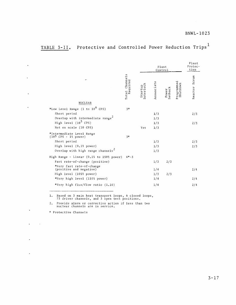
BNWL- 1023
TABLE 3-11. P r o t e c t i v e and C o n t r o l l e d Power Reduct ion T r i p s 1
NUCLEAR
*Low Level Range ( 1 t o l o 6 CPS)
S h o r t p e r i o d
Over l ap w i t h i n t e r m e d i a t e r ange 2
High l e v e l ( l o 5 CPS)
Not on s c a l e (10 CPS)
" I n t e r m e d i a t e Level Range (105 CPS - 1% power)
S h o r t p e r i o d
High l e v e l (0 .1% power)
Over l ap w i t h h i g h r ange c h a n n e l s 2
P l a n t C o n t r o l
3 * 1 / 3
1 / 3
1 / 3 Yes 1 / 3
High Range - L i n e a r (0 .1% t o 150% power) 4"-3
F a s t r a t e - o f - c h a n g e ( p o s i t i v e ) 1 / 3 2 /3
*Very f a s t r a t e - o f - c h a n g e ( p o s i t i v e and n e g a t i v e )
High l e v e l (105% power)
*Very h i g h l e v e l (110% power)
*Very h i g h f l u x / f l o w r a t i o (1.10) 1 /4
1. Based on 3 main h e a t t r a n s p o r t l o o p s , 6 c l o s e d l o o p s , 73 d r i v e r c h a n n e l s , and 3 open t e s t p o s i t i o n s .
2. P r o v i d e a l a rm o r c o r r e c t i v e a c t i o n i f l e s s t h a n two n u c l e a r c h a n n e l s a r e i n s e r v i c e .
P l a n t P r o t e c -
t i o n
* P r o t e c t i v e Channels

TABLE 3-11. (Contd)
P l a n t P l a n t P r o t e c -
C o n t r o l t i o n
"l -
Bulk Sodium
High c o r e o u t l e t t e m p e r a t u r e (815 OF)
*Very h igh c o r e o u t l e t t e m p e r a t u r e (830 OF)
t l igh c l o s e d loop p r imary h o t - l e g t e m p e r a t u r e
*Very h i g h c l o s e d loop p r imary h o t - l e g t e m p e r a t u r e
tligh main HTS p r imary c o l d - l e g t e m p e r a t u r e (515 OF)
*Very h i g h main tITS p r imary c o l d - l e g t e m p e r a t u r e (530 OF)
t l igh c l o s e d l o o p p r imary c o l d - l e g t e m p e r a t u r e
*Very h i g h c l o s e d l o o p p r imary c o l d - l e g t e m p e r a t u r e
High HTS seconda ry c o l d - l e g t e m p e r a t u r e
High c l o s e d l o o p seconda ry c o l d - l e g t e m p e r a t u r e
P o i n t sodiumL
tl igh i n d i v i d u a l d r i v e r o u t l e t t e m p e r a t u r e (825 OF) 292
IIigh i n d i v i d u a l open t e s t p o s i t i o n o u t l e t t e m p e r a t u r e ( 8 2 5 O F ) 1 2
FLOW - Bulk Sodium
*High/Low p r imary f low - i n d i v i d u a l HTS loops 1 2 * Yes 1 /4
*High Flux/Flow - Main tlTS 4 * Yes 1 /4
"High Flux/Flow - I n d i v i d u a l C losed Loops 24* Yes 1 / 4
Low seconda ry f low - i n d i v i d u a l tlTS loops 9 Yes 1 / 3
Low seconda ry f l o w - i n d i v i d u a l c l o s e d loops 18 Yes 1 / 3
1. T r l p p o i n t s n o t e d a r e r e p r e s e n t a t i v e o f i n i t i a l o p e r a t i o n .
2. Could be used f o r power s e t b a c k o r r e a c t o r scram dependen t on f u r t h e r a n a l y s i s and development of t he rmocoup le s
* P r o t e c t i v e Channels

TABLE 3-11. (Contd)
P l a n t P r o t e c -
t i o n
5 U V)
L 0 C, U cd a, d
P l a n t C o n t r o l
FLOW (con td ) -
P o i n t Sodium Flow 1
Low f l o w - i n d i v i d u a l d r i v e r e l emen t s Yes 1/1
Low f low - i n d i v i d u a l open t e s t p o s i t i o n s 3
Low f low - c l o s e d l o o p t e s t s e c t i o n s 6
Yes 1/1
Yes 1/1
"PRESSURE
Low c o r e i n l e t plenum p r e s s u r e 4 * Yes 1/4
Yes 1 / 4 Low h y d r a u l i c holddown AP 4*
High con ta inmen t b u i l d i n g p r e s s u r e c o i n c i d e n t w i t h h i g h r a d i a t i o n l e v e l i n con ta inmen t e x h a u s t 4 *
Low r e a c t o r v e s s e l l e v e l 4 * Low HTS p r imary pump l e v e l 12*
Low c l o s e d loop p r imary pump l e v e l 24*
Yes 1 / 4
Yes 1 / 4
Yes 1 / 4
MISCELLANEOUS
S u s t a i n e d l o s s o f E l e c t r i c a l Power ( > 1 / 2 s e c )
Loss o f one main bus 3
*Loss o f b o t h main b u s e s 4 * R a d i a t i o n Leve l
Yes 1 / 3
1 /4
High con ta inmen t e x h a u s t l e v e l 3
S e i s m i c I n t e n s i t y
Low t r i p ( i n s t r u m e n t m a l f u n c t i o n )
*High l e v e l 4*
C losed Loop Expe r imen ta l
S p e c i a l e x p e r i m e n t a l needs 24*-18
Yes 1 / 3
1. Not t o be used i n a u t o m a t i c power r e d u c t i o n c i r c u i t r y i n t h i s c o n c e p t ( s e e D i s c u s s i o n unde r 3 .3 .1 ) .
* P r o t e c t i v e Channels

BNWL- 1 0 2 3
TABLE 3-11. (Contd)
P l a n t P l a n t P r o t e c -
C o n t r o l t i o n
T o t a l P r o t e c t i v e Channels 1
T o t a l P r o t e c t i v e Channels I n c l u d i n g
I n d i v i d u a l Open T e s t P o s i t i o n and D r i v e r
Over t empera tu re P r o t e c t i o n 502
T o t a l CPR 129
T o t a l CPR I n c l u d i n g I n d i v i d u a l Open T e s t P o s i t i o n and D r i v e r Over t empera tu re 4 3 3
1. Channel i n c l u d e s t h e s e n s o r , a m p l i f i e r , t r i p u n i t , e t c .

A. Reac to r Response. A s a f e t y c i r c u i t t r i p s i g n a l o r l o s s
of s a f e t y c i r c u i t c o n t i n u i t y c a u s e s a l l scrammable rods
t o be r e l e a s e d i n t o t h e c o r e s i m u l t a n e o u s l y and t h e
remain ing r o d s a r e d r i v e n i n t o t h e c o r e . I n a d d i t i o n ,
t h e d r i v e s of t h e scrammable rods t h e n a u t o m a t i c a l l y
d r i v e down w i t h maximum speed t o a s s u r e t h a t t h e r o d
r e a c h e s i t s f u l l y i n s e r t e d p o s i t i o n . When a s a f e t y
c i r c u i t f u n c t i o n i s a c t u a t e d , i t i s i m p o s s i b l e t o d e l a y
o r c a n c e l t h e r e s u l t i n g scram e f f e c t .
B. Heat T r a n s p o r t System Response. A scram r e s p o n s e i s n o t
r e q u i r e d of t h e h e a t t r a n s p o r t sys t ems a t any t ime when
t h e AT a c r o s s t h e c o r e i s l e s s t h a n 1 0 % o f t h e o p e r a t i o n a l
f u l l v a l u e . Based on t h e i n i t i a l ox ide c o r e , a r e a c t o r
scram w i t h f u l l p r imary f low a t a c o r e AT of 30 OF (10%
of i n i t i a l AT) w i l l p roduce a c o r e o u t l e t t r a n s i e n t of
abou t - 5 OF/sec f o r 3 t o 4 s e c . The r e s u l t i n g the rma l
s t r e s s e s a r e w e l l w i t h i n e x p e c t e d d e s i g n v a l u e s f o r t h e
c o r e . S i n c e t h e main purpose f o r hav ing any s o r t of a
h e a t t r a n s p o r t sys tem scram r e s p o n s e i s t o l i m i t t h e
s e v e r i t y of the rma l shock , p r imary f low r e d u c t i o n i s n o t
r e q u i r e d .
The h e a t t r a n s p o r t sys tem w i l l r espond i n an i d e n t i c a l
manner t o each scram, r e g a r d l e s s of i t s c a u s e . Response
of t h e p r o c e s s sys tems (once t h e c o r e AT i s above 10%
f u l l v a l u e ) w i l l be a s f o l l o w s :
1. Pr imary sodium f low w i l l be a u t o m a t i c a l l y d e c r e a s e d
t o a p r e s e t v a l u e . A s h o r t t ime d e l a y (on t h e o r d e r
of 1 / 2 t o 1 s e c ) w i l l e l a p s e between s a f e t y r o d drop
and t h e b e g i n n i n g of f low decay , i n o r d e r t o a s s u r e
power shutdown and remove s t o r e d h e a t i n t h e f u e l .
The p o s t - s c r a m f low may depend on t h e t y p e of pump

BNWL- 1023
s e l e c t e d , A w o u n d - r o t o r , m o t o r - d r i v e n pump may have
a p o s t - s c r a m f l o w a s h i g h a s 35% f u l l v a l u e , t e n d i n g
t o c o l l a p s e t h e c o r e AT r e l a t i v e l y r a p i d l y , Thus,
t o p r e s e r v e c o r e AT f o r scram r e c o v e r y , i t would be
n e c e s s a r y t o a l l o w c o n s t a n t speed pony motors t o
p r o v i d e decay h e a t removal ( a t a b o u t 10 t o 15% of
f u l l f low) by removing power from t h e wound- ro to r
moto r s . A c o n s t a n t - s p e e d i n d u c t i o n motor w i t h an
e l e c t r o m a g n e t i c c l u t c h ( t h e a l t e r n a t i v e method) would
m a i n t a i n a p o s t - s c r a m f low between 5 and 1 0 % o f f u l l
v a l u e , Core AT would be m a i n t a i n e d , While t h e l a t t e r
pump d r i v e approach i s p r e f e r a b l e from t h e t h e r m a l
t r a n s i e n t p o i n t of view, t h e fo rmer approach may be
d i c t a t e d by o t h e r p r o c e s s sys t em c o n c e r n s .
2 . Secondary sys t em f low w i l l behave a s does t h e p r i m a r y ,
3. DHX a i r f l o w w i l l c u t back t o m a i n t a i n c o l d - l e g
t e m p e r a t u r e s a t a c o n s t a n t l e v e l , Expected r e s p o n s e
i s a s t o p p i n g of a l l f a n s f o l l o w e d by c o n t r o l on t h e
DHX s t a c k l o u v e r s t o l i m i t t h e amount of n a t u r a l a i r
d r a f t c o o l i n g . Should i t be n e c e s s a r y from t h e
s t a n d p o i n t o f c o n t r o l l a b i l i t y , s e v e r a l modules of
t h e DHX may b e t a k e n o f f - l i n e by v a l v i n g o f f sodium
f low and by t o t a l c l o s u r e o f t h e s t a c k l o u v e r s ,
4 . Heat t r a n s p o r t sys t ems f o r t h e c l o s e d t e s t l o o p s w i l l
r e spond i n t h e same manner a s f o r t h e main l o o p s ,
when f u e l e d t e s t s a r e i n - l o o p . For m a t e r i a l s t e s t s ,
f low r e s p o n s e t o scram i s n o t c r i t i c a l b e c a u s e of
t h e r e l a t i v e l y s m a l l t e s t AT,
C . Scram Recovery, A comple te i n t e g r a t i o n of t h e FTR and
c l o s e d l o o p p r i m a r y , s e c o n d a r y , and t e r t i a r y c o o l a n t s y s -
tem i s r e q u i r e d t o e f f e c t a t e m p e r a t u r e - b a l a n c e d scram

r e c o v e r y s t a r t u p . A common c o n t r o l p o i n t i s r e q u i r e d
t o c o r r e l a t e t h e combined r e s p o n s e s of t h e s e sys t ems .
That common v a r i a b l e s h o u l d b e t h e c o r e p r imary b u l k
o u t l e t t e m p e r a t u r e .
The r e s p o n s e of t h e sys tems s h o u l d be a u t o m a t i c and
s h o u l d r e s u l t i n a l l sys tems remain ing b a l a n c e d d u r i n g
t h e r e c o v e r y t o f u l l power c o n d i t i o n s . A t f u l l power
c o n d i t i o n s , t h e sys tem s h o u l d a u t o m a t i c a l l y c o n t r o l on
p r imary o u t l e t t e m p e r a t u r e .
The most complex sys t em, i n te rms of t h e number of p r o -
grammed a c t i o n s r e q u i r e d , i s t h e t e r t i a r y sys tem.
I n i t i a l l y , two o r more modules i n each sys tem w i l l be
c o m p l e t e l y s h u t down and one o r p o s s i b l y two o t h e r s w i l l
b e i n a minimum c o o l i n g s t a t u s . A s t h e scram r e c o v e r y
p r o g r e s s e s and n u c l e a r h e a t i s a g a i n g e n e r a t e d i n t h e
FTR, t h e dampers on t h e o p e r a t i n g t e r t i a r y modules w i l l
g r a d u a l l y open. Th i s w i l l c o n t i n u e u n t i l a t some p r e -
de te rmined c o n d i t i o n t h e need f o r t h e a u t o m a t i c s t a r t of
one o f t h e shutdown u n i t s w i l l b e r e q u i r e d . The s h u t -
down u n i t w i l l a u t o m a t i c a l l y s t a r t and assume i t s p o r t i o n
of t h e c o o l i n g l o a d a s r e q u i r e d . Th i s sequence w i l l con-
t i n u e a s t h e r e a c t o r power l e v e l i s i n c r e a s e d , u n t i l a l l
modules a r e back on t h e l i n e .
3.2.3 Engineered Sa feguards
A. I n t r o d u c t i o n Engineered s a f e g u a r d s a r e p r o v i d e d i n t h e
f a c i l i t y t o back up t h e s a f e t y p r o v i d e d by t h e c o r e
d e s i g n , t h e r e a c t o r c o o l a n t p r e s s u r e boundary , and t h e i r
p r o t e c t i o n sys t ems . ' T h e i r u s e f o r t h e p r e v e n t i o n o r
1. Refe r t o R e f e r e n c e s , Appendix A , I tem 18 .

r e d u c t i o n o f f i s s i o n p r o d u c t r e l e a s e t o t h e envi ronment
may be accompl ished by t h r e e g e n e r a l methods: l
o P r e v e n t i n g o r min imiz ing , by emergency c o o l i n g o r
o t h e r w i s e , t h e o v e r h e a t i n g of t h e f u e l m a t e r i a l s .
Removing t h e f i s s i o n p r o d u c t s from t h e con ta inmen t
a tmosphere by f i l t e r i n g , s c r u b b i n g , s t o r a g e , e t c .
C o n s t r u c t i n g two o r more b a r r i e r s a round t h e p r imary
sys t em s o t h a t t h e p r o b a b i l i t y t h a t a l a r g e q u a n t i t y
of f i s s i o n p r o d u c t a c t i v i t y may l e a k o u t i s n e g l i g i b l e ,
o r a t l e a s t g r e a t l y r educed ,
Eng inee red S a f e g u a r d s f o r t h e FFTF w i l l i n c l u d e t h e con-
t a i n m e n t and emergency c o r e c o o l i n g s y s t e m s , The con-
c e p t u a l c o n t r o l scheme f o r t h e s e sys t ems i s d e s c r i b e d
below.
B. Containment . A method of p r o v i d i n g c o n t a i n m e n t i s o l a t i o n
i s shown i n F i g u r e 3 - 2 ,
Two d e g r e e s of i s o l a t i o n a r e p r o v i d e d ,
1, Upon t h e o c c u r r e n c e o f h i g h r a d i o n u c l i d e c o n c e n t r a t i o n
i n t h e p l a n t e x h a u s t a i r , t h e v e n t i l a t i o n s u p p l y and
e x h a u s t v a l v e s c l o s e . A t t h e same t i m e , a programmed
r e a c t o r shutdown i s a u t o m a t i c a l l y i n i t i a t e d , The
i n s t r u m e n t a t i o n p r o v i d e d f o r t h e pu rpose w i l l n o t be
c o n s i d e r e d p r o t e c t i v e .
2 . Upon t h e o c c u r r e n c e of h i g h r a d i o n u c l i d e c o n c e n t r a t i o n
i n t h e e x h a u s t a i r c o i n c i d e n t w i t h h i g h p r e s s u r e i n
t h e o u t e r con ta inmen t volume a r e a c t o r scram i s i n l t i -
a t e d and a l l l i n e s p e n e t r a t i n g t h e con ta inmen t n o t
1. Refe r t o R e f e r e n c e s , Appendix A , I t em 19.

TO CON7d//VMLNT VAL Y E S NOT EXJKN7/AL 70 RLACTOR OPCR.4 T/ON / m BE Dk-f//NED)
I I REACTOR
5 C 6 A M
NOTES
1. Need for this monitor to be verified by design study during preliminary design.
F I G U R E 3-2. Containment Actuation Logic Diagram Plant Protection System

e s s e n t i a l t o s a f e r e a c t o r shutdown a r e i s o l a t e d .
The v a l v e s t h a t a r e c l o s e d w i l l i n c l u d e t h o s e i n t h e
v e n t i l a t i o n s u p p l y and e x h a u s t l i n e s and may i n c l u d e
l i n e s such a s t h e i n e r t gas s u p p l y and pneumat ic a i r
s u p p l y depending on t h e p r e s s u r e r a t i n g of t h e p o r -
t i o n s o f t h e s e sys t ems o u t s i d e t h e con ta inmen t b u i l d -
i n g . The s e c o n d a r y sodium l i n e s which p e n e t r a t e t h e
c o n t a i n m e n t b u i l d i n g w i l l b e d e s i g n e d w i t h a d o u b l e
b a r r i e r w i t h a p r e s s u r e r a t i n g above t h a t o f t h e con-
t a i n m e n t and w i l l , t h e r e f o r e , n o t r e q u i r e i s o l a t i o n ,
Emergency Coo l ing . The c o n c e p t f o r emergency c o o l i n g f o r
t h e d r i v e r c o r e has n o t been s e l e c t e d a t t h i s t i m e .
S i n c e c o n t r o l of t h i s emergency c o o l i n g sys t em i s c o n c e p t
dependent i t i s n o t p o s s i b l e t o p r o v i d e a c o n t r o l scheme,
For example, i f a n a t u r a l c i r c u l a t i o n sys t em i s u s e d t h e
c o n t r o l r e q u i r e d w i l l b e q u i t e l i m i t e d , I f , however, a
sys t em i s u s e d which r e q u i r e s t h e s t a r t i n g of pumps and
t h e m a n i p u l a t i o n o f v a l v e s t h e c o n t r o l c o u l d become q u i t e
complex, R e g a r d l e s s o f t h e c o n c e p t used i t w i l l b e con-
s i d e r e d an e n g i n e e r e d s a f e g u a r d and i t s c o n t r o l w i l l b e
i n i t i a t e d and c o n t r o l l e d by P r o t e c t i v e I n s t r u m e n t a t i o n .
The c o n c e p t f o r emergency c o o l i n g of each c l o s e d t e s t
l o o p employs a n e-m pump i n p a r a l l e l w i t h t h e two c e n t r i -
f u g a l pumps i n b o t h t h e p r i m a r y and secondary p o r t i o n s
o f t h e c i r c u i t . Each e-m pump i s r a t e d a t 1 5 % o f t h e
p r imary pump c a p a c i t y t o a s s u r e f o r c e d c i r c u l a t i o n f l o w
t h r o u g h t h e t e s t assembly i n t h e e v e n t t h a t b o t h c e n t r i -
f u g a l pumps f a i l . The e-m pumps a r e n o t n o r m a l l y i n
s e r v i c e , b u t a r e a u t o m a t i c a l l y s t a r t e d upon t h e o c c u r r e n c e
o f low f l o w ,

Each c l o s e d t e s t l o o p i s a l s o p r o v i d e d w i t h a backup
emergency c o o l a n t s u p p l y i n t h e p r i m a r y p o r t i o n of t h e
sys t em. I n t h e e v e n t of a p r imary c o o l a n t p i p i n g f a i l u r e
o r l e a k t h e l e v e l w i l l d rop i n t h e pump t a n k . T h i s
c o n d i t i o n i s s e n s e d by t h e p r o t e c t i v e i n s t r u m e n t a t i o n
which c l o s e s t h e v a l v e p r o v i d i n g r e c i r c u l a t i n g f l o w and
opens a s u p p l y v a l v e l e a d i n g d i r e c t l y t o t h e i n - r e a c t o r
t u b e . The F i l l and R e c i r c u l a t i n g pump which i s u s e d f o r
t h i s o p e r a t i o n i s n o r m a l l y i n o p e r a t i o n . I n t h i s manner
c o o l a n t i s s u p p l i e d t o t h e t e s t even i n t h e e v e n t of
c a t a s t r o p h i c p r imary c o o l a n t p i p i n g f a i l u r e .

APPENDIX A
REFERENCES

APPENDIX A
REFERENCES
1. G. G o Thieme and G. L. Waldkoetter. Unpublished Data.
Conceptual System Design Description for the Central
Control and Data Handling System, No. 91, A-0059-R,
Battelle-Northwest, Richland, Washington. (Preliminary
Report)
2, W. Dalos. Unpublished Data. Conceptual System Design
Description for the Reactor and Vessel Instrumentation
System, No. 92, A-0052-R. Battelle-Northwest, Richland,
Washington. (Preliminary Report)
3, M, 0. Rankin and C. R. F. Smith. 'Unpublished Data.
Conce~tual System Design Descri~tion for the Plant
Instrumentation System, No. 93, A-0055-R, Battelle-
Northwest, Richland, Washington, (Preliminary Report)
4. Unpublished Data. Conceptual System Design Description
for the Fuel Failure Monitoring System, No. 94,
Battelle-Northwest, Richland, Washington. (Preliminary
Report)
5. L . W. McClellen. Unpublished Data, Conceptual System
Design Description for the Flux P.lonitoring and Control
System, No. 95, A-0056-R. Battelle-Northwest, Richland,
Washington. (Preliminary Report)
6, M . 0. Rankin. Conceptual System Design Description for
the Radiation Monitoring System, No. 96, BNWL-500,
Volume 96. Battelle-Northwest, Richland, Washington,
September 6, 1968,

7. J . P. Thomas. Unpublished Data, Conceptual System Design
Description for the Plant Protection System, No. 99,
A-0101, Battelle-Northwest, Richland, Washington,
(Preliminary Report)
8, Re J. Hennig, Unpublished Data. Functional Testing
Requirements for the FFTF, A-0030-R. Battelle-Northwest,
Richland, Washington. (Preliminary Report)
9, M. K O Mahaffey. Unpublished Data. Conceptual System
Design Description for the Closed Loop System, No. 61,
A-0069. Battelle-Northwest, Richland, Washington.
(Preliminary Report)
10. R. R. Derusseau, Unpublished Data. Conceptual System
Design Description for the Short-Term Irradiation
Facility, No. 68. Battelle-Northwest, Richland,
Washington. (Preliminary Report)
11, Unpublished Data. Conceptual System Design Description
for the Reactor Core, No. 31, A-0036-R. Battelle-
Northwest, Richland, Washington. (Preliminary Report)
Unpublished Data. Conceptual Sys tem
Design Description for the Reactor Heat Transport System,
No, 51, A-0012-R. Battelle-Northwest, Richland,
Washington. (Preliminary Report)
13. Re E. Peterson. Technical Basis for FTR Driver Fuel
Instrumentation, BNWL-555. Battelle-Northwest, Richland,
Washington, September 1967.
14. SEFOR Facility and Safety Analysis Report, AEC Docket
No. 50-231, Volume I, Section X, August 1967,

15. Fundamentals in the Operation of Nuclear Test Reactors
(4 volumes), IDO-16872, 3, 4, 5. Phillips Petroleum
Company, Idaho Falls, Idaho,
16. Design Safety Criteria for the Fast Flux Test Facility,
BNWL-823, Battelle-Northwest, Richland, Washington,
June 17, 1968.
17. M e A, McLoughlin, Preliminary Fault Tree Analysis for
the FFTF, BNWL-874. Battelle-Northwest, Richland,
Washington, May 1968.
18. General Desien Criteria for Nuclear Power Plant Construc-
tion Permits, Proposed Appendix A to lOCFR Part 50,
July 11, 1967.
19. W. B. Cottrell and A. W. Savoloinen, ed. U. S. Reactor
Containment Technology, ORNL-NSIC-5, Volume 1. Oak Ridge
National Laboratory, Oak Ridge, Tennessee, August 1965,
20, C. D . Flowers and L . He Gerhardstein. Analog-Hybrid
Dynamic Simulation of the FFTF Reactor and Heat
Transport System, BNWL-707. Battelle-Northwest, Richland,
Washington, April 1968.

BNWL- 1023
APPENDIX B
EVALUATION OF PLANT CONTROL WITH HYBRID SIMULATION
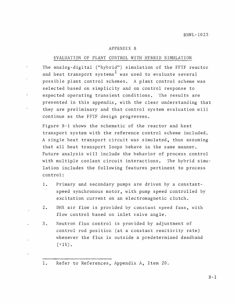
BNWL- 10 23
APPENDIX B
EVALUATION OF PLANT CONTROL WITH HYBRID SIMULATION
The a n a l o g - d i g i t a l ("hybrid") s i m u l a t i o n o f t h e FFTF r e a c t o r
and h e a t t r a n s p o r t sys tems1 was used t o e v a l u a t e s e v e r a l
p o s s i b l e p l a n t c o n t r o l schemes. A p l a n t c o n t r o l scheme was
s e l e c t e d based on s i m p l i c i t y and on c o n t r o l r e s p o n s e t o
e x p e c t e d o p e r a t i n g t r a n s i e n t c o n d i t i o n s . The r e s u l t s a r e
p r e s e n t e d i n t h i s append ix , w i t h t h e c l e a r u n d e r s t a n d i n g t h a t
t h e y a r e p r e l i m i n a r y and t h a t c o n t r o l sys t em e v a l u a t i o n w i l l
c o n t i n u e a s t h e FFTF d e s i g n p r o g r e s s e s .
F i g u r e B-1 shows t h e s c h e m a t i c of t h e r e a c t o r and h e a t
t r a n s p o r t sys t em w i t h t h e r e f e r e n c e c o n t r o l scheme i n c l u d e d .
A s i n g l e h e a t t r a n s p o r t c i r c u i t was s i m u l a t e d , t h u s assuming
t h a t a l l h e a t t r a n s p o r t l o o p s behave i n t h e same manner.
F u t u r e a n a l y s i s w i l l i n c l u d e t h e b e h a v i o r of p r o c e s s c o n t r o l
w i t h m u l t i p l e c o o l a n t c i r c u i t i n t e r a c t i o n s . The h y b r i d s imu-
l a t i o n i n c l u d e s t h e f o l l o w i n g f e a t u r e s p e r t i n e n t t o p r o c e s s
c o n t r o l :
1. Pr imary and secondary pumps a r e d r i v e n by a c o n s t a n t -
s p e e d synchronous m o t o r , w i t h pump s p e e d c o n t r o l l e d by
e x c i t a t i o n c u r r e n t on an e l e c t r o m a g n e t i c c l u t c h ,
2 . DHX a i r f low i s p r o v i d e d by c o n s t a n t s p e e d f a n s , w i t h
f low c o n t r o l b a s e d on i n l e t v a l v e a n g l e .
3 , Neutron f l u x c o n t r o l i s p r o v i d e d by a d j u s t m e n t o f
c o n t r o l r o d p o s i t i o n ( a t a c o n s t a n t r e a c t i v i t y r a t e )
whenever t h e f l u x i s o u t s i d e a p r e d e t e r m i n e d deadband
( * I % ) .
1. R e f e r t o R e f e r e n c e s , Appendix A , I t em 20,


BNWL- 1023
4. Sodium mix ing p l e n a a r e i n c l u d e d a t t h e i n l e t and o u t l e t
of t h e IHX and D H X , a s w e l l a s a t t h e i n l e t and o u t l e t
of t h e r e a c t o r v e s s e l ,
F u t u r e a n a l y s i s w i l l a l s o i n c l u d e o t h e r d e s i g n p o s s i b i l i t i e s ,
such a s sodium pumps d r i v e n by wound- ro to r m o t o r s ,
The c o n t r o l scheme shown i n F i g u r e B-1 r e p r e s e n t s a c o n f i g u r a -
t i o n which meets t h e t e s t c r i t e r i a known a t t h i s t ime . Flow
c o n t r o l f o r t h e main h e a t t r a n s p o r t c i r c u i t s i s f o r c o n s t a n t
f low ( a u t o - c o n t r o l on f low s i g n a l s , w i t h manual s e t p o i n t s ) ,
and FTR i n l e t t e m p e r a t u r e i s c o n t r o l l e d by t h e DHX a i r f l o w ,
u s i n g an a n t i c i p a t o r y c o n t r o l t e c h n i q u e , A i r f l o w i s a d j u s t e d
t o produce t h e d e s i r e d DHX sodium o u t l e t t e m p e r a t u r e , i n
r e s p o n s e t o power changes , such t h a t t h e FTR i n l e t i s main-
t a i n e d a t t h e d e f i n e d t e m p e r a t u r e , 110 O F . A c o n t r o l a l g o r i t h m ,
based on r e a c t o r power and IHX pe r fo rmance , p r o v i d e s t h e s e t -
p o i n t f o r a PGI ( g a i n - p l u s - r e s e t ) c o n t r o l l e r f o r t h i s c o n t r o l
l o o p , I n t h e s i m u l a t i o n , g a i n and r e s e t r a t e f o r t h e c o n t r o l l e r
were a r b i t r a r i l y s e l e c t e d ; no a t t e m p t was made t o m a x i m i z e 7
c o n t r o l l e r pe r fo rmance ,
The i n i t i a l c o n d i t i o n s f o r s t u d y i n g t h e c o n t r o l scheme were
a s f o l l o w s : ( a ) Power = 400 M W t , (b) R e a c t o r i n l e t tempera-
t u r e = 600 "F , ( c ) R e a c t o r O u t l e t Tempera ture = 900 OF,
(d l Number o f h e a t t r a n s p o r t c i r c u i t s o p e r a t i n g = 3 , ( e ) IHX
LMTD = 1 1 0 O F , and ( f ) A i r i n l e t t o t h e DHX = 100 "F. The
s i m u l a t i o n was made t o r e spond t o t h e f o l l o w i n g t r a n s i e n t s :
1. Power s e t b a c k from 400 MW t o 300MW by chang ing f l u x s e t -
p o i n t , a l l o w i n g c o n t r o l t o s e e k new power l e v e l a t
l $ / s e c ; f u l l f low i s m a i n t a i n e d ,
2 . Power s e t b a c k from 300 MW t o 200 MW a t l $ / s e c ; f u l l f l o w ,

3. Power s e t b a c k f rom 200 MW t o 100 MW a t l $ / s e c ; 50% f l o w ,
4 . Power s e t b a c k f rom 100 MW t o 50 MW a t l $ / s e c ; 50% f l o w .
R e s u l t s a r e shown i n F i g u r e s B - 2 t h r o u g h 3 - 5 . Fo r t h e e x t r e m e
power c h a n g e s which we re f o r c e d on t h e p r o c e s s s y s t e m , a t h i g h
and low f l o w s , t h e r e s u l t i n g c o r e i n l e t t e m p e r a t u r e c h a n g e s
we re w i t h i n t h e d e s i r e d g o a l o f '10 OF, I n e a c h c a s e , t h e
d e s i r e d s t e a d y - s t a t e i n l e t t e m p e r a t u r e was r e - e s t a b l i s h e d w i t h -
o u t e x t r e m e l y l o n g s e t t l i n g t i m e s and w i t h o u t e x c e s s i v e DHX
c o n t r o l a c t i o n .

BNWL- 1023
2 5 0 3 1 ou- J W W L L ~ A 1 5 0 ;
0 1 0 0 2 0 0 3 0 0 4 0 0 5 0 0 6 0 0
T i m e , S e c o n d s
F I G U R E 8-2 . System Response t o Power Ramp, 400-300 MWt

ou- J W W L m J
3 100
T i m e , s e c o n d s
FIGURE B - 3 . System Response t o Power Ramp, 300-200 MWt

L o n L o E
- W W + 600
( T c o r )
i o o r
3 1
Time, Seconds
00- J W a 1500 - LLLnO -10
U M - I W J 500 - Lo- o
FIGURE B-4 . System Response t o Power Ramp, 2 0 0 - 1 0 0 M W t , 5 0 % Flow
-

200 3 0 0 4 0 0 5 0 0
T i m e , s e c o n d s
4
x . 500- I l - a 3
O 400
FIGURE B-5 . System Response t o Power Ramp, 1 0 0 - 5 0 MWt, 5 0 % Flow
( T c s y o )

APPENDIX C
PRELIMINARY ANALYSIS OF CONTROLLED POWER REDUCTION

APPENDIX C
PRELIMINARY ANALYSIS OF CONTROLLED POWER REDUCTION
Some p r e l i m i n a r y a n a l y s i s has been comple ted w i t h t h e o b j e c -
t i v e of d e t e r m i n i n g what forms of CPR a c t i o n would be
f e a s i b l e f o r t h e FTR, Numerical r e s u l t s p r e s e n t e d h e r e a r e
u s e f u l f o r t h e compar ison purposes o f t h i s s t u d y . IIowever,
changing c o r e d e s i g n h a s s i n c e a l t e r e d t h e magni tude of t h e
the rma l t r a n s i e n t s p r e s e n t e d h e r e , The t h r e e a r e a s cove red
by t h e s t u d y were : s i n g l e o r p a r t i a l rod scram i n s e r t i o n s ,
a l l - r o d r u n - i n i n s e r t i o n s , and s i n g l e r o d r u n i n i n s e r t i o n s ,
SINGLE OR PARTIAL R O D SCRAMS
The u s e of a s i n g l e o r p a r t i a l rod scram was e x p l o r e d f o r u s e
a s an i n t e r m e d i a t e s t e p between a '%setbackw ( rod r u n - i n mode)
and a f u l l r e a c t o r scram, The b a s i c p u r p o s e of t h i s a c t i o n
would be t o p r o v i d e a d e f i n i t e shutdown i n t h e e v e n t of an
i n c i d e n t w h i l e a t t h e same t ime m a i n t a i n i n g a s u f f i c i e n t power
l e v e l t o minimize t h e t ime needed f o r r e - s t a r t ,
The s i m u l a t i o n s t u d i e s assumed t h a t t h e p r imary f low r a t e
remained a t f u l l f low d u r i n g each scram and examined t h e
e f f e c t of scram r e a c t i v i t y on power and c o r e c o o l a n t o u t l e t
t e m p e r a t u r e , An o x i d e c o r e was assumed and t h e d i f f e r e n t
scram r e a c t i v i t i e s were i n s e r t e d a s ramps o v e r a 1 s e c i n t e r -
v a l , I n i t i a l c o n d i t i o n s were 4 0 0 MW and 3 0 0 "F AT, The t
as sumpt ion o f f u l l f low a p p e a r s t o be r e a s o n a b l e f o r t h i s
t y p e of p a r t i a l shutdown f o r t h e f o l l o w i n g r e a s o n s : (1) a
'"junior scram" s h o u l d o f f s e t incipient r e a c t i v i t y i n c i d e n t s
w i t h o u t t h e r i s k of u n d e r c o o l i n g , and ( 2 ) f l ow coastdown
f o l l o w i n g a scram w i l l be i n i t i a t e d o n l y a f t e r i t i s c e r t a i n
t h a t r o d ( s ) have been i n s e r t e d . R e s u l t s o f t h e b r i e f s t u d y
a r e shown i n F l g u r e s C - 1 t h rough C-4, There i s l i t t l e


('Mw) ' N I W S 1 W d 3 M O d l V 1 0 1

d 0
h C, . rl > . d C, U cd O n LZ a,
M 6 d cd cd k A U U v)
'+I W O 0
a, C, C, U cd a, k ccl ccl E w 3
E .rl


BNWL- 1023
d i f f e r e n c e i n t h e e f f e c t s of scram r e a c t i v i t y f o r magni tudes
l a r g e r t h a n $ 3 t o $ 5 . For lower scram r e a e t i v i t i e s , w i t h i n
t h e s i n g l e and p a r t l a 1 r o d c a t e g o r y , t h e e f f e c t s o f r e a c t i v i t y
on power and c o r e o u t l e t t h e r m a l t r a n s i e n t s a r e more p r o -
nounced, However, t h e u t i l i t y of a j u n i o r scram a p p e a r s t o
b e l i m i t e d p r e c i s e l y b e c a u s e maximizing t h e p o s t - s c r a m power
and min imiz ing t h e t h e r m a l t r a n s i e n t s r e q u i r e s t h a t r e a c t i v i t y
b e a c c u r a t e i n t h e r e g i o n of -504 t o - $ 1 , 5 0 . I t w i l l be
d i f f i c u l t t o p r o v i d e r e a c t i v i t y r e d u c t i o n s o f t h i s s m a l l mag-
n i t u d e w i t h o u t making e x t e n s i v e u s e of d i g i t a l c o n t r o l o v e r
t h e comple te r a n g e of operating c o n d i t i o n s , I t was c o n c l u d e d ,
t h e r e f o r e , t h a t t h e u s e of s i n g l e o r p a r t i a l rod scram i n s e r -
t i o n s would n o t b e c o n s i d e r e d f u r t h e r ? a t t h i s t l m e , a s a form
of C o n t r o l l e d Power Reduc t ion ,
ALL-ROD RUN- IN INSERTIONS - PROGRAIVMED SHUTDOWN - -
R e a c t i v i t y i n s e r t i o n s of t h e magni tude r e p r e s e n t a t i v e o f
s e v e r a l o r a l l r o d s were e x p l o r e d , Pr imary f l o w r a t e was con-
t r o l l e d t o h o l d c o r e o u t l e t t e m p e r a t u r e c o n s t a n t w i t h minimum
f low s e t a t 20% of f u l l f l o w , The r e s u l t s a r e shown i n
F i g u r e C-5,
SINGLE ROD RUN-IN INSERTIONS - SETBACK
The u s e of r e a c t i v i t y r e d u c t i o n s of a magni tude r e p r e s e n t a t i v e
of a r e g u l a t i n g r o d a t i t s normal speed of i n s e r t i o n was
e x p l o r e d , The b a s i c p u r p o s e of t h i s a c t i o n would b e t o r e d u c e
r e a c t o r power i n r e s p o n s e t o s e l e c t e d abnormal c o n d i t i o n s t o
t u r n t h e s i t u a t i o n around b e f o r e t h e scram t r i p p o i n t was
r e a c h e d ,
The s i m u l a t i o n s t u d i e s a g a i n assumed t h a t t h e p r imary f l o w r a t e
remained a t f u l l f l o w d u r i n g t h e s e t b a c k and examined t h e


e f f e c t o f r e a c t i v i t y r e d u c t i o n on power and c o r e c o o l a n t
o u t l e t t e m p e r a t u r e . I n i t i a l c o n d i t i o n s were 400 MWt and
300 'F AT, R e s u l t s of t h e s t u d y a r e shown i n F i g u r e s C - 6
t h rough C - 8 , The r e s u l t s show, a s e x p e c t e d , t h a t v a r i o u s
r a t e s of c o r e o u t l e t t e m p e r a t u r e and r e a c t o r power r e d u c t i o n
can be o b t a i n e d depend ing on t h e r a t e of r e a c t i v i t y r e d u c t i o n .
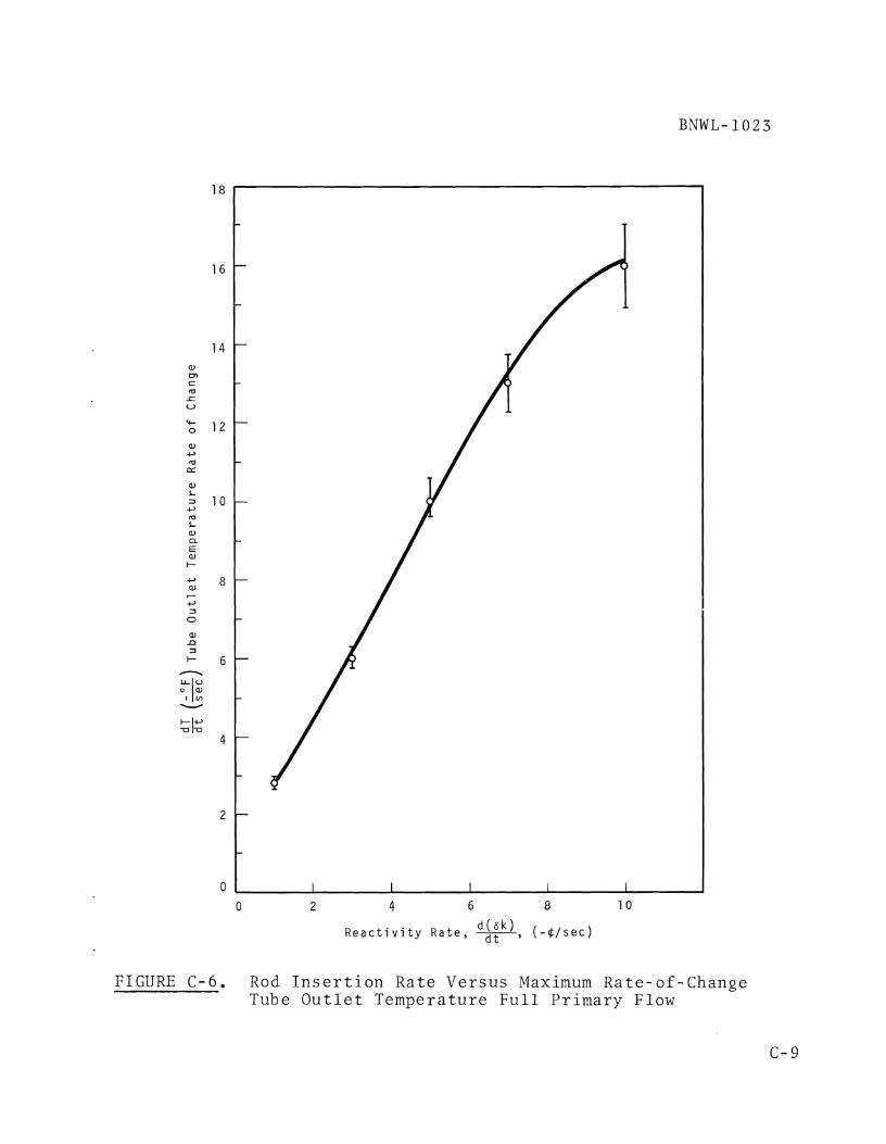
0 2 4 6 8 1 0
R e a c t i v i t y R a t e , w, ( - $ / r e c )
FIGURE C-6. Rod I n s e r t i o n R a t e V e r s u s Maximum Ra te -o f -Change Tube O u t l e t T e m p e r a t u r e F u l l P r i m a r y Flow

-+ END OF ROD I N S E R T I O N
-
-
S e c o n d s A f t e r S t a r t o f I n s e r t i o n
FIGURE C-7. Effect of Rod Insertion Rate on Tube Outlet Temperature

- END OF ROD I N S E R T I O N
C, 3 E
L a, I 0 CL 2 0 0 - L 0 C, U m aJ e
-
FIGURE C-8 . E f f e c t o f Rod I n s e r t i o n Rate on Reac to r Power
1 0 0 -
0
-
I I I I I I
0 1 0 2 0 3 0 4 0 5 0 6 0 7 0
S e c o n d s A f t e r S t a r t o f I n s e r t i o n

A P P E N D I X D
E V E N T S R E Q U I R I N G P R O T E C T I V E A C T I O N
A N D / O R C O N T R O L L E D POWER R E D U C T I O N

APPENDIX D
EVENTS REQUIRING PROTECTIVE ACTION
A N D / O R CONTROLLED POWER REDUCTION
I n o r d e r t o d e f i n e t h e i n s t r u m e n t a t i o n needed f o r FFTF p r o -
t e c t l o n , a l i s t of abnormal p r o c e s s and n u c l e a r e v e n t s which
cou ld o c c u r i s p r e s e n t e d . T h i s l i s t w i l l a l s o d e f i n e t h e
complex i ty and e x t e n t o f t h e i n s t r u m e n t a t i o n needed. The
g e n e r a l c a t e g o r i e s cove red a r e a s f o l l o w s :
1. P o s i t i v e R e a c t i v i t y I n s e r t i o n - P r e c r i t i e a l O p e r a t i o n
2 . P o s i t i v e R e a c t i v i t y I n s e r t i o n - C r i t i c a l t o Low ( 1 % )
Power
3. P o s i t i v e R e a c t i v i t y I n s e r t i o n - P o w e r O p e r a t i o n
4 . Loss of Pr imary Heat T r a n s p o r t (Main and Closed Loop)
5. Loss of Secondary Heat T r a n s p o r t (Main and Closed
Loop) 6 , Loss of T e r t i a r y Heat Dump (Main and Closed Loop)
7 . Loss of Heat Removal from I n d i v i d u a l D r i v e r and Open
T e s t P o s i t i o n Channels
8 . Sodium Leakage
9 . Loss o f E l e c t r i c a l Power
1 0 . S e i s m i c A c t i v i t y .
With t h e a i d of t h e FTR f a u l t t r e e , ' t h e above g e n e r a l c a t e -
g o r i e s a r e broken down i n t o s u b c a t e g o r i e s , and t h e f o l l o w i n g
t a b u l a t i o n s a r e made:
1. A l i s t of t h e e v e n t s guarded a g a i n s t ( p o s s i b l e c a u s e s )
2 . A l i s t of t h e r e s u l t s i f p r o t e c t i v e a c t i o n i s n o t
t a k e n ( p o s s i b l e r e s u l t s )
1. R e f e r t o R e f e r e n c e s , Appendix A , I t em 1 7 .

3 , A l i s t of t h e v a r i a b l e s o r s i g n a l s t h a t c o u l d b e used
f o r t h e d e t e c t i o n o f abnormal o p e r a t i o n ( p o s s i b l e
mon i to red v a r i a b l e s )
4 , A l i s t of p o s s i b l e a c t i o n t h a t c o u l d b e t a k e n t o
c o r r e c t t h e a b n o r m a l i t y ( p o s s i b l e a c t i o n ) ,
1. POSITIVE REACTIVITY INSERTION-PRECRITICAL OPERATION
A , P o s s i b l e Causes
- F u e l e l emen t dropped i n t o p o s i t i o n
-Loading e r r o r
- U n c o n t r o l l e d rod wi thdrawa l
-Rod e x p u l s i o n
-Removal of m a t e r i a l w i t h i n c o n t r o l o r s a f e t y rod c l a d
-Maintenance e r r o r
-Loss of f u e l holddown
B e P o s s i b l e R e s u l t s
- S h o r t r e a c t o r p e r i o d
- F u e l c l a d f a i l u r e and f u e l meltdown
C . P o s s i b l e Moni to red V a r i a b l e s
- R e a c t o r p e r i o d - l o w range c h a n n e l s
-Shutdown r e a c t i v i t y m o n i t o r
-AP indication o f h y d r a u l i c holddown
-High c o u n t r a t e - l o w range c h a n n e l s
D o P o s s i b l e A c t i o n
- R e a c t o r scram
-Cocked rod sc ram
2 , POSITIVE REACTIVITY INSERTION- CRITICAL TO LOW ( 1 % ) POWER
A. P o s s i b l e Causes
-Neut ron spec t rum s h i f t
-Dynamic i n s t a b i l i t y
- P o s i t i v e v o i d r e a c t i v i t y e f f e c t

-Positive coolant temperature effect
-Uncontrolled rod withdrawal
-Rod expulsion
-Loss of fuel holddown
-Removal of material within control or safety
clad
B. Possible Results
-Short reactor period leading to fuel melting
and/or sodium boiling
C, Possible Monitored Variables
-Reactor period-low range channels
-Reactor period-intermediate range channels
-aP indication of positive hydraulic holddown
-High level-intermediate range channels
-Primary sodium temperature
D. Possible Action
-Reactor scram
rod
3, POSITIVE REACTIVITY INSERTION-POWER OPERATION
A, Possible Causes
-Same as in 2A above
-Probability of fuel or control rod melting greater
due to higher temperature
B e Possible Results
-Power excursion leading to fuel meltdown or sodium
boiling
C. Possible Monitored Variables
-Overpower-power range channels
-High rate-of-change-power range channels
-Over temperature in primary sodium
-nP indication of positive hydraulic holddown
-Sodium boiling detection

- F l u x - f l o w r a t i o
-Low pr imary pump l e v e l
D. P o s s i b l e A c t i o n
- R e a c t o r scram o r s e t b a c k
-Flow i n c r e a s e
4 . NEGATIVE REACTIVITY INSERTIONS - POWER OPERATION
A. P o s s i b l e Causes
-Sodium v o i d i n g n e a r t h e upper a x i a l f a c e of t h e c o r e
due t o l o s s of f l o w and consequen t b o i l i n g
-Complete subassembly v o i d i n g i n o u t e r r a d i a l r e g i o n s
of t h e c o r e where l e a k a g e i s h i g h and v o i d wor th i s
n e g a t i v e
-Passage of b u b b l e s th rough t h e c o r e r e s u l t i n g i n a
r e a c t i v i t y d e c r e a s e a s bubb le e n t e r s t h e bot tom a x i a l
f a c e of t h e c o r e ,
B . P o s s i b l e R e s u l t s
- P r o p a g a t i o n of v o i d i n g t o c e n t r a l r e g i o n of t h e c o r e
r e s u l t i n g i n a p o s i t i v e r e a c t i v i t y i n s e r t i o n .
C . P o s s i b l e Moni tored V a r i a b l e s
-Low l e v e l - - power r ange c h a n n e l s
- N e g a t i v e r a t e - o f - c h a n g e power r a n g e c h a n n e l s
-Low f low i n d i v i d u a l c h a n n e l s
-Low f low HTS l o o p s
-Sodium b o i l i n g d e t e c t i o n
D . P o s s i b l e A c t i o n
- R e a c t o r scram
5 . LOSS OF PRIMARY HEAT TRANSPORT (MAIN AND CLOSED LOOP)
A. P o s s i b l e Causes
-Loss o r i n c r e a s e of sodium due t o :
F a i l u r e o f sodium p u r i f i c a t i o n and makeup sys t em
O p e r a t o r e r r o r - s o d i u m d r a i n e d from l o o p

Coolan t l e a k a g e from r e a c t o r v e s s e l
Coo lan t l e a k a g e from pr imary l o o p
O v e r p r e s s u r e o f cove r g a s
-Loss of sodium f low due t o :
Very low sodium l e v e l (pumps l o s e s u c t i o n )
Blockage o f f low th rough c o r e
Blockage of f low th rough I H X
Check v a l v e m a l f u n c t i o n
Rupture of p r imary c o o l a n t boundary
Flow b y p a s s i n g c o r e ( r e v e r s e f low)
Mechanica l o r e l e c t r i c a l f a i l u r e o r p r imary pump
- O t h e r p o s s i b l e c a u s e s
F a i l u r e of p r i m a r y h e a t s i n k ( secondary loop)
F a i l u r e of secondary h e a t s i n k ( h e a t dump)
Carbonaceous m a t e r i a l on f u e l h e a t t r a n s f e r
s u r f a c e
Gas c o l l e c t i o n on f u e l s u r f a c e
B . P o s s i b l e R e s u l t s
- I n a d e q u a t e h e a t removal f rom c o r e
-Sodium b o i l i n g a n d / o r f u e l meltdown
O v e r p r e s s u r e of p r imary sys t em
Loss o f l e v e l i n p r imary pump l e a d i n g t o g a s
e n t r a i n m e n t i n sodium
C . P o s s i b l e Moni tored V a r i a b l e s
- F o r l o s s o r i n c r e a s e of sodium l e v e l
R e a c t o r v e s s e l sodium l e v e l
Pr imary pump sodium l e v e l
Sodium l e a k d e t e c t o r s
- Cover gas p r e s s u r e ( v e s s e l a n d / o r pump)
-For l o s s o f sodium f l o w
Flow m o n i t o r s i n p r imary l o o p
AP a c r o s s p r i m a r y pump

AP a c r o s s c o r e
AP a c r o s s IHX
E l e c t r i c a l s u p p l y t o p r i m a r y pump
Pump s h a f t speed
Temperature i n c r e a s e i n p r imary h o t l e g
Sodium b o i l i n g d e t e c t o r
o Low t e m p e r a t u r e secondary h o t l e g
o I n d i v i d u a l f low m e t e r s
I n l e t plenum p r e s s u r e
-For o t h e r p o s s i b l e c a u s e s
Tempera ture i n c r e a s e i n p r imary c o l d l e g
AP a c r o s s c o r e
Sodium b o i l i n g d e t e c t o r
D. P o s s i b l e A c t i o n
-For l o s s o f sodium l e v e l
R e p l e n i s h sodium
Take l o o p o u t of s e r v i c e
R e a c t o r s e t b a c k , shutdown, o r scram
I n c r e a s e f low i n o t h e r l o o p s
* Retu rn c o v e r gas p r e s s u r e t o normal
-For l o s s o f sodium f l o w
I n c r e a s e pump s p e e d
Decrease p r e s s u r e d r o p th rough l o o p
Take l o o p o u t of s e r v i c e
R e a c t o r s e t b a c k , shutdown, o r scram
- F o r o t h e r c a u s e s
R e s t o r e secondary o r t e r t i a r y loops
R e a c t o r s e t b a c k , shutdown, o r scram
6 . LOSS OF SECONDARY HEAT TRANSPORT SYSTEM (MAIN AND
CLOSED LOOP)
A. P o s s i b l e Causes

-Loss of sodium l e v e l due t o :
F a i l u r e of secondary Na p u r i f i c a t i o n and makeup
s y s tem
O p e r a t o r e r r o r - s o d i u m d r a i n e d from l o o p
Secondary sys tem r u p t u r e o r l e a k a g e
-Loss o f f low due t o :
Loss o f sodium l e v e l
Blockage o f f l o w i n IHX o r DHX
I n a d v e r t e n t v a l v e c l o s u r e
E l e c t r i c a l o r mechan ica l f a i l u r e o f secondary pump
-Othe r c a u s e s
F a i l u r e of t e r t i a r y h e a t dump
* Loss o f h e a t t r a n s f e r t o t e r t i a r y h e a t dump-oxide
o r ca rbonaceous d e p o s i t s on t u b i n g
B e P o s s i b l e R e s u l t s
-Loss of p r imary h e a t s i n k
- I n a d e q u a t e c o o l a n t h e a t removal f rom c o r e
- F u e l m e l t i n g a n d / o r sodium b o i l i n g
C. P o s s i b l e Moni tored V a r i a b l e s
-For l o s s o f sodium l e v e l
- Expansion t ank l e v e l
Secondary pump l e v e l
Sodium l e a k d e t e c t o r s
-For l o s s of f low
Flow m o n i t o r s i n secondary loop
AP a c r o s s pump
AP a c r o s s IHX
AP a c r o s s DHX
E l e c t r i c a l s u p p l y t o s e c o n d a r y pump
* Pump s h a f t s p e e d
High t e m p e r a t u r e i n h o t l e g of secondary l o o p

BNIQL- 10 23
-For o t h e r c a u s e s
High t e m p e r a t u r e i n c o l d l e g of l o o p
D o P o s s i b l e A c t i o n
-For l o s s of sodium l e v e l
R e p l e n i s h sodium
R e a c t o r s e t b a c k , shutdown o r scram
Take l o o p o u t of s e r v i c e
-For l o s s of f low
I n c r e a s e pump s p e e d
Take l o o p o u t of s e r v i c e
R e a c t o r s e t b a c k , shutdown o r scram
-For o t h e r c a u s e s
R e a c t o r s e t b a c k , shutdown o r scram
7 . LOSS OF TERTIARY HEAT DUMP ( MAIN AND CLOSED LOOP)
A. P o s s i b l e Causes
- A i r f l o w b lockage
-Blower o r motor f a i l u r e
-Loss of h e a t t r a n s f e r i n DHX
B. P o s s i b l e R e s u l t s
- I n c r e a s e i n t e m p e r a t u r e i n secondary l o o p
- F a i l u r e of h e a t removal c a p a b i l i t y i n one comple te
h e a t t r a n s p o r t l o o p
-Power /hea t removal imbalance i n r e a c t o r
C . P o s s i b l e Moni to red V a r i a b l e s
- A i r f l ow m o n i t o r i n h e a t dump
- S h a f t speed on b lower
-Loss of power t o b lower
-Blower a i r t e m p e r a t u r e
D. P o s s i b l e A c t i o n
-Remove l o o p from s e r v i c e
- R e a c t o r s e t b a c k , shutdown, o r scram

8 , LOSS OF HEAT REMOVAL FROM INDIVIDUAL DRIVER AND OPEN
LOOP CHANNELS
A. P o s s i b l e Causes
-Flow b l o c k a g e by carbonaceous m a t e r i a l
-Flow b l o c k a g e by f o r e i g n m a t e r i a l
-Flow b l o c k a g e by f u e l s w e l l i n g
-Gas c o l l e c t i o n around f u e l p i n s
B . P o s s i b l e R e s u l t s
- I n d i v i d u a l c h a n n e l b o i l i n g
- I n d i v i d u a l c h a n n e l f u e l meltdown
C . P o s s i b l e Moni tored V a r i a b l e s
-Sodium b o i l i n g d e t e c t o r
- I n d i v i d u a l c h a n n e l thermocouples
- I n d i v i d u a l c h a n n e l f lowmete r s
- I n d i v i d u a l channe l c l a d t e m p e r a t u r e
D o P o s s i b l e A c t i o n
- R e a c t o r scram, shutdown, o r s e t b a c k
9 . SODIUM LEAKAGE
A. P o s s i b l e Causes
-Loss of r e a c t o r v e s s e l b a r r i e r
-Break i n p r imary p i p i n g (main h e a t t r a n s p o r t and
c l o s e d l o o p s y s terns)
-Break i n s e c o n d a r y sodium b a r r i e r (main h e a t
t r a n s p o r t and c l o s e d l o o p sys t ems)
-Sodium i n s t r u m e n t l i n e b r e a k
B , P o s s i b l e R e s u l t s
-Loss of f l o w i f b r e a k i s l a r g e
-Loss of h e a t t r a n s p o r t due t o l o s s of f low
-Sodium f i r e o r smoke

BNWL- 1023
C , P o s s i b l e Moni tored V a r i a b l e s
-Spark p l u g l e a k d e t e c t o r s
- A i r b o r n e a c t i v i t y f o r r a d i o a c t i v e sodium
-Smoke d e t e c t i o n
-Loss o f f low
-Loss o f i n s t r u m e n t i n d i c a t i o n
-Leve l
D . P o s s i b l e A c t i o n
- R e a c t o r shutdown o r scram
- D r a i n sodium from a r e a of l e a k a g e
1 0 . LOSS OF ELECTRICAL POWER
A. P o s s i b l e Causes
-Trans fo rmer f a i l u r e
- S w i t c h g e a r f a i l u r e
- C i r c u i t b r e a k e r f a i l u r e
-Feede r c o n d u c t o r f a i l u r e
B . P o s s i b l e R e s u l t s
-Loss o f e l e c t r i c a l power t o c r i t i c a l equipment o r
i n s t r u m e n t a t i o n
C . P o s s i b l e Moni tored V a r i a b l e s
-Undervo l t age on 13.8 kV sys tem
-Undervo l t age on 2.4 kV sys tem
-Undervo l t age on 480 Vac sys t em
-Undervo l t age on z e r o t ime o u t a g e bus
D. P o s s i b l e A c t i o n
- R e a c t o r shutdown o r scram

APPENDIX E
GLOSSARY

APPENDIX E
GLOSSARY
FFTF . FTR, e .
HTS* e
IHX. e e
DHX, . P r o t e c t i v e
P r o t e c t i o n
P r o t e c t i o n
T r i p .
Scram .
0 0 0 . 0 . .
F u n c t i o n .
I n s t r u m e n t a t i o n . .
Channel . a . .
F a s t F lux T e s t F a c i l i t y
F a s t T e s t R e a c t o r
( r e a c t o r p o r t i o n of t h e FFTF)
Heat T r a n s p o r t System
I n t e r m e d i a t e Heat Exchanger
Dump Heat Exchanger ( a i r - c o o l e d )
A c t i o n t a k e n by t h e P l a n t
P r o t e c t i o n System t o i n i t i a t e
a r e a c t o r scram o r t o a c t u a t e
Eng inee red S a f e g u a r d s
A l l e l e c t r i c a l and mechan ica l
d e v i c e s and c i r c u i t r y (from,
and i n c l u d i n g , s e n s o r s t o
a c t u a t i o n d e v i c e i n p u t t e r m i -
n a l s ) i n v o l v e d i n g e n e r a t i n g
t h o s e t r i p s i g n a l s a s s o c i a t e d
w i t h t h e p r o t e c t i v e f u n c t i o n .
An a r rangement of components
and modules a s r e q u i r e d t o
g e n e r a t e a s i n g l e p r o t e c t i v e
t r i p .
The o p e r a t i o n of a b i s t a b l e
d e v i c e t o i n i t i a t e a c t i o n by
t h e p r o t e c t i o n i n s t r u m e n t a t i o n .
Rapid r e a c t o r shutdown by i n -
s e r t i n g a l l s a f e t y rods i n t o
t h e r e a c t o r .

Controlled Power Reduction . . Action to automatically reduce (CPR) reactor power at a rate less
than that for a reactor scram
(e.g., power setback and pro-
grammed shutdown) . Power Setback. . . - . Automatic reduction of reactor
power to a predetermined set- . point or until the abnormal
condition clears.
Programmed Shutdown . . . Automatic shutdown of the reac- tor at a rate which minimizes
thermal transients.
Plant Control Instrumentation . Instrumentation used for the purpose of controlling plant
processes.

DISTRIBUTION No. of Copies
OFFSITE
1 AEC Chicago Patent Group
G . H. Lee, Chief
30 AEC Division of Reactor Development and Technology
M. Shaw, Director, RDT Asst Dir for Nuclear Safety Analysis 6 Evaluation Br, RDT:NS Environmental C, Sanitary Engrg Br, RDT:NS Research 6 Development Br, RDT:NS Asst Dir for Plant Engrg, RDT Facilities Br, RDT:PE Components Br, RDT:PE Instrumentation C, Control Br, RDT:PE Liquid Metal Systems Br, RDT:PE Asst Dir for Program Analysis, RDT Asst Dir for Project Mgmt, RDT Liquid Metals Projects Br, RDT:PM FFTF Project Manager, RDT:PM (3) Asst Dir for Reactor Engrg, RDT Control Mechanisms Br, RDT:RE Core Design Br, RDT:RE (2) Fuel Engineering Br, RDT:RE Fuel Handling Br, RDT:RE Reactor Vessels Br, RDT:RE Asst Dir for Reactor Tech, RDT Coolant Chemistry Br, RDT:RT Fuel Recycle Br, RDT:RT Fuels G Materials Br, RDT:RT Reactor Physics Br, RDT:RT Special Technology Br, RDT:RT Asst Dir for Engrg Standards, RDT
1 AEC Idaho Operations Office Nuclear Technology Division
C. W. Bills, Director
1 AEC San Francisco Operations Office
Director, Reactor Division
4 AEC Site Representatives *
Argonne National Laboratory Atomics International Atomic Power Development Assoc. General Electric Co.

No. of Copies
3 Argonne National Laboratory
R . A. Jaross N. J. Swanson LMFBR Program Office
Atomic Power Development Associates
Document Librarian
Atomics International
D. J. Cockeram (5)
Liquid Metal Information Center
J. J. Droher (2)
Babcock & Wilcox Co. - - - - .
Atomic Energy Division
S. H. Esleeck G. B. Barton
Bechtel Corporation
J. J. Teachnor, Project Administrator, FFTF
BNW Re~resentative
N. A. Hill (ZPR 111) Combustion Engineering 1000 MWe Follow-On Study
W. P. Staker, Project Manager
General Electric Co. Advanced Products Operation
Karl Cohen (3) Bertram Wolfe
Nuclear Systems Programs
D. H. Ahmann
Gulf General Atomic Inc. General Atomic Div
D. Coburn
Idaho Nuclear Corporation
Oak Ridge National Laboratorv
W. 0. Harms

No. o f Copies
1 S t a n f o r d U n i v e r s i t y Nuc lea r D i v i s i o n D i v i s i o n o f Mechanica l Engrg
R . Sher
1 U n i t e d Nuc lea r C o r p o r a t i o n Resea rch and ~ n ~ i n e e r i n ~ T e n t e r
R . F . DeAngelis
10 West inghouse E l e c t r i c Corp. Atomic Power D i v i s i o n Advanced R e a c t o r sys t ems
J . C . R . K e l l y
ONSITE-HANFORD
1 AEC Chicago P a t e n t Group
R . K . Sha rp (R ich land)
4 AEC RDT S i t e R e p r e s e n t a t i v e
P. G . H o l s t e d
3 AEC R ich land O p e r a t i o n s O f f i c e
J . M . S h i v l e y
3 B a t t e l l e Memorial I n s t i t u t e
1 B e c h t e l C o r ~ o r a t i o n
D . H . Weiss ( R i c h l a n d )
1 West inehouse E l e c t r i c C o n .
R . S t r z e l e c k i (R ich land)
81 B a t t e l l e - N o r t h w e s t
S . 0 . Arneson E . R . A s t l e y A . L . Bement, J r . R . A . B e n n e t t C . L . Boyd D . C . Boyd C . M . C a n t r e l l J . R . C a r r e l 1 W . E . Cawley W. L . Chase J . C . Cochran P . D . Cohn D . L . Condot ta R . R. Cone

No. of Co~ies
Battelle-Northwest (contd)
J. H. Cox R. E. Peterson G. M. Dalen 0. W. Priebe V. A. DeLiso M. 0. Rankin D. R . Doman W. E. Roake G. E. Driver F. 11. Shade1 R. V. Dulin D. E. Simpson E. A. Evans C. R. F. Smith L. M. Finch R. J. Squires E. E. Garrett D. D. Stepnewski K. M. Harmon G. H. Strong R. A. Harvey C. D. Swanson R. E. Heineman J. C. Tobin R. J. Hennig K. G. Toyoda P. L. Hofmann M. A. Vogel B. M. Johnson R. C. Walker H. G. Johnson J. H. Westsik E. M. Johnston J. F. Wett C. E. Love L. A. Whinery B. Mann T. W. Withers D. Marinos N. G. Wittenbrock W. B. McDonald M. R. Wood J. S. McMahon J. M. Yatabe J. W. Mitchell FFTF Files (10) C. A. Munro Technical Information (5) C. R. Nash Technical Publications (2) C. N. Orsborn Legal (2)
Related Documents


