Fast and High Quality Light Field Acquisition using Defocus Modulation Haichao Wang, 1, 2 Ni Chen, 1, * Jingdan Liu, 3 and Guohai Situ 1, † 1 Shanghai Institute of Optics and Fine Mechanics, Chinese Academy of Sciences, Shanghai 201800, China 2 University of the Chinese Academy of Sciences 3 School of Optoelectronics, Beijing Institute of Technology, Beijing 100081, China Light field reconstruction from images captured by focal plane sweeping, such as light field moment imaging (LFMI) and light field reconstruction with back projection (LFBP), can achieve high lateral resolution comparable to the modern camera sensor. This is impossible for the conventional lens array based light field capture systems. However, capturing a series of focal plane sweeping images along the optical axis is time consuming and requires fine alignment. Besides, different focal plane based light field reconstruction techniques require images with different characteristics. To solve these problems, we present an efficient approach for fast light field acquisition with precise focal plane sweeping capture by defocus modulation rather than axial movement. Because of the controllable point spread function, we can capture images for light field reconstruction with both LFMI and LFBP. I. INTRODUCTION Generally, a conventional imaging systems record intensity-only images, while the depth information of the three-dimensional (3D) scene is lost. However, the depth information can be extracted from the light field, which records not only the intensity but also the propagation directions of the light rays [1]. Generally, the light field can be captured by either a lens array with a standard camera [1, 2] or a camera array [3, 4]. From the view of geometric optics, those methods simultaneously record the two-dimensional (2D) spatial and angular informa- tion of the light rays, thus allowing perspective view im- age generation, refocusing of the scene, and free-glass 3D display [2, 5, 6]. However, lens array based light field capture [1–8] has to make an intrinsic trade-off between the the spatial and the angular resolution. This is be- cause when the size of the lenslet is large, one of the captured elemental image will have a large spatial reso- lution, therefore the covered quantity of lenslet that the light rays from the object scene will be small, which leads to less number of elemental images, i.e., low angular reso- lution. Although there exists some techniques to improve the resolution [9, 10], the trade-off induced by the lens array can not be break through. Coded masks inserted into a camera has also been in- vented to obtain a higher resolution light field. However, it sacrifices the light transmission because of the attenua- tion induced by the masks [11, 12]. Recently, it has been reported that the light field can also be obtained from a series of focal plane sweeping captured images with a conventional digital camera [13–15]. These techniques can obtain a higher resolution light field. In these cases, the light field is calculated from several photographic im- ages captured at different focal planes, the images are * Corresponding author: [email protected] † Corresponding author: [email protected] not segmented by the sub lenslet of the lens array, hence reach a higher angular and spatial image resolution com- parable to a conventional camera sensor. As these meth- ods do not require any special equipments like lens array or code masks, they are easy to be implemented. How- ever, they require a large stack of defocused images to research an accurate light field reconstruction [14, 16– 18], in which the capture process is time consuming and requires fine alignment. In this paper, we propose an ef- ficient technique for fast, precisely focal plane sweeping capture with a defocus modulation technique. This tech- nique changes special patterns displayed on a spatial light modulator (SLM) to achieve defocus instead of mechan- ical translation or focus ring rotation, thus achieve fast capturing and avoid error induced by mechanical move- ment. We verify the feasibility of the proposed method by two typical focal plane sweeping based light field recon- struction techniques, they are light field moment imag- ing (LFMI) and light field reconstruction with back prop- agation (LFBP) approach. II. FOCAL PLANE SWEEPING BASED LIGHT FIELD ACQUISITION According to the plenoptic function [1], light field can be parameterized as a five-dimensional function L(x,y,ξ,η,z), where (x, y, z) is the spatial coordinates and (ξ,η) is the angular coordinates. In the focal plane sweeping imaging system, suppose I (x, y, z m ) is the m th captured images with the focal plane located at z m , and M is the total number of the captured images. The captured images are the convolution between the clear images and the point spread function (PSF) of the sys- tem [19, 20]. In general, the PSF of a camera can be regarded as Gaussian distribution function due to the circular shape of the optical elements and apertures. For a point object, the numerical captured images with focal plane sweeping are shown in Fig. 1 (a). As the defini- tion of PSF, they equal the 2D slices of the 3D PSF of arXiv:1705.09775v1 [physics.optics] 27 May 2017

Welcome message from author
This document is posted to help you gain knowledge. Please leave a comment to let me know what you think about it! Share it to your friends and learn new things together.
Transcript
Fast and High Quality Light Field Acquisition using Defocus Modulation
Haichao Wang,1, 2 Ni Chen,1, ∗ Jingdan Liu,3 and Guohai Situ1, †
1Shanghai Institute of Optics and Fine Mechanics,Chinese Academy of Sciences, Shanghai 201800, China
2University of the Chinese Academy of Sciences3School of Optoelectronics, Beijing Institute of Technology, Beijing 100081, China
Light field reconstruction from images captured by focal plane sweeping, such as light field momentimaging (LFMI) and light field reconstruction with back projection (LFBP), can achieve high lateralresolution comparable to the modern camera sensor. This is impossible for the conventional lensarray based light field capture systems. However, capturing a series of focal plane sweeping imagesalong the optical axis is time consuming and requires fine alignment. Besides, different focal planebased light field reconstruction techniques require images with different characteristics. To solvethese problems, we present an efficient approach for fast light field acquisition with precise focal planesweeping capture by defocus modulation rather than axial movement. Because of the controllablepoint spread function, we can capture images for light field reconstruction with both LFMI andLFBP.
I. INTRODUCTION
Generally, a conventional imaging systems recordintensity-only images, while the depth information of thethree-dimensional (3D) scene is lost. However, the depthinformation can be extracted from the light field, whichrecords not only the intensity but also the propagationdirections of the light rays [1]. Generally, the light fieldcan be captured by either a lens array with a standardcamera [1, 2] or a camera array [3, 4]. From the view ofgeometric optics, those methods simultaneously recordthe two-dimensional (2D) spatial and angular informa-tion of the light rays, thus allowing perspective view im-age generation, refocusing of the scene, and free-glass 3Ddisplay [2, 5, 6]. However, lens array based light fieldcapture [1–8] has to make an intrinsic trade-off betweenthe the spatial and the angular resolution. This is be-cause when the size of the lenslet is large, one of thecaptured elemental image will have a large spatial reso-lution, therefore the covered quantity of lenslet that thelight rays from the object scene will be small, which leadsto less number of elemental images, i.e., low angular reso-lution. Although there exists some techniques to improvethe resolution [9, 10], the trade-off induced by the lensarray can not be break through.
Coded masks inserted into a camera has also been in-vented to obtain a higher resolution light field. However,it sacrifices the light transmission because of the attenua-tion induced by the masks [11, 12]. Recently, it has beenreported that the light field can also be obtained froma series of focal plane sweeping captured images with aconventional digital camera [13–15]. These techniquescan obtain a higher resolution light field. In these cases,the light field is calculated from several photographic im-ages captured at different focal planes, the images are
∗ Corresponding author: [email protected]† Corresponding author: [email protected]
not segmented by the sub lenslet of the lens array, hencereach a higher angular and spatial image resolution com-parable to a conventional camera sensor. As these meth-ods do not require any special equipments like lens arrayor code masks, they are easy to be implemented. How-ever, they require a large stack of defocused images toresearch an accurate light field reconstruction [14, 16–18], in which the capture process is time consuming andrequires fine alignment. In this paper, we propose an ef-ficient technique for fast, precisely focal plane sweepingcapture with a defocus modulation technique. This tech-nique changes special patterns displayed on a spatial lightmodulator (SLM) to achieve defocus instead of mechan-ical translation or focus ring rotation, thus achieve fastcapturing and avoid error induced by mechanical move-ment. We verify the feasibility of the proposed method bytwo typical focal plane sweeping based light field recon-struction techniques, they are light field moment imag-ing (LFMI) and light field reconstruction with back prop-agation (LFBP) approach.
II. FOCAL PLANE SWEEPING BASED LIGHTFIELD ACQUISITION
According to the plenoptic function [1], light fieldcan be parameterized as a five-dimensional functionL(x, y, ξ, η, z), where (x, y, z) is the spatial coordinatesand (ξ, η) is the angular coordinates. In the focal planesweeping imaging system, suppose I(x, y, zm) is the mth
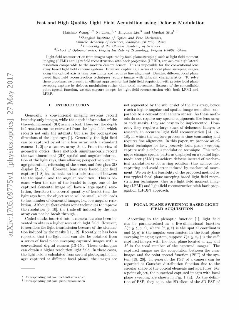
captured images with the focal plane located at zm, andM is the total number of the captured images. Thecaptured images are the convolution between the clearimages and the point spread function (PSF) of the sys-tem [19, 20]. In general, the PSF of a camera can beregarded as Gaussian distribution function due to thecircular shape of the optical elements and apertures. Fora point object, the numerical captured images with focalplane sweeping are shown in Fig. 1 (a). As the defini-tion of PSF, they equal the 2D slices of the 3D PSF of
arX
iv:1
705.
0977
5v1
[ph
ysic
s.op
tics]
27
May
201
7
2z0
y
x
z1 zm zM
(a)
ξ
x
(b)
FIG. 1: (a) Images of a point located at different focalplanes of a camera system, and (b) the corresponding
EPIs.
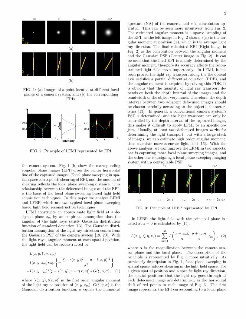
FIG. 2: Principle of LFMI represented by EPI.
the camera system. Fig. 1 (b) show the correspondingepipolar plane images (EPI) cross the center horizontalline of the captured images. Focal plane sweeping in spa-tial space corresponds shearing of EPI, and the amount ofshearing reflects the focal plane sweeping distance. Thisrelationship between the defocused images and the EPIsis the basis of the focal plane sweeping based light fieldacquisition techniques. In this paper we analyze LFMIand LFBP, which are two typical focal plane sweepingbased light field reconstruction techniques.
LFMI constructs an approximate light field at a de-signed plane zm by an empirical assumption that theangular of the light rays satisfy Gaussian distributionfunction of standard deviation [13]. The Gaussian distri-bution assumption of the light ray direction comes fromthe Gaussian PSF of the camera system [19, 20]. Withthe light rays’ angular moment at each spatial position,the light field can be reconstructed by
L(x, y, ξ, η, zm)
=I(x, y, zm) exp
{− [ξ − s(x, y)]2 + [η − t(x, y)]2
σ2
}=I(x, y, zm)δ[ξ − s(x, y), η − t(x, y)] ∗G(ξ, η, σ), (1)
where [s(x, y), t(x, y)] is the first order angular momentof the light ray at position of (x, y, zm), G(ξ, η, σ) is theGaussian distribution function, σ equals the numerical
aperture (NA) of the camera, and ∗ is convolution op-erator. This can be seen more intuitively from Fig. 2.The estimated angular moment is a sparse sampling ofthe EPI, as the left image in Fig. 2 shows, s(x) is the an-gular moment at position (x), which is the average lightray direction. The final calculated EPI (Right image inFig. 2) is the convolution between the angular momentand the Gaussian PSF (Center image in Fig. 2). It canbe seen that the final EPI is mainly determined by theangular moment, therefore its accuracy affects the recon-structed light field most importantly. In LFMI, it hasbeen proved the light ray transport along the the opticalaxis satisfies a partial differential equation (PDE), andthe angular moment is acquired by solving this PDE. Itis obvious that the quantity of light ray transport de-pends on both the depth interval of the images and thebandwidth of the object very much. Therefore, the depthinterval between two adjacent defocused images shouldbe choosn carefully according to the object’s character-istics [13]. In general, a conventional camera system’sPSF is determined, and the light transport can only becontrolled by the depth interval of the captured images,this makes it difficult to apply LFMI to an specific ob-ject. Usually, at least two defocused images works fordetermining the light transport, but with a large stackof images, we can estimate high order angular moment,thus calculate more accurate light field [16]. With theabove analysis, we can improve the LFMI in two aspects,one is capturing more focal plane sweeping images, andthe other one is designing a focal plane sweeping imagingsystem with a controllable PSF.
x0
z0
ξ
x
x1 = ξ0z1
z1
xm = ξ0zm
zm
xM = ξ0zM
zM
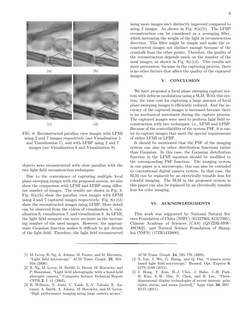
FIG. 3: Principle of LFBP represented by EPI.
In LFBP, the light field with the principal plane lo-cated at z = 0 is calculated by [14]:
L(x, y, ξ, η, z0) =
M∑m=1
I
(x+ zmξ
α,y + zmη
α, zm
), (2)
where α is the magnification between the camera sen-sor plane and the focal plane. The description of theprinciple is represented by Fig. 3 more intuitively. Aspreviously description in Fig. 1, focal plane sweeping inspatial space induces shearing in the light field space. Fora given spatial position and a specific light ray direction,the spatial positions that the light ray goes through ateach defocused image are determined, as the horizontalshift of red points in each image of Fig. 3. The firstimage represents the EPI corresponding to a focal plane

3
at z0. The red point in the first image represents thelight field of L(x0, ξ0), the corresponding position at theother focal planes is xm = ξ0zm, as the dashed whitelines show. Therefore, the radiance of the specific lightray can be obtained by averaging the corresponding ra-diance from all of the defocused images. For a real scene,the radiance of each point on the captured images is thethe accumulation of all light rays reach at it with dif-ferent directions, this induces defocus noise in LFBP. Asthe green lines and yellow points show in Fig. 3. Thegreen lines represent a point at the same depth as theyellow lines represented, but with a different lateral posi-tion. The intensity at xm is the integral along the whitedashed lines. It can been seen that the yellow points fromthe green lines also contribute to the intensities. Whenwe reconstruct the light field at a specific point, muchnoise from all the other points is induced. Fortunately,the red point change position in a linear transformationand the noise from all the other points is different at dif-ferent defocus length. By summing all image with lineartransform, the actual light field have the largest weight.It’s obvious that with a large camera NA, the defocusnoise from all the other points can be reduced becausethe summing weight of the noise will be reduced. Be-sides, It has been proved that the depth resolution of thereconstructed light field depends on the depth interval ofthe captured images, i.e., more defocused images achievebetter depth resolution [17].
From the previous contents, we can see that PSF of thecamera system that used for capturing the focal sweep-ing images is critical in the light field reconstruction. InLFMI, it affects the accuracy of the calculated light an-gular moment as well as the light field. In LFBP, it is acritical factor that affects the defocus noise in the recon-structed light field. Further more, in both of the two tech-niques, more focal plane sweeping images achieve betterlight field reconstruction. In LFMI, higher order angularmoment can be obtained from more images, and in LFBP,more images achieves higher axial resolution. However,more focal plane captured images is time consuming andinduce alignment and magnification problems [19, 20].Therefore, controlling the PSF of the focal plane sweep-ing imaging system is of great importance. Actually, PSFof an imaging system can be manipulated for many ap-plications, this is called PSF engineer in many other re-search fields [21]. In this paper we insert a PSF modula-tion component into a conventional microscopic imagingsystem. On one hand, this achieves accelerated speed andmore accurate focal plane sweeping capture. One theother hand, more freely PSF control can be performedfor specific requirements. In the following section, we de-scribe how we manipulate the PSF of the imaging systemto achieve a focal plane sweeping image capture withouttranslation movement of the camera or the object.
FIG. 4: The schematic of the experimental setup. M isa mirror, F is a light filter, A1, A2 are apertures, L1, L2
are thin lens.
III. FOCAL PLANE SWEEPING WITHDEFOCUS MODULATION
The setup scheme of our proposed system is shown inFig. 4. The components within the dashed rectangle isa commercial microscope (Nikon Ni-U). A mirror (M) isused to export the light from the microscope. F is alight filter with a bandwidth of 3 nm at the wavelengthof 532 nm. An aperture A1 is located at the imagingplane of the microscope, which is used for adjusting im-age size. The other aperture A2 is used for selecting thefirst diffraction order of the SLM. The components withinthe solid rectangle is used for PSF modulation. Lenses L1
and L2 form the 4f system. An SLM (Holoeye, LETO)is located at the Fourier spectrum plane of the 4f sys-tem, which performs the PSF modulation. The SLM isa phase-only modulator, which transforms phase shift ina range of [0, 2π] to 8-bit gray levels. The CCD (Point-Grey, GS3-U3-23S6M-C) plane is conjugated with theimage plane of the microscope. In the following para-graphs we explain how we control the patterns in theSLM to achieve PSF modulation and analyze the perfor-mance of it.
A. Principle of the PSF modulation
In our system, the SLM acts as a Fresnel lens with adesired focal length. The modification of the focal lengthon the SLM produces a focal plane sweeping, thus makingthe captured images equals captured at different depths.Suppose a desired corresponding axial focal plane shift ofzi in the imaging plane is required, the modulation focal

4
length of the SLM should be [22, 23]:
fSLM = −f2r
zi, (3)
where fr is the focal length of lens L1. The axial shift atthe sample stage is zo = zi/β
2, and β is the magnificationof the objective. The required phase pattern displayedon the SLM thus can be written as [22]:
ϕ(x, y) =π
λfSLM(x2 + y2)
=− πziλf2r
(x2 + y2), (4)
where λ is the light wavelength and (x, y) are the spatialcoordinates.
B. Defocus performance of the proposed system
It should be noted that the SLM is pixellated and thephase represented by the SLM is discrete. Therefore thecorresponding depth range and depth interval that canbe modulated by our system are limited. Here analyzethe two limitations and give the two values according tothe specifications of our system.
Because of the pixellated SLM, the phase that can berepresented by the SLM is limited by [22]
|∆ϕ| < π, (5)
where p is the pixel pitch of the SLM. This results ina limited corresponding depth range that can be repre-sented by the proposed system. Substituting Eq. (5) intoEq. (4), we obtain the maximum depth shift that can berepresented according to the system specifications
|zmax| =λf2r2prl
, (6)
where rl is the radius of the light enter into the SLM.Generally, we let rl ≤ 0.5 min(xmax, ymax), this makesure that the light is within the effective area of the SLM.(xmax, ymax) are the length and width of the SLM. Thecenter of the SLM is coincide with the optical axis, mak-ing the lateral position of the images on the CCD remainchangeless.
Since the gray level that represented by the SLM is 8-bit, which corresponds to a discrete phase value, the min-imal phase change on the SLM is ϕmin = 2π/256. Sup-pose the corresponding minimal depth change is ∆zmin,from Eq. (4) we get
|∆zmin| =λf2r
128r2. (7)
In our experimental setup, we used a 20× objective.The other parameters are p = 6.6 µm, λ = 532 nm, rl =0.5xmax ' 3.3 mm, fr = 200 mm. From Eq. (6) and
Eq. (7), the maximum defocused depth is 488.5 mm andthe minimum defocus depth shift is 0.0152 mm. In theexperiment, according to the light field reconstructiontechnique, we can control the PSF by choosing properpatterns to be displayed on the SLM, but we should makesure the phase patterns on the SLM satisfy the two limits.
In addition to the above limits, it is worth to mentionthat the bandwidth of the light filter has a great influ-ence on the image quality due to the single wavelengthselection of the SLM. The patterns on the SLM requireadditional grating phase to separate the modulated andunmodulated light, but the grating phase would lead todistinct dispersion. The bandwidth of the light filtershould be narrow enough, which also induces light at-tenuation. Besides, the SLM is not located at the ex-act Fourier plane of lens L1, while it is located on theimaging plane of the collector lens. We can see distinctimages of the dot on the collector lens as well as the edgeof the condenser aperture diaphragm. Only in this planecan the magnification of the recored images remain un-changed when we change the focal length of the patternsdisplayed on SLM. Furthermore, In order to avoid influ-ence from the previous patterns, we should control theSLM and CCD sequentially to capture the images at eachfocal plane.
IV. EXPERIMENTAL RESULTS ANDDISCUSSION
We verify the feasibility and possibility of light fieldreconstruction with the proposed imaging system in thefollowing sections.
A. Verification of PSF modulation
z = 0 mm z = 10 mm z = 20 mm z = 30 mm z = 40 mm
(a)
200 µm
(b)
FIG. 5: The captured images of the PSF at several focaldepths with (a) the conventional translation system and(b) the proposed PSF modulation system, respectively.
With the proposed system described in the previoussection, we have captured the PSF images at severaldepths, as shown in Fig. 5(b). A pinhole with a diameterof 10 µm was used as a point object. The images captured

5
with the conventional translation system were capturedas the ground truth, as shown in Fig. 5(a). We can ob-serve that the PSF of the proposed system coincides withthe the one of the conventional system. This can also beverified by the size of the PSFs. The objective is 20×, thepixel pitch of the captured images is 5.86 µm. With thetwo parameters, all the size of the PSFs can be calculatedand verified. The expected diameters of the PSF at thefive axial positions should be [200 µm, 300 µm, 400 µm,500 µm, 600 µm]. The measured diameters of the PSFcaptured with the conventional and the proposed systemsare [302.1 µm, 343.9 µm, 444.5 µm, 551.4 µm, 727.6 µm]and [257.7 µm, 317.1 µm, 391.4 µm, 456.0 µm, 629.8 µm].The results show that the PSF of the proposed systemis closer to the Gaussian distribution function than theconventional one. Besides, the shape of the PSF imagescaptured by the proposed system are more likely be circlethan the conventional one.
z = 11 mm z = 60 mm
(a)z = 11 mm z = 60 mm
(b)
FIG. 6: The captured images at two focal planes with(a) translation movement and (b) PSF modulation,
respectively.
Fig. 6 shows some captured images with the conven-tional and proposed systems. Fig. 6(a) are the im-ages captured by the conventional translation movementsystem at z = 11 mm and z = 600 mm, respectively.Fig. 6(b) show the images captured at the same axial po-sitions with the proposed system. We can observe thatthe focal plane sweeping capture can really be achievedwith our proposed system. However, even through wehave calibrated the system very carefully, lateral shift canbe clearly observed from the aperture shift in Fig. 6(a),
as the yellow lines show.We have also compared the capture time between the
conventional and the proposed systems. 61 image werecaptured with the two systems, it costs about 30 min-utes and 25 seconds respectively. It should be mentionedthat in the capture process, all the translation movementand the pattern modification on the SLM were manuallyoperated. Reduced time requirement is expected by com-putational controlling of the systems, but the problemsinduced by movement in the conventional system still ex-ist, and the translation is still more time consuming thanPSF modulation.
B. Light field reconstruction from focal planesweeping captured images with PSF modulation
(a) (b)
(c) (d)
FIG. 7: Reconstructed parallax view images with (a)(c)LFMI (see Visualization 1 and Visualization 3) and
(b)(d) LFBP (see Visualization 2 and Visualization 4)for mosquito’s mouth and mosquito larva.
We have also verified the light field reconstruction withthe two systems. Two objects were used to perform thelight filed reconstruction from the captured images. Wehave captured a stack of intensity images of the samplewith a corresponding axial spacing of ∆z = 1 µm. 60defocused images were captured for each object. And11 images were used for the light field reconstruction.Fig. 7(a)(c) and (b)(d) are the reconstructed parallaxview images with the LFMI and LFBP respectively.While Fig. 7(a)(b) are the images of mosquito’s mouth,and (b)(d) are the images of mosquito larva. More par-allax view images can be observed from the videos. Both
6
(a) (b)
(c) (d)
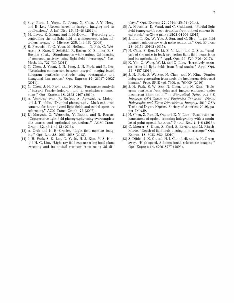
FIG. 8: Reconstructed parallax view images with LFMIusing 2 and 7 images respectively (see Visualization 5and Visualization 7), and with LFBP using 2 and 7
images (see Visualization 6 and Visualization 8).
objects were reconstructed with clear parallax with thetwo light field reconstruction techniques.
Due to the convenience of capturing multiple focalplane sweeping images with the proposed system, we alsoshow the comparison with LFMI and LFBP using differ-ent number of images. The results are shown in Fig. 8.Fig. 8(a)(b) show the parallax view images with LFMIusing 2 and 7 captured images respectively. Fig. 8(c)(d)show the reconstructed images using LFBP. More detailcan be observed from the videos of visualization 5, visu-alization 6, visualization 7, and visualization 8. In LFMI,the light field moment can more accurate as the increas-ing number of the used images. However, the approxi-mate Gaussian function makes it difficult to get detailsof the light field. Therefore, the light field reconstructed
using more images isn’t distinctly improved compared tousing 2 images. As shown in Fig. 8(a)(b). The LFBPreconstruction can be considered as a averaging filter,which increasing the weight of the light in reconstructiondirection. This filter might be simple and make the re-constructed images not distinct enough because of thecrosstalk from the other points. Therefore, the quality ofthe reconstruction depends much on the number of theused images, as shown in Fig. 8(c)(d). This results aremore persuasion, because in the capturing process, thereis no other factors that affect the quality of the capturedimages.
V. CONCLUSION
We have proposed a focal plane sweeping capture sys-tem with defocus modulation using a SLM. With this sys-tem, the time cost for capturing a large amount of focalplane sweeping images is efficiently reduced. And the ac-curacy of the captured images is increased because thereis no mechanical movement during the capture process.The captured images were used to perform light field re-construction with two techniques, i.e., LFMI and LFBP.Because of the controllability of the system PSF, it is eas-ier to capture images that meet the special requirementsof either LFMI or LFBP.
It should be mentioned that the PSF of the imagingsystem can also be other distribution functions ratherthan Gaussian. In this case, the Gaussian distributionfunction in the LFMI equation should be modified tothe corresponding PSF function. The imaging systemin our paper is a microscopic, this can also be extendedto conventional digital camera system. In that case, theSLM can be replaced by an electrically tunable lens forcolorful imaging. The SLM in the proposed system inthis paper can also be replaced by an electrically tunablelens for color imaging.
VI. ACKNOWLEDGMENTS
This work was supported by National Natural Sci-ence Foundation of China (NSFC) (61327902, 61377005),Chinese Academy of Sciences (CAS) (QYZDB-SSW-JSC002), and Natural Science Foundation of Shang-hai (NSFS) (17ZR1433800).
[1] M. Levoy, R. Ng, A. Adams, M. Footer, and M. Horowitz,“Light field microscopy,” ACM Trans. Graph. 25, 924–934 (2006).
[2] R. Ng, M. Levoy, M. Bredif, G. Duval, M. Horowitz, andP. Hanrahan, “Light field photography with a hand-heldplenoptic camera,” Computer Science Technical ReportCSTR 2, 1–11 (2005).
[3] B. Wilburn, N. Joshi, V. Vaish, E.-V. Talvala, E. An-tunez, A. Barth, A. Adams, M. Horowitz, and M. Levoy,“High performance imaging using large camera arrays,”
ACM Trans. Graph. 24, 765–776 (2005).[4] X. Lin, J. Wu, G. Zheng, and Q. Dai, “Camera array
based light field microscopy,” Biomed. Opt. Express 6,3179–3189 (2015).
[5] J. Hong, Y. Kim, H.-J. Choi, J. Hahn, J.-H. Park,H. Kim, S.-W. Min, N. Chen, and B. Lee, “Three-dimensional display technologies of recent interest: prin-ciples, status, and issues [invited],” Appl. Opt. 50, H87–H115 (2011).
7
[6] S.-g. Park, J. Yeom, Y. Jeong, N. Chen, J.-Y. Hong,and B. Lee, “Recent issues on integral imaging and itsapplications,” J. Inf. Disp 15, 37–46 (2014).
[7] M. Levoy, Z. Zhang, and I. McDowall, “Recording andcontrolling the 4d light field in a microscope using mi-crolens arrays,” J. Microsc. 235, 144–162 (2009).
[8] R. Prevedel, Y.-G. Yoon, M. Hoffmann, N. Pak, G. Wet-zstein, S. Kato, T. Schrodel, R. Raskar, M. Zimmer, E. S.Boyden et al., “Simultaneous whole-animal 3d imagingof neuronal activity using light-field microscopy,” Nat.Meth. 11, 727–730 (2014).
[9] N. Chen, J. Yeom, J.-H. Jung, J.-H. Park, and B. Lee,“Resolution comparison between integral-imaging-basedhologram synthesis methods using rectangular andhexagonal lens arrays,” Opt. Express 19, 26917–26927(2011).
[10] N. Chen, J.-H. Park, and N. Kim, “Parameter analysisof integral Fourier hologram and its resolution enhance-ment,” Opt. Express 18, 2152–2167 (2010).
[11] A. Veeraraghavan, R. Raskar, A. Agrawal, A. Mohan,and J. Tumblin, “Dappled photography: Mask enhancedcameras for heterodyned light fields and coded aperturerefocusing,” ACM Trans. Graph. 26 (2007).
[12] K. Marwah, G. Wetzstein, Y. Bando, and R. Raskar,“Compressive light field photography using overcompletedictionaries and optimized projections,” ACM Trans.Graph. 32, 46:1–46:12 (2013).
[13] A. Orth and K. B. Crozier, “Light field moment imag-ing,” Opt. Lett 38, 2666–2668 (2013).
[14] J.-H. Park, S.-K. Lee, N.-Y. Jo, H.-J. Kim, Y.-S. Kim,and H.-G. Lim, “Light ray field capture using focal planesweeping and its optical reconstruction using 3d dis-
plays,” Opt. Express 22, 25444–25454 (2014).[15] A. Mousnier, E. Vural, and C. Guillemot, “Partial light
field tomographic reconstruction from a fixed-camera fo-cal stack,” ArXiv e-prints 1503.01903 (2015).
[16] J. Liu, T. Xu, W. Yue, J. Sun, and G. Situ, “Light-fieldmoment microscopy with noise reduction,” Opt. Express23, 29154–29162 (2015).
[17] N. Chen, Z. Ren, D. Li, E. Y. Lam, and G. Situ, “Anal-ysis of the noise in back-projection light field acquisitionand its optimization,” Appl. Opt. 56, F20–F26 (2017).
[18] X. Yin, G. Wang, W. Li, and Q. Liao, “Iteratively recon-structing 4d light fields from focal stacks,” Appl. Opt.55, 8457 (2016).
[19] J.-H. Park, S.-W. Seo, N. Chen, and N. Kim, “Fourierhologram generation from multiple incoherent defocusedimages,” Proc. SPIE vol. 7690, p. 76900F (2010)
[20] J.-H. Park, S.-W. Seo, N. Chen, and N. Kim, “Holo-gram synthesis from defocused images captured underincoherent illumination,” in Biomedical Optics and 3-DImaging: OSA Optics and Photonics Congress - DigitalHolography and Three-Dimensional Imaging, 2010 OSATechnical Digest (Optical Society of America, 2010), pa-per JMA29.
[21] N. Chen, Z. Ren, H. Ou, and E. Y. Lam, “Resolution en-hancement of optical scanning holography with a modu-lated point spread function,” Photo. Res. 4, 1–6 (2016).
[22] C. Maurer, S. Khan, S. Fassl, S. Bernet, and M. Ritsch-Marte, “Depth of field multiplexing in microscopy,” Opt.Express 18, 3023–3034 (2010).
[23] S. Djidel, J. K. Gansel, H. I. Campbell, and A. H. Green-away, “High-speed, 3-dimensional, telecentric imaging,”Opt. Express 14, 8269–8277 (2006).
Related Documents