Desktop Fan Project for the Arduino Inventors Kit EAS 199A, Fall 2010 Gerald Recktenwald Portland State University [email protected] Desktop fan: EAS 199A Goal • Build a desktop fan from parts in the Arduino Inventor’s Kit • Work in teams of two • Learn new skills ❖ Controlling a servo and DC motor ❖ Make a 2D drawing with Solidworks ❖ Send drawings to Laser cutter ❖ Soldering • Due in two weeks ❖ In-class demonstration of your working fan 2 Desktop fan: EAS 199A Tasks 3 • Measure servo and DC motors ❖ prepare for structural design ❖ learn how to use your calipers • Sketch design of support structure on paper • Create Solidworks model of the base and DC motor support • Cut acrylic parts • Re-solder the DC motor leads • Assemble the system • Write Arduino program to control servo and DC motor

Welcome message from author
This document is posted to help you gain knowledge. Please leave a comment to let me know what you think about it! Share it to your friends and learn new things together.
Transcript

Desktop Fan Projectfor the
Arduino Inventors KitEAS 199A, Fall 2010
Gerald RecktenwaldPortland State University
Desktop fan: EAS 199A
Goal
• Build a desktop fan from parts in the Arduino Inventor’s Kit• Work in teams of two• Learn new skills
❖ Controlling a servo and DC motor❖ Make a 2D drawing with Solidworks❖ Send drawings to Laser cutter❖ Soldering
• Due in two weeks❖ In-class demonstration of your working fan
2
Desktop fan: EAS 199A
Tasks
3
• Measure servo and DC motors❖ prepare for structural design❖ learn how to use your calipers
• Sketch design of support structure on paper
• Create Solidworks model of the base and DC motor support
• Cut acrylic parts• Re-solder the DC motor leads• Assemble the system• Write Arduino program to
control servo and DC motor

Desktop fan: EAS 199A
Propellor and motors from Inventor’s Kit
4
Desktop fan: EAS 199A
Acrylic parts after cutting and bending
5
Desktop fan: EAS 199A
One idea for a base design
6

Desktop fan: EAS 199A
Alternative base designs
7
Desktop fan: EAS 199A
Servo motor parts
8
Desktop fan: EAS 199A
Fan Project: First Steps
9
1. Make a hand sketch of the structural parts2. Measure the servo and mounting screws3. Use measurements to add dimensions to the sketch4. Redraw the sketch as a 2D “flat” drawing in Solidworks5. Email the drawing to the instructor
a. Laser cutter works on thin sheets in 2Db. Use the acrylic bender after parts are cut
Watch this video to see the laser cutter and acrylic bender in action:
http://www.youtube.com/watch?v=DJA8EmBUfLo

Soldering Leads to the DC Motor
Desktop fan projectEAS 199A, Fall 2010
Desktop fan: EAS 199A
Overview
The DC motor that comes with the Arduino Inventor’s Kit has short and delicate leads. We need to replace the leads with more robust wiring and soldered connections
11
Desktop fan: EAS 199A
Temperature-controlled soldering iron and flux
12

Desktop fan: EAS 199A
!"
#!!"
$!!"
%!!"
&!!"
'!!"
(!!"
)!!"
*!!"
'+$$" (+##" )+#" )+$#" *+#!" *+%!" ,+#," #!+,"
!"#$%%&'"()*'+,)-$."()
/+(')
0+%%)1232)!"#$%%&'"()4'#5.5)6&')
-.."/-0"
-.."1/"
/-0"234567849"
1/"234567849"
Soldering work surface with vise
13
Desktop fan: EAS 199A
Helping Hands
14
Desktop fan: EAS 199A
Procedure
15
1. Cut a length of wire2. Strip and tin the ends of the wire3. Make note of polarity and remove leads from DC motor4. Insert tinned wire through tabs and bend into position5. Secure new leads by soldering to motor tabs
Desktop fan: EAS 199A
Cut new lead wires
16
Desktop fan: EAS 199A
Strip the leads
17
Desktop fan: EAS 199A
Tin the leads
18

Desktop fan: EAS 199A
!"
#!!"
$!!"
%!!"
&!!"
'!!"
(!!"
)!!"
*!!"
'+$$" (+##" )+#" )+$#" *+#!" *+%!" ,+#," #!+,"
!"#$%%&'"()*'+,)-$."()
/+(')
0+%%)1232)!"#$%%&'"()4'#5.5)6&')
-.."/-0"
-.."1/"
/-0"234567849"
1/"234567849"
Remove the old leads and note the polarity
19
Desktop fan: EAS 199A
Motor supported. Extension wires in place
20
Desktop fan: EAS 199A
Bend the tinned wires around the supports
21

Desktop fan: EAS 199A
Secure the leads with solder
22
Basic DC Motor Circuits
Desktop fan projectEAS 199A, Fall 2010
Desktop fan: EAS 199A
Simplest DC Motor Circuits
Connect the motor to a DC power supply
+5V +5V
I
Switch closed
24

Desktop fan: EAS 199A
Current continues after switch is opened
Opening the switch does not immediately stop current in the motor windings.
25
Desktop fan: EAS 199A
Reverse current
Charge build-up can cause damage
+5V
I+
–
Arc acrossthe switch
Current surge throughthe voltage supply
26
Desktop fan: EAS 199A
Motor Model
Simple model of a DC motor:❖ Windings have inductance and resistance❖ Inductor causes a storage of electrical charge in the windings❖ We need to provide a way to safely dissipate the charge stored in
the motor windings
+5V
I+5V
27

Desktop fan: EAS 199A
Flyback Diode
A flyback diode allows the stored charge to dissipate safely
28
Desktop fan: EAS 199A
Replace the Switch with a Transistor
A transistor allows on/off control to be automated
+5V
motorPin
330!
29
Desktop fan: EAS 199A
Control the DC motor with PWM Output
// Function: PWM_output//// PWM output to control a DC motor
int motor_pin = 5; // must be a PWM digital output
void setup(){ pinMode(motor_pin, OUTPUT)}
void loop(){ int motor_speed=200; // must be >0 and <= 255 analogWrite( motor_pin, motor_speed);}
30

Arduino Programming:PWM Control of DC motor speed
Desktop fan projectEAS 199A, Fall 2010
Desktop fan: EAS 199A
Overview
Part I❖ Circuits and code to control the speed of a small DC motor.❖ Use potentiometer for dynamic user input.❖ Use PWM output from an Arduino to control a transistor.❖ Transistor acts as variable voltage switch for the DC motor.
Part II❖ Consolidate code into reusable functions.❖ One function maps 10-bit analog input to 8-bit PWM output.❖ Another function controls the motor speed.❖ Functions developed here are useful for more complex control
tasks, e.g. the desktop fan project.
32
Desktop fan: EAS 199A
Part 1: Control motor speed with a pot
Increase complexity gradually. Test at each stage.
1. Use a potentiometer to generate a voltage signala. Read voltage with analog inputb. Print voltage to serial monitor to verify
2. Convert 10-bit voltage scale to 8-bit PWM scalea. Voltage input is in the range 0 to 1023b. PWM output needs to be in the range 0 to 255c. Print voltage to serial monitor to verify
3. Connect PWM output to DC motor
4. Write a function to linearly scale the data
5. Write a function to update the motor
33

Desktop fan: EAS 199A
Potentiometer Circuit
Use the potentiometer from the Arduino Inventor’s Kit
34
Analoginput pin
5V
Vin
Vout
Desktop fan: EAS 199A
Code to print potentiometer reading
// Function: read_potentiometer//// Read a potentiometer and print the reading
int sensor_pin = 3; // Wire sweeper of pot to // analog input pin 3void setup(){ Serial.begin(9600);}
void loop(){ int val; val = analogRead( sensor_pin ); Serial.print("reading = "); Serial.println( val );}
35
Desktop fan: EAS 199A
DC Motor Control Circuit
36
+5V
motorPin
330!
Add this to the breadboard with the potentiometer circuit

Desktop fan: EAS 199A
DC Motor Control Circuit
37
+5V
motorPin
330!
Analoginput pin
5V
Arduino
Desktop fan: EAS 199A
Control the DC motor with PWM Output
// Function: DC_motor_control_pot//// Use a potentiometer to control a DC motor
int sensor_pin = 3;int motor_pin = 5; // must be a PWM digital output
void setup(){ Serial.begin(9600); pinMode(motor_pin, OUTPUT)}
void loop(){ int pot_val, motor_speed; pot_val = analogRead( sensor_pin ); motor_speed = pot_val*255.0/1024.0; // Include decimal analogWrite( motor_pin, motor_speed);}
38
Subtle: Don’t use integer values of 255 and 1024 here. Aggressive compilers pre-compute the integer division of 255/1024 as zero.
Desktop fan: EAS 199A
// Function: DC_motor_control_pot//// Use a potentiometer to control a DC motor
int sensor_pin = 3;int motor_pin = 5; // must be a PWM digital output
void setup(){ Serial.begin(9600); pinMode(motor_pin, OUTPUT)}
void loop(){ int pot_val, motor_speed; pot_val = analogRead( sensor_pin ); motor_speed = pot_val*255.0/1024.0; // Include decimal analogWrite( motor_pin, motor_speed);}
Part II: Create functions for reusable code
39
Adjust motor speed
Map input values to output scale

Desktop fan: EAS 199A
adjust_motor_speed takes care of the two main tasks: reading the potentiometer outputs and setting the PWM signal to the transistor
// Function: DC_motor_control_pot//// Use a potentiometer to control a DC motor
int sensor_pin = 3;int motor_pin = 5; // must be a PWM digital output
void setup(){ Serial.begin(9600); pinMode(motor_pin, OUTPUT)}
void loop(){ adjust_motor_speed( sensor_pin, motor_pin);
... // do other useful stuff}
Final version of the loop() function
40
Desktop fan: EAS 199A
Using and Writing Functions
Additional information on the Arduino web site❖ http://www.arduino.cc/en/Reference/FunctionDeclaration
Functions are reusable code modules:❖ Functions encapsulate tasks into larger building blocks❖ Functions hide details and variables local to each task❖ Well-written functions can be reused❖ Functions can accept input (or not) and return output (or not)❖ All Arduino sketches have at least two functions
‣ setup: runs once to configure the system‣ loop: runs repeatedly after start-up is complete
❖ Users can add functions in the main sketch file, or in separate files
41
Desktop fan: EAS 199A
The setup() Function
Consider the simple blink sketch
42
// Blink.pde: Turn on an LED for one second, then// off for one second. Repeat continuously.
void setup() { pinMode(13, OUTPUT); }
void loop() { digitalWrite(13, HIGH); // set the LED on delay(1000); // wait for a second digitalWrite(13, LOW); // set the LED off delay(1000); // wait for a second}
No inputs
“setup” is the name of the function
“void” means Returns nothing

Desktop fan: EAS 199A
A Function to Translate Linear Scales
Linear scaling from x values to y values:
y = f(x)where f is a linear mapping
43
xmin xmaxx
yymax
ymin
In words: Given x, xmin, xmax, ymin, and ymax, compute y
Desktop fan: EAS 199A
A Function to Translate Linear Scales
Enter the code at the bottom into your sketch❖ The code is not inside any other program block
(like setup or void)
How would you test that this function is working?
44
int int_scale(int x, int xmin, int xmax, int ymin, int ymax){ int y; y = ymin + float(ymax - ymin)*float( x - xmin )/float(xmax - xmin); return(y);}
N.B. This code is essentially a reimplementation of the built-in map function.See http://arduino.cc/en/Reference/Map
Desktop fan: EAS 199A
A Function to Translate Linear Scales
45
int int_scale(int x, int xmin, int xmax, int ymin, int ymax){ int y; y = ymin + float(ymax - ymin)*float( x - xmin )/float(xmax - xmin); return(y);}
returns an int
name is int_scalefirst input is an int named “x”
return the value stored in “y”
Use float for better precision

Desktop fan: EAS 199A
Functions are not nested
46
int int_scale(int x, int xmin, int xmax, int ymin, int ymax){ ...}
void setup(){ ...}
void loop(){ ...}
// Contents of sketch, e.g. motor_control.pde
Desktop fan: EAS 199A
Functions call other functions
47
int int_scale(int x, int xmin, int xmax, int ymin, int ymax){ ... return( y );}
void setup(){ ...}
void loop(){ ... motor_speed = int_scale( pot_val, 0, 1024, 0, 255);}
// Contents of sketch, e.g. motor_control.pde
Desktop fan: EAS 199A
Functions call other functions
48
int int_scale(int x, int xmin, int xmax, int ymin, int ymax){ ... return( y );}
void setup(){ ...}
void loop(){ ... motor_speed = int_scale( pot_val, 0, 1024, 0, 255);}
// Contents of sketch, e.g. motor_control.pde

Desktop fan: EAS 199A
// Function: DC_motor_control_pot//// Use a potentiometer to control a DC motor
int sensor_pin = 3;int motor_pin = 5; // must be a PWM digital output
void setup(){ Serial.begin(9600); pinMode(motor_pin, OUTPUT)}
void loop(){ int pot_val, motor_speed; pot_val = analogRead( sensor_pin ); motor_speed = int_scale( pot_val, 0, 1024, 0, 255; analogWrite( motor_pin, motor_speed);}
int int_scale(int x, int xmin, int xmax, int ymin, int ymax){ int y; y = ymin + float(ymax - ymin)*float( x - xmin )/float(xmax - xmin); return(y);}
Use the int_scale function
49
Desktop fan: EAS 199A
A Function to update motor speedInputs
❖ sensor pin❖ motor output pin
Tasks:❖ Read potentiometer voltage❖ Convert voltage from 10 bit to 8 bit scales❖ Change motor speed
50
void adjust_motor_speed(int sensor_pin, int motor_pin){ int motor_speed, sensor_value; sensor_value = analogRead(sensor_pin); motor_speed = int_scale(sensor_value, 0, 1024, 0, 255); analogWrite( motor_pin, motor_speed);
Serial.print("Pot input, motor output = "); Serial.print(sensor_value); Serial.print(" "); Serial.println(motor_speed);}
Desktop fan: EAS 199A
Functions call functions, call functions, ...
51
int int_scale(int x, int xmin, int xmax, int ymin, int ymax){ ... return( y );}
void setup(){ ...}
void loop(){ ... adjust_motor_speed( ..., ... )}
// Contents of sketch, e.g. motor_control.pde
void adjust_motor_speed(int sensor_pin, int motor_pin){ ... motor_speed = int_scale( ..., ..., ..., ..., ... );}

Button Input:On/off state change
Desktop fan projectEAS 199A, Fall 2010
Desktop fan: EAS 199A
User input features of the fan
• Potentiometer for speed control❖ Continually variable input makes sense for speed control❖ Previously discussed
• Start/stop❖ Could use a conventional power switch❖ Push button (momentary) switch
• Lock or limit rotation angle❖ Button click to hold/release fan in one position❖ Potentiometer to set range limit
53
Desktop fan: EAS 199A
Conventional on/off switch
Basic light switch or rocker switch❖ Makes or breaks connection to power❖ Switch stays in position: On or Off❖ Toggle position indicates the state❖ NOT in the Arduino Inventors Kit
54
Image from lowes.comImage from sparkfun.com

Desktop fan: EAS 199A
Momentary or push-button switches
• Temporary “click” input❖ Two types: normally closed or normally open
• Normally open❖ electrical contact is made when button is pressed
• Normally closed❖ electrical contact is broken when button is pressed
• Internal spring returns button to its un-pressed state
55
Image from sparkfun.comOpen Closed
Desktop fan: EAS 199A
Momentary Button and LED Circuit
Digital input with a pull-down resistor❖ When switch is open (button not pressed):
‣ Digital input pin is tied to ground‣ No current flows, so there is no voltage
difference from input pin to ground‣ Reading on digital input is LOW
❖ When switch is closed (button is pressed):‣ Current flows from 5V to ground, causing LED
to light up.
‣ The 330Ω resistor limits the current draw by the input pin.
‣ The 10k resistor causes a large voltage drop between 5V and ground, which causes the digital input pin to be closer to 5V.
‣ Reading on digital input is HIGH
56
LED
10 k!330 !
5V
Digitalinput pin
Push-buttonswitch
Desktop fan: EAS 199A
Programs for the LED/Button Circuit
1. Continuous monitor of button state❖ Program is completely occupied by monitoring the button❖ Used as a demonstration — not practically useful
2. Wait for button input❖ Blocks execution while waiting❖ May be useful as a start button
3. Interrupt Handler❖ Most versatile❖ Does not block execution❖ Interrupt is used to change a flag that indicates state❖ Regular code in loop function checks the sate of the flag
All three programs use the same electrical circuit
57

Desktop fan: EAS 199A
Continuous monitor of button state
58
int button_pin = 4; // pin used to read the button
void setup() { pinMode( button_pin, INPUT); Serial.begin(9600); // Button state is sent to host}
void loop() { int button; button = digitalRead( button_pin ); if ( button == HIGH ) { Serial.println("on"); } else { Serial.println("off"); }}
Serial monitor shows a continuous stream
of “on” or “off”
This program does not control the LED
Desktop fan: EAS 199A
Wait for button input
59
int button_pin = 4; // pin used to read the button
void setup() { int start_click = LOW; // Initial state: no click yet pinMode( button_pin, INPUT); Serial.begin(9600); while ( !start_click ) { start_click = digitalRead( button_pin ); Serial.println("Waiting for button press"); }}
void loop() { int button; button = digitalRead( button_pin ); if ( button == HIGH ) { Serial.println("on"); } else { Serial.println("off"); }}
Same loop() function as
before
while loop continues as long as start_click is FALSE
Desktop fan: EAS 199A
Interrupt handler for button input
60
int button_interrupt = 0; // Interrupt 0 is on pin 2 !!int toggle_on = false; // Button click switches state
void setup() { Serial.begin(9600); attachInterrupt( button_interrupt, handle_click, RISING); // Register handler}
void loop() { if ( toggle_on ) { Serial.println("on"); } else { Serial.println("off"); }}
void handle_click(){ static unsigned long last_interrupt_time = 0; // Zero only at start unsigned long interrupt_time = millis(); // Read the clock if ( interrupt_time - last_interrupt_time > 200 ) { // Ignore when < 200 msec toggle_on = !toggle_on; } last_interrupt_time = interrupt_time;}
Desktop fan: EAS 199A
Interrupt handler for button input
61
int button_interrupt = 0; // Interrupt 0 is on pin 2 !!int toggle_on = false; // Button click switches state
void setup() { Serial.begin(9600); attachInterrupt( button_interrupt, handle_click, RISING); // Register handler}
void loop() { if ( toggle_on ) { Serial.println("on"); } else { Serial.println("off"); }}
void handle_click(){ static unsigned long last_interrupt_time = 0; // Zero only at start unsigned long interrupt_time = millis(); // Read the clock if ( interrupt_time - last_interrupt_time > 200 ) { // Ignore when < 200 msec toggle_on = !toggle_on; } last_interrupt_time = interrupt_time;}
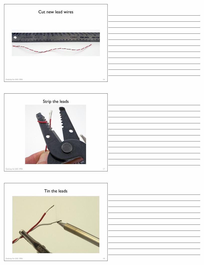
Interrupt handler must be registered when program starts
The interrupt handler, handle_click, is a user-written function that is
called when an interrupt is detected
button_interrupt is the ID or number of the interrupt.
It must be 0 or 1
A RISING interrupt occurs when the pin changes from LOW to HIGH
Desktop fan: EAS 199A
Interrupt handler for button input
62
int button_interrupt = 0; // Interrupt 0 is on pin 2 !!int toggle_on = false; // Button click switches state
void setup() { Serial.begin(9600); attachInterrupt( button_interrupt, handle_click, RISING); // Register handler}
void loop() { if ( toggle_on ) { Serial.println("on"); } else { Serial.println("off"); }}
void handle_click(){ static unsigned long last_interrupt_time = 0; // Zero only at start unsigned long interrupt_time = millis(); // Read the clock if ( interrupt_time - last_interrupt_time > 200 ) { // Ignore when < 200 msec toggle_on = !toggle_on; } last_interrupt_time = interrupt_time;}
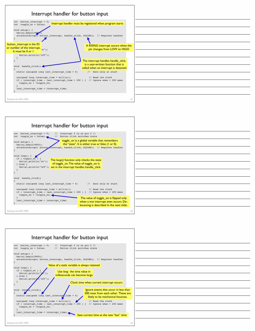
toggle_on is a global variable that remembers the “state”. It is either true or false (1 or 0).
The loop() function only checks the state of toggle_on. The value of toggle_on is
set in the interrupt handler, handle_click.
The value of toggle_on is flipped only when a true interrupt even occurs. De-bouncing is described in the next slide.
Desktop fan: EAS 199A
Interrupt handler for button input
63
int button_interrupt = 0; // Interrupt 0 is on pin 2 !!int toggle_on = false; // Button click switches state
void setup() { Serial.begin(9600); attachInterrupt( button_interrupt, handle_click, RISING); // Register handler}
void loop() { if ( toggle_on ) { Serial.println("on"); } else { Serial.println("off"); }}
void handle_click(){ static unsigned long last_interrupt_time = 0; // Zero only at start unsigned long interrupt_time = millis(); // Read the clock if ( interrupt_time - last_interrupt_time > 200 ) { // Ignore when < 200 msec toggle_on = !toggle_on; } last_interrupt_time = interrupt_time;}
Value of a static variable is always retained
Ignore events that occur in less than 200 msec from each other. These are
likely to be mechanical bounces.
Use long: the time value in milliseconds can become large
Clock time when current interrupt occurs
Save current time as the new “last” time

Desktop fan: EAS 199A
Other references
Ladyada tutorial❖ Excellent and detailed❖ http://www.ladyada.net/learn/arduino/lesson5.html
Arduino reference❖ Minimal explanation
‣ http://www.arduino.cc/en/Tutorial/Button
❖ Using interrupts‣ http://www.uchobby.com/index.php/2007/11/24/arduino-interrupts/‣ http://www.arduino.cc/en/Reference/AttachInterrupt
64
Related Documents