Fan Coil Unit (FCU) Application Guide VTR8300 Series Room Controllers TABLE OF CONTENTS VTR8300 and SCs | Fan coil terminal equipment controllers 2 VTR8300A5000 - VC3500E5000: Heating/cooling: 4-pipe fan coil unit with 3-speed fan, 2-position valves with wireless door switch 4 VTR8350A5000 -VC3404E5000: Cooling and electric heat: 2-pipe fan coil unit with 3-speed fan, dehumidification, 2-position valves 6 VTR8300A5000 - VC3504E5000: Heating/cooling with changeover sensor: 2-pipe fan coil unit with 3-speed fan and wireless window switch 8 VTR8350A5000 - VC3400E5000: Cooling and electric heat: 2-pipe fan coil unit with 3-speed fan and dehumidification, 2-position valves 10 VTR8300A5500 - VC3514E5000: Heating/cooling: 2-pipe fan coil unit with 3-speed fan and fresh air damper, 2-position valves 12 VTR8300A5000 -VC3500E5000 -VC3300E5000: Heating/cooling: 4-pipe fan coil unit with 3-speed fan, 2-position valves with slave relay pack 14 VTR8300A5000 - VC3504E5000: Cooling and electric heat: 2-pipe fan coil unit with 3-speed fan, 2-position valves with wired window switch 16 VTR8300A5000 - VC3500E5000: Heating/cooling: 4-pipe fan coil unit with 3-speed fan, 2-position valves with wired door switch 18 Appendix A - Passive infra-red (PIR) motion detector cover specifications 20 Appendix B - option network wiring if communicating models are used 21 Appendix C - controllers’ occupancy sequence of operation schematic 21 Appendix D - SED Series - wireless door & window switch 22 Appendix E - VTR8300 controller & VC3000 relay pack 23

Welcome message from author
This document is posted to help you gain knowledge. Please leave a comment to let me know what you think about it! Share it to your friends and learn new things together.
Transcript
Fan Coil Unit (FCU) Application Guide VTR8300 Series Room Controllers
TABLE OF CONTENTSVTR8300 and SCs | Fan coil terminal equipment controllers 2VTR8300A5000 - VC3500E5000: Heating/cooling: 4-pipe fan coil unit with 3-speed fan, 2-position valves with wireless door switch 4VTR8350A5000 -VC3404E5000: Cooling and electric heat: 2-pipe fan coil unit with 3-speed fan, dehumidification, 2-position valves 6VTR8300A5000 - VC3504E5000: Heating/cooling with changeover sensor: 2-pipe fan coil unit with 3-speed fan and wireless window switch 8VTR8350A5000 - VC3400E5000: Cooling and electric heat: 2-pipe fan coil unit with 3-speed fan and dehumidification, 2-position valves 10VTR8300A5500 - VC3514E5000: Heating/cooling: 2-pipe fan coil unit with 3-speed fan and fresh air damper, 2-position valves 12VTR8300A5000 -VC3500E5000 -VC3300E5000: Heating/cooling: 4-pipe fan coil unit with 3-speed fan, 2-position valves with slave relay pack 14VTR8300A5000 - VC3504E5000: Cooling and electric heat: 2-pipe fan coil unit with 3-speed fan, 2-position valves with wired window switch 16VTR8300A5000 - VC3500E5000: Heating/cooling: 4-pipe fan coil unit with 3-speed fan, 2-position valves with wired door switch 18Appendix A - Passive infra-red (PIR) motion detector cover specifications 20Appendix B - option network wiring if communicating models are used 21Appendix C - controllers’ occupancy sequence of operation schematic 21Appendix D - SED Series - wireless door & window switch 22Appendix E - VTR8300 controller & VC3000 relay pack 23
VTR8300 Fan Coil ControllerApplication Guide2
Viconics Technologies Inc. | 9245 Langelier Blvd. | St.-Leonard | Quebec | Canada | H1P 3K9 | Tel: (514) 321-5660 | Fax: (514) 321-4150 028-6047-02 www.viconics.com | [email protected] November 2014
© 2
014
Vic
onic
s Te
chno
logi
es In
c. A
ll rig
hts
rese
rved
.
OVERVIEWVTR8300 & Relay Pack
This new cost-effective solution for upgrading line-voltage fan coil unit thermostats requires only two components: the VTR8300 terminal equipment controller and the SC3000 relay pack. This solution allows existing line voltage wiring between the fan coil unit and temperature controller to be re-used, reducing overall costs and installation time. The SC3000 relay pack features an onboard universal voltage power supply and line-voltage relays which directly drive fractional horsepower fan motors and valves. This eliminates the need to install and wire costly pilot relays and transformers.
The VTR8300 Line Voltage Fan Coil Terminal Equipment Controller and SC3000 Relay Pack can be configured to handle a broad variety of applications covering all the standard implementations necessary for controlling line-voltage HVAC systems.
In addition to controlling heating, cooling and fan activity, depending on the model the VTR8300 can handle wireless networking and switches, passive infrared (PIR) occupancy detection using either onboard or remote sensors, and dehumidification control. The applications described here cover all these features, and in combination with the VTR8300’s advanced scheduling and occupancy controls can provide the functionality for any required line-voltage HVAC implementation.
VTR8300 Fan Coil ControllerApplication Guide 3
Viconics Technologies Inc. | 9245 Langelier Blvd. | St.-Leonard | Quebec | Canada | H1P 3K9 | Tel: (514) 321-5660 | Fax: (514) 321-4150 028-6047-02 www.viconics.com | [email protected] November 2014
© 2
014
Vic
onic
s Te
chno
logi
es In
c. A
ll rig
hts
rese
rved
.
VTR8300 AND SCS | FAN COIL TERMINAL EQUIPMENT CONTROLLERS
Commercial interface (local override)
Power Part Number Description Humidity PIR Cover Communication
VTR8300A0Axx Stand-alone fan coil terminal equipment controller No No Stand-alone
VTR8300A0Bxx BACnet® fan coil terminal equipment controller No No BACnet®
VTR8300A0Pxx Wireless fan coil terminal equipment controller No No ZigBee® Pro Wireless
VTR8300A5Axx Stand-alone fan coil terminal equipment controller No Yes Stand-alone
VTR8300A5Bxx BACnet® fan coil terminal equipment controller No Yes BACnet®
VTR8300A5Pxx Wireless fan coil terminal equipment controller Yes Yes ZigBee® Pro Wireless
VTR8350A0Axx Stand-alone fan coil terminal equipment controller Yes No Stand-alone
VTR8350A0Bxx BACnet® fan coil terminal equipment controller Yes No BACnet®
VTR8350A0Pxx Wireless fan coil terminal equipment controller Yes No ZigBee® Pro Wireless
VTR8350A5Axx Stand-alone fan coil terminal equipment controller Yes Yes Stand-alone
VTR8350A5Bxx BACnet® fan coil terminal equipment controller Yes Yes BACnet®
VTR8350A5Pxx Wireless fan coil terminal equipment controller Yes Yes ZigBee® Pro Wireless
Transformer relay packs for fan coil units
Power Part Number Description
SC3500E5045 Transformer relay pack five relay fan outputs
SC3504E5045 Transformer relay pack five relay fan outputs, and four outputs
SC3514E5045 Transformer relay pack five relay outputs, smart VDC OCC output, and four inputs
SC3400E5045 Transformer relay pack four relay outputs and smart VDC output
SC3404E5045 Transformer relay pack four relay outputs, smart VDC output, and four inputs
SC3300E5045 Transformer relay pack three slave fan outputs
Wireless accessories for VTR8300 Series
Power Part Number Description
SED-DOR-P-5045 Wireless door switch
SED-WIN-P-5045 Wireless window switch

VTR8300 Fan Coil ControllerApplication Guide4
Viconics Technologies Inc. | 9245 Langelier Blvd. | St.-Leonard | Quebec | Canada | H1P 3K9 | Tel: (514) 321-5660 | Fax: (514) 321-4150 028-6047-02 www.viconics.com | [email protected] November 2014
© 2
014
Vic
onic
s Te
chno
logi
es In
c. A
ll rig
hts
rese
rved
.
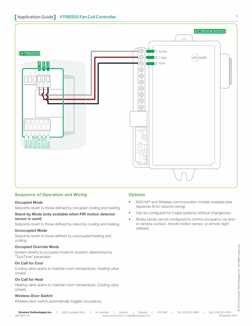
VTR83X0AXPXX WITH SC3500E5000 RELAY: HEATING/COOLING 4-PIPE FAN COIL UNIT WITH 3-SPEED FAN AND 2-POSITION VALVES WITH WIRELESS DOOR SWITCH
SC3500E5000
2 POSITIONCOOLING VALVE
Cooling Coil
2 POSITIONHEATING VALVE
Heating Coil
Door Switch
SED-DOR-P-5000
Airflow DirectionFan
VTR8300
Configuration Parameter Name
Configuration Settings
Fan Menu L-M-H-AFan cont. heat. OnBI2 Door DryPulsed heating OffPipe no. 4Seq. operation Ht - Cl
Refer to the Wireless Door and Window Switch Installation Guide for the door pairing procedure.
AND / OR
Onboard PIR Sensor
Remote PIR Sensor
VTR8300 Fan Coil ControllerApplication Guide 5
Viconics Technologies Inc. | 9245 Langelier Blvd. | St.-Leonard | Quebec | Canada | H1P 3K9 | Tel: (514) 321-5660 | Fax: (514) 321-4150 028-6047-02 www.viconics.com | [email protected] November 2014
© 2
014
Vic
onic
s Te
chno
logi
es In
c. A
ll rig
hts
rese
rved
.
Sequence of Operation and Wiring
Occupied ModeSetpoints revert to those defined by occupied cooling and heating.
Stand-by Mode (only available when PIR motion detector sensor is used)Setpoints revert to those defined by stand-by cooling and heating.
Unoccupied ModeSetpoints revert to those defined by unoccupied heating and cooling.
Occupied Override ModeSystem reverts to occupied mode for duration determined by “ToccTime” parameter.
On Call for CoolCooling valve opens to maintain room temperature. Heating valve closed.
On Call for HeatHeating valve opens to maintain room temperature. Cooling valve closed.
Wireless Door SwitchWireless door switch automatically toggles occupancy.
Options
• BACnet® and Wireless communication models available (see Appendix B for network wiring).
• Can be configured for 2-pipe systems (without changeover).
• Binary inputs can be configured to control occupancy via door or window contact, remote motion sensor, or remote night setback.
Tx/Rx
7 Vdc
Com
1
2
3
SC3500E5000
VTR8300
BA
Cne
t+
BA
Cne
t-
BA
Cne
t RE
F
UI 1
6 -
BI1
UI 1
7 -
BI2
SC
om
Tx /
Rx
7 V
DC
Com
VTR8300 Fan Coil ControllerApplication Guide6
Viconics Technologies Inc. | 9245 Langelier Blvd. | St.-Leonard | Quebec | Canada | H1P 3K9 | Tel: (514) 321-5660 | Fax: (514) 321-4150 028-6047-02 www.viconics.com | [email protected] November 2014
© 2
014
Vic
onic
s Te
chno
logi
es In
c. A
ll rig
hts
rese
rved
.
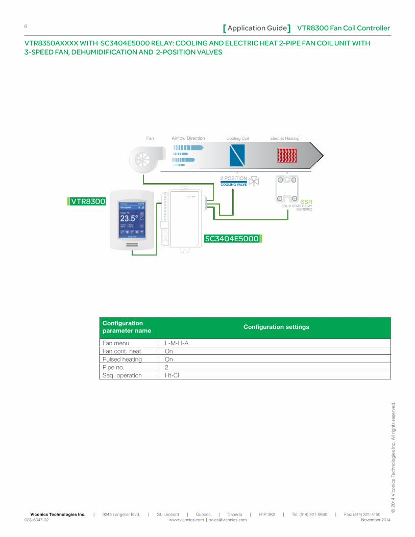
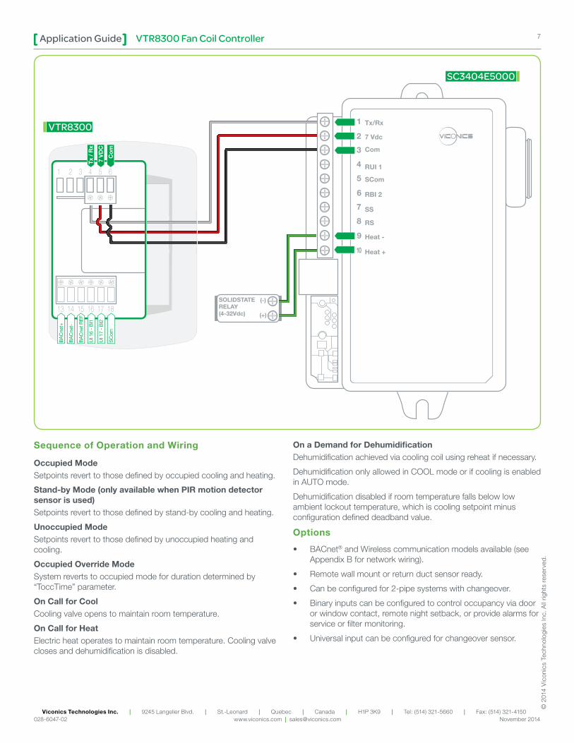
VTR8350AXXXX WITH SC3404E5000 RELAY: COOLING AND ELECTRIC HEAT 2-PIPE FAN COIL UNIT WITH 3-SPEED FAN, DEHUMIDIFICATION AND 2-POSITION VALVES
Configuration parameter name
Configuration settings
Fan menu L-M-H-AFan cont. heat OnPulsed heating OnPipe no. 2Seq. operation Ht-Cl
Cooling Coil Electric Heating
SSRSOLID STATE RELAY
(GENERIC)
SC3404E5000
2 POSITIONCOOLING VALVE
VTR8300
Airflow DirectionFan
VTR8300 Fan Coil ControllerApplication Guide 7
Viconics Technologies Inc. | 9245 Langelier Blvd. | St.-Leonard | Quebec | Canada | H1P 3K9 | Tel: (514) 321-5660 | Fax: (514) 321-4150 028-6047-02 www.viconics.com | [email protected] November 2014
© 2
014
Vic
onic
s Te
chno
logi
es In
c. A
ll rig
hts
rese
rved
.
Sequence of Operation and Wiring
Occupied ModeSetpoints revert to those defined by occupied cooling and heating.
Stand-by Mode (only available when PIR motion detector sensor is used)Setpoints revert to those defined by stand-by cooling and heating.
Unoccupied ModeSetpoints revert to those defined by unoccupied heating and cooling.
Occupied Override ModeSystem reverts to occupied mode for duration determined by “ToccTime” parameter.
On Call for CoolCooling valve opens to maintain room temperature.
On Call for HeatElectric heat operates to maintain room temperature. Cooling valve closes and dehumidification is disabled.
On a Demand for DehumidificationDehumidification achieved via cooling coil using reheat if necessary.
Dehumidification only allowed in COOL mode or if cooling is enabled in AUTO mode.
Dehumidification disabled if room temperature falls below low ambient lockout temperature, which is cooling setpoint minus configuration defined deadband value.
Options
• BACnet® and Wireless communication models available (see Appendix B for network wiring).
• Remote wall mount or return duct sensor ready.
• Can be configured for 2-pipe systems with changeover.
• Binary inputs can be configured to control occupancy via door or window contact, remote night setback, or provide alarms for service or filter monitoring.
• Universal input can be configured for changeover sensor.
Tx/Rx
7 Vdc
Com
RUI 1
SCom
RBI 2
SS
RS
Heat -
Heat +
1
2
3
4
5
6
7
8
9
10
SOLIDSTATERELAY(4-32Vdc)
(-)
(+)
SC3404E5000
VTR8300
BA
Cne
t+
BA
Cne
t-
BA
Cne
t RE
F
UI 1
6 -
BI1
UI 1
7 -
BI2
SC
om
Tx /
Rx
7 V
DC
Com
VTR8300 Fan Coil ControllerApplication Guide8
Viconics Technologies Inc. | 9245 Langelier Blvd. | St.-Leonard | Quebec | Canada | H1P 3K9 | Tel: (514) 321-5660 | Fax: (514) 321-4150 028-6047-02 www.viconics.com | [email protected] November 2014
© 2
014
Vic
onic
s Te
chno
logi
es In
c. A
ll rig
hts
rese
rved
.
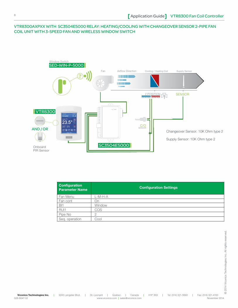
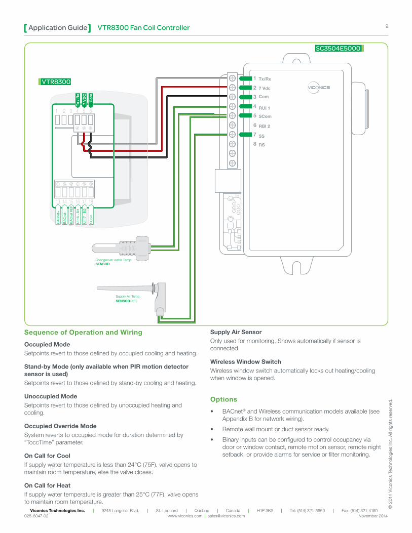
VTR8300AXPXX WITH SC3504E5000 RELAY: HEATING/COOLING WITH CHANGEOVER SENSOR 2-PIPE FAN COIL UNIT WITH 3-SPEED FAN AND WIRELESS WINDOW SWITCH
Configuration Parameter Name
Configuration Settings
Fan Menu L-M-H-AFan cont OnBI1 WindowRUI1 COSPipe No 2Seq. operation Cool
Changeover Sensor: 10K Ohm type 2
Supply Sensor: 10K Ohm type 2
SC3504E5000
2 POSITION
Cooling / Heating Coil Supply SensorAirflow DirectionFan
VTR8300
COOLING VALVE / HEATING VALVE
Window Switch
SED-WIN-P-5000
SENSOR
C/OSENSOR
Onboard PIR Sensor
AND / OR
VTR8300 Fan Coil ControllerApplication Guide 9
Viconics Technologies Inc. | 9245 Langelier Blvd. | St.-Leonard | Quebec | Canada | H1P 3K9 | Tel: (514) 321-5660 | Fax: (514) 321-4150 028-6047-02 www.viconics.com | [email protected] November 2014
© 2
014
Vic
onic
s Te
chno
logi
es In
c. A
ll rig
hts
rese
rved
.
Sequence of Operation and Wiring
Occupied ModeSetpoints revert to those defined by occupied cooling and heating.
Stand-by Mode (only available when PIR motion detector sensor is used)Setpoints revert to those defined by stand-by cooling and heating.
Unoccupied ModeSetpoints revert to those defined by unoccupied heating and cooling.
Occupied Override ModeSystem reverts to occupied mode for duration determined by “ToccTime” parameter.
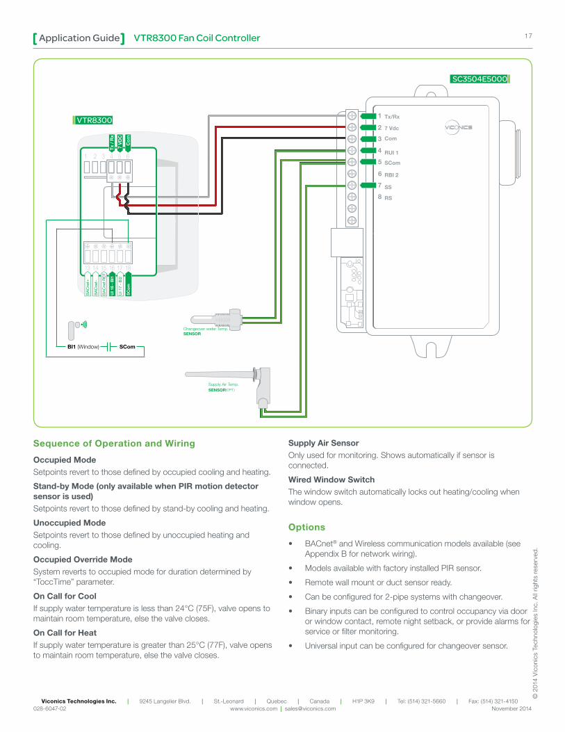
On Call for CoolIf supply water temperature is less than 24°C (75F), valve opens to maintain room temperature, else the valve closes.
On Call for HeatIf supply water temperature is greater than 25°C (77F), valve opens to maintain room temperature.
Supply Air SensorOnly used for monitoring. Shows automatically if sensor is connected.
Wireless Window SwitchWireless window switch automatically locks out heating/cooling when window is opened.
Options
• BACnet® and Wireless communication models available (see Appendix B for network wiring).
• Remote wall mount or duct sensor ready.
• Binary inputs can be configured to control occupancy via door or window contact, remote motion sensor, remote night setback, or provide alarms for service or filter monitoring.
Tx/Rx
7 Vdc
Com
RUI 1
SCom
RBI 2
SS
RS
1
2
3
4
5
6
7
8
SC3504E5000
VTR8300
BA
Cne
t+
BA
Cne
t-
BA
Cne
t RE
F
UI 1
6 -
BI1
UI 1
7 -
BI2
SC
om
Tx /
Rx
7 V
DC
Com
VTR8300 Fan Coil ControllerApplication Guide10
Viconics Technologies Inc. | 9245 Langelier Blvd. | St.-Leonard | Quebec | Canada | H1P 3K9 | Tel: (514) 321-5660 | Fax: (514) 321-4150 028-6047-02 www.viconics.com | [email protected] November 2014
© 2
014
Vic
onic
s Te
chno
logi
es In
c. A
ll rig
hts
rese
rved
.
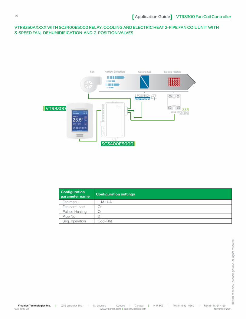
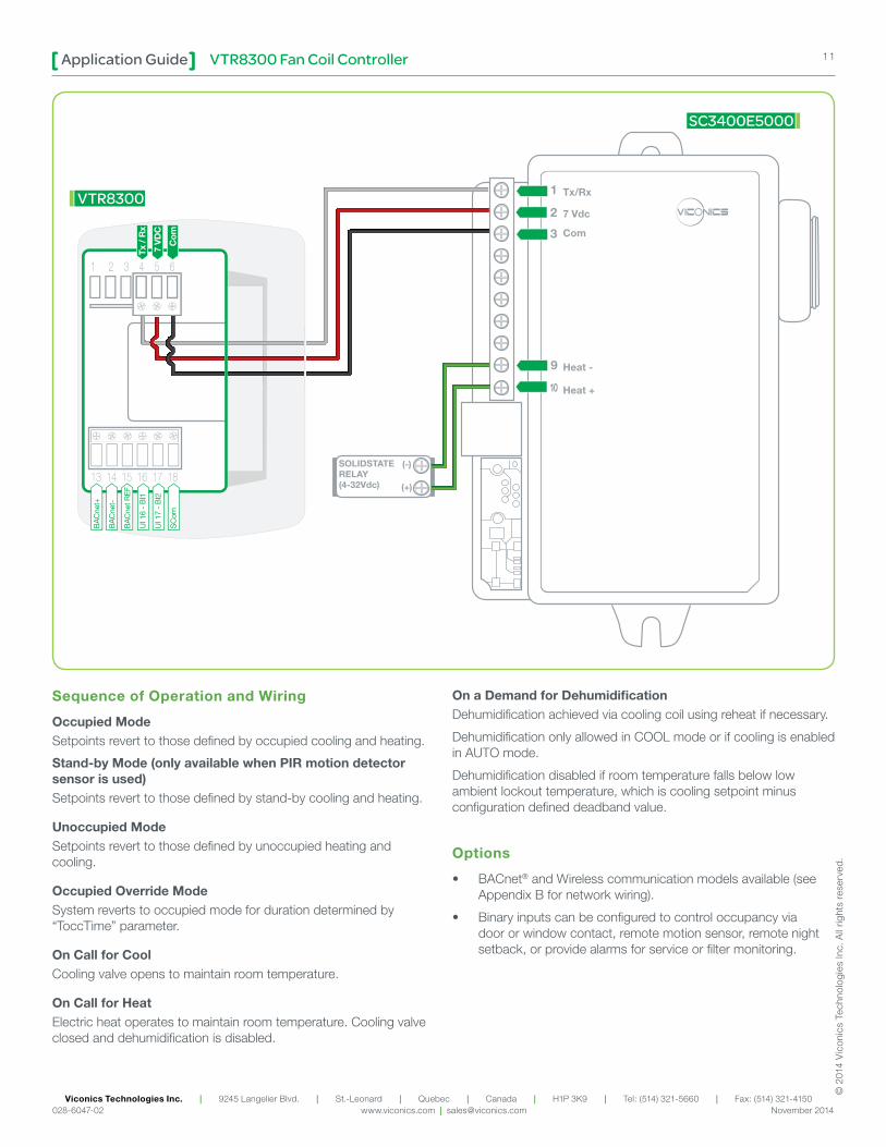
VTR8350AXXXX WITH SC3400E5000 RELAY: COOLING AND ELECTRIC HEAT 2-PIPE FAN COIL UNIT WITH 3-SPEED FAN, DEHUMIDIFICATION AND 2-POSITION VALVES
Configuration parameter name
Configuration settings
Fan menu L-M-H-AFan cont. heat. OnPulsed Heating OnPipe No 2Seq. operation Cool-Rht
Cooling Coil Electric Heating
SSRSOLID STATE RELAY
(GENERIC)
SC3400E5000
2 POSITIONCOOLING VALVE
Airflow DirectionFan
VTR8300
VTR8300 Fan Coil ControllerApplication Guide 11
Viconics Technologies Inc. | 9245 Langelier Blvd. | St.-Leonard | Quebec | Canada | H1P 3K9 | Tel: (514) 321-5660 | Fax: (514) 321-4150 028-6047-02 www.viconics.com | [email protected] November 2014
© 2
014
Vic
onic
s Te
chno
logi
es In
c. A
ll rig
hts
rese
rved
.
Sequence of Operation and Wiring
Occupied ModeSetpoints revert to those defined by occupied cooling and heating.
Stand-by Mode (only available when PIR motion detector sensor is used)Setpoints revert to those defined by stand-by cooling and heating.
Unoccupied ModeSetpoints revert to those defined by unoccupied heating and cooling.
Occupied Override ModeSystem reverts to occupied mode for duration determined by “ToccTime” parameter.
On Call for CoolCooling valve opens to maintain room temperature.
On Call for HeatElectric heat operates to maintain room temperature. Cooling valve closed and dehumidification is disabled.
On a Demand for DehumidificationDehumidification achieved via cooling coil using reheat if necessary.
Dehumidification only allowed in COOL mode or if cooling is enabled in AUTO mode.
Dehumidification disabled if room temperature falls below low ambient lockout temperature, which is cooling setpoint minus configuration defined deadband value.
Options
• BACnet® and Wireless communication models available (see Appendix B for network wiring).
• Binary inputs can be configured to control occupancy via door or window contact, remote motion sensor, remote night setback, or provide alarms for service or filter monitoring.
1
2
3
9
10
SOLIDSTATERELAY(4-32Vdc)
(-)
(+)
SC3400E5000
VTR8300
BA
Cne
t+
BA
Cne
t-
BA
Cne
t RE
F
UI 1
6 -
BI1
UI 1
7 -
BI2
SC
om
Tx /
Rx
7 V
DC
Com
VTR8300 Fan Coil ControllerApplication Guide12
Viconics Technologies Inc. | 9245 Langelier Blvd. | St.-Leonard | Quebec | Canada | H1P 3K9 | Tel: (514) 321-5660 | Fax: (514) 321-4150 028-6047-02 www.viconics.com | [email protected] November 2014
© 2
014
Vic
onic
s Te
chno
logi
es In
c. A
ll rig
hts
rese
rved
.
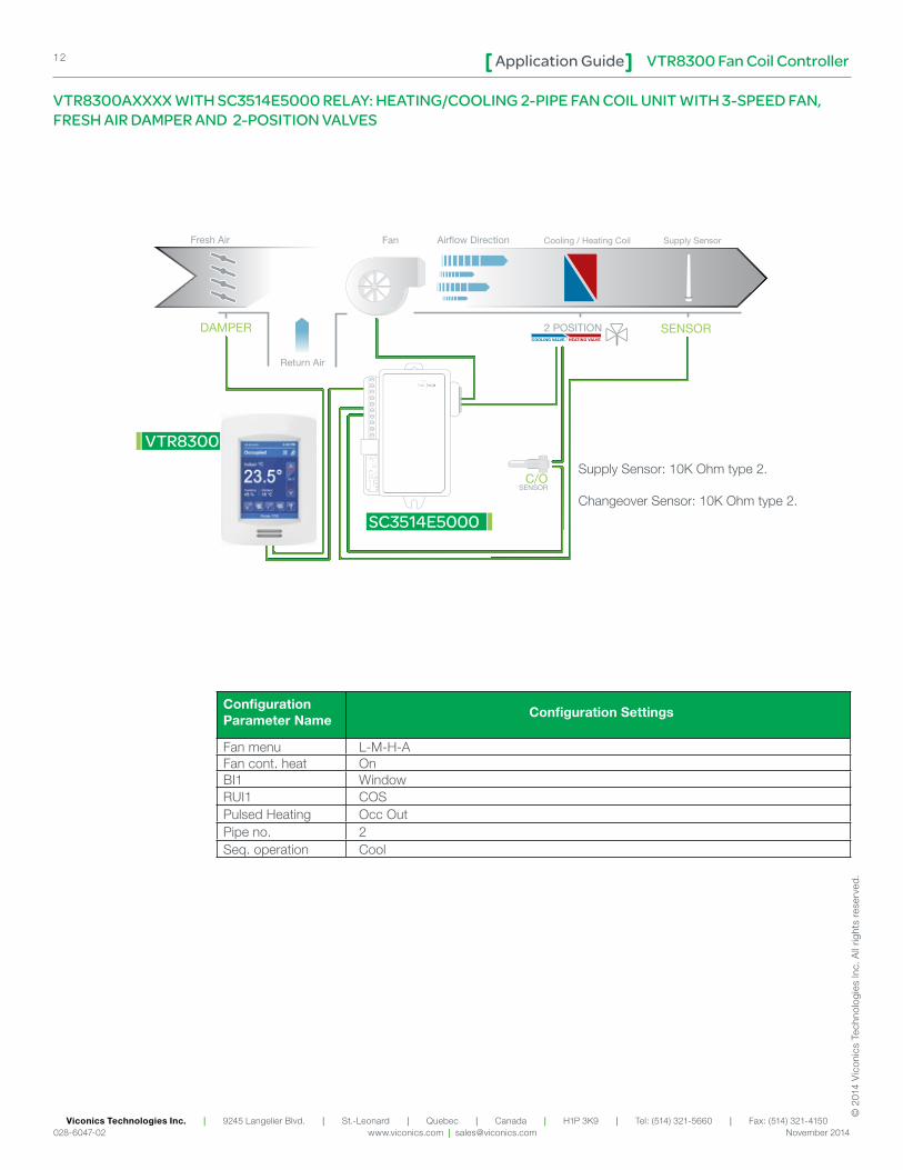
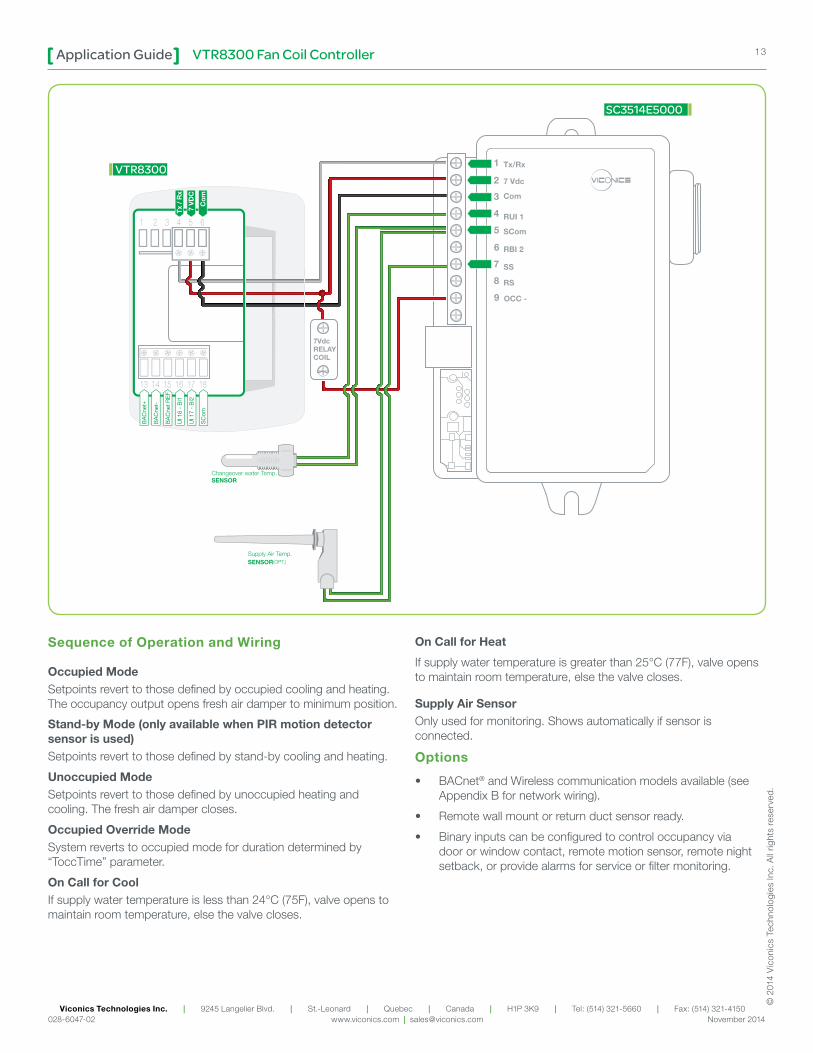
VTR8300AXXXX WITH SC3514E5000 RELAY: HEATING/COOLING 2-PIPE FAN COIL UNIT WITH 3-SPEED FAN, FRESH AIR DAMPER AND 2-POSITION VALVES
Supply Sensor: 10K Ohm type 2.
Changeover Sensor: 10K Ohm type 2.
Configuration Parameter Name
Configuration Settings
Fan menu L-M-H-AFan cont. heat OnBI1 WindowRUI1 COSPulsed Heating Occ OutPipe no. 2Seq. operation Cool
SC3514E5000
2 POSITION
Airflow Direction Cooling / Heating Coil Supply SensorFan
VTR8300
COOLING VALVE / HEATING VALVE
Fresh Air
DAMPER
Return Air
SENSOR
C/OSENSOR
VTR8300 Fan Coil ControllerApplication Guide 13
Viconics Technologies Inc. | 9245 Langelier Blvd. | St.-Leonard | Quebec | Canada | H1P 3K9 | Tel: (514) 321-5660 | Fax: (514) 321-4150 028-6047-02 www.viconics.com | [email protected] November 2014
© 2
014
Vic
onic
s Te
chno
logi
es In
c. A
ll rig
hts
rese
rved
.
Sequence of Operation and Wiring
Occupied ModeSetpoints revert to those defined by occupied cooling and heating. The occupancy output opens fresh air damper to minimum position.
Stand-by Mode (only available when PIR motion detector sensor is used)Setpoints revert to those defined by stand-by cooling and heating.
Unoccupied ModeSetpoints revert to those defined by unoccupied heating and cooling. The fresh air damper closes.
Occupied Override ModeSystem reverts to occupied mode for duration determined by “ToccTime” parameter.
On Call for CoolIf supply water temperature is less than 24°C (75F), valve opens to maintain room temperature, else the valve closes.
On Call for Heat
If supply water temperature is greater than 25°C (77F), valve opens to maintain room temperature, else the valve closes.
Supply Air SensorOnly used for monitoring. Shows automatically if sensor is connected.
Options
• BACnet® and Wireless communication models available (see Appendix B for network wiring).
• Remote wall mount or return duct sensor ready.
• Binary inputs can be configured to control occupancy via door or window contact, remote motion sensor, remote night setback, or provide alarms for service or filter monitoring.
Tx/Rx
7 Vdc
Com
RUI 1
SCom
RBI 2
SS
RS
1
2
3
4
5
6
7
8
9 OCC -
7VdcRELAYCOIL
SC3514E5000
VTR8300
BA
Cne
t+
BA
Cne
t-
BA
Cne
t RE
F
UI 1
6 -
BI1
UI 1
7 -
BI2
SC
om
Tx /
Rx
7 V
DC
Com
VTR8300 Fan Coil ControllerApplication Guide14
Viconics Technologies Inc. | 9245 Langelier Blvd. | St.-Leonard | Quebec | Canada | H1P 3K9 | Tel: (514) 321-5660 | Fax: (514) 321-4150 028-6047-02 www.viconics.com | [email protected] November 2014
© 2
014
Vic
onic
s Te
chno
logi
es In
c. A
ll rig
hts
rese
rved
.
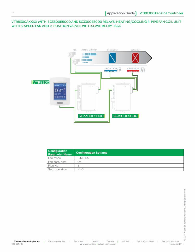
Configuration Parameter Name
Configuration Settings
Fan menu L-M-H-AFan cont. heat OnPipe No 4Seq. operation Ht-Cl
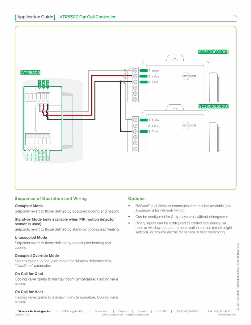
VTR8300AXXXX WITH SC3500E5000 AND SC3300E5000 RELAYS: HEATING/COOLING 4-PIPE FAN COIL UNIT WITH 3-SPEED FAN AND 2-POSITION VALVES WITH SLAVE RELAY PACK
SC3300E5000
2 POSITIONCOOLING VALVE
Cooling Coil
2 POSITIONHEATING VALVE
Heating CoilAirflow DirectionFan
SC3500E5000
VTR8300
VTR8300 Fan Coil ControllerApplication Guide 15
Viconics Technologies Inc. | 9245 Langelier Blvd. | St.-Leonard | Quebec | Canada | H1P 3K9 | Tel: (514) 321-5660 | Fax: (514) 321-4150 028-6047-02 www.viconics.com | [email protected] November 2014
© 2
014
Vic
onic
s Te
chno
logi
es In
c. A
ll rig
hts
rese
rved
.
Sequence of Operation and Wiring
Occupied ModeSetpoints revert to those defined by occupied cooling and heating.
Stand-by Mode (only available when PIR motion detector sensor is used)Setpoints revert to those defined by stand-by cooling and heating.
Unoccupied ModeSetpoints revert to those defined by unoccupied heating and cooling.
Occupied Override ModeSystem reverts to occupied mode for duration determined by “ToccTime” parameter.
On Call for CoolCooling valve opens to maintain room temperature. Heating valve closes.
On Call for HeatHeating valve opens to maintain room temperature. Cooling valve closes.
Options
• BACnet® and Wireless communication models available (see Appendix B for network wiring).
• Can be configured for 2-pipe systems without changeover.
• Binary inputs can be configured to control occupancy via door or window contact, remote motion sensor, remote night setback, or provide alarms for service or filter monitoring.
1
2
3
1
2
3
SC3500E5000T
VTR8300
SC3300E5000
BA
Cne
t+
BA
Cne
t-
BA
Cne
t RE
F
UI 1
6 -
BI1
UI 1
7 -
BI2
SC
om
Tx /
Rx
7 V
DC
Com
VTR8300 Fan Coil ControllerApplication Guide16
Viconics Technologies Inc. | 9245 Langelier Blvd. | St.-Leonard | Quebec | Canada | H1P 3K9 | Tel: (514) 321-5660 | Fax: (514) 321-4150 028-6047-02 www.viconics.com | [email protected] November 2014
© 2
014
Vic
onic
s Te
chno
logi
es In
c. A
ll rig
hts
rese
rved
.
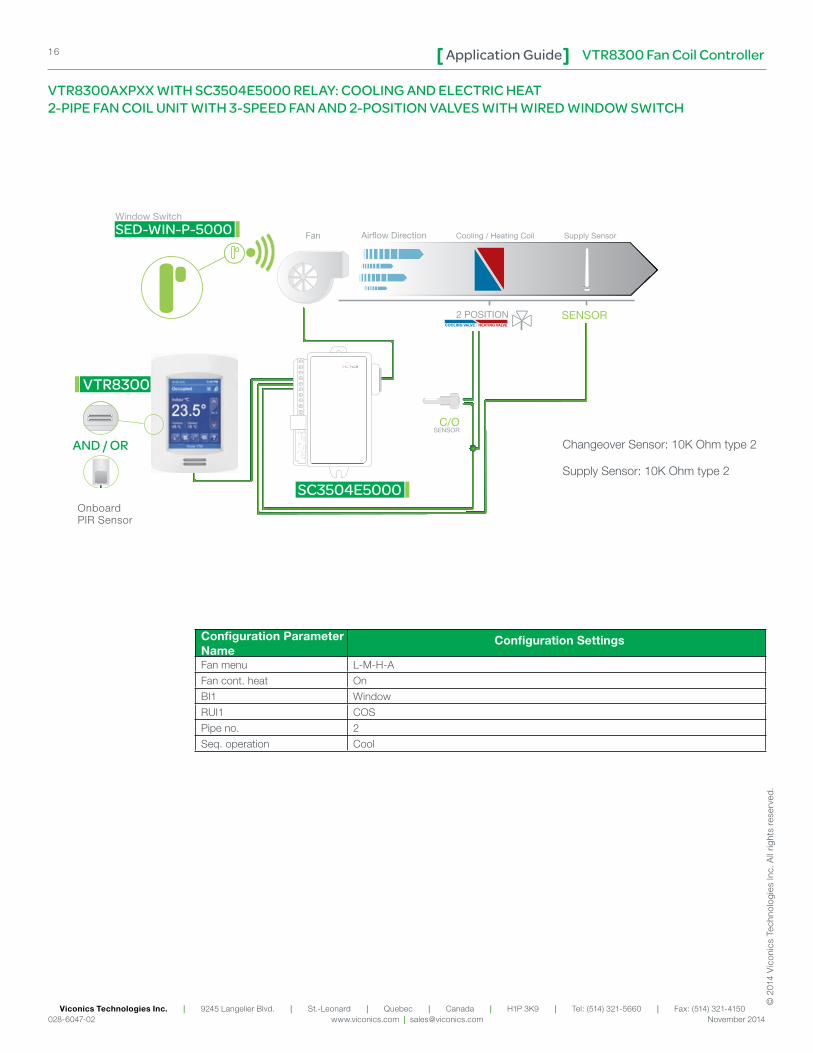
Configuration Parameter Name
Configuration Settings
Fan menu L-M-H-A
Fan cont. heat On
BI1 Window
RUI1 COS
Pipe no. 2
Seq. operation Cool
VTR8300AXPXX WITH SC3504E5000 RELAY: COOLING AND ELECTRIC HEAT 2-PIPE FAN COIL UNIT WITH 3-SPEED FAN AND 2-POSITION VALVES WITH WIRED WINDOW SWITCH
SC3504E5000
2 POSITION
Cooling / Heating Coil Supply SensorAirflow DirectionFan
VTR8300
COOLING VALVE / HEATING VALVE
Window Switch
SED-WIN-P-5000
SENSOR
C/OSENSOR
Changeover Sensor: 10K Ohm type 2
Supply Sensor: 10K Ohm type 2
Onboard PIR Sensor
AND / OR
VTR8300 Fan Coil ControllerApplication Guide 17
Viconics Technologies Inc. | 9245 Langelier Blvd. | St.-Leonard | Quebec | Canada | H1P 3K9 | Tel: (514) 321-5660 | Fax: (514) 321-4150 028-6047-02 www.viconics.com | [email protected] November 2014
© 2
014
Vic
onic
s Te
chno
logi
es In
c. A
ll rig
hts
rese
rved
.
Sequence of Operation and Wiring
Occupied ModeSetpoints revert to those defined by occupied cooling and heating.
Stand-by Mode (only available when PIR motion detector sensor is used)Setpoints revert to those defined by stand-by cooling and heating.
Unoccupied ModeSetpoints revert to those defined by unoccupied heating and cooling.
Occupied Override ModeSystem reverts to occupied mode for duration determined by “ToccTime” parameter.
On Call for CoolIf supply water temperature is less than 24°C (75F), valve opens to maintain room temperature, else the valve closes.
On Call for HeatIf supply water temperature is greater than 25°C (77F), valve opens to maintain room temperature, else the valve closes.
Supply Air SensorOnly used for monitoring. Shows automatically if sensor is connected.
Wired Window SwitchThe window switch automatically locks out heating/cooling when window opens.
Options
• BACnet® and Wireless communication models available (see Appendix B for network wiring).
• Models available with factory installed PIR sensor.
• Remote wall mount or duct sensor ready.
• Can be configured for 2-pipe systems with changeover.
• Binary inputs can be configured to control occupancy via door or window contact, remote night setback, or provide alarms for service or filter monitoring.
• Universal input can be configured for changeover sensor.
Tx/Rx
7 Vdc
Com
RUI 1
SCom
RBI 2
SS
RS
1
2
3
4
5
6
7
8
BA
Cne
t+
BA
Cne
t-
BA
Cne
t RE
F
UI 1
6 -
BI1
UI 1
7 -
BI2
SC
om
Tx /
Rx
7 V
DC
Com
BI1 (Window) SCom
SC3504E5000
VTR8300
VTR8300 Fan Coil ControllerApplication Guide18
Viconics Technologies Inc. | 9245 Langelier Blvd. | St.-Leonard | Quebec | Canada | H1P 3K9 | Tel: (514) 321-5660 | Fax: (514) 321-4150 028-6047-02 www.viconics.com | [email protected] November 2014
© 2
014
Vic
onic
s Te
chno
logi
es In
c. A
ll rig
hts
rese
rved
.
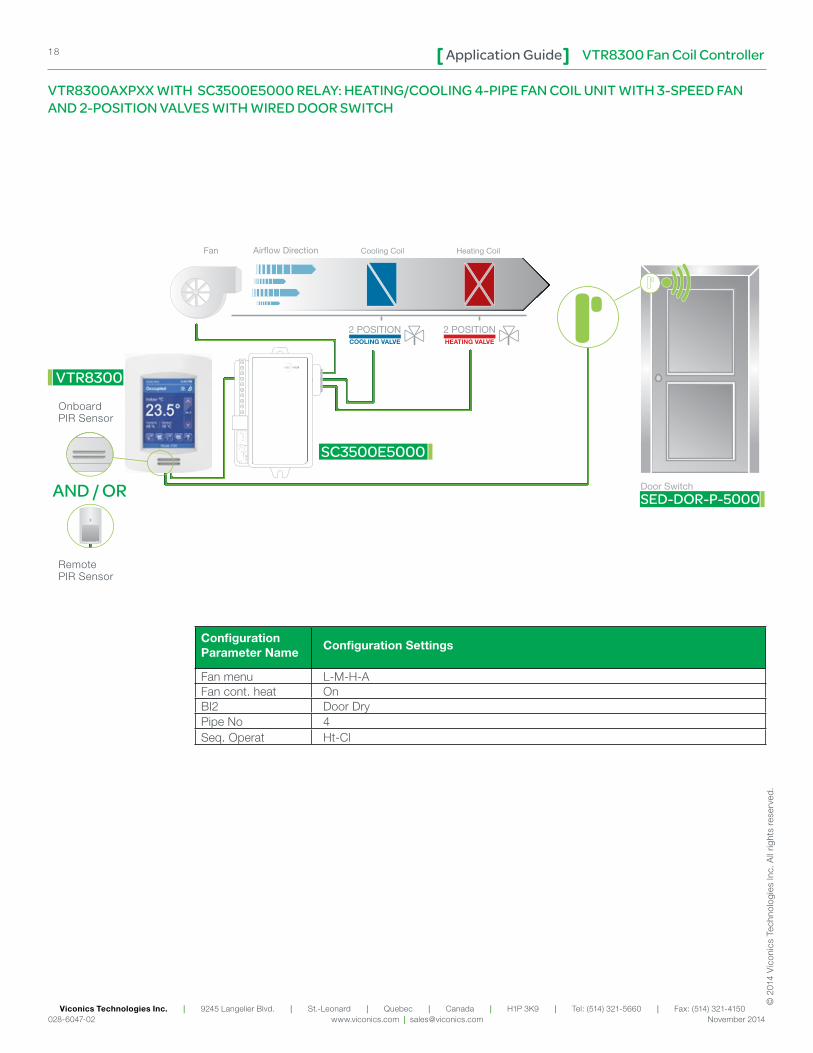
VTR8300AXPXX WITH SC3500E5000 RELAY: HEATING/COOLING 4-PIPE FAN COIL UNIT WITH 3-SPEED FAN AND 2-POSITION VALVES WITH WIRED DOOR SWITCH
Configuration Parameter Name
Configuration Settings
Fan menu L-M-H-AFan cont. heat OnBI2 Door DryPipe No 4Seq. Operat Ht-Cl
SC3500E5000
2 POSITIONCOOLING VALVE
Cooling Coil
2 POSITIONHEATING VALVE
Heating Coil
Door Switch
SED-DOR-P-5000
Airflow DirectionFan
VTR8300
AND / OR
Onboard PIR Sensor
Remote PIR Sensor
VTR8300 Fan Coil ControllerApplication Guide 19
Viconics Technologies Inc. | 9245 Langelier Blvd. | St.-Leonard | Quebec | Canada | H1P 3K9 | Tel: (514) 321-5660 | Fax: (514) 321-4150 028-6047-02 www.viconics.com | [email protected] November 2014
© 2
014
Vic
onic
s Te
chno
logi
es In
c. A
ll rig
hts
rese
rved
.
Sequence of Operation and Wiring
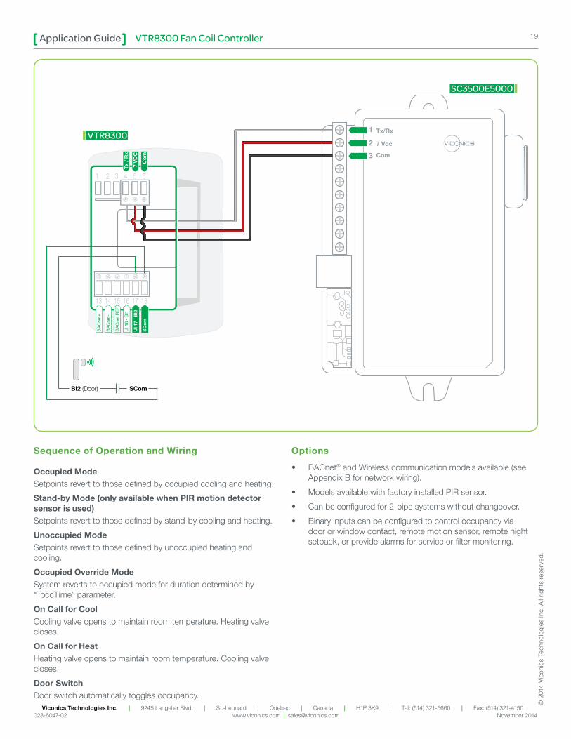
Occupied ModeSetpoints revert to those defined by occupied cooling and heating.
Stand-by Mode (only available when PIR motion detector sensor is used)Setpoints revert to those defined by stand-by cooling and heating.
Unoccupied ModeSetpoints revert to those defined by unoccupied heating and cooling.
Occupied Override ModeSystem reverts to occupied mode for duration determined by “ToccTime” parameter.
On Call for CoolCooling valve opens to maintain room temperature. Heating valve closes.
On Call for HeatHeating valve opens to maintain room temperature. Cooling valve closes.
Door SwitchDoor switch automatically toggles occupancy.
Options
• BACnet® and Wireless communication models available (see Appendix B for network wiring).
• Models available with factory installed PIR sensor.
• Can be configured for 2-pipe systems without changeover.
• Binary inputs can be configured to control occupancy via door or window contact, remote motion sensor, remote night setback, or provide alarms for service or filter monitoring.
Tx/Rx
7 Vdc
Com
1
2
3
BA
Cne
t+
BA
Cne
t-
BA
Cne
t RE
F
UI 1
6 -
BI1
UI 1
7 -
BI2
SC
om
Tx /
Rx
7 V
DC
Com
BI2 (Door) SCom
SC3500E5000
VTR8300
VTR8300 Fan Coil ControllerApplication Guide20
Viconics Technologies Inc. | 9245 Langelier Blvd. | St.-Leonard | Quebec | Canada | H1P 3K9 | Tel: (514) 321-5660 | Fax: (514) 321-4150 028-6047-02 www.viconics.com | [email protected] November 2014
© 2
014
Vic
onic
s Te
chno
logi
es In
c. A
ll rig
hts
rese
rved
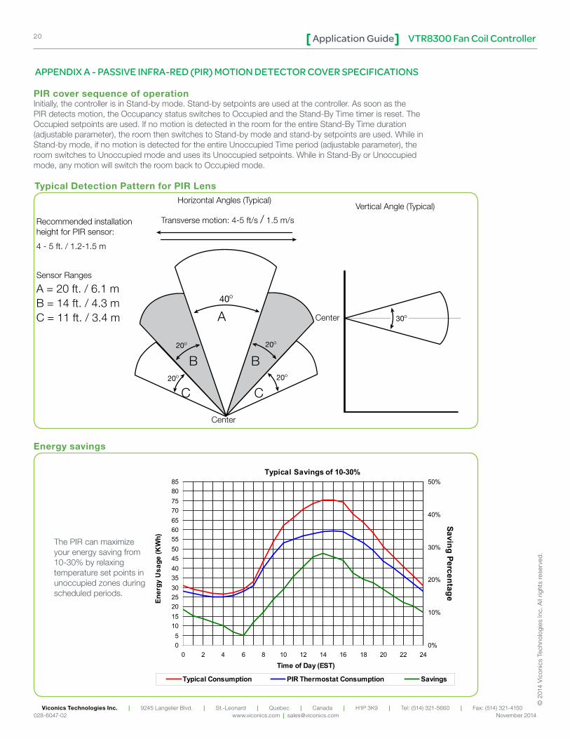
.The PIR can maximize your energy saving from 10-30% by relaxing temperature set points in unoccupied zones during scheduled periods.
Typical Savings of 10-30%
05
10152025303540455055606570758085
0 2 4 6 8 10 12 14 16 18 20 22 24
Time of Day (EST)
Ener
gy U
sage
(KW
h)
0%
10%
20%
30%
40%
50%
Saving Percentage
Typical Consumption PIR Thermostat Consumption Savings
APPENDIX A - PASSIVE INFRA-RED (PIR) MOTION DETECTOR COVER SPECIFICATIONS
Initially, the controller is in Stand-by mode. Stand-by setpoints are used at the controller. As soon as the PIR detects motion, the Occupancy status switches to Occupied and the Stand-By Time timer is reset. The Occupied setpoints are used. If no motion is detected in the room for the entire Stand-By Time duration (adjustable parameter), the room then switches to Stand-by mode and stand-by setpoints are used. While in Stand-by mode, if no motion is detected for the entire Unoccupied Time period (adjustable parameter), the room switches to Unoccupied mode and uses its Unoccupied setpoints. While in Stand-By or Unoccupied mode, any motion will switch the room back to Occupied mode.
PIR cover sequence of operation
Typical Detection Pattern for PIR Lens
Energy savings
20O
20O
20O
20O
40O
A
BB
CC
Horizontal Angles (Typical)
Transverse motion: 4-5 ft/s / 1.5 m/sRecommended installation height for PIR sensor:
4 - 5 ft. / 1.2-1.5 m
Sensor Ranges
A = 20 ft. / 6.1 mB = 14 ft. / 4.3 mC = 11 ft. / 3.4 m
Center
30O
Vertical Angle (Typical)
Center
VTR8300 Fan Coil ControllerApplication Guide 21
Viconics Technologies Inc. | 9245 Langelier Blvd. | St.-Leonard | Quebec | Canada | H1P 3K9 | Tel: (514) 321-5660 | Fax: (514) 321-4150 028-6047-02 www.viconics.com | [email protected] November 2014
© 2
014
Vic
onic
s Te
chno
logi
es In
c. A
ll rig
hts
rese
rved
.
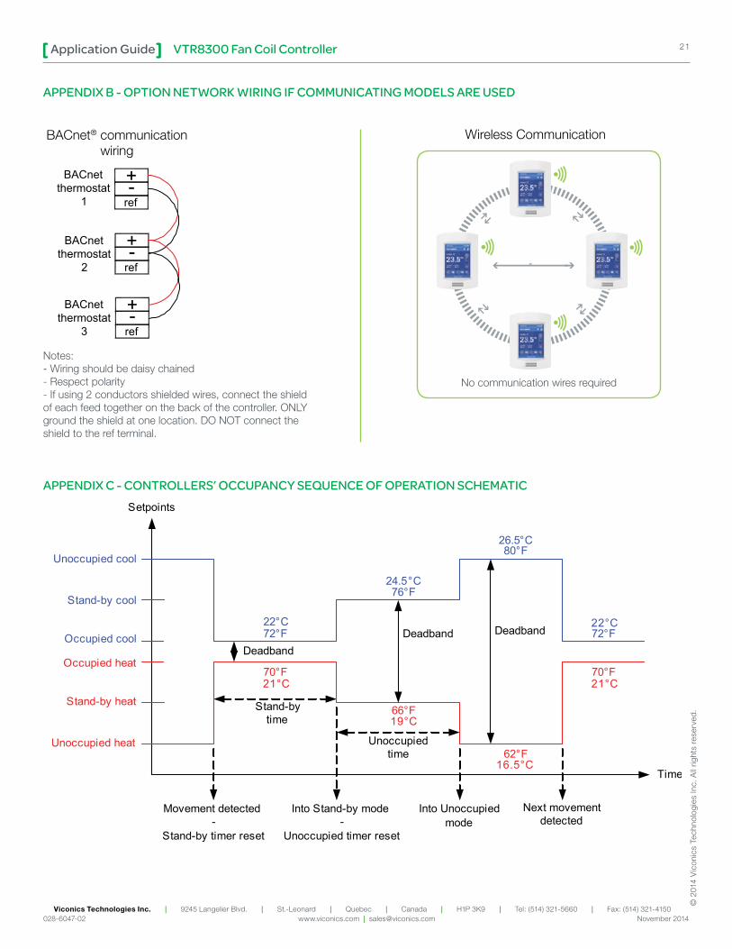
APPENDIX A - PASSIVE INFRA-RED (PIR) MOTION DETECTOR COVER SPECIFICATIONS APPENDIX B - OPTION NETWORK WIRING IF COMMUNICATING MODELS ARE USED
+-ref
+-ref
+-ref
BACnetthermostat
1
BACnetthermostat
2
BACnetthermostat
3
Notes:- Wiring should be daisy chained- Respect polarity- If using 2 conductors shielded wires, connect the shield of each feed together on the back of the controller. ONLY ground the shield at one location. DO NOT connect the shield to the ref terminal.
APPENDIX C - CONTROLLERS’ OCCUPANCY SEQUENCE OF OPERATION SCHEMATICSetpoints
Time
Unoccupied cool
Occupied cool
Stand-by cool
72°F
76°F
80°F
Movement detected-
Stand-by timer reset
Into Stand-by mode-
Unoccupied timer reset
Stand-bytime
Unoccupiedtime
Into Unoccupiedmode
Next movementdetected
70°F
62°FUnoccupied heat
Occupied heat
Stand-by heat
72°F
66°F
70°F
Deadband Deadband
Deadband
22°C
24.5°C
26.5°C
22°C
21°C 21°C
19°C
16.5°C
BACnet® communicationwiring
No communication wires required
Wireless Communication
VTR8300 Fan Coil ControllerApplication Guide22
Viconics Technologies Inc. | 9245 Langelier Blvd. | St.-Leonard | Quebec | Canada | H1P 3K9 | Tel: (514) 321-5660 | Fax: (514) 321-4150 028-6047-02 www.viconics.com | [email protected] November 2014
© 2
014
Vic
onic
s Te
chno
logi
es In
c. A
ll rig
hts
rese
rved
.
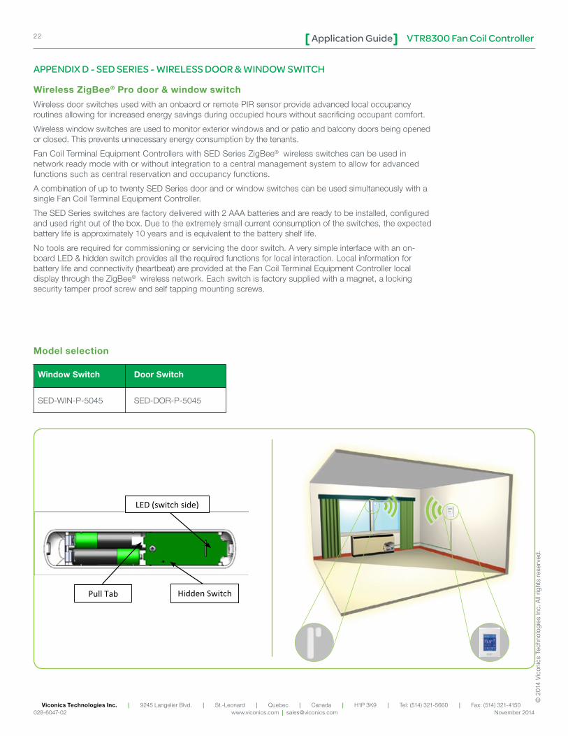
APPENDIX D - SED SERIES - WIRELESS DOOR & WINDOW SWITCH
Wireless ZigBee® Pro door & window switch
Wireless door switches used with an onbaord or remote PIR sensor provide advanced local occupancy routines allowing for increased energy savings during occupied hours without sacrificing occupant comfort.
Wireless window switches are used to monitor exterior windows and or patio and balcony doors being opened or closed. This prevents unnecessary energy consumption by the tenants.
Fan Coil Terminal Equipment Controllers with SED Series ZigBee® wireless switches can be used in network ready mode with or without integration to a central management system to allow for advanced functions such as central reservation and occupancy functions.
A combination of up to twenty SED Series door and or window switches can be used simultaneously with a single Fan Coil Terminal Equipment Controller.
The SED Series switches are factory delivered with 2 AAA batteries and are ready to be installed, configured and used right out of the box. Due to the extremely small current consumption of the switches, the expected battery life is approximately 10 years and is equivalent to the battery shelf life.
No tools are required for commissioning or servicing the door switch. A very simple interface with an on-board LED & hidden switch provides all the required functions for local interaction. Local information for battery life and connectivity (heartbeat) are provided at the Fan Coil Terminal Equipment Controller local display through the ZigBee® wireless network. Each switch is factory supplied with a magnet, a locking security tamper proof screw and self tapping mounting screws.
Window Switch Door Switch
SED-WIN-P-5045 SED-DOR-P-5045
Model selection
LED (switch side)
Hidden Switch Pull Tab
VTR8300 Fan Coil ControllerApplication Guide 23
Viconics Technologies Inc. | 9245 Langelier Blvd. | St.-Leonard | Quebec | Canada | H1P 3K9 | Tel: (514) 321-5660 | Fax: (514) 321-4150 028-6047-02 www.viconics.com | [email protected] November 2014
© 2
014
Vic
onic
s Te
chno
logi
es In
c. A
ll rig
hts
rese
rved
.
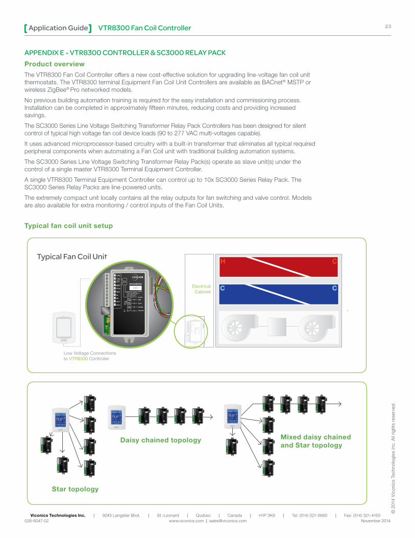
APPENDIX E - VTR8300 CONTROLLER & SC3000 RELAY PACKProduct overview
The VTR8300 Fan Coil Controller offers a new cost-effective solution for upgrading line-voltage fan coil unit thermostats. The VTR8300 terminal Equipment Fan Coil Unit Controllers are available as BACnet® MSTP or wireless ZigBee® Pro networked models.
No previous building automation training is required for the easy installation and commissioning process. Installation can be completed in approximately fifteen minutes, reducing costs and providing increased savings.
The SC3000 Series Line Voltage Switching Transformer Relay Pack Controllers has been designed for silent control of typical high voltage fan coil device loads (90 to 277 VAC multi-voltages capable).
It uses advanced microprocessor-based circuitry with a built-in transformer that eliminates all typical required peripheral components when automating a Fan Coil unit with traditional building automation systems.
The SC3000 Series Line Voltage Switching Transformer Relay Pack(s) operate as slave unit(s) under the control of a single master VTR8300 Terminal Equipment Controller.
A single VTR8300 Terminal Equipment Controller can control up to 10x SC3000 Series Relay Pack. The SC3000 Series Relay Packs are line-powered units.
The extremely compact unit locally contains all the relay outputs for fan switching and valve control. Models are also available for extra monitoring / control inputs of the Fan Coil Units.
Typical fan coil unit setup
Star topology
Daisy chained topology Mixed daisy chained and Star topology
Typical Fan Coil Unit
C C
H C
SC3404E5000
PowerSupply
Tx/Rx
7 Vdc
Com
RUI 1
SCom
RBI 2
SS
RS
Heat -
Heat +
WHITE
BLACK
RED
BLUE
BROWN
YELLOW
FANLOW
FANMED
FANHIGH
COOL5AMax
1/2 HPor 13AMax
90-277 Vac - 50/60 Hz1/2HP + 5A Max Comb. or13A+ 5A Max CombAmb. Temp. 50oC
1
2
3
4
5
6
7
8
9
10
ElectricalCabinet
xxx-xxxx-xx
PowerSupply
Tx/Rx
7 Vdc
Com
RUI 1
SCom
RBI 2
SS
RS
Heat -
Heat +
WHITE
BLACK
RED
BLUE
BROWN
YELLOW
FANLOW
FANMED
FANHIGH
COOL5AMax
1/2 HPor 13AMax
90-277 Vac - 50/60 Hz1/2HP + 5A Max Comb. or13A+ 5A Max CombAmb. Temp. 50oC
1
2
3
4
5
6
7
8
9
10
Low Voltage Connectionsto VTR8300 Controller
Related Documents