INSTALLATION MANUAL FALSE CEILING TRIM KIT A A D E E F F D B B C D E F pcs. 02 white long L-form pre- punched profiles 50x30x3 (in cm.) pcs. 04 threaded rods, length 1 mt. pcs. 02 ceiling mounting brackets pcs. 03 white U-form supports pcs. 02 white side doors pcs. 02 white mounting plates Before starting to mount the trim kit, you have to cut a rectangular hole in the false ceiling in order to position the screen and the trim kit. Afterwards, you have also to drill the holes in the concrete ceiling above for fixing the ceiling mounting brackets and the whole trim kit. Depending on the model of trim kit buyed, please follow the instructions, paying attention to the position of the screen’s bottom bar in comparison with the false ceiling: WARNING Cut the hole in the false ceiling, following the Fig. 1a. If “L” is the width of the viewing area, proceed according to the chart below: FALSE CEILING HOLE FALSE CEILING HOLE dowel bar dowel bar bracket C bracket C Fig. 1a Fig. 2a MODEL WIDTH A (CM) DEPTH B (CM) FALSE CEILING COMPACT L+41 13 FALSE CEILING COMPACT+3BB OR H.C. L+51 13 FALSE CEILING COMPACT TENSIONED L+70 13 FALSE CEILING ELLIPSE L+41 14,5 FALSE CEILING ELLIPSE+3BB OR H.C. L+51 14,5 FALSE CEILING ELLIPSE TENSIONED L+70 14,5 FALSE CEILING MAJOR L+43 15,5 FALSE CEILING MAJOR+3BB OR H.C. L+53 15,5 FALSE CEILING MAJOR TENSIONED L+72 15,5 MODEL D (CM) E (CM) F (CM) FALSE CEILING COMPACT 13,5 3,5 6 FALSE CEILING COMPACT+3BB OR H.C. 13,5 3,5 6 FALSE CEILING COMPACT TENSIONED 13,5 3,5 6 FALSE CEILING ELLIPSE 13,5 4,2 6 FALSE CEILING ELLIPSE+3BB OR H.C. 13,5 4,2 6 FALSE CEILING ELLIPSE TENSIONED 13,5 4,2 6 FALSE CEILING MAJOR 13,5 5,7 6 FALSE CEILING MAJOR+3BB OR H.C. 13,5 5,7 6 FALSE CEILING MAJOR TENSIONED 13,5 5,7 6 Drill the holes following Fig. 2a in order to fix the ceiling brackets (C) to the concrete ceiling, using suitable screws and wall plugs (see also Fig. 6a) STEP 1 STEP 2 FALSE CEILING TRIM KIT COMPONENTS INCLUDED IN THE PACKAGING:

Welcome message from author
This document is posted to help you gain knowledge. Please leave a comment to let me know what you think about it! Share it to your friends and learn new things together.
Transcript

INSTALLATION MANUAL FALSE CEILING TRIM KIT
A
A
D
E E
F F
D
B
B
C
D
E
F
pcs. 02 white long L-form pre-punched profiles 50x30x3 (in cm.)
pcs. 04 threaded rods, length 1 mt.
pcs. 02 ceiling mounting brackets
pcs. 03 white U-form supports
pcs. 02 white side doors
pcs. 02 white mounting plates
Before starting to mount the trim kit, you have to cut a rectangular hole in the false ceiling in order to position the screen and the trim kit. Afterwards, you have also to
drill the holes in the concrete ceiling above for fixing the ceiling mounting brackets and the whole trim kit.Depending on the model of trim kit buyed,
please follow the instructions, paying attention to the position of the screen’s bottom bar in comparison with the false ceiling:
WARNING
Cut the hole in the false ceiling, following the Fig. 1a. If “L” is the width of the viewing area, proceed according to the chart below:
FALSE CEILING HOLE
FALSE CEILING HOLE
dowel bar
dowel barbracket C bracket C
Fig. 1a
Fig. 2a
MODEL WIDTH A (CM) DEPTH B (CM)
FALSE CEILING COMPACT L+41 13FALSE CEILING COMPACT+3BB OR H.C. L+51 13FALSE CEILING COMPACT TENSIONED L+70 13FALSE CEILING ELLIPSE L+41 14,5FALSE CEILING ELLIPSE+3BB OR H.C. L+51 14,5FALSE CEILING ELLIPSE TENSIONED L+70 14,5FALSE CEILING MAJOR L+43 15,5FALSE CEILING MAJOR+3BB OR H.C. L+53 15,5FALSE CEILING MAJOR TENSIONED L+72 15,5
MODEL D (CM) E (CM) F (CM)
FALSE CEILING COMPACT 13,5 3,5 6FALSE CEILING COMPACT+3BB OR H.C. 13,5 3,5 6FALSE CEILING COMPACT TENSIONED 13,5 3,5 6FALSE CEILING ELLIPSE 13,5 4,2 6FALSE CEILING ELLIPSE+3BB OR H.C. 13,5 4,2 6FALSE CEILING ELLIPSE TENSIONED 13,5 4,2 6FALSE CEILING MAJOR 13,5 5,7 6FALSE CEILING MAJOR+3BB OR H.C. 13,5 5,7 6FALSE CEILING MAJOR TENSIONED 13,5 5,7 6
Drill the holes following Fig. 2a in order to fix the ceiling brackets (C) to the concrete ceiling, using suitable screws and wall plugs (see also Fig. 6a)
STEP 1
STEP 2
FALSE CEILING TRIM KIT COMPONENTS INCLUDED IN THE PACKAGING:

STEP 3 STEP 4
STEP 5 STEP 6
Mount the three U-form supports (D) on the two L-form profiles (A) using the provided screws in the pre-punched holes (see Fig. 3a); afterwards mount the two side doors (E) on the two ends left and right of the L-form profiles (see Fig. 3b).
Fig. 3a
Fig. 5a
Fig. 5b
Fig. 6a
Fig. 4a
Fig. 4b
Fig. 3b
After having assembled the structure, place it over the screen housing (see Fig. 4a) and then fix the structure to the screen housing, using the six provided screws, through the three U-form supports (see Fig. 4b).
Fix the mounting plates (F) tightly to the left and right top sides of the screen housing, paying attention that the plates have to be mounted in the exact position as shown on Fig. 5a and 5b.
Mount the ceiling brackets (C) to the concrete ceiling (see Fig. 6a), using the holes drilled before, according to Fig. 2a.
D
E
F C
A
Once you have drilled the holes correctly, you can proceed assembling the trim kit:
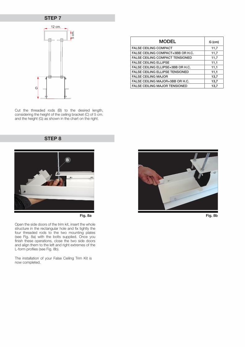
STEP 7
STEP 8
Fig. 8a Fig. 8b
Cut the threaded rods (B) to the desired length, considering the height of the ceiling bracket (C) of 5 cm. and the height (G) as shown in the chart on the right.
MODEL G (cm)
FALSE CEILING COMPACT 11,7
FALSE CEILING COMPACT+3BB OR H.C. 11,7FALSE CEILING COMPACT TENSIONED 11,7
FALSE CEILING ELLIPSE 11,1FALSE CEILING ELLIPSE+3BB OR H.C. 11,1FALSE CEILING ELLIPSE TENSIONED 11,1FALSE CEILING MAJOR 13,7FALSE CEILING MAJOR+3BB OR H.C. 13,7FALSE CEILING MAJOR TENSIONED 13,7
Open the side doors of the trim kit, insert the whole structure in the rectangular hole and fix tightly the four threaded rods to the two mounting plates (see Fig. 8a) with the bolts supplied. Once you finish these operations, close the two side doors and align them to the left and right extremes of the L-form profiles (see Fig. 8b).
The installation of your False Ceiling Trim Kit is now completed.
B
G
12 cm.
5 cm
.
G
Related Documents