Fall Protection Systems Fall Arrest Anchor Analysis Aaron Randal Andy Cash Tiruneh Haile December 7, 2005

Welcome message from author
This document is posted to help you gain knowledge. Please leave a comment to let me know what you think about it! Share it to your friends and learn new things together.
Transcript
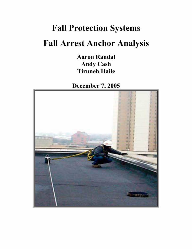
Fall Protection Systems
Fall Arrest Anchor Analysis Aaron Randal
Andy Cash Tiruneh Haile
December 7, 2005
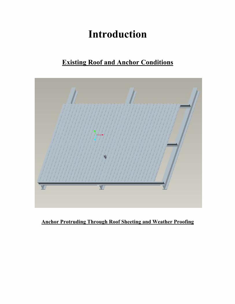
Introduction
Existing Roof and Anchor Conditions
Anchor Protruding Through Roof Sheeting and Weather Proofing
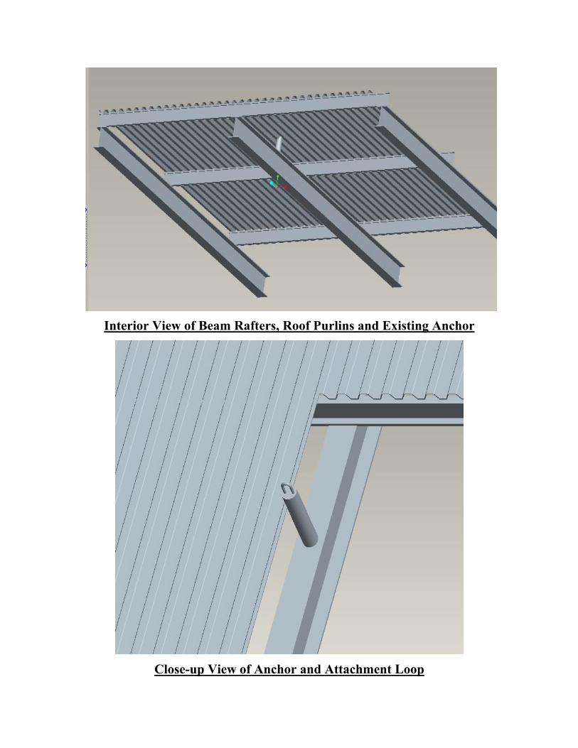
Interior View of Beam Rafters, Roof Purlins and Existing Anchor
Close-up View of Anchor and Attachment Loop
Goal Statement
To evaluate the condition of the existing roof anchor
and verify compliance with OSHA regulations for Fall
Arrest Systems.
Analysis Action Plan
Identify Parameters of Interest
Deflection
Maximum Stress
Verify Elastic Range Model
Supporting Conditions
Eliminate Unnecessary Part Features
Attachment Loop
Roof Sheeting
Purlins
Determine Applicable Loads – OSHA Summary
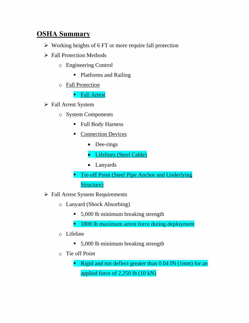
OSHA Summary Working heights of 6 FT or more require fall protection
Fall Protection Methods
o Engineering Control
Platforms and Railing
o Fall Protection
Fall Arrest
Fall Arrest System
o System Components
Full Body Harness
Connection Devices
• Dee-rings
• Lifelines (Steel Cable)
• Lanyards
Tie-off Point (Steel Pipe Anchor and Underlying
Structure)
Fall Arrest System Requirements
o Lanyard (Shock Absorbing)
5,000 lb minimum breaking strength
1800 lb maximum arrest force during deployment
o Lifeline
5,000 lb minimum breaking strength
o Tie off Point
Rigid and not deflect greater than 0.04 IN (1mm) for an
applied force of 2,250 lb (10 kN)

Theoretical Background
Linear Stress Strain Relation Ship
εσ *E=
Stress, Force and Area Relation
AF /=σ
Strain Relation
ll /∆=δ
Force and Deformation Relation
ll
AEF ∆= *)(
Load Matrix
{ } [ ]{ }UKF =

Shape Function for Solid92

Analysis Details Material Properties Modulus = 29e6 10^6 psi
Yield Strength = 36 ksi (tension), 21 ksi (shear)
Ultimate Strength = 58 ksi (tension)
Static Analysis Single Pipe Run
Pipe Material and Size Verification 4” Nominal Pipe Size Deflection < 0.04”
Existing anchor pipe fixed to 1 ft square steel plate. The plate is an extruded with a 1 in thickness. The volume was free meshed at the default setting. All nodes in the four side planes and bottom plane were then fixed with zero displacement in all degrees of freedom. A 2250 lbf was attached to a single node at approximately the center of the top of

the anchor. The analysis was run and the results were reviewed. The pipe section was found to satisfy the displacement limitations. Boundary Conditions, Mesh and Load Application
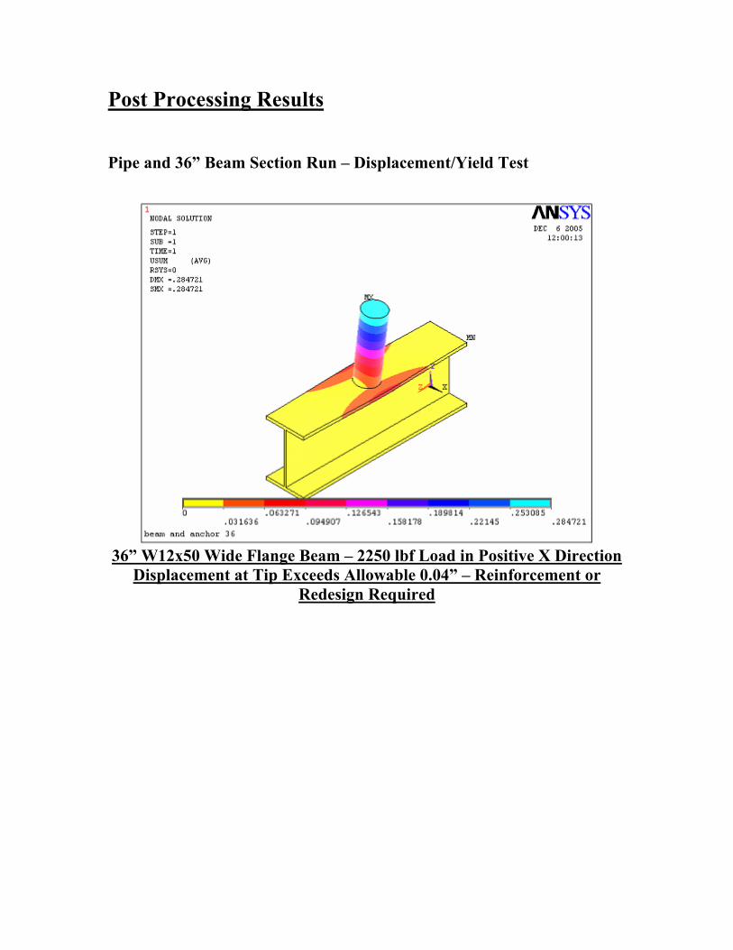
Post Processing Results
Pipe and 36” Beam Section Run – Displacement/Yield Test
36” W12x50 Wide Flange Beam – 2250 lbf Load in Positive X Direction
Displacement at Tip Exceeds Allowable 0.04” – Reinforcement or Redesign Required
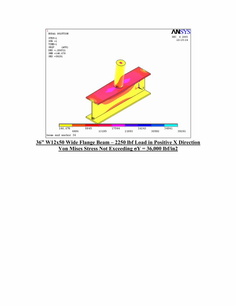
36” W12x50 Wide Flange Beam – 2250 lbf Load in Positive X Direction
Von Mises Stress Not Exceeding σY = 36,000 lbf/in2

Reinforced Pipe/Beam System – Displacement/Yield Test
Reinforced W12x50 Wide Flange Beam with 2250 lbf
Maximum Allowable Tip Displacement (0.04”) Exceeded by Factor of 2
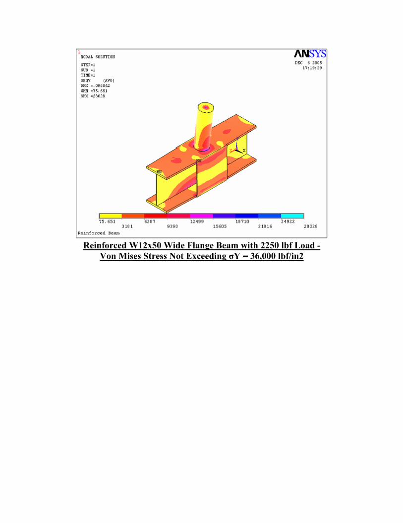
Reinforced W12x50 Wide Flange Beam with 2250 lbf Load -
Von Mises Stress Not Exceeding σY = 36,000 lbf/in2
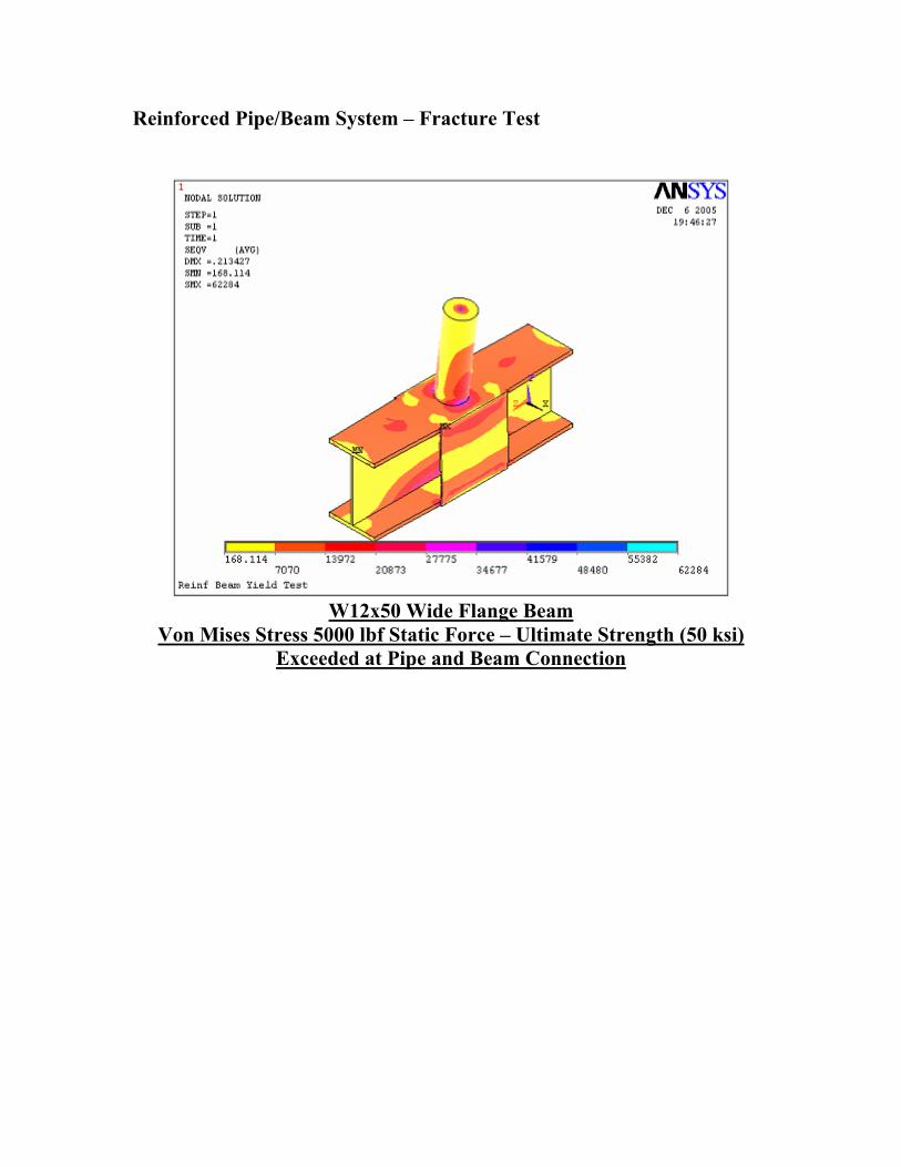
Reinforced Pipe/Beam System – Fracture Test
W12x50 Wide Flange Beam
Von Mises Stress 5000 lbf Static Force – Ultimate Strength (50 ksi) Exceeded at Pipe and Beam Connection

W12x50 Wide Flange Beam
Tip Displacement - 5000 lbf Static Force Summary The pipe anchor alone complies with OSHA requirements. When connected to the standard wide flanged beam the tip displacement of the anchor exceeds the allowable dimension. After reinforcing the sides of the beam by welding quarter inch plating the anchor system no longer deflects excessively at the tip. With an applied load of 5000 lbf the stresses in the anchor system exceed the ultimate strength for this material. Further reinforcement of the anchor system is required or more appropriately the system should be redesigned with higher grade materials.

Acknowledgements
I. Finite Element Analsys, Moaveni 2003
II. Mechanics of Materials, Beer & Johnston 2002
III. ANSYS Manual
IV. www.machinedesign.com
V. U.S. Department of Labor
VI. Lab Safety Supply
Related Documents