FALCON 4.0 Realism Patch Group Falcon 4.0 is a U.S. registered trademark of INFOGRAMES. Realism Patch v5.0 User’s Manual

Welcome message from author
This document is posted to help you gain knowledge. Please leave a comment to let me know what you think about it! Share it to your friends and learn new things together.
Transcript
FALCON 4.0 �
Realism Patch Group
� Falcon 4.0 is a U.S. registered trademark of INFOGRAMES.
Realism Patch v5.0User’s Manual

Important Information
Falcon 4 is a U.S. registered trademark of Infogrames. Permission was obtained from G2Interactive/Force 12 Studios to release this version of the Realism Patch with executable changes, andsubsequent versions of the Realism Patch with only externally driven changes.
The contents of the Realism Patch have been made by the individual authors that comprise of theRealism Patch Group. The authors have given their permission for the contents to be released only aspart of the Realism Patch installer, and no other modification packages for Falcon 4 or any derivativesof Falcon 4.
No part of this manual may be reproduced or redistributed in any other publication or product, by anycommercial or non-commercial organization or individual, without the consent of the individual authorsin concern. This manual may be reprinted or redistributed in its entirety, for the purpose of the personalenjoyment of the users of the Realism Patch only.

1
Falcon 4.0 Realism PatchVersion 5.0 FINAL (US and UK)August 6, 2001Microprose Falcon 4.0 is a flight simulation game produced by Infogrames, to simulate the Block 50 F-16C in a fictitious Korean War. Falcon 4.0 is a U.S. registered trademark of Infogrames. The lastsupported patch release by Infogrames is version 1.08, available at the now defunct Microprosewebsite, http://www.falcon4.com. Prior to the dismissal of the Falcon 4 development team inDecember 1999, an unofficial version of the v1.08 game executable modified by the Microprosedevelopers was tested by a team of public beta testers under iBeta LLC, a Colorado based qualityassurance company. This version was released with increased multiplayer stability, and has nowbecome the most widely used executable, known as version 1.08i2. This version may be obtained atthe major Falcon 4 sites. The rights to develop the Falcon 4 game was purchased by Force 12Studios/G2 Interactive in May 2001.
The Falcon 4.0 Realism Patch is a community-based project that endeavors to improve the gameplayof Falcon 4.0 by enhancing its realism. This Realism Patch is "unofficial,” and is not maintained byInfogrames. The Falcon 4.0 Realism Patch is supplied “as-is.”
The Falcon 4.0 Realism Patch concept was begun by Executive Producer Eric “Snacko” Marlow withthe support of iBeta LLC. The iBeta Realism Patch was released up to version 3.0 by iBeta. Eric andiBeta CEO Glenn “Sleepdoc” Kletzky have decided that iBeta cannot continue to provide corporateresources for further development. iBeta has ceased support of all previous versions of the RealismPatch, and has not been involved in the Realism Patch ever since.
The Realism Patch effort is carried forward by a dedicated team of flight simmers, many of who werethe original members of the iBeta Realism Patch team. The Realism Patch Group (RPG) hasexpanded to include several new members of the F4 community who have been contributing to itsdevelopment and growth, and has grown to even greater heights than its iBeta days. The members ofthe Realism Patch Group includes current and ex- service pilots and engineers, who brought withthem many years of working experience and knowledge on military aviation. The Realism Patch efforthas also expanded in scope, and is no longer a data only patch. Extensive executable changes arenow made to make full use of the data changes, as well as improving weapons and AI behavior. Theproduct that you have today is the result of close collaboration between the many members of RPG,scattered all over the world. The Realism Patch has taken more than 15,000 emails and thousands ofman hours of testing, research, and development to produce.
When the RPG was the iBeta Realism Patch Team, we received permission from Hasbro Interactive(now Infogrames) to develop externally-driven changes to the Falcon 4.0 product. Permission wasobtained from G2 Interactive to release this version of the Realism Patch with executable edits, andsubsequent releases of the Realism Patch with only externally driven edits.
This user’s guide is organized into three parts, namely the Quick Start Guide, the User’s Guide, andDesigner Notes. We suggest you read through the entire manual thoroughly. Many sections havebeen updated and re-written, and a lot of new material have been added. Most of your questions willbe answered by the material contained within this manual, and you will also find the tips and tricks ofmaking the most out of the Realism Patch.
2
USER SUPPORT
IMPORTANT NOTICE
The Realism Patch has been developed, and tested to function as design, using onlythe Falcon 4 version 1.08i2 executable. Falcon 4 is a very complex simulation, andthe incorporation of the executable changes made in the Realism Patch into any otherversions of the Falcon 4 executable does not imply compatibility with the RealismPatch, as the changes may not (and in many cases, do not) produce the same effects.This is true even for data edits. Unless the Realism Patch Group confirms thecompatibility of the executable independently, any claims of compliance is withoutbasis and the agreement of the Realism Patch Group, as the executable in concernhas either not been tested at all, or has been tested and found not to perform asdesigned with the Realism Patch. The Realism Patch Group must emphasise that theproduct will only function as designed when used in its entirety, i.e. with theexecutable and data changes. The Realism Patch Group cannot and will not providesupport for any other versions of the Falcon 4 executable, other than the one suppliedas part of the Realism Patch. Should the user choose to install the Realism Patchover any other Falcon 4 executable, they should understand that they are doing so attheir own risk, and the Realism Patch Group cannot be held responsible for anydamage, data loss, or performance loss that may result. The material covered in thisuser’s manual pertains only to the Falcon 4 executable provided as part of theRealism Patch, and do not reflect the performance of any other versions of the Falcon4 executable.
On-line and Telephone Support:On-line and telephone support are not offered.
Internet:You can read the latest news and information about the Realism Patch on our World Wide Web pageat http://rpg.falcon40.com. Questions, feedback, and ideas can be posted to official Falcon 4 forum,under the Realism Patch Group area, at http://www.delphi.com/falcon4/start/.
How to Get Help:Please see the notice at the bottom of this page for support information. If you are having problemswith the Realism Patch, we can best help you if you provide the following information:
Your computer’s processor and its speed. Total RAM installed on your computer. Version of DirectX and DirectX drivers. Video card brand and model name. Sound card brand and model name. Joystick brand and model name. Any error message or crash log. Detailed description of what you were doing when you experienced the problem, and if the
problem is reproducible, the steps required to reproduce the problem. Any saved TE or campaign files that will cause the problem. Any ACMI files or screen shots that will illustrate the problem.
Other Localized Versions: If you have other localized version of Falcon 4.0 (German, Italian, etc) youmay attempt to install these files, but you must install 1.08US as part of your upgrade. This may affectFalcon 4.0 adversely – if you choose to install 1.08US and the Realism Patch, you must do this at yourown risk. You may attempt to install these files on a French version of Falcon 4.0. Unofficial supportfor French versions of Falcon 4 may be obtained at http://www.checksix-fr.com.

3
FOREWORDFalcon 4.0 was first released in December 1998, after spending four years in development. Many bugswere resolved between the initial release of Falcon4 in December 1998 and the final official patch,version 1.08, which was released in December 1999. Falcon 4 finally became a game stable enoughfor meaningful play. However, the lay off of the entire Falcon 4 development team in December 1999had effectively stopped any more official enhancement to this revolutionary flight simulation game. Theefforts to improve and sustain this remarkable game was and is still being continued by a team ofusers from all over the world. A plethora of different patches, ranging from airplane skin textures, newcockpits, to a complete package such as the Realism Patch, have been made available after thecessation of official support by Infogrames.
The original concept of Falcon 4 as conceived by the chief designer, Gilman “Chopstick” Louie, was tosimulate the experiences of a fighter pilot, by putting the player’s head into the war, and not just intothe plane. The genius of Falcon 4 is that the game creates a tactical environment that makes theplayer look inward, and develop real fighter pilot skills, in order to succeed. The ingenious design ofthe data files and the executable also made Falcon 4 one of the most extensible and customizablegame. It is on the basis of the excellent game architecture that the Realism Patch is made possible.
In a flight simulator as complex as Falcon 4, compromises have to be made. As we developed theRealism Patch series, we have stuck faithfully to the original intent of the designers, and spared noefforts in improving the tactical environment in Falcon 4. All the changes are geared towards providinga realistic battlefield to the player, where real life tactics can be put into practice to help the playersurvive and succeed. While the changes may not be academically correct in the strictest sense (whocares about where a third order fit is better than a fifth order fit anyway?), the changes in the RealismPatch have been made to produce realistic effects and to simulate the intricacies of a modern aircampaign.
We have improved the environment to the point where you will need to develop real fighter pilotinstincts, and understand the strengths and limitations of your equipment. You will be faced withdifferent scenarios of conflicting needs, similar to those faced by real fighter pilots. For example, youwill realize the fear of not being able to positively identify targets; the limitations of electronic counter-measures; the limitations of your weapons; and the need for meticulous mission planning, amongstothers.
With the release of version 5 of the Realism Patch, we have finally completed the process of modelingthe full effects of electronic warfare on modern air campaign. With an integrated air defense system,stand-off jammers, and other electronic support and counter-measures, Falcon 4 with the RealismPatch is now the most complete simulation of a modern air war ever made available in the PC flightsimulation industry. The physics and engineering behind every change in the Realism Patch havebeen thoroughly and painstakingly researched, and put together as an integrated whole.
We hope that you will enjoy the Realism Patch, as much as we have enjoyed developing and testing it.This user’s manual is part of the Realism Patch experience, and complements the Realism Patch. Wethank you for your interest in the Realism Patch, and wish you clear skies, calm winds, and a MiG atyour twelve o’clock !
The Realism Patch Group

4
Table of Contents
PART I: QUICK START GUIDE ....................................................................................... 12Executive Producer’s Notes – Realism Patch............................................................... 13Version 5.0 ....................................................................................................................... 13
Known Issues With Realism Patch 5.0 ..................................................................................... 16Realism Patch Design Philosophy................................................................................. 17Realism Patch Version 5 Team Composition................................................................ 19Credits .............................................................................................................................. 20Highlights Of Previous Realism Patch Releases.......................................................... 21
RPG Realism Patch Version 4.1 ................................................................................................ 21RPG Realism Patch Version 4.0 ................................................................................................ 21iBeta Realism Patch Version 3.0 ............................................................................................... 22iBeta Realism Patch Version 2.1 ............................................................................................... 23iBeta Realism Patch Version 2.0 ............................................................................................... 24iBeta Realism Patch Version 1.0 ............................................................................................... 25iBeta Team – Falcon 4.0 Realism Patch (Up to Realism Patch version 3.0) ......................... 26
History of Revisions and README Files....................................................................... 27File Definitions................................................................................................................. 273rd Party Realism Add-ons .............................................................................................. 28References and Sources................................................................................................. 29
PART II: USER’S GUIDE ............................................................................................... 30Chapter 1: Falcon 4 Game Mechanics .......................................................................... 31
Introduction ................................................................................................................................. 31Milking The Hardware................................................................................................................. 32
Processor and Graphics...........................................................................................................................32Physical And Virtual Memory ...................................................................................................................33Disk I/O Optimization ...............................................................................................................................34Operating System ....................................................................................................................................34Conclusion ...............................................................................................................................................35
Banishing The Ghosts Of Multi-player ..................................................................................... 36Introduction ..............................................................................................................................................36Multiplayer Tricks .....................................................................................................................................36Setting up a TCP/IP network....................................................................................................................37
Connection Tips ..................................................................................................................................38The Incomplete And Unapproved Quick Guide To Bubbles .................................................. 39
Bubble Lexicon v1.1.................................................................................................................................40Bombing In The Bubble ............................................................................................................. 44
Some Definitions......................................................................................................................................44The Ideal ..................................................................................................................................................45Original Default Settings for the UDDs and ODDs ...................................................................................45Recommended Settings for UDDs and ODDs .........................................................................................46
The Wingmen......................................................................................................................................47Mavericks ............................................................................................................................................47Other AI Flights ...................................................................................................................................48Enemy Flights .....................................................................................................................................48
Beyond Winning Battles: Winning The War............................................................................. 49Falcon 4 "Campaign Priorities”.................................................................................................................49
Campaign Sliders Explained ...............................................................................................................49Campaign "Force Ratios” Sliders .............................................................................................................54Object Density Slider ...............................................................................................................................54Time Acceleration In TE And Campaign ..................................................................................................56
Chapter 2: Mission Planning.......................................................................................... 57Introduction ................................................................................................................................. 57Knowing Your Enemy................................................................................................................. 58

5
Analyzing The Airborne Threat ................................................................................................................58Avoiding Hostile Interceptor Radar Detection......................................................................................58Avoiding Hostile Interceptor RWR Detection.......................................................................................58Avoiding Hostile Interceptor Visual Detection......................................................................................59Threat Capabilities ..............................................................................................................................59
Analyzing The Ground Based Threat.......................................................................................................60Avoiding SAM engagements ...............................................................................................................60The Anti-Aircraft Artillery (AAA) Threat................................................................................................63
Route Planning ........................................................................................................................................64Conclusion ...............................................................................................................................................65
The AAA Menace......................................................................................................................... 66Preamble..................................................................................................................................................66The Threat ...............................................................................................................................................66Enroute To The Target.............................................................................................................................67Attacking The Target................................................................................................................................67
HARM attacks .....................................................................................................................................68Maverick attacks .................................................................................................................................68High-level bombing .............................................................................................................................68Medium-level bombing ........................................................................................................................68Low-level bombing ..............................................................................................................................68
Dispersal Pattern For The Battery............................................................................................................68AAA In Combat And Support Units ..........................................................................................................69
Jinking Against Tracer Type AAA........................................................................................................69Hell, Fire And Brimstone From Above...................................................................................... 70
Unguided Bombs .....................................................................................................................................70Guided Bombs .........................................................................................................................................74Air-to-Surface Missiles .............................................................................................................................75Anti Radiation Missiles.............................................................................................................................78Unguided Rockets....................................................................................................................................80Weapon Selection....................................................................................................................................81
The Art And Science Of Moving Mud........................................................................................ 82Introduction ..............................................................................................................................................82Target Study ............................................................................................................................................82Route Planning And De-Confliction..........................................................................................................83Ordnance Considerations ........................................................................................................................84
Safe Escape........................................................................................................................................84Cluster Bomb Splash Pattern ..............................................................................................................86
Dive Recovery Considerations.................................................................................................................87Weapon Ballistics.....................................................................................................................................88Level Bomb Mission Planning ..................................................................................................................92
Example of Level Release of Cluster Bombs ......................................................................................93Dive Bomb Mission Planning ...................................................................................................................94
Example of Dive Bombing with Low Drag Bombs ...............................................................................96Loft Bomb Mission Planning.....................................................................................................................98
Example of Loft Bombing with Low Drag Bombs ................................................................................99Pop-Up Attack Planning.........................................................................................................................100
Pop-Up Maneuver .............................................................................................................................102Pop-Up Attack Options......................................................................................................................103Deciding on Low or High Altitude Bombing .......................................................................................103Pop-Up Planning ...............................................................................................................................104
Attacking With Laser Guided Bombs .....................................................................................................105Targeting Pod Operating Limitations.................................................................................................106Differences Between Laser Guided Bombs.......................................................................................107Flight Path Considerations ................................................................................................................108
Attacking With Stand-Off Weapons........................................................................................................108Egress and Abort Plan ...........................................................................................................................109Threat Reaction .....................................................................................................................................109
Thunder and Lightning............................................................................................................. 110Introduction ............................................................................................................................................110Dismantling The Integrated Air Defense System ...................................................................................110
The Opening Move............................................................................................................................110SEAD Rollback and Destruction of the Enemy IADS ........................................................................111
6
Low and /Medium High Altitude Tactics ............................................................................................112Target Selection ................................................................................................................................112
Shifting The Emphasis ...........................................................................................................................112Ordnance Allocation and Conservation.............................................................................................113Force Protection................................................................................................................................113
Conclusion .............................................................................................................................................114Chapter 3: Tactics And Weapon Employment ........................................................... 115
Introduction ............................................................................................................................... 115Conquering The Virtual Skies.................................................................................................. 116
Realism Patch Considerations ...............................................................................................................116The Air-to-Air Environment - Missiles.....................................................................................................116Air War Tactical Changes ......................................................................................................................118Air War Strategic Changes.....................................................................................................................118The Surface-to-Air Environment.............................................................................................................118Runway Repair ......................................................................................................................................119Air to Air Changes In Realism Patch......................................................................................................120SAM and AAA Changes In Realism Patch.............................................................................................121Problems with Missing Missiles..............................................................................................................122Aircraft AI ...............................................................................................................................................123Illusory “Wall of MiGs”............................................................................................................................124
Managing Electrons.................................................................................................................. 125The Electronic Environment In Realism Patch .......................................................................................125Radar Management ...............................................................................................................................125
Pulse Radars.....................................................................................................................................126Pulse Doppler Radars .......................................................................................................................126RWS (Range While Search) Mode....................................................................................................126TWS (Track While Scan) Mode.........................................................................................................126VS (Velocity Search) Mode ...............................................................................................................127Single Target Track (STT) Mode.......................................................................................................127Non Cooperative Target Recognition (NCTR)...................................................................................127Radar Performance Under Various Conditions .................................................................................129
RWR Management ................................................................................................................................129RWR Basics ......................................................................................................................................129RWR Data Interpretation ...................................................................................................................130RWR Symbol Assignment .................................................................................................................131RWR Audio Interpretation and Launch Warning ...............................................................................133
Electronic Countermeasure Management..............................................................................................134ECM Coverage..................................................................................................................................134Employment Considerations .............................................................................................................135
Emission Control (EMCON) ...................................................................................................................137Target Identification ...............................................................................................................................137Frequently Asked Questions On Radars, Jammers, and RWR..............................................................138
The Pointed End Of the Sword................................................................................................ 142Preamble................................................................................................................................................142WVR IR Missiles ....................................................................................................................................142
Tail Chasers – AIM-9P Sidewinder and AA-2D (R-13M) Atoll ...........................................................142Russia’s Short Stick – AA-8 (R-60M) Aphid ......................................................................................143The Lethal Sidewinder – AIM-9M Sidewinder ...................................................................................144Evolution of the Heat Seeker – AIM-9X Sidewinder ..........................................................................144The Israeli Connection – Python 4 ....................................................................................................145The First of the Off-Boresight Missiles – AA-11 (R-73M1) Archer.....................................................146Chinese Clones – PL-7 and PL-8......................................................................................................147
BVR IR Missiles .....................................................................................................................................148The Grand Old Dame – AA-7 (R-24T) Apex......................................................................................148Hypersonic Heat Seeker – AA-6 (R-46TD) Acrid ..............................................................................148The Latest Incarnation of IR BVR Missiles – AA-10B (R-27T) Alamo ...............................................149
Semi-Active Radar Homing Missiles ......................................................................................................149The Faithful Workhorse – AIM-7M Sparrow ......................................................................................149The WVR Missile – AA-2C (R-3R) Atoll.............................................................................................150Arming The MiG-23 – AA-7 (R-24R) Apex ........................................................................................151Valkyrie Killer – AA-6 (R-46RD) Acrid ...............................................................................................151

7
The Fourth Generation – AA-10A and AA-10C (R-27R and R-27RE) Alamo....................................151The Longest Reach of The Bear – AA-9 (R-33) Amos ......................................................................152
Active Radar Homing Missiles ...............................................................................................................152The Rabid Dog – AIM-120 AMRAAM................................................................................................152Protecting The Fleet – AIM-54C Phoenix ..........................................................................................153The Russian Rabid Dog – AA-12 (R-77) Adder.................................................................................154
Aerial Guns ............................................................................................................................................154Missile Evasion ......................................................................................................................................154
Generating LOS Problems ................................................................................................................154Dragging and Beaming......................................................................................................................155Power Reduction and Aspect Changes.............................................................................................155Electronic Countermeasures .............................................................................................................155Dealing With SARH Missiles .............................................................................................................156Defeating ARH Missiles.....................................................................................................................156
Missile Arming and Fusing.....................................................................................................................157Frequently Asked Questions On Missiles...............................................................................................158
Chivalry Is Dead........................................................................................................................ 164Getting The Basics.................................................................................................................................164F-Pole Versus F-Pole.............................................................................................................................164F-Pole Versus A-Pole ............................................................................................................................165A-Pole Versus A-Pole ............................................................................................................................166IRCM Tactics .........................................................................................................................................167Fighting Off-Boresight Capable Missiles ................................................................................................168Using The Helmet Mounted Sight (For Russian Aircraft) .......................................................................169
Mothering The AI....................................................................................................................... 170Introduction ............................................................................................................................................170Example 1: Attacking In Trail Formation ................................................................................................170Example 2: Attacking In Spread Formation............................................................................................170Example 3: Attacking With Maverick Missiles ........................................................................................171Example 4: SEAD Escort .......................................................................................................................171Example 5: Attacking Heavily Defended Targets ...................................................................................172Example 6: Flight Path Deconfliction .....................................................................................................172Example 7: Attacking Targets In Hilly Terrain ........................................................................................173Example 8: Attacking At Low Level........................................................................................................174Example 9: Flying Pass SAM Sites........................................................................................................174Example 10: AI Fuel Management.........................................................................................................175
Chapter 4: Tactical Reference ..................................................................................... 177Introduction ............................................................................................................................... 177Fighters And Targets................................................................................................................ 178
OPFOR Fighter Aircraft..........................................................................................................................178MAPO MiG-19S / Shenyang J-6 Farmer ...........................................................................................178MAPO MiG-21PF/PFM/bis Fishbed-F/Fishbed-N..............................................................................178Chengdu J-7 III..................................................................................................................................179MAPO MiG-23ML Flogger-G.............................................................................................................180MAPO MiG-25PD Foxbat-E ..............................................................................................................181MAPO MiG-29 Fulcrum-A (9-12) / Fulcrum-C (9-13).........................................................................181MAPO MiG-31B Foxhound-A ............................................................................................................183Sukhoi Su-27 Flanker-B ....................................................................................................................184Sukhoi Su-30MKK Flanker ................................................................................................................185
Friendly Fighter Aircraft..........................................................................................................................186Northrop-Grumman F-5E Tiger II ......................................................................................................186Boeing F-4E Phantom II ....................................................................................................................187Northrop-Grumman F-14B Tomcat ...................................................................................................188Boeing F-15C Eagle..........................................................................................................................189Boeing F-15E Strike Eagle ................................................................................................................190Lockheed Martin F-16C Fighting Falcon ...........................................................................................191Boeing F-18C Hornet ........................................................................................................................191
OPFOR Strike Aircraft............................................................................................................................192MAPO MiG-17F / Shenyang J-5........................................................................................................192Sukhoi Su-25 Frogfoot-A...................................................................................................................193llyushin Il-28 Beagle / Harbin H-5......................................................................................................194

8
Tupolev Tu-16A Badger-A / Xian H-6A .............................................................................................194Tupolev Tu-95MS Bear-H .................................................................................................................195
Friendly Strike Aircraft............................................................................................................................195Northrop-Grumman A-10 Thunderbolt II............................................................................................195Lockheed Martin F-111F Aardvark....................................................................................................196Lockheed Martin F-117 NightHawk ...................................................................................................197Boeing B-1B Lancer ..........................................................................................................................198Boeing B-52H Stratofortress .............................................................................................................199
OPFOR Electronic Warfare Support Aircraft ..........................................................................................200Beriev (Ilyushin) A-50M Mainstay......................................................................................................200
Friendly Electronic Warfare Support Aircraft ..........................................................................................200Northrop-Grumman EF-111A Raven.................................................................................................200Northrop-Grumman EA-6B Prowler...................................................................................................201Boeing E-3B Sentry...........................................................................................................................202
Flying Telephone Poles............................................................................................................ 203OPFOR Surface-To-Air Missile Systems ...............................................................................................203
SA-2 (Almaz S-75 Dvina/Volkhov) “Guideline” ..................................................................................203SA-3 (Almaz S-125 Neva) “Goa”.......................................................................................................204SA-4 (Antey 2K11 Krug) “Ganef”.......................................................................................................204SA-5 (Antey S-200 Angara) “Gammon”.............................................................................................205SA-6 (NII Priborostroeniya 2K12 Kub) “Gainful”................................................................................206SA-7 (Kolomna KBM Strela-2M) “Grail”.............................................................................................207SA-8 (Antey 9K33 Osa) “Gecko” .......................................................................................................208SA-9 (Nudelman 9K31 Strela-1) “Gaskin” .........................................................................................208SA-10 (Almaz S-300PMU1) “Grumble” .............................................................................................209SA-13 (NII Priborostroeniya 9K35 Strela-10) “Gopher” .....................................................................210SA-14 (Kolomna KBM Strela-3M) “Gremlin”......................................................................................211SA-15 (Antey Tor) “Gauntlet” ............................................................................................................212SA-16 (9M313 Igla 1) “Gimlet” ..........................................................................................................212SA-19 (9M311) “Grison” / 2S6M Quad 30mm Tunguska ..................................................................213CPMEIC Hongying HN-5A ................................................................................................................214
Friendly Surface-To-Air Missile Systems ...............................................................................................214Daewoo Pegasus (Chun-Ma) ............................................................................................................214Matra Bae Dynamics Mistral .............................................................................................................215Raytheon FIM-92 Stinger ..................................................................................................................216Boeing Avenger Self Propelled Air Defense System.........................................................................217M2A2 Bradley Stinger Fighting Vehicle (BSFV)/Bradley Linebacker.................................................217Lockheed Martin Light Armored Vehicle (LAV) Air Defense System.................................................218MIM-14 Nike Hercules.......................................................................................................................219Raytheon MIM-23B Improved-HAWK................................................................................................219Raytheon MIM-104 Patriot PAC-2.....................................................................................................220
The Golden BBs........................................................................................................................ 222OPFOR Anti-Aircraft Artillery..................................................................................................................222
KS-19 100 mm Anti-Aircraft Gun.......................................................................................................222KS-12 85 mm Anti-Aircraft Gun.........................................................................................................222S-60 57 mm Automatic Anti-Aircraft Gun ..........................................................................................223M1939 37 mm Automatic Anti-Aircraft Gun.......................................................................................224ZU-23 Twin 23 mm Automatic Anti-Aircraft Gun ...............................................................................224ZPU-2 14.5 mm Anti-Aircraft Machine Guns .....................................................................................225ZSU-57-2 “Sparka” Twin 57 mm Self Propelled Anti-Aircraft Gun System........................................225ZSU-23-4 “Shilka” Quad 23 mm Self Propelled Anti-Aircraft Gun System ........................................226M-1992 Twin 30 mm Self Propelled Anti-Aircraft Gun.......................................................................227
Friendly Anti-Aircraft Artillery..................................................................................................................227Daewoo K-200 20 mm Self Propelled Anti-Aircraft Gun System .......................................................227
PART III: DESIGNER’S NOTES..................................................................................... 229I Can’t Hear You ! ...................................................................................................................... 230
COMM File Fixes (from Poogen) ...........................................................................................................230The Invulnerable Vehicles........................................................................................................ 231
Preamble................................................................................................................................................231Changes In Realism Patch.....................................................................................................................231
Outstanding Problems.......................................................................................................................232

9
To Do List..........................................................................................................................................232Structure Of The PHD And PD Files ......................................................................................................232
Docking Ships And Boats........................................................................................................ 235Preamble................................................................................................................................................235Changes Made.......................................................................................................................................235
Correcting The Golden BB....................................................................................................... 237Changes To SAMs/AAA.........................................................................................................................237Changes To AAA Accuracy....................................................................................................................239
The Changed Battlescape........................................................................................................ 240Changes Made to Ground Units.............................................................................................................240Changes Made to Air Units ....................................................................................................................241Changes Made to Squadron Stores:......................................................................................................241
Abstract Combat....................................................................................................................... 242Blast and Damage Models ....................................................................................................... 243
Design Considerations...........................................................................................................................243Effects of Napalm and the Reduction of its Damage Value....................................................................244
Arming The Birds of Prey ........................................................................................................ 245CBU-97 Sensor Fused Weapon: The Smart Tank Killer ........................................................................245Arming The Planes: Loadout Changes ..................................................................................................245
Flight Models............................................................................................................................. 250New Aircraft Limiters..............................................................................................................................250Flight Models..........................................................................................................................................250
Flight Models De-Mystified ...................................................................................................... 252Flight Model Parameters ........................................................................................................................252Atmospheric Model ................................................................................................................................258Engine Model .........................................................................................................................................258Performance and Flying Qualities ..........................................................................................................258
Life Beyond Flying The F-16.................................................................................................... 261The Realism Patch Version 3 (And Beyond) Way..................................................................................261
Finger Printing The Birds Of Prey........................................................................................... 262Designing Radar Signatures ..................................................................................................................262Designing Visual Signatures ..................................................................................................................262Designing Infra-Red Signatures .............................................................................................................263
Turning On The Heat ................................................................................................................ 264Engine Infra-Red Signature Variation ....................................................................................................264Flare Effectiveness ................................................................................................................................265Equipping The Aircraft With IRCM .........................................................................................................267
Hit Boxes ................................................................................................................................... 268Designing The Hit Boxes........................................................................................................................268
Low Aspect Ratio Wing Aircraft.........................................................................................................268High Aspect Ratio Wing Aircraft (Jet and Props)...............................................................................268Rotary Wing Aircraft ..........................................................................................................................269
Hit Boxes And Gameplay.......................................................................................................................269Open Heart Surgery On Artificial Intelligence ....................................................................... 270
AI Skill Level ..........................................................................................................................................270AI Abort Behavior...................................................................................................................................270AI Combat Behavior...............................................................................................................................271
Sensor Usage ...................................................................................................................................271AI Skill Levels and Performance .......................................................................................................272BVR and WVR Behavior ...................................................................................................................273A/A and A/G Targeting Behavior .......................................................................................................274Bombing and Ground Attack Behavior ..............................................................................................276SEAD Strikes and SEAD Escorts......................................................................................................279Ground Attack Altitudes.....................................................................................................................280Rocket Attack ....................................................................................................................................281Missile Evasion and Guns Defense...................................................................................................281Helmet Mounted Sights .....................................................................................................................283Changes To the 2D AI.......................................................................................................................284
Helping the Air Tasking Order Engine....................................................................................................284Fixing Helicopters ..................................................................................................................................286
The Electronic Battlefield......................................................................................................... 288

10
Understanding How Radars Work In Falcon 4.0 ....................................................................................288What the RCD Floats Represent.......................................................................................................288The Falcon 4 Radar and Electronic Warfare Algorithm in Realism Patch .........................................289
Radar Changes Made In The Realism Patch.........................................................................................291Correcting The APG-68 Radar In Realism Patch...................................................................................292Revamping Non-Cooperative Target Recognition (NCTR) In Realism Patch ........................................293Varying Radar Performance With Target Aspect In Realism Patch .......................................................296Making ECM Work In Realism Patch .....................................................................................................297Making Track-Via-Missile Guidance Work Properly In Realism Patch ...................................................298Making Active Radar Guided Missiles Work Properly In Realism Patch ................................................299
Modeling the ARH Missile Seekers (Monopulse with Home-On-Jam) ..............................................299Removing the ARH Missile Launch Warning.....................................................................................301
Revamping The Radar Warning Receiver In Realism Patch..................................................................301Original RWR Implementation...........................................................................................................302Realism Patch Implementation..........................................................................................................303Creating Individual RWRs .................................................................................................................304RWR Symbologies and Aural Tone Assignment ...............................................................................304
Radar Line-of-Sight In Falcon 4 .............................................................................................................306Improving The F-16 Avionics Setup In Realism Patch ...........................................................................307Ground Control Intercept, Integrated Air Defense System, And AWACS in Falcon 4 ............................307
Implementation in the Realism Patch................................................................................................308Stand-Off Jammers in the Realism Patch ..............................................................................................312
Missiles Galore.......................................................................................................................... 314Basics of How Missiles Work .................................................................................................................314Falcon 4.0 Missile Modeling...................................................................................................................316
Missile Modeling Files .......................................................................................................................316Missile Flight Modeling ......................................................................................................................317Interpreting DAT File Data Fields ......................................................................................................317General Notes ...................................................................................................................................320Creating an Accurate Missile Model in Falcon 4 ...............................................................................321Fine Tuning Surface-to-Air Missiles In Falcon 4................................................................................322
Fixing The Exploding Air-to-Ground Missiles .........................................................................................323The Long And Short Of Fuses................................................................................................. 324
Mechanization Of Warhead Arming Delay .............................................................................................324All Things Laser ........................................................................................................................ 325
Mechanization of LGB In The Realism Patch.........................................................................................325Mechanization of the LANTIRN Targeting Pod In The Realism Patch ...................................................325
Things That Fall From The Sky ............................................................................................... 327Mechanization of Bomb Ballistics...........................................................................................................327
Thunderbirds And Blue Angles............................................................................................... 328Formation Changes ...............................................................................................................................328
Trail Formation ..................................................................................................................................328Wedge Formation..............................................................................................................................329Spread Formation .............................................................................................................................329
The Funky Chicken................................................................................................................... 330Falcon’s Damage Model ........................................................................................................................330Damage Due to Exceeding Flight Limits ................................................................................................330
Bug Hunting Season ................................................................................................................ 332C-130 Taxiing Problem ..........................................................................................................................332ILS Glidescope and Course Deviation Bar.............................................................................................332Airbase Relocation.................................................................................................................................332
Supply And Demand................................................................................................................. 333Implementation in Falcon 4 ....................................................................................................................333Implementation in The Realism Patch ...................................................................................................333

11
List of Tables
Table 1 : Air-to-Air Missile Capabilities of Fighters in Falcon 4 (Korean Theatre) ................................ 60
Table 2 : Surface-to-Air Missiles In Falcon 4 (Korean Theatre) ............................................................ 61
Table 3: Minimum Release Altitude, Level Constant Speed No-Turn Escape Maneuver .................... 85
Table 4: Minimum Release Altitude, 500lb. HE bomb, 5g Climb Escape Maneuver ............................ 85
Table 5: Minimum Release Altitude, 2,000lb. HE bomb, 5g Climb Escape Maneuver ......................... 86
Table 6: Falcon 4 Cluster Bomb Pattern Diameter for Various CBU Burst Height ............................... 86
Table 7: Approximate Altitude Loss For 3g and 5g Pullout During Dive Recovery............................... 87
Table 8: Weapon Ballistics for Low Drag Bombs, CBUs, and LGBs in Level Delivery......................... 88
Table 9: Weapon Ballistics for Low Drag Bombs, CBUs, and LGBs in 10° and 15° Dive Delivery ...... 89
Table 10: Weapon Ballistics for Low Drag Bombs, CBUs, and LGBs in 30° and 45° Dive Delivery .... 89
Table 11: Weapon Ballistics for Low Drag Bombs, CBUs, and LGBs in Loft Toss Delivery................. 90
Table 12: Airspeed Conversion Table (Approximate) ........................................................................... 90
Table 13: Realism Patch Radar Warning Receiver Symbology Assignment...................................... 133

12
PART I: QUICK START GUIDE
This section provides a quick overview of the changes in the latest version of the Realism Patch. Youare advised to read through this section first to familiarize yourself with the changes in the RealismPatch, as well as the known issues. Highlights of previous Realism Patch releases are also included.The installation instructions for the Realism Patch may be found in the installation guide, which is aseparate document.
PART
I
13
EXECUTIVE PRODUCER’S NOTES – REALISM PATCHVERSION 5.0The Realism Patch Group has not been working really hard since the release of Realism Patchversion 4.1. More enhancements have been made, and more weapons are being added to theRealism Patch to reflect the updated ORBAT of the forces in the Korean theatre, as well as supportthe needs of other theatres. Realism Patch version 5.0 is the most extensive and comprehensiverelease of the RP series ever, and completes our quest to model the modern air battle in the highestfidelity possible.
Here are some of the highlights of RP5.0:
o NCTR (Non Cooperative Target Recognition) has been totally revamped. You will no longersee the friendly/hostile bar, but instead, you will see the actual target ID, depending on thetarget aspect.
o The RWR has been fixed. Contacts will now be dropped after 6 seconds if the emitter fails torepaint the target. The audio tone of the emitter will also be played when the emitter actuallyrepaints the target. You will no longer find that the emitter appearing on your RWR if you areoutside its radar gimbal limits, although the RWR will wait for 6 seconds before purging anexisting symbol.
o The RWR symbology library has been expanded and extensively modified. Additional symbolshave been added to reflect the capabilities of the most modern RWR systems such as theALR-56M. The symbol set now allows for both high and low-end RWR systems to bemodeled.
o Dogfight mode HUD symbology has been de-cluttered. The flight path marker, pitch ladder,altitude, and airspeed scales have been removed to reflect the actual symbologies of theBlock 50 HUD in dogfight mode.
o RPM symbology has been removed from the HUD. The actual HUD display does not showRPM on the F-16, and pilots rely on the engine RPM gauge for this information.
o The default bomb spacing is now 125 feet, and is the most common bomb spacing used byoperational F-16 pilots. The ripple spacing is also adjusted for release altitude, just as in theactual fire control computer.
o The ballistics of low drag bombs, cluster bombs, and laser guided bombs have been adjustedto reflect the actual ballistics of their real world counterparts.
o Laser guided bombs must now be guided all the way until impact. If the LANTIRN targetingpod breaks lock prior to impact for whatever reason, the laser guided bombs will miss. Themiss distance is dependent on the range at which the targeting pod breaks lock, and is higherfor Paveway II bombs (GBU-10, GBU-12, GBU-28) than Paveway III bombs (GBU-24).
o The LANTIRN pod will now inhibit its laser designator from firing above an altitude of 25,000feet. LGBs released above this altitude will miss even when the targeting pod is locked ontothe target. This simulates the actual LANTIRN pod behavior and the limitations of its xenonlamp laser designator.
o The radar elevation scan volume has been fixed. In all versions of Falcon 4, the radarelevation scan volume is less than that shown on the radar cursors. This is now fixed. Theradar elevation scan volume in RWS and TWS mode have also been corrected to match theactual APG-68 radar.
o The radar detection performance is now dependent on the target aspect. This captures thevariation in the radar cross section of a target, as well as the differences in the dopplervelocities in tail-on and head-on scenarios. Head-on detection ranges are higher than tail-ondetection ranges.
14
o Anti-radiation missiles can now be fired at search radars.o Warhead arming time delay has now been implemented for missiles. If you fire a missile inside
its minimum range, the warhead will not detonate.o Variable firing rates have been implemented for different guns in the Realism Patch. You will
get firing rates ranging from a few hundred rounds per minute on the 23 mm AAA guns, to6,000 rounds per minute on the M61 Vulcan cannon.
o Variable minimum engagement altitudes for SAMs have been implemented. The minimumaltitude will no longer be 1,500 feet for all SAMs, but will vary from 50 feet AGL for MANPADS,to over 4,000 feet AGL for the high altitude SA-5.
o The flight formations have been adjusted to reflect actual tactical formations used in real life.o The AAA Flak effectiveness is now dependent on the skills of the AAA battalion.o Search radars (such as GCI and EW radar sites) will now show up on the RWR and the HTS.
Destruction of these radars will have a detrimental effect on EW radar coverage, and willaffect enemy GCI/AWACS capability.
o The GCI/AWACS environment has been completed revised in 2D and 3D. If an aircraft isdetected by any component of the IADS, enemy fighters will be vectored to intercept if theyare within range. Low level tactics can now be used to evade detection.
o The radar coverage in the planning map is now dynamic, and shows the current radarcoverage. As enemy radars are destroyed, the effect on radar coverage is reflected.
o Threat circles can now be shown only for detected units (SAM units, AAA, and ground combatunits). The threat circles will show for any unit that is capable of posing a threat to aircraft,such as tank units with ADA support.
o Stand-off Jammers have been implemented. As long as a package is protected by the jammeraircraft, it will jam enemy IADS assets (SAM/AAA sites, EW/GCI radars, and AWACS) anddelay their detection of the package.
o The 2D map display now shows the details of the flights, in a pseudo AWACS mode. Togetherwith the IADS implementation, the 2D map can now be used as an AWACS module.
o Destruction of enemy power stations and nuclear plants will now affect the industrialproduction capacity. This affects the rate of resupply in the campaign.
o A new communications command to request the AI wingman for weapons check has beenimplemented.
o The AI now bombs accurately. Bombing accuracy decreases with altitude, and is dependenton the skills of the AI pilots.
o When bombing objectives, the AI flight will automatically select the features of importance,and will no longer bomb unimportant features such as taxi signs.
o The AI will now release all the air-to-ground ordnance of the same type in a single pass. Thisreduces the frequency of multiple passes over highly defended targets. The AI will also initiatetighter turns away from the target after attacking them, to avoid entering MANPADS/AAAengagement envelopes. The AI will also dispense one flare and two chaff packets after everyattack pass over the target.
o The AI will now expend all their air-to-ground ordnance against ground targets when task forBAI, strike, or interdiction missions, or when carrying A/G missiles, before returning home. TheAI lead will also not order the wingmen to rejoin when the flight is committed to ground attack.
o The AI flight will no longer stay in trail formation after attacking ground targets. They will nowassume the wedge formation for egress, and this improves the AI survivability on A/Gmissions. The AI will also follow the steerpoints and return to base after bombing.
o The AI will now obey the “Rejoin” command and abort its attack on ground targetsimmediately, and the player can reassign another target to the AI.
15
o AI SEAD strikes and SEAD escorts will prioritize radiating targets over non-radiating targets,and will no longer launch a volley of anti-radiation missiles at the same target. They will alsoengage targets of opportunity, and will query the loadout of each flight member to preventrepeated attacks on the same target.
o The ground attack altitudes for various ordnance types have been totally revamped to improveAI survivability, and their targeting effectiveness. This also brings the AI’s behavior inconformance with typical doctrines. Low drag bombs are now delivered from 11,000 feet; highdrag bombs are delivered from 1,000 feet; Durandals are delivered from 250 feet; air-to-ground missiles are delivered from 4,000 feet; rockets and gun strafe attacks will commenceat 7,000 feet; and laser guided bombs are delivered from 13,000 feet.
o The AI’s accuracy with rocket delivery has now been improved. AI helicopters and aircraft cannow hit their targets with rockets, and the kills will be displayed on the debriefing screen afterthe flight.
o Helicopters will now fire rockets, ATGMs, and air-to-air missiles. The helicopters will alsodescend to the lowest possible altitude during the attack, and are capable of executing ATGMattacks from masked positions behind terrain.
o Airplanes will now fire rockets and score reasonably accurate hits against their targets.o Helmet mounted sights have been implemented for the AI. The AI will employ the AA-11 at
high off-boresight angles, and is also more capable of employing IR missiles with smallerseeker gimbal limits more intelligently.
o The ATO will now only tasked stealth aircraft for night operations. Aircraft that are not nightcapable may also be tasked for night missions only if their morale is not broken. This allowsthem to perform night intercepts and bombing.
o New airplanes have been added. The PLAAF now has the Chengdu J-7 III, and the formidablemulti-role Su-30MKK figher. The DPRK forces now have the J-5, and the Russians are nowequipped with the MiG-29C Fulcrum.
o Flight models have been adjusted. For aircraft without afterburners, engaging the afterburnerwill not result in an increase in engine thrust and fuel flow.
o New air-to-air missiles have been added. This includes the highly capable AIM-9X Sidewinderthat entered low rate initial production in January 2001, as well as the fearsome Rafael Python4, which is in service with the Israeli Air Force and several other air forces. Both missiles havebeen added to support other theatres.
o New air-to-ground weapons have been added. This includes the AGM-84E SLAM, AGM-130A, AGM-142A Have Nap, AS-17 Krypton hypersonic ARM, AS-18 stand-off missile, Mk-83bomb, GBU-16 LGB, and the Russian ZAB-500 incendiary bomb.
o New SAMs have been added, including the Matra Mistral, SA-4, SA-16, and the formidableSA-10d (S-300PMU1) “Grumble” for the PLA.
o Helmet mounted sights are now implemented for the player. When the player flies the MiG-29A/C, Su-27, or the Su-30, the IR missiles can be slaved to the player’s line-of-sight in thePadlock view, and a missile aiming reticle will be displayed.
o New guns have been added, and the guns are no longer shared. Guns that have been addedinclude the 30 mm Gsh-N-30, 20 mm M39-2, 7.62 mm M134, 30 mm NR-30-3, and more. Thecharacteristics of each gun are now modeled.
o New 3D models have been included. This includes the F-4E, F-4G, J-7 III, MiG-31, Su-30MKK, AGM-84E, AGM-142, AS-12, AS-17, AS-18, AIM-9P, AIM-9M, AIM-120, Chun-Ma,SA-9, PL-7, and more.
o The list of units for TE, and the ATO generation table is now exported to a text file for editingexternally.
o The infamous “Nuke” bug has been fixed.
16
o The infamous “Mid-air Maverick explosion” bug has been fixed.o The “aircraft taxiing to destination” bug has been fixed.o The ILS localizer and glidescope deviation bug at various airfields has been fixed.
KNOWN ISSUES WITH REALISM PATCH 5.0
� If you have created/saved missions in TE under a previous RP or v1.08US file set, they may notfunction properly under the most recent RP. We have found a workaround – if you must go backto 1.08US after installing the Realism Patch, you must de-install your Falcon 4.0 game completelyand reinstall from the CD, re-apply the 1.08US patch, and re-apply the “i2” EXE. Similarly, if youwish to attempt to use a TE created under a previous RP then we recommend you select edit afterhighlighting the TE, change the mission clock by one minute (doesn’t matter if you move it earlieror later), and resave the mission. These attempts to ‘save’ favorite TEs are not always effective.The scope and quantity of the changes made make it impossible to maintain total compatibility.
� We do not recommend using the –Gx command on your EXE command line. This may increasesignificantly the number of objects in the F4 world and radically increase CPU loading. You willsee very significant decreases in frame rates near high activity areas (FLOT) in a campaign. When the CPU is loaded down so significantly that the frame rate drops below about 10, you willsee missiles stop fusing and pass-through targets.
� The MiG-29 will now choose to carry AA-2R's for radar guided missiles in the Dogfight module.Those wishing to practice BVR in dogfight should choose the Su-27 that now carries the AA-12.
� When using Sylvain's patches and the combat autopilot your own aircraft will not fire mediumrange missiles if your radar is set to RWS (the default). This problem is solved by switching theradar mode to TWS.
� If you load the aircraft asymmetrically, for example with CBU-58 on one side of the wing, andCBU-87 on the opposing side of the wing, or AGM-65B on one side of the wing and AGM-65D onthe other, the AI pilot will become confused, as Falcon 4 assumes a loadout that is normallysymmetric. This can produce unpredicatable AI behavior, such as flying orbits over the target areawithout dropping its ordnance. Asymmetric loadouts are rare and hardly used in war.
� If SAM units are placed too close to buildings, this will inhibit the SAMs from firing. Falcon 4 willinhibit the SAMs from firing due to collision detection. This problem affects all SAM types,especially SA-2, SA-3, SA-5, SA-10, and the Patriot. You should move the SAM unit further awayfrom buildings, or the city that it is defending, to prevent such problems from occurring.
� When the S-24 rocket is carried, the graphics will be that of the LAU-3/A rocket pod. All unguidedrockets are placed in “containers” such as the LAU-3/A. The actual 3D model of the S-24 rocketwill not be visible until the rocket is fired. This is hardcoded in the executable, and cannot bechanged. All rocket pods will share the same graphics, i.e. the LAU-3/A model.
� The AI wingman will always follow the flight lead’s waypoints. This is not unrealistic as in real life,the flight lead is responsible for the entire flight. If you set the DED waypoint to another waypointthat you are not flying towards, for example, you are landing at an airbase and have your waypointset to the divert airfield, the AI wingman may land at the divert airfield instead. This is a behaviorof the AI since the first release of Falcon 4.
� Due to the way Falcon 4 computes the drag of bombs (i.e physically incorrect by assuming alinear reduction), the ballistics of bombs when released at high and low altitudes may notcorrespond exactly to the ballistic tables supplied in this manual. Some data scatter is expected.
17
REALISM PATCH DESIGN PHILOSOPHY
“Hex Editing” started as a grass roots effort with players modifying the files of Falcon 4.0 to get moreenjoyment from their gameplay experience. Fortunately, the designers of Falcon 4.0 created a schemethat allowed much of the inner workings of the simulation to be accessed by modifying the text andbinary files that came with the game. Now, thanks to the innovative and creative discoveries made bythose who explored the depths of Falcon 4.0, we have the ability to bring additional immersion to theFalcon 4.0 world.
In most cases, F4 Hex Editing started out as a way to have some fun with the weapons by makingthem bigger and more plentiful than Falcon allows. However it has become increasingly difficult to sortthrough the various modifications and collect the ones that you would like to include. For manyplayers, “realism” is the most important thing. Having a set of files that increased realism whilemaintaining gameplay expanded the scope of Falcon 4.0 beyond what was initially delivered. This“realism patch” is the outcome of this philosophy.
During our modifications, we discovered many inaccuracies, oversights, and just plain wronginformation in the files. Our realism patch attempts to correct many of these issues. We also wantedto increase the realism by adding objects, weapons and capabilities that would exist in the real world.
We had several guiding principles in developing this patch. They are listed as follows:
� The changes should not add any additional instability to Falcon 4.0.� The changes must reflect “real world values” - real world values must be supported by actual
military or civilian documentation.� The changes will not adversely affect gameplay.
As we dealt more with the data files in Falcon 4.0, we uncovered errors inside the executable, and thelimitations posed by the original implementation proved to be a hindrance in the quest for realism.Starting with version 4 of the Realism Patch, we have started to add new data to various records in thehex files. These additions grow functionality beyond the design of the original Falcon 4.0 data files andwe have added new patch code to the game executable to take advantage this new data. We havealso made numerous changes to the executable to improve the modeling of real world tactics anddoctrines. The hex files are now intimately and inextricably tied to the executable modifications that wehave made.
The “real world” in Falcon 4.0 terms is a hypothetical battlefield in the present or near future, whichinvolves the US, ROK, DPRK, Chinese, and Russian forces. All modifications to the objects andcapabilities of Falcon 4.0 will be made with these force capabilities in mind. Although the F-16 hasadditional capabilities beyond those that the USAF employs, we tended to keep to strict USAFspecifications. The design of the avionics and weapons mechanization is also from the perspective ofthe USAF F-16, even though it is possible to fly other airplanes in the Falcon 4 world.
One of our most sacred guiding principles is to support our changes with verifiable military and civiliansources. While complete and accurate information is sometimes difficult to come by, we feel stronglythat as a matter of principle all changes made in RP must be backed by verifiable real world sources.By doing this, we will avoid getting pulled into lengthy speculative debates over capabilities andperformance characteristics of the items we are attempting to modify. The information sources that theRP has used included actual USAF technical manuals for the Viper, as well as correlated materialfrom individuals who have worked on the Viper and other military aircraft. Many of the members of theRPG have served, and some are still serving, as fighter pilots and engineers in the military aerospacesector, and brought along with them a wealth of experience and knowledge on technical and doctrinalissues.
18
The Realism Patch Group takes a very serious stand not to use any information from militarysources that has not been de-classified for public use, including unclassified information thatis meant for official use only. The lives and safety of the servicemen and servicewomen in thearmed forces depend on such information being protected, and we recognize the sacrificesmade by them to protect our freedom and our way of life. While we want to achieve the ultimaterealism in simulation, we take a very dim view of people who compromise military informationand use them in gaming.
Our vision for Falcon 4 is to create the most tactically and strategically realistic F-16 simulationavailable. Part of that vision has always included the universal axiom of "Do No Harm." All the whilethere has been the tacit recognition that realistic numbers do not always produce realistic effects in thegame. The process of thinking things and thorough debate has allowed us to produce truly remarkableadvances in Falcon 4, including realistic missile kinematics, true-blue BVR detection, fully functionalECM, unique IR signatures for every aircraft, and literally over one hundred others changes.
More important than what these data and executable edits do is what they do not do. Each and everyone of the data and executable changes produced catastrophic side effects in the game in their earlyincarnations. This taught us important lessons such as having humility in the face of code that is notfully understood, and the tenacity to look at data and executable edits from all perspectives. Thisapproach extends beyond the sake of methodology alone, but includes detailed measurements,assessments, and everyone asking all the necessary questions such as "How does the AI handle thisedit (i.e.; ECM, gimbal limits, Visual canopy restrictions, etc), "how does the campaign ATO deal withthe change we have made?” and "what are the side effects other than the intended effect of the editwe have created." The principle of making sure that the edits not only work but also work properly andwithout untoward effect, has made the RP Series what it is today. The Law of UnintendedConsequences was learned by all successful members of the RPG.
The level of testing, combined with the research required to get it there, and the axiom of not changinganything that will tilt the gameplay and balance adversely, has often increased the developmental timeof each successive Realism Patch release. We deem this approach necessary for quality assurance,and it is this approach that has ensured the playability and accuracy of the Realism Patch.
19
REALISM PATCH VERSION 5 TEAM COMPOSITIONThese are individuals who have contributed their free time and energy towards the development of theRealism Patch, for no other reward than to be able to play the end results and share it with others. Themembers of the team are from all over the world, spread across four continents. The list is organizedaccording to tasks, and some names will appear more than once.
Air Combat TacticsJohn “NavlAV8r” SimonPaul Stewart“Hoola”
Air to Ground Combat TacticsAlex EastonJeffrey “Rhino” BabineauLeonardo “Apollo11” Rogic
Aircraft Loadout ResearchLloyd “Hunter” Cole
Artificial IntelligenceAlex EastonPaul Stewart
AvionicsBarry “Baz” PutteeJohn “NavlAV8r” Simon“Hoola”
Blast and Damage ModelsJeffrey “Rhino” Babineau
Bubble EffectsAlex EastonKurt “Froglips” Giesselman
1.08i2 Executable ModificationsMarco FormatoMiran “Warlord” KlemencSylvain Gagnon
CommunicationsMarco FormatoThomas McCauleyManfred “Schumi” Nelles
Ground UnitsJeffrey “Rhino” Babineau
Integrated Air Defense SystemLeonardo “Apollo11” RogicJohn “NavlAV8r” SimonPaul Stewart“Hoola”
Missile Models and Electronic WarfareBarry “Baz” PutteeJohn “NavlAV8r” SimonPaul Stewart“Hoola”
3D ModelsChristian “Ripper” ThomsenMiran “Warlord” KlemencShawn Agne
Hex MeistersJeffrey “Rhino” BabineauLeonardo “Apollo11” Rogic
DocumentationLeonardo “Apollo11” Rogic“Hoola”
Documentation Proof ReadingDave “Killer” MorrisonMark Doran
Sub-Group Design AssistantsEltjo “BigBrother” BiemoldRob “Scoob” MuscobyThomas McCauleyLarry “Wrongway” Siddens
Beta TestingAndrew HodyBrad “Birdman” AhlfChuck “Talon” GrayJames “The Silkman” GaryJerry “Pookie” DavisMartin FriedrichMartin “Mav” VintherMichael “Huntsman” PaddonManfred “Schumi” NellesMichael “Fangs” SpanosNick “Paradox” Parker

20
CREDITSThe EXE-meisters get a medal this round for their modifications to the Falcon 4.0 EXE. The addition ofmany new EXE modifications have definitively opened up F4 like is has never been opened before.Sylvain Gagnon, Marco Formato, and Miran Klemenc have been instrumental in helping us make themost out of the many of the data enhancements that form the RP. In particular, Sylvain’s tirelessefforts have been instrumental in making the RP perform as what it is today. The monumental effortsthat the EXE-meisters put in to squash bugs and CTDs in the last hours preceding the release ofRealism Patch 5 simply exceeds descriptions. We all owe them a tremendous amount of gratitude.
Thanks must to MadMax, Bengs, Duck Holiday, Paradox, Nemesis, Shawn Agne, Metal, RAD, andothers not mentioned specifically here for their contributions to the F4 hex editing community. Theirpioneering efforts have started the long and ardous hex editing process and brought the Falcon 4community to where we are today.
Many thanks need to be offered to the entire Falcon 4.0 iBeta Public Sector team for their long hoursand attention to detail. These have made Falcon 4.0 version 1.08US and 1.08i2 a possibility, and astable base upon which the Realism Patch is built.
Many thanks also to Paul Stewart, who was the prime mover behind the efforts to improve the AI. Hiskeen observations and understanding has made the AI what it is today, and he has ensured that allthe changes in the Realism Patch do not cripple the AI. His tireless efforts in testing and designing theRP has cost him a painful back injury, and we wish him a speedy recovery.
Many thanks to Mark Doran and Dave “Killer” Morrison, who took time off to proof read the RealismPatch user’s manual.
This patch would not be possible if it were not for the efforts of Leonardo Rogic and Jeff Babineau.They bore the brunt of labor on this version, as much work had to be done just to correct theunderlying Falcon 4.0 data files to get them in shape for subsequent changes.
21
HIGHLIGHTS OF PREVIOUS REALISM PATCH RELEASES
RPG REALISM PATCH VERSION 4.1
Release Date: January 10, 2001
With the release of RP4.0, we discovered several issues that required a responsive set of fixes.RP4.1 addresses the problems with the AI not firing HARMs, and a vexxing “campaign consolidationbug” that existed since RP1.0. There were also small changes made to the missile models, andcorrections made to the loadout of different airplanes.
o The problem of AI not firing AGM-88 and the missing DLZ scale in the player’s HUD whenusing AGM-88 is fixed. This is part of the RP4 Hot Fox #1.
o Amended squadron stores for B-1, B-52, Tu-16, Tu-95, and Il-28.o “Campaign consolidation bug” fixed. Allied ground forces no longer enter into a “consolidation”
loop.o The movement type of several units (Naval Infantry, Chinese infantry, Spec Ops, Chinese Air
Defense, and HQ units).o Fixed the tail gun on the Tu-16, and removed the nose gun on the F-4G. In addition, a tail gun
was added for the Tu-16.o Fixed the loadout and hardpoints of the B-52, F-111, B-1B. F-4D, F-5E, F-117, F-15C, Mi-24,
MiG-23, MiG-29, Su-27and Su-25.o Graphical changes to the 300 gallon tank for F-14, F/A-18, F-5E, AV-8 and A-6E.o Corrected the weight and blast area of Russian laser guided bombs.o Made some changes to the composition of some units.o Corrected the Patriot missile model. The Patriot will not not give a RWR launch warning when
launched. This correction was based on information obtained from Patriot operators.o Corrected the SA-5 missile and radar model. The SA-5 is now less maneuverable and less
likely to do loops.o Corrected the AAA gun effectiveness of the K-200AD and several other AAA guns.o Minor changes to the Hellfire missile model to better reflect the missile characteristics.o Corrected the AIM-54 onboard missile radar and missile model.
RPG REALISM PATCH VERSION 4.0
Release Date: November 22, 2000
This is the most comprehensive release of the Realism Patch since version 1.0. This is also the firstrelease of the Realism Patch under the Realism Patch Group, following the withdrawal of corporatesupport from iBeta LLC. Major changes have been made to the AI, and much effort have beendedicated to creating an electronic warfare environment as close to reality as possible. The RealismPatch README was also re-organized into a user’s manual, and greatly expanded in its scope ofcoverage.
o The AI has been revamped, with different behavior for different skill levels. The changesinclude distinctions in BVR and WVR tactics, different weapon selection criteria, differentgunfight tactics, AI missile evasion tactics, and different sensors for different AI planes, andimproved AI ground attack tactics.
22
o All radars have been adjusted to create the new electronic battlefield. Changes also includecreation of different types of RWR for different airplanes, and different visual envelope.
o ECM now works with Sylvain Gagnon’s EXE hex patch. There are also coverage zones anddead zones now. Internal jammers are implemented for some aircraft where appropriate.
o Rate of fire adjusted for all ground units.o All the visual, radar, and RWR sensors on all aircraft have been separated out to facilitate
individualization of sensors for each aircraft.o New flight models included.o New hit bubble changes that reflect accurate hit areas.o SAMs fire properly at airbases and do not shoot into the ground. AAA and SAMs are no longer
invulnerable when placed at airfields.o The vehicle graphics have been fixed for the AA-11 and a new 3D model is included for AA-
12.o Many 3rd party EXE patches have been tested and included, such as the external fuel patch,
AI patches, and ECM patch.o The modeling of active radar guided missiles such as AIM-120, AA-12 and AIM-54 has been
revised. The launch of these missiles no longer triggers the RWR launch warning.o AAA and flak effectiveness has been revised and depends on slant range and airspeed.o Revised radar cross sections for airplanes, and all airplanes have unique visual and IR
signature.o A new AI wingman/element command, known as “Attack Target,” has been added.o Two new air-to-air missiles, the PL-7 and the PL-8, have been created, and may be carried by
the PRC J-7/MiG-21.o Loadouts have been corrected on more aircraft, such as F-15, F-14, and F-5, MiG-21, MiG-23,
MiG-29, Su-27, F-18, and F-4. The B-1 loadout changes from F4Alliance is now included.o New flight models for the A-10, B-52, B-1B, C-130, F-14B, F-15C, F-15E, F-16C, F-18C, F-
18D, F-4E, F-4G, F-117, MiG-29, and Il-28 are now included.
IBETA REALISM PATCH VERSION 3.0
Release Date: July 20, 2000
o The AAA has been readjusted. The blast radius values are still based on realistic numbers,and include references to warhead size, warhead type (flak vs. contact), cyclic rate of fire, andguidance. The new values diminish the power of the large-caliber flak guns, while still keepingthe deadly nature of the smaller caliber tracer-type guns. Although the new blast valuesshould make it easier to penetrate enemy airspace, there is still no substitute for goodplanning and combat tactics. Read the section of “AAA Briefing” in this document foradditional intel on how to defeat the AAA threat.
o The ground and air-based radars have been improved to allow for more realistic detectionperformance.
o The “roles” of various aircraft have been adjusted to allow the aircraft to be tasked with morecorrect mission types. No longer will the A-10 be tasked to fly OCA missions against airbases!
o The sizes of the ground and air units have been adjusted to account for the difference inOPFOR vs. US/ROK size/strength.
o Separated out all of the flight model data for the aircraft – this was done to facilitate futuremodifications for each individual aircraft.
23
o Developed a new keyboard command file (ibeta_keystrokes.key) that contains the ability toassign keystrokes to the AUX COMMs commands and to the new CAT I/III switch.
o Improved the A-10’s hardpoints, maximum takeoff weight, and fuel loads. A-10 flight modelimprovements forthcoming in a future RP version.
o Improved “abort/cowardice” behavior in AI in the statistical (2D) war (user selectable – notselected by default)
o Fixed the vehicle graphics for the 2S19 and SA-9.o Tested and included many 3rd party EXE hex patches such as the GLOC patch, “Fly and
Plane,” BARCAP, interactive airbase relocation, CAT I/III switching, and recon window fix.o Many other “minor” fixes that will improve the overall gameplay and enjoyment.
IBETA REALISM PATCH VERSION 2.1
Release Date: May 29, 2000
With the release of RP2, we discovered several issues that required a responsive set of fixes. RP2.1addresses the problems with the D-30 “super gun” and the inability of the Patriots to fire. We alsoadded the capacity for helicopters to attack ground targets using air-to-ground missiles (ATGMs).RP2.1 (like RP2a) also fixes the problem of copying a duplicate set of files to the Windows/Systemdirectory.
o We discovered several issues that required a responsive set of fixes after the release of RP2.RP2.1 addresses the problems with the D-30 “super gun” and the inability of the Patriots tofire. We also added the capacity for helicopters to attack ground targets using air-to-groundmissiles (ATGMs). RP2.1 (like RP2a) also fixes the problem of copying a duplicate set of filesto the Windows/System directory.
o We adjusted the balance of AAA along the FLOT and in mobile AAA battalions. Thesechanges were implemented after we managed to speak to a former USAF targeter withPACAF and Osan AFB. You will now find smaller caliber (57mm and below) around the DMZbecause of the mobility required in the forward-deployed units, but you will see the largercaliber AAA (85mm and 100mm) encircling Pyongyang and other fixed strategic targets.These changes were based on a conversation with a former USAF targeter with PACAF atOsan.
o Both the AAA battalion (which contain the KS-12, S-60, M-1939, and KS-19) and the TowedAAA battalion (which contain the S-60, M-1939, ZPU-2) are available for placement in TEmissions. The HART battalion, which is not available for placement in TE, now contains onlythe S-60 and the SA-7 as air defense protection.
o Radar guidance for some of the AAA guns is turned on. The FireCan radar controls the KS-19, KS-12, and S-60. While our tests have not shown that adding radar to the AAA increasestheir accuracy, you will see them on your RWR with the “A” symbol. You can target anddestroy these guns with HARMs.
o The addition of large amounts of AAA is no doubt a surprise to many F4 pilots who havebecome complacent with the lack of a Triple-A threat. North Korea has over 5000 pieces offlak-type AAA, and although much of it is older technology, many of these pieces have firecontrol radar attached and are a credible threat. The large numbers of AAA guns can be adanger, you should be able to avoid much of it by proper mission planning. Make sure to flyaround, over, or under known AAA sites (HART sites around the DMZ, cities, airbases, etc.).Be especially careful around large cities and other strategic targets, as this is where much ofthe large caliber AAA resides. You may have to run several anti-AAA sorties before attackingthe targets they are protecting. A rapid change in altitude once AAA is encountered alsoseems to defeat their ability to track and hit you.
24
IBETA REALISM PATCH VERSION 2.0
Release Date: May 17, 2000
The recent illegal release of the Falcon 4.0 source code was cause for concern at iBeta. We were notsure how Hasbro Interactive would view hex editing and the Realism Patch project in light of thesource code release. We have had the opportunity to clarify these issues with Hasbro Interactive, andthey send not only their approval to continue the iBeta Realism Patch Project, but they fully supportusers developing their own hex edits that result in an increased enjoyment for their product. Given ourconfirmation and clarification concerning this hex-editing project, we offer these modifications to theFalcon 4.0 community with “Infogrames’s blessing.”
-----------
Please be aware that with the bubble changes and other EXE modifications, there is likelihoodthat the in-game frames-per-second (FPS) rate will be affected. If you choose to adopt the iBetaF4 RP2 EXE, you will have the ability to NOT install the “airbase relocation fix” (a big frame rate hog),and adjust the in-game bubble, but everyone must understand that the more we turn on, the more itaffects the CPU and frames per second.
If you are using the Bubble Slider EXE fix, the recommended in-game bubble slider setting is“3.” We have adjusted all bubble values to reflect the best balance of AI and FPS when “3” isused.
o All A2A missile kinematics have been adjusted based on realistic performance characteristics- A2A engagement envelopes have been updated for realistic behavior
o Most SAM missile kinematics have been adjusted based on realistic performancecharacteristics - SAM engagement envelopes have been updated for realistic behavior
o Most SAMs and A2A missiles now launch at their maximum effective range; radar “pings” tothe RWR also occur at ranges commensurate with their radar distances
o The SA-5 was given a terminal homing active radar seeker head (a la AIM-120 and AA-12).Watch for the “M” to appear in the RWR
o New weapons for the ROK: KSAM (Chun-ma missile) and KFIV-AD (Tracked Vulcan) are nowincluded
o HN-5a MANPAD is now given in quantity to the “elite” forces of the DPRK. Russian forcesnow have access to the SA-14, as do some NK forces
o Weapon blast and damage values have been improve to allow for a more realisticmissile/bomb results
o Ground unit order of battle (OOB) has been improved to simulate realistic grouping ofweapons and equipment
o You can now fly any plane in TEo The USAF F-16C now has realistic loadout and carry limits; some weapons were removed
while some were added (don’t worry – we’ve compromised for those who wish to still use theMk-77 and LGBs even though these are not realistic on the block 50/52)
o The CBU-97 Sensor Fused Weapon has been added - this is THE tank buster clustermunitions to carry.
o We added the KS-19 100mm AAA gun to the HART battalion in Campaign (watch out whenflying over the DMZ!). AAA bursts up to 40,000 ft! Also added the KS-12 85mm AAA (burstsmay reach up to 26,000 ft), the S-60 (57mm AAA – bursts up to 16,000 ft), and the M-1939(37mm AAA – bursts up to 8500ft) to AAA battalions that are available in TE. Created an e M-1992 tracked 37mm AAA gun for the DPRK as well as a ZPU-2 14.5mm AAA gun.
25
o Flight model limiters have been installed into AI aircraft to give them more realisticperformance limits (the flight models of the AI aircraft are not individualized, but rather preventthem from behaving unrealistically).
o Nike Hercules, Patriot, and Hawk have now all been enabled with the correct RWRsymbologies.
o Ground-based search radars and AWACS are now enabled and emittingo Unit deaggregation distance improvements in line with the new bubble discoveries; this
improves aircraft/SAM AI among other thingso We removed the AIM-120s from the F-14A as this is no longer a legal loadouto F/A-18A has been renamed to F/A-18Co An actual AIM-9m Sidewinder “growl” sound has been added – really cool!o The C-130 and other prop planes now have a prop sound when viewed externallyo Renamed SAM launchers and SAM missiles so it will be easy to distinguish what is what in
ACMI and when using labelso Corrected all the Bradley variants: M2A2, M3A3, and M2A2 BCV (Bradley Command Vehicle):
Now they have the proper loadouts. Created the M2A2 BSFV (Bradley Stinger FightingVehicle and M6 BL (Bradley Linebacker): both are mobile Stinger platforms.
o Created the BTR-60: a common DPRK troop transporto Runways now have a repair time that is more realistic – 6-10 hours for an entire runway
IBETA REALISM PATCH VERSION 1.0
Release Date: February 18, 2000
o F4Gs now carry AGM-45 Shrikes and AGM-88 HARMs.o Ground battles are more realistic – ground units have accurate weapons/loadouts, and are
organized according to battle doctrine.o Bomb blasts, penetration, armor, and damage values are now more accurate across the
board.o Patriot and Nike SAMs are now "awake.”o Formations now work properly.o AWACS "Vector to" message now works.o Mig-19 now has radar and AA-1s.o BLU-27 (napalm) is now designated as Mk-77, which is the USAF designation.o SA-7s are more realistic – they are now impact fused and not proximity fused.o AA-10 series of missiles behave more realistically due to correct seeker heads.
26
IBETA TEAM – FALCON 4.0 REALISM PATCH (UP TO REALISM PATCH VERSION 3.0)
President and CEO: Glenn "Sleepdoc" Kletzky
Executive Producer: Eric "Snacko" Marlow
Associate Producer: Leonardo "Apollo11" Rogic
AI Coordinator: Paul StewartAircraft Loadout Coordinator: Lloyd “Hunter” Case and Robert "Trakdah" BorjessonBlast and Damage Coordinators: Jeff "Rhino" Babineau and Eric “Snacko” MarlowBubble Mafia Coordinator: Kurt “Froglips” GiesselmanCampaign/AI Coordinator: Gary “Ranger” PerryCommand/Menus/UI Coordinator: Kurt “Froglips” Giesselman and Thomas McCauleyF-16 Flight Model Coordinator: Tomas “RIK” Eisloe and "Hoola"Formation Coordinator: Rodrigo "Motor" LourencoGround Unit Coordinator: Jeff "Rhino" Babineau and Eric “Snacko” MarlowMissile Coordinator: "Hoola,” Paul Stewart, and John SimonRadar/ECM Coordinator: Eric “Snacko” Marlow and Tomas “RIK” Eisloe
Hex Meisters: Leonardo "Apollo11" Rogic and Jeff "Rhino" Babineau
Documentation: Eric "Snacko" Marlow, Leonardo "Apollo11" Rogic, and Jeff "Rhino" Babineau

27
HISTORY OF REVISIONS AND README FILESFileChanges.TXT – contains a list of the files that have changes as part of the F4 Realism Patch aswell as the patch installation and de-installation procedures.
F4_RealismPatch_v50_User_Manual.PDF – This document
F4_RealismPatch_v50_Installation_Guide.PDF – Installation instructions for the Realism Patch.
F4_RP_Sensor_Properties.XLS – Excel spreadsheet containing sensor properties (radar, visual,RWR, IR) and vehicle signatures (IR, visual and radar cross section)
FILE DEFINITIONSFALCON4 ACD - AI Control (?) DataFALCON4 CT - Falcon 4 Class TableFALCON4 FCD - Feature Control (?) DataFALCON4 FED - Feature Entity (?) DataFALCON4 INI - as isFALCON4 ICD - IR Sensor Control DataFALCON4 OCD - Objective Control (?) DataFALCON4 PD - Point DataFALCON4 PHD - Point Header Data (?)FALCON4 RCD - Radar Control DataFALCON4 RWD - Radar Warning DataFALCON4 SSD - Squadron Stores DataFALCON4 SWD - Sim Weapon DataFALCON4 UCD - Unit Control DataFALCON4 VCD - Vehicle Control DataFALCON4 VSD - Visual Sensor DataFALCON4 WCD - Weapon Control DataFALCON4 WLD - Weapon List DataKOREAOBJ HDR - Object LOD and Texture Header database (?)KOREAOBJ LOD - Object's Level Of Detail database (?)KOREAOBJ TEX - Object's Texturessimdata.zip - zip file of data for flight models, weapon sensors, etc.

28
3RD PARTY REALISM ADD-ONSThe RP Group has tested a series of additional Falcon 4.0 add-ons that we feel contribute to theadded immersion of the Realism Patch. Listed below are additional patches that we recommend:
Paul Wilson’s 1024x768 F-16C Block 50/52 cockpit –http://msnhomepages.talkcity.com:6010/msngamingzone/crazyammo/
Skypat’s and Ben Hur’s F-16C Block 50/52 cockpit –http://spower.free.fr/falcon4/addons/cockpits/ckptBS/cockpitBS.htm
Xis’s F-16C Block 50/52 cockpit –http://www.ozemail.au.com/~xis
Byoung-Hoon Moon’s Korea Skyfix – can be found at the iBeta website, or in the F4Patch distribution.
If you have a 3rd party add-on for F4 and you would like the RP team to test it for possibly inclusion inour “recommended” list, please let us know.
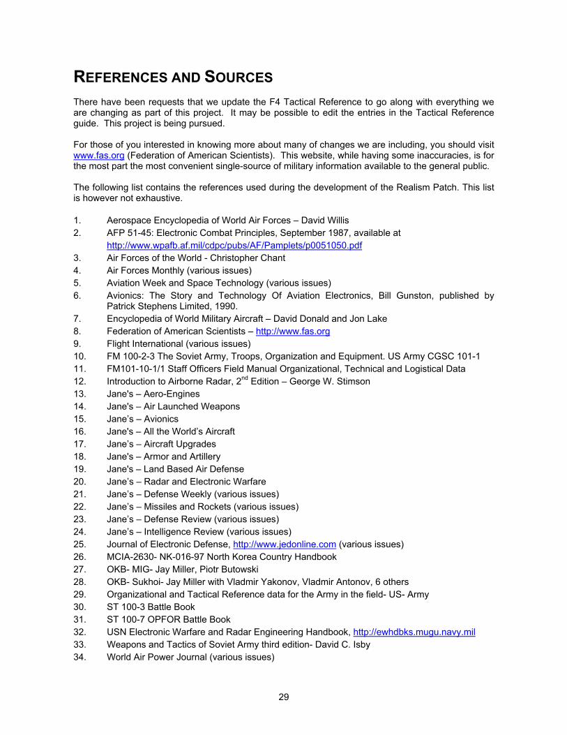
29
REFERENCES AND SOURCESThere have been requests that we update the F4 Tactical Reference to go along with everything weare changing as part of this project. It may be possible to edit the entries in the Tactical Referenceguide. This project is being pursued.
For those of you interested in knowing more about many of changes we are including, you should visitwww.fas.org (Federation of American Scientists). This website, while having some inaccuracies, is forthe most part the most convenient single-source of military information available to the general public.
The following list contains the references used during the development of the Realism Patch. This listis however not exhaustive.
1. Aerospace Encyclopedia of World Air Forces – David Willis2. AFP 51-45: Electronic Combat Principles, September 1987, available at
http://www.wpafb.af.mil/cdpc/pubs/AF/Pamplets/p0051050.pdf3. Air Forces of the World - Christopher Chant4. Air Forces Monthly (various issues)5. Aviation Week and Space Technology (various issues)6. Avionics: The Story and Technology Of Aviation Electronics, Bill Gunston, published by
Patrick Stephens Limited, 1990.7. Encyclopedia of World Military Aircraft – David Donald and Jon Lake8. Federation of American Scientists – http://www.fas.org9. Flight International (various issues)10. FM 100-2-3 The Soviet Army, Troops, Organization and Equipment. US Army CGSC 101-111. FM101-10-1/1 Staff Officers Field Manual Organizational, Technical and Logistical Data12. Introduction to Airborne Radar, 2nd Edition – George W. Stimson13. Jane's – Aero-Engines14. Jane's – Air Launched Weapons15. Jane’s – Avionics16. Jane's – All the World’s Aircraft17. Jane’s – Aircraft Upgrades18. Jane's – Armor and Artillery19. Jane's – Land Based Air Defense20. Jane’s – Radar and Electronic Warfare21. Jane’s – Defense Weekly (various issues)22. Jane’s – Missiles and Rockets (various issues)23. Jane’s – Defense Review (various issues)24. Jane’s – Intelligence Review (various issues)25. Journal of Electronic Defense, http://www.jedonline.com (various issues)26. MCIA-2630- NK-016-97 North Korea Country Handbook27. OKB- MIG- Jay Miller, Piotr Butowski28. OKB- Sukhoi- Jay Miller with Vladmir Yakonov, Vladmir Antonov, 6 others29. Organizational and Tactical Reference data for the Army in the field- US- Army30. ST 100-3 Battle Book31. ST 100-7 OPFOR Battle Book32. USN Electronic Warfare and Radar Engineering Handbook, http://ewhdbks.mugu.navy.mil33. Weapons and Tactics of Soviet Army third edition- David C. Isby34. World Air Power Journal (various issues)
30
PART II: USER’S GUIDE
This section contains information to guide you through the changes in the Realism Patch, as well ashow to best utilize it for your maximum enjoyment. You will find information that will help you to copewith and understand the tactical changes in the F4 world.
This section is organized according to topical chapters. Each chapter is preceded by a briefintroduction and overview, followed by sections elaborating on specific subjects, written by RealismPatch Group members who are experts in the particular subject. You are recommended to read theDesigner’s Notes if you require more information on the technical details concerning the relevanttopics and subjects. The Realism Patch user’s manual is designed to complement the Falcon 4 user’smanual.
PART
II
31
CHAPTER 1: FALCON 4 GAME MECHANICS
INTRODUCTION
Have you ever wondered why your wingman scored no kills even though they dropped all theirordnance apparently on target? Have you also wondered why you were still assigned with SEADmissions in campaign even though you have indicated in the campaign sliders that you want to betasked with only BAI missions? Fret not, for the sections in this chapter will explain how you caninfluence the outcome of your wingman’s bombing, and how you can influence your missionassignments. Understanding the mechanics of the game will allow you to influence the outcome of notjust your own flight, but also the campaign.
Before we begin, lets make sure that your computer system is optimized for Falcon 4. Falcon 4 is avery CPU intensive game, and will scale very well with your CPU’s horsepower. This is one of the veryfew games that will really stretch your computer system, how ever powerful it might be. We willdiscuss some of the methods to wring every bit of performance out of your PC, as well as some of thetricks of making multiplayer work.
To begin, we will need to explain the concept of bubbles. F4 is a flight simulation and battle simulationall rolled into one. To keep the CPU loading at a manageable level, combat is divided into two forms,i.e. 3D and 2D combat. The concept of bubbles is an important factor in determining the outcome of2D and 3D combat. The section titled “The Incomplete And Unapproved Quick Guide To Bubbles” willprovide you with a basic understanding of how bubbles work in F4. While you may find thedescriptions and terminology somewhat technical, do make an effort to understand the concept, as theterminology will be used consistently throughout the User’s Manual and the Designer’s Notes.
With the Realism Patch, you have the ability to change the bubble slider setting in the game option.Before you starting tweaking these, you should first understand how these changes will affectgameplay, particularly the AI bombing results. With a basic understanding on the concept of bubbles,the section titled “Bombing In The Bubble” will explain how best to overcome the limitations posed bythe bubbles on gameplay, and how you can help the AI achieve better air-to-ground kills.
Once you have busted the myth of bubbles, it is time to progress to influencing your missionassignments. The section titled “Beyond Winning Battles: Winning The War” will explain in detail howthe campaign priority sliders interact with one another, and how you can manipulate them to achievethe mixture of missions assigned to your squadron. You will also learn about the dramatic effects ofusing time acceleration in the game, the effect of changing the force ratios, and the effect of changingthe object densities. So read on, and discover the secrets of F4 !
32
MILKING THE HARDWAREOptimizing Your System For Falcon 4By “Hoola”
When Falcon 4 was first released in 1998, it represented the state-of-the-art for combat flightsimulation. Besides simulating the F-16, Falcon 4 has an internal simulation engine built to simulate anentire war in a campaign. Such a daunting task requires a lot of computing power.
Even with processors that runs at Gigahertz speeds these days, Falcon 4 can still place considerableamount of stress on the personal computer. The beauty of the game’s design lies in its ability to scalewith the computing power. With the bubble slider, the action can be cranked up tremendously, to apoint where a top-of-the-line personal computer with a Gigahertz processor can be brought to itsknees.
This section will discuss some of the ways of optimizing your computer system for Falcon 4. Sincemost of us do not have an unlimited budget, optimizing our computer system will go a long way toensure that our hardware do not become obsolete too quickly. The techniques described in thissection are by no means guaranteed. You will need to experiment and test for yourselves the optimalsettings for your own computer.
PROCESSOR AND GRAPHICS
If you have not noticed by now, Falcon 4 is extremely CPU-hungry. With the graphics sliders crankedup to their maximum, the game will exert an extremely high toll on the CPU. Obviously, the faster yourprocessor, the more smoothly the game will run. If you decide to overclock your CPU and squeezeevery bit of performance out of it, do keep in mind the need for cooling, as the CPU will run very hot.You should also disable any software CPU cooler, such as WinCooler1, as these utilities halt theprocessor regularly, and this may have an impact on the CPU performance.
The graphics slider settings play a very important role in the game FPS. I will explain what thesesliders control, and how they will affect the FPS.
Terrain Texture: This slider controls the terrain texture. The higher the setting, the greater thedistance that the terrain texture is drawn. This has an impact on the memory requirement, as loadingin the textures will lead to more disk swapping if your physical RAM is insufficient. This slider does notaffect the gameplay, other than providing better “eye candy.” If you are experiencing FPS problems,try setting this slider at a lower setting.
Terrain Texture: This slider controls the details of the terrain texture. The higher the setting,the greater the detail that the terrain texture is drawn. This has an impact on the memory requirement,as loading in the textures will lead to more disk swapping if your physical RAM is insufficient. Thisslider does not affect the gameplay, other than providing better “eye candy.” If you are experiencingFPS problems, try setting this slider at a lower setting.
Object Detail: This slider controls the details of the objects. The higher the setting, thegreater the detail that the object is drawn. As with the first two sliders, this has an impact on thememory requirement. While this slider does not affect the gameplay, the greater the object detail, theeasier it will be for you to identify ground and air targets. Lowering this setting may make it slightlymore difficult for you to spot ground targets from higher altitudes. If you are experiencing FPSproblems, try setting this slider at a lower setting. You need to bear in mind that if you set this slider to5 or less, the weapons that you are carrying will not be shown in the 2D cockpit view.
1 This software utility can be downloaded at http://www.wincooler.com
33
Object Density: This slider controls the number of ground objects. Although the Falcon 4manual seems to indicate that this slider controls only the number of ground objects in a city area, thisslider does more than that. The position of the slider will determine how many ground vehicles areshown in the 3D world. The composition of the ground units in the Realism Patch have beenextensively researched, and correspond to their real world counterparts. Setting this slider to anyposition less than 6 will result in erroneous composition of ground units, and may even result in someof the ground units being deprived of their AAA vehicles. For full realism, you are advised to set thisslider to 6. Do bear in mind that this slider has a big impact on game FPS. If you are facing a FPSproblem, you will need to weigh the trade-off yourself, between realistic ground unit composition, andhigher FPS.
Player Bubble: This slider controls the size of the bubble. For a detailed explanation of thebubble concept in Falcon 4, please refer to the next section, titled “The Incomplete And UnapprovedQuick Guide To Bubbles.” The default setting should be 3. This is the setting at which the RealismPatch is tuned to. If you increase the setting, you will improve the A/G performance of the AI jets, butreducing the 3D to 2D combat. Do bear in mind that a bubble setting of more than 3 will seriouslyaffect FPS, but setting this to less than 3 will compromise the realism.
Vehicle Magnification: This slider controls the size of the vehicles. This has no impact on FPS.
Special Effects: This slider controls the duration and details of special effects (such as smokeand explosions). There is an impact on FPS, and the higher the slider setting, the greater the impact.This slider does nothing other than to improve the “eye candy,” and if you are experiencing FPSproblems, try setting it to a lower value.
Other than tweaking the graphics sliders, you can try overclocking your processor (or upgrading it).Falcon 4 will scale very nicely with faster processors. In some of the benchmarking tests that I haveconducted, an increase of 20% in CPU clock speed resulted in an increase of at least 14% in FPS.
Falcon 4 is more limited by the CPU’s horsepower, than the graphics card, due to all the processingthat is required. If some of the benchmarking tests that I have conducted, the gain from using aVoodoo 5 card compared to using a pair of Voodoo 2 cards in SLI mode is marginal, and constitute toonly less than 10% in the FPS difference. However, using a higher processor will bring about a greaterdifference. Since Falcon 4 is optimized for Glide, running the game in Glide mode will definitely bringabout better FPS and stability, compared to running it in DirectX mode.
PHYSICAL AND VIRTUAL MEMORY
Falcon 4 is an extremely memory hungry game. This is expected, since the game is controlling everysingle AI entity, and running an entire war in the background. You should not expect to run Falcon 4with an acceptable FPS on a 64 MB RAM machine. The minimum hardware specifications defined byMicroprose is woefully inadequate, and it is for this reason that the Realism Patch Group has re-defined the recommended hardware specifications.
You should really run Falcon 4 on a machine with at least 128 MB of RAM. The performance of thegame increases with the amount of physical RAM. With RAM prices tumbling down, this is the mosteffective way of improving game performance. You should increase the physical RAM first and checkyour FPS, before considering a CPU upgrade. You will be pleasantly surprised with the effect ofrunning Falcon 4 on a machine with 265 MB RAM or more.
The Windows 95/98/ME environment do not handle memory very well. Windows can often gobble up60% (in few cases even 80%) of your installed memory for the cache. If you still have free RAM, thisshould not be the case. If not, Windows will very probably increase the usage of virtual memory (swapfile on your hard drive) instead of decreasing the disk cache by a significant amount. Using virtualmemory is an extremely slow process, compared to RAM access.
34
In addition, Windows 9x/ME may not be able to work correctly on a system with more than 512MB ofmemory. The cause is a too large cache that consumes all of the addresses in the system arena,leaving no virtual memory addresses available for other functions such as creating a new virtualmachine. You should tweak the disk and file cache settings, as well as the virtual memory settings,with utilities that you can obtain from most shareware sites. One such utility is Cacheman2, a virtualmemory and disk cache tuning utility. You should experiment with the settings to optimize for yourspecific hardware configuration. You should also consider turning on the option “Conservative SwapFile Usage,” to minimize the disk swapping.
You should also free up memory by closing every single task that is not essential. This includes hiddentasks that may not be displayed in the Task List. Lastly, you should try deactivating any power savingfeatures, such as spooling down the hard drive. This may help with the performance by eliminatingdisk spin-up time.
One last thing concerning optimizing the memory. Every time you switch view, you will incur a smallimpact on the memory, as the game will load the additional textures required to display the objects.Repeated switching of views will rapidly exhaust the free memory, and increase the disk swappingactivity. This is especially important for low memory systems.
DISK I/O OPTIMIZATION
If you are using a SCSI disk system, try putting the Windows Swap File on a separate physical disk(instead of placing on the disk that Windows or Falcon 4 reside on). The SCSI card’s ability to queuethe disk commands and the ability to disconnect while the device is busy, will help the disk I/Operformance compared to an IDE disk I/O system.
Hard disk fragmentation will also have a big impact on the game performance. Falcon 4 will load alarge number of textures during the game, and hard disk fragmentation will decrease the overall diskI/O performance. You should defragment your hard disk first, prior to installing Falcon 4. After all thepatching and installation, you should then defragment your hard disk again. Regular defragmentationof the hard disk will maintain the performance of the game.
One important note concerns the usage of the option “Rearrange program files so my programs startfaster” in the Windows Disk Defragmenter. Selection of this option can sometimes cause problemswith Falcon 4, such as the game not being able to start-up, or inexplicable crashing. If you areexperiencing such problems after defragmenting your hard disk, delete the Falcon 4 executable, andinstall a fresh copy of the executable again.
OPERATING SYSTEM
The operating system that you are running Falcon 4 on does play a part in the performance of thegame. The Windows 9x/ME series of operating systems are not known for their superior memorymanagement and stability. However, it is possible to run Falcon 4 in Windows 2000, and operatingsystem that is much more stable, and has superior memory management as compared to Windows9x/ME.
Many people have mentioned that Falcon 4 will run well with Windows 2000, but the compatibilitypatch (dated March 2001) and Service Pack 2 (SP2) needs to be installed. Although I have not tried itmyself, many users have reported success in running Falcon 4 in Direct3D mode, with F4Turbo (aDirectX proxy) installed. The game will run with both DirectX 7 and DirectX 8, and users have notreported any incidences of the devCreatesurface errors or CTDs. Several users have reported 2 Cacheman may be downloaded from http://www.outertech.cm.
35
mixed success with running Glide under Windows 2000. Some users have reportedly been able to doso by using the latest version 1.04 drivers for the Voodoo 5 card, in conjunction with DirectX 8a, theMarch 2001 Application Compatibility Update, and Service Pack 2 (SP2). Other users of Voodoo 3/4/5cards have reported that the game tends to CTD upon exiting a mission (dogfight, TE, and campaign),although these users may not have been using DirectX 8, Service Pack 2 and the Voodoo 5 version1.04 drivers.
Most if not all users have reported that Falcon 4 runs better under Windows 2000 than Windows9x/ME. You will need to experiment on your own before you decide to switch, as Windows 2000 is nota common gaming platform, and you will also need to take into consideration if your programmablejoystick is supported by Windows 2000. The robust multi-tasking, superior memory management andsuperior file system will definitely help the game in some ways.
CONCLUSION
The performance of Falcon 4 is very dependent on your hardware specification, as well as softwaresettings in Windows 9x/ME/2000. Go on, tweak your computer, and have fun finding the optimalsettings for your hardware, and be pleasantly surprised at the improvements that you may see !
36
BANISHING THE GHOSTS OF MULTI-PLAYERMaking Multi-Player Work in Falcon 4 Realism PatchBy Jeffrey “Rhino” Babineau
INTRODUCTION
We have found that multiplayer has had it's ups and down during the course of development of Falcon4. Currently we have had great success in the Realism Patch Series, defined as 12+ players in a LANcampaign. We have also found that problems that occur in online flying are also present in LAN flying,i.e. hooking up and not seeing each other and only getting 4 guys to hook up easily. Here are somethings we did to help us enjoy a really great LAN campaign event. We've found the more players youhave, the more problems you will experience, but an 8-player game will be quite reliable. Many of youwill notice our throwback techniques to Falcon 3 days.
MULTIPLAYER TRICKS
The fastest machine should load the campaign. This machine should also have at least 512 MB ofRAM. We have a dedicated Pentium III 800 MHz to run our campaign, and this machine is not usedfor flying. The campaign should be running and ready for the players to jump in and fly with no editing.What we have had great success in mission planning, is to edit all future missions for our next flightfrom the server, and then save the game and reboot before beginning the process all over again. Inshort, we adopt the following procedure:
1. Enter the campaign2. Edit the future mission3. Save the mission4. Exit the game, and reboot the machine5. Begin the player entrance procedure for flying.
Each time we begin the campaign entrance routine, it goes like this:
1. The campaign is running on the fastest machine in the LAN. Players will enter the campaignone at a time. Each player will only enter the campaign when the preceding player is in theMission Briefing UI. If a player cannot get in, he should exit Falcon 4, reboot his machine,before retrying. When all the players are in the campaign, we will proceed further.
2. Find the mission that you want to fly, i.e., the mission that you had edited previously. Typically,we will pick 4 ship missions. It is important to note that the mission time should be less than20 minutes from the current time. If you have a flight setup that you will like to fly, and the pilotreads "unassigned," it is almost certain that the server will get the pilot assigned eventually,and then fail to pass that information to the clients. When the player at the clients try to fly,they will get an error message stating that their flight has been cancelled. This is easilyavoided by entering the flight that is less than 20 minutes away from the current time.
3. Have the first (defined by take off time) human flight lead enter the selected mission. Thehuman flight lead should enter the mission alone. After he has entered his game cockpit, heshould then taxi off the main taxiway and hold in place.
4. The human flight lead should then call his entire flight of human players into the game, and asthey enter the pie, the pilots should report "2 cockpit, 3 cockpit, 4 cockpit,” before the flightmay taxi forward for take off. At no time should a human move while the rest of his flight joinsthe game. This will definitely result in the AI crashing the jet prior to the human player enteringin the cockpit. All the players need to understand how they should enter a mission, in order toeliminate AI movement while their human pilots get into their cockpits. There are times whenother AI flights will appear around you. These will taxi right through you. Your only option is to

37
ensure that collisions are deactivated in the game setup screen. This will reduce your totalpoints, but will keep your jet intact, and avoid any quirks with Falcon 4.
It is a good idea never to edit a mission while it is running. If you do, then there is a very highlikelihood that the changes made will not get passed on to all the players. You should save thecampaign after completing a mission, and have everyone save it and if the whole game crashes,reload the most recent version of the campaign.
We've also found that it is better not to enter the UI screen while other players are flying. There will bea "hiccup" that will take place, and it will almost always arrive while someone is landing or shooting.You wait in the "action view" until all the players have completed their mission.
There, that was easy!
SETTING UP A TCP/IP NETWORK
We will now go through the procedures of setting up a TCP/IP network.
1. Click on the “Start” button, and select “Settings,” and then “Control Panel.”
2. Click “Internet- select connection.”
3. For older versions of the Internet Explorer. Select "Connect to the Internet using a local areanetwork.” The reason for selecting this is that should you connect to the internet using yourmodem, initiating the TCP/IP connection in Falcon 4 will result in the activation of your dial-upadapter. This will cause Falcon 4 to "hang.” Hitting the ALT-F4 key combination may causethe dial-up adapter to hang up, and then Falcon 4 may work again, but why chance it?
4. Close all the windows and return to the Control Panel.
5. Now double click on the “Network” icon.
6. Select TCP, and then select your network card. Do not select the dial-up adapter!
7. Select the network card properties.
8. Select the "IP address" tab.
9. Select the "Specify an IP address" option.
10. Input the IP address, 192.168.1.1. The address range of 192.168.X.XX is a non-routable IPaddress, and this is a standard IP address range that is commonly used for home basednetworks.
11. Input the subnet mask address of 255.255.255.0.
12. Input the IP address of 192.168.1.2 for the next machine, and so on, until you have configuredall the machines on the network.
13. Select the "DNS configuration" tab.
14. Select the "Disable DNS" option.
15. Select the "WINS configuration" tab.
38
16. Select the "Disable WINS Resolution" option.
17. Select the "Advanced" tab.
18. Select the "Set this to be the default protocol" option.
19. Reboot the machine, and then enter Falcon 4.
20. Select the LAN option. Many of you have already discovered that the option for saving a newInternet connection is now the default, instead of LAN
21. Select a connection speed of T1 or better.
22. Select the "CONNECT" option, and you will be connected !
Connection Tips
There are some ideas that other players have found, that seem to make Falcon work better for gamesinvolving larger number of players:
1. Everyone should use the INTERNET option, instead of the LAN option.2. Everyone should use the “-pf100” command line switch to start Falcon 4. This can be put into
the Windows shortcut, e.g. “c:\falcon4\falcon4_108i2.exe –pf100”:3. The server should selects the T1 connection speed but all the clients should select 33.6 kbps.
These options are supposed to help with packet management, and have worked to the advantage ofsome players.
Good luck with your multi-player games !
39
THE INCOMPLETE AND UNAPPROVED QUICK GUIDE TO BUBBLESBy Kurt “Froglips” Giesselman
As of today, all owners of Falcon 4.0 are required to go to your nearest novelty store (No, not thosekinds of novelties! Get your mind out of the gutter. A kid's novelty store.) You are to purchase a bottleof soap bubble liquid and a large soap bubble wand for blowing soap bubbles. Go home, sit in front ofyour computer, start Falcon, enter the simulation, then open the soap bubble liquid and use yourbubble wand to blow several dozen bubbles. Now sit back and look. This is what Falcon’s AI is seeing.A world of bubbles moving, breaking apart into smaller bubbles, popping, touching each other, andtouching you.
In Falcon, like your soap bubble experience, we can divide the world into two groups. There arebubbles that you are in contact with or have even passed inside, and there are bubbles that you havenot contacted. All bubbles, in the Falcon world, have a Cluster at the exact center of the bubble. Somebubbles are in the air and are spherical, some bubbles are on the ground and appear as hemispheres.In Falcon, the soap bubbles never pop when they contact each other. So we can be in contact withand even inside dozens and dozens of bubbles at once.
The Clusters in Falcon, mentioned above, are of two types that can exist in two conditions. They areUnits or Objectives. Units are Clusters that have actions associated with them. This does not alwaysmean they move, although it often does. Aircraft, Ground Units, Naval Craft, and SAMs are all Units.Objectives are stationary and do not have an action associated with them that they could perform.Examples of Objectives are Bridges, Factories, Towns, Air Bases, and SAM Sites (note: these are notSAMs but the location of the fixed SAM emplacements).
The characteristics of these two types of Clusters aside, Falcon does not treat them any different in itsmanaging of their bubble world. Falcon will treat them as Clusters if you are not in contact with theirbubble, or Falcon will DEAGGREGATE them as Entities whenever you contact their bubble and for aslong as you remain in contact or within their bubble's sphere.
In Falcon, because the default state of an object is AGGREGATED, a Cluster is initially not drawn inthe Falcon world. Falcon assigns a placeholder to the location of that Cluster but does not draw ormanipulate the Cluster's component parts. By parts, we mean the Cluster could be composed of fouraircraft in a flight, the forty-eight members of a ground unit, or even the dozens of parts of a factorycomplex (like Office Buildings and Cooling Towers).
Falcon calculates all battles and damage for Clusters statistically. This means that there is no use ofposition for the calculation of damage to the components. Falcon calculates that a bomb from anAGGREGATED B-52 flight strikes an AGGREGATED airbase. Falcon calculates that the bomb has an'X' chance of hitting the runway. If the 'roll of the dice' is favorable, then Falcon reports that the B-52 hitthe runway and statistically calculates damage. The reason this is done is to reduce the load on thecomputer's CPU. If Falcon had to calculate the position of every bomb hit, every missile strike, andevery bullet or shell in the simulation to determine where it hit the target, there would not be a powerfulenough computer on the planet to run the full Falcon campaign. However, that is exactly what Falcondoes for all Entities in its DEAGGREGATED world.
The amazing thing in Falcon is that each Cluster type, from AT-3 to ZU-23 and Airbase toUnderground Factory, has a unique ACDD (Aggregated Cluster Deaggregation Distance) value foundin the FALCON4.CT file. A distance from zero to the length of the theatre can be assigned to eachCluster type. When we assign a distance for DEAGGREGATION we are saying one of two things istrue. At a range equal to the ACDD from the cluster, either the cluster is close enough for identificationby visual means or radar or the cluster must be DEAGGREGATED to function correctly. We would notwant to see airbases pop into existence five miles in front of us nor see a single blip on our radar thatwe were targeting suddenly become a four ship at 10 miles. Similarly, we want SAMs to 'light-up',search for us, and then fire with a measurable time period between each action. The deaggregation

40
distance of a unit and an objective is known as the Unit Deaggregation Distance (UDD) and ObjectDeaggregation Distance (ODD) respectively (see the section below for a more detailed explanation).
Setting the ACDD distances requires understanding a) what the player pilot needs to maintain hisimmersion within the simulation and b) what the different Clusters in Falcon need to function in arealistic manner. The trade off is CPU load. As stated before, we could just make every ClusterDEAGGREGATED in Korea and save a lot of people a ton of work. No one's computer could run theprogram. Every time a Cluster's ACDD is increased (their bubble increases in size) we know that, onaverage, the CPU load will increase and (sob) our frame rates will go down. Fortunately, theenormous flexibility of Falcon's design allows us to turn up UDD or ODD value for Clusters where it isnecessary for them to work properly (SAMs) and turn down UDD or ODD for Clusters where a highnumber adds no realism, no immersion, or value (airbases) to improve frame rates.
BUBBLE LEXICON V1.1
ACDD - The Aggregated Cluster Deaggregation Distance is the distance in feet from the PlayerPosition (PP) or Composite Multiplayer Position (CMP) that an AGGREGATED Cluster willDEAGGREGATE into its component Vehicles (a Unit’s components) or Features (an Objective’scomponents). The ACDD variables for Units are named UDDs and for Objectives are named ODDsand can be examined and changed in their CT file using F4Browse.
Bubble - An imaginary hemispherical volume, which surrounds every Cluster or Entity in Falcon 4.0. Itsdiameter is determined by its ACDD and is set by their UDD and ODD found in the CT file. For groundunits at least – and maybe all entities – the shape of the bubble is a hemisphere with radius equal tothe UDD and height at least 60000 ft and maybe a lot more.
Bubble Combat Types - This section is a work in progress. Better insights, descriptions, and testingare welcome. Much more investigative work needs to be done with the different types of combat.There air two overall type of combat, Air to Air (missiles, SAMs or guns attacking aircraft) and Air toGround (weapon attacks on Units {AGGREGATED, or 2D} or Entities {DEAGGREGATED, or 3D}).The type of weapon being used and the type of target being attacked are the most significant factorsin all combat engagements.
Attack Category #1 - AGGREGATED vs. AGGREGATED
This attack is conducted between (AGGREGATED) Clusters. Falcon tracks the composition of anyUnit or Objective Cluster when it is AGGREGATED. If combat occurs, Falcon 'rolls the dice' andcalculates, based on some as yet unknown percentages, how many bombs hit the target. Thecalculations for damage are not positional (i.e. Falcon does not use individual Entity positions) butdamage is ‘awarded’ against a Cluster as a whole then distributed between the components of theUnit or Objective. Falcon picks which components, of the Unit or Objective, are hit. Finally, afterFalcon determines how much damage is done and whether each Unit or Objective is damaged ordestroyed, Falcon ‘awards’ the kill to an attacker. The attacker awarded the hit is not necessarily theactual attacker that fired the weapon but one that was in the AGGREGATED Unit. If it seems like thesequence of events is peculiar then you understand it as well as anyone.
Attack Category #2 - DEAGGREGATED vs. DEAGGREGATED
This attack is conducted in the DEAGGREGATED world. All calculations are performed based on thepositional data of Entities, Vehicles or Features, vs. the impact point and blast radius of the weaponbeing employed. Falcon must check every DEAGGREGATED entity in the game and compare itsposition to the weapon impact point with appropriate blast radius. If the Entity is within the blast radiusthen additional calculations are performed for damage and for the possibility of destruction. Changesin graphics, AI response, and position are possible.

41
Attack Category #3 - DEAGGREGATED vs. AGGREGATED
Falcon uses Active Targeting weapons (LGBs and Mavericks), much like the player. Active Targeting(AT) weapons are locked onto a target. Passive targeting weapons (dumb bombs, rockets, clustermunitions) are dropped at a particular ground location. They are not targeted. The success or failureof Cat3 attacks is totally controlled by the type of weapon utilized. Active Targeting weaponssometimes hit, with varying success, and passive targeting weapons always miss. This is easy tounderstand if we remember that Falcon never uses positional data to for AGGREGATED targets. Adumb bomb may impact the ground 10 feet or ten miles from a tank column. If the column isAGGREGATED, it is all the same to Falcon.
Subtype A – AT Weapon vs. Objective
Example is an AI aircraft with a UDD of 120,000 is attacking a bridge with a UDD of 50,000 when thePP’s or CMP’s ACDD is 90,000 feet to the bridge. The aircraft are DEAGGREGATED. The bridge isAGGREGATED. AI aircraft are firing AGM-65s. Falcon will award hits and sometimes divide themarbitrarily between the aircraft.
Subtype B – Passive (dumb) Weapon vs. Objective
Example is an AI aircraft with a UDD of 120,000 is attacking a bridge with a UDD of 50,000 when thePP’s or CMP’s ACDD is 90,000 feet to the bridge. The aircraft are DEAGGREGATED. The bridge isAGGREGATED. AI aircraft are dropping Mk.84s. There is no positional data for the bridge’s Features.Falcon awards no hits against the bridge.
Subtype C – AT Weapon vs. Unit
Example is an AI aircraft with a UDD of 120,000 is attacking an armor column with a UDD of 60,000when the PP’s or CMP’s ACDD is 90,000 feet to the armor column. The aircraft areDEAGGREGATED. The armor is AGGREGATED. AI aircraft are firing Mavericks. Falcon will awardkills to the aircraft and sometimes divide them arbitrarily between the aircraft.
Subtype D – Passive (dumb) Weapon vs. Unit
Example is an AI aircraft with a UDD of 120,000 is attacking an armor column with a UDD of 60,000when the PP’s or CMP’s ACDD is 90,000 feet to the armor column. The aircraft areDEAGGREGATED. The armor is AGGREGATED. AI aircraft are dropping Mk.84s. Falcon will notaward hits against the Unit.
Attack Category #4 - AGGREGATED vs. DEAGGREGATED
Example is an aircraft with a UDD of 120,000 attacking a SAM with a UDD of 300,000 when the PP’sor CMP’s ACDD is 250,000 feet from the SAM (with all the entities involved arranged linearly). TheSAM is DEAGGREGATED. The aircraft are AGGREGATED. Falcon determines, because the aircraftare AGGREGATED, that it will use Attack Category #2. This is what Dave ‘DewDog’ Wagner reported.It is a new type of attack that exists when a SAM UDD is larger than an aircraft UDD.
Units such as aircraft and ground forces have no attack AI. The weapon being employed determineswhen an aircraft will engage. A Unit’s AI controls its movement, defensive actions, and missionactions.
BubbleRebuildTime - Variable in the Falcon.AII file (found in the MicroProse\Falcon4\campaign\savedfolder) which determines how often (in seconds) Falcon checks the UDDs and ODDs for Clusterswithin 300,000 feet of the player. Default is one (1).
Bubble Slider - This is a multiplier for the UDD and ODD values. The multiplier for the standard

42
settings is listed below. Higher settings are accessible with the –g# command line switch may becalculated by following the pattern (+1 on the slider = +0.25 to the factor).
Setting Factor1 0.502 0.753 1.004 1.255 1.506 1.757 2.00
Cluster - Clusters are Units or Objectives that remain AGGREGATED as long as their ACDD (to thePP or CMP) is greater than the Units’ or Objectives’ UDD or ODD as set by their CT value. Falcontracks them statistically, as a single item. The Cluster’s component pieces, such as individualVehicles or a structure’s Features, are not tracked positionally by Falcon for damage. Falconcalculates damage to Clusters statistically. Falcon displays a Cluster’s approximate location, whenusing far labels. A Cluster’s location may shift dramatically when it is DEAGGREGATED into Entitiesand visible with near labels.
Cursor Bubble - A player controlled, mobile, ground DEAGGREGATION bubble, one nautical mile indiameter. The center of the Cursor Bubble is moved by the player’s SOI cursors. Anything within aonenm. radius of the SOI cursor’s position and on the ground is DEAGGREGATED.
Composite Multiplayer Position (CMP) - The bubble contacts of all players are shared as long as theiraircraft’s ACDD is less than the distance to another player’s aircraft. Therefore, Falcon calculatesACDDs for each player but displays DEAGGREGATED Entities for every player within the ACDD ofanother player using the CMP. The CMP is a union of the bubble perimeters around players.
Deaggregated Entity - Vehicles (airborne, ground, or naval) or Objectives (man-made structures),which are fully drawn (rendered). Tank squads have individual vehicles drawn (the number of Vehiclesdisplayed is controlled by the Object Density slider on the Falcon/Setup/Graphics page). Aircraft flightshave all aircraft displayed individually visually or on radar. Objectives are displayed with all Featuresin place. Vehicles and Objectives may not be displayed at their maximum graphical detail. Level ofdetail is controlled by a yet unexplored FPRD (Feature Polygon Rendering Distance).
Feature - A structure that is part of an Objective and may be individually damaged. Features may notbe selected individually as targets using Recon when viewing the Falcon map screen.
FPRD - The Feature Polygon-Rendering Distance is the Bubble Distance value found in the Feature’sCT record using F4Browse. This is the distance at which the feature is POLYGON RENDERED.
Objective - Clusters that have no 'actions' associated with them. Objectives are predefined Clusters ofFeatures (as Units are predefined Clusters of Vehicles). The key difference between Objectives andUnits is the component parts of a Unit (Vehicles) require an independent AI BRAIN when theyDEAGREGATE. The component parts of Objectives (Features such as taxi signs and hangers) doNOT require AI brains when they DEAGGREGATE. They may be targeted using Recon and selectedwhen on the Falcon map or mission builder screen.
ODD - The Objective Deaggregation Distance is the distance from the player at which an Objective isDEAGGREGATED. Objectives include such Clusters as Airbases and Bridges and the value is foundin the CT file with F4Browse.
SimBubbleSize - Variable in the Falcon.AII file (found in the MicroProse\Falcon4\campaign\savedfolder), which determines the maximum distance that Clusters will be displayed on radar or are
43
detectable by other sensors. Names for entities are displayed if they are within simbubblesize distancefrom a player or three times the entity’s UDD whichever is less.
Statistical - see Cluster
UDD - The Unit Deaggregation Distance refers to the value of the ‘Bubble Distance’ variable of a Unitfound in the CT file. This value, in feet, represents the distance from the PP (or CMP) at which anAGGREGATED Unit is DEAGGREGATED into its component parts. Interestingly DEAGGREGATIONdoes NOT appear to mean that it is physically drawn as polygons. It simply means, at the point wherethe player’s ACDD is less than the Unit’s UDD, the AGGREGATE Unit is now DEAGGREGATED intoits individual components such as tanks and trucks. Each of these tanks and trucks, onceDEAGGREGATED, receive their own INDIVIDUAL AI brain and behave as individual entities. They nolonger behave as an AGGREGATED Unit, being controlled by a single, AGGREGATED AI BRAIN.However, their polygons are NOT YET rendered at the UDD. Each vehicle in the Unit is actually firstpolygon-rendered when the VPRD (Vehicle Polygon Rendering Distance) for that Vehicle is reached.
Unit - These are predefined Clusters of Vehicles. A single, AGGREGATE AI BRAIN controls a Unit,which we call a Cluster, in Falcon. This AGGREGATE AI BRAIN can detect your aircraft and will fireat you. For example, an AGGREGATE SA5 Unit will fire a DEAGGREGATED SA5 missile at you.The missile becomes DEAGGREGATE at the moment it is fired, the Unit remains AGGREGATE untilyour ACDD is less than the Unit’s UDD. When a Unit is DEAGGREGATED into its componentVehicles, each Vehicle acquires its own, individual AI BRAIN. We currently believe that the combatbehavior of a Unit, as controlled by its AGGREGATE AI BRAIN, is distinctly different from the behaviorof a DEAGGREGATED Vehicle. INDIVIDUAL AI BRAINS individually control all theDEAGGREGATED Vehicles. The difference in the behavior of an AGGREGATE Unit and aDEAGGREGATE Vehicle is still not clear, and may be very different for each Unit or Vehicle found inthe game.
Vehicle - These are the individual parts of Units. Examples include SA-5 Launchers and Kraz 255support trucks. Vehicles only exist when a Unit is DEAGGREGATED. When a Unit isDEAGGREGATED into its component Vehicles, each Vehicle is immediately tracked independentlyand positionally. A Vehicle is assigned an INDIVIDUAL AI BRAIN. At the moment a Unit isDEAGGREGATED into its component Vehicles, even though the above characteristics are true, thatVehicle is NOT YET polygon-rendered. That may happen later, when the player is closer. So we nowmake a distinction between DEAGGREGATION (which occurs first as we approach a Unit) andPOLYGON-RENDERING, which occurs to the individually DEAGGREGATED vehicles as weapproach to within visual distance.
VPRD - The Vehicle Polygon-Rendering Distance is the Bubble Distance value found in the Vehicle’sCT record. Vehicles are the component parts of Units. When a Unit has been DEAGGREGATED intoits component parts as a result of its UDD being less than the ACDD of a player, its component partsare tracked individually but may NOT be polygon-rendered. They are essentially individual butINVISIBLE vehicles until their VPRD is reached. A Vehicle in a Unit starts thinking and acting as anindividual vehicle at UDD, but is actually polygon-rendered at its VPRD.
44
BOMBING IN THE BUBBLEMaking It Work For YouBy Alex Easton
SOME DEFINITIONS
Let’s start off with some basic definitions, in case you have skipped the previous section “TheIncomplete And Unapproved Quick Guide To Bubbles.” The old way of thinking about the bubble isthat you are surrounded by a volume of space that extends out to the bubble setting. Inside thisvolume, flights, battalions, towns, etc. are DEAGGREGATED into their individual components,whereas outside it they are AGGREGATED into a single entity - the entire battalion (for example).The bubble for air units (19 miles), ground units (about 4 miles) and objectives like towns (variable)were all different in the original Falcon4.
Then it was discovered that each type of unit can be given a different bubble size - for example,bombers can have a different bubble size from fighters. This made the old way of thinking VERYcumbersome, so a new way of discussing it evolved.
In the new way, each unit-type (a T-90 battalion, say) now has a specific bubble size and the unit isdeaggregated by YOU flying into ITS bubble. Each entity is now surrounded by a volume of spacewhere your presence inside it causes the entity to deaggregate.
The "bubble size" for these entities are called the Unit Deaggregation Distance (or the UDD) whenreferring to ground or air units and the Objective Deaggregation Distance (or ODD) when referring tofixed objects like towns, airbases, factories, bridges, etc. It is the optimum setting of these UDDs andODDs that is one of the elements of the Realism Patch (version 2 and beyond).
You can also cause ground units to deaggregate when you are at a range greater than the UDD forthe entity by placing the radar cursor or the TD box of the Maverick or LGB on them. When (say) theradar cursor is within about a mile of the battalion, SECONDARY DEAGGREGATION occurs, but thebattalion will re-aggregate if the cursor is moved away and the player is more than the UDD from thebattalion.
First let us review some of the background.
CAT-3 combat is defined in the air-to-ground situation as deaggregated aircraft attacking aggregatedground units. In other words, the aircraft are "inside your air bubble" and the ground units are "outsideyour ground bubble.” Or, to put it the new way, you are within the UDD of the aircraft but outside theUDD of the battalion.
To summarize the effects of CAT-3 combat, as they are relevant for the player :
Mavericks CAN score hits against the AGGREGATED battalion, and when they do they are likely toscore multiple kills per missile - normally in clumps of 5 for the D and B mavericks and in clumps of 3for the G-maverick. However, the percentage of hits seems to reduce as the number of maverickslaunched (i.e. CPU loading) increases.
Bombs that deaggregated aircraft (such as your aircraft) drop on aggregated ground units NEVER hit.
This is CAT-3 combat (A-G).
It is therefore NECESSARY that in using bombs, the CAT-3 condition is eliminated - i.e. that the unitremains deaggregated at least when the bombs strike. We also submit for realism's sake that itshould also be eliminated as far as possible in using Mavericks, although this is less critical. The

45
purpose of this section is to indicate ways in which the player can apply a little technique to achievethis.
THE IDEAL
The ultimate aim of the project is to allow the player to fly completely naturally, employing techniquesthat he/she might employ in the real world, without having to pay ANY attention to bubble issues.
Ideally, the ground bubble (UDD's for ground units) should be the same as the air bubble (UDD's forair units). This would eliminate completely CAT-3 combat for ALL aircraft. We are unfortunately along way away from being able to do this because of the massive hit on frame rate this would entail.However, the RP group recommend that the ODD for objects such as factories be made the same asthe UDD for the aircraft. This eliminates CAT-3 conditions for strategic bombing.
More realistically, a UDD for ground units of 12 miles would ensure CAT-3 conditions are eliminatedfor the player, and would be a rarity for the wingmen (but not other AI flights). However, the setting forthe ground unit UDD will necessarily be a compromise between frame rate, the realistic capabilities ofthe GMT sub-mode of the radar, and the hit on frame rate. Arguments can be made for anyreasonable value, but after much debate the RP Group has decided to recommend a setting of 6 milesfor this parameter.
ORIGINAL DEFAULT SETTINGS FOR THE UDDS AND ODDS
The default setting for the UDD for the ground units is 4nm.. This is really too small and gives rise toproblems in many situation. These problems have always been there, but have been masked by otherbugs or wrongly diagnosed in the past but the past few months have been very productive in isolatingand solving problems with the sim. Here are a number of situations, which pertain only to the playerand not the wingmen.
a) CCIP bombing from a shallow dive, release about 8000ft.
This is OK. The battalion is deaggregated when the bombs are released, and the bombs aren't inflight long enough to permit the player to get far enough away before the bombs strike. The battaliontherefore remains deaggregated the whole time.
b) CCRP level bombing from 12000ft at 450 KIAS
This is just about OK. The battalion is deaggregated by the cursors as the bombs are released, and,as the player has approached within the battalion’s UDD, remains deaggregated UNLESS the playerpulls away as fast as possible immediately after the bombs are released. There is then a good chancethat the units will aggregate before the bombs strike.
c) CCRP level bombing from 18000 ft at 450 KIAS
This is problematic. This techniques is often used by players when attacking a stationary battalion asit gives immunity from AAA and IR SAMs, and a good stand-off distance to counter the SA-8/SA-15.However, at 450 knots, the bombs are in the air for about 30 seconds, easily enough time for thepayer to get well away from the battalion before the bombs strike if she/he pulls away. The battalionwill therefore aggregate and NO KILLS WILL BE SCORED.
d) Dive toss bombing.
This technique is usually used to enable the player to get back above 12000 feet as quickly aspossible, in which case the player will continue to approach the battalion and it will remain

46
deaggregated. However, if it is used from higher up and the player uses it to get as far away aspossible from the battalion as quickly as possible, it is likely that the battalion will aggregate. This issimilar to (c) above.
It is clear why many of us were missing with bombs in the past, and indeed why it is that our wingmenwere very variable in scoring with cluster bombs/napalm. Their success was VERY dependent onwhat YOU were doing - i.e. if you had deaggregated the battalion by flying close to it, using the AGradar cursor or the Maverick screen. With the old "bubble setting" of 4nm., it was common to missthese conditions.
RECOMMENDED SETTINGS FOR UDDS AND ODDS
The first thing to say here is that CAT-3 will NEVER be a problem with the new settings when bombingOBJECTIVES such as factories, bridges, etc. - the ODD for these entities are 30 miles, the same asfor aircraft, which eliminates completely this problem since BOTH aircraft and objectives aredeaggregated.
Secondly, bombing fixed SAM sites, such as the SA-2 again should never be a problem as the UDDsfor these battalions are set at the range of the SAM plus 10%. This was to ensure correct operation ofthe missiles, but has the added effect of essentially removing CAT-3 combat for the player, andmaking it much more unlikely for the wingmen - even using HARMs.
A "realistic ideal" for the ground unit UDD is 7.5 miles as, except in very extreme conditions, this wouldhave eliminated CAT-3 for the player. But considerations regarding frame-rates and the use of an un-hacked exe dictated a lower setting. However, the setting of 6 miles for the ground UDD is still a hugeimprovement. Let's take the situations above.
a) CCIP bombing from a shallow dive, release about 8000 feet
Even less of a problem! It should be possible to bomb from 12,000 feet in a 25 degree dive at 500knots and still keep the units deaggregated until the bombs strike, whatever you do after the bombshave gone. In a dive-bombing profile, the bombs are in the air for a shorter time and the release pointis closer to the target so there is less time to get out of the bubble.
b) CCRP level bombing from 12,000 feet at 450 KIAS
Except when the player makes EXTREME efforts to get as far as possible from the battalion as quicklyas possible, this should be OK. The only exception we can think of is when launched against by a SA-8 just after the bombs are released. Dumping stores with a deep slice away from the battalion on fullAB with a 30 degree dive to pick up speed will aggregate the battalion just before the bombs strike,but any other situation is OK. We suggest the following:
� Drop the bombs and then turn to beam the battalion dropping chaff (just in case) and thenorbit the battalion, keeping it within 6 miles from you.
� Turn away from the battalion and, as soon as it is on your six, reverse the turn to beam it justin case of a SA-8 launch.
� Keep flying towards the battalion for about 2 seconds. Then do what you like! c) CCRP level bombing from 18,000 feet at 450 KIAS If you try to get away from the battalion as soon as the bombs have gone, you will probably aggregateit before the bombs strike. We suggest something similar to the previous situation: � Drop the bombs and then turn to beam the battalion dropping chaff (just in case) and then
orbit the battalion, keeping it within 6 miles from you.
47
� Turn away from the battalion and, as soon as it is on your six, reverse the turn to beam it justin case of a SA-8 launch.
� Keep flying towards the battalion for about 5 seconds, in level flight to avoid MANPADS. Thendo what you like!
Bear in mind that attacking fixed SAM batteries is not a problem, and that the technique is only reallyrealistic when attacking stationary troops or armor. It does, however, give virtual immunity to any airdefense system carried by combat units in the Realism Patch. d) Dive toss bombing. This is easier than in the default settings as you are MUCH more likely to be attacking a deaggregatedbattalion when the bombs are released. Again, using this technique simply to get back up to 12,000feet is still OK. But to use it to get visual targeting with the greatest stand-off distance, allowing you topull away from the battalion, still has it's problems. If you are going to pull away after release, wesuggest you immediately turn to BEAM the battalion, and then orbit it at a distance of less than 6miles. Having said that, it is still very difficult to aggregate the battalion before the bombs strikebecause of the nose-high attitude of the aircraft as the bombs are released. The Wingmen The ideal here is to keep the battalion deaggregated during the times when your wingmen are makingbombing runs. You can do this with the Maverick screen, the AG radar cursor or by keeping within 6miles of the battalion. Again, fixed SAM battalions and Objectives (like bridges) are not a problem. The increase in the ground UDD to 6 miles makes it MUCH easier to do this. Added to the fact thatthe bubble seems to be a CYLINDER rather than a SPHERE allows you to fly high in the vicinity of thebattalion without having to close the horizontal distance. Six miles is a reasonable distance to orbit the battalion at 15000ft before rolling in for a CCIP dive-bomb attack. But if you want to pull away 10 miles before turning back for a medium altitude levelCCRP, attack you should consider the following two tips. Either: � Co-ordinate your wingmen by recalling them so that they don't attack when you are outside
the battalion’s UDD. When you turn back, assign them their targets just before you start yourrun and after YOUR bombs have been released, orbit the battalion at a range of just under 6miles until THEY have completed their runs. Again, this is a recognized technique - seeZambo's article again on Co-operative AG techniques (reference at end of article).
� Time your egress before turning back for your run so that they have just finished their run andtheir bombs have struck.
Having said that, the increase in UDD to 6 miles means that the battalion is aggregated for less time,so the problem of your wingmen bombing dirt in CAT-3 combat is reduced anyway. Mavericks Normally, players make the run launching as many Mavericks as they can before getting too close andthen they pull off. So CAT-3 isn't too much or a problem here as you end up within 6 miles of thebattalion as the last Maverick is launched. The exception is when a player launches a single (ormaybe two) Maverick at maximum range and then pulls away. When the angle off the nose of thebattalion exceeds the gimbal limit for the Maverick seeker head - or if you have just fired your lastMaverick - the battalion will aggregate unless you are within 6 miles of the battalion. To eliminateCAT-3 combat, we suggest one of the following: � Only launch the last Maverick when within 6 miles of the battalion.� Use slave mode in firing the last Maverick if fired from long range.
48
� Maintain a radar lock (or keep the ground-stabilized TD box) on the battalion until theMaverick has struck. You can do this by only pulling far enough round so that the battalion isstill on the radar screen.
Likewise, it is an idea to assign your wingman a target on initial approach from a range of about 10miles and drop behind him, maybe pulling off to the side to give lateral separation, either keeping thebattalion deaggregated using the AG radar or your own Maverick screen. Keep the lock until all hisMavericks have hit. Other AI Flights You have a lot less flexibility here, but there are still some things you can do to help them out. � Just as for your wingmen, you can keep close enough to their target to keep it deaggregated.
It is an idea to maybe attack a battalion that is close to the one they are attacking and to loiterbetween the two battalions
� One technique commonly used in the F4 world is to follow them in about 4 miles behind,keeping the battalion deaggregated using the Maverick screen. When a SAM launch is seenon the Maverick screen, the launcher can be targeted with a Maverick. This is a very goodway of thinning the SA-13s or the SA-8/SA-15s.
Enemy Flights
There will be some small differences here , say when Su-25s or Hinds are attacking a friendly battalionin your vicinity, especially with cluster bombs. It is now more worth while to waste them if you can!
But the big difference will be in enemy bombers attacking fixed installations like bridges or evenairbases. You really have to be much more careful in flying CAPs as they will now be able to destroytargets within a 30 miles radius of your plane. It is certainly now more worth while, even whenreturning from a strike mission, to take out these Tupolevs that you used to ignore, especially if theyare heading towards YOUR base!
And remember that allied SAM batteries now have a much greater UDD that makes them moreeffective at longer ranges, but also makes them more vulnerable. They can protect you better, but youmay have to do more to look after them in turn.
In testing these methods, the success of our bombing and that of the wingmen has significantlyimproved. But you may use different methods. So be skeptical and don't take it as the final word, butinstead think of it as something to consider in refining your AG techniques. We would be very pleasedto hear of anything we have got wrong as this will help us ALL understand better what is going on andhow to work within the limits of the game.
49
BEYOND WINNING BATTLES: WINNING THE WARUnderstanding The Falcon 4 CampaignBy Leonardo “Apollo11” Rogic
FALCON 4 "CAMPAIGN PRIORITIES”
The Campaign Priorities button allows the player to influence the type of missions created for theplayer’s squadron’s ATO. This section explains the functions of the campaign priority sliders, and howyou can best use them to influence the mission assignments.
Campaign Sliders Explained
The list of "Target Types" in "Priorities" is as follows:
- Aircraft- Air Fields- Air Defenses- Radar- Army- CCC- Infrastructure- Logistics- War Production- Naval Bases- Armored Units- Infantry Units- Artillery Units- Support Units- Naval Units
The list of "Mission Types" in "Priorities" is as follows:
- OCA- SAM Suppression- Interdiction- CAS- Strategic Strike- Anti Ship- DCA- Reconnaissance
For each mission type, it is paired to specific target types as follows:
OCA
If OCA is selected as "Mission Type" and there are no Aircraft or Air Fields or Radarselected in "Target Types,” the Campaign ATO generator will schedule:
- OCA strikes (against army bases that house helicopter units)- OCA strikes (against airstrips)- OCA strikes (against highway airstrips)
If Aircraft or Air Fields or Radar are selected then the Campaign ATO generator willschedule:
- Sweeps (against airborne targets)
50
- OCA strikes (against army bases that house helicopter units)- OCA strikes (against radar sites - rare)- OCA strikes (against airbases)- OCA strikes (against airstrips)- OCA strikes (against highway airstrips)
Note: Airfield strikes can only be generated Air Fields are present as a target type, and bothOCA and Strategic Strike are also selected as "Mission Types.”
SAM Suppression
If SAM Suppression is selected as "Mission Type" and there are no Air Defenses selectedin "Target Types,” the Campaign ATO generator will not schedule any mission.
If Air Defenses is selected then the Campaign ATO generator will schedule:
- SEAD strikes (against SAM/AAA units)
Interdiction
If Interdiction is selected as "Mission Type" and there are no Air Defenses, or ArmoredUnits, or Infantry Units, or Artillery Units, or Support Units or War Productions selected in"Target Types,” the Campaign ATO generator will not schedule any mission.
If Air Defenses or Armored Units or Infantry Units or Artillery Units or Support Units or WarProductions are selected then the Campaign ATO generator will schedule:
- Interdiction missions (against SAM/AAA units)- Interdiction missions (against Armored/Infantry/Artillery/Support units)- BAI missions against (against Armored/Infantry/Artillery/Support units)- Interdiction missions (against industry)
Note: Strikes against industrial targets will only be generated if War Productions arepresent as a target type, and both Interdiction and Strategic Strike are selected as "MissionTypes.”
CAS
If CAS is selected as "Mission Type" and there are no Armored Units or Infantry Units orArtillery Units or Support Units selected in "Target Types,” the Campaign ATO generatorwill not schedule any mission.
If Armored Units or Infantry Units or Artillery Units or Support Units are selected then theCampaign ATO generator will schedule:
- CAS missions (against Armored/Infantry/Artillery/Support units)
Strategic Strike
If Strategic Strike is selected as "Mission Type" and there are no Air Fields or Army or CCCor Infrastructure or Logistics or War Productions or Naval Bases selected in "Target Types,”the Campaign ATO generator will not schedule any mission.
51
If Air Fields or Army or CCC or Infrastructure or Logistics or War Productions or Navalbases are selected, then the Campaign ATO generator will schedule:
- Strike/Deep Strike/Bombing missions (against airbases)- Strike/Deep Strike/Bombing missions (against army HQ's - rare)- Strike/Deep Strike/Bombing missions (against CCC - rare)- Strike/Deep Strike/Bombing missions (against bridges)- Strike/Deep Strike/Bombing missions (against depots - rare)- Strike/Deep Strike/Bombing missions (against industry)- Strike/Deep Strike/Bombing missions (against naval bases - rare)- Strike/Deep Strike/Bombing missions (against airbases)
Note: Airfield strikes can only be generated Air Fields are present as a target type, and bothOCA and Strategic Strike are also selected as "Mission Types.”
Anti Ship
If Anti Ship is selected as "Mission Type" and there are no Naval Units selected in "TargetTypes" the Campaign ATO generator will not schedule any mission.
If Naval Units is selected then the Campaign ATO generator will schedule:
- Anti Ship missions (against ships - rare)
DCA
There is no need to specify "Target Type" for DCA. When selected the Campaign ATOgenerator will automatically schedule:
- CAP missions (against airborne targets)- Intercept missions (against airborne targets - rare)
Reconnaissance
There is no need to select any "Target Type" for Reconnaissance. When selected theCampaign ATO generator will automatically schedule:
- Reconnaissance missions
What you need to understand about the interactions of the sliders and mission types are as follows:
#1 The player can only influence "package type missions"
The list of "Mission Types" in "Campaign Priorities" is as follows:- OCA- SAM Suppression- Interdiction- CAS- Strategic Strike- Anti Ship
52
- DCA- Reconnaissance
The player only has influence on package type missions (i.e. the main mission on which the packagebuilds upon) and does not have any influence on the sub-package flights.
Therefore, even if you disable "SAM Suppression" in "Mission Types" but still have "Strategic Strike"enabled you will get strike packages that still include "SEAD Escort" flights. The only thing you will notget is "SEAD Strikes" as "Mission Type.”
#2 Package interconnection
Although in "Strategic Strike" or "OCA Strike" packages (for example), there are no "SEAD Strike" and"Sweep" flights - they do EXIST!
The F4 Campaign ATO generator will create those "SEAD Strike" and "Sweep" flights - but asSEPARATE PACKAGES.
In order to have "Sweep" missions, you will need to set "OCA" as the mission type and "Aircraft" asthe target type. Similarly, to have "SEAD Strikes,” you will need to have "SAM Suppression" selectedas mission type and "Air Defenses" selected as target type.
Here is a quick summary of the undesirable things resulting from this approach to ATO scheduling bythe F4 Campaign ATO generator.
a) TOT (Time On Target) problem:
A combination of "Sweep" package, "SEAD Strike" package, and "OCA Strike" package will all sharethe same TOT.
This is obviously undesirable since "SEAD Strike" and "Sweep" packages will have to have the TOTset to several minutes earlier than that of the “OCA Strike” package to clear up the path for thestrikers. You will have to manually adjust the TOT for each package to de-conflict them, and ensurethat the main strike package is free from any ground or airborne threats.
b) "Campaign Priorities":
Be VERY careful with the setting up of these preferences. If you mess up the combination of targettype and mission type, you will get strange package assignments, such as deep penetration packageswithout "Sweep" and "SEAD Strike" packages as escorts. This is the surest way of ensuring that theF4 Campaign ATO generator generates suicidal missions.
#3 PAKs
Note that the selection of PAKs also play a big role in the generation of missions. This is importantbecause in some PAKs, some targets may or may not exist at that moment in time (you can task theF4 Campaign ATO generator such that certain PAKs are NOT targeted at all).
53
Examples:
#1
OCA = 100%SAM Suppression = 0%Interdiction = 0%CAS = 0%Strategic Strike = 0%Anti Ship = 0%DCA = 0%Reconnaissance = 0%----------------------------------------------- = 100
100/100 = 1 => each percentage point in "Mission Types" carry 1% of all missions scheduled.
All missions that the F4 Campaign ATO generator schedules will be OCA. In other words, allthe missions scheduled will be OCA flights at the exclusion of other missions.
#2
OCA = 100%SAM Suppression = 0%Interdiction = 0%CAS = 0%Strategic Strike = 0%Anti Ship = 0%DCA = 100%Reconnaissance = 0%------------------------------------------------ = 200
100/200 = 0.5 => each percentage point in "Mission Types" carry 0.5% of all missionsscheduled.
All missions that the F4 Campaign ATO generator schedules will be OCA and DCA. In otherwords, there will be an even split of OCA and DCA missions scheduled at the exclusion of allother missions..
#3
OCA = 100%SAM Suppression = 0%Interdiction = 0%CAS = 50%Strategic Strike = 0%Anti Ship = 0%DCA = 100%Reconnaissance = 0%----------------------------------------------- = 250
54
100/250 = 0.4 => each percentage point in "Mission Types" carry 0.4% of all missionsscheduled.
All the missions that the F4 Campaign ATO generator will schedule will be OCA, DCA andCAS. The missions will be split between 40% of OCA, 40% DCA, and 20% of CAS flights.
CAMPAIGN "FORCE RATIOS” SLIDERS
The Campaign Force Ratio sliders allows the player to influence the power of the enemy in thecampaign. This is done by varying the number of vehicles in the enemy units. The maximum numberof vehicle slots (the number of vehicle in one entry can be a maximum of 3) is 16 (0-15) in a unit.
The principle of the "Force Ratios” sliders is very simple indeed:
Harder Gameplay Easier Gameplay (MIN) (MIDDLE) (MAX) | | | | |
Player - used vehicle slots 0-7 0-9 0-11 0-13 0-15Player - number of vehicle slots (8) (10) (12) (14) (16)
Enemy - used vehicle slots 0-15 0-13 0-11 0-9 0-7Enemy - number of vehicle slots (16) (14) (12) (10) (8)
Note 1: The enemy side is always at the "Left" regardless of the flag shown. It is important to know this when you are flying forDPRK/China/Russia.
Note 2: Some slider settings can't be obtained so you have to move slide one notch left/right and re-enter Campaign "ForceRatios Slider in order to achieve desired settings.
We recommend that the "Force Ratios” sliders in campaign be left in the middle position for RP. Thisis the only setting where realistic (real world) orbat for ground and air units are attained.
OBJECT DENSITY SLIDER
Another factor that influences the number of ground vehicles is the “Object Density” slider (in theSetup menu under the “Graphics” option). Understanding how the “Object Density” slider works willhelp you understand how F4 handles ground units, and how it will eventually affect combat.
#1 - "Object Density Slider" effectively turns OFF the vehicles inside a unit from 3D combat. Theysimply do not exist in our 3D flying world and they can't be engaged, nor engage us or other AIvehicles (air/land/sea).
#2 - When visible vehicles in unit are destroyed the previously invisible vehicles replace the destroyedvehicles in our 3D flying world. The replacement will occur only after the unit has been allowed toreaggregate, and is deaggregated again.
#3 - The "Object Density Slider" selects the percentage of vehicles inside a unit that will be shown inthe 3D world. This number may or may not be "rounded up" with the vehicle slot (i.e. some vehicleslots hold 3 vehicles, but depending on the "Object Density Slider" setting, only 1 or 2 vehicles may beselected).
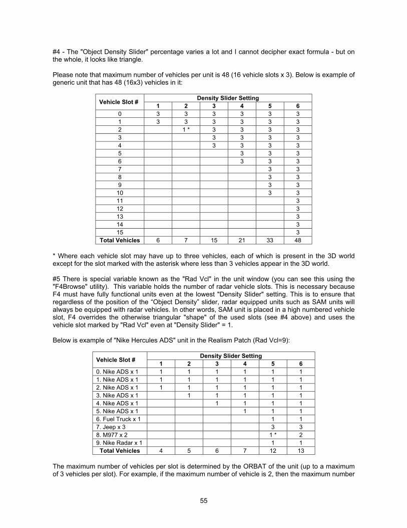
55
#4 - The "Object Density Slider" percentage varies a lot and I cannot decipher exact formula - but onthe whole, it looks like triangle.
Please note that maximum number of vehicles per unit is 48 (16 vehicle slots x 3). Below is example ofgeneric unit that has 48 (16x3) vehicles in it:
Density Slider SettingVehicle Slot # 1 2 3 4 5 60 3 3 3 3 3 31 3 3 3 3 3 32 1 * 3 3 3 33 3 3 3 34 3 3 3 35 3 3 36 3 3 37 3 38 3 39 3 3
10 3 311 312 313 314 315 3
Total Vehicles 6 7 15 21 33 48
* Where each vehicle slot may have up to three vehicles, each of which is present in the 3D worldexcept for the slot marked with the asterisk where less than 3 vehicles appear in the 3D world.
#5 There is special variable known as the "Rad Vcl" in the unit window (you can see this using the"F4Browse" utility). This variable holds the number of radar vehicle slots. This is necessary becauseF4 must have fully functional units even at the lowest "Density Slider" setting. This is to ensure thatregardless of the position of the “Object Density” slider, radar equipped units such as SAM units willalways be equipped with radar vehicles. In other words, SAM unit is placed in a high numbered vehicleslot, F4 overrides the otherwise triangular "shape" of the used slots (see #4 above) and uses thevehicle slot marked by "Rad Vcl" even at "Density Slider" = 1.
Below is example of "Nike Hercules ADS" unit in the Realism Patch (Rad Vcl=9):
Density Slider SettingVehicle Slot # 1 2 3 4 5 60. Nike ADS x 1 1 1 1 1 1 11. Nike ADS x 1 1 1 1 1 1 12. Nike ADS x 1 1 1 1 1 1 13. Nike ADS x 1 1 1 1 1 14. Nike ADS x 1 1 1 1 15. Nike ADS x 1 1 1 16. Fuel Truck x 1 1 17. Jeep x 3 3 38. M977 x 2 1 * 29. Nike Radar x 1 1 1
Total Vehicles 4 5 6 7 12 13
The maximum number of vehicles per slot is determined by the ORBAT of the unit (up to a maximumof 3 vehicles per slot). For example, if the maximum number of vehicle is 2, then the maximum number
56
of vehicles will be visible if the object density slider is set to 6, and and the number of visible vehicledecrements by 1 for every decrement in the object density slider setting.
Conclusion
In order to get the orbat of all ground/sea units composition correct (i.e. as they are designed to be)the "Object Density Slider" must be set at 6.
We know that this is hard blow for many users who manipulate the "Object Density” slider to improvethe game FPS but this is how things are... sorry folks ...
TIME ACCELERATION IN TE AND CAMPAIGN
In the design of the Realism Patch, we noticed that time acceleration plays a very, very BIG role inhow the 2D statistical fight is resolved in TE and campaign.
Note: There are essentially 2 kinds of combat in F4. Combat done in our 3D world and the 2Dstatistical fight (when you just observe unit symbols moving on the mission map).
Our conclusions are quite shocking:
Even with a Pentium III-600 MHz and 256 MB of RAM, we found that accelerated time higher than 16x(32 seems to be the "border") produces errant results.
The AI actions are EXTREMELY limited at such high time acceleration multipliers, and the AI wasunable to hit anything.
Try this for yourself in a simple TE or with any of the campaigns. Watch the statistical fight in the mapview with time acceleration of 16x or less and observe how the AI begins to score hits in missions andhow the targets are damaged/destroyed. This is simply not happening with time acceleration of 32xand 64x.
Therefore it is our strong recommendation not to run campaigns or TE at time acceleration in excessof 16x.
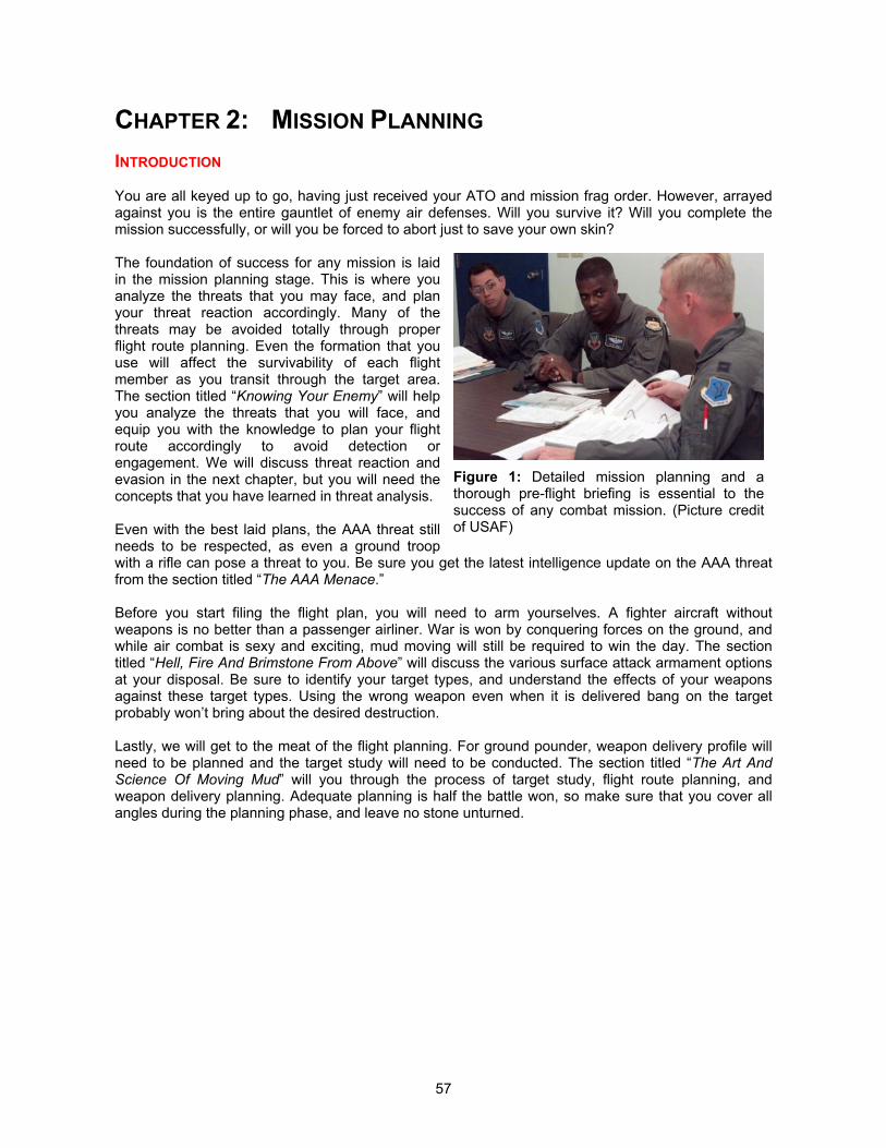
57
CHAPTER 2: MISSION PLANNING
INTRODUCTION
You are all keyed up to go, having just received your ATO and mission frag order. However, arrayedagainst you is the entire gauntlet of enemy air defenses. Will you survive it? Will you complete themission successfully, or will you be forced to abort just to save your own skin?
The foundation of success for any mission is laidin the mission planning stage. This is where youanalyze the threats that you may face, and planyour threat reaction accordingly. Many of thethreats may be avoided totally through properflight route planning. Even the formation that youuse will affect the survivability of each flightmember as you transit through the target area.The section titled “Knowing Your Enemy” will helpyou analyze the threats that you will face, andequip you with the knowledge to plan your flightroute accordingly to avoid detection orengagement. We will discuss threat reaction andevasion in the next chapter, but you will need theconcepts that you have learned in threat analysis.
Even with the best laid plans, the AAA threat stillneeds to be respected, as even a ground troopwith a rifle can pose a threat to you. Be sure you get the latest intelligence update on the AAA threatfrom the section titled “The AAA Menace.”
Before you start filing the flight plan, you will need to arm yourselves. A fighter aircraft withoutweapons is no better than a passenger airliner. War is won by conquering forces on the ground, andwhile air combat is sexy and exciting, mud moving will still be required to win the day. The sectiontitled “Hell, Fire And Brimstone From Above” will discuss the various surface attack armament optionsat your disposal. Be sure to identify your target types, and understand the effects of your weaponsagainst these target types. Using the wrong weapon even when it is delivered bang on the targetprobably won’t bring about the desired destruction.
Lastly, we will get to the meat of the flight planning. For ground pounder, weapon delivery profile willneed to be planned and the target study will need to be conducted. The section titled “The Art AndScience Of Moving Mud” will you through the process of target study, flight route planning, andweapon delivery planning. Adequate planning is half the battle won, so make sure that you cover allangles during the planning phase, and leave no stone unturned.
Figure 1: Detailed mission planning and athorough pre-flight briefing is essential to thesuccess of any combat mission. (Picture creditof USAF)
58
KNOWING YOUR ENEMYThreat Analysis in Realism PatchBy “Hoola”
ANALYZING THE AIRBORNE THREAT
The first concern that you should pay attention to is the threat of enemy interceptors. This willdetermine the ingress routes and profile that you should adopt. We will take you through a systematicway of analyzing the capabilities of interceptor types. The analysis will make extensive use of the datapresented in the Excel spreadsheet “F4_RP_Sensor_Properties.XLS,” included in the distribution ofthis user’s manual.
Avoiding Hostile Interceptor Radar Detection
The onboard radar of the interceptors will be the first sensor that will allow them to detect yourpresence. If you can avoid detection on their radar, you will deny them the ability to shoot at you withradar guided missiles, or even deny them the awareness of your presence.
1. Firstly, determine the radar range of the hostile aircraft in the sheet labeled “Radars.” Thisrange is given in feet.
2. Determine your own aircraft radar cross section in the sheet labeled “RCS.”
3. Multiply the radar range of the hostile aircraft by your own aircraft RCS, and divide the resultby 6076. This will give the range in nautical miles at which the hostile aircraft will detect you ina look up situation, assuming that you are not employing ECM and not beaming the radar.
4. Next, multiply the detection range by the look-down multiplier for the hostile radar (you canobtain this from the sheet “Radars”). This will result in the look down detection range of thehostile aircraft against you.
The radars will be in the look down mode when detecting targets that are 2.5° or more below thehorizon. For example, at a 15nm. range, the hostile radar will be looking down at the target amongstthe ground clutter return if the target is at an altitude of more than 4,000 feet below the hostile radar.Hence, if the hostile radar has a look-up performance of 15nm. and a look-down performance of10nm., you can plan your flight route to within 10nm. of the hostile interceptor as long as you maintainan ingress altitude of at least 4,000 feet below the interceptor. If you intend to ingress at a higheraltitude, you will then need to plan your flight route such that it is more than 15nm. from the hostileinterceptors to avoid detection.
For more technical details on the mechanization of radar detection in F4, please refer to the sub-section titled “The Electronic Battlefield” in the Designer’s Notes.
Avoiding Hostile Interceptor RWR Detection
You will be operating your radar during ingress to sweep the skies for bandits. This leaves anelectronic trace for the bandit’s RWR to detect (if the bandit is so equipped, which not all of them are),especially if you decide to lock up on the bandit to obtain an NCTR identification. However, not allRWRs are created equal, and they have different sensitivities. What you need to realize is that you willbe highlighting your position to the orbiting bandit whenever you ping it. To determine if the bandit’sRWR can detect your radar emissions, you will need to do the following:
1. Firstly, determine the basic radar range of your own radar in the sheet labeled “Radars.” Thisrange is given in feet.
2. Determine the bandit’s RWR sensitivity in the sheet labeled “RWR.”
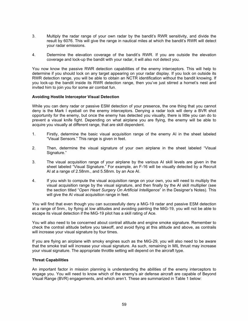
59
3. Multiply the radar range of your own radar by the bandit’s RWR sensitivity, and divide theresult by 6076. This will give the range in nautical miles at which the bandit’s RWR will detectyour radar emissions.
4. Determine the elevation coverage of the bandit’s RWR. If you are outside the elevationcoverage and lock-up the bandit with your radar, it will also not detect you.
You now know the passive RWR detection capabilities of the enemy interceptors. This will help todetermine if you should lock on any target appearing on your radar display. If you lock on outside itsRWR detection range, you will be able to obtain an NCTR identification without the bandit knowing. Ifyou lock-up the bandit inside its RWR detection range, then you’ve just stirred a hornet’s nest andinvited him to join you for some air combat fun.
Avoiding Hostile Interceptor Visual Detection
While you can deny radar or passive ESM detection of your presence, the one thing that you cannotdeny is the Mark I eyeball on the enemy interceptors. Denying a radar lock will deny a BVR shotopportunity for the enemy, but once the enemy has detected you visually, there is little you can do toprevent a visual knife fight. Depending on what airplane you are flying, the enemy will be able toacquire you visually at different range, that are skill dependent.
1. Firstly, determine the basic visual acquisition range of the enemy AI in the sheet labeled“Visual Sensors.” This range is given in feet.
2. Then, determine the visual signature of your own airplane in the sheet labeled “VisualSignature.”
3. The visual acquisition range of your airplane by the various AI skill levels are given in thesheet labeled “Visual Signature.” For example, an F-16 will be visually detected by a RecruitAI at a range of 2.58nm., and 5.58nm. by an Ace AI.
4. If you wish to compute the visual acquisition range on your own, you will need to multiply thevisual acquisition range by the visual signature, and then finally by the AI skill multiplier (seethe section titled “Open Heart Surgery On Artificial Intelligence” in the Designer’s Notes). Thiswill give the AI visual acquisition range in feet.
You will find that even though you can successfully deny a MiG-19 radar and passive ESM detectionat a range of 5nm., by flying at low altitudes and avoiding painting the MiG-19, you will not be able toescape its visual detection if the MiG-19 pilot has a skill rating of Ace.
You will also need to be concerned about contrail altitude and engine smoke signature. Remember tocheck the contrail altitude before you takeoff, and avoid flying at this altitude and above, as contrailswill increase your visual signature by four times.
If you are flying an airplane with smoky engines such as the MiG-29, you will also need to be awarethat the smoke trail will increase your visual signature. As such, remaining in MIL thrust may increaseyour visual signature. The appropriate throttle setting will depend on the aircraft type.
Threat Capabilities
An important factor in mission planning is understanding the abilities of the enemy interceptors toengage you. You will need to know which of the enemy’s air defense aircraft are capable of BeyondVisual Range (BVR) engagements, and which aren’t. These are summarized in Table 1 below:
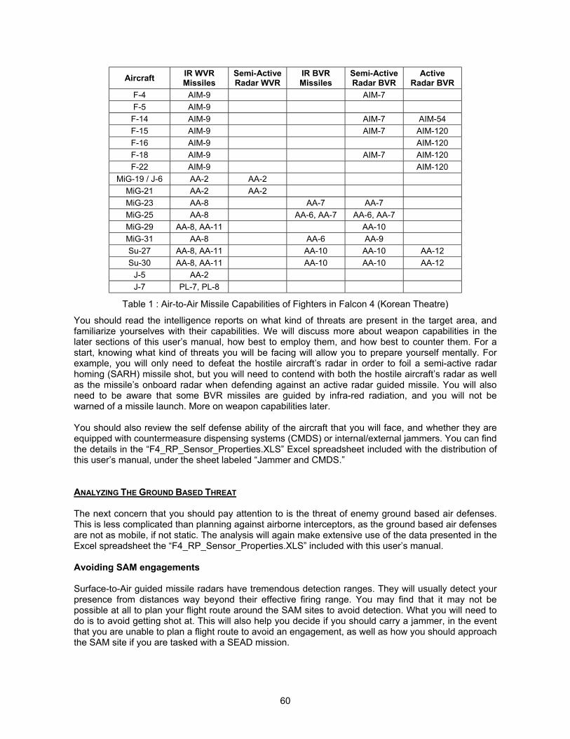
60
Aircraft IR WVRMissiles
Semi-ActiveRadar WVR
IR BVRMissiles
Semi-ActiveRadar BVR
ActiveRadar BVR
F-4 AIM-9 AIM-7F-5 AIM-9F-14 AIM-9 AIM-7 AIM-54F-15 AIM-9 AIM-7 AIM-120F-16 AIM-9 AIM-120F-18 AIM-9 AIM-7 AIM-120F-22 AIM-9 AIM-120
MiG-19 / J-6 AA-2 AA-2MiG-21 AA-2 AA-2MiG-23 AA-8 AA-7 AA-7MiG-25 AA-8 AA-6, AA-7 AA-6, AA-7MiG-29 AA-8, AA-11 AA-10MiG-31 AA-8 AA-6 AA-9Su-27 AA-8, AA-11 AA-10 AA-10 AA-12Su-30 AA-8, AA-11 AA-10 AA-10 AA-12
J-5 AA-2J-7 PL-7, PL-8
Table 1 : Air-to-Air Missile Capabilities of Fighters in Falcon 4 (Korean Theatre)
You should read the intelligence reports on what kind of threats are present in the target area, andfamiliarize yourselves with their capabilities. We will discuss more about weapon capabilities in thelater sections of this user’s manual, how best to employ them, and how best to counter them. For astart, knowing what kind of threats you will be facing will allow you to prepare yourself mentally. Forexample, you will only need to defeat the hostile aircraft’s radar in order to foil a semi-active radarhoming (SARH) missile shot, but you will need to contend with both the hostile aircraft’s radar as wellas the missile’s onboard radar when defending against an active radar guided missile. You will alsoneed to be aware that some BVR missiles are guided by infra-red radiation, and you will not bewarned of a missile launch. More on weapon capabilities later.
You should also review the self defense ability of the aircraft that you will face, and whether they areequipped with countermeasure dispensing systems (CMDS) or internal/external jammers. You can findthe details in the “F4_RP_Sensor_Properties.XLS” Excel spreadsheet included with the distribution ofthis user’s manual, under the sheet labeled “Jammer and CMDS.”
ANALYZING THE GROUND BASED THREAT
The next concern that you should pay attention to is the threat of enemy ground based air defenses.This is less complicated than planning against airborne interceptors, as the ground based air defensesare not as mobile, if not static. The analysis will again make extensive use of the data presented in theExcel spreadsheet the “F4_RP_Sensor_Properties.XLS” included with this user’s manual.
Avoiding SAM engagements
Surface-to-Air guided missile radars have tremendous detection ranges. They will usually detect yourpresence from distances way beyond their effective firing range. You may find that it may not bepossible at all to plan your flight route around the SAM sites to avoid detection. What you will need todo is to avoid getting shot at. This will also help you decide if you should carry a jammer, in the eventthat you are unable to plan a flight route to avoid an engagement, as well as how you should approachthe SAM site if you are tasked with a SEAD mission.

61
1. Firstly, determine radar range of the SAM in the sheet labeled “Radars.” This range is given infeet.
2. Determine your own aircraft radar cross section in the sheet labeled “RCS.”
3. Multiply the radar range of the SAM radar by your own aircraft RCS, and divide the result by6076. This will give the range in nautical miles at which the SAM radar will detect you in a lookup situation, assuming that you are not employing ECM and not beaming the radar.
4. Next, multiply the detection range by the “beam distance” multiplier. This will give you thedistance at which a beaming maneuver will succeed in defeating a radar track on you.
5. Multiply the radar detection range by the “ECM De-sensitization” multiplier. This will give youthe distance at which your onboard ECM equipment will succeed in defeating a radar track onyou.
Missile Guidance Max EffectiveAltitude (feet)
Min EffectiveAltitude (feet)
EngagementRange (nm) Mobility Type
Patriot TVM 80,000 500 50 StaticNike Command 70,000 4,512 45 Static
I-HAWK SARH 50,000 700 13 StaticDaewooChun-Ma
Command Line-of-Sight with FLIR 10,000 200 5 Mobile SHORAD
Mistral IR with IRCCM 10,000 50 2.5 MANPADS organicto non ADA units
Stinger IR with IRCCM 12,000 50 3 MANPADS organicto non ADA units
SA-2 Command 70,000 1,200 13 StaticSA-3 Command 48,000 5,000 12 StaticSA-4 Command 80,000 1,500 20 Mobile
SA-5Command withterminal activeradar homing
80,000 6,000 45 Static
SA-6 Command 40,000 800 10 Mobile
SA-7 IR with no IRCCM 7,000 200 2 MANPADS organicto non ADA units
SA-8 Command 30,000 300 5 Mobile SHORADSA-9 IR with no IRCCM 14,000 300 3 Mobile SHORAD
SA-10 TVM 90,000 500 50 Static and mobiledeployment
SA-13 IR with IRCCM 12,000 300 3 Mobile SHORAD
SA-14 IR with no IRCCM 14,000 200 2 MANPADS organicto non ADA units
SA-15 Command 15,000 150 5 Mobile SHORAD
SA-16 IR with no IRCCM 12,000 50 2.5 MANPADS organicto non ADA units
SA-19 Command 10,000 100 4 Mobile SHORAD
Table 2 : Surface-to-Air Missiles In Falcon 4 (Korean Theatre)
An unguided SAM is a harmless SAM, so as long as you can prevent it from gaining a radar lock onyou, you will prevent a guided launch on you. Now bear in mind the usage of ElectronicCountermeasures (ECM) requires some finesse, but more on this later. You will also need to be awareof any IR SAM threats that you will be facing. These will be problematic and will be encountered in
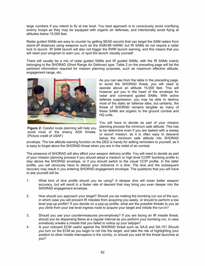
62
large numbers if you intend to fly at low level. You best approach is to consciously avoid overflyingenemy troops as they may be equipped with organic air defenses, and intentionally avoid flying ataltitudes below 15,000 feet.
Radar guided SAMs are easy to counter by getting SEAD escorts that can target the SAM radars fromstand-off distances using weapons such as the AGM-88 HARM, but IR SAMs do not require a radarlock to launch. IR SAM launch will also not trigger the RWR launch warning, and this means that youwill need your wingman to warn you, or spot the launch visually yourself.
There will usually be a mix of radar guided SAMs and IR guided SAMs, with the IR SAMs mainlybelonging to the SHORAD (Short Range Air Defense) type. Table 2 on the preceding page will list thepertinent information required for mission planning purposes, such as maximum effective altitude,engagement range, etc.
As you can see from the table in the preceding page,to avoid the SHORAD threat, you will need tooperate above an altitude 15,000 feet. This willhowever put you in the heart of the envelope forradar and command guided SAMs. With activedefense suppression, you may be able to destroymost of the static air defense sites, but certainly, thethreat of SHORAD remains tangible as many ofthese SAMs are organic to the ground combat andHQ units.
You will have to decide as part of your missionplanning process the minimum safe altitude. This hasto be determine even if you are tasked with a sweepor escort mission, as it is often easy to descendbelow the minimum safe altitude into SHORAD
envelope. The low altitude warning function on the DED is handy for setting reminders to yourself, as itis easy to forget about the SHORAD threat when you are in the midst of air combat.
The presence of SHORAD will also affect your weapon delivery profile. You will need to decide as partof your mission planning process if you should adopt a medium or high level CCRP bombing profile tostay above the SHORAD envelope, or if you should switch to the visual CCIP profile. In the latterprofile, you will obviously have to deliver your ordnance in a dive. The dive and the subsequentrecovery may result in you entering SHORAD engagement envelope. The questions that you will haveto ask yourself will be:
1. What kind of dive profile should you be using? A steeper dive will mean better weaponaccuracy, but will result in a faster rate of descent that may bring you even deeper into theSHORAD engagement envelope.
2. How should you approach your target? Should you be making the bombing run out of the sun,in which case you will prevent IR missiles from acquiring you easily, or should to perform a lowlevel pop-up profile? If you decide on a pop-up profile, what are the possible threats to you asyou climb from your low level ingress route to acquire your target and initiate the run-in?
3. Should you use your countermeasures pre-emptively? If you are facing an IR missile threat,should you be dispensing flares at a regular interval as you perform your bombing run, in casesomebody sneaks a missile that you failed to notice up your tailpipe?
4. Is your onboard ECM useful against the SHORAD threat such as SA-8 and SA-15? Shouldyou turn on the ECM as you begin to roll into the target, and take the risk of highlighting yourposition to other hostile interceptors in the vicinity, or should you wait till the threat launches atyou?
Figure 2: Careful route planning will help youavoid most of the enemy ADA threats.(Picture credit of USAF)
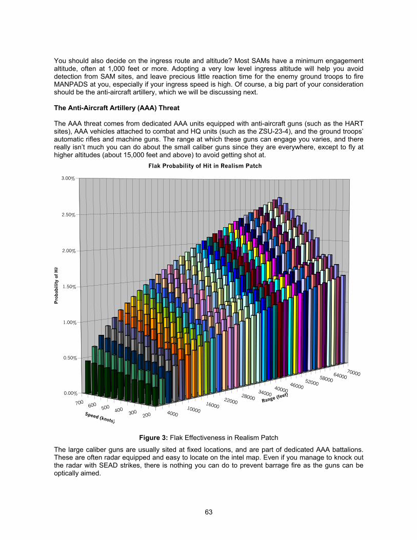
63
You should also decide on the ingress route and altitude? Most SAMs have a minimum engagementaltitude, often at 1,000 feet or more. Adopting a very low level ingress altitude will help you avoiddetection from SAM sites, and leave precious little reaction time for the enemy ground troops to fireMANPADS at you, especially if your ingress speed is high. Of course, a big part of your considerationshould be the anti-aircraft artillery, which we will be discussing next.
The Anti-Aircraft Artillery (AAA) Threat
The AAA threat comes from dedicated AAA units equipped with anti-aircraft guns (such as the HARTsites), AAA vehicles attached to combat and HQ units (such as the ZSU-23-4), and the ground troops’automatic rifles and machine guns. The range at which these guns can engage you varies, and therereally isn’t much you can do about the small caliber guns since they are everywhere, except to fly athigher altitudes (about 15,000 feet and above) to avoid getting shot at.
Figure 3: Flak Effectiveness in Realism Patch
The large caliber guns are usually sited at fixed locations, and are part of dedicated AAA battalions.These are often radar equipped and easy to locate on the intel map. Even if you manage to knock outthe radar with SEAD strikes, there is nothing you can do to prevent barrage fire as the guns can beoptically aimed.
200300400500600700
70000640005800052000460004000034000280002200016000100004000
0.00%
0.50%
1.00%
1.50%
2.00%
2.50%
3.00%
Pro
bab
ilit
y of
Hit
Speed (knots)
Range (feet)
Flak Probability of Hit in Realism Patch
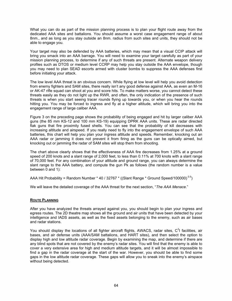
64
What you can do as part of the mission planning process is to plan your flight route away from thededicated AAA sites and battalions. You should assume a worst case engagement range of about8nm., and as long as you stay outside an 8nm. radius from such sites and units, they should not beable to engage you.
Your target may also be defended by AAA batteries, which may mean that a visual CCIP attack willbring you smack into an AAA barrage. You will need to examine your target carefully as part of yourmission planning process, to determine if any of such threats are present. Alternate weapon deliveryprofiles such as DTOS or medium level CCRP may help you stay outside the AAA envelope, thoughyou may need to plan SEAD escorts armed with cluster bombs to suppress the AAA defenses firstbefore initiating your attack.
The low level AAA threat is an obvious concern. While flying at low level will help you avoid detectionfrom enemy fighters and SAM sites, there really isn’t any good defense against AAA, as even an M-16or AK-47 rifle squad can shoot at you and score hits. To make matters worse, you cannot detect thesethreats easily as they do not light up the RWR, and often, the only indication of the presence of suchthreats is when you start seeing tracer rounds flying up towards you, or when you hear the roundshitting you. You may be forced to ingress and fly at a higher altitude, which will bring you into theengagement range of large caliber AAA.
Figure 3 on the preceding page shows the probability of being engaged and hit by larger caliber AAAguns (the 85 mm KS-12 and 100 mm KS-19) equipping DPRK AAA units. These are radar directedflak guns that fire proximity fused shells. You can see that the probability of kill decreases withincreasing altitude and airspeed. If you really need to fly into the engagement envelope of such AAAbatteries, this chart will help you plan your ingress altitude and speeds. Remember, knocking out anAAA radar or jamming it does not prevent it from firing as the guns can be optically aimed, butknocking out or jamming the radar of SAM sites will stop them from shooting.
The chart above clearly shows that the effectiveness of AAA fire decreases from 1.25% at a groundspeed of 200 knots and a slant range of 2,000 feet, to less than 0.11% at 700 knots with a slant rangeof 70,000 feet. For any combination of your altitude and ground range, you can always determine theslant range to the AAA battery, and compute the gun Pk as follows (the random number is a valuebetween 0 and 1):
AAA Hit Probability = Random Number * 40 / 32767 * ((Slant Range * Ground Speed/100000) 0.5)
We will leave the detailed coverage of the AAA threat for the next section, “The AAA Menace.”
ROUTE PLANNING
After you have analyzed the threats arrayed against you, you should begin to plan your ingress andegress routes. The 2D theatre map shows all the ground and air units that have been detected by yourintelligence and IADS assets, as well as the fixed assets belonging to the enemy, such as air basesand radar stations.
You should display the locations of all fighter aircraft flights, AWACS, radar sites, C3I facilities, airbases, and air defense units (AAA/SAM battalions, and HART sites), and then select the option todisplay high and low altitude radar coverage. Begin by examining the map, and determine if there areany blind spots that are not covered by the enemy’s radar sites. You will find that the enemy is able tocover a very extensive area for high and medium altitude targets, and it will be almost impossible tofind a gap in the radar coverage at the start of the war. However, you should be able to find somegaps in the low altitude radar coverage. These gaps will allow you to sneak into the enemy’s airspacewithout being detected.
65
Once you have identified gaps in the radar coverage, begin by planning your ingress and egress flightroutes. Make sure that your flight route does not take you over any enemy early warning radar sites,airbases, or SAM/AAA units, as these form part of the enemy’s integrated air defense system (IADS),and once you have been detected by them, enemy fighters will be vectored towards you.
During the start of an air campaign, you may find that the only way you can sneak into the enemy’sairspace undetected is to fly at low altitudes (below 500 feet AGL), and exploit the radar blind spots.As you wage the air war and destroy the enemy’s C3 facilities such as airbases and radar sites, youwill create more gaps in the low and high altitude radar coverage. Destruction of SAM sites and airdefense units will also degrade the enemy’s ability to detect you. Low level tactics will becomeextremely important at the start, and this will expose you to a considerable amount of MANPADSthreat. As the air war progresses, you can expect to operate using medium level tactics once theenemy’s IADS has been degraded.
It is thus important to begin by systematically destroying the enemy’s air defense assets, as this willreduce the ability for the enemy to guide fighters. By blinding the enemy’s fighters and forcing them torely on their own onboard sensors to detect targets, you will give your strike aircraft a better chance ofentering the enemy’s airspace without having to contend with airborne threats. This reduces thechance of them aborting their primary strike mission, and increases the overall effectiveness of the air-to-ground campaign.
CONCLUSION
With the knowledge of threat analysis, you will be put in a better position to assess the threats arrayedagainst you, and plan your flight route and weapon delivery profile to minimize your exposure to suchrisks. This will also help you determine the true capabilities of the threats arrayed against you. Whilethis sounds like a tedious exercise in arithmetic, we strongly urge you to develop the habit of propermission planning. Many a times, you will need to intervene to manually plan the flight so as to improvethe survivability of your packages. Remember, proper mission planning is half the success of anymission!
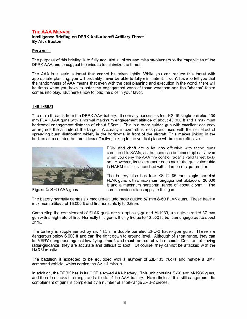
66
THE AAA MENACEIntelligence Briefing on DPRK Anti-Aircraft Artillery ThreatBy Alex Easton
PREAMBLE
The purpose of this briefing is to fully acquaint all pilots and mission-planners to the capabilities of theDPRK AAA and to suggest techniques to minimize the threat.
The AAA is a serious threat that cannot be taken lightly. While you can reduce this threat withappropriate planning, you will probably never be able to fully eliminate it. I don't have to tell you thatthe randomness of AAA means that even with the best planning and execution in the world, there willbe times when you have to enter the engagement zone of these weapons and the "chance" factorcomes into play. But here's how to load the dice in your favor.
THE THREAT
The main threat is from the DPRK AAA battery. It normally possesses four KS-19 single-barreled 100mm FLAK AAA guns with a normal maximum engagement altitude of about 45,000 ft and a maximumhorizontal engagement distance of about 7.5nm.. This is a radar guided gun with excellent accuracyas regards the altitude of the target. Accuracy in azimuth is less pronounced with the net effect ofspreading burst distribution widely in the horizontal in front of the aircraft. This makes jinking in thehorizontal to counter the threat less effective; jinking in the vertical plane will be more effective.
ECM and chaff are a lot less effective with these gunscompared to SAMs, as the guns can be aimed optically evenwhen you deny the AAA fire control radar a valid target lock-on. However, its use of radar does make the gun vulnerableto HARM missiles launched within the correct parameters.
The battery also has four KS-12 85 mm single barreledFLAK guns with a maximum engagement altitude of 20,000ft and a maximum horizontal range of about 3.5nm.. Thesame considerations apply to this gun.
The battery normally carries six medium-altitude radar guided 57 mm S-60 FLAK guns. These have amaximum altitude of 15,000 ft and fire horizontally to 2.5nm.
Completing the complement of FLAK guns are six optically-guided M-1939, a single-barreled 37 mmgun with a high rate of fire. Normally this gun will only fire up to 12,000 ft, but can engage out to about2nm..
The battery is supplemented by six 14.5 mm double barreled ZPU-2 tracer-type guns. These aredangerous below 6,000 ft and can fire right down to ground level. Although of short range, they canbe VERY dangerous against low-flying aircraft and must be treated with respect. Despite not havingradar-guidance, they are accurate and difficult to spot. Of course, they cannot be attacked with theHARM missile.
The battalion is expected to be equipped with a number of ZIL-135 trucks and maybe a BMPcommand vehicle, which carries the SA-14 missile.
In addition, the DPRK has in its OOB a towed AAA battery. This unit contains S-60 and M-1939 guns,and therefore lacks the range and altitude of the AAA battery. Nevertheless, it is still dangerous. Itscomplement of guns is completed by a number of short-range ZPU-2 pieces.
Figure 4: S-60 AAA guns
67
How do we translate such intelligence into our mission planning and the techniques to be employedagainst sites protected by these units?
ENROUTE TO THE TARGET
These units are quite common in the theatre and it is likely that your flight path on a deep-strikemission will take you close to at least one of them. Here are some indications on how to plan suchmissions.
1) Avoid them when you can. The KS-19 can engage out to 7.5nm., so plan the mission to pass themwith a minimum separation of 8nm.. If you are in combat spread formation, close it up to avoid thepossibility of the outside planes entering the engagement zone of the guns.
2) If you must overfly the battery, do so as quickly as you can. The radar-guided guns are lessaccurate in engaging targets at high speeds, and you will spend less time in the engagement zone byflying faster.
3) Best altitudes when flying close to the battery (but not over it) are over 20,000 ft where ONLY theKS-19s will engage, or UNDER 2,000 ft where the flak guns will not fire. But if flying low, do notoverfly the battery directly or you will be engaged by the ZPU-2s. The best low-level altitude is below1,500 ft, which is below the low-level limit of the radar SAMs, but make sure you do not fly near atown, or any site that may have a combat or AD unit stationed there. Also avoid, where possible,roads which may have combat battalions moving along them.
4) The DPRK has modified the guns so they can fire on the move. If you encounter the batterymoving along a road, EXPECT them to engage you if within range.
5) If you ARE caught in the engagement zone of the guns, jinking in the VERTICAL plane is moreeffective than jinking in the horizontal plane as good altitude discrimination but poor accuracy inazimuth results in a burst distribution that is wide in the level plane but thin in terms of altitude. If yourwingman is being targeted by the guns and INSISTS, like any good wingman, in maintainingformation, then YOU jink to make him maneuver as well.
6) Don't rely on chaff or ECM - they are ineffective against these weapons.
7) If you are engaged by a battery that had previously gone undetected, then either pull up above20,000 ft or drop below 10,000 ft and head away from the battery. In the former case, this willeliminate all the guns other than the KS-19, and in the latter, the horizontal range of ALL the guns issomewhat lower below 10,000ft.
Having said all that, it is a good strategy to punch a hole in the defenses around the FLOT and then todirect deep strike missions through the gap. This worked for the Israelis during the Yom Kippur war-and it'll work again if pre-strike intelligence is good enough.
There will be times when, despite all the best planning, you find yourself in the heart of theengagement zone for the battery. Have a game plan up your sleeve for this eventuality and keep aconstant eye using the A/G radar on the positions of surrounding units to help you decide your plan ofaction - going low or high.
ATTACKING THE TARGET
First of all, I'd like to say that there is NO good substitute for preparing the way for a strike mission bydegrading the battery by SEAD and Interdiction missions beforehand. If possible, arrange such flightsto precede the strike package to reduce the risk.
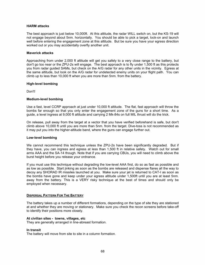
68
HARM attacks
The best approach is just below 10,000ft. At this altitude, the radar WILL switch on, but the KS-19 willnot engage beyond about 5nm. horizontally. You should be able to pick a target, lock-on and launchwell before entering the engagement zone at this altitude. But be sure you have your egress directionworked out or you may accidentally overfly another unit.
Maverick attacks
Approaching from under 2,000 ft altitude will get you safely to a very close range to the battery, butdon't go too near or the ZPU-2s will engage. The best approach is to fly under 1,500 ft as this protectsyou from radar guided SAMs, but check on the A/G radar for any other units in the vicinity. Egress atthe same altitude, but look on the A/G radar for undetected enemy units on your flight path. You canclimb up to less than 10,000 ft when you are more than 5nm. from the battery.
High-level bombing
Don't!
Medium-level bombing
Use a fast, level CCRP approach at just under 10,000 ft altitude. The flat, fast approach will throw thebombs far enough so that you only enter the engagement zone of the guns for a short time. As aguide, a level ingress at 9,000 ft altitude and carrying 2 Mk-84s on full MIL thrust will do the trick.
On release, pull away from the target at a vector that you have verified beforehand is safe, but don'tclimb above 10,000 ft until you are more than 5nm. from the target. Dive-toss is not recommended asit may put you into the higher-altitude band, where the guns can engage further out.
Low-level bombing
We cannot recommend this technique unless the ZPU-2s have been significantly degraded. But ifthey have, you can ingress and egress at less than 1,500 ft in relative safety. Watch out for smallarms AAA and the SA-14 though. Note that if you are carrying CBUs, you will need to climb above theburst height before you release your ordnance.
If you must use this technique without degrading the low-level AAA first, do so as fast as possible andas low as possible. Start jinking as soon as the bombs are released and dispense flares all the way todecoy any SHORAD IR missiles launched at you. Make sure your jet is returned to CAT-I as soon asthe bombs have gone and keep under your egress altitude under 1,500ft until you are at least 5nm.away from the battery. This is a VERY risky technique at the best of times and should only beemployed when necessary.
DISPERSAL PATTERN FOR THE BATTERY
The battery takes up a number of different formations, depending on the type of site they are stationedat and whether they are moving or stationary. Make sure you check the recon screens before take-offto identify their positions more closely.
At civilian sites - towns, villages, etcThey are generally arranged in line-abreast formation.
In transitThe battery will move from site to site in a column formation.
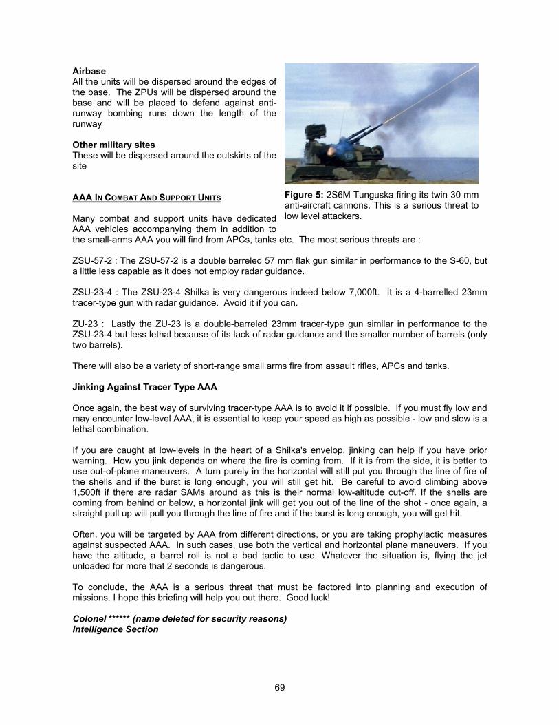
69
AirbaseAll the units will be dispersed around the edges ofthe base. The ZPUs will be dispersed around thebase and will be placed to defend against anti-runway bombing runs down the length of therunway
Other military sitesThese will be dispersed around the outskirts of thesite
AAA IN COMBAT AND SUPPORT UNITS
Many combat and support units have dedicatedAAA vehicles accompanying them in addition tothe small-arms AAA you will find from APCs, tanks etc. The most serious threats are :
ZSU-57-2 : The ZSU-57-2 is a double barreled 57 mm flak gun similar in performance to the S-60, buta little less capable as it does not employ radar guidance.
ZSU-23-4 : The ZSU-23-4 Shilka is very dangerous indeed below 7,000ft. It is a 4-barrelled 23mmtracer-type gun with radar guidance. Avoid it if you can.
ZU-23 : Lastly the ZU-23 is a double-barreled 23mm tracer-type gun similar in performance to theZSU-23-4 but less lethal because of its lack of radar guidance and the smaller number of barrels (onlytwo barrels).
There will also be a variety of short-range small arms fire from assault rifles, APCs and tanks.
Jinking Against Tracer Type AAA
Once again, the best way of surviving tracer-type AAA is to avoid it if possible. If you must fly low andmay encounter low-level AAA, it is essential to keep your speed as high as possible - low and slow is alethal combination.
If you are caught at low-levels in the heart of a Shilka's envelop, jinking can help if you have priorwarning. How you jink depends on where the fire is coming from. If it is from the side, it is better touse out-of-plane maneuvers. A turn purely in the horizontal will still put you through the line of fire ofthe shells and if the burst is long enough, you will still get hit. Be careful to avoid climbing above1,500ft if there are radar SAMs around as this is their normal low-altitude cut-off. If the shells arecoming from behind or below, a horizontal jink will get you out of the line of the shot - once again, astraight pull up will pull you through the line of fire and if the burst is long enough, you will get hit.
Often, you will be targeted by AAA from different directions, or you are taking prophylactic measuresagainst suspected AAA. In such cases, use both the vertical and horizontal plane maneuvers. If youhave the altitude, a barrel roll is not a bad tactic to use. Whatever the situation is, flying the jetunloaded for more that 2 seconds is dangerous.
To conclude, the AAA is a serious threat that must be factored into planning and execution ofmissions. I hope this briefing will help you out there. Good luck!
Colonel ****** (name deleted for security reasons)Intelligence Section
Figure 5: 2S6M Tunguska firing its twin 30 mmanti-aircraft cannons. This is a serious threat tolow level attackers.
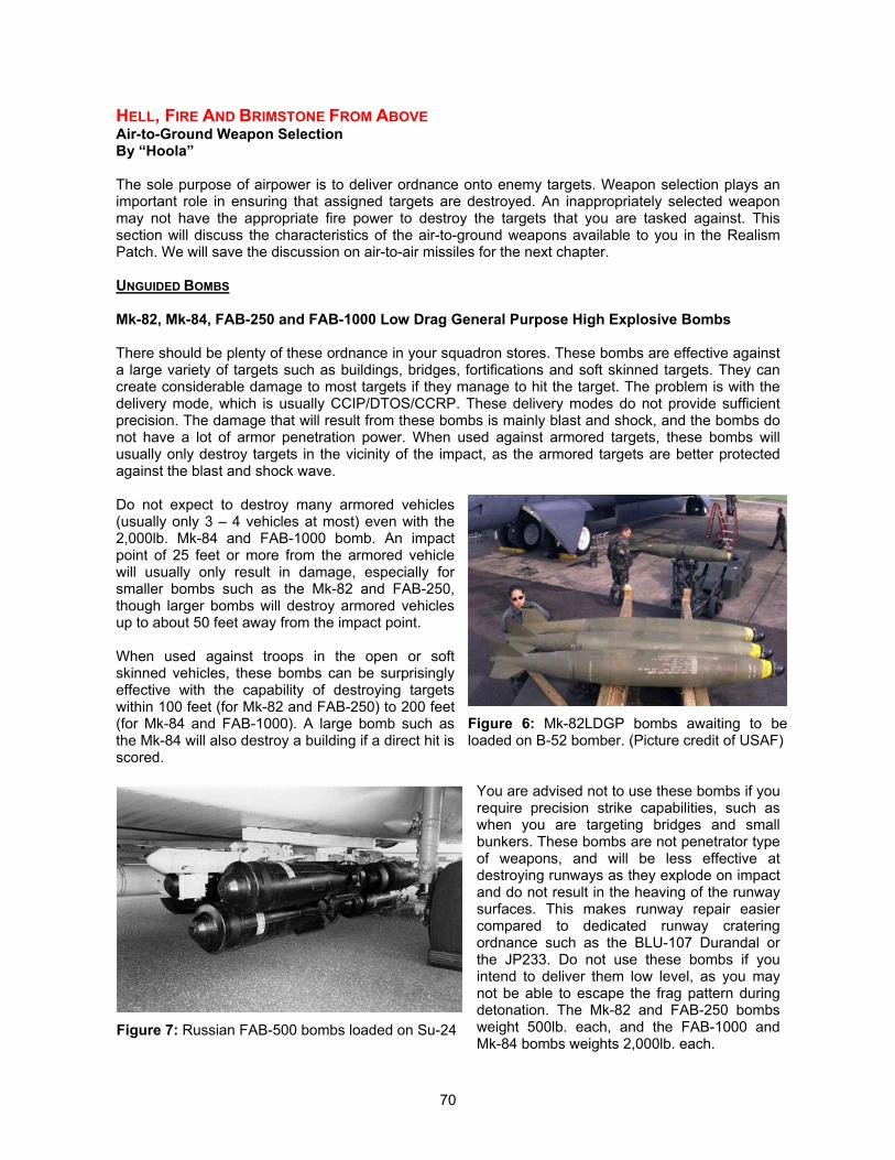
70
HELL, FIRE AND BRIMSTONE FROM ABOVEAir-to-Ground Weapon SelectionBy “Hoola”
The sole purpose of airpower is to deliver ordnance onto enemy targets. Weapon selection plays animportant role in ensuring that assigned targets are destroyed. An inappropriately selected weaponmay not have the appropriate fire power to destroy the targets that you are tasked against. Thissection will discuss the characteristics of the air-to-ground weapons available to you in the RealismPatch. We will save the discussion on air-to-air missiles for the next chapter.
UNGUIDED BOMBS
Mk-82, Mk-84, FAB-250 and FAB-1000 Low Drag General Purpose High Explosive Bombs
There should be plenty of these ordnance in your squadron stores. These bombs are effective againsta large variety of targets such as buildings, bridges, fortifications and soft skinned targets. They cancreate considerable damage to most targets if they manage to hit the target. The problem is with thedelivery mode, which is usually CCIP/DTOS/CCRP. These delivery modes do not provide sufficientprecision. The damage that will result from these bombs is mainly blast and shock, and the bombs donot have a lot of armor penetration power. When used against armored targets, these bombs willusually only destroy targets in the vicinity of the impact, as the armored targets are better protectedagainst the blast and shock wave.
Do not expect to destroy many armored vehicles(usually only 3 – 4 vehicles at most) even with the2,000lb. Mk-84 and FAB-1000 bomb. An impactpoint of 25 feet or more from the armored vehiclewill usually only result in damage, especially forsmaller bombs such as the Mk-82 and FAB-250,though larger bombs will destroy armored vehiclesup to about 50 feet away from the impact point.
When used against troops in the open or softskinned vehicles, these bombs can be surprisinglyeffective with the capability of destroying targetswithin 100 feet (for Mk-82 and FAB-250) to 200 feet(for Mk-84 and FAB-1000). A large bomb such asthe Mk-84 will also destroy a building if a direct hit isscored.
You are advised not to use these bombs if yourequire precision strike capabilities, such aswhen you are targeting bridges and smallbunkers. These bombs are not penetrator typeof weapons, and will be less effective atdestroying runways as they explode on impactand do not result in the heaving of the runwaysurfaces. This makes runway repair easiercompared to dedicated runway crateringordnance such as the BLU-107 Durandal orthe JP233. Do not use these bombs if youintend to deliver them low level, as you maynot be able to escape the frag pattern duringdetonation. The Mk-82 and FAB-250 bombsweight 500lb. each, and the FAB-1000 andMk-84 bombs weights 2,000lb. each.
Figure 6: Mk-82LDGP bombs awaiting to beloaded on B-52 bomber. (Picture credit of USAF)
Figure 7: Russian FAB-500 bombs loaded on Su-24
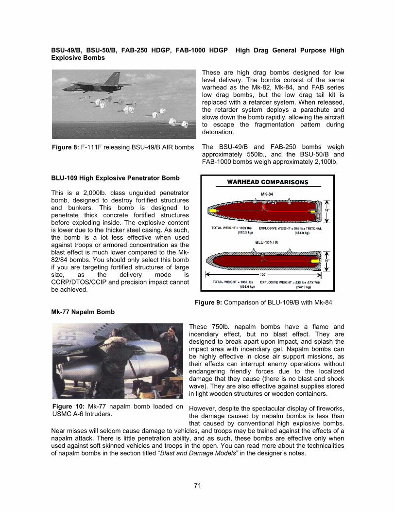
71
BSU-49/B, BSU-50/B, FAB-250 HDGP, FAB-1000 HDGP High Drag General Purpose HighExplosive Bombs
These are high drag bombs designed for lowlevel delivery. The bombs consist of the samewarhead as the Mk-82, Mk-84, and FAB serieslow drag bombs, but the low drag tail kit isreplaced with a retarder system. When released,the retarder system deploys a parachute andslows down the bomb rapidly, allowing the aircraftto escape the fragmentation pattern duringdetonation.
The BSU-49/B and FAB-250 bombs weighapproximately 550lb., and the BSU-50/B andFAB-1000 bombs weigh approximately 2,100lb.
BLU-109 High Explosive Penetrator Bomb
This is a 2,000lb. class unguided penetratorbomb, designed to destroy fortified structuresand bunkers. This bomb is designed topenetrate thick concrete fortified structuresbefore exploding inside. The explosive contentis lower due to the thicker steel casing. As such,the bomb is a lot less effective when usedagainst troops or armored concentration as theblast effect is much lower compared to the Mk-82/84 bombs. You should only select this bombif you are targeting fortified structures of largesize, as the delivery mode isCCRP/DTOS/CCIP and precision impact cannotbe achieved.
Mk-77 Napalm Bomb
These 750lb. napalm bombs have a flame andincendiary effect, but no blast effect. They aredesigned to break apart upon impact, and splash theimpact area with incendiary gel. Napalm bombs canbe highly effective in close air support missions, astheir effects can interrupt enemy operations withoutendangering friendly forces due to the localizeddamage that they cause (there is no blast and shockwave). They are also effective against supplies storedin light wooden structures or wooden containers.
However, despite the spectacular display of fireworks,the damage caused by napalm bombs is less thanthat caused by conventional high explosive bombs.
Near misses will seldom cause damage to vehicles, and troops may be trained against the effects of anapalm attack. There is little penetration ability, and as such, these bombs are effective only whenused against soft skinned vehicles and troops in the open. You can read more about the technicalitiesof napalm bombs in the section titled “Blast and Damage Models” in the designer’s notes.
Figure 8: F-111F releasing BSU-49/B AIR bombs
Figure 9: Comparison of BLU-109/B with Mk-84
Figure 10: Mk-77 napalm bomb loaded onUSMC A-6 Intruders.
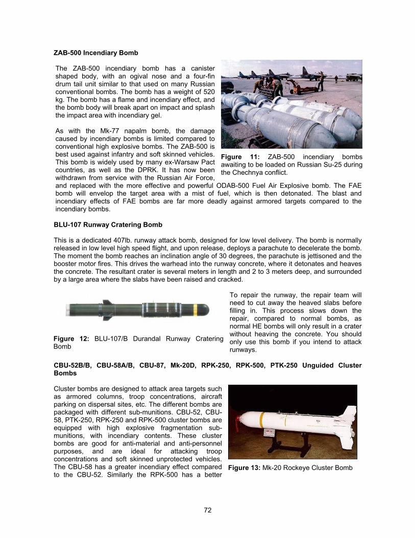
72
ZAB-500 Incendiary Bomb
The ZAB-500 incendiary bomb has a canistershaped body, with an ogival nose and a four-findrum tail unit similar to that used on many Russianconventional bombs. The bomb has a weight of 520kg. The bomb has a flame and incendiary effect, andthe bomb body will break apart on impact and splashthe impact area with incendiary gel.
As with the Mk-77 napalm bomb, the damagecaused by incendiary bombs is limited compared toconventional high explosive bombs. The ZAB-500 isbest used against infantry and soft skinned vehicles.This bomb is widely used by many ex-Warsaw Pactcountries, as well as the DPRK. It has now beenwithdrawn from service with the Russian Air Force,and replaced with the more effective and powerful ODAB-500 Fuel Air Explosive bomb. The FAEbomb will envelop the target area with a mist of fuel, which is then detonated. The blast andincendiary effects of FAE bombs are far more deadly against armored targets compared to theincendiary bombs.
BLU-107 Runway Cratering Bomb
This is a dedicated 407lb. runway attack bomb, designed for low level delivery. The bomb is normallyreleased in low level high speed flight, and upon release, deploys a parachute to decelerate the bomb.The moment the bomb reaches an inclination angle of 30 degrees, the parachute is jettisoned and thebooster motor fires. This drives the warhead into the runway concrete, where it detonates and heavesthe concrete. The resultant crater is several meters in length and 2 to 3 meters deep, and surroundedby a large area where the slabs have been raised and cracked.
To repair the runway, the repair team willneed to cut away the heaved slabs beforefilling in. This process slows down therepair, compared to normal bombs, asnormal HE bombs will only result in a craterwithout heaving the concrete. You shouldonly use this bomb if you intend to attackrunways.
CBU-52B/B, CBU-58A/B, CBU-87, Mk-20D, RPK-250, RPK-500, PTK-250 Unguided ClusterBombs
Cluster bombs are designed to attack area targets suchas armored columns, troop concentrations, aircraftparking on dispersal sites, etc. The different bombs arepackaged with different sub-munitions. CBU-52, CBU-58, PTK-250, RPK-250 and RPK-500 cluster bombs areequipped with high explosive fragmentation sub-munitions, with incendiary contents. These clusterbombs are good for anti-material and anti-personnelpurposes, and are ideal for attacking troopconcentrations and soft skinned unprotected vehicles.The CBU-58 has a greater incendiary effect comparedto the CBU-52. Similarly the RPK-500 has a better
Figure 11: ZAB-500 incendiary bombsawaiting to be loaded on Russian Su-25 duringthe Chechnya conflict.
Figure 12: BLU-107/B Durandal Runway CrateringBomb
Figure 13: Mk-20 Rockeye Cluster Bomb
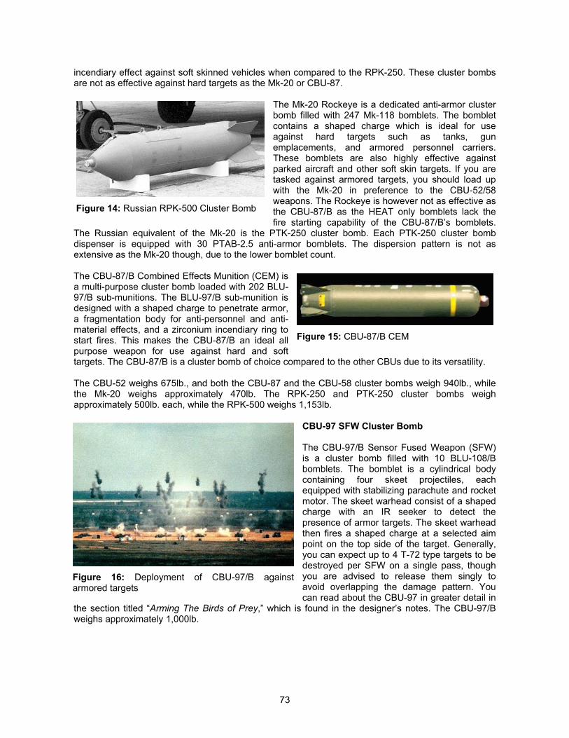
73
incendiary effect against soft skinned vehicles when compared to the RPK-250. These cluster bombsare not as effective against hard targets as the Mk-20 or CBU-87.
The Mk-20 Rockeye is a dedicated anti-armor clusterbomb filled with 247 Mk-118 bomblets. The bombletcontains a shaped charge which is ideal for useagainst hard targets such as tanks, gunemplacements, and armored personnel carriers.These bomblets are also highly effective againstparked aircraft and other soft skin targets. If you aretasked against armored targets, you should load upwith the Mk-20 in preference to the CBU-52/58weapons. The Rockeye is however not as effective asthe CBU-87/B as the HEAT only bomblets lack thefire starting capability of the CBU-87/B’s bomblets.
The Russian equivalent of the Mk-20 is the PTK-250 cluster bomb. Each PTK-250 cluster bombdispenser is equipped with 30 PTAB-2.5 anti-armor bomblets. The dispersion pattern is not asextensive as the Mk-20 though, due to the lower bomblet count.
The CBU-87/B Combined Effects Munition (CEM) isa multi-purpose cluster bomb loaded with 202 BLU-97/B sub-munitions. The BLU-97/B sub-munition isdesigned with a shaped charge to penetrate armor,a fragmentation body for anti-personnel and anti-material effects, and a zirconium incendiary ring tostart fires. This makes the CBU-87/B an ideal allpurpose weapon for use against hard and softtargets. The CBU-87/B is a cluster bomb of choice compared to the other CBUs due to its versatility.
The CBU-52 weighs 675lb., and both the CBU-87 and the CBU-58 cluster bombs weigh 940lb., whilethe Mk-20 weighs approximately 470lb. The RPK-250 and PTK-250 cluster bombs weighapproximately 500lb. each, while the RPK-500 weighs 1,153lb.
CBU-97 SFW Cluster Bomb
The CBU-97/B Sensor Fused Weapon (SFW)is a cluster bomb filled with 10 BLU-108/Bbomblets. The bomblet is a cylindrical bodycontaining four skeet projectiles, eachequipped with stabilizing parachute and rocketmotor. The skeet warhead consist of a shapedcharge with an IR seeker to detect thepresence of armor targets. The skeet warheadthen fires a shaped charge at a selected aimpoint on the top side of the target. Generally,you can expect up to 4 T-72 type targets to bedestroyed per SFW on a single pass, thoughyou are advised to release them singly toavoid overlapping the damage pattern. Youcan read about the CBU-97 in greater detail in
the section titled “Arming The Birds of Prey,” which is found in the designer’s notes. The CBU-97/Bweighs approximately 1,000lb.
Figure 14: Russian RPK-500 Cluster Bomb
Figure 15: CBU-87/B CEM
Figure 16: Deployment of CBU-97/B againstarmored targets
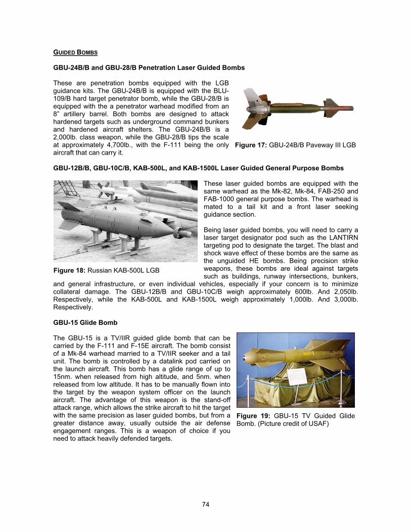
74
GUIDED BOMBS
GBU-24B/B and GBU-28/B Penetration Laser Guided Bombs
These are penetration bombs equipped with the LGBguidance kits. The GBU-24B/B is equipped with the BLU-109/B hard target penetrator bomb, while the GBU-28/B isequipped with the a penetrator warhead modified from an8” artillery barrel. Both bombs are designed to attackhardened targets such as underground command bunkersand hardened aircraft shelters. The GBU-24B/B is a2,000lb. class weapon, while the GBU-28/B tips the scaleat approximately 4,700lb., with the F-111 being the onlyaircraft that can carry it.
GBU-12B/B, GBU-10C/B, KAB-500L, and KAB-1500L Laser Guided General Purpose Bombs
These laser guided bombs are equipped with thesame warhead as the Mk-82, Mk-84, FAB-250 andFAB-1000 general purpose bombs. The warhead ismated to a tail kit and a front laser seekingguidance section.
Being laser guided bombs, you will need to carry alaser target designator pod such as the LANTIRNtargeting pod to designate the target. The blast andshock wave effect of these bombs are the same asthe unguided HE bombs. Being precision strikeweapons, these bombs are ideal against targetssuch as buildings, runway intersections, bunkers,
and general infrastructure, or even individual vehicles, especially if your concern is to minimizecollateral damage. The GBU-12B/B and GBU-10C/B weigh approximately 600lb. And 2,050lb.Respectively, while the KAB-500L and KAB-1500L weigh approximately 1,000lb. And 3,000lb.Respectively.
GBU-15 Glide Bomb
The GBU-15 is a TV/IIR guided glide bomb that can becarried by the F-111 and F-15E aircraft. The bomb consistof a Mk-84 warhead married to a TV/IIR seeker and a tailunit. The bomb is controlled by a datalink pod carried onthe launch aircraft. This bomb has a glide range of up to15nm. when released from high altitude, and 5nm. whenreleased from low altitude. It has to be manually flown intothe target by the weapon system officer on the launchaircraft. The advantage of this weapon is the stand-offattack range, which allows the strike aircraft to hit the targetwith the same precision as laser guided bombs, but from agreater distance away, usually outside the air defenseengagement ranges. This is a weapon of choice if youneed to attack heavily defended targets.
Figure 17: GBU-24B/B Paveway III LGB
Figure 18: Russian KAB-500L LGB
Figure 19: GBU-15 TV Guided GlideBomb. (Picture credit of USAF)
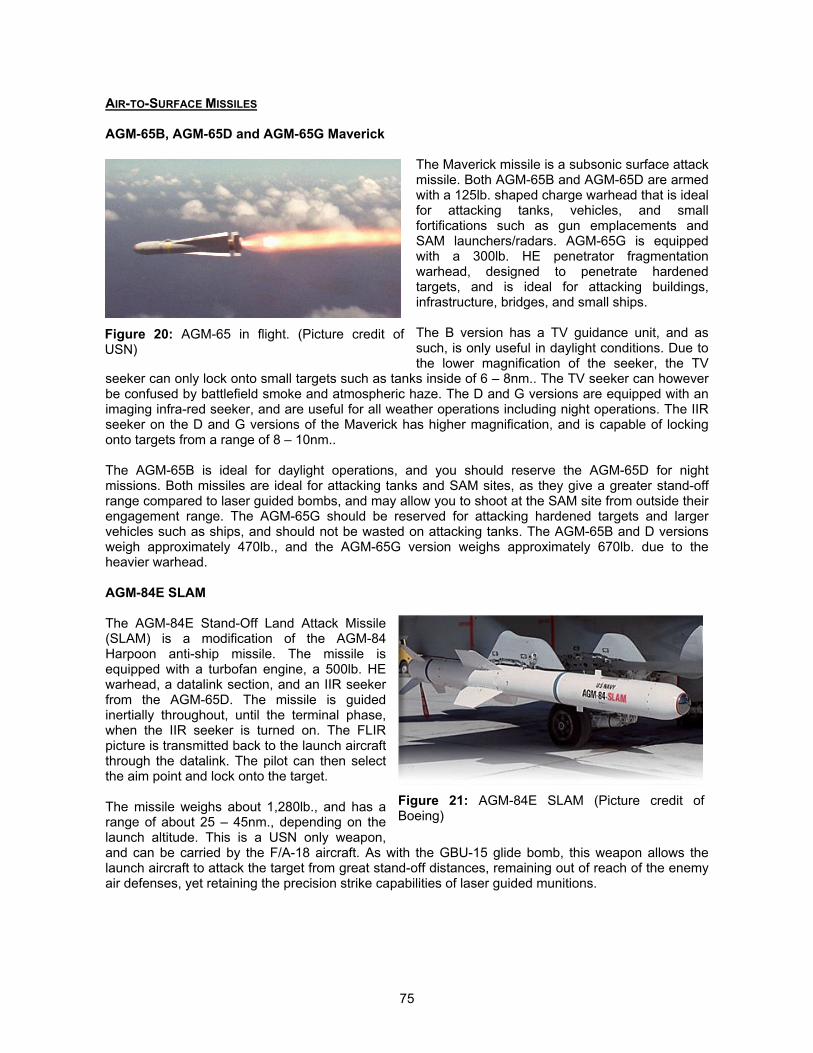
75
AIR-TO-SURFACE MISSILES
AGM-65B, AGM-65D and AGM-65G Maverick
The Maverick missile is a subsonic surface attackmissile. Both AGM-65B and AGM-65D are armedwith a 125lb. shaped charge warhead that is idealfor attacking tanks, vehicles, and smallfortifications such as gun emplacements andSAM launchers/radars. AGM-65G is equippedwith a 300lb. HE penetrator fragmentationwarhead, designed to penetrate hardenedtargets, and is ideal for attacking buildings,infrastructure, bridges, and small ships.
The B version has a TV guidance unit, and assuch, is only useful in daylight conditions. Due tothe lower magnification of the seeker, the TV
seeker can only lock onto small targets such as tanks inside of 6 – 8nm.. The TV seeker can howeverbe confused by battlefield smoke and atmospheric haze. The D and G versions are equipped with animaging infra-red seeker, and are useful for all weather operations including night operations. The IIRseeker on the D and G versions of the Maverick has higher magnification, and is capable of lockingonto targets from a range of 8 – 10nm..
The AGM-65B is ideal for daylight operations, and you should reserve the AGM-65D for nightmissions. Both missiles are ideal for attacking tanks and SAM sites, as they give a greater stand-offrange compared to laser guided bombs, and may allow you to shoot at the SAM site from outside theirengagement range. The AGM-65G should be reserved for attacking hardened targets and largervehicles such as ships, and should not be wasted on attacking tanks. The AGM-65B and D versionsweigh approximately 470lb., and the AGM-65G version weighs approximately 670lb. due to theheavier warhead.
AGM-84E SLAM
The AGM-84E Stand-Off Land Attack Missile(SLAM) is a modification of the AGM-84Harpoon anti-ship missile. The missile isequipped with a turbofan engine, a 500lb. HEwarhead, a datalink section, and an IIR seekerfrom the AGM-65D. The missile is guidedinertially throughout, until the terminal phase,when the IIR seeker is turned on. The FLIRpicture is transmitted back to the launch aircraftthrough the datalink. The pilot can then selectthe aim point and lock onto the target.
The missile weighs about 1,280lb., and has arange of about 25 – 45nm., depending on thelaunch altitude. This is a USN only weapon,and can be carried by the F/A-18 aircraft. As with the GBU-15 glide bomb, this weapon allows thelaunch aircraft to attack the target from great stand-off distances, remaining out of reach of the enemyair defenses, yet retaining the precision strike capabilities of laser guided munitions.
Figure 20: AGM-65 in flight. (Picture credit ofUSN)
Figure 21: AGM-84E SLAM (Picture credit ofBoeing)
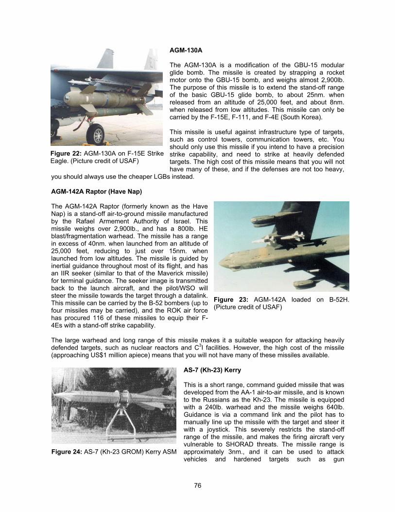
76
AGM-130A
The AGM-130A is a modification of the GBU-15 modularglide bomb. The missile is created by strapping a rocketmotor onto the GBU-15 bomb, and weighs almost 2,900lb.The purpose of this missile is to extend the stand-off rangeof the basic GBU-15 glide bomb, to about 25nm. whenreleased from an altitude of 25,000 feet, and about 8nm.when released from low altitudes. This missile can only becarried by the F-15E, F-111, and F-4E (South Korea).
This missile is useful against infrastructure type of targets,such as control towers, communication towers, etc. Youshould only use this missile if you intend to have a precisionstrike capability, and need to strike at heavily defendedtargets. The high cost of this missile means that you will nothave many of these, and if the defenses are not too heavy,
you should always use the cheaper LGBs instead.
AGM-142A Raptor (Have Nap)
The AGM-142A Raptor (formerly known as the HaveNap) is a stand-off air-to-ground missile manufacturedby the Rafael Armement Authority of Israel. Thismissile weighs over 2,900lb., and has a 800lb. HEblast/fragmentation warhead. The missile has a rangein excess of 40nm. when launched from an altitude of25,000 feet, reducing to just over 15nm. whenlaunched from low altitudes. The missile is guided byinertial guidance throughout most of its flight, and hasan IIR seeker (similar to that of the Maverick missile)for terminal guidance. The seeker image is transmittedback to the launch aircraft, and the pilot/WSO willsteer the missile towards the target through a datalink.This missile can be carried by the B-52 bombers (up tofour missiles may be carried), and the ROK air forcehas procured 116 of these missiles to equip their F-4Es with a stand-off strike capability.
The large warhead and long range of this missile makes it a suitable weapon for attacking heavilydefended targets, such as nuclear reactors and C3I facilities. However, the high cost of the missile(approaching US$1 million apiece) means that you will not have many of these missiles available.
AS-7 (Kh-23) Kerry
This is a short range, command guided missile that wasdeveloped from the AA-1 air-to-air missile, and is knownto the Russians as the Kh-23. The missile is equippedwith a 240lb. warhead and the missile weighs 640lb.Guidance is via a command link and the pilot has tomanually line up the missile with the target and steer itwith a joystick. This severely restricts the stand-offrange of the missile, and makes the firing aircraft veryvulnerable to SHORAD threats. The missile range isapproximately 3nm., and it can be used to attackvehicles and hardened targets such as gun
Figure 22: AGM-130A on F-15E StrikeEagle. (Picture credit of USAF)
Figure 23: AGM-142A loaded on B-52H.(Picture credit of USAF)
Figure 24: AS-7 (Kh-23 GROM) Kerry ASM
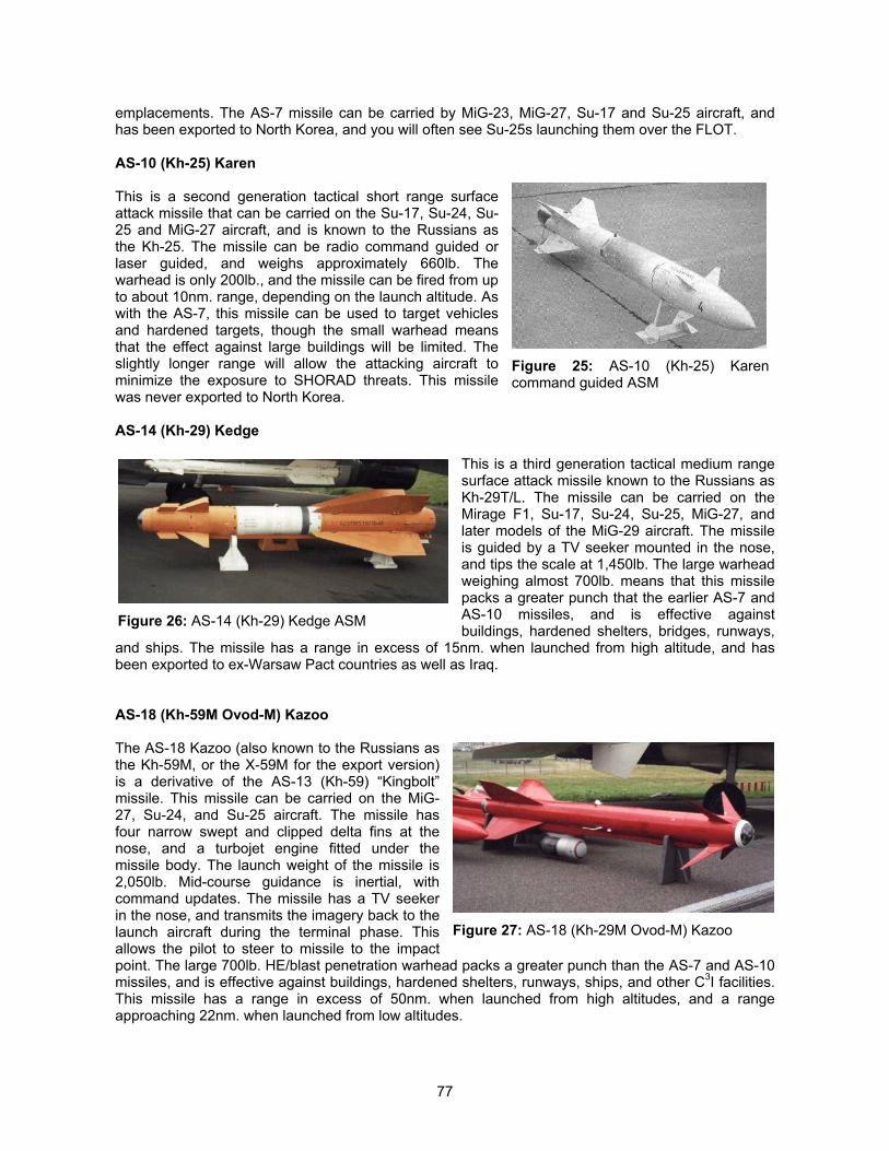
77
emplacements. The AS-7 missile can be carried by MiG-23, MiG-27, Su-17 and Su-25 aircraft, andhas been exported to North Korea, and you will often see Su-25s launching them over the FLOT.
AS-10 (Kh-25) Karen
This is a second generation tactical short range surfaceattack missile that can be carried on the Su-17, Su-24, Su-25 and MiG-27 aircraft, and is known to the Russians asthe Kh-25. The missile can be radio command guided orlaser guided, and weighs approximately 660lb. Thewarhead is only 200lb., and the missile can be fired from upto about 10nm. range, depending on the launch altitude. Aswith the AS-7, this missile can be used to target vehiclesand hardened targets, though the small warhead meansthat the effect against large buildings will be limited. Theslightly longer range will allow the attacking aircraft tominimize the exposure to SHORAD threats. This missilewas never exported to North Korea.
AS-14 (Kh-29) Kedge
This is a third generation tactical medium rangesurface attack missile known to the Russians asKh-29T/L. The missile can be carried on theMirage F1, Su-17, Su-24, Su-25, MiG-27, andlater models of the MiG-29 aircraft. The missileis guided by a TV seeker mounted in the nose,and tips the scale at 1,450lb. The large warheadweighing almost 700lb. means that this missilepacks a greater punch that the earlier AS-7 andAS-10 missiles, and is effective againstbuildings, hardened shelters, bridges, runways,
and ships. The missile has a range in excess of 15nm. when launched from high altitude, and hasbeen exported to ex-Warsaw Pact countries as well as Iraq.
AS-18 (Kh-59M Ovod-M) Kazoo
The AS-18 Kazoo (also known to the Russians asthe Kh-59M, or the X-59M for the export version)is a derivative of the AS-13 (Kh-59) “Kingbolt”missile. This missile can be carried on the MiG-27, Su-24, and Su-25 aircraft. The missile hasfour narrow swept and clipped delta fins at thenose, and a turbojet engine fitted under themissile body. The launch weight of the missile is2,050lb. Mid-course guidance is inertial, withcommand updates. The missile has a TV seekerin the nose, and transmits the imagery back to thelaunch aircraft during the terminal phase. Thisallows the pilot to steer to missile to the impactpoint. The large 700lb. HE/blast penetration warhead packs a greater punch than the AS-7 and AS-10missiles, and is effective against buildings, hardened shelters, runways, ships, and other C3I facilities.This missile has a range in excess of 50nm. when launched from high altitudes, and a rangeapproaching 22nm. when launched from low altitudes.
Figure 25: AS-10 (Kh-25) Karencommand guided ASM
Figure 26: AS-14 (Kh-29) Kedge ASM
Figure 27: AS-18 (Kh-29M Ovod-M) Kazoo
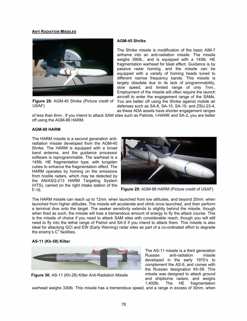
78
ANTI RADIATION MISSILES
AGM-45 Shrike
The Shrike missile is modification of the basic AIM-7airframe into an anti-radiation missile. The missileweighs 390lb., and is equipped with a 145lb. HEfragmentation warhead for blast effect. Guidance is bypassive radar homing, and the missile can beequipped with a variety of homing heads tuned todifferent narrow frequency bands. This missile islargely obsolete due to its lack of programmability,slow speed, and limited range of only 7nm..Employment of the missile will often require the launchaircraft to enter the engagement range of the SAMs.You are better off using the Shrike against mobile airdefenses such as SA-8, SA-15, SA-19, and ZSU-23-4,as these ADA assets have shorter engagement ranges
of less than 6nm.. If you intend to attack SAM sites such as Patriots, I-HAWK and SA-2, you are betteroff using the AGM-88 HARM.
AGM-88 HARM
The HARM missile is a second generation anti-radiation missile developed from the AGM-45Shrike. The HARM is equipped with a broadband antenna, and the guidance processorsoftware is reprogrammable. The warhead is a145lb. HE fragmentation type, with tungstencubes to enhance the fragmentation effect. TheHARM operates by homing on the emissionsfrom hostile radars, which may be detected bythe AN/ASQ-213 HARM Targeting System(HTS), carried on the right intake station of theF-16.
The HARM missile can reach up to 12nm. when launched from low altitudes, and beyond 20nm. whenlaunched from higher altitudes. The missile will accelerate and climb once launched, and then performa terminal dive onto the target. The seeker sensitivity extends to slightly behind the missile, thoughwhen fired as such, the missile will lose a tremendous amount of energy to fly the attack course. Thisis the missile of choice if you need to attack SAM sites with considerable reach, though you will stillneed to fly into the lethal range of Patriot and SA-5 if you intend to attack them. This missile is alsoideal for attacking GCI and EW (Early Warning) radar sites as part of a co-ordinated effort to degradethe enemy’s C3 facilities.
AS-11 (Kh-58) Kilter
The AS-11 missile is a third generationRussian anti-radiation missiledeveloped in the early 1970’s tocomplement the AS-9, and comes withthe Russian designation Kh-58. Thismissile was designed to attack groundand shipborne radars, and weighs1,400lb. The HE fragmentation
warhead weighs 330lb. This missile has a tremendous speed, and a range in excess of 30nm. when
Figure 28: AGM-45 Shrike (Picture credit ofUSAF)
Figure 29: AGM-88 HARM (Picture credit of USAF)
Figure 30: AS-11 (Kh-28) Kilter Anti-Radiation Missile
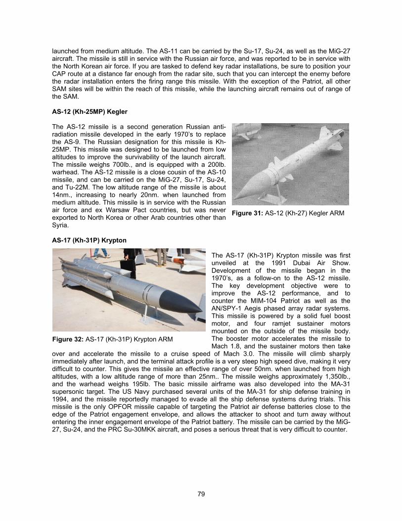
79
launched from medium altitude. The AS-11 can be carried by the Su-17, Su-24, as well as the MiG-27aircraft. The missile is still in service with the Russian air force, and was reported to be in service withthe North Korean air force. If you are tasked to defend key radar installations, be sure to position yourCAP route at a distance far enough from the radar site, such that you can intercept the enemy beforethe radar installation enters the firing range this missile. With the exception of the Patriot, all otherSAM sites will be within the reach of this missile, while the launching aircraft remains out of range ofthe SAM.
AS-12 (Kh-25MP) Kegler
The AS-12 missile is a second generation Russian anti-radiation missile developed in the early 1970’s to replacethe AS-9. The Russian designation for this missile is Kh-25MP. This missile was designed to be launched from lowaltitudes to improve the survivability of the launch aircraft.The missile weighs 700lb., and is equipped with a 200lb.warhead. The AS-12 missile is a close cousin of the AS-10missile, and can be carried on the MiG-27, Su-17, Su-24,and Tu-22M. The low altitude range of the missile is about14nm., increasing to nearly 20nm. when launched frommedium altitude. This missile is in service with the Russianair force and ex Warsaw Pact countries, but was neverexported to North Korea or other Arab countries other thanSyria.
AS-17 (Kh-31P) Krypton
The AS-17 (Kh-31P) Krypton missile was firstunveiled at the 1991 Dubai Air Show.Development of the missile began in the1970’s, as a follow-on to the AS-12 missile.The key development objective were toimprove the AS-12 performance, and tocounter the MIM-104 Patriot as well as theAN/SPY-1 Aegis phased array radar systems.This missile is powered by a solid fuel boostmotor, and four ramjet sustainer motorsmounted on the outside of the missile body.The booster motor accelerates the missile toMach 1.8, and the sustainer motors then take
over and accelerate the missile to a cruise speed of Mach 3.0. The missile will climb sharplyimmediately after launch, and the terminal attack profile is a very steep high speed dive, making it verydifficult to counter. This gives the missile an effective range of over 50nm. when launched from highaltitudes, with a low altitude range of more than 25nm.. The missile weighs approximately 1,350lb.,and the warhead weighs 195lb. The basic missile airframe was also developed into the MA-31supersonic target. The US Navy purchased several units of the MA-31 for ship defense training in1994, and the missile reportedly managed to evade all the ship defense systems during trials. Thismissile is the only OPFOR missile capable of targeting the Patriot air defense batteries close to theedge of the Patriot engagement envelope, and allows the attacker to shoot and turn away withoutentering the inner engagement envelope of the Patriot battery. The missile can be carried by the MiG-27, Su-24, and the PRC Su-30MKK aircraft, and poses a serious threat that is very difficult to counter.
Figure 31: AS-12 (Kh-27) Kegler ARM
Figure 32: AS-17 (Kh-31P) Krypton ARM
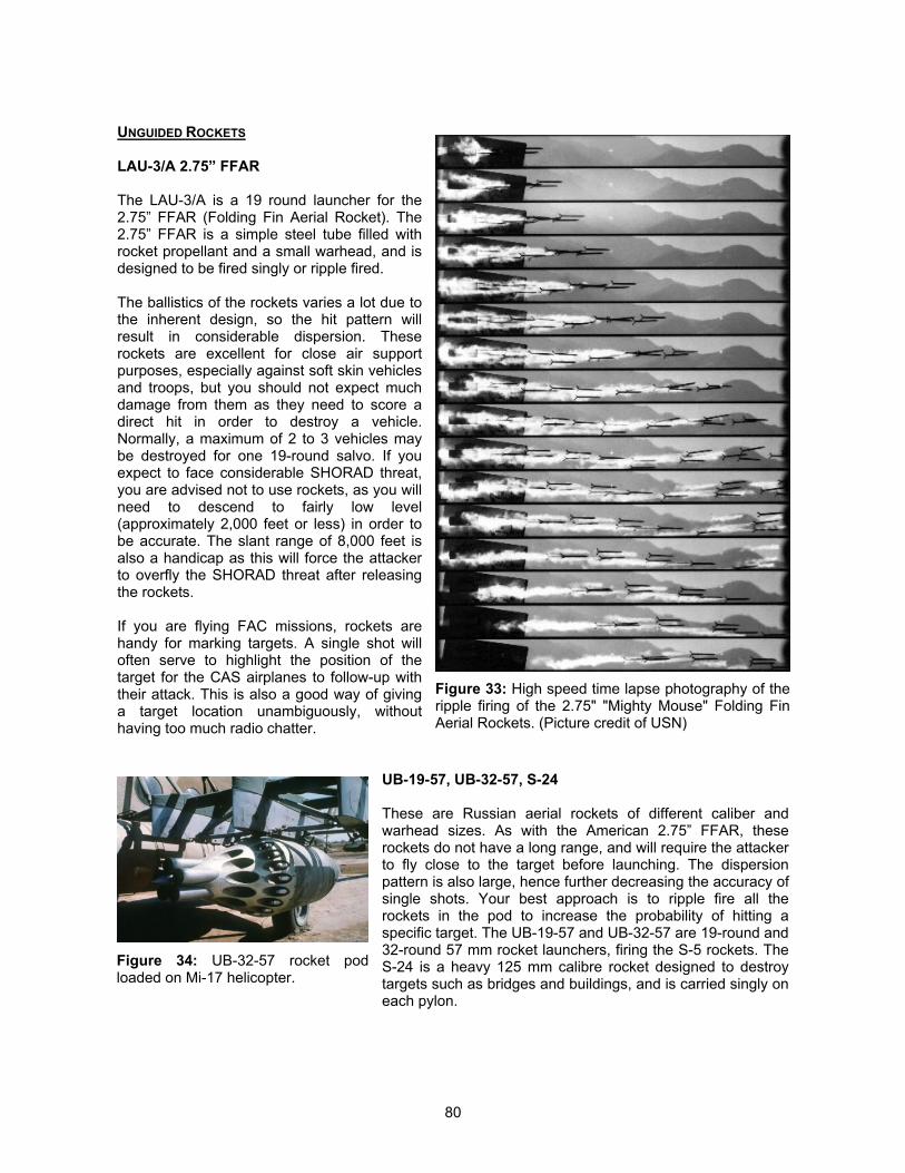
80
UNGUIDED ROCKETS
LAU-3/A 2.75” FFAR
The LAU-3/A is a 19 round launcher for the2.75” FFAR (Folding Fin Aerial Rocket). The2.75” FFAR is a simple steel tube filled withrocket propellant and a small warhead, and isdesigned to be fired singly or ripple fired.
The ballistics of the rockets varies a lot due tothe inherent design, so the hit pattern willresult in considerable dispersion. Theserockets are excellent for close air supportpurposes, especially against soft skin vehiclesand troops, but you should not expect muchdamage from them as they need to score adirect hit in order to destroy a vehicle.Normally, a maximum of 2 to 3 vehicles maybe destroyed for one 19-round salvo. If youexpect to face considerable SHORAD threat,you are advised not to use rockets, as you willneed to descend to fairly low level(approximately 2,000 feet or less) in order tobe accurate. The slant range of 8,000 feet isalso a handicap as this will force the attackerto overfly the SHORAD threat after releasingthe rockets.
If you are flying FAC missions, rockets arehandy for marking targets. A single shot willoften serve to highlight the position of thetarget for the CAS airplanes to follow-up withtheir attack. This is also a good way of givinga target location unambiguously, withouthaving too much radio chatter.
UB-19-57, UB-32-57, S-24
These are Russian aerial rockets of different caliber andwarhead sizes. As with the American 2.75” FFAR, theserockets do not have a long range, and will require the attackerto fly close to the target before launching. The dispersionpattern is also large, hence further decreasing the accuracy ofsingle shots. Your best approach is to ripple fire all therockets in the pod to increase the probability of hitting aspecific target. The UB-19-57 and UB-32-57 are 19-round and32-round 57 mm rocket launchers, firing the S-5 rockets. TheS-24 is a heavy 125 mm calibre rocket designed to destroytargets such as bridges and buildings, and is carried singly oneach pylon.
Figure 33: High speed time lapse photography of theripple firing of the 2.75" "Mighty Mouse" Folding FinAerial Rockets. (Picture credit of USN)
Figure 34: UB-32-57 rocket podloaded on Mi-17 helicopter.
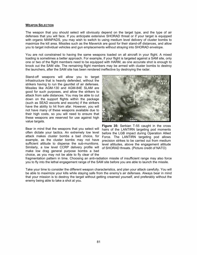
81
WEAPON SELECTION
The weapon that you should select will obviously depend on the target type, and the type of airdefenses that you will face. If you anticipate extensive SHORAD threat or if your target is equippedwith organic MANPADS, you may wish to switch to using medium level delivery of cluster bombs tomaximize the kill area. Missiles such as the Maverick are good for their stand-off distances, and allowyou to target individual vehicles and gun emplacements without straying into SHORAD envelope.
You are not constrained to having the same weapons loaded on all aircraft in your flight. A mixedloading is sometimes a better approach. For example, if your flight is targeted against a SAM site, onlyone or two of the flight members need to be equipped with HARM, as one accurate shot is enough toknock out the SAM site. The remaining flight members may be armed with cluster bombs to destroythe launchers, after the SAM site has been rendered ineffective by destroying the radar.
Stand-off weapons will allow you to targetinfrastructure that is heavily defended, without thestrikers having to run the gauntlet of air defenses.Missiles like AGM-130 and AGM-84E SLAM aregood for such purposes, and allow the strikers toattack from safe distances. You may be able to cutdown on the support flights within the package(such as SEAD escorts and escorts) if the strikershave the ability to hit from afar. However, you willnot have many of these weapons available due totheir high costs, so you will need to ensure thatthese weapons are reserved for use against highvalue targets.
Bear in mind that the weapons that you select willoften dictate your tactics. An extremely low levelattack makes cluster bombs a bad choice, forexample, as the cluster bombs may not havesufficient altitude to disperse the sub-munitions.Similarly, a low level CCRP delivery profile willmake low drag general purpose bombs a badchoice, as you may not be able to fly clear of thefragmentation pattern in time. Choosing an anti-radiation missile of insufficient range may also forceyou to fly into the lethal engagement range of the SAM site before you are able to launch the missile.
Take your time to consider the different weapon characteristics, and plan your attack carefully. You willbe able to maximize your kills while staying safe from the enemy’s air defenses. Always bear in mindthat your mission is to destroy the target without getting creamed yourself, and preferably without theenemy being able to take a shot at you.
Figure 35: Serbian T-55 caught in the crosshairs of the LANTIRN targeting pod momentsbefore the LGB impact during Operation AlliedForce. The LANTIRN targeting pod allowsprecision strikes to be carried out from mediumlevel altitudes, above the engagement altitudeof SHORAD threats. (Picture credit of NATO)
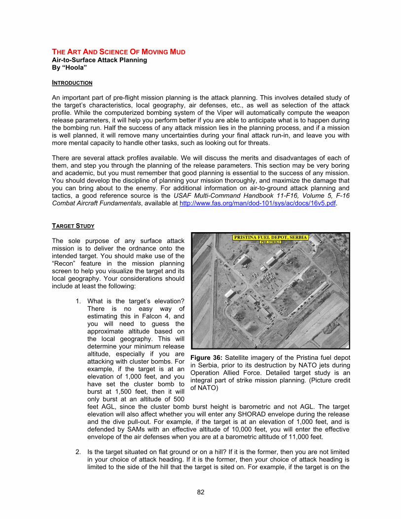
82
THE ART AND SCIENCE OF MOVING MUDAir-to-Surface Attack PlanningBy “Hoola”
INTRODUCTION
An important part of pre-flight mission planning is the attack planning. This involves detailed study ofthe target’s characteristics, local geography, air defenses, etc., as well as selection of the attackprofile. While the computerized bombing system of the Viper will automatically compute the weaponrelease parameters, it will help you perform better if you are able to anticipate what is to happen duringthe bombing run. Half the success of any attack mission lies in the planning process, and if a missionis well planned, it will remove many uncertainties during your final attack run-in, and leave you withmore mental capacity to handle other tasks, such as looking out for threats.
There are several attack profiles available. We will discuss the merits and disadvantages of each ofthem, and step you through the planning of the release parameters. This section may be very boringand academic, but you must remember that good planning is essential to the success of any mission.You should develop the discipline of planning your mission thoroughly, and maximize the damage thatyou can bring about to the enemy. For additional information on air-to-ground attack planning andtactics, a good reference source is the USAF Multi-Command Handbook 11-F16, Volume 5, F-16Combat Aircraft Fundamentals, available at http://www.fas.org/man/dod-101/sys/ac/docs/16v5.pdf.
TARGET STUDY
The sole purpose of any surface attackmission is to deliver the ordnance onto theintended target. You should make use of the“Recon” feature in the mission planningscreen to help you visualize the target and itslocal geography. Your considerations shouldinclude at least the following:
1. What is the target’s elevation?There is no easy way ofestimating this in Falcon 4, andyou will need to guess theapproximate altitude based onthe local geography. This willdetermine your minimum releasealtitude, especially if you areattacking with cluster bombs. Forexample, if the target is at anelevation of 1,000 feet, and youhave set the cluster bomb toburst at 1,500 feet, then it willonly burst at an altitude of 500feet AGL, since the cluster bomb burst height is barometric and not AGL. The targetelevation will also affect whether you will enter any SHORAD envelope during the releaseand the dive pull-out. For example, if the target is at an elevation of 1,000 feet, and isdefended by SAMs with an effective altitude of 10,000 feet, you will enter the effectiveenvelope of the air defenses when you are at a barometric altitude of 11,000 feet.
2. Is the target situated on flat ground or on a hill? If it is the former, then you are not limitedin your choice of attack heading. If it is the former, then your choice of attack heading islimited to the side of the hill that the target is sited on. For example, if the target is on the
Figure 36: Satellite imagery of the Pristina fuel depotin Serbia, prior to its destruction by NATO jets duringOperation Allied Force. Detailed target study is anintegral part of strike mission planning. (Picture creditof NATO)
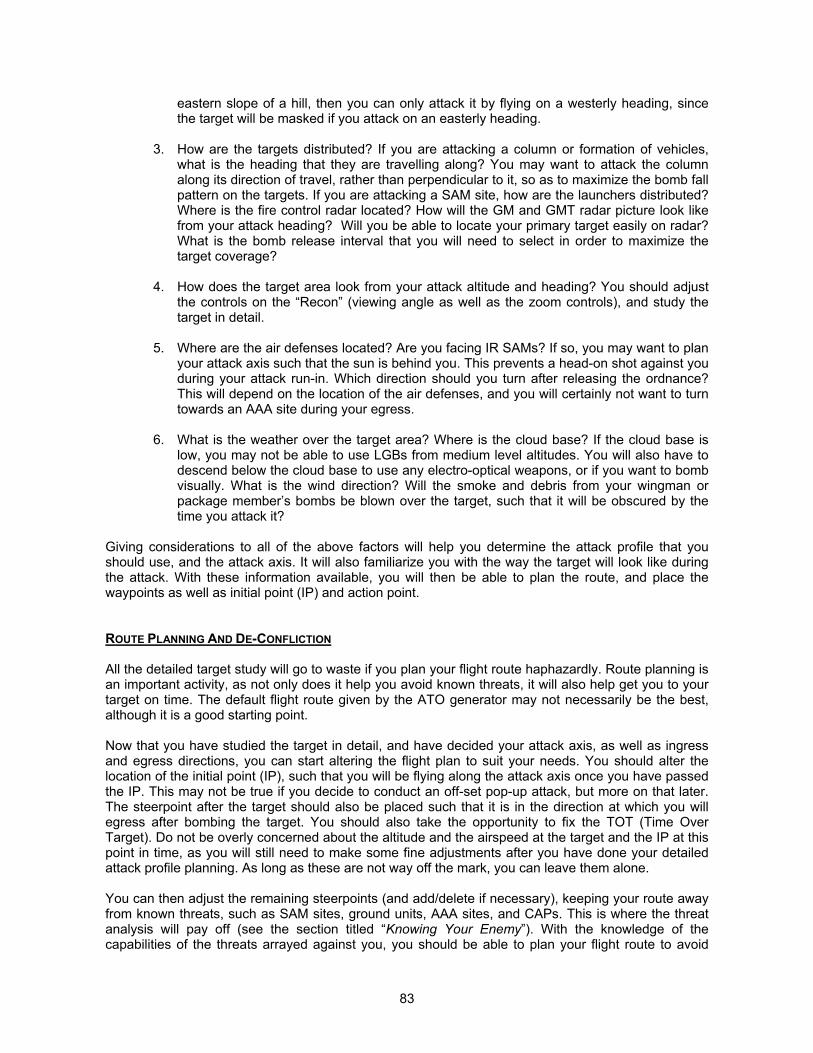
83
eastern slope of a hill, then you can only attack it by flying on a westerly heading, sincethe target will be masked if you attack on an easterly heading.
3. How are the targets distributed? If you are attacking a column or formation of vehicles,what is the heading that they are travelling along? You may want to attack the columnalong its direction of travel, rather than perpendicular to it, so as to maximize the bomb fallpattern on the targets. If you are attacking a SAM site, how are the launchers distributed?Where is the fire control radar located? How will the GM and GMT radar picture look likefrom your attack heading? Will you be able to locate your primary target easily on radar?What is the bomb release interval that you will need to select in order to maximize thetarget coverage?
4. How does the target area look from your attack altitude and heading? You should adjustthe controls on the “Recon” (viewing angle as well as the zoom controls), and study thetarget in detail.
5. Where are the air defenses located? Are you facing IR SAMs? If so, you may want to planyour attack axis such that the sun is behind you. This prevents a head-on shot against youduring your attack run-in. Which direction should you turn after releasing the ordnance?This will depend on the location of the air defenses, and you will certainly not want to turntowards an AAA site during your egress.
6. What is the weather over the target area? Where is the cloud base? If the cloud base islow, you may not be able to use LGBs from medium level altitudes. You will also have todescend below the cloud base to use any electro-optical weapons, or if you want to bombvisually. What is the wind direction? Will the smoke and debris from your wingman orpackage member’s bombs be blown over the target, such that it will be obscured by thetime you attack it?
Giving considerations to all of the above factors will help you determine the attack profile that youshould use, and the attack axis. It will also familiarize you with the way the target will look like duringthe attack. With these information available, you will then be able to plan the route, and place thewaypoints as well as initial point (IP) and action point.
ROUTE PLANNING AND DE-CONFLICTION
All the detailed target study will go to waste if you plan your flight route haphazardly. Route planning isan important activity, as not only does it help you avoid known threats, it will also help get you to yourtarget on time. The default flight route given by the ATO generator may not necessarily be the best,although it is a good starting point.
Now that you have studied the target in detail, and have decided your attack axis, as well as ingressand egress directions, you can start altering the flight plan to suit your needs. You should alter thelocation of the initial point (IP), such that you will be flying along the attack axis once you have passedthe IP. This may not be true if you decide to conduct an off-set pop-up attack, but more on that later.The steerpoint after the target should also be placed such that it is in the direction at which you willegress after bombing the target. You should also take the opportunity to fix the TOT (Time OverTarget). Do not be overly concerned about the altitude and the airspeed at the target and the IP at thispoint in time, as you will still need to make some fine adjustments after you have done your detailedattack profile planning. As long as these are not way off the mark, you can leave them alone.
You can then adjust the remaining steerpoints (and add/delete if necessary), keeping your route awayfrom known threats, such as SAM sites, ground units, AAA sites, and CAPs. This is where the threatanalysis will pay off (see the section titled “Knowing Your Enemy”). With the knowledge of thecapabilities of the threats arrayed against you, you should be able to plan your flight route to avoid
84
most if not all of them. Be sure that you study the mission planning map carefully, and identify thelocations of the ground as well as air units along your entire flight route. Note that the situation maychange once you are airborne, and the “fog of war” may not provide a complete picture of thebattlefield at the time of mission planning.
If you are flying in a multi-player mission, or as part of a multi-package strike mission, you will alsoneed to consider de-conflicting the TOT for different members of the flight, and different packages.The airspace over the target can become congested if every flight member is to arrive at the sametime, and the risk of mid-air collision increases tremendously under such circumstances.
You should also consider the minimum interval between the TOT of various members of the sameflight, if they are bombing the same target. This is especially important if you are using a low levelweapon delivery profile. The minimum interval between flight members should allow for the flight timeof the ordnance. For example, if the bombs require a flight time of 10 seconds between release toimpact, then, for a start, the TOT between each aircraft should be spaced at least 10 seconds apart.This will be increased by the time required for the bomb fragments from the resulting explosion todescend back to the ground, and a rule of thumb to use is to add approximately 15 to 20 seconds. Forthis example, the minimum TOT spacing between each aircraft should be at least 25 to 30 seconds toallow for this.
The last thing to consider is planning a different attack axis for each member of the flight. This ensuresthat the target is attacked from multiple directions, and adds an element of surprise to the airdefenses. This is very useful especially if you are attacking SAM sites, as it allows you to overwhelmthe SAM site since the SAM battery will not be able to engage any targets outside its sensor’s azimuthcoverage. If the SAM battery targets a specific flight member, the remaining flight member can attack itfrom a different direction, and can often remain undetected and unmolested during the attack run-in.
ORDNANCE CONSIDERATIONS
The type of ordnance that you are carrying will determine the feasibility of the delivery profile, as wellas the placement of the initial point and action point. The planning considerations for the variousordnance types are as follows:
Safe Escape
The minimum release altitude for ordnance is determined by fuse arming requirements (which is notmodeled in Falcon 4), and the safe escape requirement. The latter allows the aircraft to escape fromthe fragmentation pattern of its own bombs, so as to avoid being damaged by the explosion. The safeescape minimum release altitude is dependent on the release profile, as well as the escape maneuver.For planning purposes, typical safe escape minimum release altitudes (MRA) for low drag bombs andvarious escape maneuvers are given in Table 3 through Table 5. For high drag bombs, as long as yourelease them at an altitude of at least 300 feet, you should not be concerned about safe escape.
The escape maneuvers are as follows:
i. For level release, a constant speed, no-turn profile. The time duration to maintain the profile is3 seconds more than the time-of-flight (TOF) of the bombs. For example, if the TOF for a levelrelease is 6 seconds, then the escape maneuver is a level constant speed maneuver of 9seconds in duration. This is known as the Level Constant Speed, No-Turn maneuver.
ii. For a dive release, the escape maneuver is to initiate a 5g pull-up after releasing the bombs,and maintaining 5g until the aircraft pitch attitude reaches 20°. The g is reduced gradually to1g as the aircraft achieves a 30° climb. This is known as the 5g Climb maneuver.
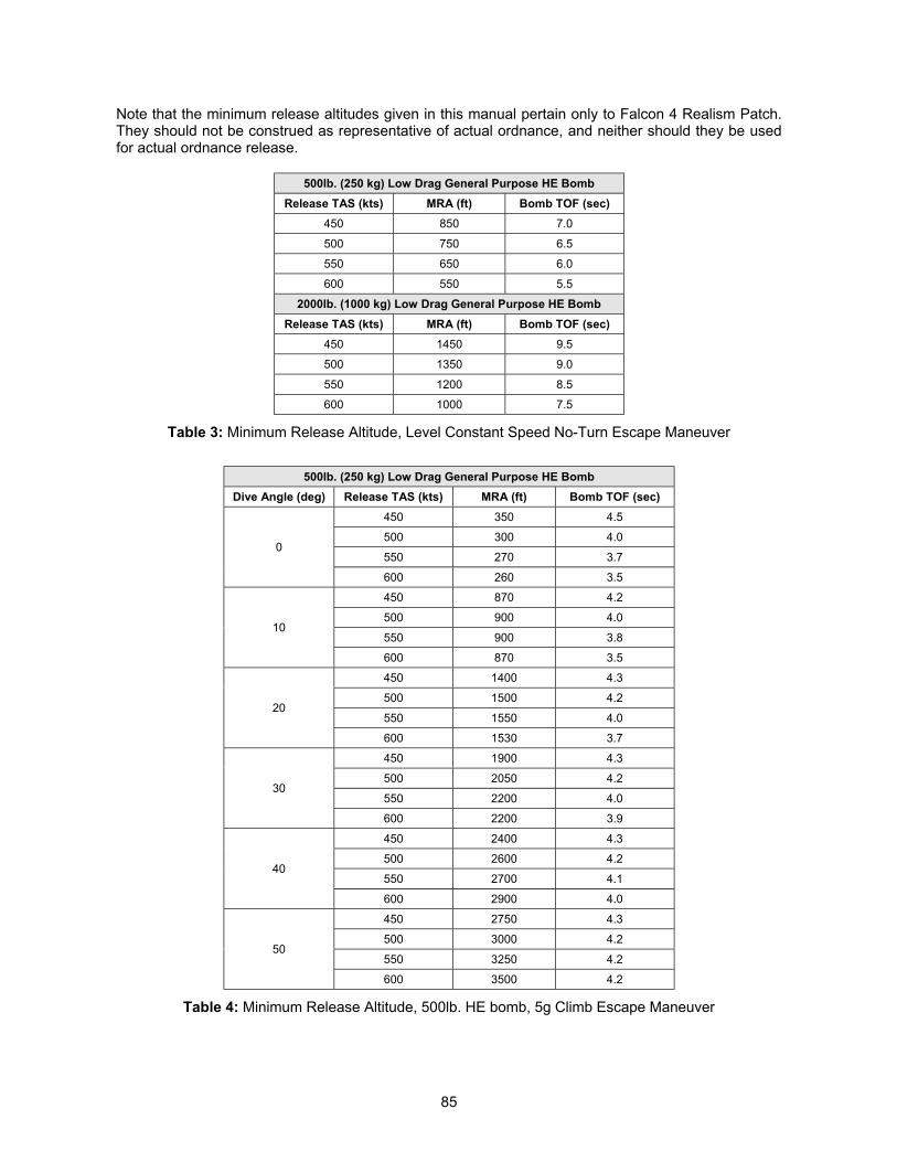
85
Note that the minimum release altitudes given in this manual pertain only to Falcon 4 Realism Patch.They should not be construed as representative of actual ordnance, and neither should they be usedfor actual ordnance release.
500lb. (250 kg) Low Drag General Purpose HE BombRelease TAS (kts) MRA (ft) Bomb TOF (sec)
450 850 7.0
500 750 6.5
550 650 6.0
600 550 5.5
2000lb. (1000 kg) Low Drag General Purpose HE BombRelease TAS (kts) MRA (ft) Bomb TOF (sec)
450 1450 9.5
500 1350 9.0
550 1200 8.5
600 1000 7.5
Table 3: Minimum Release Altitude, Level Constant Speed No-Turn Escape Maneuver
500lb. (250 kg) Low Drag General Purpose HE BombDive Angle (deg) Release TAS (kts) MRA (ft) Bomb TOF (sec)
450 350 4.5
500 300 4.0
550 270 3.70
600 260 3.5
450 870 4.2
500 900 4.0
550 900 3.810
600 870 3.5
450 1400 4.3
500 1500 4.2
550 1550 4.020
600 1530 3.7
450 1900 4.3
500 2050 4.2
550 2200 4.030
600 2200 3.9
450 2400 4.3
500 2600 4.2
550 2700 4.140
600 2900 4.0
450 2750 4.3
500 3000 4.2
550 3250 4.250
600 3500 4.2
Table 4: Minimum Release Altitude, 500lb. HE bomb, 5g Climb Escape Maneuver
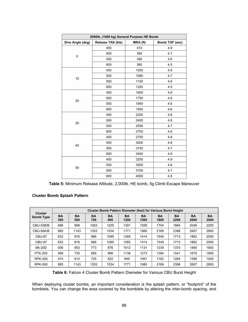
86
2000lb. (1000 kg) General Purpose HE BombDive Angle (deg) Release TAS (kts) MRA (ft) Bomb TOF (sec)
450 410 4.9
500 390 4.7
550 390 4.60
600 380 4.5
450 1050 4.8
500 1080 4.7
550 1150 4.610
600 1200 4.5
450 1650 4.8
500 1750 4.8
550 1850 4.620
600 1950 4.6
450 2200 4.8
500 2400 4.8
550 2550 4.730
600 2700 4.6
450 2750 4.8
500 3000 4.8
550 3150 4.740
600 3400 4.6
450 3250 4.9
500 3500 4.8
550 3700 4.750
600 4050 4.8
Table 5: Minimum Release Altitude, 2,000lb. HE bomb, 5g Climb Escape Maneuver
Cluster Bomb Splash Pattern
Cluster Bomb Pattern Diameter (feet) for Various Burst HeightCluster
Bomb Type BA300
BA500
BA700
BA900
BA1200
BA1500
BA1800
BA2200
BA2600
BA3000
CBU-52B/B 696 898 1063 1205 1391 1556 1704 1884 2048 2200
CBU-58A/B 885 1143 1353 1534 1771 1980 2169 2398 2607 2800
CBU-87 632 816 966 1095 1265 1414 1549 1713 1862 2000
CBU-97 632 816 966 1095 1265 1414 1549 1713 1862 2000
Mk-20D 506 653 773 876 1012 1131 1239 1370 1490 1600
PTK-250 569 735 869 986 1138 1273 1394 1541 1676 1800
RPK-250 474 612 725 822 949 1061 1162 1285 1396 1500
RPK-500 885 1143 1353 1534 1771 1980 2169 2398 2607 2800
Table 6: Falcon 4 Cluster Bomb Pattern Diameter for Various CBU Burst Height
When deploying cluster bombs, an important consideration is the splash pattern, or “footprint” of thebomblets. You can change the area covered by the bomblets by altering the inter-bomb spacing, and

87
altering the burst height, in the Stores Management System (SMS). For planning purposes, typicalcluster bomb pattern diameter for various burst height are given in Table 6.
Note that the release dive angle does not affect the pattern diameter significantly, and will generallyvary the pattern diameter by about ±15%. You can approximate the pattern diameter by taking thecosine of the dive angle multiplied by the pattern diameter in a level release.
DIVE RECOVERY CONSIDERATIONS
If you are delivering the ordnance in a dive, you will need to consider the altitude lost during the divepull-out. This will prevent you from adopting a dive profile that will lead to excessive altitude lossduring pull-out. The consequence of excessive altitude loss is obvious, as you will either stray intoSHORAD envelope or stay in SHORAD envelope for a longer time, or, in the worst case, you willauger into the ground during the dive recovery.
The approximate altitude loss during pull-out for various airspeeds, and altitudes, for 3g and 5gpullouts, are given in Table 7. This is on assumption of the following flight parameters:
i. IDLE thrust at the commencement of pulloutii. Immediate pullout initiation after ordnance releaseiii. Wings leveliv. Maximum g onset ratev. Full speedbrakes at the commencement of pullout
3g Dive Pullout 5g Dive PulloutCalibrated
Airspeed (KCAS)Initial DiveAngle (deg)
Altitude Loss(feet)
CalibratedAirspeed (KCAS)
Initial DiveAngle (deg)
Altitude Loss(feet)
15 400 15 150
30 1100 30 800300
45 2200
300
45 1400
15 450 15 200
30 1300 30 800350
45 2700
350
45 1600
15 500 15 350
30 1400 30 950400
45 3200
400
45 1850
15 600 15 400
30 1800 30 1100450
45 3800
450
45 2200
15 700 15 500
30 2100 30 1300500
45 4200
500
45 2450
15 800 15 600
30 2400 30 1400550
45 4800
550
45 2800
Table 7: Approximate Altitude Loss For 3g and 5g Pullout During Dive Recovery
To determine the approximate altitude loss during dive recovery, you can interpolate between thedifferent airspeeds and dive angles. The exact altitude loss will be dependent on the initial altitude,due to slightly different air densities, but the variation between an initial altitude of 5,000 feet and15,000 feet is small, and for can be ignored for all intent and purposes of gameplay.
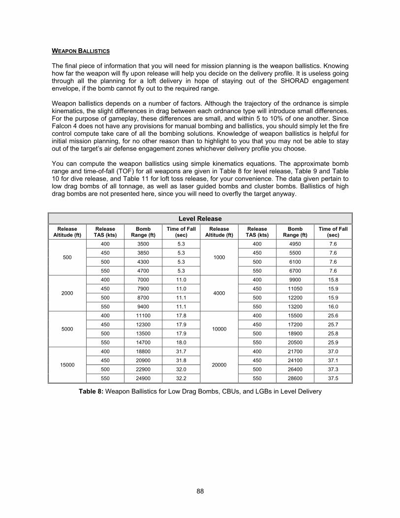
88
WEAPON BALLISTICS
The final piece of information that you will need for mission planning is the weapon ballistics. Knowinghow far the weapon will fly upon release will help you decide on the delivery profile. It is useless goingthrough all the planning for a loft delivery in hope of staying out of the SHORAD engagementenvelope, if the bomb cannot fly out to the required range.
Weapon ballistics depends on a number of factors. Although the trajectory of the ordnance is simplekinematics, the slight differences in drag between each ordnance type will introduce small differences.For the purpose of gameplay, these differences are small, and within 5 to 10% of one another. SinceFalcon 4 does not have any provisions for manual bombing and ballistics, you should simply let the firecontrol compute take care of all the bombing solutions. Knowledge of weapon ballistics is helpful forinitial mission planning, for no other reason than to highlight to you that you may not be able to stayout of the target’s air defense engagement zones whichever delivery profile you choose.
You can compute the weapon ballistics using simple kinematics equations. The approximate bombrange and time-of-fall (TOF) for all weapons are given in Table 8 for level release, Table 9 and Table10 for dive release, and Table 11 for loft toss release, for your convenience. The data given pertain tolow drag bombs of all tonnage, as well as laser guided bombs and cluster bombs. Ballistics of highdrag bombs are not presented here, since you will need to overfly the target anyway.
Level ReleaseRelease
Altitude (ft)Release
TAS (kts)Bomb
Range (ft)Time of Fall
(sec)Release
Altitude (ft)Release
TAS (kts)Bomb
Range (ft)Time of Fall
(sec)400 3500 5.3 400 4950 7.6
450 3850 5.3 450 5500 7.6
500 4300 5.3 500 6100 7.6500
550 4700 5.3
1000
550 6700 7.6
400 7000 11.0 400 9900 15.8
450 7900 11.0 450 11050 15.9
500 8700 11.1 500 12200 15.92000
550 9400 11.1
4000
550 13200 16.0
400 11100 17.8 400 15500 25.6
450 12300 17.9 450 17200 25.7
500 13500 17.9 500 18900 25.85000
550 14700 18.0
10000
550 20500 25.9
400 18800 31.7 400 21700 37.0
450 20900 31.8 450 24100 37.1
500 22900 32.0 500 26400 37.315000
550 24900 32.2
20000
550 28600 37.5
Table 8: Weapon Ballistics for Low Drag Bombs, CBUs, and LGBs in Level Delivery
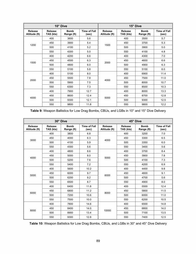
89
10° Dive 15° DiveRelease
Altitude (ft)Release
TAS (kts)Bomb
Range (ft)Time of Fall
(sec)Release
Altitude (ft)Release
TAS (kts)Bomb
Range (ft)Time of Fall
(sec)400 3600 5.6 400 3500 5.7
450 3900 5.4 450 3700 5.3
500 4100 5.2 500 3900 5.01200
550 4300 5.0
1500
550 4100 4.8
400 4200 6.6 400 4300 7.0
450 4500 6.3 450 4600 6.6
500 4800 6.0 500 4900 6.31500
550 5100 5.8
2000
550 5100 6.0
400 5100 8.0 400 6900 11.4
450 5500 7.8 450 7500 11.0
500 5900 7.5 500 8000 10.72000
550 6300 7.3
4000
550 8500 10.3
400 7900 12.7 400 8000 13.3
450 8600 12.4 450 8700 12.8
500 9300 12.1 500 9300 12.54000
550 9800 11.8
5000
550 9800 12.2
Table 9: Weapon Ballistics for Low Drag Bombs, CBUs, and LGBs in 10° and 15° Dive Delivery
30° Dive 45° DiveRelease
Altitude (ft)Release
TAS (kts)Bomb
Range (ft)Time of Fall
(sec)Release
Altitude (ft)Release
TAS (kts)Bomb
Range (ft)Time of Fall
(sec)400 3800 6.8 400 3200 7.0
450 4000 6.3 450 3300 6.5
500 4100 5.9 500 3350 6.03000
550 4300 5.6
4000
550 3400 5.6
400 4800 8.6 400 3700 8.4
450 5000 8.0 450 3900 7.8
500 5200 7.6 500 4100 7.34000
550 5400 7.2
5000
550 4200 6.9
400 5600 10.2 400 4400 9.8
450 6000 9.7 450 4600 9.1
500 6200 9.2 500 4700 5.65000
550 6500 8.7
6000
550 4900 8.0
400 6400 11.8 400 5500 12.4
450 6800 11.2 450 5800 11.5
500 7200 10.6 500 6000 11.06000
550 7500 10.0
8000
550 6200 10.5
400 7800 14.6 400 6500 14.8
450 8400 14.0 450 6800 14.0
500 8900 13.4 500 7100 13.58000
550 9300 12.8
10000
550 7400 12.5
Table 10: Weapon Ballistics for Low Drag Bombs, CBUs, and LGBs in 30° and 45° Dive Delivery
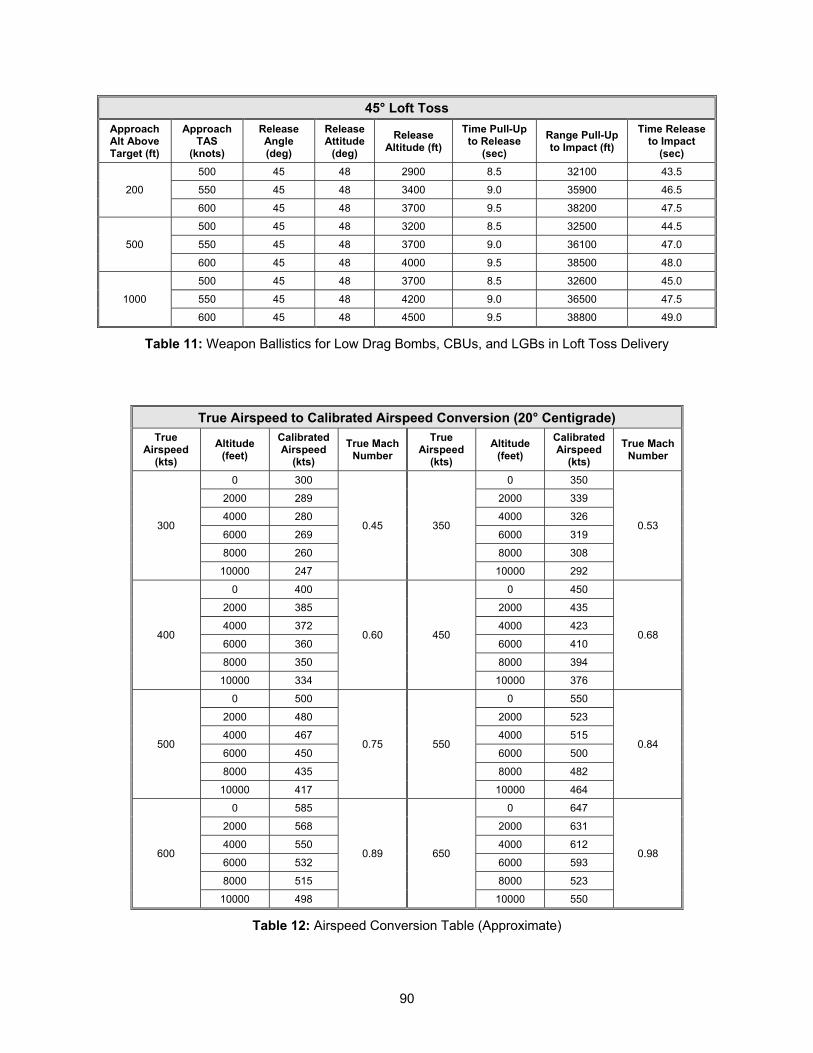
90
45° Loft TossApproachAlt AboveTarget (ft)
ApproachTAS
(knots)
ReleaseAngle(deg)
ReleaseAttitude
(deg)Release
Altitude (ft)Time Pull-Up
to Release(sec)
Range Pull-Upto Impact (ft)
Time Releaseto Impact
(sec)500 45 48 2900 8.5 32100 43.5
550 45 48 3400 9.0 35900 46.5200
600 45 48 3700 9.5 38200 47.5
500 45 48 3200 8.5 32500 44.5
550 45 48 3700 9.0 36100 47.0500
600 45 48 4000 9.5 38500 48.0
500 45 48 3700 8.5 32600 45.0
550 45 48 4200 9.0 36500 47.51000
600 45 48 4500 9.5 38800 49.0
Table 11: Weapon Ballistics for Low Drag Bombs, CBUs, and LGBs in Loft Toss Delivery
True Airspeed to Calibrated Airspeed Conversion (20° Centigrade)True
Airspeed(kts)
Altitude(feet)
CalibratedAirspeed
(kts)True Mach
NumberTrue
Airspeed(kts)
Altitude(feet)
CalibratedAirspeed
(kts)True Mach
Number
0 300 0 350
2000 289 2000 339
4000 280 4000 326
6000 269 6000 319
8000 260 8000 308
300
10000 247
0.45 350
10000 292
0.53
0 400 0 450
2000 385 2000 435
4000 372 4000 423
6000 360 6000 410
8000 350 8000 394
400
10000 334
0.60 450
10000 376
0.68
0 500 0 550
2000 480 2000 523
4000 467 4000 515
6000 450 6000 500
8000 435 8000 482
500
10000 417
0.75 550
10000 464
0.84
0 585 0 647
2000 568 2000 631
4000 550 4000 612
6000 532 6000 593
8000 515 8000 523
600
10000 498
0.89 650
10000 550
0.98
Table 12: Airspeed Conversion Table (Approximate)
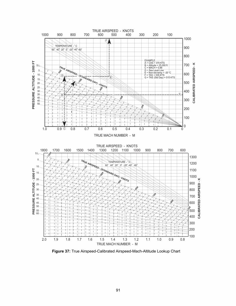
91
2.0 1.9 1.8 0.9 0.81.01.11.21.31.41.51.61.7
S.L.
5
10
15
20
25
30
3540
4550
5560
TRUE MACH NUMBER - M
1300
1200
1100
1000
900
800
700
600
500
400
300
200
100
1800 1700 1600 1500 1400 1300 1200 1100 1000 900 800 700 600TRUE AIRSPEED - KNOTS
TEMPERATURE - ˚ C0˚20˚40˚60˚ -20˚ -40˚ -60˚
PR
ES
SU
RE
ALT
ITU
DE
- 1
000
FT
TRUE AIRSPEED - KNOTS
1.0 0.9 0.8 0.7 0.6 0.5 0.4 0.3 0.2 0.1 0
S.L.
5
10
15
20
253035404550
100
200
300
400
500
600
700
800
900
10001000 900 800 700 600 500 400 300 200 100
0
TRUE MACH NUMBER - M
AB
C
DE
F
G
60˚ 40˚ 20˚ 0˚ -20˚ -40˚ -60˚
TEMPERATURE - ˚ C
EXAMPLE:A = CAS = 370 KTSB = Altitude = 25,000 ftC = MACH = 0.86D = Sea Level LineE = Non-std temp = -20˚CF = TAS = 535 KTSG = TAS (Std Day) = 515 KTS
PR
ES
SU
RE
ALT
ITU
DE
- 1
000
FT
CA
LIB
RA
TE
D A
IRS
PE
ED
- K
CA
LIB
RA
TE
D A
IRS
PE
ED
- K
TRUE AIRSPEED - (STANDARD DAY) - KNOTS
TRUE AIRSPEED - (STANDARD DAY) - KNOTS
Figure 37: True Airspeed-Calibrated Airspeed-Mach-Altitude Lookup Chart
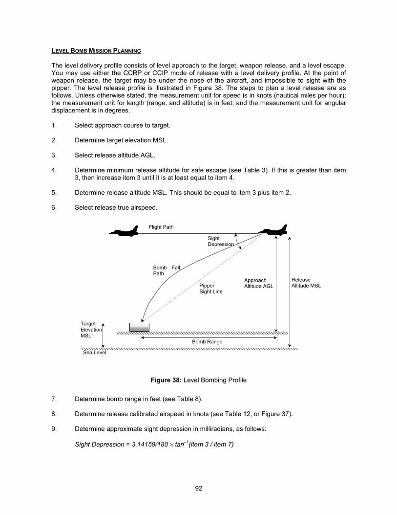
92
LEVEL BOMB MISSION PLANNING
The level delivery profile consists of level approach to the target, weapon release, and a level escape.You may use either the CCRP or CCIP mode of release with a level delivery profile. At the point ofweapon release, the target may be under the nose of the aircraft, and impossible to sight with thepipper. The level release profile is illustrated in Figure 38. The steps to plan a level release are asfollows. Unless otherwise stated, the measurement unit for speed is in knots (nautical miles per hour);the measurement unit for length (range, and altitude) is in feet; and the measurement unit for angulardisplacement is in degrees.
1. Select approach course to target.
2. Determine target elevation MSL.
3. Select release altitude AGL.
4. Determine minimum release altitude for safe escape (see Table 3). If this is greater than item3, then increase item 3 until it is at least equal to item 4.
5. Determine release altitude MSL. This should be equal to item 3 plus item 2.
6. Select release true airspeed.
Figure 38: Level Bombing Profile
7. Determine bomb range in feet (see Table 8).
8. Determine release calibrated airspeed in knots (see Table 12, or Figure 37).
9. Determine approximate sight depression in milliradians, as follows:
Sight Depression = 3.14159/180 � tan–1(item 3 / item 7)
PipperSight Line
Bomb FallPath
ApproachAltitude AGL
Sea Level
TargetElevationMSL
ReleaseAltitude MSL
Flight Path
SightDepression
Bomb Range

93
If the sight depression is less than 260mrad, then the target is visible in the HUD at the point ofweapon release. If the sight depression is greater than 260mrad, the target is not visible in the HUD atthe point of release, and if you are using CCIP mode, you should be expecting to see the CCIP delaycue. In this case, you are better off using CCRP mode instead.
10. If you are using cluster bombs, determine the cluster bomb splash pattern as follows:
a. Select burst height (feet) and determine corresponding pattern diameter (feet) for theweapon of interest (see Table 6).
b. Select release mode (single or paired)c. Select ripple quantityd. Select bomb spacinge. Determine total cluster bomb coverage area as follows:
Width of cluster bomb pattern = Item 10a (this is the same for single and paired release)
Length of cluster bomb pattern = Item 10a + ({No. of bombs – 1} � bomb spacing)
11. If you are using low or high drag bombs, determine the bomb stick length as follows:
a. Select release mode (single or paired)b. Select ripple quantityc. Select bomb spacingd. Determine stick length as follows:
Stick Length = ({No. of bombs – 1} � bomb spacing)
By going through the above planning process, you can determine the best bombing mode to use, aswell as pre-plan your release parameters such as cluster bomb burst height, ripple count, and rippleinterval.
If you are using the level bombing profile at low level, the target is likely to remain visible duringweapon release, provided the ordnance is not a high drag bomb or a BLU-107. At medium or highaltitudes, the sight depression required is such that the target will not be visible during weaponrelease. If you are employing high drag bombs, you are advised to use the CCRP mode in a levelprofile, as the target will not be visible during weapon release.
Example of Level Release of Cluster Bombs
You are tasked to attack a tank column with 6 CBU-58A/B cluster bombs, and there are no constraintson release parameters. The tank column is in a single file formation with a total length of 5,000 feet,and is traveling in the direction of 040. Target elevation is at sea level.
1. Approach Course To Target 040 deg
2. Target Elevation MSL 0 feet
3. Release Altitude AGL 2000 feet
4. Minimum Release Altitude for Safe Escape None for cluster bomb
5. Release Altitude MSL 2000 feet
6. Release True Airspeed 450 knots
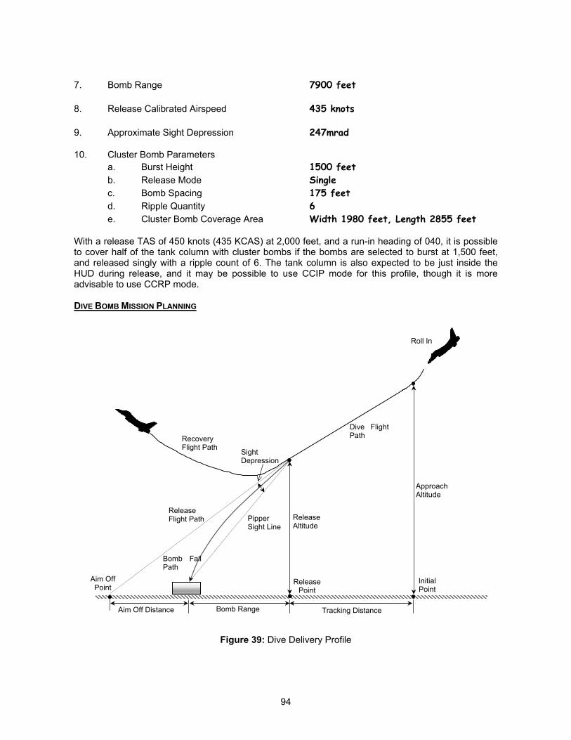
94
7. Bomb Range 7900 feet
8. Release Calibrated Airspeed 435 knots
9. Approximate Sight Depression 247mrad
10. Cluster Bomb Parametersa. Burst Height 1500 feetb. Release Mode Singlec. Bomb Spacing 175 feetd. Ripple Quantity 6e. Cluster Bomb Coverage Area Width 1980 feet, Length 2855 feet
With a release TAS of 450 knots (435 KCAS) at 2,000 feet, and a run-in heading of 040, it is possibleto cover half of the tank column with cluster bombs if the bombs are selected to burst at 1,500 feet,and released singly with a ripple count of 6. The tank column is also expected to be just inside theHUD during release, and it may be possible to use CCIP mode for this profile, though it is moreadvisable to use CCRP mode.
DIVE BOMB MISSION PLANNING
Figure 39: Dive Delivery Profile
PipperSight Line
Bomb FallPath
ReleaseAltitude
Aim OffPoint
ApproachAltitude
Dive FlightPath
SightDepression
Bomb RangeAim Off Distance
RecoveryFlight Path
ReleaseFlight Path
ReleasePoint
InitialPoint
Roll In
Tracking Distance
95
The dive delivery profile consist of a roll into the dive over the IP (Initial Point), dive approach to thetarget, weapon release, and a 4g pull-out in 2 seconds. This profile may be used for dive bombing,rocket attack, or strafing. The proper dive flight path is attained by rolling into the dive at the properaltitude over the IP, and aiming the flight path marker at the aim off point. Following weapon release, a4g pullout escape maneuver is performed. The dive delivery profile is illustrated in Figure 39. Theplanning steps are as follows. Unless otherwise stated, the measurement unit for speed is in knots(nautical miles per hour); the measurement unit for length (range, and altitude) is in feet; and themeasurement unit for angular displacement is in degrees.
1. Select approach course to target.
2. Determine target elevation MSL.
3. Select approach altitude AGL.
4. Determine approach altitude MSL (item 3 plus item 2).
5. Select release/approach true airspeed.
6. Select release dive angle.
7. Determine minimum release altitude for safe escape (see Table 4 for 500lb. HE bomb, andTable 5 for 2,000lb. HE bomb).
8. Select release altitude AGL. This should be greater than item 7 to ensure that you do not gethit by the bomb fragments, and item 10 to ensure that you do not auger into the ground duringdive recovery.
9. Determine release calibrated airspeed (see Table 12, or Figure 37) based on release altitudeMSL.
10. Determine altitude lost during dive recovery (see Table 7).
11. Determine bomb range (see Table 9 and Table 10).
12. Determine sight depression angle (in radians) from flight path:
Sight Depression = 3.14159/180 � { Dive Angle – tan–1(item 3 / item 11) }
If the sight depression is less than 260mrad, then the target is visible in the HUD at the point ofweapon release. If the sight depression is greater than 260mrad, the target is not visible in the HUD atthe point of release, and if you are using CCIP mode, you should be expecting to see the CCIP delaycue. Strictly speaking, the total sight depression should also include the aircraft AOA. This is inherentlyvariable and dependent on the weight at the point of release. Since Falcon 4 does not have anyprovisions for manual bombing, and the fire control computer takes care of the bombing solution, theAOA may be ignored, and the sight depression computed here can taken as a guide to the final sightpicture during the bomb run.
13. Determine aim off distance:
Aim Off Distance = (Release Altitude AGL / tan (Dive Angle)) – Bomb Range (item 11)
14. Determine Initial Point Distance:
96
Initial Point Distance = Approach Altitude AGL (item 3) / tan (Dive Angle) – Aim Off Distance(item 13)
15. Determine Tracking Distance:
Tracking Distance = Initial Point Distance (item 14) – Bomb Range (item 11)
16. Determine ground speed during dive, assuming zero winds:
Ground Speed = True Airspeed � cos (Dive Angle)
17. Determine tracking time:
Tracking Time (sec) = Tracking Distance / (Ground Speed � 1.69)
18. Determine altitude lost during tracking:
Tracking Altitude Loss = (True Airspeed � 1.69) � sin (Dive Angle) � Tracking Time
19. If you are using cluster bombs, determine the cluster bomb splash pattern as follows:
a. Select burst height (feet) and determine corresponding pattern diameter (feet) for therelease TAS (see Table 6).
b. Select release mode (single or paired)c. Select ripple quantityd. Select bomb spacinge. Determine total cluster bomb coverage area as follows:
Width of cluster bomb pattern = Item 10a (this is the same for single and paired release)
Length of cluster bomb pattern = Item 10a + ({No. of bombs – 1} � bomb spacing)
20. If you are using low or high drag bombs, determine the bomb stick length as follows:
a. Select release mode (single or paired)b. Select ripple quantityc. Select bomb spacingd. Determine stick length as follows:
Stick Length = ({No. of bombs – 1} � bomb spacing)
Example of Dive Bombing with Low Drag Bombs
You are tasked to attack a building with dimensions of 250 feet by 50 feet, with 6 Mk-82 low dragbombs, and there are no constraints on release parameters. The building is defended by a battalion ofinfantry armed with SA-7 missiles. The building’s length is aligned along a magnetic heading of 090,and the building consist of a single story, and its elevation is at sea level. The time of the attack is0800 hours.
1. Approach Course To Target 270 deg to attack out of the sun
2. Target Elevation MSL 0 feet
3. Approach Altitude AGL 12000 feet

97
4. Approach Altitude MSL 12000 feet
5. Release True Airspeed 450 knots
6. Release Dive Angle 30 degrees
7. Minimum Release Altitude for Safe Escape 1900 feet
8. Release Altitude AGL 8000 feet
9. Release Calibrated Airspeed 394 knots
10. Altitude Lost During Dive Recovery 950 feet (approximately) for 5g pullout
11. Bomb Range 8400 feet
12. Approximate Sight Depression 237mrad
13. Aim Off Distance 5456 feet
14. Initial Point Distance 15329 feet
15. Tracking Distance 6929 feet
16. Ground Speed During Dive 390 knots
17. Tracking Time 10.5 seconds
18. Tracking Altitude Loss 3998 feet
19. Mk-82 Low Drag Bomb Parametersa. Release Mode Singleb. Bomb Spacing 75 feetc. Ripple Quantity 6d. Stick Length 375 feet
For this particular profile, the dive is entered at 12,000 feet altitude, and bomb release is at 8,000 feetaltitude. The flight path marker should be placed approximately 5,400 feet long of the target, and thetarget will remain visible during the bomb run. This makes both CCIP and CCRP modes usable. Thetotal tracking time of 10.5 seconds should give you ample opportunity to fine tune your aim pointduring the run-in.
The minimum altitude reached during the 5g pullout is 7,050 feet, which just puts you outside the SA-7envelope (maximum SA-7 engagement altitude is 7,000 feet). The stick length is 375 feet, and thetarget will be struck by 3 of the bombs.
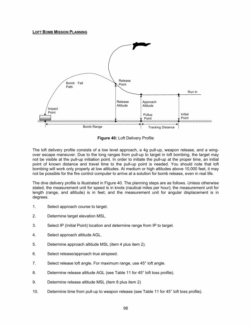
98
LOFT BOMB MISSION PLANNING
Figure 40: Loft Delivery Profile
The loft delivery profile consists of a low level approach, a 4g pull-up, weapon release, and a wing-over escape maneuver. Due to the long ranges from pull-up to target in loft bombing, the target maynot be visible at the pull-up initiation point. In order to initiate the pull-up at the proper time, an initialpoint of known distance and travel time to the pull-up point is needed. You should note that loftbombing will work only properly at low altitudes. At medium or high altitudes above 10,000 feet, it maynot be possible for the fire control computer to arrive at a solution for bomb release, even in real life.
The dive delivery profile is illustrated in Figure 40. The planning steps are as follows. Unless otherwisestated, the measurement unit for speed is in knots (nautical miles per hour); the measurement unit forlength (range, and altitude) is in feet; and the measurement unit for angular displacement is indegrees.
1. Select approach course to target.
2. Determine target elevation MSL.
3. Select IP (Initial Point) location and determine range from IP to target.
4. Select approach altitude AGL.
5. Determine approach altitude MSL (item 4 plus item 2).
6. Select release/approach true airspeed.
7. Select release loft angle. For maximum range, use 45° loft angle.
8. Determine release altitude AGL (see Table 11 for 45° loft toss profile).
9. Determine release altitude MSL (item 8 plus item 2)
10. Determine time from pull-up to weapon release (see Table 11 for 45° loft toss profile).
Bomb FallPath
ReleaseAltitude
ApproachAltitude
Bomb Range
ImpactPoint
ReleasePoint
PullupPoint
InitialPoint
Run In
Tracking Distance
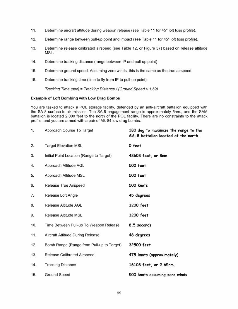
99
11. Determine aircraft attitude during weapon release (see Table 11 for 45° loft toss profile).
12. Determine range between pull-up point and impact (see Table 11 for 45° loft toss profile).
13. Determine release calibrated airspeed (see Table 12, or Figure 37) based on release altitudeMSL.
14. Determine tracking distance (range between IP and pull-up point)
15. Determine ground speed. Assuming zero winds, this is the same as the true airspeed.
16. Determine tracking time (time to fly from IP to pull-up point):
Tracking Time (sec) = Tracking Distance / (Ground Speed � 1.69)
Example of Loft Bombing with Low Drag Bombs
You are tasked to attack a POL storage facility, defended by an anti-aircraft battalion equipped withthe SA-8 surface-to-air missiles. The SA-8 engagement range is approximately 5nm., and the SAMbattalion is located 2,000 feet to the north of the POL facility. There are no constraints to the attackprofile, and you are armed with a pair of Mk-84 low drag bombs.
1. Approach Course To Target 180 deg to maximize the range to theSA-8 battalion located at the north.
2. Target Elevation MSL 0 feet
3. Initial Point Location (Range to Target) 48608 feet, or 8nm.
4. Approach Altitude AGL 500 feet
5. Approach Altitude MSL 500 feet
6. Release True Airspeed 500 knots
7. Release Loft Angle 45 degrees
8. Release Altitude AGL 3200 feet
9. Release Altitude MSL 3200 feet
10. Time Between Pull-up To Weapon Release 8.5 seconds
11. Aircraft Attitude During Release 48 degrees
12. Bomb Range (Range from Pull-up to Target) 32500 feet
13. Release Calibrated Airspeed 475 knots (approximately)
14. Tracking Distance 16108 feet, or 2.65nm.
15. Ground Speed 500 knots assuming zero winds
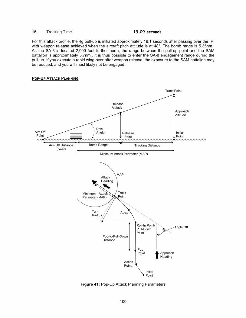
100
16. Tracking Time 19.09 seconds
For this attack profile, the 4g pull-up is initiated approximately 19.1 seconds after passing over the IP,with weapon release achieved when the aircraft pitch attitude is at 48°. The bomb range is 5.35nm..As the SA-8 is located 2,000 feet further north, the range between the pull-up point and the SAMbattalion is approximately 5.7nm.. It is thus possible to enter the SA-8 engagement range during thepull-up. If you execute a rapid wing-over after weapon release, the exposure to the SAM battalion maybe reduced, and you will most likely not be engaged.
POP-UP ATTACK PLANNING
Figure 41: Pop-Up Attack Planning Parameters
ReleaseAltitude
Aim OffPoint
ApproachAltitude
DiveAngle
Bomb RangeAim Off Distance(AOD)
ReleasePoint
InitialPoint
Track Point
Tracking Distance
Minimum Attack Perimeter (MAP)
Apex
Angle Off
TurnRadius
Minimum AttackPerimeter (MAP)
MAP
Roll-In Point/Pull-DownPoint
PopPoint
ActionPoint
TrackPoint
Pop-to-Pull-DownDistance
AttackHeading
ApproachHeading
InitialPoint
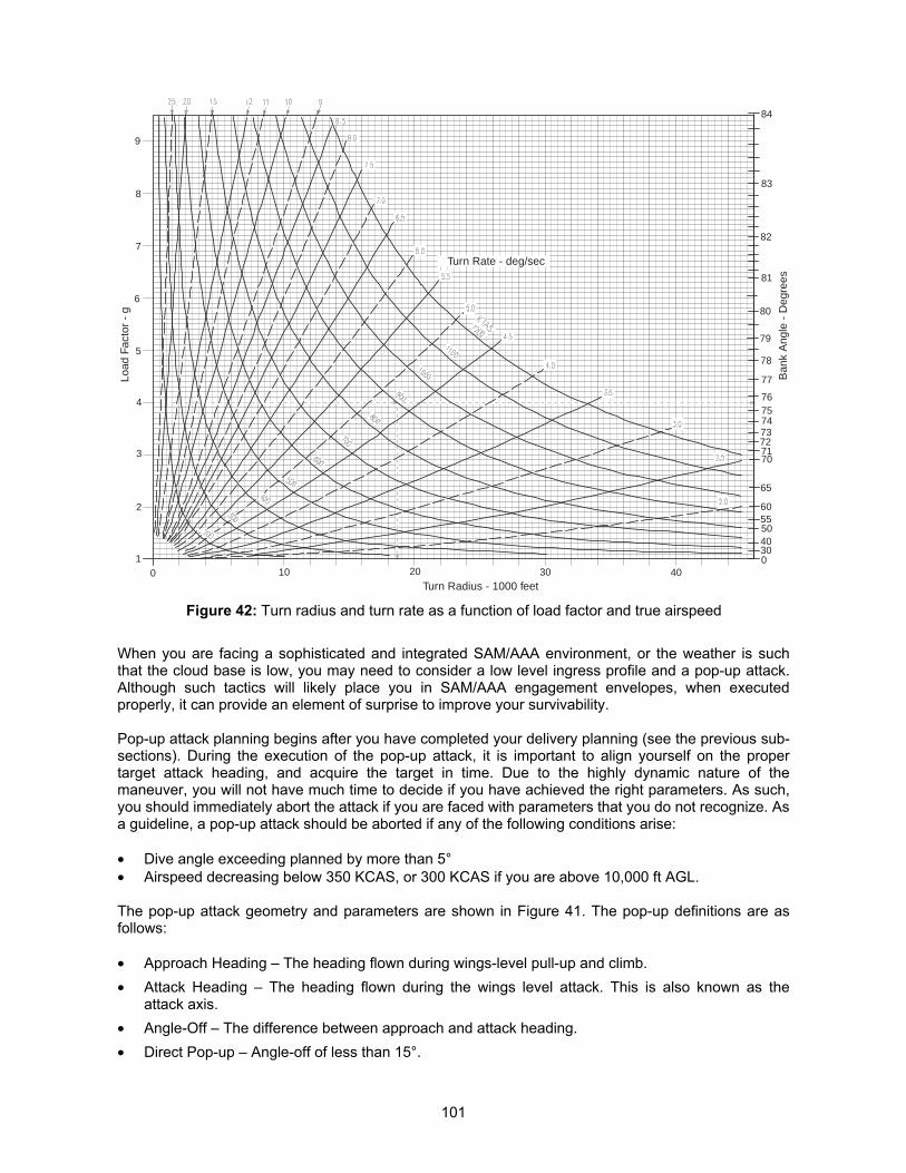
101
When you are facing a sophisticated and integrated SAM/AAA environment, or the weather is suchthat the cloud base is low, you may need to consider a low level ingress profile and a pop-up attack.Although such tactics will likely place you in SAM/AAA engagement envelopes, when executedproperly, it can provide an element of surprise to improve your survivability.
Pop-up attack planning begins after you have completed your delivery planning (see the previous sub-sections). During the execution of the pop-up attack, it is important to align yourself on the propertarget attack heading, and acquire the target in time. Due to the highly dynamic nature of themaneuver, you will not have much time to decide if you have achieved the right parameters. As such,you should immediately abort the attack if you are faced with parameters that you do not recognize. Asa guideline, a pop-up attack should be aborted if any of the following conditions arise:
� Dive angle exceeding planned by more than 5°� Airspeed decreasing below 350 KCAS, or 300 KCAS if you are above 10,000 ft AGL.
The pop-up attack geometry and parameters are shown in Figure 41. The pop-up definitions are asfollows:
� Approach Heading – The heading flown during wings-level pull-up and climb.� Attack Heading – The heading flown during the wings level attack. This is also known as the
attack axis.� Angle-Off – The difference between approach and attack heading.� Direct Pop-up – Angle-off of less than 15°.
Turn Rate - deg/sec
Load
Fac
tor
- g
Ban
k A
ngle
- D
egre
es
Turn Radius - 1000 feet0 30
1
2
402010
5
6
8
4
7
3
9
84
83
82
81
80
79
78
77
76757473727170
65
60555040300
Figure 42: Turn radius and turn rate as a function of load factor and true airspeed
102
� Offset Pop-up – Angle-off between 15° and 90°.� Indirect Pop-up – Angle-off greater than 90°.� Initial Point (IP) – The point where the final leg to the target commences. You should set this to a
unique and easily identifiable point, about 10 to 20nm. away from the target.� Action Point – The point from the target where you take an offset for an offset or indirect pop-up
attack. The action point is typically placed between the initial point and the pop point.� Pop Point – The point at which the pop-up attack is initiated. You will also initiate the climb at this
point.� Climb Angle – The angle of climb to be achieved during the initiation of pop-up.� Pop-to-Pull-Down Distance – Distance from the pop point to the pull-down point. This distance can
be computed.� Pull-Down Point (PDP) – The point at which you will transition from climbing to the diving portion
of the pop-up profile.� Dive Angle – The selected dive angle for weapon delivery.� Apex – The highest altitude reached during the pop-up delivery.� Minimum Attack Perimeter (MAP) – This is defined as the sum of the distance covered by target
tracking, and the bomb range.� Tracking – The portion of the weapon delivery profile dedicated to fine tuning the aircraft sighting
system with the target.� Tracking Time – The time required for target tracking. This is usually the time taken from roll out to
weapon release.� Horizontal Tracking Distance – The distance traveled across the ground during tracking time.� Vertical Tracking Distance – The vertical distance between tracking altitude and release altitude.
Pop-Up Maneuver
During a pop-up maneuver, the approach course is usually selected such that the angle-off varies withthe required climb angle to permit the pilot to acquire the target as soon as possible and maintainvisual contact until the completion of weapons delivery. For steeper climbs, the angle-off requirementswill increase.
The pop-up is executed over a pre-planned pop point, with a minimum airspeed of at least 450 KCAS.If you have a radar lock on the target, the locator line will give you a good indication of your angle off.At the initiation of the pop-up, select the desired power to minimize the loss of airspeed (either MIL orAB), and then execute a 3 – 4g wings-level pull-up to the desired climb angle. Depending on thethreats, they may detect you once you execute this maneuver, so it may be prudent to dispense chaffand flares, or to activate your ECM system. You should expect the target to become visible just slightlyoff to the planned roll-in direction. It is also important for you to maintain the planned climb angle andmonitor the altitude gained.
Once you have arrived at the pre-planned pull-down altitude, execute an unloaded roll in the directionof the target, and then perform a 3 – 5g pull-down to intercept the pre-planned dive angle. You shouldpractice the pull-down maneuver to determine the bank angle that you need to establish beforeexecuting the pull-down. At this point in time, you should be making slight course adjustments tocompensate for minor errors as well as unexpected winds. The apex altitude will usually be achievedhalfway through the pull-down maneuver.
103
Pop-Up Attack Options
There are several options available to you if you decide to execute a pop-up attack. These are alldependent on your ordnance load, and the threat that you are up against.
Low Angle High Drag Bombing (LAHD): This delivery profile is designed for delivery of highdrag bombs. The dive angle is usually between 10° to 15°. The approach is normally planned to bemade with an angle-off of 15° to 30°, at a speed of at least 450 KCAS. At the pop point, a 3 – 4g pull-up is initiated, to achieve a climb angle that is usually 5° more than the desired dive angle (forexample, if the desired dive angle is 10°, then the desired climb angle is about 15°). At the pre-planned pull-down point, the aircraft is rolled towards the target and the nose pulled down to roll out.The delivery profile will usually allow 3 – 5 seconds of tracking time, so the margins for error at verytight. If you are bombing with CCIP, you should plan to roll out with the target approximately one thirddown between the flight path marker and the CCIP pipper. The flight path marker should ideally beclose to if not exactly on the aim-off point.
Low Angle Low Drag Bombing (LALD): This delivery profile is designed for delivery of lowdrag bombs, and as such, safe escape and fuse arming requirements become important. The plannedangle-off is usually twice the climb angle (for example, if the desired climb angle is 30°, then the angle-off should be about 60°). The pop-up profile is the same as LAHD, but you should expect the apexaltitude to be much higher than LAHD. If you are bombing with CCIP, you should plan to roll out withthe target approximately halfway down between the flight path marker and the CCIP pipper.
High Altitude Dive Bombing (HADB): This delivery profile is designed for high angle (between 30°to 45° dive angle) delivery of low drag bombs in a high threat environment. If you are heavily loaded,this form of delivery may not be suitable as you may not be able to achieve the required parameters.The approach is normally made at a higher speed of 500 KCAS or more, with an action point placed 4to 5nm. away from the target. Once over the action point, a check turn of 20° to 30° is made to obtainthe required offset. You may also choose to take the offset directly at the IP if the IP is placed close tothe target. At the desired pop-point, a 4g pull-up is initiated to achieve the planned climb angle (usuallydive angle plus 15°) in full AB. You should try to acquire the target as soon as possible, and keep alook-out for the altitude as the pull-down altitude will be achieved very quickly. You will be almostinverted at the apex during the pull-down, so plan to give yourself at least 5 seconds of tracking timesince it will be tricky to achieve the appropriate aiming parameters during pull-down. For CCIPbombing, you should plan to roll out with the target approximately one third down between the flightpath marker and the CCIP pipper. The flight path marker should ideally be close to if not exactly on theaim-off point.
Visual Level Delivery (VLD): This delivery profile is usually flown using CCIP, and if the threatprecludes a steep dive, or the cloud base is too low and will hinder visual acquisition of the targetduring a steep dive. The dive angle is usually between 0° to 5°, and if a 5° dive profile is selected, a10° climb is initiated at the pull-up point. You should initiate the pull-down or bunt over just 500 feetshort of the apex altitude, and pay attention to the minimum release altitude for safe escape andground avoidance.
Deciding on Low or High Altitude Bombing
One of the most important considerations for the selection of the bombing profile is the altitude atwhich the bombing will be carried out. This is a tradeoff between bombing accuracy and threatavoidance. When you are low down in the weeds, the apparent target size will be larger. This makes iteasier for pipper placement if you are bombing in CCIP mode, and may be more accurate thanbombing in CCRP mode.
As bombing altitude decreases, bombing accuracy increases. Higher release altitudes introduce moreuncertainties into the bombing solution, such as temperature differences, varying wind gradients, etc.Bombinb accuracy at 5,000 feet is typically double that at 10,000 feet. For point targets, higher release
104
altitudes make it a lot more difficult to put an unguided bomb onto the target accurately, though thismay be less of a problem for area weapons such as CBUs.
The down side of low altitude bombing is the exposure of your strike aircraft to the enemy’s SHORADsystems. You will be taking greater risks of being hit by enemy AAA fire, or IR SAMs. For someordnance such as the BLU-107, you do not have much choice other than to use low altitude bombingprofile. While you can increase the bombing accuracy by using precision bombs such as LGBs, thesebombs are more expensive, and you will not have many of them. You will need to weigh the increasedaccuracy of low altitude bombing against the threats, and strike a balance that will allow you toachieve your mission objectives.
Pop-Up Planning
The planning procedures for a pop-up attack are as follows. Unless otherwise stated, themeasurement unit for speed is in knots (nautical miles per hour); the measurement unit for length(range, and altitude) is in feet; and the measurement unit for angular displacement is in degrees.
1. Select the delivery profile to use (LALD, LAHD, HADB, etc).
2. Determine the following bombing parameters:
a. Axis of attackb. Dive anglec. Release altituded. Bomb rangee. Aim-off distancef. Track point altitudeg. Tracking distanceh. Approach altitude
3. Determine the Minimum Attack Perimeter (MAP):
Minimum Attack Perimeter = Bomb Range + Horizontal Tracking Distance
4. Select the roll-in g, i.e. the load factor that you will want to attain during the roll-in to the target.
5. Determine the turn radius:
Turn Radius = (True Airspeed � 1.69)2 / (32.2 � Aircraft g)
where aircraft g is the g that you will see in the cockpit during the roll-in to the attack heading. You canalso estimate the turn radius using Figure 42.
6. Select the climb angle:
Climb Angle = Dive Angle + 5° (for 5° through 15° deliveries) Dive Angle + 10° (for 20° and higher angle deliveries)
7. Determine angle-off:
Angle-Off = Climb Angle � 2
8. Determine apex altitude:
Apex Altitude = Track Point Altitude + (Dive Angle � 50)
105
9. Determine pull-down altitude:
Pull-Down Altitude = Apex Altitude – (Climb Angle � 50) for a 3 to 3.5g roll-in = Apex Altitude – (Climb Angle � 37.5) for a 4.5 to 5g roll-in
10. Determine Pop-to-Pull-Down Distance:
Pop-to-Pull-Down Distance = (Apex Altitude � 60) / Climb Angle
11. Determine roll-in point (horizontal range to target, in feet), by constructing a scaled drawing ofthe various parameters, as shown in Figure 41. You can measure the range between the roll-in point to the target from the scaled drawing.
12. Determine the range between the pull-up point and the target, by constructing a scaleddrawing of the various parameters, as shown in Figure 41. You can measure the rangebetween the pop-up point to the target from the scaled drawing.
ATTACKING WITH LASER GUIDED BOMBS
Laser guided bombs (LGBs) such as the American GBU-10, GBU-12, GBU-24 and the Russian KAB-500L and KAB-1500L are designed for attacking point targets. Laser guided bomb delivery requiressome pre-flight planning to execute correctly, and requires the pilot to understand the limitations of thelaser target designator. This sub-section will discuss the delivery of LGBs from the perspective of theF-16 pilot using the LANTIRN targeting pod.
The LANTIRN targeting pod has a FLIR camera, and a laser target designator. The laser targetdesignator is correlated to the boresight of the FLIR camera, and the laser will fire at the aim point ofthe FLIR camera. The firing of the laser is automatic, and occurs at the point of LGB release. The laseris fired at the target, and the reflections form a cone that will seem to emanate from the target. Thediameter of the cone increases with increasing range away from the target. This is known as the “laserbasket.” The seeker mounted on the nose of every laser guided bomb will search for the laser spotand the “basket,” and will steer the bomb into the “basket.” As the bomb closes in on the target, thediameter of the “basket” decreases, and the guidance of the bomb becomes increasingly more precisedue to this. The bomb increases its frequency of control movements in order to keep the seekercentered on the “basket.” This continues until the point of impact, when the diameter of the “basket”shrinks to just a few feet.
The laser designator must remain firing throughout the flight of the LGB. This ensures that the target iscontinuously illuminated with the laser energy, so that the LGB seeker can guide. As long as theLANTIRN targeting pod remains locked onto the target, the laser will continue firing. If the lock isbroken for whatever reasons (either due to the pilot manually breaking the lock, or the pod reaching itsgimbal limits), the laser will cease firing, and the LGB will go ballistic.
You should be aware of the total flight time of the LGB for the delivery profile that you have chosen.The flight time may be obtained from Table 8 through Table 11. For the entire duration of the LGB’sflight, you will need to ensure that you do not break the targeting pod’s lock prematurely, and fly aprofile that will prevent the targeting pod reaching its gimbal limits. This limits the amount ofmaneuvering you can perform, and should you be engaged by enemy SAMs during the LGB delivery,the lock will most likely be broken by your maneuvering, and the LGB will miss. The increasedaccuracy comes with the price of increased vulnerability to enemy air defenses due to the predictableprofile that you will be flying.
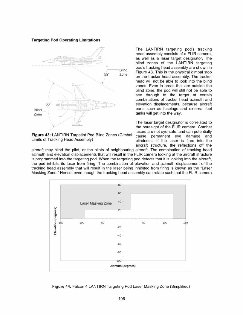
106
Targeting Pod Operating Limitations
The LANTIRN targeting pod’s trackinghead assembly consists of a FLIR camera,as well as a laser target designator. Theblind zones of the LANTIRN targetingpod’s tracking head assembly are shown inFigure 43. This is the physical gimbal stopon the tracker head assembly. The trackerhead will not be able to look into the blindzones. Even in areas that are outside theblind zone, the pod will still not be able tosee through to the target at certaincombinations of tracker head azimuth andelevation displacements, because aircraftparts such as fuselage and external fueltanks will get into the way.
The laser target designator is correlated tothe boresight of the FLIR camera. Combatlasers are not eye-safe, and can potentiallycause permanent eye damage andblindness. If the laser is fired into theaircraft structure, the reflections off the
aircraft may blind the pilot, or the pilots of neighbouring aircraft. The combination of tracking headazimuth and elevation displacements that will result in the FLIR camera looking at the aircraft structureis programmed into the targeting pod. When the targeting pod detects that it is looking into the aircraft,the pod inhibits its laser from firing. The combination of elevation and azimuth displacement of thetracking head assembly that will result in the laser being inhibited from firing is known as the “LaserMasking Zone.” Hence, even though the tracking head assembly can rotate such that the FLIR camera
30˚
60˚
BlindZone
BlindZone
Figure 43: LANTIRN Targetint Pod Blind Zones (GimbalLimits of Tracking Head Assembly)
-100
-80
-60
-40
-20
20
40
60
80
-150 -100 -50 50 100 150
Azimuth (degrees)
Ele
vati
on
(d
egre
es)
Laser Masking Zone
Figure 44: Falcon 4 LANTIRN Targeting Pod Laser Masking Zone (Simplified)
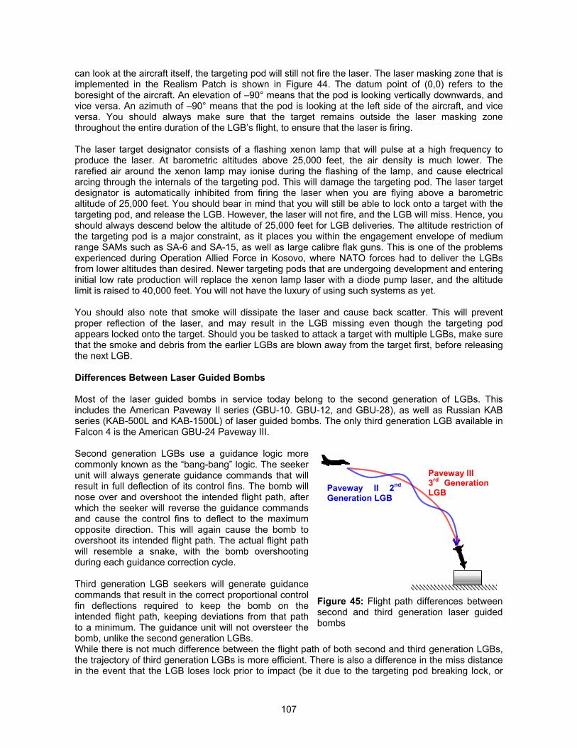
107
can look at the aircraft itself, the targeting pod will still not fire the laser. The laser masking zone that isimplemented in the Realism Patch is shown in Figure 44. The datum point of (0,0) refers to theboresight of the aircraft. An elevation of –90° means that the pod is looking vertically downwards, andvice versa. An azimuth of –90° means that the pod is looking at the left side of the aircraft, and viceversa. You should always make sure that the target remains outside the laser masking zonethroughout the entire duration of the LGB’s flight, to ensure that the laser is firing.
The laser target designator consists of a flashing xenon lamp that will pulse at a high frequency toproduce the laser. At barometric altitudes above 25,000 feet, the air density is much lower. Therarefied air around the xenon lamp may ionise during the flashing of the lamp, and cause electricalarcing through the internals of the targeting pod. This will damage the targeting pod. The laser targetdesignator is automatically inhibited from firing the laser when you are flying above a barometricaltitude of 25,000 feet. You should bear in mind that you will still be able to lock onto a target with thetargeting pod, and release the LGB. However, the laser will not fire, and the LGB will miss. Hence, youshould always descend below the altitude of 25,000 feet for LGB deliveries. The altitude restriction ofthe targeting pod is a major constraint, as it places you within the engagement envelope of mediumrange SAMs such as SA-6 and SA-15, as well as large calibre flak guns. This is one of the problemsexperienced during Operation Allied Force in Kosovo, where NATO forces had to deliver the LGBsfrom lower altitudes than desired. Newer targeting pods that are undergoing development and enteringinitial low rate production will replace the xenon lamp laser with a diode pump laser, and the altitudelimit is raised to 40,000 feet. You will not have the luxury of using such systems as yet.
You should also note that smoke will dissipate the laser and cause back scatter. This will preventproper reflection of the laser, and may result in the LGB missing even though the targeting podappears locked onto the target. Should you be tasked to attack a target with multiple LGBs, make surethat the smoke and debris from the earlier LGBs are blown away from the target first, before releasingthe next LGB.
Differences Between Laser Guided Bombs
Most of the laser guided bombs in service today belong to the second generation of LGBs. Thisincludes the American Paveway II series (GBU-10. GBU-12, and GBU-28), as well as Russian KABseries (KAB-500L and KAB-1500L) of laser guided bombs. The only third generation LGB available inFalcon 4 is the American GBU-24 Paveway III.
Second generation LGBs use a guidance logic morecommonly known as the “bang-bang” logic. The seekerunit will always generate guidance commands that willresult in full deflection of its control fins. The bomb willnose over and overshoot the intended flight path, afterwhich the seeker will reverse the guidance commandsand cause the control fins to deflect to the maximumopposite direction. This will again cause the bomb toovershoot its intended flight path. The actual flight pathwill resemble a snake, with the bomb overshootingduring each guidance correction cycle.
Third generation LGB seekers will generate guidancecommands that result in the correct proportional controlfin deflections required to keep the bomb on theintended flight path, keeping deviations from that pathto a minimum. The guidance unit will not oversteer thebomb, unlike the second generation LGBs.While there is not much difference between the flight path of both second and third generation LGBs,the trajectory of third generation LGBs is more efficient. There is also a difference in the miss distancein the event that the LGB loses lock prior to impact (be it due to the targeting pod breaking lock, or
Figure 45: Flight path differences betweensecond and third generation laser guidedbombs
Paveway III3rd GenerationLGBPaveway II 2nd
Generation LGB
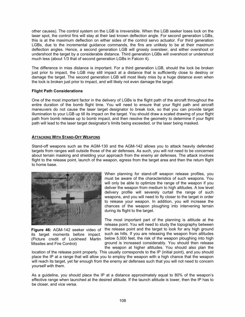
108
other causes). The control system on the LGB is irreversible. When the LGB seeker loses lock on thelaser spot, the control fins will stay at their last known deflection angle. For second generation LGBs,this is at the maximum deflection on either sides of the control servo actuator. For third generationLGBs, due to the incremental guidance commands, the fins are unlikely to be at their maximumdeflection angles. Hence, a second generation LGB will grossly oversteer, and either overshoot orundershoot the target by a considerable distance. Third generation LGBs will overshoot or undershootmuch less (about 1/3 that of second generation LGBs in Falcon 4).
The difference in miss distance is important. For a third generation LGB, should the lock be brokenjust prior to impact, the LGB may still impact at a distance that is sufficiently close to destroy ordamage the target. The second generation LGB will most likely miss by a huge distance even whenthe lock is broken just prior to impact, and will likely not even damage the target.
Flight Path Considerations
One of the most important factor in the delivery of LGBs is the flight path of the aircraft throughout theentire duration of the bomb flight time. You will need to ensure that your flight path and aircraftmaneuvers do not cause the laser target designator to break lock, so that you can provide targetillumination to your LGB up till its impact on the target. You should draw a scaled drawing of your flightpath from bomb release up to bomb impact, and then resolve the geometry to determine if your flightpath will lead to the laser target designator’s limits being exceeded, or the laser being masked.
ATTACKING WITH STAND-OFF WEAPONS
Stand-off weapons such as the AGM-130 and the AGM-142 allows you to attack heavily defendedtargets from ranges well outside those of the air defenses. As such, you will not need to be concernedabout terrain masking and shielding your approach from the enemy air defenses. The attack involvesflight to the release point, launch of the weapon, egress from the target area and then the return flightto home base.
When planning for stand-off weapon release profiles, youmust be aware of the characteristics of such weapons. Youwill only be able to optimize the range of the weapon if youdeliver the weapon from medium to high altitudes. A low leveldelivery profile will severely curtail the range of suchweapons, and you will need to fly closer to the target in orderto release your weapon. In addition, you will increase thechances of the weapon ploughing into intervening terrainduring its flight to the target.
The most important part of the planning is altitude at therelease point. You will need to study the topography betweenthe release point and the target to look for any high groundsuch as hills. If you are releasing the weapon from altitudesbelow 5,000 feet, the risk of the weapon ploughing into highground is increased considerably. You should then releasethe weapon at higher altitudes. You should also plan the
location of the release point properly. This usually corresponds to the IP (initial point), and you shouldplace the IP at a range that will allow you to employ the weapon with a high chance that the weaponwill reach its target, yet far enough from the enemy air defenses such that you will not need to concernyourself with them.
As a guideline, you should place the IP at a distance approximately equal to 80% of the weapon’seffective range when launched at the desired altitude. If the launch altitude is lower, then the IP has tobe closer, and vice versa.
Figure 46: AGM-142 seeker video ofits target moments before impact.(Picture credit of Lockheed MartinMissiles and Fire Control)
109
EGRESS AND ABORT PLAN
Once you have delivered your weapons, it is time to get away from the target and its air defenses. Theegress plan must be a simple as possible, and the priorities for egress are as follows:
1. Leave the target area2. Get away from threats3. Regain formation mutual support
The egress route should be planned such that it is relatively free of enemy defenses. It is possible forthe formation to split up during the attack, due to the need to de-conflict the various flight members,and possibly due to threat reactions. As such, there is a possibility of flight members losing mutualsupport and needing to provide their own threat lookout. Selecting an egress route that is relativelyfree of threats will minimize the possibility of any unsupported flight member being shot down. This willalso give an opportunity to initiate a re-attack, if necessary. If the attack involves lofting of weapons,you will need to make sure that you de-conflict your flight path with that of the lofted weapons, ascollision with your own weapons will not do you any good.
For two-ship egress, you should ideally egress in line abreast formation, to provide mutual support.Four ship egress should maintain at least element integrity, with visual mutual support. If the egressroute is over mountainous terrain, then the terrain provides for ample opportunity to mask your flightfrom enemy defenses, and a trail formation egress may be more suitable.
You should also consider an abort plan for the attack. In the event that the target is too heavilydefended, or the weather is too poor, it may be more prudent to conserve your forces and attack itanother day, when the conditions are more favorable. The possible reasons for aborting an attack areas follows:
1. Poor weather, such that the pre-planned delivery profile (and any alternate deliveryprofiles) cannot be executed properly without undue risks.
2. Target acquisition problems.3. Unacceptable target defenses.4. Low fuel.5. Battle damage
THREAT REACTION
You will need to pre-plan and brief the reactions to any expected threats that may become activeduring ingress and egress to the target area. When you are on an air-to-ground mission, even if youdetect any enemy aircraft, you should exercise discipline to stay on your mission and not chase afterthe enemy, unless they are a threat to you. This applies whether you are ingressing to the target, oregressing after delivering your weapons. Getting yourself shot down due to your eagerness to getsome air-to-air kills will be a bad way to start and end a bombing mission. In general, you should drawup a listing of criteria, under which you will consider engaging the enemy airplanes:
1. Any enemy airplane faster than 300 KCAS and at high aspect inside of 40nm. fromyou.
2. Any low aspect target between 10 to 20nm. out within 30° of your nose.3. Any low aspect target inside 10nm..4. Any enemy airplane called by AWACS or visually spotted inside 5nm..
In summary, do not mess with any enemy fighter who is not messing with you while you are on an air-to-ground mission. Concentrate on the mission, and you will stay out of trouble if you do not go lookingfor trouble.
110
THUNDER AND LIGHTNINGWaging the Air Campaign in the Realism PatchBy “Hoola”
INTRODUCTION
We have been discussing tactical matters so far. While it is important that you survive your combatmissions, and get home alive, you need to understand a little about the air war at the strategic level.Many battles can be won, but a war can still be lost anyway. The Air Tasking Order (ATO) engine inFalcon 4 is not very smart, and you will need to assist it in the selection of targets, so that the air war isalso taken care of at the strategic level. This section is written to give a brief introduction of planningan air campaign, and is tailored to the Falcon 4 environment. I do not claim to know the tenets of an airwar: that is best left to professionals. One of the best books available on the art of waging an aircampaign is “The Air Campaign,” authored by John A Warden III (revised edition published in 1998,ISBN 1583481001). This section is also useful for TE designers who design complex tacticalengagements. You can systematically plan your air campaign to destroy piece-by-piece the enemy’sair defenses.
DISMANTLING THE INTEGRATED AIR DEFENSE SYSTEM
One of the key features in the Falcon 4 Realism Patch is the presence of an integrated air defensesystem (IADS) and network. With such a network, the enemy is capable of detecting the presence ofyour forces, and vector interceptors or command SAM batteries to engage them. From a forceprotection point of view, it is important for you to reduce the enemy’s integrated air defense networkinto various isolated components. You will need to divide your enemy so that you can rule over him.You should make sure that you understand how the IADS environment function in the Realism Patch.A detailed description of the IADS implementation in the Realism Patch can be found in the sectiontitled “Ground Control Intercept, Integrated Air Defense System, And AWACS in Falcon 4” in theDesigner’s Notes.
The Opening Move
The functional state of the enemy IADS will determine the tactics that you can use. At the beginning ofthe campaign, the enemy air defenses will be largely intact. Your strike aircraft will be forced to run thegauntlet of enemy interceptors and SAM/AAA batteries. Since the enemy’s GCI/EW radar network isfunctional, you may want to consider using low level NOE (Nap of the Earth) tactics during the openingmoments of the air war. Such tactics allow your strike packages to enter the enemy’s airspace, whileminimizing the chances of the enemy detecting them.
However, this will expose your strike packages to a considerable amount of low level SHORADthreats. You should target the enemy’s EW/GCI radar network early in the air campaign, so that youcan create gaps in the enemy’s radar coverage. While your ground forces may be in need of airsupport, you need to bear in mind that the presence of enemy interceptors and combat air patrols willseriously disrupt your ability to conduct BAI/CAS missions effectively. You should plan to destroy theenemy’s GCI ability early in the campaign, as well as destroy enemy airbases and disrupt his ability toconduct air operations against you.
The emphasis in the early part of an air campaign should be to establish air dominance over thebattlefield. This means that you should actively seek out and destroy airbases and EW/GCI radars.You should also actively sweep the skies for enemy interceptors and combat air patrols, as these willpresent problems when you need to shift the emphasis of the air war towards ground support.Destruction of airbases will ground the enemy’s interceptors, and the two pronged approach ofdestroying enemy fighters that are flying, while preventing others from taking off, is the most effectiveway of ensuring that your own strike packages remain unmolested by enemy fighters.
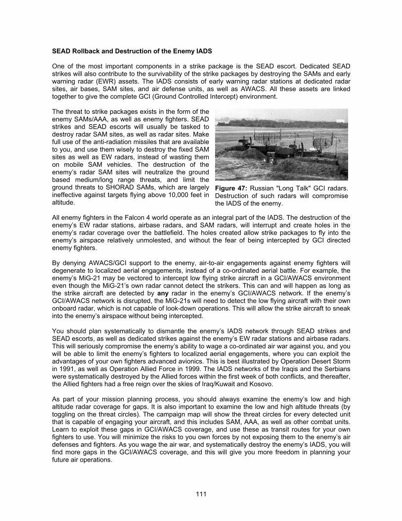
111
SEAD Rollback and Destruction of the Enemy IADS
One of the most important components in a strike package is the SEAD escort. Dedicated SEADstrikes will also contribute to the survivability of the strike packages by destroying the SAMs and earlywarning radar (EWR) assets. The IADS consists of early warning radar stations at dedicated radarsites, air bases, SAM sites, and air defense units, as well as AWACS. All these assets are linkedtogether to give the complete GCI (Ground Controlled Intercept) environment.
The threat to strike packages exists in the form of theenemy SAMs/AAA, as well as enemy fighters. SEADstrikes and SEAD escorts will usually be tasked todestroy radar SAM sites, as well as radar sites. Makefull use of the anti-radiation missiles that are availableto you, and use them wisely to destroy the fixed SAMsites as well as EW radars, instead of wasting themon mobile SAM vehicles. The destruction of theenemy’s radar SAM sites will neutralize the groundbased medium/long range threats, and limit theground threats to SHORAD SAMs, which are largelyineffective against targets flying above 10,000 feet inaltitude.
All enemy fighters in the Falcon 4 world operate as an integral part of the IADS. The destruction of theenemy’s EW radar stations, airbase radars, and SAM radars, will interrupt and create holes in theenemy’s radar coverage over the battlefield. The holes created allow strike packages to fly into theenemy’s airspace relatively unmolested, and without the fear of being intercepted by GCI directedenemy fighters.
By denying AWACS/GCI support to the enemy, air-to-air engagements against enemy fighters willdegenerate to localized aerial engagements, instead of a co-ordinated aerial battle. For example, theenemy’s MiG-21 may be vectored to intercept low flying strike aircraft in a GCI/AWACS environmenteven though the MiG-21’s own radar cannot detect the strikers. This can and will happen as long asthe strike aircraft are detected by any radar in the enemy’s GCI/AWACS network. If the enemy’sGCI/AWACS network is disrupted, the MiG-21s will need to detect the low flying aircraft with their ownonboard radar, which is not capable of look-down operations. This will allow the strike aircraft to sneakinto the enemy’s airspace without being intercepted.
You should plan systematically to dismantle the enemy’s IADS network through SEAD strikes andSEAD escorts, as well as dedicated strikes against the enemy’s EW radar stations and airbase radars.This will seriously compromise the enemy’s ability to wage a co-ordinated air war against you, and youwill be able to limit the enemy’s fighters to localized aerial engagements, where you can exploit theadvantages of your own fighters advanced avionics. This is best illustrated by Operation Desert Stormin 1991, as well as Operation Allied Force in 1999. The IADS networks of the Iraqis and the Serbianswere systematically destroyed by the Allied forces within the first week of both conflicts, and thereafter,the Allied fighters had a free reign over the skies of Iraq/Kuwait and Kosovo.
As part of your mission planning process, you should always examine the enemy’s low and highaltitude radar coverage for gaps. It is also important to examine the low and high altitude threats (bytoggling on the threat circles). The campaign map will show the threat circles for every detected unitthat is capable of engaging your aircraft, and this includes SAM, AAA, as well as other combat units.Learn to exploit these gaps in GCI/AWACS coverage, and use these as transit routes for your ownfighters to use. You will minimize the risks to you own forces by not exposing them to the enemy’s airdefenses and fighters. As you wage the air war, and systematically destroy the enemy’s IADS, you willfind more gaps in the GCI/AWACS coverage, and this will give you more freedom in planning yourfuture air operations.
Figure 47: Russian "Long Talk" GCI radars.Destruction of such radars will compromisethe IADS of the enemy.
112
You should also make full use of any stand-off jammers that may be at your disposal. Stand-offjammers are invaluable in providing protection to your strike packages, when the SAM and fighterthreats have not already been neutralized. SOJs are “soft kill” options available to you as part of aSEAD rollback campaign. The most effective SEAD campaign will combine the “soft kill” options suchas SOJs, and “hard kill” options such as SEAD strikers equipped with anti-radiation missiles.
One important factor that you should know about an IADS is the level of integration between all theEW/GCI and SAM radars. This is a key feature of all modern IADS (and is modeled in the RealismPatch). The radar coverages of EW/GCI radars and SAM radars overlap. If the radar coverage of aradar is covered by another radar in the IADS network, the radar will shut down and rely on otherradars in the IADS network for detection and target information. These SAM sites are still capable ofengaging enemy aircraft. When SAM and EW/GCI radars have been destroyed, the “dormant” radarswill become active to fill in the gaps in the radar coverage. You will thus need to maintain the pressurefor at least the first few days of the war, to ensure that you have crippled the enemy IADS structure.
You can influence the ATO generator by changing the campaign priority sliders (for a detaileddescription of the functions of the sliders, please refer to the section titled “Beyond Winning Battles:Winning The War”). Your primary target types should be aircraft, air fields, air defenses, radar, andCCC facilities. You should also concentrate on OCA, SEAD, and interdiction missions. This will ensurethat the campaign engine allocates a greater proportion of missions dedicated to destroy the enemyIADS.
Low and /Medium High Altitude Tactics
As you begin to gain air superiority, you should move away from low level tactics, and begin to shiftyour operations to medium level altitudes. Low level tactics are extremely dangerous, as the low levelSHORAD threats cannot be eradicated effectively in the SEAD rollback. Every ground troop will beable to shoot at your strike airplanes, and the SHORAD threat cannot be dismissed lightly.
As you gain air dominance and destroy the SAM and fighter threats, you will have a free reign over theskies. Medium level tactics (above 10,000 to 15,000 feet altitude) will put your own strike aircraft out ofthe range of most if not all the MANPADS and SHORAD threats. The SHORAD threat accounts formore combat loss during Operation Desert Storm, as compared to enemy SAM/AAA batteries andfighters.
One of the disadvantages of adopting medium level tactics is the difficulty in identifying targets, andthe reduced accuracy when delivering dumb bombs. You will have to trade off between forceprotection, and targeting accuracy. If the SHORAD threat is dense, then it may not be worth pursuingthe higher targeting accuracy at the expense of your own pilots.
Target Selection
Target selection is an extremely important aspect of an air campaign. In the Falcon 4 world, you havecontrol over the targets for your strike packages. You should ensure that you maximize the destructioncapacity of your strike packages by ensuring that they do not all target the same objective (such as thecontrol tower). You should also assign targets to individual strike aircraft to ensure that the keyobjectives are destroyed (such as runways, control towers, radar sites, etc).
SHIFTING THE EMPHASIS
However many EW/GCI radars, SAM sites, and enemy fighters you destroy, this will never help to winthe war. Wars are won and lost on the ground. The destruction of the enemy’s IADS will serve toprovide a conducive and less hostile environment for you to conduct BAI/CAS operations in support ofthe ground combat units. The political aspect of an air campaign is not modeled in Falcon 4. As such,it will be rather pointless for you to target political and infrastructure targets.
113
Airlift missions are generated in Falcon 4 to provide supplies needed to fuel the war effort. Eachsuccessfully airlift mission gives the team a total of 20 supply points, 2 fuel points, and 2 replacementpoints. Factories and refineries produce supplies and fuel to sustain the war effort. The productioncapacity of each factory and refinery varies, and decreases as they are damaged 3. The factories andrefineries require power supply to function, and the destruction of power and nuclear plants willprevent them from functioning. Destruction of the enemy’s war production and logistics infrastructurewill hamper his ability to wage war against you.
You should provide adequate air support for ground units that are involved in combat with enemyunits. Your fighter assets are essentially flying bomb trucks once you have achieved air superiority.You should also dedicate a portion of your fighters for interdiction missions, i.e. to destroy enemyground units that have yet to enter the war (such as strategic reserves).
You should strike a balance between apportioning part of your air assets to strategic strikes, and partof your assets to support the ground forces. It is useless to attack only strategic targets, as the enemyground units may be over-running your frontline. Similarly, it is a futile exercise to attack the groundunits when their supply lines are intact. As you move into this phase of the air war, you should shiftyour emphasis towards targeting infantry, armor, artillery, and support units, as well as infrastructure,logistics, war production, and CCC facilities. You should also adjust your mission priorities, so that thecampaign engine will generate a greater proportion of interdiction, CAS, and strategic strikes.
Ordnance Allocation and Conservation
One of the most important functions for a war planner is ordnance allocation and conservation.Weapons will run out during a war, and effective usage management will ensure that you do not runout of weapons before the next resupply.
You have a wide variety of different weapons at your disposal. Each of these weapons has beenoptimized for a different target. You should ensure that your fighters are loaded with the appropriateweapon for its mission. You should also know the amount of weapons available to you, and monitortheir usage. For example, if you do not anticipate any serious air threats, you should conserveweapons such as AIM-120 and AIM-9M, and equip your fighters with the less capable AIM-9P instead.You will thus save the more capable air-to-air missiles for a time when the air-to-air threat is moreominous.
You should also conserve your stocks of precision guided weapons. While laser guided bombs andMavericks are highly accurate, you will not have many of them. You should learn to equip your strikepackages with various weapon fits, for example, equipping the lead with Mavericks and the wingmanwith cluster bombs. This gives you more flexibility in target selection, especially on BAI/CAS missions.Effective ordnance management will help prevent your squadrons from running out of certain weaponswhen you need them most.
Force Protection
While you are waging war on the enemy’s IADS, you will need to protect your own assets. You dependon your GCI/EW radar sites, SAM battalions, and AWACS, to provide you with the air picture. The airpicture is only as complete as your assets are, and as your own IADS assets are destroyed, you willfind that the air picture becomes less complete, and uncertainty increases.
You should understand the threat posed by your enemy, such as his ability to conduct SEADoperations, etc. Place your CAPs and interceptors at locations that will allow them to intercept enemyairplanes flying at low altitudes, and make sure that the HAVCAPs and BARCAPs are positioned 3 The production capacity of factories and refineries are given in the objective data file,FALCON4.OCD. The data field is labeled “Data”, and this corresponds to the number of supply or fuelpoints that the facility is capable of producing over a 24 hour period, if it is 100% functional.
114
sufficiently forward of your IADS assets (such as EW/GCI radars and AWACS), so that the enemycannot engage these assets from stand-off ranges. For example, the AS-17 anti-radiation missile hasa typical range of 50nm.. You should place your CAP flights at least 50 to 60nm. ahead of yourEW/GCI radars and SAM batteries, so that the enemy fighters equipped with this missile will beintercepted before they can launch their missiles.
Your fighters are most effective when they function as part of your IADS. By placing your interceptorsand CAPs where you have radar coverage, you will give them a better change of success as yourIADS assets can vector them to the threats. You should also consider placing some fighters to plugthe blind zones of your EW/GCI/AWACS radar network.
CONCLUSION
Adjustments of the campaign priority sliders will allow you to exert an influence over the war. Youshould adjust the target and mission priorities of each squadron individually, as the campaignprogresses. It is a good idea to save the campaign periodically, and then reenter the campaign undera different squadron to adjust the priorities. Although this is a tedious process, it allows you toinfluence the ATO engine and tailor your air campaign depending on how the war progresses. Athorough understanding of functions of the campaign sliders is essential for you to use themeffectively.
The effectiveness of any air war is not just dependent on good piloting skills. Effective management ofyour assets will multiply the effective combat power. A systematic way of waging the air war will helpyou achieve your war objective in a progressive and systematic fashion, and increase the optionsavailable to you for conducting air operations. Effective logistics management will also ensure that youare able to sustain the tempo of your own operations, and bring pressure to bear on your enemyaround the clock. You will be surprised at the results if you take an active interest in management ofthe air war in the Realism Patch.
115
CHAPTER 3: TACTICS AND WEAPON EMPLOYMENT
INTRODUCTION
Now that we have covered the basics of missionplanning, it is time for some action. All the planning andconsiderations will go to waste if the tactics do not matchup. We will not cover the basics such as intercept tacticsand basic fighter maneuvers. These are best describedin the Falcon 4 user’s manual, and other books dedicatedto such topics. The tactics covered here are limited tomissile employment, missile evasion, and sensoremployment.
The section titled “Conquering The Virtual Skies” will giveyou a quick overview of the changes made in theRealism Patch, and some of the considerations that wehave taken into account. It you are impatient and do notwant to read about the details, this is the section to read to familiarize yourself with the new air warenvironment compared to the stock Falcon 4 1.08US. We will then plough into the nitty gritty of tacticsand weapon employment.
Sensor management is the most important factor in maintaining your situational awareness. Youronboard sensors include your own Mark I eyeball, the radar, and the RWR. All these sensors willsupply information to you, which you will need to interpret and understand, and form your own mentalpicture on what is going on around you. We will discuss this in detail in the section titled “ManagingElectrons.” This is where you will learn the differences between each radar mode, and what the RWRis trying to tell you. You will also learn about the intricacies of using jammers, and emission control(EMCON) discipline. We have also compiled a number of frequently asked questions, and providedthe answers to these common questions.
We will then discuss in detail all the air-to-airweapons available in Falcon 4. You will bebriefed on the employment considerations,and the tactics to evade and counter them.Knowing your weapon’s characteristics willenable you to employ them more effectively,and knowing the weapon characteristics ofyour enemy will allow you to counter themmore effectively. Read all that you need toknow about air-to-air weapons in the sectiontitled “The Pointed End Of the Sword.” Incase you do not have the patience to wadethrough the detailed briefing, we have alsocompiled a number of frequently askedquestions at the end of this section.
Lastly, we will discuss how not to play nicewith the enemy in “Chivalry Is Dead,” and how to manage your AI wingman in “Mothering The AI.” Wewill discuss in some detail the tactical considerations of fighting F-pole and A-pole combat, and infra-red countermeasure tactics as well as fighting off-boresight missiles. If you want to survive, you willneed to be able to destroy the enemy before they destroy you. You will also learn the various tricks ofhelping your AI wingman survive their missions.
Read on, have fun, and we wish you clear skies and tail winds!
Figure 48: Kitting up and getting readyfor the flight. (Picture credit of USAF)
Figure 49: F-16C from the 36th FS taking off fromOsan AB, South Korea. (Picture credit of USAF)
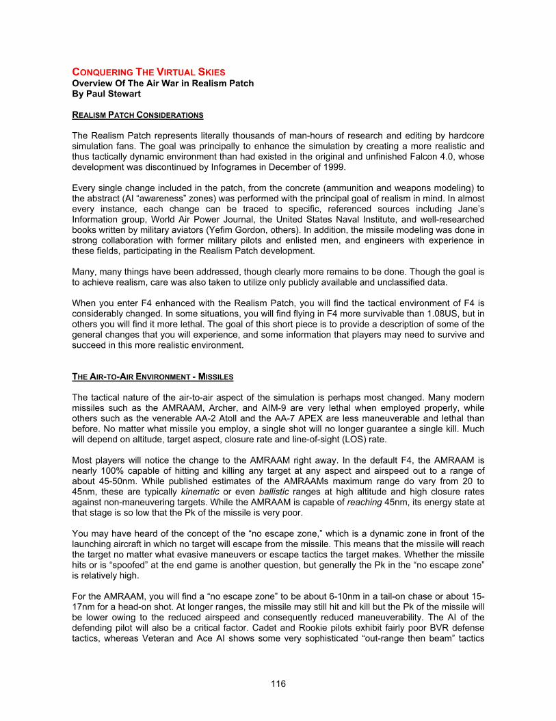
116
CONQUERING THE VIRTUAL SKIESOverview Of The Air War in Realism PatchBy Paul Stewart
REALISM PATCH CONSIDERATIONS
The Realism Patch represents literally thousands of man-hours of research and editing by hardcoresimulation fans. The goal was principally to enhance the simulation by creating a more realistic andthus tactically dynamic environment than had existed in the original and unfinished Falcon 4.0, whosedevelopment was discontinued by Infogrames in December of 1999.
Every single change included in the patch, from the concrete (ammunition and weapons modeling) tothe abstract (AI “awareness” zones) was performed with the principal goal of realism in mind. In almostevery instance, each change can be traced to specific, referenced sources including Jane’sInformation group, World Air Power Journal, the United States Naval Institute, and well-researchedbooks written by military aviators (Yefim Gordon, others). In addition, the missile modeling was done instrong collaboration with former military pilots and enlisted men, and engineers with experience inthese fields, participating in the Realism Patch development.
Many, many things have been addressed, though clearly more remains to be done. Though the goal isto achieve realism, care was also taken to utilize only publicly available and unclassified data.
When you enter F4 enhanced with the Realism Patch, you will find the tactical environment of F4 isconsiderably changed. In some situations, you will find flying in F4 more survivable than 1.08US, but inothers you will find it more lethal. The goal of this short piece is to provide a description of some of thegeneral changes that you will experience, and some information that players may need to survive andsucceed in this more realistic environment.
THE AIR-TO-AIR ENVIRONMENT - MISSILES
The tactical nature of the air-to-air aspect of the simulation is perhaps most changed. Many modernmissiles such as the AMRAAM, Archer, and AIM-9 are very lethal when employed properly, whileothers such as the venerable AA-2 Atoll and the AA-7 APEX are less maneuverable and lethal thanbefore. No matter what missile you employ, a single shot will no longer guarantee a single kill. Muchwill depend on altitude, target aspect, closure rate and line-of-sight (LOS) rate.
Most players will notice the change to the AMRAAM right away. In the default F4, the AMRAAM isnearly 100% capable of hitting and killing any target at any aspect and airspeed out to a range ofabout 45-50nm. While published estimates of the AMRAAMs maximum range do vary from 20 to45nm, these are typically kinematic or even ballistic ranges at high altitude and high closure ratesagainst non-maneuvering targets. While the AMRAAM is capable of reaching 45nm, its energy state atthat stage is so low that the Pk of the missile is very poor.
You may have heard of the concept of the “no escape zone,” which is a dynamic zone in front of thelaunching aircraft in which no target will escape from the missile. This means that the missile will reachthe target no matter what evasive maneuvers or escape tactics the target makes. Whether the missilehits or is “spoofed” at the end game is another question, but generally the Pk in the “no escape zone”is relatively high.
For the AMRAAM, you will find a “no escape zone” to be about 6-10nm in a tail-on chase or about 15-17nm for a head-on shot. At longer ranges, the missile may still hit and kill but the Pk of the missile willbe lower owing to the reduced airspeed and consequently reduced maneuverability. The AI of thedefending pilot will also be a critical factor. Cadet and Rookie pilots exhibit fairly poor BVR defensetactics, whereas Veteran and Ace AI shows some very sophisticated “out-range then beam” tactics
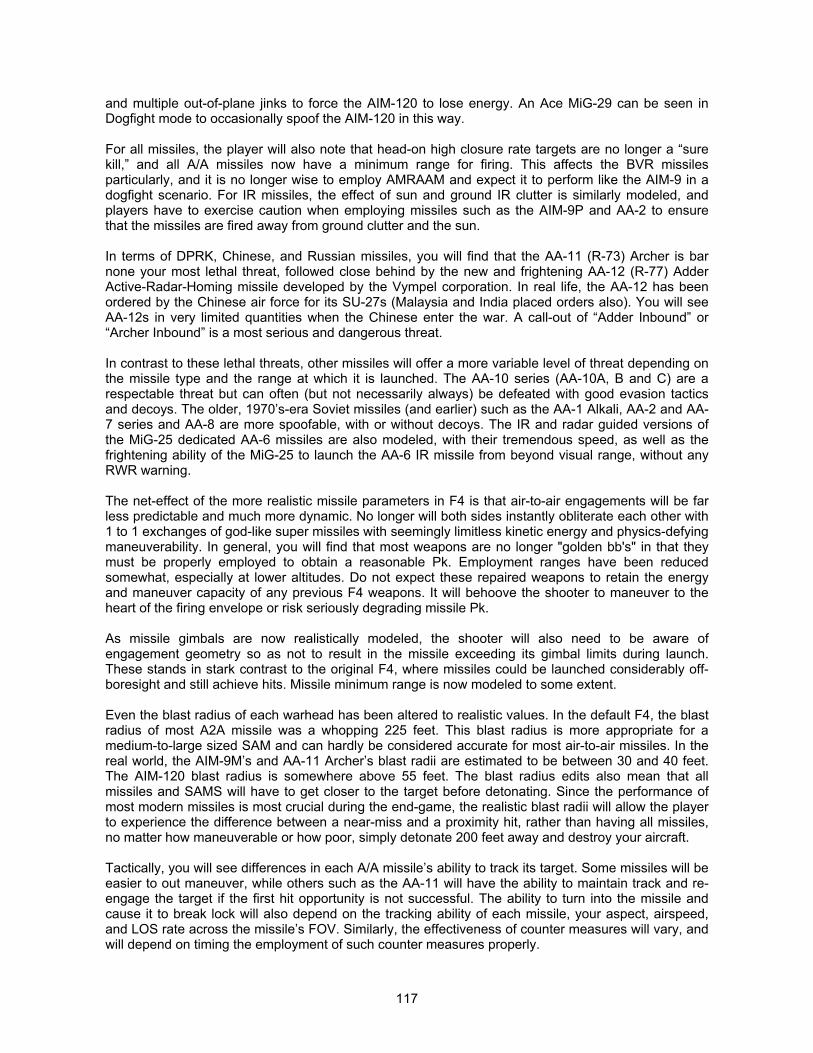
117
and multiple out-of-plane jinks to force the AIM-120 to lose energy. An Ace MiG-29 can be seen inDogfight mode to occasionally spoof the AIM-120 in this way.
For all missiles, the player will also note that head-on high closure rate targets are no longer a “surekill,” and all A/A missiles now have a minimum range for firing. This affects the BVR missilesparticularly, and it is no longer wise to employ AMRAAM and expect it to perform like the AIM-9 in adogfight scenario. For IR missiles, the effect of sun and ground IR clutter is similarly modeled, andplayers have to exercise caution when employing missiles such as the AIM-9P and AA-2 to ensurethat the missiles are fired away from ground clutter and the sun.
In terms of DPRK, Chinese, and Russian missiles, you will find that the AA-11 (R-73) Archer is barnone your most lethal threat, followed close behind by the new and frightening AA-12 (R-77) AdderActive-Radar-Homing missile developed by the Vympel corporation. In real life, the AA-12 has beenordered by the Chinese air force for its SU-27s (Malaysia and India placed orders also). You will seeAA-12s in very limited quantities when the Chinese enter the war. A call-out of “Adder Inbound” or“Archer Inbound” is a most serious and dangerous threat.
In contrast to these lethal threats, other missiles will offer a more variable level of threat depending onthe missile type and the range at which it is launched. The AA-10 series (AA-10A, B and C) are arespectable threat but can often (but not necessarily always) be defeated with good evasion tacticsand decoys. The older, 1970’s-era Soviet missiles (and earlier) such as the AA-1 Alkali, AA-2 and AA-7 series and AA-8 are more spoofable, with or without decoys. The IR and radar guided versions ofthe MiG-25 dedicated AA-6 missiles are also modeled, with their tremendous speed, as well as thefrightening ability of the MiG-25 to launch the AA-6 IR missile from beyond visual range, without anyRWR warning.
The net-effect of the more realistic missile parameters in F4 is that air-to-air engagements will be farless predictable and much more dynamic. No longer will both sides instantly obliterate each other with1 to 1 exchanges of god-like super missiles with seemingly limitless kinetic energy and physics-defyingmaneuverability. In general, you will find that most weapons are no longer "golden bb's" in that theymust be properly employed to obtain a reasonable Pk. Employment ranges have been reducedsomewhat, especially at lower altitudes. Do not expect these repaired weapons to retain the energyand maneuver capacity of any previous F4 weapons. It will behoove the shooter to maneuver to theheart of the firing envelope or risk seriously degrading missile Pk.
As missile gimbals are now realistically modeled, the shooter will also need to be aware ofengagement geometry so as not to result in the missile exceeding its gimbal limits during launch.These stands in stark contrast to the original F4, where missiles could be launched considerably off-boresight and still achieve hits. Missile minimum range is now modeled to some extent.
Even the blast radius of each warhead has been altered to realistic values. In the default F4, the blastradius of most A2A missile was a whopping 225 feet. This blast radius is more appropriate for amedium-to-large sized SAM and can hardly be considered accurate for most air-to-air missiles. In thereal world, the AIM-9M’s and AA-11 Archer’s blast radii are estimated to be between 30 and 40 feet.The AIM-120 blast radius is somewhere above 55 feet. The blast radius edits also mean that allmissiles and SAMS will have to get closer to the target before detonating. Since the performance ofmost modern missiles is most crucial during the end-game, the realistic blast radii will allow the playerto experience the difference between a near-miss and a proximity hit, rather than having all missiles,no matter how maneuverable or how poor, simply detonate 200 feet away and destroy your aircraft.
Tactically, you will see differences in each A/A missile’s ability to track its target. Some missiles will beeasier to out maneuver, while others such as the AA-11 will have the ability to maintain track and re-engage the target if the first hit opportunity is not successful. The ability to turn into the missile andcause it to break lock will also depend on the tracking ability of each missile, your aspect, airspeed,and LOS rate across the missile’s FOV. Similarly, the effectiveness of counter measures will vary, andwill depend on timing the employment of such counter measures properly.
118
AIR WAR TACTICAL CHANGES
In the original F4, most air-to-ground sorties werewasted (both Allied and Enemy –see Bubble andabstract combat definitions) because ground entitieswere not deaggregated except for very near the playeraircraft. However, since the bubble slider is nowfunctional, this allows for an even greater expansion ofthe air and ground bubble. Aborts are drasticallydecreased and CAS, STRIKE and BAI missionsperformed by AI aircraft are far more successful on bothsides when "inside the bubble."
The aircraft and long-range SAMs are now moreaggressive on both sides (allied and enemy). This effectis primarily due to an increase in “awareness” zones ofaircraft and SAMs, as well as improved AI sensorusage.
SAMS now require a more realistic detect and track timeprior to actual missile launch. This allows for greaterHARM opportunities. There is also no need to keep theHTS cursor locked on the SAM site to deaggregate it inorder for HARMs to engage effectively.
AIR WAR STRATEGIC CHANGES
Rapid Runway Repair efforts are now based upon real-world data (based on Iraqi Gulf War repairtimes, Arab-Israeli repair times, and consultation with an expert on Rapid Runway Repair at ArizonaState University). Individual runway sections now take 3-4 hours to repair, resulting in total runwayrepair times of up to 12-16 hours depending on runway size and the extent of damage.
THE SURFACE-TO-AIR ENVIRONMENT
DPRK (and Allied) air defense systems will be both more and less lethal than the original 1.08US,depending on the defensive system encountered. Unquestionably the most immediate and salientchange is the much greater frequency and range of AAA guns. North Korea possesses a greatquantity and a wide array of AAA in its arsenal, from low altitude 30mm AAA to extremely high altitude100mm AAA guns. The higher-caliber AAA guns have practical engagement altitudes of between24,000 and 45,000 feet AGL. Combined with low (ZSU-23-4) and medium-altitude AAA, it is possiblefor the DPRK to pose an AAA threat from as low as 1,000 feet to as high as almost 45,000 feet. TheKS-19 100mm AAA gun and the KS-12 85mm AAA gun near the FLOT at the DPRK HART sites willmake this clear fairly quickly. Below 1,000 feet there is now the danger of encountering small arms fire(AK-47s) and MANPADS on both foot soldiers and soldiers in select vehicles. As always, it is best tofly above AAA unless there are many high-altitude SAMs. If forced to fly through AAA, it is best toenter and exit its envelope quickly, and where possible alter course to throw off the enemy's firingsolution.
SAMS are more numerous and varied than in the original F4, especially if and when Russia enters thewar. Many SAMS that belong to the DPRK and the Combined Forces were lying dormant in the F4code, whereas a few (such as the Chun-Ma) were added to F4 because they are actually in the DPRKor ROK inventory. In general, older Soviet-era SAMS such as the SA-2, 3, 5, and 6 have far greaterenvelopes (altitude and horizontal ranges) and are capable of engaging at longer ranges rather thanwaiting until the last possible moment.
Figure 50: Direct hit on the target ! Thisis the desired end result of everybombing mission. (Picture credit ofUSN)
119
At the same time, however, the maneuverability of these SAMs is now based upon well researchedkinematic and performance data from a professional aeronautical engineer. This means that althoughthe SAMS are more numerous and longer-legged, they are also more easily spoofed. By far the mostdangerous SAMS are the low to low-medium altitude Russian SAM systems such as the 2S6 SA-19launcher and the SA-14. Some of these systems have the capability of engaging air targets as high as9-14,000 feet. All this information again points to the necessity of being wary as one enters the lowaltitude arena. When you play with the Realism Patch, you will understand far better why it was thatmany aircraft were not allowed below 15,000 ft in the Kosovo Conflict. For medium and high altitudeSAMs, you will also notice a distinct minimum range and altitude where the SAM can be fired at you,and it will not have the ability to maneuver quickly enough for a kill. This allows the shooter to employtactics to close in to bomb at lower altitudes and out turn the missile during SEAD strikes, the sametactics the Israelis employed against the SA-2, SA-3, and SA-6 SAM sites during the Yom Kippur War.
RUNWAY REPAIR
Runway repair times in F4 have always varied from one extreme to the other. In the original Falcon4.0, runways were repaired at an unrealistic rate (in as little as 20 minutes) following even massivecratering damage. Runway repair times were later disabled completely in 1.08US (a bug that thedevelopers later planned to fix before the project was discontinued), and then set arbitrarily at 12hours per section by MPS in the waning days of the Microprose F4 labs.
However, none of these repair times had a specific basis in any historical records. Researchinvestigating runway repair times during the Gulf War [1] and the Arab-Israeli Wars [2] was conducted.In addition, information about the North Korean’s capabilities was gathered through consultation withan expert [3] in Rapid Runway Repair (at the Performance Based Studies Research Group (PBSRG)at Arizona State University). All three sources of information have revealed that, in real life situations,entire runways can be restored to at least operational status in 4-12 hours depending on the amountof damage. The North Koreans may take as long as 12 hours to repair a runway that has beencratered continually by multiple BLU-107 Durandals across its longitudinal axis [3]. This is possiblebecause organized airfield-repair teams are typically supplied with fast-setting concrete and othercritical materials that are pre-positioned very close to the runways.
For example, "Runways are attractive targets for enemy aircraft to take out. A bomb is dropped on arunway, which creates a large crater putting the runway out of commission. If aircraft can't get off theground then they can't fight. Rapid runway repair is a long, tedious process that is vital to success onthe battlefield and in the skies. The main focus in airfield repair is the Minimum Operating Strip (MOS),which the United States doctrinally defines as 15 by 1,525 meters for fighter aircraft and 26 by 2,134meters for cargo aircraft.
Coalition attacks on runways complicated Iraqi airbase operations, but there is little evidence that theyhampered sortie rates. Iraqi runways were reportedly repaired in as little as four to six hours [1]. Underideal conditions with a motivated crew, the rapid runway repair task would take a minimum of aboutfour hours. If reasonable allowances are made for the cold weather impacts on both the soldiers andequipment used for a snowy, windy 20°F day, the time is increased to about seven hours. In the Arab-Israeli war of October 1973, Arab repair teams typically restored damaged runways in nine to twelvehours. [2]" [FAS.org].
1. Air Attack Short of Goal; Hussein's Force Intact, Defense Aides Say Privately," Newsday, 24January 1991, 5
2. V. K. Babich, Aviation in Local Wars (Moscow: Voyenizdat Publishing House, 1988), in JointPublications Research Service (JPRS) Report--Soviet Union, JPRS-UMA-89-010-L, 2 October1990, 51.
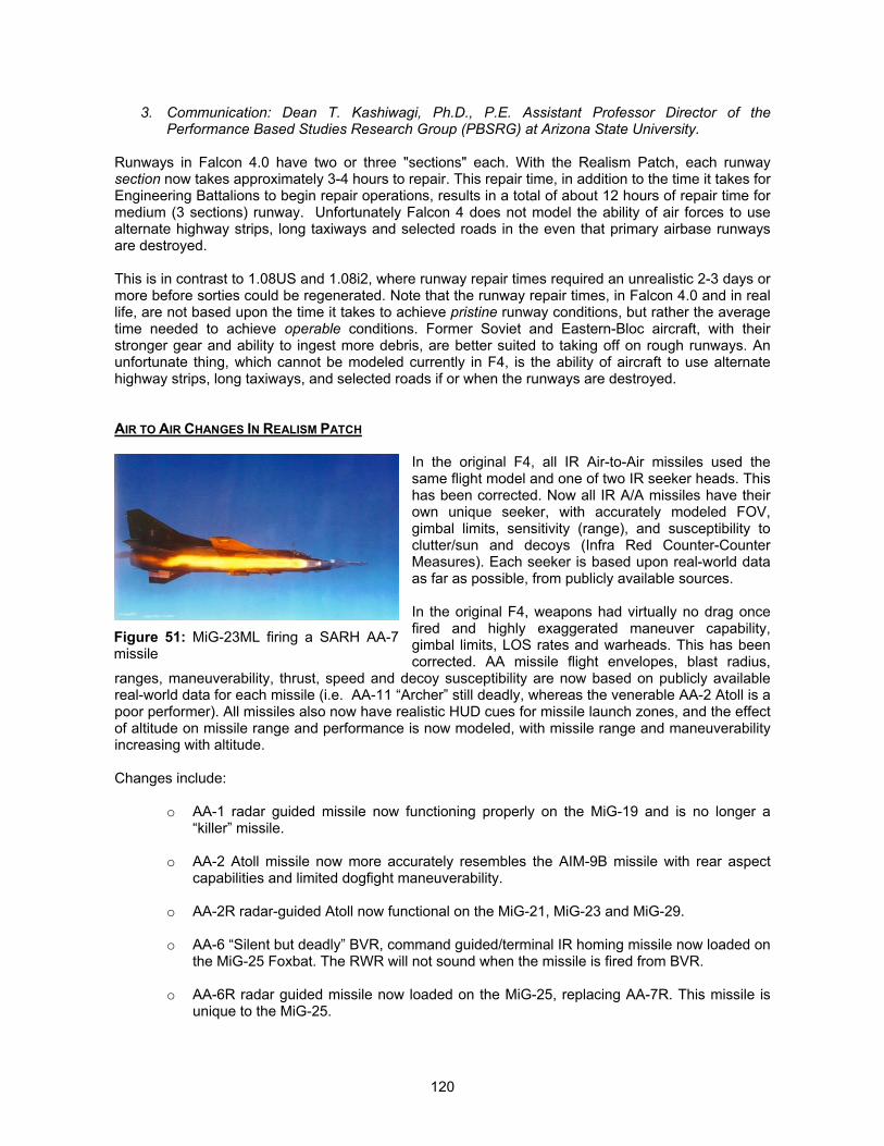
120
3. Communication: Dean T. Kashiwagi, Ph.D., P.E. Assistant Professor Director of thePerformance Based Studies Research Group (PBSRG) at Arizona State University.
Runways in Falcon 4.0 have two or three "sections" each. With the Realism Patch, each runwaysection now takes approximately 3-4 hours to repair. This repair time, in addition to the time it takes forEngineering Battalions to begin repair operations, results in a total of about 12 hours of repair time formedium (3 sections) runway. Unfortunately Falcon 4 does not model the ability of air forces to usealternate highway strips, long taxiways and selected roads in the even that primary airbase runwaysare destroyed.
This is in contrast to 1.08US and 1.08i2, where runway repair times required an unrealistic 2-3 days ormore before sorties could be regenerated. Note that the runway repair times, in Falcon 4.0 and in reallife, are not based upon the time it takes to achieve pristine runway conditions, but rather the averagetime needed to achieve operable conditions. Former Soviet and Eastern-Bloc aircraft, with theirstronger gear and ability to ingest more debris, are better suited to taking off on rough runways. Anunfortunate thing, which cannot be modeled currently in F4, is the ability of aircraft to use alternatehighway strips, long taxiways, and selected roads if or when the runways are destroyed.
AIR TO AIR CHANGES IN REALISM PATCH
In the original F4, all IR Air-to-Air missiles used thesame flight model and one of two IR seeker heads. Thishas been corrected. Now all IR A/A missiles have theirown unique seeker, with accurately modeled FOV,gimbal limits, sensitivity (range), and susceptibility toclutter/sun and decoys (Infra Red Counter-CounterMeasures). Each seeker is based upon real-world dataas far as possible, from publicly available sources.
In the original F4, weapons had virtually no drag oncefired and highly exaggerated maneuver capability,gimbal limits, LOS rates and warheads. This has beencorrected. AA missile flight envelopes, blast radius,
ranges, maneuverability, thrust, speed and decoy susceptibility are now based on publicly availablereal-world data for each missile (i.e. AA-11 “Archer” still deadly, whereas the venerable AA-2 Atoll is apoor performer). All missiles also now have realistic HUD cues for missile launch zones, and the effectof altitude on missile range and performance is now modeled, with missile range and maneuverabilityincreasing with altitude.
Changes include:
o AA-1 radar guided missile now functioning properly on the MiG-19 and is no longer a“killer” missile.
o AA-2 Atoll missile now more accurately resembles the AIM-9B missile with rear aspectcapabilities and limited dogfight maneuverability.
o AA-2R radar-guided Atoll now functional on the MiG-21, MiG-23 and MiG-29.
o AA-6 “Silent but deadly” BVR, command guided/terminal IR homing missile now loaded onthe MiG-25 Foxbat. The RWR will not sound when the missile is fired from BVR.
o AA-6R radar guided missile now loaded on the MiG-25, replacing AA-7R. This missile isunique to the MiG-25.
Figure 51: MiG-23ML firing a SARH AA-7missile
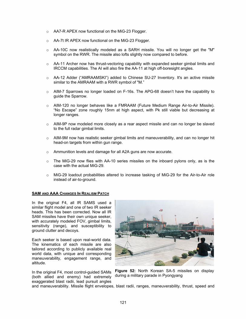
121
o AA7-R APEX now functional on the MiG-23 Flogger.
o AA-7t IR APEX now functional on the MiG-23 Flogger.
o AA-10C now realistically modeled as a SARH missile. You will no longer get the "M"symbol on the RWR. The missile also lofts slightly now compared to before.
o AA-11 Archer now has thrust-vectoring capability with expanded seeker gimbal limits andIRCCM capabilities. The AI will also fire the AA-11 at high off-boresight angles.
o AA-12 Adder (“AMRAAMSKI”) added to Chinese SU-27 Inventory. It's an active missilesimilar to the AMRAAM with a RWR symbol of "M.”
o AIM-7 Sparrows no longer loaded on F-16s. The APG-68 doesn’t have the capability toguide the Sparrow.
o AIM-120 no longer behaves like a FMRAAM (Future Medium Range Air-to-Air Missile).“No Escape” zone roughly 15nm at high aspect, with Pk still viable but decreasing atlonger ranges.
o AIM-9P now modeled more closely as a rear aspect missile and can no longer be slavedto the full radar gimbal limits.
o AIM-9M now has realistic seeker gimbal limits and maneuverability, and can no longer hithead-on targets from within gun range.
o Ammunition levels and damage for all A2A guns are now accurate.
o The MiG-29 now flies with AA-10 series missiles on the inboard pylons only, as is thecase with the actual MiG-29.
o MiG-29 loadout probabilities altered to increase tasking of MiG-29 for the Air-to-Air roleinstead of air-to-ground.
SAM AND AAA CHANGES IN REALISM PATCH
In the original F4, all IR SAMS used asimilar flight model and one of two IR seekerheads. This has been corrected. Now all IRSAM missiles have their own unique seeker,with accurately modeled FOV, gimbal limits,sensitivity (range), and susceptibility toground clutter and decoys.
Each seeker is based upon real-world data.The kinematics of each missile are alsotailored according to publicly available realworld data, with unique and correspondingmaneuverability, engagement range, andaltitude.
In the original F4, most control-guided SAMs(both allied and enemy) had extremelyexaggerated blast radii, lead pursuit anglesand maneuverability. Missile flight envelopes, blast radii, ranges, maneuverability, thrust, speed and
Figure 52: North Korean SA-5 missiles on displayduring a military parade in Pyongyang
122
decoy susceptibility are now based on real-world data for each missile. The radar SAMs now ping firstbefore launching, and give ample warning through the RWR prior to launch, giving time for evasiveactions. The kinematics against closing and retreating targets are realistic now.
Changes Include:
o HAWKs, Patriots, SA-2s, SA-3s, SA-5s, and SA-6s now have much greater engagementaltitudes, but are less maneuverable. The missiles will also fly out to higher altitudes,corresponding to their real world counterparts.
o SA-5 now has realistic terminal active seeker, and realistic Pk against fighter sized targets
o The SA-7 is now much less maneuverable and effective. Real world data indicate the poorperformance of this missile. The sun or ground IR clutter can now decoy the missileeasily.
o SA-8 range now reduced and is more susceptible to chaff
o SA-13 now included in the sim
o SA-14 now included in the sim
o SA-15 now included in the sim
o SA-19 now included in the sim
o The Stinger now far more maneuverable and effective, and now rejects flares moreconsistently.
o The Patriot made more effective based upon real-world performance, with increasedenergy and engagement range
o Chun-Ma, an indigenous ROK, low-altitude command guided SAM now in ROK inventory
o North Korea’s wide array of 25 to 100mm AAA capabilities now modeled much morerealistically. KS-12 85mm AAA reaches a maximum engagement altitude of 24,000-27,000 feet, and the KS-19 100m AAA gun, which is deployed around the DMZ, can reachaltitudes in excess of 40,000 feet.
o ZSU-57-2 AAA now reaches realistic engagement ranges of 13,000-15,000 feet.
o DPRK M-1992 37mm AAA now in Mechanized battalions with engagement ranges of -8,500 feet
o 2S6 Tunguska now carries realistic SA19 missile launcher system in addition to 30mmAAA capability with engagement ranges of 8,000 – 10,000 feet for the missile.
o Low altitude small-arms fire now modeled
o Range of ZSU-23-4 Shilka adjusted based upon actual performance data
PROBLEMS WITH MISSING MISSILES
An issue that arose with the first Realism Patch was that many users reported that their missile Pkwere extremely low, even though the original Realism Patch did not, in fact, contain any of the new
123
missile modifications except the blast radius edits. We have now determined that there is indeed amissile “pass-through” bug that can occur during period of very heavy CPU demand and high activitylevels in the sim (very low frame rates). The “pass-through” bug simply refers to the fact that someA2A missiles will literally “pass through” the target and fail to detonate. This problem occurs becausethe Falcon 4.0 program must continually “poll” each missile and perform collision detection. Whenmany missiles and objects are in the air at once, it takes longer for the F4 program to “strobe through”or “cycle through” all the missile and objects. When the missile is very fast and the blast radius issmall, the target may pass in and out of the blast radius too quickly for the CPU to detect the collision.This problem did not exist in the original F4 because all the missile blast radii were unusually huge,thereby allowing even slow CPUs enough time to detect a collision even under the most CPU-intensive circumstances.
To address this problem in F4, the actual blast radii in the sim are slightly higher than they are in reallife to compensate, though far less than they were in the 1.08US default. In addition, the problem isonly occurring with regularity for users with slower CPUs and/or users who set the bubble and objectdensities to very high levels. Because it is caused by intensive CPU demand, it most regularly occursover the FLOT, and rarely if ever occurs away from the FLOT. If you are experiencing what appears tobe an unreasonably low Pk, and the missiles appear to be passing through the target or missing by adistance less than the blast radius (typically 30-60 feet) without detonating, the following should fix theproblem:
1. Turn down the bubble2. Turn down object density. You should bear in mind that a setting of less than 6 will not result in
realistic composition of ground units, and many ground units will not perform properly (see thesection titled “Beyond Winning Battles: Winning The War” in chapter 1).
3. Get a faster CPU
All three of these strategies should work. The final option would be to either uninstall the RealismPatch or go back to 1.08i2 until you get a faster processor. Option #1 and #2 should be sufficient,however. We recommend a bubble setting of “3” as a starting point if your bubble slider is enabled.Generally speaking, as frame rate falls below 10, the probability of missile pass-through grows. Thereis really no permanent solution to this, since with the bubble slider and –g switch, anyone can set ithigh enough to cause these problems.
AIRCRAFT AI
In general, the intercept AI of fighter aircraft has been enhanced in the sim beyond the rather myopicF4 default (see section titled “Open Heart Surgery On Artificial Intelligence”). In Falcon 4.0, the abilityof any AI aircraft to detect you is unfortunately limited not just by its radar, but by the WEZ cues on theHUD which indicate the maximum engagement range of the missiles that it is carrying, or 10nm,whichever is larger. Falcon 4.0 AI aircraft can "see" you only if you have fallen into their weaponsenvelope. Because MiG-19s and MiG-21s all carry only short-range IR homing missiles, they cannotliterally perceive or respond to threat outside of 10nm (save defensive maneuvers against missiles).
However, many missiles in the original F4 had unrealistically small WEZ cues associated with them.Thus, paradoxically, the missiles themselves were overpowered while the WEZ cues were undersized.This has been corrected. WEZ cues in the HUD now match the true kinematic envelopes of eachmissile. This results not only in correct weapons envelope feedback to the player and/or launcheraircraft, it has also expanded the "awareness zones" of many aircraft, permitting them to detect andrespond to other aircraft outside of 10nm far more often than before. The AI changes have also totallyrevolutionized the AI, and as a result, the aircraft AI is now more intelligent and aggressive.
The net effect of this is that many times you will encounter enemy (and friendly) AI that is no longer“flying blind.” They will pick you up on radar and run an intercept on you, and will react to your
124
presence when your radar spikes their RWR. This creates a far more realistic tactical situation, andrequires you to be much more “on your guard.”
ILLUSORY “WALL OF MIGS”
Many players of F4 have complained about the “Wall of MiGs” that they feel they have to get throughto reach their target. While it is true that there are a large number of aircraft in Falcon 4.0 (allied andenemy), most players see this “wall” because they use labels and see scores and scores of “red”aircraft, each one looking like a potential threat. Labels may actually make it harder for people toconcentrate on their mission and fly F4. Players see these aircraft everywhere, and tend to go afterMiG-21s and such when they get within 15 miles, because they figure that distance is unsafe. And themore they see, the more they feel threatened and compelled to engage. Suddenly, your senses areflooded with potential dangers and it’s hard to focus because so many things are distracting you andcausing you to worry. Prioritization becomes difficult because you are looking at labels instead of yourradar and RWR.
This hyper-defensive posture can be counter-productive especially when you realize that the vastmajority of those aircraft are not after you. Most of them are on Strike, SEAD, CAS, BAI, or other non-AA missions. Aircraft on these sorts of missions will only attack you if you attack them, or if you flywithin 2nm of the forward hemisphere of their aircraft. Leave them alone and they will leave you alone.Of those aircraft that are tasked with AA mission, you will only be “seen” if you fall inside their“engagement zones.” For MiG-19 and MiG-21, these have a 10nm radius around the MiG. Don’t getthat close. For MiG-23s, 29s and SU-27s, they are potential danger since their engagement zonesmay be anywhere form 12-30nm radius depending on your altitude. Take this information into accountand pay attention to AWACS and your RWR. And turn off the labels too (use the force, Luke). You’lllive longer. Once you can start prioritizing your threats and ignoring non-threats you will find the skiesa lot less crowded than you have perceived them to be!

125
MANAGING ELECTRONSSensor and Electronic Warfare Management in Realism PatchBy “Hoola”
THE ELECTRONIC ENVIRONMENT IN REALISM PATCH
With Sylvain Gagnon’s and Marco Formato’s assistance in the executable patches, and the datachanges, we have created a totally new experience in electronic warfare in Falcon 4. You will find thatin order to survive the battlefield environment, you will need to understand how best to employ youronboard electronic sensors, and how best to defeat the different radar types that you will encounter inthe battlefield of Falcon 4.
All the different radars in the Falcon 4 universe have been given separate characteristics. We havemade distinction between pulse and pulse doppler radars, pulse doppler radars with pulse capabilities,and radars of varying ability to resist electronic counter measures. You will also find differences inradar performance when looking down, and the varying ability of radars to maintain track when you arebeaming them.
For example, with the MiG-21, the radar is not capable of detecting targets in the ground clutter. Assuch, if you are able to remain outside the MiG’s visual envelope, you can now slip past it undetected.Beaming will also not work against this aircraft as the radar is a pulse type and does not rely ondoppler returns to filter out targets. Comparatively, the MiG-29 radar is capable of looking down, but ishandicapped in detection range. If you have detected the MiG-29 in the RWR, and you are flying in theweeds, knowing its characteristics will allow you to know if the MiG-29 has detected you, and allowyou to take action before this happens.
The biggest change that has occurred is in electronic countermeasures. There are now considerationsof coverage zones, and electronic signature caused by the ECM system. Use it properly and you willbe able to deter a successful tracking missile launch against you. Use it improperly and you will loseits effect, or worse still, attract unwanted attention to yourself.
Implicitly, it also means that you will now need to employ a variety of tactics to avoid detection and foila tracking radar missile shot. To best defeat an airborne radar, you will need to fly low, and beam oremploy ECM against it. If you decide to beam the radar, you will lose ECM coverage. Do you then useECM against ground threats, and beam against airborne threats? You will need to makeconsiderations such as these to best utilize the defensive measures at your disposal. In order tosurvive, you will have to take the time to understand the threats, and how best to counter themdefensively.
You will also find changes in the way NCTR works. You will now need to use a combination of RWR,radar, and AWACS to identify a target and its intentions. The pucker factor will now be higher in aircombat, and it is important for you to really understand the characteristics and capabilities of everyairborne threat, as you will need every bit of this knowledge to identify the target.
Enjoy the changes in the electronic landscape of Falcon 4, and welcome to the brave new world ofelectronic warfare. The maxim is “Understand your electronic threats and you will survive!”
RADAR MANAGEMENT
The sensor with the greatest reach is your own onboard radar. We will discuss the characteristics ofvarious radars and radar modes, to give you a better understanding of how best to employ your ownradar and exploit the unique characteristics of each radar mode.
126
Pulse Radars
Pulse radars detect targets by detecting the raw returns from the radar’s own transmissions, anddisplays everything. This is akin to operating a pulse doppler radar in the ground mapping mode. Theupside of this approach is that it makes the radar impervious to beaming, as there is no doppler filter toscreen out slow moving targets. The downside of this is that the radar is incapable of detecting targetsin look-down situations, as the ground clutter return will often mask out the true target return.
Pulse radars also have difficulty distinguishing chaff from the target return, and as such, are not proneto being decoyed by chaff. Interpretation of the radar picture requires a lot more skills, as the radarpicture is displayed in raw video format, and will display even rain clouds or birds under somecircumstances. The examples of pulse radars are the APG-159 in the F-5E, the Saphir RP-21 on theMiG-21PF, and the radar on the MiG-19.
If you are operating such a radar, you will need to exploit the ability of the radar to retain target lockeven when the target beams you. However, your ability to detect targets are negligible in a look-downscenario. You are best served by maintaining a low altitude and search for targets in look-upscenarios. Once targets are detected, close in for your kill.
Pulse Doppler Radars
These radars rely on a doppler filter, and detect targets based on their doppler frequency. The filterscreens out target doppler returns below a set threshold (sometimes known as the Moving TargetReject, or MTR). This will prevent slow moving vehicles such as trains and cars, as well as groundclutter, from showing up on the radar screen. This confers the radar the ability to look-down intoground clutter and search for targets, though the performance is much poorer compared to look-upperformance (often about 2/3 of the look-up performance).
Pulse doppler radars have a high resistance to chaff as they base target detection on velocities. Chaffdecelerates rapidly after being dispensed, and this is easily detected by virtue of the design of pulsedoppler radars. The downside is that the pulse doppler radar is susceptible to beaming, which willlower the perceived closing velocity to a level below the doppler threshold.
Some pulse doppler radars such as the AWG-9 on the F-14 and the APG-71 on the F-15, have pulseand pulsed doppler modes. This allows the radar to switch to pulse mode when tracking a targetperforming a beaming maneuver, yet at the same time retaining the ability to look-down into clutter.
RWS (Range While Search) Mode
The RWS mode on the radar is a good compromise between rapid scan rate and target detection. Theradar operates in a medium PRF mode to obtain a good trade off between detection range and rangediscrimination. Targets detected is displayed almost instantaneously, as no track processing are done.Coupled with a rapid scan rate and large scan area, the RWS mode is optimized for rapid targetdetection over a large scan area.
You can bug a target in RWS and maintain track on it, while searching for other targets in the SAMsub-mode. The detection ability of the radar is not degraded at all if all that you are interested in is onesingle tracked target while searching for other possible targets. The target track for the bugged targetin RWS is also updated more frequently compared to other search modes. This should be the radarmode of choice, due to its rapid scan rate and good target detection ability.
TWS (Track While Scan) Mode
The TWS mode on the radar is a compromise of large scan area and target tracking performance. Theradar operates in a medium PRF mode with a smaller scan area than RWS. Targets detected are notdisplayed immediately, as the radar needs to process the track file first. This makes TWS a poor mode

127
to detect targets rapidly if you need to do so, though once detected, you can have data for multipletarget tracks compared to track information for only one target in RWS.
The downside of TWS is the additional processing required to maintain track files on all the targetsdetected. This leads to increased processing and a lower update frequency for all the track files.Target tracks may appear jumpy at times due to the lower frequency of radar update frames, and asthe radar processor’s attention is split over all the targets, TWS does not retain track as well as abugged target in RWS. This is a compromise of being able to maintain track information on multipletargets.
Implicitly, it also means that it is easier for a target to beam a radar in TWS mode and break its lockcompared to RWS mode. The anomaly with TWS mode is that even when a target has exited theradar gimbal or scan limits, track processing will still take place for the next 8 seconds, even when thetarget has flown behind the radar. This feature of track extrapolation allows the target track to beretained if the target returns to the radar scan volume within the 8 second timeframe, but carries with itthe penalty of degrading overall radar track retention capabilities due to the additional processing.
If you need to be able to maintain track information on multiple targets, this is the radar mode to use.Otherwise, you are better off with the RWS mode that offers faster target detection at a slightly greaterrange (approximately 10%), plus better track stability and retention for a bugged target.
VS (Velocity Search) Mode
The VS mode is a dedicated high PRF mode designed to detect targets with high closure speeds. Thehigh PRF waveform confers VS mode a greater detection range, at the expense of range resolution.Bugging a target in VS mode will result in the radar going into single target track (STT). Theadvantages of VS mode are the increased detection range (about 20%) over RWS mode, and betterability to detect small, fast targets.
The increased detection range will yield more reaction time especially in look-down scenarios. Onceyou have identified the greatest threat, bugging the threat will transit into STT mode to obtain the finerange, angular, and velocity measurements.
VS mode is ideal if you are tasked for sweep missions or CAP missions. The longer detection rangewill identify any incursions from further out, allowing you to take action faster, and the one steptransition to STT is invaluable as you do not have to double designate like in RWS to transit into STT.
Single Target Track (STT) Mode
This radar mode concentrates all the radar’s attention on the single target of interest. The track data isupdated very frequently as the antenna is trained solely on the target. This results in excellent trackquality, and makes it more difficult for the target to break the STT lock through beaming or ECM, asthe radar processing power is dedicated to maintaining the STT lock. Radar ECCM performance isalso enhanced in the STT mode.
Target track quality comes at the expense of scan volume and search ability. You should use the STTmode if the target is maneuvering violently, as the radar is better able to retain track update. Whenfiring active radar guided missiles, STT mode will also provide higher quality of target information forthe inflight datalink update of the missile, to further improve the Pk compared to firing in RWS buggedtarget mode.
Non Cooperative Target Recognition (NCTR)
NCTR is a radar processing technique used to identify a radar contact. This function is available inboth STT and TWS modes. Due to the way the RWS and VS modes process data, NCTR will not beavailable in these modes.
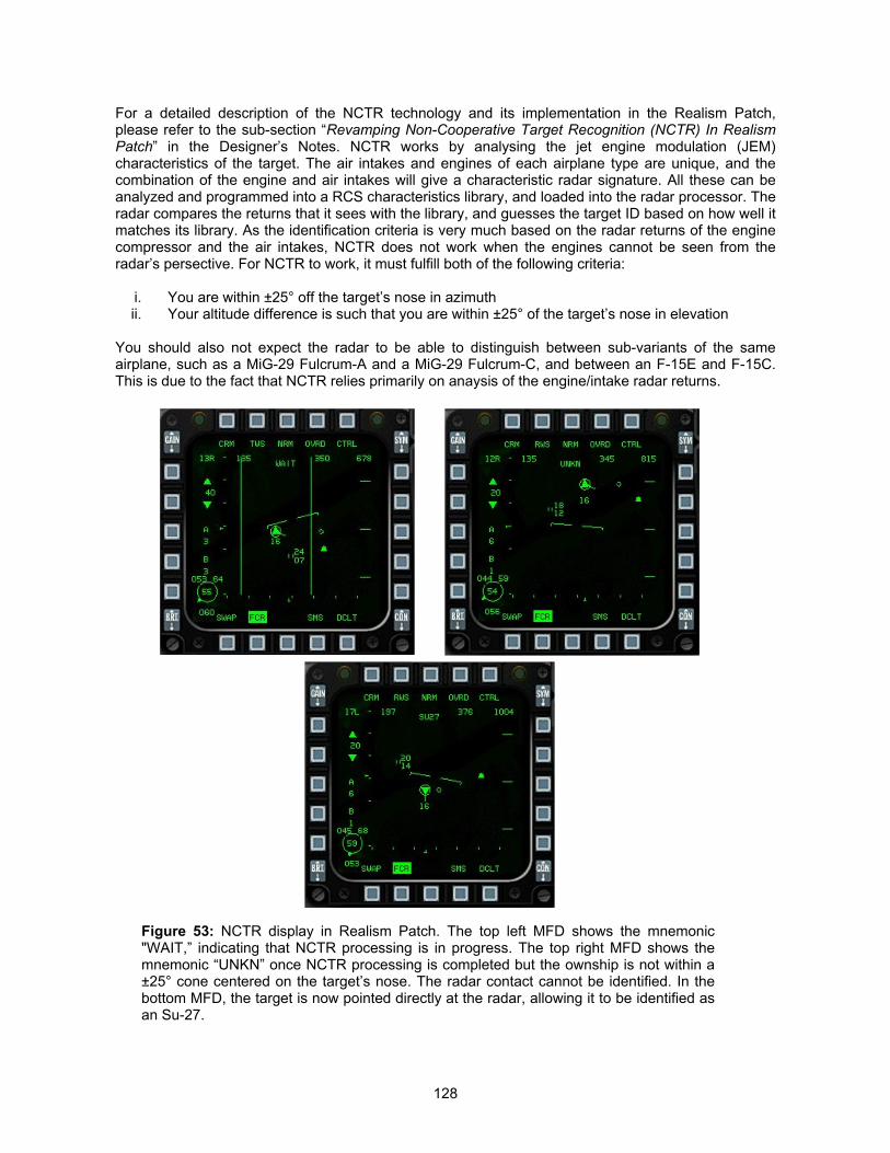
128
For a detailed description of the NCTR technology and its implementation in the Realism Patch,please refer to the sub-section “Revamping Non-Cooperative Target Recognition (NCTR) In RealismPatch” in the Designer’s Notes. NCTR works by analysing the jet engine modulation (JEM)characteristics of the target. The air intakes and engines of each airplane type are unique, and thecombination of the engine and air intakes will give a characteristic radar signature. All these can beanalyzed and programmed into a RCS characteristics library, and loaded into the radar processor. Theradar compares the returns that it sees with the library, and guesses the target ID based on how well itmatches its library. As the identification criteria is very much based on the radar returns of the enginecompressor and the air intakes, NCTR does not work when the engines cannot be seen from theradar’s persective. For NCTR to work, it must fulfill both of the following criteria:
i. You are within ±25° off the target’s nose in azimuth ii. Your altitude difference is such that you are within ±25° of the target’s nose in elevation
You should also not expect the radar to be able to distinguish between sub-variants of the sameairplane, such as a MiG-29 Fulcrum-A and a MiG-29 Fulcrum-C, and between an F-15E and F-15C.This is due to the fact that NCTR relies primarily on anaysis of the engine/intake radar returns.
Figure 53: NCTR display in Realism Patch. The top left MFD shows the mnemonic"WAIT,” indicating that NCTR processing is in progress. The top right MFD shows themnemonic “UNKN” once NCTR processing is completed but the ownship is not within a±25° cone centered on the target’s nose. The radar contact cannot be identified. In thebottom MFD, the target is now pointed directly at the radar, allowing it to be identified asan Su-27.
129
When you lock-up on a target in STT mode, or bug a contact in TWS mode, the radar will attempt toidentify the target ID. While the radar is processing the data, you will see the mnemonics “WAIT.” If theradar signal returns are strong enough for identification purposes, but you are not within ±25° inelevation and azimuth off the target’s nose, you should see the mnemonics “UNKN,” indicating that theradar is not able to determine the target ID. When you are within ±25° in elevation and azimuth off thetarget’s nose, the “UNKN” mnemonic is replaced by the target’s ID (see Figure 53).
The NCTR ID of each airplane in Falcon 4 Realism Patch can be found in the spreadsheet titled“F4_RP_Sensor_Properties.XLS,” under the worksheet titled “NCTR.” You will also find the range andconditions at which the NCTR ID can be obtained by the APG-68 radar in STT mode. For TWS mode,the NCTR ID will be obtained at approximately 70% of the STT range.
You will need to use all the means at your disposal to identify the target. As NCTR is not capable oftelling you the intention of the radar contact, you will have to use the RWR (if the target is painting you)to identify it, as well as enlist the help of AWACS. You will find that for small targets, AWACS may beable to determine if the radar contact is hostile or friendly at ranges much further than the NCTRidentification distance. For airplanes such as the MiG-29A and MiG-29C, you will have to analyze itscharacteristics, as the NCTR ID will be identical. The pucker factor will be higher, especially when youare facing a fast closing small target.
Radar Performance Under Various Conditions
The detection performance of a radar system is dependent on many factors, such as look-downsituations, target aspect, etc. The radar cross section of a target varies with its aspect angle. For pulsedoppler radars, this is complicated by the different doppler velocities at different target aspect angles.Tail-on targets are more difficult to detect due to the lower doppler velocities, and the smaller radarcross section, compared to head-on targets. For a detailed description of this topic, please refer to thesub-section “Varying Radar Performance With Target Aspect In Realism Patch” in the Designer’sNotes.
Typically, you can expect detection ranges to be reduced by 25% in tail-on situations, as compared tohead-on situations. Detection range will be in between head-on and tail-on scenarios for targets in thebeam. If you are using a pulse doppler radar, you will need to be concerned about the targetdisappearing into the doppler notch when it beams you. Look-down situations will present an evenmore challenging scenario to the radar, as the ground clutter will need to be filtered out, even for pulsedoppler radars. You can also expect a reduction in look-down detection ranges for pulse dopplerradars
RWR MANAGEMENT
The RWR is the only passive ESM equipment available onboard modern fighters. It is important thatyou understand the limitations of your RWR, and how information is presented by the RWR.
RWR Basics
RWRs are not all born equal. The early RWRs use crystal video receivers of limited sensitivity, whilelater RWRs use narrow and scanning wide band superheterodyne receivers with greater sensitivity.RWR are simple RF receivers designed to receive RF signals, analyze them rapidly, and if possibleclassify and recognize the emitter. They are normally comprise of receiving antennae (usually 4 ormore), a processor, and a display system to display to the pilot the threats detected.
When the antenna receives an RF signal, it first processes the RF signal and reduces it to a raw videosignal of the pulse pattern, and then the processor will analyze the signal and classify it according tothe pulse width, frequency, pulse repetition interval (PRI), antenna scan, and direction of arrival(DOA). Once these are done, it will compare the characteristics against a pre-determined look-up table
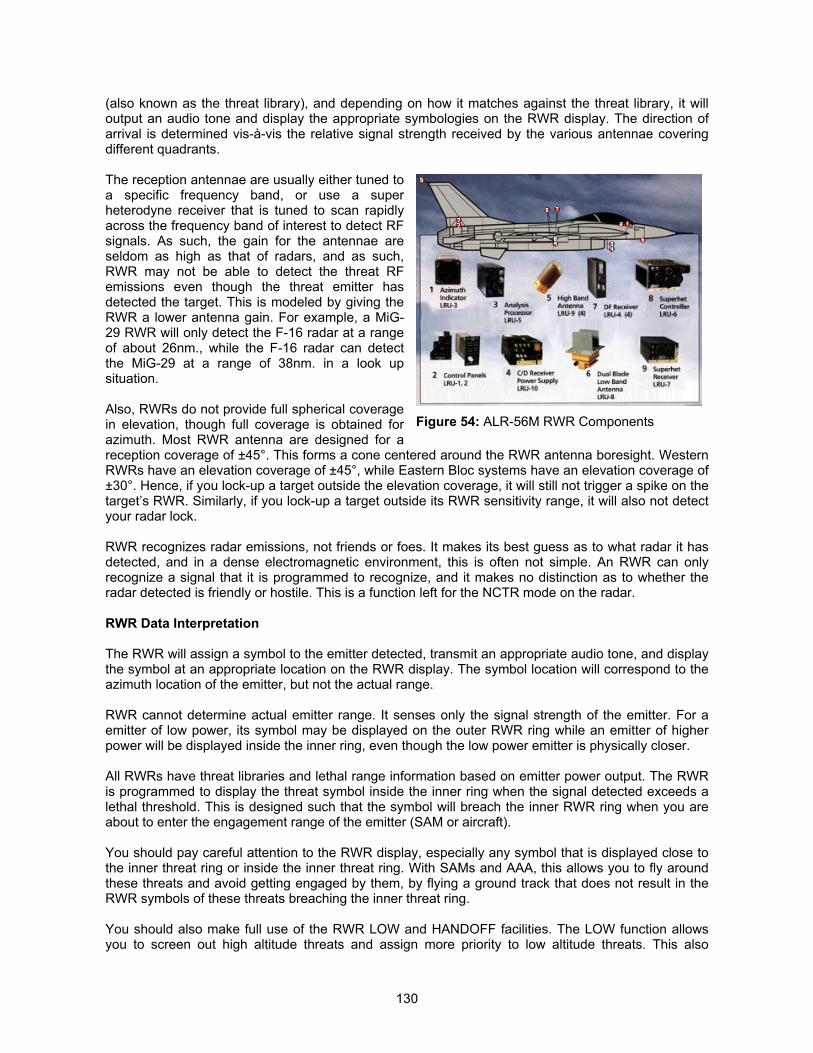
130
(also known as the threat library), and depending on how it matches against the threat library, it willoutput an audio tone and display the appropriate symbologies on the RWR display. The direction ofarrival is determined vis-à-vis the relative signal strength received by the various antennae coveringdifferent quadrants.
The reception antennae are usually either tuned toa specific frequency band, or use a superheterodyne receiver that is tuned to scan rapidlyacross the frequency band of interest to detect RFsignals. As such, the gain for the antennae areseldom as high as that of radars, and as such,RWR may not be able to detect the threat RFemissions even though the threat emitter hasdetected the target. This is modeled by giving theRWR a lower antenna gain. For example, a MiG-29 RWR will only detect the F-16 radar at a rangeof about 26nm., while the F-16 radar can detectthe MiG-29 at a range of 38nm. in a look upsituation.
Also, RWRs do not provide full spherical coveragein elevation, though full coverage is obtained forazimuth. Most RWR antenna are designed for areception coverage of ±45°. This forms a cone centered around the RWR antenna boresight. WesternRWRs have an elevation coverage of ±45°, while Eastern Bloc systems have an elevation coverage of±30°. Hence, if you lock-up a target outside the elevation coverage, it will still not trigger a spike on thetarget’s RWR. Similarly, if you lock-up a target outside its RWR sensitivity range, it will also not detectyour radar lock.
RWR recognizes radar emissions, not friends or foes. It makes its best guess as to what radar it hasdetected, and in a dense electromagnetic environment, this is often not simple. An RWR can onlyrecognize a signal that it is programmed to recognize, and it makes no distinction as to whether theradar detected is friendly or hostile. This is a function left for the NCTR mode on the radar.
RWR Data Interpretation
The RWR will assign a symbol to the emitter detected, transmit an appropriate audio tone, and displaythe symbol at an appropriate location on the RWR display. The symbol location will correspond to theazimuth location of the emitter, but not the actual range.
RWR cannot determine actual emitter range. It senses only the signal strength of the emitter. For aemitter of low power, its symbol may be displayed on the outer RWR ring while an emitter of higherpower will be displayed inside the inner ring, even though the low power emitter is physically closer.
All RWRs have threat libraries and lethal range information based on emitter power output. The RWRis programmed to display the threat symbol inside the inner ring when the signal detected exceeds alethal threshold. This is designed such that the symbol will breach the inner RWR ring when you areabout to enter the engagement range of the emitter (SAM or aircraft).
You should pay careful attention to the RWR display, especially any symbol that is displayed close tothe inner threat ring or inside the inner threat ring. With SAMs and AAA, this allows you to fly aroundthese threats and avoid getting engaged by them, by flying a ground track that does not result in theRWR symbols of these threats breaching the inner threat ring.
You should also make full use of the RWR LOW and HANDOFF facilities. The LOW function allowsyou to screen out high altitude threats and assign more priority to low altitude threats. This also
Figure 54: ALR-56M RWR Components
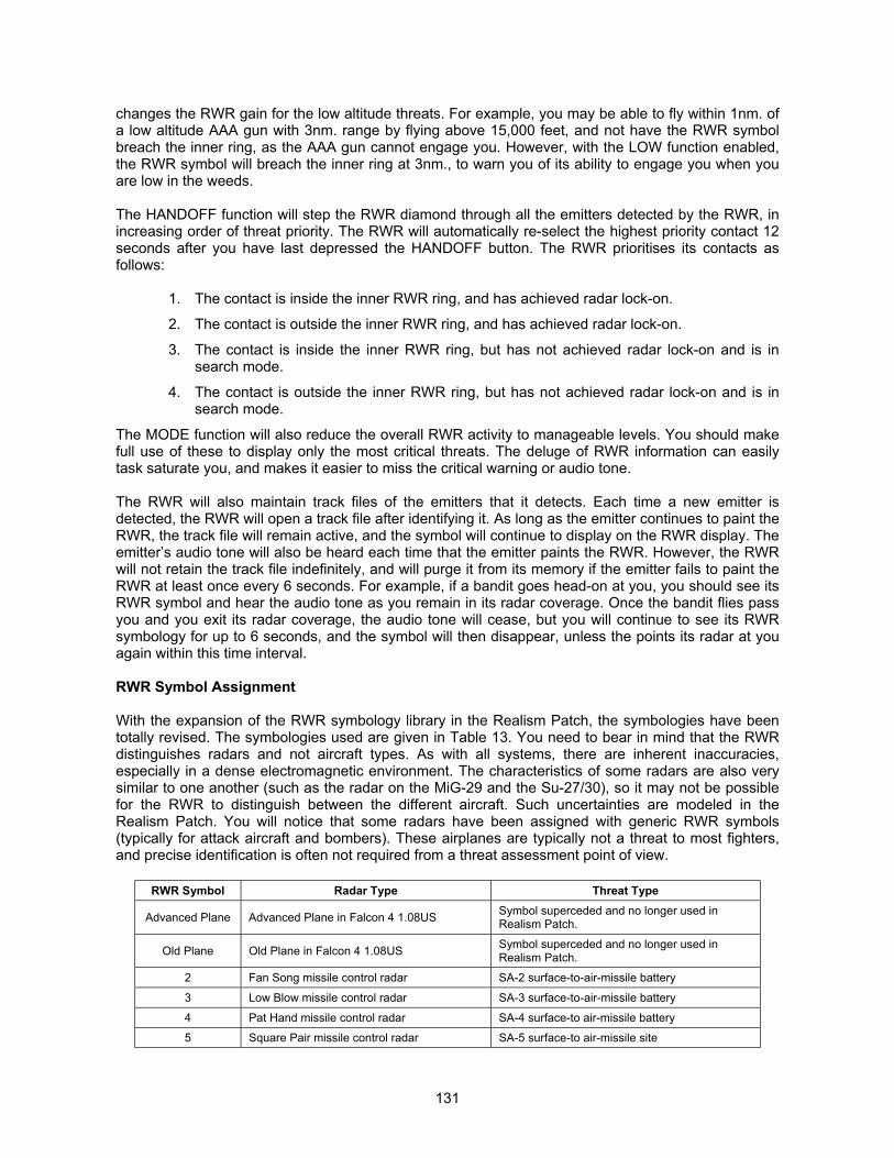
131
changes the RWR gain for the low altitude threats. For example, you may be able to fly within 1nm. ofa low altitude AAA gun with 3nm. range by flying above 15,000 feet, and not have the RWR symbolbreach the inner ring, as the AAA gun cannot engage you. However, with the LOW function enabled,the RWR symbol will breach the inner ring at 3nm., to warn you of its ability to engage you when youare low in the weeds.
The HANDOFF function will step the RWR diamond through all the emitters detected by the RWR, inincreasing order of threat priority. The RWR will automatically re-select the highest priority contact 12seconds after you have last depressed the HANDOFF button. The RWR prioritises its contacts asfollows:
1. The contact is inside the inner RWR ring, and has achieved radar lock-on.
2. The contact is outside the inner RWR ring, and has achieved radar lock-on.
3. The contact is inside the inner RWR ring, but has not achieved radar lock-on and is insearch mode.
4. The contact is outside the inner RWR ring, but has not achieved radar lock-on and is insearch mode.
The MODE function will also reduce the overall RWR activity to manageable levels. You should makefull use of these to display only the most critical threats. The deluge of RWR information can easilytask saturate you, and makes it easier to miss the critical warning or audio tone.
The RWR will also maintain track files of the emitters that it detects. Each time a new emitter isdetected, the RWR will open a track file after identifying it. As long as the emitter continues to paint theRWR, the track file will remain active, and the symbol will continue to display on the RWR display. Theemitter’s audio tone will also be heard each time that the emitter paints the RWR. However, the RWRwill not retain the track file indefinitely, and will purge it from its memory if the emitter fails to paint theRWR at least once every 6 seconds. For example, if a bandit goes head-on at you, you should see itsRWR symbol and hear the audio tone as you remain in its radar coverage. Once the bandit flies passyou and you exit its radar coverage, the audio tone will cease, but you will continue to see its RWRsymbology for up to 6 seconds, and the symbol will then disappear, unless the points its radar at youagain within this time interval.
RWR Symbol Assignment
With the expansion of the RWR symbology library in the Realism Patch, the symbologies have beentotally revised. The symbologies used are given in Table 13. You need to bear in mind that the RWRdistinguishes radars and not aircraft types. As with all systems, there are inherent inaccuracies,especially in a dense electromagnetic environment. The characteristics of some radars are also verysimilar to one another (such as the radar on the MiG-29 and the Su-27/30), so it may not be possiblefor the RWR to distinguish between the different aircraft. Such uncertainties are modeled in theRealism Patch. You will notice that some radars have been assigned with generic RWR symbols(typically for attack aircraft and bombers). These airplanes are typically not a threat to most fighters,and precise identification is often not required from a threat assessment point of view.
RWR Symbol Radar Type Threat Type
Advanced Plane Advanced Plane in Falcon 4 1.08US Symbol superceded and no longer used inRealism Patch.
Old Plane Old Plane in Falcon 4 1.08US Symbol superceded and no longer used inRealism Patch.
2 Fan Song missile control radar SA-2 surface-to-air-missile battery
3 Low Blow missile control radar SA-3 surface-to-air-missile battery
4 Pat Hand missile control radar SA-4 surface-to air-missile battery
5 Square Pair missile control radar SA-5 surface-to air-missile site
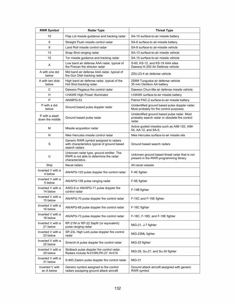
132
RWR Symbol Radar Type Threat Type
10 Flap Lid missile guidance and tracking radar SA-10 surface-to-air missile battery
6 Straight Flush missile control radar SA-6 surface-to air-missile battery
8 Land Roll missile control radar SA-8 surface-to air-missile vehicle
13 Snap Shot ranging radar SA-13 surface-to-air missile vehicle
15 Tor missile guidance and tracking radar SA-15 surface-to-air missile vehicle
A Low band air defense AAA radar, typical ofthe Firecan fire director radar
S-60, KS-12, and KS-19 AAA sitesDaewoo K-200 Air Defense vehicle
A with one dotbelow
Mid band air defense AAA radar, typical ofthe Gun Dish tracking radar ZSU-23-4 air defense vehicle
A with two dotsbelow
High band air defense radar, typical of theHot Shot tracking radar.
2S6M Tunguska air defense vehicle35 mm Oerlikon AA battery
C Daewoo Pegasus fire control radar Daewoo Chun-Ma air defense missile vehicle
H I-HAWK High Power Illuminator I-HAWK surface-to-air missile battery
P AN/MPQ-53 Patriot PAC-2 surface-to-air missile battery
P with a dotbelow Ground based pulse doppler radar Unidentified ground based pulse doppler radar.
Most probably for fire control purposes.
P with a slashdown the middle Ground based pulse radar
Unidentified ground based pulse radar. Mostprobably search radar or obsolete fire controlradar.
M Missile acquisition radar Active guided missiles such as AIM-120, AIM-54, AA-12, and SA-5.
N Nike Hercules missile control radar Nike Hercules surface-to-air missile site
SGeneric RWR symbol assigned to radarswith characteristics typical of ground basedsearch radars
Ground based search radars
UUnknown radar type, ground emitter. TheRWR is not able to determine the radarcharacteristics.
Unknown ground based threat radar that is notpresent in the RWR programming library.
Ship Naval radars All naval vessels
Inverted V with a4 below AN/APG-120 pulse doppler fire control radar F-4E fighter
Inverted V with a5 below AN/APQ-159 pulse ranging radar F-5E fighter
Inverted V with a14 below
AWG-9 or AN/APG-71 pulse doppler firecontrol radar F-14B fighter
Inverted V with a15 below AN/APG-70 pulse doppler fire control radar F-15C and F-15E fighter
Inverted V with a16 below AN/APG-68 pulse doppler fire control radar F-16C fighter
Inverted V with a18 below AN/APG-73 pulse doppler fire control radar F-18C, F-18D, and F-18E fighter
Inverted V with a21 below
RP-21M or RP-22 Sapfir (or equivalent)pulse ranging radar MiG-21, J-7 fighter
Inverted V with a23 below
SP-23L High Lark pulse doppler fire controlradar MiG-23ML fighter
Inverted V with a25 below Smerch-A pulse doppler fire control radar MiG-25 fighter
Inverted V with a29 below
Slotback pulse doppler fire control radar.Radars include N-010RLPK-27, N-019 MiG-29, Su-27, and Su-30 fighter
Inverted V with a31 below S-800 Zaslon pulse doppler fire control radar MiG-31
Inverted V withan A below
Generic symbol assigned to fire controlradars equipping ground attack aircraft
Ground attack aircraft assigned with genericRWR symbol
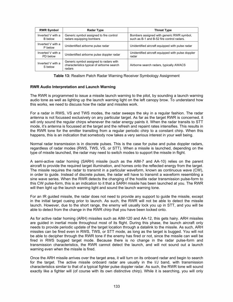
133
RWR Symbol Radar Type Threat TypeInverted V with a
B belowGeneric symbol assigned to fire controlradars equipping bombers
Bombers assigned with generic RWR symbol,such as B-1 and B-52 fire control radars.
Inverted V with aP below Unidentified airborne pulse radar Unidentified aircraft equipped with pulse radar
Inverted V with aPD below Unidentified airborne pulse doppler radar Unidentified aircraft equipped with pulse doppler
radar
Inverted V with aS below
Generic symbol assigned to radars withcharacteristics typical of airborne searchradars
Airborne search radars, typically AWACS
Table 13: Realism Patch Radar Warning Receiver Symbology Assignment
RWR Audio Interpretation and Launch Warning
The RWR is programmed to issue a missile launch warning to the pilot, by sounding a launch warningaudio tone as well as lighting up the launch warning light on the left canopy brow. To understand howthis works, we need to discuss how the radar and missiles work.
For a radar in RWS, VS and TWS modes, the radar sweeps the sky in a regular fashion. The radarantenna is not focussed exclusively on any particular target. As far as the target RWR is concerned, itwill only sound the regular chirps whenever the radar energy paints it. When the radar transits to STTmode, it’s antenna is focussed at the target and the refresh and repaint rates intensifies. This results inthe RWR tone for the emitter transiting from a regular periodic chirp to a constant chirp. When thishappens, this is an indication that somebody now takes a very serious interest in your well being.
Normal radar transmission is in discrete pulses. This is the case for pulse and pulse doppler radars,regardless of radar modes (RWS, TWS, VS, or STT). When a missile is launched, depending on thetype of missile launched, the radar may need to switch modes to support the missile in flight.
A semi-active radar homing (SARH) missile (such as the AIM-7 and AA-10) relies on the parentaircraft to provide the required target illumination, and homes onto the reflected energy from the target.The missile requires the radar to transmit in a particular waveform, known as continuous wave (CW),in order to guide. Instead of discrete pulses, the radar will have to transmit a waveform resembling asine wave series. When the RWR detects the changing of the hostile radar transmission pulse-form tothis CW pulse-form, this is an indication to it that a SARH missile has been launched at you. The RWRwill then light up the launch warning light and sound the launch warning tone.
For an IR guided missile, the radar does not need to provide any support to guide the missile, exceptin the initial target cueing prior to launch. As such, the RWR will not be able to detect the missilelaunch. However, due to the short range, the enemy will usually lock you up in STT, and you will beable to detect from the change in the RWR chirp that you have been locked onto.
As for active radar homing (ARH) missiles such as AIM-120 and AA-12, this gets hairy. ARH missilesare guided in inertial mode throughout most of its flight. During this phase, the launch aircraft onlyneeds to provide periodic update of the target location through a datalink to the missile. As such, ARHmissiles can be fired even in RWS, TWS, or STT mode, as long as the target is bugged. You will notbe able to decipher through the RWR tone if the enemy has fired or not, since the missile can well befired in RWS bugged target mode. Because there is no change in the radar pulse-form andtransmission characteristics, the RWR cannot detect the launch, and will not sound out a launchwarning even when the missile is fired.
Once the ARH missile arrives over the target area, it will turn on its onboard radar and begin to searchfor the target. The active missile onboard radar are usually in the I/J band, with transmissioncharacteristics similar to that of a typical fighter pulse doppler radar. As such, the RWR tone will soundexactly like a fighter will (of course with its own distinctive chirp). While it is searching, you will only
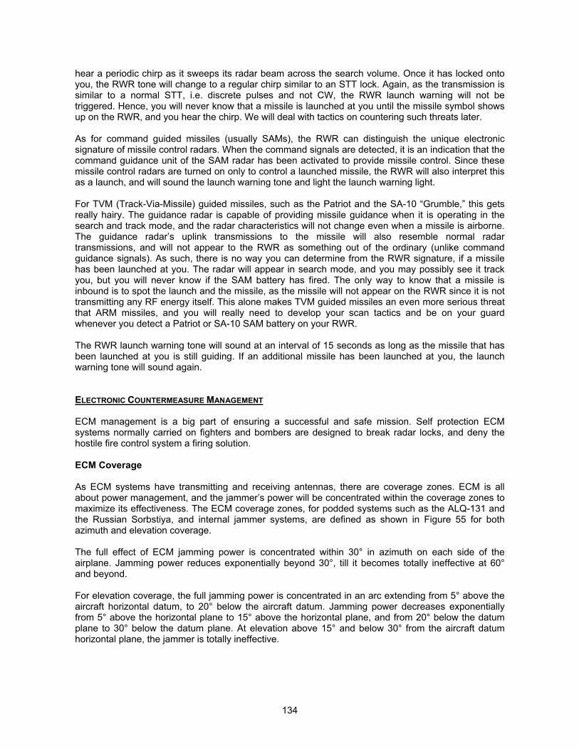
134
hear a periodic chirp as it sweeps its radar beam across the search volume. Once it has locked ontoyou, the RWR tone will change to a regular chirp similar to an STT lock. Again, as the transmission issimilar to a normal STT, i.e. discrete pulses and not CW, the RWR launch warning will not betriggered. Hence, you will never know that a missile is launched at you until the missile symbol showsup on the RWR, and you hear the chirp. We will deal with tactics on countering such threats later.
As for command guided missiles (usually SAMs), the RWR can distinguish the unique electronicsignature of missile control radars. When the command signals are detected, it is an indication that thecommand guidance unit of the SAM radar has been activated to provide missile control. Since thesemissile control radars are turned on only to control a launched missile, the RWR will also interpret thisas a launch, and will sound the launch warning tone and light the launch warning light.
For TVM (Track-Via-Missile) guided missiles, such as the Patriot and the SA-10 “Grumble,” this getsreally hairy. The guidance radar is capable of providing missile guidance when it is operating in thesearch and track mode, and the radar characteristics will not change even when a missile is airborne.The guidance radar’s uplink transmissions to the missile will also resemble normal radartransmissions, and will not appear to the RWR as something out of the ordinary (unlike commandguidance signals). As such, there is no way you can determine from the RWR signature, if a missilehas been launched at you. The radar will appear in search mode, and you may possibly see it trackyou, but you will never know if the SAM battery has fired. The only way to know that a missile isinbound is to spot the launch and the missile, as the missile will not appear on the RWR since it is nottransmitting any RF energy itself. This alone makes TVM guided missiles an even more serious threatthat ARM missiles, and you will really need to develop your scan tactics and be on your guardwhenever you detect a Patriot or SA-10 SAM battery on your RWR.
The RWR launch warning tone will sound at an interval of 15 seconds as long as the missile that hasbeen launched at you is still guiding. If an additional missile has been launched at you, the launchwarning tone will sound again.
ELECTRONIC COUNTERMEASURE MANAGEMENT
ECM management is a big part of ensuring a successful and safe mission. Self protection ECMsystems normally carried on fighters and bombers are designed to break radar locks, and deny thehostile fire control system a firing solution.
ECM Coverage
As ECM systems have transmitting and receiving antennas, there are coverage zones. ECM is allabout power management, and the jammer’s power will be concentrated within the coverage zones tomaximize its effectiveness. The ECM coverage zones, for podded systems such as the ALQ-131 andthe Russian Sorbstiya, and internal jammer systems, are defined as shown in Figure 55 for bothazimuth and elevation coverage.
The full effect of ECM jamming power is concentrated within 30° in azimuth on each side of theairplane. Jamming power reduces exponentially beyond 30°, till it becomes totally ineffective at 60°and beyond.
For elevation coverage, the full jamming power is concentrated in an arc extending from 5° above theaircraft horizontal datum, to 20° below the aircraft datum. Jamming power decreases exponentiallyfrom 5° above the horizontal plane to 15° above the horizontal plane, and from 20° below the datumplane to 30° below the datum plane. At elevation above 15° and below 30° from the aircraft datumhorizontal plane, the jammer is totally ineffective.
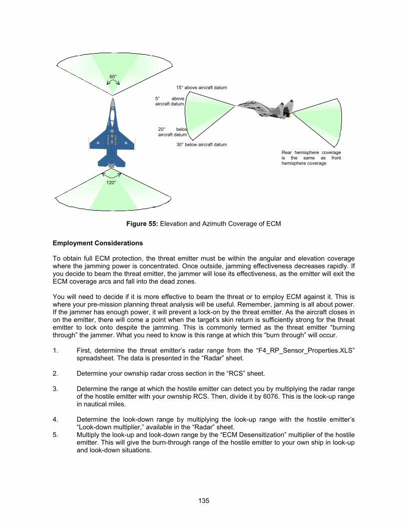
135
Figure 55: Elevation and Azimuth Coverage of ECM
Employment Considerations
To obtain full ECM protection, the threat emitter must be within the angular and elevation coveragewhere the jamming power is concentrated. Once outside, jamming effectiveness decreases rapidly. Ifyou decide to beam the threat emitter, the jammer will lose its effectiveness, as the emitter will exit theECM coverage arcs and fall into the dead zones.
You will need to decide if it is more effective to beam the threat or to employ ECM against it. This iswhere your pre-mission planning threat analysis will be useful. Remember, jamming is all about power.If the jammer has enough power, it will prevent a lock-on by the threat emitter. As the aircraft closes inon the emitter, there will come a point when the target’s skin return is sufficiently strong for the threatemitter to lock onto despite the jamming. This is commonly termed as the threat emitter “burningthrough” the jammer. What you need to know is this range at which this “burn through” will occur.
1. First, determine the threat emitter’s radar range from the “F4_RP_Sensor_Properties.XLS”spreadsheet. The data is presented in the “Radar” sheet.
2. Determine your ownship radar cross section in the “RCS” sheet.
3. Determine the range at which the hostile emitter can detect you by multiplying the radar rangeof the hostile emitter with your ownship RCS. Then, divide it by 6076. This is the look-up rangein nautical miles.
4. Determine the look-down range by multiplying the look-up range with the hostile emitter’s“Look-down multiplier,” available in the “Radar” sheet.
5. Multiply the look-up and look-down range by the “ECM Desensitization” multiplier of the hostileemitter. This will give the burn-through range of the hostile emitter to your own ship in look-upand look-down situations.
15° above aircraft datum
30° below aircraft datum
5° aboveaircraft datum
20° belowaircraft datum
Rear hemisphere coverageis the same as fronthemisphere coverage
60°
120°
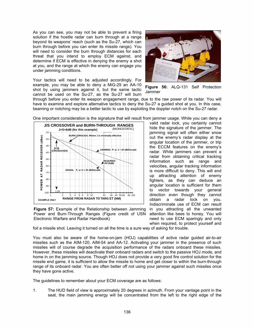
136
As you can see, you may not be able to prevent a firingsolution if the hostile radar can burn through at a rangebeyond its weapons’ reach (such as the Su-27, which canburn through before you can enter its missile range). Youwill need to consider the burn through distances for eachthreat that you intend to employ ECM against, anddetermine if ECM is effective in denying the enemy a shotat you, and the range at which the enemy can engage youunder jamming conditions.
Your tactics will need to be adjusted accordingly. Forexample, you may be able to deny a MiG-29 an AA-10shot by using jammers against it, but the same tacticcannot be used on the Su-27, as the Su-27 will burnthrough before you enter its weapon engagement range, due to the raw power of its radar. You willhave to examine and explore alternative tactics to deny the Su-27 a guided shot at you. In this case,beaming or notching may be a better tactic to use by exploiting the doppler notch on the Su-27 radar.
One important consideration is the signature that will result from jammer usage. While you can deny avalid radar lock, you certainly cannothide the signature of the jammer. Thejamming signal will often either snowout the enemy’s radar display at theangular location of the jammer, or tripthe ECCM features on the enemy’sradar. While jammers can prevent aradar from obtaining critical trackinginformation such as range andvelocities, angular tracking informationis more difficult to deny. This will endup attracting attention of enemyfighters, as they can deduce anangular location is sufficient for themto vector towards your generaldirection even though they cannotobtain a radar lock on you.Indiscriminate use of ECM can resultin you attracting all the unwantedattention like bees to honey. You willneed to use ECM sparingly and onlywhen required, to protect yourself and
foil a missile shot. Leaving it turned on all the time is a sure way of asking for trouble.
You must also be aware of the home-on-jam (HOJ) capabilities of active radar guided air-to-airmissiles such as the AIM-120, AIM-54 and AA-12. Activating your jammer in the presence of suchmissiles will of course degrade the acquisition performance of the radars onboard these missiles.However, these missiles will deactivate their onboard radars and switch to the passive HOJ mode, andhome in on the jamming source. Though HOJ does not provide a very good fire control solution for themissile end game, it is sufficient to allow the missile to home and get closer to within the burn-throughrange of its onboard radar. You are often better off not using your jammer against such missiles oncethey have gone active.
The guidelines to remember about your ECM coverage are as follows:
1. The HUD field of view is approximately 20 degrees in azimuth. From your vantage point in theseat, the main jamming energy will be concentrated from the left to the right edge of the
Figure 56: ALQ-131 Self ProtectionJammer
1 2 3 4 5 6 8 10 20 30 50 60 80 100
-100
-90
-80
-70
-60
-50
-40
-30
-20
-10
RANGE FROM RADAR TO TARG ET (NM)
J=S
J/S CROSSOVER and BURN-THROUGH RANGES
40
J=S+6dB (for this example)
JAMMING P or J = 20 dB/Decade
J/S (6dB)REQUIRED
EXAMPLE ONLY
r
SIGNAL P or S = 40 dB/Decader
(CROSSOVER)
(MONOSTATIC)
1.29
BURN-THROUGH, Where J is minimally effective
Figure 57: Example of the Relationship between JammingPower and Burn-Through Ranges (Figure credit of USNElectronic Warfare and Radar Handbook)
137
cockpit brow. Any emitter that you see inside this arc will be jammed to full effect. The effect ofjamming outside these arcs are hard to determine due to the exponential falloff.
2. From your HUD pitch ladder, the main jamming energy is concentrated between the HUDbore cross (which is at 5° above the datum horizontal plane), extending to 25° downwards.For example, if the bore cross is at the 5° pitch ladder mark, then the lower bound of thejamming energy is at the –20° pitch ladder mark. Any target inside this coverage will receivethe full effect of the jamming.
As such, if you are flying against SAM sites or interceptors, this provides a quick gauge to whether thethreat that you are jamming is receiving the full effect of the jammer.
EMISSION CONTROL (EMCON)
Emission Control (EMCON) plays a big part in modern warfare. This ranges from controlling preciselywhat frequencies are allowed to be transmitted from the radar (which is not a game function,unfortunately), to silencing all the transmitting devices on the aircraft when required (such as turningoff jammers and radars). You cannot be unaware of the presence of ESM sensors onboard C3
platforms such as the A-50 Mainstay, E-3 Sentry, and E-2C Hawkeye AWACS aircraft. These aircraftcan passively detect your radar and jammer emissions from further than you can detect them.
You can also prevent enemy detection by turning off your radars and sneak up on them from behindfor an ambush. This is particularly useful for sneaking up on aircraft with bad rearward visibility, andfiring an uncaged IR missile at them while sneaking up to them undetected can often prevent timelydispensation of flares and decoys. You should try such tactics if you are armed with IR missiles withno IRCCM and the target is equipped with flare dispensers, else the missile will always be decoyed bythe flare.
EMCON discipline is especially important for jammer usage. You and your wingman should exercisediscipline and restraint in using jammers, and once the intended effect is achieved, de-activate it toavoid unwanted attention. Failure to do so may result in you hitting the silk.
TARGET IDENTIFICATION
The biggest problem in all modern warfare is positive airborne target identification. All targets may beidentified either through EID (Electronic Identification) methods, or by the VID (Visual Identification)method. The latter will require you to fly to a range sufficiently close to the target, such that you canvisually identify its aircraft type and hopefully, intentions. This should always be your last resort andyou should use whatever means available to you to identify targets well before they enter into yourvisual range.
The types of EID methods available to you include NCTR, RWR, as well as AWACS. The USAFVipers are not equipped with IFF interrogators, so this is not an option for you. You should always tryto use more than one method of identifying the target, as it is very easy to mis-identify a target.
If the target is at high aspect angles, then identification is a lot easier, as you will be able to use NCTRto identify it. If the target has a radar and is painting you, then you can also confirm the target’s identityfrom its RWR signature. AWACS will also be able to help you by declaring if the target is hostile orfriendly. If you have locked up on a friendly target, you should expect to hear a “Buddy Spike” call, butthis may not always happen. If the target is at a low aspect angle, then identifying it becomes moreproblematic, as NCTR and RWR will be useless. In this case, your best option is to query AWACS, orto lock up the target on STT and see if you hear a “Buddy Spike” call.
138
You may often need to query AWACS more than once before you get a confirmed answer. However,AWACS can be wrong, and it is not unheard of for AWACS to mis-identify targets in real life. One suchexample is quoted below:
During the first night of Operation Desert Storm, Captain Gentner Drummond fromthe 1st TFW was orbiting outside Baghdad on MIGCAP, when he was vectored to ahigh speed, low level bandit ingressing towards Saudi Arabia. The contact was notegressing along the pre-determined egress routes for friendly aircraft, and one of theROEs was to engage any aircraft that is not egressing along the prescribed routes.The IFF interrogation drew no response, and he was unable to identify the targetthrough NCTR. AWACS, however, ordered him to shoot, and confirmed that thetarget was hostile.
The F-15 pilot was doubtful, and although he knew that AWACS probably had RivetJoint data to confirm that the target was hostile, he decided to close in for a VID, justto be sure. He executed a stern conversion, and pulled up next to a Saudi Tornadoegressing after a deep strike.
You will always need to bear in mind that AWACS (and Rivet Joint, an ELINT asset) can be wrong. Itis a fallacy to wish for a complete air picture in an all out war. Even in a limited war, things can often goterribly wrong. Mis-identification of the target can often lead to a wrongful shoot-down, as evident inthe UH-60 Blackhawk shoot-down by a pair of F-15C over Kurdistan, during the aftermath of OperationDesert Storm. In this case, both the F-15s and AWACS mis-identified the low flying targets, and the F-15s even mis-identified the targets as Mi-24 Hinds during a VID fly-pass. This fog of war is replicatedin Falcon 4, as it is not unheard of for targets to be declared as hostile, and yet they turned out to befriendlies.
FREQUENTLY ASKED QUESTIONS ON RADARS, JAMMERS, AND RWR
We have collated a series of common questions on radars, jammers and RWR for your convenience.You will find that some of the materials and answers presented in the FAQ are repetitive of materialsand concepts presented earlier in this section. This section is designed to be a quick reference toprovide information in bite size chunks, specific to your questions. We hope that you will find themuseful.
Should you require more details on the electronic warfare mechanization in the Realism Patch, or justwant to know about the design considerations, plus refer to the section titled “The ElectronicBattlefield” in the Designer’s notes.
Why can’t I detect any targets below me when I am flying the MiG-21 or F-5E?
These aircraft are equipped with pulse radars. Pulse radars display only the raw radar video return,and in a look down situation, the ground reflects a large part of the radar’s return. This will mask outthe target return, and as such, pulse radars are unable to detect targets in a look down situation.
Why does the target disappear when the it goes perpendicular to me, and also why does theradar lose the lock under such situations?
This will only happen with pulse doppler radars. For a description of the different radar types andmodes, refer to the earlier sub-section titled “Radar Management.” The pulse doppler radar isequipped with a doppler filter that will filter out targets with velocities lower than the filter threshold.Pulse doppler radars rely on the doppler shift on the target’s return to detect its presence. When thetarget goes perpendicular to the radar, the doppler shift decreases towards zero. When this decreasesto a value corresponding to the minimum velocity threshold in the doppler filter (also called the dopplernotch), the radar no longer regards it as a legitimate target and drops the lock and track.
139
Why isn’t there an IFF in the game?
For the simple reason that USAF F-16C/D do not carry IFF interrogators. USAF F-16s (other than theF-16A ADF version) carry only IFF transponders to respond to IFF interrogations, but cannotinterrogate others. IFF interrogators are carried on F-16s operated by other countries, such as the F-16A MLU, Turkish and Greek Block 50 F-16C/D, and Taiwanese Block 20 F-16A/B. The USAF Block50 jets are not slated to be retrofitted with IFF interrogators until post 2003, under the CommonConfiguration Upgrade Program.
The associated fallacy is that IFF identifies friends and foes. This is wrong. IFF will identify only friendsand unknowns. If the IFF codes match the target will be recognized as friendly. If the transpondercodes do not match, it is either that the transponder being interrogated is set wrongly, not operating, ortransmitting the wrong code. In all of these instances, the identity cannot be determined, and the IFFdisplays the target as unknown. The target could well be a friendly with a faulty IFF transponder, asmuch as it could be a hostile. Of course, the rules of engagement can be made such that an unknownIFF return can be assumed to be hostile. In this case, technically speaking, the IFF still cannot identifythe target as a threat. It is just that the ROE specify that unidentified targets are to be treated asthreats.
We understand that instead of using IFF interrogation (which will give away the location of theinterrogator), USAF is more reliant on using NCTR for target identification, and a positive identificationon NCTR is sufficient to initiate a missile engagement. This is far more reliable than IFF as the targetis positively identified. IFF is not able to provide positive identification of all targets, as a failure in theIFF transponder on friendly aircraft will not allow it to be identified as friendly to its own side. This wasone of the contributing factors that led to the shoot-down of two US Army UH-60 over Kurdistan, Iraq,by a pair of USAF F-15C enforcing the no-fly zone during the aftermath of the 1991 Gulf War.
How do I find out whether the target can detect me on its RWR when I am painting it?
The RWR system in the original F4 was a common system for all vehicles, and offered 360° sphericalcoverage, with 100% detection at 100% of the emitter ranges. From RP4 onwards, different RWRshave been created, with different coverage zones and different sensitivities (including creation of ESMsystems). To find out the range at which the target can detect your own radar, look up the RWR typeused by the target from the RP documentation (the sheet named “RWR” in the Excel spreadsheet“F4_RP_Sensor_Properties.XLS,” included in the distribution of this user’s manual). This spreadsheetshows the RWR gain, and coverage zones.
To find out your own radar range, look up the same documentation under the “Radar” sheet for theradar properties of your own ship. This is given in feet. Dividing this by 6076 will give you the nominaldetection range. Multiplying this again by the RWR gain will give you the detectable range for thetarget’s RWR system.
Do RWRs recognize friendlies and foes?
This is the biggest fallacy of all. RWRs cannot and do not recognize foes and friends. All that an RWRdoes is to detect the emitter, classify it by referencing the threat library, output a relevant audio tone,and display the pre-determined symbol. The RWR will recognize emitter type, but cannot make thedistinction between friends and foes. If the opponents are flying the same aircraft as the friendlies, theRWR will not be able to distinguish them. The RWRs in the Realism Patch are designed as such.
RWR can make mistakes in real life, and much of its accuracy in determining the emitter type isdependent on how well the threat library is programmed (i.e. how good the intelligence and ELINTinformation are), and how sophisticated the emitter is with its ECCM mode. Frequency agility andvarying stagger/jitter will often make identifying the emitter type more difficult in real life.
140
The RWR symbologies are not accurate !
The default Microprose RWR symbologies are by and large correct for the older RWR in the ALR-56Cand ALR-69 class, albeit with some minor inaccuracies. MPS was more correct than everyone elsegave them credit for, as far as the USAF RWR symbology implementation is concerned. With newerRWRs (such as ALR-56M and the ALR-67) and that have more processing and memory capacity, theRWRs are also capable of generating and displaying a greater variety of symbols. The Realism Patchhas reflected this and updated the RWR implementation to reflect the latest generation of digitalRWRs. RWR symbologies are hardwired in the executable, and are not editable without hex edits.
The revised RWR symbologies provide much better situational awareness, but cannot provide 100%target identification certainty, as RWR accuracy depends on the quality of the software programming,which is in turn dependent on quality intelligence information on the threat radar’s operatingcharacteristics. Some radars such as the N-019ME “Slotback” on the MiG-29, and the N-001“Slotback” on the Su-27/30, have very similar electromagnetic characteristics, and is very difficult if notimpossible to distinguish. Older pulse radars such as the radars equipping the MiG-19/J-5 havecharacteristics that are generic to most pulse radars, and this also makes it difficult to identifyaccurately. Even with the expanded memory capacity on the latest RWRs, the size of the threat libraryof newer emitters are often very large, and low priority threats such as the MiG-19 are not given muchattention, and are sometimes left out of the threat library to make space for newer threats. This willalso add to emitter identification difficulties. Such constraints are modeled in the Realism Patch RWRimplementation.
Can RWR be programmed such that friendlies are always outside the inner ring?
As mentioned before, RWRs do not recognize friends and foes. If you program an emitter to remainoutside the inner ring, then if the opponent has the same emitter, it is similarly affected. RWRsdetermine where the symbols are placed by determining the signal strength it receives. It then looksup a pre-determined signal strength table to determine where to display the symbol. At some point intime, the signal strength will become strong enough such that it will breach the inner threat ring, be it afriendly emitter or a hostile emitter, so programming the RWR such that friendly emitters will neverbreach the inner ring is not a possibility in real life.
The Realism Patch radars and RWR are adjusted such that the emitters will breach the inner threatring when you are about to enter their effective engagement range. As such, for emitters outside theinner threat ring, they are not in a position to engage you, while emitters inside the inner threat ring willpose a danger to you as you are inside their engagement range. For aircraft, this range is set at therange of their typical BVR weapon.
Is the jammer working properly? Why does it appear that it is working intermittently?
The jammer effects have been revamped totally with effect from Realism Patch version 4. Microprosecoded F4 with a spherical ECM coverage. As long as ECM is activated, it is effective and assumestotal coverage. However, ECM systems have coverage areas, and within the antenna beamwidth, itsability to direct jamming power also depends on the angular displacement of the threat radar off fromthe jammer antenna boresight.
With Realism Patch, jammers have been given an effective coverage area of ±60° in azimuth(measured from the aircraft centerline), and an effective elevation coverage of +15° (up) to –30°(down). Within this angular and elevation coverage, the full effects of ECM are obtained within anazimuth of ±30°, and an elevation from +5° to –20°. Between azimuth of 30° and 60°, and elevation of+5° and +15° as well as –20° to –30°, the effect of ECM decreases logarithmically with an exponent of0.5. Hence, in order to obtain the full effects of ECM coverage, it is necessary to ensure that the threatemitter is within the effective coverage cone. If you decide to beam a radar, you will lose ECMcoverage.

141
Why do I not get any launch warning from the RWR when AIM-120, AIM-54 and AA-12 arelaunched at me?
The RWR missile launch warning is triggered by the detection of missile guidance transmissions fromthe launching platform. These transmissions are only made for SARH and command guided missiles.Active radar homing missiles do not require the transmission of any guidance signals, and at most onlyrequire a periodic datalink update on the target’s location throughout missile flight. This is howeveroptional, but desirable to improve missile Pk through flight path optimization.
Semi-active radar homing (SARH) missiles rely on continuous wave (CW) radar illumination to guide.The launching aircraft has to activate a CW illuminator (CWI) to “paint” the target, and the SARHmissile will guide on the reflected CW energy. This CW waveform is a continuous sinusoidalwaveform, unlike normal pulse or pulse doppler transmissions, and can be very easily distinguished.Whenever SARH missiles are launched, the CWI is turned on automatically, and this will trigger thelaunch warning light and audio tone on the RWR.
For command guided missiles (such as SA-2, SA-3, and SA-8), the command guidance transmissionsfrom the missile guidance radar can be easily detected and distinguished from the normal search andtrack radar transmission. Detection of the command guidance transmission will similarly trigger theRWR launch warning.
Conversely, when ARH missiles are launched, the radar does not need to provide target illumination.In terms of radar transmission, it is still as per normal for the particular radar operating mode. Sincethere is no change in the radar pulse-form received by the RWR, it will not trigger the launch warning.When the missile turns autonomous, the transmission from the monopulse seeker also resembles thatof a normal airborne radar in the I/J band, as the RF waveforms are pulse doppler signals. This willsimilarly not trigger the RWR launch warning. As such, the only time the RWR will know that an ARHmissile is launched is when the missile goes autonomous, and the missile symbology appears on theRWR display.
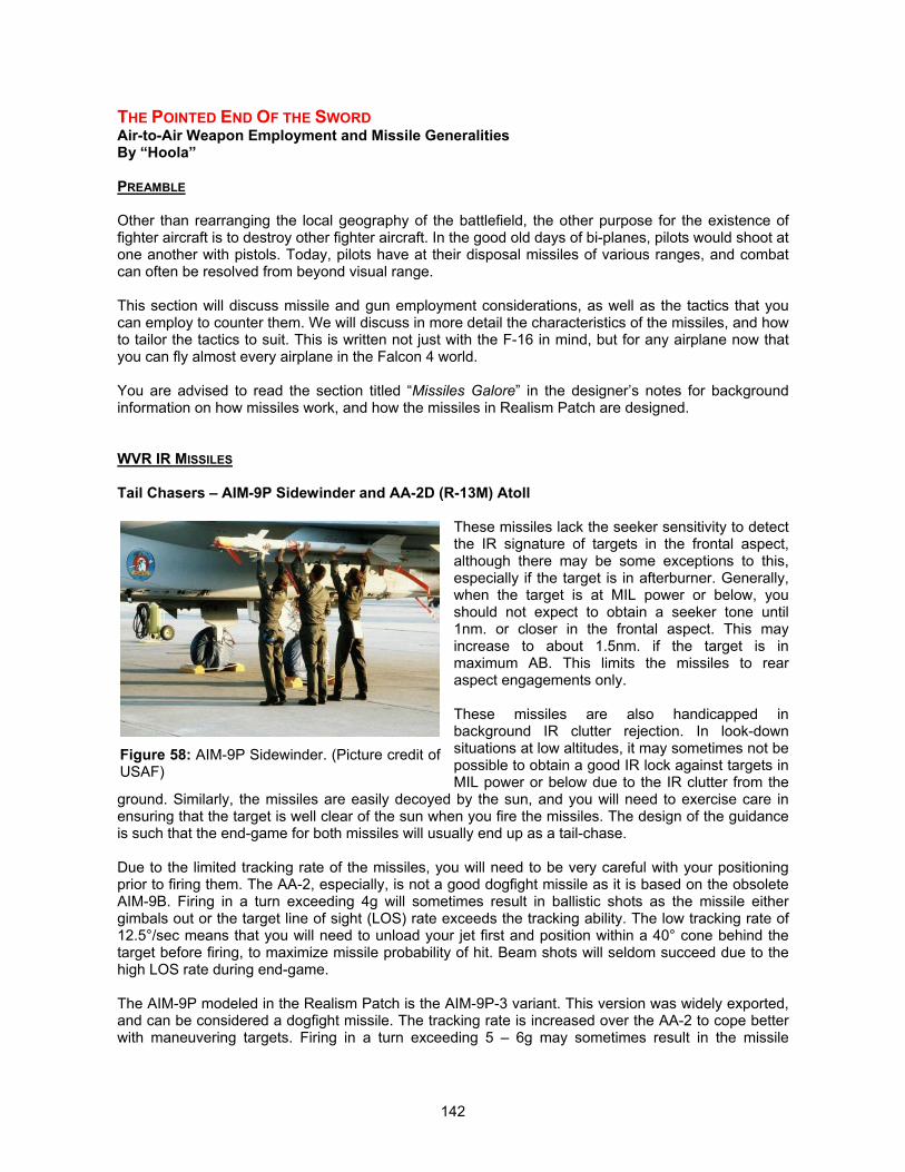
142
THE POINTED END OF THE SWORDAir-to-Air Weapon Employment and Missile GeneralitiesBy “Hoola”
PREAMBLE
Other than rearranging the local geography of the battlefield, the other purpose for the existence offighter aircraft is to destroy other fighter aircraft. In the good old days of bi-planes, pilots would shoot atone another with pistols. Today, pilots have at their disposal missiles of various ranges, and combatcan often be resolved from beyond visual range.
This section will discuss missile and gun employment considerations, as well as the tactics that youcan employ to counter them. We will discuss in more detail the characteristics of the missiles, and howto tailor the tactics to suit. This is written not just with the F-16 in mind, but for any airplane now thatyou can fly almost every airplane in the Falcon 4 world.
You are advised to read the section titled “Missiles Galore” in the designer’s notes for backgroundinformation on how missiles work, and how the missiles in Realism Patch are designed.
WVR IR MISSILES
Tail Chasers – AIM-9P Sidewinder and AA-2D (R-13M) Atoll
These missiles lack the seeker sensitivity to detectthe IR signature of targets in the frontal aspect,although there may be some exceptions to this,especially if the target is in afterburner. Generally,when the target is at MIL power or below, youshould not expect to obtain a seeker tone until1nm. or closer in the frontal aspect. This mayincrease to about 1.5nm. if the target is inmaximum AB. This limits the missiles to rearaspect engagements only.
These missiles are also handicapped inbackground IR clutter rejection. In look-downsituations at low altitudes, it may sometimes not bepossible to obtain a good IR lock against targets inMIL power or below due to the IR clutter from the
ground. Similarly, the missiles are easily decoyed by the sun, and you will need to exercise care inensuring that the target is well clear of the sun when you fire the missiles. The design of the guidanceis such that the end-game for both missiles will usually end up as a tail-chase.
Due to the limited tracking rate of the missiles, you will need to be very careful with your positioningprior to firing them. The AA-2, especially, is not a good dogfight missile as it is based on the obsoleteAIM-9B. Firing in a turn exceeding 4g will sometimes result in ballistic shots as the missile eithergimbals out or the target line of sight (LOS) rate exceeds the tracking ability. The low tracking rate of12.5°/sec means that you will need to unload your jet first and position within a 40° cone behind thetarget before firing, to maximize missile probability of hit. Beam shots will seldom succeed due to thehigh LOS rate during end-game.
The AIM-9P modeled in the Realism Patch is the AIM-9P-3 variant. This version was widely exported,and can be considered a dogfight missile. The tracking rate is increased over the AA-2 to cope betterwith maneuvering targets. Firing in a turn exceeding 5 – 6g may sometimes result in the missile
Figure 58: AIM-9P Sidewinder. (Picture credit ofUSAF)
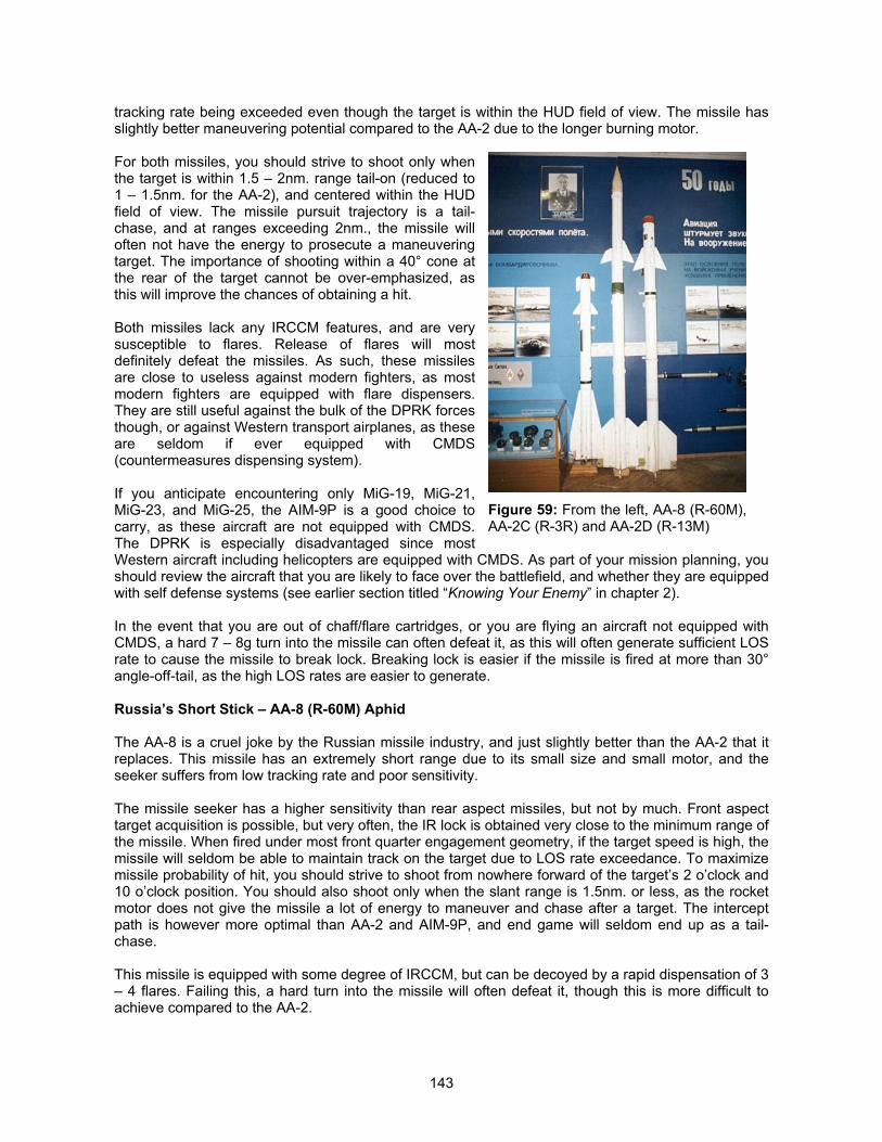
143
tracking rate being exceeded even though the target is within the HUD field of view. The missile hasslightly better maneuvering potential compared to the AA-2 due to the longer burning motor.
For both missiles, you should strive to shoot only whenthe target is within 1.5 – 2nm. range tail-on (reduced to1 – 1.5nm. for the AA-2), and centered within the HUDfield of view. The missile pursuit trajectory is a tail-chase, and at ranges exceeding 2nm., the missile willoften not have the energy to prosecute a maneuveringtarget. The importance of shooting within a 40° cone atthe rear of the target cannot be over-emphasized, asthis will improve the chances of obtaining a hit.
Both missiles lack any IRCCM features, and are verysusceptible to flares. Release of flares will mostdefinitely defeat the missiles. As such, these missilesare close to useless against modern fighters, as mostmodern fighters are equipped with flare dispensers.They are still useful against the bulk of the DPRK forcesthough, or against Western transport airplanes, as theseare seldom if ever equipped with CMDS(countermeasures dispensing system).
If you anticipate encountering only MiG-19, MiG-21,MiG-23, and MiG-25, the AIM-9P is a good choice tocarry, as these aircraft are not equipped with CMDS.The DPRK is especially disadvantaged since mostWestern aircraft including helicopters are equipped with CMDS. As part of your mission planning, youshould review the aircraft that you are likely to face over the battlefield, and whether they are equippedwith self defense systems (see earlier section titled “Knowing Your Enemy” in chapter 2).
In the event that you are out of chaff/flare cartridges, or you are flying an aircraft not equipped withCMDS, a hard 7 – 8g turn into the missile can often defeat it, as this will often generate sufficient LOSrate to cause the missile to break lock. Breaking lock is easier if the missile is fired at more than 30°angle-off-tail, as the high LOS rates are easier to generate.
Russia’s Short Stick – AA-8 (R-60M) Aphid
The AA-8 is a cruel joke by the Russian missile industry, and just slightly better than the AA-2 that itreplaces. This missile has an extremely short range due to its small size and small motor, and theseeker suffers from low tracking rate and poor sensitivity.
The missile seeker has a higher sensitivity than rear aspect missiles, but not by much. Front aspecttarget acquisition is possible, but very often, the IR lock is obtained very close to the minimum range ofthe missile. When fired under most front quarter engagement geometry, if the target speed is high, themissile will seldom be able to maintain track on the target due to LOS rate exceedance. To maximizemissile probability of hit, you should strive to shoot from nowhere forward of the target’s 2 o’clock and10 o’clock position. You should also shoot only when the slant range is 1.5nm. or less, as the rocketmotor does not give the missile a lot of energy to maneuver and chase after a target. The interceptpath is however more optimal than AA-2 and AIM-9P, and end game will seldom end up as a tail-chase.
This missile is equipped with some degree of IRCCM, but can be decoyed by a rapid dispensation of 3– 4 flares. Failing this, a hard turn into the missile will often defeat it, though this is more difficult toachieve compared to the AA-2.
Figure 59: From the left, AA-8 (R-60M),AA-2C (R-3R) and AA-2D (R-13M)
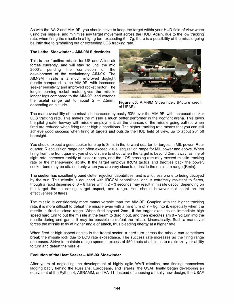
144
As with the AA-2 and AIM-9P, you should strive to keep the target within your HUD field of view whenusing this missile, and minimize any target movement across the HUD. Again, due to the low trackingrate, when firing the missile in a high g turn exceeding 6 – 7g, there is a possibility of the missile goingballistic due to gimballing out or exceeding LOS tracking rate.
The Lethal Sidewinder – AIM-9M Sidewinder
This is the frontline missile for US and Allied airforces currently, and will stay so until the mid2000’s pending the completion of thedevelopment of the evolutionary AIM-9X. TheAIM-9M missile is a much improved dogfightmissile compared to the AIM-9P, with increasedseeker sensitivity and improved rocket motor. Thelonger burning rocket motor gives the missilelonger legs compared to the AIM-9P, and extendsthe useful range out to about 2 – 2.5nm.,depending on altitude.
The maneuverability of the missile is increased by easily 50% over the AIM-9P, with increased seekerLOS tracking rate. This makes the missile a much better performer in the dogfight arena. This givesthe pilot greater leeway with missile employment, as the chances of the missile going ballistic whenfired are reduced when firing under high g conditions. The higher tracking rate means that you can stillachieve good success when firing at targets just outside the HUD field of view, up to about 20° offboresight.
You should expect a good seeker tone up to 3nm. in the forward quarter for targets in MIL power. Rearquarter IR acquisition range can often exceed visual acquisition range for MIL power and above. Whenfiring from the front quarter, you should strive to shoot when the target is beyond 2nm. away, as line ofsight rate increases rapidly at closer ranges, and the LOS crossing rate may exceed missile trackingrate or the maneuvering ability. If the target employs IRCM tactics and throttles back the power,seeker tone may be attained only when you are very close to or inside the minimum range (Rmin).
The seeker has excellent ground clutter rejection capabilities, and is a lot less prone to being decoyedby the sun. This missile is equipped with IRCCM capabilities, and is extremely resistant to flares,though a rapid dispense of 6 – 8 flares within 2 – 3 seconds may result in missile decoy, depending onthe target throttle setting, target aspect, and range. You should however not count on theeffectiveness of flares.
The missile is considerably more maneuverable than the AIM-9P. Coupled with the higher trackingrate, it is more difficult to defeat the missile even with a hard turn of 7 – 8g into it, especially when themissile is fired at close range. When fired beyond 2nm., if the target executes an immediate highspeed hard turn to put the missile at the beam to drag it out, and then executes am 8 – 9g turn into themissile during end game, it may be possible to defeat the missile kinematically. Such a maneuverforces the missile to fly at higher angle of attack, thus bleeding energy at a higher rate.
When fired at high aspect angles in the frontal sector, a hard turn across the missile can sometimesbreak the missile lock due to LOS rate exceedance. The success rate increases as the firing rangedecreases. Strive to maintain a high speed in excess of 450 knots at all times to maximize your abilityto turn and defeat the missile.
Evolution of the Heat Seeker – AIM-9X Sidewinder
After years of neglecting the development of highly agile WVR missiles, and finding themselveslagging badly behind the Russians, Europeans, and Israelis, the USAF finally began developing anequivalent of the Python 4, ASRAMM, and AA-11. Instead of choosing a totally new design, the USAF
Figure 60: AIM-9M Sidewinder. (Picture creditof USAF)
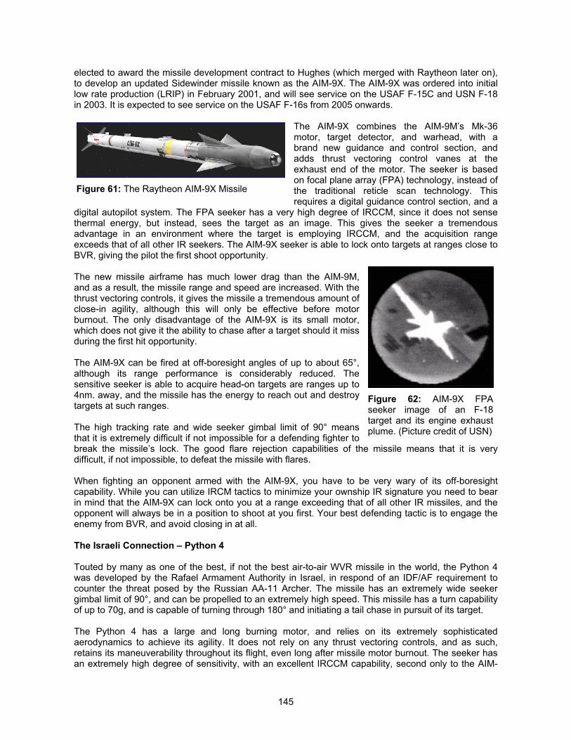
145
elected to award the missile development contract to Hughes (which merged with Raytheon later on),to develop an updated Sidewinder missile known as the AIM-9X. The AIM-9X was ordered into initiallow rate production (LRIP) in February 2001, and will see service on the USAF F-15C and USN F-18in 2003. It is expected to see service on the USAF F-16s from 2005 onwards.
The AIM-9X combines the AIM-9M’s Mk-36motor, target detector, and warhead, with abrand new guidance and control section, andadds thrust vectoring control vanes at theexhaust end of the motor. The seeker is basedon focal plane array (FPA) technology, instead ofthe traditional reticle scan technology. Thisrequires a digital guidance control section, and a
digital autopilot system. The FPA seeker has a very high degree of IRCCM, since it does not sensethermal energy, but instead, sees the target as an image. This gives the seeker a tremendousadvantage in an environment where the target is employing IRCCM, and the acquisition rangeexceeds that of all other IR seekers. The AIM-9X seeker is able to lock onto targets at ranges close toBVR, giving the pilot the first shoot opportunity.
The new missile airframe has much lower drag than the AIM-9M,and as a result, the missile range and speed are increased. With thethrust vectoring controls, it gives the missile a tremendous amount ofclose-in agility, although this will only be effective before motorburnout. The only disadvantage of the AIM-9X is its small motor,which does not give it the ability to chase after a target should it missduring the first hit opportunity.
The AIM-9X can be fired at off-boresight angles of up to about 65°,although its range performance is considerably reduced. Thesensitive seeker is able to acquire head-on targets are ranges up to4nm. away, and the missile has the energy to reach out and destroytargets at such ranges.
The high tracking rate and wide seeker gimbal limit of 90° meansthat it is extremely difficult if not impossible for a defending fighter tobreak the missile’s lock. The good flare rejection capabilities of the missile means that it is verydifficult, if not impossible, to defeat the missile with flares.
When fighting an opponent armed with the AIM-9X, you have to be very wary of its off-boresightcapability. While you can utilize IRCM tactics to minimize your ownship IR signature you need to bearin mind that the AIM-9X can lock onto you at a range exceeding that of all other IR missiles, and theopponent will always be in a position to shoot at you first. Your best defending tactic is to engage theenemy from BVR, and avoid closing in at all.
The Israeli Connection – Python 4
Touted by many as one of the best, if not the best air-to-air WVR missile in the world, the Python 4was developed by the Rafael Armament Authority in Israel, in respond of an IDF/AF requirement tocounter the threat posed by the Russian AA-11 Archer. The missile has an extremely wide seekergimbal limit of 90°, and can be propelled to an extremely high speed. This missile has a turn capabilityof up to 70g, and is capable of turning through 180° and initiating a tail chase in pursuit of its target.
The Python 4 has a large and long burning motor, and relies on its extremely sophisticatedaerodynamics to achieve its agility. It does not rely on any thrust vectoring controls, and as such,retains its maneuverability throughout its flight, even long after missile motor burnout. The seeker hasan extremely high degree of sensitivity, with an excellent IRCCM capability, second only to the AIM-
Figure 61: The Raytheon AIM-9X Missile
Figure 62: AIM-9X FPAseeker image of an F-18target and its engine exhaustplume. (Picture credit of USN)
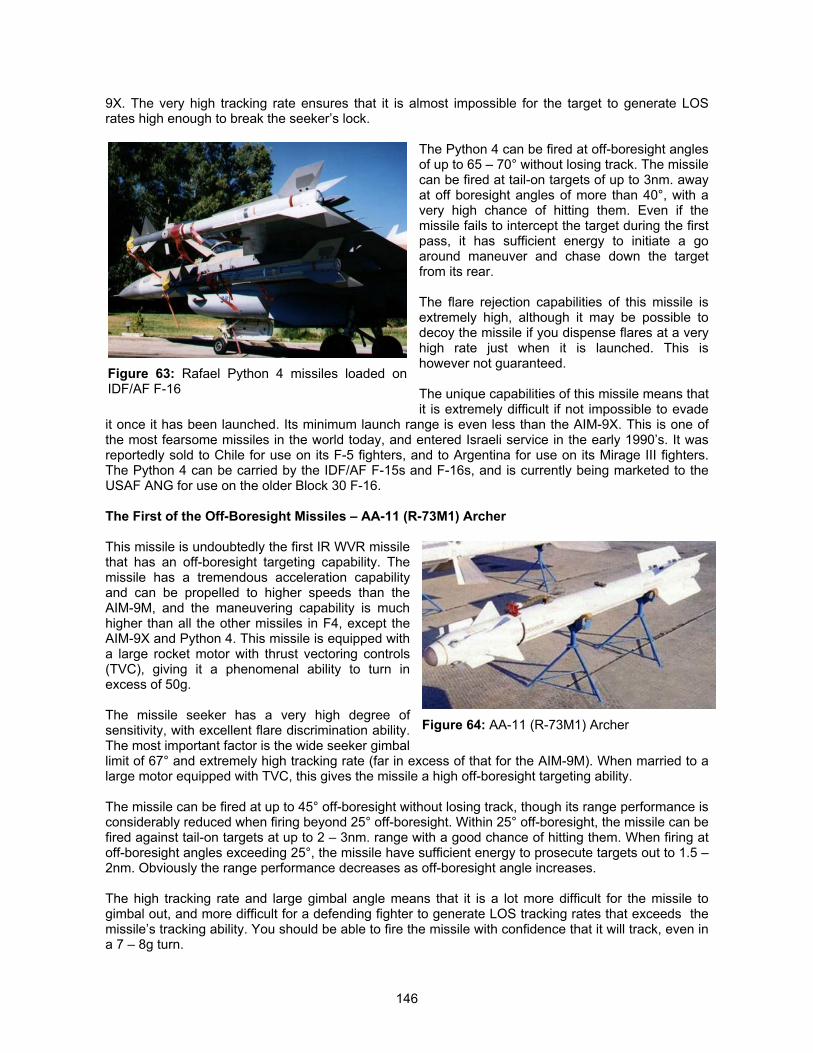
146
9X. The very high tracking rate ensures that it is almost impossible for the target to generate LOSrates high enough to break the seeker’s lock.
The Python 4 can be fired at off-boresight anglesof up to 65 – 70° without losing track. The missilecan be fired at tail-on targets of up to 3nm. awayat off boresight angles of more than 40°, with avery high chance of hitting them. Even if themissile fails to intercept the target during the firstpass, it has sufficient energy to initiate a goaround maneuver and chase down the targetfrom its rear.
The flare rejection capabilities of this missile isextremely high, although it may be possible todecoy the missile if you dispense flares at a veryhigh rate just when it is launched. This ishowever not guaranteed.
The unique capabilities of this missile means thatit is extremely difficult if not impossible to evade
it once it has been launched. Its minimum launch range is even less than the AIM-9X. This is one ofthe most fearsome missiles in the world today, and entered Israeli service in the early 1990’s. It wasreportedly sold to Chile for use on its F-5 fighters, and to Argentina for use on its Mirage III fighters.The Python 4 can be carried by the IDF/AF F-15s and F-16s, and is currently being marketed to theUSAF ANG for use on the older Block 30 F-16.
The First of the Off-Boresight Missiles – AA-11 (R-73M1) Archer
This missile is undoubtedly the first IR WVR missilethat has an off-boresight targeting capability. Themissile has a tremendous acceleration capabilityand can be propelled to higher speeds than theAIM-9M, and the maneuvering capability is muchhigher than all the other missiles in F4, except theAIM-9X and Python 4. This missile is equipped witha large rocket motor with thrust vectoring controls(TVC), giving it a phenomenal ability to turn inexcess of 50g.
The missile seeker has a very high degree ofsensitivity, with excellent flare discrimination ability.The most important factor is the wide seeker gimballimit of 67° and extremely high tracking rate (far in excess of that for the AIM-9M). When married to alarge motor equipped with TVC, this gives the missile a high off-boresight targeting ability.
The missile can be fired at up to 45° off-boresight without losing track, though its range performance isconsiderably reduced when firing beyond 25° off-boresight. Within 25° off-boresight, the missile can befired against tail-on targets at up to 2 – 3nm. range with a good chance of hitting them. When firing atoff-boresight angles exceeding 25°, the missile have sufficient energy to prosecute targets out to 1.5 –2nm. Obviously the range performance decreases as off-boresight angle increases.
The high tracking rate and large gimbal angle means that it is a lot more difficult for the missile togimbal out, and more difficult for a defending fighter to generate LOS tracking rates that exceeds themissile’s tracking ability. You should be able to fire the missile with confidence that it will track, even ina 7 – 8g turn.
Figure 63: Rafael Python 4 missiles loaded onIDF/AF F-16
Figure 64: AA-11 (R-73M1) Archer
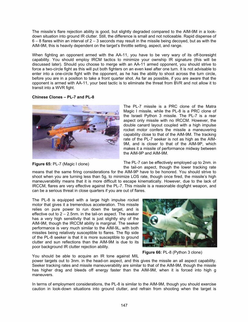
147
The missile’s flare rejection ability is good, but slightly degraded compared to the AIM-9M in a look-down situation into ground IR clutter. Still, the difference is small and not noticeable. Rapid dispense of6 – 8 flares within an interval of 2 – 3 seconds may result in the missile being decoyed, but as with theAIM-9M, this is heavily dependent on the target’s throttle setting, aspect, and range.
When fighting an opponent armed with the AA-11, you have to be very wary of its off-boresightcapability. You should employ IRCM tactics to minimize your ownship IR signature (this will bediscussed later). Should you choose to merge with an AA-11 armed opponent, you should strive toforce a two-circle fight as this will put both fighters on an even keel after one turn. It is not advisable toenter into a one-circle fight with the opponent, as he has the ability to shoot across the turn circle,before you are in a position to take a front quarter shot. As far as possible, if you are aware that theopponent is armed with AA-11, your best tactic is to eliminate the threat from BVR and not allow it totransit into a WVR fight.
Chinese Clones – PL-7 and PL-8
The PL-7 missile is a PRC clone of the MatraMagic I missile, while the PL-8 is a PRC clone ofthe Israeli Python 3 missile. The PL-7 is a rearaspect only missile with no IRCCM. However, thedouble canard layout coupled with a high impulserocket motor confers the missile a maneuveringcapability close to that of the AIM-9M. The trackingrate of the PL-7 seeker is not as high as the AIM-9M, and is closer to that of the AIM-9P, whichmakes it a missile of performance midway betweenthe AIM-9P and AIM-9M.
The PL-7 can be effectively employed up to 2nm. inthe tail-on aspect, though the lower tracking rate
means that the same firing considerations for the AIM-9P have to be honored. You should strive toshoot when you are turning less than 5g, to minimize LOS rate, though once fired, the missile’s highmaneuverability means that it is more difficult to escape kinematically. However, due to the lack ofIRCCM, flares are very effective against the PL-7. This missile is a reasonable dogfight weapon, andcan be a serious threat in close quarters if you are out of flares.
The PL-8 is equipped with a large high impulse rocketmotor that gives it a tremendous acceleration. This missilerelies on pure power to run down the target, and iseffective out to 2 – 2.5nm. in the tail-on aspect. The seekerhas a very high sensitivity that is just slightly shy of theAIM-9M, though the IRCCM ability is marginal. The seekerperformance is very much similar to the AIM-9L, with bothmissiles being relatively susceptible to flares. The flip sideof the PL-8 seeker is that it is more susceptible to groundclutter and sun reflections than the AIM-9M is due to itspoor background IR clutter rejection ability.
You should be able to acquire an IR tone against MILpower targets out to 3nm. in the head-on aspect, and this gives the missile an all aspect capability.Seeker tracking rates and missile maneuverability are similar to that of the AIM-9M, though the missilehas higher drag and bleeds off energy faster than the AIM-9M, when it is forced into high gmaneuvers.
In terms of employment considerations, the PL-8 is similar to the AIM-9M, though you should exercisecaution in look-down situations into ground clutter, and refrain from shooting when the target is
Figure 65: PL-7 (Magic I clone)
Figure 66: PL-8 (Python 3 clone)
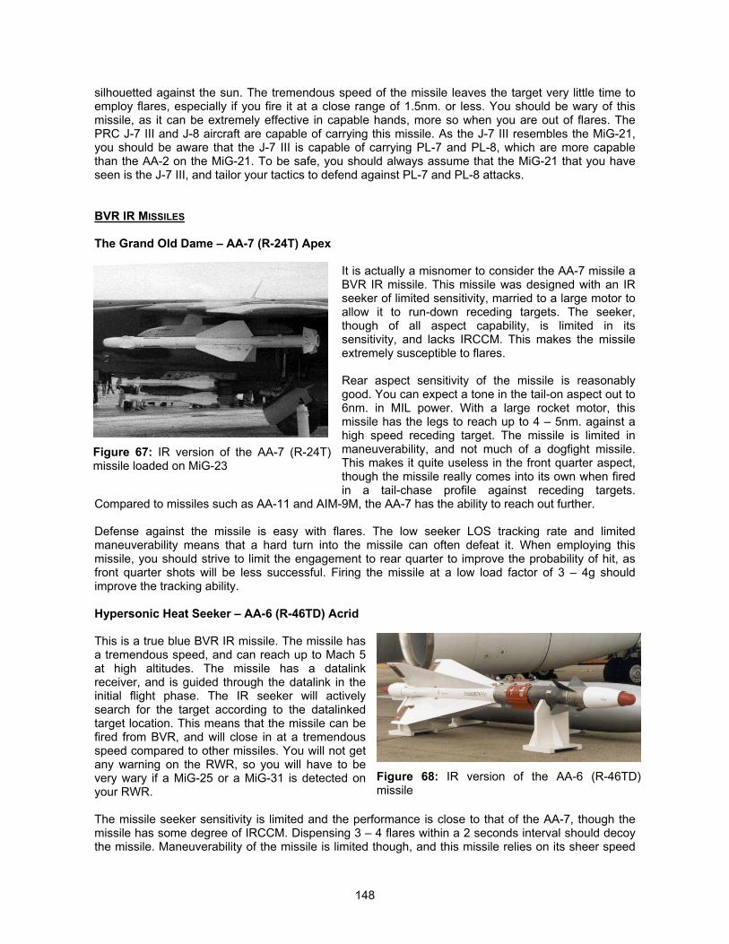
148
silhouetted against the sun. The tremendous speed of the missile leaves the target very little time toemploy flares, especially if you fire it at a close range of 1.5nm. or less. You should be wary of thismissile, as it can be extremely effective in capable hands, more so when you are out of flares. ThePRC J-7 III and J-8 aircraft are capable of carrying this missile. As the J-7 III resembles the MiG-21,you should be aware that the J-7 III is capable of carrying PL-7 and PL-8, which are more capablethan the AA-2 on the MiG-21. To be safe, you should always assume that the MiG-21 that you haveseen is the J-7 III, and tailor your tactics to defend against PL-7 and PL-8 attacks.
BVR IR MISSILES
The Grand Old Dame – AA-7 (R-24T) Apex
It is actually a misnomer to consider the AA-7 missile aBVR IR missile. This missile was designed with an IRseeker of limited sensitivity, married to a large motor toallow it to run-down receding targets. The seeker,though of all aspect capability, is limited in itssensitivity, and lacks IRCCM. This makes the missileextremely susceptible to flares.
Rear aspect sensitivity of the missile is reasonablygood. You can expect a tone in the tail-on aspect out to6nm. in MIL power. With a large rocket motor, thismissile has the legs to reach up to 4 – 5nm. against ahigh speed receding target. The missile is limited inmaneuverability, and not much of a dogfight missile.This makes it quite useless in the front quarter aspect,though the missile really comes into its own when firedin a tail-chase profile against receding targets.
Compared to missiles such as AA-11 and AIM-9M, the AA-7 has the ability to reach out further.
Defense against the missile is easy with flares. The low seeker LOS tracking rate and limitedmaneuverability means that a hard turn into the missile can often defeat it. When employing thismissile, you should strive to limit the engagement to rear quarter to improve the probability of hit, asfront quarter shots will be less successful. Firing the missile at a low load factor of 3 – 4g shouldimprove the tracking ability.
Hypersonic Heat Seeker – AA-6 (R-46TD) Acrid
This is a true blue BVR IR missile. The missile hasa tremendous speed, and can reach up to Mach 5at high altitudes. The missile has a datalinkreceiver, and is guided through the datalink in theinitial flight phase. The IR seeker will activelysearch for the target according to the datalinkedtarget location. This means that the missile can befired from BVR, and will close in at a tremendousspeed compared to other missiles. You will not getany warning on the RWR, so you will have to bevery wary if a MiG-25 or a MiG-31 is detected onyour RWR.
The missile seeker sensitivity is limited and the performance is close to that of the AA-7, though themissile has some degree of IRCCM. Dispensing 3 – 4 flares within a 2 seconds interval should decoythe missile. Maneuverability of the missile is limited though, and this missile relies on its sheer speed
Figure 67: IR version of the AA-7 (R-24T)missile loaded on MiG-23
Figure 68: IR version of the AA-6 (R-46TD)missile
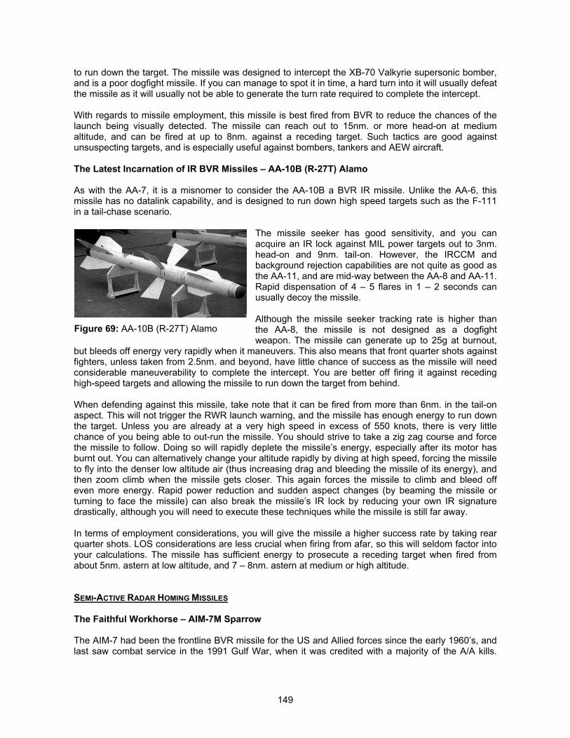
149
to run down the target. The missile was designed to intercept the XB-70 Valkyrie supersonic bomber,and is a poor dogfight missile. If you can manage to spot it in time, a hard turn into it will usually defeatthe missile as it will usually not be able to generate the turn rate required to complete the intercept.
With regards to missile employment, this missile is best fired from BVR to reduce the chances of thelaunch being visually detected. The missile can reach out to 15nm. or more head-on at mediumaltitude, and can be fired at up to 8nm. against a receding target. Such tactics are good againstunsuspecting targets, and is especially useful against bombers, tankers and AEW aircraft.
The Latest Incarnation of IR BVR Missiles – AA-10B (R-27T) Alamo
As with the AA-7, it is a misnomer to consider the AA-10B a BVR IR missile. Unlike the AA-6, thismissile has no datalink capability, and is designed to run down high speed targets such as the F-111in a tail-chase scenario.
The missile seeker has good sensitivity, and you canacquire an IR lock against MIL power targets out to 3nm.head-on and 9nm. tail-on. However, the IRCCM andbackground rejection capabilities are not quite as good asthe AA-11, and are mid-way between the AA-8 and AA-11.Rapid dispensation of 4 – 5 flares in 1 – 2 seconds canusually decoy the missile.
Although the missile seeker tracking rate is higher thanthe AA-8, the missile is not designed as a dogfightweapon. The missile can generate up to 25g at burnout,
but bleeds off energy very rapidly when it maneuvers. This also means that front quarter shots againstfighters, unless taken from 2.5nm. and beyond, have little chance of success as the missile will needconsiderable maneuverability to complete the intercept. You are better off firing it against recedinghigh-speed targets and allowing the missile to run down the target from behind.
When defending against this missile, take note that it can be fired from more than 6nm. in the tail-onaspect. This will not trigger the RWR launch warning, and the missile has enough energy to run downthe target. Unless you are already at a very high speed in excess of 550 knots, there is very littlechance of you being able to out-run the missile. You should strive to take a zig zag course and forcethe missile to follow. Doing so will rapidly deplete the missile’s energy, especially after its motor hasburnt out. You can alternatively change your altitude rapidly by diving at high speed, forcing the missileto fly into the denser low altitude air (thus increasing drag and bleeding the missile of its energy), andthen zoom climb when the missile gets closer. This again forces the missile to climb and bleed offeven more energy. Rapid power reduction and sudden aspect changes (by beaming the missile orturning to face the missile) can also break the missile’s IR lock by reducing your own IR signaturedrastically, although you will need to execute these techniques while the missile is still far away.
In terms of employment considerations, you will give the missile a higher success rate by taking rearquarter shots. LOS considerations are less crucial when firing from afar, so this will seldom factor intoyour calculations. The missile has sufficient energy to prosecute a receding target when fired fromabout 5nm. astern at low altitude, and 7 – 8nm. astern at medium or high altitude.
SEMI-ACTIVE RADAR HOMING MISSILES
The Faithful Workhorse – AIM-7M Sparrow
The AIM-7 had been the frontline BVR missile for the US and Allied forces since the early 1960’s, andlast saw combat service in the 1991 Gulf War, when it was credited with a majority of the A/A kills.
Figure 69: AA-10B (R-27T) Alamo
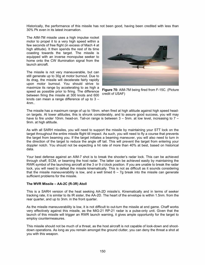
150
Historically, the performance of this missile has not been good, having been credited with less than30% Pk even in its latest incarnation.
The AIM-7M missile uses a high impulse rocketmotor to propel it to a very high speed within afew seconds of free flight (in excess of Mach 4 athigh altitude). It then spends the rest of its timecoasting towards the target. The missile isequipped with an inverse monopulse seeker tohome onto the CW illumination signal from thelaunch aircraft.
The missile is not very maneuverable, but canstill generate up to 30g at motor burnout. Due toits drag, the missile will decelerate fairly rapidlyupon motor burnout. You should strive tomaximize its range by accelerating to as high aspeed as possible prior to firing. The differencebetween firing the missile at 300 knots and 600knots can mean a range difference of up to 3 –4nm..
The missile has a maximum range of up to 18nm. when fired at high altitude against high speed head-on targets. At lower altitudes, this is shrunk considerably, and to assure good success, you will mayhave to fire under 10nm. head-on. Tail-on range is between 3 – 5nm. at low level, increasing to 7 –9nm. at high altitude.
As with all SARH missiles, you will need to support the missile by maintaining your STT lock on thetarget throughout the entire missile flight till impact. As such, you will need to fly a course that preventsthe target from beaming you. If the target initiates a beaming maneuver, you will also need to turn inthe direction of the target to reduce the angle off tail. This will prevent the target from entering yourdoppler notch. You should not be expecting a hit rate of more than 40% at best, based on historicaldata.
Your best defense against an AIM-7 shot is to break the shooter’s radar lock. This can be achievedthrough chaff, ECM, or beaming the host radar. The latter can be achieved easily by maintaining theRWR symbol of the launching aircraft at the 3 or 9 o’clock position. If you are unable to break the radarlock, you will need to defeat the missile kinematically. This is not as difficult as it sounds consideringthat the missile maneuverability is low, and a well timed 6 – 7g break into the missile can generatesufficient problems for the missile.
The WVR Missile – AA-2C (R-3R) Atoll
This is a SARH version of the heat seeking AA-2D missile’s. Kinematically and in terms of seekertracking rate, it is similar to its IR sister, the AA-2D. The heart of the envelope is within 1.5nm. from therear quarter, and up to 3nm. in the front quarter.
As the missile maneuverability is low, it is not difficult to out-turn the missile at end game. Chaff worksvery effectively against this missile, as the MiG-21 RP-21 radar is a pulse-only unit. Given that thelaunch of this missile will trigger an RWR launch warning, it gives ample opportunity for the target toemploy countermeasures.
This missile should not be much of a threat, as the host aircraft is not capable of look-down and shoot-down operations. As long as you remain amongst the ground clutter, you can deny the threat a shot atyou with this weapon.
Figure 70: AIM-7M being fired from F-15C. (Picturecredit of USAF)
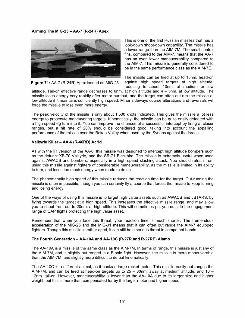
151
Arming The MiG-23 – AA-7 (R-24R) Apex
This is one of the first Russian missiles that has alook-down shoot-down capability. The missile hasa lower range than the AIM-7M. The small controlfins, compared to the AIM-7, means that the AA-7has an even lower maneuverability compared tothe AIM-7. This missile is generally considered tobe in the same performance class as the AIM-7E.
The missile can be fired at up to 15nm. head-onagainst high speed targets at high altitude,reducing to about 10nm. at medium or low
altitude. Tail-on effective range decreases to 6nm. at high altitude and 4 – 5nm. at low altitude. Themissile loses energy very rapidly after motor burnout, and the target can often out-run the missile atlow altitude if it maintains sufficiently high speed. Minor sideways course alterations and reversals willforce the missile to lose even more energy.
The peak velocity of the missile is only about 1,500 knots indicated. This gives the missile a lot lessenergy to prosecute maneuvering targets. Kinematically, the missile can be quite easily defeated witha high speed 6g turn into it. You can improve the chances of a successful intercept by firing at closerranges, but a hit rate of 20% should be considered good, taking into account the appallingperformance of the missile over the Bekaa Valley when used by the Syrians against the Israelis.
Valkyrie Killer – AA-6 (R-46RD) Acrid
As with the IR version of the AA-6, this missile was designed to intercept high altitude bombers suchas the defunct XB-70 Valkyrie, and the SR-71 Blackbird. The missile is extremely useful when usedagainst AWACS and bombers, especially in a high speed slashing attack. You should refrain fromusing this missile against fighters of considerable maneuverability, as the missile is limited in its abilityto turn, and loses too much energy when made to do so.
The phenomenally high speed of this missile reduces the reaction time for the target. Out-running themissile is often impossible, though you can certainly fly a course that forces the missile to keep turningand losing energy.
One of the ways of using this missile is to target high value assets such as AWACS and JSTARS, byflying towards the target at a high speed. This increases the effective missile range, and may allowyou to shoot from out to 20nm. at high altitude. This will sometimes put you outside the engagementrange of CAP flights protecting the high value asset.
Remember that when you face this threat, your reaction time is much shorter. The tremendousacceleration of the MiG-25 and the MiG-31 means that it can often out range the AIM-7 equippedfighters. Though this missile is rather aged, it can still be a serious threat in competent hands.
The Fourth Generation – AA-10A and AA-10C (R-27R and R-27RE) Alamo
The AA-10A is a missile of the same class as the AIM-7M. In terms of range, this missile is just shy ofthe AIM-7M, and is slightly out-ranged in a F-pole fight. However, the missile is more maneuverablethan the AIM-7M, and slightly more difficult to defeat kinematically.
The AA-10C is a different animal, as it packs a large rocket motor. This missile easily out-ranges theAIM-7M, and can be fired at head-on targets up to 25 – 30nm. away at medium altitude, and 10 –12nm. tail-on. However, maneuverability is lower than the AA-10A due to its larger size and higherweight, but this is more than compensated for by the larger motor and higher speed.
Figure 71: AA-7 (R-24R) Apex loaded on MiG-23
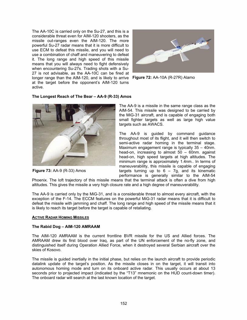
152
The AA-10C is carried only on the Su-27, and this is aconsiderable threat even for AIM-120 shooters, as themissile out-ranges even the AIM-120. The morepowerful Su-27 radar means that it is more difficult touse ECM to defeat this missile, and you will need touse a combination of chaff and maneuvering to defeatit. The long range and high speed of this missilemeans that you will always need to fight defensivelywhen encountering Su-27s. Trading shots with a Su-27 is not advisable, as the AA-10C can be fired atlonger range than the AIM-120, and is likely to arriveat the target before the opponent’s AIM-120 turnsactive.
The Longest Reach of The Bear – AA-9 (R-33) Amos
The AA-9 is a missile in the same range class as theAIM-54. This missile was designed to be carried bythe MiG-31 aircraft, and is capable of engaging bothsmall fighter targets as well as large high valuetargets such as AWACS.
The AA-9 is guided by command guidancethroughout most of its flight, and it will then switch tosemi-active radar homing in the terminal stage.Maximum engagement range is typically 35 – 40nm.head-on, increasing to almost 50 – 60nm. againsthead-on, high speed targets at high altitudes. Theminimum range is approximately 1.4nm.. In terms ofmaneuverability, this missile is capable of engagingtargets turning up to 6 – 7g, and its kinematicperformance is generally similar to the AIM-54
Phoenix. The loft trajectory of this missile means that the terminal attack is often a dive from highaltitudes. This gives the missile a very high closure rate and a high degree of maneuverability.
The AA-9 is carried only by the MiG-31, and is a considerable threat to almost every aircraft, with theexception of the F-14. The ECCM features on the powerful MiG-31 radar means that it is difficult todefeat the missile with jamming and chaff. The long range and high speed of the missile means that itis likely to reach its target before the target is capable of retaliating.
ACTIVE RADAR HOMING MISSILES
The Rabid Dog – AIM-120 AMRAAM
The AIM-120 AMRAAM is the current frontline BVR missile for the US and Allied forces. TheAMRAAM drew its first blood over Iraq, as part of the UN enforcement of the no-fly zone, anddistinguished itself during Operation Allied Force, when it destroyed several Serbian aircraft over theskies of Kosovo.
The missile is guided inertially in the initial phase, but relies on the launch aircraft to provide periodicdatalink update of the target’s position. As the missile closes in on the target, it will transit intoautonomous homing mode and turn on its onboard active radar. This usually occurs at about 13seconds prior to projected impact (indicated by the “T13” mnemonic on the HUD count-down timer).The onboard radar will search at the last known location of the target.
Figure 72: AA-10A (R-27R) Alamo
Figure 73: AA-9 (R-33) Amos
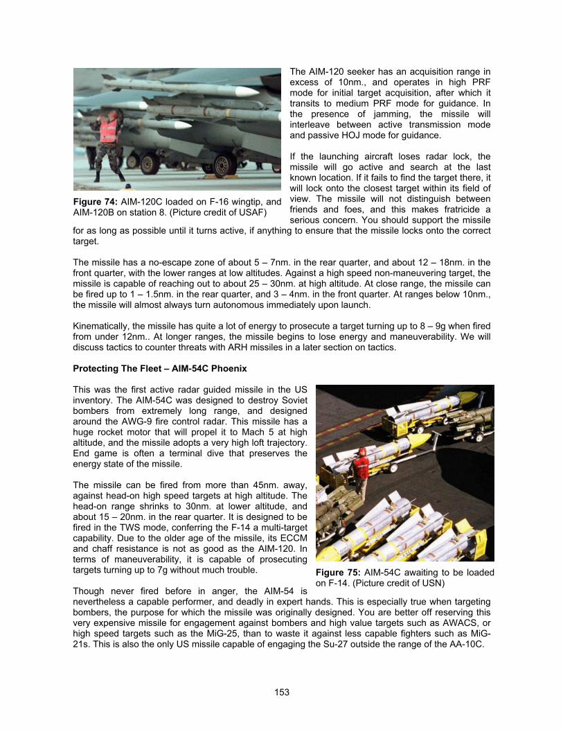
153
The AIM-120 seeker has an acquisition range inexcess of 10nm., and operates in high PRFmode for initial target acquisition, after which ittransits to medium PRF mode for guidance. Inthe presence of jamming, the missile willinterleave between active transmission modeand passive HOJ mode for guidance.
If the launching aircraft loses radar lock, themissile will go active and search at the lastknown location. If it fails to find the target there, itwill lock onto the closest target within its field ofview. The missile will not distinguish betweenfriends and foes, and this makes fratricide aserious concern. You should support the missile
for as long as possible until it turns active, if anything to ensure that the missile locks onto the correcttarget.
The missile has a no-escape zone of about 5 – 7nm. in the rear quarter, and about 12 – 18nm. in thefront quarter, with the lower ranges at low altitudes. Against a high speed non-maneuvering target, themissile is capable of reaching out to about 25 – 30nm. at high altitude. At close range, the missile canbe fired up to 1 – 1.5nm. in the rear quarter, and 3 – 4nm. in the front quarter. At ranges below 10nm.,the missile will almost always turn autonomous immediately upon launch.
Kinematically, the missile has quite a lot of energy to prosecute a target turning up to 8 – 9g when firedfrom under 12nm.. At longer ranges, the missile begins to lose energy and maneuverability. We willdiscuss tactics to counter threats with ARH missiles in a later section on tactics.
Protecting The Fleet – AIM-54C Phoenix
This was the first active radar guided missile in the USinventory. The AIM-54C was designed to destroy Sovietbombers from extremely long range, and designedaround the AWG-9 fire control radar. This missile has ahuge rocket motor that will propel it to Mach 5 at highaltitude, and the missile adopts a very high loft trajectory.End game is often a terminal dive that preserves theenergy state of the missile.
The missile can be fired from more than 45nm. away,against head-on high speed targets at high altitude. Thehead-on range shrinks to 30nm. at lower altitude, andabout 15 – 20nm. in the rear quarter. It is designed to befired in the TWS mode, conferring the F-14 a multi-targetcapability. Due to the older age of the missile, its ECCMand chaff resistance is not as good as the AIM-120. Interms of maneuverability, it is capable of prosecutingtargets turning up to 7g without much trouble.
Though never fired before in anger, the AIM-54 isnevertheless a capable performer, and deadly in expert hands. This is especially true when targetingbombers, the purpose for which the missile was originally designed. You are better off reserving thisvery expensive missile for engagement against bombers and high value targets such as AWACS, orhigh speed targets such as the MiG-25, than to waste it against less capable fighters such as MiG-21s. This is also the only US missile capable of engaging the Su-27 outside the range of the AA-10C.
Figure 74: AIM-120C loaded on F-16 wingtip, andAIM-120B on station 8. (Picture credit of USAF)
Figure 75: AIM-54C awaiting to be loadedon F-14. (Picture credit of USN)
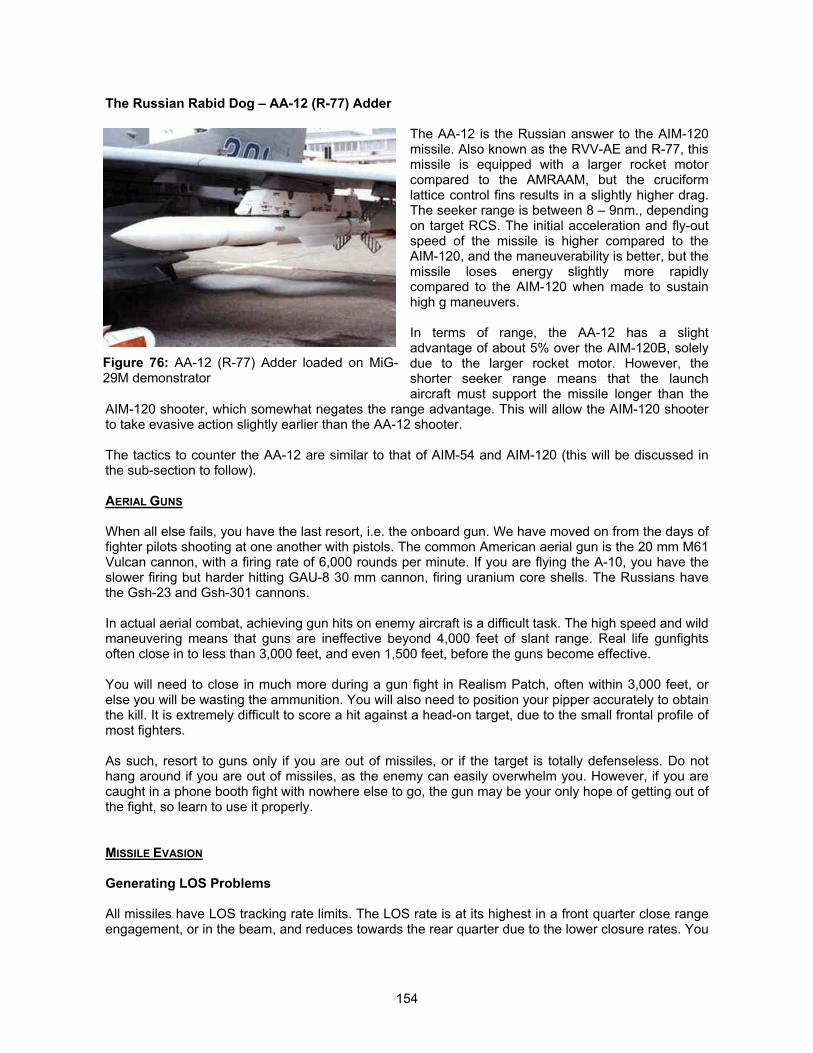
154
The Russian Rabid Dog – AA-12 (R-77) Adder
The AA-12 is the Russian answer to the AIM-120missile. Also known as the RVV-AE and R-77, thismissile is equipped with a larger rocket motorcompared to the AMRAAM, but the cruciformlattice control fins results in a slightly higher drag.The seeker range is between 8 – 9nm., dependingon target RCS. The initial acceleration and fly-outspeed of the missile is higher compared to theAIM-120, and the maneuverability is better, but themissile loses energy slightly more rapidlycompared to the AIM-120 when made to sustainhigh g maneuvers.
In terms of range, the AA-12 has a slightadvantage of about 5% over the AIM-120B, solelydue to the larger rocket motor. However, theshorter seeker range means that the launchaircraft must support the missile longer than the
AIM-120 shooter, which somewhat negates the range advantage. This will allow the AIM-120 shooterto take evasive action slightly earlier than the AA-12 shooter.
The tactics to counter the AA-12 are similar to that of AIM-54 and AIM-120 (this will be discussed inthe sub-section to follow).
AERIAL GUNS
When all else fails, you have the last resort, i.e. the onboard gun. We have moved on from the days offighter pilots shooting at one another with pistols. The common American aerial gun is the 20 mm M61Vulcan cannon, with a firing rate of 6,000 rounds per minute. If you are flying the A-10, you have theslower firing but harder hitting GAU-8 30 mm cannon, firing uranium core shells. The Russians havethe Gsh-23 and Gsh-301 cannons.
In actual aerial combat, achieving gun hits on enemy aircraft is a difficult task. The high speed and wildmaneuvering means that guns are ineffective beyond 4,000 feet of slant range. Real life gunfightsoften close in to less than 3,000 feet, and even 1,500 feet, before the guns become effective.
You will need to close in much more during a gun fight in Realism Patch, often within 3,000 feet, orelse you will be wasting the ammunition. You will also need to position your pipper accurately to obtainthe kill. It is extremely difficult to score a hit against a head-on target, due to the small frontal profile ofmost fighters.
As such, resort to guns only if you are out of missiles, or if the target is totally defenseless. Do nothang around if you are out of missiles, as the enemy can easily overwhelm you. However, if you arecaught in a phone booth fight with nowhere else to go, the gun may be your only hope of getting out ofthe fight, so learn to use it properly.
MISSILE EVASION
Generating LOS Problems
All missiles have LOS tracking rate limits. The LOS rate is at its highest in a front quarter close rangeengagement, or in the beam, and reduces towards the rear quarter due to the lower closure rates. You
Figure 76: AA-12 (R-77) Adder loaded on MiG-29M demonstrator
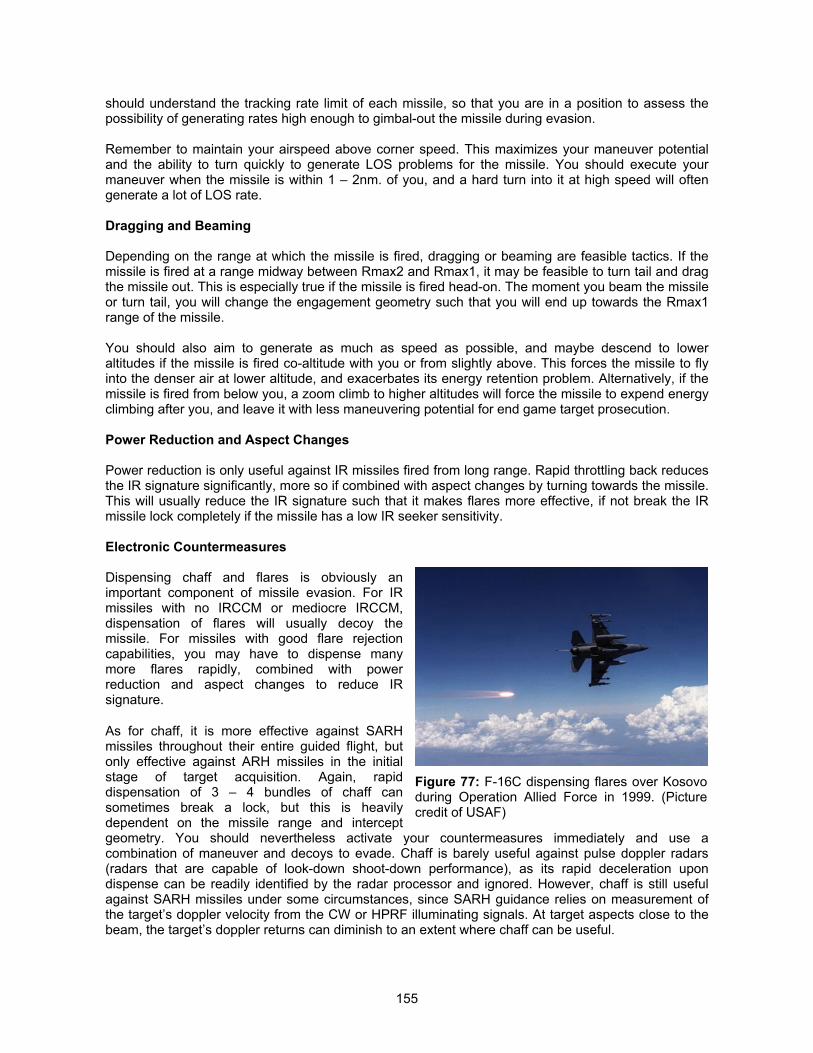
155
should understand the tracking rate limit of each missile, so that you are in a position to assess thepossibility of generating rates high enough to gimbal-out the missile during evasion.
Remember to maintain your airspeed above corner speed. This maximizes your maneuver potentialand the ability to turn quickly to generate LOS problems for the missile. You should execute yourmaneuver when the missile is within 1 – 2nm. of you, and a hard turn into it at high speed will oftengenerate a lot of LOS rate.
Dragging and Beaming
Depending on the range at which the missile is fired, dragging or beaming are feasible tactics. If themissile is fired at a range midway between Rmax2 and Rmax1, it may be feasible to turn tail and dragthe missile out. This is especially true if the missile is fired head-on. The moment you beam the missileor turn tail, you will change the engagement geometry such that you will end up towards the Rmax1range of the missile.
You should also aim to generate as much as speed as possible, and maybe descend to loweraltitudes if the missile is fired co-altitude with you or from slightly above. This forces the missile to flyinto the denser air at lower altitude, and exacerbates its energy retention problem. Alternatively, if themissile is fired from below you, a zoom climb to higher altitudes will force the missile to expend energyclimbing after you, and leave it with less maneuvering potential for end game target prosecution.
Power Reduction and Aspect Changes
Power reduction is only useful against IR missiles fired from long range. Rapid throttling back reducesthe IR signature significantly, more so if combined with aspect changes by turning towards the missile.This will usually reduce the IR signature such that it makes flares more effective, if not break the IRmissile lock completely if the missile has a low IR seeker sensitivity.
Electronic Countermeasures
Dispensing chaff and flares is obviously animportant component of missile evasion. For IRmissiles with no IRCCM or mediocre IRCCM,dispensation of flares will usually decoy themissile. For missiles with good flare rejectioncapabilities, you may have to dispense manymore flares rapidly, combined with powerreduction and aspect changes to reduce IRsignature.
As for chaff, it is more effective against SARHmissiles throughout their entire guided flight, butonly effective against ARH missiles in the initialstage of target acquisition. Again, rapiddispensation of 3 – 4 bundles of chaff cansometimes break a lock, but this is heavilydependent on the missile range and interceptgeometry. You should nevertheless activate your countermeasures immediately and use acombination of maneuver and decoys to evade. Chaff is barely useful against pulse doppler radars(radars that are capable of look-down shoot-down performance), as its rapid deceleration upondispense can be readily identified by the radar processor and ignored. However, chaff is still usefulagainst SARH missiles under some circumstances, since SARH guidance relies on measurement ofthe target’s doppler velocity from the CW or HPRF illuminating signals. At target aspects close to thebeam, the target’s doppler returns can diminish to an extent where chaff can be useful.
Figure 77: F-16C dispensing flares over Kosovoduring Operation Allied Force in 1999. (Picturecredit of USAF)
156
ECM can be very effective against SAMs, provided you stay outside the burn-through range. Usage ofECM against aircraft is more dicey, as it will compromise your position and allow them to vectortowards you. Since SAM sites cannot move so rapidly, even though you will compromise your position,this is less of a concern.
Do remember to turn off your ECM system once you have defeated the threat. Forgetting to turn it offwill often attract a huge gaggle of enemy fighters on your tail, and this is hardly the kind of attentionthat you will want.
Dealing With SARH Missiles
You need to remember that as long as you can defeat the radar on the launching aircraft, you willsucceed in defeating the missile. This means that you must make life as hard as possible for the hostradar, by beaming, employing ECM, and forcing the radar to look-down into ground clutter, plusemploying chaff. You can decrease your altitude rapidly, while flying a course that puts the threat radaron your beam. You will need to adjust your course all the time to maintain the threat radar in yourbeam, and this is easy to do using the RWR. Combined with decoys, this can often defeat the hostradar and break its lock. When all else fails, you will need to defeat the missile kinematically.
Defeating ARH Missiles
Please see the sub-section, “Modeling the ARH Missile Seekers (Monopulse with Home-On-Jam)” inthe designer’s notes section titled “The Electronic Battlefield,” for the background information on howthese ARH missile seekers work. You are best served if you understand the characteristics of the ARHmissile seekers, so that you can take the appropriate actions to counter them.
Jamming will not work well against these missiles, and you may be making matters worse by givingthe missile a beacon to home on. As such, the first reaction should be to turn off your jammer so thatyou will not trigger the HOJ mode of the missile and give it a beacon to track. You should alsodispense chaff immediately (and at a rapid rate) before the missile has a lock on you. Once locked on,the missile is exceedingly difficult to decoy with chaff. In fact, if you are unaware of the missile launchuntil the missile symbology appears on the RWR, chances of defeating the missiles are very low, butyou might want to try a maximum g break into the missile (it is useless to employ chaff by now). Withluck, you may generate sufficiently high LOS rates that will exceed the missile’s tracking ability.
The best way to defeat an ARH missile is to commence evasion at the point of launch, so that you candefeat it kinematically. This is difficult as the RWR does not show whether the bandit has launched ornot and the only indication you will get is when the missile goes autonomous, by which time it is almoston top of you.
You should fly an arcing path that will bring you around the missile, keeping it in your beam for as longas possible. This forces the missile to fly an arcing path to you, allowing you to bleed the missile of itsenergy after its motor has burnt out. At the same time, it also degrades the seeker radar signal returnand keeps you within the doppler notch of the missile. You should note that it is important to fly so asto beam the radar in the missile not the radar in the launching aircraft once the missile radar goesactive.
Effective evasion will require a combination of different tactics, and you should also strive to divetowards the ground and force the missile to acquire you amidst the ground clutter. The combination ofbeaming and look-down will often delay the missile target acquisition, and increase chaffeffectiveness. At the same time, it allows you to bleed energy from the missile, thus decreasing its endgame maneuverability. The by-product of diving towards the ground is also to force the missile to flyinto the denser air at lower altitudes, where the drag will be higher, thus increasing its energy bleedrate.
157
You should also utilize uplink starvation tactics to deny the missile of datalink updates. This meansthat you should break the launch aircraft’s radar lock as soon as possible when he has launched, andrapidly change your spatial location so that you will be outside the missile seeker field of view when itturns autonomous after the inertial phase. The missile will search for you in the vicinity of your lastknown location prior to you breaking the launch aircraft’s radar lock, so it is imperative that you fly outof its search area. This is easier said than done considering that you will not have any launchindication other than the visual signature of the missile’s motor. Remember that you should bebeaming the launch aircraft before the missile turns active (by keeping the RWR symbol at the 3 or 9o’clock position), but once the missile goes active, you should be beaming the missile.
If the missile is fired at longer ranges, the most effective tactic is to turn tail and drag the missile out. Ifyou are heavily loaded, you should consider jettisoning the weapons to clean up the aircraft, andaccelerate as fast as possible away from the missile.
The fact that the launch warning is absent will force you to change your tactics. You will need toidentify the threat on the RWR and determine the aircraft type, and if the emitter is capable of carryingARH missiles, you will need to accord it the respect it deserves. You can ill afford to go chargingstraight at the threat and hope to get off a missile before it does, and will need to utilize proper F-poleand A-pole tactics to approach the threat, while denying it the opportunity to obtain a radar lock onyou. Hopefully, you will get off a shot first before it does. This is where understanding the radar andmissile capabilities of each threat becomes extremely important. Understanding the threat’scapabilities will allow you to ascertain if you are within its effective weapon employment range. Ifnecessary, you will need to fly defensively and assume the worst case scenario that the threat hasalready fired a missile at you.
MISSILE ARMING AND FUSING
An important factor to remember during the employment of missiles is the arming and fusing timerequired. All missiles have an arming and fusing delay. This is a safety mechanism, and inhibits thewarhead from detonating until the missile has flown to a distance sufficiently far away from the launchaircraft such that any inadvertent warhead detonation will not harm the launch aircraft. For long rangeSAMs with booster sections or strapped-on booster motors, the warhead will often arm only afterbooster separation.
This means that while the missile may commence guidance immediately upon launch, there is stillminimum time of flight required for the missile. The range within which the warhead will not arm isdependent on the engagement geometry, with the greatest distance in the front quarter. In general,the rule of thumb to use for estimating the minimum range of air-to-air missiles are as follows:
Rear quarter shots: 1,500 to 2,500 feetBeam shots: 3,000 to 6,000 feetFront quarter shots: 6,000 to 9,000 feet
The arming time is often dependent on the size of the warhead. The larger the warhead, the longer thearming time required. Hence, you should expect short range A/A missiles to have a tighter Rmincompared to long range A/A missiles.
For medium and long range SAMs, the arming time typically ranges from 4 to over 10 seconds. ForMANPADS, the arming time is fairly short. For SAMs such as the SA-2, SA-3, and SA-5, the need forbooster separation to occur means that the minimum range of the SAM will range from 1 to 10nm..However, you should treat all missiles launched at you with respect, and assume that the warhead isarmed and capable of doing damage. For more details on how this is implemented in the RealismPatch, you are advised to read the section titled “The Long And Short Of Fuses” in the Designer’sNotes.
158
FREQUENTLY ASKED QUESTIONS ON MISSILES
Why is it that the AIM-9P is now so easy to evade?
The AIM-9P-3 missile has no IRCCM capability. Any flares will decoy the missile regardless of targetaspect. In addition, the seeker is also easily decoyed by ground IR clutter and the Sun. The lowtracking rate means that the target needs to be positioned correctly within the HUD, with minimal lineof sight movement before a successful launch can be assured.
The AIM-9M missile seems a lot less effective than before and misses head-on shots morecompared to before.
Head-on shots occur with very high closure rates. The high closure means that the tracking rateincreases tremendously as the missile closes in, and this often exceeds the ability of the missile tomaintain track. The AIM-9M seeker performance has also been adjusted to reflect more correctly whatthe actual performance should be. This missile is capable of successfully shooting down targets up toabout 2-3nm. away.
Why isn’t the AA-10A/C (or any other missile) capable of its published maximum range?
Missile range is dependent on the missile kinematics and engagement geometry. The publishedmaximum range is useless unless the launch conditions and geometry are known. Missilemanufacturers quote different ranges to different sources, and the favorite is to quote head-on highclosure engagements at extremely high altitudes, such as co-speed, co-altitude Mach 1.6 head-onengagement at 40,000 feet altitude, against a non-maneuvering target. Missile ranges decreasedramatically at lower altitudes typical of most air combat encounters, due to the denser air and higherdrag, and also against maneuvering targets (with anything more than 2-3g).
Does semi-active radar homing missile possess greater effective range than active missiles?
No. Semi-active radar missiles are constrained by seeker sensitivity. Most seekers are not sensitiveenough to detect reflected radiation from the target at ranges greater than 13-18nm.. Also, SARHmissiles do not have true range information, and must rely on extrapolation from the launch condition,using the target Doppler shift. SARH missiles are also more easily decoyed by chaff, since it does notpossess onboard radar and the sophistication of onboard radars. Guidance is by homing on thereflected energy and comparing signal coherency by having rear-facing receivers to receive theradiated energy from the parent aircraft. The missile knows the target range at the point of launch, butonce it leaves the launcher, range is derived from extrapolating the initial target range from the dopplershift of the reflected radiation sensed by the seeker.
When chaff is dispensed, the bloom characteristics can flood the target return with a bigger return thanthe actual aircraft, making it very difficult for the seeker to determine the true target return from thechaff target return. Due to the nature of the seeker, SARH missiles may be kinematically able to hitmore distant targets, but the effective range is usually constrained by seeker performance to shorterdistances. When launched outside the seeker sensitivity range, SARH missiles like the AA-6 rely oninertial updates from the parent aircraft. However, this form of guidance only allows the missile tobegin searching for the target return at the expected area (known as the uncertainty zone). The size ofthis uncertainty zone depends on the track stability of the parent radar, and any target maneuverssuch as beaming, ECM, or chaffing will reduce the track stability and increase the uncertainty zone.This decreases missile Pk tremendously, compared to launching at targets inside the seekersensitivity range. Inertial target location update occurs at a much lower frequency compared to theseeker sensing the actual target radar return, and as such, the Pk decreases dramatically.
159
Why is it so easy to dodge some missiles now?
The original Falcon 4 missile-tracking rate is way too high and unrealistic for the missiles represented.They have been decreased to realistic values. It is now possible to pull into a missile and force themissile the break lock (provided you maneuver correctly) by exceeding the missile tracking ratethrough a rapid pull across the seeker line of sight.
Why are AA-10B launched so close to the target when Internet sources stated that they haveinertial guidance?
The AA-10B does not have any inertial guidance. This missile is designed as a “run-down” missile,having enough energy to pursue a high-speed target from further out in a tail chase scenario. Shortrange missiles such as AIM-9M and AA-11 will run out of energy in such engagements, while the AA-10B will have sufficient energy to catch up with the target. As with the AIM-9M and AA-11 this missileneeds to lock on to the target before it can be launched.
Does having an IRST increase the acquisition range of IR seekers?
No, it does not. Heat seeking missiles need to detect a heat source above the guidance threshold inorder to initiate a tracking solution. Although an IRST can be used to cue the missile seeker, an IRSTis an imaging IR sensor that forms an image of the IR scene. Most IR air-to-air missiles have reticlescan mirror seekers and track using heat sources instead of IR images. A target that providessufficient IR contrast to imaging IR sensors may not provide sufficient thermal radiation to enable atracking solution. This is because reticle seekers cannot be overly sensitive in order to reject groundIR clutter and solar radiation. All that an IRST does is to cue to seeker in the right direction. Thelaunch criteria is still the seeker being able to physically lock onto the target.
Will the MiG-29, Su-27, and Su-30 launch the AA-11 at high off boresight angles?
Yes, the helmet-mounted sight is now implemented in the AI. The AI will launch the AA-11 missiles athigh off-boresight angles, up to 65% of the seeker gimbal limit. For the AA-11, the AI will launch it atoff-boresight angles of up to 43°. This makes merging with any AA-11 equipped opponent a very hairraising experience, as the AI can now shoot at you without needing to point its nose in your direction.You should review the tactics to counter HMS equipped opponents, in the next section titled “ChivalryIs Dead.”
Can I use real world launch denial tactics with IR missiles?
This may or may not work. Flare susceptibility is modeled as a simple probability in Falcon 4. As such,with an uncaged missile, if the target drops flares, you will not find the missile going after the flare, butrather, it will simply break lock and go ballistic. However, against a missile launched from the edge ofthe IR detection envelope, tactics to reduce IR signature do work just as in real life. Examples of suchtactics are cutting the throttle and turning head-on against a missile launched from the beam.
The AMRAAM used to hit targets out to 20nm. with a very high success rate prior to the RP.Why is it so bad now?
The AMRAAM has a smaller no escape zone, mainly constrained by seeker performance and missilekinematics. It will still hit targets out to 20+nm., but if the target performs an escape maneuver bydragging or beaming the missile, it may be defeated easily.
I thought the missiles ought to pull more lead, why is it that the proportional navigation gain isso low now?
The missile’s kinematic and guidance performance is affected by thrust, aerodynamics, and thenavigation gain. These three factors need to be adjusted in unison. The combination in the missile
160
data files represent the numbers required to replicate missile kinematics and guidance performance,such that the missile envelope is reasonably accurate compared to the actual article.
How is the Rmin modeled in the new missile models?
Microprose did not model Rmin properly, as the warhead fusing time was never taken into account. Inthe Realism Patch, this has been changed. The default AIM-120 model can actually be fired at targetswell within 1nm. of range head on, and still obtain a hit. The time to safe and arm missiles plays a veryimportant role in constraining the Rmin for missiles. From RP5 onwards, the safe and arming time formissiles is now modeled. Missile warhead safe and arming usually occurs within 300-400 meters fromthe launch aircraft, which corresponds to about 900-1500 feet. The typical arming time is about 2 to 3seconds for an air-to-air missile, and may be more than 10 seconds for a long range surface-to-airmissile due to the needs for booster separation. If you fire the missile at ranges under Rmin, themissile may still guide properly, but the warhead will not detonate and you will waste the shot. Ingeneral, Rmin is about 1,500 to 2,500 feet for rear quarter shots, 3,000 to 6,000 feet in the beam, andbetween 6,000 and 9,000 feet for front quarter shots.
How do you interpret missile range and performance from published specifications?
Missile ranges are often quoted in reputable journals and publications. These ranges are howeveroften quoted without the firing conditions and geometry. Firing geometry and target maneuver willinfluence missile range considerably. Taking the AA-10 as an example, when fired head-on at a non-maneuvering target, its range is approximately 3 times more than a maneuvering target in a constant5g turn. In the latter case, the AA-10 is barely even BVR. The AMRAAM is also often quoted with a 50km range. This range would only be practical in a head-on engagement against a non-maneuveringtarget.
The general rules of thumb are as follows:
Rmin is largest when firing at head-on, high closure targets. The higher the closure, the further Rminbecomes.
Rmin in tail-on engagements is smaller than Rmin in head-on engagements. This is only to beexpected, since the missile needs to maneuver less to complete the intercept. Head-on shots oftenhave high LOS crossing rates, and in many cases the rate may exceed the maximum maneuvercapability of the missile thereby making a successful intercept impossible.
Rmax against a non-maneuvering target is also about 2-3 times more than a maneuvering target.Head-on engagement range is greater than tail-on. This is plain kinematics. However, head-on rangesfor IR missiles are limited by the seeker performance. Thus, IR missile head-on ranges are less thantail-on ranges, even for all aspect seekers.
New IR missiles generally have greater seeker acquisition range in the rear aspect than its kinematicrange. Kinematic range will however exceed seeker acquisition range in the front aspect.
Anytime the missile is made to maneuver, it will lose energy rapidly. Prior to motor burnout, the missilecan maneuver without losing much energy. Once the motor has burnt out, you should expect themissile to lose energy fairly quickly even when not maneuvering. Missile drag at high supersonic Machnumbers is considerable.
Why is it that AA-10C is fired only within 30nm. of the target?
Falcon 4.0 can only model SARH missiles effectively when the target and the shooter are within the airbubble, and the default air bubble is set to 30nm.. SARH missiles, when fired outside the air bubble,will go ballistic, as the AI does not gain a radar lock first before shooting. As such, AA-10C can only befired inside the bubble, even though kinematically the missile is more capable. However, human pilots
161
can fire at targets successfully outside the 30nm. air bubble. Testing has that revealed successfulshots are possible out to about 30-35nm. range head-on. If you increase the bubble slider setting, theAA-10C will be fired further out, depending on the size of the bubble, and may reach a maximum of45nm. at high altitude with high closure speeds.
Is the altitude effect on missile range modeled?
Yes and no. A reasonable correct atmosphere model is captured in F4, and this will give lower airdensity at high altitudes. As a result, missile drag decreases with increasing altitude, leading to greaterrange at higher altitudes than lower altitudes. However, the effect on the rocket plume pressurepattern and thrust is not modeled. Real life ratio of high altitude range versus low altitude range isabout 3:1, and this is not achievable in F4 due to the lack of an accurate missile plume model. Theachievable range ratio is closer to 2.5:1 and 2:1. This effect is modeled for the AI as well, and isreflected in the HUD DLZ scale.
Why is the MiG-25 capable of launching the IR guided AA-6 from BVR ranges and the missilewill still guide?
The IR AA-6 has a command link to the launch aircraft where the launch aircraft can update themissile will the target location real time even though the missile does not have a valid lock. This willguide the missile towards the target, for it to employ its onboard seeker for terminal guidance. Thebehavior and tactical employment is modeled in the game by giving the seeker a very large acquisitionrange, as F4 does not model command guidance. The missile will thus be launched from as far as15nm. out head-on, though tail-on launch range is restricted to under 10nm. by the missile rangebreakpoints.
Why is it that the F-14 chooses to fire other radar or SARH missiles first before the AIM-54?
The AI is coded to always fire the missile loaded on the forward fuselage hardpoints first. As such, ifany other missile is loaded at the two forward fuselage hardpoints, these get fired first before any othermissiles, even though AIM-54s may be loaded under the wing or on the aft fuselage hardpoints. Toforce the F-14 to shoot the AIM-54 first, you will need to manually alter the loadout and load the AIM-54 in the forward fuselage hardpoints.
Why is the hit rate of the SA-7 so bad?
SA-7 is a man portable missile with an uncooled seeker head. As such, its seeker sensitivity is low andit breaks lock easily when the target aspect changes. In addition, it is also very prone to ground IRclutter, and is easily decoyed by clouds and sun. Most of the shots that seem to be launchedballistically are due to guidance problems, i.e. the missile locks onto something else like the sun. Aswith all man portable SAMs, these missiles have very small control fins, and are limited in theirmaneuverability. Hence, against higher speed targets, they are usually not able to complete theintercept due to rapid energy loss. This problem affects all MANPADS such as Stinger, SA-7, SA-14,and HN-5A.
Why can’t the Daewoo Chun-Ma (K-SAM) be decoyed by flares or chaff?
The Daewoo Chun-Ma (Pegasus) SAM system relies on command guidance. The missile has noonboard seeker, and relies on rear facing antenna to receive guidance signals from the launch vehicle.Guidance is through the gunner tracking the target on a FLIR targeting sight, and the fire controlsystem sends out steering commands to the missile by collimating the missile flight path with the lineof sight to the target. As such, this mode of guidance is impervious to counter measures such as flaresand chaff. However, the command link can be jammed, though this aspect is not modeled in F4. Theonly means of defeating the missile is to out maneuver or out-run it, which should not be too difficultgiven the low proportional navigation gain and tracking rate of the missile.
162
Why is it that the SA-2 is only marginally effective above 60,000 feet? Did it not shoot down aU-2 from 72,000 feet once?
The U-2 was shot down at 72,000 feet over Soviet Union. At that time, a total of approximately 14 SA-2 were fired, and only one struck. The U-2 has a very low cruise indicated airspeed in the region of150+ knots, and as such, it does not require a missile of tremendous energy state to reach it. The SA-2 that stuck the U-2 only needed to fly slightly faster to complete the intercept. Against fighter typetargets, the SA-2 will stand a lesser chance of completing the intercept due to the higher target speed.
Why do I get an “M” symbol on the RWR whenever the SA-5 fires?
The SA-5 is a command guided missile in the initial stage, but is equipped with an onboard activeradar seeker for terminal homing. The seeker is usually activated close to the target location, and assuch, it will trigger the RWR system to display the “M” symbol, indicating that the SA-5 launch crewhas activated the missile’s onboard seeker for terminal guidance.
The SAMs in F4 are killing me, and the kill ratios are much higher than actual combat statistics.Are the SAMs too maneuverable?
The SAM kinematic and guidance models have been tested in stock firing profiles to evaluate thekinematic performance as well as guidance characteristics against a variety of different engagementscenarios and profiles. Tests have allowed the kinematic models to be tuned such that theperformance are commensurate with their design and size, and as such, are as accurate as possiblewithin the limitations of publicly available information.
Combat experience and statistics are influenced by a variety of different factors. An integrated airdefense suppression plan, in the form of stand-off jammers (SOJ) such as EA-6B, EF-111 and EC-130(the “soft” kill assets), as well as SEAD strikers such as F-4G and F-16 (the “hard” kill assets),precedes every strike in real combat. The SOJ often employ broad band noise jamming techniques todeny the SAM radars any chance of detecting and locking onto targets by flooding the receivers withnoise and drowning out the true target radar returns. This prevents the fire control radars fromachieving firing solutions. In addition, the SEAD strikers equipped with HARMs often launchpreemptively at any SAM radars that actively emit. Such techniques prevent lock-ons by activeemitters, and at the same time kills the emitters that are radiating. This forces the air defenses not toemit so as to deny a HARM shot. The consequence is that the air defense network is neutralized.
Without fire control information, SAMs are often fired ballistically or optically aimed, resulting inreduced effectiveness. In addition, SAMs are often fired in barrages, aimed or otherwise, to deterstrikers from approaching the target area. All these factors contribute to the low kill statistics of SAMsin actual conflicts. The defensive ECM suite present on a strike aircraft not only serves to delay ordeny a lock-on by SAM radars, but it also represents just one small part of a larger integratedelectronic warfare plan.
F4 does not model strike packages accurately, in that most strike packages are not accompanied bystand off jammers, and many packages are similarly not accompanied by SEAD packages withHARMs. As such, strike packages often face the full wrath of the integrated air defense system,resulting in the higher SAM kill statistics in F4.
All podded defensive ECM have effective coverage arcs that do not encompass the entire aircraft, andthe emitter must be within the coverage arcs in order for the jammer to be effective. Once the aircrafttakes evasive action, the SAM site may not stay within the coverage arc for a significant amount oftime for the jammer to become effective.
Jammer effectiveness is also governed by the jamming to signal ratio. This ratio is higher when thejammer is further away, and progressively decreases with range reduction. As such, the closer thetarget is to the SAM radar, the higher the chance of the SAM radar “burning through,” and this
163
happens when the target return signal is high enough and exceeds the jammer signal. When thishappens, the jammer loses it effectiveness. This aspect is modeled in F4.
I used to be able to lock-on to targets from 10-15nm. away using the Maverick, but the Mavericktracking gates now begin to pulse only at closer ranges. What happened?
Maverick missiles (TV and IIR) guide using the contrast of the video picture. The original AGM-65Bseeker in F4 was over-modeled, especially against small sized targets such as ground vehicles. Thisaspect has been corrected, and the new lock-on range is an average between small sized targets andlarger sized targets. In addition, due to the limited zoom capability on the AGM-65B, the lock-on rangehave been decreased slightly to model its characteristics more accurately. In addition, the target has toachieve a certain size in the Maverick video before the tracking solution can be arrived. Currently, thisaspect is similarly over represented in F4.
As for the IR Mavericks, the IR seeker’s acquisition range is dependent on humidity, thermaldifferences, atmospheric particulate count, etc. For the seeker sensitivity wavelengths in the Maverick,the seeker’s acquisition range is expected to be lower in the Korean atmosphere. This aspect issimilarly captured by scaling back the seeker range. The video picture over-represents the imagingcapabilities against small targets, and as such, the acquisition range have been reined in.
How do flares and chaff work in Falcon 4?
The details on how chaff and flares work in Falcon 4 is explained in the section “The ElectronicBattlefield,” in the designer’s notes. The effectiveness of chaff and flares against various missiles canbe computed for each seeker type to determine their lethality as part of your mission planning.
Why do I not get any launch warning when AIM-120, AIM-54 and AA-12 are launched at me?
See answer in the section, “Frequently Asked Questions On Radars, Jammers, and RWR.”
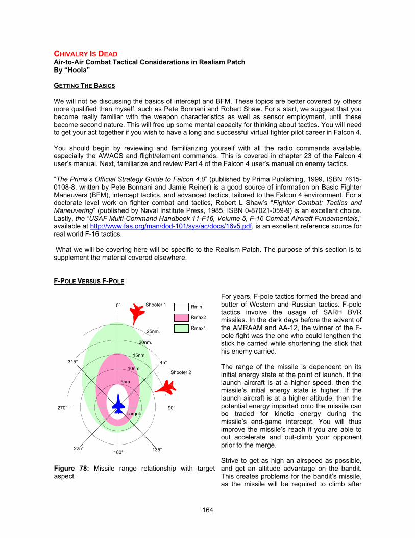
164
CHIVALRY IS DEADAir-to-Air Combat Tactical Considerations in Realism PatchBy “Hoola”
GETTING THE BASICS
We will not be discussing the basics of intercept and BFM. These topics are better covered by othersmore qualified than myself, such as Pete Bonnani and Robert Shaw. For a start, we suggest that youbecome really familiar with the weapon characteristics as well as sensor employment, until thesebecome second nature. This will free up some mental capacity for thinking about tactics. You will needto get your act together if you wish to have a long and successful virtual fighter pilot career in Falcon 4.
You should begin by reviewing and familiarizing yourself with all the radio commands available,especially the AWACS and flight/element commands. This is covered in chapter 23 of the Falcon 4user’s manual. Next, familiarize and review Part 4 of the Falcon 4 user’s manual on enemy tactics.
“The Prima’s Official Strategy Guide to Falcon 4.0” (published by Prima Publishing, 1999, ISBN 7615-0108-8, written by Pete Bonnani and Jamie Reiner) is a good source of information on Basic FighterManeuvers (BFM), intercept tactics, and advanced tactics, tailored to the Falcon 4 environment. For adoctorate level work on fighter combat and tactics, Robert L Shaw’s “Fighter Combat: Tactics andManeuvering” (published by Naval Institute Press, 1985, ISBN 0-87021-059-9) is an excellent choice.Lastly, the “USAF Multi-Command Handbook 11-F16, Volume 5, F-16 Combat Aircraft Fundamentals,”available at http://www.fas.org/man/dod-101/sys/ac/docs/16v5.pdf, is an excellent reference source forreal world F-16 tactics.
What we will be covering here will be specific to the Realism Patch. The purpose of this section is tosupplement the material covered elsewhere.
F-POLE VERSUS F-POLE
For years, F-pole tactics formed the bread andbutter of Western and Russian tactics. F-poletactics involve the usage of SARH BVRmissiles. In the dark days before the advent ofthe AMRAAM and AA-12, the winner of the F-pole fight was the one who could lengthen thestick he carried while shortening the stick thathis enemy carried.
The range of the missile is dependent on itsinitial energy state at the point of launch. If thelaunch aircraft is at a higher speed, then themissile’s initial energy state is higher. If thelaunch aircraft is at a higher altitude, then thepotential energy imparted onto the missile canbe traded for kinetic energy during themissile’s end-game intercept. You will thusimprove the missile’s reach if you are able toout accelerate and out-climb your opponentprior to the merge.
Strive to get as high an airspeed as possible,and get an altitude advantage on the bandit.This creates problems for the bandit’s missile,as the missile will be required to climb after
Figure 78: Missile range relationship with targetaspect
0°
90°
180°
270°
45°
135°225°
315°10nm.
5nm.
15nm.
20nm.
25nm.
Rmin
Rmax2
Rmax1
Shooter 2
Target
Shooter 1
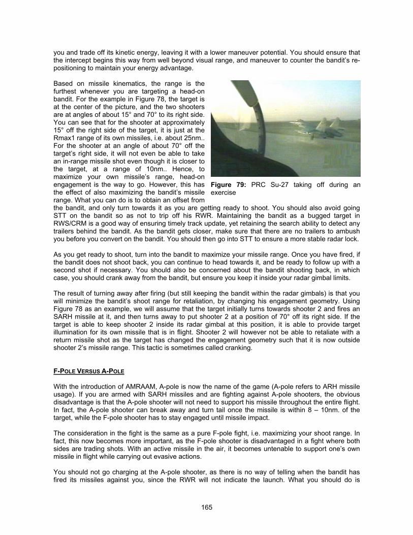
165
you and trade off its kinetic energy, leaving it with a lower maneuver potential. You should ensure thatthe intercept begins this way from well beyond visual range, and maneuver to counter the bandit’s re-positioning to maintain your energy advantage.
Based on missile kinematics, the range is thefurthest whenever you are targeting a head-onbandit. For the example in Figure 78, the target isat the center of the picture, and the two shootersare at angles of about 15° and 70° to its right side.You can see that for the shooter at approximately15° off the right side of the target, it is just at theRmax1 range of its own missiles, i.e. about 25nm..For the shooter at an angle of about 70° off thetarget’s right side, it will not even be able to takean in-range missile shot even though it is closer tothe target, at a range of 10nm.. Hence, tomaximize your own missile’s range, head-onengagement is the way to go. However, this hasthe effect of also maximizing the bandit’s missilerange. What you can do is to obtain an offset fromthe bandit, and only turn towards it as you are getting ready to shoot. You should also avoid goingSTT on the bandit so as not to trip off his RWR. Maintaining the bandit as a bugged target inRWS/CRM is a good way of ensuring timely track update, yet retaining the search ability to detect anytrailers behind the bandit. As the bandit gets closer, make sure that there are no trailers to ambushyou before you convert on the bandit. You should then go into STT to ensure a more stable radar lock.
As you get ready to shoot, turn into the bandit to maximize your missile range. Once you have fired, ifthe bandit does not shoot back, you can continue to head towards it, and be ready to follow up with asecond shot if necessary. You should also be concerned about the bandit shooting back, in whichcase, you should crank away from the bandit, but ensure you keep it inside your radar gimbal limits.
The result of turning away after firing (but still keeping the bandit within the radar gimbals) is that youwill minimize the bandit’s shoot range for retaliation, by changing his engagement geometry. UsingFigure 78 as an example, we will assume that the target initially turns towards shooter 2 and fires anSARH missile at it, and then turns away to put shooter 2 at a position of 70° off its right side. If thetarget is able to keep shooter 2 inside its radar gimbal at this position, it is able to provide targetillumination for its own missile that is in flight. Shooter 2 will however not be able to retaliate with areturn missile shot as the target has changed the engagement geometry such that it is now outsideshooter 2’s missile range. This tactic is sometimes called cranking.
F-POLE VERSUS A-POLE
With the introduction of AMRAAM, A-pole is now the name of the game (A-pole refers to ARH missileusage). If you are armed with SARH missiles and are fighting against A-pole shooters, the obviousdisadvantage is that the A-pole shooter will not need to support his missile throughout the entire flight.In fact, the A-pole shooter can break away and turn tail once the missile is within 8 – 10nm. of thetarget, while the F-pole shooter has to stay engaged until missile impact.
The consideration in the fight is the same as a pure F-pole fight, i.e. maximizing your shoot range. Infact, this now becomes more important, as the F-pole shooter is disadvantaged in a fight where bothsides are trading shots. With an active missile in the air, it becomes untenable to support one’s ownmissile in flight while carrying out evasive actions.
You should not go charging at the A-pole shooter, as there is no way of telling when the bandit hasfired its missiles against you, since the RWR will not indicate the launch. What you should do is
Figure 79: PRC Su-27 taking off during anexercise
166
minimize the ability of the A-pole shooter to gain a radar lock on you. Then you can get a shot offbefore he does, you have put him on the defensive. The AA-10C shooter has the advantage here, inthat the missile out-ranges the AIM-120. The Su-27 has a radar big enough to burn through thejamming before the AIM-120 can be fired at it.
You should also consider taking a shot under marginalRmax1 conditions once you are in range to put the bandit inthe defensive mode first. Shooting you will then be the lastthing on his mind. If the A-pole shooter has already fired,taking a shot at him will force him to abandon support of hismissile as he will have to honor the inbound missile. This willdeprive his missile with the datalink update, thus decreasingthe probability of the ARH missile finding you when it turnsautonomous. You should then do whatever you can to getout of the vicinity when the ARH missile turns active. Do notbother about whether your missile will hit or not, as the mainobjective is to force the A-pole shooter to abandon hismissile that is in-flight, and put him on the defensive. If youcan initiate evasive maneuvers while keeping your radarlock on the bandit, so much the better. This will at least giveyou a fighting chance.
Bear in mind that your survival chances against an A-pole shooter are the greatest if you cansuccessfully deny the ARH missile with its uplink from the bandit. You should tailor your tactics to forcethe bandit onto the defensive, and the bandit’s RWR launch warning is a good thing to exploit.
A-POLE VERSUS A-POLE
Now things get a little more dicey with fighting pure A-pole. Both you and the bandit will not have aclue that a missile has been fired until the RWR detects the missile turning autonomous. Obviouslytrading shots is a bad way to win a fight, and you cannot force the bandit to abandon support of hisown missile just by shooting back, as the launch of your missile will not trigger his RWR launchwarning.
What you should do is still the same, i.e. to maximizeyour own shoot range while minimizing the bandit’s.Again, having a huge altitude and speed advantagehelps to maximize your own missile’s range. Whenyou initiate your intercept, you should always assumethe worst case that the bandit has fired, and be verycareful anytime you get within 25nm. of the bandit (forAIM-120 and AA-12). Shooting in RWS/CRM or TWSmode also has the advantage of not highlighting to thebandit that he now has your attention.
The AA-12 shooter has the advantage of a longerrange compared to the AMRAAM shooter, though thelatter requires less support from the launch aircraftcompared to the former (about 20% difference inseeker range). The AIM-54 shooter has the advantageof out-ranging both AIM-120 and AA-12, but theonboard seeker is slightly less sophisticated.
As long as you play the defensive game, you should be able to survive the skirmish. Keep in mind thatyour chances of survival get drastically lower once the missile turns active and locks onto you. If you
Figure 80: Fox 1 kill as an AIM-7 firedfrom a F-14 scores a direct hit on thetarget drone. (Picture credit of USN)
Figure 81: An AIM-7 Sparrow missile asseen by the target drone, moments before themissile impact.
167
suspect that the enemy has fired at you, and you are still not in firing parameters, light the afterburnerand get out of the dodge first. It is often better to save your own skin and fight on another day, whenthe dice is loaded in your favor, than to hang around and try to get a shot off.
IRCM TACTICS
In the event that you are not able to eliminate the bandit from BVR, you may have to merge. IRCMtactics will allow you to remain offensive by denying the bandit a chance to shoot at you. It is a myththat all aspect IR missiles can always be fired in the front quarter regardless of the target’s throttlesetting. Aerodynamic heating on an airframe seldom exceeds 150°C, and this means that the airframeIR signature (discounting the exhaust plume) is often not visible at longer ranges. The key to denyinga front quarter all aspect missile shot is to throttle back prior to the merge, and reduce your own IRsignature. Merging with afterburners blazing is a sure way of being put on the defensive immediately,as you are just presenting a big IR target for the opponent’s missile.
You should aim to maintain your energy at ahigh state prior to the merge. This allowsyou to retain as much energy as possibleeven when you throttle back. At about 6 –8nm. away from the bandit, you shouldthrottle back below AB to reduce your IRsignature, and if necessary, throttle backbelow MIL, depending on what aircraft youare flying.
In general, throttling back to about 80% willoften reduce your IR signature sufficiently toprevent an opponent’s all aspect IR missilefrom being launched beyond Rmin. Even ifthe opponent shoots, the range will be tooclose, and a break into the missile will often
defeat it. For example, throttling back to 80% will only allow the AIM-9M and AA-11 to obtain an IRlock at 1nm. head-on, which is inside the minimum range of the missiles. You need to remember thatthe engine needs time to cool down, so if you initiate the IRCM tactic too late (for example, inside5nm.), you may not cool the engines in time to prevent a front sector launch. You may also want todispense flares pre-emptively in case the bandit shoots.
The bulk of the DPRK aircraft are not equipped with countermeasure dispensers, and as such, theyare vulnerable to the AIM-9P. PRC and Russian aircraft are better protected with self protectionsystems and countermeasure dispensers. Hence, you should learn to arm the aircraft appropriately forthe threat that they will encounter over the battlefield.
For ground attack aircraft, you can often conserve their stock of AIM-9M by arming them with olderAIM-9P, if the threats that they are expected to face over the battlefield are not equipped withchaff/flare dispensers. Against newer aircraft or aircraft equipped with dispensers, these missiles willbe close to useless unless fired without the target detecting it. While this may appear to penalize theOPFOR aircraft, it also means that the Su-27 and MiG-29 aircraft have become the greatest air threat,as long as you do not allow the OPFOR to sneak an older missile up your tail without you realizing it.
You will need to be aware of the threats that you will be facing, in case you feel like engaging in someair combat. You will need to learn to recognize the threats on the RWR, and know if the target has anycountermeasure capabilities, if you are unfortunate enough to be equipped with older IR missiles. Bearin mind that merging with aircraft that are equipped with chaff/flare dispensers may be a waste of time
Figure 82: Su-27UB from the PLAAF. This aircraft iscapable of fighting F-pole and A-pole, as well as havingan off-boresight WVR targeting capability.
168
if you are equipped with missiles that have little or no IRCCM capabilities, so you may be better offconcentrating on the air-to-ground mission.
FIGHTING OFF-BORESIGHT CAPABLE MISSILES
Fighting off-boresight capable missiles such as the AA-11, AIM-9X, and Python 4 can be a hair raisingexperience. IRCM launch denial tactics will allow you to prevent an off-boresight launch. However, youshould bear in mind that the bandit can engage you up to 40 – 50 degrees off its nose, so it does notnecessarily have to point its nose at you to shoot. Now that the AI is capable of taking full advantageof the capabilities of such missiles, it is even more important for you to learn how to counter them.
You should exercise caution whenever you are in front of the bandit’s 3 – 9line. As you merge, force a one-circle fight instead of getting into a two-circlefight, as it leaves you on an even keel with the bandit after the turn, andkeeps you inside the minimum range of the AA-11. If you get into a two-circlefight, the bandit will be in a position to shoot at you across the circle beforeyou can shoot at it, as you will end up outside the minimum range of the AA-11 after ¾ of a turn. Taking Figure 84 as an example, with both fightersentering into a two-circle fight, the F-16 will enter into the AA-11 firingenvelope before the MiG-29 enters into the AIM-9M firing envelope, atposition number 3. This gives the MiG-29 pilot the first shot opportunity,enabling him to fire across the turn circle, thus putting the F-16 on thedefensive. The wider AA-11 seeker gimbal envelope is hence moreadvantageous in a close fight. By forcing a one-circle fight, the separationbetween the two fighters will be less, keeping you inside the AA-11’sminimum firing range all the time, and denying the bandit of a shot.
Be careful about throttling up as you gopast the bandit. If you power up too early,the bandit may still be able to take a shot atyou. The AA-11 has sufficient energy andseeker gimbal angle to complete a 180degrees turn and chase you down. Bepatient and maneuver to get yourself into aposition to shoot, and always bear in mindthat the bandit does not need to point itsnose at you to kill you. Proper throttle andenergy management will help prevent youfrom being put on the defensive.
The flip side of a missile shot fired at highoff-boresight angles is the huge amount ofenergy that the missile has to expend tonegotiate the turn. This often leaves themissile with a lot less energy than if it hadbeen fired at smaller off-boresight angles.The consequence of this is a reduction inthe missile’s maneuverability during the endgame. You can try to exploit this bymaintaining a high energy state, and“blowing through” the engagement as fastas possible, forcing the missile into a tailchase engagement scenario after it has
negotiated the initial turn to pursue you. With some luck, the missile may not have sufficient energy tohunt you down. If you are the one firing the off-boresight missile, then bear in mind that engaging high
Figure 83: Russianhelmet mounted sightfor the MiG-29 and Su-27.
Figure 84: A two-circle fight will give off-boresightmissile armed opponent the first shot opportunity
AA-11 Firing Envelope
AIM-9M Firing Envelope
1
2
3
4
2
1
3
4
169
off-boresight targets more than 2nm. away will decrease the missile’s energy state tremendously, thuslowering the kinematic Pk of the missile.
The HMS/AA-11 combination is an extremely effective combat capability, and it can compensate forthe lack of flying skills and aircraft performance. The effectiveness of the HMS/AA-11 combination wasquantified during the development of the Realism Patch, by a series of dogfights between AIM-9Marmed F-16 and HMS/AA-11 armed MiG-29. The results are shown below:
F-16 Skill Level MiG-29 Skill Level Kill Ratio (F-16:MiG-29)Ace Ace 1 : 1.5Ace Veteran 1 : 1.41Ace Cadets 1.2 : 1Ace Recruit 1.63 : 1
Without the HMS, and armed only with the AA-11 (thus limiting the AA-11 to the same firingconstraints as the AIM-9M), the kill ratio of Ace F-16 versus Ace MiG-29 became 1.48 : 1, in favor ofthe F-16. As you can see, the HMS expands the engagement zone of the AA-11 tremendously, andthis off-boresight targeting ability reverses the odds against the F-16, and allowed even Cadet MiG-29pilots to come close to winning a WVR fight against Ace F-16 pilots. The HMS/AA-11 combinationmore than compensates for the poorer flying skills, making it an extremely high threat even in less-than-competent hands. The USAF and USN has only begun to redress this imbalance with theJHMCS (Joint Helmet Mounted Cueing and Sighting system) and the AIM-9X program, while theIsraelis have had the Elbit DASH HMD (Helmet Mounted Display) and Python 4 in service since theearly 1990s. The JHMCS/AIM-9X and DASH/Python 4 combination is even more deadly than theHMS/AA-11 combination.
Your best tactic against such opponents is to exploit the BVR advantage of the F-16, and engage theenemy at BVR ranges. The A-pole advantage of the F-16 should be exploited to its fullest. Learn tomake use of the means available to you, and if you are not able to engage the target beyond visualrange, you should always consider a retreat to preserve your forces. Courage is not just aboutcharging into a fight fearlessly, but also about knowing when to disengage and fight on another dayunder conditions that are more favorable to you.
USING THE HELMET MOUNTED SIGHT (FOR RUSSIAN AIRCRAFT)
For aircraft equipped with a helmet mounted sight (MiG-29, Su-27, and the Su-30MKK), the advantageconferred to the pilot is tremendous. The helmet mounted sight allows the pilot to literally “point andshoot,” as the pilot can designate the target using his helmet mounted sight instead of his radar. Theability to turn his head and cue missiles removes some of the need for him to maneuver, and makeshim a serious threat.
The helmet mounted sight in the Realism Patch is mechanized to simulate the Russian sightingsystem. When used with the AA-11 Archer, the HMS allows the pilot to engage targets up to the fullgimbal limit of the missile seeker. This mode of targeting works in the Padlock view. When youcommand the missile the uncage, an aiming reticle will appear at the center of your field of view. Thisaiming reticle has a sighting crosshair at its center, and the missile will automatically be cued to it. Ifyou padlock any aircraft, the missile will automatically be slaved to your target of interest, and you mayfire the missile normally.
170
MOTHERING THE AIManaging the AI Wingman in Air-to-Ground MissionsBy Alex Easton
INTRODUCTION
The AI in Falcon 4 has a lot of problems. While the Realism Patch has attempted to rectify many of thedeficiencies, there are several tricks that you can apply to help your AI wingman out, and prevent themfrom killing themselves. This will not solve everything, as the AI has a mind of its own at times, but itwill put right some of the problems that you may have experienced.
EXAMPLE 1: ATTACKING IN TRAIL FORMATION
The Situation
You are tasked on a CAS mission, and you approach the target with your wingman in trail. You lockupa target on the A/G radar, and issue him the "Attack targets" command. You then launch your ownMaverick missiles, and decide to orbit the target at a range of 5nm. and an altitude of 12,000 feet, soas to keep the target deaggregated. Your intention is to commence your bombing run when the AI hascompleted his attack runs with the Maverick missiles. As the AI launches its last missile, you are atthe opposite side of the target, and you decided to wait until his missiles have struck their targets. Yousuddenly hear it call "I'm a dot,” and when you try to ask him what is going on, the command menu isblanked out.
What Went Wrong
What happened was that as soon as the AI has fired all its Maverick missiles, it tries to rejoin, as italways does. You have to give it a new attack command before it will attack with its bombs. However,the AI has to overfly the target to get to you, as you have positioned yourself on the far side ofthe target. The AI is at a low altitude when it has finished its Maverick attack, and is trying to climb inorder to get to you. This places the AI in the middle of the AAA engagement zone.
The Solution
Position yourself such that when the AI tries to rejoin, it does not have to overfly the target. It is a goodidea to orbit around the target area, as you will be able to cover the AI during its attack run. However, Isuggest that you orbit around the target on the same side as the AI’s previous attack pass. You shouldalso try to trail the AI, and be offset to its side when it completes the AI, as this makes it easier for theAI to rejoin on you.
EXAMPLE 2: ATTACKING IN SPREAD FORMATION
The Situation
You have learnt from your previous mistake in the first case, and have been tasked for anotherbombing mission. You elect to put the AI into trail formation, bomb the target, and then you orbit thetarget on the same side as the AI. When the AI has completed its attack run and is rejoining you, youbegin to turn for home. However, the AI wingman called "I'm a dot,” and your wingmancommunications menu goes blank. You have lost another AI wingman.
What Went Wrong
The AI did everything that you asked it to do, and tried to rejoin on you. Unfortunately, the AI is still intrail formation, so it flies away from you for a short distance, in order to get obtain the correct spacing
171
for the formation. This puts the AI directly over the target, and the AAA defending the target managedto shoot down the AI.
The Solution
You can issue the "Go spread" command anytime after the AI has commenced its attack run. Thiscommand does not have a "Rejoin" command attached to it. When the AI has completed its attack, orwhen you recall the AI prior to it completing its attack, it will attempt to rejoin in the spread formation.This prevents the AI from flying away from you before rejoining in trail.
EXAMPLE 3: ATTACKING WITH MAVERICK MISSILES
The Situation
Your flight is in the spread formation, and you have been tasked on a BAI mission. You do not knowthe exact location of the target, and decided to approach the target at an altitude of 15,000 feet, so asto avoid the AAA and SHORAD threats. You spotted the target at a range of 6nm., and promptlylocked up a vehicle on your A/G radar. You then issued the "Attack targets" command to yourwingman, and watched as it commenced its attack run with its Maverick missiles. However, you didnot hear your wingman call out "Rifle,” but instead, it flew off to the right, and overflew anotherarmored unit and was promptly shot down.
What Went Wrong
The AI needs to get into position for a Maverick missile attack (at an altitude of about 1,500 feet, andlined up with the target) at a range of 7.5nm. from the target, before it can commence its attack run. Ifit cannot make it to this position, it will pull off to the right, and attempt to obtain the requiredseparation before it turns back to commence the attack.
The Solution
You should give the order to attack from further out. If you are approaching from a higher altitude, givethe AI more space to commence its descend. For an approach altitude of 8,000 feet, I suggest thatyou issue the attack command at a range of no less than 8.5nm. from the target. This should beincreased for higher approach altitudes. As you close in on the target, you should descend a little tosee if you can spot the target. If you managed to spot the targets late, you should mark the target, andthen pull back to a range of about 12nm. before turning back to attack it.
EXAMPLE 4: SEAD ESCORT
The Situation
You have been tasked on a SEAD escort mission, and are armed with HARM missiles and clusterbombs. You intend to destroy the radars with the HARM missiles, and the AAA sites with the clusterbombs. As you approached the target, you detected a SA-3 site, and locked up on its radar. Youordered your wingman to attack the SA-3 radar, with the "Attack targets" command, and veered off todestroy a SA-2 radar that you have detected. As you are about to launch your own HARM missile, youhear you wingman make the "Magnum" calls. A few seconds later, you hear your wingman call"Cluster bombs away,” and the next moment, your wingman has been shot down.
172
What Went Wrong
The AI will not rejoin after firing its HARM missiles, when tasked on a SEAD escort mission. They willcarry on the attack with their bombs or Maverick missiles, and will only rejoin automatically afterexpending their ordnance.
The Solution
You should recall your wingman the moment you hear them make the “Magnum” call.
EXAMPLE 5: ATTACKING HEAVILY DEFENDED TARGETS
The Situation
You are tasked on a CAS mission against a Russian HQ battalion, and are armed with Maverickmissiles. You ordered your wingman to attack the battalion, and the wingman duly obeyed by firing twomissiles. As it turns away from the target for another attack run, you hear a SAM launch warning, andyour wingman is shot down.
What Went Wrong
Russian HQ battalions are defended by SA-8 missiles. This missile is very dangerous, and the AI willenter the engagement zone of this missile when it attacks the target.
The Solution
You have been tasked to attack a heavily defended target. It is important that you know the ORBAT ofthe ground units that you are likely to encounter, more so the ground unit that you are tasked to attack.Many of these ground units are defended by modern SAMs, such as the SA-8, SA-13, SA-15, and the2S6. These air defense systems are very dangerous to both your as a player, and the AI. The AI willinevitably enter the weapon engagement zone of these SAM systems, and will be very vulnerableduring its attack runs. You will need to adapt your tactics when you are attacking such ground units.For example, you can try to attack the unit yourself first, so as to reduce the risk. You may also elect tocarry HARMs so that you can destroy the air defense vehicles before your wingman commences itsattack. Alternatively, you can try to distract the SAMs by flying just within the weapon engagementzone of these systems, thereby giving your wingman a clear run at the targets. As a last resort, youcan choose another mission that is less risky.
EXAMPLE 6: FLIGHT PATH DECONFLICTION
The Situation
You are tasked to attack a depot, and decided to execute a single-side offset attack. Both you andyour wingman are armed with two bombs each, and you intend to release both bombs in a pair. Theattack will be conducted in the spread formation.
The attack begins according to the plan. At a range of 20nm. from the target, and an altitude of 12,000feet, you scanned the airspace ahead with your radar, and confirmed with the AWACS that there areno airborne threats in the vicinity. Your RWR is silent, and you commanded your wingman to “Kickout.”
When your wingman is in position, you locked up the depot on your A/G radar, and commanded yourwingman to attack it with the “Attack my target command.” You plan to accelerate and get ahead ofyour wingman, and then climb to the right to achieve an altitude of 15,000 feet, before leveling off with
173
the target at your 9 o’clock. The attack will commence with a roll into the target, in a 10° dive, and aminimum bomb release altitude of 8,000 feet. You plan to commence your own attack run as the AIcalls "Bombs away.” This will ensure that the target is not obscured by the explosions from the AI’sbombs. You intend to pull off to the left as you come off the attack, and allow your wingman to rejoinyou smoothly.
You see your wingman commence its attack, and you commenced your own attack. As you pull off thetarget, you hear a loud explosion, and your aircraft is destroyed.
What Went Wrong
The attack was executed perfectly. However, you collided with your wingman due to flight path conflict!As the AI released its bombs at an altitude of 4,000 feet, and then climbed to rejoin the formation onyour left, you were heading towards it in a descend. When you pulled off to the left, you crossed theAI’s flight path and collided with it.
The Solution
The art of getting your AI wingman to rejoin the formation quickly and safely following a bombing run isdifficult to master. However, the behavior of the AI is predictable. The AI will execute a 45° turntowards you and engage afterburner as soon as it releases its weapons, and will climb or descend asrequired to formate on you, before shallowing off its turn. The AI will head directly towards you, and asit closes in on you, will maneuver towards its formation position on your left.
There was nothing wrong with this plan, except the execution timing. You should delay your roll ontothe target until the AI is in a position such that your flight path will not conflict with it as it tries to regainformation. In this example, if you have executed your attack 10 seconds after the AI has completed itsown attack, the AI will be behind you as you turn into the target. The AI will be flying towards your rearas you release the bombs and pull off to your left.
You can deconflict your operating altitudes. The AI was climbing to meet you as you were descendingon your bombing run. Both of you will be at the same altitude at some point in time, and you shouldmake sure that you are not at the same location as the AI when this happens. You need to considerthe AI’s actions when it tries to rejoin you after a bombing run, and adjust your own actions accordinglyto deconflict with it, as the AI will not be changing its own actions to suit you.
EXAMPLE 7: ATTACKING TARGETS IN HILLY TERRAIN
The Situation
Your flight has been tasked to attack a battalion with Maverick missiles. The battalion is situatedamongst some hills. The AI responded to your order to attack by firing its missiles, and misses all itstargets.
What Went Wrong
This problem is most probably caused by the AI’s Maverick missile impacting on intervening terrain, asthe AI will normally launch its Maverick missiles from low altitudes.
The Solution
You should make sure that the AI is approaching the targets from flat terrain.
174
EXAMPLE 8: ATTACKING AT LOW LEVEL
The Situation
Your flight is tasked to bomb a target, and you intend to check the target for threats on the approach,and cover the AI as it attacks. The approach was made at low level, over hilly terrain, with a pop up atthe IP. Before you reached the IP, you put your AI wingman into trail formation to give it some time toset up the formation. As you reached the IP, you tried to issue the “Attack my target” command, andfound that your AI wingman has crashed.
What Went Wrong
There are many possibilities for this situation. One of the possibility is that the AI crashed while tryingto get into trail formation. The wingman will execute a specific maneuver when commanded to switchinto the trail formation, from a spread or wedge formation. On receiving the command, the AI willexecute a 360° turn at 1.2g, and end up more or less in the appropriate trail formation. This works likea treat, as long as you are not travelling too fast, and keep to a constant airspeed. However, the AI isnot good at low-level flying. They are adequate when flying in a straight line, but incompetent whenturning sharply over hilly terrain. It appears that the AI will only see the objects that are directly in frontof them when they maneuver (although this is not true when the AI launches the Maverick missile),and if they are at the side of a hill when turning into it, they fail to climb quickly and thus plough intothe ground.
The Solution
First of all, when you command the AI to fly in a trail formation (or command any change in theformation), do not fly at too high an airspeed while the AI wingmen are switching formation. Youshould keep your airspeed constant as this helps the AI. Secondly, you should avoid ordering the AIinto trail formation at low altitudes. Finally, if you must be flying at low altitudes when you give the "Gotrail" command, then plan it so that the final approach to the IP (also known as the pre-IP, where youwill normally give the command to change formation) is on level terrain, and the level terrain extendsfor about 3nm. back along the flight path. You should also leave plenty of distance between the pre-IPand the IP to let the AI form up in trail formation.
I have some techniques that I use as a matter of routine. For example, if I'm turning right at the pre-IP,towards the IP, I will have the AI wingman in spread formation on my left, and will kick the wingmanout twice (this is to make sure that there will not be any trouble on your left at this point). I will usuallydo this in the minute leading up to the pre-IP, and give the AI some time between the "Kick out"commands, so that this is done smoothly. As I begin the right hand turn to the IP, I will give the "Gotrail" command. The AI will already be a few miles behind me after the turn, and almost in the trailformation. This helps to save fuel as the AI will not try to catch up with you as it takes the wider turnand longer route around the corner. If you do not command it to go into the trail formation, the AI willattempt to catch up with you to stay in the spread formation.
EXAMPLE 9: FLYING PASS SAM SITES
The Situation
You are tasked for an attack mission, and your approach route to the IP takes you between some SA-2 SAM sites. You elect to stay at low altitudes, and pop-up at the IP for your bombing run.
The AI switches to trail formation perfectly, and makes the ingress to the IP at an altitude of 500 feet.You ordered the AI with the “Attack my target” command as you commence your pop-up maneuver.You pulled down to the right after releasing your bombs and commenced a low-level egress along a
175
river valley that bypasses the SAM sites and then realize that your wingman is not with you. Yourecalled hearing your wingman call out a SAM launch, followed by the all-too-familiar "I'm a dot.”
What Went Wrong
When you give the attack command, the first reaction of your wingman, wherever it is, is to climb to itsdesignated bombing altitude. This is approximately 7,000 feet for a bombing mission against fixedtargets. The AI popped up too soon, and entered into the weapon engagement zone of the SAM sitesin the vicinity.
The Solution
This is a difficult problem to solve. You should close up the formation so that the AI is close behind youand in trail when you give the command to attack. If it is safe for you to execute the pop up maneuver,then it is also safe for the AI to do so. You can also consider putting the AI in a spread formationinstead of a trail formation. You should hit the target first, so that the AI will be behind you (this is toprovide flight path deconfliction). Make sure that you pull off in the correct direction as the AIcommences its attack, as it will rejoin on your wing after its attack. Finally, you should considerplanning the mission differently, such as planning a SEAD escort or a different ingress route.
EXAMPLE 10: AI FUEL MANAGEMENT
The Situation
You are tasked on a deep strike against an armored battalion. The mission was planned and you tookevery care to manage your AI wingman properly, and managed to complete the attack without losingyour wingman. During the egress, your AI wingman gave you a “Bingo” call. Your flight is still a longway from home, and you cannot afford to conserve fuel by flying at high altitude or low airspeed. Asyou search for an alternate airfield to land, your wingman announces that it is running on fumes, andthen crashes.
What Went Wrong
The root cause of this problem is the AI’s poor fuel management skills. This is caused in part by theplayer, as formation keeping and other flight duties may require the AI to use afterburner if the playerdoes not fly smoothly. The indiscriminate loading of the aircraft, often with all the hardpoints loadedwith ordnance instead of additional fuel tanks, does not help with the situation. In addition, protractedhigh-speed low level flight will increase the fuel consumption tremendously. As the AI tries its best tomaintain formation and perform the duties that the player expects them to, the fuel consumption willincrease as compared to the player. Admittedly, the AI uses the afterburner indiscriminately, but theplayer can help in the situation by looking after the AI.
The Solution
You should do your best to help the AI with its fuel management throughout the entire mission. Thefollowing is not an exhaustive list of the various techniques::
1. Upon taking off, you should turn off the runway in the wrong direction, and then orbit theairfield before heading for the second steerpoint. The AI will not be far behind you whenthey take off, and will not need to consume a lot of fuel as they try to catch up with you.You should also adjust the TOS of the second and the third steerpoint to allow for this.
2. If you do not need to fly at low altitudes, then you should not, especially when you areflying over friendly territory.
3. If you do not need to fly at high airspeeds, you should not, especially when you are flyingover friendly territory.
176
4. You should accelerate slowly if it is possible. This will prevent the AI from usingafterburner indiscriminately.
5. You should avoid afterburner usage yourself, if this is possible. If you do, you will give theAI the permission to use afterburner as well.
6. If you need to change your heading at a steerpoint, you should keep your wingman closeto you. For example, you should close up a spread and trail formation if you are turningright. While this may appear to make the AI go the “long way round,” it makes it easier forthe AI to rejoin on your wing after the turn if they are on the outside of the turn. If the AI ison the inside of the turn, closing up the formation will shorten the AI’s route around thecorner.
7. You should use some of the techniques described in example 8 when you command theAI to change formation.
8. You should avoid loading the AI with too much ordnance. The maneuvering at the targetarea will consume a lot of fuel if the aircraft is too heavily loaded. “One Pass, Haul Ass”tactics will help in AI survivability as well as fuel management.
9. You should give the AI external fuel tanks whenever you are in doubt.10. You should learn to refuel in flight. The AI will do this.11. You should learn to use the cruise management page on the DED. This gives the most
fuel efficient flight condition to fly at.
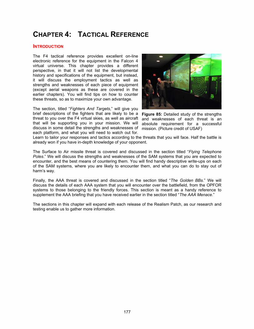
177
CHAPTER 4: TACTICAL REFERENCE
INTRODUCTION
The F4 tactical reference provides excellent on-lineelectronic reference for the equipment in the Falcon 4virtual universe. This chapter provides a differentperspective, in that it will not list the developmentalhistory and specifications of the equipment, but instead,it will discuss the employment tactics as well asstrengths and weaknesses of each piece of equipment(except aerial weapons as these are covered in theearlier chapters). You will find tips on how to counterthese threats, so as to maximize your own advantage.
The section, titled “Fighters And Targets,” will give youbrief descriptions of the fighters that are likely to be athreat to you over the F4 virtual skies, as well as aircraftthat will be supporting you in your mission. We willdiscuss in some detail the strengths and weaknesses ofeach platform, and what you will need to watch out for.Learn to tailor your responses and tactics according to the threats that you will face. Half the battle isalready won if you have in-depth knowledge of your opponent.
The Surface to Air missile threat is covered and discussed in the section titled “Flying TelephonePoles.” We will discuss the strengths and weaknesses of the SAM systems that you are expected toencounter, and the best means of countering them. You will find handy descriptive write-ups on eachof the SAM systems, where you are likely to encounter them, and what you can do to stay out ofharm’s way.
Finally, the AAA threat is covered and discussed in the section titled “The Golden BBs.” We willdiscuss the details of each AAA system that you will encounter over the battlefield, from the OPFORsystems to those belonging to the friendly forces. This section is meant as a handy reference tosupplement the AAA briefing that you have received earlier in the section titled “The AAA Menace.”
The sections in this chapter will expand with each release of the Realism Patch, as our research andtesting enable us to gather more information.
Figure 85: Detailed study of the strengthsand weaknesses of each threat is anabsolute requirement for a successfulmission. (Picture credit of USAF)
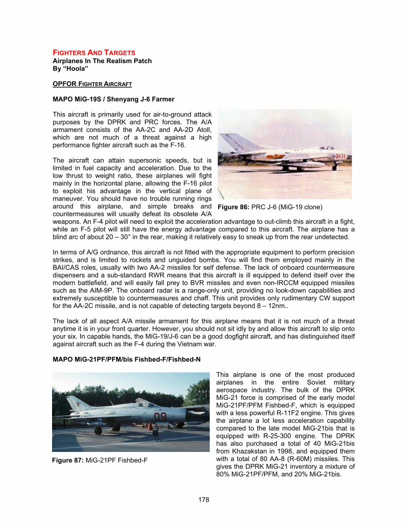
178
FIGHTERS AND TARGETSAirplanes In The Realism PatchBy “Hoola”
OPFOR FIGHTER AIRCRAFT
MAPO MiG-19S / Shenyang J-6 Farmer
This aircraft is primarily used for air-to-ground attackpurposes by the DPRK and PRC forces. The A/Aarmament consists of the AA-2C and AA-2D Atoll,which are not much of a threat against a highperformance fighter aircraft such as the F-16.
The aircraft can attain supersonic speeds, but islimited in fuel capacity and acceleration. Due to thelow thrust to weight ratio, these airplanes will fightmainly in the horizontal plane, allowing the F-16 pilotto exploit his advantage in the vertical plane ofmaneuver. You should have no trouble running ringsaround this airplane, and simple breaks andcountermeasures will usually defeat its obsolete A/Aweapons. An F-4 pilot will need to exploit the acceleration advantage to out-climb this aircraft in a fight,while an F-5 pilot will still have the energy advantage compared to this aircraft. The airplane has ablind arc of about 20 – 30° in the rear, making it relatively easy to sneak up from the rear undetected.
In terms of A/G ordnance, this aircraft is not fitted with the appropriate equipment to perform precisionstrikes, and is limited to rockets and unguided bombs. You will find them employed mainly in theBAI/CAS roles, usually with two AA-2 missiles for self defense. The lack of onboard countermeasuredispensers and a sub-standard RWR means that this aircraft is ill equipped to defend itself over themodern battlefield, and will easily fall prey to BVR missiles and even non-IRCCM equipped missilessuch as the AIM-9P. The onboard radar is a range-only unit, providing no look-down capabilities andextremely susceptible to countermeasures and chaff. This unit provides only rudimentary CW supportfor the AA-2C missile, and is not capable of detecting targets beyond 8 – 12nm..
The lack of all aspect A/A missile armament for this airplane means that it is not much of a threatanytime it is in your front quarter. However, you should not sit idly by and allow this aircraft to slip ontoyour six. In capable hands, the MiG-19/J-6 can be a good dogfight aircraft, and has distinguished itselfagainst aircraft such as the F-4 during the Vietnam war.
MAPO MiG-21PF/PFM/bis Fishbed-F/Fishbed-N
This airplane is one of the most producedairplanes in the entire Soviet militaryaerospace industry. The bulk of the DPRKMiG-21 force is comprised of the early modelMiG-21PF/PFM Fishbed-F, which is equippedwith a less powerful R-11F2 engine. This givesthe airplane a lot less acceleration capabilitycompared to the late model MiG-21bis that isequipped with R-25-300 engine. The DPRKhas also purchased a total of 40 MiG-21bisfrom Khazakstan in 1998, and equipped themwith a total of 80 AA-8 (R-60M) missiles. Thisgives the DPRK MiG-21 inventory a mixture of80% MiG-21PF/PFM, and 20% MiG-21bis.
Figure 86: PRC J-6 (MiG-19 clone)
Figure 87: MiG-21PF Fishbed-F
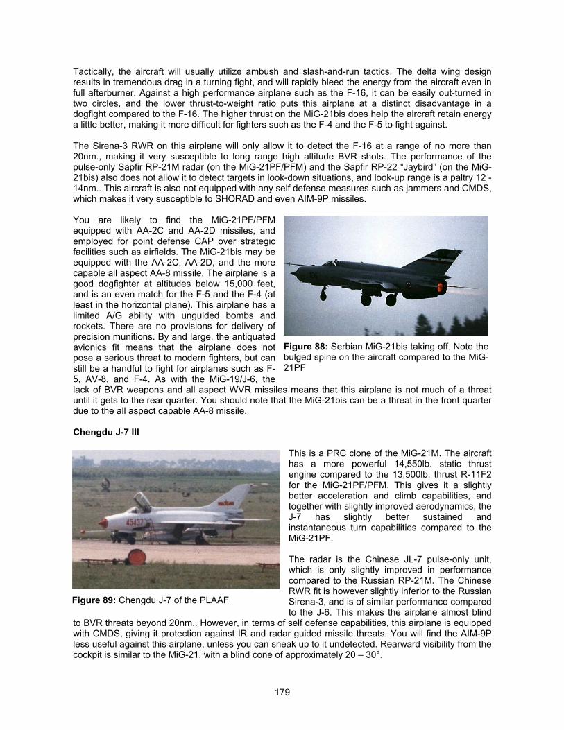
179
Tactically, the aircraft will usually utilize ambush and slash-and-run tactics. The delta wing designresults in tremendous drag in a turning fight, and will rapidly bleed the energy from the aircraft even infull afterburner. Against a high performance airplane such as the F-16, it can be easily out-turned intwo circles, and the lower thrust-to-weight ratio puts this airplane at a distinct disadvantage in adogfight compared to the F-16. The higher thrust on the MiG-21bis does help the aircraft retain energya little better, making it more difficult for fighters such as the F-4 and the F-5 to fight against.
The Sirena-3 RWR on this airplane will only allow it to detect the F-16 at a range of no more than20nm., making it very susceptible to long range high altitude BVR shots. The performance of thepulse-only Sapfir RP-21M radar (on the MiG-21PF/PFM) and the Sapfir RP-22 “Jaybird” (on the MiG-21bis) also does not allow it to detect targets in look-down situations, and look-up range is a paltry 12 -14nm.. This aircraft is also not equipped with any self defense measures such as jammers and CMDS,which makes it very susceptible to SHORAD and even AIM-9P missiles.
You are likely to find the MiG-21PF/PFMequipped with AA-2C and AA-2D missiles, andemployed for point defense CAP over strategicfacilities such as airfields. The MiG-21bis may beequipped with the AA-2C, AA-2D, and the morecapable all aspect AA-8 missile. The airplane is agood dogfighter at altitudes below 15,000 feet,and is an even match for the F-5 and the F-4 (atleast in the horizontal plane). This airplane has alimited A/G ability with unguided bombs androckets. There are no provisions for delivery ofprecision munitions. By and large, the antiquatedavionics fit means that the airplane does notpose a serious threat to modern fighters, but canstill be a handful to fight for airplanes such as F-5, AV-8, and F-4. As with the MiG-19/J-6, thelack of BVR weapons and all aspect WVR missiles means that this airplane is not much of a threatuntil it gets to the rear quarter. You should note that the MiG-21bis can be a threat in the front quarterdue to the all aspect capable AA-8 missile.
Chengdu J-7 III
This is a PRC clone of the MiG-21M. The aircrafthas a more powerful 14,550lb. static thrustengine compared to the 13,500lb. thrust R-11F2for the MiG-21PF/PFM. This gives it a slightlybetter acceleration and climb capabilities, andtogether with slightly improved aerodynamics, theJ-7 has slightly better sustained andinstantaneous turn capabilities compared to theMiG-21PF.
The radar is the Chinese JL-7 pulse-only unit,which is only slightly improved in performancecompared to the Russian RP-21M. The ChineseRWR fit is however slightly inferior to the RussianSirena-3, and is of similar performance comparedto the J-6. This makes the airplane almost blind
to BVR threats beyond 20nm.. However, in terms of self defense capabilities, this airplane is equippedwith CMDS, giving it protection against IR and radar guided missile threats. You will find the AIM-9Pless useful against this airplane, unless you can sneak up to it undetected. Rearward visibility from thecockpit is similar to the MiG-21, with a blind cone of approximately 20 – 30°.
Figure 88: Serbian MiG-21bis taking off. Note thebulged spine on the aircraft compared to the MiG-21PF
Figure 89: Chengdu J-7 of the PLAAF
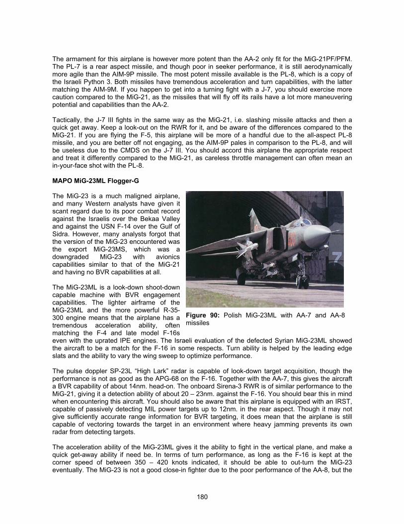
180
The armament for this airplane is however more potent than the AA-2 only fit for the MiG-21PF/PFM.The PL-7 is a rear aspect missile, and though poor in seeker performance, it is still aerodynamicallymore agile than the AIM-9P missile. The most potent missile available is the PL-8, which is a copy ofthe Israeli Python 3. Both missiles have tremendous acceleration and turn capabilities, with the lattermatching the AIM-9M. If you happen to get into a turning fight with a J-7, you should exercise morecaution compared to the MiG-21, as the missiles that will fly off its rails have a lot more maneuveringpotential and capabilities than the AA-2.
Tactically, the J-7 III fights in the same way as the MiG-21, i.e. slashing missile attacks and then aquick get away. Keep a look-out on the RWR for it, and be aware of the differences compared to theMiG-21. If you are flying the F-5, this airplane will be more of a handful due to the all-aspect PL-8missile, and you are better off not engaging, as the AIM-9P pales in comparison to the PL-8, and willbe useless due to the CMDS on the J-7 III. You should accord this airplane the appropriate respectand treat it differently compared to the MiG-21, as careless throttle management can often mean anin-your-face shot with the PL-8.
MAPO MiG-23ML Flogger-G
The MiG-23 is a much maligned airplane,and many Western analysts have given itscant regard due to its poor combat recordagainst the Israelis over the Bekaa Valleyand against the USN F-14 over the Gulf ofSidra. However, many analysts forgot thatthe version of the MiG-23 encountered wasthe export MiG-23MS, which was adowngraded MiG-23 with avionicscapabilities similar to that of the MiG-21and having no BVR capabilities at all.
The MiG-23ML is a look-down shoot-downcapable machine with BVR engagementcapabilities. The lighter airframe of theMiG-23ML and the more powerful R-35-300 engine means that the airplane has atremendous acceleration ability, oftenmatching the F-4 and late model F-16seven with the uprated IPE engines. The Israeli evaluation of the defected Syrian MiG-23ML showedthe aircraft to be a match for the F-16 in some respects. Turn ability is helped by the leading edgeslats and the ability to vary the wing sweep to optimize performance.
The pulse doppler SP-23L “High Lark” radar is capable of look-down target acquisition, though theperformance is not as good as the APG-68 on the F-16. Together with the AA-7, this gives the aircrafta BVR capability of about 14nm. head-on. The onboard Sirena-3 RWR is of similar performance to theMiG-21, giving it a detection ability of about 20 – 23nm. against the F-16. You should bear this in mindwhen encountering this aircraft. You should also be aware that this airplane is equipped with an IRST,capable of passively detecting MIL power targets up to 12nm. in the rear aspect. Though it may notgive sufficiently accurate range information for BVR targeting, it does mean that the airplane is stillcapable of vectoring towards the target in an environment where heavy jamming prevents its ownradar from detecting targets.
The acceleration ability of the MiG-23ML gives it the ability to fight in the vertical plane, and make aquick get-away ability if need be. In terms of turn performance, as long as the F-16 is kept at thecorner speed of between 350 – 420 knots indicated, it should be able to out-turn the MiG-23eventually. The MiG-23 is not a good close-in fighter due to the poor performance of the AA-8, but the
Figure 90: Polish MiG-23ML with AA-7 and AA-8missiles
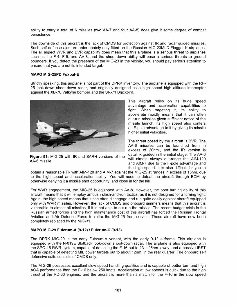
181
ability to carry a total of 6 missiles (two AA-7 and four AA-8) does give it some degree of combatpersistence.
The downside of this aircraft is the lack of CMDS for protection against IR and radar guided missiles.Such self defense aids are unfortunately only fitted on the Russian MiG-23MLD Flogger-K airplanes.The all aspect WVR and BVR capability does mean that this airplane is a serious threat to airplanessuch as the F-4, F-5, and AV-8, and the shoot-down ability will pose a serious threats to groundpounders. If you detect the presence of the MiG-23 in the vicinity, you should pay serious attention toensure that you are not its intended target.
MAPO MiG-25PD Foxbat-E
Strictly speaking, this airplane is not part of the DPRK inventory. The airplane is equipped with the RP-25 look-down shoot-down radar, and originally designed as a high speed high altitude interceptoragainst the XB-70 Valkyrie bomber and the SR-71 Blackbird.
This aircraft relies on its huge speedadvantage and acceleration capabilities tofight. When targeting it, its ability toaccelerate rapidly means that it can oftenout-run missiles given sufficient notice of themissile launch. Its high speed also confersan F-pole advantage to it by giving its missilehigher initial velocities.
The threat posed by the aircraft is BVR. TheAA-6 missiles can be launched from inexcess of 20nm., and the IR version isdatalink guided in the initial stage. The AA-6will almost always out-range the AIM-120and AIM-7 due to the F-pole advantage andthe high speed. It is also difficult for you to
obtain a reasonable Pk with AIM-120 and AIM-7 against the MiG-25 at ranges in excess of 15nm. dueto the high speed and acceleration ability. You will need to defeat the aircraft through ECM byotherwise denying it a missile shot opportunity, and close in for the kill.
For WVR engagement, the MiG-25 is equipped with AA-8. However, the poor turning ability of thisaircraft means that it will employ ambush slash-and-run tactics, as it is not designed for a turning fight.Again, the high speed means that it can often disengage and run quite easily against aircraft equippedonly with WVR missiles. However, the lack of CMDS and onboard jammers means that this aircraft isvulnerable to almost all missiles, if it is not able to out-run the missile. The recent budget crisis in theRussian armed forces and the high maintenance cost of this aircraft has forced the Russian FrontalAviation and Air Defense Force to retire the MiG-25 from service. These aircraft have now beencompletely replaced by the MiG-31.
MAPO MiG-29 Fulcrum-A (9-12) / Fulcrum-C (9-13)
The DPRK MiG-29 is the early Fulcrum-A variant, with the early 9-12 airframe. This airplane isequipped with the N-019E Slotback look-down shoot-down radar. The airplane is also equipped withthe SPO-15 RWR system, capable of detecting the F-16 out to 23 – 25nm. away, and a passive IRSTthat is capable of detecting MIL power targets out to about 12nm. in the rear quarter. The onboard selfdefensive suite consists of CMDS only.
The MiG-29 possesses excellent slow speed handling qualities and is capable of better turn and highAOA performance than the F-16 below 250 knots. Acceleration at low speeds is quick due to the highthrust of the RD-33 engines, and the aircraft is more than a match for the F-16 in the slow speed
Figure 91: MiG-25 with IR and SARH versions of theAA-6 missile
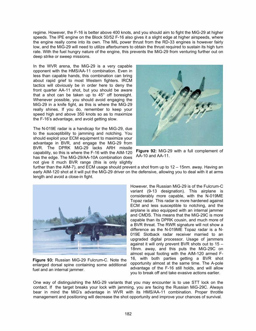
182
regime. However, the F-16 is better above 400 knots, and you should aim to fight the MiG-29 at higherspeeds. The IPE engine on the Block 50/52 F-16 also gives it a slight edge at higher airspeeds, wherethe engine really come into its own. The MIL power thrust from the RD-33 engines is however fairlylow, and the MiG-29 will need to utilize afterburners to obtain the thrust required to sustain its high turnrate. With the fuel hungry nature of the engine, this prevents the MiG-29 from venturing further out ondeep strike or sweep missions.
In the WVR arena, the MiG-29 is a very capableopponent with the HMS/AA-11 combination. Even inless than capable hands, this combination can bringabout rapid grief to most Western fighters. IRCMtactics will obviously be in order here to deny thefront quarter AA-11 shot, but you should be awarethat a shot can be taken up to 45° off boresight.Whenever possible, you should avoid engaging theMiG-29 in a knife fight, as this is where the MiG-29really shines. If you do, remember to keep yourspeed high and above 350 knots so as to maximizethe F-16’s advantage, and avoid getting slow.
The N-019E radar is a handicap for the MiG-29, dueto the susceptibility to jamming and notching. Youshould exploit your ECM equipment to maximize youradvantage in BVR, and engage the MiG-29 fromBVR. The DPRK MiG-29 lacks ARH missilecapability, so this is where the F-16 with the AIM-120has the edge. The MiG-29/AA-10A combination doesnot give it much BVR range (this is only slightlyfurther than the AIM-7), and ECM usage should prevent a shot from up to 12 – 15nm. away. Having anearly AIM-120 shot at it will put the MiG-29 driver on the defensive, allowing you to deal with it at armslength and avoid a close-in fight.
However, the Russian MiG-29 is of the Fulcrum-Cvariant (9-13 designation). This airplane isconsiderably more capable, with the N-019METopaz radar. This radar is more hardened againstECM and less susceptible to notching, and theairplane is also equipped with an internal jammerand CMDS. This means that the MiG-29C is morecapable than its DPRK cousin, and much more ofa BVR threat. The RWR signature will not show adifference as the N-019ME Topaz radar is a N-019E Slotback radar receiver married to anupgraded digital processor. Usage of jammersagainst it will only prevent BVR shots out to 15 –18nm. away, and this puts the MiG-29C onalmost equal footing with the AIM-120 armed F-16, with both parties getting a BVR shotopportunity almost at the same time. The A-poleadvantage of the F-16 still holds, and will allowyou to break off and take evasive actions earlier.
One way of distinguishing the MiG-29 variants that you may encounter is to use STT lock on thecontact. If the target breaks your lock with jamming, you are facing the Russian MiG-29C. Alwaysbear in mind the MiG’s advantage in WVR with its HMS/AA-11 combination. Proper throttlemanagement and positioning will decrease the shot opportunity and improve your chances of survival.
Figure 92: MiG-29 with a full complement ofAA-10 and AA-11.
Figure 93: Russian MiG-29 Fulcrum-C. Note theenlarged dorsal spine containing some additionalfuel and an internal jammer.
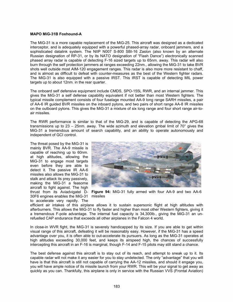
183
MAPO MiG-31B Foxhound-A
The MiG-31 is a more capable replacement of the MiG-25. This aircraft was designed as a dedicatedinterceptor, and is adequately equipped with a powerful phased-array radar, onboard jammers, and asophisticated datalink system. The NIIP N007 S-800 SBI-16 Zaslon (also known by an alternateRussian designation of RP-31, or by its NATO designation of “Flash Dance”) electronically scannedphased array radar is capable of detecting F-16 sized targets up to 65nm. away. This radar will alsoburn through the self protection jammers at ranges exceeding 22nm., allowing the MiG-31 to take BVRshots well outside most AIM-120 engagement ranges. This radar is also more more resistant to chaff,and is almost as difficult to defeat with counter-measures as the best of the Western fighter radars.The MiG-31 is also equipped with a passive IRST. This IRST is capable of detecting MIL powertargets up to about 12nm. in the rear quarter.
The onboard self defensive equipment include CMDS, SPO-155L RWR, and an internal jammer. Thisgives the MiG-31 a self defense capability equivalent if not better than most Western fighters. Thetypical missile complement consists of four fuselage mounted AA-9 long range SARH missiles, a pairof AA-6 IR guided BVR missiles on the inboard pylons, and two pairs of short range AA-8 IR missileson the outboard pylons. This gives the MiG-31 a mixture of six long range and four short range air-to-air missiles.
The RWR performance is similar to that of the MiG-29, and is capable of detecting the APG-68transmissions up to 23 – 25nm. away. The wide azimuth and elevation gmbal limit of 70° gives theMiG-31 a tremendous amount of search capability, and an ability to operate autonomously andindependent of GCI control.
The threat posed by the MiG-31 ismainly BVR. The AA-9 missile iscapable of reaching up to 60nm.at high altitudes, allowing theMiG-31 to engage most targetseven before they are able todetect it. The passive IR AA-6missiles also allows the MiG-31 tostalk and attack its prey passively,making the MiG-31 a feasomeaircraft to fight against. The highthrust from its Aviadvigatel D-30F6 engines enables the MiG-31to accelerate very rapidly. Theefficient air intakes of this airplane allows it to sustain supersonic flight at high altitudes withafterburners. This allows the MiG-31 to fly faster and higher than most other Western fighters, giving ita tremendous F-pole advantage. The internal fuel capacity is 34,300lb., giving the MiG-31 an un-refuelled CAP endurance that exceeds all other airplanes in the Falcon 4 world.
In close-in WVR fight, the MiG-31 is severely handicapped by its size. If you are able to get withinvisual range of this aircraft, defeating it will be reasonably easy. However, if the MiG-31 has a speedadvantage over you, it is often able to out-accelerate its pursuers. As long as the MiG-31 operates athigh altitudes exceeding 30,000 feet, and keeps its airspeed high, the chances of successfullyintercepting this aircraft in an F-16 is marginal, though F-14 and F-15 pilots may still stand a chance.
The best defense against this aircraft is to stay out of its reach, and attempt to sneak up to it. Itscapable radar will not make it any easier for you to stay undetected. The only “advantage” that you willhave is that this aircraft is still not capable of carrying the AA-12 missiles, and should it engage you,you will have ample notice of its missile launch from your RWR. This will be your signal to get away asquickly as you can. Thankfully, this airplane is only in service with the Russian VVS (Frontal Aviation)
Figure 94: MiG-31 fully armed with four AA-9 and two AA-6missiles
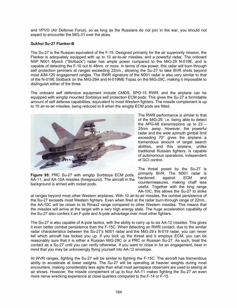
184
and VPVO (Air Defense Force), so as long as the Russians do not join in the war, you should notexpect to encounter the MiG-31 over the skies.
Sukhoi Su-27 Flanker-B
The Su-27 is the Russian equivalent of the F-15. Designed primarily for the air superiority mission, theFlanker is adequately equipped with up to 10 air-to-air missiles, and a powerful radar. The onboardNIIP N001 Myech (“Slotback”) radar has ample power compared to the MiG-29 N-019E, and iscapable of detecting the F-16 out to 48nm. or more. In terms of raw power, this radar will burn throughself protection jammers at ranges exceeding 22nm., allowing the Su-27 to take BVR shots beyondmost AIM-120 engagement ranges. The RWR signature of the N001 radar is also very similar to thatof the N-019E Slotback on the MiG-29A and N-019ME Topaz on the MiG-29C, making it impossible todistinguish either of the three.
The onboard self defensive equipment include CMDS, SPO-15 RWR, and the airplane can beequipped with wingtip mounted Sorbtsiya self protection ECM pods. This gives the Su-27 a formidableamount of self defense capabilities, equivalent to most Western fighters. The missile complement is upto 10 air-to-air missiles, being reduced to 8 when the wingtip ECM pods are fitted.
The RWR performance is similar to thatof the MiG-29, i.e. being able to detectthe APG-68 transmissions up to 23 –25nm. away. However, the powerfulradar and the wide azimuth gimbal limitexceeding 70° gives the airplane atremendous amount of target searchabilities, and this airplane, unliketraditional Russian fighters, is capableof autonomous operations, independentof GCI control.
The threat posed by the Su-27 isprimarily BVR. The N001 radar ishardened against ECM andcountermeasures, making chaff lessuseful. Together with the long rangeAA-10C, this allows the Su-27 to strike
at ranges beyond most other Western airplanes. With 10 air-to-air missiles, the combat persistence ofthe Su-27 exceeds most Western fighters. Even when fired at the radar burn-through range of 22nm.,the AA-10C will be closer to its Rmax2 range compared to other Western missiles. This means thatthe missiles will arrive at the target with a very high energy state. The huge acceleration capability ofthe Su-27 also confers it an F-pole and A-pole advantage over most other fighters.
The Su-27 is also capable of A-pole tactics, with the ability to carry up to six AA-12 missiles. This givesit even better combat persistence than the F-15C. When detecting an RWR contact, due to the similarradar characteristics between the Su-27’s N001 radar and the MiG-29’s N-019 radar, you can nevertell which aircraft has locked you up. If you lock up the threat and it employs ECM, you can bereasonably sure that it is either a Russian MiG-29C or a PRC or Russian Su-27. As such, treat thecontact as a Su-27 until you can verify otherwise. If you want to close in for an engagement, bear inmind that you may be unknowingly flying yourself into AA-12 envelope.
At WVR ranges, fighting the Su-27 will be similar to fighting the F-15C. The aircraft has tremendousability to accelerate at lower weights. The Su-27 will be operating at heavier weights during mostencounters, making considerably less agile than what most aerospace observers are used to seeing atair shows. However, the missile complement of up to four AA-11 makes fighting the Su-27 an evenmore nerve wrecking experience at close quarters compared to the F-14 or F-15.
Figure 95: PRC Su-27 with wingtip Sorbtsiya ECM pods,AA-11, and AA-10A missiles (foreground). The aircraft in thebackground is armed with rocket pods.
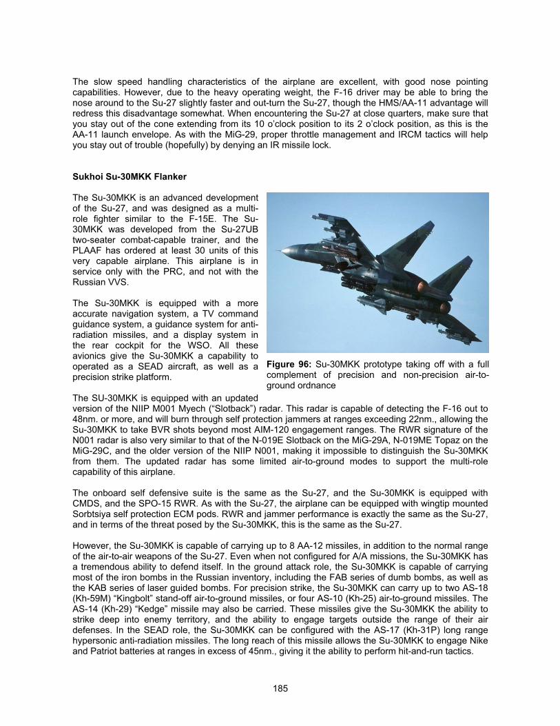
185
The slow speed handling characteristics of the airplane are excellent, with good nose pointingcapabilities. However, due to the heavy operating weight, the F-16 driver may be able to bring thenose around to the Su-27 slightly faster and out-turn the Su-27, though the HMS/AA-11 advantage willredress this disadvantage somewhat. When encountering the Su-27 at close quarters, make sure thatyou stay out of the cone extending from its 10 o’clock position to its 2 o’clock position, as this is theAA-11 launch envelope. As with the MiG-29, proper throttle management and IRCM tactics will helpyou stay out of trouble (hopefully) by denying an IR missile lock.
Sukhoi Su-30MKK Flanker
The Su-30MKK is an advanced developmentof the Su-27, and was designed as a multi-role fighter similar to the F-15E. The Su-30MKK was developed from the Su-27UBtwo-seater combat-capable trainer, and thePLAAF has ordered at least 30 units of thisvery capable airplane. This airplane is inservice only with the PRC, and not with theRussian VVS.
The Su-30MKK is equipped with a moreaccurate navigation system, a TV commandguidance system, a guidance system for anti-radiation missiles, and a display system inthe rear cockpit for the WSO. All theseavionics give the Su-30MKK a capability tooperated as a SEAD aircraft, as well as aprecision strike platform.
The SU-30MKK is equipped with an updatedversion of the NIIP M001 Myech (“Slotback”) radar. This radar is capable of detecting the F-16 out to48nm. or more, and will burn through self protection jammers at ranges exceeding 22nm., allowing theSu-30MKK to take BVR shots beyond most AIM-120 engagement ranges. The RWR signature of theN001 radar is also very similar to that of the N-019E Slotback on the MiG-29A, N-019ME Topaz on theMiG-29C, and the older version of the NIIP N001, making it impossible to distinguish the Su-30MKKfrom them. The updated radar has some limited air-to-ground modes to support the multi-rolecapability of this airplane.
The onboard self defensive suite is the same as the Su-27, and the Su-30MKK is equipped withCMDS, and the SPO-15 RWR. As with the Su-27, the airplane can be equipped with wingtip mountedSorbtsiya self protection ECM pods. RWR and jammer performance is exactly the same as the Su-27,and in terms of the threat posed by the Su-30MKK, this is the same as the Su-27.
However, the Su-30MKK is capable of carrying up to 8 AA-12 missiles, in addition to the normal rangeof the air-to-air weapons of the Su-27. Even when not configured for A/A missions, the Su-30MKK hasa tremendous ability to defend itself. In the ground attack role, the Su-30MKK is capable of carryingmost of the iron bombs in the Russian inventory, including the FAB series of dumb bombs, as well asthe KAB series of laser guided bombs. For precision strike, the Su-30MKK can carry up to two AS-18(Kh-59M) “Kingbolt” stand-off air-to-ground missiles, or four AS-10 (Kh-25) air-to-ground missiles. TheAS-14 (Kh-29) “Kedge” missile may also be carried. These missiles give the Su-30MKK the ability tostrike deep into enemy territory, and the ability to engage targets outside the range of their airdefenses. In the SEAD role, the Su-30MKK can be configured with the AS-17 (Kh-31P) long rangehypersonic anti-radiation missiles. The long reach of this missile allows the Su-30MKK to engage Nikeand Patriot batteries at ranges in excess of 45nm., giving it the ability to perform hit-and-run tactics.
Figure 96: Su-30MKK prototype taking off with a fullcomplement of precision and non-precision air-to-ground ordnance
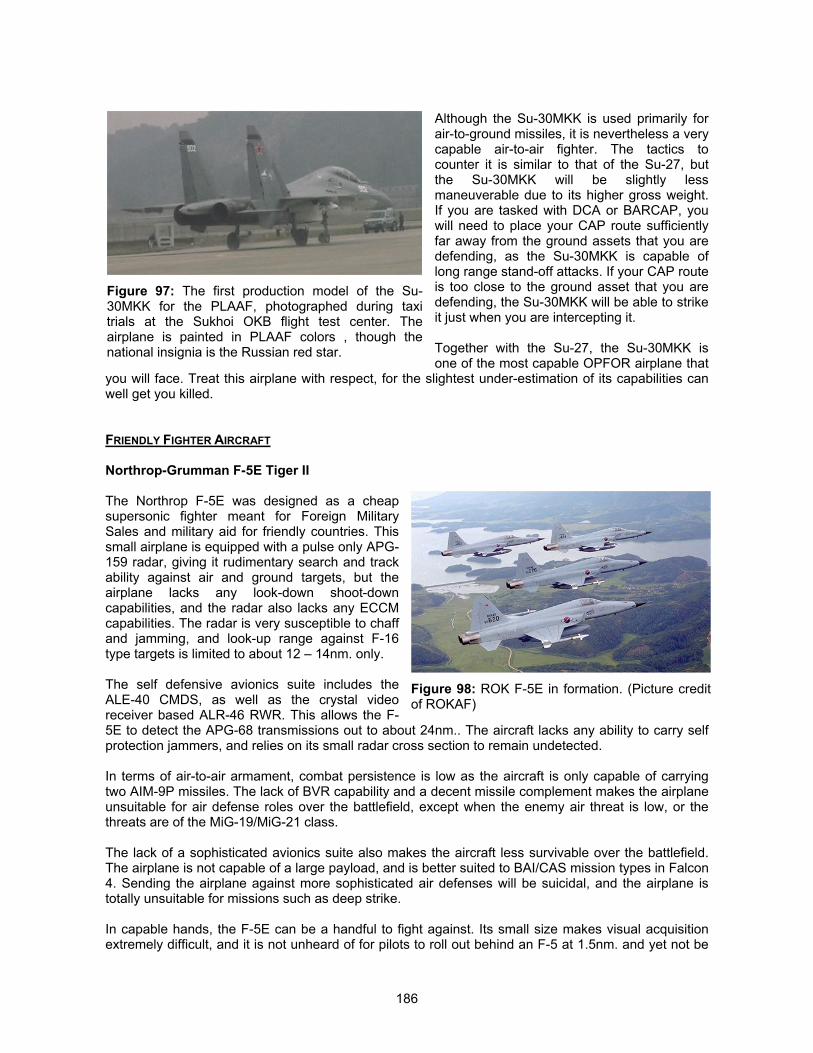
186
Although the Su-30MKK is used primarily forair-to-ground missiles, it is nevertheless a verycapable air-to-air fighter. The tactics tocounter it is similar to that of the Su-27, butthe Su-30MKK will be slightly lessmaneuverable due to its higher gross weight.If you are tasked with DCA or BARCAP, youwill need to place your CAP route sufficientlyfar away from the ground assets that you aredefending, as the Su-30MKK is capable oflong range stand-off attacks. If your CAP routeis too close to the ground asset that you aredefending, the Su-30MKK will be able to strikeit just when you are intercepting it.
Together with the Su-27, the Su-30MKK isone of the most capable OPFOR airplane that
you will face. Treat this airplane with respect, for the slightest under-estimation of its capabilities canwell get you killed.
FRIENDLY FIGHTER AIRCRAFT
Northrop-Grumman F-5E Tiger II
The Northrop F-5E was designed as a cheapsupersonic fighter meant for Foreign MilitarySales and military aid for friendly countries. Thissmall airplane is equipped with a pulse only APG-159 radar, giving it rudimentary search and trackability against air and ground targets, but theairplane lacks any look-down shoot-downcapabilities, and the radar also lacks any ECCMcapabilities. The radar is very susceptible to chaffand jamming, and look-up range against F-16type targets is limited to about 12 – 14nm. only.
The self defensive avionics suite includes theALE-40 CMDS, as well as the crystal videoreceiver based ALR-46 RWR. This allows the F-5E to detect the APG-68 transmissions out to about 24nm.. The aircraft lacks any ability to carry selfprotection jammers, and relies on its small radar cross section to remain undetected.
In terms of air-to-air armament, combat persistence is low as the aircraft is only capable of carryingtwo AIM-9P missiles. The lack of BVR capability and a decent missile complement makes the airplaneunsuitable for air defense roles over the battlefield, except when the enemy air threat is low, or thethreats are of the MiG-19/MiG-21 class.
The lack of a sophisticated avionics suite also makes the aircraft less survivable over the battlefield.The airplane is not capable of a large payload, and is better suited to BAI/CAS mission types in Falcon4. Sending the airplane against more sophisticated air defenses will be suicidal, and the airplane istotally unsuitable for missions such as deep strike.
In capable hands, the F-5E can be a handful to fight against. Its small size makes visual acquisitionextremely difficult, and it is not unheard of for pilots to roll out behind an F-5 at 1.5nm. and yet not be
Figure 97: The first production model of the Su-30MKK for the PLAAF, photographed during taxitrials at the Sukhoi OKB flight test center. Theairplane is painted in PLAAF colors , though thenational insignia is the Russian red star.
Figure 98: ROK F-5E in formation. (Picture creditof ROKAF)
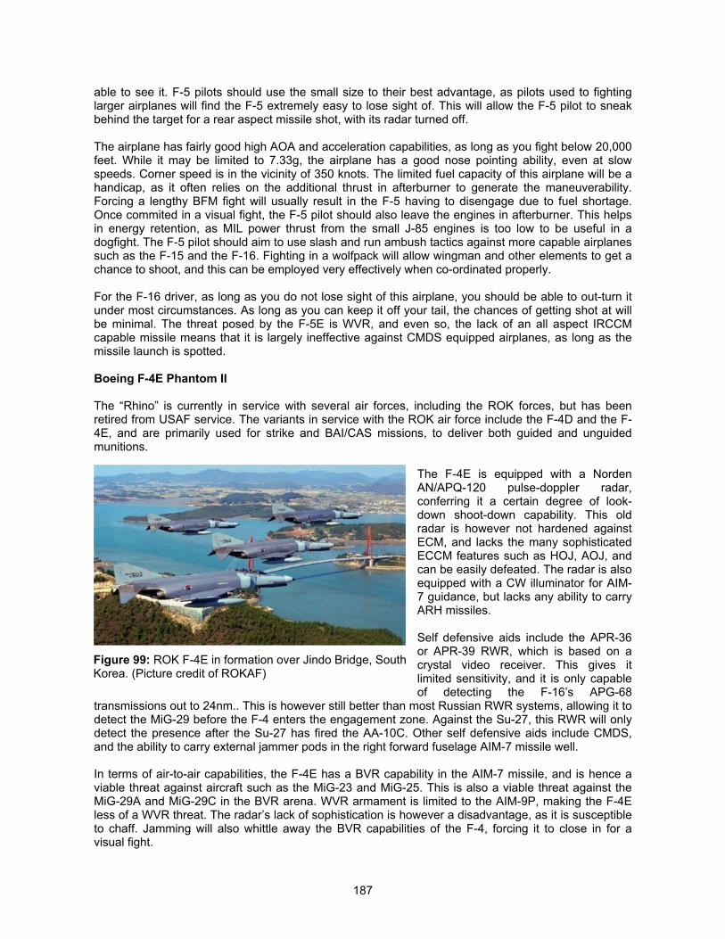
187
able to see it. F-5 pilots should use the small size to their best advantage, as pilots used to fightinglarger airplanes will find the F-5 extremely easy to lose sight of. This will allow the F-5 pilot to sneakbehind the target for a rear aspect missile shot, with its radar turned off.
The airplane has fairly good high AOA and acceleration capabilities, as long as you fight below 20,000feet. While it may be limited to 7.33g, the airplane has a good nose pointing ability, even at slowspeeds. Corner speed is in the vicinity of 350 knots. The limited fuel capacity of this airplane will be ahandicap, as it often relies on the additional thrust in afterburner to generate the maneuverability.Forcing a lengthy BFM fight will usually result in the F-5 having to disengage due to fuel shortage.Once commited in a visual fight, the F-5 pilot should also leave the engines in afterburner. This helpsin energy retention, as MIL power thrust from the small J-85 engines is too low to be useful in adogfight. The F-5 pilot should aim to use slash and run ambush tactics against more capable airplanessuch as the F-15 and the F-16. Fighting in a wolfpack will allow wingman and other elements to get achance to shoot, and this can be employed very effectively when co-ordinated properly.
For the F-16 driver, as long as you do not lose sight of this airplane, you should be able to out-turn itunder most circumstances. As long as you can keep it off your tail, the chances of getting shot at willbe minimal. The threat posed by the F-5E is WVR, and even so, the lack of an all aspect IRCCMcapable missile means that it is largely ineffective against CMDS equipped airplanes, as long as themissile launch is spotted.
Boeing F-4E Phantom II
The “Rhino” is currently in service with several air forces, including the ROK forces, but has beenretired from USAF service. The variants in service with the ROK air force include the F-4D and the F-4E, and are primarily used for strike and BAI/CAS missions, to deliver both guided and unguidedmunitions.
The F-4E is equipped with a NordenAN/APQ-120 pulse-doppler radar,conferring it a certain degree of look-down shoot-down capability. This oldradar is however not hardened againstECM, and lacks the many sophisticatedECCM features such as HOJ, AOJ, andcan be easily defeated. The radar is alsoequipped with a CW illuminator for AIM-7 guidance, but lacks any ability to carryARH missiles.
Self defensive aids include the APR-36or APR-39 RWR, which is based on acrystal video receiver. This gives itlimited sensitivity, and it is only capableof detecting the F-16’s APG-68
transmissions out to 24nm.. This is however still better than most Russian RWR systems, allowing it todetect the MiG-29 before the F-4 enters the engagement zone. Against the Su-27, this RWR will onlydetect the presence after the Su-27 has fired the AA-10C. Other self defensive aids include CMDS,and the ability to carry external jammer pods in the right forward fuselage AIM-7 missile well.
In terms of air-to-air capabilities, the F-4E has a BVR capability in the AIM-7 missile, and is hence aviable threat against aircraft such as the MiG-23 and MiG-25. This is also a viable threat against theMiG-29A and MiG-29C in the BVR arena. WVR armament is limited to the AIM-9P, making the F-4Eless of a WVR threat. The radar’s lack of sophistication is however a disadvantage, as it is susceptibleto chaff. Jamming will also whittle away the BVR capabilities of the F-4, forcing it to close in for avisual fight.
Figure 99: ROK F-4E in formation over Jindo Bridge, SouthKorea. (Picture credit of ROKAF)
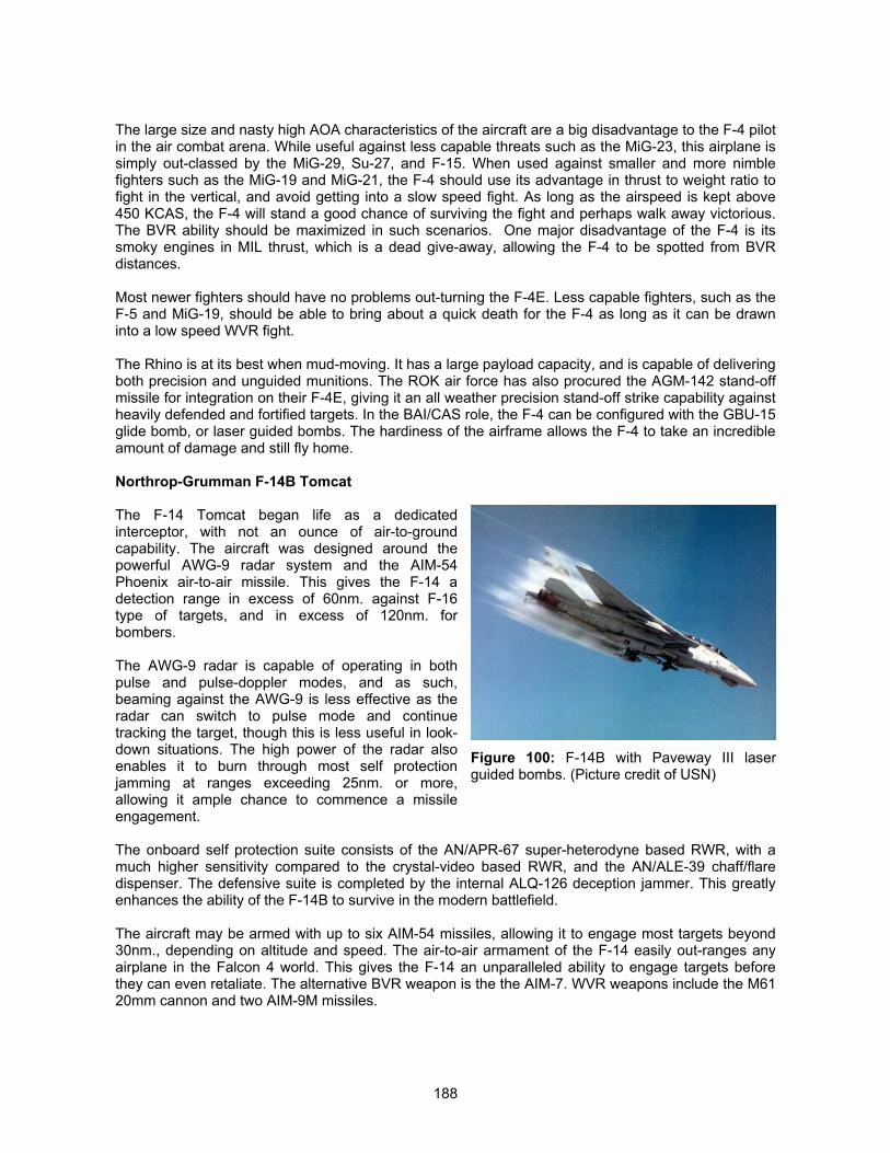
188
The large size and nasty high AOA characteristics of the aircraft are a big disadvantage to the F-4 pilotin the air combat arena. While useful against less capable threats such as the MiG-23, this airplane issimply out-classed by the MiG-29, Su-27, and F-15. When used against smaller and more nimblefighters such as the MiG-19 and MiG-21, the F-4 should use its advantage in thrust to weight ratio tofight in the vertical, and avoid getting into a slow speed fight. As long as the airspeed is kept above450 KCAS, the F-4 will stand a good chance of surviving the fight and perhaps walk away victorious.The BVR ability should be maximized in such scenarios. One major disadvantage of the F-4 is itssmoky engines in MIL thrust, which is a dead give-away, allowing the F-4 to be spotted from BVRdistances.
Most newer fighters should have no problems out-turning the F-4E. Less capable fighters, such as theF-5 and MiG-19, should be able to bring about a quick death for the F-4 as long as it can be drawninto a low speed WVR fight.
The Rhino is at its best when mud-moving. It has a large payload capacity, and is capable of deliveringboth precision and unguided munitions. The ROK air force has also procured the AGM-142 stand-offmissile for integration on their F-4E, giving it an all weather precision stand-off strike capability againstheavily defended and fortified targets. In the BAI/CAS role, the F-4 can be configured with the GBU-15glide bomb, or laser guided bombs. The hardiness of the airframe allows the F-4 to take an incredibleamount of damage and still fly home.
Northrop-Grumman F-14B Tomcat
The F-14 Tomcat began life as a dedicatedinterceptor, with not an ounce of air-to-groundcapability. The aircraft was designed around thepowerful AWG-9 radar system and the AIM-54Phoenix air-to-air missile. This gives the F-14 adetection range in excess of 60nm. against F-16type of targets, and in excess of 120nm. forbombers.
The AWG-9 radar is capable of operating in bothpulse and pulse-doppler modes, and as such,beaming against the AWG-9 is less effective as theradar can switch to pulse mode and continuetracking the target, though this is less useful in look-down situations. The high power of the radar alsoenables it to burn through most self protectionjamming at ranges exceeding 25nm. or more,allowing it ample chance to commence a missileengagement.
The onboard self protection suite consists of the AN/APR-67 super-heterodyne based RWR, with amuch higher sensitivity compared to the crystal-video based RWR, and the AN/ALE-39 chaff/flaredispenser. The defensive suite is completed by the internal ALQ-126 deception jammer. This greatlyenhances the ability of the F-14B to survive in the modern battlefield.
The aircraft may be armed with up to six AIM-54 missiles, allowing it to engage most targets beyond30nm., depending on altitude and speed. The air-to-air armament of the F-14 easily out-ranges anyairplane in the Falcon 4 world. This gives the F-14 an unparalleled ability to engage targets beforethey can even retaliate. The alternative BVR weapon is the the AIM-7. WVR weapons include the M6120mm cannon and two AIM-9M missiles.
Figure 100: F-14B with Paveway III laserguided bombs. (Picture credit of USN)
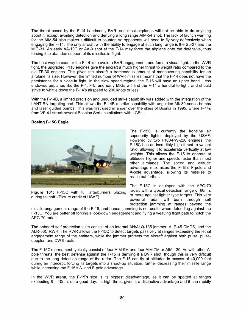
189
The threat posed by the F-14 is primarily BVR, and most airplanes will not be able to do anythingabout it, except avoiding detection and denying a long range AIM-54 shot. The lack of launch warningfor the AIM-54 also makes it difficult to counter, so opponents will need to fly very defensively whenengaging the F-14. The only aircraft with the ability to engage at such long range is the Su-27 and theMiG-31. An early AA-10C or AA-9 shot at the F-14 may force the airplane onto the defensive, thusforcing it to abandon support of its missiles in-flight.
The best way to counter the F-14 is to avoid a BVR engagement, and force a visual fight. In the WVRfight, the upgraded F110 engines give the aircraft a much higher thrust to weight ratio compared to theold TF-30 engines. This gives the aircraft a tremendous amount of maneuvering capability for anairplane its size. However, the limited number of WVR missiles means that the F-14 does not have thepersistence for a close-in fight. In the slow speed regime, the F-16 will have an upper hand. Lessendowed airplanes like the F-4, F-5, and early MiGs will find the F-14 a handful to fight, and shouldstrive to whittle down the F-14’s airspeed to 200 knots or less.
With the F-14B, a limited precision and unguided strike capability was added with the integration of theLANTIRN targeting pod. This allows the F-14B a strike capability with unguided Mk-80 series bombsand laser guided bombs. This was first used in anger over the skies of Bosnia in 1995, where F-14sfrom VF-41 struck several Bosnian Serb installations with LGBs.
Boeing F-15C Eagle
The F-15C is currently the frontline airsuperiority fighter deployed by the USAF.Powered by two F100-PW-220 engines, theF-15C has an incredibly high thrust to weightratio, allowing it to accelerate vertically at lowweights. This allows the F-15 to operate ataltitudes higher and speeds faster than mostother airplanes. The speed and altitudeadvantage maximizes the F-15’s F-pole andA-pole advantage, allowing its missiles toreach out further.
The F-15C is equipped with the APG-70radar, with a typical detection range of 60nm.or more against fighter type targets. This verypowerful radar will burn through selfprotection jamming at ranges beyond the
missile engagement range of the F-15, and hence, jamming is not useful when defending against theF-15C. You are better off forcing a look-down engagement and flying a weaving flight path to notch theAPG-70 radar.
The onboard self protection suite consist of an internal AN/ALQ-135 jammer, ALE-45 CMDS, and theALR-56C RWR. The RWR allows the F-15C to detect targets passively at ranges exceeding the lethalengagement range of the emitters, while the jammer protects the aircraft against both pulse, pulse-doppler, and CW threats.
The F-15C’s armament typically consist of four AIM-9M and four AIM-7M or AIM-120. As with other A-pole threats, the best defense against the F-15 is denying it a BVR shot, though this is very difficultdue to the long detection range of the radar. The F-15 can fly at altitudes in excess of 40,000 feetduring an intercept, forcing its targets into a shoot-up situation, further decreasing their missile rangewhile increasing the F-15’s A- and F-pole advantage.
In the WVR arena, the F-15’s size is its biggest disadvantage, as it can be spotted at rangesexceeding 8 – 10nm. on a good day. Its high thrust gives it a distinctive advantage and it can rapidly
Figure 101: F-15C with full afterburners blazingduring takeoff. (Picture credit of USAF)
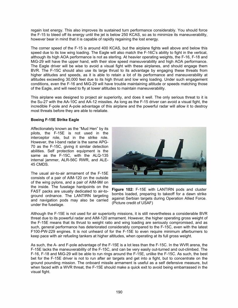
190
regain lost energy. This also improves its sustained turn performance considerably. You should forcethe F-15 to bleed off its energy until the jet is below 250 KCAS, so as to minimize its maneuverability,however bear in mind that it is capable of rapidly regaining the lost energy.
The corner speed of the F-15 is around 400 KCAS, but the airplane fights well above and below thisspeed due to its low wing loading. The Eagle will also match the F-16C’s ability to fight in the vertical,although its high AOA performance is not as sterling. At heavier operating weights, the F-16, F-18 andMiG-29 will have the upper hand, with their slow speed maneuverability and high AOA performance.The Eagle driver will be wise to avoid a visual fight with these airplanes, and should engage themBVR. The F-15C should also use its large thrust to its advantage by engaging these threats fromhigher altitudes and speeds, as it is able to retain a lot of its performance and maneuverability ataltitudes exceeding 30,000 feet due to its high thrust and low wing loading. Under such engagementconditions, even the F-16 and MiG-29 will have trouble maintaining altitude or speeds matching thoseof the Eagle, and will need to fly at lower altitudes to maintain maneuverability.
This airplane was designed to project air superiority, and does it well. The only serious threat to it isthe Su-27 with the AA-10C and AA-12 missiles. As long as the F-15 driver can avoid a visual fight, theincredible F-pole and A-pole advantage of this airplane and the powerful radar will allow it to destroymost threats before they are able to retaliate.
Boeing F-15E Strike Eagle
Affectionately known as the “Mud Hen” by itspilots, the F-15E is not used in theinterceptor role, but in the strike role.However, the I-band radar is the same APG-70 as the F-15C, giving it similar detectionabilities. Self protection equipment is thesame as the F-15C, with the ALQ-135internal jammer, ALR-56C RWR, and ALE-45 CMDS.
The usual air-to-air armament of the F-15Econsists of a pair of AIM-120 on the outsideof the wing pylons, and a pair of AIM-9M onthe inside. The fuselage hardpoints on theFAST packs are usually dedicated to air-to-ground ordnance. The LANTIRN targetingand navigation pods may also be carriedunder the fuselage.
Although the F-15E is not used for air superiority missions, it is still nevertheless a considerable BVRthreat due to its powerful radar and AIM-120 armament. However, the higher operating gross weight ofthe F-15E means that its thrust to weight ratio and wing loading are seriously compromised, and assuch, general performance has deteriorated considerably compared to the F-15C, even with the latestF100-PW-229 engines. It is not unheard of for the F-15E to even require minimum afterburners tokeep pace with air refueling tankers at higher altitudes, when operating at its full gross weight.
As such, the A- and F-pole advantage of the F-15E is a lot less than the F-15C. In the WVR arena, theF-15E lacks the maneuverability of the F-15C, and can be very easily out-turned and out-climbed. TheF-16, F-18 and MiG-29 will be able to run rings around the F-15E, unlike the F-15C. As such, the bestbet for the F-15E driver is not to run after air targets and get into a fight, but to concentrate on theground pounding mission. The onboard missile armament is useful as a self defensive measure, butwhen faced with a WVR threat, the F-15E should make a quick exit to avoid being embarrassed in thevisual fight.
Figure 102: F-15E with LANTIRN pods and clusterbombs loaded, preparing to takeoff for a dawn strikeagainst Serbian targets during Operation Allied Force.(Picture credit of USAF)
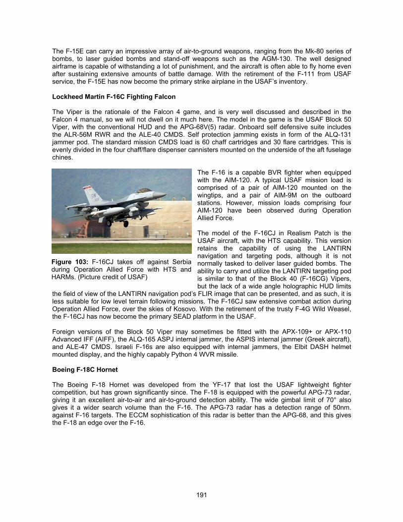
191
The F-15E can carry an impressive array of air-to-ground weapons, ranging from the Mk-80 series ofbombs, to laser guided bombs and stand-off weapons such as the AGM-130. The well designedairframe is capable of withstanding a lot of punishment, and the aircraft is often able to fly home evenafter sustaining extensive amounts of battle damage. With the retirement of the F-111 from USAFservice, the F-15E has now become the primary strike airplane in the USAF’s inventory.
Lockheed Martin F-16C Fighting Falcon
The Viper is the rationale of the Falcon 4 game, and is very well discussed and described in theFalcon 4 manual, so we will not dwell on it much here. The model in the game is the USAF Block 50Viper, with the conventional HUD and the APG-68V(5) radar. Onboard self defensive suite includesthe ALR-56M RWR and the ALE-40 CMDS. Self protection jamming exists in form of the ALQ-131jammer pod. The standard mission CMDS load is 60 chaff cartridges and 30 flare cartridges. This isevenly divided in the four chaff/flare dispenser cannisters mounted on the underside of the aft fuselagechines.
The F-16 is a capable BVR fighter when equippedwith the AIM-120. A typical USAF mission load iscomprised of a pair of AIM-120 mounted on thewingtips, and a pair of AIM-9M on the outboardstations. However, mission loads comprising fourAIM-120 have been observed during OperationAllied Force.
The model of the F-16CJ in Realism Patch is theUSAF aircraft, with the HTS capability. This versionretains the capability of using the LANTIRNnavigation and targeting pods, although it is notnormally tasked to deliver laser guided bombs. Theability to carry and utilize the LANTIRN targeting podis similar to that of the Block 40 (F-16CG) Vipers,but the lack of a wide angle holographic HUD limits
the field of view of the LANTIRN navigation pod’s FLIR image that can be presented, and as such, it isless suitable for low level terrain following missions. The F-16CJ saw extensive combat action duringOperation Allied Force, over the skies of Kosovo. With the retirement of the trusty F-4G Wild Weasel,the F-16CJ has now become the primary SEAD platform in the USAF.
Foreign versions of the Block 50 Viper may sometimes be fitted with the APX-109+ or APX-110Advanced IFF (AIFF), the ALQ-165 ASPJ internal jammer, the ASPIS internal jammer (Greek aircraft),and ALE-47 CMDS. Israeli F-16s are also equipped with internal jammers, the Elbit DASH helmetmounted display, and the highly capably Python 4 WVR missile.
Boeing F-18C Hornet
The Boeing F-18 Hornet was developed from the YF-17 that lost the USAF lightweight fightercompetition, but has grown significantly since. The F-18 is equipped with the powerful APG-73 radar,giving it an excellent air-to-air and air-to-ground detection ability. The wide gimbal limit of 70° alsogives it a wider search volume than the F-16. The APG-73 radar has a detection range of 50nm.against F-16 targets. The ECCM sophistication of this radar is better than the APG-68, and this givesthe F-18 an edge over the F-16.
Figure 103: F-16CJ takes off against Serbiaduring Operation Allied Force with HTS andHARMs. (Picture credit of USAF)
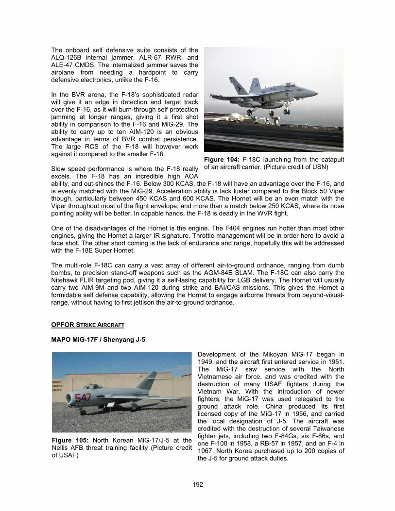
192
The onboard self defensive suite consists of theALQ-126B internal jammer, ALR-67 RWR, andALE-47 CMDS. The internalized jammer saves theairplane from needing a hardpoint to carrydefensive electronics, unlike the F-16.
In the BVR arena, the F-18’s sophisticated radarwill give it an edge in detection and target trackover the F-16, as it will burn-through self protectionjamming at longer ranges, giving it a first shotability in comparison to the F-16 and MiG-29. Theability to carry up to ten AIM-120 is an obviousadvantage in terms of BVR combat persistence.The large RCS of the F-18 will however workagainst it compared to the smaller F-16.
Slow speed performance is where the F-18 reallyexcels. The F-18 has an incredible high AOAability, and out-shines the F-16. Below 300 KCAS, the F-18 will have an advantage over the F-16, andis evenly matched with the MiG-29. Acceleration ability is lack luster compared to the Block 50 Viperthough, particularly between 450 KCAS and 600 KCAS. The Hornet will be an even match with theViper throughout most of the flight envelope, and more than a match below 250 KCAS, where its nosepointing ability will be better. In capable hands, the F-18 is deadly in the WVR fight.
One of the disadvantages of the Hornet is the engine. The F404 engines run hotter than most otherengines, giving the Hornet a larger IR signature. Throttle management will be in order here to avoid aface shot. The other short coming is the lack of endurance and range, hopefully this will be addressedwith the F-18E Super Hornet.
The multi-role F-18C can carry a vast array of different air-to-ground ordnance, ranging from dumbbombs, to precision stand-off weapons such as the AGM-84E SLAM. The F-18C can also carry theNitehawk FLIR targeting pod, giving it a self-lasing capability for LGB delivery. The Hornet will usuallycarry two AIM-9M and two AIM-120 during strike and BAI/CAS missions. This gives the Hornet aformidable self defense capability, allowing the Hornet to engage airborne threats from beyond-visual-range, without having to first jettison the air-to-ground ordnance.
OPFOR STRIKE AIRCRAFT
MAPO MiG-17F / Shenyang J-5
Development of the Mikoyan MiG-17 began in1949, and the aircraft first entered service in 1951.The MiG-17 saw service with the NorthVietnamese air force, and was credited with thedestruction of many USAF fighters during theVietnam War. With the introduction of newerfighters, the MiG-17 was used relegated to theground attack role. China produced its firstlicensed copy of the MiG-17 in 1956, and carriedthe local designation of J-5. The aircraft wascredited with the destruction of several Taiwanesefighter jets, including two F-84Gs, six F-86s, andone F-100 in 1958, a RB-57 in 1957, and an F-4 in1967. North Korea purchased up to 200 copies ofthe J-5 for ground attack duties.
Figure 104: F-18C launching from the catapultof an aircraft carrier. (Picture credit of USN)
Figure 105: North Korean MiG-17/J-5 at theNellis AFB threat training facility (Picture creditof USAF)
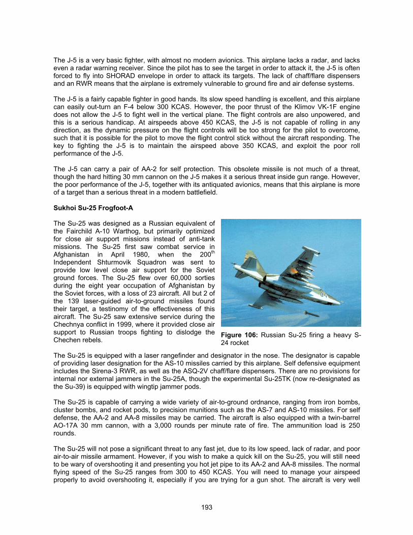
193
The J-5 is a very basic fighter, with almost no modern avionics. This airplane lacks a radar, and lackseven a radar warning receiver. Since the pilot has to see the target in order to attack it, the J-5 is oftenforced to fly into SHORAD envelope in order to attack its targets. The lack of chaff/flare dispensersand an RWR means that the airplane is extremely vulnerable to ground fire and air defense systems.
The J-5 is a fairly capable fighter in good hands. Its slow speed handling is excellent, and this airplanecan easily out-turn an F-4 below 300 KCAS. However, the poor thrust of the Klimov VK-1F enginedoes not allow the J-5 to fight well in the vertical plane. The flight controls are also unpowered, andthis is a serious handicap. At airspeeds above 450 KCAS, the J-5 is not capable of rolling in anydirection, as the dynamic pressure on the flight controls will be too strong for the pilot to overcome,such that it is possible for the pilot to move the flight control stick without the aircraft responding. Thekey to fighting the J-5 is to maintain the airspeed above 350 KCAS, and exploit the poor rollperformance of the J-5.
The J-5 can carry a pair of AA-2 for self protection. This obsolete missile is not much of a threat,though the hard hitting 30 mm cannon on the J-5 makes it a serious threat inside gun range. However,the poor performance of the J-5, together with its antiquated avionics, means that this airplane is moreof a target than a serious threat in a modern battlefield.
Sukhoi Su-25 Frogfoot-A
The Su-25 was designed as a Russian equivalent ofthe Fairchild A-10 Warthog, but primarily optimizedfor close air support missions instead of anti-tankmissions. The Su-25 first saw combat service inAfghanistan in April 1980, when the 200th
Independent Shturmovik Squadron was sent toprovide low level close air support for the Sovietground forces. The Su-25 flew over 60,000 sortiesduring the eight year occupation of Afghanistan bythe Soviet forces, with a loss of 23 aircraft. All but 2 ofthe 139 laser-guided air-to-ground missiles foundtheir target, a testinomy of the effectiveness of thisaircraft. The Su-25 saw extensive service during theChechnya conflict in 1999, where it provided close airsupport to Russian troops fighting to dislodge theChechen rebels.
The Su-25 is equipped with a laser rangefinder and designator in the nose. The designator is capableof providing laser designation for the AS-10 missiles carried by this airplane. Self defensive equipmentincludes the Sirena-3 RWR, as well as the ASQ-2V chaff/flare dispensers. There are no provisions forinternal nor external jammers in the Su-25A, though the experimental Su-25TK (now re-designated asthe Su-39) is equipped with wingtip jammer pods.
The Su-25 is capable of carrying a wide variety of air-to-ground ordnance, ranging from iron bombs,cluster bombs, and rocket pods, to precision munitions such as the AS-7 and AS-10 missiles. For selfdefense, the AA-2 and AA-8 missiles may be carried. The aircraft is also equipped with a twin-barrelAO-17A 30 mm cannon, with a 3,000 rounds per minute rate of fire. The ammunition load is 250rounds.
The Su-25 will not pose a significant threat to any fast jet, due to its low speed, lack of radar, and poorair-to-air missile armament. However, if you wish to make a quick kill on the Su-25, you will still needto be wary of overshooting it and presenting you hot jet pipe to its AA-2 and AA-8 missiles. The normalflying speed of the Su-25 ranges from 300 to 450 KCAS. You will need to manage your airspeedproperly to avoid overshooting it, especially if you are trying for a gun shot. The aircraft is very well
Figure 106: Russian Su-25 firing a heavy S-24 rocket
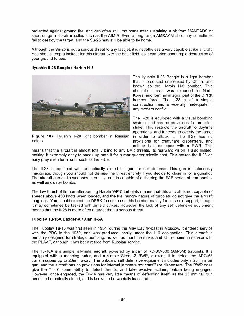
194
protected against ground fire, and can often still limp home after sustaining a hit from MANPADS orshort range air-to-air missiles such as the AIM-9. Even a long range AMRAAM shot may sometimesfail to destroy the target, and the Su-25 may still be able to fly home.
Although the Su-25 is not a serious threat to any fast jet, it is nevetheless a very capable strike aircraft.You should keep a lookout for this aircraft over the battlefield, as it can bring about rapid destruction ofyour ground forces.
llyushin Il-28 Beagle / Harbin H-5
The llyushin Il-28 Beagle is a light bomberthat is produced unlicensed by China, andknown as the Harbin H-5 bomber. Thisobsolete aircraft was exported to NorthKorea, and form an integral part of the DPRKbomber force. The Il-28 is of a simpleconstruction, and is woefully inadequate inany modern conflict.
The Il-28 is equipped with a visual bombingsystem, and has no provisions for precisionstrike. This restricts the aircraft to daytimeoperations, and it needs to overfly the targetin order to attack it. The Il-28 has noprovisions for chaff/flare dispensers, andneither is it equipped with a RWR. This
means that the aircraft is almost totally blind to any BVR threats. Its rearward vision is also limited,making it extremely easy to sneak up onto it for a rear quarter missile shot. This makes the Il-28 aneasy prey even for aircraft such as the F-5E.
The Il-28 is equipped with an optically aimed tail gun for self defense. This gun is notoriouslyinaccurate, though you should not dismiss the threat entirely if you decide to close in for a gunshot.The aircraft carries its weapons internally, and is capable of delivering the FAB series of iron bombs,as well as cluster bombs.
The low thrust of its non-afterburning Harbin WP-5 turbojets means that this aircraft is not capable ofspeeds above 450 knots when loaded, and the fuel hungry nature of turbojets do not give the aircraftlong legs. You should expect the DPRK forces to use this bomber mainly for close air support, thoughit may sometimes be tasked with airfield strikes. However, the lack of any self defensive equipmentmeans that the Il-28 is more often a target than a serious threat.
Tupolev Tu-16A Badger-A / Xian H-6A
The Tupolev Tu-16 was first seen in 1954, during the May Day fly-past in Moscow. It entered servicewith the PRC in the 1959, and was produced locally under the H-6 designation. This aircraft isprimarily designed for strategic bombing, as well as maritime strike, and still remains in service withthe PLAAF, although it has been retired from Russian service.
The Tu-16A is a simple, all-metal aircraft, powered by a pair of RD-3M-500 (AM-3M) turbojets. It isequipped with a mapping radar, and a simple Sirena-2 RWR, allowing it to detect the APG-68transmissions up to 23nm. away. The onboard self defensive equipment includes only a 23 mm tailgun, and the aircraft has no provisions for internal jammers nor chaff/flare dispensers. The RWR doesgive the Tu-16 some ability to detect threats, and take evasive actions, before being engaged.However, once engaged, the Tu-16 has very little means of defending itself, as the 23 mm tail gunneeds to be optically aimed, and is known to be woefully inaccurate.
Figure 107: Ilyushin Il-28 light bomber in Russiancolors
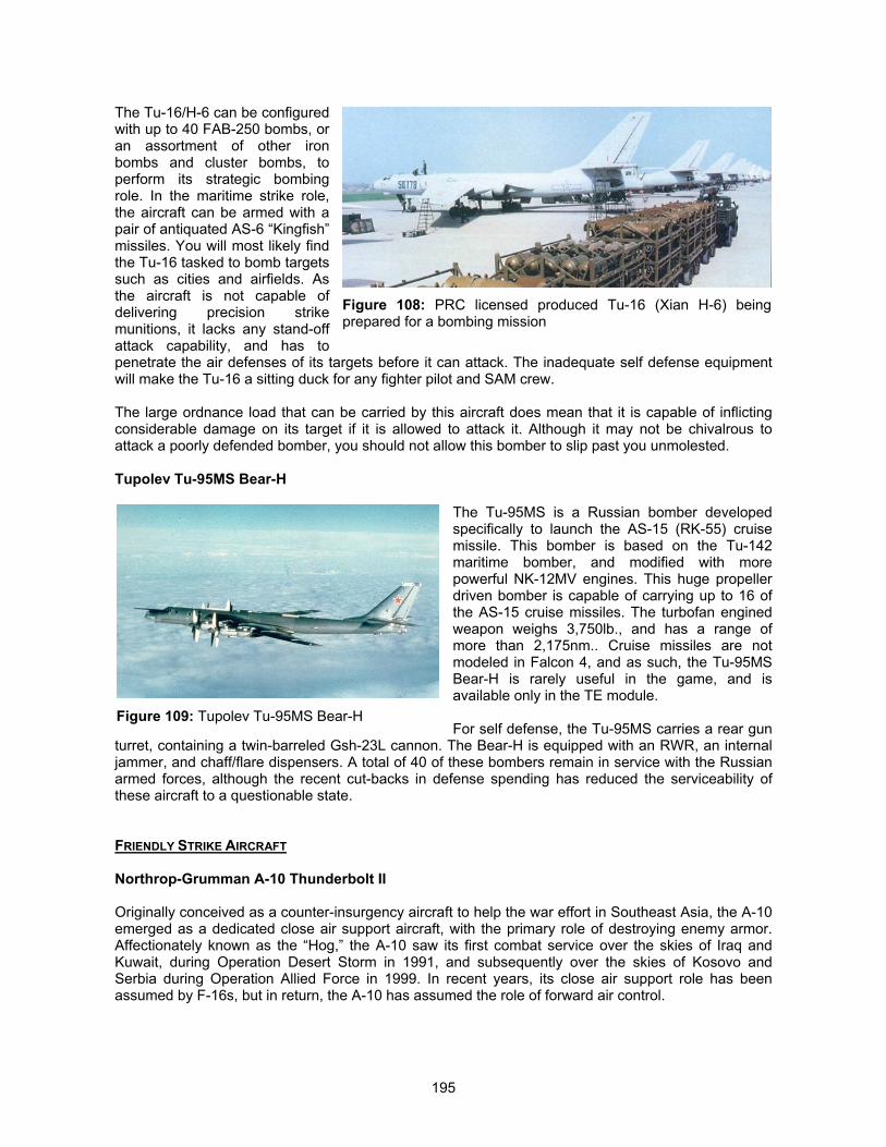
195
The Tu-16/H-6 can be configuredwith up to 40 FAB-250 bombs, oran assortment of other ironbombs and cluster bombs, toperform its strategic bombingrole. In the maritime strike role,the aircraft can be armed with apair of antiquated AS-6 “Kingfish”missiles. You will most likely findthe Tu-16 tasked to bomb targetssuch as cities and airfields. Asthe aircraft is not capable ofdelivering precision strikemunitions, it lacks any stand-offattack capability, and has topenetrate the air defenses of its targets before it can attack. The inadequate self defense equipmentwill make the Tu-16 a sitting duck for any fighter pilot and SAM crew.
The large ordnance load that can be carried by this aircraft does mean that it is capable of inflictingconsiderable damage on its target if it is allowed to attack it. Although it may not be chivalrous toattack a poorly defended bomber, you should not allow this bomber to slip past you unmolested.
Tupolev Tu-95MS Bear-H
The Tu-95MS is a Russian bomber developedspecifically to launch the AS-15 (RK-55) cruisemissile. This bomber is based on the Tu-142maritime bomber, and modified with morepowerful NK-12MV engines. This huge propellerdriven bomber is capable of carrying up to 16 ofthe AS-15 cruise missiles. The turbofan enginedweapon weighs 3,750lb., and has a range ofmore than 2,175nm.. Cruise missiles are notmodeled in Falcon 4, and as such, the Tu-95MSBear-H is rarely useful in the game, and isavailable only in the TE module.
For self defense, the Tu-95MS carries a rear gunturret, containing a twin-barreled Gsh-23L cannon. The Bear-H is equipped with an RWR, an internaljammer, and chaff/flare dispensers. A total of 40 of these bombers remain in service with the Russianarmed forces, although the recent cut-backs in defense spending has reduced the serviceability ofthese aircraft to a questionable state.
FRIENDLY STRIKE AIRCRAFT
Northrop-Grumman A-10 Thunderbolt II
Originally conceived as a counter-insurgency aircraft to help the war effort in Southeast Asia, the A-10emerged as a dedicated close air support aircraft, with the primary role of destroying enemy armor.Affectionately known as the “Hog,” the A-10 saw its first combat service over the skies of Iraq andKuwait, during Operation Desert Storm in 1991, and subsequently over the skies of Kosovo andSerbia during Operation Allied Force in 1999. In recent years, its close air support role has beenassumed by F-16s, but in return, the A-10 has assumed the role of forward air control.
Figure 108: PRC licensed produced Tu-16 (Xian H-6) beingprepared for a bombing mission
Figure 109: Tupolev Tu-95MS Bear-H
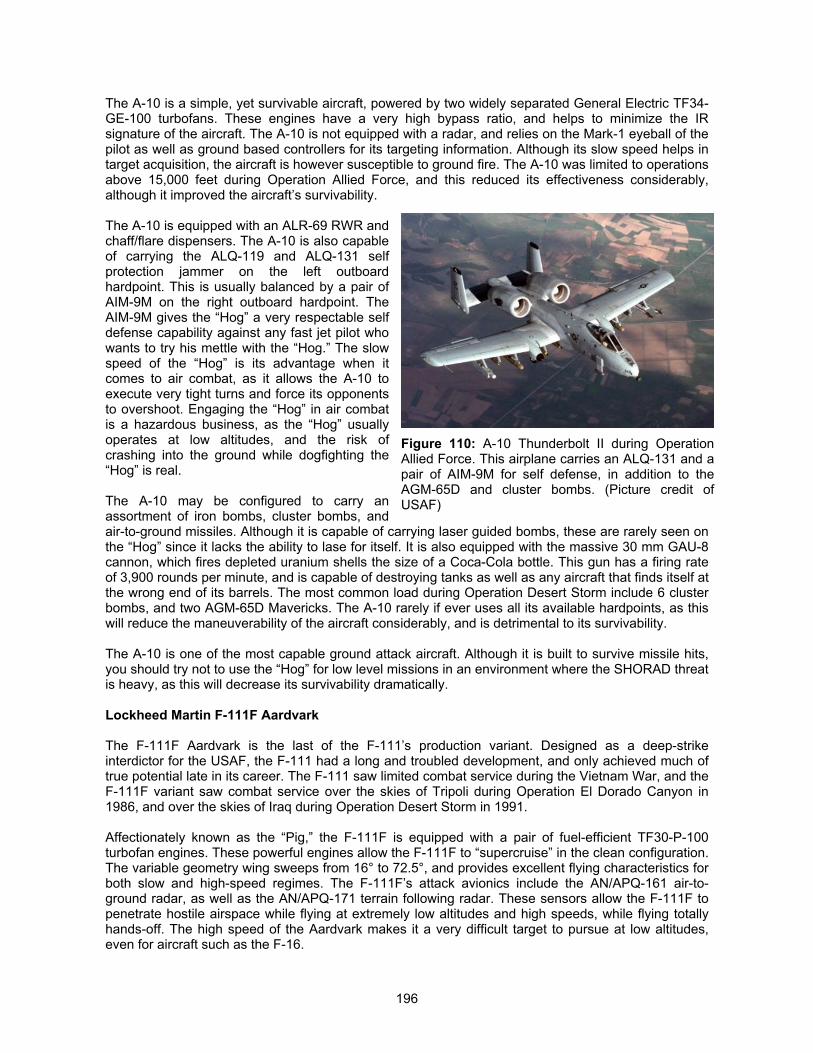
196
The A-10 is a simple, yet survivable aircraft, powered by two widely separated General Electric TF34-GE-100 turbofans. These engines have a very high bypass ratio, and helps to minimize the IRsignature of the aircraft. The A-10 is not equipped with a radar, and relies on the Mark-1 eyeball of thepilot as well as ground based controllers for its targeting information. Although its slow speed helps intarget acquisition, the aircraft is however susceptible to ground fire. The A-10 was limited to operationsabove 15,000 feet during Operation Allied Force, and this reduced its effectiveness considerably,although it improved the aircraft’s survivability.
The A-10 is equipped with an ALR-69 RWR andchaff/flare dispensers. The A-10 is also capableof carrying the ALQ-119 and ALQ-131 selfprotection jammer on the left outboardhardpoint. This is usually balanced by a pair ofAIM-9M on the right outboard hardpoint. TheAIM-9M gives the “Hog” a very respectable selfdefense capability against any fast jet pilot whowants to try his mettle with the “Hog.” The slowspeed of the “Hog” is its advantage when itcomes to air combat, as it allows the A-10 toexecute very tight turns and force its opponentsto overshoot. Engaging the “Hog” in air combatis a hazardous business, as the “Hog” usuallyoperates at low altitudes, and the risk ofcrashing into the ground while dogfighting the“Hog” is real.
The A-10 may be configured to carry anassortment of iron bombs, cluster bombs, andair-to-ground missiles. Although it is capable of carrying laser guided bombs, these are rarely seen onthe “Hog” since it lacks the ability to lase for itself. It is also equipped with the massive 30 mm GAU-8cannon, which fires depleted uranium shells the size of a Coca-Cola bottle. This gun has a firing rateof 3,900 rounds per minute, and is capable of destroying tanks as well as any aircraft that finds itself atthe wrong end of its barrels. The most common load during Operation Desert Storm include 6 clusterbombs, and two AGM-65D Mavericks. The A-10 rarely if ever uses all its available hardpoints, as thiswill reduce the maneuverability of the aircraft considerably, and is detrimental to its survivability.
The A-10 is one of the most capable ground attack aircraft. Although it is built to survive missile hits,you should try not to use the “Hog” for low level missions in an environment where the SHORAD threatis heavy, as this will decrease its survivability dramatically.
Lockheed Martin F-111F Aardvark
The F-111F Aardvark is the last of the F-111’s production variant. Designed as a deep-strikeinterdictor for the USAF, the F-111 had a long and troubled development, and only achieved much oftrue potential late in its career. The F-111 saw limited combat service during the Vietnam War, and theF-111F variant saw combat service over the skies of Tripoli during Operation El Dorado Canyon in1986, and over the skies of Iraq during Operation Desert Storm in 1991.
Affectionately known as the “Pig,” the F-111F is equipped with a pair of fuel-efficient TF30-P-100turbofan engines. These powerful engines allow the F-111F to “supercruise” in the clean configuration.The variable geometry wing sweeps from 16° to 72.5°, and provides excellent flying characteristics forboth slow and high-speed regimes. The F-111F’s attack avionics include the AN/APQ-161 air-to-ground radar, as well as the AN/APQ-171 terrain following radar. These sensors allow the F-111F topenetrate hostile airspace while flying at extremely low altitudes and high speeds, while flying totallyhands-off. The high speed of the Aardvark makes it a very difficult target to pursue at low altitudes,even for aircraft such as the F-16.
Figure 110: A-10 Thunderbolt II during OperationAllied Force. This airplane carries an ALQ-131 and apair of AIM-9M for self defense, in addition to theAGM-65D and cluster bombs. (Picture credit ofUSAF)
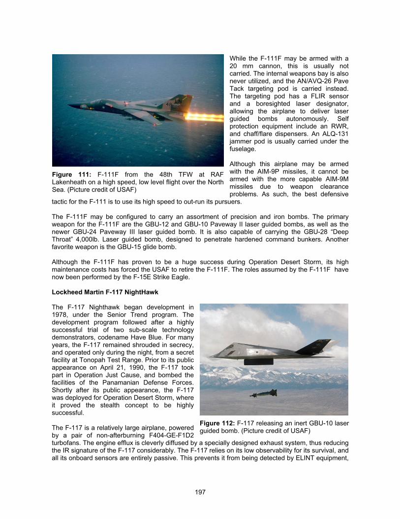
197
While the F-111F may be armed with a20 mm cannon, this is usually notcarried. The internal weapons bay is alsonever utilized, and the AN/AVQ-26 PaveTack targeting pod is carried instead.The targeting pod has a FLIR sensorand a boresighted laser designator,allowing the airplane to deliver laserguided bombs autonomously. Selfprotection equipment include an RWR,and chaff/flare dispensers. An ALQ-131jammer pod is usually carried under thefuselage.
Although this airplane may be armedwith the AIM-9P missiles, it cannot bearmed with the more capable AIM-9Mmissiles due to weapon clearanceproblems. As such, the best defensive
tactic for the F-111 is to use its high speed to out-run its pursuers.
The F-111F may be configured to carry an assortment of precision and iron bombs. The primaryweapon for the F-111F are the GBU-12 and GBU-10 Paveway II laser guided bombs, as well as thenewer GBU-24 Paveway III laser guided bomb. It is also capable of carrying the GBU-28 “DeepThroat” 4,000lb. Laser guided bomb, designed to penetrate hardened command bunkers. Anotherfavorite weapon is the GBU-15 glide bomb.
Although the F-111F has proven to be a huge success during Operation Desert Storm, its highmaintenance costs has forced the USAF to retire the F-111F. The roles assumed by the F-111F havenow been performed by the F-15E Strike Eagle.
Lockheed Martin F-117 NightHawk
The F-117 Nighthawk began development in1978, under the Senior Trend program. Thedevelopment program followed after a highlysuccessful trial of two sub-scale technologydemonstrators, codename Have Blue. For manyyears, the F-117 remained shrouded in secrecy,and operated only during the night, from a secretfacility at Tonopah Test Range. Prior to its publicappearance on April 21, 1990, the F-117 tookpart in Operation Just Cause, and bombed thefacilities of the Panamanian Defense Forces.Shortly after its public appearance, the F-117was deployed for Operation Desert Storm, whereit proved the stealth concept to be highlysuccessful.
The F-117 is a relatively large airplane, poweredby a pair of non-afterburning F404-GE-F1D2turbofans. The engine efflux is cleverly diffused by a specially designed exhaust system, thus reducingthe IR signature of the F-117 considerably. The F-117 relies on its low observability for its survival, andall its onboard sensors are entirely passive. This prevents it from being detected by ELINT equipment,
Figure 111: F-111F from the 48th TFW at RAFLakenheath on a high speed, low level flight over the NorthSea. (Picture credit of USAF)
Figure 112: F-117 releasing an inert GBU-10 laserguided bomb. (Picture credit of USAF)
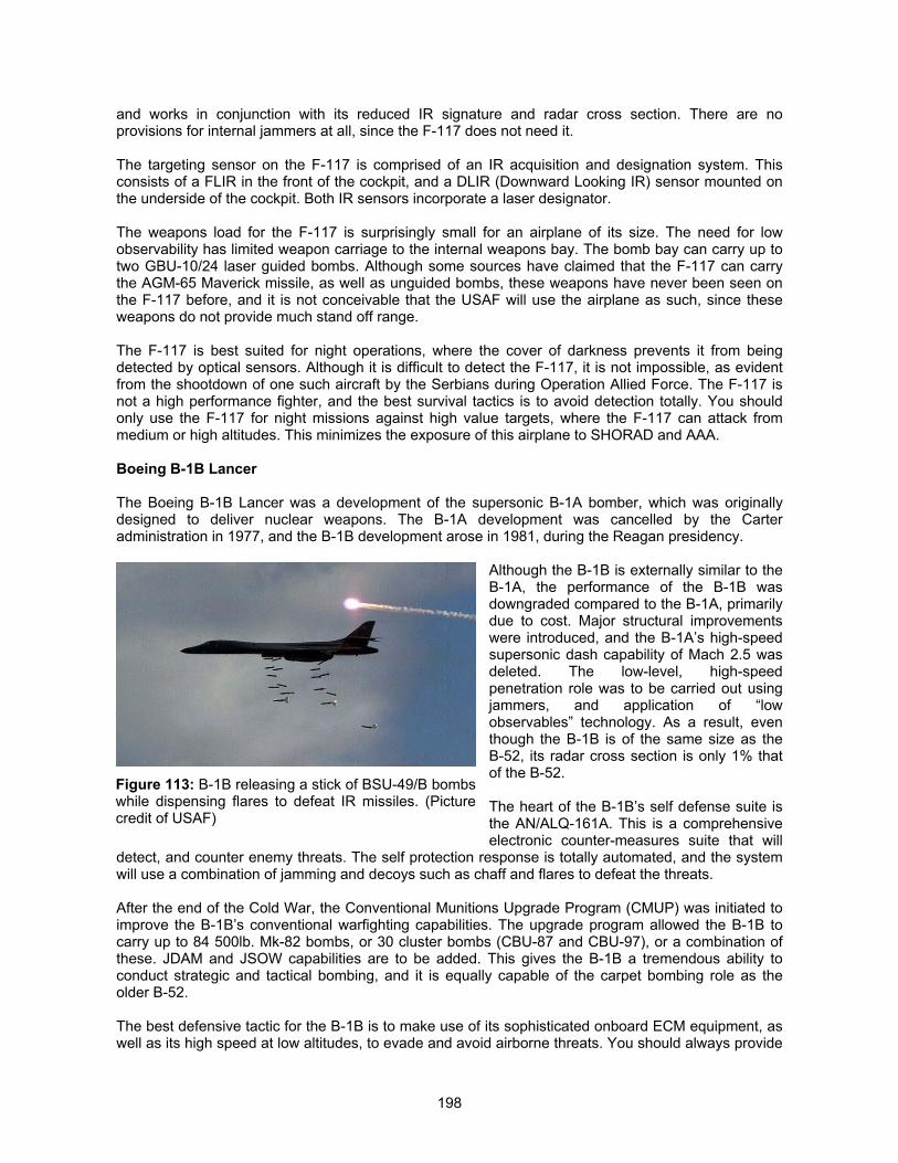
198
and works in conjunction with its reduced IR signature and radar cross section. There are noprovisions for internal jammers at all, since the F-117 does not need it.
The targeting sensor on the F-117 is comprised of an IR acquisition and designation system. Thisconsists of a FLIR in the front of the cockpit, and a DLIR (Downward Looking IR) sensor mounted onthe underside of the cockpit. Both IR sensors incorporate a laser designator.
The weapons load for the F-117 is surprisingly small for an airplane of its size. The need for lowobservability has limited weapon carriage to the internal weapons bay. The bomb bay can carry up totwo GBU-10/24 laser guided bombs. Although some sources have claimed that the F-117 can carrythe AGM-65 Maverick missile, as well as unguided bombs, these weapons have never been seen onthe F-117 before, and it is not conceivable that the USAF will use the airplane as such, since theseweapons do not provide much stand off range.
The F-117 is best suited for night operations, where the cover of darkness prevents it from beingdetected by optical sensors. Although it is difficult to detect the F-117, it is not impossible, as evidentfrom the shootdown of one such aircraft by the Serbians during Operation Allied Force. The F-117 isnot a high performance fighter, and the best survival tactics is to avoid detection totally. You shouldonly use the F-117 for night missions against high value targets, where the F-117 can attack frommedium or high altitudes. This minimizes the exposure of this airplane to SHORAD and AAA.
Boeing B-1B Lancer
The Boeing B-1B Lancer was a development of the supersonic B-1A bomber, which was originallydesigned to deliver nuclear weapons. The B-1A development was cancelled by the Carteradministration in 1977, and the B-1B development arose in 1981, during the Reagan presidency.
Although the B-1B is externally similar to theB-1A, the performance of the B-1B wasdowngraded compared to the B-1A, primarilydue to cost. Major structural improvementswere introduced, and the B-1A’s high-speedsupersonic dash capability of Mach 2.5 wasdeleted. The low-level, high-speedpenetration role was to be carried out usingjammers, and application of “lowobservables” technology. As a result, eventhough the B-1B is of the same size as theB-52, its radar cross section is only 1% thatof the B-52.
The heart of the B-1B’s self defense suite isthe AN/ALQ-161A. This is a comprehensiveelectronic counter-measures suite that will
detect, and counter enemy threats. The self protection response is totally automated, and the systemwill use a combination of jamming and decoys such as chaff and flares to defeat the threats.
After the end of the Cold War, the Conventional Munitions Upgrade Program (CMUP) was initiated toimprove the B-1B’s conventional warfighting capabilities. The upgrade program allowed the B-1B tocarry up to 84 500lb. Mk-82 bombs, or 30 cluster bombs (CBU-87 and CBU-97), or a combination ofthese. JDAM and JSOW capabilities are to be added. This gives the B-1B a tremendous ability toconduct strategic and tactical bombing, and it is equally capable of the carpet bombing role as theolder B-52.
The best defensive tactic for the B-1B is to make use of its sophisticated onboard ECM equipment, aswell as its high speed at low altitudes, to evade and avoid airborne threats. You should always provide
Figure 113: B-1B releasing a stick of BSU-49/B bombswhile dispensing flares to defeat IR missiles. (Picturecredit of USAF)
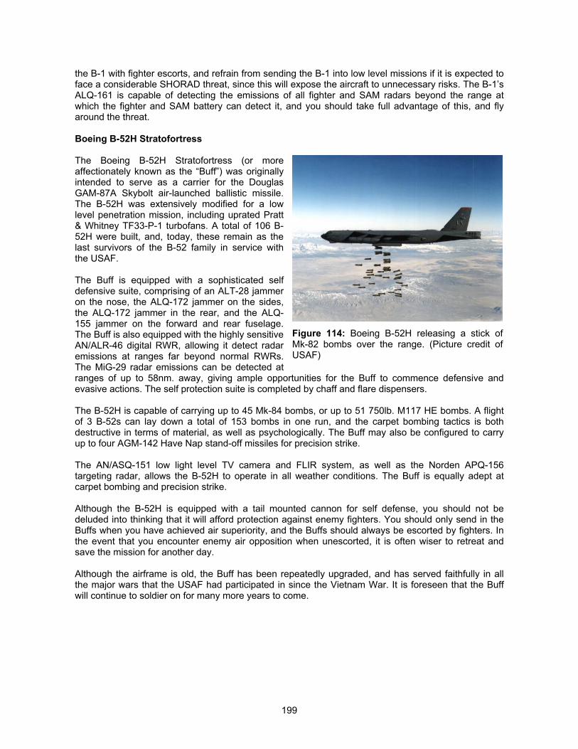
199
the B-1 with fighter escorts, and refrain from sending the B-1 into low level missions if it is expected toface a considerable SHORAD threat, since this will expose the aircraft to unnecessary risks. The B-1’sALQ-161 is capable of detecting the emissions of all fighter and SAM radars beyond the range atwhich the fighter and SAM battery can detect it, and you should take full advantage of this, and flyaround the threat.
Boeing B-52H Stratofortress
The Boeing B-52H Stratofortress (or moreaffectionately known as the “Buff”) was originallyintended to serve as a carrier for the DouglasGAM-87A Skybolt air-launched ballistic missile.The B-52H was extensively modified for a lowlevel penetration mission, including uprated Pratt& Whitney TF33-P-1 turbofans. A total of 106 B-52H were built, and, today, these remain as thelast survivors of the B-52 family in service withthe USAF.
The Buff is equipped with a sophisticated selfdefensive suite, comprising of an ALT-28 jammeron the nose, the ALQ-172 jammer on the sides,the ALQ-172 jammer in the rear, and the ALQ-155 jammer on the forward and rear fuselage.The Buff is also equipped with the highly sensitiveAN/ALR-46 digital RWR, allowing it detect radaremissions at ranges far beyond normal RWRs.The MiG-29 radar emissions can be detected atranges of up to 58nm. away, giving ample opportunities for the Buff to commence defensive andevasive actions. The self protection suite is completed by chaff and flare dispensers.
The B-52H is capable of carrying up to 45 Mk-84 bombs, or up to 51 750lb. M117 HE bombs. A flightof 3 B-52s can lay down a total of 153 bombs in one run, and the carpet bombing tactics is bothdestructive in terms of material, as well as psychologically. The Buff may also be configured to carryup to four AGM-142 Have Nap stand-off missiles for precision strike.
The AN/ASQ-151 low light level TV camera and FLIR system, as well as the Norden APQ-156targeting radar, allows the B-52H to operate in all weather conditions. The Buff is equally adept atcarpet bombing and precision strike.
Although the B-52H is equipped with a tail mounted cannon for self defense, you should not bedeluded into thinking that it will afford protection against enemy fighters. You should only send in theBuffs when you have achieved air superiority, and the Buffs should always be escorted by fighters. Inthe event that you encounter enemy air opposition when unescorted, it is often wiser to retreat andsave the mission for another day.
Although the airframe is old, the Buff has been repeatedly upgraded, and has served faithfully in allthe major wars that the USAF had participated in since the Vietnam War. It is foreseen that the Buffwill continue to soldier on for many more years to come.
Figure 114: Boeing B-52H releasing a stick ofMk-82 bombs over the range. (Picture credit ofUSAF)
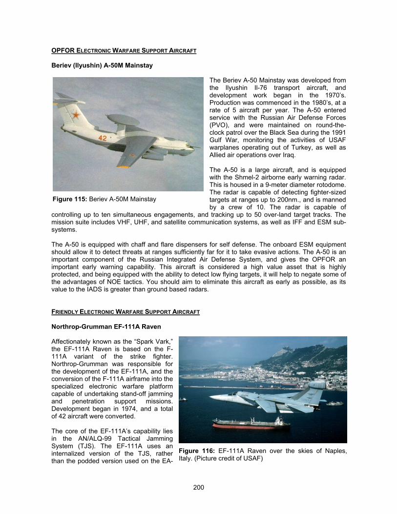
200
OPFOR ELECTRONIC WARFARE SUPPORT AIRCRAFT
Beriev (Ilyushin) A-50M Mainstay
The Beriev A-50 Mainstay was developed fromthe Ilyushin Il-76 transport aircraft, anddevelopment work began in the 1970’s.Production was commenced in the 1980’s, at arate of 5 aircraft per year. The A-50 enteredservice with the Russian Air Defense Forces(PVO), and were maintained on round-the-clock patrol over the Black Sea during the 1991Gulf War, monitoring the activities of USAFwarplanes operating out of Turkey, as well asAllied air operations over Iraq.
The A-50 is a large aircraft, and is equippedwith the Shmel-2 airborne early warning radar.This is housed in a 9-meter diameter rotodome.The radar is capable of detecting fighter-sizedtargets at ranges up to 200nm., and is mannedby a crew of 10. The radar is capable of
controlling up to ten simultaneous engagements, and tracking up to 50 over-land target tracks. Themission suite includes VHF, UHF, and satellite communication systems, as well as IFF and ESM sub-systems.
The A-50 is equipped with chaff and flare dispensers for self defense. The onboard ESM equipmentshould allow it to detect threats at ranges sufficiently far for it to take evasive actions. The A-50 is animportant component of the Russian Integrated Air Defense System, and gives the OPFOR animportant early warning capability. This aircraft is considered a high value asset that is highlyprotected, and being equipped with the ability to detect low flying targets, it will help to negate some ofthe advantages of NOE tactics. You should aim to eliminate this aircraft as early as possible, as itsvalue to the IADS is greater than ground based radars.
FRIENDLY ELECTRONIC WARFARE SUPPORT AIRCRAFT
Northrop-Grumman EF-111A Raven
Affectionately known as the “Spark Vark,”the EF-111A Raven is based on the F-111A variant of the strike fighter.Northrop-Grumman was responsible forthe development of the EF-111A, and theconversion of the F-111A airframe into thespecialized electronic warfare platformcapable of undertaking stand-off jammingand penetration support missions.Development began in 1974, and a totalof 42 aircraft were converted.
The core of the EF-111A’s capability liesin the AN/ALQ-99 Tactical JammingSystem (TJS). The EF-111A uses aninternalized version of the TJS, ratherthan the podded version used on the EA-
Figure 115: Beriev A-50M Mainstay
Figure 116: EF-111A Raven over the skies of Naples,Italy. (Picture credit of USAF)
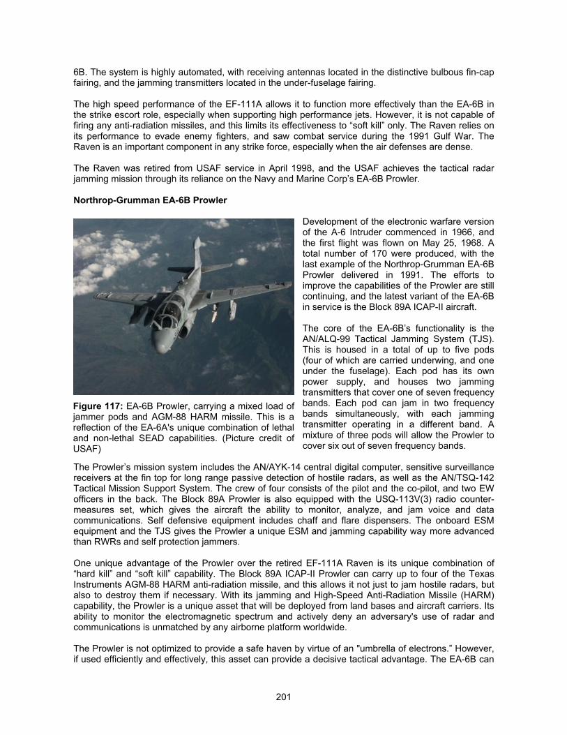
201
6B. The system is highly automated, with receiving antennas located in the distinctive bulbous fin-capfairing, and the jamming transmitters located in the under-fuselage fairing.
The high speed performance of the EF-111A allows it to function more effectively than the EA-6B inthe strike escort role, especially when supporting high performance jets. However, it is not capable offiring any anti-radiation missiles, and this limits its effectiveness to “soft kill” only. The Raven relies onits performance to evade enemy fighters, and saw combat service during the 1991 Gulf War. TheRaven is an important component in any strike force, especially when the air defenses are dense.
The Raven was retired from USAF service in April 1998, and the USAF achieves the tactical radarjamming mission through its reliance on the Navy and Marine Corp’s EA-6B Prowler.
Northrop-Grumman EA-6B Prowler
Development of the electronic warfare versionof the A-6 Intruder commenced in 1966, andthe first flight was flown on May 25, 1968. Atotal number of 170 were produced, with thelast example of the Northrop-Grumman EA-6BProwler delivered in 1991. The efforts toimprove the capabilities of the Prowler are stillcontinuing, and the latest variant of the EA-6Bin service is the Block 89A ICAP-II aircraft.
The core of the EA-6B’s functionality is theAN/ALQ-99 Tactical Jamming System (TJS).This is housed in a total of up to five pods(four of which are carried underwing, and oneunder the fuselage). Each pod has its ownpower supply, and houses two jammingtransmitters that cover one of seven frequencybands. Each pod can jam in two frequencybands simultaneously, with each jammingtransmitter operating in a different band. Amixture of three pods will allow the Prowler tocover six out of seven frequency bands.
The Prowler’s mission system includes the AN/AYK-14 central digital computer, sensitive surveillancereceivers at the fin top for long range passive detection of hostile radars, as well as the AN/TSQ-142Tactical Mission Support System. The crew of four consists of the pilot and the co-pilot, and two EWofficers in the back. The Block 89A Prowler is also equipped with the USQ-113V(3) radio counter-measures set, which gives the aircraft the ability to monitor, analyze, and jam voice and datacommunications. Self defensive equipment includes chaff and flare dispensers. The onboard ESMequipment and the TJS gives the Prowler a unique ESM and jamming capability way more advancedthan RWRs and self protection jammers.
One unique advantage of the Prowler over the retired EF-111A Raven is its unique combination of“hard kill” and “soft kill” capability. The Block 89A ICAP-II Prowler can carry up to four of the TexasInstruments AGM-88 HARM anti-radiation missile, and this allows it not just to jam hostile radars, butalso to destroy them if necessary. With its jamming and High-Speed Anti-Radiation Missile (HARM)capability, the Prowler is a unique asset that will be deployed from land bases and aircraft carriers. Itsability to monitor the electromagnetic spectrum and actively deny an adversary's use of radar andcommunications is unmatched by any airborne platform worldwide.
The Prowler is not optimized to provide a safe haven by virtue of an "umbrella of electrons.” However,if used efficiently and effectively, this asset can provide a decisive tactical advantage. The EA-6B can
Figure 117: EA-6B Prowler, carrying a mixed load ofjammer pods and AGM-88 HARM missile. This is areflection of the EA-6A's unique combination of lethaland non-lethal SEAD capabilities. (Picture credit ofUSAF)
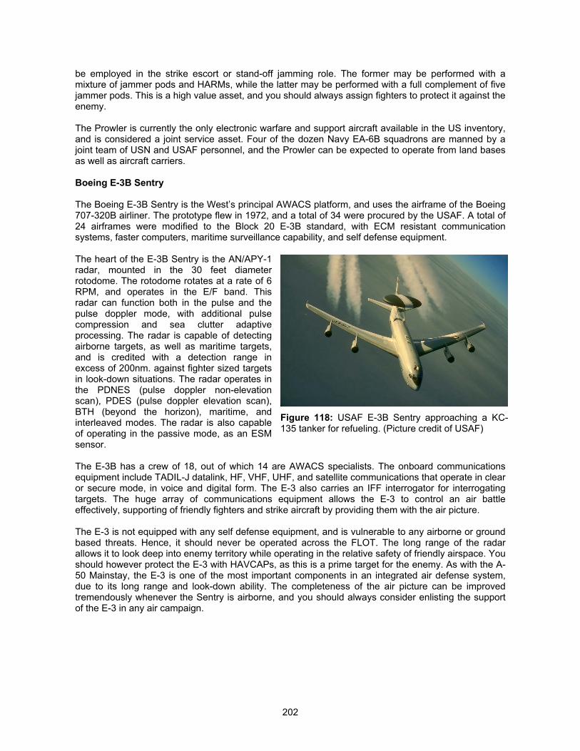
202
be employed in the strike escort or stand-off jamming role. The former may be performed with amixture of jammer pods and HARMs, while the latter may be performed with a full complement of fivejammer pods. This is a high value asset, and you should always assign fighters to protect it against theenemy.
The Prowler is currently the only electronic warfare and support aircraft available in the US inventory,and is considered a joint service asset. Four of the dozen Navy EA-6B squadrons are manned by ajoint team of USN and USAF personnel, and the Prowler can be expected to operate from land basesas well as aircraft carriers.
Boeing E-3B Sentry
The Boeing E-3B Sentry is the West’s principal AWACS platform, and uses the airframe of the Boeing707-320B airliner. The prototype flew in 1972, and a total of 34 were procured by the USAF. A total of24 airframes were modified to the Block 20 E-3B standard, with ECM resistant communicationsystems, faster computers, maritime surveillance capability, and self defense equipment.
The heart of the E-3B Sentry is the AN/APY-1radar, mounted in the 30 feet diameterrotodome. The rotodome rotates at a rate of 6RPM, and operates in the E/F band. Thisradar can function both in the pulse and thepulse doppler mode, with additional pulsecompression and sea clutter adaptiveprocessing. The radar is capable of detectingairborne targets, as well as maritime targets,and is credited with a detection range inexcess of 200nm. against fighter sized targetsin look-down situations. The radar operates inthe PDNES (pulse doppler non-elevationscan), PDES (pulse doppler elevation scan),BTH (beyond the horizon), maritime, andinterleaved modes. The radar is also capableof operating in the passive mode, as an ESMsensor.
The E-3B has a crew of 18, out of which 14 are AWACS specialists. The onboard communicationsequipment include TADIL-J datalink, HF, VHF, UHF, and satellite communications that operate in clearor secure mode, in voice and digital form. The E-3 also carries an IFF interrogator for interrogatingtargets. The huge array of communications equipment allows the E-3 to control an air battleeffectively, supporting of friendly fighters and strike aircraft by providing them with the air picture.
The E-3 is not equipped with any self defense equipment, and is vulnerable to any airborne or groundbased threats. Hence, it should never be operated across the FLOT. The long range of the radarallows it to look deep into enemy territory while operating in the relative safety of friendly airspace. Youshould however protect the E-3 with HAVCAPs, as this is a prime target for the enemy. As with the A-50 Mainstay, the E-3 is one of the most important components in an integrated air defense system,due to its long range and look-down ability. The completeness of the air picture can be improvedtremendously whenever the Sentry is airborne, and you should always consider enlisting the supportof the E-3 in any air campaign.
Figure 118: USAF E-3B Sentry approaching a KC-135 tanker for refueling. (Picture credit of USAF)
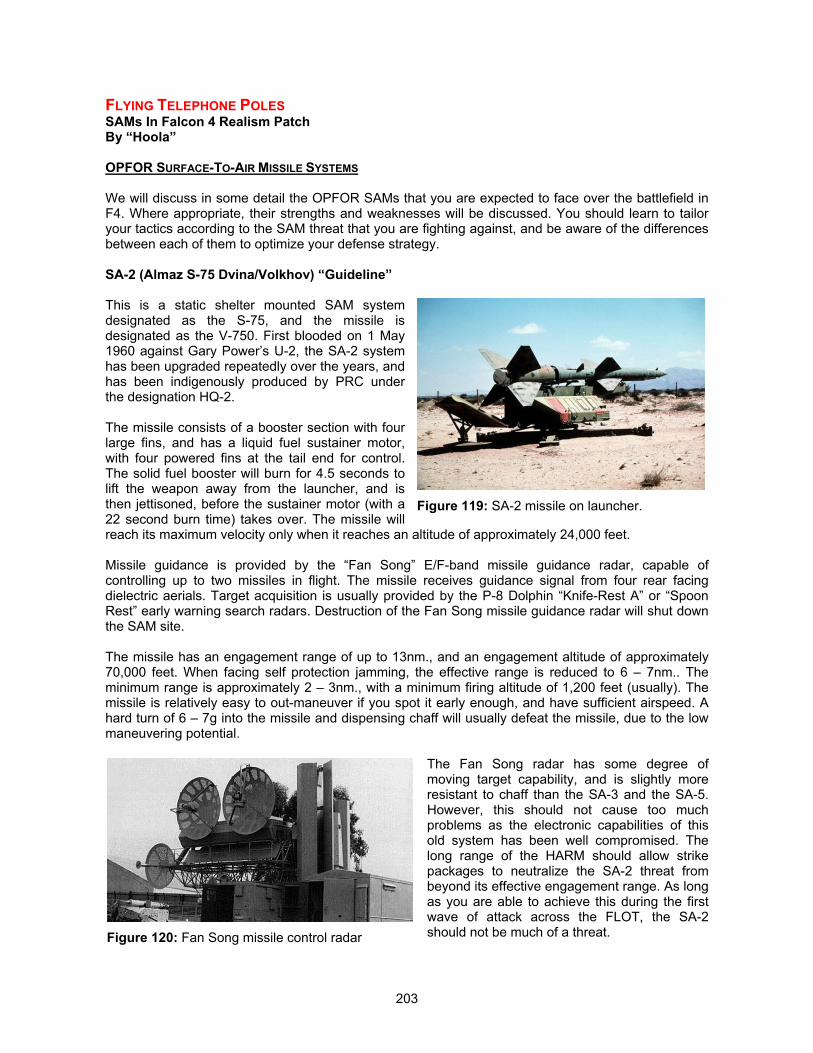
203
FLYING TELEPHONE POLESSAMs In Falcon 4 Realism PatchBy “Hoola”
OPFOR SURFACE-TO-AIR MISSILE SYSTEMS
We will discuss in some detail the OPFOR SAMs that you are expected to face over the battlefield inF4. Where appropriate, their strengths and weaknesses will be discussed. You should learn to tailoryour tactics according to the SAM threat that you are fighting against, and be aware of the differencesbetween each of them to optimize your defense strategy.
SA-2 (Almaz S-75 Dvina/Volkhov) “Guideline”
This is a static shelter mounted SAM systemdesignated as the S-75, and the missile isdesignated as the V-750. First blooded on 1 May1960 against Gary Power’s U-2, the SA-2 systemhas been upgraded repeatedly over the years, andhas been indigenously produced by PRC underthe designation HQ-2.
The missile consists of a booster section with fourlarge fins, and has a liquid fuel sustainer motor,with four powered fins at the tail end for control.The solid fuel booster will burn for 4.5 seconds tolift the weapon away from the launcher, and isthen jettisoned, before the sustainer motor (with a22 second burn time) takes over. The missile willreach its maximum velocity only when it reaches an altitude of approximately 24,000 feet.
Missile guidance is provided by the “Fan Song” E/F-band missile guidance radar, capable ofcontrolling up to two missiles in flight. The missile receives guidance signal from four rear facingdielectric aerials. Target acquisition is usually provided by the P-8 Dolphin “Knife-Rest A” or “SpoonRest” early warning search radars. Destruction of the Fan Song missile guidance radar will shut downthe SAM site.
The missile has an engagement range of up to 13nm., and an engagement altitude of approximately70,000 feet. When facing self protection jamming, the effective range is reduced to 6 – 7nm.. Theminimum range is approximately 2 – 3nm., with a minimum firing altitude of 1,200 feet (usually). Themissile is relatively easy to out-maneuver if you spot it early enough, and have sufficient airspeed. Ahard turn of 6 – 7g into the missile and dispensing chaff will usually defeat the missile, due to the lowmaneuvering potential.
The Fan Song radar has some degree ofmoving target capability, and is slightly moreresistant to chaff than the SA-3 and the SA-5.However, this should not cause too muchproblems as the electronic capabilities of thisold system has been well compromised. Thelong range of the HARM should allow strikepackages to neutralize the SA-2 threat frombeyond its effective engagement range. As longas you are able to achieve this during the firstwave of attack across the FLOT, the SA-2should not be much of a threat.
Figure 119: SA-2 missile on launcher.
Figure 120: Fan Song missile control radar
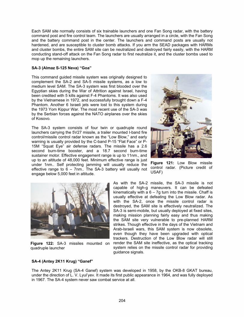
204
Each SAM site normally consists of six trainable launchers and one Fan Song radar, with the batterycommand post and fire control team. The launchers are usually arranged in a circle, with the Fan Songand the battery command post in the center. The launchers and command posts are usually nothardened, and are susceptible to cluster bomb attacks. If you arm the SEAD packages with HARMsand cluster bombs, the entire SAM site can be neutralized and destroyed fairly easily, with the HARMconducting stand-off attack on the Fan Song radar to first neutralize it, and the cluster bombs used tomop up the remaining launchers.
SA-3 (Almaz S-125 Neva) “Goa”
This command guided missile system was originally designed tocomplement the SA-2 and SA-5 missile systems, as a low tomedium level SAM. The SA-3 system was first blooded over theEgyptian skies during the War of Attrition against Israel, havingbeen credited with 5 kills against F-4 Phantoms. It was also usedby the Vietnamese in 1972, and successfully brought down a F-4Phantom. Another 6 Israeli jets were lost to this system duringthe 1973 Yom Kippur War. The most recent use of the SA-3 wasby the Serbian forces against the NATO airplanes over the skiesof Kosovo.
The SA-3 system consists of four twin or quadruple roundlaunchers carrying the 5V27 missile, a trailer mounted I-band firecontrol/missile control radar known as the “Low Blow,” and earlywarning is usually provided by the C-band P-15 “Flat Face” or P-15M “Squat Eye” air defense radars. The missile has a 2.6second burn-time booster, and a 18.7 second burn-timesustainer motor. Effective engagement range is up to 11nm., andup to an altitude of 48,000 feet. Minimum effective range is justunder 1nm.. Self protecting jamming will usually reduce theeffective range to 6 – 7nm.. The SA-3 battery will usually notengage below 5,000 feet in altitude.
As with the SA-2 missile, the SA-3 missile is notcapable of high-g maneuvers. It can be defeatedkinematically with a 6 – 7g turn into the missile. Chaff isusually effective at defeating the Low Blow radar. Aswith the SA-2, once the missile control radar isdestroyed, the SAM site is effectively neutralized. TheSA-3 is semi-mobile, but usually deployed at fixed sites,making mission planning fairly easy and thus makingthe SAM site very vulnerable to pre-planned HARMstrikes. Though effective in the days of the Vietnam andArab-Israeli wars, this SAM system is now obsolete,even though they have been upgraded with opticaltrackers. Destruction of the Low Blow radar will stillrender the SAM site ineffective, as the optical trackingsystem relies on the missile control radar for providingguidance signals.
SA-4 (Antey 2K11 Krug) “Ganef”
The Antey 2K11 Krug (SA-4 Ganef) system was developed in 1958, by the OKB-8 GKAT bureau,under the direction of L. V. Lyul’yev. It made its first public appearance in 1964, and was fully deployedin 1967. The SA-4 system never saw combat service at all.
Figure 121: Low Blow missilecontrol radar. (Picture credit ofUSAF)
Figure 122: SA-3 missiles mounted onquadruple launcher
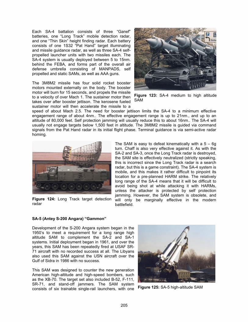
205
Each SA-4 battalion consists of three “Ganef”batteries, one “Long Track” mobile detection radar,and one “Thin Skin” height finding radar. Each batteryconsists of one 1S32 “Pat Hand” target illuminatingand missile guidance radar, as well as three SA-4 self-propelled launcher units with two missiles each. TheSA-4 system is usually deployed between 5 to 15nm.behind the FEBA, and forms part of the overall airdefense umbrella consisting of MANPADS, selfpropelled and static SAMs, as well as AAA guns.
The 3M8M2 missile has four solid rocket boostermotors mounted externally on the body. The boostermotor will burn for 15 seconds, and propels the missileto a velocity of over Mach 1. The sustainer motor thentakes over after booster jettison. The kerosene fueledsustainer motor will then accelerate the missile to aspeed of about Mach 2.5. The need for booster jettison limits the SA-4 to a minimum effectiveengagement range of about 4nm.. The effective engagement range is up to 21nm., and up to analtitude of 80,000 feet. Self protection jamming will usually reduce this to about 16nm.. The SA-4 willusually not engage targets below 1,500 feet in altitude. The 3M8M2 missile is guided via commandsignals from the Pat Hand radar in its initial flight phase. Terminal guidance is via semi-active radarhoming.
The SAM is easy to defeat kinematically with a 5 – 6gturn. Chaff is also very effective against it. As with theSA-2 and SA-3, once the Long Track radar is destroyed,the SAM site is effectively neutralized (strictly speaking,this is incorrect since the Long Track radar is a searchradar, but this is a game constraint). The SA-4 system ismobile, and this makes it rather difficult to pinpoint itslocation for a pre-planned HARM strike. The relativelylong range of the SA-4 means that it will be difficult toavoid being shot at while attacking it with HARMs,unless the attacker is protected by self protectionjamming. However, the SAM system is obsolete, andwill only be marginally effective in the modernbattlefield.
SA-5 (Antey S-200 Angara) “Gammon”
Development of the S-200 Angara system began in the1950’s to meet a requirement for a long range highaltitude SAM to complement the SA-2 and SA-1systems. Initial deployment began in 1961, and over theyears, this SAM has been repeatedly fired at USAF SR-71 aircraft with no recorded success at all. The Libyansalso used this SAM against the USN aircraft over theGulf of Sidra in 1986 with no success.
This SAM was designed to counter the new generationAmerican high-altitude and high-speed bombers, suchas the XB-70. The target set also included B-52, F-111,SR-71, and stand-off jammers. The SAM systemconsists of six trainable single-rail launchers, with one
Figure 123: SA-4 medium to high altitudeSAM
Figure 124: Long Track target detectionradar
Figure 125: SA-5 high-altitude SAM
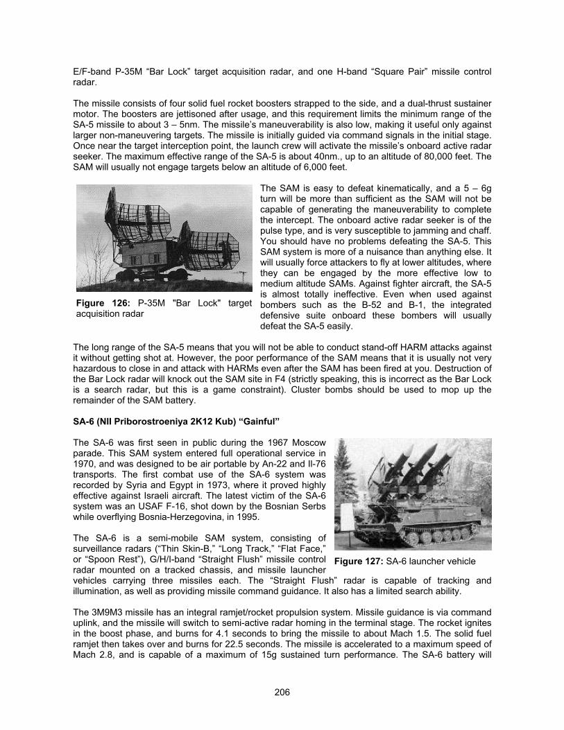
206
E/F-band P-35M “Bar Lock” target acquisition radar, and one H-band “Square Pair” missile controlradar.
The missile consists of four solid fuel rocket boosters strapped to the side, and a dual-thrust sustainermotor. The boosters are jettisoned after usage, and this requirement limits the minimum range of theSA-5 missile to about 3 – 5nm. The missile’s maneuverability is also low, making it useful only againstlarger non-maneuvering targets. The missile is initially guided via command signals in the initial stage.Once near the target interception point, the launch crew will activate the missile’s onboard active radarseeker. The maximum effective range of the SA-5 is about 40nm., up to an altitude of 80,000 feet. TheSAM will usually not engage targets below an altitude of 6,000 feet.
The SAM is easy to defeat kinematically, and a 5 – 6gturn will be more than sufficient as the SAM will not becapable of generating the maneuverability to completethe intercept. The onboard active radar seeker is of thepulse type, and is very susceptible to jamming and chaff.You should have no problems defeating the SA-5. ThisSAM system is more of a nuisance than anything else. Itwill usually force attackers to fly at lower altitudes, wherethey can be engaged by the more effective low tomedium altitude SAMs. Against fighter aircraft, the SA-5is almost totally ineffective. Even when used againstbombers such as the B-52 and B-1, the integrateddefensive suite onboard these bombers will usuallydefeat the SA-5 easily.
The long range of the SA-5 means that you will not be able to conduct stand-off HARM attacks againstit without getting shot at. However, the poor performance of the SAM means that it is usually not veryhazardous to close in and attack with HARMs even after the SAM has been fired at you. Destruction ofthe Bar Lock radar will knock out the SAM site in F4 (strictly speaking, this is incorrect as the Bar Lockis a search radar, but this is a game constraint). Cluster bombs should be used to mop up theremainder of the SAM battery.
SA-6 (NII Priborostroeniya 2K12 Kub) “Gainful”
The SA-6 was first seen in public during the 1967 Moscowparade. This SAM system entered full operational service in1970, and was designed to be air portable by An-22 and Il-76transports. The first combat use of the SA-6 system wasrecorded by Syria and Egypt in 1973, where it proved highlyeffective against Israeli aircraft. The latest victim of the SA-6system was an USAF F-16, shot down by the Bosnian Serbswhile overflying Bosnia-Herzegovina, in 1995.
The SA-6 is a semi-mobile SAM system, consisting ofsurveillance radars (“Thin Skin-B,” “Long Track,” “Flat Face,”or “Spoon Rest”), G/H/I-band “Straight Flush” missile controlradar mounted on a tracked chassis, and missile launchervehicles carrying three missiles each. The “Straight Flush” radar is capable of tracking andillumination, as well as providing missile command guidance. It also has a limited search ability.
The 3M9M3 missile has an integral ramjet/rocket propulsion system. Missile guidance is via commanduplink, and the missile will switch to semi-active radar homing in the terminal stage. The rocket ignitesin the boost phase, and burns for 4.1 seconds to bring the missile to about Mach 1.5. The solid fuelramjet then takes over and burns for 22.5 seconds. The missile is accelerated to a maximum speed ofMach 2.8, and is capable of a maximum of 15g sustained turn performance. The SA-6 battery will
Figure 126: P-35M "Bar Lock" targetacquisition radar
Figure 127: SA-6 launcher vehicle
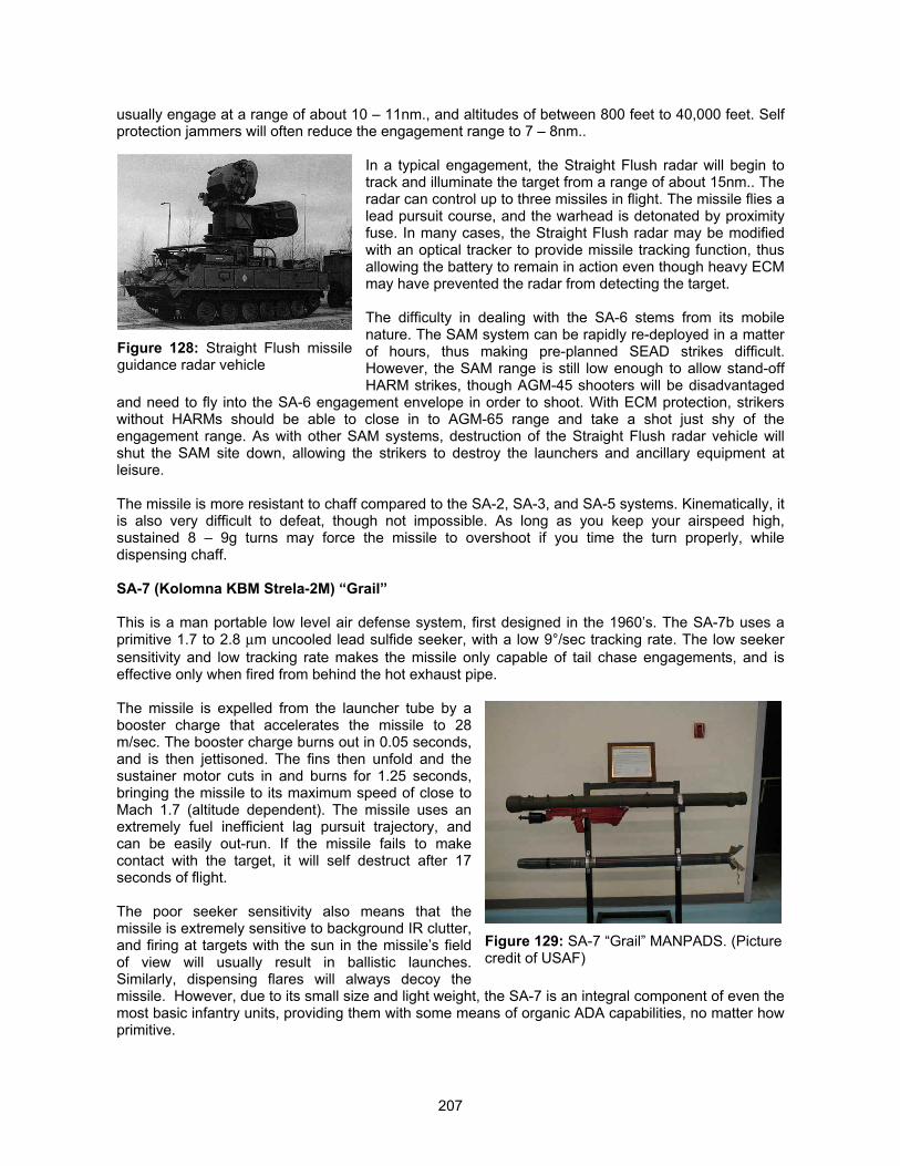
207
usually engage at a range of about 10 – 11nm., and altitudes of between 800 feet to 40,000 feet. Selfprotection jammers will often reduce the engagement range to 7 – 8nm..
In a typical engagement, the Straight Flush radar will begin totrack and illuminate the target from a range of about 15nm.. Theradar can control up to three missiles in flight. The missile flies alead pursuit course, and the warhead is detonated by proximityfuse. In many cases, the Straight Flush radar may be modifiedwith an optical tracker to provide missile tracking function, thusallowing the battery to remain in action even though heavy ECMmay have prevented the radar from detecting the target.
The difficulty in dealing with the SA-6 stems from its mobilenature. The SAM system can be rapidly re-deployed in a matterof hours, thus making pre-planned SEAD strikes difficult.However, the SAM range is still low enough to allow stand-offHARM strikes, though AGM-45 shooters will be disadvantaged
and need to fly into the SA-6 engagement envelope in order to shoot. With ECM protection, strikerswithout HARMs should be able to close in to AGM-65 range and take a shot just shy of theengagement range. As with other SAM systems, destruction of the Straight Flush radar vehicle willshut the SAM site down, allowing the strikers to destroy the launchers and ancillary equipment atleisure.
The missile is more resistant to chaff compared to the SA-2, SA-3, and SA-5 systems. Kinematically, itis also very difficult to defeat, though not impossible. As long as you keep your airspeed high,sustained 8 – 9g turns may force the missile to overshoot if you time the turn properly, whiledispensing chaff.
SA-7 (Kolomna KBM Strela-2M) “Grail”
This is a man portable low level air defense system, first designed in the 1960’s. The SA-7b uses aprimitive 1.7 to 2.8 �m uncooled lead sulfide seeker, with a low 9°/sec tracking rate. The low seekersensitivity and low tracking rate makes the missile only capable of tail chase engagements, and iseffective only when fired from behind the hot exhaust pipe.
The missile is expelled from the launcher tube by abooster charge that accelerates the missile to 28m/sec. The booster charge burns out in 0.05 seconds,and is then jettisoned. The fins then unfold and thesustainer motor cuts in and burns for 1.25 seconds,bringing the missile to its maximum speed of close toMach 1.7 (altitude dependent). The missile uses anextremely fuel inefficient lag pursuit trajectory, andcan be easily out-run. If the missile fails to makecontact with the target, it will self destruct after 17seconds of flight.
The poor seeker sensitivity also means that themissile is extremely sensitive to background IR clutter,and firing at targets with the sun in the missile’s fieldof view will usually result in ballistic launches.Similarly, dispensing flares will always decoy themissile. However, due to its small size and light weight, the SA-7 is an integral component of even themost basic infantry units, providing them with some means of organic ADA capabilities, no matter howprimitive.
Figure 128: Straight Flush missileguidance radar vehicle
Figure 129: SA-7 “Grail” MANPADS. (Picturecredit of USAF)
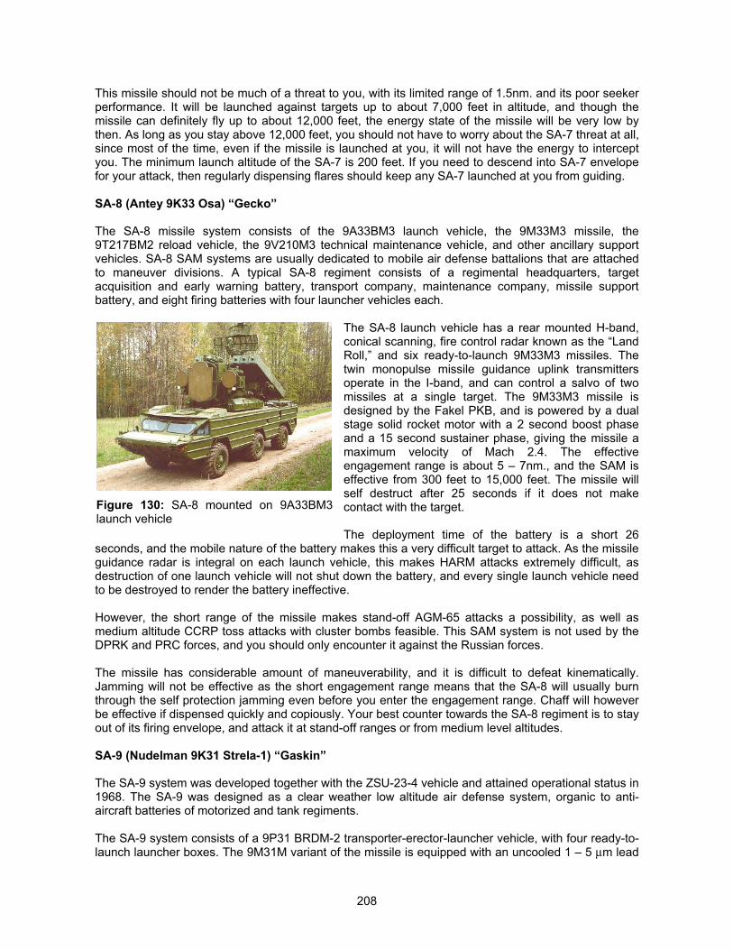
208
This missile should not be much of a threat to you, with its limited range of 1.5nm. and its poor seekerperformance. It will be launched against targets up to about 7,000 feet in altitude, and though themissile can definitely fly up to about 12,000 feet, the energy state of the missile will be very low bythen. As long as you stay above 12,000 feet, you should not have to worry about the SA-7 threat at all,since most of the time, even if the missile is launched at you, it will not have the energy to interceptyou. The minimum launch altitude of the SA-7 is 200 feet. If you need to descend into SA-7 envelopefor your attack, then regularly dispensing flares should keep any SA-7 launched at you from guiding.
SA-8 (Antey 9K33 Osa) “Gecko”
The SA-8 missile system consists of the 9A33BM3 launch vehicle, the 9M33M3 missile, the9T217BM2 reload vehicle, the 9V210M3 technical maintenance vehicle, and other ancillary supportvehicles. SA-8 SAM systems are usually dedicated to mobile air defense battalions that are attachedto maneuver divisions. A typical SA-8 regiment consists of a regimental headquarters, targetacquisition and early warning battery, transport company, maintenance company, missile supportbattery, and eight firing batteries with four launcher vehicles each.
The SA-8 launch vehicle has a rear mounted H-band,conical scanning, fire control radar known as the “LandRoll,” and six ready-to-launch 9M33M3 missiles. Thetwin monopulse missile guidance uplink transmittersoperate in the I-band, and can control a salvo of twomissiles at a single target. The 9M33M3 missile isdesigned by the Fakel PKB, and is powered by a dualstage solid rocket motor with a 2 second boost phaseand a 15 second sustainer phase, giving the missile amaximum velocity of Mach 2.4. The effectiveengagement range is about 5 – 7nm., and the SAM iseffective from 300 feet to 15,000 feet. The missile willself destruct after 25 seconds if it does not makecontact with the target.
The deployment time of the battery is a short 26seconds, and the mobile nature of the battery makes this a very difficult target to attack. As the missileguidance radar is integral on each launch vehicle, this makes HARM attacks extremely difficult, asdestruction of one launch vehicle will not shut down the battery, and every single launch vehicle needto be destroyed to render the battery ineffective.
However, the short range of the missile makes stand-off AGM-65 attacks a possibility, as well asmedium altitude CCRP toss attacks with cluster bombs feasible. This SAM system is not used by theDPRK and PRC forces, and you should only encounter it against the Russian forces.
The missile has considerable amount of maneuverability, and it is difficult to defeat kinematically.Jamming will not be effective as the short engagement range means that the SA-8 will usually burnthrough the self protection jamming even before you enter the engagement range. Chaff will howeverbe effective if dispensed quickly and copiously. Your best counter towards the SA-8 regiment is to stayout of its firing envelope, and attack it at stand-off ranges or from medium level altitudes.
SA-9 (Nudelman 9K31 Strela-1) “Gaskin”
The SA-9 system was developed together with the ZSU-23-4 vehicle and attained operational status in1968. The SA-9 was designed as a clear weather low altitude air defense system, organic to anti-aircraft batteries of motorized and tank regiments.
The SA-9 system consists of a 9P31 BRDM-2 transporter-erector-launcher vehicle, with four ready-to-launch launcher boxes. The 9M31M variant of the missile is equipped with an uncooled 1 – 5 �m lead
Figure 130: SA-8 mounted on 9A33BM3launch vehicle
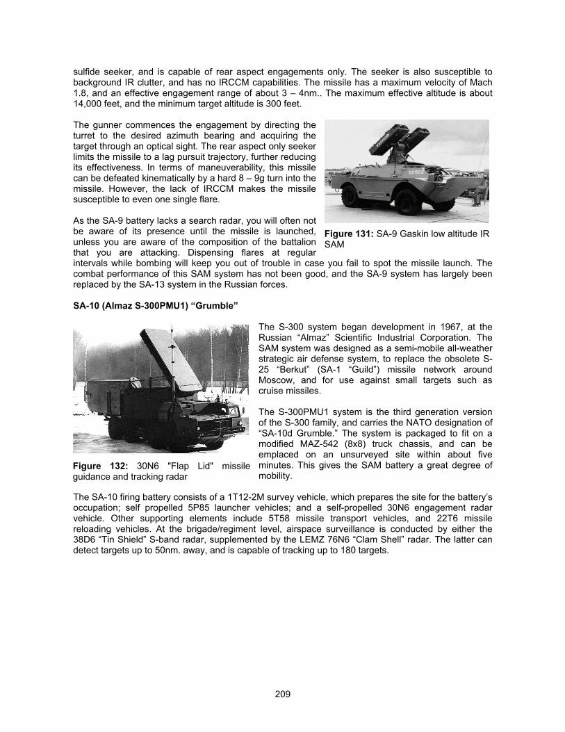
209
sulfide seeker, and is capable of rear aspect engagements only. The seeker is also susceptible tobackground IR clutter, and has no IRCCM capabilities. The missile has a maximum velocity of Mach1.8, and an effective engagement range of about 3 – 4nm.. The maximum effective altitude is about14,000 feet, and the minimum target altitude is 300 feet.
The gunner commences the engagement by directing theturret to the desired azimuth bearing and acquiring thetarget through an optical sight. The rear aspect only seekerlimits the missile to a lag pursuit trajectory, further reducingits effectiveness. In terms of maneuverability, this missilecan be defeated kinematically by a hard 8 – 9g turn into themissile. However, the lack of IRCCM makes the missilesusceptible to even one single flare.
As the SA-9 battery lacks a search radar, you will often notbe aware of its presence until the missile is launched,unless you are aware of the composition of the battalionthat you are attacking. Dispensing flares at regularintervals while bombing will keep you out of trouble in case you fail to spot the missile launch. Thecombat performance of this SAM system has not been good, and the SA-9 system has largely beenreplaced by the SA-13 system in the Russian forces.
SA-10 (Almaz S-300PMU1) “Grumble”
The S-300 system began development in 1967, at theRussian “Almaz” Scientific Industrial Corporation. TheSAM system was designed as a semi-mobile all-weatherstrategic air defense system, to replace the obsolete S-25 “Berkut” (SA-1 “Guild”) missile network aroundMoscow, and for use against small targets such ascruise missiles.
The S-300PMU1 system is the third generation versionof the S-300 family, and carries the NATO designation of“SA-10d Grumble.” The system is packaged to fit on amodified MAZ-542 (8x8) truck chassis, and can beemplaced on an unsurveyed site within about fiveminutes. This gives the SAM battery a great degree ofmobility.
The SA-10 firing battery consists of a 1T12-2M survey vehicle, which prepares the site for the battery’soccupation; self propelled 5P85 launcher vehicles; and a self-propelled 30N6 engagement radarvehicle. Other supporting elements include 5T58 missile transport vehicles, and 22T6 missilereloading vehicles. At the brigade/regiment level, airspace surveillance is conducted by either the38D6 “Tin Shield” S-band radar, supplemented by the LEMZ 76N6 “Clam Shell” radar. The latter candetect targets up to 50nm. away, and is capable of tracking up to 180 targets.
Figure 131: SA-9 Gaskin low altitude IRSAM
Figure 132: 30N6 "Flap Lid" missileguidance and tracking radar
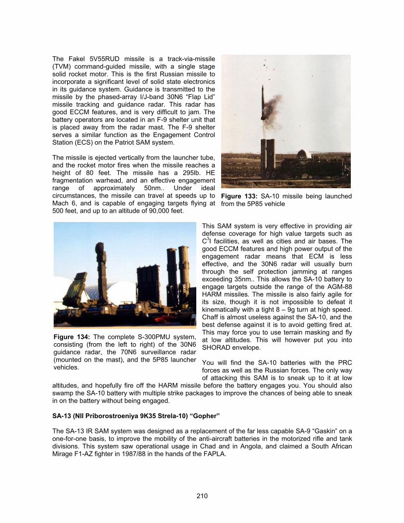
210
The Fakel 5V55RUD missile is a track-via-missile(TVM) command-guided missile, with a single stagesolid rocket motor. This is the first Russian missile toincorporate a significant level of solid state electronicsin its guidance system. Guidance is transmitted to themissile by the phased-array I/J-band 30N6 “Flap Lid”missile tracking and guidance radar. This radar hasgood ECCM features, and is very difficult to jam. Thebattery operators are located in an F-9 shelter unit thatis placed away from the radar mast. The F-9 shelterserves a similar function as the Engagement ControlStation (ECS) on the Patriot SAM system.
The missile is ejected vertically from the launcher tube,and the rocket motor fires when the missile reaches aheight of 80 feet. The missile has a 295lb. HEfragmentation warhead, and an effective engagementrange of approximately 50nm.. Under idealcircumstances, the missile can travel at speeds up toMach 6, and is capable of engaging targets flying at500 feet, and up to an altitude of 90,000 feet.
This SAM system is very effective in providing airdefense coverage for high value targets such asC3I facilities, as well as cities and air bases. Thegood ECCM features and high power output of theengagement radar means that ECM is lesseffective, and the 30N6 radar will usually burnthrough the self protection jamming at rangesexceeding 35nm.. This allows the SA-10 battery toengage targets outside the range of the AGM-88HARM missiles. The missile is also fairly agile forits size, though it is not impossible to defeat itkinematically with a tight 8 – 9g turn at high speed.Chaff is almost useless against the SA-10, and thebest defense against it is to avoid getting fired at.This may force you to use terrain masking and flyat low altitudes. This will however put you intoSHORAD envelope.
You will find the SA-10 batteries with the PRCforces as well as the Russian forces. The only wayof attacking this SAM is to sneak up to it at low
altitudes, and hopefully fire off the HARM missile before the battery engages you. You should alsoswamp the SA-10 battery with multiple strike packages to improve the chances of being able to sneakin on the battery without being engaged.
SA-13 (NII Priborostroeniya 9K35 Strela-10) “Gopher”
The SA-13 IR SAM system was designed as a replacement of the far less capable SA-9 “Gaskin” on aone-for-one basis, to improve the mobility of the anti-aircraft batteries in the motorized rifle and tankdivisions. This system saw operational usage in Chad and in Angola, and claimed a South AfricanMirage F1-AZ fighter in 1987/88 in the hands of the FAPLA.
Figure 133: SA-10 missile being launchedfrom the 5P85 vehicle
Figure 134: The complete S-300PMU system,consisting (from the left to right) of the 30N6guidance radar, the 70N6 surveillance radar(mounted on the mast), and the 5P85 launchervehicles.
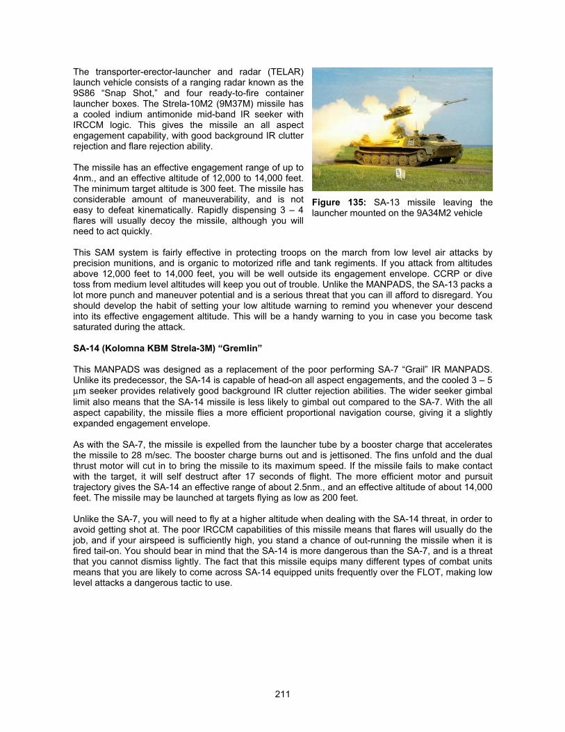
211
The transporter-erector-launcher and radar (TELAR)launch vehicle consists of a ranging radar known as the9S86 “Snap Shot,” and four ready-to-fire containerlauncher boxes. The Strela-10M2 (9M37M) missile hasa cooled indium antimonide mid-band IR seeker withIRCCM logic. This gives the missile an all aspectengagement capability, with good background IR clutterrejection and flare rejection ability.
The missile has an effective engagement range of up to4nm., and an effective altitude of 12,000 to 14,000 feet.The minimum target altitude is 300 feet. The missile hasconsiderable amount of maneuverability, and is noteasy to defeat kinematically. Rapidly dispensing 3 – 4flares will usually decoy the missile, although you willneed to act quickly.
This SAM system is fairly effective in protecting troops on the march from low level air attacks byprecision munitions, and is organic to motorized rifle and tank regiments. If you attack from altitudesabove 12,000 feet to 14,000 feet, you will be well outside its engagement envelope. CCRP or divetoss from medium level altitudes will keep you out of trouble. Unlike the MANPADS, the SA-13 packs alot more punch and maneuver potential and is a serious threat that you can ill afford to disregard. Youshould develop the habit of setting your low altitude warning to remind you whenever your descendinto its effective engagement altitude. This will be a handy warning to you in case you become tasksaturated during the attack.
SA-14 (Kolomna KBM Strela-3M) “Gremlin”
This MANPADS was designed as a replacement of the poor performing SA-7 “Grail” IR MANPADS.Unlike its predecessor, the SA-14 is capable of head-on all aspect engagements, and the cooled 3 – 5�m seeker provides relatively good background IR clutter rejection abilities. The wider seeker gimballimit also means that the SA-14 missile is less likely to gimbal out compared to the SA-7. With the allaspect capability, the missile flies a more efficient proportional navigation course, giving it a slightlyexpanded engagement envelope.
As with the SA-7, the missile is expelled from the launcher tube by a booster charge that acceleratesthe missile to 28 m/sec. The booster charge burns out and is jettisoned. The fins unfold and the dualthrust motor will cut in to bring the missile to its maximum speed. If the missile fails to make contactwith the target, it will self destruct after 17 seconds of flight. The more efficient motor and pursuittrajectory gives the SA-14 an effective range of about 2.5nm., and an effective altitude of about 14,000feet. The missile may be launched at targets flying as low as 200 feet.
Unlike the SA-7, you will need to fly at a higher altitude when dealing with the SA-14 threat, in order toavoid getting shot at. The poor IRCCM capabilities of this missile means that flares will usually do thejob, and if your airspeed is sufficiently high, you stand a chance of out-running the missile when it isfired tail-on. You should bear in mind that the SA-14 is more dangerous than the SA-7, and is a threatthat you cannot dismiss lightly. The fact that this missile equips many different types of combat unitsmeans that you are likely to come across SA-14 equipped units frequently over the FLOT, making lowlevel attacks a dangerous tactic to use.
Figure 135: SA-13 missile leaving thelauncher mounted on the 9A34M2 vehicle
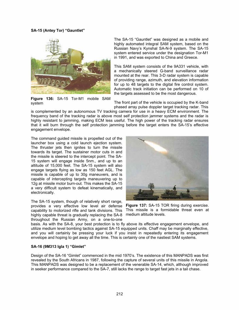
212
SA-15 (Antey Tor) “Gauntlet”
The SA-15 “Gauntlet” was designed as a mobile andhighly automated integral SAM system, based on theRussian Navy’s Kynshal SA-N-9 system. The SA-15system entered service under the designation Tor-M1in 1991, and was exported to China and Greece.
This SAM system consists of the 9A331 vehicle, witha mechanically steered G-band surveillance radarmounted at the rear. This 3-D radar system is capableof providing range, azimuth, and elevation informationfor up to 48 targets to the digital fire control system.Automatic track initiation can be performed on 10 ofthe targets assessed to be the most dangerous.
The front part of the vehicle is occupied by the K-bandphased array pulse doppler target tracking radar. This
is complemented by an autonomous TV tracking camera for use in a heavy ECM environment. Thefrequency band of the tracking radar is above most self protection jammer systems and the radar ishighly resistant to jamming, making ECM less useful. The high power of the tracking radar ensuresthat it will burn through the self protection jamming before the target enters the SA-15’s effectiveengagement envelope.
The command guided missile is propelled out of thelauncher box using a cold launch ejection system.The thruster jets then ignites to turn the missiletowards its target. The sustainer motor cuts in andthe missile is steered to the intercept point. The SA-15 system will engage inside 5nm., and up to analtitude of 15,000 feet. The SA-15 system will alsoengage targets flying as low as 150 feet AGL. Themissile is capable of up to 30g maneuvers, and iscapable of intercepting targets maneuvering up to12g at missile motor burn-out. This makes the SA-15a very difficult system to defeat kinematically, andelectronically.
The SA-15 system, though of relatively short range,provides a very effective low level air defensecapability to motorized rifle and tank divisions. Thishighly capable threat is gradually replacing the SA-8throughout the Russian Army, on a one-to-onebasis. As with the SA-8, your best protection is to fly above its effective engagement envelope, andutilize medium level bombing tactics against SA-15 equipped units. Chaff may be marginally effective,and you will certainly be pressing your luck if you insist in repeatedly entering its engagementenvelope and hoping to get away all the time. This is certainly one of the nastiest SAM systems.
SA-16 (9M313 Igla 1) “Gimlet”
Design of the SA-16 “Gimlet” commenced in the mid 1970’s. The existence of this MANPADS was firstrevealed by the South Africans in 1987, following the capture of several units of this missile in Angola.This MANPADS was designed to be a replacement of the venerable SA-14, which, although improvedin seeker performance compared to the SA-7, still lacks the range to target fast jets in a tail chase.
Figure 136: SA-15 Tor-M1 mobile SAMsystem
Figure 137: SA-15 TOR firing during exercise.This missile is a formidable threat even atmedium altitude levels.
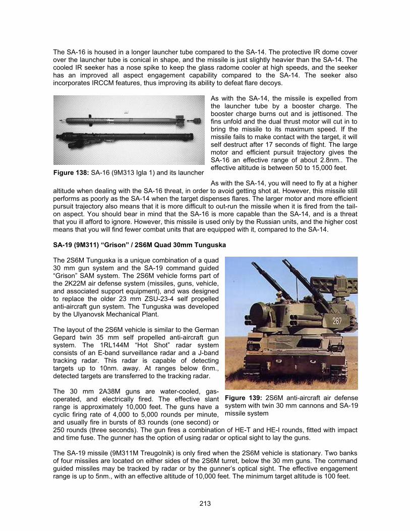
213
The SA-16 is housed in a longer launcher tube compared to the SA-14. The protective IR dome coverover the launcher tube is conical in shape, and the missile is just slightly heavier than the SA-14. Thecooled IR seeker has a nose spike to keep the glass radome cooler at high speeds, and the seekerhas an improved all aspect engagement capability compared to the SA-14. The seeker alsoincorporates IRCCM features, thus improving its ability to defeat flare decoys.
As with the SA-14, the missile is expelled fromthe launcher tube by a booster charge. Thebooster charge burns out and is jettisoned. Thefins unfold and the dual thrust motor will cut in tobring the missile to its maximum speed. If themissile fails to make contact with the target, it willself destruct after 17 seconds of flight. The largemotor and efficient pursuit trajectory gives theSA-16 an effective range of about 2.8nm.. Theeffective altitude is between 50 to 15,000 feet.
As with the SA-14, you will need to fly at a higheraltitude when dealing with the SA-16 threat, in order to avoid getting shot at. However, this missile stillperforms as poorly as the SA-14 when the target dispenses flares. The larger motor and more efficientpursuit trajectory also means that it is more difficult to out-run the missile when it is fired from the tail-on aspect. You should bear in mind that the SA-16 is more capable than the SA-14, and is a threatthat you ill afford to ignore. However, this missile is used only by the Russian units, and the higher costmeans that you will find fewer combat units that are equipped with it, compared to the SA-14.
SA-19 (9M311) “Grison” / 2S6M Quad 30mm Tunguska
The 2S6M Tunguska is a unique combination of a quad30 mm gun system and the SA-19 command guided“Grison” SAM system. The 2S6M vehicle forms part ofthe 2K22M air defense system (missiles, guns, vehicle,and associated support equipment), and was designedto replace the older 23 mm ZSU-23-4 self propelledanti-aircraft gun system. The Tunguska was developedby the Ulyanovsk Mechanical Plant.
The layout of the 2S6M vehicle is similar to the GermanGepard twin 35 mm self propelled anti-aircraft gunsystem. The 1RL144M “Hot Shot” radar systemconsists of an E-band surveillance radar and a J-bandtracking radar. This radar is capable of detectingtargets up to 10nm. away. At ranges below 6nm.,detected targets are transferred to the tracking radar.
The 30 mm 2A38M guns are water-cooled, gas-operated, and electrically fired. The effective slantrange is approximately 10,000 feet. The guns have acyclic firing rate of 4,000 to 5,000 rounds per minute,and usually fire in bursts of 83 rounds (one second) or250 rounds (three seconds). The gun fires a combination of HE-T and HE-I rounds, fitted with impactand time fuse. The gunner has the option of using radar or optical sight to lay the guns.
The SA-19 missile (9M311M Treugolnik) is only fired when the 2S6M vehicle is stationary. Two banksof four missiles are located on either sides of the 2S6M turret, below the 30 mm guns. The commandguided missiles may be tracked by radar or by the gunner’s optical sight. The effective engagementrange is up to 5nm., with an effective altitude of 10,000 feet. The minimum target altitude is 100 feet.
Figure 138: SA-16 (9M313 Igla 1) and its launcher
Figure 139: 2S6M anti-aircraft air defensesystem with twin 30 mm cannons and SA-19missile system
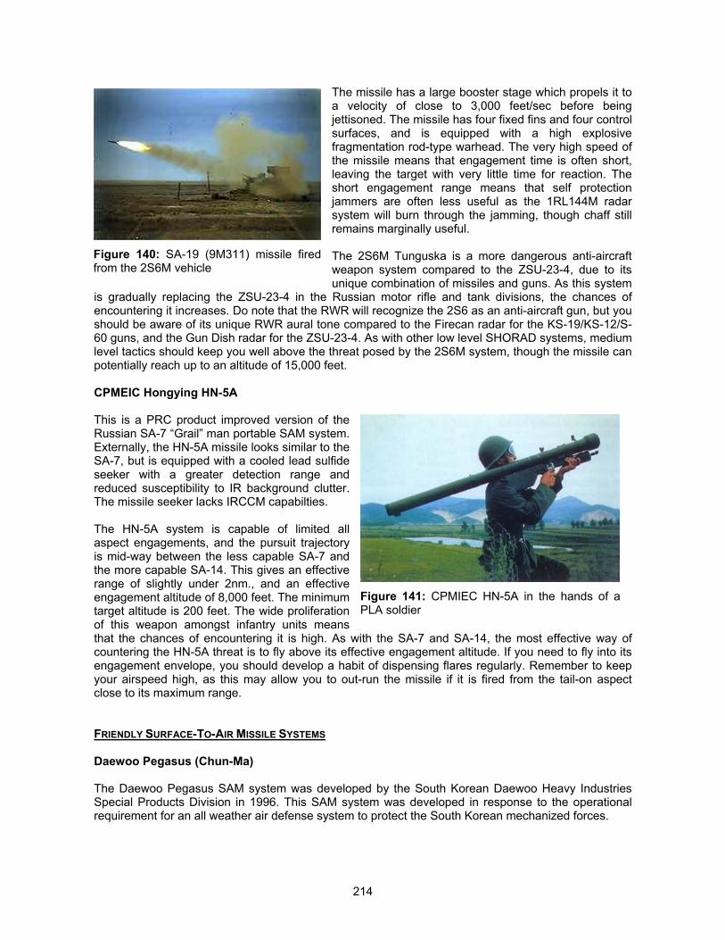
214
The missile has a large booster stage which propels it toa velocity of close to 3,000 feet/sec before beingjettisoned. The missile has four fixed fins and four controlsurfaces, and is equipped with a high explosivefragmentation rod-type warhead. The very high speed ofthe missile means that engagement time is often short,leaving the target with very little time for reaction. Theshort engagement range means that self protectionjammers are often less useful as the 1RL144M radarsystem will burn through the jamming, though chaff stillremains marginally useful.
The 2S6M Tunguska is a more dangerous anti-aircraftweapon system compared to the ZSU-23-4, due to itsunique combination of missiles and guns. As this system
is gradually replacing the ZSU-23-4 in the Russian motor rifle and tank divisions, the chances ofencountering it increases. Do note that the RWR will recognize the 2S6 as an anti-aircraft gun, but youshould be aware of its unique RWR aural tone compared to the Firecan radar for the KS-19/KS-12/S-60 guns, and the Gun Dish radar for the ZSU-23-4. As with other low level SHORAD systems, mediumlevel tactics should keep you well above the threat posed by the 2S6M system, though the missile canpotentially reach up to an altitude of 15,000 feet.
CPMEIC Hongying HN-5A
This is a PRC product improved version of theRussian SA-7 “Grail” man portable SAM system.Externally, the HN-5A missile looks similar to theSA-7, but is equipped with a cooled lead sulfideseeker with a greater detection range andreduced susceptibility to IR background clutter.The missile seeker lacks IRCCM capabilties.
The HN-5A system is capable of limited allaspect engagements, and the pursuit trajectoryis mid-way between the less capable SA-7 andthe more capable SA-14. This gives an effectiverange of slightly under 2nm., and an effectiveengagement altitude of 8,000 feet. The minimumtarget altitude is 200 feet. The wide proliferationof this weapon amongst infantry units meansthat the chances of encountering it is high. As with the SA-7 and SA-14, the most effective way ofcountering the HN-5A threat is to fly above its effective engagement altitude. If you need to fly into itsengagement envelope, you should develop a habit of dispensing flares regularly. Remember to keepyour airspeed high, as this may allow you to out-run the missile if it is fired from the tail-on aspectclose to its maximum range.
FRIENDLY SURFACE-TO-AIR MISSILE SYSTEMS
Daewoo Pegasus (Chun-Ma)
The Daewoo Pegasus SAM system was developed by the South Korean Daewoo Heavy IndustriesSpecial Products Division in 1996. This SAM system was developed in response to the operationalrequirement for an all weather air defense system to protect the South Korean mechanized forces.
Figure 140: SA-19 (9M311) missile firedfrom the 2S6M vehicle
Figure 141: CPMIEC HN-5A in the hands of aPLA soldier
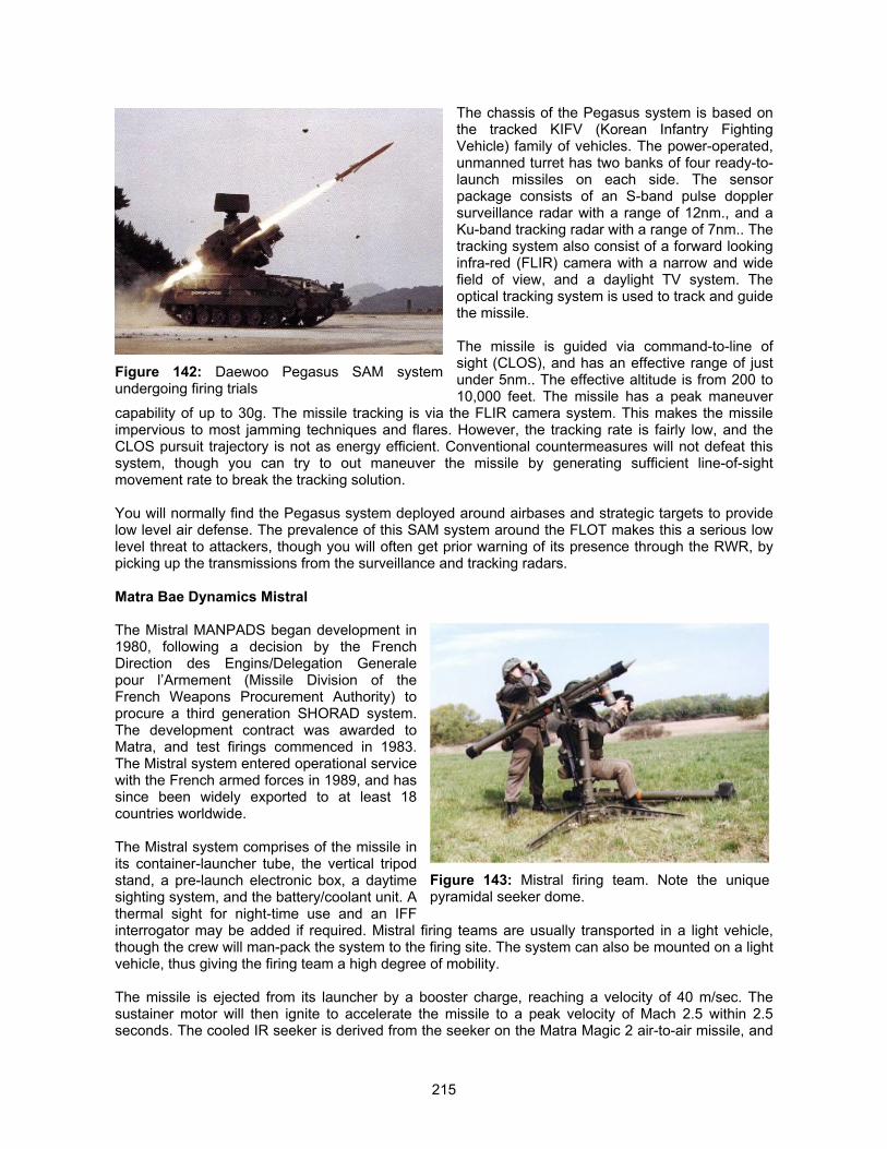
215
The chassis of the Pegasus system is based onthe tracked KIFV (Korean Infantry FightingVehicle) family of vehicles. The power-operated,unmanned turret has two banks of four ready-to-launch missiles on each side. The sensorpackage consists of an S-band pulse dopplersurveillance radar with a range of 12nm., and aKu-band tracking radar with a range of 7nm.. Thetracking system also consist of a forward lookinginfra-red (FLIR) camera with a narrow and widefield of view, and a daylight TV system. Theoptical tracking system is used to track and guidethe missile.
The missile is guided via command-to-line ofsight (CLOS), and has an effective range of justunder 5nm.. The effective altitude is from 200 to10,000 feet. The missile has a peak maneuver
capability of up to 30g. The missile tracking is via the FLIR camera system. This makes the missileimpervious to most jamming techniques and flares. However, the tracking rate is fairly low, and theCLOS pursuit trajectory is not as energy efficient. Conventional countermeasures will not defeat thissystem, though you can try to out maneuver the missile by generating sufficient line-of-sightmovement rate to break the tracking solution.
You will normally find the Pegasus system deployed around airbases and strategic targets to providelow level air defense. The prevalence of this SAM system around the FLOT makes this a serious lowlevel threat to attackers, though you will often get prior warning of its presence through the RWR, bypicking up the transmissions from the surveillance and tracking radars.
Matra Bae Dynamics Mistral
The Mistral MANPADS began development in1980, following a decision by the FrenchDirection des Engins/Delegation Generalepour l’Armement (Missile Division of theFrench Weapons Procurement Authority) toprocure a third generation SHORAD system.The development contract was awarded toMatra, and test firings commenced in 1983.The Mistral system entered operational servicewith the French armed forces in 1989, and hassince been widely exported to at least 18countries worldwide.
The Mistral system comprises of the missile inits container-launcher tube, the vertical tripodstand, a pre-launch electronic box, a daytimesighting system, and the battery/coolant unit. Athermal sight for night-time use and an IFFinterrogator may be added if required. Mistral firing teams are usually transported in a light vehicle,though the crew will man-pack the system to the firing site. The system can also be mounted on a lightvehicle, thus giving the firing team a high degree of mobility.
The missile is ejected from its launcher by a booster charge, reaching a velocity of 40 m/sec. Thesustainer motor will then ignite to accelerate the missile to a peak velocity of Mach 2.5 within 2.5seconds. The cooled IR seeker is derived from the seeker on the Matra Magic 2 air-to-air missile, and
Figure 142: Daewoo Pegasus SAM systemundergoing firing trials
Figure 143: Mistral firing team. Note the uniquepyramidal seeker dome.
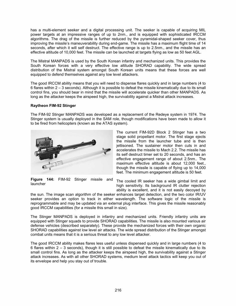
216
has a multi-element seeker and a digital processing unit. The seeker is capable of acquiring MILpower targets at an impressive ranges of up to 2nm., and is equipped with sophisticated IRCCMalgorithms. The drag of the missile is further reduced by the pyramidal-shaped seeker cover, thusimproving the missile’s maneuverability during end-game. The missile has a maximum flight time of 14seconds, after which it will self destruct. The effective range is up to 2.5nm., and the missile has aneffective altitude of 10,000 feet. The missile can be launched at targets flying as low as 50 feet AGL.
The Mistral MANPADS is used by the South Korean infantry and mechanized units. This provides theSouth Korean forces with a very effective low altitude SHORAD capability. The wide spreaddistribution of the Mistral system amongst South Korean units means that these forces are wellequipped to defend themselves against any low level attackers.
The good IRCCM ability means that you will need to dispense flares quickly and in large numbers (4 to6 flares within 2 – 3 seconds). Although it is possible to defeat the missile kinematically due to its smallcontrol fins, you should bear in mind that the missile will accelerate quicker than other MANPADS. Aslong as the attacker keeps the airspeed high, the survivability against a Mistral attack increases.
Raytheon FIM-92 Stinger
The FIM-92 Stinger MANPADS was developed as a replacement of the Redeye system in 1974. TheStinger system is usually deployed in the SAM role, though modifications have been made to allow itto be fired from helicopters (known as the ATAS system).
The current FIM-92D Block 2 Stinger has a twostage solid propellant motor. The first stage ejectsthe missile from the launcher tube and is thenjettisoned. The sustainer motor then cuts in andaccelerates the missile to Mach 2.2. The missile hasits self destruct timer set to 20 seconds, and has aneffective engagement range of about 2.5nm.. Themaximum effective altitude is about 12,000 feet.,though the missile is capable of flying up to 14,000feet. The minimum engagement altitude is 50 feet.
The cooled IR seeker has a wide gimbal limit andhigh sensitivity. Its background IR clutter rejectionability is excellent, and it is not easily decoyed by
the sun. The image scan algorithm of the seeker enhances target detection, and the two color IR/UVseeker provides an option to track in either wavelength. The software logic of the missile isreprogrammable and may be updated via an external plug interface. This gives the missile reasonablygood IRCCM capabilities (for a missile this small in size).
The Stinger MANPADS is deployed in infantry and mechanized units. Friendly infantry units areequipped with Stinger squads to provide SHORAD capabilities. The missile is also mounted various airdefense vehicles (described separately). These provide the mechanized forces with their own organicSHORAD capabilities against low level air attacks. The wide spread distribution of the Stinger amongstcombat units means that it is a serious threat to any low level attacker.
The good IRCCM ability makes flares less useful unless dispensed quickly and in large numbers (4 to6 flares within 2 – 3 seconds), though it is still possible to defeat the missile kinematically due to itssmall control fins. As long as the attacker keeps the airspeed high, the survivability against a Stingerattack increases. As with all other SHORAD systems, medium level attack tactics will keep you out ofits envelope and help you stay out of trouble.
Figure 144: FIM-92 Stinger missile andlauncher
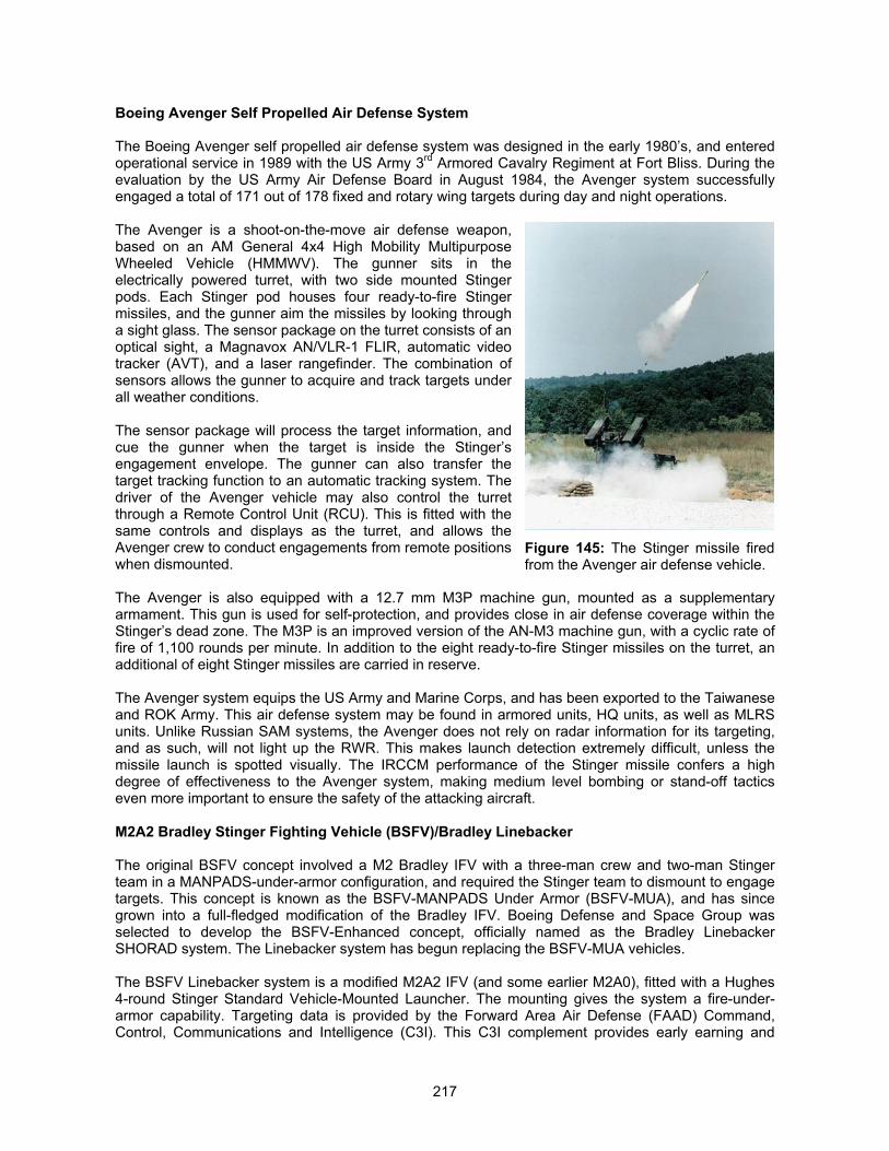
217
Boeing Avenger Self Propelled Air Defense System
The Boeing Avenger self propelled air defense system was designed in the early 1980’s, and enteredoperational service in 1989 with the US Army 3rd Armored Cavalry Regiment at Fort Bliss. During theevaluation by the US Army Air Defense Board in August 1984, the Avenger system successfullyengaged a total of 171 out of 178 fixed and rotary wing targets during day and night operations.
The Avenger is a shoot-on-the-move air defense weapon,based on an AM General 4x4 High Mobility MultipurposeWheeled Vehicle (HMMWV). The gunner sits in theelectrically powered turret, with two side mounted Stingerpods. Each Stinger pod houses four ready-to-fire Stingermissiles, and the gunner aim the missiles by looking througha sight glass. The sensor package on the turret consists of anoptical sight, a Magnavox AN/VLR-1 FLIR, automatic videotracker (AVT), and a laser rangefinder. The combination ofsensors allows the gunner to acquire and track targets underall weather conditions.
The sensor package will process the target information, andcue the gunner when the target is inside the Stinger’sengagement envelope. The gunner can also transfer thetarget tracking function to an automatic tracking system. Thedriver of the Avenger vehicle may also control the turretthrough a Remote Control Unit (RCU). This is fitted with thesame controls and displays as the turret, and allows theAvenger crew to conduct engagements from remote positionswhen dismounted.
The Avenger is also equipped with a 12.7 mm M3P machine gun, mounted as a supplementaryarmament. This gun is used for self-protection, and provides close in air defense coverage within theStinger’s dead zone. The M3P is an improved version of the AN-M3 machine gun, with a cyclic rate offire of 1,100 rounds per minute. In addition to the eight ready-to-fire Stinger missiles on the turret, anadditional of eight Stinger missiles are carried in reserve.
The Avenger system equips the US Army and Marine Corps, and has been exported to the Taiwaneseand ROK Army. This air defense system may be found in armored units, HQ units, as well as MLRSunits. Unlike Russian SAM systems, the Avenger does not rely on radar information for its targeting,and as such, will not light up the RWR. This makes launch detection extremely difficult, unless themissile launch is spotted visually. The IRCCM performance of the Stinger missile confers a highdegree of effectiveness to the Avenger system, making medium level bombing or stand-off tacticseven more important to ensure the safety of the attacking aircraft.
M2A2 Bradley Stinger Fighting Vehicle (BSFV)/Bradley Linebacker
The original BSFV concept involved a M2 Bradley IFV with a three-man crew and two-man Stingerteam in a MANPADS-under-armor configuration, and required the Stinger team to dismount to engagetargets. This concept is known as the BSFV-MANPADS Under Armor (BSFV-MUA), and has sincegrown into a full-fledged modification of the Bradley IFV. Boeing Defense and Space Group wasselected to develop the BSFV-Enhanced concept, officially named as the Bradley LinebackerSHORAD system. The Linebacker system has begun replacing the BSFV-MUA vehicles.
The BSFV Linebacker system is a modified M2A2 IFV (and some earlier M2A0), fitted with a Hughes4-round Stinger Standard Vehicle-Mounted Launcher. The mounting gives the system a fire-under-armor capability. Targeting data is provided by the Forward Area Air Defense (FAAD) Command,Control, Communications and Intelligence (C3I). This C3I complement provides early earning and
Figure 145: The Stinger missile firedfrom the Avenger air defense vehicle.
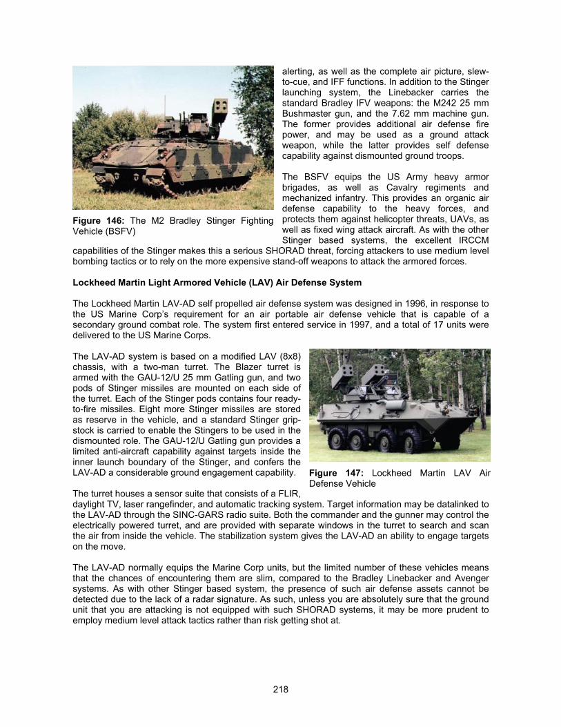
218
alerting, as well as the complete air picture, slew-to-cue, and IFF functions. In addition to the Stingerlaunching system, the Linebacker carries thestandard Bradley IFV weapons: the M242 25 mmBushmaster gun, and the 7.62 mm machine gun.The former provides additional air defense firepower, and may be used as a ground attackweapon, while the latter provides self defensecapability against dismounted ground troops.
The BSFV equips the US Army heavy armorbrigades, as well as Cavalry regiments andmechanized infantry. This provides an organic airdefense capability to the heavy forces, andprotects them against helicopter threats, UAVs, aswell as fixed wing attack aircraft. As with the otherStinger based systems, the excellent IRCCM
capabilities of the Stinger makes this a serious SHORAD threat, forcing attackers to use medium levelbombing tactics or to rely on the more expensive stand-off weapons to attack the armored forces.
Lockheed Martin Light Armored Vehicle (LAV) Air Defense System
The Lockheed Martin LAV-AD self propelled air defense system was designed in 1996, in response tothe US Marine Corp’s requirement for an air portable air defense vehicle that is capable of asecondary ground combat role. The system first entered service in 1997, and a total of 17 units weredelivered to the US Marine Corps.
The LAV-AD system is based on a modified LAV (8x8)chassis, with a two-man turret. The Blazer turret isarmed with the GAU-12/U 25 mm Gatling gun, and twopods of Stinger missiles are mounted on each side ofthe turret. Each of the Stinger pods contains four ready-to-fire missiles. Eight more Stinger missiles are storedas reserve in the vehicle, and a standard Stinger grip-stock is carried to enable the Stingers to be used in thedismounted role. The GAU-12/U Gatling gun provides alimited anti-aircraft capability against targets inside theinner launch boundary of the Stinger, and confers theLAV-AD a considerable ground engagement capability.
The turret houses a sensor suite that consists of a FLIR,daylight TV, laser rangefinder, and automatic tracking system. Target information may be datalinked tothe LAV-AD through the SINC-GARS radio suite. Both the commander and the gunner may control theelectrically powered turret, and are provided with separate windows in the turret to search and scanthe air from inside the vehicle. The stabilization system gives the LAV-AD an ability to engage targetson the move.
The LAV-AD normally equips the Marine Corp units, but the limited number of these vehicles meansthat the chances of encountering them are slim, compared to the Bradley Linebacker and Avengersystems. As with other Stinger based system, the presence of such air defense assets cannot bedetected due to the lack of a radar signature. As such, unless you are absolutely sure that the groundunit that you are attacking is not equipped with such SHORAD systems, it may be more prudent toemploy medium level attack tactics rather than risk getting shot at.
Figure 146: The M2 Bradley Stinger FightingVehicle (BSFV)
Figure 147: Lockheed Martin LAV AirDefense Vehicle
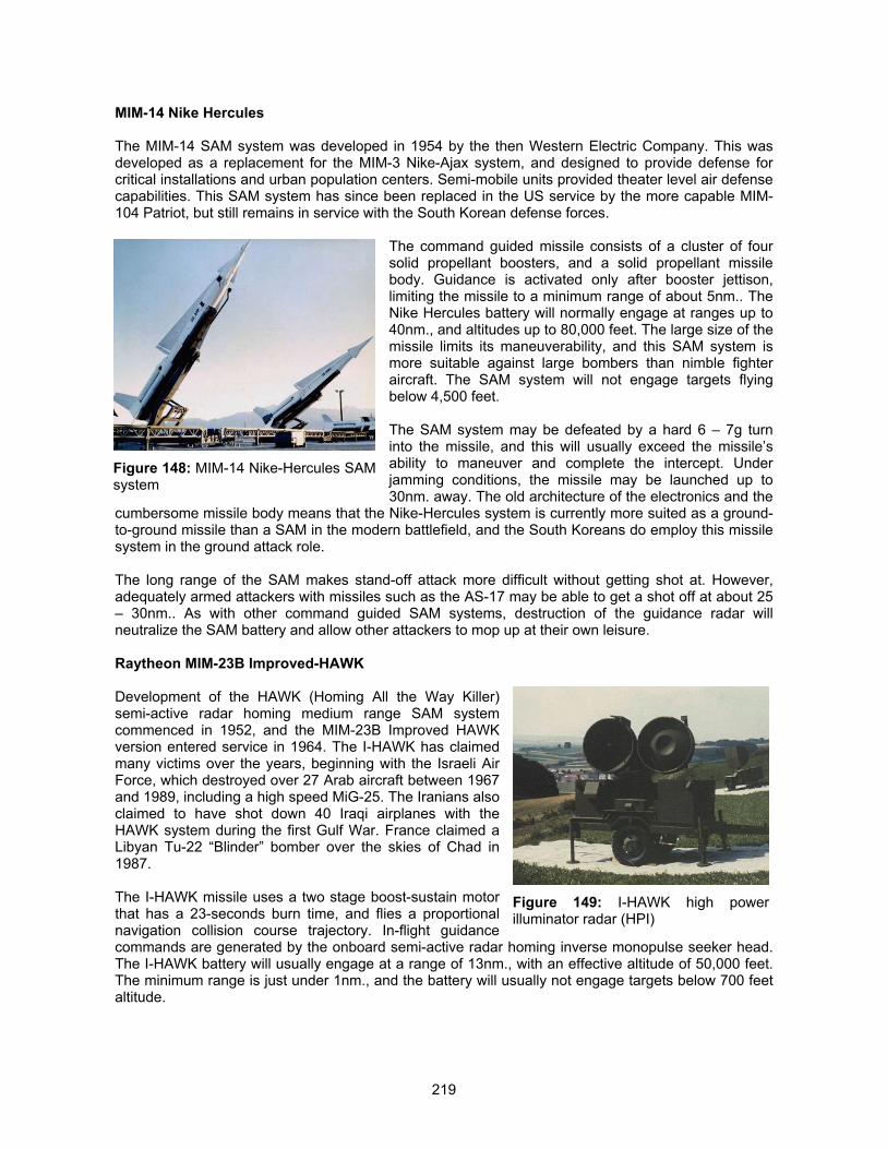
219
MIM-14 Nike Hercules
The MIM-14 SAM system was developed in 1954 by the then Western Electric Company. This wasdeveloped as a replacement for the MIM-3 Nike-Ajax system, and designed to provide defense forcritical installations and urban population centers. Semi-mobile units provided theater level air defensecapabilities. This SAM system has since been replaced in the US service by the more capable MIM-104 Patriot, but still remains in service with the South Korean defense forces.
The command guided missile consists of a cluster of foursolid propellant boosters, and a solid propellant missilebody. Guidance is activated only after booster jettison,limiting the missile to a minimum range of about 5nm.. TheNike Hercules battery will normally engage at ranges up to40nm., and altitudes up to 80,000 feet. The large size of themissile limits its maneuverability, and this SAM system ismore suitable against large bombers than nimble fighteraircraft. The SAM system will not engage targets flyingbelow 4,500 feet.
The SAM system may be defeated by a hard 6 – 7g turninto the missile, and this will usually exceed the missile’sability to maneuver and complete the intercept. Underjamming conditions, the missile may be launched up to30nm. away. The old architecture of the electronics and the
cumbersome missile body means that the Nike-Hercules system is currently more suited as a ground-to-ground missile than a SAM in the modern battlefield, and the South Koreans do employ this missilesystem in the ground attack role.
The long range of the SAM makes stand-off attack more difficult without getting shot at. However,adequately armed attackers with missiles such as the AS-17 may be able to get a shot off at about 25– 30nm.. As with other command guided SAM systems, destruction of the guidance radar willneutralize the SAM battery and allow other attackers to mop up at their own leisure.
Raytheon MIM-23B Improved-HAWK
Development of the HAWK (Homing All the Way Killer)semi-active radar homing medium range SAM systemcommenced in 1952, and the MIM-23B Improved HAWKversion entered service in 1964. The I-HAWK has claimedmany victims over the years, beginning with the Israeli AirForce, which destroyed over 27 Arab aircraft between 1967and 1989, including a high speed MiG-25. The Iranians alsoclaimed to have shot down 40 Iraqi airplanes with theHAWK system during the first Gulf War. France claimed aLibyan Tu-22 “Blinder” bomber over the skies of Chad in1987.
The I-HAWK missile uses a two stage boost-sustain motorthat has a 23-seconds burn time, and flies a proportionalnavigation collision course trajectory. In-flight guidancecommands are generated by the onboard semi-active radar homing inverse monopulse seeker head.The I-HAWK battery will usually engage at a range of 13nm., with an effective altitude of 50,000 feet.The minimum range is just under 1nm., and the battery will usually not engage targets below 700 feetaltitude.
Figure 148: MIM-14 Nike-Hercules SAMsystem
Figure 149: I-HAWK high powerilluminator radar (HPI)
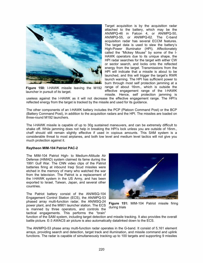
220
Target acquisition is by the acquisition radarattached to the battery, which may be theAN/MPQ-46 in Falcon 4, or AN/MPQ-50,AN/MPQ-55, or AN/MPQ-62. The C-bandacquisition radar has several ECCM features.The target data is used to slew the battery’sHigh-Power Illuminator (HPI). Affectionatelycalled the “Mickey Mouse” by some of the I-HAWK operators due to its unique shape, theHPI radar searches for the target with either CWor sector search, and locks onto the reflectedenergy from the target. Transmissions from theHPI will indicate that a missile is about to belaunched, and this will trigger the target’s RWRlaunch warning. The HPI has sufficient power toburn through most self protection jamming at arange of about 16nm., which is outside theeffective engagement range of the I-HAWKmissile. Hence, self protection jamming is
useless against the I-HAWK as it will not decrease the effective engagement range. The HPI’sreflected energy from the target is tracked by the missile and used for its guidance.
The other components of an I-HAWK battery includes the PCP (Platoon Command Post) or the BCP(Battery Command Post), in addition to the acquisition radars and the HPI. The missiles are loaded onthree-round M192 launchers.
The I-HAWK missile is capable of up to 30g sustained maneuvers, and can be extremely difficult toshake off. While jamming does not help in breaking the HPI’s lock unless you are outside of 16nm.,chaff should still remain slightly effective if used in copious amounts. This SAM system is aconsiderable threat to most airplanes, and both low level and medium level tactics will not give youmuch protection against it.
Raytheon MIM-104 Patriot PAC-2
The MIM-104 Patriot High- to Medium-Altitude AirDefense (HIMAD) system claimed its fame during the1991 Gulf War. The CNN video clips of the Patriotbatteries firing at inbound Iraqi Scud missiles wereetched in the memory of many who watched the warfrom the television. The Patriot is a replacement ofthe I-HAWK system in the US Army, and has beenexported to Israel, Taiwan, Japan, and several othercountries.
The Patriot battery consist of the AN/MSQ-104Engagement Control Station (ECS), the AN/MPQ-53phased array multi-function radar, the AN/MSQ-24power plant, and the M901 launcher station. The ECSis manned by three operators, and controls thetactical engagements. This performs the “brain”function of the SAM system, including target detection and missile tracking. It also provides the overallbattle picture. E-3 AWACS air picture is also automatically datalinked down to the ECS.
The AN/MPQ-53 phase array multi-function radar operates in the G-band. It consist of 5,161 elementarrays, providing search and detection, target track and illumination, and missile command and uplinkfunctions. The radar is capable of simultaneously tracking up to 100 targets and supporting 9 missiles
Figure 150: I-HAWK missile leaving the M192launcher in pursuit of its target.
Figure 151: MIM-104 Patriot missile firingduring trials
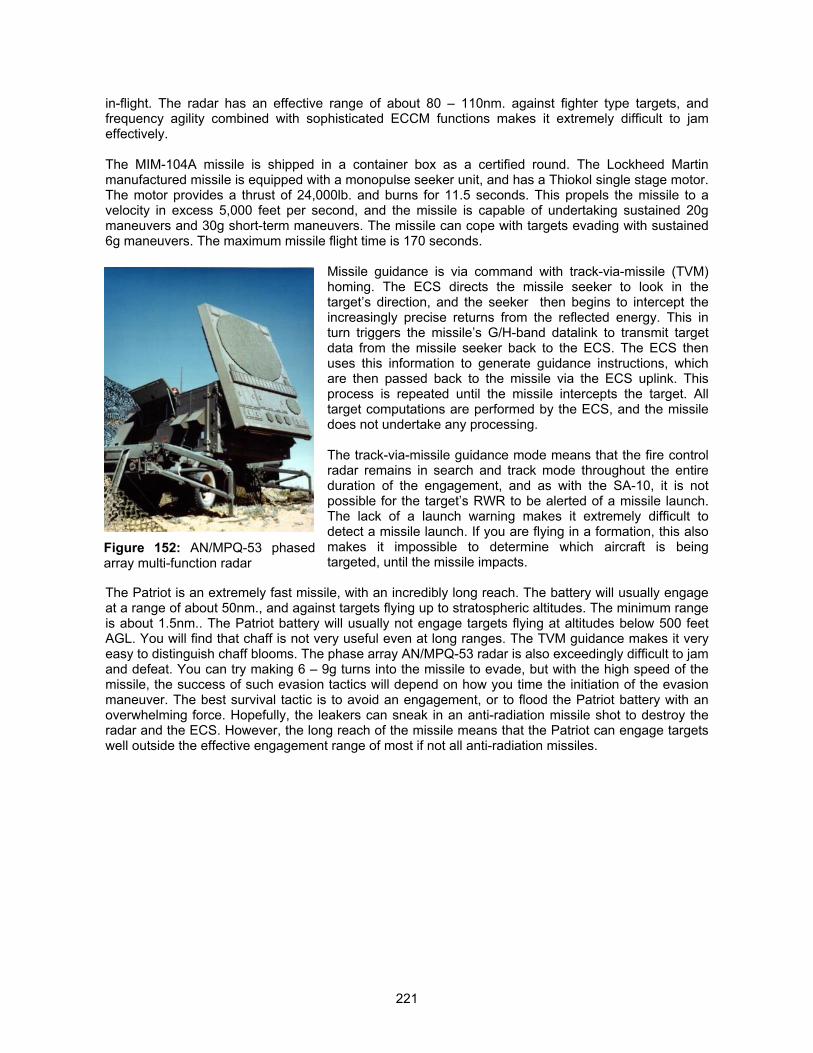
221
in-flight. The radar has an effective range of about 80 – 110nm. against fighter type targets, andfrequency agility combined with sophisticated ECCM functions makes it extremely difficult to jameffectively.
The MIM-104A missile is shipped in a container box as a certified round. The Lockheed Martinmanufactured missile is equipped with a monopulse seeker unit, and has a Thiokol single stage motor.The motor provides a thrust of 24,000lb. and burns for 11.5 seconds. This propels the missile to avelocity in excess 5,000 feet per second, and the missile is capable of undertaking sustained 20gmaneuvers and 30g short-term maneuvers. The missile can cope with targets evading with sustained6g maneuvers. The maximum missile flight time is 170 seconds.
Missile guidance is via command with track-via-missile (TVM)homing. The ECS directs the missile seeker to look in thetarget’s direction, and the seeker then begins to intercept theincreasingly precise returns from the reflected energy. This inturn triggers the missile’s G/H-band datalink to transmit targetdata from the missile seeker back to the ECS. The ECS thenuses this information to generate guidance instructions, whichare then passed back to the missile via the ECS uplink. Thisprocess is repeated until the missile intercepts the target. Alltarget computations are performed by the ECS, and the missiledoes not undertake any processing.
The track-via-missile guidance mode means that the fire controlradar remains in search and track mode throughout the entireduration of the engagement, and as with the SA-10, it is notpossible for the target’s RWR to be alerted of a missile launch.The lack of a launch warning makes it extremely difficult todetect a missile launch. If you are flying in a formation, this alsomakes it impossible to determine which aircraft is beingtargeted, until the missile impacts.
The Patriot is an extremely fast missile, with an incredibly long reach. The battery will usually engageat a range of about 50nm., and against targets flying up to stratospheric altitudes. The minimum rangeis about 1.5nm.. The Patriot battery will usually not engage targets flying at altitudes below 500 feetAGL. You will find that chaff is not very useful even at long ranges. The TVM guidance makes it veryeasy to distinguish chaff blooms. The phase array AN/MPQ-53 radar is also exceedingly difficult to jamand defeat. You can try making 6 – 9g turns into the missile to evade, but with the high speed of themissile, the success of such evasion tactics will depend on how you time the initiation of the evasionmaneuver. The best survival tactic is to avoid an engagement, or to flood the Patriot battery with anoverwhelming force. Hopefully, the leakers can sneak in an anti-radiation missile shot to destroy theradar and the ECS. However, the long reach of the missile means that the Patriot can engage targetswell outside the effective engagement range of most if not all anti-radiation missiles.
Figure 152: AN/MPQ-53 phasedarray multi-function radar
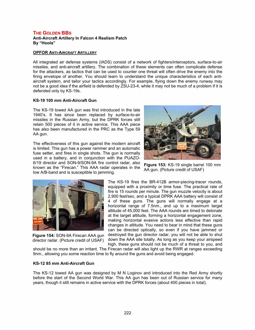
222
THE GOLDEN BBSAnti-Aircraft Artillery In Falcon 4 Realism PatchBy “Hoola”
OPFOR ANTI-AIRCRAFT ARTILLERY
All integrated air defense systems (IADS) consist of a network of fighters/interceptors, surface-to-airmissiles, and anti-aircraft artillery. The combination of these elements can often complicate defensefor the attackers, as tactics that can be used to counter one threat will often drive the enemy into thefiring envelope of another. You should learn to understand the unique characteristics of each anti-aircraft system, and tailor your tactics accordingly. For example, flying down the enemy runway maynot be a good idea if the airfield is defended by ZSU-23-4, while it may not be much of a problem if it isdefended only by KS-19s.
KS-19 100 mm Anti-Aircraft Gun
The KS-19 towed AA gun was first introduced in the late1940’s. It has since been replaced by surface-to-airmissiles in the Russian Army, but the DPRK forces stillretain 500 pieces of it in active service. This AAA piecehas also been manufactured in the PRC as the Type 59AA gun.
The effectiveness of this gun against the modern aircraftis limited. This gun has a power rammer and an automaticfuse setter, and fires in single shots. The gun is normallyused in a battery, and in conjunction with the PUAZO-6/19 director and SON-9/SON-9A fire control radar, alsoknown as the “Firecan.” This AAA radar operates in thelow A/B-band and is susceptible to jamming.
The KS-19 fires the BR-412B armor-piecing-tracer rounds,equipped with a proximity or time fuse. The practical rate offire is 15 rounds per minute. The gun muzzle velocity is about2,900 feet/sec, and a typical DPRK AAA battery will consist of4 of these guns. The guns will normally engage at ahorizontal range of 7.5nm., and up to a maximum targetaltitude of 45,000 feet. The AAA rounds are timed to detonateat the target altitude, forming a horizontal engagement zone,making horizontal evasive actions less effective than rapidchanges in altitude. You need to bear in mind that these gunscan be directed optically, so even if you have jammed ordestroyed the gun director radar, you will not be able to shutdown the AAA site totally. As long as you keep your airspeedhigh, these guns should not be much of a threat to you, and
should be no more than an irritant. The Firecan radar will also light up the RWR at ranges exceeding9nm., allowing you some reaction time to fly around the guns and avoid being engaged.
KS-12 85 mm Anti-Aircraft Gun
The KS-12 towed AA gun was designed by M N Loginov and introduced into the Red Army shortlybefore the start of the Second World War. This AA gun has been out of Russian service for manyyears, though it still remains in active service with the DPRK forces (about 400 pieces in total).
Figure 153: KS-19 single barrel 100 mmAA gun. (Picture credit of USAF)
Figure 154: SON-9A Firecan AAA gundirector radar. (Picture credit of USAF)
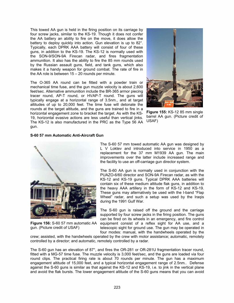
223
This towed AA gun is held in the firing position on its carriage byfour screw jacks, similar to the KS-19. Though it does not conferthe AA battery an ability to fire on the move, it does allow thebattery to deploy quickly into action. Gun elevation is up to 82°.Typically, each DPRK AAA battery will consist of four of theseguns, in addition to the KS-19. The KS-12 is normally used withthe SON-9/SON-9A Firecan radar, and fires fragmentationammunition. It also has the ability to fire the 85 mm rounds usedby the Russian assault guns, field, and tank guns, which alsomakes it a handy weapon for ground combat. The rate of fire inthe AA role is between 15 – 20 rounds per minute.
The O-365 AA round can be fitted with a powder train ormechanical time fuse, and the gun muzzle velocity is about 2,600feet/sec. Alternative ammunition include the BR-365 armor piecingtracer round, AP-T round, or HVAP-T round. The guns willtypically engage at a horizontal range of 3.5nm., and at targetaltitudes of up to 20,000 feet. The time fuse will detonate therounds at the target altitude, and the guns are trained to fire in ahorizontal engagement zone to bracket the target. As with the KS-19, horizontal evasive actions are less useful than vertical jinks.The KS-12 is also manufactured in the PRC as the Type 56 AAgun.
S-60 57 mm Automatic Anti-Aircraft Gun
The S-60 57 mm towed automatic AA gun was designed byL V Loktev and introduced into service in 1950 as areplacement for the 37 mm M1939 AA gun. The mainimprovements over the latter include increased range andthe facility to use an off-carriage gun director system.
The S-60 AA gun is normally used in conjunction with thePUAZO-6/60 director and SON-9A Firecan radar, as with theKS-12 and KS-19 guns. Typical DPRK AAA batteries willcontain six of these medium altitude flak guns, in addition tothe heavy AAA artillery in the form of KS-12 and KS-19.These guns may alternatively be used with the I-band “FlapWheel” radar, and such a setup was used by the Iraqisduring the 1991 Gulf War.
The S-60 gun is raised off the ground and the carriagesupported by four screw jacks in the firing position. The gunscan be fired on its wheels in an emergency, and fire controlequipment consist of a reflex sight for AA use, and atelescopic sight for ground use. The gun may be operated infour modes: manual, with the handwheels operated by the
crew; assisted, with the handwheels operated by the crew with motor assistance; automatic, remotelycontrolled by a director; and automatic, remotely controlled by a radar.
The S-60 gun has an elevation of 87°, and fires the OR-281 or OR-281U fragmentation tracer round,fitted with a MG-57 time fuse. The muzzle velocity is 3,000 feet/sec, and the guns are loaded via fourround clips. The practical firing rate is about 70 rounds per minute. The gun has a maximumengagement altitude of 15,000 feet, and a typical horizontal engagement range of 2.5nm.. Defenseagainst the S-60 guns is similar as that against the KS-12 and KS-19, i.e. to jink in the vertical planeand avoid the flak bursts. The lower engagement altitude of the S-60 guns means that you can avoid
Figure 155: KS-12 85 mm singlebarrel AA gun. (Picture credit ofUSAF)
Figure 156: S-60 57 mm automatic AAgun. (Picture credit of USAF)
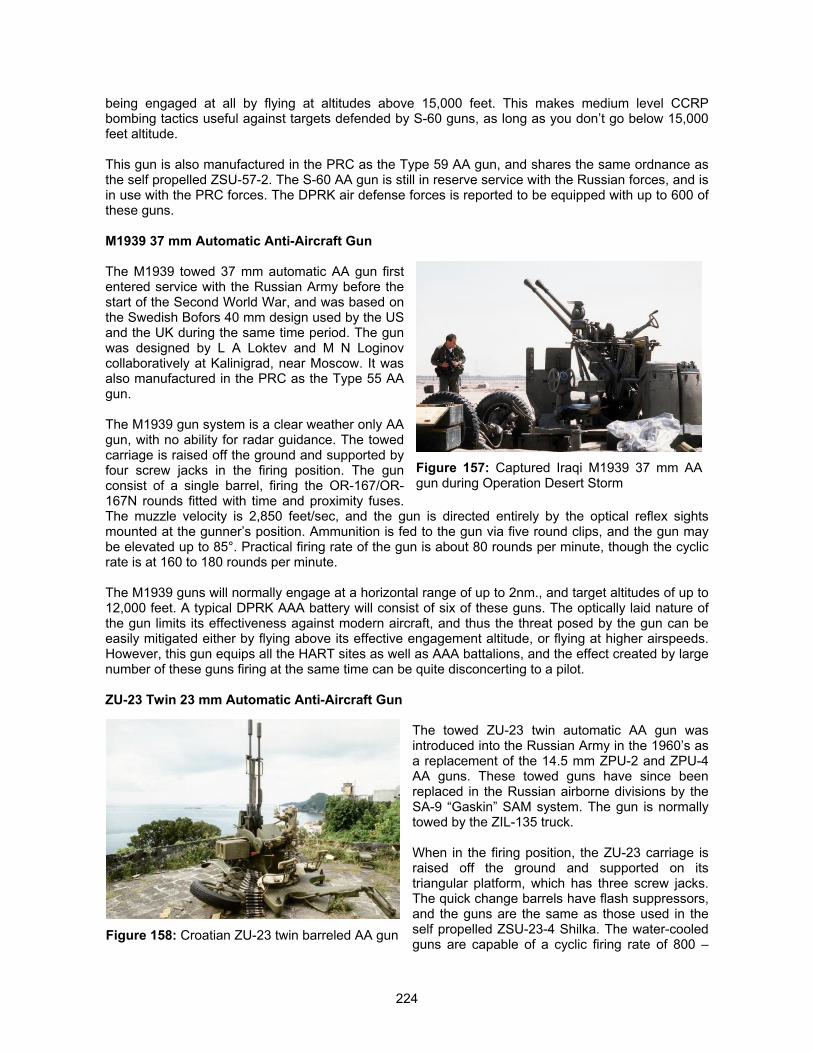
224
being engaged at all by flying at altitudes above 15,000 feet. This makes medium level CCRPbombing tactics useful against targets defended by S-60 guns, as long as you don’t go below 15,000feet altitude.
This gun is also manufactured in the PRC as the Type 59 AA gun, and shares the same ordnance asthe self propelled ZSU-57-2. The S-60 AA gun is still in reserve service with the Russian forces, and isin use with the PRC forces. The DPRK air defense forces is reported to be equipped with up to 600 ofthese guns.
M1939 37 mm Automatic Anti-Aircraft Gun
The M1939 towed 37 mm automatic AA gun firstentered service with the Russian Army before thestart of the Second World War, and was based onthe Swedish Bofors 40 mm design used by the USand the UK during the same time period. The gunwas designed by L A Loktev and M N Loginovcollaboratively at Kalinigrad, near Moscow. It wasalso manufactured in the PRC as the Type 55 AAgun.
The M1939 gun system is a clear weather only AAgun, with no ability for radar guidance. The towedcarriage is raised off the ground and supported byfour screw jacks in the firing position. The gunconsist of a single barrel, firing the OR-167/OR-167N rounds fitted with time and proximity fuses.The muzzle velocity is 2,850 feet/sec, and the gun is directed entirely by the optical reflex sightsmounted at the gunner’s position. Ammunition is fed to the gun via five round clips, and the gun maybe elevated up to 85°. Practical firing rate of the gun is about 80 rounds per minute, though the cyclicrate is at 160 to 180 rounds per minute.
The M1939 guns will normally engage at a horizontal range of up to 2nm., and target altitudes of up to12,000 feet. A typical DPRK AAA battery will consist of six of these guns. The optically laid nature ofthe gun limits its effectiveness against modern aircraft, and thus the threat posed by the gun can beeasily mitigated either by flying above its effective engagement altitude, or flying at higher airspeeds.However, this gun equips all the HART sites as well as AAA battalions, and the effect created by largenumber of these guns firing at the same time can be quite disconcerting to a pilot.
ZU-23 Twin 23 mm Automatic Anti-Aircraft Gun
The towed ZU-23 twin automatic AA gun wasintroduced into the Russian Army in the 1960’s asa replacement of the 14.5 mm ZPU-2 and ZPU-4AA guns. These towed guns have since beenreplaced in the Russian airborne divisions by theSA-9 “Gaskin” SAM system. The gun is normallytowed by the ZIL-135 truck.
When in the firing position, the ZU-23 carriage israised off the ground and supported on itstriangular platform, which has three screw jacks.The quick change barrels have flash suppressors,and the guns are the same as those used in theself propelled ZSU-23-4 Shilka. The water-cooledguns are capable of a cyclic firing rate of 800 –
Figure 157: Captured Iraqi M1939 37 mm AAgun during Operation Desert Storm
Figure 158: Croatian ZU-23 twin barreled AA gun
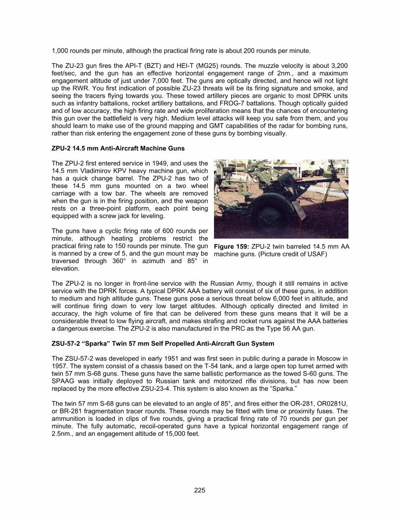
225
1,000 rounds per minute, although the practical firing rate is about 200 rounds per minute.
The ZU-23 gun fires the API-T (BZT) and HEI-T (MG25) rounds. The muzzle velocity is about 3,200feet/sec, and the gun has an effective horizontal engagement range of 2nm., and a maximumengagement altitude of just under 7,000 feet. The guns are optically directed, and hence will not lightup the RWR. You first indication of possible ZU-23 threats will be its firing signature and smoke, andseeing the tracers flying towards you. These towed artillery pieces are organic to most DPRK unitssuch as infantry battalions, rocket artillery battalions, and FROG-7 battalions. Though optically guidedand of low accuracy, the high firing rate and wide proliferation means that the chances of encounteringthis gun over the battlefield is very high. Medium level attacks will keep you safe from them, and youshould learn to make use of the ground mapping and GMT capabilities of the radar for bombing runs,rather than risk entering the engagement zone of these guns by bombing visually.
ZPU-2 14.5 mm Anti-Aircraft Machine Guns
The ZPU-2 first entered service in 1949, and uses the14.5 mm Vladimirov KPV heavy machine gun, whichhas a quick change barrel. The ZPU-2 has two ofthese 14.5 mm guns mounted on a two wheelcarriage with a tow bar. The wheels are removedwhen the gun is in the firing position, and the weaponrests on a three-point platform, each point beingequipped with a screw jack for leveling.
The guns have a cyclic firing rate of 600 rounds perminute, although heating problems restrict thepractical firing rate to 150 rounds per minute. The gunis manned by a crew of 5, and the gun mount may betraversed through 360° in azimuth and 85° inelevation.
The ZPU-2 is no longer in front-line service with the Russian Army, though it still remains in activeservice with the DPRK forces. A typical DPRK AAA battery will consist of six of these guns, in additionto medium and high altitude guns. These guns pose a serious threat below 6,000 feet in altitude, andwill continue firing down to very low target altitudes. Although optically directed and limited inaccuracy, the high volume of fire that can be delivered from these guns means that it will be aconsiderable threat to low flying aircraft, and makes strafing and rocket runs against the AAA batteriesa dangerous exercise. The ZPU-2 is also manufactured in the PRC as the Type 56 AA gun.
ZSU-57-2 “Sparka” Twin 57 mm Self Propelled Anti-Aircraft Gun System
The ZSU-57-2 was developed in early 1951 and was first seen in public during a parade in Moscow in1957. The system consist of a chassis based on the T-54 tank, and a large open top turret armed withtwin 57 mm S-68 guns. These guns have the same ballistic performance as the towed S-60 guns. TheSPAAG was initially deployed to Russian tank and motorized rifle divisions, but has now beenreplaced by the more effective ZSU-23-4. This system is also known as the “Sparka.”
The twin 57 mm S-68 guns can be elevated to an angle of 85°, and fires either the OR-281, OR0281U,or BR-281 fragmentation tracer rounds. These rounds may be fitted with time or proximity fuses. Theammunition is loaded in clips of five rounds, giving a practical firing rate of 70 rounds per gun perminute. The fully automatic, recoil-operated guns have a typical horizontal engagement range of2.5nm., and an engagement altitude of 15,000 feet.
Figure 159: ZPU-2 twin barreled 14.5 mm AAmachine guns. (Picture credit of USAF)
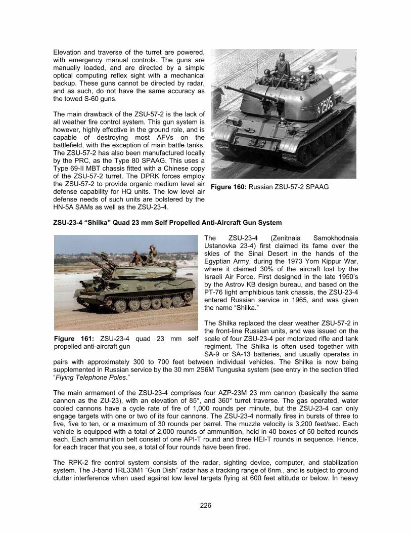
226
Elevation and traverse of the turret are powered,with emergency manual controls. The guns aremanually loaded, and are directed by a simpleoptical computing reflex sight with a mechanicalbackup. These guns cannot be directed by radar,and as such, do not have the same accuracy asthe towed S-60 guns.
The main drawback of the ZSU-57-2 is the lack ofall weather fire control system. This gun system ishowever, highly effective in the ground role, and iscapable of destroying most AFVs on thebattlefield, with the exception of main battle tanks.The ZSU-57-2 has also been manufactured locallyby the PRC, as the Type 80 SPAAG. This uses aType 69-II MBT chassis fitted with a Chinese copyof the ZSU-57-2 turret. The DPRK forces employthe ZSU-57-2 to provide organic medium level airdefense capability for HQ units. The low level airdefense needs of such units are bolstered by theHN-5A SAMs as well as the ZSU-23-4.
ZSU-23-4 “Shilka” Quad 23 mm Self Propelled Anti-Aircraft Gun System
The ZSU-23-4 (Zenitnaia SamokhodnaiaUstanovka 23-4) first claimed its fame over theskies of the Sinai Desert in the hands of theEgyptian Army, during the 1973 Yom Kippur War,where it claimed 30% of the aircraft lost by theIsraeli Air Force. First designed in the late 1950’sby the Astrov KB design bureau, and based on thePT-76 light amphibious tank chassis, the ZSU-23-4entered Russian service in 1965, and was giventhe name “Shilka.”
The Shilka replaced the clear weather ZSU-57-2 inthe front-line Russian units, and was issued on thescale of four ZSU-23-4 per motorized rifle and tankregiment. The Shilka is often used together withSA-9 or SA-13 batteries, and usually operates in
pairs with approximately 300 to 700 feet between individual vehicles. The Shilka is now beingsupplemented in Russian service by the 30 mm 2S6M Tunguska system (see entry in the section titled“Flying Telephone Poles.”
The main armament of the ZSU-23-4 comprises four AZP-23M 23 mm cannon (basically the samecannon as the ZU-23), with an elevation of 85°, and 360° turret traverse. The gas operated, watercooled cannons have a cycle rate of fire of 1,000 rounds per minute, but the ZSU-23-4 can onlyengage targets with one or two of its four cannons. The ZSU-23-4 normally fires in bursts of three tofive, five to ten, or a maximum of 30 rounds per barrel. The muzzle velocity is 3,200 feet/sec. Eachvehicle is equipped with a total of 2,000 rounds of ammunition, held in 40 boxes of 50 belted roundseach. Each ammunition belt consist of one API-T round and three HEI-T rounds in sequence. Hence,for each tracer that you see, a total of four rounds have been fired.
The RPK-2 fire control system consists of the radar, sighting device, computer, and stabilizationsystem. The J-band 1RL33M1 “Gun Dish” radar has a tracking range of 6nm., and is subject to groundclutter interference when used against low level targets flying at 600 feet altitude or below. In heavy
Figure 160: Russian ZSU-57-2 SPAAG
Figure 161: ZSU-23-4 quad 23 mm selfpropelled anti-aircraft gun
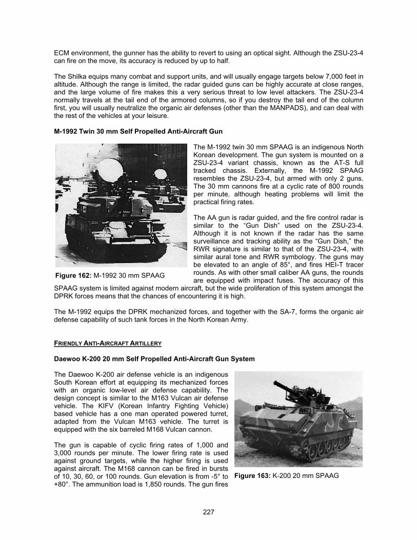
227
ECM environment, the gunner has the ability to revert to using an optical sight. Although the ZSU-23-4can fire on the move, its accuracy is reduced by up to half.
The Shilka equips many combat and support units, and will usually engage targets below 7,000 feet inaltitude. Although the range is limited, the radar guided guns can be highly accurate at close ranges,and the large volume of fire makes this a very serious threat to low level attackers. The ZSU-23-4normally travels at the tail end of the armored columns, so if you destroy the tail end of the columnfirst, you will usually neutralize the organic air defenses (other than the MANPADS), and can deal withthe rest of the vehicles at your leisure.
M-1992 Twin 30 mm Self Propelled Anti-Aircraft Gun
The M-1992 twin 30 mm SPAAG is an indigenous NorthKorean development. The gun system is mounted on aZSU-23-4 variant chassis, known as the AT-S fulltracked chassis. Externally, the M-1992 SPAAGresembles the ZSU-23-4, but armed with only 2 guns.The 30 mm cannons fire at a cyclic rate of 800 roundsper minute, although heating problems will limit thepractical firing rates.
The AA gun is radar guided, and the fire control radar issimilar to the “Gun Dish” used on the ZSU-23-4.Although it is not known if the radar has the samesurveillance and tracking ability as the “Gun Dish,” theRWR signature is similar to that of the ZSU-23-4, withsimilar aural tone and RWR symbology. The guns maybe elevated to an angle of 85°, and fires HEI-T tracerrounds. As with other small caliber AA guns, the roundsare equipped with impact fuses. The accuracy of this
SPAAG system is limited against modern aircraft, but the wide proliferation of this system amongst theDPRK forces means that the chances of encountering it is high.
The M-1992 equips the DPRK mechanized forces, and together with the SA-7, forms the organic airdefense capability of such tank forces in the North Korean Army.
FRIENDLY ANTI-AIRCRAFT ARTILLERY
Daewoo K-200 20 mm Self Propelled Anti-Aircraft Gun System
The Daewoo K-200 air defense vehicle is an indigenousSouth Korean effort at equipping its mechanized forceswith an organic low-level air defense capability. Thedesign concept is similar to the M163 Vulcan air defensevehicle. The KIFV (Korean Infantry Fighting Vehicle)based vehicle has a one man operated powered turret,adapted from the Vulcan M163 vehicle. The turret isequipped with the six barreled M168 Vulcan cannon.
The gun is capable of cyclic firing rates of 1,000 and3,000 rounds per minute. The lower firing rate is usedagainst ground targets, while the higher firing is usedagainst aircraft. The M168 cannon can be fired in burstsof 10, 30, 60, or 100 rounds. Gun elevation is from -5° to+80°. The ammunition load is 1,850 rounds. The gun fires
Figure 162: M-1992 30 mm SPAAG
Figure 163: K-200 20 mm SPAAG
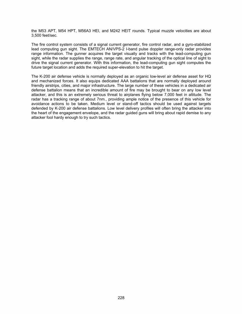
228
the M53 APT, M54 HPT, M56A3 HEI, and M242 HEIT rounds. Typical muzzle velocities are about3,500 feet/sec.
The fire control system consists of a signal current generator, fire control radar, and a gyro-stabilizedlead computing gun sight. The EMTECH AN/VPS-2 I-band pulse doppler range-only radar providesrange information. The gunner acquires the target visually and tracks with the lead-computing gunsight, while the radar supplies the range, range rate, and angular tracking of the optical line of sight todrive the signal current generator. With this information, the lead-computing gun sight computes thefuture target location and adds the required super-elevation to hit the target.
The K-200 air defense vehicle is normally deployed as an organic low-level air defense asset for HQand mechanized forces. It also equips dedicated AAA battalions that are normally deployed aroundfriendly airstrips, cities, and major infrastructure. The large number of these vehicles in a dedicated airdefense battalion means that an incredible amount of fire may be brought to bear on any low levelattacker, and this is an extremely serious threat to airplanes flying below 7,000 feet in altitude. Theradar has a tracking range of about 7nm., providing ample notice of the presence of this vehicle foravoidance actions to be taken. Medium level or stand-off tactics should be used against targetsdefended by K-200 air defense battalions. Low level delivery profiles will often bring the attacker intothe heart of the engagement envelope, and the radar guided guns will bring about rapid demise to anyattacker fool hardy enough to try such tactics.

229
PART III: DESIGNER’S NOTES
This section contains information on how the various changes in the Realism Patch are implemented.The design considerations and technical implementation are elaborated on a topical basis. The innerworkings of F4 that we discovered during the course of creating the Realism Patch will also beelaborated.
PART
III
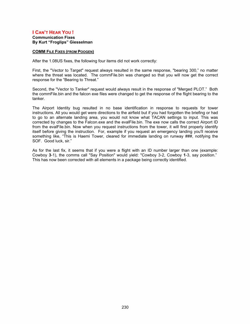
230
I CAN’T HEAR YOU !Communication FixesBy Kurt “Froglips” Giesselman
COMM FILE FIXES (FROM POOGEN)
After the 1.08US fixes, the following four items did not work correctly:
First, the ''Vector to Target" request always resulted in the same response, "bearing 300,” no matterwhere the threat was located. The commFile.bin was changed so that you will now get the correctresponse for the “Bearing to Threat.”
Second, the "Vector to Tanker" request would always result in the response of "Merged PLOT.” Boththe commFile.bin and the falcon exe files were changed to get the response of the flight bearing to thetanker.
The Airport Identity bug resulted in no base identification in response to requests for towerinstructions. All you would get were directions to the airfield but if you had forgotten the briefing or hadto go to an alternate landing area, you would not know what TACAN settings to input. This wascorrected by changes to the Falcon.exe and the evalFile.bin. The exe now calls the correct Airport IDfrom the evalFile.bin. Now when you request instructions from the tower, it will first properly identifyitself before giving the instruction. For, example if you request an emergency landing you'll receivesomething like, “This is Haemi Tower, cleared for immediate landing on runway ###, notifying theSOF. Good luck, sir.”
As for the last fix, it seems that if you were a flight with an ID number larger than one (example:Cowboy 3-1), the comms call "Say Position" would yield: "Cowboy 3-2, Cowboy 1-3, say position.” This has now been corrected with all elements in a package being correctly identified.
231
THE INVULNERABLE VEHICLESSolving The Mystery of The Invulnerable VehiclesBy Alex Easton
PREAMBLE
There has been a long-term problem of vehicles being invulnerable to cluster bomb attacks whenplaced at double-runway bases. An additional manifestation of this problem is that most SAMs (withthe exception of the SA-2 and Nike) explode on the launcher and won't launch.
This is a problem with ALL airbases, but for the single-runway bases, MPS had already moved thepositions air defense vehicles take up off the edges of the base, so solving the problem. The doublerunway bases were by-and-large untouched, and the problem remained. The same solution has nowbeen implemented at double-runway bases.
The opportunity was taken to improve the dispersal of air defense units at other military bases and tocorrect some obvious errors in the taxiing data for some of the bases.
There are two types of entry for vehicles in an air defense unit - AAA/support and SAM/support. Theformer was intended to be used but are currently inactive. They may be able to be activated at a laterdate. The second is a real mess. At airbases, MOST air defense units use only the "support" and"radar" positions, where the RDR VCL slot in the FALCON4.UCD file places all units in that slot intothe radar position. However, SOME vehicles use the "sam" positions - the SA-8, Stinger squad, K-200. For military sites other than airbases, all units use all of the positions (sam, radar AND support)without distinction in the sequence that they appear on the file. At non-military sites like towns, thereis no positioning data and the units take up pre-determined formations.
You can examine a typical dispersal by over-flying a site, recording it on ACMI and then viewing usingthe satellite view.
Sylvain and Joel have also independently solved the cluster bomb problem by adjusting the clusterbombs to treat proximity damage better. You will still damage the runway, taxiway or lights withcluster bombs, but this will no longer protect the units stationed within the boundary box of the base.So even combat units, which can straddle the base, and taxiing aircraft are now vulnerable to clusterbomb attacks.
CHANGES IN REALISM PATCH
Falcon4.phd file
Entry no 31 for Osan was changed to type 4 - i.e. from a helicopter-type entry to a sam/support-typeentry.
Falcon4.pd file
Double runway airbases
1) Moved SAM, AAA, support and radar positions to the edges of airbases to enable ALL SAMs tolaunch and make the vehicles vulnerable to destruction by cluster bombs2) Arranged in positions to improve the effectiveness against attacks from all directions but particularlyrunway bombing approaches3) Arranged in positions to reduce vulnerability against cluster bomb attacks4) Corrected obvious errors in taxiing data for aircraft
232
Single runway airbases
1) Adjusted slightly some SAM/support positions further from the base to allow maneuvering byvehicles while keeping them vulnerable to destruction by cluster bombs2) Reorganized AAA/support positions (currently unused) in case they can be activated at later date3) Corrected obvious errors in taxiing data
Osan airbase
Changed the pd entry, which listed 13 helicopter landing/take-off positions (an obvious error) toSAM/support positions and arranged them as for a double-runway base.
Highway strips
1) Moved vehicles further from runway so as not to intrude on the strip2) Gave them better dispersal3) Arranged them as far as possible so as not to overlap with combat/support units also placed at thebase.
Depots, Radar sites and Army bases
1) Dispersed units to make them less vulnerable to a cluster bomb attack2) Spread them round the approaches to the site so as to provide better defense against attacks fromall directions3) Moved them away from buildings so as not to overlap buildings and make them less vulnerableagainst attacks on the targets at the site
Outstanding Problems
1) There is still a problem with combat units based at airbases sometimes straddling the base and thuspreventing their own SAMs such as the SA-15 from firing2) There remain some anomalies in the taxiing data for some bases. This may occasionally result inodd behavior during taxiing of AI-controlled aircraft.
To Do List
1) Reorganize slightly dispersal patterns at ports (there are cases where vehicles overlap each otherand structures at the site)2) Investigate possible errors in taxiing data for some sites (the uncorrected "errors" may not be errors,but if they are, they may be the cause for some strange behavior of aircraft at some bases)3) Investigate effects of small changes in helicopter landing positions (currently only #1 lands and therest of the flight hover near the landing sites)4) Investigate how to activate the AAA/support positions5) Investigate why some vehicles can occupy the "sam" positions, while MOST occupy only the"support" positions.
STRUCTURE OF THE PHD AND PD FILES
Here are some of the things in the PhD and Pd files that I am sure of - or not so sure of! Of course,there may be more than one effect from each of the entries, but here is what I have been able toidentify. It is clear to me where MPS was heading with all this stuff. It is also clear that they did notfinish it.
233
PHD Entry
Pd - counter for number of sets of positional data in the entryPd Ptr - entry in the Pd file which contains positional datachain - the next entry in the chain for that objective. Equals zero for last entry.Heading/L/R - corresponds to "instructions" from ATO on which runway to landRwy No - Probably relates to position on which AI plane appearsType - relates to type of data in Pd entryFeature (6 boxes) unknownsin/cos (hdg) the sine and cosine or the heading (in degrees). Use unknown.
Entry Types
1 : Taxiing/takeoff/landing data for AI4: Positions of vehicles in SAM battery5: Artillery positions6: Positions of AAA air defense vehicles (apparently not used)8 : Runway ends11: Boundaries of "parks.” Use unknown14: Positions for helicopter landing/taking off.16 : Defines a small dock at a port. Possibly for positioning ships in a port.
Position Types
X and Y refer to positions in feet from a local origin. X-axis is E-W and Y-axis is N-S. "flags" delimitsthe first and last in the list.
1: "runway" far end of runway. Probably point to be aimed at along runway for AI planes taking off. Or"touch-down point for AI planes landing
2 : "takeoff" point at which AI plane holds before take off
3: "taxi" Taxiing sps for planes preparing to take off, or taxiing after landing. Route traveled in reverseon taking off/landing. Planes "disappear" on reaching last point, and "appear at one of these pointsdepending on number of other planes in the queue to take off.
4: "sam" For use by launchers in SAM batteries. Currently used for most vehicles in an air defensebattalion
5: "artillery" Defines positions of artillery vehicles at a HART site
6: "aaa" presumably intended for use by guns in AAA battery. Apparently not used.
7: "radar" Exclusive slot reserved for vehicle in "Rdr Vcl" slot defined in unit file. Not used in non-ADunits, and used by SOME vehicles in air defense batteries even if Rdr Vcl is not set.
8: "runwayDim" marks out ends of entire runway. Use unknown, but maybe landing/taking off data forAI or positional data for runway strobe lights??
9: "support" In AAA and sam entry, presumably intended for support vehicles. Apparently not used inAAA entry, but used for all vehicles in SAM entry.
11: "small park" Defines boundaries of a "small park" or area. Use unknown
12 : "large park" Defines boundaries of a "large park" or area. Use unknown

234
13: "small dock" Defines boundaries of a "small dock" at a port. Presumably positioning data forplacement of (small??) ships
14: "large dock" Defines boundaries of a "large dock" at a port. Presumably positioning data forplacement of (large??) ships at a port.
15: "take runway" point at which taxiing plane turns onto runway, or landing plane turns off runwayonto taxiway
16: "helicopter" positions from which helicopters take off and land at a site.
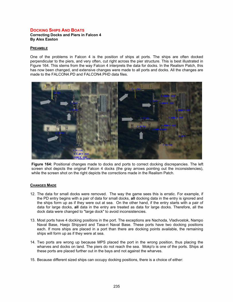
235
DOCKING SHIPS AND BOATSCorrecting Docks and Piers in Falcon 4By Alex Easton
PREAMBLE
One of the problems in Falcon 4 is the position of ships at ports. The ships are often dockedperpendicular to the piers, and very often, cut right across the pier structure. This is best illustrated inFigure 164. This stems from the way Falcon 4 interprets the data for docks. In the Realism Patch, thishas now been changed, and extensive changes were made to all ports and docks. All the changes aremade to the FALCON4.PD and FALCON4.PHD data files.
CHANGES MADE
12. The data for small docks were removed. The way the game sees this is erratic. For example, ifthe PD entry begins with a pair of data for small docks, all docking data in the entry is ignored andthe ships form up as if they were out at sea. On the other hand, if the entry starts with a pair ofdata for large docks, all data in the entry are treated as data for large docks. Therefore, all thedock data were changed to "large dock" to avoid inconsistencies.
13. Most ports have 4 docking positions in the port. The exceptions are Nachoda, Vladivostok, NampoNaval Base, Haejo Shipyard and Tasa-ri Naval Base. These ports have two docking positionseach. If more ships are placed in a port than there are docking points available, the remainingships will form up as if they were at sea.
14. Two ports are wrong up because MPS placed the port in the wrong position, thus placing thewharves and docks on land. The piers do not reach the sea. Mokp'o is one of the ports. Ships atthese ports are placed further out in the bays and not against the wharves.
15. Because different sized ships can occupy docking positions, there is a choice of either:
Figure 164: Positional changes made to docks and ports to correct docking discrepancies. The leftscreen shot depicts the original Falcon 4 docks (the gray arrows pointing out the inconsistencies),while the screen shot on the right depicts the corrections made in the Realism Patch.
236
a. placing the small ships against the wharves, but with the penalty that the big ships will overlapthe wharves
b. placing the big ships against the wharves (and under the cranes), with the penalty that thesmaller ships will have a gap between themselves and the pier.
I have chosen the second because then nothing looks bad, and ships often do sit at some distancefrom the dock if they have finished unloading. The widest ship in the game sits tight against thepier/wharf.
16. Each docking position consists of two sub-positions. The first defines the center of the position,and the second defines the point at which the ship is pointing when docked.
17. The dispersal of the vehicles in the Air Defense Battalion posted at the docks has been improvedin the same way as for the airbases and army bases.
18. The major remaining problem is with the aircraft carrier. This is currently too big to fit into any port.
19. The following ports are used by the OCD entries:
00C : Nachoda, Vladivostok, Namp'o NB, Haejo S/Y, Tasa-ri NB66D : N/W Seoul731 : Mokpo795 : Incheon79A : Chodo-ri NB, Pusan S/Y79B : Mayang NB, Wosan, Pusan port79D : Sinp'o79E : Namp'o S/Y, Nanam, Hamhung7A0 : Najin, Pohang, Dahaitsu7A1 : Toejo NB, Sagon-ni NB, Chongjin, Pupo-ri NB7A6 : Kosong NB7A5 : Pipa-got Submarine base7A2 : Kinchaek NB
237
CORRECTING THE GOLDEN BBAir Defense Changes in Realism PatchBy Alex Easton
CHANGES TO SAMS/AAA
1) Up to now, there has been an abrupt reduction in the range of air defense systems at thealtitude of 10,000ft. For example, at 10,100ft, the range of the SA-15 is about 4.5nm, while at 9,900ft,it is 1.5nm. This is completely unrealistic and allowed unrealistic tactics to be developed. Typically,the range is reduced to one third below 10,000ft, but this was only approximately true for somesystems, depending on the settings of the air and low air hit chances in the weapons file.
In Realism Patch version 4, this discontinuity as been halved. Taking the above example, the rangebelow 10,000ft has been increased to 3nm.. For future patches, each system will be investigatedindividually to try to achieve the maximum realism for each system, but in RP4, the interim measurehas been taken to reduce the discontinuity by half.
Changes Made
In FALCON4.AII file, the parameter LowAirRangeModifier has been increased from 33 to 66
2) As far as it goes, the flak AAA is well modeled in F4, but there are some serious limitations inthe modeling. One of the main deficiency is that the probability of a hit is the same for short and longslant ranges. This means that you are no safer at higher altitudes and longer horizontal ranges thanyou are low down and close to the guns.
In addition, although it is safer to keep your speed high simply because you spend less time in theweapon's engagement zone, there was no difference in the probability per second at low and highspeeds.
Sylvain Gagnon has produced an EXE patch that lowers the probability of a hit when the speed of thetarget is high, and the probability reduces progressively with increasing slant range to the target.Although this does not increase the survival rate when jinking, especially at large slant ranges, it doesimprove the survival rate at all times when the slant range and/or speed is high.
3) Previously, the radar would only switch on and the guns start to "fire" when the DPRK AAAunit deaggregated at 6nm. This curtailed the maximum horizontal range of the KS-19 from 7.5 to 6nm.and meant that there would be no warning on the RWR before the guns started to "fire.” This problemhas been addressed by increasing the UDD for the unit to 8.5nm and the Firecan AAA radar rangeextended to 14nm
With these changes, the KS-19s will begin to shoot at you earlier than before when you are below25,000 feet, but the reduction in horizontal range with altitude means that above this altitude, you willsee no change other than an earlier warning on your RWR. The other guns have engagement rangesthat are less than 6nm. and so remain unaffected.
Changes Made
Firecan radar range increased to 14nm.UDD for DRPK AAA unit increased to 8.5nm.
4) The setting RDR VCL in the unit file has some consequences in addition to protecting vehiclesin the slot from "disappearing" at low object density and force level settings.
Firstly, at airbases, the units in the slot defined by RDR VCL sit on a dedicated radar position aroundthe airbase. If there is more than one vehicle in this slot, all the vehicles will sit directly on top of each
238
other and can all be destroyed by a single Maverick shot. Secondly, if the vehicles in this slot are alldestroyed, any remaining radars in the battalion will cease to operate.
This is acceptable for units such as the SA-5, where the single vehicle in the RDR VCL slot is theBarlock-B radar vehicle. When this is destroyed, the SA-5s cannot launch, and this is how it should be.It is also acceptable for units with no radar-carrying vehicles, where RDR VCL is set at 255. But forunits like the SA-15 battery, knocking out both vehicles in the RDR VCL position will turn off the radaron the surviving launchers and prevent them from firing. The whole unit can therefore effectively beneutralized with one shot.
The partially effective solution is to set the RDR VCL at a carefully chosen "virtual slot.” There areonly 16 REAL slots -(0 - 15) and setting RDR VCL above 15 will mean that there is no real RDR VCLslot, so nothing will be placed in the dedicated radar position around airbases. But there will still besome real, occupied slots which, when the vehicles contained in them are destroyed, will shut downthe remaining radars in the battalion. This appears to be unavoidable without exe hacking, but wehave optimized it by choosing a virtual slot for the RDR VCL that puts a number of well-dispersedvehicles in the critical slot - the one which will shut down the radar if emptied. It will therefore nolonger be possible to shut down the radar in the battalions listed below with a single shot, and onaverage at least half the launchers/guns have to be destroyed before the radar shuts off.
For combat/support battalions containing radar-carrying vehicles such as the ZSU-23-4, the RDR VCLis correctly set at the slot containing the SAM launchers (e.g. the SA-15). The SAMs can only beprevented from launching by destroying all the launchers - which is how it should be.
The ROK K-200 AAA battalion has been rearranged to put a larger number of vehicles in the criticalslot, making it less vulnerable to having its radar shut down with a small number of hits.
Changes Made
DRPK KS-19 AAA battery : RDR VCL = 20DPRK SA-15 SAM battery : RDR VCL = 21DPRK SA-8 SAM battery : RDR VCL = 17DPRK Towed AAA battery : RDR VCL = 20ROK K-200 AAA battery : RDR VCL = 17
Ordering of the K-200 AAA batteryslot 0 - 3xK-200slot 1 - 3xK-200slot 2 - 2xK-200slot 3 - 3xM-977slot 4 - 3xM-977slot 5 - 3xM-113
5) The tracer-type AAA for some of the guns have their effectiveness reduced by too much inRP3. With more knowledge about how the F4browse parameters "blast radius" and "rate of fire" workfor different classes of weapon, we have been able to set values that give these guns more realisticperformances. The problems were with the ZSU-23-4, the ZU-23 and the K-200 vehicles carrying the23mm and 20mm AAA tracer-type guns.
Changes Made
GUN Blast Radius Rate of Fire12.7 3 214.5 4 220mm 69 820mm (RG) 139 8
239
23mm 65 623mm (RG) 130 630mm (RG) 302 625mm 50 3All small arms 2 2
6) As mentioned in the section titled “The Invulnerable Vehicles,” the dispersal patterns for airdefense systems around military targets - airbases, depots, army bases and radar installations - havebeen changed to enable these units to better defend the site and render them less vulnerable to massdestruction by cluster bomb attacks.
CHANGES TO AAA ACCURACY
One of the problems that we have experienced during the development of the Realism Patch is thedifficulty in achieving good performance for small caliber AAA at lower altitudes. The AAA vehiclessuch as ZSU-23-4 and the K-200AD were not achieving any degree of accuracy, and we were able tofly around at low altitude in lazy circles and not get hit.
In addition, flagging any vehicle as “Air Defense” does nothing to improve its accuracy, but insteaddecreased its accuracy. The guns will also stop firing under 3,000 feet in range. This allows the planesto fly in at low level below 3,000 feet altitude and not have any air defense guns shoot. As a result,most of the low altitude hits were actually scored by Ak-47 rifles.
With the Realism Patch, these have now been changed as follows by Sylvain Gagnon’s exe patch:
1. Increased gun accuracy. F4 was aiming the guns with gravity compensation, which is notnecessary. F4’s default aiming algorithm reduces the z-axis velocity but let the x and y axisvelocities remain, and as a result, lead to a very low accuracy. The trajectory of the bullets androunds are still subjected to gravity though.
2. Firing rate of guns have been increased. Default 1.08US fires in bursts of 3 rounds, with 6 to20 seconds between bursts (depending on skills). With RP, the guns will fire at 0.5 secondinterval between bursts, until the target exits the engagement zone. The guns will howeverwait for 6 to 20 seconds (skill dependent) after you have entered their engagement zonebefore commencing initial firing. Shells are fired at two every second.
3. Some randomness is introduced to air defense guns such that they will not be shooting in alinear pattern but the tracers will have a dispersion pattern of a few hundred feet around thetarget.
4. The weapon selection criteria in RP is such that if the weapon is a gun, the target’s range inkilometers must be less than 1/11th that of the gun’s range, or less than 2 km. If 1/11th of thegun’s range is more than 2 km (i.e. the gun has a range in excess of 22 km) it will be skipped.
5. Varying muzzle velocities for each gun, and time-to-live for the bullets. This allows the bulletspeed and time-to-live for every gun be customized.
6. Varying skill ratings for the air defense artillery crew. The accuracy of the AAA is multiplied bythe skill factor, which is 0.57 for recruits, 1.29 for cadets, 2.29 for rookies, 3.57 for veterans,and 5.14 for aces.
This produces a huge increase in low level small caliber AAA fire, and with great accuracy. Your bestway to survive is to jink constantly, or better still, avoid it altogether.
240
THE CHANGED BATTLESCAPEBackground and Philosophy of Ground and Air Unit ChangesBy Jeffery “Rhino” Babineau
CHANGES MADE TO GROUND UNITS
Significant work has been done to duplicate battle formations as best as Falcon 4.0 will allow. No unitfights pure. There is always mutual support from other units in the battalion. In all cases this is missiondirected. Engineer units are commonly assigned to attacking units to support the breach of obstaclesused for defenses and cross bridges. In the defense, engineer units prepare the defense but are thenheld back as these are mostly lightly armored vehicles, if they are armored at all.
In the case of rocket units (MLRS, BM24) and SAM units, we decided to split up the unit to reflect adeployed battery instead of a deployed battalion. In no case that I can think of is a SAM battalion allplaced in one location. In the Falcon 4.0 world that location could be one sq. km. Now you can take aSAM battery and protect a city and another battery to protect another city. If you look at Patriotdeployment to South Korea, you will see that we have one Patriot Battalion for the whole county.Where would you place it? Now we have the option to place a battery around Seoul, Pusan,Chuncheon, etc. In all of these cases supporting vehicles have been assigned. SAM batteries arecommonly supported with handheld portable weapons such as the SA7 and stinger.
Falcon 4.0 allows a limited number of vehicles to occupy a battalion (the basic unit structure in F4 –also represented as a single UNIT entry in the UCD). The maximum number of vehicles an F4battalion can hold is 48. There are far more vehicles in a real battalion, but unfortunately we cannotinclude every vehicle that a battalion would normally include.
The ratio of non-combat (trucks, etc.) to combat vehicles (tanks, IFVs) is now quite balanced,beginning from version 3 of the Realism Patch. In addition, different nations organize their battalionsdifferently. We are lucky, that in some cases, eastern forces (DPRK, China) tend to copy the Russianmodel. Western units (ROK) in F4 copy the US model. There are significant differences in the numberof combat vehicles included a Russian maneuver unit and a US maneuver unit. Russian units tend tohave 30 combat vehicles while US units would typically have 58. What Falcon allows is a reasonablerepresentation of Russian type units, while only allowing about 2/3 of a US style unit.
The modifications incorporated since Realism Patch v3.0 are meant to bring the battalions into a"realistic" representation of their real world counterparts, and to balance the ratio between the differenttypes of units.
We have also found that the force ratio slider has an impact on the amount of these vehicles whendeployed. This could have potentially serious effects. You can inadvertently leave significant vehiclesout of the unit by moving the slider one way or the other. Imagine a Mechanized task force with notanks! We had originally designed these units around how they would typically deploy, as we knewthat F4 moved them in column formations. Now we must arrange them based on slider settings. Slider0 would only use vehicles in UCD slots 0-6. Slider position 6 will use ALL the vehicles resident in theUNIT UCD record. When you create your campaign difficulty settings, please be aware that the centersetting is based on "most accurate size" for both ground and air units.
Example: A US Armor battalion has approximately 58 tanks. In F4 if the unit were totally pure withtanks, it could only have 82% of its full strength. However it is typical that at least one company oftanks gets cross attached to a mechanized battalion and one company from that mechanized battaliongets attached to that Armor battalion. Now we have 42 tanks, and 14 IFVs or 12 platoons of tanks andfour platoons of IFVs. Also hindering our effort is that Falcon will not allow you to place more thanthree vehicles in a UCD entry slot and the US units deploy in platoons of four. Therefore, we now endup with cutting the US unit back further as each "slot" in F4 can be called a platoon. But with all thesupport vehicles that are still needed like scouts, mortars, air defense attachments, trucks, andHUMWVEEs, the US battalion is shrunk in combat power even further.

241
CHANGES MADE TO AIR UNITS
Starting from version 3 of the Realism Patch, changes were made to the squadron sizes to reflectactual order of battle. The air units (squadron size) used in F4’s campaign by default are 24 aircraft insize. Recent research has discovered that Russian squadron sizes are in-fact smaller. Informationgathered from references in the 80's show Russian bomber units of only nine aircraft. Russian fighterand fighter-bomber units are typically between 12-15 aircraft in size. Looking at current forcestructures of the Hungarian Air Regiments used in Kosovo confirms these numbers.
In fact, even US squadrons have reduced in size, with the average USAF fighter squadron now with18 aircraft and not 24. In some cases, you can still find larger sized squadrons but in most situations,you will find smaller unit sizes.
Other aircraft unit sizes are surprisingly small too. It is a matter of simple math - there are 606 C-130aircraft in 40 squadrons. This averages out to be 15 aircraft per squadron and not 24. ROK, DPRK,CHINA and the rest are assumed to use their allied squadron organizations, which means that theyadopt the squadron sizing constructs of their “big brothers” – the US and Russia.
We also know that Falcon 4.0 does not, and probably could not, do a Korean War on a 1-for-1 basis.Over 200 J-5 aircraft (Mig15, 17 types) are not even depicted, but since we have now allowed theMIG19 to perform the same missions as the J-5, we have accommodated and implemented a lost butvital part of a war in Korea. Numerical superiority in the DPRK is prevalent in the number ofsquadrons available in F4. Falcon currently does a good job of showing more DPRK units than NATO.Chopper units in the real world, in some cases, are actually much larger than F4 allows. However, theattack helicopter units on both sides are well represented.
Although maintenance and repair is a critical issue, it was not used for consideration. Poor countriessometimes have such a poor military budget that they just cannot keep their aircraft flying. It isarguable that of the 60 or so MiG-29s the DPRK has, only about 30-40 are combat capable at any onetime. Most of the DPRK fleet is older, outdated, and near museum pieces from the 50's and 60's.Although the fleet has been modernized through the years, and is rumored to actually be licensedbuilders of the MiG 29, the DPRK does not throw away any aircraft. An air war in Korea will still featureMiG-15s, even today.
The campaign force slider can change the number of aircraft in a campaign slightly. In building theseunits, we recommend a middle slider setting to get the most realistic known squadron size. The forceslider is bugged in that it will not stay where you put it. Move the slider one notch to the right and it willthen move to the center position.
The UCD (unit) modifications were built with force reductions representing real world known aviationunit sizes. Where unknown, we used “lie” units - the DPRK would use Russian types and ROK woulduse US types. Force sliders assumed to be centered with no more than 25% changes from low to midor mid to high.
CHANGES MADE TO SQUADRON STORES:
Merely updated to support new units in the squadron/battalion and new weapons on those aircraft orvehicles.
242
ABSTRACT COMBATFighting in the 2D WorldBy Jeffery “Rhino” Babineau
Abstract combat exists when weapons that have no flight model, no collision bubble, no seeker headwith sensors, and yet still have blast areas and damage values, are used in combat in the Falconworld.
We know that combat exists because in tank vs. tank combat, we can see tanks exploding but noobjects flying through the air. We see tracers but these are only graphics and have no effect on thecombat at all. We know this because we can change the graphical effects to portray a single shotweapon and the combat will still resolve in the same way. This effect governs the sounds played asyou view the object.
A review of the CT file in F4 shows that all objects that fly through the air are classified as AIRVEHICLES. These weapons will only fire when they are deaggregated. This is why you are alwaysseeing this type of activity. If you did not enter the bubble of the ground unit, he would execute hisabstract combat and use calculated results. This type of war has also been called the “statistical war."
However, your entrance into his bubble triggers the unit into launching his "air vehicles." Prior to thedeaggregation process, they remain in abstract combat. Every time you break into the deaggregationbubble, you will see missiles fire. This effect is entirely eye candy. It is not necessary to resolve thecombat. In rocket combat, we have always seen that rockets will fly through the air and airburst.However what most people fail to see is that combat is still resolved on the ground at a cost of lowerframe rates, which is arguably less realistic, because the chance a combat pilot will see a surface-to-surface rocket or missile flying through the air is quite remote.
We also get some very unrealistic missile side effects such as: 1) flying incorrectly and bursting in theair 2) only fire when its deaggregated 3) fires directly into any object it is placed behind (i.e. friendlyfire). In testing this concept we placed all surface-to-surface missiles in an abstract category like tankguns and found that all combat was resolved and vehicles received damage and they were removedfrom play even at extended ranges outside of current ranges. Frame rates improved in some cases100%, rockets no longer destroyed the city they were protecting. So we decided that we would placemost all of the ground weapons in this abstract category. Surface combat is now nearly 100%"abstract" and happens all the time in the game, in the bubble, out of the bubble, when it actuallyhappens.
One of our concerns was aircraft that launch "abstract" weapons. This cannot happen. It will crash thegame. However, the only aircraft that actually fire ground-based missiles are helicopters. Currently F4will not allow helicopters to fire. The immersive feel that we've all come to expect in Falcon4 is stillthere. In the future with faster CPU's and continued development of the RP, we can continue to deploynew individual surface-to-surface missile flight models and warhead/seeker heads and allow them tobe seen in the Falcon world and engage accurately as their real world counterparts.
The missiles changed to abstract combat were the AT-3, AT-4, AT-5, Dragon, LAAW, 122mm Rocket,MLRS, 240mm Rocket, and 57mm Rocket.
243
BLAST AND DAMAGE MODELSUnderstanding the Blast and Damage Modeling in Realism PatchBy Jeffery “Rhino” Babineau
DESIGN CONSIDERATIONS
A formula was used to take into account the weapon’s warhead size and type in proportion to allsimilar types. The formula was used to ensure correct relative values between similar types. Someitems could, perhaps, be more researched to determine if 6kg of C4 is more powerful than 6kg of TNT(I did not go that far....yet!)
You will find damage values that will look blatantly wrong at first glance. It is then that you need tounderstand that all damage values have different effects based on their damage type. Air blast isdifferent than GP/HE blast that is again different from incendiary and armor penetration. Evenpenetration alone has very different determining values that Falcon may not understand. Armorpenetration from tank to tank is very different than armor penetration of bomb to ground. So ultimatelywe end up with data and values that need to be translated into the Falcon world.
In some cases, we are talking pure art, feel, or gameplay. In others it is a cold and hard fact that thistank gun will penetrate that tank. Now in tank vs. tank damage, we need to look at the vastdifferences in armor types and penetrators. Shaped charge weapons, i.e. AGM-65B's, HEATpenetrate very differently than do 120mm APFSDS kinetic rounds. On the other side is the effect thatstandard hardened steel offers much less protection against HEAT rounds than does composite armorlike the M1A1 and reactive armor like the T80's normally carry. However, both of those types of armordo not offer any significant effect to a standard APFSDS round. There is only one case in the world,that I know of, where a composite armor offers both chemical and kinetic protection, that is thedepleted uranium (DU) armored M1A2.
Also, the armor on a tanks frontal arc is vastly different than the armor on its roof, sides and rear.Luckily Falcon accounts for this by allowing damage to accumulate on the target. A T-55 unit couldpound a M1A1 unit all day in the frontal arc and never kill a tank. In Falcon it will end up getting kills. Ithink this is a good tradeoff to simulate the effects of maneuvering for side and rear aspect shots.
Now in the case of air dropped munitions, we need to understand that although they may beexclusively shaped charge weapons, with relatively little penetration (3 to 7 inches), they are taskedwith raining down on the most unarmored part of the tank. I say “tanks” in most of this discussion.They are on the far end of the armor spectrum. Most APC's and IFV's are so lightly armored that, inmost cases, troops ride on top of them to get out quickly when they blow up because nearly everyweapon in the world can kill an APC.
Now, with all this being understood, you will find in some rare cases weapons do not fit into my"formula" for all of these described reasons. And let us also remember that in fact APCs do offerprotection from small arms fire and most artillery fragments. It only takes 1.5 inches of hardened steelto stop the shrapnel of a 500lb bomb at 10 feet from impact. Most APC's have about 1 inch and in thecase of almost all OPFOR vehicles, 20mm and less. Yes, in fact it is true. A .50 caliber or 12.7mm APround will penetrate one of these vehicles at close range. Another reason why ZSU 23-4's are nastyhouse-to-house weapons as well as AAA terrors.
Addendum: Different weapons have different characteristics and F4 allows different TYPE warheads.GP/HE is calculated based on shear mass of weapon. AP or armor piercing is calculated on armorpenetration value. Bullets are also calculated differently. Each target in F4 has "vulnerability areas'against each weapon type. In an extreme example, a Durandal has an anti-runway warhead in F4. Ifthe target, i.e. a BTR-70, has a Vulnerability of 0 against anti-runway, the target would receive little ifany damage effects at all.

244
Some people might get confused as to why a 2000lb bomb has less "blast" than a Maverick. Answer:2000lbs of C4 is different than 1000mm of High Explosive Anti-Tank. (a shaped charge weapon).
The Maverick G is a "penetrator" much like the BLUs. It is a HE round encased in more steel to allowit to get deeper into concrete bunkers and dug in emplacements, but it is not a "shaped charge"explosive.
Blast areas for shaped charges are much smaller due to the fact that the explosion is manipulated tocause overpressures in the millions of pounds per square inch. This provides the energy to punch a20-30mm hole through up to 4 feet of steel and not to disperse it's energy over a wide area like an HEround. The shaped charge also needs enough BAE (behind armor effects) to cause damage toequipment and crew. Punching a hole is meaningless unless it can ruin a crew's day.
It is also very likely that MPS used its blast radius more for the F-16. There are minimum safe altitudesto drop ordnance. These altitudes are based on less than a 1-10% chance of doing any damage toyour aircraft. Those tables are easily found. In the Falcon world, this is translated into weapons thatequally distribute their damage over an area and (this causes large weapons to have large damagevalues) destroy or disable formations of vehicles where in reality they would need a direct hit todestroy the vehicle. Although this is a speculative assumption, I am guessing that minimum safealtitude is lower now.
EFFECTS OF NAPALM AND THE REDUCTION OF ITS DAMAGE VALUE
The effects of napalm were toned down based on extensive research on its true effects. The followingpassages, re-printed from USAF Intelligence targeting guide AIR FORCE PAMPHLET 14-210Intelligence 1 FEBRUARY 1998, illustrates:
A6.1.5. Flame and Incendiary Effects. Firebombs can be highly effective in close air support. Theirshort, well-defined range of effects can interrupt enemy operations without endangering friendlyforces. They are also effective against supplies stored in light wooden structures or woodencontainers.
A6.1.5.1. Flame and incendiary weapons, however, are often misleading as to the actualphysical damage they inflict. Even a relatively small firebomb can provide a spectacular display butoften does less damage than might be expected. When a large firebomb splashes burning gel overan area the size of a football field, it may boil flames a hundred feet into the air. This effect isimpressive to the untrained observer, and experienced troops have broken off attacks and fled whenexposed to napalm attack. However, soldiers can be trained against this tendency to panic. They canbe taught to take cover, put out the fires, and even to brush burning material off their own clothing.
A6.1.5.2. Near misses with firebombs seldom cause damage to vehicles, and the number oftroops actually incapacitated by the attacks is usually rather small. Incendiaries of the type thatstarted great fires in Japanese and German cities in World War II projected nonmetallic fragments.They had little penetrating capability. Today's newer munitions have full fragmentation and penetratingcapabilities, as well as incendiary devices. However, both types can penetrate and start fires and arehighly effective against fuel storage tanks or stacked drums of flammable material of any sort.

245
ARMING THE BIRDS OF PREYLoadouts and Weapons ChangesBy Eric “Snacko” Marlow, Jeffery “Rhino” Babineau and Lloyd “Hunter” Cole
CBU-97 SENSOR FUSED WEAPON: THE SMART TANK KILLER
The CBU-97 was added to the inventory of the USAF.
http://www.fas.org/man/dod-101/sys/dumb/cbu-97.htm
The CBU-97 is a standard weapon that is carried on the F-16, and it’s pretty mean - meaner than theMk-20, as the little sub-munitions in the CBU-97 are "smart" and are guided. The CBU-97 has alreadyseen action in Kosovo. For detailed description of this new weapon, please see the link above. http://www.afa.org/magazine/0398dev.html
From the Air Force Magazine link above: "No one expects each SFW slug to destroy a target. Thegoal is to stop the vehicle in its tracks. Latas noted, "The goal is a mobility kill, not a catastrophic kill."He added, however, "a mobility kill is just as good as anything else, when you can cover that kind ofarea and affect that many targets per sortie. USAF has postulated three levels of mobility kill,differentiated by how quickly a target stops functioning. Latas said the SFW achieves the highest-levelmobility kill currently measured by the Air Force. The SFW's kill probability is classified, but Latassaid, "We've seen in testing that, with the current threat, this is going to be a pretty devastatingweapon.” The Air Force has run more than 111 SFW tests so far and, Wise noted, it has exceeded itsrequirements.
also of note:
"The CBU-97 is the first multiple-kills-per-pass smart anti-armor weapon in production, said Col. BillWise, director of the Area Attack Systems Program Office at Eglin. Wise said it represents a significantcapability for combat forces."
and best of all:
"In more than 100 tests of CBU-97s, each weapon, or dispenser, delivered against a representativecolumn of armored vehicles and trucks, has damaged, on average, three to four armored vehicles.Average spacing between the armored vehicles in these columns has been around 50 meters. Thus,for the eight armored vehicles that fall within a single weapon's 400-meter "footprint," we can expectthat nearly half of them will be damaged to at least an "availability kill" (or "A-kill") level. This meansthat some component of the vehicle has been damaged to the extent that the vehicle must bewithdrawn from the line of march and repaired before continuing on."
Therefore, in F4 terms, we really must consider an "A-kill" to be a destroyed vehicle. Repairand reinforcement are not modeled. I would expect that for one bomb dropped (no other bombsdropped for fear of damage overlap), I would consider on average 4 T-72 class kills to be appropriate.
ARMING THE PLANES: LOADOUT CHANGES
Falcon has the most realistic loads ever seen in a flight simulation. The scope of the firepoweravailable to the player is awesome to say the least. Each weapon in Falcon is designed for a specificmission profile, whether it is a SEAD, BARCAP, CAS, or Special.
The player can select his loads and configure his plane as he wants and each of these weapons willperform as it is supposed to.
246
When Falcon was first released, the weapons were somewhat exaggerated in their yield, force, whathard points they were carried on often was incorrect and in some cases, such as the A-10, resulted inthe plane being so overweight it could barely take off.
The results left a lot of people questioning the MPS design team. It often left the player with anunsatisfied idea of what a GBU would do to a runway. Sometimes it would take several CBUs toeliminate a runway, where one or two direct hits would knock it out for a extended period of time inreality.
When Infogrames “killed“ Falcon in December 1999, iBeta began the first of the RP series. By usinghex editing we were able to redo the weapons and reconfigure what an aircraft was able to carry. Thegoal is correct weapon on the correct hardpoint on all airplanes.
Through research from sources ranging from Jane’s Information Group, World Air Power Journal,actual Department of Defense and Armed Forces manuals as well as through input from thecrewdogs, pilots of the actual planes, iBeta and now the Realism Patch Group we were able to puttogether a load out sheet for each plane in Falcon 4.
All data we have used to create these patches is Not Classified! The weapon performance isdocumented and available in the public domain. Some of these weapons such as the Nukes like theB-61 and B-83 are semi classified. We know that these weapons are carried by some aircraft like theB-52H, B-1B, B-2A, Tu-22, and Tu-16. These planes were designed to be strategic bombers. Wedon’t know the exact total of these weapons carried by these planes. And as Falcon 4 does not modelthe Nukes we have not made them usable in our patches.
This is not to say that groups like F4 Alliance or other independents haven’t made them available andcan be added to the simulation. F4 Alliance’s magnificent B-1B add-on does include it.
F-16
The Falcon modeled here is the Block 52 version. Most know the history of the plane so it won’t bedealt with here. The F-16 loads have been researched and verified as all of the aircraft here. Theseweapons range from the Mk-82 to the B-61 Tactical Nuke, which is not available. We have created amaster list of all legal loadouts for the F-16C block 50/52, but some of them are controversial. Addition/removal of certain weapons are easy to support with documentation, but we may not want tostart a battle over which items to keep/remove. Below are the changes: - ALL LGBs - not tasked for use in block USAF 50/52 loadouts, but we aren't removing them- AIM-7 Sparrow – USAF does not use in block 50/52 with APG-68 and USAF APG-68 is not capableof supporting AIM-7 operation - removed- Addition of the CBU-97 - cool weapon- Ability to carry 1 Maverick on inner hardpoint (4/6) - realistic and will be changed- Ability to carry only 1 AGM-65G on HP 3/7 because of weight concerns – realistic and will bechanged- Ability to carry 3 Mk-20s on HP 3/7 and 4/6 - realistic and will be changed- LAU-3/A - ability to carry 2 pods on HP 3/7 - realistic and will be changed- CBU-52 - can now carry 3 on HP 3/7 and 3 on HP 4/6 (deleted 1 bomb from HP 3/7) - realistic- CBU-58 - can now carry 3 on HP 3/7 and 3 on HP 4/6 (added 1 bomb to HP 4/6) - realistic- BLU-109 - can only carry 1 bomb on HP 3/7 - removed ability to carry 1 bomb on HP 4/6 - realistic- GBU-12 - now you can only carry 2 on HP 3/7 and 1 on HP 4/6 - realistic- We kept the Mk77, even though it's not realistic We should also point out that carriage of weapons on certain hardpoints is dependent on what iscurrently on other HP stations. Unfortunately, F4 does not contain the complex logic needed tovalidate certain combinations of loadouts. We also recognize that there are usually fuel considerations
247
to take into account, and most F-16C combat sorties usually include two 370gal wing tanks. Wegenerally erred toward being liberal with the ability to place weapons.
A-10
During the development of version 3 of the Realism Patch, we were able to obtain access to someexcellent material regarding the A-10. With the new “Fly Any Plane” patch, human pilots are nowallowed to jump into the cockpit of the ‘Hog’. We realize the importance of further developing therealism of the A-10. While there are additional areas that will need to be explored (the flight modelwas not modified for Realism Patch v3.0), we have addressed many concerns.
If Falcon is left to it’s original programming, the A-10 would carry every hard point fully loaded. Thisoften resulted in the aircraft being seriously overloaded and its performance somewhat lacking. In thecourse of our research, we discovered that the USAF leaves several hard points empty in order to givethe A-10 a better performance envelope. Several A-10 drivers have verified this.
The OA-10A represents a mission change, not a model change. The USAF recognized the need for amulti mission capable aircraft to replace the old OV-10D Bronco in the Forward Air Control mission.The changes made to the aircraft to enable it to perform this mission are mainly the addition of safetyfeatures and electronics. It is still capable of performing its original mission. Below are some of ourchanges:
o The Maximum Take Off Weight (MTOW) was changed to 51,000lb.o The fuel load was adjusted to 10,700lb.o The “roles” that the A-10 performs (what the campaign ATO generator schedules the A-10
to execute) were adjusted to include those roles traditionally performed by the A-10: CAS,Interdiction, BAI, and FAC. No more will the A-10 be scheduled to fly OCA missionsagainst airbases or anti-shipping sorties.
o The biggest change is regarding the A-10s is legal loadouts. The A-10 has 11 hardpoints(five on each side with one on the centerline). With all these hardpoints loaded, the issuebecame one of weight and maneuverability. With a MTOW of 51,000, if all of the 11hardpoints were loaded up by the campaign auto-loadmaster, the A-10 would far too oftenbe overloaded – exceeding its MTOW. In F4, when a plane exceeds it MTOW, it will nottake off – it is just not smart enough to balance the load accordingly.
Our research also recognized that a combat operational A-10 NEVER goes fully loaded on allhardpoints, even if the weight comes in under the MTOW. The reason is maneuverability. As most ofyou already know, the A-10 is not a very fast plane – it relies on its maneuverability to perform well atlow altitudes. A combat operationally A-10 typically loads stores on all hardpoints except HPs 2/10and 5/7. There are other reasons besides weight for not loading ordnance on those hardpoints:interference with the wheel wells and missile exhaust blowback.
Therefore, for the reasons stated above, we have chosen to remove HPs 2/10 and 5/7 from the A-10.We think you will find the A-10 now performs in a much better capacity than it did before, both as an AIplane and when you fly it yourself.
Even though we removed several hardpoints, we made it a point to make sure that the remaininghardpoints could carry all the ordnance that they could legally carry, including weapon type andnumbers. We have even included LGBs, which typically are not used on the A-10 (due to the rolesthey perform, and the altitudes they normally perform those roles from).
Typically, on an A-10, two AIM-9s are carried on HP 1 and one ALQ-119/131 is carried on HP 11. TheAIM-9s are for self-protection and the possible helicopters that get in the way. Unfortunately, thehardpoint logic included in F4 does not like non-symmetrical loadouts. Even though we have specifiedthat the ONLY store that can be carried on HP 1 is the AIM-9, the F4 auto-loadmaster will not load
248
them up, as it selects the ALQ by default FIRST for HP 11. The auto-loadmaster will not load up twoALQs, but it will not load up the AIM-9s either. It is legal to add the AIM-9s manually, but theloadmaster will not do it for you. This is a problem we are still trying to overcome.
B-1B
Changes to this plane has been to give it the correct number of weapons each bay is capable ofcarrying. There are no wing pylons on this craft.
B-2A
This plane is not in FALCON, but given the nature of this “dead” simulation, it will be but a matter oftime before it will be available.
B-52H
The changes made to this plane were to correct amount of bombs carried on the wing pylons, bombbays, and the type of weapons. The type was changed from the B-52 G, which has been retired, tothe B-52H. This plane is capable of launching ACLBMs (cruise missiles) as well as performing regularbombing runs. It doesn’t carry as large a bomb load as the Vietnam era B-52G, which was modified todo so. But, it still carries a hefty load. It is slow, and can’t penetrate modern air defenses like the B-1B, B-2A, and F-117A. With the right use of tactics, it can still be formidable as the Iraqi’s found outduring the Gulf War.
F-117A
This plane is not a fighter but a bomber. During its early development and deployment, it was giventhe “F” designation to further confuse the Soviet Union. It has a remarkable combat record. Not one F-117A was lost during the Gulf War. It led the first waves that decimated the Iraqi’s communicationsand EW radar as well as going after the Scuds. Nine years later, one F-117A would be shot downduring the NATO raids into Kosovo and Yugoslavia.
It carries its loads in an internal bay, which keeps its radar signature to a minimum. It’s load out issomewhat secret, but it is known to carry an assortment of GBU-10/12/24/28s weapons in it’s bombbay. It carries no gun or A2A missiles. It relies on its stealth characteristics and is usually flown atnight where it’s jet black color blends into the darkness.
F-15E
This is the bomber version of the F-15C EAGLE. It has a crew of two, a pilot and a weapons officer.This plane is capable of carrying an awesome amount of bombs and yet is capable of engagingenemy aircraft in air to air combat. Just one of these planes carries more explosive power than did twoWWII B-17s.
It is larger than the F-16 and more expensive, but is a proven design. The USAF plans on operatingthe F-15E well into the 21st Century when it will be replaced by the JSF. The changes in the load outof this plane have been the addition of the LANTRIN pods. All weapons are legal.
F-18C
Carrier based fighter/attack aircraft. This plane replaced the old A-7 Corsair II attack jets in the Navy.In the USMC, the Hornet replaced the F-4S Phantom II and the A-4M Skyhawk as the primaryattack/fighter jet. When the Marines refitted with the Hornet, several of the old Skyhawk squadronswere retired and the Phantom squadrons given attack missions. Changes made to this plane were toadd additional weapon systems to the newer E models.
249
F-14A/B
This carrier based Interceptor entered service just after the Vietnam War and was designed to replacethe F-4S Phantom II in both the Marines and Navy. The Marines decided against this and used themoney to improve the existing F-4s.
The F-14 is a variable geometry wing aircraft like the F-111A and B-1B. This movable wing helps givethe F-14 an astounding range of speed from slow to supersonic. The F-14, while missing Vietnam, hasproven itself as a MiG Killer, having nailed two Libyan MiGs over the Gulf of Sidra in 1982 and thenagain in the Gulf. The Phoenix missile system is the F-14’s main weapon, capable of locking on anddestroying a target BVR. It also carries AIM-9L/M, AIM-7, and AIM–54. Due to rising costs to operateand maintain the F-14A, the Navy plans on replacing the F-14 with the F/A-18E Super Hornet. The F-14 is now modified for an air-to-ground role, with provisions for carriage of the LANTIRN targeting pod,LGBs, Mk-20 cluster bombs, and Mk-82/83 iron bombs.
F-22A
This is the USAF’s next generation fighter. It’s slated to replace the F-15C and F-16C as the airsuperiority fighter. This plane has stealth technology; variable thrust vectoring, exotic avionics, andsupersonic cruise speed. It carries weapons internally, but has hardpoints for external weapon loads.
MiG-19/J-5
It has 20mm cannon and can fire the older AA-2 missile. This plane and its Chinese copy are still inuse by the DPRK Air Force, but in a ground support role. It is pretty much obsolete, but still is deadly ifit catches an F-16 pilot daydreaming.
MiG-21
This day fighter is a nasty plane. Its radar is not very good, but it is highly maneuverable, and carries apair of all aspect AA-8 missiles (for the newer MiG-21bis variant, which is not in use by the DPRK), orthe older AA-2 missiles. Though obsolete, this plane can be deadly if it is allowed to sneak behind anyaircraft.
Other Aircraft
Other aircraft modeled in Falcon are:
AV-8B Harrier, F-5 E Tiger II, F-4G Wild Weasel, MiG-19/J-5, MiG-25, MiG-27, MiG-31,C-130, AC-130, IL-28, TU-16, TU-22, TU-95, SU-27, SU-25, SU-24, FB-111A
HelicoptersKA-50, MI-28,MI-8,MI-26, CH-53E,CH-47,CH-46 ,UH-1N, UH-60A, AH-1G,AH-64D, OH-58D, AH-66
UtilityKC-10, KC-37, RC-135, P-3, EA-6B, EF-111, U-2A, TR-1, SR-71, OV-10D, E-2C, E-3, E-8C, C-5A, C-141,C-17,AN-12,AN-21,AN-124, AN-225,AN-24 , AN-70 , AN-71
Most of these planes can be flown with the fly any plane patch. As we get more into the program, moreof these planes will become available.As they do, we will continue to adjust the loads that they carry.
250
FLIGHT MODELSCreating The Accurate Flight ModelsBy Tom “Saint” Launder
NEW AIRCRAFT LIMITERS
One of the odd things that always presented itself in Falcon 4 was the flight behavior of the bomberaircraft. While reviewing the data on the flight models, you can see that the F-16 fly-by-wire flightmodel is using 17 flight model limiters in its data. Understanding that this is information used for theflight model and is probably how the on board FLCS calculates its flight model, what effect would ithave on other flight models? The other aircraft in the game were using only four limiters.Nevertheless, we know that ALL these limiters are necessary for an accurate flight model.
In the F-16, these limiters are used to keep the aircraft from departing from controlled flight. In otheraircraft, HUMAN input is the only tool that allows the aircraft to try and stay in its flight envelope. Thereis no human input in the AI aircraft. So, what is the effect? Once I was able to fly other aircraft inFalcon 4, I discovered that as a HUMAN flies the aircraft he is in fact NOT restricted by the same limitsthat the player in an F-16 has. The A-10, fully laden with MK-82's, was able to pull up and do 360°loops with no noticeable adverse effects. In the A-10 flight model, as all other AI aircraft, there were nodrag limiters, CAT 1 / CAT 3 limiter, no pitch limiter, etc. Once these 17 flight model limiters were inplace, the A-10 that I flew could no longer easily perform those maneuvers. Once I set in place these17 limiters for ALL AI aircraft, I began to see a lessening of dog fighting, barrel rolling bombers. It stilldoes happen and perhaps these values need to be tweaked for each aircraft but as it stands now, thechanges at least "limited" the wild flight behavior of the AI bombers.
The 17 limiters in the F16.dat file are used to model the aircraft behavior, but MPS is obviously takinga shortcut by using them only for fly-by-wire aircraft, and using simple dampers for other aircraft.However, the other data do play a part in controlling AI plane behavior and maximum allowable G.
If you look under the file, the maximum allowable g will control how much g you can pull. I tried flyingan F-15E with it set to 7.33 and that is what I got. The other data such as maximum roll angle willcontrol how much an aircraft rolls, and one of the reason why the Tu-95 and other bombers dogfightwith you is because their dat files have this set to 190, which allows them to roll over.
Most of the data inside the dat files is off, like maximum VCAS speed, which is very high, and peak rollrates, which are too high. The data in the limiter block mirrors the F-16 digital flight controls, but notexactly. Some aspects are off, like the AOA limiter allowing AOA up to 30x. It should have been 25.5°instead, etc.
FLIGHT MODELS
Part of the genius of Falcon 4.0 is that much of the data used for the simulation are in files that can bemodified using a simple text editor like Notepad. Thankfully the flight model data is similar. Thoughevery variable is not adjustable, many are and that gives us the ability to enhance the flight models.The RP includes many new models worked on by certain individuals and many in accordance withfighter pilot input. Because F4 is a home PC simulation, absolute realism is not achievable. This iswhere pilot input is often very helpful. A flight model designer can spend hours adjusting the numbersfor lift, drag, and acceleration only to have a pilot comment that the model is unrealistic. Overall, everymodel that is reworked is better than the originals. Why is that the case? The models are betterbecause in the beginning the flight model data used was generic. This works well for the AI since theAI will not be pushing the aircraft like a human player will. But with the advent of "fly any aircraft"human players are now able to fly a MIG-29, F-15C, A-10, etc. When left with the original data files,the problems become quite apparent.

251
When flight models are modified to be more realistic, the primary areas of rework are in drag, thrust,and roll rate. The original models were too drag heavy at higher speeds and very few models wouldever hit their book numbers for acceleration and top speeds. Roll rates for some of the fighters weretoo low and for the bombers too high. Take a flight in the B-52 or C-130 and the changes will be veryobvious. Still, with all the improvements, some areas remain that are not very realistic. The primarydifficulty is with low speed characteristics. The F-16C model is more dynamic and handles low speedstall much better than the other flight models. Because of this, you can often get another aircraft modelto hold high AOA and not nose drop. If the home PC pilot has realistic expectations about what a PCsimulation can provide, the new models will satisfy. The flight model project has been about "realismwithin realistic limits." The models included are better and should enhance the F4 experience.
252
FLIGHT MODELS DE-MYSTIFIEDThe Physics Behind the Flight Models in Falcon 4By “Hoola”
FLIGHT MODEL PARAMETERS
The flight models in Falcon 4 can be found in the zips/simdata.zip file, or the sim/acdata directory.Each flight model is a text file that is read by the Falcon 4 executable. The parameters in the flightmodels are explained here. I will not discuss in detail what each parameter mean, as this requiressome background in aerodynamics. There are textbooks that will explain the aerodynamic equationsbetter than I can.
# Input Mass and Geometric PropertiesThis specifies the aircraft empty weight in pounds (i.e. without fuel and ordnance, but inclusive ofexpendables and pilot), wing area in square feet, and internal fuel load in pounds.
# Angle of Attack and Sideslip LimitsThis specifies the maximum and minimum AOA and sideslip limits for the aircraft. For most aircraft, thesideslip limit is less than ±18° for controlled flight. For AOA, the maximum limit is usually between 20to 35°. This is used by the AI and by the player.
# Maximum G's for structural limitThis specifies the maximum allowable g for the aircraft.
# Maximum roll angleThis specifies the maximum roll angle that the aircraft can and will roll through. If it is set to 190, theaircraft will roll through 180°. This is only used by the AI.
# Minimum Vcas SpeedThis specifies the minimum speed for the flight model. This parameter interacts with the landingalgorithm, and if it is set at too high a value, the AI controlled aircraft will not be able to extend theirundercarriage for landing.
# Maximum Vcas SpeedThis specifies the maximum speed for the flight model. This parameter is only used by the AI.
# Attack SpeedThis specifies the typical corner speed of the flight model, and is used by the AI for determining itscombat speeds.
# Max ThetaThis specifies the maximum pitch angle, and I suspect that it is only used by the AI.
# Num GearThis specifies the number of gears in the undercarriage system.
# Nose Gear X, Y, Z, RngThis specifies the x, y, and z co-ordinates of the nose undercarriage. The Rng field is unknown, butprobably relates to the angular travel of the undercarriage during retraction/extension.
# Lt Gear X, Y, Z, RngAs for the nose undercarriage, this is the data for the left main undercarriage.
# Rt Gear X, Y, Z, RngAs for the nose undercarriage, this is the data for the right main undercarriage.# CG Location in ft from nose
253
The center of gravity location of the airplane, relative to its nose (along the x-axis, which is defined aspositive from the nose to the tail).
# Length in ftThe length of the aircraft in feet. This is not used at all.
# Span in FtThe wingspan of the aircraft in feet. This is not used at all.
# Fus Radius in ftThe average fuselage radius of the aircraft in feet. This is not used at all.
# Tail height in ftThe height of the tail of the aircraft in feet. This is not used at all.
# Num MACHThis defines the Mach breakpoints basic aerodynamic coefficients on the aircraft. This sectionspecifies the number of Mach numbers (and the corresponding Mach numbers) in the data matrix. Thedefault flight model uses 7 Mach breakpoints, at 0.0, 0.2, 0.8, 0.9, 1.0, 1.1, and 2.5. More breakpointscan be used to model the flight model in greater fidelity, but with the penalty of greater memory andcomputational requirements.
# Num ALPHAThis defines the AOA (angle of attack) breakpoints. The default flight model uses 21 AOA breakpointsat –20, -10, -5, 0, 5, 10, 15, 20, 25, 30, 35, 40, 45, 50, 55, 60, 65, 70, 75, 80, and 90.
# Lift Coefficient CLThis section specifies the lift coefficient for each Mach number and AOA. Every section specifies thelift coefficient for the entire AOA matrix at a single Mach numbers. Using the default 7 Mach numberand 21 AOA breakpoints, there should be 7 sections of 21 numbers.
# Table MultiplierThis specifies the multiplier factor that is to be used for multiplying the lift coefficient.
# Drag Coefficient CDThis section specifies the drag coefficient for each Mach number and AOA. Every section specifies thedrag coefficient for the entire AOA matrix at a single Mach numbers. Using the default 7 Mach numberand 21 AOA breakpoints, there should be 7 sections of 21 numbers.
# Table MultiplierThis specifies the multiplier factor that is to be used for multiplying the drag coefficient.
# Side Force Derivative CY-BETAThis section specifies the side force derivative (CY�) coefficient for each Mach number and AOA. Everysection specifies the CY� coefficient for the entire AOA matrix at a single Mach numbers. Using thedefault 7 Mach number and 21 AOA breakpoints, there should be 7 sections of 21 numbers. Thiscoefficient controls the rudder effectiveness in the game. The higher the number, the greater therudder effectiveness.
# Table MultiplierThis specifies the multiplier factor that is to be used for multiplying the side force derivative.
# Propulsion DataThis section specifies the engine performance data.
# Thrust multiplier
254
This is the multiplier factor for the engine thrust data.
# Fuel Flow MultiplierThis is the multiplier factor to obtain the fuel flow based on engine thrust. We are not sure how Falcon4 computes the fuel flow based on the engine thrust, but it seems like it assumes some degree ofspecific fuel consumption based on the actual thrust produced.
# Mach Breakpoints# num MACH This section specifies the Mach number breakpoints to be used for definition of engine performancedata. There are usually 14 breakpoints, at Mach 0.0, 0.2, 0.4, 0.6, 0.8, 0.9, 1.0, 1.1, 1.2, 1.4, 1.6, 1.8,2.0, and 2.5. More Mach breakpoints can be used to model the engine in greater fidelity.
# Altitude Breakpoints# num ALTThis section specifies the altitude breakpoints to be used for definition of engine performance data.There are usually 8 breakpoints, at sea level, 5,000 feet, 10,000 feet, 15,000 feet, 20,000 feet, 35,000feet, 50,000 feet, and 70,000 feet. More altitude breakpoints can be used to model the engine ingreater fidelity.
# THRST1 – Thrust at IDLE (THROTL = 0.0)This specifies the engine thrust in pounds, at IDLE setting, for every Mach number at all the specificaltitude breakpoints. For the default setup of 14 Mach number breakpoints and 8 altitude breakpoints,there should be 8 blocks of data with 14 numbers each.
# THRST2 - Thrust at MIL Power Setting (THROTL = 1.0)This specifies the engine thrust in pounds, at MIL power setting, for every Mach number at all thespecific altitude breakpoints. For the default setup of 14 Mach number breakpoints and 8 altitudebreakpoints, there should be 8 blocks of data with 14 numbers each.
# THRST3 – Thrust at Full Afterburner (THROTL = 1.5)This specifies the engine thrust in pounds, at maximum afterburner setting, for every Mach number atall the specific altitude breakpoints. For the default setup of 14 Mach number breakpoints and 8altitude breakpoints, there should be 8 blocks of data with 14 numbers each.
# Roll Data# num ALPHAThis section specifies the number of AOA breakpoints that are to be used for defining the rollperformance of the flight model. The default flight model uses 7 AOA breakpoints, at –10, 0, 10, 20,30, 40, and 90 degrees.
# Dynamic Pressure Breakpoints# num QBARThis section specifies the number of dynamic pressure (qc) breakpoints that are to be used for definingthe roll performance of the flight model. I am not too sure of the engineering units used to definedynamic pressure in Falcon 4, but I suspect that this is in pounds per square feet. The default flightmodel has 14 dynamic pressure breakpoints, at 0, 100, 200, 300, 400, 500, 600, 700, 800, 900, 1000,1100, 1200, and 2000.
# Table ScaleThis specifies the multiplier factor used to multiply the roll rate data.
# RCMDMX – Peak Roll RateThis section specifies the peak roll rate achievable at each AOA and dynamic pressure. The data isarranged in matrices. For a default setup with 7 AOA breakpoints and 14 dynamic pressure
255
breakpoints, there will be 7 blocks of data with 14 numbers each. The roll rate is specified in degreesper second.
# Num LimitersThis specifies the number of limiters used to define the flight control system for the flight model. Thefull definition requires a total of 17 limiters. The limits are defined with three blocks of data, specifyingthe type, the key, and the values for the limiter. The keys for each limiter are as follows:
0 Negative g limiter1 Positive g limiter in CAT I (air-to-air flight controls mode)2 Roll rate limiter (CAT I)3 Yaw alpha limiter4 Yaw roll rate limiter5 CAT III command type6 CAT III AOA limiter7 CAT III roll rate limiter8 CAT III yaw alpha limiter9 CAT III yaw roll rate limiter10 Pitch and yaw control damper11 Roll control damper12 Command type13 Low speed omega14 Stores drag15 CAT III max g16 AOA limiter
# Neg G Limiter0 0 250.0 -3.0 100.0 0.0
This specifies the properties of the negative g limiter. I will use the example here. The data blockspecifies that this is a type 0 limiter, and the second 0 specifies that this is a negative g limiter. Thevalues are specified in pairs, with the first number indicating the airspeed, and the second number inthe pair indicating the negative g that the pilot can command. In this example, when the airspeed is100 knots, the airplane will be limited to 0g, and the negative g limit is increased to –3g when theairspeed is at 250 knots and above.
# Pos G Limiter (Cat I)3 1 15.0 9.0 20.4 7.3 25.0 1.0
This specifies the properties of the CAT 1 positive g limiter. I will use the example here. The data blockspecifies that this is a type 3 limiter, and the 1 specifies that this is a positive g limiter. In the F-16, theg that the pilot can demand from the flight control system in CAT I is dependent on the AOA. Thevalues are specified in pairs, with the first number in the pair indicating the AOA, and the secondnumber in the pair indicating the positive g that the pilot can command. In this example, the pilot cancommand up to 9g when the AOA is at 15° or below, and this is reduced to 7.3g at 20.4° AOA, andfurther reduced to 1g at 25° AOA.
# Roll Rate Limiter0 2 15.0 1.0 29.0 0.0
This specifies the properties of the CAT 1 roll rate limiter. I will use the example here. The data blockspecifies that this is a type 0 limiter, and the 2 specifies that this is a CAT 1 roll rate limiter. In the F-16,the peak roll rate that the flight control system will generate is dependent on the AOA. The values arespecified in pairs, with the first number in the pair indicating the AOA, and the second number in thepair indicating the multiplier factor for the peak roll rate. This multiplier factor is used to compute theachievable peak roll rate as AOA changes. In this example, the maximum peak roll rate can beachieved with AOA at 15° or below, and this is reduced linearly until the aircraft is incapable of rollingat 29° AOA.
256
# Yaw Alpha Limiter0 3 14.0 1.0 26.0 0.0
This specifies the properties of the CAT 1 rudder-AOA limiter. I will use the example here. The datablock specifies that this is a type 0 limiter, and the 3 specifies that this is a CAT 1 yaw-AOA limiter. Inthe F-16, the flight control system reduces the rudder authority as AOA increases. The values arespecified in pairs, with the first number in the pair indicating the AOA, and the second number in thepair indicating the multiplier factor for the rudder effectiveness. This multiplier factor is used tocompute the rudder effectiveness as AOA changes. In this example, the maximum ruddereffectiveness can be achieved with AOA at 14° or below, and this is reduced linearly until the aircraftignores any pilot rudder inputs at 26° AOA.
# Yaw Roll Rate Limiter0 4 20.0 1.0 360.0 0.0
This specifies the properties of the CAT 1 roll rate limiter as a function of yaw angle. I will use theexample here. The data block specifies that this is a type 0 limiter, and the 4 specifies that this is aCAT 1 yaw-roll rate limiter. This limiter functions to reduce the rudder authority as roll rate increases.The values are specified in pairs, with the first number in the pair indicating the roll rate, and thesecond number in the pair indicating the multiplier factor for the rudder effectiveness. This multiplierfactor is used to compute the rudder effectiveness as roll rate changes. In this example, the maximumrudder effectiveness can be achieved with roll rate of up to 20°/sec, and this is reduced linearly untilthe aircraft ignores any pilot rudder inputs when the roll rate is at 360°/sec.
# Cat III Command Type0 5 100.0 7.0 420.0 15.0
This is supposedly the CAT 3 (air-to-ground) flight control system. Using the example here, the datablock specifies that this is a type 0 limiter, and the 5 specifies that this is a CAT III command limiter.The exact nature of this limiter is unknown to me currently, but from the example shown here, the firstnumber in the pair of values seems to be the airspeed, while the second number seems to be AOA. Isuspect that the limiter restricts the AOA that the pilot can command according to the airspeedschedule.
# Cat III AOA Limiter1 6 17.0
This specifies the properties of the CAT 3 AOA limiter. I will use the example here. The data blockspecifies that this is a type 1 limiter, and the 6 specifies that this is a CAT 3 AOA limiter. This limiterfunctions to restrict the maximum allowable AOA in CAT 3. The value specified here indicates that theAOA will be limited to 17° in CAT 3.
# Cat III Roll Rate Limiter2 7 0.6
This specifies the properties of the CAT 3 roll rate limiter. I will use the example here. The data blockspecifies that this is a type 2 limiter, and the 7 specifies that this is a CAT 3 roll rate limiter. This limiterfunctions to restrict the maximum peak roll rate in CAT 3. The value specified here indicates that theCAT 3 peak roll rate will be limited to 60% of the CAT 1 peak roll rate.
# Cat III Yaw Alpha Limiter0 8 3.0 1.0 15.0 0.0
This specifies the properties of the CAT 3 rudder-AOA limiter. I will use the example here. The datablock specifies that this is a type 0 limiter, and the 8 specifies that this is a CAT 3 yaw-AOA limiter. Inthe F-16, the flight control system reduces the rudder authority as AOA increases. The values arespecified in pairs, with the first number in the pair indicating the AOA, and the second number in thepair indicating the multiplier factor for the rudder effectiveness. This multiplier factor is used tocompute the rudder effectiveness as AOA changes. In this example, the maximum ruddereffectiveness can be achieved with AOA at 3° or below, and this is reduced linearly until the aircraftignores any pilot rudder inputs at 15° AOA.
257
# Cat III Yaw Roll Rate Limiter0 9 20.0 1.0 180.0 0.0
This specifies the properties of the CAT 3 roll rate limiter as a function of yaw angle. I will use theexample here. The data block specifies that this is a type 0 limiter, and the 9 specifies that this is aCAT 3 yaw-roll rate limiter. This limiter functions to reduce the rudder authority as roll rate increases.The values are specified in pairs, with the first number in the pair indicating the roll rate, and thesecond number in the pair indicating the multiplier factor for the rudder effectiveness. This multiplierfactor is used to compute the rudder effectiveness as roll rate changes. In this example, the maximumrudder effectiveness can be achieved with roll rate of up to 20°/sec, and this is reduced linearly untilthe aircraft ignores any pilot rudder inputs when the roll rate is at 180°/sec.
# Pitch and Yaw Control Damper3 10 50.0 1.0 15.0 0.85 0.0 0.3
This specifies the properties of the pitch and yaw control damper. Using the example here, the firstnumber shows that this is a type 0 limiter, while the 10 indicates that this is the pitch and yaw controldamper. The nature of data block is unknown, but this serves to damp out the aircraft pitch and yawmotions after control inputs, and minimizes aircraft pitch and yaw oscillations.
# Roll Control Damper3 11 50.0 1.0 15.0 0.85 0.0 0.6
This specifies the properties of the roll control damper. Using the example here, the first numbershows that this is a type 3 limiter, while the 11 indicates that this is the roll control damper. The natureof data block is unknown, but this serves to damp out the aircraft roll motions after control inputs, andminimizes roll oscillations.
# Command Type1 12 15.0
The nature of this limiter is unknown.
# Low Speed Omega3 13 60.0 1.0 40.0 0.8 0.01 0.1
The nature of this limiter is unknown, but the first number in the pairs of values seem to indicateairspeed, while the second number in the pair seem to indicate the “omega.”
# Stores Drag0 14 0.9 0.00024 1.0 0.00033
The nature of this limiter is unknown, although it seems to pertain to how the flight model computesdrag.
# Cat III Max Gs1 16 6.0
This specifies the properties of the CAT 3 g limiter. Using the example here, the first number showsthat this is a type 1 limiter, while the 16 indicates that this is CAT 3 maximum g limiter. The valueindicate the maximum allowable g in CAT 3, and in this example, this is limited to 6g.
# AOA Limiter1 17 30.0
This specifies the properties of the CAT 1 maximum AOA limiter. Using the example here, the firstnumber shows that this is a type 1 limiter, while the 17 indicates that this is CAT 1 maximum AOAlimiter. The value indicate the maximum allowable AOA in CAT 1, and in this example, this is limited to30°.
258
ATMOSPHERIC MODEL
Microprose has coded into Falcon 4 an atmospheric model that is surprisingly accurate. The physicsinvolved replicates the atmospheric pressure and density ratio relationship with altitude andtemperature. This atmospheric model is based on the standard U.S. atmosphere (or what is commonlyknown in the aerospace industry as the International Standard Atmosphere), with the tropopause at36,089 feet barometric altitude.
The atmospheric model captures the temperature lapse rate, and variation in density accurately. Thisallows Falcon 4 to compute Mach number and airspeed relationships accurately. However, there areno provisions for a different temperature profile, such as deserts and tropics. Regardless of whetherthe Falcon 4 campaign is taking place in summer or winter, in the Nordic countries or in the desert, theatmospheric model remains the same, and does not replicate the effects of non-standard conditions.
The merit of replicating the full atmospheric effect is arguable, as this complicates the engine model,since the engine model will require temperature compensation. While such an approach may provide ahigher degree of fidelity in the performance of flight models, the utility is marginal since the memoryand computational requirements will be increased tremendously, at the expense of gameplayperformance.
One thing that the atmospheric model do not capture is the wind effects, and varying wind conditionsat various altitudes. Contrail altitude is not dependent on the atmospheric model, and is fixed(although the user can change it by editing the files). Wind shear and jet streams are also notmodeled, and neither is the effect of variations in wind on bomb ballistics.
ENGINE MODEL
The engine model in Falcon 4 is a simple look-up table of engine thrust at various throttle settings(IDLE, MIL, and maximum afterburner), and Mach numbers. Temperature effects are not modeled inFalcon 4, and as such, you will not see an increase in engine thrust on a cold day, and a decrease inengine thrust on a hot day. However, the model does allow ram effects to be modeled, by adjustingthe thrust.
Inherent within the engine model is a fuel flow computation engine. This is related to the engine thrust.I have not discovered the exact details on how the fuel flow is computed. Similarly, engine spool timingand afterburner light-off timing are controlled within the Falcon 4 executable. As such, it is not possibleto model different engine spool characteristics, and distinguish between the long spool-up timing of theengine on the Il-28, and the fast spool-up timing on the F-16’s F110 engine.
In Realism Patch version 5, the flight model engine has been modified. For airplanes without theafterburner, the engine thrust will be the same for both max AB and MIL. The executable will no longerincrease the fuel flow to afterburner rates even if the player (or the AI) engages afterburner.
PERFORMANCE AND FLYING QUALITIES
I will not discuss the physics behind how Falcon 4 computes aircraft performance. The equations usedto compute lift and drag are standard aeronautical equations, and the coverage of such topics arebeyond the scope of this article. For a detailed treatment on the topic of aircraft performance, you willbe better served by textbooks that deal with this topic. An excellent source of information on themathematics behind aircraft performance may be found at the US Navy Flight Test website, and theURL is http://flighttest.navair.navy.mil/unrestricted/FTM108.
Since Falcon 4 uses the standard aerodynamic coefficients (CL, CD, and CY�), and incorporates anaccurate atmospheric model, the performance of flight model is based on a good understanding of
259
physics, especially with regards to turn rate computation and specific excess power. I will insteadconcentrate on the simulation of the aircraft’s flying qualities.
The first thing that is immediately apparent with the flight model is the lack of roll-yaw and pitch-rollcoupling effects, from both the aerodynamic as well as the inertia point of view. Aerodynamically, anaircraft will couple in the roll-yaw plane, i.e. rolling the aircraft will cause the aircraft to yaw, and yawingthe aircraft will also result in the aircraft rolling. While the actual F-16 has an aileron-rudderinterconnect to automatically reduce the sideslip in rolls, the ailerons are not automatically used tocompensate whenever the rudder is deflected by the pilot. Rudder deflection in Falcon 4 produces apure yaw with no roll, and this is aerodynamically incorrect. This does not allow the aircraft to performrudder rolls at high AOA.
Most F-16 pilots do not use rudders if at all when flying the aircraft, and this anomaly is by and largeacademic. However, for other aircraft such as the MiG-29 and F-5, the rudder allows the aircraft to rollat high angles of attack, where aileron rolls will otherwise result in a loss of control. Rudder rolls arehence common in conventional aircraft, and the flight model in Falcon 4 does not allow for this.Instead, ailerons will need to be used, when such techniques will actually result in a departure fromcontrolled flight in a real aircraft.
There is also an absence of inertia coupling effects in Falcon 4. The inertia properties of an aircraft issuch that it works in the pitch-roll plane, as well as the roll-yaw plane. Rolling at high angles of attackwill cause the angle of attack to increase further due to pitch-roll inertia coupling. This is not so inFalcon 4.
Before you cry foul at Microprose for creating such crippled flight models, let’s take a look at theunderlying equations governing coupling effects:
{
4444 34444 21
&
321
444444444444 3444444444444 21
&&&
&&
&
&
gyroaero
inertia
total
P
xx
y
xx
z
xx
x
P
xx
P
xx
yz
xx
xy
xx
xz
xx
yyzz
P
Ih
RIhQ
Ih
IL
II
RQII
PRQIIRPQ
III
QRP
���
�
�� ���
�
�
��
���
�
� � ���
� )()()( 22
{
4444 34444 21
&
321
444444444444 3444444444444 21
&&&
&&
&
&
gyroaero
inertia
total
Q
yy
z
yy
z
yy
y
Q
yy
Q
yy
yz
yy
xy
yy
xz
yy
xxzz
Q
IhP
IhR
Ih
IM
II
PQRII
PQRIIPR
IIIPRQ
���
�
�� ��
��
�
��
���
�
� �����
� )()()( 22
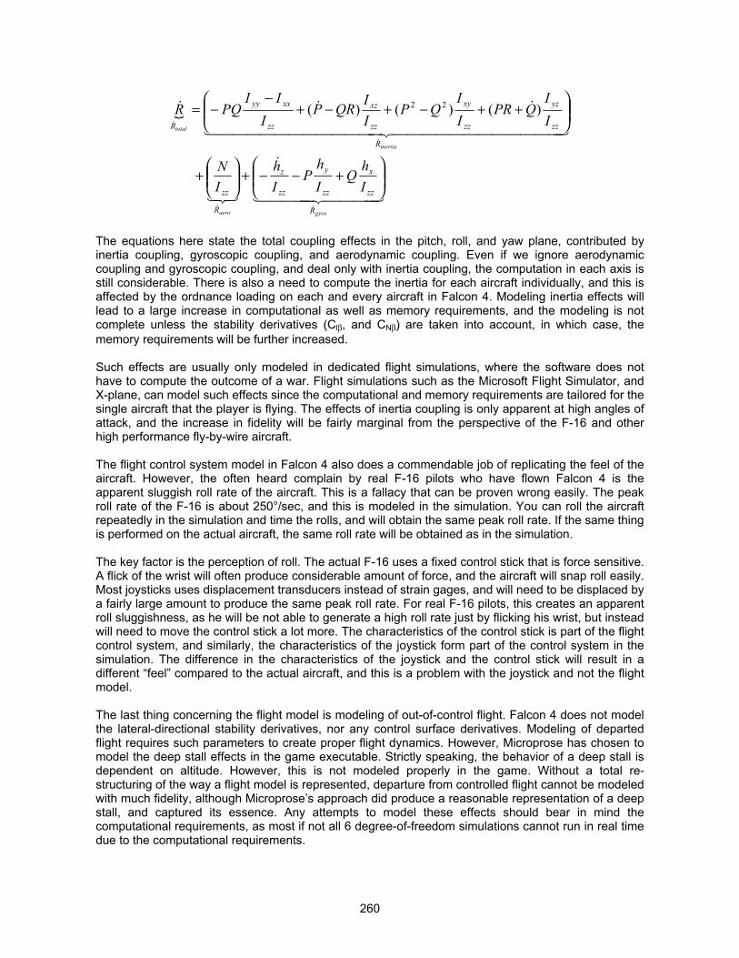
260
{
4444 34444 21
&
321
444444444444 3444444444444 21
&&&
&&
&
&
gyroaero
inertia
total
R
zz
x
zz
y
zz
z
R
zz
R
zz
yz
zz
xy
zz
xz
zz
xxyy
R
IhQ
Ih
PIh
IN
II
QPRII
QPIIQRP
III
PQR
���
�
�� ���
�
�
��
���
�
��� � �
� )()()( 22
The equations here state the total coupling effects in the pitch, roll, and yaw plane, contributed byinertia coupling, gyroscopic coupling, and aerodynamic coupling. Even if we ignore aerodynamiccoupling and gyroscopic coupling, and deal only with inertia coupling, the computation in each axis isstill considerable. There is also a need to compute the inertia for each aircraft individually, and this isaffected by the ordnance loading on each and every aircraft in Falcon 4. Modeling inertia effects willlead to a large increase in computational as well as memory requirements, and the modeling is notcomplete unless the stability derivatives (Cl�, and CN�) are taken into account, in which case, thememory requirements will be further increased.
Such effects are usually only modeled in dedicated flight simulations, where the software does nothave to compute the outcome of a war. Flight simulations such as the Microsoft Flight Simulator, andX-plane, can model such effects since the computational and memory requirements are tailored for thesingle aircraft that the player is flying. The effects of inertia coupling is only apparent at high angles ofattack, and the increase in fidelity will be fairly marginal from the perspective of the F-16 and otherhigh performance fly-by-wire aircraft.
The flight control system model in Falcon 4 also does a commendable job of replicating the feel of theaircraft. However, the often heard complain by real F-16 pilots who have flown Falcon 4 is theapparent sluggish roll rate of the aircraft. This is a fallacy that can be proven wrong easily. The peakroll rate of the F-16 is about 250°/sec, and this is modeled in the simulation. You can roll the aircraftrepeatedly in the simulation and time the rolls, and will obtain the same peak roll rate. If the same thingis performed on the actual aircraft, the same roll rate will be obtained as in the simulation.
The key factor is the perception of roll. The actual F-16 uses a fixed control stick that is force sensitive.A flick of the wrist will often produce considerable amount of force, and the aircraft will snap roll easily.Most joysticks uses displacement transducers instead of strain gages, and will need to be displaced bya fairly large amount to produce the same peak roll rate. For real F-16 pilots, this creates an apparentroll sluggishness, as he will be not able to generate a high roll rate just by flicking his wrist, but insteadwill need to move the control stick a lot more. The characteristics of the control stick is part of the flightcontrol system, and similarly, the characteristics of the joystick form part of the control system in thesimulation. The difference in the characteristics of the joystick and the control stick will result in adifferent “feel” compared to the actual aircraft, and this is a problem with the joystick and not the flightmodel.
The last thing concerning the flight model is modeling of out-of-control flight. Falcon 4 does not modelthe lateral-directional stability derivatives, nor any control surface derivatives. Modeling of departedflight requires such parameters to create proper flight dynamics. However, Microprose has chosen tomodel the deep stall effects in the game executable. Strictly speaking, the behavior of a deep stall isdependent on altitude. However, this is not modeled properly in the game. Without a total re-structuring of the way a flight model is represented, departure from controlled flight cannot be modeledwith much fidelity, although Microprose’s approach did produce a reasonable representation of a deepstall, and captured its essence. Any attempts to model these effects should bear in mind thecomputational requirements, as most if not all 6 degree-of-freedom simulations cannot run in real timedue to the computational requirements.
261
LIFE BEYOND FLYING THE F-16Flying Other Planes in Falcon 4By “Hoola”
THE REALISM PATCH VERSION 3 (AND BEYOND) WAY
This modification typifies the spirit of cooperation and sharing of knowledge that exists in the Falcon4.0 community. Someone on the Delphi Falcon4 forum posted a note on how to simply edit a text filein the campaign folder that would allow you to join any squadron in a campaign. Unfortunately, wecannot remember that user’s name, as that user rarely posts - we should thank him for his finding andsubsequent sharing of information.
The excitement of the discovery overwhelmed those involved in exploiting it. Very quickly, thisinformation was passed on to Marco Formato who discovered how the numbers were related to theFalcon4 file structure to identify F-16s. Rhino, then edited the file to include all the aircraft squadronsin the campaign. Later this was modified by Leonardo Rogic to include the helicopter squadrons aswell.
Marco then discovered that he could edit the Falcon 4.0 executable to "skip" the check for an F-16before the human flew his aircraft. Hence, one can now jump into ANY active squadron and await thecampaign sortie generator to fly in the squadrons in campaign or TE. This now allows adversarialmultiplayer flights with one team flying for the OPFOR and another team for NATO. This also createda huge push for players to begin to correct the flight models, cockpits, and ordnance loads of the otheraircraft in the game.
To fly as any other aircraft in the Realism Patch, one must only start a campaign or TE and look at thedifferent airbases that are available for tasking in the theatre window in the upper right-hand corner ofthe mission wrapper screen. If you click on one of the active airbases, you will see the squadronsavailable for tasking at that airbase. Then, if you click on one of the squadrons that are listed, you willsee the different aircraft available to you. If you start the mission at this point, you will have joined as amember of that squadron, and the planes that squadron flies will be available to you.
While it is arguable that it is not realistic to be able to fly other airplanes with an F-16 cockpit andavionics, it is nevertheless a “fun” option that will contribute to the longevity of the simulation. This hasallowed cockpit artists to make cockpits for other airplanes, and coders such as Miran Klemenc tomodel the avionics systems on other airplanes with a limited degree of success, giving a greater senseof immersion when you fly other airplanes.
262
FINGER PRINTING THE BIRDS OF PREYRadar, Visual, and Infra-red Signatures for AirplanesBy “Hoola”
Together with the AI changes, each aircraft in Falcon 4 has been given unique IR and visualsignatures. Prior to the Realism Patch, the only signature available for vehicles in the F4 world was theradar signature. Beginning with Realism Patch version 4, this is now expanded to include IR as well asvisual signatures.
DESIGNING RADAR SIGNATURES
Radar signature in F4 is not mechanized as radar cross section, but instead is a linear multiplier. Thisform of representation is not necessarily inaccurate, as radar acquisition range is an exponentialfunction with an exponent of 4, and very computationally intensive. For the purpose of the game, alinear multiplier is equally good.
In the design of the radar signature (or rather, re-design), we have utilized the F-16 as a baseline, andestimated its actual radar cross section. Based on this, we extended the estimation of the RCS to eachairplane in the F4 world, and computed the detection distances based on actual monostatic two-wayradar equations.
Radar detection is dependent on many variables such as aspect angles, maneuvers (thus causingglints and fluctuations in RCS), antenna capture area, antenna gain, etc. By using the F-16 APG-68 asa baseline, and the F-16 radar signature as a baseline, we have normalized all performance relative tothe F-16 (this was what MPS did as well). The radar equation is thus reduced to include range as wellas RCS.
Based on the estimated RCS, the detection range is computed, and then normalized against that ofthe F-16 to determine the final F4 radar multiplier factor for each airplane. For a detailed discussion onradars, as well as radar cross section, please refer to the USN Electronic Warfare and RadarEngineering Handbook, available at http://ewhdbks.mugu.navy.mil. This is an invaluable source thatwe have utilized to estimate the RCS, although it does require some engineering and mathematicalbackground to use the information effectively.
DESIGNING VISUAL SIGNATURES
Visual signatures affect only AI target acquisition with their virtual Mark I eyeball. As with radar crosssection, we have normalized visual detection distances against the F-16. This is set to a baselinedetection distance of 1, and we then computed the visual acquisition distance for various AI skilllevels.
The length and span of the F-16 are then determined, and the visual acuity (in terms of angularresolution from the AI’s eye point to both the tip and tail of the aircraft, and from left wing tip to rightwing tip of the aircraft), is computed. We then assumed that the visual acuity and optical resolution ofthe AI stays the same, and will be able to acquire a target that fulfills this visual acuity and opticalresolution requirement.
The dimensions (length and span) of every individual aircraft is then computed, and the visualacquisition range determined. This forms the baseline visual detection range for the same visualresolution and optical resolution.
The visual signatures are then adjusted with a “fudge” factor. This factor will lower the visual detectionranges to account for atmospheric haze, atmospheric distortions, camouflage pattern on the airplane,glare, and the AI pilot having to look through helmet visors and canopy reflections. In our iterations
263
with former military pilots, the “fudge” factor was adjusted so that the resultant visual acquisitionranges are more realistic and representative.
One important consideration was that F4 previously assumed a visual acquisition range of 10nm.. Thisis grossly overdone, as most fighter sized airplanes cannot be visually acquired until much closer. It isa known fact, for example, that the F-16 can be easily acquired visually out to only 3 – 4nm., andsome aircraft like the F-5 and MiG-21 are hardly even visible in head-on or tail-on aspect at 1nm.. Wehave adjusted all the AI pilot’s visual acquisition ranges to much lower values to reflect this. As fighterpilots say, “Lose the sight, lose the fight.” The AI now has realistic eyesight, albeit still a wee bit on thehigh side so as not to neuter it.
DESIGNING INFRA-RED SIGNATURES
In Realism Patch version 4, we have also given each airplanes IR signature that is unique. The IRsignature is created by utilizing spare bytes in the named entry of the FALCON4.VCD file (ditto visualsignature), and requires an exe patch created by Sylvain Gagnon. This visual signature will affect theIR acquisition range of IR guided missiles, and performs as a multiplier factor. In the design of the IRsignatures, the engine type was taken into account, for example:
i. Turbo-jet engines, non afterburning, with typical EGT of 400 – 900°C ii. Turbo-jet engines, afterburning, with typical EGT of 400 – 950°C in MIL iii. Turbo-fan engines, low bypass ratio, with typical MIL EGT of 450 – 1050°C iv. Turbo-fan engines, high bypass ratio, with typical EGT of 400 – 900°C v. Turbo-prop engines, with typical EGT of 400 – 750°C vi. Turbo-shaft engines, with typical EGT of 400 – 750°C
We have also considered if the airplane has any schemes implemented to suppress its IR signature,for example, the F-117 and F-22, and the Mi-24 and AH-64. Presence of IR suppressors will improvecold air mixing with the exhaust air, resulting in lower IR signature. We have also considered thepresence of propellers and rotors, which will create improved cold air/exhaust mixing to further lowerthe exhaust gas temperatures (EGT) downstream of the exhaust pipe.
Lastly, the total number of engines was also considered. The presence of multiple engines increasethe overall exhaust plume size, and although the plume peripheral will mix with the atmospheric air,the exhaust plume core will still be of higher temperature, leading to a greater IR signature. Thesefactors were all taken into account in the design of the IR signatures.
264
TURNING ON THE HEATInfra-Red Countermeasures in Falcon 4By “Hoola”
One of the biggest changes to come into Falcon 4 is the incorporation of infra-red countermeasuretactics. This takes place in four different forms, in engine IR signature variation with throttle setting,unique vehicle IR signatures (described separately in the previous section), flare effectivenessadjustments, and lastly, equipping relevant aircraft with flare/chaff dispensers. Of all, the engine IRsignature variation began life as a request from John “NavlAV8r” Simon, to Sylvain Gagnon, toimprove the engine IR signature with throttle position.
ENGINE INFRA-RED SIGNATURE VARIATION
The design of this dates back to pre Realism Patch version 3, sometime in May 2000. This originatedas a request to improve F4 so that it allows real life IRCM and launch denial tactics to be used foronline head-to-head play, as F4 does not model engine IR signature well.
In the default implementation, F4 models the IR signature as a linear function of engine RPM, i.e., for70% RPM, the IR signature will be 0.70 that of the baseline, increasing to 1.0 at MIL, and 1.03 in maxafterburner. This obviously does not correlate well with how engine IR and exhaust temperatures vary,as engine exhaust gas temperature can range from 450°C at IDLE to over 1,000°C at full MIL, andeven above 1,400°C in afterburner.
Also, the IR signature is tied to the RPM decay. While the RPM decay in F4 is somewhat realistic andclose to what a jet engine will provide, exhaust gas temperatures often do not decrease quite as fastdue to the need for the engine core to cool down. Relating the engine IR signature in a linear functionto the RPM will hence result in the engine exhaust gas temperature cooling way too fast, which isunrealistic and can be exploited to result in IR missiles going ballistic easily.
Based on our knowledge of jet engines and typical engine spool times as well as EGT (exhaust gastemperature) decay times, the engine exhaust plume temperature are mechanized as follows:
� For engine RPM at MIL or below, IR signature is the percentage RPM (divided by 100)raised to an exponent of 4.5. Hence, at IDLE (70%), the IR signature will be 0.20 that ofMIL.
� For afterburner at 101%, the IR signature is 1.3 that of MIL, increasing to 1.4 at 102%RPM, and 1.5 at 103% RPM.
Players can cycle the throttle up to max AB and then back down to IDLE, and not have their engine IRsignature increase to afterburner levels as long as the engine RPM never breaches 100% and neverresults in AB light-off.
As for the cool-down timings after throttle reduction, it is mechanized as a function of the magnitudeand speed of throttle movement. Generally, the engine will cool down slightly faster if the throttle isreduced drastically, compared to small throttle adjustments. As a rough guide, the engine IR signaturedecay timings are as follows:
� For max AB to MIL at 100%, engine exhaust IR signature will take approximately 6seconds to decay from 1.5 to 1.0.
� For MIL to 80% RPM, engine exhaust IR signature will take approximately 8 seconds todecay from 1.0 to 0.366.
� For 80% to 70% RPM, engine exhaust IR signature will take approximately 8 to 10seconds to decay from 0.366 to 0.20.

265
In addition, the engine exhaust temperature is now reflected in the FTIT (Fan Turbine InletTemperature) gauge in the cockpit, so players can monitor their engine temperature.
The design of the engine IR signature went through many iterations to remove possibilities of players“cheating” by chopping throttle to IDLE rapidly upon IR missile launch, thus causing missiles to loselock and go ballistic. We utilized a time stepping computation to determine under various engagementscenarios, the optimal cool down timings so that IRCM tactics can be meaningfully employed withoutcausing unrealistic problems such as missiles going ballistic. With Realism Patch, throttling back to 80-90% RPM at a sufficiently far range (thus allowing the engine to cool down first) prior to merge canoften deny a front quarter IR missile launch, by delaying IR missile acquisition to ranges under themissile Rmin.
FLARE EFFECTIVENESS
The way flare effectiveness is mechanized is the same as chaff, and will not be repeated here (see thesub-section titled “The Falcon 4 Radar and Electronic Warfare Algorithm” in the section titled “TheElectronic Battlefield.” The default F4 flare effectiveness array is as follows:
[ 0 5500 11000 16500 27500][ 0 0.0 1.0 1.0 0.0 ]
As you can see, flares lose their effectiveness totally below 5,500 feet from the target. This implies thateven missiles with absolutely no IRCCM (i.e. flare rejection) capabilities will become totally immune toflares when they are within 5,500 feet of the target. In addition, between a distance of 5,500 feet and11,000 feet, the missile will gradually gain higher flare rejection capabilities with decreasing range.This is no doubt a simplified manner of accounting for all possible target aspect angles withoutincurring the overhead computational cost of computing engagement geometry.
We have undertaken to address this anomaly which accounts for the missiles with no IRCCM beingtotally flare resistant at short ranges. The discussion below ignores the effect of IRCCM first, which willonly confuse the issue.
Flares have typical burn time of 6-12 seconds. For an IR missile, it tracks the strongest heat source,(ignoring any IRCCM logic). When ejected from afar, it will see a stronger heat source separating fromwhat it is tracking and then follows the stronger of the two, as long as the flare is crossing its seekerFOV at a rate that does not exceed its tracking rate. At closer ranges, the relative LOS (line-of-sight)rate of the flare increases, and at some point in time, it will exceed the seeker's LOS tracking rate.When this happens, the seeker cannot switch track to it since the flare is going too fast.
Hence, for a seeker without IRCCM, flare effectiveness should be effectively almost in a plateau fromafar, then as line of sight rate increases, it should decrease to zero at the point where the LOS rateexceeds the seeker tracking rate (which means it should really be missile dependent).
Now consider these two scenarios, tail-on and in the beam, and a flare ejection velocity of 100feet/sec on average. For a tail-on case, the LOS rate of the flare is purely its ejection velocity(assuming it stays the same throughout, which is not a bad assumption). Assuming a seeker trackingrate of 12.5 deg/sec to cater for early missiles (the higher the rate, the closer the missile needs to befor the flare be ineffective due to exceedance of LOS tracking rate), the flare velocity will result in LOSrate exceedance at a distance of 451 feet from the flare. For a missile with 25 deg/sec track rate, thisdecreases to 214 feet.
For an in-the-beam case, the LOS rate of the flare is purely due to the aircraft pulling away, sinceflares are ejected normal to the aircraft velocity vector. Again, assuming a seeker tracking rate of 12.5deg/sec, and an aircraft velocity of 600 knots (1013 feet/sec), the distance at which the flare LOS ratewill exceed seeker tracking rate becomes 4,568 feet, reducing to 2,283 feet when the airplane velocity

266
decreases to 300 knots. For 25 deg/sec seeker tracking rate, the distances for 600 knots and 300knots are 2,172 feet and 1,086 feet respectively.
Now, taking the case of the flare burning out while the target is in the seeker FOV, lets assume a caseof a nominal 10 second burning time for the flare, and a seeker FOV of 3 degrees. Assuming that thetarget is centered on the seeker, the flare will remain in the FOV for 1.5 degrees. Taking 10 secondsand a flare muzzle velocity of 100 ft/sec, the total distance traversed by the flare to result in 1.5degrees of FOV change is 1,000 feet. This translates to a slant range of 38,188 feet, beyond whichthe flare will burn out while the target is still in the seeker FOV and the seeker will switch track to thetarget after flare burnout. This is of course for a case in the tail-on aspect. For beam aspect, thedistance becomes 386,721 feet at 600 knots target crossing rate, and 193,360 feet at 300 knotscrossing rate. At distances inside these numbers, the missile will completely switch track to the flare(again assuming no IRCCM) and never will be able to regain the target after flare burnout since thetarget has moved out of the FOV.
Hence, we can average all the distances to form an effectiveness curve that is a compromisebetween early model missiles with low tracking rate and late model missiles with higher tracking rates(again, ignoring IRCCM as it will confuse the issue right now). The first breakpoint is obviously [0 0].
For close in tail-on, we are looking at a minimum range of 214 feet to 451 feet, depending on missiletype. None of these matter much, so we have put it at 451 feet as it will better cater to early modelseekers (else these early model seekers will be better than they should be). Below this range, flaresshould be ineffective. The second breakpoint becomes [451 0].
Then, we considered the minimum range for the in-the-beam case. It will be between 4,568 feet and2,283 feet, and 2,172 feet and 1,086 feet. The most constraining factor becomes the early modelseekers, which is between 2,283 and 4,568 feet. We took a mid point for a compromise and thenrounded off, with the third breakpoint becoming [3500 1]. This allows interpolation between secondand third breakpoints, to cater for some aspect differences.
Going to the fourth breakpoint, it goes out to 38,188 feet tail-on, and between 386,721 and 193,360feet. These numbers convert to 6.3nm., 31.8nm., and 63.64nm. respectively. Obviously the last twonumbers are ridiculous as IR seekers will not be able to see this far, so effectively, only 38,188 isuseful. Rounding off, the last breakpoint (the fifth one) then becomes [38000 0]
As missiles are typically fired from less than 2nm. for heaters, the fourth breakpoint is left at where itstill is, i.e. 16500 feet (2.71nm.). The revised breakpoint for the flare effectiveness distance arraybecomes:
[0 451 3500 16500 38000][0 0 1 1 0]
Now, IRCCM in F4 just functions as a probability of the missile biting on the flare, which is the flarechance. The flares will now work in full effectiveness down to 3500 feet, compared to 11,000 feet asbefore, and will continue to work though with reduced effectiveness down to 451 feet, compared toflares losing their effectiveness totally at 5,500 feet previously. For missiles without IRCCM, the flarewill always decoy them. These include AIM-9P, HN-5, SA-7, AA-2, SA-14, AA-6, and AA-7. Missileswith some IRCCM may sometimes go after the first flare, and probability of it going after flaresincreases with number and frequency of dispense, depending on how sophisticated their IRCCM logicis.
This makes a real distinction in the capabilities of each missile. Against targets equipped withchaff/flare dispensers, missiles without IRCCM or with less sophisticated IRCCM will be totallyuseless, as the AI will employ flares at a rapid rate to try to decoy the missile. This relegates the earlygeneration missiles to targets such as helicopters and transport airplanes, and replicates the truemissile capabilities and puts these missiles in their rightful place on the modern battlefield.

267
EQUIPPING THE AIRCRAFT WITH IRCM
The downside of F4 is that it assumes that every aircraft is equipped with flare/chaff dispensers.However, this is not the case. One downside of the original Falcon 4 was that all aircraft wereassumed to have chaff and flare dispensers. Since flares effectively render older IR missiles useless,this gives an unfair advantage to aircraft that are erroneously equipped with flares. As a result it isimportant to model the aircraft in the Falcon 4 world properly to reflect IRCM capability or lack thereofin particular in order to maintain appropriate game play balance.
The Realism Patch models the airplane self defense capabilities by adding an additional data flag inthe vehicle VCD entry, to enable chaff/flare dispensing. Checking of this flag will indicate that theparticular airplane is equipped with chaff/flare dispensers.
While it is arguable that most fighters should have chaff/flare dispensers, this is not so for earlygeneration aircraft such as MiG-19, MiG-21, and MiG-23. Russian design philosophy in the past (andin the present) has always neglected the fighter aircraft, choosing to protect the ground attackplatforms with better self defense equipment. In the extensive research for individual aircraft in F4, thefollowing airplanes are determined not to be equipped with chaff/flare dispensers, and are modeled assuch in the Realism Patch:
1. A-37B Dragonfly2. An-2 Colt3. An-12 Cub4. An-24 Coke5. An-706. An-72 Coaler7. An-124 Ruslan8. An-225 Mriya9. C-5 Galaxy10. C-141 Starlifter11. E-2C Hawkeye12. E-3 Sentry13. Il-28 Beagle14. Il-76M Midas15. Il-76 Candid16. J-517. KC-10 Extender18. KC-130R Hercules19. KC-135 Stratotanker20. MD-500 Defender21. MiG-19 Farmer22. MiG-21 Fishbed (MiG-21PF and MiG-21bis model in F4)23. MiG-23 Flogger-G (DPRK MiG-23ML)24. MiG-25 Foxbat25. RC-135C Rivet Joint26. SR-71 Blackbird27. TR-128. TR-229. Tu-1630. Tu-16N31. U-232. UH-1N33. Y-8
268
HIT BOXESCreating The Accurate Hit Boxes for AirplanesBy “Hoola”
Have you ever wondered how the AI was able to gun your F-16 from more than 5,000 feet away whileyou were jinking all over the place? If you have, the answer is here. We have found that the hit boxesfor most aircraft in the Falcon 4.0 universe are grossly out of proportion, with some being too large(such as the F-16 being 4-5 times larger than its actual dimensions), and some being too small (suchas the C-5).
DESIGNING THE HIT BOXES
The hit boxes for all the aircraft are revised differently depending on their physical geometry, and otherfactors. We have divided the aircraft types into low aspect ratio wing aircraft (mainly fighters), highaspect ratio wing jet aircraft (jet transports), high aspect ratio wing prop aircraft (prop transports), andhelicopters. The guidelines used to re-define the hit boxes for every single aircraft in F4 are as follows,with the objective of minimizing the inclusion of empty space within the rectangular box representingthe aircraft hit volume:
Low Aspect Ratio Wing Aircraft
These are mainly fighter aircraft. The geometry of the fighter aircraft is such that the bulk of theplanform area forms the wing. The fuselage is often slender, and contributes to the bulk of the frontalarea. From the sideward planform, the fuselage also forms the majority of the area. Defining a hit boxbased on the height of the aircraft including the vertical fins would have resulted in inclusion of atremendous amount of dead space both sideways and head-on. The guidelines for the hit boxdimensions are:
Length: 70% to 90% of actual fuselage length, depending on fuselage geometry. This willexclude the forward fuselage ahead of the wing, as this component is often veryslender compared to the wing span.
Height: Based on actual fuselage diameter (average of width and fuselage height, asfuselages are elliptical).
Width: 50% of the wing span. For variable geometry aircraft, this is based on 50% of theaverage span for wings fully swept back and wings fully swept forward. Such aguideline will cover the horizontal tail span and minimize dead space inclusion.
High Aspect Ratio Wing Aircraft (Jet and Props)
These are mainly transport aircraft. The geometry of the transport aircraft is such that the wing is oftenlong and slender, and occupies a small length along the fuselage. The fuselage is often slender, andcontributes to the bulk of the frontal area. From the sideward planform, the fuselage also forms themajority of the area. Defining a hit box based on the height of the aircraft including the vertical finswould have resulted in inclusion of a tremendous amount of dead space both sideways and head-on.However, the propeller airplanes, the prop disk will contribute to the frontal area, and has to be takeninto account. This is obviously dependent on the number of engines. The guidelines for the hit boxdimensions are:
Length: 70% - 90% of the actual fuselage length.Height: Based on actual fuselage diameter (average of width and fuselage height, as
fuselages are elliptical).Width: For jet transports, 25% of the wing span as this minimizes dead space inclusion for
planform as well as head-on profiles. For twin props, 30-35% of the wing span,depending on the location of the prop engine vis-à-vis the wing. For prop planes withfour engines, 35-40% of the wing span, depending on prop location.

269
Rotary Wing Aircraft
These are all helicopters. The geometry of the helicopter is such that the cabin is the biggest portion,and the tail boom is often very slender and long. The number of rotor blades and the rotor RPM alsoaffects the solidity of the rotor disk in the planform view. The guideline for the hit box dimensions are:
Length: Actual fuselage length sans tail boom. For aircraft such as the Chinook, this meansthe entire fuselage, as the CH-47 does not have a tail boom. This will minimize deadspace inclusion in the length as the tail boom is very slender compared to thefuselage..
Height: Based on actual fuselage diameter (average of width and fuselage height, asfuselages are elliptical).
Width: For twin bladed helicopters, the fuselage cabin width. This is due to the very low rotorsolidity contributed by the low rotor RPM and low rotor blade count. For multi-bladedhelicopters, 30% of the rotor diameter is used. This is to cater for the higher bladecount and higher RPM, resulting in higher rotor solidity. For the MD-500, this is furtherincreased to 70% of the rotor diameter due to the very high rotor RPM.
HIT BOXES AND GAMEPLAY
In actual aerial combat, achieving gun hits on enemy aircraft is a difficult task. The high speed and wildmaneuvering means that guns are largely ineffective beyond 4,000 feet of slant range. With theoriginal Falcon 4 hit boxes, gun kills can easily be obtained from more than 5,500 feet away, with apipper that is even offset from the target.
Real life gunfights often require the shooter to close in to less than 3,000 feet, or even 1,500 feet,before the guns become effective. The reduced hit boxes will allow a more interesting and accuratemultiplayer air-to-air duels. You will need to close in much more compared to before, often within3,000 feet, or you will be wasting ammunition. You will also need to position your pipper accurately toobtain the kill. Easy head-on shots against fighters will now be a thing of the past.
One related concern that arose in the course of the hit box design was the effect on the AI and AAA.Much testing was done to quantify the AAA effects, and the reduced hit boxes were found not to bedetrimental to the AAA accuracy. The AI pilots experienced the greatest problems though gun hitswere registered. Microprose originally coded the AI to begin firing from 10,000 feet slant range, andthe AI will cease firing within 2,000 feet. The AI also pulls less lead during the shot, and as a result, AIgun kills plummeted. With the help of Sylvain Gagnon, the AI was made to begin the gunfight at 5,000feet, and will continue to press in and shoot until 1,000 feet slant range (depending on closure andrelative speed, as the AI will avoid collisions). The AI will also pull more lead during firing, and all thesecontributed to maintaining an AI pilot with reasonable gunfire accuracy.
270
OPEN HEART SURGERY ON ARTIFICIAL INTELLIGENCEThe AI Changes In Realism PatchSylvain Gagnon and “Hoola”
In Realism Patch 4.0 and 5.0, major changes have been made to the AI behavior, most of which arethe result of the ingenuity and dedication of Sylvain Gagnon, who created these EXE patches. MarcoFormato had also assisted greatly in improving the helicopters. The write-up includes some of theconsiderations taken into account during the development and design of the patches.
AI SKILL LEVEL
In the implementation of 1.08US, the skill level setting in TE is non-functional. Regardless of thesetting the that player selects, the pilot skills obtained are only Veterans and Aces. For campaign,whenever new pilots are received as reinforcements, their skill levels are restricted to only Veteransand Aces.
With the AI changes, the skill levels obtained are now close to what the player selects, and will be amixture. For example, if rookie is selected, the squadron will be manned with some recruits, somerookies, and some veterans (the skill levels will be a mixture of what is selected, plus one level aboveand one level below). The same is applicable to reinforcements received during campaigns. Inaddition, F4 displays the experience of the squadron according to the LOWEST pilot skill. For asquadron with all aces and one rookie, the squadron will be displayed with an experience level of therookie. With RP, the squadron skill level is now the average of the pilots’ skill.
It should be noted that the skill slider affects only enemy squadrons in campaign. For the squadronson the player’s side, they are either ‘Reserve’, ‘Regulars’, or ‘Veterans’.
Also, in F4, If you create 'Sortie' mission already taken off, pilot skills for planes with UNASSIGNEDpilots will be set to Recruits (lowest settings). This has been changed to DISABLE the Fly icon untilyou advance the time so these planes have assigned pilots, as the sortie type mission has a stoppedclock.
AI ABORT BEHAVIOR
The default AI behavior in 1.08US is atrocious. Once the AI aborts, it is totally oblivious threats, and itis easy to formate on the AI enemy plane once it is in the abort mode. Regardless of what you do, theAI will refuse to engage even defensively. In addition, AI planes armed to the teeth will often aborteven though they have the ability to engage the threat. Ace pilots that see the player will also abort ifthey detect you but do not have the missiles to reach you.
With RP, the abort conditions have been amended to the following:
i. The AI has nothing to shoot at you with, not even bullets ii. The AI is greater than 7nm. away from you, and is alone and without a wingman.
With these changes, the problem of aborting and cowardly AI is reduced. The AI will also engagedefensively when the bandit is 7nm. or less from it. However, this fix is limited to in-game air-to-airabort, and neither UI abort, nor in-game air-to-ground aborts are affected.
The behavior of the AI after an abort was also altered and the AI is now more sensible about survivingand less fixated about landing back home. Prior to version 4 of the Realism Patch, the AI willDISREGARD everything around it except defending against a missile shot, and is meek enough foryou to fly formation with it. With RP, the AI who has aborted and RTB will now react to you, whenever
271
you are within its effective weapon engagement zone (WEZ). It will begin to plot an intercept on you,and shoot when within the envelope.
For an AI equipped with BVR missiles, it allows the AI still to be partly offensive while in RTB mode.Similarly, once another plane enters its WVR envelope, the AI will also seize the chance to shoot.However, once landed, the AI will not takeoff again to engage. Such behavior is more consistent withhuman reactions, and has been designed with the help of an RP member who specializes inbehavioral sciences.
AI COMBAT BEHAVIOR
The biggest change in the AI is in combat behavior. In all versions of F4 prior to RP, the AI’s sensoryperceptions are tied to its weapons engagement zone (WEZ) outside a WVR envelope of 10nm.radius. For an AI equipped with WVR weapons, if the target hovers just outside the 10nm. WVRengagement range, the AI will blissfully be unaware of the presence of the target. Once this distance isbreached, the AI will suddenly commit.
In addition, the AI will often launch its radar guided BVR missiles without a valid radar lock, themoment the target enters the weapon engagement zone. What is more vexing is that the AI’s sensorsare not limited to their coverage zones once it has detected you. This results in the AI still being ableto maintain radar lock even after it flies past you in a merge. The following describes the changesmade to the AI with respect to its usage of onboard sensors, as well as BVR and WVR tactics.
Sensor Usage
In Falcon 4 as Microprose/Infogrames coded it, the instant the AI pilot detects a target with any of itsonboard sensors (visual, radar, RWR, or IRST), every sensor on the AI plane is directed to point at thetarget. This results in the sensors not obeying their gimbal limits. For example, once a target isdetected by say the RWR, the AI’s radar is directed at the target. Even if you fly behind the target, itsradar is still directed at you. Moreover, a poor form of GCI (Ground Controlled Intercept) isimplemented by giving AI Ace and Veteran pilots an automatic target acquisition range of 15nm..Hence, even if you ingress amongst the weeds and the AI is at 40,000 feet altitude, once inside15nm., it will automatically detect you, never mind the fact that it’s radar may not even be capable oflook-down operation.
Beginning with RP4, the AI’s sensors (RWR, IRST, radar, and visual) are constrained to theirrespective range and azimuth/elevation coverages. The AI will have to locate you on each of itssensors. As such, it is possible to sneak up to an AI undetected through its blind visual cone, with yourradar turned off, and ambush the AI with an uncaged heat seeking missile. Similarly, the AI will nolonger be able to automatically locate your presence if its sensors are not able to detect you. Thismakes real life low level ingress tactics possible.
More importantly, and tied to the effective operation of ECM, or rather the lack of effectiveness ofECM, the default algorithm for refreshing radar locks in F4 1.08US has the radar lock beingmaintained in perpetuity once the lock is obtained. The AI’s radar does not drop track after it hasobtained initial lock even when the signal strength decreases below detection level. As a result, the AIis able to maintain constant lock on you, despite jamming or beaming. This also accounts for whybeaming and ECM are effective only if initiated before the radar lock is obtained, and fails to workthereafter. This is also rectified in RP, and is the main contributing factor to the whole new electronicwarfare battlefield being created.
Also related to the AI’s use of radar is how it regards ECM. Electronic counter-measures do not renderfull invisibility to the user. On the contrary, it will often result in tell tale traces of its approximatelocation on the radar screen, for example, snowing, or angular noise data, and the radar maysometimes be able to display angular information even though range and velocity measurements are
272
denied. For a real pilot, they will have remembered where the target previously was prior to the ECMbreaking their radar lock, and will continue to press in for re-acquisition on their radar. Such traces ofinformation are also sometimes sufficient for pilots to determine approximate angular position of thejammer. This is now captured in the RP. Usage of ECM will leave behind sufficient traces and the AIwill continue to press towards you even though it is not able to gain a valid track on you, as long asyou are inside its radar coverage.
The AI wingman will also now employ ECM when the lead does. This allows the AI pilot to have ECMprotection as well. As in the original F4, the lead pilot is the only one that will employ ECM, and otherwingman will not activate their ECM even though they are carrying it.
A related bug fix was also with the AI’s visual acquisition ability with respect to contrails. F4implemented this erroneously, with contrails decreasing visual acquisition range by 4 times instead ofincreasing it. Contrails now will increase the visual acquisition range by 4 times, though clouds will stillaffect acquisition ranges for visual sensors. In addition, damage sustained by planes will leave asmoke trail that will similarly increase visual detection ranges, as will leaving the navigation lightsturned on as the sky turns dark.
AI Skill Levels and Performance
The AI’s performance and adeptness at using its onboard sensors is also now tied to the skill level.Pilots vary in their ability to operate their sensors effectively, and in their ability to transit smoothly fromBVR fight into WVR fight. Novice pilots are known to be fixated on staring at radar scopes in vain tosee their target when transiting from an intercept to a merge. Similarly, novice pilots and evenexperienced pilots are sometimes fixated on HUD presentation and forget that there is a whole worldoutside the HUD field of view. All these factors affect the ability of the pilot in successfully acquiring thetarget using their Mark I eyeball.
Beginning with RP4, the visual acquisition range of the AI pilot is mechanized as such:
Recruit: 0.83 times the visual acquisition rangeCadet: 1.18 times the visual acquisition rangeRookies: 1.44 times the visual acquisition rangeVeterans: 1.67 times the visual acquisition rangeAce: 1.86 times the visual acquisition range
As every plane in F4 has its own vision envelope peculiar to it, AI pilots will lose sight in a dogfight ifyou enter its blind visual cone. With the default AI behavior in F4, the AI will immediately lose itsawareness of your presence if it does not have any other onboard sensor that has acquired you. Thiscan potentially lead to the AI transiting to RTB mode and becoming totally defenseless.
To overcome this potential shortcoming, the AI have been mechanized with a limited amount of“memory.” The AI will retain its knowledge of where you were for a specific amount of time related toits skill level. For a recruit, this time will be 24 seconds, while for an Ace, this timing will be about 32seconds. This confers the AI some degree of ability to keep fighting and reacquire the target visually.
The way the AI employs its weapons is also skill level related. In F4, the lower skilled pilots will wait alittle longer before launching their weapons compared to higher skilled pilots. This results in the lowerskilled pilots actually launching missiles within a firing envelope of higher Pk than the higher skilledpilots. This effect was due to the AI firing routine being run less frequently (it is tied to the AI’s sensorroutine) and hence the AI being closer to the target when they satisfy the shoot conditions.
In RP, this is modified such that the lower skilled pilots will shoot earlier (i.e. shoot at a range wherethe missile Pk is lower, i.e. closer to Rmax1), while the higher skilled pilots will wait a little longerbefore shooting (i.e. shoot at a range closer to Rmax2). This is mechanized by reducing internallywithin the AI the Rmax perceived by it, thus constraining the higher skilled AI to shoot closer.
273
For the RP AI’s use of radar guided BVR missiles, skills will also affect missile evasion capabilities andhow long the AI pilot will support its own missile in flight. If the AI already has a missile in flight towardsthe target, and the target retaliates by shooting at the AI, lower skilled pilots are more likely tocommence evasive maneuvers immediately and forego supporting their missile in flight. Higher skilledpilots will wait a little longer before commencing the evasive maneuvers, thus giving their missile ahigher chance of getting near the target or shooting down the target. This is mechanized as describedbelow.
Recruits – random duration, ranging from 1 second to how long ago it launched its missile Cadets – random duration, ranging from 2 seconds to how long ago it launched its missile Rookies – random duration, ranging from 3 seconds to how long ago it launched its missile Veterans – random duration, ranging from 4 seconds to how long ago it launched its missile Aces – random duration, ranging from 5 seconds to how long ago it launched its missile
This gives the higher skilled pilots better Pk for a missile that is already in-flight for considerableduration. It will however evade sooner and increase its survival chances if the missile time of flight isstill short.
BVR and WVR Behavior
One of the biggest changes made to F4 is the BVR engagement behavior. In fact, the AI changesoriginated from the aim of changing the AI BVR behavior. F4 does not distinguish between BVR andWVR combat, and employs basically the weapon with the greatest range. This makes modelingdecent BVR fights impossible other than the AI taking long range shots at you while driving inbound.BVR intercept tactics such as pince and single side offsets are not possible due to this anemicrepresentation. Also, Sylvain discovered that the AI wingman will only employ its visual sensor tocheck for other targets, while its radar will only scan for the target that the lead has locked onto.
The RP AI changes makes a distinction between BVR and WVR combat, with WVR combat defined asinside 10nm.. For BVR combat, once the AI sees the target, it will begin a pince or single side offsetmaneuver instead of driving straight at the target. For an element, the flight lead will take one side ofthe maneuver, and the wingman the opposing side. For the pince and single side offset, it is executedwith a 4nm. separation between the lead and the wingman. The wingman will also use its radar toscan for all possible targets during the intercept, in addition to the one that the lead has locked onto.
BVR combat is set to commence at 30nm., or the WEZ of the longest range weapon loaded on the AI,whichever is higher, provided the AI has detected you. The BVR engagement range is also related tothe mission type. For example, flights tasked with air-to-ground missions will not commit as far out asflights tasked with sweep or OCA. As this is tied to the onboard weapon WEZ, it allows for betterarmed AI pilots to initiate the BVR fight from further out (such as AA-10C, or AIM-54 armed airplanes),and lesser armed AI pilots to initiate from closer distances (such as AA-7 or AIM-7 armed airplanes).This prevents inadequately armed AI pilots from initiating the BVR fight from too far out. The 30nm.range was chosen as typical range for initiating BVR engagements.
In addition, both flight lead and wingman will now employ their onboard sensors throughout themaneuver, with each being able to take a shot whenever their respective shoot conditions aresatisfied.
Weapon selection in F4 was also a simple case of the AI selecting the weapon with the Rmax closestto the target range. In a situation where the AI sensor is prevented from acquiring the target early(such as due to ECM), it will lead to cascading effect with the AI switching to WVR weapon whenclosing in from BVR (especially if WVR weapons have forward quarter WEZ beyond 10nm.). It will alsosometimes lead to the AI not firing its missiles in a dogfight, preferring to employ guns instead.
274
With RP, unless the weapon is the AI’s only weapon onboard, the weapon selection routine ischanged to allow the AI will select the weapon based on the following conditions:
i. Weapon with the highest Rmaxii. AI range to target must be greater than the weapon’s Rmax divided by 3.5
For WVR combat, the AI’s ability to gunfight is modified. In F4, the AI will commit to guns if the slantrange is 10,000 feet or less, though if it has a missile, it will still use the missile. The AI will also notshoot below 2,000 feet in slant range. This results in the AI commencing gunfiring from more than6,000 feet slant range if it only has guns, and with a realistic hit box for each aircraft, the AI is notcapable of hitting anything. Realistically, gunfights are not committed until much closer ranges, oftenbelow 3,000 feet, and will carry on up to 1,000 feet or less.
With RP, the AI will commit to guns only at 5,000 feet slant range. This prevents the AI from shootingbeyond this range and wasting ammunition. In addition, the AI will continue to shoot until 1,000 feetslant range, subjected to closure speeds that will not trigger the AI to avoid a collision. The aimingaccuracy is also improved with the AI taking more lead before commencing firing.
The AI’s ability to support their BVR weapon in flight when they are shot at is also added in the RP(see section on AI Skill Level for details). The AI will now try to hold the radar lock a little more beforecommencing evasive maneuvers, thereby giving their weapon a better chance at hitting the target.
One annoying problem with the AI in WVR combat is that it will often go into ground avoidance modeand maneuver strangely. The AI will always check for its height above ground, and if its calculated turncircle exceeds its altitude, it will enter ground avoidance mode and maneuver accordingly. This makesBFM fights quite weird, with the AI switching between fighting and avoiding the ground even in ahorizontal turn. With RP, the AI will not ever go into ground avoidance mode if their altitude is higherthan 10,000 feet.
The last change affects both the players and the AI. The default F4 way of computing missile WEZ isbased on using the relative bearing of the shooter and the target. This is obviously wrong as missileWEZ is dependent on aspect angle instead. This is now reflected in RP, and the WEZ display in theHUD should be more sensible with aspect changes, and AI will also employ the weapons moresensibly as a result.
A/A and A/G Targeting Behavior
The way the AI targets other aircraft is also altered. This is mechanized slightly differently for AI flightstargeting other flights, and the player’s flight targeting others. In 1.08US and 1.08i2, if the playercommands the wingman or element to attack a certain target, then they will only attack that target.With Realism Patch, up to two AI flight members will shoot at the target, until the player repeats thecommand again. This is to allow the player some degree of flexibility at sorting targets.
As for the way the AI flights target other flights, the flight lead will always target the opposing flightlead, while the others will target their respective counterparts. If the targeting flight is a four-ship flight,and the targeted flight is a two-ship flight, both the flight lead and the element lead will target the two-ship flight lead, while their wingmen will target the two-ship wingman. Conversely, for the two-shipflight being engaged, the lead will only target the opposing flight lead, while its wingman targets theopposing flight lead’s wingman. The opposing element will not be targeted. This gives a slightimprovement and prevents multiple AI ships from attacking and fixating on a single target while lettingother targets off.
The AI targeting in 1.08US often resulted in multiple missile shots at the same target, even when thetarget was badly damaged and has lost control. Although F4 has code to prevent the AI from shootingwhen the target is about to explode, the time interval at which this is checked often meant that the AIwill still be shooting if the target does not explode immediately.
275
With RP, the AI will now stop shooting when the target is badly damaged and out of control. The AI willalso switch targets, but not if it is supporting an SARH missile in flight, unless it is being threateneditself, in which case self preservation will take precedence. The AI will also build its potential target listout to 20nm. away against fighters, and 5nm. away for other aircraft.
One related finding during the course of RP testing is that whenever the AI wingmen request forpermission to engage, they set an internal count-down timer of 30 seconds for you to respond. If theyare given a “Weapons Free” command, they will still not do anything as the “Weapons Free” commanddoes not check for engagement (BVR, WVR, missiles, or guns). This means that they will only reactwhen they are shot at.
With RP, the moment the “Weapons Free” command is given, the AI will proceed to find their owntargets and you will not even need to designate one if you have not. Unless you want the AI to shootat a specific target, a “Weapons Free” command will unleash them.
One of the annoying AI behaviors in 1.08US is that the AI will ask for permission to engage as theypass the IP, whether or not they have a target. When this happens, a variable is set to indicate thatthey have requested for permission. If a “Weapons Free” command is given, they will check thisvariable to confirm that they have asked for permission, and then clear it and look for a target. Theproblem is, if the AI cannot find a target, they will reply as “Unable,” and then they will no longersearch for targets in response to subsequent “Weapons Free” commands. However, if you delay theissuing of the “Weapons Free” command until they are within 5.4nm. of the targets, they will have atarget selected and will attack the target in response to the “Weapons Free” command. This searchdistance of 5.4nm. has now been extended to 8.3nm. in RP to improve the AI’s A/G abilities.
A new “Attack Targets” command has also been added in RP, and once this command is issued whenyou target a specific plane in a formation, the rest of the AI wingmen will target their respectivecounterparts. The opposing lead may however be left untargeted as this is the flight lead’sresponsibility. The “Attack Targets” command also applies in A/G combat. It should be noted that the“Attack Targets” command should be used when you want the AI to attack a specific target(s), but the“Weapons Free” command should be given when you want to allow them to search and attack targetson their own. The AI will now also begin to search and monitor ground targets at the waypoint beforethe actual target waypoint. When they find one, they will now request for permission to engage, andwill do so if you give them the “Weapons Free” command. Do note that if you have mistakenly targetedfriendlies and requested the AI wingman to attack them, there is a chance that recruit and cadet AIpilots will comply, leading to fratricide.
A related change is with the AI’s response to your “Weapons Hold” command. In 1.08US, the AI willstill engage even when you issue the “Weapons Hold” command. The “Weapons Hold” command waslargely cosmetic. With RP, if the “Weapons Hold” command is given, the AI will withhold and not shoot.You will need to respond within 30 seconds of the AI requesting permission to engage, or else the AIwill proceed to attack.
The A/G behavior of the AI wingman is also modified. Previously, once committed to an A/G attack,the AI would persist in the attack even when the player issued a command to rejoin or re-target the AIat inbound enemy aircraft. The targeting behavior in A/G was changed to also allow A/A targeting, andit is now possible for the AI to switch to A/A when ordered to.
In 1.08US, the AI flight lead will always choose a random feature to bomb during an A/G mission. Thewingmen in the flight will choose their targets according to the order of features comprising of thetarget. This behavior accounts for the wingmen bombing taxi signs and taxiways during airfield strikes,instead of target the more important targets such as runways and control towers.
With the RP, the AI flight lead will now target the mission assigned target, unless the target has beendestroyed, in which case it will select the next target on the feature list. The list of features for all theobjectives are contained within the FALCON4.PHD, FALCON4.FED, and FALCON4.OCD files. The
276
features that makes up objectives (examples of features are control towers and taxiways, and anexample of an objective is an airbase) have been resorted for all the objectives, in order of decreasingvalue. As such, the features of the highest value are listed at the top. With the new AI A/G targetingbehavior, the AI flight lead will always target the most important feature, and the wingmen will targetthe features of decreasing importance, in a sequence corresponding to their position in the flight (i.e.the lead’s wingman will target the second feature of the objective, and so on). If their target has beendestroyed, they will target the next feature. For example, if #1 (in a flight of 4) is assigned to destroyfeature #1 and it had already been destroyed, it will then target feature #5. If feature #5 has alreadybeen destroyed, it will then target feature #9.
For AI attacking ground units, the default behavior of the flight lead in 1.08US was to switch to anotherundestroyed target after releasing one weapon. This ensures that the lead does not release twoweapons at the same ground target. However, the targeting behavior of the AI wingman is different,and the AI wingman has a tendency to release two weapons (such as Maverick missiles) at the sametarget. This decreases the number of kills made by the wingman.
With the RP, the targeting behavior of the AI wingman is now the same as the AI flight lead. The AIwingman will switch to another target that has yet to be destroyed at the time of target selection, afterreleasing each weapon. For AI employing air-to-ground missiles such as the Maverick, the AI wingmanwill fire one missile at each target. This improves the A/G kill ratio of the AI wingman. The AI also willbehave as described if the player is the flight lead, and if the player issues the “Attack targets”command. If the player issues an “Attack my target” command, the AI wingman will attack the targetthat the player has commanded it to. If the command is “Weapons free,” the AI will behave like a pureAI flight.
Bombing and Ground Attack Behavior
One of the persistent problems in Falcon 4 is the AI’s bombing behavior. The AI is consistentlybombing approximately 50 feet short of the target. No discussion of bombing accuracy can becomplete without a discussion of the bombing system.
Bombing accuracy is expressed in terms of Circular Error Probability (CEP). The CEP describes thedistance from the target, within which 50% of all the bombs will impact. The total CEP of a bombingsystem consists of the individual CEP of the bombing sight, ballistic variations in individual bombs,inaccuracy in pilot techniques, and variations in weather (air density, altitude, wind gradient), as wellas inaccuracy in radar azimuth and ranging information.
CCRP uses the radar to obtain target azimuth and ranging information. In all bombing systems, datafrom the inertial navigation system is also used to determine the winds aloft, at the aircraft’s altitude.There are some assumptions made by all fire control computers, which will integrate and determinethe wind gradient down to the target’s altitude. This is used to determine the effect on the bombballistics, and compute the bombing solution.
However, temperature variations and difference in wind gradient will affect the ballistics of the bomb.This is made worse if the temperature variations and wind gradient differs from what the fire controlcomputer thinks. Typically, the bomb will impact between 2 to 3 milliradians away from the intendedimpact point. At a slant range of 10,000 feet, this translates to a CEP of 25 feet (meaning that 50% ofall the bombs will impact within a circle of 25 feet radius, centered on the target).
For CCIP, the accuracy in a perfect bomb run is typically less than 1 milliradian, translating to one footper 1,000 feet in slant range. For a slant range of 10,000 feet, the CEP will be 10 feet. However,weather variations, and variation in pilot technique will often increase the CEP. CCIP systems typicallyrequire some time to “settle” down on the bombing solution, and require the pilot to place the pippersmoothly onto the target. At low altitudes, due to the larger apparent target size, pipper placement iseasier. As the altitude increases, the apparent target size decreases, making pipper placementincreasingly difficult. Battlefield smoke and dust will often obscure the target, leading to late or
277
inaccurate pipper placement. Combat stress will also affect bombing performance, especially in theface of strong enemy air defenses. All these factors will contribute to bombing inaccuracy. Typically,newer pilots are more affected than experienced pilots.
The inaccuracy in bombing is now captured in the Realism Patch. The bombing accuracy is dependenton the aircraft altitude, as well as pilot skills. For ace AI aircrew, the bombs will impact between 0 to 63feet away from the target, when the bombing is conducted at 10,000 feet. For recruits, the accuracyranges from 0 to 315 feet at 10,000 feet. The bombing accuracy will result in the bombs falling short aswell as long, to simulate the effect of CEP. Bombing accuracy is doubled at 5,000 feet, and halved at20,000 feet. The variation between 5,000 feet and 20,000 feet is linear. The effect of such changescreates a penalty for releasing unguided bombs are medium level altitudes, as the accuracy suffers.Low altitude bombing increases the bombing accuracy, at the expense of exposing the strike aircraft toSHORAD threats. The mechanization if the bombing inaccuracy is as follows:
a. A random variable between –64 and +63 is set for the bomb impact point.b. This random variable is multiplied by the result of subtracting the skill level from 5. For
ace, the skill level is 4 for ace, and 0 for recruits.c. The result is then multiplied by the aircraft’s altitude, and then divided by 10,000, to obtain
the offset for the impact point. When the aircraft is at 10,000 feet, the offset remainsunchanged. This gives the offset for the impact position. For ace, the worst case impactpoint offset is 64 feet, while this becomes 320 feet for recruits. The altitude multiplicationfactor halves the offset point at 5,000 feet, and doubles it at 20,000 feet, thus penalizingmedium altitude bombing.
d. The offset is then added to the designated impact point (which is the target’s position), toobtain the true bomb impact point.
Bombing accuracy is also increased. In 1.08US, the AI will determine the bomb drop point by using thedifference between the impact point and the target’s co-ordinates. This always results in the AIbombing short by about 50 to 100 feet, and is noticeable only when you release Mk-82 bombs. Thelarger blast radii of other larger bombs will often obliterate the target and mask this problem. Thealtitude of the impact point is increased by 100 feet artificially in the AI aiming algorithm with theRealism Patch, and the AI will now bomb accurately, with the bombs hitting the desired aim point. Thebombing inaccuracy and spread will be superimposed on this.
With 1.08US, the AI was coded to release bombs in pairs. This was in response to many user’scomplaints that the AI was rippling off all its bombs in a single pass. However, the change resulted inthe AI making multiple passes over the target. With the more capable air defenses, such tactics aresuicidal, and results in a high attrition rate for the AI. Such tactics are also not sound realistically, sincemost bombs are released in a ripple, especially in the presence of any significant surface-to-air threat.With the Realism Patch, the AI will now release all of the same type of bombs at one go. For example,if the AI is carrying a mixture of CBUs and low drag bombs, the AI will release all the CBUs in onepass, and all the low drag bombs in another pass. This reduces the number of repeated passes overthe target, and is more consistent with real life tactics.
The default AI behavior in 1.08US also resulted in the AI overflying ground targets when employingair-to-ground missiles such as Mavericks. The AI will continue to ripple fire its missiles until it reachesthe minimum range of the missile, by which time they would have entered the lethal engagementrange of SHORAD systems defending the ground targets. This often result in a high attrition rate dueto MANPADS and AAA, and lowers the survivability of the AI considerably.
The air-to-ground missile employment has been changed in the Realism Patch. The missileemployment behavior has been altered, such that the AI will fire at most two missiles at each target.The original AI logic will command the AI pilot to initiate another pass when the weapon count reachesone. For example, if the AI is equipped with six missiles, it will only initiate another pass when it is leftwith one missile, and will fire off five missiles in the first pass. The AI is now commanded to initiateanother pass whenever it has fired off two missiles (i.e., the third and fourth missile will be fired on the
278
second pass, and so on). If the AI is still in firing parameters after releasing the first two missiles, it willwait for an interval of 5 seconds before firing the third missile. This results in the AI breaking off thepass much earlier, before it enters the SHORAD range of the ground targets. For AI pilots tasked withsix Mavericks, this will result in three separate passes with two missiles fired per pass. Such behaviorimproves the survivability of the AI pilots, especially in the face of sophisticated SHORAD threats suchas the SA-8, SA-15, and SA-16.
One of the bugs that we have discovered during the development of the A/G AI behavior is thetendency for the AI pilot to fire the first Maverick missile without a valid lock on the target. The AI isnow forced the ensure that their Maverick missiles have locked onto the target, before they areallowed to shoot.
For AI tasked for search and destroy, interdiction, or BAI missions, or AI carrying air-to-groundmissiles, they will now keep pounding their targets or keep looking for targets, as long as they haveunexpended ordnance with them. With 1.08US, after every pass, the steerpoint will move to the nextone. This leads to the AI bringing back unexpended ordnance. With the Realism Patch, the AIbehavior has been modified such that the steerpoint will not increment to the next one until the AI hasexpended all its air-to-ground ordnance, or there is nothing else to destroy, or it has stayed in thetarget area for more than 10 minutes. This improves the air-to-ground capability of the AI, resulting in ahigher number of kills.
One of the problems with the AI in 1.08US was the random occurrence of the AI lead requesting thewingman to rejoin, while the wingman is still carrying air-to-ground ordnance. The problem was withone of the wingman becoming the air-to-air target of the lead. When this happens, the AI lead requestthe wingman to rejoin since it cannot be a target, even though other wingmen may still be carrying air-to-ground ordnance and in the midst of attacking ground targets. With the Realism Patch, this bug isnow fixed, and the AI lead will ignore air-to-air threats while engaging ground targets.
The main factor affecting AI survivability in 1.08US is the tendency for the AI to stay in trail formationafter attacking ground targets. This is akin to lining up all the aircraft in the flight for target practice.With the Realism Patch, the AI wingmen will automatically assume the wedge formation after pullingoff the ground targets, and they will also initiate tighter and harder turns away from the targets afterattacking them. This improves the AI survivability by lowering the transit time through hostile territory,and the tighter pull-off from the target prevents the AI from overflying ground threats some of the time.
During the course of development of RP5, one of the problems that surfaced was the AI flight(especially the AI flight lead) loitering around the target area after attacking it, and then it would returnto base, but not follow the steerpoints. This often results in the AI flight overflying ground threats, andaffected the survivability of pure AI flights.
As it turned out, the AI lead was setting itself up for another pass over the target, even though it hadexpended all its ordnance in the preceding pass. The AI kept at this until it became too late for it toreach the next steerpoint on time, and it then skips the next steerpoint and heads directly back tobase. This behavior is now corrected in the RP, and the AI flight lead will no longer loiter around thetarget area, but will proceed to the following steerpoint immediately. The altitude selected for thesteerpoint immediately after the target defaults to the cruise altitude for each individual aircraft type(defined in the FALCON4.VCD file). For the F-16, this means that the AI will climb to 22,000 feet at420 knots immediately after bombing, which will bring the AI flight out of SHORAD range, thusincreasing their survivability. The default cruise altitude for all the aircraft have been adjusted toimprove their survivability, and this is discussed in the sub-section titled “Helping the Air Tasking OrderEngine.”
One of the most important changes in the AI’s survivability during bombing runs is the AI’s self-defensive measures. The AI is mechanized to dispense one flare and two chaff packets as itcompletes a bomb run. This is a common tactic used by pilots, i.e., to release countermeasures pre-emptively, especially when flying over SHORAD threats.
279
The final change in the AI’s behavior during A/G missions is the AI’s ability to obey the “Rejoin”command. Prior to RP5, when the AI is attacking a ground target, and the player orders the AI to rejoinformation, the AI will ignore the command, and continue with the attack. The AI will only rejoin theformation when it has completed its attack. As a result, the AI cannot be ordered to break off a groundattack and prepare to defend itself against enemy fighters. The AI will also ignore the “Rejoin”command once they have set their next waypoint to the landing waypoint. This makes it impossible torequest the AI to rejoin the formation once they are in transit to the airfield. With RP5, the AI will clearits ground target, and rejoin immediately. If the AI is defensive and evading a missile, it will defeat themissile first before it rejoins. The player can order the AI to attack another ground target, or to attackan air target. Once the “Rejoin” command is given, the AI will also set its waypoint to the player’scurrent waypoint. The only time the AI will ignore a “Rejoin” command is during landing, or if the AI haslanded. This gives the player a greater degree of control over the behavior of the AI.
SEAD Strikes and SEAD Escorts
For SEAD strikes, the entire flight is often loaded with only HARMs, and all the HARMs will belaunched at a single radar. This results in a very high wastage, since SEAD strikes are often tasked toa flight of four, and with two HARMs per aircraft, up to seven missiles will be wasted. The sameproblem afflicts the AI’s employment of the HARM missile. The AI will always fire the missile when itreaches half the missile’s maximum range, even if the target radar is not emitting. SEAD escorts willnot engage threats that they encounter along the route to the target, and neither will they engagemultiple SAM targets. This behavior makes SEAD escorts practically useless in Falcon 4, as they failto protect themselves as well as the flights that they are escorting.
Many changes were made to the AI tasked for SEAD strike and SEAD escort missions. The changesaffect both 2D and 3D combat. In the RP, for 2D combat, if the IP is closed to the target steerpoint, theflight will not wait until they reach the IP before they will engage the target. The flights will commenceengagement if their range to the target is less than the effective 2D-engagement range of the targetagainst them. The 2D flights will also fire only one HARM per aircraft, instead of two as in 1.08US.This behavior permits the flights to engage at least two different targets in 2D
For 3D combat, the flight lead of a HARM equipped AI flight that is tasked for SEAD strike or escortwill only target a radar vehicle or radar site, and the wingmen will ignore the radar vehicle/site. If thelead does not have HARM missiles loaded, another flight member will target the radar vehicle/site. TheAI flight members will query the loadout of each member, thus preventing the flight members fromshooting multiple missiles at the same target. If the wingmen are equipped with CBUs and HARMs,they will not fire their HARMs unless the flight lead is shot down, in which case the lead’s wingman willassume the flight lead position and use its HARMs. The other wingmen will use their CBUs against theSAM launchers. This change improves the usage of HARMs and reduces wastage, while improvingthe targeting ability of the AI.
With the RP, the AI pilot will not use the HARM if the target radar is not radiating. When the AI closesto within half the effective engagement range of the HARM, and the target radar is still not radiating, itwill switch to another weapon if available, as long as the AI is equipped with another type of air-to-ground ordnance (excluding guns). The AI will however check the radar status every 5 seconds, andshould the radar start to radiate, it will attack it with HARMs. If the AI is equipped only with the HARMmissile, the missile will not be fired when the target is not radiating, and the AI will fly to the nextsteerpoint if the target radar remains off. This prevents the AI from shooting at SAM radars that are notradiating. The AI will also launch the HARM and Maverick missiles at the deaggregation distance orweapon’s range, whichever is shorter. SEAD escorts will also attack from stand-off distance ifpossible. If a 3D plane fires a HARM at an aggregated SEAD target, this will also prevent other flightmembers from attacking the same target with HARMs. In terms of target prioritization, the AI willprioritize radars that are radiating over radars that are not. Should a radar begin to radiate halfwaythrough an attack, the AI will now re-prioritize and attack it.
280
The HARM launching algorithm was also refined. In 1.08US, the AI will pull away from the target andreset the HARM attack run if it is inside 1.1 times of Rmin, or if the target is more than 135� off itsnose. The AI will also pull back by a distance of between 15 to 21 nm. This leads to the AI flying veryfar away before turning back to re-attack. With the Realism Patch, the AI will now pull away if thetarget is inside Rmin. The distance at which the AI will pull back 0.5 times the Rmax and thenmultiplied by the x and y offset of the target from the aircraft boresight. The AI will also employ theHARM if the target is within �60� off its nose, as compared to �15� in 1.08US.
For SEAD escorts in the Realism Patch, the AI will stop its attack when all the radar vehicles in thetarget SAM unit have been destroyed. SEAD strikes will continue to attack the target to totaldestruction. This behavior permits the SEAD escorts to stop attacking when the air defense unit isincapable of posing a threat anymore, and allows the AI to switch its attention onto other air defensethreats. This is mechanized by allowing the SEAD escort flight lead to switch targets when the radarvehicle is destroyed, and it will order the AI wingman to rejoin and switch targets as well. For AAAunits, the AI flight will only stop attacking when all the vehicles in the unit have been destroyed, as theguns can still fire without the fire control radar. The AI flight lead will also climb to 4,000 feet AGL whenit is switching to LGBs/CBUs, instead of flying at low altitudes. This change in behavior gives thecluster bombs sufficient height to burst open. If the AI is carrying HARMs, it will remain at low altitudes.This improves the AI’s survivability. The AI flight lead will also check at 5 seconds interval to see if itstarget is the same as the 2D engine’s target, and will switch to the same target as the 2D engine ifthere is a mismatch. The AI’s choice of its target is also related to its skills. The AI may choose avehicle or feature at random (which could have been destroyed, or already being targeted by someoneelse). Recruit AI will have a probability of 5 out of 32 to do so, decreasing linearly to 1 out of 32 for AceAI.
The ATO engine was also modified to permit SEAD strikes to attack targets of opportunity along theirroute. They will however still proceed to attack their primary targets. This allows the SEAD strikes toengage any SEAD targets that may be threatening them, and allows the AI to defend itself againstsuch threats. This is made by assigning the SEAD action to all waypoints between the third andsecond last waypoints in the flight plan.
If the flight lead is evading a SAM, and other members of the flight still have air-to-ground ordnanceand are not attacking any other targets, the wingmen will attack the SAM site that has launched at theflight lead. If the flight lead already has a target at the time of the SAM launch, the wingmen will attackthe flight lead’s target while the lead takes evasive actions. The AI will also react to missiles that arelaunched at them when they commenced their attack run. This behavior is a big improvement over1.08US.
The changes in the behavior of the AI tasked for SEAD strikes and SEAD escorts drastically improvedtheir effectiveness over 1.08US. The AI will now sweep and clear the route for strike flights effectively,and in many cases, will decimate the enemy air defenses, even if they have been caught in a SAMtrap.
Ground Attack Altitudes
Changes were made in the AI’s ground attack altitudes to improve its survivability as well as to modelreal world tactics. The driving factor behind the changes in the Realism Patch was the inability of theAI to adequately defend itself against low altitude AAA and SHORAD threats. The AI weapon deliveryaltitudes was also not differentiated properly in 1.08US.
With the Realism Patch, the changes have been made as such:
1. For SEAD flights, anti-radiation missiles will be launched at low altitudes. The AI will climbto an altitude of 4,000 feet in a pop-up maneuver if they need to deliver bombs (ironbombs, cluster bombs, and laser guided bombs).
281
2. Air-to-ground missiles will be delivered at a higher altitude of 4,000 feet, instead of the low1,500 feet AGL in 1.08US.
3. Laser guided bombs will be delivered from an altitude of 13,000 feet. The AI will alsocontinue to lase the target for a duration of 27 seconds.
4. Low drag iron bombs will be delivered from an altitude of 11,000 feet.5. High drag iron bombs will be delivered at an altitude of 1,000 feet. High drag bombs are
defined as bombs will drag factor of 0.9 or more, in the FALCON4.SWD entry.6. Durandals (BLU-107) will be delivered from 250 feet. The AI will attempt to get as close to
this delivery altitude as possible.7. Cluster bombs will be delivered from an altitude of 5,000 feet. This gives the cluster bomb
better performance, and allow the bombs to dispense their contents.8. Rockets and gun strafe will commence in a dive towards the target, at a starting altitude of
7,000 feet.9. Iron bomb and cluster bomb delivery altitudes can be constrained by the aircraft’s
designated minimum and maximum altitude in the FALCON4.VCD entry. If the minimumaltitude is higher, the bombs will be delivered at the aircraft’s minimum altitude.
10. With air-to-ground missiles, the AI will turn away at a heading of at least 90� for a distanceof 3 to 5 nm after every attack pass, before it sets up for another pass. This allows the AIto pull back for a short distance and avoid closing in to the target too much with eachsucceeding attack pass.
11. The AI will not launch an air-to-ground missile unless it has a valid target lock.12. The AI will loiter for a maximum of 7 minutes over the target area to complete its assigned
attack mission.
The changes will allow the AI to attack from higher altitudes, where it is better able to avoid the smallcaliber AAA, and gain better survivability against MANPADS. It also differentiates between thedifferent weapon types and their unique delivery requirements.
The standard USAF doctrine calls for LGB delivery above 10,000 feet, and the Realism Patch nowmodels this change faithfully. You will find that some degree of bombing accuracy will be sacrificed bymoving the attack altitude upwards, but this is a constraint that real pilots face as well. The gain insurvivability is considered to be far more important than the slight loss in targeting accuracy. Forcluster bomb weapons, their accuracy and effectiveness are increased at lower delivery altitudes dueto lower wind effects, and the Realism Patch now models the lower delivery altitude requirements. Thelarge reduction in CBU effectiveness when delivered from medium level altitudes was the factor thatdrove the USAF to develop the Wind Corrected Munitions Dispenser (WCMD).
Rocket Attack
The glaring bugs with the employment of rockets in 1.08US are the lack of accuracy (for the AI), andthe total lack of debrief information after the flight. With the RP, these defects have now been rectified.The first problem lie with the selected aimpoint, which was off and does not correspond to the rocketballistics. For the helicopters, the selected aimpoint was depressed by about 0.025 radians. Theaimpoint for aircraft was raised by 0.028 radians. With these changes, rockets fired by the AI will landaround the center of the intended aimpoint. The debriefing screen was also enabled for rockets.
With these changes, rocket employment is not possible for the AI. It should be cautioned that rocketsare area weapons, and not intended for targeting small targets. It is near impossible to put a 2.75”FFAR through a vehicle. The effectiveness of rockets lies in the shrapnel effect created by the entiresalvo. With the exception of the heavy S-24 rocket from the Russians, rockets should be used only asa last resort, due to their low effectiveness and the risk to the aircraft (from SHORAD) delivering it.
Missile Evasion and Guns Defense
Another change in the AI is in its ability to evade missiles. This is mechanized into AI reaction to activeguided missiles, IR missiles, and SARH missiles. For a start, the missile launch will need to be

282
detected by the AI. This can only be achieved either visually, or via the RWR (only for SARH and ARHmissiles). Once the missile is detected, the AI will begin to evade as follows:
ii. For recruits, if the missile is more than 10nm. away, they will turn tail and drag the missile out.For ace, they will drag the missile out only if it is more than 16nm. away.
iii. If the missile is 10nm. or less away from a recruit, it will begin to beam the missile. For ace, itwill begin to beam if the missile is closer than 16nm. from it.
iv. Three seconds before impact, the AI will attempt a last ditch maneuver and commence a turninto the missile, at the same time pump out chaff and flares at a rapid rate.
v. Once the AI has detected a missile inbound, it will begin to deploy countermeasures at a rateof 2 chaff packets and 1 flare per two seconds.
For SARH missiles, if the AI is equipped with a RWR, the missile launch will be detected immediately.For ARH missiles, the AI will detect the missile on the RWR once the missile turns autonomous. For AInot equipped with RWR, as well as for IR missiles, the AI will have to acquire the missile visually. Thevisual acquisition range is skill dependent and as follows:
Recruits – 1.5nm. Cadets – 2.5nm. Rookies – 3.5nm. Veterans – 4.5nm. Aces – 5.5nm.
Once the AI has commenced missile evasion, it will persist until the missile is defeated. When themissile is defeated, the AI will cease its missile evasion according to skill level, and ranges from 2seconds for ace to 6 seconds for recruits. This simulates the pilot finally figuring out that the missile isno longer after him. The AI will however continue to monitor the missile, and if the missile re-acquiresit, it will commence missile evasion again. The AI confirms whether the missile is still after him bychecking on closure. If the distance between the missile and him is increasing, then the missile isconsidered defeated.
A problem with Falcon 4 is that the AI is only capable of reacting to the first missile fired at it, and willignore subsequent missiles even if the first missile has missed but is still flying. This is now altered inRealism Patch. The AI pilot will be able to handle up to two missiles launched at it, and will evade themissile closest to him. For example, if an AIM-120 is inbound from afar and an AIM-9M is then fired,the AI will begin to evade the AIM-9M first, and once successful, then begin to evade the AIM-120.
In 1.08US, the AI will also not react to uncaged IR missiles that are fired at it (i.e. IR missile fired witha valid IR lock but without a radar lock), even though the missiles may be fired within visual acquisitionenvelope. With Realism Patch, this is now different. The AI now has the ability to detect an uncaged IRmissile fired at it, provided it can acquire the missile launch visually (i.e. the missile is inside its visualenvelope). If the AI has a target at the time of missile launch, its visual search volume is between ±50°to ±100° (skill dependent) to the sides and in the vertical plane (these must still be inside the AI visualenvelope). This is to simulate some form of target fixation that results in less visual scanning. If the AIdoes not have a target at the point of missile launch, it will search its entire visual envelope.
Now if the AI cannot see the bandit that is shooting at it (i.e. the missile and the bandit are not withinthe AI’s visual envelope), it may still spot the IR missile launch under the following circumstances:
1. If the missile is launched caged, the AI will have a 50% to 90% chance of spotting the missile(skill dependent, with Recruit at 50% and Ace at 90%).
2. If the missile is launched uncaged, then Veterans will have a 10% chance of detecting it, whileAce will have a 20% chance.
In addition, when evading an IR missile, AI veterans and aces will only use MIL power to beam or dragthe missile, but will not go into afterburner so as to present a smaller IR signature. They will only utilize
283
afterburner during the last ditch maneuver to obtain energy. The AI wingman will now also not warnyou of incoming missiles if the AI wingman is more than 6nm. away, or if it is engaged defensively (i.e.evading a missile itself or jinking) and its skill level is less than Ace. An Ace AI wingman will alwayswarn you of an incoming missile even when engaged defensively itself, as long as it is no further than6nm. away.
For AI pilots flying fighters, if their speed is less than 85% of the airplane’s corner speed, ace AI pilotswill always jettison their A/G weapons whenever they are performing guns defense. Rookie andveteran AI pilots will jettison the A/G weapons 75% of the time. For cadet AI pilots, they will jettisontheir A/G weapons 60% of the time, but there is a 10% chance that they will jettison everything exceptA/A missiles. For recruit AI pilots, they will jettison everything except A/A missiles 50% of the time, buthas an 80% chance of jettisoning A/G weapons only. Recruit AI pilots also have a chance of ejectingfrom their airplane 5% of the time.
The AI is now more adept at using ECM (if so equipped). The flight lead will turn off the ECM if he isno longer locked onto. In 1.08US, the wingman will not use their ECM, but with RP, they will now turnon their ECM if they have been locked onto by a threat radar. The wingmen will also turn on their ECMwhen the flight lead activates his ECM.
Helmet Mounted Sights
Although the AA-11 is a formidable missile that can be fired at high off-boresight angles, the AI inFalcon 4 has never taken advantage of this unique ability of the missile. This makes air combat withAA-11/hemlet mounted sight equipped opponents similar to fighting any other all aspect missileequipped airplanes. The player can engage in two circle fights with an AA-11 armed opponent withoutsuffering the consequences of being shot at across the turn circle. In addition, a large proportion ofMANPADS were fired very close to their gimbal limits. These MANPADS have seeker gimbal limitsthat is less than 30°, and most shots will become ballistic shortly upon due to the missiles exceedingtheir gimbal limits.
The root of the problem lies in the firing conditions for the AI. The AI will only shoot an IR missile underthe following conditions:
i. The missile has a valid IR lock ii. The target is in range iii. The target is within ±20° of the AI’s boresight
Due to the last condition, the AI is incapable of taking full advantage of the expanded seeker gimballimit on the AA-11, and neither is it capable of improving its shots with missiles that have smallergimbal limits.
This is now changed in the Realism Patch. The AI’s firing constraints are now as follows:
i. The missile has a valid IR lock ii. The target is in range iii. The target is within ±65% of the IR missile’s gimbal limits
With the amendment of the last condition, the AI is now capable of taking advantage of the expandedseeker limit of the AA-11, and it is also capable of making better use of missiles with smaller seekergimbal limits. For example, for the AA-11, the AI will shoot the missile at off-boresight angles of up to43°, which expands its potential engagement envelope tremendously. The AI will also shoot an SA-7at off-boresight angles of up to 16°, which is slightly less than before, thus decreasing the chances ofthe missile reaching its gimbal limits.

284
Changes To the 2D AI
Some minor changes were also made to the 2D AI. In F4, the range of the best weapon is defines thedistance at which a target can be detected. This is changed to allow the range to be the higher of thebest weapon’s range or 20nm.. This was changed to allow the AI better detection against one anotherin the 2D fight (aggregated planes), and has no effects on deaggregated planes in the 3D world. Thelast change to the 2D war is to the game engine. The game engine will now account for aircraftdestroyed in the 3D world, and update the 2D war accordingly.
In 2D combat, aircraft that are tasked for air-to-ground missions will no longer aggressively engageenemy aircraft, since this is not their primary mission. They will however defend themselves ifattacked, or if any enemy aircraft closes to within 16 km of them. This eliminated most if not all of theflight aborts. In the original Falcon 4, all fighters will abort their air-to-ground mission as soon as theydetect any enemy flight within a radius of 128 km (approximately 71nm.) from them. These aircraft willjettison their air-to-ground ordnance, and attempt to attack the enemy aircraft. This in effect results inthe aircraft aborting their primary mission, when they should have pressed on instead.
The behavior of all aircraft armed with air-to-air missiles have also been altered, such that they willactively defend themselves and consider all enemy aircraft within 16 km of them as threats, and willattack them accordingly. For CAPs, the AI will not attack any enemy targets beyond a range of 30nm.from them, but will attack all enemy targets inside a 30nm. radius from them.
The behavior of escort flights has been changed, and escorts will only peel off to attack enemy fighterswhen they close to within 25nm. of them. The escorts will not attack enemy bombers even when theyfly to within 25nm. of them, unless the enemy bombers are within 16 km of them. HAVCAPs areassigned to protect high value assets such as AWACS, and as such, the behavior of HAVCAPs arethe same as the behavior of escorts.
The 2D AI for sweep flights will also engage any enemy aircraft that they encounter, but the behaviorhas been changed in the Realism Patch, such that they will prefer to attack fighters if given a choice.All air-to-air flights will also RTB immediately once they are out of ordnance.
The 2D AI for ground attack flights will also not engage any enroute AAA that fire on them, if the AAAsites are not their target. This prevents the 2D AI from expending their ordnance on such targets ofopportunity, instead of their assigned target. It also solves the problem of 3D airplanes arriving overtheir target with no ordnance, because the 2D engine has expended these ordnance by ordering the2D flight to engage AAA sites enroute. The 2D AI will still react to flights shooting at them, and willdefend themselves by attacking the offending bandit.
HELPING THE AIR TASKING ORDER ENGINE
Beginning with version 5 of the RP, some minor changes were made to help the ATO engine taskaircraft “more responsibly.” Some of the problems with the ATO engine include the tasking of stealthairplanes for daylight missions, at low altitudes, as well as default steerpoint altitudes that are too low,and exposing the aircraft to ground threats unnecessarily.
The tasking of aircraft for specific TOT is controlled by the “Night” flag in the aircraft’s FALCON4.VCDentry. There are two wrong implementations in the ATO engine that results in stealth aircraft beingtasked for daytime missions. The current time is used by the ATO engine to determine the TOT forthe aircraft. The current time that is used also includes the days since day 1 of the campaign, andonly time before dawn of the first day will be considered as night. This results in the stealth aircraftbeing tasked for early missions (if they are activated in the campaign). The change in RP amends thetime used to the current time within the day. This ensures that the ATO engine is able to determinethe TOT accurately.
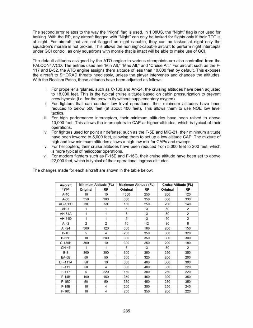
285
The second error relates to the way the “Night” flag is used. In 1.08US, the “Night” flag is not used fortasking. With the RP, any aircraft flagged with “Night” can only be tasked for flights only if their TOT isat night. For aircraft that are not flagged as night capable, they can be tasked at night only thesquadron’s morale is not broken. This allows the non night-capable aircraft to perform night interceptsunder GCI control, as only squadrons with morale that is intact will be able to make use of GCI.
The default altitudes assigned by the ATO engine to various steerpoints are also controlled from theFALCON4.VCD. The entries used are “Min Alt,” “Max Alt,” and “Cruise Alt.” For aircraft such as the F-117 and B-52, the ATO engine assigns them altitude of less than 10,000 feet by default. This exposesthe aircraft to SHORAD threats needlessly, unless the player intervenes and changes the altitudes.With the Realism Patch, these altitudes have been adjusted as follows:
i. For propeller airplanes, such as C-130 and An-24, the cruising altitudes have been adjustedto 18,000 feet. This is the typical cruise altitude based on cabin pressurization to preventcrew hypoxia (i.e. for the crew to fly without supplementary oxygen).
ii. For fighters that can conduct low level operations, their minimum altitudes have beenreduced to below 500 feet (at about 400 feet). This allows them to use NOE low leveltactics.
iii. For high performance interceptors, their minimum altitudes have been raised to above10,000 feet. This allows the interceptors to CAP at higher altitudes, which is typical of theiroperations.
iv. For fighters used for point air defense, such as the F-5E and MiG-21, their minimum altitudehave been lowered to 5,000 feet, allowing them to set up a low altitude CAP. The mixture ofhigh and low minimum altitudes allows a high-low mix for CAPs and sweeps.
v. For helicopters, their cruise altitudes have been reduced from 5,000 feet to 200 feet, whichis more typical of helicopter operations.
vi. For modern fighters such as F-15E and F-16C, their cruise altitude have been set to above22,000 feet, which is typical of their operational ingress altitudes.
The changes made for each aircraft are shown in the table below:
Minimum Altitude (FL) Maximum Altitude (FL) Cruise Altitude (FL)AircraftType Original RP Original RP Original RPA-10 10 10 4500 250 200 120A-50 350 300 350 350 300 330
AC-130U 30 50 150 250 200 140AH-1 1 1 5 3 50 2
AH-64A 1 1 5 3 50 2AH-64D 1 1 5 3 50 2
An-2 2 2 10 12 80 8An-24 300 120 300 180 200 150B-1B 5 4 200 350 300 320
B-52H 10 280 300 350 300 300C-130H 300 10 300 250 200 180CH-47 1 1 5 3 50 2
E-3 300 300 300 350 250 350EA-6B 50 50 300 320 200 200
EF-111A 50 10 300 400 300 300F-111 50 4 300 400 350 220F-117 5 220 150 300 250 220F-14B 100 150 350 450 300 350F-15C 50 50 350 450 250 350F-15E 10 4 200 350 250 240F-16C 10 4 250 350 200 220

286
Minimum Altitude (FL) Maximum Altitude (FL) Cruise Altitude (FL)AircraftType Original RP Original RP Original RPF-22A 150 150 300 450 250 350F-4E 10 15 250 320 250 220F-4G 10 15 250 320 250 220F-5E 10 15 250 280 300 150
F/A-18C 10 4 250 350 250 200F/A-18D 10 4 250 350 250 200
Il-28 5 4 150 180 200 120Il-76M 300 250 300 350 300 320Il-78 300 200 300 350 250 220J-5 5 4 300 250 200 180
J-7 III 5 10 300 350 250 250Ka-50 1 1 5 3 50 2KC-10 300 200 300 350 250 220
KC-130 250 150 250 250 200 180KC-135R 300 200 300 350 250 220MD-500 1 1 5 3 50 2Mi-24 1 1 5 3 50 2
MiG-19 100 10 250 280 200 180MiG-21 100 50 300 420 250 300MiG-25 400 350 800 580 400 400MiG-27 50 4 200 250 200 180
MiG-29A 100 100 300 350 200 250MiG-29C 100 100 300 350 200 250MiG-31 400 400 800 500 400 400OH-58D 1 1 5 3 20 2Su-25 10 10 150 180 200 120Su-27 10 100 300 450 250 320
Su-30MKK 10 50 300 450 250 240Tu-16 20 30 200 300 200 220
Tu-16N 300 180 300 350 250 220Tu-95MS 20 120 200 250 200 180UH-1N 1 1 5 3 50 2UH-60L 1 1 5 3 50 2
Y-8 10 120 250 250 200 180
FIXING HELICOPTERS
The helicopters in Falcon 4 failed to function properly even in 1.08US. The helicopters were made tofire the anti-tank guided missiles (ATGM) in RP3, but kept flying towards the target in due process. Asa result, the helicopters were often decimated by the air defense vehicles, such as the ZSU-23-4.
With Realism Patch version 5, the helicopters were improved. The changes include:
i. Helicopters will fire ATGM, air-to-air missiles, and rockets. ii. The helicopters will now hover if they are within 60% of the ATGM’s range (from the
FALCON4.WCD entry), and more than 2,000 feet away from the target. iii. The helicopters will only fire the ATGM if the target is within range and more than
2,000 feet away. iv. If the targets are within 1,000 and 10,000 feet away, the helicopters will select rockets
and then fire from a hover position. v. The ATGMs will be fired at 15-second intervals.

287
vi. The helicopters will fly at the lowest possible altitude of 150 feet when they are within36,000 feet of their targets. This allows the helicopters to fire from masked positions.
With the changes implemented, the helicopters are now more survivable in ground combat, and will beable to engage their targets outside the range of the typical SHORAD weapons. We have also seennumerous occasions of the AH-64 helicopters launching Hellfire missiles are targets from maskedpositions across hills.
288
THE ELECTRONIC BATTLEFIELDWinning The Virtual War of ElectronsBy “Hoola”
UNDERSTANDING HOW RADARS WORK IN FALCON 4.0
Sylvain Gagnon discovered the details of how the radars work and affect the AI. The explanationshere on how the radar works in Falcon 4 is credited to Sylvain.
F4 models the radar in two forms in the game. For the human player, the radar scan volume obeys thebar scan, azimuth coverage and beamwidth stipulated in the FALCON4.RCD file. As such, the entireazimuth and elevation limit is not scanned, which is realistic and is how a real radar behaves. For theAI, the radar scan volume is the entire azimuth and elevation limit. This is something that is codedinside the game, and not easily hex editable as discovered by Sylvain. In actual fact, had the AI beenmodeled with an accurate radar, the FPS penalty would have been tremendous.
To do justice to the basics of radar operation, one would require a separate thesis rather than thecoverage this short piece can allow. References (6), (7), and (8) will provide the basic knowledge forradar operations. Reference (5) is an invaluable source of information for understanding themathematics and electronics behind radar operations, and was extensively used to compute some ofthe radar parameters.
What the RCD Floats Represent
RWR and RWR LOW Gain:
The RWR gain is used for normal RWR modes, while the RWR LOW gain is used for the RWR in theLOW mode. When the RWR detects that a target has spiked it, the slant range between the emitterand the target (the player) is calculated by taking the square root of the sum of the square of heightdifference and longitudinal range difference (Pythagoras' Theorem). The value is then divided by twotimes the range of the emitter radar. If the resultant value is less than 0.8, the RWR (or RWR LOW)gain is multiplied by the difference between 1 and this value. Else, the RWR gain is multiplied by 0.2.The net value will be a float between 0.2 and 1. The RCD float will control if the emitter symbol isplaced inside the inner or outer ring.
Chaff:
This float controls the chaff susceptibility of the radar to chaff. The routine for maintaining a radar locktakes into account target range from the emitter, and the chaff susceptibility. When the target releaseschaff, F4 performs some computation using two hard coded static arrays that is dependent ondistance. The resultant float is then multiplied by the chaff susceptibility, to determine if the radar lockis maintained. As such, chaff susceptibility is also distance dependent. In general, the higher the float,the easier it will be to break radar lock, and chaff will remain effective even as the emitter closes in.
ECM, Beam Distance:
This controls the radar signal strength degradation that will occur when ECM is employed or when thetarget is beaming. For example, if a radar has a range of 32nm. against a target, and the ECM andbeam multipliers are 0.1 and 0.2 respectively, then ECM will break the radar lock unless the target iswithin 3.2nm. of the radar. Similarly, the target can break the radar lock by beaming as long as theemitter is more than 6.4nm. away.
Range, Look Down Distance:
Range is the radar range in feet. The detection range for target is computed as follows:
289
Detection Range = Radar Cross Section × Radar Range
Look down distance is a radar signal strength multiplier, used when the target is more than 2.5degrees below the emitter. This represents the look down performance of the radar. For example, for aradar with a range of 32nm. against the F-16, in a look down situation, if the Look Down multiplier is0.5, then it will only detect the F-16 at 16nm..
Lock Time:
This is the time interval in milliseconds for the radar to refresh the target track. For example, for asweep time of 3000, the radar will refresh the target track every 3 seconds to check if the target is stilldetected and locked.
All the other RCD floats are self explanatory.
The Falcon 4 Radar and Electronic Warfare Algorithm in Realism Patch
First things first. For a radar to lock onto a target in F4, it must first have a signal strength of 1 or more.The radar algorithm in F4 is as follows:
Radar Signal strength = (RCD radar range / Target Distance) X (Radar Cross Section)
The radar cross section does not work the same way as the actual radar equations do. In F4, thisworks more like a reflective value that is linear with range. Actual RCS affects radar detection range byan exponent of four. This is a good representation without the overhead of power computations, andwe have modeled the RCS of vehicles taking this into account.
The height of the radar and the target is then subtracted, and if the difference is greater than the rangeto the target (in feet) multiplied by the tangent of 2.5 degrees, the radar range ratio is multiplied by theLook Down multiplier. This results in a smaller detection distance and lower signal strength in look-down situations for pulse doppler radars. For pure pulse radars, look-down performance is nearimpossible.
ECM from the target is then checked. If the target employs ECM, then the signal strength is multipliedby the ECM multiplier. Hence, ECM will decrease the range at which the target may be detected andtracked. Of course, this is provided the radar is inside the ECM coverage zones of the target.
The doppler filter is then checked, and if the target’s doppler velocity in feet/sec decreases below thedoppler filter in the RCD entry for the radar, the range ratio is multiplied again by the beamingmultiplier.
Once the resultant signal strength is greater than 1.0, the radar is now able to lock onto the target. Thesignal strength is boosted once the target is locked. Depending on what radar mode the radar isoperating in, the multiplier for boosting the signal strength is different. For RWS, the signal strength ofthe lock is multiplied by 1.0. For VS mode, the signal strength is multiplied by 1.2, while STT modemultiplies the signal strength by 1.3. For TWS mode, the signal is multiplied by 0.9. All other radarmodes do not modify the signal strength. This somewhat models the different track retention algorithmand scan pattern on real radars. With modes such as TWS, the radar can only spend a fraction of itstime updating the locked target’s track file, in addition to tracking all other targets, and thus it becomeseasier to break the lock as the radar is not paying full attention to it. For STT, the radar is dedicated totracking this target, and all the radar processing capabilities are geared towards maintaining the lock.This is surprisingly accurate modeling on MPS’s part.
Hence, the greatest penalty against a radar is to fly low and either employ ECM, or beam the radar, orutilize a combination of all tactics including dispensing chaff.
290
If there is a radar lock and a missile is in flight with the radar supporting, it then checks to see if thetarget is dispensing chaff. The chaff algorithm is mechanized in the same way for SARH missilescompared to active radar guided missiles, though the chaff effectiveness is different. Chaffeffectiveness is mechanized as a two dimensional array of distance versus effectiveness ratio.
For SARH missiles, the chaff effectiveness arrays are as follows:
[ 0 1500 3000 11250 18750 30000][ 0 0.1 0.5 0.5 0.2 0.1 ]
For ARH missiles, the chaff effectiveness arrays are as follows:
[ 0 12000 24000 48000 120000][ 0 0 0.75 0.75 0.0 ]
The first dimension of the array is the distance between the missile and the target in feet, and thesecond dimension (the lower row) is the chaff effectiveness quotient.
The chaff algorithm first checks the distance between the missile and the target, and then computesthe chaff effectiveness quotient based on linear interpolation. For example, if the missile is 13,000 feetaway from the target, the chaff effectiveness quotients will be:
SARH Chaff Effectiveness Quotient = 0.5 – [{(13000-11250) / (18750-11250)} * (0.5-0.2)] = 0.43
ARH Chaff Effectiveness Quotient = 0.0 – [{(13000-12000) / (24000-12000)} * (0.0-0.75)] = 0.06
The chaff effectiveness quotient is then multiplied by the chaff multiplier in the RCD entry for theparticular radar, to determine the chances (in percentage probability) that the missile lock will bebroken. This is then compared against a random number between 0 and 1, and if the random numberis below the resultant number, the lock is lost and the missile misses.
As you can see, chaff effectiveness for SARH missiles is at its greatest between 3,000 feet (1/2nm.)and 11,250 feet (about 1.85nm.), and at distances greater than 11,250 feet and distances less than3,000 feet, chaff effectiveness tapers off. For ARH missiles, chaff is most effective between 24,000feet (about 3.95nm.) and 48,000 feet (about 7.9nm.), and effectiveness decreases beyond 48,000 feetand below 24,000 feet, and is totally ineffective under 12,000 feet (about 2nm.).
This variation of chaff effectiveness with missile range to target is a close approximation to how chaffaffects radars. At longer ranges, the chaff bloom can be distinguished due to the rapidly decreasingvelocity of the chaff cloud, thus making angular differences between the chaff cloud and the true targetreturn more apparent. Both chaff and target are likely to stay within the missile seeker field of view fora considerable amount of time. This allows the missile to detect the presence of chaff and reject it aftertracking both the chaff cloud and target for a while (target return still being inside the seeker FOV). Atcloser distances, the missile will switch lock to the chaff cloud as before, but being closer to the target,the target radar return has a higher chance of leaving the seeker FOV while the seeker is still trackingthe chaff cloud, thus lowering the chances of missile reacquisition. At even closer ranges, the line ofsight rate of the chaff cloud versus the target is higher, and this allows the missile to determineimmediately the presence of chaff and reject it. Again, this aspect of chaff effectiveness modeling in F4is surprisingly realistic.
For flares, the two dimensional arrays become:
[ 0 5500 11000 16500 27500][ 0 0.0 1.0 1.0 0.0 ]

291
The way flare susceptibility works is also the same as that of chaff. As you can see, flares are reallyonly effective when the missile is between 5,500 feet and 27,500 feet. You may ask why should thisbe since some missiles have no IRCCM capabilities and should always be decoyed by flares. At closerdistances, the flare will stay inside the seeker FOV for only a split second, and this very short durationmay sometimes not be sufficient for the seeker to switch lock before it exits the seeker FOV,particularly if the line of sight rate at which the flare exits the seeker FOV is too high for the trackingsystem to follow. However, the mechanization isn’t exactly quite accurate, and this aspect has beenaddressed as an overall holistic solution to improving IRCM combat in F4 (see earlier section titled“Turning On The Heat.”
We will next discuss the RWR mechanization in F4. RWRs in real life have a specific antenna gain.This is similarly modeled in Realism Patch. The ability for the RWR to detect a radar transmission iscontrolled by the RWR gain. The distance at which a radar may be detected is simply as follows:
RWR Detection Distance = Radar RCD range x RWR gain in FALCON4.RWD entry
Thus, for example, if the radar range is 38nm., and the RWR gain is 0.5, then the radar can only bedetected by this specific RWR at a range of 19nm..
The RWR symbology placement in F4 is mechanized as follows:
Slant Range between Emitter and Target = SQRT((Ground range) 2 + (elevation difference)2)
The result is then divided by two times the range (in feet) of the emitter (i.e. the radar) to determine therange ratio. If the range ratio is less than 0.8, the RWR (or RWR LOW gain if LOW is selected) ismultiplied by the difference between 1 and the range ratio. If not, the RWR gain is multiplied by 0.2.Hence, the RWR and RWR LOW coefficients for each radar acts as a pseudo lethality signal strengthcurve for the real RWR implementation, and determines if the threat emitter symbol should bedisplayed inside the inner threat ring.
While not entirely in conformance with actual radar equations, F4’s way of modeling radarperformance is adequate to simulate the appropriate radar characteristics without imposing an undueimpact on graphics and FPS. Actual radar computations are very intensive and involve exponents,which will certainly drag the FPS down with little additional gain in simulation fidelity.
It is imperative that you understand how F4 handles the radars. With this understanding, you will be ina position to determine, as part of your mission planning, how best to employ your EW assets such asjammers, and how to interpret what your RWR is telling you. You will also be in a position to formulatetactics to counter each unique electronic threat. Understanding the threats are you are facing is a keycomponent in surviving on the electronic battlefield, be it virtual or actual. with the Realism Patch, youwill need to fly like real pilots do.
RADAR CHANGES MADE IN THE REALISM PATCH
Changes were made to all radars, based on public information available on Jane’s Avionics, Jane’sRadar and Electronic Warfare, and other sources such as the USN Radar and Electronic WarfareHandbook. Information was produced using radar equations as far as possible, before being used tomodify the RCD floats. Radar performance data is, understandably, sensitive information and notpublicly available. Hence, ECM performance was deduced by examining the state of the technology,and whatever information was available publicly. F4 does not model ECCM modes as they should be,and neither does F4 model the full effects of ECM. ECM in F4 will only result in the radar lock beingbroken, but will not result in false targets, etc.
You will find a big difference between different radars now. For example, you will not be able to detecttargets with the F-5E or the MiG-19 and MiG-21 in a look down situation, as these aircraft are

292
equipped with pulse radars that lack a look down capability. In addition, beaming will not be effectiveagainst such aircraft, as it does not utilize a doppler gate.
Chaff and ECM resistance is also changed, with older radars being more susceptible to ECM andchaff, and newer radars being more resistant. Beaming is also more effective now and closer to actualradar performance. Before this, beaming was largely ineffective in F4. We have also modeledmonopulse radars in F4 (this will be discussed in later in more detail), and these are the radars usedon AIM-120, AIM-54 and AA-12 missiles. These radars are extremely difficult to defeat throughjamming or chaff employment, and we have implemented a HOJ (Home-On-Jam) mode on theseradars.
If you need to understand electronic warfare and how radars work, we have used the followinginformation sources. This is not an exhaustive list that we have used, but only a representativeselection:
1. Jane’s Avionics 1998-992. Jane’s Radar and Electronic Warfare 1998-993. Jane’s All The World Aircraft 1998-994. Jane’s Aircraft Upgrade 1998-995. USN Electronic Warfare and Radar Engineering Handbook, available at
http://ewhdbks.mugu.navy.mil6. Journal of Electronic Defense, http://www.jedonline.com7. AFP 51-45: Electronic Combat Principles, September 1987, available at
http://www.wpafb.af.mil/cdpc/pubs/AF/Pamplets/p0051050.pdf8. Avionics: The Story and Technology Of Aviation Electronics, Bill Gunston, published by
Patrick Stephens Limited, 1990.
CORRECTING THE APG-68 RADAR IN REALISM PATCH
The original Falcon 4 implementation of the APG-68 radar scan volume is erroneous. You will oftenfind situations where a radar contact may be within the altitude coverage of your scan pattern, but theradar fails to detect the target even though the target is not beaming nor jamming you. In addition, thealtitude coverage for 2 bar, 3 bar, and 4 bar scan patterns are way too much for the APG-68 radar.
In Falcon 4 version 1.08, the radar altitude coverage are as follows:
1. At 20nm. in RWS mode, the altitude coverage is 9,000 feet in 1 bar scan; 18,000 feet in 2bar scan; and 35,000 feet in 4 bar scan.
2. At 40nm. in RWS mode, the altitude coverage is 20,000 feet in 1 bar scan; 36,000 feet in2 bar scan; and 70,000 feet in 4 bar scan.
3. At 20nm. in TWS mode, the altitude coverage is 30,000 feet in 3 bar scan; and 34,000feet in 4 bar scan.
4. At 40nm. in TWS mode, the altitude coverage is 61,000 feet in 3 bar scan; and 66,000feet in 4 bar scan.
In the actual APG-68 radar, the radar altitude coverage are as follows:
1. At 20nm. in RWS mode, the altitude coverage is 10,000 feet in 1 bar scan; 14,000 feet in2 bar scan; and 24,000 feet in 4 bar scan.
2. At 40nm. in RWS mode, the altitude coverage is 20,000 feet in 1 bar scan; 28,000 feet in2 bar scan; and 48,000 feet in 4 bar scan.
293
3. At 20nm. in TWS mode, the altitude coverage is 24,000 feet in 3 bar scan; and 30,000feet in 4 bar scan.
4. At 40nm. in TWS mode, the altitude coverage is 48,000 feet in 3 bar scan; and 60,000feet in 4 bar scan.
Now, the radar algorithm in Falcon 4 steps the antenna in 2° in elevation for each bar in the scanpattern (this is also known as the bar step). For example, with the radar centered on the airplane’scenterline, and set to a 4 bar RWS scan pattern, the antenna will tilt to 3° above the centerline for thefirst bar, and then tilt downwards by 2°, to a position that is 1° above the centerline for the second bar.It then tilts to 1° below the centerline for the third bar, and 3° below the centerline for the fourth bar.With a beam width of 4.6°, and the antenna step of 2°, the total elevation coverage of the radarimplementation is thus 10.6°. In the real APG-68, the antenna moves in steps of 2.2° in RWS, and anaverage of 3.25° in TWS (the exact antenna step is dependent on the MFD radar range). Theimplementation of the scan pattern in Falcon 4 is surprisingly accurate for the RWS mode, but toonarrow for the TWS mode.
However, from the altitude covered by the radar cursors, the RWS 4 bar scan results in an elevationcoverage of 17.2°. We thus have a situation where the radar code is implementing the scan patterncorrectly, but the MFD code is displaying the altitude coverage erroneously ! You can thus tilt theantenna to cover the altitude of interest, and yet not detect the target at all if the target is flying at analtitude that is close to the upper or lower limit of the cursor altitude coverage ! This is so because theradar isn’t scanning that particular area in the sky, even though the MFD radar cursor is displaying itas such.
Sylvain investigated the implementation of the radar and the MFD codes in the assembler, anddiscovered that the equations for determining the MFD radar cursor altitude coverage is as follows:
Cursor Altitude Coverage = (sin ((No. of Bars – 1) � Bar Step) + (2 � Half Beam Width)) � Range
This equation is actually wrong. For example, in a 4 bar scan, this is equivalent to having the first barscan at 4° above the centerline, and the second bar at 2° above the centerline. The third and fourthbar will scan at 2° and 4° below the centerline respectively. However, the antenna step between thesecond and third bar is 4° instead of 2° ! This results in the mismatch between the actual radar scanvolume and the MFD displayed scan volume.
With the Realism Patch, the cursor altitude coverage is now as follows:
Cursor Altitude Coverage = (sin (((No. of Bars – 1) � Bar Step) + (2 � Half Beam Width))) / 2) � Range
This addresses the discrepancy between the radar cursor altitude coverage and the actual radarcoverage. In addition, the antenna step (or bar step) is increased from 2° in RWS, to 2.2°, andincreased from 2.6° in TWS, to 3.25°. The radar scan volume in RWS and TWS modes are nowcorrect.
The other small change in the radar mechanisation is the antenna elevation step when you commandthe radar antenna to tilt up or down. The antenna will tilt in 4.6° increments previously, and this is fartoo coarse for antenna movement, as it corresponds to about 10,000 feet of altitude coverage at20nm.. With the Realism Patch, this has now been adjusted to 2.5° steps in elevation, correspondingto approximately 4,000 feet of altitude coverage at 20nm..
REVAMPING NON-COOPERATIVE TARGET RECOGNITION (NCTR) IN REALISM PATCH
One of the most glaring mistakes in the radar mechanization of Falcon 4 is in the Non CooperativeTarget Recognition (NCTR) feature. The Falcon 4 way of implementing NCTR is to represent the
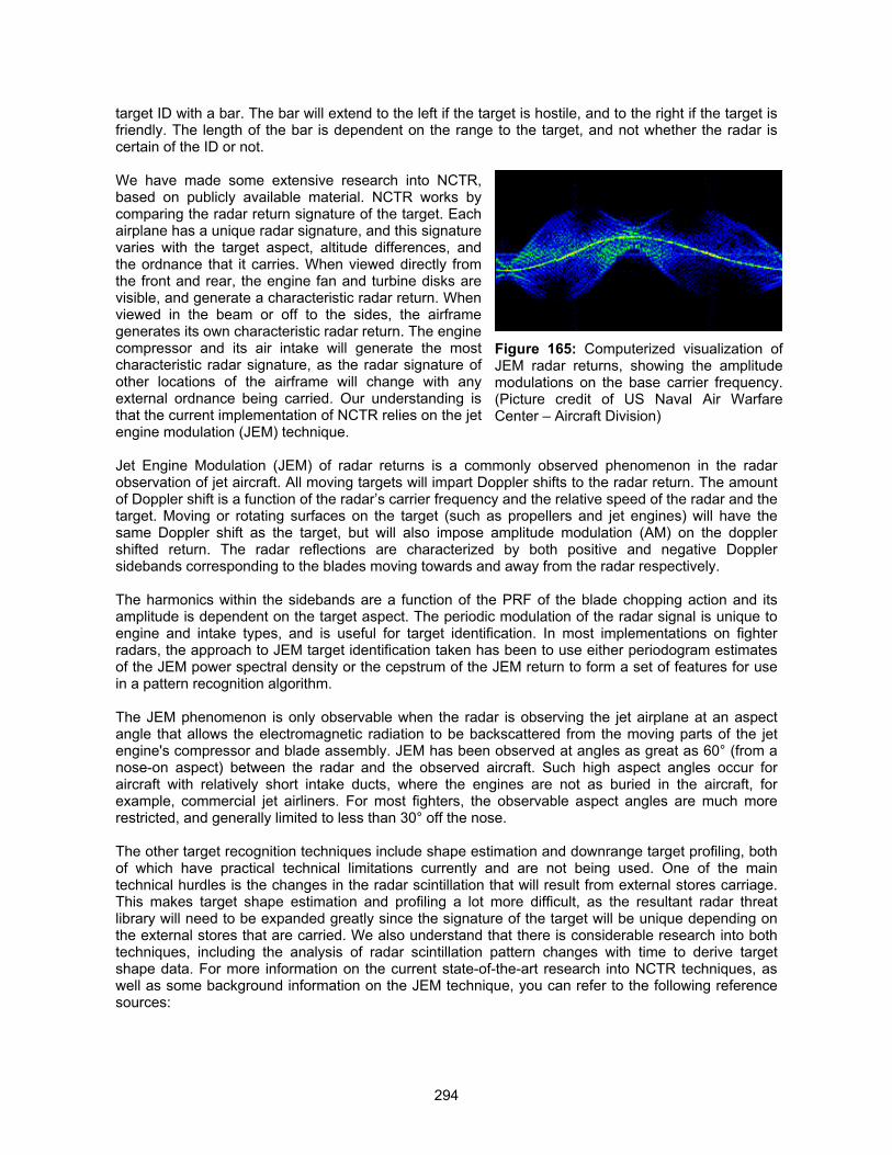
294
target ID with a bar. The bar will extend to the left if the target is hostile, and to the right if the target isfriendly. The length of the bar is dependent on the range to the target, and not whether the radar iscertain of the ID or not.
We have made some extensive research into NCTR,based on publicly available material. NCTR works bycomparing the radar return signature of the target. Eachairplane has a unique radar signature, and this signaturevaries with the target aspect, altitude differences, andthe ordnance that it carries. When viewed directly fromthe front and rear, the engine fan and turbine disks arevisible, and generate a characteristic radar return. Whenviewed in the beam or off to the sides, the airframegenerates its own characteristic radar return. The enginecompressor and its air intake will generate the mostcharacteristic radar signature, as the radar signature ofother locations of the airframe will change with anyexternal ordnance being carried. Our understanding isthat the current implementation of NCTR relies on the jetengine modulation (JEM) technique.
Jet Engine Modulation (JEM) of radar returns is a commonly observed phenomenon in the radarobservation of jet aircraft. All moving targets will impart Doppler shifts to the radar return. The amountof Doppler shift is a function of the radar’s carrier frequency and the relative speed of the radar and thetarget. Moving or rotating surfaces on the target (such as propellers and jet engines) will have thesame Doppler shift as the target, but will also impose amplitude modulation (AM) on the dopplershifted return. The radar reflections are characterized by both positive and negative Dopplersidebands corresponding to the blades moving towards and away from the radar respectively.
The harmonics within the sidebands are a function of the PRF of the blade chopping action and itsamplitude is dependent on the target aspect. The periodic modulation of the radar signal is unique toengine and intake types, and is useful for target identification. In most implementations on fighterradars, the approach to JEM target identification taken has been to use either periodogram estimatesof the JEM power spectral density or the cepstrum of the JEM return to form a set of features for usein a pattern recognition algorithm.
The JEM phenomenon is only observable when the radar is observing the jet airplane at an aspectangle that allows the electromagnetic radiation to be backscattered from the moving parts of the jetengine's compressor and blade assembly. JEM has been observed at angles as great as 60° (from anose-on aspect) between the radar and the observed aircraft. Such high aspect angles occur foraircraft with relatively short intake ducts, where the engines are not as buried in the aircraft, forexample, commercial jet airliners. For most fighters, the observable aspect angles are much morerestricted, and generally limited to less than 30° off the nose.
The other target recognition techniques include shape estimation and downrange target profiling, bothof which have practical technical limitations currently and are not being used. One of the maintechnical hurdles is the changes in the radar scintillation that will result from external stores carriage.This makes target shape estimation and profiling a lot more difficult, as the resultant radar threatlibrary will need to be expanded greatly since the signature of the target will be unique depending onthe external stores that are carried. We also understand that there is considerable research into bothtechniques, including the analysis of radar scintillation pattern changes with time to derive targetshape data. For more information on the current state-of-the-art research into NCTR techniques, aswell as some background information on the JEM technique, you can refer to the following referencesources:
Figure 165: Computerized visualization ofJEM radar returns, showing the amplitudemodulations on the base carrier frequency.(Picture credit of US Naval Air WarfareCenter – Aircraft Division)
295
1. “Radar-Based Target Identification,” Dr. Brett H. Borden, Naval Air Warfare Center WeaponsDivision, available at http://www.nawcwpns.navy.mil/hybrid/rbti.html.
2. “A Likelihood-Based Approach to Joint Target Tracking and Identification,” J. O’Sullivan,Steven P. Jacobs, Michael I. Miller, and Donald L. Synder, conference record of the 27th
Asilomar Conference on Signals, Systems & Computers, Volume 1, November 1993, pages290 – 294.
3. “High Resolution Radar Models for Joint Tracking and Recognition,” Steven Jacobs, JosephA. O’Sullivan, Proceedings of the 1997 IEEE National Radar Conference, May 1997, pages 99– 104.
4. "Modeling of Jet Engine Modulated Radar Signal Returns for Target Identification,” Mark R.Bell and Robert A. Grubbs, IEEE Transactions on Aerospace and Electronic Systems, Volume29, No. 1, January 1993, pages 73 – 87.
5. USN Electronic Warfare and Radar Engineering Handbook, available athttp://ewhdbks.mugu.navy.mil
The JEM characteristics are programmed into a RCS characteristics library, and loaded into the radarprocessor. Using pattern recognition algorithm, the radar will guess the target ID based on how well itmatches its library, and then displays its best guess. As such, it is not possible for the radar todetermine if the target is hostile or friendly, as a hostile MiG-29 will look the same to the radar as afriendly MiG-29.
Due to the unique combination of air intakes and engines, a target carrying external ordnance can beidentified as positively as a target without any external ordnance. However, airplanes with similarcombinations of air intakes and engines cannot be distinguished from one another. It is henceimpossible to distinguish sub-variant differences, such as a MiG-29 Fulcrum-A and a MiG-29 FulcrumC, or distinguishing between F/A-18C and F/A-18D, unless there are big differences in the engine andair intake RCS characteristics. It is important to know that even though the sub-variants may beequipped with sub-models of certain engines (for example, the F110-GE-100 engine on the Block 40F-16 and the F110-GE-129 on the Block 50 F-16), the RCS characteristics may not vary significantlyto allow positive identification between the two. JEM is heavily dependent on aspect, and fairlysusceptible to jamming. As such, this limits the NCTR capability to aspect angles that allow the radarto see the target’s air intakes and engine compressor blades (usually ±15° to ±25° for fighter aircraft).
With Marco Formato’s help, the Realism Patch has revised the NCTR to reflect this understanding ofhow this technology works. The NCTR bar has been replaced with a four-character ID string. Theimplementation is as follows:
1. If the target is in STT or TWS, and the resultant radar return strength is less than 2.5, then theradar MFD will display the mnemonics “WAIT,” to indicate that the radar is analyzing the signalreturns and attempting to identify the target.
2. If the radar signal return is 2.5 or greater, the “WAIT” mnemonic will be replaced by thefollowing:a. “UNKN” if you are not within a ±25° cone centered on the target’s nose, i.e. you must be
within ±25° in azimuth and elevation of the target. This indicates that the radar is unable todetermine the target’s ID.
b. Target’s NCTR ID if you are within a ±25° cone centered on the target’s nose.We have decided to use the aspect limit of ±25°, as this is more representative of fighter aircraft, whichare present in more abundance in the virtual skies of Falcon 4. Although we understand that the JEMsignature may be observable up to greater aspect angles for transport aircraft and fighter aircraft withvery short intake ducts (for example, the AV-8B Harrier), we deem this a reasonable tradeoff to modelmost of the aircraft in greater fidelity.
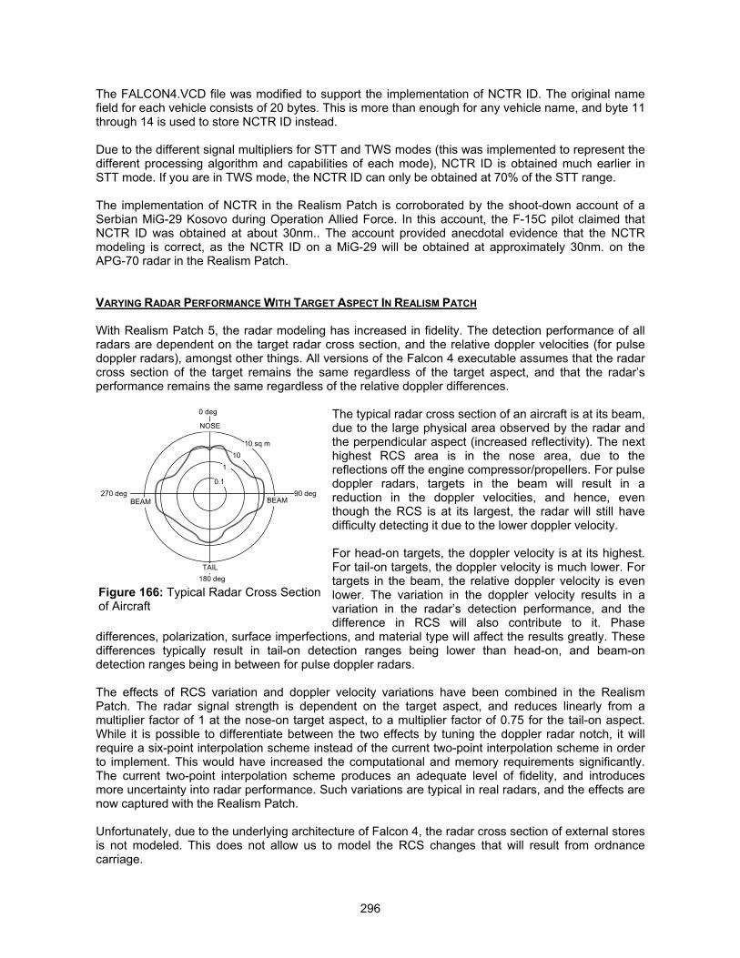
296
The FALCON4.VCD file was modified to support the implementation of NCTR ID. The original namefield for each vehicle consists of 20 bytes. This is more than enough for any vehicle name, and byte 11through 14 is used to store NCTR ID instead.
Due to the different signal multipliers for STT and TWS modes (this was implemented to represent thedifferent processing algorithm and capabilities of each mode), NCTR ID is obtained much earlier inSTT mode. If you are in TWS mode, the NCTR ID can only be obtained at 70% of the STT range.
The implementation of NCTR in the Realism Patch is corroborated by the shoot-down account of aSerbian MiG-29 Kosovo during Operation Allied Force. In this account, the F-15C pilot claimed thatNCTR ID was obtained at about 30nm.. The account provided anecdotal evidence that the NCTRmodeling is correct, as the NCTR ID on a MiG-29 will be obtained at approximately 30nm. on theAPG-70 radar in the Realism Patch.
VARYING RADAR PERFORMANCE WITH TARGET ASPECT IN REALISM PATCH
With Realism Patch 5, the radar modeling has increased in fidelity. The detection performance of allradars are dependent on the target radar cross section, and the relative doppler velocities (for pulsedoppler radars), amongst other things. All versions of the Falcon 4 executable assumes that the radarcross section of the target remains the same regardless of the target aspect, and that the radar’sperformance remains the same regardless of the relative doppler differences.
The typical radar cross section of an aircraft is at its beam,due to the large physical area observed by the radar andthe perpendicular aspect (increased reflectivity). The nexthighest RCS area is in the nose area, due to thereflections off the engine compressor/propellers. For pulsedoppler radars, targets in the beam will result in areduction in the doppler velocities, and hence, eventhough the RCS is at its largest, the radar will still havedifficulty detecting it due to the lower doppler velocity.
For head-on targets, the doppler velocity is at its highest.For tail-on targets, the doppler velocity is much lower. Fortargets in the beam, the relative doppler velocity is evenlower. The variation in the doppler velocity results in avariation in the radar’s detection performance, and thedifference in RCS will also contribute to it. Phase
differences, polarization, surface imperfections, and material type will affect the results greatly. Thesedifferences typically result in tail-on detection ranges being lower than head-on, and beam-ondetection ranges being in between for pulse doppler radars.
The effects of RCS variation and doppler velocity variations have been combined in the RealismPatch. The radar signal strength is dependent on the target aspect, and reduces linearly from amultiplier factor of 1 at the nose-on target aspect, to a multiplier factor of 0.75 for the tail-on aspect.While it is possible to differentiate between the two effects by tuning the doppler radar notch, it willrequire a six-point interpolation scheme instead of the current two-point interpolation scheme in orderto implement. This would have increased the computational and memory requirements significantly.The current two-point interpolation scheme produces an adequate level of fidelity, and introducesmore uncertainty into radar performance. Such variations are typical in real radars, and the effects arenow captured with the Realism Patch.
Unfortunately, due to the underlying architecture of Falcon 4, the radar cross section of external storesis not modeled. This does not allow us to model the RCS changes that will result from ordnancecarriage.
Figure 166: Typical Radar Cross Sectionof Aircraft
0.1
110
10 sq m
0 deg
270 deg 90 deg
180 deg
NOSE
BEAM BEAM
TAIL
297
MAKING ECM WORK IN REALISM PATCH
The debate of whether ECM works or not in F4 has been a point of contention since the release of thegame. With the work done by Sylvain Gagnon, this debate is set to end once and for all. Well, theanswer is that ECM works and does not work! This write-up is an adaptation from Sylvain’s README,and includes some of the historical design considerations taken into account during the developmentof the patch.
The problem lies in the way F4 mechanizes the radars. This has to do with the way F4 handles thefading of the radar signal. If you turn on the ECM before the radar has a lock, ECM will work until youenter the burn-through range, after which the radar will re-acquire lock. The problem lies on turning theECM on after the radar has locked onto you. When this is the situation, the ECM is supposed todegrade the radar signal. When this decreases below the detectable threshold (be it due to ECM orbeaming, or the target going into the ground clutter, or the target getting out of range), the lock shouldbe lost after a specific time specified in the RCD (the “Lock Time” entry, which is in milliseconds). InF4, this fading of signal is never applied, and as a result, the AI radar never loses the radar lock. TheECM patch developed by Sylvain changes this, and in addition to this, enables the AI plane to checkwhether it’s own radar has a lock first before launching a radar guided missile (F4 does not do thischeck and will result in wasted missiles as the AI will launch without a valid radar lock).
What this means for the player is that if ECM is turned on before the hostile emitter has a lock, thesignal can be degraded such that a lock cannot be obtained, and you can prevent a launch. If you turnon the ECM after a launch, then as long as the radar is still outside the ECM burn-through range, itslock will be degraded and broken, and you will defeat the missile.
The ECM patch also activates the effect of internal jammers. Without the patch, internal jammers arecosmetic in nature, and though it will display the jamming “X” symbol, the jammer will never be able tobreak a radar lock.
For SAM crews, there is also a random factor thrown in, and SAM crews will sometimes launchunguided missiles. This is skill level related, with recruits being more likely to launch unguided thanveterans. Ace SAM crews will always wait for a valid lock prior to launch. With a mixed crew, you canexpect to see some unguided launches every now and then.
Another big change in the implementation of ECM is the coverage zones. In F4, ECM is assumed togive full spherical coverage. All ECM systems are designed with specific coverage zones, and ECMtransmitting and reception antenna do have their coverage zones. In addition, the antenna patternvaries, and hence the strength of the jamming signal is dependent on the location of the threat emittervis-à-vis the boresight of the antenna main lobe. This also means that if a threat is outside the ECMantenna coverage zone, it will never be jammed.
With Realism Patch, a generic coverage zone has been defined and implemented (by contrast inreality all ECM systems have distinct coverage zones of their own). The coverage zone is defined as±60° in azimuth (measured from aircraft centerline), and elevation of +15° (upwards) to –30°(downwards), and is a generic representation of the 3 dB jamming beamwidth. Within this coveragezone, the main lobe of the jamming beam is defined as ±30° in azimuth, and elevation from +5° to –20°. Between azimuth of +30° to +60° (and also –30° to –60°), the ECM effect falls off logarithmicallywith an exponent of 0.5 (gradually first, then more and more abrupt). This applies to elevationcoverage as well, with effectiveness falling off from elevation of +5° to +15°, and from –20° to –30°.Outside the effective coverage zones, ECM remains totally ineffective. The generic coverage zoneswere devised after examining photographs of many podded and internal ECM systems to estimatethey antenna coverage.
One important change to ECM affects the AI. ECM leaves behind visible traces of its usage on thetarget radar display. For a raw video display, this can be snowing on the radar display, or a verticalnoise strobe at the angular position. For synthetic displays, this can be synthetic symbologies

298
indicating that the radar sees some jamming signal. The radar may also be able to determine theangular position of the jamming signal, and indicate it on the scope. Hence this allows the pilot todetermine the approximate azimuth location of the jammer, even though a valid radar lock is denied,and normal tracking information such as velocity and range measurements are not possible. This alsomeans that even though the pilot has been denied a firing solution, he is still able to maneuver andclose in on the jammer in an attempt to get inside the burn-through range.
The RP ECM changes implemented by Sylvain will allow the AI to know where the jammer source is,though a valid radar lock is denied (hence denying a shot). As such, usage of ECM will attract theattention of the AI pilots if you are inside their radar coverage cones. In addition, for monopulse radarswith Home-On-Jam (HOJ) capabilities, such as the AIM-120, AIM-54 and AA-12, turning on thejammer will result in the missile radar seekers transiting into interleaved HOJ/pinging mode. For thesemissiles, the one-way monostatic radar transmission effectively acts as a beacon to attract the missile.This implementation is more realistic, and the players have to be aware of the effects of using ECM.Understanding its usage will go a long way in surviving the electronic virtual battlefield in Falcon 4.
The last change incorporated in the ECM model is the ability to vary the effectiveness of different ECMsystems on different aircraft. ECM systems equipping fighter aircraft are often limited in their poweroutput, whereas ECM systems equipping bomber aircraft such as the B-1 and the B-52 have muchhigher power output and processing capability. The default Falcon 4 ECM model does not allow thedifferent ECM systems to be differentiated. With the Realism Patch, this has now been implemented.A data field is created at byte 14 of the VCD name field for the aircraft, and this is used to store themultiplier effect of the ECM system equipping the aircraft. The effectiveness of the ECM can now bevaried to model the different ECM systems in higher fidelity.
MAKING TRACK-VIA-MISSILE GUIDANCE WORK PROPERLY IN REALISM PATCH
The only missiles in the Falcon 4 world that uses the Track-Via-Missile (TVM) mode of guidance arethe Patriot PAC-2 and the SA-10 (S-300PMU1) “Grumble.” These missiles have always been modeledas semi-active radar homing, and the launch of these missiles will always trigger a RWR launchwarning.
We received some unclassified background information on the TVM mode of guidance from anexperienced Patriot and Nike operator, indicating that the launch of a TVM guided missile will nottrigger a RWR launch warning. The target will never be notified electronically that he has beentargeted, and there will be no RWR indication other than the pilot being able to see a Patriot or SA-10radar in search mode.
The TVM mode of guidance relies on two links. The radar continually paints the target normally, as itwould track any airborne target, and directs the missile to look in the target’s direction through aseparate uplink. The missile will receive the reflected RF energy from the target, and as it closes it, willbegin to intercept the increasingly precise returns. The missile will re-transmit the target data that itreceives back to the guidance radar, which will then use this information to generate guidanceinstructions. The instructions are then passed back to the missile using the radar-to-missile uplink. Themissile does not emit any RF energy of its own, unlike active radar guided missiles.
Throughout the entire engagement, there is no perceptible change in the radar pulse form and PRF,thus making it impossible for an RWR to determine if the guidance radar is in search and track mode,or in fire control mode. The active electronically scanned array radar is also capable of multiple mixedmode operations, making any attempts of jamming it rather futile. Chaff is also almost useless againstthis mode of guidance, thus making these SAMs one of the most formidable threats.
We have modified the Patriot and SA-10 radars and missile model, such that the launch of thesemissiles will not trigger an RWR launch warning. You will only see the Patriot and SA-10 radar on theRWR in search mode, and possible when it locks onto you, but you will never know if a missile has

299
been launched. Even when the missile arrives at the target, the only way to know it is to spot theinbound missile, as the RWR will not be able to give any indication of the inbound missile.
MAKING ACTIVE RADAR GUIDED MISSILES WORK PROPERLY IN REALISM PATCH
Active radar homing (ARH) missiles have always somewhat worked in Falcon 4, but not to their fullestextent. We have made significant changes to the underlying algorithm (thanks to Sylvain Gagnon),and modeled the ARH missile seekers with a lot greater accuracy compared to RP3 and before.
From RP4 onwards, the ARH missiles now have a pseudo COAST mode. Missiles such as the AIM-120, AIM-54 and AA-12 have an inertial guidance mode. In this mode the missile will make coursecorrections, using periodic datalink updates on the target’s spatial location, provided that the launchingaircraft maintains a valid radar lock throughout this phase. Once at the pre-determined location(defined as 13 seconds of flight time from the target), the missile goes active and autonomous, and willfirst search the extrapolated position of the target to see if it is present.
In 1.08US or 1.08i2, if the parent aircraft breaks the radar lock, when the missile turns autonomous, itwill search only directly ahead. This does not simulate a proper inertial mode where the missileextrapolates the target location based on the last known velocity vector prior to the loss of datalinkinformation.
From RP4 onwards, the ARH missiles are mechanized such that when the missile turns autonomous,it will snap look at the last known position of the target, to determine if the target is within itsbeamwidth. If the target is detected, it will guide towards it. If the target is not within its FOV, but thereare other airplanes within 10nm. of it (the ARH missile search distance), it will lock on to the closesttarget. This means that the missile is indeed a rabid dog once it turns autonomous. The only way toensure that you will not commit fratricide is to ensure that you support the missile via datalink until itturns autonomous. Failure to do so may result in the missile not acquiring the target when it turnsautonomous, especially if the target maneuvers violently and way out of plane to avoid being caughtwhen the missile goes active. Worst still, if this happen, the missile may lock onto any target within itssearch distance, including friendlies.
ARH missile seekers also operate in a mixed mode for initial acquisition. These seekers typicallyoperate initially in a high PRF (HPRF) mode to maximize detection range (while sacrificing somerange resolution accuracy) when they turns autonomous. Once a target is detected, they will normallytransit to medium PRF (MPRF) modes for better range measurement to plot the intercept trajectory. In1.08US and 1.08i2, the ARH missiles are programmed to search out to 8nm., and any target inside8nm. will be considered for targeting. This does not model the initial HPRF mode quite as accurately,and has been amended to 10nm. from RP4 onwards.
Modeling the ARH Missile Seekers (Monopulse with Home-On-Jam)
A problem arose in RP3, where the ARH missile seekers were modeled as conventional radars. Thismade the ARH missiles very susceptible to chaff, ECM, and beaming, especially in high clutter, look-down scenarios. The problem was masked by the less than competent AI missile evasion tactics (nowaltered and much improved from RP4 onwards), but was revealed in the F4 ladder competitions duringhuman-to-human BVR fights. A lot of research was poured into identifying the problem, and improvingthe accuracy of the ARH seeker modeling, when we managed to replicate the scenario and identify thespecific engagement geometries.
Our additional research revealed that the ARH missile seekers are monopulse seekers. I will discussabout monopulse seekers and their mechanization first, to lay the ground work for understanding whythe ARH missiles are now modeled as such in the Realism Patch. All materials presented here arepublicly available, though much of this information is difficult to locate and must be paid for.
300
Unlike conventional radars that derive tracking information by comparing the characteristics of a seriesof pulse returns (measurement of pulse-to-pulse amplitude variations), monopulse radars derive itstracking information (in azimuth and elevation) from every return pulse that is received. Monopulseradars have four separate receivers to receive the return pulses. Every return radar pulse is receivedby all four receivers. By comparing the relative pulse amplitudes received on all four antennas, theazimuth and elevation correction signals can be generated to center the target on the trackingantenna.
The distinct advantage of a monopulse radar is that the pulse-to-pulse amplitude variations caused bynoise or deliberate use of ECM will not affect its tracking ability, and error signals are updated at amuch higher rate since a new position is generated for every pulse transmitted. The flip side of thecoin is that monopulse radars are capable of tracking only single targets.
The established method of defeating monopulse tracking is through using the radar resolution cell, orother methods. The former can be achieved by having a stand-off jammer within half of the radar’spulse width from the target. This is however not practical against ARH missiles as the ranges are tooclose. Another technique involves using two airplanes equipped with blinking jammers, all within theradar resolution cell of the monopulse tracker, with the jammers blink alternatively on and off at a rateclose to the radar’s guidance servo bandwidth (typically 0.1 to 10 Hz), and attempt to cause resonancein the tracking response so as to throw off the antenna, resulting in overshoots.
Other techniques include terrain bounce (bouncing the jamming signal off the ground to reflect towardsthe monopulse tracker), skirt jamming, and image jamming. These techniques, however, require a lotof jamming power that is usually not achievable on self protection jammer systems. Cross polarizationjamming may also be used, though this technique can be easily defeated by the monopulse trackerthrough the use of a polarization screen, and we have assumed that the ARH missiles are all equippedas such.
The last two methods of jamming monopulse radars include coherent jamming and cross eyejamming. The former requires the usage of two jammers that provide coherent transmissions (usuallyvery difficult to achieve due to electrical phasing), while the latter relies on a pair of coherent repeaterloops. The latter is equally difficult due to the difficulty in maintaining closely matched electrical pathsbetween the two repeater loops. A very high jamming power is also required to overwhelm the signalson the monopulse tracker.
The current ways to defeat the monopulse tracker include using towed decoys operating on repeatermode, and activated at sufficiently far distance such that the towed decoy is inside the same radarresolution cell as the aircraft. With properly timed repeater signals, the repeater signal can be injectedinto the tracking gate, and as the missile closes in, it makes it more difficult for the missile todistinguish between the towed decoy repeater signal and the parent aircraft skin return. Hopefully, themissile will track the towed decoy if the repeater signal is stronger than the skin return from theaircraft.
As such, conventional self protection jammers have little ability to defeat a monopulse radar. Thenormal deception and noise tactics do not work well, as even if it denies the monopulse tracker withcertain tracking information such as velocity or range, the radar can still track in angular position, andthis is sufficient to plot a coarse path towards the target and close in for the onboard monopulse radarto burn through and re-acquire the target.
The usage of chaff is also largely ineffective, as the chaff bloom is fairly ineffective in the HPRF initialacquisition mode. However, chaff will still be effective at longer ranges, when the missile just turnsautonomous and has yet to lock onto the target, though the effectiveness is marginal. Once locked on,the chaff bloom is easily distinguished from the target return.
In addition, the ARH seekers are equipped with Home-On-Jam (HOJ) capabilities. Activation ofjamming will often cause the missile to transit into tracking modes that interleave the passive HOJ

301
mode with active transmission mode. HOJ allows the radar to obtain angular information about thejamming source, and this is sufficient for the radar to plot an approximate course of intercept throughproportional navigation. Since the jamming transmission is one-way, this in effect acts as a beacon forthe missile to home onto, even though the missile seeker’s signal-to-noise ratio is degraded underjamming, and we have modeled the seekers as such. The way the seeker is modeled is that it willsimulate the missile seeker plotting an initial proportional navigation course to the target using HOJmode, while interleaving active radar transmission to attempt a burn-through. Once inside burn-through range, the missile will transit to full active homing for terminal guidance.
While it is true that HOJ modes do not provide sufficient targeting information for an accurate intercept,and will often decrease the missile Pk through the missile plotting a sub-optimal intercept course, thuswasting energy, it is not possible to simulate the full effects of jamming on the guidance system andmissile Pk within the confines of Falcon 4.
One thing that any radar will not be able to overcome is the ground clutter in look-down scenarios.This raises the noise threshold that will mask the skin returns in look-down situations. This aspect hasalso been modeled in the ARH seekers, though the monopulse seekers are slightly less susceptibledue to the inertial mode and datalink capabilities, enabling the seeker to look at the last known goodposition of the target and attempt to acquire the target.
Removing the ARH Missile Launch Warning
In 1.08US and 1.08i2, whenever an ARH air-to-air missile is launched, the RWR launch warning lightand audio tone will always be triggered. Strictly speaking, this is not correct, as ARH missiles guide byinertial mode in the initial phase, while receiving datalink information to update the target location.
Semi-active radar homing (SARH) missiles rely on continuous wave (CW) radar illumination to guide.The launching aircraft has to activate a CW illuminator (CWI) to “paint” the target, and the SARHmissile will guide on the reflected CW energy. This CW waveform is a continuous sinusoidalwaveform, unlike normal pulse or pulse doppler transmissions, and can be very easily distinguished.Whenever SARH missiles are launched, the CWI is turned on automatically, and this will trigger thelaunch warning light and audio tone on the RWR. For command guided missiles (such as SA-2, SA-3,and SA-8), the command guidance transmissions from the missile guidance radar can be easilydetected and distinguished from the normal search and track radar transmission. Detection of thecommand guidance transmission will similarly trigger the RWR launch warning.
Conversely, when ARH missiles are launched, the radar does not need to provide target illumination.In terms of radar transmission, it is still as per normal for the particular radar operating mode. Sincethere is no change in the radar pulse-form received by the RWR, it will not trigger the launch warning.When the missile turns autonomous, the transmission from the monopulse seeker also resembles thatof a normal airborne radar in the I/J band, as the RF waveforms are pulse doppler signals. This willsimilarly not trigger the RWR launch warning. As such, the only time the RWR will detect the presenceof an ARH missile is when the missile goes autonomous, and the missile symbology appears on theRWR display. With the Realism Patch, this is now implemented.
REVAMPING THE RADAR WARNING RECEIVER IN REALISM PATCH
One of the most vexing problems with Falcon 4 is the implementation of the radar warning receiver.The RWR will continue to display the threat symbol and play the audio tone even long after the threatemitter has lost radar lock, or exceeded its radar gimbal limits. For example, the “M” symbol of theAIM-120 as well as its RWR tone will continue to be displayed and played back long after missileimpact, for a duration as long as 10 seconds or even more. In addition, the “HANDOFF” function didnot function properly, as the depression of the “HANDOFF” button will often not play back the audiotone of the corresponding threat.
302
With the help of Sylvain Gagnon, the implementation of the RWR has been changed and fixed in theRealism Patch. Before we discuss about the changes made, you should first familiarize yourselveswith the workings of a radar warning receiver. This is covered in detail in the section titled “RWRManagement,” in user’s manual.
Original RWR Implementation
In the original implementation of the RWR in Falcon 4, depression of the HANDOFF button will notresult in the audio tone of the new priority threat being heard, although the next highest priority threatsymbol will be selected. The threat priority is sorted by the relative lethality of each emitter detected,regardless of whether the emitter is in search mode or lock-on mode. The RWR routine will also checkif the emitter’s orientation to see if the contact is within the radar coverage. If the emitter is not lockedonto the target, the coverage is assumed to be the entire radar azimuth and elevation volume (this isthe radar scan volume for all AI controlled airplanes). If the emitter is locked onto the target, thecoverage is changed to the beamwidth of the emitter. However, the RWR routine does not take intoaccount the position of the emitter, and as such, does not determine if the emitter can see the contact.The RWR routine does not check if the target is outside radar gimbal coverage, and if the target’ssignal strength is too low for it to detect. The RWR coverage zones are also not checked. The RWRroutine is written such that the emitter’s audio tone is played automatically every 12 seconds,regardless of what happens.
The RWR routine will also retain every emitter contact for up to a period of 30 seconds. While this isacceptable for the AI, as an implementation of pseudo memory, it creates an extremely unrealisticbehavior on the player’s RWR, since the RWR symbol will continue to be displayed long after theemitter loses radar lock. The audio tone will also continue to play. The RWR routine will also updatethe “Last Repaint” timer of the radar each time the radar loses lock, when it should only update eachtime the radar pings on the target. This results in a track refresh even though the radar has lost lock onthe target.
The most irritating aspect of the original RWR implementation is the constant “New Guy” beeping tone.The RWR will display up to 16 targets at any one time. In the original implementation, before the RWRadds a new contact when it detects a radar painting it, it will check to see if the emitter is already in itslist of contacts. If it is not, the RWR then plays the “New Guy” audio tone, and attempts to add thecontact to its list. However, the “Add Contact” routine in the RWR code may not add the contact if itssignal strength is too low to be considered a threat, or if the target list is full. Hence, every time theRWR code goes through its target list, it will play the “New Guy” audio even though the target is notadded.
The launch warning on the RWR was mechanized to sound upon missile launch. However, the launchwarning is affected by the launch guidance delay of the missile. For missiles such as the SA-5, missileguidance will only commence 15 seconds after launch, but the missile control radar will begintransmitting immediately upon missile launch. Hence, the launch warning should sound immediatelyupon missile launch, whether the missile has commenced guidance or not.
There is also a problem of the launch warning light being lit, and the launch warning tone not beingsounded. When a missile is being fired at the player (be it in a single or multiplayer environment), amessage is sent to the player that a missile has been launched. The player’s computer receives thismessage event and checks if the “Missile Activity” flag on this RWR contact has been set to 1. If it isnot, the launch warning tone is sounded. This message event is sent once for each missile fired, andhence, the launch warning tone cannot be sounded more than once per missile fired. In the player’sRWR mechanization, the “Missile Activity” flag of each RWR contact is tested and if any of the contacthas it set to 1, the launch warning light will be lit. Hence, it is possible that the contact has fired atsomeone else, and the launch warning light triggers. Since the contact has not fired at the player, the“missile fired” message is not sent to the player, and hence, the RWR launch warning tone does notsound.
303
Realism Patch Implementation
In the Realism Patch, the RWR behavior is modified to correct these inaccuracies and deficiencies.The changes are made only to the player’s RWR, as the AI lacks memory. Implementation of suchchanges to the AI’s RWR will result in unrealistic AI behavior as the AI will forget about a contact andcease to react to it, whereas a human will not.
All RWR creates emitter track files each time it detects a new emitter. This track file is updated eachtime the emitter pings the RWR. The purpose of track file retention is to prevent the creation ofextraneous RWR contacts each time the emitter pings the RWR, as the signal will be correlated withthe track file to determine if it is the same contact. If this is so, the track file is updated, and a newsymbol is not created. However, the RWR will not retain the track file indefinitely, and will drop thetrack if the emitter fails to repaint it at regular intervals. The track file retention duration is decided asfollows:
We assumed an emitter radar in a 60° azimuth, 4-bar search scan. Assuming a beamwidth overlap of2.2°, and a beamwidth of 4.6°, and assuming that the target is detected by the radar in 2 of the 4 scanbars, at the extreme azimuth limit of 60°, the target’s RWR will not be refreshed during the remaining 2scan bars coverage 60° azimuth. Taking a typical antenna scan rate of about 60°/sec, the remainingtwo scan bars will be covered in approximately 4 seconds. When the radar returns to the first scan bar,it will have to traverse across from 60° on one end, to the opposing end where the target is located.This will take another 2 seconds. As such, the target’s RWR will be painted every 6 seconds in thesearch mode, and the RWR track file will be updated every 6 seconds. For any scan interval beyondthis, the track will be dropped and the radar sweep will lead to the creation of a new track file.
1. The HANDOFF button will now select the next highest priority threat symbol, and play itsaudio tone. The audio tone that is played will depend on the radar mode that the emitter is in.If the emitter is in search mode, then the audio tone will only be heard each time the emittersweeps its radar beam pass the RWR. If the emitter is locked onto the target, the audio tonewill be heard continuously.
2. The threat priority is now sorted by lethality and emitter status. Each depression of the“HANDOFF” button will step the RWR through to emitters of lesser priority. The emitters aresorted as follows, in decreasing order of threat priority:
� Emitters inside the lethal inner ring of the RWR display, and is locked onto the target.
� Emitters outside the lethal inner ring of the RWR display, and is locked onto the target.
� Emitters inside the lethal inner ring of the RWR display, but is in search mode and notlocked onto the target.
� Emitters outside the lethal inner ring of the RWR display, but is in search mode and notlocked onto the target.
3. The RWR routine now checks if the emitter is able to see the target, and obeys the gimballimits as well as radar transmission signal strength. The audio tone will not be heard if theemitter is not painting the RWR, even though the symbol may be displayed due to trackretention.
4. The “Last Repaint” time of the radar will no longer be refreshed when the radar loses lock.This timer is only refreshed each time the radar repaints the target.
5. The RWR will no longer retain an emitter track for 30 seconds after the emitter last ping it. TheRWR will drop the track if the emitter fails to ping it every 6 seconds. This means that theRWR will retain an old emitter track up to 6 seconds before discarding it. The symbol willdisappear. The design rationale of this 6 second track file duration is elaborated in theparagraph above, and is based on the typical scan interval of an airborne interception radar.
304
6. The “New Guy” audio tone is only played when a newly detected emitter is added to theRWR’s contact list (16 contacts in normal operation, and 5 contacts in PRIORITY mode).
7. The launch warning aural tone will sound immediately when a missile is launched at theplayer. If the missile is not decoyed, and the emitter remains in the fire control and missileguidance mode, the launch warning is sounded again at an interval of 15 seconds. If themissile is successfully decoyed, or the hostile radar is destroyed, the launch warning will notsound again. The launch warning light will remain lit throughout.
With the Realism Patch, the RWR symbols will now be purged 6 seconds after the emitter losescontact. You will now be able to interpret the RWR data accurately, as a contact that does not give anaudio tone will mean that it is not painting you, and you are now in a position to determine whichemitter has lost track of you.
Creating Individual RWRs
Prior to the Realism Patch, all aircraft in the Falcon 4 world share the same RWR model (the RWRcharacteristics are found in the FALCON4.RWD file (this is found in the terrdata\objects directory).There are 5 parameters contained in each RWD entry:
Range :This is the RWR gain, used to determine the range at which radar emissions can be detected by theRWR. The range of the target emitter (obtained from the FALCON4.RCD file) is multiplied by this gain,to obtain the range at which the emitter can be detected.
Left / Right :This determines the azimuth angular coverage limits of the RWR. For most RWRs, it is ±180°,indicating full azimuth coverage.
Top / Bottom :This determines the elevation angular coverage limits of the RWR.
Most if not all RWRs use spiral antennas. These antennas have specific sensitivity zones, and theirangular coverage is a ±45° cone centered on the antenna boresight. Since the RWR antennas areusually placed at 4 separate corners of an airplane, each spiral antenna provides coverage for a 90°quadrant in azimuth. With a set of 4 antennas, total azimuth coverage is obtained. The elevationcoverage is however not complete, due to the sensitivity zone of the spiral antenna. For most WesternRWRs, the elevation angular coverage is ±45°, while most Russian systems have elevation angularcoverage of ±30°.
The Realism Patch models the elevation coverage of individual RWRs, as well as the sensitivitycharacteristics of each RWR type. Prior to the Realism Patch, all RWRs have the same gain, andprovide complete spherical coverage. RWR sensitivity is dependent on the receiver type, with simplecrystal video receivers being far less sensitive than the new super-heterodyne receivers are. SinceRWR systems often use a receiver system that scans across different frequency bands instead oflistening to all frequency bands simultaneously, there is some degree of degradation in detectionrange. Crystal video receiver based RWRs often pick up the radar emissions at ranges that are closeto or inside the weapon engagement envelope of the hostile emitter, and as such, provides far lessreaction time to the user. Super-heterodyne receivers based RWRs are far more sensitive, and willdetect the hostile radar emissions at ranges outside the weapon engagement envelope. This is nowmodeled in detail in the Realism Patch.
RWR Symbologies and Aural Tone Assignment
The RWR symbols in 1.08US are assigned as follows:
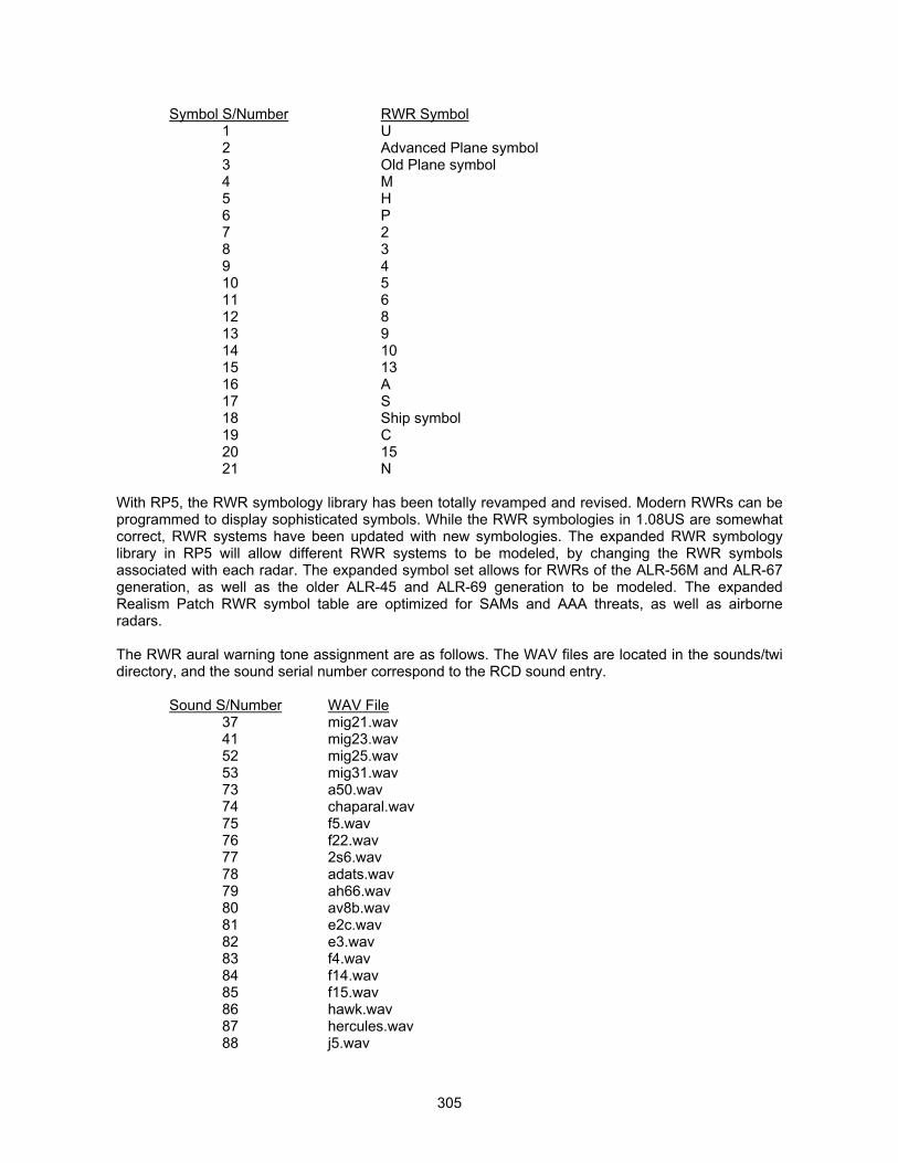
305
Symbol S/Number RWR Symbol1 U2 Advanced Plane symbol3 Old Plane symbol4 M5 H6 P7 28 39 410 511 612 813 914 1015 1316 A17 S18 Ship symbol19 C20 1521 N
With RP5, the RWR symbology library has been totally revamped and revised. Modern RWRs can beprogrammed to display sophisticated symbols. While the RWR symbologies in 1.08US are somewhatcorrect, RWR systems have been updated with new symbologies. The expanded RWR symbologylibrary in RP5 will allow different RWR systems to be modeled, by changing the RWR symbolsassociated with each radar. The expanded symbol set allows for RWRs of the ALR-56M and ALR-67generation, as well as the older ALR-45 and ALR-69 generation to be modeled. The expandedRealism Patch RWR symbol table are optimized for SAMs and AAA threats, as well as airborneradars.
The RWR aural warning tone assignment are as follows. The WAV files are located in the sounds/twidirectory, and the sound serial number correspond to the RCD sound entry.
Sound S/Number WAV File37 mig21.wav41 mig23.wav52 mig25.wav53 mig31.wav73 a50.wav74 chaparal.wav75 f5.wav76 f22.wav77 2s6.wav78 adats.wav79 ah66.wav80 av8b.wav81 e2c.wav82 e3.wav83 f4.wav84 f14.wav85 f15.wav86 hawk.wav87 hercules.wav88 j5.wav

306
89 j7.wav92 patriot.wav93 sa2.wav94 sa3.wav95 sa4.wav96 sa5.wav97 sa6.wav98 sa8.wav99 sa9.wav100 sa10.wav101 sa13.wav102 slotback.wav103 su15.wav152 barlock.wav153 firecan.wav154 flatface.wav155 longtrak.wav156 lowblow.wav157 mpq54.wav158 msq48.wav159 msq50.wav160 spoonrst.wav161 tps63.wav162 f16.wav163 spy1a.wav164 gundish.wav165 amraam.wav166 phoenix.wav
RADAR LINE-OF-SIGHT IN FALCON 4
During the course of the development of Realism Patch, we discovered that a basic radar line-of-sight(LOS) model is included in Falcon 4. For example, when testing the SA-10 missile, our tester sited theSA-10 SAM site on flat ground, amidst some hilly terrain. With a minimum engagement altitude of 512feet AGL, our tester mapped out the SA-10 firing range vis-à-vis ingress altitude:
Ingress Altitude SA-10 Firing Range20,000 ft 40nm.15,000 ft 35nm.4,000 ft 20nm.1,500 ft 11nm.700 ft 4nm.
When the SA-10 SAM site is located on flat ground near the sea, it engaged targets ingressing at 800feet AGL from as far out as 30nm.. When the SA-10 is sited behind a hill, the SAM site will never fireat a target unless the target is almost on top of it, or is approaching it from the same side of the hill thatthe SAM site is located.
In another set of testing, we tested the SA-2 by siting it in an urban environment, next to a building. Byflying around in circles around the Fan Song radar, the RWR symbol and aural tone were observed.When the Fan Song has a clear line of sight to the target, the RWR symbol is displayed at theappropriate azimuth location, and the aural tone indicated that the Fan Song has a lock on the target.When the target flies to a location such that the building is between the Fan Song and the target, theFan Song’s RWR tone stopped abruptly. If the building continues to block the Fan Song’s line of sightto the target, the Fan Song’s RWR symbol will be dropped 6 seconds after losing contact.

307
The testing observations confirmed that a basic radar line-of-sight model is present in Falcon 4. Thisallows terrain masking tactics to be used against SAM sites and other targets, and it is even moreimportant to know how to interpret the RWR data accurately.
IMPROVING THE F-16 AVIONICS SETUP IN REALISM PATCH
The HUD dogfight symbology has also been modified. In the actual Block 50/52 F-16, the HUD is de-cluttered in dogfight mode, and all extraneous symbologies are removed to aid heads-out fighting andminimize information overload. The default 1.08US HUD contains extraneous symbologies, and theseinclude:
i. Flight path marker ii. Pitch ladder iii. Altitude scale iv. Airspeed scale
The extraneous symbologies have been removed in the Realism Patch, and the HUD display is now acorrect representation of the actual F-16C HUD in dogfight mode. The RPM reading has also beenremoved from the HUD, as the real F-16 HUD symbology does not display RPM.
We have also consulted several F-16 pilots who specialized in air-to-ground missions on the mostcommonly used avionics settings for air-to-ground weapon delivery. The avionics settings used in theRealism Patch are modeled closely after these settings used in the USAF:
1. The default A/G weapon delivery master mode is CCRP, with the radar defaulting to STPTmode in GM.
2. The bomb spacing is set to 125 feet, which is the most commonly used setting, instead of50 feet.
GROUND CONTROL INTERCEPT, INTEGRATED AIR DEFENSE SYSTEM, AND AWACS IN FALCON 4
One of the most important elements of a modern air battlefield is the presence of GCI (Ground ControlIntercept) and AWACS. In our early attempts to create a GCI/AWACS environment in Falcon 4, wediscovered the following things about the 1.08i2 version of Falcon 4:
1. In the 2D world, GCI and AWACS coverage is present and active. By activating the threatcircles for low and high altitude radar coverage, we can see enemy fighters being vectoredtowards friendly fighters if the friendly fighters are inside the enemy’s radar coverage zones.This is despite the friendly fighters being outside the radar detection range of the enemyfighters. When the friendly fighters are not inside the radar coverage, the enemy fighters willnot be vectored.
2. Radar sites in Falcon 4 can detect you electronically and visually. Visual detection isdependent on the time of the day and the movement type of the target. For a radar vehiclewhose radar coverage is fully overlapped by another radar vehicle, the vehicle will turn off itsradar, and only turn it on when the other radar vehicle is destroyed. This does not happenregularly, and only occurs at 15-minute intervals. The visual detection ranges of the radar sitesare coded in the FALCON4.OCD file (for objectives). For daytime, the detection ranges are asis in the OCD entry. For nighttime, the detection range is modified by first adding 3 to the OCDentries, and then dividing the result by 4. At dawn and dusk, the detection range is obtained byfirst adding the OCD entry by 1, and then dividing by 2.
3. Many radar sites are named wrongly. There are many objectives named as radar sites, butthey do not contain any radars. These are often TV stations and radio towers, and do not have
308
any search radars mounted. As such, these supposed EW radar sites are cosmetic and non-functional, and since these radars are non-functional, they cannot be targeted by anti-radiationmissiles as part of a SEAD campaign.
4. Microprose had coded such that flights/airplanes are detected/spotted only if they are within acertain detection range around a unit. The detection boundary is a cylinder around the unit.For a flight in 3D, it is automatically marked as spotted. Because of this, 3D GCI cannot workbecause any deaggregated airplane would automatically be spotted. Similarly, 2D GCI will notwork properly since the detection volume is a cylinder encompassing a unit (such as a radarstation), and not a hemisphere. The targeting flight also has 360 degrees coverage.
Implementation in the Realism Patch
In order to make GCI/AWACS work in Falcon 4, the Realism Patch GCI is designed such that a flighthas to be detected in 2D world before it can be detected in the 3D world. If all this sounds reallyconfusing, it is ! We needed a long time to figure out the GCI implementation as well. There are someterminologies that we will use here:
DetectedWhen a targeting entity (such as an interceptor flight) has detected an enemy flight, the enemy flightcan be considered as a potential target. The targeting entity cannot consider a flight that it has notdetected as a target. Aggregated and deaggregated entities will detect both aggregated anddeaggregated entities. A detected target does not equate to the target being spotted. It just meansthat the physical conditions permit the targeting entity to see the target (such as no LOS blockage,and the target being within the detection range), and can be a candidate for initiating combat.
In RangeThis means that the targeting entity is within firing parameters. The targeting entity will check to makesure that its best weapon can reach the target. The orientation of the airplanes in the 2D world is notconsidered, and range of the weapon is the only factor. This is used only by aggregated targetingentities. Deaggregated targeting entities have their own AI logic, and will engage the target as theydeem fit.
SpottedWhen a flight has been spotted, it means that it has been detected by the enemy’s GCI infrastructure.
The distinction between “Detected” and “Spotted” means that a certain target may be “spotted” by aGCI radar (as in, the GCI radar physically sees the target on its radar screen), and yet not be seen bya pair of interceptors. However, since the GCI radar controls the interceptors, the target is consideredto be “detected” by the interceptors as well, as the GCI passes the target’s information to theinterceptors. The interceptors can then initiate an intercept, while at the same time attempt to “spot”the target using its own sensors for fire control purposes. The interceptors cannot shoot at the targetuntil it has “spotted” the target on its own sensors. This makes the distinction between GCI guidance,and fire control guidance. For former can only guide fighters to their targets, while the latter is requiredfor the fighters to shoot at the targets.
An aggregated entity can only spot other aggregated entities, while deaggregated entities can spotboth aggregated and deaggregated entities. An aggregated entity will consider an aggregated targetas detected if the target is within the targeting entity’s "Detect" range for the target’s movement type.Objectives are also capable of detecting targets. If the targeting entity is a battalion, it will also use thedetection range and the range/azimuth coverage of the nearest objective. If the targeting entity is aflight (a flight is an aggregated entity, while an airplane is a deaggregated entity) and the target is alsoa flight, the targeting entity will use the radar azimuth coverage of the first vehicle in the flight. If thetarget is outside the radar coverage, it will use a generic visual detection routine. This allows AWACSassets to have 360° coverage.
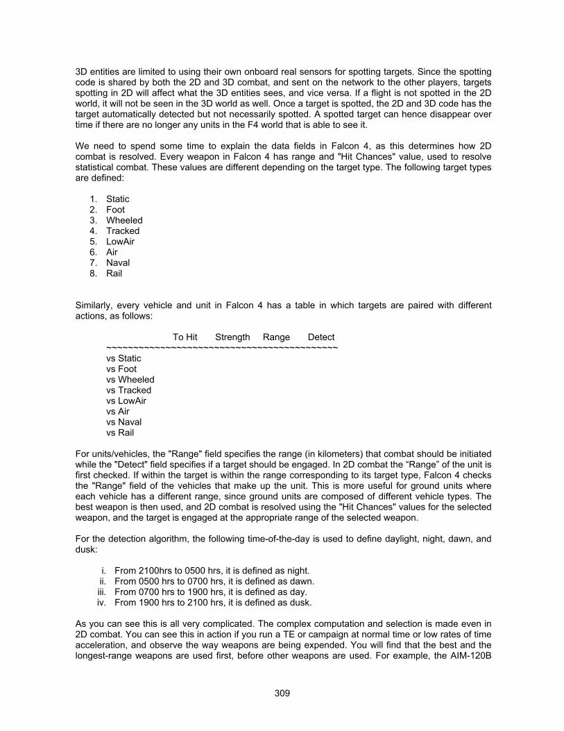
309
3D entities are limited to using their own onboard real sensors for spotting targets. Since the spottingcode is shared by both the 2D and 3D combat, and sent on the network to the other players, targetsspotting in 2D will affect what the 3D entities sees, and vice versa. If a flight is not spotted in the 2Dworld, it will not be seen in the 3D world as well. Once a target is spotted, the 2D and 3D code has thetarget automatically detected but not necessarily spotted. A spotted target can hence disappear overtime if there are no longer any units in the F4 world that is able to see it.
We need to spend some time to explain the data fields in Falcon 4, as this determines how 2Dcombat is resolved. Every weapon in Falcon 4 has range and "Hit Chances" value, used to resolvestatistical combat. These values are different depending on the target type. The following target typesare defined:
1. Static2. Foot3. Wheeled4. Tracked5. LowAir6. Air7. Naval8. Rail
Similarly, every vehicle and unit in Falcon 4 has a table in which targets are paired with differentactions, as follows:
To Hit Strength Range Detect~~~~~~~~~~~~~~~~~~~~~~~~~~~~~~~~~~~~~~~~~~~vs Staticvs Footvs Wheeledvs Trackedvs LowAirvs Airvs Navalvs Rail
For units/vehicles, the "Range" field specifies the range (in kilometers) that combat should be initiatedwhile the "Detect" field specifies if a target should be engaged. In 2D combat the “Range” of the unit isfirst checked. If within the target is within the range corresponding to its target type, Falcon 4 checksthe "Range" field of the vehicles that make up the unit. This is more useful for ground units whereeach vehicle has a different range, since ground units are composed of different vehicle types. Thebest weapon is then used, and 2D combat is resolved using the "Hit Chances" values for the selectedweapon, and the target is engaged at the appropriate range of the selected weapon.
For the detection algorithm, the following time-of-the-day is used to define daylight, night, dawn, anddusk:
i. From 2100hrs to 0500 hrs, it is defined as night. ii. From 0500 hrs to 0700 hrs, it is defined as dawn. iii. From 0700 hrs to 1900 hrs, it is defined as day. iv. From 1900 hrs to 2100 hrs, it is defined as dusk.
As you can see this is all very complicated. The complex computation and selection is made even in2D combat. You can see this in action if you run a TE or campaign at normal time or low rates of timeacceleration, and observe the way weapons are being expended. You will find that the best and thelongest-range weapons are used first, before other weapons are used. For example, the AIM-120B
310
will be first used, and only when the missiles are expended, will the AIM-9 then be used. You will alsofind that the ordnance load in 2D war correspond exactly to the ordnance load of the sameunit/vehicle in the 3D war.
The key parts of the Realism Patch GCI/IADS/AWACS changes are as follows:
1. The radar coverage on 2D map is made dynamic. You can see the low altitude and highaltitude radar coverage on the 2D map (by activating the radar coverage circles in the 2Dmap), and the radar coverage circles will indicate the radar coverage zones at that instance. Ifradar stations are destroyed, the gap in radar coverage will be reflected on the 2D map. Thisdoes not happen constantly, but occurs at a regular time interval of about 15 minutes. Assuch, you can see a real-time air picture as you destroy the enemy’s IADS, and use this as amission planning tool to select ingress routes for your strike aircraft.
2. The threat circles on the 2D map are made dynamic to reflect the threat situation based on thecurrent intelligence. For every detected unit that is capable of engaging air targets, a threatcircle will be drawn for its engagement range at low and high altitudes. These units need notbe SAM/AAA units, and need not have functional radars. As long as they can pose a threat toaircraft, they are considered a threat, and the threat circle will be displayed. For undetectedunits, their threat circles cannot be displayed. This simulates the fog of war due to incompleteintelligence information.
3. The 2D map will now only show aircraft that have been detected by any component of theIADS. For example, if an enemy flight is not being detected by any of your IADS/GCI/AWACSassets, and has not been detected by any of your fighters, they will not appear on the 2D map,and you will not be aware of its presence. The IADS/GCI/AWACS assets include aircraft,AWACS, early warning radar sites, air bases with radars, and SAM sites and battalions.
4. Low level tactics are now possible in 2D and 3D combat. You (and the AI) can now fly in 2D or3D at low altitudes, and not be detected at all if the flight route does not take the aircraft overany enemy IADS assets. Even if an aircraft overflies an IADS asset, the enemy will only beable to detect you as long you stay in inside its coverage area (such as visual or radardetection range). This means that if the enemy has gaps in its radar coverage, even if youhave been detected, if you fly into areas that are not covered by radar or any other visualsensors, the enemy will lose you. This allows you to sneak away as the IADS will not havesufficient reaction time to direct fighters against you.
5. All aircraft in 2D will now use their radar and visual sensors to detect and spot targets. Theoriginal Falcon 4 implementation has the aircraft seeing everything around it that is within a128 km radius (approximately 71nm.).
6. In 2D combat (which also occurs during 3D combat), the EW and SAM radar sites areinterlinked. When the radar coverage of SAM radars are overlapping, the SAM radars withlower range will shut down, and will rely on other SAM radars on the IADS network fordetection and targeting purposes. As active radars are destroyed, these “dormant” radars willbecome active to take over the air defense radar coverage.
7. When in 2D combat, all components of the IADS can detect and send information about thetargets that they have detected to friendly aircraft that are nearby. For example, enemyAWACS, fighter aircraft, SAM radars, and EW radars can now pass the information on adetected target to other enemy fighters, and if the enemy fighters are within range, they will bevectored to intercept the target.
8. In 3D combat, IADS assets such as aircraft, AWACS, SAM sites/battalions, air base radars,and early warning radar sites/stations can and will detect targets, and send the information toother friendly interceptors/fighters nearby. If the interceptors/fighters are within range, they willcommence an intercept.
9. In the 3D world, IADS information can be passed on to other IADS assets by air defense units.IADS information can also be passed on to, and made used of, by aircraft that are crewed by
311
aces or veterans that are within range of the target, provided that their morale is not broken.Since the 2D IADS detection code is also used in 3D, targets detected by 2D GCI assets canalso be seen by airplanes in the 3D world. This allows ace and veteran pilots to be guided byGCI information for vectored intercepts. Pilots of lower skills can sometimes act on GCI data,but this is based on a random generation. For AWACS, they can detect targets when they areaggregated as well as deaggregated.
10. In the 2D world, IADS information can be passed on by any air defense unit (AAA or SAM),early warning radar sites, airbase radars, and AWACS. Fighter and fighter bomber aircraft thatare tasked for missions other than air-to-ground, and crewed by ace or veteran pilots whosemorale are not broken can also pass on IADS information, and make use of such informationfor vectored intercept. Pilots of lower skills can sometimes act on GCI data, but this is basedon a random generation. Aircraft flying at low altitudes (less than 500 feet AGL) can alsoescape detection from high flying CAP, although they can still be detected if they overfly EWradar sites, or SAM/AAA battalions.
11. The visual detection envelope of 2D airplanes is limited to ±175° in azimuth, and –30° to +90°in elevation. The visual detection envelop of 2D IADS combat units (such as SAM/AAAbattalions), as well as 2D IADS objectives (such as airbases) is ±180° in azimuth. The visualdetection range is dependent on the time of the day, and ranges from 16 km in daytime (about8.9nm.), 8 km at dawn and dusk (about 4.5nm.), and 4 km at night (about 2.3nm.). Thedetection ranges are the same for airplanes, objectives, and combat units.
12. For 2D airplanes, there is an additional condition for visual detection of enemy airplanes. If anenemy airplane is within a circle of 1nm. radius around the airplane, and has not beendetected by it (for whatever reasons, such as the enemy being outside the visual detectionenvelope), the enemy airplane will automatically be detected if it is flying above the altitude ofthe airplane. If the enemy is flying below the airplane, it will be automatically detected if thealtitude separation is less than 5,000 feet, else the enemy will remain undetected. For NOEenemy airplane flying at altitudes below 500 feet AGL, they cannot be detected if the verticalseparation between the enemy airplanes and the friendly airplanes exceeds 2,000 feet
13. For 2D radar detection of enemy airplanes by AWACS or friendly interceptors, the radarazimuth coverage of the first airplane in the unit is used. For targets flying above an altitude of10,000 feet, the detection range is the “Air” value in the “Detect” field for the unit. For targetsflying at an altitude between 500 feet and 10,000 feet, the detection range is the “Low Air”value in the “Detect” field for the unit. For targets flying at altitudes below 500 feet AGL, theycan only be detected if the AWACS or friendly interceptors are flying below 2,000 feetthemselves. The 2D radar elevation coverage is ±60°. There is a 2D doppler notchmechanized, at ±10° off the boresight. Any targets flying inside the 2D notch will not bedetected.
14. For 2D radar detection of enemy airplanes by AAA/SAM units as well as objectives equippedwith a functional radar feature, the azimuth limit of the detection envelope is specified inoctants of 22.5°. For targets flying at altitudes above 10,000 feet, the detection range is the“Air” value in the “Detect” field for the unit/objective. If the target is flying at altitudes between 0feet and 10,000 feet, the detection range is dependent on the “Low Air” value in the “Detect”field for unit/objective, as well as the target’s altitude. Each objective and 2D unit has a radararray that specifies how far its radar can see at various octants. The range may vary fromoctant to octant, thus creating blind zones in coverage. These values are stored in thecampaign CAM files for each objective. The detection range of an air target is the relativealtitude of the air target compared to the objective, divided by the radar array element at thecorresponding octant. The result is in feet. If the “Low Air” value for the objective/unit is largerthan the resultant detection range, then the detection range remains as is. If the “Low Air”value is smaller than the detection range, then the detection range is capped at the rangespecified in the “Low Air” value. For example, if a target is flying at a bearing of 30° from aradar equipped objective, at an altitude of 2,700 feet. The altitude of the objective is 2,300feet, and the relative altitude difference is 400 feet. If the radar array element for the 22.5° to
312
45° octant of the objective is 0.022 (for example), the detection range is 400 divided by 0.022,giving 18,181 feet (about 3nm.). If the “Low Air” value of the objective is 10 (this is inkilometers, and equates to about 5.5nm.), the target will be detected only at 3nm.. If the “LowAir” value of the objective is 5 (equating to 2.7nm.), then the target can only be detected at2.7nm.. In essence, it makes it impossible for IADS radars to detect targets flying below theiraltitude.
15. The detection range of long range EW/GCI radars and AWACS have been altered. This is setto kilometers, and the longest available range is only 255 km. For AWACS and EW/GCIradars, this limitation to their detection range is not realistic, as AWACS can detect targetsmuch further than 255 km (about 142nm.). For ranges at 250 or below, the detection range isas specified. For example, if the range is 250, it remains as is. Every one unit increment above250 increases the range by 50 km. For example, if the detection value is 251, the detectionrange becomes 300 km. For the detection value of 255, this equates to a detection range of500 km (about 278nm.). This change creates a more functional AWACS, and simulates thecapabilities of modern C3I facilities better.
16. The detection range of stealth aircraft in 2D is also changed. In 1.08US, the detection rangesof stealth aircraft are halved as compared to normal aircraft. This is however unrealistic, andhas been changed to 1/20th of normal aircraft in the Realism Patch.
The IADS modifications in the Realism Patch now makes it possible to progressively destroy the IADSand gain air dominance over the enemy, by targeting its EW radar sites, SAM/AAA sites, as well asAWACS assets. As the IADS assets are destroyed, you will find that the low and medium/high altituderadar coverage zones will progressively shrink, and gaps in radar coverage will be created. The airpicture is a lot more dynamic and uncertain, as the campaign map will no longer show all the enemytargets, but will only show targets that have been detected by your own IADS assets. Since EW radarscan be targeted, you will need to participate actively in the selection of targets for SEAD strikes andSEAD escorts, and make it a priority to destroy the IADS EW radar sites. With the destruction of suchsites, you will reduce the air engagements to localized engagements, where the enemy fighters willhave to rely solely on their own onboard sensors for detection.
STAND-OFF JAMMERS IN THE REALISM PATCH
One of the major components in an air campaign is the usage of tactical jamming assets, such asstand-off jammers, to disrupt the enemy’s integrated air defense system. The usage of tactical stand-off jammers will prevent enemy IADS assets such as EW radars and SAM radars, from detecting yourown strike packages, and engaging them. This aspect was never implemented in Falcon 4, andconstitutes one of the most glaring omissions from an otherwise well designed air campaign engine.
Stand-off jamming targets the communication links, as well as detection and early warning radars inan air defense environment. Most modern SAM fire control systems require some amount of initialtargeting information in order to initiate a fire control solution that will lead to an engagement of theenemy airplanes. Enemy interceptors will also rely on targeting information from early warning radarsites, so that they can be vectored to the correct location to intercept the intruders. Stand-off jammerstargets the early warning radars that supply the information to the SAM batteries and interceptors, andforces them to detect the targets using their own onboard sensors.
SOJs are primarily noise jammers, putting out white noise at the frequency of the victim radars. For aradar to be susceptible to jamming, the jamming signal must be close to the victim's radar frequency.The distance that it needs to be at depends on the antenna design of the victim's radar, as well as itscharacteristics. Most modern radar receivers have some form of AGC (automatic gain control) logicimplemented in their radar receiver. Radar returns are very much weaker than the radartransmissions, and hence radar receivers are designed to be very sensitive so they can listen out forthe echoes. If the returning RF pulse is of a high signal strength, it can potentially saturate or burn out
313
the receiver, due to the receiver’s high sensitivity. The gain control logic will reduce the receiver gain,so that the returning RF pulses do not saturate or burn out the receiver. If there is a legitimate targetreturn, and the receiver gain has been reduced, the receiver may no longer be able to detect thelegitimate target return simply because the signal strength of the target is below the detectablethreshold. Now, if there is a legitimate target return, but there is a lot of RF white noise, the signalstrength of the white noise may be higher than that of the target return. Under such circumstances,the target can no longer be detected since its return has been “drowned out” by the backgroundnoise.
What an SOJ does is to achieve these effects. It introduces white noise to the receivers of the victimradar. This “drowns out” legitimate target returns, unless the target is sufficiently close to the victimradar such that its returns have a higher signal strength than the white noise. The high signal strengthof the white noise will also cause the victim radar receiver to reduce its gain, thus making it even lesssensitive to weak target returns. The detection range of the victim radar will be reduced. It is possibleto jam a GCI radar through its side lobe, in addition to jamming it through its main lobe.
Stand-off jammers are now implemented in the Realism Patch. If an ECM squadron is available in TE,such as the EA-6B, the SOJ flights can be assigned to provide stand-off jamming protection to otherflights in the same package as the jammers. The SOJ has been implemented in 2D and 3D combat,and its effectiveness is dependent on the range at which the SOJ is flying from its victim radar. If ECMsquadrons are available in campaign, the ATO engine will task them for jamming missions.
If the SOJ is within 1.5 times the nominal 2D radar range of a radar equipped SAM unit, a radarequipped objective, or an AWACS, the detection range of the SAM unit’s 2D radar is reduced by apower of 2 on the square of its detection range. The mathematical relationship is as follows:
(Effective Victim’s Radar Range)2 = (Victim’s Radar Range)2 �((Jammer’s Range from Victim)2 / (Victim’s Radar Range � 1.5)2)2
This is best illustrated by some examples. Assuming that the radar has a detection range of 200nm..
1. If the SOJ is flying at a range of 300nm. or more from the radar, the radar’s range isunaffected.
2. If the SOJ is flying at a range of 290nm. from the radar, the radar’s range is 187nm..3. If the SOJ is flying at a range of 200nm. from the radar, the radar’s range is 89nm..4. If the SOJ is flying at a range of 100nm. from the radar, the radar’s range is 22nm..5. If the SOJ is flying at a range of 50nm. from the radar, the radar’s range is 6nm..
For 3D implementation of SOJ, the implementation is the same as in 2D. The effective range of thevictim radar is first determined from the relationship above, and the effective radar range is then usedto determine the radar signal strength, through the normal radar detection routine (see the details ofthis in the earlier sub-section titled “Understanding How Radars Work In Falcon 4.0.”
As you can see, the high output power of the SOJ totally saturates the receiver system on the victimradar, and practically shuts down the radar the closer it is to the victim. The jamming power drownsout all other radar contacts and de-sensitizes the victim radar. Unless the radar contact is inside theeffective range, the contact cannot be detected.
314
MISSILES GALORETechnical Notes On Missile Modeling in Falcon 4By “Hoola”
BASICS OF HOW MISSILES WORK
Before all the fun can begin, it pays to understand how missiles work. With a basic understanding ofthe underlying mechanism of missiles, you will be able to identify how the changes made to the F4files will affect final missile performance, and identify any anomalies that may arise.
Basic Layout
The basic layout of the missile consists of 4 sections:
Guidance sectionWarhead and fusing sectionControl sectionPropulsive section
The propulsive section may consist of either a turbojet with a fuel tank, like the AGM-130, and AGM-84, or a solid rocket motor. The weight of the propellant depends on the missile type, and more oftenthan not, is about 30-50% of the total missile weight.
Rocket Motor Properties
Most missiles equipped with solid rocket motors do not have a long burn time due to the burncharacteristics of such motors. Solid rocket motors may have two different thrust profiles, a pure boostprofile which will give a very short burn time but a very high thrust to accelerate the missile to themaximum velocity at burnout, and a boost-sustain profile, which is a compromise. The boost-sustainprofile consists of a short boost phase of high thrust (still lower boost thrust than a pure boost profile),where the missile is accelerated to its maximum velocity (Vmax), and a longer sustain phase withlower thrust to maintain Vmax while the motor is burning.
The disadvantage of a pure boost motor profile is the quick acceleration. This often increasesaerodynamic heating and drag due to the high Mach, and once the motor has burnt out, the missilewill begin to decelerate rapidly even when not maneuvering. If the missile maneuvers, the higher dragwill slow the missile down even more. Kinematic range is thus shorter for pure boost rockets. Theupside of a pure boost rocket is that the missile can prosecute the target more rapidly than a missilewith a boost-sustain rocket, while the rocket is still burning. The maneuvering potential is also higherduring rocket firing, though the disadvantages outweigh the benefits once the rocket has burnt out.Most new missiles are equipped with boost-sustain rockets these days. Pure boost profiles are used inmissiles like the AIM-9P and PL-7.
Proportional Navigation
Almost all modern missiles guide themselves to the target using proportional navigation. The targetline of sight (LOS) is used as an input to the guidance system, to compute a collision course. Thisinvolves turning the missile until a heading is found which stops the target's apparent LOS drift rate.By maintaining this lead angle, the missile will theoretically fly a straight path to intercept a non-maneuvering target. The lead required to stop the drift rate is dependent on target speed and aspect,as well as missile speed, but not range. This mode of guidance is what results in the characteristicwriggle of the missile as it corrects for LOS drift.
315
Missile Range and Kinematics
Missile ranges are described in various different definitions. The common definitions used by theUSAF are as follows:
Rmax1 - The maximum range at which the missile may be launched at a 1g non-maneuvering target,and either achieve a direct hit or pass within lethal distance of the warhead.
Rmax2 - The maximum range at which the missile may be launched at a target that performs aconstant speed 6g turn to 0° aspect at the point of launch, and then accelerate at a rate of 1g to anairspeed that is 300 knots above the starting airspeed.
Rmin1 -The minimum range at which the missile may be launched at a 1g non-maneuvering target,and arm the fuse.
Rmin2 - The minimum range at which the missile may be launched at a target that performs a constantspeed 6g turn to 180° aspect, and thereafter heads directly towards the launch aircraft, and stillachieve either a direct hit or pass within lethal distance of the warhead and result in warheaddetonation.
The weapon employment envelope encompassed by Rmin2 and Rmax2 is sometimes known as theno escape zone. In most cases, missiles may be launched between Rmax1 and Rmax2. Thedifference between Rmax1 and Rmax2 can be significant, and sometimes up to 3 times in difference.
The reason for the difference is primarily due to missile aerodynamics. Missile drag increasesdrastically the moment the missile angle of attack is increased due to maneuvering. Since the missilemotor does not burn for long and the missile is in coast most of the time, any maneuvering will result inenergy loss. The maximum maneuvering potential is thus realized only at the point of motor burnout,and the more the missile has to correct its trajectory to pursue the target, the more limited themaneuvering potential towards the end of its flight.
Missile kinematics refers to the missile aerodynamic performance, such as acceleration rate duringrocket motor burn, deceleration rate after burnout and during maneuvers, and g capability with missilespeed. It generally governs to the missile range, without accounting for seeker performance.
IR Guidance System
IR guided missiles are normally tail chasers during end game. The only information available to theguidance system is the seeker LOS and drift rate. Thus, end game is usually tail chase, and themissile is limited in the amount of lead that it can achieve.
Semi Active Radar Guidance System
Semi active radar guidance relies on the host aircraft’s radar to perform the guidance. The radarseeker will home onto the reflected signals that the missile is tuned to recognize. Range and drift rateis thus available to the missile, as are target velocity and direction. The missile can thus potentially pullmore lead during intercept.
Active Radar Guidance System
When active radar missiles are fired, they are usually guided inertially in the initial stage. At the pointof firing, the missile is usually given a predicted location of the target based on the target track, and apoint in the sky to turn on the onboard radar. However, since missile flight time can exceed 20-30seconds, the possible target location is actually an uncertainty zone. The missile seeker FOV isusually much smaller than this uncertainty zone, and the probability of the missile finding the targetwithin its FOV at the point of onboard radar activation is thus lower.
316
If the launch aircraft maintains target track, it is then able to update the missile periodically with thetarget information, and the missile will adjust its inertial flight path accordingly, as well as the activationpoint. The missile is usually updated through a datalink, and the effect of the datalink is toprogressively shrink the uncertainty zone. The probability of the missile finding the target within itsseeker FOV at the point of activation is thus higher, increasing the probability of kill (Pk) of the missile.
This is the same for active guided radar missiles such as AA-12, AIM-54, and AIM-120. The onboardmissile seeker will obtain range, velocity, LOS, and drift rate for determining the intercept course.Active missiles are thus able to pull more lead during the inertial phase as well as the final guidancephase.
Missiles like AA-12 and AIM-120 have a limited close in capability as the minimum range isconstrained by fusing and missile aerodynamics.
Fusing and Arming
All missiles are armed only after some flight time. The arming of the fuse and warhead is usually dueto onboard gas generator pressure, or inertial switches triggered by missile axial acceleration. Thisarming time and distance is one of the constraints on the minimum range at which the missile can belaunched, together with the servo lockout time designed to prevent the missile from maneuveringwithin close proximity of the launch aircraft.
Even though the missile may be able to maneuver and strike the target at closer range than the Rmin,the warhead may not be armed. This process is not modeled in Falcon 4, and missiles can stillsuccessfully destroy targets at very close ranges of up to 1500 ft or so, which is well within gun range.
FALCON 4.0 MISSILE MODELING
Missile Modeling Files
The files used for modeling the missiles are as follows. The files with extensions DAT and VEH areASCII files, while the FALCON4.SWD, FALCON4.ICD and FALCON4.WCD files are binary files.Descriptions of the binary files are based on Julian Onions’ F4browse utility.
.DAT - In sim/misdata directory. This contains the missile seeker information, as well as motor burntime, missile aerodynamic coefficients for flight modeling, and range information for the AI.
.VEH - In sim/vehdef directory. Contains the missile vehicular information, such as weight, drag factor,name, and weapon type.
FALCON4.SWD - In terrdata/objects. Contains the simulations weapons data, which includes themissile pointer and the type of the weapon. The missile pointer indicates the corresponding entry inthe mistypes.lst in the sim/misdata directory. The entry in the mistypes.lst file then refers Falcon4 tothe appropriate DAT file.
FALCON4.WCD - In terrdata/objects directory. Contains the weapon data, such as weight, blastradius, drag (in counts), guidance type, damage, and the onboard seeker radar type (if any). ForSAMs, the maximum and minimum engagement altitudes, as well as engagement range, is included inthis file, and is not controlled by the SAM kinematic model data files.
FALCON4.ICD - In terrdata/objects directory. Contains the missile IR seeker properties, similar to the.IRS file. The information includes nominal range, seeker field of regard, seeker field of view, flarechance, and ground factor. I suspect that the information presented here supercedes that in the .IRSfile.
317
FALCON4.RWD - In terrdata/objects directory. Contains the anti-radiation missile seeker properties, inaddition to the RWR characteristics. The information includes acquisition sensitivity, field of view inazimuth, and field of view in elevation.
FALCON4.VSD - In terrdata/objects directory. Contains the TV seeker properties, in addition to thevisual seeker characteristics (such as Mk-1 eyeball). The information includes acquisition range, fieldof view in azimuth, and field of view in elevation.
Missile Flight Modeling
The missile model in Falcon 4 mimics that of the actual missile range computation algorithm in the firecontrol computer of modern aircraft. The missile range modeling is a three-degree of freedomsimulation, mechanized as follows:
Missile aerodynamics is resolved using trigonometry, through two tables, one containing the normalforce coefficient Cx (perpendicular to the x axis of the missile), and the axial force Cz (along themissile x axis). The missile lift and drag force relative to its flight path is resolved based on the angle ofattack, as follows:
Lift = {Cz * Reference Area x cos (missile AOA)} + {Cx * Reference Area x sin (missile AOA)}Drag = {Cx * Reference Area x cos (missile AOA)} + {Cz * Reference Area x sin (missile AOA)}
Missile thrust is computed from the motor time history. Flight trajectory is computed by resolving thelift, drag, and thrust, as well as the missile weight. Missile guidance is affected by a proportional gainfactor, which controls directly how much the missile leads the target in the pursuit
Warhead effectiveness is controlled not by the data files, but by the FALCON4.WCD file, whichcontains the weapon warhead data and damage potential.
Interpreting DAT File Data Fields
Final Time (sec) - This controls the total guidance time of the missile. In actual fact, this is the life ofthe thermal battery onboard the missile, which provide electrical power to the guidance package.Some missiles will self-destruct at this time. Falcon 4 will command a self-destruct for the missile.
Pk - The probability of kill, assuming that the missile is fired at a non-maneuvering target that does notevade nor employ IRCCM/ECM. This may or may not be one. I have not found any effect of this at all.
Weight of missile (lb.) - Missile weight at launch, in pounds.
Weight of propellant (lb.) - Weight of missile rocket motor. This weight is burned off from the missileweight linearly throughout the life of the missile motor burn time.
Motor Impulse (lb-sec) - The missile rocket motor impulse, in lb-sec. This is the integral of the motorthrust time history. I have not found any part that this number will play in Falcon 4, other than beingthere for information. For most missiles, this number is left unchanged or at some arbitrary figure.
Missile Reference Area (ft*ft) - The missile reference area in square feet, usually defined as the crosssection of the missile body.
Nozzle Exit Area (ft*ft) - The missile rocket motor nozzle exit area. This number has no game functionand is usually for reference.
Length (ft) - Missile length. This number has no game function.
318
AOA min, AOA max, Beta min, Beta max (deg) - The maximum allowable angle of attack and angle ofsideslip for the missile, in degrees. For a missile, both angles are the same since missiles aresymmetric about the pitch and yaw axis. The default values in Falcon 4 are way too high for mostmissiles, at 25°. The more appropriate AOA and sideslip for conventionally steered missiles (i.e. nonthrust vectoring missiles) is about 15-19°, with AA-11 going up to maybe about 25-35°. Exceeding thiswill usually result in the missile stalling and losing lift, which is not modeled in Falcon 4.
Velocity min (ft/sec) - The minimum missile velocity. The missile will self-destruct when its velocity fallsbelow this limit. The unit is actually not in ft/sec, but rather, in nm./hr.
Gimbal Angle Limit (deg) - The missile seeker gimbal angle limit, in degrees, with reference to themissile x body axis. This is way too high for most missiles. This number does not control IR seekergimbals, which are controlled by the FALCON4.ICD file.
Gimbl Ang Rate Lim (deg/sec) - The missile seeker gimbal angular rate limit. In actual missiles, theperformance is determined by the smaller of either the gimbal angular rate limit or the tracking ratelimit. Since Falcon 4 missile modeling is simple, this figure actually corresponds to the tracking rate,and defines how fast (in degrees per second) the target can traverse across the seeker. The higherthe number, the better the missile is at keeping track of a high crossing rate target. This number is waytoo high on all the missiles.
Field of view (deg) - The missile seeker field of view in degrees. This number does not control IRmissiles, for which seeker data is embedded in the FALCON4.ICD file.
Guidance Delay - The time in seconds between missile launch and commencement of missileguidance. The times for most A/A missiles are something like 0.2 to 0.5 seconds, and about 2-5seconds for SAMs. It prevents the missile from maneuvering while in close proximity to the launchaircraft. This is not the safe and arming time. However, since Falcon 4 does not model safe andarming, the guidance delay can be used to simulate this to increase Rmin. The downside of usingguidance delay is that if you are shooting close to the gimbal limit, the guidance delay may result in thetarget exiting the seeker gimbal limits and losing lock. This may not necessarily happen with the realmissile.
Lofting bias - This controls how much the missile will loft once fired. The higher the number, thegreater the lofting upon launch.
Proportional Nav gain - This number controls how much lead the missile guidance will perform. Bylowering the number, the missile end game will usually result in a tail chase. Raising the number willlead to a shorter intercept time since the missile will pull a lot of lead to perform the quickest intercept.The number is also way too high in all the missiles.
Autopilot Bandwidth - This is the autopilot guidance system bandwidth for active missiles only. Ihaven't found the exact effect of changing this.
Time to go active (sec) - The time that the missile will go active, for an active radar guided missile. Fora passive sensor, this is set to -1.
Seeker Type, Version - The seeker type and version. Version for IR missiles pertains to theappropriate entry in the FALCON4.ICD file.
Type0 Infra-red homing1 Active radar homing2 Anti radiation radar homing3 Optically guided6 Semi active radar homing
319
Display - This number indicate whether the missile displays any picture on the aircraft MFD (I guess).
0 No picture1 Optical picture (normal optics)2 Imaging Infrared picture4 HARM Targeting Display
Missile Aerodynamic Data - The data here is presented in an entire block. The data grid is divided intoMach and Alpha (angle of attack), for the pertinent aerodynamic coefficients, Cz (normal force) and Cx(axial force).
The coefficients are presented in a matrix for each Mach number breakpoint, with a normal or axialmultiplier factor. The multiplier allows Microprose to use the same aerodynamic data for differentmissiles, and scale them according to the missile weight. The multiplier is applied to all data pointswithin the data grid. All Cx and Cz data are given as negative, since this is the normal convention formissile or aircraft aerodynamics. When resolved accordingly, the negative sign will produce dragaccordingly. The data for Cz is not aerodynamically representative, and I have applied someengineering judgment to re-create typical drag data for missiles.
Mach - This states the number of Mach breakpoints in the data grid
Alpha - This states the number of angle of attack breakpoints in the data grid
Normal Multiplier - The multiplier factor used to alter all the data points in the normal force coefficientmatrix.
Axial Multiplier - The multiplier factor used to alter all the data points in the axial force coefficientmatrix.
Engine Data - The rocket motor data is given as a thrust profile, with respect to time, in pounds. Thefirst number under the BRNTIM entry is the number of breakpoints in the rocket motor burn timehistory, followed by a data block with the corresponding time breakpoints.The second data block is the motor thrust in pounds, corresponding to the individual time breakpoints.
Range Data - This gives the missile engagement range in Rmax2, for the AI. The descriptions are asfollows:
Table Multiplier - The multiplier factor for the range data
Altitude Breakpoints - This shows the number of different altitude bands, and breakdown of eachaltitude in feet.
Velocity Breakpoints - This gives the number of velocity breakpoints, and a breakdown of eachvelocity. The velocity seems to be in knots, and appears to pertain to launch aircraft velocity.
Aspect Breakpoints - This gives the engagement range data for the different target aspects. Rangedata is given as a block for all three aspects for each mach and altitude combination. It is possible tocreate rear aspect missiles and prevent the AI from firing it all aspect, by limiting the aspectbreakpoints to angles behind the 3-9 line.
The range is given in feet, and aspect angle is given in radians (1.57 is pi radians, and gives 90degrees).
The range breakpoints for A/A missiles will determine the range envelope, as well as the HUD DLZcues. For example, to determine the firing range against a target closing at 800 knots, at 16,000 feet,20 degrees off the nose, you will need to first interpolate between the range breakpoints for aspect of
320
0 and 1.5708 for both 15000 and 20000 feet, for both 0 knots and 1181.49 knots to obtain the firingrange for closure of 0 knots and 1181.49 at 15000 and 20000 feet at 20 degrees angle off. You theninterpolate the two closure speeds to obtain the firing range for a closure speed of 800 knots for both15000 and 20000 feet, and finally interpolate between the altitude to obtain 16000 feet.
For SAMs, the range breakpoints in the DAT file are for reference only, and not actually used. Thefiring ranges and altitudes are encoded in the FALCON4.WCD file, in the fields labeled as RANGE,AIR BLAST, and AIR HIT, by Julian Onions’ F4Browse utility. There may be other data fields involved.The relationships between these data fields are currently not entirely known, though the SAMs havebeen tweaked to achieve realistic firing altitudes and ranges.
General Notes
It is possible to include more breakpoints in modeling the missile aerodynamics. However, Falcon 4interpolates linearly between breakpoints, and introduction of more breakpoints to more accuratelymodel missile performance will only incur additional CPU cycles and memory for processing.
Modeling Rmin – In the Realism Patch, warhead arming time is now modeled (see section titled “TheLong And Short Of Fuses“ in the Designer’s Notes). The default implementation of Falcon 4 does notmodel Rmin properly. The AIM-120 model can actually be fired at targets well within 1nm. of rangehead on, and still obtain a hit. The safe and arming time for missiles play a very important role inconstraining the Rmin for missiles. Besides the safe and arming time for missiles, there is alsoguidance delay to consider. All missile guidance systems are programmed with a guidance delay, toallow the missile to fly out ballistically so that any autopilot failure will not cause the missile to crashinto the parent aircraft. If the missile is launched close to the gimbal limits, the delay may result in thetarget exiting the limits. Safe and arming usually occurs within 300-400 meters from the launch aircraft,which corresponds to about 900-1500 feet.
Interpreting Missile Range – Before any one screams about the AIM-120 or any other BVR missileshitting targets when launched at 0.5nm from the target being totally unrealistic, and BVR missiles notbeing able to hit anything beyond 12nm., you need to consider the firing geometry.
Missile ranges are often quoted in reputable journals and publications. These ranges are howeveroften quoted without the firing conditions and geometry. Firing geometry and target maneuver willinfluence range considerably. Consider the AIM-7, when fired head-on at a non-maneuvering target,its range is approximately 3 times farther then when fired at a maneuvering target in a constant 5gturn. In the latter case, the AIM-7 is barely even BVR. As another example, the AMRAAM is oftenquoted with a 50 km range. This figure would be for a head-on engagement against a non-maneuvering target.
The general rules of thumb are as follows:
Rmin is smallest when firing head-on at high closure. The higher the closure, the larger Rminbecomes.
Rmin in tail-on engagements is closer than Rmin in head-on engagements. This is only to be expectedsince the missile needs to maneuver less. Head-on shots often have high LOS drift rates and maythus exceed the missile’s maneuvering capability.
Rmax for a non-maneuvering target is also about 2-3 times more than for a maneuvering target. Head-on engagement range is greater than tail-on. This is plain kinematics. However, head-on range for IRmissiles is limited by seeker performance. Thus, IR missile head-on ranges are less than tail-onranges.
Newer IR missiles generally have greater seeker acquisition range in the rear aspect than its kinematicrange. Kinematic range will however exceed seeker acquisition range in the front aspect.
321
When the missile is made to maneuver, it will lose energy rapidly. Prior to motor burnout, the missilecan maneuver without losing much energy. Once the motor has burned out, you should expect themissile to lose energy fairly quickly even when not maneuvering. Missile drag at high supersonic Machnumbers is considerable.
Creating an Accurate Missile Model in Falcon 4
The following factors have the greatest influence over missile performance in Falcon 4. Thesechanges must be applied together to obtain the correct behavior:
1. Seeker gimbal limit2. Seeker angular rate3. Missile Cx (normal force) and Cz (axial force)4. Cx and Cz multiplier5. Motor thrust history6. Reference area7. Missile weight and propellant weight
Most hex editors only concern themselves with changing blast distance, warhead damage figures,seeker characteristics (gimbal limit, angular rate, and seeker range), and missile mass properties.Some will also change the motor burn time to affect range. Some have also adjusted the maximumAOA and sideslip to limit maneuverability. However, the most important changes of all are the missileaerodynamics, which many leave unchanged.
Without changing missile aerodynamics, it is impossible to properly model motor burnout effects, andvary the missile maneuvering capability with missile speed. The default Falcon 4 missile model losesenergy at an incredibly slow rate after burnout, even when maneuvering. This gives the missileimpossibly high maneuverability throughout the entire engagement range.
The Realism Patch models the missile aerodynamics as follows:
1. Leave the maximum and minimum AOA and sideslip at realistically high values such as 15-20°. Make sure that missile mass properties and reference area are correct.
2. Adjust normal force to aerodynamically representative values. This should decrease slightlywith Mach.
3. Reduce normal force multiplier slightly to reduce missile maneuverability. The overall effect ofthis change, together with (1) and (2), will make the missile more maneuverable at higherMach due to the higher normal force, though missile AOA required to achieve the g will beless. At lower Mach, the missile has the ability to use higher AOA to complete the intercept,though normal force will be lower, and missile g may be lower.
4. Adjust axial force to model higher energy loss at higher AOA, and also increase missile dragat 0° AOA to increase the nominal energy bleed rate. Missile drag increases with Mach, andthis has to be reflected. Hence, the missile energy bleed rate is higher at higher Mach, anddecreases as Mach decreases.
5. Increase axial force multiplier to increase missile drag. The overall effect of (4) and (5) is tosimulate increased missile energy loss rate under g, due to increased missile drag.
ACMI recordings are also invaluable for diagnosing missile problems. It is important to determinefiring geometry as well as ranges, and target maneuvering history, in order to interpret the test resultsproperly. The satellite and isometric view is also good for working out target g as well as estimatingmissile speed and g. You should also utilize standard fixed firing profiles and engagement geometriesto tweak the missile. That way, you will always have a consistent baseline for comparison.
322
Fine Tuning Surface-to-Air Missiles In Falcon 4
One of the biggest problems with modeling SAMs in Falcon 4 is the inability to control SAM launchrange and altitudes with the missile kinematic model (the missile data files in the sim\misdatadirectory). SAM launch range and altitudes are controlled by the following parameters:
1. Range field in the FALCON4.WCD file in the terrdata\objects directory. This is the nominalSAM launch range in kilometers.
2. Max Alt field in the FALCON4.WCD file in the terrdata\objects directory. This is the maximumtarget altitude at which the SAM will be launched.
3. LowAirRangeModifier factor in the FALCON4.AII file (in the campaign\save directory). This isa percentage factor.
For target at altitudes below 10,000 feet, the SAM launch range is the Range field multiplied by theLowAirRangeModifier factor in percentage. For example, if the former is set to 23, and the latter is setto 66, then, the SAM will launch at 12.8nm. when the target is flying at 10,000 feet and above, and8.4nm. when the target is flying below 10,000 feet. This is the same regardless of the target velocity.As such, we cannot tailor the SAM engagement envelope to suit various target velocity and altitudeprofiles.
The minimum launch altitude of all SAMs is also hardcoded in the executable, at 1,500 feet. This isapplied to all SAMs, and allows targets flying below 1,500 feet altitude to penetrate heavily defendedairspace with impunity. SHORAD systems such as the SA-7 and Stinger have much lowerengagement altitudes than 1,500 feet, and this does not allow a layered air defense to be modeled.We can only surmise that Microprose/Infogrames has chosen this approach to simulate some kind ofterrain masking and line-of-sight constraints.
With the help of Sylvain Gagnon, we have modified each SAM to tailor their minimum launch altitude.Byte 18 of the FALCON4.WCD file was modified to support the Min Alt field to indicate the minimumlaunch altitude. As such, we are now able to create a layered air defense system, with overlappingaltitude and range coverage. Medium and high altitude SAMs will cease firing at higher altitudes, whilethe low altitude attackers will be attacked by short and medium range systems. For example, targetsthat managed to escape engagement by HAWK batteries will now be engaged by Stinger SHORADbatteries, and the air defense system no longer shuts off abruptly when the target is flying below 1,500feet altitude. Instead, the targets will be engaged at altitudes as low as 50 feet above ground level.
We have also tested for the existence of a line-of-sight (LOS) model in Falcon 4, and discovered thatMicroprose/Infogrames has created a rudimentary but effective model. This allows for meaningfulterrain masking tactics to be used, as the minimum launch altitude is designed such that it is thetarget’s altitude above ground instead of barometric altitude. For example, in some of our testing withthe SA-10 missile (minimum engagement altitude of 512 feet), we obtained the following results thatdemonstrated the existence of a LOS model in Falcon 4:
Ingress Altitude (feet) SA-10 Engagement20,000 40nm.15,000 35nm.4,000 20nm.1,500 11nm.700 4nm.
The results clearly demonstrated the existence of a line-of-sight model, as the engagement range isalso heavily dependent on the terrain type. The engagement range increases when the target is flyingover water, and decreases when the target is flying at the same altitude AGL over mountainousterrain.

323
FIXING THE EXPLODING AIR-TO-GROUND MISSILES
One of the problems existing in Falcon 4 since version 1.08US was inexplicable mid-air explosion ofMaverick missiles fired by the AI. In most cases, the first missile fired by the AI pilot will alwaysexplode in mid-air. In some cases, most if not all of the AI’s missiles will explode. Missiles will explodein mid-air primarily due to two reasons. The first, when the time-of-flight of the missile has expired, andthe second, when the velocity of the missile has reached a minimum threshold. When the bugmanifests, the missile is well within the limit of the time-of-flight, and the missile velocity is alwayshigher than the minimum threshold.
With the help of Sylvain Gagnon, this infamous bug that was noticed since Realism Patch version 4was finally found. There was a programming error where the local structure containing the range,azimuth, elevation, etc. of the missile target was not set for Mavericks (and other TV and FLIR guidedmissiles) when they are configured for firing by the AI. With RP5, the current range is checked to see ifit is zero upon being configured for firing by the AI. This should only happen when the missile localstructure has just been initialized but not calculated. If the check finds that the current range is zero,the standard geometric calculation is then performed to set this variable to the correct value.
The exploding missile phenomenon was due to an interaction between the sensor coverage and themissile range. If the local structure (i.e. elevation and azimuth) are set to zero, and the missile islooking down (as it usually will be prior to launch), the missile will lose the target immediately uponlaunch if the elevation field of regard is small. Since the range is also set to zero, the missile willassume that it is right over the target. However, Falcon 4 was coded such that the missile will wait for15 seconds first prior to detonating, probably due to the programmer not being able to figure out whatwas wrong to begin with. With the bug fix in Realism Patch, the mystery of exploding missiles is nowsolved.
324
THE LONG AND SHORT OF FUSESModeling Warhead Arming Delay in The Realism PatchBy “Hoola”
In the Microprose implementation of Falcon 4, missile and bomb detonation is triggered by the collisionof 3D objects. When a missile passes close to an aircraft, if the aircraft is situated within its blastradius, the missile is detonated. The moment any object becomes placed in the 3D world, objectcollision detection is enabled.
While this is acceptable under most circumstances, the side effect is that the warhead on missiles andbombs will become active immediately upon launch/release. In reality, all warheads on missiles andbombs are mechanized with a time delay for the fuse to arm. For missiles, this requirement exists toprotect the launch aircraft against any premature detonation or malfunction of the warhead. Thearming time is often set such that the missile will be sufficiently far away that the warhead will notcause any damage to the parent aircraft if it is detonated. For bombs, this delay is often to allow theordnance to separate from the aircraft, and inhibit any detonation that may result from collisionbetween bombs. For medium and long range SAMs, the arming time often correspond to boosterseparation or burnout.
The time required to arm the fuse plays an important role in determining the minimum launch range ofa missile, and minimum release altitude for bombs. While an air-to-air missile may guide perfectlyeven when launched at extremely close ranges, the need for fuse arming means that even if themissile guides to its target, the warhead will not detonate and the shot is wasted. This importantaspect was never captured in Falcon 4, and it was possible to launch missiles at extremely closeranges and still score a kill.
MECHANIZATION OF WARHEAD ARMING DELAY
With Realism Patch, the situation is now changed. Warhead arming is now part of Falcon 4. Thismakes use of the “Bullet TTL” parameter in the FALCON4.WCD file for each weapon. This parameterwas originally created by Sylvain Gagnon for tweaking the guns and tracer rounds. With the help ofMarco Formato, this parameter is adapted for use as warhead arming time delay.
The “Bullet TTL” parameter takes an integer from 0 to 7, representing different time delays options.The time delay corresponding to the parameter are as follows:
Bullet TTL Arming Delay0 0 seconds1 1 second2 2 seconds3 3 seconds4 4 seconds5 10 seconds6 12 seconds7 14 seconds
Object collision detection for the weapon is inhibited if the time duration that the object exist in the 3Dworld is less than the arming delay. The parameter values of 0 through 4 allow arming time delays forbombs, A/A and A/G missiles, as well as short range SAMs to be simulated, while the parametervalues of 5 through 7 allow arming time delay of medium and long range SAMs to be simulated.
From version 5 of the Realism Patch onwards, all missiles and bombs now have arming delays, andthis is an important factor to consider during missile launch and bomb deliveries.

325
ALL THINGS LASERRe-Modeling the Laser Guided Bombs in The Realism PatchBy “Hoola”
The mechanization of laser guided bombs (LGBs) has always been wrong in Falcon 4. Laser guidedbombs can be released while you are doing a barrel roll, and still hit the target. You can also break thelock of the LANTIRN pod immediately upon releasing the bomb, and the LGB will still guide perfectly.Similarly, if you maneuver such that the target is outside the gimbal limits of the LANTIRN pod, thelaser guided bomb will still guide.
These bugs make the laser guided bomb guaranteed to hit, and makes the delivery of laser guidedbombs extremely easy. It is difficult to deliver LGBs in real life, as extensive planning and preparationsare required. It also requires flying the delivery profile accurately, to avoid exceeding the gimbal limitsof the laser designator. This aspect of LGB delivery was never captured accurately in Falcon 4.
MECHANIZATION OF LGB IN THE REALISM PATCH
The most important fix in the Realism Patch is the mechanization of the LGB guidance mode. Laserguided bombs guide by homing onto the laser reflections from a laser target designator. In the case ofthe F-16, the source of the laser is the LANTIRN targeting pod, which contains a FLIR camera, as wellas a boresighted laser designator. The laser spot must be kept on the target, and must remain visibleto the LGB seeker throughout the entire flight of the bomb, in order for the bomb to guide.
The firing of the laser is automatic in Falcon 4. As long as the targeting pod remains locked onto thetarget, the laser will continue firing, and the LGB will continue to guide. If the lock is broken before theLGB impacts the target, the LGB will no longer guide, and will go ballistic. The miss distance isdependent on the LGB type, as well as the range at which the LGB is from the target at the point ofbreaking lock. The further the LGB is at the point of breaking lock, the greater the miss distance. Youmust now keep the targeting pod locked onto the target to ensure that you are providing guidance tothe LGB throughout its flight.
The other difference is the flight profile between second generation LGBs (the American Paveway IIseries and the Russian KAB series), and the third generation LGBs (the American Paveway III series).Second generation LGBs use a control logic known as the “bang-bang” guidance logic. The controlfins will move to their maximum deflections every time a guidance command is received to alter thebomb flight path. The LGB will always oversteer and understeer about its flight path, and its flight pathto the target resembles a snake. Third generation LGBs will deflect the control fins proportionately,according to the amount of steering required.
The most important fix in the Realism Patch is the mechanization of the LGB guidance mode. Laserguided bombs guide by homing onto the laser reflections from a laser target designator. The differencewill show up in the impact point of the LGBs if the lock on the target is broken prematurely. For asecond generation LGB, the control fins will be at either end of their maximum travel, and the bombwill immediately perform a hard-over maneuver, and either fall way short of the target, or way long. Fora third generation LGB, the control fins will remain at their previous positions, which is usually by muchless than the maximum fin travel. Hence, the bomb will not miss as much. This distinct difference inthe miss distance between second and third generation LGBs is captured in the Realism Patch. Thirdgeneration LGBs are identified by the checking of the “0x40” flag in their entry in the FALCON4.WCDdata file.
MECHANIZATION OF THE LANTIRN TARGETING POD IN THE REALISM PATCH
The current LANTIRN targeting pod (as with other targeting pods in the same generation) uses aflashing xenon lamp to produce the laser. Operation of the xenon lamp at altitudes above 25,000 feet

326
will often result in electrical arcing inside the lamp, due to the reduced air density. As such, the laserwill be inhibited from firing above a barometric altitude of 25,000 feet, even though the pod can lockonto the target, and the pilot can release the bomb. This is now captured in the Realism Patch. TheLGB will miss if it is released above 25,000 feet, even with the targeting pod locked onto the target, asthe Realism Patch simulates the inhibition on the firing of the laser above this altitude.
If the LGB is released above 25,000 feet, its trajectory will be ballistic and similar to an unguidedbomb. If the aircraft descends below this altitude prior to bomb impact, the LGB will begin to guide. Ifthe aircraft ascends above this altitude again, guidance will be lost, and the LGB will behave as if ithas lost lock.
The LANTIRN pod has a gimbaled head with a FLIR camera and a laser target designator that iscorrelated to the boresight of the FLIR camera. The gimbals have a physical limit of ±150°, and can berotated through 360° about the x-axis of the pod. However, even though the pod is capable of lookingalmost all around, there will be locations where the FLIR camera (and the laser designator) will belooking directly at the airframe structure. The silhouette of the airframe is programmed into the pod.The laser that is used for LGB target designation is not eye-safe, and can cause permanent damageand blindness. If the laser is fired while the targeting pod is looking at part of the airframe structure, thelaser will reflect off the airframe. This poses a potential health hazard to the pilot, as well as pilots ofother aircraft flying in the vicinity. As such, the targeting pod will automatically inhibit the laserdesignator from firing if it detects that it is looking at part of the airframe structure. This will occur evenif the physical gimbal limits of the targeting pod has not been reached. The laser is said to be“masked” when this happens. Since the targeting pod knows the position of its gimbaled head (inazimuth and elevation), the co-ordinates of the gimbal head that will result in the laser designator firinginto the airframe is programmed into the pod as the “laser masking zone.”
The exact laser masking zone is impossible if to model to any degree of accuracy in Falcon 4. Thishas been abstracted in the Realism Patch, and the limit of the field-of-regard of the laser designator isshown in Figure 43 and Figure 44. This implementation is an adequate approximation of the maskingzone on the F-16.
327
THINGS THAT FALL FROM THE SKYFixing Bomb Ballistics in The Realism PatchBy “Hoola”
Ever since the first version of Falcon 4 was released, the ballistics of the bombs has not been correct.This affects the low drag bombs such as Mk-82 and Mk-84, cluster bombs such as the CBU-87/B, andlaser guided bombs such as the GBU-12. The bombs were flying further than they should be uponrelease, and did not appear to be affected by drag. With the help and work of Sylvain Gagnon, thebomb ballistics have been adjusted in the Realism Patch.
MECHANIZATION OF BOMB BALLISTICS
At bomb release, the bomb is given the velocity vector of the parent aircraft. Falcon 4 computes theground distance covered by resolving the x and y velocity vectors (where x and y represents thelongitude and latitude). The z velocity vector acts vertically downwards, and the altitude lost by thebomb every second is also computed at the point of bomb release.
For the first second of flight, drag is not applied to the bomb, and gravity is the only factor affectingbomb trajectory. The drag is then applied as follows:
Drag Factor = Weapon Drag � 1.4 (if weapon drag is less than 1.0)Drag Factor = 1.4 (if weapon is a Durandal)Drag Factor = 1.26 (if weapon drag exceeds 1.0)
The drag factor is the velocity reduction The weapon drag is found in the corresponding entry for theweapon in the FALCON4.SWD hex file. The rate at which the x and y velocity changes is resolved byfirst dividing the x and y velocity (in feet per second) by the ground distance traveled per second, andthen multiplied by the drag factor. The resultant is then added to the x and y velocities. For z velocity,the effect of gravity is applied to the weapon. If the weapon is a Durandal, the effect of gravity ismultiplied by 0.65 to simulate the drag chute. Drag is not modeled otherwise. This process is repeatedevery second until bomb impact.
Taking an example where the aircraft is moving only along the x-axis at 450 knots TAS. The velocity is760 feet per second along the x-axis, and 0 along the y-axis. The drag factor of a Mk-82 is 0.2. For aMk-82 that is released, the x velocity will be reduced by 0.28 for every second after its release. It willthus take 2,714 seconds for the drag to stop the bomb. This is obviously wrong, as the drag is too low.
The drag computation has been changed in the Realism Patch, and the drag factor increased by 100.With this change, the drag factors of the bombs were also changed in the FALCON4.SWD to reflectthe updated drag. The bomb fall distance for low drag bombs, CBUs, and LGBs are now correct andwithin 5 to 10% of their real world counterparts.
328
THUNDERBIRDS AND BLUE ANGLESFlight Formation Adjustments in The Realism PatchBy “Hoola”
The different flight formations available in Falcon 4 include wedge, fluid four, spread, trail, ladder,stack, resolution cell, and arrowhead. The default formations do not reflect the actual tacticalformations used, and resulted in quirks such as the number four AI wingman missing with his bombswhen the flight adopts a trail formation (due the an interaction with the player’s bubble). With theRealism Patch, we have now researched the formations used tactically by fighter pilots, and amendedthe flight formations in the game. The formations had been edited with reference to USAF Multi-Command Handbook 11-F16, Volume 5, F-16 Combat Aircraft Fundamentals, available athttp://www.fas.org/man/dod-101/sys/ac/docs/16v5.pdf, and we have also obtained valuable inputsfrom an ex-USN BFM and air combat instructor.
FORMATION CHANGES
Trail Formation
The default Falcon 4 trail formation is shown on page 23-10 of the Falcon 4 game manual. Thisformation is not correct, and the actual trail formation is closer to a straight line. The spacing betweeneach member of the flight is tuned to provide approximately 6 seconds of separation between eachmember, at a typical combat speed of 500 KTAS. The entire four-ship formation will transit through thetarget area in 18 seconds, as compared to 40 seconds with the default formation.
For a four-ship air-to-ground attack, the trail formation in the Realism Patch also gave better air-to-ground score, and a slightly faster rejoin. From a spread formation, the AI requires only 12 seconds attypical combat speeds, to transit into a trail formation. The second element will also not execute a360° turn in order to formate on the leading element.
Figure 167: Corrected Formations in the Realism Patch
4
2
3
1
5000’
5000’
5000’
4000’
4000’
9000’
1
2
3
4
6000’
12 3 4
6000’6000’
Spread Formation
Wedge Formation
Trail Formation
329
Wedge Formation
The default Falcon 4 wedge formation is shown on page 23-10 of the Falcon 4 game manual. Thisformation is incorrect, as the separation between the lead and the wingman within each element isonly 990 feet. The actual separation should be between 3,000 to 6,000 feet, and we have chosen4,000 feet for the ease of AI management. The separation between the two elements has also beenincreased from 1nm. to 1.5nm. (9,000 feet). This makes the second element more useful tactically, asthe second element trails further back, at approximately 75° swept back from the leading element (theoriginal Falcon 4 formation has the second element at 45° swept). This formation is closer to theformation used by F-16 pilots. The wingman of each element has been moved out to 4,000 feet away,making them tactically useful. The original 990 feet separation limits the amount of maneuvering thatcan be made.
Spread Formation
The default Falcon 4 spread formation is shown on page 23-8 of the Falcon 4 game manual. Thisformation has the wingman of each element placed at 3,000 feet away from the lead. The actualseparation should be approximately 6,000 feet between the wingman and the lead, and 6,000 feetbetween the lead of each element. The separation between the two elements has been leftunchanged at 1nm., although the separation can range from 1 to 1.5nm.. All the flight members will beseparated by a lateral distance of 6,000 feet. The increased distance between the element lead andthe wingman also increased to tactical flexibility and usefulness, giving each flight member moremaneuvering space.
330
THE FUNKY CHICKENTruths and Myths Of Aircraft DamageBy “Hoola”
Ever since the release of Falcon 4, there have been numerous complaints about the “funky chickendance” that the airplane will perform whenever it sustains damage. There have been variousexplanations and attempts to “model” damage better, some of which are correct, but many of whichare totally unrealistic and wrong, if not more so than the “funky chicken dance.” Damage modeling wasnot changed in the Realism Patch, as the bulk of the efforts are geared towards developing structuralchanges to the tactics, avionics, and war making engine. The purpose of this article is to dispel someof the myths, and explain the situation better.
FALCON’S DAMAGE MODEL
Falcon 4 models different kinds of battle damage. One of the biggest gripes is the wobbly way that theaircraft flies whenever it sustains damage, making flight impossible. Mechanical damage to airframecan result in various effects, ranging from total loss of the aircraft, to the loss of control or liftgenerating. In most cases, airframe battle damage will probably damage a control surface, or result inthe loss of part of a tail or wing.
With such damage, the aircraft will develop a constant tendency to roll or yaw (where it rolls or yawsdepends on the nature of the damage). It may also develop a pitching tendency if the damage issustained at the tail. The flying qualities are often severely degraded, and precise flight path controlbecomes very difficult, if not impossible. The lack of precise flight path control is what Microprose’s“funky chicken dance” tries to portray, albeit somewhat poorly. The roll/yaw/pitch tendency followingbattle damage is not modeled even though it is one of the most likely consequences.
Another fallacy concerns the re-start of engines following battle damage. Modern jet engines areextremely reliable, and exceedingly difficult to stall (unless you intentionally mis-handle it). Mostcompressor stalls are caused by departure from controlled flight, or engine mis-handling. If battledamage or FOD ingestion results in an engine flameout, or an engine running roughly, the engine willbe shut-down and in most cases, cannot be re-started. The engine would have been damagedconsiderably for it to shut-down, and re-lights will not be possible since the engine is already incapableof sustaining operation. The ability to re-light an engine following battle damage is thus not realisticand bogus.
The other forms of damage modeled in Falcon 4 include avionics and SMS damage. This is possibledue to equipment being hit by shrapnel, or connectors being jolted loose by the impact or detonationof missiles. This aspect of battle damage is reasonably accurate, although it does not capture therandom equipment failure due to reliability problems. The latter is common in modern military aviation,especially when the aircraft ages.
DAMAGE DUE TO EXCEEDING FLIGHT LIMITS
All air vehicles are designed with specific operating limits. This includes g limit, airspeed/Mach limits,and weapon release limits. These operating limits define the conditions within which the aircraft maybe operated safely without the fear of structural failure. For example, when bombs are carried on theF-16, the aircraft is typically limited to 5.5g and 550 KCAS, 0.95 Mach.
The airspeed/Mach limit is usually determined by the structural divergence limit, or flutter limit. Fluid-structural interaction (to put this is layman’s terms, interaction between the airflow and the airframe)will often bring about a structural divergence when the airspeed/Mach increases to the point where theinherent structural damping becomes negative. For aircraft such as the F-16 and the F-18, they areaffected by a slightly different form of structural vibration problem known as limit cycle oscillation. The
331
fluid-structural interaction produces a vibration throughout the airframe, and the vibrations usuallyincrease with airspeed. The vibrations will grow in magnitude, but is usually not divergent. The limitairspeed/Mach is usually the airspeed at which the structural vibrations become too much for the pilotto handle, such that the pilot can no longer perform his mission effectively. The airframe will not beharmed by these vibrations.
In the former situation, the limit airspeed is usually set to a value that is at least 15% lower than theactual airspeed when structural divergence will manifest. This gives a considerable amount ofprotection against over-speed. Exceeding the speed limit by a little will usually not cause any damageto the aircraft at all.
In the latter situation (which is the case for the F-16), exceeding the airspeed limit will only increasethe structural vibrations to an intolerable extent for the pilot. The pilot will usually reduce the airspeedautomatically due to the discomfort, but the airframe will not be damaged. In many cases, the limit isset to whatever that aircraft was actually tested to. Even though the aircraft may be capable of higherairspeeds, budget and manpower limitations will often prevent further effort from being expended toincrease the airspeed limit, especially when the achieved limit is sufficient to meet operationalrequirements. It is complicated if not impossible to model the effects of such vibrations in a PC flightsimulator, but it is equally unrealistic to model any airframe damage that will result from minor over-speeding.
The g limit of an aircraft is determined by the structural loads which the airframe is subjected. Allairframe components are designed to a specific structural limit. For normal operations, this g limit willresult in the structural loads reaching 100% of the material elastic structural strength. The airframestructure behaves elastically up to the g limit. When the g limit is exceeded, some of the componentsmay become permanently deformed, but as long as the g load does not exceed 1.5 times the g limit,the airframe will not break into pieces. It is a mandatory requirement for most if not all aircraft to bedesigned such that they will not break into pieces until the g limit reaches 150% of the limit.
Even if the airframe is severely over-stressed due to g limit exceedance, this usually results in somebent panels and warped wings. It is rare if not unheard of for the stores management system andpylons to become damaged, as these components are often subjected to greater loads duringordnance release. It is hence not correct to model hardpoint and SMS damage due to over-g, as thisrarely if ever happens in real life. The author (and several other more qualified members in the RPG,including former and serving military pilots and aerospace specialists/engineers) has seen aircraftover-stressed by 33% of their g limit during air combat, suffering from nothing other than a few warpedpanels and a bent wing (not counting the pilot’s badly bruised ego after a severe dressing down by hissuperiors, but he still had the last laugh since he won the fight).
PC pilots are not subjected to the same constraints as real pilots are, and they have to constantly beaware of the operating limitations of their aircraft, even though their aircraft may have the performanceto exceed these limits. The real pilot also have other sensory perceptions to assist him and stayingwithin the limits, such as the perception of the g force, and these peripheral sensory perceptions arenot present in a PC flight simulator. While it is acceptable to incorporate some elements of this into aPC flight simulator, to simulate the constraints that a real fighter pilot will have to face, modelingaircraft SMS damage and hung ordnance is totally unrealistic. A more graduated approach to modelprogressive structural damage depending on the extent of airspeed or g limit exceedance, selectedunavailability of the aircraft due to the maintenance downtime, plus a demotion in rank or status andgrounding, will capture the effect realistically. It is unfortunate that some quarters of the Falcon 4community has incorporated such unrealistic damage modeling into other Falcon 4 executables, evenafter being advised against doing so by qualified personnel (within their own ranks) who have spentmany years working on and flying military aircraft, on the basis that too much efforts have beenexpended to justify the removal of the “feature.”
332
BUG HUNTING SEASONSolving the Niggling Bugs in Falcon 4By “Hoola”
There are numerous bugs in Falcon 4, many of which have existed since the first version of the game.During the course of development, several of these bugs were investigated by Alex Easton, whofingered the problem, and Sylvain Gagnon provided the executable patches. A brief description ofeach bug is written here, together with the solution in the Realism Patch. The credit of the investigationand solution goes to Alex Easton and Sylvain Gagnon.
C-130 TAXIING PROBLEM
This problem affects all AI aircraft when the landing airbase is different from the airbase that theaircraft took of. The problem is especially bad with the C-130, as the airlift mission will produce a flightplan that has a different landing base from the takeoff base. The problem lies in the taxiing data for thelanding being loaded up for both bases, and as a result, the AI will taxi all the way to the landing base.Once the correct data is loaded for each base, the problem was resolved.
ILS GLIDESCOPE AND COURSE DEVIATION BAR
The ILS glidescope deviation bar was not accurate for airbases with elevation that are well above themean sea level. The ILS routine uses the MSL elevation, and as such, will guide the aircraft to landshort. This was fixed by ensuring that the correct airfield elevation is used by the ILS routine.
The ILS course deviation bar also gave erroneous approach vector. The ILS routine truncated therunway heading by two significant figures, and this round up the runway heading to the nearestmultiple of 10. For airfields that have runway headings that are not an even multiple of 10, this resultsin erroneous heading information being shown on the course deviation bar. By including an extrasignificant figure in the ILS routine, the runway heading is not correct to the nearest 0.5 degrees.
AIRBASE RELOCATION
In the original implementation of the airbase relocation patch, the squadrons will relocateinstantaneously when the activity is triggered. This “teleportation” of the entire squadron and itslogistical train is unrealistic. The behavior has now been modified in the Realism Patch (within theconfines of the executable), and the squadrons that have been relocated can only be tasked for flightsafter one day. This simulates the effect of the squadron transiting to the new airbase, and setting upthe logistical support operations.
333
SUPPLY AND DEMANDLogistics Support in the Realism PatchBy “Hoola”
One of the beauties of Falcon 4 is the modeling of the effect of logistical supplies on the war wagingcapacity in the campaign. Airlift missions are generated by the campaign engine to resupply thecombat units, and industrial facilities will contribute to the war waging capability of the country. SylvainGagnon discovered the effects of supply on the campaign, and several changes were made in theRealism Patch to model the effects better.
IMPLEMENTATION IN FALCON 4
Airlift missions are generated by the ATO engine. Whenever a transport airplane (C-130 or equivalent)lands at its destination, the team that the transport airplane belongs to gets a total of 20 “supplypoints”, 2 “fuel points”, and 2 “replacement points”. This simulates the logistical effort required tosustain the war.
Factories produce supplies in Falcon 4, while oil refineries produce fuel. The DATA field in theFALCON4.OCD hex file corresponds to the supply or fuel points that the factory or refinery canproduce over a period of 24 hours. For example, if the DATA field is 100 for the refinery, then therefinery will produce 100 “fuel points” every 24 hours.
Supplies and fuel are produced at the 50th minute of every hour. If the factory or refinery is damaged,the production capacity is reduced accordingly. For example, if the factory is capable of producing 100“supply points” every 24 hours, and is 50% damaged, then it is only able to produce 50 “supply points”every 24 hours.
Although factories and refineries require electrical power to function, this is however not modeled inFalcon 4. Destruction of power stations and nuclear plants will not affect the functioning of theindustrial complex.
IMPLEMENTATION IN THE REALISM PATCH
In the Realism Patch, power stations and nuclear plants will now affect the production capacity offactories and oil refineries. The electrical power used by factories and refineries will be provided by thenearest power or nuclear plant. The production capacity is relative to the status of the power ornuclear plant. The takeoff and landing rate of airbases are also affected by the operating status of thenearest power station or nuclear plant.
For example, a factory is capable of producing 100 “supply points” every 24 hours, and its electricalpower is supplied by a nearby power station. If the power station is 100% operational, the factory willproduce 100 “supply points” every 24 hours. If the power station is 80% operational, then the factory’soutput will be reduced to 80 “supply points” every 24 hours. If the factory is damaged and itsproduction capacity is reduced to 80%, then its production capacity will be further reduced to 64“supply points” every 24 hours.
With the changes made in the Realism Patch, destruction of enemy power stations and nuclear plantswill now have an impact on the war waging capacity of the opposing team. This allows for a realistic aircampaign to be modeled, and strategic strikes against the enemy’s industrial complex will affect theoutcome of the war.
Related Documents