Falcon 1 Launch Vehicle Payload User’s Guide R e v 7

Welcome message from author
This document is posted to help you gain knowledge. Please leave a comment to let me know what you think about it! Share it to your friends and learn new things together.
Transcript
Falcon 1 Launch VehiclePayload User’s Guide
R e v 7
TABLE OF CONTENTS
1. Introduction 4 1.1. Revision History 4 1.2. Purpose 6 1.3. Company Description 6 1.4. Falcon Program Overview 6 1.5. Mission Management 7
2. Falcon 1 Launch Vehicles 8 2.1. Overview 8
2.1.1. Falcon 1 9 2.1.2. Falcon 1e 11
2.2. Availability 12 2.3. Reliability 13 2.4. Performance 15 2.5. Pricing 16 2.6. Standard Services 16 2.7. Non‐standard Services 16 2.8. Vehicle Axes/Attitude Definitions 17
3. Requirements & Environments 18 3.1. Mass Properties 18 3.2. Payload Interfaces 19
3.2.1. Falcon Payload Attach Fittings 19 3.2.2. Test Fittings and Fitcheck Policy 19 3.2.3. Electrical Design Criteria 19
3.3. Documentation Requirements 21 3.4. Payload Environments 23
3.4.1. Transportation Environments 23 3.4.2. Humidity, Cleanliness and Thermal Control 23 3.4.3. Payload Air Conditioning 24 3.4.4. Launch and Flight Environments 24
4. Facilities 32 4.1. Headquarters – Hawthorne, California 32 4.2. Washington, DC 32 4.3. Test Facility ‐ Central Texas 32 4.4. Launch Site – Kwajalein Atoll 33
4.4.1. Processing Services and Equipment 33
5. Launch Operations 36 5.1. Launch Control Organization 36 5.2. Mission Integration 37
5.2.1. Payload Transport to Launch Site 38 5.2.2. Payload Integration 38 5.2.3. Example Flight Profiles 41
D000973 Rev
Falcon 1 User’s Guide ‐ D000973 Rev. 7 P a g e | 3
6. Safety 42 6.1. Safety Requirements 42 6.2. Hazardous Systems and Operations 42 6.3. Waivers 42
7. Payload Questionnaire 43
8. Quick Reference 44 8.1. List of Figures 44 8.2. List of Tables 44 8.3. List of Acronyms 45
Copyright –2008
Falcon 1 User’s Guide ‐ D000973 Rev. 7 P a g e | 4
Copyright –2008
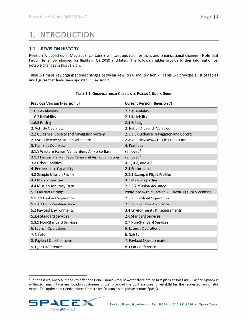
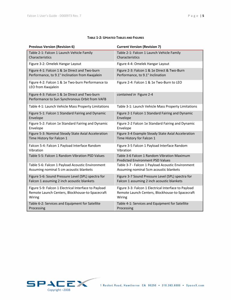
1. INTRODUCTION 1.1. REVISION HISTORY Revision 7, published in May 2008, contains significant updates, revisions and organizational changes. Note that Falcon 1e is now planned for flights in Q2 2010 and later. The following tables provide further information on notable changes in this version. Table 1‐1 maps key organizational changes between Revision 6 and Revision 7. Table 1‐2 provides a list of tables and figures that have been updated in Revision 7.
TABLE 1‐1: ORGANIZATIONAL CHANGES TO FALCON 1 USER'S GUIDE
Previous Version (Revision 6) Current Version (Revision 7)
1.6.1 Availability 2.2 Availability 1.6.2 Reliability 2.3 Reliability 1.6.3 Pricing 2.5 Pricing 2. Vehicle Overview 2. Falcon 1 Launch Vehicles 2.2 Guidance, Control and Navigation System 2.1.1.3 Guidance, Navigation and Control 2.3 Vehicle Axes/Attitude Definitions 2.8 Vehicle Axes/Attitude Definitions 3. Facilities Overview 4. Facilities 3.1.1 Western Range: Vandenberg Air Force Base removed1
3.1.3 Eastern Range: Cape Canaveral Air Force Station removed1 3.2 Other Facilities 4.1 , 4.2, and 4.3 4. Performance Capability 2.4 Performance 4.2 Sample Mission Profile 5.2.3 Example Flight Profiles 4.3 Mass Properties 3.1 Mass Properties 4.4 Mission Accuracy Data 2.1.1.7 Mission Accuracy
5.1 Payload Fairings contained within Section 2. Falcon 1 Launch Vehicles
5.1.3.1 Payload Separation 2.1.1.5 Payload Separation
5.1.3.2 Collision Avoidance 2.1.1.6 Collision Avoidance
5.2 Payload Environments 3.4 Environments & Requirements
5.3.4 Standard Services 2.6 Standard Services
5.3.5 Non‐Standard Services 2.7 Non‐Standard Services
6. Launch Operations 5. Launch Operations
7. Safety 6. Safety
8. Payload Questionnaire 7. Payload Questionnaire
9. Quick Reference 8. Quick Reference
1 In the future, SpaceX intends to offer additional launch sites, however there are no firm plans at this time. Further, SpaceX is willing to launch from any location customers chose, provided the business case for establishing the requested launch site exists. To inquire about performance from a specific launch site, please contact SpaceX.
Falcon 1 User’s Guide ‐ D000973 Rev. 7 P a g e | 5
TABLE 1‐2: UPDATED TABLES AND FIGURES
Previous Version (Revision 6) Current Version (Revision 7)
Table 2‐1: Falcon 1 Launch Vehicle Family Characteristics
Table 2‐1: Falcon 1 Launch Vehicle Family Characteristics
Figure 3‐2: Omelek Hangar Layout Figure 4‐4: Omelek Hangar Layout
Figure 4‐1: Falcon 1 & 1e Direct and Two‐burn Performance, to 9.1° Inclination from Kwajalein
Figure 2‐3: Falcon 1 & 1e Direct & Two‐Burn Performance, to 9.1° Inclination
Figure 4‐2: Falcon 1 & 1e Two‐burn Performance to LEO from Kwajalein
Figure 2‐4: Falcon 1 & 1e Two‐Burn to LEO
Figure 4‐3: Falcon 1 & 1e Direct and Two‐burn Performance to Sun Synchronous Orbit from VAFB
contained in Figure 2‐4
Table 4‐1: Launch Vehicle Mass Property Limitations Table 3‐1: Launch Vehicle Mass Property Limitations
Figure 5‐1: Falcon 1 Standard Fairing and Dynamic Envelope
Figure 2‐1 Falcon 1 Standard Fairing and Dynamic Envelope
Figure 5‐2: Falcon 1e Standard Fairing and Dynamic Envelope
Figure 2‐2 Falcon 1e Standard Fairing and Dynamic Envelope
Figure 5‐3: Nominal Steady State Axial Acceleration Time History for Falcon 1
Figure 3‐4 Example Steady State Axial Acceleration Time History for Falcon 1
Falcon 5‐4: Falcon 1 Payload Interface Random Vibration
Figure 3‐5 Falcon 1 Payload Interface Random Vibration
Table 5‐5: Falcon 1 Random Vibration PSD Values Table 3‐6 Falcon 1 Random Vibration Maximum Predicted Environment PSD Values
Table 5‐6: Falcon 1 Payload Acoustic Environment Assuming nominal 5 cm acoustic blankets
Table 3‐7 ‐ Falcon 1 Payload Acoustic Environment Assuming nominal 5cm acoustic blankets
Figure 5‐6: Sound Pressure Level (SPL) spectra for Falcon 1 assuming 2 inch acoustic blankets
Figure 3‐7 Sound Pressure Level (SPL) spectra for Falcon 1 assuming 2 inch acoustic blankets
Figure 5‐9: Falcon 1 Electrical Interface to Payload Remote Launch Centers, Blockhouse‐to‐Spacecraft Wiring
Figure 3‐3: Falcon 1 Electrical Interface to Payload Remote Launch Centers, Blockhouse‐to‐Spacecraft Wiring
Table 6‐2: Services and Equipment for Satellite Processing
Table 4‐1: Services and Equipment for Satellite Processing
Copyright –2008
Falcon 1 User’s Guide ‐ D000973 Rev. 7 P a g e | 6
Copyright –2008
1.2. PURPOSE The Falcon 1 User’s Guide is a planning document provided for potential and current customers of SpaceX. This document is not intended for detailed design use. Data for detailed design purposes will be exchanged directly between a SpaceX Mission Manager and the Payload Provider.
1.3. COMPANY DESCRIPTION In an era when most technology‐based products follow a path of ever‐increasing capability and reliability while simultaneously reducing costs, launch vehicles today are little changed from those of 40 years ago. SpaceX is changing this paradigm by developing and manufacturing a family of launch vehicles that will ultimately reduce the cost and increase the reliability of access to space by a factor of ten. SpaceX was founded with the philosophy that simplicity, reliability and low‐cost are closely coupled. Thus, we approach all elements of launch services with a focus on simplicity to both increase reliability and lower cost. The SpaceX corporate structure is flat and our business processes are lean, which results in fast decision making and delivery. Products are designed to require low‐infrastructure facilities (production and launch) with low maintenance overhead. Vehicle design teams are co‐located with production and quality assurance staff to tighten this critical feedback loop, resulting in highly producible and low cost designs with quality embedded. To better understand how SpaceX can achieve low cost without sacrificing reliability; please see the Frequently Asked Questions2 section of the Company page on the SpaceX website. Established in 2002 by Elon Musk, the founder of PayPal and the Zip2 Corporation, SpaceX has already developed and launched a light lift launch vehicle‐‐Falcon 1, nearly completed development of the Falcon 9, and developed state of the art testing and launch locations. Our design and manufacturing facilities are conveniently located near the Los Angeles International (LAX) airport. This location allows us to leverage the deep and rich aerospace talent pool available in Southern California. Our state of the art propulsion and structural test facilities are located in Central Texas. SpaceX has built an impressive launch manifest that includes a broad array of commercial, government, and international satellite missions. It is also bolstered by a NASA Launch Services (NLS) contract and selection to demonstrate delivery and return of cargo to the International Space Station for NASA’s Commercial Orbital Transportation Services (COTS) program. Based on these contracts, SpaceX is on sound financial footing.
1.4. FALCON PROGRAM OVERVIEW Drawing upon a rich history of prior launch vehicle and engine programs, SpaceX is privately developing the Falcon family of rockets from the ground up, including main and upper stage engines, the cryogenic tank structure, avionics, guidance & control software and ground support equipment. With the Falcon 1, Falcon 1e, Falcon 9 and Falcon 9 Heavy launch vehicles, SpaceX is able to deliver spacecraft into any inclination and altitude, from low Earth orbit (LEO) to geosynchronous orbit (GEO) to planetary missions. The Falcon 9 and Falcon 9 Heavy are the only US launch vehicles with true engine out reliability. They are also designed such that all stages may be reusable. Our Dragon crew and cargo capsule, currently under development, will revolutionize access to space by providing efficient and reliable transport of crew and cargo to the ISS and other LEO destinations.
2 http://www.spacex.com/company.php#frequently_asked_questions
Falcon 1 User’s Guide ‐ D000973 Rev. 7 P a g e | 7
1.5. MISSION MANAGEMENT To facilitate and streamline communication, each customer works with a single point of contact at SpaceX. The Mission Manager works closely with the customer, SpaceX technical execution staff and all associated licensing agencies in order to achieve a successful mission, and is responsible for coordinating mission integration analysis and documentation deliverables, planning integration meetings and reports and coordinating all integration and test activities associated with the mission. During the launch campaign, the Mission Manager will also facilitate customer insight into the launch operations. Though the launch operations team is ultimately responsible for customer hardware and associated Ground Support Equipment (GSE), the Mission Manager will coordinate all launch site activities to ensure customer satisfaction during this critical phase.
Copyright –2008
Falcon 1 User’s Guide ‐ D000973 Rev. 7 P a g e | 8
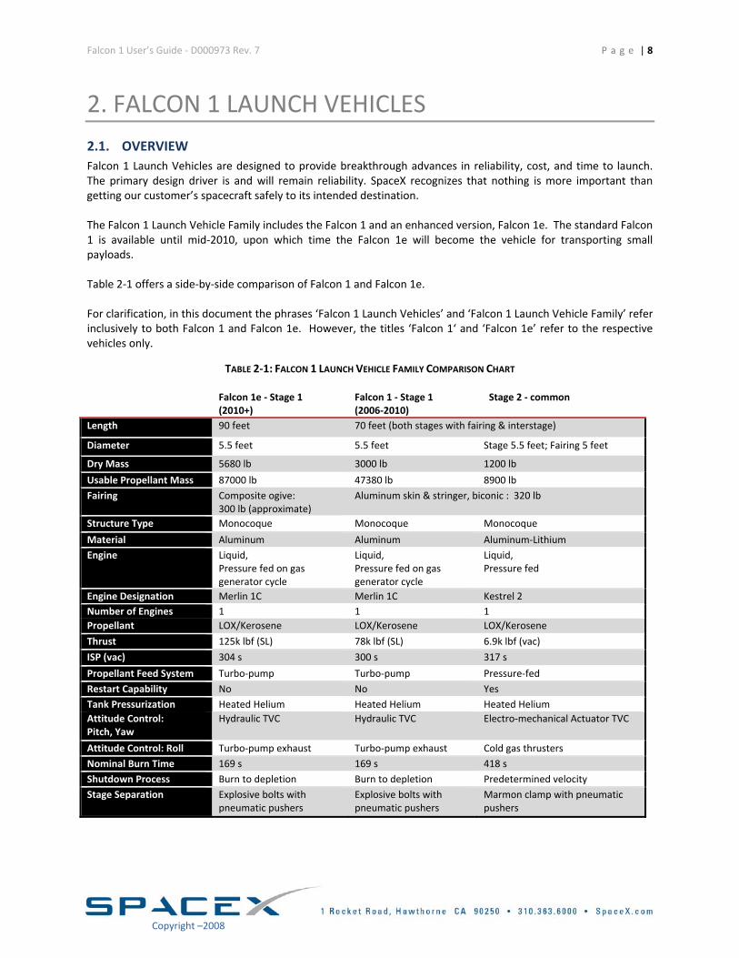
2. FALCON 1 LAUNCH VEHICLES 2.1. OVERVIEW Falcon 1 Launch Vehicles are designed to provide breakthrough advances in reliability, cost, and time to launch. The primary design driver is and will remain reliability. SpaceX recognizes that nothing is more important than getting our customer’s spacecraft safely to its intended destination. The Falcon 1 Launch Vehicle Family includes the Falcon 1 and an enhanced version, Falcon 1e. The standard Falcon 1 is available until mid‐2010, upon which time the Falcon 1e will become the vehicle for transporting small payloads. Table 2‐1 offers a side‐by‐side comparison of Falcon 1 and Falcon 1e. For clarification, in this document the phrases ‘Falcon 1 Launch Vehicles’ and ‘Falcon 1 Launch Vehicle Family’ refer inclusively to both Falcon 1 and Falcon 1e. However, the titles ‘Falcon 1‘ and ‘Falcon 1e’ refer to the respective vehicles only.
TABLE 2‐1: FALCON 1 LAUNCH VEHICLE FAMILY COMPARISON CHART
Falcon 1e ‐ Stage 1 (2010+)
Falcon 1 ‐ Stage 1 (2006‐2010)
Stage 2 ‐ common
Length 90 feet 70 feet (both stages with fairing & interstage)
Diameter 5.5 feet 5.5 feet Stage 5.5 feet; Fairing 5 feet
Dry Mass 5680 lb 3000 lb 1200 lb
Usable Propellant Mass 87000 lb 47380 lb 8900 lb Fairing Composite ogive:
300 lb (approximate) Aluminum skin & stringer, biconic : 320 lb
Structure Type Monocoque Monocoque Monocoque
Material Aluminum Aluminum Aluminum‐Lithium Engine Liquid,
Pressure fed on gas generator cycle
Liquid, Pressure fed on gas generator cycle
Liquid, Pressure fed
Engine Designation Merlin 1C Merlin 1C Kestrel 2 Number of Engines 1 1 1 Propellant LOX/Kerosene LOX/Kerosene LOX/Kerosene
Thrust 125k lbf (SL) 78k lbf (SL) 6.9k lbf (vac)
ISP (vac) 304 s 300 s 317 s
Propellant Feed System Turbo‐pump Turbo‐pump Pressure‐fed Restart Capability No No Yes Tank Pressurization Heated Helium Heated Helium Heated Helium Attitude Control: Pitch, Yaw
Hydraulic TVC Hydraulic TVC Electro‐mechanical Actuator TVC
Attitude Control: Roll Turbo‐pump exhaust Turbo‐pump exhaust Cold gas thrusters Nominal Burn Time 169 s 169 s 418 s Shutdown Process Burn to depletion Burn to depletion Predetermined velocity Stage Separation Explosive bolts with
pneumatic pushers Explosive bolts with pneumatic pushers
Marmon clamp with pneumatic pushers
Copyright –2008
Falcon 1 User’s Guide ‐ D000973 Rev. 7 P a g e | 9
2.1.1. FALCON 1
Falcon 1 is a two‐stage, liquid oxygen (LOX) and rocket grade kerosene (RP‐1) powered launch vehicle. It is designed from the ground up for cost efficient and reliable transport of satellites to low Earth orbit.
2.1.1.1. FIRST STAGE The primary structure is made of a space grade aluminum alloy in a patent pending, graduated monocoque, common bulkhead, flight pressure stabilized architecture developed by SpaceX. The design is a blend between a fully pressure stabilized design, such as Atlas II and a heavier isogrid design, such as Delta II. As a result, we have been able to capture the mass efficiency of pressure stabilization, but avoid the ground handling difficulties of a structure unable to support its own weight. A single SpaceX Merlin engine powers the Falcon 1 first stage. After engine start, Falcon 1 is held down until all vehicle systems are verified to be functioning normally before release for liftoff. Helium tank pressurization is provided by composite over‐wrapped inconel tanks from Arde Corporation, the same model used in Boeing’s Delta IV rocket. Stage separation occurs via dual initiated separation bolts and a pneumatic pusher system. All components are space qualified and have flown before on other launch vehicles. The first stage returns by parachute to a water landing, where it is picked up by ship in a procedure similar to that of the Space Shuttle solid rocket boosters. The parachute recovery system is built for SpaceX by Airborne Systems Corporation, who also builds the Shuttle booster recovery system.
2.1.1.2. SECOND STAGE The second stage tank structure is made of aluminum‐lithium, an alloy possessing the highest strength to weight ratio of any aluminum and currently used by the Space Shuttle External Tank. Although we intend to continue researching alternatives in the long term, for this particular application it has the lowest total system mass for any material we have examined, including liquid oxygen compatible super‐alloys and composites. The tanks are precision machined from thick plate with integral flanges and ports, minimizing the number of welds necessary. The major circumferential welds are all done by an automated welding machine, reducing the potential for error and ensuring consistent quality.
2.1.1.3. GUIDANCE, NAVIGATION AND CONTROL The Guidance, Navigation and Control (GNC) System includes a ruggedized flight computer and an Inertial Measurement Unit (IMU). The flight computer is a PC/104 based Pentium class 586 (Geode) with analog and digital input and output. It provides an interface to the payload on the ground and the engine computer (on the first stage) in flight via Ethernet. A GPS receiver is flown for navigation updates, supporting the IMU. The GNC system also includes an S‐band telemetry system, an S‐Band video downlink, a C‐Band transponder, a bang‐bang controller for tank pressure regulation, batteries and power distribution.
2.1.1.4. FAIRING The launch vehicle will provide a signal to the payload at separation to initiate payload power‐up. Alternate configurations for separation signals (break‐wires, separation switches monitored directly by the payload, or other configurations) can be accommodated as options.
Copyright –2008
Falcon 1 User’s Guide ‐ D000973 Rev. 7 P a g e | 10
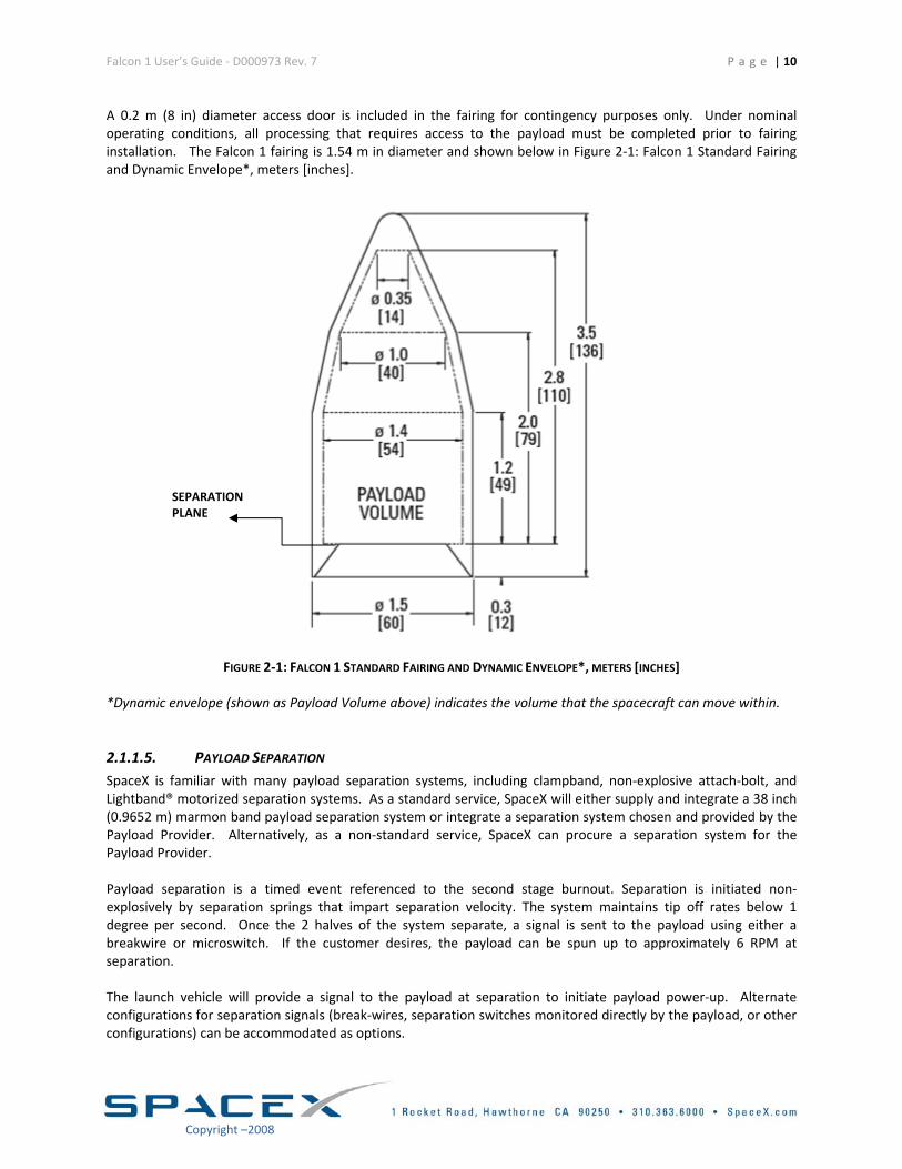
A 0.2 m (8 in) diameter access door is included in the fairing for contingency purposes only. Under nominal operating conditions, all processing that requires access to the payload must be completed prior to fairing installation. The Falcon 1 fairing is 1.54 m in diameter and shown below in Figure 2‐1: Falcon 1 Standard Fairing and Dynamic Envelope*, meters [inches].
SEPARATION PLANE
FIGURE 2‐1: FALCON 1 STANDARD FAIRING AND DYNAMIC ENVELOPE*, METERS [INCHES]
*Dynamic envelope (shown as Payload Volume above) indicates the volume that the spacecraft can move within.
2.1.1.5. PAYLOAD SEPARATION SpaceX is familiar with many payload separation systems, including clampband, non‐explosive attach‐bolt, and Lightband® motorized separation systems. As a standard service, SpaceX will either supply and integrate a 38 inch (0.9652 m) marmon band payload separation system or integrate a separation system chosen and provided by the Payload Provider. Alternatively, as a non‐standard service, SpaceX can procure a separation system for the Payload Provider. Payload separation is a timed event referenced to the second stage burnout. Separation is initiated non‐explosively by separation springs that impart separation velocity. The system maintains tip off rates below 1 degree per second. Once the 2 halves of the system separate, a signal is sent to the payload using either a breakwire or microswitch. If the customer desires, the payload can be spun up to approximately 6 RPM at separation. The launch vehicle will provide a signal to the payload at separation to initiate payload power‐up. Alternate configurations for separation signals (break‐wires, separation switches monitored directly by the payload, or other configurations) can be accommodated as options.
Copyright –2008
Falcon 1 User’s Guide ‐ D000973 Rev. 7 P a g e | 11
Almost any attitude can be accommodated at separation. However, it may take up to 15 minutes to obtain some attitudes prior to separation. In addition, multiple separations can be achieved. The second stage attitude and rate accuracies at separation are:
• Roll ± 2° • Pitch/Yaw ± 0.5° • Body rates ± 0.1°/sec/axis
2.1.1.6. COLLISION AVOIDANCE If analysis shows a Collision Avoidance Maneuver (CAM) is necessary, a CAM will be provided as a standard service. Ten seconds post payload separation the CAM will be performed using the heated helium pressurant and the RCS thrusters. The thrusters are tilted forward by 20° and positioned to minimize gas impingement on the spacecraft while still providing adequate separation.
2.1.1.7. MISSION ACCURACY As a liquid propellant vehicle with re‐start capability, Falcon 1 Launch Vehicles provide flexibility required for payload insertion into orbit with higher eccentricity and for deploying multiple payloads into slightly different orbits. Until verified by actual operations, SpaceX expects to achieve the following minimum target orbital insertion accuracy:
• Inclination ± 0.1° • Perigee ± 5 km • Apogee ± 15 km
2.1.2. FALCON 1e
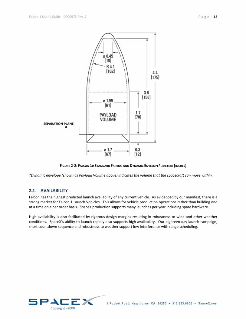
Beginning in Q2 2010, Falcon 1e will offer enhanced performance capabilities by making use of the full capacity and performance of an upgraded Merlin engine. Falcon 1e will have an extended first stage tank to support the propellant consumption needs of this engine while also being strengthened to deal with the larger axial loads. In addition, Falcon 1e will have a larger, lighter 1.7 m fairing. The design is a composite ogive versus the standard aluminum skin and stringer design. The enhanced fairing for the Falcon 1e is shown below in Figure 2‐2. Two access doors are provided as a standard service.
Copyright –2008
Falcon 1 User’s Guide ‐ D000973 Rev. 7 P a g e | 12
SEPARATION PLANE
FIGURE 2‐2: FALCON 1e STANDARD FAIRING AND DYNAMIC ENVELOPE*, METERS [INCHES]
*Dynamic envelope (shown as Payload Volume above) indicates the volume that the spacecraft can move within.
2.2. AVAILABILITY Falcon has the highest predicted launch availability of any current vehicle. As evidenced by our manifest, there is a strong market for Falcon 1 Launch Vehicles. This allows for vehicle production operations rather than building one at a time on a per order basis. SpaceX production supports many launches per year including spare hardware. High availability is also facilitated by rigorous design margins resulting in robustness to wind and other weather conditions. SpaceX’s ability to launch rapidly also supports high availability. Our eighteen‐day launch campaign, short countdown sequence and robustness to weather support low interference with range scheduling.
Copyright –2008
Falcon 1 User’s Guide ‐ D000973 Rev. 7 P a g e | 13
Copyright –2008
2.3. RELIABILITY The vast majority of launch vehicle failures in the past two decades can be attributed to three causes: engine, avionics and stage separation failures. An analysis by Aerospace Corporation3 showed that 91% of known failures can be attributed to those subsystems. With this in mind, Falcon 1 Launch Vehicles are designed to have robust propulsion systems and the minimum number of separation events: Merlin 1C is a man‐rated engine with high structural margins and a highly reliable, redundant ignition system, and Falcon 1 is a two stage vehicle which minimizes separation events. Similarly with the vehicle avionics system, SpaceX has gone the extra mile in building a state‐of‐the‐art system using 21st century electronics that will feed forward into larger vehicle developments following Falcon 1. Falcon 1 Launch Vehicles are designed for high reliability starting at the architectural level. Many design choices were made to ensure reliability was not compromised. These choices include:
• ROBUST STRUCTURAL DESIGN MARGINS The first stage is designed to be recovered and reused, and therefore, must have significantly higher margins than an expendable stage. To date, we have taken a flight first stage through over 190 cryogenic pressure cycles with no evidence of fatigue.
• PROPULSION AND SEPARATION EVENT DESIGN
Propulsion and separation events are the primary causes of failures in launch vehicles. Therefore, we have designed Falcon 1 with the minimum number of engines, in serial, required for the mission: only one engine per stage and only one engine that is started outside of operator control. We have also minimized the number of stages (2) to minimize separation events. In addition, as a part of our launch operations, we hold down the first stage after ignition, but prior to release to watch engine trends. If an off‐nominal condition exists, then an autonomous abort is conducted. This helps prevent an engine performance issue from causing a failure in flight.
• PUMP‐FED PROPULSION
Although a pressure‐fed system has the fewest number of parts, it relies on cryogenic tank structures and technology that have never been proven in full scale testing. Therefore, the trade was made that the first stage should be pump‐fed, but with the simplest possible turbopump design: a single shaft for both the LOX and RP, a gas generator cycle versus the more complex staged combustion and finally, an ablative chamber. In addition, the pintle injector was selected for both engine stages for its inherent combustion stability.
• ETHERNET BACKBONE
SpaceX eliminated the design and integration complexity and opportunity for human error associated with large serial cable bundles with the use of the Ethernet bus.
• FAILURE MODE MINIMIZATION
SpaceX minimized the number of failure modes by minimizing the number of separate subsystems. Our first stage thrust vector control (TVC) system makes use of the pressurized fuel, rocket‐grade kerosene (RP‐1), through a line tapped off of the high pressure RP side of the pump to power the TVC. This eliminates the separate hydraulic system. In addition it eliminates the failure mode associated with running out of pressurized fluid. Another example is the first stage roll control system—a redundant gimbal actuates the exhaust gas for roll control, again, eliminating a separate system.
3 http://www.aero.org/publications/crosslink/winter2001/03.html. A hard copy of this reference can be made available upon request.
Falcon 1 User’s Guide ‐ D000973 Rev. 7 P a g e | 14
• RIGOROUS TESTING In addition to these design decisions, Falcon 1 will undergo an exhaustive series of tests from the component to the vehicle system level. This includes component level qualification and workmanship testing, structures load and proof testing, flight system and propulsion subsystem level testing, full first and second stage testing up to full system testing, including a 5 second static firing. In addition to testing environmental extremes (plus margin), all hardware must be tested to account for off nominal conditions. For example, both our stage and fairing separation tests require testing for off‐nominal cases with respect to geometrical misalignment, anomalous pyrotechnic timing and sequencing.
• LAUNCH OPERATIONS
A major contributor to a reliable system is its operations. To support robust launch operations, our countdown is fully automated with thousands of checks made prior to vehicle release. After first stage ignition, the vehicle is not released until the first stage engine is confirmed to be operating normally. A safe shutdown is executed should any off nominal conditions be detected. Falcon 1 design and our operations crew can accommodate very rapid recycle to recover depending upon the cause of the abort.
Copyright –2008
Falcon 1 User’s Guide ‐ D000973 Rev. 7 P a g e | 15
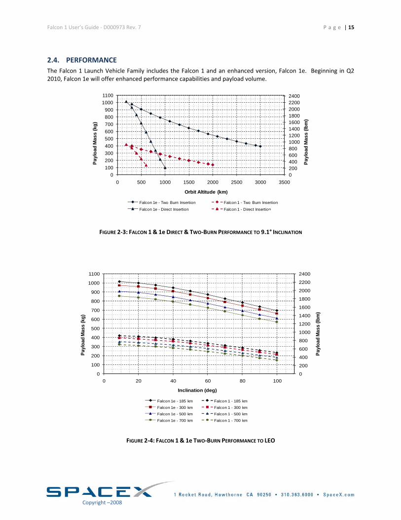
2.4. PERFORMANCE The Falcon 1 Launch Vehicle Family includes the Falcon 1 and an enhanced version, Falcon 1e. Beginning in Q2 2010, Falcon 1e will offer enhanced performance capabilities and payload volume.
020040060080010001200140016001800200022002400
0100200300400500600700800900
10001100
0 500 1000 1500 2000 2500 3000 3500
Payl
oad
Mas
s (lb
m)
Payl
oad
Mas
s (k
g)
Orbit Altitude (km)
Falcon 1e - Two Burn Insertion Falcon 1 - Two Burn Insertion
Falcon 1e - Direct Insertion Falcon 1 - Direct Insertion
F1E87 200SBM0 NB 02/14/08REVDP 100SBM0 NB 02/14/08
FIGURE 2‐3: FALCON 1 & 1e DIRECT & TWO‐BURN PERFORMANCE TO 9.1° INCLINATION
0
200
400
600
800
1000
1200
1400
1600
1800
2000
2200
2400
0
100
200
300
400
500
600
700
800
900
1000
1100
0 20 40 60 80 100
Payl
oad
Mas
s (lb
m)
Payl
oad
Mas
s (k
g)
Inclination (deg)
Falcon 1e - 185 km Falcon 1 - 185 km
Falcon 1e - 300 km Falcon 1 - 300 km
Falcon 1e - 500 km Falcon 1 - 500 km
Falcon 1e - 700 km Falcon 1 - 700 kmF1E87 200SBM0 NB 02/14/08REVDP 100SBM0 NB 02/14/08
FIGURE 2‐4: FALCON 1 & 1e TWO‐BURN PERFORMANCE TO LEO
Copyright –2008
Falcon 1 User’s Guide ‐ D000973 Rev. 7
P a g e | 16
Copyright –2008
Pricing and Performance
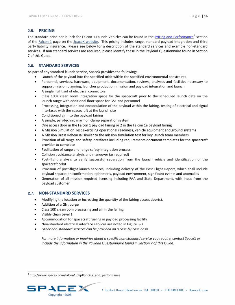
2.5. PRICING The standard price per launch for Falcon 1 Launch Vehicles can be found in the 4 section of the Falcon 1 page on the SpaceX website. This pricing includes range, standard payload integration and third party liability insurance. Please see below for a description of the standard services and example non‐standard services. If non standard services are required, please identify these in the Payload Questionnaire found in Section of this Guide. 7
2.6. STANDARD SERVICES As part of any standard launch service, SpaceX provides the following:
• Launch of the payload into the specified orbit within the specified environmental constraints • Personnel, services, hardware, equipment, documentation, reviews, analyses and facilities necessary to
support mission planning, launcher production, mission and payload integration and launch • A single flight set of electrical connectors • Class 100K clean room integration space for the spacecraft prior to the scheduled launch date on the
launch range with additional floor space for GSE and personnel • Processing, integration and encapsulation of the payload within the fairing, testing of electrical and signal
interfaces with the spacecraft at the launch site • Conditioned air into the payload fairing • A simple, pyrotechnic marmon clamp separation system • One access door in the Falcon 1 payload fairing or 2 in the Falcon 1e payload fairing • A Mission Simulation Test exercising operational readiness, vehicle equipment and ground systems • A Mission Dress Rehearsal similar to the mission simulation test for key launch team members • Provision of all range and safety interfaces including requirements document templates for the spacecraft
provider to complete • Facilitation of range and range safety integration process • Collision avoidance analysis and maneuver (as required) • Post‐flight analysis to verify successful separation from the launch vehicle and identification of the
spacecraft orbit • Provision of post‐flight launch services, including delivery of the Post Flight Report, which shall include
payload separation confirmation, ephemeris, payload environment, significant events and anomalies • Generation of all mission required licensing including FAA and State Department, with input from the
payload customer
2.7. NON‐STANDARD SERVICES • Modifying the location or increasing the quantity of the fairing access door(s). • Addition of a GN2 purge • Class 10K cleanroom processing and air in the fairing • Visibly clean Level 1 • Accommodation for spacecraft fueling in payload processing facility • Non‐standard electrical interface services are noted in Figure 3‐3 • Other non‐standard services can be provided on a case‐by‐case basis.
For more information or inquiries about a specific non‐standard service you require, contact SpaceX or include the information in the Payload Questionnaire found in Section 7 of this Guide.
4 http://www.spacex.com/falcon1.php#pricing_and_performance
Falcon 1 User’s Guide ‐ D000973 Rev. 7 P a g e | 17
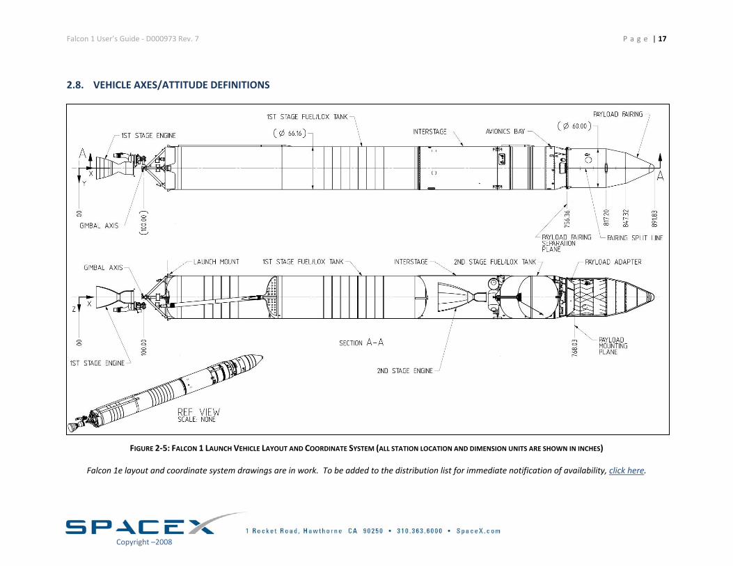
2.8. VEHICLE AXES/ATTITUDE DEFINITIONS
FIGURE 2‐5: FALCON 1 LAUNCH VEHICLE LAYOUT AND COORDINATE SYSTEM (ALL STATION LOCATION AND DIMENSION UNITS ARE SHOWN IN INCHES)
Falcon 1e layout and coordinate system drawings are in work. To be added to the distribution list for immediate notification of availability, click here.
Copyright –2008
Falcon 1 User’s Guide ‐ D000973 Rev. 7 P a g e | 18
Copyright –2008
3. REQUIREMENTS & ENVIRONMENTS
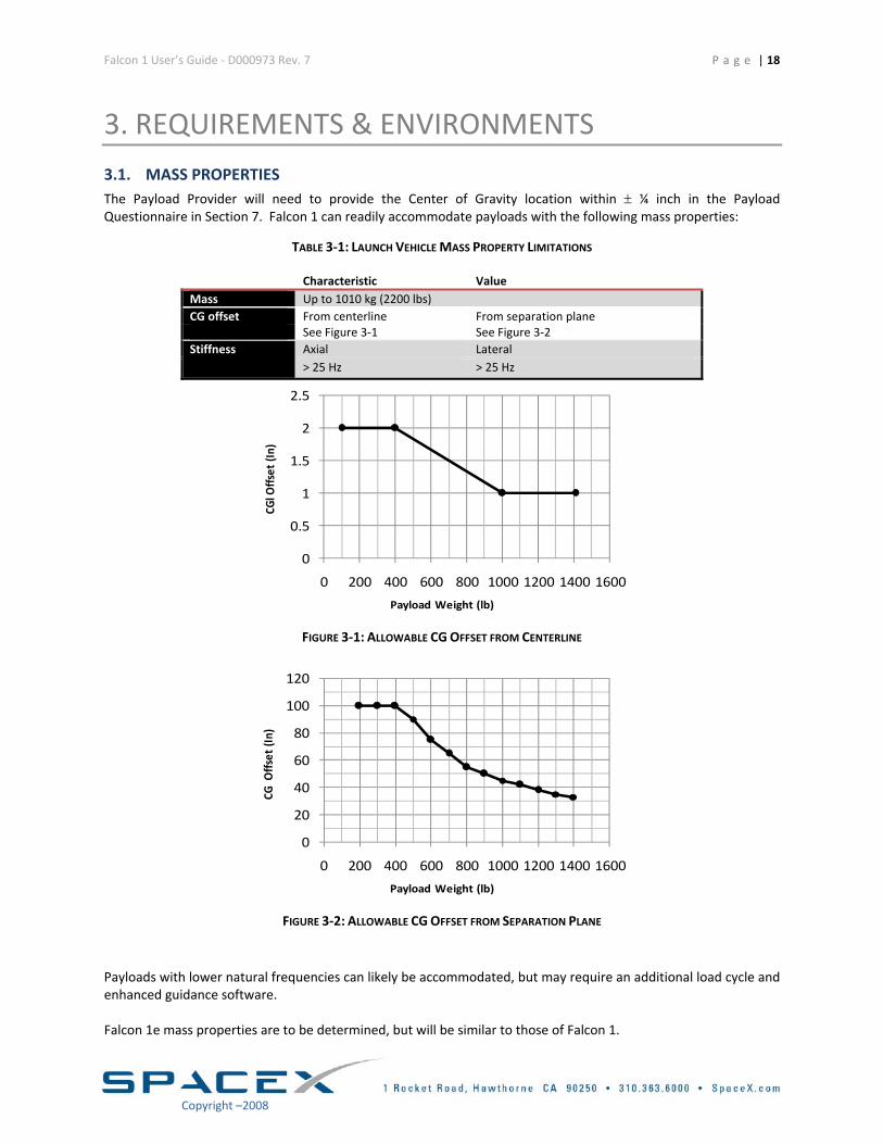
3.1. MASS PROPERTIES The Payload Provider will need to provide the Center of Gravity location within ± ¼ inch in the Payload Questionnaire in Section 7. Falcon 1 can readily accommodate payloads with the following mass properties:
TABLE 3‐1: LAUNCH VEHICLE MASS PROPERTY LIMITATIONS
Characteristic Value Mass Up to 1010 kg (2200 lbs) CG offset From centerline From separation plane See Figure 3‐1 See Figure 3‐2
Stiffness Axial Lateral > 25 Hz > 25 Hz
0
0.5
1
1.5
2
2.5
0 200 400 600 800 1000 1200 1400 1600
Payload Weight (lb)
CGl O
ffset
(In)
FIGURE 3‐1: ALLOWABLE CG OFFSET FROM CENTERLINE
0
20
40
60
80
100
120
0 200 400 600 800 1000 1200 1400 1600
Payload Weight (lb)
CG O
ffset(In)
FIGURE 3‐2: ALLOWABLE CG OFFSET FROM SEPARATION PLANE
Payloads with lower natural frequencies can likely be accommodated, but may require an additional load cycle and enhanced guidance software. Falcon 1e mass properties are to be determined, but will be similar to those of Falcon 1.
Falcon 1 User’s Guide ‐ D000973 Rev. 7
P a g e | 19
Copyright –2008
3.2. PAYLOAD INTERFACES The launch vehicle will provide a signal to the payload at separation to initiate payload power‐up. Alternate configurations for separation signals (break‐wires, separation switches monitored directly by the payload, or other configurations) can be accommodated as options. An 8 in (0.2 m) diameter access door is included in the fairing for contingency purposes only. Under nominal operating conditions, all processing that requires access to the payload must be completed prior to fairing installation. Payloads with consumables must include the ability to de‐tank through the fairing access door while on the launch pad.
3.2.1. FALCON PAYLOAD ATTACH FITTINGS
Payloads interface with the launch vehicle by means of a Payload Attach Fitting (PAF). Falcon 1 Launch Vehicles offer a standard and modifiable PAF to accommodate customer needs. The mechanical interface for the standard service is 38.81 in (0.986 m) bolt circle with 60 attach points.
3.2.2. TEST FITTINGS AND FITCHECK POLICY
A mechanical fit check (including electrical connector locations) may be conducted with the spacecraft or a representative spacecraft template using a mechanical template. This is typically done prior to shipment of the spacecraft to the launch site. SpaceX personnel will be available to conduct this activity at the SpaceX facility. Specific requirements for the fit check will be worked with the SpaceX Mission Manager during the integration process.
3.2.3. ELECTRICAL DESIGN CRITERIA
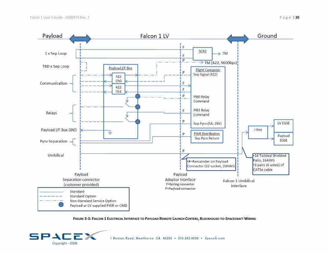
The electrical interface for ground and flight operations is shown in Figure 3‐3. It is preferred that the satellite is powered OFF during launch. If the satellite is on, it may not transmit and special precautions must be taken to eliminate the potential for interference. The electrical interface provides flexibility on the ground through Ethernet or pass through cables. The Ethernet is a shared resource and the payload should therefore not saturate the network. Note that the distance between Mission Control and the vehicle is significant and that the Ethernet data line serves as the only connection between Mission Control and the launch pad. For remote control of battery chargers located at the launch pad and other ground equipment, up to 4 relays are available (with a maximum load of 3 A at 28 V) through the pad computer. Grounding ‐ The satellite mounting interface must be conductive. The electrical resistance will be verified to be <0.1Ω prior to the assembly of the payload onto the separation system. With the standard interface, the connector types and pin designation will be determined during the integration process. As an optional service, an enhanced telemetry system can be supplied.
Falcon 1 User’s Guide ‐ D000973 Rev. 7 P a g e | 20
FIGURE 3‐3: FALCON 1 ELECTRICAL INTERFACE TO PAYLOAD REMOTE LAUNCH CENTERS, BLOCKHOUSE‐TO‐SPACECRAFT WIRING
Copyright –2008
Falcon 1 User’s Guide ‐ D000973 Rev. 7 P a g e | 21
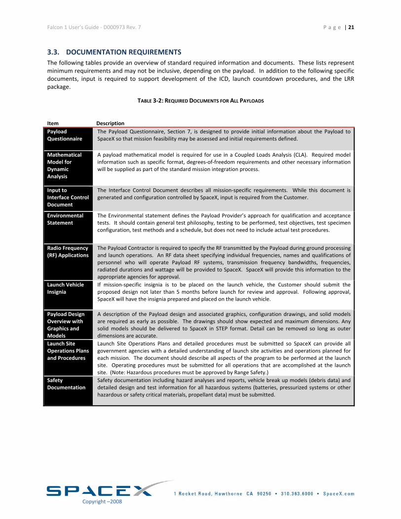
3.3. DOCUMENTATION REQUIREMENTS The following tables provide an overview of standard required information and documents. These lists represent minimum requirements and may not be inclusive, depending on the payload. In addition to the following specific documents, input is required to support development of the ICD, launch countdown procedures, and the LRR package.
TABLE 3‐2: REQUIRED DOCUMENTS FOR ALL PAYLOADS
Item Description Payload Questionnaire
The Payload Questionnaire, Section 7, is designed to provide initial information about the Payload to SpaceX so that mission feasibility may be assessed and initial requirements defined.
Mathematical Model for Dynamic Analysis
A payload mathematical model is required for use in a Coupled Loads Analysis (CLA). Required model information such as specific format, degrees‐of‐freedom requirements and other necessary information will be supplied as part of the standard mission integration process.
Input to Interface Control Document
The Interface Control Document describes all mission‐specific requirements. While this document is generated and configuration controlled by SpaceX, input is required from the Customer.
Environmental Statement
The Environmental statement defines the Payload Provider’s approach for qualification and acceptance tests. It should contain general test philosophy, testing to be performed, test objectives, test specimen configuration, test methods and a schedule, but does not need to include actual test procedures.
Radio Frequency (RF) Applications
The Payload Contractor is required to specify the RF transmitted by the Payload during ground processing and launch operations. An RF data sheet specifying individual frequencies, names and qualifications of personnel who will operate Payload RF systems, transmission frequency bandwidths, frequencies, radiated durations and wattage will be provided to SpaceX. SpaceX will provide this information to the appropriate agencies for approval.
Launch Vehicle Insignia
If mission‐specific insignia is to be placed on the launch vehicle, the Customer should submit the proposed design not later than 5 months before launch for review and approval. Following approval, SpaceX will have the insignia prepared and placed on the launch vehicle.
Payload Design Overview with Graphics and Models
A description of the Payload design and associated graphics, configuration drawings, and solid models are required as early as possible. The drawings should show expected and maximum dimensions. Any solid models should be delivered to SpaceX in STEP format. Detail can be removed so long as outer dimensions are accurate.
Launch Site Operations Plans and Procedures
Launch Site Operations Plans and detailed procedures must be submitted so SpaceX can provide all government agencies with a detailed understanding of launch site activities and operations planned for each mission. The document should describe all aspects of the program to be performed at the launch site. Operating procedures must be submitted for all operations that are accomplished at the launch site. (Note: Hazardous procedures must be approved by Range Safety.)
Safety Documentation
Safety documentation including hazard analyses and reports, vehicle break up models (debris data) and detailed design and test information for all hazardous systems (batteries, pressurized systems or other hazardous or safety critical materials, propellant data) must be submitted.
Copyright –2008
Falcon 1 User’s Guide ‐ D000973 Rev. 7 P a g e | 22
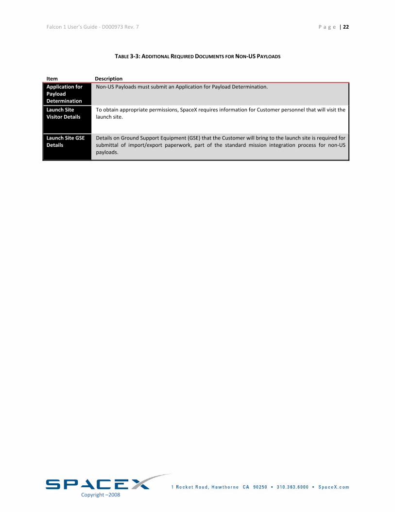
TABLE 3‐3: ADDITIONAL REQUIRED DOCUMENTS FOR NON‐US PAYLOADS
Item Description Application for Payload Determination
Non‐US Payloads must submit an Application for Payload Determination.
Launch Site Visitor Details
To obtain appropriate permissions, SpaceX requires information for Customer personnel that will visit the launch site.
Launch Site GSE Details
Details on Ground Support Equipment (GSE) that the Customer will bring to the launch site is required for submittal of import/export paperwork, part of the standard mission integration process for non‐US payloads.
Copyright –2008
Falcon 1 User’s Guide ‐ D000973 Rev. 7 P a g e | 23
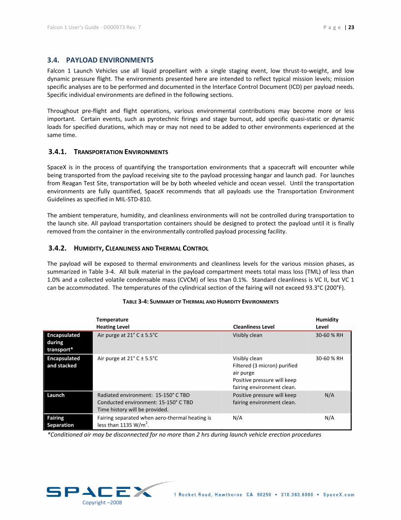
3.4. PAYLOAD ENVIRONMENTS Falcon 1 Launch Vehicles use all liquid propellant with a single staging event, low thrust‐to‐weight, and low dynamic pressure flight. The environments presented here are intended to reflect typical mission levels; mission specific analyses are to be performed and documented in the Interface Control Document (ICD) per payload needs. Specific individual environments are defined in the following sections. Throughout pre‐flight and flight operations, various environmental contributions may become more or less important. Certain events, such as pyrotechnic firings and stage burnout, add specific quasi‐static or dynamic loads for specified durations, which may or may not need to be added to other environments experienced at the same time.
3.4.1. TRANSPORTATION ENVIRONMENTS
SpaceX is in the process of quantifying the transportation environments that a spacecraft will encounter while being transported from the payload receiving site to the payload processing hangar and launch pad. For launches from Reagan Test Site, transportation will be by both wheeled vehicle and ocean vessel. Until the transportation environments are fully quantified, SpaceX recommends that all payloads use the Transportation Environment Guidelines as specified in MIL‐STD‐810. The ambient temperature, humidity, and cleanliness environments will not be controlled during transportation to the launch site. All payload transportation containers should be designed to protect the payload until it is finally removed from the container in the environmentally controlled payload processing facility.
3.4.2. HUMIDITY, CLEANLINESS AND THERMAL CONTROL
The payload will be exposed to thermal environments and cleanliness levels for the various mission phases, as summarized in Table 3‐4. All bulk material in the payload compartment meets total mass loss (TML) of less than 1.0% and a collected volatile condensable mass (CVCM) of less than 0.1%. Standard cleanliness is VC II, but VC 1 can be accommodated. The temperatures of the cylindrical section of the fairing will not exceed 93.3°C (200°F).
TABLE 3‐4: SUMMARY OF THERMAL AND HUMIDITY ENVIRONMENTS
Temperature Heating Level Cleanliness Level
Humidity Level
Encapsulated during transport*
Air purge at 21° C ± 5.5°C Visibly clean 30‐60 % RH
Encapsulated and stacked
Air purge at 21° C ± 5.5°C Visibly clean Filtered (3 micron) purified air purge Positive pressure will keep fairing environment clean.
30‐60 % RH
Launch Radiated environment: 15‐150° C TBD Conducted environment: 15‐150° C TBD Time history will be provided.
Positive pressure will keep fairing environment clean.
N/A
Fairing Separation
Fairing separated when aero‐thermal heating is less than 1135 W/m2.
N/A
N/A
*Conditioned air may be disconnected for no more than 2 hrs during launch vehicle erection procedures
Copyright –2008
Falcon 1 User’s Guide ‐ D000973 Rev. 7 P a g e | 24
Copyright –2008
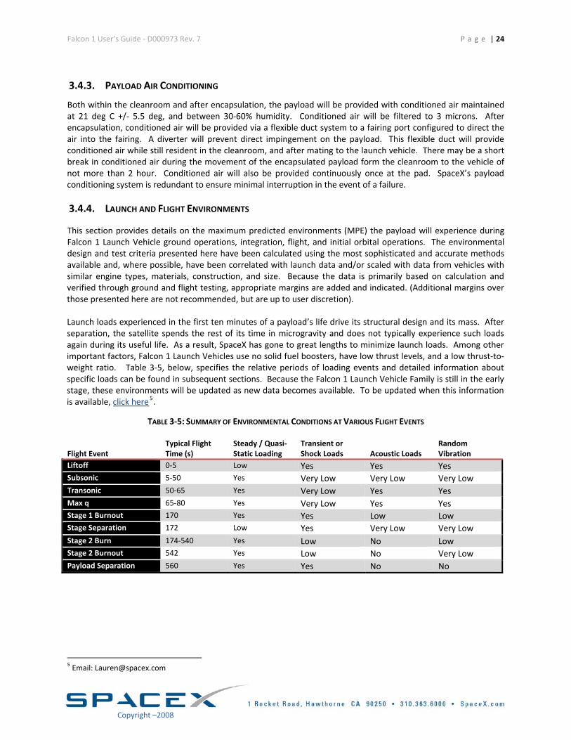
3.4.3. PAYLOAD AIR CONDITIONING
Both within the cleanroom and after encapsulation, the payload will be provided with conditioned air maintained at 21 deg C +/‐ 5.5 deg, and between 30‐60% humidity. Conditioned air will be filtered to 3 microns. After encapsulation, conditioned air will be provided via a flexible duct system to a fairing port configured to direct the air into the fairing. A diverter will prevent direct impingement on the payload. This flexible duct will provide conditioned air while still resident in the cleanroom, and after mating to the launch vehicle. There may be a short break in conditioned air during the movement of the encapsulated payload form the cleanroom to the vehicle of not more than 2 hour. Conditioned air will also be provided continuously once at the pad. SpaceX’s payload conditioning system is redundant to ensure minimal interruption in the event of a failure.
3.4.4. LAUNCH AND FLIGHT ENVIRONMENTS
This section provides details on the maximum predicted environments (MPE) the payload will experience during Falcon 1 Launch Vehicle ground operations, integration, flight, and initial orbital operations. The environmental design and test criteria presented here have been calculated using the most sophisticated and accurate methods available and, where possible, have been correlated with launch data and/or scaled with data from vehicles with similar engine types, materials, construction, and size. Because the data is primarily based on calculation and verified through ground and flight testing, appropriate margins are added and indicated. (Additional margins over those presented here are not recommended, but are up to user discretion). Launch loads experienced in the first ten minutes of a payload’s life drive its structural design and its mass. After separation, the satellite spends the rest of its time in microgravity and does not typically experience such loads again during its useful life. As a result, SpaceX has gone to great lengths to minimize launch loads. Among other important factors, Falcon 1 Launch Vehicles use no solid fuel boosters, have low thrust levels, and a low thrust‐to‐weight ratio. Table 3‐5, below, specifies the relative periods of loading events and detailed information about specific loads can be found in subsequent sections. Because the Falcon 1 Launch Vehicle Family is still in the early stage, these environments will be updated as new data becomes available. To be updated when this information is available, click here5.
TABLE 3‐5: SUMMARY OF ENVIRONMENTAL CONDITIONS AT VARIOUS FLIGHT EVENTS
Flight Event Typical Flight Time (s)
Steady / Quasi‐ Static Loading
Transient or Shock Loads Acoustic Loads
Random Vibration
Liftoff 0‐5 Low Yes Yes Yes Subsonic 5‐50 Yes Very Low Very Low Very LowTransonic 50‐65 Yes Very Low Yes Yes Max q 65‐80 Yes Very Low Yes Yes Stage 1 Burnout 170 Yes Yes Low Low Stage Separation 172 Low Yes Very Low Very LowStage 2 Burn 174‐540 Yes Low No Low Stage 2 Burnout 542 Yes Low No Very LowPayload Separation 560 Yes Yes No No
5 Email: [email protected]
Falcon 1 User’s Guide ‐ D000973 Rev. 7 P a g e | 25
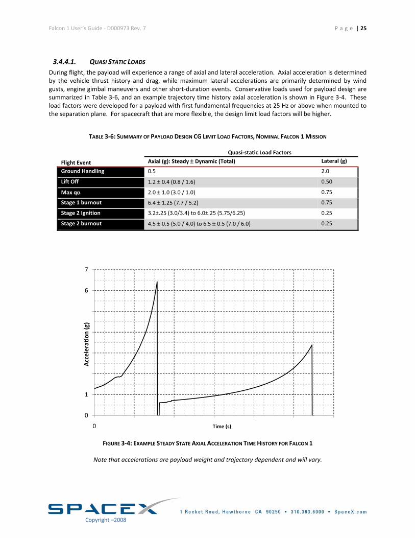
3.4.4.1. QUASI STATIC LOADS During flight, the payload will experience a range of axial and lateral acceleration. Axial acceleration is determined by the vehicle thrust history and drag, while maximum lateral accelerations are primarily determined by wind gusts, engine gimbal maneuvers and other short‐duration events. Conservative loads used for payload design are summarized in Table 3‐6, and an example trajectory time history axial acceleration is shown in Figure 3‐4. These load factors were developed for a payload with first fundamental frequencies at 25 Hz or above when mounted to the separation plane. For spacecraft that are more flexible, the design limit load factors will be higher.
TABLE 3‐6: SUMMARY OF PAYLOAD DESIGN CG LIMIT LOAD FACTORS, NOMINAL FALCON 1 MISSION
Flight Event
Quasi‐static Load Factors
Axial (g): Steady ± Dynamic (Total) Lateral (g)
Ground Handling 0.5 2.0
Lift Off 1.2 ± 0.4 (0.8 / 1.6) 0.50
Max qα 2.0 ± 1.0 (3.0 / 1.0) 0.75
Stage 1 burnout 6.4 ± 1.25 (7.7 / 5.2) 0.75
Stage 2 Ignition 3.2±.25 (3.0/3.4) to 6.0±.25 (5.75/6.25) 0.25
Stage 2 burnout 4.5 ± 0.5 (5.0 / 4.0) to 6.5 ± 0.5 (7.0 / 6.0) 0.25
0
1
2
3
4
5
6
7
0 100 200 300 400 500 600
Acceleration (g)
Time (s)
FIGURE 3‐4: EXAMPLE STEADY STATE AXIAL ACCELERATION TIME HISTORY FOR FALCON 1
Note that accelerations are payload weight and trajectory dependent and will vary.
Copyright –2008
Falcon 1 User’s Guide ‐ D000973 Rev. 7 P a g e | 26
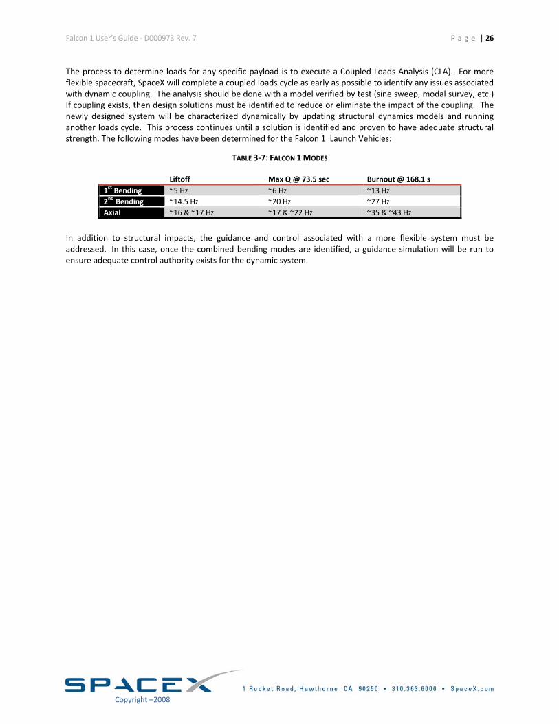
The process to determine loads for any specific payload is to execute a Coupled Loads Analysis (CLA). For more flexible spacecraft, SpaceX will complete a coupled loads cycle as early as possible to identify any issues associated with dynamic coupling. The analysis should be done with a model verified by test (sine sweep, modal survey, etc.) If coupling exists, then design solutions must be identified to reduce or eliminate the impact of the coupling. The newly designed system will be characterized dynamically by updating structural dynamics models and running another loads cycle. This process continues until a solution is identified and proven to have adequate structural strength. The following modes have been determined for the Falcon 1 Launch Vehicles:
TABLE 3‐7: FALCON 1 MODES
Liftoff Max Q @ 73.5 sec Burnout @ 168.1 s 1st Bending ~5 Hz ~6 Hz ~13 Hz 2nd Bending ~14.5 Hz ~20 Hz ~27 Hz Axial ~16 & ~17 Hz ~17 & ~22 Hz ~35 & ~43 Hz
In addition to structural impacts, the guidance and control associated with a more flexible system must be addressed. In this case, once the combined bending modes are identified, a guidance simulation will be run to ensure adequate control authority exists for the dynamic system.
Copyright –2008
Falcon 1 User’s Guide ‐ D000973 Rev. 7 P a g e | 27
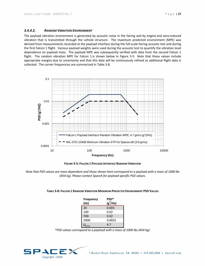
3.4.4.2. RANDOM VIBRATION ENVIRONMENT The payload vibration environment is generated by acoustic noise in the fairing and by engine and aero‐induced vibration that is transmitted through the vehicle structure. The maximum predicted environment (MPE) was derived from measurements recorded at the payload interface during the full‐scale fairing acoustic test and during the first Falcon 1 flight. Various payload weights were used during the acoustic test to quantify the vibration level dependence on payload mass. The payload MPE was subsequently verified with data from the second Falcon 1 flight. The random vibration MPE for Falcon 1 is shown below in Figure 3‐5. Note that these values include appropriate margins due to uncertainty and that this data will be continuously refined as additional flight data is collected. The corner frequencies are summarized in Table 3‐8. .
0.0001
0.001
0.01
0.1
10 100 1000 10000
Falcon 1 Payload Interface Random Vibration MPE, 4.7 grms (g^2/Hz)
MIL-STD-1540E Minimum Vibration ATP for Spacecraft (3.8 grms)
Frequency (Hz)
PSD (g
2 /HZ)
FIGURE 3‐5: FALCON 1 PAYLOAD INTERFACE RANDOM VIBRATION
Note that PSD values are mass dependent and those shown here correspond to a payload with a mass of 1000 lbs (454 kg). Please contact SpaceX for payload specific PSD values.
TABLE 3‐8: FALCON 1 RANDOM VIBRATION MAXIMUM PREDICTED ENVIRONMENT PSD VALUES
Frequency(Hz)
PSD*(g2/Hz)
20 0.003100 0.02700 0.022000 0.0025
Grms 4.7
*PSD values correspond to a payload with a mass of 1000 lbs (454 kg).
Copyright –2008
Falcon 1 User’s Guide ‐ D000973 Rev. 7 P a g e | 28
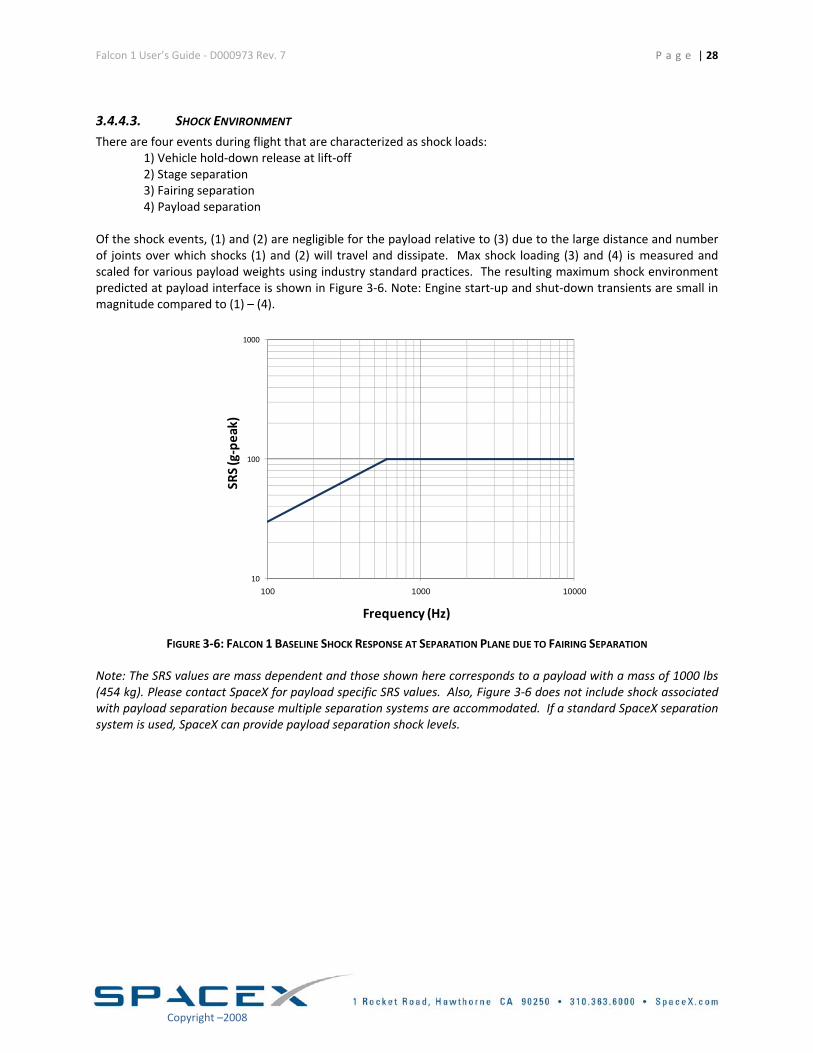
3.4.4.3. SHOCK ENVIRONMENT There are four events during flight that are characterized as shock loads:
1) Vehicle hold‐down release at lift‐off 2) Stage separation 3) Fairing separation 4) Payload separation
Of the shock events, (1) and (2) are negligible for the payload relative to (3) due to the large distance and number of joints over which shocks (1) and (2) will travel and dissipate. Max shock loading (3) and (4) is measured and scaled for various payload weights using industry standard practices. The resulting maximum shock environment predicted at payload interface is shown in Figure 3‐6. Note: Engine start‐up and shut‐down transients are small in magnitude compared to (1) – (4).
10
100
1000
100 1000 10000
Frequency (Hz)
SRS(g‐peak)
FIGURE 3‐6: FALCON 1 BASELINE SHOCK RESPONSE AT SEPARATION PLANE DUE TO FAIRING SEPARATION
Note: The SRS values are mass dependent and those shown here corresponds to a payload with a mass of 1000 lbs (454 kg). Please contact SpaceX for payload specific SRS values. Also, Figure 3‐6 does not include shock associated with payload separation because multiple separation systems are accommodated. If a standard SpaceX separation system is used, SpaceX can provide payload separation shock levels.
Copyright –2008
Falcon 1 User’s Guide ‐ D000973 Rev. 7 P a g e | 29
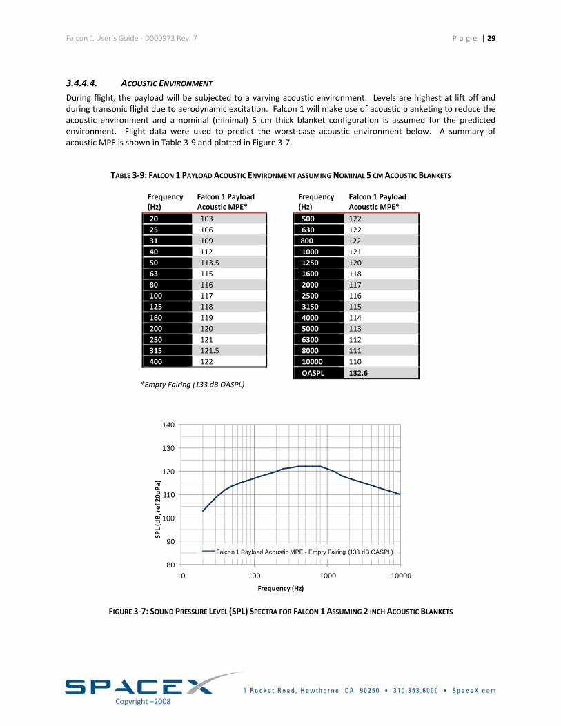
3.4.4.4. ACOUSTIC ENVIRONMENT During flight, the payload will be subjected to a varying acoustic environment. Levels are highest at lift off and during transonic flight due to aerodynamic excitation. Falcon 1 will make use of acoustic blanketing to reduce the acoustic environment and a nominal (minimal) 5 cm thick blanket configuration is assumed for the predicted environment. Flight data were used to predict the worst‐case acoustic environment below. A summary of acoustic MPE is shown in Table 3‐9 and plotted in Figure 3‐7.
TABLE 3‐9: FALCON 1 PAYLOAD ACOUSTIC ENVIRONMENT ASSUMING NOMINAL 5 CM ACOUSTIC BLANKETS
Frequency (Hz)
Falcon 1 Payload Acoustic MPE*
Frequency (Hz)
Falcon 1 Payload Acoustic MPE*
20 103 500 122 25 106 630 122 31 109 800 122 40 112 1000 121 50 113.5 1250 120 63 115 1600 118 80 116 2000 117 100 117 2500 116 125 118 3150 115 160 119 4000 114 200 120 5000 113 250 121 6300 112 315 121.5 8000 111 400 122 10000 110 OASPL 132.6
*Empty Fairing (133 dB OASPL)
80
90
100
110
120
130
140
10 100 1000 10000
Falcon 1 Payload Acoustic MPE - Empty Fairing (133 dB OASPL)
SPL (dB, re
f 20u
Pa)
Frequency (Hz)
FIGURE 3‐7: SOUND PRESSURE LEVEL (SPL) SPECTRA FOR FALCON 1 ASSUMING 2 INCH ACOUSTIC BLANKETS
Copyright –2008
Falcon 1 User’s Guide ‐ D000973 Rev. 7 P a g e | 30
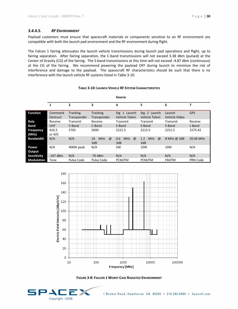
3.4.4.5. RF ENVIRONMENT Payload customers must ensure that spacecraft materials or components sensitive to an RF environment are compatible with both the launch pad environment and the RF environment during flight. The Falcon 1 fairing attenuates the launch vehicle transmissions during launch pad operations and flight, up to fairing separation. After fairing separation, the C‐band transmissions will not exceed 3.38 dbm (pulsed) at the Center of Gravity (CG) of the fairing. The S‐band transmissions at this time will not exceed ‐4.87 dbm (continuous) at the CG of the fairing. We recommend powering the payload OFF during launch to minimize the risk of interference and damage to the payload. The spacecraft RF characteristics should be such that there is no interference with the launch vehicle RF systems listed in Table 3‐10.
TABLE 3‐10: LAUNCH VEHICLE RF SYSTEM CHARACTERISTICS
Source
1 2 3 4 5 6 7
Function Command Destruct
Tracking Transponder
Tracking Transponder
Stg 1 Launch Vehicle Telem
Stg 2 Launch Vehicle Telem
Launch Vehicle Video
GPS
Role Receive Transmit Receive Transmit Transmit Transmit ReceiveBand UHF C‐Band C‐Band S‐Band S‐Band S‐Band L‐BandFrequency (MHz)
416.5 or 425
5765 5690 2221.5 2213.5 2251.5 1575.42
Bandwidth N/A N/A 14 MHz @ 3dB
0.6 MHz @ 3dB
1.2 MHz @ 3dB
8 MHz @ 3dB 20.46 MHz
Power Output
N/A 400W peak N/A 5W 10W 10W N/A
Sensitivity ‐107 dBm N/A ‐70 dBm N/A N/A N/A N/AModulation Tone Pulse Code Pulse Code PCM/FM PCM/FM FM/FM PRN Code
FIGURE 3‐8: FALCON 1 WORST CASE RADIATED ENVIRONMENT
Copyright –2008
Falcon 1 User’s Guide ‐ D000973 Rev. 7
P a g e | 31
Copyright –2008
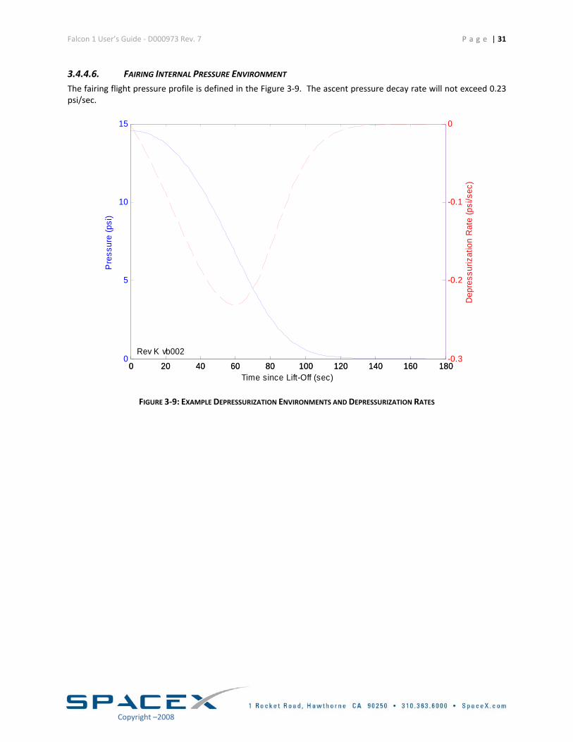
3.4.4.6. FAIRING INTERNAL PRESSURE ENVIRONMENT The fairing flight pressure profile is defined in the Figure 3‐9. The ascent pressure decay rate will not exceed 0.23 psi/sec.
0 20 40 60 80 100 120 140 160 1800
5
10
15
Pre
ssur
e (p
si)
0 20 40 60 80 100 120 140 160 180-0.3
-0.2
-0.1
0
Time since Lift-Off (sec)
Dep
ress
uriz
atio
n R
ate
(psi
/sec
)
Rev K vb002
FIGURE 3‐9: EXAMPLE DEPRESSURIZATION ENVIRONMENTS AND DEPRESSURIZATION RATES
Falcon 1 User’s Guide ‐ D000973 Rev. 7 P a g e | 32
Copyright –2008
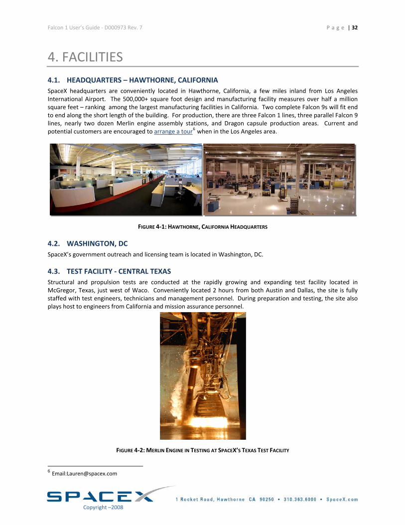
4. FACILITIES 4.1. HEADQUARTERS – HAWTHORNE, CALIFORNIA SpaceX headquarters are conveniently located in Hawthorne, California, a few miles inland from Los Angeles International Airport. The 500,000+ square foot design and manufacturing facility measures over half a million square feet – ranking among the largest manufacturing facilities in California. Two complete Falcon 9s will fit end to end along the short length of the building. For production, there are three Falcon 1 lines, three parallel Falcon 9 lines, nearly two dozen Merlin engine assembly stations, and Dragon capsule production areas. Current and potential customers are encouraged to arrange a tour6 when in the Los Angeles area.
FIGURE 4‐1: HAWTHORNE, CALIFORNIA HEADQUARTERS
4.2. WASHINGTON, DC SpaceX’s government outreach and licensing team is located in Washington, DC.
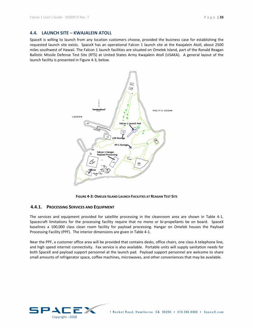
4.3. TEST FACILITY ‐ CENTRAL TEXAS Structural and propulsion tests are conducted at the rapidly growing and expanding test facility located in McGregor, Texas, just west of Waco. Conveniently located 2 hours from both Austin and Dallas, the site is fully staffed with test engineers, technicians and management personnel. During preparation and testing, the site also plays host to engineers from California and mission assurance personnel.
FIGURE 4‐2: MERLIN ENGINE IN TESTING AT SPACEX’S TEXAS TEST FACILITY
6 Email:[email protected]
Falcon 1 User’s Guide ‐ D000973 Rev. 7 P a g e | 33
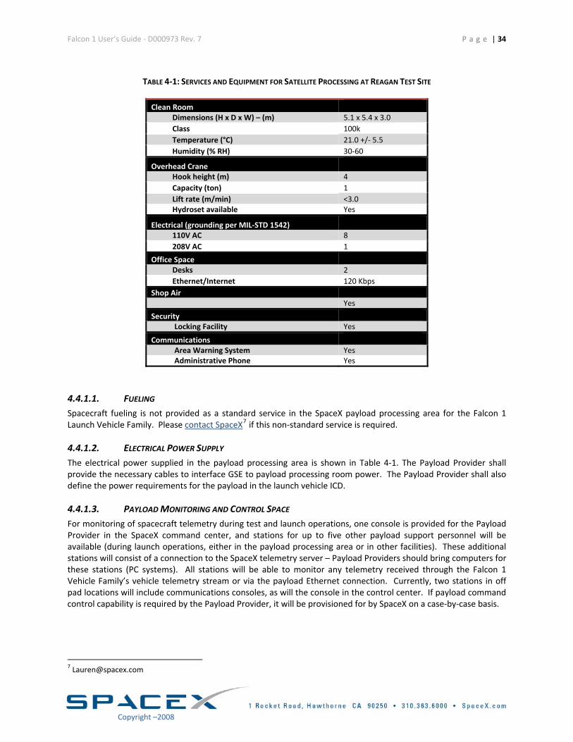
4.4. LAUNCH SITE – KWAJALEIN ATOLL SpaceX is willing to launch from any location customers choose, provided the business case for establishing the requested launch site exists. SpaceX has an operational Falcon 1 launch site at the Kwajalein Atoll, about 2500 miles southwest of Hawaii. The Falcon 1 launch facilities are situated on Omelek Island, part of the Ronald Reagan Ballistic Missile Defense Test Site (RTS) at United States Army Kwajalein Atoll (USAKA). A general layout of the launch facility is presented in Figure 4‐3, below.
FIGURE 4‐3: OMELEK ISLAND LAUNCH FACILITIES AT REAGAN TEST SITE
4.4.1. PROCESSING SERVICES AND EQUIPMENT
The services and equipment provided for satellite processing in the cleanroom area are shown in Table 4‐1. Spacecraft limitations for the processing facility require that no mono or bi‐propellants be on board. SpaceX baselines a 100,000 class clean room facility for payload processing. Hangar on Omelek houses the Payload Processing Facility (PPF). The interior dimensions are given in Table 4‐1. Near the PPF, a customer office area will be provided that contains desks, office chairs, one class A telephone line, and high speed internet connectivity. Fax service is also available. Portable units will supply sanitation needs for both SpaceX and payload support personnel at the launch pad. Payload support personnel are welcome to share small amounts of refrigerator space, coffee machines, microwaves, and other conveniences that may be available.
Copyright –2008
Falcon 1 User’s Guide ‐ D000973 Rev. 7
P a g e | 34
Copyright –2008
TABLE 4‐1: SERVICES AND EQUIPMENT FOR SATELLITE PROCESSING AT REAGAN TEST SITE
Clean Room
Dimensions (H x D x W) – (m) 5.1 x 5.4 x 3.0 Class 100k Temperature (°C) 21.0 +/‐ 5.5 Humidity (% RH) 30‐60
Overhead Crane
Hook height (m) 4 Capacity (ton) 1 Lift rate (m/min) <3.0 Hydroset available Yes
Electrical (grounding per MIL‐STD 1542)
110V AC 8 208V AC 1
Office Space Desks 2 Ethernet/Internet 120 Kbps
Shop Air Yes
Security Locking Facility Yes
Communications
Area Warning System Yes Administrative Phone Yes
4.4.1.1. FUELING Spacecraft fueling is not provided as a standard service in the SpaceX payload processing area for the Falcon 1 Launch Vehicle Family. Please contact SpaceX7 if this non‐standard service is required.
4.4.1.2. ELECTRICAL POWER SUPPLY The electrical power supplied in the payload processing area is shown in Table 4‐1. The Payload Provider shall provide the necessary cables to interface GSE to payload processing room power. The Payload Provider shall also define the power requirements for the payload in the launch vehicle ICD.
4.4.1.3. PAYLOAD MONITORING AND CONTROL SPACE For monitoring of spacecraft telemetry during test and launch operations, one console is provided for the Payload Provider in the SpaceX command center, and stations for up to five other payload support personnel will be available (during launch operations, either in the payload processing area or in other facilities). These additional stations will consist of a connection to the SpaceX telemetry server – Payload Providers should bring computers for these stations (PC systems). All stations will be able to monitor any telemetry received through the Falcon 1 Vehicle Family’s vehicle telemetry stream or via the payload Ethernet connection. Currently, two stations in off pad locations will include communications consoles, as will the console in the control center. If payload command control capability is required by the Payload Provider, it will be provisioned for by SpaceX on a case‐by‐case basis.
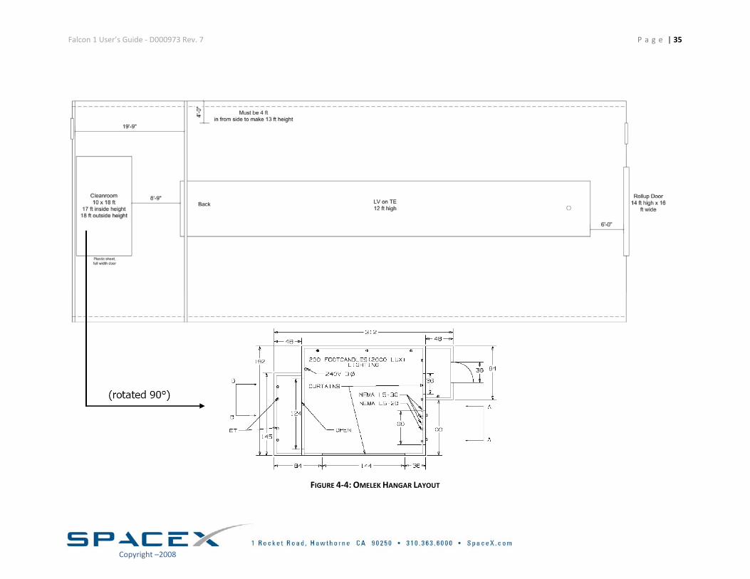
Falcon 1 User’s Guide ‐ D000973 Rev. 7 P a g e | 35
FIGURE 4‐4: OMELEK HANGAR LAYOUT
Copyright –2008
Falcon 1 User’s Guide ‐ D000973 Rev. 7 P a g e | 36
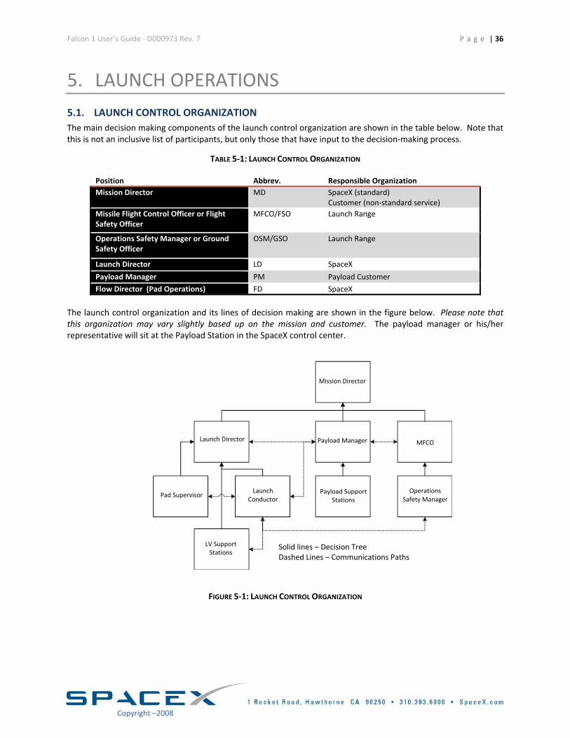
5. LAUNCH OPERATIONS 5.1. LAUNCH CONTROL ORGANIZATION The main decision making components of the launch control organization are shown in the table below. Note that this is not an inclusive list of participants, but only those that have input to the decision‐making process.
TABLE 5‐1: LAUNCH CONTROL ORGANIZATION
Position Abbrev. Responsible Organization Mission Director MD SpaceX (standard)
Customer (non‐standard service) Missile Flight Control Officer or Flight Safety Officer
MFCO/FSO Launch Range
Operations Safety Manager or Ground Safety Officer
OSM/GSO Launch Range
Launch Director LD SpaceX
Payload Manager PM Payload Customer
Flow Director (Pad Operations) FD SpaceX
The launch control organization and its lines of decision making are shown in the figure below. Please note that this organization may vary slightly based up on the mission and customer. The payload manager or his/her representative will sit at the Payload Station in the SpaceX control center.
LV Support Stations
Launch Director
Pad Supervisor Launch
Conductor Payload Support
Stations Operations
Safety Manager
MFCO
Mission Director
Payload Manager
Dashed Lines – Communications Paths Solid lines – Decision Tree
FIGURE 5‐1: LAUNCH CONTROL ORGANIZATION
Copyright –2008
Falcon 1 User’s Guide ‐ D000973 Rev. 7 P a g e | 37
5.2. MISSION INTEGRATION
The Launch Vehicle to payload interfaces, payload environmental conditions, and general capabilities are described in this User Guide. SpaceX will supply a single Point of Contact, the Mission Manager, from contract award through launch.. The Mission Manager will assess the launch vehicle capabilities against payload requirements. Throughout the integration process, the capabilities will be merged with payload requirements. This process will be accomplished by teleconferences, integration meetings and mission unique design reviews, as required. The result of this process is documented in the Launch Vehicle to Spacecraft ICD—the Master document for any SpaceX mission. Following signature approval of the ICD, configuration control is maintained by SpaceX. SpaceX also coordinates all aspects of the launch vehicle production, range and range safety integration, and all mission required licensing. The Mission Manager facilitates these interfaces for the Payload Provider. Once the payload arrives at the launch site, the physical accommodation for the spacecraft is turned over to the Payload Integration Manager—part of the operations crew. The Mission Manager will continue to manage the customer interface at the launch site.
TABLE 5‐2: STANDARD LAUNCH INTEGRATION PROCESS
Launch – 8 months or more Contract signing and authority to proceed• Estimated payload mass, volume, mission, operations and interface
requirements • Safety information (Safety Program Plan; Design information:
battery, ordnance, propellants, and operations) • Mission analysis summary provided to the Customer within 30 days
of contract
Launch – 6 months Final payload design, including: mass, volume, structural characteristics, mission, operations, and interface requirements
• Payload to provide test verified structural dynamic model Launch – 4 months Payload readiness review for Range Safety
• Launch site operations plan • Hazard analyses
Launch – 3 months Verification• Review of payload test data verifying compatibility with Falcon 1
environments • Coupled payload and Falcon 1 loads analysis completed • Confirm payload interfaces as built are compatible with Falcon 1 • Mission safety approval
Launch – 4‐6 weeks System Readiness Review (SRR)• Pre‐shipment reviews have occurred, or are about to occur. • Verify launch site, Range, Regulatory agencies, launch vehicle,
payload, people and paper are all in place and ready to begin launch campaign
Launch – 2 weeks Payload arrival at launch location Launch – 8‐9 days Payload mating to Launch Vehicle and fairing encapsulation
Launch – 7 days Flight Readiness Review (FRR)• Review of LV and payload checkouts in hangar. Confirmation of
readiness to proceed with Vehicle rollout. Launch – 1 day Launch Readiness Review (LRR)
Launch
Launch + 4 hours Post‐Launch Reports‐ Quick look
Launch + 4 weeks Post‐Launch Report‐ Final Report
Copyright –2008
Falcon 1 User’s Guide ‐ D000973 Rev. 7
P a g e | 38
Copyright –2008
5.2.1. PAYLOAD TRANSPORT TO LAUNCH SITE
Upon arrival of the Payload at Kwajalein, the payload container and all associated test/support equipment are off‐loaded from the plane by Kwajalein Airport cargo handlers. SpaceX arranges for transportation from the airport to the launch site on the island of Omelek. This transport takes place by boat. Both the payload and equipment will make three major moves between facilities:
o From Kwajalein Airport to the Kwajalein marina via truck o From the Kwajalein marina to the Omelek Island loading ramp via cargo ship o From the Omelek Island loading ramp to the vehicle assembly hangar cleanroom via forklift
If shipment to Omelek Island cannot be completed on the same day as SC and equipment arrival on Kwajalein (due to late plane arrival, sea state, or otherwise) then the equipment and SC will either stay overnight in the plane or be transported via truck to a designated SpaceX storage facility. This facility will be provided with standard office grade air conditioning, but the conditioning is not guaranteed. The SC will be transported in its own shipping container until it reaches the vehicle assembly hangar on Omelek Island.
5.2.2. PAYLOAD INTEGRATION
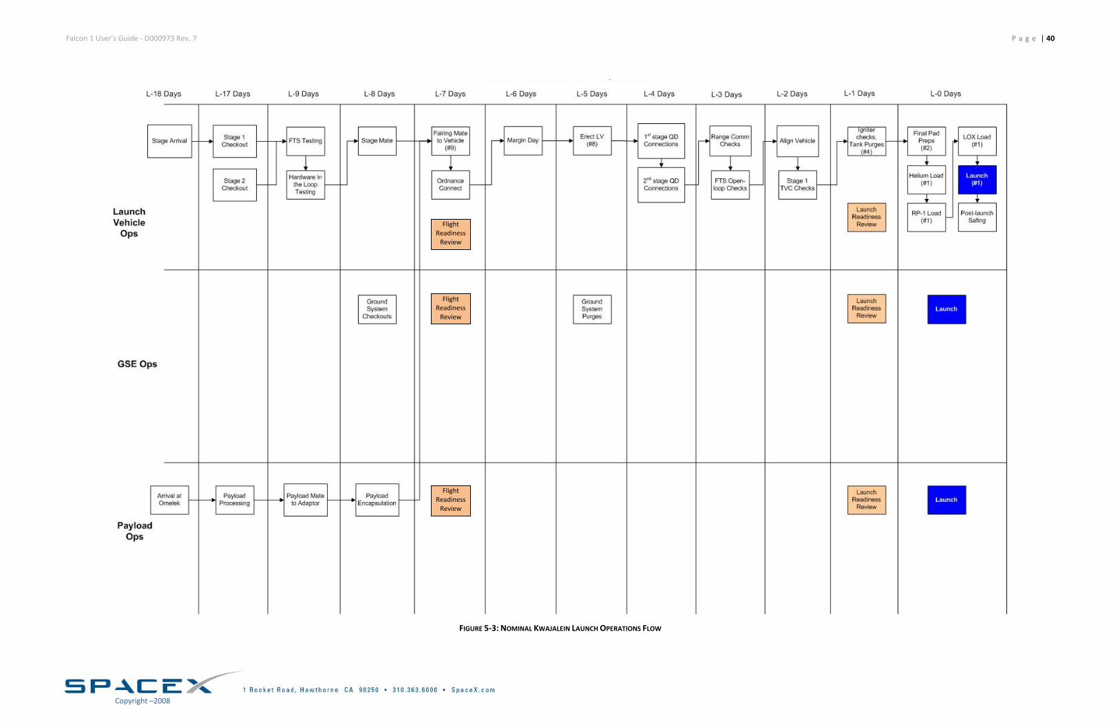
SpaceX makes pre‐launch operations as simple and streamlined as possible. Figure 5‐3 shows nominal launch operations flow for Launch Vehicle Operations, GSE Operations and Payload Operations, beginning at L‐18 days. SpaceX requires that the payload be brought to the launch site only two weeks prior to launch. For customer convenience, SpaceX provides Class 100K clean room facilities for non‐hazardous processing for up to three weeks as a standard service. Once the payload arrives at the launch site, attachment and fairing encapsulation can be completed in less than twenty‐four hours. SpaceX integrates the payload on the adapter in the vertical configuration, followed closely by fairing encapsulation. Once fully encapsulated, the system is rotated horizontally and then integrated to the second stage. Post‐mate checkouts are conducted followed by a Flight Readiness Review (FRR). Once the FRR is completed, the vehicle is rolled out to the pad. Note that the integrated payload and launch vehicle go vertical within six days of lift off. Access until rollout is available as a standard service. Falcon 1 Launch Vehicle missions and associated operations have been designed for minimal complexity and minimal time at the pad. The payload will be integrated horizontally to the launcher approximately seven days prior to launch. Once integrated, the vehicle is moved to the pad and is erected using the Falcon 1 Launch Vehicle transporter. Final system close‐out, fueling and testing is then completed. Twenty‐four hours prior to launch, the Launch Readiness Review (LRR) is held. Once the launch approval is given, the twenty‐four hour countdown begins.
Falcon 1 User’s Guide ‐ D000973 Rev. 7 P a g e | 39
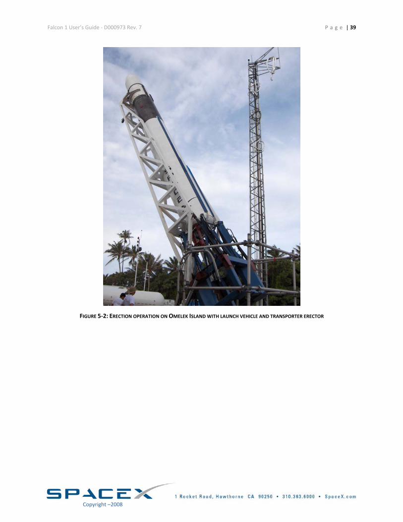
FIGURE 5‐2: ERECTION OPERATION ON OMELEK ISLAND WITH LAUNCH VEHICLE AND TRANSPORTER ERECTOR
Copyright –2008
Falcon 1 User’s Guide ‐ D000973 Rev. 7 P a g e | 40
Flight Readiness Review
Flight Readiness Review
Flight Readiness Review
FIGURE 5‐3: NOMINAL KWAJALEIN LAUNCH OPERATIONS FLOW
Copyright –2008
Falcon 1 User’s Guide ‐ D000973 Rev. 7 P a g e | 41
5.2.3. EXAMPLE FLIGHT PROFILES
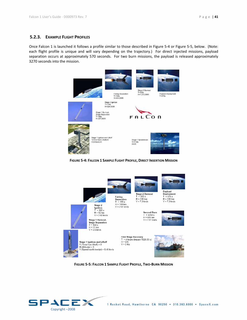
Once Falcon 1 is launched it follows a profile similar to those described in Figure 5‐4 or Figure 5‐5, below. (Note: each flight profile is unique and will vary depending on the trajectory.) For direct injected missions, payload separation occurs at approximately 570 seconds. For two burn missions, the payload is released approximately 3270 seconds into the mission.
FIGURE 5‐4: FALCON 1 SAMPLE FLIGHT PROFILE, DIRECT INSERTION MISSION
FIGURE 5‐5: FALCON 1 SAMPLE FLIGHT PROFILE, TWO‐BURN MISSION
Copyright –2008
Falcon 1 User’s Guide ‐ D000973 Rev. 7
P a g e | 42
Copyright –2008
6. SAFETY 6.1. SAFETY REQUIREMENTS Falcon 1 customers are required to meet AFSPC 91‐710 Range Safety Manual requirements in the design and operation of their flight and ground systems. These requirements encompass mechanical design, electrical design, fluid and pressurant systems, lifting and handling systems, ordnance and RF systems, ground support equipment, and other design and operational features. SpaceX can assist the customer in determining which requirements in particular pertain to the customers systems, and can also assist in completing required documentation.
6.2. HAZARDOUS SYSTEMS AND OPERATIONS Most ranges consider hazardous systems or operations to include ordnance operations, pressurized systems that operate below a 4 to 1 safety factor, lifting operations, operations or systems that include toxic or hazardous materials, high power RF systems, laser systems, and a variety of other systems and operations. The details of the system design and its operation will determine whether the system or its operation are considered hazardous. Typically, additional precautions are required for operating systems that are considered hazardous – these will be determined during the safety approval process with SpaceX and the launch range. All hazardous operations will require procedures that are approved by both SpaceX and the launch range prior to execution. Ordnance operations in particular require coordination to provide reduced RF environments, cleared areas, safety support, and other requirements.
6.3. WAIVERS For systems or operations that are not able to meet safety requirements and yet are believed to be acceptable for ground operations and launch, a waiver is typically produced for approval by the launch range safety authority. Waivers are a last resort solution and require considerable coordination and should not be considered a standard practice. SpaceX will assist the customer in determining whether an issue should be elevated to require a waiver as the integration process evolves.
Falcon 1 User’s Guide ‐ D000973 Rev. 7 P a g e | 43
7. PAYLOAD QUESTIONNAIRE Completion of the following Payload Questionnaire is necessary for use in evaluating the compatibility of any new payload with Falcon 1 Launch Vehicles. If you are considering using Falcon 1 Launch Vehicles, then please complete as much of the questionnaire as possible and return it to:
SpaceX ATTN: Lauren Dreyer
1 Rocket Rd. Hawthorne, CA 90250
Please Note: SpaceX will treat all customer supplied data as proprietary information and will not disclose or retransmit any part of the information contained herein to any outside entity without the expressed written consent of your organization.
Copyright –2008
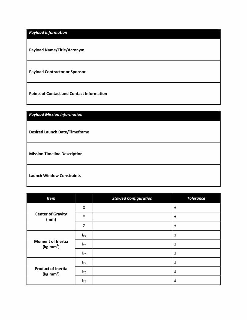
Payload Information
Payload Name/Title/Acronym
Payload Contractor or Sponsor
Points of Contact and Contact Information
Payload Mission Information
Desired Launch Date/Timeframe
Mission Timeline Description
Launch Window Constraints
Item Stowed Configuration Tolerance
Center of Gravity (mm)
X ±
Y ±
Z ±
Moment of Inertia (kg.mm2)
IXX ±
IYY ±
IZZ ±
Product of Inertia (kg.mm2)
IXY ±
IYZ ±
IXZ ±
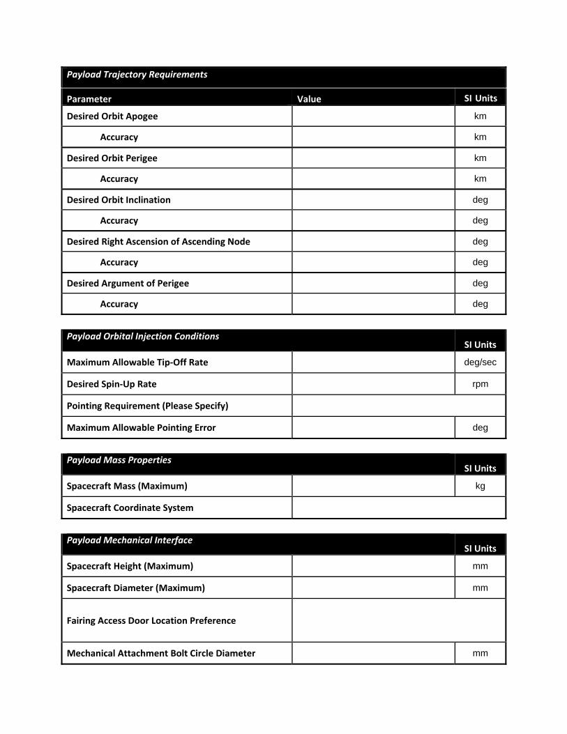
Payload Trajectory Requirements
Parameter Value SI Units
Desired Orbit Apogee km
Accuracy km
Desired Orbit Perigee km
Accuracy km
Desired Orbit Inclination deg
Accuracy deg
Desired Right Ascension of Ascending Node deg
Accuracy deg
Desired Argument of Perigee deg
Accuracy deg
Payload Orbital Injection Conditions SI Units
Maximum Allowable Tip‐Off Rate deg/sec
Desired Spin‐Up Rate rpm
Pointing Requirement (Please Specify)
Maximum Allowable Pointing Error deg
Payload Mass Properties
SI Units
Spacecraft Mass (Maximum) kg
Spacecraft Coordinate System
Payload Mechanical Interface
SI Units
Spacecraft Height (Maximum) mm
Spacecraft Diameter (Maximum) mm
Fairing Access Door Location Preference
Mechanical Attachment Bolt Circle Diameter mm
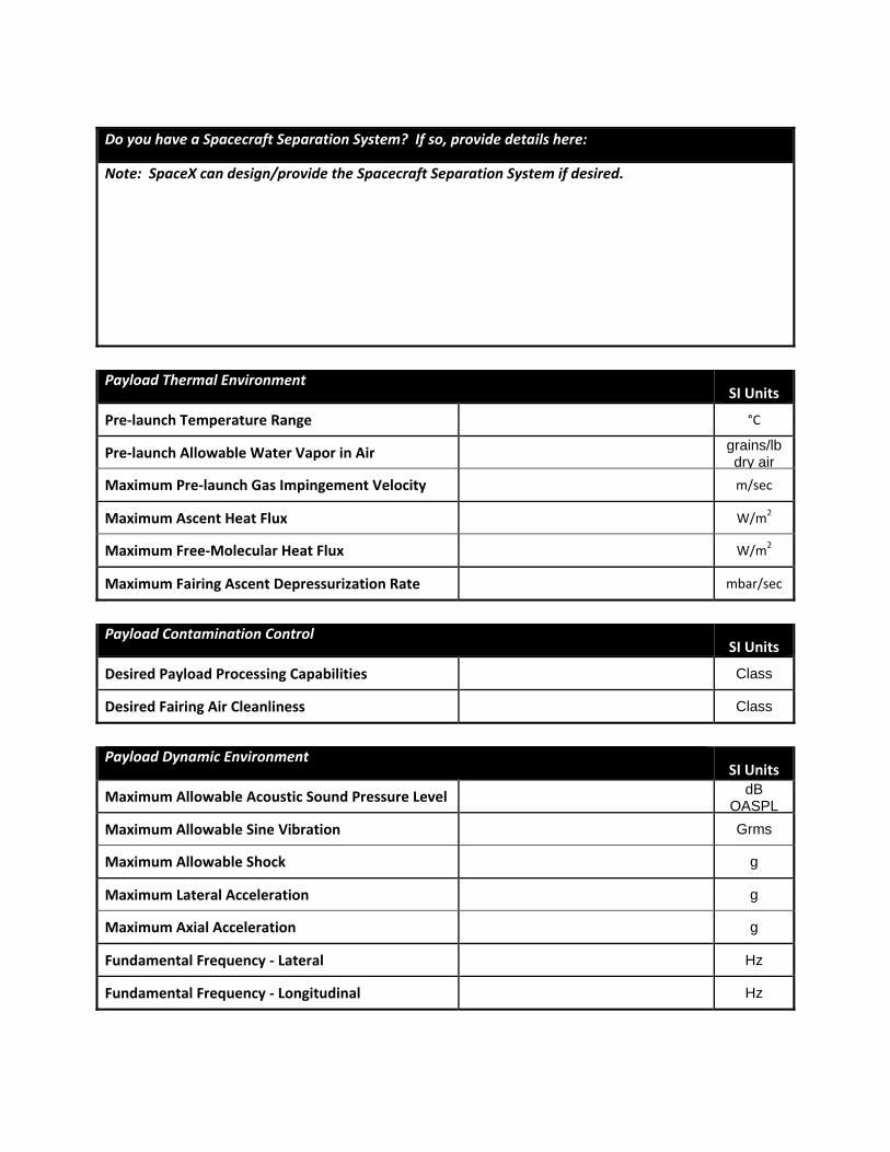
Do you have a Spacecraft Separation System? If so, provide details here:
Note: SpaceX can design/provide the Spacecraft Separation System if desired.
Payload Thermal Environment
SI Units
Pre‐launch Temperature Range °C
Pre‐launch Allowable Water Vapor in Air grains/lb dry air
Maximum Pre‐launch Gas Impingement Velocity m/sec
Maximum Ascent Heat Flux W/m2
Maximum Free‐Molecular Heat Flux W/m2
Maximum Fairing Ascent Depressurization Rate mbar/sec
Payload Contamination Control
SI Units
Desired Payload Processing Capabilities Class
Desired Fairing Air Cleanliness Class
Payload Dynamic Environment
SI Units
Maximum Allowable Acoustic Sound Pressure Level dB OASPL
Maximum Allowable Sine Vibration Grms
Maximum Allowable Shock g
Maximum Lateral Acceleration g
Maximum Axial Acceleration g
Fundamental Frequency ‐ Lateral Hz
Fundamental Frequency ‐ Longitudinal Hz
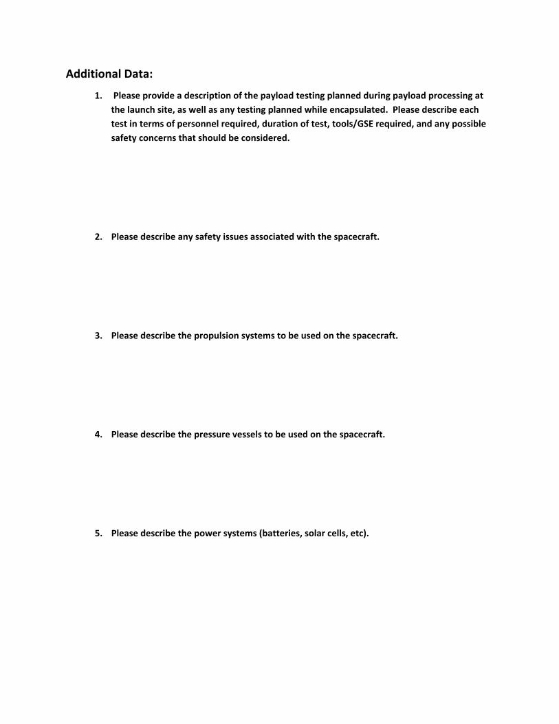
Additional Data:
1. Please provide a description of the payload testing planned during payload processing at the launch site, as well as any testing planned while encapsulated. Please describe each test in terms of personnel required, duration of test, tools/GSE required, and any possible safety concerns that should be considered.
2. Please describe any safety issues associated with the spacecraft.
3. Please describe the propulsion systems to be used on the spacecraft.
4. Please describe the pressure vessels to be used on the spacecraft.
5. Please describe the power systems (batteries, solar cells, etc).
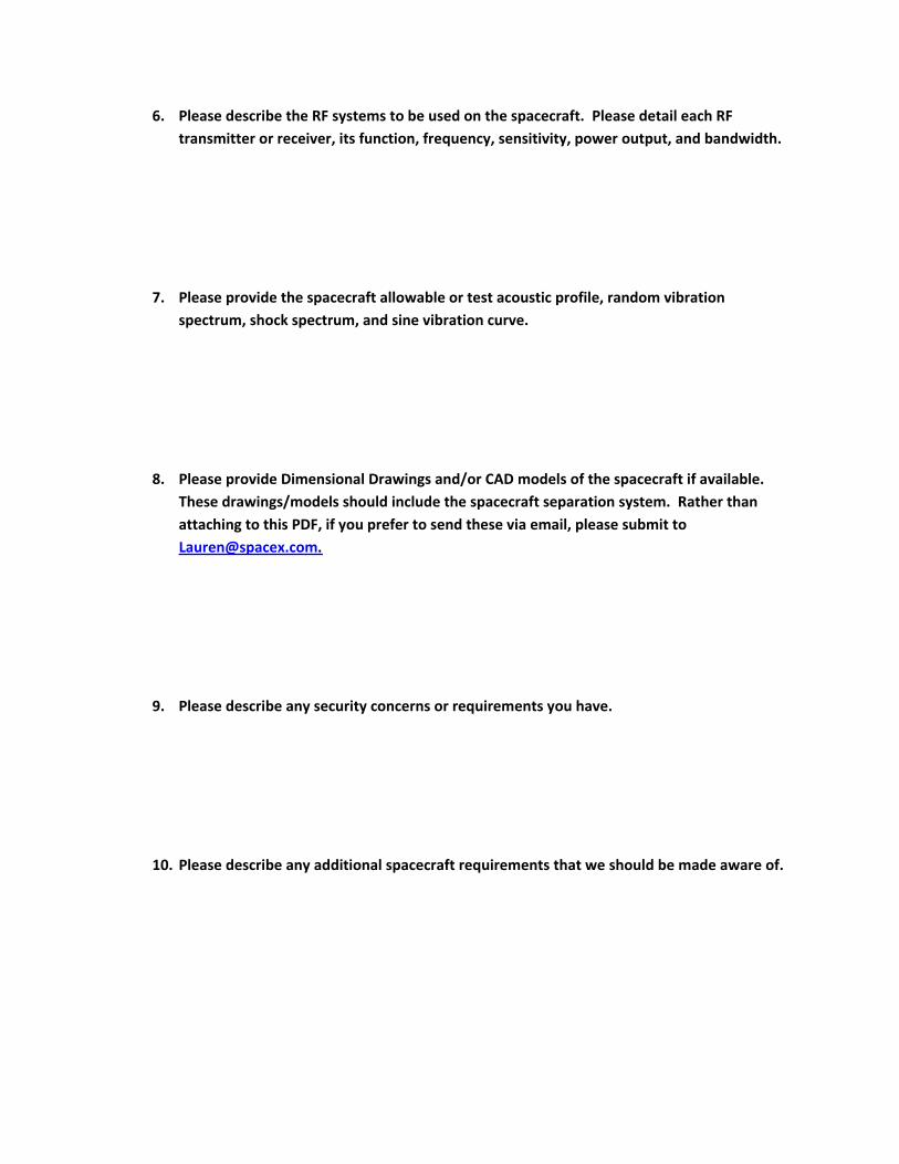
6. Please describe the RF systems to be used on the spacecraft. Please detail each RF transmitter or receiver, its function, frequency, sensitivity, power output, and bandwidth.
7. Please provide the spacecraft allowable or test acoustic profile, random vibration spectrum, shock spectrum, and sine vibration curve.
8. Please provide Dimensional Drawings and/or CAD models of the spacecraft if available. These drawings/models should include the spacecraft separation system. Rather than attaching to this PDF, if you prefer to send these via email, please submit to [email protected].
9. Please describe any security concerns or requirements you have.
10. Please describe any additional spacecraft requirements that we should be made aware of.
Falcon 1 User’s Guide ‐ D000973 Rev. 7
P a g e | 44
Copyright –2008
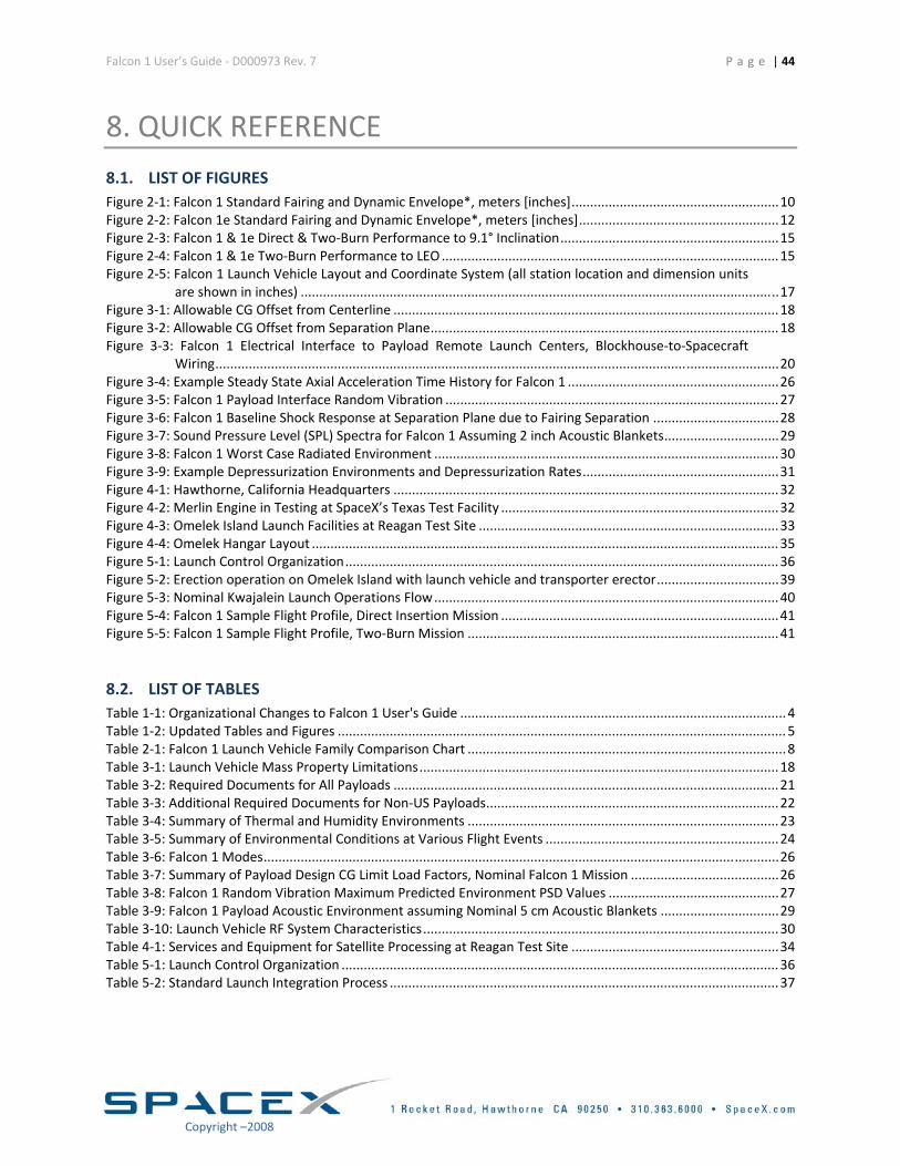
8. QUICK REFERENCE 8.1. LIST OF FIGURES Figure 2‐1: Falcon 1 Standard Fairing and Dynamic Envelope*, meters [inches] ........................................................ 10 Figure 2‐2: Falcon 1e Standard Fairing and Dynamic Envelope*, meters [inches] ...................................................... 12 Figure 2‐3: Falcon 1 & 1e Direct & Two‐Burn Performance to 9.1° Inclination ........................................................... 15 Figure 2‐4: Falcon 1 & 1e Two‐Burn Performance to LEO ........................................................................................... 15 Figure 2‐5: Falcon 1 Launch Vehicle Layout and Coordinate System (all station location and dimension units
are shown in inches) ................................................................................................................................. 17 Figure 3‐1: Allowable CG Offset from Centerline ........................................................................................................ 18 Figure 3‐2: Allowable CG Offset from Separation Plane .............................................................................................. 18 Figure 3‐3: Falcon 1 Electrical Interface to Payload Remote Launch Centers, Blockhouse‐to‐Spacecraft
Wiring ........................................................................................................................................................ 20 Figure 3‐4: Example Steady State Axial Acceleration Time History for Falcon 1 ......................................................... 26 Figure 3‐5: Falcon 1 Payload Interface Random Vibration .......................................................................................... 27 Figure 3‐6: Falcon 1 Baseline Shock Response at Separation Plane due to Fairing Separation .................................. 28 Figure 3‐7: Sound Pressure Level (SPL) Spectra for Falcon 1 Assuming 2 inch Acoustic Blankets ............................... 29 Figure 3‐8: Falcon 1 Worst Case Radiated Environment ............................................................................................. 30 Figure 3‐9: Example Depressurization Environments and Depressurization Rates ..................................................... 31 Figure 4‐1: Hawthorne, California Headquarters ........................................................................................................ 32 Figure 4‐2: Merlin Engine in Testing at SpaceX’s Texas Test Facility ........................................................................... 32 Figure 4‐3: Omelek Island Launch Facilities at Reagan Test Site ................................................................................. 33 Figure 4‐4: Omelek Hangar Layout .............................................................................................................................. 35 Figure 5‐1: Launch Control Organization ..................................................................................................................... 36 Figure 5‐2: Erection operation on Omelek Island with launch vehicle and transporter erector ................................. 39 Figure 5‐3: Nominal Kwajalein Launch Operations Flow ............................................................................................. 40 Figure 5‐4: Falcon 1 Sample Flight Profile, Direct Insertion Mission ........................................................................... 41 Figure 5‐5: Falcon 1 Sample Flight Profile, Two‐Burn Mission .................................................................................... 41
8.2. LIST OF TABLES Table 1‐1: Organizational Changes to Falcon 1 User's Guide ........................................................................................ 4 Table 1‐2: Updated Tables and Figures ......................................................................................................................... 5 Table 2‐1: Falcon 1 Launch Vehicle Family Comparison Chart ...................................................................................... 8 Table 3‐1: Launch Vehicle Mass Property Limitations ................................................................................................. 18 Table 3‐2: Required Documents for All Payloads ........................................................................................................ 21 Table 3‐3: Additional Required Documents for Non‐US Payloads ............................................................................... 22 Table 3‐4: Summary of Thermal and Humidity Environments .................................................................................... 23 Table 3‐5: Summary of Environmental Conditions at Various Flight Events ............................................................... 24 Table 3‐6: Falcon 1 Modes ........................................................................................................................................... 26 Table 3‐7: Summary of Payload Design CG Limit Load Factors, Nominal Falcon 1 Mission ........................................ 26 Table 3‐8: Falcon 1 Random Vibration Maximum Predicted Environment PSD Values .............................................. 27 Table 3‐9: Falcon 1 Payload Acoustic Environment assuming Nominal 5 cm Acoustic Blankets ................................ 29 Table 3‐10: Launch Vehicle RF System Characteristics ................................................................................................ 30 Table 4‐1: Services and Equipment for Satellite Processing at Reagan Test Site ........................................................ 34 Table 5‐1: Launch Control Organization ...................................................................................................................... 36 Table 5‐2: Standard Launch Integration Process ......................................................................................................... 37
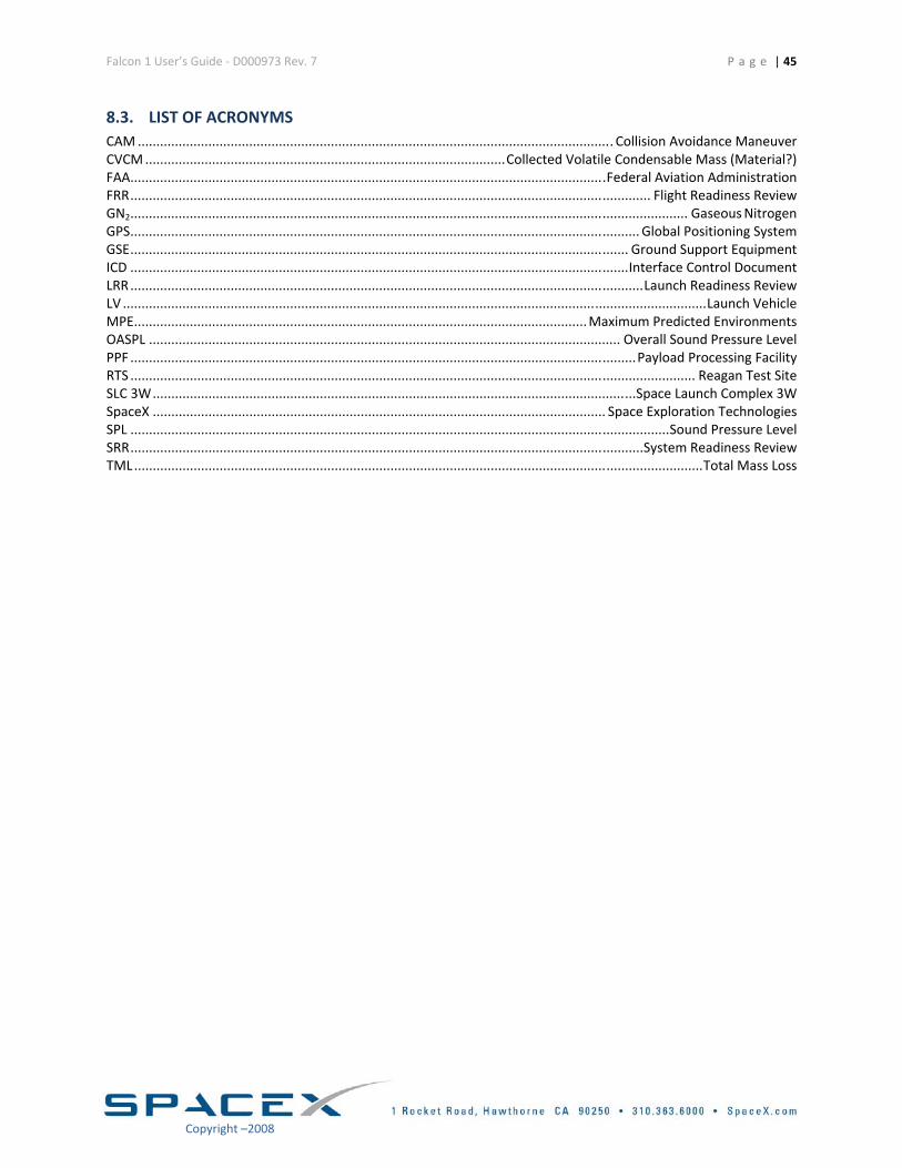
Falcon 1 User’s Guide ‐ D000973 Rev. 7
P a g e | 45
Copyright –2008
8.3. LIST OF ACRONYMS CAM ................................................................................................................................ Collision Avoidance Maneuver CVCM ................................................................................................. Collected Volatile Condensable Mass (Material?) FAA ................................................................................................................................ Federal Aviation Administration FRR ............................................................................................................................................ Flight Readiness Review GN2 ...................................................................................................................................................... Gaseous Nitrogen GPS ......................................................................................................................................... Global Positioning System GSE ...................................................................................................................................... Ground Support Equipment ICD ...................................................................................................................................... Interface Control Document LRR .......................................................................................................................................... Launch Readiness Review LV ............................................................................................................................................................. Launch Vehicle MPE .......................................................................................................................... Maximum Predicted Environments OASPL ............................................................................................................................... Overall Sound Pressure Level PPF ........................................................................................................................................ Payload Processing Facility RTS ........................................................................................................................................................ Reagan Test Site SLC 3W .................................................................................................................................. Space Launch Complex 3W SpaceX .......................................................................................................................... Space Exploration Technologies SPL ................................................................................................................................................. Sound Pressure Level SRR .......................................................................................................................................... System Readiness Review TML ......................................................................................................................................................... Total Mass Loss
Related Documents