Failure analysis of buried piping and cold drain vessel M.S. Attia a,⇑ , A.R. Ragab a , S. El-Raghy b a Department of Mechanical Design and Production, Faculty of Engineering, Cairo University, 12613 Giza, Egypt b Department of Mining, Metallurgy, and Petroleum, Faculty of Engineering, Cairo University, 12613 Giza, Egypt article info Article history: Received 18 July 2010 Received in revised form 17 October 2010 Accepted 28 November 2010 Available online 4 December 2010 Keywords: Failure analysis Stress corrosion cracking Pressure vessel Fracture mechanics Finite element analysis abstract This paper describes the failure analysis of a cold drain vessel used to collect hydrocarbon fluids off liquefied natural gas through a network of buried piping. The analysis deals with (i) the corrosion of the buried piping and (ii) the cracking of the head plate of the vessel. The analysis comprises visual inspection, chemical and mechanical testing, and finite ele- ment thermo-mechanical stress analysis. Corrosion of the buried pipe was found to result from the combined effect of saline ground water, defective coating, ineffective cathodic protection, and stray current. Improper corrosion treatment led to stress corrosion cracking which ultimately caused complete fracture of the vessel head plate at a nozzle attachment. It is recommended to improve coating and cathodic protection, and to enhance welding quality and employ better design considerations to reduce the local stresses. Ó 2010 Elsevier Ltd. All rights reserved. 1. Introduction 1.1. Problem description A gas processing plant located on the Mediterranean Sea shore uses a cold drain vessel to separate both butane and pro- pane in the liquefied natural gas (LNG) from offshore platforms through a network of buried piping. Fig. 1 depicts a sche- matic of the cold drain vessel under investigation, which was fabricated in 2004 from 304L (18Cr–8Ni) stainless steel according to ASME section VIII-Div. 1 [1]. The vessel is located 8 m below sea level and is fed by the hydrocarbon liquids collected through a network of buried drain piping. The four millimeter thick tape-coated buried piping is made of 316L (16Cr–12Ni–2Mo) stainless steel. The pipe is 50.8 mm thick. A heating coil inside the vessel is used to evaporate the collected liquids to the flare. The coil utilizes hot oil, which is fed through the inlet nozzle connected to the 10 mm thick ellipsoidal head plate as shown in Fig. 1. The nominal operating data of the vessel are: internal pressure P v = 1.5 barg. and temperature range of 5/69 °C, and for the heating coil are: internal pressure P n = 16 barg. and temperature range of 250/150 °C between oil inlet and outlet, respec- tively. Actual pressure and temperature histories were not available. The operation of this vessel is intended to be intermit- tent since these liquids are collected during a plant shutdown/startup. No data is available on the liquid levels which may trigger the vessel operation. However, vessel operation was more frequent than expected. The piping connected to the hot oil inlet nozzle has experienced severe corrosion after 2 years in service, which ultimately penetrated its full thickness. This has eventually led to through-thickness cracking in the ellipsoidal head at the hot oil inlet nozzle weldment and hazardous leakage of flammable hydrocarbons was reported. This study presents the results of the fail- ure analysis of both the buried piping and the vessel. 1350-6307/$ - see front matter Ó 2010 Elsevier Ltd. All rights reserved. doi:10.1016/j.engfailanal.2010.11.011 ⇑ Corresponding author. Tel.: +1 416 323 9873. E-mail address: [email protected] (M.S. Attia). Engineering Failure Analysis 18 (2011) 933–943 Contents lists available at ScienceDirect Engineering Failure Analysis journal homepage: www.elsevier.com/locate/engfailanal

Welcome message from author
This document is posted to help you gain knowledge. Please leave a comment to let me know what you think about it! Share it to your friends and learn new things together.
Transcript

Engineering Failure Analysis 18 (2011) 933–943
Contents lists available at ScienceDirect
Engineering Failure Analysis
journal homepage: www.elsevier .com/locate /engfai lanal
Failure analysis of buried piping and cold drain vessel
M.S. Attia a,⇑, A.R. Ragab a, S. El-Raghy b
a Department of Mechanical Design and Production, Faculty of Engineering, Cairo University, 12613 Giza, Egyptb Department of Mining, Metallurgy, and Petroleum, Faculty of Engineering, Cairo University, 12613 Giza, Egypt
a r t i c l e i n f o a b s t r a c t
Article history:Received 18 July 2010Received in revised form 17 October 2010Accepted 28 November 2010Available online 4 December 2010
Keywords:Failure analysisStress corrosion crackingPressure vesselFracture mechanicsFinite element analysis
1350-6307/$ - see front matter � 2010 Elsevier Ltddoi:10.1016/j.engfailanal.2010.11.011
⇑ Corresponding author. Tel.: +1 416 323 9873.E-mail address: [email protected] (M.S. Attia)
This paper describes the failure analysis of a cold drain vessel used to collect hydrocarbonfluids off liquefied natural gas through a network of buried piping. The analysis deals with(i) the corrosion of the buried piping and (ii) the cracking of the head plate of the vessel.The analysis comprises visual inspection, chemical and mechanical testing, and finite ele-ment thermo-mechanical stress analysis. Corrosion of the buried pipe was found to resultfrom the combined effect of saline ground water, defective coating, ineffective cathodicprotection, and stray current. Improper corrosion treatment led to stress corrosion crackingwhich ultimately caused complete fracture of the vessel head plate at a nozzle attachment.It is recommended to improve coating and cathodic protection, and to enhance weldingquality and employ better design considerations to reduce the local stresses.
� 2010 Elsevier Ltd. All rights reserved.
1. Introduction
1.1. Problem description
A gas processing plant located on the Mediterranean Sea shore uses a cold drain vessel to separate both butane and pro-pane in the liquefied natural gas (LNG) from offshore platforms through a network of buried piping. Fig. 1 depicts a sche-matic of the cold drain vessel under investigation, which was fabricated in 2004 from 304L (18Cr–8Ni) stainless steelaccording to ASME section VIII-Div. 1 [1]. The vessel is located 8 m below sea level and is fed by the hydrocarbon liquidscollected through a network of buried drain piping. The four millimeter thick tape-coated buried piping is made of 316L(16Cr–12Ni–2Mo) stainless steel. The pipe is 50.8 mm thick. A heating coil inside the vessel is used to evaporate the collectedliquids to the flare. The coil utilizes hot oil, which is fed through the inlet nozzle connected to the 10 mm thick ellipsoidalhead plate as shown in Fig. 1.
The nominal operating data of the vessel are: internal pressure Pv = 1.5 barg. and temperature range of �5/69 �C, and forthe heating coil are: internal pressure Pn = 16 barg. and temperature range of 250/150 �C between oil inlet and outlet, respec-tively. Actual pressure and temperature histories were not available. The operation of this vessel is intended to be intermit-tent since these liquids are collected during a plant shutdown/startup. No data is available on the liquid levels which maytrigger the vessel operation. However, vessel operation was more frequent than expected.
The piping connected to the hot oil inlet nozzle has experienced severe corrosion after 2 years in service, which ultimatelypenetrated its full thickness. This has eventually led to through-thickness cracking in the ellipsoidal head at the hot oil inletnozzle weldment and hazardous leakage of flammable hydrocarbons was reported. This study presents the results of the fail-ure analysis of both the buried piping and the vessel.
. All rights reserved.
.
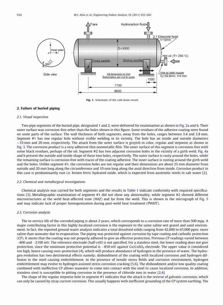
Fig. 1. Schematic of the cold drain vessel.
934 M.S. Attia et al. / Engineering Failure Analysis 18 (2011) 933–943
2. Failure of buried piping
2.1. Visual inspection
Two pipe segments of the buried pipe, designated 1 and 2, were delivered for examination as shown in Fig. 2a and b. Theirouter surface was corrosion-free other than the holes shown in this figure. Some residues of the adhesive coating were foundon some parts of the surface. The wall thickness of both segments, away from the holes, ranges between 3.4 and 3.8 mm.Segment #1 has one regular hole without visible welding in its vicinity. The hole has an inside and outside diameters�10 mm and 20 mm, respectively. The attack from the outer surface is greyish in color, regular and stepwise as shown inFig. 3. The corrosion product is a very adherent thin nonmetallic film. The inner surface of this segment is corrosion-free withsome black residues, perhaps of the oil. Segment #2 has two adjacent corrosion holes in the vicinity of a girth weld. Fig. 4aand b present the outside and inside shape of these two holes, respectively. The outer surface is rusty around the holes, whilethe remaining surface is corrosion-free with traces of the coating adhesive. The inner surface is rusting around the girth weldand the holes. Unlike segment #1, the corrosion holes are not regular and their dimensions are about 25 mm diameter fromoutside and 20 mm long along the circumference and 10 mm long along the axial direction from inside. Corrosion product inthis case is predominantly rust i.e. brown ferric hydrated oxide, which is expected from austenitic steels in salt water [2].
2.2. Chemical and metallurgical investigations
Chemical analysis was carried for both segments and the results in Table 1 indicate conformity with required specifica-tions [3]. Metallographic examination of segment #1 did not show any abnormality, while segment #2 showed differentmicrostructures at the weld heat-affected zone (HAZ) and far from the weld. This is shown in the micrograph of Fig. 5and may indicate lack of proper homogenization during post-weld heat treatment (PWHT).
2.3. Corrosion analysis
The in-service life of the corroded piping is about 2 years, which corresponds to a corrosion rate of more than 500 mpy. Amajor contributing factor in this highly localized corrosion is the exposure to the same saline wet gravel and sand environ-ment. In fact, the reported ground water analysis indicates a total dissolved solids ranging from 42,000 to 65,000 ppm; moresaline than seawater due to evaporation. The piping was protected against corrosion by tape coating and cathodic protection(CP). It seems that the coating was not properly adhered to give an effective protection. Previous CP readings varied between�800 and �2100 mV. The reference electrode (half-cell) is not specified. For a stainless steel, the lower reading does not giveprotection, since the minimum protective potential is �850 mV against Cu/CuSO4 electrode. The upper value is consideredtoo high, hence causing over-protection [4], which will produce abundance of hydrogen in the presence of water. The hydro-gen evolution has two detrimental effects namely; disbondment of the coating with localized corrosion and hydrogen dif-fusion in the steel causing embrittlement. In the presence of tensile stress fields and corrosive environment, hydrogenembrittlement may evolve to hydrogen assisted stress corrosion cracking [5,6]. The disbondment and/or low quality coatingcombined with ineffective CP allows seawater to come into contact with the steel to cause localized corrosion. In addition,stainless steel is susceptible to pitting corrosion in the presence of chloride ions in water [2,4].
The shape of the regular stepwise hole in segment #1 indicates that the attack is the reverse of galvanic corrosion, whichcan only be caused by stray current corrosion. This usually happens with inefficient grounding of the CP system earthing. The

Fig. 2. Visible external corrosion on (a) pipe segment #1, (b) pipe segment #2.
Fig. 3. Macroscopic internal view of corrosion of pipe segment #1.
M.S. Attia et al. / Engineering Failure Analysis 18 (2011) 933–943 935

Fig. 4. Macroscopy of corrosion of pipe segment #1: (a) external view, (b) internal view.
Table 1Chemical analysis of the two segments of the buried pipe.
Segment Alloy C% Si% Mn% S% P% Cr% Ni% Mo%
Segment #1 316L 0.030 0.45 1.43 0.012 0.015 17.15 10.5 2.05Segment #2 316L 0.035 0.44 1.46 0.010 0.020 17.20 10.6 2.00
936 M.S. Attia et al. / Engineering Failure Analysis 18 (2011) 933–943
development of a through-thickness hole in 4 mm thick piping in such a short time span needs a very high rate of attack. Thisrate cannot be even achieved in bare stainless steel in seawater, yet can be justified in the presence of stray current. In seg-ment #2, on the other hand, it is observed that the two adjacent holes on the internal surface are elongated parallel to thewelding line, Fig. 2b. The HAZ is known to be more susceptible to corrosion due to the heterogeneity of the metal on both theatomic scale and the microstructural scale in this region. The lack of homogenization treatment shown in Fig. 5 may explainthe elongated shape of the corrosion holes in this section.

Fig. 5. Metallography of the HAZ of segment #2 (X100).
M.S. Attia et al. / Engineering Failure Analysis 18 (2011) 933–943 937
3. Failure of cold drain vessel
3.1. Visual inspection
Due to plant operational considerations, the vessel was repaired and returned to service at the time of the site visit.Hence, it was not possible to inspect the cracked vessel in situ. Fig. 6 depicts the delivered specimen constituting the crackedarea cut from the vessel end. The observed branched crack was through-thickness. However, the specimen does not includethe crack front due to crude cutting and grinding prior to shipping, hence no corrosive deposits were observed. The specimenis almost elliptical with maximum and minimum dimensions of 170 mm � 130 mm, respectively, and a thickness of 10 mm.Apart from some observed branching; it starts circumferentially close to the weld and propagates radially in a north-east andsouth-west direction from the weld, with north pointing to the top of the vessel. The crack length measured diagonally isa = 170 mm. The welded joint between the nozzle and the head plate is of poor workmanship, showing crude appearancewith visible non-uniformities. The weld has a leg size ranging from 10 to 15 mm, compared to the specified size 5.5 mm[1]. Fig. 7 illustrates numerous weld defects, porosities, slag inclusions, and cracks close to the weld root. Any of these defectsshould have resulted in weld rejection during inspection.
Fig. 6. As-received specimen with branched cracking.
Fig. 7. Various weld defects in the nozzle–head plate weldment.
938 M.S. Attia et al. / Engineering Failure Analysis 18 (2011) 933–943
3.2. Laboratory investigations
Specimens were taken from the defective head plate and the nozzle for chemical, metallographic, and mechanical char-acterization. Table 2 depicts the results of the chemical analysis of the two specimen materials. These results conform to thespecified limits for the respective alloys [3].
Tension testing was performed on a 6 mm diameter sub-size rod specimen taken from the head plate in accordance withASTM specifications [7]. Table 3 presents the measured mechanical properties compared to Code minimum specified values[3] as minimum requirements. The specimen exhibited high ductility and dull rough fracture surface, commonly found inannealed alloys, while the measured strength value indicates that the plate was subjected to cold working conditions.

Table 2Chemical analysis of the head plate and nozzle materials.
Specimen Alloy C% Si% Mn% S% Cr% Ni% Mo%
Head plate 304L 0.038 0.75 1.67 0.009 18.9 8.6 0.5Nozzle 316L 0.035 0.48 1.48 0.009 16.9 10.8 2.1
Table 3Measured mechanical properties of the head plate alloy.
Property Measured value Code min. value [3]
Yield strength, rY (MPa) 471 170Ultimate tensile strength (MPa) 698 485Modulus of elasticity, E (GPa) Not measured 195Elongation to break (%) 69.8% 58%
M.S. Attia et al. / Engineering Failure Analysis 18 (2011) 933–943 939
Furthermore, examination of the broken specimen reveals peculiar spots, at which the specimen surface was flaked. In addi-tion, average hardness measurements of the weld, HAZ, and the head plate are: weld metal: 195 BHN, HAZ: 225 BHN, parentmetal: 205 BHN. Finally, metallographic examination of the cracked material revealed transgranular branched cracking.
Charpy V-Notch impact energy (CVN) of the parent metal was measured in accordance with ASTM-E23-2002 standard atroom temperature [8]. The measured value of CVN equals 180 J, which is indicative of ductile fracture. It was not possible toobtain a valid specimen for plane strain fracture toughness KIC measurements due to insufficient material volume of the pro-vided sample. However, a conservative estimate of KIC can be obtained using the following relation [10]:
K IC ¼ 8:47ðCVNÞ0:63 ¼ 223:2 MPaffiffiffiffiffimp
ð1Þ
3.3. Stress analysis
In this section, the findings of visual inspection and material characterization tests are used to accurately model the load-ing and environmental conditions that led to the catastrophic fracture of the vessel head plate. First, the vessel is subjected toboth mechanical and thermal loads as outlined in Section 1. Second, the presence saline ground water (42,000–32,000 ppmNaCl) around the hot oil inlet nozzle and intermittent operation of the vessel cause the build-up of heavy brine of NaCl in thisregion. Stainless steel 304L is susceptible to NaCl corrosion and stress corrosion [4]. The presence of prior plastic deformationduring head plate forming and local heating further aggravate its corrosion susceptibility. Finally, while the Code does notenforce post-weld heat treatment (PWHT) for the head plate with this thickness [1], the poor quality of the nozzle-plateweldments indicates that the HAZ residual stresses must be taken into consideration. Therefore, stress analysis and fracturemodeling must take into account the combined effect of these factors. A finite element analysis is conducted using a com-mercial package [12] to evaluate the resulting thermo-mechanical stresses in the vicinity of the nozzle–head intersection.
3.3.1. Finite element analysisFig. 1 indicates that the ellipsoidal head radius of curvature is very large compared to that of the nozzle. Therefore, it is
feasible to model the head plate as a flat circular plate to simplify the analysis. Fig. 8a and b depicts the schematic and the FEmodel of the proposed equivalent configuration. The model employs thin shell elements with six degrees of freedom pernode [12]. Very fine mesh was imposed at the nozzle-plate intersection zone due to steep temperature and stress gradientsat this region.
The vessel and the connected piping are primarily subjected to internal pressure and thermal loading as detailed in Sec-tion 1. Other secondary and marginal loads such as wind and seismic loads were not considered. The stress field due to Pv inthe vicinity of the hot oil inlet nozzle weldment is evaluated using membrane analysis [10]. Furthermore, the temperaturedistribution around the nozzle was evaluated using a combined conduction–free-convection heat transfer mechanism be-tween the nozzle and the vessel and surrounding atmosphere, respectively. While the thermal conductivity of stainlesssteels is known, K = 14.8 W/m2 K, the convection coefficient of the surrounding atmosphere is not so accurately defined. Aclose approximation of the free-convection heat transfer coefficient from a horizontal cylinder is 10.68 W/m2 �C [13].Accordingly, the resulting thermal stresses were evaluated using the sequential FE solver [12].
It is noteworthy that both thermal and mechanical stresses are compressive in the vicinity of the intersection zone. This isanticipated due to the constraints imposed on the thermal expansion of the nozzle. Furthermore, the location of nozzle willexperience compressive membrane stresses due to internal pressure. However, the situation changes drastically with thesuperposition of residual stresses. A review of the literature [9,11,14] showed that there is no unified treatment of residualstress distributions in weldments due to the interaction of numerous factors such as material and geometric properties, andwelding techniques. However, a reasonable estimate is obtained by setting the peak value of tensile residual stresses rRes

Fig. 8. Schematic representation of the equivalent plate model finite element mesh of the equivalent model: (a) complete model, (b) zoomed view of theintersection zone.
940 M.S. Attia et al. / Engineering Failure Analysis 18 (2011) 933–943
equal to the material yield strength along the centerline of the weld [9]. The magnitude of self-equilibrating residual stressdistribution is illustrated in Fig. 9.
3.3.2. Fracture modelFig. 10a and b illustrate the distribution of superposed mechanical, thermal, and residual radial (rnet
r ) and circumferential(rnet
h ) stresses along the horizontal and downward directions emanating from the nozzle edge, respectively. These figuresindicate a zone around the weld where adverse tensile stress fields of rnet
r and rneth exist. This can be correlated to the ob-
served cracking close to these zones around the nozzle. The maximum net tensile radial stress rmaxr occurs at the nozzle edge,
which justifies crack growth in the circumferential direction. Simultaneously, the maximum net circumferential stress rmaxh
is attained at approximately 30 mm from the nozzle edge. This transition in maximum tensile stress directions explains thesubsequent growth of a crack in the radial direction in Fig. 6. The notion of stress intensity factor KI is thus applied such that:
KI ¼ rnetr
ffiffiffiffiffiffipap
CCF ð2Þ
where ‘‘a’’ is the depth of an elliptical crack penetrating the head plate thickness and CCF is a configuration correction factordependent on both crack geometry and applied loading. Stress corrosion cracking occurs for a stress intensity factor greaterthan a material parameter designated KISCC for a given corrosive environment. A crack will grow if
KI > K ISCC ð3Þ
In the presence of a sizable through-thickness crack previously extending in a radial direction due to stress corrosioncauses a ‘‘Leak before Break’’ incident as has been reported; a typical situation for cracks at welds [9]. Ignoring an
Fig. 9. Residual stress distribution in the vicinity of the weldment.

Fig. 10. Net distribution of stresses vs. distance from nozzle edge along the horizontal direction: (a) radial stress, (b) circumferential stress.
M.S. Attia et al. / Engineering Failure Analysis 18 (2011) 933–943 941
immediate repair after leakage gives an opportunity to the continuous growth of several cracks due to stress corrosion.Considering that the vessel material is ductile, calls for an elastic–plastic fracture mechanics approach such as J-integralcondition [11] i.e.
Je þ Jp < Jc ð4Þ
where Je and Jp designates the J-integral elastic and plastic values respectively while Jc is the J-critical value. These are givenfor a crack length ‘‘a’’ and plate width W by:
Je ¼K2
I
E¼ par2
ECCF2
1 ð5-aÞ
Jp ¼ar2
Y CCF2
EðW � aÞ a
W
� � WW � a
� �nþ1 rrY
� �nþ1
ð5-bÞ
where CCF1 and CCF2 are configuration correction factors for the elastic and plastic crack opening conditions, respectively.The parameters a = 20 and n = 2.5 are evaluated for the 304L vessel alloy as represented by the expression
eeY¼ r
rYþ a
rrY
� �n
ð6Þ
The critical corrosion stress intensity KISCC in polluted seawater is recommended to be between 5 and 10 MPap
m [10],KIC = 223 MPa
pm and the critical J-integral value, Jc = KIC
2/E = 249 kJ/m2. Using the mechanical properties measured in Ta-ble 3 and referring to Eq. (3), an initial crack will grow in stress corrosion cracking mode if:
KI ¼ rnetr
ffiffiffiffiffiffiffiffipaip
CCF P K ISCC

942 M.S. Attia et al. / Engineering Failure Analysis 18 (2011) 933–943
which indicates that an initial surface (non-penetrating) elliptical crack of ai = 0.55 mm due to a defective welding is suffi-cient to promote stress corrosion cracking. Subsequently, a through-thickness crack in the head plate is reached when1:
1 The
KI ¼ rnetr
ffiffiffiffiffiffiptp
CCF P K ISCC
hence indicating rnetr � 85 MPa is sufficient to promote a through-thickness crack. This may promote further crack growth
due to stress corrosion cracking, thus causing the formation of a sizeable through crack. Applying the J-integral elastic–plas-tic condition in Eq. (4), the final fracture is supposed to occur under the action of net tensile circumferential stress rnet
h
according to Eq. (5). Assuming a measurable through crack af of about 20 mm length requires a net tensile stress of about220 MPa to cause fracture. As can be seen from Fig. 10a and b, the maximum net tensile stresses in this region amountedto 300 MPa, which is sufficient to cause the observed fracture.
4. Conclusions
As regards the failure of the buried drain piping, it may be concluded from the extent and shape of corrosion holes in thetwo received pipe segments that corrosion has started from outside where ground water with high chloride ions found itsway to be in contact with the piping due to defective coating. In addition, ineffective CP and over-protection at some loca-tions could have caused excessive hydrogen evolution leading to coating disbondment. Pipe segment #1 was likely exposedto stray current causing excessive localized corrosion. In segment #2, corrosion was localized in the HAZ of the girth welddue to microstructural heterogeneity of the metal. In order to prevent the recurrence of this incident, the following recom-mendations are provided:
� more protective coating better than field-applied tape is needed,� CP level should be effective and adjusted not to cause over-protection. This means a potential between �950 and�1200 mV against the half cell. The readings are to be followed-up regularly,� earthing of all electric power sources, especially those of D.C. nature, for CP should be tested periodically, and� proper welding practice is recommended, together with proper PWHT of the HAZ.
For the fracture case of the cold drain vessel, it has been reported that the heating and vaporization processes were oper-ating on a more frequent basis than expected due to the ingress of saline underground water from holes of the corroded bur-ied drain piping. This provided frequent immersion or, at least, wetting, of the nozzle with aqueous liquids causing corrosionof stainless steel 304L. Visual and macro-etching inspection of the nozzle weldment showed an oversized defective weld. Itwas not neat, non-uniform, and contained several flaws. This welded joint is subjected to stresses due to temperature gra-dient and pressure, as well as residual stresses in the HAZ surrounding the weldments. The superposition of these stresses (inthe absence of proper PWHT) results in an adverse tensile stress field favorable to crack propagation of a pre-existing weldflaw under the mechanism of stress corrosion cracking. Once a through-thickness crack occurred and an LBB condition wasestablished, tiny leakage of fluids to the outside environment started. Further elastic–plastic crack opening occurred until asizeable crack was formed followed by gross leakage and failure of the nozzle joint. The following recommendations are pro-vided to prevent the recurrence of this failure in future:
� Modify the construction details by using a flexible connection at the inlet of the hot-oil coil to remove thermal stresseswithin the head plate.� Modify the construction details of the joint to avoid its possible immersion (or wetting) in the collected fluids. This may
be done by raising the ingoing coil to a higher elevation.� Perform the welds according to ASME code [1]. Inspection of the weld quality is a must and PWHT may be also
considered.
References
[1] ASME boiler and pressure vessels code – section VIII-Div. 1: rules for construction of pressure vessels. American Society of Mechanical Engineers; 2001.[2] Rao BSC, Madeswaran R, Chandramohan R. In-fabrication and pre-service care on stainless steel pressure vessels. Int J Press Ves Pip 1997;73:53–7.[3] ASME boiler and pressure vessels code – section II-Part A: specifications for ferrous materials. American Society of Mechanical Engineers; 2001.[4] Roberge PR. Handbook of corrosion engineering. McGraw Hill; 2002.[5] Graca MLA, Hoo CY, Silva OMM, Lourenco NJ. Failure analysis of a 300 M steel pressure vessel. Eng Fail Anal 2009;16:182–6.[6] Zhou J, Wang K, Gao L. Failure analysis of the pressure vessel by stainless steel: 1Cr18 Ni9 Ti. J Press Ves Tech Trans ASME 2004;126:414–8.[7] ASTM-E8M: standard test methods for tension testing of metallic materials. American Society for Testing of Materials; 2004.[8] ASTM-E23: standard test methods for notched bar impact testing of metallic materials. American Society for Testing of Materials; 2002.[9] API-579-ASME/1 fitness-for-service code. American Petroleum Institute; 2007.
[10] Ragab AF, Bayoumi SE. Engineering solid mechanics: fundamentals and applications. Boca Raton: CRC Press; 1999.[11] Anderson TL. Fracture mechanics: fundamentals and applications. 3rd ed. Boca Raton: CRC Press; 2005.[12] COSMOSM theory manual. Structural Research and Analysis Corp.; 2004.
computations are based on an effective crack length corrected for local crack tip plasticity.

M.S. Attia et al. / Engineering Failure Analysis 18 (2011) 933–943 943
[13] Mechanical engineering handbook. ed. Frank Kreith, CRC Press; 1999.[14] Dong P, Brust FW. Welding residual stresses and effects on fracture in pressure vessel and piping components: a millennium review and beyond. J
Press Ves Tech Trans ASME 2000;122:329–38.
Related Documents