49 Practical Failure Analysis Volume 1(2) April 2001 Failure Analysis of a Polysulfone Flow Sensor Body – A Case Study Jeffrey A. Jansen (Submitted 12 December 2000; in revised form 5 January 2001) A failure analysis was conducted on a flow-sensing device that had cracked while in service. The polysulfone sensor body cracked radially, adjacent to a molded-in steel insert. This article describes the investigative methods used to conduct the failure analysis. The techniques utilized included scanning electron microscopy, Fourier transform infrared spectroscopy, differential scanning calorimetry, thermomechanical analysis, and melt flow rate determination. It was the conclusion of the investigation that the part failed via brittle fracture, with evidence also indicating low cycle fatigue associated with cyclic temperature changes from normal service. The design of the part and the material selection were significant contributing factors because of stresses induced during molding, physical aging of the amorphous polysulfone resin, and the substantial differential in coefficients of thermal expansion between the polysulfone and the mating steel insert. Jeffrey A. Jansen, Stork Technimet, Inc., 2345 S. 170th Street, New Berlin, WI 53151. Contact e-mail: [email protected]. Keywords: (author please provide 3-7 keywords) PFANF8 (2001) 2:49-52 © ASM International Introduction A flow sensor was submitted for analysis because the plastic body section had failed while in service in an industrial application. The part was represen- tative of approximately 10 other sensors that had been returned from service with generally compar- able features. It was also anticipated that similar failures went otherwise unreported, and that the premature failures posed a significant risk to other parts still in service. Engineering drawings specified that the body section be made from an unfilled polysulfone resin. Polysulfone is a transparent amorphous engineering thermoplastic, which, by comparison with other resins, is generally considered to be a ductile and tough material. Like many other plastics, however, it is somewhat notch sensitive. As a class of materials, polysulfone is known for good electrical insulation properties, excellent thermal stability, and exceptional hydrolytic stability. Because of its unique combi- nation of thermal and hydrolytic properties, polysulfone is commonly used in several demanding applications including food processing, medical components, and fluid handling. [1] The polysulfone body of the failed sensor had been injection molded around a tubular stainless steel insert to form the final component. Background information obtained on the application showed that the part was routinely exposed to alternating hot and cold cycles. The fluid passing through the flow sensor had ranged from 40 to 200 °F (4 to 93 °C). Cleaning agents, including chlorine-based and acid-based chemicals had also been put through the sensor. In addition to the failed part, a typical sample of molding resin was also received for comparison with the sensor material. Visual Examination A visual inspection of the failed part confirmed numerous cracks within the collar of the plastic body section. The cracks were oriented radially, as shown in Fig. 1. The cracks were completed in the laboratory and further examination of the fracture surface, using an optical stereomicroscope, showed relatively brittle fracture features. No signs of significant ductility, as would be evidenced by stress whitening or permanent Fig. 1 The failed flow sensor shown as received exhibiting cracks radially within the plastic collar around the metal insert

Welcome message from author
This document is posted to help you gain knowledge. Please leave a comment to let me know what you think about it! Share it to your friends and learn new things together.
Transcript
49Practical Failure Analysis Volume 1(2) April 2001
Failure Analysis of a Polysulfone Flow Sensor Body –A Case Study
Jeffrey A. Jansen
(Submitted 12 December 2000; in revised form 5 January 2001)
A failure analysis was conducted on a flow-sensing device that had cracked while in service. The polysulfonesensor body cracked radially, adjacent to a molded-in steel insert. This article describes the investigativemethods used to conduct the failure analysis. The techniques utilized included scanning electron microscopy,Fourier transform infrared spectroscopy, differential scanning calorimetry, thermomechanical analysis, andmelt flow rate determination. It was the conclusion of the investigation that the part failed via brittle fracture,with evidence also indicating low cycle fatigue associated with cyclic temperature changes from normal service.The design of the part and the material selection were significant contributing factors because of stressesinduced during molding, physical aging of the amorphous polysulfone resin, and the substantial differentialin coefficients of thermal expansion between the polysulfone and the mating steel insert.
Jeffrey A. Jansen, Stork Technimet, Inc., 2345 S. 170th Street, New Berlin, WI 53151. Contact e-mail: [email protected].
Keywords: (author please provide 3-7 keywords)
PFANF8 (2001) 2:49-52 © ASM International
IntroductionA flow sensor was submitted for analysis because
the plastic body section had failed while in servicein an industrial application. The part was represen-tative of approximately 10 other sensors that hadbeen returned from service with generally compar-able features. It was also anticipated that similarfailures went otherwise unreported, and that thepremature failures posed a significant risk to otherparts still in service.
Engineering drawings specified that the bodysection be made from an unfilled polysulfone resin.Polysulfone is a transparent amorphous engineeringthermoplastic, which, by comparison with otherresins, is generally considered to be a ductile andtough material. Like many other plastics, however,it is somewhat notch sensitive. As a class of materials,polysulfone is known for good electrical insulationproperties, excellent thermal stability, and exceptionalhydrolytic stability. Because of its unique combi-nation of thermal and hydrolytic properties,polysulfone is commonly used in several demandingapplications including food processing, medicalcomponents, and fluid handling.[1]
The polysulfone body of the failed sensor had beeninjection molded around a tubular stainless steelinsert to form the final component. Backgroundinformation obtained on the application showed thatthe part was routinely exposed to alternating hot andcold cycles. The fluid passing through the flow sensor
had ranged from 40 to 200 °F (4 to 93 °C). Cleaningagents, including chlorine-based and acid-basedchemicals had also been put through the sensor. Inaddition to the failed part, a typical sample ofmolding resin was also received for comparison withthe sensor material.
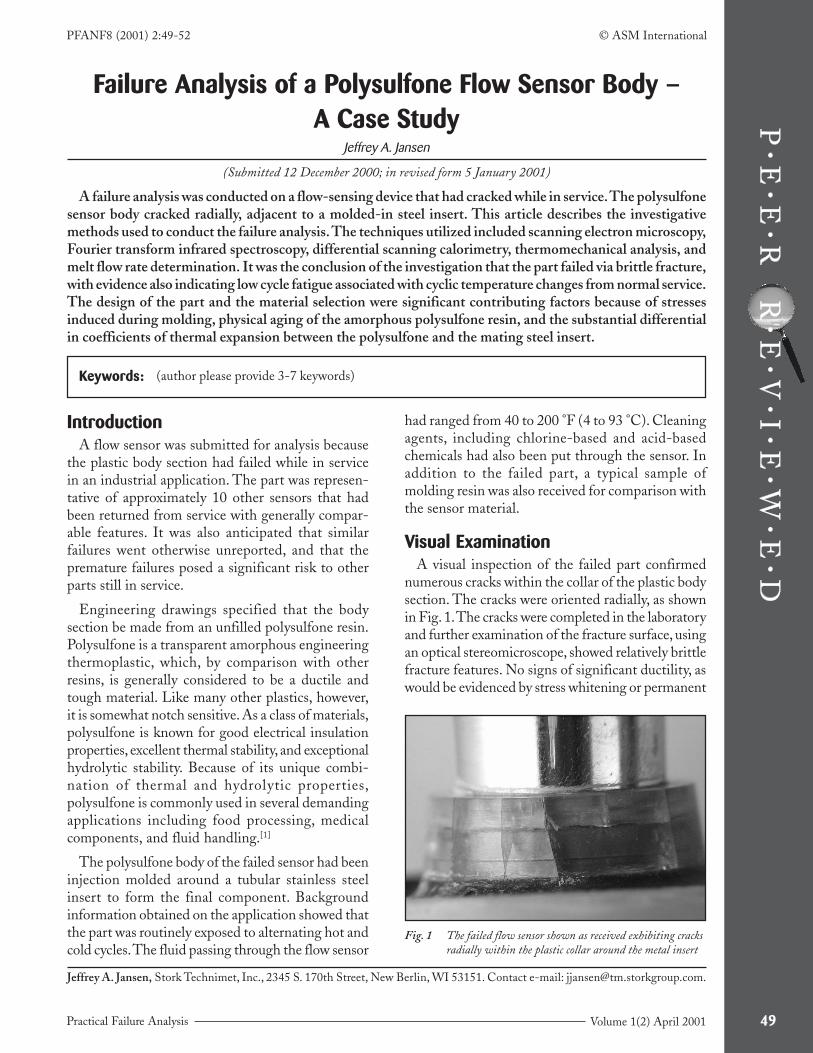
Visual ExaminationA visual inspection of the failed part confirmed
numerous cracks within the collar of the plastic bodysection. The cracks were oriented radially, as shownin Fig. 1. The cracks were completed in the laboratoryand further examination of the fracture surface, usingan optical stereomicroscope, showed relatively brittlefracture features. No signs of significant ductility, aswould be evidenced by stress whitening or permanent
Fig. 1 The failed flow sensor shown as received exhibiting cracksradially within the plastic collar around the metal insert

Polysulfone Flow Sensor Body Case Study (continued)
50 Practical Failure AnalysisVolume 1(2) April 2001
deformation, were apparent. Additionally, thefracture surface exhibited beach marks, suggestingthat the crack had propagated via fatigue.
Scanning Electron MicroscopyThe fracture surface was further inspected using
scanning electron microscopy (SEM). The SEMexamination indicated that the apparent crack originwas located at an area along the inner diameter ofthe sensor body, which contacts the molded-in steelinsert. This area had a relatively flat morphology,characteristic of brittle fracture. Surrounding thecrack origin were features of alternating cracking andarrest cycles, consistent with low cycle fatigue, asshown in Fig. 2. The final fracture zone showed fea-tures associated with brittle overload, as evidencedby the significant concentration of hackle marks, andexhibited limited ductility in the form of isolatedstretched fibrils. Throughout the SEM examination,no signs were found to indicate that post-moldingdegradation, such as chemical attack or thermaldeterioration, had occurred.
Fourier Transform InfraredSpectroscopy
The sample of the molding resin and the failedpart were analyzed using micro-Fourier transforminfrared spectroscopy (FTIR) in the attenuated totalreflectance (ATR) mode. The results obtained onthe sensor body yielded an excellent match with thoseobtained on the molding resin. Both spectraexhibited absorption bands characteristic of apolysulfone resin. This is illustrated in the spectral
comparison presented in Fig. 3. These resultsdemonstrated that the failed part was fabricated froma typical polysulfone resin and showed no evidenceof contamination or degradation.
Differential Scanning CalorimetryThe molding resin and the failed sensor were also
analyzed via differential scanning calorimetry(DSC). Again, the results that were obtained on thematerials were consistent. Both thermogramsshowed a single transition at approximately 187 °C,as illustrated in Fig. 4. This is in agreement withthe expected results for a polysulfone resin, as theseresins generally exhibit a glass transition temperature(Tg) between 185 and 190 °C. No other transitionswere observed, and no signs of contamination ordegradation were found.
Thermomechanical AnalysisA sample of material was excised from the inner
diameter of the sensor body adjacent to the fractureorigin and analyzed using thermomechanicalanalysis (TMA). The resulting thermogramindicated that the material expanded steadily as afunction of temperature through 170 °C. At thatpoint, just under the glass transition temperature,the material contracted, as a result of the load placedupon the sample during the evaluation. This con-traction was significant as it indicated that thematerial itself was not under bulk residual molded-in stress in the as-received condition. The results also
Fig. 2 Scanning electron image showing brittle fracture featuresand beach marks suggestive of low cycle fatigue
Fig. 3 FTIR spectral comparison showing a very good matchbetween the results obtained on the failed collar materialand those representing a typical molding resin. Bothspectra exhibit absorption bands characteristic ofpolysulfone.

51Practical Failure Analysis Volume 1(2) April 2001
showed that the material had a coefficient of thermalexpansion of 57 µm/m °C between 0 and 100 °C.The steel insert from the sensor was also tested, andthe results were consistent with those expected forthis type of material. A review of the thermogramindicated that the steel material had a coefficient ofthermal expansion of 19 µm/m °C through 100 °C.A comparison of these results, illustrating thethermal expansion properties that approximate actualservice temperatures, is included in Fig. 5.
Melt Flow RateMelt flow rate determinations were performed on
the molding resin and material taken from the failedsensor body. The testing was performed inaccordance with ASTM D 1238 – Procedure B usinga test temperature of 343 °C and a constant load of2.16 kg. The samples were dried to a moisturecontent below 500 ppm prior to the analysis. Thetesting indicated that the molding resin had a meltflow rate of 8.19 g/10 min. This is in agreement withthe expected results based upon the grade ofpolysulfone indicated on the engineering drawing.The analysis of the failed part material producedsimilar results, 8.03 g/10 min., showing a slightreduction in the melt flow rate for the failed partmaterial. Such a reduction is commonly observed inpolysulfone resins as a result of melt processing,where molecular weight can increase due to thermalinduced crosslinking. The magnitude of the change,however, is low and the melt flow rate results suggestgood retention of molecular weight through themolding process, without molecular degradation.
DiscussionMetal insert molding certainly offers distinct
manufacturing and design advantages; however, ithas inherent risks. These liabilities include thepotential to generate excessive strain on the locationof the part surrounding the insert due to a differentialin the coefficients of thermal expansion between theplastic and the metal insert.
During molding, the plastic is in a molten state,which for the current material, was approximately370 °C. Through the cooling process associated withthe molding operation, the plastic, having a sig-nificantly higher coefficient of thermal expansion,will contract to a much greater extent than the metalinsert. This difference in thermal expansion causesa high level of interference hoop stress on the plasticmaterial at the interface. Such stresses are exertedon the part as soon as it cools from the moldingprocess.
Additionally, amorphous resins, such as poly-sulfone, may develop cracks over time due to agingin conjunction with stresses.[2] This aging, commonlyreferred to as physical aging, occurs over an extendedperiod of time, at temperatures below the glass transi-tion, as the polymer undergoes molecular motion inan attempt to achieve an equilibrium state. Physicalaging is particularly prevalent when an amorphousresin is cooled rapidly through the glass transitiontemperature.[3] The condition is aggravated when theplastic resin is molded over a metal insert, as dimen-sional changes often accompany physical aging, thusproducing additional hoop stress at the interface.
Molding Resin
Fig. 4 A comparison of the DSC results showing comparableheat flow profiles for the failed collar material and themolding resin
Failed Collar
Fig. 5 TMA plot overlay showing the differential in thecoefficients of thermal expansion between the plastic collarmaterial and the steel insert
Collar Material
Steel Insert

Polysulfone Flow Sensor Body Case Study (continued)
52 Practical Failure AnalysisVolume 1(2) April 2001
Because of these phenomena, namely, the differentialin thermal expansion coefficients of the plastic andthe metal and physical aging, over-molding withamorphous resins, such as polysulfone, in con-junction with metal inserts should be approachedcarefully.
ConclusionIt was the conclusion of the investigation that the
flow sensor body failed within the collar section ofthe part immediately surrounding the molded-inmetal insert via brittle fracture, which was broughtabout by the exertion of stresses beyond the strengthof the material. Examination of the fracture surfacerevealed features associated with brittle cracking,with additional evidence indicating alternatingcycles of cracking and arrest, characteristic of lowcycle fatigue.
The location of the cracks, which were orientedradially around the metal insert, was a strong indi-cation that the source of the principal stress was theinterference between the plastic collar on the sensorbody and the molded-in insert. Although the analysisresults indicated that the failure was primarily assoc-iated with mechanical stress produced during service,the design and production of the part are significant
contributing factors. It appears likely that continuedtemperature changes, encountered during standarduse conditions, coupled with the differential in thecoefficients of thermal expansion between thepolysulfone sensor body and the steel insert, alongwith physical aging, compounded the inherentinternal stresses associated with the interference atthe interface. This combination of stresses initiatedthe stress fractures radially around the insert overtime in service. Given the notch sensitivity of poly-sulfone,[4] the cracks propagated through low cyclefatigue with the repeated temperature cycles. Finalcatastrophic failure occurred within some of thecracks due to the reduced cross section of the collar.
References1. James E. Harris: Handbook of Plastic Materials and
Technology, Irvin I. Rubin, ed., John Wiley & Sons, Inc.,New York, NY, 1990, pp. 487- 491.
2. Plastics Engineering Handbook of the Society of the PlasticsIndustry, Inc., 5th ed., Michael L. Berins, ed., Chapman &Hall, New York, NY, 1991, p. 752.
3. Julie P. Harmon and Charles L. Beatty: Engineered MaterialsHandbook, vol. 2, ASM International, Metals Park, OH,1988, p. 751.
4. James E. Harris: Handbook of Plastic Materials and Tech-nology, Irvin I. Rubin, ed., John Wiley & Sons, Inc., NewYork, NY, 1990, p. 488.
Related Documents