Failure analysis of a bolt in a scaffolding system R. Lacalle * , S. Cicero, D. Ferren ˜o, J.A. A ´ lvarez Department of Materials Science and Engineering, University of Cantabria, Av. de los Castros s/n, 39005 Santander, Spain Available online 27 July 2007 Abstract This paper analyses the failure of a bolt which sustained a scaffolding during a construction process. The work per- formed begins with the fractographic analysis of the failure section and continues with a structural integrity assessment using the European FITNET FFS procedure. The main conclusion is that failure occurred due to the superposition of an overloading which the scaffolding was not designed for and an environmental assisted cracking process. Ó 2007 Elsevier Ltd. All rights reserved. Keywords: Bolt; Scaffolding; Failure analysis; FITNET FFS procedure 1. Introduction During the dismantling process of a scaffolding, the bolt which fastens one of the modules of the system suffered a sudden failure when it was only supporting the weight of one worker (who fell four meters and was seriously injured). Fig. 1 shows the bolt as it was received in the Materials Laboratory of the University of Cantabria. In short, this work analyses the causes of the failure. 2. Description of the scaffolding The typology of the scaffolding is commonly used in order to facilitate the spilling and vibration of the con- crete in the wall form to which it is fastened, as shown in Fig. 2. In spite of this main function, the structure is also used as a footbridge between different places of the working area. The different modules of the scaffolding are frequently assembled and dismantled in the construction works. Therefore, these processes should be as simple as possible: a footbridge made of planks lies on metallic mod- ules which are separated at a constant distance. These modules are fastened to the form with just one bolt. The scheme is shown in Fig. 2. 1350-6307/$ - see front matter Ó 2007 Elsevier Ltd. All rights reserved. doi:10.1016/j.engfailanal.2007.06.005 * Corresponding author. Tel.: +34 942 200917; fax: +34 942 20 18 18. E-mail address: [email protected] (R. Lacalle). Available online at www.sciencedirect.com Engineering Failure Analysis 15 (2008) 237–246 www.elsevier.com/locate/engfailanal

Welcome message from author
This document is posted to help you gain knowledge. Please leave a comment to let me know what you think about it! Share it to your friends and learn new things together.
Transcript
Available online at www.sciencedirect.com
Engineering Failure Analysis 15 (2008) 237–246
www.elsevier.com/locate/engfailanal
Failure analysis of a bolt in a scaffolding system
R. Lacalle *, S. Cicero, D. Ferreno, J.A. Alvarez
Department of Materials Science and Engineering, University of Cantabria, Av. de los Castros s/n, 39005 Santander, Spain
Available online 27 July 2007
Abstract
This paper analyses the failure of a bolt which sustained a scaffolding during a construction process. The work per-formed begins with the fractographic analysis of the failure section and continues with a structural integrity assessmentusing the European FITNET FFS procedure. The main conclusion is that failure occurred due to the superposition ofan overloading which the scaffolding was not designed for and an environmental assisted cracking process.� 2007 Elsevier Ltd. All rights reserved.
Keywords: Bolt; Scaffolding; Failure analysis; FITNET FFS procedure
1. Introduction
During the dismantling process of a scaffolding, the bolt which fastens one of the modules of the systemsuffered a sudden failure when it was only supporting the weight of one worker (who fell four meters andwas seriously injured). Fig. 1 shows the bolt as it was received in the Materials Laboratory of the Universityof Cantabria.
In short, this work analyses the causes of the failure.
2. Description of the scaffolding
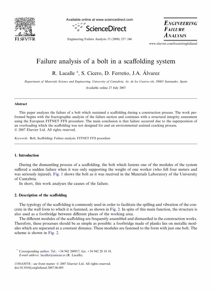
The typology of the scaffolding is commonly used in order to facilitate the spilling and vibration of the con-crete in the wall form to which it is fastened, as shown in Fig. 2. In spite of this main function, the structure isalso used as a footbridge between different places of the working area.
The different modules of the scaffolding are frequently assembled and dismantled in the construction works.Therefore, these processes should be as simple as possible: a footbridge made of planks lies on metallic mod-ules which are separated at a constant distance. These modules are fastened to the form with just one bolt. Thescheme is shown in Fig. 2.
1350-6307/$ - see front matter � 2007 Elsevier Ltd. All rights reserved.
doi:10.1016/j.engfailanal.2007.06.005
* Corresponding author. Tel.: +34 942 200917; fax: +34 942 20 18 18.E-mail address: [email protected] (R. Lacalle).
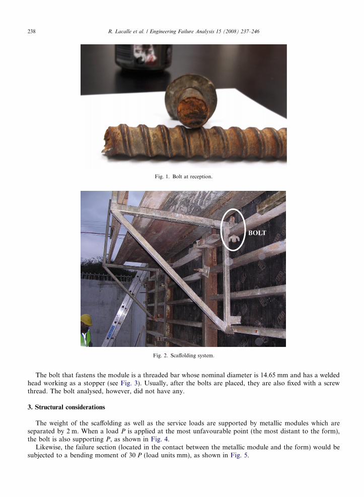
Fig. 2. Scaffolding system.
Fig. 1. Bolt at reception.
238 R. Lacalle et al. / Engineering Failure Analysis 15 (2008) 237–246
The bolt that fastens the module is a threaded bar whose nominal diameter is 14.65 mm and has a weldedhead working as a stopper (see Fig. 3). Usually, after the bolts are placed, they are also fixed with a screwthread. The bolt analysed, however, did not have any.
3. Structural considerations
The weight of the scaffolding as well as the service loads are supported by metallic modules which areseparated by 2 m. When a load P is applied at the most unfavourable point (the most distant to the form),the bolt is also supporting P, as shown in Fig. 4.
Likewise, the failure section (located in the contact between the metallic module and the form) would besubjected to a bending moment of 30 P (load units mm), as shown in Fig. 5.
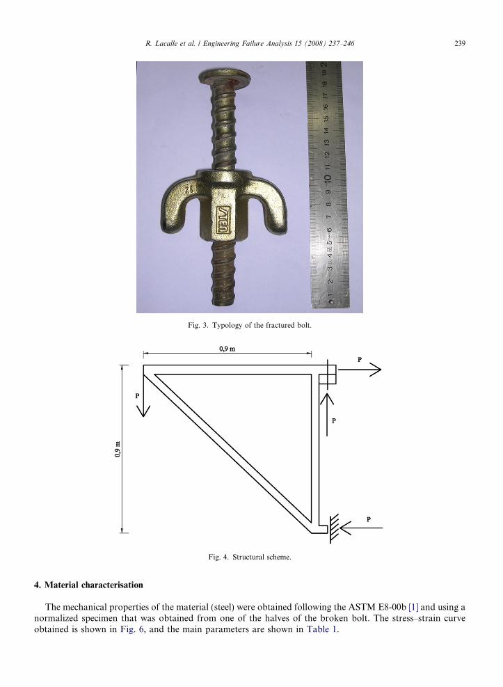
Fig. 3. Typology of the fractured bolt.
Fig. 4. Structural scheme.
R. Lacalle et al. / Engineering Failure Analysis 15 (2008) 237–246 239
4. Material characterisation
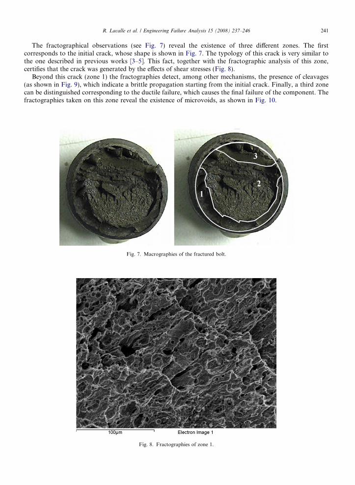
The mechanical properties of the material (steel) were obtained following the ASTM E8-00b [1] and using anormalized specimen that was obtained from one of the halves of the broken bolt. The stress–strain curveobtained is shown in Fig. 6, and the main parameters are shown in Table 1.
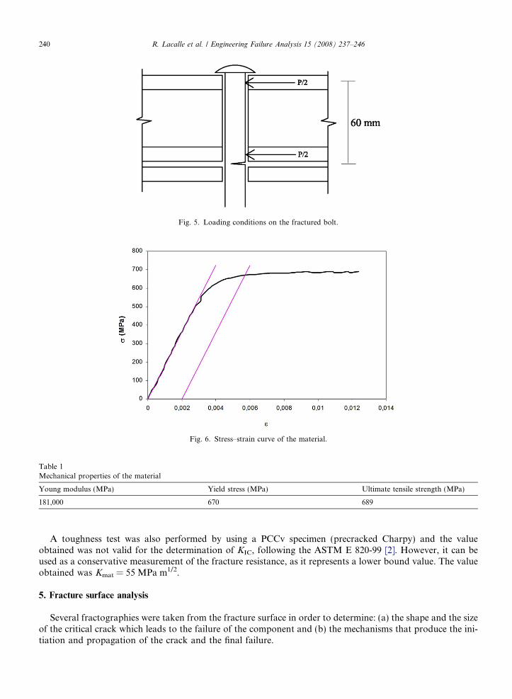
Fig. 5. Loading conditions on the fractured bolt.
Fig. 6. Stress–strain curve of the material.
Table 1Mechanical properties of the material
Young modulus (MPa) Yield stress (MPa) Ultimate tensile strength (MPa)
181,000 670 689
240 R. Lacalle et al. / Engineering Failure Analysis 15 (2008) 237–246
A toughness test was also performed by using a PCCv specimen (precracked Charpy) and the valueobtained was not valid for the determination of KIC, following the ASTM E 820-99 [2]. However, it can beused as a conservative measurement of the fracture resistance, as it represents a lower bound value. The valueobtained was Kmat = 55 MPa m1/2.
5. Fracture surface analysis
Several fractographies were taken from the fracture surface in order to determine: (a) the shape and the sizeof the critical crack which leads to the failure of the component and (b) the mechanisms that produce the ini-tiation and propagation of the crack and the final failure.
R. Lacalle et al. / Engineering Failure Analysis 15 (2008) 237–246 241
The fractographical observations (see Fig. 7) reveal the existence of three different zones. The firstcorresponds to the initial crack, whose shape is shown in Fig. 7. The typology of this crack is very similar tothe one described in previous works [3–5]. This fact, together with the fractographic analysis of this zone,certifies that the crack was generated by the effects of shear stresses (Fig. 8).
Beyond this crack (zone 1) the fractographies detect, among other mechanisms, the presence of cleavages(as shown in Fig. 9), which indicate a brittle propagation starting from the initial crack. Finally, a third zonecan be distinguished corresponding to the ductile failure, which causes the final failure of the component. Thefractographies taken on this zone reveal the existence of microvoids, as shown in Fig. 10.
Fig. 7. Macrographies of the fractured bolt.
Fig. 8. Fractographies of zone 1.
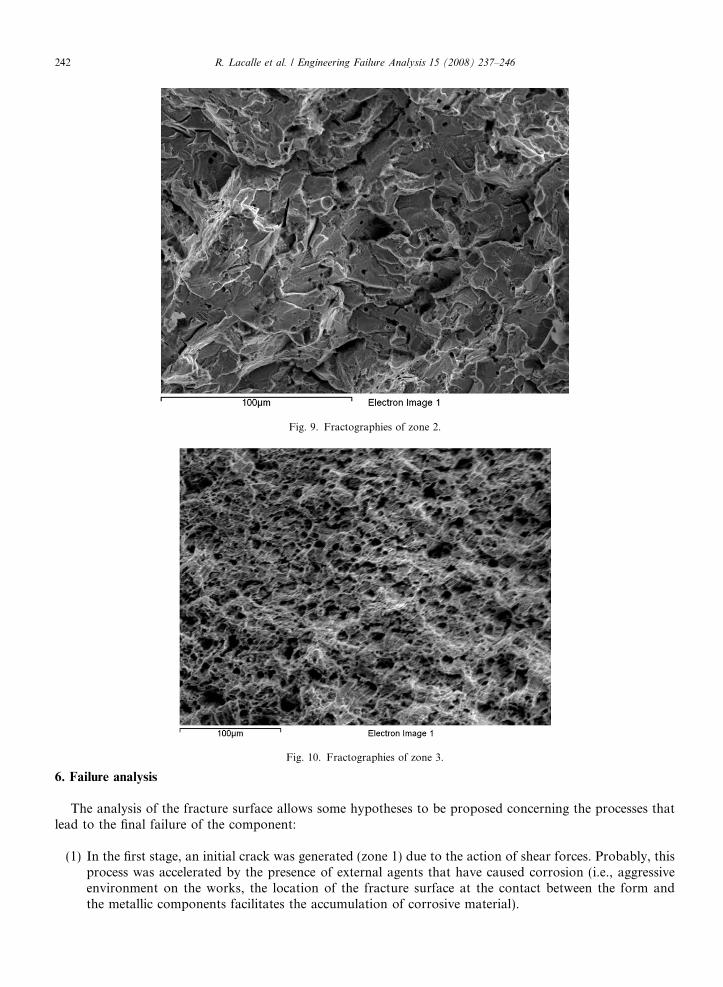
Fig. 9. Fractographies of zone 2.
Fig. 10. Fractographies of zone 3.
242 R. Lacalle et al. / Engineering Failure Analysis 15 (2008) 237–246
6. Failure analysis
The analysis of the fracture surface allows some hypotheses to be proposed concerning the processes thatlead to the final failure of the component:
(1) In the first stage, an initial crack was generated (zone 1) due to the action of shear forces. Probably, thisprocess was accelerated by the presence of external agents that have caused corrosion (i.e., aggressiveenvironment on the works, the location of the fracture surface at the contact between the form andthe metallic components facilitates the accumulation of corrosive material).
R. Lacalle et al. / Engineering Failure Analysis 15 (2008) 237–246 243
(2) After the crack reached a critical value, a brittle propagation was produced and the crack progressedthrough the zone 2 (probably after some overloading).
(3) Finally, the accident happened due to the final failure of the bolt. Considering the fractographic obser-vations of the fracture surface and the small load that was acting at failure (the weight of the worker), itcan be stated that only zone 3 formed the resistant ligament at failure.
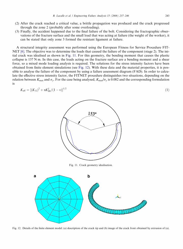
A structural integrity assessment was performed using the European Fitness for Service Procedure FIT-NET [6]. The objective was to determine the loads that caused the failure of the component (stage 2). The ini-tial crack was idealised as shown in Fig. 11. For this geometry, the bending moment that causes the plasticcollapse is 137 N m. In this case, the loads acting on the fracture surface are a bending moment and a shearforce, so a mixed mode loading analysis is required. The solutions for the stress intensity factors have beenobtained from finite element simulations (see Fig. 12). With these data and the material properties, it is pos-sible to analyse the failure of the component by using a failure assessment diagram (FAD). In order to calcu-late the effective stress intensity factor, the FITNET procedure distinguishes two situations, depending on therelation between Kmat and ry. For the case being analysed, Kmat/ry is 0.082 and the corresponding formulationis
Fig. 12
Keff ¼ ½ðK12Þ2 þ aK2III=ð1� tÞ�1=2 ð1Þ
Fig. 11. Crack geometry idealisation.
. Details of the finite element model: (a) description of the crack tip and (b) image of the crack front obtained by extrusion of (a).
244 R. Lacalle et al. / Engineering Failure Analysis 15 (2008) 237–246
where
K12 ¼2KI þ 6
ffiffiffiffiffiffiffiffiffiffiffiffiffiffiffiffiffiffiffiffiK2
I þ 8K2II
q� �
8
K2I þ 12K2
II þ KI
ffiffiffiffiffiffiffiffiffiffiffiffiffiffiffiffiffiffiffiffiK2
I þ 8K2II
q2K2
I þ 18K2II
8<:
9=; ð2Þ
and a = 1 in general. The equation used for K12 corresponds to situations where jKI/KIIjP 0.466. To obtainKII, a finite element simulation was performed.
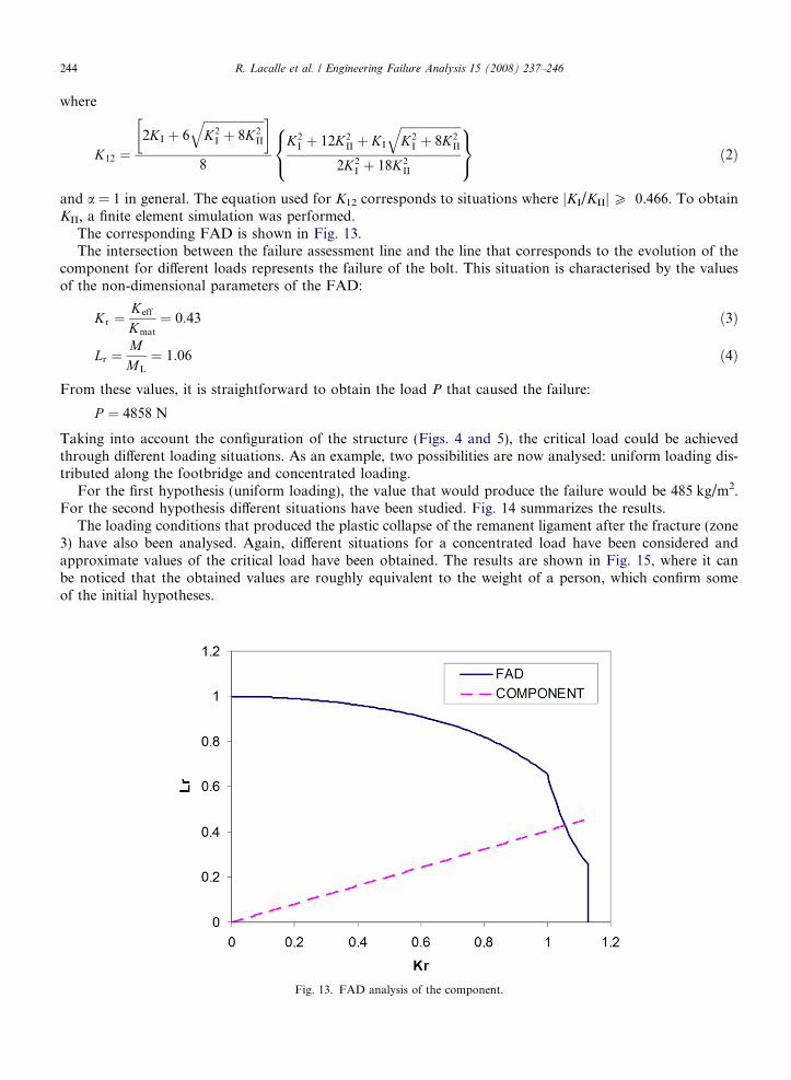
The corresponding FAD is shown in Fig. 13.The intersection between the failure assessment line and the line that corresponds to the evolution of the
component for different loads represents the failure of the bolt. This situation is characterised by the valuesof the non-dimensional parameters of the FAD:
Kr ¼Keff
Kmat
¼ 0:43 ð3Þ
Lr ¼MML
¼ 1:06 ð4Þ
From these values, it is straightforward to obtain the load P that caused the failure:
P ¼ 4858 N
Taking into account the configuration of the structure (Figs. 4 and 5), the critical load could be achievedthrough different loading situations. As an example, two possibilities are now analysed: uniform loading dis-tributed along the footbridge and concentrated loading.
For the first hypothesis (uniform loading), the value that would produce the failure would be 485 kg/m2.For the second hypothesis different situations have been studied. Fig. 14 summarizes the results.
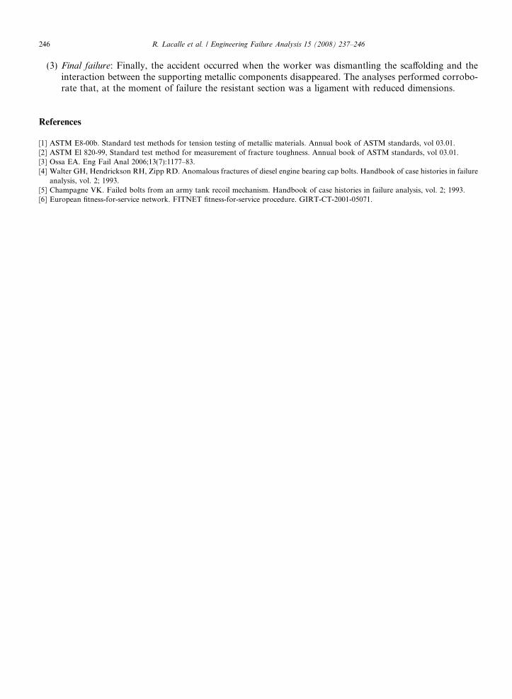
The loading conditions that produced the plastic collapse of the remanent ligament after the fracture (zone3) have also been analysed. Again, different situations for a concentrated load have been considered andapproximate values of the critical load have been obtained. The results are shown in Fig. 15, where it canbe noticed that the obtained values are roughly equivalent to the weight of a person, which confirm someof the initial hypotheses.
Fig. 13. FAD analysis of the component.
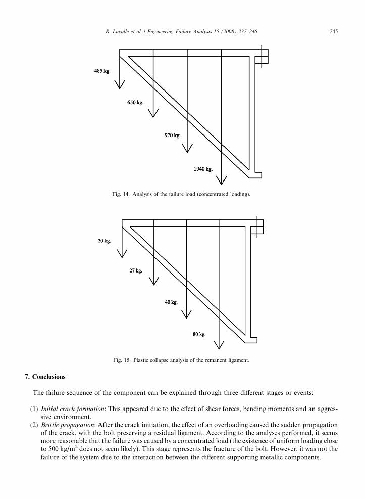
Fig. 14. Analysis of the failure load (concentrated loading).
Fig. 15. Plastic collapse analysis of the remanent ligament.
R. Lacalle et al. / Engineering Failure Analysis 15 (2008) 237–246 245
7. Conclusions
The failure sequence of the component can be explained through three different stages or events:
(1) Initial crack formation: This appeared due to the effect of shear forces, bending moments and an aggres-sive environment.
(2) Brittle propagation: After the crack initiation, the effect of an overloading caused the sudden propagationof the crack, with the bolt preserving a residual ligament. According to the analyses performed, it seemsmore reasonable that the failure was caused by a concentrated load (the existence of uniform loading closeto 500 kg/m2 does not seem likely). This stage represents the fracture of the bolt. However, it was not thefailure of the system due to the interaction between the different supporting metallic components.
246 R. Lacalle et al. / Engineering Failure Analysis 15 (2008) 237–246
(3) Final failure: Finally, the accident occurred when the worker was dismantling the scaffolding and theinteraction between the supporting metallic components disappeared. The analyses performed corrobo-rate that, at the moment of failure the resistant section was a ligament with reduced dimensions.
References
[1] ASTM E8-00b. Standard test methods for tension testing of metallic materials. Annual book of ASTM standards, vol 03.01.[2] ASTM El 820-99, Standard test method for measurement of fracture toughness. Annual book of ASTM standards, vol 03.01.[3] Ossa EA. Eng Fail Anal 2006;13(7):1177–83.[4] Walter GH, Hendrickson RH, Zipp RD. Anomalous fractures of diesel engine bearing cap bolts. Handbook of case histories in failure
analysis, vol. 2; 1993.[5] Champagne VK. Failed bolts from an army tank recoil mechanism. Handbook of case histories in failure analysis, vol. 2; 1993.[6] European fitness-for-service network. FITNET fitness-for-service procedure. GIRT-CT-2001-05071.
Related Documents