1-1 REDA Production Systems REDA Production Systems REDA Production Systems REDA Production Systems REDA Production Systems FACT- PAC Operations Manual Contents Contents Contents Contents Contents 1.1 Safety Notations ................................................................................................................................................................................. 3 1.1.1 Danger ................................................................................................................................................................................... 3 1.1.2 Warning ................................................................................................................................................................................ 3 1.1.3 Caution .................................................................................................................................................................................. 4 1.1.4 Notice .................................................................................................................................................................................... 5 1.2 Introduction ......................................................................................................................................................................................... 5 1.2.1 Input Terminals and Cable ................................................................................................................................................ 5 1.2.2 Disconnect and Isolation Switch .................................................................................................................................... 5 1.2.3 Secondary Voltage Range ................................................................................................................................................ 5 1.2.4 Control and Overcurrent Protection ............................................................................................................................... 6 1.2.5 Beacon Light ....................................................................................................................................................................... 6 1.2.6 Amp Chart Recorder ........................................................................................................................................................... 6 1.2.7 Backspin Protection .......................................................................................................................................................... 6 1.2.8 Ground Fault Protection .................................................................................................................................................... 6 1.2.9 Control and Metering Voltage ......................................................................................................................................... 6 1.2.10 Lighting and Auxilary Voltage .......................................................................................................................................... 7 1.2.11 Surge Suppression ............................................................................................................................................................. 7 1.2.12 Convenience Outlet ........................................................................................................................................................... 7 1.2.13 Space Heater ....................................................................................................................................................................... 7 1.2.14 Cabinet Cooler ..................................................................................................................................................................... 7 1.2.15 Soft Starter ........................................................................................................................................................................... 7 1.3 Handling Procedures ......................................................................................................................................................................... 9 1.3.1 Inspection ............................................................................................................................................................................ 9 1.3.2 Nitrogen Pressure ............................................................................................................................................................... 9 1.3.3 Acceptance Tests .............................................................................................................................................................. 9 1.3.4 Handling ................................................................................................................................................................................ 9 1.3.5 Storage .................................................................................................................................................................................. 9 1.4 Installation Procedures .................................................................................................................................................................... 8 1.4.1 Caution Sign for Down-pole .............................................................................................................................................. 8 1.4.2 Foundation ........................................................................................................................................................................... 8 1.4.3 Grounding ............................................................................................................................................................................. 9 1.4.4 Primary Connection .......................................................................................................................................................... 15 1.4.5 Secondary Connection .................................................................................................................................................... 19 1.4.6 Chemical Pump Connection ............................................................................................................................................ 19 1.4.7 Soft Starter ......................................................................................................................................................................... 20

Factpac Manual
Nov 08, 2014
ok
Welcome message from author
This document is posted to help you gain knowledge. Please leave a comment to let me know what you think about it! Share it to your friends and learn new things together.
Transcript
1-1
REDA Production SystemsREDA Production SystemsREDA Production SystemsREDA Production SystemsREDA Production Systems
FACT- PAC Operations Manual
ContentsContentsContentsContentsContents1.1 Safety Notations ................................................................................................................................................................................. 3
1.1.1 Danger ................................................................................................................................................................................... 31.1.2 Warning ................................................................................................................................................................................ 31.1.3 Caution .................................................................................................................................................................................. 41.1.4 Notice .................................................................................................................................................................................... 5
1.2 Introduction ......................................................................................................................................................................................... 51.2.1 Input Terminals and Cable ................................................................................................................................................ 51.2.2 Disconnect and Isolation Switch .................................................................................................................................... 51.2.3 Secondary Voltage Range ................................................................................................................................................ 51.2.4 Control and Overcurrent Protection ............................................................................................................................... 61.2.5 Beacon Light ....................................................................................................................................................................... 61.2.6 Amp Chart Recorder ........................................................................................................................................................... 61.2.7 Backspin Protection .......................................................................................................................................................... 61.2.8 Ground Fault Protection .................................................................................................................................................... 61.2.9 Control and Metering Voltage ......................................................................................................................................... 61.2.10 Lighting and Auxilary Voltage .......................................................................................................................................... 71.2.11 Surge Suppression ............................................................................................................................................................. 71.2.12 Convenience Outlet ........................................................................................................................................................... 71.2.13 Space Heater ....................................................................................................................................................................... 71.2.14 Cabinet Cooler ..................................................................................................................................................................... 71.2.15 Soft Starter ........................................................................................................................................................................... 7
1.3 Handling Procedures ......................................................................................................................................................................... 91.3.1 Inspection ............................................................................................................................................................................ 91.3.2 Nitrogen Pressure ............................................................................................................................................................... 91.3.3 Acceptance Tests .............................................................................................................................................................. 91.3.4 Handling ................................................................................................................................................................................ 91.3.5 Storage .................................................................................................................................................................................. 9
1.4 Installation Procedures .................................................................................................................................................................... 81.4.1 Caution Sign for Down-pole .............................................................................................................................................. 81.4.2 Foundation ........................................................................................................................................................................... 81.4.3 Grounding ............................................................................................................................................................................. 91.4.4 Primary Connection .......................................................................................................................................................... 151.4.5 Secondary Connection .................................................................................................................................................... 191.4.6 Chemical Pump Connection ............................................................................................................................................ 191.4.7 Soft Starter ......................................................................................................................................................................... 20
1-2
REDA Production SystemsREDA Production SystemsREDA Production SystemsREDA Production SystemsREDA Production Systems
FACT- PAC Operations Manual
1.5 Energizing FACT-PAC ........................................................................................................................................................................ 211.5.1 Checks ................................................................................................................................................................................. 221.5.2 Changing Taps ................................................................................................................................................................... 22
1.6 Commissioning the K095 Motor Controller ................................................................................................................................. 221.6.1 Start-up ............................................................................................................................................................................... 23
1.7 Fuses .................................................................................................................................................................................................... 241.8 Parts List ............................................................................................................................................................................................. 241.9 Control Wiring Diagram .................................................................................................................................................................. 28
1-3
REDA Production SystemsREDA Production SystemsREDA Production SystemsREDA Production SystemsREDA Production Systems
FACT- PAC Operations Manual
This section contains information proprietary to Southwest Electric Company. Any reproduction or disclosureof this publication or any part hereof to persons other than FACT-PAC users is strictly prohibited withoutpermission by Southwest Electric Company.
COPYRIGHT © 1994COPYRIGHT © 1994COPYRIGHT © 1994COPYRIGHT © 1994COPYRIGHT © 1994
Southwest Electric Company
Oklahoma City, Oklahoma, USA
ALL RIGHTS RESERVED
The intent of this publication is to offer the best recommendations known to the supplier for the safe andsuccessful operation of FACT-PAC. In case of conflicts with previous or standard practices, the user is urgedto carefully analyze the recommendations and communicate with the supplier before proceding.
1.1 Safety Notations1.1.1 Danger
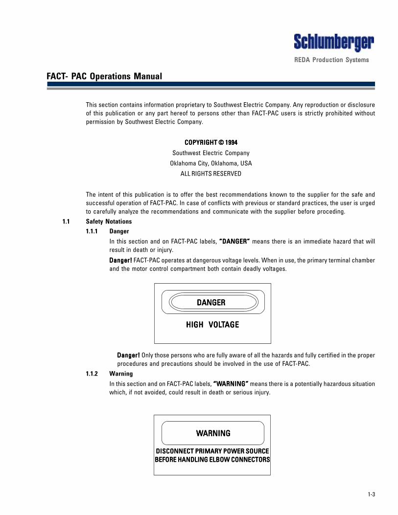
In this section and on FACT-PAC labels, “DANGER”“DANGER”“DANGER”“DANGER”“DANGER” means there is an immediate hazard that willresult in death or injury.
Danger!Danger!Danger!Danger!Danger! FACT-PAC operates at dangerous voltage levels. When in use, the primary terminal chamberand the motor control compartment both contain deadly voltages.
Danger!Danger!Danger!Danger!Danger! Only those persons who are fully aware of all the hazards and fully certified in the properprocedures and precautions should be involved in the use of FACT-PAC.
1.1.2 Warning
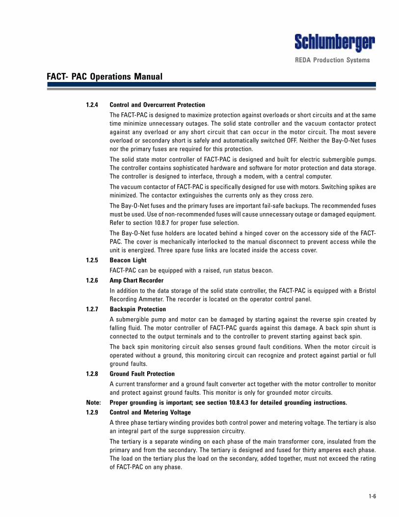
In this section and on FACT-PAC labels, “W“W“W“W“WARNING”ARNING”ARNING”ARNING”ARNING” means there is a potentially hazardous situationwhich, if not avoided, could result in death or serious injury.
DANGERDANGERDANGERDANGERDANGER
HIGH VOLHIGH VOLHIGH VOLHIGH VOLHIGH VOLTTTTTAGEAGEAGEAGEAGE
WWWWWARNINGARNINGARNINGARNINGARNING
DISCONNECT PRIMARY POWER SOURCEDISCONNECT PRIMARY POWER SOURCEDISCONNECT PRIMARY POWER SOURCEDISCONNECT PRIMARY POWER SOURCEDISCONNECT PRIMARY POWER SOURCEBEFORE HANDLING ELBOW CONNECTORSBEFORE HANDLING ELBOW CONNECTORSBEFORE HANDLING ELBOW CONNECTORSBEFORE HANDLING ELBOW CONNECTORSBEFORE HANDLING ELBOW CONNECTORS

1-4
REDA Production SystemsREDA Production SystemsREDA Production SystemsREDA Production SystemsREDA Production Systems
FACT- PAC Operations Manual
Warning!Warning!Warning!Warning!Warning! The manual disconnect should be padlocked in the OFF position for any maintenance tothe motor circuit or the control circuits. Withdrawn Bay-O-Net fuses are visual proof that power tothe controller is OFF.
WWWWWarning!arning!arning!arning!arning! The elbow connectors and lines that feed FACT-PAC should not be handled while thecutouts are closed.
Warning!Warning!Warning!Warning!Warning! The manual disconnect switch does not turn OFF the voltages inside the primary terminalchamber.
Warning!Warning!Warning!Warning!Warning! The primary terminal chamber should be closed and padlocked at all times while theprimary feeder cables are energized.
Warning!Warning!Warning!Warning!Warning! Opening the current transformer secondary circuits must be done only when the motor isoff. The manual disconnect should be turned OFF any time wiring changes are made.
Warning!Warning!Warning!Warning!Warning! The mechanical interlocks should never be disabled.
WWWWWarning!arning!arning!arning!arning! When FACT-PAC is energized and unattended, all access doors should be closed andpadlocked.
WWWWWarning!arning!arning!arning!arning! The FACT-PAC enclosure must be solidly grounded.1.1.3 Caution
In this section and on FACT-PAC labels, “CAUTION”“CAUTION”“CAUTION”“CAUTION”“CAUTION” means there is a potentially hazardous situationwhich, if not avoided, may result in minor or moderate injury.
CAUTION! CAUTION! CAUTION! CAUTION! CAUTION! The FACT-PAC manual disconnect should be OFF any time the cutouts are to be operated,opened or closed. Dangerously high over voltages, ferro-resonance, may occur if the cutouts areoperated with the manual disconnect ON.
Caution!Caution!Caution!Caution!Caution! Turn OFF manual disconnect switch before changing the transformer taps.
Caution!Caution!Caution!Caution!Caution! Turn OFF manual disconnect switch before removing or installing Bay-O-Net fuses.
Caution!Caution!Caution!Caution!Caution! Vent all pressure before unsealing the Bay-O-Net fuse holders. Pull and hold the pressurerelief valve ring until all pressure has been released.
CAUTIONCAUTIONCAUTIONCAUTIONCAUTION
-TURN OFF--TURN OFF--TURN OFF--TURN OFF--TURN OFF-MANUAL DISCONNECT BEFOREMANUAL DISCONNECT BEFOREMANUAL DISCONNECT BEFOREMANUAL DISCONNECT BEFOREMANUAL DISCONNECT BEFORE
REMOVING OR INSTREMOVING OR INSTREMOVING OR INSTREMOVING OR INSTREMOVING OR INSTALLING FUSESALLING FUSESALLING FUSESALLING FUSESALLING FUSES

1-5
REDA Production SystemsREDA Production SystemsREDA Production SystemsREDA Production SystemsREDA Production Systems
FACT- PAC Operations Manual
1.1.4 Notice
In this section and on FACT-PAC labels, “NOTICE”“NOTICE”“NOTICE”“NOTICE”“NOTICE” means there is a potential situation which, if notavoided, may result in equipment damage and may void the warranties.
Notice. Notice. Notice. Notice. Notice. Use only the recommended fuses or fuse links in the control circuits, in the Bay-O-Netfuse holders and on the primary cutouts. Improper fuses will cause nuisance outages or equipmentdamage and may void warranties.
1.2 Introduction
FACT-PAC is a power supply and motor control package for electric submergible pumps. Motor controller andpower transformer are combined into a single unit.1.2.1 Input Terminals and Cable
The primary input terminals of FACT-PAC are separable, insulated, high-voltage connectors commonlycalled “Dead Front”.
The primary terminals are fully insulated and shielded. However, personnel safety is enhanced bykeeping the primary terminal chamber closed and padlocked any time the feeder cables are energized.
1.2.2 Disconnect and Isolation Switch
The manual disconnect of FACT-PAC is designed and rated to interrupt load currents. The disconnectacts as an emergency shut down switch or as an isolation switch. The disconnect can safelyinterrupt the power to a stalled motor. When the manual disconnect is OFF all circuits in the motorcontrol section are OFF. A padlock in the hole (staple), near the disconnect handle, will prevent theswitch from being thrown, on or off.
Note: The handle is not to be locked to the staple but left fully up or fully down.
The Bay-O-Net fuses of FACT-PAC are used for visual certainty that the power is OFF. After the manualdisconnect is turned OFF, release the pressure and remove the Bay-O-Net fuses. The motor controlsection cannot be energized while the Bay-O-Net fuses are removed.
1.2.3 Secondary Voltage Range
FACT-PAC secondary is adjustable through a wide voltage range. The FACT-PAC is equipped with aDelta-Wye switch and two tap changers. All voltage ratings are full kVA.
The FACT-PAC must be de-energized before operating the tap changers or the Delta-Wye switch. Theadjusting handles are located behind a hinged cover on the accessory side of the FACT-PAC. Thecover is mechanically interlocked to the manual disconnect to prevent access while the unit isenergized.
NOTICENOTICENOTICENOTICENOTICE
USE ONLUSE ONLUSE ONLUSE ONLUSE ONLYYYYY358C10 25 AMP358C10 25 AMP358C10 25 AMP358C10 25 AMP358C10 25 AMP
FUSE LINKFUSE LINKFUSE LINKFUSE LINKFUSE LINK
1-6
REDA Production SystemsREDA Production SystemsREDA Production SystemsREDA Production SystemsREDA Production Systems
FACT- PAC Operations Manual
1.2.4 Control and Overcurrent Protection
The FACT-PAC is designed to maximize protection against overloads or short circuits and at the sametime minimize unnecessary outages. The solid state controller and the vacuum contactor protectagainst any overload or any short circuit that can occur in the motor circuit. The most severeoverload or secondary short is safely and automatically switched OFF. Neither the Bay-O-Net fusesnor the primary fuses are required for this protection.
The solid state motor controller of FACT-PAC is designed and built for electric submergible pumps.The controller contains sophisticated hardware and software for motor protection and data storage.The controller is designed to interface, through a modem, with a central computer.
The vacuum contactor of FACT-PAC is specifically designed for use with motors. Switching spikes areminimized. The contactor extinguishes the currents only as they cross zero.
The Bay-O-Net fuses and the primary fuses are important fail-safe backups. The recommended fusesmust be used. Use of non-recommended fuses will cause unnecessary outage or damaged equipment.Refer to section 10.8.7 for proper fuse selection.
The Bay-O-Net fuse holders are located behind a hinged cover on the accessory side of the FACT-PAC. The cover is mechanically interlocked to the manual disconnect to prevent access while theunit is energized. Three spare fuse links are located inside the access cover.
1.2.5 Beacon Light
FACT-PAC can be equipped with a raised, run status beacon.1.2.6 Amp Chart Recorder
In addition to the data storage of the solid state controller, the FACT-PAC is equipped with a BristolRecording Ammeter. The recorder is located on the operator control panel.
1.2.7 Backspin Protection
A submergible pump and motor can be damaged by starting against the reverse spin created byfalling fluid. The motor controller of FACT-PAC guards against this damage. A back spin shunt isconnected to the output terminals and to the controller to prevent starting against back spin.
The back spin monitoring circuit also senses ground fault conditions. When the motor circuit isoperated without a ground, this monitoring circuit can recognize and protect against partial or fullground faults.
1.2.8 Ground Fault Protection
A current transformer and a ground fault converter act together with the motor controller to monitorand protect against ground faults. This monitor is only for grounded motor circuits.
Note: Proper grounding is important; see section 10.8.4.3 for detailed grounding instructions.1.2.9 Control and Metering Voltage
A three phase tertiary winding provides both control power and metering voltage. The tertiary is alsoan integral part of the surge suppression circuitry.
The tertiary is a separate winding on each phase of the main transformer core, insulated from theprimary and from the secondary. The tertiary is designed and fused for thirty amperes each phase.The load on the tertiary plus the load on the secondary, added together, must not exceed the ratingof FACT-PAC on any phase.
1-7
REDA Production SystemsREDA Production SystemsREDA Production SystemsREDA Production SystemsREDA Production Systems
FACT- PAC Operations Manual
1.2.10 Lighting and Auxilary Voltage
A three-phase fuse block for lighting and auxillary power is provided in the low voltage compartment.It is designed and fused for 208 volts, 10 amps. A supplemental schematic is displayed beneaththe main schematic on the access cover of the high voltage section.
1.2.11 Surge Suppression
FACT-PAC effectively limits voltage spikes in the secondary and in the tertiary. An electrostaticshield in each phase blocks line-to-ground spikes from both secondary and tertiary. A bank ofcapacitors combined with metal oxide varistors suppress line-to-line spikes both in the secondaryand in the tertiary. The motor, the cable and the control components are protected from thedestructive effects of lightning.
Note: Proper grounding is important for effective surge suppression; see detailed grounding instructions insection 10.8.4.3.1.2.12 Convenience Outlet
An outdoor type, duplex, convenience outlet is located on the operator control panel. The outletis ground fault protected for personnel safety and the circuit is fused at 10 amps.
13.2.13 Space Heater
To prevent condensation inside the FACT-PAC controller, a thermostatically controlled, spaceheater is mounted in the low voltage section. The space heater stays on any time the FACT-PAC isenergized and the air temperature inside the controller is below 100 degrees F.
1.2.14 Cabinet Cooler
The motor control section of the FACT-PAC is equipped with a cabinet cooler to keep thecomponents below their rated temperature. The cabinet cooler is an air-to-air heat exchangerwhich cools and recirculates the clean air inside the enclosure while maintaining the enclosure’sprotective seal against contamination.
1.2.15 Soft Starter
The soft starter is designed to extend the run life of a submergible motor by reducing the startingtorque when the torque is so great that damage to the equipment occurs during normal starting.

1-8
REDA Production SystemsREDA Production SystemsREDA Production SystemsREDA Production SystemsREDA Production Systems
FACT- PAC Operations Manual
Figure 10S - FACT-PAC One Line Schematic

1-9
REDA Production SystemsREDA Production SystemsREDA Production SystemsREDA Production SystemsREDA Production Systems
FACT- PAC Operations Manual
1.3 Handling Procedures
This section explains the proper procedures to be followed when handling, receiving and inspecting a FACT-PAC prior to commisioning.1.3.1 Inspection
FACT-PAC should be un-crated and inspected immediately upon receipt. If there is any damage to theshipping crate or any abnormal impacts recorded, the unit should be un-crated and inspected in thepresence of the shipping company’s representative. This inspection should be done before the unitis accepted.
After un-crating, inspect the FACT-PAC, including the inside of all compartments. If the enclosure orany component is damaged, an internal inspection and thorough testing is recommended.
An oil leak indicates the possibility that moisture has entered the unit. The leak must be located andrepaired. After the leak is repaired, the tank should be pressurized with 2 psig of dry nitrogen andobserved after 24 hours to confirm the seal. An oil dielectric test is recommended.
1.3.2 Nitrogen Pressure
FACT-PAC is shipped with positive pressure inside the transformer section. A tag attached to thepressure gauge indicates the pressure and the temperature at the time of shipment.
1.3.3 Acceptance Tests
FACT-PAC is ruggedly constructed and thoroughly tested prior to shipment. Regardless of theconstruction and the testing, shipping damage can occur and the damage be hidden. Electricaltests are recommended at the time of receipt.
The number of tests performed must be decided by the user. The extent of the testing should bebased on the economics of finding and correcting problems before the unit is commissioned intoservice. Duplication of some or all of the factory tests can show whether or not the integrity of theunit has been compromised.
1.3.4 Handling
FACT-PAC is ruggedly constructed for normal handling. Rough handling can cause damage.
FACT-PAC is equipped with four lifting lugs at the top of the unit. Slings with loops or with clevises areappropriate. Be sure the lifting equipment can safely lift the weight. The weight of the unit in poundsis shown on the steel nameplate on the accessory side of the FACT-PAC.
The lugs at the ends of the skid rails may be used to slide the unit into position. To prevent rust, theunit should be skidded only with protective boards or a pallet attached under the skid.
1.3.5 Storage
FACT-PAC is suitable for storage outside. The motor control door must be sealed against the elements.Use the four draw latches adjusted for tight gasket compression and inspect inside the motorcontroller periodically.
FACT-PAC should be stored and handled on a pallet while it is not in service.

1-10
REDA Production SystemsREDA Production SystemsREDA Production SystemsREDA Production SystemsREDA Production Systems
FACT- PAC Operations Manual
1.4 Installation Procedures
The distance from the well to the FACT-PAC, the distance from the Down-pole to the FACT-PAC and thedistance from the Down-pole to the well are very important in the site plan. Personnel safety and lightningsuppression are the major considerations.
To provide safety from explosive gases, the FACT-PAC must be installed a safe distance from the well. Theminimum safe distance is 50 feet.
For effective lightning suppression, FACT-PAC must be placed as far from the Down-pole as practical and asclose to the well as safe. For best results, the distance from the FACT-PAC to the Down-pole and the distancefrom the well to the Down-pole should be equal to each other; each of these two distances should be at leasttwice the distance from the FACT-PAC to the well. Refer to Figure 10V.1.4.1 Caution Sign for Down-pole
Energizing or de-energizing the FACT-PAC primary feeder cables with the manual disconnect ON maycause damage to the FACT-PAC unit because of ferro-resonance. If the manual disconnect is OFF,ferro-resonance will not occur.
Using a non-recommended primary fuse will cause nuisance outages or will not give proper protection.
A steel caution sign is provided with each FACT-PAC. The caution sign should be mounted in plainview of anyone preparing to operate the primary fuse cutouts. A drawing of the caution sign is shownin figure 10T.
1.4.2 Foundation
When in service, FACT-PAC must be level. If FACT-PAC is installed more than two (2) Degrees out oflevel the oil will not cover critical components.
The skid of FACT-PAC is designed to rest directly on the ground or on a raised foundation. The lowersection of the high voltage terminal chamber (skirt) may be mounted in three different positions. Theupper position is the shipping position. The middle mounting position is for use when the bottomsurface of the skid is directly on grade or on a concrete pad. The lowest position is for use when thebottom surface of the skid is raised six inches (6") above the grade. Any other height above graderequires the user to secure the bottom of the high voltage terminal chamber.
The foundation must be constructed so as not to interfere with cable entry or exit.
CAUTIONCAUTIONCAUTIONCAUTIONCAUTION
-TURN OFF--TURN OFF--TURN OFF--TURN OFF--TURN OFF-FFFFFACTACTACTACTACT-P-P-P-P-PAC MANUAL DISCONNECT BEFOREAC MANUAL DISCONNECT BEFOREAC MANUAL DISCONNECT BEFOREAC MANUAL DISCONNECT BEFOREAC MANUAL DISCONNECT BEFORE
CLOSING OR OPENINGCLOSING OR OPENINGCLOSING OR OPENINGCLOSING OR OPENINGCLOSING OR OPENINGD-POLE CUTOUTSD-POLE CUTOUTSD-POLE CUTOUTSD-POLE CUTOUTSD-POLE CUTOUTS
FOR D-POLE FUSE RAFOR D-POLE FUSE RAFOR D-POLE FUSE RAFOR D-POLE FUSE RAFOR D-POLE FUSE RATING REFER TO LABELTING REFER TO LABELTING REFER TO LABELTING REFER TO LABELTING REFER TO LABELON FON FON FON FON FACTACTACTACTACT-P-P-P-P-PAC UNITAC UNITAC UNITAC UNITAC UNIT
Figure 10T - Caution Sign For D-Pole

1-11
REDA Production SystemsREDA Production SystemsREDA Production SystemsREDA Production SystemsREDA Production Systems
FACT- PAC Operations Manual
1.4.3 Grounding
Grounding involves the distribution system, the motor system, the interconnecting transformer andthe control circuitry. Important considerations are:
• Personnel safety
• Primary system ground fault detection and relaying
• Dissipation of lightning without equipment damage and with minimum power interruption
• Protection of secondary equipment from surges
• Secondary ground fault detection and relaying
• Code requirements
Specific Grounding ConnectionsSpecific Grounding ConnectionsSpecific Grounding ConnectionsSpecific Grounding ConnectionsSpecific Grounding Connections
1. Connect the bare neutral of the primary cable from the Down-pole to the FACT-PAC enclosure.Connect this bare conductor to the Down-pole grounding conductor. Connect it to the FACT-PACenclosure at the grounding provision located inside the primary terminal chamber.
2. Connect a bare #2 AWG or larger from the base of the Down-pole to the FACT-PAC enclosure.Connect this conductor to the FACT-PAC enclosure at the grounding provision located inside theprimary terminal chamber.
This #2 conductor may be installed in the same trench with the primary cable. For protection fromtheft or mechanical damage, both the primary cable and the bare conductor should emergedirectly under the primary terminal chamber.
3. Connect a bare conductor from the Down-pole to the well casing. Use the same wire size as isused between the Down-pole and the FACT-PAC (#2 AWG or larger).
The bare conductor must be protected at both ends from theft, from mechanical damage and fromcorrosion.
Figure 10U - FACT-PAC on Concrete Pad

1-12
REDA Production SystemsREDA Production SystemsREDA Production SystemsREDA Production SystemsREDA Production Systems
FACT- PAC Operations Manual
4. Connect a bare #2/0 AWG or larger from the FACT-PAC enclosure to the well casing. At the FACT-PAC, connect the conductor to the grounding provision in the high voltage section of the FACT- P A Cmotor controller. The grounding provision is located near the ground fault CT. The ground wire must not passthrough the ground fault CT.
The conductor may be protected at the FACT-PAC by installing it in a short length of rigid or flexible steelconduit. One (1) inch NPT conduit hubs are provided on the bottom surface of the controller enclosure. Theburied end of this protective conduit need not be sealed and may extend only a short distance under ground.If protective conduit is not used then the enclosure must be sealed by an alternate method.
This bare conductor must be protected at the well end from theft, from mechanical damage and fromcorrosion.
5. Connect an insulated (1000 volt minimum) #2 AWG or larger from the X0 terminal of FACT-PAC to the wellcasing. The X0 terminal is the secondary neutral. The X0 terminal is located in the high voltage section ofthe motor controller. The insulation must be suitable for direct burial.
Note: This insulated grounding conductor must not enter through the ground fault CTNote: This insulated grounding conductor must not enter through the ground fault CTNote: This insulated grounding conductor must not enter through the ground fault CTNote: This insulated grounding conductor must not enter through the ground fault CTNote: This insulated grounding conductor must not enter through the ground fault CT.....
This conductor may be protected at the FACT-PAC end by installing it in a short length of rigid or flexiblesteel conduit. A one (1) inch NPT conduit hub is provided next to the ground fault CT. The buried end of thisprotective conduit need not be sealed and may extend only a short distance under ground. If a protectiveconduit is not used then the enclosure must be sealed by an alternate method.
This insulated conductor may be installed in the same trench with the bare conductor of paragraph 4 above.Both the neutral and the ground wire may be installed in the same trench with the three-phase secondarycable.
6. Connect a bare #4 or larger conductor from the J box to the buried, bare #2/0 conductor that bonds theFACT-PAC enclosure to the well casing. NOTE: Do not break the #2/0 conductor.
This conductor must be protected from theft, from mechanical damage and from corrosion.
7. Connect a bare #2 AWG or larger from the FACT-PAC enclosure to a driven ground rod. Connect thisconductor to the grounding provision inside the primary terminal chamber of the FACT-PAC.
Drive the ground rod near the end of the primary cable. Be sure the ground rod is located such that it can beenclosed within the primary terminal chamber. The terminal chamber will protect this conductor from theftand from mechanical damage.
8. The tertiary neutral Y0 is connected to the FACT-PAC enclosure at the factory. Do not disconnect this ground.

1-13
REDA Production SystemsREDA Production SystemsREDA Production SystemsREDA Production SystemsREDA Production Systems
FACT- PAC Operations Manual
Important Grounding Considerations:Important Grounding Considerations:Important Grounding Considerations:Important Grounding Considerations:Important Grounding Considerations:
Personnel SafetyPersonnel SafetyPersonnel SafetyPersonnel SafetyPersonnel Safety
Effective grounding for personnel safety means that people are safe from electric shock. All FACT-PAC enclosure surfaces are electrically bonded. To eliminate shock hazard, the enclosure must beelectrically bonded to a driven ground rod or rods that are near the FACT-PAC unit. A ground resistanceless than five ohms is recommended by the IEEE Std 142-1982.
Primary System Ground FaultsPrimary System Ground FaultsPrimary System Ground FaultsPrimary System Ground FaultsPrimary System Ground Faults
For primary system ground fault detection the FACT-PAC enclosure must be connected to the primarysystem neutral. This path should have low impedance at power frequencies. Connect the FACT-PACenclosure to the primary system neutral using the grounding conductor in the primary cable.
Protecting the Motor Circuit from Lightning SurgesProtecting the Motor Circuit from Lightning SurgesProtecting the Motor Circuit from Lightning SurgesProtecting the Motor Circuit from Lightning SurgesProtecting the Motor Circuit from Lightning Surges
FACT-PAC is designed to protect the motor circuit from destructive surges. FACT-PAC safely limitssecondary surges relative to the enclosure. If the enclosure is elevated to a high potential relativeto the well casing then the surge protection is compromised.
B
C
A
J-Box ThreePhaseSubmersibleCable
Bond J-Box t o #2/0BareConduct or
ThreePhaseSubmersibleCable
Buried, Insulat ed #2 AWGor Larger Connect ed t o t heWell Casingand t o t he SecondaryNeut ral. Not e: DoNot Connect t heSecondaryNeut ral t o t heFACT-PACEnclosure
Bare, #2/0 AWGor Larger, Buried CopperConduct or Bonded t oWell Casing andToFACT-PACEnclosure
May Be Inst alledIna CommonTrench
Light ningDischargePoint
FACT-PAC
Well
DISTANCE“A” SHOULDBETHEMIMIMUMSAFEDISTANCE,DETERMINEDBYTHEUSER.DISTANCE“B” AND “C” SHOULDBEATLEAST50 FEET.LIGHTNING PROTECTION IS IMPROVEDBYMAKING “B” AND“C” ATLEASTTWICE“A”
Figure 10V - FACT-PAC Site Plan

1-14
REDA Production SystemsREDA Production SystemsREDA Production SystemsREDA Production SystemsREDA Production Systems
FACT- PAC Operations Manual
It is very important to keep the enclosure of the FACT-PAC and the well casing at the same potential;therefore, the following must be incorporated in the installation:
1. Locate the Down-pole as far away from the well and the FACT-PAC as is practical.
2. Locate the FACT-PAC as close to the well head as is safe. For maximum protection make thedistance from the FACT-PAC to the well substantially less than the distance from the FACT-PAC tothe Down-pole.
3. Connect the well casing to the Down-pole with a bare, buried conductor that has approximatelythe same impedance (surge impedance) as the grounding conductor from the Down-pole to theFACT-PAC.
4. Connect the FACT-PAC enclosure to the well casing using bare, buried conductor(s). Thisconnection from the FACT-PAC to well casing should have less impedance (surge impedance)than the connection to the Down-pole from either the FACT-PAC or from the well casing. Widelyspaced parallel conductors may be used to lower the impedance of this connection; lowinductance is important. Refer to the SITE PLAN DRAWING Figure 10V.
Protecting the Primary of the FProtecting the Primary of the FProtecting the Primary of the FProtecting the Primary of the FProtecting the Primary of the FACTACTACTACTACT-P-P-P-P-PACACACACAC
A low resistance, low inductance (low surge impedance) lightning discharge ground must beestablished at the arrester pole.
Secondary Ground FaultsSecondary Ground FaultsSecondary Ground FaultsSecondary Ground FaultsSecondary Ground Faults
Ground the secondary neutral without connecting it directly to the FACT-PAC enclosure or to theearth. Connect the secondary neutral of the FACT-PAC to the well casing only. Use a single, dedicated,insulated conductor, #2 AWG or larger. Use 1000 volt minimum insulation suitable for direct burial.Note: The tertiary neutral is connected to the enclosure at the factory. Do not disconnect thisground.
Code RequirementsCode RequirementsCode RequirementsCode RequirementsCode Requirements
Article 250-21(a) of the NEC 1990 states, “The grounding of electric systems, circuit conductors,surge arresters and conductive noncurrent-carrying materials and equipment shall be installed andarranged in a manner that will prevent an objectionable flow of current over the grounding conductorsor grounding paths.” The flow of lightning discharge current into the motor circuit qualifies as “anobjectionable flow of current”.
In the case of FACT-PAC alteration 250-21(b)(1) is required for the connections called for in article250-53(b). NOTE: One of the four alterations is required (not optional) by article 250-21(b). Number (1)is the proper choice in this case.
Article 250-53(b) states, “For a grounded system, an unspliced main bonding jumper shall be used toconnect the equipment grounding conductor and the service-equipment enclosure to the groundedconductor of the system within the service equipment or within the service conductor enclosure.”
Article 250-21(b)(1) states, “If the use of multiple grounding connections results in an objectionableflow of current, one or more of the following alterations shall be made:
(1) Discontinue one or more such grounding connections.”
Article 250-21(c) defines currents that flow during ground faults as necessary and desirable. Isolationof the secondary neutral from the FACT-PAC enclosure does not interfere with desirable currentssuch as ground fault currents.
1-15
REDA Production SystemsREDA Production SystemsREDA Production SystemsREDA Production SystemsREDA Production Systems
FACT- PAC Operations Manual
The well casing is a “Grounding Electrode System” in accordance with article 250-81 of the NationalElectrical Code 1990.
Grounding the secondary neutral of FACT-PAC to the well casing only, with an insulated conductor,satisfies the intent of the NEC-1990 and adheres to the exact wording of the code. Otherwise thecode is violated.
14.4 Primary Connection
The location of the primary bushings of all FACT-PAC units is relative to the skid. When the primarycable is terminated properly for one FACT-PAC then any FACT-PAC can be substituted using the samecable terminations.
The center line of the primary bushings is 46.75" above the bottom surface of the skid. When theprimary cable is first installed it should extend a minimum of 60" above the foundation, pad or gradeon which the FACT-PAC skid will rest. The cable will be trimmed to exact length to install the elbowconnectors.
Primary TPrimary TPrimary TPrimary TPrimary Termination at the Fermination at the Fermination at the Fermination at the Fermination at the FACTACTACTACTACT-P-P-P-P-PACACACACAC
Elbow connectors should be installed and serviced only by personnel familiar with good safetypractices and the handling of high-voltage electrical equipment.
Elbow connectors are provided with each FACT-PAC. High voltage elbows are designed to fit only alimited range of insulation diameters. Be sure the cable and the elbows are compatible. The cableinsulation diameter range is molded on the side of each elbow. The insulation diameter referred to isthe diameter of the insulation and not the diameter of the semi-conductive jacket over the insulation.
The primary cable, the separate bare grounding wire from the Down-pole and the driven ground rodmust emerge directly into the primary terminal chamber of FACT-PAC.
NOTE: Steps 1 through 4 below, should be completed before the FACT-PAC is moved into operating position.Several feet of clear work space is desirable around the point where the cable emerges.
1. Prior to moving the FACT-PAC into operating position, cut the primary cable (armor and conductors)at 53" elevation above the bottom surface of the FACT-PAC skid. This will allow approximately 3"of length for the final cut of the phase wires.
2. Before positioning the FACT-PAC, remove the metal armor, along with the plastic jacket, from theprimary cable. Remove all the armor above the support surface or as close as possible to thesupport surface. Be careful not to damage the phase wire insulation, the semi-conductivephase wire jackets or the foil shields. Trim the primary cable filler materials at the top of thearmor.
3. Restrain the foil shields with a few wraps of electrical tape 6" from the end of the phase wires.This restraining tape will be removed later. Trim away the foil above the tape.

1-16
REDA Production SystemsREDA Production SystemsREDA Production SystemsREDA Production SystemsREDA Production Systems
FACT- PAC Operations Manual
4. Before positioning the FACT-PAC, drive a ground rod near the point where the primary cableemerges. The ground rod should be a minimum of 10 feet long.
CAUTION! Be careful not to drive the ground rod into the primary cable or into the bare wire from the Down-pole. The top of the ground rod should protrude 6" above the mounting surface. Drive the ground rod so thatit will be enclosed by the primary terminal chamber. If the mounting is a concrete pad, drive the ground rodbefore the pad is poured.
5. Move the FACT-PAC to the operating position. If possible, position the FACT-PAC so the centerprimary bushing is directly over the point where the primary cable emerges from the ground.
Note: After the elbows are installed, all three phase wires must reach any of the primary bushings. Phasereversal may be required after installation.
6. Cut all three phase wires, square, 2" above the center of primary bushing that is farthest away.More than 2" will cause cable bends that are excessive.
7 Remove the temporary foil restraining tape. Neatly trim and secure the ends of the foil withseveral wraps of electrical tape 9" down from the end of the phase wire. This tape will bepermanent.
8. Before preparing the phase wires for termination, put two hose clamps around each phase wire.The clamps are for use after the elbows are installed. Do not tighten the clamps at this time. Letthem drop down to the top of the armor and remain there until needed. Six stainless steel clampsare provided.
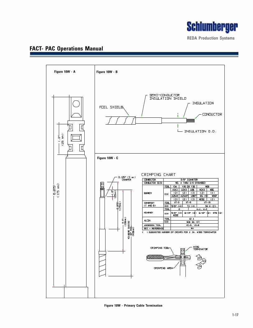
9. Remove 1" of high-voltage insulation and semi-conductive shield at the end of each phase wire.Be careful not to notch (cut) the conductor. Also be careful not to unwind the conductor. Seefigure 10W - A.
10. Consult crimping chart (see figure 10W - C) for correct tool and number of crimps. Wire brush theexposed phase conductor and insert it into the terminator. Before crimping, ensure that theterminator is fully seated against the end of the phase conductor and oriented toward thebushing. Make the first crimp immediately beneath the line on the terminator where the twocolors join. Make the recommended number of crimps. Rotate each crimp 90 degrees from theprevious crimp.
11. Strip semi-conductor insulation shield back 6-7/8" from the top of the terminator. Be careful notto nick (cut) the high-voltage insulation.
12. Carefully clean the insulation. Wipe downward using cable cleaner applied to a lint-free cloth.Apply cable cleaner to the cloth and not the cable. Cable insulation must be clean before andduring installation of the elbow.
13. Thoroughly lubricate the exposed cable insulation and the bottom of the inner bore of the elbowwith the silicone grease that is provided with each elbow. Save half of the silicone grease foruse on the elbow to bushing interface. Slowly push and twist the elbow onto the cable until theterminator reaches the top, inside the elbow. The threaded hole in the terminator must be visiblethrough the other part of the elbow. Wipe away excess silicone grease from the cable andelbow.
1-17
REDA Production SystemsREDA Production SystemsREDA Production SystemsREDA Production SystemsREDA Production Systems
FACT- PAC Operations Manual
Figure 10W - Primary Cable Termination
Figure 10W - A Figure 10W - B
Figure 10W - C

1-18
REDA Production SystemsREDA Production SystemsREDA Production SystemsREDA Production SystemsREDA Production Systems
FACT- PAC Operations Manual
Figure 10X - A Figure 10X - B
Figure 10X - C
Figure 10X - High Voltage Elbow Installation
1-19
REDA Production SystemsREDA Production SystemsREDA Production SystemsREDA Production SystemsREDA Production Systems
FACT- PAC Operations Manual
14. Engage the threaded end of the male probe into the threaded eye of the terminator. Use the wirewrench that is provided. Tighten the probe until the wrench bends 180 degrees. Recommendedtorque is 80 inch-pounds plus or minus 10 inch-pounds.
15. Slide the upper hose clamp up around the bottom of the elbow. Tighten the clamp around thebottom of the elbow beneath the rubber ground tab. This clamp is to ensure that moisture issealed out of the elbow.
16. Carefully clean the interior surface of the elbow and the mating surface of the bushing. Cleanthe surfaces with a lint-free cloth. Thoroughly lubricate the bushing and the elbow matingsurfaces using the silicone grease that is provided with each elbow or approved substitute.Engage the elbow with the bushing.
The elbow must be firmly seated on the bushing. The final bit of travel, when engaging the elbow,is a noticeable snap (detente). The snap must be felt to ensure that the elbow is fully engaged.If the elbow pulls back easily then the elbow was not properly engaged.
17. Cut a 48" length of the bare, #6 AWG, stranded, wire for each elbow. The #6 bare wire, for thispurpose, is provided with the FACT-PAC. Insert one end of the 48" length through the eye of therubber grounding tab near the bottom of the elbow. Push the #6 through the hole 10 inches. Bendboth sections of the #6 wire down so the long section and the short section are both physicallyparallel to the high voltage phase wire. Be careful not to tear the rubber grounding tab.
Thread both sections of the #6 wire inside the second hose clamp and slide the clamp up.Position the clamp immediately beneath the tape near the upper end of the foil. Tighten theclamp to bond the foil to the bare #6 AWG grounding wire. The long section of the #6 should passthrough the clamp and beyond. Be careful not to damage the high voltage insulation by overtightening the clamp.
Connect the end of the long section of the bare #6 AWG to the grounding provision on theenclosure.
18. Connect the driven ground rod to the FACT-PAC enclosure as specified in section 10.8.4.3. Usethe bare conductor from the Down-pole. Use a ground rod clamp to connect the groundingconductor to the rod and then, without breaking it, extend the bare conductor to the groundterminal in the primary chamber of the FACT-PAC.
1.4.5 Secondary Connection
A two-inch conduit hub is provided in the bottom of the motor control section of FACT-PAC for thesecondary cable entry. The user must provide the weather seal for the secondary cable entry.
Connect the secondary cable conductors to the compression terminals marked A, B and C locatedabove the ground fault current transformer. Torque set screws to 180 inch-pounds.
Connect the secondary neutral X0 to the well casing with an insulated wire. See section 10.8.4.3.1.4.6 Chemical Pump Connection
Four, one-inch conduit hubs are provided near the bottom of terminal board B in the low voltagesection of the motor control section of FACT-PAC. Any of these hubs may be used for the chemicalpump cable entry. The user must provide the weather seal for the cable entry.
1-20
REDA Production SystemsREDA Production SystemsREDA Production SystemsREDA Production SystemsREDA Production Systems
FACT- PAC Operations Manual
Connect the chemical pump to terminals 34 and 35 of terminal block B. The chemical pump circuit israted for a one-half horse power, 120 volt, single phase motor. It is fused by a dedicated 25 amp fuse.When the chemical pump switch is ON, the chemical pump is operated automatically by an auxiliarycontact on the main contactor.
1.4.7 Soft Starter
The soft starter is a reactor that has a current sensing relay that bypasses the reactor, by meansof a vacuum contactor, when the motor current drops to 160 percent of nameplate amps.
The soft starter has a seven (7) position tap changer that permits adjustments of the reactorwinding. This allows the user to calculate the voltage sag required and adjust the reactoraccordingly. The tap changer is located on the accessory side of the FACT-PAC behind the hingedcover. Tap position “A” is the bypass position; in this position the reactor is totally bypassed.Positions “B” thru “G” each have a 250 volt sag.
Tap Settings
The combined impedence of the power system, transformer and cable is normally enough tocause voltage sag to the motor thus reducing the starting torque of the motor.
Electric submergible pump motors draw several times the rated current when full rated voltage isswitched on and can deliver several times rated torque to the motor-pump coupling and shaft.
The conservative assumption or “Rule of Thumb” is:
1. The motor will draw 5 times nameplate amps when 100% of nameplate voltage is available atthe motor terminals.
2. The motor will draw 4 times nameplate amps when 80% of nameplate voltage is available atthe motor terminals.
3. The motor will draw 3 times nameplate amps when 60% of nameplate voltage is available atthe motor terminals.
4. The motor will draw 2 times nameplate amps when 40% of nameplate voltage is available atthe motor terminal.
Submergible pump motors require a minimum of two and one half (2½)times the nameplate amprating and in excess of fifty (50) percent of the nameplate voltage to start.
The initial tap setting will be determined by the power available from the power system. Anaccurate calculation of the voltage at the motor terminals can be made if the power supply isknown to be reasonably stiff. The starting amperage of the motor is between two and one half (2½)and three (3) times the nameplate rating.
The power must be turned off before changing the taps.
The user should be aware that loads added to the power system, after the Soft Starter has beenset up, may cause aborted starts, due to the additional voltage drop on the power system. Resettingthe Soft Starter to a lower tap setting may be necessary.

1-21
REDA Production SystemsREDA Production SystemsREDA Production SystemsREDA Production SystemsREDA Production Systems
FACT- PAC Operations Manual
SC Relay Adjustment
The SC Relay controls the Vacuum contactor which bypasses the Reactor. When themotor current has dropped to 1.6 times the nameplate current rating of the motor thebypass can be safely accomplished.
1. To calculate the “Bypass Current”, multiply the motor nameplate amp rating by 1.6.EXAMPLE: 100 Amp Motor 100 X 1.6 = 160 Amps
2. To calculate the CT ratio, divide the primary current by the secondary currentrating.
EXAMPLE: 200 to 5 CT has a ratio of 40. (200/5)
3. To calculate the SC relay setting, divide the “Bypass Current” by the CT ratio.
EXAMPLE: 160 Amps / 40(CT ratio) = 4 amps
The SC relay setting in the example is 4 amps
4. Set the SC relay to 4 amps by adjusting the knurled nut to position 4 on the verticalshaft.
1.5 Energizing FACT-PAC
When a FACT-PAC is being energized for the first time after installation at the present location,several precautionary steps should be taken before the primary feeder cables are energized.
1. Make sure the manual disconnect is OFF.
2. Make sure the HAND-OFF-AUTO selector is OFF.
3. Make sure the CHEMICAL PUMP selector is OFF.
4. Adjust the transformer secondary to the desired tap. The adjusting handles are located on theaccessory side of the transformer compartment behind a hinged cover. The tap voltages areshown on the metal nameplate located to the right hand side of the hinged cover.
5. Connect the current transformer circuits to the desired current transformer ratio. The currenttransformer ratios are selected at Terminal Board B located in the low voltage section of themotor control. All four current transformers should operate at the same ratio. Three of thecurrent transformers are dedicated to the solid state motor controller and the fourth to the ampchart recorder. The ground fault detection current transformer has no optional ratios.
6. Remove the main control circuit fuses, fuses A, B and C, located at the top of Terminal Board Bin the low voltage section of the motor controller.
7. Close and padlock the primary terminal chamber door.
8. After these steps are taken the primary feeder cables may be energized by closing the primarycutouts.
Note: It is important that the FACT-PAC’s manual disconnect switch is OFF while closing the primary cutouts.
9. After the primary feeder cables are energized, the FACT-PAC’s manual disconnect may be switched ON.
1-22
REDA Production SystemsREDA Production SystemsREDA Production SystemsREDA Production SystemsREDA Production Systems
FACT- PAC Operations Manual
1.5.1 Checks
After the FACT-PAC is energized, check the tertiary voltage and the secondary voltage.Properly rated instruments and proper protective equipment is mandatory.
Check the tertiary voltage on the “LIVE” side of the control fuse holders A, B and C at thetop of Terminal Block B. The tertiary should be measured line-to-line and line-to-ground.Variation from these established values indicates the primary system is not exact.
After the tertiary voltage has been confirmed, replace the control fuses. The unit neednot be turned OFF to replace these fuses. Be careful not to touch a live wire or terminal.
Check the secondary voltage at the top of the vacuum contactor.CAUTION: A properly rated volt meter and lineman’s gloves are mandatory.
The secondary should measure according to the nameplate for that tap. Variation fromthe nameplate value indicates the primary system is not exact.
1.5.2 Changing Taps
If secondary voltage adjustment is desired, switch the manual disconnect OFF, open thetap changer cover, change the taps, close the cover and switch the manual disconnectON.
1.6 Commissioning the K095 Motor Controller
Carefully read and understand the Keltronics K095 Advanced Motor Controller Operator’s Manual(see section 8) before attempting to commission and start the FACT-PAC.
Use Appendix C on page 44 of section 8 to record the commissioning parameters and the start upconditions.
The steps for commissioning the K095 Advanced Motor Controller in FACT-PAC are the same as thosefor a conventional switchboard that has been equipped with D095 ground fault monitoring and A095back spin monitoring.
Make sure the HAND-OFF-AUTO selector is OFF.
Return all parameters to factory defaults. Refer to section 8.4
The information below is required for set up. The information is organized by subject. It is not in theexact order that it will be entered into the K095.
Equipment
FACT-PAC is equipped with a three-phase tertiary. The tertiary fulfills the PT function.
Answer YES to the question Three-Phase Voltage? in the “EQUIPMENT TABLE”.
Answer YES to the question WYE Tertiary used for PTs? in the “EQUIPMENT TABLE”.
Exception: When the FACT-PAC has a Delta secondary, answer NO to the question WYE Tertiary usedfor PTs?.
PT ratios must be entered into the K095 in the “EQUIPMENT TABLE”.
The two PT ratios are the same. The ratio is determined by the tap changer position. Each tapposition has a unique PT ratio. The ratios are shown on the metal nameplate located beneath thegauges on the accessory side of the FACT-PAC.
Note: New PT ratios must be entered into the K095 any time the tap changer is adjusted.
1-23
REDA Production SystemsREDA Production SystemsREDA Production SystemsREDA Production SystemsREDA Production Systems
FACT- PAC Operations Manual
FACT-PAC is equipped with multiple ratio CTs. The CT ratio must be entered into the K095 in the“EQUIPMENT TABLE”.
The CT ratio is selected at Terminal Block B inside the low voltage section of the motor controller ofFACT-PAC. The ratio selected at Terminal Block B must be entered into the K095.
FACT-PAC is equipped with a D095 ground fault monitoring circuit. Refer to section 8, pages 18 and 29for information on its set-up.
When the secondary neutral of FACT-PAC is grounded to the well casing then enter YES at EnableAnalog loop 1: in the “EQUIPMENT TABLE”. Name and calibrate Loop 1. Refer to section 8.3-(8>) andsection 8.3-(9>) of the Keltronics Manual.
Set *GROUND FLT* Action: to STOP+ in the “VALUE TABLE”. Either accept the other factory defaultsetting for this function or adjust them appropriately.
When the secondary neutral of FACT-PAC is not grounded then enter NO at Enable Analog Loop 1: inthe “EQUIPMENT TABLE”.
Note: When using a FACT-PAC with the secondary connected DELTA, the neutral is never grounded andLoop 1 should not be enabled.
FACT-PAC is equipped with an A095 back spin monitoring circuit. A leg ground monitoring circuit isbuilt into this back spin circuit.
When the secondary neutral of FACT-PAC is grounded to the well casing then set the *LEG GROUND*Action: to BYPASS in the “VALUE TABLE”.
When the secondary neutral of FACT-PAC is not grounded then the LEG GROUND protection may bedesirable. Refer to section 8.3.5 and section 8.4.0-21.
Short Circuit Protection
The vacuum contactor in FACT-PAC is designed to clear secondary short circuits.
Set the Action: to STOP+ and the 100% Set01 to 0.0s at *SHORT CCT* in the “VALUE TABLE”. Set theSHORT CCT Setpoint at six times the motor’s rated current. Refer to section 8.4.0-3.
Stall Protection
FACT-PAC is designed to protect against motor stalls.
Set the Action: to STOP+ at *STALL* in the “VALUE TABLE”. Set the STALL Setpoint at three times themotor’s rated current and the 100% Set01 at two times the motor’s acceleration time. Refer to section8.4.0-3.
High Temperature Protection
The FACT-PAC includes two normally closed temperature alarm switches connected in series to theK095 auxiliary input. One of the alarms is in the oil temperature gauge the other is in the motor controlsection. Each of these alarms is field adjustable.
Set the Set points to open at *AUXILIARY* in the “VALUE TABLE”, set the ACTION: to stop+ and setthe RETRY NO: TO 0.1.6.1 Start-up
Refer to the Keltronics K095 Advanced Controller Operator’s Manual, Section 8.4.2,

1-24
REDA Production SystemsREDA Production SystemsREDA Production SystemsREDA Production SystemsREDA Production Systems
FACT- PAC Operations Manual
1.7 Fuses
The draw out fuses of FACT-PAC are coordinated with the solid state motor controller and with therecommended primary fuses. DO NOT SUBSTITUTE. A decal inside the hinged cover specifies thecorrect Bay-O-Net fuse link and recommended primary fuse.
The control fuse ratings for all FACT-PAC’s are:
3 MAIN CONTROL FUSES .................. KTK R 30 ............... (30 AMP)
CONVENIENCE OUTLET .................... KTK R 25 ............... (25 AMP)
AUXILLARY LOAD FUSES ................... KTK R 10 ............... (10 AMP)Warning! The control fuses used in the FACT-PAC must have a minimum interrupting capacity of 100,000amperes. The Limitron KTK R fuses are suitable.
1.8 Parts List
Control Cabinet Spare Parts
Dwg.Dwg.Dwg.Dwg.Dwg. REDAREDAREDAREDAREDANumberNumberNumberNumberNumber DescriptionDescriptionDescriptionDescriptionDescription Part NumberPart NumberPart NumberPart NumberPart Number
3I .................. OBSTRUCTION LIGHT(GREEN LENS)...................... ............................................. 1152073
2B ................. QUARTER TURN CLOSURE............................... ....................................................... 1152081
1E ................. DRAW LATCH......................................... ................................................................... 1152099
1M ................. DRAW LATCH KEEPER .............................................................................................. 1152313
1C ................. TERMINAL BLOCK ..................................................................................................... 1152107
TERMINAL BLOCK RAILS ......................................................................................... 1152115
TERMINAL BLOCK END STOP ................................................................................. 1152123
TERMINAL BLOCK END SECTION .......................................................................... 1152131
1A1B
1C 1D
1E1F1G
1H1I
1J
1K
1L1M

1-25
REDA Production SystemsREDA Production SystemsREDA Production SystemsREDA Production SystemsREDA Production Systems
FACT- PAC Operations Manual
2G ................. STAND OFF INSULATOR .............................................................................................. 738344
2A ................. METAL OXIDE VARISTOR ......................................................................................... 1152149
1A ................. HEATER STRIP ............................................................................................................ 1152156
1G ................. RECEPTACLE 120V ........................................................................................................518076
RECEPTACLE COVER.................................................................................................. 1152164
1I .................. PUSHBUTTON SWITCH ............................................................................................ 1152172
1H ................. 3 POSITION SELECTOR SWITCH ............................................................................ 1152180
1J ................. 2 POSITION SELECTOR SWITCH ............................................................................ 1152198
1K ................. PILOT LIGHT (RED) ....................................................................................................... 516070
PILOT LIGHT (GREEN) ................................................................................................. 516067
PILOT LIGHT (AMBER) ................................................................................................516054
2E ................. VACUUM CONTACTOR (5000V)
2H ................. CURRENT TRANSFORMER (Ground Fault) ........................................................... 1152230
2F ................. MULTI-RATIO CURRENT TRANSFORMER ............................................................. 1152248
2C ................. CAPACITORS (LOW VOLTAGE) ................................................................................ 1152255
2D ................. CAPACITOR MOUNTING CLAMP ............................................................................ 1152263
1L ................. RECORD AMMETER ......................................................................................................509323
1B ................. CONTROL FUSE BLOCK ............................................................................................. 1152271
LIMITRON 30 AMP FUSE .......................................................................................... 1152289
LIMITRON 25 AMP FUSE .......................................................................................... 1152297
LIMITRON 10 AMP FUSE .......................................................................................... 1152305
1F ................. GROUND LUG ................................................................................................................ 516849
2E
2F
2G
2H
2D
2C
2B
2A
1-26
REDA Production SystemsREDA Production SystemsREDA Production SystemsREDA Production SystemsREDA Production Systems
FACT- PAC Operations Manual
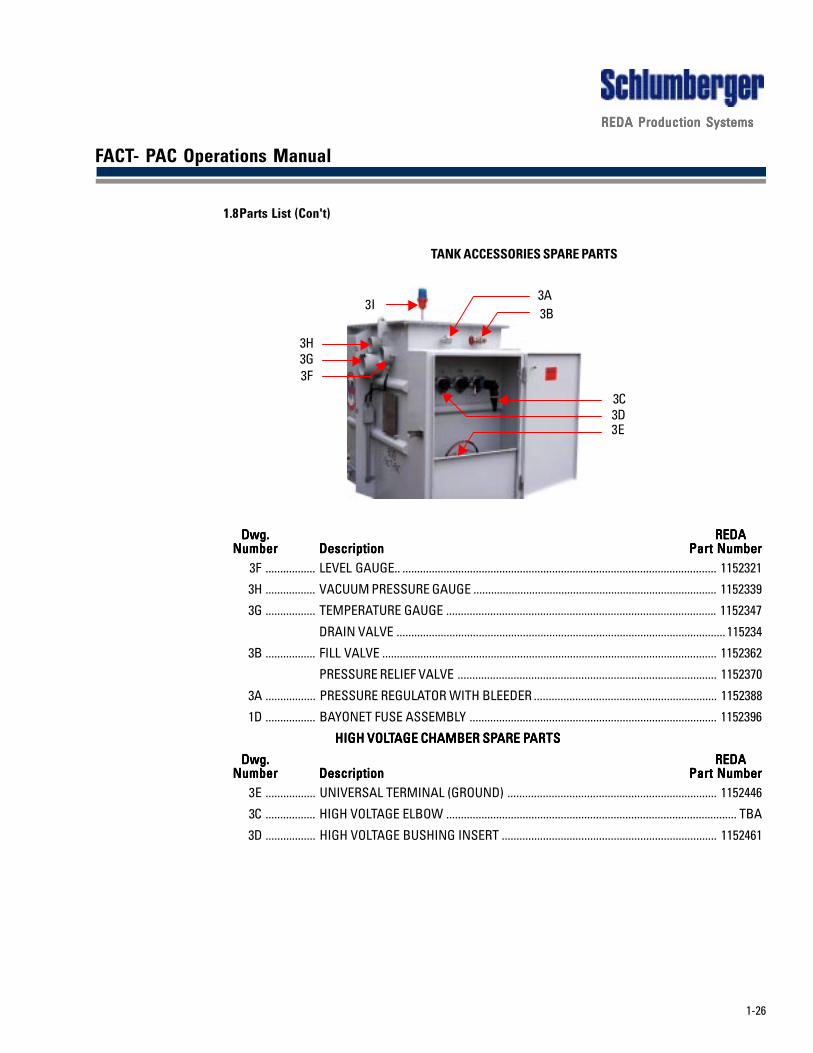
1.8Parts List (Con't)
TANK ACCESSORIES SPARE PARTS
Dwg.Dwg.Dwg.Dwg.Dwg. REDAREDAREDAREDAREDANumberNumberNumberNumberNumber DescriptionDescriptionDescriptionDescriptionDescription Part NumberPart NumberPart NumberPart NumberPart Number
3F ................. LEVEL GAUGE.. ........................................................................................................... 1152321
3H ................. VACUUM PRESSURE GAUGE ................................................................................... 1152339
3G ................. TEMPERATURE GAUGE ............................................................................................ 1152347
DRAIN VALVE ................................................................................................................ 115234
3B ................. FILL VALVE .................................................................................................................. 1152362
PRESSURE RELIEF VALVE ........................................................................................ 1152370
3A ................. PRESSURE REGULATOR WITH BLEEDER .............................................................. 1152388
1D ................. BAYONET FUSE ASSEMBLY .................................................................................... 1152396
HIGH VOLHIGH VOLHIGH VOLHIGH VOLHIGH VOLTTTTTAGE CHAMBER SPAGE CHAMBER SPAGE CHAMBER SPAGE CHAMBER SPAGE CHAMBER SPARE PARE PARE PARE PARE PARTSARTSARTSARTSARTS
Dwg.Dwg.Dwg.Dwg.Dwg. REDAREDAREDAREDAREDANumberNumberNumberNumberNumber DescriptionDescriptionDescriptionDescriptionDescription Part NumberPart NumberPart NumberPart NumberPart Number
3E ................. UNIVERSAL TERMINAL (GROUND) ....................................................................... 1152446
3C ................. HIGH VOLTAGE ELBOW ................................................................................................... TBA
3D ................. HIGH VOLTAGE BUSHING INSERT ......................................................................... 1152461
3E3D3C
3B3A
3H3G3F
3I
1-27
REDA Production SystemsREDA Production SystemsREDA Production SystemsREDA Production SystemsREDA Production Systems
FACT- PAC Operations Manual
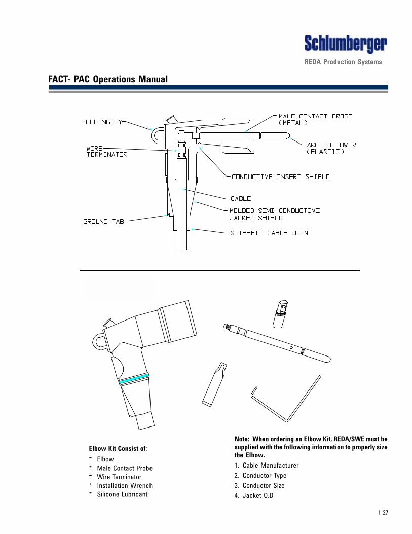
Elbow Kit Consist of:
* Elbow* Male Contact Probe* Wire Terminator* Installation Wrench* Silicone Lubricant
Note: When ordering an Elbow Kit, REDA/SWE must besupplied with the following information to properly sizethe Elbow.1. Cable Manufacturer2. Conductor Type3. Conductor Size4. Jacket O.D

1-28
REDA Production SystemsREDA Production SystemsREDA Production SystemsREDA Production SystemsREDA Production Systems
FACT- PAC Operations Manual
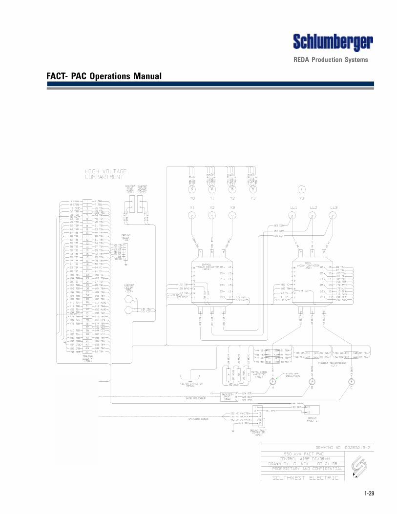
1.9 Control Wiring Diagram
1-29
REDA Production SystemsREDA Production SystemsREDA Production SystemsREDA Production SystemsREDA Production Systems
FACT- PAC Operations Manual
Related Documents