BBV28581 04/2009 29 Factory configuration Drive factory settings The Altivar 12 is factory-set for the most common operating conditions (motor rating according to drive rating): • Display: drive ready (rdY) motor stopped or motor frequency reference while running • Automatic adaptation of the deceleration ramp in the event of overvoltage on braking. • No automatic restarting after a detected fault is cleared • Logic inputs: - LI1: forward (2-wire transitional control) - LI2, LI3, LI4: no assignment • Logic output: LO1: no assignment • Analog input: AI1 (0 to + 5 V) speed reference • Relay R1: the contact opens in the event of a detected fault (or drive off) • Analog output AO1: no assignment If the above values are compatible with the application, the drive can be used without changing the settings. Drive factory wiring diagram (1) R1 relay contacts, for remote indication of the drive status. (2) Internal + 24 V c. If an external source is used (+ 30 V c maximum), connect the 0 V of the source to the COM terminal, and do not use the + 24 V c terminal on the drive. (3) Reference potentiometer SZ1RV1202 (2.2 k ) or similar (10 k maximum). (4) Forward Code Description Value page bFr Standard motor frequency 50 Hz 44 UnS Rated motor voltage 230 V 55 ACC Acceleration 3 seconds 62 dEC Deceleration 3 seconds 62 LSP Low speed 0 Hz 44 75 HSP High speed 50 Hz 76 Ctt Motor control type Standard U/F law 55 UFr IR compensation (law U/F) 100% 56 Ith Motor thermal current equal to nominal motor current (value determined by drive rating) 80 SdC1 Automatic DC injection current 0.7 x nominal drive current, for 0.5 seconds. 65 SFr Switching frequency 4 kHz 57 ATV12ppppM3 3-phase motor Source

Welcome message from author
This document is posted to help you gain knowledge. Please leave a comment to let me know what you think about it! Share it to your friends and learn new things together.
Transcript

BBV28581 04/2009 29
Factory configuration
Drive factory settings
The Altivar 12 is factory-set for the most common operating conditions (motor rating according to drive rating):
• Display: drive ready (rdY) motor stopped or motor frequency reference while running
• Automatic adaptation of the deceleration ramp in the event of overvoltage on braking.
• No automatic restarting after a detected fault is cleared
• Logic inputs:
- LI1: forward (2-wire transitional control)
- LI2, LI3, LI4: no assignment
• Logic output: LO1: no assignment
• Analog input: AI1 (0 to + 5 V) speed reference
• Relay R1: the contact opens in the event of a detected fault (or drive off)
• Analog output AO1: no assignment
If the above values are compatible with the application, the drive can be used without changing the settings.
Drive factory wiring diagram
(1) R1 relay contacts, for remote indication of the drive status.
(2) Internal + 24 V c. If an external source is used (+ 30 V c maximum), connect the 0 V of the source to the COM terminal, and do not
use the + 24 V c terminal on the drive.
(3) Reference potentiometer SZ1RV1202 (2.2 k ) or similar (10 k maximum).
(4) Forward
Code Description Value page
bFr Standard motor frequency 50 Hz 44
UnS Rated motor voltage 230 V 55
ACC Acceleration 3 seconds 62
dEC Deceleration 3 seconds 62
LSP Low speed 0 Hz 44
75
HSP High speed 50 Hz 76
Ctt Motor control type Standard U/F law 55
UFr IR compensation (law U/F) 100% 56
Ith Motor thermal current equal to nominal motor current (value determined by drive rating) 80
SdC1 Automatic DC injection current 0.7 x nominal drive current, for 0.5 seconds. 65
SFr Switching frequency 4 kHz 57
ATV12ppppM3
3-phase
motor
Source

30 BBV28581 04/2009
Basic functions
Status relay, unlocking
The R1 status relay is energized when the drive power is applied with no fault detected. It de-energizes in the event of a detected fault or
when the drive power is removed.
The drive is reset after a detected fault:
• by switching off the drive until the display disappears completely, then switching on again
• automatically in the cases described in the "automatic restart" function, FLt- menu, Automatic restart Atr page 77 set to YES
• via a logic input when this input is assigned to the "drive reset" function, FLt- menu, Detected fault reset assignment rSF page
77 set to LpH.
Drive thermal detection
Thermal detection is provided by a built-in PTC probe in the power module.
Drive ventilation
Ratings up to 0.75 kW (1 HP) do not include a fan. The fan runs only when the drive thermal state requires ventilation.
Motor thermal detection
Function:
Thermal detection by calculating the I2t.
Note: The motor thermal state memory returns to zero when the drive power is cycled if Motor thermal state memo MtM page 80
is not set to YES.
CAUTION
RISK OF DAMAGE TO THE MOTOR
The use of external overload protection is required under the following conditions:
• Repowering up the product since there is no motor thermal state memory.
• Running multiple motors
• Running motors rated at less than 20% of the nominal drive current
• Using motor switching
Failure to follow these instructions can result in equipment damage.
CAUTION
MOTOR OVERHEATING
• This drive does not provide direct thermal protection for the motor.
• Use of a thermal sensor in the motor may be required for protection at all speeds or loading conditions.
• Consult the motor manufacturer for the thermal capability of the motor when operated over the desired speed range
Failure to follow these instructions can result in equipment damage.

BBV28581 04/2009 31
Programming
HMI description
Functions of the display and keys
(a) If illuminated, indicates that a value is displayed, for example,
(b)When changing a value the Configuration mode LED and the value LED are on steady.
(c) If illuminated, indicates that a unit is displayed, for example, AMP is displayed for "Amps"
1. Value LED (a) (b).
2. Charge LED
3. Unit LED (c)
4. ESC button: Exits a menu or parameter, or aborts the displayed
value to return to the previous value in the memory.
5. STOP button: stops the motor (could be hidden by door if function
disabled). Important: See instructions for "RUN/STOP" cover
removal.
6. RUN button: Starts running if the function is configured (could be
hidden by door if function disabled).
7. Jog dial
- Acts as a potentiometer in local mode.
- For navigation when turned clockwise or counterclockwise
- and selection / validation when pushed.
This action is represented by this symbol
8. MODE button
Switches between the control/programming modes. The MODE
button is only accessible with the HMI door open.
9. CONFIGURATION mode LED (b)
10. MONITORING mode LED
11. REFERENCE mode LED
12. Four "7-segment" displays
WARNINGLOSS OF CONTROL
The stop buttons on ATV12 drive and on the remote keypad display can be programmed to not have priority. To retain stop key priority,
set Stop key priority PSt page 60 to YES. Do not set PSt to nO unless exterior stopping method(s) exist.
Failure to follow these instructions can result in death, serious injury, or equipment damage.
5 is displayed for "0.5"0.
32 BBV28581 04/2009
Programming
Remote control
Remote operation and programming by HMI is possible using the optional remote HMI part VW3A1006. The dimensions are 70 mm
(2.76 in) x 50 mm (2.76 in).
Important: when connected, the remote control shows an exact copy of the drive display, it is totally interactive with the embedded keypad.
BBV28581 04/2009 33
Programming
First power-up
At first power-up you are prompted to set Standard motor frequency bFr page 44. Next time power is applied rdY appears. Operating
mode selection is then possible using the MODE key as detailed below.
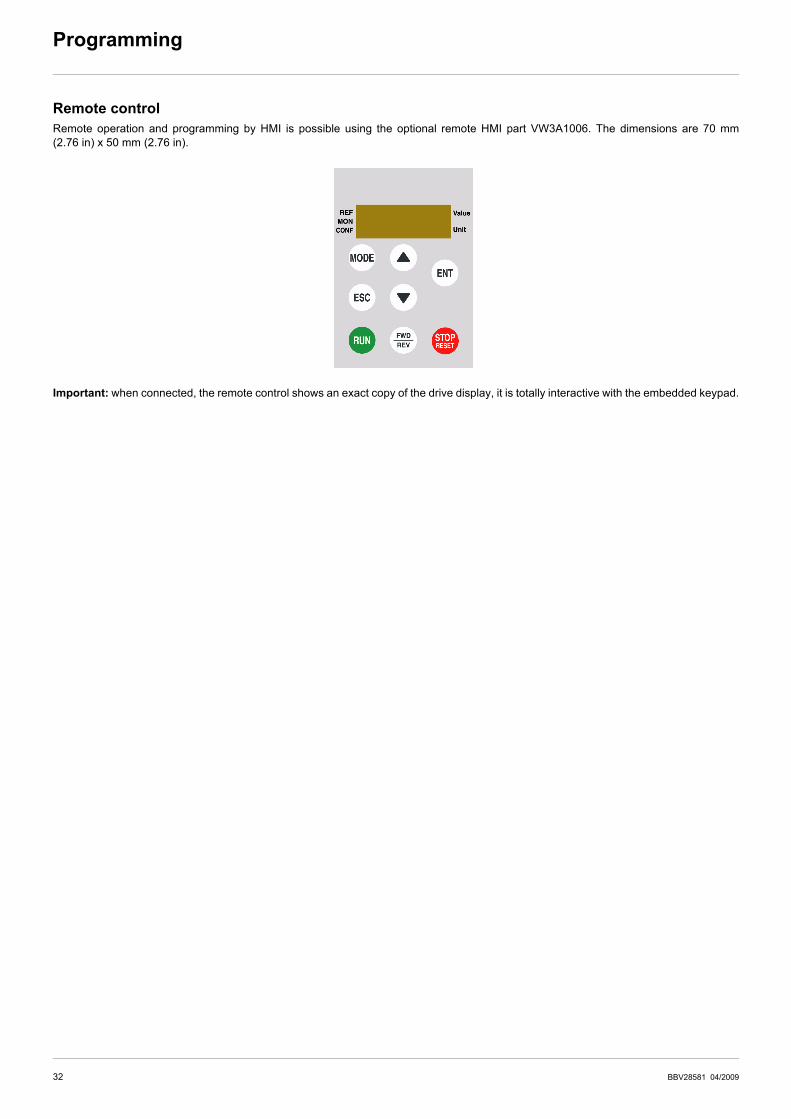
Menus structure
Access to menus and parameters is possible through 3 modes: Reference rEF page 36, Monitoring MOn page 37 and Configuration
COnF page 43. Switching between these modes is possible at any time using the MODE key or Jog Dial on keyboard. The first press on
the MODE key moves from the current position to the top of the branch. A second press switches to the next mode.
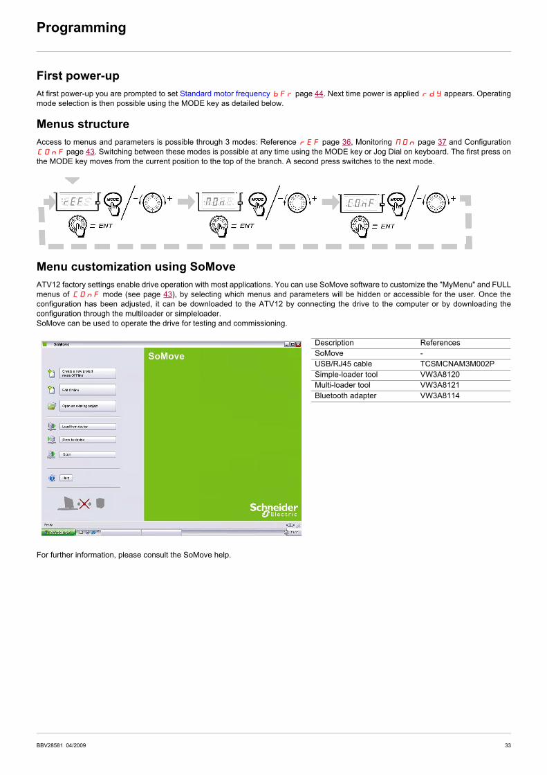
Menu customization using SoMove
ATV12 factory settings enable drive operation with most applications. You can use SoMove software to customize the "MyMenu" and FULL
menus of COnF mode (see page 43), by selecting which menus and parameters will be hidden or accessible for the user. Once the
configuration has been adjusted, it can be downloaded to the ATV12 by connecting the drive to the computer or by downloading the
configuration through the multiloader or simpleloader.
SoMove can be used to operate the drive for testing and commissioning.
For further information, please consult the SoMove help.
Description References
SoMove -
USB/RJ45 cable TCSMCNAM3M002P
Simple-loader tool VW3A8120
Multi-loader tool VW3A8121
Bluetooth adapter VW3A8114
34 BBV28581 04/2009
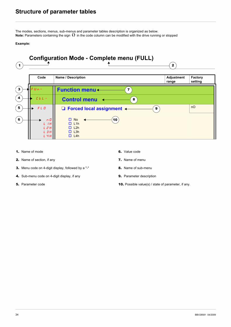
Structure of parameter tables
The modes, sections, menus, sub-menus and parameter tables description is organized as below.
Note: Parameters containing the sign in the code column can be modified with the drive running or stopped
Example:
Configuration Mode - Complete menu (FULL)
Code Name / Description Adjustment
range
Factory
setting
FUn- Function menu
CtL- Control menu
FLO M Forced local assignment nO
nO
LIH
L2H
L3H
L4H
v No
v L1h
v L2h
v L3h
v L4h
3
4
1
5
8
2
7
6
9
10
1. Name of mode
2. Name of section, if any
3. Menu code on 4-digit display, followed by a "-"
4. Sub-menu code on 4-digit display, if any
5. Parameter code
6. Value code
7. Name of menu
8. Name of sub-menu
9. Parameter description
10. Possible value(s) / state of parameter, if any.
BBV28581 04/2009 35
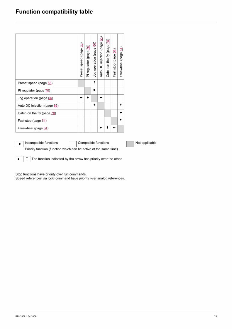
Function compatibility table
Stop functions have priority over run commands.
Speed references via logic command have priority over analog references.
Pre
set
sp
eed
(pa
ge
68
)
PI
regu
lato
r (p
ag
e 7
0)
Jo
g o
pe
ratio
n (
pa
ge 6
6)
Au
to D
C inje
ctio
n (
pa
ge 6
5)
Ca
tch o
n t
he
fly
(p
ag
e 7
8)
Fa
st sto
p (
pa
ge
64
)
Fre
ew
he
el (p
ag
e 6
4)
Preset speed (page 68) A
PI regulator (page 70) p
Jog operation (page 66) X p X
Auto DC injection (page 65) A A
Catch on the fly (page 78) X
Fast stop (page 64) A
Freewheel (page 64) X A X
Incompatible functions Compatible functions Not applicable
The function indicated by the arrow has priority over the other.
Priority function (function which can be active at the same time)
36 BBV28581 04/2009
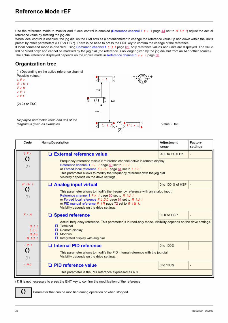
Reference Mode rEF
Use the reference mode to monitor and if local control is enabled (Reference channel 1 Fr1 page 44 set to AIU1) adjust the actual
reference value by rotating the jog dial.
When local control is enabled, the jog dial on the HMI acts as a potentiometer to change the reference value up and down within the limits
preset by other parameters (LSP or HSP). There is no need to press the ENT key to confirm the change of the reference.
If local command mode is disabled, using Command channel 1 Cd1 page 61, only reference values and units are displayed. The value
will be "read only" and cannot be modified by the jog dial (the reference is no longer given by the jog dial but from an AI or other source).
The actual reference displayed depends on the choice made in Reference channel 1 Fr1 page 60.
Organization tree
(1) It is not necessary to press the ENT key to confirm the modification of the reference.
(1) Depending on the active reference channel
Possible values:
LFr
AIU1
FrH
rPI
rPC
(2) 2s or ESC
Displayed parameter value and unit of the
diagram is given as examples Value - Unit
Code Name/Description Adjustment
range
Factory
settings
LFr
(1)
M External reference value -400 to +400 Hz -
Frequency reference visible if reference channel active is remote display.
Reference channel 1 Fr1 page 60 set to LCC
or Forced local reference FLOC page 61 set to LCC.
This parameter allows to modify the frequency reference with the jog dial.
Visibility depends on the drive settings.
AIU1
(1)
M Analog input virtual 0 to 100 % of HSP -
This parameter allows to modify the frequency reference with an analog input.
Reference channel 1 Fr1 page 60 set to AIU1
or Forced local reference FLOC page 61 set to AIU1
or PID manual reference PIM page 72 set to AIU1.
Visibility depends on the drive settings.
FrH M Speed reference 0 Hz to HSP -
AI1
LCC
Mdb
AIUI
Actual frequency reference. This parameter is in read-only mode. Visibility depends on the drive settings.
v Terminal
v Remote display
v Modbus
v Integrated display with Jog dial
rPI
(1)
M Internal PID reference 0 to 100% -
This parameter allows to modify the PID internal reference with the jog dial.
Visibility depends on the drive settings.
rPC M PID reference value 0 to 100% -
This parameter is the PID reference expressed as a %.
Parameter that can be modified during operation or when stopped.

BBV28581 04/2009 37
Monitoring mode MOn
When the drive is running, the value displayed is that of one of the monitoring parameters. The default value displayed is the motor Output
frequency rFr page 38.
While the value of the desired new monitoring parameter is being displayed, press a second time on the jog dial button to display the units.
Organization tree
(1) Depending on reference channel active.
Possible values:
LFr
AIU1
(2) 2 sec or ESC
Displayed parameter values and units of the diagram are given as
examples.
values
units
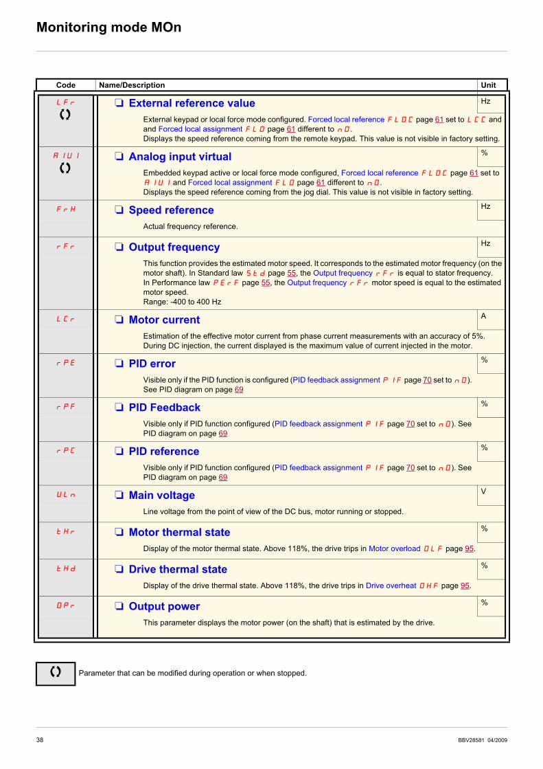
38 BBV28581 04/2009
Monitoring mode MOn
Code Name/Description Unit
LFr M External reference value Hz
External keypad or local force mode configured. Forced local reference FLOC page 61 set to LCC and
and Forced local assignment FLO page 61 different to nO.
Displays the speed reference coming from the remote keypad. This value is not visible in factory setting.
AIU1 M Analog input virtual %
Embedded keypad active or local force mode configured, Forced local reference FLOC page 61 set to
AIU1 and Forced local assignment FLO page 61 different to nO.
Displays the speed reference coming from the jog dial. This value is not visible in factory setting.
FrH M Speed reference Hz
Actual frequency reference.
rFr M Output frequency Hz
This function provides the estimated motor speed. It corresponds to the estimated motor frequency (on the
motor shaft). In Standard law Std page 55, the Output frequency rFr is equal to stator frequency.
In Performance law PErF page 55, the Output frequency rFr motor speed is equal to the estimated
motor speed.
Range: -400 to 400 Hz
LCr M Motor current A
Estimation of the effective motor current from phase current measurements with an accuracy of 5%.
During DC injection, the current displayed is the maximum value of current injected in the motor.
rPE M PID error %
Visible only if the PID function is configured (PID feedback assignment PIF page 70 set to nO).
See PID diagram on page 69
rPF M PID Feedback %
Visible only if PID function configured (PID feedback assignment PIF page 70 set to nO). See
PID diagram on page 69
rPC M PID reference %
Visible only if PID function configured (PID feedback assignment PIF page 70 set to nO). See
PID diagram on page 69
ULn M Main voltage V
Line voltage from the point of view of the DC bus, motor running or stopped.
tHr M Motor thermal state %
Display of the motor thermal state. Above 118%, the drive trips in Motor overload OLF page 95.
tHd M Drive thermal state %
Display of the drive thermal state. Above 118%, the drive trips in Drive overheat OHF page 95.
Opr M Output power %
This parameter displays the motor power (on the shaft) that is estimated by the drive.
Parameter that can be modified during operation or when stopped.
BBV28581 04/2009 39
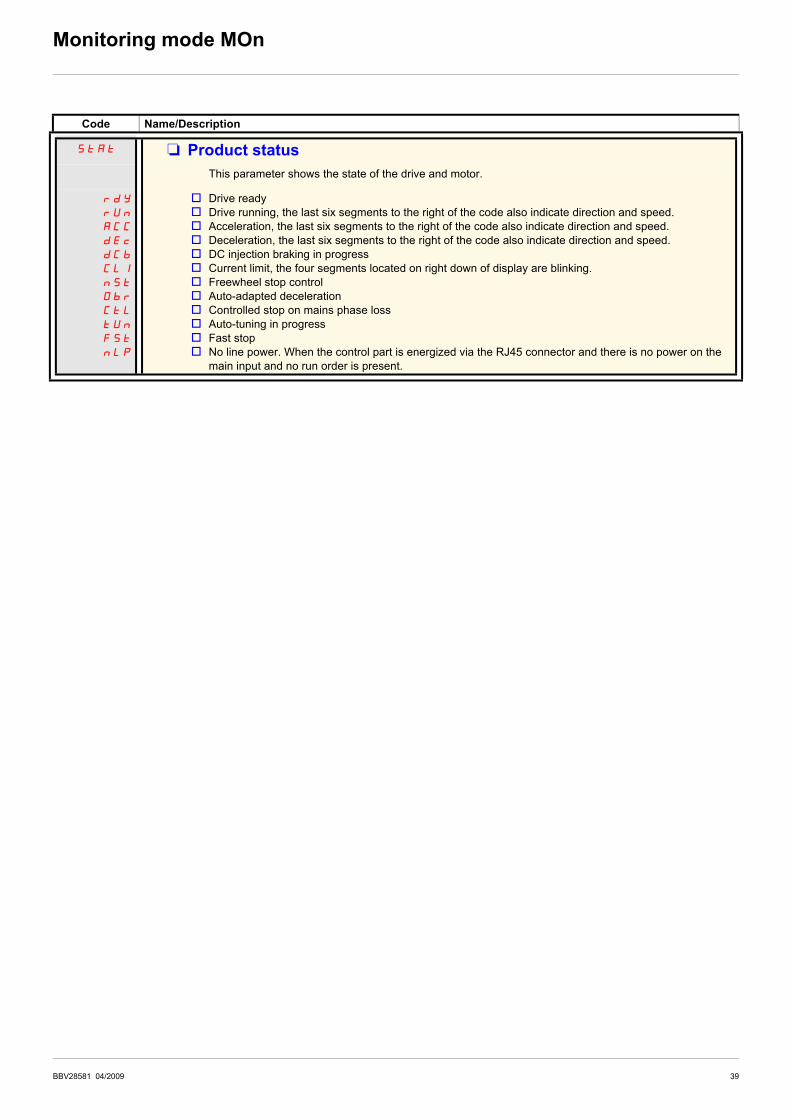
Monitoring mode MOn
Code Name/Description
StAt M Product status
This parameter shows the state of the drive and motor.
rdY
rUn
ACC
dEc
dCb
CLI
nSt
Obr
CtL
tUn
FSt
nLP
v Drive ready
v Drive running, the last six segments to the right of the code also indicate direction and speed.
v Acceleration, the last six segments to the right of the code also indicate direction and speed.
v Deceleration, the last six segments to the right of the code also indicate direction and speed.
v DC injection braking in progress
v Current limit, the four segments located on right down of display are blinking.
v Freewheel stop control
v Auto-adapted deceleration
v Controlled stop on mains phase loss
v Auto-tuning in progress
v Fast stop
v No line power. When the control part is energized via the RJ45 connector and there is no power on the
main input and no run order is present.
40 BBV28581 04/2009
Monitoring mode MOn
Code Name/Description Unit
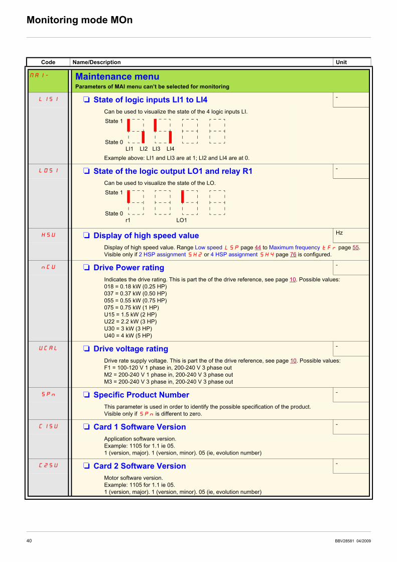
MAI- Maintenance menuParameters of MAI menu can’t be selected for monitoring
LIS1 M State of logic inputs LI1 to LI4 -
Can be used to visualize the state of the 4 logic inputs LI.
Example above: LI1 and LI3 are at 1; LI2 and LI4 are at 0.
LOS1 M State of the logic output LO1 and relay R1 -
Can be used to visualize the state of the LO.
HSU M Display of high speed value Hz
Display of high speed value. Range Low speed LSP page 44 to Maximum frequency tFr page 55.
Visible only if 2 HSP assignment SH2 or 4 HSP assignment SH4 page 76 is configured.
nCU M Drive Power rating -
Indicates the drive rating. This is part the of the drive reference, see page 10. Possible values:
018 = 0.18 kW (0.25 HP)
037 = 0.37 kW (0.50 HP)
055 = 0.55 kW (0.75 HP)
075 = 0.75 kW (1 HP)
U15 = 1.5 kW (2 HP)
U22 = 2.2 kW (3 HP)
U30 = 3 kW (3 HP)
U40 = 4 kW (5 HP)
UCAL M Drive voltage rating -
Drive rate supply voltage. This is part the of the drive reference, see page 10. Possible values:
F1 = 100-120 V 1 phase in, 200-240 V 3 phase out
M2 = 200-240 V 1 phase in, 200-240 V 3 phase out
M3 = 200-240 V 3 phase in, 200-240 V 3 phase out
SPn M Specific Product Number -
This parameter is used in order to identify the possible specification of the product.
Visible only if SPn is different to zero.
C1SU M Card 1 Software Version -
Application software version.
Example: 1105 for 1.1 ie 05.
1 (version, major). 1 (version, minor). 05 (ie, evolution number)
C2SU M Card 2 Software Version -
Motor software version.
Example: 1105 for 1.1 ie 05.
1 (version, major). 1 (version, minor). 05 (ie, evolution number)
State 1
State 0
LI1 LI2 LI3 LI4
State 1
State 0
r1 LO1

BBV28581 04/2009 41
Monitoring mode MOn
Code Name/Description Unit
MAI- Maintenance menu (continued)
rtHI M Run elapsed time display 0.01
Total time the motor has been powered up. Range: 0 to 65535 hours. Value displayed is as described in the
table below. Parameter resettable by services
Hours Display
1 0.01
10 0.10
100 1.00
1000 10.0
10000 100
PtH M Power On time display 0.01
Total time the drive has been powered on. Range: 0 to 65535 hours. Value displayed is as described in
the table above. Parameter resettable by services.
FtH M Fan time display 0.01
Range: 0 to 65535 hours. Value displayed is as described in the table above. Parameter resettable by
customer.
PEt M Process elapsed time 0.01
Range: 0 to 65535 hours. Value displayed is as described in the table above. Parameter resettable by
customer.
COM1 M Modbus communication status -
r0t0
rOt1
r1t0
r1t1
v Modbus no reception, no transmission = communication idle
v Modbus no reception, transmission
v Modbus reception, no transmission
v Modbus reception and transmission
dP1 M Last detected fault 1 -
This parameter describes the last detected fault.
EP1 M State of drive at detected fault 1 -
This parameter describes the state at the moment of the 1st detected fault.
bit 0 bit 1 bit 2 bit 3 bit 4
ETA.1:
Switched on
ETA.5:
Quick stop
ETA.6:
Switch on
disabled
Forced local
enabled
ETA.15 :
Motor rotation in forward
direction (or stopped)
bit 5 bit 6 bit 7 bit 8 bit 9
ETI.4: Run
order present
ETI.5:
DC injection
running
ETI.7:
Motor thermal
threshold
reached
ETI.8: Reserved ETI.9:
Product in
acceleration
bit 10 bit 11 bit 12 bit 13 - 14 bit 15
ETI.10 : Product
in deceleration
ETI.11 : Current
limitation or
torque limitation
is running
Fast stop in
progress
ETI.14= 0 + ETI.13=0 :
Drive controlled by terminal or local
keypad
ETI.14= 0 + ETI.13=1 :
Drive controlled by remote keypad
ETI.14= 1 + ETI.13=0 :
Drive controlled by Modbus
ETI.14= 1 + ETI.13=0 : Reserved
ETI.15 :
Reverse
direction
applied to
the ramp
Parameter that can be modified during operation or when stopped.

42 BBV28581 04/2009
Monitoring mode MOn
Code Name/Description Adjustment range Factory setting
MAI- Maintenance menu (continued)
dP2 M Last detected fault 2 -
This parameter describes the 2nd detected fault.
EP2 M State of drive at detected fault 2 -
This parameter describes the state at the moment of the 2nd detected fault. See EP1.
dP3 M Last detected fault 3 -
This parameter describes the 3rd detected fault.
EP3 M State of drive at detected fault 3 -
This parameter describes the state at the moment of the 3rd detected fault. See EP1
dP4 M Last detected fault 4 -
This parameter describes the 4th detected fault.
EP4 M State of drive at detected fault 4 -
This parameter describes the state at the moment of the 4th detected fault. See EP1
COd M HMI Password 2 to 9999 OFF
OFF
On
Possible state value:
v Code disabled
v Code activated
Range 2 to 9999
If you have lost your code, please contact Schneider Electric.
This parameter is used to restrict access to the drive.
To lock the drive, go to the HMI Password COd parameter, enter a code within the above range.
Once activated, the code state changes to On:
The protection enables only access to rEF(see page 36) and MOn (see page 37) modes, except when
using SoMove. Return to factory settings or access to FULL section are disabled,
Download configuration to SoMove is possible,
Upload configuration to SoMove is disabled.
To unlock the drive, go to the COd parameter, enter the valid code, then press ENT.
Code protection removal is then possible and carried out by entering OFF using the jog dial, then press
ENT.

BBV28581 04/2009 43
Configuration Mode ConF
Configuration mode includes 3 parts:
1. MyMenu includes 11 factory set parameters (among them 9 visible by default). Up to 25 parameters are available for user customization
using SoMove software.
2. store/recall parameter set: these 2 functions are used to store and recall customer settings.
3. FULL: This menu provides access to all other parameters. It includes 6 sub-menus:
- Macro-configuration CFG- page 46
- Input Output menu I_O- page 47
- Motor control menu drC- page 56
- Control menu CtL- page 60
- Function menu FUn- page 62
- Fault detection management menu FLt- page 77
- Communication menu COM-page 83.
Organization tree
Motor frequency
Reference channel 1
Acceleration
Deceleration
Low speed
High speed
Motor rated power
Motor rated current
AI1 type
Store customer
parameter set
Factory / recall
customer parameter set
FULL
Displayed parameter values are given as examples only
(1) Depending on reference channel
active.
Possible values: LFr or AIU1
(2) 2 seconds or ESC. (3) plus 14 other customizable parameters selectable (in "FULL" list)
using SoMove.

44 BBV28581 04/2009
Configuration Mode - MyMenu
Code Name/Description Adjustment range Factory setting
LFr M External reference value -400 Hz to 400 Hz -
This parameter allows to modify the frequency reference with the jog dial.
External keypad or local force mode configured. Forced local reference FLOC page 61 set to LCC and
and Forced local assignment FLO page 61 different to nO. Visibility depends on the drive settings.
AIU1 M Analog input virtual 0% to 100% -
This parameter allows to modify the frequency reference when
• Forced local reference FLOC page 61 is set to AIU1
• and Forced local assignment FLO page 61 is different to nO.
Visible if reference channel active is integrated display (Reference channel 1 Fr1 set to AIU1).
bFr M Standard motor frequency 50 Hz
50
60
External keypad or local force mode configured (FLOC = LCC) (not visible in the factory setting).
v 50 Hz
v 60 Hz
Set to 50 Hz or 60 Hz, taken from the motor rating plate. Changing bFr sets back parameters:
FrS, Ftd and HSP: 50 Hz or 60 Hz
itH is set to nCr
nCr according to drive rating
nPr Watt or HP
nSP according to drive rating
tFr 60 Hz or 72 Hz
Fr1 M Reference channel 1 AI1
AI1
LCC
Mdb
AIUI
This parameter allows selection of the reference source.
v Terminal
v Remote display
v Modbus
v Integrated display with Jog dial
ACC M Acceleration 0.0 s to 999.9 s 3.0 s
Acceleration time between 0 Hz and the Rated motor frequency FrS page 55.
Make sure that this value is compatible with the inertia being driven.
dEC M Deceleration 0.0 s to 999.9 s 3.0 s
Time to decelerate from the Rated motor frequency FrS page 55 to 0 Hz.
Make sure that this value is compatible with the inertia being driven.
LSP M Low speed 0 Hz to HSP 0 Hz
Motor frequency at minimum reference
If HSP, HSP2, HSP3 and HSP4 are already set then LSP is limited to the minimum of those
values.
HSP M High speed LSP to tFr (Hz) 50 or 60 Hz
according to BFr,
max TFr
Motor frequency at maximum reference.
Check that this setting is appropriate for the motor and the application. The values of HSP, HSP2,
HSP3 and HSP4 are idependent but each HSP value is linked to the values of Low speed LSP and
Maximum frequency tFr page 55 according to the following rules:
• HSPx is limited to LSP and tFr (LSP y HSPx y tFr).
• If tFr is decreased below the current HSPx value, then HSPx automatically decreases to the new
value of tFr.
• Once HSP, HSP2, HSP3 and HSP4 are set, LSP is limited to their minimum.
Parameter that can be modified during operation or when stopped.

BBV28581 04/2009 45
Configuration Mode - MyMenu
How to control the drive locally
In factory settings "RUN", "STOP" and the jog dial are inactive. To control the drive locally, adjust the following parameter:
set Reference channel 1 Fr1 page 44 to AIU1 (Integrated display with jog dial).
LI assignment information
It is possible with ATV12 to use multi assignment function (ie: AC2 and rrS on the same LI).
It is also possible on some functions to assign LIH (high) or LIl (low), which means that the assigned function will be activated to high (LIH)
or low level (LIl) of LI.
Code Name/Description Adjustment range Factory setting
nPr M Rated Motor Power NCV -5 to
NCV +2
According to drive
rating
Visible only if Motor parameter choice MPC page 58 is set to nPr. If nPr is available CoS disappears.
Rated motor power given on the nameplate. Motors can range from five ratings lower up to two ratings
higher than the drive rating.. Performance is optimized when there is a maximum of one rating difference.
If Standard motor frequency bFr page 44 is set to 50Hz, theRated motor power nPr unit will be kW,
otherwise it will be HP.
SCS M Store customer parameter set nO
nO
Str1
This function creates a backup of the present configuration:
v Function inactive
v Saves the current configuration in the drive memory. SCS automatically switches to nO as soon as the
save has been performed.
When a drive leaves the factory the current configuration and the backup configuration are both initialized
with the factory configuration.
FCS M Factory / recall customer parameter set nO
nO
rEC1
InI
InI1
This function permits to restore a configuration.
v Function inactive.
FCS automatically changes to nO as soon as one of the following actions has been performed.
v The current configuration becomes identical to the backup configuration previously saved by SCS.
FCS automatically changes to nO as soon as this action has been performed. rEC1 is only visible
if the backup has been carried out. If this value appears, InI1 is not visible.
v The current configuration becomes identical to the factory setting. If this value appears, InI1 is not
visible.
v The current configuration becomes identical to the backup configuration previously defined by SoMove
software. If this value appears, Ini and rEC1 are not visible.
DANGERUNINTENDED EQUIPMENT OPERATIONCheck that the modification of the current configuration is compatible with the wiring diagram used.
Failure to follow these instructions will result in death or serious injury.
To change the assignment of this parameter press the “ENT” key for 2 s.
2 s
2 s
2 s

46 BBV28581 04/2009
Configuration Mode - Complete menu (FULL)
Code Name/Description Adjustment range Factory setting
CFG M Macro-configuration StS
DANGERUNINTENDED EQUIPMENT OPERATIONCheck that the selected macro configuration is compatible with the wiring diagram used.
Failure to follow these instructions will result in death or serious injury.
StS
PId
SPd
Macro configuration provides a shortcut to configure a set of parameters suited to a specific field of
application.
3 macro configurations are available:
v Start/stop. Only forward is assigned
v PID regulation. Activate PID function, dedicated AI1 for feedback and AIV1 for reference.
v Speed. Allocate LI to preset speed (same allocation as ATV11) which provides a means of speeding up
the configuration of functions for a specific field of application.
Selecting a macro configuration assigns the parameters in this macro configuration.
Each macro configuration can still be modified in the other menus.
To change the assignment of this parameter press the “ENT” key for 2 s.
2 s
Input / output or parameter Start / Stop PID regulation Speed
AI1 Ref. channel 1 PID feedback No
AIV1 No Reference channel 1
AO1 No
LO1 No
R1 No drive detected fault
L1h (2-wire) Forward
L2h (2-wire) No Reverse
L3h (2-wire) No Auto/Manu 2 preset speeds
L4h (2-wire) No 4 preset speeds
L1h (3-wire) Stop
L2h (3-wire) Forward
L3h (3-wire) No Reverse
L4h (3-wire) No Auto / Manu 2 preset speeds
Fr1 (Reference channel 1) AIUI AIUI
Ctt (Motor control type) PUMP
rIn (Reverse inhibition) YES
AI1t (AI1t type) 0A
LFLl (4-20 mA loss) YES
SP2 (Preset speed 2) 10.0
SP3 (Preset speed 3) 25.0
SP4 (Preset speed 4) 50.0
MPC (Motor parameter choice) COS
AdC (Automatic DC injection) YES YES YES
2 s

BBV28581 04/2009 47
Configuration Mode - Complete menu (FULL)
Code Name/Description Adjustment range Factory setting
I_O- Input Output menu
tCC M Type of control 2C
2C
3C
v 2-wire control (see page 50)
The open or closed state of the input controls the running or stopping.
Example of "source" wiring:
LI1: forward
LIx: reverse
v 3-wire control (see page 50)
"forward" or "reverse" pulse is sufficient to command starting, a "stop" pulse is sufficient to command
stopping
Example of "source" wiring:
LI1: stop
LI2: forward
LIx: reverse
DANGERUNINTENDED EQUIPMENT OPERATIONThe following function will be returned to factory settings: 2 wire type control tCt page 50 as will all functions
which assign logic inputs.
The macro configuration selected will also be reset it if has been customized (loss of custom settings).
Check that this change is compatible with the wiring diagram used.
Failure to follow these instructions will result in death or serious injury.
To change the assignment of this parameter press the “ENT” key for 2 s.
I-O-
drC-
CtL-
FUN-
FLt-
COM-
2 s
2 s

48 BBV28581 04/2009
Configuration Mode - Complete menu (FULL)
2 wire control diagrams (see page 50)
I-O-
drC-
CtL-
FUN-
FLt-
COM-
t
Reverse (1)
Forward
Forward
Forward
Reverse
2-Wire with transient detection
2-Wire without transient detection
transient detection forward priority
Drive powered and ready
2-Wire with transient detection
t
Reverse (1)
Forward
Reverse (1)
(1) Reverse is not factory assigned. See Reverse direction rrS page 64.
Forward and Reverse realised in same time provides motor starting in Forward direction.
t
t
t
Speed
LI
LI
Speed
Speed
Drive
ready to start
BBV28581 04/2009 49
Configuration Mode - Complete menu (FULL)
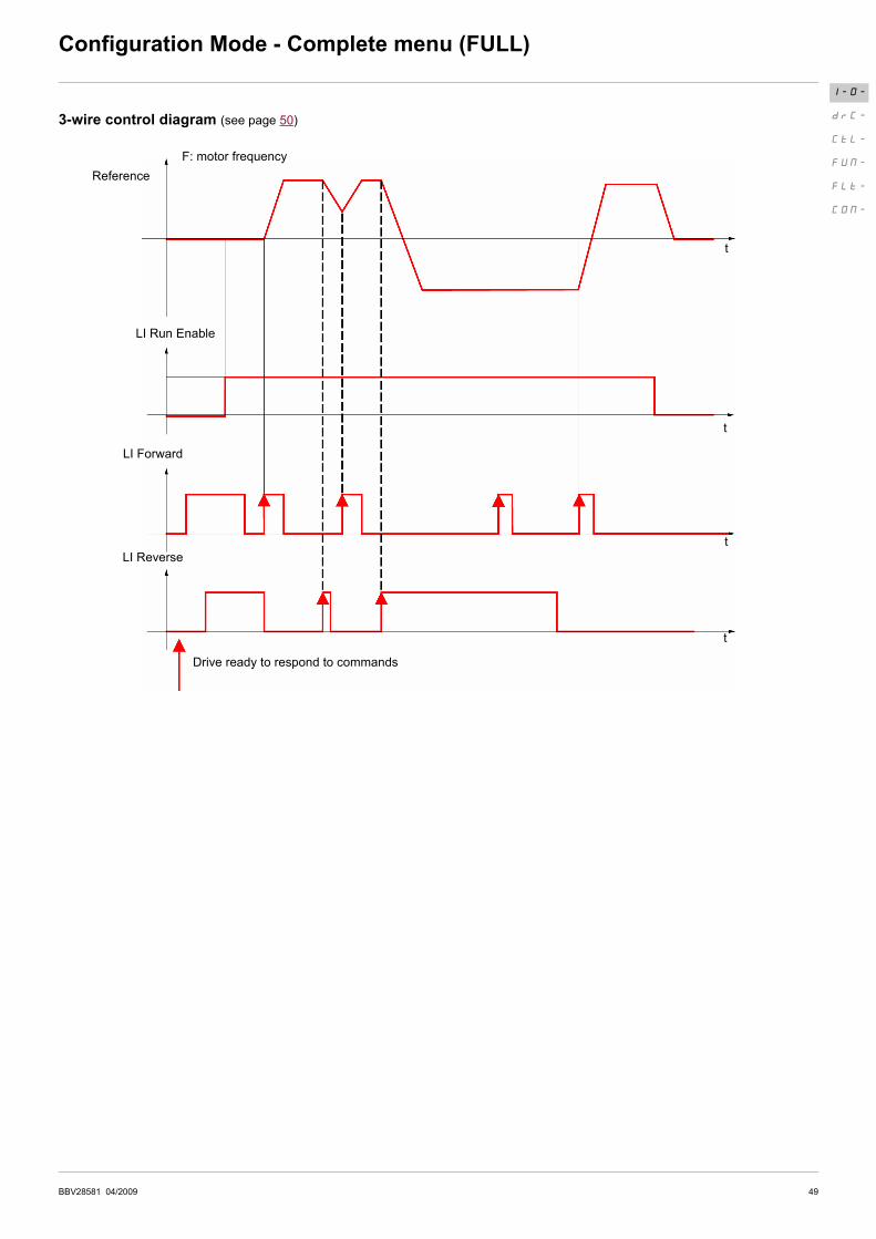
3-wire control diagram (see page 50)
I-O-
drC-
CtL-
FUN-
FLt-
COM-
F: motor frequency
LI Run Enable
LI Forward
t
t
t
Reference
Drive ready to respond to commands
t
LI Reverse
50 BBV28581 04/2009
Configuration Mode - Complete menu (FULL)
Code Name/Description Adjustment range Factory setting
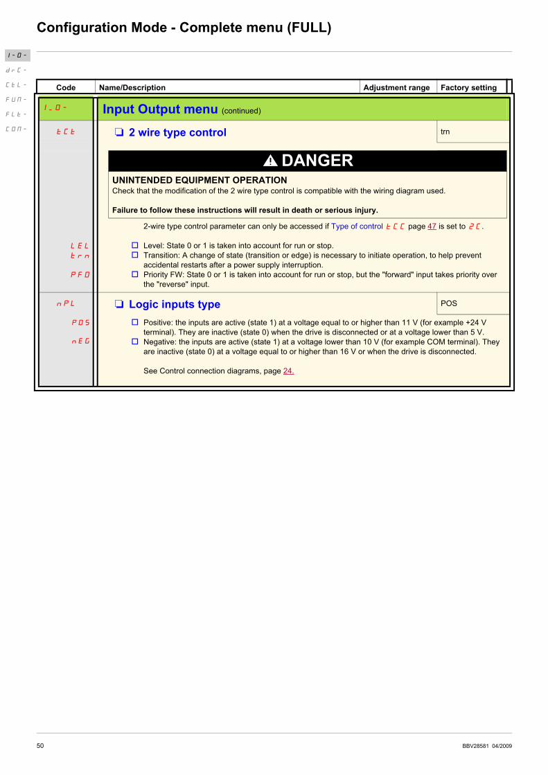
I_O- Input Output menu (continued)
tCt M 2 wire type control trn
LEL
trn
PFO
DANGERUNINTENDED EQUIPMENT OPERATIONCheck that the modification of the 2 wire type control is compatible with the wiring diagram used.
Failure to follow these instructions will result in death or serious injury.
2-wire type control parameter can only be accessed if Type of control tCC page 47 is set to 2C.
v Level: State 0 or 1 is taken into account for run or stop.
v Transition: A change of state (transition or edge) is necessary to initiate operation, to help prevent
accidental restarts after a power supply interruption.
v Priority FW: State 0 or 1 is taken into account for run or stop, but the "forward" input takes priority over
the "reverse" input.
nPL M Logic inputs type POS
POS
nEG
v Positive: the inputs are active (state 1) at a voltage equal to or higher than 11 V (for example +24 V
terminal). They are inactive (state 0) when the drive is disconnected or at a voltage lower than 5 V.
v Negative: the inputs are active (state 1) at a voltage lower than 10 V (for example COM terminal). They
are inactive (state 0) at a voltage equal to or higher than 16 V or when the drive is disconnected.
See Control connection diagrams, page 24.
I-O-
drC-
CtL-
FUN-
FLt-
COM-

BBV28581 04/2009 51
Configuration Mode - Complete menu (FULL)
Code Name/Description Adjustment range Factory setting
I_O- Input Output menu (continued)
AI1- AI1 configuration menu
AI1t M AI1 type 5U
5U
10U
0A
This function makes interface from the analog input signal to a drive internal value.
v Voltage: 0-5 Vdc
v Voltage: 0-10 Vdc
v Current: x-y mA. Range determined by the AI1 current scaling parameter of 0% CrL1 and AI1 current
scaling parameter of 100% CrH1 settings below, see page 51.
CrL1 M AI1 current scaling parameter of 0% 0 to 20 mA 4 mA
Visible only if AI1 type AI1t is set to 0A
CrH1 M AI1 current scaling parameter of 100% 0 to 20 mA 20 mA
Visible only if AI1 type AI1t is set to 0A
I_O- Input Output menu (continued)
r1 M R1 assignment FLt
nO
FLt
rUn
FtA
FLA
CtA
SrA
tSA
ULA
OLA
AP1
v Not assigned
v No error detected
v Drive run
v Frequency threshold reached
v HSP reached
v I threshold reached
v Frequency reference reached
v Motor thermal reached
v Underload alarm
v Overload alarm
v AI1 Al. 4-20 - Visible only if AI1t is set to 0A (see above)
I-O-
drC-
CtL-
FUN-
FLt-
COM-

52 BBV28581 04/2009
Configuration Mode - Complete menu (FULL)
Code Name/Description Adjustment range Factory setting
I_O- Input Output menu (continued)
LO1- LO1 Configuration menu (LO1-)
LO1 M LO1 assignment nO
Allows to adapt the logic output to the application need
Same values as r1. See previous page.
LO1S M LO1 status (output active level) POS
POS
nEG
v Positive : hight activation level
v Negative : low activation level
I_O- Input Output menu (continued)
tOL M Application Overload time delay 0 to 100 s 0 s
This function can be used to stop the motor in the event of an application overload. This is not a motor or
drive thermal overload. If the motor current exceeds the Application Overload threshold LOC, an
Application Overload time delay tOL is activated. Once this time delay tOL has elapsed, if the current
is still greater than the overload threshold LOC -10%, the drive will stop running and display OLC
Process overload.
Overload detection is only active when the system is in steady state (speed reference reached).
A value of 0 will disable application overload detection.
LOC M Application Overload threshold 70 to 150% of nCr 90% of of nCr
Visible only if Application Overload time delay tOL above is not set to 0.
This parameter is used to detect an "application overload". LOC can be adjusted between 70 and 150%
of the nominal drive current. This is not a motor or drive thermal overload.
Parameter that can be modified during operation or when stopped.
I-O-
drC-
CtL-
FUN-
FLt-
COM-
LOC
Motor current
LOC -10%
Drive stop
on OLC detected fault
tOL< tOL
(hysteresis)
t

BBV28581 04/2009 53
Configuration Mode - Complete menu (FULL)
(1) In = nominal drive current
Code Name/Description Adjustment range Factory setting
I_O- Input Output menu (continued)
ULt M Application underload time delay 0 to 100 s 0 s
ULt can be adjusted between 0 and 100 s.
If the motor current undershoots the underload threshold LUL for longer than the adjustable time delay
ULt, the drive will stop running and display ULF (Process underload fault) page 96.
Underload detection is only active when the system is in steady state (speed reference reached).
A value of 0 will disable application underload detection.
LUL M Application Underload threshold 20 to 100% of nCr 60%
Visible only if Application underload time delay ULt is not set to 0. This parameter is used to detect an
application underload condition on the motor. Application Underload thresholdLUL can be adjusted
between 20 and 100% of the nominal drive current
Ftd M Motor frequency threshold 0 to 400 Hz 50 or 60 Hz
According to drive
rating
Visible only if R1 assignment r1 page 51 or a LO1 assignment LO1 page 52 is set to FtA.
Ctd M Motor current threshold 0 to 1.5 In (1) InV
Visible only if R1 assignment r1 page 51 or a LO1 assignment LO1 page 52 is set to CtA.
ttd M Motor thermal state threshold 0 to 118% of tHr 100%
Visible only if R1 assignment r1 page 51 is set to tSA.
Trip threshold for motor thermal alarm (logic output or relay)
Parameter that can be modified during operation or when stopped.
I-O-
drC-
CtL-
FUN-
FLt-
COM-
LUL +10%
Motor current
LUL
Drive stop on ULF
detected fault
ULt< ULt
(hysteresis)
t

54 BBV28581 04/2009
Configuration Mode - Complete menu (FULL)
Code Name/Description Adjustment range Factory setting
I_O- Input Output menu (continued)
AO1- AO1 configuration menu
AO1 M AO1 assignment nO
nO
OCr
OFr
OrP
OPS
OPF
OPE
OPr
tHr
tHd
This parameter is used to set the value of an analog output.
v Not assigned
v Motor current
v Output frequency
v Ramp output
v PID reference - Visible only if PID feedback assignment PIF�page 70 is not set to nO
v PID feedback - Visible only if PID feedback assignment PIF�page 70 is not set to nO
v PID error - Visible only if PID feedback assignment PIF�page 70 is not set to nO
v Output power
v Motor thermal state
v Drive thermal state
AO1t M AO1 type 0A
10U
OA
4A
This parameter provides the interface between the drive internal value and an analog output signal.
v Voltage: 0-10 Vdc
v Current: 0-20 mA
v Current: 4-20 mA
I-O-
drC-
CtL-
FUN-
FLt-
COM-
BBV28581 04/2009 55
Configuration Mode - Complete menu (FULL)
(1) In = nominal drive current
Code Name/Description Adjustment
range
Factory setting
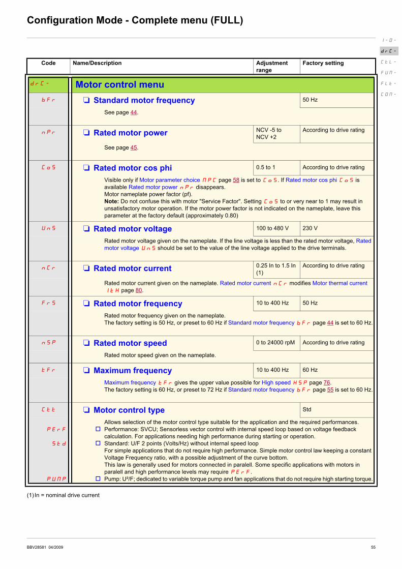
drC- Motor control menu
bFr M Standard motor frequency 50 Hz
See page 44.
nPr M Rated motor power NCV -5 to
NCV +2
According to drive rating
See page 45.
CoS M Rated motor cos phi 0.5 to 1 According to drive rating
Visible only if Motor parameter choice MPC page 58 is set to CoS. If Rated motor cos phi CoS is
available Rated motor power nPr disappears.
Motor nameplate power factor (pf).
Note: Do not confuse this with motor "Service Factor". Setting CoS to or very near to 1 may result in
unsatisfactory motor operation. If the motor power factor is not indicated on the nameplate, leave this
parameter at the factory default (approximately 0.80)
UnS M Rated motor voltage 100 to 480 V 230 V
Rated motor voltage given on the nameplate. If the line voltage is less than the rated motor voltage, Rated
motor voltage UnS should be set to the value of the line voltage applied to the drive terminals.
nCr M Rated motor current 0.25 In to 1.5 In
(1)
According to drive rating
Rated motor current given on the nameplate. Rated motor current nCr modifies Motor thermal current
ItH page 80.
FrS M Rated motor frequency 10 to 400 Hz 50 Hz
Rated motor frequency given on the nameplate.
The factory setting is 50 Hz, or preset to 60 Hz if Standard motor frequency bFr page 44 is set to 60 Hz.
nSP M Rated motor speed 0 to 24000 rpM According to drive rating
Rated motor speed given on the nameplate.
tFr M Maximum frequency 10 to 400 Hz 60 Hz
Maximum frequency tFr gives the upper value possible for High speed HSP page 76.
The factory setting is 60 Hz, or preset to 72 Hz if Standard motor frequency bFr page 55 is set to 60 Hz.
Ctt M Motor control type Std
PErF
Std
PUMP
Allows selection of the motor control type suitable for the application and the required performances.
v Performance: SVCU; Sensorless vector control with internal speed loop based on voltage feedback
calculation. For applications needing high performance during starting or operation.
v Standard: U/F 2 points (Volts/Hz) without internal speed loop
For simple applications that do not require high performance. Simple motor control law keeping a constant
Voltage Frequency ratio, with a possible adjustment of the curve bottom.
This law is generally used for motors connected in paralell. Some specific applications with motors in
paralell and high performance levels may require PErF.
v Pump: U²/F; dedicated to variable torque pump and fan applications that do not require high starting torque.
I-O-
drC-
CtL-
FUN-
FLt-
COM-
56 BBV28581 04/2009
Configuration Mode - Complete menu (FULL)
Code Name/Description Adjustment range Factory setting
drC- Motor control menu (continued)
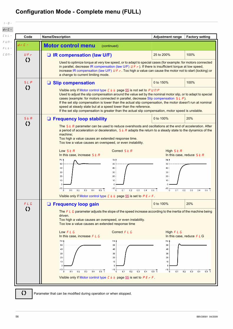
UFr M IR compensation (law U/F) 25 to 200% 100%
Used to optimize torque at very low speed, or to adapt to special cases (for example: for motors connected
in parallel, decrease IR compensation (law U/F) UFr). If there is insufficient torque at low speed,
increase IR compensation (law U/F) UFr. Too high a value can cause the motor not to start (locking) or
a change to current limiting mode.
SLP M Slip compensation 0 to 150% 100%
Visible only if Motor control type Ctt page 55 is not set to PUMP
Used to adjust the slip compensation around the value set by the nominal motor slip, or to adapt to special
cases (example: for motors connected in parallel, decrease Slip compensation SLP).
If the set slip compensation is lower than the actual slip compensation, the motor doesn't run at nominal
speed at steady state but at a speed lower than the reference.
If the set slip compensation is greater than the actual slip compensation, motor speed is unstable.
StA M Frequency loop stability 0 to 100% 20%
The StA parameter can be used to reduce overshoots and oscillations at the end of acceleration. After
a period of acceleration or deceleration, StA adapts the return to a steady state to the dynamics of the
machine;
Too high a value causes an extended response time.
Too low a value causes an overspeed, or even instability.
Low StA Correct StA High StA
In this case, increase StA In this case, reduce StA
Visible only if Motor control type Ctt page 55 is set to PErF.
FLG M Frequency loop gain 0 to 100% 20%
The FLG parameter adjusts the slope of the speed increase according to the inertia of the machine being
driven.
Too high a value causes an overspeed, or even instability.
Too low a value causes an extended response time
Low FLG Correct FLG High FLG
In this case, increase FLG In this case, reduce FLG
Visible only if Motor control type Ctt page 55 is set to PErF.
Parameter that can be modified during operation or when stopped.
I-O-
drC-
CtL-
FUN-
FLt-
COM-
BBV28581 04/2009 57
Configuration Mode - Complete menu (FULL)
Code Name/Description Adjustment range Factory setting
drC- Motor control menu (continued)
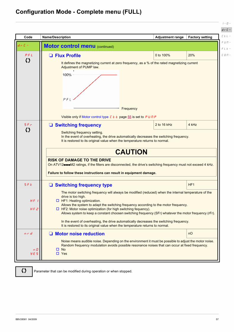
PFL M Flux Profile 0 to 100% 20%
It defines the magnetizing current at zero frequency, as a % of the rated magnetizing current
Adjustment of PUMP law.
Frequency
Visible only if Motor control type Ctt page 55 is set to PUMP
SFr M Switching frequency 2 to 16 kHz 4 kHz
Switching frequency setting.
In the event of overheating, the drive automatically decreases the switching frequency.
It is restored to its original value when the temperature returns to normal.
CAUTIONRISK OF DAMAGE TO THE DRIVEOn ATV12ppppM2 ratings, if the filters are disconnected, the drive’s switching frequency must not exceed 4 kHz.
Failure to follow these instructions can result in equipment damage.
SFt M Switching frequency type HF1
HF1
HF2
The motor switching frequency will always be modified (reduced) when the internal temperature of the
drive is too high.
v HF1: Heating optimization.
Allows the system to adapt the switching frequency according to the motor frequency.
v HF2: Motor noise optimization (for high switching fequency).
Allows system to keep a constant choosen switching frequency (SFr) whatever the motor frequency (rFr).
In the event of overheating, the drive automatically decreases the switching frequency.
It is restored to its original value when the temperature returns to normal.
nrd M Motor noise reduction nO
nO
YES
Noise means audible noise. Depending on the environment it must be possible to adjust the motor noise.
Random frequency modulation avoids possible resonance noises that can occur at fixed frequency.
v No
v Yes
Parameter that can be modified during operation or when stopped.
I-O-
drC-
CtL-
FUN-
FLt-
COM-
58 BBV28581 04/2009
Configuration Mode - Complete menu (FULL)
Code Name/Description Adjustment range Factory setting
drC- Motor control menu (continued)
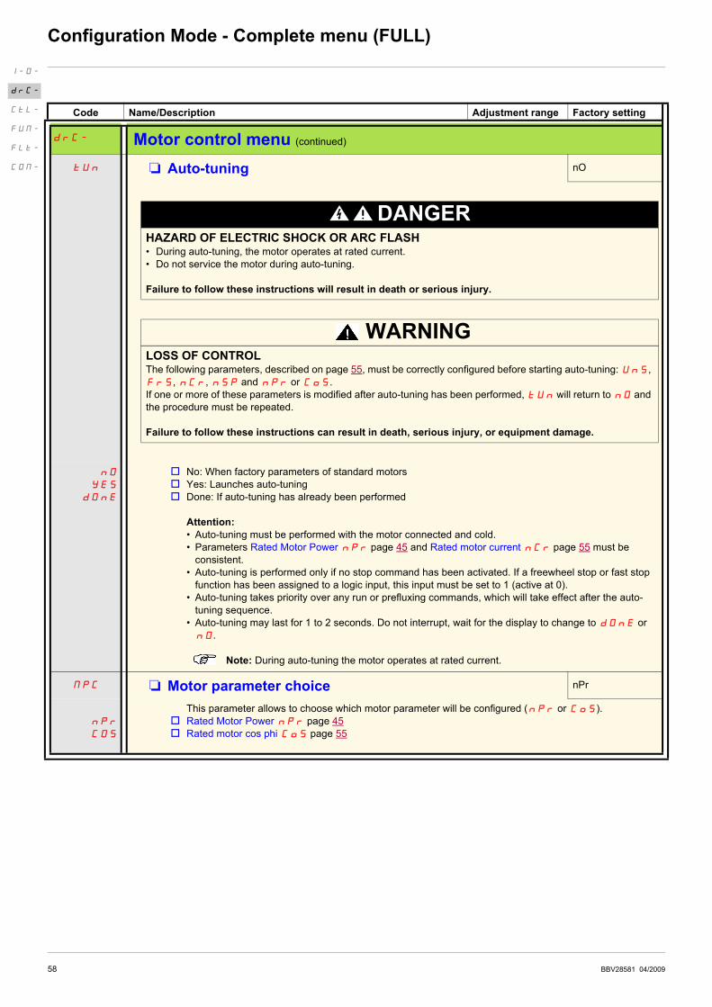
tUn M Auto-tuning nO
DANGERHAZARD OF ELECTRIC SHOCK OR ARC FLASH• During auto-tuning, the motor operates at rated current.
• Do not service the motor during auto-tuning.
Failure to follow these instructions will result in death or serious injury.
WARNINGLOSS OF CONTROLThe following parameters, described on page 55, must be correctly configured before starting auto-tuning: UnS,
FrS, nCr, nSP and nPr or CoS.
If one or more of these parameters is modified after auto-tuning has been performed, tUn will return to nO and
the procedure must be repeated.
Failure to follow these instructions can result in death, serious injury, or equipment damage.
nO
YES
dOnE
v No: When factory parameters of standard motors
v Yes: Launches auto-tuning
v Done: If auto-tuning has already been performed
Attention:
• Auto-tuning must be performed with the motor connected and cold.
• Parameters Rated Motor Power nPr page 45 and Rated motor current nCr page 55 must be
consistent.
• Auto-tuning is performed only if no stop command has been activated. If a freewheel stop or fast stop
function has been assigned to a logic input, this input must be set to 1 (active at 0).
• Auto-tuning takes priority over any run or prefluxing commands, which will take effect after the auto-
tuning sequence.
• Auto-tuning may last for 1 to 2 seconds. Do not interrupt, wait for the display to change to dOnE or
nO.
Note: During auto-tuning the motor operates at rated current.
MPC M Motor parameter choice nPr
nPr
COS
This parameter allows to choose which motor parameter will be configured (npr or CoS).
v Rated Motor Power nPr page 45
v Rated motor cos phi CoS page 55
I-O-
drC-
CtL-
FUN-
FLt-
COM-

BBV28581 04/2009 59
Configuration Mode - Complete menu (FULL)
Control menu
Control channel diagram
I-O-
drC-
CtL-
FUN-
FLt-
COM-
Stop
key
priority
Preset
speed
PID
reg.
JOG or PIF
60 BBV28581 04/2009
Configuration Mode - Complete menu (FULL)
Code Name/Description Adjustment range Factory setting
CtL- Control menu
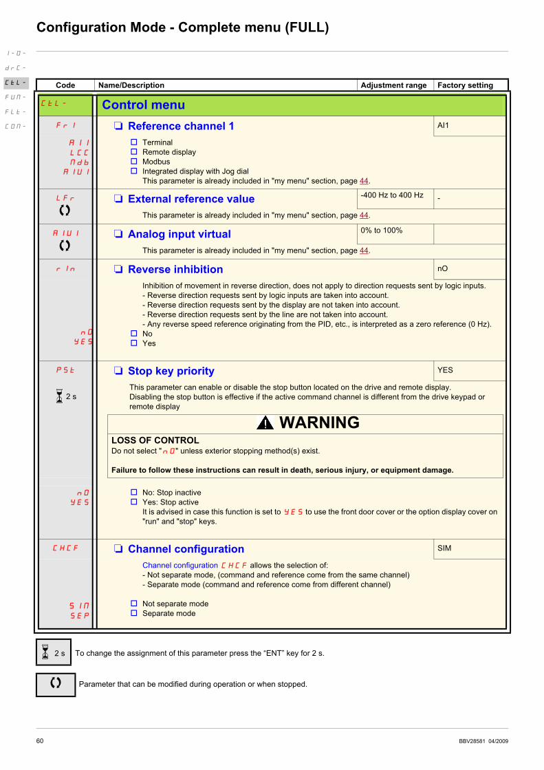
Fr1 M Reference channel 1 AI1
AI1
LCC
Mdb
AIUI
v Terminal
v Remote display
v Modbus
v Integrated display with Jog dial
This parameter is already included in "my menu" section, page 44.
LFr M External reference value -400 Hz to 400 Hz -
This parameter is already included in "my menu" section, page 44.
AIU1 M Analog input virtual 0% to 100%
This parameter is already included in "my menu" section, page 44.
rIn M Reverse inhibition nO
l
nO
YES
Inhibition of movement in reverse direction, does not apply to direction requests sent by logic inputs.
- Reverse direction requests sent by logic inputs are taken into account.
- Reverse direction requests sent by the display are not taken into account.
- Reverse direction requests sent by the line are not taken into account.
- Any reverse speed reference originating from the PID, etc., is interpreted as a zero reference (0 Hz).
v No
v Yes
PSt M Stop key priority YES
This parameter can enable or disable the stop button located on the drive and remote display.
Disabling the stop button is effective if the active command channel is different from the drive keypad or
remote display
WARNINGLOSS OF CONTROLDo not select "nO" unless exterior stopping method(s) exist.
Failure to follow these instructions can result in death, serious injury, or equipment damage.
nO
YES
v No: Stop inactive
v Yes: Stop active
It is advised in case this function is set to YES to use the front door cover or the option display cover on
"run" and "stop" keys.
CHCF M Channel configuration SIM
SIM
SEP
Channel configuration CHCF allows the selection of:
- Not separate mode, (command and reference come from the same channel)
- Separate mode (command and reference come from different channel)
v Not separate mode
v Separate mode
To change the assignment of this parameter press the “ENT” key for 2 s.
Parameter that can be modified during operation or when stopped.
I-O-
drC-
CtL-
FUN-
FLt-
COM-
2 s
2 s

BBV28581 04/2009 61
Configuration Mode - Complete menu (FULL)
Code Name/Description Adjustment range Factory setting
CtL- Control menu (continued)
Cd1 M Command channel 1 tEr
tEr
LOC
LCC
Mdb
This parameter allows selection of the command channel.
v Terminals
v Local
v Remote display
v Modbus
This parameter is available if Channel configuration CHCF page 60 is set to Separate
FLO M Forced local assignment nO
nO
L1H
-
L4H
v Function inactive
v L1h to L4h: Forced local mode is active when the input is at state 1.
FLOC M Forced local reference nO
nO
AI1
LCC
AIU1
Visible only if Forced local assignment FLO is not set to nO.
v Not assigned
v Terminal
v Remote display
v Integrated display with jog dial
I-O-
drC-
CtL-
FUN-
FLt-
COM-

62 BBV28581 04/2009
Configuration Mode - Complete menu (FULL)
Code Name/Description Adjustment range Factory setting
FUn- Function menu
rPt- Ramp menu
ACC M Acceleration 0.0 s to 999.9 s 3.0 s
Acceleration time between 0 Hz and the Rated motor frequency FrS page 55.
Make sure that this value is compatible with the inertia being driven.
dEC M Deceleration 0.0 s to 999.9 s 3.0 s
Time to decelerate from the Rated motor frequency FrS page 55 to 0 Hz
Make sure that this value is compatible with the inertia being driven.
rPt M Ramp shape assignment Lin
LIn
S
U
v Linear
v S shape
v U shape
S shape
U shape
The rounding coefficient is fixed,
t1 = 0.6 set ramp time (linear)
t2 = 0.4 set ramp time (round)
t3 = 1.4 set ramp time
The rounding coefficient is fixed,
t1 = 0.5 set ramp time (linear)
t2 = set ramp time (round)
t3 = 1.5 set ramp time
rPS M Ramp switching commutation nO
nO
LIH
L2H
L3H
L4H
LIL
L2L
L3L
L4L
v Not assigned
v L1H: LI1 active High
v L2H: LI2 active High
v L3H: LI3 active High
v L4H: LI4 active High
v L1L: LI1 active low
v L2L: LI2 active low
v L3L: LI3 active low
v L4L: LI4 active low
See LI assignment information on page 45.
Parameter that can be modified during operation or when stopped.
I-O-
drC-
CtL-
FUN-
FLt-
COM-

BBV28581 04/2009 63
Configuration Mode - Complete menu (FULL)
Code Name/Description Adjustment range Factory setting
FUn- Function menu (continued)
rPt- Ramp menu (continued)
AC2 M Acceleration 2 0.0 to 999.9 s 5.0 s
Visible only if Ramp switching commutation rPS page 62 is not set to nO.
Second acceleration ramp time, adjustable from 0.0 to 999.9 s
This ramp will be the active ramp when using PID for the start and wake-up phases only, see PID wake up
level page 73.
dE2 M Deceleration 2 0.0 to 999.9 s 5.0 s
Visible only if Ramp switching commutation rPS page 62 is not set to nO.
Second deceleration ramp time, adjustable from 0.0 to 999.9 s
brA M Decel Ramp Adaptation assignment YES
nO
YES
dYnA
v Function inactive. The drive will decelerate based on the normal deceleration adjustment. This setting is
compatible with optional dynamic braking if used.
v This function automatically increases deceleration time when stopping or reducing the speed of high inertia
loads to help prevent DC bus overvoltage or overbraking.
v Motor Braking: This mode allows the drive to attempt the most rapid stop possible without the use of a
dynamic brake resistor. It uses motor losses to dissipate energy from regeneration. This function may be
incompatible with positioning. This function should not be used when an optional braking resistor and
module are being used.
Attention: When using a braking resistor set brA to nO.
Parameter that can be modified during operation or when stopped.
I-O-
drC-
CtL-
FUN-
FLt-
COM-

64 BBV28581 04/2009
Configuration Mode - Complete menu (FULL)
Code Name/Description Adjustment range Factory setting
FUn- Function menu (continued)
Stt- Stop configuration menu
Stt M Type of stop rMP
rMP
FSt
nSt
Stop mode on disappearance of the run command and appearance of a stop command
v Ramp stop
v Fast stop
v Freewheel
nSt M Freewheel stop assignment nO
nO
L1L
L2L
L3L
L4L
The stop is activated when the input or the bit changes to 0. If the input returns to state 1 and the run
command is still active, the motor will only restart if Type of control tCC page 47 = 2C and 2 wire type
control tCt page 50 = LEL or PFO. If not, a new run command must be sent.
v Not assigned
v L1L: LI1 Active Low to stop
v L2L: LI2 Active Low to stop
v L3L: LI3 Active Low to stop
v L4L: LI4 Active Low to stop
FSt M Fast stop assignment nO
nO
L1L
L2L
L3L
L4L
v Not assigned
v L1L: LI1 Active Low to stop
v L2L: LI2 Active Low to stop
v L3L: LI3 Active Low to stop
v L4L: LI4 Active Low to stop
dCF M Ramp divider 1 to 10 4
Visible only if Fast stop assignment FSt page 61 is not set to nO or if FSt is set to Type of stop Stt
page 64.
The ramp that is enabled (Deceleration dEC page 44 or Deceleration 2 dE2 page 63) is then divided
by this coefficient when stop requests are sent.
Value 10 corresponds to a minimum ramp time.
Code Name/Description Adjustment range Factory setting
FUn- Function menu (continued)
rrS M Reverse direction nO
nO
LIH
L2H
L3H
L4H
LI1 to LI4: choice of the input assigned to the reverse command
v Function inactive
v L1h: L1 active high
v L2h: L2 active high
v L3h: L3 active high
v L4h: L4 active high
Parameter that can be modified during operation or when stopped.
I-O-
drC-
CtL-
FUN-
FLt-
COM-

BBV28581 04/2009 65
Configuration Mode - Complete menu (FULL)
Code Name/Description Adjustment range Factory setting
FUn- Function menu (continued)
AdC- Auto DC injection menu
AdC
nO
YES
Ct
M Automatic DC injection YES
v Function inactive, no DC injected current.
v Time limited DC injection
v Continuous DC injection
SdC1 M Automatic DC injection current 0 to 120% of nCr 70%
Visible only if Automatic DC injection AdC is not set to nO.
Injection current on stopping and continuous DC injection.
tdC1 M Automatic DC injection time 0.1 to 30 s 0.5 s
Visible only if Automatic DC injection AdC is not set to nO.
Injection time on stopping.
Parameter that can be modified during operation or when stopped.
I-O-
drC-
CtL-
FUN-
FLt-
COM-

66 BBV28581 04/2009
Configuration Mode - Complete menu (FULL)
Code Name/Description Adjustment range Factory setting
FUn- Function menu (continued)
JOG M Jog assignment nO
nO
L1H
L2H
L3H
L4H
This parameter provides step by step control of motor running, using a logic input associated with a 2 and
3-wire control logic input. The jog frequency is fixed at 5 Hz. Acceleration and decelaration ramps taken
into account in the Jog function are 0.1 s.
v Function inactive.
v L1h: LI1 active high
v L2h: LI2 active high
v L3h: LI2 active high
v L4h: LI4 active high
2-wire control
3 wire control
I-O-
drC-
CtL-
FUN-
FLt-
COM-
Jog
Forward
Reverse
MotorFrequency
5Hz
5HzAcceleration
0,5s
Jog
Forward
Reverse
MotorFrequency
5Hz
5Hz
Normalramp
Jogramp
LI1 Run

BBV28581 04/2009 67
Configuration Mode - Complete menu (FULL)
Preset speeds
2, 4, or 8 speeds can be preset, requiring 1, 2 or 3 logic inputs respectively
Combination table for preset speed inputs
8 speeds
LI (PS8)
4 speeds
LI (PS4)
2 speeds
LI (PS2)
Speed reference
0 0 0 Reference
0 0 1 SP2
0 1 0 SP3
0 1 1 SP4
1 0 0 SP5
1 0 1 SP6
1 1 0 SP7
1 1 1 SP8
I-O-
drC-
CtL-
FUN-
FLt-
COM-

68 BBV28581 04/2009
Configuration Mode - Complete menu (FULL)
Code Name/Description Adjustment range Factory setting
FUn- Function menu (continued)
PSS- Preset speed menu
PS2 M 2 Preset speeds nO
nO
L1H
L2H
L3H
L4H
v Function inactive
v L1h: LI1 active high
v L2h: LI2 active high
v L3h: LI2 active high
v L4h: LI4 active high
PS4 M 4 Preset speeds nO
as PS2
PS8 M 8 Preset speeds nO
as PS2
SP2 M Preset speed 2 0 to 400 Hz 10 Hz
Visible only if 2 Preset speeds PS2 is not set to nO.
SP3 M Preset speed 3 0 to 400 Hz 15 Hz
Visible only if 4 Preset speeds PS4 is not set to nO.
SP4 M Preset speed 4 0 to 400 Hz 20 Hz
Visible only if 2 Preset speeds PS2 and 4 Preset speeds PS4 are not set to nO.
SP5 M Preset speed 5 0 to 400 Hz 25 Hz
Visible only if 8 Preset speeds PS8 is not set to nO.
SP6 M Preset speed 6 0 to 400 Hz 30 Hz
Visible only if 2 Preset speeds PS2 and 8 Preset speeds PS8 are not set to nO.
SP7 M Preset speed 7 0 to 400 Hz 35 Hz
Visible only if 4 Preset speeds PS4 and 8 Preset speeds PS8 are not set to nO.
SP8 M Preset speed 8 0 to 400 Hz 40 Hz
Visible only if 2 Preset speeds PS2, 4 Preset speeds PS4 and 8 Preset speeds PS8 are not set to nO.
JPF M Skip frequency 0 to 400 Hz 0 Hz
v This parameter prevents prolonged operation within an adjustable range around the regulated frequency.
This function can be used to prevent a critical speed, which would cause resonance, being reached. Setting
the function to 0 renders it inactive.
Parameter that can be modified during operation or when stopped.
I-O-
drC-
CtL-
FUN-
FLt-
COM-
BBV28581 04/2009 69
Configuration Mode - Complete menu (FULL)
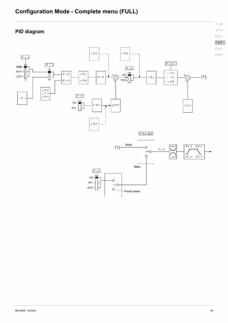
PID diagram
I-O-
drC-
CtL-
FUN-
FLt-
COM-
Preset speed
Auto
Man.

70 BBV28581 04/2009
Configuration Mode - Complete menu (FULL)
Code Name/Description Adjustment range Factory setting
FUn- Function menu (continued)
PId- PID menu
PIF M PID feedback assignment nO
nO
A11
v Not assigned
v Terminal. Choice not possible if Fr1 is set to AI1
rPG M PID proportional gain 0.01 to 100 1
Visible only if PID feedback assignment PIF is not set to nO.
rIG M PID integral gain 0.01 to 100 1
Visible only if PID feedback assignment PIF is not set to nO.
rdG M PID derivative gain 0.00 to 100.00 0.00
Visible only if PID feedback assignment PIF is not set to nO.
FbS M PID feedback scale factor 0.1 to 100.0 1.0
This parameter gives the relation between process range and feedback range.
Visible only if PID feedback assignment PIF is not set to nO.
PII M Activation internal PID reference nO
nO
YES
Visible only if PID feedback assignment PIF is not set to nO.
v No
v Yes
Pr2 M 2 preset PID assignment nO
nO
L1H
L2H
L3H
L4H
Visible only if PID feedback assignment PIF is not set to nO.
v No
v L1h
v L2h
v L3h
v L4h
Parameter that can be modified during operation or when stopped.
I-O-
drC-
CtL-
FUN-
FLt-
COM-

BBV28581 04/2009 71
Configuration Mode - Complete menu (FULL)
Code Name/Description Adjustment range Factory setting
FUn- Function menu (continued)
PId- PID menu (continued)
Pr4 M 4 preset PID assignment nO
nO
L1H
L2H
L3H
L4H
Visible only if PID feedback assignment PIF page 70 is not set to nO.
v No
v L1h
v L2h
v L3h
v L4h
2 preset PID assignment Pr2 page 70 must be assigned before assigning 4 preset PID assignment
Pr4.
rP2 M 2 preset PID reference 0 to 100% 25%
Visible only if PID feedback assignment PIF page 70 and 2 preset PID assignment Pr2 page 70 are
not set to nO.
rP3 M 3 preset PID reference 0 to 100% 50%
Visible only if PID feedback assignment PIF�page 70 and 4 preset PID assignment Pr4 page 70 are
not set to nO.
rP4 M 4 preset PID reference 0 to 100% 75%
Visible only if PID feedback assignment PIF page 70 and 2 preset PID assignment Pr2 and 4 preset
PID assignment Pr4 page 70 are not set to nO.
rPI M Internal PID reference 0 to 100% 0%
Visible only if PID feedback assignment PIF page 70 is not set to nO and if Activation internal PID
reference PII page 70 is set to YES or Reference channel 1 Fr1 page 44 is set to LCC.
PrP M PID reference ramp 0 to 100% 0%
Visible only if PID feedback assignment PIF page 70 is not set to nO.
rPL M PID min value reference 0 to 100% 0%
Visible only if PID feedback assignment PIF page 70 is not set to nO.
rPH M PID max value reference 0 to 100% 100%
Visible only if PID feedback assignment PIF page 70 is not set to nO
SFS M PID predictive speed 0.1 to 400 Hz nO
This parameter allows to go directly to a set speed reference.
Visible only if PID feedback assignment PIF page 70 is not set to nO.
Parameter that can be modified during operation or when stopped.
I-O-
drC-
CtL-
FUN-
FLt-
COM-
72 BBV28581 04/2009
Configuration Mode - Complete menu (FULL)
Code Name/Description Adjustment range Factory setting
FUn- Function menu (continued)
PId- PID menu (continued)
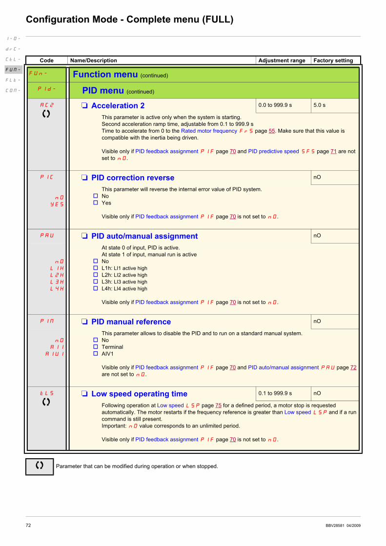
AC2 M Acceleration 2 0.0 to 999.9 s 5.0 s
This parameter is active only when the system is starting.
Second acceleration ramp time, adjustable from 0.1 to 999.9 s
Time to accelerate from 0 to the Rated motor frequency FrS page 55. Make sure that this value is
compatible with the inertia being driven.
Visible only if PID feedback assignment PIF page 70 and PID predictive speed SFS page 71 are not
set to nO.
PIC
nO
YES
M PID correction reverse nO
This parameter will reverse the internal error value of PID system.
v No
v Yes
Visible only if PID feedback assignment PIF page 70 is not set to nO.
PAU M PID auto/manual assignment nO
nO
L1H
L2H
L3H
L4H
At state 0 of input, PID is active.
At state 1 of input, manual run is active
v No
v L1h: LI1 active high
v L2h: LI2 active high
v L3h: LI3 active high
v L4h: LI4 active high
Visible only if PID feedback assignment PIF page 70 is not set to nO.
PIM M PID manual reference nO
nO
A11
A1U1
This parameter allows to disable the PID and to run on a standard manual system.
v No
v Terminal
v AIV1
Visible only if PID feedback assignment PIF page 70 and PID auto/manual assignment PAU page 72
are not set to nO.
tLS M Low speed operating time 0.1 to 999.9 s nO
Following operation at Low speed LSP page 75 for a defined period, a motor stop is requested
automatically. The motor restarts if the frequency reference is greater than Low speed LSP and if a run
command is still present.
Important: nO value corresponds to an unlimited period.
Visible only if PID feedback assignment PIF page 70 is not set to nO.
Parameter that can be modified during operation or when stopped.
I-O-
drC-
CtL-
FUN-
FLt-
COM-
BBV28581 04/2009 73
Configuration Mode - Complete menu (FULL)
Code Name/Description Adjustment range Factory setting
FUn- Function menu (continued)
PId- PID menu (continued)
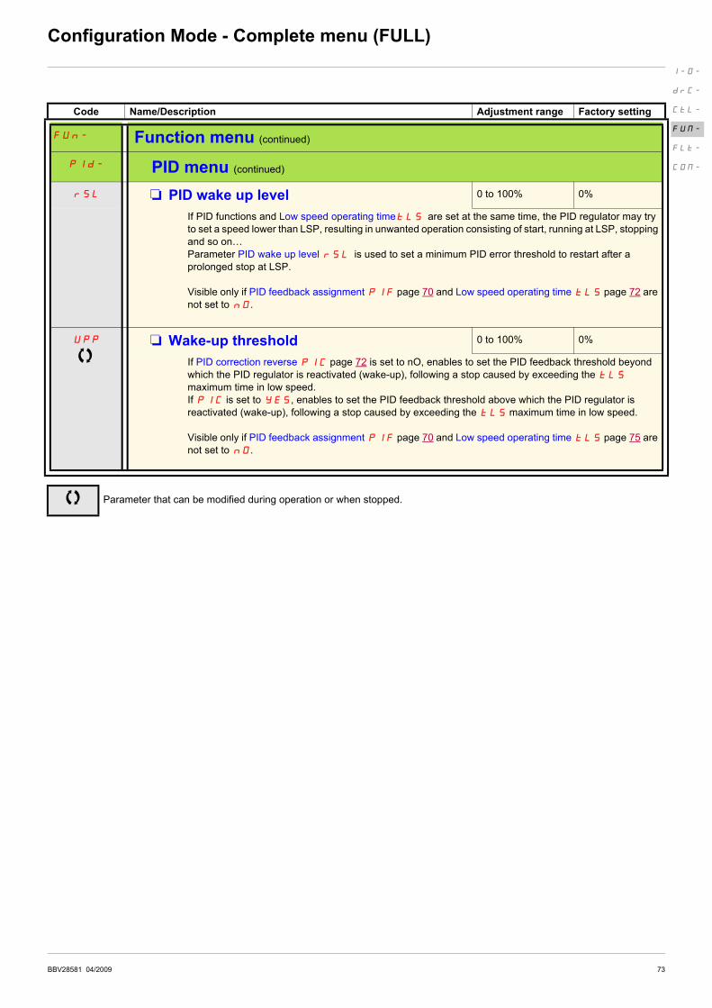
rSL M PID wake up level 0 to 100% 0%
If PID functions and Low speed operating timetLS�are set at the same time, the PID regulator may try
to set a speed lower than LSP, resulting in unwanted operation consisting of start, running at LSP, stopping
and so on…
Parameter PID wake up level rSL�is used to set a minimum PID error threshold to restart after a
prolonged stop at LSP.
Visible only if PID feedback assignment PIF page 70 and Low speed operating time tLS page 72 are
not set to nO.
UPP M Wake-up threshold 0 to 100% 0%
If PID correction reverse PIC page 72 is set to nO, enables to set the PID feedback threshold beyond
which the PID regulator is reactivated (wake-up), following a stop caused by exceeding the tLS
maximum time in low speed.
If PIC is set to YES, enables to set the PID feedback threshold above which the PID regulator is
reactivated (wake-up), following a stop caused by exceeding the tLS maximum time in low speed.
Visible only if PID feedback assignment PIF page 70 and Low speed operating time tLS page 75 are
not set to nO.
Parameter that can be modified during operation or when stopped.
I-O-
drC-
CtL-
FUN-
FLt-
COM-
74 BBV28581 04/2009
Configuration Mode - Complete menu (FULL)
(1) In = nominal drive current
Code Name/Description Adjustment range Factory setting
FUn- Function menu (continued)
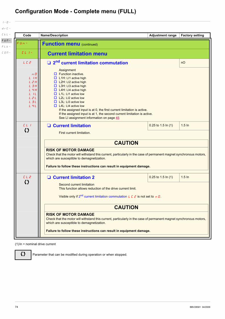
CLI- Current limitation menu
LC2 M 2nd current limitation commutation nO
nO
L1H
L2H
L3H
L4H
L1L
L2L
L3L
L4L
Assignment
v Function inactive.
v L1H: LI1 active high
v L2H: LI2 active high
v L3H: LI3 active high
v L4H: LI4 active high
v L1L: LI1 active low
v L2L: LI2 active low
v L3L: LI3 active low
v L4L: LI4 active low
If the assigned input is at 0, the first current limitation is active.
If the assigned input is at 1, the second current limitation is active.
See LI assignment information on page 45
CLI M Current limitation 0.25 to 1.5 In (1) 1.5 In
First current limitation.
CAUTION
RISK OF MOTOR DAMAGECheck that the motor will withstand this current, particularly in the case of permanent magnet synchronous motors,
which are susceptible to demagnetization.
Failure to follow these instructions can result in equipment damage.
CL2 M Current limitation 2 0.25 to 1.5 In (1) 1.5 In
Second current limitation
This function allows reduction of the drive current limit.
Visible only if 2nd current limitation commutation LC2 is not set to nO.
CAUTION
RISK OF MOTOR DAMAGECheck that the motor will withstand this current, particularly in the case of permanent magnet synchronous motors,
which are susceptible to demagnetization.
Failure to follow these instructions can result in equipment damage.
Parameter that can be modified during operation or when stopped.
I-O-
drC-
CtL-
FUN-
FLt-
COM-

BBV28581 04/2009 75
Configuration Mode - Complete menu (FULL)
Code Name/Description Adjustment range Factory setting
FUn- Function menu (continued)
SPL- Speed limit menu
LSP M Low speed 0 Hz to HSP 0 Hz
Motor frequency at minimum reference.
This parameter is already included in "my menu" section, page 44.
tLS M Low speed operating time 0.1 to 999.9 s nO
Following operation at Low speed LSP for a defined period, a motor stop is requested automatically. The
motor restarts if the frequency reference is greater than Low speed LSP and if a run command is still
present.
Important: nO corresponds to an unlimited period.
I-O-
drC-
CtL-
FUN-
FLt-
COM-

76 BBV28581 04/2009
Configuration Mode - Complete menu (FULL)
High speed configuration
The logic inputs enable selection of the desired high speed.
Desired
High speed
Setting
Parameter State
HSP SH2 nO
SH4 nO
HSP2 SH2 assigned
SH4 nO
HSP3 SH2 nO
SH4 assigned
HSP4 SH2 assigned
SH4 assigned
Code Name/Description Adjustment range Factory setting
FUn- Function menu (continued)
SPL- Speed limit menu
HSP M High speed LSP to tFr 50 or 60 Hz
according to BFr,
max TFr
Motor frequency at maximum reference, can be set between Low speed LSP and Maximum frequency
tFr page 55.
If tFr is decreased below the value defined for HSP, then HSP automatically decreases to the new
value of tFr.
This parameter is already included in "my menu" section, page 44.
SH2 M 2 HSP assignment nO
nO
L1H
L2H
L3H
L4H
v No
v L1h: LI1 active high
v L2h: LI2 active high
v L3h: LI3 active high
v L4h: LI4 active high
SH4 M 4 HSP assignment nO
nO
L1H
L2H
L3H
L4H
v No
v L1h: LI1 active high
v L2h: LI2 active high
v L3h: LI3 active high
v L4h: LI4 active high
HSP2 M High speed 2 LSP to tFr as HSP
Visible only if 2 HSP assignment SH2 is not set to nO.
HSP3 M High speed 3 LSP to tFr as HSP
Visible only if 4 HSP assignment SH4 is not set to nO.
HSP4 M High speed 4 LSP to tFr as HSP
Visible only if 2 HSP assignment SH2 and 4 HSP assignment SH4 are not set to nO.
Parameter that can be modified during operation or when stopped.
I-O-
drC-
CtL-
FUN-
FLt-
COM-
BBV28581 04/2009 77
Configuration Mode - Complete menu (FULL)
Code Name/Description Adjustment range Factory setting
FLt- Fault detection management menu
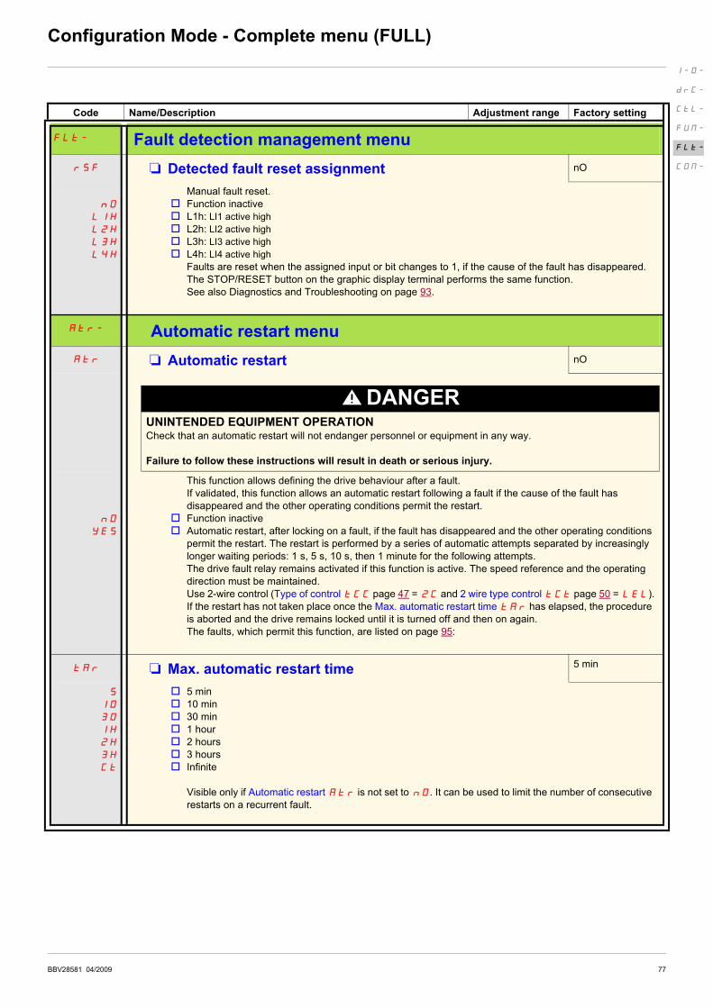
rSF M Detected fault reset assignment nO
nO
L1H
L2H
L3H
L4H
Manual fault reset.
v Function inactive
v L1h: LI1 active high
v L2h: LI2 active high
v L3h: LI3 active high
v L4h: LI4 active high
Faults are reset when the assigned input or bit changes to 1, if the cause of the fault has disappeared.
The STOP/RESET button on the graphic display terminal performs the same function.
See also Diagnostics and Troubleshooting on page 93.
Atr- Automatic restart menu
Atr M Automatic restart nO
DANGERUNINTENDED EQUIPMENT OPERATIONCheck that an automatic restart will not endanger personnel or equipment in any way.
Failure to follow these instructions will result in death or serious injury.
nO
YES
This function allows defining the drive behaviour after a fault.
If validated, this function allows an automatic restart following a fault if the cause of the fault has
disappeared and the other operating conditions permit the restart.
v Function inactive
v Automatic restart, after locking on a fault, if the fault has disappeared and the other operating conditions
permit the restart. The restart is performed by a series of automatic attempts separated by increasingly
longer waiting periods: 1 s, 5 s, 10 s, then 1 minute for the following attempts.
The drive fault relay remains activated if this function is active. The speed reference and the operating
direction must be maintained.
Use 2-wire control (Type of control tCC page 47 = 2C and 2 wire type control tCt page 50 = LEL).
If the restart has not taken place once the Max. automatic restart time tAr has elapsed, the procedure
is aborted and the drive remains locked until it is turned off and then on again.
The faults, which permit this function, are listed on page 95:
tAr M Max. automatic restart time 5 min
5
10
30
1H
2H
3H
Ct
v 5 min
v 10 min
v 30 min
v 1 hour
v 2 hours
v 3 hours
v Infinite
Visible only if Automatic restart Atr is not set to nO. It can be used to limit the number of consecutive
restarts on a recurrent fault.
I-O-
drC-
CtL-
FUN-
FLt-
COM-
78 BBV28581 04/2009
Configuration Mode - Complete menu (FULL)
Code Name/Description Adjustment range Factory setting
FLt- Fault detection management menu (continued)
FLr M Catch on the fly nO
nO
YES
Used to enable a smooth restart if the run command is maintained after the following events:
• Loss of line supply or disconnection
• Reset of current fault or automatic restart
• Freewheel stop.
The speed given by the drive resumes from the estimated speed of the motor at the time of the restart, then
follows the ramp to the reference speed.
This function requires 2-wire level control.
v Function inactive
v Function active
I-O-
drC-
CtL-
FUN-
FLt-
COM-
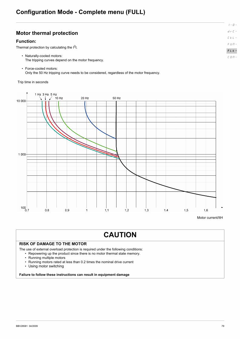
BBV28581 04/2009 79
Configuration Mode - Complete menu (FULL)
Motor thermal protection
Function:
Thermal protection by calculating the I2t.
• Naturally-cooled motors:
The tripping curves depend on the motor frequency.
• Force-cooled motors:
Only the 50 Hz tripping curve needs to be considered, regardless of the motor frequency.
Trip time in seconds
Motor current/ItH
CAUTIONRISK OF DAMAGE TO THE MOTOR
The use of external overload protection is required under the following conditions:
• Repowering up the product since there is no motor thermal state memory.
• Running multiple motors
• Running motors rated at less than 0.2 times the nominal drive current
• Using motor switching
Failure to follow these instructions can result in equipment damage
I-O-
drC-
CtL-
FUN-
FLt-
COM-

80 BBV28581 04/2009
Configuration Mode - Complete menu (FULL)
(1) In = nominal drive current
Code Name/Description Adjustment range Factory setting
FLt- Fault detection management menu (continued)
tHt- Motor thermal protection menu
ItH M Motor thermal current 0.2 to 1.5 In (1) According to drive
rating
Current used for the motor thermal detection. Set ItH to the nominal current on the motor rating plate.
tHt M Motor protection type ACL
ACL
FCL
v Self-ventilated
v Motor-ventilated
OLL M Overload fault management YES
nO
YES
Type of stop in the event of a motor thermal fault.
v Fault ignored
v Freewheel stop
Setting Overload fault management OLL to nO inhibits the Motor overload OLF page 95.
CAUTION
RISK OF DAMAGE TO THE MOTORIif OLL is set to nO, motor thermal protection is no longuer provided by the drive. Provide an alternative means
of thermal protection.
Failure to follow these instructions can result in equipment damage.
MtM M Motor thermal state memo nO
nO
YES
v Motor thermal state not stored at power off.
v Motor thermal state is stored at power off.
FLt- Fault detection management menu (continued)
OPL M Output Phase loss YES
nO
YES
v Function inactive
v Tripping on OPF1 (1 phase loss) or OPF2 (3 phase loss) fault with freewheel stop.
IPL M Input Phase loss According to
drive rating
nO
YES
Invisible if drive rating is F1 and factory setting is nO
Invisible if drive rating is ATV12pppF1 and ATV12pppM2.
In this case no factory settings appears.
v Fault ignored. To be used when the drive is supplied via a single phase supply.
v Fault with freewheel stop.
If one phase disappears, the drive switches to fault mode Input Phase lossIPL but if 2 or 3 phases
disappear, the drive continues to operate until it trips on an undervoltage fault.
Parameter that can be modified during operation or when stopped.
I-O-
drC-
CtL-
FUN-
FLt-
COM-
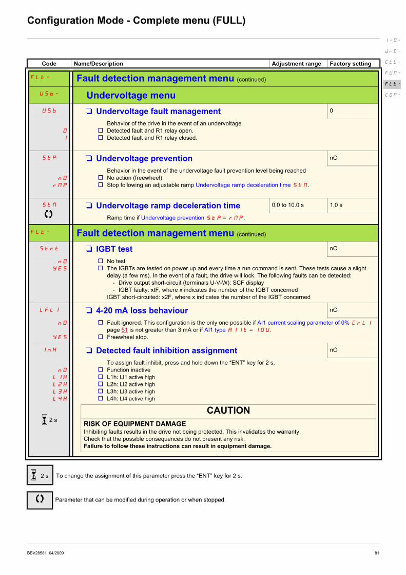
BBV28581 04/2009 81
Configuration Mode - Complete menu (FULL)
Code Name/Description Adjustment range Factory setting
FLt- Fault detection management menu (continued)
USb- Undervoltage menu
USb M Undervoltage fault management 0
O
1
Behavior of the drive in the event of an undervoltage
v Detected fault and R1 relay open.
v Detected fault and R1 relay closed.
StP M Undervoltage prevention nO
nO
rMP
Behavior in the event of the undervoltage fault prevention level being reached
v No action (freewheel)
v Stop following an adjustable ramp Undervoltage ramp deceleration time StM.
StM M Undervoltage ramp deceleration time 0.0 to 10.0 s 1.0 s
Ramp time if Undervoltage prevention StP = rMP.
FLt- Fault detection management menu (continued)
Strt M IGBT test nO
nO
YES
v No test
v The IGBTs are tested on power up and every time a run command is sent. These tests cause a slight
delay (a few ms). In the event of a fault, the drive will lock. The following faults can be detected:
- Drive output short-circuit (terminals U-V-W): SCF display
- IGBT faulty: xtF, where x indicates the number of the IGBT concerned
IGBT short-circuited: x2F, where x indicates the number of the IGBT concerned
LFL1 M 4-20 mA loss behaviour nO
nO
YES
v Fault ignored. This configuration is the only one possible if AI1 current scaling parameter of 0% CrL1
page 51 is not greater than 3 mA or if AI1 type AI1t = 10U.
v Freewheel stop.
InH M Detected fault inhibition assignment nO
nO
L1H
L2H
L3H
L4H
To assign fault inhibit, press and hold down the “ENT” key for 2 s.
v Function inactive
v L1h: LI1 active high
v L2h: LI2 active high
v L3h: LI3 active high
v L4h: LI4 active high
CAUTION
RISK OF EQUIPMENT DAMAGEInhibiting faults results in the drive not being protected. This invalidates the warranty.
Check that the possible consequences do not present any risk.
Failure to follow these instructions can result in equipment damage.
To change the assignment of this parameter press the “ENT” key for 2 s.
Parameter that can be modified during operation or when stopped.
I-O-
drC-
CtL-
FUN-
FLt-
COM-
2 s
2 s

82 BBV28581 04/2009
Configuration Mode - Complete menu (FULL)
Code Name/Description Adjustment range Factory setting
FLt- Fault detection management menu (continued)
SLL M Modbus fault management YES
nO
YES
Behavior of the drive in the event of a communication fault with integrated Modbus.
v Fault ignored
v Freewheel stop
WARNINGLOSS OF CONTROLIf Modbus fault mgt SLL is set to n0, communication control will be inhibited. For safety reasons, inhibition of
communication fault should only be used for adjustment or special applications purpose.
Failure to follow these instructions can result in death, serious injury, or equipment damage.
drn M Degraded line supply operation nO
nO
YES
Lowers the tripping threshold of the USF fault to operate on a line supply down to 50% of nominal line
voltage. In this case, a line choke must be used and the performance of the drive controller cannot be
guaranteed
v nO
v Yes
rPr
nO
FtH
M Reset power run nO
This reset will initialize the settings located on MOn section, menu MAI-, page 40.
v nO
v Reset fan time display
To change the assignment of this parameter press the “ENT” key for 2 s.
Parameter that can be modified during operation or when stopped.
I-O-
drC-
CtL-
FUN-
FLt-
COM-
2 s

BBV28581 04/2009 83
Configuration Mode - Complete menu (FULL)
Code Name/Description Adjustment range Factory setting
COM- Communication menu
Add M Modbus address OFF to 247 OFF
Modbus address is adjustable from OFF to 247. When OFF, communication is not active.
tbr M Modbus baud rate 19.2
4.8
9.6
19.2
38.4
v 4.8 kbps
v 9.6 kbps
v 19.2 kbps
v 38.4 kbps
tFO M Modbus format 8E1
8o1
8E1
8n1
8n2
v 8o1
v 8E1
v 8N1
v 8N2
ttO M Modbus time out 0.1 to 30 s 10 s
The drive detects a Modbus fault if it does not receive any Modbus request at its address within a
predefined time period (time out).
ICS- Input scanner menu (values are expressed in hexadecimal)
nMA1 M Com scanner read address parameter 1 0C81
Address of the 1st input word.
nMA2 M Com scanner read address parameter 2 219C
Address of the 2nd input word.
nMA3 M Com scanner read address parameter 3 0
Address of the 3rd input word.
nMA4 M Com scanner read address parameter 4 0
Address of the 4th input word.
OCS- Output scanner menu (values are expressed in hexadecimal)
nCA1 M Com scanner write address parameter 1 2135
Address of the 1st output word.
nCA2 M Com scanner write address parameter 2 219A
Address of the 2nd output word.
nCA3 M Com scanner write address parameter 3 0
Address of the 3rd output word.
nCA4 M Com scanner write address parameter 4 0
Address of the 4th output word.
I-O-
drC-
CtL-
FUN-
FLt-
COM-

84 BBV28581 04/2009
Configuration Mode - Complete menu (FULL)
Code Name/Description Adjustment range Factory setting
COM- Communication menu (continued)
ISA- Input scanner access menu (values are expressed in hexadecimal)
nM1 M Com scanner read address value 1 ETA VALUE
Value of the 1st input word
nM2 M Com scanner read address value 2 RFRD value
Value of the 2nd input word
nM3 M Com scanner read address value 3 0
Value of the 3rd input word
nM4 M Com scanner read address value 4 0
Value of the 4rd input word
OSA- Output scanner access menu (values are expressed in hexadecimal)
nC1 M Com scanner write address value 1 CMD value
Value of the 1st output word
nC2 M Com scanner write address value 2 LFRD value
Value of the 2nd output word
nC3 M Com scanner write address value 3 0
Value of the 3rd output word
nC4 M Com scanner write address value 4 0
Value of the 4th output word
Parameter that can be modified during operation or when stopped.
I-O-
drC-
CtL-
FUN-
FLt-
COM-
Related Documents