Citation: Khan, U.; Pao, W.; Sallih, N. A Review: Factors Affecting Internal Two-Phase Flow-Induced Vibrations. Appl. Sci. 2022, 12, 8406. https:// doi.org/10.3390/app12178406 Academic Editor: Jianzhong Lin Received: 12 July 2022 Accepted: 19 August 2022 Published: 23 August 2022 Publisher’s Note: MDPI stays neutral with regard to jurisdictional claims in published maps and institutional affil- iations. Copyright: © 2022 by the authors. Licensee MDPI, Basel, Switzerland. This article is an open access article distributed under the terms and conditions of the Creative Commons Attribution (CC BY) license (https:// creativecommons.org/licenses/by/ 4.0/). applied sciences Review A Review: Factors Affecting Internal Two-Phase Flow-Induced Vibrations Umair Khan , William Pao * and Nabihah Sallih Mechanical Engineering Department, Universiti Teknologi PETRONAS (UTP), Seri Iskandar 32610, Malaysia * Correspondence: [email protected] Abstract: Two-phase flow is commonly encountered in various engineering systems. Momentum fluctuation in two-phase flow can create undesirable and destructive vibrations. These vibrations are known as flow-induced vibrations, which are a fundamental phenomenon in fluid–structure interactions, and have been the center of this type of research in the past few decades. Flow-induced vibrations due to the multiphase flow are a complex phenomenon and its understanding is still immature. Various accidents related to flow-induced vibrations have been reported in heat exchangers and piping systems and it is very important to develop a deeper understanding of flow-induced vibrations in multiphase flow. The present review article aims to discuss the literature related to flow- induced vibrations, with special focus on factors affecting flow-induced vibrations in internal two- phase flow. Various factors affecting the magnitude and dominant frequency of forces are narrated and the correlations previously developed to estimate these quantities are discussed. Dimensionless forces are extracted from the literature and plotted against Weber number, to provide a database for comparison and to serve as a validation tool for any studies conducted using computational fluid dynamics. Furthermore, some important literature on flow-induced vibrations under different conditions is presented in tabular form to better understand these findings. Finally, some concluding remarks and comments on future research prospects and challenges are outlined. Keywords: flow-induced vibrations; dimensionless forces; dominant frequency; Weber number; fluid–structure interaction 1. Introduction Fluid flow is an important phenomenon in many engineering systems. In the literature, primarily two different flows are discussed, namely single-phase and multiphase flows. Two-phase flow is a simplified form of multiphase flow, which is further classified into gas– liquid [1], liquid–liquid [2,3], gas–solid [4,5], and liquid–solid flow [6,7]. It is widely present in various engineering systems, such as petroleum transportation and production, power plants, chemical industry, and heat exchangers. Moreover, two-phase flow is very unstable due to its fluctuating density, pressure, velocity, and momentum [8,9]. This fluctuating nature of two-phase flow, when combined with bends used to change the flow direction, can produce gravitational, centrifugal, and buoyant forces [10,11]. This leads to a complex fluid–structure interaction (FSI), which causes severe vibrations. These vibrations have recently attracted considerable attention and are known as flow-induced vibrations (FIV). Fluid-related vibrations were discussed in the two conferences [12,13] held in 1972 and 1979 in Germany. Several practical problems in the field of fluid-related vibrations and their results were presented. The term, FIV, became well-known after it was coined by Blevins [14] in his book. Flow-induced vibrations can be explained as a form of sequential interaction between hydrodynamic forces and structural dynamics. The fluid exerts force on the surface of structure, causing the structure to deform. The deformation of the structure depends on the mechanical properties of the structure. In response, the deformed structure will react and apply the opposite force against the fluid. Consequently, flow- induced vibration is generated due to the interaction between these two forces, according Appl. Sci. 2022, 12, 8406. https://doi.org/10.3390/app12178406 https://www.mdpi.com/journal/applsci

Welcome message from author
This document is posted to help you gain knowledge. Please leave a comment to let me know what you think about it! Share it to your friends and learn new things together.
Transcript

Citation: Khan, U.; Pao, W.; Sallih, N.
A Review: Factors Affecting Internal
Two-Phase Flow-Induced Vibrations.
Appl. Sci. 2022, 12, 8406. https://
doi.org/10.3390/app12178406
Academic Editor: Jianzhong Lin
Received: 12 July 2022
Accepted: 19 August 2022
Published: 23 August 2022
Publisher’s Note: MDPI stays neutral
with regard to jurisdictional claims in
published maps and institutional affil-
iations.
Copyright: © 2022 by the authors.
Licensee MDPI, Basel, Switzerland.
This article is an open access article
distributed under the terms and
conditions of the Creative Commons
Attribution (CC BY) license (https://
creativecommons.org/licenses/by/
4.0/).
applied sciences
Review
A Review: Factors Affecting Internal Two-PhaseFlow-Induced VibrationsUmair Khan , William Pao * and Nabihah Sallih
Mechanical Engineering Department, Universiti Teknologi PETRONAS (UTP), Seri Iskandar 32610, Malaysia* Correspondence: [email protected]
Abstract: Two-phase flow is commonly encountered in various engineering systems. Momentumfluctuation in two-phase flow can create undesirable and destructive vibrations. These vibrationsare known as flow-induced vibrations, which are a fundamental phenomenon in fluid–structureinteractions, and have been the center of this type of research in the past few decades. Flow-inducedvibrations due to the multiphase flow are a complex phenomenon and its understanding is stillimmature. Various accidents related to flow-induced vibrations have been reported in heat exchangersand piping systems and it is very important to develop a deeper understanding of flow-inducedvibrations in multiphase flow. The present review article aims to discuss the literature related to flow-induced vibrations, with special focus on factors affecting flow-induced vibrations in internal two-phase flow. Various factors affecting the magnitude and dominant frequency of forces are narratedand the correlations previously developed to estimate these quantities are discussed. Dimensionlessforces are extracted from the literature and plotted against Weber number, to provide a databasefor comparison and to serve as a validation tool for any studies conducted using computationalfluid dynamics. Furthermore, some important literature on flow-induced vibrations under differentconditions is presented in tabular form to better understand these findings. Finally, some concludingremarks and comments on future research prospects and challenges are outlined.
Keywords: flow-induced vibrations; dimensionless forces; dominant frequency; Weber number;fluid–structure interaction
1. Introduction
Fluid flow is an important phenomenon in many engineering systems. In the literature,primarily two different flows are discussed, namely single-phase and multiphase flows.Two-phase flow is a simplified form of multiphase flow, which is further classified into gas–liquid [1], liquid–liquid [2,3], gas–solid [4,5], and liquid–solid flow [6,7]. It is widely presentin various engineering systems, such as petroleum transportation and production, powerplants, chemical industry, and heat exchangers. Moreover, two-phase flow is very unstabledue to its fluctuating density, pressure, velocity, and momentum [8,9]. This fluctuatingnature of two-phase flow, when combined with bends used to change the flow direction,can produce gravitational, centrifugal, and buoyant forces [10,11]. This leads to a complexfluid–structure interaction (FSI), which causes severe vibrations. These vibrations haverecently attracted considerable attention and are known as flow-induced vibrations (FIV).
Fluid-related vibrations were discussed in the two conferences [12,13] held in 1972and 1979 in Germany. Several practical problems in the field of fluid-related vibrationsand their results were presented. The term, FIV, became well-known after it was coined byBlevins [14] in his book. Flow-induced vibrations can be explained as a form of sequentialinteraction between hydrodynamic forces and structural dynamics. The fluid exerts forceon the surface of structure, causing the structure to deform. The deformation of thestructure depends on the mechanical properties of the structure. In response, the deformedstructure will react and apply the opposite force against the fluid. Consequently, flow-induced vibration is generated due to the interaction between these two forces, according
Appl. Sci. 2022, 12, 8406. https://doi.org/10.3390/app12178406 https://www.mdpi.com/journal/applsci

Appl. Sci. 2022, 12, 8406 2 of 23
to Blevins [15]. Furthermore, for the first time, Blevins classified FIV based on two typesof flows, namely steady and unsteady flows. Later, the types of FIV already known wereclassified based on the type of flow involved [16], as shown in Figure 1. In steady flow, theinteraction between fluid and structure is the main cause of vibration forces, whereas inunsteady flow, turbulent forces are the main source of vibrations.
Appl. Sci. 2022, 12, x FOR PEER REVIEW 2 of 24
force on the surface of structure, causing the structure to deform. The deformation of the structure depends on the mechanical properties of the structure. In response, the de-formed structure will react and apply the opposite force against the fluid. Consequently, flow-induced vibration is generated due to the interaction between these two forces, ac-cording to Blevins [15]. Furthermore, for the first time, Blevins classified FIV based on two types of flows, namely steady and unsteady flows. Later, the types of FIV already known were classified based on the type of flow involved [16], as shown in Figure 1. In steady flow, the interaction between fluid and structure is the main cause of vibration forces, whereas in unsteady flow, turbulent forces are the main source of vibrations.
Figure 1. Classification of flow-induced vibrations.
The focus of this review is FIV due to the two-phase flow. Two-phase FIV can be divided into three categories [16], as illustrated in Figure 2. The first category is the vibra-tion of piping system by the two-phase flow, which includes FIV generated due to the impact of flow or change in flow direction as a result of piping components, such as bends and T-junctions. The second category, bubble-induced vibration, is primarily due to the sloshing effect. The third category, thermal-hydraulic vibration associated with phase change, induced from the main sources of the FIV process, involves phase change due to the energy transfer between the interface, such as the instability caused by boiling and condensation. Examples of thermal-hydraulic vibration include flow in suppression pool and feedwater piping of nuclear power plant. Moreover, vibrations generated by the two-phase flow can be categorized based on flow orientations, namely internal and external flow. Flow-induced vibrations due to internal and external flows are discussed in the next section.
Figure 2. Classification of two-phase flow-induced vibrations.
1.1. Two-Phase External Flow Two-phase external flow indicates that the fluid is flowing outside a pipe or a bundle
of pipes. Major causes of FIV due to external flow include vortex-induced vibrations (VIV) [17], vortex shedding, and fluid-elastic vibrations [14]. In the past few decades, FIV due
Figure 1. Classification of flow-induced vibrations.
The focus of this review is FIV due to the two-phase flow. Two-phase FIV can bedivided into three categories [16], as illustrated in Figure 2. The first category is thevibration of piping system by the two-phase flow, which includes FIV generated due tothe impact of flow or change in flow direction as a result of piping components, such asbends and T-junctions. The second category, bubble-induced vibration, is primarily dueto the sloshing effect. The third category, thermal-hydraulic vibration associated withphase change, induced from the main sources of the FIV process, involves phase changedue to the energy transfer between the interface, such as the instability caused by boilingand condensation. Examples of thermal-hydraulic vibration include flow in suppressionpool and feedwater piping of nuclear power plant. Moreover, vibrations generated bythe two-phase flow can be categorized based on flow orientations, namely internal andexternal flow. Flow-induced vibrations due to internal and external flows are discussed inthe next section.
Appl. Sci. 2022, 12, x FOR PEER REVIEW 2 of 24
force on the surface of structure, causing the structure to deform. The deformation of the structure depends on the mechanical properties of the structure. In response, the de-formed structure will react and apply the opposite force against the fluid. Consequently, flow-induced vibration is generated due to the interaction between these two forces, ac-cording to Blevins [15]. Furthermore, for the first time, Blevins classified FIV based on two types of flows, namely steady and unsteady flows. Later, the types of FIV already known were classified based on the type of flow involved [16], as shown in Figure 1. In steady flow, the interaction between fluid and structure is the main cause of vibration forces, whereas in unsteady flow, turbulent forces are the main source of vibrations.
Figure 1. Classification of flow-induced vibrations.
The focus of this review is FIV due to the two-phase flow. Two-phase FIV can be divided into three categories [16], as illustrated in Figure 2. The first category is the vibra-tion of piping system by the two-phase flow, which includes FIV generated due to the impact of flow or change in flow direction as a result of piping components, such as bends and T-junctions. The second category, bubble-induced vibration, is primarily due to the sloshing effect. The third category, thermal-hydraulic vibration associated with phase change, induced from the main sources of the FIV process, involves phase change due to the energy transfer between the interface, such as the instability caused by boiling and condensation. Examples of thermal-hydraulic vibration include flow in suppression pool and feedwater piping of nuclear power plant. Moreover, vibrations generated by the two-phase flow can be categorized based on flow orientations, namely internal and external flow. Flow-induced vibrations due to internal and external flows are discussed in the next section.
Figure 2. Classification of two-phase flow-induced vibrations.
1.1. Two-Phase External Flow Two-phase external flow indicates that the fluid is flowing outside a pipe or a bundle
of pipes. Major causes of FIV due to external flow include vortex-induced vibrations (VIV) [17], vortex shedding, and fluid-elastic vibrations [14]. In the past few decades, FIV due
Figure 2. Classification of two-phase flow-induced vibrations.
1.1. Two-Phase External Flow
Two-phase external flow indicates that the fluid is flowing outside a pipe or a bundleof pipes. Major causes of FIV due to external flow include vortex-induced vibrations(VIV) [17], vortex shedding, and fluid-elastic vibrations [14]. In the past few decades,FIV due to external flow has been studied by many researchers [18–21]. For example,

Appl. Sci. 2022, 12, 8406 3 of 23
Kang et al. [18] developed a model to examine the effect of spring support on FIV dueto external axial flow. In addition, Shiels et al. [20] studied the effect of flow-inducedvibrations on circular cylinder due to external cross flow. Two main types of externaltwo-phase flow are explained in the following sub-sections.
1.1.1. Axial Flow
External axial flow is defined as the flow of fluid parallel to the axial direction ofpipe and it is also known as parallel flow, as shown in Figure 3a. Geometries, suchas straight tubes or tube bundles, when subjected to axial flow at high velocities, mayundergo some instabilities. These instabilities can be generated at low velocities due topressure fluctuations. Vibrations due to external axial flow are usually smaller than inthe case of external cross flow. Considerable studies have been performed on axial-flow-induced vibrations, especially since the surfacing of nuclear reactors in 1960s, focusingon systems, such as Boiling Water Reactor fuel bundles, are subjected to axial flow [22,23].The vibration due to axial flow is mainly due to vibration mechanisms, such as fluidelastic instabilities and random turbulence excitations [24–27]. Void fraction fluctuations,flow velocity, pressure, and geometry are reported to be major influencing parameters.Pettigrew and Taylor [28] reported that based on their experimental work on BWR fuelrod under steam water flow, there is no effect on vibration due to nucleate boiling onthe surface of the heated rod. Kang et al. [18] proposed a model for axial-flow-inducedvibrations to examine the effect of spring support on FIV for Pressurized Water Reactor fuelrods. The vibration response for both spring supported and simply supported rods wasrecorded. The displacement in the case of spring supported rod was larger than the simplysupported rod, and vibration displacement decreased with the increasing spring constantfor the spring supported rod. Gorman [29] reported from his experiments on BWR fuelrod vibrations that damping in axial flow is approximately four times higher comparedto the single-phase flow. Moreover, the author reported that the highest amplitude ofvibrations was observed for mass quality (vapor mass/total mass) range of 0.1 and 0.2.Later, Pettigrew and Gorman [30] also reported a peak amplitude at mass quality of 0.1–0.2and 0.4–0.5, indicating the role played by flow regime on vibration amplitude, consideringflow regime changes with the change in mass quality. The effect of flow regime was notproperly explained, and it is hard to create a linkage of two-phase flow regime with axialFIV [31,32].
Appl. Sci. 2022, 12, x FOR PEER REVIEW 3 of 24
to external flow has been studied by many researchers [18–21]. For example, Kang et al. [18] developed a model to examine the effect of spring support on FIV due to external axial flow. In addition, Shiels et al. [20] studied the effect of flow-induced vibrations on circular cylinder due to external cross flow. Two main types of external two-phase flow are explained in the following sub-sections.
1.1.1. Axial Flow External axial flow is defined as the flow of fluid parallel to the axial direction of pipe
and it is also known as parallel flow, as shown in Figure 3a. Geometries, such as straight tubes or tube bundles, when subjected to axial flow at high velocities, may undergo some instabilities. These instabilities can be generated at low velocities due to pressure fluctua-tions. Vibrations due to external axial flow are usually smaller than in the case of external cross flow. Considerable studies have been performed on axial-flow-induced vibrations, especially since the surfacing of nuclear reactors in 1960s, focusing on systems, such as Boiling Water Reactor fuel bundles, are subjected to axial flow [22,23]. The vibration due to axial flow is mainly due to vibration mechanisms, such as fluid elastic instabilities and random turbulence excitations [24–27]. Void fraction fluctuations, flow velocity, pressure, and geometry are reported to be major influencing parameters. Pettigrew and Taylor [28] reported that based on their experimental work on BWR fuel rod under steam water flow, there is no effect on vibration due to nucleate boiling on the surface of the heated rod. Kang et al. [18] proposed a model for axial-flow-induced vibrations to examine the effect of spring support on FIV for Pressurized Water Reactor fuel rods. The vibration response for both spring supported and simply supported rods was recorded. The displacement in the case of spring supported rod was larger than the simply supported rod, and vibration displacement decreased with the increasing spring constant for the spring supported rod. Gorman [29] reported from his experiments on BWR fuel rod vibrations that damping in axial flow is approximately four times higher compared to the single-phase flow. Moreo-ver, the author reported that the highest amplitude of vibrations was observed for mass quality (vapor mass/total mass) range of 0.1 and 0.2. Later, Pettigrew and Gorman [30] also reported a peak amplitude at mass quality of 0.1–0.2 and 0.4–0.5, indicating the role played by flow regime on vibration amplitude, considering flow regime changes with the change in mass quality. The effect of flow regime was not properly explained, and it is hard to create a linkage of two-phase flow regime with axial FIV [31,32].
Figure 3. Types of two-phase flow. (a) Axial flow, (b) cross flow, (c) internal flow.
1.1.2. Cross Flow Cross flow is another type of flow, where fluid flows perpendicular to a group of
pipes, as shown in Figure 3b. This type of flow involves isolated cylinders as well as bun-dles of cylinders. It is commonly found in submerged legs of offshore structures, shell and tube heat exchangers, nuclear steam generators, and petrochemical industries [33–38]. Flow-induced vibrations due to cross flow are generated by mechanisms, such as fluid elastic instabilities, vortex excitation, periodic wave shedding, bubbles and structure
Figure 3. Types of two-phase flow. (a) Axial flow, (b) cross flow, (c) internal flow.
1.1.2. Cross Flow
Cross flow is another type of flow, where fluid flows perpendicular to a group of pipes,as shown in Figure 3b. This type of flow involves isolated cylinders as well as bundles ofcylinders. It is commonly found in submerged legs of offshore structures, shell and tubeheat exchangers, nuclear steam generators, and petrochemical industries [33–38]. Flow-induced vibrations due to cross flow are generated by mechanisms, such as fluid elasticinstabilities, vortex excitation, periodic wave shedding, bubbles and structure interaction,and random excitation caused by turbulence [39–42]. Flow-induced vibrations can be severe

Appl. Sci. 2022, 12, 8406 4 of 23
under resonance conditions. However, Shiels et al. [20] reported that FIV due to cross flowon a cylinder can be with significantly higher amplitudes even without the presence ofcoupling with mechanical system, which can cause resonance. These vibrations dependon many factors, such as configuration of cylinders, physical properties of fluid, pitch todiameter ratio, Reynold number, flow velocity, flow regime, and turbulence level [43,44].
1.1.3. Two-Phase Internal Flow
Two-phase internal flow is the most common type of flow in oil and gas, chemicalindustries, and numerous engineering systems. In this flow, fluid flows inside the pipe asshown in Figure 3c. FIV in two-phase internal flow has attracted considerable attention dueto high instabilities and complex interactions at interface. Flow turning elements causinga sudden momentum change and pressure fields change are the main reason for FIV ininternal two-phase flow [45–52]. Different factors affecting FIV in internal two-phase flow,such as geometry, flow pattern, velocity, and void fraction, are discussed in detail in the nextsection. Various correlations are developed over time to calculate flow-induced vibrationsin different geometries, which are further explained in Section 4. These correlations mainlyfocus on determining dimensionless forces and dominant frequency. Computational fluiddynamics methods are instrumental in FIV research and many scholars [53–56] haveclearly verified the use of VOF model to handle multiphase flow patterns and turbulenceinside the pipe. With the development of computational methods, many researchers haveimplemented one-way and two-way FSI models to study fluid–structure interactions inpipes with bends [57–61]. Moreover, different studies have been conducted to study thedisplacement due to vibration.
Miwa et al. [62] published a review paper which explains FIV in internal two-phaseflow. However, the authors were more focused on developing a correlation to determine theforces on bend. In contrast, the present review paper discusses various parameters affectingthe magnitude and frequency of the forces causing these vibrations, in addition to theinclusion of the most recent literature. Moreover, the relationship between different influ-encing parameters and dominant frequency of forces is discussed. A detailed comparisonof dimensionless forces against Weber number is performed, which is helpful in comparingthe major works performed in this field. These data can be used to easily validate theaccuracy of CFD results with previous experimental results. Different correlation modelsdeveloped in the past are collected and discussed, along with up-to-date models presentedin the literature. An overview of the work performed on two-phase internal flow-inducedvibrations is listed in Section 4.
2. Factors Affecting FIV in Internal Two-Phase Flow
The first experiment to relate momentum fluctuation with FIV was conducted by theauthors of [8]. In this experiment, effects of volumetric quality, flow velocity, pressure,flow channel size, and geometry were observed. In the next section, the effects of differentparameters are discussed in detail.
2.1. Effect of Flow Velocity
The effect of flow velocity on FIV was reported in research conducted on multiphaseFIV at bends with 20.6 mm internal diameter [48,63]. A piezoelectric force sensor was usedto record excitation force signal and an optical probe was used to record void fraction data.It was reported that the amplitude and predominant frequency of excitation forces increaselinearly with flow velocity, for a given void fraction. As the velocity of the fluid increases,the higher modes become excited. Moreover, the authors correlated the root mean squareof excitation force (FRMS) with inlet superficial mixture velocity (Vm). The experimentalresults on U-bends suggested that the relationship between excitation forces and superficialvelocities can be expressed in Equation (1), as shown below:
FRMS ∝ Vm1.2 (1)

Appl. Sci. 2022, 12, 8406 5 of 23
The same trend was also reported by Giraudeau et al. [64]. The authors conductedexperiments to investigate FIV for various diameters of U-bends, for a vertically upwardtwo-phase flow. The experiments were conducted for volumetric quality or gas voidfraction, β, of 25%, 50%, 75%, and 95%, and superficial mixture velocity between 1–12,2–14, 2–20, and 5–30 m/s, respectively. These conditions represent bubbly, churn, slug, andannular flow regimes. It was concluded that for a specific value of void fraction, excitationforces on bends increase with an increase in the mixture velocity. This was true for thevolumetric quality values of 50%, 75%, and 95%. However, in the case of 25% void fraction,there is a large decrease in forces between 2 and 3 m/s mixture velocity. This is attributedto the fact that in this range, a transition from slug/bubbly flow to finely dispersed bubblyflow occurs. Force spectrum data demonstrated that the peak/dominant frequency showsa linear increasing trend with superficial velocity for all the observed conditions.
Hossain et al. [65] reported the effect of superficial velocities on excitation forces anddominant frequency for an upward two-phase flow in a vertical 90◦ elbow of internaldiameter 0.0525 m (2 inch) and curvature radius of 0.0762 m (3 inch), specifically for slugand churn flows. To study the effect of superficial liquid velocity (Vsl), it was variedfrom 0.642 to 5 m/s, while maintaining a constant superficial gas velocity (Vsg) at 5 m/s.Furthermore, to study the effect of superficial gas velocity, it was varied from 0.5 to 9.04m/s, while maintaining a constant superficial gas velocity at 0.642 m/s. It was observedthat the magnitude of excitation force increases and the predominant frequency decreaseswith the increasing gas superficial velocity, while both frequency and force magnitudeincrease with the increasing liquid superficial velocity.
The effect of superficial velocity on force fluctuations and peak frequency was studiedby Liu et al. [66], for vertically upward two-phase flow in 52.6 mm (2 inch) internal diameterpipe with a bend having a radius of 76.2 mm (3 inch). The ranges for liquid and gas phasesuperficial velocities investigated are 0.61–2.31 m/s and 0.1–18 m/s, respectively, coveringslug, churn, annular, and bubbly flow regimes. For a fixed liquid superficial velocity, theRMS force increases monotonically with an increase in superficial velocity of gas. Moreover,the RMS force increases with liquid flow rates, but with a few exceptions, which can beattributed to flow regime transition. In the case of predominant frequency, for a constantliquid phase flow rate, the peak frequency increased to its maximum value when flowtransitioned from bubbly to slug flow. A further increase in flow rate of gas phase, causedthe peak frequency to decrease first for slug and churn flow regimes and increase again forannular flow regime. For a fixed flow rate of gaseous phase, the peak/dominant frequencyincreased with the liquid phase flow rate in general.
Experimental and numerical techniques were used by Wang et al. [67] to investigatethe dynamic response of a horizontal pipe under slug flow. It was reported that thesedynamic responses are created as a combined effect of the interaction between fluid andstructure, and flow characteristics. The velocity of slug body has a considerable effect onthe response of vibrations since this velocity affects centrifugal and Coriolis forces. Theeffect of slug transitional velocity was found to be intense, considering that it affects therate of change of system properties, such as damping, stiffness, and loading.
Wang et al. [59] applied the one-way fluid structure interaction model to study theinteraction of multiphase flow in a 90◦ pipe bend using numerical simulation. The geometryand flow parameters used were similar to Liu et al. [66]. The two-phase flow was simulatedusing the volume of fluid (VOF) model and realizable k-є turbulence model. It was reportedthat at fixed liquid superficial velocity, the increasing gas velocity increases the maximumtotal deformation and equivalent stress, while the decreasing trend was observed with theincreasing superficial liquid velocity, while maintaining a constant gas superficial velocity.The evolution of slug flow affected the position of distribution of maximum stress anddeformation. The maximum value of total deformation was found at the 90◦ pipe bend forlow liquid superficial velocities, but as the superficial velocity of liquid phase increases, thelocation of maximum value of total deformation was in the horizontal section of pipe. As a

Appl. Sci. 2022, 12, 8406 6 of 23
result, serious cyclic impact on the 90◦ pipe bend will be produced for higher superficialgas velocity.
In summary, fluctuation forces increase with the increase in gas superficial velocitywhile maintaining a constant liquid superficial velocity. Moreover, this condition is true ifwe reverse the conditions, where liquid superficial velocity increases while maintaining aconstant gas superficial velocity. A few exceptions exist as reported, which are primarilydue to flow regime transition. The peak/dominant frequency of fluctuations increaseswith liquid superficial velocity, but shows inconsistent behavior with the increasing gassuperficial velocity, depending on flow regime change.
2.2. Effect of Pipe Geometry and Sizes
The flow behaviors in small diameter pipe bends and large diameter pipe bends aredifferent. Schlegel et al. [68] reported that pipes can be characterized as small or large basedon non-dimensional hydraulic diameter, D∗H , as shown in Equation (2). Small pipes haveD∗H less than 18.6 and larger pipes have D∗H greater than 40. With relevance to air-watertwo-phase flow, diameters < 0.0507 m correspond to D∗H = 16.8, while diameters >0.1091 mrepresent D∗H = 40. The region between these two extremes is known as the transitionregion and affects both large and small diameter pipes, as observed. Mishima and Ishii [69]and Schlegel et al. [68] reported that bubbly flow regime is present in small as well as largediameter pipes. Beyond the bubbly flow regime, as the superficial velocities increase, gasbubbles with larger dimensions begin to form in both small and larger diameter pipes.In small pipes, these bubbles grow and fill the entire pipe, creating long slugs, which areknown as slug flow regime. In large pipes, these bubbles form cap bubbles, which areknown as cap bubbly flow regime. By further increasing the velocity, the flow in smallerpipes remains as a stable slug flow, while a churn turbulent flow regime develops in pipeswith a larger diameter.
D∗H =DH√
σg∆ρ
(2)
where DH , g, σ, and ∆ρ, are hydraulic diameter, gravitational acceleration, liquid phasesurface tension, and difference of density between two phases, respectively.
Yih and Griffith [8] investigated three different pipe diameters (6.35, 15.9, 25.4 mm) andreported that unsteady momentum fluxes decrease as the pipe diameter increases. This isprimarily due to the fact that phases are mixed better in large pipes when compared to smallpipes. Overall, the pipe diameter has a very little effect on predominant frequency. Theauthors also reported that high transverse vibrations were observed in rectangular pipes,which were not observed in round pipes. These transverse vibrations can be attributed tothe fact that rectangular pipes have low natural frequency.
Giraudeau et al. [64] investigated the effect of four different diameters (12, 15, 20,52 mm) of U-bends on FIV for a vertically upward two-phase flow. For all conditions tested,the RMS force increased with the tube internal diameter. The increasing trend in RMS forcewas D1.38, D1.52, and D1.9 on average for 50%, 75%, and 95% void fraction, respectively. Itwas reported that the peak/main frequency on force spectrum generally decreases with thetube diameter.
Chinenye-Kanu et al. [70] reported a variation in the fluctuating forces with diameter.A validated numerical modelling approach, which was used for 52.5 mm (2 inch) internaldiameter pipe geometry by Hossain et al. [65] was applied to a 203.2 mm (8 inch) internaldiameter pipe geometry. It was reported that peak frequencies for gas superficial velocitiesbetween 0.773 and 9.04 m/s were higher in pipes with smaller diameter compared tolarger diameter pipes for similar flow conditions. Peak frequency was higher in churn flowregime for the large internal diameter pipe and in slug flow regime for the small pipes.Therefore, slug flow is critical for multiphase fluid-induced vibrations in small diameterpipes and churn flow is important when large diameter pipes are involved. The fluctuationforce displayed a similar behavior in both pipe sizes by increasing monotonically with gas

Appl. Sci. 2022, 12, 8406 7 of 23
superficial velocity. Moreover, the study showed that for large to small pipe diameter ratioof 4, fluctuation forces were about 10× higher in the large dimeter pipe when comparedto the small diameter pipe. Later, Asiegbu et al. [71] extended this study to investigatedifferent diameter pipes (0.0525, 0.1016, 0.2032 mm). It was reported that at a constantliquid phase superficial velocity, the predominant frequency of force fluctuations increaseswith the increase in gas superficial velocity within the slug flow regime and drops whenthe flow regime transitioned into churn flow for 0.0525 mm (2 inch) and 0.2032 mm(8 inch) diameter pipe. For the case of 0.1016 mm (4 inch), the behavior of the pipe wasmore irregular. It was also reported that the presence of internal two-phase flow changesthe natural frequency of all pipes, but the effect was more dominant in small diameterpipes when compared to large pipes.
Belfroid et al. [72] conducted experimentations to investigate the effects of FIV in largediameter pipes (i.e., 6 inch). Two different bend configurations were used with a radius of1.5 D, one elbow and another consisted of an elbow with a U-bend upstream. The resultsobtained were reported to be higher than smaller diameter pipes, but were comparablewith large diameter pipes (70 and 100 mm) [73,74]. A correlation to determine forces wasintroduced using the quasi-steady approach, as shown in Equation (3). A constant, C,of 25 and 10 is recommended to determine FRMS for large and small pipes, respectively,as follows:
FRMS = C(
ρlVm2 A)
We−0.4 (3)
where ρl is the liquid phase density, Vm is the mixture velocity, A is the cross-sectional areaof pipe, C is a constant, and We is the Weber number.
Riverin and Pettigrew [63] performed experiments on bends with different radii ofcurvature, R/D, (0.5, 2, 5, 7.2) and reported that R/D of the bend has a minimal effect onexcitation forces. A similar conclusion regarding the minimal effect of bend radius wasderived by Belfroid et al. [75]. Moreover, Cargnelutti et al. [76,77] reported the effect ofradius of curvature on excitation forces. In their experiments, it was found that a larger bendradius showed greater forces when compared to a smaller bend radius. This increase inforces was attributed to the larger pressure drop in the bend with larger radius of curvature,which causes larger excitations due to the larger pressure difference. Kim et al. [78]reported that the bend radius has a direct effect on the distribution and development oflocal parameters. Moreover, it changes the void fraction and effects phase separation atthe elbow. Yamano et al. [79,80] investigated the effect of two different radii of curvature(1 and 1.5) on FIV and reported that flow separation is continuous in short elbow andintermittent in larger elbow at the exit. Moreover, the authors observed the secondary flowbehavior at the elbow, which showed that the position of high-turbulence intensity regionand separation region was affected by the radius of curvature.
In summary, the excitation forces increase with the increasing diameter, while thedominant frequency decreases with the increasing diameter. The majority of these findingsare based on small diameter pipes. According to Schlegel et al. [68], flow behavior insmall and large pipe diameters is different. Therefore, it would be inappropriate to deriveconclusions regarding FIV behavior in large pipes based on conclusions derived for smallpipes and vice versa. This is also true when comparing horizontal and vertical two-phaseflows. The database available on large diameter pipes is almost non-existent and furtherstudies on their behavior are needed since the majority of practical industrial pipes arewith larger diameters. In addition, it is noted that the literature on the effect of bend radiusis not explored properly, and very limited variations and cases are studied. Riverin andPettigrew [63] only studied four different bend radii and other research involved studiedtwo different radii [76,79,80]. Therefore, there is a big gap in the body of knowledge.A further exploration on different bend radii is highly recommended, considering thedimension of bend radius effect parameters, such as void fraction, pressure drop, andphase separation. These parameters can lead to different behaviors of excitation forcesand vibrations.

Appl. Sci. 2022, 12, 8406 8 of 23
2.3. Effect of Flow Regimes
Two-phase flow can be divided into different flow regimes depending on their proper-ties and appearances. Various flow regime maps are introduced over time to identify flowregimes using visual inspection and flow rates of phases involved [81,82]. Kaichiro andIshii [69] used void fraction to identify criteria for different flow regimes and established aflow regime map with gas superficial velocity and liquid superficial velocity as horizonaland vertical coordinates. This criterion was developed for vertical two-phase flow andtheir results are comparable with the existing literature. More advanced methods, such asthe measurement of void fraction using X-rays [83], electrical capacitance tomography [84],rotating electric field conductance gauge [85], conductivity and electrical impedance [86]are also being used to identify different flow regimes. Different flow regime visualizationsare shown in Figure 4 to help in understanding and better visualizing the different types offlow regimes.
Appl. Sci. 2022, 12, x FOR PEER REVIEW 8 of 24
flows. The database available on large diameter pipes is almost non-existent and further studies on their behavior are needed since the majority of practical industrial pipes are with larger diameters. In addition, it is noted that the literature on the effect of bend radius is not explored properly, and very limited variations and cases are studied. Riverin and Pettigrew [63] only studied four different bend radii and other research involved studied two different radii [76,79,80]. Therefore, there is a big gap in the body of knowledge. A further exploration on different bend radii is highly recommended, considering the di-mension of bend radius effect parameters, such as void fraction, pressure drop, and phase separation. These parameters can lead to different behaviors of excitation forces and vi-brations.
2.3. Effect of Flow Regimes Two-phase flow can be divided into different flow regimes depending on their prop-
erties and appearances. Various flow regime maps are introduced over time to identify flow regimes using visual inspection and flow rates of phases involved [81,82]. Kaichiro and Ishii [69] used void fraction to identify criteria for different flow regimes and estab-lished a flow regime map with gas superficial velocity and liquid superficial velocity as horizonal and vertical coordinates. This criterion was developed for vertical two-phase flow and their results are comparable with the existing literature. More advanced meth-ods, such as the measurement of void fraction using X-rays [83], electrical capacitance tomography [84], rotating electric field conductance gauge [85], conductivity and electri-cal impedance [86] are also being used to identify different flow regimes. Different flow regime visualizations are shown in Figure 4 to help in understanding and better visualiz-ing the different types of flow regimes.
Figure 4. Flow visualization. (a) Flow patterns in horizontal pipe, (b) flow patterns in vertical pipe.
Flow regime is a critical parameter when discussing FIV in two-phase flow and dif-ferent flow regimes cause different magnitudes of vibrations. Cargnelutti et al. [76,77] in-vestigated the effect of two-phase flow on FIV in a 6-mm pipe with bend in different con-figurations. It was reported that slug flow showed the highest absolute forces followed by annular flow, while stratified flow showed the lowest forces. These observations were also verified in another research [75]. Cargnelutti et al. [76] developed a simple slug unit model by considering momentum fluctuation and neglecting turbulence and friction effects. This model could explain the forces generated by slug flow, but it was unable to describe forces due to annular and stratified flow regimes since no distinct slugs travel through the pipe in these flow regimes. Instead, a mixture model was presented to estimate excitation forces due to annular and stratified flows. This model is analogous to single-phase condi-tions, where a simple mixture momentum is considered. The results of these models were comparable to experimental results, but the accuracy can be further increased by
Figure 4. Flow visualization. (a) Flow patterns in horizontal pipe, (b) flow patterns in vertical pipe.
Flow regime is a critical parameter when discussing FIV in two-phase flow anddifferent flow regimes cause different magnitudes of vibrations. Cargnelutti et al. [76,77]investigated the effect of two-phase flow on FIV in a 6-mm pipe with bend in differentconfigurations. It was reported that slug flow showed the highest absolute forces followedby annular flow, while stratified flow showed the lowest forces. These observations werealso verified in another research [75]. Cargnelutti et al. [76] developed a simple slugunit model by considering momentum fluctuation and neglecting turbulence and frictioneffects. This model could explain the forces generated by slug flow, but it was unable todescribe forces due to annular and stratified flow regimes since no distinct slugs travelthrough the pipe in these flow regimes. Instead, a mixture model was presented to estimateexcitation forces due to annular and stratified flows. This model is analogous to single-phase conditions, where a simple mixture momentum is considered. The results of thesemodels were comparable to experimental results, but the accuracy can be further increasedby considering parameters, such as random excitations due to turbulence, friction, gravity,and impact force.
Liu et al. [66] conducted experiments on vertically upward two-phase flow in 52.6 mm(2 inch) internal diameter pipe with a bend radius of curvature of 76.2 mm (3 inch). Inthis study, 36 multiphase flow cases, which include bubbly, slug, churn, and annular flowregimes, were studied. The investigated superficial velocities range of gas and liquid are0.61–2.31 m/s and 0.1–18 m/s, respectively. For all the flow regimes, the high frequencycomponent (>20 Hz) measured by the force sensor was insignificant. RMS values of forcefluctuations were recorded in x and z directions and their peak frequency was plotted. The

Appl. Sci. 2022, 12, 8406 9 of 23
RMS of force fluctuation in x and z directions are the lowest for bubbly flow regime andthe value increases as the flow enters slug and churn flow regimes. In addition, it reachesthe maximum value after the flow transitions into an annular flow. On the other hand, thepeak frequency of force fluctuation is almost zero in bubbly flow, except for the 7-Hz peakat liquid superficial velocity of 1.78 m/s and air superficial velocity of 0.407 m/s. Thisrandom peak did not show a significant amplitude and was due to the absence of systemfluctuations. When the flow transitioned into slug and churn flows, the peak frequencyincreased instantly to its overall maximum value due to the formation of slug bubbles invertical section, and then decreased a little before transitioning into annular flow. The peakfrequency increased again in annular flow, which was due to the disturbance wave effect.Overall, slug and churn flow regimes showed the highest peak frequencies in the range of8 to 10 Hz.
Riverin and Pettigrew [63] also reported the behavior of force transducer signals atthe elbow due to different flow regimes. Force signals are composed of regular impulses inslug flow regime, which can be attributed to the passage of liquid slugs. The force spectrumin bubbly flow regime is rather broadband due to the presence of bubbles, whereas amixture of narrow-band and periodic components was detected in churn flow. The forcesignal observed in annular flow was composed of sharp impulses, which can be due todroplet entrainment. Although the majority of the literature primarily focuses on how FIVis affected by different flow regimes, it is also reported that vibration can cause a changein flow regime. Enoki et al. [87,88] observed the effect of oscillation on horizontal two-phase flow patterns in rectangular mini-channel. The flow behavior became increasinglydisturbed under the influence of mechanical oscillations when compared to a stationarycondition. The oscillation effect of the two-phase flow behavior was herein confirmed [88].Moreover, it was reported than when the test section oscillated above a certain level,stratified flow would change into annular flow [88].
In conclusion, FIV behavior changes with a change in flow regime and it is a flowregime specific phenomenon. Flow-induced vibrations in slug and churn flow regimes aremore intense and a further investigation is necessary, especially in annular flow regime,which appears to have received the least attention by researchers. In addition, FIV researchrelies on flow regime maps developed in 1970s and 1980s [82,89], and new approaches,such as flow regime map developed using machine learning algorithms or flow regimesmaps for specific experimental conditions, are encouraged to be used.
2.4. Effect of Physical Properties
The effect of physical properties on excitation force exerted at 90◦ bend due to thetwo-phase flow was investigated by Tay and Thorpe [73]. It was concluded that by reducingsurface tension by 32%, there was no notable effect on forces exerted on bend due to thetwo-phase flow. Similarly, no notable effect was observed when liquid phase viscosity wasincreased by 2.62%. Moreover, it was reported that liquid holdup reduces by reducingliquid surface tension, while there was no effect of liquid viscosity on liquid holdup.Furthermore, these results are supported by the empirical correlation proposed by Riverinet al. [48]. An investigation [8,73] on forces on bends was extended by Riverin et al. [48]to distinguish the effect of dimensionless parameters. The dependence of dimensionlessparameters on RMS force was presented by Riverin, as shown in Equation (4). This can befurther simplified to Equation (12), as shown below:
FRMS = b(Vm,β, D, ρl , ρg, σ, µ, g
)(4)
where b represents the unknown function of mentioned dimensional parameters, Vm is themixture velocity, β is the void fraction, D is the pipe diameter, σ is the surface tension, µ isthe dynamic viscosity, g is the gravitational acceleration, ρl and ρg are liquid and gas phasedensities, respectively. With the use of the standard dimensional analysis from de Langreand Villard [90], Equation (4) can be written as follows:

Appl. Sci. 2022, 12, 8406 10 of 23
FRMSFstat
= B(
β,ρlρg
, We, Re, Fr)
(5)
Fstat = ρl(1− β)Vm2(
πD2
4
)(6)
We =ρlVm
2Dσ
(7)
Re =ρlVmD
µ(8)
Fr =Vm√ρl g
(9)
where B only depends on dimensionless parameters and can be assumed to vary with1
(1−β). Riverin who used his experimental results [48] as well as conclusions of Yih and
Griffith [8] and of Tay and Thorpe [73] to study the effect of each parameter, concluded thatthe formulation can be extended as follows:
FRMS
ρl(1− β)Vm2(
π D2
4
) =B
(1− β)We−0.4 (10)
This is further simplified into a dimensionless form using the Bukingham pi-theorem [91],as follows:
FRMS =FRMS
ρlVm2(
π D2
4
) (11)
FRMS = CWe−0.4 (12)
where C is a constant, Fstat is the stationary component of force, We, Re, Fr are dimensionlessWeber, Reynolds, and Froude numbers, respectively. From the experimental data analysis [8,63,73],the suggested value of C is 10. Later, Cargnelutti et al. [76] tried to correlate experimentaldata of excitation forces on bends to the Weber number alone. The effort was unsuccessfuland a reasonable accuracy was not achieved. Yih and Griffith [8] suggested the use ofdimensionless parameters, such as We, Fr, and Re, while developing the correlation of exci-tation forces on bends. This stipulated that the incorporation of surface tension, viscosity,and gravitational effect into the FRMS correlation may be important, although they appearto be unimportant. A very limited literature is available on the effects of physical propertieson FIV. In addition, the available studies are focused on slug flow regime only and thefindings are for limited diameter ranges. For a better explanation on the effects of physicalproperties in wider scale systems and various flow regimes, further research is needed.
2.5. Effect of Void Fraction
Void fraction or liquid holdup is a dimensionless parameter and can be defined asthe ratio of cross-sectional area of pipe Ag occupied by vapor phase or gas to the totalcross-sectional area, Ag + Al . Void fraction (β) can be calculated using Equation (10) [92],as follows:
β =Ag
A=
Ag
Ag + Al(13)
Riverin and Pettigrew [63] concluded from their experiments on multiphase flow inU-bend that excitation forces are indeed affected by the change in void fraction. In thisstudy, the effect of excitation forces on bends at values of 25%, 50%, 75%, and 95% gasvoid fraction were studied. The authors reported that for a specific velocity, the excitationforces increase as void fraction increases. Maximum forces are reported between 50% to60% gas void fraction. Beyond 60% gas void fraction, the excitation forces start to decrease.However, it is noteworthy that this effect is normally due to flow regime change. For

Appl. Sci. 2022, 12, 8406 11 of 23
void fractions between 50% and 60%, flow regime is normally associated with slug orchurn flow, which possesses the maximum momentum flux. In addition, they are moreprominent when it comes to excitation forces when compared to bubbly (25%) and annular(95%) flows.
Giraudeau et al. [64] conducted experiments to investigate flow-induced vibrations in52 mm (2 inch) internal diameter U-bend, with a vertically upward two-phase flow. Therange of gas void fraction tested during experiments are 25%, 50%, 75%, and 95%. Fromthe force spectra data, it was concluded that the average void fraction signal correspondsto force spectra. It was reported that for a constant velocity, the excitation forces increasewith void fraction until 75%, and then decrease with further increase in velocity. Thisbehavior agrees with previous observations [63]. For 25% void fraction, forces start toincrease after 3 m/s in bubbly flow. These forces are produced due to propagation of voidfraction waves [93,94]. For 50% void fraction, the force increases with velocity until 7 m/sand after further increase in velocity, the forces do not show any increase, which can beexplained by the transition of flow regime from unstable slug flow to bubbly flow regime.The same increasing behavior can be obtained for void fraction of 75% until velocity isincreased to 14 m/s and after further increase in velocity, the force decreases. This was dueto the transition of flow from unstable slug to churn flow regime. In 95% void fraction, thetransition from churn to annular flow is observed at 20 m/s. Forces increase first and thenstart to decrease after 20 m/s due to less momentum variation in annular flow and voidfraction when compared to slug and churn flow regimes.
Liu et al. [66] reported that void fraction fluctuations show a similar trend as forcefluctuations, and thus it is important to determine the changes in void fraction whenthe two-phase flow passes through the pipe bend. Moreover, the authors observed thepredominant frequency of void fraction fluctuation signals and found that for a fixedliquid superficial velocity, as superficial velocity of gas is increased from bubbly to slugflow, the predominant frequency of void fraction fluctuations reaches a maximum value,upon further increase the predominant frequency decreases in churn flow followed by anincrease again in annular flow. Wang et al. [59] reported that when slug flow passes througha 90◦ bend, the flow regime transition affects the increase or decrease in void fractionafter passing through the pipe bend. For slug flow, at a constant gas superficial velocity,void fraction decreases with the increasing liquid velocity after the slug passes throughthe pipe bend. However, an increasing gas superficial velocity has a minimal effect onthis phenomenon.
A relationship between void fraction, liquid and gas flow rates and flow regimesbased on data available in the literature [95] has been developed as illustrated in Figure 5.Notably, these data are for upward vertical flow, a flow type widely used in the study ofFIV. This figure concludes the effect of void fraction on excitation forces and its relation toflow regime. For a fixed mixture velocity, the excitation forces increase as gas void fractionincreases, where the maximum forces were reported to be between 50% and 75% voidfraction value, and upon further increase, the excitation forces start to decrease, as shownin Figure 5. In addition, Figure 5 shows that this range covers the slug/churn flow regime,which shows maximum momentum fluctuation and, in turn, produces the highest forces.The annular and bubbly flows occur outside this range of void fraction, which shows lesserforces due to the less turbulent nature. This change is attributed to the change in flowregime as we increase the void fraction, rather than the effect of void fraction.

Appl. Sci. 2022, 12, 8406 12 of 23
Appl. Sci. 2022, 12, x FOR PEER REVIEW 12 of 24
the predominant frequency of void fraction fluctuations reaches a maximum value, upon further increase the predominant frequency decreases in churn flow followed by an in-crease again in annular flow. Wang et al. [59] reported that when slug flow passes through a 90° bend, the flow regime transition affects the increase or decrease in void fraction after passing through the pipe bend. For slug flow, at a constant gas superficial velocity, void fraction decreases with the increasing liquid velocity after the slug passes through the pipe bend. However, an increasing gas superficial velocity has a minimal effect on this phenomenon.
A relationship between void fraction, liquid and gas flow rates and flow regimes based on data available in the literature [95] has been developed as illustrated in Figure 5. Notably, these data are for upward vertical flow, a flow type widely used in the study of FIV. This figure concludes the effect of void fraction on excitation forces and its relation to flow regime. For a fixed mixture velocity, the excitation forces increase as gas void frac-tion increases, where the maximum forces were reported to be between 50% and 75% void fraction value, and upon further increase, the excitation forces start to decrease, as shown in Figure 5. In addition, Figure 5 shows that this range covers the slug/churn flow regime, which shows maximum momentum fluctuation and, in turn, produces the highest forces. The annular and bubbly flows occur outside this range of void fraction, which shows lesser forces due to the less turbulent nature. This change is attributed to the change in flow regime as we increase the void fraction, rather than the effect of void fraction.
Figure 5. Relationship between void fraction with liquid and gas flowrates, and flow regimes and excitation forces.
3. Factors Affecting Dominant Frequency Literature on two-phase flow-induced vibration is focused on the magnitude of flow
forces as well as the spectrum of forces. Techniques, such as fast Fourier transform (FFT) and power spectral density (PSD) are used to identify the peak/dominant frequency. Dominant frequency carries the most energy and this frequency has the highest potential to cause damage. To avoid resonance with structural component’s natural frequency, it is important to determine the dominant frequency. It can be observed from previously re-ported literature that this frequency lies in the range of 0–50 Hz. Moreover, the literature reports several factors that affect the dominant/peak frequency in two-phase flow, which is discussed here in detail.
Giraudeau et al. [64] analyzed the force spectrum from their experiments on U-bend with vertically upward two-phase flow. The authors reported that for the entire range of experiments, the main/dominant frequency increases linearly with superficial mixture ve-locity. Moreover, it was reported that the main frequency decreases with the increasing
Figure 5. Relationship between void fraction with liquid and gas flowrates, and flow regimes andexcitation forces.
3. Factors Affecting Dominant Frequency
Literature on two-phase flow-induced vibration is focused on the magnitude of flowforces as well as the spectrum of forces. Techniques, such as fast Fourier transform (FFT)and power spectral density (PSD) are used to identify the peak/dominant frequency.Dominant frequency carries the most energy and this frequency has the highest potentialto cause damage. To avoid resonance with structural component’s natural frequency, itis important to determine the dominant frequency. It can be observed from previouslyreported literature that this frequency lies in the range of 0–50 Hz. Moreover, the literaturereports several factors that affect the dominant/peak frequency in two-phase flow, whichis discussed here in detail.
Giraudeau et al. [64] analyzed the force spectrum from their experiments on U-bendwith vertically upward two-phase flow. The authors reported that for the entire range ofexperiments, the main/dominant frequency increases linearly with superficial mixturevelocity. Moreover, it was reported that the main frequency decreases with the increasingtube diameter. For 25% void fraction, narrow peaks are observed on force spectrum andas the velocity increases and flow transitions from spherical cap bubble flow to bubblyflow, the spectrum becomes wider and shows non-harmonic multiple peaks. For 50%void fraction, two harmonic frequency peaks are observed, and they increase linearlywith velocity. These peaks are attributed to the passing slugs. After 7 m/s, the slug flowtransition into bubbly flow and the force spectrum decrease and become wider. For 75%void fraction, one frequency peak is observed, which increases linearly with superficialmixture velocity until 14 m/s. This frequency corresponds to the slug frequency, whereonly one body of slug passes within a certain period. For 95% void fraction, the spectrumis considerably wider than all the other cases and increases with velocity. This can beexplained by the presence of quasi-periodic excitation, which occurs in annular flow at theinterface of liquid film and gas phase. Moreover, Costigan and Whalley [96] observed afew disturbances of comparable frequencies in their void fraction signals for annular flow,which contribute to the wider spectrum in annular flow. Furthermore, Giraudeau et al. [64]reported that slug frequency can be correlated to the peak frequency of force signal, and itis possible to obtain the peak frequency of force signal from slug frequency. The authorsalso proposed a formula, which is shown in Equation (14), to determine the peak frequencyin diameter range of 20 to 52 mm for slug, unstable slug, churn, and churn/annular flows.
This formula agrees with the experimental results, except for the case of 25% voidfraction, where it overestimates the value, as shown below:

Appl. Sci. 2022, 12, 8406 13 of 23
f0 = 0.081Vm√
1− β
D(14)
where D is the tube diameter, Vm is the mixture velocity, and β is the void fraction.Hossain et al. [65] reported the effect of superficial velocities on dominant frequency
for a vertical 90◦ elbow of diameter 0.0525 m (2 inch) in upward vertical flow. The superficialgas velocity was varied from 0.5 to 9.04 m/s, and superficial liquid velocity was variedfrom 0.642 to 5 m/s, covering slug and churn flow regimes. It was reported that with theincrease in superficial liquid velocity, the dominant frequency initially increases and dropswith a further increase as the bubbly flow approaches. The peak frequency varied between1 and 7 Hz. In the case of increasing gas velocity, the dominant frequency increases first tothe highest value after the transition into slug flow and drops slightly with further increasetoward the churn flow regime before increasing again in annular flow. In this case, the peakfrequency was also varied between 1 and 7 Hz. Liu et al. [66] observed a similar behaviorin their experimental study, considering that this numerical study used their experimentsfor validation purposes.
Asiegbu et al. [71] and Al-Hash et al. [97] reported the presence of fluid effect onnatural frequencies of pipes. Asiegbu et al. found that this effect is more dominant insmall diameter pipes when compared to large diameter pipes. The natural frequenciesof the pipe increased with the increasing gas volume fraction. In large diameter pipes,the risk of resonance was higher since force fluctuations have low frequencies, which isequivalent with the observed low natural frequencies of large pipes. Furthermore, Al-Hashet al. [97] reported that increasing the fluid density decreases the natural frequencies ofthe pipe. Riverin and Pettigrew [63] performed spectral analysis of excitation forces andreported that the excitation component of forces always lies below 60 Hz, which agreeswith the findings of Yih and Griffith [8]. Analysis of force spectra showed that predominantfrequency increases with the increase in mixture velocity for a given void fraction. Thepredominant frequency is very clear for flows with intermediate void fraction values (50%and 75%). Riverin and Pettigrew [63] also proposed a formula to determine dimensionlessfrequency, f , using Equation (15), to correlate the dimensionless force and frequency data,as follows:
f =f DVm
(15)
In conclusion, the literature shows that dominant frequency increases with an increasein the mixture velocity and decreases with an increase in pipe diameter. The frequency rangelies between 0 and 60 Hz. To investigate FIV successfully, the vibration of experimental flowloop should be diminished, and the frequency of experimental loop must be determined toavoid resonance. Moreover, while evaluating the natural frequency of pipe structure, theeffect of added mass due to fluid should not be ignored. The literature on this phenomenonis very limited and requires further research. Furthermore, it should be noted that removingthe risk of resonance does not abolish the risk of fatigue failure or excessive stress. Stresscalculations are recommended to be performed in detail and the force magnitude andfrequency equation can be correlated with stress to illustrate resonance and fatigue.
4. Compilation of Existing Correlations and Models for Flow-Induced Vibrations
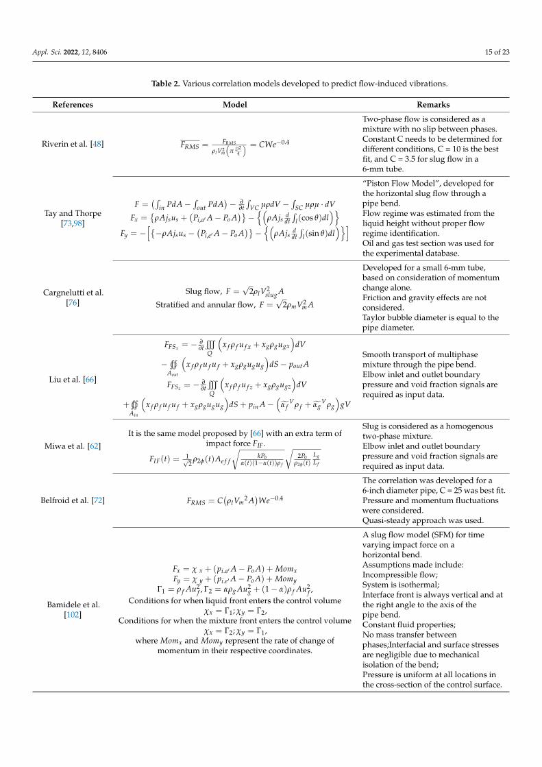
Tables 1 and 2 summarize the existing database on FIV and the correlations developedto predict FIV in multiphase flow. The focus of past literature is on determining themagnitude of fluctuating force and force spectrum for different geometries and variousflow regimes. Major existing works on FIV due to two-phase flow along with their operatingconditions and limitations are listed in Table 1. The correlations developed over time byvarious researchers are listed in Table 2. These correlations were developed for differentfluids, void fractions, pressure conditions, and geometries. The assumptions made toderive each of these equations are also listed for better understanding.

Appl. Sci. 2022, 12, 8406 14 of 23
Table 1. Summary of existing database on flow-induced vibrations.
Ref. Geometry Diametermm Bend Radius Operating
PhasesFlow Regime Flow
Direction
SuperficialVelocity
Gas
SuperficialVelocity
Water
Measured ExperimentalResults
Simulation CorrelationFormulaForce
MagnitudeFrequencySpectrum
[73,98] 90◦ 70 1.5 D
A-WA-5 wt% IPA
A-35 wt%glycerol
Slug Horizontal 0.38–2.87 m/s 0.2–0.7 m/s Yes No No Yes
[48,63]T-JointU-Bend
90◦20.6 R/d = (0.5, 2, 5,
and 7.2) A-W Slug-Bubbly-Churn-Annular Vertical 0.1–10.4 L/s 0.17–1.25 L/s Yes Yes No Yes
[76,77]T-Junction
T-Joint90◦ Bend
625.4
16.5 and 25 mmUnknown A-W Slug-Annular
-Stratified Horizontal 0.1–30 m/s 0.05–2 m/s Yes No No Yes
[66] 90◦ Bend 52.5 1.5 D A-W Bubbly-Slug-Churn-Annular Vertical 0.1–18 m/s 0.610–2.310
m/s Yes Yes No Yes
[64,99] U-Bend
12152052
4 D A-WBubbly-Churn-Slug-Annular
-DispersedVertical 0.1–30 m/s 0.7–9 m/s Yes Yes No No
[100] 90◦ Bend 50.8 1.5 D A-W Bubbly-Slug-Churn-Annular Vertical 0.1–18 m/s 0.610–2.310
m/s Yes Yes No Yes
[72] 90◦ BendU-Bend 152.4 1.5 D A-W
Stratified-Bubbly-Slug-
Annular-Dispersed
Horizonal 1–45 m/s 0.004–4 m/s Yes Yes Yes Yes
[60] 90◦ Bend 152.4 1.5 D A-W Stratified-Slug-Annular Horizontal - - No No Yes No
[65] 90◦ Bend 52.5 1.5 D A-W Slug-Churn Vertical 0.5–9.04 m/s 0.642–5 m/s No No Yes No
[71] 90◦ Bend52.5
101.6203.2
1.5 D1.5 D1.5 D
A-W Slug-Churn Vertical 0.5–9.04 m/s 0.642–5 m/s No No Yes No
[101] 90◦ Bend 78 Unknown A-W Slug Horizontal 0.025–0.0495 Kg/s 2.48–4.97 Kg/s No No Yes No[57] U-Bend 6.9 1.5 D A-W Stratified-Slug Vertical - - No No Yes No
[59] 90◦ Bend 52.5 1.5 D A-W Bubbly-Slug-Churn Vertical 0.86–3.44 m/s 0.86–2.12 m/s No No Yes No
[102] U-Bend 25.4 0.4 D A-WBubbly-slug-
wavy-annulardispersed
0.01–1.7 m/s 0.46–1.3 m/s Yes Yes No Yes
Appl. Sci. 2022, 12, 8406 15 of 23
Table 2. Various correlation models developed to predict flow-induced vibrations.
References Model Remarks
Riverin et al. [48] FRMS = FRMS
ρlV2m
(π D2
4
) = CWe−0.4
Two-phase flow is considered as amixture with no slip between phases.Constant C needs to be determined fordifferent conditions, C = 10 is the bestfit, and C = 3.5 for slug flow in a6-mm tube.
Tay and Thorpe[73,98]
F =(∫
in PdA−∫
out PdA)− ∂
∂t∫
VC µρdV −∫
SC µρµ · dV
Fx ={
ρAjsus +(
Pi,a′A− Po A)}−{(
ρAjs ddt∫
l(cos θ)dl)}
Fy = −[{−ρAjsus −
(Pi,e′A− Po A
)}−{(
ρAjs ddt∫
l(sin θ)dl)}]
“Piston Flow Model”, developed forthe horizontal slug flow through apipe bend.Flow regime was estimated from theliquid height without proper flowregime identification.Oil and gas test section was used forthe experimental database.
Cargnelutti et al.[76]
Slug flow, F =√
2ρlV2slug A
Stratified and annular flow, F =√
2ρmV2m A
Developed for a small 6-mm tube,based on consideration of momentumchange alone.Friction and gravity effects are notconsidered.Taylor bubble diameter is equal to thepipe diameter.
Liu et al. [66]
FFSx = − ∂∂tt
Q
(x f ρ f u f x + xgρgugx
)dV
−v
Aout
(x f ρ f u f u f + xgρgugug
)dS− pout A
FFSz = −∂∂tt
Q
(x f ρ f u f z + xgρgugz
)dV
+v
Ain
(x f ρ f u f u f + xgρgugug
)dS + pin A−
(α̃ f
Vρ f + α̃gVρg
)gV
Smooth transport of multiphasemixture through the pipe bend.Elbow inlet and outlet boundarypressure and void fraction signals arerequired as input data.
Miwa et al. [62]
It is the same model proposed by [66] with an extra term ofimpact force FIF.
FIF(t) = 1√2
ρ2φ(t)Ae f f
√kP0
α(t)(1−α(t))ρ f
√2P0
ρ2φ(t)LgL f
Slug is considered as a homogenoustwo-phase mixture.Elbow inlet and outlet boundarypressure and void fraction signals arerequired as input data.
Belfroid et al. [72] FRMS = C(ρlVm
2 A)We−0.4
The correlation was developed for a6-inch diameter pipe, C = 25 was best fit.Pressure and momentum fluctuationswere considered.Quasi-steady approach was used.
Bamidele et al.[102]
Fx = χ x + (pi.a′A− Po A) + MomxFy = χ y + (pi.e′A− Po A) + Momy
Γ1 = ρ f Au2f , Γ2 = αρg Au2
g + (1− α)ρ f Au2f ,
Conditions for when liquid front enters the control volumeχx = Γ1; χy = Γ2,
Conditions for when the mixture front enters the control volumeχx = Γ2; χy = Γ1,
where Momx and Momy represent the rate of change ofmomentum in their respective coordinates.
A slug flow model (SFM) for timevarying impact force on ahorizontal bend.Assumptions made include:Incompressible flow;System is isothermal;Interface front is always vertical and atthe right angle to the axis of thepipe bend.Constant fluid properties;No mass transfer betweenphases;Interfacial and surface stressesare negligible due to mechanicalisolation of the bend;Pressure is uniform at all locations inthe cross-section of the control surface.

Appl. Sci. 2022, 12, 8406 16 of 23
5. Comparison of Dimensionless Forces
Riverin et al. [48] proposed an empirical correlation for dimensionless forces as shownin Equation (13). This correlation was based on experimental data for 20 mm internaldiameter U-bends and tees, and appear to provide better results for void fraction valuesin the range of 55 to 98%. This correlation was developed on the base of model [72] forexternal cross flow. To develop this model, the Weber, Reynolds, and Froude numbers wereconsidered, as shown below:
FRMS =FRMS
ρlV2m
(π D2
4
) = CWe−0.4 (16)
The dashed line shown in Figure 6 is drawn using Equation (16) with C of 10. Thiswas proposed as a reasonable approximation of dimensionless forces. The dash dotted lineshown in Figure 6 is drawn using C of 3.5 using Equation (16) and it is the best fit curve forslug flow regime. Giraudeau et al. [99] proposed that to be conservative, an upper bound ofdimensionless forces should be defined and from their experiments on 12 to 52 mm internaldiameter U-bends, Cmax of 25 was proposed. This corresponds to the dotted line shownin Figure 6. The experimental results for 12 and 52 mm U-bends are included here, whichshows that Cmax = 25 is a good approximation for upper limit. The dimensionless forces due toslug flow from experiments conducted by Cargnelutti et al. [33,34], in 6 mm internal diameterhorizontal and vertical elbows for bend radii of 16.5 and 25 and the results for 25.4 mm(1 inch) internal diameter elbow, are also recorded in Figure 6. Notably, both horizontal andvertical elbows are subjected to the horizontal two-phase flow in these experiments. Theoverall forces on vertical elbow are higher than the horizontal elbow, which was thoughtto be due to gravity. Notably, forces in vertical elbow are also higher than the maximumlimit introduced by Giraudeau et al. [69] at C of 25. The forces due to the 16.5 bend radiusare lower than the 25 mm bend radius for the same diameter pipe, which shows that thebend radius affects the forces. Moreover, it can be observed that the forces in 25.4 mm(1 inch) pipe are higher than the 6 mm experiments. This behavior was unusual, consideringthat the 25.4 mm (1 inch) experiments contained more gas than the 6 mm experiments.Cargnelutti et al. [76] reported that this can also be due to the difference of stiffness ofmaterial used (glass vs. perspex). Overall, the results of Cargnelutti experiments showhigher forces than the Revirin experiments and results for 25.4 mm bend are higher thanC = 10 line. Experimental results for 20 mm internal diameter tee [42], for elbow with 70 mmdiameter under the horizontal flow [98], and for 6 to 25 mm diameter vertical U-tubes [8],are also reported. All these results are in agreement with Riverin et al. [48] approximationat C of 10. Results [66] for 52.5 mm vertical elbow are also presented and these resultsare spread over a wide range from C of 3.51 to 25 lines. This can be attributed to the factthat 0 to 100% void fraction was considered, covering a wide range of flow conditions.The simulation results of Hossain et al. [65] for vertical elbow of 52.5 mm diameter arepresented and they mostly lie between C of 10 and 25 lines. Figure 6 can serve as a databasefor comparison and can also be used to validate the simulation results.

Appl. Sci. 2022, 12, 8406 17 of 23Appl. Sci. 2022, 12, x FOR PEER REVIEW 18 of 24
Figure 6. Comparison of dimensionless forces plotted against the Weber number [8,48,63–66,73,76,77].
6. Conclusions In conclusion, this review article briefly introduces the background of flow-induced
vibrations and its classification, followed by an in-depth review of FIV in internal two-phase flow. It is evident from the literature that for a successful investigation of FIV, the vibration of experimental flow loop should be diminished, and the natural frequency of experimental structure must be determined to avoid resonance. In addition, while evalu-ating the natural frequency of pipe structure, the effect of added mass due to the two-phase flow should not be ignored. It should also be noted that eliminating the risk of res-onance does not remove the risk of fatigue failure or excessive stress and stress calcula-tions should be performed in detail.
Flow-induced vibration phenomenon is flow regime dependent and most of the lit-erature agree that forces due to slug and churn flow regimes are more intense. The effect of flow regimes should be explored further, particularly annular flow regime, which has received the least attention by researchers. Moreover, for analysis of FIV in multiphase flow, researchers are still utilizing flow regime maps developed in the 1970s and 1980s. Furthermore, additional advanced approaches are needed, such as machine learning al-gorithms or flow regimes maps developed for specific experimental conditions and ge-ometries.
Geometry is considered as the major factor while considering FIV in multiphase flow. As suggested by Schlegel et al. [68], flow behavior in small and large diameter pipes is different. It can be concluded from the literature that the physical mechanism of phase distribution would be different in small and large diameter pipes and between vertical and horizontal flows. Therefore, it would be inappropriate to derive conclusions regard-ing FIV behavior in large pipes based on conclusions derived for small pipes and vice
Figure 6. Comparison of dimensionless forces plotted against the Weber number [8,48,63–66,73,76,77].
6. Conclusions
In conclusion, this review article briefly introduces the background of flow-inducedvibrations and its classification, followed by an in-depth review of FIV in internal two-phaseflow. It is evident from the literature that for a successful investigation of FIV, the vibrationof experimental flow loop should be diminished, and the natural frequency of experimentalstructure must be determined to avoid resonance. In addition, while evaluating the naturalfrequency of pipe structure, the effect of added mass due to the two-phase flow should notbe ignored. It should also be noted that eliminating the risk of resonance does not removethe risk of fatigue failure or excessive stress and stress calculations should be performedin detail.
Flow-induced vibration phenomenon is flow regime dependent and most of the lit-erature agree that forces due to slug and churn flow regimes are more intense. The effectof flow regimes should be explored further, particularly annular flow regime, which hasreceived the least attention by researchers. Moreover, for analysis of FIV in multiphase flow,researchers are still utilizing flow regime maps developed in the 1970s and 1980s. Further-more, additional advanced approaches are needed, such as machine learning algorithms orflow regimes maps developed for specific experimental conditions and geometries.
Geometry is considered as the major factor while considering FIV in multiphase flow.As suggested by Schlegel et al. [68], flow behavior in small and large diameter pipes isdifferent. It can be concluded from the literature that the physical mechanism of phasedistribution would be different in small and large diameter pipes and between verticaland horizontal flows. Therefore, it would be inappropriate to derive conclusions regardingFIV behavior in large pipes based on conclusions derived for small pipes and vice versa.In addition, this remark is true when comparing horizontal and vertical two-phase flows.

Appl. Sci. 2022, 12, 8406 18 of 23
As an example, Nennie et al. [103] concluded that the effect of void fraction on FIV is thesame for different diameter pipes. However, the authors’ observations were based on smalldiameter pipes and may not hold true for large diameter pipes with bend in a verticallyupward orientation.
Several predictive models are available in literature to predict dominant frequencyand magnitude of forces due to the two-phase flow. For example, the model of Liu et al. [66]and Miwa et al. [62] can predict the magnitude and dominant frequency of forces withan average error of 30%. This model with its relatively high margin of error also needsvoid fraction data as an input from experiments to determine force. Therefore, to use thismodel to solve problems, experiments must be conducted to extract void fraction data, forspecific geometry and flow conditions. The correlation by Riverin et al. [48] can also beused to calculate RMS of force fluctuations. It is recommended for void fraction value of55% to 98% and the error margin reported is 50%. An important point to note here is thatthese models were developed for small diameter pipes only and the error and limitationscan further increase if an attempt is made to predict for large diameter pipes. An attemptwas made [72] to fit the RMS of force fluctuations for large diameter pipe (6 inch) andthe prediction was further outside the original 50% error. This suggests that FIV in largediameter pipe needs to be investigated, considering there is a negligible database of FIV onlarge diameter pipes.
Due to the inherent complexities in interface and turbulent behavior of two-phaseflow, in the past, CFD was not preferred as a tool to investigate FIV in multiphase flow.Recently, it is gaining more recognition and some previously mentioned researchers haveimplemented and validated their CFD results [60,65], against experimental results, toincorporate more confidence in the use of CFD for research.
7. Future Research Prospects and Challenges
The following recommendations are made to overcome the challenges in internaltwo-phase FIV research.
• Predictive models used to estimate FIV have many limitations, such as high marginof error, developed for a specific range of parameters and, in some cases, requireexperiments to collect input data for models. A study should be conducted to improvepredictive models.
• Flow-induced vibrations due to multiphase flow is a flow regime dependent phe-nomenon. Among two-phase flow regimes, the annular flow regime needs to beexplored further.
• Flow regime maps developed in the 1970s and 1980s should be replaced and newapproaches should be developed.
• Research on large diameter pipes is limited and research is encouraged to widenthe database.
• The effect of physical parameter, such as surface tension, viscosity, and gravity shouldbe explored further to develop better understanding. In addition, predictive modelsshould consider physical parameters and its effect on overall model performance.
• The effect of added mass due to two-phase flow on the natural frequency of systemneeds more attention.
• Developing better CFD models to study FIV. Additional comparisons of CFD andexperimental results are encouraged to provide confidence to CFD users for studyingmultiphase FIV.
Author Contributions: Conceptualization, U.K., W.P.; writing—original draft preparation, U.K.;writing—review and editing, W.P. and N.S.; data collection, U.K.; formal analysis, U.K.; visualization,U.K.; supervision, W.P. and N.S.; data analysis, U.K. and W.P.; methodology, U.K.; project adminis-tration, U.K. and W.P.; funding acquisition W.P. and N.S. All authors have read and agreed to thepublished version of the manuscript.
Appl. Sci. 2022, 12, 8406 19 of 23
Funding: The first and second author wish to specially acknowledge the funding for this study fromMalaysia Ministry of Higher Education through Fundamental Research Grant Scheme FRGS/1/2019/TK03/UTP/02/10. All the researchers wish to thank Yayasan Universiti Teknologi PETRONAS underYUTP-15LC0-456 and YUTP-015LC0-237 for supplementary funding.
Institutional Review Board Statement: Not applicable.
Data Availability Statement: The authors declare that all data can be obtained from the correspond-ing author upon request.
Conflicts of Interest: The authors declare no conflict of interest.
Nomenclature
A Area (m2)D Diameter (m)F Force (N)f frequency (Hz)f Dimensionless frequencyG Gravitational acceleration (m/s2)P Pressure (Pa)t Time (s)V Fluid Velocity (m/s)Ag Area occupied by gas phase (m)Al Area occupied by liquid phase (m)VM Mixture Velocity (m/s)Vsg Superficial Velocity of gas(m/s)Vsl Superficial Velocity of liquid (m/s)We Weber numberRe Reynolds numberFr Froude numberβ Void fractionµ dynamic viscosity (Pa s)σ Surface tension (N/m)ρl Liquid phase density (kg/m3)ρg Gas phase density (kg/m3)Subscriptsg Gas Phasel Liquid PhaseRMS Root Mean Squarem Liquid-Gas Mixturesg Superficial Gassl Superficial Liquid
References1. Triplett, K.A.; Ghiaasiaan, S.M.; Abdel-Khalik, S.I.; Sadowski, D.L. Gas–Liquid Two-Phase Flow in Microchannels Part I:
Two-Phase Flow Patterns. Int. J. Multiph. Flow 1999, 25, 377–394. [CrossRef]2. Brauner, N. Liquid-liquid two-phase flow systems. In Modelling and Experimentation in Two-Phase Flow; Springer: Berlin/Heidelberg,
Germany, 2003; pp. 221–279. [CrossRef]3. Ibarra, R.; Markides, C.N.; Matar, O.K. A Review of Liquid-Liquid Flow Patterns in Horizontal and Slightly Inclined Pipes.
Multiph. Sci. Technol. 2014, 26, 171–198. [CrossRef]4. Wang, W.; Li, J. Simulation of Gas–Solid Two-Phase Flow by a Multi-Scale CFD Approach—Of the EMMS Model to the Sub-Grid
Level. Chem. Eng. Sci. 2007, 62, 208–231. [CrossRef]5. Fu, F.F.; Li, J. Gas–Solid Two-Phase Flow Pattern Identification Based on Artificial Neural Network and Electrostatic Sensor Array.
Sensors 2018, 18, 3522. [CrossRef]6. Peker, S.M.; Helvaci, S.S. Solid-Liquid Two Phase Flow; Elsevier: Amsterdam, The Netherlands, 2008; p. 515.7. Nirmala, G.S.; Muruganandam, L. An Experimental Study of Liquid-Solid Flow in a Circulating Fluidized Bed of Varying Liquid
Viscosity. J. Appl. Fluid Mech. 2014, 8, 95–101. [CrossRef]8. Yih, T.; Griffith, P. Unsteady Momentum Fluxes in Two-Phase Flow and the Vibration of Nuclear Reactor Components; Massachusetts
Institute of Technology: Cambridge, MA, USA, 1968.
Appl. Sci. 2022, 12, 8406 20 of 23
9. Ruspini, L.C.; Marcel, C.P.; Clausse, A. Two-Phase Flow Instabilities: A Review. Int. J. Heat Mass Transf. 2014, 71, 521–548.[CrossRef]
10. Dang, Z.; Yang, Z.; Yang, X.; Ishii, M. Experimental Study of Vertical and Horizontal Two-Phase Pipe Flow through Double 90Degree Elbows. Int. J. Heat Mass Transf. 2018, 120, 861–869. [CrossRef]
11. O’neill, L.E.; Mudawar, I. Review of Two-Phase Flow Instabilities in Macro-and Micro-Channel Systems. Int. J. Heat Mass Transf.2020, 157, 119738. [CrossRef]
12. Naudascher, N. Flow-Induced Structural Vibrations; Springer: Berlin/Heidelberg, Germany, 1972.13. Naudascher, E.; Rockwell, D. Practical Experiences with Flow-Induced Vibrations; Springer: Berlin/Heidelberg, Germany, 1979.14. Blevins, R.D. Flow-Induced Vibration; Van Nostrand Reinhold Co.: New York, NY, USA, 1977; ISBN 9780442208288.15. Blevins, R.D. Flow-Induced Vibration, 2nd ed.; Van Nostrand Reinhold Co.: New York, NY, USA, 1990; ISBN 9780442206512.16. Kaneko, S.; Nakamura, T.; Inada, F.; Kato, M.; Ishihara, K.; Nishihara, T.; Mureithi, N.W.; Langthje, M.A. Flow-Induced Vibrations:
Classifications and Lessons from Practical Experiences, 2nd, ed.; Butterworth-Heinemann: Oxford, UK, 2013; ISBN 9780080983479.17. Zhang, H.; Liu, M.K.; Fan, B.C.; Chen, Z.H.; Li, J.; Gui, M.Y. Investigations on the Effects of Vortex-Induced Vibration with
Different Distributions of Lorentz Forces. Appl. Sci. 2017, 7, 61. [CrossRef]18. Kang, H.S.; Song, K.N.; Kim, H.K.; Yoon, K.H. Axial-Flow-Induced Vibration for a Rod Supported by Translational Springs at
Both Ends. Nucl. Eng. Des. 2003, 220, 83–90. [CrossRef]19. Lee, H.B.; Lee, T.R.; Chang, Y.S. Numerical Simulation of Flow-Induced Bi-Directional Oscillations. J. Fluids Struct. 2013, 37,
220–231. [CrossRef]20. Shiels, D.; Leonard, A.; Roshko, A. Flow-Induced Vibration of a Circular Cylinder at Limiting Structural Parameters. J. Fluids
Struct. 2001, 15, 3–21. [CrossRef]21. Ali, U.; Islam, M.; Janajreh, I.; Fatt, Y.; Alam, M.M. Flow-Induced Vibrations of Single and Multiple Heated Circular Cylinders: A
Review. Energies 2021, 14, 8496. [CrossRef]22. Quinn, E. Vibration of Fuel Rods in Parallel Flow; U.S. Atomic Energy Commission, Division of Technical Information: Oak Ridge,
TN, USA, 1962.23. Morita, R.; Takahashi, S.; Okuyama, K.; Inada, F.; Ogawa, Y.; Yoshiikawa, K. Evaluation of Acoustic- and Flow-Induced Vibration
of the BWR Main Steam Lines and Dryer. J. Nucl. Sci. Technol. 2011, 48, 759–776. [CrossRef]24. Pettigrew, M.J.; Taylor, C.E.; Kim, B.S. The Effects of Bundle Geometry on Heat Exchanger Tube Vibration in Two-Phase Cross
Flow. J. Press. Vessel Technol. Trans. ASME 2001, 123, 414–420. [CrossRef]25. Pettigrew, M.J.; Knowles, G.D. Some Aspects of Heat-Exchanger Tube Damping in Two-Phase Mixtures. J. Fluids Struct. 1997, 11,
929–945. [CrossRef]26. Wang, J.S.; Fan, D.; Lin, K. A Review on Flow-Induced Vibration of Offshore Circular Cylinders. J. Hydrodyn. 2020, 32, 415–440.
[CrossRef]27. Paidoussis, M.P. Vibration of Cylindrical Structures Induced by Axial Flow. J. Eng. Ind. 1974, 96, 547–552. [CrossRef]28. Pettigrew, M.J.; Taylor, C.E. Two-Phase Flow-Induced Vibration: An Overview (Survey Paper). J. Press. Vessel Technol. 1994, 116,
233–253. [CrossRef]29. Gorman An Analytical and Experimental Investigation of the Vibration of Cylindrical Reactor Fuel Elements in Two-Phase
Parallel Flow. Nucl. Sci. Eng. 1971, 44, 277–290. [CrossRef]30. Pettigrew, M.J.; Gorman, D.J. Experimental Studies on Flow Induced Vibration to Support Steam Generator Design, Part 1: Vibration of a
Heated Cylinder in Two-Phase Axial Flow; Atomic Energy of Canada Limited: Laurentian Hills, ON, Canada, 1973.31. Carlucci, L.N.; Brown, J.D. Experimental Studies of Damping and Hydrodynamic Mass of a Cylinder in Confined Two-Phase
Flow. J. Vib. Acoust. Stress Reliab. Des. 1983, 105, 83–89. [CrossRef]32. Carlucci, L.N. Damping and Hydrodynamic Mass of a Cylinder in Simulated Two-Phase Flow. J. Mech. Des. 1980, 102, 597–602.
[CrossRef]33. Khushnood, S.; Khan, Z.M.; Malik, M.A.; Koreshi, Z.U.; Khan, M.A. A Review of Heat Exchanger Tube Bundle Vibrations in
Two-Phase Cross-Flow. Nucl. Eng. Des. 2004, 230, 233–251. [CrossRef]34. Mitra, D.; Dhir, V.K.; Catton, I. Fluid-Elastic Instability in Tube Arrays Subjected to Air-Water and Steam-Water Cross-Flow.
J. Fluids Struct. 2009, 25, 1213–1235. [CrossRef]35. Nakamura, T.; Fujita, K.; Kawanishi, K.; Yamaguchi, N.; Tsuge, A. Study on the Vibrational Characteristics of a Tube Array
Caused by Two-Phase Flow—Part 1: Random Vibration. J. Press. Vessel Technol. 1992, 114, 472–478. [CrossRef]36. Sasakawa, T.; Serizawa, A.; Kawara, Z. Fluid-Elastic Vibration in Two-Phase Cross Flow. Exp. Therm. Fluid Sci. 2005, 29, 403–413.
[CrossRef]37. Zhang, C.; Pettigrew, M.J.; Mureithi, N.W. Vibration Excitation Force Measurements in a Rotated Triangular Tube Bundle
Subjected to Two-Phase Cross Flow. J. Press. Vessel Technol. 2007, 129, 21–27. [CrossRef]38. Wang, Z.; Fan, D.; Triantafyllou, M.S. Illuminating the Complex Role of the Added Mass during Vortex Induced Vibration. Phys.
Fluids 2021, 33, 085120. [CrossRef]39. Pettigrew, M.J.; Taylor, C.E.; Fisher, N.J.; Yetisir, M.; Smith, B.A.W. Flow-Induced Vibration: Recent Findings and Open Questions.
Nucl. Eng. Des. 1998, 185, 249–276. [CrossRef]40. Konstantinidis, E. Cross-Flow-Induced Vibration of an Elastic Plate. Fluids 2021, 6, 82. [CrossRef]

Appl. Sci. 2022, 12, 8406 21 of 23
41. Garg, H.; Soti, A.K.; Bhardwaj, R. Vortex-Induced Vibration and Galloping of a Circular Cylinder in Presence of Cross-FlowThermal Buoyancy. Phys. Fluids 2019, 31, 113603. [CrossRef]
42. Chen, W.; Ji, C.; Williams, J.; Xu, D.; Yang, L.; Cui, Y. Vortex-Induced Vibrations of Three Tandem Cylinders in Laminar Cross-Flow:Vibration Response and Galloping Mechanism. J. Fluids Struct. 2018, 78, 215–238. [CrossRef]
43. Sawadogo, T.; Mureithi, N. Time Domain Simulation of the Vibration of a Steam Generator Tube Subjected to Fluidelastic ForcesInduced by Two-Phase Cross-Flow. J. Press. Vessel Technol. Trans. ASME 2013, 135, 030905. [CrossRef]
44. Sadek, O.; Mohany, A.; Hassan, M. Numerical Investigation of the Cross Flow Fluidelastic Forces of Two-Phase Flow in TubeBundle. J. Fluids Struct. 2018, 79, 171–186. [CrossRef]
45. Chen, S.S. Out-of-Plane Vibration and Stability of Curved Tubes Conveying Fluid. J. Appl. Mech. 1973, 40, 362–368. [CrossRef]46. Crawford, N.M.; Cunningham, G.; Spence, S.W.T. An Experimental Investigation into the Pressure Drop for Turbulent Flow in
90◦ Elbow Bends. Proc. Inst. Mech. Eng. Part E J. Process. Mech. Eng. 2007, 221, 77–88. [CrossRef]47. Weaver, D.S.; Ziada, S.; Au-Yang, M.K.; Chen, S.S.; Païdoussis, M.P.; Pettigrew, M.J. Flow-Induced Vibrations in Power and
Process Plant Components—Progress and Prospects. J. Press. Vessel Technol. Trans. ASME 2000, 122, 339–348. [CrossRef]48. Riverin, J.L.; de Langre, E.; Pettigrew, M.J. Fluctuating Forces Caused by Internal Two-Phase Flow on Bends and Tees. J. Sound
Vib. 2006, 298, 1088–1098. [CrossRef]49. Bamidele, O.E.; Ahmed, W.H.; Hassan, M. Flow Induced Vibration of Separated Two-Phase Flow Due to Restricting Orifice. Int.
Conf. Fluid Flow Heat Mass Transf. 2019, 38, 1–10. [CrossRef]50. Wang, S.; Shoji, M. Fluctuation Characteristics of Two-Phase Flow Splitting at a Vertical Impacting T-Junction. Int. J. Multiph. Flow
2002, 28, 2007–2016. [CrossRef]51. Zhu, H.; Gao, Y.; Zhao, H. Experimental Investigation on the Flow-Induced Vibration of a Free-Hanging Flexible Riser by Internal
Unstable Hydrodynamic Slug Flow. Ocean Eng. 2018, 164, 488–507. [CrossRef]52. Ali, F.; Bilal, M.; Sheikh, N.A.; Khan, I.; Nisar, K.S. Two-Phase Fluctuating Flow of Dusty Viscoelastic Fluid between Non-
Conducting Rigid Plates with Heat Transfer. IEEE Access 2019, 7, 123299–123306. [CrossRef]53. Emmerson, P.; Lewis, M.; Barton, N. Improving Boundary Conditions For Multiphase CFD Predictions of Slug Flow Induced
Forces. In Proceedings of the 17th International Conference on Multiphase Production Technology, Cannes, France, 10–12June 2015.
54. Araújo, J.D.P.; Miranda, J.M.; Campos, J.B.L.M. CFD Study of the Hydrodynamics of Slug Flow Systems: Interaction betweenConsecutive Taylor Bubbles. Int. J. Chem. React. Eng. 2014, 13, 541–549. [CrossRef]
55. Ban, S.; Pao, W.; Nasif, M.S. Numerical Simulation of Two-Phase Flow Regime in Horizontal Pipeline and Its Validation. Int. J.Numer. Methods Heat Fluid Flow 2018, 28, 1279–1314. [CrossRef]
56. Nichita, B.A.; Zun, I. A Volume of Fluid Method for Modeling of Gas-Liquid Interface. J. Fluids Eng. 2015, 132, 081302. [CrossRef]57. De Moerloose, L.; Degroote, J. A Study of the Vibration of a Horizontal U-Bend Subjected to an Internal Upwards Flowing
Air–Water Mixture. J. Fluids Struct. 2020, 93, 102883. [CrossRef]58. Mohmmed, A.O.; Al-Kayiem, H.H.; Osman, A.B.; Sabir, O. One-Way Coupled Fluid–Structure Interaction of Gas–Liquid Slug
Flow in a Horizontal Pipe: Experiments and Simulations. J. Fluids Struct. 2020, 97, 103083. [CrossRef]59. Wang, Z.; He, Y.P.; Li, M.Z.; Qiu, M.; Huang, C.; Liu, Y.D.; Wang, Z. Fluid—Structure Interaction of Two-Phase Flow Passing
Through 90◦ Pipe Bend Under Slug Pattern Conditions. China Ocean Eng. 2021, 35, 914–923. [CrossRef]60. Mack, A.; Joshi, H.; Belfroid, S. Numerical Rebuilding of Dynamic Instabilities and Forces in Multiphase Pipe Bend Flow. Int. J.
Comput. Methods Exp. Meas. 2018, 6, 358–372. [CrossRef]61. Liang, Z.; Guo, C.; Wang, C. The Connection between Flow Pattern Evolution and Vibration in 90-Degree Pipeline: Bidirectional
Fluid-Structure Interaction. Energy Sci. Eng. 2022, 10, 308–323. [CrossRef]62. Miwa, S.; Mori, M.; Hibiki, T. Two-Phase Flow Induced Vibration in Piping Systems. Prog. Nucl. Energy 2015, 78, 270–284.
[CrossRef]63. Riverin, J.L.; Pettigrew, M.J. Vibration Excitation Forces Due to Two-Phase Flow in Piping Elements. J. Press. Vessel Technol. Trans.
ASME 2007, 129, 7–13. [CrossRef]64. Giraudeau, M.; Mureithi, N.W.; Pettigrew, M.J. Two-Phase Flow-Induced Forces on Piping in Vertical Upward Flow: Excitation
Mechanisms and Correlation Models. J. Press. Vessel Technol. Trans. ASME 2013, 135, 1–16. [CrossRef]65. Hossain, M.; Chinenye-Kanu, N.M.; Droubi, G.M.; Islam, S.Z. Investigation of Slug-Churn Flow Induced Transient Excitation
Forces at Pipe Bend. J. Fluids Struct. 2019, 91, 102733. [CrossRef]66. Liu, Y.; Miwa, S.; Hibiki, T.; Ishii, M.; Morita, H.; Kondoh, Y.; Tanimoto, K. Experimental Study of Internal Two-Phase Flow
Induced Fluctuating Force on a 90◦ Elbow. Chem. Eng. Sci. 2012, 76, 173–187. [CrossRef]67. Wang, L.; Yang, Y.; Li, Y.; Wang, Y. Dynamic Behaviours of Horizontal Gas-Liquid Pipes Subjected to Hydrodynamic Slug Flow:
Modelling and Experiments. Int. J. Press. Vessel. Pip. 2018, 161, 50–57. [CrossRef]68. Schlegel, J.P.; Miwa, S.; Chen, S.; Hibiki, T.; Ishii, M. Experimental Study of Two-Phase Flow Structure in Large Diameter Pipes.
Exp. Therm. Fluid Sci. 2012, 41, 12–22. [CrossRef]69. Kaichiro, M.; Ishii, M. Flow Regime Transition Criteria for Upward Two-Phase Flow in Vertical Tubes. Int. J. Heat Mass Transf.
1984, 27, 723–737. [CrossRef]70. Chinenye-Kanu, N.M.; Hossain, M.; Droubi, M.G.; Islam, S.Z. Numerical Investigation of Two-Phase Flow Induced Local
Fluctuations and Interactions of Flow Properties through Elbow. Lect. Notes Mech. Eng. 2019, 2019, 124–141. [CrossRef]

Appl. Sci. 2022, 12, 8406 22 of 23
71. Asiegbu, N.M.; Hossain, M.; Droubi, G.M.; Islam, S.Z. Investigation of the Effects of Pipe Diameter of Internal Multiphase Flow onPipe Elbow Vibration and Resonance. Proc. Inst. Mech. Eng. Part E J. Process. Mech. Eng. 2022, 2022, 095440892211155. [CrossRef]
72. Belfroid, S.P.; Nennie, E.; Lewis, M. Multiphase Forces on Bends—Large Scale 6” Experiments. In Proceedings of the SPE AnnualTechnical Conference and Exhibition, Dubai, United Arab Emirates, 26–28 September 2016.
73. Tay, B.L.; Thorpe, R.B. Effects of Liquid Physical Properties on the Forces Acting on a Pipe Bend in Gas-Liquid Slug Flow. Chem.Eng. Res. Des. 2004, 82, 344–356. [CrossRef]
74. Nennie, E.D.; Belfroid, S.P.C.; van Bokhorst, E.; Remans, D. Multiphase Fluid Structure Interaction in Pipe Systems with MultipleBends. In Proceedings of the 10th International Conference on Flow-Induced Vibration, Dublin, Ireland, 3–6 July 2012; TNOPublications: The Hague, The Netherlands.
75. Belfroid, S.P.C.; Cargnelutti, M.F.; Schiferli, W.; Van Osch, M. Forces on Bends and T-Joints Due to Multiphase Flow. Am. Soc.Mech. Eng. Fluids Eng. Div. FEDSM 2010, 3, 613–619. [CrossRef]
76. Cargnelutti, M.F.; Belfroid, S.P.C.; Schiferli, W.; Van Osch, M. Two-Phase Flow-Induced Forces on Bends in Small Scale Tubes.J. Press. Vessel. Technol. 2009, 132, 1–9.
77. Cargnelutti, M.F.; Belfroid, S.P.C.; Schiferli, W.; Van Osch, M. Multiphase Fluid Structure Interaction in Bends and T-Joints. InProceedings of the ASME 2010 Pressure Vessels and Piping Division/K-PVP Conference, Bellevue, DC, USA, 18–22 July 2016;pp. 1–8.
78. Kim, S.; Park, J.H.; Kojasoy, G.; Kelly, J.M.; Marshall, S.O. Geometric Effects of 90-Degree Elbow in the Development of InterfacialStructures in Horizontal Bubbly Flow. Nucl. Eng. Des. 2007, 237, 2105–2113. [CrossRef]
79. Yamano, H.; Tanaka, M.; Murakami, T.; Iwamoto, Y.; Yuki, K.; Sago, H.; Hayakawa, S. Unsteady Elbow Pipe Flow to Develop aFlow-Induced Vibration Evaluation Methodology for Japan Sodium-Cooled Fast Reactor. J. Nucl. Sci. Technol. 2011, 48, 677–687.[CrossRef]
80. Yamano, H.; Tanaka, M.A.; Kimura, N.; Ohshima, H.; Kamide, H.; Watanabe, O. Development of Flow-Induced VibrationEvaluation Methodology for Large-Diameter Piping with Elbow in Japan Sodium-Cooled Fast Reactor. Nucl. Eng. Des. 2011, 241,4464–4475. [CrossRef]
81. Taitel, Y.; Barnea, D.; Dukler, A.E. Modelling Flow Pattern Transitions for Steady Upward Gas-Liquid Flow in Vertical Tubes.AIChE J. 1980, 26, 345–354. [CrossRef]
82. Mandhane, J.M.; Gregory, G.A.; Aziz, K. A Flow Pattern Map for Gas—Liquid Flow in Horizontal Pipes. Int. J. Multiph. Flow1974, 1, 537–553. [CrossRef]
83. Jones, O.C.; Zuber, N. The Interrelation between Void Fraction Fluctuations and Flow Patterns in Two-Phase Flow. Int. J. Multiph.Flow 1975, 2, 273–306. [CrossRef]
84. Wang, H.X.; Zhang, L.F. Identification of Two-Phase Flow Regimes Based on Support Vector Machine and Electrical CapacitanceTomography. Meas. Sci. Technol. 2009, 20, 114007. [CrossRef]
85. Merilo, M.; Dechene, R.L.; Cichowlas, W.M. Void Fraction Measurement With a Rotating Electric Field Conductance Gauge.J. Heat Transfer 1977, 99, 330–332. [CrossRef]
86. Juliá, J.E.; Liu, Y.; Paranjape, S.; Ishii, M. Upward Vertical Two-Phase Flow Local Flow Regime Identification Using NeuralNetwork Techniques. Nucl. Eng. Des. 2008, 238, 156–169. [CrossRef]
87. Enoki, K.; Ono, M.; Okawa, T.; Kristiawan, B.; Wijayanta, A.T. Water Flow Boiling Heat Transfer in Vertical Minichannel. Exp.Therm. Fluid Sci. 2020, 117, 110147. [CrossRef]
88. Enoki, K.; Ono, M.; Okawa, T.; Akisawa, A.; Mori, H.; Kristiawan, B.; Wijayanta, A.T. Two-Phase Flow Regimes of RefrigerantR134a in an Oscillating Horizontal Rectangular Minichannel Conduit. Int. J. Refrig. 2020, 118, 261–268. [CrossRef]
89. Taitel, Y.; Dukler, A.E. A Model for Predicting Flow Regime Transitions in Horizontal and near Horizontal Gas-liquid Flow.AIChE J. 1976, 22, 47–55. [CrossRef]
90. De Langre, E.; Villard, B. An Upper Bound on Random Buffeting Forces Caused by Two-Phase Flows across Tubes. J. Fluids Struct.1998, 12, 1005–1023. [CrossRef]
91. Buckingham, E. On Physically Similar Systems; Illustrations of the Use of Dimensional Equations. Phys. Rev. 1914, 4, 345.[CrossRef]
92. Thome, J.R.; Cioncolini, A. Encyclopedia of Two-Phase Heat Transfer and Flow I; Chapter 4: Void Fraction; World Scientific: Singapore,2015; pp. 85–112. [CrossRef]
93. Park, J.W.; Drew, D.A.; Lahey, R.T. The Measurement of Void Waves in Bubbly Two-Phase Flows. Nucl. Eng. Des. 1994, 149, 37–52.[CrossRef]
94. Sun, B.; Yan, D.; Zhang, Z. The Instability of Void Fraction Waves in Vertical Gas-Liquid Two-Phase Flow. CNSNS 1999, 4, 181–186.[CrossRef]
95. Ghajar, A.J.; Bhagwat, S.M. Frontiers and Progress in Multiphase Flow I; Springer: Berlin/Heidelberg, Germany, 2014;ISBN 9783319043586.
96. Costigan, G.; Whalley, P.B. Slug Flow Regime Identification from Dynamic Void Fraction Measurements in Vertical Air-WaterFlows. Int. J. Multiph. Flow 1997, 23, 263–282. [CrossRef]
97. Al-Hash, Z.I.; Al-Kayi, H.H.; Hasan, F.; Mohmmedd, A. Effect of Various Fluid Densities on Vibration Characteristics in VariableCross-Section Pipes. J. Appl. Sci. 2014, 14, 2054–2060. [CrossRef]

Appl. Sci. 2022, 12, 8406 23 of 23
98. Tay, B.L.; Thorpe, R.B. Hydrodynamic Forces Acting on Pipe Bends in Gas-Liquid Slug Flow. Chem. Eng. Res. Des. 2014, 92,812–825. [CrossRef]
99. Giraudeau, M.; Mureithi, N.W.; Pettigrew, M.J. Two-Phase Flow Excitation Forces on a Vertical U-Bend Tube. In Proceedings ofthe ASME 2011 Pressure Vessels and Piping Conference, Baltimore, MD, USA, 17–21 July 2011; pp. 103–111.
100. Miwa, S.; Liu, Y.; Hibiki, T.; Ishii, M.; Kondo, Y.; Morita, H.; Tanimoto, K. Study of Unsteady Gas-Liquid Two-Phase Flow InducedForce Fluctuation (Part 2: Horizontal-Downward Two-Phase Flow). Trans. JSME 2014, 80, TEP0046. [CrossRef]
101. Gourma, M.; Verdin, P.G. Nature and Magnitude of Operating Forces in a Horizontal Bend Conveying Gas-Liquid Slug Flows.J. Pet. Sci. Eng. 2020, 190, 107062. [CrossRef]
102. Bamidele, O.E.; Ahmed, W.H.; Hassan, M. Characterizing Two-Phase Flow-Induced Vibration in Piping Structures with U-Bends.Int. J. Multiph. Flow 2022, 151, 104042. [CrossRef]
103. Nennie, E.; Belfroid, S.P.C.; O’Mahoney, T.S.D. Omae2013-10543 Validation of CFD and Simplified Models with ExperimentalData for Multiphase Flow in Bends. In International Conference on Offshore Mechanics and Arctic Engineering; American Society ofMechanical Engineers: New York, NY, USA, 2013; pp. 1–10.
Related Documents