2.0 Project Description Blythe Solar Power Project August 2009 FACT SHEET Project Name Blythe Solar Power Project (BSPP) General site location State County: location (SW corner of ROW) Description: California Riverside 33°37'55"N latitude, 114°45'45"W longitude Site is ~8 miles west of Blythe and 2 mi north of Interstate I-10 (I-10) at exit #232, Airport/Mesa Dr Nominal power output, per unit / total 250 MW / 1000 MW Number of units 4 Annual expected net electrical energy delivered to the grid per unit / total 525 GWh / 2,100 GWh Type of turbine exhaust steam condensing Air Cooled Condenser (dry cooling) Source of water onsite wells Construction water consumption Operational water consumption ~3,100 af (total) ~ 600 afy Primary energy source radiant solar energy Supplemental fuel natural gas (for quick startup and heat transfer fluid freeze protection only) source of supplemental fuel approximate tie-in location length 4" diameter pipeline 33°36'13"N latitude; 114°44’41”W longitude ~2 mi offsite Forecasted operating profile: quick start capability heat transfer fluid freeze protection for each power block: 8 MMBtu/hr overnight 34.4 MMBtu/hr for 1/2 hr each morning 35 MMBtu/hr ~50 hr/yr winter nights Project Right-of-Way (ROW) (total area leased from BLM) ~9,400 acres Disturbance area (total area within ROW disturbed by construction and operation, including ~ 1,100 acres outside facility footprint, mostly rerouted drainage channels) ~7,030 acres Facility footprint (total area within disturbance area that is inside security fencing encompassing all four units; excludes off-site linears {gen-tie transmission line and gas pipeline) ~ 5,950 acres Unit #1 (power block and solar field) – area ~ 1,600 acres Unit #2 (power block and solar field) – area ~ 1,600acres Unit #3 (power block and solar field) – area ~ 1,200acres Unit #4 (power block and solar field) – area ~ 1,200acres Gen-tie Transmission Line Tie-in ownership entity line name tie-in location line voltage length of gen-tie line Southern California Edison Devers-Palo Verde Colorado River Substation (~5 miles southwest of the Project site) 500 kV, Possible route: ~ 6.5 mi offsite

Welcome message from author
This document is posted to help you gain knowledge. Please leave a comment to let me know what you think about it! Share it to your friends and learn new things together.
Transcript
2.0 Project Description
Blythe Solar Power Project August 2009
FACT SHEET
Project Name Blythe Solar Power Project (BSPP)
General site location
StateCounty:
location (SW corner of ROW)Description:
California Riverside 33°37'55"N latitude, 114°45'45"W longitude Site is ~8 miles west of Blythe and 2 mi north of Interstate I-10 (I-10) at exit #232, Airport/Mesa Dr
Nominal power output, per unit / total 250 MW / 1000 MW
Number of units 4
Annual expected net electrical energy delivered to the grid per unit / total
525 GWh / 2,100 GWh
Type of turbine exhaust steam condensing Air Cooled Condenser (dry cooling)
Source of water onsite wells
Construction water consumption Operational water consumption
~3,100 af (total) ~ 600 afy
Primary energy source radiant solar energy
Supplemental fuel natural gas (for quick startup and heat transfer fluid freeze protection only)
source of supplemental fuelapproximate tie-in location
length
4" diameter pipeline 33°36'13"N latitude; 114°44’41”W longitude ~2 mi offsite
Forecasted operating profile:quick start capability
heat transfer fluid freeze protection
for each power block: 8 MMBtu/hr overnight 34.4 MMBtu/hr for 1/2 hr each morning 35 MMBtu/hr ~50 hr/yr winter nights
Project Right-of-Way (ROW) (total area leased from BLM) ~9,400 acres
Disturbance area (total area within ROW disturbed by construction and operation, including ~ 1,100 acres outside facility footprint, mostly rerouted drainage channels)
~7,030 acres
Facility footprint (total area within disturbance area that is inside security fencing encompassing all four units; excludes off-site linears {gen-tie transmission line and gas pipeline)
~ 5,950 acres
Unit #1 (power block and solar field) – area ~ 1,600 acres
Unit #2 (power block and solar field) – area ~ 1,600acres
Unit #3 (power block and solar field) – area ~ 1,200acres
Unit #4 (power block and solar field) – area ~ 1,200acres
Gen-tie Transmission Line Tie-in
ownership entityline name
tie-in location
line voltagelength of gen-tie line
Southern California Edison Devers-Palo Verde Colorado River Substation (~5 miles southwest of the Project site) 500 kV, Possible route: ~ 6.5 mi offsite
2.0 Project Description
Blythe Solar Power Project 2-1 August 2009
2.0 Project Description
2.1 Introduction and Overview
Solar Millennium LLC and Chevron Energy Solutions (as joint developers and referred to as the Applicants in this document) are proposing to construct a utility-scale thermal electric power generating facility, referred to as the Blythe Solar Power Project (BSPP or Project). The Project will have a nominal output of 1,000 megawatts (MW), consisting of four nearly identical and independent 250-MW units, Unit #1 through Unit #4. The BSPP will be located in the southern California inland desert, approximately eight miles west of the City of Blythe and two miles north of the Interstate-10 (I-10) freeway in Riverside County, California.
The Applicants have applied for a right-of-way (ROW) grant for approximately 9,400 acres of lands owned by the Federal government and managed by the Bureau of Land Management (BLM). Construction and operation of the PSPP will disturb a total of about 7,030 acres. This total includes areas outside the fence line of the Project facilities themselves, primarily rerouted drainage channels that avoid Project facilities but are designed to return the drainages to approximately their previous conditions downstream of the site. The Project facilities will occupy approximately 5,950 acres of land.
The BSPP will utilize solar parabolic trough technology to generate electricity. With this technology, arrays of parabolic mirrors collect heat energy from the sun and refocus the radiation on a receiver tube located at the focal point of the parabola. A synthetic hydrocarbon is used as a heat transfer fluid (HTF) that is heated to high temperatures (750 degrees F [°F]) as it is piped through the receiver tubes. The HTF is then piped through a series of heat exchangers where it releases stored heat to generate high-pressure steam. The steam is fed to a traditional steam turbine generator where electricity is produced.
Unit #1 will occupy the northeast portion of the Project site; Unit #2 the northwest portion; Unit #3 the southwest portion; and Unit #4 the southeast portion. Unit #1 and Unit #2 will provide nominal 500 MW of electrical power and will each occupy approximately 1,600 acres of land. Unit #3 and Unit #4 will also provide a nominal 500 MW of electrical power and each will occupy approximately 1,200 acres of land.
Pending receipt of necessary permits and approvals, construction is scheduled to begin in late 2010 and to the middle of 2016. The units will be developed in phases. Commercial operation of the first completed unit is expected to begin in mid 2013, with subsequent units coming online in 6 to 12 month intervals.
The four power generating units will share a main office building, a main warehouse/maintenance facility and laydown area, a 200-vehicle parking lot, onsite access roads, and two land treatment units (LTUs) to bioremediate or land farm HTF-contaminated soil. Some facilities may serve multiple units: Units #1 and #2 and Units #3 and #4 may share water treatment systems and water storage tanks for dust control. These shared facilities will be located in Unit #1 and Unit #3. A central internal switchyard to serve all four units will be located south of Unit #1 just outside the northwest corner of Unit #4, east of the laydown area.
The BSPP will generate electric power solely via solar energy. Natural gas will be used to fire an auxiliary boiler overnight to support rapid start-up each morning. Because the HTF must be kept above 54 °F to avoid freezing, a second natural gas-fired heater in each unit will be used as needed {but mostly during the winter), to prevent HTF freezing.
2.0 Project Description
Blythe Solar Power Project 2-2 August 2009
Each of the four units will have its own solar field comprised of solar collector loops arranged in parallel groups connected to supply and return header piping. Each power block will be located centrally within its solar field. In addition to the main office and warehouse buildings mentioned above, each power block will be comprised of its own administration, control, warehouse, maintenance, and lab buildings. The power block will have its own HTF pumping and freeze protection system including natural gas-fired heater; solar steam generators; a natural gas-fired auxiliary boiler; one steam turbine generator; and one air-cooled condenser. Each power block will have its own generator step up transformer (GSU), onsite transmission lines and related electrical system; and auxiliary equipment, i.e., diesel-powered emergency generator and firewater system.
Water pipelines will be routed from on-site wells to water treatment units in Unit #1 and Unit #3. A natural gas pipeline will be installed parallel to the Project’s new access road and will tie into a gas transmission pipeline south of U.S. Interstate 10 (I-10). Electrical transmission lines will connect each steam turbine generator to a central internal switchyard. From this switchyard, a new single-circuit three-phase 500 kilovolt (kV) transmission line will interconnect with Southern California Edison’s (SCE) regional transmission system at the planned Colorado River substation.
The location of this substation southwest of the Project site was only finalized recently. Because of the uncertainty about the substation’s location, no Project transmission line route could be finalized. Thus, the AFC addresses fully the impacts of the power generating facilities, but in disciplines where site/route-specific field information are essential (biological, cultural, and paleontological resources, primarily), the AFC sections do not include the potential impacts of a Project gen-tie line route.
Figure 2-1 shows the overall layout of Project facilities, including a possible transmission line route to the Colorado River substation. When the route is finalized, the necessary environmental surveys and studies will be performed and the results reported to the regulatory agencies and stakeholders. Other aspects of the Project transmission system are described in Section 2.7, Transmission System.
All thermal power plants (including solar) that utilize a steam cycle to generate electricity require cooling, which typically involves considerable amounts of cooling water. The BSPP is located in the arid desert of Southern California where water consumption is of particular concern. Consistent with State policy, the Project will save water and drastically reduce water use by utilizing air-cooled condensers (ACCs), an alternative cooling method commonly referred to as dry cooling. Water will be used principally for solar mirror washing, feedwater makeup, onsite domestic use, cooling of auxiliary equipment, and firewater supply. Total consumption for the four units is estimated at 600 acre-feet annually.
2.2 Project Objectives, Purpose and Need
2.2.1 Project Objectives and Purpose
The specific objectives and purpose of the BSPP are:
To develop a utility-scale solar energy project utilizing parabolic trough technology;
To construct and operate an environmentally friendly, economically sound, and operationally reliable solar power generation facility that will contribute over 2,000,000 MW hours of clean, renewable solar energy per year to the State of California’s renewable energy goals;
To locate the project in an area with high solar insolation (i.e., high intensity of solar energy);
To interconnect directly to the CAISO Grid through the SCE electrical transmission system while minimizing additions to electrical infrastructure (e.g., avoiding lengthy new transmission lines); and
2.0 Project Description
Blythe Solar Power Project 2-3 August 2009
To commence construction in 2010 to qualify for the American Recovery and Reinvestment Act (ARRA) of 2009’s Renewable Energy Grant Program.
2.2.2 Project Need
The Federal government and the State of California have clearly established the need for the nation and State to increase the development and use of renewable energy in order to enhance the nation’s energy independence, meet environmental goals, and create new economic and employment growth opportunities. The BSPP will help meet these needs.
More specifically, the Project will further the development of renewable energy and thereby:
Assist California in meeting its Renewable Portfolio Standard goals of 20 percent of retail electric power sales by 2010 under existing law (Senate Bill 1078 – Chapter 516, Statutes of 2002) and 33 percent of electrical power retail sales by 2020 under pending legislation;
Support U.S. Secretary of the Interior Salazar’s Orders 3283 and 3285 making the production, development and delivery of renewable energy top priorities for the United States;
Support Governor Schwarzenegger’s Executive Order S-14-08 to streamline California's renewable energy project approval process and to increase the State's Renewable Energy Standard to 33 percent renewable power by 2020;
Support the greenhouse gas reduction goals of Assembly Bill 832 (California Global Warming Solutions Act of 2006); and
Sustain and stimulate the economy of Southern California by helping to ensure an adequate supply of renewable electrical energy, while creating additional construction and operations employment and increased expenditures in many local businesses.
Two integral goals of the ARRA of 2009’s Renewable Energy Grant Program are to enhance America's energy independence and create near-term employment opportunities for Americans. The BSPP will help meet these two vital needs.
2.3 Location of Facilities
The Project site is located approximately two miles north of I-10 and one mile northwest of the Blythe Airport, in an unincorporated area of Riverside County, California (Figure 2-1). The site is about eight miles west of the City of Blythe.
The proposed BSPP site is entirely on Federal land, BLM ROW # CACA 48811, in Township 6 South, Ranges 21 and 22 East and Township 5 South, Range 22 East. A legal description is provided in Table 2-1. Ownership information for the properties surrounding the plant site and linear facilities is provided in AFC Appendix A.
The ROW application covers approximately 9,400 acres of flat desert terrain and is adjacent to the Blythe Airport. The area inside the Project’s security fence, the footprint within which all Project facilities will be located, will occupy approximately 5,950 acres of the ROW. The total disturbance area, the area inside the Project’s security fence plus the area disturbed outside of the security fence, primarily rerouted drainage channels, will be approximately 7,030 acres. Access to the site will be provided by a new public road. This access road will run north from the I-10 frontage road, Black Rock Road, just north of I-10, for about 1.5 miles until it reaches the Project ROW, then continues north until it reaches the facility entrance gate.
2.0 Project Description
Blythe Solar Power Project 2-4 August 2009
The new natural gas pipeline will originate from a tie-in point with Southern California Gas Company’s (SCG’s) main gas transmission pipeline that runs parallel to and south of I-10. The new gas pipeline will head north from a tie-in point located approximately 1,800 feet south of I-10, continue north under the I-10 and then parallel the Project’s new access road to the BSPP. Approximately two miles of new gas line will be constructed to reach the site boundary with an additional eight miles of gas line on the site.
The new electrical transmission gen-tie line route that will interconnect the Project to the regional grid may follow the route shown on Figure 2-1. However, as indicated above, the final transmission route has not been selected.
Table 2.3-1 Summary Legal Description of Parcels within the Plant Site Boundary
APN 818150003 APN 818160002 APN 818150002
APN 818160004 APN 818160005 APN 818160003
APN 818160007 APN 818160008 APN 818160006
APN 818160010 APN 818160011 APN 818160009
APN 818160013 APN 821050011 APN 818160012
APN 821020008 APN 818150006 APN 818180020
APN 818150005 APN 818180009 APN 821020011
APN 818180008 APN 818180013 APN 818180011
APN 818180012 APN 818180017 APN 818180014
APN 818180015 APN 818180010 APN 818180018
APN 818180021
APN = Assessor’s Parcel Number
Source: Riverside County Assessor’s Office
2.4 Site Description
2.4.1 Existing Site Conditions
The 9,400-acre BSPP ROW is completely vacant, undisturbed and is owned by the BLM ,with the exception of two 160-privately owned parcels, one within the plant site footprint and one outside the site boundary. The Applicants are trying to contact the owner. Currently the Project facilities are designed so that the solar facilities avoid the parcel. There are no existing structures on the site.
The site is mostly flat, with elevation ranging on U.S. Geological Survey topographical maps from a high of about 670 feet above sea level at the southwestern limits of the site to a low of about 420 feet above sea level near the southeastern site boundary. The Project site lies in the Palo Verde Mesa east of the McCoy Mountains. The general stormwater flow pattern is from the higher elevations in the mountains located approximately three miles west to the lower elevations in the Palo Verde Mesa to the east. The stormwater from the Project site flows southeast to irrigation canals in the Palo Verde Valley. The major watercourse in the project area is McCoy Wash which drains 210 square miles of the Palo Verde Mesa, McCoy Mountains, Little Maria Mountains and Big Maria Mountains, and exits the Mesa to the southeast of the site. Figure 2-2 shows representative photographs of the site in its present condition.
2.0 Project Description
Blythe Solar Power Project 2-5 August 2009
During World War II, the ROW (and much of rest of the California desert) was part of General George S. Patton’s Desert Training Center (DTC). The DTC, officially the California-Arizona Maneuver Area (DTC-CAMA), was the largest military facility in the world and was used as a simulated theater of operations. The BSPP site area was heavily used by tanks and other military vehicles. Nearby Blythe Airport was used as a CAMA training field. The 46th Bomb Group, and later the 34th Bomb Group occupied nearby Blythe Airport, then known as Bishop Army Field, and flew training missions in a variety of military aircraft. Additional detail on historical use of the site is provided in Section 5.4 of this AFC.
2.4.2 Site Surveys and Engineering Design Criteria
Light Detection and Ranging mapping of the site has been performed to obtain preliminary topographic information on the site to establish local benchmarks and site boundaries and to understand grading and drainage-related requirements and issues. Detailed land and topographic surveys will be performed during the final design of the Project.
A preliminary geotechnical study of the Project plant site is in progress to evaluate general subsurface conditions, seismicity, and other geologic hazards and to provide recommendations for design and construction of the foundations for Project structures. Results of the study will be submitted for agency and stakeholder review when they are available. It is anticipated that the study will find that the site is geotechnically feasible for construction of the proposed Project. Additional geotechnical investigations (e.g., additional soil borings at specific equipment locations), will be performed as part of the detailed facility design. Seismic design criteria, as well as other engineering design criteria for the Project (civil, electrical, etc.) are provided in AFC Appendix C.
2.5 Generating Facility Description
The following sections describe the Project site arrangement and the processes, systems, and equipment that constitute the power plant. All plant facilities will be designed, constructed, and operated in accordance with applicable laws, ordinances, regulations, and standards. Figure 2-3a is a photograph that shows a current view of the plant site and surrounding area; Figure 2-3b is the same photograph with the proposed plant facilities added. All generating facilities described in this section with their associated construction and operating footprint will be located within the 5,950-acre facility footprint.
Project-related linear facilities located outside the Project fence line are limited to the site access road, gas pipeline, 500-kV electric power transmission line, and telecommunications line, all expected to follow a common corridor south from the plant site. The gas and telecommunications lines will continue past the terminus of the access road, cross the I-10, and tie into existing infrastructure south of the of the I-10. As mentioned above, the transmission line route to interconnect the Project with the regional grid at the SCE Colorado River substation is not firmly established because the location of the substation where the gen-tie line will terminate was only confirmed recently. The natural gas pipeline and the 500-kV electric power transmission line are described further in Sections 2.6 and 2.7, respectively.
2.5.1 Site Arrangement
Figure 2-4 shows the layout of Project facilities on the plant site which include:
Unit #1 (northeast);
Unit #2 (northwest);
Unit #3 (southwest);
Unit #4 (southeast);

2.0 Project Description
Blythe Solar Power Project 2-6 August 2009
Power blocks within the solar fields;
Access road from I-10 frontage road to onsite office;
Office and parking;
LTU for bioremediation/land farming of HTF-contaminated soil;
Warehouse/maintenance building and laydown area;
Onsite transmission facilities, including central internal switchyard;
Dry wash rerouting; and
Groundwater wells used for water supply.
A plot plan of a PSPP power block is included as Figure 2-5. The four power blocks are identical in design, except for water treatment systems and water tanks for dust control, which are only found in the power blocks of Unit #1 and Unit #3. Otherwise, the descriptions below apply to all four power blocks in all four units. As shown in this figure, major components of the power block include:
Steam generation heat exchangers;
HTF overflow and expansion vessels;
One HTF freeze protection heat exchanger;
One auxiliary boiler;
One steam turbine-generator (STG);
One GSU;
ACC;
One small wet cooling tower for ancillary equipment;
Reverse osmosis (RO) concentrate/dust control water storage tank;
Treated water tank;
Water treatment system;
Water, natural gas, and HTF pipelines exiting the power block;
Operations and maintenance buildings; and
Transmission and telecommunications lines exiting the power block.
Elevation and three-dimensional views of the power block facilities are provided in Figure 2-6a and 2-6b, respectively.
2.5.2 Process Description
This section describes the power generation process and thermodynamic cycle employed by the Project. Each of the four units is comprised of the following major components for power generation:
Deaerator;
Feedwater pumps;
Feedwater heaters;
Solar steam generator (SSG);
2.0 Project Description
Blythe Solar Power Project 2-7 August 2009
Steam superheater;
Steam reheater;
STG;
ACC;
Solar fields of about 1600 acres or 1200 acres (two of each size ); and
HTF piping, pumping and conditioning system.
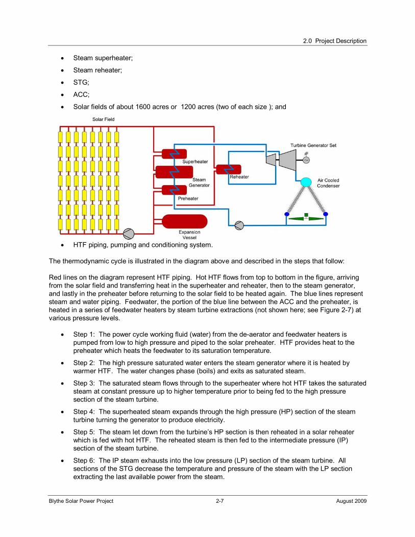
The thermodynamic cycle is illustrated in the diagram above and described in the steps that follow:
Red lines on the diagram represent HTF piping. Hot HTF flows from top to bottom in the figure, arriving from the solar field and transferring heat in the superheater and reheater, then to the steam generator, and lastly in the preheater before returning to the solar field to be heated again. The blue lines represent steam and water piping. Feedwater, the portion of the blue line between the ACC and the preheater, is heated in a series of feedwater heaters by steam turbine extractions (not shown here; see Figure 2-7) at various pressure levels.
Step 1: The power cycle working fluid (water) from the de-aerator and feedwater heaters is pumped from low to high pressure and piped to the solar preheater. HTF provides heat to the preheater which heats the feedwater to its saturation temperature.
Step 2: The high pressure saturated water enters the steam generator where it is heated by warmer HTF. The water changes phase (boils) and exits as saturated steam.
Step 3: The saturated steam flows through to the superheater where hot HTF takes the saturated steam at constant pressure up to higher temperature prior to being fed to the high pressure section of the steam turbine.
Step 4: The superheated steam expands through the high pressure (HP) section of the steam turbine turning the generator to produce electricity.
Step 5: The steam let down from the turbine’s HP section is then reheated in a solar reheater which is fed with hot HTF. The reheated steam is then fed to the intermediate pressure (IP) section of the steam turbine.
Step 6: The IP steam exhausts into the low pressure (LP) section of the steam turbine. All sections of the STG decrease the temperature and pressure of the steam with the LP section extracting the last available power from the steam.

2.0 Project Description
Blythe Solar Power Project 2-8 August 2009
Step 7: The wet steam from the LP section then enters the ACC where it is cooled at a constant low pressure to become a saturated liquid. The condensed liquid returns to the feed water heater train and the beginning of the steam cycle to begin the process again.
At each of the four units, a gas-fired auxiliary boiler with a capacity of 25,000 pounds per hour steam provides minimum load steam for maintaining steam cycle equipment vacuum over night, and full steam briefly each morning for the steam turbine startup. Sealing steam is used to prevent air from entering the steam turbine while the condenser is under vacuum. This method reduces startup time for the plant compared to relying on solar-generated steam as the sealing steam source. Unlike a gas-fired power plant, a solar thermal plant must wait for the sun to rise in the morning to start generating steam and has a finite time to generate electricity (i.e., the number of sunlight hours). Once the plant begins generating electricity for delivery to the electrical grid, the fired auxiliary boiler is no longer needed and is held in stand-by mode until auxiliary heat is again required after plant shutdown. The auxiliary boiler requires approximately 36.7 million British thermal units per hour (MMBtu/hr) of fuel at full load (design load is 34.4 MMBtu/hr). A heat balance diagram for the steam cycle of Units #1 through Unit #4 is provided as Figure 2-7.
2.5.3 Energy Conversion Facilities Description
This section describes the major energy conversion components of the Project including the solar collection system, SSG, STG, auxiliary boilers, and HTF freeze protection heat exchanger.
The Project will be a four-unit parabolic trough solar power plant, each unit having a nominal output of 250 MW. The plant will consist of a conventional steam Rankine-cycle power block, a parabolic trough solar field, an HTF and steam generation system, as well as a variety of ancillary facilities (sometimes referred to collectively as “balance-of-plant”), such as conventional water treatment, electrical switchgear, administration, warehouse, and maintenance facilities, etc.
The electric output of the Project will be provided entirely by solar energy. No electricity will be generated by the use of fossil fuel. A natural gas-fired HTF heater will be used for freeze protection of the HTF in each of the four power blocks. The HTF is a synthetic hydrocarbon liquid mixture of diphenyl ether and biphenyl. Similar formulations are marketed by different manufacturers under the names of Therminol or Dowtherm. The HTF is not classified as a hazardous material by the United States Department of Transportation (DOT) , and is not listed under U.S. Environmental Protection Agency (EPA)
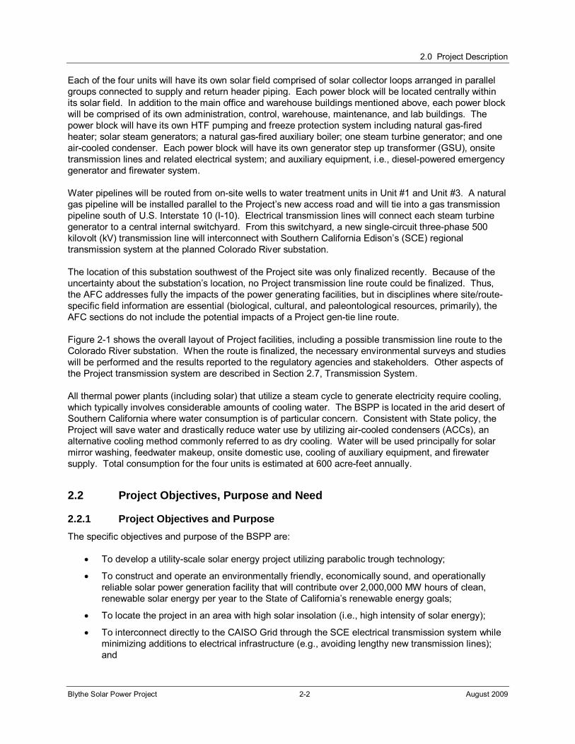
PARABOLIC MIRROR
HEAT COLLECTING ELEMENT
DRIVE MOTOR
DIRECT NORMAL RADIATION
Sun Path from East to West

2.0 Project Description
Blythe Solar Power Project 2-9 August 2009
Comprehensive Environmental Response, Compensation, and Liability Act (CERCLA or Superfund) regulations; however, it is regulated as a hazardous material by the State of California. It has a crystallizing (freezing) point of about 54 ºF (12 degrees Celsius [°C]). Freeze protection is routinely accomplished by circulating HTF at a very low flow rate through the solar field using hot HTF from the vessel as a source. Performance model results indicate that the HTF heater may be required on cold nights in the winter. See Appendix D for the Material Safety Data Sheet.
A gas-fired auxiliary boiler will be used to support rapid startup each morning, i.e., maintaining steam seals. Steam generated by the auxiliary boiler will be at a relatively LP, approximately 165 pounds per square inch gauge (psig).
Each solar field will be a modular, distributed system of solar collector assemblies (SCAs) connected in a series-parallel arrangement via a system of insulated pipes. The collectors will be equipped with a sun tracking mechanism that moves the reflecting panels toward the sun to the optimum angle for solar energy collection. The collectors will be aligned north-south to track the sun from east to west.
HTF will flow from the HTF pumping area in the power blocks to the cold HTF headers that distribute it to the collector loops of SCAs in each of their respective solar fields.
Parabolic Trough Collector Loop. Each of the collector loops consist of two adjacent rows of SCAs, each row is about 1,300 feet long. The two rows are connected by a crossover pipe. HTF is heated in the loop and enters the header, which returns hot HTF from all loops to the power block where the power generating equipment is located.
2.0 Project Description
Blythe Solar Power Project 2-10 August 2009
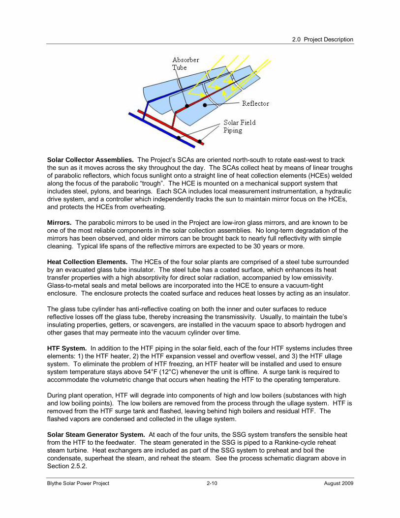
Solar Collector Assemblies. The Project’s SCAs are oriented north-south to rotate east-west to track the sun as it moves across the sky throughout the day. The SCAs collect heat by means of linear troughs of parabolic reflectors, which focus sunlight onto a straight line of heat collection elements (HCEs) welded along the focus of the parabolic “trough”. The HCE is mounted on a mechanical support system that includes steel, pylons, and bearings. Each SCA includes local measurement instrumentation, a hydraulic drive system, and a controller which independently tracks the sun to maintain mirror focus on the HCEs, and protects the HCEs from overheating.
Mirrors. The parabolic mirrors to be used in the Project are low-iron glass mirrors, and are known to be one of the most reliable components in the solar collection assemblies. No long-term degradation of the mirrors has been observed, and older mirrors can be brought back to nearly full reflectivity with simple cleaning. Typical life spans of the reflective mirrors are expected to be 30 years or more.
Heat Collection Elements. The HCEs of the four solar plants are comprised of a steel tube surrounded by an evacuated glass tube insulator. The steel tube has a coated surface, which enhances its heat transfer properties with a high absorptivity for direct solar radiation, accompanied by low emissivity. Glass-to-metal seals and metal bellows are incorporated into the HCE to ensure a vacuum-tight enclosure. The enclosure protects the coated surface and reduces heat losses by acting as an insulator.
The glass tube cylinder has anti-reflective coating on both the inner and outer surfaces to reduce reflective losses off the glass tube, thereby increasing the transmissivity. Usually, to maintain the tube’s insulating properties, getters, or scavengers, are installed in the vacuum space to absorb hydrogen and other gases that may permeate into the vacuum cylinder over time.
HTF System. In addition to the HTF piping in the solar field, each of the four HTF systems includes three elements: 1) the HTF heater, 2) the HTF expansion vessel and overflow vessel, and 3) the HTF ullage system. To eliminate the problem of HTF freezing, an HTF heater will be installed and used to ensure system temperature stays above 54°F (12°C) whenever the unit is offline. A surge tank is required to accommodate the volumetric change that occurs when heating the HTF to the operating temperature.
During plant operation, HTF will degrade into components of high and low boilers (substances with high and low boiling points). The low boilers are removed from the process through the ullage system. HTF is removed from the HTF surge tank and flashed, leaving behind high boilers and residual HTF. The flashed vapors are condensed and collected in the ullage system.
Solar Steam Generator System. At each of the four units, the SSG system transfers the sensible heat from the HTF to the feedwater. The steam generated in the SSG is piped to a Rankine-cycle reheat steam turbine. Heat exchangers are included as part of the SSG system to preheat and boil the condensate, superheat the steam, and reheat the steam. See the process schematic diagram above in Section 2.5.2.
2.0 Project Description
Blythe Solar Power Project 2-11 August 2009
Steam Turbine Generator. The STG receives steam from the SSG. The steam expands through the STG turbine blades to drive the steam turbine, which then drives the generator, converting mechanical energy to electrical energy. Each of the Project’s STGs will be a three-stage casing type with high pressure (HP) intermediate pressure (IP), and low pressure (LP) steam sections. The STG is equipped the following needed accessories:
Steam stop and control valves,
Gland seal system,
Lubricating and jacking oil systems,
Thermal insulation, and
Control instrumentation.
2.5.3.1 Process Control of the Solar Field
Each of the four solar field systems operates under the control of its Field Supervisor Controller (FSC), a computer located in the central control room that communicates with each SCA and with the plant’s distributed control system. The FSC collects information from each SCA and from the distributed control system, and issues instructions to the field as a whole, and/or modular instructions to SCA loops or individual SCAs. It deploys the solar field during the day when weather and plant availability permit, and stows it at night and during high winds.
A weather station located in the power block areas provides real-time measurements of weather conditions that affect the solar field operation. Radiation data is used to determine the performance of the solar field. Wind speed data is needed since under high wind conditions the solar field must be stowed. The FSC communicates with the plant’s distributed control system (DCS), which coordinates and integrates power block, HTF system, and solar field operation.
The solar thermal power plant cycle basically consists of two separate, coupled systems – the HTF loop, and the power block steam loop. The HTF loop transfers accumulated solar heat from the parabolic trough solar field as described above in the previous section for steam generation to drive the turbine generator. The HTF cycle is driven by two parallel pump stations. Cold HTF returning from the power block is heated to the design temperature in the solar field. The hot HTF flows to parallel steam generation trains. Each train includes a preheater, steam generator, superheater, and reheater. In normal operation, the hot HTF stream is split between the trains. It is also possible to remove each train from the loop via motor control valves.
At the basic level, the system distributes cold HTF from the power block to solar field collector loops, and collects hot HTF from the solar field, and inputs the collected heat to the feedwater/steam cycle. Due to the characteristics of HTF, several auxiliary systems are required to keep the HTF loop functioning. A system of reclamation and ullage vessels removes sludge, low boiler and high boiler distillates that develop over time in the HTF system.
As the solar field begins tracking the sun and the HTF heats up, its thermal expansion is accommodated in an expansion vessel. If the HTF in this vessel reaches its design working level it overflows into overflow vessels. If thermal input to the HTF stops, HTF begins to contract. The HTF level in the expansion vessel falls, and overflow return pumps transfer HTF from the overflow vessels back into the expansion vessel to maintain sufficient content there.
2.0 Project Description
Blythe Solar Power Project 2-12 August 2009
2.5.3.2 Operational Modes of the Solar Field
At each solar field, a DCS containing several automation units controls the HTF and steam loops and all auxiliary plant systems, and determines the appropriate operating sequences for them. It also monitors and records the primary operating parameters and functions as the primary interface for system control. It communicates with all subsystem controls, including electrical system equipment, steam cycle controllers, variable frequency drives and balance-of-plant system controllers via serial data communication. It receives analog and digital inputs/outputs from all instruments and equipment not served directly by dedicated local controllers. The DCS controls both the steam and HTF cycles directly, operating rotating equipment via relevant electrical panels. It includes a graphical user interface at an operator console in the main control room. Day-to-day, the following operation modes are usually passed in the HTF system:
Warm up,
Solar field mode (heat transfer from solar field to power block),
Shutdown, and
Freeze protection.
Warm up
Usually in the morning, the warm up mode brings the HTF flow rate and temperatures up to their steady-state operating conditions. It does this by positioning all required valves, starting the required numbers of HTF main pumps for establishing a minimum flow within the solar field and tracking the solar field collectors into the sun.
At the beginning of warm up at each of the four units, HTF is circulated through a bypass around the power block heat exchangers until the outlet temperature reaches the residual steam temperature in the heat exchangers. HTF is then circulated through the heat exchangers and the bypass is closed. As the HTF temperature at the solar field outlet continues to rise, steam pressure builds up in the heat exchangers until the minimum turbine inlet conditions are reached, upon which the turbine can be started and run up to speed. The turbine is synchronized and loaded according to the design specification until its power output matches the full steady state solar field thermal output.
Solar Field Control Mode
The DCS enters solar field control mode automatically after completing warm-up mode. It regulates the flow by controlling the HTF main pump speeds to maintain the design solar field outlet temperature. Several HTF pumps will generally be operated in parallel, at the speed required to provide the required flow in the field. If the thermal output of the solar field is higher than the design capacity of the steam generation system, collectors within the solar field are de-focused to maintain design operating temperatures.
Shutdown
If the minimal thermal input to the turbine required by the Project’s operating strategy cannot be met under the prevalent weather conditions, then shutdown is indicated. Operators will track all solar collectors into the stow position, reduce the number of HTF main pumps to a minimum, and stop the HTF flow to the power block heat exchangers.
2.0 Project Description
Blythe Solar Power Project 2-13 August 2009
Freeze Protection
During periods when the solar power generating facility is shutdown, HTF is circulated through the piping in the solar fields at low flowrate. For most of the year, under typical weather conditions, no supplemental heat is required to keep the HTF flowing freely. However, it is anticipated that on colder winter nights supplemental heat will be required to ensure the HTF doesn’t freeze in the piping. A gas-fired HTF heater, with a rated capacity of 35 MMBtu/hr, will be provided as part of the HTF system. It is expected the HTF heater will need to operate approximately 50 hours per year to keep the HTF from freezing.
2.5.4 Electrical System Description
This section describes the Project’s major electrical systems and equipment. All power produced by the Project will be delivered to the SCE transmission grid through interconnection with SCE’s Palo Verde-Devers 500-kV transmission line at the Colorado River substation, as described in greater detail in Section 2.7.1.
Descriptions of major electrical systems and equipment provided in the following subsections refer to AC power unless otherwise noted. A single-line diagram of the major electrical components of the four power blocks is presented as Figure 2-8. A single-line diagram of the interconnection between the Project and the SCE transmission system, including the Project’s central internal switchyard and SCE substation, is presented as Figure 2-9.
2.5.4.1 Electrical Generation
The STG of each power block will generate electricity at 18 kV and will connect to the central switchyard described in the above paragraph. An oil-filled GSU will step up the voltage to 230 kV. Generator parameters are listed in Table 2-2 below.
Table 2.5-1 Generator Specification
Generator main data (rating) Value
Rated apparent power 320 million volt amperes
Rated active power 270MW
Rated terminal voltage (+ 5.0% / - 5.0%) 21000 volts
Rated phase current 9000 amperes
Rated power factor 0.85 per unit
Rated frequency (+ 2.0% / - 2.0%) 60 hertz
Rated speed 3600 revolutions per minute
Cooling air inlet temperature 90°F
Air overpressure 2.9 psig
2.5.4.2 Electrical System for Plant Auxiliaries
In addition to the following text, please see the single-line diagram in Figure 2-8.
2.0 Project Description
Blythe Solar Power Project 2-14 August 2009
DC Power Supply System
An uninterruptible power system (UPS) will be provided in all four plants. The UPS will service emergency lighting, the DCS, electrical breakers, and relays. The DC power system will serve as a temporary bridge to the more robust emergency diesel AC power supply in the event external power is suddenly lost.
Essential Service AC System
A 120 volt essential service AC power distribution system serves critical equipment loads, lighting and alarms, and loads that protect equipment from potential damage in the event of sudden loss of station service. This system is served through an inverter that receives power from the DC power supply system.
2.5.5 Plant Auxiliary Systems
The following subsections describe the various power plant auxiliary systems (fuel supply, water supply, water treatment, cooling systems, waste management, etc.) associated with each of the four 250 MW units that comprise the Project.
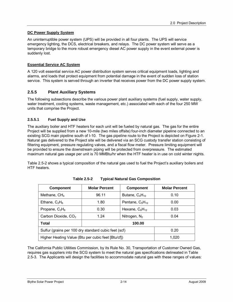
2.5.5.1 Fuel Supply and Use
The auxiliary boiler and HTF heaters for each unit will be fueled by natural gas. The gas for the entire Project will be supplied from a new 10-mile (two miles offsite) four-inch diameter pipeline connected to an existing SCG main pipeline south of I-10. The gas pipeline route to the Project is depicted on Figure 2-1. Natural gas delivered to the Project site will be delivered via an SCG custody transfer station consisting of filtering equipment, pressure regulating valves, and a fiscal flow meter. Pressure limiting equipment will be provided to ensure the downstream piping will be protected from overpressure. The estimated maximum natural gas usage per unit is 70 MMBtu/hr when the HTF heater is in use on cold winter nights.
Table 2.5-2 shows a typical composition of the natural gas used to fuel the Project’s auxiliary boilers and HTF heaters.
Table 2.5-2 Typical Natural Gas Composition
Component Molar Percent Component Molar Percent
Methane, CH4 96.11 Butane, C4H10 0.10
Ethane, C2H6 1.80 Pentane, C5H12 0.00
Propane, C3H8 0.30 Hexane, C6H12 0.03
Carbon Dioxide, CO2 1.24 Nitrogen, N2 0.04
Total 100.00
Sulfur (grains per 100 dry standard cubic feet (scf) 0.20
Higher Heating Value (Btu per cubic feet [Btu/cf]) 1,020
The California Public Utilities Commission, by its Rule No. 30, Transportation of Customer Owned Gas, requires gas suppliers into the SCG system to meet the natural gas specifications delineated in Table 2.5-3. The Applicants will design the facilities to accommodate natural gas with these ranges of values:
2.0 Project Description
Blythe Solar Power Project 2-15 August 2009
Table 2.5-3 California Public Utilities Commission Rule No. 30 Requirements
Heating value (minimum / maximum)
990 to 1150 BTU/cf (gross, dry basis)
Water content no more than 7 pounds per million standard cubic feet
Hydrogen sulfide no more than 0.25 grains per 100 scf (4 parts per million [ppm])
Mercaptan sulfur no more than 0.3 grains per 100 scf (5 ppm)
Total sulfur compounds
no more than 0.75 grains per 100 scf (12.6 ppm)
Carbon dioxide no more than 3 percent by volume
Oxygen no more than 0.2 percent by volume
Inerts no more than 4percent (total combined CO2, N2, O2, and any other inert compound)
Hydrocarbons dew point is not to exceed 45°F at 400 psig or at the delivery pressure if the delivery pressure is below 400 psig
Delivery temperature between 50°F and 105°F, inclusive
Wobbe index 1279 to 1385, inclusive
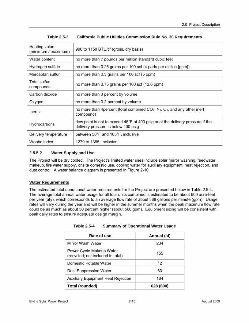
2.5.5.2 Water Supply and Use
The Project will be dry cooled. The Project’s limited water uses include solar mirror washing, feedwater makeup, fire water supply, onsite domestic use, cooling water for auxiliary equipment, heat rejection, and dust control. A water balance diagram is presented in Figure 2-10.
Water Requirements
The estimated total operational water requirements for the Project are presented below in Table 2.5-4. The average total annual water usage for all four units combined is estimated to be about 600 acre-feet per year (afy), which corresponds to an average flow rate of about 388 gallons per minute (gpm). Usage rates will vary during the year and will be higher in the summer months when the peak maximum flow rate could be as much as about 50 percent higher (about 568 gpm). Equipment sizing will be consistent with peak daily rates to ensure adequate design margin.
Table 2.5-4 Summary of Operational Water Usage
Rate of use Annual (af)
Mirror Wash Water 234
Power Cycle Makeup Water (recycled; not included in total)
155
Domestic Potable Water 12
Dust Suppression Water 63
Auxiliary Equipment Heat Rejection 164
Total (rounded) 628 (600)
2.0 Project Description
Blythe Solar Power Project 2-16 August 2009
Water Source and Quality
The Project water needs will be met by use of groundwater pumped from one of two wells on the plant site. Water for domestic uses by Project employees will also be provided by onsite groundwater treated to potable water standards. As discussed in Section 5.17, Water Resources, a well testing program is underway, using a newly installed water supply well, to allow determination of the optimum groundwater pumping program to provide the needed volumes of water with minimum impact to other groundwater users and the groundwater basin. The results of this well testing program will be made available to regulatory agencies and other stakeholders when the testing program is completed. See Appendix J for water resources supporting documentation.
It is expected that two new water supply wells in the power blocks of the Project site will adequately serve the entire Project. A second well will provide redundancy and backup water supply in the event of outages or maintenance of the first well.
2.5.5.3 Water Treatment
The peak load (summer) water balance diagram presented in Figure 2-10 shows the power plants’ various water uses and water treatment processes. Power cycle makeup, mirror washing water, cooling water for ancillary equipment, and water for domestic uses all require onsite treatment and this treatment varies according to the quality required for each of these uses.
Groundwater
As stated above, the planned water source for the entire Project is groundwater supplied by new wells located within the Project site boundary. Water quality data from local irrigation wells is not available. However, water quality information for wells serving a natural gas-fired power plant located about two miles southeast of the BSPP site show total dissolved solids (TDS) of about 1010 milligrams per liter (mg/L). Hardness is about 140 mg/L and silica concentration is about 24 mg/L. The quality of water from these wells has been used in this preliminary evaluation. No information is available on arsenic concentrations. Additional information on local groundwater in provided in section 5.17, Water Resources.
The groundwater will be piped directly from the wells to the treatment process without raw water storage. The groundwater will first be treated by RO or electrodialysis reversal (EDR) process in treatment units in Unit #1 and Unit #3 prior to storage in one million-gallon treated water (permeate) tanks, one in each power block. Excluding any use for firefighting, this volume of treated water will provide enough storage capacity for three days interruption of water supply to the facility. Concentrate from the RO (or EDR) process will serve as water for dust control and will be stored in 300,000-gallon tanks located in Unit #1 and Unit #3. These tanks will be provided with a piping connection directly from the wells for supplemental raw water supply.
Water Treatment Process
As noted above, water used for power cycle feedwater makeup, mirror washing, ancillary equipment heat rejection, and domestic uses will require treatment for reduction of TDS. This type of treatment process is known as desalination, and can be accomplished by either thermal processes (evaporation/condensation) or membrane processes such as RO or EDR. Given the concentration of TDS in the source water, it is unlikely that thermal processes will be cost effective. Accordingly, only membrane processes are considered here. Since RO and EDR produce similar product water quality and waste streams, further discussion here will reference only RO for simplicity. The proposed treatment process for the various water uses is presented schematically in Figure 2-10. Selection of the process to be used at the Project will be made during the final design process.
2.0 Project Description
Blythe Solar Power Project 2-17 August 2009
Membrane desalination processes split the feed stream into two streams: 1) a product water stream (permeate) with reduced salinity and 2) a concentrate stream containing the majority of the salts that were in the feed stream. Desalination processes are usually designed to operate with the highest safe recovery (recovery is the fraction of feed water recovered as permeate) in order to minimize water loss, since the concentrate will normally be considered a waste stream. In this case, it appears that the highest safe recovery is 90 percent.
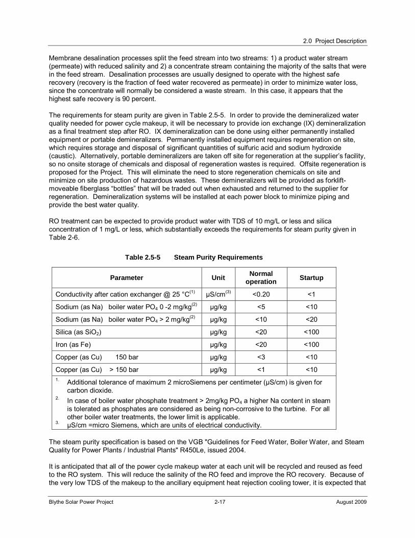
The requirements for steam purity are given in Table 2.5-5. In order to provide the demineralized water quality needed for power cycle makeup, it will be necessary to provide ion exchange (IX) demineralization as a final treatment step after RO. IX demineralization can be done using either permanently installed equipment or portable demineralizers. Permanently installed equipment requires regeneration on site, which requires storage and disposal of significant quantities of sulfuric acid and sodium hydroxide (caustic). Alternatively, portable demineralizers are taken off site for regeneration at the supplier’s facility, so no onsite storage of chemicals and disposal of regeneration wastes is required. Offsite regeneration is proposed for the Project. This will eliminate the need to store regeneration chemicals on site and minimize on site production of hazardous wastes. These demineralizers will be provided as forklift-moveable fiberglass “bottles” that will be traded out when exhausted and returned to the supplier for regeneration. Demineralization systems will be installed at each power block to minimize piping and provide the best water quality.
RO treatment can be expected to provide product water with TDS of 10 mg/L or less and silica concentration of 1 mg/L or less, which substantially exceeds the requirements for steam purity given in Table 2-6.
Table 2.5-5 Steam Purity Requirements
Parameter Unit Normal
operation Startup
Conductivity after cation exchanger @ 25 °C(1) μS/cm(3) <0.20 <1
Sodium (as Na) boiler water PO4 0 -2 mg/kg(2) μg/kg <5 <10
Sodium (as Na) boiler water PO4 > 2 mg/kg(2) μg/kg <10 <20
Silica (as SiO2) μg/kg <20 <100
Iron (as Fe) μg/kg <20 <100
Copper (as Cu) 150 bar μg/kg <3 <10
Copper (as Cu) > 150 bar μg/kg <1 <10 1. Additional tolerance of maximum 2 microSiemens per centimeter (μS/cm) is given for
carbon dioxide. 2. In case of boiler water phosphate treatment > 2mg/kg PO4 a higher Na content in steam
is tolerated as phosphates are considered as being non-corrosive to the turbine. For all other boiler water treatments, the lower limit is applicable.
3. μS/cm =micro Siemens, which are units of electrical conductivity.
The steam purity specification is based on the VGB "Guidelines for Feed Water, Boiler Water, and Steam Quality for Power Plants / Industrial Plants" R450Le, issued 2004.
It is anticipated that all of the power cycle makeup water at each unit will be recycled and reused as feed to the RO system. This will reduce the salinity of the RO feed and improve the RO recovery. Because of the very low TDS of the makeup to the ancillary equipment heat rejection cooling tower, it is expected that
2.0 Project Description
Blythe Solar Power Project 2-18 August 2009
blowdown will not be required. Rather, drift (windblown mist) will provide the necessary salt removal. If blowdown is required, it will be recycled to the RO system. It may be more advantageous to recycle the power cycle makeup water to the IX demineralizer rather than to the RO. This modification will be evaluated during final design.
Water from the site groundwater wells may require treatment to meet public health requirements for domestic potable water supplies. Based on the assumed water quality, it is expected that TDS concentrations must be reduced, which indicates the need for a desalination process. Following desalination, the water will require addition of chlorine to prevent growth of pathogenic organisms. Use of a solid calcium hypochlorite system is recommended. Since the source water is groundwater, there is no need to meet the requirements of the Surface Water Treatment Rule (and its amendments) of the National Primary Drinking Water Standards.
Solar Mirror Washing Water
At each solar field, to facilitate dust and contaminant removal, water from the primary desalination process, RO water, will be used to spray clean the solar collectors on once to twice per week, determined by the reflectivity monitoring program. This mirror washing operation is done at night and involves a water truck spraying treated water on the mirrors in a drive-by fashion. It is expected that the mirrors will be washed weekly in winter and twice weekly from mid spring through mid fall. Because the mirrors are angled down for washing, water does not accumulate on the mirrors; instead, it falls from the mirrors to the ground and, due to the small volume, soaks in with no appreciable runoff. Any remaining rinse water from the washing operation is expected to evaporate on the mirror surface. The treated water production facilities will be sized to accommodate the solar mirror washing demand of about 230 afy and is shown on the Figure 2-10, Water Balance Diagram.
2.5.5.4 Cooling Systems
Each of the four power plant units includes two cooling systems: 1) the air-cooled steam cycle heat rejection system and, 2) the closed cooling water system for ancillary equipment cooling, each of which is discussed below.
Steam Cycle Heat Rejection System
The cooling system for heat rejection from the steam cycle consists of a forced draft air-cooled condenser, or dry cooling system. At each power block, the dry cooling system receives exhaust steam from the LP section of the STG and condenses it to liquid for return to the SSG.
Auxiliary Cooling Water System
The auxiliary cooling water systems use small wet cooling towers for cooling plant equipment, including the STG lubrication oil cooler, the STG generator cooler, steam cycle sample coolers, large pumps, etc. The water picks up heat from the various equipment items being cooled and rejects the heat to the cooling tower. This auxiliary cooling system will allow critical equipment such as the generator and HTF pumps to operate at their design ratings during hot summer months when the Project’s power output is most valuable. An average of 146,000 gallons of water per day (160 afy) will be consumed by the auxiliary cooling water system; the maximum rate of consumption is 223,000 gallons per day in summer.
2.5.5.5 Waste Generation and Management
Project wastes will be comprised of non-hazardous wastes including solids and liquids and lesser amounts of hazardous wastes and universal wastes. The non-hazardous solid waste primarily will consist of construction and office wastes, as well as liquid and solid wastes from the water treatment system.
2.0 Project Description
Blythe Solar Power Project 2-19 August 2009
The non-hazardous solid wastes will be trucked to the nearest Class II or III landfill as discussed in Section 5.16, Waste Management. Non-hazardous liquid wastes will consist primarily of domestic sewage, and reusable water streams such as RO system reject water, boiler blowdown, and auxiliary cooling tower blowdown. A septic tank and leach field system will be installed to manage domestic sewage.
Wastewater
The Project will produce two primary wastewater streams:
Non-reusable sanitary wastewater produced from administrative centers and operator stations.
Reusable streams including: blowdown from the cooling tower for the ancillary equipment heat rejection system, RO reject water, and boiler blowdown.
As noted above, the power generation cycle will not produce cooling tower blowdown because the plant will be dry cooled. A small auxiliary cooling tower at each unit will generate a small amount of blowdown, which will be reused on site.
Sanitary wastewater production will consist of domestic water use. Maximum domestic water use is expected to be less than 332,000 gallons per month (11,000 gallons per day). It is anticipated that the wastewater will be consistent with domestic sanitary wastewater and will have biochemical oxygen demand and total suspended solids in the range of 150 to 250 mg/L.
Wastewater Treatment
Sanitary wastes will be collected for treatment in septic tanks and disposed via leach fields located at the four power blocks as well as at the administration area and warehouse area. Smaller septic systems will be provided for the control room buildings to receive sanitary wastes at those locations. Based on the current estimate of 11,000 gallons of sanitary wastewater production per day for the entire site, a total leach field area of approximately 22,000 square feet will be required spread out among several locations.
Construction Wastewater
Sanitary wastes produced during construction will be held in chemical toilets and transported offsite for disposal by a commercial chemical toilet service. Any other wastewater produced during construction such as equipment rinse water will be collected by the construction contractor in Baker tanks and transported off site for disposal in a manner consistent with applicable regulatory requirements.
On-Site Land Treatment Unit
The four solar fields to be installed at the Project will share two LTUs to bioremediate or land farm soil contaminated from releases of HTF. Each LTU will be designed in accordance with Colorado River Basin Regional Water Quality Control Board (RWQCB) requirements and is expected to comprise an area of about 360,000 square feet (8.3 acres). The bioremediation facility would utilize indigenous bacteria to metabolize hydrocarbons contained in non-hazardous HTF contaminated soil. A combination of nutrients, water, and aeration facilitates the bacterial activity where microbes restore contaminated soil within two to four months. The California Department of Toxic Substances Control (DTSC) has determined for a similar thermal solar power plant that soil contaminated with up to 10,000 mg/kg of HTF is classified as a
2.0 Project Description
Blythe Solar Power Project 2-20 August 2009
non-hazardous waste.1 However, the DTSC has further indicated that site-specific data will be required to provide a classification of the waste. Initially, in addition to sampling for HTF, samples would be analyzed for ignitability and toxicity using appropriate State and Federal methods to verify generator knowledge and characterize the waste as hazardous or non-hazardous. These data will be obtained to provide site specific information and verify this classification, as discussed in Section 5.16.3.
The LTU will be constructed with a clay liner at least five feet in thickness as per Title 27 requirements. Unsaturated zone monitoring and/or groundwater monitor will be used to evaluate liner integrity. Nutrients including nitrogen and phosphorus would be added to the contaminated soil to encourage consumption of the HTF by the indigenous bacteria. The soil would remain in the remediation unit until concentrations are reduced to an average concentration of less than 100 mg/kg HTF. Soil contaminated with HTF levels of between 100 and 1,000 mg/kg will be land farmed at the LTU, meaning that the soil will be aerated but no nutrients will be added.
Other Non-Hazardous Solid Waste
Non-hazardous solid wastes may be generated by construction, operation, and maintenance of the Project which are typical of power generation facilities. These wastes may include scrap metal, plastic, insulation material, glass, paper, empty containers, and other solid wastes. Disposal of these wastes will be accomplished by contracted solid refuse collection and recycling services.
Hazardous Solid and Liquid Waste
Limited hazardous wastes will be generated during Project construction and operation. During construction, these wastes may include substances such as paint and paint-related wastes (e.g., primer, paint thinner, and other solvents), equipment cleaning wastes and spent batteries. During Project operation, these wastes may include used oils, hydraulic fluids, greases, filters, spent cleaning solutions, spent batteries, and spent activated carbon. Section 5.16, Waste Management, provides detail regarding the anticipated hazardous waste streams in terms of quantities of waste, origin and composition, and waste management method. Both construction and operation-phase hazardous waste will be recycled and reused to the maximum extent possible.
2.5.5.6 Hazardous Materials Management
There will be a variety of hazardous materials used and stored during construction and operation of the Project, as summarized below. Section 5.6, Hazardous Materials Handling, provides additional data on the hazardous materials that will be used during construction and operation, including quantities, associated hazards and permissible exposure limits, storage methods and special handling precautions.
Hazardous materials that will be used during construction include gasoline, diesel fuel, oil, lubricants, and small quantities of solvents and paints. All hazardous materials used during construction and operation will be stored onsite in storage tanks/vessels/containers that are specifically designed for the characteristics of the materials to be stored; as appropriate, the storage facilities will include the needed secondary containment in case of tank/vessel failure. Aboveground carbon steel tanks (300 gallons} also will be used to store diesel fuel) at each power block. Secondary containment will be provided for these tanks.
1 DTSC, 1995. Letter to Mr. David Rib, KJC Operating Company, re: Request for Reclassification of Therminol Contaminated Soil as Nonhazardous Pursuant to Section 66260.200(f), Title 22, California Code of Regulations (22 CCR) – Waste Evaluation Unit File # F143 (WEU File # F143). April 4.

2.0 Project Description
Blythe Solar Power Project 2-21 August 2009
A variety of safety-related plans and programs will be developed and implemented to ensure safe handling, storage, and use of hazardous materials (e.g., Hazardous Material Business Plan). Plant personnel will be supplied with appropriate personal protective equipment (PPE) and will be properly trained in the use of PPE and the handling, use, and cleanup of hazardous materials used at the facility, as well as procedures to be followed in the event of a leak or spill. Adequate supplies of appropriate cleanup materials will be stored on site.
2.5.5.7 Fire Protection
Fire protection systems are provided to limit personnel injury, property loss, and Project downtime resulting from a fire. The systems include a fire protection water system, foam generators, carbon dioxide fire protection systems, and portable fire extinguishers.
The location of the Project is such that it will fall under the jurisdiction of the Riverside County Fire Department. Based on the requirements of Riverside County Ordinance No. 787.1, the piping system supplying the fire hydrants must be sized to convey a potential firewater flowrate of 5,000 gpm. Minimum firewater storage volume in each power block will be 300,000 gallons.
Firewater will be supplied from the one million-gallon treated water (permeate) storage tanks located at the four power blocks on the Project site. One electric and one diesel-fueled backup firewater pump, each with a capacity of 5,000 gpm, will deliver water to the fire protection piping network.
The piping network will be configured in a loop so that a piping failure can be quickly isolated with shutoff valves without interrupting water supply to other areas in the loop. Fire hydrants will be placed at intervals throughout the Project site that will be supplied with water from the supply loop. The water supply loop will also supply firewater to a sprinkler deluge system at each unit transformer, HTF expansion tank and circulating pump area and sprinkler systems at the steam turbine generator and in the administration building. Fire protection for each solar field will be provided by zoned isolation of the HTF lines in the event of a rupture that results in a fire.
2.5.5.8 Distributed Control System
The DCS provides control, monitoring, alarm, and data storage functions for power plant systems. These include:
Control of the STG, SSG system, and balance-of-plant system in a coordinated manner;
Monitoring of operating parameters from plant systems and equipment;
Visual display of the associated operating data to control operators and technicians;
Detection of abnormal operating parameters and parameter trends;
Provision of visual and audible alarms to apprise control operators of such conditions; and
Storage and retrieval of historical operating data.
The DCS is a microprocessor-based system. Redundant capability is provided for critical DCS components such that no single component failure will cause a plant outage. The DCS consists of the following major components:
Computer monitor-based control operator interface (redundant);
Computer monitor-based control engineering work station;
Multi-function processors (redundant);
2.0 Project Description
Blythe Solar Power Project 2-22 August 2009
Input/output processors (redundant for critical control parameters);
Field sensors and distributed processors (redundant for critical control parameters);
Historical data archive; and
Printers, data highways, data links, control cabling, and cable trays.
The DCS is linked to the control systems furnished by the STG supplier and to the solar field controls. These datalinks provide STG control, monitoring, alarm, and data storage functions via the control operator interface and control technician workstation of the DCS.
2.5.5.9 Telecommunications and Telemetry
The Project will have telecommunications service from providers who serve the Blythe area. Voice and data communications will be supported by a fiber optic system. This will be augmented with wireless telecom equipment, particularly to support communication with Project staff dispersed throughout the large Project site
With respect to telemetry, the Project will utilize electronic systems to control equipment and facilities operations over a large site. Because of the presence of nearby Blythe Airport, the Applicants are sensitive to the need to ensure that use of the electronic spectrum by the Project does not interfere with aircraft operations. Detailed information on Project use of the electronic spectrum has not yet been developed at the current stage of the Project engineering design process. However, the Applicants have met with airport representatives and the parties have agreed on a process that will avoid potential electronic interference issues.
2.5.5.10 Lighting System
The Project’s lighting system will provide operations and maintenance personnel with illumination in normal and emergency conditions. AC lighting will be the primary form of illumination, but DC lighting will be included for activities or emergency egress required during an outage of the plant’s AC system. AC convenience outlets will also be provided for portable lamps and tools. The lighting fixtures will be hooded to minimize nighttime glare in deference to the “dark skies” initiatives that strive to protect views of night skies. The minimum illumination required to ensure safety and security objectives will be provided and will be oriented to minimize additional illumination in areas not pertinent to the facility.
2.5.5.11 HTF Freeze Protection System
At each unit, a freeze protection system will be used to prevent freezing of the HTF piping systems during cooler winter nights. Since the HTF freezes at a relatively high temperature (54°F or 12°C), HTF will be routinely circulated at low flow rates throughout the solar field using hot HTF from the storage vessel as a source. During winter, a natural gas-fired HTF heater will be used when weather conditions dictate (i.e., on cold nights).
2.5.5.12 HTF Leak Detection
Leak detection of HTF will be accomplished in various ways. Visual inspection throughout the solar field on a daily basis will detect small leaks occurring at ball joints or other connections. Such leaks can be corrected via minor repairs or repacking of joints and valves. The configuration of the looped system, allowing different sections of the loops to be isolated, will facilitate the repair of small leaks. Since larger leaks are of a greater concern, detection of large leaks is being proposed by using remote pressure sensing equipment and remote operating valves to allow for isolation of large areas of the loops in the solar field. Details of the design will be developed in the design detail process.
2.0 Project Description
Blythe Solar Power Project 2-23 August 2009
2.5.5.13 Service Air and Instrument Air Systems
The service air system supplies compressed air to hose connections located at intervals throughout the power plant. Compressors deliver compressed air at a regulated pressure to the service air-piping network.
The instrument air system provides dry, filtered air to pneumatic operators and devices throughout the power plant. Air from the service air system is dried, filtered, and pressure regulated prior to delivery to the instrument air-piping network.
2.5.6 Project Civil/Structural Features
The following subsections describe civil/structural features of the Project, as illustrated in the site arrangement presented in Figure 2-4. The four power plants will be designed and constructed in conformance with the Uniform Building Code and California Building Code criteria for Seismic Zone 3, the zone of second highest seismic risk.
2.5.6.1 SSG System, STG and Associated Equipment
At each power block, the SSG system, STG, and dry cool condensers will be located outdoors and supported on reinforced concrete mat foundations. The STG foundation will include a reinforced concrete pedestal. The one step-up transformer and GSU will be supported on reinforced concrete mat foundations. Balance-of-plant mechanical and electrical equipment will be supported on individual reinforced concrete pads. Balance-of-plant components/materials include piping, valves, cables, switches, etc., that are not included with major equipment and are generally installed or erected onsite.
2.5.6.2 Solar Collector Assembly Support Structures
Each SCA will be supported by structures (stands) that connect the parabolic troughs to the drive mechanism. Each array will be supported by multiple individual foundations with a foundation located approximately every 63 feet along the assembly. Foundation design will be based on site-specific geotechnical conditions to ensure that the SCA stands are able to support all loading conditions (including wind loading) at the Project site.
2.5.6.3 Buildings
The Project will include an administration building and warehouse adjacent to the solar field. The power blocks will include a control building, maintenance shop, water treatment lab (Unit #1 and Unit #3 only), electrical building, and office building. The design and construction of the central administration building and warehouse will be consistent with normal building standards. Other plant site buildings will include the water treatment building (Unit #1 and Unit #3 only), as well as a number of pre-engineered enclosures for mechanical and electrical equipment. Building columns will be supported on reinforced concrete mat foundations or individual spread footings and the structures will rest on reinforced concrete slabs. The total footprint area of the central warehouse and main office is approximately 122,000 square feet (SF). The footprint area of buildings in each power block is 31,200 SF.
2.5.6.4 Water Storage Tanks
There will be six covered water tanks on the site: two 300,000-gallon RO concentrate/dust control storage tanks located in Unit #1 and Unit #3 and four one million-gallon treated water storage tanks, one in each power block. Water storage tanks will be vertical, cylindrical, field-erected steel tanks supported on foundations consisting of either a reinforced concrete mat or a reinforced concrete ring wall with an interior bearing layer of compacted sand supporting the tank bottom.

2.0 Project Description
Blythe Solar Power Project 2-24 August 2009
2.5.6.5 Roads, Fencing, and Security
As noted earlier, access to the Project site will be via the public road heading north from the frontage road, Black Rock Road, along I-10, accessed from the Airport/Mesa Drive exit. Improvements to some segments of the public road will be required.
Only a small portion of the overall Project site will be paved, primarily the site access road, the service roads to the power blocks, and portions of the power blocks (paved parking lot and roads encircling the STG and SSG areas). The remaining portions of each power block will be gravel surfaced. In total, each power block area will be approximately 18.4 acres each, with approximately six acres of paved area. The solar fields will remain unpaved and without a gravel surface in order to prevent rock damage from mirror wash vehicle traffic; an approved dust suppression coating will be used on the dirt roadways within and around the solar fields. Roads and parking areas located within the power block areas and adjacent to the administration building and warehouses will be paved with asphalt.
The Project solar fields and support facilities’ perimeter will be secured with a combination of chain link and wind fencing. Chainlink metal fabric security fencing consists of eight-foot tall fencing with one-foot barbed wire or razor wire on top along the north and south sides of the facilities. Thirty-foot tall wind fencing, comprised of A-frames and wire mesh, will be installed along the east and west sides of each solar field. Desert Tortoise exclusion fencing will be included. Controlled access gates will be located at the site entrance. As discussed below, the drainage channels will be outside the plant and the security fencing but still within the Project ROW.
2.5.6.6 Site Drainage and Earthwork
The existing topographic conditions of the Project site show an average slope of approximately one foot in 80 feet (1.25 percent) toward the east on the west side of the site and approximately one foot in 200 feet (0.50 percent) toward the southeast on the east side of the site. The Project site lies in the Palo Verde Mesa east of the McCoy Mountains. The general stormwater flow pattern is from the higher elevations in the mountains located three miles west of the site to the lower elevations in the McCoy Wash to the east of the site. Runoff from the McCoy Mountains, west of the Project site, discharges into shallow moderately defined channels at the base of the mountains and passes through the Project site in a southeasterly direction and is intercepted offsite by irrigation canals before reaching McCoy Wash. The development of the site will include intercepting the storm flows at the Project boundaries, channelizing and rerouting the flows around and through the site, and then returning the flows to their sheet flow regime on the east and southeast sides of the site. The channel segments will be designed to meet Riverside County and/or Colorado River Basin RWQCB requirements. A site drainage study and a drainage plan are included in Appendix L.
A channel is proposed along the entire west side of Unit #1 and the majority of Unit #3. The channel will be designed for the 100-year flow rate with a minimum of one foot of freeboard in the northwest portion of the site, and for a lesser storm interval in the southwest portion of the site. Additional protection will be provided by an elevated roadway/berm on the east side of the channel. The channel then turns eastward and flows through Unit #3 toward the south of Unit #4 to the southeast corner of the site. Here the channel spreads the flows similar to the existing flow regime.
In the center of the site, the storm flows will be directed to a channel that will flow easterly on the south side of Units #1 and #2. This central channel will also be designed for the 100-year flow rate with a minimum of one foot of freeboard. This channel will merge with another channel on the east side of the site.
On the north side of the site, the storm flows will be directed to a channel on the north side of Units #1 and #2 that directs the flows to the northeast corner of the site and then turns southerly along the east boundary of the site. The storm flows from the center channel merge with the north channel flows and
2.0 Project Description
Blythe Solar Power Project 2-25 August 2009
then continue toward the south. The combined flows are then spread in the area where the existing runoff currently flows.
The solar units will be graded generally following the existing contours of the site in order to minimize the amount of disturbance and to allow a balanced distribution of material. The runoff from the units will be collected in a series of swales and small channels which will direct the flow to the appropriate channel. Culverts will be provided across the southerly center channels for essential onsite roads.
The power block areas that are centrally located within the solar units will have their own detention/water quality basins within the block. The power blocks will generally drain by sheet flow or swales to the basins prior to release. The basins will be designed to accommodate the 25-year storm flow and to provide temporary retention for water quality mitigation. Oil and chemical storage areas within the power blocks will have their own containment features. The basins will also be designed to retain for a short duration prior to outfall to the nearest downstream channel.
The preliminary site grading plan is designed to be balanced; no import or export of soil is expected for general earthwork. The grading plan does not currently allow for any soil shrinkage or other losses. When the geotechnical investigation report is available for the site, the grading plan will be adjusted to account for any loss in elevation that could occur. Engineered fill will be provided as required for equipment and structure foundations as/if recommended by the geotechnical report. Only soil material approved by the geotechnical engineer will be used for structural fill. Additionally, granular material may need to be imported for use as road base and possible use below foundations. Grading of the site will commence at the beginning of the construction period and last over a period of approximately 55 months. Such an extended grading period will require less water on a daily basis for grading operations as well as for dust control over a smaller area. The total earth movement required is estimated to be 8,300,000 cubic yards.
As summarized in Section 5.17, Water Resources, and described in the preliminary construction Storm Water Pollution Prevention Plan (SWPP)/Drainage, Erosion and Sediment Control Plan (DESCP) provided in Appendix L, the Project will employ a comprehensive system of management controls. The management controls include site-specific Best Management Practices (BMPs) to minimize storm water contact with contaminants . These management controls may include:
Erosion and sediment control,
Employee training program,
Good housekeeping programs,
Preventive maintenance programs,
Structural BMPs:
Temporary containment during maintenance activities,
Permanent secondary containment structures at chemical storage and process areas,
Materials, equipment and vehicle management practices,
Spill prevention and response programs, and
Inspection programs.
2.5.7 Construction of Generating Facilities
Major milestones of the planned construction schedule are as follows:
2.0 Project Description
Blythe Solar Power Project 2-26 August 2009
Begin construction: Fourth quarter 2010
Startup and test: Unit #1 - First quarter 2013 Unit #2 – Third quarter 2013 Unit #3 – First quarter 2015 Unit #4 – Second quarter 2016
Commercial operation: Unit #1 - Second quarter 2013 Unit #2 – Fourth quarter 2013 Unit #3 – Second quarter 2015 Unit #4 – Second quarter 2016
Project construction is expected to occur over a total of 69 months. Project construction will require an average of 604 employees over the entire 69-month construction period, with manpower requirements peaking at approximately 1,004 workers in Month 16 of construction. The construction workforce will consist of a range of laborers, craftsmen, supervisory personnel, support personnel, and management personnel. Section 5.11, Socioeconomics, provides a breakdown of the construction workforce by skill over the entire construction period.
Temporary construction parking areas will be provided within the Project site adjacent to the laydown area. The plant laydown area will be utilized throughout the build out of the four solar units. The construction sequence for power plant construction includes the following general steps:
Site Preparation: this includes detailed construction surveys, mobilization of construction staff, grading, and preparation of drainage features. Grading for the solar fields, power blocks, and drainage channels will be completed during the first 55-months of the construction schedule.
Linears: this includes the site access road, telecommunication line, and transmission line. The site access road and telecommunication line for Unit #1 will be constructed during the first nine months of the construction schedule in conjunction with plant site preparation activities. The natural gas pipeline, electric transmission lines, and telecommunications lines will be constructed during the first 18 months of the construction schedule.
Foundations: this includes excavations for large equipment (STG, SSG, GSU, etc.), footings for the solar field, and ancillary foundations in the power block.
Major Equipment Installation: once the foundations are complete, the larger equipment will be installed. The solar field components will be assembled in an onsite erection facility and installed on their foundations.
BOP: with the major equipment in place, the remaining field work will be piping, electrical, and smaller component installations.
Testing and Commissioning: testing of subsystems will be conducted as they are completed. Major equipment will be tested once all supporting subsystems are installed and tested.
Most equipment and materials will be delivered to the Project site by truck. Delivery of the STG, GSU, HTF, solar collector structural steel, and other materials for which rail transport is appropriate, will be by rail. The Applicants are exploring the possibility of utilizing an existing rail spur in Blythe about a quarter-mile south of I-10 and one block east of Lovekin Street. Alternatively, there are rail spurs in the Indio area that also may be usable. From either location, the materials will be trucked to I-10 by the most direct appropriate route and then trucked on I-10 either west (from Blythe) or east (from Indio) to the site.
2.0 Project Description
Blythe Solar Power Project 2-27 August 2009
A Construction Fire Protection and Prevention Plan will be developed and followed throughout all phases of construction. The permanent facility fire protection system will be put into use during construction as soon as is practicable. Prior to the availability of this system, fire extinguishers and other portable fire fighting equipment will be available on site. All equipment will be California Occupational Health and Safety Administration compliant. Locations of portable fire fighting equipment may include portable office spaces, welding areas, flammable chemical areas, and vehicles and other mobile equipment.
2.5.7.1 Construction Water
Construction water requirements cover all construction related activities including:
Dust control for areas experiencing construction work as well as mobilization and demobilization,
Dust control for roadways,
Water for grading activities associated with both cut and fill work,
Water for soil compaction in the utility and infrastructure trenches,
Water for soil compaction of the site grading activities,
Water for stockpile sites,
Water for the various building pads, and
Water for concrete pours on site.
The predominant use of water will be for grading activities which will have a steady rate of work each month. The grading schedule for the site has been spread to cover the total construction period and there should be no definable peak but rather a steady state condition of water use. The average water use for the Project is estimated to be about 499,000 gallons per working day. Total water use for the duration of Project construction is estimated to be about 3,100 acre feet. Construction water will be sourced from onsite wells. Potable water during construction will be brought on site in trucks and held in day tanks.
2.5.8 Project Operation
While electrical power is to be generated only during daylight hours, the Project will be staffed 24 hours a day, seven days per week. A total estimated workforce of 84 full time employees will be needed to staff the first phase of the project (Unit #1). Completion of subsequent power units will necessitate the following additional personnel: +50 (total 134) with Unit #2 added, +48 (total 182) with Unit #3 added, and +39 with Unit #4 added for a total 221 with all four units operating. A breakdown of operational staff is provided in Section 5.11, Socioeconomics.
2.6 Natural Gas Pipeline
2.6.1 Pipeline Description
A new four-inch diameter, 9.8-mile long natural gas pipeline will be constructed by SCG to connect the Project to an existing SCG pipeline situated south of I-10. Approximately eight miles will be within the plant site boundary and two miles outside the plant site boundary. The line will be buried with a minimum three feet of cover depending on location.
As shown on Figure 2-1, the Project’s gas line route takes off from an existing SCG line 1,800 feet south of I-10. The alignment of the pipeline is directly north to the Project site.
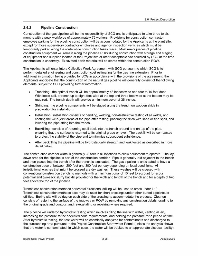
2.0 Project Description
Blythe Solar Power Project 2-28 August 2009
2.6.2 Pipeline Construction
Construction of the gas pipeline will be the responsibility of SCG and is anticipated to take three to six months with a peak workforce of approximately 75 workers. Provisions for construction contractor employee parking for the pipeline construction will be accommodated by the Applicants at the plant site, except for those supervisory contractor employee and agency inspection vehicles which must be temporarily parked along the route while construction takes place. Most major pieces of pipeline construction equipment will remain along the pipeline ROW during construction with storage and staging of equipment and supplies located at the Project site or other acceptable site selected by SCG at the time construction is underway. Excavated earth material will be stored within the construction ROW.
The Applicants will enter into a Collective Work Agreement with SCG pursuant to which SCG is to perform detailed engineering and construction cost estimating for the gas line extension. Prior to additional information being provided by SCG in accordance with the provisions of the agreement, the Applicants anticipate that the construction of the natural gas pipeline will generally consist of the following elements, subject to SCG providing further information.
Trenching: the optimal trench will be approximately 48 inches wide and four to 10 feet deep. With loose soil, a trench up to eight feet wide at the top and three feet wide at the bottom may be required. The trench depth will provide a minimum cover of 36 inches.
Stringing: the pipeline components will be staged along the trench on wooden skids in preparation for installation.
Installation: installation consists of bending, welding, non-destructive testing of all welds, and coating the weld-joint areas of the pipe after testing; padding the ditch with sand or fine spoil, and lowering the pipe string into the trench.
Backfilling: consists of returning spoil back into the trench around and on top of the pipe, ensuring that the surface is returned to its original grade or level. The backfill will be compacted to protect the stability of the pipe and to minimize subsequent subsidence.
After backfilling the pipeline will be hydrostatically strength and leak tested as described in more detail below.
The construction corridor width is generally 30 feet in all locations to allow equipment to operate. The lay-down area for the pipeline is part of the construction corridor. Pipe is generally laid adjacent to the trench and then placed into the trench after the trench is excavated. The gas pipeline is anticipated to have a construction pace of between 200 feet and 300 feet per day depending on local conditions. All jurisdictional washes that might be crossed are dry washes. These washes will be crossed with conventional construction trenching methods with a minimum burial of 10 feet to account for scour potential and two-sack slurry backfill provided for the width and length of the trench and for a depth of two feet above the top of the pipeline.
Trenchless construction methods horizontal directional drilling will be used to cross under I-10. Trenchless construction methods also may be used for short crossings under other buried pipelines or utilities. Boring pits will be dug on each side of the crossing to accommodate the process. Cleanup consists of restoring the surface of the roadway or ROW by removing any construction debris, grading to the original grade and contour, and revegetating or repairing where required.
The pipeline will undergo hydrostatic testing which involves filling the line with water, venting all air, increasing the pressure to the specified code requirements, and holding the pressure for a period of time. After hydrostatic testing, the test water will be chemically analyzed for contaminants and discharged to the surrounding area pursuant to the Project Construction Stormwater Permit (unless the analysis shows that the water is contaminated, in which case, the water will be trucked to an appropriate disposal facility).
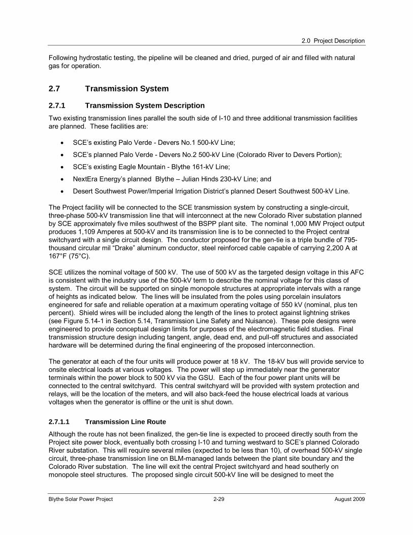
2.0 Project Description
Blythe Solar Power Project 2-29 August 2009
Following hydrostatic testing, the pipeline will be cleaned and dried, purged of air and filled with natural gas for operation.
2.7 Transmission System
2.7.1 Transmission System Description
Two existing transmission lines parallel the south side of I-10 and three additional transmission facilities are planned. These facilities are:
SCE’s existing Palo Verde - Devers No.1 500-kV Line;
SCE’s planned Palo Verde - Devers No.2 500-kV Line (Colorado River to Devers Portion);
SCE’s existing Eagle Mountain - Blythe 161-kV Line;
NextEra Energy’s planned Blythe – Julian Hinds 230-kV Line; and
Desert Southwest Power/Imperial Irrigation District’s planned Desert Southwest 500-kV Line.
The Project facility will be connected to the SCE transmission system by constructing a single-circuit, three-phase 500-kV transmission line that will interconnect at the new Colorado River substation planned by SCE approximately five miles southwest of the BSPP plant site. The nominal 1,000 MW Project output produces 1,109 Amperes at 500-kV and its transmission line is to be connected to the Project central switchyard with a single circuit design. The conductor proposed for the gen-tie is a triple bundle of 795- thousand circular mil “Drake” aluminum conductor, steel reinforced cable capable of carrying 2,200 A at 167°F (75°C).
SCE utilizes the nominal voltage of 500 kV. The use of 500 kV as the targeted design voltage in this AFC is consistent with the industry use of the 500-kV term to describe the nominal voltage for this class of system. The circuit will be supported on single monopole structures at appropriate intervals with a range of heights as indicated below. The lines will be insulated from the poles using porcelain insulators engineered for safe and reliable operation at a maximum operating voltage of 550 kV (nominal, plus ten percent). Shield wires will be included along the length of the lines to protect against lightning strikes (see Figure 5.14-1 in Section 5.14, Transmission Line Safety and Nuisance). These pole designs were engineered to provide conceptual design limits for purposes of the electromagnetic field studies. Final transmission structure design including tangent, angle, dead end, and pull-off structures and associated hardware will be determined during the final engineering of the proposed interconnection.
The generator at each of the four units will produce power at 18 kV. The 18-kV bus will provide service to onsite electrical loads at various voltages. The power will step up immediately near the generator terminals within the power block to 500 kV via the GSU. Each of the four power plant units will be connected to the central switchyard. This central switchyard will be provided with system protection and relays, will be the location of the meters, and will also back-feed the house electrical loads at various voltages when the generator is offline or the unit is shut down.
2.7.1.1 Transmission Line Route
Although the route has not been finalized, the gen-tie line is expected to proceed directly south from the Project site power block, eventually both crossing I-10 and turning westward to SCE’s planned Colorado River substation. This will require several miles (expected to be less than 10), of overhead 500-kV single circuit, three-phase transmission line on BLM-managed lands between the plant site boundary and the Colorado River substation. The line will exit the central Project switchyard and head southerly on monopole steel structures. The proposed single circuit 500-kV line will be designed to meet the

2.0 Project Description
Blythe Solar Power Project 2-30 August 2009
requirements of California Public Utilities Commission General Order 95 (GO-95). During preliminary transmission line design, a conservative approach was taken in the pole design height in order to ensure ground clearance is in accordance with GO-95, but final design will be based on actual field conditions and site requirements.
2.7.1.2 Transmission Structures
The monopole structures are expected to range in height from 90 feet to a maximum height of 145 feet and an average span length of in the range of 400 to 1,200 feet. Structure heights and corresponding span lengths will be selected to meet Federal Aviation Administration (FAA) requirements for the nearby Blythe Airport located to the southeast of the Project facility. Along parts of the north-south run of the transmission line, pole heights will be no taller than 90 feet.
Access by vehicle to the Project transmission line route will be by existing dirt roads wherever possible. The access road system used for the construction of the Project facilities will be used as much as possible, however, approximately three miles of new access road will be required. There also will be new stub access roads (approximately 100 feet long each) from the Project access road to provide access to new structure locations between the plant site and the point where the gen-tie line crosses I-10 approximately four miles south of the Project’s central switchyard. Installation of the transmission structures and conductors will require disturbance of small additional areas totaling less than one acre in the aggregate. These include several pull sites (from which the new conductors are actually installed on the new structures and strung between them) and a few splicing sites.
The approximate routing of the gen-tie line is illustrated on Figure 2-1. The precise equipment and interconnection configuration within the Colorado River substation are currently being defined by SCE. They will own and operate the substation, which is being planned to serve a variety of generating stations expected in the region.
The transmission line will be constructed in accordance with the guidelines of Institute of Electrical and Electronics Engineers (IEEE) Guide 524 “Guide to the Installation of Overhead Transmission Line Conductors” with crews working continuously along the ROW. Construction of the entire transmission line requires a peak workforce of approximately 20 workers. Transmission line construction will include the installation of tubular steel poles involving the following sequence of activities:
Marshalling Yards: Staging areas for trailers, office personnel, equipment, material staging, laydown and employee parking for the project will be established in an approved area.
Road Work: As needed, dirt roads for access along the transmission line route to provide access to the structure locations. These access roads will be installed in locations that avoid sensitive environmental resources identified in Project environmental surveys.
Pole Erection: Each pole will be assembled on site and dressed out with insulators and conductor hardware.
Conductors: From pulling sites, the conductors will be installed, sagged and permanently connected to the insulators.
Pulling Sites: There will be approximately three pulling sites required to install the conductors.
Communication System: The overhead ground/fiber optic communications cable will be installed using the same pulling sites as were used for the conductor installation.
The BSPP gen-tie line will be a 500-kV line placed on steel monopoles. The lines and monopoles will be placed both inside and outside the facility boundary and tower type and placement techniques will be the same in either case. The construction corridor will be about 80 feet wide with a final easement width of
2.0 Project Description
Blythe Solar Power Project 2-31 August 2009
175 feet. Transmission towers immediately west of Blythe Airport will be limited in height to 90 feet in accordance with FAA regulations. On this stretch of line, tower spacing will be reduced.
The towers will be installed using cranes to place the towers on concrete foundations buried in the ground. The construction footprint at the tower locations is approximately 20-feet by 20-feet square. The laydown area is contained within the construction corridor of 80 feet along the full alignment. Material will only be delivered to the offsite locations sufficient for each day’s construction activities. North of I-10 the towers will be installed along the site access road. South of the I-10, a 15-foot wide access road will be constructed adjacent to the towers for the remaining length of the alignment. Pull sites are the same general locations as the tower sites. The pull will originate from the end of the alignment and will progress from tower to tower for the full alignment using pulley rigs and cables.
2.7.2 Interconnection Study
The California Independent System Operator (CAlSO) and SCE initiated a Phase 1 Cluster Study in the fall of 2008. The Phase I Cluster Study was released on August 5, 2009. The Applicant will provide this document under confidential cover.
The final Phase 2 Study will commence in November 2009 and will be completed in 2010. The Applicants expect to conclude an Interconnection Agreement for the Project in the fourth quarter of 2010.
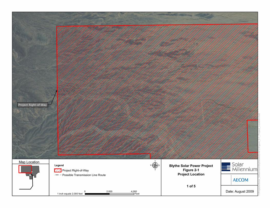
Blythe Solar Power ProjectFigure 2-1
Project Location
LEGEND
Map Location
Date: August 2009
Y:\Pr
ojects
\Sola
r_Mille
nnium
\Blyt
he\M
XD\AF
C\Fig
ure_2
-1_Pr
oject_
Loca
tion.m
xd
Project Right-of-Way
0 2,000 4,000Feet1 inch equals 2,000 feet
LegendProject Right-of-WayPossible Transmission Line Route
1 of 5
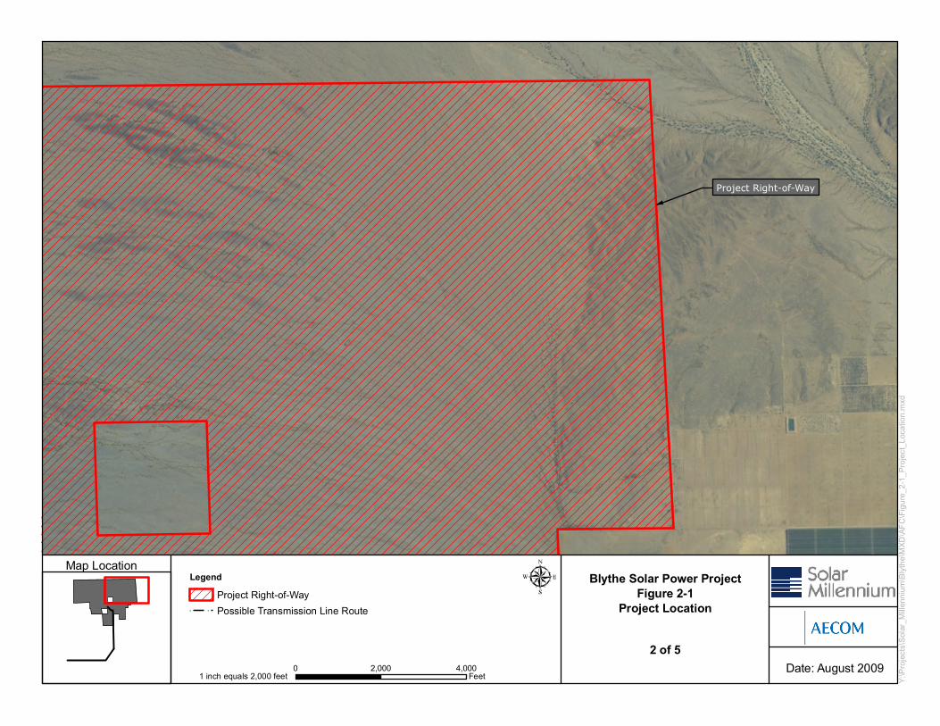
Blythe Solar Power ProjectFigure 2-1
Project Location
LEGEND
Map Location
Date: August 2009
Y:\Pr
ojects
\Sola
r_Mille
nnium
\Blyt
he\M
XD\AF
C\Fig
ure_2
-1_Pr
oject_
Loca
tion.m
xd
Project Right-of-Way
0 2,000 4,000Feet1 inch equals 2,000 feet
LegendProject Right-of-WayPossible Transmission Line Route
2 of 5
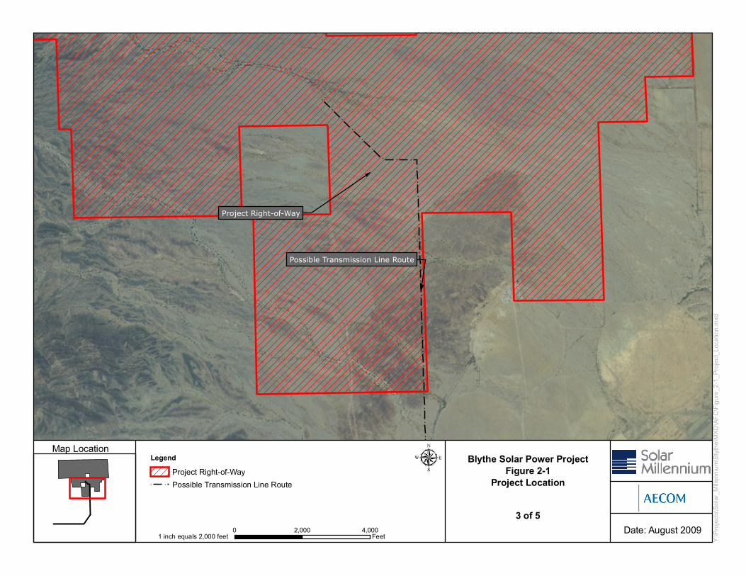
Blythe Solar Power ProjectFigure 2-1
Project Location
LEGEND
Map Location
Date: August 2009
Y:\Pr
ojects
\Sola
r_Mille
nnium
\Blyt
he\M
XD\AF
C\Fig
ure_2
-1_Pr
oject_
Loca
tion.m
xd
Possible Transmission Line Route
Project Right-of-Way
0 2,000 4,000Feet1 inch equals 2,000 feet
LegendProject Right-of-WayPossible Transmission Line Route
3 of 5
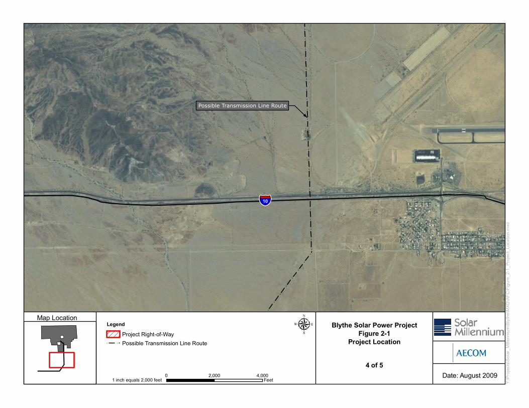
Blythe Solar Power ProjectFigure 2-1
Project Location
LEGEND
Map Location
Date: August 2009
Y:\Pr
ojects
\Sola
r_Mille
nnium
\Blyt
he\M
XD\AF
C\Fig
ure_2
-1_Pr
oject_
Loca
tion.m
xd
Possible Transmission Line Route
10
0 2,000 4,000Feet1 inch equals 2,000 feet
LegendProject Right-of-WayPossible Transmission Line Route
4 of 5
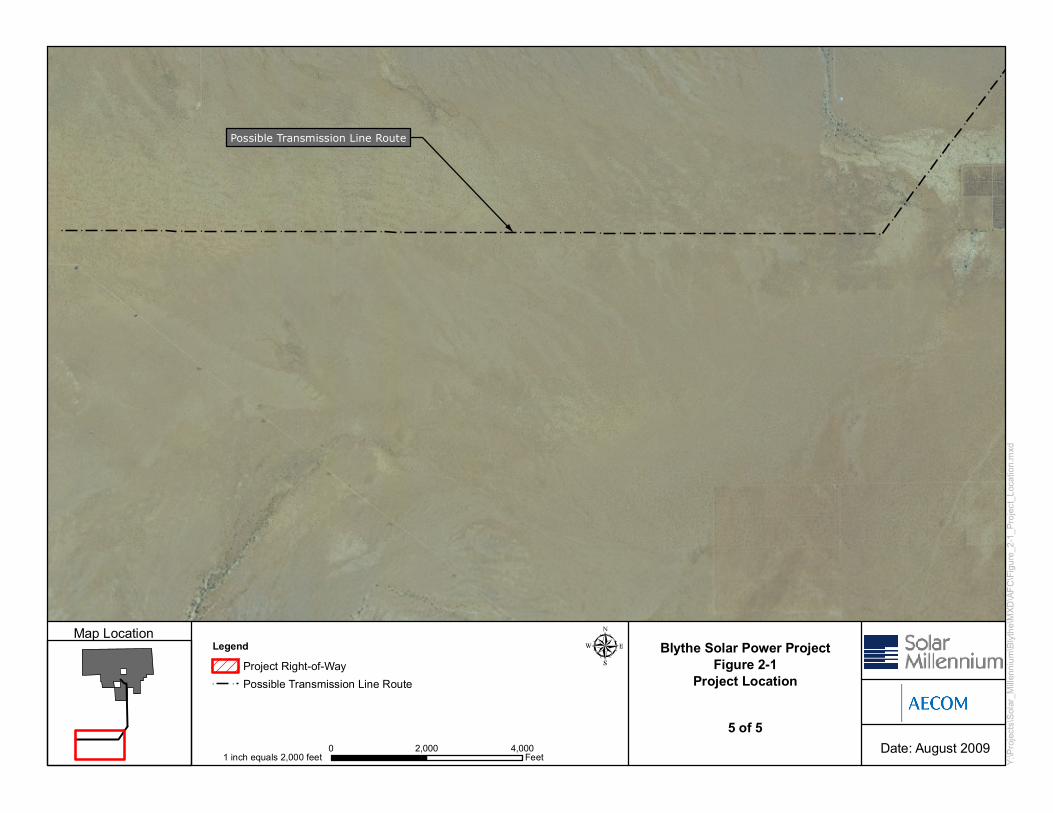
Blythe Solar Power ProjectFigure 2-1
Project Location
LEGEND
Map Location
Date: August 2009
Y:\Pr
ojects
\Sola
r_Mille
nnium
\Blyt
he\M
XD\AF
C\Fig
ure_2
-1_Pr
oject_
Loca
tion.m
xd
Possible Transmission Line Route
0 2,000 4,000Feet1 inch equals 2,000 feet
LegendProject Right-of-WayPossible Transmission Line Route
5 of 5
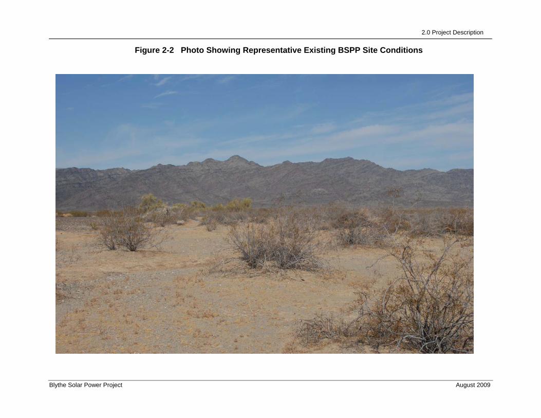
2.0 Project Description
Blythe Solar Power Project August 2009
Figure 2-2 Photo Showing Representative Existing BSPP Site Conditions

2.0 Project Description
Blythe Solar Power Project August 2009
Figure 2-3a Photo Showing BSPP Site without Simulated Project Facilities
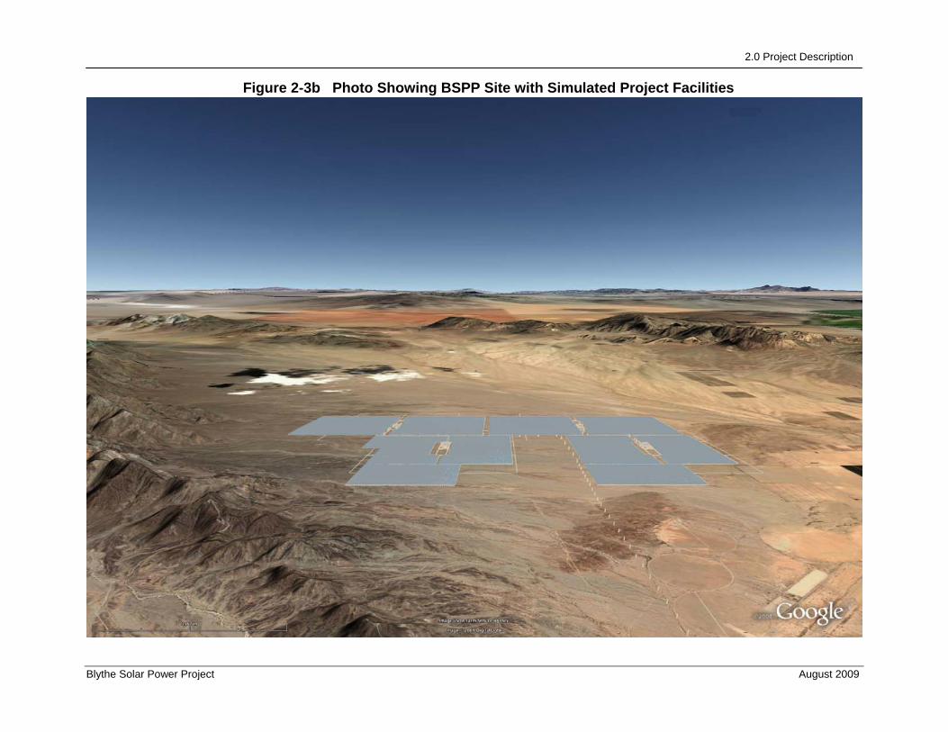
2.0 Project Description
Blythe Solar Power Project August 2009
Figure 2-3b Photo Showing BSPP Site with Simulated Project Facilities
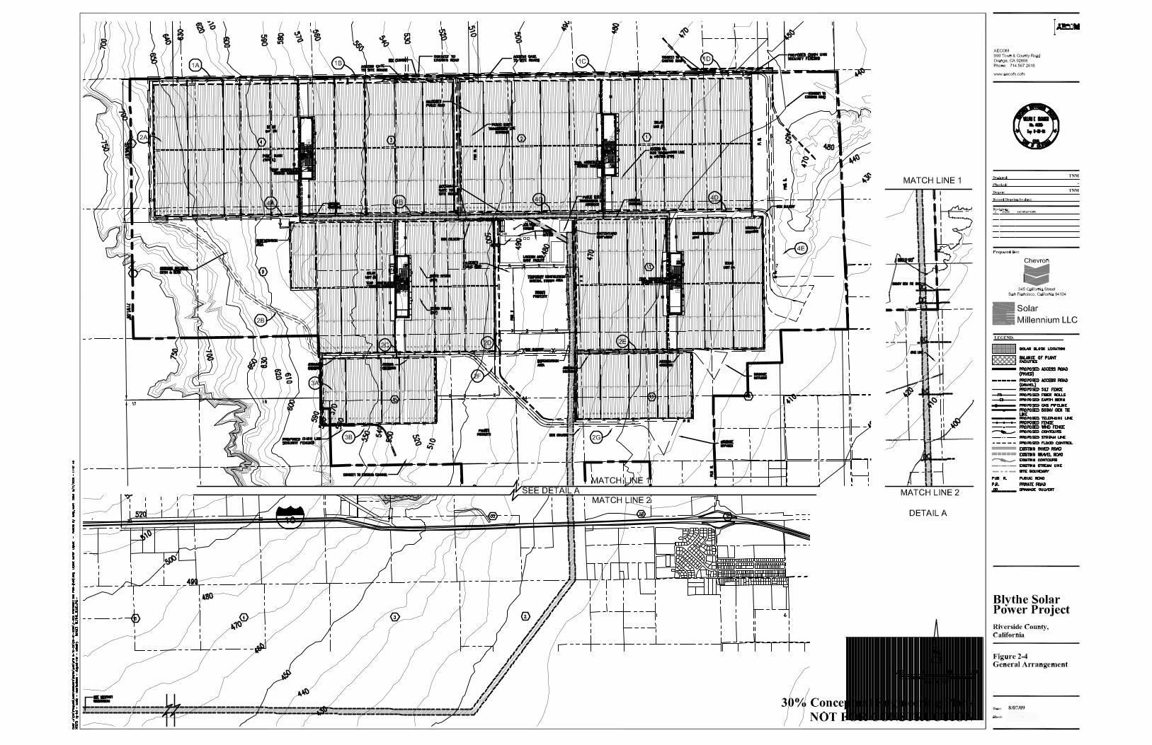
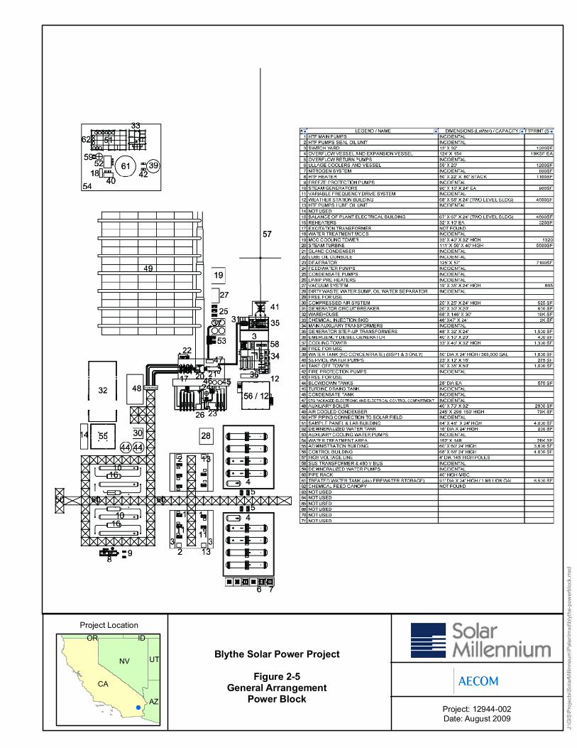
Project: 12944-002Date: August 2009
Blythe Solar Power ProjectFigure 2-5
General ArrangementPower Block
Project Location
J:\GI
S\Proj
ects\
Solar
Millin
neum
\Palen
\mxd
\blyth
e-pow
erbloc
k.mxd
CA
NV
AZ
UT
OR ID

Project: 12944-002Date: August 2009
Blythe Solar Power ProjectFigure 2-6a
Elevation View ofProject Facilities
Project Location
J:\GI
S\Proj
ects\
Solar
Millin
neum
\Blyth
e\mxd
\blyth
e-Elev
ation
View
.mxd
CA
NV
AZ
UT
OR ID
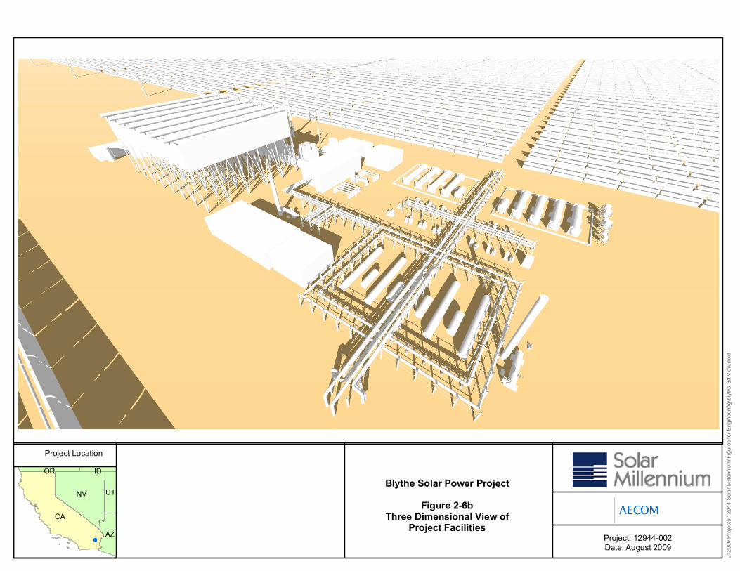
Project: 12944-002Date: August 2009
Blythe Solar Power ProjectFigure 2-6b
Three Dimensional View ofProject Facilities
Project Location
J:\20
09 Pr
ojects
\1294
4-Sola
r Mille
nnium
\Figu
res fo
r Eng
ineeri
ng\bl
ythe-3
d View
.mxd
CA
NV
AZ
UT
OR ID
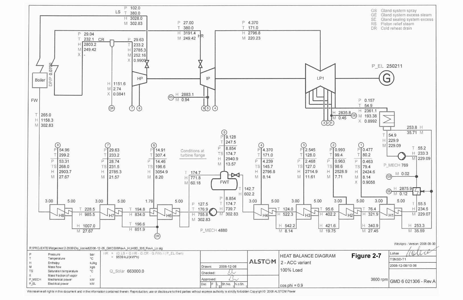
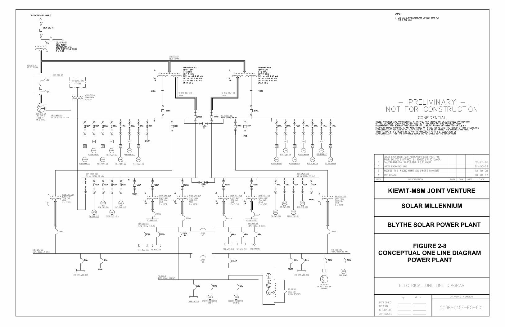
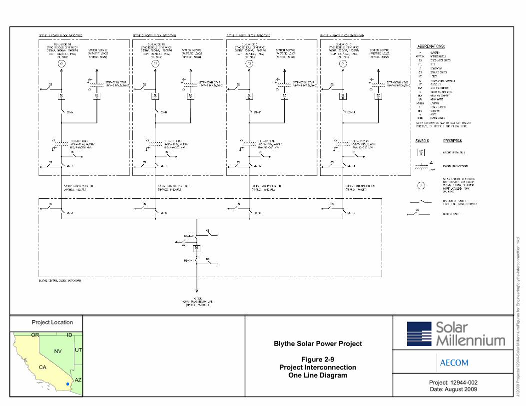
Project: 12944-002Date: August 2009
Blythe Solar Power ProjectFigure 2-9
Project InterconnectionOne Line Diagram
Project Location
J:\20
09 Pr
ojects
\1294
4-Sola
r Mille
nnium
\Figu
res fo
r Eng
ineeri
ng\bl
ythe-i
nterco
nnec
ttion.m
xd
CA
NV
AZ
UT
OR ID
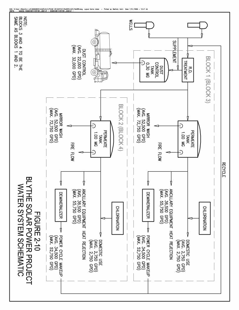
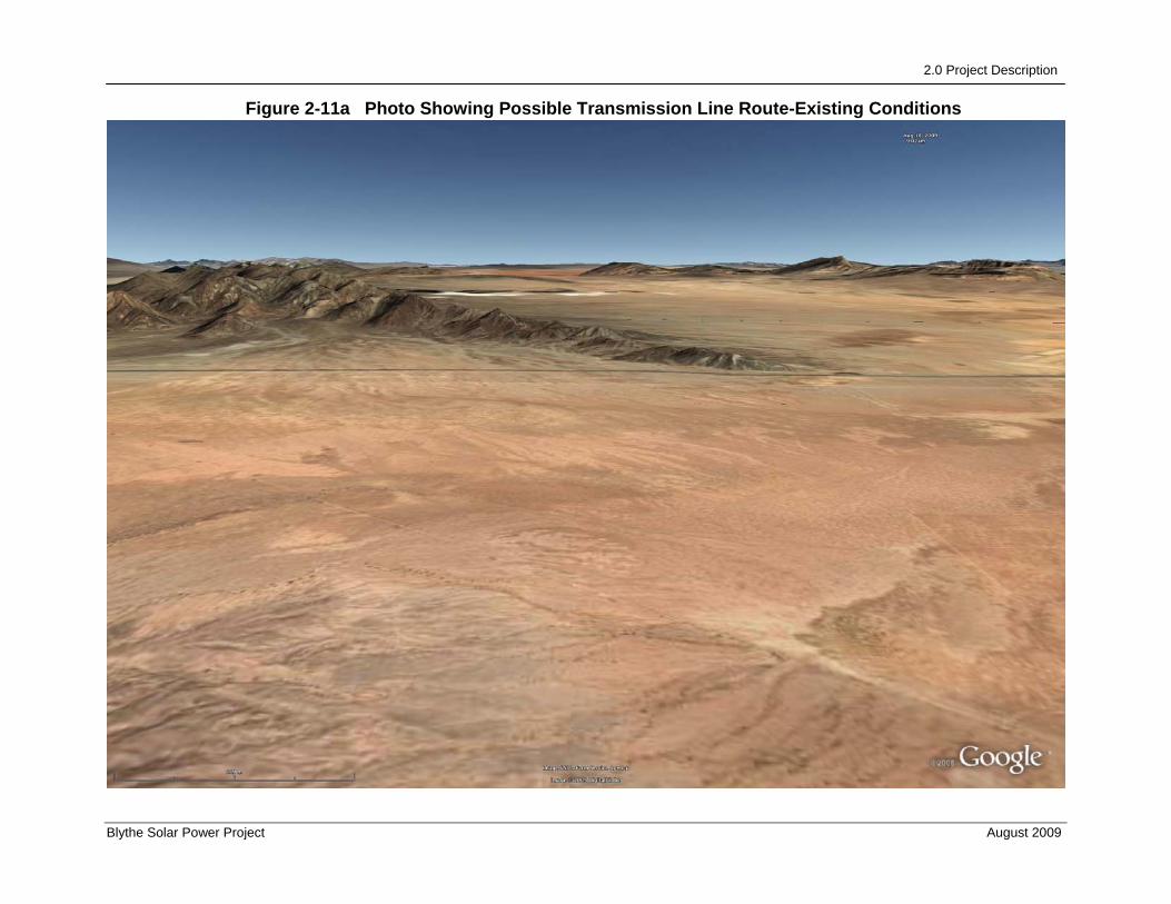
2.0 Project Description
Blythe Solar Power Project August 2009
Figure 2-11a Photo Showing Possible Transmission Line Route-Existing Conditions
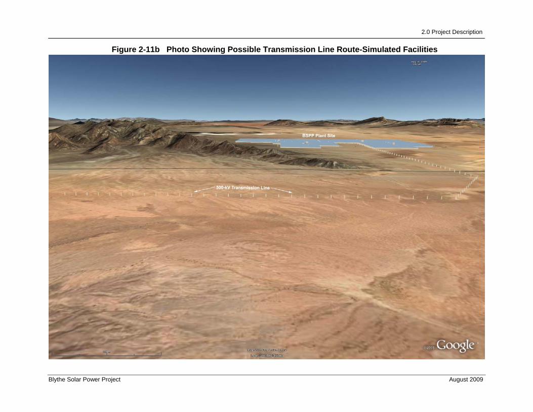
2.0 Project Description
Blythe Solar Power Project August 2009
Figure 2-11b Photo Showing Possible Transmission Line Route-Simulated Facilities
Related Documents