FACILITIES SUBCOMMITTEE MEETING Gilroy Unified School District – via Zoom teleconference 9 a.m. Friday, Feb. 5, 2021 1. ITEM PAGE # A. Approval of minutes: Jan. 8, 2021 1-4 2. FACILITIES & NEW CONSTRUCTION (PAUL NADEAU) ITEM SITE VENDOR COST FUNDING SOURCE PAGE # A. Music room discussion Brownell MS Aedis Architects $600,000 Measure E 5 B. Design Update South Valley MS Aedis Architects N/A Measure E 6-12 C. Additional Architecture fees Brownell MS Aedis Architects $183,451 Measure E 13-20 D. Door Station Installation Brownell MS QoVo Inc. $1,218.52 Measure E 21-27 E. Monitor Stands for classrooms Brownell MS CDW-G $24,196.95 Measure E 28 F. At Risk Insurance for AIPG installs Rod Kelley, El Roble, Glen View Zurich Inc. $1,768 General fund 29-38 G. Re-Location of Adult Ed from SVMS campus TBD N/A TBD N/A N/A H. Additional IOR fees for lighting project GHS Jerome Zalinski $6,300 Measure E 39 I. District Standards Update All N/A N/A N/A 40-461 3. MAINTENANCE (DAN MCAULIFFE) ITEM SITE VENDOR COST FUNDING SOURCE PAGE # A. Roofing needs Gilroy HS and ADB/South County Annex TREMCO Consultant Contractor TBD TBD Deferred Maintenance 462-467 B. Storm water concerns INFORMATION ONLY Transportation and Maintenance yards N/A N/A N/A N/A

Welcome message from author
This document is posted to help you gain knowledge. Please leave a comment to let me know what you think about it! Share it to your friends and learn new things together.
Transcript

FACILITIES SUBCOMMITTEE MEETING
Gilroy Unified School District – via Zoom teleconference
9 a.m. Friday, Feb. 5, 2021
1.
ITEM PAGE #
A. Approval of minutes: Jan. 8, 2021 1-4
2. FACILITIES & NEW CONSTRUCTION (PAUL NADEAU)
ITEM SITE VENDOR COST FUNDING SOURCE
PAGE #
A. Music room discussion Brownell MS Aedis Architects $600,000 Measure E 5
B. Design Update South Valley MS Aedis Architects N/A Measure E 6-12
C. Additional Architecture
fees
Brownell MS Aedis Architects $183,451 Measure E 13-20
D. Door Station Installation Brownell MS QoVo Inc. $1,218.52 Measure E 21-27
E. Monitor Stands for
classrooms
Brownell MS CDW-G $24,196.95 Measure E 28
F. At Risk Insurance for
AIPG installs
Rod Kelley, El Roble, Glen View
Zurich Inc. $1,768 General fund 29-38
G. Re-Location of Adult Ed
from SVMS campus
TBD N/A TBD N/A N/A
H. Additional IOR fees for
lighting project
GHS Jerome Zalinski $6,300 Measure E 39
I. District Standards Update All N/A N/A N/A 40-461
3. MAINTENANCE (DAN MCAULIFFE)
ITEM SITE VENDOR COST FUNDING SOURCE
PAGE #
A. Roofing needs Gilroy HS and ADB/South County Annex
TREMCO Consultant Contractor TBD
TBD Deferred Maintenance
462-467
B. Storm water concerns
INFORMATION ONLY
Transportation and Maintenance yards
N/A N/A N/A N/A
namartinez
Typewritten Text
Updated: 4 p.m. 2/4/21

C. HVAC assessments #2 All remaining sites TEAM Val’s/Cypress/ Alpha Air
*Waiting on current proposal (not to exceed)
ESSER Funds N/A
D. Tree risk assessment
arborist report
All sites Anderson’s Tree Care
$9,675 RRM 468-471
E. Roof replacement for fire
pump house
Rucker ES Waterproofing Associates
$8,548 RRM 472-474
F. Roof replacement for old
pump house
Maintenance yard Waterproofing Associates
$6,708 RRM 475-476
4. SAFETY/EMERGENCY PREPAREDNESS (AURELIO RODRIGUEZ)
ITEM SITE VENDOR COST FUNDING SOURCE
PAGE #
A. Security cameras Glen View ES Qovo $32,228.78 N/A 477-485
OTHER PROJECTS/FACILITY ISSUES AT SITES
SITES
ANTONIO DEL BUONO ES BROWNELL MS CHRISTOPHER HS
ELIOT ES SOLORSANO MS GECA
EL ROBLE ES SOUTH VALLEY MS GILROY HS
GLEN VIEW ES MT. MADONNA HS
LAS ANIMAS ES
LUIGI APREA ES DISTRICT OFFICE
ROD KELLEY ES
RUCKER ES
NEXT MEETING: 9 A.M. FRIDAY, March 5, 2021
namartinez
Typewritten Text
Updated: 4 p.m. 2/4/21
namartinez
Typewritten Text
FACILITIES SUBCOMMITTEE MEETING
Gilroy Unified School District – Via Webex teleconference
Friday, Jan. 8, 2021
PRESENT
BC Doyle
Mark Good
Anna O’Connor
Alvaro Meza
Debbie Flores
Paul Nadeau
Linda Piceno
Dan McAuliffe
MEETING CALLED TO ORDER: 9:15 a.m.
APPROVAL OF MINUTES FROM DEC. 4, 2020:
• Mark made the motion to approve the minutes, Linda seconded.
• All approve.
APPROVAL OF MINUTES FROM DEC. 18, 2020:
• Mark made the motion to approve the minutes, Linda seconded.
• All approve.
FACILITIES ITEMS (PAUL NADEAU)
SOUTH VALLEY MS: TRAFFIC STUDY
• $14,000 from Measure E
• Traffic impact study for South Valley Middle School Modernization Project.
• W-Trans is the recommended vendor, from the four submitted bids.
• In the absence of the regular school traffic, the plan is to interview local authorities, Gilroy Prep,
South Valley and other entities around South Valley. The vendor offered to conduct a
supplemental study with actuals, once traffic returns to the area.
• This is basic study is a CEQA requirement. But it also serves for the city’s information.
• James: Does this study include the CEQA and LOS study? Do we need to conduct the LOS study,
especially during the shutdown? If a LOS study is conducted, are we including information that is
unnecessary?
• We will ask that W-Tran not do the LOS or the follow up.
• Next steps: The proposal from W-Trans will go to the board for approval, with the modification
of only including the CEQA requirement (not the LOS or follow-up study).
EL ROBLE ES, GLEN VIEW ES, ROD KELLEY ES: PLAYGROUND CONTRACTS
• This item is not ready for the committee to discuss.
Page 1
namartinez
Typewritten Text
1a
namartinez
Typewritten Text
namartinez
Typewritten Text
namartinez
Typewritten Text
namartinez
Typewritten Text
namartinez
Typewritten Text
namartinez
Typewritten Text
namartinez
Typewritten Text
namartinez
Typewritten Text
namartinez
Rectangle
namartinez
Typewritten Text
Debbie Flores Mark Good Alvaro Meza Paul Nadeau Anna O'Connor James Pace Linda Piceno Anna O'Connor Aurelio Rodriguez
namartinez
Typewritten Text
namartinez
Typewritten Text
namartinez
Typewritten Text
namartinez
Typewritten Text
namartinez
Typewritten Text
namartinez
Typewritten Text
namartinez
Typewritten Text
Updated: 4 p.m. 2/4/21
namartinez
Typewritten Text

BROWNELL MS: INSTALLATION OF FILING IN ADMIN AREA AND HEALTH OFFICE
• $1,500 from Measure E
• Golden PMI
• This is to replace the older file cabinets. This is to install a row of cabinets in the corridor in the
admin building.
• This is also to install a file cabinet and desktop to the health office.
• Next steps: This will go to the board for approval
BROWNELL MS: CAMERA INSTALLATIONS
• $20,857.36 from Measure E
• This is to add five additional cameras to finish the plan for cameras on this campus.
• This also includes the installation of a license-plate reader in the alley on the northeast part of
the campus. The access to the data would be limited to Aurelio so he could work with the police
in case of any issues. The camera does not pull up the registered driver information – the police
would have to pull that. The camera just captures a clear picture of a license plate.
• Dr. Flores: This might be a good idea for the maintenance yard and district office.
• Next steps: This will go to the board for approval.
BROWNELL MS: FINAL CLASSROOM MOVE
• $5,986.45 from Measure E.
• Hollister Moving.
• This is to move the sixth-grade teachers from temporary locations to their permanent
classrooms.
• This will move the books from temporary library to the permanent library.
• Hollister Moving has been the moving vendor throughout the project. They are one of two on
the district’s pre-qualified list. Moving companies based in Gilroy and can bond at our
requirements can go through our pre-qualified process.
• Next steps: This will go to the board for approval.
BROWNELL MS: INDUSTRIAL HYGIENE (ABATEMENT) MANAGEMENT
• $26,202 from Measure E
• EnviroScience, Inc.
• This has been historically called abatement in in the past in the district. The more accurate name
for the process is industrial hygiene management.
• They will monitor the process in which the abatement company does their work during the
demolition process. They don’t actually the abatement itself, though.
• They’ve built in a contingency into the quote to allow for any unknowns that may come up in
the abatement phase.
• Next steps: This will go to the board for approval
FACILITIES: PRE-QUALIFICATION PROCESSING
• $10,000 from Measure E.
• Colbi Technologies.
• This would be an add-on the services Colbi is already providing.
Page 2
namartinez
Typewritten Text
Updated: 4 p.m. 2/4/21
namartinez
Typewritten Text
namartinez
Typewritten Text
• The services screen and process contractors for the district pre-qualified list. We work with as
many as 200 contractors and if we do this in-house, it would be three-four hours for each
contractor.
• Linda: Can we use Measure E funds for Maintenance contractors?
o Alvaro: To be safe, we should only for Measure E for Facilities contractors. For
Maintenance contractors, the cost would have to carried by that department’s RRM
budget.
• Next steps: This will go to the board for approval.
GILROY HS: ADDITIONAL FENCING FOR THE POOL PROJECT
• $44,529 from Measure E.
• Dryco Construction, Inc.
• This is for a few fencing improvements at Gilroy HS, near the stadium and pool:
o Installation of double-swing gate near the ticket booth, $5,821:
▪ Includes gate posts, chain-link fence and double gates. Allows for better crowd
control and vehicle access/traffic in this area.
▪ This would replace the existing stand-alone ticket booth with this gate. The
ticket booth would move to the neighboring building, which has a roll-up
window.
o Installation of coil-wire fence at the top of the gates in pool area, $3,438:
▪ To help deter intruders.
▪ Paul recommends starting with one panel so we can evaluate whether this
solution visually fits into the area.
o Removal of existing gate and construction of new fence, $2,569:
▪ Removes the ADA gate on the left now that the ADA gate and ramp are moved
to the right of the area.
▪ Retains existing poles to anchor the fence.
o Installation of chain-link cage and gates, $26,906:
▪ This swaps in a drive gate for future equipment access, not regular vehicle
access. One side of pool that faces stadium parking lot.
• This removes the stand-alone ticket booth. This would move
• This includes these improvements:
o Gate posts: This removes the stand-alone ticket booth. This would move
o Chain link fence:
o Double-swing gate:
• The cost of these improvements fall under the allocated pool project budget. These projects will
not exceed the set budget.
• Next steps: These will go the board for approval.
GLEN VIEW ES: GARDEN FENCING
• $8,716 from site funds (from NSU grant).
• Crusader, Inc.
• Along with the playground replacement at this site, the principal would like to use grant funds to
build a school garden near this area.
• The plan is for fenced-in area with raised garden beds. The gardens have features that allow for
easy composting at the end of the school year.
• Next steps: Paul will connect with the site principal to move to the next steps.
Page 3
namartinez
Typewritten Text
Updated: 4 p.m. 2/4/21
namartinez
Typewritten Text
namartinez
Typewritten Text

ALVARO MEZA’S ITEMS
GILROY HS: FOLLOW-UP ON COST SHARE OF 10TH-STREET IMPROVEMENTS
• The city asked for $30K from the district for the improvements in this crossing at 10th Street at
Gilroy HS.
• Alvaro doesn’t want to take this to the board yet because they haven’t provided bid information
or documents.
• Mark and James: If the city’s contribution is less than 50 percent, they should be asked to
rework their proposal until it is 50 percent.
• Next steps: Alvaro will follow up with the city for the documents and the budget details.
OTHER PROJECTS/FACILITY ISSUES AT SITES
BROWNELL MS:
• For the next FSC meeting, Dr. Flores requests a discussion item about the band and choir room
at Brownell MS. She’d like to look at a specific proposal and the cost. She’s given Paul direction
of what she’d like presented.
o Brownell MS has one section of choir and two sections of band.
o Trustee Good: Where is this coming from?
▪ One of the former teachers has said his hearing has been affected by the sound
quality in the MPR and another classroom, where classes had been held before
the modernization.
▪ The band teachers, who are new, in the district asked for band/music rooms in
each of the middle schools. They would like equality in this across the district.
Solorano MS has a band room. It’s part of the plan for South Valley MS. The
question is why it wasn’t a dedicated band/choir included in Brownell MS?
▪ In addition, after today’s site tour of Brownell MS, the suggestion was made to
put this on the next FSC agenda.
▪ Trustee Good: Was it an oversight in the planning of the school?
• Dr. Flores and Alvaro: We don’t remember it being brought up during
the planning and design of the school.
NEXT MEETING: 9 a.m. Friday, March 5.
Page 4
namartinez
Typewritten Text
Updated: 4 p.m. 2/4/21
namartinez
Typewritten Text
��
�� ��
��
�����������
����
�� ����������������
�� �������������������� ���������������������������������������������
�� ���������������������������� �� �������!
""""
��
�� ��
��
""
�����������
����
����������� ������������������������������������ ��������� ���������!���������
����������������#��������������������������������������
����������������� �����"�$��������������#������
%&
����������������������� �������������������������������#��#���#��������������������������� ���������������$ ������
'(�"�&
""""
��
�� ��
��
)(�" &)(�" &
)(�" �&
�����������
����
������������������� ������" )'&�#���#�
�������#��������!
""""
�� ��
�����#����(�" &
������!���#������� ������! ����%
����� ���������#������
������#�����(�" &
�������������������� ����� ����������������! ���������������� ������! �
�����������*(�" &
���������� ����������� ����������������! ��������������+$������������#������������
�#����,
���������
���������
�#���
��-���
����������
���
����
-���,
��
�������������������������� ����� ����������������� �� �� ����� ��������������������������������������� ��������� �!�����"�# ������# ����$��%���&����� �!�����"�# ������# ����'��
��������������
�������� �
�.+'.++��%/��/���
�/0�12310145367890�:;59
26<10+��+)�"��
���!
� �������
�����=14536789
3><
���
������������������������������������������������������������������������������������
�����!�����������#�����������
��������� �������#������������? ������@�����
�.+.+
+��+)
�.+'.++
�� ������ !��" �#!�
* ����,+� AA.AA.AA
�����$ %&'(�)�%*+ (% ��������������������
�����$ %&'(�)�%*+ (, ����������������
�����$ %&'(�)�%*+ (� �����������������������������
�����$ %&'(�)�%*+ (' ��������������
����-���-�����
�� ���.�������-
������
��������/�� ��� ��������-/�������- �����������
����������-
�� �! ��"� �"+ � "���� "+��� "% ��� � "� ����������"�� ��� �����+ ��������������� �$������ �"� � "���� "% �$�������������
��������� ������ "�
��� �������� ��"� �"� � "���� "% ���������� ��������� �����
� "�
��� ���������� ��"� �"� � "���� "% �$������������� ��������� �����
� "�
��) ������� �$������ �"� � "���� "% �$������������� ��������� �����
� "�
�+ ������ �������� �$������ �"� � "���� "% �$������������� ��������� �����
� "�
����-������
���0 ��������� �����&�/��� ����&�����- ������
���"� +("&�$��("&��������������������������
���� ��� �#��� ������������ � ��������+B�������������
���"+ +("&�$��("&��������������������������
���� ��� ����# ������������ � ���������B�������������
���"% +("&�$��("&��������������������������
���� ��� ����� �� ���#�� ��')�� ���
������������ � ���������B�������������
�"� �&���������� ��������� �� � '+���#� ����� ����������������!������(����������"+ �&���������� ��������� �� � �+%��#������ ����������������!������(���������� "� ��������� ���� ����!� ���� � �+����� �����C���������� �����
������C�! ���� "+ ��������� ���� ����!� ���� � ��')��� ��� ������C����� �������#���
���������������������#������������
� "% ��������� ���� ����!� ���� � ��+���� ��� ���! �� ��������C������������������ �������������� �����!
� "� ��������� ���� ����!� ���� � ��%��#�������#��� �� ��������C��$ �����-�����������������#�� ������������
�����������#�� � � ������������
�����C�����������! ������������� ��������� ���������
��"� ��������������� ���� �'�� � ��
����/�����#������������#����D��������������� ������������� ����������������������� ������������!� ����� �� �� � �������������������� ����� �$�������������������� �������������
������������������� ������" )'&�#���#�
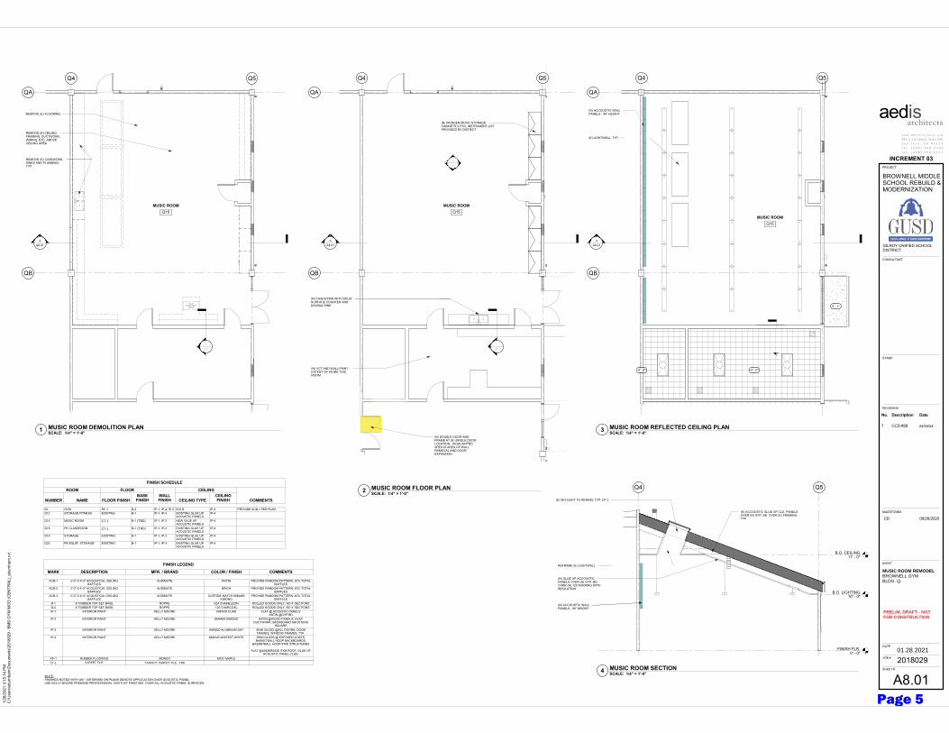
MUSIC ROOM REMODELBROWNELL GYM BLDG. Q.
PRELIM. DRAFT - NOTFOR CONSTRUCTION
01.28.2021
����������������#��������������������������������������
����/�����#������������#����D��������������� ������������� ����������������������� ������������!� ����� �� �� � �������������������� ����� �$�������������������� �������������
��"� ��������������� ���� �'�� � ��CT-1 CARPET TILE TARKETT CARPET TILE - TBD
CT-1
CT-1
(TBD)
(TBD)
Page 5
namartinez
Typewritten Text
2a
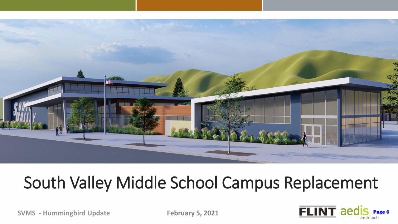
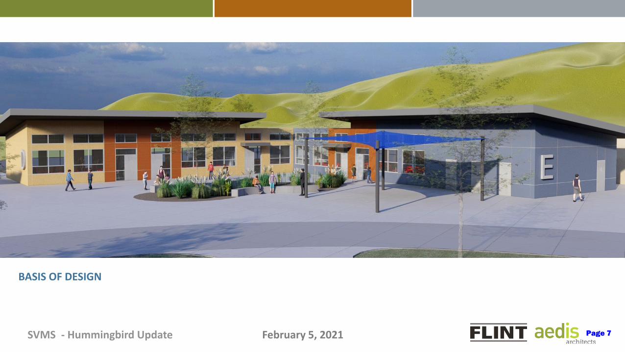
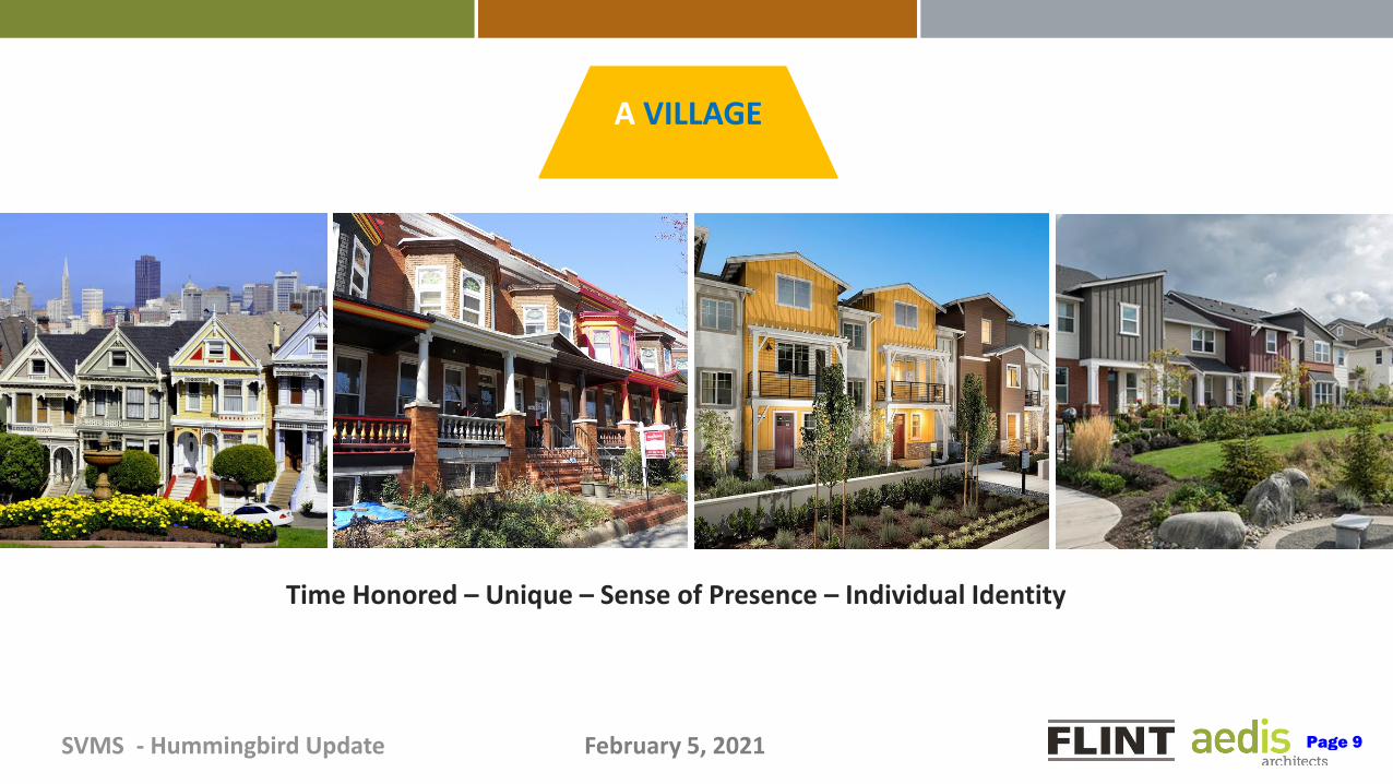
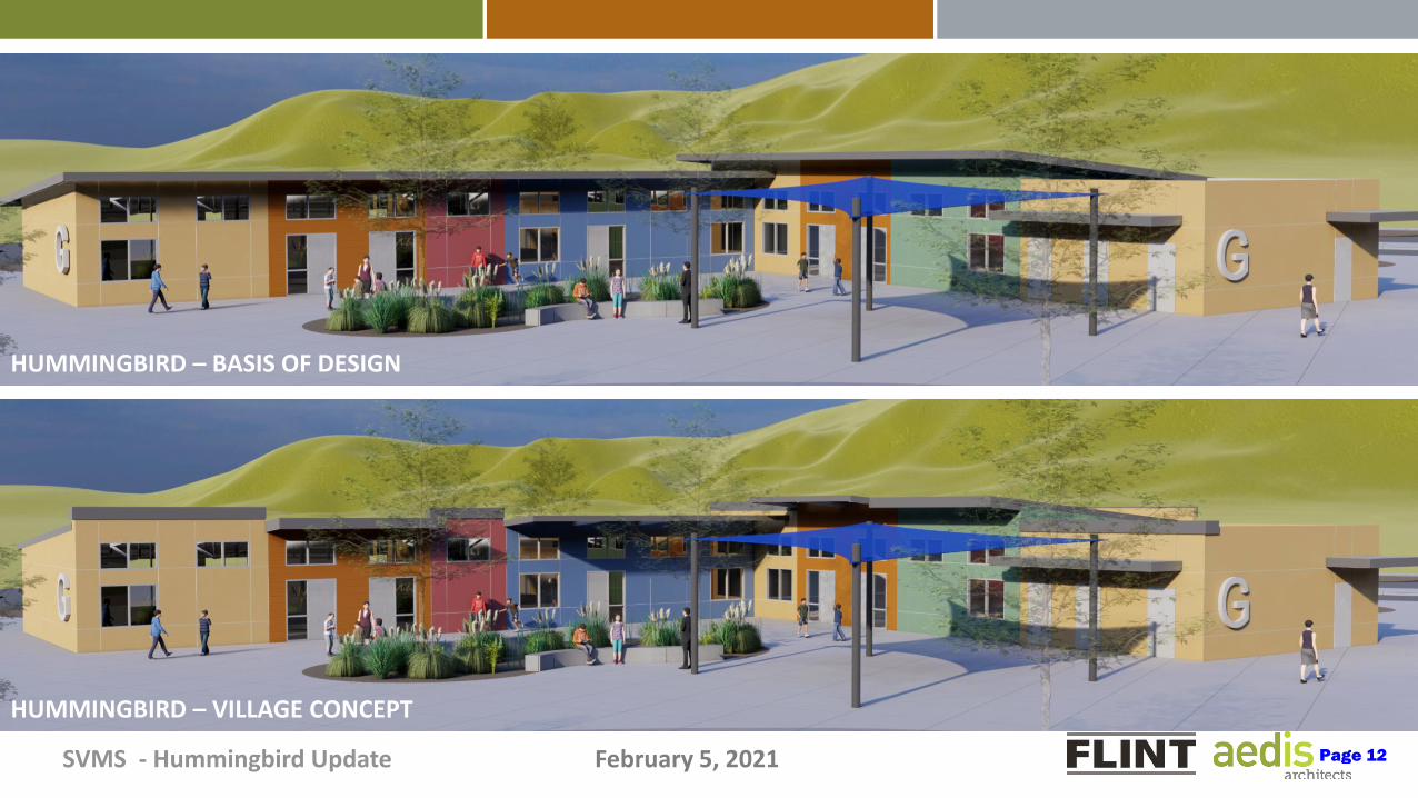
SVMS - Hummingbird Update February 5, 2021
South Valley Middle School Campus Replacement
Page 6
namartinez
Typewritten Text
2c
SVMS - Hummingbird Update February 5, 2021
BASIS OF DESIGN
Page 7

SVMS - Hummingbird Update February 5, 2021
A VILLAGEfor a kind
and fearless community
The Market PlaceThe Village Main Street Graphic Presence
Page 8
SVMS - Hummingbird Update February 5, 2021
Time Honored – Unique – Sense of Presence – Individual Identity
A VILLAGE
Page 9

SVMS - Hummingbird Update February 5, 2021
HUMMINGBIRD – BASIS OF DESIGN
Page 10

SVMS - Hummingbird Update February 5, 2021
HUMMINGBIRD – VILLAGE CONCEPT
Page 11
SVMS - Hummingbird Update February 5, 2021
BASIS OF DESIGN
HUMMINGBIRD – BASIS OF DESIGN
HUMMINGBIRD – VILLAGE CONCEPT
Page 12
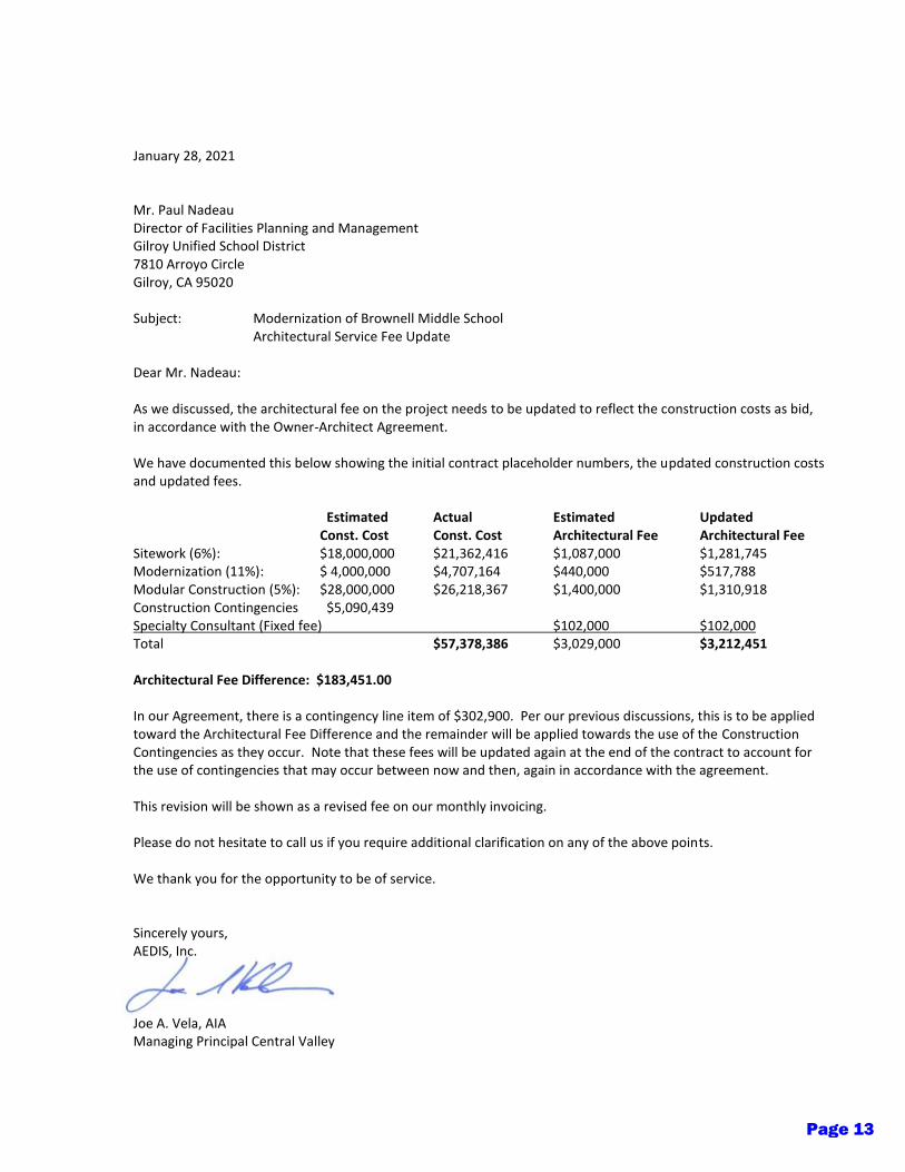
January 28, 2021 Mr. Paul Nadeau Director of Facilities Planning and Management Gilroy Unified School District 7810 Arroyo Circle Gilroy, CA 95020 Subject: Modernization of Brownell Middle School Architectural Service Fee Update Dear Mr. Nadeau: As we discussed, the architectural fee on the project needs to be updated to reflect the construction costs as bid, in accordance with the Owner-Architect Agreement. We have documented this below showing the initial contract placeholder numbers, the updated construction costs and updated fees. Estimated Actual Estimated Updated Const. Cost Const. Cost Architectural Fee Architectural Fee Sitework (6%): $18,000,000 $21,362,416 $1,087,000 $1,281,745 Modernization (11%): $ 4,000,000 $4,707,164 $440,000 $517,788 Modular Construction (5%): $28,000,000 $26,218,367 $1,400,000 $1,310,918 Construction Contingencies $5,090,439 Specialty Consultant (Fixed fee) $102,000 $102,000 Total $57,378,386 $3,029,000 $3,212,451 Architectural Fee Difference: $183,451.00 In our Agreement, there is a contingency line item of $302,900. Per our previous discussions, this is to be applied toward the Architectural Fee Difference and the remainder will be applied towards the use of the Construction Contingencies as they occur. Note that these fees will be updated again at the end of the contract to account for the use of contingencies that may occur between now and then, again in accordance with the agreement. This revision will be shown as a revised fee on our monthly invoicing. Please do not hesitate to call us if you require additional clarification on any of the above points. We thank you for the opportunity to be of service. Sincerely yours, AEDIS, Inc. Joe A. Vela, AIA Managing Principal Central Valley
Page 13
namartinez
Typewritten Text
2c

A B C D E F GItem Description of Work ScheduledNo. Value Sitework Modernization New Construction
(Modular) Overhead Contingencies
100 CONSTRUCTION SERVICES 0.00
105 Project Mobilization 60,000.00 60,000.00$
110 Trade Labor - site cleaning, safety, etc. 336,204.00 336,204.00$
115 Temporary Irrigation 0.00 -$
120 Barricades & Safety (Signage, etc.) Protection of (E) 35,682.00 35,682.00$
125 Protection of (E) Finishes to Remain 0.00
130 Temporary Fencing 46,950.00 46,950.00$
135 Tree Protection 16,996.00 16,996.00$
140 SWPPP Maintanence 43,194.00 43,194.00$
145 Field Engineering (Survey) 166,510.00 166,510.00$
150 SITE DEMOLITION 0.00 -$
155 Off-Site Demolition 36,162.00 36,162.00$
160 On-Site Demolition - Phase 1 242,764.00 242,764.00$
165 On-Site Demolition - Phase 2/3 130,472.00 130,472.00$
170 On-Site Demolition - Phase 4 52,977.00 52,977.00$
175 BUILDING DEMOLITION 0.00 -$
180 Bldg. Demo - Phase 1 296,916.00 296,916.00$
185 Bldg. Demo - Phase 2/3 83,232.00 83,232.00$
190 Bldg. Demo - Phase 4 40,495.00 40,495.00$
195 ABATEMENT 0.00
200 Aresenic Removal - Phase 1 42,971.00 42,971.00$
205 Bldg. Abatement - Phase 1 249,362.00 249,362.00$
210 Bldg. Abatement - Phase 2/3 60,586.00 60,586.00$
215 Hazmat (RAW) removal 0.00 -$
220 EARTHWORK & ASPHALT PAVING - PHASE I 0.00 -$
225 Mobilization 79,791.00 79,791.00$
230 SWPPP Installation 98,170.00 98,170.00$
235 Rough Grading 60,328.00 60,328.00$
240 Import Material 429,355.00 429,355.00$
245 Building Pad Grading 49,999.00 49,999.00$
250 Site & Landscaping Grading 109,156.00 109,156.00$
255 Bio-Swale Grading & CL 2 Base 165,496.00 165,496.00$
260 Subgrade Material (AB) 254,443.00 254,443.00$
265 AC Paving 448,793.00 448,793.00$
270 Striping & Signs 12,064.00 12,064.00$
275 Off-Site Work - Carmel 75,352.00 75,352.00$
280 Off-Site Work - Hannah 47,182.00 47,182.00$
285 EARTHWORK & ASPHALT PAVING - PHASE 2 0.00 -$
290 Mobilization 52,535.00 52,535.00$
295 Rough Grading 35,914.00 35,914.00$
300 Import Material 60,328.00 60,328.00$
305 Temporary Fire Access Road 47,182.00 47,182.00$
Page 14
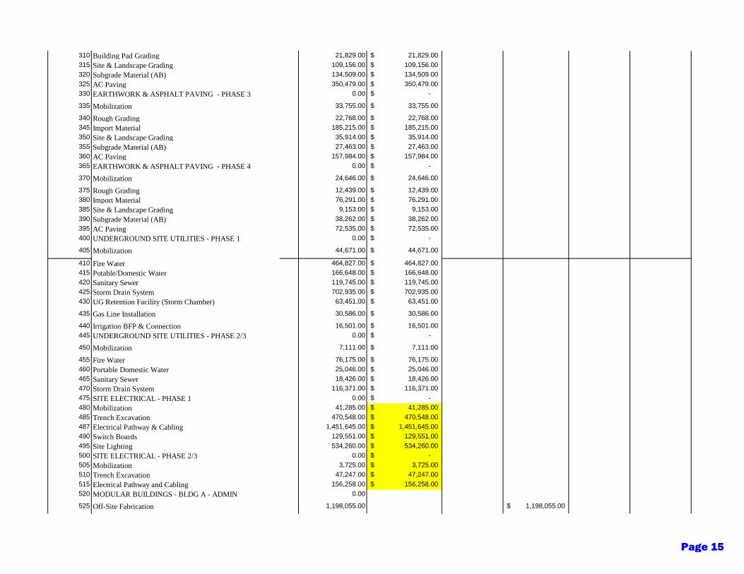
310 Building Pad Grading 21,829.00 21,829.00$
315 Site & Landscape Grading 109,156.00 109,156.00$
320 Subgrade Material (AB) 134,509.00 134,509.00$
325 AC Paving 350,479.00 350,479.00$
330 EARTHWORK & ASPHALT PAVING - PHASE 3 0.00 -$
335 Mobilization 33,755.00 33,755.00$
340 Rough Grading 22,768.00 22,768.00$
345 Import Material 185,215.00 185,215.00$
350 Site & Landscape Grading 35,914.00 35,914.00$
355 Subgrade Material (AB) 27,463.00 27,463.00$
360 AC Paving 157,984.00 157,984.00$
365 EARTHWORK & ASPHALT PAVING - PHASE 4 0.00 -$
370 Mobilization 24,646.00 24,646.00$
375 Rough Grading 12,439.00 12,439.00$
380 Import Material 76,291.00 76,291.00$
385 Site & Landscape Grading 9,153.00 9,153.00$
390 Subgrade Material (AB) 38,262.00 38,262.00$
395 AC Paving 72,535.00 72,535.00$
400 UNDERGROUND SITE UTILITIES - PHASE 1 0.00 -$
405 Mobilization 44,671.00 44,671.00$
410 Fire Water 464,827.00 464,827.00$
415 Potable/Domestic Water 166,648.00 166,648.00$
420 Sanitary Sewer 119,745.00 119,745.00$
425 Storm Drain System 702,935.00 702,935.00$
430 UG Retention Facility (Storm Chamber) 63,451.00 63,451.00$
435 Gas Line Installation 30,586.00 30,586.00$
440 Irrigation BFP & Connection 16,501.00 16,501.00$
445 UNDERGROUND SITE UTILITIES - PHASE 2/3 0.00 -$
450 Mobilization 7,111.00 7,111.00$
455 Fire Water 76,175.00 76,175.00$
460 Portable Domestic Water 25,046.00 25,046.00$
465 Sanitary Sewer 18,426.00 18,426.00$
470 Storm Drain System 116,371.00 116,371.00$
475 SITE ELECTRICAL - PHASE 1 0.00 -$
480 Mobilization 41,285.00 41,285.00$
485 Trench Excavation 470,548.00 470,548.00$
487 Electrical Pathway & Cabling 1,451,645.00 1,451,645.00$
490 Switch Boards 129,551.00 129,551.00$
495 Site Lighting 534,260.00 534,260.00$
500 SITE ELECTRICAL - PHASE 2/3 0.00 -$
505 Mobilization 3,725.00 3,725.00$
510 Trench Excavation 47,247.00 47,247.00$
515 Electrical Pathway and Cabling 156,258.00 156,258.00$
520 MODULAR BUILDINGS - BLDG A - ADMIN 0.00
525 Off-Site Fabrication 1,198,055.00 1,198,055.00$
Page 15
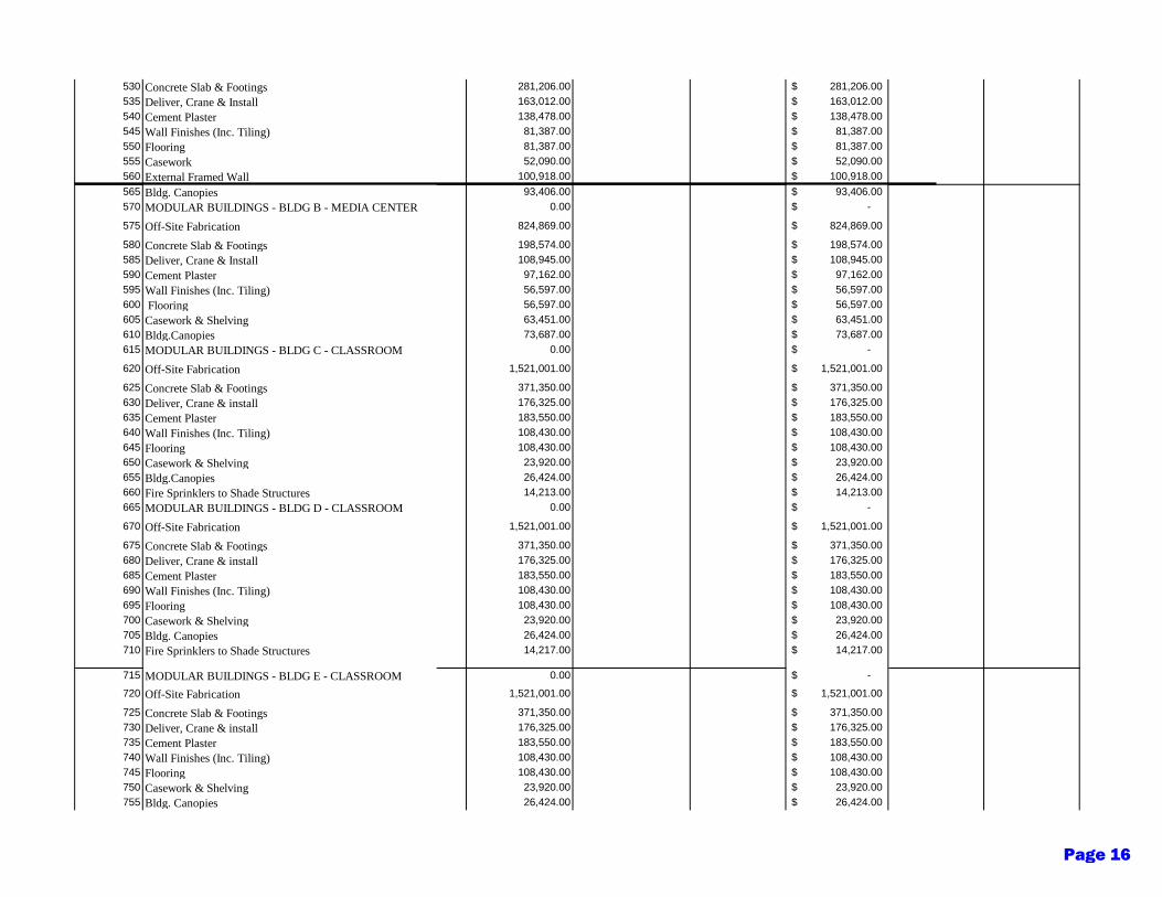
530 Concrete Slab & Footings 281,206.00 281,206.00$
535 Deliver, Crane & Install 163,012.00 163,012.00$
540 Cement Plaster 138,478.00 138,478.00$
545 Wall Finishes (Inc. Tiling) 81,387.00 81,387.00$
550 Flooring 81,387.00 81,387.00$
555 Casework 52,090.00 52,090.00$
560 External Framed Wall 100,918.00 100,918.00$
565 Bldg. Canopies 93,406.00 93,406.00$
570 MODULAR BUILDINGS - BLDG B - MEDIA CENTER 0.00 -$
575 Off-Site Fabrication 824,869.00 824,869.00$
580 Concrete Slab & Footings 198,574.00 198,574.00$
585 Deliver, Crane & Install 108,945.00 108,945.00$
590 Cement Plaster 97,162.00 97,162.00$
595 Wall Finishes (Inc. Tiling) 56,597.00 56,597.00$
600 Flooring 56,597.00 56,597.00$
605 Casework & Shelving 63,451.00 63,451.00$
610 Bldg.Canopies 73,687.00 73,687.00$
615 MODULAR BUILDINGS - BLDG C - CLASSROOM 0.00 -$
620 Off-Site Fabrication 1,521,001.00 1,521,001.00$
625 Concrete Slab & Footings 371,350.00 371,350.00$
630 Deliver, Crane & install 176,325.00 176,325.00$
635 Cement Plaster 183,550.00 183,550.00$
640 Wall Finishes (Inc. Tiling) 108,430.00 108,430.00$
645 Flooring 108,430.00 108,430.00$
650 Casework & Shelving 23,920.00 23,920.00$
655 Bldg.Canopies 26,424.00 26,424.00$
660 Fire Sprinklers to Shade Structures 14,213.00 14,213.00$
665 MODULAR BUILDINGS - BLDG D - CLASSROOM 0.00 -$
670 Off-Site Fabrication 1,521,001.00 1,521,001.00$
675 Concrete Slab & Footings 371,350.00 371,350.00$
680 Deliver, Crane & install 176,325.00 176,325.00$
685 Cement Plaster 183,550.00 183,550.00$
690 Wall Finishes (Inc. Tiling) 108,430.00 108,430.00$
695 Flooring 108,430.00 108,430.00$
700 Casework & Shelving 23,920.00 23,920.00$
705 Bldg. Canopies 26,424.00 26,424.00$
710 Fire Sprinklers to Shade Structures 14,217.00 14,217.00$
715 MODULAR BUILDINGS - BLDG E - CLASSROOM 0.00 -$
720 Off-Site Fabrication 1,521,001.00 1,521,001.00$
725 Concrete Slab & Footings 371,350.00 371,350.00$
730 Deliver, Crane & install 176,325.00 176,325.00$
735 Cement Plaster 183,550.00 183,550.00$
740 Wall Finishes (Inc. Tiling) 108,430.00 108,430.00$
745 Flooring 108,430.00 108,430.00$
750 Casework & Shelving 23,920.00 23,920.00$
755 Bldg. Canopies 26,424.00 26,424.00$
Page 16
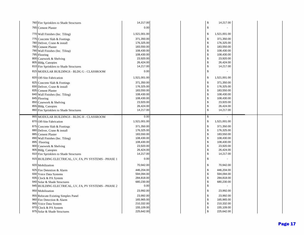
760 Fire Sprinklers to Shade Structures 14,217.00 14,217.00$
765 Cement Plaster 0.00 -$
770 Wall Finishes (Inc. Tiling) 1,521,001.00 1,521,001.00$
775 Concrete Slab & Footings 371,350.00 371,350.00$
780 Deliver, Crane & install 176,325.00 176,325.00$
785 Cement Plaster 183,550.00 183,550.00$
790 Wall Finishes (Inc. Tiling) 108,430.00 108,430.00$
795 Flooring 108,430.00 108,430.00$
800 Casework & Shelving 23,920.00 23,920.00$
805 Bldg, Canopies 26,424.00 26,424.00$
810 Fire Sprinklers to Shade Structures 14,217.00 14,217.00$
815 MODULAR BUILDINGS - BLDG G - CLASSROOM 0.00 -$
820 Off-Site Fabrication 1,521,001.00 1,521,001.00$
825 Concrete Slab & Footings 371,350.00 371,350.00$
830 Deliver, Crane & install 176,325.00 176,325.00$
835 Cement Plaster 183,550.00 183,550.00$
840 Wall Finishes (Inc. Tiling) 108,430.00 108,430.00$
845 Flooring 108,430.00 108,430.00$
850 Casework & Shelving 23,920.00 23,920.00$
855 Bldg. Canopies 26,424.00 26,424.00$
860 Fire Sprinklers to Shade Structures 14,217.00 14,217.00$
865 MODULAR BUILDINGS - BLDG H - CLASSROOM 0.00 -$
870 Off-Site Fabrication 1,521,001.00 1,521,001.00$
875 Concrete Slab & Footings 371,350.00 371,350.00$
880 Deliver, Crane & install 176,325.00 176,325.00$
885 Cement Plaster 183,550.00 183,550.00$
890 Wall Finishes (Inc. Tiling) 108,430.00 108,430.00$
895 Flooring 108,430.00 108,430.00$
900 Casework & Shelving 23,920.00 23,920.00$
905 Bldg. Canopies 26,424.00 26,424.00$
910 Fire Sprinklers to Shade Structures 14,217.00 14,217.00$
915 BUILDING ELECTRICAL, LV, FA, PV SYSTEMS - PHASE 1 0.00 -$
920 Mobilization 70,942.00 70,942.00$
925 Fire Detention & Alarm 446,204.00 446,204.00$
930 Voice Data Systems 594,094.00 594,094.00$
935 Clock & PA System 284,818.00 284,818.00$
940 Solar & Shade Structures 680,230.00 680,230.00$
945 BUILDING ELECTRICAL, LV, FA, PV SYSTEMS - PHASE 2 0.00 -$
950 Mobilization 23,992.00 23,992.00$
955 Relocate Existing Simplex Panel 23,992.00 23,992.00$
960 Fire Detection & Alarm 165,965.00 165,965.00$
965 Voice Data System 210,332.00 210,332.00$
970 Clock & PA System 155,109.00 155,109.00$
975 Solar & Shade Structures 225,642.00 225,642.00$
Page 17
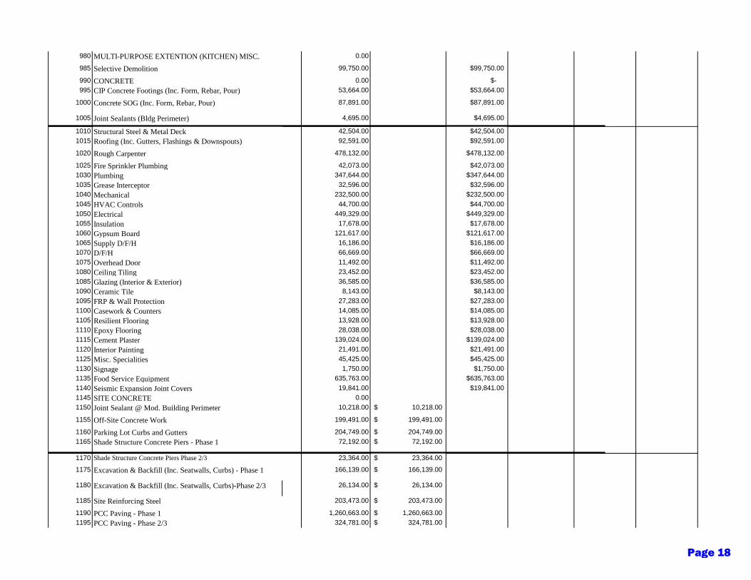
980 MULTI-PURPOSE EXTENTION (KITCHEN) MISC. 0.00
985 Selective Demolition 99,750.00 99,750.00$
990 CONCRETE 0.00 -$
995 CIP Concrete Footings (Inc. Form, Rebar, Pour) 53,664.00 53,664.00$
1000 Concrete SOG (Inc. Form, Rebar, Pour) 87,891.00 87,891.00$
1005 Joint Sealants (Bldg Perimeter) 4,695.00 4,695.00$
1010 Structural Steel & Metal Deck 42,504.00 42,504.00$
1015 Roofing (Inc. Gutters, Flashings & Downspouts) 92,591.00 92,591.00$
1020 Rough Carpenter 478,132.00 478,132.00$
1025 Fire Sprinkler Plumbing 42,073.00 42,073.00$
1030 Plumbing 347,644.00 347,644.00$
1035 Grease Interceptor 32,596.00 32,596.00$
1040 Mechanical 232,500.00 232,500.00$
1045 HVAC Controls 44,700.00 44,700.00$
1050 Electrical 449,329.00 449,329.00$
1055 Insulation 17,678.00 17,678.00$
1060 Gypsum Board 121,617.00 121,617.00$
1065 Supply D/F/H 16,186.00 16,186.00$
1070 D/F/H 66,669.00 66,669.00$
1075 Overhead Door 11,492.00 11,492.00$
1080 Ceiling Tiling 23,452.00 23,452.00$
1085 Glazing (Interior & Exterior) 36,585.00 36,585.00$
1090 Ceramic Tile 8,143.00 8,143.00$
1095 FRP & Wall Protection 27,283.00 27,283.00$
1100 Casework & Counters 14,085.00 14,085.00$
1105 Resilient Flooring 13,928.00 13,928.00$
1110 Epoxy Flooring 28,038.00 28,038.00$
1115 Cement Plaster 139,024.00 139,024.00$
1120 Interior Painting 21,491.00 21,491.00$
1125 Misc. Specialities 45,425.00 45,425.00$
1130 Signage 1,750.00 1,750.00$
1135 Food Service Equipment 635,763.00 635,763.00$
1140 Seismic Expansion Joint Covers 19,841.00 19,841.00$
1145 SITE CONCRETE 0.00
1150 Joint Sealant @ Mod. Building Perimeter 10,218.00 10,218.00$
1155 Off-Site Concrete Work 199,491.00 199,491.00$
1160 Parking Lot Curbs and Gutters 204,749.00 204,749.00$
1165 Shade Structure Concrete Piers - Phase 1 72,192.00 72,192.00$
1170 Shade Structure Concrete Piers Phase 2/3 23,364.00 23,364.00$
1175 Excavation & Backfill (Inc. Seatwalls, Curbs) - Phase 1 166,139.00 166,139.00$
1180 Excavation & Backfill (Inc. Seatwalls, Curbs)-Phase 2/3 26,134.00 26,134.00$
1185 Site Reinforcing Steel 203,473.00 203,473.00$
1190 PCC Paving - Phase 1 1,260,663.00 1,260,663.00$
1195 PCC Paving - Phase 2/3 324,781.00 324,781.00$
Page 18
1200 Seatwalls - Phase 1 229,236.00 229,236.00$
1205 Seatwalls - Phase 2/3 54,409.00 54,409.00$
1210 STEEL & MISC. METALS 0.00 -$
1215 Shade Structure Struct. Steel - Phase 1 478,368.00 478,368.00$
1220 Shade Structure Struct. Steel - Phase 2/3 189,195.00 189,195.00$
1225 Metal Decking - Phase 1 126,280.00 126,280.00$
1230 Metal Decking - Phase 2/3 49,280.00 49,280.00$
1235 Misc. Steel (Inc. Railings & Bollards) 50,128.00 50,128.00$
1240 ROOFING 0.00 -$
1245 Shade Structure Roofing - Phase 1 332,503.00 332,503.00$
1250 Shade Structure Struct. Steel - Phase 2/3 131,288.00 131,288.00$
1255 Gymnasium - Demo Shingles 53,486.00 53,486.00$
1260 Gymnasium - New Shingle Roof 186,047.00 186,047.00$
1265 PAINTING 0.00 -$
1270 New Shade Structure 43,589.00 43,589.00$
1275 Existing Lunch Shade Structure 14,480.00 14,480.00$
1280 Gym - Exterior 41,711.00 41,711.00$
1285 Multi-Purpose - Exterior 37,016.00 37,016.00$
1290 FINAL CLEANING 0.00 -$
1295 Exterior AC & Concrete 7,783.00 7,783.00$
1300 Building Exterior 14,455.00 14,455.00$
1305 Building Interior 37,329.00 37,329.00$
1310 Athletic Equipment 63,054.00 63,054.00$
1315 Site Furnishings 229,193.00 229,193.00$
1320 Asphalt Painting Coating - Phase 1 218,773.00 218,773.00$
1325 Asphalt Painting Coating - Phase 2/3 73,001.00 73,001.00$
1330 Basketball Court & Track Markings 32,710.00 32,710.00$
1335 Synthetic Turf 102,538.00 102,538.00$
1340 FENCES & GATES 0.00 -$
1345 6' High Chain Link Fence (Inc.Gates) 113,549.00 113,549.00$
1350 4' High Chain Link Fence (Inc.Gates) 31,890.00 31,890.00$
1355 6' High Iron Fence (Inc. Gates) 266,903.00 266,903.00$
1360 Classroom Courtyard Screening 426,429.00 426,429.00$
1365 Gate Hardware 53,487.00 53,487.00$
1370 Marquee Sign 55,070.00 55,070.00$
1375 LANDSCAPE IRRIGATION 0.00 -$
1380 Landscape 1,789,677.00 1,789,677.00$
1385 Irrigation 406,819.00 406,819.00$
1390 Landscape Maintenance Period 7,088.00 7,088.00$
1395 GENERAL CONDITIONS & FEES 0.00 -$
1400 General Conditions 2,868,919.00 2,868,919.00$
1405 General Liability Insurance 889,365.00 889,365.00$
1410 GC Payments & Performance Bonds 344,270.00 344,270.00$
1415 SDI/Subcontractor Bonds 676,307.00 676,307.00$
1420 Contractor Fee 1,692,662.00 1,692,662.00$
Page 19
1425 CONTINGENCIES / SUBLEASE PAYMENT 0.00
1430 Owner Contingency 1,928,332.00 1,928,332.00$
1435 Contractor Contingency 2,295,135.00 2,295,135.00$
1437 Hazmat Remediation RAW Allowance 250,000.00 250,000.00$
1438 Hazmat Unforeseen Bldg Allowance 150,000.00 150,000.00$
1440 Sub-Lease Payment 2,868,919.00 2,868,919.00$
Grand Totals
57,378,386.00 17,724,103.00$ 3,905,469.00$ 21,753,019.00$ 9,772,328.00$ 4,223,467.00$
47,606,058.00$ 37% 8% 46% 9%3,638,313.17$ 801,694.69$ 4,465,348.44$ 866,971.70$
21,362,416.17$ 4,707,163.69$ 26,218,367.44$ 5,090,438.70$
UPDATED ARCHITECTURAL FEES
Sitework 6% 1,281,744.97$ Modernization 11% 517,788.01$ Modular Construction 5% 1,310,918.37$ Construction Congengencies TBD
Fixed Fee Services 102,000.00$
Updated Architectural Fee 3,212,451.35$
Page 20

Gilroy Unified School District Door Station MainEntrance Change OrderQuote # Q-GG003097Version 1
Prepared for:
Gilroy Unified School District
Paul [email protected]
We have prepared a quote for you
Page 21
namartinez
Typewritten Text
2d
- MANAGED SERVICES
- VIDEO SURVEILLANCE
- WIRELESS
Gilroy Unified School DistrictPaul Nadeau7810 Arroyo CircleGilroy, CA [email protected]
Dear Paul,
Wednesday, January 06, 2021
QOVO Solutions, Inc. is pleased to present this proposal for hardware and services as requested. We prideourselves on the quality and simplicity of the solutions that we deliver and our company was founded onphilosophy that the customer makes the business.
This proposal is for the installation of a door station at BMS but does not include programming which must beperformed by GUSD IT Staff who have access to the existing Cisco unified communications platform.
The following is included in this proposal:
Aiphone Ix-Ss-2g Intercom Sub Station
CAT6 Cabling
Cut in and installation
Ongoing maintenance as proposed and available through QOVO Solutions, Inc. (QSI) typically proposedyearly.
Please do not hesitate to let us know if there are any questions.
Sincerely;
Page: 2 of 7Quote #Q-GG003097 v1 521 Charcot Ave - Suite 239B - San Jose - CA 95131 - Main 844-768-6462 - Lic #1058025 Page 22

- MANAGED SERVICES
- VIDEO SURVEILLANCE
- WIRELESS
Garth Gilmour
QOVO Solutions, Inc.
Page: 3 of 7Quote #Q-GG003097 v1 521 Charcot Ave - Suite 239B - San Jose - CA 95131 - Main 844-768-6462 - Lic #1058025 Page 23
- MANAGED SERVICES
- VIDEO SURVEILLANCE
- WIRELESS
Line# Qty Description Price Ext. Price
HARDWARE
1.1 1 IX-SS-2G AUDIO DOOR STATION, 2-GANG FLUSH MOUNT STAINLESS S $685.00 $685.00
Subtotal: $685.00
Estimated Tax: $61.65
Line# Qty Description Price Ext. Price
PROFESSIONAL SERVICES
3.1 1 QOVO-PS CUT-IN and Finish Door Station $185.00 $185.00
3.2 1 PS-WP-INT
Door sensor installation
CAT 6 Cable and Termination $225.00 $225.00
Subtotal: $410.00
Estimated Tax: $16.65
NOTES
Line# Qty Description
4.1 1 NEW
Terms and Conditions Taxes, shipping, handling and other fees may apply. We reserve the right to cancel orders arising from pricing or other errors. All orders paid by Credit Card will incur and 3% handling and convenience fee.
Terms and Conditions Taxes, shipping, handling and other fees may apply. We reserve the right tocancel orders arising frompricing or other errors. All orders paid by Credit Card will incur and 3%handling and convenience fee.
Page: 4 of 7Quote #Q-GG003097 v1 521 Charcot Ave - Suite 239B - San Jose - CA 95131 - Main 844-768-6462 - Lic #1058025 Page 24
- MANAGED SERVICES
- VIDEO SURVEILLANCE
- WIRELESS
NOTES
Line# Qty Description
4.2 1 Note
This proposal including all elements, diagrams, documents, and communications are considered the proprietary work product of QOVO Solutions, Inc. Any dissemination of these documents beyond the intended recipients and related entities will be considered a violation of a confidentiality agreement and any items related to this proposal cannot be disclosed to any third party without the express written permission of QOVO Solutions, inc.
4.3 1 Config
Configuration and programming to be performed by GUSD IT Staff with access to the existing Cisco infrastructure.
Line# Qty Description Price Ext. Price
SHIPPING
5.1 1 Shipping
Shipping
Shipping $45.22 $45.22
Subtotal: $45.22
Page: 5 of 7Quote #Q-GG003097 v1 521 Charcot Ave - Suite 239B - San Jose - CA 95131 - Main 844-768-6462 - Lic #1058025 Page 25
- MANAGED SERVICES
- VIDEO SURVEILLANCE
- WIRELESS
7810 Arroyo CircleGilroy, CA 95020Paul Nadeau(408) [email protected]
Gilroy Unified School District
Garth [email protected]
QOVO Solutions, Inc.
Prepared by: Prepared for: Quote Information:
Quote #: Q-GG003097
Version: 1Delivery Date: 01/06/2021Expiration Date: 02/05/2021
Gilroy Unified School District Door Station Main Entrance Change Order
Description Amount
Quote Summary
HARDWARE $685.00
PROFESSIONAL SERVICES $410.00
Subtotal: $1,095.00
Shipping: $45.22
Estimated Tax: $78.30
Total: $1,218.52
Payment Details
Description Payments Interval Amount
Mobilization Deposit
Mobilization Deposit Billed Upon Approved Contract. 1 One-Time $586.65
Progress Billing
Progress Billing @ 100% Completion 1 One-Time $609.26
Page: 6 of 7Quote #Q-GG003097 v1 521 Charcot Ave - Suite 239B - San Jose - CA 95131 - Main 844-768-6462 - Lic #1058025 Page 26
- MANAGED SERVICES
- VIDEO SURVEILLANCE
- WIRELESS
TERMS AND CONDITIONS
PRICING:Quote is valid for 30 days from issuance.
PAYMENT TERMS:Taxes, shipping, handling and other fees may apply, actual amounts will be provided upon invoicing. Unless otherwise agreed in writing byQovo Solutions Inc. all invoices are payable with twenty-one (21) days of the date of invoice. All hardware, software, and/or manufacturerrelated services will be invoiced upon shipment from the manufacturer. We reserve the right to cancel orders arising from pricing or othererrors.
LATE PAYMENT POLICY:Penalties will be applied to all late payment of 10% of the outstanding value.
PURCHASE ORDERS:In the event your company does not issue Purchase Orders (PO), please utilize the signature option below. Your signature below is consideredequivalent to your signed Purchase Order. With your acceptance, you are also signing and agreeing to the purchase of the products andservices included and the terms and conditions of this quote. If you have any questions, please contact your sales representative directly.
COMMUNICATIONS:The information contained in this transmission may be confidential. Any disclosure, copying, or further distribution of confidentialinformation is not permitted unless such privilege is explicitly granted in writing by QOVO Solutions, Inc.(QSI). QSI reserves the right to haveelectronic communications, including email and attachments, sent across its networks filtered through anti-virus and spam softwareprograms and retain such messages in order to comply with applicable data security and retention requirements. QSI is not responsible forthe proper and complete transmission of the substance of this communication or for any delay in its receipt.
QOVO Solutions, Inc.
Signature:
Name: Paul Nadeau
Date:
Signature:
Name: Garth Gilmour
Title:
Date: 01/06/2021
Gilroy Unified School District
Page: 7 of 7Quote #Q-GG003097 v1 521 Charcot Ave - Suite 239B - San Jose - CA 95131 - Main 844-768-6462 - Lic #1058025 Page 27
Page 1 of 1
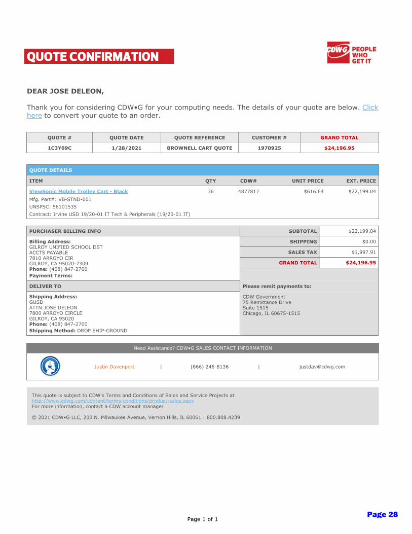
QUOTE CONFIRMATION
DEAR JOSE DELEON,
Thank you for considering CDW•G for your computing needs. The details of your quote are below. Click
here to convert your quote to an order.
QUOTE # QUOTE DATE QUOTE REFERENCE CUSTOMER # GRAND TOTAL
1C3Y09C 1/28/2021 BROWNELL CART QUOTE 1970925 $24,196.95
QUOTE DETAILS
ITEM QTY CDW# UNIT PRICE EXT. PRICE
ViewSonic Mobile Trolley Cart - Black 36 4877817 $616.64 $22,199.04
Mfg. Part#: VB-STND-001
UNSPSC: 56101535
Contract: Irvine USD 19/20-01 IT Tech & Peripherals (19/20-01 IT)
PURCHASER BILLING INFO SUBTOTAL
$22,199.04
Billing Address:
GILROY UNIFIED SCHOOL DST
ACCTS PAYABLE
7810 ARROYO CIR
GILROY, CA 95020-7309
Phone: (408) 847-2700
Payment Terms:
SHIPPING
$0.00
SALES TAX
$1,997.91
GRAND TOTAL
$24,196.95
DELIVER TO Please remit payments to:
Shipping Address:
GUSD
ATTN:JOSE DELEON
7800 ARROYO CIRCLE
GILROY, CA 95020
Phone: (408) 847-2700
Shipping Method: DROP SHIP-GROUND
CDW Government
75 Remittance Drive
Suite 1515
Chicago, IL 60675-1515
Need Assistance? CDW•G SALES CONTACT INFORMATION
Justin Davenport | (866) 246-8136 | [email protected]
This quote is subject to CDW's Terms and Conditions of Sales and Service Projects at
http://www.cdwg.com/content/terms-conditions/product-sales.aspx
For more information, contact a CDW account manager
© 2021 CDW•G LLC, 200 N. Milwaukee Avenue, Vernon Hills, IL 60061 | 800.808.4239
Page 28
namartinez
Typewritten Text
2e
A1-U-GU-1220-B CW (09/16) 112008270
Zurich Insurance Group (Zurich) offers insurance solutions around the globe through its member companies.
Rating as of March 31, 2016. A.M. Best and S&P’s ratings are under continuous review and subject to change and/or affirmation. For the latest ratings, access the ratings section on www.zurichna.com. The rating represents the overall financial status of the individual member companies of Zurich in North America, including Zurich American Insurance Company in the United States and Zurich Insurance Company Ltd (Canadian Branch) in Canada; and is not a recommendation of the specific policy provisions, rates or practices of each issuing insurance company. The Zurich logo and Zurich are trademarks of Zurich Insurance Company Ltd. © 2016 Zurich American Insurance Company. All rights reserved.© 2016 Zurich Insurance Company Ltd (Canadian Branch). All rights reserved.
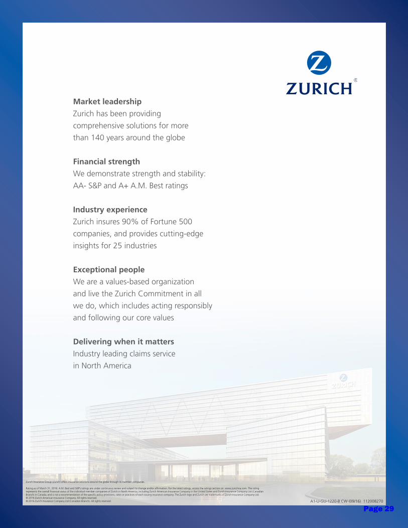
Market leadership
Zurich has been providing
comprehensive solutions for more
than 140 years around the globe
Financial strength
We demonstrate strength and stability:
AA- S&P and A+ A.M. Best ratings
Industry experience
Zurich insures 90% of Fortune 500
companies, and provides cutting-edge
insights for 25 industries
Exceptional people
We are a values-based organization
and live the Zurich Commitment in all
we do, which includes acting responsibly
and following our core values
Delivering when it matters
Industry leading claims service
in North America
Page 29
namartinez
Typewritten Text
2f
Zurich Programs Builders Risk and Installation
This is a proposal for insurance. It is not an insurance policy
This proposal is not a part of and is not incorporated into the insurance policy. If there is any conflict between the coverage descriptions shown in this proposal and the actual insurance policy, the insurance policy prevails. The insurance policy supercedes this proposal.
. Only the policy itself provides coverage. The coverages offered in this proposal are based on information received through the agent and may not include all available coverages. The client and their agent should discuss any additional or optional coverages needed. Coverage descriptions are abbreviated and do not indicate in force coverage.
Quote Proposal Thank you for the opportunity to provide you with a quote proposal. The quote is based on the underwriting and rating information, including deductibles and retention, provided to date and may be subject to additional rating, pricing or underwriting considerations. Also, acceptability may be subject to an Engineering and Safety Services survey and compliance with its recommendations. This is a proposal for insurance. It is not an insurance policy. The coverages offered in this proposal are based on information received through the agent and may not include all available coverages. The agent and the customer should discuss the need for any additional or optional coverages. Coverage descriptions are abbreviated and do not indicate in force coverage. Only the policy itself provides coverage. This proposal is not a part of and is not incorporated into the insurance policy. If there is any conflict between the coverage descriptions shown in this proposal and the actual insurance policy, the insurance policy prevails. The insurance policy supercedes this proposal. Thank you, Builders Risk Underwriter US Assure8230 Nations Way Jacksonville, Florida 32256 800-800-3907
1
Attention US ASSURE INSURANCE SERVICES OF FLORIDA, INC. D/B/
6Date Generated: 01/25/2021 7:27:27 PM Page ofPage 30

Zurich Programs Builders Risk and Installation
This is a proposal for insurance. It is not an insurance policy
This proposal is not a part of and is not incorporated into the insurance policy. If there is any conflict between the coverage descriptions shown in this proposal and the actual insurance policy, the insurance policy prevails. The insurance policy supercedes this proposal.
. Only the policy itself provides coverage. The coverages offered in this proposal are based on information received through the agent and may not include all available coverages. The client and their agent should discuss any additional or optional coverages needed. Coverage descriptions are abbreviated and do not indicate in force coverage.
Our Builders Risk Plan offers world-class coverages, flexibility and service to agents and builders nationwide. For more than 30 years, we've been pioneering the development of insurance solutions for construction professionals and have protected the property interests of builders and developers on even the most intricate residential and commercial construction projects. The Builders Risk product offers a wide spectrum of property coverage. Here are few highlights of the coverage offered: • Construction Forms, Scaffolding and Temporary Structures up to • Re-erection of scaffolding if caused by or results from a covered cause of loss up to • Valuable Papers and Records – Cost of Research up to • Outdoor Trees, Shrubs, Plants and Lawns • Additional Debris Removal expense is covered up to but not exceeding • Coverage for Pollutant Clean-up and Removal of land and water for up to for each 12 month
period of the policy. • Fire Department Service Charge up to • Reward up to • • Foundations • Our valuation can include profit up to 20% for new structures only if included in the Limit of Insurance
you selected • Broad Collapse coverage • Back-up or overflow of sewers, drains or sumps up to • Paving, Curbing, Fences and Outdoor Fixtures • Ordinance or Law demolition and increased cost Coverage up to limit for construction of
new structures only • Inadvertent omission in reporting on a monthly reporting form policy • Model Homes and Model Home Contents coverage can be added on a reporting form policy Strong, reliable insurance protection is available from Zurich Programs. Zurich Programs is an integral part of Zurich North America. Zurich Financial Services (www.zurich.com) is an insurance-based financial services provider with a global network that focuses its activities on its key markets in North America and Europe. Founded in 1872, Zurich is headquartered in Zurich, Switzerland. Through its offices in more than 50 countries, 57,000 Zurich employees serve clients in more than 120 countries. In North America, Zurich (www.zurichna.com) is a leading commercial property-casualty insurance provider serving the global corporate, large corporate, middle market, specialties and programs sectors.
2
$25,000$50,000
$50,000
$50,000$25,000
$25,000$25,000
Waiver of Coinsurance clause if loss is less than or equal to $25,000
$25,000
$1,000,000
6Date Generated: 01/25/2021 7:27:27 PM Page of
Page 31
Zurich Programs Builders Risk and Installation
This is a proposal for insurance. It is not an insurance policy
This proposal is not a part of and is not incorporated into the insurance policy. If there is any conflict between the coverage descriptions shown in this proposal and the actual insurance policy, the insurance policy prevails. The insurance policy supercedes this proposal.
. Only the policy itself provides coverage. The coverages offered in this proposal are based on information received through the agent and may not include all available coverages. The client and their agent should discuss any additional or optional coverages needed. Coverage descriptions are abbreviated and do not indicate in force coverage.
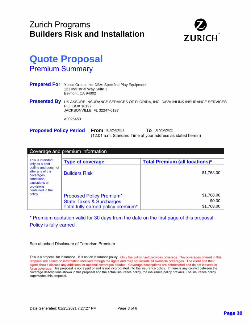
Quote Proposal Premium Summary Prepared For
Presented By
Proposed Policy Period From To (12:01 a.m. Standard Time at your address as stated herein)
Coverage and premium information
Type of coverage Total Premium (all locations)*
This is intended only as a brief outline and does not alter any of the coverages, conditions, exclusions or provisions contained in the policy.
Builders Risk Proposed Policy Premium* State Taxes & Surcharges
* Premium quotation valid for 30 days from the date on the first page of this proposal. See attached Disclosure of Terrorism Premium.
3
US ASSURE INSURANCE SERVICES OF FLORIDA, INC. D/B/A INLINK INSURANCE SERVICESP.O. BOX 10197JACKSONVILLE, FL 32247-0197
A0026450
01/25/2021 01/25/2022
Yosso Group, Inc. DBA: Specified Play Equipment121 Industrial Way Suite 1Belmont, CA 94002
Total fully earned policy premium*
$1,768.00
$1,768.00$0.00
$1,768.00
Policy is fully earned
6Date Generated: 01/25/2021 7:27:27 PM Page ofPage 32

Zurich Programs Builders Risk and Installation
This is a proposal for insurance. It is not an insurance policy
This proposal is not a part of and is not incorporated into the insurance policy. If there is any conflict between the coverage descriptions shown in this proposal and the actual insurance policy, the insurance policy prevails. The insurance policy supercedes this proposal.
. Only the policy itself provides coverage. The coverages offered in this proposal are based on information received through the agent and may not include all available coverages. The client and their agent should discuss any additional or optional coverages needed. Coverage descriptions are abbreviated and do not indicate in force coverage.
Primary Builders Risk Coverages Deductible Total Limits Premium
Coverage Extensions Deductible Total Limits Premium
4
Coverage Limit at Any One Building or Structure $5,000 $1,290,325
All Covered Property at all Locations $5,000 $1,290,325 $1,768
Additional Coverages:
Back-up or Overflow of Sewer, Drains or Sumps None $25,000 $0
Debris Removal None $50,000 $0
Fire Department Service Charge None $25,000 $0
Ordinance or law $5,000 $1,000,000
Loss to the undamaged portion of the building $5,000 Included
Demolition cost $5,000 $1,000,000
Increased cost of construction $5,000 $1,000,000
Combined Aggregate for Demolition Cost and Increased Cost of Construction $5,000 $1,000,000 $0
Pollutant Clean-Up and Removal None $25,000 $0
Rewards None $25,000 $0
Re-erection of Scaffolding None $25,000 $0
Scaffolding, Construction Forms and Temporary Structures None $50,000 $0
Property at a Temporary Storage Location $5,000 $64,516 $0
Property in Transit $5,000 $64,516 $0
Valuable Papers and Records None $50,000 $0
Profit If included
6Date Generated: 01/25/2021 7:27:27 PM Page ofPage 33

Zurich Programs Builders Risk and Installation
This is a proposal for insurance. It is not an insurance policy
This proposal is not a part of and is not incorporated into the insurance policy. If there is any conflict between the coverage descriptions shown in this proposal and the actual insurance policy, the insurance policy prevails. The insurance policy supercedes this proposal.
. Only the policy itself provides coverage. The coverages offered in this proposal are based on information received through the agent and may not include all available coverages. The client and their agent should discuss any additional or optional coverages needed. Coverage descriptions are abbreviated and do not indicate in force coverage.
Special Conditions Deductible Total Limits Premium
Quote Proposal 24-hour Claim Service Our claim representatives understand businesses like yours and recognize how difficult a business shutdown can be for you. So, while they provide service that’s fast, responsive and fair, their ultimate goal is to minimize your business disruption and get you back to full operation as promptly as possible.
In the event you have a loss, we now offer online loss reporting with immediate acknowledgement. Your claim is assigned to a local claim office, usually within two hours of reporting the loss, but generally no longer than 24 hours. You can also call us toll-free at 1-888-279-9375.
5 6Date Generated: 01/25/2021 7:27:27 PM Page ofPage 34

Zurich Programs Builders Risk and Installation
This is a proposal for insurance. It is not an insurance policy. Only the policy itself provides coverage. The coverages offered in this proposal are based on information received through the agent and may not include all available coverages. The client and their agent should discuss any additional or optional coverages needed. Coverage descriptions are abbreviated and do not indicate in force coverage. This proposal is not a part of and is not incorporated into the insurance policy. If there is any conflict between the coverage descriptions shown in this proposal and the actual insurance policy, the insurance policy prevails. The insurance policy supercedes this proposal.
Quote Proposal Customer and Agent Information Named Insured: Agency Name: Customer Location Information Location Address:
Protection Class: Construction: # of Stories: Primary occupancy:
Additional Interests
6
Yosso Group, Inc. DBA: Specified Play EquipmentUS ASSURE INSURANCE SERVICES OF FLORIDA, INC. D/B/A INLINK INSURANCE SERVICES
3Non-Combustible8755 Kern Ave., 600 W. 8th St., 930 3rd St.
Gilroy, CA 95020 1Other
6Date Generated: 01/25/2021 7:27:27 PM Page of
Page 35

U-GU-632-E CW (01/20) Copyright © 2020 Zurich American Insurance Company Page 1 of 2
Includes copyrighted material of Insurance Services Office, Inc., with its permission.
THIS DISCLOSURE DOES NOT GRANT ANY COVERAGE OR CHANGE THE TERMS AND CONDITIONS OF ANY COVERAGE UNDER ANY POLICY.
DISCLOSURE OF IMPORTANT INFORMATION
RELATING TO TERRORISM RISK INSURANCE ACT
SCHEDULE*
Premium attributable to risk of loss from certified acts of terrorism for lines of insurance subject to TRIA:
$0
*Any information required to complete this Schedule, if not shown above, will be shown in the quote or proposal.
A. Disclosure of Premium
In accordance with the federal Terrorism Risk Insurance Act (“TRIA”), as amended, we are required to provide you with a notice disclosing the portion of your premium, if any, attributable to the risk of loss from terrorist acts certified under that Act for lines subject to TRIA. That portion of premium attributable is shown in the Schedule above. The premium shown in the Schedule above is subject to adjustment upon premium audit, if applicable.
B. Disclosure of Federal Participation in Payment of Terrorism Losses
You should know that where coverage is provided by this policy for losses resulting from certified acts of terrorism, the United States Government may pay up to 80% of insured losses exceeding the statutorily established deductible paid by the insurance company providing the coverage.
C. Disclosure of $100 Billion Cap on All Insurer and Federal Obligations
If aggregate insured losses attributable to terrorist acts certified under TRIA exceed $100 billion in a calendar year (January 1 through December 31) and an insurer has met its deductible under the program, that insurer shall not be liable for the payment of any portion of the amount of such losses that exceeds $100 billion, and in such case insured losses up to that amount are subject to pro rata allocation in accordance with procedures established by the Secretary of Treasury.
D. Availability
As required by TRIA, we have made available to you for lines subject to TRIA coverage for losses resulting from acts of terrorism certified under TRIA with terms, amounts and limitations that do not differ materially from those for losses arising from events other than acts of terrorism.
E. Definition of Act of Terrorism under TRIA
TRIA defines "act of terrorism" as any act that is certified by the Secretary of the Treasury, in accordance with the provisions of the federal Terrorism Risk Insurance Act (“TRIA”), to be an act of terrorism. The Terrorism Risk Insurance Act provides that the Secretary of Treasury shall certify an act of terrorism:
1. To be an act of terrorism;
2. To be a violent act or an act that is dangerous to human life, property or infrastructure;
3. To have resulted in damage within the United States, or outside of the United States in the case of an air carrier (as defined in section 40102 of Title 49, United States Code) or a United States flag vessel (or a vessel based principally in the United States, on which United States income tax is paid and whose insurance coverage is subject to regulation in the United States), or the premises of a United States mission; and
4. To have been committed by an individual or individuals as part of an effort to coerce the civilian population of the United States or to influence the policy or affect the conduct of the United States Government by coercion.
Page 36

U-GU-632-E CW (01/20) Copyright © 2020 Zurich American Insurance Company Page 2 of 2
Includes copyrighted material of Insurance Services Office, Inc., with its permission.
No act may be certified as an "act of terrorism" if the act is committed as part of the course of a war declared by Congress (except for workers’ compensation) or if losses resulting from the act, in the aggregate for insurance subject to TRIA, do not exceed $5,000,000.
Page 37

California Disclosure Statement
U-GU-884-A CA (01-12) Page 1 of 1
Fully Earned premium This policy is subject to the Total Fully Earned Policy Premium shown in the Declarations.
If this policy is cancelled you must pay at least the Total Fully Earned Policy Premium unless the policy is cancelled as of
the inception date shown in the Declarations.
Page 38

CONSTRUCTION SERVICES OF JEROME R. ZALINSKI P.O. Box 36, Gustine, Ca. 95322-0036
Cell (209) 652-9447 Office(209) 854-2370Fax (209) 854-1842
Calif. Contractors Lic.# 356114 DSA/ORS Cert.# 2520 OSHPD Cert.# 20814
01-05-2021
Mr. Paul Nadeau
Facilities Director
Gilroy Unified School District
7810 Arroyo Circle
Gilroy, CA 95020
Mr. Nadeau
We are pleased to provide you with proposals for Additional inspection services for the new Gilroy High
School Pool replacement project (DSA app #01-118060) in the Gilroy Unified School District. The proposal is
based on Additional time and construction costs added to the project.
Project Description and proposal amount as follows:
Gilroy High School Pool Project original Contract amount $72,000
added Inspection Fee for additional costs and time to complete the project. $ 6,300
Amended contract amount $78,300
District to supply each Inspector with a minimum 8ft by 12ft (96 sq. ft.) of office space on project site for Summer projects (10 weeks or less) and
10ft by 300ft (300 sq. ft.) for projects with duration exceeding 10 weeks. With internet connection available in office. Office MUST be left on-site until ALL (includes punch list) work is completed on-site.
Class 2 Inspector may be assigned to these projects.
Estimates are based on plans, specification and information received on or before the above date. If the schedule duration is extended or accelerated by the School District or the Contactor, or additional work is added to the project scope, additional costs may be incurred by the
District under this proposal.
If District, Architect or DSA requires additional coverage on any of the noted projects that project budget shall be reevaluated. Projects must close out within 90 days of substantial completion/occupancy for projects up to 10 weeks scheduled duration and 180 days of
projects exceeding 10 weeks of scheduled duration or addition costs may incur.
This proposal shall be an attachment to any contract issed by the District for the above noted work.
Thank You
Jerome R. Zalinski
Principal Inspector
Page 39
namartinez
Typewritten Text
2h
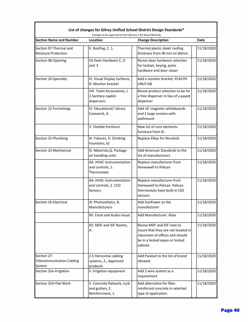
Section Name and Number Location Change Description Date
Section 07-Thermal and
Moisture Protection
V. Roofing, C. 1. Thermal plastic sheet roofing
thickness from 40 mm to 60mm.
11/18/2020
Section 08-Opening VII.Door Hardware C, D
and E
Revise door hardware selection
for lockset, keying, panic
hardware and door closer
11/18/2020
Section 10-Specialty III. Visual Display Surfaces,
D. Monitor bracket
Add a monitor bracket, PLAV70-
UNLP-GB
11/18/2020
VIII. Toilet Accessoiries, J.
2.Sanitary napkin
dispensers
Revise product selection to be for
a free dispenser in lieu of a payed
dispenser
11/18/2020
Section 12-Furnishings IV. Educational/ Library
Casework, A.
Add 16' magnetic whiteboards
and 2 large screens with
wallmount
11/18/2020
V. Flexible furniture New list of core elements
furniture from KI.
11/18/2020
Section 22-Plumbing IX. Fixtures, D. Drinking
Fountains, b)
Replace Elkay for Murdock 11/18/2020
Section 23-Mechanical III. Materials,Q. Package
air handling units
Add American Standards to the
list of manufacturers
11/18/2020
AA. HVAC Instrumentation
and controls, 1.
Thermostats
Replace manufacturer from
Honeywell to Pelican
11/18/2020
AA. HVAC Instrumentation
and controls, 2. CO2
Sensors
Replace manufacturer from
Honeywell to Pelican. Pelican
thermostats have built-in C02
sensors.
11/18/2020
Section 26-Electrical IX. Photovoltaics, B.
Manufacturers
Add SunPower as the
manufacturer
11/18/2020
XII. Clock and Audio visual Add Manufacturer: Atlas 11/18/2020
XV. MDF and IDF Rooms,
A.
Revise MDF and IDF note to
insure that they are not located in
classroom of offices and should
be in a locked space or locked
cabinet.
11/18/2020
Section 27-
Telecommunication Cabling
System
2.5 Horizontal cabling
systems, 2., Approved
products
Add Panduit to the list of brand
allowed.
11/18/2020
Section 32a-Irrigation II. Irrigation equipment Add 2 wire system as a
requirement
11/18/2020
Section 32H-Flat Work V. Concrete flatwork, curb
and gutters, E.
Reinforcment, 1.
Add alternative for fiber
reinforced concrete in selected
type of application.
11/18/2020
List of changes for Gilroy Unified School District Design Standards*
Changes to be approved at the February 11th Board Meeting
Page 40
namartinez
Typewritten Text
2i
GILROY UNIFIED SCHOOL DISTRICT
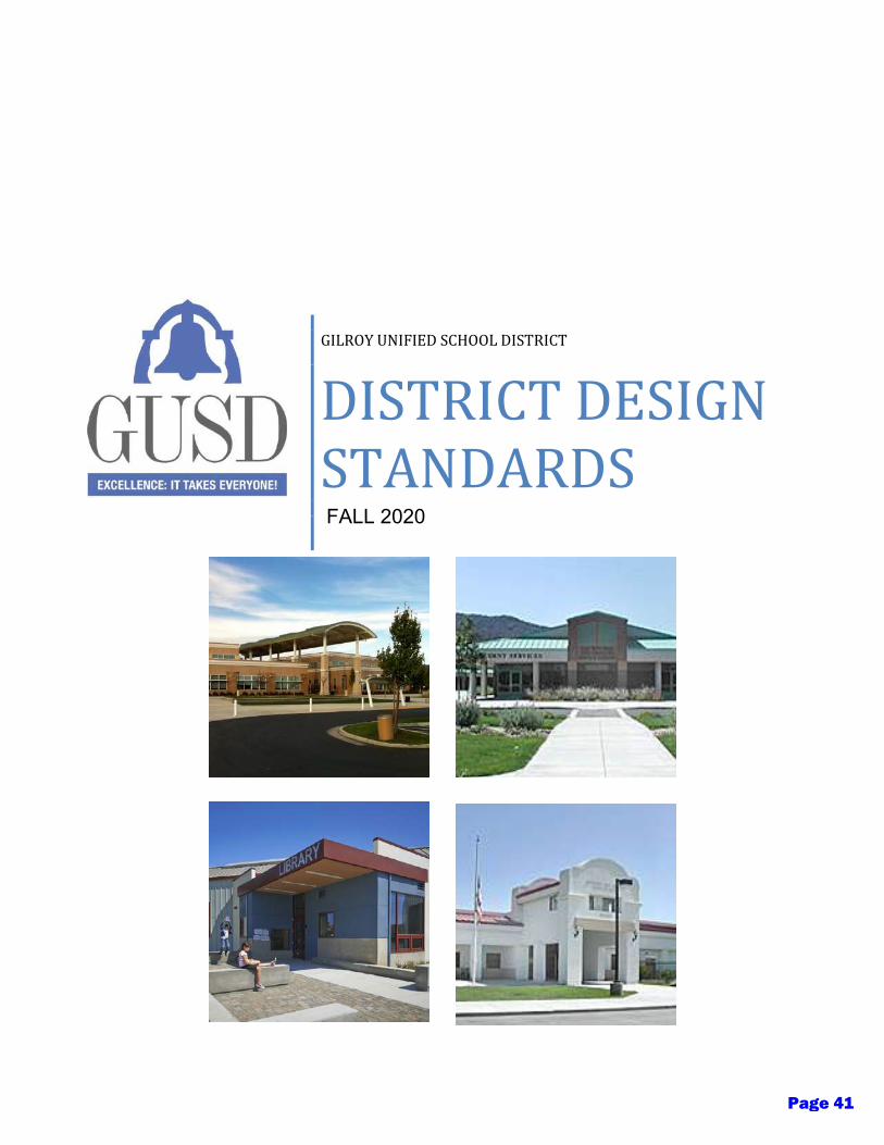
DISTRICT DESIGN
STANDARDS WINTER 2017
FALL 2020
Page 41
1
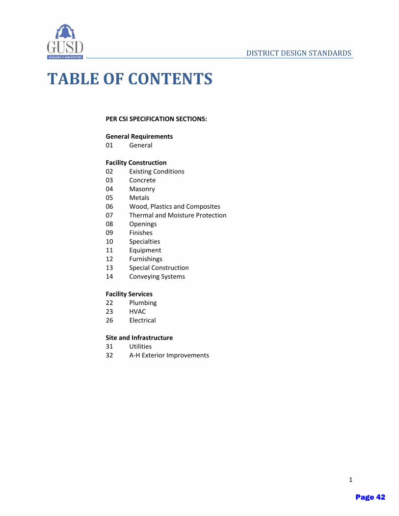
DISTRICT DESIGN STANDARDS
TABLE OF CONTENTS
PER CSI SPECIFICATION SECTIONS: General Requirements 01 General
Facility Construction 02 Existing Conditions 03 Concrete 04 Masonry 05 Metals 06 Wood, Plastics and Composites 07 Thermal and Moisture Protection 08 Openings 09 Finishes 10 Specialties 11 Equipment 12 Furnishings 13 Special Construction 14 Conveying Systems
Facility Services 22 Plumbing 23 HVAC 26 Electrical
Site and Infrastructure 31 Utilities 32 A-H Exterior Improvements
Page 42
2
DISTRICT DESIGN STANDARDS
Page 43

3
DISTRICT DESIGN STANDARDS
TEAM MEMBERS
Paul Nadeau –Facilities Planning & Management Director
Dan McAuliffe – Maintenance/Operations Manager
Marissa VanPatten –Project Manager
Aurelio Rodriguez – Energy, Safety and Facility Use
Maribel Guizar – Information and Technology Director
Roy Cripps – HVAC Technician
Teofilo Delgado – Lead Custodian
Joe Vela – Aedis Architects
Matthew Puckett – Aedis Architects
David Maino – Atium Engineering
Erik Plato – ANLA Landscape
Page 44

4
DISTRICT DESIGN STANDARDS
Page 45
General - 1
DISTRICT DESIGN STANDARDS
Section 01 - General
Issued: Fall 2020 Updates:
I. Purpose
A. The purpose of these District Design Standards is to provide general design guidelines for architects, engineers, and other designers involved in District facilities projects. The intention is to minimize excessive variation within building systems, equipment, and finishes in order to streamline maintenance and operations for maintenance staff while still maintaining an attractive, sustainable and vibrant learning environment. The design standards have been compiled by the District as a minimum standard and guide for the design team. Due to the changing nature of program needs and technological advancements, flexibility is key in the successful design and maintenance of the District’s facilities. Therefore, the District welcomes suggestions for improvement for the design standards.
II. Design Standards
A. The design team should consult these District Design Standards as a starting point for evaluating District priorities and concerns in campus facility design. This document should be consulted in addition to federal, state, and local code requirements.
B. The Design Guidelines are organized per CSI sections. The design team should consult the appropriate section for their purpose in addition to the specific user and site research they would perform for their respective project.
C. The standards are meant to be a reference for the design process. These guidelines are based on the District’s preferred preferences. The design team should discuss proposed deviations from the standards with the District in order to remain open to continually emerging technologies, products, and methodologies in building and site construction. All deviations from the Standards should be approved by the District prior to implementation.
D. These standards do not cover every conceivable area of design in a new or modernization project. The standards start with the general facilities, utilities and infrastructure. General building spaces such as classrooms, entries, lobbies, offices, corridors, interior and exterior finishes, HVAC, electrical and plumbing
Page 46
2 - General
DISTRICT DESIGN STANDARDS
systems are typically discussed. Specialty areas such as specialty classrooms, labs, kitchens, theaters spaces, vocational classrooms should be discussed with the District and end users to determine the appropriateness of standards listed. Modifications to the standards should be balanced based on the intent of the standards and the need to accommodate the learning environment.
E. These standards are meant to be updated as technologies, products and methodologies continue to change. The table of contents indicates the latest version of the updates and the reason for the change.
III. Sustainable Design Principles
A. Sustainability is a top priority in the design, construction, and operations of all of GUSD’s facilities. It is the District’s desire that sustainability be woven into all aspects of design.
B. Site
1. The design team should endeavor to create a sustainable design with the goal of mitigating storm water runoff through use of bioswales and collection of rainwater for irrigation or other gray water recycling when possible.
2. Landscape design should aim to use native planting to help restore natural habitats for local fauna, and plants that require minimal watering.
3. Landscape design should encourage minimizing paving so as to reduce mechanical loads on the buildings. Not only does minimizing paving allow for a reduction in storm water runoff and the potential to recharge groundwater reserves, but it aids in reducing the ‘heat island effect’ created when large areas of paving around buildings gather and amplify heat. The use of light colored pervious pavement with a Solar Reflectance Index of 29 or higher should be used to reduce the ‘heat island effect’ of the non-roof spaces within the project site.
4. The appropriate selection and location of trees should be included in the design process as a way to provide shading to help reduce heating loads on buildings. Deciduous trees also allow natural daylight to warm buildings in colder months.
C. Building
Page 47

General - 3
DISTRICT DESIGN STANDARDS
1. The demolition and modernization of existing buildings should endeavor to reduce the amount of construction waste produced by maximizing recycling or reusing as much material as possible.
2. New construction should aim to use building materials and products which maximize recycled content and preferably are themselves recyclable. Building materials and products should also be specified from local sources and manufacturing facilities to reduce the carbon footprint from delivery needs.
3. Natural ventilation and operable windows should be provided where practical at all classrooms, offices and workspaces. Consideration should be given for mechanical equipment override switches when windows are in the open position.
4. Mechanical systems should be designed to maximize efficiency and consider the natural advantages in the District’s location. These Standards are written taking into consideration future Net Zero mandated code requirements along with the District’s desire to begin implementing Net Zero strategies now in new buildings, retrofits, and modernizations.
5. Natural daylighting should be maximized throughout with the use of properly oriented skylights, clerestory windows, and other glazing with appropriate sun-shading or diffusing devices. By taking advantage of the naturally sunny climate, the District can reduce the energy loads associated with artificial lighting and therefore reduce cooling loads.
6. Shading devices should be included in all new facilities to help reduce glare and cooling loads. Electrically operated Mecho Shades should be considered and connected to an energy management system, if allowed for in the project budget.
7. Building design shall adhere to the most recent edition of the California Energy Code. Care should be taken in the proper detailing of joints and penetrations to reduce air infiltration and leakage.
8. Photovoltaic panels should be considered to provide a source of on-site renewable energy to reduce energy bills and offset buildings’ carbon footprints.
9. The use of repeating elements in the layout and structure of a building can help reduce construction waste (i.e. ability to reuse formwork).
Page 48
4 - General
DISTRICT DESIGN STANDARDS
10. Recycling areas for each new or modernized facility should be included to reduce material going into the waste stream.
Page 49
Concrete - 1
DISTRICT DESIGN STANDARDS
Section 03 – Concrete
Issued: Fall 2020 Updates:
I. Purpose
A. The following District Design Standards for concrete are intended to provide basic guidelines for the District with the goal of optimizing structural performance, minimizing end user maintenance, and supporting sustainable design goals.
B. These standards should be applied to all new construction, modernization, renovation, and replacement projects.
II. Sustainability
A. The demolition and modernization of existing buildings should endeavor to reduce the amount of construction waste produced by maximizing recycling or reusing as much material as possible.
B. New construction should aim to use building materials and products which maximize recycled content and preferably are themselves recyclable. Building materials and products should also be specified from local sources and manufacturing facilities to reduce the carbon footprint from delivery needs.
C. Fly-ash and recycled slag should be used when possible.
III. Design Standards
A. Concrete design shall comply with the most recent Chapter 19 of the CBC.
B. The use of repeating elements in the layout and structure of a building should be considered to increase the ability to reuse formwork.
C. Concrete design mixes shall be determined by the structural engineer.
D. Structural design should provide for the flexibility of changes in space usage. This may include designing for higher floor live and dead load than the originally prescribed use or an increase in fire rating of structural elements. The District should discuss options with the designer on a case by case basis.
Page 50

Concrete - 2
DISTRICT DESIGN STANDARDS E. Floor vibration from walking, rhythmic activities (i.e. gymnasiums, dance studios,
music studios, etc.), or mechanical equipment can significantly impact the comfort and use of a space and should be addressed in the structural design rather than being addressed with finishes.
F. Concrete floors should be used throughout all academic spaces or on second floors such that vibration from walking and other impact noise may be minimized.
Page 51

Masonry - 1
DISTRICT DESIGN STANDARDS
Section 04 – Masonry
Issued: Fall 2020 Updates:
I. Purpose
A. The following District Design Standards for masonry are intended to provide basic guidelines for the District with the goal of optimizing structural performance, minimizing end user maintenance, and supporting sustainable design goals.
B. These standards should be applied to all new construction, modernization, renovation, and replacement projects.
II. Design Standards
A. Exterior cladding may be of any material permissible by Chapter 14 of CBC, however, the following should be considered:
1. Exterior materials should be durable and of relatively low maintenance. Maintenance requirements should be consistent with the District’s available maintenance and operations resources.
2. Exterior materials should be suitable for the project’s climatic conditions.
3. Exterior materials should be suitable for the programmatic requirements of the project.
B. Exterior materials should be consistent with the overall character and context of the existing buildings at each campus.
III. Concrete Unit Masonry
A. CMU block finishes shall be used in compliance with the current edition of the CBC. The design team should pay particular attention to detailing and the design of the systems that are associated with CMU, including but not limited to the adjacent or integrated structural systems, electrical plumbing and HVAC systems.
B. Consideration should be given to location of the chosen finish used. A split face finish may or may not be appropriate for a particular location. Whereas a smooth face or similar finish may not be appropriate in certain areas, as well.
Page 52

2 – Masonry
DISTRICT DESIGN STANDARDS C. Seal coating should always be specified as recommended by the manufacturer.
D. Where available for the finish type, anti-graffiti coatings should be used on exterior finishes up to 8’-0”.
E. Finish:
1. Split face
2. Smooth face
3. Split face fluted
4. Slump finish
5. Glazed finish
6. Aggregate type: Standard Aggregate or Scoria Aggregate
Page 53

Metals - 1
DISTRICT DESIGN STANDARDS
Section 05 – Metals
Issued: Fall 2020 Updates:
I. Purpose
A. The following District Design Standards for metals are intended to provide basic guidelines for the District with the goal of optimizing structural performance, minimizing end user maintenance, and supporting sustainable design goals.
B. These standards should be applied to all new construction, modernization, renovation, and replacement projects.
II. Exposed Finishes
A. Hot dipped galvanized
1. Provide at drinking fountain handrails/barriers and similar areas.
B. Sprayed finish must be a repairable system.
C. Powder coated finishes should be used only with approval from the District.
D. Ferrous metals should be finished as follows:
1. Industrial alkyd finish:
a) 1710 Kel-Guard Alkyd Rust-Preventative Primer
b) 1700 Kel-Guard Alkyd Rust-Preventative Gloss Enamel
E. Galvanized metals should be finished as follows:
1. Industrial alkyd finish:
a) 1725 Acry-Shield 100% Acrylic Metal Primer
b) 1700 Kel-Guard Alkyd Rust-Preventative Gloss Enamel
2. Industrial urethane finish:
a) KM-15 Chemical Mastic High Build Epoxy
b) KM-375 High Build Gloss Polyurethane Enamel
Page 54
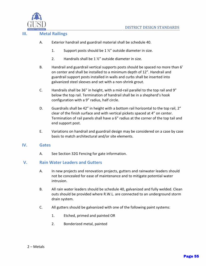
2 – Metals
DISTRICT DESIGN STANDARDS III. Metal Railings
A. Exterior handrail and guardrail material shall be schedule 40.
1. Support posts should be 1 ½” outside diameter in size.
2. Handrails shall be 1 ½” outside diameter in size.
B. Handrail and guardrail vertical supports posts should be spaced no more than 6’ on center and shall be installed to a minimum depth of 12”. Handrail and guardrail support posts installed in walls and curbs shall be inserted into galvanized steel sleeves and set with a non-shrink grout.
C. Handrails shall be 36” in height, with a mid-rail parallel to the top rail and 9” below the top rail. Termination of handrail shall be in a shepherd’s hook configuration with a 9” radius, half circle.
D. Guardrails shall be 42” in height with a bottom rail horizontal to the top rail, 2” clear of the finish surface and with vertical pickets spaced at 4” on center. Termination of rail panels shall have a 6” radius at the corner of the top tail and end support post.
E. Variations on handrail and guardrail design may be considered on a case by case basis to match architectural and/or site elements.
IV. Gates
A. See Section 32G Fencing for gate information.
V. Rain Water Leaders and Gutters
A. In new projects and renovation projects, gutters and rainwater leaders should not be concealed for ease of maintenance and to mitigate potential water intrusion.
B. All rain water leaders should be schedule 40, galvanized and fully welded. Clean outs should be provided where R.W.L. are connected to an underground storm drain system.
C. All gutters should be galvanized with one of the following paint systems:
1. Etched, primed and painted OR
2. Bonderized metal, painted
Page 55
Wood, Plastics and Composites - 1
DISTRICT DESIGN STANDARDS
Section 06 – Wood, Plastics and Composites
Issued: Fall 2020 Updates:
I. Purpose
A. The following District Design Standards for wood are intended to provide basic guidelines for the District with the goal of optimizing structural performance, minimizing end user maintenance, and supporting sustainable design goals.
B. The structural design shall be based on the latest design provisions upon which the Building Code is based to provide improved structural performance. This requirement would extend the design criteria beyond the code requirement of prevention of major structural system failures and loss of life to include prevention of damage to mechanical and architectural components and the ability to maintain the building functionality post-earthquake.
C. The building’s structure shall be designed to comply with all applicable requirements of Structural Design Chapter 16 of the CBC.
D. These standards should be applied to all new construction, modernization, renovation and replacement projects.
II. Sustainability
A. The demolition and modernization of existing buildings should endeavor to reduce the amount of construction waste produced by maximizing recycling or reusing as much material as possible.
B. New construction should aim to use building materials and products which maximize recycled content and preferably are themselves recyclable. Building materials and products should also be specified from local sources and manufacturing facilities to reduce the carbon footprint from delivery needs.
C. Lumber from FSC certified sources should be used when possible.
III. Design Standards
A. Structural design should provide for the flexibility of changes in space usage. This may include designing for higher floor live and dead load than the originally prescribed use or an increase in fire rating of structural elements. The District should discuss options with the designer on a case by case basis.
Page 56

2 – Wood, Plastics and Composites
DISTRICT DESIGN STANDARDS B. Floor vibration from walking, rhythmic activities (i.e. gymnasiums, dance studios,
music studios, etc.), or mechanical equipment can significantly impact the comfort and use of a space and should be addressed in the structural design rather than being addressed with finishes.
Page 57
Thermal and Moisture Protection - 1
DISTRICT DESIGN STANDARDS
Section 07 – Thermal and Moisture Protection
Issued: Fall 2020 Updates:
I. Purpose
A. The following District Design Standards for thermal and moisture protection are intended to provide basic guidelines for the District with the goal of maximizing the energy efficiency of buildings while maintaining water resistance, minimal maintenance requirements, and aesthetically compelling designs.
B. These standards should be applied to all new construction, modernization, renovation and replacement projects.
II. General Design Standards
A. Exterior cladding of building shell can be of any material permissible by Chapter 14 of CBC and the current Energy Code. However, the following should be considered:
1. Exterior materials should be durable and of relatively low maintenance. Maintenance requirements should be consistent with the District’s available maintenance and operations resources.
2. Exterior materials should be suitable for the project’s climatic conditions.
3. Exterior materials should be suitable for the programmatic requirements of the project.
4. Exterior materials should be consistent with the overall character and context of the existing buildings at each campus.
III. Insulation and Building Envelope
A. The more robust a building’s envelope the more efficient it will perform, with smaller heating and cooling loads, thereby reducing the size and expense of the HVAC equipment. In new construction and major renovations of buildings, the envelope should be designed closely with the HVAC systems in mind.
B. Roof assemblies in new construction or major renovation projects shall adhere to the most recent edition of the California Energy Code for insulation and assembly requirements.
Page 58

2 – Thermal and Moisture Protection
DISTRICT DESIGN STANDARDS C. Wall assemblies in new construction or major renovation projects shall adhere to
the most recent edition of the California Energy Code for insulation and assembly requirements.
D. Acceptable insulation products manufacturers:
1. CertainTeed Corporation
2. Johns Manville
3. Owens Corning
IV. Metal Panel Wall Systems
A. All wall materials used shall meet the requirements for Energy Star compliance coated finish systems. Metal panels shall include coatings equal to Valspar Energy Star Compliant Fluropon SR Premier Coatings. Special consideration should be given to detailing of systems attachment, water proofing, and integration of other systems, such as windows and doors. The Design Team should consider the appropriate type of panel to use for the project and discuss the advantages with the District for their input and approval.
B. Wall systems should be designed as concealed fastener/lap seam systems.
C. Dry joint systems should be used, as wet joint systems require ongoing maintenance.
D. The following types of panelized systems may be used if deemed appropriate:
1. Single skin
2. Composite panels
3. Rain screen systems
E. Acceptable manufacturers shall be of national recognition and have complete documented systems, details and service:
1. AEP-Span.
2. ATAS International, Inc.
3. CENTRIA Architectural Systems.
4. MBCI; Div. of NCI Building Systems.
5. Metal Sales Manufacturing Corporation.
Page 59
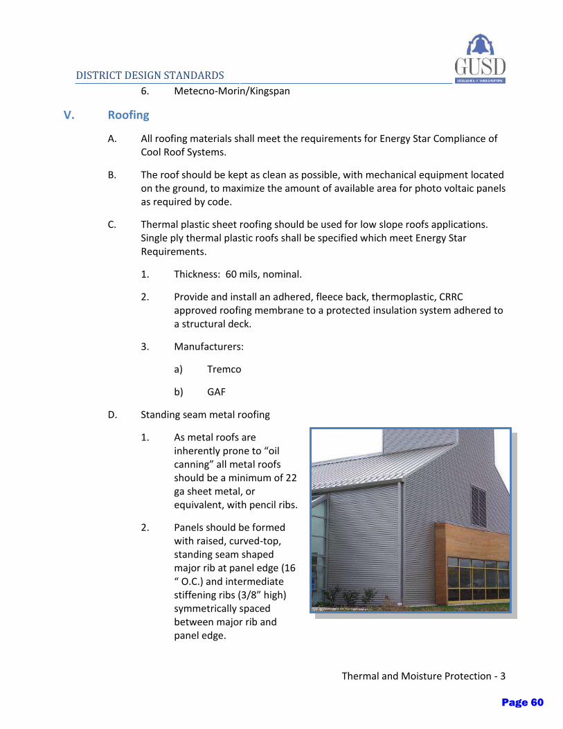
Thermal and Moisture Protection - 3
DISTRICT DESIGN STANDARDS 6. Metecno-Morin/Kingspan
V. Roofing
A. All roofing materials shall meet the requirements for Energy Star Compliance of Cool Roof Systems.
B. The roof should be kept as clean as possible, with mechanical equipment located on the ground, to maximize the amount of available area for photo voltaic panels as required by code.
C. Thermal plastic sheet roofing should be used for low slope roofs applications. Single ply thermal plastic roofs shall be specified which meet Energy Star Requirements.
1. Thickness: 60 mils, nominal.
2. Provide and install an adhered, fleece back, thermoplastic, CRRC approved roofing membrane to a protected insulation system adhered to a structural deck.
3. Manufacturers:
a) Tremco
b) GAF
D. Standing seam metal roofing
1. As metal roofs are inherently prone to “oil canning” all metal roofs should be a minimum of 22 ga sheet metal, or equivalent, with pencil ribs.
2. Panels should be formed with raised, curved-top, standing seam shaped major rib at panel edge (16 “ O.C.) and intermediate stiffening ribs (3/8” high) symmetrically spaced between major rib and panel edge.
Page 60
4 – Thermal and Moisture Protection
DISTRICT DESIGN STANDARDS 3. Steel sheet, ASTM A446 with “Zincalume” coating conforming to ASTM A-
792. Smooth finish with 22 gauge thickness.
4. The design team should work with the manufacturer to ensure that the use of photovoltaic panels may be attached to the roof in the event that the District wishes to install panels at a later date and per current CBC requirements.
5. Special consideration should be given when designing barrel roofs, installation of solar panels, or extra-long panel installations.
6. Manufacturers and products listed below are proven to comply with the requirements above. Other manufacturers shall require written approval by the district prior to use by the design team.
a) Bemo Roofing – 16” wide panel
b) Morin-Kingspan SRR-16”
c) Morin-Kingspan Zip-Rib – 16” wide panel
VI. Roof Accessories
VII. Expansion Joint Cover Assemblies
A. Provide factory-fabricated architectural joint systems capable of withstanding the types of loads and of accommodating the kinds of movement, and other functions for which they are designed, without failure.
Page 61

ARCHITECTURAL METAL PANELSP R O D U C T S E L E C T I O N G U I D E
800-733-4955 www.aepspan.com
a r c h i t e c t u r a l e n g i n e e r e D
P r o D u c t s
Page 62

n 12", 16", 17" & 18" net coverages roof panel.
n Minimum recommended slope 2:12.
n Gauges: 22ga and 24ga in standard finishes. (Refer to AEP Span Color Charts for full range of color options, prints, textures, finishes and paint systems).
n Custom manufactured sheet lengths: 6'-0" to 45'-0".
n Factory applied sealant is a standard offer.
n Subtle striations available on 16", 17" & 18" panels.
n Testing: ASTM E1592 (wind uplift), ASTM E1680 (air infiltration) and ASTM E1646 (water infiltration).
nMeets UL580-Class 90 wind uplift requirements.
n Panel assemblies are also Class A Fire Rated per UL790 when installed in accordance to UL listings.
n Building Code Approval Report: IAPMO-UES #ER-0309.
n Manufactured in Fontana, CA and Tacoma, WA.
Design Span® hp
STRENGTH AND ELEGANCE IN A STANDING ROOF SYSTEM
Design Span hp is a performance-rated structural standing seam metal roof system which does not require field seaming. Recommended as a roof over metal or wood decking, and as a fascia or mansard over plywood or supports.
Design Span hp
Design Span hp
Optional Wide Batten
Design Span hp with optional Wide Batten
1800-733-4955 www.aepspan.com
13⁄4"
12", 16", 17", & 18" Coverages
17⁄8"
17⁄8"
Page 63
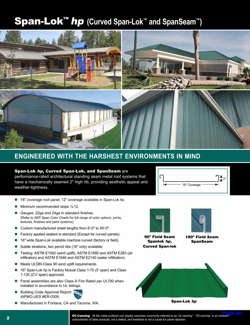
n 16" coverage roof panel, 12" coverage available in Span-Lok hp.
n Minimum recommended slope ¼:12.
n Gauges: 22ga and 24ga in standard finishes. (Refer to AEP Span Color Charts for full range of color options, prints, textures, finishes and paint systems).
n Custom manufactured sheet lengths from 6'-0" to 45'-0".n Factory applied sealant is standard (Except for curved panels).n 16" wide Span-Lok available machine curved (factory or field).
n Subtle striations, two pencil ribs (16" only) available.
n Testing: ASTM E1592 (wind uplift), ASTM E1680 and ASTM E283 (air infiltration) and ASTM E1646 and ASTM E2140 (water infiltration).
nMeets UL580-Class 90 wind uplift requirements.n 16" Span-Lok hp is Factory Mutual Class 1-75 (5’ span) and Class
1-120 (2½' span) approved.
n Panel assemblies are also Class A Fire Rated per UL790 when installed in accordance to UL listings.
n Building Code Approval Report: IAPMO-UES #ER-0309.
n Manufactured in Fontana, CA and Tacoma, WA.
Span-Lok™ hp (Curved Span-Lok™ and SpanSeam™)
ENGINEERED WITH THE HARSHEST ENVIRONMENTS IN MIND
Span-Lok hp, Curved Span-Lok, and SpanSeam are performance-rated architectural standing seam metal roof systems that have a mechanically seamed 2" high rib, providing aesthetic appeal and weather-tightness.
180º Field SeamSpanSeam
90º Field SeamSpanlok hp,
Curved Span-lok
Span-Lok hp
2Oil Canning: All flat metal surfaces can display waviness commonly referred to as “oil canning”. “Oil canning” is an inherent characteristic of steel products, not a defect, and therefore is not a cause for panel rejection.
16" Coverage
2"
Page 64
FLEXIBILITY TO CREATE STRIKING DESIGNS
Flex Series
FLEX
SER
IES
1.2F
X30-
12
FLEX
SER
IES
1.5F
X30-
1211⁄4" or 11⁄2"
6" 12"
Net
Cov
erag
e
2"
2"
FLEX
SER
IES
1.2F
X10-
12
11⁄4"
12"
Net
Cov
erag
e
FLEX
SER
IES
1.2F
X20-
12
FLEX
SER
IES
1.5F
X20-
12
10"
11⁄4" or 11⁄2"
12"
Net
Cov
erag
e
2"
FLEX
SER
IES
1.2F
X40-
12
FLEX
SER
IES
1.5F
X40-
12
11⁄4" or 11⁄2"
4"
4"
12"
Net
Cov
erag
e
n 12" coverage wall panel.
n Gauges: 22ga and 24ga in standard finishes and 20ga in ZINCALUME® Plus. (Refer to AEP Span Color Charts for full range of color options, prints, textures, finishes and paint systems).
n Custom manufactured sheet lengths: 5'-0" to 20'-0".
n Wall Installation: Horizontal or Vertical.
n Available in two panel attachment configurations – a directly attached fastening flange or clip interlocking hem.
n Flush Mount and 1/2" Standoff high performance clips available.
n ASTM E1592 (wind uplift), ASTM E283 (air infiltration) and ASTM E331 (water infiltration) tested.
n Manufactured in Fontana, CA and Anchorage, AK.
Flex Series is a concealed fastener metal wall collection with various geometric boxed rib designs which can be combined to create unique linear patterns. Profiles are also ideal for fascia and equipment screen applications.
Shown as direct fastened
Shown with standoff clip
Shown with flush clip
Flex Series
7800-733-4955 www.aepspan.comPage 65
SEAMLESS CLEAN ATTACHMENT AND UNIQUE SHADOW LINES
7⁄8″
12"
Net
Cov
erag
e11⁄2"
21⁄2"
4"
TW-12C
n 12" coverage wall panel.
n Gauges: 22ga and 24ga in standard finishes and 20ga, 22ga and 24ga in ZINCALUME® Plus. (Refer to AEP Span Color Charts for full range of color options, prints, textures, finishes and paint systems).
n Custom manufactured sheet lengths: 5'-0" to 20'-0".
n Wall Installation: Horizontal or Vertical.
n Flush Mount and 1/2" Standoff high performance clips available.
n Testing: ASTM E1592 (wind uplift), ASTM E283 (air infiltration) and ASTM E331 (water infiltration).
n Manufactured in Fontana, CA and Anchorage, AK.
TW-12 is a concealed fastener metal wall panel with trapezoid ribs designed to provide unique shadow lines. Ideal for wall and fascia applications as well.
Shown as direct fastened
Shown with flush clip
TW-12
Shown with standoff clip
8Oil Canning: All flat metal surfaces can display waviness commonly referred to as “oil canning”. “Oil canning” is an inherent characteristic of steel products, not a defect, and therefore is not a cause for panel rejection.
Page 66
Page 67
Page 68
Page 69
Page 70

Page 71
Page 72
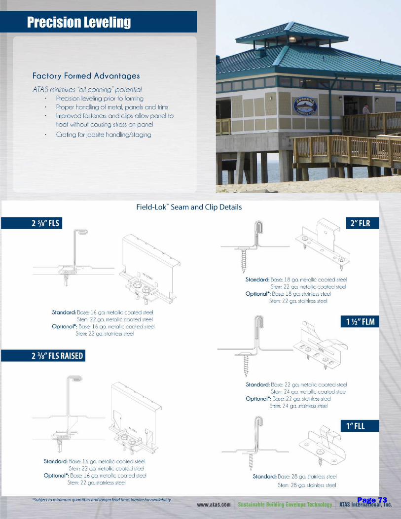
Page 73
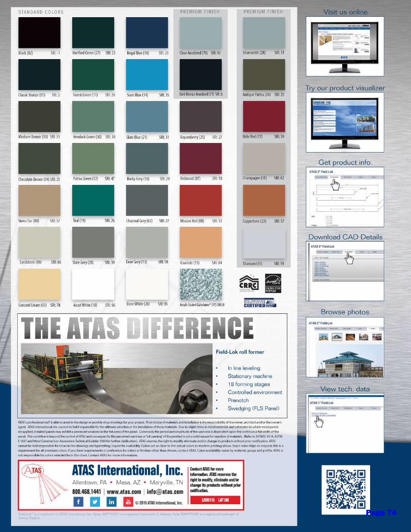
Page 74
REIMAGINE METAL
PRODUCT CATALOG
Page 75
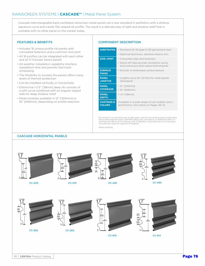
34 CENTRIA Product Catalog
1-1/2" [38mm]
12"[305mm]
2-3/4"[70mm]
1-1/2" [38mm]
12"[305mm]
4-1/4"[108mm]
1-1/2" [38mm]
12"[305mm]
2-3/4"[70mm]
1-1/4"[32mm]
4-1/4"[108mm]
1-1/2" [38mm]
12"[305mm]
8-1/4"[210mm]
1-1/2" [38mm]
12"[305mm]
2-3/4"[70mm]
CC-262
1-1/2" [38mm]
12"[305mm]
2-3/4"[70mm]
CC-263
CC-260
RAINSCREEN SYSTEMS | CASCADE™ | Metal Panel System
FEATURES & BENEFITS
• Includes 16 unique profile rib panels with concealed fasteners and a common-lock joint
• All 16 profiles can be integrated with each other and all 11 Concept Series panels
• All-weather installation capability shortens installation time and permits fast-track scheduling
• The flexibility to insulate the panels offers many levels of thermal protection
• Can be installed vertically or horizontally
• Distinctive 1-1/2" [38mm] deep rib consists of a soft curve combined with an angular sloped web for deep shadow relief
• Panel modules available in 12" [305mm] or 16" [406mm], depending on profile selection
SUBSTRATES • Standard 22–18 gage G-90 galvanized steel
• Optional aluminum, stainless steel or zinc
SIDE JOINT • Concealed clips and fasteners
• Stand-off clips provide ventilation cavity and continuous drain plane behind panel
SURFACE FINISH
• Smooth or embossed surface texture
PANELLENGTHS
• Lengths up to 30' [9.14m] for steel panels (Standard)
PANEL COVERAGE
• 12" [305mm]
• 16" [406mm]
PANELDEPTH
• 1.5" [38mm]
COATINGS & COLORS
Available in a wide range of coil-coated colors and finishes. See charts on Pages 46–51.
COMPONENT DESCRIPTION
Cascade interchangeable back-ventilated rainscreen metal panels set a new standard in aesthetics with a striking signature curve and a bold, flat, sloped rib profile. The result is a delicate play of light and shadow relief that is available with no other panel on the market today.
CASCADE HORIZONTAL PANELS
CC-200 CC-210 CC-220
CC-610 CC-612
1-1/2" [38mm]
16"[406mm]
4-1/4"[108mm]
2-3/4"[70mm]
1-1/4"[32mm]
1-1/2" [38mm]
16"[406mm]
8-1/4"[210mm]
“ Oil canning” is an inherent part of light-gage cold-formed metal products, particularly those with broad flat areas. CENTRIA takes every precaution, as defined by MCA, to minimize the effects of oil canning. Lack of flatness or waviness due to oil canning is not sufficient cause for rejection of material.
Patent pending.
Page 76
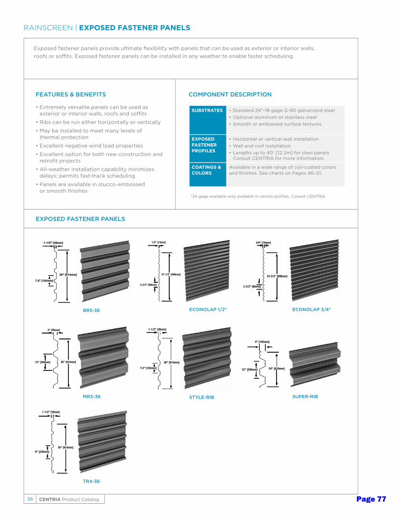
38 CENTRIA Product Catalog
RAINSCREEN | EXPOSED FASTENER PANELS
Exposed fastener panels provide ultimate flexibility with panels that can be used as exterior or interior walls, roofs or soffits. Exposed fastener panels can be installed in any weather to enable faster scheduling.
FEATURES & BENEFITS
• Extremely versatile panels can be used as exterior or interior walls, roofs and soffits
• Ribs can be run either horizontally or vertically
• May be installed to meet many levels of thermal protection
• Excellent negative wind load properties
• Excellent option for both new construction and retrofit projects
• All-weather installation capability minimizes delays; permits fast-track scheduling
• Panels are available in stucco-embossed or smooth finishes
SUBSTRATES • Standard 24*–18 gage G-90 galvanized steel• Optional aluminum or stainless steel • Smooth or embossed surface textures
EXPOSED FASTENERPROFILES
• Horizontal or vertical wall installation • Wall and roof installation• Lengths up to 40' [12.2m] for steel panels
Consult CENTRIA for more information.
COATINGS & COLORS
Available in a wide range of coil-coated colors and finishes. See charts on Pages 46–51.
COMPONENT DESCRIPTION
1/2" [13mm]
2-2/3" [68mm]
37-1/3" [948mm]
ECONOLAP 1/2"
3/4" [19mm]
2-2/3" [68mm]
34-2/3" [888mm]
ECONOLAP 3/4"
1-1/2" [38mm]
9" [229mm]36" [914mm]
TR4-36
1-1/2" [38mm]
7.2" [183mm]
36" [914mm]
STYLE-RIB
1-1/2" [38mm]
7.2" [183mm]
36" [914mm]
BR5-36
3" [76mm]
12" [305mm] 36" [914mm]
MR3-36
4" [102mm]
12" [305mm] 24" [610mm]
SUPER-RIB
EXPOSED FASTENER PANELS
*24 gage available only available in certain profiles. Consult CENTRIA.
Page 77
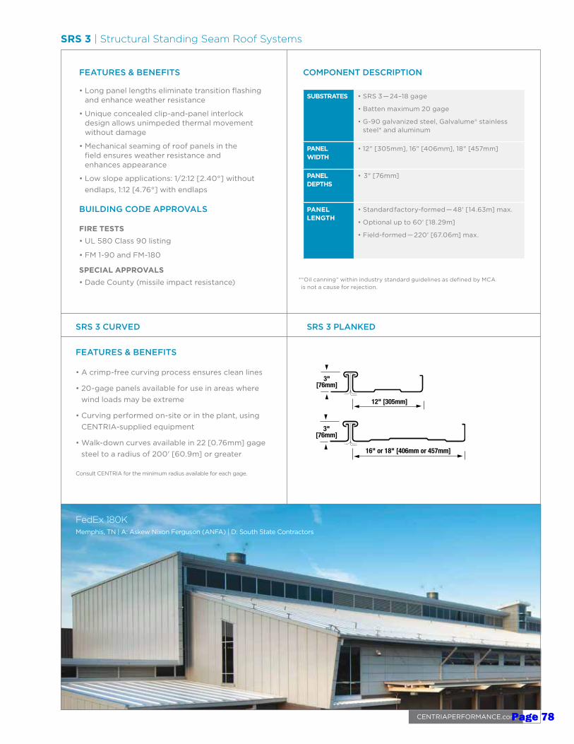
45CENTRIAPERFORMANCE.com
FEATURES & BENEFITS
• Long panel lengths eliminate transition flashing and enhance weather resistance
• Unique concealed clip-and-panel interlock design allows unimpeded thermal movement without damage
• Mechanical seaming of roof panels in the field ensures weather resistance and enhances appearance
• Low slope applications: 1/2:12 [2.40°] without endlaps, 1:12 [4.76°] with endlaps
BUILDING CODE APPROVALS
FIRE TESTS• UL 580 Class 90 listing
• FM 1-90 and FM-180
SPECIAL APPROVALS• Dade County (missile impact resistance)
SUBSTRATES • SRS 3 — 24–18 gage
• Batten maximum 20 gage
• G-90 galvanized steel, Galvalume® stainless steel* and aluminum
PANEL WIDTH
• 12" [305mm], 16" [406mm], 18" [457mm]
PANEL DEPTHS
• 3" [76mm]
PANEL LENGTH
• Standard factory-formed — 48' [14.63m] max.
• Optional up to 60' [18.29m]
• Field-formed — 220' [67.06m] max.
COMPONENT DESCRIPTION
SRS 3 CURVED
FEATURES & BENEFITS
• A crimp-free curving process ensures clean lines
• 20-gage panels available for use in areas where wind loads may be extreme
• Curving performed on-site or in the plant, using CENTRIA-supplied equipment
• Walk-down curves available in 22 [0.76mm] gage steel to a radius of 200' [60.9m] or greater
Consult CENTRIA for the minimum radius available for each gage.
12" [305mm]
3"[76mm]
16" or 18" [406mm or 457mm]
3"[76mm]
SRS 3 PLANKED
* “Oil canning” within industry standard guidelines as defined by MCA is not a cause for rejection.
SRS 3 | Structural Standing Seam Roof Systems
FedEx 180KMemphis, TN | A: Askew Nixon Ferguson (ANFA) | D: South State Contractors
Page 78
Architectural Pricing Guide
Page 79
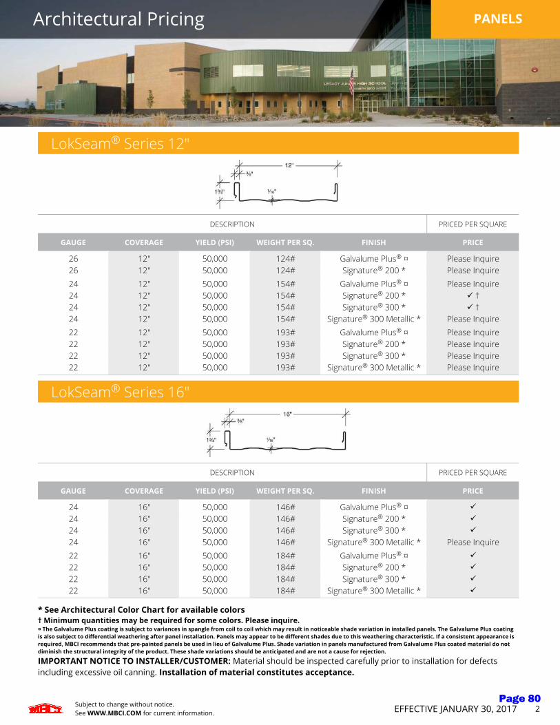
Architectural Pricing PANELS
Subject to change without notice.See WWW.MBCI.COM for current information. EFFECTIVE JANUARY 30, 2017 2
LokSeam® Series 12"
DESCRIPTION PRICED PER SQUARE
GAUGE COVERAGE YIELD (PSI) WEIGHT PER SQ. FINISH PRICE
26 12" 50,000 124# Galvalume Plus® ¤ Please Inquire26 12" 50,000 124# Signature® 200 * Please Inquire24 12" 50,000 154# Galvalume Plus® ¤ Please Inquire24 12" 50,000 154# Signature® 200 * ü †24 12" 50,000 154# Signature® 300 * ü †24 12" 50,000 154# Signature® 300 Metallic * Please Inquire22 12" 50,000 193# Galvalume Plus® ¤ Please Inquire22 12" 50,000 193# Signature® 200 * Please Inquire22 12" 50,000 193# Signature® 300 * Please Inquire22 12" 50,000 193# Signature® 300 Metallic * Please Inquire
LokSeam® Series 16"
DESCRIPTION PRICED PER SQUARE
GAUGE COVERAGE YIELD (PSI) WEIGHT PER SQ. FINISH PRICE
24 16" 50,000 146# Galvalume Plus® ¤ ü
24 16" 50,000 146# Signature® 200 * ü
24 16" 50,000 146# Signature® 300 * ü
24 16" 50,000 146# Signature® 300 Metallic * Please Inquire22 16" 50,000 184# Galvalume Plus® ¤ ü
22 16" 50,000 184# Signature® 200 * ü
22 16" 50,000 184# Signature® 300 * ü
22 16" 50,000 184# Signature® 300 Metallic * ü
* See Architectural Color Chart for available colors† Minimum quantities may be required for some colors. Please inquire.¤ The Galvalume Plus coating is subject to variances in spangle from coil to coil which may result in noticeable shade variation in installed panels. The Galvalume Plus coating is also subject to differential weathering after panel installation. Panels may appear to be different shades due to this weathering characteristic. If a consistent appearance is required, MBCI recommends that pre-painted panels be used in lieu of Galvalume Plus. Shade variation in panels manufactured from Galvalume Plus coated material do not diminish the structural integrity of the product. These shade variations should be anticipated and are not a cause for rejection.
IMPORTANT NOTICE TO INSTALLER/CUSTOMER: Material should be inspected carefully prior to installation for defects including excessive oil canning. Installation of material constitutes acceptance.
Page 80

Architectural Pricing PANELS
Subject to change without notice.See WWW.MBCI.COM for current information. EFFECTIVE JANUARY 30, 2017 3
LokSeam® Series 18"
DESCRIPTION PRICED PER SQUARE
GAUGE COVERAGE YIELD (PSI) WEIGHT PER SQ. FINISH PRICE
24 18" 50,000 146# Galvalume Plus® ¤ ü
24 18" 50,000 146# Signature® 200 * ü
24 18" 50,000 146# Signature® 300 * ü
24 18" 50,000 146# Signature® 300 Metallic * Please Inquire22 18" 50,000 184# Galvalume Plus® ¤ Please Inquire22 18" 50,000 184# Signature® 200 * Please Inquire22 18" 50,000 184# Signature® 300 * Please Inquire22 18" 50,000 184# Signature® 300 Metallic * Please Inquire
* See Architectural Color Chart for available colors† Minimum quantities may be required for some colors. Please inquire.¤ The Galvalume Plus coating is subject to variances in spangle from coil to coil which may result in noticeable shade variation in installed panels. The Galvalume Plus coating is also subject to differential weathering after panel installation. Panels may appear to be different shades due to this weathering characteristic. If a consistent appearance is required, MBCI recommends that pre-painted panels be used in lieu of Galvalume Plus. Shade variation in panels manufactured from Galvalume Plus coated material do not diminish the structural integrity of the product. These shade variations should be anticipated and are not a cause for rejection.
Consult the MBCI LOKSEAM® DESIGN AND INSTALLATION MANUAL for proper product application, design details and other product information.
Panel Pricing:1. All pricing is based on net coverage and include standard packaging. 2. Minimum quantities may be required for certain panel gauges and/or colors. Please Inquire.3. For short panel lengths, add: $3.70 per panel for panels 4'-0" in length and shorter.4. Panels must be specified as: "Striated", or "Non-Striated". No charge for Striations.5. Add $8.00 per square for embossing.6. Panels may be specified as: "Notched" for folding hem at eave. Add 3 inches to panel length. Notching charge $1.10 per panel. If notching is requested,
panels will be notched 1 1/2" at both ends. Note: Notching is only available for Blank Panels.7. Panels must be specified as "blank" (no endlaps),"eave", "mid", or "peak" (when endlaps are required).8. For panels with swaged ends (required at endlaps), add $5.15 per panel. Panels less than 4'-0" can not be swaged.9. See Page 30 for clip selection.10. Panel price includes mastic. For panels without mastic in the sidelap, deduct:
$4.20 per square for 18" wide panels. $4.75 per square for 16" wide panels. $6.30 per square for 12" wide panels.
Packaging Cost:1. Standard packaging: Block and band with strippable film on female rib of painted panels. Galvalume Plus panels will have microfoam interleafing.2. Optional interleafing: Microfoam interleafing: available at $0.10 per square foot.3. LTL shipments require plywood crating with microfoam interleafing.4. Plywood crating with strippable film on panels .....................................................................................................................$15.50/lf of bundle. $200.00 minimum.5. Special packaging ................................................................................................................................................................................................................. Please inquire
Delivery:1. 24 gauge - stocked colors .......................................................................................................................................................................Approximately 10 working days2. 26 gauge not available for 16" or 18" wide panels.3. Other gauges, colors and metals .........................................................................................................................................................................................Please inquire
Notes:1. All panel lengths over 40'-0" ................................................................................................................................................................................................Please inquire2. Striations are recommended on 18", 16" and 12" panels; MBCI standard will include light striations. If non-striated panels are required,
customer must specify in writing on order and sign MBCI Striation Waiver to Production.3. Heavier gauges, narrower widths, striations and embossing may minimize oil canning.4. Panel lengths 4'-0" or less do not have factory applied mastic.
IMPORTANT NOTICE TO INSTALLER/CUSTOMER: Material should be inspected carefully prior to installation for defects including excessive oil canning. Installation of material constitutes acceptance.
Page 81
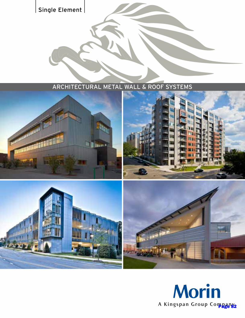
ARCHITECTURAL METAL WALL & ROOF SYSTEMS
Single Element
Page 82
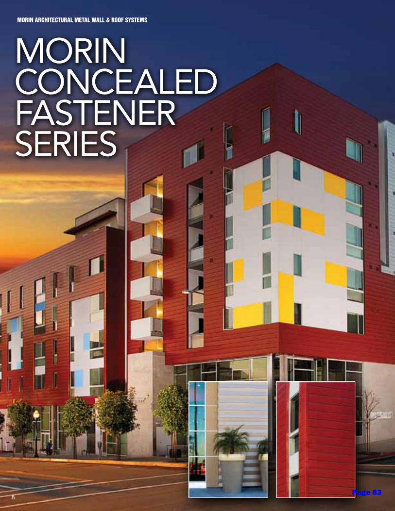
MORIN ARCHITECTURAL METAL WALL & ROOF SYSTEMS
MORINCONCEALEDFASTENERSERIES
8Page 83
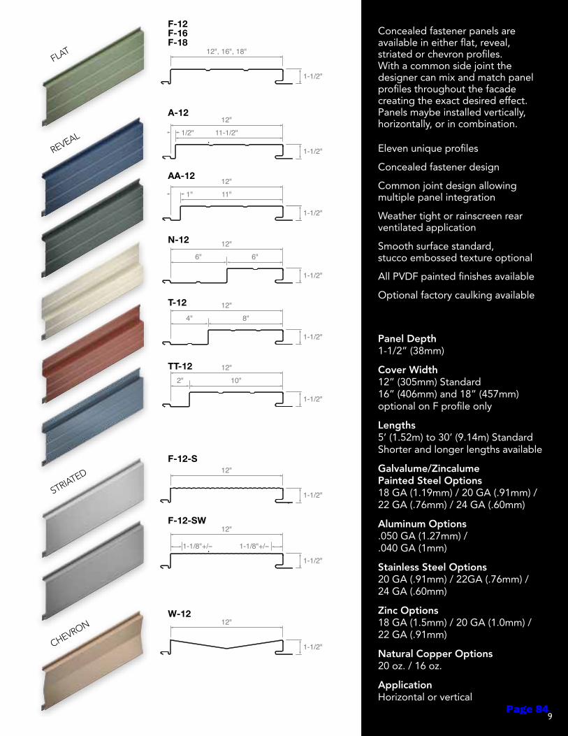
Eleven unique profiles
Concealed fastener design
Common joint design allowing multiple panel integration
Weather tight or rainscreen rear ventilated application
Smooth surface standard, stucco embossed texture optional
All PVDF painted finishes available
Optional factory caulking available
Panel Depth 1-1/2” (38mm)
Cover Width 12” (305mm) Standard 16” (406mm) and 18” (457mm) optional on F profile only
Lengths 5’ (1.52m) to 30’ (9.14m) Standard Shorter and longer lengths available
Galvalume/Zincalume Painted Steel Options 18 GA (1.19mm) / 20 GA (.91mm) / 22 GA (.76mm) / 24 GA (.60mm)
Aluminum Options .050 GA (1.27mm) / .040 GA (1mm)
Stainless Steel Options 20 GA (.91mm) / 22GA (.76mm) / 24 GA (.60mm)
Zinc Options 18 GA (1.5mm) / 20 GA (1.0mm) / 22 GA (.91mm)
Natural Copper Options 20 oz. / 16 oz.
Application Horizontal or vertical
Concealed fastener panels are available in either flat, reveal, striated or chevron profiles. With a common side joint the designer can mix and match panel profiles throughout the facade creating the exact desired effect. Panels maybe installed vertically, horizontally, or in combination.
FLAT
REVEAL
STRIATED
CHEVRON
F-12F-16F-18
A-12
AA-12
N-12
T-12
TT-12
F-12-S
F-12-SW
W-12
BUTTON PUNCH
B-12
12"
1-1/2"
D-12
J-12
K-12
R-12
V-12
12"
1-1/2"
12"
1-1/2"
12"
1-1/2"
12"
1-1/2"
12"
1-1/2"
CONCEALED
A-12
AA-12
F-12-S
F-12-SW
F-12F-16F-18
N-12
T-12
W-12
TT-12
1-1/2"
12", 16", 18"
1-1/2"
12"
1-1/2"
12"
1-1/2"
1-1/2"
1-1/2"
1-1/2"
1-1/2"
1-1/2"
12"11"
12"11-1/2"
12"6"6"
12"8"4"
12"10"2"
12"
1-1/8"+/-- 1-1/8"+/--
1"
1/2"
BR9-36
36"
1-1/2"
EXPOSED
BR7-35*BR-35 DeLand Facility
BR-28
C-37-7/8"C-29-7/8"
C-40-1/2
E8-40
E-30
E-36
MR-36
O-24
O-24W
VB-34
VB-36
Y-29Y-36
35"
1-1/2"
28"
1-1/2"
29-5/8" or 37-5/16"
7/8"
40"
1/2"
40"
1"
30"
1"
36"
1"
36"
3"
24"
4"
24"
4"
34-1/8"
1-3/4"
36"
1"
29" or 36"
1-1/2"
INTEGRITY
S-16
X-12
X-16
XAB-16
XB-12XB-16
XC-12
XD-12
XE-12XE-16
XF-12XF-16
XG-12
16"
7/8"
16"
7/8"
16"
7/8"
12"
7/8"
16"
7/8"
12" or 16"
7/8"
12"
7/8"
12"
7/8"
12" or 16"
7/8"
12" or 16"
7/8"
12"
7/8"
STANDING SEAM
BCR
SCR
SLR**
SRR**
12", 16", 18"
2-1/2"
12", 16", 18"
2"
SWL**
12", 16", 18"
1-3/4"
12", 16", 18"
1-1/2"
12", 16", 18"
1"
LINER PANELS
F-24
L3-24-3F
L-12 L-16
L-12-2FL2-12-2F
L-24-5FL2-24-5F
L-12W-1L-24W-2
24"
24"
3"
12" or 16"
3", 4-1/2", 6"
12"
1-1/2" or 2"
24"
12" or 24"
1-1/2" or 2"
1-5/16"
1-1/2"
9Page 84

MORIN ARCHITECTURAL METAL WALL & ROOF SYSTEMS
MORIN MORZIP®
SERIES NATURALS AND PAINTED METALS
14Page 85

Design Features
• MorZip®Naturals in stainless steel, zinc, copper and aluminum, will last the lifetime of the building.
• MorZip®Painted Metals offered in aluminum or Galvalume/Zincalume
• Mechanically seamed sidelap provides unsurpassed weathertightness at slopes as low as ¼:12.
• Hidden clip fastening eliminates need for through fasteners.
• Jobsite roll forming of MorZip panels in continuous lengths is available to eliminate panel end laps.
• Curving capabilities include convex lay-down and mechanical curve and concave mechanical curve.
• Tapered options are either a curved tapered or a straight tapered MorZip panel.
• Contact MORIN Technical Service Department with your unique project requirements.
No longer does the designer have to select a separate wall and roofing panel.
MorZip® does it all, providing seamless transition from wall to roof and back again.
This panel profile, in existence since 1964, is the most successful structural standing seam roof system used on high profile projects throughout the world.
Dual purpose wall & roof systemoffers limitless design flexibility
Sustainability
All MorZip products contain various recycled content and are 100% recyclable at the end of their useful life.
Aluminum Avg. Recycled 80% Estimated Life Span 70+ Years
Stainless Steel Avg. Recycled 60% Estimated Life Span 80+ Years
Alloy Zinc Avg. Recycled 10% Estimated Life Span 80+ Years
Copper Avg. Recycled 80% Estimated Life Span 90+ Years
Materials
MorZip®Naturals
Bare Aluminum .050/.040 in.
Stainless Steel 20/22 gauge
Zinc 1.0mm
Copper 20 oz.
MorZip®Painted Metals
Painted Aluminum .050/.040 in.
Painted Steel - Galvalume/Zincalume 20/22 gauge
Clip Detail
Assembly Detail
12", 16", 18"
2-1/2"
15Page 86
MORIN ARCHITECTURAL METAL WALL & ROOF SYSTEMS
MORINSTANDINGSEAMSERIES
16Page 87
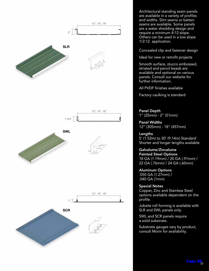
Concealed clip and fastener design
Ideal for new or retrofit projects
Smooth surface, stucco embossed, striated and pencil beads are available and optional on various panels. Consult our website for further information.
All PVDF finishes available
Factory caulking is standard
Architectural standing seam panels are available in a variety of profiles and widths. Slim seams or batten seams are available. Some panels are a water shedding design and require a minimum 4:12 slope. Others can be used in a low slope 1/2:12 application.
Panel Depth 1” (25mm) - 2” (51mm)
Panel Widths 12” (305mm) - 18” (457mm)
Lengths 5’ (1.52m) to 30’ (9.14m) Standard Shorter and longer lengths available
Galvalume/Zincalume Painted Steel Options 18 GA (1.19mm) / 20 GA (.91mm) / 22 GA (.76mm) / 24 GA (.60mm)
Aluminum Options .050 GA (1.27mm) / .040 GA (1mm)
Special Notes Copper, Zinc and Stainless Steel options available dependent on the profile.
Jobsite roll forming is available with SLR and SWL panels only.
SWL and SCR panels require a solid substrate.
Substrate gauges vary by product, consult Morin for availability.
SLR
BUTTON PUNCH
B-12
12"
1-1/2"
D-12
J-12
K-12
R-12
V-12
12"
1-1/2"
12"
1-1/2"
12"
1-1/2"
12"
1-1/2"
12"
1-1/2"
CONCEALED
A-12
AA-12
F-12-S
F-12-SW
F-12F-16F-18
N-12
T-12
W-12
TT-12
1-1/2"
12", 16", 18"
1-1/2"
12"
1-1/2"
12"
1-1/2"
1-1/2"
1-1/2"
1-1/2"
1-1/2"
1-1/2"
12"11"
12"11-1/2"
12"6"6"
12"8"4"
12"10"2"
12"
1-1/8"+/-- 1-1/8"+/--
1"
1/2"
BR9-36
36"
1-1/2"
EXPOSED
BR7-35*BR-35 DeLand Facility
BR-28
C-37-7/8"C-29-7/8"
C-40-1/2
E8-40
E-30
E-36
MR-36
O-24
O-24W
VB-34
VB-36
Y-29Y-36
35"
1-1/2"
28"
1-1/2"
29-5/8" or 37-5/16"
7/8"
40"
1/2"
40"
1"
30"
1"
36"
1"
36"
3"
24"
4"
24"
4"
34-1/8"
1-3/4"
36"
1"
29" or 36"
1-1/2"
INTEGRITY
S-16
X-12
X-16
XAB-16
XB-12XB-16
XC-12
XD-12
XE-12XE-16
XF-12XF-16
XG-12
16"
7/8"
16"
7/8"
16"
7/8"
12"
7/8"
16"
7/8"
12" or 16"
7/8"
12"
7/8"
12"
7/8"
12" or 16"
7/8"
12" or 16"
7/8"
12"
7/8"
STANDING SEAM
BCR
SCR
SLR**
SRR**
12", 16", 18"
2-1/2"
12", 16", 18"
2"
SWL**
12", 16", 18"
1-3/4"
12", 16", 18"
1-1/2"
12", 16", 18"
1"
LINER PANELS
F-24
L3-24-3F
L-12 L-16
L-12-2FL2-12-2F
L-24-5FL2-24-5F
L-12W-1L-24W-2
24"
24"
3"
12" or 16"
3", 4-1/2", 6"
12"
1-1/2" or 2"
24"
12" or 24"
1-1/2" or 2"
1-5/16"
1-1/2"
SWL
BUTTON PUNCH
B-12
12"
1-1/2"
D-12
J-12
K-12
R-12
V-12
12"
1-1/2"
12"
1-1/2"
12"
1-1/2"
12"
1-1/2"
12"
1-1/2"
CONCEALED
A-12
AA-12
F-12-S
F-12-SW
F-12F-16F-18
N-12
T-12
W-12
TT-12
1-1/2"
12", 16", 18"
1-1/2"
12"
1-1/2"
12"
1-1/2"
1-1/2"
1-1/2"
1-1/2"
1-1/2"
1-1/2"
12"11"
12"11-1/2"
12"6"6"
12"8"4"
12"10"2"
12"
1-1/8"+/-- 1-1/8"+/--
1"
1/2"
BR9-36
36"
1-1/2"
EXPOSED
BR7-35*BR-35 DeLand Facility
BR-28
C-37-7/8"C-29-7/8"
C-40-1/2
E8-40
E-30
E-36
MR-36
O-24
O-24W
VB-34
VB-36
Y-29Y-36
35"
1-1/2"
28"
1-1/2"
29-5/8" or 37-5/16"
7/8"
40"
1/2"
40"
1"
30"
1"
36"
1"
36"
3"
24"
4"
24"
4"
34-1/8"
1-3/4"
36"
1"
29" or 36"
1-1/2"
INTEGRITY
S-16
X-12
X-16
XAB-16
XB-12XB-16
XC-12
XD-12
XE-12XE-16
XF-12XF-16
XG-12
16"
7/8"
16"
7/8"
16"
7/8"
12"
7/8"
16"
7/8"
12" or 16"
7/8"
12"
7/8"
12"
7/8"
12" or 16"
7/8"
12" or 16"
7/8"
12"
7/8"
STANDING SEAM
BCR
SCR
SLR**
SRR**
12", 16", 18"
2-1/2"
12", 16", 18"
2"
SWL**
12", 16", 18"
1-3/4"
12", 16", 18"
1-1/2"
12", 16", 18"
1"
LINER PANELS
F-24
L3-24-3F
L-12 L-16
L-12-2FL2-12-2F
L-24-5FL2-24-5F
L-12W-1L-24W-2
24"
24"
3"
12" or 16"
3", 4-1/2", 6"
12"
1-1/2" or 2"
24"
12" or 24"
1-1/2" or 2"
1-5/16"
1-1/2"
SCR
BUTTON PUNCH
B-12
12"
1-1/2"
D-12
J-12
K-12
R-12
V-12
12"
1-1/2"
12"
1-1/2"
12"
1-1/2"
12"
1-1/2"
12"
1-1/2"
CONCEALED
A-12
AA-12
F-12-S
F-12-SW
F-12F-16F-18
N-12
T-12
W-12
TT-12
1-1/2"
12", 16", 18"
1-1/2"
12"
1-1/2"
12"
1-1/2"
1-1/2"
1-1/2"
1-1/2"
1-1/2"
1-1/2"
12"11"
12"11-1/2"
12"6"6"
12"8"4"
12"10"2"
12"
1-1/8"+/-- 1-1/8"+/--
1"
1/2"
BR9-36
36"
1-1/2"
EXPOSED
BR7-35*BR-35 DeLand Facility
BR-28
C-37-7/8"C-29-7/8"
C-40-1/2
E8-40
E-30
E-36
MR-36
O-24
O-24W
VB-34
VB-36
Y-29Y-36
35"
1-1/2"
28"
1-1/2"
29-5/8" or 37-5/16"
7/8"
40"
1/2"
40"
1"
30"
1"
36"
1"
36"
3"
24"
4"
24"
4"
34-1/8"
1-3/4"
36"
1"
29" or 36"
1-1/2"
INTEGRITY
S-16
X-12
X-16
XAB-16
XB-12XB-16
XC-12
XD-12
XE-12XE-16
XF-12XF-16
XG-12
16"
7/8"
16"
7/8"
16"
7/8"
12"
7/8"
16"
7/8"
12" or 16"
7/8"
12"
7/8"
12"
7/8"
12" or 16"
7/8"
12" or 16"
7/8"
12"
7/8"
STANDING SEAM
BCR
SCR
SLR**
SRR**
12", 16", 18"
2-1/2"
12", 16", 18"
2"
SWL**
12", 16", 18"
1-3/4"
12", 16", 18"
1-1/2"
12", 16", 18"
1"
LINER PANELS
F-24
L3-24-3F
L-12 L-16
L-12-2FL2-12-2F
L-24-5FL2-24-5F
L-12W-1L-24W-2
24"
24"
3"
12" or 16"
3", 4-1/2", 6"
12"
1-1/2" or 2"
24"
12" or 24"
1-1/2" or 2"
1-5/16"
1-1/2"
17Page 88

Openings - 1
DISTRICT DESIGN STANDARDS
Section 08 – Openings
Issued: Fall 2020 Updates:
I. Purpose
A. The following District Design Standards for openings are intended to provide basic guidelines for the District. This standard includes various criteria, including durability, maintainability, sustainability, acoustics, cost and ease of use. The standards listed herein are to minimize excessive variation within opening systems, including finishes, in order to streamline maintenance and operations for District maintenance staff while still maintaining an attractive, sustainable and vibrant learning environment.
B. These standards should be applied to all new construction, modernization, renovation and replacement projects.
II. General Design Standards
A. All new windows shall be in compliance with the latest version of the California Green Building Code, meeting the requirements of the California Energy Commission.
B. The Design Team shall insure that all fenestration complies with and is documented as part of the DSA submittal process.
C. All door hardware shall be ADA Compliant. In addition, all clearances in front of the door and at the push and pull sides of the door shall be ADA compliant.
III. Doors
A. Installation
1. All installations should be installed per the manufacturer’s installation recommendations and procedures. All installation details shall be approved through DSA. All jambs should have self-adhered weather resistive barrier applied over any wood rough opening prior to installation of door.
2. For new construction, all exterior door frames should be embedded in the concrete slab a minimum of 3”.
Page 89
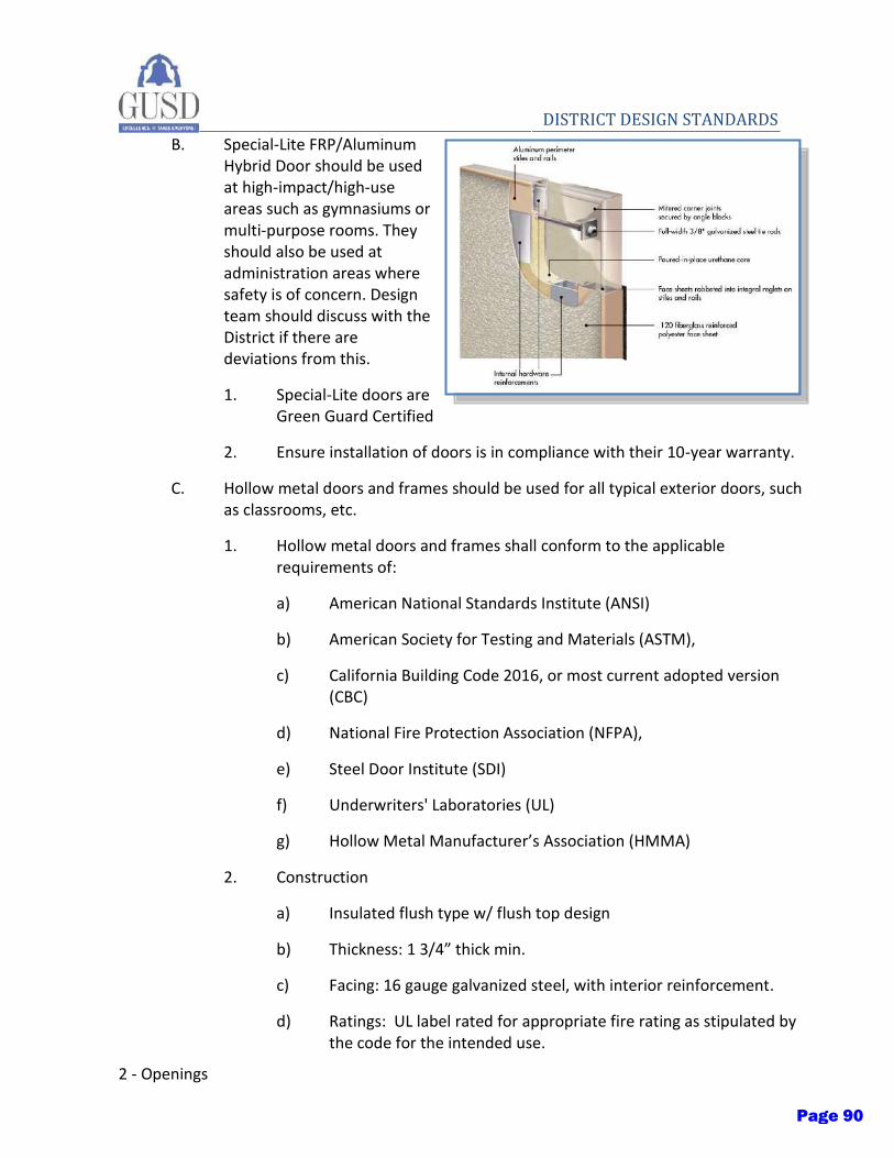
2 - Openings
DISTRICT DESIGN STANDARDS B. Special-Lite FRP/Aluminum
Hybrid Door should be used at high-impact/high-use areas such as gymnasiums or multi-purpose rooms. They should also be used at administration areas where safety is of concern. Design team should discuss with the District if there are deviations from this.
1. Special-Lite doors are Green Guard Certified
2. Ensure installation of doors is in compliance with their 10-year warranty.
C. Hollow metal doors and frames should be used for all typical exterior doors, such as classrooms, etc.
1. Hollow metal doors and frames shall conform to the applicable requirements of:
a) American National Standards Institute (ANSI)
b) American Society for Testing and Materials (ASTM),
c) California Building Code 2016, or most current adopted version (CBC)
d) National Fire Protection Association (NFPA),
e) Steel Door Institute (SDI)
f) Underwriters' Laboratories (UL)
g) Hollow Metal Manufacturer’s Association (HMMA)
2. Construction
a) Insulated flush type w/ flush top design
b) Thickness: 1 3/4” thick min.
c) Facing: 16 gauge galvanized steel, with interior reinforcement.
d) Ratings: UL label rated for appropriate fire rating as stipulated by the code for the intended use.
Page 90

Openings - 3
DISTRICT DESIGN STANDARDS e) Hollow metal frames shall comply with UL ratings. Knock down
frames are not acceptable.
D. Interior doors should be thermally fused flush doors.
1. Interior doors should be Maiman Thermal Fused Door, any deviation from this should be discussed with the District.
2. Interior thermally fused doors shall conform to the applicable requirements of:
a) WDMA I.S IA
b) ANSI-A208.1 grade M2
c) NEMA LS 3-2000
d) LMA.2003 – Decorative Overlay
e) ASTM E90-99, STC Testing
f) ASTM F-476, Security Testing grade 40
3. Construction
a) Thermal Fused LPDL – Low pressure decorative laminate
b) Maximum dimensions are 48” x 108”
c) Face material: Thermally fused to the core at approximately 600 psi and 392 F
d) Core material: 42 lb structurally engineered particle board core
e) Edgebanding: 1mm thick durable edgebanding, completely sealing the perimeter of the door
f) Lite and louver openings: Cut out should not exceed 40% of door area, with a minimum 6” from the edge and top of door.
g) Sustainable content: 85% recycled and recovered content.
IV. Aluminum Storefronts and Aluminum Doors
A. Aluminum storefronts and doors are allowed provided they meet the requirements of the most current edition of the CBC. The design team shall provide all necessary DSA approved drawings and calculations for system being
Page 91

4 - Openings
DISTRICT DESIGN STANDARDS provided. Design team shall provide an appropriate product for the intended
function of the product being used. Provide storefronts and associated products by a nationally recognized manufacturer of aluminum storefronts systems by one of the following:
1. Arcadia, Northrop Architectural Systems
2. Kawneer.
3. United States Aluminum.
4. Vistawall Architectural Products.
B. Exterior glazing shall be a minimum 1” dual insulated glazing panels.
V. Windows
A. Aluminum windows should be by a single source. Windows shall conform to a minimum performance standard of HC/AW 50.
B. For spaces greater than 5,000 square feet, window percentage and placement must conform with sidelight and daylight requirements in the most current edition of the California Energy Code.
C. Installation: All installations should be installed per the manufacturer’s installation recommendations and procedures. All installation details should be approved through DSA. Set sill members in bed of sealant or with gaskets, as indicated, for weather tight construction. All jambs and mullions should have self-adhered weather resistive barrier applied over any wood rough opening prior to installation of window. All manufacturers’ leg extenders or other accessories should be applied over window sealant/tape, then exterior wood/aluminum trim should be installed.
D. Where practical, operable windows should be provided allowing occupants the ability to maintain thermal comfort to help promote productivity, comfort and well-being. The quantity of operable sashes should be based on maximizing the number of operable windows and the project budget.
E. Frame:
Page 92

Openings - 5
DISTRICT DESIGN STANDARDS 1. Frames should be an aluminum extrusion which is factory fabricated of
equal leg construction with the use of compensating channel as determined by the architect. The frame should be thermally broken. Nailing fin style windows are not acceptable.
2. Frame finish: Factory finished clear anodized. Other colors may be used with the approval of the District.
3. AAMA Rating/Class: AW 50 – Minimum for all windows.
F. Operation: Fixed or Awning – Project Out
1. 4” max projection (from face to wall) at walkways to be compliant with ADA.
2. In places where ADA or path of travel is not an issue, all windows should have a 6” projection limit (from face to wall).
3. If it can be determined that a larger projection can be accommodated, then the limit may be set at a different depth.
G. Hardware: Provide manufacturer’s standard stainless steel hardware including but not limited to:
1. Lever handle with cam lock
2. Operators for projecting sash arms
3. Limit stops (see above)
4. Screens: No screens should be provided.
5. Electronic operators: Electronic operators should be used for all operable high bay windows that are inaccessible such as in multi-use rooms, gymnasiums, libraries, etc.
H. Key operation should be provided in a convenient yet secure location. The design team should coordinate with the District facilities department to determine desired location.
I. Basis of design manufacturers:
1. All Weather Aluminum, Series 6000
2. Boyd Aluminum, Series 2300
3. Graham Architectural, Series 6500
Page 93
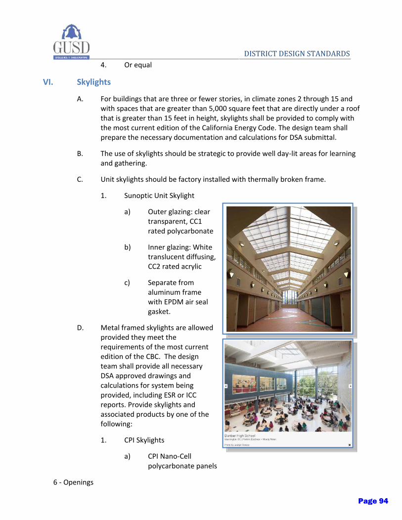
6 - Openings
DISTRICT DESIGN STANDARDS 4. Or equal
VI. Skylights
A. For buildings that are three or fewer stories, in climate zones 2 through 15 and with spaces that are greater than 5,000 square feet that are directly under a roof that is greater than 15 feet in height, skylights shall be provided to comply with the most current edition of the California Energy Code. The design team shall prepare the necessary documentation and calculations for DSA submittal.
B. The use of skylights should be strategic to provide well day-lit areas for learning and gathering.
C. Unit skylights should be factory installed with thermally broken frame.
1. Sunoptic Unit Skylight
a) Outer glazing: clear transparent, CC1 rated polycarbonate
b) Inner glazing: White translucent diffusing, CC2 rated acrylic
c) Separate from aluminum frame with EPDM air seal gasket.
D. Metal framed skylights are allowed provided they meet the requirements of the most current edition of the CBC. The design team shall provide all necessary DSA approved drawings and calculations for system being provided, including ESR or ICC reports. Provide skylights and associated products by one of the following:
1. CPI Skylights
a) CPI Nano-Cell polycarbonate panels
Page 94
Openings - 7
DISTRICT DESIGN STANDARDS b) For specific applications where room darkening is needed,
IntelaSun system should be used.
2. Kalwall
a) Fiber-Reinforced Polymer FRP face sheet
b) For specific applications where room darkening is needed, HC and E-Series should be used.
VII. Door Hardware
A. Door hardware shall be carefully coordinated with District’s locksmith and for compliance with all ADA standards. The project shall be sent to the District’s locksmith for review and site specific requirements. In general, door hardware should be selected by the Architect for the given situation and should follow the minimum design standards set below. Deviations shall be reviewed and approved by the District.
B. Hinges: Five knuckle full mortise, non-removable stainless hinge pins at all outswing/exterior doors.
C. Lockset: Schlage ND Series, RHO Levers with Vandalguard breakaway levers
1. Cores: interchangeable (verify installation by contractor or district)
2. Keying: Construction keyed during construction; Permanent cores installed by owner’s locksmith.
a) Primus Series 3; Everest C and/or D keyways (verify location with district locksmith)
D. Panic Hardware: Von Duprin AX-99NL x 99DT SNB
E. Door Closers: LCN 4040XP
1. All door closures shall meet current ADA requirements as stipulated in the most current edition of the California Building Code.
2. Hold open should be provided at exterior locations
3. Mounting: Sex nut bolt, through bolt mounting
4. Closure should have an all metal enclosure
5. Parallel arm should be provided at all locations. Design team should consult with the District if there are deviations from this.
Page 95
8 - Openings
DISTRICT DESIGN STANDARDS F. Thresholds: all door thresholds shall meet current ADA requirements as
stipulated in the current adopted issue of California Building Code.
1. Pemko
G. Push plates should be provided at all restroom locations
H. Smoke seals shall be provided at all rated door conditions
I. Kick plates should be provided at all wood and hollow metal doors
J. Door stops should be provided at all doors
K. Wall bumpers should be provided as an alternative to door stops where a door stop will interfere with the path of travel.
VIII. Automatic Door Closers
A. Main entrances should be provided with the following automatic door closers:
1. Stanley
IX. Glazing:
A. Tempered glass shall be installed in locations per current code.
B. Laminated glass should be installed at all window and doors located on the exterior of the campus fence, specifically the administration area, to comply with the City of Gilroy Police Department’s recommendation.
1. Film-applied laminate can be used in renovation projects.
C. Insulated glass, 1” with ½” air space
1. Exterior sheet: ¼” tempered (clear)
2. Interior sheet: ¼” tempered (clear)
3. Solar Heat Gain Coefficient: .27
4. U-Value: .29
5. Light to Solar Gain Ratio: 2.37
D. Tinted Glazing: Tinted glazing should be used on exterior sheets to help reduce heat gain and glare on the inside spaces. Careful consideration should be given to be consistent across the campus. Color should be selected by the design team to be reviewed and approved by the District.
Page 96
Openings - 9
DISTRICT DESIGN STANDARDS E. Low E coating: basis of design PPG Solarban 70XL, or equal
F. Graffiti coating should be applied to all windows less than 8’-0”.
Page 97

Thermal Fused Flush Doors
MAIMAN
Photo: iStockphoto .comPage 98
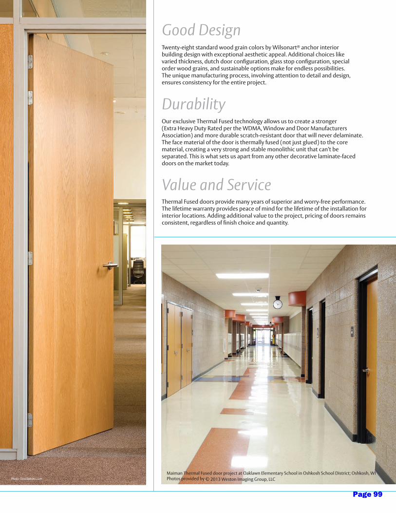
Value and ServiceThermal Fused doors provide many years of superior and worry-free performance. The lifetime warranty provides peace of mind for the lifetime of the installation for interior locations. Adding additional value to the project, pricing of doors remains consistent, regardless of finish choice and quantity.
Good DesignTwenty-eight standard wood grain colors by Wilsonart® anchor interior building design with exceptional aesthetic appeal. Additional choices like varied thickness, dutch door configuration, glass stop configuration, special order wood grains, and sustainable options make for endless possibilities. The unique manufacturing process, involving attention to detail and design, ensures consistency for the entire project.
DurabilityOur exclusive Thermal Fused technology allows us to create a stronger (Extra Heavy Duty Rated per the WDMA, Window and Door Manufacturers Association) and more durable scratch-resistant door that will never delaminate. The face material of the door is thermally fused (not just glued) to the core material, creating a very strong and stable monolithic unit that can’t be separated. This is what sets us apart from any other decorative laminate-faced doors on the market today.
Maiman Thermal Fused door project at Oaklawn Elementary School in Oshkosh School District; Oshkosh, WIPhotos provided by © 2013 Weston Imaging Group, LLCPhoto: iStockphoto.com
Page 99
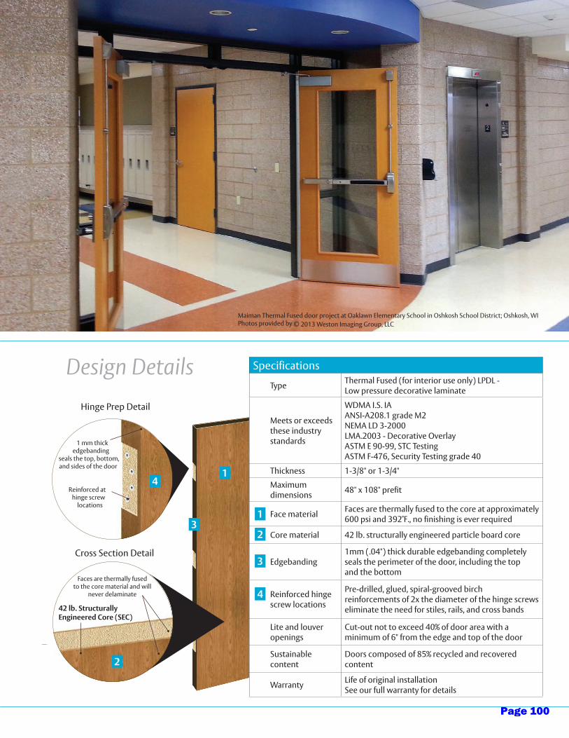
Design DetailsHinge Prep Detail
Cross Section Detail
1 mm thick edgebanding
seals the top, bottom, and sides of the door
Reinforced at hinge screw
locations
42 lb. Structurally Engineered Core (SEC)
1
2
3
4
Specifications
Type Thermal Fused (for interior use only) LPDL - Low pressure decorative laminate
Meets or exceeds these industry standards
WDMA I.S. IAANSI-A208.1 grade M2NEMA LD 3-2000LMA.2003 - Decorative OverlayASTM E 90-99, STC TestingASTM F-476, Security Testing grade 40
Thickness 1-3/8" or 1-3/4"
Maximum dimensions 48" x 108" prefit
Face material Faces are thermally fused to the core at approximately 600 psi and 392˚F., no finishing is ever required
Core material 42 lb. structurally engineered particle board core
Edgebanding1mm (.04") thick durable edgebanding completely seals the perimeter of the door, including the top and the bottom
Reinforced hinge screw locations
Pre-drilled, glued, spiral-grooved birch reinforcements of 2x the diameter of the hinge screws eliminate the need for stiles, rails, and cross bands
Lite and louver openings
Cut-out not to exceed 40% of door area with a minimum of 6" from the edge and top of the door
Sustainable content
Doors composed of 85% recycled and recovered content
Warranty Life of original installationSee our full warranty for details
1
2
3
4
Faces are thermally fused to the core material and will
never delaminate
Maiman Thermal Fused door project at Oaklawn Elementary School in Oshkosh School District; Oshkosh, WIPhotos provided by © 2013 Weston Imaging Group, LLC
Page 100

The samples shown here are intended to be used as a guide. Due to commercial printing processes the colors displayed may not be completely accurate.
Please ask an expert at Maiman for a color sample to choose exact colors.
Phone: 417.862.0681Website: www.maiman.com
The Standard Color Collection of woodgrain colors by Wilsonart® will anchor your design with exceptional durability and aesthetic appeal.
Asian Sand7952K
Blond Echo7939K
Beigewood7850
New Age Oak7938
High Line7970K
Fusion Maple7909
Monticello Maple7925
Brazilwood7946
Harvest Maple7953
Fonthill Pear10745
Huntington Maple7929
Asian Sun7951K
Thermal Fused Door Standard Color Collection
Page 101

Uptown Walnut7971K
River Cherry7937
Walnut Heights7965K
Nepal Teak7209K
Wild Cherry7054
Amber Cherry7919K
Biltmore Cherry7924K
English Oak7885K
Zanzibar7957K
Shaker Cherry7935K
Versailles Anigre7923K
Mambo7948K
Colombian Walnut7943K
Brighton Walnut7922K
Empire Mahogany7122K
Cafelle7933K
Page 102
Health ProductDECLARATION
TM
Sustainability
LEED Certification Contribution
Maiman understands that building materials need to be healthier and more sustainable for the future. Thanks to the Health Product Declaration initiative, Maiman is opening the doors to product transparency. Ingredients and materials are openly shared so that architects and specifiers can utilize the information for more sustainable built environments.
In addition, Maiman can help to achieve prerequisites and accumulate points in many category and credit areas of LEED.
Materials & Resources (MR)Credit 1.2Building Reuse Maintain existing interior non-structural elements
MR Credit 4Recycled Content
Products contain recycled content and can assist in the attainment of this credit
MR Credit 5Regional Material
Doors and frames qualify for Regional Material credit under LEED for commercial interiors
MR Credit 6Rapidly Renewable
Maiman offers an agrifiber core made of wheat stalks that can help projects qualify for this credit
MR Credit 7Certified Wood
Maiman has Forest Stewardship Council (FSC)® certified products across their product lines to help projects qualify for this credit
Indoor Environmental Quality (IEQ)IEQ Credit 3.2Construction Indoor Air Quality Management Plan-Before Occupancy
Project teams specify Maiman doors meeting GREENGUARD Gold testing will assist with IEQ 3.2 compliance
IEQ Credit 4.1 & 4.2Low-Emitting Materials - Adhesives & Sealants, Paints & Coatings
Only applies to materials applied within the weatherproofing system however, Maiman offers solutions including pre-finished door openings and pre-installed glazing, allowing LEED projects to avoid applying materials on site
IEQ Credit 4.4Low-Emitting Materials -Composite Wood & Agrifiber Products
Maiman has NAUF and CARB 1 & 2 certified products available across their product lines;Thermal fused, stile and rail and wood door jambs meet NAUF;Maiman doors and frames are certified to GREENGUARD Indoor Air Quality testing and can be used where required in LEED school, healthcare and retail projects
IEQ Credit 4.6Low-Emitting Materials - Ceiling & Wall Systems
All Maiman products are GREENGUARD Indoor Air Quality certified to meet this LEED credit requirement
IEQ Credit 8.1 & 8.2Daylight & Views
Adding glazing and sidelights to openings built with products from Maiman will assist projects in achieving this LEED credit
LEED Pilot Credit 43Certified Products
Maiman products provide single attribute certification for recycled content through Science Certification Systems, Inc. (SCS) as well as wood under FSC and contribute 50% based on cost
IEQ Credit 9Enhanced Acoustical Performance
Maiman offers Thermal Fused and Stile and Rail STC door solutions with an operable range from 33 to 46; these products can come with seal sets and can help LEED projects gain credit for Enhanced Acoustical Performance
LEED EBOM Specific CreditsMR Credit 3Sustainable Purchasing -Facility Alterations & Additions
Maiman can help sustainable purchasing programs meet many of the requirements to obtain this credit
MR Credit 9Solid Waste Management -Facility Alterations & Additions
Many products can be recycled (in the case of our metal products, potentially infinitely) and reused
Page 103
Properties Description Test Standards Performance Values Maiman
Values
Hingeload Test
The ability of a wood door stile to resist the horizontal withdrawal of an attached hinge; the test is designed to simulate the downward force to knob area on theleading edge of a hinged swinging door
WDMA TM-8Standard Duty 400 lbs.Heavy Duty 475 lbs.Extra Heavy Duty 550 lbs.
1,239 lbs.
Screw Withdrawal Vertical Door Edge
The ability of a wood door component to resist the withdrawal of a screw perpendicular to the component
WDMA TM-10Standard Duty 400 lbs.Heavy Duty 475 lbs.Extra Heavy Duty 550 lbs.
909 lbs.
Screw Withdrawal Door Face
The ability of a wood door component to resist the withdrawal of a screw perpendicular to the component
WDMA TM-10Standard Duty 400 lbs.Heavy Duty 475 lbs.Extra Heavy Duty 550 lbs.
699 lbs.
Warp The allowable variation from a flat plane within the door surface WDMA TM-2
All Duty Levels:1/4" within 3'-6" x 7'-0"Door Section Max.
Meets or Exceeds
Squareness The allowable differential in squareness, measured on the diagonal WDMA T-3 Diagonal Variance 1/8" Meets or Exceeds
Cycle Slams
To determine the physical endurance of wood doors and associated hardware connections under accelerated operating conditions
WDMA TM-7
Standard Duty 250,00 cyclesHeavy Duty 500,000 cyclesExtra Heavy Duty 1,000,000 cycles
1,000,000 Cycles
STC Rating The sound insulating property of a wood door ASTM E90-99 N/A 32-46
Security Test
To determine the strength of an opening when subjected to a kicking force that could be achieved by an individual breaking into a building
ADTM F-476
Medium 10Low/Med 20Med/High 30High 40
Grade 40
Structural Core Specifications
Density ANSI-A208.1 Grade M-2 28-32 lbs./ft3 Average 42 lbs./ft3
Door Dimensional TolerancesWidthHeightThickness
+ or - 1/32" Factory Prefit+ or - 1/16" Factory Prefit+ or - 1/16" Factory Prefit
Decorative Surface Characteristics
Wear ResistanceMeasure of the ability of the surface to keep its design or color under abrasive wear
NEMA LD 3-2000 400 Cycles 400 Cycles
Appearance Presence of visual defects on the decorative surface
WDMA I.S. 1A-2004
Premium 3 ft.Custom 6 ft.
Premium 3 ft.Custom 6 ft.
Scratch Resistance Measure of the ability of the decorative surface to scratch by diamond tip tool EN 438 2.14-91 UV - Cured Veneer -
1N HPDL - 1.5 N 3.7 N
Stain ResistanceMeasure of the ability of the decorative surface to resist stain when exposed to 15 household products
NEMA LD 3-2000
1-10 No Effect, 11-15 Moderate
1-10 No Effect, 11-15 Slight to
Moderate Effect
CleanabilityMeasure of the ability of the decorative surface to be cleaned with exposed to 15 different soiling agents
NEMA LD 3-2000 Max. 20 Max. 20
Light ResistanceMeasure of the ability of the decorative surface to retain its color when exposed to a light source similar to sunlight
NEMA LD 3-2000 Slight No to Slight Effect
Impact ResistanceMeasure of the maximum height of a steel ball that does ot cause fracture of the decorative surface
NEMA LD 3-2000 15 in. 20 in.
Performance Testing
Page 104
Your resource for beautiful doors, frames, and hardware from ASSA ABLOY Group brands.
www.thegooddesignstudio.com
AAW-003-02/16
Copyright © 2015, AADG, Inc., an ASSA ABLOY Group company. All rights reserved. Reproduction in whole or in part without the express written permission of AADG, Inc. is prohibited.
ASSA ABLOY Springfield3839 East Mustard Way | Springfield, MO 65803Phone: 417-862-0681 | Fax: 417-862-3780www.maiman.com
Page 105
Features & Benefits
• Manufactured with stiles and rails of extruded 6063-T6 aluminum alloy.
• Stiles and rails are joined with mitered corners and angle blocks secured by 3/8" diameter full-width galvanized steel tie rods.
• Standard and optional internal reinforcements provide secure attachment for the exact hardware specified.
• Face sheets are rabbeted and secured on all four sides by full-length integral reglets on the edges of the stiles and rails to form a truly flush door.
• SpecLite3® face sheets are .120" thick and provide scratch, scuff and fade resistance and will never rust, corrode, crack, split, peel or rot.
• Face sheets available in standard through-molded colors so scratches will not be obvious.
• Color match available in painted pebble grain sheet.
• Poured-in-place closed cell urethane core that is a minimum of 5 lb./cubic foot density.
• Doors can be supplied with hardware installed, reinforced only, or prepped for field installation of hardware.
• All anodized finishes are Class I (.7 mil).
• Unique configurations such as arched doors, odd sizes, unequal pairs, monorail cut-outs, dutch or bi-fold doors and custom lites are no problem.
• Thermal performance — minimum U-value/R-value = .29U/3.45R
Special-Lite was the first to introduce the FRP/Aluminum Flush Door in 1981 — our SL-17
Special-Lite® SL-17 pebble grain doors were first designed to offer a solution to the school market by offering a door product that would have a long, maintenance-free life and dent/graffiti resistance for tough applications. It didn’t take long for the SL-17 to be synonymous with School Door. Over the next 30+ years, with advancements in materials and technology, this door moved from schools to many other high abuse and heavy traffic locations.
FRP/Aluminum Hybrid Door
SL-17
Page 106
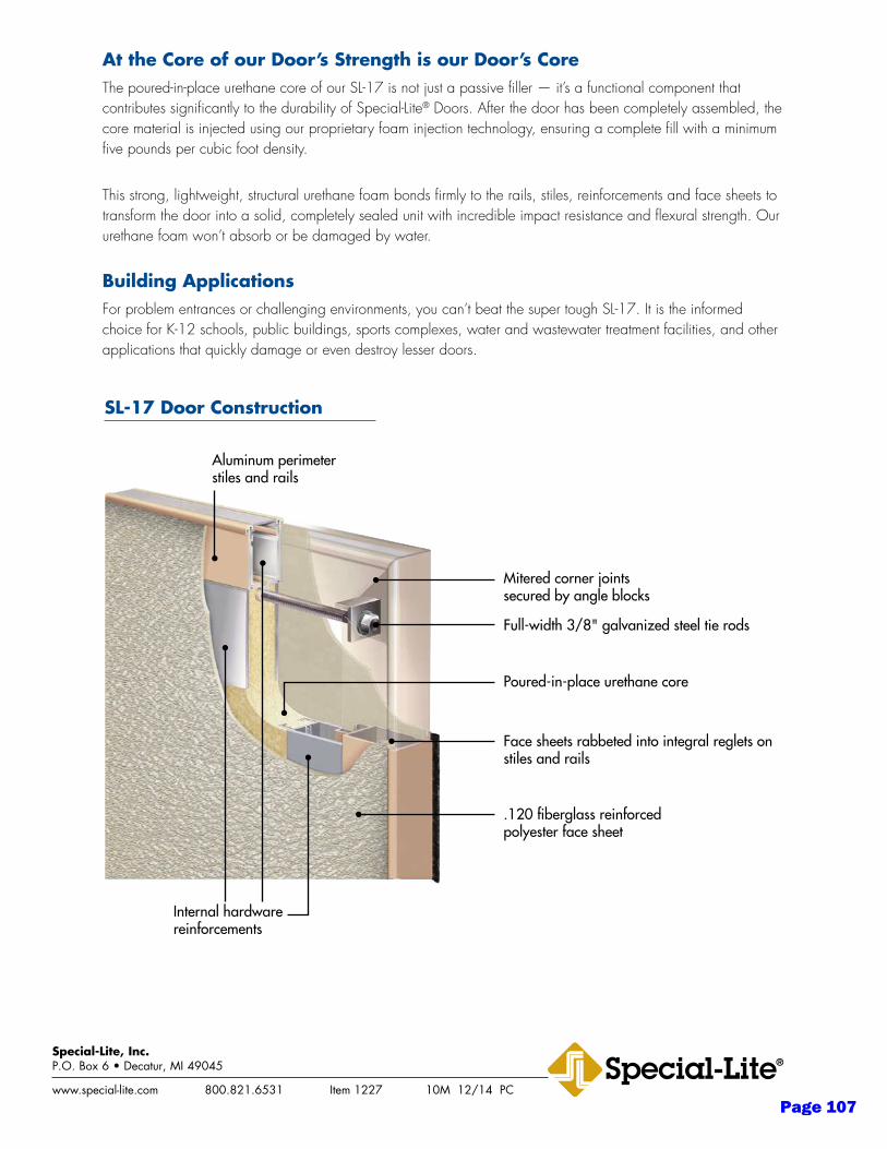
At the Core of our Door’s Strength is our Door’s CoreThe poured-in-place urethane core of our SL-17 is not just a passive filler — it’s a functional component that contributes significantly to the durability of Special-Lite® Doors. After the door has been completely assembled, the core material is injected using our proprietary foam injection technology, ensuring a complete fill with a minimum five pounds per cubic foot density.
This strong, lightweight, structural urethane foam bonds firmly to the rails, stiles, reinforcements and face sheets to transform the door into a solid, completely sealed unit with incredible impact resistance and flexural strength. Our urethane foam won’t absorb or be damaged by water.
Building ApplicationsFor problem entrances or challenging environments, you can’t beat the super tough SL-17. It is the informed choice for K-12 schools, public buildings, sports complexes, water and wastewater treatment facilities, and other applications that quickly damage or even destroy lesser doors.
www.special-lite.com 800.821.6531 Item 1227 10M 12/14 PC
Special-Lite, Inc.P.O. Box 6 • Decatur, MI 49045
Aluminum perimeter stiles and rails
Mitered corner joints secured by angle blocks
Full-width 3/8" galvanized steel tie rods
Face sheets rabbeted into integral reglets on stiles and rails
.120 fiberglass reinforced polyester face sheet
Poured-in-place urethane core
Internal hardware reinforcements
SL-17 Door Construction
Page 107
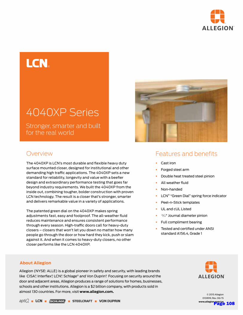
Allegion (NYSE: ALLE) is a global pioneer in safety and security, with leading brands
like CISA®, Interflex®, LCN®, Schlage® and Von Duprin®. Focusing on security around the
door and adjacent areas, Allegion produces a range of solutions for homes, businesses,
schools and other institutions. Allegion is a $2 billion company, with products sold in
almost 130 countries. For more, visit www.allegion.com.
About Allegion
© 2015 Allegion
010899, Rev. 06/15
www.allegion.com/us
4040XP Series Stronger, smarter and built for the real world
Overview
The 4040XP is LCN’s most durable and flexible heavy duty surface mounted closer, designed for institutional and other demanding high traffic applications. The 4040XP sets a new standard for reliability, longevity and value with a beefier design and extraordinary performance testing that goes far beyond industry requirements. We built the 4040XP from the inside out, combining tougher, bolder construction with proven LCN technology. The result is a closer that’s stronger, smarter and delivers remarkable value in a variety of applications. The patented green dial on the 4040XP makes spring adjustments fast, easy and foolproof. The all-weather fluid reduces maintenance and ensures consistent performance through every season. High-traffic doors call for heavy-duty closers – closers that won’t let you down no matter how many people go through the door or how hard they kick, push or slam against it. And when it comes to heavy-duty closers, no other closer performs like the LCN 4040XP.
Features and benefits § Cast iron
§ Forged steel arm
§ Double heat treated steel pinion
§ All weather fluid
§ Non-handed
§ LCN® “Green Dial” spring force indicator
§ Peel-n-Stick templates
§ UL and cUL Listed
§ 3⁄4" Journal diameter pinion
§ Full compliment bearing
§ Tested and certified under ANSI standard A156.4, Grade 1
Page 108

9
Full Mortise Hinges - 5 Knuckle
5BB1SC5 Knuckle, Ball Bearing,Swing Clear
5BB1SC Steel with steel pin
• Dimensions & tolerances conform to ANSI - A156.7• 5BB1SC Steel Description conforms to ANSI - A8122• Packed with flat head wood and machine screws
Size (Inches) Size (mm) Gauge
4.5 114 0.134
5 127 0.134
2 BALL BEARING • MEDIUM FREQUENCY
STANDARD WEIGHT • SWING CLEAR
Designed to completely clear the opening when door is opened 92 degrees.
Pins and tips are reversible.
AR
CH
IT
EC
TU
RA
LH
IN
GE
S
5BB1HW5 Knuckle, Ball Bearing,Heavy Weight
5BB1HW Steel with steel pin
5BB1HW Brass with stainless steel pin
5BB1HW Stainless steel with stainless steel pin (630 finish only)
NRP = Non-Removable Pin
• Dimensions & tolerances conform to ANSI - A156.7• 5BB1HW Steel description conforms to ANSI - A8111• 5BB1HW Brass description conforms to ANSI - A2111• 5BB1HW Stainless description conforms to ANSI - A5111• Packed with wood and machine screws
Size (Inches) Size (mm) Gauge
4.5 x 4 114 x 102 0.180
4.5 x 4.5 114 x 114 0.180
4.5 x 5 114 x 127 0.190
5 x 5 127 x 127 0.190
4 BALL BEARING • HIGH FREQUENCY • HEAVY WEIGHT
For use on Heavy Weight Doors or High Frequency Usage
5BB1HWRC5 Knuckle, Ball Bearing,Heavy Weight, Round Corner
5BB1HW Steel with steel pin
5BB1HW Brass with stainless steel pin
5BB1HW Stainless steel with stainless steel pin (630 finish only)
NRP = Non-Removable Pin
• Dimensions & tolerances conform to ANSI - A156.7• 1/4" radius• 5BB1HW Steel description conforms to ANSI - A8111• 5BB1HW Brass description conforms to ANSI - A2111• 5BB1HW Stainless description conforms to ANSI - A5111• Packed with wood and machine screws
Size (Inches) Size (mm) Gauge
4.5 x 4 114 x 102 0.180
4 BALL BEARING • HIGH FREQUENCY • HEAVY WEIGHT
For use on Heavy Weight Doors or High Frequency Usage
Page 109
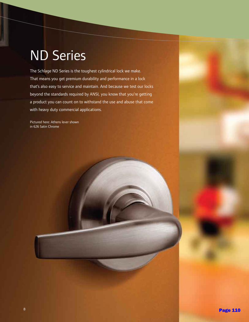
88
ND SeriesThe Schlage ND Series is the toughest cylindrical lock we make.
That means you get premium durability and performance in a lock
that’s also easy to service and maintain. And because we test our locks
beyond the standards required by ANSI, you know that you’re getting
a product you can count on to withstand the use and abuse that come
with heavy duty commercial applications.
Pictured here: Athens lever shownin 626 Satin Chrome
Page 110
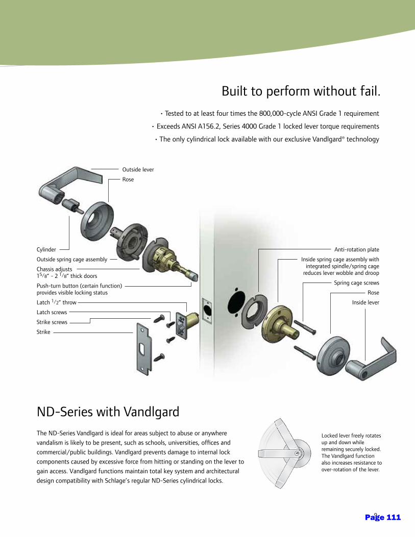
9
• Tested to at least four times the 800,000-cycle ANSI Grade 1 requirement
• Exceeds ANSI A156.2, Series 4000 Grade 1 locked lever torque requirements
• The only cylindrical lock available with our exclusive Vandlgard® technology
Locked lever freely rotates up and down while remaining securely locked. The Vandlgard function also increases resistance to over-rotation of the lever.
ND-Series with Vandlgard The ND-Series Vandlgard is ideal for areas subject to abuse or anywhere
vandalism is likely to be present, such as schools, universities, offices and
commercial/public buildings. Vandlgard prevents damage to internal lock
components caused by excessive force from hitting or standing on the lever to
gain access. Vandlgard functions maintain total key system and architectural
design compatibility with Schlage’s regular ND-Series cylindrical locks.
Built to perform without fail.
Outside lever
Rose
Cylinder
Outside spring cage assembly
Chassis adjusts 15/8” - 2 1/8” thick doors
Push-turn button (certain function) provides visible locking status
Latch 1/2” throw
Latch screws
Strike screws
Strike
Anti-rotation plate
Inside spring cage assembly with integrated spindle/spring cage
reduces lever wobble and droop
Spring cage screws
Rose
Inside lever
Page 111
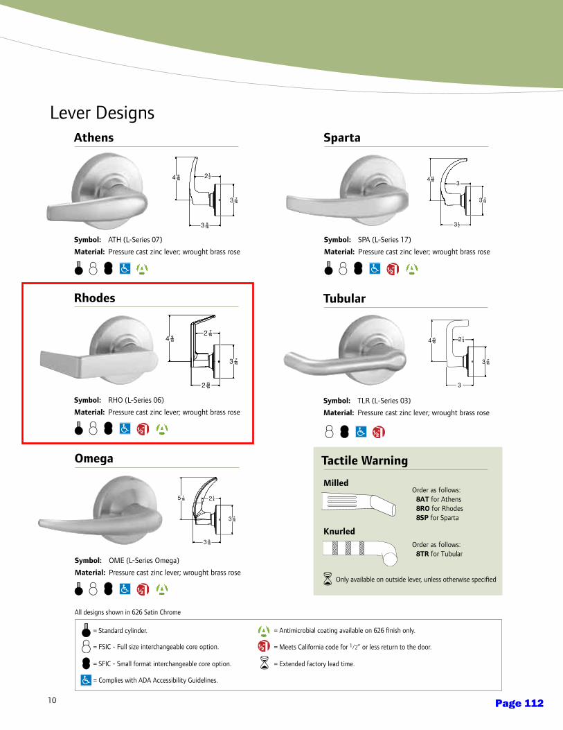
10
Lever Designs
Symbol: ATH (L-Series 07)
Material: Pressure cast zinc lever; wrought brass rose
Athens
All designs shown in 626 Satin Chrome
= Complies with ADA Accessibility Guidelines.
= FSIC - Full size interchangeable core option.
= Antimicrobial coating available on 626 finish only.
Symbol: SPA (L-Series 17)
Material: Pressure cast zinc lever; wrought brass rose
Sparta
Symbol: RHO (L-Series 06)
Material: Pressure cast zinc lever; wrought brass rose
Rhodes
= SFIC - Small format interchangeable core option.
Symbol: TLR (L-Series 03)
Material: Pressure cast zinc lever; wrought brass rose
Tubular
Symbol: OME (L-Series Omega)
Material: Pressure cast zinc lever; wrought brass rose
Omega
= Meets California code for 1/2” or less return to the door.
= Extended factory lead time.
Order as follows:8TR for Tubular
Order as follows:8AT for Athens8RO for Rhodes8SP for Sparta
Tactile Warning
Knurled
Milled
= Standard cylinder.
Only available on outside lever, unless otherwise specified
Page 112
11
Lever Finishes
605Bright Brass
606Satin Brass
612Satin Bronze
613Oil Rubbed
Bronze
619Satin Nickel
625Bright
Chromium Plated
626Satin
Chromium Plated
643eAged Bronze
ND SERIES LOCKS NEW IN 2009Athens • • • • • • • •Omega • • • • • • • •Rhodes • • • • • • • •Sparta • • • • • • • •Tubular • • • • • • • •
ADA-Compliant ProductsIn compliance with the American National Standards Institute (ANSI A117.1) and the Americans with Dis abil i ties Act
(ADA), Schlage Lock Company offers a wide selection of locks designed for the needs of the physically challenged.
This act is designed to provide protection for people with disabilities.
The intent of ADA is that owners of certain types of buildings must remove barriers and provide people with
disabilities with access equal to, or similar to, that available to the general public.
Product information and specifications contained in this catalog are subject to change without notice. Please consult the factory.
Door HandingAll ND levers are reversible. Hand information is
necessary to ensure proper cylinder orientation in keyed
functions, and finish of latchbolt and strike for locks that
are to be installed on reverse bevel doors. Follow the
diagram to correctly determine the hand of the door.
LHLeft Hand
INSIDE
OUTSIDE
OUTSIDE
INSIDE
LRLeft HandReverse
RHRight Hand
RR Right Hand
Reverse
e = an equivilent finish to the BHMA standard.
Page 113
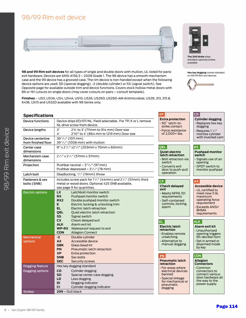
8 • Von Duprin 98/99 Series
98
/99
Rim
exi
t d
evic
e
98/99 Rim exit device
98 and 99 Rim exit devices for all types of single and double doors with mullion, UL listed for panic exit hardware. Devices are ANSI A156.3 – 2008 Grade 1. The 98 device has a smooth mechanism case and the 99 device has a grooved case. The rim device is non-handed except when the following device options are used: SD (special dogging), -2 (double cylinder) or SS (signal switch). See Opposite page for available outside trim and device functions. Covers stock hollow metal doors with 86 or 161 cutouts on single doors (may cover cutouts on pairs – consult template).
Finishes – US3, US3A, US4, US4A, US10, US26, US26D, US26D-AM Antimicrobial, US28, 313, 315 & 643E. US15 and US32D available with 98 Series only.
hex key dogging comes standard on 98/99 Rim exit devices
The 299 Strike ships standard, optional strikes available
SpecificationsDevice functions Device ships EO/DT/NL. Field selectable. For TP, K or L remove
NL drive screw from device.Device lengths 3' 2'4' to 3' (711mm to 914 mm) Door size
4' 2'10" to 4' (864 mm to 1219 mm) Door sizeDevice centerline from finished floor
39 13/16" (1011 mm)39 11/16" (1008 mm) with mullion
Center case dimensions
8" x 2 3/4" x2 3/8" (203mm x 70mm x 60mm)
Mechanism case dimensions
2 1/4" x 2 1/4" (57mm x 57mm)
Projection Pushbar neutral – 3 13/16" (97 mm)Pushbar depressed – 3 1/16" (78 mm)
Latch bolt Deadlocking, 3/4" (19mm) throw
Fasteners & sex bolts (SNB)
Includes screw pack for 1 3/4" (44mm) and 2 1/4" (57mm) thick metal or wood doors. Optional 425 SNB available, see page 9 for quantities.
Electric options LX Latchbolt monitor switch RX Pushpad monitor switchRX2 Double pushpad monitor switchE Electric locking & unlocking trim EL Electric latch retractionQEL Quiet electric latch retractionSS Signal switchCX Chexit delayed exitALK Alarm exit kitWP-RX Waterproof request to exit CON Allegion Connect
Mechanical options
-2 Double cylinderAX Accessible device GbK Glass bead kitPN Pneumatic latch retractionXP Extra protectionSNb Sex boltsSEC Security screws
Dogging feature Hex key dogging standardDogging options CD Cylinder dogging
SD Special center case doggingLD Less doggingDI Dogging indicatorCI Cylinder dogging indicator
Strikes 299 – Dull black
QELQuiet electric latch retraction • Bolt retraction via
switch• Converts exit
door to push-pull operation
CXChexit delayed exit• Meets NFPA 101
requirements• Self-contained
controls, locking, alarm
ALKAlarm exit kit• Unauthorized
opening triggers 85-decibel horn
• Set in armed or disarmed mode by key
CONAllegion Connectors• Common
connectors to connect various door hardware all the way to the power supply
RXPushpad monitor switch• Signals use of an
opening • SPDT switch to
monitor pushpad
XPExtra protection• 90˚ latch-to-
strike contact • Force resistance
of 2,000+ lbs.
AXAccessible device• UL certified to
meet new 5 lb. maximum operating force requirement
• Exceeds ANSI/BHMA requirements
CDCylinder dogging• Replaces hex key
dogging • Requires 1 1/4"
mortise cylinder with inverted cam
ELElectric latch retraction• Enables remote
unlatching • Alternative to
manual dogging
PNPneumatic latch retraction • For areas where
electrical devices banned
• Special linkage for mechanical or pneumatic dogging
Page 114
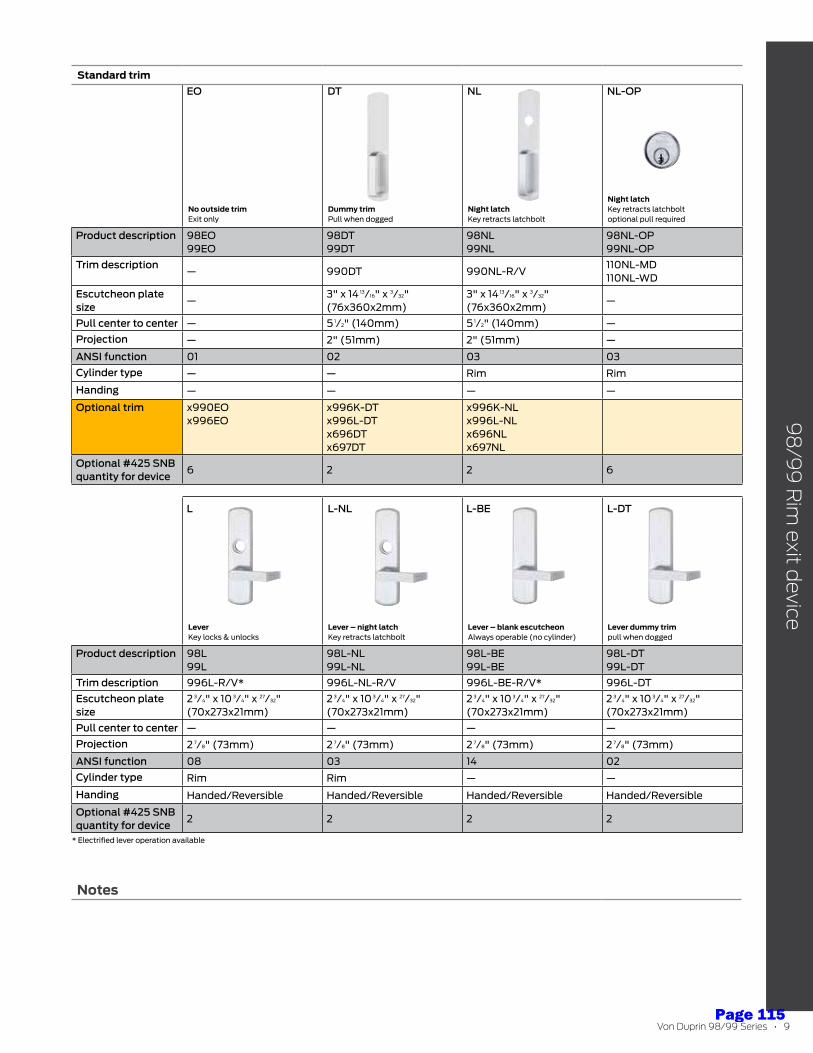
Von Duprin 98/99 Series • 9
Notes
98
/99
Rim
exit device
Standard trim
No outside trim Exit only
Dummy trim Pull when dogged
Night latch Key retracts latchbolt
Night latch Key retracts latchbolt optional pull required
Product description 98EO99EO
98DT99DT
98NL99NL
98NL-OP99NL-OP
Trim description— 990DT 990NL-R/V
110NL-MD110NL-WD
Escutcheon plate size
—3" x 14 13/16" x 3/32"(76x360x2mm)
3" x 14 13/16" x 3/32"(76x360x2mm)
—
Pull center to center — 5 1/2" (140mm) 5 1/2" (140mm) —Projection — 2" (51mm) 2" (51mm) —
ANSI function 01 02 03 03Cylinder type — — Rim Rim
Handing — — — —
Optional trim x990EOx996EO
x996K-DTx996L-DTx696DTx697DT
x996K-NLx996L-NLx696NLx697NL
Optional #425 SNB quantity for device
6 2 2 6
Lever Key locks & unlocks
Lever – night latch Key retracts latchbolt
Lever – blank escutcheon Always operable (no cylinder)
Lever dummy trim pull when dogged
Product description 98L99L
98L-NL99L-NL
98L-BE99L-BE
98L-DT99L-DT
Trim description 996L-R/V* 996L-NL-R/V 996L-BE-R/V* 996L-DTEscutcheon plate size
2 3/4" x 10 3/4" x 27/32"(70x273x21mm)
2 3/4" x 10 3/4" x 27/32"(70x273x21mm)
2 3/4" x 10 3/4" x 27/32"(70x273x21mm)
2 3/4" x 10 3/4" x 27/32"(70x273x21mm)
Pull center to center — — — —Projection 2 7/8" (73mm) 2 7/8" (73mm) 2 7/8" (73mm) 2 7/8" (73mm)
ANSI function 08 03 14 02Cylinder type Rim Rim — —
Handing Handed/Reversible Handed/Reversible Handed/Reversible Handed/Reversible
Optional #425 SNB quantity for device
2 2 2 2
* Electrified lever operation available
EO
L L-NL L-BE L-DT
DT NL NL-OP
Page 115
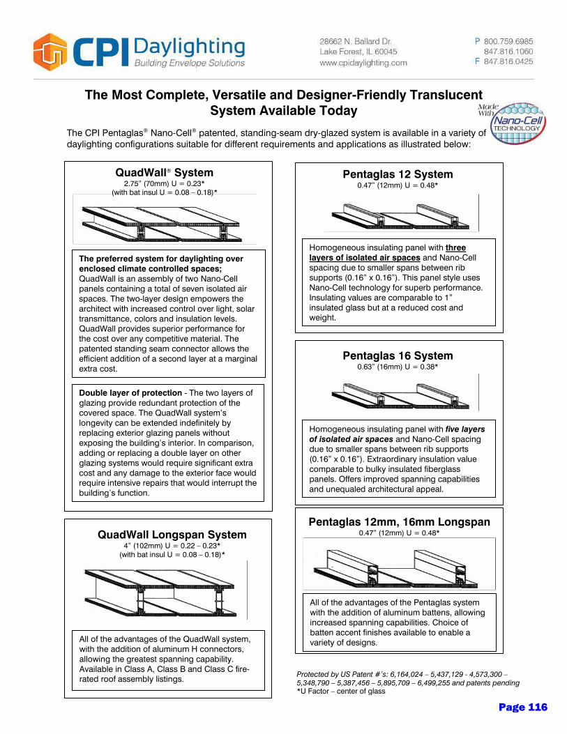
The Most Complete, Versatile and Designer-Friendly Translucent System Available Today
The CPI Pentaglas® Nano-Cell® patented, standing-seam dry-glazed system is available in a variety of daylighting configurations suitable for different requirements and applications as illustrated below:
QuadWall® System
2.75” (70mm) U = 0.23* (with bat insul U = 0.08 – 0.18)*
The preferred system for daylighting over enclosed climate controlled spaces; QuadWall is an assembly of two Nano-Cell panels containing a total of seven isolated air spaces. The two-layer design empowers the architect with increased control over light, solar transmittance, colors and insulation levels. QuadWall provides superior performance for the cost over any competitive material. The patented standing seam connector allows the efficient addition of a second layer at a marginal extra cost.
Double layer of protection - The two layers of glazing provide redundant protection of the covered space. The QuadWall system’s longevity can be extended indefinitely by replacing exterior glazing panels without exposing the building’s interior. In comparison, adding or replacing a double layer on other glazing systems would require significant extra cost and any damage to the exterior face would require intensive repairs that would interrupt the building’s function.
QuadWall Longspan System 4” (102mm) U = 0.22 – 0.23*
(with bat insul U = 0.08 – 0.18)*
All of the advantages of the QuadWall system, with the addition of aluminum H connectors, allowing the greatest spanning capability. Available in Class A, Class B and Class C fire-rated roof assembly listings.
Pentaglas 12 System 0.47” (12mm) U = 0.48*
Homogeneous insulating panel with three layers of isolated air spaces and Nano-Cell spacing due to smaller spans between rib supports (0.16” x 0.16”). This panel style uses Nano-Cell technology for superb performance. Insulating values are comparable to 1” insulated glass but at a reduced cost and weight.
Pentaglas 16 System 0.63” (16mm) U = 0.38*
Homogeneous insulating panel with five layers of isolated air spaces and Nano-Cell spacing due to smaller spans between rib supports (0.16” x 0.16”). Extraordinary insulation value comparable to bulky insulated fiberglass panels. Offers improved spanning capabilities and unequaled architectural appeal.
Pentaglas 12mm, 16mm Longspan 0.47” (12mm) U = 0.48*
All of the advantages of the Pentaglas system with the addition of aluminum battens, allowing increased spanning capabilities. Choice of batten accent finishes available to enable a variety of designs.
Protected by US Patent #’s: 6,164,024 – 5,437,129 - 4,573,300 – 5,348,790 – 5,387,456 – 5,895,709 – 6,499,255 and patents pending *U Factor – center of glass
Page 116
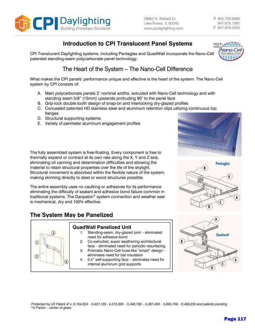
The System May be Panelized
Introduction to CPI Translucent Panel Systems
CPI Translucent Daylighting systems, including Pentaglas and QuadWall incorporate the Nano-Cell patented standing-seam polycarbonate panel technology.
The Heart of the System – The Nano-Cell Difference
What makes the CPI panels’ performance unique and effective is the heart of the system. The Nano-Cell system by CPI consists of:
A. Main polycarbonate panels 2’ nominal widths, extruded with Nano-Cell technology and with standing seam 5/8” (15mm) upstands protruding 90° to the panel face
B. Grip-lock double tooth design of snap-on and interlocking dry-glazed profiles C. Concealed patented HD stainless steel and aluminum retention clips utilizing continuous top
flanges D. Structural supporting systems E. Variety of perimeter aluminum engagement profiles
The fully assembled system is free-floating. Every component is free to thermally expand or contract at its own rate along the X, Y and Z axis, eliminating oil canning and delamination difficulties and allowing the material to retain structural properties over the life of the skylight. Structural movement is absorbed within the flexible nature of the system, making skinning directly to steel or wood structures possible.
The entire assembly uses no caulking or adhesives for its performance eliminating the difficulty of sealant and adhesive bond failure common in traditional systems. The Danpalon® system connection and weather seal is mechanical, dry and 100% effective.
QuadWall Panelized Unit 1. Standing-seam, dry-glazed joint – eliminated
need for adhesive bond 2. Co-extruded, super weathering architectural
face – eliminated need for periodic resurfacing 3. Prismatic Nano-Cell truss-like “smart” design –
eliminates need for bat insulation 4. 0.4” self-supporting face – eliminates need for
internal aluminum grid supports
Protected by US Patent #’s: 6,164,024 – 5,437,129 - 4,573,300 – 5,348,790 – 5,387,456 – 5,895,709 – 6,499,255 and patents pending *U Factor – center of glass
Page 117

THE ENLIGHTENED SOLUTION
Page 118

Since 1978, Sunoptics® has delivered innovation and
excellence in daylighting. Our vision has always been to
help our customers conserve energy by maximizing the
number of hours their electric lights can be turned off.
The easiest, most cost-effective way to achieve this is to
use rooftop skylights to daylight a space and harness
the full spectrum of natural sunlight.
REVOLUTIONARY DESIGN
Sunoptics has created a revolutionary optical design and frame for our skylights. Our unique prismatic skylights bring in more natural light while providing the optimum level of diffusion for soft, glare-free light. Our rugged frames have a durable structure and are warranted against leakage, providing many years of worry-free performance.
DAYLIGHTINGPIONEERS
EASY INTEGRATION
As part of the Acuity Brands portfolio, Sunoptics offers customers the advantage of integrated daylighting, electric luminaires and advanced lighting controls from one source, resulting in the industry’s most complete, sustainable and energy-efficient lighting solution.
ENERGY EFFICIENT
In short, Sunoptics prismatic skylights maximize customers’ energy-savings potential, giving them the most daylight for their lighting dollar. Many customers are able to replace electric lighting for up to eight hours a day, while also producing less heat than electric lighting.
Page 119
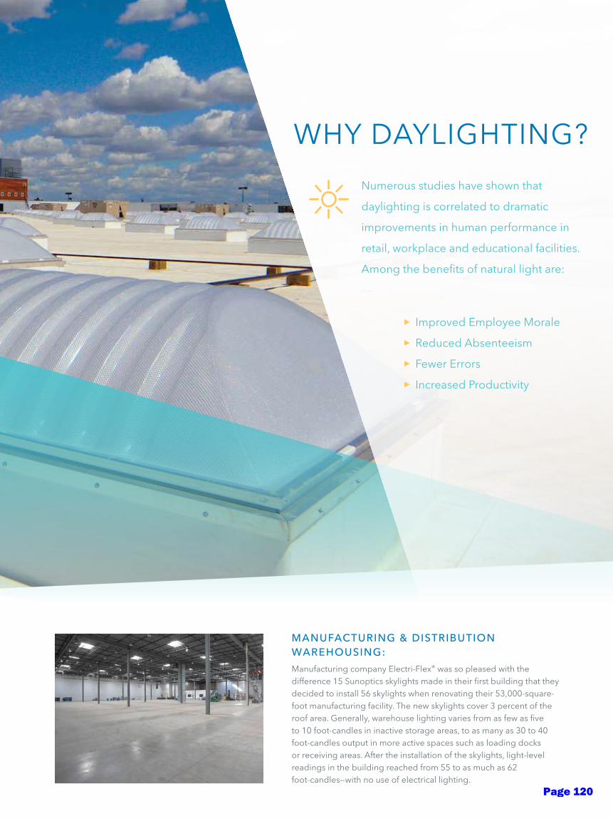
Improved Employee Morale
Reduced Absenteeism
Fewer Errors
Increased Productivity
Numerous studies have shown that
daylighting is correlated to dramatic
improvements in human performance in
retail, workplace and educational facilities.
Among the benefits of natural light are:
WHY DAYLIGHTING?
MANUFACTURING & DISTRIBUTION WAREHOUSING:
Manufacturing company Electri-Flex® was so pleased with the difference 15 Sunoptics skylights made in their first building that they decided to install 56 skylights when renovating their 53,000-square-foot manufacturing facility. The new skylights cover 3 percent of the roof area. Generally, warehouse lighting varies from as few as five to 10 foot-candles in inactive storage areas, to as many as 30 to 40 foot-candles output in more active spaces such as loading docks or receiving areas. After the installation of the skylights, light-level readings in the building reached from 55 to as much as 62 foot-candles—with no use of electrical lighting.
Page 120
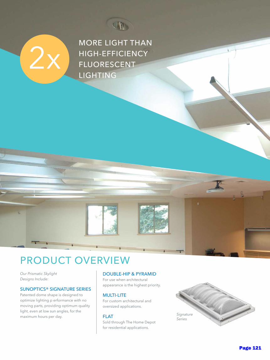
Our Prismatic Skylight Designs Include:
SUNOPTICS® SIGNATURE SERIESPatented dome shape is designed to optimize lighting p erformance with no moving parts, providing optimum quality light, even at low sun angles, for the maximum hours per day.
DOUBLE-HIP & PYRAMIDFor use when architectural appearance is the highest priority.
MULTI-LITEFor custom architectural and oversized applications.
FLATSold through The Home Depot for residential applications.
PRODUCT OVERVIEW
MORE LIGHT THANHIGH-EFFICIENCYFLUORESCENTLIGHTING
2x
Signature Series
Page 121
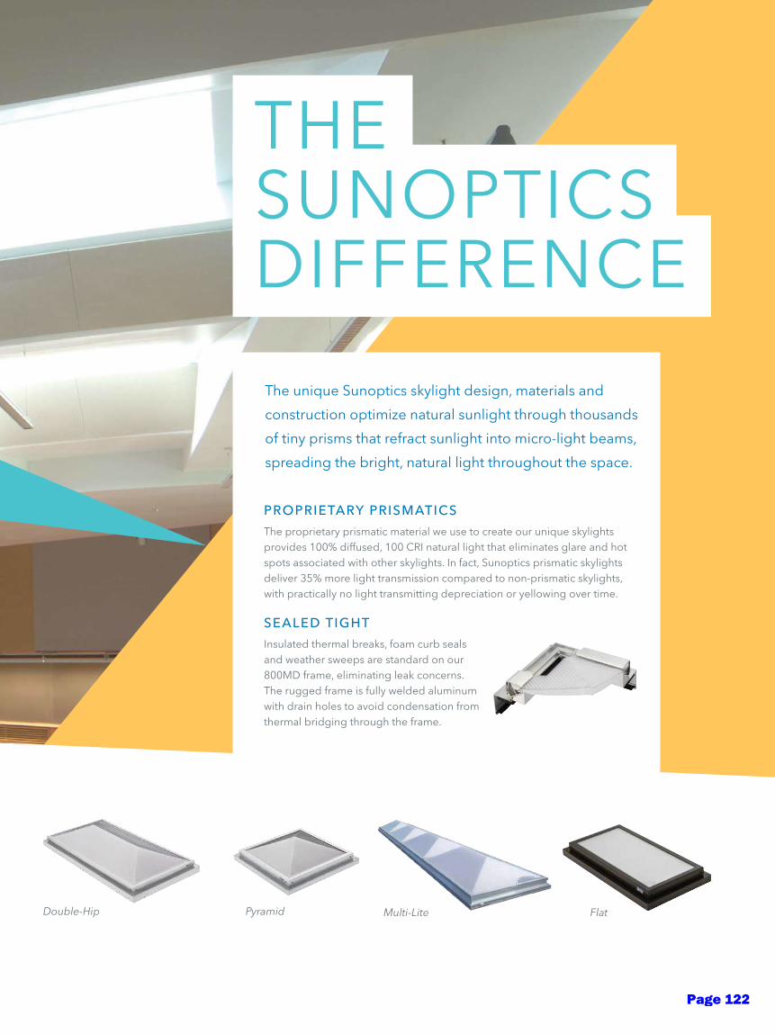
Double-Hip Flat
The unique Sunoptics skylight design, materials and
construction optimize natural sunlight through thousands
of tiny prisms that refract sunlight into micro-light beams,
spreading the bright, natural light throughout the space.
PROPRIETARY PRISMATICS
The proprietary prismatic material we use to create our unique skylights provides 100% diffused, 100 CRI natural light that eliminates glare and hot spots associated with other skylights. In fact, Sunoptics prismatic skylights deliver 35% more light transmission compared to non-prismatic skylights, with practically no light transmitting depreciation or yellowing over time.
SEALED TIGHT
Insulated thermal breaks, foam curb seals and weather sweeps are standard on our 800MD frame, eliminating leak concerns. The rugged frame is fully welded aluminum with drain holes to avoid condensation from thermal bridging through the frame.
THE SUNOPTICSDIFFERENCE
Multi-LitePyramid
Page 122
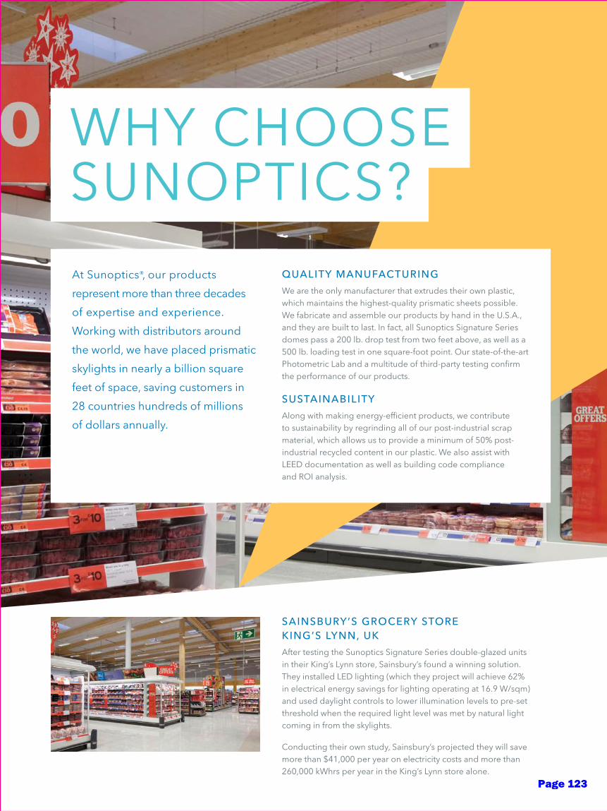
At Sunoptics®, our products
represent more than three decades
of expertise and experience.
Working with distributors around
the world, we have placed prismatic
skylights in nearly a billion square
feet of space, saving customers in
28 countries hundreds of millions
of dollars annually.
QUALITY MANUFACTURING
We are the only manufacturer that extrudes their own plastic, which maintains the highest-quality prismatic sheets possible. We fabricate and assemble our products by hand in the U.S.A., and they are built to last. In fact, all Sunoptics Signature Series domes pass a 200 lb. drop test from two feet above, as well as a 500 lb. loading test in one square-foot point. Our state-of-the-art Photometric Lab and a multitude of third-party testing confirm the performance of our products.
SUSTAINABILITY
Along with making energy-efficient products, we contribute to sustainability by regrinding all of our post-industrial scrap material, which allows us to provide a minimum of 50% post-industrial recycled content in our plastic. We also assist with LEED documentation as well as building code compliance and ROI analysis.
SAINSBURY’S GROCERY STORE KING’S LYNN, UK
After testing the Sunoptics Signature Series double-glazed units in their King’s Lynn store, Sainsbury’s found a winning solution. They installed LED lighting (which they project will achieve 62% in electrical energy savings for lighting operating at 16.9 W/sqm) and used daylight controls to lower illumination levels to pre-set threshold when the required light level was met by natural light coming in from the skylights.
Conducting their own study, Sainsbury’s projected they will save more than $41,000 per year on electricity costs and more than 260,000 kWhrs per year in the King’s Lynn store alone.
WHY CHOOSE SUNOPTICS?
Page 123

WALMART: HARVESTING DAYLIGHT AROUND THE WORLD
Sunoptics® Signature Series double-glazed units using impact-modified, clear prismatic acrylic over high-white prismatic acrylic are used to daylight more than 2,000 Walmart Supercenters worldwide.
Page 124

Rev. 3/14 | Form No. 1060.002 | Job No. 09
© 2014 Acuity Brands Lighting, Inc. All rights reserved. All trademarks referenced are property of their respective owners.
Call us for a free, energy-savings analysis.Toll free at 800.289.4700
Find out more about the Sunoptics prismatic daylighting difference at www.sunoptics.com
Page 125
SERIES 6000 6500
T: 707.452.1600 F: 707.452.1616
www.allweathersweb.com777 ALDRIDGE ROAD VACAVILLE, CA 95688 ALL WEATHER
ARCHITECTURAL ALUMINUM
All Weather Architectural Aluminum was founded in 1969 and has remained a family owned and operated commercial window manu-facturer for 40 years. All Weather currently resides in a state of the art facility in Vacaville, California and produces an array of high quality aluminum windows with light and heavy grade commercial ratings.
The Series 6000/6500 projected window is All Weather’s highest rated product. Available as an inside or outside glazed product, this window series is ready to meet your building’s design and performance crite-ria. Mitered and crimped corners provide exceptional strength with a contemporary look while the thermal strut provides increased thermal performance, improved condensation resistance, and the ability to have separate finishes on the interior and exterior of the window.
Page 126
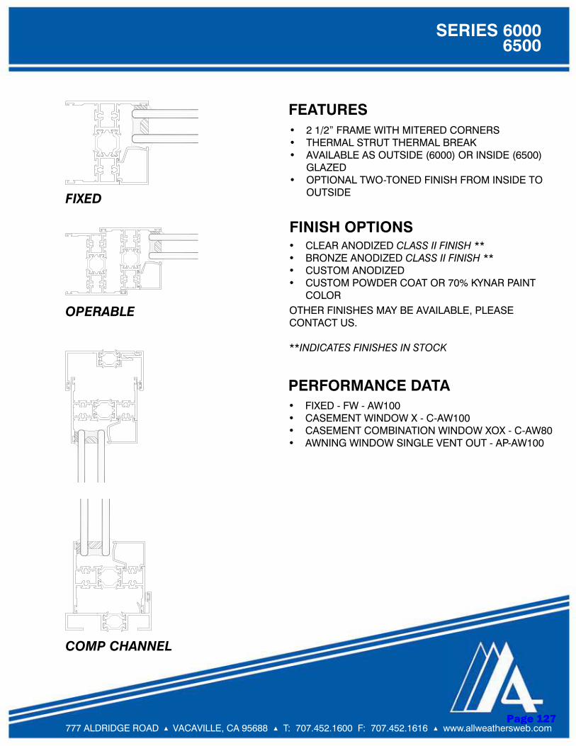
T: 707.452.1600 F: 707.452.1616 www.allweathersweb.com
SERIES 6000 6500
777 ALDRIDGE ROAD VACAVILLE, CA 95688
PERFORMANCE DATA• FIXED - FW - AW100• CASEMENT WINDOW X - C-AW100• CASEMENT COMBINATION WINDOW XOX - C-AW80• AWNING WINDOW SINGLE VENT OUT - AP-AW100
FEATURES• 2 1/2” FRAME WITH MITERED CORNERS• THERMAL STRUT THERMAL BREAK• AVAILABLE AS OUTSIDE (6000) OR INSIDE (6500)
GLAZED• OPTIONAL TWO-TONED FINISH FROM INSIDE TO
OUTSIDE
FINISH OPTIONS• CLEAR ANODIZED CLASS II FINISH **• BRONZE ANODIZED CLASS II FINISH **• CUSTOM ANODIZED• CUSTOM POWDER COAT OR 70% KYNAR PAINT
COLOROTHER FINISHES MAY BE AVAILABLE, PLEASE CONTACT US.
**INDICATES FINISHES IN STOCK
FIXED
OPERABLE
COMP CHANNEL
Page 127
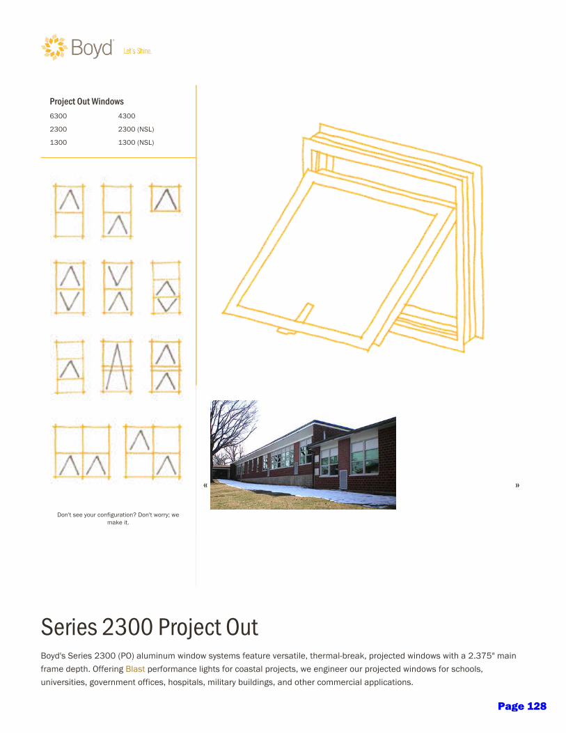
erie 2300 Project Outod' erie 2300 (PO) aluminum window tem feature veratile, thermal-reak, projected window with a 2.375" mainframe depth. Offering lat performance light for coatal project, we engineer our projected window for chool,univeritie, government office, hopital, militar uilding, and other commercial application.
Project Out Window6300 4300
2300 2300 (NL)
1300 1300 (NL)
Don't ee our configuration? Don't worr; wemake it.
« »
Page 128

Uing the latet AAMA tet, we enure the erie 2300 (PO) aluminum window tem meet AAMA pecification for AW-85projected window. And for contemporar uilding deign, we offer the erie with narrow ightline. To elect the afe, leekerie 2300, contact our Direct Aitance™ rep.
erie 2300 pecification
erie 2300
Window Tpe Project Out
Thermal arrier Ye
tem Depth (Inche) 2.375
AAMA Rating AW-85
Teting tandard Method 2005/2008
Air Infiltration (CFM/FT) [email protected]
Water Reitance (PF) 15.00
tructural Performance (PF) 150.00
Maximum Glazing Thickne 1.50
CRF 55
U-Value 0.51
True Muntin Ye
Interior Muntin Ye
Hitorical Muntin Ye
lind/Dual Glazing Ye
Impact Ye
lat Ye
2300 erie Detail Drawing PDF DWG
2300 erie pecification DOC PDF
2300 erie lat Detail Drawing PDF DWG
2300 erie lat pecification DOC PDF
Acceorie PDF DWG
Finih Option Finihe
New:
π
xcited and honored to attend onnell Aluminum vent 2015 Hopitalit Reception - The Glenn Hotelhttp://t.co/8LTMOYIfh #contantcontact
COPYRIGHT © 2016 OYD ALUMINUM MFG. CO.
ALL RIGHT RRVD
RVIW OUR ONLIN PRIVACY TATMNT
ITMAP
CONTACT U 1.800.737.2800
Page 129
Check website for most current information including detail drawings and hardware options: www.grahamwindows.com1551 Mt. Rose Avenue, York, Pennsylvania 17403-2909 (800) 755-6274 (717) 849-8100
Our products are tested to the standards of and certified by the American Architectural Manufacturer’s Association and the National Fenestration Rating Council.
TYPE AAMA RATING & TEST SIZE
AIR (cfm/ft2)
at 50 mph
WATER (psf)
DESIGNPRESSURE (psf)
STRUCTURAL OVERLOAD (psf)
U-VALUE(BTU/hr/ft2/°F)1 CRF STC OITC
CASEMENTC-HC80 42 x 66 0.04
12 80 120 0.48 – 0.63 54 37 - 43 29 - 34AW-PG80 42 x 66 0.03
PROJECTEDAP-PG120 72 x 48 0.01 15 150 180
0.44 – 0.59 54 37 - 43 29 - 34AP-AW85 72 x 48 0.04 12 90 128
FIXEDAW-PG120 60 x 99 0.01 20 120.0 180 0.34 – 0.54 58 37 - 43 29 - 34
FW-AW110 60 x 99 0.01 15 110 165 0.34 – 0.54 58 37 - 43 29 - 34
6500 SERIES QUICK VIEW:A commercial window with integral and stack mull for minimum sightlines. Dual glazed design allows for integral mini-blinds and high-performance glazing combinations.
STANDARD FEATURES• Integral and fixed-stack mull for minimal sightlines• Mulls horizontally or vertically to 2¼” frame fixed and
operable products• Receptor and panning systems available for installation• Flush design of vent and frame for aesthetic appeal• Frame and Vent 0.125” wall thickness
OPTIONAL FEATURES• Dual-glazed design offers optional: - High performance glazing combinations - Integral mini-blinds - Impact-resistant polycarbonate lite• Stainless steel projected or aluminum hardware• Hardware options to limit access to custodial use• In-swing or out-swing on operable units• Blast-resistant(B6500)versionavailable
•NominalFrame/SillWallThickness:0.125”•Applications:Industrial,Educational,HospitalsandAcoustical•Max.TestSize: Casement: 3’6” x 5’6” Projected: 6’0” x 4’0” Fixed: 5’0” x 8’3”•GlazingOptions: Single Glazed: Available Insulating: 1” IG available; also dual-glazed option Integral Mini-Blinds: Available on dual glazed units•DualGlazedOption: Guardian™ option with interior access panels for cleaning and maintenance•Muntins:Between-the-glassgrids,true-dividedlites,andappliedgrids available
Window series: 6500 Casement/Projected/Fixed — General Specifications & Details
6500 SERIES DATA SHEET
6500 Series2¼” Frame Depth
Casement/Projected/Fixed
•FinishOptions: AAMA 2603 — Standard acyrlic or polyester AAMA 2604 — 2 coat 50% fluoropolymer AAMA 2605 — 2 coat fluoropolymer 70% kynar Powder Coat Anodized•Hardware(OperableUnits): Hinges: 4-bar stainless steel or aluminum butt-hinge option Lock/Latch: White bronze standardRoto-operatoroption,limitdevices,andcustodialuse•Accessories: Frame Familiy: 2¼” Fixed Lite Option System: 6500 Mullions: Stacking: Integral & fixed-stack mull Side: 3-piece-mull Panning: Available Trims: Available Receptor Systems: Available Screen: Security/vandal screen available
OUT-SWING
OPERATIONIN-SWING
¹U-valueswillvarydependinguponglazingselected
Page 130
www.FLEETWOODUSA .comPage 131
Made in the U.S.A.11
¹Max width and height are not necessarily available in combination.²Specimen size: Nom. 79" x 79".
³Simulated Performance Alternative size: 10' x 12' PXIXP using SNX62-IS20/Argon Warm Edge glass.
SERIES 3050
MULTI-SLIDE & POCKET DOOR
C O N F IG U R AT I O N S
• Virtually Unlimited Multi-Slide, Curved, Pocket, and Corner applications.
POCKET AND POCKET INTERLOCKERS WITH STANDARD
3-1/2" SIGHTLINE EXTENDER
POCKET AND POCKET INTERLOCKERS
SILL
HEAD
ELEVATION VIEW:PXXP WITH SCREENS CONFIGURATION
MEETING STILES
2NFRC: 0.213S.P.A.: 0.22
EXAMPLE SHGC
2NFRC: 0.463S.P.A.: 0.39
EXAMPLE U-FACTOR
¹ 18' ¹ 10'MAX PANEL HEIGHTMAX PANEL WIDTH
Page 132

Made in the U.S.A.13
SERIES 3000
SLIDING DOOR
T Y P I C A L C O N F IG U R AT I O N S
• OX, XO, OXO, OOX, XOO, XOX, OXXO, XOOX.
INTERLOCKERS
ELEVATION VIEW:OXOL CONFIGURATION
FIXED JAMB
FALSE JAMB
SILL
HEAD
2NFRC: 0.223S.P.A.: 0.24
EXAMPLE SHGC
2NFRC: 0.473S.P.A.: 0.35
EXAMPLE U-FACTOR
¹ 14' ¹ 7'
¹Max width and height are not necessarily available in combination. ²Specimen size: Nom. 79" x 79".
³Simulated Performance Alternative size: 180" x 130" OXO using SNX62-IS20/Argon Warm Edge glass.
MAX PANEL HEIGHTMAX PANEL WIDTH
Pho
to b
y N
ico
Mar
que
s/ P
hote
kt
Page 133
Made in the U.S.A.15
SERIES 3300-T
“THERMAL FRAME” SLIDING DOOR
T Y P I C A L C O N F IG U R AT I O N S
• OX, XO, OXO, OOX, XOO, XOX, OXXO, XOOX.
ELEVATION VIEW:OXIXO CONFIGURATION
INTERLOCKERSSILL
FIXED JAMBHEAD
Optional: Archetype NarrowMEETING STILES
STANDARD
2NFRC: 0.223S.P.A.: 0.24
EXAMPLE SHGC
2NFRC: 0.343S.P.A.: 0.27
EXAMPLE U-FACTOR
¹ 12' ¹ 6'
¹Max width and height are not necessarily available in combination. ²Specimen size: Nom. 79" x 79".
³Simulated Performance Alternative size: 192" x 120" OXIXO using Cardinal 366-i89/Argon glass.
MAX PANEL HEIGHTMAX PANEL WIDTH
Pho
to b
y Jo
eFle
tche
r.co
m
Page 134
W O R L D L E A D E R I N F L E X I B L E S P A C E M A N A G E M E N T
GLASS WALLMOVABLE PARTITIONS
Page 135
FOR MORE INFORMATION OR TO CREATE YOUR OWN PRELIMINARY DRAWINGS VISIT www.hufcor.com
MODEL CONFIG.TOP SEALS
FIXED RETRACTFLOOR SEALS
RETRACT FIXED VERT.TRIM
MAX.1
HEIGHTS
MAX. OPENING
WIDTHSTC2 ACOUS.
RATINGS
PairedFrameless
Frameless
Timber-Framed
Timber-Framed
Acoustically Rated Ultra
Acoustically Rated Ultra
std n/a stdn/a opt 10'5" [3.2m] Unlimited n/a
Single std n/a stdn/a opt 10'5" [3.2m] Unlimited n/a
SERIES #
GL2
GL1
Paired std n/a stdn/a n/a 10'2" [3.1m] Unlimited n/a
Single std n/a stdn/a n/a 10'2" [3.1m] Unlimited n/a
GT2
GT1
Pairedstd stdoptn/a std 12'2" [3.7m]
Single36, 45
GA2
GA1
Acoustically Rated Ultra
Acoustically Rated Ultra
Pairedstd stdstdn/a std 12'2" [3.7m]
Single
26 PanelsWith 2 LCP
Panels
26 PanelsWith 2 LCP
Panels46
GA2
GA1
Hufcor glass walls are clearly visionary.Our movable glass partitions allow natural light to flood an interior
space while providing space flexibility. With your choice of clear
tempered, full satiny translucent, etched, or custom glass, our walls
can become the signature design element of your room. Satisfied
customers are using glass partitions to close off offices, storefronts,
restaurants, bank lobbies and library training centers, creating secure,
flexible spaces.
1Heights shown are standard. Contact your local Hufcor distributor for custom sizes. 2n/a = not available
GLASS WALL PRODUCT SELECTOR
main imageColor matched aluminum or timber panels can also be used for acoustical separation as shown at this meeting space in Texas.
insets (top to bottom)Hufcor partitions easily & effectively close off the narthex at the St. Joseph’s Catholic church in Maryland.
Wisconsin Center for Discovery installed frameless glass walls to create large meeting areas open to the building’s multi-story atrium.
A library uses a large Hufcor glass slider with custom graphics to close the entrance to the children’s wing.
Note: Metric dimensions in [ ] are in millimeters unless otherwise indicated.
MOVABLE PARTITIONSGlass Wall
2 Page 136

FOR MORE INFORMATION OR TO CREATE YOUR OWN PRELIMINARY DRAWINGS VISIT www.hufcor.com
BIM REVIT® FAMILIES NOW AVAILABLECONTACT YOUR LOCAL HUFCOR DISTRIBUTOR FOR ASSISTANCE OR VISIT hufcor.com/ga-ultra-bim.
is Hufcor’s next generation of acoustically rated moveable glass partition systems with sound ratings of STC 36, 45 and 46. The durable frame is of steel and aluminum and is powder coated in a clear satin metallic finish.
STC 45 and 46 models include enhanced 2” [51] double-laminated sealed I.G. glass to achieve the ultimate acoustical performance. The STC 46 bottom seal has both retractable and sweep seals. The STC 36 model include single pane tempered glass and comes with sweep bottom seals and optional retractable seals.
All models are available as single panels or pairs with an expanding jamb or hinged closure. Options include an ADA compliant pass door with panic hardware, custom colors, and more.
GA-ULTRA ACOUSTIC GLASS WALL HUFCOR "SMARTER" BIM REVIT® FAMILIES
◆ Acoustic Glass Wall Paired Panels - Tamarack Center - NATC (Rhinelander, WI)
◆ Acoustic Glass Wall Paired Panels - Tamarack Center - NATC (Rhinelander, WI)◆ Acoustic Glass Wall Paired Panels - Tamarack Center - NATC (Rhinelander, WI)
glass wallCLEARLY VISIONARYNote: Metric dimensions in [ ] are in millimeters unless otherwise indicated.
can adjust minimum clearance dimensions to account for accessories like pass doors and panic hardware with simple, easy-to-use check boxes.
ULTRA ACOUSTIC Glass WallU
LT
RA
AC
OU
ST
IC - G
LA
SS W
ALL
6 Page 137

Operable Partitions
Acousti-Seal® Non-Steel
Page 138

6
Paired panels offer the most efficient operable partition option.
Advantages
• Quick setup with movement of two panels at a time.• Smooth operation.• Economical overhead support of straight-line track.• Simple automatic bottom seals for efficient operation.• SOSS Invisible hinges available.
Available in top-supported or floor-supported configurations, the center-hung, paired panels are perfect for straight-line openings and offer quick and easy setup. For convenient and economical space division, the paired panel is the ideal solution.
+ Custom-engineered solutions available beyond maximum height
* Customers Own Material – must be approved by factory
PAIRED PANEL MODEL 932 932FS 912
Nominal Panel Thickness 3-inch 3-inch 3-inch
Operation Manual Floor Supported Manual Manual Fire Rated
FrameRoll Formed & Welded 14/18-gage & 16-gage*
Steel
Roll Formed & Welded 14/18-gage Steel
Roll Formed & Welded 16-gage Steel
Skin/Face Options
Gypsum,Gypsum w/ steel face,
MR Board, MDF Board, Steel*
Gypsum,Gypsum w/ steel face,
MR Board, MDF Board, Wood Veneer
Steel
Finish Options
Vinyl, Heavy Duty Vinyl, Carpet, Fabric, Customer’s Own
Material*, Full Height Marker/Tack
Board, Plastic Laminate, Wood
Veneer, Uncovered
Vinyl, Heavy Duty Vinyl, Carpet, Fabric, Customer’s Own
Material*, Full Height Marker/Tack
Board, Plastic Laminate, Wood
Veneer, Uncovered
Vinyl, Heavy Duty Vinyl, Carpet, Fabric, Customer’s Own
Material*, Full Height Marker/Tack
Board, Uncovered
Maximum Width Unlimited 80’-9” Unlimited
Maximum Height+ 18-feet 12-feet 18-feet
STC 28, 41, 47, 50, 52* 28, 41, 47, 50 45, 50, 52
Hanging Weight (STC-dependent) 6 to 11 lb/sq ft 6 to 8 lb/sq ft 8 to 11 lb/sq ft
* Consult your local Modernfold distributor for custom options including: finishes, cutouts, and alternative platforms for pocket space restraints.
Page 139

7
Quickly and easily convert a classroom to meet fluctuations in class size.
Page 140

21st Century School DesignPage 141

PRODUCT FAMILIES
University of Washington Merrill Hall, Seattle WANanaWall Wood Framed Folder System WD66Architect: The Miller | Hull Partnership 25Page 142

Folding Glass Walls
Nine structurally distinct systems of connected bi-fold door
panels offer hundreds of configurations and options for size,
hardware, and performance. Choose from all aluminum with
over 200 custom colors, 100% solid wood frames, an edge-
to-edge all glass system, or an aluminum clad system.
Features
• Top-hung or floor mounted models, inward or outward
openings, or center pivot.
• Panel heights of up to 12’ (3660 mm) and widths
of 4’ (1220 mm) are possible.
• Meets or exceeds industry standards for air infiltration,
water penetration, structural performance,
acoustical attenuation, forced entry, and extreme
weather protection.
• Convenient swing entry doors may be hinged to a side
jamb or be configured within the chain of panels
with door closer and panic hardware options available.
• Effortless one-handed operation.
Single Track Sliding Glass Walls
Unlimited spans of individual top-hung panels riding within a
single narrow header over an optional single floor track glide
effortlessly to open or close across extremely large openings.
NanaWall’s single track design easily navigates multiple angle
changes up from 90º to 180 º. Stacking options and minimal
parking bays can be designed with total customization.
Features
• Almost any shape is possible including open corners.
• No “train station” effect from multiple floor tracks means
no need to engineer an extra-wide header.
• Panels interlock to create a streamlined look and secure,
rattle, draft-free weather protection in the most demanding
environments and acoustical privacy when needed.
• Convenient swinging entrance/egress doors available nearly
anywhere within the span of the opening with door closer
and panic hardware options available.
• Panels park virtually anywhere in multiple types of stacking
bay arrangements.
PRODUCT FAMILIES
27
SL70
SL82
WA67
SL60
SL80/81
WD66
SL45
SL73
WD65
HSW45
HSW66
HSW60
Page 143

Folding Glass Walls
Nine structurally distinct systems of connected bi-fold door
panels offer hundreds of configurations and options for size,
hardware, and performance. Choose from all aluminum with
over 200 custom colors, 100% solid wood frames, an edge-
to-edge all glass system, or an aluminum clad system.
Features
• Top-hung or floor mounted models, inward or outward
openings, or center pivot.
• Panel heights of up to 12’ (3660 mm) and widths
of 4’ (1220 mm) are possible.
• Meets or exceeds industry standards for air infiltration,
water penetration, structural performance,
acoustical attenuation, forced entry, and extreme
weather protection.
• Convenient swing entry doors may be hinged to a side
jamb or be configured within the chain of panels
with door closer and panic hardware options available.
• Effortless one-handed operation.
Single Track Sliding Glass Walls
Unlimited spans of individual top-hung panels riding within a
single narrow header over an optional single floor track glide
effortlessly to open or close across extremely large openings.
NanaWall’s single track design easily navigates multiple angle
changes up from 90º to 180 º. Stacking options and minimal
parking bays can be designed with total customization.
Features
• Almost any shape is possible including open corners.
• No “train station” effect from multiple floor tracks means
no need to engineer an extra-wide header.
• Panels interlock to create a streamlined look and secure,
rattle, draft-free weather protection in the most demanding
environments and acoustical privacy when needed.
• Convenient swinging entrance/egress doors available nearly
anywhere within the span of the opening with door closer
and panic hardware options available.
• Panels park virtually anywhere in multiple types of stacking
bay arrangements.
PRODUCT FAMILIES
27
SL70
SL82
WA67
SL60
SL80/81
WD66
SL45
SL73
WD65
HSW45
HSW66
HSW60
Page 144
Stanford University Bio Chemical Engineering Department, Stanford CANanaWall Frameless Glass Wall SL25 XXL with custom glazingArchitect: Walters & Wolf
• From design to installation—we’re here to help.
Our Dedicated Design Team can answer your
questions and assist with planning, ordering
and optimizing your NanaWall options.
• Visit NanaWall.com for: CAD, product specifications, animations, installation/
operational videos, architectural binder, owner’s manuals, and a complete line
of brochures and photo ideabooks.
• NanaWall opening glass walls are sold factory direct through local architectural
design representatives across North America. Our Certified Installation Network
option ensures correct installation with speed and precision.
Support Highlights
29
Frameless Glass Walls
NanaWall all glass options for interior and exterior applications
feature a range of frameless folding, center pivot, and single track
sliding wall solutions with no visible vertical profile. The clean,
contemporary aesthetic offers separation with total transparency,
natural daylight, and acoustic buffering when closed.
Features
• Narrow top and bottom rail heights, no vertical profiles.
• Panels are available to 4’ (1220 mm) wide and 10’ 6” (3230 mm)
in height (please contact NanaWall for larger options).
• Accommodates swing doors with patented conversion system,
locking hardware, and closer options anywhere in chain of doors.
• Cornerless configurations possible.
• Polyamide rollers with sealed bearings ensure silent running
and resistance to changes in temperature.
PRODUCT FAMILIES
HSW75
CSW75 SL25
FSW75
Page 145
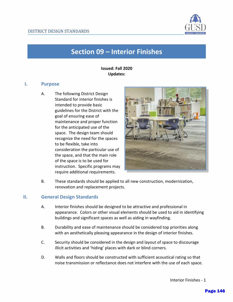
Interior Finishes - 1
DISTRICT DESIGN STANDARDS
Section 09 – Interior Finishes
Issued: Fall 2020 Updates:
I. Purpose
A. The following District Design Standard for interior finishes is intended to provide basic guidelines for the District with the goal of ensuring ease of maintenance and proper function for the anticipated use of the space. The design team should recognize the need for the spaces to be flexible, take into consideration the particular use of the space, and that the main role of the space is to be used for instruction. Specific programs may require additional requirements.
B. These standards should be applied to all new construction, modernization, renovation and replacement projects.
II. General Design Standards
A. Interior finishes should be designed to be attractive and professional in appearance. Colors or other visual elements should be used to aid in identifying buildings and significant spaces as well as aiding in wayfinding.
B. Durability and ease of maintenance should be considered top priorities along with an aesthetically pleasing appearance in the design of interior finishes.
C. Security should be considered in the design and layout of space to discourage illicit activities and ‘hiding’ places with dark or blind corners.
D. Walls and floors should be constructed with sufficient acoustical rating so that noise transmission or reflectance does not interfere with the use of each space.
Page 146
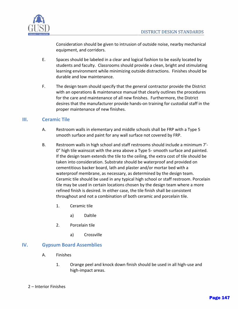
2 – Interior Finishes
DISTRICT DESIGN STANDARDS
Consideration should be given to intrusion of outside noise, nearby mechanical equipment, and corridors.
E. Spaces should be labeled in a clear and logical fashion to be easily located by students and faculty. Classrooms should provide a clean, bright and stimulating learning environment while minimizing outside distractions. Finishes should be durable and low maintenance.
F. The design team should specify that the general contractor provide the District with an operations & maintenance manual that clearly outlines the procedures for the care and maintenance of all new finishes. Furthermore, the District desires that the manufacturer provide hands-on training for custodial staff in the proper maintenance of new finishes.
III. Ceramic Tile
A. Restroom walls in elementary and middle schools shall be FRP with a Type 5 smooth surface and paint for any wall surface not covered by FRP.
B. Restroom walls in high school and staff restrooms should include a minimum 7’-0” high tile wainscot with the area above a Type 5- smooth surface and painted. If the design team extends the tile to the ceiling, the extra cost of tile should be taken into consideration. Substrate should be waterproof and provided on cementitious backer board, lath and plaster and/or mortar bed with a waterproof membrane, as necessary, as determined by the design team. Ceramic tile should be used in any typical high school or staff restroom. Porcelain tile may be used in certain locations chosen by the design team where a more refined finish is desired. In either case, the tile finish shall be consistent throughout and not a combination of both ceramic and porcelain tile.
1. Ceramic tile
a) Daltile
2. Porcelain tile
a) Crossville
IV. Gypsum Board Assemblies
A. Finishes
1. Orange peel and knock down finish should be used in all high-use and high-impact areas.
Page 147

Interior Finishes - 3
DISTRICT DESIGN STANDARDS
2. Level 5 smooth finish should be used only in low-traffic areas such as administration, and where required, such as restroom and specialty areas (kitchens).
B. Impact resistant gypsum board
1. 8’-0” high impact resistant gypsum board should be installed in all locker rooms and gymnasiums. The design team should consult the District if it should be provided in other locations based upon the project’s needs.
a) For locker room applications, ½” plywood can be provided behind the impact resistant gypsum board.
V. Portland Cement Plaster
A. Portland Cement should comply with ASTM C150/C150M, Type 1
B. Lime should comply with ASTM C206, Type S
C. Plaster should be applied in accordance with ASTM C296
D. A three-coat application over metal lath should be used:
1. Apply first coat to a nominal thickness of 3/8”
2. Apply second coat to a nominal thickness of 3/8”
3. Apply finish coat to a nominal thickness of 1/8”
E. Finish coat should be integral color plaster with elastomeric paint
1. Amerimix, an Old Castle brand: AMX 775C
2. BMI Products Co.: Exterior Stucco Finish
F. Fiberglass reinforced: Glass fibers, chopped to ½” nominal length, alkali resistant.
VI. Ceiling Finishes
A. All ceiling surfaces shall be appropriate for use in the intended facility. Suspended ceilings shall meet the requirements of the most current edition of the CBC and/or the authority having jurisdiction. The light reflectance and acoustic properties of the ceiling should be considered to meet the intent of the program.
B. In general, classroom ceilings should be suspended 24”X48” T-bar with acoustical ceiling panels. Provide manufacturer's direct-hung metal suspension systems of
Page 148

4 – Interior Finishes
DISTRICT DESIGN STANDARDS
types, structural classifications, and finishes indicated that comply with applicable requirements in ASTM C 635. Ceiling systems shall also be compliant with the DSA Interpretive Regulations. Systems shall be complete with all required components including, but not limited to, wire hanger, braces, ties, seismic struts, seismic clips, hold down clips, impact clips. Systems shall meet a minimum of intermediate duty as required by the most current edition of the CBC.
C. Glue-up ceiling: The use of glue up ceiling tiles should be used on an appropriate substrate for the proper intended use within the facility. design. All glue up products and adhesives shall comply with latest federal and state VOC requirements and regulations. The design team shall specify products with high recycled content as appropriate. Provide all trim, edge molding, base, skirting, etc. for a finished and complete product. Special consideration should be given to the acoustic value of the system, if deemed necessary by the program requirements.
D. Hard lid ceilings may be used, where applicable, and should be acoustically treated with 12”x12” ceiling panels over gypsum board ceiling. Ceiling tiles should be specified with manufacturer’s recommended spine attachments. The design team should consider acoustic requirements based on the project’s use. Ceilings shall have a Type 5 – smooth finish and paint.
E. Special acoustic ceilings: The design team should consider acoustic ceilings where appropriate. Wood batten ceilings, perforated suspension ceilings or acoustic panel ceilings should be available options. Special acoustic ceilings should be considered provided they are produced by a nationally recognized manufacturer for the intent of the system being provided and the system meets the requirements of the most current edition of the CBC.
F. At the discretion of the design team, and budget permitting, other considerations for gypsum soffits or other design features may be used for enhancement of the space.
G. Products
1. Armstrong World Industries, Inc.
2. US Gypsum, Inc
VII. Floor Finishes
Page 149
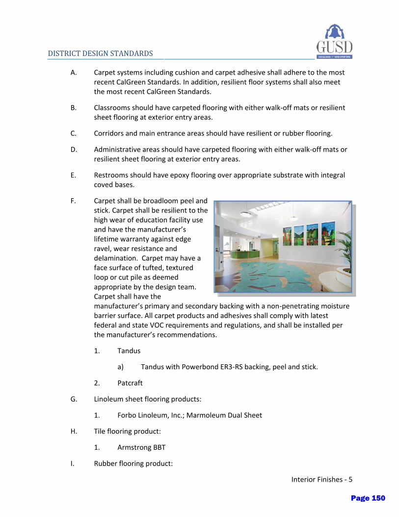
Interior Finishes - 5
DISTRICT DESIGN STANDARDS
A. Carpet systems including cushion and carpet adhesive shall adhere to the most recent CalGreen Standards. In addition, resilient floor systems shall also meet the most recent CalGreen Standards.
B. Classrooms should have carpeted flooring with either walk-off mats or resilient sheet flooring at exterior entry areas.
C. Corridors and main entrance areas should have resilient or rubber flooring.
D. Administrative areas should have carpeted flooring with either walk-off mats or resilient sheet flooring at exterior entry areas.
E. Restrooms should have epoxy flooring over appropriate substrate with integral coved bases.
F. Carpet shall be broadloom peel and stick. Carpet shall be resilient to the high wear of education facility use and have the manufacturer’s lifetime warranty against edge ravel, wear resistance and delamination. Carpet may have a face surface of tufted, textured loop or cut pile as deemed appropriate by the design team. Carpet shall have the manufacturer’s primary and secondary backing with a non-penetrating moisture barrier surface. All carpet products and adhesives shall comply with latest federal and state VOC requirements and regulations, and shall be installed per the manufacturer’s recommendations.
1. Tandus
a) Tandus with Powerbond ER3-RS backing, peel and stick.
2. Patcraft
G. Linoleum sheet flooring products:
1. Forbo Linoleum, Inc.; Marmoleum Dual Sheet
H. Tile flooring product:
1. Armstrong BBT
I. Rubber flooring product:
Page 150
6 – Interior Finishes
DISTRICT DESIGN STANDARDS
1. Roppe
J. Epoxy flooring product:
1. Dex-o-tex
2. Terralite
K. Wood athletic flooring for gymnasiums:
1. Attached floor system.
2. ½”x 2 ¼”maple over two layers of plywood.
3. Basis of design: Robbins BioCushion LP system
L. Wood flooring for dance studios, stages and auditoriums:
1. Floating floor systems.
2. ¾” x 2 ¼” Maple over two layers of plywood over absorbing pad.
3. Ventilated perimeter base
4. Basis of Design: Robbins BioCushion LP system
VIII. Vinyl Coated Fabric Wall Covering
A. A limited amount of vinyl-coated wall covering may be considered on select walls as an accent. It should be installed full height, without utilizing a panelized system. All vinyl products and adhesives shall comply with latest federal and state VOC requirements and regulations. Vinyl shall be a minimum of Type II vinyl and appropriate for educational facility use. Tear and tensile strength shall be considered in the selection process for abuse, durability and longevity.
B. Depending on the type of space and use, the design team should consider a wainscot or chair rail to protect walls from carts and furniture at height appropriate for the furniture and equipment anticipated to be used.
1. Koroseal Wall coverings West, Inc. with minimum 20% pre-consumer recycled content.
2. Genon Wallcoverings or Lanmark Wallcoverings, Omnova Solutions, Inc.: with minimum 30% pre-consumer recycled content.
IX. Acoustics
Page 151

Interior Finishes - 7
DISTRICT DESIGN STANDARDS
A. The design team should design standard classrooms, libraries and other core learning areas to have a background noise level no greater than 35 dbA as recommended by the ANSI standard S12.60-2002. The design team should consult ANSI standards for other areas and make a concerted effort to meet these standards, in addition to the recommendations of an acoustic consultant.
B. In general, all walls between classrooms or walls separating offices should be full height walls, floor to structure above and filled with sound attenuation. Any room where noise can transfer from room to room, interrupting the learning environment should have a full height wall with sound attenuation.
C. Landscape design should also be considered in acoustical design. The strategic planting of leafy trees and shrubbery can be used to mitigate road noise adjacent to a building, just as curtains can absorb indoor noises from conversation.
D. Acoustic wall covering:
1. For gymnasium and high-impact areas: Tectum
2. Wall Technology Inc.
E. Sound absorbing wall units:
1. Fabric coated acoustic panels with NRC 1.0-1.1, 2” thick
2. Lamvin – Sonic Series
X. Paint
A. All paints and coating shall meet the VOC limits prescribed in the most recent CalGreen Standards.
B. Painted gypsum board should finish the walls. Finish paint systems for all surfaces shall be acrylic latex, where possible.
C. All paints shall comply with the latest federal and state VOC requirements and regulations.
D. Specify no less than three coats; a prime coat (or sealer, for gypsum board), and two finish coats. Finish coats shall be semi-gloss enamel for all exposed surfaces, including gypsum board walls and ceilings; metal doors, door frames and trim, and wood doors and cabinetry not stained; and structural members, where
Page 152
8 – Interior Finishes
DISTRICT DESIGN STANDARDS
exposed. Exposed electrical or mechanical items shall be painted with the appropriate preparation specified.
E. Specify non-bridging paint for acoustic walls and conditions.
F. No flat finish shall be used.
1. Kelly Moore
2. Dunn Edwards
XI. Mirrors
A. Dance studio and weight room mirrors
1. In locations with mirrors, they should be ¼” thick, full-height, pre-drilled for ballet barres, electrical outlets or other penetrations. These should be coordinated with the District.
Page 153
Commercial Flooring All Products Eco Flooring
Eco Flooring
A High-Performance Alternative to PVC Tile Flooring
You can create beautiful and productive sustainable environments with our innovative bio-flooring,which continues to reinforce Armstrong Flooring as a leader in advancing sustainability. Ourmodular bio-flooring products enhance both design quality and performance in all commercialsettings where sustainable strategies are critical factors in your overall design vision.
Reasons to Specify Eco Flooring
Bio-based alternative PVC flooring
Low-carbon footprint – main ingredient is 85% North American limestone locally quarried,further reducing the product’s carbon footprint
Contains no Ortho-Phthalates or heavy metals
Made with rapidly renewable material*, U.S.-grown plant ingredients
40% pre-consumer recycled content, third-party certified
Low VOC emissions and FloorScore® certified
Long life value, true through-pattern wear layer
Withstands heavy foot and rolling load traffic**
Manufactured to Armstrong Flooring’s Diamond Standard of Quality
Page 154

CASE STUDY
Bio-flooring case studyDeveloping flooring options that are both beautiful and more environmentally friendly
Browse All Eco Flooring
Explore Eco Flooring Collections
Migrations BBT
Made with rapidly renewable resources, thismodular floor provides enhanced performanceover composition tile.
Striations BBT
A beautiful non-PVC commercial tile withlinear visuals and a convenient 12"x24"modular format, providing sustainable designsolutions.
Performance
BIO Product Structure
*This product contains 2% rapidly renewable material (corn) which can be regenerated annually.
**Refer to the Armstrong Flooring Guaranteed Installation Systems manual (F-5061) at ArmstrongFlooring.com/installationmanual
and at floorexpert.com for proper installation, care, and maintenance information.
Page 155

Striations BBT, Migrations BBT Wear Layer: Entire product Dimensionally Stable: Size and squareness PVC Free: Bio-based formulation Recycled Content: Pre-consumer third-partycertified
*Refer to the Armstrong Flooring GuaranteedInstallation Systems manual (F-5061) for properinstallation, care, and maintenance information.
©2016 Armstrong Flooring. All rights reserved
EXCLUSIVE FAST START® FACTORY FINISH
Protective layer during installation
Makes initial maintenance quick and easy
1
TRUE THROUGH-PATTERN WEAR LAYER
Pattern/color wear performance: High durability Gouge resistance Rolling load impact resistance* Appearance retention
2
Page 156
AV211 Cinema Champagne 6 x 6 UPS, AV214 Gallery Grey 6 x 18 UPS, AV215 Boutique Black 12 x 12 UPS
Porcelain Stone
Main StreetPorcelain Stone
45Page 157

Please visit CrossvilleInc.com for more details
V3S H A D E &
T E X T U R E
Wet DCOF
(UPS) 0.58 – 0.68
AV211 Cinema Champagne 12 x 12 UPS
Recommended Use
Main Street is recommended for interior floors, walls, countertops, and exterior walls in both residential and commercial applications. Main Street is not recommended for exterior horizontal surfaces or exterior paving. If offset pattern is required for tiles 18 inches or longer, Crossville® recommends an offset of not greater than 33%. See CrossvilleInc.com for detailed installation instructions.
Sizes & FinishesNominal (in) Actual (in) Thickness (in) Finish2 x 2 Mosaics* 11-13/16 x 11-13/16 3/8 UPS6 x 6† 5-13/16 x 5-13/16 3/8 UPS6 x 18† 5-13/16 x 17-13/16 3/8 UPS12 x 12 11-13/16 x 11-13/16 3/8 UPS18 x 18 17-13/16 x 17-13/16 3/8 UPS
* 2 x 2 mosaic tile mounted on 11-13/16 x 11-13/16 sheets.† The cut/bevel tile is cut from larger format tile and the edges are beveled to provide a factory appearance. Please allow two to eight weeks for delivery depending on Crossville’s production schedule.Crossville® recommends a grout joint of 3/16 to 1/4 inch.Actual measurements stated in inches indicate tile is calibrated (non-rectified). Actual measurements stated in mm indicate tile is rectified.
Coordinating Trim (Available in all colors)
4 x 12 Single Bullnose 3-3/4 x 11-3/4 3/8 UPS6 x 12 Cove Base 5-7/8 x 11-3/4 3/8 UPS
6 x 12 Cove Base (Universal, flat top)4 x 12 Single Bullnose
Wet Area Use for Mosaics
See Tile Performance Data chart.
AV213 Bistro Brown 20% recycled content*
AV214 Gallery Grey20% recycled content*
AV211 Cinema Champagne4% recycled content*
AV212 Café Caramel4% recycled content*
AV215 Boutique Black20% recycled content*
Colors
Example Sizes (Available in all colors)
18 x 18
12 x 12
2 x 2 Mosaic*6 x 6
6 x 18
* This product contains pre-consumer recycled content. Percentage varies by color.
• Ideal for commercial settings
• High Wet DCOF and low maintenance
• Cross-Sheen® finish for easy cleaning (available on UPS only)
• Crossville® recommends a grout joint of 3/16 to 1/4 inch Porcelain Stone
Main Street
46Page 158
A1119 Night Night, A1103 Slinky, A1101 Sandbox, A1105 Yellow Brick Road, and A1113 Blue Suede Shoes all 18 x 18 UPS
Porcelain Stone
Color Blox®/Color Blox® Mosaics
24Page 159
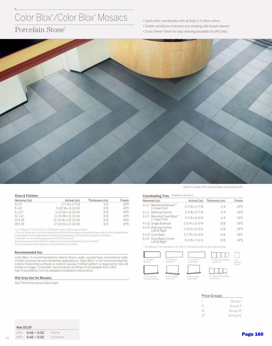
Wet DCOF
(UPS) 0.42 – 0.52 Field Tile
(UPS) 0.42 – 0.52 3 x 3 Mosaics
Recommended Use
Color Blox® is recommended for interior floors, walls, countertops, and exterior walls in both commercial and residential applications. Color Blox® is not recommended for exterior horizontal surfaces or exterior paving. If offset pattern is required for tiles 18 inches or longer, Crossville® recommends an offset of not greater than 33%. See CrossvilleInc.com for detailed installation instructions.
Sizes & FinishesNominal (in) Actual (in) Thickness (in) Finish3 x 3* 2-7/8 x 2-7/8 1/4 UPS6 x 6† 5-13/16 x 5-13/16 3/8 UPS6 x 12† 5-13/16 x 11-13/16 3/8 UPS12 x 12 11-13/16 x 11-13/16 3/8 UPS12 X 24 11-13/16 x 23-13/16 3/8 UPS18 X 18 17-13/16 x 17-13/16 3/8 UPS
* 3 x 3 Mosaic Tile in 11-7/8 x 11-7/8 sheets with a 1/8 inch grout joint. † The cut/bevel tile is cut from larger format tile and the edges are beveled to provide a factory appearance. Please allow two to eight weeks for delivery depending on Crossville’s production schedule. Crossville® recommends a grout joint of 3/16 to 1/4 inch.Actual measurements stated in inches indicate tile is calibrated (non-rectified).Actual measurements stated in mm indicate tile is rectified.
Coordinating Trim (Available in all colors)
Nominal (in) Actual (in) Thickness (in) Finish3 x 3 Mounted Bullnose**
1 Linear Foot 2-7/8 x 2-7/8 1/4 UPS
3 x 3 Bullnose Corner 2-7/8 x 2-7/8 1/4 UPS3 x 3 Mounted Cove Base**
1 Linear Foot 2-7/8 x 3-5/8 1/4 UPS
4 x 12 Single Bullnose 3-3/4 x 11-3/4 3/8 UPS4 x 12 Bullnose Corner
Left & Right 3-3/4 x 11-3/4 3/8 UPS
6 x 12 Cove Base 5-7/8 x 11-3/4 3/8 UPS6 x 8 Cove Base Corner
Left & Right 5-7/8 x 7-3/4 3/8 UPS
* 3 x 3 Mosaic Tile mounted on 11-7/8 x 11-7/8 sheets with a 1/8 inch grout joint.
Wet Area Use for Mosaics
See Tile Performance Data chart.
Price Groups
I Group III Group IIIII Group IIIIV Group IV
A1104 It’s a Boy! UPS, and A1113 Blue Suede Shoes UPS
3 x 3 BullnoseCorner
3 x 3 Mounted Bullnose, 1 Linear Foot
3 x 3 Mounted Cove Base, 1 Linear Foot
6 x 12 Cove Base (Universal, flat top)
4 x 12 SingleBullnose
4 x 12 Bullnose Corner Right
4 x 12 Bullnose Corner Left
6 x 8 Cove Base Corner Right
6 x 8 Cove Base Corner Left
Porcelain Stone
Color Blox®/Color Blox® Mosaics • Each color coordinates with at least 2-3 other colors
• Subtle variations in texture and shading add visual interest
• Cross-Sheen® finish for easy cleaning (available on UPS only)
25Page 160
NA
TU
RA
L HU
ES™
EC
O-B
OD
Y C
ER
AM
IC
Page 161
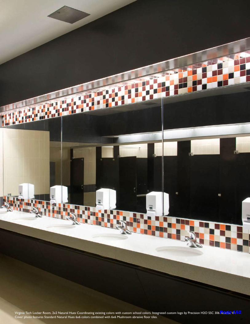
Virginia Tech Locker Room, 2x2 Natural Hues Coordinating existing colors with custom school colors. Integrated custom logo by Precision H2O SSC 306 Roanke, VA Cover photo features Standard Natural Hues 6x6 colors combined with 6x6 Mushroom abrasive floor tiles.
Page 162

PEARL WHITE QH63 (2)
CARNATION QH48* (2)
IVORY QH24 (1)
VANILLA QH23 (1)
ALMOND QH02 (1)
MICA PINPOINT QH81 (1)
DIJON QH73 (2)
LACE QH83*(1)
DAISY QH97 (2)
BUTTERSCOTCH QH07 (1)
ORANGE POPPY QH95*(2)
SUNSET QH94*(2)
Field Tile
SPECIAL ORDER
PEBBLE QH18 (1)
BUTTERCREAM QH06 (1)
BIRCH QH84 *(1)
ROSE BEIGE QH19 (1)
SPICE QH20 (1)
MUSHROOM QH16 (1)
CHOCOLATE QH27 (1)
MIST QH15 (1)
ESPRESSO QH85 (1)
MANGO QH71 (2)
CINNAMON QH50 (1)
LATTE QH26 (1)
KIWI QH30 (1)
FERN QH80 (2)
HONEYDEW QH86 (1)
MINT QH58 (2)
ASPEN QH42 (2)
JADE QH55 (2)
NATURAL HUES™ ECO-BODY CERAMIC
PINE QH64 (2)
SPRING GREEN QH29 (1)
PAPRIKA QH72 (2)
SWEET PEA QH28 (1)
EVERGLADE QH52 (2)
PEACOCK QH62 (2)
All colors available with abrasive content upon request.*Recommended for walls only. May exhibit crazing.(1) and (2) indicate price group, (1) being the least expensive.
(Colors continued on next page)
Page 163
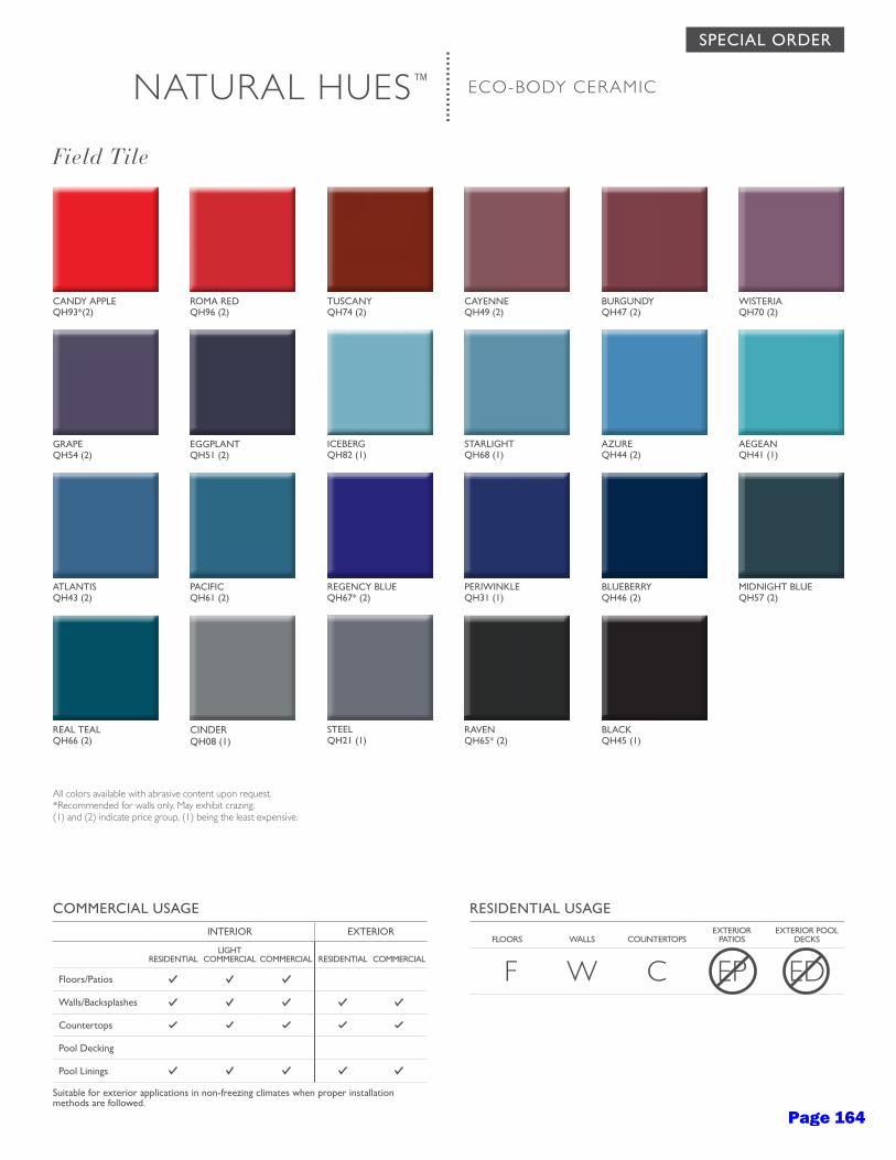
CANDY APPLE QH93*(2)
ROMA RED QH96 (2)
TUSCANY QH74 (2)
CAYENNE QH49 (2)
BURGUNDY QH47 (2)
WISTERIA QH70 (2)
ATLANTIS QH43 (2)
PACIFIC QH61 (2)
REGENCY BLUE QH67* (2)
PERIWINKLE QH31 (1)
BLUEBERRY QH46 (2)
MIDNIGHT BLUE QH57 (2)
STARLIGHT QH68 (1)
AZURE QH44 (2)
AEGEAN QH41 (1)
ICEBERG QH82 (1)
EGGPLANT QH51 (2)
GRAPE QH54 (2)
STEEL QH21 (1)
RAVEN QH65* (2)
BLACK QH45 (1)
REAL TEAL QH66 (2)
CINDER QH08 (1)
All colors available with abrasive content upon request.*Recommended for walls only. May exhibit crazing.(1) and (2) indicate price group, (1) being the least expensive.
NATURAL HUES™ ECO-BODY CERAMIC
RESIDENTIAL USAGE
FLOORS
WALLS
COUNTERTOPSEXTERIOR
PATIOSEXTERIOR POOL
DECKS
F W C EP ED
COMMERCIAL USAGE
INTERIOR EXTERIOR
RESIDENTIAL
LIGHT COMMERCIAL
COMMERCIAL
RESIDENTIAL
COMMERCIAL
Floors/Patios
Walls/Backsplashes
Countertops
Pool Decking
Pool Linings
Suitable for exterior applications in non-freezing climates when proper installation methods are followed.
Field Tile
SPECIAL ORDER
Page 164
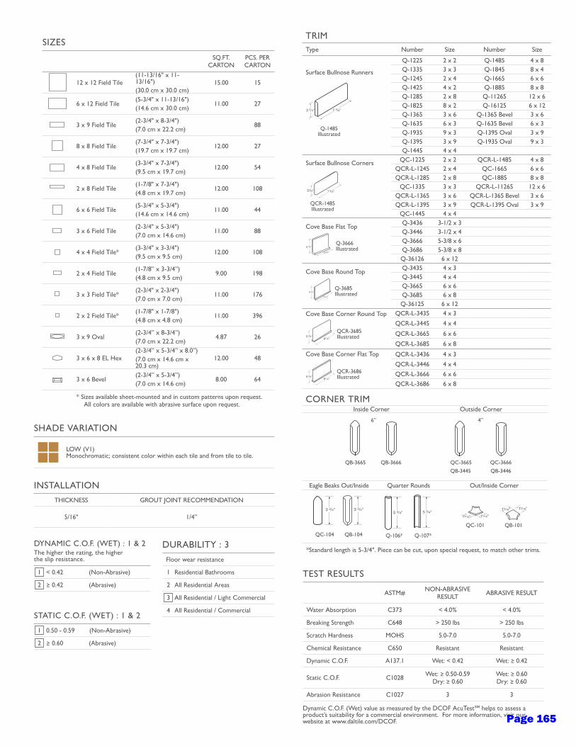
TRIMType Number Size Number Size
Surface Bullnose Runners
Q-1485Illustrated
Q-1225 2 x 2 Q-1485 4 x 8Q-1335 3 x 3 Q-1845 8 x 4Q-1245 2 x 4 Q-1665 6 x 6Q-1425 4 x 2 Q-1885 8 x 8Q-1285 2 x 8 Q-11265 12 x 6Q-1825 8 x 2 Q-16125 6 x 12Q-1365 3 x 6 Q-1365 Bevel 3 x 6Q-1635 6 x 3 Q-1635 Bevel 6 x 3Q-1935 9 x 3 Q-1395 Oval 3 x 9Q-1395 3 x 9 Q-1935 Oval 9 x 3Q-1445 4 x 4
Surface Bullnose Corners
QCR-1485Illustrated
QC-1225 2 x 2 QCR-L-1485 4 x 8QCR-L-1245 2 x 4 QC-1665 6 x 6QCR-L-1285 2 x 8 QC-1885 8 x 8
QC-1335 3 x 3 QCR-L-11265 12 x 6QCR-L-1365 3 x 6 QCR-L-1365 Bevel 3 x 6QCR-L-1395 3 x 9 QCR-L-1395 Oval 3 x 9
QC-1445 4 x 4
Cove Base Flat Top
Q-3666Illustrated
Q-3436 3-1/2 x 3Q-3446 3-1/2 x 4Q-3666 5-3/8 x 6Q-3686 5-3/8 x 8Q-36126 6 x 12
Cove Base Round Top
Q-3685Illustrated
Q-3435 4 x 3Q-3445 4 x 4Q-3665 6 x 6Q-3685 6 x 8Q-36125 6 x 12
Cove Base Corner Round Top
QCR-3685Illustrated
QCR-L-3435 4 x 3
QCR-L-3445 4 x 4
QCR-L-3665 6 x 6
QCR-L-3685 6 x 8
Cove Base Corner Flat Top
QCR-3686Illustrated
QCR-L-3436 4 x 3
QCR-L-3446 4 x 4
QCR-L-3666 6 x 6
QCR-L-3686 6 x 8
CORNER TRIMInside Corner Outside Corner
QB-3665
QB-3666 QC-3665
Eagle Beaks Out/Inside Quarter Rounds Out/Inside Corner
QC-104 QB-104 Q-106* Q-107*
QC-101 QB-101
*Standard length is 5-3/4". Piece can be cut, upon special request, to match other trims.
SIZES
SQ.FT. CARTON
PCS. PER CARTON
12 x 12 Field Tile(11-13/16" x 11-13/16")(30.0 cm x 30.0 cm)
15.00 15
6 x 12 Field Tile(5-3/4" x 11-13/16")(14.6 cm x 30.0 cm)
11.00 27
3 x 9 Field Tile(2-3/4" x 8-3/4")(7.0 cm x 22.2 cm)
88
8 x 8 Field Tile(7-3/4" x 7-3/4")(19.7 cm x 19.7 cm)
12.00 27
4 x 8 Field Tile(3-3/4" x 7-3/4")(9.5 cm x 19.7 cm)
12.00 54
2 x 8 Field Tile(1-7/8" x 7-3/4")(4.8 cm x 19.7 cm)
12.00 108
6 x 6 Field Tile(5-3/4" x 5-3/4")(14.6 cm x 14.6 cm)
11.00 44
3 x 6 Field Tile(2-3/4" x 5-3/4")(7.0 cm x 14.6 cm)
11.00 88
4 x 4 Field Tile*(3-3/4" x 3-3/4")(9.5 cm x 9.5 cm)
12.00 108
2 x 4 Field Tile(1-7/8” x 3-3/4”)(4.8 cm x 9.5 cm)
9.00 198
3 x 3 Field Tile*(2-3/4" x 2-3/4")(7.0 cm x 7.0 cm)
11.00 176
2 x 2 Field Tile*(1-7/8" x 1-7/8")(4.8 cm x 4.8 cm)
11.00 396
3 x 9 Oval(2-3/4” x 8-3/4”)(7.0 cm x 22.2 cm)
4.87 26
3 x 6 x 8 EL Hex(2-3/4” x 5-3/4” x 8.0”)(7.0 cm x 14.6 cm x 20.3 cm)
12.00 48
3 x 6 Bevel(2-3/4” x 5-3/4”)(7.0 cm x 14.6 cm)
8.00 64
* Sizes available sheet-mounted and in custom patterns upon request. All colors are available with abrasive surface upon request.
SHADE VARIATION
LOW (V1)Monochromatic; consistent color within each tile and from tile to tile.
INSTALLATION
THICKNESS GROUT JOINT RECOMMENDATION
5/16" 1/4”
TEST RESULTS
ASTM# NON-ABRASIVE RESULT ABRASIVE RESULT
Water Absorption C373 < 4.0% < 4.0%
Breaking Strength C648 > 250 lbs > 250 lbs
Scratch Hardness MOHS 5.0-7.0 5.0-7.0
Chemical Resistance C650 Resistant Resistant
Dynamic C.O.F. A137.1 Wet: < 0.42 Wet: ≥ 0.42
Static C.O.F. C1028 Wet: ≥ 0.50-0.59Dry: ≥ 0.60
Wet: ≥ 0.60Dry: ≥ 0.60
Abrasion Resistance C1027 3 3
Dynamic C.O.F. (Wet) value as measured by the DCOF AcuTest℠ helps to assess a product’s suitability for a commercial environment. For more information, visit our website at www.daltile.com/DCOF.
DURABILITY : 3
Floor wear resistance
1 Residential Bathrooms
2 All Residential Areas
3 All Residential / Light Commercial
4 All Residential / Commercial
DYNAMIC C.O.F. (WET) : 1 & 2The higher the rating, the higher the slip resistance.
1 < 0.42 (Non-Abrasive)
2 ≥ 0.42 (Abrasive)
STATIC C.O.F. (WET) : 1 & 2
1 0.50 - 0.59 (Non-Abrasive)
2 ≥ 0.60 (Abrasive)
QB-3445 QB-3446
6” 4”
QC-3666
Page 165

7834 C. F. Hawn Freeway | Dallas, TX 75217 | 214.398.1411 800.933.TILEFor more information about Daltile products and services, visit our website at daltile.com
floo
r •
wal
l •
deco
rati
ve
FLOOR & WALL TILENATURAL HUES™
All or selected items within this series are Made in the USA. For more information visit www.daltile.com/naturalhues.
©2013 Dal-Tile Corporation (7/13)
By their very design, Daltile products can help make it easier for you to earn LEED™ points and/or points towards many industry leading green home building programs. From using recycled material content to establishing manufacturing facilities within 500 miles of your project, we help ensure you don’t have to compromise your design to be environmentally conscious. For detailed information, visit daltilegreenworks.com.
Page 166
marmoleum® modular
linesshadecolourmarble
Page 167

3332
OTHER FORBO LINOLEUM COLLECTIONS
marmoleum® cork linoleum® marmoleum®sport bulletin board® furniture linoleumThe Unexpected
Nature of linoleum
MarmoleumTake a fascinating look into the world of
colours and designs. Marmoleum was
created to complement and enhance
the architecture interiors of today’s
and tomorrow’s buildings. Marmo-
leum is a natural floor, created from
all natural ingredients. It is the most
sustainable floor in the resilient flooring
category. All Marmoleum floors include
Topshield2, a double UV cured finish
delivering floor performance in the real
world, that result in the lowest cost of
ownership over its life time.
The Unexpected Nature of LinoleumThis collection, based on modern design
trends, is inspired by the natural phe-
nomena around the world that make
our planet special. Volcanic formations,
tropical forests and lagoons as well as salt
and ice formations have all inspired this
collection of subtle, natural designs. Both
the marbled and striped collections have
unconventional colour combinations that
are perfect for creating hugely inspiring
floors that form serene environments with
a natural touch.
Cork LinoleumForbo Marmoleum is created by
combining linseed and rosin with wood
flour and limestone. For Cork linoleum,
the wood flour component is replaced
by finely ground cork particles. Cork
enhances the shock absorbent quality
of floors and gives warmth under foot.
This makes Cork linoleum the ideal
surface for therapy rooms and rest
areas in day care centres. Cork linoleum
is available in a range of natural colours
ranging from sand and ochre to stone
red and a selection of subtle greys.
Bulletin boardFrom the floor to the wall, Forbo Bulletin
board is a linoleum surfacing material
that’s ideal for walls or vertical surfaces
such as notice or pin-boards. It’s also a
functional aesthetic finish for walls, doors
or cabinets. Bulletin board is also avail-
able in framed formats. Its bacteriostatic
properties make it ideal for patient rooms
and nurses’ quarters.
Furniture LinoleumWhere Marmoleum is praised for its
sustainable profile and functional perfor-
mance, Furniture Linoleum is heralded
for its aesthetic and tactile qualities. This
finely ground, high-quality linoleum is a
designer’s dream when it comes to creat-
ing matte, smooth, hand-warm finishes to
tabletops, cabinets and other furniture. The
decorative surface can be easily cleaned,
and, like leather, develops a beautiful
natural patina over time. Forbo Furniture
Linoleum is available in a range of 24 four
solid, uni colours ranging from coal black
to a warm white and the whole spectrum
of colours in between.
Marmoleum SportThis 3.2 and 4.0mm Marmoleum is
specially created for indoor multi-sports
facilities. Sport offers a genuine environ-
mentally friendly alternative to any PVC or
Rubber sports floor offer. When installed
on official sprung-wood subfloor construc-
tions, it complies with the requirements of
the international indoor sports associations
for indentation, bounce and slip charac-
teristics. For multi-sport environments or
school gyms, Marmoleum Sport can be
installed with a recycled rubber shock
absorbent underlay. Markers lines and
appropriate finish requirements can be
applied easily.
Page 168
3534
MORE FORBO FLOORINGCOLLECTIONS
TECHNICAL SPECIFICATIONS
Luxury vinyl tiles Project Vinyl Flotex flocked flooring Textile flooring Entrance flooring
Luxury Vinyl TilesLuxury Vinyl Tiles have matured into a new flooring category that is readily winning ground in all kinds of market segments. Whether it is retail, leisure, hospitality, offices or education and healthcare facilities, LVT is recognized as an easy to install, easy to maintain high performance floor covering that has the look and feel of its natural counterparts, be it wood, stone or any abstract ma-terial. Forbo’s Allura LVT will last for years to come, with a unique design that has been created from the natural original to the refinement of the grain and texture that creates a lifelike copy, which in itself can claim to be an original.
Project VinylNext to Luxury vinyl tiles Forbo offers a range of sheet vinyl flooring with specifics technical fea-tures such as slip resistant flooring, conductive flooring, acoustic floor coverings and general purpose vinyl floors that come in a wide range of colours and designs. In some cases sheet flooring is chosen as alterna-tive to LVT, at Forbo we have taken care that our collections are matching in colour and design to make combinations of various products possible within one installation.
Flotex flocked flooringFlotex combines the practicality of a resilient flooring with the slip resistant and acoustic properties usually as-sociated with textiles. Completely waterproof, Flotex is the only truly washable textile floor covering available today. The result is a warm, comfortable, hygienic floor covering that offers constant protection against bacteria and dust mites, and which is suit-able for any commercial specification.
Textile flooringForbo’s textile flooring collection is made up of high quality tufted tiles and a comprehensive range of needle-punched carpets. Our tufted carpet tiles offer the kind of flexibility in design and installation that the contemporary office de-mands, while our robust, hard-wearing needlefelt textiles are ideal for creating a tranquil and harmonious atmosphere in high-traffic situations.
Entrance flooringCreating better envi-ronments starts at the entrance of any building. To avoid water, sand, mud and gravel being carried into the building a proper entrance floor is a good line of defense. Coral en-trance floors are created to absorb moisture and scrape dirt of shoes and wheel that find their way into a building. Entrance floors can take care of lower cleaning and maintenance costs and give the floors inside the building their appearance retention.
Marmoleum Modular meets the requirements of EN-ISO 24011
1 Total thickness EN-ISO 24346 2.5 mm
D Domestic: heavy EN-ISO 10874 Class 23
H Commercial: very heavy EN-ISO 10874 Class 34
K Light Industrial: heavy EN-ISO 10874 Class 43
; Dimensions (length x width) EN-ISO 24342 25 x 25 cm 25x50 cm 50 x 25 cm 50 x 50 cm 75 x 50 cm 100 x 15 cm 100 x 25 cm
2 Squareness and straightness EN-ISO 24342 ≤ 0.25 mm ≤ 0.35 mm ≤ 0.35 mm ≤ 0.35 mm ≤ 0.35 mm ≤ 0.35 mm ≤ 0.35 mm
3 Indentation residual EN-ISO 24343-1 ≤ 0.15 mm
g Castor chair continuous use EN 425 Suitable for office chairs with castors
> Light fastness EN-ISO 105-B02 Method 3: blue scale minimum 6
5 Resistance to chemicals EN-ISO 26987Resistant to diluted acids, oils, fats and to conventional solvents. Not resistant to prolonged exposure to alkalis
* Bacteriostatic propertiesMarmoleum has natural bacteriostatic properties, which are confirmed by independent laboratories, even against the bacteria MRSA
u Cigarette resistance EN 1399 Marks left on linoleum as a result of stubbed-out cigarettes can be removed
[ Slip resistance DIN 51130 R9
s Acoustical impact sound reduction EN ISO 717-2 ≤ 5 dB
- Life Cycle Assessment LCA is the foundation for securing the lowest environmental impact
Marmoleum meets the requirements of EN 14041
T Reaction to fire EN 13501-1 Cfl-s1
Z Slip resistance EN 13893 DS: ≥ 0.30
L Body voltage EN 1815 < 2 kV
e Thermal conductivity EN 12524 0.17 W/m·K
0100203-DoP-306
All Forbo Flooring Systems’ sales organisations worldwide have a certified Quality Management System in accordance with ISO 9001.All Forbo Flooring Systems’ manufacturing operations have a certified Environmental Management System in accordance with ISO 14001.The Life Cycle Assessment (LCA) of Forbo Flooring Systems’ products is documented in individual Environmental Product Declarations (EPD’s) which can be found on all of our websites.
Page 169
Dancer or Athlete....Nobody Provides
Support Better than Robbins
MA
PL
E F
LO
OR
ING
SY
ST
EM
S
Robbins, Inc. | 4777 Eastern Avenue | Cincinnati, OH 45226
robbinsfloor.com | 1.800.543.1913
ST1 ®
Contributes ToLEED® Credits
B i o - C u s h i on ® L P
High-performing Robbins Zero/G® shockpad provides continuous cushioning and consistent support for optimal shock absorption
Highly attractive maple surface and superior construction for flexibility makes it perfect for dance studios, in addition to gymnasiums
Value engineered to provide an economical choice for sport and dance surfaces with no compromise in quality or service
The Bio-Cushion LP is a low-profile subfloor design that provides enhanced acoustics and dynamic uniformity. Robbins’ continuous Zero/G shock Pad provides continuous support for dancers and athletes on every inch of the floor, greatly reducing the exposure to the harmful stress of high impact from play and performance.
Page 170

Product Specifications
System Type
Slab Depression
Floating
1⅞″(48mm) with ½″(13mm) maple
Warranty 1 year Industry Standard with optional Extended Warranty Program (Egis Floorlife)
Robbins, Inc. | 4777 Eastern Avenue | Cincinnati, OH 45226
robbinsfloor.com | 1.800.543.1913
ST1 ®
All Rights Reserved. © 2012 Robbins, Inc. BCLP201207
Bio-Cushion FamilyReference Facilities
Richmond Olympic OvalTexas A&M University
Terwillegar Community Recreation Centre
California State University- East Bay
LA Fitness
B i o - C u s h i on ® L P
Subfloor Construction
Resilience Layer
Vapor Barrier
Double layer Plywood subfloor
7/16″ Resilient Zero/G® Shock Pad
6 MIL Polyethylene
Surface- MFMA Northern Hard Maple
LEED Contributions MR credit 4, 5, & 7IEQ 4.1, 4.2, 4.3, 4.4 FSC© Lumber Available*Credits are based on products selected and location of facility
Optional Construction
Contact a Robbins Representative for Alternative Systems
Concrete Slab
Subfloor Panel
Insert Plate
Equipment View
Concrete Slab
Subfloor Panels
1/4" (6mm)Threshold Plate
Solid Stop Block
Threshold View
6 MIL Vapor Barrier
6 MIL Vapor Barrier
1/2" (13mm) MFMA Maple Flooring
1.5"- 2" (38mm-51mm) Expansion Void
1/2" (13mm) MFMA Maple Flooring
1.5"- 2" (38mm-51mm) Expansion Void
Concrete Slab
Subfloor Panels
Wall View
1 7/8" (48mm)
1 7/8" (48mm)
3" (76mm) x 4" (102mm) Vented Cove Base
1.5"- 2" (38mm-51mm) Expansion Void
7/16" (11mm) Zero/G Shock Pad
1/2" (13mm) MFMA Maple Flooring
6 MIL Vapor Barrier
1 7/8" (48mm)
7/16" (11mm) Zero/G Shock Pad
7/16" (11mm) Zero/G Shock Pad
Robbins Continuous Strip® XL (FJ)
Robbins Floating Systems
Robbins Sports Surfaces is a division of Robbins, Inc., a values driven company that
upholds the highest standards in manufacturing & customer
relationships.
Page 171
FLOORING DESIGNEDFOR EDUCATION
Page 172
Tandus Centiva’s unique line of Powerbond®, Freeform®, Modular, Broadloom,
Woven and LVT flooring products offer a true fit-for-purpose approach to
enhance spaces for learning, working, healing and living. With industry-leading
product design, unrivaled service and a commitment to environmental and
social stewardship, Tandus Centiva provides the ultimate flooring experience
for our customers.
Page 173
Page 174

All of these styles shown are available in powerbond and modular unless indicated otherwise.
Ask me about Tandus Centiva’s Fit-for-purpose solutions:
· Texture — Texture Appearance Retention Ratings (TARR)
· Acoustics — Impact Insulation Class Products (IIC) & Noise Reduction Coefficients (NRC)
· Comfort — Thermal Comfort and Comfort Under Foot
· Cost — Lower Life Cycle Cost
· Moisture — Tolerance to higher concrete slab moisture
At Tandus Centiva, we design and manufacture flooring with a commitment and purpose to communicate better, simpler, clearer form and function. From the technical expertise, strength and recycled/recyclable core of our backing systems to the beautifully engineered construction of our face fibers and patterns, we offer product platforms geared for today’s 21st century education market, where products need to work with one another aesthetically and in terms of intent and how they function in the education environment.
This is what drives us. Our extremely dedicated staff of managers, technicians, manufacturers, world-renowned textile consultants and designers–including Suzanne Tick and Jhane Barnes–succeed when our customers desire our floor coverings as much for their beauty as for their ability to add meaning and longevity to the interior spaces they so skillfully design.
Tandus Centiva is proud to offer solutions that enhance places where we live, work, learn and heal.
Page 175
g r o u p i
1. Accentuate trona
2. Paradigm seahorse
3. Stack 9 splash
4. Glacial Striae beryl*
5. Emphasize trona*
6. Arete beryl / arctic sea*
7. Stack 9 mineral spring
8. Rivet blue horizon*
9. Glacial Striae amethyst floe*
10. Arete amethyst floe*
* Only available in modular
101
3
4
5
6
89
7
2
Page 176

g r o u p i i
1.Emphasize kasha*
2. Glacial Striae arctic sea*
3. Inline aluminum frame*
4. Stack 9 timber
5. Rivet heel-toe*
6. Haphazard palomino
7. Applause skyscraper
8. Punctuate trona
9. Glacial Striae fresh earth*
10. Stack 9 beach trail
11. Accentuate icelandic
* Only available in modular
12
3
4
56
78
9
10
11
Page 177

g r o u p i i i
1. Glacial Striae early green*
2. Rivet peace frog*
3. Stack 9 spray bloom
4. Applause mosaic
5. Accentuate copal
6. Inline downhill*
7. Arete early green*
8. Stack 9 rio grande
9. Change spray paint
* Only available in modular
1 2
3
4
56
7
8
9
Page 178

g r o u p iv
1. Accentuate bark cloth
2. DV8 sugar shack
3. Paradigm particolor
4. Box Study compose
5. Glacial Striae isotaupe*
6. Inline pennant*
7. Arete fresh earth*
8. Rivet cherry-flip*
9. Arete clay red*
10. Stack 9 burgundy road
* Only available in modular
1
2 3
45
6
7
89
10
Page 179
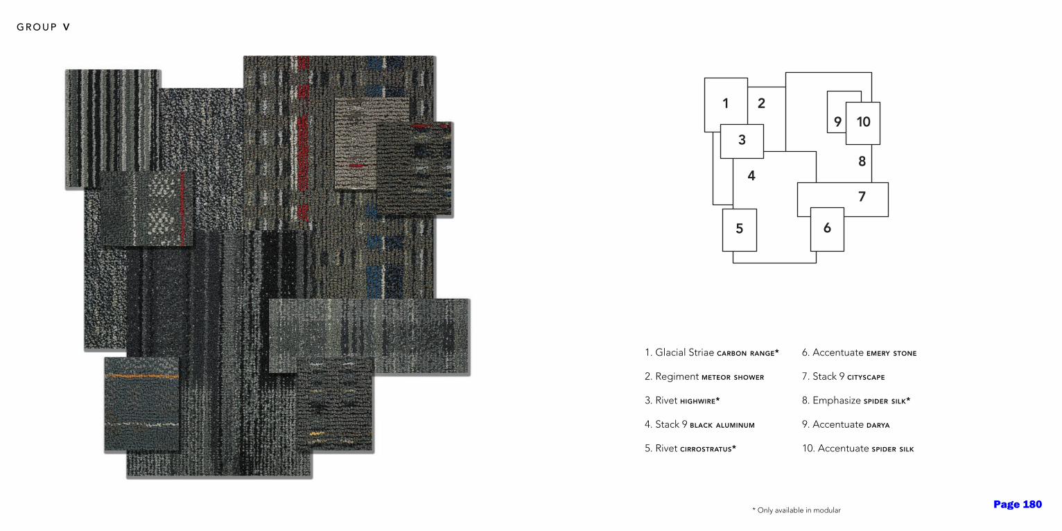
g r o u p v
1. Glacial Striae carbon range*
2. Regiment meteor shower
3. Rivet highwire*
4. Stack 9 black aluminum
5. Rivet cirrostratus*
6. Accentuate emery stone
7. Stack 9 cityscape
8. Emphasize spider silk*
9. Accentuate darya
10. Accentuate spider silk
* Only available in modularPage 180
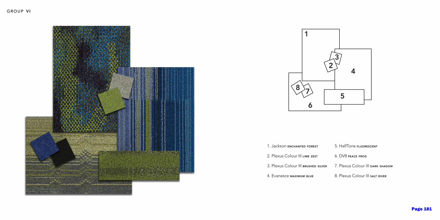
g r o u p v i
1. Jackson enchanted forest
2. Plexus Colour III lime zest
3. Plexus Colour III brushed silver
4. Evanesce maximum blue
5. HalfTone fluorescent
6. DV8 peace frog
7. Plexus Colour III dark shadow
8. Plexus Colour III salt river
Page 181
TANDUS-CENTIVA.COM 800.248.2878Powerbond® Freeform® Modular Broadloom Woven LVT
Page 182

TSW8 AM August 2014 Page 1
PRODUCT DATA SHEET
TSW8 Acryli-Master™
Graffiti Resistant Coating
Clear Matte Finish
Non-Sacrificial, Low VOC
Developed to: Provide repeated protection against graffiti attacks
From: Most surfaces both painted and non-painted
IMPORTANT: All applicators are required to call TSW, Inc. at 800.447.2334 prior to application of TSW8™.
The reason for calling is to review proper application methods, register the job and prevent any
potential errors. Failure to do so voids any warranty.
DESCRIPTION: TSW8 Acryli-Master™ is a water-based acrylic, non-sacrificial, graffiti resistant coating that
dries to a clear matte finish. TSW8™ is specifically formulated to provide repeated protection again
graffiti vandalism by sealing the surface, preventing the permanent staining caused by graffiti
vandalism. Spray paints, permanent markers, lipstick, paint pens, and other commonly used tools of the
graffiti vandal can be successfully removed without marring the surface. TSW8™ treated surfaces are
also protected from the harmful effects of the environment (smog, ultra-violet rays, sulfur dioxide (SO₂),
smoke, ozone, dirt, wind, sea mist and spray, and other common urban pollutants). Graffiti can be
removed up to a dozen times from TSW8 Acryli-Master™ using TSW2G Multi-Master (GEL)™ or TSW2 Multi-
Master™ Graffiti and Stain Remover. TSW will not guarantee the coatings durability when other methods
of removal are used.
SUBSTRATES: It is always best to perform a test patch to ensure compatibility. Underlying surfaces should
be fully cured prior to application of TSW8™. Surfaces should be clean and thoroughly dry before
application. Porous Surfaces (non-painted) – When applying over surfaces such as concrete, masonry,
stucco etc. allow surface to cure at least thirty days prior to coating. Surface pH levels should be
between 7 and 10 on all natural substrates before application. On darker natural surfaces such as red
brick a minimum of one coat should be applied to the top of the surface to prevent moisture from
getting behind the coating. If it is a free standing surface a minimum of one coat should be applied on
the top as well to prevent moisture from getting behind the coating. If the surface has been pressure
washed it is recommend to wait a minimum of 48 hours prior to coating. Painted Surfaces – A cure time
of 48 hours is recommended for latex paint prior to coating. Underlying paint should be 100% Acrylic.
Application of TSW8™ over oil-based paints is not recommended. Wood, Composition Board – Patch all
holes and imperfections. Prime as directed. Paint with 100% acrylic paint before applying TSW8™.
WARNING: Protect from freezing. It will be necessary to re-coat areas that have been repeatedly
cleaned as some coating removal will occur. In those cases re-apply TSW8™ to the affected areas as
necessary to maintain the integrity and thickness of the protective coating. TSW8™ protects painted
surfaces from outdoor exposure.
APPLICATION: TSW8™ must be thoroughly mixed or blended prior to decanting or adding Acryli-Link™ as
flattening agents may have settled to the bottom of the container.
Add three ounces of Acryli-Link™ per gallon of TSW8 Acryli-Master TM and stir until thoroughly blended.
Do not mix more than can be applied in a four to six hour period. For optimum results, airless sprayer
application is recommended. It is important to catch any runs, drips or sags before drying. For small
areas, touch-up or when airless application is not practical, a roller and/or brush may be used (nylon
brush or nap roller with a synthetic cover recommended). When protecting porous surfaces (non-
painted), a diluted prime coat (to fill the pores) and 3 top coats are recommended (prime coat should
Page 183

TSW8 AM August 2014 Page 2
be thinned with 40% water). Protecting painted, sealed or smooth surfaces requires a minimum of 3 thin
coats. 4 coats are recommended.
When applying with a brush, roller or pad, thin entire mixture with 5% water to prevent any foaming or
bubbles. If foam or bubbles do appear, smooth surface with dry brush or pad painter.
When applying with an airless sprayer, the recommended tip sizes are as follows:
Porous Surfaces (non-painted) = .015”
Painted, Sealed or Smooth Surfaces = .011” - .013”
Reapplication between coats is approximately one hour or dry to the touch. It is not recommended to
apply when surface temperature is below 50 or above 95 . TSW8™ will protect approximately 150-175
sq. ft. per gallon after applying all recommended coats. Apply THIN coats (1 mil. per coat). DO NOT
OVERAPPLY. Over-application of TSW8™ can cause it to turn opaque, whitish, cloudy or yellow. Protect
adjacent surfaces. Keep container closed when not in use. Wait 24-48 hours, allowing final coat to cure
appropriately prior to removing graffiti and/or stains using TSW2G or TSW2 Multi-Master™. Follow
directions of TSW2G or TSW2 Multi-Master™ for removal.
VOC CONTENT = 9.28% = 92.8 g/L
CLEANUP INFORMATION: Clean spills and splatters immediately with soap and water. Clean hands and
tools immediately after with soap and water. After cleaning, flush airless sprayer with suitable cleaners
such as TSW5 Spray Clean™.
HEALTH AND SAFETY INFORMATION: KEEP OUT OF REACH OF CHILDREN. Do not take internally. Neoprene
gloves are recommended for prolonged or repeated contact. Guard against splashing into eyes.
Contains: Ethylene glycol butyl ether. Use with adequate ventilation. FIRST AID: For eye contact flush
with large amounts of water. If irritation persists, contact a physician. This product contains no chemical
at a level which poses a significant risk as defined by California Proposition 65. There are no known
chronic health effects caused by the use of this product.
PACKAGING: TSW8 Acryli-Master™ is packaged in a test kit, single gallon and five gallon quantities.
For complete safety information refer to MSDS or call customer support at 800.447.2334.
CHEM-TEL 24-Hour Emergency Contact # 800.255.3924
Visit our website www.TSWwarehouse.com
Questions? Comments? Contact tech support at 800.4GRAFFITI (800.447.2334)
Page 184
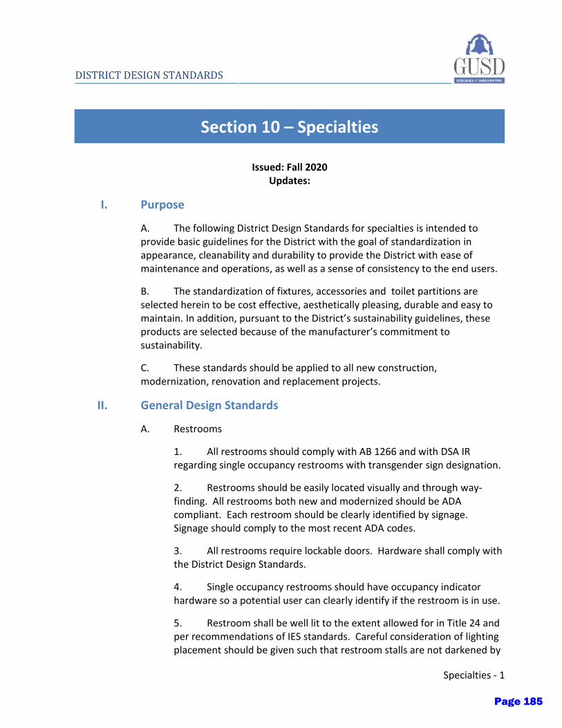
Specialties - 1
DISTRICT DESIGN STANDARDS
Section 10 – Specialties
Issued: Fall 2020 Updates:
I. Purpose
A. The following District Design Standards for specialties is intended to provide basic guidelines for the District with the goal of standardization in appearance, cleanability and durability to provide the District with ease of maintenance and operations, as well as a sense of consistency to the end users.
B. The standardization of fixtures, accessories and toilet partitions are selected herein to be cost effective, aesthetically pleasing, durable and easy to maintain. In addition, pursuant to the District’s sustainability guidelines, these products are selected because of the manufacturer’s commitment to sustainability.
C. These standards should be applied to all new construction, modernization, renovation and replacement projects.
II. General Design Standards
A. Restrooms
1. All restrooms should comply with AB 1266 and with DSA IR regarding single occupancy restrooms with transgender sign designation.
2. Restrooms should be easily located visually and through way-finding. All restrooms both new and modernized should be ADA compliant. Each restroom should be clearly identified by signage. Signage should comply to the most recent ADA codes.
3. All restrooms require lockable doors. Hardware shall comply with the District Design Standards.
4. Single occupancy restrooms should have occupancy indicator hardware so a potential user can clearly identify if the restroom is in use.
5. Restroom shall be well lit to the extent allowed for in Title 24 and per recommendations of IES standards. Careful consideration of lighting placement should be given such that restroom stalls are not darkened by
Page 185
2 - Specialties
DISTRICT DESIGN STANDARDS
toilet partitions. Light fixtures should be easy to change. Motion sensors, where required by code, should be set such that lights do not turn off when the restroom is occupied.
6. Ventilation shall be provided to meet minimum standards of Title 24. Restroom exhaust fans shall be connected to the building’s energy management system or the lighting system to shut off when the restroom is unoccupied.
III. Visual Display Surfaces
A. Marker boards
1. Bestrite, 8’-0” wide
B. Painted whiteboard paint can be implemented in specific areas such as administration, conference rooms. The design team should consult with the District when choosing locations for white board paint.
C. Visual display manufacturers:
1. Da Lite
2. Best-Rite Mfr
D. Monitor wall bracket:
1. PLAV70-UNLP-GB wall mount
E. Projector mount manufacturers:
1. Peerless
2. Chief
F. Bulletin boards and display cases
1. All display cases should be made with laminated glass.
2. Blocking should be provided in the wall at all display case locations.
IV. Signage
A. Signage shall be specified for all doors complying with the most current edition of the California Building Code, The Division of the State Architect, and the Americans with Disabilities Act. Signs shall be mechanically fastened to doors
Page 186
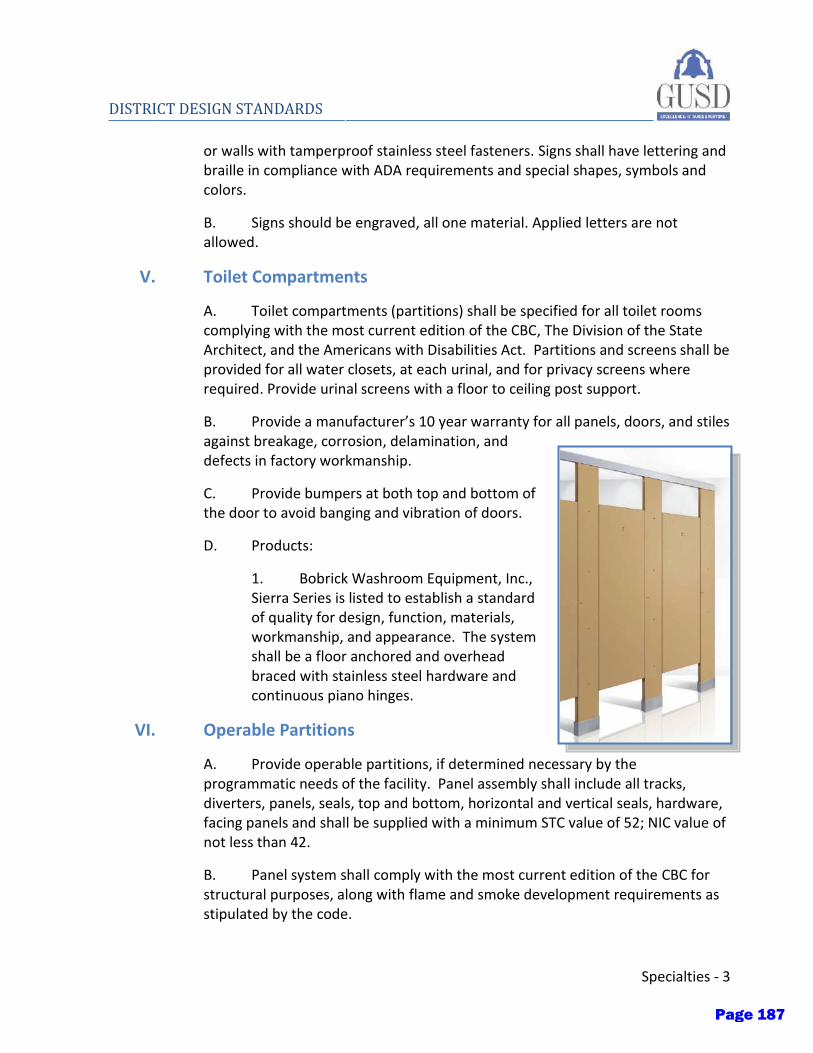
Specialties - 3
DISTRICT DESIGN STANDARDS
or walls with tamperproof stainless steel fasteners. Signs shall have lettering and braille in compliance with ADA requirements and special shapes, symbols and colors.
B. Signs should be engraved, all one material. Applied letters are not allowed.
V. Toilet Compartments
A. Toilet compartments (partitions) shall be specified for all toilet rooms complying with the most current edition of the CBC, The Division of the State Architect, and the Americans with Disabilities Act. Partitions and screens shall be provided for all water closets, at each urinal, and for privacy screens where required. Provide urinal screens with a floor to ceiling post support.
B. Provide a manufacturer’s 10 year warranty for all panels, doors, and stiles against breakage, corrosion, delamination, and defects in factory workmanship.
C. Provide bumpers at both top and bottom of the door to avoid banging and vibration of doors.
D. Products:
1. Bobrick Washroom Equipment, Inc., Sierra Series is listed to establish a standard of quality for design, function, materials, workmanship, and appearance. The system shall be a floor anchored and overhead braced with stainless steel hardware and continuous piano hinges.
VI. Operable Partitions
A. Provide operable partitions, if determined necessary by the programmatic needs of the facility. Panel assembly shall include all tracks, diverters, panels, seals, top and bottom, horizontal and vertical seals, hardware, facing panels and shall be supplied with a minimum STC value of 52; NIC value of not less than 42.
B. Panel system shall comply with the most current edition of the CBC for structural purposes, along with flame and smoke development requirements as stipulated by the code.
Page 187
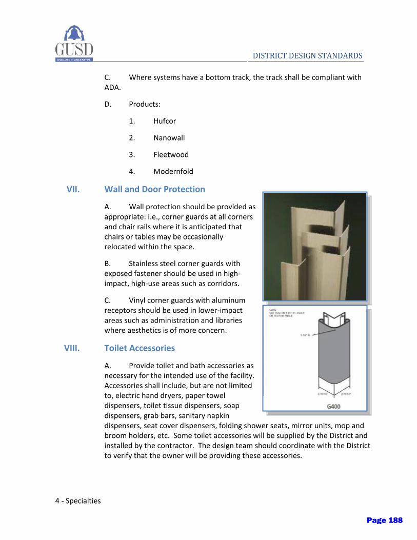
4 - Specialties
DISTRICT DESIGN STANDARDS
C. Where systems have a bottom track, the track shall be compliant with ADA.
D. Products:
1. Hufcor
2. Nanowall
3. Fleetwood
4. Modernfold
VII. Wall and Door Protection
A. Wall protection should be provided as appropriate: i.e., corner guards at all corners and chair rails where it is anticipated that chairs or tables may be occasionally relocated within the space.
B. Stainless steel corner guards with exposed fastener should be used in high-impact, high-use areas such as corridors.
C. Vinyl corner guards with aluminum receptors should be used in lower-impact areas such as administration and libraries where aesthetics is of more concern.
VIII. Toilet Accessories
A. Provide toilet and bath accessories as necessary for the intended use of the facility. Accessories shall include, but are not limited to, electric hand dryers, paper towel dispensers, toilet tissue dispensers, soap dispensers, grab bars, sanitary napkin dispensers, seat cover dispensers, folding shower seats, mirror units, mop and broom holders, etc. Some toilet accessories will be supplied by the District and installed by the contractor. The design team should coordinate with the District to verify that the owner will be providing these accessories.
Page 188

Specialties - 5
DISTRICT DESIGN STANDARDS
B. Toilet and bath accessories shall be specified for all toilet rooms complying with the latest requirements of California Building Code, The Division of the State Architect, and the Americans with Disabilities Act.
C. High-efficiency electric hand dryers are to be the primary means of hand drying in restrooms. Hand dryers should be located conveniently near sinks with at least one unit at accessible height. They should be installed in a 1:2 ratio with the number of sinks in the restroom. Sound isolation and power for the electric hand dryer should be provided for by the design team.
D. Paper towel dispensers should be installed as a backup to electric hand dryers in the event of power outages and are allocated to one per restroom.
E. Waste containers – The District does not anticipate using built-in waste containers as there will be limited paper towel dispensers. Design team should consider the District may place a freestanding waste receptacle for convenience of throwing trash away, likely located between the sinks and exit door.
F. Soap dispensers – The soap dispenser should be wall mounted and located above the sink, such that drips fall into the sink. Dispenser should be mechanically fastened and not tape mounted.
G. Mirrors – Single mirrors should be installed at multiple accommodation restrooms. Single mirrors shall be provided at single accommodation restrooms. Shelves for personal belongings shall be provided at sink areas. Multiple shelves may be required for larger restrooms.
1. At grade school, standard mirrors should be provided.
2. At high school, the following stainless steel mirrors should be provided:
a) Bobrick B-1556 Series
b) Ketcham Stainless Steel Mirrors
H. Sanitary napkin dispensers – Sanitary napkin dispensers shall be provided at all multiple accommodation women’s toilet rooms.
I. Sanitary Napkin Disposal – In women’s restrooms and unisex restrooms a sanitary napkin disposal should be located at the toilet adjacent to the toilet paper dispenser.
J. Products:
Page 189
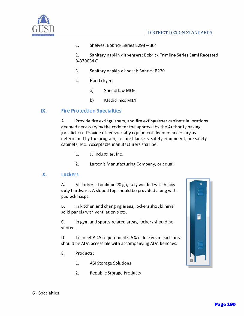
6 - Specialties
DISTRICT DESIGN STANDARDS
1. Shelves: Bobrick Series B298 – 36”
2. Sanitary napkin dispensers: Bobrick Trimline Series Semi Recessed B-370634 C
3. Sanitary napkin disposal: Bobrick B270
4. Hand dryer:
a) Speedflow MO6
b) Mediclinics M14
IX. Fire Protection Specialties
A. Provide fire extinguishers, and fire extinguisher cabinets in locations deemed necessary by the code for the approval by the Authority having jurisdiction. Provide other specialty equipment deemed necessary as determined by the program, i.e. fire blankets, safety equipment, fire safety cabinets, etc. Acceptable manufacturers shall be:
1. JL Industries, Inc.
2. Larsen's Manufacturing Company, or equal.
X. Lockers
A. All lockers should be 20 ga, fully welded with heavy duty hardware. A sloped top should be provided along with padlock hasps.
B. In kitchen and changing areas, lockers should have solid panels with ventilation slots.
C. In gym and sports-related areas, lockers should be vented.
D. To meet ADA requirements, 5% of lockers in each area should be ADA accessible with accompanying ADA benches.
E. Products:
1. ASI Storage Solutions
2. Republic Storage Products
Page 190

INTRODUCING
TOILET PARTITION SELECTION AND SPECIFICATION METHOD
Toilet Partition Catalog
Page 191
2
Planning Guide for Accessible RestroomsThe Guide is the latest reference resource for ADAAG accessible restrooms, including wheelchair turning radiuses, accessory mounting heights, reach ranges, and accessible toilet compartments.
Portfolio of Values
Architects, developers and facility managers have selected Bobrick’s performance-engineered toilet partitions with confidence since 1970. As a market leader, Bobrick delivers building owner value through design excellence, multiple options, code compliance, and long-lasting durability.
Specifiers choose from a variety of partition materials including Solid Color Reinforced Composite (SCRC), Compact Laminate (CL) and High Pressure Laminate (HPL) with a substantial selection of colors and patterns. Mounting configurations, Gap -Free® and Maximum Height privacy and hardware options are available.
SCRC, CL and HPL are first quality, extra-durable toilet partition materials that score exceptionally high for graffiti, impact and scratch-resistance. Excellent maintainability is another measure of durability and results in long-term performance, minimizing costly repair and replacement expense.
Partition hardware is fabricated of 50% –70% post-industrial recycled stainless steel. Regional manufacturing and distribution facilities within 500 miles of 70% of the U.S. population conserve transportation energy consumption. Bobrick’s Toilet Partitions can contribute to LEED points.
Bobrick toilet partitions comply with the latest ASTM E 84 Flame Spread and Smoke Development index requirements for Interior Finishes. Bobrick will gladly provide toilet partition accessibility consultation including wheelchair accessibility compartment layouts, approaches, turning radiuses and reach range compliance.
Cleanability is a key factor in maintaining partitions in a sanitary condition. CL and SCRC surfaces, including doors, stiles and panels, feature Graffiti-Off ®
non-porous surfaces for easy graffiti removal and disinfection. Other materials with porous textures make cleaning more difficult.
Bobrick’s Restroom Accessory CatalogFeaturing hundreds of stainless steel accessories, including dispensers, receptacles, vendors, warm-air dryers, and grab bars, this catalog provides all amenities required for the contemporary commercial restroom.
Additional Bobrick Resources
Page 192
3
Catalog Information
Bobrick Toilet Partition Series Numerical Product Index
SierraSeries® (SCRC) - 1090 page 6 –7
DuraLineSeries® (CL) - 1080 8–9
DesignerSeriesTM (HPL) - 1040 10
MetroSeriesTM (HPL) - 1550 11
TrimLineSeriesTM (HPL) - 1030 12
AccentSeriesTM (HPL) - 1530 13
BOBSpec is a systematic approach to Toilet Partition selection factors assuring the most appropriate partitions for a given project, efficient fabrication and successful installation.
BOBSpec assists architects, designers and developers, first in evaluating needs and priorities of a project, and then in selecting materials, configurations, design and privacy options, hardware and color/pattern choices.
BOBSpec results in delivering a concise specification reducing confusion and rework.
Toilet Partition Selection and Specification Method
Selecting, Specifying and Ordering Toilet Partitions for Each Building Type
1. Use the Material Selection Chart on page 5 toidentify the most appropriate material and mountingconfiguration for the project.
2. Select the desired material from page 5 and pair it with the partition series height, privacy and hardware options.
3. Next, select the colors and patterns based on the design concept (SCRC page 7, CL page 9 and HPL page 14).
Prestige Properties
Standard Use Buildings
Heavy Traffic Facilities
Symbols and Resources for Architects, Designers and Facility Managers
All Bobrick partitions are NFPA and ICC fire code compliant. Please refer to Bobrick’s TB-73 which provides Flame Spread and Smoke Developed indices. Test results available upon request.
The RapidÏResponse® symbol signifies 2, 5 (1550 series) and 10-day shipping programs.
Bobrick.com is a world of electronic information and tools, including access to Bobrick’s global network of Architectural Representatives, Authorized Distributors and Installers.
Electronic Guide Specs and BIM Objectsfacilitate efficient project specification
Spec Wizard aggregates selected Toilet Partition Series for a project into a comprehensive specification.
Page 193
4
Bobrick’s Toilet Partition Advantages
Two additional advantages: The BOBSpec method for accurate, concise specs, and the expertise of Bobrick Architectural Reps.
Privacy and Security
Gap-Free interlock eliminates sight lines. 72" Maximum Height doors and panels provide 4-5/16" floor clearance.
Robust Engineering
Factory-Installed Inserts provide durability and protect against heavy-use and abuse.
Easy Installation
Stile Base Leveling Devices ensure perfect alignment and plumb.
Concealed Hardware
Standard on CL and HPL Bobrick Toilet Partition series, results in a clean, flush architectural styling.
Page 194

5
Note: Urinal Screen Mounting Configurations are Wall-Hung, Post-to-Ceiling and Floor-Anchored.
Mounting Configuration Selection
Material Approx. Initial Cost/ Index Graffiti/Scratch Removal Notes
Oth
er M
anuf
actu
rers
Painted Metal
Lowest (1.0) Low scratch and moderate graffiti resistancePaint or replacement required
Budget applicationsMany feature standard plastic hingesClass A Interior Finish Fire Code Classification
Plastic (HDPE)
Moderate (1.9) Low scratch and graffiti resistanceLow impact resistance
High traffic environmentsDoes not meet Interior Finishes Fire Code Classification. Be sure to specify the NFPA 286 test.
Stainless Steel
Highest (3.0) Low scratch and impact resistanceModerate graffiti resistance
High Design lookLimited FinishesClass A Interior Finish Fire Code Classification
Bob
rick
Mat
eria
ls Laminate (HPL)
Lowest (1.1) Low scratch and impact resistanceGraffiti can be removed
Budget for high-end applications depending on options selectedConcealed stainless steel hardware is standard for Bobrick partitionsClass B Interior Finish Fire Code Classification
Phenolic (CL)
Moderate (2.4) High scratch and impact resistanceComplete graffiti removal
Highest traffic environmentsMany colors and patternsClass A and B Interior Finish Fire Code Classification
SCRC
Moderate to High (2.7)
Highest scratch and impact resistanceComplete graffiti removal
High traffic and vandal-prone environments4 Earthtone colors Class B Interior Finish Fire Code Classification
Material Selection
Configuration Overhead-Braced Floor-to-Ceiling Floor-Anchored Ceiling-HungPoints of Attachment Two Points Two Points One Point One Point
Benefits Offers the most durable mounting configuration at a budget price.
Durable mounting option even without the headrail.
Superior design. Specify for low-traffic, non-vandal prone restrooms.
Contemporary appearance, provides clear access for floor maintenance.
Additional Information
Most specified toilet partition configuration.
A small premium compared to Overhead-Braced.
Anchored into a solid substrate.
Not appropriate for heavy-traffic, vandal-prone restrooms. (Requires additional structural support.)
Standard andMaximumHeight Stiles
85" to top of stile Accommodates up to 120" ceiling height
70" to top of stile (standard), 76-5/16" to top of stile (max height)
Accommodates up to 120" ceiling height
Page 195
6
SierraSeries – Solid Color Reinforced Composite (SCRC) 1090
FeaturesSolid color-through material
Ultra-hard Graffiti-Off surfaces
Scratch, dent, moisture and impact-resistant
3/4" Doors/stiles and 1/2" panels
Through-bolted panel-to-stile bracket, keeper and robe hook
Class B ASTM E 84 Interior Wall and Ceiling Finish Classification
Emergency access doors
Material SpecificationsDyed wood fibrous material reinforced with polycarbonate and phenolic resins coated with a non-ghosting, graffiti-resistant surface thermoset and integrally fused into a homogeneous piece.
Notes Options Price Index
RapidÏResponse: 10-days or less, 4 earthtone colors, up to 25 compartments 25 -Year Warranty
Gap-Free Privacy DesignMaximum-Height PrivacyHeavy-Duty Continuous Stainless Steel Hardware
SCRC 2.7 CL 2.4HDPE 1.9
Page 196
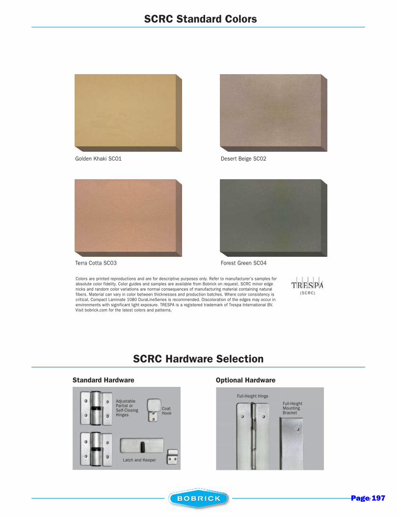
7
(SCRC)
SCRC Standard Colors
SCRC Hardware Selection
Golden Khaki SCO1 Desert Beige SC02
Terra Cotta SC03 Forest Green SC04
Colors are printed reproductions and are for descriptive purposes only. Refer to manufacturer’s samples for absolute color fidelity. Color guides and samples are available from Bobrick on request. SCRC minor edge nicks and random color variations are normal consequences of manufacturing material containing natural fibers. Material can vary in color between thicknesses and production batches. Where color consistency is critical, Compact Laminate 1080 DuraLineSeries is recommended. Discoloration of the edges may occur in environments with significant light exposure. TRESPA is a registered trademark of Trespa International BV. Visit bobrick.com for the latest colors and patterns.
Full-Height Mounting Bracket
Full-Height Hinge
Optional HardwareStandard Hardware
Adjustable Partial or Self-Closing Hinges
Coat Hook
Latch and Keeper
Page 197

CATALOG FORM NO. TP-2015, SEPTEMBER 2015, 20M, © 2015, BOBRICK WASHROOM EQUIPMENT, INC.
U.S.ManufacturingLocations
Los Angeles 818.982.9600 818.503.1102 [email protected] Tujunga Avenue North Hollywood, CA 91605-6213
www.bobrick.com
Tennessee 818.982.9600 818.503.1102 [email protected] Bobrick Drive Jackson, TN 38301-5625
www.bobrick.com
New York 818.982.9600 818.503.1102 [email protected] Commerce Drive Clifton Park, NY 12065-1350
www.bobrick.com
Canada 877.423.6555
Eastern Canada877.423.8555 [email protected]
45 Rolark Drive Toronto, Ontario M1R 3B1
www.bobrick.com
877.423.6444Western Canada
877.423.8444 [email protected] Rolark Drive Toronto, Ontario M1R 3B1
www.bobrick.com
GamcoA Division of Bobrick
818.982.9600 818.503.1102 [email protected] Gamco PlaceDurant, OK 74701-1910
www.gamcousa.com
Koala Kare ProductsA Division of Bobrick
888.733.3456 303.539.8399 [email protected] S. Quentin StreetCentennial, CO 80112-3945
www.koalabear.com
Page 198

www.FLEETWOODUSA .comPage 199
Made in the U.S.A.11
¹Max width and height are not necessarily available in combination.²Specimen size: Nom. 79" x 79".
³Simulated Performance Alternative size: 10' x 12' PXIXP using SNX62-IS20/Argon Warm Edge glass.
SERIES 3050
MULTI-SLIDE & POCKET DOOR
C O N F IG U R AT I O N S
• Virtually Unlimited Multi-Slide, Curved, Pocket, and Corner applications.
POCKET AND POCKET INTERLOCKERS WITH STANDARD
3-1/2" SIGHTLINE EXTENDER
POCKET AND POCKET INTERLOCKERS
SILL
HEAD
ELEVATION VIEW:PXXP WITH SCREENS CONFIGURATION
MEETING STILES
2NFRC: 0.213S.P.A.: 0.22
EXAMPLE SHGC
2NFRC: 0.463S.P.A.: 0.39
EXAMPLE U-FACTOR
¹ 18' ¹ 10'MAX PANEL HEIGHTMAX PANEL WIDTH
Page 200
Made in the U.S.A.13
SERIES 3000
SLIDING DOOR
T Y P I C A L C O N F IG U R AT I O N S
• OX, XO, OXO, OOX, XOO, XOX, OXXO, XOOX.
INTERLOCKERS
ELEVATION VIEW:OXOL CONFIGURATION
FIXED JAMB
FALSE JAMB
SILL
HEAD
2NFRC: 0.223S.P.A.: 0.24
EXAMPLE SHGC
2NFRC: 0.473S.P.A.: 0.35
EXAMPLE U-FACTOR
¹ 14' ¹ 7'
¹Max width and height are not necessarily available in combination. ²Specimen size: Nom. 79" x 79".
³Simulated Performance Alternative size: 180" x 130" OXO using SNX62-IS20/Argon Warm Edge glass.
MAX PANEL HEIGHTMAX PANEL WIDTH
Pho
to b
y N
ico
Mar
que
s/ P
hote
kt
Page 201

Made in the U.S.A.15
SERIES 3300-T
“THERMAL FRAME” SLIDING DOOR
T Y P I C A L C O N F IG U R AT I O N S
• OX, XO, OXO, OOX, XOO, XOX, OXXO, XOOX.
ELEVATION VIEW:OXIXO CONFIGURATION
INTERLOCKERSSILL
FIXED JAMBHEAD
Optional: Archetype NarrowMEETING STILES
STANDARD
2NFRC: 0.223S.P.A.: 0.24
EXAMPLE SHGC
2NFRC: 0.343S.P.A.: 0.27
EXAMPLE U-FACTOR
¹ 12' ¹ 6'
¹Max width and height are not necessarily available in combination. ²Specimen size: Nom. 79" x 79".
³Simulated Performance Alternative size: 192" x 120" OXIXO using Cardinal 366-i89/Argon glass.
MAX PANEL HEIGHTMAX PANEL WIDTH
Pho
to b
y Jo
eFle
tche
r.co
m
Page 202

W O R L D L E A D E R I N F L E X I B L E S P A C E M A N A G E M E N T
GLASS WALLMOVABLE PARTITIONS
Page 203

FOR MORE INFORMATION OR TO CREATE YOUR OWN PRELIMINARY DRAWINGS VISIT www.hufcor.com
MODEL CONFIG.TOP SEALS
FIXED RETRACTFLOOR SEALS
RETRACT FIXED VERT.TRIM
MAX.1
HEIGHTS
MAX. OPENING
WIDTHSTC2 ACOUS.
RATINGS
PairedFrameless
Frameless
Timber-Framed
Timber-Framed
Acoustically Rated Ultra
Acoustically Rated Ultra
std n/a stdn/a opt 10'5" [3.2m] Unlimited n/a
Single std n/a stdn/a opt 10'5" [3.2m] Unlimited n/a
SERIES #
GL2
GL1
Paired std n/a stdn/a n/a 10'2" [3.1m] Unlimited n/a
Single std n/a stdn/a n/a 10'2" [3.1m] Unlimited n/a
GT2
GT1
Pairedstd stdoptn/a std 12'2" [3.7m]
Single36, 45
GA2
GA1
Acoustically Rated Ultra
Acoustically Rated Ultra
Pairedstd stdstdn/a std 12'2" [3.7m]
Single
26 PanelsWith 2 LCP
Panels
26 PanelsWith 2 LCP
Panels46
GA2
GA1
Hufcor glass walls are clearly visionary.Our movable glass partitions allow natural light to flood an interior
space while providing space flexibility. With your choice of clear
tempered, full satiny translucent, etched, or custom glass, our walls
can become the signature design element of your room. Satisfied
customers are using glass partitions to close off offices, storefronts,
restaurants, bank lobbies and library training centers, creating secure,
flexible spaces.
1Heights shown are standard. Contact your local Hufcor distributor for custom sizes. 2n/a = not available
GLASS WALL PRODUCT SELECTOR
main imageColor matched aluminum or timber panels can also be used for acoustical separation as shown at this meeting space in Texas.
insets (top to bottom)Hufcor partitions easily & effectively close off the narthex at the St. Joseph’s Catholic church in Maryland.
Wisconsin Center for Discovery installed frameless glass walls to create large meeting areas open to the building’s multi-story atrium.
A library uses a large Hufcor glass slider with custom graphics to close the entrance to the children’s wing.
Note: Metric dimensions in [ ] are in millimeters unless otherwise indicated.
MOVABLE PARTITIONSGlass Wall
2 Page 204
FOR MORE INFORMATION OR TO CREATE YOUR OWN PRELIMINARY DRAWINGS VISIT www.hufcor.com
BIM REVIT® FAMILIES NOW AVAILABLECONTACT YOUR LOCAL HUFCOR DISTRIBUTOR FOR ASSISTANCE OR VISIT hufcor.com/ga-ultra-bim.
is Hufcor’s next generation of acoustically rated moveable glass partition systems with sound ratings of STC 36, 45 and 46. The durable frame is of steel and aluminum and is powder coated in a clear satin metallic finish.
STC 45 and 46 models include enhanced 2” [51] double-laminated sealed I.G. glass to achieve the ultimate acoustical performance. The STC 46 bottom seal has both retractable and sweep seals. The STC 36 model include single pane tempered glass and comes with sweep bottom seals and optional retractable seals.
All models are available as single panels or pairs with an expanding jamb or hinged closure. Options include an ADA compliant pass door with panic hardware, custom colors, and more.
GA-ULTRA ACOUSTIC GLASS WALL HUFCOR "SMARTER" BIM REVIT® FAMILIES
◆ Acoustic Glass Wall Paired Panels - Tamarack Center - NATC (Rhinelander, WI)
◆ Acoustic Glass Wall Paired Panels - Tamarack Center - NATC (Rhinelander, WI)◆ Acoustic Glass Wall Paired Panels - Tamarack Center - NATC (Rhinelander, WI)
glass wallCLEARLY VISIONARYNote: Metric dimensions in [ ] are in millimeters unless otherwise indicated.
can adjust minimum clearance dimensions to account for accessories like pass doors and panic hardware with simple, easy-to-use check boxes.
ULTRA ACOUSTIC Glass WallU
LT
RA
AC
OU
ST
IC - G
LA
SS W
ALL
6 Page 205
Operable Partitions
Acousti-Seal® Non-Steel
Page 206
6
Paired panels offer the most efficient operable partition option.
Advantages
• Quick setup with movement of two panels at a time.• Smooth operation.• Economical overhead support of straight-line track.• Simple automatic bottom seals for efficient operation.• SOSS Invisible hinges available.
Available in top-supported or floor-supported configurations, the center-hung, paired panels are perfect for straight-line openings and offer quick and easy setup. For convenient and economical space division, the paired panel is the ideal solution.
+ Custom-engineered solutions available beyond maximum height
* Customers Own Material – must be approved by factory
PAIRED PANEL MODEL 932 932FS 912
Nominal Panel Thickness 3-inch 3-inch 3-inch
Operation Manual Floor Supported Manual Manual Fire Rated
FrameRoll Formed & Welded 14/18-gage & 16-gage*
Steel
Roll Formed & Welded 14/18-gage Steel
Roll Formed & Welded 16-gage Steel
Skin/Face Options
Gypsum,Gypsum w/ steel face,
MR Board, MDF Board, Steel*
Gypsum,Gypsum w/ steel face,
MR Board, MDF Board, Wood Veneer
Steel
Finish Options
Vinyl, Heavy Duty Vinyl, Carpet, Fabric, Customer’s Own
Material*, Full Height Marker/Tack
Board, Plastic Laminate, Wood
Veneer, Uncovered
Vinyl, Heavy Duty Vinyl, Carpet, Fabric, Customer’s Own
Material*, Full Height Marker/Tack
Board, Plastic Laminate, Wood
Veneer, Uncovered
Vinyl, Heavy Duty Vinyl, Carpet, Fabric, Customer’s Own
Material*, Full Height Marker/Tack
Board, Uncovered
Maximum Width Unlimited 80’-9” Unlimited
Maximum Height+ 18-feet 12-feet 18-feet
STC 28, 41, 47, 50, 52* 28, 41, 47, 50 45, 50, 52
Hanging Weight (STC-dependent) 6 to 11 lb/sq ft 6 to 8 lb/sq ft 8 to 11 lb/sq ft
* Consult your local Modernfold distributor for custom options including: finishes, cutouts, and alternative platforms for pocket space restraints.
Page 207
7
Quickly and easily convert a classroom to meet fluctuations in class size.
Page 208
21st Century School DesignPage 209
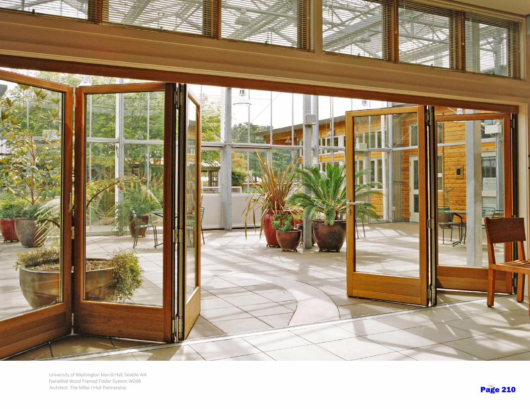
PRODUCT FAMILIES
University of Washington Merrill Hall, Seattle WANanaWall Wood Framed Folder System WD66Architect: The Miller | Hull Partnership 25Page 210
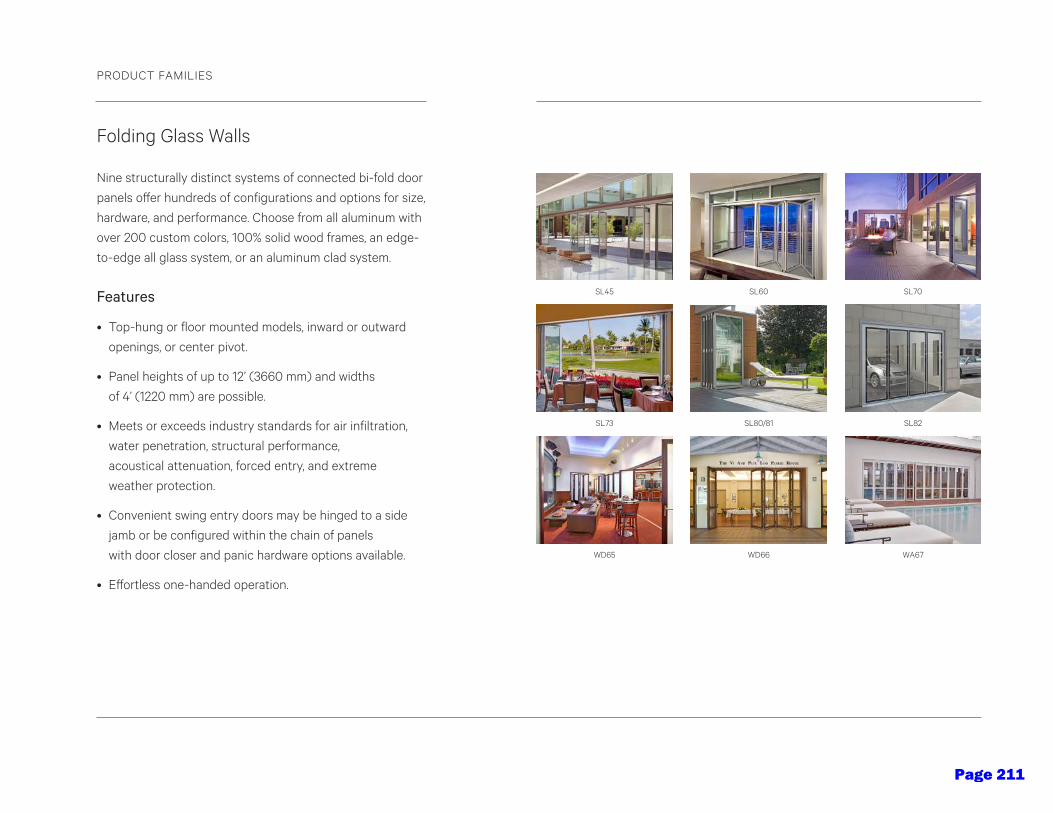
Folding Glass Walls
Nine structurally distinct systems of connected bi-fold door
panels offer hundreds of configurations and options for size,
hardware, and performance. Choose from all aluminum with
over 200 custom colors, 100% solid wood frames, an edge-
to-edge all glass system, or an aluminum clad system.
Features
• Top-hung or floor mounted models, inward or outward
openings, or center pivot.
• Panel heights of up to 12’ (3660 mm) and widths
of 4’ (1220 mm) are possible.
• Meets or exceeds industry standards for air infiltration,
water penetration, structural performance,
acoustical attenuation, forced entry, and extreme
weather protection.
• Convenient swing entry doors may be hinged to a side
jamb or be configured within the chain of panels
with door closer and panic hardware options available.
• Effortless one-handed operation.
Single Track Sliding Glass Walls
Unlimited spans of individual top-hung panels riding within a
single narrow header over an optional single floor track glide
effortlessly to open or close across extremely large openings.
NanaWall’s single track design easily navigates multiple angle
changes up from 90º to 180 º. Stacking options and minimal
parking bays can be designed with total customization.
Features
• Almost any shape is possible including open corners.
• No “train station” effect from multiple floor tracks means
no need to engineer an extra-wide header.
• Panels interlock to create a streamlined look and secure,
rattle, draft-free weather protection in the most demanding
environments and acoustical privacy when needed.
• Convenient swinging entrance/egress doors available nearly
anywhere within the span of the opening with door closer
and panic hardware options available.
• Panels park virtually anywhere in multiple types of stacking
bay arrangements.
PRODUCT FAMILIES
27
SL70
SL82
WA67
SL60
SL80/81
WD66
SL45
SL73
WD65
HSW45
HSW66
HSW60
Page 211
Folding Glass Walls
Nine structurally distinct systems of connected bi-fold door
panels offer hundreds of configurations and options for size,
hardware, and performance. Choose from all aluminum with
over 200 custom colors, 100% solid wood frames, an edge-
to-edge all glass system, or an aluminum clad system.
Features
• Top-hung or floor mounted models, inward or outward
openings, or center pivot.
• Panel heights of up to 12’ (3660 mm) and widths
of 4’ (1220 mm) are possible.
• Meets or exceeds industry standards for air infiltration,
water penetration, structural performance,
acoustical attenuation, forced entry, and extreme
weather protection.
• Convenient swing entry doors may be hinged to a side
jamb or be configured within the chain of panels
with door closer and panic hardware options available.
• Effortless one-handed operation.
Single Track Sliding Glass Walls
Unlimited spans of individual top-hung panels riding within a
single narrow header over an optional single floor track glide
effortlessly to open or close across extremely large openings.
NanaWall’s single track design easily navigates multiple angle
changes up from 90º to 180 º. Stacking options and minimal
parking bays can be designed with total customization.
Features
• Almost any shape is possible including open corners.
• No “train station” effect from multiple floor tracks means
no need to engineer an extra-wide header.
• Panels interlock to create a streamlined look and secure,
rattle, draft-free weather protection in the most demanding
environments and acoustical privacy when needed.
• Convenient swinging entrance/egress doors available nearly
anywhere within the span of the opening with door closer
and panic hardware options available.
• Panels park virtually anywhere in multiple types of stacking
bay arrangements.
PRODUCT FAMILIES
27
SL70
SL82
WA67
SL60
SL80/81
WD66
SL45
SL73
WD65
HSW45
HSW66
HSW60
Page 212

Stanford University Bio Chemical Engineering Department, Stanford CANanaWall Frameless Glass Wall SL25 XXL with custom glazingArchitect: Walters & Wolf
• From design to installation—we’re here to help.
Our Dedicated Design Team can answer your
questions and assist with planning, ordering
and optimizing your NanaWall options.
• Visit NanaWall.com for: CAD, product specifications, animations, installation/
operational videos, architectural binder, owner’s manuals, and a complete line
of brochures and photo ideabooks.
• NanaWall opening glass walls are sold factory direct through local architectural
design representatives across North America. Our Certified Installation Network
option ensures correct installation with speed and precision.
Support Highlights
29
Frameless Glass Walls
NanaWall all glass options for interior and exterior applications
feature a range of frameless folding, center pivot, and single track
sliding wall solutions with no visible vertical profile. The clean,
contemporary aesthetic offers separation with total transparency,
natural daylight, and acoustic buffering when closed.
Features
• Narrow top and bottom rail heights, no vertical profiles.
• Panels are available to 4’ (1220 mm) wide and 10’ 6” (3230 mm)
in height (please contact NanaWall for larger options).
• Accommodates swing doors with patented conversion system,
locking hardware, and closer options anywhere in chain of doors.
• Cornerless configurations possible.
• Polyamide rollers with sealed bearings ensure silent running
and resistance to changes in temperature.
PRODUCT FAMILIES
HSW75
CSW75 SL25
FSW75
Page 213
The illustrations and descriptions herein are applicable to production as of the date of this Technical Data Sheet. B-1556 Rev. 4/01/16R/A, S/A Printed in U.S.A.The manufacturer reserves the right to, and does from time to time, make changes and improvements in designs and dimensions. © 2016 by Bobrick Washroom Equipment, Inc.
Technical Data
W1''
25mmTyp.
1''25mmTyp.
H
S
S
Rec
om
men
ded
Mo
un
tin
g H
eig
ht
Off
Flo
or
for
Un
iver
sal /
Ace
ssib
le D
esig
n
40''
Max
. 1
015m
m
TemperedMasoniteBacking
1/4''6mm
MATERIALS:
Mirror — 18-8, type-304, 20 gauge (0.9mm) stainless steel polished to a No. 8 mirror finish. Mirror has 1/4" (6mm) return.
Backing — 1/4" (6mm) thick tempered masonite.
INSTALLATION:
Mount mirror on wall with four #8 oval head screws, furnished by manufacturer, at points indicated by an S. For plaster or dry wall construction, provide concealed backing to comply with local building codes, then secure unit with sheet-metal screws furnished. For other wall surfaces, provide fiber plugs or expansion shields for use with sheet-metal screws furnished, or provide 1/8" (3mm) toggle bolts or expansion bolts.
SPECIFICATION:
Frameless stainless steel mirror shall be 18-8, type-304, 20-gauge (0.9mm) stainless steel polished to a No. 8 mirror finish. Mirror shall have 1/4" (6mm) return concealing 1/4" (6mm) tempered masonite backing. Four corner countersunk holes provide flush fit of mounting screws with mirror surface.
Mirror shall be Model B-1556 ______________ (insert width and height) of Bobrick Washroom Equipment, Inc., Clifton Park, New York; Jackson, Tennessee; Los Angeles, California; Bobrick Washroom Equipment Company, Scarborough, Ontario: Bobrick Washroom Equipment Pty. Ltd., Australia; and Bobrick Washroom Equipment Limited, United Kingdom.
FRAMELESSSTAINLESS STEEL
MIRRORb-1556
SERIES
Designer’s Notes:1. Special-order sizes available on request.2. Maximum size mirror available, 48'' x 36'' (122 x 91cm) or 36'' x 48'' (91 x 122cm); minimum size, 12" x 12" (30 x 30cm).3. Overall width and height of custom 1556-series mirrors will be 1/2" (12mm) smaller than dimension specified.
Number ofMountingScrews
Model No.
(W) (H)
B-1556 1824 17-1/2'' (445mm) 23-1/2'' (597mm) 4 B-1556 1830 17-1/2'' (445mm) 29-1/2'' (749mm) 4 B-1556 2436 23-1/2'' (597mm) 35-1/2'' (902mm) 4
Overall Size
STANDARD b-1556 SERIES MIRRORS
Page 214
Page 215

Page 216
Page 217

provided.
provided.
Page 218

Korogard G100 Corner Guard with H600 Handrail
Bellagard® Textured Stainless Steel Corner Guard Korogard G100 Corner Guard with H60W Handrail andC600 Crash Rail
Corner GuardsScratches anddents are common occurrences inmost commercial environments. That’swhyKorogard® has designed a variety of corner guardstoprotect the edges of yourwalls from the inevitable abuse of high-traffic areas.Offering everything fromstandardPVC tomodern stainless steel,Korogard can provide a unique blend of options to complement a variety of interiors from traditional to contemporary.
Page 219
33
Textured StainlessSteel Corner Guards• Available in 20-gauge stainless steel with#4 satin finish with five unique textures
• S6 available in 16-gauge stainless steelwith #4 satin finish
• Available as surface or recessed
• Surface can be specified with a squareor arch crown
• 90˚ angle is standard, 135˚ angle also available
• Surface available in 4' or 8' lengths /Recessed available in 8' length only
• Surface available in 1-1/2" and 3-1/2" sizes /Recessed available in 3-1/2" size only
Surface Recessed
S1 S2 S3 S4 S5 S6
Surface Stainless Steel Textured Corner Guards are available with either a square-crown (left) or arc-crown (right)
CornerG
uards
Anodized AluminumCorner Guards• 1/2" x 1/2" anodized aluminum corner guard
• Available in Satin, Bronze, Black, andSilver Brite in 1/2" x 1/2" only
• Offered in 4', 6', 8', and 12' lengths
• All colors are available with a standard 90º angle
Page 220
34
NOTE:1.STOCK
GS35-3-1/2" WING, T304 STAINLESSSTEEL, COLOR #4 SATIN FINISH,STANDARD HEIGHT 4', 8'.
2.OPTIONAL ITEMS - COUNTERSUNKHOLES (FASTENERS NOTINCLUDED), #6 POLISH, ANDCUSTOM HEIGHTS.
3.NON-STOCK1", 2", 2-1/2", 3", 4" WINGS,CUSTOM ANGLES.
1/8" R
3-1/2"3-1/2"
Stainless SteelCorner Guards• Available in 16-gauge stainless steel cornerguards with #4 satin finish
• Available in lengths up to 10'
3-1/2"
AS SPECIFIED
• Standard 90˚ angle; 135˚ angle availablein 3-1/2" wing size
• Available in 1", 1-1/2", 2", 2-1/2", 3", and 3-1/2"sizes
• Customgauges, finishes, and sizes availablewithminimumsand lead times
KOROGARD “LEXAN”CORNER GUARD
NOTE:1.AVAILABLE IN 3/4", 11/8", 1-1/2", 2",
OR 2-1/2" WINGS.2.COLORS AVAILABLE: CLEAR, BEIGE,
BROWN, BLACK, BLUE, GREEN,GRAY, IVORY, AND WHITE.
3.STANDARD HEIGHTS - 4', 8'.4.ALL CORNER GUARDS ARE
PRE-DRILLED AND SUPPLIEDWITH FASTENERS.
Lexan®
• Lexan® polycarbonate corner guard inClear, Beige, Brown, Black, Blue, Green,Gray, Ivory, andWhite
• Available in 4' and 8' lengths
• Standard 90˚ angle
• Available in 3/4", 1-1/8", 1-1/2", 2",and 2-1/2" wing sizes
GS35 GS35E
Korogard® Limited WarrantyKoroseal® Interior Products warrants to its purchasers that Korogard® products will be free from any defects in material orworkmanship and meet the design criteria noted in our catalogs when properly applied and installed per our recommendedinstallation instructions. If, in the sole opinion of Koroseal Interior Products, a product covered by this warranty is defective, KorosealInterior Products will replace it free of charge. This warranty shall extend for a period of five years from the date of shipment byKoroseal Interior Products. THIS WARRANTY IS IN LIEU OF ALL OTHER WARRANTIES EXPRESSED OR IMPLIED AND ISTHE SOLE WARRANTY EXTENDED BY KOROSEAL INTERIOR PRODUCTS. The liability of Koroseal Interior Products undert h i smaterial warranty is limited to the replacement of Korogard products and does not include any responsibility for other damages.
Lexan
Korogard® SamplesKorogard products are available in a variety of standard colors, all of which are listed on page 42. To ensure color accuracy, weencourage you to request a product sample to verify the actual color. Please contact yourKorogard representative today at 800-628-0449to request a sample for your next project.
Page 221
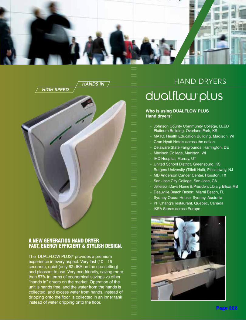
HAND DRYERS
A NEW GENERATION HAND DRYERFAST, ENERGY EFFICIENT & STYLISH DESIGN.
The DUALFLOW PLUS® provides a premium experience in every aspect. Very fast (10 – 15 seconds), quiet (only 62 dBA on the eco-setting) and pleasant to use. Very eco-friendly, saving more than 57% in terms of economical savings vs other “hands in” dryers on the market. Operation of the unit is hands free, and the water from the hands is collected, and excess water from hands, instead of dripping onto the floor, is collected in an inner tank instead of water dripping onto the floor.
HIGH SPEEDHANDS IN
Who is using DUALFLOW PLUS Hand dryers:
- Johnson County Community College, LEED Platinum Building, Overland Park, KS
- MATC, Health Education Building, Madison, WI - Gran Hyatt Hotels across the nation - Delaware State Fairgrounds, Harrington, DE - Madison College, Madison, WI - IHC Hospital, Murray, UT - United School District, Greensburg, KS - Rutgers University (Tillett Hall), Piscataway, NJ - MD Anderson Cancer Center, Houston, TX - San Jose City College, San Jose, CA - Jefferson Davis Home & President Library, Biloxi, MS - Deauville Beach Resort, Miami Beach, FL - Sydney Opera House, Sydney, Australia - PF Chang’s restaurant, Quebec, Canada - IKEA Stores across Europe
®
Page 222
233mph
233mph
• Adjustable motor speed to obtain variable power, allowing electricity consumption to be regulated.
• Minimum Heating element (only 250 W) & Switch “On/Off” Option.
• PA6 V0 ABS cover.• 2 IR sensors in both sides for automatic
hands detection.• H13 HEPA filter, efficient to MPPS* > 99,95%,
penetration at the MPPS* of 0,05%. Humidity resistance 100%.
• Internal water tank to collect the water. Removable water tank, with external valve for easy emptying.
• An acoustic and optical warning of full water tank on the frontal leds for a quick diagnosis
• Lower noise level down to 62 dBA.• BioCote antimicrobial surface protection is
integrated into the U-shape part of the unit. • GreenSpec® approved & offering LEED
Credits.MPPS*: Most penetrating particle size.
sensor operated
M14A-UL & M14ACS-UL COMPONENTS AND MATERIALS
M14A-UL & M14ACS-UL TECHNICAL SPECIFICATIONS
®
U-SHAPE HAND DRYER
12 5/8” 7”
9”
26 1
/8”
Estimated drying time 10-15 seconds Total Power 600 – 1,300 W
Voltage 100-120V, 208V, 220-240V Heating Element 250 W (Switch On/Off option)
Frequency 50/60 Hz Protection level IPX4
Power Consumption8-10 Amps (120V): H. Element “ON”6-8 Amps (120V): H. Element “OFF”
Effective airflow 65.92– 91.23 CFM
Electrical insulation (ground required) Air temp (at 4” distance/70ºF) 104ºF (40ºC)
Motor Power 350 – 1,050 W Dimensions 26 1/8”H x 12 5/8”W x 9”D
rpm adjustable (19.000 – 28.000 rpm) Weight 18,3 Lbs. (8.3 Kg)
Max Air speed 233 mph/ 20,468 LFM Noise level 62-72 dBA
material: high impact ABS UL 94V0 plasticfinish: white
M14A-UL
material: high impact ABS UL 94V0 plasticfinish: satin
M14ACS-UL
9
(A)
The American with Disabilities Act (ADA) defines the accessible requirements for the design and construction of washroom spaces in the USA.
The ® has been designed to comply with these recommendations. As you can see on these examples of installations: le
adin
g ed
ges
at27
” or
bel
ow
may protrude any amount
15”
min
.
max
imum
allo
wed
48”
48”
Legend for symbols shown on last page of catalog
ADA
ADA
320 mm
665
mm
179 mm
228 mm
9
(A)
Page 223
Voltaje 220 - 240 V
Frecuencia 50 / 60 Hz
Aislamiento eléctrico Clase II I Dimensiones 160 x 220 x 77 mm
Peso 0,8 Kg
Velocidad del aire 60 Km/h
Potencia Total 200 - 1.800 W
Consumo 0,9 - 7 A
rpm 9.000 -18.000 min
Temperatura aire 63 °C
Índice de protección IP20
Nivel sonoro (a 2 m) 65 dBA
Voltaje 220 - 240 V
Frecuencia 50 / 60 Hz
Aislamiento eléctrico Clase II I Dimensiones 160 x 220 x 77 mm
Peso 0,8 Kg
Velocidad del aire 60 Km/h
Potencia Total 200 - 1.800 W
Consumo 0,9 - 7 A
rpm 9.000 -18.000 min
Temperatura aire 63 °C
Índice de protección IP20
Nivel sonoro (a 2 m) 65 dBA
Dimensiones 185 x 165 x 95 mm
Peso 0,75 Kg
Capacidad 1.250 ml
Cantidad dispensada/pulsación 0,7 ml
Dimensiones 185 x 165 x 95 mm
Peso 0,75 Kg
Capacidad 1.250 ml
Cantidad dispensada/pulsación 0,7 ml
Dimensiones 185 x 165 x 95 mm
Peso 0,75 Kg
Capacidad 1.250 ml
Cantidad dispensada/pulsación 0,7 ml
Dimensiones 185 x 165 x 95 mm
Peso 0,75 Kg
Capacidad 1.250 ml
Cantidad dispensada/pulsación 0,7 ml
Dim. ± 4%
HAND DRYERS
SENSOR OPERATED Dualflow Plus
General description
The dualflow© Plus M14 240V is a fast, energy efficient, ecologic, hygienic & stylish hand dryer.
“Hands in” model it has 2 pairs of IR sensors on both sides of the upper covers for instant hand detection
Maximum air speed 410 Km/h.
Dries hands in only 8 / 15 seconds.
Motor power adjustable, allowing electricity consumption to be regulated. (Between 420 and 1.100W).
30 seconds safety timer.
Lowest noise level in its category. (62 dBA in ECO mode).
Suitable for medium and high traffic facilities.
Easy maintenance.
Components & materials
M14A: ABS cover, white finish.
M14AC: ABS cover, satin finish.
M14AB: ABS cover, black finish.
High speed class F universal brush motor, adjustable from 19000 to 30000 rpm.
Minimum waved wire NiCr heating element of 400W,
mounted on a mica frame that incorporates a self-
resetable thermal cut-off which disconnect the whole
appliance. The heating element can be disconnected
by means of an ON/OFF switch.
Biocote® antimicrobial and antibacterial protection technology based on silver ions. These ions inhibit the reproduction of micro-organisms in the product throughout its lifetime.
H13 HEPA filter which eliminates more than the 99% of particles.
Base plate made in plastic PA6V0.
Inner tank to collect the water. It is removable and it has an external valve for easy emptying.
Optionally, and by means of a kit for the connection to the waste pipe, code KITDESM14A, the dualflow© Plus can be connected directly to the waste pipe.
LED front light for fast diagnosis of the dryer (green - machine running, blue - full tank, red - check engine).
Optical and acoustic warning full tank.
Odor neutralizer (optional).
Technical Specifications
(*) According to UNE EN ISO 11201:2010 V2 standard.
Dimensions
Voltage 220- 240 V
Frequency 50/60 Hz
Electrical Isolation Class I
Total power 420 – 1,500 W
Consumption 3.2 – 6.4 A
Motor power 420 – 1,100 W
Rpm 19,000 – 30,000
Heating element power 0 or 400 W (ON/OFF switch)
Dimensions 665x320x228 mm
Weight 8.3 Kg
Cover thickness 3 mm
Drying time 8-15 sec
Effective airflow 94-165m3/h –1,570-2,750 l/min
Air velocity 234 – 410 Km/h
Air temperature (10 cm distance/21ºC)
40 OC
Sound pressure (*)
(at 2m) 62 – 72 dBA
Protection rating IPX4
M14A M14ACS Acabac white finish satin finish
M14AB black finish
Page 224
Operation
Place the hands between the air outflow valves, inside the hand dryer.
The dryer will start automatically, and go on with no interruption as long
as the hands are kept in the detection range of the sensor. Move the
hands vertically in order to dry them completely. The appliance will stop
2 seconds after the hands are removed from the airflow.
Mounting Recommended heights distance from the floor
Page 225
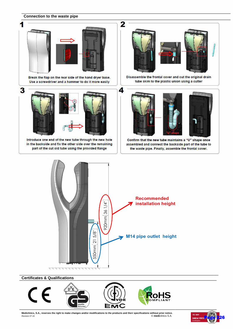
Connection to the waste pipe
Certificates & Qualifications
Mediclinics, S.A., reserves the right to make changes and/or modifications to the products and their specifications without prior notice. Revision 07-16 © mediclinics S.A.
Page 226
HAND DRYERS
VERSATILE, ADA COMPLIANT, DURAbLE, MODERN & ULTRA-SLEEk DESIGN
The Speedflow hand dryer is the first designed adjustable speed warm-air hand dryer available. It can be set to fit any application. Users can choose their preferred air speed (thru a potentiometer) and active settings for quieter operation (museums or libraries). Convenient to install as the voltage (110-240 V) adjusts automatically saving on installation time. No need to order a recessed kit for ADA applications. GreenSpec listed, contributing to points for LEED credits.
high speed
Who is using SPeeDFLOW M06 Hand dryers:
- Wal Mart Stores & Superstores, nationwide - United Airlines VIP red carpet Clubs, nationwide - Texas Department of Transportation, TX - Dallas-Ft. Worth entire school district, TX - Dodgers Stadium, Los Angeles, CA - The Town School, NYC, NY - Justin Siena High School, Napa, CA - Tumwater High School, Tumwater, WA - H. Frank Carey High School, Franklin Square, NY - Hanover High School, Town of Hanover, MA - University of California - Berkeley, Vance Brown Bldg., CA - San Diego State University, CA - YMCA of Greater Miami, Miami, FL - USS Arizona Memorial, Honolulu, HI - Glendale Heights Police Station, Glendale Heights, IL - Academie Ste. Therese, Rosemere, Quebec, Canada - Hemmingford Aerospace, Quebec, Canada - Ecole Polymechanique, Laval, Quebec, Canada
Page 227
M06A · M06AF · M06AB · M06AC · M06ACS
COMPONENTS AND MATERIALS
TECHNICAL SPECIFICATIONS
• 3/16” thick cast iron or 1/16” thick stainless steel one piece cover.
• High Speed – Universal brush motor, 3.800 – 8.200 rpm A class. • The motor includes an automatically resetting safety
thermal cut-off.• Universal Voltage (from 110 to 240 V). • Sensors come with a vandal-resistant polycarbonate
viewing window.• Cover fixed to the base by means of 2 vandal-proof lock
screws and lock with special Speedflow wrench.
• Fully adjustable (2” – 8”) IR electronic detection sensor by means of a potentiometer.
• Automatic disconnection system after 60 seconds of continuous use.
• Waved wire NiCr heating element mounted on a mica frame. It incorporates a self-resetable safety thermal cut-off which disconnects the whole appliance.
• Aluminum centrifugal double asymmetrical inlet fan wheel.• Fire resistant plastic UL 94-V0 fan scroll.• UL & CUL comply with UL499 norm and electrical safety.• ADA compliant (no recessed kit needed).
11 1/2”290 mm
4”100 mm
10 5
/8”
270
mm
110mph
material: steel finish: white epoxy
M06A
ADA
110mph
material: cast ironfinish: white porcelain enameled
M06AF
ADA
110mph
110mph
110mph
material: steel finish: black epoxy
M06AB
ADA
material: AISI 304 stainless steel finish: bright
M06AC
ADA
material: AISI 304 stainless steel finish: satin
M06ACS
ADA
Estimated drying time 10-15 seconds Total Power: 1080 – 1150 W
Voltage 100-120 V, 208V, 220-240 V Heating Element: 900 W
Frequency 50/60 Hz Protection level IP23
Power Consumption 9.0 – 9.5 Amps (120 V) / 4.3 - 5.1 Amps (230 V) Nominal airflow 43 – 70 CFM
Electrical insulation Clase I (ground required) Effective airflow 36– 58 CFM
Motor Power 180 – 250 W Air temp (at 4” distance/70ºF) 107.6ºF (42ºC)
rpm adjustable (3.800 – 8.200 rpm) Dimensions 11 1/2” x 10 5/8” x 4”
Air speed: 55 - 110 mph / 4.920 – 9.840 LFM Weight All: 7.9 Lbs. (3.6 kg) M06AF: 15.2 Lbs (6.9 kg)
Noise level 64 – 74 dB
Legend for symbols shown on last page of catalog
M06A · M06AF · M06AB · M06AC · M06ACS
HAND DRYERS
sensor operated
36
(B)
36
(B)
36
(B)
36
(B)
36
(B)
Page 228

Page 229
Page 230
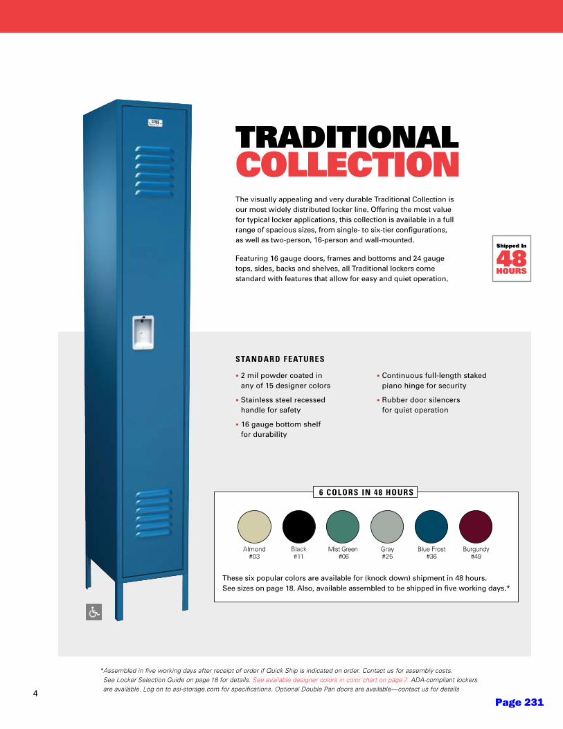
Page 231

Page 232
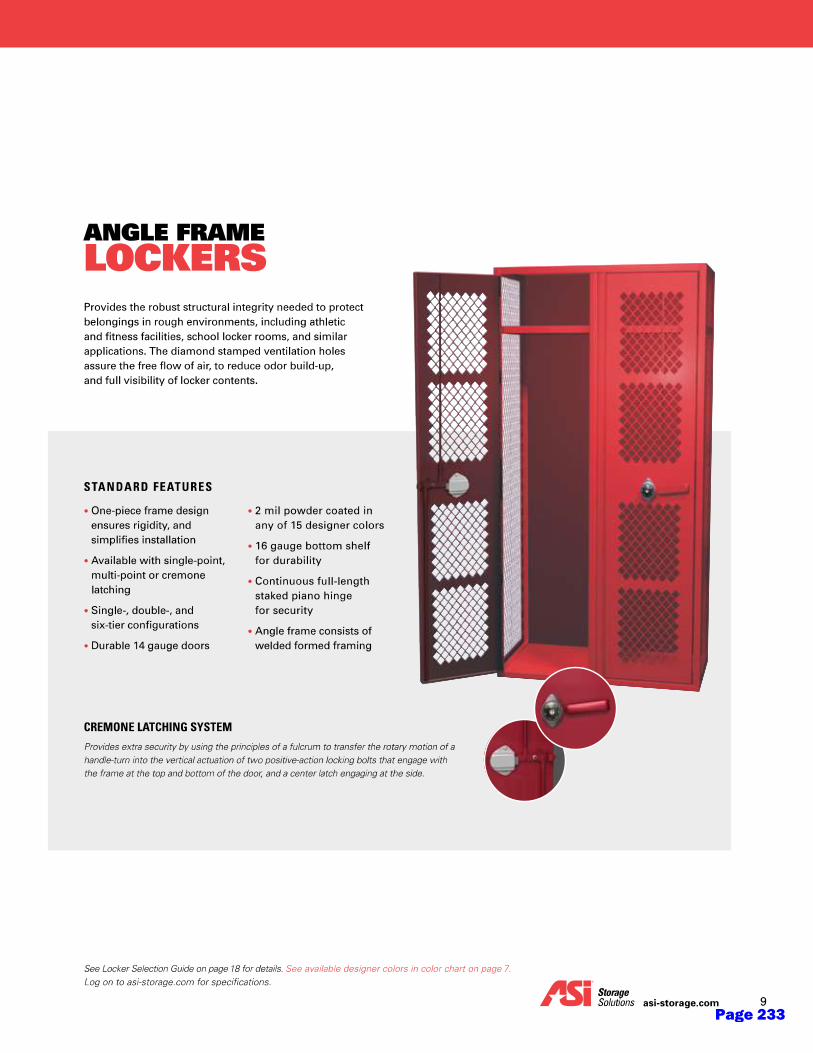
Page 233
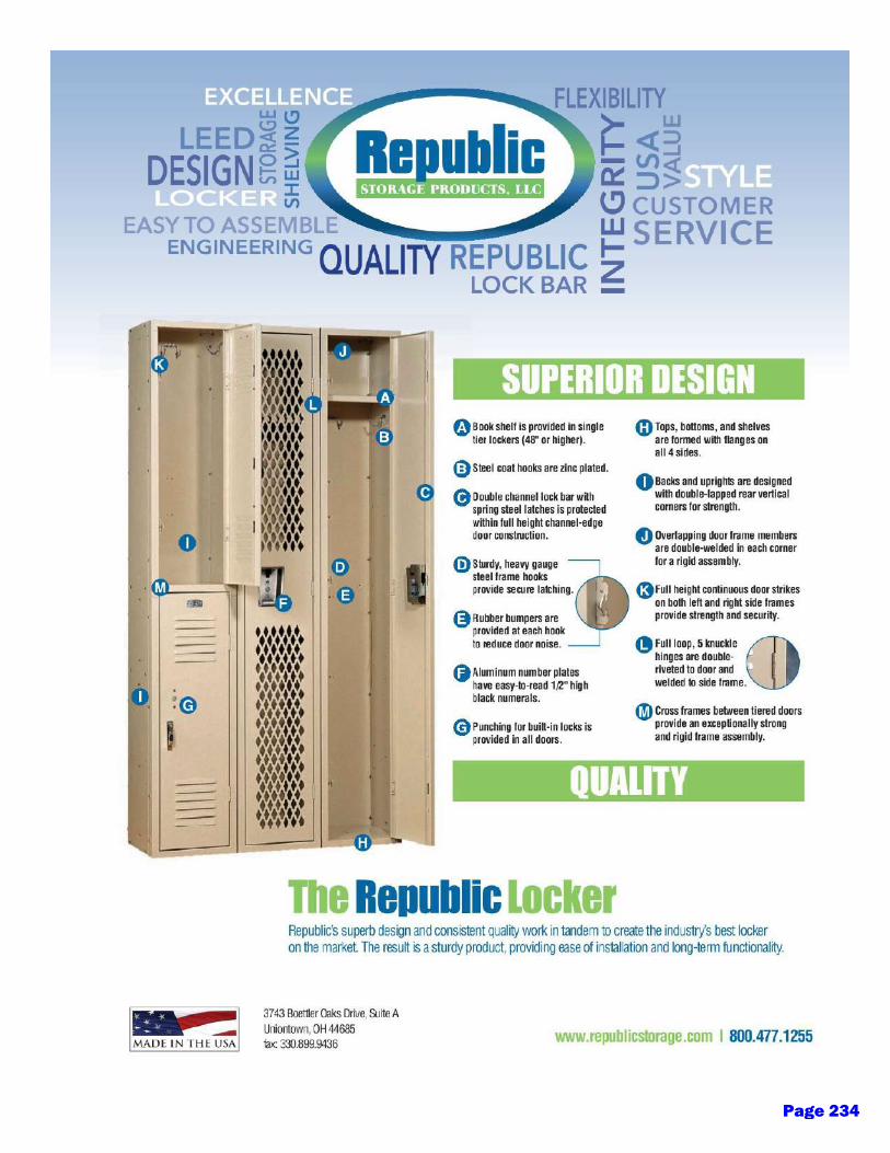
Page 234
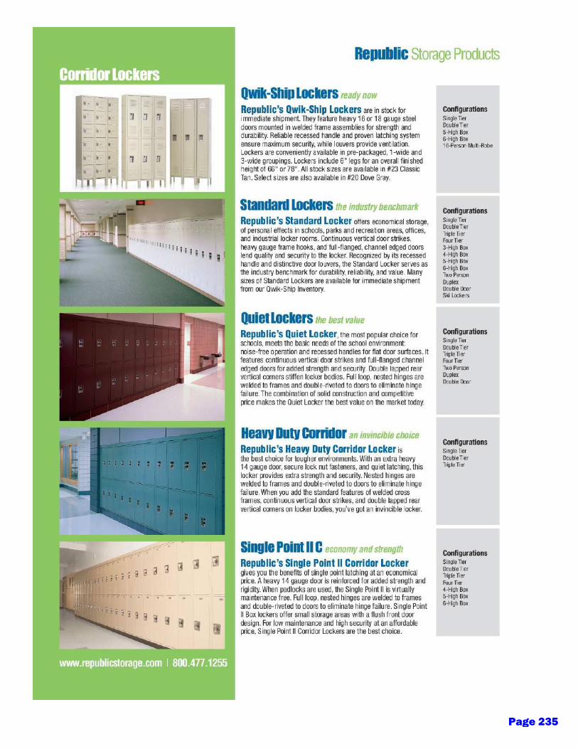
Page 235

Page 236

Page 237
Equipment - 1
DISTRICT DESIGN STANDARDS
Section 11 – Equipment
Issued: Fall 2020 Updates:
I. Purpose
A. The following District Design Standard for equipment is intended to provide basic guidelines for the District with the goal of ensuring ease of maintenance and proper function for the anticipated use of the space.
B. These standards should be applied to all new construction, modernization, renovation and replacement projects.
II. General Design Standards
A. The design team should recognize the need for spaces to be flexible, take into consideration the particular use of the space, and that the main role of the space is to be used for the instructional delivery of education. Specific programs may require additional requirements.
B. The District shall provide all equipment and furnishings required by the program to the design team. However, the design team should coordinate with the District and/or their consultants to provide electrical connections and services for District-provided equipment. Layout and coordination of space shall also be included in this coordination.
C. The design team should compile user input specific to specialty classrooms for each campus.
Page 238
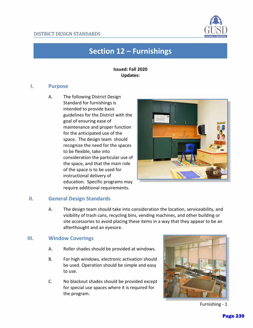
Furnishing - 1
DISTRICT DESIGN STANDARDS
Section 12 – Furnishings
Issued: Fall 2020 Updates:
I. Purpose
A. The following District Design Standard for furnishings is intended to provide basic guidelines for the District with the goal of ensuring ease of maintenance and proper function for the anticipated use of the space. The design team should recognize the need for the spaces to be flexible, take into consideration the particular use of the space, and that the main role of the space is to be used for instructional delivery of education. Specific programs may require additional requirements.
II. General Design Standards
A. The design team should take into consideration the location, serviceability, and visibility of trash cans, recycling bins, vending machines, and other building or site accessories to avoid placing these items in a way that they appear to be an afterthought and an eyesore.
III. Window Coverings
A. Roller shades should be provided at windows.
B. For high windows, electronic activation should be used. Operation should be simple and easy to use.
C. No blackout shades should be provided except for special use spaces where it is required for the program.
Page 239
2 - Furnishings
DISTRICT DESIGN STANDARDS D. Products:
1. Mecho Shade
2. Hunter Douglass, commercial grade
IV. Educational/ Library Casework
A. Elementary and middle school classrooms should be provided with teaching wall equipment appropriate for the classroom program. This may include but should not be limited to a 16’ magnetic whiteboards and 2 large screens with wall mounts.
B. Casework should be of plastic laminate finish and Purebond Classic Core plywood construction from Columbia Forest Products, or equal.
C. Hardware:
1. 5-knuckle hinges with hospital ends
2. 100 lb drawer guides
a) Accuride International
D. Countertops:
1. In wet areas, provide solid surface with coved backsplash
2. In science and lab classrooms, provide chemically resistant solid surface
3. In all regular classrooms, staff areas and library areas provide plastic laminate
E. Products:
1. Plastic laminates
a) Nevamar Corp – with “Armor Protection Plus”
b) Wilsonart: Ralph Wilson Plastics Co. with “High Wear Laminate”
2. Solid surface countertop
a) Corian by Dupont, Terra Collection
3. Chemical resistant solid panel
a) Trespa
Page 240
Furnishing - 3
DISTRICT DESIGN STANDARDS b) Resistop
c) Corian by Dupont
4. Cabinet locks
a) Olympus
5. Flammable and chemical storage cabinets
a) Justrite Manufacturing
V. Flexible Furniture Manufacturer: KI, https://www.ki.com/ The intent for the furniture selection in this document is to provide a list of core elements for classrooms, makerspaces, admin and library furniture. The manufacturer and the furniture have been selected through a pilot program and stakeholder engagement process with the end goal to provide flexibility, multi-level seating options and consistency across the type of furniture used in the District. Furniture not listed should be coordinate with the District and the KI representative. No substitution will be accepted for the core elements. Product Line Link to Brochure Product Specfied out of Collection
Classroom Product
All-Terrain Storage All-Terrain Mobile Storage Mobile Storage Towers
Oath Task Chair Oath Task Seating
Pirouette Tables Pirouette Tables
Ruckus Collection Ruckus Collection Ruckus Post Leg Desks, Stack
Chairs, Stools, Bookcase, ADA
Desk, and Lectern
Toggle Tables Toggle Tables
Tattoo Collection Tattoo Collection Tattoo Vanity
Universal Screens Universal Screens
Makerspace Products
All-Terrain Storage All-Terrain Mobile Storage Mobile Storage Towers
Oath Task Chair Oath Task Seating
Ruckus Collection Ruckus Collection Ruckus Tote Storage
Toggle Tables Toggle Tables
Tattoo Collection Tattoo Collection Tattoo Vanity
Universal Screens Universal Screens
Pillar Tables Pillar Table With Chemsurf laminate
Page 241
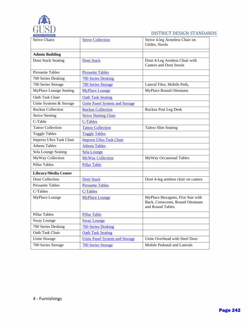
4 - Furnishings
DISTRICT DESIGN STANDARDS Strive Chairs Strive Collection Strive 4-leg Armeless Chair on
Glides, Stools
Admin Building
Doni Stack Seating Doni Stack Doni 4-Leg Armless Chair with
Casters and Doni Stools
Pirouette Tables Pirouette Tables
700 Series Desking 700 Series Desking
700 Series Storage 700 Series Storage Lateral Files, Mobile Peds,
MyPlace Lounge Seating MyPlace Lounge MyPlace Round Ottomans
Oath Task Chair Oath Task Seating
Unite Systems & Storage Unite Panel System and Storage
Ruckus Collection Ruckus Collection Ruckus Post Leg Desk
Strive Nesting Strive Nesting Chair
C-Table C-Tables
Tattoo Collection Tattoo Collection Tattoo Slim Seating
Toggle Tables Toggle Tables
Impress Ultra Task Chair Impress Ultra Task Chair
Athens Tables Athens Tables
Sela Lounge Seating Sela Lounge
MyWay Collection MyWay Collection MyWay Occasional Tables
Pillar Tables Pillar Table
Library/Media Center
Doni Collection Doni Stack Doni 4-leg armless chair on casters
Pirouette Tables Pirouette Tables
C-Tables C-Tables
MyPlace Lounge MyPlace Lounge MyPlace Hexagons, Five Star with
Back, Cresecents, Round Ottomans
and Round Tables
Pillar Tables Pillar Table
Sway Lounge Sway Lounge
700 Series Desking 700 Series Desking
Oath Task Chair Oath Task Seating
Unite Storage Unite Panel System and Storage Unite Overhead with Steel Door
700 Series Storage 700 Series Storage Mobile Pedastal and Laterals
Page 242
SolarTrac® System The WindowManagement® solution for daylighting
The
New
Yor
k Ti
mes
Bui
ldin
g. Im
age
cour
tesy
of:
The
New
Yor
k Ti
mes
Com
pan
y, F
ores
t C
ity R
atne
r C
omp
anie
s, R
enzo
Pia
no B
uild
ing
Wor
ksho
p, F
XFo
wle
Arc
hite
cts,
pho
to A
rtef
acto
ry
The brochure titleIs placed hereMecho®/5 System The original manual roller shade
Page 243
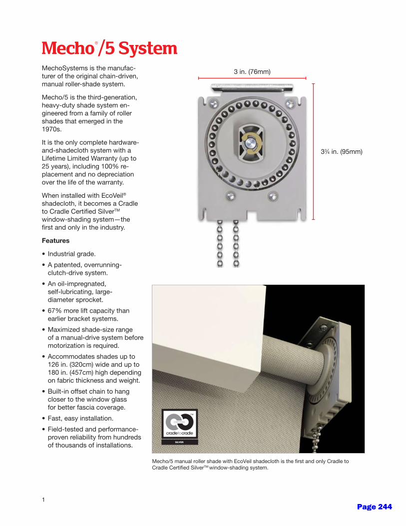
Mecho®/5 System
1
MechoSystems is the manufac-turer of the original chain-driven, manual roller-shade system.
Mecho/5 is the third-generation, heavy-duty shade system en-gineered from a family of roller shades that emerged in the 1970s.
It is the only complete hardware-and-shadecloth system with a Lifetime Limited Warranty (up to 25 years), including 100% re-placement and no depreciation over the life of the warranty.
When installed with EcoVeil® shadecloth, it becomes a Cradle to Cradle Certified SilverTM window-shading system—the first and only in the industry.
Features
• Industrial grade.
• A patented, overrunning- clutch-drive system.
• An oil-impregnated, self-lubricating, large- diameter sprocket.
• 67% more lift capacity than earlier bracket systems.
• Maximized shade-size range of a manual-drive system before motorization is required.
• Accommodates shades up to 126 in. (320cm) wide and up to 180 in. (457cm) high depending on fabric thickness and weight.
• Built-in offset chain to hang closer to the window glass for better fascia coverage.
• Fast, easy installation.
• Field-tested and performance- proven reliability from hundreds of thousands of installations.
Mecho/5 manual roller shade with EcoVeil shadecloth is the first and only Cradle to Cradle Certified SilverTM window-shading system.
3 in. (76mm)
33⁄4 in. (95mm)
Page 244
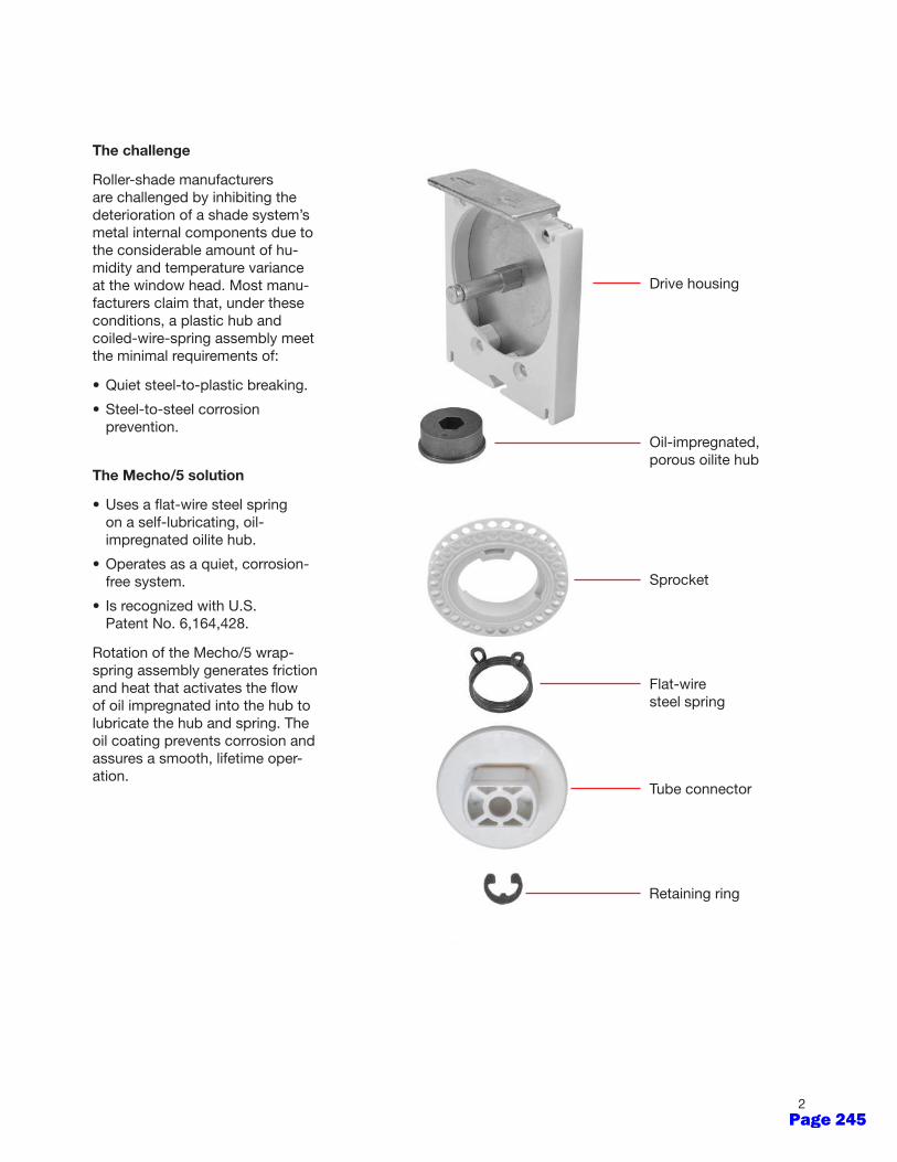
2
The challenge
Roller-shade manufacturers are challenged by inhibiting the deterioration of a shade system’s metal internal components due to the considerable amount of hu-midity and temperature variance at the window head. Most manu-facturers claim that, under these conditions, a plastic hub and coiled-wire-spring assembly meet the minimal requirements of:
• Quiet steel-to-plastic breaking.
• Steel-to-steel corrosion prevention.
The Mecho/5 solution
• Uses a flat-wire steel spring on a self-lubricating, oil- impregnated oilite hub.
• Operates as a quiet, corrosion- free system.
• Is recognized with U.S. Patent No. 6,164,428.
Rotation of the Mecho/5 wrap-spring assembly generates friction and heat that activates the flow of oil impregnated into the hub to lubricate the hub and spring. The oil coating prevents corrosion and assures a smooth, lifetime oper-ation.
Oil-impregnated, porous oilite hub
Drive housing
Sprocket
Flat-wire steel spring
Tube connector
Retaining ring
Page 245

Mecho®/5 SystemSnapLoc® spline
• Assures properly aligned shade bands.
• Holds the shadecloth onto the shade tube for secure shade alignment.
• Easily pressed in and then pulled out for simple replacement.
• Prevents shadecloth from slipping off the roller tube.
• Excellent for hospitals for decontamination.
SnapLoc fascia
• Has a clean, sleek finish.
• Snaps into place top-edge-first and locks at the bottom for ease of installation and added safety.
• No exposed fasteners.
The offset position of the drive chain clears the fascia and hides the chain.
Edge clearances
• Have very narrow edge clearances without side channels.
Regular roll Reverse roll Double fascia(front and back for a cassette effect)
3
idle-endbracket
Edge clearances ≠ 1⁄8 in. (3mm). Shown: A Mecho/5 3-band shade, right-hand drive, regular roll, no fascia.
½ in.(13mm)
½ in.(13mm)
1 in. (25mm)
13⁄16 in. (21mm)
5⁄8 in. (16mm)5⁄8 in. (16mm) 15⁄16 in. (33mm)
5⁄16 in.(8mm)
5⁄16 in.(8mm)
5⁄16 in.(8mm)
5⁄16 in.(8mm)
½ in.(13mm)
½ in.(13mm)
center-support bracket
center-support bracket
drive-endbracket
idle-end bracketto idle-end bracket
drive-end bracketto idle-end bracket
Page 246
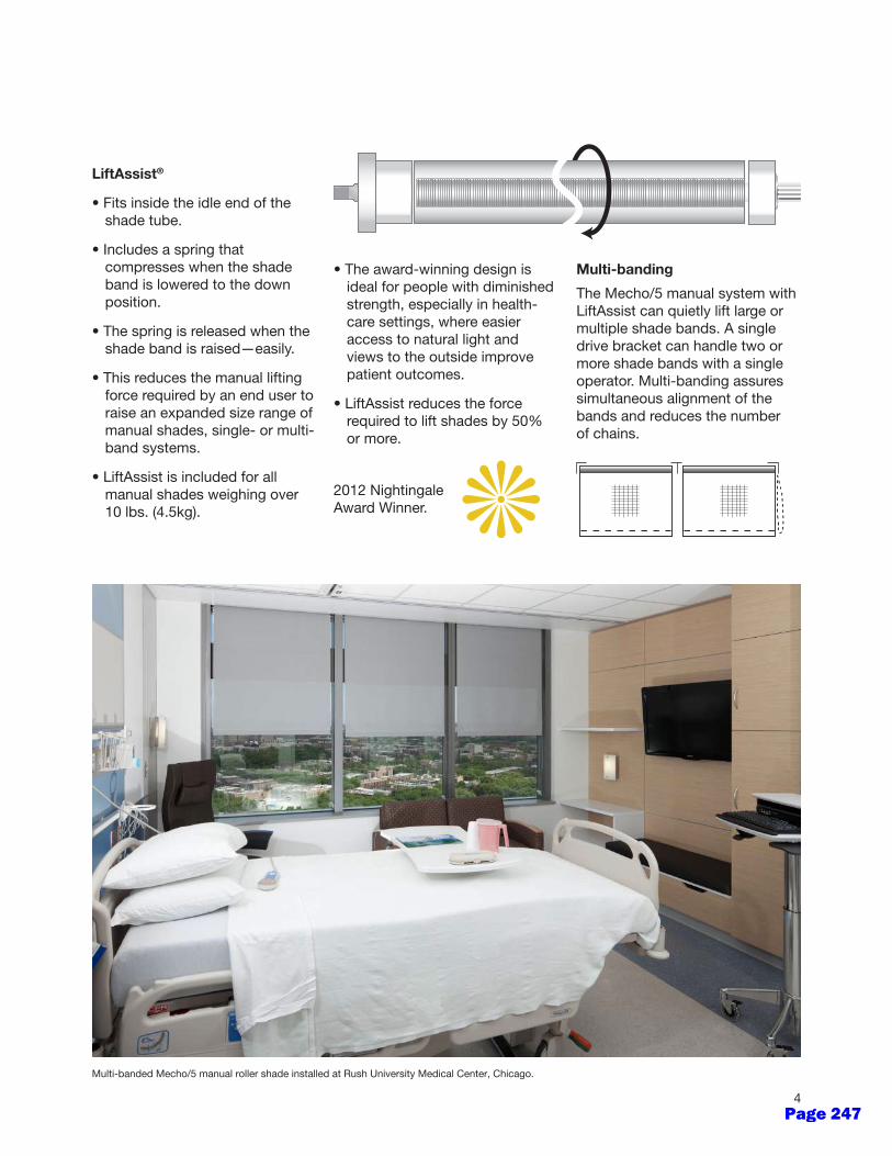
2012 Nightingale Award Winner.
LiftAssist®
• Fits inside the idle end of the shade tube.
• Includes a spring that compresses when the shade band is lowered to the down position.
• The spring is released when the shade band is raised—easily.
• This reduces the manual lifting force required by an end user to raise an expanded size range of manual shades, single- or multi- band systems.
• LiftAssist is included for all manual shades weighing over 10 lbs. (4.5kg).
4
• The award-winning design is ideal for people with diminished strength, especially in health- care settings, where easier access to natural light and views to the outside improve patient outcomes.
• LiftAssist reduces the force required to lift shades by 50% or more.
Multi-banded Mecho/5 manual roller shade installed at Rush University Medical Center, Chicago.
Multi-banding
The Mecho/5 manual system with LiftAssist can quietly lift large or multiple shade bands. A single drive bracket can handle two or more shade bands with a single operator. Multi-banding assures simultaneous alignment of the bands and reduces the number of chains.
Page 247
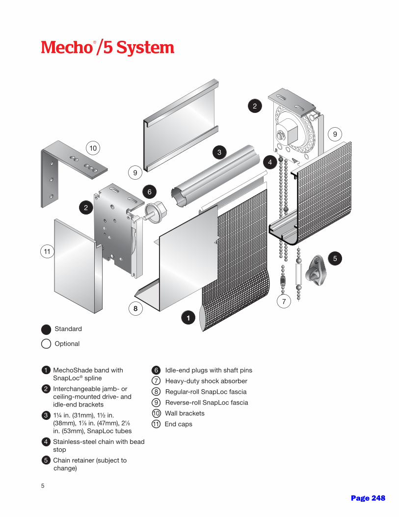
Mecho®/5 System
11
9
9
7
10
2
18
3
6
4
5
2
Standard
Optional
1 MechoShade band with SnapLoc® spline
2 Interchangeable jamb- or ceiling-mounted drive- and idle-end brackets
3 1¼ in. (31mm), 1½ in. (38mm), 17⁄8 in. (47mm), 21⁄8 in. (53mm), SnapLoc tubes
4 Stainless-steel chain with bead stop
5 Chain retainer (subject to change)
6 Idle-end plugs with shaft pins
7 Heavy-duty shock absorber
8 Regular-roll SnapLoc fascia
9 Reverse-roll SnapLoc fascia
10 Wall brackets
11 End caps
5
Page 248
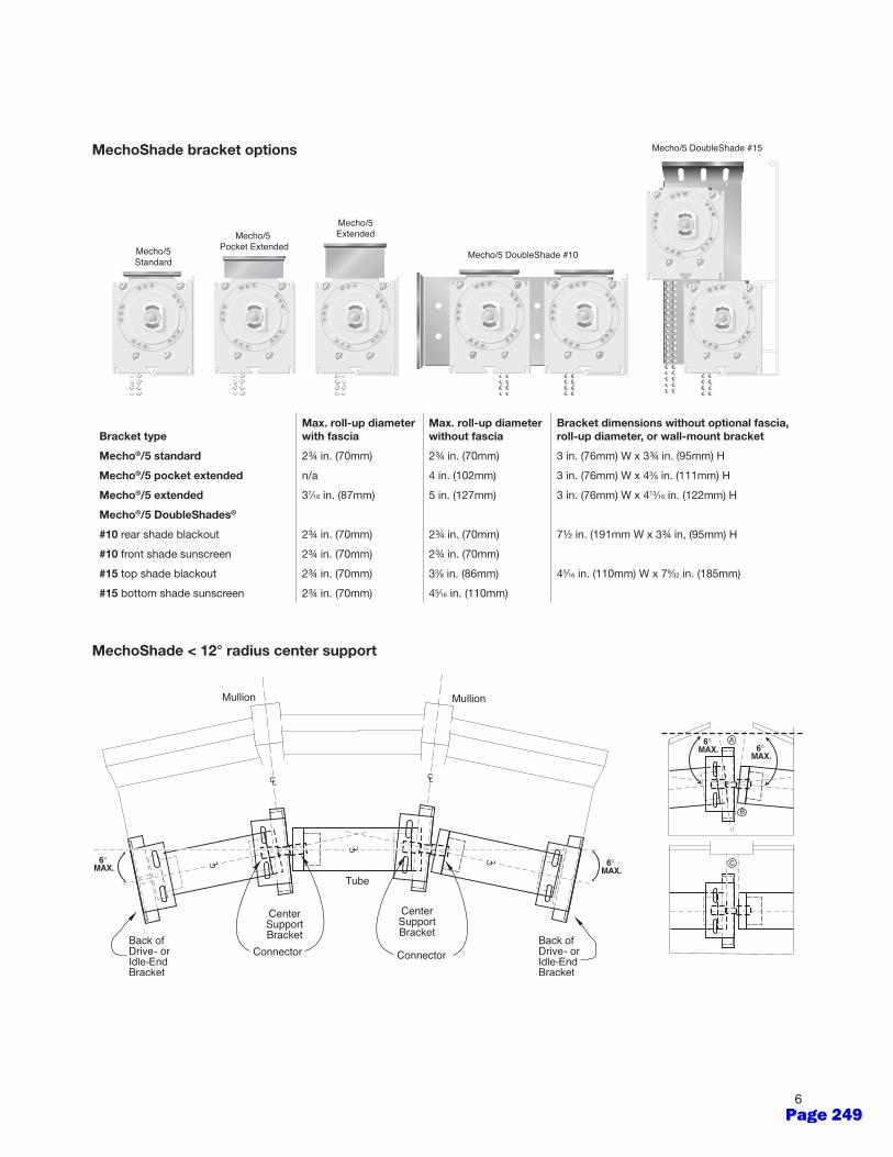
MechoShade bracket options
MechoShade < 12° radius center support
--
--
6
Bracket typeMax. roll-up diameter with fascia
Max. roll-up diameter without fascia
Bracket dimensions without optional fascia, roll-up diameter, or wall-mount bracket
Mecho®/5 standard 2¾ in. (70mm) 2¾ in. (70mm) 3 in. (76mm) W x 3¾ in. (95mm) H
Mecho®/5 pocket extended n/a 4 in. (102mm) 3 in. (76mm) W x 43⁄8 in. (111mm) H
Mecho®/5 extended 37⁄16 in. (87mm) 5 in. (127mm) 3 in. (76mm) W x 413⁄16 in. (122mm) H
Mecho®/5 DoubleShades®
#10 rear shade blackout 2¾ in. (70mm) 2¾ in. (70mm) 7½ in. (191mm W x 3¾ in, (95mm) H
#10 front shade sunscreen 2¾ in. (70mm) 2¾ in. (70mm)
#15 top shade blackout 2¾ in. (70mm) 33⁄8 in. (86mm) 45⁄16 in. (110mm) W x 79⁄32 in. (185mm)
#15 bottom shade sunscreen 2¾ in. (70mm) 45⁄16 in. (110mm)
Page 249

Special Construction - 1
DISTRICT DESIGN STANDARDS
Section 13 – Special Construction
Issued: Fall 2020 Updates:
I. Purpose
A. The following District Design Standards for special construction are intended to provide basic guidelines for the District in relationship to pre-engineered, modular and ‘pre-check’ buildings.
B. These standards should be applied to all new construction.
II. General Design Standards
A. There are several methods of procuring a modular building and the District should understand whether the building is pre-engineered, modular or a ‘pre-check’ (PC) building and the implications of each to design and construction schedules.
B. In the event that the District decides to submit a Request for Proposal from a building manufacturer as part of the design process, the following should be included in the deliverables from the building manufacturer as part of the RFP:
1. Schedule acknowledgement
2. Manufacturer’s proposed floor plans, reflecting the basis of design documents provided by the District
3. Budget analysis and cost breakdown
C. In the event that there are separate building and site contractors, the design team should create a responsibility matrix delegating responsibility to each party, including, but not limited to the following:
1. Field office, temporary site fencing, power, water, phone and other utilities as needed
2. Existing building demolition
3. Grading – rough and final
4. Building pads, building footing excavation and spoils removal
Page 250
2 - Special Construction
DISTRICT DESIGN STANDARDS
5. Survey, stake and maintaining corners of modular buildings
6. Asphalt and concrete paving, tactile warning stripes, parking improvements, ramp, stair and handrail construction
7. Concrete sidewalk at grade for building walkway
8. Connection of fire water, gas and electrical from main to building
9. Fire alarm and low voltage systems
10. Exterior lights
Page 251
Conveying Equipment - 1
DISTRICT DESIGN STANDARDS
Section 14 – Conveying Equipment
Issued: Fall 2020 Updates:
I. Purpose
A. The following District Design Standards for conveying equipment are intended to provide basic guidelines for the District with the goal of ensuring ease of maintenance, proper function, and efficient vertical circulation for the use of students and staff.
B. These standards should be applied to all new construction, modernization, renovation and replacement projects.
II. General Design Standards
A. Installer qualifications: Elevator manufacturer or an experienced installer approved by elevator manufacturer who has completed elevator installations similar in material, design, and extent to that indicated for this Project and with a record of successful in-service performance.
B. Regulatory requirements: In addition to local governing regulations, comply with applicable provisions in ASME A17.1, "Safety Code for Elevators and Escalators."
C. Seismic risk zone: Project is located in Zone 4 or greater.
D. Comply with applicable requirements of the most current edition of the CBC.
E. Accessibility requirements: In addition to local governing regulations, comply with Section 4.10 in the U.S. Architectural & Transportation Barriers Compliance Board's "Americans with Disabilities Act (ADA), Accessibility Guidelines (ADAAG)."
III. Elevators
A. The elevator system shall include the hoistway system and structure; elevator car, frame and landing; pumps; power, emergency communication systems, security; signage, indicators and lanterns; as required by code.
B. Provide all components for an architecturally finished elevator including removable wall panels, suspended ceiling, trim, accessories, access doors, doors,
Page 252
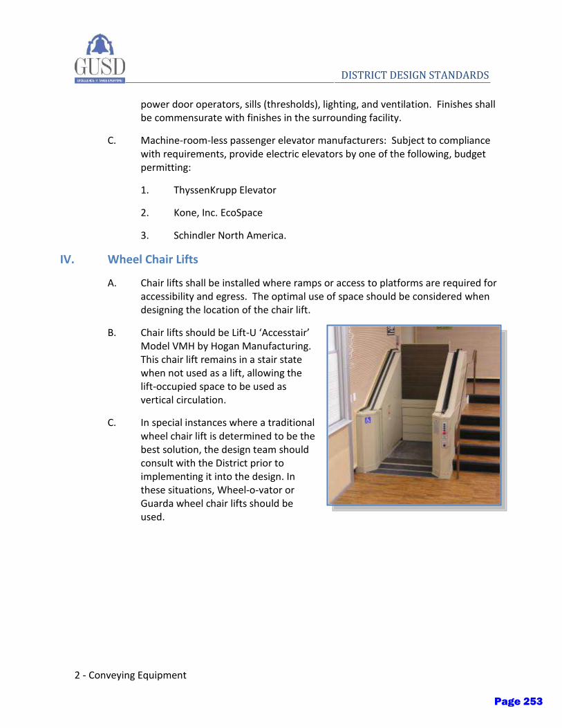
2 - Conveying Equipment
DISTRICT DESIGN STANDARDS
power door operators, sills (thresholds), lighting, and ventilation. Finishes shall be commensurate with finishes in the surrounding facility.
C. Machine-room-less passenger elevator manufacturers: Subject to compliance with requirements, provide electric elevators by one of the following, budget permitting:
1. ThyssenKrupp Elevator
2. Kone, Inc. EcoSpace
3. Schindler North America.
IV. Wheel Chair Lifts
A. Chair lifts shall be installed where ramps or access to platforms are required for accessibility and egress. The optimal use of space should be considered when designing the location of the chair lift.
B. Chair lifts should be Lift-U ‘Accesstair’ Model VMH by Hogan Manufacturing. This chair lift remains in a stair state when not used as a lift, allowing the lift-occupied space to be used as vertical circulation.
C. In special instances where a traditional wheel chair lift is determined to be the best solution, the design team should consult with the District prior to implementing it into the design. In these situations, Wheel-o-vator or Guarda wheel chair lifts should be used.
Page 253
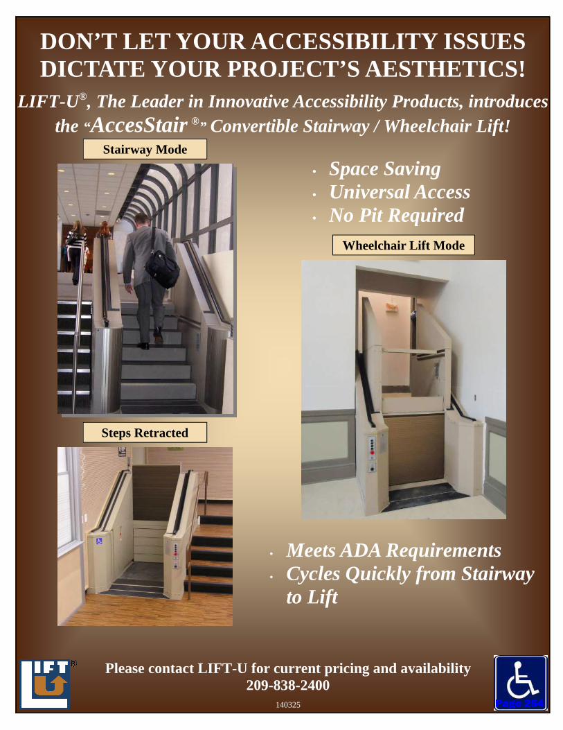
DON’T LET YOUR ACCESSIBILITY ISSUES DICTATE YOUR PROJECT’S AESTHETICS!
LIFT-U ®, The Leader in Innovative Accessibility Products, introduces the “AccesStair ®” Convertible Stairway / Wheelchair Lift!
140325
Please contact LIFT-U for current pricing and availability 209-838-2400
Steps Retracted
• Space Saving • Universal Access • No Pit Required
• Meets ADA Requirements • Cycles Quickly from Stairway
to Lift
Wheelchair Lift Mode
Stairway Mode
Page 254
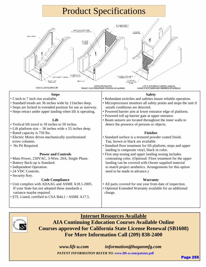
Internet Resources Available AIA Continuing Education Courses Available Online
Courses approved for California State License Renewal (SB1608) For More Information Call (209) 838-2400
www.lift-u.com [email protected]
PATENT INFORMATION REFER TO: www.lift-u.com/patents.pdf
Product Specifications
Steps • 5 inch to 7 inch rise available. • Standard treads are 36 inches wide by 11inches deep. • Steps are locked in extended position for use as stairway. • Steps retract under upper landing when lift is operating.
Lift • Vertical lift travel is 18 inches to 50 inches. • Lift platform size – 36 inches wide x 55 inches deep. • Rated capacity is 750 lbs. • Electric Motor drives mechanically synchronized screw columns. • No Pit Required.
Power and Controls • Main Power, 230VAC, 3-Wire, 20A, Single Phase. • Battery Back-up is Standard. • Independent Operation. • 24 VDC Controls. • Security Key.
Code Compliance • Unit complies with ADAAG and ASME A18.1-2005. If your State has not adopted these standards a variance maybe required. • ETL Listed, certified to CSA B44.1 / ASME A17.5.
Safety • Redundant switches and safeties insure reliable operation. • Microprocessor monitors all safety points and stops the unit if unsafe conditions are detected. • Powered barrier arm at lower entrance edge of platform. • Powered roll up barrier gate at upper entrance. • Beam sensors are located throughout the inner walls to detect the presence of persons or objects.
Finishes • Standard surface is a textured powder coated finish. Tan, brown or black are available. • Standard floor treatment for lift platform, steps and upper landing is composite vinyl, black in color. • First step nosing and upper landing nosing includes contrasting color. (Optional: Floor treatment for the upper landing can be covered with Owner supplied material to match project aesthetics. Arrangements for this option need to be made in advance.)
Warranty • All parts covered for one year from date of inspection. • Optional Extended Warranty available for an additional charge.
Page 255
Fire Suppression - 1
DISTRICT DESIGN STANDARDS
Section 21 – Fire Suppression
Issued: Fall 2020 Updates:
I. Purpose
A. The following District Design Standards for fire suppression are intended to provide basic guidelines for the District.
B. These standards should be applied to all new construction, modernization, renovation and replacement projects.
II. General Design Standards
A. Code compliance:
1. California Fire Code
2. NFPA 13 Standard for the Installation of Sprinkler Systems
3. NFPA 14 Standard for the Installation of Standpipes and Hose Systems
4. California State Fire Marshal
B. All work shall be installed in strict conformity with California Building Code (CBC), California Plumbing Code (CPC), and California Electric Codes (CEC), all Industrial Safety Orders, California Mechanical Code (CMC), National Fire Code (NFC), and any other laws and regulations of legally constituted authorities having jurisdiction.
C. Sprinklers shall be installed by a licensed fire sprinkler contractor and shall be designed by a licensed fire protection engineer. Testing and acceptance of fire sprinklers shall be in accordance with NFPA standards and California Codes.
III. Fire Sprinkler Scope
A. Furnish all labor, design drawings, calculations, materials, tools, and equipment to install a wet pipe automatic fire sprinkler system as hereinafter described, ready for service. System shall be hydraulically calculated for the occupancy as determined by NFPA Pamphlet 13, 2002 Edition.
Page 256
2 – Fire Suppression
DISTRICT DESIGN STANDARDS
B. Determine the static and residual pressure for the site as required for accurate determination of system requirements. Base system calculations on the lowest expected static and residual pressure for the area.
C. The work should include the following:
1. Complete automatic fire risers, including all valves, fire department connections, flow switches, pressure switch and service mains as indicated.
2. Complete wet type automatic fire protection spray type sprinkler distribution system, including overhead service and branch mains, lateral supply piping, supports, hangers, seismic bracing, heads and tests.
3. Provide all electrical work required for a complete operating and DSA-approved system. Provide all connections to fire alarm panels, i.e. water flow indicator, sprinkler flow switches, valve tamper switches, etc.
4. Fire protection shall include all areas above and below the finished ceilings, exterior exposure, canopies, stairways, rooms, areaways, entry, etc, and other areas requiring sprinklers. Thoroughly examine all architectural and other drawings as required to satisfy this requirement.
5. Necessary tags, identification labels and instruction manuals for proper operation and maintenance. Included shall be hydraulic data plans permanently attached to the risers, indicating the location, basis of design, water supply and pressure requirements of hydraulically designed systems.
IV. Quality Assurance
A. Manufacturers: Firms regularly engaged in manufacture of fire protection products, of types, materials, and sizes required, whose products have been in satisfactory use in similar service for not less than 5 years.
B. Installer: A firm with at least five years of successful installation experience on projects with fire sprinkler piping systems similar to that required for this project.
V. Sprinkler Heads
A. Provide spray pattern type sprinkler heads, of ordinary degree temperature rating, except that sprinkler heads to be installed in the vicinity of heating equipment shall be of the temperature ratings required for such locations by 2000 UBC Standard 9-1.
Page 257

Fire Suppression - 3
DISTRICT DESIGN STANDARDS
B. Provide recessed sprinkler heads in occupied areas. Recessed sprinkler heads shall have chrome finish and adjustable chrome finish escutcheons; exposed pendent heads in finished ceilings shall have chrome finish and white ceiling escutcheons. Concealed (flush) heads shall be all chrome, with white cover plate. Sprinkler heads in service rooms i.e. mechanical, electrical, storage, etc. shall be upright, pendent and sidewall, as required:
C. For installation outside and inside building underground to 12 inches above ground provide Ductile Cast Iron AWWA C111 and C151. Outside the building below ground, J.M. Blue Brute Class 200 UL, P.W. Pipe, or equal, C900, PVC pressure pipe, approved for fire protection use. Install in accordance with NFPA24 and AWWA standards. Provide concrete thrust blocks at each change or direction.
D. Firesafing
1. Penetrations in fire rated assemblies shall also be protected in accordance with CBC Chapter 7, Section 714, and UBC Standard 7-5.
VI. Structural Requirements
A. Seismic bracing system shall be a complete pre-engineered bracing system. Pre-engineered bracing system shall include plan layout, brace selection, specification, and calculations. Complete system shall be submitted to the design team for review. Provide adequate seismic separation required at all building expansion joints as required by code.
VII. Testing
A. Upon completion and prior to acceptance of the installation, subject the entire new system to the tests required in UBC Standard 9-1 and shall furnish the District with certificates as appropriate. At various stages and upon completion, the system shall be tested in the presence of the enforcing agency.
Page 258
Plumbing - 1
DISTRICT DESIGN STANDARDS
Section 22 – Plumbing
Issued: Fall 2020 Updates:
I. Purpose
A. The following District Design Standards for plumbing are intended to provide basic guidelines for the District with the goal of standardization in appearance, cleanability and durability to provide ease of maintenance and operations, as well as a sense of consistency to the end users.
B. The standardization of fixtures are selected herein to be cost effective, aesthetically pleasing, durable and easy to maintain. In addition, pursuant to the District’s sustainability guidelines, these products are selected because of the manufacturer’s commitment to sustainability.
C. These standards should be applied to all new construction, modernization, renovation and replacement projects.
II. General Design Standards
A. Code compliance: All restroom fixtures shall comply with the most current CalGreen Standards
B. Restrooms should be easily located visually and through way-finding. All restrooms both new and modernized should be ADA compliant. Each restroom should be clearly identified by signage. Signage should comply to the most recent ADA codes.
III. Plumbing Scope
A. Provide all components to complete a full operating system for the intended purpose of the facility. This shall include, but not be limited to, gas and water supply lines, sanitary sewer, storm sewer, valves and valve boxes, shut off valves, strainers and grates, gauges, thermometers, identification as required by code, and insulation of systems, interceptors, hot water heaters and expansion tanks, vents, etc. The design team shall provide all components to meet within the requirements of the code and/or authority having jurisdiction.
Page 259
2 - Plumbing
DISTRICT DESIGN STANDARDS
B. Provide factory fabricated fixtures of type, style and material for intended use. For each type fixture, provide fixture manufacturer's standard trim, carrier, seats, and valves as indicated by their published product information; either as designed and constructed, or as recommended by the manufacturer, and as required for a complete, installation.
C. Although certification by sustainable building agency such as the U.S. Green Building Council is not a requirement, the design team is encouraged to incorporate sustainable features into its design and construction practices.
IV. Domestic Water Distribution
A. General: Water systems outside of buildings shall be designed to meet Uniform Plumbing Code, NFPA Standards and City of Gilroy Standards.
B. Domestic Water
1. Adequate pressures shall be determined through the water purveyor or private testing. And pressure tests and disinfectant procedures shall be required.
2. The source is to be potable water and not landscape or fire system water.
3. Pipe:
a) Pipe for main lines 4” or greater shall be ductile iron pipe, Class 350 or PVC C900 pipe.
b) Pipe for 3” and smaller shall be PVC Schedule 80.
c) Unless pipe has mechanical joint or glued joints, pipe shall be restrained with appropriately sized thrust blocks.
4. Thrust blocks for 4” pipes and greater shall be installed at all bends, tees and changes in diameter and at all valves.
5. Valves:
a) Valves shall be gate valves, bronze, non-rising stem.
b) Blow off valves shall be installed at all dead ends.
c) Air relief and vacuum valves shall be installed at high and low points of lines as needed.
Page 260

Plumbing - 3
DISTRICT DESIGN STANDARDS
6. All connections to City of Gilroy or Santa Clara Valley Water District mains shall be in accordance with their requirements.
7. Encroachment permits are required for work in the city right-of-way.
8. Valve boxes shall be appropriate for the traffic area where located and shall be marked “WATER”.
9. Water lines shall have a minimum 24” cover.
10. Water lines shall be a minimum of 7 feet from sewer lines and at least 1 foot above sewer lines at crossings. If water lines cross under sanitary sewer lines, encase sanitary sewer line in concrete 4 feet each direction.
V. Restroom Requirements
A. Provide a single hose bib at all multiple accommodation toilet rooms.
B. All restrooms shall have floor drains with a trap primer.
C. Each restroom shall have a main water line shut off valve, such that the whole building does not have to be shut down to provide maintenance in the restroom. Provide stainless steel keyed access panel at each valve.
D. Provide a 6” concrete curb at all restroom walls.
VI. Flush Valve Requirements
A. Electronic flush valves shall be provided and shall be non-hold open type with exposed parts chrome plated. Conform to all codes and manufacturers' recommendations. All diaphragms are to have multiple filtered bypass and be chloramine and resistant synthetic rubber with rubber and internal components suitable for 180 degree hot water to 150 pounds pressure, plastic or leather diaphragm not acceptable. All flush valve solenoids and sensors shall be UL listed.
VII. Plumbing Fixture Hangers and Supports
A. Install fixtures on concealed support with feet of support securely anchored to floor. Anchor top of support to wall construction.
1. Wall hung lavatories
2. Wall mounted urinals
3. Electric water coolers
Page 261

4 - Plumbing
DISTRICT DESIGN STANDARDS
4. Wall mounted water closets
VIII. Plumbing Fixtures Heights
A. Install all plumbing fixtures at height required by code. If not required provide industry standard heights.
B. Special requirements for ADA requirements:
1. Operating handle or valve for ADA water closets, urinals, lavatories, and sinks shall operate with less than 5 pounds force. Metering faucets shall be adjusted to operate between 10 and 15 seconds.
2. Insulate hot and cold domestic water piping and waste piping below ADA plumbing fixtures with molded fire resistant foam single piece removable insulation covers for domestic hot water and waste piping. Install insulation to conform to ADA requirements.
3. Install ADA accessible fixtures in accordance with Chapter 16 California Plumbing Code, California Building Code, and ADA requirements.
IX. Fixtures
A. Water closets
1. Water closets shall be dual-flush, wall mounted types with carrier supports.
2. Flush valves should operate by low voltage electric powered valves. Battery operated flush valves are not allowed. A minimum of one water closet in multiple fixture restrooms should be manual and operable without electrical power in the event of power outage.
3. Manufacturers:
a) American Standard, U.S. Plumbing Products
b) Sloan
c) Zurn
B. Urinals
Page 262
Plumbing - 5
DISTRICT DESIGN STANDARDS
1. Urinals should be hybrid, flushing every 72 hours.
2. Where urinals are not hybrid, they should not be waterless, but adhere to the most current Cal Green standards for water conserving plumbing fixtures and fittings.
3. Manufacturers:
a) American Standard, U.S. Plumbing Products
b) Sloan
c) Zurn
C. Sinks
1. Sinks shall be porcelain
2. The design team should consult the District on which of the following sensors to provide:
a) Low voltage sensor operation of the faucets. Battery powered sensors are not allowed. The ability to override the sensor operation for servicing is preferred.
b) Metered lavatory faucet.
3. Provide shrouds at all sinks; wiring should never be exposed to students.
4. The design team should consult the use of multiple gang sinks with the District.
5. Counter sinks may be use used, when sink is integral or under counter mounted. The counters should be of solid surface material by Corian or approved equal. The use of multiple gang sinks or sinks shall be considered in consultation with the District.
6. All-in-one lavatory systems which include sinks, faucets, soap dispensers, etc. should not be specified without written approval from the District.
7. Manufacturer:
a) Bradley
b) Acorn
c) American Standard (Service Sinks)
Page 263
6 - Plumbing
DISTRICT DESIGN STANDARDS
D. Drinking Fountains
1. Drinking fountains should incorporate bottle fillers as required by code. In exterior applications, bottle filler should be located under overhangs and in sheltered areas.
2. Chillers should not be included
3. Manufacturers:
a) Haas
b) Murdock
Page 264

������������� �����������
���������� �������� �!"�#$%�&'(&)���*���*+,,
- ������./�*�01/$�.��%�#��1���/.���21�$�/$��3$��%��4����..�561/22�1
- 7�/���1��
- ��8��+9�8 ���%�:;�<$�&1/$�=�15�1
- ��0%��������/.�
- ��!�4�$����/>�5:5��:$�&�5�
- ���>�?��*�7�#����#*�$.�5�41�?�/�*�$.����./.��$*�(�$�!@:�1.��:??��1
- A$���1�/�����7�����4/$�?���$�./�������=.�"�;"��1�1�;".�"�;"�#�."�$�/���.��$/��2/1.�9
- B/$����1���!�$��1�32�1/.��$
- �"�����1��:�.� ���52��/$.�C#"�$�21�2�1�D��$�./����E
�FGGHIJ�KHHIL
MHINGLKNJOPGILJQFFHIL
- �:.��!.�2�/���#���/1.1��;��/$��!.1/�$�1���1��4�R�."�:.�1�5���$;�4����1��4S�.��/44����#/.�1��:22�D��.�2
- � ���52��/$.
- �������"�<$��.�!.1/�$�1
- 7/5�$/1����#�6/.�1�!:22�D
TUVWXYZ[\Z]_ abcdeWfWXgaWXhdiUjkbjWVlmWaanmoWVpbkWmqUUXWmkrbkVWXfWmabsjsnsUh tu]vuewxyUhzbkWmbk{]|_tZ]|qyiUUXWVhmUs ]|_t\}v[|qyjXWkzbkWmbjV~]|_tu\v\|qybs�Wjkv�jkarbXX�WbikfbkWVhmUsbjYjksimU�bX_mUjkwnar�nkkUjnaj�XWaakrbj{lUnjVaUhhUmiWvcn��XWmarbXXVWXfWmb]vu�wT hXUzgrbfWbjYjksimU�bX_XW��XW�nbmVzkrbjjkW�mbXX�VWa�jWVjUjda�nmkhWbknmWbjVUlWmbkWUjbzbkWmlmWaanmWmbj�WUh\]dZ]{w���vcbajarbXX�WiUjakmnikWVhmUsu]��kbjXWaa�kWWXbjVrbfWbj�jkW�mbX�mbjvqb�jWkarbXX�WWkrWm�bXfbjoWV�kWWXzkr�mbjkWwUzVWmqUbkUm�kbjXWaa�kWWXvqUUXj�a�akWsarbXXnaW�dZu�bmWhm�WmbjkbjV�WqblXXbm��n�WmW�nXbkWVvYjYV�nakb�XW�rWmsUakbkzkrbj�Uhh�lUakUjarbXXmW�nXbkWkrWmWhm�WmbkUja�akWsv�jkarbXX�WXakWV���jVWmzmkWmaeb�UmbkUmWahUm�UkrkrW��bjVqbjbVbbjV aiUslXbjkkUkrWYmqUjVkUjj�bjV�Whm�WmbkUj�jakknkW�kbjVbmVZ]Z]v�jkaiWmkhWVkUY���YZZ[vZgwn�XiebzZZZdu]t��de�Y�ygqx�qZZ}[{bjV��_�Y���}Zg�WikUj~v_�knmWsWWkaY�YgY�Y�kbjVj�wWmaUjgbjVY�YqrXVmW�nmWsWjkazrWjsUnjkWVbllmUlmbkWX�v�jkarbXXakXXVWXfWmbs�WjkzbkWmkWslWmbknmWkUkrWcn��XWmjkrWb�aWjiWUhWXWikmibXlUzWmbaXUj�bakrWmW�a�b�lmWaanmoWV�zbkWm�anllX�v
������
cUkkXW_XXj�njkarbXXjiXnVW�WjaUm�lWmbkWVbikfbkUjzkrb\]aWiUjVsb�snsmnjksWve��e�rkaXXnsjbkWkrWcUkkXW_XXbmWbbjV�m�rkWjzrWjb�UkkXWaVWkWikWVvxUnaj�iUjakmnikUjzXX�W\]�b�W�kbjXWaa�kWWXzkrbabkjhjarbjVzXXbXaU jiXnVWiUslUjWjkasbjnhbiknmWVhmUsYjksimU�bXgslbikmWaakbjkYc�v�lkUjbXdcq�tcUkkXWqUnjkWm�alXb�yjVibkWakrW�nbjkk�UhZ}UoValUab�XWwXbakicUkkXWaabfWVhmUs bXbjVhXXbjVbXaUValXb�azrWjkrWpbkWm_XkWmjWWVakU�WmWlXbiWVv�lkUjbXdp_ZrbabZ{]]d�bXXUjiblbik�grba��_�Y����\�{uiWmkhibkUjbjVmWVniWaXWbViUjkWjkjkrWVmj�j�zbkWm��~~�vcUkkXW_XXWmarbXXlmUfVWbllmU�sbkWX�Z�wThXUzmbkWzkrbebsjbm_XUz��lUnk�kU�sjsoW�alXbarj�v
MHINGLKNJOPGILJQFFHIL
�FGGHIJ�KHHIL
�dp_Z Z{]]d�bXXUj�iblbik�g���_��\�{ugZ�simUj�eWbV��WVnikUj�_XkWm
� d\\]� \\]�fUXk���{]�xo�iUslmWaaUm
�dq�qu qUjiWbXWV��nllUmk�qbmmWm
�de��� qnakUsWm��lWihWV�eU�U����mblria
��� ¡�¢¡J�M��£¢M�
¤¥¦§©ª«¬¥§® °±²
�£��M��M¡J��MQ³�³Q��³ �
µ£¢¡ Q¶µ���·Z{Z\{wmUikUmYfWjnW qk�Uh�jVnakm�gqY~Z[�}��YwrUjW ]]d�{ud[�}{Um}\}duuud\{�u _b�}\}d{{d�}] zzzvsnmVUi�sh�viUs
��5?�1��=
O��M¢JQ ¹M¢J��³ �C/���.��$/��4��.��5/D�?���$4:11��E
�¹Mº³�¹MJ�£��¹M¢�YZ[\Z]_dc_Z\ �mbjkW�_jar�qUUXWm�z���bkj�_jar
cUkkXW�_XXWmYZ[\�]_dc_Z\ �bkj��kbjXWaa�_jar�t�rUzjy�
¹M�¡��¢MMJ���³ ¹M��J��MM¹�£��¹M¢�YZ[\Z]�dc_Z\ �mbjkW�_jar�qUUXWm�z���bkj�_jar
cUkkXW�_XXWmYZ[\�]�dc_Z\ �bkj��kbjXWaa�_jar�
µ ¡M¹»C�:�.�!2�4�=DE
O��M¢JJQ ¹M¢¼� ��¹MJJ�³¹¹M¢
_WVWmbXwn�Xi�ebzZZZdu]t�U�eWbVy
qUslXWazkr�krWhUXXUzj�akbjVbmVa½
cY�����d_���g�pYeeT���������������Yec�de���e�e�q���q�pY����q��e���p��xdc_Z\���������w��Y����c���e��_�ee��
�dcq� cUkkXW�qUnjkWm��alXb�
� ��¹MJ�³¹¹M¢J��³ �C/���.��$/��4��.��5/D�?���$4:11��E
��4D4�/?��%1��:4.
��5?�1��=A9!9�01��$�:����$;��:$4��
6/.�1��$��1��$;%1��:4.
pY�����½�qbjiWm�bjV��WlmUVnikfW�xbms�d�zzzvw}{pbmjj�avibv�Uf
�¾HH �¿¿LFÀ�µFÁIH ¢PGIÁ ¹FPÁ �ÂK¿¿KÃÄ ¾ÅÆIL ���Ç OPGGÈ �Å¿È OIKÄÂG
YZ[\�]_dc_Z\ v] uu{ �v� Z[�X�av
��wx�Uh�{]|_�zbkWm�bk��~]|_�bs�Wjk�mUUs�kWslWmbknmW�bjV�]|_�jXWk�zbkWm�kWslWmbknmWqUslmWaaUm�sUkUm�UlWmbkWa�Uj�ZZ{��UXk���}]�xo�aj�XW�lrbaWv
ÊËÌÍÎÏÐÑÒËÐÓÔÏÒÒËÌÔÏÐÒÕÍÏÒÒËÐÕÖÎ×
Page 265
������������� �����������
��������� �!�"�#$%&�'()))))))))))))))))))))))))))))))))))))))))))))))))))))))))))))))))))))*�+'%&%,)))))))))))))))
-�'%+.%)))))))))))))))))))))))))))))))))))))))))))))))))/&%��))))))))))))))))))))))))))))))))))))))))))))))))))))
0&1'+%�!�23$$!�4+��5�!�+'�5+.%�!&'16))))))))))))))))))))))))))))))))))))))))))))))))))))))))))))))))))7+%��))))))))))))))))))))))))))))
-��$+',)))))))))))))))))))))))))))))))))))))))))))))))))))))))))))))))))))))))))))))))))))))))))))))))))))))))
89:9;<=>?@8ABB�CD
E�FFC>G�:�>C
B�?A��;<AC=?H
IJJ���K�L��ML��NO���PQR�ST�TMKNLPUNSTPO���TMJ�ONLS��MU�VJP��MOK�LP��WXLMK�LNJ�NL���PQR�ST�TMSYNLZ��[�TYMPT�LMT�S�\�]PO�MSN��PK���LM�O��VML��Q�J�T_�UMO�P���MU�M���MO��PV�O�������NTN\��K�L��ML�KN_�SYNLZ��[�TY�TY��N���T�ML�MUMVT�MLNJ�NSS���MO���\�]PO�MS�]UZ\ab]�KQ�O�MU�]MOO���cOMPVdLT�OLNT�MLNJa\�eJ�N�������TfffghijklmnhopgmlhUMO�KM�TSPOO�LT��V�S�U�SNT�ML�\
BACq>;rB�H�stutvuw!�.%�!34�'��x-&%,�5y'��(%!,z-3{t|}~�03w��'�����}u��|}~u�!~v~�����vu}�x�+�~v~��uu�}�~�x������!��.��51�.��
]�KQ�O�MU
�������������������3��y�������z��3���#��/�7���y���03��y���������-/�y-��3/���-##�����y/����tv�0��0#��#w��3/�7��#//����y����
�<9C@@;>>:9C¡�><<:9@@�=::9C
]PO�MS�]UZ\a[NOONLT��TYNT��T��VOM�PST��NO��UO���UOMK���U�ST���L�KNT�O�NJ�MO�[MOKNL�Y�V�PL��O�LMOKNJ�P���NL����O��S��UMO�N�V�O�M��MU�� KMLTY��UOMK��NT��MU��Y�VK�LT\�¢Y����NJ���O�UO�Z�ONT�ML��_�T�K����[NOONLT���UMO�U����_�NO�\�]PO�MS£��J�NQ�J�T_�PL��O�TY���[NOONLT_��YNJJ�Q����SYNOZ����MJ�J_�Q_�O�VJNS�K�LT�MO�O�VN�O�MU���U�ST����KNT�O�NJb�VOM������]PO�MSa���LMT�U�����L�[O�T�LZ�[�TY�L�ML��_�NO�UOMK��NT��MU�Y�VK�LTb�¤\¥\¦\�dL�P�TO_b�§NJ�UMOL�N\
t�t}©�ª�v«w�/�3w�¬#/���0
-�
-�
-�
-�
3�/���3/���#��/y�-#��y��3/y#�
|t}©
ªt�}«
v�}©
ª|�«
t�tv©
ª}|�«
t�u�©
ª}|�«
}t}©
ªt��«
t��©
ª�u«
~©ªtuv«tv©
ª��u«
®��©ª���«
~©ªtuv«
®vt|�©
ªuu~«
®�ut}©
ª�{u«
7
t�u�©
ª}|�«
�
t{��©
ª}{v«~©ªtuv«
||�©
ªv��«
vt}©
ªu|«
-
ut}©
ªt��«®t~u�©
ª}vv«
||�©
ªv��«
~u�©
ªt~�«
~u�©
ªt~�«
�
3
�|t�©
ª{}�«
-�
-�
�'�!+����%�(t�3����&��'(&�'(�+!��&'�&'.��(�ª��«v�3�����}�&'.��(�ªt�v��«��&'&����.��+!+'.��$�!�(&���5�!�4�'%&�+%&�'®��7&��'(&�'(�(���'�+!��5�!373+���%���&1�%�3�°�(%�4�!%&.+���&��'(&�'(�+('�.�((+!,�%��.��$�,��&%������!+�z�0%+%��"���.+��-���(
}�0%�$��+�4�z�w�/!+$�"����.%!&.+��#�%��%�'�%�(�$$�&��u�y�$�!%+'%�-����!(���(%� ��+%%+.����%���+����&%��+$$!�$!&+%�3'.��!�0.!��(
3���©�#�7��0�$$�,�y'��%���+(%��#�%��%�5�!�t�t}©�w�/!+$z� ,��%��!(-����.%!&.+��0�!4&.�����1�7�±��©��+'1�!��!+.��%�w�'.�&'1z���$�+.�(5�!3'.��!&'1��+!��+!�� ,��%��!(
��±t}©�w�'.�&'1z�v�$�+.�(�5�!3'.��!&'1�+!��+!�z� ,��%��!(
�t�©
ª|{«
t�t}©
ª}~}«
tvu�©
ª�vt«
t{©ª}��«
#$%&�'+����-7���%%��-��'%�!�+'���&�%�!
��$�+.���'%�7&($�+,
t���©
ª�}�«
Page 266
������������� ��������������������
� ��� !"#$%&'()*+,+&-,$&.*+!
� /0/&1#+23*($4&56!$&*$74(33!%&"#88!"439:&-!;!8&4#&��<�&/0/& 4($%(8%7&;#8&/""!77*=3!&0!7*>$&;#8&"#+23!4!&?$74(33(4*#$&-!@,*8!+!$47&2(84*",3(839&*;&3#"(4!%&#$&($&/AA�BBCD���E�FG�&�CHAF�IGC����IG�:&1#+23*($"!&*7&7,=J!"4&4#&46!&?$4!828!4(4*#$&($%&-!@,*8!+!$47&#;&46!&K#"(3&1#%!&/,46#8*49:
� L#3%&0#5$&M#,7*$>&;#8&!(79&'(*$4!$($"!&/""!77&
� <��&N/1OP&N01&23,>�*$&.8($7;#8+!8&
� Q$*R!87(3&'#,$4*$>&S#*$47&;#8&!(79&-!48#;*4&1(2(=*3*49
� <���'!76&?$3!4& 48(*$!8
� K(+*$(8&L3#5&T(4!8& ,2239
� <:�&US'&L*33&-(4!
� K!(%�L8!!
'#%!3&VL<W&*7&(& ,8;("!&'#,$4& !$7#8&X2!8(4!%&V#443!&L*33!8:&V#443!&L*33*$>&,$*4&76(33&*$"3,%!& !$7#8&X2!8(4!%&("4*R(4*#$&5*46&(&���7!"#$%&+()*+,+&8,$&4*+!:&KY0&K*>647&*33,+*$(4!&46!&V#443!&L*33&(8!(&($%&=8*>64!$7&56!$&(&V#443!&*7&%!4!"4!%:&X24*#$(3&�V10&ZV#443!&1#,$4!8&0*723(9[&*$%*"(4!7&46!&@,($4*49&#;&<W&#\&%*72#7(=3!&S3(74*"&V#443!7&7(R!%&;8#+&(&3($%&;*33&($%&(37#&%*723(97&46!&T(4!8&L*34!8&74(4,7:&X24*#$(3T(4!8&L*34!8&6(7&] LO/] ?&�&_&a&"!84*;*"(4*#$&($%&8!%,"!7&3!(%&"#$4!$4&*$&46!&%8*$b*$>&5(4!8&=9&PPc:&V#443!&L*33!8&76(33&28#R*%!&(228#)*+(4!39&<:��&US'&;3#5&8(4!&5*46&(&K(+*$(8&L3#5& 2#,4&4#&+*$*+*\!&723(76*$>:&M#,7*$>&6(7&(&73*+&($%&48*+&3##b&46(4&=3!$%7&*$4#&9#,8&!$R*8#$+!$4:&0!7*>$!%&;#8&'(*$4!$($"!&/%R($4(>!&*$74(33(4*#$&($%&7!8R*"!:&T6!$&*$74(33!%&28#2!839d&46!&V#443!&L*33!8&"#+23*!7&5*46&/0/&;#85(8%&($%&7*%!&8!("6&8!@,*8!+!$47:&V#443!&L*33!8&*7&;(=8*"(4!%&#;&492!&a�&74(*$3!77&74!!3&2#3*76!%&4#&(&7(4*$&;*$*76&5*46&($4*+*"8#=*(3&*+2("4&8!7*74($4&/V &7,8;("!7:&Q$*4&*7&"!84*;*!%&4#&/] ?&/<<e:<d&S,=3*"&K(5&<<<�af�&Z]X�KY/0[d&1M 1&<<Wfe&($%&] LO/] ?&W<d& !"4*#$&P:
ghijkilkmnoihplog
qrstuvwxywz Q-L/1Y&'XQ].& Y] X-XSY-/.Y0&VX..KY&L?KKY-
gp{{oghokmg|o}~n~}ih~�jg
E��CB��������������
�plk�}�m�n{�m�m<<�&S8#"4#8&/R!$,!&�&1*49&#;&?$%,7489d&1/&P<eW&Q /&S6#$!&f��� a�eW&W�W�aaa�� a&�&L()&W�W�f �fW�&�&555:+,8%#"b+;>:"#+
���D�H���
��hh�omn~��ol
�n��
L!%!8(3S,=3*"&K(5<<<�af�&Z]#&K!(%[
1#+23*!7&5*46&46!;#33#5*$>&74($%(8%7�
���V10&V#443!&1#,$4!8&0*723(9
���KXUX&1,74#+!8& 2!"*;*!%&K#>#&O&U8(26*"7
���TL<& <���>(33#$&"(2("*49d&] L&��ad&& <&+*"8#$&K!(%&-!%,"4*#$&T(4!8&L*34!8
���TLa& a����>(33#$&"(2("*49d&] L&��ad&& <&+*"8#$&K!(%&-!%,"4*#$&T(4!8&L*34!87
���V/.& V(44!89&X2!8(4!%& Z]O/&5*46&V#443!&1#,$4!8[
�|h~�jg�I��CGC��I��A�BGB��I��D��C�AFHH���
���VL<W& ,8;("!&'#,$4!%& !$7#8&X2!8(4!%&V#443!&L*33!8
��ko����FBG� ��AC���
E�A�A�ID���H��FAG
���D�H������ ���H�����FC��C�����F�AC�
�IG�H����B�H�C���H��FAG
T/-]?]U�&1($"!8&($%&-!28#%,"4*R!&M(8+&�&555:SWT(8$*$>7:"(:>#R
Page 267

�
�
�
������������� ��������������������������������������������������������������������������������������������������
�
������������������������������������������������������������������������������������������������������������������
�
������������������������������������ ������������������������������������������������������������������!��������������������������������
�������������������������������������������������������������������������������������������������������������
"#$#%&'()*"+,,-./
0*-11.(2-$*3(.
,-)+3-%&+.')4
566789:;<=9><=7?@;7=ABC;DE7E>7:?<AF?DEA@;=7E>6;@?<D;7>F7G6A=7>@7:9<A=7HI7<>:9<?67?<87=ABC;DE7E>7DJ?<K;7L9EJ>AE7<>E9D;M7NA@8>DO7?==A:;=7<>7@;=G><=9B969EP7F>@7A=;7>F7Q>987>@7=AG;@=;8;878?E?M7R9:;<=9><=7:?P7DJ?<K;7L9EJ7EJ;7?889E9><7>F7>GE9><?67?DD;==>@9;=M7NA@8>DO7NFKMST7N;:B;@7>F7N>@@9=7U@>AG7V<E;@<?E9><?6SM7W6;?=;7Q9=9E77XXXYZ[\] _ZabY_Z7F>@7:>=E7DA@@;<E7=G;D9F9D?E9><=M
,+.c(%d*,34e*f*ghgih�j��������������k���������l�������m����ngopq�r���js����tuuvphwvopqh����qiqvwwwvihpw�k�x�y�qiqvthhvptqu�k�zzz{�����|��{��
N;:B;@7>F
}(&&$#*3'$$#.
}3~�
������������r�x����� r���!����� �� j�����!
� �����xl����
NA@8>DO7NFKMS7L?@@?<E=7EJ?E79E=7G@>8ADE=7?@;7F@;;7F@>:78;F;DE=79<7:?E;@9?67>@7L>@O:?<=J9G7A<8;@7<>@:?67A=;7?<87=;@Q9D;7F>@7?7G;@9>87>F7��7:><EJ=7F@>:78?E;7>F7=J9G:;<EM7�J;7=;?6;87@;F@9K;@?E9><7=P=E;:79=7L?@@?<E;87F>@7F9Q;7P;?@=M7NA@8>DO�=769?B969EP7A<8;@7EJ9=7L?@@?<EP7=J?667B;789=DJ?@K;87=>6;6P7BP7@;G6?D;:;<E7>@7@;G?9@7>F78;F;DE9Q;7:?E;@9?6T7G@>Q98;87NA@8>DOS79=7<>E9F9;879<7L@9E9<K7L9EJ9<7><;7P;?@7F@>:78?E;7>F7=J9G:;<ET7�M�M�M7V<8A=E@PT7�?69F>@<9?M
x� ����l�� �l!���l��
� j��l��
j�l ����v��!�� ����� r�������!�xl������j���������!l�j���
ingi�
�opn�
gtgp�
�pqp�
owt�
�gto
gigt�
�wut�
giht�
�wig�
pot�
�gip�
��������� ����g{�����!l����l �������l��l���������
��!��l���l���l���v��!� j�l �
���
�;Q9=;8 7¡�¢�£¢¤¡¤¡Page 268
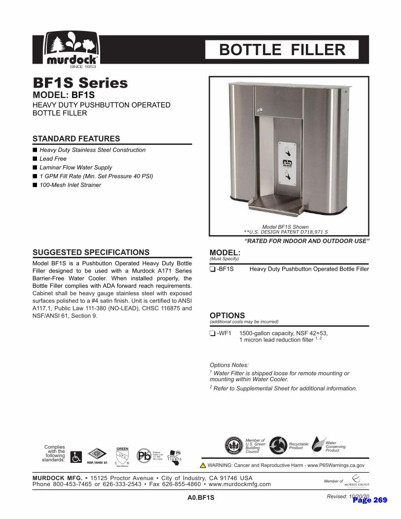
������������� �����
� ���������
� ��������������������������� !�����"��!�
� ��#�������!$�%�������&&��
� ��'()�����������*)��+�����(��������,�(�-.
� �/)��0�-�������������
123456789:6;<6=6>?<@A?BB2C6DE4F=B436G4=HI6J?BI672BB546
8;554F634<;KC436B26A46?<436L;B@6=61?F32MN6O9P96:4F;4<6
7=FF;4FQ8F446R=B4F6S2254FT6R@4C6;C<B=55436EF2E4F5IU6B@46
72BB5468;554F6M2VE5;4<6L;B@6OJO6W2FL=F36F4=M@6F4X?;F4V4CB<T6
S=A;C4B6<@=556A46@4=HI6K=?K46<B=;C54<<6<B4456L;B@64YE2<436
<?FW=M4<6E25;<@436B26=6Z[6<=B;C6W;C;<@T6\C;B6;<6M4FB;W;436B26O]:6
O99PT9U6>?A5;M6_=L6999Qab6c]DQ_dOJeU6SG:S699faPg6=C36
]:8hO]:6f9U6:4MB;2C6iT
j&��!���k!����
����l����!���&&��#�������0����l!��������!������l!�#���!�+
mnQR896 9gbbQK=552C6M=E=M;BIU6]:86[opgU�q��6 96V;MF2C654=36F43?MB;2C6W;5B4F6
��%����������������0�&&����!!���l!����#!���#!�����r�!��#!�����r�$��0���%����� !!���+
�s�tu�vuw�x�syvx�
z{|}~}�������ux��w����GdO��6J\��6>\:G7\��D]6D>d�O�dJ7D��_d68__d�
�y��x�sxuw��x������s��t�
�yvu���w����w�w9g9og6>F2MB2F6OH4C?46�6S;BI62W6C3?<BFIU6SO6i9P[f6\:O6>@2C46abbQ[gQP[fg62F6fofQ`Qog[6�68=Y6fofQaggQ[afb6�6LLLTV?F32MNVWKTM2V
)�#����!l
��s��t�*������!����"!����#��������"�����.
mnQ789:� G4=HI6J?BI6>?<@A?BB2C6DE4F=B43672BB5468;554F
��ux��*)�����&�"�l�.
��ss�xw����xv
������������������������������� �¡
8434F=5>?A5;M6_=L999Qab6c]26_4=3e
S2VE5;4<6L;B@6B@4W2552L;CK6<B=C3=F3<¢
��"�"�����(�!��"�
)�#����!l�£+�+�'�����¤������r� !��"��
%����� !�������r(�!��"�
RO�]]¥¢6S=CM4F6=C36�4EF23?MB;H46G=FV6Q6LLLT>fgR=FC;CK<TM=TK2H
¦¦§©ª«¬©® ª°±²¬ ²ª«³ µ¶·³ ª©)!����¤�����0!$�
Page 269
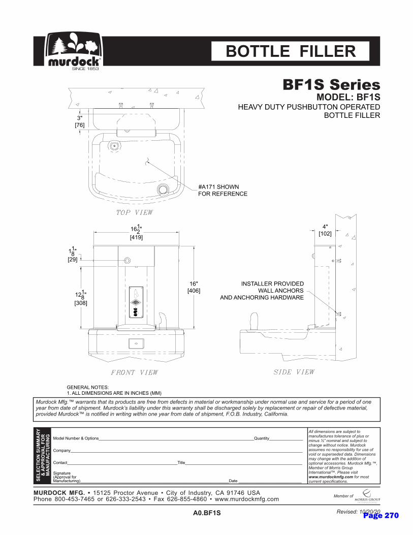
������������
� ���������������������������������� ����������������������������������������������������� ������������ ���������������������������������������������������������������� ����������� ������ ������������������������� �������������������� ���������������������������������������������!����������� �������������������������������������������������������������������!�"�#�$��%�� ����!�&����������
'
'
'
()*+,-./01+2-3-4567)89:::::::::::::::::::::::::::::::::::::::::::::::::::::::::::::::::::::;/<8676=:::::::::::::::
'
'>)86<?6:::::::::::::::::::::::::::::::::::::::::::::::::@76,+::::::::::::::::::::::::::::::::::::::::::::::::::::
'
A7B8<6/2+-CD552)E<,-F)2(<8/F<?6/278BG::::::::::::::::::::::::::::::::::::::::::::::::::::::::::::::::::H<6+-::::::::::::::::::::::::::::
>)05<8=:::::::::::::::::::::::::::::::::::::::::::::::::::::::::::::::::::::::::::::::::::::::::::::::::::::::
IJKJLMNOPQIRSSTUV
WQTXXUOYTKQZOU
STPRZTLMRUNP[
\������������������� ]���������� ���� ������������������� �������� ��_�������������� ]������������������� ����������� ��������� ��������������� ���������� ��������������� �������������������������������������������������������������������������������� �����������!���� �������������a�� ��%���������������b�������������cccdefghijkelmdjie����������� ���������������������
SRUnOLoQSZ[pQqQrsrts-u2)?6)2-DE+8/+-v->76=-)F-w8*/962=x->D-yrz{|-}AD-u~)8+-����{s��z{|s-)2-|t|�����ts{�-v-�<�-|t|��ss�{�|�-v-����0/2*)?�0FB�?)0
��� �����
�OMMKJQZNKKJU
�����������SOnJK�Q�Z�I
��D��-H}@�-u}A��}@@4.-4u��D@�H-�4@@��-�w����
T�p�Z�I
��.��D�-.4@�A�r�-D��-Hw(�.Aw4.A-D��-w.-w.>��A-C((G
�Drzr-A�4�.�4�-������.>�
w.A@D����-u�4�wH�H�D��-D.>�4�A
D.H-D.>�4�w.�-�D�H�D��
{ ¡r�t¢
� ¡z|¢
rtr�
¡���¢
r|rt
¡{ry¢
rr�
¡ty¢
r| ¡{�|¢
Page 270

�������������
� ��������������� ������������� !�"#$�!$��%&'()%&��
* +,-��,.��� ��/,0�.��122�3
* ��-��������0��0.,���.
* ��45��������,0��6���7���0�5.���1.��8�5�9:
* ;,�����.������� .�<2�.,0� �
* ��=��5�1>����?.,��@ .-�.
* ;�,�3��103��0,��������0����� ��0.1A0� �
* +�,���.��
BCDEFGHIJKGLMGNGOGPCFQGKERMCSGTUESNQEDGVENPWGXYQWGHCQQFEG
ILFFESGDEMLZREDGQCG[EGYMEDG\LQ]GNRGBYSDC_GabaGKESLEMG
HNSSLEScISEEGdNQESGeCCFESfGd]ERGLRMQNFFEDGUSCUESFWgGQ]EG
HCQQFEGILFFESGChUFLEMG\LQ]GX GiCS\NSDGSEN]GSEjYLSEhERQMfG
eN[LREQGM]NFFG[EG]ENPWGZNYZEGMQNLRFEMMGMQEEFG\LQ]GEkUCMEDG
MYSiNEMGUCFLM]EDGQCGNGlmGMNQLRGiLRLM]fGnRLQGLMGESQLiLEDGQCGoKpG
aabfagGqY[FLGrN\GaaacstuGvoTcrw XxgGeVKeGaaytbzGNRDG
oKI{oKpGyagGKEQLCRGOf
��/,0�.����0�.�������22���� ���@ .�.�- 0��- 1�0��>� .�- 1�0��>���0����/,0�.�� ��.7����@�.�0 ��122��-��0,������0�@ .�,���0� �,����@ .-,0� �7
<20� ���| 0���
}~cdIaG azuuGZNFFCRGNUNLQWgGoKIGmJ�zsg����G aGhLSCRGFENDGSEDYQLCRGiLFQESG
}~cH�G HNQQESWGTUESNQEDGG vo{GdLQ]GHCQQFEGeCYRQESx
}~cHeXG HCQQFEGeCYRQESGXLMUFNW
�����������������
����������������������Vw��GXn��GKwoKT�GTqw� �wXHT��rwGIprrw�
������������� ¡�¡ ��¡���
����� ¢����£�¤�azaJzGqSCQCSGPERYEG¥GeLQWGCiGpRDYMQSWgGe GOabmyGnK Gq]CREGtuucmzscbmyzGCSGyJycssscJzmsG¥GINkGyJyctzzcmtyuG¥G\\\fhYSDC_hiZfCh
��-¦�.� @
���¡���6,���0� �,��A �0��-,3�¦����A1..��:
}~cHIJKG VENPWGXYQWGKERMCSGTUESNQEDGHCQQFEGILFFES
������6�1�0��2�A�@3:
��������¡����
§©ª««¬® °«©±²³
IEDESNFqY[FLGrN\aaacstuGvoCGrENDx
eChUFLEMG\LQ]GQ]EiCFFC\LRZGMQNRDNSDM
�µ£����
��A3A�,¦��5. �1A0
��-¦�.� @�¶7�7�4.�����1�����>�� 1�A��
/,0�.�� ���.���>5. �1A0
d �opo·GeNRESGNRDG�EUSCDYQLPEGVNShGcG\\\fqyzdNSRLRZMfNfZCP
Page 271

�������������
� ���������������������������������� ����������������������������������������������������� ������������ ���������������������������������������������������������������� ����������� ������ ������������������������� �������������������� ���������������������������������������������!����������� �������������������������������������������������������������������!�"�#�$��%�� ����!�&����������
'
'
'
()*+,-./01+2-3-4567)89:::::::::::::::::::::::::::::::::::::::::::::::::::::::::::::::::::::;/<8676=:::::::::::::::
'
'>)86<?6:::::::::::::::::::::::::::::::::::::::::::::::::@76,+::::::::::::::::::::::::::::::::::::::::::::::::::::
'
A7B8<6/2+-CD552)E<,-F)2(<8/F<?6/278BG::::::::::::::::::::::::::::::::::::::::::::::::::::::::::::::::::H<6+-::::::::::::::::::::::::::::
>)05<8=:::::::::::::::::::::::::::::::::::::::::::::::::::::::::::::::::::::::::::::::::::::::::::::::::::::::
IJKJLMNOPQIRSSTUV
WQTXXUOYTKQZOU
STPRZTLMRUNP[
\������������������� ]���������� ���� ������������������� �������� ��_�������������� ]������������������� ����������� ��������� ��������������� ���������� ��������������� �������������������������������������������������������������������������������� �����������!���� �������������a�� ��%���������������b�������������cccdefghijkelmdjie����������� ���������������������
SRUnOLoQSZ[pQqQrsrts-u2)?6)2-DE+8/+-v->76=-)F-w8*/962=x->D-yrz{|-}AD-u~)8+-����{s��z{|s-)2-|t|�����ts{�-v-�<�-|t|��ss�{�|�-v-����0/2*)?�0FB�?)0
��� �����
�OMMKJQZNKKJU
T�p�Z�I
����������SOnJKQT���������Z�
��D��-H}@�-A�.A4�-4u��D@�H-�4@@��-�w����
�Drrr-A�4�.�4�-������.>�
w.A@D����-u�4�wH�H�D��-D.>�4�AD.H-D.>�4�w.�
�D�H�D��
rt�
C��sG
r|�
C{�|G
r|rt�
C{ryG{�
Cr�tG
��
CzzG
�4@@��->4}.@��D.H-�w�@��-��u�D>�(�.@HwAu�D�
��.��D�-.4@�A r�-D��-Hw(�.Aw4.A-D��-w.-w.>��A-C((G�
Page 272
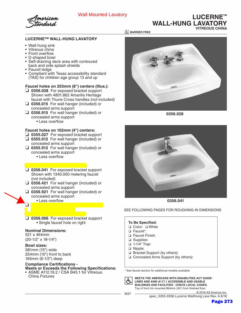
M37 © 2016 AS America Inc.spec_0355-0356 Lucerne WallHung Lavs Rev. A 8/16
To Be Specified:❏ Color: ❏ White ❏ Faucet*:❏ Faucet Finish:❏ Supplies:❏ 1-1/4" Trap:❏ Nipple:❏ Bracket Support (by others):❏ Concealed Arms Support (by others):
* See faucet section for additional models available
LUCERNE™
WALL-HUNG LAVATORYVITREOUS CHINA
LUCERNE™ WALL-HUNG LAVATORY
•Wall-hungsink• Vitreouschina• Frontoverflow• D-shapedbowl• Self-drainingdeckareawithcontoured back and side splash shields• Faucetledge• CompliantwithTexasaccessibilitystandard
(TAS) for children age group 13 and up
Faucet holes on 203mm (8") centers (Illus.):❏ 0356.028 Forexposedbracketsupport Shownwith4801.862AmarilisHeritage faucetwithTriuneCrosshandles(notincluded)❏ 0356.015Forwallhanger(included)or concealed arms support❏ 0356.915Forwallhanger(included)or concealed arms support •Lessoverflow
Faucet holes on 102mm (4") centers:❏ 0355.027Forexposedbracketsupport❏ 0355.012Forwallhanger(included)or concealed arms support❏ 0355.912Forwallhanger(included)or concealed arms support •Lessoverflow
Single center faucet hole (Illus.):❏ 0356.041Forexposedbracketsupport Shownwith1340.000meteringfaucet (not included)❏ 0356.421Forwallhanger(included)or concealed arms support❏ 0356.921Forwallhanger(included)or concealed arms support •Lessoverflow❏ 0356.439Forwallhanger(included)or concealed arms support •Singlefaucetholeonright❏ 0356.066Forexposedbracketsupport •Singlefaucetholeonright
Nominal Dimensions: 521x464mm(20-1/2"x18-1/4")
Bowl sizes:381mm(15")wide254mm(10")fronttoback165mm(6-1/2")deepCompliance Certifications -Meets or Exceeds the Following Specifications:• ASMEA112.19.2/CSAB45.1forVitreous ChinaFixtures
SEEFOLLOWINGPAGESFORROUGHING-INDIMENSIONS
MEETS THE AMERICANS WITH DISABILITIES ACT GUIDE-LINES AND ANSI A117.1 ACCESSIBLE AND USABLEBUILDINGS AND FACILITIES - CHECK LOCAL CODES.Top of front rim mounted 864mm (34") from finished floor.
0356.028
0356.041
BARRIER FREE
Wall Mounted Lavatory
Page 273
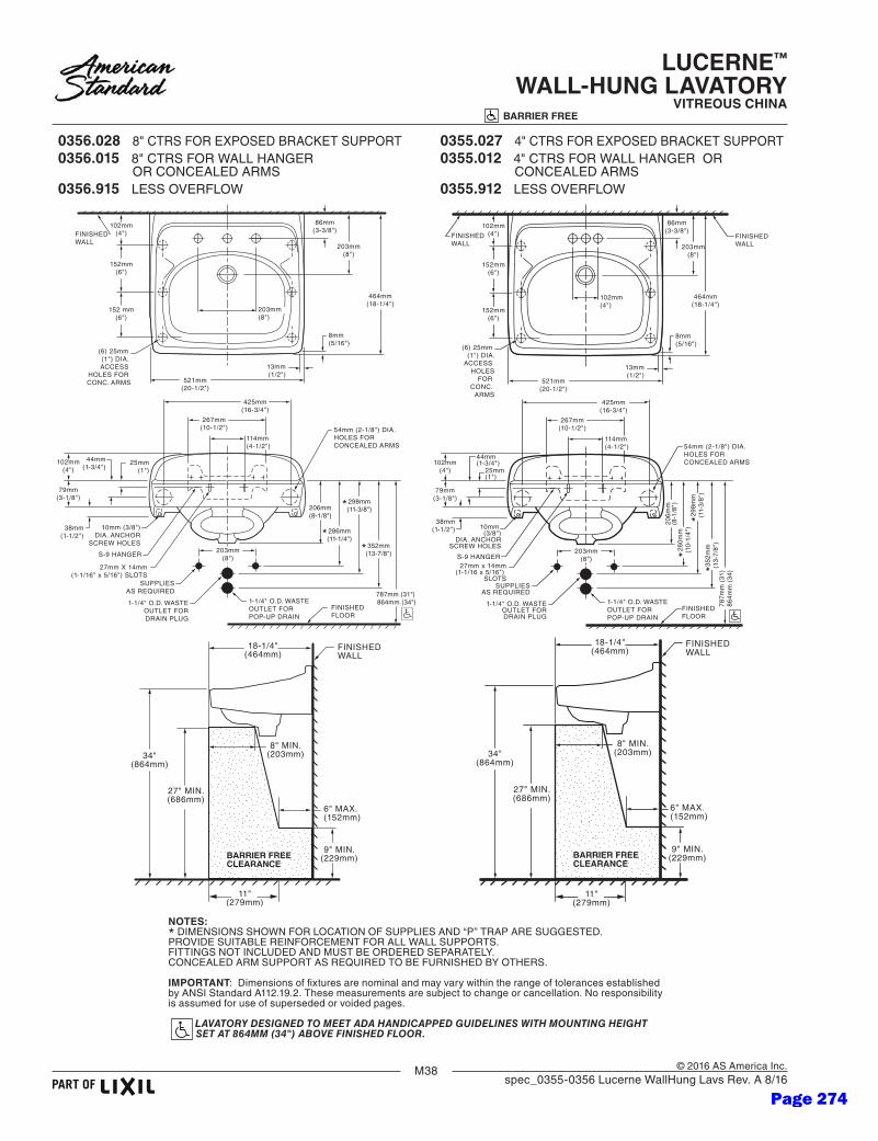
M38 © 2016 AS America Inc.spec_0355-0356 Lucerne WallHung Lavs Rev. A 8/16
LUCERNE™
WALL-HUNG LAVATORYVITREOUS CHINA
BARRIER FREE
0356.028 8"CTRSFOREXPOSEDBRACKETSUPPORT 0356.015 8" CTRSFORWALLHANGER ORCONCEALEDARMS0356.915 LESSOVERFLOW
102mm(4")
152mm(6")
152mm(6")
102mm(4")
86mm(3-3/8")
203mm(8")
8mm(5/16")
464mm(18-1/4")
521mm(20-1/2")
13mm(1/2")
FINISHEDWALL
FINISHEDWALL
(6) 25mm (1") DIA.
ACCESS HOLES
FOR CONC.
ARMS
102mm(4") 25mm
(1")
79mm(3-1/8")
267mm(10-1/2")
425mm(16-3/4")
114mm(4-1/2")
44mm (1-3/4")
38mm(1-1/2") 10mm
(3/8")DIA. ANCHOR
SCREW HOLES203mm
(8")
SUPPLIESAS REQUIRED
1-1/4" O.D. WASTEOUTLET FORDRAIN PLUG
1-1/4" O.D. WASTEOUTLET FORPOP-UP DRAIN
27mm x 14mm(1-1/16 x 5/16")
SLOTS
S-9 HANGER
206m
m(8
-1/8
")
*260m
m(1
0-1/
4")
298m
m(1
1-3/
8")
*35
2mm
(13-
7/8"
)*
787m
m (
31)
864m
m (
34)
FINISHEDFLOOR
54mm (2-1/8") DIA.HOLES FORCONCEALED ARMS
34"(864mm)
27" MIN.(686mm)
18-1/4"(464mm)
8" MIN.(203mm)
FINISHEDWALL
6" MAX.(152mm)
9" MIN.(229mm)BARRIER FREE
CLEARANCE
11"(279mm)
102mm(4")
152mm(6")
152 mm(6")
86mm(3-3/8")
203mm(8")
8mm(5/16")
464mm(18-1/4")
521mm(20-1/2")
13mm(1/2")
FINISHEDWALL
(6) 25mm (1") DIA. ACCESS
HOLES FOR CONC. ARMS
102mm(4")
25mm(1")
79mm(3-1/8")
267mm(10-1/2")
425mm(16-3/4")
114mm(4-1/2")
44mm(1-3/4")
38mm(1-1/2")
10mm (3/8")DIA. ANCHOR
SCREW HOLES203mm
(8")
SUPPLIESAS REQUIRED
1-1/4" O.D. WASTEOUTLET FORDRAIN PLUG
1-1/4" O.D. WASTEOUTLET FORPOP-UP DRAIN
27mm X 14mm(1-1/16" x 5/16") SLOTS
S-9 HANGER
206mm(8-1/8")
*286mm(11-1/4")
298mm(11-3/8")*
352mm(13-7/8")*
787mm (31") 864mm (34")
FINISHEDFLOOR
54mm (2-1/8") DIA.HOLES FORCONCEALED ARMS
203mm(8")
34"(864mm)
27" MIN.(686mm)
18-1/4"(464mm)
8" MIN.(203mm)
FINISHEDWALL
6" MAX.(152mm)
9" MIN.(229mm)BARRIER FREE
CLEARANCE
11"(279mm)
0355.027 4"CTRSFOREXPOSEDBRACKETSUPPORT0355.012 4" CTRSFORWALLHANGEROR CONCEALEDARMS0355.912 LESSOVERFLOW
NOTES:*DIMENSIONSSHOWNFORLOCATIONOFSUPPLIESAND“P”TRAPARESUGGESTED.PROVIDESUITABLEREINFORCEMENTFORALLWALLSUPPORTS.FITTINGSNOTINCLUDEDANDMUSTBEORDEREDSEPARATELY.CONCEALEDARMSUPPORTASREQUIREDTOBEFURNISHEDBYOTHERS.
IMPORTANT:DimensionsoffixturesarenominalandmayvarywithintherangeoftolerancesestablishedbyANSIStandardA112.19.2.Thesemeasurementsaresubjecttochangeorcancellation.Noresponsibilityis assumed for use of superseded or voided pages.
LAVATORY DESIGNED TO MEET ADA HANDICAPPED GUIDELINES WITH MOUNTING HEIGHT SET AT 864MM (34") ABOVE FINISHED FLOOR.
Page 274
M39 © 2016 AS America Inc.spec_0355-0356 Lucerne WallHung Lavs Rev. A 8/16
LUCERNE™
WALL-HUNG LAVATORYVITREOUS CHINA
BARRIER FREE
0356.041 SINGLECENTERHOLEFOREXPOSED BRACKETSUPPORT0356.421 SINGLECENTERHOLEFORWALL HANGERORCONCEALEDARMS0356.921LESSOVERFLOW
0356.439 SINGLECENTERHOLEONRIGHTFORWALL HANGERORCONCEALEDARMS0356.066 SINGLECENTERHOLEONRIGHTFOR EXPOSEDBRACKETSUPPORT
102mm(4")
152mm(6")
152mm(6")
86mm(3-3/8")
203mm(8")
8mm(5/16")
464mm(18-1/4")
FINISHEDWALL
(6) 25mm (1") DIA.ACCESS HOLES
FOR CONC. ARMS
25mm (1-3/8") DIA.PUNCHING
521mm(20-1/2")
13mm(1/2")
44mm (1-3/4") DIA.STD. OUTLET
102mm(4")
79mm(3-1/8")
425mm(16-3/4")
44mm(1-3/4")
38mm(1-1/2")
10mm (3/8")DIA. ANCHOR
SCREW HOLES
206mm(8-1/8")
787mm (31")864mm (34")
FINISHEDFLOOR
54mm (2-1/8") DIA.HOLES FOR
CONCEALED ARMS25mm(1")
267mm(10-1/2")
114mm(4-1/2")
27mm X 14mm(1-1/16" x 5/16") SLOTS
S-9 HANGER
34"(864mm)
27" MIN.(686mm)
18-1/4"(464mm)
8" MIN.(203mm)
FINISHEDWALL
6" MAX.(152mm)
9" MIN.(229mm)BARRIER FREE
CLEARANCE
11"(279mm)
114mm(4-1/2")
86mm(3-3/8")
203mm(8")
8mm(5/16")
464mm(18-1/4")
521mm(20-1/2")
13mm(1/2")
FINISHEDWALL
425mm(16-3/4")
102mm(4")
13mm x 51mm BRACKET(1/2" x 2") SLOTS
349mm(13-3/4")
57mm(2-1/4")
44mm (1-3/4") DIA.STD. OUTLET
25mm (1") DIA.HOLES
35mm (1-3/8") DIA.PUNCHING
102mm(4")
79mm(3-1/8")
425mm(16-3/4")
44mm(1-3/4")
38mm(1-1/2")
10mm (3/8")DIA. ANCHOR
SCREW HOLES
206mm(8-1/8")
787mm (31")864mm (34")
FINISHEDFLOOR
54mm (2-1/8") DIA.HOLES FORCONCEALED ARMS
25mm(1")
267mm(10-1/2")
114mm(4-1/2")
27mm X 14mm(1-1/16" x 5/16") SLOTS
S-9 HANGER
34"(864mm)
27" MIN.(686mm)
18-1/4"(464mm)
8" MIN.(203mm)
FINISHEDWALL
6" MAX.(152mm)
9" MIN.(229mm)BARRIER FREE
CLEARANCE
11"(279mm)
NOTES:*DIMENSIONSSHOWNFORLOCATIONOFSUPPLIESAND“P”TRAPARESUGGESTED.PROVIDESUITABLEREINFORCEMENTFORALLWALLSUPPORTS.FITTINGSNOTINCLUDEDANDMUSTBEORDEREDSEPARATELY.CONCEALEDARMSUPPORTASREQUIREDTOBEFURNISHEDBYOTHERS.
IMPORTANT:DimensionsoffixturesarenominalandmayvarywithintherangeoftolerancesestablishedbyANSIStandardA112.19.2.Thesemeasurementsaresubjecttochangeorcancellation.Noresponsibilityis assumed for use of superseded or voided pages.
LAVATORY DESIGNED TO MEET ADA HANDICAPPED GUIDELINES WITH MOUNTING HEIGHT SET AT 864MM (34") ABOVE FINISHED FLOOR.
Page 275
J53
BARRIER FREE
© 2008 AS America Inc.
OVALYN™UNDERCOUNTER SINK
VITREOUS CHINA
Revised 2/08
OVALYN™ UNDERCOUNTER SINK
• Classic oval undermount sink• Made from vitreous china• Front overflow• Supplied with mounting kit (047194-0070A) and template
❏ 0495.221 Unglazed rim 435 x 359mm (17-1/8" x 14-1/8")❏ 0495.300 Glazed underside
Bowl size: 382mm (15-1/16") wide306mm (12-1/16") front to back140mm (5-1/2") deep
❏ 0496.221 Unglazed rim 489 x 413mm (19-1/4" x 16-1/4")❏ 0496.300 Glazed underside
Bowl size: 432mm (17") wide356mm (14") front to back140mm (5-1/2") deep
❏ 0497.221 Unglazed rim 546 x 441mm (21-1/2" x 17-3/8")❏ 0497.300 Glazed underside
Bowl size: 483mm (19") wide391mm (15-3/8") front to back140mm (5-1/2") deep
Compliance Certifications -Meets or Exceeds the Following Specifications:• ASME A112.19.2M for Vitreous China Fixtures • CAN/CSA B45 series
SEE REVERSE FOR ROUGHING-IN DIMENSIONS
To Be Specified:❏ Color: ❏ White ❏ Bone ❏ Linen ❏ Silver ❏ Fawn Beige ❏ Black❏ Faucet*:❏ Faucet Finish:❏ Supplies:❏ 1-1/4" Trap:
* See faucet section for additional models available
Page 276

J54
BARRIER FREE
© 2008 AS America Inc.
38mm(1-1/2)
ADA DRAINOUTLET
AB
FINISHED WALLOR SPLASHBACK
140mm(5-1/2) REF
51mm(2)MINIMUM
EDGE OFCOUNTERTOPCUTOUT
C/L
382mm(15-1/16)
SEALINGCOMPOUND
*349mm(13-3/4)
COUNTERTOP(BY OTHERS)
191mm(7-1/2)
203mm(8)
1-1/4 O.D. TAILPIECE
1-1/4O.D. WASTE
SUPPLIESAS REQ'D
64mm(2-1/2)
359mm(14-1/8)
*286mm(11-1/4)
13mm(1/2)
FINISHED FLOOR
864mm(34)
686mm(27)MIN.
864mm(34)
51mm(2)
306mm(12-1/16)
435mm(17-1/8)
610mm(24)
BARRIER FREECLEARANCE
152mm(6)
MAX.
229mm(9)
MIN.
203mm(8)
MIN.
FURNITUREINTERIORSURFACE
MINIMUMINTERIOR
CLEARANCE454mm(17-7/8)
FITTING
CENTERSET
SPREAD
A
1-1/4 (32mm)
1-3/8 (35mm)
B
4 (102mm)
8 (203mm)
DETAIL OF MOUNTING CLIP(KIT No. 047194-0070A)
SINK
BRASS INSERT
19mm(3/4) MIN.
REFER TO INSTRUCTIONSPROVIDED WITH KIT FORADDITIONAL INFORMATION
CLIP MACH.SCREW
DRAWING FOR DIMENSIONAL
PURPOSES ONLY. IT IS NOT AN EXACT REPRESENTATION.
CAT. NO.
0496.221
E489mm(19-1/4)546mm(21-1/2)
F413mm(16-1/4)441mm(17-3/8)
G H
0497.221
FITTING
CENTERSET
SPREAD
A
1-1/4 (32mm)
1-3/8 (35mm)
B
4 (102mm)
8 (203mm)
D182mm(7-3/16)191mm
J16mm(5/8)
19mm(7-1/2) (3/4)
K500mm(19-11/16)534mm(21-1/16)
C103mm(4-1/16)95mm(3-3/4)
432mm(17)
483mm(19)
356mm(14)
391mm(15-3/8)
38mm(1-1/2)
ADA DRAINOUTLET
AB
FINISHED WALLOR SPLASHBACK
C
51mm(2)MINIMUM
EDGE OFCOUNTERTOPCUTOUT
C/L
G
SEALINGCOMPOUND
*349mm(13-3/4)
COUNTERTOP(BY OTHERS)
D
203mm(8)
1-1/4 O.D. TAILPIECE
1-1/4O.D. WASTE
SUPPLIESAS REQ'D
DETAIL OF MOUNTING CLIP(KIT No. 047194-0070A)
SINK
BRASS INSERT
19mm(3/4) MIN.
REFER TO INSTRUCTIONSPROVIDED WITH KIT FORADDITIONAL INFORMATION
CLIP MACH.SCREW
13mm(1/2)
29mm(1-1/8)
64mm(2-1/2)
F
-2mm(1/16)
*286mm(11-1/4)
16mm(5/8)
FINISHED FLOOR
+3mm(1/8)
864mm(34)
H
E
CABINETINTERIORFACE
MINIMUMINTERIOR
CLEARANCE(K)
686mm(27)MIN.
864mm(34)
76mm(3)
610mm(24)
BARRIER FREECLEARANCE
152mm(6)
MAX.
229mm(9)
MIN.
203mm(8)
MIN.DRAWING FOR DIMENSIONAL
PURPOSES ONLY. IT IS NOT AN EXACT REPRESENTATION.
OVALYN™UNDERCOUNTER SINK
VITREOUS CHINA
MEETS THE AMERICANS WITH DISABILITIES ACT GUIDELINES AND ANSI A117.1 ACCESSIBLE AND USABLE BUILDINGS AND FACILITIES - CHECK LOCAL CODES.Countertop 864mm (34") from finished floor. Lavatoryinstalled 51mm (2") from front edge of countertop.Countertop thickness to be 25mm (1") maximum.
MEETS THE AMERICANS WITH DISABILITIES ACT GUIDELINES AND ANSI A117.1 ACCESSIBLE AND USEABLE BUILDINGS AND FACILITIES - CHECK LOCAL CODES.Countertop 864mm (34") from finished floor. Lavatoryinstalled 76mm (3") from front edge of countertop.Countertop thickness to be 25mm (1") maximum.
NOTES:* DIMENSIONS SHOWN FOR LOCATION OF SUPPLIED AND “P" TRAP ARE SUGGESTED.▼ UNDERCOUNTER MOUNTING KIT SUPPLIED WITH SINK.PLEASE NOTE MINIMUM INTERIOR CLEARANCE DIMENSION (K).FITTINGS NOT INCLUDED AND MUST BE ORDERED SEPARATELY.USE ENCLOSED TEMPLATE FOR COUNTERTOP CUTOUTSEALING COMPOUND SUPPLIED BY OTHERS.
IMPORTANT: Dimensions of fixtures are nominal and may vary within the range of tolerances established by ANSI Standard A112.19.2.These measurements are subject to change or cancellation. No responsibility is assumed for use of superseded or voided pages.
NOTES:USE ENCLOSED TEMPLATE FOR COUNTER TOP CUTOUT.FITTINGS NOT INCLUDED WITH FIXTURE AND MUST BE ORDERED SEPARATELY.* DIMENSIONS SHOWN FOR LOCATION OF SUPPLIED AND “P" TRAP ARE SUGGESTED.▼ UNDERCOUNTER MOUNTING KIT SUPPLIED WITH SINK.PLEASE NOTE MINIMUM INTERIOR CLEARANCE DIMENSION (K).SEALING COMPOUND SUPPLIED BY OTHERS.
IMPORTANT: Dimensions of fixtures are nominal and may vary within the range of tolerances established by ANSI Standard A112.19.2.These measurements are subject to change or cancellation. No responsibility is assumed for use of superseded or voided pages
0496/0497
0495
Revised 2/08
Page 277
SPECIFICATIONS
Metered Lavatory Deck Mount Faucet Model(s) LK654
In keeping with our policy of continuing product improvement, Elkay reserves the right to change product specifications without notice. Please visit elkay.com for the most current version of Elkay product specification sheets. This specification describes an Elkay product with design, quality, and functional benefits to the user. When making a comparison of other producers’ offerings, be certain these features are not overlooked.
Elkay REV 02022017 2222 Camden Court © 2017 LK654 Oak Brook, IL 60523 LK654_spec.pdf
PRODUCT SPECIFICATIONS Metered Lavatory Deck Mount Faucet. Faucet has a flow rate of 1.0 GPM, and is made of Chrome Plated Brass material, with a Ceramic Disc valve. Faucet requires 1 faucet holes.
Mounting Type: Deck Mount Special Features: Solid brass waterway construction
Vandal resistant aerator with key Finish: Chrome (CR) Handle Type: Push Button Deck Clearance: 1-3/4" Spout Reach: 4-1/8" Spout Height: 4-1/8" Hole Drillings: 1 Material: Chrome Plated Brass Valve Type: Ceramic Disc Valve Connection: 1/2"-14 NPSM
Flow Rate: 1.0 GPM Countertop Thickness: 1-3/8 Spout Swing Rotation: 0° Spout Type: Fixed Spout
Special Note: Self-closing metering ceramic cartridge
AMERICAN PRIDE. A LIFETIME TRADITION. Like your family, the Elkay family has values and traditions that endure. For almost a century, Elkay has been a family-owned and operated company, providing thousands of jobs that support our families and communities.
Product Compliance: ADA & ICC A117.1
ASME A112.18.1/CSA B125.1 NSF 61 NSF 372 (lead free)
Clean and Care Manual (PDF) Installation Instructions (PDF) Limited Warranty (PDF)
PART:________________________________QTY: _____________
PROJECT:______________________________________________
CONTACT:______________________________________________
DATE:__________________________________________________
NOTES:_________________________________________________
APPROVAL:_____________________________________________
Metered Lavatory Faucetfor Students
Page 278
►► Code NumberCode Number3335016
►► DescriptionDescriptionSolar Powered, Sensor Activated Electronic Hand Washing Faucetfor pre-tempered or hot and cold water operation.
►► Flow RatesFlow Rates☐ EAF-12 0.5 gpm/1.9 Lpm Multi-Stream Laminar Spray Head
►► SpecificationsSpecificationsSolar Powered, Sensor Activated, Electronic, Chrome PlatedConstructed Metal, Hand Washing Faucet with the followingfeatures:
● ● Modular One-piece Construction with all ConcealedComponents above deck
● ● Double infrared sensors with automatic setting feature
● ● Automatic Self-adapting Sensor Technology
● ● Solar Powered
● ● Magnetic Solenoid Valve
● ● Water Supply Connection with Flexible High-pressure Hose andStrainer
● ● Appropriate Mounting Hardware included
● ● Includes 6 VDC Lithium Battery Back-up Power Source
►► The new Optima solar powered faucet — BringingThe new Optima solar powered faucet — Bringingintelligence to waterintelligence to water"The first solar powered electronic faucet's integrated power planttransforms light into electrical energy. Optimal performance anyplace, any time
Sloan’s new Optima EAF-275 Series electronic hand washingfaucets operate by means of a dual infrared sensor andmicroprocessor based logic. The modular design incorporates all ofthe operating components of the faucet, including the sensor,solenoid, circuitry and solar energy module above the sink within adie-cast metal spout.
ISM models feature an integral temperature control lever whichallows the user to adjust the water temperature. This adjustmentcan also be converted to a fixed setting. EAF faucets orderedwithout the ISM variation must be connected to a single, pre-tempered water supply.
►► Compliance & CertificationsCompliance & CertificationsASME A112.18.1-2005/CSA B125.1-05, ISO/IEC 17025
This space for Architect/Engineer Approval
Sloan Solis® Faucet EAF-275
2017-06-02 Page 1 of 2
SLOAN 10500 SEYMOUR AVE. ● FRANKLIN PARK, ● IL. SLOAN 10500 SEYMOUR AVE. ● FRANKLIN PARK, ● IL. 60131 60131 Ph: 1-800-9-VALVE-9 or 1-847-671-4300 ● Fax: 1-800-447-8329 or 1-847-671-4380 ● http://www.sloan.com
Staff Lavatory Faucet w/ Leonard170-LF thermostatic mixing valve
Specify 0.35 gpm
Page 279
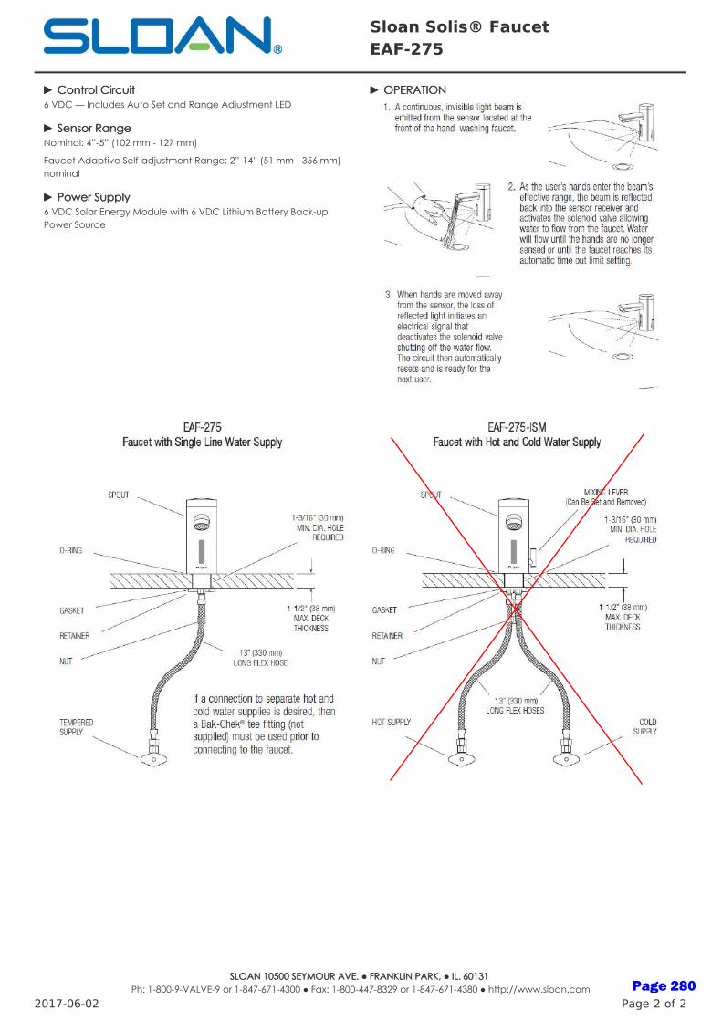
►► Control CircuitControl Circuit6 VDC — Includes Auto Set and Range Adjustment LED
►► Sensor RangeSensor RangeNominal: 4”-5” (102 mm - 127 mm)
Faucet Adaptive Self-adjustment Range: 2”-14” (51 mm - 356 mm)nominal
►► Power SupplyPower Supply6 VDC Solar Energy Module with 6 VDC Lithium Battery Back-upPower Source
►► OPERATIONOPERATION
Sloan Solis® Faucet EAF-275
2017-06-02 Page 2 of 2
SLOAN 10500 SEYMOUR AVE. ● FRANKLIN PARK, ● IL. SLOAN 10500 SEYMOUR AVE. ● FRANKLIN PARK, ● IL. 60131 60131 Ph: 1-800-9-VALVE-9 or 1-847-671-4300 ● Fax: 1-800-447-8329 or 1-847-671-4380 ● http://www.sloan.com Page 280
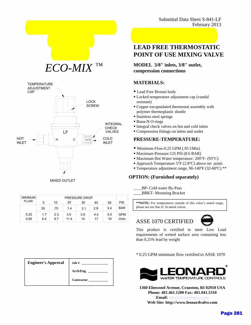
Submittal Data Sheet S-841-LFFebruary 2013THERMOSTATIC
MIXINGVALVE
MODEL 170-LFLEAD FREE THERMOSTATIC
VALVE POINT OF USE MIXING VALVEMODEL 3/8" inlets, 3/8" outlet, compression connections
MATERIALS:TEMPERATUREADJUSTMENT
ECO-MIX ™
Lead Free Bronze body Locked temperature adjustment cap (vandal
resistant) Copper encapsulated thermostat assembly with
polymer thermoplastic shuttle Stainless steel springs Buna-N O-rings
I t l h k l h t d ld i l tINTEGRAL
LOCKSCREW
ADJUSTMENTCAP
Integral check valves on hot and cold inlets Compression fittings on inlets and outlet
PRESSURE-TEMPERATURE:
Minimum Flow:0.25 GPM (.95 l/Min)Maximum Pressure:125 PSI (8.6 BAR)Maximum Hot Water temperature: 200F- (93°C)
A h T t 5°F (2 8°C) b t i t
CH COLDINLET
HOTINLET
CHECKVALVESLF
Approach Temperature 5°F (2.8°C) above set point. Temperature adjustment range, 90-140ºF (32-60ºC) **
____BP- Cold water By-Pass____BRKT- Mounting Bracket
OPTION: (Furnished separately)MIXED OUTLET
PRESSURE DROPMINIMUM
ASSE 1070 CERTIFIEDThis product is certified to meet Low Leadrequirements of wetted surface area containing less
**NOTE: For temperatures outside of this valve’s stated range,please see our line of bi-metal valves.
503.4
19
20
1.4
3.011.4
1.76.4
.35
5
2.38.7
.70
10
3.614
2.1
30
4.417
5.0
2.8
40
GPMl/min
BARPSIFLOW
0.250.95
q gthan 0.25% lead by weight
* 0.25 GPM minimum flow certified to ASSE 1070
Engineer's Approval Job # ________________
Arch/Eng. ____________
1360 Elmwood Avenue, Cranston, RI 02910 USAPhone: 401.461.1200 Fax: 401.941.5310
Email: [email protected] Site: http://www.leonardvalve.com
Contractor ____________
Page 281
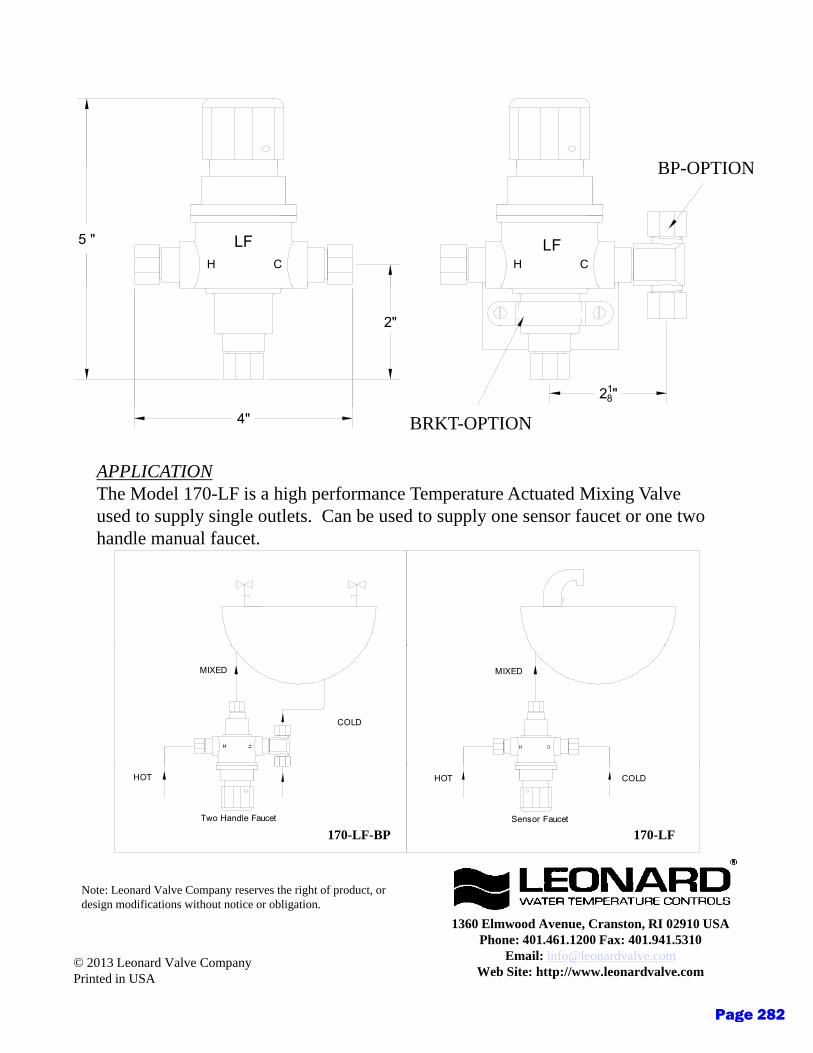
BP OPTIONBP-OPTION
CH
5 " LFH
LFC
2"
218"
APPLICATIONThe Model 170-LF is a high performance Temperature Actuated Mixing Valve used to supply single outlets. Can be used to supply one sensor faucet or one two
BRKT-OPTION4"
handle manual faucet.
COLD
MIXED MIXED
CH
Two Handle Faucet
HOT COLD
Sensor Faucet
HOT
170-LF-BP 170-LF
1360 Elmwood Avenue, Cranston, RI 02910 USAPhone: 401.461.1200 Fax: 401.941.5310
Email: [email protected] Site: http://www.leonardvalve.com
© 2013 Leonard Valve CompanyPrinted in USA
Note: Leonard Valve Company reserves the right of product, or design modifications without notice or obligation.
Page 282
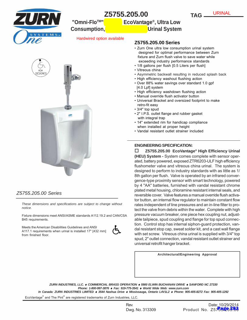
ZURN INDUSTRIES, LLC. ♦♦♦♦♦ COMMERCIAL BRASS OPERATION ♦♦♦♦♦ 5900 ELWIN BUCHANAN DRIVE ♦♦♦♦♦ SANFORD NC 27330Phone: 1-800-997-3876 ♦♦♦♦♦ Fax: 919-775-3541 ♦♦♦♦♦ World Wide Web: www.zurn.com
In Canada: ZURN INDUSTRIES LIMITED ♦♦♦♦♦ 3544 Nashua Drive ♦♦♦♦♦ Mississauga, Ontario L4V1L2 ♦♦♦♦♦ Phone: 905-405-8272 Fax: 905-405-1292
EcoVantage® and The Pint® are registered trademarks of Zurn Industries, LLC.
TAGZ5755.205.00"Omni-FloTM" 1/8 gpf, EcoVantage®, Ultra LowConsumption, Battery Powered Urinal System
Rev. Date: 10/29/2014Dwg. No. 313309 Product No. Z5755.205.00
Architectural/Engineering Approval
ENGINEERING SPECIFICATION: Z5755.205.00 EcoVantage® High Efficiency Urinal(HEU) System - System comes complete with sensor oper-ated, battery powered, exposed ZTR6203-ULF high efficiencyflushometer valve and vitreous china urinal. The system isdesigned to perform to industry standards with as little as 1/8th gallon per flush. Valve is operated by an infrared conver-gence-type proximity sensor with smart technology, poweredby 4 "AA" batteries, furnished with vandal resistant chromeplated metal housing, chloramine resistant internal seals, andreversible cover. Valve features a manual override flush activa-tor button, an internal flow regulator to maintain constant flowrates independent of line pressures and an in-line filter to pro-tect the valve from debris within the water. Complete with highpressure vacuum breaker, one piece hex coupling nut, adjust-able tailpiece, spud coupling and flange for top spud connec-tion. Control stop has internal siphon-guard protection, van-dal resistant stop cap, sweat solder kit, and a cast wall flangewith set screw. Vitreous china urinal is supplied with 3/4" topspud, 2" outlet connection, vandal resistant outlet strainer anduniversal retrofit hanger bracket.
These dimensions and specifications are subject to change withoutnotice.
Fixture dimensions meet ANSI/ASME standards A112.19.2 and CAN/CSAB45 requirements.
Meets the American Disabilities Guidelines and ANSIA117.1 requirements when urinal is installed 17" [432 mm]from finished floor.
Z5755.205.00 Series• Zurn One ultra low consumption urinal system designed for optimal performance between Zurn fixture and Zurn flush valve to save water while exceeding industry performance standards• 1/8 gallons per flush [0.5 Liters per flush]• Vitreous china• Asymmetric backwall resulting in reduced splash back• High efficiency washout flushing action• Over 88% water savings over standard 1.0 gpf [4.0 Lpf] system• High efficiency washdown flushing action• Manual override flush activator button• Universal Bracket and oversized footprint to make
retro-fit easy• 3/4" top spud• 2" I.P.S. outlet flange and rubber gasket with integral trap• 14" extended rim for handicap compliance
when installed at proper height• Vandal resistant outlet strainer included
Z5755.205.00 Series
URINAL
Hardwired option available
Page 283
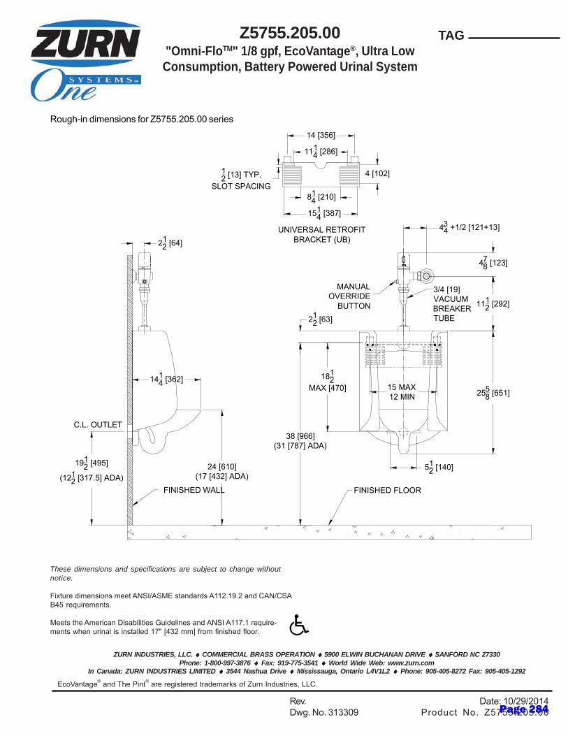
ZURN INDUSTRIES, LLC. ♦♦♦♦♦ COMMERCIAL BRASS OPERATION ♦♦♦♦♦ 5900 ELWIN BUCHANAN DRIVE ♦♦♦♦♦ SANFORD NC 27330Phone: 1-800-997-3876 ♦♦♦♦♦ Fax: 919-775-3541 ♦♦♦♦♦ World Wide Web: www.zurn.com
In Canada: ZURN INDUSTRIES LIMITED ♦♦♦♦♦ 3544 Nashua Drive ♦♦♦♦♦ Mississauga, Ontario L4V1L2 ♦♦♦♦♦ Phone: 905-405-8272 Fax: 905-405-1292
EcoVantage® and The Pint® are registered trademarks of Zurn Industries, LLC.
TAGZ5755.205.00"Omni-FloTM" 1/8 gpf, EcoVantage®, Ultra LowConsumption, Battery Powered Urinal System
Rev. Date: 10/29/2014Dwg. No. 313309 Product No. Z5755.205.00
4 [102]
1514 [387]
814 [210]
1114 [286]
14 [356]
UNIVERSAL RETROFITBRACKET (UB)
12 [13] TYP.
SLOT SPACING
FINISHED WALL
C.L. OUTLET
1912 [495]
(1212 [317.5] ADA)
FINISHED FLOOR
1112 [292]
434 +1/2 [121+13]-
212 [64]
24 [610](17 [432] ADA)
1414 [362]
2558 [651]
38 [966](31 [787] ADA)
1812
MAX [470]
212 [63]
512 [140]
15 MAX12 MIN
478 [123]
MANUALOVERRIDE
BUTTON
3/4 [19]VACUUMBREAKERTUBE
These dimensions and specifications are subject to change withoutnotice.
Fixture dimensions meet ANSI/ASME standards A112.19.2 and CAN/CSAB45 requirements.
Meets the American Disabilities Guidelines and ANSI A117.1 require-ments when urinal is installed 17" [432 mm] from finished floor.
Rough-in dimensions for Z5755.205.00 series
Page 284

ZURN INDUSTRIES, LLC. ♦♦♦♦♦ COMMERCIAL BRASS OPERATION ♦♦♦♦♦ 5900 ELWIN BUCHANAN DRIVE ♦♦♦♦♦ SANFORD NC 27330Phone: 1-800-997-3876 ♦♦♦♦♦ Fax: 919-775-3541 ♦♦♦♦♦ World Wide Web: www.zurn.com
In Canada: ZURN INDUSTRIES LIMITED ♦♦♦♦♦ 3544 Nashua Drive ♦♦♦♦♦ Mississauga, Ontario L4V1L2 ♦♦♦♦♦ Phone: 905-405-8272 Fax: 905-405-1292
EcoVantage® and AV are trademarks of Zurn Industries, LLC.
Z5615.395.00.AM.001.1 gpf Elongated Wall Hung
EcoVantage Flush Valve Toilet System with Antimicrobial Glaze
TAG
Rev. - Date: 12/9/2014Dwg. No. 313385 Product No. Z5615.395.00.AM.00
These dimensions and specifications are subject to change withoutnotice.
Fixture dimensions meet ANSI/ASME standard A112.19.2 andCAN/CSA B45 requirements.
Z5615 HET Series• Zurn One HET Toilet System designed for optimal performance between Zurn fixture and Zurn flush valve to save water.• 1.1 gpf (gallons per flush)• 14% water savings over standard 1.28 gpf system• 31% water savings over standard 1.6 gpf system• *Vitreous china• Elongated front rim• 2-1/8" fully glazed trapway• High efficiency siphon jet flush action• Zurn product system component compatibility and quality assurance• Shipping Weight: 46 lbs.
Meets the American Disabilities Guidelines and ANSIA117.1 requirements when installed according to theserequirements.
Z5615 Series Elongated (shown with seat)
See Zurn One Systems for suggested packages.
Architectural/Engineering Approval
Engineering SpecificationZ5615, EcoVantage High Efficiency Toilet System -System comes complete with exposed ZTR6200-ONE highefficiency flushometer valve and vitreous china wall-hung toilet.The system is designed to perform to industry standards withas little as 1.1 gallons per flush. Valve is operated by aninfrared convergence-type proximity sensor with smarttechnology, powered by 4 “AA” batteries, furnished with avandal resistant chrome plated cast brass valve body,chloramine resistant internal seals, manual over ride buttonand reversible cover. Complete with high pressure vacuumbreaker, one piece hex coupling nut, adjustable tailpiece, spudcoupling and flange for top spud connection. Control stophas internal siphon-guard protection, vandal resistant stopcap, sweat solder kit and a cast wall flange with set screw.Vitreous china toilet is 1-1/2” top spud with 2-1/8” fully glazedtrapway and siphon jet action. Valve and toilet are anengineered system designed to provide optimal performanceand 31% water savings over 1.6 gpf conventional toilets.
*Antimicrobial ceramic glaze utilizing SmartSilver™ nano-technology to create a permanent surface that inhibits thegrowth of stain and odor causing mold, mildew and bacteria,thus minimizing the need for cleaning chemicals and water tocleanse the bowl.
Suffix Options:
-RF Retro-Fit Nut Kit for extending carrierstuds from existing wall.
Recommended Trim:
Z5955SS-EL Elongated, standard white, openfront toilet seat less cover with stainless steelcheck hinge. Z1201 or Z1202 High Efficiency Carrier
Note: To ensure system performance:Minimum Running Water Pressure = 25 psi.
X
WATER CLOSET
Hardwired option available
Page 285
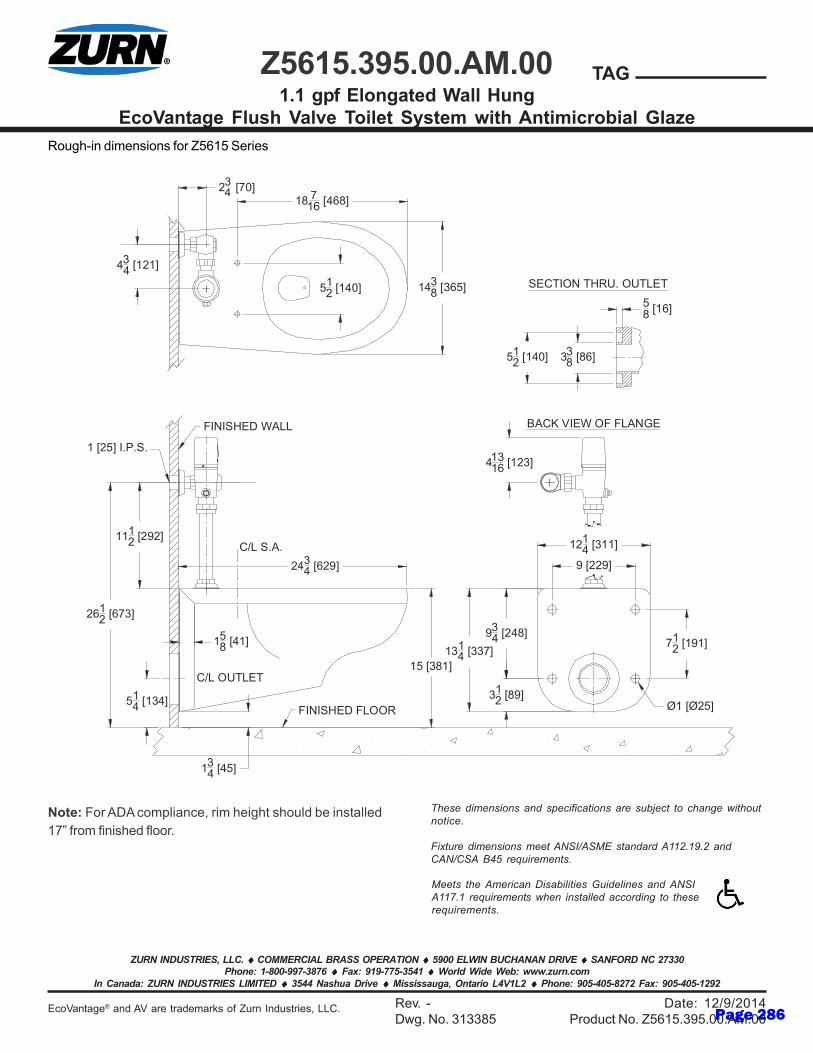
ZURN INDUSTRIES, LLC. ♦♦♦♦♦ COMMERCIAL BRASS OPERATION ♦♦♦♦♦ 5900 ELWIN BUCHANAN DRIVE ♦♦♦♦♦ SANFORD NC 27330Phone: 1-800-997-3876 ♦♦♦♦♦ Fax: 919-775-3541 ♦♦♦♦♦ World Wide Web: www.zurn.com
In Canada: ZURN INDUSTRIES LIMITED ♦♦♦♦♦ 3544 Nashua Drive ♦♦♦♦♦ Mississauga, Ontario L4V1L2 ♦♦♦♦♦ Phone: 905-405-8272 Fax: 905-405-1292
EcoVantage® and AV are trademarks of Zurn Industries, LLC.
Z5615.395.00.AM.001.1 gpf Elongated Wall Hung
EcoVantage Flush Valve Toilet System with Antimicrobial Glaze
TAG
Rev. - Date: 12/9/2014Dwg. No. 313385 Product No. Z5615.395.00.AM.00
Meets the American Disabilities Guidelines and ANSIA117.1 requirements when installed according to theserequirements.
These dimensions and specifications are subject to change withoutnotice.
Fixture dimensions meet ANSI/ASME standard A112.19.2 andCAN/CSA B45 requirements.
Rough-in dimensions for Z5615 Series
Note: For ADA compliance, rim height should be installed17” from finished floor.
FINISHED WALL
712 [191]
934 [248]
9 [229]
1214 [311]
312 [89]
Ø1 [Ø25]514 [134]
1314 [337]
FINISHED FLOOR
18 716 [468]
512 [140] 143
8 [365]
434 [121]
1 [25] I.P.S.
134 [45]
158 [41]
15 [381]
C/L S.A.
C/L OUTLET
2612 [673]
58 [16]
338 [86]51
2 [140]
BACK VIEW OF FLANGE
SECTION THRU. OUTLET
234 [70]
2434 [629]
1112 [292]
41316 [123]
Page 286
Mechanical - 1
DISTRICT DESIGN STANDARDS
Section 23 – Mechanical
Issued: Fall 2020 Updates:
I. Purpose
A. The following District Design Standards for mechanical systems are intended to provide basic guidelines for the District with the goal of standardizing systems and provide ease of maintenance and operations.
B. Pursuant to the District’s sustainability guidelines, these products are selected because of the manufacturer’s commitment to sustainability.
II. Mechanical
A. Drawings and general provisions of the Contract, including General and Supplementary Conditions and Division 01 Specification Sections, apply to this Section.
B. Scope
1. Work included: Design, furnish, and install complete and fully functioning heating, ventilating, and air conditioning (HVAC) systems.
C. Design Documents:
1. The engineer of record for this project is responsible for all calculations, system concepts, equipment selections, distribution routings, coordination with other trades during design, and any other tasks needed to furnish and install complete and operating systems that meet or exceed the design performance intent.
2. Changes required to meet the design performance intent including, but not limited to; recalculations, revisions to the system concepts, equipment reselections, distribution re-routings, re-coordination, and any other tasks needed to furnish and install complete and operating systems is the responsibility of the Engineer of Record.
3. The standards prepared by the District are not complete and are conceptual in nature.
4. Coordination issues that result from the design or installation of the selected systems, or performance of the systems engineered, designed
Page 287

2 - Mechanical
DISTRICT DESIGN STANDARDS and installed by the engineer of record shall not be the responsibility of
the District.
5. The District bears no responsibility for the final design or system performance.
6. Engineer of record shall deviate from the design criteria when deviation is required to provide a fully functioning HVAC system. Any such deviations shall be coordinated with the District and brought to the District’s attention as soon as they are realized in the design process. Additionally, deviations shall adhere to performance and efficiency criteria specified herein.
7. Areas of work as related to this standard:
a) Engineer of record shall be responsible for detailing approach and shall work with design team to gain approval from authority having jurisdiction for all spaces, systems and modifications to the building.
b) Pumps, water distribution, some utilities, including sewage injection, and building work room.
c) Points of connection to utility services, gas, electrical vaults, MPOE/TCOM entrance, main electric rooms, city cold water, storage, janitor, locker rooms, restrooms, showers.
d) Electrical Rooms. Main Electrical Rooms and building electrical rooms shall be conditioned and ventilated.
e) TeleCom Rooms. Main MPOE/TCOM and building TCOM rooms shall be conditioned and ventilated.
f) Elevator Machine Rooms. All 2-hour rated elevator machine rooms shall be conditioned and ventilated.
Page 288
Mechanical - 3
DISTRICT DESIGN STANDARDS D. HVAC Energy Efficiency and Design Requirements
1. HVAC systems shall be designed with the following minimum pressure, friction and energy efficiency requirements. The Contractor is highly encouraged to provide low energy system designs beyond those described herein. In many cases, increased energy efficiencies may be realized by careful attention to selection of equipment and system design, beyond the guidelines set herein, at no cost impact to the project. Any modification of design criteria or system approach shall adhere to efficiency requirements herein.
2. Dry side systems:
a) Supply ducts shall be designed with the equal friction method, 0.05”/100; for main ducts (not to exceed 2000 ft/min). Flex ducts shall not exceed 5 feet in length and shall occur only at connections to concealed diffusers or grilles.
b) Return ducts shall be designed with the equal friction method at 0.05”/100ft (not to exceed 1,500 ft/min). Design plenum return air systems for low pressure drops. Design transfer air systems at 250 ft/min to minimize pressure drops.
c) Outside air intake and relief louvers shall be designed for maximum 400 fpm air velocity.
d) Maximum velocity through unducted plenum return elements shall not exceed 700 fpm.
e) Duct layout shall emphasize the use of 45 degree branch takeoffs and wye (“pant-leg”) fittings for duct splitting. Whenever a 90 degree bend is required, round duct with a minimum 1 ½ times radius is preferred.
f) Care shall be taken for all exposed ducts to preserve clean lines and appearance. Ducts shall be connected using internal sleeves and any visible excess duct sealant shall be removed quickly after assembly. Ducts shall be free of any dents, dings or other markings.
g) Fire smoke dampers and backdraft dampers shall be sized for a pressure drop less than 0.02” w.g.
h) Locate rooftop package units and/or air handlers so that supply air discharge is directly over shafts wherever possible. Exposed ductwork on the roof should be avoided.
Page 289
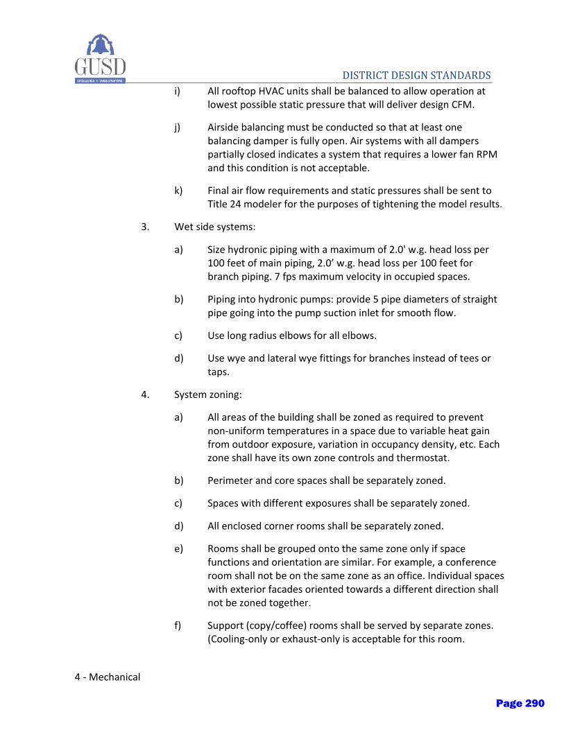
4 - Mechanical
DISTRICT DESIGN STANDARDS i) All rooftop HVAC units shall be balanced to allow operation at
lowest possible static pressure that will deliver design CFM.
j) Airside balancing must be conducted so that at least one balancing damper is fully open. Air systems with all dampers partially closed indicates a system that requires a lower fan RPM and this condition is not acceptable.
k) Final air flow requirements and static pressures shall be sent to Title 24 modeler for the purposes of tightening the model results.
3. Wet side systems:
a) Size hydronic piping with a maximum of 2.0' w.g. head loss per 100 feet of main piping, 2.0’ w.g. head loss per 100 feet for branch piping. 7 fps maximum velocity in occupied spaces.
b) Piping into hydronic pumps: provide 5 pipe diameters of straight pipe going into the pump suction inlet for smooth flow.
c) Use long radius elbows for all elbows.
d) Use wye and lateral wye fittings for branches instead of tees or taps.
4. System zoning:
a) All areas of the building shall be zoned as required to prevent non-uniform temperatures in a space due to variable heat gain from outdoor exposure, variation in occupancy density, etc. Each zone shall have its own zone controls and thermostat.
b) Perimeter and core spaces shall be separately zoned.
c) Spaces with different exposures shall be separately zoned.
d) All enclosed corner rooms shall be separately zoned.
e) Rooms shall be grouped onto the same zone only if space functions and orientation are similar. For example, a conference room shall not be on the same zone as an office. Individual spaces with exterior facades oriented towards a different direction shall not be zoned together.
f) Support (copy/coffee) rooms shall be served by separate zones. (Cooling-only or exhaust-only is acceptable for this room.
Page 290

Mechanical - 5
DISTRICT DESIGN STANDARDS Adjacent corridors and non-critical spaces may also be served by
this zone.)
E. Definitions, codes & standards
1. Specifications, standards, tests and recommended methods from following trade, industry and government organizations shall determine quantity and quality of materials and methods.
a) American Gas Association (AGA)
b) Underwriter's Laboratories, Inc. (UL)
c) American Society of Heating and Refrigeration and Air Conditioning Engineers (ASHRAE)
d) Air Moving and Conditioning Association (AMCA)
e) Air-Conditioning and Refrigeration Institute (ARI)
f) National Fire Protection Association (NFPA)
g) National Electrical Manufacturers Association (NEMA)
h) Sheet Metal and Air Conditioning Contractors Association (SMACNA)
2. This project shall strictly comply with the following locally approved codes including their adopted amendments shall be used for this project:
a) 2016 California Building Code
b) 2016 California Mechanical Code
c) 2016 California Plumbing Code
d) 2014 National Electrical Code
e) 2016 Title 24 California Energy Code
f) 2016 Title 24 California Green Building Standards
g) 2016 California Fire Code (approved by local fire authority)
h) 2013 NFPA 101 - National Fire Protection Association, applicable standards
i) American National Standards Institute (ANSI)
Page 291
6 - Mechanical
DISTRICT DESIGN STANDARDS j) National Fire Protection Association (NFPA), applicable standards
k) Americans with Disabilities Act (ADA)
l) ASHRAE 62.1-2016 Ventilation for Acceptable Indoor Air Quality
m) ASHRAE 55-2013 Thermal Environmental Conditions for Human Occupancy
n) Division of the State Architect (DSA)
o) Other applicable local codes
3. Where locally adopted codes are silent on an issue, NFPA Standards shall apply.
4. Materials and equipment shall be listed and labeled by Underwriters Laboratories or as required by authorities having jurisdiction.
5. Industry standards and manufacturers' recommendations, diagrams or requirements shall be strictly adhered to for installation of materials and equipment.
F. Title 24 Documentation Requirements
1. Engineer of record shall compile and sign all Title 24 compliance documentation using prescriptive (for small renovations) or performance (large renovations or new construction) compliance method.
G. Design Criteria
1. Codes: Project shall comply with all applicable standards including but not limited to those listed in Section “1.4 Definitions, Codes & Standards” of this document.
2. Location Criteria:
a) Location:
b) Climate zone:
c) Latitude:
d) Longitude:
e) Elevation:
Page 292
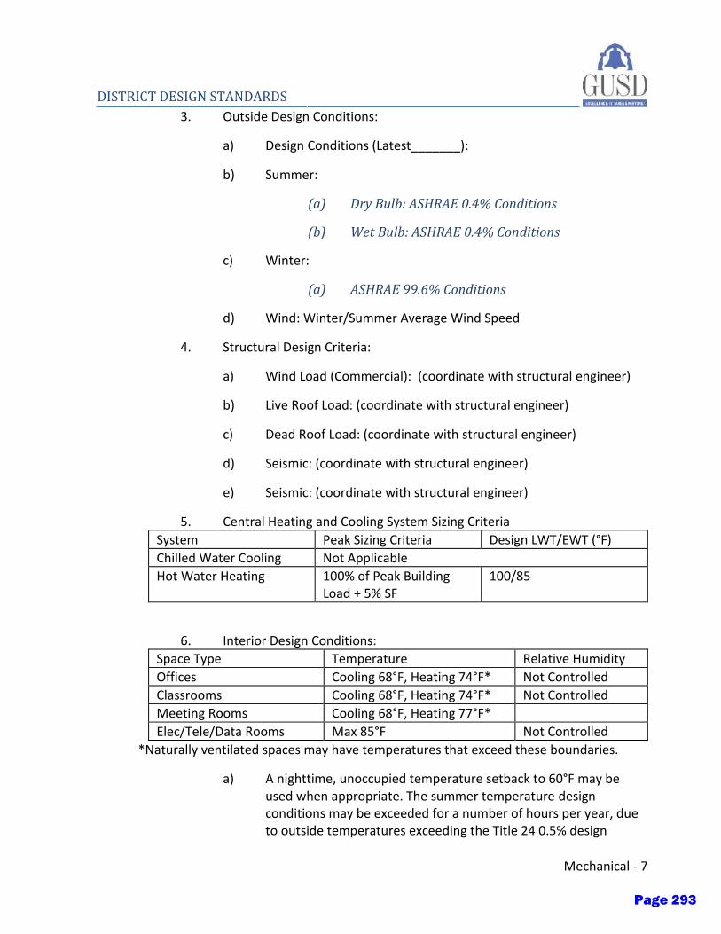
Mechanical - 7
DISTRICT DESIGN STANDARDS 3. Outside Design Conditions:
a) Design Conditions (Latest_______):
b) Summer:
(a) Dry Bulb: ASHRAE 0.4% Conditions
(b) Wet Bulb: ASHRAE 0.4% Conditions
c) Winter:
(a) ASHRAE 99.6% Conditions
d) Wind: Winter/Summer Average Wind Speed
4. Structural Design Criteria:
a) Wind Load (Commercial): (coordinate with structural engineer)
b) Live Roof Load: (coordinate with structural engineer)
c) Dead Roof Load: (coordinate with structural engineer)
d) Seismic: (coordinate with structural engineer)
e) Seismic: (coordinate with structural engineer)
5. Central Heating and Cooling System Sizing Criteria
System Peak Sizing Criteria Design LWT/EWT (°F)
Chilled Water Cooling Not Applicable
Hot Water Heating 100% of Peak Building Load + 5% SF
100/85
6. Interior Design Conditions:
Space Type Temperature Relative Humidity
Offices Cooling 68°F, Heating 74°F* Not Controlled
Classrooms Cooling 68°F, Heating 74°F* Not Controlled
Meeting Rooms Cooling 68°F, Heating 77°F*
Elec/Tele/Data Rooms Max 85°F Not Controlled
*Naturally ventilated spaces may have temperatures that exceed these boundaries.
a) A nighttime, unoccupied temperature setback to 60°F may be used when appropriate. The summer temperature design conditions may be exceeded for a number of hours per year, due to outside temperatures exceeding the Title 24 0.5% design
Page 293
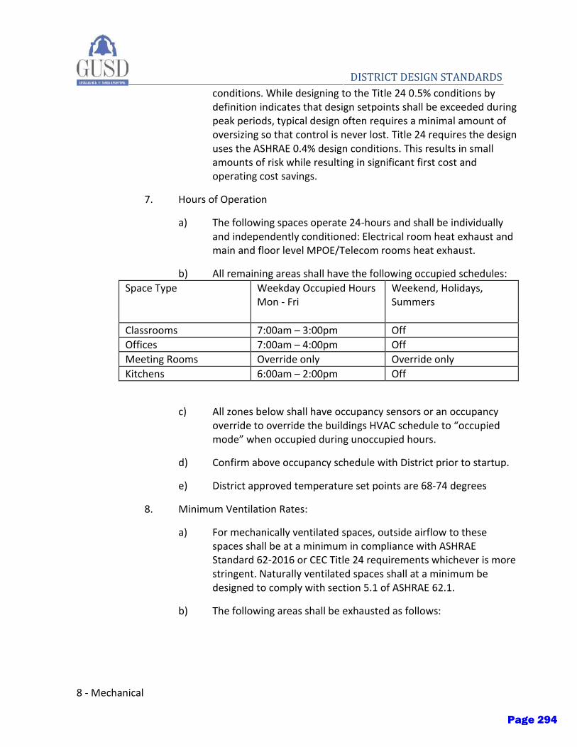
8 - Mechanical
DISTRICT DESIGN STANDARDS conditions. While designing to the Title 24 0.5% conditions by
definition indicates that design setpoints shall be exceeded during peak periods, typical design often requires a minimal amount of oversizing so that control is never lost. Title 24 requires the design uses the ASHRAE 0.4% design conditions. This results in small amounts of risk while resulting in significant first cost and operating cost savings.
7. Hours of Operation
a) The following spaces operate 24-hours and shall be individually and independently conditioned: Electrical room heat exhaust and main and floor level MPOE/Telecom rooms heat exhaust.
b) All remaining areas shall have the following occupied schedules:
Space Type Weekday Occupied Hours Mon - Fri
Weekend, Holidays, Summers
Classrooms 7:00am – 3:00pm Off
Offices 7:00am – 4:00pm Off
Meeting Rooms Override only Override only
Kitchens 6:00am – 2:00pm Off
c) All zones below shall have occupancy sensors or an occupancy override to override the buildings HVAC schedule to “occupied mode” when occupied during unoccupied hours.
d) Confirm above occupancy schedule with District prior to startup.
e) District approved temperature set points are 68-74 degrees
8. Minimum Ventilation Rates:
a) For mechanically ventilated spaces, outside airflow to these spaces shall be at a minimum in compliance with ASHRAE Standard 62-2016 or CEC Title 24 requirements whichever is more stringent. Naturally ventilated spaces shall at a minimum be designed to comply with section 5.1 of ASHRAE 62.1.
b) The following areas shall be exhausted as follows:
Page 294
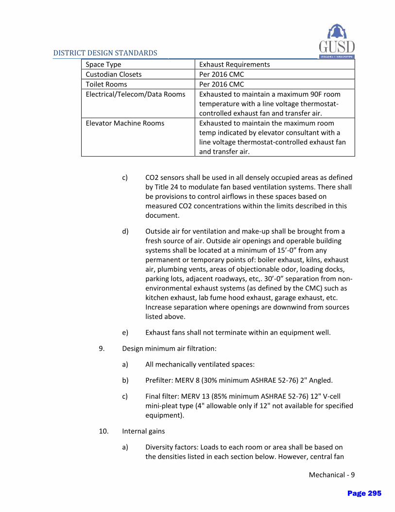
Mechanical - 9
DISTRICT DESIGN STANDARDS Space Type Exhaust Requirements
Custodian Closets Per 2016 CMC
Toilet Rooms Per 2016 CMC
Electrical/Telecom/Data Rooms Exhausted to maintain a maximum 90F room temperature with a line voltage thermostat- controlled exhaust fan and transfer air.
Elevator Machine Rooms Exhausted to maintain the maximum room temp indicated by elevator consultant with a line voltage thermostat-controlled exhaust fan and transfer air.
c) CO2 sensors shall be used in all densely occupied areas as defined by Title 24 to modulate fan based ventilation systems. There shall be provisions to control airflows in these spaces based on measured CO2 concentrations within the limits described in this document.
d) Outside air for ventilation and make-up shall be brought from a fresh source of air. Outside air openings and operable building systems shall be located at a minimum of 15’-0” from any permanent or temporary points of: boiler exhaust, kilns, exhaust air, plumbing vents, areas of objectionable odor, loading docks, parking lots, adjacent roadways, etc,. 30’-0” separation from non-environmental exhaust systems (as defined by the CMC) such as kitchen exhaust, lab fume hood exhaust, garage exhaust, etc. Increase separation where openings are downwind from sources listed above.
e) Exhaust fans shall not terminate within an equipment well.
9. Design minimum air filtration:
a) All mechanically ventilated spaces:
b) Prefilter: MERV 8 (30% minimum ASHRAE 52-76) 2" Angled.
c) Final filter: MERV 13 (85% minimum ASHRAE 52-76) 12" V-cell mini-pleat type (4" allowable only if 12" not available for specified equipment).
10. Internal gains
a) Diversity factors: Loads to each room or area shall be based on the densities listed in each section below. However, central fan
Page 295

10 - Mechanical
DISTRICT DESIGN STANDARDS systems may be sized based on the total load multiplied by the
diversity factor listed. Where no diversity factor is listed, assume a diversity factor of 1.0.
b) All calculations shall be completed utilizing DOE-approved calculation software.
c) Densities below are based on conditioned (net) square feet.
d) Occupancy heat gain
(a) Occupancy shall be based on architectural plans and verified with Architect and District during design phase.
(b) Occupancy shall be based on typical space type occupancy as defined by ASHRAE or where available, the architectural plans and or number of chairs indicated on furniture plans for conference rooms and waiting areas, and on the number of workstations in open office areas.
e) Electrical heat gain
(a) Coordinate with Electrical Engineer of record for lighting design power density and controls.
(b) Lighting loads shall be calculated at CEC T-24 watt per square foot values during preliminary design. Engineers shall execute final calculations upon selection of final lighting fixture selections. The densities in the table are for estimates only; actual loads will be obtained for final design. For future tenant spaces, heat gain shall not exceed code allowable densities. Where diversity factors are not provided assume 1.0.
(c) Equipment loads are variable and should be based on actual equipment to be installed in each location. The Engineer of Record shall apply diversity factors so as not to oversize the central HVAC system.
f) Infiltration
Page 296
Mechanical - 11
DISTRICT DESIGN STANDARDS (a) Assumed air leakage rate of 0.1 cfm/sf of façade
area on two windward adjacent façade orientations.
11. Envelope criteria
a) Envelope criteria listed below are minimum entire assembly performance values used for load calculations and equipment sizing purposes only, more stringent requirements shall be followed wherever listed, see ENERGY EFFICIENCY of this section and Architect’s documents.
b) Thermal mass shall be considered during calculations as a method to offset cooling loads.
c) U-Values for walls and roofs: Loads shall be calculated at CEC T-24 allowances during preliminary design. Engineers shall execute final calculations upon selection of final cooling loads.
d) U-Values and solar heat gain factors for windows: Loads shall be calculated at CEC T-24 allowances during preliminary design. The engineer of record shall execute final calculations upon selection of final building façade materials.
e) The heat transfer conductances of building envelope in most areas (BTU/sq.ft./hr.°F). U-factors, U-Values or R-Values shall be reported as composite (total assembly) values.
Page 297
12 - Mechanical
DISTRICT DESIGN STANDARDS (a) Glazing U-Factor:
(i) Fixed Window Baseline: 0.36
(b) Glazing RSHGC:
(i) Fixed Window Baseline: 0.25
(c) Exterior Walls: Metal Framed; U-Value: 0.113
(d) Roof: Wood Framed or other; U-Value: 0.039
(e) Floor: Mass; U-Value: 0.269
(f) Windows shall be tested, verified, and labeled in accordance with mandatory provision of ASHRAE 90.1-2016 Section 5.4 and all referenced standards therein.
(g) Skylights: Glass, Curb Mounted; U-Value: 0.58
(h) Skylights: Glass, Curb Mounted; SHGC: 0.25
(i) Contractor is responsible for verifying conditions and making corrections to load calculation where envelope varies from these values.
12. Acoustic & vibrations
a) Acoustic submittals
Page 298
Mechanical - 13
DISTRICT DESIGN STANDARDS (a) Acoustic Louvers. Provide location, model number and
size for all louvers, include manufacturer's data sheets listing noise performance and ability to reduce exterior environmental noise.
(b) Air Velocities. Indicate air velocity at all louvers, dampers, inlets and outlets to the building.
(c) Duct and Plenum Sections. Provide submittals for all duct mains and plenums with dimensions for duct, linings and insulation. Note sheet metal type, thickness, gauge and whether dimensions are clear inside or total.
(d) Fans. List acoustic performance data for fans. Provide barrier
(e) Equipment Details. Provide details illustrating vibration isolation approach for each piece of equipment whether, hanging, spring isolated inertia pad, or frame mounted with springs or neoprene pads.
(f) General Equipment Submittals. Provide manufacturer's published sound data with referenced standards and certifications to include octave band sound power levels at inlet, discharge, and casing, for operations at typical design load.
b) General acoustic requirements
Page 299
14 - Mechanical
DISTRICT DESIGN STANDARDS (a) Acoustical calculations shall be completed by a
professional specializing in the science of sound transmission, acoustics, and vibrations.
(b) Design shall conform to ASHRAE chapter “Sound and Vibration Control”, latest edition.
(c) The design of the mechanical systems shall consider any limitations of the structure, and the presence of program areas with restrictive sound criteria. Particular attention shall be given to the location and isolation of heavy equipment, including air conditioning units, and exhaust fans.
(d) Duct noise, including noise generated by fans, excessive air speed, excessive pressure drop, dampers, turning vanes, terminal boxes, resonance and pressure fluctuations shall be considered. Low pressure-drop ducting shall reduce sound problems throughout. All air diffusers and grilles shall have a target of NC 25 or lower. Pipe noise and vibration transfer due to pump vibration and excessive pipe velocity shall also be considered. The low pressure drop design approach being taken typically eliminates most sound traps from the supply side.
c) All fan duct connections should be flexible.
d) There should be a minimum straight duct run of 2 duct diameters on flow changing elements and elbows before and after each element.
e) Flow changing elements and elbows should not be used closer than two duct diameters from the outlet or inlet of a fan or a diffuser, register or grille.
f) Supply ducts immediately downstream of fans should have the same dimensions as the fan discharge opening for a length of 1.5 times the largest discharge duct dimension.
g) Transition sections of duct should have slopes not greater than 1 in 4.
h) Flexible duct used for connecting a branch duct to a register, grille, diffuser or to VAV unit should be insulated and should be no more than 5’ in lineal length.
Page 300
Mechanical - 15
DISTRICT DESIGN STANDARDS i) Local air-handling equipment, such as fan coil units, fan powered
boxes, etc., should not be installed in the ceiling plenums of Acoustically Important (NC<35) spaces. If equipment must be installed in acoustically important spaces, it is probable that significant noise control, such as gypsum board enclosures or ceilings, will be required to meet the background noise criteria.
j) Diffusers, registers and grilles should be chosen for a total performance Noise Criteria (NC) value of at least five points below the room NC goal (shown in Table 2). The manufacturer’s NC rating of the selected device, used for comparison with the NC goals, should include the NC contributions of all individual units within the space along with all appropriate adjustments for face velocity, device length, device area, the presence of dampers (non-critical spaces only), the number of devices in the room and the “room adjustment”. Manufacturer’s NC values must not contain more than a 10 dB “room adjustment” or “room correction” factor.
k) The air volume at a VAV system fan should be controlled by a variable speed motor or variable drive wheel.
l) All duct silencers, if absolutely required, should be sized to a maximum of 0.2” pressure drop including any system effect due to an irregular duct connection. An allowance should be made for a minimum of 3 duct diameters of straight duct on each end of the silencer.
m) Acoustically Critical (NC<30) Areas:
Page 301

16 - Mechanical
DISTRICT DESIGN STANDARDS (a) Horizontal discharge, fan units should be used
where possible.
(b) The first elbow in the supply ductwork from the fan should direct the air in the same direction as the fan scroll and should be a radiused type with a minimum 6” radius, or the elbow should have rugged turning vanes extending for the full arc of the elbow.
(c) Where possible, balancing dampers should not be located within 20 feet of any register, grille or diffuser.
(d) Registers, grilles and diffusers should have an acoustically lined branch duct connected to them off the main duct of at least 5’0” in length. Devices installed directly into ducts should be avoided.
(e) Return air ceiling plenums should be avoided. All return air should be ducted.
(f) The only ductwork that should be routed in the ceiling of a critical space should be ductwork servicing that space.
n) Acoustically important (NC 30-35) areas:
(a) The first elbow in the supply ductwork from the fan should direct the air in the same direction as the fan scroll and should be a radiused type with a minimum 6” radius, or the elbow should have rugged turning vanes extending for the full arc of the elbow.
(b) Ceiling plenums may be used for return air, provided return air grilles have an acoustically lined “boot” with an elbow and a minimum of 5 feet of straight lined duct attached, to prevent crosstalk and miscellaneous plenum noise from intruding into the space.
(c) Balancing dampers should not be located within 8 feet of any supply register, grille or diffuser.
o) All ductwork should be sized to the velocities listed in the table below.
p) Maximum Air Velocities (per 2013 ASHRAE Fundamentals):
Page 302
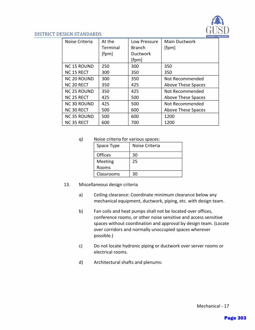
Mechanical - 17
DISTRICT DESIGN STANDARDS Noise Criteria At the
Terminal [fpm]
Low Pressure Branch Ductwork [fpm]
Main Ductwork [fpm]
NC 15 ROUND NC 15 RECT
250 300
300 350
350 350
NC 20 ROUND NC 20 RECT
300 350
350 425
Not Recommended Above These Spaces
NC 25 ROUND NC 25 RECT
350 425
425 500
Not Recommended Above These Spaces
NC 30 ROUND NC 30 RECT
425 500
500 600
Not Recommended Above These Spaces
NC 35 ROUND NC 35 RECT
500 600
600 700
1200 1200
q) Noise criteria for various spaces:
Space Type Noise Criteria
Offices 30
Meeting Rooms
25
Classrooms 30
13. Miscellaneous design criteria
a) Ceiling clearance: Coordinate minimum clearance below any mechanical equipment, ductwork, piping, etc. with design team.
b) Fan coils and heat pumps shall not be located over offices, conference rooms, or other noise sensitive and access sensitive spaces without coordination and approval by design team. (Locate over corridors and normally unoccupied spaces wherever possible.)
c) Do not locate hydronic piping or ductwork over server rooms or electrical rooms.
d) Architectural shafts and plenums:
Page 303
18 - Mechanical
DISTRICT DESIGN STANDARDS (a) Non-ducted architectural shafts shall only be
allowed for return air risers. All supplies and exhausts shall be fully ducted. (For example, toilet exhausts shall not use the shaft as a duct).
(b) All return air transfer across rated corridors shall be sheet metal where allowed by code. Only where code prohibits penetrations of rated wall shall rated enclosures be used instead of sheet metal ductwork.
e) Walls around all conference, meeting, and other acoustically sensitive rooms shall be full height except where noted otherwise. Provide acoustically lined return air transfer ducts accordingly.
f) All new motors shall be NEMA premium efficiency or EMC (when available), except those 1/2 HP and less and those powering emergency-only equipment.
g) Duct and piping insulation: All insulation that shall be exposed to an airstream shall have a protective non-PVC jacket or non-fibrous coating that shall eliminate the insulation from coming into direct contact with the airstream.
h) Condensate pans: All condensate pans shall be double sloped and gravity drained.
i) Toilet rooms shall be exhausted to the outdoors.
j) Exhaust all copy rooms and kitchenette areas to the outdoors.
H. HVAC system description
1. Rooftop packaged unit heat pumps
a) Packaged DX heat pump air handlers with air to air heat recovery and bypass.
b) Ducted supply and ducted return for heat recovery. Toilet and janitor exhaust ducted to air handlers for heat recovery.
c) Packaged controls with 365, 7-day programmable thermostats.
d) No gas heating.
2. Variable refrigerant flow with dedicated outdoor air system (VRF w/DOAS)
3. Air-to-water heat pump with radiant
Page 304
Mechanical - 19
DISTRICT DESIGN STANDARDS 4. Indoor packaged heat pump units
III. MATERIALS
A. HVAC General Requirements (230000)
1. Materials and substitutions: Shop drawings of proposed material and equipment that differ from the specified materials and equipment, shall be accompanied by drawings that define changes. These drawings shall show modifications of architectural, plumbing, electrical and mechanical work required by the proposed materials and equipment, such as relocation of flues, drains, revised electrical circuits, relocation of roof or wall penetrations, revised foundations, etc.
2. Manufacturer's directions: Manufacturer's directions shall be followed in cases where the manufacturers of articles used in this contract furnish directions covering points not shown in the specifications.
3. Protection of Work: Until final acceptance of the work, protect materials from damage and provide adequate and proper storage facilities. Replace damaged or defective work, material, and equipment before requesting final acceptance.
4. Workmanship: Equipment and materials shall be installed in a neat and workmanlike manner. Materials and equipment not so installed shall, upon order of the design team, be removed and replaced in a satisfactory manner, without change in contract price.
5. Closing in uninspected work:
a) Do not allow or cause any work to be covered up or enclosed until it has been inspected, tested, and accepted by the Architect and the District.
b) Any work enclosed or covered-up prior to inspection and testing shall be uncovered. After the work has been tested, inspected and accepted, repair such materials as may be necessary to restore disturbed work to its original and proper condition at no extra cost to the District.
6. Equipment anchoring: Equipment shall be securely anchored to the building structure to prevent shifting or overturning during earthquakes.
7. Final inspection: At the time of final inspection, a service representative shall be available to make final adjustments.
Page 305

20 - Mechanical
DISTRICT DESIGN STANDARDS B. Basic Mechanical Materials and Methods
1. Vinyl and PVC products shall be avoided to the extent reasonably possible for this project.
2. Water based sealants and mastics only shall be used on ductwork. All sealant products shall be no- or low- VOC.
3. All solder shall be lead-free.
C. Common Motor Requirements for HVAC Equipment
1. Provide NEMA premium efficiency motors, as required by equipment specified elsewhere.
2. Electronic commutating motors (ECM) shall be provided where appropriate and additional savings beyond NEMA premium rated motors can be achieved.
3. Motors smaller than ½ horsepower: 1 phase. Motors ½ horsepower and larger, 3 phase.
4. Maximum motor speed of 1750 RPM.
5. Provide inverter rated motors per NEMA MG1-31 where variable frequency drives are applied or where soft start starters are utilized.
6. All motors exposed to the outside air stream to be TEFC motors.
7. Approved manufactures: General Electric, Westinghouse, Baldor, Reliance. Submit substitution request for others.
8. Disconnects to be specified by Section 26.
9. Starters to be specified by Section 26.
10. Motors to have name plate giving manufacture’s name, shop number, HP, RPM and current characteristics.
D. Meters and Gauges for HVAC Piping
1. All meters shall provide an analog output and be compatible with the building energy management system.
2. Accuracy shall be 1 percent of full scale with repeatability of 1 percent.
3. Meter display shall be alphanumeric indicating current flow rate.
4. Current Output: 4-20ma.
Page 306
Mechanical - 21
DISTRICT DESIGN STANDARDS E. Hangers and supports
1. Mount all equipment and accessories according to manufacturer’s recommendations and applicable codes.
2. Material and installation of supports, anchors and sleeves including: horizontal piping hangers and supports; vertical piping clamps; hanger rod attachments; building attachments; saddles and shields; miscellaneous metals, miscellaneous materials; roof equipment supports; anchors; equipment supports; wall and floor sleeves; and escutcheon plates for a complete and operable systems.
3. Design pipe hangers and supports whose materials, design and manufacture comply with MSS SP58, "Pipe Hangers and Supports Materials, Design and Manufacture" latest edition.
4. Select and apply pipe hangers and supports complying with MSS SP69, "Pipe Hangers and Supports Selection and Application, "latest edition. Use only one type by one manufacturer for each piping service. Select size of hangers and supports to exactly fit pipe size for bare piping, and to exactly fit around piping insulation with saddle or shield for insulated piping. Provide copper plated hangers and supports for uninsulated copper piping systems.
a) Pipe Hangers Size 2 Inches and Smaller: Adjustable swivel ring hanger, UL listed.
b) Pipe Hangers Size 2 ½ Inches and Larger: Adjustable clevis type, UL listed.
5. Manufactures: Pipe Hangers, B-Line, Michigan, Superstrut, Unistrut. Roof Equipment Supports, Pate ES, Custom Curb, Vibrex, Thycurb. Roof Pipe Supports, Erico Pipe Piers, Nelson-Olsen Inc.
F. Vibration and Seismic Controls For HVAC Piping, Ductwork And Equipment
1. Provide seismic restraints to meet requirements of the ASCE-10. Restraints shall not short-circuit vibration isolation systems under normal operation.
2. Design restraints shall be per code or SMACNA "Seismic Restraint Manual Guidelines for Mechanical Systems".
3. Vibration isolation shall be provided for the vertically mounted exhaust fans and all other applicable mechanical equipment.
Page 307
22 - Mechanical
DISTRICT DESIGN STANDARDS 4. Issue table of vibration isolation systems (include types) for fan units,
boilers, chillers, cooling towers, pumps for hydronic piping, and associated pipes and other equipment requiring vibration isolation for review. Provide cutsheets for the design team to review.
5. Manufacturers: Isolation Equipment, Amber Booth, Mason, Vibrex. Seismic Pipe Loops and Expansion Joints, Amber Booth, Mason, Metraflex, Vibrex.
G. Identification for HVAC Piping And Equipment
1. Provide mechanical identification of all mechanical equipment, including ductwork, piping, valves, and mechanical equipment.
2. Adhere to ANSI A-13.1.
H. Duct Insulation
1. Manufacturers: Owens Corning, Johns Manville, Knauf or equal.
2. Insulation shall:
a) Meet minimum thickness requirements of Chapter 2-53 of Title 24 and UMW 604.1.
b) Meet mold, humidity, and erosion resistance requirements of UMW Standard 6-1.
c) Have flame spread not more than 25 and smoke density of not more than 50 when tested as a composite installation per UMW 604.3..
3. Ductwork shall be insulated as follows:
a) In concealed space, including ceiling plenum: Shall be insulated with 1-1/2" Fiberglass, 3/4 lb./cuft faced Duct Wrap.
b) Exposed to outdoors: Shall be internally lined with Certainteed Toughgard Duct Liner, 1-1/2 lb. density, 2" thick. (Exposed ductwork should be avoided).
c) At fan inlet and discharge, where required for acoustical attenuation: Shall be internally lined with Certainteed Toughgard Duct Liner, 1-1/2 lb. density, 1" thick.
Page 308
Mechanical - 23
DISTRICT DESIGN STANDARDS d) Longitudinal joints shall be stapled. For rectangular ducts
exceeding 24 inches, insulation on the bottom shall be additionally secured with adhesive.
4. Exposed insulation: Insulation exposed to weather shall be protected by a smooth or corrugated aluminum jacket, minimum 0.016 inch thick, secured 3" on center, overlapped at joints and sealed watertight.
I. HVAC Equipment Insulation
1. Hot equipment: Hot equipment shall be insulated with 1-1/2" thick fiberglass, and secured with wire or bands. Finish with insulating cement and a six ounce canvas jacket sized with Fosters 30-36 or Arabol as required for a neat job. Do not insulate expansion tank or chemical feeder (if any). For outdoor equipment, insulation shall be integral to casing and weather protection system.
2. Manufactures: Owens Corning, Johns Manville, Knauf or equal.
3. At a minimum the following equipment shall be provided with insulation: air eliminators, boilers, chilled water pumps bodies, hot water storage tanks, heat exchangers, cold surfaces of chillers, flue pipe, engine exhaust.
a) Insulation shall meet Title-24 requirements.
J. HVAC Pipe Insulation
1. Provide weatherproof non-vinyl jacket for all piping exposed to the outdoors.
2. Manufacturers: Owens Corning, Johns Manville, Knauf or equal.
3. Insulation shall:
a) Meet minimum thickness requirements of Title 24.
4. Hot water piping shall be insulated with fiberglass molded pipe insulation with all service jacket, thickness as follows:
a) 1" thick up to 2" pipe, 1-1/2" thick from 2-1/2" and larger pipe.
b) Fittings on pipe over 1/2" shall be insulated with fiberglass and finished with one piece non-PVC fitting cover. Valves, flanges and irregular surfaces two inches and over shall be insulated with oversized pipe covering with ASJ jacket. Exposed ends shall be finished with four ounce canvas jacket saturated in Arabol.
Page 309
24 - Mechanical
DISTRICT DESIGN STANDARDS c) Insulation shall meet Title-24 requirements.
K. Hydronic Piping
1. General electrical equipment clearances: Do not route piping through electrical rooms, transformer vaults and other electrical or electronic equipment spaces and enclosures. Within mechanical or plumbing equipment rooms, provide minimum 3 feet lateral clearance from sides of electric switch gear panels, MCCs,etc. Do not route piping above any electric power or lighting panel, switchgear, or similar electric device. Coordinate with electrical and coordinate exact pipe routing to provide proper clearance with such items.
2. Steel Pipe: ASTM A53, Hot dipped, zinc coated welded or seamless, grade B: black.
3. Copper Tube: Temper: Annealed (hard drawn)
4. Carrier Pipe Material; Schedule 40 black steel pipe with 150 PSI malleable screwed fittings.
5. Steel fittings. Flanged, fittings unions and other products, mark in accordance with MSS SP-25. Welding fittings, wrought carbon steel fittings, ASTM A234, ANSU B16.9, B16.28. Butt welding type unless otherwise indicated to be socket welding type. Branch connection, from mains or headers 2-1/2 in or larger, welded tees or forged welding outlets. Welding outlets, “Weldolets” or “Treadolets” equivalent to Bonney Forge. Uses forged welding outlets where branch line is at least 1 nominal pipe size smaller than local main or header. Threaded fittings, ANSI B2.1, ASTM A4, 150 PSI rating, except where otherwise specified, prevailing code requirements or specifications dictate use of 300 PSI. Flanges, carbon steel conforming to ASTM A105, ANSI B16.5 and factory forged in the USA. , welded or grooved (Victaulic). For copper, 95/5 tin/antimony solder. Unions, ANSI B16.39, ASTM A47, and be fabricated from malleable iron with bronze to iron ground joints rated at 150 percent design operating pressure. Threads ANSI B2.1.
6. Fitting for copper tubing: Wrought copper/bronze solder joint fittings complying with ANSI B16.22.
7. Piping may be run exposed on the roof provided:
a) It is supported 18" above the roof (for re-roofing) on seismically braced struts.
b) Insulation is protected from weather.
Page 310
Mechanical - 25
DISTRICT DESIGN STANDARDS c) The overall height of piping is not visible from the street level or
from any window.
d) It does not interfere with access to any equipment on the roof.
L. Hydronic pumps
1. Hydronic pumps shall be bronze fitted centrifugal pumps as manufactured by Bell and Gossett, Taco, Armstrong or equal.
2. 1750 rpm maximum motor speed.
3. All pumps shall have variable speed drives with integral starters or electronically-commutated motors.
4. All pumps shall meet energy efficiency criteria described in Part 1.
5. Factory-tested pumps cleaned and painted with enamel prior to shipment.
6. All pumps shall have bronze impellers.
7. A single gauge shall be connected to the discharge and suction side of each pump and across the strainer so that the differential pressure can be observed.
8. Closed-coupled pumps are not permitted over 0.5 hp.
M. Hydronic Specialties
1. Piping system components shall be selected for maximum design operating pressure based on static head, shutoff pump head, and pressure relief valve setting.
2. Water treatment systems:
a) Provide manufacturer recommended chemical water treatment for all hot water and chilled water systems.
3. Air removal (closed systems):
a) Provide manual air vents at system high points with shut-off cock and pipe vent to nearest drain when located inside. of building. Air vents in tenant ceiling space need not be piped to drains.
b) Air pursers (scoops). or centrifugal air separators need be provided only at contractors option.
Page 311
26 - Mechanical
DISTRICT DESIGN STANDARDS 4. Strainers:
a) C.M. Bailey, Mueller, or equal. Cast iron or bronze "Y-pattern" body to match piping material. Perforated money screen, size of perforations to suit service or per plans.
b) Provide gate valve with hose bib adapter for all strainers.
c) Provide strainers at the inlet to all pumps, and entry to any flow control (Griswold) valves.
5. Gauges:
a) Fixed gauges: Provide a single fixed pressure gauge (Weksler Model BA13P) with valved connections to inlets and outlets of all pumps.
6. Piping flexible connectors:
a) Double sphere plastic type flexible piping connections at air handlers shall be provided if necessary to prevent objectionable vibrations from being transmitted to the structure.
b) For steel piping systems, Victaulic fittings may be used to allow for vibration isolation and misalignment at Contractor's option.
7. Valves:
a) Nibco or equal.
b) Ball, butterfly or check valves only.
c) Triple duty valves shall not be used.
d) Ball valves may be standard port.
e) Butterfly valves used for balancing shall have infinite position handles with memory stop. Butterfly valves shall have removable seats, and the stem shall be fastened to the disc so that no liquid can reach the stem. External fasteners such as roll pins, cotters, keys, or set screws shall not be allowed.
f) Provide manual gear operator for butterfly valves 8" and larger.
g) Extended neck model for all insulated lines.
h) Provide chain operators on all valves located higher than 7 feet above access level.
Page 312
Mechanical - 27
DISTRICT DESIGN STANDARDS 8. Pipe supports:
a) Kin-line, Superstrut, or equal.
b) Where pipe is insulated, protect insulation at hangers by installing a 22 gauge shield and clamp sized to allow pipe insulation to pass continuously through the hanger. For piping 2" and larger, provide 360 degree high density calcium silicate insert within shield.
c) Piping for hydronic systems should be vibration isolated.
(a) All fluid filled and hydronic pipes throughout the building must be vibration isolated from the building. Specify neoprene collars for pipes at all pipe supports at horizontal runs. These vibration isolation requirements do not apply to inert or horizontally supported insulated piping.
(b) Pipes should not directly contact framing, ductwork, structure, gypsum board, or other pipes. Use acoustical sleeves where pipes where pipes penetrate acoustically rated walls. Provide detail of penetrations for typical conditions where occurs.
(c) Pipe risers shall be isolated from structure using 40 durometer neoprene or rubber pads under load bearing plate.
9. Escutcheons: Provide stainless steel escutcheons at piping penetrations of walls where exposed public view and required for proper appearance. Provide galvanized steel escutcheons at penetrations of masonry walls elsewhere. Escutcheons not generally required at drywall penetrations where not exposed to public view.
10. Sleeves:
a) Provide sleeves where pipes pass through floors above grade, roofs, poured-in-place masonry walls, and exterior walls.
b) Sleeves shall be standard weight steel pipe, except sleeves for concealed piping through floors not in structural members may be 25-gauge galvanized sheet metal.
c) Floor sleeves for piping shall extend from the bottom of the slab to 2-inches above the finished floor.
Page 313
28 - Mechanical
DISTRICT DESIGN STANDARDS d) Seal between piping and sleeve with fire-rated caulk at all
penetrations of fire-rated partitions and floors.
e) Sleeves that pass through structural expansion joint areas shall be oversized to accommodate the building and pipe movement. Coordinate required sleeve size and building movement with Structural Engineer.
f) Make sleeves through outside walls watertight. Caulk between uninsulated pipe and sleeve.
g) Size sleeves for insulated pipes to allow full thickness insulation.
11. Manual air vent valves. Armstrong, Bell & Gossett Hoffman, Spirax, Sarco,
12. Automatic air vent valves: Taco, Bell & Gossett, Hoffman
13. Automatic flow control valves: Griswold, Taco, Bell & Gossett
14. Strainers: Mueller, Armstrong, Hoffman, Wheatley, Victaulic.
15. Air separators: Armtrol, Armstrong, Bell & Gossett, Taco, Wheatley
16. Expansion tanks: Mueller, Amtrol, Armstrong, Taco, Bell & Gossett.
17. Liquid flow switch: McDonnell & Miller, Dwyer
18. Water pressure relief valves: Amtrol, Bell & Gossett, Spirax Sarco, Watts Regulator.
19. Water pressure reducing valves: Amtrol, Armstrong Pumps, Bell & Gossett, Taco.
20. Thermometers: Ashcroft, Trerice, Weiss.
21. Thermometer wells:. Ashcroft, Trerice, Weiss.
22. Pressure gauge: Amtrek / US Gauge, Ashcroft Palmer, Marshaltown Instruments, Trerice, Weiss, Weksler.
23. Expansion joint: Flexonics, Mason Industries, Amber-Bush, Metraflex.
24. Pipe guides: Flexonics, Mason Industries, Amber-Bush, Metraflex.
25. Pipe anchors: Flexonics, Mason Industries, Amber-Bush, Metraflex.
N. Expansion fittings and loops for HVAC piping
Page 314
Mechanical - 29
DISTRICT DESIGN STANDARDS 1. Provide expansion and contraction fittings or loops on vertical and
horizontal hydronic piping for thermal growth, that are capable of absorbing growth or contraction and seismic drift (See Structural).
2. Provide expansion joint in piping at each crossover of an expansion joint.
O. Refrigerant piping
1. Piping material shall be:
a) Copper tube ASTM B 280, H58 hard drawn or O60 soft annealed.
(a) Fittings: ASME B16.22 wrought copper
(b) Joints: Braze, AWS A5.8 BCuP silver/phosphorus/copper alloy
(c) Copper tube to 7/8” OD: ASTM B 88 (ASTM B 88M), Type K (A), annealed.
(d) Fittings: ASME B16.26 cast copper
(e) Joints: Flared
(f) Pipe supports and anchors: Conform to ASME B31.5
2. Refrigerant:
a) Manufacturers: Subject to compliance with requirements, provide products by of the following:
(a) DuPont Company; Elf Atochem North America, Inc.; ICI Americas Inc.
(b) R-407c or R-410a only as defined in ASHRAE Std 34.
3. Installation:
a) Install refrigeration specialties in accordance with manufacturer's instructions.
b) Route piping in orderly manner, with plumbing parallel to building structure, and maintain gradient.
c) Install piping to conserve building space and avoid interference with use of space.
Page 315
30 - Mechanical
DISTRICT DESIGN STANDARDS d) Group piping whenever practical at common elevations and
locations. Slope piping one percent in direction of oil return.
e) Install piping as short and direct as possible, with a minimum number of joints, elbows, and fittings.
f) Arrange piping to allow inspection and service of compressor and other equipment. Install valves and specialties in accessible locations to allow for service and inspection.
g) Install piping with adequate clearance between pipe and adjacent walls and hangers or between pipes for insulation installation. Use sleeves through floors, walls, or ceilings, sized to permit installation of full-thickness insulation.
h) Belowground, install copper tubing in protective conduit. Vent conduit outdoors.
i) Install piping to allow for expansion and contraction without stressing pipe, joints, or connected equipment.
P. Variable Frequency Controllers
1. ABB, Siemens, General Electric, Danfoss, Yaskawa, Mitsubishi.
2. Electrical Characteristics.
a) Efficiency shall be not less than 97% at rated voltage, current, and frequency and fundamental power factor shall not be less than 98% at all speeds and loads.
b) VFD shall maintain line noise (voltage harmonics) on the input electrical system at or below levels specified in IEEE 519 for a "General System." Manufacturer shall include in submittals a harmonic distortion analysis (IEEE 519, 3%) for this particular jobsite. Provide RLC tuned filters as required to comply with the above requirements. Provide as a minimum 3-phase line reactors, 3% impedance type or as required to meet local utility and possible rebate specifications.
3. Features and Accessories.
a) Plain language LCD display (code numbers not acceptable). All set-up parameters, indications, faults, warnings, and other information must be displayed in words, not codes.
Page 316
Mechanical - 31
DISTRICT DESIGN STANDARDS b) Displays and meters for the following: Output voltage, output
frequency, motor rpm, motor current, motor watts, speed signal input, last three faults.
c) HOA switch and speed potentiometer.
d) Input line fuses.
e) Adjustable or multiple carrier frequencies up to 12 kHz. Drive shall be capable of full motor rated current at all carrier frequencies.
f) Isolated 4-20 mA or 0-10 Vdc speed signal input.
g) Analog outputs for kW and speed.
h) Digital outputs for alarm and motor on/off status. Latter shall be based on field adjustable motor current.
i) Auto-restart after trip due to overcorrect, under-voltage, over-voltage, or over-temperature upon correction of causative condition. Include a maximum of 3 restart attempts for over-current only, with VFD shutting down and requiring manual restart after the third attempt. The attempt counter shall reset after 10 minutes of successful operation.
j) Provide interface with DDC system for status points, or hard-wire points listed.
k) VFD shall have 5% line reactor for input line conditioning.
l) Comply with the applicable requirements of the latest standards of ANSI, NEMA, National Electric Code (NEC), FCC Subpart J of Part 15, and IEEE 519-1992.
m) Solid state, with a Pulse Width Modulated (PWM) output waveform enclosed in a NEMA 1 enclosure (provide other NEMA enclosures as required for application), completely assembled and tested by manufacturer. Employ a full wave rectifier (to prevent input line notching), DC Line Reactor, capacitors, and Insulated Gate Bipolar Transistors (IGBTs) as the output switching.
n) Door interlocked thermal magnetic circuit breaker disconnect handle, through-the-door type, and pad-lockable in the "Off" position.
o) Provide all VFDs with the same customer interface, including digital display, keypad and customer connections; regardless of
Page 317
32 - Mechanical
DISTRICT DESIGN STANDARDS horsepower rating. The keypad is to be used for local control
(start/stop, forward/reverse, and speed adjust), for setting all parameters, and for stepping through the displays and menus
4. Equipment protection and safeties.
a) VFDs short-circuit interrupting rating shall equal or exceed that indicated on the distribution-switchboard serving the drive.
b) VFD shall protect itself against all normal transients and surges in incoming power line, any grounding or disconnecting of its output power, and any interruption or run away of incoming speed signal without time delay considerations. Protection is defined as normal shutdown with no component damage.
c) VFD must protect itself against all phase-to-phase or phase-to-ground faults.
d) VFD shall be able to start into a rotating load at all speeds (forward or reverse) without trip.
e) Anti-regeneration circuit shall match the deceleration rate of the drive to that of the motor to prevent high bus voltage shutdown common to high inertia loads, such as fans.
f) VFD shall ride through an input power dip of 3 cycles without trip.
g) VFD shall operate with an input voltage range from 400-550 Vac without trip.
h) VFD shall employ three current limit circuits to provide trip-free operation: slow current regulation, rapid current regulation, and current limit switch-off limit. VFD shall be designed so that overcurrent trip shall be at least 315% of the drive's current rating.
5. Start-up/warranty
a) Certified factory start-up shall be provided. A certified start-up form shall be filled out for each drive with a copy to the District and a copy kept on file by the manufacturer.
b) Warranty shall be 24 months from date of start-up certification including all parts, labor, travel time, and expenses.
Q. Packaged air handling units
Page 318
Mechanical - 33
DISTRICT DESIGN STANDARDS 1. Manufacturer: Light Commercial – Aaon, Carrier, York, McQuay, Trane,
and American Standards. Substitutions allowed, if performance and quality equivalency can be evidenced.
2. Backward inclined, double width, double inlet, centrifugal type fan with airfoil-type blades.
3. Filter box: Section with filter guides, access doors from both sides, for side loading with gaskets and blank-off plates.
4. Filter media: UL 900 listed, Class I or Class II, approved by local authorities.
5. Flat: 4 inches deep disposable, extended area panel filters.
6. Filter gauges:
a) 3-1/2 inch diameter diaphragm actuated dial in metal case with static pressure tips.
7. Air-to-air heat recovery via flat plate or wheel.
8. Air-cooled packaged air conditioning equipment shall be equipped with low ambient cooling if systems are not provided with economizers or if systems serve a 24/7 load.
9. Non Dedicated Outside Air Units: All units shall have a dedicated set of minimum outside air dampers for ventilation requirements. The dampers shall be two-position, and a second set of modulating outside air dampers shall be provided, as required, for economizer operation or tracking with exhaust air.
10. Rooftop package air conditioners 5 ton and larger shall be mounted on structural steel channel curbs with curb vibration isolation rails. Smaller units may be mounted on the manufacturer’s prefabricated curbs.
11. Non Dedicated Outside Air Units: All air handling units shall have, at minimum, a dedicated set of two-position outside air dampers for ventilation requirements plus a second set of modulating outside air dampers, as required, for economizer operation or tracking with exhaust air.
12. Coils shall be copper coils with aluminum fins.
13. Insulated casings and plenums shall be specified for all units, including those serving heat and vent applications. Provide double wall casings at all locations.
Page 319
34 - Mechanical
DISTRICT DESIGN STANDARDS 14. Units shall be installed to allow removal of all coils and filters. Clearance
equal to full-finned width of coil shall be provided to facilitate removal.
15. Units shall be mounted on internal vibration isolators and concrete housekeeping pads.
16. Units shall have a mixing box and filter box or a combination filter/mixing box properly sized so as not to exceed the filter manufacturer’s recommended face velocities. Low leakage dampers (2%) shall be provided for mixing box dampers.
17. All cooling coil drain pans shall be stainless steel.
18. Variable speed drives shall be installed on the air handlers in a separate conditioned vestibule.
R. Packaged air to water heat pumps
1. Manufacturers: Climacool, ClimateMaster, Inc., Aermec.
2. Description: Packaged air-source unitary heat pump with temperature controls; factory assembled, piped, wired, tested, and rated according to ASHRAE/ARI/ISO-13256-1.
3. Cabinet and Chassis: Factory powder coated appropriate for coastal salty climate with the following features:
a) Access panel for access and maintenance of internal components.
b) Knockouts for electrical and piping connections.
c) Cabinet Insulation: Glass-fiber liner, minimum, 3/4 inch thick, complying with UL 181, ASTM C 1071, and ASTM G 21.
4. Refrigerant-to-Water Heat Exchangers:
a) Stainless-steel, brazed-plate heat exchanger is leak tested to 450 psig on refrigerant side and 400 psig on water side. Factory mount heat exchanger in unit on resilient rubber vibration isolators.
5. Refrigerant Circuit Components:
a) Sealed Refrigerant Circuit: Charge with R-410A refrigerant.
b) Filter-Dryer: Factory installed to clean and dehydrate the refrigerant circuit.
Page 320
Mechanical - 35
DISTRICT DESIGN STANDARDS c) Charging Connections: Service fittings on suction and liquid for
charging and testing on each circuit.
6. Compressor:
a) Scroll, Two stage or Variable speed.
b) Installed on vibration isolators and mounted on a structural steel base plate and full-length channel stiffeners.
c) Exterior of compressor shall be wrapped with a high-density sound-attenuating blanket and housed in an acoustically treated enclosure.
d) Air-cooled Condenser Coils: Aluminum fins mechanically bonded to seamless copper tubing. Provide sub-cooling circuits. Air test under water to 425 psig, and vacuum dehydrate. Seal with holding charge of nitrogen.
7. Fans and motors
a) Vertical discharge direct driven propeller type condenser fans with fan guard on discharge. Equip with roller or ball bearings with grease fittings extended to outside of casing.
b) Weatherproof motors suitable for outdoor use, single phase permanent split capacitor or 3 phase, with permanent lubricated ball bearings and built in current and thermal overload protection.
8. Refrigerant piping materials: ASTM B 743 copper tube with wrought-copper fittings and brazed joints.
9. Pipe insulation: Refrigerant minimum 3/8-inch-thick, flexible elastomeric insulation on piping exposed to airflow through the unit. Maximum 25/50 flame-spread/smoke-developed indexes according to ASTM E 84.
10. Pipe insulation cladding: All exterior insulation shall be clad with aluminum or stainless steel per Section 23 07 19 and/or Section 23 07 16.
a) Identify insulated piping and unit per Section 23 15 53; All piping must be labled and direction of flow indicated.
11. Refrigerant metering device: Electronic thermal-expansion valve.
12. Controls: Fully packaged controls.
Page 321
36 - Mechanical
DISTRICT DESIGN STANDARDS 13. Electrical connection: Single electrical connection with fused disconnect
meeting all requirements defined in Section 26. System must be provided with a dedicated Lock Out Tag Out device with an O&M Manual describing the Lock Out Tag Out procedure for this specific piece of equipment.
14. Pump Module:
a) Minimum 1/2 HP, 230-V, single-phase pump, rated for at least 3 gpm per 12,000 Btu/hr capacity at 20 feet of head.
b) Include pump module hose kit with thread to barb fittings, hose, and hose clamps.
c) Include controls to operate pump as required.
d) Packaged Accessories: expansion tank, mechanical water filter and storage tank.
S. Ceiling Fans
1. Manufacturers: Big Ass Fans, Aerotron, Minka Air.
2. Oil-free permanent magnet prime mover, gearless direct drive.
3. Wall-controller: Manufacturer’s LCD type.
4. Color and finish to be coordinated with Architect prior to purchase and installation.
T. HVAC ducts and casings
1. Ductwork shall be galvanized steel, except as allowed below. The gauge of metal, type of joints, hanging, reinforcing, and other. Details of construction shall conform to the SMACNA HVAC Duct Construction Standards. Pressure classes shall be as required by the fan system. For the purpose of this section, "medium pressure" herein refers to ductwork in main shafts. "Low pressure" herein refers to all other ductwork.
2. Fiberglass duct: not allowed.
3. Flexible Duct:
a) Standard factory fabricated product, construct an inner wall of impervious vinyl or chlorinated polyethylene, permanently bonded to a vinyl or zinc-coated spring steel helix. Cover the assembly with fiberglass blanket insulation covered by an outer
Page 322
Mechanical - 37
DISTRICT DESIGN STANDARDS wall of vinyl or fiberglass-reinforced metalized vapor barrier. UL
181 listed Class 1 flexible air duct material. Overall thermal transmission no more than 0.25 (BTU/in)/(hr/sq.ft./deg. F) at 75F differential, per ASTM C335. Vapor transmission value no more than 0.10 perm, per ASTM E96. Rated for a minimum of 4-inch w.g. positive pressure and 1-inch w.g. negative pressure. Air friction correction factor of 1.3 maximum at 1000 FPM. Working air velocity of at least 2000 FPM. Flame spread rating no more than 25. Smoke development rating no more than 50 as tested per ASTM E84. Must have cataloged data on insertion loss characteristics, minimum attenuation of 29 DB for 10-foot straight length at 8-inch diameter and 500 Hz.
b) Install flexible duct with bend radius equal to 1.5 times the diameter. Minimum length 2 feet. Maximum length 5 feet.
c) Provide round neck grilles/diffusers or square-to-round transitions. No flex duct connections directly to square neck allowed.
d) Flex duct allowed only for vertical drops to diffusers. Maximum offset angle from vertical: 30 degrees.
e) Approved for use on supply ducts only; not allowed for return or exhaust.
f) Flex duct allowed in concealed spaces above lay-in ceilings only
4. Joints in rectangular sheet metal duct:
a) Joints in medium pressure ductwork shall be "Fabriduct T.D.C." or Duct-Mate. Longitudinal seams shall be Pittsburgh.
b) Joints in low pressure ductwork shall be "Fabriduct T.D.C." or Duct-Mate except that ducts under 19" longest side may be "S" and drive. Longitudinal seams shall be Pittsburgh.
5. Rectangular and medium pressure duct bends greater than 45 degrees shall be curved sections, the center line radius of which shall not be less than 1-1/2 times the width of the duct in the plane of the bend. Where required due to space constraints, short radius elbows with duct splitters or square elbows with turning vanes may be used. Round duct elbows may be adjustable type on low pressure systems, witch gores sealed for systems operating in excess of 1” w.c..
6. Ductwork Sealing:
Page 323

38 - Mechanical
DISTRICT DESIGN STANDARDS a) Ductwork shall be sealed per SMACNA sealing classes as follows:
(a) Medium pressure: Seal class A.
(b) Low pressure: Seal class C.
(c) Duct sealant shall be Foster’s 32-14 "High Velocity Duct Sealant", hard cast, or equal. Pressure applied tapes are not acceptable as the sole sealant.
(d) Gasketed joints (e.g. Duct-Mate and T.D.C.) and longitudinal joints with sealant installed during fabrication do not require additional sealing.
(e) Flexible ducts shall be connected using Panduit strap on the inner liner, sealed with tape, then the outer liner shall be sealed with tape.
U. Air Duct Accessories
1. Smoke and fire dampers:
a) Motorized fire/smoke damper with motor. 22 gauge roll from galvanized steel with a 120VAC motor for motorized operation. Standard UL 212F fusible link. Provide smoke detector at each damper per code. Dynamic type. The fire dampers to be U.S. standard for 1-1/2 hour listing. Motors to be UL listed. Provide the thermal protection via the fusible link. Damper to be normally closed. Minimum leakage Class II damper. Provide with automatic reset. Damper to fail closed when power is interrupted to actuator.
2. Barometric Relief Dampers:
a) Large: Frame and blades fabricated from 0.063 mill finish aluminum. Blades have polyurethane edge seals. 1/2-inch diameter aluminum blade shafts with bronze bearings. Adjustable counterweight. Blades start to open at 0.05-inch APD - 55 FPM. Blades fully open at 0.06-inch APD - 680 FPM. Manufacturers: Louvers & Dampers, Ruskin, Cesco, Greenheck, Prefco, or approved.
b) Large: All welded 14 gauge aluminum, with blades pivoting off center, double crimped front and rear, polyurethane seals. Link blades to work in unison, pivoting in ball bearings, and provide adjustable counterweights attached to the blades. . Blades start to open at 0.05-inch APD - 55 FPM. Blades fully open at 0.06-inch
Page 324

Mechanical - 39
DISTRICT DESIGN STANDARDS APD - 680 FPM. Frames: Channel type with flanges to facilitate
mounting. Manufacturers: Louvers & Dampers, Ruskin, Cesco, Greenheck, Prefco, or approved
3. All exhaust fans shall have backdraft dampers.
4. Volume dampers
a) Construct of galvanized sheets not lighter than 18 gauge, reinforced to prevent vibration, equipped at both ends with brass bearing mounts and of sufficient length to provide a complete shutoff of the duct.
b) Provide each damper with an adjustment and locking quadrant device for accessible locations, or remote type for non-accessible locations. Provide operating rod and attaching devices as required. Provide raised platform for insulated duct.
5. Control Dampers:
a) Provide automatic control dampers as indicated. Airfoil, multiblade type, maximum blade length of 48 inches. Provide parallel blades for positive or modulating mixing service and opposed blades for throttling service. Blades to be interlocking, minimum 16 gauge galvanized steel. Damper blades reinforced, have continuous full length axle shafts and/or operating jackshafts as required to provide coordinated tracking of blades. Dampers over 25 sq.ft. in area to be in two or more sections, with interconnecting blades. Dampers to have a maximum air leakage of 15 CFM psf at 4-inch w.g. pressure. Provide automatic dampers except those specified with units. Manufacturers: Alerton, Auto-Matrix, Honeywell, Johnson Controls, Staefa, Siemens, Trane, Siebe.
V. Fans (General)
1. Cook, Panasonic, Greenheck, or equal.
2. Where possible, fans must be Energy Star Rated.
3. Fans shall be tested and rated in accordance with AMCA Standards and shall bear AMCA labels.
4. Wheels shall be balanced statically and dynamically, free from vibration or noises.
Page 325
40 - Mechanical
DISTRICT DESIGN STANDARDS 5. Bearings self-aligning, ball-bearing type, complete with grease fittings,
extended to single point on drive side or to accessible location.
6. Actual brake horsepower of fan and drive shall not exceed nameplate rating of motor driving fan.
7. Provide direct drives on motors 15 HP or less. Sheaves shall be selected to operate at mid-point of fan curve to allow adjustment in both directions. For belt drives with more than two strands serving motors over 15 HP, provide fixed sheaves. Replace fan sheaves as necessary to obtain desired results.
8. Provide VFDs for all variable volume systems greater than 1 HP.
9. Fan shall be AMCA rated for sound and air performance
10. All fans shall be statically and dynamically balanced and run at the factory.
11. The motor horsepower shall not be less than 120% of the fan bhp, non-overloading.
12. Where variable speed drives are utilized, consider use of direct drive fans to reduce maintenance for belts. Consider fan’s critical speed in selection of direct drive fans with variable speed operation.
W. Centrifugal HVAC fans
1. Provide high efficiency cabinet fans, Cook or equal, for utility fans.
2. Where possible, fans must be Energy Star Rated.
X. Air outlets and inlets
1. Titus, Price, Kreuger, Tuttle & Bailey, Nailor, or equal.
2. Styles:
a) Ceiling Supply: 12” x 12” Square plaque-face.
b) Sidewall Supply: Louvered rectangular.
c) Displacement Supply: Perforated-face displacement diffuser. Price DF1W or equal.
d) Ceiling Return: 12” x 12” Square plaque-face .
e) Exhaust grilles: Perforated 12” x 12”.
Page 326
Mechanical - 41
DISTRICT DESIGN STANDARDS f) Louvers: Ruskin ELF6350DMP or equal, coordinate finish with
design team.
g) Egg-crate grilles not acceptable in any location.
h) Opposed blade dampers shall not be used on any supply, return or exhaust grille, except where inline dampers will not fit and OBD will not create objectionable noise.
3. Diffuser trim to match ceiling type (if any). See reflected ceiling plans. Provide center-tees for slots.
4. Air outlet balancing shall be through volume dampers located at the upstream end of the flex duct connection to the outlet or duct/plenum tap, except Young regulators (Bowden cable dampers) may be used for outlets mounted in inaccessible ceilings and at wall. Access doors shall not be used for access to balancing dampers above inaccessible ceilings such as drywall ceilings.
5. Provide components that have velocity, throw and drop, and noise criteria ratings for each size device as listed in manufacturer's current standard literature, which are plus or minus 10 percent of the components as listed in the diffuser, register and grille schedule, or as specified herein.
6. Indicate 1-, 2-, 3-, 4-way deflection so as to reduce chances of drafts.
Y. HVAC air cleaning devices
1. Air filters
a) Cambridge, AAF.
b) See equipment sections for efficiency requirements.
c) Construction Filters: Provide MERV 13 V-cell pleated filters in lieu of or in addition to final filters during construction and start-up. Remove before air balancing and replace with final filters.
d) Start-up Procedures: Supply fans shall not be operated unless filters are installed, including temporary filters for use during construction. If the final pressure drop of the temporary filters is reached during construction or test and balance, replace them with a spare set.
Z. Commissioning
Page 327

42 - Mechanical
DISTRICT DESIGN STANDARDS 1. The installing contractor of a particular system or equipment is
responsible for the commissioning activities relating to that system or equipment item and shall include pricing in their bid.
2. The Commissioning Authority (CA) directs and coordinates all commissioning activities and provides Prefunctional Checklists and Functional Test Procedures for contractor's use.
3. The following systems shall be commissioned:
a) HVAC equipment
b) DDC control system and devices
c) Metering devices
4. Submittals:
a) Enhanced Commissioning requires a Commissioning Design Review at 50% CD phase. Contractor to provide drawings to Commissioning Agent for review. Contractor shall provide feedback and incorporate comments into final drawings. Contractor shall also provide drawings at 100% CD for Commissioning Agent to conduct back-check for comment incorporation.
b) Enhanced Commissioning requires Commissioning Agent to conduct a submittal review of all equipment included in commissioning scope. Contractor to provide submittals to Commissioning Agent for review.
c) Submit TAB plan for Commissioning Agent for review.
d) Updated submittals: Keep the Commissioning Agent informed of all changes to control system documentation made during programming and setup; revise and resubmit when substantial changes are made.
e) O & M manuals: Submit manuals related to items that were commissioned to Commissioning Agent for review; make changes recommended by Commissioning Agent.
5. Provide all standard testing equipment required to perform start-up and initial checkout and required functional performance testing.
Page 328
Mechanical - 43
DISTRICT DESIGN STANDARDS 6. Cooperate with the Commissioning Agent in development of the
Prefunctional checklists and functional test procedures. Furnish additional information requested by the Commissioning Agent.
7. Contractors to attend commissioning meetings necessary to facilitate the commissioning process.
8. Prepare a schedule for mechanical system testing, flushing and cleaning, equipment start-up and testing, adjusting, and balancing start and completion for use by the Commissioning Agent; update the schedule as appropriate.
9. Provide temperature and pressure taps in accordance with the contract documents. Provide a pressure/temperature plug at each water sensor that is an input point to the control system.
10. The prefunctional checklist and functional test requirements specified in this section are in addition to, not a substitute for, inspection or testing specified in other sections. Submit start-up documentation, pre-functional checklists for each item of equipment to be commissioned. Submit TAB report for Commissioning Agent review prior to functional testing.
11. Perform the functional tests directed by the Commissioning Agent for each item of equipment or other assembly to be commissioned. Using a skilled technician who is familiar with this building, execute the functional testing of the control system as required by the Commissioning Agent. Functional testing of the control system constitutes demonstration, graphic review and trend logging of control points monitored by the control system.
12. Commissioning Agent to be provided a minimum of 2 weeks of trend data following functional testing. Data shall be in.xls,.csv file format.
13. Commissioning Agent will provide a list of deficiencies after the functional testing and trending period. The contractor is responsible for making corrections and providing Commissioning Agent verification. The Commissioning Agent will only return 1 time for re-testing. Any additional testing will be back-charged to the contractor.
14. Trend logging:
a) Trend logs must be established before functional testing. Commissioning Agent to review 24 hours of trend data prior to functional testing.
Page 329
44 - Mechanical
DISTRICT DESIGN STANDARDS b) Trend logging shall include all control points specified and
required to verify system performance. This may include software points, setpoints, etc.
c) The control system shall be capable of trending all points at 1 minute intervals and storing data for a minimum 12 month period.
15. Remote access:
a) Remote access must be coordinated with appropriate contractors.
b) Remote access must be established prior to functional testing.
c) The Commissioning Agent shall be given remote access to the control system.
16. M&V requirements
a) Collecting and storing performance data for a 12 month period is required.
b) Commissioning and review of the metering devices.
17. Provide classroom and hands-on training of District's designated personnel on operation and maintenance of the HVAC system, control system, and all equipment items indicated to be commissioned.
18. Provide support for any necessary off-season testing.
AA. HVAC Instrumentation and Controls
1. Thermostats:
a) Acceptable manufacturer: Pelican TS250 programmable and wireless thermostats
b) Screen:
Page 330
Mechanical - 45
DISTRICT DESIGN STANDARDS (a) Minimum 4 in² backlit LCD display
(b) Minimum information displayed
(c) Zone temperature
(d) Setpoint temperature
(e) Low battery indicator
(f) Cooling or Heating operation
(g) Current time
(h) Low battery indicator
c) Programs:
(a) 5 + 1 + 1 per week or 7 days per week
d) Features:
(a) Thermostat shall have equal or greater number of stages for cooling and heating when unit(s) being served have multiple stages of cooling and/or heating. Low voltage.
(b) Battery backup.
(c) Heat-Off-Cool-Auto operation options.
(d) Energy Star compliant.
(e) California T-24 Part 6 2008 Compliant.
e) Temperature Accuracy;
(a) +/- 2ºF
2. CO2 sensors:
a) Acceptable manufacturers: Pelican TS250 programmable and wireless thermostats have CO2 sensors
b) Sensor: Non-dispersive infrared (NDIR).
c) Display: LCD display of current CO2 level in ppm.
d) Scale: 0-2000 ppm.
Page 331
46 - Mechanical
DISTRICT DESIGN STANDARDS e) Accuracy: +/- 2% of full scale and +/- 75 ppm @1000ppm.
f) Calibration frequency: 5 years or greater.
g) Mounting height: 3’0” – 5’0” AFF or as required by ADA.
3. Control sequence:
a) Provide control sequence as needed to provide a fully functioning system including a control sequence that not only meets the indoor design criteria but also current energy codes and this project’s low energy use goals.
BB. Testing, adjusting, and balancing
1. Provide full TAB services for the HVAC systems. Include Title 24 acceptance test requirements in pricing.
2. All testing and balancing shall be done in conformance with National Environmental Balancing Bureau (NEBB) or Associate Air Balance Council (AABC)
IV. EXECUTION
A. Installation and execution
1. Industry standards and manufacturers' recommendations, diagrams or requirements shall be strictly adhered to for installation of materials and equipment.
2. Provide protective covers, skids, plugs or caps to protect equipment and materials from damage and deterioration during construction. Protect exposed coils with plywood or other suitable rigid covers to avoid damage to fins.
3. Porous materials, such as duct insulation and liner, shall be protected from weather. If such material becomes wet during construction, it shall be removed and replaced at no cost to District.
4. All equipment and material shall be installed in a neat and workmanlike manner.
5. In conditions where freezing temperatures are a possibility, water systems shall be cleaned and tested using a glycol or similar non-freezing fluid, or system testing shall be postponed until weather conditions are favorable. Contractor shall bear all responsibility for coordinating system testing such that it will not adversely affect the project construction
Page 332
Mechanical - 47
DISTRICT DESIGN STANDARDS schedule. Under no conditions shall water system be filled with water
with freeze potential during conditions where freezing temperatures are a possibility.
6. Thoroughly clean all equipment, ducts, etc. free of dust, scale, filings, plaster, grease, oil, paint and other construction debris using low- or non-VOC cleaning products only.
7. All ductwork, piping and equipment shall be installed in an orderly and neat fashion. All exposed HVAC equipment, ductwork and piping shall be installed without any rough edges, dents, level to structure and in a neat, orderly fashion. All excess sealants to be wiped from seams.
8. Blow air through all duct systems until they are free of all foreign materials.
9. Protect all equipment from weather and joist conditions during rough-in phase of construction.
10. Repair all damaged paint or protective coatings with factory approved paint or finish.
B. Equipment And Piping Identification
1. Equipment:
a) All mechanical equipment shall be identified by nameplates securely fastened in a clearly visible location to the equipment housing or frame. Nameplates shall include the equipment design plan mark and brief description of the area or system served, such as: "AH-1: Dedicated Outside Air Handler". Where starters are provided by Mechanical Contractor, provide additional nameplate indicating equipment mark, such as "AH-1", mounted on starter face.
b) Nameplates shall be 2-1/2" x 3/4" minimum, either 1/6" thick Bakelite with engraved white core letters and beveled edge, or aluminum with black enameled background and etched or engraved. natural aluminum lettering.
c) Manufacturer's nameplate shall be clean and legible and installed in a clearly visible location.
2. Piping:
Page 333
48 - Mechanical
DISTRICT DESIGN STANDARDS a) Identify piping with symbol identification (e.g. CHWS) and
direction of flow arrows, complying with ANSI A 13.1 color standards.
b) Identify piping at approximately 25' centers where unconcealed. Concealed piping above inaccessible ceilings shall be identified at each access panel. Concealed piping above accessible ceilings shall be identified within 10 feet of each wall penetration (both sides of walls).
c) Where capped piping is provided for future connections, provide legible and durable metal tags indicating symbol identification.
d) Printed labels with colored background and attaching strap: Stern, W. Brads, or equal.
3. Valves:
a) All valves, except isolation shut-off valves located at equipment, shall be tagged with brass tags not less than 1-A/2" in diameter or 1-1/4" x 1-1/4" with depressed black filled letters or numbers. Valves shall be labeled with service 'e.g. HWS, CHWS) and number corresponding to controls or piping diagram listing. Directory shall include service, location, normal position (e.g. NC or NO), and use, located in a bound manual or framed directory with plastic lens in the main mechanical room.
b) Valve tags shall be installed on handwheels or stems with a brass hook or nickel-plated beaded chain.
4. Warning signs:
a) Provide warning signs at all equipment driven by electric motors which are controlled by fully automatic starters, per Article 3281, General Industry Safety Orders.
b) Provide refrigeration system labeling per ASHRAE Standard 15-1992, section 13.1.
C. Startup And Commissioning:
1. Start-up and commissioning procedures shall be based on ASHRAE Guideline 1 HVAC Systems Commissioning.
2. A registered engineer shall be the Commissioning Agent and conduct or supervise commissioning tests.
Page 334

Mechanical - 49
DISTRICT DESIGN STANDARDS D. Testing And Balancing
1. Duct leakage testing: Duct leakage tests are not required unless specifically required by Title 24. Duct leakage testing required by Title 24 shall be done at the Mechanical Contractor’s expense. If it is not required by Title 24, the District may elect to conduct one at their cost. If tests are performed, they shall be in accordance with the SMACNA Duct Leakage Testing Manual. If duct systems do not meet the leakage classes listed in this manual at applicable duct rating pressure, leaks shall be sealed and tests rerun, both at the Mechanical Contractor's expense.
2. Test and adjust all items of air conditioning system to provide design conditions.
a) All testing, adjusting, and balancing (TAB) shall be done in accordance with the National Environmental Balancing Bureau (NEBB) or Associated Air Balance Council (AABC).
b) Environmental systems, including all equipment, apparatus, and distribution systems, shall be tested and balanced in accordance with the AABC or NEBB procedural standards. Fume hood testing shall be in accordance with the procedure outlined in the AABC manual.
c) All instruments used for measurements shall be accurate, and calibration histories for each instrument shall be available for examination. Calibration and maintenance of all instruments shall be in accordance with the requirements of AABC or NEBB.
d) Accuracy of measurements shall be in accordance with AABC or NEBB standards.
e) In order to verify field capacities of plants, during the operating tests of the chilled water system and/or heating water system, the Contractor shall provide a false load equal to full capacity on the chiller plant/boiler plant and submit data on gpm flow, pressure drop, inlet and outlet temperatures of chilled water/hot water, amperage of chiller, and ambient air temperature at condenser.
f) In addition, the Contractor shall check the operation of all automatic temperature control equipment; verify all thermostat, aquastat, airstat, etc., set-points and operations; and enlist the aid of the control subcontractor to make necessary adjustment where required.
Page 335
50 - Mechanical
DISTRICT DESIGN STANDARDS g) Air Systems:
Page 336
Mechanical - 51
DISTRICT DESIGN STANDARDS (a) Test and adjust each air outlet and intake to
within 10% of design requirements.
(b) Each grille, diffuser and register shall be identified as to locations and area. Size, type and manufacturer of diffusers, grilles, registers shall be identified and listed. Readings and tests of diffusers, grilles, and registers shall include design, initial test, and final adjusted FPM velocity and CFM.
(c) Total air quantities for all air-handling units shall be determined by pitot tube traverse of main ducts, traverse of filter banks or coils, and by totaling the readings of individual air outlets. All three methods should be employed where possible so that comparisons can be made.
(d) Total air quantities shall be obtained by adjustment of fan speeds. The Mechanical Contractor shall include the costs of dampers, pulley and belt changes in their contract.
(e) Minimum outside air quantities shall be established by pitot tube traverse of outside air duct or louver, or by deduction from pitot traverse of return air and outside air ducts. Balance by measurement of return air, outside air, and mixed air temperatures shall NOT be used due to inherent inaccuracy.
(f) Provide a completion of running tests, two (2) complete sets of data listed below for all items of equipment for incorporation in District's equipment manual for the job:
(g) Name and address of testing agency and name of individual responsible for the work.
(h) Make, model and latest calibration date of testing equipment.
(i) Sketch or written description sufficient to identify individual devices tested.
(j) Final air quantities at each air outlet and inlet.
(k) Final air quantities and static pressures at each piece of air handling equipment.
Page 337
52 - Mechanical
DISTRICT DESIGN STANDARDS (l) Entering and leaving water pressures and test
temperatures at each coil.
(m) Manufacturer, size, model, serial number, motor hp, rpm, voltage, full load amps, vee belt sheave sizes, grooves, belts, sizes, length, starter heater size, rating and fuse size of each fan and pump.
(n) Pertinent running test data, including final instrument set points and adjustments as left.
h) Reports
(a) Three copies of the final reports shall be submitted on applicable AABC or NEBB Reporting Forms for review and approval by the Mechanical Contractor and the District.
(b) Each individual final reporting form submitted shall bear the signature of the person who recorded the data and the signature of the testing and balancing supervisor of the performing firm.
(c) If more than one certified firm performs the TAB work, all final reports shall be submitted by that certified firm having managerial responsibility.
(d) Identification of all types of instruments used and their last dates of calibration shall be submitted with the final report.
(e) The final test report shall include appropriate reference to all problems regarding the system(s) encountered prior to, during, and after testing and what action was taken to correct the problem(s), including noise and vibration problems.
(f) Each report shall include a print (or sketch) reduced in size, showing all supply, return, and exhaust air outlets for easy reference to report data.
(g) An approved copy of the balancing report shall be included in the maintenance manual submittal.
E. Training
1. General training: Upon completion of work, provide District's operating personnel two instruction periods in operation and maintenance of
Page 338

Mechanical - 53
DISTRICT DESIGN STANDARDS material and equipment. Each period shall be a minimum of 4 hours
continuous; first period to be immediately upon completion, and second period within warranty period. (See Temperature Controls herein for additional control system training.)
F. Close-Out
1. O&M Manual: Prior to acceptance and the start of the warranty period, submit digital PDF copies of operations and maintenance manuals. Manuals shall be bound in one or more 3-ring binders with index and tabs and include the following:
a) Service telephone number of the installing contractor
b) Manufacturers' equipment submittals (see previous section).
c) Equipment performance curves or capacity tables, where applicable.
d) Manufacturers' maintenance instruction sheets and parts list.
e) Address and phone number of the nearest sales and service organization for each major piece of equipment.
f) Operating instructions for installation as a whole and for each piece of equipment.
g) Copy of inspection certificates provided by the local code authorities.
h) "As-built" control shop drawings and diagrams.
Page 339

Electrical - 1
DISTRICT DESIGN STANDARDS
Section 26 – Electrical
Issued: Fall 2020 Updates:
I. Purpose
A. The following District Design Standards for electrical are intended to provide basic guidelines for the District. This standard includes various criteria, including durability, maintainability, sustainability, acoustics, cost and ease of use. The standards listed herein are to minimize excessive variation within electrical systems, including required spare parts, in order to streamline maintenance and operations for District maintenance staff while still maintaining an attractive, sustainable and vibrant learning environment.
B. These standards should be applied to all new construction, modernization, renovation and replacement projects.
II. General Design Standards
A. At a minimum, all electrical installations shall be in compliance with the latest version of the following codes and standards:
1. California Building Code
2. California Electrical Code
3. California Plumbing Code
4. California Mechanical Code
5. California Fire Code
6. California Energy Code
7. ADA Standards for Accessible Design
8. California Green Building Code
B. All components of the electrical system shall be UL listed for their intended use.
C. Electrical systems and installations shall exceed the requirements of the code where indicated as part of these standards, or where best practices dictate exceeding code.
Page 340
2 - Electrical
DISTRICT DESIGN STANDARDS D. The design team shall insure that all electrical systems comply with and are
documented as part of the DSA submittal process.
E. All switches, receptacles, wall mounted light fixtures, and other miscellaneous devices shall be ADA Compliant and shall be mounted in accordance with ADA requirements.
F. All installations should be installed per the manufacturer’s installation recommendations and procedures. All installation details should be approved through DSA.
G. All materials, equipment, and miscellaneous appurtenances required for each project shall be new unless reuse is explicitly requested or allowed by district representatives.
III. Power
A. Distribution equipment
1. Locations:
a) All electrical distribution equipment shall be located in dedicated utility spaces, or spaces with access by qualified personnel only. No panelboards or live distribution equipment shall be placed in areas directly accessible to students.
2. Labeling:
a) All electrical equipment shall be labeled with an engraved plastic tag with white lettering on black background.
b) Label shall be permanently adhered to equipment using adhesive recommended by label manufacturer, or using rivets or screws where acceptable to equipment manufacturer.
c) Panel naming convention shall follow the following format:
Page 341

Electrical - 3
DISTRICT DESIGN STANDARDS 1. “VOLTAGE – SYSTEM – FLOOR – IDENTIFIER”
2. VOLTAGE =
a. H = High Voltage (e.g. 480Y/277V)
b. L = Low Voltage (e.g. 208Y/120V)
c. Other voltage designations shall be indicated in a legend on the contract documents.
3. SYSTEM =
a. L = Lighting
b. R = Receptacles/Plugs
c. T = IT/telecom
d. K = Kitchens
e. M = Mechanical
f. Other system designations shall be indicated in a legend on the contract documents.
4. FLOOR =
a. B = Basement
b. 1 = First floor, etc.
5. IDENTIFIER = unique panel number, in sequence (e.g. 01, 02, etc)
6. Example: The first 480Y/277V, Lighting panel, located on the 2nd floor = HL201
3. Accessibility and Construction:
a) Code minimum clearances around equipment shall be maintained around all electrical equipment. Additional clearances shall be provided where requested by district personnel.
b) All busbars shall be tin plated copper. Aluminum busbars shall not be used.
c) All switchgear shall be front accessible and shall not require side or rear access.
Page 342
4 - Electrical
DISTRICT DESIGN STANDARDS d) All panelboards shall be door-in-door construction, with a piano
hinge along the vertical face of the panelboard. This shall allow the front cover of the panel to be opened to allow access to either just the breakers or the interior of the panelboard.
4. Mounting:
a) Surface mounted panels shall be used in utility spaces, unfinished areas, or other back of house areas.
b) Recessed panels shall be used in finished areas. Provide a minimum of (3) ¾” spare conduits with pull strings stubbed from each recessed panel to above accessible ceiling for future use without the need to demolish wall or ceiling surfaces.
c) Transformers shall be pad mounted on a 6” housekeeping pad and shall be mounted on vibration isolation mounts, similar to Mason BR series, to limit vibration and noise.
5. Efficiency:
a) Transformers shall exceed all DOE energy efficiency requirements and shall be sized to match the load served. Please note that the manufacturer selected has additional transformer sizes available beyond the typical sizes normally available. This allows for the transformers to be more closely sized to the application in order to minimize energy losses in the electrical systems.
6. Manufacturers:
a) Switchgear: Square D.
b) Panelboards: Square D, I-Line series.
c) Transformers: PowerSmiths, E-Saver Opal series.
B. Raceways
1. Locations:
a) All conduit shall be concealed unless otherwise noted, or unless approved by the district and architect for a specific application.
b) Surface mounted raceways shall only be used in renovations where concealed conduit and wire would require excessive demolition of wall surfaces, or in new construction where directed by the district or architect.
Page 343
Electrical - 5
DISTRICT DESIGN STANDARDS c) All conduit and surface mounted raceway shall be run parallel to
building structural elements.
2. Types and Properties:
a) Conduit in underground applications, or where installed in concrete slabs, shall be PVC or HDPE.
(a) Below-grade elbows or transitions to above-grade conduit shall be wrapped GRC.
b) Conduit in above-ground exterior locations shall be GRC.
c) Conduit in interior finished locations (concealed), or in exposed, unfinished interior locations above 8’-0” shall be EMT.
d) Conduit in exposed, unfinished interior locations below 8’-0” shall be GRC.
e) Multi-compartment surface mounted raceway shall be anodized aluminum with quantity of compartments as required to serve quantity and types of devices required.
f) Single-compartment, small form-factor raceway shall be steel.
3. Manufacturers:
a) Conduit: Wheatland, Allied Tube and Conduit, or approved equal.
b) Surface Raceway: Wiremold, Panduit, or approved equal.
C. Wiring
1. Locations:
a) Provide ground wire for each circuit. Conduits shall not be used as grounding pathways.
b) All wiring shall be installed in conduit.
1. Use of MC cable may be acceptable for use in renovation projects with prior approval from the district and the architect.
2. Types and properties:
a) Insulation for wire sized #8 and smaller shall be THHN/THWN.
b) Insulation for wire sized #6 and larger shall be XHHW.
Page 344

6 - Electrical
DISTRICT DESIGN STANDARDS 3. Manufacturers:
a) Wire: Southwire, Cerro Wire, or approved equal.
IV. Lighting
A. Locations:
1. Public areas, common areas, and exterior areas shall all be considered subject to vandalism and shall have fixtures specified accordingly. Fixtures with accessories or decorative features subject to breakage shall be reviewed and approved by the District and design team prior to construction documents being completed.
2. Classroom spaces shall be provided with recessed, lay-in fixtures. Pendant fixtures are not preferred due to potential damage from students.
B. Types and properties:
1. All fixtures shall be LED type with integral dimming drivers.
2. Drivers shall be 0-10V to match requirements of lighting controls, or provide interface modules as may be required to connect the fixtures to the controls systems.
3. Standard fixture color temperature shall be 3500K. Use of other color temperatures may be acceptable in certain areas with prior approval from district and architect.
C. Manufacturers:
1. Light fixtures: Where able, specify local manufacturers with quick-ship options for fast replacement of malfunctioning fixtures.
V. Lighting Controls
A. Locations:
1. Provide manual, automatic, daylighting, time clock, and other types of controls in all areas required by code and as noted below.
2. In all areas, manual light switches shall be placed on the hinge side of the door, and shall be clear of the door swing such that they are not obscured by the door when the door is open.
Page 345
Electrical - 7
DISTRICT DESIGN STANDARDS 3. In classrooms, provide manual lighting controls at each entry door and
adjacent to teacher’s desk location as designated by the design team.
4. In hallways or other common areas locate controls at each entry/exit point.
5. Dual-technology occupancy sensors shall be used in offices, classrooms, and public areas.
6. Ultrasonic occupancy sensors shall be used in multi-occupant restrooms.
7. Ultrasonic occupancy sensor switches shall be used in storage rooms and other back of house spaces.
8. Toggle switches shall be used in designated electrical rooms or other utility spaces where code does not allow for automatic controls due to safety concerns.
9. Occupancy sensors shall be ceiling mounted, out of reach of students. Wall mounted occupancy sensors shall not be used (although combination occupancy sensor / light switches are acceptable).
B. Labeling:
1. Label all controls with description of what area of lighting a given switch controls. For example, if there are three zones of lighting in a classroom, one near the windows, one over student desks, and one near the teaching wall, controls shall be labeled, “WINDOW LTG”, “DESK LTG”, and “WALL LTG”, respectively.
2. Labeling shall either be engraved on the switch itself by the manufacturer, or shall be a field-applied, typed self-adhesive label with black lettering on white background in a minimum 12pt font. All capital lettering shall be used.
C. Types and Properties:
1. Controls system shall be networked, with individual room networks and whole-building networks or interconnected devices.
2. Controls system shall be capable of accepting a demand response signal from the utility company. Coordinate with district for areas to receive reduction in lighting power upon receipt of such a signal.
D. Manufacturers:
1. Lighting controls: Wattstopper DLM.
Page 346
8 - Electrical
DISTRICT DESIGN STANDARDS VI. Receptacles
A. Locations:
1. Provide receptacles where required by code, and as required by District and design team.
2. Receptacles shall be located at ADA accessible heights and locations where required by applicable codes and standards.
3. Provide receptacles with integral USB charging capabilities in all offices, reception areas, at each teaching station, and at any additional locations requested by the district or architect.
B. Labeling:
1. Label each receptacle with a field-applied, typed, self-adhesive label which provides the panel and circuit number feeding the receptacle in minimum 12pt font. For example, a receptacle fed from panel HR101, circuit 5 shall read “HR101-5”.
2. Label shall be located above the receptacle on the faceplate of the device.
C. Types and Properties:
1. Each receptacle shall be white in color, unless otherwise directed by the architect or district.
2. Each receptacle shall be 20A rated, provided with straight blade connectors, and decora type.
3. Each duplex, tamper resistant, and GFCI type receptacle shall be commercial grade.
4. Each USB type receptacle shall be hospital grade. If commercial grade is available from the manufacturer, commercial grade is acceptable.
5. Each GFCI type receptacle, or receptacles located in daycare, Pre-K or Kindergarten classrooms, shall be tamper resistant type.
D. Manufacturers:
1. Duplex Receptacles: Leviton 16342-W, or approved equal.
2. Tamper Resistant Receptacles: Hubbell DR20WHITR or approved equal.
3. GFCI Receptacles: Leviton GFTR2-W or approved equal.
Page 347

Electrical - 9
DISTRICT DESIGN STANDARDS 4. USB Receptacles: Leviton T5832-HGW or approved equal.
VII. Controlled Receptacles
A. Locations:
1. Provide receptacles controlled with room lighting controls in all areas as required by code.
2. Where required, controlled receptacles shall be duplex receptacles, mounted in a two-gang j-box with an uncontrolled receptacle immediately adjacent.
B. Labeling:
1. Label each controlled receptacle with a field-applied, typed, self-adhesive label which reads “TURNS OFF W/ LTG” above the receptacle on faceplate, in minimum 12pt font.
2. Each controlled receptacle shall be red in color.
3. Each controlled receptacle shall have permanent markings from the manufacturer which indicate that it is a controlled receptacle.
C. Types and Properties:
1. Each controlled receptacle shall be 20A rated, provided with straight blade connectors, decora type, and commercial grade.
D. Manufacturers:
1. Controlled Receptacles: Leviton 16352-2P, Hubbell DR20C2R, or approved equal.
VIII. Energy Metering
A. Locations:
1. At a minimum, energy meters shall be located at the main service to each building where required by code.
2. Additional meters shall be provided where requested by the District.
3. Where a utility meter is provided at the service entrance to each building, that meter shall be acceptable for use, provided it meets the requirements of the code.
Page 348
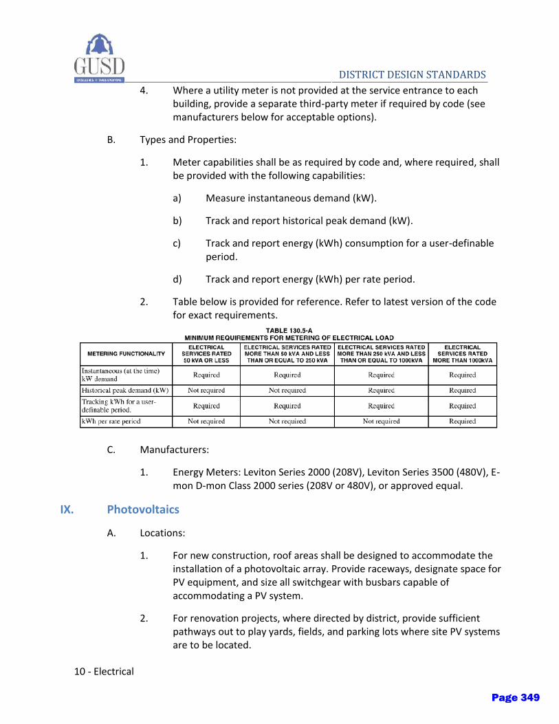
10 - Electrical
DISTRICT DESIGN STANDARDS 4. Where a utility meter is not provided at the service entrance to each
building, provide a separate third-party meter if required by code (see manufacturers below for acceptable options).
B. Types and Properties:
1. Meter capabilities shall be as required by code and, where required, shall be provided with the following capabilities:
a) Measure instantaneous demand (kW).
b) Track and report historical peak demand (kW).
c) Track and report energy (kWh) consumption for a user-definable period.
d) Track and report energy (kWh) per rate period.
2. Table below is provided for reference. Refer to latest version of the code for exact requirements.
C. Manufacturers:
1. Energy Meters: Leviton Series 2000 (208V), Leviton Series 3500 (480V), E-mon D-mon Class 2000 series (208V or 480V), or approved equal.
IX. Photovoltaics
A. Locations:
1. For new construction, roof areas shall be designed to accommodate the installation of a photovoltaic array. Provide raceways, designate space for PV equipment, and size all switchgear with busbars capable of accommodating a PV system.
2. For renovation projects, where directed by district, provide sufficient pathways out to play yards, fields, and parking lots where site PV systems are to be located.
Page 349
Electrical - 11
DISTRICT DESIGN STANDARDS B. Manufacturers: SunPower
1. Photovoltaics: Systems shall be designed and installed by a PPA provider as selected by the district. Coordinate with PPA provider for all requirements and provide conduit, disconnects, panels, and other miscellaneous appurtenances as required to tie the PV systems into the building electrical systems.
X. Emergency Power
A. Locations:
1. Provide emergency power for all emergency lighting fixtures to meet code required minimum egress light levels at both the interior and exterior of the building.
2. Provide standby power for all large walk-in fridges and freezers at central kitchen locations.
B. Types and properties:
1. Emergency power for light fixtures shall be provided via centralized battery inverter system to provide a minimum of 90 minutes of run time. Individual battery packs shall not be used.
2. Fire alarm and security systems shall be provided with integral battery backup sized to provide, at a minimum, backup times in accordance with code and owner requirements, whichever is larger.
3. Walk-in fridges and freezers shall be provided with standby power fed via diesel generator or via battery system where a PV system is available to recharge batteries. Backup time shall be a minimum of 12 hours to sustain power to the units throughout the night when facilities personnel may not be available to relocate perishable food items.
C. Manufacturers:
1. Centralized Inverters: Myers Power, Dual-Light, Iso-Light, or approved equal.
2. Diesel Generators: Cummins, Siemens, Generac, or approved equal.
3. Battery Systems: Tesla Powerwall or approved equal (to be vetted and approved by District prior to finalizing design development documents).
Page 350
12 - Electrical
DISTRICT DESIGN STANDARDS XI. Fire Alarm
A. Furnish and install all materials and equipment including all required equipment, panels, raceways, conductors and connections, and provide all labor required and necessary to provide a complete operational and DSA approved fire alarm system complying with the latest applicable codes. All other work and miscellaneous items, not specifically mentioned, but reasonably inferred for a complete addressable fire alarm installation including all accessories and appurtenances required for testing the systems.
B. Provide a complete, non-coded, addressable, microprocessor-based fire alarm system with initiating devices, notification appliances, and monitoring and control devices compatible with the existing District systems. Provide all necessary software upgrades so that systems can communicate effectively.
C. Devices and equipment for fire alarm system shall be listed by the California State Fire Marshal for the specific purpose the device or equipment is used.
D. System shall include, but not limited to, all drawings, CSFM cutsheets, voltage drop calculations, battery calculations and all components necessary for DSA approval.
XII. Clock and Audio Visual
A. Clock and Speakers Manufacturer: Atlas
B. All new components should be compatible with the IP network.
C. Speakers:
1. Speakers should be ceiling mounted.
D. Provide all components to provide a complete operational communications systems. Including but not limited to, raceways, boxes, wiring, patch panels, racks and other required equipment as required for a fully functioning systems.
E. Provide any and all upgrades needed to allow new systems work with the campus existing systems.
F. Where possible, a minimum of two (2) duplex power outlets should be provided per classroom wall for convenience and laptop usage by students.
G. A wall-mounted telephone should be located by a main exterior door for emergency contact with the office.
Page 351
Electrical - 13
DISTRICT DESIGN STANDARDS XIII. Intrusion Alarm System
A. All intrusion alarm systems should be IP enabled.
B. Current high schools are currently 100% monitored.
C. Current elementary and middle schools have intrusion alarms including administration, multi-purpose rooms, computer labs and library spaces.
D. New schools should be 100% zoned, with modernization upgrading to the reasonable extent possible.
XIV. Electrical Rooms
A. Electrical rooms shall be separated from other occupancies as required by the CBC.
B. Access to electrical rooms shall be directly from outdoors or a corridor, access through intervening spaces is not allowed.
C. Doors for exterior entrances shall be oversized or double doors based on the equipment being provided. Designer must coordinate with the design team and District to determine the implementation of this requirement.
D. Ingress/egress openings shall be sized to allow future equipment replacement without demolition of walls or roof. (Removable louvers are acceptable). Provide minimum of two 3’-0” double doors for rooms larger than 100 sf.
E. Electrical rooms shall be used only for electrical related equipment (including fire alarm, EMS and other dry utilities).
F. Rooms shall be equipped with a thermostatically controlled exhaust fan and provisions for filtered make up air. Fan shall be sized to remove electrical equipment heat generation (transformers, VFDs, etc.)
G. Rooms shall be equipped with adequate lighting and lighting shall be controlled via occupancy sensor.
H. All panels and electrical equipment shall be provided with code required service access space.
I. Wet utilities (with the exception of fire sprinklers, where required) shall not pass through, or be installed in, any electrical room.
J. Underground conduit entrance into electrical switchgear should be routed under the equipment unless otherwise approved by the owner prior to scope finalization.
Page 352
14 - Electrical
DISTRICT DESIGN STANDARDS
XV. MDF and IDF Rooms
A. For all new construction, IDFs should not be located in classrooms or offices, but should ideally be placed in a separate locked location when possible. When not possible, enough room must be supplied to allow for lockable cabinets to secure all network equipment.
B. IDFs are ideally located in the middle of a classroom wing so they can serve both ends of a wing.
C. Uninterrupted Power Supply (UPS) should be provided in every IDF closet.
XVI. IT
A. Reference attached IT specification section from District.
Page 353
Page 1 of 32
GILROY UNIFIED SCHOOL DISTRICT – TELECOMMUNICATIONS SYSTEM 27 00 00
SECTION 27 00 00 – TELECOMMUNICATIONS CABLING SYSTEM PART 1 – GENERAL 1.1 RELATED DOCUMENTS:
A. Drawings and general provisions of Contract, including General and Supplementary Conditions and Division-1 Specification sections, apply to work of this section.
B. Division-16 or 26, Basic Materials and Methods sections apply to work specified in this section.
1.2 REFERENCE STANDARDS
A. ANSI/TIA-492.AAAC-B – Detail Specification for 850-nm Laser-Optimized, 50-um Core Diameter/125-um Cladding Diameter Class 1a Graded-index Multimode Optical Fibers (OM3/OM4). Current Edition
B. ANSI TIA-492.CAAB – Detail Specification for Class IVa Dispersion-Unshifted Single-Mode Optical Fibers with Low Water Peak. Current Edition
C. ANSI/TIA-568.0-D – Generic Communications Cabling for Customer Premises
D. ANSI/TIA-568.1-D – Commercial Building Communications Cabling Standard
E. ANSI/TIA-568-C.2 – Balanced Twisted-Pair Telecommunications Cabling and Components Standards
F. ANSI/TIA-568-C.3 – Optical Fiber Cabling Components Standard
G. ANSI/TIA-569-D – Telecommunications Pathways and Spaces
H. ANSI/TIA-606-B – Administration Standard for the Commercial Telecommunications Infrastructure.
I. ANSI/JSTD-607-B – Generic Telecommunications Bonding and Grounding (Earthing) for Customer Premises
J. NFPA 70 – National Electrical Code (NEC).
K. BICSI – TDMM, Building Industries Consulting Services International, Telecommunications Distribution Methods Manual (TDMM)
1.3 GOVERNANCE
A. The Electrical Code referred to in these specifications is the National Electrical Code as currently adopted by the State of California. All work will be provided in strict compliance with the Electrical Code and all regulations that may apply.
B. Where standards exist, for a particular category, products used on this project will be listed by an OSHA approved Nationally Recognized Testing Laboratory (NRTL), and be approved or listed for the intended service and application.
C. These specifications do not undertake to repeat the requirements of codes, regulations or NRTL listing or labeling instructions. The Specifications or Drawings may require items or work beyond the requirements of applicable codes or regulations. The stricter, higher quality,
Page 354
Page 2 of 32
GILROY UNIFIED SCHOOL DISTRICT – TELECOMMUNICATIONS SYSTEM 27 00 00
greater quantity or higher cost will be allowed, and accommodations must be approved by Owner prior to procurement or installation. It is incumbent on the Installer, material and equipment suppliers to meet these specifications, applicable codes, regulations, and NRTL listing agency restrictions.
D. The word "Manufacturer" will include the Manufacturer, the Manufacturer’s Representative, the Distributor, the Fabricator, and the Supplier of the particular classification of equipment, system, product, and material.
E. All work, equipment, and systems will be manufactured, provided, repaired, installed, and tested in accordance with the latest edition and all current amendments of the applicable publications and standards of the organizations listed below as of the date of the Contract Documents. When the Specification requirements exceed the requirements of these publications and standards the Specifications will govern:
1. State Building Code (SBC) 2. Building Department Inspectional Services 3. American Society for Testing and Materials (ASTM) 4. Underwriter's Laboratories, Inc. (UL) 5. Insulated Cable Engineers Association (ICEA) 6. National Electrical Manufacturers Association (NEMA) 7. Institute of Electrical and Electronics Engineers, Inc. (IEEE) 8. American National Standards Institute, Inc. (ANSI) 9. National Fire Protection Association (NFPA) 10. Local Electric Code 11. Department of Public Safety (DPS) 12. Building Officials and Code Administrators International, Inc. (BOCA) 13. Department of Labor USA. Safety and Health Regulations for Construction (OSHA) 14. Energy Codes 15. National Electrical Contractors Association (NECA) 16. National Bureau of Standards (NBS) 17. Federal Communications Commission (FCC) 18. Utilities Serving Project. 19. Fire Department. 20. Americans with Disabilities Act Applications Guidelines (ADAAG). 21. Accessibility Guidelines for Buildings and Facilities. 22. Any and all Federal, State and Local Standards, Codes and Authorities having
Jurisdiction. 23. In addition, all phases of the Structured Cabling System installation will adhere to
applicable Local Area Network (LAN) Specifications of the Institute of Electrical and Electronics Engineers (IEEE), Electronics Industry Association/Telecommunications Industry Association (TIA/EIA), and Building Industry Consulting Service International (BICSI). The entire system and all components will be NRTL certified to appropriate TIA/EIA performance rating Category, Latest TIA/EIA Standards 455-A, 492AAAA, 568-A (latest revision) and (SP-4195-B and SP-4195-B-1), 569-A, 570, 606, 607 and 758, TIA/EIA TSB 67, TSB 72, TSB 75, TSB 95 and other standards as applicable.
F. The Installer will have available at the job site at all times one copy of the latest edition of the Electrical Code, TIA and BICSI Standards applicable to the work as specified within this document.
G. The above requirements will not in any way limit responsibility or requirements to comply with all other codes, standards and laws.
H. Material, equipment, enclosures, and systems will be designed for use as required to suit the conditions, exterior or interior operation, dust tight, water tight, explosion-proof, or other
Page 355

Page 3 of 32
GILROY UNIFIED SCHOOL DISTRICT – TELECOMMUNICATIONS SYSTEM 27 00 00
special types.
I. All materials shall be purchased from Distributors authorized by system Manufacturers to sell new and unused components.
1.4 DESCRIPTION OF WORK:
A. The extent of telephone/data system work is indicated and is hereby defined to include, but not be limited to cable, cable supports, raceway, connectors, panels, wire management, device plates, patch cords, backboard, cabinets, grounding, firestop and miscellaneous items required for a complete, tested and operational system.
B. Provide, install and test the complete cable and outlet system as indicated and described herein. Work includes procurement, project management, installation, labeling, termination, testing and cleanup of all cables installed under this project.
C. Provide system testing, as-builts (redlines) of installed cables and numbering plan, Operations & Maintenance Manuals (O&M’s), and processing of warranty registration with Manufacturer.
D. Project coordination with General Contractor, Owner, Owners Representative, and other trades before, during and upon completion of project as necessary for a well-executed project.
E. Refer to other Master Division sections, bid proposal and project responsibilities matrix for responsibility and requirements for raceways, boxes and fittings, wiring devices (plates), and supporting devices, and other sections, as applicable.
F. Horizontal cable and its connecting hardware provide the means of transporting signals between the telecommunications outlet/connector and the horizontal cross-connect located in the communications equipment room. This cabling and its connecting hardware are called "permanent link," a term that is used in the testing protocols.
G. Horizontal copper cabling system consists of four twisted pairs of solid annealed copper. Each four pair cable is terminated onto 8 position 8 conductor (“RJ45”, or 8P8C) connectors (jacks) using 110-style Insulation Displacement Conductors (IDCs). Color-coded connectors are placed into NEMA rated faceplates at the work area and placed into corresponding rack-mounted patch panels in the equipment / networking rooms. The jacks use state-of-the-art flexible circuit technology and other techniques to effectively eliminate Alien Crosstalk.
H. Horizontal cabling may contain no more than one transition point or consolidation point between the horizontal cross-connect and the telecommunications outlet/connector.
I. Bridged taps and/or splices will not be installed in the horizontal cabling.
J. Communications cables shall be rated CMR or CMP. CMP cable ratings are required for cables passing through or contained within plenum air handling spaces, such as above drop ceilings and return or supply air shafts. However, the contractor is responsible for installing the correct cable type in the appropriate environment, and any failures to do so according to the District or the Authority Having Jurisdiction (AHJ) will result in the contractor removing the unsuitable cable and installing the correct cable, at their own expense.
K. The maximum allowable horizontal cable length is 295 feet (90 m). This maximum allowable length does not include an allowance for patch cords, maximum length of 16 feet (4.9 m) to the workstation equipment and of 16 feet (4.9 m) in the horizontal cross-connect.
Page 356

Page 4 of 32
GILROY UNIFIED SCHOOL DISTRICT – TELECOMMUNICATIONS SYSTEM 27 00 00
1.5 QUALITY ASSURANCE:
A. Comply with applicable portions of NEC as to type products used and installation of components. Provide products and materials, which have been UL-listed and labeled. Comply with NEMA standards for low loss extended frequency cable and EIA/TIA TSB-36. Comply with EIA/TIA 568-A, EIA/TIA 569 and manufacturer's recommendations. Comply with EIA/TIA testing standards for horizontal cabling.
1.6 SUBMITTALS AND SUBSTITUTIONS
A. The District has standardized on a copper and optical fiber cabling system design using Leviton jacks, patch panels, patch cords, fiber cords, fiber connectors, trunk cables, fiber enclosures and modules, as well as Berk-Tek field-terminable copper and fiber cables. The District is satisfied that the products specified herein are qualified for the purpose intended.
B. Submittals: Contractor shall transmit all submittals to architect and owner for review within 21 days of award of contract.
C. Substitutions: Products which are proposed in the bid response which are of an alternative solution will be reviewed by Owner and Architect. Any substitutions must be approved by Owner or Owner’s Representative in writing.
1. Submit manufacturer’s data and installation details for all devices, plates, cable, terminal blocks, patch cords, wire management, labels and similar equipment which are not in accordance with District standards.
2. Submit a copy of 3rd
party testing and certification documents which prove they meet or exceed the requirements as set forth in this document, for any product or system not specified herein or proposed as an “equal or better” substitute for District-approved products.
1.7 CONTRACTOR QUALIFICATIONS AND TRAINING
A. The contractor shall be fully conversant and capable in the cabling of low voltage applications such as, but not limited to data, voice and imaging network systems. The Contractor shall at a minimum possess the following qualifications:
1. Possess those licenses/permits required to perform telecommunications installations in
the specified jurisdiction.
2. Provide references of the type of installation provided in this specification.
3. Personnel trained and certified in fiber optic cabling, splicing, termination and testing techniques. Personnel must have experience using a light meter and OTDR.
4. Personnel trained in the installation of pathways and support for housing horizontal and backbone cabling.
5. Personnel knowledgeable in local, state, province and national codes, and regulations. All work shall comply with the latest revision of the codes or regulations. When conflict exists between local or national codes or regulations, the most stringent codes or regulations shall be followed.
6. Be in business a minimum of five (5) years.
7. Be an approved Leviton Certified Installer in the Leviton Certified Network Installer
Page 357
Page 5 of 32
GILROY UNIFIED SCHOOL DISTRICT – TELECOMMUNICATIONS SYSTEM 27 00 00
program before, during, and through completion of the system installation. Supporting documentation will be required as part of the submittal.
8. Maintain a certified RCDD on staff and utilize certified BICSI Installers for this project.
1.8 WARRANTY
A. A Limited Lifetime Product & Performance Warranty covering all components, equipment and workmanship shall be provided to the Owner, submitted in writing with system documentation. The warranty period shall begin on the system's first use by the owner.
1. Horizontal channels shall be completed with Leviton Network Solutions factory-terminated copper and/or fiber optic patch cords in order to be eligible for the applicable Leviton Warranty with channel performance guarantees.
2. Approved product shall be listed on the most recent version of the applicable Leviton data sheets for each listed Berk-Tek Leviton Technologies solution.
3. The Contractor must pre-register the project with the Manufacturer before installation has begun. Following project completion, contractor is responsible for completing all warranty registration procedures on behalf of the District.
4. Should the cabling system fail to perform its expected operation within this warranty period due to inferior or faulty material and/or workmanship, the contractor shall promptly make all required corrections without cost to the owner.
B. Certified Installer shall provide labor, materials, and documentation in accordance with Leviton Network Solutions requirements necessary to ensure that the Owner will be furnished with the maximum available Manufacturer’s Warranty in force at the time of this project.
C. The installed structured cabling system shall provide a warranty guaranteeing 2 dB NEXT installed channel performance above the ANSI/TIA 568-C requirements for Augmented Category 6 (CAT 6A) cabling systems or ISO 11801 requirements for Cass E.
1. Standards-compliant channel or permanent link performance tests shall be performed in the field with a Leviton-approved certification tester in the appropriate channel or permanent link test configuration.
D. Necessary documentation for warranty registration shall be provided to the manufacturer by the installer (within 10 days) following 100 percent testing of cables.
1. Submit test results to Leviton Network Solutions in the certification tester’s original software files.
2. Installer shall ensure that the warranty registration is properly submitted, with all required documentation within 10 days of project completion.
3. Certified Contractor/Integrator must adhere to the terms and conditions of the respective manufacturer’s warranty programs.
E. Installer shall ensure that the Owner receives the manufacturer issued project warranty certificate within 60 calendar days of warranty registration.
1.9 PRODUCTS INSTALLED BUT NOT SUPPLIED UNDER THIS SECTION
Page 358
Page 6 of 32
GILROY UNIFIED SCHOOL DISTRICT – TELECOMMUNICATIONS SYSTEM 27 00 00
A. All conduit and EMT required for Communications cabling pathway in/out of cross connect closets and in/out of wall cavities at the work area. EMT or Conduit for pathways shall have no more than two 90 degree bends between pull boxes and no continuous section over 100’.
B. All core holes through concrete, metal, finished hardwood or masonry; in-floor troughs (“Walker Duct”), and poke through devices in the floor for the installation of Communications cabling. Device plates for landing communication cables should be included in the Communications scope.
C. All core holes and EMT sleeves between floors for the routing of Communications cabling.
D. Back boxes for the mounting of NEMA rated faceplates.
E. Drag line or pull string at the back boxes fished through existing EMT, conduit, or wall cavities (“Ring and String”) to the accessible ceiling or other end of conduit, for installing 4 pair, multi-pair or fiber optic (horizontal and backbone) cables.
F. Minimum of 2 walls covered in ¾” AC grade plywood painted white with fire retardant paint in each cross connect closet or connection point for data, voice, video, security and building automation systems. Plywood walls shall be covered 4’ W x 8’ H whenever possible.
G. Basket tray or ladder racking to support main pathway cable bundles through hallways, open areas or exiting telecom rooms unless otherwise requested at time of bid.
H. #2 ground wire or other size as appropriate, from Telecommunications Grounding Bus Bar(s) to Building Ground. Use of #6 ground wire, or smaller as allowed, for grounding of telecommunications equipment installed under this Scope is included within the Telecommunications scope of work.
Page 359
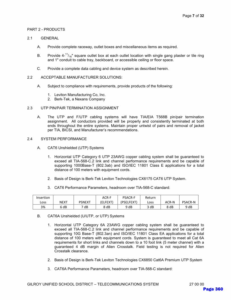
Page 7 of 32
GILROY UNIFIED SCHOOL DISTRICT – TELECOMMUNICATIONS SYSTEM 27 00 00
PART 2 - PRODUCTS 2.1 GENERAL
A. Provide complete raceway, outlet boxes and miscellaneous items as required.
B. Provide 4-11
/16" square outlet box at each outlet location with single gang plaster or tile ring and 1" conduit to cable tray, backboard, or accessible ceiling or floor space.
C. Provide a complete data cabling and device system as described herein.
2.2 ACCEPTABLE MANUFACTURER SOLUTIONS:
A. Subject to compliance with requirements, provide products of the following:
1. Leviton Manufacturing Co, Inc. 2. Berk-Tek, a Nexans Company
2.3 UTP PIN/PAIR TERMINATION ASSIGNMENT
A. The UTP and F/UTP cabling systems will have TIA/EIA T568B pin/pair termination assignment. All conductors provided will be properly and consistently terminated at both ends throughout the entire systems. Maintain proper untwist of pairs and removal of jacket per TIA, BICSI, and Manufacturer’s recommendations.
2.4 SYSTEM PERFORMANCE
A. CAT6 Unshielded (UTP) Systems
1. Horizontal UTP Category 6 UTP 23AWG copper cabling system shall be guaranteed to exceed all TIA-568-C.2 link and channel performance requirements and be capable of supporting 1000Base-T (802.3ab) and ISO/IEC 11801 Class E applications for a total distance of 100 meters with equipment cords.
2. Basis of Design is Berk-Tek Leviton Technologies CX6175 CAT6 UTP System.
3. CAT6 Performance Parameters, headroom over TIA-568-C standard:
B. CAT6A Unshielded (U/UTP, or UTP) Systems
1. Horizontal UTP Category 6A 23AWG copper cabling system shall be guaranteed to exceed all TIA-568-C.2 link and channel performance requirements and be capable of supporting 10G Base-T (802.3an) and ISO/IEC 11801 Class EA applications for a total distance of 100 meters with equipment cords. System is guaranteed to meet all Cat 6A requirements for short links and channels down to a 10 foot link (5 meter channel) with a guaranteed 4 dB margin of Alien Crosstalk. Field testing is not required for Alien Crosstalk clearance.
2. Basis of Design is Berk-Tek Leviton Technologies CX6850 Cat6A Premium UTP System
3. CAT6A Performance Parameters, headroom over TIA-568-C standard:
Insertion
Loss NEXT PSNEXT
ACR-F
(ELFEXT)
PSACR-F
(PSELFEXT)
Return
Loss ACR-N PSACR-N
3% 6 dB 7 dB 8 dB 9 dB 3 dB 8 dB 9 dB
Page 360
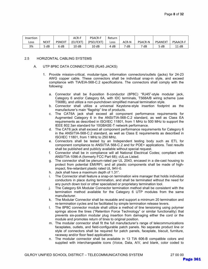
Page 8 of 32
GILROY UNIFIED SCHOOL DISTRICT – TELECOMMUNICATIONS SYSTEM 27 00 00
2.5 HORIZONTAL CABLING SYSTEMS
A. UTP 8P8C DATA CONNECTORS (RJ45 JACKS)
1. Provide mission-critical, modular-type, information connectors/outlets (jacks) for 24-23 AWG copper cable. These connectors shall be individual snap-in style, and exceed compliance with TIA/EIA-568-C.2 specifications. The connectors shall comply with the following:
a. Connector shall be 8-position 8-conductor (8P8C) “RJ45”-style modular jack, Category 6 and/or Category 6A, with IDC terminals, T568A/B wiring scheme (use T568B), and utilize a non-punchdown simplified manual termination style.
b. Connector shall utilize a universal Keystone-style insertion footprint as the manufacturer’s main “flagship” line of products.
c. The CAT6A jack shall exceed all component performance requirements for Augmented Category 6 in the ANSI/TIA-568-C.2 standard, as well as Class EA requirements as described in ISO/IEC 11801, from 1 MHz to 500 MHz to support the IEEE 802.3an standard for 10GBASE-T network performance.
d. The CAT6 jack shall exceed all component performance requirements for Category 6 in the ANSI/TIA-568-C.2 standard, as well as Class E requirements as described in ISO/IEC 11801, from 1 MHz to 250 MHz.
e. Connectors shall be tested by an Independent testing body such as ETL for component compliance to ANSI/TIA 568-C.2 and for POE+ applications. Test results shall be published and publicly available without special request.
f. Connector shall be in compliance will all National Electrical Codes; compliant with ANSI/TIA-1096-A (formerly FCC Part 68); cULus Listed.
g. The connector shall be plenum-rated per UL 2043, encased in a die-cast housing to protect from potential EMI/RFI, and all plastic components shall be made of high-impact, fire-retardant plastic rated UL 94V-0.
h. Jack shall have a maximum depth of 1.31”. i. The Connector shall feature a snap-on termination wire manager that holds individual
conductors in place during termination, and shall be terminated without the need for any punch down tool or other specialized or proprietary termination tool.
j. The Category 6A Modular Connector termination method shall be consistent with the termination method available for the Category 6 UTP modules from the same manufacturer.
k. The Modular Connector shall be reusable and support a minimum 20 termination and re-termination cycles and be facilitated by simple termination release levers.
l. The 8P8C connector module shall utilize a method of tine tensioning using polymer springs above the tines (“Retention Force Technology” or similar functionality) that prevents six-position modular plug insertion from damaging either the cord or the module and promotes return of tines to original position.
m. The modular connector shall fit the full manufacturer’s range of telecommunications faceplates, outlets, and field-configurable patch panels. No separate product line or style of connectors shall be required for patch panels, faceplate, biscuit, furniture, raceway and/or floor feed applications.
n. The modular connector shall be available in 13 TIA 606-B compatible colors and supplied with interchangeable icons (Voice, Data, A/V, and blank, color coded to
Insertion
Loss NEXT PSNEXT
ACR-F
(ELFEXT)
PSACR-F
(PSELFEXT)
Return
Loss ACR-N PSACR-N PSANEXT PSAACR-F
3% 5 dB 6 dB 10 dB 10 dB 4 dB 7 dB 7 dB 5 dB 11 dB
Page 361
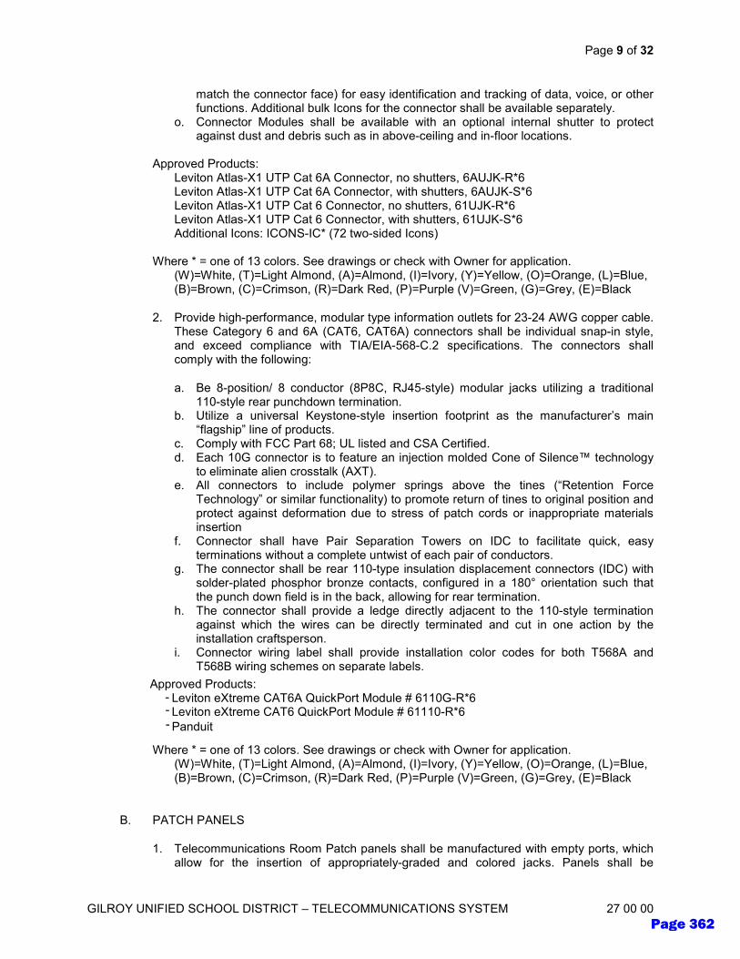
Page 9 of 32
GILROY UNIFIED SCHOOL DISTRICT – TELECOMMUNICATIONS SYSTEM 27 00 00
match the connector face) for easy identification and tracking of data, voice, or other functions. Additional bulk Icons for the connector shall be available separately.
o. Connector Modules shall be available with an optional internal shutter to protect against dust and debris such as in above-ceiling and in-floor locations.
Approved Products:
Leviton Atlas-X1 UTP Cat 6A Connector, no shutters, 6AUJK-R*6 Leviton Atlas-X1 UTP Cat 6A Connector, with shutters, 6AUJK-S*6 Leviton Atlas-X1 UTP Cat 6 Connector, no shutters, 61UJK-R*6 Leviton Atlas-X1 UTP Cat 6 Connector, with shutters, 61UJK-S*6 Additional Icons: ICONS-IC* (72 two-sided Icons)
Where * = one of 13 colors. See drawings or check with Owner for application.
(W)=White, (T)=Light Almond, (A)=Almond, (I)=Ivory, (Y)=Yellow, (O)=Orange, (L)=Blue, (B)=Brown, (C)=Crimson, (R)=Dark Red, (P)=Purple (V)=Green, (G)=Grey, (E)=Black
2. Provide high-performance, modular type information outlets for 23-24 AWG copper cable. These Category 6 and 6A (CAT6, CAT6A) connectors shall be individual snap-in style, and exceed compliance with TIA/EIA-568-C.2 specifications. The connectors shall comply with the following:
a. Be 8-position/ 8 conductor (8P8C, RJ45-style) modular jacks utilizing a traditional 110-style rear punchdown termination.
b. Utilize a universal Keystone-style insertion footprint as the manufacturer’s main “flagship” line of products.
c. Comply with FCC Part 68; UL listed and CSA Certified. d. Each 10G connector is to feature an injection molded Cone of Silence™ technology
to eliminate alien crosstalk (AXT). e. All connectors to include polymer springs above the tines (“Retention Force
Technology” or similar functionality) to promote return of tines to original position and protect against deformation due to stress of patch cords or inappropriate materials insertion
f. Connector shall have Pair Separation Towers on IDC to facilitate quick, easy terminations without a complete untwist of each pair of conductors.
g. The connector shall be rear 110-type insulation displacement connectors (IDC) with solder-plated phosphor bronze contacts, configured in a 180° orientation such that the punch down field is in the back, allowing for rear termination.
h. The connector shall provide a ledge directly adjacent to the 110-style termination against which the wires can be directly terminated and cut in one action by the installation craftsperson.
i. Connector wiring label shall provide installation color codes for both T568A and T568B wiring schemes on separate labels.
Approved Products:
Leviton eXtreme CAT6A QuickPort Module # 6110G-R*6 Leviton eXtreme CAT6 QuickPort Module # 61110-R*6
Where * = one of 13 colors. See drawings or check with Owner for application.
(W)=White, (T)=Light Almond, (A)=Almond, (I)=Ivory, (Y)=Yellow, (O)=Orange, (L)=Blue, (B)=Brown, (C)=Crimson, (R)=Dark Red, (P)=Purple (V)=Green, (G)=Grey, (E)=Black
B. PATCH PANELS
1. Telecommunications Room Patch panels shall be manufactured with empty ports, which allow for the insertion of appropriately-graded and colored jacks. Panels shall be
Approved Products: Leviton eXtreme CAT6A QuickPort Module # 6110G-R*6 Leviton eXtreme CAT6 QuickPort Module # 61110-R*6
Panduit
---
Page 362

Page 10 of 32
GILROY UNIFIED SCHOOL DISTRICT – TELECOMMUNICATIONS SYSTEM 27 00 00
standard density and used for all CAT6 and CAT6A terminations at IDF and MDF locations. Panels shall be:
a. Independently tested and verified by Intertek (ETL) to meet all TIA component, permanent link, and channel requirements.
b. QuickPort modular panels with CAT6 or CAT6A jacks in either standard density OR QuickPort modular Shielded panels with CAT6 and CAT6A High-Density shielded jacks.
c. Patch panels shall be sized to fit an EIA standard, 19 inch relay rack. d. QuickPort modular patch panels will utilize a universal Keystone-style insertion
footprint as the manufacturer’s main “flagship” line of products and receive the same jacks as are used in the workstation outlets. No special “Panel jack” shall be required.
Approved Products:
Leviton 1RU QuickPort® Flat Patch Panel # 49255-H24 (24-port)
Leviton 1RU QuickPort® Flat High Density Patch Panel # 49255-Q48 (48-port)
C. FACEPLATES
1. Faceplates (wallplates) secure information outlets to the work area. Contractor shall provide and install single gang faceplate kits to house all jacks as required for all work area outlets, workstation base feeds, and furniture openings. Unused telecom backboxes shall receive a solid blank faceplate. Telecommunications faceplates shall:
a. Utilize a keystone-type (“QuickPort”) footprint to match the approved connectivity manufacturer, and be made by the same manufacturer as the connectors.
b. Precisely match colors and materials of the power wiring device plates. c. Support any connectivity media type, including fiber, AV and copper applications. d. Have write-on or printable designation labels for circuit identification together with a
clear plastic cover. e. Be available in single-gang and double-gang configurations. f. Have surface-mount boxes and standoff rings available for both single and double
gang faceplates. g. Have single-port matching color blank inserts available in packs of 10.
Approved Products: Leviton QuickPort Single-Gang, Plastic, with ID Windows, # 42080-#xS Leviton QuickPort Double-Gang, Plastic, with ID Windows, # 42080-#xP Leviton QuickPort 12-port Double-Gang, Plastic, with ID Windows, # 42080-12x Leviton QuickPort Single-Gang, Stainless Steel, with ID Windows, # 43080-1L# Leviton QuickPort Double-Gang, Stainless Steel, with ID Windows, # 43080-2L# Leviton QuickPort 12-port Double-Gang, Stainless Steel, with ID Windows, # 43080-L12 Leviton QuickPort Blank Inserts, pack of 10, #41084-BxB Leviton QuickPort Single-Gang Stainless Steel Wall Phone faceplate, #4108W-0SP Leviton Blank Single-Gang Plate #xx014-000, xx= 88 (White), 77 (Lt. Almond), 86 (Ivory) Leviton Blank Stainless Steel Blank Plate #84014-040 (1-gang), 84025-040 (2-gang)
Where: # = number of ports: 1, 2, 3, 4, 6 x = color: White (W), Ivory (I), Light Almond (T), Gray (G), Black (E)
D. SURFACE-MOUNT BLOCKS (SMB)
1. Surface-Mount Blocks (SMBs) are used to protect terminated CAT6 and CAT6A cables at the endpoints where they are not contained within walls or furniture. Example locations
Page 363

Page 11 of 32
GILROY UNIFIED SCHOOL DISTRICT – TELECOMMUNICATIONS SYSTEM 27 00 00
may be Wireless Access Points (WAPs), Group Work Areas fed by conduits run down columns, security cameras, or other network-enabled device locations.
2. Ceiling, WAP, Camera and other non-wallmount locations will use a 2-port plastic SMB.
3. Small Surface-Mount Boxes shall exhibit the following characteristics:
a. Outlet housings for WAPs and other devices shall be a high-density, low profile design with (2) or (4) field-configurable ports, snap-lock cover, and cable knockouts on back.
b. Housing cover shall have raceway knockouts for top and bottom entry. Base shall include Tie-wrap anchor points at all cable entrances.
c. The housing shall be mountable with screws, tape or a single magnet. d. The cover shall provide the option of securing it to the base with a screw that is
hidden under the outlet identification window. e. Shall be constructed of high-impact self-extinguishing plastic rated UL 94V-0, and be
UL Listed and compliant with FCC Part 68 and TIA-568- B specifications.
Approved Products: Leviton QuickPort 2-port Surface-mount Housing, White, #41089-2WP
E. DATA CABLES
1. CAT6 Unshielded twisted-pair cable (UTP)
a. 100 ohm, Category 6, 23 AWG, 4-pair unshielded twisted pair solid annealed copper conductors
b. Cable shall be characterized to 550 MHz and UL/ETL Listed by the Manufacturer printed on the cable jacket and package, as well as ETL Verified to TIA/EIA-568-C.2 Category 6 and ISO/IEC 11801 Class E.
c. Cable shall be Plenum-rated (CMP) for any location where plenum cable is required. d. Color: White. e. Outer Diameter: 0.230” max. f. Cable shall be guaranteed to exceed all TIA-568-C.2 link and channel performance
requirements and be capable of supporting 1000Base-T (802.3ab) and ISO/IEC 11801 Class E applications for a total distance of 100 meters with equipment cords
2. CAT6A Unshielded twisted-pair cable (U/UTP, or UTP)
a. 100-Ohm, 23 AWG, CAT 6A 4-pair balanced unshielded twisted pair solid annealed copper
b. Cable shall be characterized to 750 MHz and UL/ETL Listed by the Manufacturer printed on the cable jacket and package, as well as ETL Verified to TIA/EIA-568-C.2 Category CAT 6A and ISO/IEC 11801 Class EA requirements for channel, link and component performance to support IEEE 10GBASE-T (802.3an) networks
c. Maximum Cable Outer Diameter: 0.275”. d. Documentation available from an independent third-party testing agency that verifies
through random sampling that cable components perform at or above the levels contained on their product specifications, not simply at or above the standard.
e. Guaranteed cable balance improves overall performance and reduces emissions which results in error-free performance up to 10 Gigabit Ethernet with full duplex transmission
f. Provided on spools to reduce risk of kinking cable upon deployment g. Cable shall be Plenum-rated (CMP) for any location where plenum cable is required. h. Color: White i. Be made by an ISO 9001 and 14001 Certified Manufacturer.
Page 364
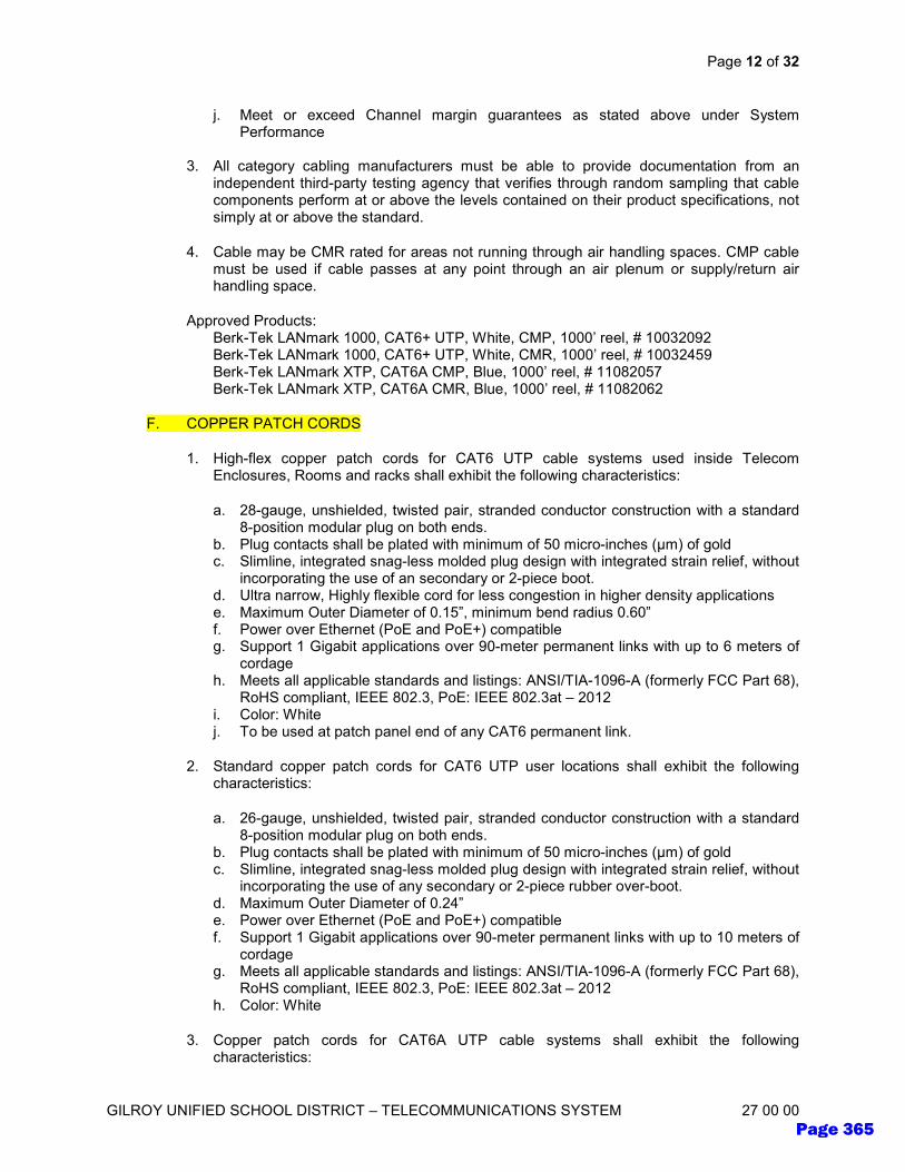
Page 12 of 32
GILROY UNIFIED SCHOOL DISTRICT – TELECOMMUNICATIONS SYSTEM 27 00 00
j. Meet or exceed Channel margin guarantees as stated above under System Performance
3. All category cabling manufacturers must be able to provide documentation from an
independent third-party testing agency that verifies through random sampling that cable components perform at or above the levels contained on their product specifications, not simply at or above the standard.
4. Cable may be CMR rated for areas not running through air handling spaces. CMP cable must be used if cable passes at any point through an air plenum or supply/return air handling space.
Approved Products: Berk-Tek LANmark 1000, CAT6+ UTP, White, CMP, 1000’ reel, # 10032092 Berk-Tek LANmark 1000, CAT6+ UTP, White, CMR, 1000’ reel, # 10032459 Berk-Tek LANmark XTP, CAT6A CMP, Blue, 1000’ reel, # 11082057 Berk-Tek LANmark XTP, CAT6A CMR, Blue, 1000’ reel, # 11082062
F. COPPER PATCH CORDS
1. High-flex copper patch cords for CAT6 UTP cable systems used inside Telecom Enclosures, Rooms and racks shall exhibit the following characteristics:
a. 28-gauge, unshielded, twisted pair, stranded conductor construction with a standard 8-position modular plug on both ends.
b. Plug contacts shall be plated with minimum of 50 micro-inches (μm) of gold c. Slimline, integrated snag-less molded plug design with integrated strain relief, without
incorporating the use of an secondary or 2-piece boot. d. Ultra narrow, Highly flexible cord for less congestion in higher density applications e. Maximum Outer Diameter of 0.15”, minimum bend radius 0.60” f. Power over Ethernet (PoE and PoE+) compatible g. Support 1 Gigabit applications over 90-meter permanent links with up to 6 meters of
cordage h. Meets all applicable standards and listings: ANSI/TIA-1096-A (formerly FCC Part 68),
RoHS compliant, IEEE 802.3, PoE: IEEE 802.3at – 2012 i. Color: White j. To be used at patch panel end of any CAT6 permanent link.
2. Standard copper patch cords for CAT6 UTP user locations shall exhibit the following characteristics:
a. 26-gauge, unshielded, twisted pair, stranded conductor construction with a standard 8-position modular plug on both ends.
b. Plug contacts shall be plated with minimum of 50 micro-inches (μm) of gold c. Slimline, integrated snag-less molded plug design with integrated strain relief, without
incorporating the use of any secondary or 2-piece rubber over-boot. d. Maximum Outer Diameter of 0.24” e. Power over Ethernet (PoE and PoE+) compatible f. Support 1 Gigabit applications over 90-meter permanent links with up to 10 meters of
cordage g. Meets all applicable standards and listings: ANSI/TIA-1096-A (formerly FCC Part 68),
RoHS compliant, IEEE 802.3, PoE: IEEE 802.3at – 2012 h. Color: White
3. Copper patch cords for CAT6A UTP cable systems shall exhibit the following characteristics:
Page 365
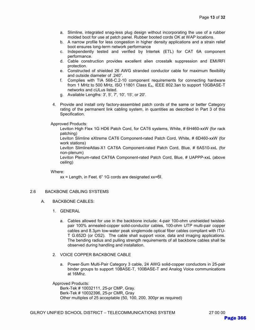
Page 13 of 32
GILROY UNIFIED SCHOOL DISTRICT – TELECOMMUNICATIONS SYSTEM 27 00 00
a. Slimline, integrated snag-less plug design without incorporating the use of a rubber molded boot for use at patch panel. Rubber booted cords OK at WAP locations.
b. A narrow profile for less congestion in higher density applications and a strain relief boot ensures long-term network performance
c. Independently tested and verified by Intertek (ETL) for CAT 6A component performance.
d. Cable construction provides excellent alien crosstalk suppression and EMI/RFI protection.
e. Constructed of shielded 26 AWG stranded conductor cable for maximum flexibility and outside diameter of .240”.
f. Complies with TIA 568-C.2-10 component requirements for connecting hardware from 1 MHz to 500 MHz, ISO 11801 Class EA, IEEE 802.3an to support 10GBASE-T networks and cULus listed.
g. Available Lengths: 3', 5', 7', 10', 15', or 20'.
4. Provide and install only factory-assembled patch cords of the same or better Category rating of the permanent link cabling system, in quantities as described in Part 3 of this Specification.
Approved Products: Leviton High Flex 1G HD6 Patch Cord, for CAT6 systems, White, # 6H460-xxW (for rack patching) Leviton Slimline eXtreme CAT6 Component-rated Patch Cord, White, # 6D460-xxW (for work stations) Leviton SlimlineAtlas-X1 CAT6A Component-rated Patch Cord, Blue, # 6AS10-xxL (for non-plenum) Leviton Plenum-rated CAT6A Component-rated Patch Cord, Blue, # UAPPP-xxL (above ceiling)
Where:
xx = Length, in Feet. 6” 1G cords are designated xx=6I.
2.6 BACKBONE CABLING SYSTEMS
A. BACKBONE CABLES:
1. GENERAL
a. Cables allowed for use in the backbone include: 4-pair 100-ohm unshielded twisted-pair 100% annealed-copper solid-conductor cables, 100-ohm UTP multi-pair copper
cables and 8.3µm low-water peak singlemode optical fiber cables compliant with ITU-T G.652D (or OS2). The cable shall support voice, data and imaging applications. The bending radius and pulling strength requirements of all backbone cables shall be observed during handling and installation.
2. VOICE COPPER BACKBONE CABLE
a. Power-Sum Multi-Pair Category 3 cable, 24 AWG solid-copper conductors in 25-pair
binder groups to support 10BASE-T, 100BASE-T and Analog Voice communications at 16Mhz.
Approved Products:
Berk-Tek # 10032111, 25-pr CMP, Gray. Berk-Tek # 10032396, 25-pr CMR, Gray Other multiples of 25 acceptable (50, 100, 200, 300pr as required)
Page 366

Page 14 of 32
GILROY UNIFIED SCHOOL DISTRICT – TELECOMMUNICATIONS SYSTEM 27 00 00
3. SINGLEMODE OPTICAL FIBER CABLE
a. Optical fiber cables run shall be low-water-peak Singlemode (OS2), and meet all of
the requirements delineated within the specifications of ANSI/TIA/EIA-568-C. b. Fiber optic cables will utilize an interlocking armor outer cover around an integrated
tight-buffer (indoor only) or Loose-Tube (indoor/outdoor) cable construction. c. Indoor fiber optic cable shall be minimum 12 strands, tight buffered, and individual
fiber strands shall be 900 micron jacketed. d. Outdoor or indoor/outdoor fiber optic cable shall be minimum 24 strands, loose tube
construction with 250 micron unjacketed fiber strands in a 12-strand buffer tube. e. Cables are typically OFNR rated for in-conduit applications, but must always be
constructed of materials and rated appropriate for the environment in which it is installed (Indoor, Indoor/Outdoor, Outside Plant (OSP), OFNP or OFNR, OFCP or OFCR). In-slab conduits are considered a “wet environment” and require OSP or Indoor/Outdoor rating. Cables running at least a portion of the length through an open-air plenum or air handling space must be OFNP or OFCP (plenum) rated. Contractor is solely responsible for installation of the correctly-rated cable in the appropriate environment, as required by the AHJ or local ordinance
f. Loose tube fibers shall utilize a fan-out kit to fit 250 micron fibers into a 900 micron protective sheath when terminating. Loose Tube cables are generally expected for outdoor environments
Approved Products:
Berk-Tek Adventum Indoor/Outdoor armored Dry Loose-Tube Plenum cable, 12-strand, # LTPK012BAB0403
Berk-Tek Adventum Indoor/Outdoor armored Dry Loose-Tube Plenum cable, 24-strand, # LTPK12B024AB0403
Berk-Tek Adventum Indoor/Outdoor armored Dry Loose-Tube Plenum, 48-strand, #LTPK12B048AB0403
Leviton 12-fiber, 24” fan-out Kit, # 49887-12S
B. COPPER TERMINATION BLOCKS
1. Provide termination blocks for Category 3 Backbone Cabling Systems that support up to
Category 5e applications and facilitate cross-connection using twisted pair wiring. 2. Provide termination blocks for voice as required for all building telecommunications
needs. A minimum of two termination blocks shall be provided at each back board location.
3. The connecting hardware block shall support the appropriate Category 3 to 5e voice
(non-VOIP) applications and facilitate cross-connection and/or inter-connection using cross-connect wire. The cross-connect hardware shall be of 66-type (telephone) AND:
a. Made of flame-retardant thermoplastic, with the base consisting of vertical columns
for terminating up to 25-pairs of conductors. b. Available in a variety of insulation displacement clips (IDC) with and without tails. c. Have detachable stand-off brackets available. d. Available up to and including category 5e, and its use must be consistent with or
exceed the category of cable being terminated on it. e. Allow for a minimum of 200 re-terminations without signal degradation below
standards compliance limit. f. Have available color-coded hinged covers for administration. g. Support wire sizes: Solid: Wire Ranges 22-26 AWG (0.64mm - 0.40mm).
Page 367

Page 15 of 32
GILROY UNIFIED SCHOOL DISTRICT – TELECOMMUNICATIONS SYSTEM 27 00 00
h. ANSI/TIA/EIA-568-C and ISO/IEC 11801 category 5e compliant. i. UL Listed 1863 and CSA C22.2 approved. 66-type Connecting Blocks from an ISO
9001 Certified Manufacturer
Approved Products: Leviton 66 Connecting Block, Split-M type, 50-pair, # 40066-M50 Leviton 66 Connecting Block 89-D mounting Bracket, # 40089-00D Snap-on Cover for 66 blocks, clear, # 40050-MCV
C. COPPER PATCH PANELS
1. See above section 2.3.A.2.
D. FIBER OPTIC ENCLOSURES, PANELS AND TRAYS
1. All Fiber enclosures shall provide cross connect, inter connect, and splicing capabilities and contain cable management for supporting and routing the fiber cables/jumpers.
2. Fiber Adapter panel openings shall accept Fiber Adapter Plates (bulkheads), Splice Modules, and plug-n-play MTP modules/cassettes or any combination thereof.
3. 1RU, 2RU and 4RU enclosures shall hold up to 3, 6 or 12 adapter plates or cassettes, respectively.
4. All Fiber enclosures, panels and trays (units) shall provide cross-connect, inter-connect, and splicing capabilities and contain cable management for supporting and routing the fiber cables/jumpers.
5. Fiber enclosures shall exhibit the following characteristics:
a. Fiber enclosure shall be available in 1RU, 2RU or 4RU versions to accommodate fiber adapter plates, MTP Modules, and/or termination and splicing of fiber as needed
b. Enclosure shall inherently accept a 1-panel integrated splice cassette. c. Enclosures shall have a sliding tray which can be removed completely from
enclosure (from front or rear) to facilitate field terminations and splicing. Sliding tray glides forward and backward providing accessibility to front and rear bulkhead after installation.
d. 17" depth for high density fiber termination and/or splicing. e. Removable transparent hinged doors and slide away covers allow easy access
during install and visibility of interior after installation. f. Patch cord bend radius guides minimize macro bending. g. Stackable and adjustable fiber rings simplify cable routing and organization h. Fiber Jumper saddles pivot for improved patch cord routing and organization i. Removable rubber grommets protect cable and minimize dust build-up j. Multiple mounting bracket positions for 19" or 23" rack and cabinet installation (23"
1RU mounting bracket sold separately) k. Constructed of durable polycarbonate plastic and 16 gauge steel, powder-coated
black l. Door lock option available on front, rear, or both doors m. Fiber cable management shall allow for routing, storage, and protection of patch
cords, tight-buffer fiber, and backbone cables. n. Enclosure shall be available either empty or in custom pre-loaded configurations.
Approved Products: Leviton Opt-X Ultra Rack-Mount Enclosure, #5R1UH-S03 (1RU) Leviton Opt-X Ultra Rack-Mount Enclosure, #5R2UH-S06 (2RU)
Page 368

Page 16 of 32
GILROY UNIFIED SCHOOL DISTRICT – TELECOMMUNICATIONS SYSTEM 27 00 00
Leviton Opt-X Ultra Rack-Mount Enclosure, #5R4UH-S12 (4RU) Leviton armored cable ground kit, # DPGRD-KIT Leviton lock and key, # 5L000-KAL
E. FIBER TERMINATION PRODUCTS
1. FIBER OPTIC SPLICE CASSETTES AND MODULES
a. Use of fusion splice cassette assemblies shall be the standard means of splicing fiber optic cables at the enclosure.
b. Fiber Optic Splices shall be done using fusion splice equipment. Mechanical splices are not permitted.
c. Fiber pigtail fusion splice cassettes shall be offered in 12- or 24-fiber LC configurations in OS2 fiber type. Construction of module shall be of 14-gauge aluminum for robustness and light weight.
d. Splice Modules shall be pre-loaded and routed with respective 3-meter, color-coded pigtail assembly.
e. Individual OS2 pigtails shall have maximum insertion loss of 0.3 dB. Return Loss shall be greater than 55 dB.
f. Individual compartments shall provide slack storage and bend radius protection for incoming backbone fibers, 900 μm tight-buffer fibers, and fusion-spliced fibers.
g. Incoming 250 μm backbone fibers shall be protected by a braided mesh sleeve. Heat shrink style splice sleeves, braided mesh sleeve, and tie wraps shall be included with module.
Approved Products: Leviton Opt-X 12-Fiber LC Singlemode OS2 Splice Module # SPLCS-12L Leviton Opt-X 24-Fiber LC Singlemode OS2 Splice Module # SPLCS-24L Leviton Opt-X 12-Fiber LC Multimode OM3 Splice Module # SPLCS-12A Leviton Opt-X 24-Fiber LC Multimode OM3 Splice Module # SPLCS-24A
2. FIBER ADAPTER PLATES
a. The fiber adapter plate shall be modular and functional for use in either a wall-mount or rack-mount enclosure. The adapter plate shall be provided in LC styles, in 12- or 24-fiber configurations. 12-fiber adapter plates are used to terminate 12-fiber cables, and 24-fiber adapter plates are used to terminate 24-fiber (or greater) cables. Do not utilize adapter plates with unused ports at the rear.
b. The adapter plate shall be compliant to TIA-568-C.3 (for performance) and respective TIA-604-X (for intermateability) standards. Adapter plates shall use zirconia ceramic sleeves and be offered in standard fiber type colors pursuant to TIA-568-C.3 standards.
c. LC adapter plates shall be precision-molded in the USA and integrated to eliminate “rattle” and loose fit. All ferrules shall be zirconia-ceramic. Adapter plates shall be offered in standard fiber type colors. Singlemode colors are typically BLUE.
Approved Products: Leviton Opt-X Fiber Adapter Plate, 12 LC SM Blue, #5F100-2LL Leviton Opt-X Fiber Adapter Plate, 24 LC SM Blue, #5F100-4LL
3. FIBER CONNECTORS
a. The fiber optic connector shall meet or exceed the requirements described in ANSI/TIA-568-C.3 and ANSI/TIA-604-3 (SC) Connector Intermateablity Standards
b. Connector shall be pre polished and field installable to eliminate the need for hand polishing, bonding, or epoxy in the field.
Page 369

Page 17 of 32
GILROY UNIFIED SCHOOL DISTRICT – TELECOMMUNICATIONS SYSTEM 27 00 00
c. Connector shall be provided in SC, single-mode or multimode (laser optimized) configurations, terminated on 250 or 900 μm buffered fiber and/or 2mm or 3 mm jacketed fiber.
d. Maximum connector insertion loss shall be no greater than 0.5 dB, with an average of 0.1 dB (MM) or 0.2dB (SM). Typical connector return loss shall be 35 dB (multimode) and 56 dB (single mode). All versions shall allow continuity to be verified by use of a visual fault locator (VFL).
e. Connector shall utilize a precision zirconia ceramic ferrule, and be re-terminable up to 3 times during testing without loss of performance.
f. Connector shall require the use of a cleaver with a guaranteed maximum cleaving angle of 2 degrees for multimode and 1 degree for singlemode fibers.
Approved Products:
Leviton FastCAM LC Singlemode, # 49991-SLC Leviton / Lynx cleaver # 49886-LNX or equal
4. FIBER JUMPERS AND ARRAY CORDS
a. Fiber optic LC-LC patch cords, or jumpers, will make LC connections from the rack termination points to the equipment. The jumpers will meet the following requirements:
b. Factory-manufactured using Singlemode OS2 optical fiber. Field terminations on fiber jumpers are not acceptable.
c. Shall utilize A-B polarity. d. Shall exhibit <0.3 dB insertion loss and -25 dB return loss. e. Shall be available in standard lengths of 1, 2, 3, 5 and 10 meters and custom-
orderable up to any length of feet or meters f. Provide factory assembled patch cords meeting or exceeding all criteria specified in
the horizontal cabling standard subsection above, in the following quantities and/or as specified in Part 3:
g. (2) 2m LC duplex fiber jumper for each duplex port, or 1 patch cord per strand terminated in IDF.
h. Verify lengths, quantities and configuration with owner prior to delivery.
Approved Products: Leviton LC-LC SM duplex jumper, UPDLC-Sxx (xx = Length in Meters, for example, 02 or 10) as required
2.7 FRAMES, RACKS AND CABINETS
A. FLOOR-MOUNTED CABINETS
1. Floor Rack, 4-post, closed frame to be used in telecom rooms and open space installations where a full-height cabinet is required to be mounted against a wall.
2. Floor cabinets are dual hinged. Swing-gate cabinet body enables easy access to the rear of installed equipment. 5”D (130 mm) rear panel is pre-punched with knock-outs for 1/2”, 3/4”, 2-1/2” and 3” conduit and has cable tie points and attachment points for accessory rack-mount brackets
3. Cabinet body includes one pair of adjustable 19” EIA threaded equipment rails.Cabinet body is vented, vents will accept accessory fan. A locking front door and rear panel provide security.
4. Cabinet is 72” Hx30”Dx27”W, Black, with locking Plexiglass door and swing-out rear panel.
Page 370
Page 18 of 32
GILROY UNIFIED SCHOOL DISTRICT – TELECOMMUNICATIONS SYSTEM 27 00 00
5. Shall 19” EIA rails, 40RU height, and load rated to 1`000 lbs when properly secured to floor and wall
Approved Products: Chatsworth Products, Inc. CUBE-iT Wall-Mounted, Floor-Supported Cabinet, # 13496-772 Chatsworth Products, Inc. Fan Kit, 100CFM, 115 VAC, #12804-701 Chatsworth Products, Inc. Filter Kit, Black, #12805-701 Chatsworth Products, Inc. Vertical Cable Manager Kit, 40U, # 13485-772
B. FLOOR-MOUNTED RACKS
1. Universal junction hole pattern matches most manufacturers racks. #12-24 panel mounting holes. Conformance to EIA/ECA-310-E and UL Listed (File No. E171936) as a communications circuit accessory.
2. Load Rating: 1200 Lbs. (544kg) weight capacity when evenly distributed for the height of the rack (84” (2133mm) and shorter).
3. Material: Aluminum. Twin top angles for rigidity.
4. Add (1) front/rear vertical wire manager on each side or between racks. See Wire Management, below.
5. Permanently stamped rack mount unit (RMU) markings included. Double sided universal (5/8" (16mm), 5/8" (16mm), 1/2" (13mm)) mounting spacing.
6. Includes thirty (30) dog point combo head (Phillips and flat blade) mounting screws.
7. Tapped assembly holes eliminate the need for nuts and simplifies assembly and squaring.
Approved Products: B-Line 2-Post Network Equipment rack, 19” x 7’ x 3” channel, 45RU, Black, SB556084XUFB
C. WALL-MOUNTED CABINETS
1. 19RU usable 36” tall, 30” depth, 24” wide, 19” hole pattern, locking Plexiglass door
2. Enclosure features fully welded, 16 gauge (1.5mm) cold rolled steel construction.
3. Mounts to wall as left hinged or right hinged opening with Heavy duty, field reversible hinge and lock system.
4. Rear section can easily be separated from the cabinet for simple installation onto a wall and rear sections feature removable plates with either multiple knockouts for conduit or bushing installation, or a high-density foam gland plate for ease of installing pre-terminated patch panels.
5. Gland Plate Kit shall be available to adapt cabinet to fit over existing installed or terminated cables, as needed.
6. Provisioned for 16" (406mm) on-center mounting and multiple wire management lances for cable tie points or accessory mounting. Provide one Vertical cable lacing bar for each wall mount cabinet
Page 371
Page 19 of 32
GILROY UNIFIED SCHOOL DISTRICT – TELECOMMUNICATIONS SYSTEM 27 00 00
7. Fully adjustable EIA/ECA-310-E compliant mounting rail system with #12-24 tapped rails. UL listed to the UL60950
8. 36" (914mm) high cabinets rated for 200 lb (91kg) load; 48" (1219mm) high cabinets are rated for 300 lb (136kg) load. 36# cabinet is standard, use 48” as required.
Approved Products: B-Line V-LINE WallMount cabinet, 36Hx30Dx24W, Black, VLWM3630PB B-Line V-LINE Gland Plate Kit, Black, VLWMGPB B-Line V-LINE Wallmount Cable Lacing Bar, Black, VLWMCLBB B-Line V-LINE Wallmount 105 Cfm Fan Kit With Filter and Power Cord, VLWMFKB B-Line V-LINE 90 Degree Vertical Equipment Mounting Bracket, VLWMSMBV90B
2.8 WIRE MANAGEMENT
A. GENERAL
1. Provide wiring spindles and channels as necessary to allow neat bundling of all wire and cable on backboard.
2. Provide wiring channel (horizontal) above and/or below each termination block or patch panel, or on the side (vertical) as appropriate.
3. Provide wiring channels by same manufacturer of termination blocks or patch panels.
4. Provide nylon or Velcro type ties for all cables at telephone backboard not run in conduit or channels.
B. J-HOOKS
1. All cable shall be supported above ceiling on dedicated cable support hardware.
2. Cable saddles and J-hooks shall be used where cable tray or wire basket is not available. These must be supported on their own ceiling wires, threaded rod, or affixed to building structure by use of beam clamps (on metal beams) or wood screws (on wood beams). Affixing communication cable supports to existing ceiling support wires is not allowed.
Approved Products: B-Line Cable Hook, BCHxx B-Line Cable Hook, Cable to Beam Fastener, BCHxx-C2 B-Line Cable Hook, Cable to Fastener, 2”, BCHxx-C442 B-Line Cable Hook, Cable to Rod Fastener, 2”, BCHxx-W2
Where: xx = 21 (1.25”), 32 (2”), or 64 (4”)
C. CABLE TRAY
1. In Telecom Rooms, cable tray (ladder runway) shall be installed to support all cable running to racks and cabinets.
2. Cable tray to be added to all Telecom Rooms in places where cable is run horizontally.
3. Cable tray shall be aluminum, with 9” rung spacing. Rungs can be removed or repositioned to accommodate specific project or building requirements.
4. Cable shall be combed and bundled in all exposed runs outside walls, in TR/TE, and
Page 372
Page 20 of 32
GILROY UNIFIED SCHOOL DISTRICT – TELECOMMUNICATIONS SYSTEM 27 00 00
inside cabinets and wire managers.
5. All appropriate cable tray support hardware including angle brackets, rack-to-runway brackets, wall-to-runway brackets, elevation kits, junction splices, butt splices, and grounding jumpers shall be used for a complete and professional installation.
Approved Products: B-Line Redi-Rail Runway, SB13AL12FB All associated materials from B-Line
D. JACK/OUTLET BRACKETS
1. Above-ceiling cable termination locations shall be either wall-mounted or suspended from structure above the drop ceiling. Cables or terminations shall not rest on ceiling grid or equipment above ceiling grid.
2. For Wireless access Points and other above-ceiling-mounted communications devices, cables shall land in an above-ceiling bracket which is affixed to dedicated cable support hardware.
3. Two category-rated jacks may be installed in each above-ceiling bracket. Each above-ceiling bracket will hold a 2-port Surface-Mount Box or 1-U MOS SMB for multimedia applications.
4. For wall-mounted device locations (above or below ceiling), devices needing to be mounted directly to a backbox will utilize the in-wall mounting bracket to secure the jack inside the backbox.
5. One category-rated jack can be installed in each in-wall backbox jack mounting bracket. For devices requiring (2) category-rated jacks, (2) in-wall brackets must be used.
Approved Products:
Leviton QuickPort In-Ceiling Bracket, rod/wire hanger, 49223-CBC Leviton QuickPort In-Ceiling Bracket, accepts beam and screw mounts, 49223-CB0 Leviton QuickPort In-Wall Bracket, 49223-BA5 (pack of 5)
E. HORIZONTAL WIRE MANAGERS
1. Provide 2RU duct-style horizontal wire managers above and below or between every 2RU of patch panel, as space allows.
a. Cable managers shall be flat, covered duct style with front and rear channels. b. Do not coil or wind patch cords inside wire managers. c. Use recessed flat wire manager as needed within enclosed cabinets to route patch
cords to opposite sides, where the rings of the flat wire managers would interfere with cabinet door closure.
Approved Products:
Leviton Horizontal manager, 1RU, # 491RU-HFR Leviton Horizontal manager, 2RU, # 492RU-HFR Leviton Recessed Flat Horizontal manager, 1RU, # 49253-RCM
F. VERTICAL WIRE MANAGERS
1. Provide full height, front-and-rear, 8” wide Vertical Wire Managers at the side of and between each 2-post and/or 4-post termination rack or frame. If space will not allow, the
Page 373

Page 21 of 32
GILROY UNIFIED SCHOOL DISTRICT – TELECOMMUNICATIONS SYSTEM 27 00 00
5” wide wire manager may be substituted at row ends only, leaving the 8” vertical wire manager between each rack. Owner approval in writing is required prior to this substitution.
a. The vertical cable management system shall be cULus listed, PCI rated for 94V-O, ABS rated for UL94HB, and compliant with ANSI/TIA/EIA 568-B standards.
b. Mounting hardware shall be included to insure the proper installation to infrastructure. It shall mount onto a standard TIA/EIA recognized equipment rack.
c. The management system shall offer an assortment of accessories, including a bend radius slack loop organizer, cable retainers, and shall accommodate top, bottom, side and pass-through cable routing. Dual hinged, cable concealing covers shall be included.
Approved Products:
Leviton Vertical 80"L x 8"W x 8"D channel, black cover, #8980L-VFR
2.9 POWER DISTRIBUTION UNITS (PDU)
A. Provide (1) PDU per rack or wall cabinet. Unswitched, non-surge suppressed. 19” Horizontal for wall cabinets and 48” Vertical for floor-mounted cabinets.
B. Utilize plug and receptacle style appropriate for installation circuits and equipment interfaces.
Approved Products Leviton Horizontal PDU, 19”, 20A P1000 series, L5-20P twist-lock plug, # P1020-12S Leviton Horizontal PDU, 19”, 15A P1000 series, 5-15P straight-blade plug, # P1022-12L Leviton Vertical PDU, 48” P1000 series, 5-20P straight-blade plug, # P1043-10S Leviton Vertical PDU, 48” P1000 series, L5-20P twist-lock plug, # P1044-10L
2.10 LABELING:
A. Cables
1. Horizontal and backbone cables shall be labeled at each end according to district labeling standards (see below). The cable or its label shall be marked with its identifier.
2. Cable labels shall be machine-generated wrap-around labels with multiple cable ID’s printed such that it can be viewable in place without turning the cable.
B. Faceplates
1. A unique location identifier shall be marked on each faceplate to identify its location in the cable plant.
2. Each port in the faceplate shall be labeled with its own unique identifier.
C. Racks, Panels, Blocks
1. A unique identifier shall be marked on each piece of connecting hardware to identify it as connecting hardware.
2. Each port on the connecting hardware shall be labeled with its own identifier to match the other end of the cable.
Page 374

Page 22 of 32
GILROY UNIFIED SCHOOL DISTRICT – TELECOMMUNICATIONS SYSTEM 27 00 00
PART 3 - EXECUTION 3.1 ADDITIONAL INFORMATION
A. Refer to Section 27 00 00 for the following Part 3 - Execution information
1. General 2. Cable Pathways 3. Work Area Outlets 4. Installation Practices 5. Labeling 6. Firestopping 7. Sealing of Penetrations and Openings 8. Cable Supports 9. Cable Protection 10. Grounding 11. Documentation 12. Training 13. Cleaning 14. Project Closeout
3.2 CABLE HANDLING / CABLE MANAGEMENT
A. Proper cable handling is critical to maintaining the design integrity of high-performance cabling. Cable handling recommendations include:
1. Cable must be conditioned above 32 degrees F for 48 hours prior to installation.
2. Do not use excessive force when pulling cable. The maximum pull-force guideline for a 4-pair horizontal UTP should not exceed 110N (25lbf). Meeting this guideline avoids stretching conductors during installation and the associated transmission degradation.
3. The minimum bend radius for UTP should not exceed 4 times the cable outside diameter (O.D.) The O.D. of Cat 6A 100 ohm, balanced UTP cable is .30 in. (4 x .3 = 1.2 in. bend radius).
4. The minimum bend radius for fiber should not exceed 10x the cable outside diameter.
5. Traditional bundling of Category 6A cabling for a combed appearance is acceptable for Category 6A.
6. In TR, use appropriate horizontal cable management for patch cords on front of patch panels. Also, use appropriate cable management bar(s) for support of terminated horizontal cable.
7. Do not use vinyl or plastic cable ties due to the potential for over-cinching of cable bundles which can alter the cable geometry and degrade the system cabling performance. Use only hook and loop (“Velcro”) fasteners for bundling of horizontal cables.
8. Store cable slack in an extended loop configuration to alleviate cable stress. Cabe loops in ceiling above workstation outlets or before entering conduit should be (1) 12” diameter loop, secured with Velcro. Fiber service loops shall be stored on the wall in a circular storage ring such as Leviton 48900-IFR. 5 feet of Category-rated cable should be stored in an “S”-shaped
loop in cable tray above racks.
Page 375

Page 23 of 32
GILROY UNIFIED SCHOOL DISTRICT – TELECOMMUNICATIONS SYSTEM 27 00 00
3.3 SEPARATION OF DATA AND POWER CABLING
A. Design cable pathways to avoid potential sources of EMI. Avoid installing cable near sources of EMI (X-ray equipment, large motors/generators, electrical power cabling and transformers, Radio frequency (RF) sources and transmitters, lighting, copiers, etc.).
B. Physically separate power & data cabling according to relevant code and standard requirements when run in a common pathway.
1. Never run data and Class 1 power cabling in parallel closer than 2”.
2. Avoid crossing cables if possible. If necessary, always cross cables at 90 degrees.
3. Maintain a minimum of 5 in. separation between data cable and all ballast controlled lighting.
C. Minimum separation distances for potential sources of EMI exceeding 5kVA
Source: BICSI TDMM, v12
3.4 INSTALLATION OF STRUCTURED CABLING SYSTEM
A. Install raceway and cable system and specified equipment as indicated to comply with NEC and recognized industry practices.
1. CAT6 UTP systems shall be installed in classroom and administrative locations, including offices, wallphones, utility services, and other common telecommunications locations..
2. CAT6A UTP systems shall be installed at all Wireless Access Point locations. Security camera and Multimedia locations requiring twisted-pair category-rated cabling will also require CAT6A. Coordinate these locations with bid plans.
B. PRE-INSTALLATION CONFERENCE
1. Schedule a conference a minimum of five calendar days prior to beginning work of this section.
2. Agenda: Clarify questions related to work to be performed, scheduling, coordination, etc.
3. Attendance: Communications system installer, General Contractor, Owners Representatives and any additional parties affected by work of this section.
4. Copy of Leviton application and warranty Number will be provided.
Page 376

Page 24 of 32
GILROY UNIFIED SCHOOL DISTRICT – TELECOMMUNICATIONS SYSTEM 27 00 00
5. Pre-Installation conference may be waived only by Owner.
C. WARRANTY
1. A lifetime performance warranty covering all components, equipment and workmanship shall be submitted in writing with system documentation. The warranty period shall begin on the system’s first use by the Owner.
2. The project must be pre-registered with Leviton before installation has begun.
3. Should the cabling system fail to perform within its expected operation within this warranty period due to inferior or faulty material and/or workmanship, the Contractor shall promptly make all required corrections without cost to Owner.
D. PATHWAYS AND TOPOLOGY
1. Utilize “thin film” lubricants only! It has been shown that cable-pilling lubricants will affect your testing as the cable needs several weeks to dry before attenuation levels recover. Use of incorrect cable lubricants will erode cable jacket and void cable warranty.
2. Fill capacity in conduit, modular furniture and other horizontal pathways should not exceed 40%. A maximum of 60 % pathway fill is allowed to accommodate unplanned additions after initial installation. The Cat 6A cable is a larger O.D. (.30” vs. .23” for typical for Cat6 cable). The increased diameter of Cat 6A cable will require appropriate design considerations when sizing conduit and other pathways. In most installations, conduit sizes will have to be increased in order to accommodate all of the cables being installed. This will impact the design and material selection of the project. To calculate the fill ratio, divide the sum of the cross-sectional area of all cables, by the most restricted cross-sectional area of the pathway.
3. Fill ratios for Augmented CAT6 cable (CAT6A) requires 1” EMT for 4 cables and sized larger for additional cables as required to maintain a 60% fill ratio.
4. Flat-rung and/or solid bottom cable tray shall be utilized for large, high-density installations. J-hooks and other specific cable support hardware shall be used at ll locations outside of cable tray.
5. Pathway design should not exceed (2) 90 degree bends between pull points or pull boxes (PB). If more than (2) 90 degree bends are required, install a pull box between bends.
6. Provide NEC-sized pullboxes for any run greater than 100 feet, or with more than two ninety-degree bends.
7. J-hooks should be randomly spaced 60” or less. Do not exceed J-hook capacity for size and weight limitations.
8. Mixing of various Category cables in the same pathway is allowed as long as the applications are appropriate for each category of cable used.
9. Prior to placing any cable pathways or cable, the contractor shall survey the site to determine job conditions will not impose any obstructions that would interfere with the safe and satisfactory placement of the cables. The arrangements to remove any obstructions with the Project Manager need to be determined at that time.
10. Maintain a distance of at least 12 inches from all power conduits and cables, and 6 inches from all fluorescent lighting fixtures. Do not install power feeders 100 amps or
Page 377
Page 25 of 32
GILROY UNIFIED SCHOOL DISTRICT – TELECOMMUNICATIONS SYSTEM 27 00 00
greater above or within 5 feet of telecommunications backboard. Do not install telecommunications conduits above power panels or switchboards.
11. The backbone subsystem shall include cable installed in a vertical manner between floor telecommunications room/closets (TCs or IDFs) and the main or intermediate cross-connect in a multi-story building and cable installed horizontally between telecommunications room/closets and the main or intermediate cross-connect in a long single story building.
12. Unless otherwise recommended by the Owner, all fiber cables will be encased in interlocking armor. All fibers will be terminated in the Telecom Rooms or Cabinets in rack-mounted enclosures equipped with sufficient ports to allow for growth, slack storage space and splice trays if required to terminate and secure all fibers.
13. Adequate riser sleeve/slot space shall be available with the ability to ingress the area at a later date in all Telecommunications rooms/closets, such that no drilling of additional sleeves/slots is necessary. Sleeves may need to be provided and installed under the scope of this Project.
14. The backbone cables shall be installed in a star topology, emanating from the main cross-connect to each telecommunications room/closet. An intermediate cross-connect may be present between the main cross-connect and the horizontal cross-connect. This is known as a hierarchical star topology.
15. Backbone and Horizontal pathways shall be installed or selected such that the minimum bend radius is maintained both during and after installation.
16. Do not run fiber cables in conduits which are less than 2” in diameter.
17. All horizontal cables, regardless of media type, shall not exceed 90 m (295 ft) from the telecommunications outlets in the work area to the horizontal cross connect.
18. The combined length of jumpers, or patch cords and equipment cables in the telecommunications room/closet and the work area shall not exceed 10m (33 ft).
19. For voice or data applications, 4 pair UTP or fiber optic cables shall be run using a star topology from the telecommunications room/closet serving that floor to every individual information outlet.
20. The Contractor shall observe the bending radius and pulling strength requirements of the 4 pair UTP and fiber optic cable during handling and installation.
21. Each run of UTP cable between horizontal portions of the cross-connect in the telecommunication closet and the information outlet shall not contain splices.
22. In a false ceiling environment, a minimum of 3 inches (75 mm) shall be observed between the cable supports and the false ceiling. Minimum 6” is preferred.
23. All horizontal pathways shall be designed, installed and grounded to meet applicable local and national building and electrical codes.
24. J-hooks shall be provided for all suspended cable, at a semi-irregular spacing not to exceed 5 feet between supports. Cables shall be supported by dedicated low-voltage cable support hardware. Support of cables or hanging hardware by means of supports or surfaces related to other trades or applications is not allowed.
Page 378
Page 26 of 32
GILROY UNIFIED SCHOOL DISTRICT – TELECOMMUNICATIONS SYSTEM 27 00 00
25. Install ¾” x 4’ x 8’ fire-rated plywood across all walls in telecom rooms, from 6” AFF to 8’-6” AFF. Coat with 2 coats of white paint. Do not paint over fire rating stamp.
26. Contractor shall firestop all used pathways which enter or leave the telecom rooms via conduit, cable tray or slot. Contractor is responsible for installing sleeves at each wall or partition penetration, and firestopping all fire-rated penetrations. Intumescent caulk shall be applied around the outside of each sleeve, and intumescent putty inside the sleeve or conduits around the cables. Appropriate fill ratios must be followed when penetrating fire-rated walls.
E. GROUNDING:
1. All grounding (earthing) and bonding shall be done to applicable codes, standards and regulations.
2. All shielded cables shall be bonded to a telecom grounding system via shielded patch panels at the rack locations. Shielded connectors must be properly installed to maintain electrical ground conductivity along entire length of cable and at both ends of the cable. UTP connectors shall not be used on shielded cables at either end.
3. Shielded Patch cords shall be provided for use and employed at each workstation location utilizing shielded cable. Shielded patch cords can be identified by their gray color and metallic RJ45 plug. Shielded patch cords are not required at the patch panels.
4. Telecom Contractor shall bond and ground all telecom room metals. Telecom Contractor shall provide and install TIA-rated Telecommunications Grounding Busbar (TGB) at all MDF and IDF locations, and an in-cabinet grounding busbar at each remote wall-mounted cabinet or telecom enclosure. All ground lugs shall be 2-hole make-up.
5. Electrician will provide connection between TGB and building ground; Telecom contractor (if separate, otherwise electrician) will provide a busbar and ground all equipment and telecom metals to the busbar.
6. Telecom installer will ground and bond all armored and/or shielded cables, racks, cabinets, cable tray, ladder racking, and shielded panels to telecom grounding busbar.
F. CABLES AND TERMINATIONS:
1. Typical data/networking faceplate complement includes:
a. (1) 2-cable (minimum) CAT6 data drop per teacher desk in classrooms. Use a 4-port faceplate with (2) blank inserts for future expansion;
b. (1) 1-cable CAT6A data drop at TV location located at +70” AFF or as otherwise noted on drawings;
c. (1) 2-cable CAT6A data drop above ceilings at Wireless Access Point locations; d. (1) 1-cable CAT6 data drop at front of classroom for smartboard/laptop at +48” AFF
or as otherwise noted on drawings; e. (1) 1-cable CAT6A data drop in ceiling at projector locations; f. Multi-cable CAT6 data drops at computer labs or computer banks as denoted in
plans. g. Check plans and symbology for final determination of faceplate constitution or consult
with District prior to bid.
2. Install additional cables at drop locations and in quantities indicated on the drawings. Do not exceed manufacturers’ recommendations for maximum allowable pulling tension, side wall pressure or minimum bending radius. Use pulling compound as recommended by cabling manufacturer.
3. Provide a full-size service loop (at least once around the inside edge of the box) in each J-box in the communications system.
Page 379

Page 27 of 32
GILROY UNIFIED SCHOOL DISTRICT – TELECOMMUNICATIONS SYSTEM 27 00 00
4. Install all cable in plenum spaces with J-hooks of at least 1” in width to disperse the weight on the bottom cables. Homerun all cable to nearest TR Cabinet.
5. Coordinate with EIA/TIA 569 tables 4.4-1 and 4.4-2 for conduit and splice box sizing.
6. Install modular jacks at all outlets shown; one data jack for each data cable at each faceplate or termination point. Install additional cables and modular jacks as indicated on the drawings. Do not “split pairs” between different jacks.
7. Terminate cables at each jack location and at termination board or patch panel. Follow industry guidelines and manufacturers’ recommendations and procedures as required. All termination hardware shall be rated to exceed their associated Category rating as specified above.
8. For enclosed ceiling WAP locations, install and terminate CAT6A cables to approximate location as shown on plans. For open-ceiling environments, land cables on nearest support structure. For wall-mounted WAPs, utilize faceplate as described above. For in-ceiling WAP locations, secure jacks inside a surface-mount block mounted to in-ceiling metal assembly, and provide a 3’ patch cord or longer, as needed, to connect device to its final determined location in ceiling.
9. Label and identify each outlet and cable for data circuits. Label at outlet end and at termination board or patch panel with matching designations.
10. Provide data outlets in surface raceway at 26” on center unless otherwise indicated.
11. Extreme care must be taken not to nick any of the copper conductors when removing jacket. Use rip cord to expose pairs for termination onto Insulation Displacement Contacts. You can also use a precision stripper that allows the technician to set the depth of the blade.
12. Maintain twists as close as possible to the point of termination. Untwisting of copper pairs should not exceed ¼” to the termination point.
13. Utilize Pair Separation Towers on connector to separate pairs and avoid excessive untwisting of copper pairs.
14. Manage the cable bundles in a symmetrical orientation. For example, in a 48-port patch panel, distribute 24 cables to the vertical cable management on the left side of the rack and 24 cables to the vertical cable management on the right side of the rack.
15. For cable management on rear of patch panel, cable shall sweep into termination points and be supported by appropriate rear cable management.
16. Horizontal patch cord management is required on all installations which do not use angled patch panels.
17. Maintain cable bend radius 4X outer diameter (UTP only) when mounting faceplate onto EMT backbox, box-eliminators or furniture knock-outs.
18. Faceplates and SMBs shall be fully installed and labeled prior to testing.
G. ABOVE-CEILING AND WALL-MOUNTED WIRELESS ACCESS POINTS AND DEVICES
1. All WAP locations shall receive (2) Category 6A cables from the nearest TE or TR. Multimedia, security and other video devices shall receive (1) CAT6A cable.
Page 380

Page 28 of 32
GILROY UNIFIED SCHOOL DISTRICT – TELECOMMUNICATIONS SYSTEM 27 00 00
2. Clock/Speakers and other low-bandwidth mounted devices shall receive (1) CAT6 cable.
3. WAP, IP Camera and other communications cables shall terminate on patch panels in the TE/TR.
4. WAP cables shall terminate on Category 6A information outlets and shall be supported by an in-ceiling termination bracket. Affixing of a 2-port SMB to the bracket is recommended.
5. SMB, jacks, and patch cords used in plenum spaces shall be plenum-rated.
6. SMB shall be mounted in the ceiling on a specially-designed clip attached to a cable support ceiling wire or threaded rod support per cable management section in Part 2. SMB shall not be tie wrapped to supports, or left on ceiling tiles or other equipment located above the ceiling.
7. Wall-mounted devices not requiring faceplates will be mounted directly to the backbox. Jacks will be secured inside backbox on a specially-designed in-wall bracket clip per cable management section in Part 2.
H. TERMINAL BLOCKS AND PATCH PANELS:
1. Arrange all terminal blocks in a manner that allows natural wiring progression and minimizes crossing of wires.
2. Dress and comb all incoming cable bundles in groups of 24 cables each. Eliminate crossed cables and “divers”.
3. Ground all shielded patch panels to telecom ground source via paint-piercing washers to a grounded rack, or via direct ground wire to telecom bus bar.
I. PATCH CORDS:
1. Contractor to provide and install fiber and copper patch cords in quantities as described below. Neatly install (minimum) one 6” or 1’, 3’, 5’ or 7’ CAT6 patch cord (as appropriate to reduce unnecessary length in wire managers) at the equipment cabinet between patch panel and owner-provided switches for each patch panel and workstation location. Patch cords shall generally direct-connect between patch panel and networking switch in 6” or 1’ lengths. For longer patch cords, dress and bundle patch cords as appropriate for final installation. Provide any unused patch cables to Owner upon completion of project.
2. One (1) CAT6 or CAT6A patch cable (as appropriate) shall be supplied and installed at the patch panel for all terminated data cables (copper). Additionally, each wireless Access Point, Camera and other field-installed networkable device shall be connected via a vendor-supplied patch cord at the remote location.
3. Two (2) fiber optic jumpers shall be supplied and installed for each terminated duplex port (fiber).
4. All fiber patch cords and required workstation/equipment patch cords not installed shall be provided in hand to Owners Representative prior to project closeout.
J. LABELING
1. Provide labels appropriate for all components supplied and installed.
Page 381
Page 29 of 32
GILROY UNIFIED SCHOOL DISTRICT – TELECOMMUNICATIONS SYSTEM 27 00 00
a. Each faceplate, cable or data outlet (drop) will be numbered with a unique identifier based on the room number and the orientation of the wall containing the drop.
2. Example:
a. Room 1215 may have 3 outlets, 1 each on the North, East and South wall. Faceplates will be numbered 1215N, 1215E, and 1215S.
b. If 1215E had more than one cable, each jack/cable combination would have its own number, such as 1215E.1 and 1215E.2
3.5 TESTING
A. COPPER TESTING
1. Test all equipment and each outlet, horizontal cable, termination block, patch cords, etc. to verify compliance with requirements. Testing shall consist of attenuation and NEXT across all splices and devices installed in the field and shall meet latest requirements of EIA/TIA. Re-terminate any cable or connection found to be defective.
2. Tester is to be configured with the specific cable installed, and the Permanent Link test will be performed according to the Category’s standard methodology. All parameters must exhibit a PASS test result prior to project completion. PASS*, FAIL* or FAIL test results will not be accepted.
B. FIBER OPTIC TESTING
1. Each pre-terminated fiber strand shall be tested for continuity and attenuation with an Optical Power Meter and light source for actual length and splice/connector loss. Each field-terminated fiber strand (if any) shall be tested for attenuation with an Optical Power Meter and light source and with an Optical Time Domain Reflectometer (OTDR) for actual length and splice/connector loss.
2. Cable length shall be verified using sheath markings. The guidelines and procedures established for Tier 1 testing in TIA/TSB-140 shall apply.
3. All fiber optic cables shall be tested from the site’s MDF to each fiber terminals located in the IDF.
4. The Contractor shall conduct a power meter (loss) test of each fiber optic station and riser cable at both wavelengths, 850/1300nm for MM and 1310/1550nm for SM, A to B, B to A, and OSPL (OSPL is defined as La + Lb). The results of OTDR testing to define the length of each riser cable shall be documented.
5. No individual station or riser fiber link segment (including connectors) shall measure more than 2.0 dB loss for LC, and 1.5dB loss for MTP. LC links shall be tested with LC jumpers from the LC cassette to the tester. MTP links shall be tested either with an MTP tester and array cord, or with an MTP-LC breakout harness and LC duplex fiber tester.
6. Tests shall be conducted using ANSI/EIA/TIA/EIA-526-14A, Method B. Test results evaluation for the panel to panel (backbone) shall be based on the values set forth in ANSI/TIA/EIA-568-C.2.
7. The Contractor shall provide an electronic printout for each strand tested with the Power Meter and the OTDR.
8. Where concatenated links are installed to complete a circuit between devices, the
Page 382

Page 30 of 32
GILROY UNIFIED SCHOOL DISTRICT – TELECOMMUNICATIONS SYSTEM 27 00 00
Contractor shall test each link from end to end to ensure the performance of the system. After the link performance test has been successfully completed, each link shall be concatenated and tested. The test method shall be the same used for the test described above. The evaluation criteria shall be established between the Owner and the Contractor prior to the start of the test.
9. All installed cables must meet or exceed the defined standards for performance. The Contractor shall take all steps and all expense necessary to clean, repair or replace any optic link not meeting the standard.
C. TEST RESULTS
1. Repair and resolve any shortcomings in the test results. Mitigation efforts may require re-termination or replacement of the jack, outlet or cable. Repairs or attempts to resolve test failures will be completed solely at the expense of the Contractor.
2. Provide test results to Manufacturer and District representative in native Tester format. Upon request, provide a copy of the tester software and license, if needed, at no charge to District representative.
3. Include PDF of full test results, summary index in electronic format on CD or memory stick in the O&M package upon project completion.
4. Cabling systems shall meet or exceed the electrical and transmission characteristics of the systems specified.
5. Cable segments and links shall be tested from both ends of the cable for each of the construction phases. (Verify that cable labeling matches at both ends).
6. The system shall not be considered certified until the tester has acknowledged that the performance of the physical layer of the system has been fully tested and is operational at the completion of the installation phase.
7. After the installation is complete, in addition to any other required testing as described herein, and at such times as the Owner/Engineer directs, the Contractor shall be present while the Owner conducts an operating test for approval. The installation shall be demonstrated to be in accordance with the requirements of this specification. Any defects revealed shall be corrected promptly at the Contractor's expense and the tests performed again.
8. After review of the completed test results, the Owner reserves the right to retest cables, utilizing the Contractor's tester and the Contractor's labor.
9. The test results information for each link shall be recorded in the memory of the field tester upon completion of the test. The tester shall be capable of storing test data in either internal or external memory. The external media used shall be left to the discretion of the user.
10. Test results saved by the tester shall be transferred into a Windows based database utility that allows for maintenance, inspection and archiving of these test records. A guarantee must be made that the measurement results are transferred to the PC unaltered as well as any printed reports generated from the software application.
11. Test results shall be provided in both native Tester format as well as comma separated variable (.csv), Portable Document File (.pdf), plain text (.txt), or hypertext markup language (.html/.htm). A copy of the tester native test software must be provided to
Page 383
Page 31 of 32
GILROY UNIFIED SCHOOL DISTRICT – TELECOMMUNICATIONS SYSTEM 27 00 00
Owner or Owner’s representative for comparison of results.
12. Test Results for CAT6 shall include the following:
a. Applicable room number of jack location (room number per Contract Documents) b. Applicable Telecommunications Room number c. Circuit I.D. number with corresponding jack identifier d. Wire Map – shall include the following:
i. Continuity to the remote end ii. Shorts between any two or more conductors iii. Crossed pairs iv. Reversed pairs v. Split pairs vi. Any other mis-wiring
e. Length f. Insertion Loss g. Near-end Crosstalk (NEXT) Loss h. PS-NEXT (Power Sum Near End Cross Talk) i. FEXT (Far End Crosstalk) j. ELFEXT (Equal Level Far End Cross Talk) k. PS-ELFEXT (Power Sum Equal Level Far End Cross Talk) l. Propagation Delay m. Delay Skew n. Return loss o. PSFEXT (Power Sum Far End Crosstalk) p. PSACRF (Power Sum Attenuation to Crosstalk Ratio, Far End)
13. Test Results for CAT6A shall also include: a. AACRF (Alien Attenuation to Crosstalk Ratio, Far End) b. AFEXT (Alien Far End Crosstalk) c. ANEXT (Alien Near End Crosstalk) d. PSANEXT (Power Sum Alien Near End Crosstalk) e. PSAACRF (Power Sum Alien Attenuation to Crosstalk Ratio, Far End)
Approved Tester Products: Fluke DTX or VERSIV platform Cable Certification testers Linkware Record Management Software
3.6 PROJECT CLOSEOUT
A. Operating and maintenance manuals shall be submitted prior to testing of the system. A total of (4) manuals shall be delivered to the Owner. Manuals shall include all service, installation, and programming information.
B. Provide a full set of “as-built” (redline) drawings in AutoCAD DWG and PDF format. Drawings to depict final location and drop/cable identification numbers and labels which match the test reports. Include (1) hard copy paper format of all as-builts in 30”x42” size or equivalent.
C. Contractor to provide all warranty information to Leviton for processing. Leviton will send warranty document direct to District.
3.7 TRAINING
A. Provide four (4) hours training on the operation and installation of the data system, at job site, at no cost to owner.
Page 384

Page 32 of 32
GILROY UNIFIED SCHOOL DISTRICT – TELECOMMUNICATIONS SYSTEM 27 00 00
END OF SECTION
Page 385
Irrigation - 1
DISTRICT DESIGN STANDARDS
Section 32A – Irrigation
Issued: Fall 2020 Updates:
I. General Irrigation Information
A. Irrigation Drawings and Specifications shall comply with City of Gilroy Water Conservation recommendations at http://www.cityofgilroy.org/333/Water-Conservation. Irrigation system shall operate in compliance with water restrictions such as watering days and times.
B. Irrigation Drawings and Specifications shall comply with Division of the State Architect Landscape Irrigation Water Efficiency Requirements for Schools at https://www.documents.dgs.ca.gov/dsa/pubs/WaterRegsFactSheet.pdf.
II. Irrigation Equipment
A. Irrigation Controller shall be 2 wires Hydropoint Weather Trak ET Pro 3.
1. Controllers shall be exterior wall mount installed in a wall mount, vandal proof, locking, metal box, painted to match building color.
2. The quantity of control wires shall equal the number of stations on the irrigation clock, plus one common wire, a spare common wire and five spare control wires for each controller.
B. Backflow Preventer shall be Febco Lead Free MasterSeries LF860 for sizes 2 ½” to 10” and Febco Lead Free Series LF825Y for sizes ¾” to 2”.
1. Backflow preventers shall be installed immediately downstream of the water meter, a maximum of 10’ clear.
2. Backflow preventers shall be installed inside a Lemeur, or equal, locking, double swing, backflow enclosure with expanded, wire mesh and painted green.
3. Install planting on sides of backflow enclosure to screen from view as much as possible and practical.
B. Irrigation pressurized mainline pipe shall be PVC Schedule 40, NSF approved, purple reclaimed water pipe up to 2” in size and Class 315 for 2-1/2” to 4” in size.
Page 386
2 - Irrigation
DISTRICT DESIGN STANDARDS
1. Mainline irrigation pipe shall be buried 24” in depth, and 36” in depth under fire lanes.
2. Mainline shall be backfilled with 6” depth sand above the pipe.
3. A tracer wire shall be installed with the mainline to be #8, solid bare, copper wire.
C. Irrigation lateral line pipe shall be PVC Schedule 40, NSF approved, purple reclaimed water pipe for all sizes.
1. Lateral pipe shall be buried 18” in depth.
2. Lateral pipe shall be backfilled with 6” depth sand above the pipe.
D. Thrust blocking shall be concrete blocking. Install concrete thrust blocking, at a minimum, on pressurized mainline 4” and larger in size at changes in direction, connections or branches from mainline and dead ends and as necessary to prevent pipe movement thrusts created by internal water pressure. Concrete shall be placed directly on the fitting perpendicular to the line of thrust and also against the undisturbed earth. The amount of concrete shall be in accordance to the pressure, angle and soil type. Refer to pipe manufacturer for calculating exact size of thrust blocking material, 2010 CPC and IAPMO installation standards.
E. Isolation valves shall be Aqua brass ball valve line size up to 2-1/2” in size and Nibco brass TI-9 series gate valve, line size for 3” and 4”.
F. Remote control valves shall be Rainbird EFB-CP series brass valves.
G. Quick Coupling Valves shall be Rainbird 44LRC installed in valve boxes at each valve cluster and at 150’ maximum spacing.
H. Turf rotor sprays to be Hunter I-40 Series installed on a triple swing joint.
I. Pop-up sprays shall be Toro 570Z PRX Series installed on a triple swing joint.
J. Drip irrigation shall be Toro DL2000 Series subsurface drip system.
K. Shrub bubblers shall be Toro flood bubbler installed on a flexible Cobra, or equal, tubing and placed to water top of rootball, but shall not extend more than 1 ½” above grade. Installing one bubbler per shrub is preferred to subsurface drip.
L. Tree Bubblers shall be a Toro flood bubbler installed on a flexible King Bros., or equal, flexible nipple and inserted into the side of a 4” diameter, perforated, PVC drainpipe, extending 12” below rootball, filled with drain rock in the bottom 6”
Page 387

Irrigation - 3
DISTRICT DESIGN STANDARDS
and capped with a grated PVC cap secured in place with 2 wood screws, a minimum of 2 bubbler assemblies per tree.
M. Irrigation specifications shall require the installing irrigation contractor provide a written guarantee to Gilroy Unified School District to warrant the irrigation system for a period of 1 year such as the following:
I. We hereby guarantee that the sprinkler system we have furnished and installed is free from defects in materials and workmanship, and the work has been completed in accordance with the drawings and specifications, ordinary wear and tear and unusual abuse or neglect excepted.
II. We agree to repair or replace any defects in materials and workmanship which may develop during the period for one (1) year from the date of acceptance and also to repair or replace any damage resulting from the repairing or replacing of such defects at no additional cost to the Owner. We shall make such repairs or replacements within a reasonable time, as determined by the Owner, after receipt of written notice.
III. The Owner reserves the right to make temporary repairs as necessary to keep the irrigation system and equipment in operating conditions. This shall not relieve the Contractor of his responsibilities under this Guarantee.
IV. In the event of failure to make such repairs or replacements within a reasonable time after receipt of written notice form the Owner, we authorize the Owner to proceed with said repairs or replacements made at our expense and we will pay the costs and charges therefore upon demand.
Page 388
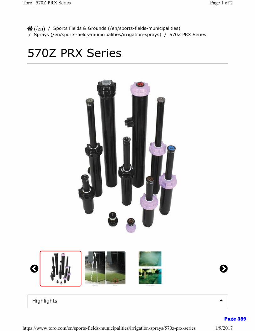
/ Sports Fields & Grounds (/en/sports-fields-municipalities)/ Sprays (/en/sports-fields-municipalities/irrigation-sprays) / 570Z PRX Series
570Z PRX Series
(/en)
Highlights
Page 1 of 2Toro | 570Z PRX Series
1/9/2017https://www.toro.com/en/sports-fields-municipalities/irrigation-sprays/570z-prx-series
Page 389

About Toro (/en/about) Corporate Responsibility (/en/about/corporate-responsibility)Financing (/en/financing) Customer Support (/en/customer-support)Safety (/en/product-safety-information) Lawn Care (http://yardcare.toro.com/)Dealer Login (https://secure.toro.com) Press Room (http://pressroom.toro.com)Investors (http://phx.corporate-ir.net/phoenix.zhtml?c=62289&p=irol-irhome)Careers (http://www.thetorocompany.com/careers)
Overview
Features
Specifications
Documents
• Zero-flush seal prevents flushing on pop-up• Several body sizes—to satisfy varying installation requirements• 115 different nozzles provide tremendous versatility• Ratcheting riser feature for easy and reliable arc adjustment
570Z PRX This model comes complete with both the patented X-Flow and pressure regulation-perfect for high or varying pressure, including long lines and slopes.
Learn more about the 570Z PRX Click here(http://www.toro.com/irrigation/res/smturfsprink/570z/video/570PRX.html)
Connect With Us: (https://www.facebook.com/Toro.Company)(https://twitter.com/TheToroCompany)(https://www.youtube.com/channel/UCQd20DNP_mT_PMUr-
6z2E-g)(http://www.pinterest.com/thetorocompany/)(http://instagram.com/thetorocompany)
DMCA/Copyright Policy (/en/legal/DMCA-copyright-policy) Terms of Use (/en/legal/terms-of-use)Privacy Policy (/en/legal/privacy-policy)
Copyright © 2017 The Toro Company. All Rights Reserved.
Page 2 of 2Toro | 570Z PRX Series
1/9/2017https://www.toro.com/en/sports-fields-municipalities/irrigation-sprays/570z-prx-series
Page 390
ES-F-LF860L
MasterSeries® LF860Reduced Pressure Zone Backflow Prevention AssembliesSize: 21⁄2" - 10" (65mm - 250mm)
Series LF860 Reduced Pressure Zone Assembly
LEAD FREE*
The FEBCO MasterSeries LF860 Reduced Pressure Zone Assembly is specifi-cally designed to protect against possible backpressure and backsiphonage conditions for high hazard [i.e., toxic] application in accordance with Local Governing Water Utility Code. This Backflow Prevention Assembly is primarily used on potable drinking water systems where Local Governing Code man-dates protection from non-potable water being pumped or siphoned back into the potable water system.
The LF860 features Lead Free* construction to comply with low lead installa-tion requirements. The Lead Free* Reduced Pressure Zone Assemblies shall comply with state codes and standards, where applicable, requiring reduced lead content.
Features
SpecificationsThe FEBCO MasterSeries LF860 Reduced Pressure Zone Assembly shall be installed on the potable water supply and at each point of cross-connection to protect against possible backpressure and backsiphonage conditions for high hazard [i.e., toxic] applications. The assembly shall consist of a main line valve body composed of a pressure differential relief valve located in a zone between two (2) independently acting approved clapper style check modules with replaceable seats and disc rubbers. Servicing of the pres-sure differential relief valve and both check modules does not require any special tools; both check modules are accessed through independently top entry covers. This assembly shall be fitted with AWWA Compliant inlet/outlet resilient seated shutoff valves; when used on a Fire-Sprinkler application, the assembly shall be fitted with approved UL/FM inlet/outlet resilient seated shutoff valves and contain four (4) properly located resilient seated test cocks as specified by AWWA Standard C511. Flow and pressure loss performance parameters shall meet the requirements of AWWA Standard C511.
S P E C I F I C AT I O N S H E E T
Job Name ––––––––––––––––––––––––––––––––––––––––––– Contractor ––––––––––––––––––––––––––––––––––––––––––––
Job Location ––––––––––––––––––––––––––––––––––––––––– Approval –––––––––––––––––––––––––––––––––––––––––––––
Engineer –––––––––––––––––––––––––––––––––––––––––––– Contractor’s P.O. No. ––––––––––––––––––––––––––––––––––
Approval –––––––––––––––––––––––––––––––––––––––––––– Representative ––––––––––––––––––––––––––––––––––––––––
FEBCO product specifications in U.S. customary units and metric are approximate and are provided for reference only. For precise measurements, please contact FEBCO Technical Service. FEBCO reserves the right to change or modify product design, construction, specifications, or materials without prior notice and without incurring any obligation to make such changes and modifications on FEBCO products previously or subsequently sold.
*The wetted surface of this product contacted by consumable water contains less than 0.25% of lead by weight.
NOTICE
NOTICEThe information contained herein is not intended to replace the full product installation and safety information available or the experience of a trained product installer. You are required to thoroughly read all installation instruc-tions and product safety information before beginning the installation of this product.
Page 391
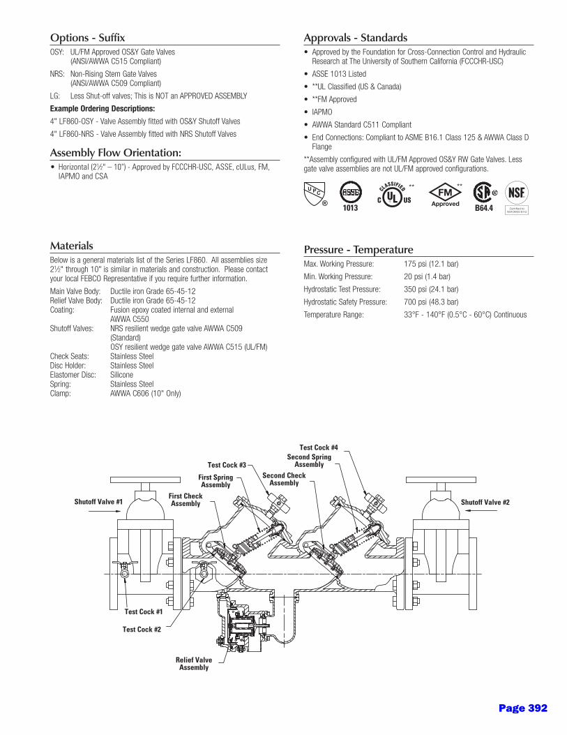
Options - Suffix
Example Ordering Descriptions:
Assembly Flow Orientation:1⁄ "
MaterialsBelow is a general materials list of the Series LF860. All assemblies size 21⁄2" through 10" is similar in materials and construction. Please contact your local FEBCO Representative if you require further information.
Coating: Fusion epoxy coated internal and external AWWA C550
(Standard) OSY resilient wedge gate valve AWWA C515 (UL/FM) Check Seats: Stainless Steel
Spring: Stainless Steel Clamp: AWWA C606 (10" Only)
Approvals - Standards
Flange
gate valve assemblies are not UL/FM approved configurations.
Pressure - TemperatureMax. Working Pressure: 175 psi (12.1 bar)
Min. Working Pressure: 20 psi (1.4 bar)
Relief Valve Assembly
Test Cock #3
Test Cock #4
Test Cock #2
Test Cock #1
Shutoff Valve #1 Shutoff Valve #2First Check Assembly
First Spring Assembly
Second Spring Assembly
Second Check Assembly
1013 B64.4
** **
Page 392
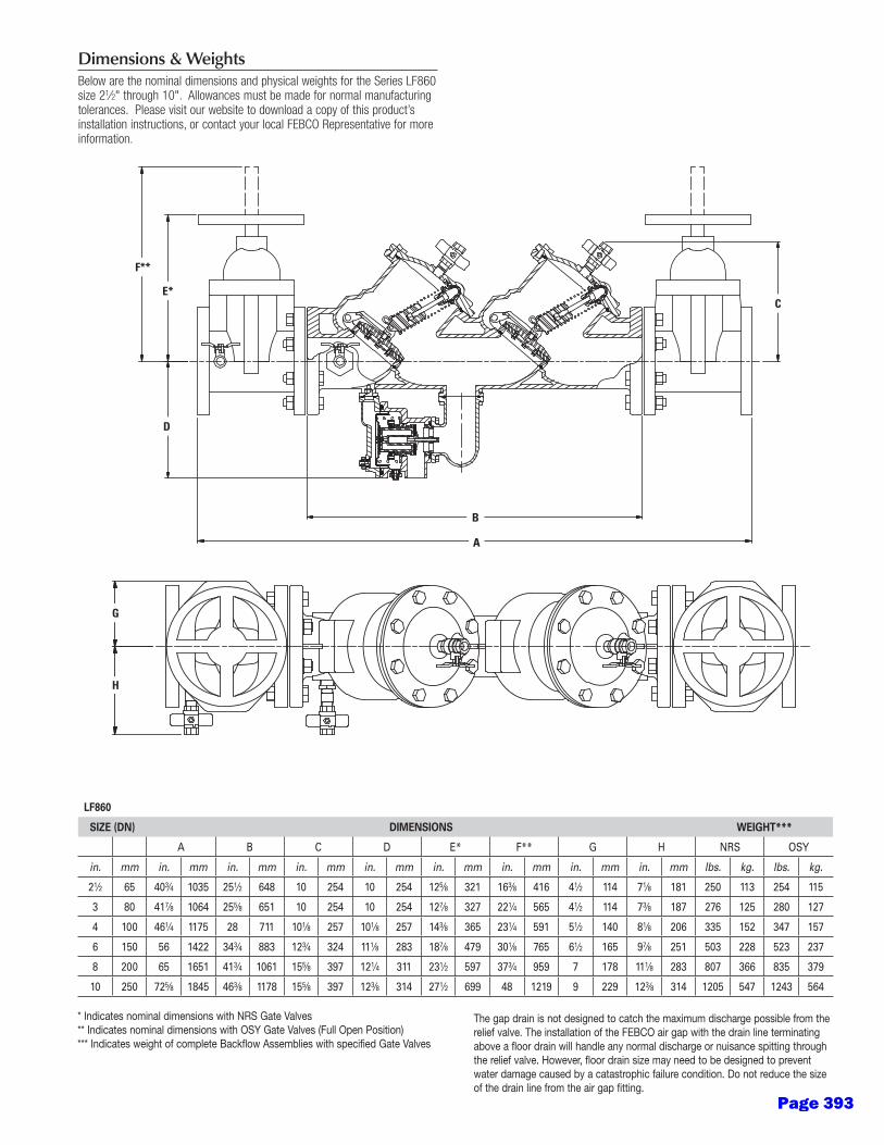
Dimensions & WeightsBelow are the nominal dimensions and physical weights for the Series LF860 size 21⁄2" through 10". Allowances must be made for normal manufacturing tolerances. Please visit our website to download a copy of this product’s installation instructions, or contact your local FEBCO Representative for more information.
LF860
SIZE (DN) DIMENSIONS WEIGHT***
A B C D E* F** G H NRS OSY
in. mm in. mm in. mm in. mm in. mm in. mm in. mm in. mm in. mm lbs. kg. lbs. kg.
21⁄2 65 403⁄4 1035 251⁄2 648 10 254 10 254 125⁄8 321 163⁄8 416 41⁄2 114 71⁄8 181 250 113 254 115
3 80 417⁄8 1064 255⁄8 651 10 254 10 254 127⁄8 327 221⁄4 565 41⁄2 114 73⁄8 187 276 125 280 127
4 100 461⁄4 1175 28 711 101⁄8 257 101⁄8 257 143⁄8 365 231⁄4 591 51⁄2 140 81⁄8 206 335 152 347 157
6 150 56 1422 343⁄4 883 123⁄4 324 111⁄8 283 187⁄8 479 301⁄8 765 61⁄2 165 97⁄8 251 503 228 523 237
8 200 65 1651 413⁄4 1061 155⁄8 397 121⁄4 311 231⁄2 597 373⁄4 959 7 178 111⁄8 283 807 366 835 379
10 250 725⁄8 1845 463⁄8 1178 155⁄8 397 123⁄8 314 271⁄2 699 48 1219 9 229 123⁄8 314 1205 547 1243 564
* Indicates nominal dimensions with NRS Gate Valves** Indicates nominal dimensions with OSY Gate Valves (Full Open Position)*** Indicates weight of complete Backflow Assemblies with specified Gate Valves
The gap drain is not designed to catch the maximum discharge possible from the relief valve. The installation of the FEBCO air gap with the drain line terminating above a floor drain will handle any normal discharge or nuisance spitting through the relief valve. However, floor drain size may need to be designed to prevent water damage caused by a catastrophic failure condition. Do not reduce the size of the drain line from the air gap fitting.
A
B
E*C
D
F**
E*
F**
D
A
B
C
G
H
Page 393

ES-F-LF860L 1515 © 2015 FEBCO
PerformanceFlow capacity chart identifies valve performance based upon rated water
7.5fps.
USA:Canada:
Latin America:
A Watts Water Technologies Company
21⁄2" LF860
3" LF860
4" LF860
6" LF860
8" LF860
10" LF860
psi
22 20 18 16 14 12 10 8 6 4 2 0
psi
22 20 18 16 14 12 10 8 6 4 2 0
psi 18 16 14 12 10 8 6 4 2 0
psi 18 16 14 12 10 8 6 4 2 0
psi
18 16 14 12 10 8 6 4 2 0
psi
18 16 14 12 10 8 6 4 2 0
0 25 50 75 100 125 150 175 200 225 250 275 300 325 350 gpm 284 568 852 1136 lpm 7.5 14.7 22.0 fps
0 50 100 150 200 250 300 350 400 450 500 gpm 379 757 1136 1514 lpm 7.5 14.5 22.0 fps
0 100 200 300 400 500 600 700 800 gpm 379 1136 1893 2650 lpm 7.5 12.8 19.1 fps
0 200 400 600 800 1000 1200 1400 1600 gpm 757 2271 3785 5300 lpm 7.5 11.4 17.0 fps
0 400 800 1200 1600 2000 2400 gpm 1514 3028 4543 6057 7571 9085 lpm 7.5 10.5 15.3 fps
0 600 1200 1800 2400 3000 3600 gpm 2271 4543 6814 9085 11356 13627 lpm 7.5 9.4 14.1 fps
Service Flow
Service Flow
Service Flow
Service Flow
Service Flow
Service Flow
Rated Flow
Rated Flow
Rated Flow
Rated Flow
Rated Flow
Rated Flow
*UL Rated Flow
*UL Rated Flow
*UL Rated Flow
*UL Rated Flow
*UL Rated Flow
*UL Rated Flow
Capacity
PSI D
rop
(*Fr
ictio
n Lo
ss)
PSI D
rop
(*Fr
ictio
n Lo
ss)
PSI D
rop
(*Fr
ictio
n Lo
ss)
PSI D
rop
(*Fr
ictio
n Lo
ss)
PSI D
rop
(*Fr
ictio
n Lo
ss)
PSI D
rop
(*Fr
ictio
n Lo
ss)
Page 394

Single Swing Backflow Preventer Valve Enclosures fabricated of barsize A36 angle, A569 Sht. 7 Ga. and A569 Sht. Expanded metal. Stock finish is acrylic enamel foliage green or desert tan (black is available at no charge, but is not stocked).SIZES (in inches):BF-56 12W x 24L x 18HBF-60 12W x 24L x 24HBF-71 12W x 30L x 24H (shown)BF-86 18W x 30L x 30H BF-99 18W x 42L x 30HBF-SPL YOUR REQUIREMENT
Dual Swing Enclosures are of similar construction in the following sizes (in inches):BF-168 24W x 60L x 36H (Shown)BF-214 30W x 72L x 42HBF-232 30W x 84L x 42HBF-SPL YOUR REQUIREMENT
Special finishes and colors are beyond our scope. We will apply your paint for a consideration if your paint does not require special mixing or surface preparation.
We believe our products are the best available. If your project requires the best, do not accept imitations, insist on product with our Le Meur Welding & Mfg. Co. serialized name plate. Le Meur Welding & Mfg. Co., is family owned and operated since 1948
[Home] [Safeguard Enclosures] [Backflow Enclosures] [Standard Finishes] [Stainless Backflow] [Inqui
Page 1 of 1Backflow-Enclosures
1/9/2017http://www.lemeurenclosures.com/Backflow-Enclosures/body_backflow-enclosures.html
Page 395

ES-F-LF825Y
The FEBCO Series LF825Y Reduced Pressure Zone Assemblies are used to protect against high hazard (toxic) fluids in water services to industrial plants, hospitals, morgues, mortuaries, and chemical plants. They are also used in irrigation systems, boiler feed, water lines and other installations requiring maximum pro-tection. The LF825Y features Lead Free* construction to comply with Lead Free* installation requirements.
Features• Ultimate mechanical protection of potable water, against haz-
ards of cross-connection contamination.
• Meets all specifications of AWWA, ASSE, CSA and approved by the Foundation for Cross-Connection Control and Hydraulic Research at the University of Southern California.
• Approved by the Foundation of Cross-Connection Control and Hydraulic Research at the University of Southern California.
• Modular relief valve for ease of maintenance.
• Simple Service procedures. All internal parts serviceable in line.
• Low head loss.
• Spring loaded “Y” type check valves.
• Internal relief valve pressure sensing passages.
• Replaceable seat rings on all sizes.
• End connection – NPT ANSI / ASME B1.20.1
SpecificationsThe reduced pressure zone assembly shall consist of two inde-pendently operating, spring loaded, “Y” pattern check valves and one hydraulically dependent differential relief valve. The assembly shall automatically reduce the pressure in the “zone” between the check valves to at least 5psi lower than inlet pressure. Should the differential between the upstream and the zone of the unit drop to 2psi, the differential relief valve shall open and maintain the proper differential.
Mainline valve body and caps including relief valve body and cover shall be Lead Free* cast copper silicon alloy. Check valve moving member shall be center stem guided. All hydraulic sens-ing passages shall be internally located within the mainline and relief valve bodies and relief valve cover. Diaphragm to seat area ratio shall be 10:1 minimum. Relief valve shall have a remov-able seat ring. Check valve and relief valve components shall be constructed so they may be serviced without removing the valve body from the line. All seat discs shall be reversible. Shutoff valves and test cocks shall be full ported ball valves.
The assembly shall be rated to 175psi (12.1 bar) working pres-sure and water temperature range from 32°F to 140°F (0ºC - 60ºC). The Lead Free* Reduced Pressure Zone Assemblies shall comply with state codes and standards, where applicable, requir-ing reduced lead content.
The assembly shall meet the requirements of ASSE Standard 1013; AWWA Standard Code C511; CSA Standard B64.4; and approved by the Foundation for Cross-Connection Control and Hydraulic Hydraulic Research at the University of Southern California.
OperationIn a flow condition the check valves are open with the pressure between the checks, called the zone, being maintained at least 5.0psi lower than the inlet pressure and the relief valve is main-tained closed.
Should abnormal conditions arise under no flow or reversal of flow, the differential relief valve will open and discharge to main-tain the zone at least 2psi lower than the supply.
When normal flow resumes, the zone’s differential pressure will resume and the relief valve will close.
Typical InstallationReduced pressure zone assemblies should be installed with mini-mum clearance of 12" (300mm) between relief valve discharge port and floor or grade. They must be installed where discharge will not be objectionable and can be positively drained away. They should be installed where easily accessible for testing and maintenance and must be protected from freezing. Thermal water expansion and/or water hammer downstream of the backflow preventer can cause excessive pressure. Excessive pressure situations should be eliminated to avoid possible damage to the system and assembly.
Refer to local codes for specific installation requirements. Some codes may prohibit vertical installation.
30" Max. (700mm) 12" Min. (300mm)Flow
Series LF825YReduced Pressure Zone AssembliesSize: 3⁄4" - 2"
LEAD FREE*
LF825Y
NOTICE
For Health Hazard Applications
Job Name ––––––––––––––––––––––––––––––––––––––––––– Contractor ––––––––––––––––––––––––––––––––––––––––––––
Job Location ––––––––––––––––––––––––––––––––––––––––– Approval –––––––––––––––––––––––––––––––––––––––––––––
Engineer ––––––––––––––––––––––––––––––––––––––––––––– Contractor’s P.O. No. –––––––––––––––––––––––––––––––––––
Approval ––––––––––––––––––––––––––––––––––––––––––––– Representative ––––––––––––––––––––––––––––––––––––––––
FEBCO product specifications in U.S. customary units and metric are approximate and are provided for reference only. For precise measurements, please contact FEBCO Technical Service. FEBCO reserves the right to change or modify product design, construction, specifications, or materials with-out prior notice and without incurring any obligation to make such changes and modifications on FEBCO products previously or subsequently sold.
* The wetted surface of this product contacted by consumable water contains less than 0.25% of lead by weight.
Page 396
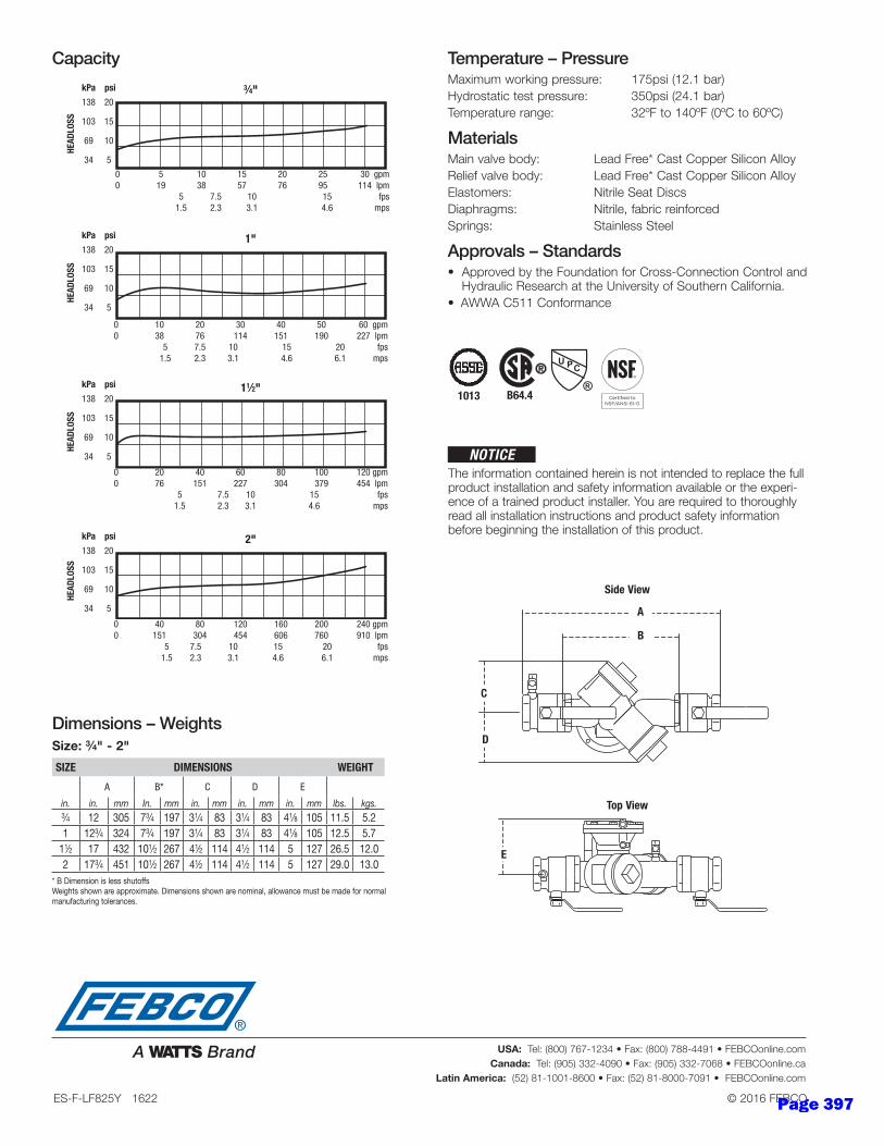
Temperature – PressureMaximum working pressure: 175psi (12.1 bar)
Hydrostatic test pressure: 350psi (24.1 bar)
Temperature range: 32ºF to 140ºF (0ºC to 60ºC)
MaterialsMain valve body: Lead Free* Cast Copper Silicon Alloy
Relief valve body: Lead Free* Cast Copper Silicon Alloy
Elastomers: Nitrile Seat Discs
Diaphragms: Nitrile, fabric reinforced
Springs: Stainless Steel
Approvals – Standards• Approved by the Foundation for Cross-Connection Control and
Hydraulic Research at the University of Southern California.
• AWWA C511 Conformance
Capacity
Dimensions – WeightsSize: 3⁄4" - 2"
SIZE DIMENSIONS WEIGHT
A B* C D E
in. in. mm In. mm in. mm in. mm in. mm lbs. kgs.3⁄4 12 305 73⁄4 197 31⁄4 83 31⁄4 83 41⁄8 105 11.5 5.21 123⁄4 324 73⁄4 197 31⁄4 83 31⁄4 83 41⁄8 105 12.5 5.7
11⁄2 17 432 101⁄2 267 41⁄2 114 41⁄2 114 5 127 26.5 12.02 173⁄4 451 101⁄2 267 41⁄2 114 41⁄2 114 5 127 29.0 13.0
3⁄4" kPa psi
138 20
103 15
69 10
34 5
0 5 10 15 20 25 30 gpm 0 19 38 57 76 95 114 lpm 5 7.5 10 15 fps 1.5 2.3 3.1 4.6 mps
HEAD
LOSS
1"
11⁄2"
2"
0 10 20 30 40 50 60 gpm 0 38 76 114 151 190 227 lpm 5 7.5 10 15 20 fps 1.5 2.3 3.1 4.6 6.1 mps
0 20 40 60 80 100 120 gpm 0 76 151 227 304 379 454 lpm 5 7.5 10 15 fps 1.5 2.3 3.1 4.6 mps
kPa psi
138 20
103 15
69 10
34 5
kPa psi
138 20
103 15
69 10
34 5
kPa psi
138 20
103 15
69 10
34 5
0 40 80 120 160 200 240 gpm 0 151 304 454 606 760 910 lpm 5 7.5 10 15 20 fps 1.5 2.3 3.1 4.6 6.1 mps
HEAD
LOSS
HEAD
LOSS
HEAD
LOSS
1013 B64.4
* B Dimension is less shutoffsWeights shown are approximate. Dimensions shown are nominal, allowance must be made for normal manufacturing tolerances.
The information contained herein is not intended to replace the full product installation and safety information available or the experi-ence of a trained product installer. You are required to thoroughly read all installation instructions and product safety information before beginning the installation of this product.
NOTICE
ES-F-LF825Y 1622 © 2016 FEBCO
USA: Tel: (800) 767-1234 • Fax: (800) 788-4491 • FEBCOonline.com
Canada: Tel: (905) 332-4090 • Fax: (905) 332-7068 • FEBCOonline.ca
Latin America: (52) 81-1001-8600 • Fax: (52) 81-8000-7091 • FEBCOonline.com
E
Top View
A
B
Side View
C
D
Page 397
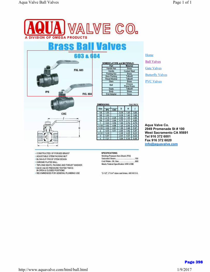
Ball Valves
Aqua Valve Co.2949 Promenade St # 100West Sacramento CA 95691Tel 916 372 6001Fax 916 372 [email protected]
Gate Valves
Butterfly Valves
PVC Valves
Home
Page 1 of 1Aqua Valve Ball Valves
1/9/2017http://www.aquavalve.com/html/ball.html
Page 398
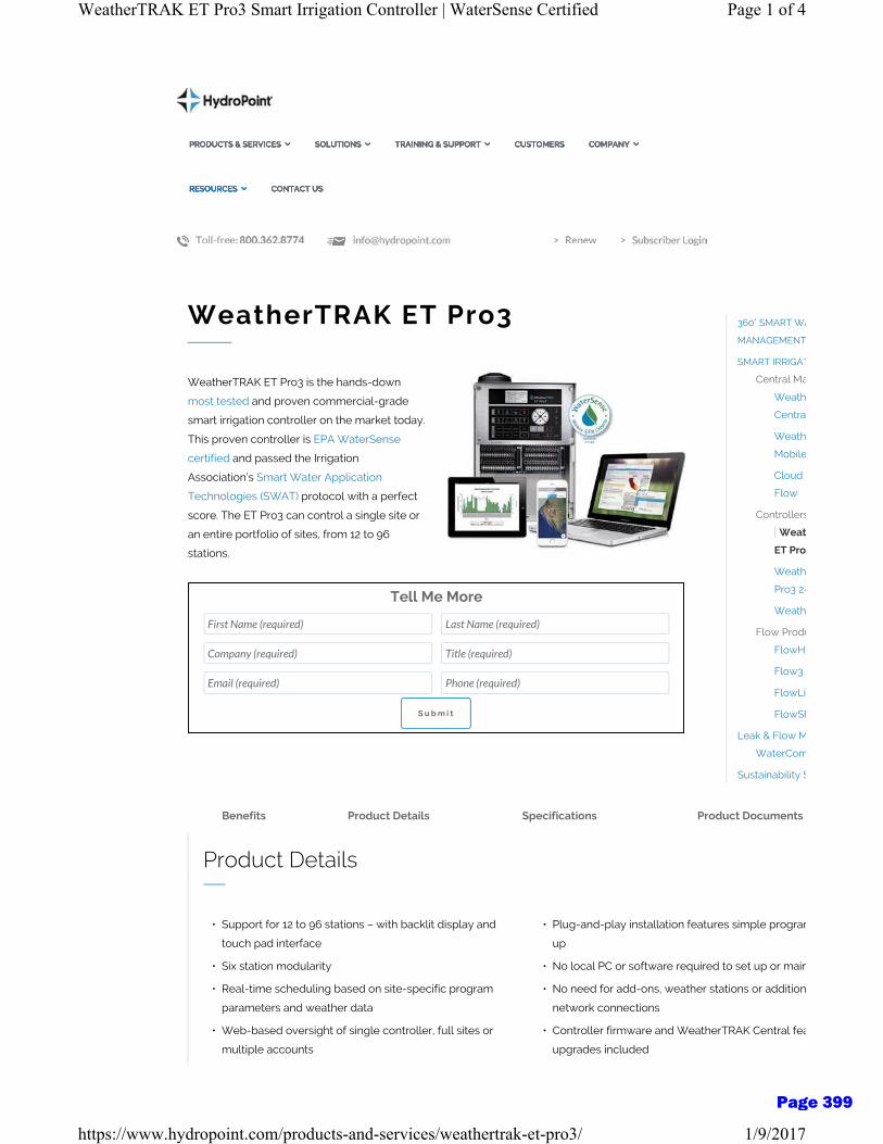
WeatherTRAK ET Pro3
WeatherTRAK ET Pro3 is the hands-down
most tested and proven commercial-grade
smart irrigation controller on the market today.
This proven controller is EPA WaterSense
certified and passed the Irrigation
Association’s Smart Water Application
Technologies (SWAT) protocol with a perfect
score. The ET Pro3 can control a single site or
an entire portfolio of sites, from 12 to 96
stations.
Tell Me More
First Name (required) Last Name (required)
Company (required) Title (required)
Email (required) Phone (required)
S u b m i t
360° SMART WA
MANAGEMENT
SMART IRRIGAT
Central Ma
Weath
Centra
Weath
Mobile
Cloud A
Flow
Controllers
Weat
ET Pro
Weath
Pro3 2-
Weath
Flow Produ
FlowH
Flow3
FlowLi
FlowSh
Leak & Flow M
WaterCom
Sustainability S
Benefits Product Details Specifications Product Documents
Product Details
• Support for 12 to 96 stations – with backlit display and
touch pad interface
• Six station modularity
• Real-time scheduling based on site-specific program
parameters and weather data
• Web-based oversight of single controller, full sites or
multiple accounts
• Plug-and-play installation features simple program
up
• No local PC or software required to set up or main
• No need for add-ons, weather stations or addition
network connections
• Controller firmware and WeatherTRAK Central fea
upgrades included
PRODUCTS & SERVICES ∠ SOLUTIONS ∠ TRAINING & SUPPORT ∠ CUSTOMERS COMPANY ∠
RESOURCES ∠ CONTACT US
PRODUCTS & SERVICES ∠ SOLUTIONS ∠ TRAINING & SUPPORT ∠ CUSTOMERS COMPANY ∠
RESOURCES ∠ CONTACT US
PRODUCTS & SERVICES ∠ SOLUTIONS ∠ TRAINING & SUPPORT ∠ CUSTOMERS COMPANY ∠
RESOURCES ∠ CONTACT US
PRODUCTS & SERVICES ∠ SOLUTIONS ∠ TRAINING & SUPPORT ∠ CUSTOMERS COMPANY ∠
RESOURCES ∠ CONTACT US
Page 1 of 4WeatherTRAK ET Pro3 Smart Irrigation Controller | WaterSense Certified
1/9/2017https://www.hydropoint.com/products-and-services/weathertrak-et-pro3/
Page 399
• Account or site level reports, field asset tracking and
dashboards
• One-touch customer support from a mobile device
• Bilingual, expert technical advice, six days per wee
• Ongoing training and online resources
Programming Features
• Up to eight simultaneous programs with five program
modes and two start times
• Program all settings at the controller, or remotely with
WeatherTRAK Central
• Independent station programming (72 cycles / station)
with automated cycle and soak
• User-defined water days and water windows per
program to comply with agency regulations
• Built-in scheduling engine optimizes by plant, soil,
sprinkler, sun exposure and slope data
• Automated daily runtime adjustments at the controller
using site specific weather data
• % adjust – fine tune by station
• Automated skip days based on zone-specific soil
moisture depletion
• Sports turf and high desert specific scheduling
• Runtime rationing protects plant health under
constricted water windows
• Stacked station manual watering from 1-99 minutes
Hardware Features
• Integrated flow sensor support included expanda
to 4 flow sensors
• Dedicated master valve and pump start
• Up to 14 outputs energized simultaneously (8 prog
manual, pump, 4 MVs)
• Commercial grade screw-less wire terminals
• Built-in handheld remote compatibility w/ RainMa
Pro-Max UA series with EX-32 cable or TRC™
Commander Series
• Built-in amp meter for fault protection and diagno
• Wall mount enclosure option in both cold-rolled s
and stainless steel; option to mount on small pede
• Four stainless steel enclosure options
• Six chassis options to quickly retrofit existing high
pedestals
• Cellular radio and first year WeatherTRAK Central
included
• Non-volatile memory stores settings without batte
to 10 years
• High lightning protection
• 5-year warranty; option of 10 year extended warra
Integrated Flow Features
• Mainline / catastrophic break detection and shutdown
• Leak detection and management
• Real-time station specific flow monitoring and control
• Local and remote station learned flow
• Fault detection, diagnostics and alerts
• Supports up to four flow sensor inputs and master valve
outputs
• Supports normally open or normally closed master
valves
• Supports Data Industrial, CST, Netafim flow sensors and
custom K and offset values
• Compatible with WeatherTRAK FlowLink, FlowShare,
Flow3 and FlowHD
Electrical & Enclosure Specification
Input Power: 120 VAC +/- 10%, (60 Hz) or 220
+/- 10%, (60 Hz)
Output Power: 24 VAC (60 Hz)
• 1.0 Amp (1000mA) max per s
output including a pump sta
• 1.0 Amp (1000mA) max per
master valve output
• 3.0 Amps (80 VA) total load
Up to 14 terminal outputs energ
simultaneously (8 programs, ma
pump, MV1, MV2, MV3, MV4)
Idle State: 2.5 Watts Power
Maximum Power Requirements
Page 2 of 4WeatherTRAK ET Pro3 Smart Irrigation Controller | WaterSense Certified
1/9/2017https://www.hydropoint.com/products-and-services/weathertrak-et-pro3/
Page 400
Ordering Information Consumptive
Power
Certifications:
Irrigation State: 70 Watts EPA
WaterSense Approved, FCC
Certified, UL Listed , 100% SWAT
tested
Enclosure
Options:
Wall Mount Enclosures
• 16 gauge wall mount enclos
available in stainless and pow
coated finishes
• Key-hole mounting for wall
mount enclosures for easy
installation
• Easily adapts to a small 14 ga
pedestal; available in two fin
VIT Strong Box Stainless Steel
Pedestal Enclosures
Retrofit Chassis for Existing
Enclosures
• All come with key lock entry
• UL listed, NEMA-3R weather
resistant
Search …
Search
Home
Products & Services
Solutions
Training & Support
Customers
Company
Resources
Contact Us
Site Map
Follow HydroPoint Get In Touch
First Name (required)
Last Name (required)
Email (required)
Phone (required)
Page 3 of 4WeatherTRAK ET Pro3 Smart Irrigation Controller | WaterSense Certified
1/9/2017https://www.hydropoint.com/products-and-services/weathertrak-et-pro3/
Page 401

Company (required)
Title (required)
How can we help?
© 2016 HydroPoint Data Systems, Inc. | 1720 Corporate Circle | Petaluma, CA 94954 USA | Toll-free:
800.362.8774 | Fax: 707.769.9695 | Privacy Notice
∠
Page 4 of 4WeatherTRAK ET Pro3 Smart Irrigation Controller | WaterSense Certified
1/9/2017https://www.hydropoint.com/products-and-services/weathertrak-et-pro3/
Page 402
Toro® DL2000 Dripline is the most technologically advanced subsurface irrigation system available. Through its non-toxic ROOTGUARD® technology, only DL2000 delivers optimal water application directly to the root zone while safely inhibiting root intrusion.
U.S. Government-Approved ROOTGUARD®
ProtectionThe pre-emergent, ROOTGUARD® material, is impregnated into
the emitter during the molding process and creates a “force
field” effect around the emitter outlet, diverting root growth and
assuring long term reliability.
At Grade Or Buried OptionsCan be installed at grade or buried 4” – 8” underground, delivering
irrigation directly to the plant’s root zone.
Pressure-Compensating Self-cleaning Emitters
Provide precise, trouble-free water application. ROOTGUARD®
impregnated emitters are inseparably welded to the inside wall of
durable polyethylene dripline tubing during manufacturing.
Environmentally FriendlyIrrigation takes place at or below grade so there is minimal water
loss due to mist, evaporation, run-off or wind. Fertigation needs
are reduced because water is applied only at the root zone.
Safety and LiabilityWhen DL2000 is installed below ground, the landscape surface is
free from irrigation equipment that may disrupt activities or cause
injury. Sub-surface performance also avoids slippery walkways
and roadways as well as wet walls, fences and windows.
DL2000™ SERIES SUBSURFACE DRIPLINE
FEATURES & BENEFITS
Distinctive red stripe on tubing signifies DL2000 with ROOTGUARD
Effluent OptionsAvailable
Page 403

SPECIFICATIONS Operational• Design flexibility for narrow, odd-shaped landscape areas• Precise watering puts water where it’s needed; avoids water
marks on expensive hardscapes, glass or signage• Distinctive red strip on tubing signifies DL2000 with ROOTGUARD®
Warranty• Against Root Intrusion: Seven years• Hose: Five years pro-rated
DL2000 MODEL LIST
Model Description
5/8” DL 2000 PC DRIPLINE WITH ROOTGUARDRGP-212-01 0.5 gph, 12” emitter spacing, 100 ft. coil
RGP-412-01 1.0 gph, 12” emitter spacing, 100 ft. coil
RGP-218-01 0.5 gph, 18” emitter spacing, 100 ft. coil
RGP-418-01 1.0 gph, 18” emitter spacing, 100 ft. coil
RGP-212-05 0.5 gph, 12” emitter spacing, 500 ft. coil
RGP-412-05 1.0 gph, 12” emitter spacing, 500 ft. coil
RGP-218-05 0.5 gph, 18” emitter spacing, 500 ft. coil
RGP-418-05 1.0 gph, 18” emitter spacing, 500 ft. coil
RGP-212-10 0.5 gph, 12” emitter spacing, 1000 ft. coil
RGP-412-10 1.0 gph, 12” emitter spacing, 1000 ft. coil
RGP-218-10 0.5 gph, 18” emitter spacing, 1000 ft. coil
RGP-418-10 1.0 gph, 18” emitter spacing, 1000 ft. coil
5/8” DL2000 PC PURPLE DRIPLINE WITH ROOTGUARDRGP-212-05-E 0.5 gph, 12” emitter spacing, 500 ft. coil
RGP-412-05-E 1.0 gph, 12” emitter spacing, 500 ft. coil
RGP-218-05-E 0.5 gph, 18” emitter spacing, 500 ft. coil
RGP-418-05-E 1.0 gph, 18” emitter spacing, 500 ft. coil
Specifying Information—DL2000RGP X-XX-XX-E
Emitter FlowEmitter Spacing
Coil Length Optional
X XX XX E2—.53 gph4—1.0 gph
12—12”18—18”
01—100’ 05—500’10—1000’
E—Purple Tubing for Non-potable Water
Example: A 500’ coil of Pressure-compensating Dripline with rootguard,12” emitter spacing and 0.5 gph, would be specified as: RGP-212-05
Note: Specify/use Loc-Eze Fittings or .710 Compression Fittings.
Air/Vacuum Relief Valve(Part No. T-YD–500–34)
Water Source
Filter(Part Nos. T-ALFD75150–L)
Control Valve
Pressure Regulator(Part Nos. T-PMR15–LF,
T-PMR25–LF, T-PMR40–MF, T-PMR25–HF & T-PMR25–MF)
Also Available as a Drip Zone Valve Kit.
Emitter
Tee (Part No. T-FTT16)
Elbow(Part No. T-FEE16)
Flush Valve(Part No. T-FCH–H)
Dripline
Other fittings available:• Coupling (Part No. T-FCC16)• Adapter (Part No. T-FAM16)• Compression Adapter (Part No. T-CA-710)
5/8” OD INLET PRESSURE VS.MAXIMUM LENGTH OF RUN IN FEET
Part No. Flow Rate
(gph)Emitter Spacing
15 psi 25 psi 30 psi 40 psi
RGP-212 .53 12” 250’ 360’ 400’ 460’
RGP-218 .53 18” 350’ 515’ 565’ 650’
RGP-412 1.0 12” 160’ 240’ 260’ 300’
RGP-418 1.0 18” 240’ 340’ 375’ 430’
DL2000 PERFORMANCE TABLEFlow Rate .53/1.00 gph
Inside Diameter 0.620”
Outside Diameter 0.710”
Wall 0.045”
Operating pressure (P) 15–60 psi
Minimum filtration requirement 120 Mesh
Hazen-Williams C factor 140
Barb loss factor (Kd) .98
PRECIPITATION RATE FOR EVENLY SPACEDLATERALS AND EMITTERS
Precipitation Rate for Drip Laterals (inches/hour)Emitter
Flow(gph)
Emitter Spacing
(in.)
Spacing Between Drip Laterals
6 in. 12 in. 18 in. 24 in. 30 in. 36 in.
0.53 12 1.7 0.85 0.57 0.43 0.34 0.28
0.53 18 1.13 0.57 0.38 0.28 0.23 0.191.00 12 3.27 1.64 1.09 0.82 0.65 0.551.00 18 2.18 1.09 0.73 0.55 0.44 0.36
Precipitation Rate (in./hr.) = Precipitation Rate Formula:
231.1 x Emitter Flow (gph)Lateral Spacing (in.) x Emitter Spacing (in.)
Note: This formula applies to evenly spaced drip irrigation laterals and emitters.
www.toro.comThe Toro Company • Irrigation Division • 5825 Jasmine St. Riverside, CA • 92504 • 877-345-8676Specifications subject to change without notice. For more information, contact your local Toro distributor. ©2015 The Toro Company. All rights reserved. P/N 15-1061-IRC
Page 404
Many Products...One Source
© Copyright 2017 Boshart Industries Inc. All Rights Reserved
Boshart Industries sells only to wholesaler distributors. Home Catalogue Rep Finder Career Opportunities Policies
UNITED STATES
About Us Products News & Events Contact Us Login
Catalogue > Plumbing Valves > GATE VALVES > BRASS FULL PORT GATE VALVES > NO LEAD
NO LEAD
Part Number Description List Price-F Ctn / Case Class
• Max Pressure Rating: 200 PSI WOG Non-Shock based on ambient temperature• Max Temp Rating: 150°F (66°C)• Cast brass body• Non-rising stem• PTFE Packing• Black cast hand wheel• NSF/ANSI Standard 61 & 372 Certified
Documents1 Other Information Document4 Brochures Documents3 Product Technical Information Documents1 Catalogue Pages Document1 Marketing Information Document1 Archived Pricing Changes Document
PricingProduct GroupingSection 2, All Products
THREADED 0818-02NL NO LEAD 1/4" FPT G.V. 200 WOG 10.17 10 / 120 01003 0818-03NL NO LEAD 3/8" FPT G.V. 200 WOG 10.17 10 / 120 01003 0818-05NL NO LEAD 1/2" FPT G.V. 200 WOG 10.17 10 / 120 01003 0818-07NL NO LEAD 3/4" FPT G.V. 200 WOG 13.87 10 / 80 01003 0818-10NL NO LEAD 1" FPT G.V. 200 WOG 20.62 5 / 60 01003 0818-12NL NO LEAD 1-1/4" FPT G.V. 200WOG 29.10 5 / 40 01003 0818-15NL NO LEAD 1-1/2" FPT G.V. 200WOG 37.01 5 / 30 01003 0818-20NL NO LEAD 2" FPT G.V. 200 WOG 56.31 2 / 20 01003 0818-25NL NO LEAD 2-1/2" FPT G.V. 200WOG 104.02 2 / 12 01003 0818-30NL NO LEAD 3" FPT G.V. 200 WOG 141.40 1 / 8 01003 0818-40NL NO LEAD 4" FPT G.V. 200 WOG 218.75 1 / 4 01003
CXC 0818C-05NL NO LEAD 1/2" CxC G.V. 200 WOG 10.17 10 / 120 01003 0818C-07NL NO LEAD 3/4" CxC G.V. 200 WOG 13.87 10 / 80 01003 0818C-10NL NO LEAD 1" CxC G.V. 200 WOG 20.62 5 / 60 01003 0818C-12NL NO LEAD 1-1/4" CxC G.V. 200WOG 29.10 5 / 40 01003 0818C-15NL NO LEAD 1-1/2" CxC G.V. 200WOG 37.01 5 / 30 01003 0818C-20NL NO LEAD 2" CxC G.V. 200 WOG 56.31 2 / 20 01003
Search...
Page 1 of 1Boshart Industries : NO LEAD
1/10/2017http://www.boshart.com/product.php?id=RNKPO9NL1pXdABEe0Ifa3-QZn7qGr5N5tpc0...
Page 405
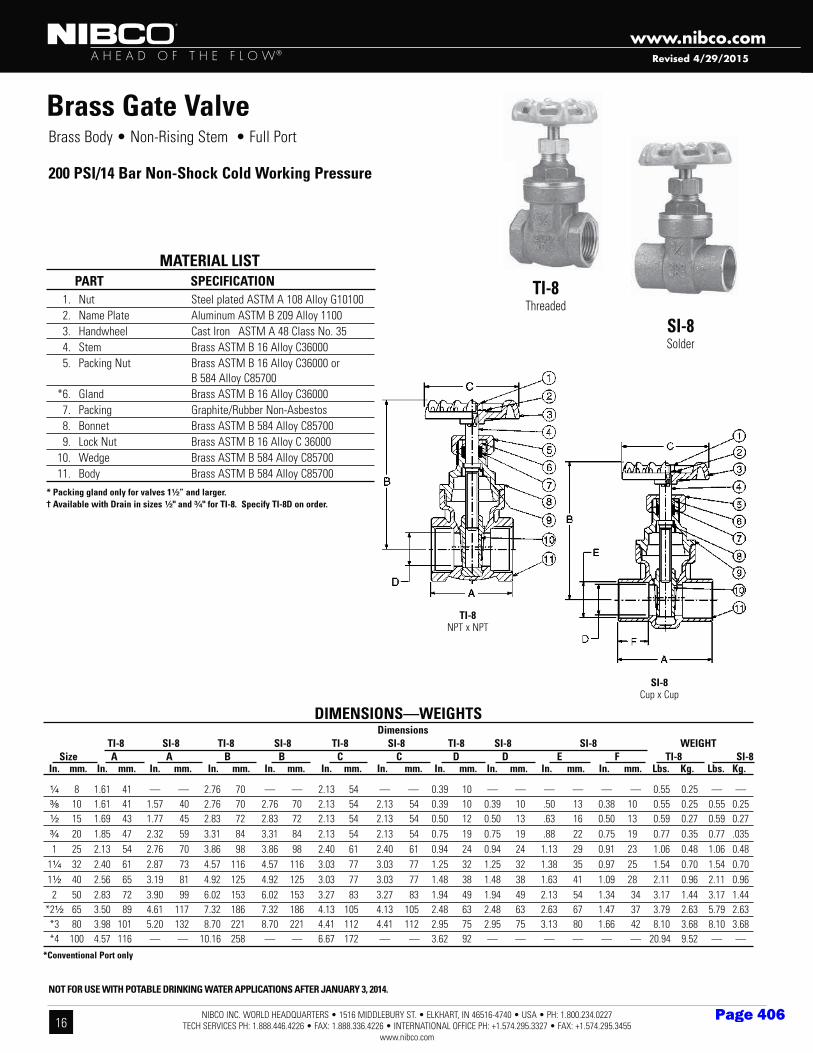
NIBCO INC. WORLD HEADQUARTERS • 1516 MIDDLEBURY ST. • ELKHART, IN 46516-4740 • USA • PH: 1.800.234.0227 TECH SERVICES PH: 1.888.446.4226 • FAX: 1.888.336.4226 • INTERNATIONAL OFFICE PH: +1.574.295.3327 • FAX: +1.574.295.3455
www.nibco.com16
A H E A D O F T H E F L O W®
www.nibco.comRevised 4/29/2015
1. Nut Steel plated ASTM A 108 Alloy G10100 2. Name Plate Aluminum ASTM B 209 Alloy 1100 3. Handwheel Cast Iron ASTM A 48 Class No. 35 4. Stem Brass ASTM B 16 Alloy C36000 5. Packing Nut Brass ASTM B 16 Alloy C36000 or B 584 Alloy C85700 *6. Gland Brass ASTM B 16 Alloy C36000 7. Packing Graphite/Rubber Non-Asbestos 8. Bonnet Brass ASTM B 584 Alloy C85700 9. Lock Nut Brass ASTM B 16 Alloy C 36000 10. Wedge Brass ASTM B 584 Alloy C85700 11. Body Brass ASTM B 584 Alloy C85700
MATERIAL LIST PART SPECIFICATION TI-8
Threaded
SI-8Solder
SI-8Cup x Cup
Brass Gate Valve
200 PSI/14 Bar Non-Shock Cold Working Pressure
* Packing gland only for valves 1¹⁄₂” and larger. † Available with Drain in sizes ¹⁄₂" and ³⁄₄" for TI-8. Specify TI-8D on order.
DIMENSIONS—WEIGHTS Dimensions TI-8 SI-8 TI-8 SI-8 TI-8 SI-8 TI-8 SI-8 SI-8 WEIGHT Size A A B B C C D D E F TI-8 SI-8 In. mm. In. mm. In. mm. In. mm. In. mm. In. mm. In. mm. In. mm. In. mm. In. mm. In. mm. Lbs. Kg. Lbs. Kg.
¹⁄₄ 8 1.61 41 — — 2.76 70 — — 2.13 54 — — 0.39 10 — — — — — — 0.55 0.25 — — ³�₈ 10 1.61 41 1.57 40 2.76 70 2.76 70 2.13 54 2.13 54 0.39 10 0.39 10 .50 13 0.38 10 0.55 0.25 0.55 0.25 ¹⁄₂ 15 1.69 43 1.77 45 2.83 72 2.83 72 2.13 54 2.13 54 0.50 12 0.50 13 .63 16 0.50 13 0.59 0.27 0.59 0.27 ³⁄₄ 20 1.85 47 2.32 59 3.31 84 3.31 84 2.13 54 2.13 54 0.75 19 0.75 19 .88 22 0.75 19 0.77 0.35 0.77 .035 1 25 2.13 54 2.76 70 3.86 98 3.86 98 2.40 61 2.40 61 0.94 24 0.94 24 1.13 29 0.91 23 1.06 0.48 1.06 0.48 1¹⁄₄ 32 2.40 61 2.87 73 4.57 116 4.57 116 3.03 77 3.03 77 1.25 32 1.25 32 1.38 35 0.97 25 1.54 0.70 1.54 0.70 1¹⁄₂ 40 2.56 65 3.19 81 4.92 125 4.92 125 3.03 77 3.03 77 1.48 38 1.48 38 1.63 41 1.09 28 2.11 0.96 2.11 0.96 2 50 2.83 72 3.90 99 6.02 153 6.02 153 3.27 83 3.27 83 1.94 49 1.94 49 2.13 54 1.34 34 3.17 1.44 3.17 1.44 *2¹⁄₂ 65 3.50 89 4.61 117 7.32 186 7.32 186 4.13 105 4.13 105 2.48 63 2.48 63 2.63 67 1.47 37 3.79 2.63 5.79 2.63 *3 80 3.98 101 5.20 132 8.70 221 8.70 221 4.41 112 4.41 112 2.95 75 2.95 75 3.13 80 1.66 42 8.10 3.68 8.10 3.68 *4 100 4.57 116 — — 10.16 258 — — 6.67 172 — — 3.62 92 — — — — — — 20.94 9.52 — —*Conventional Port only
Brass Body • Non-Rising Stem • Full Port
TI-8NPT x NPT
NOT FOR USE WITH POTABLE DRINKING WATER APPLICATIONS AFTER JANUARY 3, 2014.
Page 406
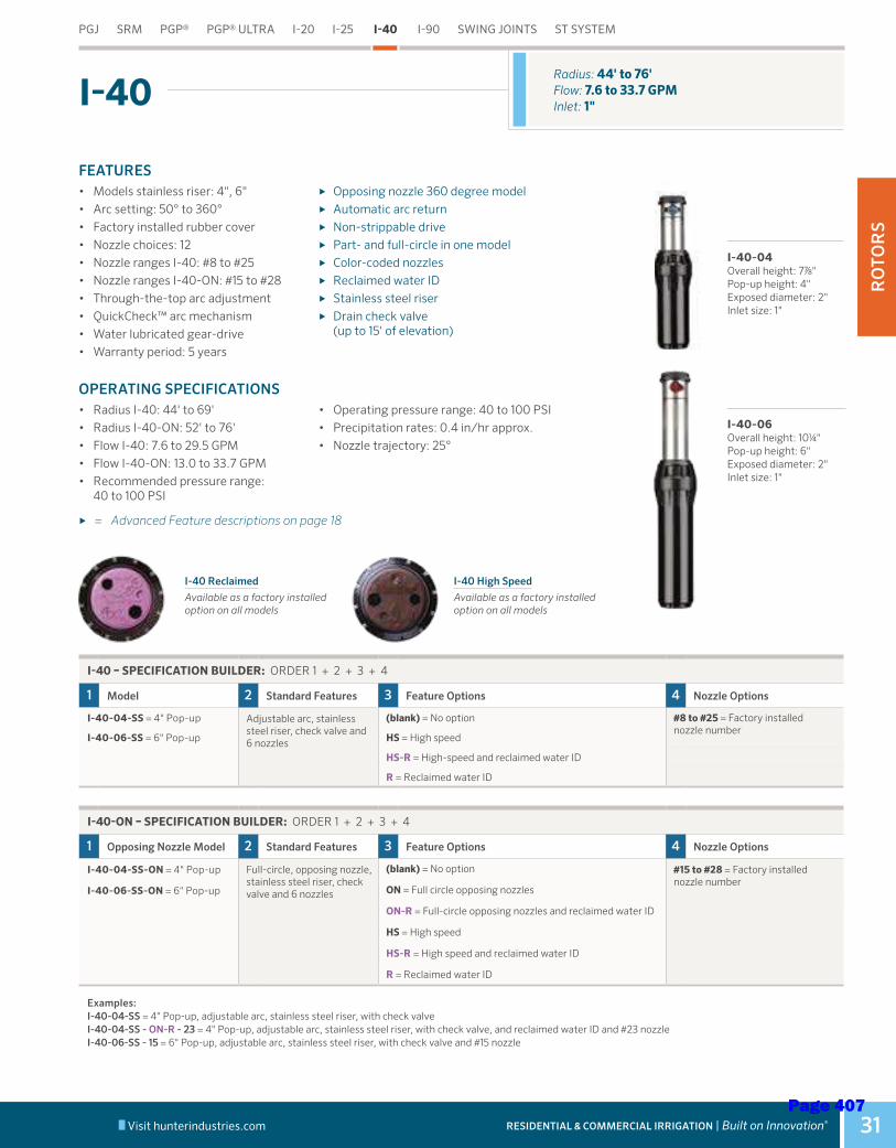
RO
TOR
S
Visit hunterindustries.com RESIDENTIAL & COMMERCIAL IRRIGATION | Built on Innovation® 31
I-40-06Overall height: 10¼" Pop-up height: 6"Exposed diameter: 2"Inlet size: 1"
I-40-04Overall height: 7⅞" Pop-up height: 4"Exposed diameter: 2"Inlet size: 1"
Radius: 44' to 76'Flow: 7.6 to 33.7 GPMInlet: 1"
FEATURES• Models stainless riser: 4", 6"• Arc setting: 50° to 360°• Factory installed rubber cover• Nozzle choices: 12• Nozzle ranges I-40: #8 to #25• Nozzle ranges I-40-ON: #15 to #28• Through-the-top arc adjustment• QuickCheck™ arc mechanism• Water lubricated gear-drive• Warranty period: 5 years
► Opposing nozzle 360 degree model ► Automatic arc return ► Non-strippable drive ► Part- and full-circle in one model ► Color-coded nozzles ► Reclaimed water ID ► Stainless steel riser ► Drain check valve
(up to 15' of elevation)
OPERATING SPECIFICATIONS• Radius I-40: 44' to 69'• Radius I-40-ON: 52' to 76'• Flow I-40: 7.6 to 29.5 GPM• Flow I-40-ON: 13.0 to 33.7 GPM• Recommended pressure range:
40 to 100 PSI
• Operating pressure range: 40 to 100 PSI• Precipitation rates: 0.4 in/hr approx.• Nozzle trajectory: 25°
► = Advanced Feature descriptions on page 18
I-40
I-40 Reclaimed
Available as a factory installed option on all models
I-40 High Speed
Available as a factory installed option on all models
I-40 – SPECIFICATION BUILDER: ORDER 1 + 2 + 3 + 4
1 Model 2 Standard Features 3 Feature Options 4 Nozzle Options
I-40-04-SS = 4" Pop-up Adjustable arc, stainless steel riser, check valve and 6 nozzles
(blank) = No option #8 to #25 = Factory installed nozzle number
I-40-06-SS = 6" Pop-up HS = High speed
HS-R = High-speed and reclaimed water ID
R = Reclaimed water ID
I-40-ON – SPECIFICATION BUILDER: ORDER 1 + 2 + 3 + 4
1 Opposing Nozzle Model 2 Standard Features 3 Feature Options 4 Nozzle Options
I-40-04-SS-ON = 4" Pop-up Full-circle, opposing nozzle, stainless steel riser, check valve and 6 nozzles
(blank) = No option #15 to #28 = Factory installed nozzle number
I-40-06-SS-ON = 6" Pop-up ON = Full circle opposing nozzles
ON-R = Full-circle opposing nozzles and reclaimed water ID
HS = High speed
HS-R = High speed and reclaimed water ID
R = Reclaimed water ID
Examples: I-40-04-SS = 4" Pop-up, adjustable arc, stainless steel riser, with check valve I-40-04-SS - ON-R - 23 = 4" Pop-up, adjustable arc, stainless steel riser, with check valve, and reclaimed water ID and #23 nozzle I-40-06-SS - 15 = 6" Pop-up, adjustable arc, stainless steel riser, with check valve and #15 nozzle
Cross References:I-40
Solutions I-40
PGJ SRM PGP® PGP® ULTRA I-20 I-25 I-40 I-90 SWING JOINTS ST SYSTEM
Page 407
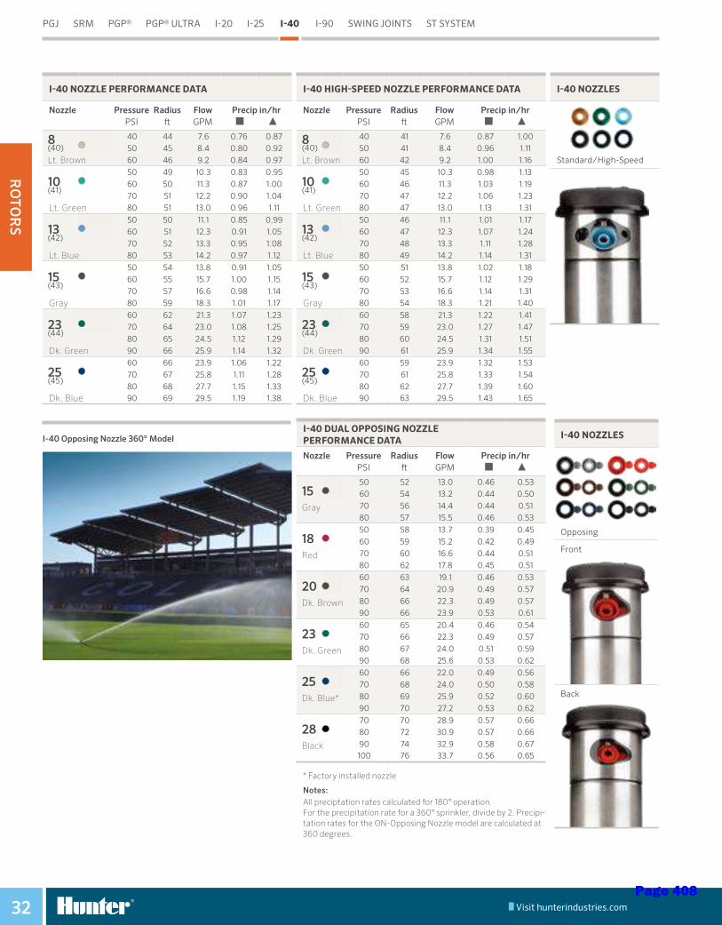
RO
TOR
S
Visit hunterindustries.com32
I-40 Opposing Nozzle 360° Model
I-40 NOZZLE PERFORMANCE DATA
Nozzle PressurePSI
Radius ft
Flow GPM
Precip in/hr
8(40)
40 44 7.6 0.76 0.8750 45 8.4 0.80 0.92
Lt. Brown 60 46 9.2 0.84 0.97
10(41)
50 49 10.3 0.83 0.9560 50 11.3 0.87 1.00
70 51 12.2 0.90 1.04
Lt. Green 80 51 13.0 0.96 1.11
13(42)
50 50 11.1 0.85 0.9960 51 12.3 0.91 1.05
70 52 13.3 0.95 1.08
Lt. Blue 80 53 14.2 0.97 1.12
15(43)
50 54 13.8 0.91 1.0560 55 15.7 1.00 1.15
70 57 16.6 0.98 1.14
Gray 80 59 18.3 1.01 1.17
23(44)
60 62 21.3 1.07 1.2370 64 23.0 1.08 1.25
80 65 24.5 1.12 1.29
Dk. Green 90 66 25.9 1.14 1.32
25(45)
60 66 23.9 1.06 1.2270 67 25.8 1.11 1.28
80 68 27.7 1.15 1.33
Dk. Blue 90 69 29.5 1.19 1.38
I-40 HIGH-SPEED NOZZLE PERFORMANCE DATA
Nozzle PressurePSI
Radius ft
Flow GPM
Precip in/hr
8(40)
40 41 7.6 0.87 1.0050 41 8.4 0.96 1.11
Lt. Brown 60 42 9.2 1.00 1.16
10(41)
50 45 10.3 0.98 1.1360 46 11.3 1.03 1.19
70 47 12.2 1.06 1.23
Lt. Green 80 47 13.0 1.13 1.31
13(42)
50 46 11.1 1.01 1.1760 47 12.3 1.07 1.24
70 48 13.3 1.11 1.28
Lt. Blue 80 49 14.2 1.14 1.31
15(43)
50 51 13.8 1.02 1.1860 52 15.7 1.12 1.29
70 53 16.6 1.14 1.31
Gray 80 54 18.3 1.21 1.40
23(44)
60 58 21.3 1.22 1.4170 59 23.0 1.27 1.47
80 60 24.5 1.31 1.51
Dk. Green 90 61 25.9 1.34 1.55
25(45)
60 59 23.9 1.32 1.5370 61 25.8 1.33 1.54
80 62 27.7 1.39 1.60
Dk. Blue 90 63 29.5 1.43 1.65
I-40 DUAL OPPOSING NOZZLE PERFORMANCE DATA
Nozzle PressurePSI
Radius ft
Flow GPM
Precip in/hr
1550 52 13.0 0.46 0.5360 54 13.2 0.44 0.50
Gray 70 56 14.4 0.44 0.5180 57 15.5 0.46 0.53
1850 58 13.7 0.39 0.4560 59 15.2 0.42 0.49
Red 70 60 16.6 0.44 0.5180 62 17.8 0.45 0.51
2060 63 19.1 0.46 0.5370 64 20.9 0.49 0.57
Dk. Brown 80 66 22.3 0.49 0.5790 66 23.9 0.53 0.61
2360 65 20.4 0.46 0.5470 66 22.3 0.49 0.57
Dk. Green 80 67 24.0 0.51 0.5990 68 25.6 0.53 0.62
2560 66 22.0 0.49 0.5670 68 24.0 0.50 0.58
Dk. Blue* 80 69 25.9 0.52 0.6090 70 27.2 0.53 0.62
2870 70 28.9 0.57 0.6680 72 30.9 0.57 0.66
Black 90 74 32.9 0.58 0.67100 76 33.7 0.56 0.65
* Factory installed nozzle
Notes:All preciptation rates calculated for 180° operation.For the precipitation rate for a 360° sprinkler, divide by 2. Precipi-tation rates for the ON-Opposing Nozzle model are calculated at 360 degrees.
I-40 NOZZLES
Standard/High-Speed
I-40 NOZZLES
Opposing
Front
Back
PGJ SRM PGP® PGP® ULTRA I-20 I-25 I-40 I-90 SWING JOINTS ST SYSTEM
Page 408

www.nibco.com
A H E A D O F T H E F L O W®
www.nibco.com
DezincificationResistant
Bronze Ball Valves¹⁄₄ ¹⁄₄
600 PSI/41.4 Bar Non-Shock Cold Working Pressure150 PSI/10.3 Bar Saturated Steam
T-580-70MATERIAL LIST
PART SPECIFICATION
¹⁄₄" size only has a 304 stainless steel grounding washer.
For detailed Operating Pressure, refer to Pressure Temperature Chart on page 41.
Revision 3/31/2011
DIMENSIONS—WEIGHTS—QUANTITIES Dimensions
T-580-70 S-580-70 T-580-70 S-580-70
Size A A B C C D T-580-70 S-580-70 Master In. mm. In. mm. In. mm. In. mm. In. mm. In. mm. In. mm. Lbs. Kg. Lbs. Kg. Ctn. Qty. † ¹⁄₄ † ³⁄₈ † ¹⁄₂ † ³⁄₄
¹⁄₄
¹⁄₂
¹⁄₂
† NIBCO supplies Full Port T or S-585-70 on this size.
Note: Solder end is designed to be soft-soldered into lines using solders with the melting point not exceeding 500°F. Higher temperature solders will damage the seat material. See installation sheet packaged with valves.
S-580-70
T-580-70
S-580-70
B
A
C
D
Page 409

Toro® 570Z Series spray heads provide everything needed for residential and commercial contractors to satisfy all installation and retrofit requirements. In combination with Toro spray and rotating nozzles, 570Z Series spray heads can be configured in hundreds of combinations and present an unparalleled range of flexibility. Available in 2”, 3”, 4”, 6” and 12” models with both bottom and side inlet thread options, Toro 570Z Series spray heads are further available with patented in-stem X-Flow® Technology and Pressure Regulating water-saving features. Trusted for over 25 years, Toro’s 570Z Series spray heads are the ideal choice.
Zero Flush Wiper SealThe elimination of flushing on pop-up allows for more sprinklers to
be installed per zone.
Patented X-Flow® Technology
The X-Flow in-stem flow shut-off device is built into the riser
and restricts water loss by 99% should the nozzle be removed
or damaged. The exclusive X-Flow device greatly reduces water
waste, landscape erosion, and wet hardscape safety concerns.
Furthermore, X-Flow allows for ‘dry’ nozzle and filter replacement
or system maintenance while the system is running.
One-Piece Check Valve
Pre-installed from the factory or easily installed in the field, Toro’s
one-piece check valve prevents low-head drainage on elevation
changes of up to 10 feet.
Ratcheting RiserQuick and precise arc adjustment on all pop-up models.
570Z SERIES SPRAYS
FEATURES & BENEFITS
Effluent OptionsAvailable
CheckValveOptionsAvailable
Page 410

WATER MANAGEMENT HIGHLIGHT
Without X-Flow
Without Pressure Regulation
With Pressure Regulation
Enhanced Zero Flush Seal
No Water Wasted at System StartSystem start up is a critical time when water waste can occur. The Toro 570Z Series spray head’s wiper seal is pressure-activated and prevents flow-by at start up, meaning no water is wasted and more heads can be installed on the same line.
Pressure Regulator
Reliability thanks to Built-in Pressure RegulationToro’s factory-installed pressure regulator eliminates water misting and fogging at the nozzle that can lead to rapid evaporation or water being blown away from the intended irrigation area. From the first to the last head, the in-stem pressure regulator provides a steady outlet pressure of 30 PSI and consistent spray head performance across the zone.
X-Flow® Technology Cuts Off Water Waste Up to 40 gallons of water per minute can escape through a spray head that has a missing or damaged nozzle. This wasted water can lead to landscape erosion, property damage, or unsafe conditions due to wet hardscapes. The patented X-Flow device is factory-installed in the riser and holds back over 99% of the water that would otherwise be wasted in cases where the nozzle has been compromised through unintentional accidents or vandalism. Furthermore, X-Flow Technology allows for spray head maintenance or component replacement without the need to turn off the system.
Patented X-Flow® Shut-off Device
With X-Flow
Page 411

570ZPRX
570ZPR
570ZXF
570Z &570ZLP
570ZXF (SPRAY HEADS WITH X-FLOW® TECHNOLOGY)
570Z-4P XF570Z-4P XF COM570Z-6P XF570Z-6P XF SI570Z-6P XF COM570Z-12P XF570Z-12P XF SI570Z-12P XF COM570S-XF
4” spray head with X-Flow4” spray head with X-Flow and Check Valve6” spray head with X-Flow6” spray head with X-Flow, Side Inlet Body6” spray head with X-Flow and Check Valve12” spray head with X-Flow12” spray head with X-Flow, Side Inlet Body12” spray head with X-Flow and Check ValveShrub adapter with X-Flow
570ZPR (SPRAY HEADS WITH PRESSURE REGULATION)
570Z-4P PR570Z-4P PR COM570Z-6P PR570Z-6P PR COM570Z-12P PR570Z-12P PR COM570S-PR
4” spray head with Pressure Regulation4” spray head with Pressure Regulation and Check Valve6” spray head with Pressure Regulation6” spray head with Pressure Regulation and Check Valve12” spray head with Pressure Regulation12” spray head with Pressure Regulation and Check ValveShrub adapter with Pressure Regulation
570ZPRX (SPRAY HEADS WITH PRESSURE REGULATION AND X-FLOW®)
570Z-4P PRX570Z-4P PRX COM570Z-4P PRX E570Z-4P PRX COM E570Z-6P PRX570Z-6P PRX COM570Z-6P PRX E570Z-6P PRX COM E570Z-6P SI PRX570Z-12P PRX570Z-12P PRX E570Z-12P PRX COM E570Z-12P SI PRX570S-PRX
4” PRX spray head 4” PRX spray head with Check Valve4” PRX spray head with Effluent cap4” PRX spray head with Check Valve and Effluent cap6” PRX spray head6” PRX spray head with Check Valve6” PRX spray head with Effluent cap6” PRX spray head with Check Valve and Effluent cap6” PRX spray head, Side Inlet Body12” PRX spray head12” PRX spray head with Effluent cap12” PRX spray head with Check Valve and Effluent cap12” PRX spray head, Side Inlet BodyPRX Shrub adapter
570Z (STANDARD SPRAY HEADS)
570Z-2P570Z-3P570Z-4P570Z-4P COM570Z-6P570Z-6P SI570Z-6P COM570Z-12P570Z-12P SI570Z-12P COM570S
2” spray head3” spray head4” spray head4” spray head with Check Valve6” spray head6” spray head, Side Inlet Body6” spray head with Check Valve12” spray head12” spray head, Side Inlet Body12” spray head with Check ValveShrub adapter
570ZLP (LOW PRESSURE SPRAY HEADS)
570Z-2LP570Z-3LP570Z-4LP570Z-6LP570Z-6LP SI570Z-12LP570Z-12LP SI
570Z, 2”, Low Pressure570Z, 3”, Low Pressure570Z, 4”, Low Pressure570Z, 6”, Low Pressure570Z, 6”, Low Pressure, Side Inlet Body570Z, 12”, Low Pressure570Z, 12”, Low Pressure, Side Inlet Body
570Z SERIES SPRAYS
Page 412
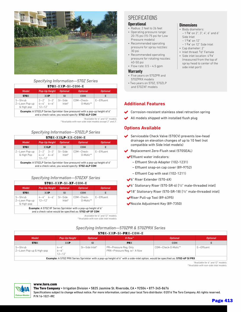
SPECIFICATIONS Operational• Radius: 2 feet to 26 feet• Operating pressure range:
20-75 psi (15-75 psi for Low Pressure models)
• Recommended operating pressure for spray nozzles: 30 psi
• Recommended operating pressure for rotating nozzles: 40-50 psi
• Flow rate: 0.5 – 4.5 gpm
Warranty• Five years on 570ZPR and
570ZPRX models• Two years on 570Z, 570ZLP
and 570ZXF models
Dimensions• Body diameters: – 13/8” on 2”, 3”, 4”, 6” and 6”
Side Inlet – 15/8” on 12” – 13/4” on 12” Side Inlet• Cap diameter: 2”• Inlet thread: 1/2” Female• Side inlet location: 43/4”
(measured from the top of spray head to center of the side inlet port)
Additional Features
Corrosion-resistant stainless steel retraction spring
All models shipped with installed flush plug
Options Available
Serviceable Check Valve (570CV) prevents low-head drainage on elevation changes of up to 10 feet (not compatible with Side Inlet models)
Replacement Zero-Flush seal (570SEAL)
Effluent water indicators:
– Effluent Shrub Adapter (102-1231)
– Effluent snap-on cap cover (89-9752)
– Effluent Cap with seal (102-1211)
6” Riser Extender (570-6X)
6” Stationary Riser (570-SR-6) [1/2” male-threaded inlet]
18” Stationary Riser (570-SR-18) [1/2” male-threaded inlet]
Riser Pull-up Tool (89-6395)
Nozzle Adjustment Key (89-7350)
Specifying Information—570Z Series570X-XXP-SI-COM-E
Model Pop-Up Height Optional Optional Optional
570X XXP SI COM E
S—ShrubZ—Lawn Pop-up & High pop
2—2” 3—3” 4—4” 6—6” 12—12”
SI—Side Inlet*
COM—Check- O-Matic**
E—Effluent
Example: A 570ZLP Series Sprinkler (low pressure) with a pop-up height of 6”and a check valve, you would specify: 570Z-6LP COM
*Available for 6” and 12” models.**Available with non-side inlet models except 2” and 3”.
Specifying Information—570ZLP Series570X-XXLP-XX-COM-E
Model Pop-Up Height Optional Optional Optional
570X XXLP SI COM E
Z—Lawn Pop-up & High Pop
2—2” 3—3” 4—4” 6—6” 12—12”
SI—Side Inlet*
COM—Check- O-Matic**
E—Effluent
Example: A 570ZLP Series Sprinkler (low pressure) with a pop-up height of 6” and a check valve, you would specify: 570Z-6LP COM
Specifying Information—570ZXF Series570X-XXP-SI-XF-COM-E
Model Pop-Up Height Optional Optional Optional
570X XXP SI COM E
S—ShrubZ—Lawn Pop-up & High-pop
4—4” 6—6” 12—12”
SI—Side Inlet*
COM—Check- O-Matic**
E—Effluent
Example: A 570Z XF Series Sprinkler with a pop-up height of 6” and a check valve would be specified as: 570Z-6P XF COM
Available for 6” and 12” models.**Available with non-side inlet models.
Specifying Information—570ZPR & 570ZPRX Series570X-XXP-SI-PRX-COM-E
Model Pop-Up Height Optional X-flow™ Optional Optional
570X XXP SI PRX COM E
S—ShrubZ—Lawn Pop-up & High-pop
4—4”6—6” 12—12”
SI—Side Inlet* PR—Pressure Reg. OnlyPRX—Pressure Reg. w/- X-flow
COM—Check-O-Matic** E—Effluent
Example: A 570Z PRX Series Sprinkler with a pop-up height of 6” with a side-inlet option, would be specified as: 570Z-6P SI PRX
*Available for 6” and 12” models.**Available with non-side inlet models.
www.toro.comThe Toro Company • Irrigation Division • 5825 Jasmine St. Riverside, CA • 92504 • 877-345-8676Specifications subject to change without notice. For more information, contact your local Toro distributor. ©2016 The Toro Company. All rights reserved. P/N 16-1021-IRC
Page 413
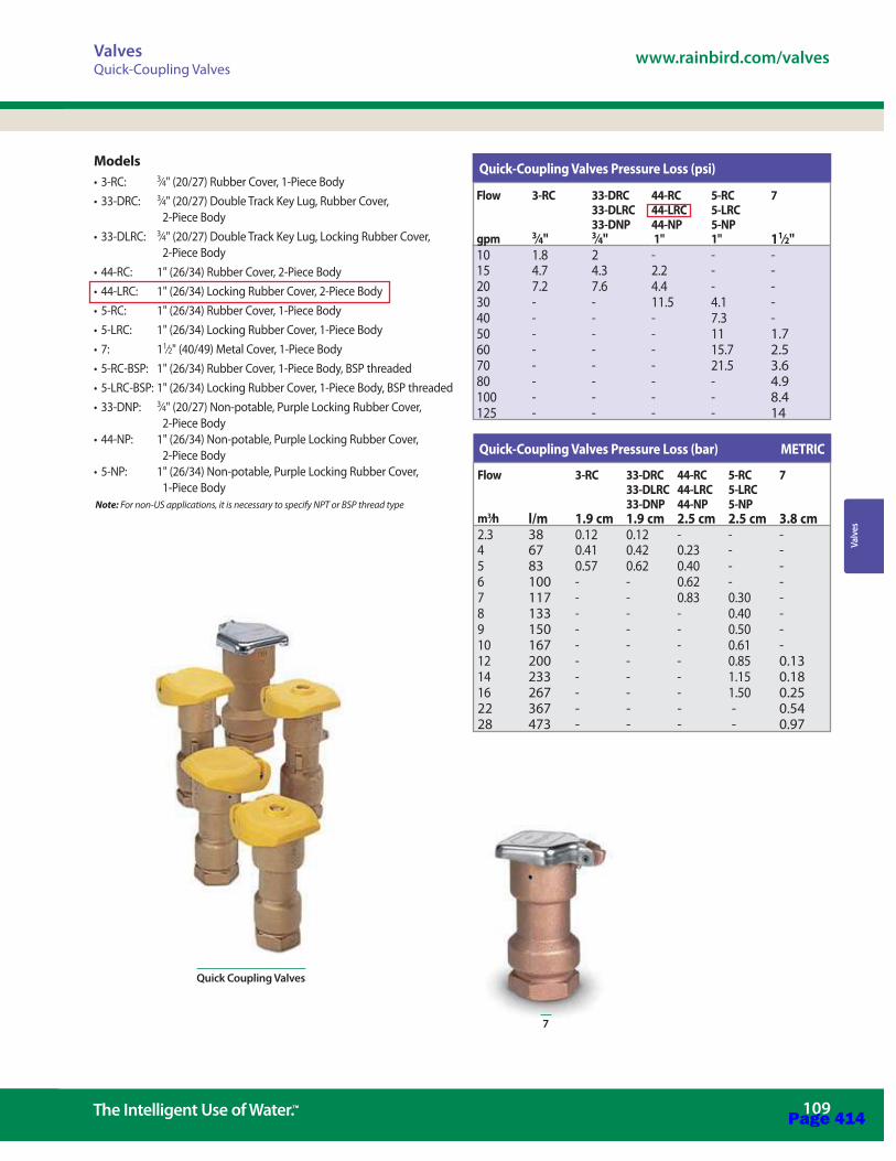
Val
ves
www.rainbird.com/valves
109 The Intelligent Use of Water.™
Valves
7
Quick-Coupling Valves Pressure Loss (bar) METRIC
Quick-Coupling Valves Pressure Loss (psi)Models
3⁄4" (20/27) Rubber Cover, 1-Piece Body3⁄4
2-Piece Body3⁄4
2-Piece Body
1⁄2" (40/49) Metal Cover, 1-Piece Body
3⁄4" (20/27) Non-potable, Purple Locking Rubber Cover, 2-Piece Body
2-Piece Body
1-Piece Body Note: For non-US applications, it is necessary to specify NPT or BSP thread type
Flow 3-RC 33-DRC 44-RC 5-RC 733-DLRC 44-LRC 5-LRC33-DNP 44-NP 5-NP
gpm 3⁄4" 3⁄4" 1" 1" 11⁄2" 10 1.8 2 - - -15 4.7 4.3 2.2 - -20 7.2 7.6 4.4 - -30 - - 11.5 4.1 -40 - - - 7.3 -50 - - - 11 1.760 - - - 15.7 2.570 - - - 21.5 3.680 - - - - 4.9100 - - - - 8.4125 - - - - 14
Flow 3-RC 33-DRC 44-RC 5-RC 733-DLRC 44-LRC 5-LRC33-DNP 44-NP 5-NP
m3⁄h l/m 1.9 cm 1.9 cm 2.5 cm 2.5 cm 3.8 cm2.3 38 0.12 0.12 - - -4 67 0.41 0.42 0.23 - -5 83 0.57 0.62 0.40 - -6 100 - - 0.62 - -7 117 - - 0.83 0.30 -8 133 - - - 0.40 -9 150 - - - 0.50 -10 167 - - - 0.61 -12 200 - - - 0.85 0.1314 233 - - - 1.15 0.1816 267 - - - 1.50 0.2522 367 - - - - 0.5428 473 - - - - 0.97
Quick Coupling Valves
Page 414
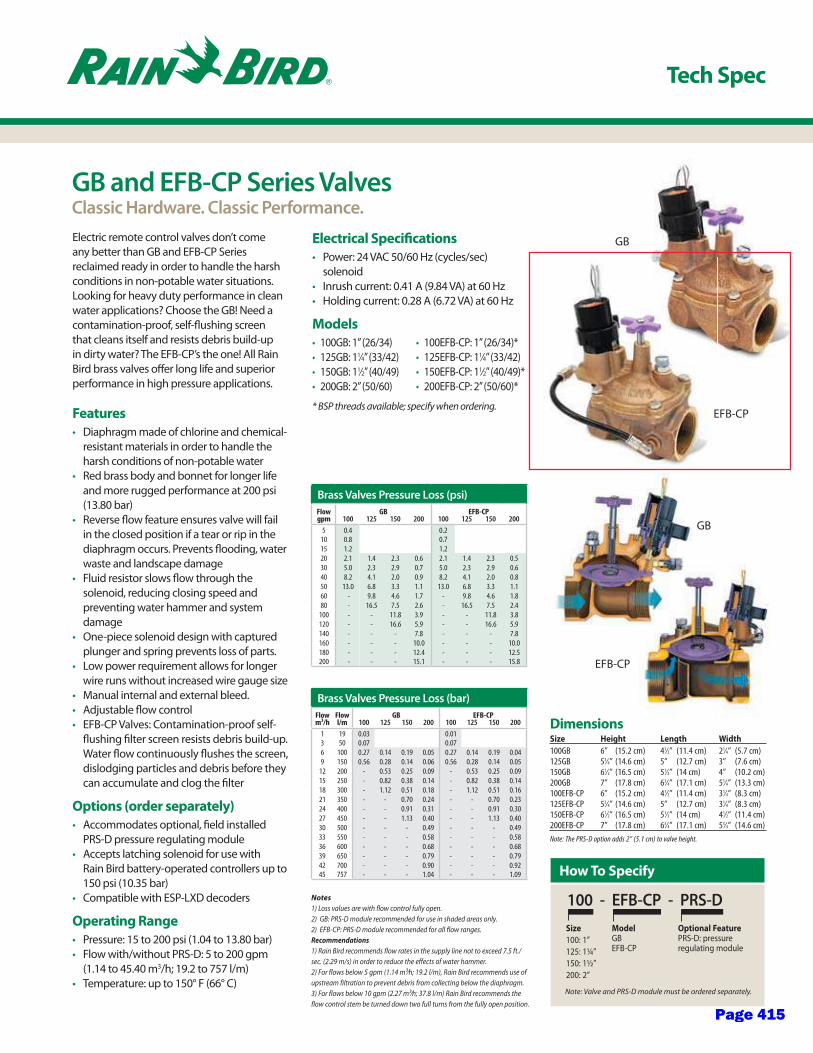
GB
EFB-CP
Electric remote control valves don’t come any better than GB and EFB-CP Series reclaimed ready in order to handle the harsh conditions in non-potable water situations. Looking for heavy duty performance in clean water applications? Choose the GB! Need a contamination-proof, self-flushing screen that cleans itself and resists debris build-up in dirty water? The EFB-CP’s the one! All Rain Bird brass valves offer long life and superior performance in high pressure applications.
Features
Diaphragm made of chlorine and chemical-resistant materials in order to handle the harsh conditions of non-potable water Red brass body and bonnet for longer life and more rugged performance at 200 psi (13.80 bar)Reverse flow feature ensures valve will fail in the closed position if a tear or rip in the diaphragm occurs. Prevents flooding, water waste and landscape damageFluid resistor slows flow through the solenoid, reducing closing speed and preventing water hammer and system damageOne-piece solenoid design with captured plunger and spring prevents loss of parts.Low power requirement allows for longer wire runs without increased wire gauge sizeManual internal and external bleed.Adjustable flow controlEFB-CP Valves: Contamination-proof self-flushing filter screen resists debris build-up. Water flow continuously flushes the screen, dislodging particles and debris before they can accumulate and clog the filter
Options (order separately)
Accommodates optional, field installed PRS-D pressure regulating moduleAccepts latching solenoid for use with Rain Bird battery-operated controllers up to 150 psi (10.35 bar)Compatible with ESP-LXD decoders
Operating Range
Pressure: 15 to 200 psi (1.04 to 13.80 bar)Flow with/without PRS-D: 5 to 200 gpm (1.14 to 45.40 m3/h; 19.2 to 757 l/m)Temperature: up to 150° F (66° C)
Electrical Specifications
Power: 24 VAC 50/60 Hz (cycles/sec) solenoid Inrush current: 0.41 A (9.84 VA) at 60 HzHolding current: 0.28 A (6.72 VA) at 60 Hz
Models
100GB: 1” (26/34)125GB: 11⁄4” (33/42)150GB: 11⁄2” (40/49)200GB: 2” (50/60)
* BSP threads available; specify when ordering.
Tech Spec
GB and EFB-CP Series ValvesClassic Hardware. Classic Performance.
DimensionsSize Height Length Width
100GB 6” (15.2 cm) 41⁄2” (11.4 cm) 21⁄4” (5.7 cm)125GB 53⁄4” (14.6 cm) 5” (12.7 cm) 3” (7.6 cm)150GB 61⁄2” (16.5 cm) 51⁄2” (14 cm) 4” (10.2 cm)200GB 7” (17.8 cm) 63⁄4” (17.1 cm) 51⁄4” (13.3 cm)100EFB-CP 6” (15.2 cm) 41⁄2” (11.4 cm) 31⁄4” (8.3 cm)125EFB-CP 53⁄4” (14.6 cm) 5” (12.7 cm) 31⁄4” (8.3 cm)150EFB-CP 61⁄2” (16.5 cm) 51⁄2” (14 cm) 41⁄2” (11.4 cm)200EFB-CP 7” (17.8 cm) 63⁄4” (17.1 cm) 53⁄4” (14.6 cm)Note: The PRS-D option adds 2” (5.1 cm) to valve height.
Notes1) Loss values are with flow control fully open.2) GB: PRS-D module recommended for use in shaded areas only.2) EFB-CP: PRS-D module recommended for all flow ranges.Recommendations1) Rain Bird recommends flow rates in the supply line not to exceed 7.5 ft./sec. (2.29 m/s) in order to reduce the effects of water hammer.2) For flows below 5 gpm (1.14 m3⁄h; 19.2 l/m), Rain Bird recommends use of upstream filtration to prevent debris from collecting below the diaphragm.3) For flows below 10 gpm (2.27 m3⁄h; 37.8 l/m) Rain Bird recommends the flow control stem be turned down two full turns from the fully open position.
Brass Valves Pressure Loss (psi)Flow GB EFB-CPgpm 100 125 150 200 100 125 150 200
5 0.4 0.210 0.8 0.715 1.2 1.220 2.1 1.4 2.3 0.6 2.1 1.4 2.3 0.530 5.0 2.3 2.9 0.7 5.0 2.3 2.9 0.640 8.2 4.1 2.0 0.9 8.2 4.1 2.0 0.850 13.0 6.8 3.3 1.1 13.0 6.8 3.3 1.160 - 9.8 4.6 1.7 - 9.8 4.6 1.880 - 16.5 7.5 2.6 - 16.5 7.5 2.4
100 - - 11.8 3.9 - - 11.8 3.8120 - - 16.6 5.9 - - 16.6 5.9140 - - - 7.8 - - - 7.8160 - - - 10.0 - - - 10.0180 - - - 12.4 - - - 12.5200 - - - 15.1 - - - 15.8
Brass Valves Pressure Loss (bar)Flow Flow GB EFB-CPm3/h l/m 100 125 150 200 100 125 150 200
1 19 0.03 0.013 50 0.07 0.076 100 0.27 0.14 0.19 0.05 0.27 0.14 0.19 0.049 150 0.56 0.28 0.14 0.06 0.56 0.28 0.14 0.05
12 200 - 0.53 0.25 0.09 - 0.53 0.25 0.0915 250 - 0.82 0.38 0.14 - 0.82 0.38 0.1418 300 - 1.12 0.51 0.18 - 1.12 0.51 0.1621 350 - - 0.70 0.24 - - 0.70 0.2324 400 - - 0.91 0.31 - - 0.91 0.3027 450 - - 1.13 0.40 - - 1.13 0.4030 500 - - - 0.49 - - - 0.4933 550 - - - 0.58 - - - 0.5836 600 - - - 0.68 - - - 0.6839 650 - - - 0.79 - - - 0.7942 700 - - - 0.90 - - - 0.9245 757 - - - 1.04 - - - 1.09 How To Specify
100 - EFB-CP - PRS-DSize
100: 1”125: 1¼”150: 1½”200: 2”
ModelGBEFB-CP
Optional FeaturePRS-D: pressure regulating module
Note: Valve and PRS-D module must be ordered separately.
100EFB-CP: 1” (26/34)*125EFB-CP: 11⁄4” (33/42)150EFB-CP: 11⁄2” (40/49)*200EFB-CP: 2” (50/60)*
GB
EFB-CP
Page 415

® Registered Trademark of Rain Bird Corporation © 2012 Rain Bird Corporation 7/12
Rain Bird Corporation
6991 E. Southpoint RoadTucson, AZ 85756Phone: (520) 741-6100Fax: (520) 741-6522
Rain Bird Technical Services
(800) RAINBIRD (1-800-724-6247) (U.S. and Canada)
Rain Bird Corporation
970 West Sierra Madre AvenueAzusa, CA 91702Phone: (626) 812-3400Fax: (626) 812-3411
Specification Hotline
800-458-3005 (U.S. and Canada)
Rain Bird International, Inc.
1000 West Sierra Madre Ave.Azusa, CA 91702Phone: (626) 963-9311Fax: (626) 852-7343
The Intelligent Use of Water™
www.rainbird.com
The electric remote control valve shall be a normally closed 24 VAC 50/60 Hz (cycles/sec) solenoid actuated globe pattern with a bal-anced pressure diaphragm design. The valve pressure rating shall not be less than 200 psi (13.80 bar). The valve shall have the following characteristics (circle one):
Flow rate: ________ gpm m3/h l/m
Pressure loss not to exceed: _______ psi bar
The valve body and bonnet shall be con-structed of heavy cast red brass; diaphragm shall be of EPDM rubber. All other internal parts shall be made of bronze, brass, and stainless steel to ensure corrosion resistance.
The valve shall have both internal and external manual open/close control (internal and external bleed) for manually opening and closing the valve without electrically energizing the solenoid. The valve shall have internal manual bleed to prevent flooding of the valve box.
The valve shall house a fully-encapsulated, one-piece solenoid. The solenoid shall have a captured plunger with a removable retainer for easy servicing and a leverage handle for easy turning. This 24 VAC 50/60 Hz solenoid shall open with 19.6 VAC minimum at 200 psi (13.80 bar). At 24 VAC, average inrush current shall not exceed 0.41 amps. Average holding current shall not exceed 0.28 amps.
The valve shall have a stainless steel flow control stem with cross handle for regulating or shutting off the flow of water. The valve must open or close in less than one minute at 200 psi (13.80 bar), and less than 30 seconds at 20 psi (1.38 bar).
The valve construction shall be such as to provide for all internal parts to be removable from the top of the valve without disturbing the valve installation.
GB only: The valve shall have a control port filter screen to filter out grit and prevent clogging of hydraulic control ports.
EFB-CP: The valve shall have a contamina-tion proof (CP) self-flushing stainless steel screen located at the valve inlet to filter out grit and prevent clogging of hydraulic con-trol ports and assure reliable operation.
Optional Feature Specification
When so indicated on the design, the 1”, 11⁄2”, 11⁄4”, and 2” electric remote control valves shall have a pressure regulating module (PRS-D) capable of regulating outlet pressure between 15 and 100 psi (±3 psi) (1.04 and 6.90 bar (±0.21 bar)).
The PRS-D module shall have an adjusting knob for setting pressure and Schrader valve connection for monitoring pressure. Pressure shall be adjustable from the PRS-D when the valve is internally manually bled or electrically activated.
Specifications
Brass Electric Remote Control GB Valve
Brass Electric Remote Control EFB-CP Valve
D38949GPage 416
Planting - 1
DISTRICT DESIGN STANDARDS
Section 32B – Planting
Issued: Fall 2020 Updates:
I. Purpose
A. The following District Design Standard is meant to provide guidance on creating planting designs within the landscape that are economical, functional, and attractive. This section will provide guidance on plant selection and placement and address ancillary landscape materials. Lastly, this section addresses items required of a planting installation to help ensure the long-term success such as maintenance periods and warranties.
II. Planting Design
A. Planting design and installation shall comply with the DSA landscape regulations including applicable portions of the MWELO and CalGreen.
B. Planting design should account for the following considerations:
1. Trees spaced so mature canopies do not overlap with each other or building roofs.
2. Trees are not in conflict with underground utilities, especially wet ones.
3. Turf should be used only for recreational areas.
4. Plants are suited for the microclimate.
5. Adjacent plants have similar light and water requirements.
6. Plants are spaced to allow for mature height and widths without shearing.
7. Plants do not endanger public safety by blocking sight lines or creating un-safe dark areas.
8. Plant material ties into the campus’ adjacent landscape design.
C. Plant material should be:
1. Drought tolerant and climate appropriate.
Page 417
2 - Planting
DISTRICT DESIGN STANDARDS
2. Low maintenance.
3. Safe for school age children.
III. Prohibited plants
A. Use of plants on the California Invasive Plants Council Inventory are discouraged. See www.cal-ipc.org.
B. The District has learned that some plants are inappropriate for use at their schools. These plants are prohibited from use for because of invasiveness, poor past performance, inappropriate for the climate, or endangering the public safety. Planting design should account for the following non-allowed plantings:
1. Bamboo, all genus and species.
2. Buxus species, Boxwood.
3. Callistemon species, Bottlebrush.
4. Cotoneaster, all genus and species.
5. Eucalyptus, all genus and species.
6. Fraxinus uhdei, Evergreen ash.
7. Hedera helix, English ivy.
8. Liquidambar styraciflua, Sweet gum.
9. Maytenus boaria, Mayten.
10. Melaluca styphelioides, Prickly-leaved paperbark.
11. Nerium oleander, Oleander.
12. Pinus species, Pine.
13. Platanus species, Sycamore AKA London plane tree.
14. Sequoia sempervirens, Coast redwood.
15. Trachelospermum jasminoides, Star jasmine.
16. Ulmus parvifolia, Chinese elm.
17. Any plants with messy berries or fruit.
Page 418

Planting - 3
DISTRICT DESIGN STANDARDS
III. Trees
Cercis occidentalis Western Redbud
Height: 10’-18’
Width: 10’-18’
Deciduous
Light Requirements: Full sun to part sun
Water Requirements: Regular water to establish, drought tolerant once established, WUCOLS VL
Maintenance: Prune to shape
Native to: California, Arizona and Utah
Notes: Pink spring flowers, magenta seed pods in summer, reddish brown seed pods in winter.
X Chitalpa tashkentensis No common name
Height: 20’- 30’
Width: 20’-30’
Deciduous
Light Requirements: Full sun
Water Requirements: Regular water to establish, drought tolerant once established, WUCOLS L
Notes: Blooms spring through fall in pinks and whites
Page 419
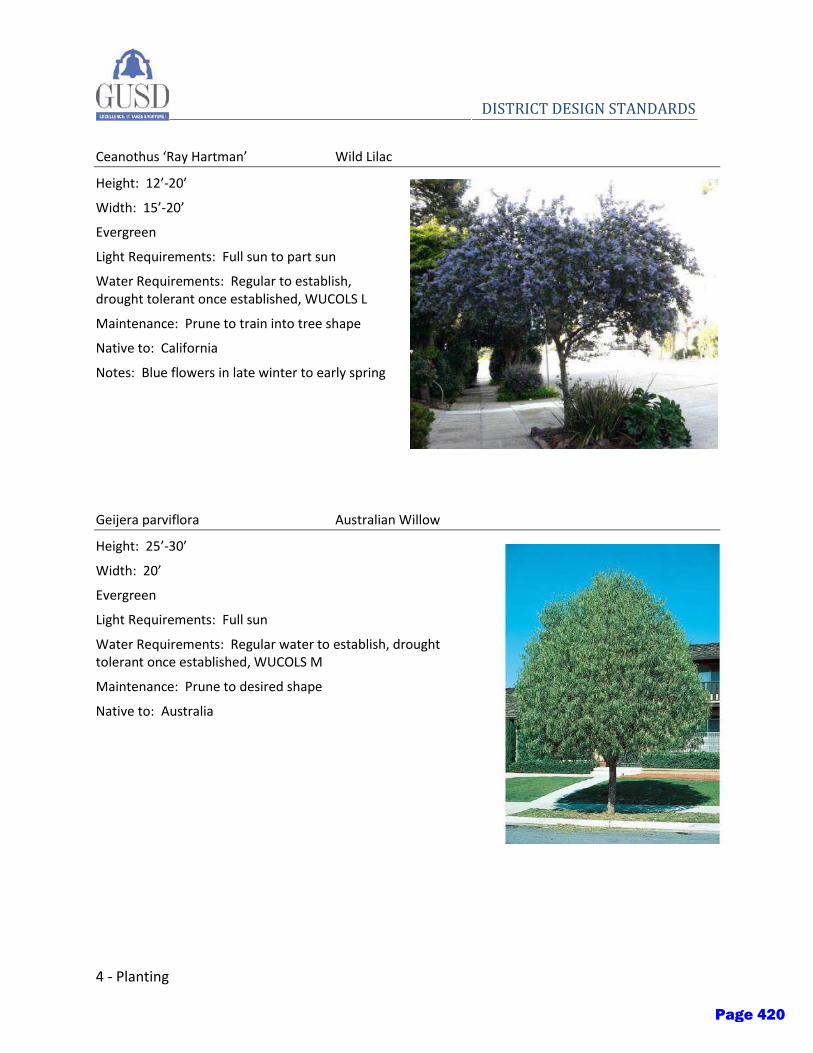
4 - Planting
DISTRICT DESIGN STANDARDS
Ceanothus ‘Ray Hartman’ Wild Lilac
Height: 12’-20’
Width: 15’-20’
Evergreen
Light Requirements: Full sun to part sun
Water Requirements: Regular to establish, drought tolerant once established, WUCOLS L
Maintenance: Prune to train into tree shape
Native to: California
Notes: Blue flowers in late winter to early spring
Geijera parviflora Australian Willow
Height: 25’-30’
Width: 20’
Evergreen
Light Requirements: Full sun
Water Requirements: Regular water to establish, drought tolerant once established, WUCOLS M
Maintenance: Prune to desired shape
Native to: Australia
Page 420
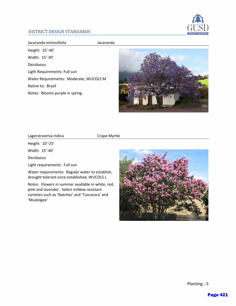
Planting - 5
DISTRICT DESIGN STANDARDS Jacaranda mimosifolia Jacaranda
Height: 25’-40’
Width: 15’-30’
Deciduous
Light Requirements: Full sun
Water Requirements: Moderate, WUCOLS M
Native to: Brazil
Notes: Blooms purple in spring.
Lagerstroemia indica Crape Myrtle
Height: 10’-25’
Width: 25’-40’
Deciduous
Light requirements: Full sun
Water requirements: Regular water to establish, drought tolerant once established, WUCOLS L
Notes: Flowers in summer available in white, red, pink and lavender. Select mildew resistant varieties such as ‘Natchez’ and ‘Tuscarora’ and ‘Muskogee’
Page 421

6 - Planting
DISTRICT DESIGN STANDARDS
Melaleuca quinquenervia Paperbark tree
Height: 20’-40’
Width: 15’-25’
Evergreen
Light Requirements: Full sun
Water Requirements: Regular water to establish, drought tolerant once established, WUCOLS L
Native to: Australia
Notes: Spongy white bark
Metrosideros excelsus New Zealand Christmas Tree
Height: 30’
Width: 30’
Evergreen
Light Requirements: Full sun to part shade
Water Requirements: Regular water to establish, drought tolerant once established, WUCOLS L
Native to: New Zealand
Notes: Red winter bloom
Page 422
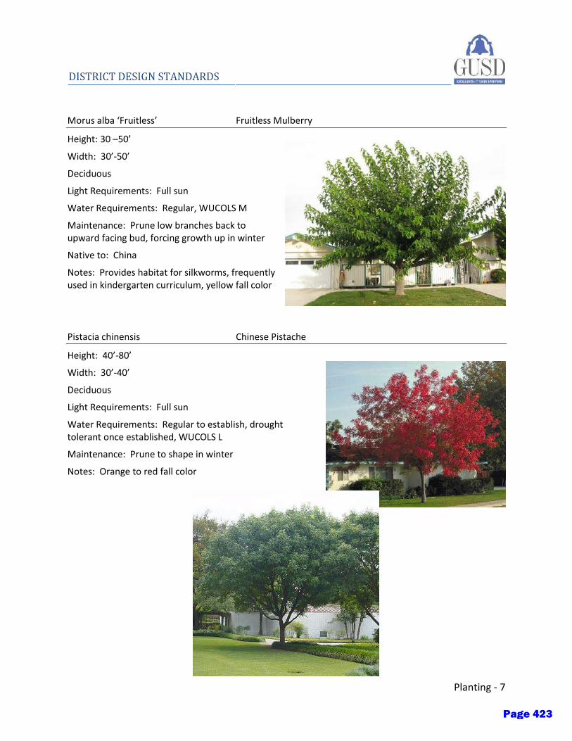
Planting - 7
DISTRICT DESIGN STANDARDS
Morus alba ‘Fruitless’ Fruitless Mulberry
Height: 30 –50’
Width: 30’-50’
Deciduous
Light Requirements: Full sun
Water Requirements: Regular, WUCOLS M
Maintenance: Prune low branches back to upward facing bud, forcing growth up in winter
Native to: China
Notes: Provides habitat for silkworms, frequently used in kindergarten curriculum, yellow fall color
Pistacia chinensis Chinese Pistache
Height: 40’-80’
Width: 30’-40’
Deciduous
Light Requirements: Full sun
Water Requirements: Regular to establish, drought tolerant once established, WUCOLS L
Maintenance: Prune to shape in winter
Notes: Orange to red fall color
Page 423
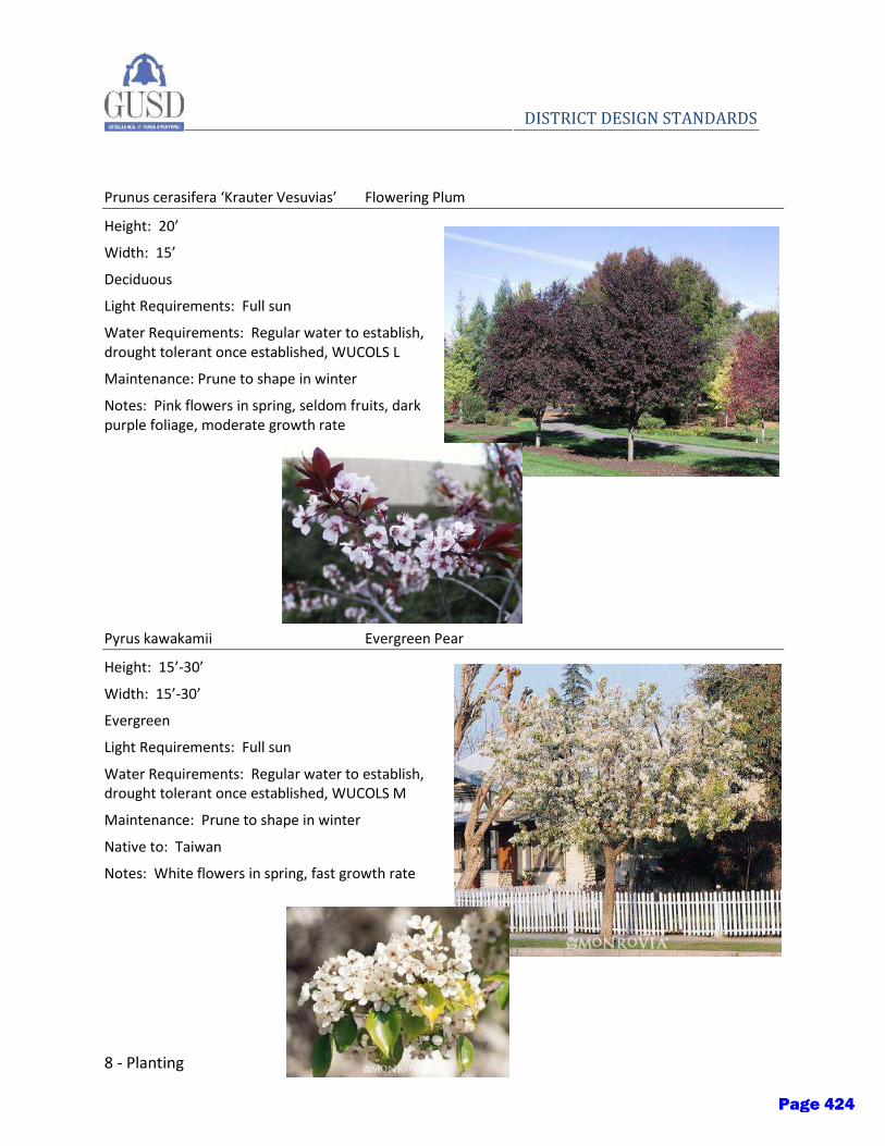
8 - Planting
DISTRICT DESIGN STANDARDS
Prunus cerasifera ‘Krauter Vesuvias’ Flowering Plum
Height: 20’
Width: 15’
Deciduous
Light Requirements: Full sun
Water Requirements: Regular water to establish, drought tolerant once established, WUCOLS L
Maintenance: Prune to shape in winter
Notes: Pink flowers in spring, seldom fruits, dark purple foliage, moderate growth rate
Pyrus kawakamii Evergreen Pear
Height: 15’-30’
Width: 15’-30’
Evergreen
Light Requirements: Full sun
Water Requirements: Regular water to establish, drought tolerant once established, WUCOLS M
Maintenance: Prune to shape in winter
Native to: Taiwan
Notes: White flowers in spring, fast growth rate
Page 424
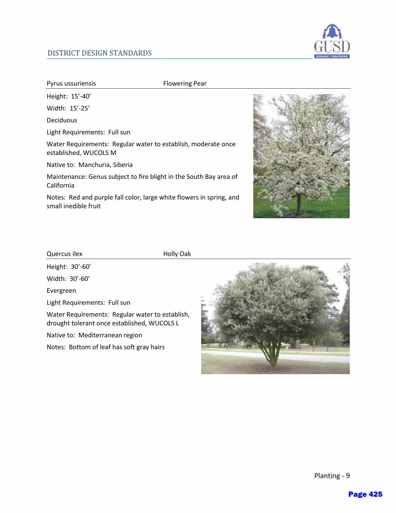
Planting - 9
DISTRICT DESIGN STANDARDS
Pyrus ussuriensis Flowering Pear
Height: 15’-40’
Width: 15’-25’
Deciduous
Light Requirements: Full sun
Water Requirements: Regular water to establish, moderate once established, WUCOLS M
Native to: Manchuria, Siberia
Maintenance: Genus subject to fire blight in the South Bay area of California
Notes: Red and purple fall color, large white flowers in spring, and small inedible fruit
Quercus ilex Holly Oak
Height: 30’-60’
Width: 30’-60’
Evergreen
Light Requirements: Full sun
Water Requirements: Regular water to establish, drought tolerant once established, WUCOLS L
Native to: Mediterranean region
Notes: Bottom of leaf has soft gray hairs
Page 425
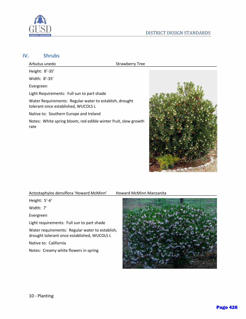
10 - Planting
DISTRICT DESIGN STANDARDS
IV. Shrubs
Arbutus unedo Strawberry Tree
Height: 8’-35’
Width: 8’-35’
Evergreen
Light Requirements: Full sun to part shade
Water Requirements: Regular water to establish, drought tolerant once established, WUCOLS L
Native to: Southern Europe and Ireland
Notes: White spring bloom, red edible winter fruit, slow growth rate
Actostaphylos densiflora ‘Howard McMinn’ Howard McMinn Manzanita
Height: 5’-6’
Width: 7’
Evergreen
Light requirements: Full sun to part shade
Water requirements: Regular water to establish, drought tolerant once established, WUCOLS L
Native to: California
Notes: Creamy white flowers in spring
Page 426
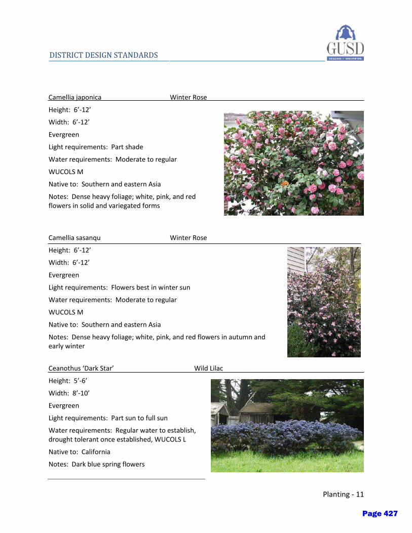
Planting - 11
DISTRICT DESIGN STANDARDS
Camellia japonica Winter Rose
Height: 6’-12’
Width: 6’-12’
Evergreen
Light requirements: Part shade
Water requirements: Moderate to regular
WUCOLS M
Native to: Southern and eastern Asia
Notes: Dense heavy foliage; white, pink, and red flowers in solid and variegated forms
Camellia sasanqu Winter Rose
Height: 6’-12’
Width: 6’-12’
Evergreen
Light requirements: Flowers best in winter sun
Water requirements: Moderate to regular
WUCOLS M
Native to: Southern and eastern Asia
Notes: Dense heavy foliage; white, pink, and red flowers in autumn and early winter
Ceanothus ‘Dark Star’ Wild Lilac
Height: 5’-6’
Width: 8’-10’
Evergreen
Light requirements: Part sun to full sun
Water requirements: Regular water to establish, drought tolerant once established, WUCOLS L
Native to: California
Notes: Dark blue spring flowers
Page 427
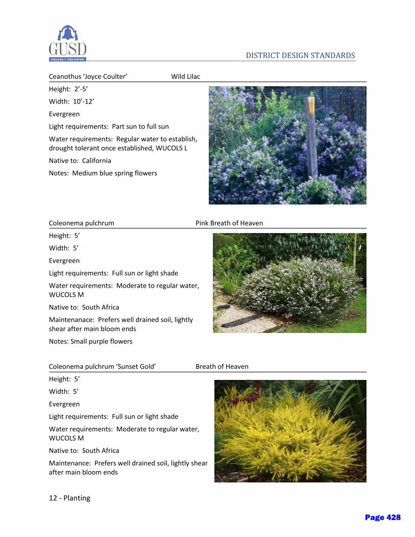
12 - Planting
DISTRICT DESIGN STANDARDS
Ceanothus ‘Joyce Coulter’ Wild Lilac
Height: 2’-5’
Width: 10’-12’
Evergreen
Light requirements: Part sun to full sun
Water requirements: Regular water to establish, drought tolerant once established, WUCOLS L
Native to: California
Notes: Medium blue spring flowers
Coleonema pulchrum Pink Breath of Heaven
Height: 5’
Width: 5’
Evergreen
Light requirements: Full sun or light shade
Water requirements: Moderate to regular water, WUCOLS M
Native to: South Africa
Maintenanace: Prefers well drained soil, lightly shear after main bloom ends
Notes: Small purple flowers
Coleonema pulchrum ‘Sunset Gold’ Breath of Heaven
Height: 5’
Width: 5’
Evergreen
Light requirements: Full sun or light shade
Water requirements: Moderate to regular water, WUCOLS M
Native to: South Africa
Maintenance: Prefers well drained soil, lightly shear after main bloom ends
Page 428

Planting - 13
DISTRICT DESIGN STANDARDS Notes:yellow foliage, small purple flower
Cupressus sempervirens Italian cypress
Height: 60’
Width: 5’-10’
Evergreen Tree
Light requirements: Full sun
Water requirements: Little to moderate, WUCOLS L
Native to: Southern Europe and western Asia
Notes: Dense, narrow tree; little pruning required
Dietes vegata Fortnight Lily
Height: 3’
Width: 3’
Evergreen
Light requirements: Full sun or part shade
Water requirements: Regular water to establish, drought tolerant once established, WUCOLS L
Native to: East Africa
Notes: White summer flowers
Euryops pectinatus No common name
Height: 3’-6’
Width: 3’-6’
Evergreen
Light requirements: Full sun
Water requirements: Regular water to establish, drought tolerant once established, WUCOLS L
Native to: East Africa
Maintenance: Cut back in late spring to limit size and maintain compact growth
Notes: Yellow blooms nearly year-round
Page 429
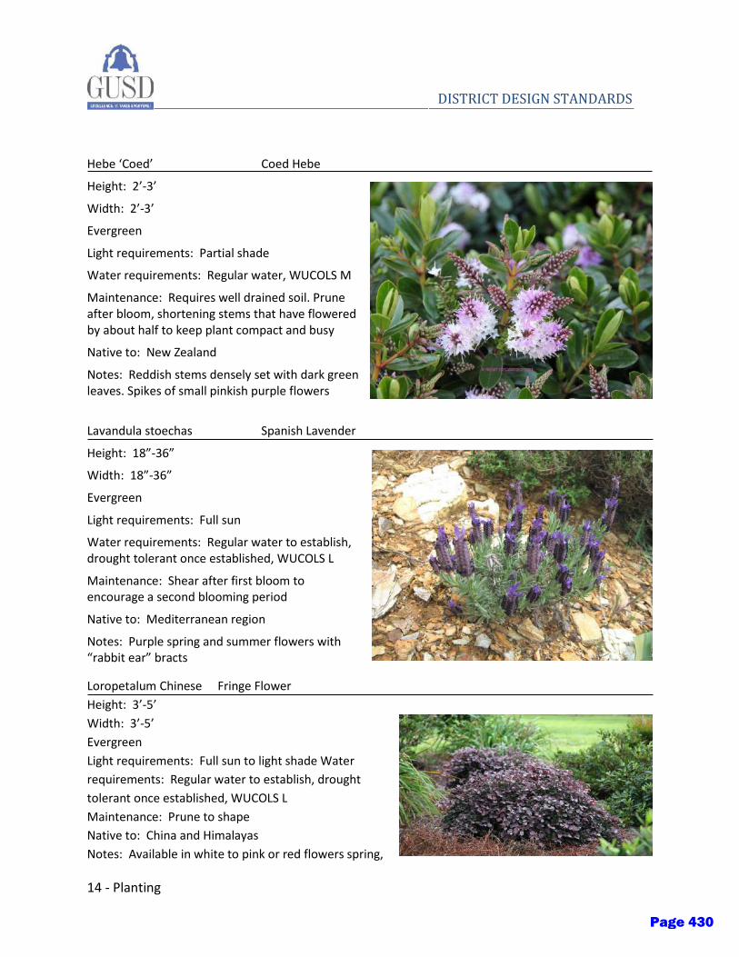
14 - Planting
DISTRICT DESIGN STANDARDS
Hebe ‘Coed’ Coed Hebe
Height: 2’-3’
Width: 2’-3’
Evergreen
Light requirements: Partial shade
Water requirements: Regular water, WUCOLS M
Maintenance: Requires well drained soil. Prune after bloom, shortening stems that have flowered by about half to keep plant compact and busy
Native to: New Zealand
Notes: Reddish stems densely set with dark green leaves. Spikes of small pinkish purple flowers
Lavandula stoechas Spanish Lavender
Height: 18”-36”
Width: 18”-36”
Evergreen
Light requirements: Full sun
Water requirements: Regular water to establish, drought tolerant once established, WUCOLS L
Maintenance: Shear after first bloom to encourage a second blooming period
Native to: Mediterranean region
Notes: Purple spring and summer flowers with “rabbit ear” bracts
Loropetalum Chinese Fringe Flower
Height: 3’-5’
Width: 3’-5’
Evergreen
Light requirements: Full sun to light shade Water
requirements: Regular water to establish, drought
tolerant once established, WUCOLS L
Maintenance: Prune to shape
Native to: China and Himalayas
Notes: Available in white to pink or red flowers spring,
Page 430

Planting - 15
DISTRICT DESIGN STANDARDS summer and fall
Muhlenbergia capillaris Pink Muhly
Height: 3’
Width: 6’
Deciduous
Light requirements: Full sun to light shade
Water requirements: Regular water to establish, drought tolerant once established, WUCOLS L
Maintenance: Cut back foliage in late winter for fresh spring growth
Muhlenbergia rigens Deer Grass
Height: 4’
Width: 4’
Deciduous
Light requirements: Full sun to light shade
Water requirements: Regular water to establish, drought tolerant once established, WUCOLS L
Maintenance: If shabby, cut back to mound about 12” high in late winter
Myrtus communis ‘compacta’ Myrtus
Height: 5’-6’
Width: 4’-5’ Evergreen
Light requirements: Full sun or partial shade
Water requirements: Little to moderate, WUCOLS L
Native to: Mediterranean
Notes: Glossy bright green leaves; white, sweet-scented flowers in summer, followed by small bluish-black berries
Page 431

16 - Planting
DISTRICT DESIGN STANDARDS
Maintenance: prefers well drained soil, used as informal hedge with little pruning
Nandina domestica Heavenly bamboo
Height: 6’-8’
Width: 3’-4’
Evergreen to semievergreen
Light requirements: Some shade
Water requirements: Little to regular water, WUCOLS L
Native to: China and Japan
Maintenance: Subject to chlorosis in alkaline soil, cut oldest canes to ground each year before growth begins in spring. May need to control spreading throughout planter.
Notes: Pinkish bronze new foliage, clusters of creamy white blossoms in late spring followed by shiny red berries
Phormium species New Zealand flax
Height: 1’-6’
Width: 1’-6’
Evergreen
Light requirements: Full sun to full shade
Water requirements: Regular to establish, drought tolerant once established, WUCOLS L
Native to: New Zealand
Page 432

Planting - 17
DISTRICT DESIGN STANDARDS
Pittosporum tobira ‘Variegata’ Variegated Mock Orange
Height: 6’-8’
Width: 6’-8’
Evergreen
Light requirements: Full sun or partial shade
Water requirements: Regular water to establish, drought tolerant once established, WUCOLS L
Maintenance: Shear to shape in winter
Native to: Japan
Notes: Creamy white blooms have orange fragrance
Rhaphiolepis indica ‘Jack Evans’ India Hawthorn
Height: 4’
Width: 4’-5’
Evergreen
Light requirements: Full sun or light shade
Water requirements: Little to regular, WUCOLS L
Maintenance: Shear to shape after bloom
Native to: China
Notes: Pink spring and summer bloom, moderate growth rate
Rhaphiolepis indica ‘Majestic Beauty’ India Hawthorn
Height: 10’-12’ (shrub); 25’ (tree)
Width: 6’-8’ (shrub); 10’ (tree)
Evergreen
Light requirements: Full sun or light shade
Water requirements: Little to regular, WUCOLS L
Maintenance: Can be trained to a single or multi-trunked tree
Page 433
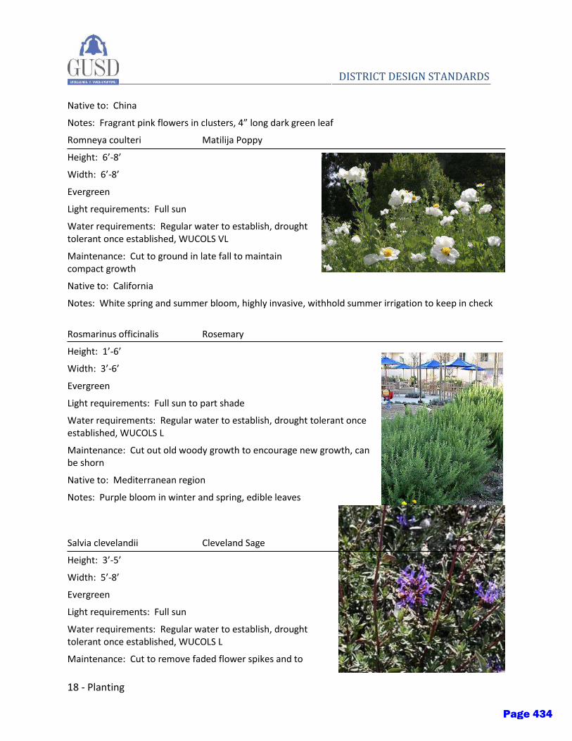
18 - Planting
DISTRICT DESIGN STANDARDS
Native to: China
Notes: Fragrant pink flowers in clusters, 4” long dark green leaf
Romneya coulteri Matilija Poppy
Height: 6’-8’
Width: 6’-8’
Evergreen
Light requirements: Full sun
Water requirements: Regular water to establish, drought tolerant once established, WUCOLS VL
Maintenance: Cut to ground in late fall to maintain compact growth
Native to: California
Notes: White spring and summer bloom, highly invasive, withhold summer irrigation to keep in check
Rosmarinus officinalis Rosemary
Height: 1’-6’
Width: 3’-6’
Evergreen
Light requirements: Full sun to part shade
Water requirements: Regular water to establish, drought tolerant once established, WUCOLS L
Maintenance: Cut out old woody growth to encourage new growth, can be shorn
Native to: Mediterranean region
Notes: Purple bloom in winter and spring, edible leaves
Salvia clevelandii Cleveland Sage
Height: 3’-5’
Width: 5’-8’
Evergreen
Light requirements: Full sun
Water requirements: Regular water to establish, drought tolerant once established, WUCOLS L
Maintenance: Cut to remove faded flower spikes and to
Page 434
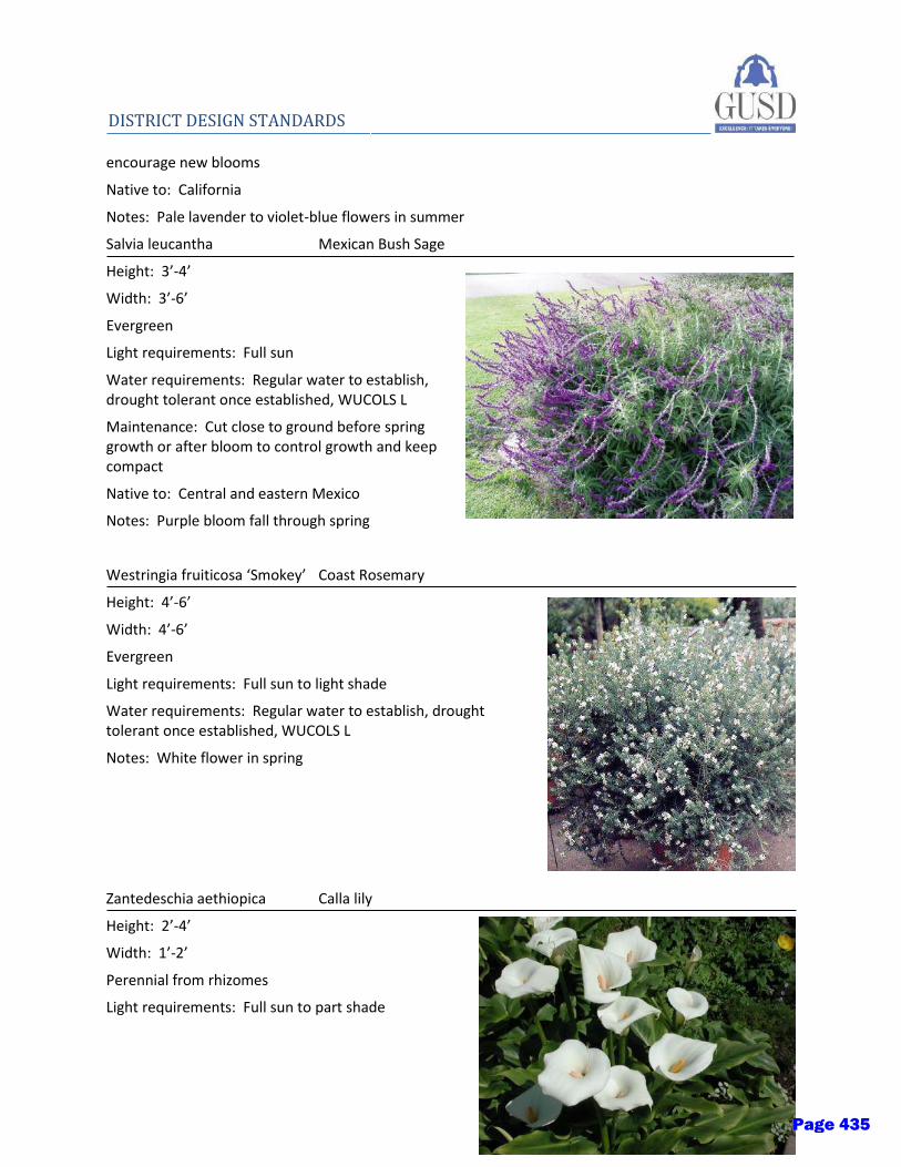
Planting - 19
DISTRICT DESIGN STANDARDS encourage new blooms
Native to: California
Notes: Pale lavender to violet-blue flowers in summer
Salvia leucantha Mexican Bush Sage
Height: 3’-4’
Width: 3’-6’
Evergreen
Light requirements: Full sun
Water requirements: Regular water to establish, drought tolerant once established, WUCOLS L
Maintenance: Cut close to ground before spring growth or after bloom to control growth and keep compact
Native to: Central and eastern Mexico
Notes: Purple bloom fall through spring
Westringia fruiticosa ‘Smokey’ Coast Rosemary
Height: 4’-6’
Width: 4’-6’
Evergreen
Light requirements: Full sun to light shade
Water requirements: Regular water to establish, drought tolerant once established, WUCOLS L
Notes: White flower in spring
Zantedeschia aethiopica Calla lily
Height: 2’-4’
Width: 1’-2’
Perennial from rhizomes
Light requirements: Full sun to part shade
Page 435

20 - Planting
DISTRICT DESIGN STANDARDS
Water requirements: Regular to moist soil, WUCOLS M
Native to: Africa
Notes: Grow in clumps, showy white and yellow flower
V. Ground covers
Erigeron karvinskianus Santa Barbara Daisy
Height: 10’-20”
Width: 3’
Evergreen
Light requirements: Full shade to part shade
Water requirements: Regular water to establish, drought tolerant once established, WUCOLS L
Native to: Mexico
Notes: Year-round white bloom
Festuca glauca ‘Siskiyou Blue’ Blue Fescue
Height: 1’-2’
Width: 1’-2’
Evergreen
Light requirements: Full sun to part sun
Water requirements: Regular water to establish, drought tolerant once established, WUCOLS L
Notes: Grows well with California native plants
Page 436
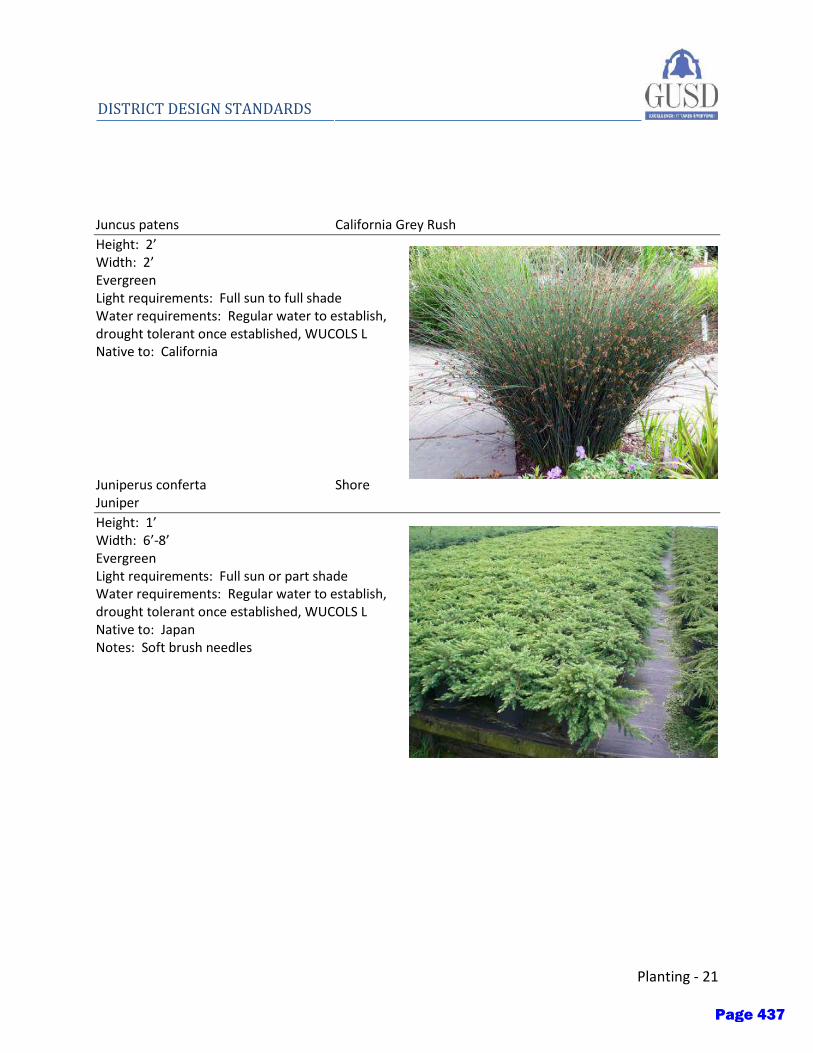
Planting - 21
DISTRICT DESIGN STANDARDS Juncus patens California Grey Rush
Height: 2’ Width: 2’ Evergreen Light requirements: Full sun to full shade Water requirements: Regular water to establish, drought tolerant once established, WUCOLS L Native to: California
Juniperus conferta Shore Juniper
Height: 1’ Width: 6’-8’ Evergreen Light requirements: Full sun or part shade Water requirements: Regular water to establish, drought tolerant once established, WUCOLS L Native to: Japan Notes: Soft brush needles
Page 437
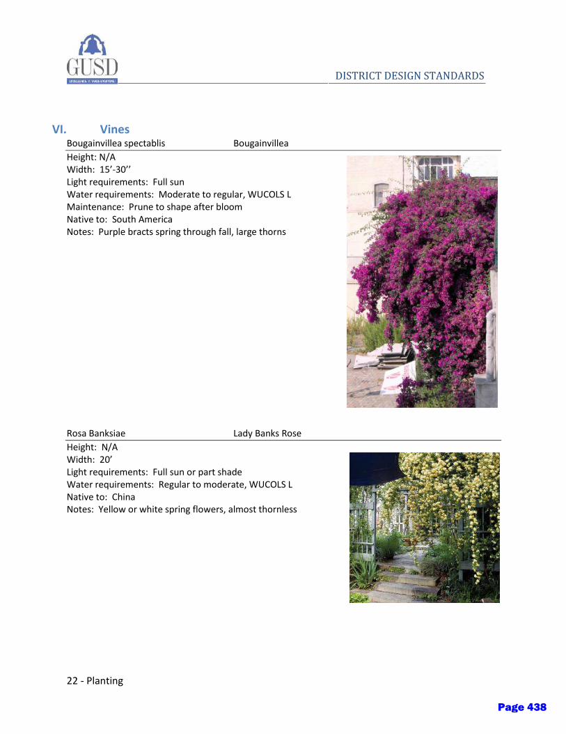
22 - Planting
DISTRICT DESIGN STANDARDS
VI. Vines Bougainvillea spectablis Bougainvillea
Height: N/A Width: 15’-30’’ Light requirements: Full sun Water requirements: Moderate to regular, WUCOLS L Maintenance: Prune to shape after bloom Native to: South America Notes: Purple bracts spring through fall, large thorns
Rosa Banksiae Lady Banks Rose
Height: N/A Width: 20’ Light requirements: Full sun or part shade Water requirements: Regular to moderate, WUCOLS L Native to: China Notes: Yellow or white spring flowers, almost thornless
Page 438
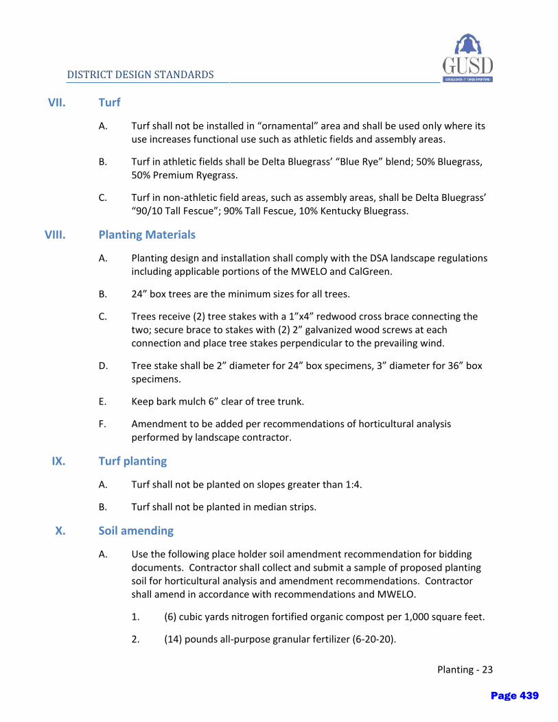
Planting - 23
DISTRICT DESIGN STANDARDS
VII. Turf
A. Turf shall not be installed in “ornamental” area and shall be used only where its use increases functional use such as athletic fields and assembly areas.
B. Turf in athletic fields shall be Delta Bluegrass’ “Blue Rye” blend; 50% Bluegrass, 50% Premium Ryegrass.
C. Turf in non-athletic field areas, such as assembly areas, shall be Delta Bluegrass’ “90/10 Tall Fescue”; 90% Tall Fescue, 10% Kentucky Bluegrass.
VIII. Planting Materials
A. Planting design and installation shall comply with the DSA landscape regulations including applicable portions of the MWELO and CalGreen.
B. 24” box trees are the minimum sizes for all trees.
C. Trees receive (2) tree stakes with a 1”x4” redwood cross brace connecting the two; secure brace to stakes with (2) 2” galvanized wood screws at each connection and place tree stakes perpendicular to the prevailing wind.
D. Tree stake shall be 2” diameter for 24” box specimens, 3” diameter for 36” box specimens.
E. Keep bark mulch 6” clear of tree trunk.
F. Amendment to be added per recommendations of horticultural analysis performed by landscape contractor.
IX. Turf planting
A. Turf shall not be planted on slopes greater than 1:4.
B. Turf shall not be planted in median strips.
X. Soil amending
A. Use the following place holder soil amendment recommendation for bidding documents. Contractor shall collect and submit a sample of proposed planting soil for horticultural analysis and amendment recommendations. Contractor shall amend in accordance with recommendations and MWELO.
1. (6) cubic yards nitrogen fortified organic compost per 1,000 square feet.
2. (14) pounds all-purpose granular fertilizer (6-20-20).
Page 439
24 - Planting
DISTRICT DESIGN STANDARDS
3. (15) pounds soil sulfur.
4. Thoroughly till to (6) inch minimum depth.
XI. Root barrier
A. Deep Root LB 18-2.
B. Place flush against side of paving, remove “overpour” as necessary.
C. Place 12’ of root barrier along edge of paving centered on tree trunk when tree is within 6’ of paving, wall, curb, etc.
XII. Bark mulch
A. Republic Service’s “Pro-Chip” bark mulch for non-bioretention planting areas.
B. Sun-Gro Horticulture’s “Shredded Cedar” bark mulch for bioretention areas.
C. Install 3” depth in all shrub and ground cover planters.
XIII. Weed Barrier
A. Herbicides
1. Pre-emergent: Ronstar-G, Treflan, or approved equal.
2. Selective and non-selective Herbicides: EPA registered and approved, of type recommended by manufacturer for application.
3. Contact Owner and obtain School District, Local, State and Federal policies and procedures for regulating application of chemical controls. Contractor shall comply with all applicable policies and/or procedures for application, posting and notifications.
B. Sheet Mulch
4. Weed control shall consist of biodegradable, paper product, permeable weed barrier layer. Paper products may consist of two (2) to three (3) layers of recycled content builder’s paper, four (4) to (6) layers of newspaper print, or one (1) layer of cardboard.
5. Apply to all shrub and ground cover planters.
XIV. Headerboard
A. Headerboard to be construction heart redwood.
Page 440
Planting - 25
DISTRICT DESIGN STANDARDS
B. Anchor with wood stakes and chamfer top of stakes.
XV. Maintenance and Warranties A. All new planting and irrigation installations shall contain the following minimum
maintenance standards and warranties.
B. Maintenance period shall be 90 days minimum with an option to extend if the installation is not to the satisfaction of the District.
C. Implement pest management as necessary to control pests, including gophers.
Contact the District to obtain local, state and federal policies and procedures for regulating application of fertilizers, fungicides, insecticides, pesticides, and herbicides. Contractor shall comply with all applicable policies and/or procedures for application, posting and notifications. Disease, pest (moles and gophers) and inset damage shall be controlled by the use of the fungicides, pesticides or poisons. Contractor shall obtain written approval from the District prior to application of fungicides, insecticides, or pesticides and shall abide by all posting requirements prior to application.
D. Maintenance obligations must include a minimum of:
1. Mowing and trimming of turf.
2. Pruning of trees, shrubs, and ground cover.
3. Watering of turf, trees, shrubs, vines, and ground cover.
4. Weeding of turf, trees, shrubs, vines, and ground cover.
5. Tightening and repairing of tree stakes.
6. Re-planting of turf, trees, shrubs, vines, and ground cover.
7. Re-mulching of trees, shrubs, vines, and ground cover.
8. Protection of turf, trees, shrubs, vines, and ground cover.
B. The irrigation system shall be warrantied in writing for (1) year from Final Acceptance against defective workmanship, materials, or components.
C. Turf, trees, shrubs, vines, and ground covers shall be warrantied in writing for (1) year from Final Acceptance against defects including death and unsatisfactory growth, except for defects resulting from lack of adequate maintenance, neglect, or abuse by the District or users, or incidents that are beyond the Contractor’s control.
Page 441
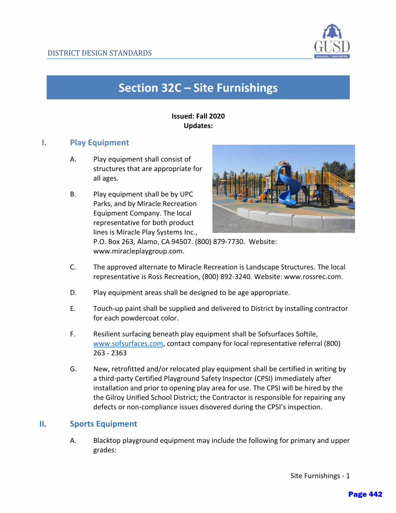
Site Furnishings - 1
DISTRICT DESIGN STANDARDS
Section 32C – Site Furnishings
Issued: Fall 2020 Updates:
I. Play Equipment
A. Play equipment shall consist of structures that are appropriate for all ages.
B. Play equipment shall be by UPC Parks, and by Miracle Recreation Equipment Company. The local representative for both product lines is Miracle Play Systems Inc., P.O. Box 263, Alamo, CA 94507. (800) 879-7730. Website: www.miracleplaygroup.com.
C. The approved alternate to Miracle Recreation is Landscape Structures. The local representative is Ross Recreation, (800) 892-3240. Website: www.rossrec.com.
D. Play equipment areas shall be designed to be age appropriate.
E. Touch-up paint shall be supplied and delivered to District by installing contractor for each powdercoat color.
F. Resilient surfacing beneath play equipment shall be Sofsurfaces Softile, www.sofsurfaces.com, contact company for local representative referral (800) 263 - 2363
G. New, retrofitted and/or relocated play equipment shall be certified in writing by a third-party Certified Playground Safety Inspector (CPSI) immediately after installation and prior to opening play area for use. The CPSI will be hired by the the Gilroy Unified School District; the Contractor is responsible for repairing any defects or non-compliance issues disovered during the CPSI’s inspection.
II. Sports Equipment
A. Blacktop playground equipment may include the following for primary and upper grades:
Page 442

2 - Site Furnishings
DISTRICT DESIGN STANDARDS
1. Basketball assembly to be Patterson Williams model 1525-20-45 for single backboard and model 1526-20-45 for back to back installation, with nylon net, www.pwathletic.com, contact local representative: David O’Keefe Northern California, (510) 558-0141, www.davidokeefecompany.com, Kelly O’Keefe, [email protected].
2. Drop shot assembly to be Landscape Structures, model 100042A, www.playlsi.com, contact local representative: Ross Recreation (707) 538-3800, [email protected].
3. Tetherball assembly to be post, chain, rope and ball assembly to be Patterson Williams, model 2221-10, www.pwathletic.com, contact local representative: David O’Keefe Northern California, (510) 558-0141, www.davidokeefecompany.com, Kelly O’Keefe, [email protected].
4. Volleyball post set to include two posts per court, one with two fixed eyes and one with net tightener, rope clamp and side pulley to be Patterson Williams, 2214-21. Volleyball posts installed within basketball courts shall be installed in sleeves, Patterson Williams, model 8303-24-IH, also provide one net per court, model 8362-10, www.pwathletic.com, contact local representative: David O’Keefe Northern California, (510) 558-0141, www.davidokeefecompany.com, Kelly O’Keefe, [email protected].
B. Athletic Sport Field Equipment shall include the following:
1. Baseball Backstop to be Patterson Williams, 17’6” x 24’ Regulation Series model 1228-03G Galvanized frame and mesh with 3 planks. Planks to be painted little league green in color, www.pwathletic.com, contact local representative: David O’Keefe Northern California, (510) 558-0141, www.davidokeefecompany.com, Kelly O’Keefe, [email protected].
III. Athletic Fields
A. High school and middle school athletic fields should include the following supplied by Sportsfield Specialties (888) 975 3343:
1. Football goalposts
a) 20’ Uprights, 6’ Offset
b) Model # GP4300PL in Yellow
2. Goal post access frame kit
a) Model # GP4570
3. Goal post pad
Page 443

Site Furnishings - 3
DISTRICT DESIGN STANDARDS
a) One pad for each goal post
b) GP4590RFULL
4. Weighted pylons
a) One set for each endzone
b) TFDCTF099 in Orange
5. Cast aluminum pole vault box and cover plug
a) TFPV002SS-Y/TFPV003ALTR powder coated Yellow w/ Cover Plug in Track Material
6. Pole vault planting box safety collar
a) TFPVPBSC
7. Take-off boards
a) TFLTSY008SS
8. Discus cage
a) TFDCHS in aluminum
9. Discus ring
a) TFD099AL in aluminum
10. Shot put ring
a) TFSPH084AL in aluminum
11. Shot put toe board
a) TFSPT001AL in aluminum
12. Portable soccer goals
a) One set of (2) goals
b) SG4950 white with round front posts
13. Mobility wheel kit for soccer goals
a) SG4955 white
Page 444

4 - Site Furnishings
DISTRICT DESIGN STANDARDS
14. Soccer corner flags
a) 2 sets – Yellow base with red flag, set of 4 flags
b) SG6B1104
15. Player benches
a) Wabash Valley (800) 253 8619
b) 15’ w/ back, portable system, perforated metal finish with vinyl coating
c) SG436
d) 2 benches per side (total of 4 benches)
16. Lacrosse goals
a) One set of (2) goals
b) LCG in orange
17. Field hockey goal(s)
a) 1 set of (2) goals
b) FHG in white
18. Water canon
a) Provide water cannon/Rotor ST-1600B or equal with nozzle 24 in vault box with STV30V valve and quick coupler. Ensure that 6” hydrometer and coaches switch is provided as part of the system.
b) Design team to work closely with athletics and the District to incorporate this feature into the design.
IV. Site Furnishings
B. Flag pole to be Bolander Extra Heavy Ground Set Cone Tapered Aluminum Flagpole External Halyard with gold anodized spun aluminum ball. Pole color shall be black. Pole height to be 30’, model HT30. Pole to be located a minimum of 10’ from building overhangs, contact: www.bolanderflagpole.com, (800) 434-5611.
Page 445

Site Furnishings - 5
DISTRICT DESIGN STANDARDS
C. Memorial bench to be Timberform, Columbia Cascade Renaissance model 2806-MP with Armrests & Plaque Mounting Plate, black in color. www.columbia-cascade.com, contact local representative: Park Pacific, (888) 460-7275, www.parkpacific.com, Ted Jonsson, [email protected].
D. Trash receptacle to be Belson model R32TR 32 gallon in black. Rigid liner to be model R32L, black. Flat top cover to be model R3216FC with 16” opening in sandstone, contact Belson Outdoors: (800) 323-5664,
www.belson.com.
E. Bike racks to be Timberform, Columbia Cascade Cycloops model 2170 series, contact local representative: Park Pacific, (888) 460-7275, www.parkpacific.com, Ted Jonsson, [email protected].
F. Shade structures to be NSP3, www.nspx3.com, with metal roofs, fabric shade sails may be acceptable, verify with District, model to be custom design, contact local representative: (877) 473-7619, [email protected].
Page 446

Site Walls - 1
DISTRICT DESIGN STANDARDS
Section 32D – Site Walls
Issued: Fall 2020 Updates:
I. Site Walls - Concrete
A. Cast-in-place concrete site walls and concrete seat walls shall be designed with skateboard deterrent built into the conrete such as repeating notches.
II. Site Walls - Options
A. Creative options for site walls and seat walls are encouraged, such as gabions filled with rock and topped with wood plank seating.
Page 447
Stone Paving - 1
DISTRICT DESIGN STANDARDS
Section 32E – Stone Paving
Issued: Fall 2020 Updates:
I. Decomposed Granite
A. Decomposed granite may be considered as an alternate paving system for student gardens, walking paths around fields, and remote locations.
B. Decomposed granite used for pedestrian access shall have a stablizing product incorporated into the mix.
C. Do not use decomposed granite near classrooms and other school buildings where the decomposed granite my be tracked indoors.
II. Boulders
A. Boulders may be used in the landscape and considered in place of using bollards.
Page 448

Stone Paving - 1
DISTRICT DESIGN STANDARDS
Section 32F – Synthetic Turf
Issued: Fall 2020 Updates:
I. Synthetic turf
A. Synthetic turf shall be ‘XM6-57’ by FieldTurf; a rigid monofilament fiber.
B. Synthetic turf shall have a Manufacturer’s Warranty which guarantees the usabilitya nd playability of the product for its intended uses for a minimum of (8) years.
C. All field of play lines shall be inlaid or tufted and a contrasting color with the field color.
II. Infill
A. Synthetic turf shall have infill placed in it uniformly to a depth of ¾” below the top of the fibers.
B. The infill shall be a mix of rubber and sand. The sand shall be 50% to 60% of the mix as measured by weight.
Page 449

Fencing - 1
DISTRICT DESIGN STANDARDS
Section 32G – Fencing
Issued: Fall 2020 Updates:
I. Purpose
A. The following District Design Standards for fencing are intended to provide basic guidelines for the District with the goal of minimizing end user maintenance, promoting security and consistency across all of the District sites.
II. Decorative fencing
A. All fences and gates should have a glossy black finish.
B. For elementary school campuses, fencing should be appropriate to accommodate the surrounding neighborhood in terms of safety and security. For locations that need higher security, pinch points should be provided.
C. For middle school campuses provide upgraded tube steel type fencing in high visibility areas. Decorative fence shall be Ameristar “Montage” series fencing, http://www.ameristarfence.com/residential-ornamental-wrought-iron-steel-fence-montage.
III. Security fencing
A. Security fencing shall be chain link, galvanized finish with 1” mesh fabric.
IV. Chain link fencing
A. Knuckle selvage top and bottom of all fences.
B. Mesh should be 1”, 9 gauge fabric. All chain link material shall be vinyl coated black.
C. Chain link fencing should be installed on the publicly accessible side of the fence.
Page 450
2 - Fencing
DISTRICT DESIGN STANDARDS
V. Gates
A. Gates shall comply with all ADA requirements
1. At gates along the path of travel, provide panic hardware with push force of no more than 5 lbs.
2. Where panic hardware is required, provide expanded metal at gate and fence panels the full height and for 4’-0” in both directions from the gate to help prevent students from accessing the panic hardware from the exterior.
3. Provide clear space in front of and on the push and pull side of the gate in compliance with the most recent ADA requirements.
4. All fences and gates shall be standard gloss black, with no exception.
B. Gate hardware:
1. Panic hardware: Von Duprin CD99NL x 99DY SNB
2. Hinges: self-closing and adjustable, fully welded. Hinges shall comply with ADA requirements.
3. Closer: weatherproof LCN Closer 7500H
4. Stainless steel kickplate: Trimco
Page 451
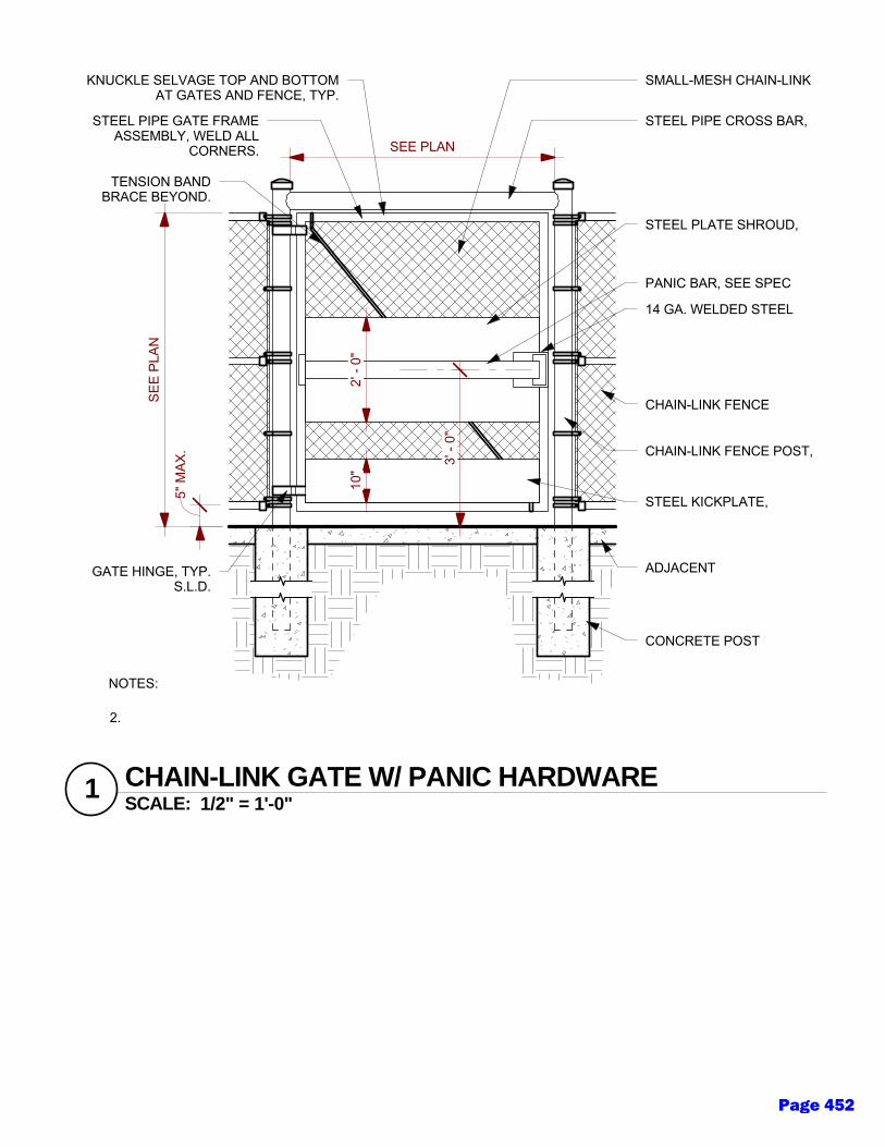
CONCRETE POST
FOO
TING
, TYP.S.L.D
.
ADJACENT
PAVEMEN
T, TYP. SEEPLAN
S & LAND
SCAPE
DR
AWIN
GS
GATE HINGE, TYP.S.L.D.
STEEL PIPE GATE FRAMEASSEMBLY, WELD ALL
CORNERS.
TENSION BANDBRACE BEYOND.
KNUCKLE SELVAGE TOP AND BOTTOMAT GATES AND FENCE, TYP.
CHAIN-LINK FENCE POST,
TYP. S.L.D.
CHAIN-LINK FENCE
ASSEMBLY, TYP. S.L.D
.
STEEL PIPE CROSS BAR,
SIZE TO M
ATCH
FENC
EPO
STS. WELD
TO FEN
CE
POSTS @
EITHER
SIDE.
10"
STEEL KICKPLATE,
WELD
@ ALL ED
GES TO
GATE FR
AME
5" M
AX.
SEE
PLAN
SEE PLAN
3' -
0"
14 GA. WELDED STEEL
LOC
KSET BOX, BY KEED
EXO
R APPR
OVED
EQU
AL.W
ELD G
ATE FRAM
E TO TO
P& BO
TTOM
PANIC BAR, SEE SPEC
2' -
0"
STEEL PLATE SHROUD,
WELD
TO G
ATE FRAM
E ATBO
TH EN
DS
SMALL-MESH CHAIN-LINK
FABRIC
, SEE SPEC.
NOTES:
1.G
RIN
D ALL W
ELDS SM
OO
TH PR
IOR
TO G
ALVANIZATIO
N.
SCALE: 1/2" = 1'-0"1 CHAIN-LINK GATE W/ PANIC HARDWARE
2.
FIELD-W
ELDED
OR
ASSEMBLED
CO
MPO
NEN
TS (GATE FR
AME, G
ATE POST
FRAM
E) TO BE G
ALVANIZED
& PAINTED
TO M
ATCH
ADJAC
ENT FEN
CE FIN
ISH.
Page 452
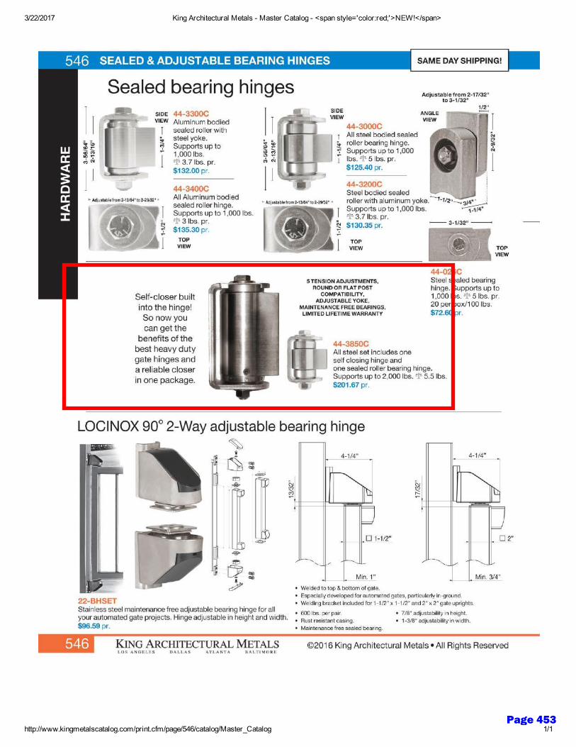
Page 453
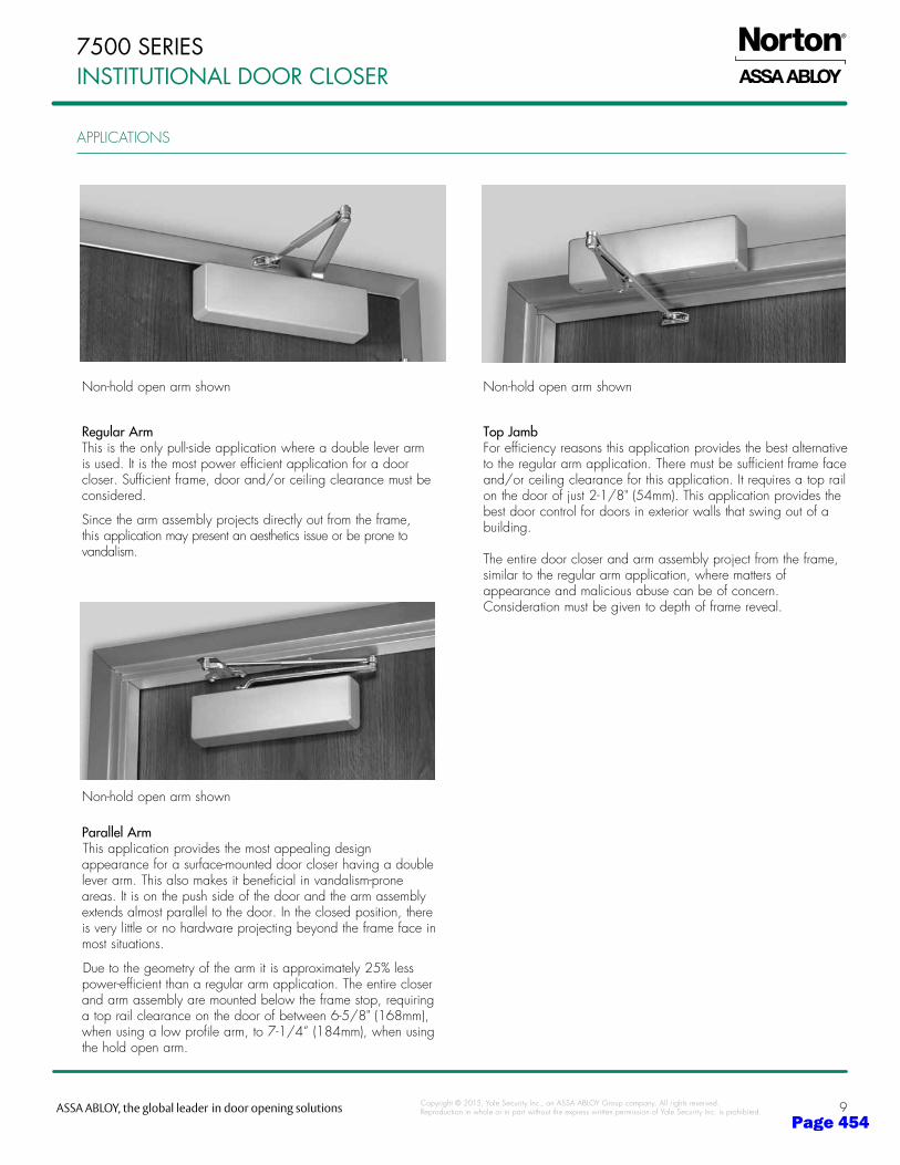
9
APPLiCATioNS
Copyright © 2015, Yale Security inc., an ASSA ABLoY Group company. All rights reserved. reproduction in whole or in part without the express written permission of Yale Security inc. is prohibited.
7500 SERIES InStItutIonal dooR cloSER
RegularArmThis is the only pull-side application where a double lever arm is used. it is the most power efficient application for a door closer. Sufficient frame, door and/or ceiling clearance must be considered.
Since the arm assembly projects directly out from the frame, this application may present an aesthetics issue or be prone to vandalism.
TopJambForefficiencyreasonsthisapplicationprovidesthebestalternativeto the regular arm application. There must be sufficient frame face and/or ceiling clearance for this application. it requires a top rail onthedoorofjust2-1/8"(54mm).Thisapplicationprovidesthebest door control for doors in exterior walls that swing out of a building.
The entire door closer and arm assembly project from the frame, similar to the regular arm application, where matters of appearance and malicious abuse can be of concern. Consideration must be given to depth of frame reveal.
ParallelArmThis application provides the most appealing design appearance for a surface-mounted door closer having a double lever arm. This also makes it beneficial in vandalism-prone areas. it is on the push side of the door and the arm assembly extends almost parallel to the door. in the closed position, there is very little or no hardware projecting beyond the frame face in most situations.
Due to the geometry of the arm it is approximately 25% less power-efficient than a regular arm application. The entire closer and arm assembly are mounted below the frame stop, requiring atoprailclearanceonthedoorofbetween6-5/8"(168mm),whenusingalowprofilearm,to7-1/4”(184mm),whenusingthe hold open arm.
Non-hold open arm shown Non-hold open arm shown
Non-hold open arm shown
Page 454
Flatwork - 1
DISTRICT DESIGN STANDARDS
Section 32H - Flat Work
Issued: Fall 2020 Updates:
I. Purpose
A. The following District Design Standards for flat work are intended to provide basic guidelines for the District with the goal of ensuring ease of maintenance. Sustainable products used for such pavements shall be incorporated as appropriate.
B. These standards should be applied to all new construction, modernization, renovation and replacement projects.
II. General Design Standards
A. Safety and security are of utmost importance to the District. Planting and site features should not create hidden areas.
B. For new construction, the design team shall provide general excavation and site work to construct building on the site and connect all utilities to the project. Site grading and excavating shall be in accordance with the Geotechnical Engineers Report and in conformance with the requirements of the most current edition of the CBC for the applicable foundation and structural requirements.
C. Geotechnical Report: The design team shall follow the recommendations of the owner provided geotechnical report. This report shall be submitted concurrently to the California Geological Society and the Division of the State Architect for approval with the project.
D. Local Fire Authority: The design team shall comply with the local fire authority, as allowed for by the CBC, for review of the site and approval of site access, gates and on-site fire hydrants.
E. Part of the process should include cooperation between the design team and the District with several design package reviews (with comments) from grounds staff. Reviews should take place at a concept level, 90%, 100% and at a pre-construction meeting. Grounds staff should also be present at site project closeout to review irrigation system functionality, receive keys, controller charts, remote control devices, etc.
Page 455
2 – Flatwork
DISTRICT DESIGN STANDARDS III. Sustainable Design
A. The District’s desire is to design, implement and maintain sustainable features within the site plan, such that the plan adheres to best practices for a sustainable campus. The design team should endeavor to design with the goal of mitigating storm water runoff through use of bioswales and collection of rainwater for irrigation or other gray water recycling when possible.
IV. Asphalt Paving
A. Minimizing paving should be encouraged in the design to reduce mechanical loads on the buildings. Not only does paving reduction allow for a reduction in stormwater runoff and the potential to recharge groundwater reserves, but it aids in reducing the ‘heat island effect’ created when large areas of paving around buildings gather and amplify heat. The use of light-colored pervious pavement with a Solar Reflectance Index of 29 or higher should be used to reduce the ‘heat island effect’ of the non-roof spaces within the project site.
B. Vehicular access: Vehicular access shall be giving consideration when developing the program. Vehicular access pathways shall be in compliance with recommendations of geotechnical report for sections and materials to be used.
C. Asphalt paving shall be Type A with ¾” aggregate for base course and ½” aggregate for surface course as specified in the City of Gilroy Standard Specifications latest addition and thickness per the geotechnical investigation.
D. Aggregate base shall be Class II Aggregate Base (R value 78 minimum) as specified in the City of Gilroy Standard Specifications latest addition, and thickness per the Geotechnical Investigation. With the approval of the Geotechnical Engineer, recycled Class II AB base rock may be used for base under pavements.
E. Prime coats, tack coats, and seal coats shall be as specified in the City of Gilroy Standard Specifications latest addition.
F. Lane markings, parking striping and symbols and legends shall be as specified in the City of Gilroy Standard Specifications latest addition.
V. Concrete Flatwork, Curbs and Gutters
A. Provide concrete sidewalks as appropriate for on-site pedestrian circulation. Circulation pathways in close proximity to campus promenade shall be carefully considered to compliment the campus masterplan in texture and finishes.
Page 456
Flatwork - 3
DISTRICT DESIGN STANDARDS B. Concrete flatwork shall be in conformance with the requirements of the CBC for
slope and cross slopes.
C. Concrete shall be a minimum 4” thick for flatwork and 6” thick for curbs and gutters and driveways unless otherwise specified in the project Geotechnical Investigation.
D. Composition:
1. Concrete shall be Class A 3000 psi (28 day) minimum strength as specified in the City of Gilroy Standard Specifications latest addition.
2. Concrete shall contain appropriate amounts of fly ash or other approved sustainable products as specified in the project specifications or City of Gilroy Standard Specifications latest addition.
3. Aggregate base shall be Class II Aggregate Base (R value 78 minimum) as specified in the City of Gilroy Standard Specifications latest addition and thickness per the geotechnical investigation.
Reinforcement:
1. Flatwork shall contain #10 6x6 WWM or #3 bars at 18” on center, or be fiber reinforced concrete unless directed otherwise by geotechnical investigation.
2. Curbs, curbs and gutters and valley gutters shall have a continuous #4 bar within 3” of the top and bottom or edges of valley gutter or lip of curb and gutter. Curbs deeper than 16” and gutters wider than 18” shall have a midpoint #4 bar as well.
F. Finish:
1. Concrete pavements shall be finished as directed by the Landscape Architect but as a minimum:
a) Light broom finish transverse to path of travel for flatwork and longitudinally for curb and gutters.
2. Concrete shall contain color additives as directed by the Landscape Architect.
G. Control joints and expansion joints shall be designed as appropriate for the surface designed.
VI. Permeable Concrete
Reinforcement:
1. Flatwork shall contain #10 6x6 WWM or #3 bars at 18” on center, or be fiber reinforced concrete unless directed otherwise by geotechnical investigation. Fiber reinforced concrete shall not be used in high traffic vehicular areas or at fire lane area. areas .
E.
Page 457
4 – Flatwork
DISTRICT DESIGN STANDARDS A. Permeable concrete shall be un-reinforced and mixed so that water easily passes
through it. It shall be placed on a permeable base.
B. Where soil conditions require it, a subdrain system shall be installed to drain the base.
C. Where soil conditions require it, a woven geotextile fabric shall be placed between the subgrade and base.
Page 458
Utilities - 1
DISTRICT DESIGN STANDARDS
Section 33 - Utilities
Issued: Fall 2020 Updates:
I. Purpose
A. This following District Design Standard for utilities are intended as a guide to designers of new and renovated facilities at the Gilroy Unified School District campuses. This document shall also be referenced for renovations or new facilities at the District Office, where applicable.
B. Provide all utility connections to existing campus services including but not limited to, gas, water, sewer, storm sewer, fire loop, power, data, telephone, fire alarm, intrusion alarm, etc. Coordinate with campus representatives for known locations of recently updated infrastructure systems.
C. In so much as possible, all utilities shall be underground. Underground utilities shall be in compliance with the most current edition of the CBC and recognized industry standards.
II. Utility Routing
A. Common trenches are encouraged, however they must comply with minimum separation as delineated in the infrastructure details. Trench routes will be determined on a case by case basis, taking care to avoid congested areas and keeping trenches out of the dripline of trees wherever possible.
B. Typical infrastructure modifications for a new building would include trenching and utility placement, and the installation of manholes for building connections. These manholes may be from 5 to 50 feet away from the building. Coordination with the infrastructure designer is mandatory.
III. Sanitary Sewer
A. All work within City of Gilroy rights-of-way requires an encroachment permit and plans prepared in City of Gilroy format.
B. Gradient: Pipe shall be designed at 1% minimum slope or in difficult cases Mannings Equation shall be used for velocity of 2 fps minimum and 8 fps maximum.
Page 459
2 – Utilities
DISTRICT DESIGN STANDARDS C. Size: 4” minimum pipe size shall be used. The Uniform Plumbing Code shall be
used to size pipe based on fixture unit counts. For larger systems pipe shall be sized for 100 gpd per capita.
D. Depth: For depths in traffic areas less than 2 feet of cover, use DIP.
E. Location: Pipe shall be outside a 1:1 slope from 9” above the bottom of building footings (or 2:1 slope if the geotechnical engineer/investigation requires it).
F. Pipe:
1. SDR 26 PVC or DIP for drainage use.
2. VCP shall not be used.
3. Install tracer wire over pipe.
4. Sanitary sewer pipe shall be air tested and video or ball checked for deflection, sags and joint separation following installation.
5. Pipe bedding shall be minimum 6” under pipe and 12” over pipe.
G. Sanitary sewer cleanouts: Shall be size of pipe line and be spaced not greater than 100 feet apart and at all bends, branch connections, or change in gradient, and at all connections to buildings.
H. Manholes: Manholes shall be per City of Gilroy and shall be spaced not greater than 400 feet apart.
I. All pipes entering manholes shall be equal or less than 2 feet above manhole mainline invert. If greater than 2 feet use drop connections.
J. Sanitary sewer cleanouts shall be installed in boxes with cast iron lid marked “SEWER”.
IV. Storm Drainage
A. Storm Water Management: The design team shall comply with the requirements of the local authority having jurisdiction for Stormwater Pollution, Prevention and Protection (SWPPP). The design team shall be responsible for providing a SWPPP document, as required.
B. Gradient: Pipe shall be designed using Mannings Equation for velocity of 2 fps minimum.
C. Design storm shall be per Santa Clara County drainage manual for 10-year storm.
Page 460
Utilities - 3
DISTRICT DESIGN STANDARDS D. Size: 8” minimum pipe size shall be used except RWL’s may be 4” or 6”at 1%
slope.
E. Depth:
1. For depths in traffic areas less than 2 feet of cover, use DIP or RCP (Class IV).
2. Pipe bedding shall be minimum 6” under pipe and 12” over pipe.
F. Location: Pipe shall be outside a 1:1 slope from 9” above the bottom of building footings (or 2:1 slope if the geotechnical engineer requires it).
G. Pipe:
1. SDR 26 PVC, HDPE or DIP for drainage use.
2. RCP and CMP may be used as required by job site conditions.
3. Perforated pipe shall be SDR 35 or Schedule 40 PVC and installed with holes down.
4. Install tracer wire over pipe.
H. Storm water inlets:
1. Grates to be lockable, bicycle proof, and ADA compliant.
2. Inlets to have heavy frame and grate in traffic areas.
3. Minimum size inlet shall be 12” in size.
4. Inlets over 3 feet in depth shall be 18” in size.
5. Inlets over 4 feet in depth shall be 24” in size.
I. Manholes: Manholes shall be per City of Gilroy Standards and Specifications and shall be spaced not greater than 400 feet.
J. Storm drain: Storm drain cleanouts shall be installed at ends and all bends of RWLs in boxes with cast iron lids marked “STORM DRAIN”.
K. Storm sewer pipe shall be video, or ball checked for deflection, sags and joint separation following installation.
Page 461
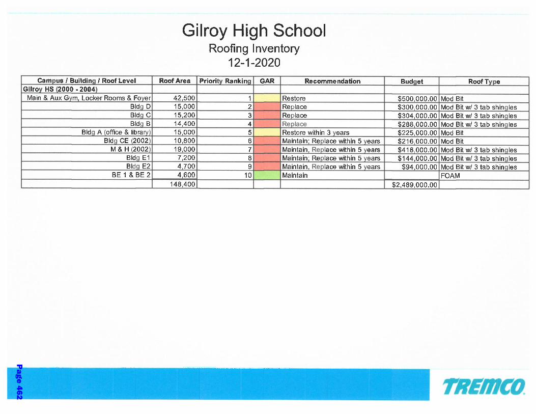
Page 462
namartinez
Typewritten Text
3a

Page 463
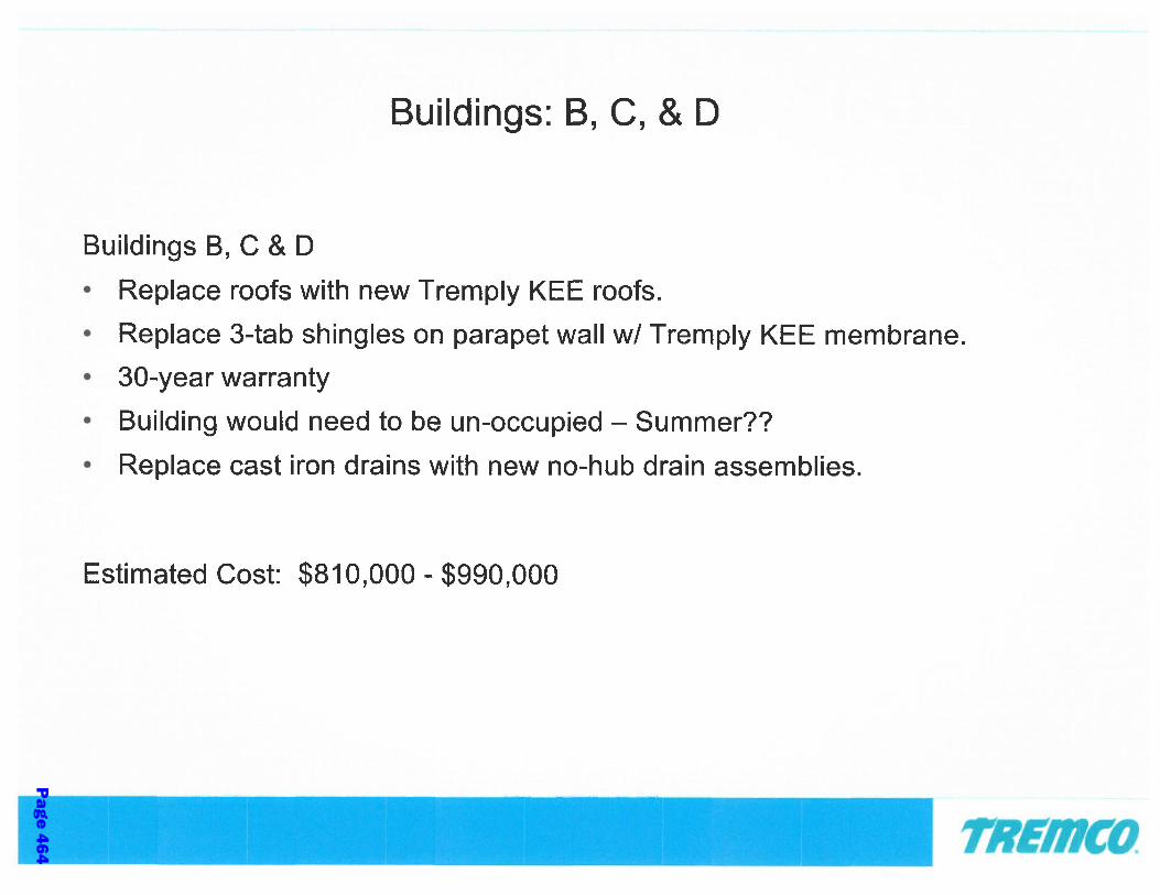
Page 464
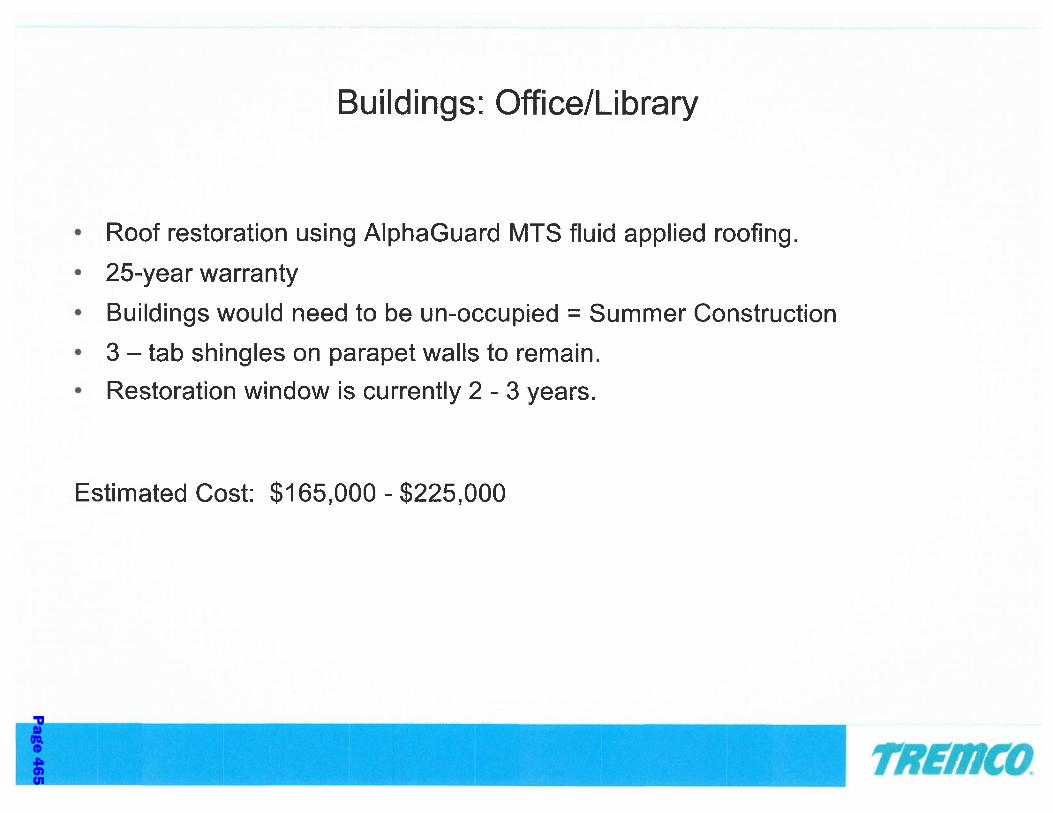
Page 465

Page 466

Page 467
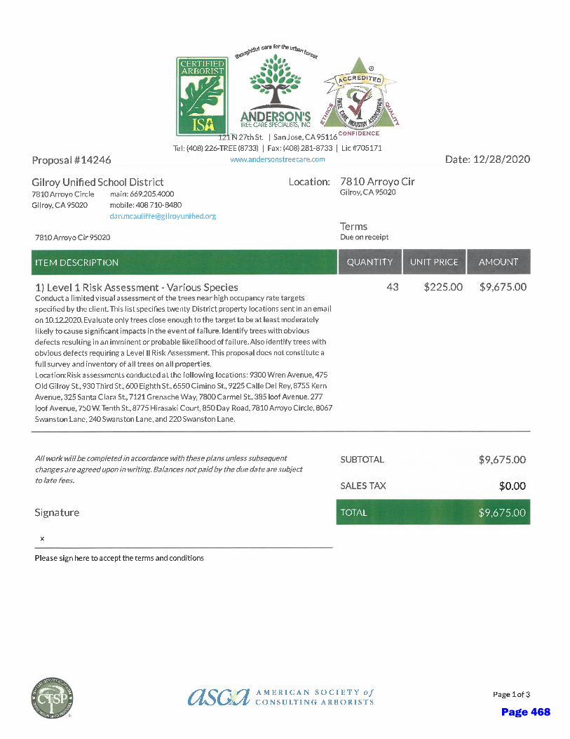
Page 468
namartinez
Typewritten Text
3d

Page 469
Page 470

Page 471
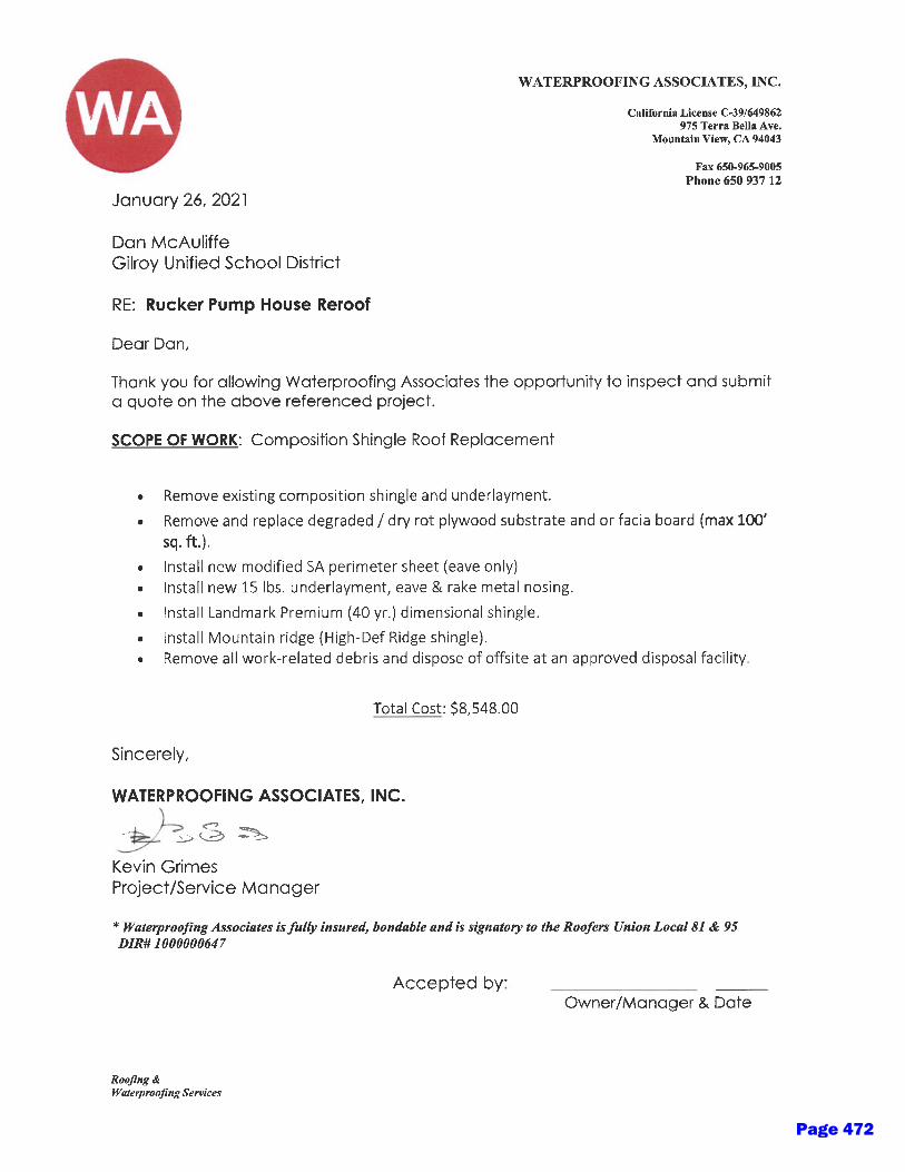
Page 472
namartinez
Typewritten Text
3e
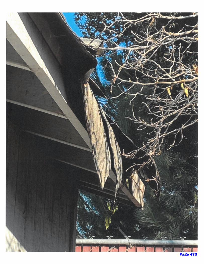
Page 473
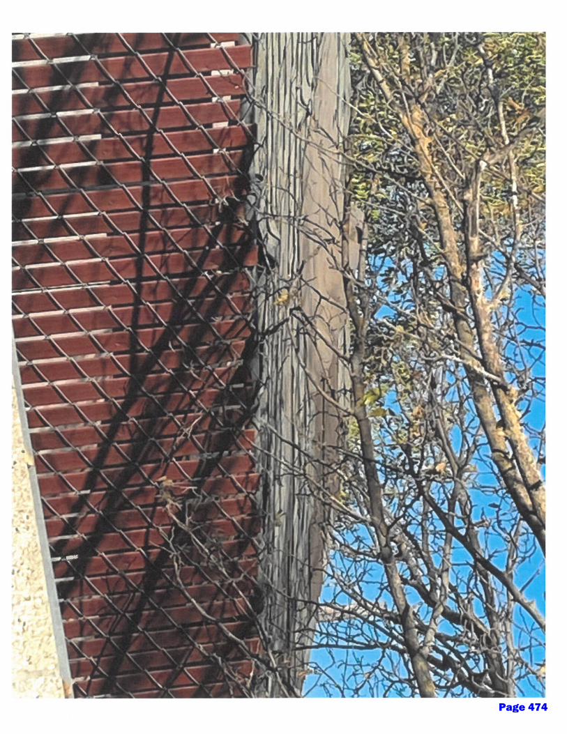
Page 474

Page 475
namartinez
Typewritten Text
3f
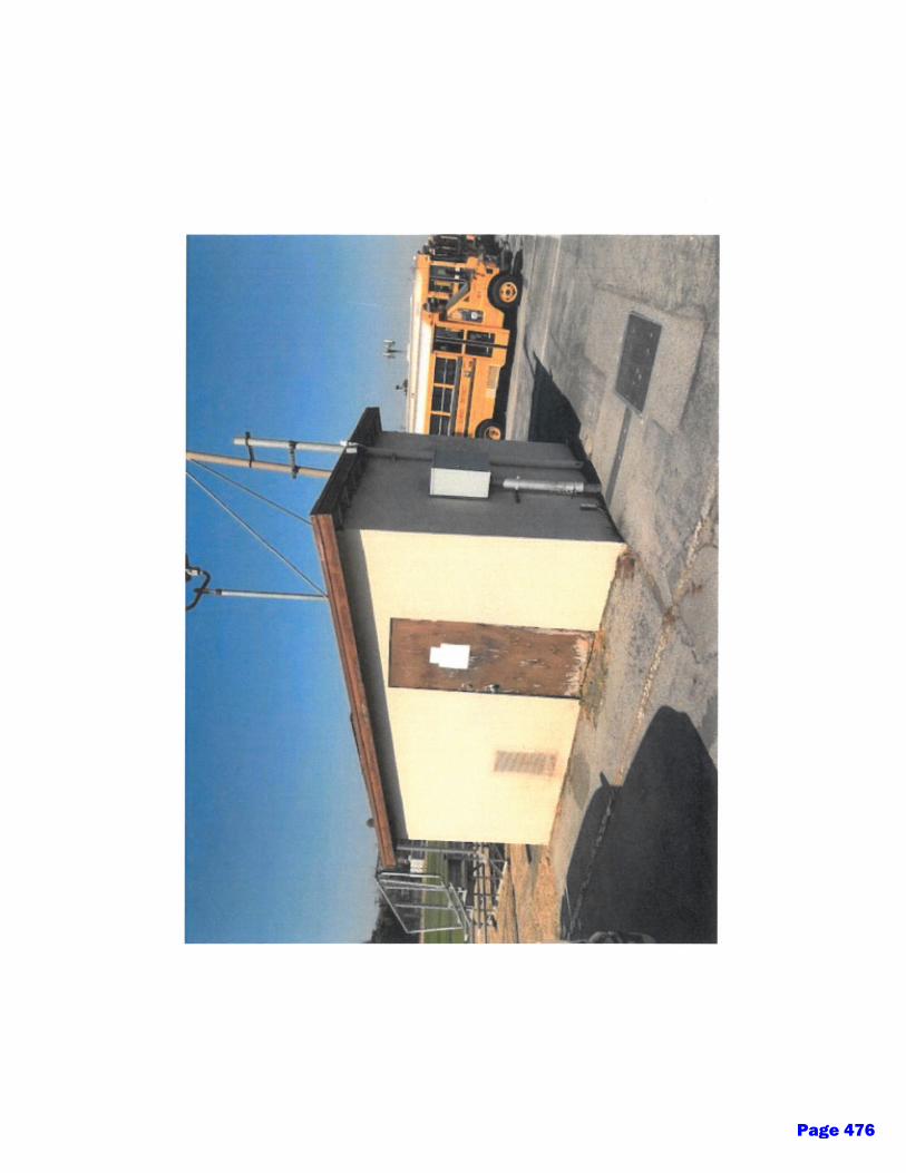
Page 476

Glen View Elementary Video Surveillance Proposal2021Quote # Q-GG003116Version 2
Prepared for:
Gilroy Unified School District
Paul [email protected]
We have prepared a quote for you
Page 477
namartinez
Typewritten Text
4a
- MANAGED SERVICES
- VIDEO SURVEILLANCE
- WIRELESS
Gilroy Unified School DistrictPaul Nadeau7810 Arroyo CircleGilroy, CA [email protected]
Dear Paul,
Wednesday, January 27, 2021
QOVO Solutions, Inc. is pleased to present this proposal for hardware and services as requested. We pride ourselves on thequality and simplicity of the solutions that we deliver and our company was founded on philosophy that the customer makes thebusiness.
The following is included in this proposal:
Video Surveillance Cameras, mounting hardware, wiring, licensing and installation including configuration and customer hand-offwith documentation and training as proposed with optional additional items (specified optional).
Hardware licensing as support as specified with advanced hardware replacement and 7x24 support available through thehardware manufacturer.
• 14 x Cameras and Licensing
• CAT 6 Ethernet Cable wired to all IDF's and terminated on patch panels provided by GUSD
• Wiring and Installation of said equipment affixed to existing structures
• DHCP, PoE capable switch ports and internet access to be provided by GUSD
• On going maintenance is quoted as optional and is highly recommended. As it will cover all labor to replace cameras and switches if needed. Also include quarterly as needed cleanings.
This is Version 2 of this proposal.
Ongoing maintenance as proposed and available through QOVO Solutions, Inc. (QSI) typically proposed monthly, quarterly or yearly.
QOVO is a CMAS approved vendor. In situations where CMAS approved hardware or services are proposed all pricing will be at or below CMAS approved pricing.
Quote #Q-GG003116 v2 521 Charcot Ave - Suite 239B - San Jose - CA 95131 - Main 844-768-6462 - Lic #1058025 Page: 2 of 9Page 478
- MANAGED SERVICES
- VIDEO SURVEILLANCE
- WIRELESS
Please do not hesitate to let us know if there are any questions.
Sincerely;
Garth Gilmour
QOVO Solutions, Inc.
Quote #Q-GG003116 v2 521 Charcot Ave - Suite 239B - San Jose - CA 95131 - Main 844-768-6462 - Lic #1058025 Page: 3 of 9Page 479
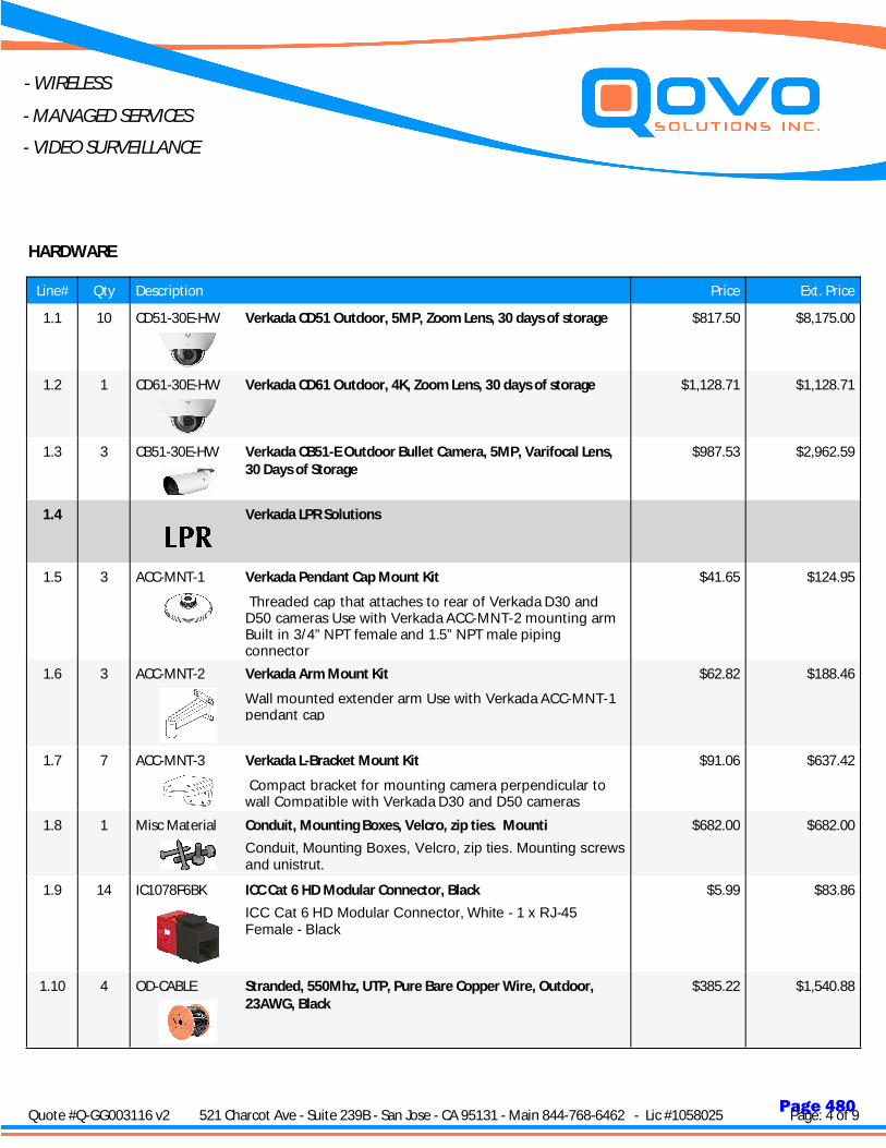
- MANAGED SERVICES
- VIDEO SURVEILLANCE
- WIRELESS
Line# Qty Description Price Ext. Price
HARDWARE
1.1 10 CD51-30E-HW Verkada CD51 Outdoor, 5MP, Zoom Lens, 30 days of storage $817.50 $8,175.00
1.2 1 CD61-30E-HW Verkada CD61 Outdoor, 4K, Zoom Lens, 30 days of storage $1,128.71 $1,128.71
1.3 3 CB51-30E-HW Verkada CB51-E Outdoor Bullet Camera, 5MP, Varifocal Lens,30 Days of Storage
$987.53 $2,962.59
1.4 Verkada LPR Solutions
1.5 3 ACC-MNT-1
Threaded cap that attaches to rear of Verkada D30 and D50 cameras Use with Verkada ACC-MNT-2 mounting arm Built in 3/4” NPT female and 1.5” NPT male piping connector
Verkada Pendant Cap Mount Kit $41.65 $124.95
1.6 3 ACC-MNT-2
Wall mounted extender arm Use with Verkada ACC-MNT-1 pendant cap
Verkada Arm Mount Kit $62.82 $188.46
1.7 7 ACC-MNT-3
Compact bracket for mounting camera perpendicular to wall Compatible with Verkada D30 and D50 cameras
Verkada L-Bracket Mount Kit $91.06 $637.42
1.8 1 Misc Material
Conduit, Mounting Boxes, Velcro, zip ties. Mounting screws and unistrut.
Conduit, Mounting Boxes, Velcro, zip ties. Mounti $682.00 $682.00
1.9 14 IC1078F6BK
ICC Cat 6 HD Modular Connector, White - 1 x RJ-45 Female - Black
ICC Cat 6 HD Modular Connector, Black $5.99 $83.86
1.10 4 OD-CABLE Stranded, 550Mhz, UTP, Pure Bare Copper Wire, Outdoor,23AWG, Black
$385.22 $1,540.88
Quote #Q-GG003116 v2 521 Charcot Ave - Suite 239B - San Jose - CA 95131 - Main 844-768-6462 - Lic #1058025 Page: 4 of 9Page 480
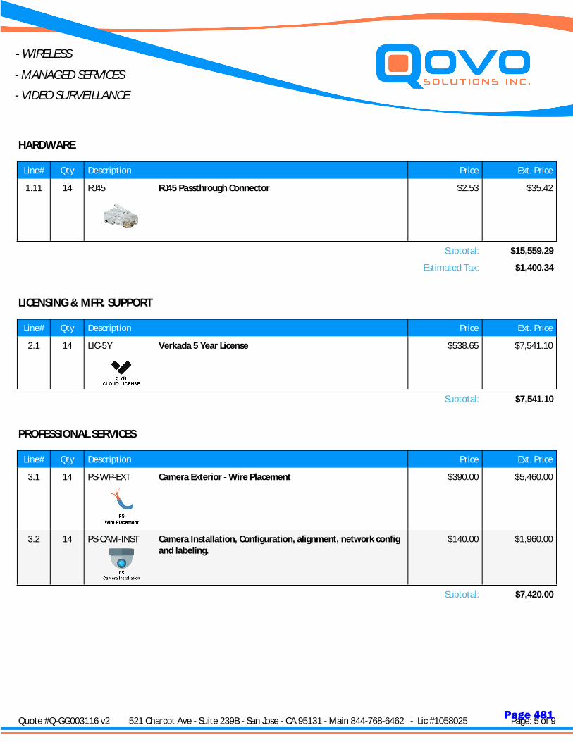
- MANAGED SERVICES
- VIDEO SURVEILLANCE
- WIRELESS
Line# Qty Description Price Ext. Price
HARDWARE
1.11 14 RJ45 RJ45 Passthrough Connector $2.53 $35.42
Subtotal: $15,559.29
Estimated Tax: $1,400.34
Line# Qty Description Price Ext. Price
LICENSING & MFR. SUPPORT
2.1 14 LIC-5Y Verkada 5 Year License $538.65 $7,541.10
Subtotal: $7,541.10
Line# Qty Description Price Ext. Price
PROFESSIONAL SERVICES
3.1 14 PS-WP-EXT Camera Exterior - Wire Placement $390.00 $5,460.00
3.2 14 PS-CAM-INST Camera Installation, Configuration, alignment, network configand labeling.
$140.00 $1,960.00
Subtotal: $7,420.00
Quote #Q-GG003116 v2 521 Charcot Ave - Suite 239B - San Jose - CA 95131 - Main 844-768-6462 - Lic #1058025 Page: 5 of 9Page 481
- MANAGED SERVICES
- VIDEO SURVEILLANCE
- WIRELESS
NOTES
Line# Qty Description
5.1 1 Note
Terms and Conditions Taxes, shipping, handling and other fees may apply. We reserve the right to cancel orders arising frompricing or other errors. All orders paid by Credit Card will incur and 3% handling and convenience fee.
Terms and Conditions Taxes, shipping, handling and other fee
5.2 1 Note
Please note that the proposed system needs to have a Basic High Speed Internet to configure, control to be functional. This allows for remote monitoring and visibility to the camera system. The Verkada model is to remove the need for a local DVR/Machine that draws power and requires maintenance and updates. The High Speed internet can be shared with other facility uses such as Access Control Systems and other shared services.
5.3 1 Note
Pricing in this proposal is based on the proposed quantity and scope of work. In the event that the proposed quantities change the proposed pricing will be adjusted to reflect the revised quantities and scope of work.
Discounts in this proposal as based on the proposed hardware and licensing quantities. QOVO retains the right to adjust discounts as quantities on hardware and licensing items change.
5.4 1 Exclusion
Qovo Solutions Inc is not providing high speed internet or managed services unless otherwise noted with in this quote.
5.5 6 Note - IDF Power
Each MDF/IDF location will need access to 1 power outlet to power up provided switch which will provide power to cameras.
5.6 1 Note
This proposal including all elements, diagrams, documents, and communications are considered the proprietary work product of QOVO Solutions, Inc. Any dissemination of these documents beyond the intended recipients and related entities will be considered a violation of a confidentiality agreement and any items related to this proposal cannot be disclosed to any third party without the express written permission of QOVO Solutions, inc.
Quote #Q-GG003116 v2 521 Charcot Ave - Suite 239B - San Jose - CA 95131 - Main 844-768-6462 - Lic #1058025 Page: 6 of 9Page 482

- MANAGED SERVICES
- VIDEO SURVEILLANCE
- WIRELESS
Line# Qty Description Price Ext. Price
SHIPPING
6.1 1 UPS-GROUND
UPS-GROUND SHIPPING
$308.00 $308.00
Subtotal: $308.00
Quote #Q-GG003116 v2 521 Charcot Ave - Suite 239B - San Jose - CA 95131 - Main 844-768-6462 - Lic #1058025 Page: 7 of 9Page 483
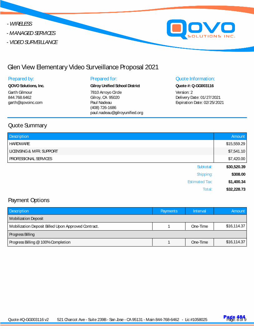
- MANAGED SERVICES
- VIDEO SURVEILLANCE
- WIRELESS
7810 Arroyo CircleGilroy, CA 95020Paul Nadeau(408) [email protected]
Gilroy Unified School District
Garth [email protected]
QOVO Solutions, Inc.
Prepared by: Prepared for: Quote Information:
Quote #: Q-GG003116
Version: 2Delivery Date: 01/27/2021Expiration Date: 02/25/2021
Glen View Elementary Video Surveillance Proposal 2021
Description Amount
Quote Summary
HARDWARE $15,559.29
LICENSING & MFR. SUPPORT $7,541.10
PROFESSIONAL SERVICES $7,420.00
Subtotal: $30,520.39
Shipping: $308.00
Estimated Tax: $1,400.34
Total: $32,228.73
Payment Options
Description Payments Interval Amount
Mobilization Deposit
Mobilization Deposit Billed Upon Approved Contract. 1 One-Time $16,114.37
Progress Billing
Progress Billing @ 100% Completion 1 One-Time $16,114.37
Quote #Q-GG003116 v2 521 Charcot Ave - Suite 239B - San Jose - CA 95131 - Main 844-768-6462 - Lic #1058025 Page: 8 of 9Page 484
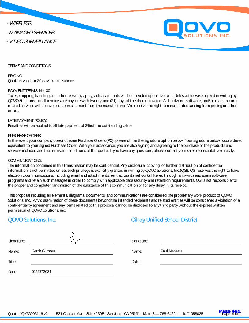
- MANAGED SERVICES
- VIDEO SURVEILLANCE
- WIRELESS
TERMS AND CONDITIONS
PRICING:Quote is valid for 30 days from issuance.
PAYMENT TERMS: Net 30Taxes, shipping, handling and other fees may apply, actual amounts will be provided upon invoicing. Unless otherwise agreed in writing byQOVO Solutions Inc. all invoices are payable with twenty-one (21) days of the date of invoice. All hardware, software, and/or manufacturerrelated services will be invoiced upon shipment from the manufacturer. We reserve the right to cancel orders arising from pricing or othererrors.
LATE PAYMENT POLICY:Penalties will be applied to all late payment of 3% of the outstanding value.
PURCHASE ORDERS:In the event your company does not issue Purchase Orders (PO), please utilize the signature option below. Your signature below is consideredequivalent to your signed Purchase Order. With your acceptance, you are also signing and agreeing to the purchase of the products andservices included and the terms and conditions of this quote. If you have any questions, please contact your sales representative directly.
COMMUNICATIONS:The information contained in this transmission may be confidential. Any disclosure, copying, or further distribution of confidentialinformation is not permitted unless such privilege is explicitly granted in writing by QOVO Solutions, Inc.(QSI). QSI reserves the right to haveelectronic communications, including email and attachments, sent across its networks filtered through anti-virus and spam softwareprograms and retain such messages in order to comply with applicable data security and retention requirements. QSI is not responsible forthe proper and complete transmission of the substance of this communication or for any delay in its receipt.
This proposal including all elements, diagrams, documents, and communications are considered the proprietary work product of QOVOSolutions, Inc. Any dissemination of these documents beyond the intended recipients and related entities will be considered a violation of aconfidentiality agreement and any items related to this proposal cannot be disclosed to any third party without the express writtenpermission of QOVO Solutions, inc.
QOVO Solutions, Inc.
Signature:
Name: Paul Nadeau
Date:
Signature:
Name: Garth Gilmour
Title:
Date: 01/27/2021
Gilroy Unified School District
Quote #Q-GG003116 v2 521 Charcot Ave - Suite 239B - San Jose - CA 95131 - Main 844-768-6462 - Lic #1058025 Page: 9 of 9Page 485
Related Documents