IAEA-158 FACILITIES AND TECHNOLOGY NEEDED FOR NUCLEAR FUEL MANUFACTURE PROCEEDINGS OF A STUDY GROUP MEETING ORGANIZED BY THE INTERNATIONAL ATOMIC ENERGY AGENCY GRENOBLE, FRANCE, 4-15 SEPTEMBER 1972 A TECHNICAL REPORT PUBLISHED BY THE INTERNATIONAL ATOMIC ENERGY AGENCY, VIENNA, 1973

Welcome message from author
This document is posted to help you gain knowledge. Please leave a comment to let me know what you think about it! Share it to your friends and learn new things together.
Transcript
IAEA-158
FACILITIES AND TECHNOLOGYNEEDED FOR
NUCLEAR FUEL MANUFACTUREPROCEEDINGS OF A STUDY GROUP MEETING
ORGANIZED BY THEINTERNATIONAL ATOMIC ENERGY AGENCY
GRENOBLE, FRANCE, 4-15 SEPTEMBER 1972
A TECHNICAL REPORT PUBLISHED BY THEINTERNATIONAL ATOMIC ENERGY AGENCY, VIENNA, 1973

The IAEA does not maintain stocks of reports in this series. However,microfiche copies of these reports can be obtained from
INIS Microfiche ClearinghouseInternational Atomic Energy AgencyKdmfner Ring 11P.O. Box 590A-1011 Vienna, Austria
on prepayment of US $0.65 or against one IAEAmicrofiche service coupon.
F O R S 17 0 R D
The increasing role which nuclear power is playing in supplyingthe xtforld's electrical energy requirements has led to a burgeoningdemand for nuclear fuel, A recent study "by the Euclear Energy Agencyof the Organization for Economic Co-operation and Development and theIASA has estimated that the world's annual uranium requirements fornuclear fuel vail increase from a minimum of 16,000 tonnes in 1975to 100,000 tonnes "by 1935» An important consideration in the nationaleconomy of countries with nuclear power programmes is whether theirindigenous industries should manufacture any part of the fuel neededfor power reactors. The objective of the Study Group was to presentpertinent information on the technical and economic aspects andrequirements of this part of the fuel cycle, The lectures given atthis meeting which was held at the Centre d'Utudes ITucleaires, Grenoble,France in September 1972 are published in this volume. The meetingwas primarily intended for senior technical personnel and for nationalenergy policy planners, particularly from countries which have nuclearpower programmes under active development or with major uraniumresources*
In 1971 the Agency convened a group of consultants to assist inthe drawing up of an agenda and to suggest countries who might use-fully be invited to the Study Group, At that time it was agreed thatthe agenda should be restricted only to oxide fuels. It was alsosuggested that lectures from countries which are entering the field offuel technology should be sought, as these would serve usefully ascase histories.
The Agenda was sub-divided into four sections according to thetype of activity described and was as follows:
I. The Production of Power Grade Fuel.
II. The Imbrication of Canning and other structuralMaterials.
III. The Manufacture of Fuel Elements and their Assembly.
IV. Economic Criteria for Fuel Fabrication,
For Group IV, certain countries who had initiated fuel programmesor were actively planning to do so had kindly
agreed to contribute summary review lectures on their programmes.These countries were India, Korea and Pakistan.
In addition to the lectures, visits to nuclear fuelfabrication facilities and to the laboratories and other researchdepartments of the CBN, Grenoble had been arranged.
During the discussions following the lectures and ata round table seminar it was the consensus of the meeting thatcountries planning to undertake nuclear fuel fabrication tech-nology could do so by the following means:-
1. Joint Ventures.
2. Licencing under patents held by established fuelmanufacturers.
3. Development of an indigenous fuel fabrication tech-nology, probably with assistance in the form offinancial loans combined with technical advice fromdeveloped countries on a bilateral basis. Internationalorganizations such as the IAEA could render assistanceat the pre-industrial development stage by arrangingfor the advice of experts, the placement of fellowshipsand the supply of equipment on the principles offabrication processes. In industrially sensitive areaswhere proprietary information may be needed, the place-ment of experts and fellowships would in general, bepart of bilateral and licencing agreements.
The licencing agreements which have been concluded todate appear to follow no general guidelines,but have varied accord-ing to the needs and technological capability of individual licencees.There is a trend for such licences to fall into two categories,one for countries with a significant infra-structure of relevantindustrial technology and the other for countries having little ornone. In the former case the licences may adopt a combination ofjoint venture together with licence(s) to use specific processesor equipment. For the developing countries licences might cover awider spectrum of the relevant technological processes with eventualplans for such countries to develop their own fuel technology,over relatively long period (5-10 years). Licensing agreementsmight well include provisions for a training programme for indigenousstaff, as well is for the loan of experts. They may cover the wholeor part of the fuel fabrication process. There was support for theview that countries entering the field of nuclear fuel manufactureshould do so in stages rather than to attempt to undertake theentire fabrication at once. Decision criteria on which phase of thefabrication process to allocate priority would includei-
(a) Availability of skilled manpower;
(1>) Extent and nature of industrial infra-structure existing)
(c) Financial resources;
(d) Size and type of nuclear programme under development orplanned;
(e) Export possibilities.
Several speakers from the developed as well as thedeveloping countries emphasized the broad spectrum of trainingrequired in fuel fabrication technology. Apart from relevantskills in the nuclear field, trained personnel would be requiredin such fields as vacuum technology, welding, electronics andchemical and metallurgical analysis including metallography.
It was emphasized that close liaison between the reactormanufacturer, the designer and the fabricator was necessary atall times, not only because the fuel produced must meet the speci-fications set by the reactor manufacturer but also because ofrequirements for a "built-in" flexibility to allow for improvementsin technology and design and for possible expansion in plant capacity*
Estimates for the cost of producing nuclear fuels shouldallow for such diverse factors as:-
(a) Raw material costs including where applicable, mining andprocessing costs.
(b) Design costs.
(c) Development costs.
(d) Licensing fees where pertinent, including regulatory fees.
(e) Inventories.
(f) Insurance.
The feasibility of regional cooperative projects, whereassociated countries could undertake complementary tasks bycarrying out different fabrication steps was discussed. It waspointed out that the requirements for nuclear fuel in the develop-ing countries was relatively small at present and that such regionalassociation of countries in a common effort could make indigenousfuel fabrication more economically viable.
After some discussion on the role of the 1ABA in the fieldof nuclear fuel fabrication there was no decision on the degreeof priority the Agency should allocate to activities, as the typeof assistance requested by each country may vary considerably fromcountry to country.
There was some support for the view that currentefforts to standarize methods of quality control includingnon-destructive testing and chemical analyses should be en-couraged and where necessary, should be expanded. It is insuch fields that the Agency could play a useful supportingrole.
It is hoped that the lectures will be of interestto those concerned with the launching of nuclear fuel technologyand fabrication programmes, as well as to international organiza-tions giving technical assistance in this field.
The Agency wishes to express its appreciationto the CBAfor hosting the meeting, to the authors of the papers, to allwho participated in the discussions and to Messrs. Rogan,Flipot,Schaus and Jonkheere for guiding the individual sessions*
The meeting was closed by Mr.Gerbier, Deputy DirectorCBN Grenoble, who extended an invitation to delegates to parti-cipate in a follow-up meeting at a CBfo Centre two or three yearshence in order to assess the progress made by countries in thedevelopment of an indigenous nuclear fuel technology.
The countries participating and the number of delegatesat the meeting are as shown on the attached list.
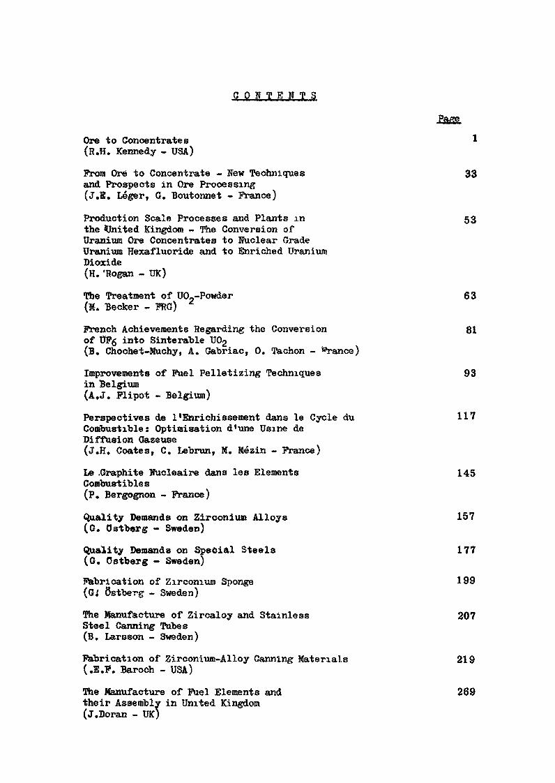
C O N T E N T S
Ore to Concentrates 1(R.H. Kennedy - USA)
Prom Ore to Concentrate - New Techniques 33and Prospects in Ore Processing(J.E. Léger, G. Boutonnet - Prance)
Production Scale Processes and Plants in 53the United Kingdom - The Conversion ofUranium Ore Concentrates to Nuclear GradeUranium Hexafluoride and to Enriched UraniumDioxide(H. 'Rogan - UK)
The Treatment of U0?-Powder 63(M. Becker - PRO)
French Achievements Regarding the Conversion 81of UPg into Sinterable U02(B. Chochet-Muchy, A. Gabriac, 0. Tachon - i«*rance)
Improvements of Fuel Pelletizing Techniques 93in Belgium(A.J. Plipot - Belgium)
Perspectives de l'Enrichissement dans le Cycle du 117Combustible: Optimisation d'une Usine deDiffusion Gazeuse(J.H, Coates, C. Lebrun, M. Mézin - Prance)
Le .Graphite Nucléaire dans les Eléments 145Combustibles(P. Bergognon - Prance)
Quality Demands on Zirconium Alloys 157(G. Ostberg - Sweden)
Quality Demands on Special Steels 177(G. Ostberg - Sweden)
Fabrication of Zirconium Sponge 199Sstberg - Sweden)
The Manufacture of Zircaloy and Stainless 207Steel Canning Tubes(B. Larsson - Sweden)
Fabrication of Zirconium-Alloy Canning Materials 219(.E.F. Baroch - USA)
The Manufacture of Fuel Elements and 269their Assembly in United Kingdom(j.Doran - UK)
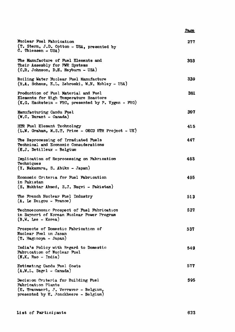
Nuclear Fuel fabrication 277(T. Stern, J.D. Cotton - USA, presented byC. Thiessen - USA)
The Manufacture of Fuel Elements and 303Their Assembly for PWR Systems(C.R. Johnson, D.E. Heybum - USA)
Boiling Water Nuclear Fuel Manufacture 339(R.A. Schaus, E.L. Zebroski, W.N. Mobley - USA)
Production of Fuel Material and Fuel 381Elements for High Temperature Reactors(K.G, Hackstein - FRG, presented by P. Vygen - FRG)
Manufacturing Candu Fuel 397(W.C. Durant - Canada)
HTR Fuel Element Technology 415(L.W. Graham, M.S.T. Price - OECD HTR Project - UK)
The Reprocessing of Irradiated Fuels 447Technical and Economic Considerations(E.J. Detilleux - Belgium
Implication of Reprocessing on Fabrication 483Techniques(Y. Nakamura, S. Abiko - Japan)
Economic Criteria for Fuel Fabrication 495in Pakistan(S. Mukhtar Ahmed, S.J. Naqvi - Pakistan)
The French Nuclear Fuel Industry 513(A. Le Duigou - France)
Technoeconomic Prospect of Fuel Fabrication 527in Supnort of Korean Nuclear Power Program(B.W. Lee - Korea)
Prospects of Domestic Fabrication of 537Nuclear Fuel in Japan(T. Haginoya - Japan)
India's Policy with Rpgard to Domestic 549Fabrication of Nuclear Fuel(N.K. Rao - India)
Estimating Candu Fuel Costs 577(A.W.I.. Segel - Canada)
Decision Criteria for Building Fuel 595Fabrication Plants(E. Trauwaert, J. Verraver - Belgium,presented by Ê. Jonckheere - Belgium)
List of Participants 623
ORE TO CONCENTRATES
A Discussion of the Processingof Uranium Bearing Ores
Richard H, KennedyMetallurgical Engineer
Division of Production and Materials ManagementU. S. Atomic Energy Commission
Abstract
The paper provides a broad background discussionof the principal activities in the production ofuranium concentrates. Estimates of market require-ments and uranium delivery commitments through 1985are given. Generalized costs for exploration,development and mining of uranium ore in the UnitedStates are presented.
The principal methods of ore processing for therecovery of uranium are described and their principaladvantages and disadvantages are mentioned. Data onmill capital costs and operating costs are presentedfor the four principal processes used, and for therange of mill operating rates found in the UnitedStates. Labor productivity is also given for variousmilling rates.
The conclusions are that all of the processes inuse today are capable of producing uranium concentratesat reasonable and competitive costs. No one processhas a clear economic advantage* As would be expected,larger mills show some advantages in terms of lowercapital and operating costs. These advantages are notconclusive, however, and mills of modest size havebeen built and operated at competitive costs.
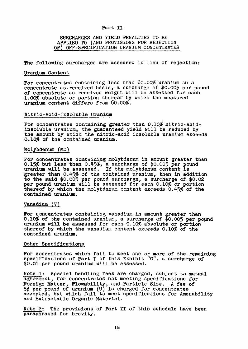
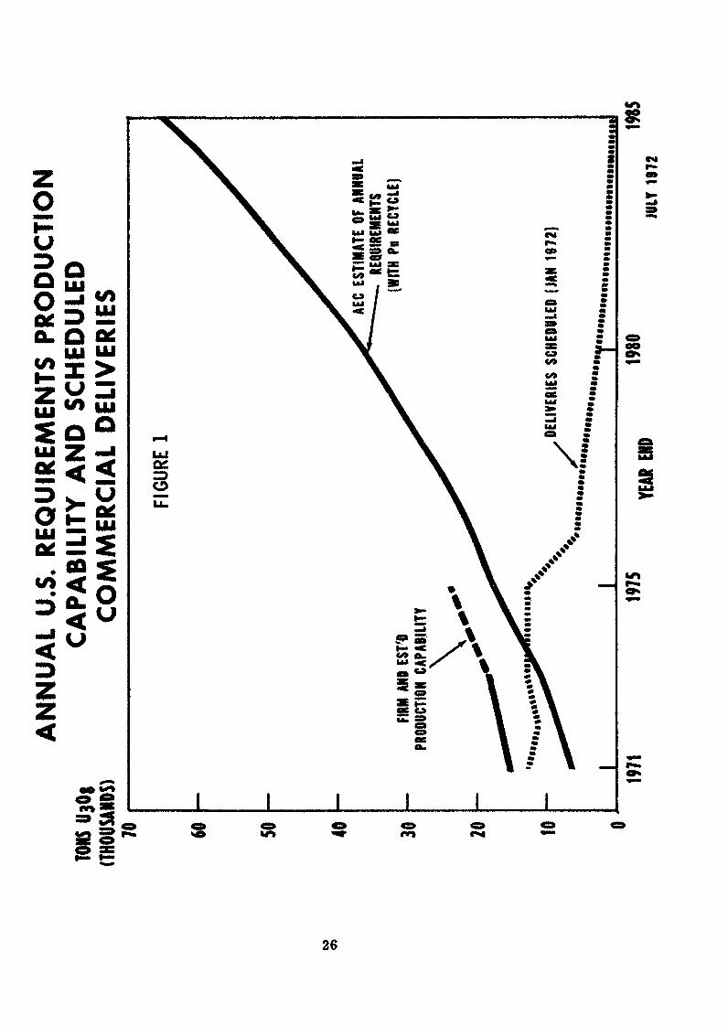
I. IntroductionThe market for uranium has been below the productive capabilityof the uranium producing industry for about 10 years. Thecommercial market got underway in 1969 when a change in theAtomic Energy Act permitted for the first time the privateownership of enriched uranium for use in nuclear electric plants.Since that time the U.S. requirements for uranium have grownsteadily, and will be at a level of about 9,200 tons in 1972.The annual requirements are projected to reach 18,000 tons by1975, and 37,000 tons by 1980. The annual requirements andexisting sales commitments to meet those requirements areshown in Fig. 1. Table 1 projects annual requirements anddelivery commitments through 1985. Peak production in the U.S.
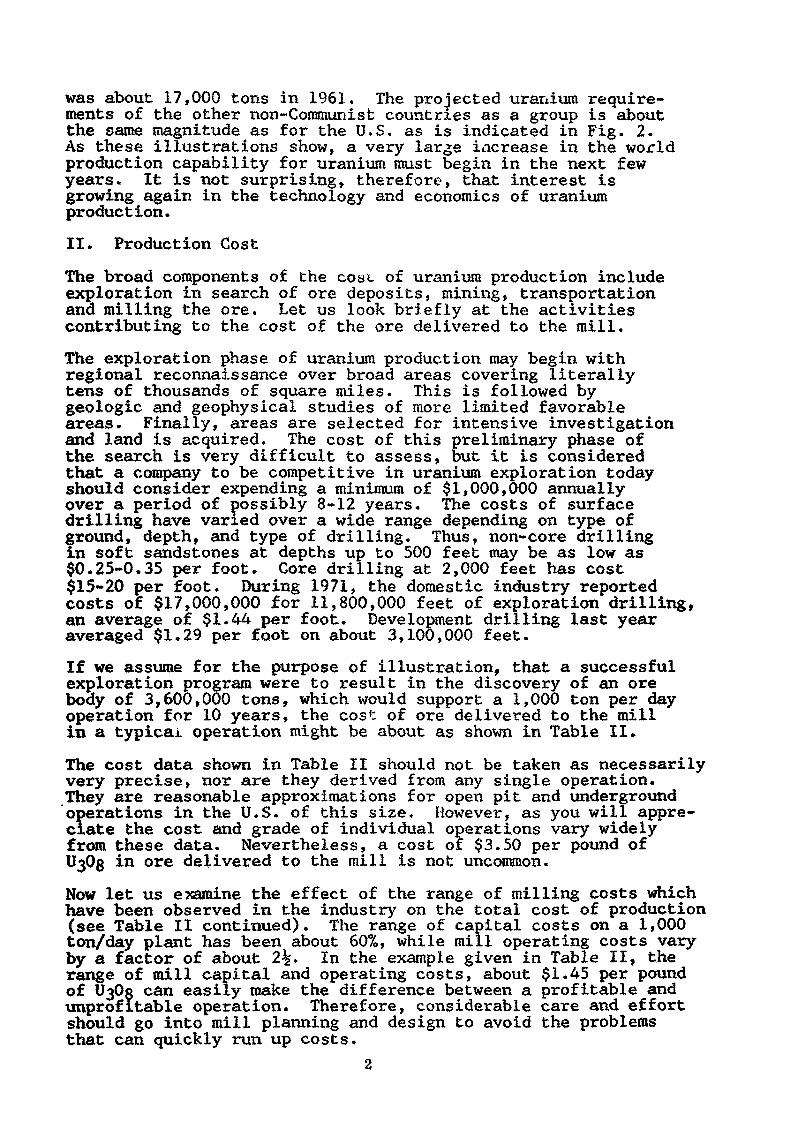
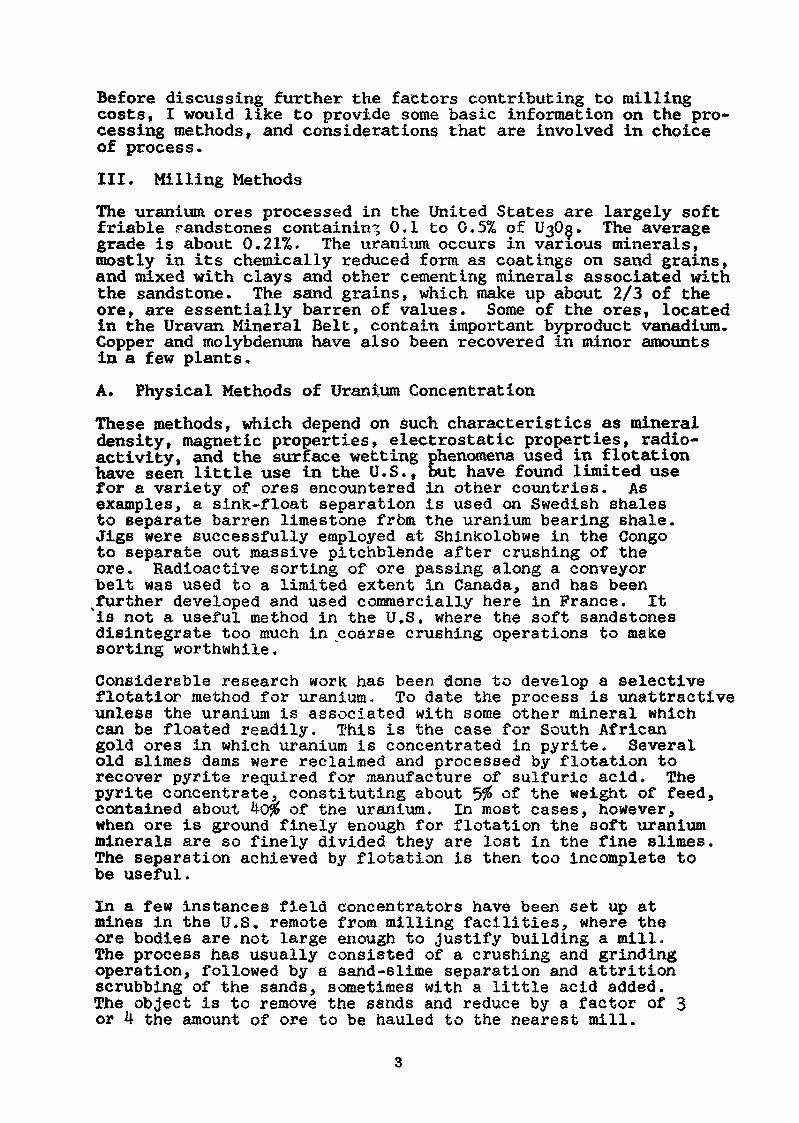
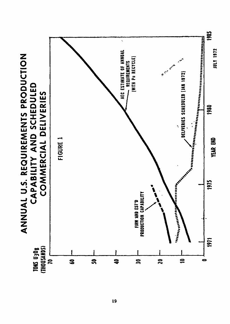
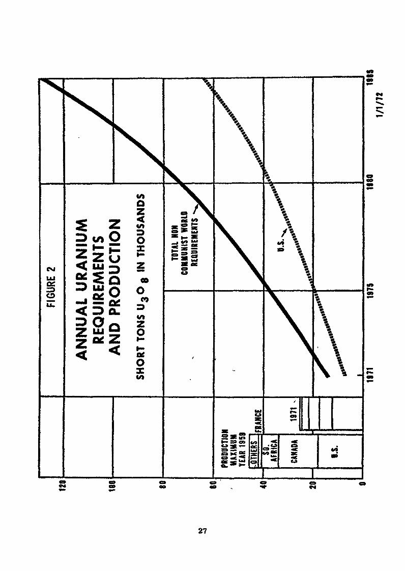
was about 17,000 tons in 1961. The projected uranium require-ments of the other non-Communist countries as a group is aboutthe same magnitude as for the U.S. as is indicated in Fig. 2.As these illustrations show, a very large increase in the worldproduction capability for uranium must begin in the next fewyears. It is not surprising, therefore, that interest isgrowing again in the technology and economics of uraniumproduction.
II. Production Cost
The broad components of the cost of uranium production includeexploration in search of ore deposits, mining, transportationand milling the ore. Let us look briefly at the activitiescontributing to the cost of the ore delivered to the mill.
The exploration phase of uranium production may begin withregional reconnaissance over broad areas covering literallytens of thousands of square miles. This is followed bygeologic and geophysical studies of more limited favorableareas. Finally, areas are selected for intensive investigationand land is acquired. The cost of this preliminary phase ofthe search is very difficult to assess, but it is consideredthat a company to be competitive in uranium exploration todayshould consider expending a minimum of $1,000,000 annuallyover a period of possibly 8-12 years. The costs of surfacedrilling have varied over a wide range depending on type of
?round, depth, and type of drilling. Thus, non-core drillingn soft sandstones at depths up to 500 feet may be as low as$0.25-0.35 per foot. Core drilling at 2,000 feet has cost$15-20 per foot. During 1971, the domestic industry reportedcosts of $17,000,000 for 11,800,000 feet of exploration drilling,an average of $1.44 per foot. Development drilling last yearaveraged $1.29 per foot on about 3,100,000 feet.
If we assume for the purpose of illustration, that a successfulexploration program were to result in the discovery of an orebody of 3,600,000 tons, which would support a 1,000 ton per dayoperation for 10 years, the cos': of ore delivered to the millin a typical operation might be about as shown in Table II.
The cost data shown in Table II should not be taken as necessarilyvery precise, nor are they derived from any single operation.They are reasonable approximations for open pit and undergroundoperations in the U.S. of this size. However, as you will appre-ciate the cost and grade of individual operations vary widelyfrom these data. Nevertheless, a cost of $3.50 per pound of0363 in ore delivered to the mill is not uncommon.
Now let us examine the effect of the range of milling costs whichhave been observed in the industry on the total cost of production(see Table II continued). The range of capital costs on a 1,000ton/day plant has been about 60%, while mill operating costs varyby a factor of about 2 . In the example given in Table II, therange of mill capital and operating costs, about $1.45 per poundof U30« can easily make the difference between a profitable andunprofitable operation. Therefore, considerable care and effortshould go into mill planning and design to avoid the problemsthat can quickly run up costs.
Before discussing further the factors contributing to millingcosts, I would like to provide some basic information on the pro-cessing methods, and considerations that are involved in choiceof process.
III. Milling Methods
The uranium ores processed in the United States are largely softfriable randstones containing 0.1 to 0.5% of lÏ30ç. The averagegrade is about 0.21%. The uraniiim occurs in various minerals,mostly in its chemically reduced form as coatings on sand grains,and mixed with clays and other cementing minerals associated withthe sandstone. The sand grains, which make up about 2/3 of theore, are essentially barren of values. Some of the ores, locatedin the Uravan Mineral Belt, contain important byproduct vanadium.Copper and molybdenum have also been recovered in minor amountsin a few plants.
A. Physical Methods of Uranium Concentration
These methods, which depend on such characteristics as mineraldensity, magnetic properties, electrostatic properties, radio-activity, and the surface wetting phenomena used in flotationhave seen little use in the U.S., but have found limited usefor a variety of ores encountered in other countries. Asexamples, a sink-float separation is used on Swedish shalesto separate barren limestone from the uranium bearing shale.Jigs were successfully employed at Shinkolobwe in the Congoto separate out massive pitchblende after crushing of theore. Radioactive sorting of ore passing along a conveyorbelt was used to a limited extent in Canada, and has beensfurther developed and used commercially here in Prance. It"is not a useful method in the U.S. where the soft sandstonesdisintegrate too much in coarse crushing operations to makesorting worthwhile.
Considerable research work has been done to develop a selectiveflotation method for uranium. To date the process is unattractiveunless the uranium is associated with some other mineral whichcan be floated readily. This is the case for South Africangold ores in which uranium is concentrated in pyrite. Severalold slimes dams were reclaimed and processed by flotation torecover pyrite required for manufacture of sulfuric acid. Thepyrite concentrate, constituting about 5% of the weight of feed,contained about 4o$ of the uranium. In most cases, however,when ore is ground finely enough for flotation the soft uraniumminerals are so finely divided they are lost in the fine slimes.The separation achieved by flotation is then too incomplete tobe useful.In a few instances field concentrators have been set up atmines in the U.S. remote from milling facilities, where theore bodies are not large enough to justify building a mill.The process has usually consisted of a crushing and grindingoperation, followed by a sand-slime separation and attritionscrubbing of the sands, sometimes with a little acid added.The object is to remove the sands and reduce by a factor of 3or 4 the amount of ore to be hauled to the nearest mill.
It is difficult with most physical concentration methods toobtain a sufficiently high recovery of uranium so that itno longer pays to reprocess the reject material, and also toproduce sufficient savings in reduced haulage costs to justifythe cost of the concentrating operation. There are no longerany upgrading plants operating in the U.S.
B. Hydrometallurgical Methods of Ore Processing
1. Ore Preparation
In most cases, a mill is supplied with ore from a number ofmines, the ore being brought to the mill by truck and railroad.After weighing, the ore is dumped on a pad or in bins at themill. If the ore is to be purchased from an independent mine,it is crushed and sampled in lots of appropriate sizeand kept segregated until accepted for purchase. If the millis not purchasing ore, the coarse ore sampling may be eliminated,and mill feed sampling may be done in connection with grindingoperations. In most mills, the ore on the receiving pad istransferred to the primary crusher by a front-end-loader. Thecrushed ore is conveyed to one'or more fine ore bins for storage.Crushing is commonly performed on one shift only, while theremainder of the plant operates continuously. High moisturecontent of sandstone ores frequently causes ore handling problems.The ores may be sticky and difficult to handle in the crushingand sampling operations. In severe winter weather it may freeze1.n unprotected ore bins. A number of mills have added equip-ment for drying ore, 'usually a part of the total ore feed topermit control of moisture content and improve handling charac-teristics.
The ore receiving, sampling, crushing and storage operationsrepresent a large part of the mill installation and also ofoperating costs. It is in this portion of the operation thatsome of the most serious operating difficulties have arisen,and an area in which good design has the greatest potentialfor reducing overall production costs. One of the very recentlybuilt mills in the U.S., the Utah International Inc. mill in theShirley Basin of Wyoming, has taken a new and interestingapproach to ore handling. The system has no primary crusher,conveyor belts or fine ore bins. A large autogenous mill isfed directly from the ore stockpiles by front end loader.The ground ore is pumped to a large holding pachuca which pro-vides surge storage capacity between the ore preparation sectionand the leaching section. From all reports so far, the systemappears to be working well.
2. The Basic Flowsheets
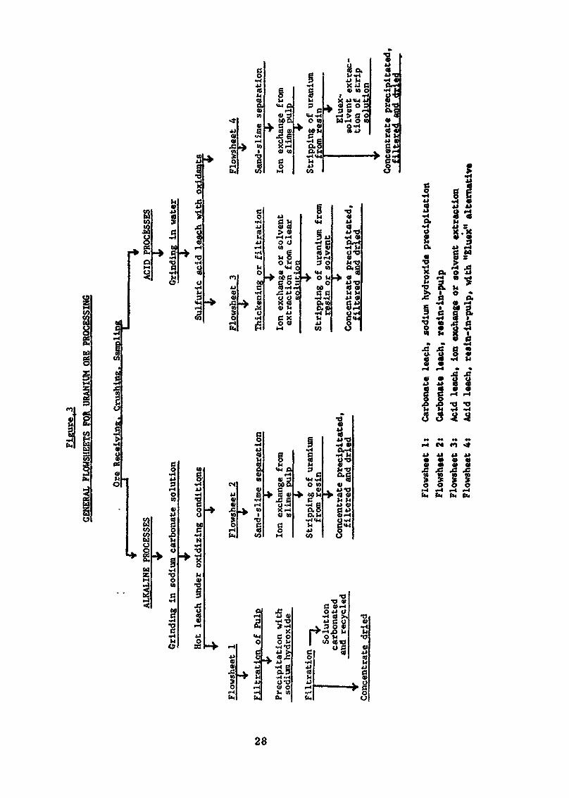
Uranium can be dissolved from its ores by treatment with eithersodium carbonate solutions or with mineral acids. If theuranium is present in the ore in its chemically reduced form(+4 valence state), as is usually the case, an oxidizing reagentmust be added. Heat is beneficial in increasing the rate ofuranim dissolution in either system, and is essential to achieveadequate recovery of values in a practicable length of time inthe carbonate leach process.
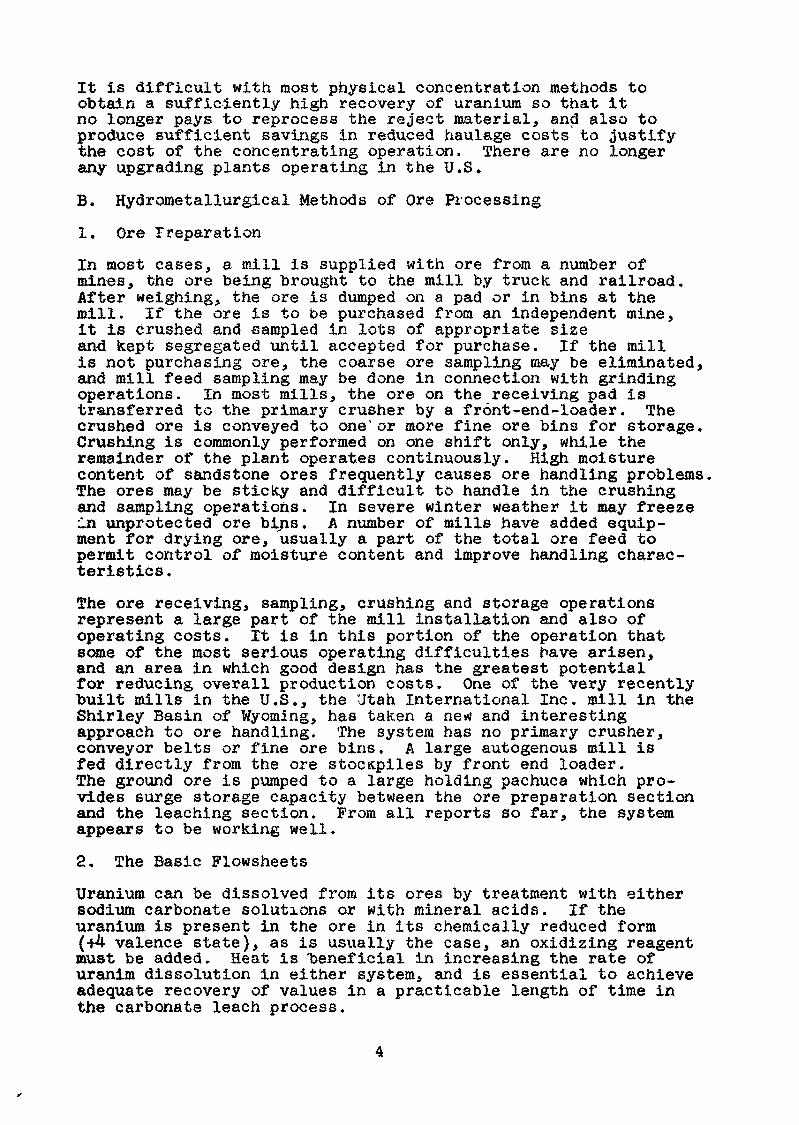
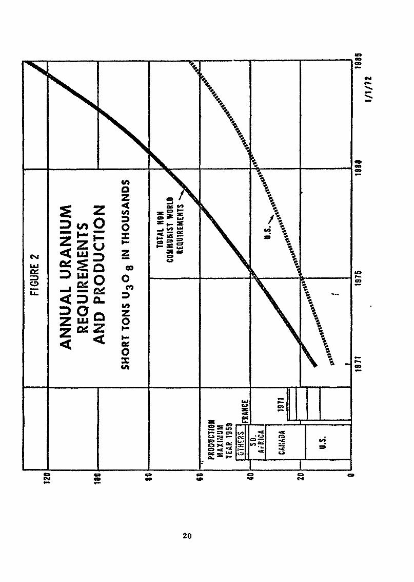
The four basic flowsheets currently in use in the U.S. areshown in Fig. 3. Two of these processes begin with tne sodiumcarbonate leach of the uranium from the ore. In one methodthe barren solids are next separated from the ore residue by3-stage filtration and tne uranium subsequently recovered byprecipitation from the solution with sodium hydroxide. Inthe other method, the 4-325 mesh sands are removed by means ofclassifiers and cyclones. The uranixim is then absorbed fromthe slime pulp onto an ion exchange resin and subsequentlyrecovered from the resin,
The other two processes begin with an acid leach of the ore.Thereafter, a separation of sand and slime may be made, withrejection of the sand tailings. Uranium is then recoveredfrom the slime fraction by the well known resln-in~pulp pro-cedures. Alternatively, the pregnant solution resulting fromthe leach process may be separated from the barren ore residueby filtration or thickening and subsequently clarified to pro-duce a clear solution. Uranium may be recovered from thissolution and purified by either ion exchange or solvent extraction.
3. Carbonate Leaching
The carbonate leaching process has advantages in treating orescontaining large amounts of acid consuming constituents suchas limestone. It is also very selective for uranium and doesnot dissolve nearly the quantities of unwanted impurities fromthe ore that acid leaching does. However, to achieve gooduranium recoveries and minimize leach time the ore is veryfinely ground, commonly 80$ or more - 200 mesh size in asolution containing the leach reagents - sodium carbonate andbicarbonate. With pulp temperatures elevated to the boilingpoint in pachucas, or above the atmospheric boiling point byusing autoclaves, the leaching time is usually in the range of18-24 hours. Air or oxygen are continuously supplied, andsometimes chemical oxidants such as copper and ammonia areused as well. The pulp is discharged from the leach circuitthrough heat exchangers, transferring heat to the incomingleach feed, and then filtered on rotary drum filters. Usually3 stages of filters are used. High concentrations of leachreagents are used in this process. Only a fraction, about athird, of the reagents are consumed. Therefore, dilution inthe filtering step must be kept low to permit recycling of theunconsumed reagents. Flocculating agents are necessary to getadequate filter performance.
Sodium hydroxide is added to the clarified pregnant solution toprecipitate the uranium as an impure sodium diuranate. Thisstep is not necessarily quantitative, and special measures aretaken to improve recovery of uranium, including recycling ofpreviously precipitated sodium diuranate.
The final product is usually high enough in uranium content tomeet specifications, but may need to be redissolved and re-precipitated to remove sodium, or roasted and water leachedto eliminate vanadium. The barren solution from the precipitationstep is recarbonated with boiler flue gas and returned to theprocess.
4. Acid Leaching
For acid leaching, the ore is crushed, and ground in water onlysufficiently to separate the sand grains. The pulp is leachedat about 55$ solids for 8-12 hours with dilute sulfuric acidand usually an oxidizing reagent. Manganese dioxide and sodiumchlorate are most often used for this purpose. To withstandthe corrosive acid leach solutions either wooden or rubberlined mild steel tanks are used. Leaching is done in a seriesof tanks, wi«h reagent addition made at several points in orderto permit continuous control of reagent concentrations. Someplants provide for 2-stage leaching, trie first stage beingperformed without oxidizing reagents. The savings in acidoxidizing and other reagents achieved by this method is largelyoffset by the added cost of two liquid-solid separation steps,and the added difficulties in maintaining solution balances.Consequently, the 2-stage system is seldom used.
5. Separation of Liquids from Solids
Filters are favored over other liquid-solid separation systemswhen:
ablc
Dilution must be kept to a minimumReagent recovery and recycle is importantLeach pulps have low slime content and good filteringcharacteristics.
The principal disadvantages of filters are high labor require-ments for operation and maintenance, and close control requiredto maintain solution balances in the system and obtain goodwashing of the filter cake. Carbonate leach pulps are handledby filtration to minimize dilution and keep reagent concentrationshigh enough to allow the solutions to be recycled after uraniumprecipitation. In addition, carbonate leach pulps generallyhave poor settling rates in thickener systems,
Thickener systems are usually favored when:
a) Dilution on the order of 1 to 2.5 tons of solutionper ton of ore can be tolerated
b) Leach pulps have poor filtering rates, but willsettle at acceptable rates, with suitable flocculatingreagents.
In U.S. installations a variety of combinations of thickenersystems with cyclones and classifiers are to be found. Inthese systems the slimes are handled in thickeners and thesands in either classifiers or cyclones. It is not clearlyestablished that the separate handling of sands is advantageous,in view of the additional equipment and handling required. Inseveral more recently constructed plants employing thickeners,no sand slime separation is made. The coarse sands have notbeen difficult to handle in the thickeners, and help to compressthe slimes, resulting in better overall washing efficiency.
6
Sand-slime separation followed by resin-in-pulp recovery ofthe uranium is necessary fhen filtration and settlingcharacteristics of the ore pulps are poor. The procedure doesnot require the costly flocculating reagents u&ually employedin plants using filtration and t hie teeners. This type of planthandles a variety 01 ore types reasonably well. However, thedilution ratios in sand slime separation circuits are higherthan other systems, about 2-4 tons solution per ton of solids.
6. Extraction of Uranium from Leach Solutions
a) Ion exchange
The ion exchange resins used are styrène polymer bead shapedparticles, in a sise range dependent on the intended use from10 to 60 raesh. Coarser sizes are used in resin-in-pulp systemsto make screening easier. In recovering uranium from clearsolutions the finer sizes are satisfactory. The resins areanion excnange materials. That is they attract and holdnegatively charged ions from solution. The resins are highlyporous sponge like structures. Afc> most asetals form positivelycharged ions in solution, they are not held by the resin.Therefore, the resins offer a means of separation of positivelyfrom negatively charged ions. Further, the resins offer aconsiderable degree of selectivity among anions, and hold moststrongly ions with higher charge. Uranium forms anion complexeswith both sulfate and carbonate ions, and resins have beenmade which are reasonably selective toward these complexes.Thus, in practice a highly concentrated and purified uraniumbearing solution can be produced from a very impure acid leachsolution in a single step. The resins are extremely toughand durable, and under difficult operating conditions havebeen known to maintain good performance over a period ofseveral years.
In treating clear pregnant solutions resulting from filtrationor thickening operations the ion exchange resins are containedin sets of cylindrical pressure vessels, 3 or 4 to a set.These tanks are 7 feet or more in diameter and with a heightabout twice the diameter. Bither a sand bed or screen plateat the bottom of the column provides support for a bed ofresin 5 feet or more in depth. The sets are operated continuouslyand fully automatically. Pregnant solution is passed throughtwo or three columns in series for absorption of the uraniumon the resin. Meanwhile one column is stripped by means of anacidified eluting solution containing a common anion such asnitrate, chloride or sulfate. Each reagent has its advantagesand disadvantages. Recently, producers have tended to use asolution of a sulfate salt and dilute sulfuric acid (about 10$)as an eluting reagent. It leaves the resin in the sulfateform which is advantageous, and is cheaper than other reagents.The concentrated sulfate solution of uranium is then treatedby solvent extraction. The uranium product recovered is veryhigh grade, generally 95 to 98$ U308 and meets all productspecifications without difficulty. Th3s system is known asthe Eluex process.
In resin-in-pulp operations the principles of operation remainessentially the same as in co3umn ion exchange. However, theresin is either confined in screen baskets, the system used inthe first RIP plants built, or passed continuously through aseries of 6-8 tanks containing desanded leach pulp, as in themore recently constructed RIP systems. The resin and pulpare airlifted over screens between stages and flow counter-currently through the absorption circuit. The resins surviveamazingly well in contact with the slime pulps, as long asagitation is not severe. Solids content in these systems isabout 5-lCt. The resins show little if any detectable wearfrom agitation in pachuca typ., tanks with air, or when thepulp is suspended by wide sweep agitators. Airlifts alsodo not cause appreciable wear of resin beads, nor do vibratingscreens. However, the resins do show appreciable higher ratesof loss when subjected to high speed agitators, or pumpimpellers regardless of the design of the pump. In optimumconditions resin losses in an RIP circuit from «fear may be onthe order of 20-30$ of the operating inventory per year, verycomparable with resin life in column ion exchange units.
The uranium is stripped or eluted from the resin in a seriesof smaller tanks, usually 10-14 in number. Screens have beenreplaced between stages by small settling cones. When theresin accumulates in the bottom of the cones to a pre-determineddepth, an automatic valve discharges it to the next tank. TheEluex process is generally used.
b) Solvent extraction
Solvent extraction as practiced today in uranium ore millingis limited to the treatment of clarified acid-leach solutions,and as previously mentioned, acid eluates from ion exchangeresins. No operating plant uses solvents to recover uraniumfrom slime pulps. A number of devices have been tested forthis purpose, but none has been used commercially. In view ofsome inherent obstacles3 such as the strong absorption of someof the solvents on certain minerals, it is doubtful the solventswill ever be successful in slime systems. Also, solvents arenot used c i carbonate leach s<. lutions, as they have appreciablesolubility in dilute carbonate solutions.
For clear acid leach liquors, however, solvent extraction hassome attractive characteristics. There are many solventsavailable with a wide variety of properties. The mixer-settlerequipment used is simple and runs in continuous countercurrentflow of organic and aqueous liquids with controls only on therate of solution feed to the system. The units are lessexpensive to construct than ion exchange units.
The solvents now used are either acidic or basic. The acidicsolvents are alkyl phosphoric acids and act as cation exchangers,The basic solvents are alkyl amines and are anion exchangers.Chemically they perform in a manner analagous to ion exchangeresins. There is a third solvent type, neutral solvents, thatfinds only incidental use in uranium ore processing. Theactive solvents are too viscous to be used directly, and con-sequently they are diluted in kerosene or other light high
8
boiling point petreleurs dis til la ce before use. This doesintroduce a fire nazard, a factor which is often not givs.nsufficient consideration, Taere have been two serious firesin solvent extraction units In the U.S. In one case, anelectrical short in wiring mDunted above the unit dropped hotmetal sparks into tne solvent. Tne resultant fire caused overa million dollars damage. Ir the .jther case, welding sparksignited solvent flowing in an open launaer. However, withadequate precautions and constant safety education these systemscan be safely run.
Some solvent loss from the circuit is unavoidable. Theprincipal source of loss is likely to be entrainment of fin©solvent droplets in the barren solution leaving the system.In practice solvent losses hâve been kept in tne range of 0.1to 0.5 gallon per 1,000 gallons of solution treated.
Uranium bearing pregnant solution and the solvent are mixedtogether briefly in a small mixing compartment by means of afairly high speed agitator. The centrifuge! force of themixing action raises the liquid level in the mixing compartmentand the unit overflows into a long settling tank in which tnewater and oil phases separate again. The organic phase over-flows from the settler into the next mixing unit, and theaqueous phase passes through a port at the bottom of thesettler into an adjoining mixer. The agitators in the mixingunits supply sufficient head to move the solutions throughthe system without pumps.
Uranium can be stripped from solvents with a number of reagents.A concentrated soda ash solution is often used for acidicsolvents. For stripping uranium from amines the most usedreagent combination is a fairly concentrated (1 molar) solutionof ammonium sulfate acidified to a pH of 4.0 to 4.5. Theuranium is precipitated from such a solution by addition ofammonia.
The precipitated uranium is thickened, further dewatered byfiltering or centrifuging, then dried or roasted under closelycontrolled temperatures» The product is dense and a standard55 gallon drum usually contains 700-800 pounds of concentrate.
The product is still an impxire material, which generallycontains 80$ or more uranium calculated as U308. To beacceptable feed te a refinery converting concentrates of UFgthe product must meet certain impurity specifications. Thespecifications used by the t«o commercial UFg plants operatingin the U.S. are given in Appendix A.IV. Milling CostsA. Mill Construction
Most of the mills operating in the United States today werebuilt in the late 1950's and early 1960»s. In analyzing theavailable data, I have tried to eliminate situations whereunique or non-typical circumstances have had a large effect oncost. Howeverj there are variations in most instances that
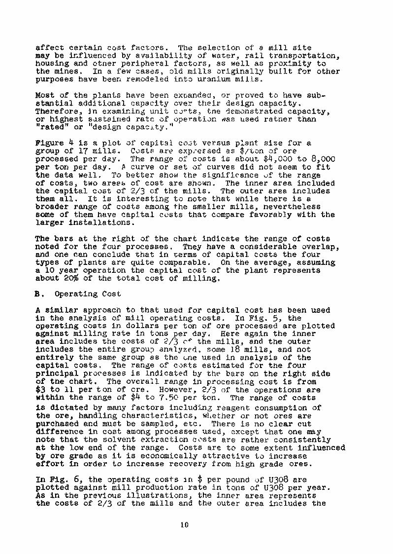
affect certain cost factors. The selection of a mill sitemay be influenced by availability of water, rail transportation,housing and otner peripheral factors, as well as proximity tothe mines. In a few cases, old mills originally built for otherpurposes have been remodeled into uranium mi ils.
Most of the plants have been expanded, or proved to have sub-stantial additional capacity over their design capacity.Therefore, in examining unit c^ts, tne demonstrated capacity,or highest sastsined rate of operation *?as used rainer than"rated" or "design capacity."
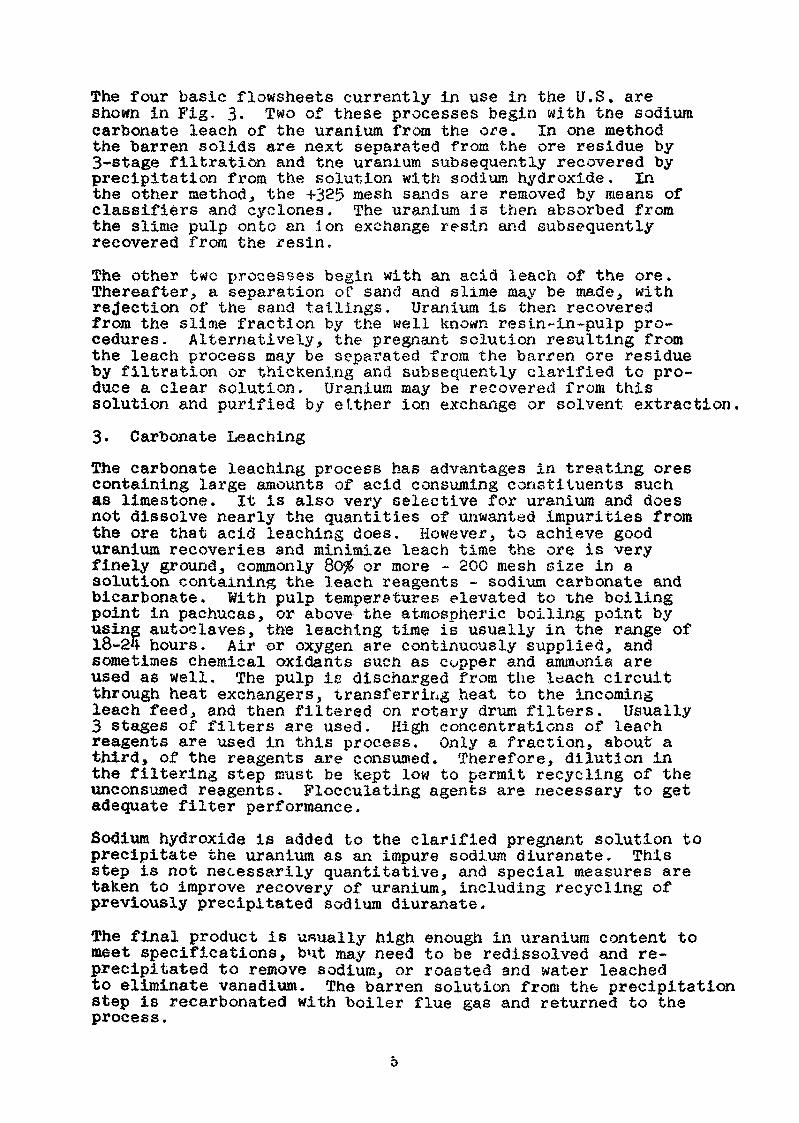
Figure 4 is a plot of capital co^t versus plant sise for agroup of I? mills. Costs are expressed as $/ton of oreprocessed per day. ïfhe range of costs is about $4,000 to 8,000per ton per day. A curve or set of curves did not seem to fitthe data well. To better show the significance of the rangeof costs, two are&fa of cost are shown. The inner area includedthe capital cost of 2/3 of the mills. The outer area includesthem all. It is interesting to note that while there is abroader raxige of costs among the smaller mills, neverthelesssome of them have capital costs that compare favorably with thelarger installations.
The bars at the right of the chart indicate the range of costsnoted for the four processes. They have a considerable overlap,and one can conclude that in terms of capital costs the fourtypes of plants are quite comparable. On the average, assuminga 10 year operation the capital cost of the plant representsabout 20$ of the total cost of milling.B, Operating Cost
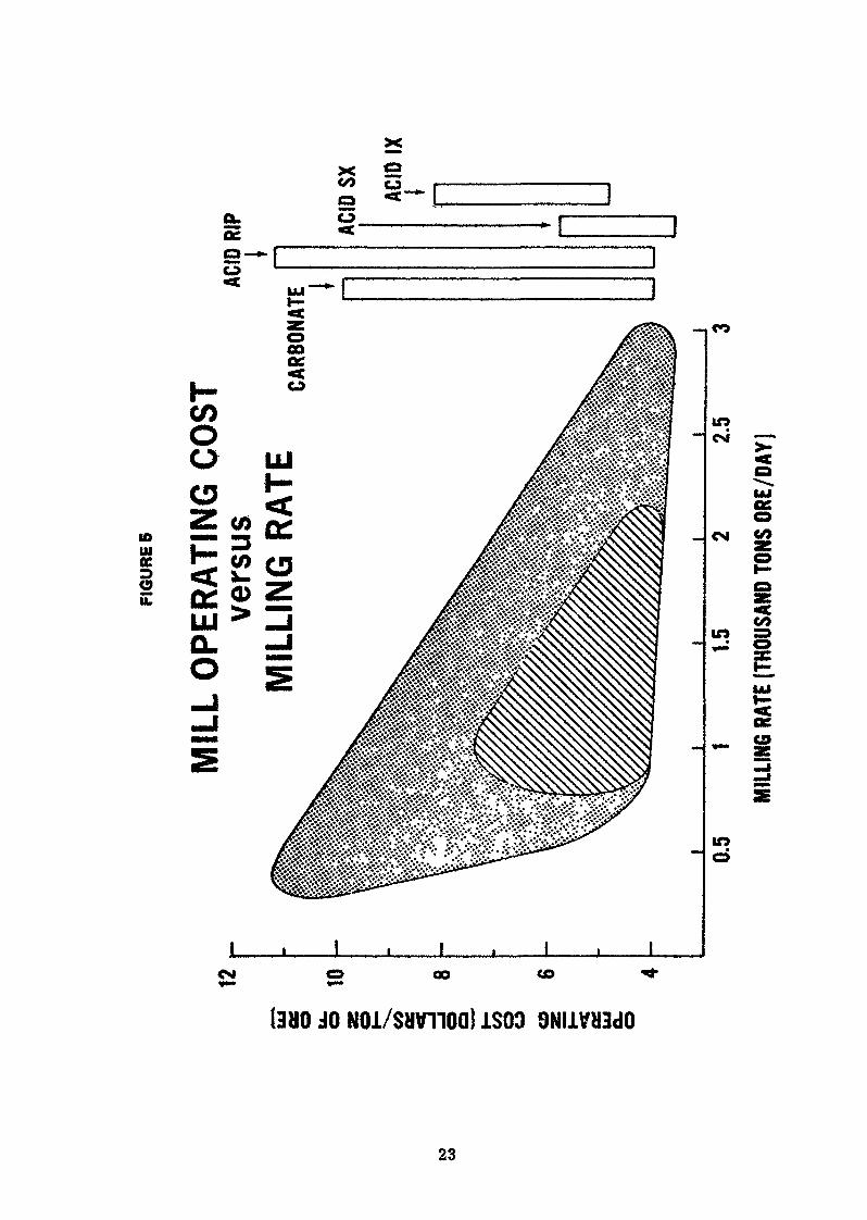
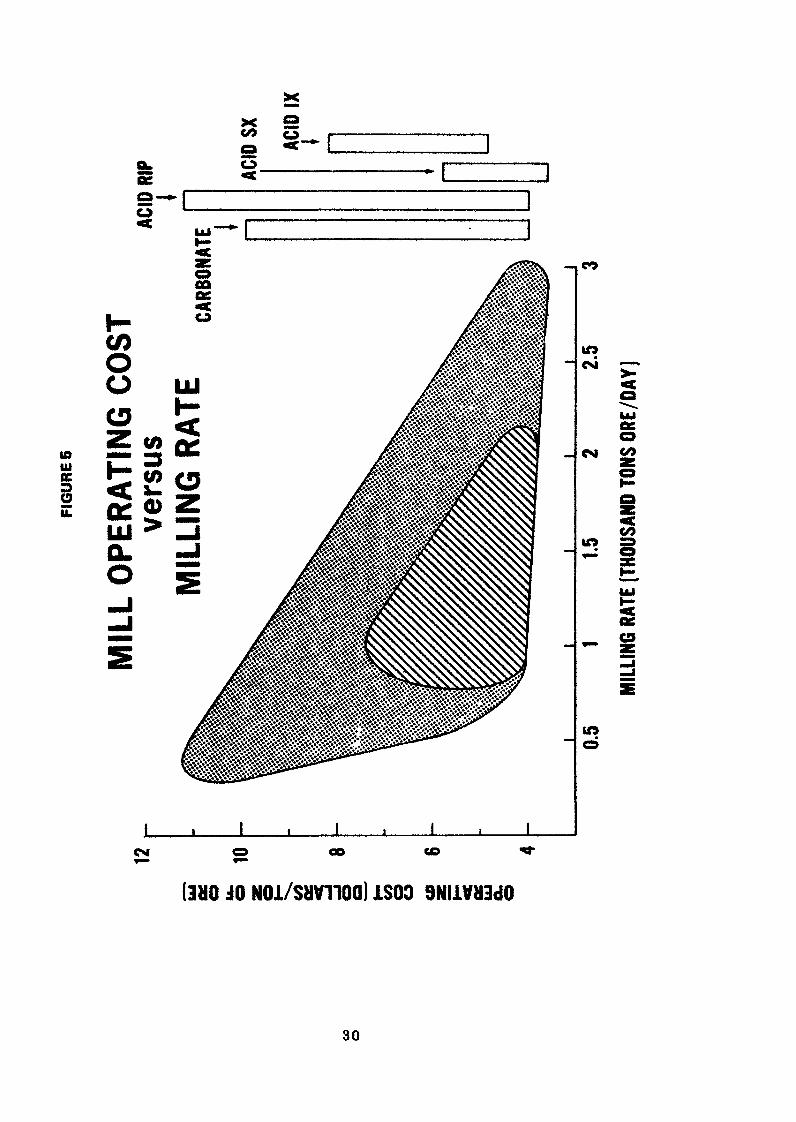
A similar approach to that used for capital cost has been usedin the analysis of mill operating costs. In Fig, 5, theoperating costs in dollars per ton of ore processed are plottedagainst milling rate in tons per day. Here again the innerarea includes the costs of 2/3 c*' the mills, and the outerincludes the entire group analyzed, some 18 mills, and notentirely the same group as the one used in analysis of thecapital costs. The range of costs estimated for the fourprincipal processes is indicated by the bars on the right sideof the chart. The overall range in processing cost is from$3 to 11 per ton of ere. However, 2/3 of the operations arewithin the range of $4 to 7-50 per ton. The range of costsis dictated by many factors including reagent consumption ofthe ore, handling characteristics, whether or not ores arepurchased and must be sampled, etc. There is no clear cutdifference in cost among processes used, except that one maynote that the solvent extraction costs are rather consistentlyat the low end of the range. Costs are to some extent influencedby ore grade as it is economically attractive to increaseeffort in order to increase recovery from high grade ores.
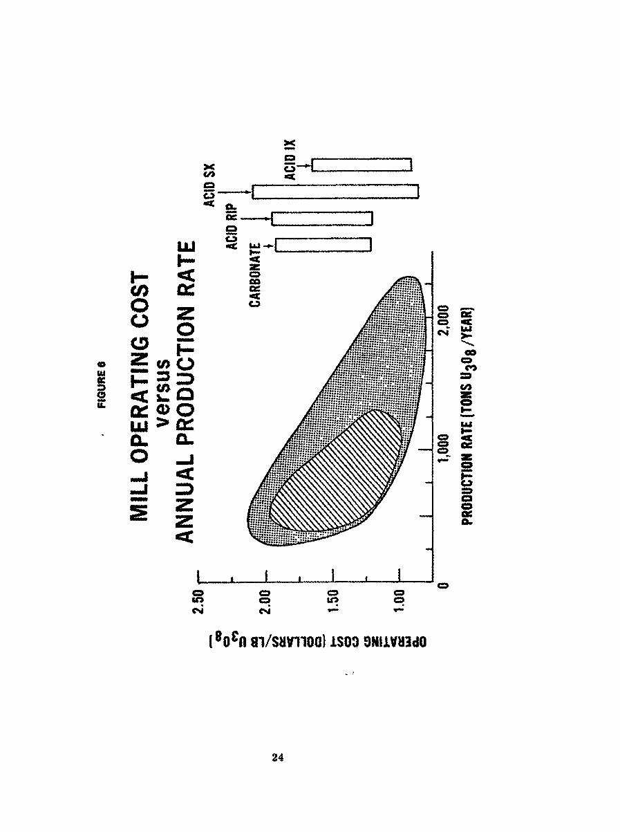
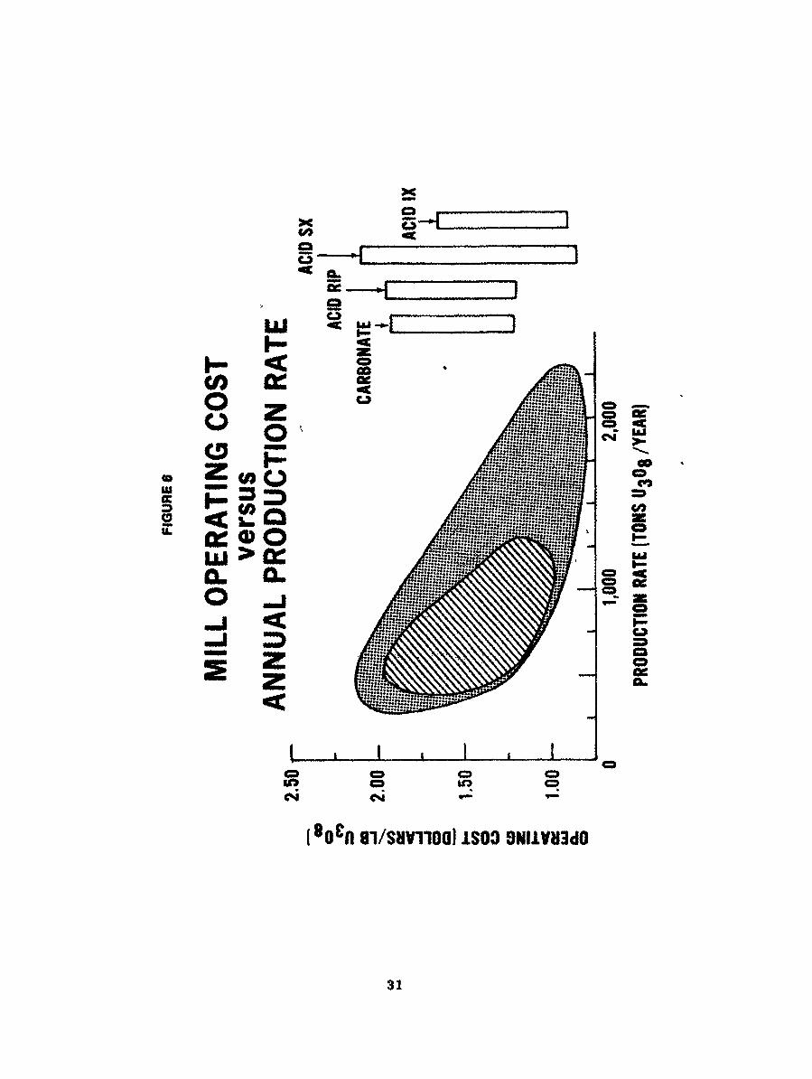
In Pig. 6, the operating costs an $ per pound of U308 areplotted against mill production rate in tons of U308 per year.As in the previous illustrations, the inner area representsthe costs of 2/3 of the mills and the outer area includes the
10
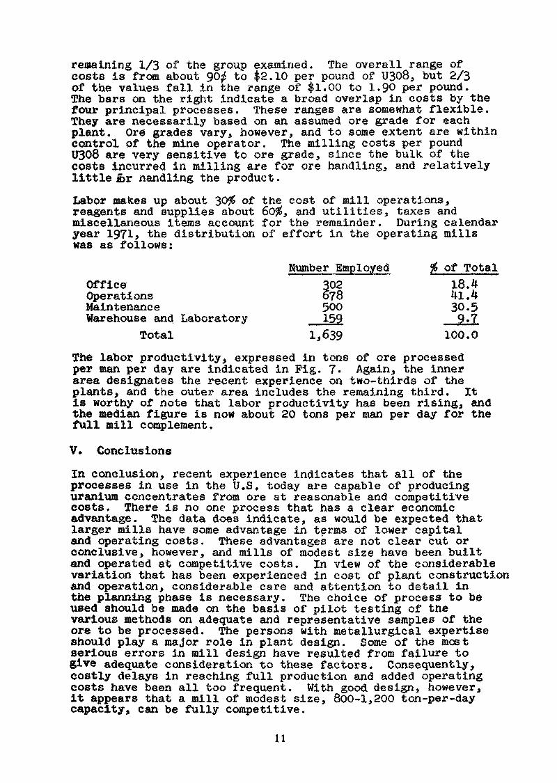
regaining 1/3 of the group examined. The overall range ofcosts is from about 90# to $2.10 per pound of U308, but 2/3of the values fall in the range of $1.00 to 1.90 per pound.The bars on the right indicate a broad overlap in costs by thefour principal processes. These ranges are somewhat flexible.They are necessarily based on an assumed ore grade for eachplant. Ore grades vary, however, and to some extent are withincontrol of the mine operator. The milling costs per poundU308 are very sensitive to ore grade, since the bulk of thecosts incurred in milling are for ore handling, and relativelylittle &r Handling the product.Labor makes up about 30$ of the cost of mill operations,reagents and supplies about 60$, and utilities, taxes andmiscellaneous items account for the remainder. During calendaryear 1971, the distribution of effort in the operating millswas as follows:
Number Employed % of TotalOffice 302 18.4Operations 678 4l.4Maintenance 500 30.5Warehouse and Laboratory 159 9*7
Total 1,639 100,0The labor productivity, expressed in tons of ore processedper man per day are indicated in Pig. 7. Again, the innerarea designates the recent experience on two-thirds of theplants, and the outer area includes the remaining third. Itis worthy of note that labor productivity has been rising, andthe median figure is now about 20 tons per man per day for thefull mill complement.
V. Conclusions
In conclusion, recent experience indicates that all of theprocesses in use in the U.S. today are capable of producinguranium concentrates from ore at reasonable and competitivecosts. There is no one process that has a clear economicadvantage. The data does indicate, as would be expected thatlarger mills have some advantage in terms of lower capitaland operating costs. These advantages are not clear cut orconclusive, however, and mills of modest size have been builtand operated at competitive costs. In view of the considerablevariation that has been experienced in cost of plant constructionand operation, considerable care and attention to detail inthe planning phase is necessary. The choice of process to beused should be made on the basis of pilot testing of thevarious methods on adequate and representative samples of theore to be processed. The persons with metallurgical expertiseshould play a major role in plant design. Some of the mostserious errors in mill design have resulted from failure togive adequate consideration to these factors. Consequently,costly delays in reaching full production and added operatingcosts have been all too frequent. With good design, however,it appears that a mill of modest size, 800-1,200 ton-per-daycapacity, can be fully competitive.
n
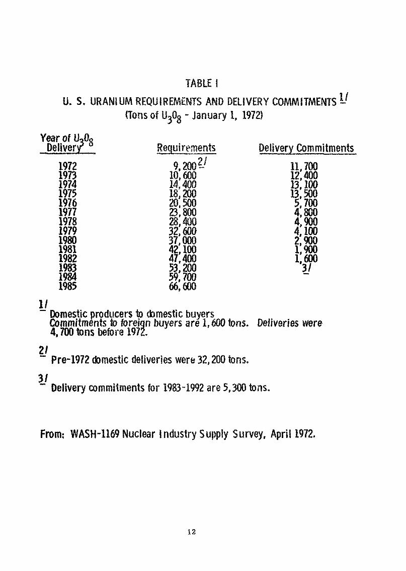
TABLE f
U. S, URANIUM REQUIREMENTS AND DELIVERY COMMITMENTS (Tons of U^08 - January I, 1972)
Year of UoO«Deliver/ Rec|uirements Dell very Com mltments1972 9,200 11,7001973 10,600 124001974 14,400 13,1001975 18,200 135001976 20,500 5,7001977 23,800 4,8001978 28,400 4,9001979 32,600 4,1001980 37,000 29001981 42,100 19001982 47,400 16001983 53,200 3/1984 59,7001985 66,600
yDomestic producers to domestic buyersCommitments to foreign buyers are 1,600 tons. Deliveries were4,700 tons before 1972.
21" Pre-1972 domestic deliveries were 32,200 tons.3/~ Delivery commitments for 1983-1992 are 5,300 tons.
From,- WASH-1169 Nuclear Industry Supply Survey, April 1972.
12
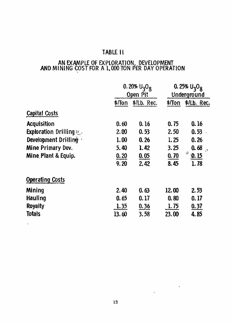
TABLE i}AN EXAMPLE OF EXPLORATION, DEVELOPMENT
AND MINING COST FOR A 1,000 TON f*ER DAY OPERATION
0.20% U308 0.25% U308
Open Pit Undergroundf/Ton $/Lb. Rec. $/Ton $/Lb. Rec.
Capital CostsAcquisition 0.60 0.16 0.75 0*16Exploration Drillingu. 2.00 0.53 2.50 0.53Development DriUinf ' LOO 0.26 1.25 0.26Mine Primary Dev. 5.40 1.42 3.25 0.68,Mine Ftent & Equip. IUÔ 005 0.70 a;(U5
9,20 2.42 8.45 1.78
Operating CostsMining 2.40 0.63 12.00 2.53Hauling 0.65 0.17 0.80 0.17Royalty 1.35 036 1.75 0.37Totals 13.60 3.58 a 00 4.85
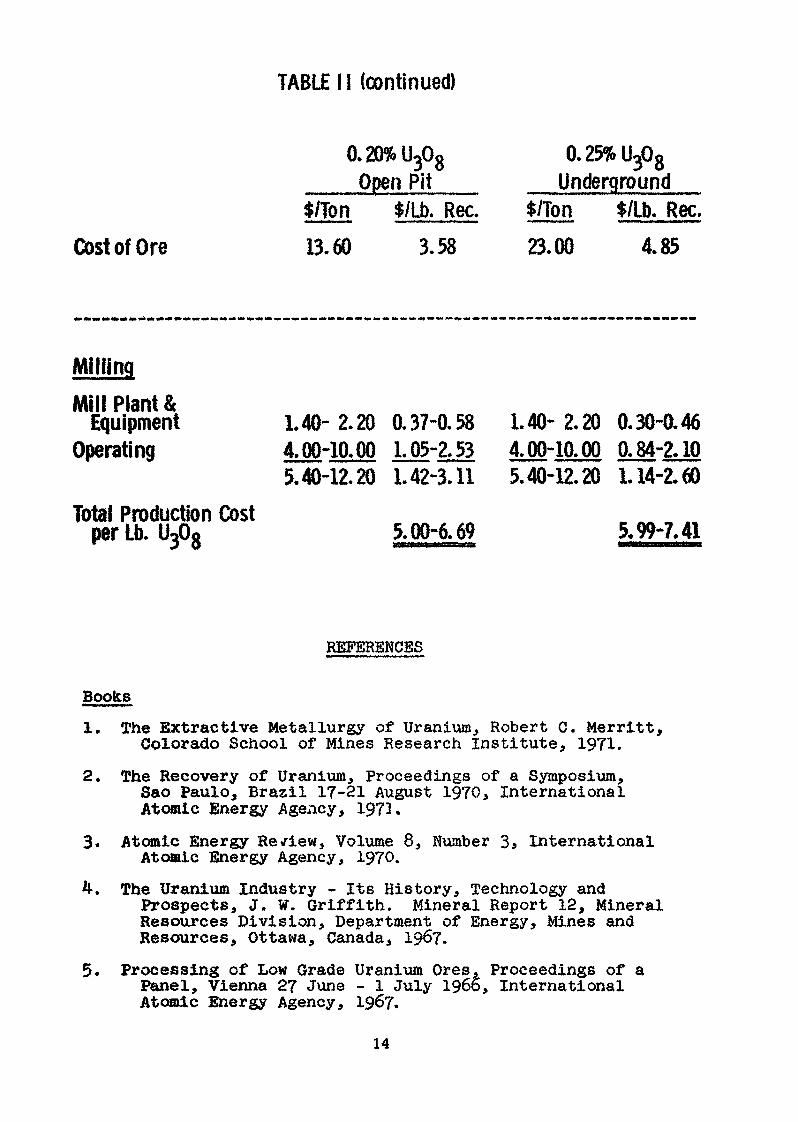
TABLE 11 (continued)
0.20% U30gOpen Pit
0.25% U308
Underground
Cost of Ore$/Ton13.60
$/Lb. Rec.3.58
$/Ton23 00*»«J. UU
$/Lb. Rec.4.85
MillingMill Plant &
EquipmentOperating
Total Production Costper Lb. U308
1.40-2.20 0.37-0.584.00-10.00 1.05-2,535.40-12.20 1.42-3.11
5.00-6.69
1.40- 2.20 0.30-0.464.00-10.00 0.84-2.105.40-12.20 1.14-2.60
5,99-7,41
REFERENCES
Books1. The Extractive Metallurgy of Uranium, Robert C. Merritt,
Colorado School of Mines Research Institute, 1971.
2. The Recovery of Uranium, Proceedings of a Symposium,Sao Paulo, Brazil 17-21 August 1970, InternationalAtomic Energy Agency, 1972.
3. Atomic Energy Review, Volume 8, NumberAtomic Energy Agency, 1970.
5.
International
The Uranium Industry - Its History, Technology andProspects, J. W. Griffith, Mineral Report 12, MineralResources Division, Department of Energy, Mines andResources, Ottawa, Canada, 1967.
Processing of Low Grade Uranium Ores, Proceedings of aPanel, Vienna 27 June - 1 July 1966, InternationalAtomic Energy Agency, 1967.
14
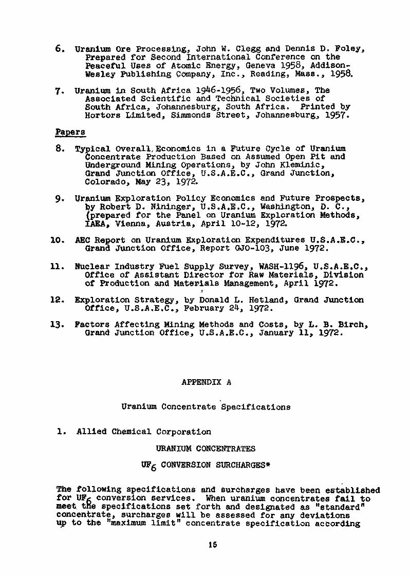
6. Uranium Ore Processing, John W. Clegg and Dennis D. Foley,Prepared for Second International Conference on thePeaceful Uses of Atomic Energy, Geneva 1958, Addison-Wesley Publishing Company, Inc., Reading, Mass., 1958.
7. Uranium in South Africa 1946-1956, Two Volumes, TheAssociated Scientific and Technical Societies ofSouth Africa, Johannesburg, South Africa. Printed byHortors Limited, Simmonds Street, Johannesburg, 1957.
Papers8. Typical Overall, Economics in a Future Cycle of Uranium
Concentrate Production Based on Assumed Open Pit andUnderground Mining Operations, by John Kleminic,Grand Junction Office, U.S.A.E.G., Grand Junction,Colorado, May 23, 1972.
9. Uranium Exploration Policy Economics and Future Prospects,by Robert D, Nininger, U.S.A,B.C., Washington, D. C.,(prepared for the Panel on Uranium Exploration Methods,IAEA, Vienna, Austria, April 10-12, 1972.
10. AEC Report on Uranium Exploration Expenditures U.S.A.E.C.,Grand Junction Office, Report GJO-103, June 1972.
11. Nuclear Industry Fuel Supply Survey, WASH-1196, U.S.A.E.G.,Office of Assistant Director for Raw Materials, Divisionof Production and Materials Management, April 1972.t
12. Exploration Strategy, by Donald L. Hetland, Grand JunctionOffice, U.S.A.B.C., February 24, 1972.
13. Factors Affecting Mining Methods and Costs, by L» B. Birch,Grand Junction Office, U.S.A.E.G., January 11, 1972.
APPENDIX A
Uranium Concentrate Specifications
1. Allied Chemical Corporation
URANIUM CONCENTRATES
UFg CONVERSION SURCHARGES*
The following specifications and surcharges have been establishedfor UFg conversion services. When uranium concentrates fail tomeet the specifications set forth and designated as "standard"concentrate, surcharges will be assessed for any deviationsup to the "maximum limit" concentrate specification according
15
1.2.
I:I:I:10.11.12.X?'14.
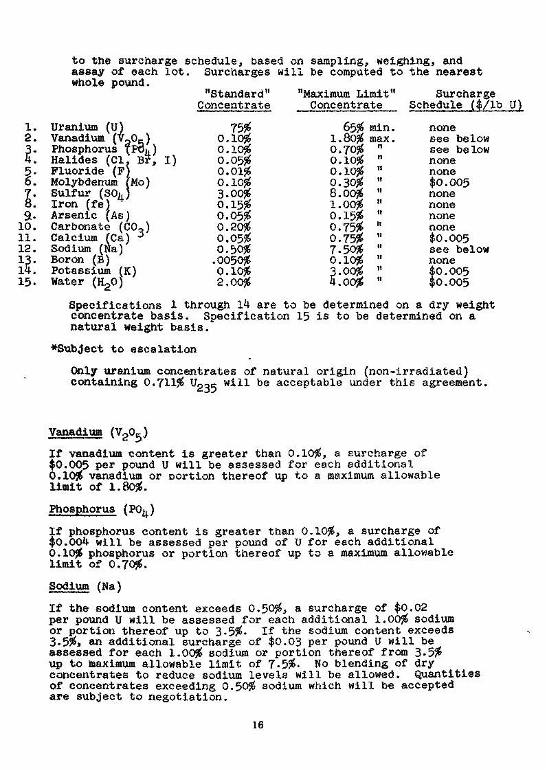
to the surcharge schedule, based on sampling, weighing, andassay of each lot. Surcharges will be computed to the nearestwhole pound.
"Standard" "Maximum Limit" SurchargeConcentrate Concentrate Schedule ($/lb U)
Uranium (U)Vanadium (V205)Phosphorus fPOh)Halides (Cl, B?, I)Fluoride (F)Molybdenum (Mo)Sulfur (SO,,)Iron (fe) 4Arsenic (As)Carbonate (CO )Calcium (Ça) ~JSodium (Ha)Boron (B)Potassium (K)Water (HgO)
75$0.10$0.10$0.05$0.10$3.00$0.15$0.05$0.20$0.05$0.50$.0050$0.10$2.00$
65$ min.1.80$ max.0.70$0.10$0.10J60.30$S.oojé1.00$0.15950.75$0.75$7.50$0.10$3.00$4.00$
nnilit«nttt!
titt»«»
nonesee belowsee belownonenone$0.005nonenonenonenone$0.005see belownone$0.005$0.005
Specifications 1 through 14 are to be determined on a dry weightconcentrate basis. Specification 15 is to be determined on anatural weight basis.
*Subject to escalation
Only uranium concentrates of natural origin (non-irradiated)containing 0,711$ U23c will be acceptable under this agreement.
Vanadium (VgO-)If vanadium content is greater than 0.10$, a surcharge of$0.005 per pound U will be assessed for each additional0.10$ vanadium or cortion thereof up to a maximum allowablelimit of 1.80$.
Phosphorus (PO )If phosphorus content is greater than 0.10$, a surcharge of$0.004 will be assessed per pound of U for each additional0.10$ phosphorus or portion thereof up to a maximum allowablelimit of 0.70$.Sodium (Na)
If the sodium content exceeds 0.50$, a surcharge of $0.02per pound U will be assessed for each additional 1.00$ sodiumor portion thereof up to 3-5$« If the sodium content exceeds3.5$» an additional surcharge of $0.03 per pound U will beassessed for each 1.00$ sodium or portion thereof from 3*5$up to maximum allowable limit of 7.5$. No blending of dryconcentrates to reduce sodium levels will be allowed. Quantitiesof concentrates exceeding 0.50$ sodium which will be acceptedare subject to negotiation.
16
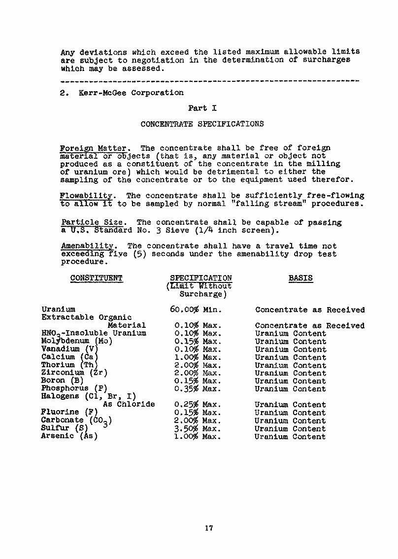
Any deviations which exceed the listed maximum allowable limitsare subject to negotiation in the determination of surchargeswhich may be assessed.
2. Kerr-McGee Corporation
Part I
CONCENTRATE SPECIFICATIONS
Foreign Matter. The concentrate shall be free of foreignmaterial or objects (that is, any material or object notproduced as a constituent of the concentrate in the millingof uranium ore) which would be detrimental to either thesampling of the concentrate or to the equipment used therefor.
Flowability. The concentrate shall be sufficiently free-flowingto allow it to be sampled by normal "falling stream" procedures.
Particle Size. The concentrate shall be capable of passinga U.S. Standard No. 3 Sieve (1/4 inch screen).
Amenability. The concentrate shall have a travel time noty.fiexceeding five (5) seconds under the amenability drop test
procedure .
CONSTITUENT
UraniumExtractable Organic
MaterialHNOo-Insoluble UraniumMolybdenum (Mo)Vanadium (V)Calcium fCajThorium (Th)Zirconium (Zr)Boron (B)Phosphorus (P)Halogens (01, Br, I)
As ChlorideFluorine (F)Carbonate (CO,)Sulfur (S) J
Arsenic (As)
SPECIFICATION(Limit Without
Surcharge)
60.00$ Min.
0.10$ Max.0.10$ Max.0.15$ Max.0.10$ Max.1.00$ Max.2.00$ Max.2.00$ Max.0,15$ Max.0.35$ Max.
0.25$ Max.0.15$ Max.2.00$ Max.3.50$ Max.1.00$ Max.
BASIS
Concentrate as Received
Concentrate as ReceivedUranium ContentUranium ContentUranium ContentUranium ContentUranium ContentUranium ContentUranium ContentUranium Content
UraniumUraniumUraniumUraniumUranium
ContentContentContentContentContent
17
Part II
SURCHARGES AND YIELD PENALTIES TO BEAPPLIED TO (AND PROVISIONS FOR REJECTIONOP) OFF-SPECIFICATION URANIUM CONCENTRATES
The following surcharges are assessed in lieu of rejection:
Uranium Content
For concentrates containing less than 60.00$ uranium on aconcentrate as-received basis, a surcharge of $0.005 per poundof concentrate as-received weight will be assessed for each1.00$ absolute or portion thereof by which the measureduranium content differs from 60.00$.
Nitrie-Acid-Insoluble Uranium
For concentrates containing greater than 0.10$ nitric-acid-insoluble uranium, the guaranteed yield will be reduced bythe amount by which the nitric-acid insoluble uranium exceeds0.10$ of the contained uranium.
Molybdenum (Mo)
For concentrates containing molybdenum in amount greater than0.15$ but less than 0.45$» a surcharge of $0.005 per pounduranium will be assessed. If the molybdenum content isgreater than 0.45$ of the contained uranium, then in additionto the said $0.005 per pound surcharge, a surcharge of $0.02per pound uranium will be assessed for each 0.10$ or portionthereof by which the molybdenum content exceeds 0.45$ of thecontained uranium.Vanadium (V)
For concentrates containing vanadium in amount greater than0.10$ of the contained uranium, a surcharge of $0.005 per pounduranium will be assessed for each 0.10$ absolute or portionthereof by which the vanadium content exceeds 0.10$ of thecontained uranium.Other Specifications
For concentrates which fail to meet one or more of the remainingspecifications of Part I of this Exhibit "C", a surcharge of$0.01 per pound uranium will be assessed.
Note 1; Special handling fees are charged, subject to mutualagreement, for concentrates not meeting specifications forForeign Matter, Flowability, and Particle Size. A fee of5# per pound of uranium (U) is charged for concentratesaccepted, but which fail to meet specifications for Amenabilityand Extractable Organic Material.
Note 2; The provisions of Part II of this schedule have beenparaphrased for brevity.
18
TONS
(THOU
SAND
S)70
AN
NU
AL
U.S
. REQ
UIRE
MEN
TS P
RO
DU
CTI
ON
CAPA
BILI
TY A
ND
SCHE
DULE
DC
OM
MER
CIA
L DE
LIVE
RIES
60 50 40 30 20 10
FIGUR
E 1
FIRM
AND
EST'D
PROD
UCTIO
N CA
PABI
LITY
AEC
ESTIM
ATE
OF A
NNUA
LRE
QUIRE
MENT
S(W
ITH P
u RE
CYCL
E)
DELIV
ERIES
SCH
EDUL
ED (I
MI 1
972)
''"""
""•'
*•'•
:„„
„„
, •«•«
toM
lUlt
1971
1975
YEAR
END
1980
1985
JULY
197
2
to o
FIGUR
E 2
AN
NU
AL
UR
AN
IUM
REQ
UIRE
MEN
TSA
ND
PR
OD
UC
TIO
NSH
ORT
TO
NS U
3O
8 I
N T
HO
USA
ND
S
TOTA
L NO
NCO
MMUN
IST W
ORLD
REQU
IREM
ENTS
PROD
UCTIO
NMA
XIMU
MYE
AR 1
959
'.-*'
40 20 —
1971
1975
1985
1/1/
72
Figure 3
GENERAL FLOWSHEETS FOR URANIUM ORE PROCESSING
Ore Receiving» Crushing» Sampling
ALKALINE PROCESSES
ACID PROCESSES
Grinding in sodium carbonate solution
Hot leach under oxidizing conditions
I
*Flowsheet 1
Flowsheet 2
.
Grinding in water
4Sulfuric acid leach with oxidants
Flowsheet 3
Flowsheet 4
Filtration of Pulp
Precipitation with
sodium hydroxide
Filtration
Solu
tion
carb
onat
edan
d re
cycl
ed
Concentrate dried
Sand- s
lime separation
^
rIon exchange from
slime pulp
-*
-——
Stripping of uranium
from resin
- — -j-
-p.
Concentrate precipitated,
filtered and dried
Thickening or filtration
^
Ion exchange or solvent
extraction
from clear
_______S
Q-l
llti
OJl
Stripping of uranium from
resin or solvent
c__
Concentrate precipitated,
filtered and dried
Sand-slime separation
-j.
Ion exchange from
_ slime pulp
Stri
ppin
g of
ura
nium
_
rom r
esin
__
__
Eluex-
solvent extrac-
tion of strip
solution
Concentrate precipitated,
filtered and dried
Flowsheet 1:
Carbonate leach, «odium hydroxide precipitation
Flowsheet
2i Carbonate leach» resln-in-pulp
Flowsheet 3:
Acid leach, ion exchange or solvent extraction
Flowsheet 4:
Acid leach, resln-ln-pulp, with "Eluex" alternative
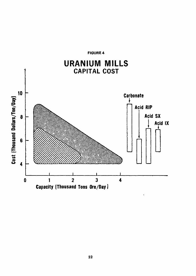
FIGURE 4
10
8J5"oo
io«9OO
URANIUM MILLSCAPITAL COST
Carbonate
Acid RIPAcid SX
Acid IX
1 2 3Capacity (Thousand Tons Ore/Day )
22
FIG
URE
5
12
UJ
10
CO octo 09
8
CO o o CD UJ
O.
O
MIL
L O
PER
ATIN
G C
OST
vers
usM
ILLI
NG
RAT
EAC
ID R
IP
CARB
ONAT
E J
0.5
1 1.5
2
2.5
MILL
ING
RATE
(THO
USAN
D TO
NS O
RE/D
AY)
ACID
SX
ACID
IX
FIGU
RE 6
2.50
1-
00
o 9*
S» CQ OC V» o o CS OC tu o.
2.00 1.50
1.00
MIL
L O
PERA
TING
CO
STve
rsus
ANN
UAL
PRO
DUCT
ION
RATE
ACID
SXAC
IO RI
PCA
RBON
ATE
ACiO
IX
1,000
2,000
PROD
UCTIO
N RA
TE (T
ONS U
308/Y
EAR]
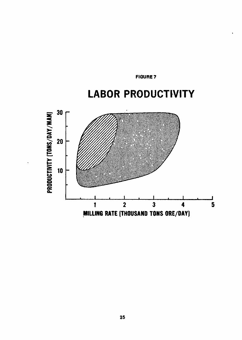
FIGURE 7
=> 30
oCO
iooOSo.
20
10
LABOR PRODUCTIVITY
1 2 3 4MILLING RATE (THOUSAND TONS ORE/DAY)
25
to 0»
TONS
(THOU
SAND
S)70
AN
NU
AL
U.S.
REQ
UIRE
MEN
TS P
RO
DU
CTI
ON
CAPA
BILI
TY A
ND S
CHED
ULED
CO
MM
ERC
IAL
DELI
VERI
ES
60 50 40 30 20 10 0
FIRM
AND
EST'f
lPR
ODUC
TION
CAPA
BILIT
Y
'•••••,,
M%.»
»»«^
M"M
V*
^>*
FIGUR
E 1
1971
1975
AEC
ESTIM
ATE
OF A
NNUA
LRE
QUIRE
MENT
S(W
ITH P
u RE
CYCL
E)
DELIV
ERIES
SCH
EDUL
ED (J
AN 1
972)
'••••
••••
•„
YEAR
END
1980
1985
JULY
197
2
to -J
120 60 40 20
PROD
UCTIO
NMA
XIMU
MYE
AR 1
9SO
FIGUR
E 2
AN
NU
AL
UR
AN
IUM
REQ
UIRE
MEN
TSAN
D P
RO
DU
CTI
ON
SHO
RT T
ONS
U3O
g IN
TH
OU
SAN
DS
TOTA
L NO
NCO
MMUN
IST W
ORLD
REQU
IREME
NTS
1971
197S
1900
1/1/
7219
9S
Figure,3
GENERAL FLOWSHEETS
FOft URANIUM ORE PROCESSING
Ore Receiving. Crushing.
Sampli
ALKA
LINE
PRO
CESS
ES
tACID PROCESSES
Grin
ding
in
sodi
um c
arbo
nate
sol
utio
nGrinding in water
Hot leach under oxidizing conditions
ISulfuric acid leach with oxidats
oo
Flowsheet 1
Filtration of
Pulo
Précipitation with
sodium hydroxide
Filtration
Solution
carbonated
and recycled
Concentrate dried
Flowsheet 2
Sand-slime separation
^
Ion exchange from
slime pulp
F——
Stripping of uranium
from resin
^
Concentrate precipitated,
filtered and dried
Flowsheet 3
Thickening or filtration
TIon exchange or solvent
extraction from clear
solution
Stripping of uranium from
resin or solvent
Concentrate precipitated,
filtered and dried
Flowsheet 4
-Ç———
Sand-slime separation
Ion exchange
from
slime pulp
¥Stripping of uranium
from resin____
Eluex-
solvent extrac-
tion of strip
solution
Concentrate precipitated,
filtered and dried
Flowsheet 1:
Carbonate leach, sodium hydroxide precipitation
Flowsheet
2t
Carbonate leach, resin-in-pulp
Flowsheet 3:
Acid leach, ion exchange or solvent extraction
Flowsheet 4}
Acid leach, resta-ln-pulp, with "Eluex" alternative
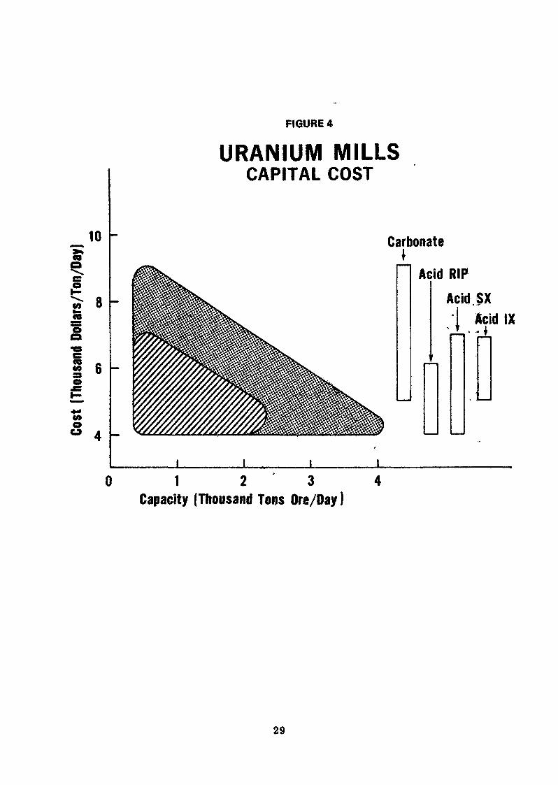
FIGURE 4
10
«2 8«5M»
O
oo
URANIUM MILLSCAPITAL COST
CarbonateI
1 Acid RIPAcid SX
I Acid IX
1 2 3Capacity (Thousand Tons Ore/Day )
29
FIG
URE
S
12 10
oo
CO o
g o UJ
MIL
L O
PERA
TING
CO
STve
rsus
MIL
LIN
G R
ATE
ACID
RIP
• ICA
RBON
ATE i I
ACID
SX
ACID
IX
0.51
1.52.
5
MILL
ING
RAT
E (T
HOUS
AND
TONS
ORE
/DAY
)
FIGU
RE 6
C7
OÙ 07 O o es at Ul a.
2.50
r-
2.00
1.50
1,00
MIL
L O
PERA
TING
COS
Tve
rsus
ANNU
AL P
RODU
CTIO
N RA
TEAC
ID S
XAC
ID RIP
CARB
ONAT
ErE I
* &
ACID
IX
1,000
2,0
00PR
ODUC
TION
RATE
(TON
S U 3
0g /Y
EAR)
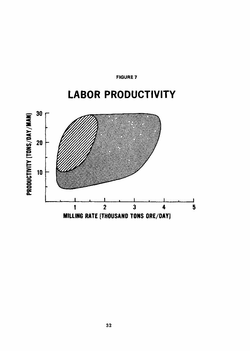
FIGURE 7
LABOR PRODUCTIVITY
=r 30
20
S 1 0
OSQ.
1 2 3 4 5MILLING RATE (THOUSAND TONS ORE/DAY)
32
PROM ORE TO CONCENTRATE
New Techniques and Prospects in Ore Processing
J.E.'Léger and G. Boutonnet
Pechiney Ugine Kuhlmann, France
Abstract
This article describes the reasons and circumstances governingthe development of uranium hydrometallurgy in " Vance, the objectiveslaid down for this industry, technological resources and expected futuredevelopments.
Two French processes stand out against the standard methods adoptedelsewhere in the world: the "calcium" process and attack by forminga paste.
Chemical, technological and economic research has .cone on sinceI960, into the most logical form of connection bettveen the concentrationunits on the mining sites and the fluoridation units oreceding enrich-ment.
Yellow cake can no longer be justified excent in enecial circum-stances, while UP. appears as an a'ooronriate and obligatory intermediatestage. Two orocesses have been tested un to the -nlot stage, to orovethe possibility of producing UP. on the site suitable for conversioninto UP.
33
On expose les raisons et les circonstances qui ont présidé audévieloppement de l'hydrométallurgie de l'uranium en France: objectifsimparts à cette industrie, moyens technologiques et développementsprévisibles de l'époque.
Deux procédés français se détachent des schémas classiques adoptésailleurs dans le monde: le procédé dit "calcique" et l'attaque parempâtage.
Depuis I960, ont été poursuivies des études chimiques, technologiqueset économiques sur l'articulation la plus logique entre les unîtes deconcentration établies sur les sites miniers, et les unités de fluorationprécédant l'enrichissement.
Le "yellow cake" ne se justifie que par des raisons circonstancielles,tandis que UP. apparaît comme point de nassage privilégié et obligatoire.Deux procédés ont été expérimentés jusqu'au stade pilote pour faire lapreuve de cette possibilité de produire, sur le site minier, UP. apte àêtre transformé en UP.
PROM ORB TO CONCENTRATE
New techniques and prospects in ore processing*
France started to extract uranium seventeen years ago, in January1955» shortly before the First International Conference was held inQeneva. '
Six years later, in February 1961, the fourth of the plants builtby French industry came on stream in the Gaboon Republic, bringingproduction capacity up to two thousand metric tons of metal perannum.
In order to understand the development which has occurred in thisindustry's objectives, it is necessary to refer back to thecircumstances which existed when this industry first came into being.
34
In Prance, as elsewhere, following the near-universal failure ofphysical methods of concentration, mining engineers took their oreprocessing problems to the chemists. The fact that processing unitshad to be designed and built as quickly as possible, combined withthe then state of the art as concerns wet metallurgy and the securityblackout on work done in other countries led to the adoption ofsimple process routes. At the time, the international "economies'1
of uranium did not come into the picture. Each of the countriesconcerned followed its own, strictly national, policy, which wasfrequently dictated by strategic considerations.
The industrial facilities built in response to these requirementsresponded remarkably well to the demands made upon them in the yearsimmediately following their installation when they were having toproduce to full capacity.
There can be no doubt that the original scheme of things would haveundergone changes earlier if the size and scope of demand hadcontinued to expand, instead of which the pattern of facilitiesinstalled in 1961 found itself frozen for a decade by the subsequentcurtailment of demand.
While, therefore, there were no changes in terms of concentrationand production facilities per se, process technology and «oonomicaunderwent a radical transformation, involving (i) a modificationof the original objectives and planned use of the finished products,(ii) improved production methods and (ill) greater emphasis onmedium and long-term market prospects.
the some time, the French ore processing industry took advantageof this pause to think out what it wanted to do and run pilot-scaletests on process routes which had been glimpsed us early as I960and were gradually being seen as more rational»
35
A - ORIGINAL TSCHWOLOGIGM AND ECONQgC COWrlDER/iTICWS ,iffD SUBSSQtfESTDEYELOPSŒNTS
ï
1. ..Concentration industry objective a and planned uses of products
In France, as elsewhere, uranium extraction and proceeding objectivéewere twofold :
(i) In terms of economics, the 'aim was to convert the ore - whichcould not economically be shipped - on the s>ot and in us simple amanner as possible into a technical-grade concentrate which couldeconomically be shipped.
-, r r-V ' '<processes , where the,/ can be used-, are a eiw.ple answer*
processes, however, owing to the quantities of acidsemployed and the impurities inevitably taken into solution» entailan additional stage of purification by ion exchange prior to the'precipitation of the final concentrate.
^ i !
(ii) In terms of process technology, it was then desired to 'refinethe technical-grade concentrate as a separate stage, which had aboveall else to ensure consistency of product quality rather thanadherence to standards which could not always be expressed in termsof analytical limits. French industry sought a second stage designedwith a iview to the production of natural uranium taetal.
1 shift towards the use of enriched fuels has since introducedthe conversion to the hexafluoride, and hence new standards' forthe UFjj to be fluorinated. Certain specifications - e.g. molybdenumcontent - have increased in severity, while others - e.g. rare earthswith large neutron cross-section - have been relaxed. At the sametime, standards have been made international., »
2 - Process technology
The solid and subsequently liquid ion exchange systems constitutedthe maximum feasible revolutionary development when the firstindustrial units were built. The French plants at Ecarpiere (LoireAtlantique) and Bessines (Haute Vienne) exemplified that trend: theformer uses strong anionic resins, while the latter uses these resins
36
in combination with a liquid/liquid exchange process employing asecondary amine. Otherwise, the methods of wet grinding, digestionin stirred vessels, washing and grading continued to be based onwhat was most orthodox in ore processing practice.
As early as 1953, however, two new developments provided an insightinto the potentialities of this infant industry.
The calcium process
The first of these developments found expression in the Forez plantin Prance and the Mounana plant in the Gaboon Republié, which cameon stream in January I960 and February 1961, respectively. This wasthe "Calcium process", which features a two-stage concentrationflowsheet* Each of these stages involves a departure from earlierpractice.
(Pig. 1)
Digestion of the ore is followed by the conventional liquid/solidseparation, using a filter at Forez and separators at Mounana. Theuranium-containing solution then undergoes a two-stage precipitationtreatment :
(i) The solution la first treated at pH 3-3*5 to neutralisaresidual free acidity and precipitate the bulk of the ferriehydroxide. The latter is recircul&ted to the ore digestion stageto maintain a concentration of 6-8 g/1 of iron and, after additionof an oxidising agent, a ratio of ferric to ferrous ion of 6-10/1 .Ferric iron was known at the time to be able to oxidise lr4 andfacilitate solution of IK 4* » especially in the presence ofinhibitors such as eheluting hos -hutes. Tnis process resultsin selective digestion of the ganrue, so that, in the case of theores concerned, solubilisation efficiencies of 96.5-97;=- are obtainedwith 25-30 ke;/ton of sulphuric acid, by maintaining a pH close to 1.8 .
(ii) The second precipitation stage, from an almost neutral solution,yields a crude concentrate with the following typical composition(calcium process) :
37
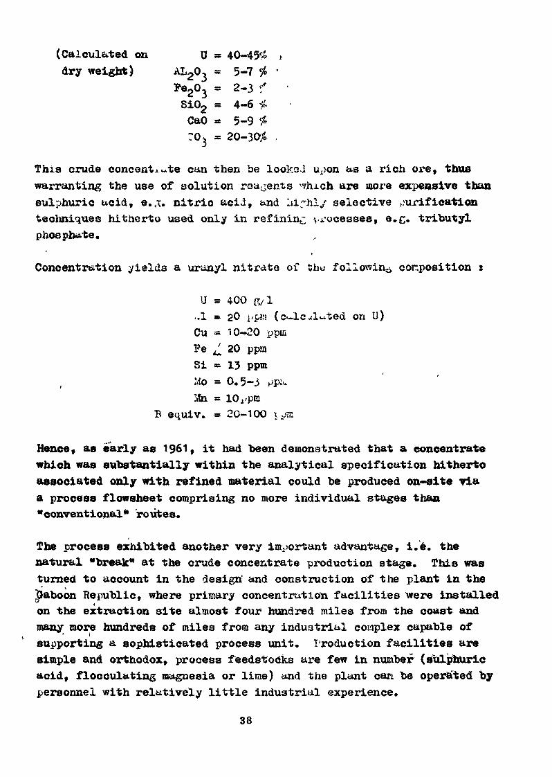
(Calculât ecl on U » 40-45 /*dry weight) AL203 - 5-7 #
Fe203 « 2-3 i"Si02 * 4-6 #CaO « 5-9 £
This crude concentrate can then be looks .1 upon as a rich ore, thuswarranting the use of solution reagents '-vhich are more expensive thansulphuric ucid, e. . nitric acid, and aifhl/ selective purificationtechniques hitherto used only in refining v ocesses, e.g. tributylphosphate,
*
Concentration yields a uranyl nitrate of the following corposition t
U » 400 S/l
-1 = 20 j'p«» (cu-lc .tinted on D)Cu » 10-20 ppinFe £ 20 ppmSi - 13 ppmIvlo » 0.5-3 pptu
B equiv. = 20-100 x pm
Hence, as early as 1961, it had been demonstrated that a concentratewhich was substantially within the analytical specification hithertoassociated only with refined material could be produced on-site viaa process flowsheet comprising no more individual stages than"conventional" routes.
The process exhibited another very important advantage, i.e. thenatural "break" at the crude concentrate production stage. This wasturned to account in the design' and construction of the plant in the|raboon Republic, where primary concentration facilities were installedon the extraction site almost four hundred miles from the coast andmany more hundreds of miles from any industrial complex capable of
' i
supporting a sophisticated process unit. Production facilities aresimple and orthodox, process feedstocks are few in number (sulphuricacid, flocculating magnesia or lime) and the plant can be opera'ted bypersonnel with relatively little industrial experience.
38
The intermediate concentrate is subsequently processed in Preface,where improved resources and facilities - in terms of reagents,process control and servicing - are available,
The reaction paste process
The second of the developments referred to earlier was designed toreduce consumption of sulphuric acid, the major cost factor in theore concentration process. *s early us 1955» Kuhlmann had patenteda process based on the use of dilute sulphuric aci.4 to digest ore inthe form of a paste.
Generally speaking, the digestion process requires the- maintenanceof an appreciable level of free acidity (10--40 gA<) && Qrder todigest <£he gangue, and ensure an adequate rate of solution of theuranium contained therein, additionally, the normal -method, ofsolution, in stirred vessels, of a slurry obtained by a wet grindingprocess, produces 0.7-1 cu.su of solution per metric ton of drymaterial. This means that 20-40£ of the acid used - in the case ofFrench plants - has to be neutralised and goes to waste.
The use of a diluted acid spray to produce a reaction paste goesat least part of the way to meeting three objectives, viz :
(i) The quantity of water employed is restricted to the absoluteminimum necessary to enable the various reactions involved, whichare basically of the ionic type, to occur. Depending on the typeof ore concerned, and particularly the clays of which it is composed,the volume of waiter required can vary from 40 to 100 litres permetric ton dry weight of ore, so that, for the same free acid concen-tration in the final digestion medium, the amount of acid not usedand which goes to waste is reduced by a factor of ten or twenty ascompared to a slurry containing 700-1000 litres of water per metricton of dry material.
(ii) An aqueous medium containing hot 50$ sulphuric acid is itselfoxidising enough that less, if any, of the usual oxidising agent iarequired.
39
(ill) The heat of dilution and reaction of the sulphuric acid*combined with the fact that the volume of water used is small, mayin practice raise the temperature of the mass sufficiently to ensurea suitable rate of solution.
Additionally, the very small volume of water required to operate thisprocess makes it particularly suitable for applications in ariaregions. This idea could not, however, be tried out right away andwas first put into effect in the Comair plant in the Niger Republic,which came on stream in November 1970.
In addition to these ideas, which had a substantial effect on processflowsheets, work went ahead patiently on the newer techniques basedon liquidAiQuid exchange. While it would take too lone» and go toofar beyond the scope of this presentation, to go over all the stepsinvolved, the avenues opened up by refining processes incorporatingthese techniques will be considered in a moment»
3 - Production prosects and market-oriented trends
Between 1955 and 1958 nuclear energy had by no means shown itself tobe competitive. It was hoped that this could be demonstrated between1965 and 197O and hopes were just high enough to support moderateforecasts for the next fifteen years.
Hence, world production capacity in ternis of concentrate is newsufficient to cater for demand for at least two decades. France isno exception to the rule, so tr^at there can be no serious thoughtof modifying the original overall pattern of concentrate productionand refining facilities.
The nuclear programmes of every country concerned hu.ve now been esta-blished for as far ahead us 1985, or even 1990, Any slight uncertaintywhich rnay still persist due to environmental objections sho-ld notcause nuclear schedules to be aodified by a-.ore thun two years.
This means that by 1980, at the latest, \?orld demand for concentrate -amounting to 50,000 cietric tons per iinnuit; - will be higher than theproduction capacity of plants now in operation, under constructionor definitely to be built.
40
Longer term forecasts point to a level of demand of 120,000 tone toy1985 and 200,000 tons by 1990.
The prospect of having to increase production capacity by a factorof four within the space of fifteen years means that, howeveroptimistic a view is taken, a long, hard look needs to be taken atthe total industrial resources available in the chain extending fromextraction to the hexafluoride.
RESOURCES AMD POTENTI.q ROUTES
The sequence of possible operations front the ore to the hexafluorideincludes .only one which is absolutely mandatory* This is .theproduction of UP . Logically, therefore, the pattern should beone of local mine-based units producing UF for subsequent conversionto UPg by a central unit, assuming of course that no technical oreconomic barriers exist,
Again, it is a basic principle of process design that the mosteconomic route is generally that which involves no changes of phase*In the particular case considered, therefore, the hydrometallurgistwill seek a process sequence terminating in the production of QFwhich can. be carried through as f &r as possible in the liquid phase.Any stage producing solid intermediates will, unless it exhibitsclear advantages such as those associated with the calcium processdescribed earlier, inevitably entail additional costs in terms ofseparation, drying, packing and re-solution*
À final consideration based on the hydrometallurgist* s experience ofwhat nature can hold in store is that no process can claim to be ofuniversal application. Hence, .failing 4 unique process route able tocater for any and all types and ore, what has to be sought is theright combination of two or more process sequences.
Assuming that these basic premises are accepted, several proposalscan be made.
41
(Table 2}
The nature of the ores normally encountered la such that what firstsuggests itself is to employ the two process routes discussed earlier»viz t
I - Digestion» leaching and concentration b$ ion exchange, alloperations being carried out on an open-run basis»
II - Digestion, leaching and precipitation of a crude concentrateand, possibly, recirculation to the digestion stage of purt of thesoluble salts»
s.
Which of these two methods is employed will normally be determined by s
(i) how difficult the ore is to brinf into solution, since onlythe open-run process can ensure the very strongly acid conditions»which may be required ;
(ii) alumina or soluble silica contents, since these will mean aleaner crude concentrate where the calcium process is employed ;and
(iii') the presence or otherwise of inhibitors, e.g. P20c » which maybe released in excessive amounts and thus build up in thecalcium process, which employs recirculâtion.
1,1 - This is the conventional route and has been improved in manyrespects, mainly as concerns the ionic concentration stage, e.g. useof more highly selective solvents, improved phase separation, useof synergistic agents, introduction of sutvration or scrubbing stages»
These improvements have not, hovever, at least u.s fur «s the Frenchtechniques are concerned, enabled the THP refining ct^-e to be elimi-nated. The amounts of sulphates, œolybdenur., silicon, iron and rareearths present in the concentrates obtained <*re such th«t it scarcelyappears feasible to TUBS directly to the stuge of reaction with HP.
42
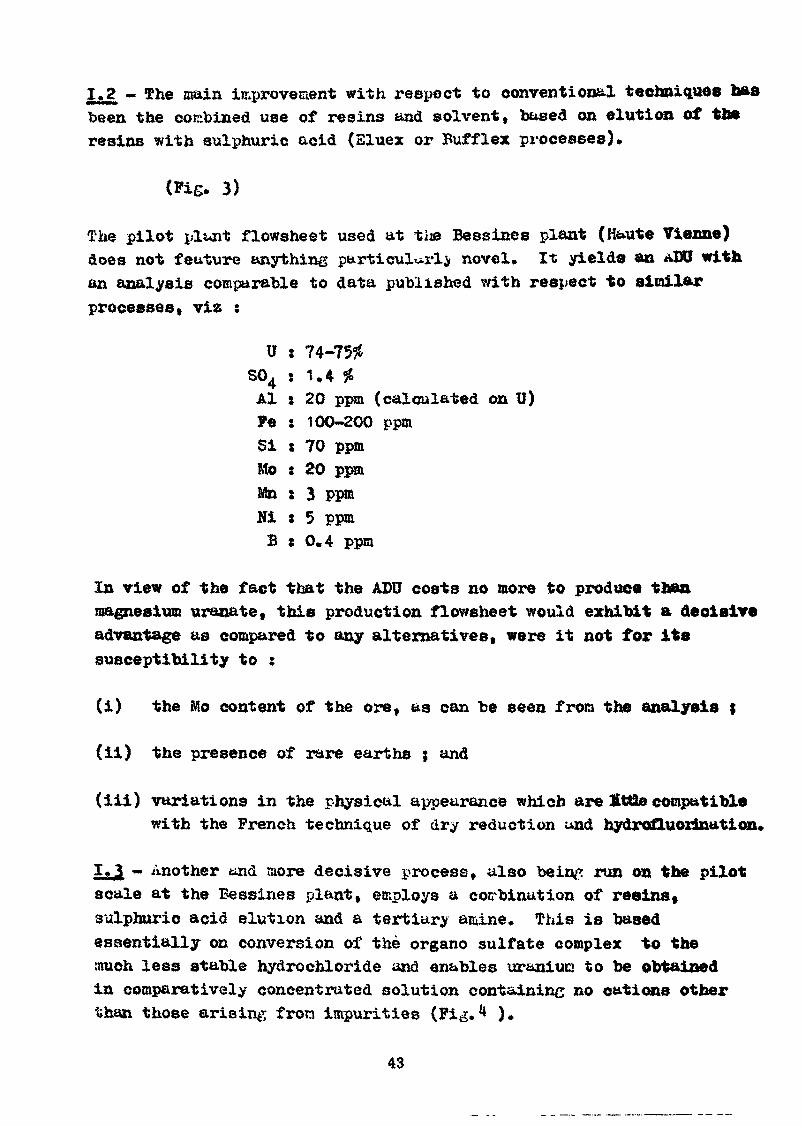
1.2 - The main improvement with respect to conventional techniques liasbeen the combined use of resins and solvent, based on élut ion of theresins with sulphuric acid (Eluex or Buff lex processes).
(Fig. 3)
The pilot plunt flowsheet used at tiie Bessines plant (Haute Tienne)does not feature anything particularly novel. It yields an ADO withan analysis comparable to data published with respect to similarprocesses, via :
U j 74-75#S04 s 1,4 %Al : 20 ppm (calculated on U)Fe : 100-200 ppmSi : 70 ppmMo : 20 ppmMn : 3 ppmHi : 5 ppmB : 0.4 ppm
In view of the fact that the ADU costs no more to produce thanmagnesium uranate, this production flowsheet would exhibit a decisiveadvantage as compared to any alternatives, were it not for itssusceptibility to :
(i) the Mo content of the ore, as can be seen from the analysis ;
(ii) the presence of rare earths ; and
(iii) variations in the physical appearance which are £t8e compatiblewith the French technique of dry reduction and hydrofluorinution,
«- Another and store decisive process, also beinp run on the pilotscale at the Bessines plant, employs a combination of resins*sulphuric acid elution and a tertiary amine, This is basedessentially on conversion of the organo sulfate complex to themuch less stable hydrochloride and enables uraniucj to be obtainedin comparatively concentrated solution containing no cations otherthan those arising fron impurities (Fig,1* ).
43
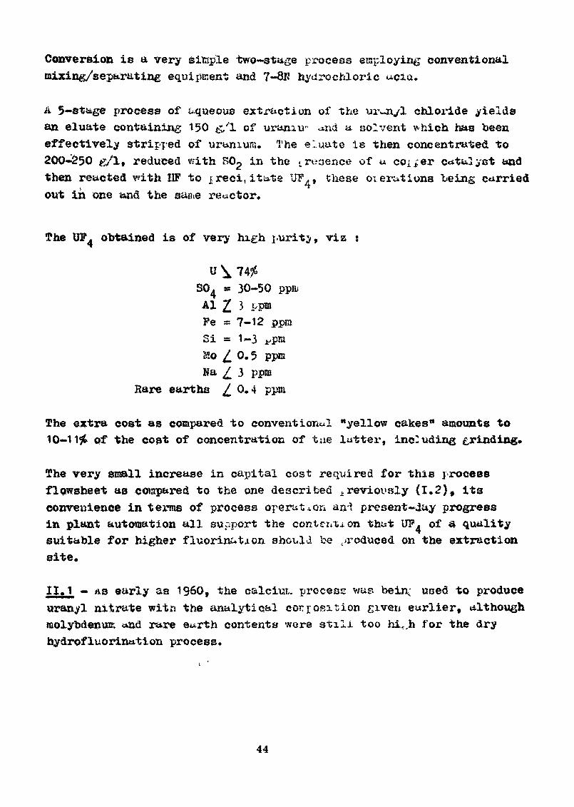
Conversion is a very sitsple two-stage process employing conventionalmixing/separating equipment and 7-8$ hydrochloric
A 5-stage process of aqueous extraction of the ui\-n/l chloride yieldsan eluate containing 150 &1 of uraniu- xnd a solvent v-hich nus beeneffectively stripped of uranium. The eluate is then concentrated to200-250 g/lf reduced with T in the s.reoertce of u coiner catalyst andthen reacted vdth IIP to ireci, itate UF^, these oierutiuns being carriedout in one and the same reactor.
The UP. obtained is of very high purity, viz
U \ 7436SO * 30-50 ppruAl 2 3 ppmPe =s 7-12 ppraSi = 1-3 i'Mo 0.5Na 3 ppm
Rare earths 0.4 ppni
The extra cost as compared to conventional "yellow cakes" amounts to10-1 \i» of the cost of concentration of tue latter, inc-tiding grinding.
The very small increase in capital cost required for this processflowsheet as compared to the one described treviovsly (1.2), itsconvenience in terras of process operation an-î present-day progressin plant automation all support the contention that UP, of a qualitysuitable for higher fluorinutaon should be ./reduced on the extractionsite.
11,1 - AS early as 1960, the calciut. process v/ap. beir< used to produceuran. 1 nitrate with the analytical corrrosition given earlier, althoughmolybdenum «»nd rare e«.rth contents were stili too hi<Jh for the dryhydrofluorintttion process.
44
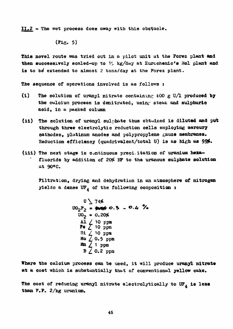
11,2 - The wet process does away with this obstacle.
(Fig. 5)
This novel route was tried out in a pilot unit at the Forez plant andthen successively scaled-up to 1S kg/day at Eurechemic's .Mol plant andis to be' extended to almost 2 tons/day at the Forez plant.
The sequence of operations involved is as follows ;
(i) The solution of uranyl nitrate containing 400 g UA produced bythe calcium process is denitrated, usinr s teas, and sulphuricacid, in a packed column
(ii) The solution of uranyl sulphate thus obtained is diluted «ad putthrough three electrolytic reduction cells employing mercurycathodes, platinum anodes and polypropylene gauze membranes*Reduction efficiency (quadrivalent/total U) is as high ae 99J&-
(iii) The next stage is continuous preci. itation of uranium hexa—fluoride by addition of 20# HP to the uranous sulphate solutionat 90°C.
Filtration, drying and dehydration in an atmosphere of nitrogenyields a dense UF^ of the following composition :
U02F2
Al / 10 ppmFe £ 10 ppmSi £ 10 ppmMo £ 0. 5 ppm3Sn / 1 ppmB 0.2 ppm
Where the calcium process can be used, it will produce uranyl nitrateat a cost which is substantially th&t of conventional yellow cake.
The cost of reducing uranyl nitrate electrolytically to UF, is lessthan F.F. 2/kg uranium.
45
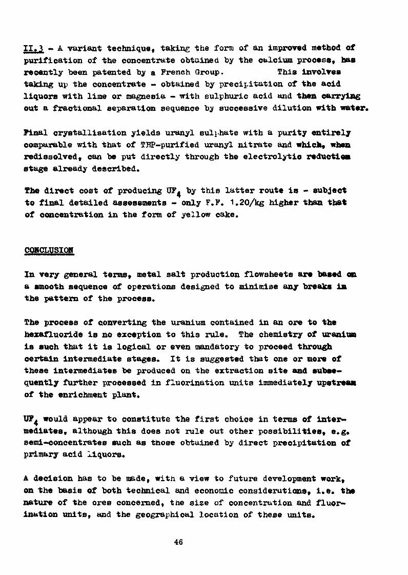
II.3 - A variant technique, taking the form of an improved method ofpurification of the concentrate obtained by the calcium process, hasrecently been patented by a French Group. This involvestalcing up the concentrate - obtained by precipitation of the acidliquors with lime or magnesia « with sulphuric acid and then carryingout a fractional separation sequence by successive dilution with water*
Final crystallisation yields uranyl sulphate with a purity entirelycomparable with that of TBP-purified uranyl nitrate and which, whenredissolved, can be put directly through the electrolytic reductionétage already described.
The direct cost of producing TTF by this latter route is - subjectto final detailed assessments - only P.P. 1.20/kg higher than thatof concentration in the form of yellow cake.
COWCLUSIOH
In very general terms, metal salt production flowsheets are based ona smooth sequence of operations designed to minimise any breaks inthe pattern of the process.
The process of converting the uranium contained in an ore to thehexafluoride is no exception to this rule. The chemistry of uraniumis such that it is logical or even mandatory to proceed throughcertain intermediate stages. It is suggested that one or more ofthese intermediates be produced on the extraction site and subse-quently further processed in fluorination units immediately upstreamof the enrichment plant.
would appear to constitute the first choice in terms of inter-mediates, although this does not rule out other possibilities» e.g.semi-concentrates such as those obtained by direct precipitation ofprimary acid liquors.
A decision has to be made, with a view to future development work,on the basis of both technical and economic considerations, i.e. thenature of the ores concerned, the size of concentration and fluor-ination units, and the geographical location of these units.
46
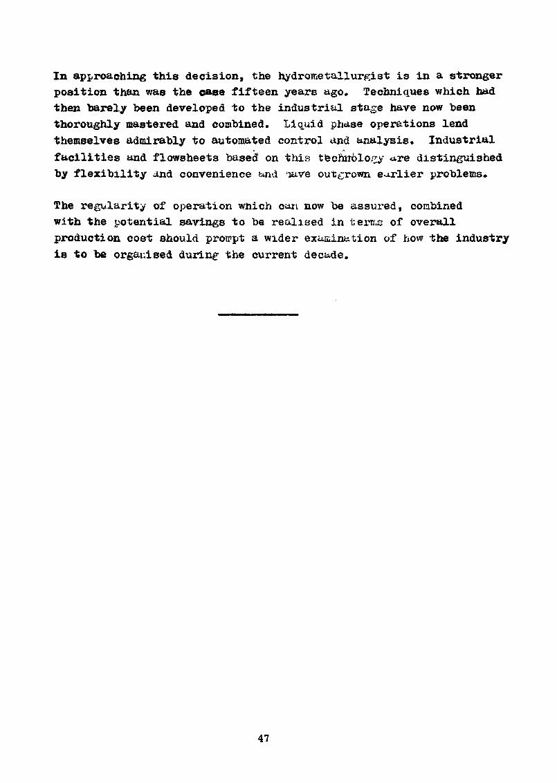
In approaching this decision, the hydroinetallurgist is in a strongerposition than was the ease fifteen years ago. Techniques which hadthen barely been developed to the industrial stage have now beenthoroughly mastered and combined. Liquid phase operations lendthemselves admirably to automated control and analysis. Industrialfacilities and flowsheets based on this technology <*re distinguishedby flexibility and convenience and rave outgrown earlier problems.
The regularity of operation which can now be assured, combinedwith the potential savings to be realised in terms of overallproduction cost should proirpt a wider examination of how the industryis to be organised during- the current decade.
47
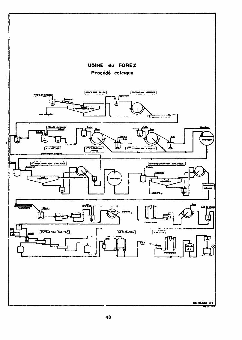
USINE du FOREZProcédé colaque
SCHEMA n*1
48
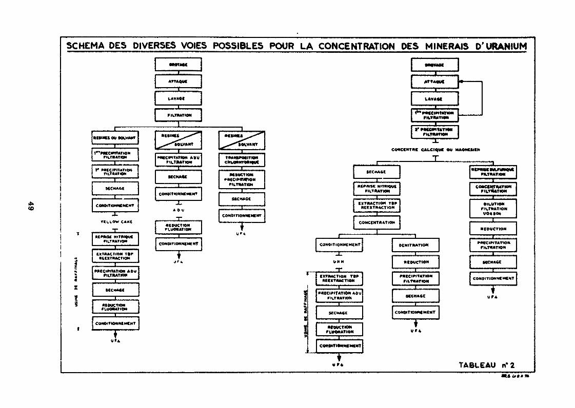
SCHEMA DES DIVERSES VOIES POSSIBLES POUR LA CONCENTRATION DES MINERAIS D'URANIUM
3ATTAQVC
LAVAM
FH.TMATIOH
CO
YIC1.0W CAKE
Hi»*** NITMIOVCFILTRATION
tlTMACTION I»F•4CXTHACTIOM
rikTMATIOH
l»CCHA«C
*t MICTIONFLUWIATIOM
_l_MOgCTIONccmir/trioNrikTMTMH
SCCHACC
CONOITIONNCMCW
t' WUCIFITATtOMribTMTION
CONCCMT4C CALCIUM OU MA4NCSIIH
T
NITRIQVfFILTRATION
EXTHACTIO* TtFXCCXTHACTIOH
CONCeNTAATION
CONOlTIONMEMCNT
•CMMKMlFtfMauCFttTMATlON
COMCCMTDATIONFIUTKATIOM
OIUUTIOHFU.THATION
HCDUCTION
P«CC IMITATIONFILT4ATIOH
MCHAOC
COMOITIONHCMCHT
TABLEAU n'2
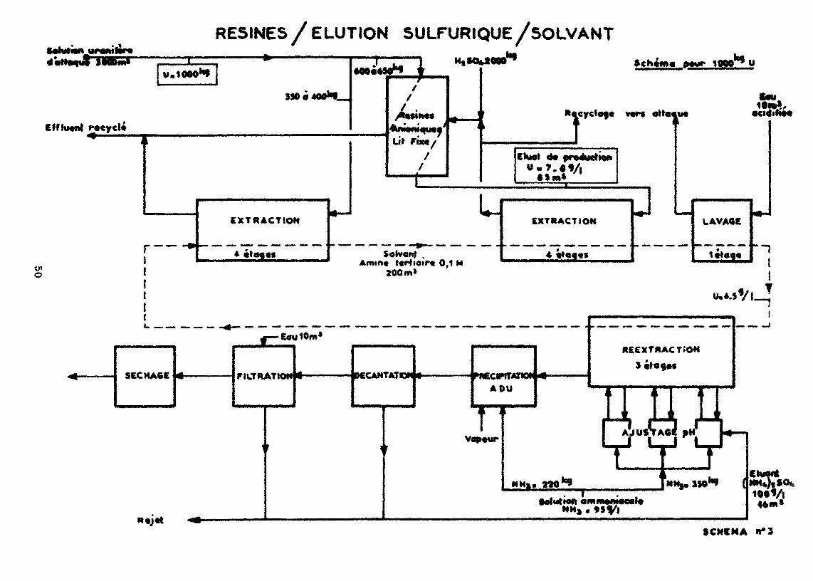
RESINES / ELUTION SULFURIQUE/SOLVANT
V. 1000*1
350
racyct*""ÏL
M flMAdU tt K4i ^ '
EXTRACTION
10QCT U
«Jm»
Soivanf .Armo* t«rttair« 0,1 M
200m*
EXTRACT I OK
r" I r iSW ^H J-l—,
^NM». SSO1^ {
Solution ammoiN«c«i«
CMMt
«*»»
SCNfMA 1*3
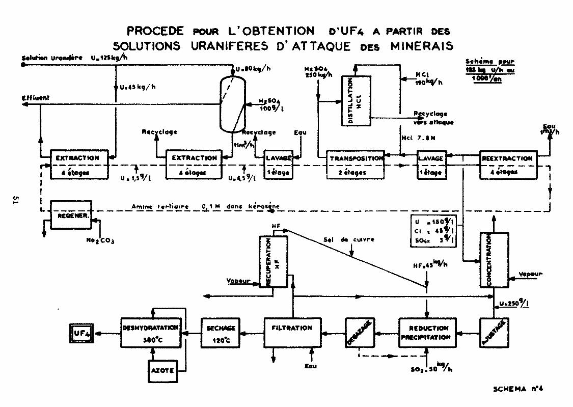
PROCEDE POUR L'OBTENTION D'UF* A PARTIR DESSOLUTIONS URANIFERES D'ATTAQUE DES MINERAIS
S*lurion urontftrc
EHlutnt
Lu.tOk9/h Ht 504
100 f/i
EXTRACTION
4 «toc**
*T%**m
„ ,U,
99 e
EXTRACTION*
W-1 «evci
W/ht«J L.1
UM^S'/I
âge
LAVAGEf
Eau
«H TRrf
2
kNS*»osn•
•tow t» — 1— -«
H cl
U —7.«N
LAVAGE
14*09.
«A1t REEXTMACTION
f
MÀ
MCI U/K «y1000 '/or.
jRgcyclog*attaque
MECENE*.Aminé >«rïioir« 0,1 M dons k*ros«n«
HF
HojCOi S«l d* cuivre
14?09«
U ,1SO'Ci , 451
S04> S^
IM/.
RCl
—
fc
y
îi1t
tJ
SCHEMA n*4
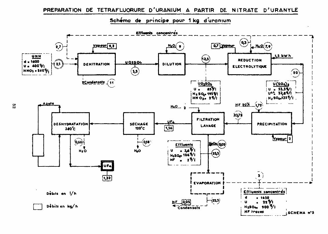
PREPARATION DE TETRAFLUORURE D'URANIUM A PARTIR DE NITRATE D'URANYLE
Scheme de principe pour 1 kg d'une mu m
Effluents concentre*
ÇV-j
U N Hd.1400U« 400 Vl | «"*H HO» «240^, i
t - -<
2,5
to iDESHYDRATATION
HtO
en l/h
De bite «n k«j/h
SECHAGE120*C
DILUTION
504uHNOj
1,56
FILTRATION
LAVAGE
4
REDUCTION
C LECT « OLY TIQUE
1S kW h
r; U « $1.39/1
V
PRECIPITATION
ïI EVAPORATION j- — — — — -j | ,..___ ——._J_ J ! EfHueitfs concentre'»!fc "•"• **P •" — "* I •—————-——•———————•'
L '**«> ! ^ * 1é5°HFJO^OSI r^*7 u • 2«Vl
•oo Vi.SCMCMA
PRODUCTION SCALE PROCESSES AND PLANTS tN THE UNITED KINGDOM—THE
CONVERSION OF URANIUM ORE CONCENTRATES TO NUCLEAR GRADE
URANIUM HEXAFLUORIDE AND TO ENRICHED URANIUM DIOXIDE
by H. Rogan
ABSTRACT x
Large scale production of nuclear fuels in the United Kingdom is carriedout by British Nuclear Fuels Limited, a Company formed from the UnitedKingdom Atomic ïhergy Authority in 1971, The Springfields Works ofBritish Nuclear Fuels Limited undertakes the conversion of uranium oreconcentrates to uranium metal and uranium hexafluoride, the reconversionof enriched uranium hexafluoride to uranium dioxide and the manufacture ofdifferent types of nuclear fuel elements with a wide range of specifications.
The lecture describes in some detail the Springfields Works process for theconversion of uranium ore concentrates to uranium hexafluoride - dissolutionof the concentrate, filtration, purification and evaporation of the liquor,followed by its conversion to uranium trioxide, uranium dioxide and then touranium tetrafluoride. The capacity of the uranium ore concentrate to U0_stages of plant is 7,000 tonnes U per annum. The capacity of the UO, andTJF, production stages is 5,000 tonnes U per annum, and is now beingincreased to match that of the preceding stages. Uranium hexafluoride isproduced by fluorination of the UF in a pl<mt with a capacity of 3,000tonnes U per annum, to be extended in 1973 to 8,000 tonnes U per annum.
After a brief reference to uranium enrichment, carried out at the CapenhurstV/orks of British Nuclear Fuels Limited, details are given of the processesused for reconversion of enriched uranium hexafluoride to uranium dioxide,including a new single-stage dry process with a capacity of 500 tonnes Uper annum at enrichments up to f$ U235» in waich UF6 is directly convertedto ceramic oxide by reaction with steam and hydrogen in a kiln. Theassociated processes for recovery of uranium residues and treatment ofwaste hydrofluoric acid, analytical procedures, the operatin» costs of theprocesses and tue safety measures that are employed, are also described.
1. INTRODUCTION
Springfields Works, part of the British Nuclear Fuels Ltd Company formed from the United KingdomAtomic Energy Authority in April 1971, has been manufacturing nuclear fuels for over 20 years. Thislecture gives an account of those fuel manufacturing stages involved in the conversion of uraniumore concentrate to uranium hexafluoride, and makes a brief reference to uranium enrichment andconversion to enriched oxide.The Springfields Works process for the conversion of uranium ore concentrates to uranium hexa-fluoride can be conveniently split into six process stages, viz:
i. Dissolution of uranium and soluble impunties in the ore concentrates in nitric acid, followed byremoval of the insoluble impurities by filtration.
ii. Purification by separation of uranium from the soluble impurities by continuous, counter-currentsolvent extraction.
53
Hi. Evaporation of the pure urany! nitrate solutions obtained from the purification plant to concen-trated uranyt nitrate, followed by thermal denitrat.on to uranium tnoxide.
iv. Hydrogen reduction of the trioxide to uranium dioxide.v. Hydrofluorination of the dioxide to uranium tetrafluoride.vi. Ftuorination of the uranium tetrafluoride to uranium hexafluoride.The following describes these stages in some detail, discusses the associated processes for recoveryof uranium residues and treatment of waste hydrofluoric acid, analytical procedures, the operatingcosts of the processes and the safety measures that are employed.
2. RECEIPT, SAMPLING AND DISSOLUTION Oc URANIUM ORE CONCENTRATES
The uranium ore concentrates used as feeds to the BNFL process at Springfields Works are obtainedmainly from Canada, South Africa, Australia and the United States of America. The concentrates arederived by calcination of precipitates of ammonium or sodium diuranate and, depending on theirsource, have a uranium content of about 60% to over 80% uranium w/w After being sampled andassayed the concentrates are fed to the first stage of the process for production of uranium fuel.
2.1 DissolutionDrums of ore concentrate are fed to ventilated mild steel tipping cubicles and the contentsemptied into stainless steel hoppers. From the hoppers, the concentrate is fed to the primarydissolvers by stainless steel screw feeders. The dissolvers used in ore dissolution are, because ofthe corrosive nature of the nitric acid dissolving agent, fabricated in stainless steel. They arequadranted stirred vessels, the ore concentrate being fed to the first quacrant of the primarydissolver, co-currently with concentrated nitric acid. The contents of this quadrant are heatedto 95-100°C by a steam coil, to produce a slurry containing approximately 45% w/v uraniumand 4.5-6.0% w/v free acid. The slurry is then aged in the remaining three quadrants of thisvessel and in a secondary vessel to give a coagulated slurry with improved filtration properties.Automatic control of the acid and water feeds to the primary dissolvers is effected by use of agamma spectrometer giving the uranium content of the slurry and a free acid monitor measuringpH.The aged slurry is pumped from the secondary vessel to the trough of one of three primaryrotary vacuum filters. The drum of each filter is covered by two stainless steel support gauzes andis pre-coated with a 2£ inch layer of a periite-type filter-aid. A clean surface for filtration ismaintained at all times by an automatically advancing, stellite tipped knife, which continuouslycuts off the top layer of filter aid and undissolved solids in the slurry, so that they can be dischargedto a reslurry vessel. Wash water, fed at the rate of 20% of slurry input, is applied to the drum at apoint just above the knife. The nitric acid solution of uranium and soluble impurities, togetherwith the wash water, is drawn through the filter medium into pipelines, then to a filtrate receiverfrom which it is pumped to stainless steel crude product tanks. The filtered liquor contains about30% w/v uranium and 4 5-6.0% w/v free acid. The residua from the primary filters is reslurriedwith secondary filter filtrate to produce a slurry containing 1-3% w/v solids. This slurry isrefiltered on a secondary filter, operated on a similar principle to that used on the primary filters;the solids discharged from this filter contain less than 0.10% w/v uranium, at which level theycan be dispo - à of outside the works under s* tutory regulations.
3. PURIFICATION OF CRUDE URANYL NITRATE SOLUTIONS
Purification of uranyl nitrate solutions is carried out in two continuously operated counter-currentflow, mixer-settler extraction boxes, using a solution of tri-normal butyl phosphate in odourlesskerosene as the extracting agentThis process is the determining step in the production of nuclear grade uranium, that is uraniumwhich is capable of sustaining the fission reaction responsible for the prime generation of power inthe nuclear power station, Amongst the more important impurities removed by the solvent extractionprocess are:(9) those with high neutron capture cross-sections such as boron and cadmium,(b) those elements which form volatile fluorides that can bo distilled along with, and therefore
contained in, the UFe produced at a later processing stage. Some of these compounds havedeleterious effects on the gaseous diffusion plants used for UF« enrichment, and a notableexample of this type of compound is molybdenum f luoride,
(c) those with similar chemical properties to uranium, eg thorium.
54
Crude uranyl nitrate is fed automatically to mixer 8 of the first extractor, which is a sixteen-stagehorizontal, stainless steel unit, each stage comprising a mixer with independent stirrer, and a settler.Purification is effected in 8 stages by use of a 20% v/v solution of TBP in odourless kerosene, fedin at mixer 1. Further purification is achieved in the remaining 8 stages by stripping the solventextract with pure uranyl nitrate solution, fed in at mixer 16. This strips impurities out of the solventAutomatic control of the crude uranyl nitrate feed to this extractor is achieved by recording thespecific gravity and temperature of the loaded solvent in settler 7, and relating these two readings tothe uranium concentration in this settler. A check for the presence of thorium in the loaded solventleaving the extractor is carried out. Solvent, containing about 7% w/v uranium as uranyl nitrate,leaves the first extractor, is preheated to 50°C, then fed to the second extractor, a twelve-stagestainless steel mixer/settler unit Here it is backwashed with 0 02N nitric acid solution heated to60°C and prepared by acidifying distillate from the evaporation section. At these temperatures, thecomplex formed etween uranyl nitrate and TBP becomes unstable with respect to its constituentparts, and the purified uranyl nitrate is, therefore, transferred back into the aqueous phase to givea final solution, emerging from the extractor to the storage tanks, of about 10% w/v uranium asuranyl nitrate at about 0.3% free acid.Stripped solvent from this extractor is recycled to the first extractor but a small proportion is con-tinuously "bled off" to be washed with sodium carbonate solution and water before rejoining thestripped solvent main-stream. This process is necessary to remove TBP hydrolysis products, suchas dtbutyl phosphate and phosphoric acid, and odourless kerosene degradation products. Stringentregulations are imposed on tho quantity of uranium discharged to dram in the raîfmate from the firstextractor. The uranium level in the raffinate is continuously monitored Uranium concentrations of20-25 ppm uranium are normally encountered and at this level the raffmate is discharged to drain,but at higher levels the raffmate is recycled to a Uranium Saveall Plant for recovery of uranium.
4. EVAPORATION AND DENITRATION
Pure, dilute solutions of uranyl nitrate are concentrated by evaporation to a 100% w/v solution(uranyl nitrate hexahydrate contains 117% w/v U) which •<> then thermally denitrated at 300°C touranium trioxide.
U02 (N03)2 xH20 -» UO3 + N02 + Oa -f xH2OThe reaction is endothermic, the heat of formation of U03 from the hexahydrate being 570 Kcal/kgmof uranium.
4.1 EvaporationThe pure dilute uranyl nitrate solution is pumped from the stainless steel storage tanks, througha series of stainless steel preheaters, to raise tho liquor tempsr.jure to 906-100''C The hotliquor then passes to the first of four stainless steel evaporation SKKJCS operating in «.cries. Theconcentration of the product from the fourth stage is controlled by measuring the boiling pointelevation of the liquor in this stage.The evaporators work under a partial vacuum. There is a progressive decrease in pressure fromthe first stage to the fourth stage, which is maintained at 350 mm Hg.
4.2 DenilrationConcentrated uranyl nitrate liquor is maintained at a temperature of about 90°C in 3 stainlesssteel stock tank, where it Is spiked with concentrated sulphuric <icid to owe a final concentrationof 1200 ppm sulphate (on a uranium basis). The function of the sulphate is to impari a greaterdegree of porosity to the UOa and UO2 particles, s property which markedly enhances the rateof reaction of UO2 with hydrofluoric acid. The throughput of the dsnitralors is dependent on therate at which the concentrated liquor is sprayed to the bed Thus, it can be seen that tho capacity ofthe unit will increase as the uranium concentration in the concentrated liquor increases, and it isof vital importance to keep the liquor strength at, or around, the 1001/» w/v mark.The liquor is pumped to one of two guns and sprayed into the demtrator, containing a bed of U03,fluidised by air, at a temperature of about 300°C At this temperature, denitration to U03 takesplace; U03 continuously overflows down a central pips to a lift pot and is pneumatically" trans-ported, via a routing pot, to one of two hoppers.Reaction off-gases pass through primary stainless steel filters and back-up rigi-mesh filtersbefore being used m a heat exchanger to preheat the f luidising air stream to the demtrator. Off*gases finally pass to the nitric acid recovery plant. This recovery plant basically consists of ^pre-absorption condenser, six packed towers m which the fume is absorbed in circulatingaqueous solutions, and a chimney stack A very rigorous statutory control is exercised over the
55
nitrous content of the fume passing to the stack and thence to atmosphere. Most of the nitricacid recovered in this plant which also deals with the fume from other areas of the Works, isre-used for dissolution of ore concentrate and residues.The material of construction of the denitrator and ancillary equipment is stainless steel. Thedenitrator reactor is fitted with internai heaters, providing a total of about 170 kW, and externalmuff heaters, rated at 100 kW total. The reactor bed temperature is regulated by a controller whichdetermines the voltage supplied to both sets of heaters, and the ratio of external to internalheat supplied is controlled by a second transformer. Thermocouples, positioned on each of theinternal heaters, on the outside of the reactor wall, and in tho external heater jacket enablecontinuous scanning, for temperature control purposes, to be carried outThe capacity of th - plant from uranium ore concer ..rate dissolution to U0a production is 7000tes U/annum.
5. HYDROGEN REDUCTION TO URANIUM DIOXIDE
The hydrogen reduction of uranium trioxide to uranium dioxide, carried out at a temperatureapproaching 500°C in one of four fluidised bed reactors, can be expressed by the equation :
The reaction is exothermic, the heat of reaction being -24 Kcal/mole.The reduction reaction proceeds in a semi-continuous manner. The reaction is started with a heelof UO2 heated to just under 500°C, then about 4 tonnes of U03 are fed to the stainless steel reactorby a rotary feeder over a period of several hours to maintain a constant bed temperature. After theUO3 has been fed, the reaction with hydrogen is completed and the product U02 powder is pneu-matically transported with compressed nitrogen via a routing pot to storage hoppers, leaving a heelfor the next reaction, it is important to ensure that tho correct reaction time and temperature areutilised and also that the quantity of hydrogen being fed to the reaction is sufficient for completereduction. Otherwise, incomplete reduction, which will be followed by the undesirable productionof uranyl fluoride, UO2F2, in the hydrofluorination section, will probably occur.Hydrogen is generated on site by electrolysis of sodium hydroxide solution, compressed and used asfluidising and reoctaw gas. The reduction reactor is fitted with sintered stainless steel primaryfilters, stainless steel back-up filters and two external heat exchangers. The composition of thefluidising gas is maintained in the range 70-85% H2 in N2 and the level of 02 in N2 is continuouslymonitored. Reactor heating is provided by electrically operated external muff heaters, the bedtemperature being controlled automatically and reactor wall temperatures scanned continuously.Gamma radiation from a cobalt-60 source inside the reactor, and operating in conjunction with adetector sited outside the reactor, is used for powder level indication.
6. HYDROFLUORINAi'lON TO URANIUM TETRAFLUORIDE
Uranium dioxide reacts with hydrofluoric acid according to the equation :
The reaction is exothermic, the heat of reaction being -43 Kcals/mole. Any residual U03 in the U02is converted to uranyl fluoride, thus:
Every effort is made, by adequate control of the reduction process, to produce UF4 which containsnot greater than 1 .2% by weight of UO2Fa. The presence of U02F2 has two undesirable effects onthe processes downstream of UF4 manufacture, viz:(a) decrease in the efficiency of fluorine usage in the UF6 production plant,(b) unstable conditions during the process for magnesium reduction of UF4 to uranium metal.Approximately 8 tonnes of U02 are fed by gravity from a storage hopper to one of the eight inconelhydrofluorination reactors, containing a heel of UF4, fluidising on compressed nitrogen. After loading,the bed temperature is allowed to stabilise, then superheated anhydrous hydrofluoric acid (AHF)' isintroduced to the reactor whilst, at the same time, the nitrogen flow is reduced. Over the next 12hours of reaction, the nitrogen flow is gradually reduced to zero, while ;r.e AHF flow is increasedto a maximum, This flow rate is maintained until a sample of powder, drawn from the reactor, isshown by analysis to have a U02 content of 1% by weight or less. The reaction time is usually ofthe order of 40 hours. The bed temperature rises to 450°C, at which it is controlled by means of abed thermocouple linked to the top and bottom bed external muff heaters. Temperature control is
56
also effected by continuously scanned thermocouples on the reactor wad. Because of the exothermicnature of the reaction, it is necessary to use heaters only after the reaction has proceeded for 20hours. At the end of the reaction, the bed is fluidised by nitrogen while it is cooled by forced aircooling of the reactor exterior The UF4, after being offloaded to hoppers by pneumatic transport canbe transported, again pneumatically, either to the UF6 production plant or to the uranium metalproduction plantGases from the hydrofluorination reactors consist of nitrogen, water and hydrofluoric acid and areexhausted to brine-cooled condensers where the condensibte water and acid are removed, whilethe incondensible nitrogen passes to a scrubbing system before returning to the Nash compressors.The hydrofluoric acid solution, ranging in concentration from approximately 60-80% by weight isfractionally distilled in a monel, sieve-plate type of distillation column. The AHF product is returnedto an AHF storage tank prior to re-use as fiuidising gas. The azeotrope is collected and after furthertreatment is sold.The main nitrogen generating plant involving the separation of air into pure nitrogen and an oxygenenriched mixture by low temperature fractional distillation, supplies nitrogen to Nash Hytor com»pressors which are used to compress nitrogen to approximately 45 psig. This compressed nitrogen,after being dried, is used as reactor fiuidising gas.The capacity of the reduction and hydrofluorination plant is 5000 tes U/annum and is now beingincreased to match the capacity of the preceding stages.
7. FLUOR1NAT1ON OF URANIUM TETRAFLUORIDE TO URANIUM HEXAFLUORIDE
Uranium hexafiuoride (UF6) is produced by the reaction of uranium tetrafluoride (UF4) withelemental fluorine (F2). The production of fluorine is an integral part of the production process andIs carried out by the electrolysis of hydrofluoric acid (HF) in an electrolyte of fused KF2HF. Thechemical equation for the process is :
UF4 (solid) -i- F2 (gas) = UF6 (gas) +112.000 BTU/lb mol Uand the reaction is very exothermic.The present plant has a capacity of 3000 tes U/annum, and in 1973 will be extended to 8000 tesU/annum.
7.1 Fluorine ProductionFluorine is produced by the ftlectroiysis of the fused salt KFPHF at 90-100°C in mild steel cellsequipped v.-rth amorphous caioon anodes at a current, density of approximately 1 amp/sq inch.'The cell temperature »s conUoHod by a system oî coohnçj coite which act as cathodes to theindividual anode assembles The hydrogen ffuoride content of the electrolyte is controlled by iheautomatic addition of anhydrous hydrofluoric acid to maintain 3 pre-se'ected electrolyte levelin the cell The hydrofluoric acid used has to setisfy a demanding spscif«cation with regard towater and v jmbined sulphur content. Too h , ,1 an HF conten i produces, rapid anode deterioration,whilst too low a content leads to high electricity costs Experience has shown that for opt'mumefficiency the H F concentration must be kept within the range 40% to 42%' As H F is the onlymaterial consumed in the electrolytic process U was found that its concentration could best becontrolled by inomto'ting changes in the level of the electrolyte The measuring equipment nueds tobe robust because of the corrosive environment but very sensitive because the'oveiscorrespondiogto the maximum and minimum H F content differ by only ,%-". The necessary control is achievedusing* a transducer to monitor the change in pressure on a dip pipe caused by changes in leveland to transmit a signal which, actuates the HF feed valve The fluorine leaving the cells passesthrough a surge vessel which minimises any tendency for pressures to fluctuate.The fluorine produced contains 5-7% v/v H F which is removed by absorption in a primaryabsorber containing sodium fluorjdé powder, to reduce the H F content of the gas to approxi-mately 0 5% v/v. This is further reduced to 01% v/v by passage through a secondary absorberof sodium fluonde pellets. Both H F absorbers and thé process lines in the fluorine plant arefabricated in mild steel. The primary absorber is provrdc-d with electric heaters which enable thesodium fluoride to be regenerated end the H F returned to the cells The pressure of the fluorineand hydrogen in the ceils is controlled at 5 cms WG and a safety system is provided whichautomatically shuts down the plant should the cell pressures deviate markedly from 5 cms WQ.
7.2 Uranium Hexattuoride (Hex) ProductionThe purified fluorine together with sufficient nitrogen for fluidisation is fed into an inert bed ofcalcium fluoride contained in a cylindrical rnonel reactor provided with a conical base and acarefully designed distributor plate to provide me required pattern of gas distribution within thecalcium fluoride. The reactor température is automatically controlled by means of external
57
electric heaters and a forced air cooling sy&tem and the UF4 is fed into the reactor using ascrewfeeder Under normal operating conditions the rate of reaction is so rapid that the uraniumIn the bed does not exceed &%,The transfer of the uranium tetrafluoride from the Production Plant, approximately a quarter of amile away, is accomplished using an eirveying system At the uranium hexafluorido plant theuranium tetrafiuonde is collected in a large storage hopper and then pneumatically transportedas required to a smaller feed hopper sited alongside the reactor. A screwfeeder at the base of thishopper meters uranium tetrafluoride powder into a larger constant speed screwfeeder whichdelivers the pow 3r into the reactor.The UF6 products together with the fiao solids entrained in the gas stream, excess fluorine andthe nitrogen earner gas is then passed through two sintered mone! filters in series to remove theentrained solids. Solids collected in these filters are periodically removed and additions of calciumfluoride powder made to t^e reactor in order to maintain a given reactor bed heightThe second filter is provided to prevent collection of solids m the condensers should the first*filter fail.Uranium hexafluoride contained m the gas stream leaving the filters condenses as a solid in twoof four mild steel condensers arranged in series which are cooled with ftuorocarbon 11 at -40°C.Each condenser is used sequentially for primary and backing up duties. The gas stream passesfirst through the primary condenser where the majority of the uranium hexafluoride is collectedand then enters the oack-i ;> condenser to remove the remainder of the uranium hexafluoride.The condenser tail gases than enter an oil free recycle compressor and a sample of this gasstream is analysed for fluorine by an automatic on line monitor. The uranium tetrafiuonde feed rateto the reactor is manual!/ adjusted to keep the fluorine concentration in the gas stream in therange 5-10"', v/v A major proportion of the condenser tail gas stream is automatically directedback to the reactor in order to achieve high fluorine usage efficiencies. The remaining gas isdischarged to a wet scrubbing system via a cold trap which removes the last traces of UF6 -fromthe gas stream.The effluent gases from the plant are scrubbed free of traces of fluorine, hydrogen fluoride andtraces of uranium hexefiuortda with caustic alkali prior to discharge to atmosphere via a stack60 feet high, Th-i ef'luer.t rciessec! from the stack «s m inhoir d c-ont»pyai's'v Liquor* containingprecipitated uranium *re filtered aitd moniio.cci before Ifacl'u.r^3 to oidm. Viunerâu e areas cfthe plant are monitored for uranium and fluorine leveis in ihe ew
7.3 Hex CollectionWhen 6 tonnes of uranium tetrafiaoride have beer» charged to the reactor a primary condenseris considered fui! and another empty cold condenser is brought into line on back-up duty andthe existing back-up condenser is put on primary duty. The full primary condenser is then takenoff line and heated with hot fiuorocarbon 11 at 105°C. This raises the temperature of the uraniumhexafluoride to 90-95°C convening the solid uranium hexafluoride to a liquid which can thenbe run out into transit cylinders. A sample of the uranium hexafluoride is collected as it enters thecylinder.7.4 Process Control ProceduresThe continuous nature of the process, the absence of intermediate storage, and the low pressuredifferential ellowcd throughout the plant which operates at less than atmospheric pressurenecessitates fine control procedures and immediate availability of analytical results. One exampleof the special instrumentation is the fluorine in nitrogen analyser which enables the fluorineconcentration in the recycle gas stream to be monitored. This instrument withdraws a sample ofgas from the stream eight times an hour, passes it over heated sodium chloride and measures thechlorine liberated by means of a kathrometer. This actuates a potentiometric recorder linked witha slave recorder on the control panel so that the fluorine content of the gas stream is continuouslyknown and adjustments can be made as necessary to optimise efficiency. A second example isthe automatic fluorine impurity analyser. Fluorine produced eiectrolytically contains a number ofvolatile impurities It is necessary to know that the purification system for removing HF carriedover from the electrolyte is working efficiently and be able to identify the presence of CF4 andS02F2 which indicate incipient disintegration of the anodes. The analyser isolates samples ofgas from an appropriate position in the purification system and separates impurities along atemperature gradient in a liquid nitrogen cooled coil. The coil is then subjected to a controlledheating cycle whilst purging with pure helium. The impurities are individually swept by a mole-cular transpiration process through a kathrometer detector and the result is displayed as esequence of peaks on a calibrated chartThe plant's fiuonne usage efficiency HF to UF6 is in excess of 90%, and the uranium efficiency,UF4 to UFa, is batter than 99%.
58
8. RECOVERY OF NATURAL URANIUM RESIDUESVarious types of uranium-containing residues arise continuously in ail plants processing naturalmaterial. Economically, it is advisable to feed the residues back into the main line at the plant in whichthey arise and this is done, for example, in the case of UF4 residues. However, many of the residuesoccur in such a form, or contain such impurities, that this is not possible and for recovery of uraniumfrom these residues, a central plant exists alongside the ore dissolution and purification plant Theuranium is leached from the residues with nitric acid, the slurries filtered and the filtered solutionspurified in a separate purification plant, smaller than the main line unit, but operating in a similarfashion.Amongst the problems that have been encountered, and overcome, in the operation of the recoveryline purification plant ara recovary of fiuonae containing residues, and maintenance of solventquality. Fluoride ion forms a complex with uranyl ion and therefore interferes with solvent extraction.Addition of aluminium to the dissolver to pre-complex the fluoride, overcomes this. Solvent qualitydeteriorates &!3 to the presence of entrained oil, grease etc, which is not readily filterable. Res-toration of solvent quality can be effected by washing it with concentrated nitric acid, then filteringit through activated charcoal.
9. ANALYSISIn addition to the in-line analysers and checks described already, a number of other analyses arecarried out on both urantc and non-uranic process materials. Amongst the most important of theseare:i. Purity analysis of u-aniurn ore concentrates which are purchased according to agreed
specifications.ii. Analysis of pure uranyi nitrate for uranium, free acid, molybdenum, U235 content (every batch)
and for other elements cited in the specifications for metal and UF6 (on bulk samples to aschedule).
Hi. Monitoring of the progress of the UO2 to UF4 conversion reaction by analysis of powder sample»taken at intervals specified for each run as it proceeds.
iv. Analysis of each batch of natural UF4 for U02, UO2F2, Fe (to check on possible breakthroughof transition metals In the purification plant, and corrosion of stainless steel evaporation equip»ment). Ni (inconei corrosion product). Mo and IA (U23S).
v. Analysis of AHF for sulphur-containing compounds such as S02 and H2SO4 which enhancethe rate of corrosive attack of HF on monel and inconei.
vi. Analysis of the pure azeotrope for re-sale to 9 schedule agreed by the contractor.vii. Analysis of all the UF6 to a rigorous specification, with particular emphasis on volatile gas
content and concentrations of elements which form volatile fluencies.
10. SAFETYBecause of ths corrosive nature of many of the raw materials handled, and the dangers that canarise from ingestion and inhalation of uranium-containing powders, strict procedures are definedto ensure saf ,y of personnel working in the areas concerned. All in ustrial personnel workingfull-time in the chemical plant? undergo a complete change into what is known as "contact clothing"at the start of each shift, and make use of shower facilities before redonning their outdoor clothing atthe end of tho shift. Masks are used in certain areas'to guard against dust inhalation or ingestion,goggles or visors and acid-resistant gloves afford protection against contact with nitric acid andcaustic alkalis, in some cases, in particular in the UQ2 to UF4 conversion, and HF recovery plants, afull suit consisting of PVC gloves, trousers, turtle arid an integral hood and clean air mask (connectedto an air supply), is worn over the contact clothing to ensure protection from the highly corrosivehydrofluoric acid.On the Hex Plant the possibility of recombination of hydrogen and fluorine following their electro-chemical separation, ingress of oxygen into the hydrogen containing vessels, and release of fluorineinto the atmosphere is minimised by the provision of an integrated automatic plant safety circuitactuated by small changes in pressure.Explosimeter tests for presence of hydrogen are carried out before any burning or welding workis carried out in. or in the vicinity of, equipment which normally contains hydrogen. Before testing,of course, the equipment is well purged with nitrogen.
11. COSTSDealing first with Capital Expenditure, the original book value of the plant and equipment so farmentioned was approximately £M9, and these will be supplemented by the previously mentionedadditional plant items to be installed shortly at a capital expenditure of some £M3.
59
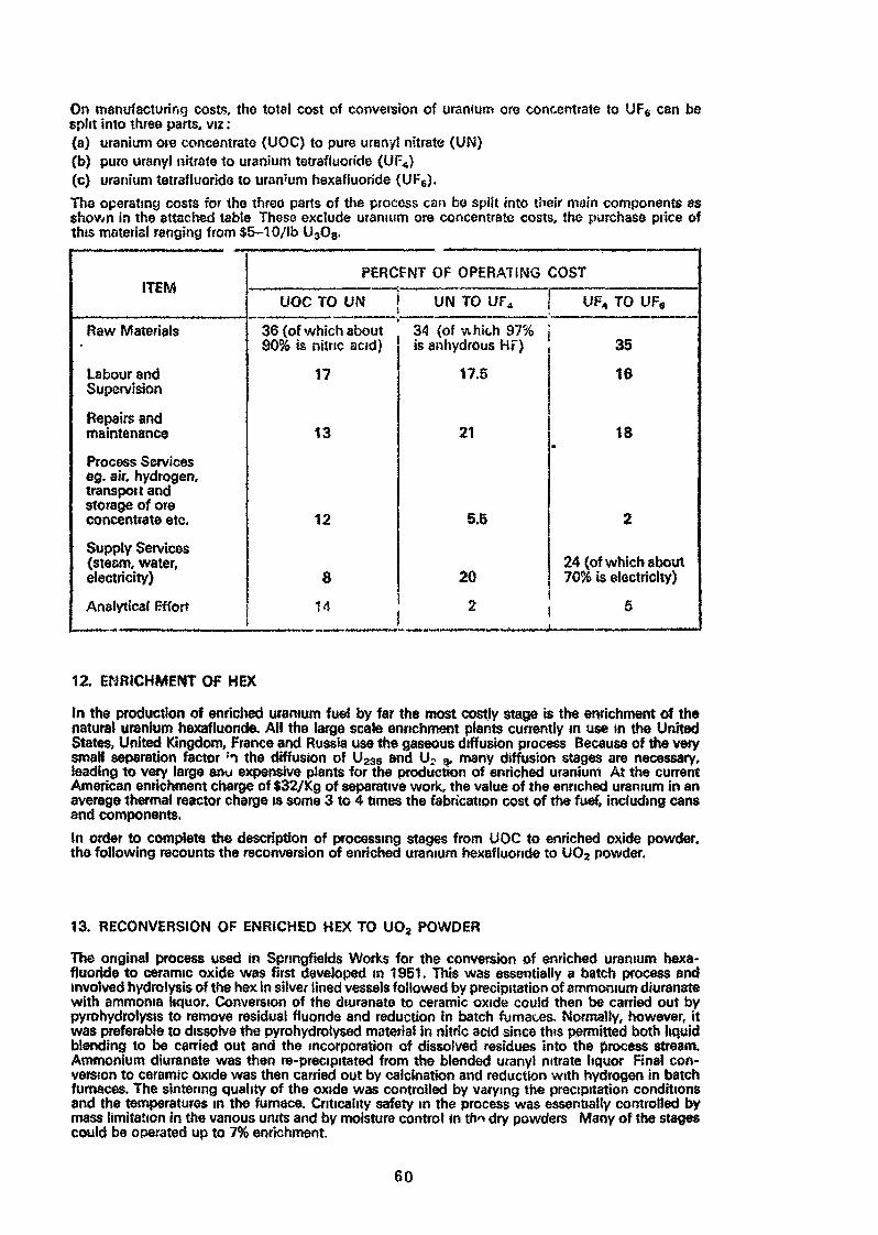
On manufacturing costs, the total cost of conversion of uranium ore concentrate to UF6 can besplit into three parts, viz :{a} uranium ore concentrate (UOC) to pure urany! nitrate (UN)(b) pure uranyl nitrate to uranium tetrafluoride (UF )(c) uranium letrafiuorido to uran'um hexafluoride (UF6).The operating costs for the three parts of the process can be split into their main components asshov/n in the attached table These exclude uranium ore concentrate costs, the purchase price ofthis material ranging from $5-10/lb U3O8,
ITEM
Raw Materials
Labour andSupervision
Repairs andmaintenance
Process Serviceseg. air, hydrogen,transport andstorage of oreconcentrate etc.
Supply Services(steam, water,electricity)
Analytical Effort
PERCFNT OF OPERATING COST
UOC TO UN
36 (of which about90% is nitric acid)
17
13
12
8
14
UN TO UF4
34 (of which 97%is anhydrous HF)
17.S
21
5.5
20
UF4 TO UF6
35
16
18
2
24 (of which about70% is electricity)
2 , 6
12. ENRICHMENT OF HEX
In the production of enriched uranium fuel by far the most costly stage is the enrichment of thenatural uranium hexafluoride. AH the large scale enrichment plants currently in use in the UnitedStates, United Kingdom, France and Russia use the gaseous diffusion process Because of the verysmall separation factor :n the diffusion of U23S and U2 3, many diffusion stages are necessary,leading to very large anu expensive plants for the production of enriched uranium At the currentAmerican enrichment charge of $32/Kg of separative work, the value of the enriched uranium in anaverage thermal reactor charge is some 3 to 4 times the fabrication cost of the fuel, including cansand components.In order to complete the description of processing stages from UOC to enriched oxide powder,the following recounts the reconversion of enriched uranium hexafluoride to U02 powder.
13. RECONVERSION OF ENRICHED HEX TO UO2 POWDER
The original process used in Sprmgfields Works for the conversion of enriched uranium hexa-fluoride to ceramic oxide was first developed in 1951. This was essentially a batch process andinvolved hydrolysis of the hex in silver iined vessels followed by precipitation of ammonium diuranatewith ammonia liquor. Conversion of the diuranate to ceramic oxide couid then be carried out bypyrohydrolysis to remove residual fluoride and reduction in batch furnaces. Normally, however, itwas preferable to dissolve the pyrohydrolysed material in nitric acid since this permitted both liquidblending to be carried out and the incorporation of dissolved residues into the process stream.Ammonium diuranate was then re-precipitated from the blended uranyl nitrate liquor Final con-version to ceramic oxide was then carried out by calcination and reduction with hydrogen in batchfurnaces. The sintering quality of the oxide was controlled by varying the precipitation conditionsand the temperatures in the furnace. Criticahty safety in the process was essentially controlled bymass limitation in the various units and by moisture control in tht dry powders Many of the stagescould be operated up to 7% enrichment.
60
This process was later developed into a large scale continuous plant with a throughput of 300tonnes U per annum. In this plant cylinders containing 2 tonnes uranium hexafluoride were heatedin steam baths and the gaseous hex converted to uranyi fluoride by contacting with steam in aninconel fluidtsed bed reactor Control of the uranyi fluoride discharged from the base of the reactorwas carried out by operation of level indicators in the bed. The urany! fluoride was then fed to aninconel kiln in which it was reacted countercurrently with steam and hydrogen. The product oxidewas virtually stoichiometric but with a very low specific surface area which made it unsuitable forthe production of high density fuel. This first stage oxide was, therefore, dissolved continuously innitric acid. Liquid blending and the incorporation of dissolved residues as necessary was carriedout at this stage. The blended uranyi nitrate liquor was then precipitated continuously with ammoniaand the ammonium diuranate filtered and dried continuously. The ammonium diuranate was passedthrough a granulator to convert it to a free flawing powder and then to a stainless steel kiln for cal-cination and reduction co-currently with hydrogen to produce ceramic oxide Finally, the ceramicoxide was homogenised in 2 te batches in a double cone blender before passing to the granulationprocess.Criticality control in this plant was generally by the geometry of the units which ensured safety upto 4% enrichment. Air contamination was kept to a minimum by the arrangement of many of theplant units in ventilated cubicles, the extract air being drawn through absolute filters before dischargeto atmosphere Ail liquid effluents were precipitated and filtered before passing to the drainagesystem.This multi-stage wet process has now in general been superseded by a single stage dry process inwhich the hex is converted directly to ceramic oxide by reaction with steam and hydrogen in aninconei kiln. This plant has a throughput of 500 tes uranium/annum and has been designed tohandle enrichments up to 5%.In this plant the cylinders containing 2 tes uranium hexafluoride are heated by hot water sprays togive gaseous hex at low pressure. The hex vapour is fed with steam into the base of the outlet gasfilter hopper. The hex reacts with the steam producing uranyi fluoride which is fed to the rotatingkiln by means of a scroll feeder The kiln is heated by a number of zone heaters so that the tempera-ture profile through the unit can be varied according to the process requirements. Reduction iscarried out by hydrogen fed to the powder discharge end of the kiln.The ceramic powder from the kiln passes in to check hoppers from which it can be discharged in tolarge transport containers A moisture meter in the check hopper continuously monitors the powderin the hopper and should the moisture level rise the outlet valve of the hopper is closed automatically.The ceramic powder is homogenised in 2 te batches before further processing.The plant has been designed for operational control from one centralised control room. The controlequipment includes a computer programmed data logger which prints a complete tog of all theprocess parameters at required intervals. The data logger also has an alarm facility which prints outabnormal levels of the main parameters as they occur.Effluent gases from the kilns are passed to an HF Recovery Plant.
The plant described in this paper for the conversion of uranium ore concentrate to UF4 has beenin full operation since 1960. Sfnce then over 35,000 tonnes of uranium in the form of natural anddepleted UF4 have been produced, for conversion to uranium metal for natural uranium fuel, or forconversion to uranium hexefluoride.Since the construction of the UF6 plant the conversion of other customers' UOC to natural UF, hasbeen undertaken on a large scale and so far over 6,500 tonnes of natural uranium hexafluoride havebeen sent to the USAEC diffusion plants for enrichment on their behalf.In the new plants for the manufacture of enriched UO2 powder, almost 1,200 tonnes of enrichedUO2 have so far been produced for the British Nuclear Power Programme and for export to oversea»customers, either as powder or as fuel for their reactors.
61
THE TREATMENT OP UO^-POWDER
by M, Becker
RBG Reaktor-Brennelemente GmbH6451 Wolfgang at KanauFederal Reptiblic of Germany
A b s t r a c t
Fuel elements of modern nuclear power stations are ex-pected to have a good performance in spite of frequentload cycles and increased rod power. This tendency toincreased quality not necessarily involves higher costs.Among the various manufacturing steps for fuel elementsthe conversion of low enriched uraniumhexafluoride toUOg-powder is delt with as well as the pelletizing ofthe powder. Both, conversion and pelletizing must be seentogether. This leads to lower costs for the pelletsbecause the powder parameters needed for more economical_pelletizing can be better adjusted*
In addition to various other steps necessary to meet thebefore mentioned higher quality the introduction ofUO^-pellets of lower density is of importance» In thefollowing proceeding from the manufacturing methods,forpellets with usual high density the possible ways for theproduction of such advanced lower dense pellets shall bediscussed. Spécial emphasis will be given to the related 'powder parameters and to the manufacturing method ofsuch powder. With the use of pellets of medium and,especially, of low density the possible moisture and gascontent of fuel rods has to -be watched very closely.
Both methods and the related equipment with regard toconversion of uraniumhexaflworide to UO^-powder andconcerning pelletizing will be discussed.
63
I n t r o d u c t i o n
Basicly production of fuel elements for light waterreactors is marked by the following fabrication steps:
Conversion of enriched UP,, or uranylnitrateto sinterable UC -powder.
Production of tfC -pellets.
Loading of pellets into canning tubes andsealing of the tubes.
Assembling of fuel rods and structuralcomponents to fuel elements.
In the following the steps of conversion and, especially,pelletizing will be described along with the considerationsleading' to the distinct solutions chosen in the PWR-lineOf RBG.
C o n v e r s i o n
As starting material for the production of fuel elements,mainly the uraniumhexafluoride is used which it> deliveredfrom the enrichment plant.
For both, pressurized and boiling water reactors, atthe time being,slightly enriched fuel, that means upto about 3 % U-235 is used* Uraniumhexafluoride is theonly binary compound fairly volatile at room temperaturewhich is one of the reasons that it is suited for isotopicseparation and for purification*
All chemical treatments of this material lead, irrespectiveof the kind of procedure, to fluorine containing products?for example, by hydrolysis to KF. The corrosion of equip-ment influenced by these products must be avoided in orderto maintain the purity of the fuel.
64
Other starting materials are solutions of uranylnitrateof natural isotopic composition,or are solutions fromreprocessing plants with compositions somewhat higherthan natural. Finally, the scrap material from the fuelplant itself is converted into the uranylnitrate state -with or without liquid liquid extraction for cleaning.
Some of the conversion methods to UO^-powder can easilyhandle both UPg and uranylnitrat», whereas other methodscan only work with UF- and will need an additional linefor nitrate conversion at least for internal scrap re-covery» This fact is of importance when different methodsare compared and evaluated.
It is of special importance that conversion and pelletizingare seen together, that means that all steps leading tothe finished pellets have to be taken into consideration.This philosophy is necessary because of several reasons*As example for the first reason - quality of pellets -one should consider the fluorine content of the pellets.It makes no sense to put costly efforts into reducing th/»fluorine content of the powder below a difficult to reachlimit knowing that during sintering fluorine is remarkablyreduced. As a second reason may be mentioned the fact thatfor the pellet-production-costs starting with UF^ a l lworking steps are of importance. In case that it ispossible to save working steps by harmonizing chemistryand ceramics a reduction of expenses can be expected.
In the following the various possible processes for theconversion of UFg to U02 are briefly discussed:
Among the so-called wet processes the ammoniumdiuranatprocess, the ADU-process, is well-known. After evaporationthe UFg is dissolved in water and reacted with ammonia.Usually the ABU-precipitate is dried and then treatedwith steam and hydrogen in a furnace to reduce theADU to UO^ and decrease the fluorine content to anacceptable level. The powder then is stabilized by a
65
slight oxidation in air, milled and sieved. To improvethe pressing conditions the powder must be mixed witha small amount of binder-lubricant precompacted and thengranulated, followed by crushing through a coarse sieve*The binder-lubricant, usually zincstearat, also helpsto decrease internal friction during pressing of thepellets.
In principle,the most known dry process consists of thereaction of gaseous UFg with superheated steam atelevated temperatures, creating solid uranylfluoride.This 130^^2 now aas to be ^educed by hydrogen to UO^»The simplified equation
UF6 + H2 + H2O -+ UO2 + 6 HF
shows that as effluents only hydrofluoric acid iscreated. By this the dry process•could be moreadvantageous than the wet processes which have moreeffluents. On the other hand, the various working stepsleading to sinterable UOj-powder do not seem to befree of problems. Concepts using rotary furnaces orfluidized bed furnaces are in competition.
Among the numerous possible wet processes Nukem andRBG in Germany have chosen the ammoniumuranylcarbonate-process. In this case one gets a free-flowing UO.-powder which can be pressed directly without anyadditional treatment, such as milling, precompactionand so on. It can, however, also be processed by anyother palletizing techniques.
At first the UFg-containers are placed in a pressurevessel and connected to the conversion line (picture 1).In this vessel the UFg is heated by steam at 100° C.The UF€ is vaporized at this temperature and the gas overthe liquid has a pressure of 3.2 atm. Thus, the UFg canbe transferred as a gas via heated piping to the nextprocess step, the precipitation.
66
The hydrolysis of the UFg and the precipitation as AUC,ammoniurnuranylcarbonate, is performed batchwise withbatch- sizes of approx. 250 kg oxid. The precipitationunit (picture 2) at the beginning of each batch is filledwith demineralized. water. UF^, COg and NH^ are dosed asgases through a nozzle-syst »m into the water in such amanner that there is always enough excess of ammonium—hydrogencarbonate to form immediately AUC from thehydrolysed UFg.
The reaction is performed according to the followingequation:
+ 5 H20 + 10 NH3 * 3 C02 ~» (NH^ JJO^CO^) 3 + 6
The AUC precipitates as crystals with an average grain sizeof 0,06 mm. The suspension is cooled down in the preci-pitation tank in order to obtain a perfect precipitationwith a low uranium content in the filtrate» Instead o£ UP* ,also uranylnitrate solution can be used as feed material.The resulting UO «-powder is of the same quality.
The suspension is then, filtered by means of a planerotating vacuum filter (picture 3). On this filter the AUCis successively washed with a solution of ammoniumcarbonateand methyl alcohol. The filtrates contain only up to 200 mguranium per liter. This uranium, together with the containedchemicals, can be recovered in an effluent treatment plant»After washing >the AUC crystals have a very low fluorinecontent, usually less than 0.05 %.
The decomposition of the AUC and the subsequent reductionto UO2 is performed in a fluidized bed furnace. The AUCis scraped off from the rotating filter continuously andtransferred pneumatically into the fluidized bed furnace.As fluidizing medium dry steam is used to which hydrogen
67
is added as reductive component. The transformation intoUOg is performed at temperatures of abput 550° C within9. few seconds after entry of the AUC into the furnace.After having fed the whole batch of about 500 kg AUC intothe fluidized bed - that requires about 3 hours - thetemperature is increased to 650° C in order to lowerthe fluorine content by pyrohydrolysis to less than100 ppm.
From the fluidized bed the hot powder is transferred intoa cooling drum in which the powder is stabilized for thefurther processing by partial oxidation with air. Thenthe powder is cooled to room temperature.
The cold UOp-powder is transferred batchwi.se from thecooling drum into the homogenizer. The homogenizer canblend 8 charges which amount to about 2 tons of powder.By that method relatively large quantities of uniformmaterial are obtained which means that testing costs canbe kept on a rather low level. Samples of this 2-ton-lotare taken for control ,of the physical and chemical properties,For example samples are tested for BET area, the bulkdensity, the O : U-ratio, the fluorine content and, ofcourse, the purity of the powder regarding boron-equivalentby analysing corresponding impurity elements. Finally aperformance test is made to determine whether or not thepowder can be pressed and sintered to pellets accordingto the specifications.
The powder from the AUC-process is a free-flowing powder.This is mainly due to the specific kind of precipitationof the ammoniumuranylcarbonate-crystals. The property offree-flowability has many advantages. Among other advantagesthis powder is able to be transported pneumatically and itcan be easily mixed with plutoniurnoxid.
All of the before-mentioned equipment is constructed inever safe, geometry. The related dimensions depend on theenrichment degree of the material to be handled. Based
68
on a batch size of 250 kg UO2 each of the two 3 % enrich-ment lines has a 3-shift capacity of about 150 tons a year.The 4 %-line has a 100 tons capacity. The' lines are semi-automated and all 3 lines require a total of eightoperating personnel per shift. Up to now about 1000 tonsof U02-powder have been produced -by this AUC-process.
P e l i e t i z i n g
The homogenized UO^-powder is pneumatically transferredfrom the homogenizers of the powder lines into the feedhpppetrs of the powder presses. In each of these hoppersapprox. 200 kg UO^-powder can be stored, the amountnecessary for one shift operation of the press. Promeach hopper the powder is transferred via special dosingequipment into the respective shuttle-box by which thepowder is uniformly fed into the die cavities of themechanical press.
Because of its special properties already mentioned beforethe UOp-powder can be manufactured directly into pressedgreen bodies without intermediate production steps likemilling, precompaction, granulating and addition of binder-lubricants. This lack of binder-lubricant within thepowder,.however, nécessita es lubrication of the die wall.This is done by an automatic lubricating system usingcommon Diesel fuel injection pumps. By this method a certainamount of heavy duty oil is pressed through the hollow lowerpunch, wiping the punch sidewards, thus providing a thinfilm of Jubricant on the die wall. Because of the smallamount of lubricant and because the oil is only on thesurface of the green body a special dewaxing furnace isnot necessary.
Pressing can be performed with toolings with up to 9 diesin which 9 green bodies per stroke are pressed thus in-creasing the capacity of the press significantly (picture 4),In order to have only a minimum variation with regard to
69
the properties and dimensions of the sintered bodies thecompacting conditions must be maintained over the wholepowder lot for which they were fixed by a performance test.
Here a main factor is the green density for which theweight of the green body can be taken as a measure.Samples are taken for that purpose on a statistical basis.Especially in case of multitooling presses these testsare of importance.
Now the green bodies which are put on molybdenum sheetsat the press are loaded in a molybdenum boat. Sintering isperformed in a contineous pusher type furnace under hydrogenatmosphere at temperatures between 1600 and 1700° C(picture 5). By variation of powder properties, greendensity, sintering time and temperature, pellet densitiesin the range from 9.5 to 10.7 g per cm can be achievedwith tight density tolerances and with uniform micro- andmacrostructure. This is of great importance because moreand more pellets of reduced density - that means reducedswelling in the reactor - are used for fuel elements withhigher burn-up, frequent load cycles and increased rod power.
In a rough terminology,low pellet densities, for instancesmaller than 9.8 g per cm are used for fast breeder
3reactors, medium densities between 9.8 and 10.2 g per cmfor light water reactors and high densities, for examplegreater than 1°.2 g per cm for heavy water reactors. Thepossible moisture and gas content of the pellets dependsto quite an amount on the density and the structure of theinternal voids. Mainly it is the portion of open pores ofthe entire volume of voids and, therefore, the free surfaceof the pellets which determines the moisture content. Con-cerning pellets of low and medium density this portion ofopen voids can be kept relatively small up to a certain degreeby means of special preparation of powder and conditionsof sintering.
70
Water contents, higher than 20 ppm, have already showndetrimental effects in zircaloy fuel rods. The tolerablewater and gas content of fuel rods may call for specificequipment and precautions. Considering various possibilities,the entire cost of production should not be overlooked.Thus ,it can be profitable to reduce efforts towardlowering the portion of op^n pores in medium densitypellets and instead to dry the pellets before loading.R- and D-work toward reaching sufficiently high tolerancesof pellet diameter in the sintered state despite theremarkable shrinkage of about 15 % linear are under way.In order to meet the tight tolerances at the time beingthe cylindrical surface of the sintered pellets is groundby a centerless grinding machine. By an automatic feedingdevice the pellets are continuously fed to the grinder.Grinding to the required tolerances, normally - 0.01 mm,is performed in one step by a diamond grinding wheel.
Subsequently the pellets are automatically discharged,washed with démineraiized water and dried by hot air..> •On the automatic discharge device the surfaces of thepellets are 100 % compared with standard pellets by theoperator of the grinder. He removes defective pellets withchips and cracks*. Notwithstanding the tight specificationsthe percentage of defective pellets is only in the rangeof up to 3 % of the throughput. The inspected pellets areautomatically loaded onto storage trays (picture 6).
The material ground from the pellets, the grinding sludge,is separated from the grinding water in a centrifuge. Thissludge is chemically clean. Because of using a diamondwheel it does not contain contaminants from grinding. So itcan be directly recycled.
With the exception of chips and cracks all other importantproperties of the pellets are controlled on a statisticalbasis. Thus,the dimensions like diameter,height, dishingvolume, parallelism of the faces, shoulder, hour-glassing,
Tl
are tested but also the density, porosity, the structureand finally the content of moisture and non-condensablegases are determined.
Besides the normal PWR and BWR pellets there can be manu-factured more -sophisticated forms (picture ?). Especiallythe hollow pellets could play a role in the future.In this case because of the lubricated die somewhatcomplicated punches have to be used.
S c r a p R e c o v e r y
The scraps produced during fabrication of pellets and rodscan be recovered by a dry method. These scraps are mainlychipped and cracked green and sintered bodies but alsothe grinding sludge. They are converted by oxidation intoU-Og-powder. After sieving this powder is added to theoriginal powder and both are homogenized in the homo-genizers of the powder line. This method has two advantages,First* the whole amount of chemically ceean scrap can berecycled without any wet chemical treatment and second ,this addition of U3Og decreases the pellet density. Byproperly adjusting the percentage of the U-Og nearly eachof the densities in the range of medium density can beachieved. But this method results in pellets witn rtore orless open pores which mu&t be dried entirely before loading.In case that closed pores are desired adding of a salt isrecommended of which decomposition gases are created,forming closed pores. Suited fcr this method is forinstance the AUC.
Chemically contaminated scraps cxnd production tail scrapsare dissolved in nitric acid arid, after filtration of theobtained uranylnitrate solutions, precipitated as AUC. Asthe AUC precipitation has an excellent cleaning effect^cleaning of the solution by extraction methods is usuallynot necessary. In case of heavily contaminated scraps AUC'precipitation, redissolving and second precipitation canbe applied.
72
In summary: AUC-conversion leads to free-flowing powderwhich can easily be processed to U02-pellets or optionallythis process allows the flexibility of preparing mixedoxide fuel.
Picture 1
Loading of the UFg-conlainer into theevaporation station
73

Picture 2
Unit for the precipitation of theuranium as ammoniumuranylcarbonate
74
Picture 3
Filtration of the AUC on a plane rotatingvacuum filter; in the background precipitationunits with control panel
75
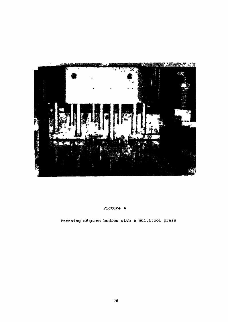
Picture 4
Pressing of green bodies with a multitool press
76

Picture 5
Sintering furnaces
77
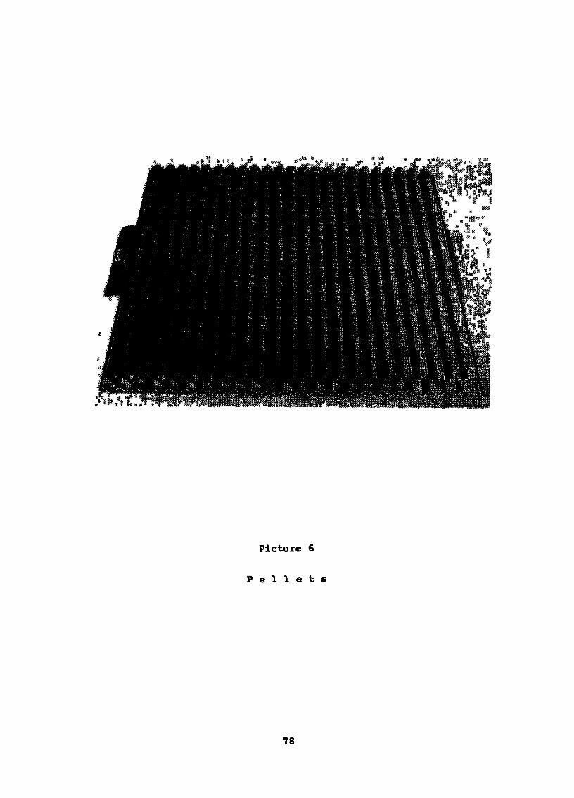
Picture 6
P e l l e t s
78
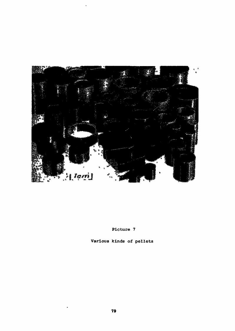
Picture 7
Various kinds of pellets
79
FRENCH ACHIEVEMENTS
REGARDING THE CONVERSION OF UFg INTO SINTERA8LE
B. COCHET-MUCHY, A. SA8RIAC, 0. TACHON
The COKMRHEX Company
ABSTRACT
The problem of converting UFg to U0g of sinterable quality arose ratherlate in Prance because the country's first nuclear power stations used naturaluranium.
Beginning in I960 the Commissariat à l'Energie Atomique (ClA) undertookin its own laboratories, and in those of industrial firms collaborating withit under 'contract, a study programme aimed at simplifying the process used upto that time to produce enriched oxide for experimental reactors from UFg.
Two parallel research efforts were launched, one concentrating on a dryprocess, the other on a wet process»
The present paper summarizes the different stages of this research anddescribes the patented processes which resulted and were subsequently put intooperation on a semi-industrial scale. They are:
- A continuous process used by CEA at the Cadarache site in which the oxideis produced by hydrolysis of UFg followed by reducing pyrohydrolysis (ina rotary oven) of the intermediate uranyl fluoridej and
- A continuous wet process used by the Société des Usines Chimiques, dePierrelatte (UCP) which makes it possible to obtain, via intermediateprecipitation of ammonium uranate followed by calcination and reductionin a rotary oven, an oxide of sinterable quality in the form of powder orgrains*
The paper describes, in addition to the basic technological featuresof these processes, the principal operating conditions involved and thephysico-chemical characteristics and sintering properties of the productsobtained*
The advantages and disadvantages of the two processes are discussed,as are the effluent problems associated with them.
In conclusion, their economic aspects are touched on briefly»
81
RESUME
Historiquement, le problème de la conversion de 1*UF6 en UO2 dequalité frittable s'est posé en France assez tardivement puisque lespremières centrales nucléaires françaises utilisaient l'uranium naturel*
C'est à par*ir de I960 que le Commissariat à l'Energie Atomique(CEA) a entrepris dans ses propres laboratoires, comme dans ceuxd'industriels travaillant avec lui sous contrat, un programme d'étudesdestiné à simplifier le procédé utilisé jusqu'alors pour l'obtention, àpartir d*UF6, de l'oxyde enrichi destiné aux réacteurs expérimentaux*
Les recherches furent menées parallèlement dans deux directions :
- la Voie Sèche,- la Voie Humide
L'exposé ci-après résume les étapes successives de ces rechercheset décrit les procédés brevetés qu'elles permirent de mettre en oeuvre àl'échelle semi-industrielle, à savoir :
- un procédé contimx exploité par le CEA sur le site de Cadarache quipermet d'obtenir l'oxyde par hydrolyse de l'UF6 suivie d'une pyrohydrolyseréductrice en four tournant d« Fluorure d'Uranyle obtenu inter médiaire-ment*
- un procédé continu de voie humide exploité par la Société des UsinesChimiques de Pierrelatte (UCP) qui au travers d'une précipitation in-termédia-ire d'Uranate d'Ammonium permet, après calcination et réduc-tion en four tournant, d'obtenir un oxyde de qualité frittable sous formede poudre ou de granulés.
Outre les caractéristiques technologiques essentielles des procédésdécrits, l'exposé indique les principales conditions opératoires utiliséesdans leur mise en oeuvre, ainsi que let- caractéristiques physico-chimiqueset l'aptitude au frittage des produits obtenus.
Mention est faite également des avantages et des inconvénientsrespectifs de chacun des procédés décrits ainsi que des problèmesd'effluents liés aux schémas de traitement retenus.
Enfin, l'aspect économique de ces procédés est brièvementabordé pour conclure»
1 - INTRODUCTION -
The présent uranium enrichment processes result in theproduction of UFg which is used as the basic material for the productionof reactor fuel elements using enriched uranium. However, the problem ofthe conversion of UFg into sinterable UQ appeared rather late in FRANCE
82
since the first reactors used natural uranium. Thus, the first prepara-tion of enriched UQ- for test reactors included the following steps :
- conversion through pyrohydrolysis of UFg into UgQg- dissolution of this oxide in nitric acid- conversion of the uranyl nitrate into U0_. a process
which was then well-known and industrially achieved.
However» to simplify this process, some studies .were under-taken as soon as 1960 by the Commissariat à l'Energie Atomique (C.E.A.).either in its own laboratories or through some contractors. Parallelresearch works were carried out on two processes :
1.1. "Dry process"
The Known processes consist in hydrolysing UF_ by steam toD
obtain UO-F» which is then subjected to a pyrohydrolysis under reducingatmosphere. The first studies were made by the UGINE company in itsCentre de Recherches de LYON. They resulted in showing that it was possible
3to obtain some UO» by performing the two operations in two successive fluidbeds. This process was then developed to a semi-industrial scale by theAteliers de Traitement d'Uranium Enrichi du C.E.A., in CAQARAdHË.
Some technological difficulties at the level of the reducingpyrohydrolysis did not allow the continuous operating of the installation,thus impairing the quality of the resulting UCL which was then poorly'sinterable according to the process commonly used in FRANCE. Therefore,such method was left. But the research works were carried on inCADARACHE and resulted recently in the present process described furtherdown (paragraph 2.).
1.2. "Wet process"•
The various processes include the following successivesteps :
- ammonia precipitation providing ammonium uranate- filtration- calcination and pyrohydrolysis to provide a defluorinated oxide- reduction to UOo by hydrogen
83
Further to some preliminary works carried out in the Centrede Recherches de LYON of the USINE Company, the C.E.A. carried on in itslaboratories of GRENOBLE some research works which resulted in the processflowsheet hereunder, drawn directly from the one applied to obtain UOfrom uranyl nitrate :
- two-stage precipitation by ammonium hydroxide- filtration of the precipitate- calcination - pyrohydrolysis in a rotary furnace providing the
UJ30 oxideo a- reduction in a rotary furnace by the hydrogen proceeding from
ammonia cracking,•providing UO whose characteristicscan be adjusted by modifying the parameters involved in thevarious stages.
This process for which the C.E.A. was granted a patent wasadopted by the Société des Usines Chimiques de PIERRELATTE which perfectedit rapidly. It was then looked for its optimization to improve its profit-ability. It could in some ways be simplified without impairing the proper-ties of the final product :
- single-stage precipitation by ammonia- single rotary furnace for the calcination, pyrohydrolysis and
reduction operations.
The present process is described further on in this report(paragraph 3.}.
2 - "DRY" PROCESS -
This patented process operated by the Ateliers de Traitementd'Uranium Enrichi du C.E.A. in CADARACHE allows the continuous operationthe two reactions of hydrolysis of UF and pyrohydrolysis of the resulting
2.1. Operating flowsheet
The process includes the following operations :
84
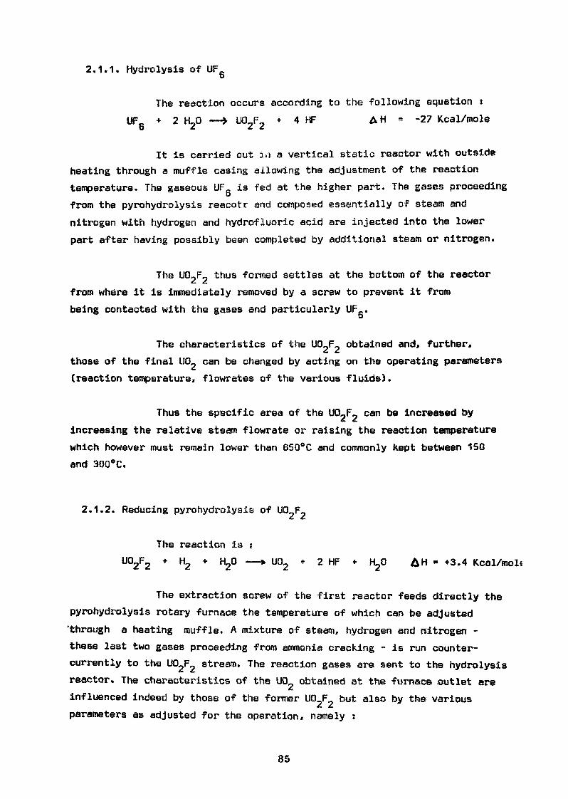
2.1.1. Hydrolysis of UFCb
The reaction occurs according to the following equation :UF0 + 2 HJD —» UO_F0 * 4 hF AH = -27 Kcal/mole
O <C *• £•
It is carried out i,i a vertical static reactor with outsideheating through a muffle casing allowing the adjustment of the reactiontemperature. The gaseous UF is fed at the higher part. The gases proceedingfrom the pyrohydrolysis reacotr and composed essentially of steam andnitrogen with hydrogen and hydrofluoric acid are injected into the lowerpart after having possibly been completed by additional steam or nitrogen.
The U02F2 thus formed settles at the bottom of the reactorfrom where it is immediately removed by a screw to prevent it frombeing contacted with the gases and particularly UFe.D
The characteristics of the UO_F_ obtained and, further,those of the final U0_ can be changed by acting on the operating parameters(reaction temperature» flowrates of the various fluids).
Thus the specific area of the UQJr* can t>8 increased bv
increasing the relative steam flowrate or raising the reaction temperaturewhich however must remain lower than 650°C and commonly Kept between 150and 300°C.
2.1.2. Reducing pyrohydrolysis of UO F~
The reaction is iU02F2 * H2 * H2° —* U02 + 2 HF * "2° AH * +3.4 Kcal/mol«
The extraction screw of the first reactor feeds directly thepyrohydrolysis rotary furnace the temperature of which can be adjusted'through a heating muffle. A mixture of steam, hydrogen and nitrogen -these last two gases proceeding from ammonia cracking - is run counter-currently to the U02F2 stream. The reaction gases are sent to the hydrolysisreactor. The characteristics of the U02 obtained at the furnace .outlet areinfluenced indeed by those of the former UO F but also by the variousparameters as adjusted for the operation, namely ;
85
- reaction temperature- residence time- reagents flowrates
for example» the diameter of the particles can be decreasedor the Specific urea of UCU increased by reducing the residence time insidethe reactor or lowering the reaction temperature which however shouldalways exceed 550°C.
2.1.3. Reception of U0_
Considering the characteristics of sinterabillty which arepresently looked for, it is not necessary to stabilize the UCL. The latterreacts little enough with air to be handled without risking a sharp re-oxidation. For some special operations (for example thorough crushing)»however» it is recommended to operate under inert atmosphere.
2.1.4. Treatment of effluents
The only effluents consist of the gases proceeding fromthe hydrolysis reactor and are composed of hydrogen» nitrogen* steam andhydrofluoric acid. They are removed from the reactor through sintared-metalfilters to. avoid any entrainment of uraniferous products. Then, they arerun through a limestone bed which absorbs the HP as solid calcium fluoride.The outlet gases can then be safely vented to atmosphere after runningthrough a safety-water scrubber.
2.2. Characteristics of the UP obtained
2.2.1. Physical characteristics
The main characteristics of the UCL which can be obtainedrange as follows :
- B.E.T. specific area 1 to 4 m2/g- mean particle diameter (BLAINE's method) 0.4 to 1 ,- compressed density 1 to 2.5
86
2.2.2. Chemical characteristics
- uranium content . 87.7 %- 0/U ratio < 2.10- moisture content ,/ 0.1 %
~6- fluorine content 10. 10 U-6- carbon content ^ 50. 10 U— fi
- nitrogen content ' X 50. 10 U^ ""fi
- thermal neutron capture section < 1. 10 Uboron equivalent
2.2.3. Fitness for sintering.
The little flowability of the U02 powder obtained up to nowrequires to apply the "double cycle" method. Under normal sintering condi-tions» namely :
- temperature £ 1650°C- bulk density ^ 6- sintering time ^ 2.30 hrs
it is possible to obtain sintered pellets with densities ranging between90 and 96 % of the theoretical density with an excellent reproducibility.
2.3. Advantages and drawbacks of the process
2.3.1. Advantages :
- Very simple technology allowing a very easy operating of theinstallation and offering a great fiability.
*f
- Production of effluents as solids only eliminating practicallythe problems of environment.
- Reagent saving - Hydrogen only is expensive.
- Problems of criticity simplified by the exclusive use of solidor gaseous products with use of water only in vapour phase and
t
small quantity. This allows more precisely to desigh high-capacity plants.
87
2.3.2. Drawbacks :
- The process has not, up to now, made it possible to obtain a"flowable powder" of U0_ allowing a single-cycle shaping.
- The installation cannot be used for processing the uranylnitrate .olutions. The re-processing of the wastes more par-ticularly involves their previous conversion into pure UF_.
D
3 - "WET" PROCESS
Operated by the Société des Usines Chimiques de PIERRELATTE,this process allows the continuous development of the various reactionsrequired to obtain UCU.
3.1. Operating flowsheet
The successive operations are :
3.1.1. Ammonium uranate precipitation
The precipitation of ammonium uranate involves many rathercomplex reactions. However, for an overall representation, the main reactioncan be illustrated by the following equation :
2 UF_ + 14 NH.OH —» (NH.)_U_0, + 12 NH.F + 7 H006 4 4 2 2 7 4 2
It is achieved inside an agitated reactor provided withexternal heating to control its temperature and fed with water,UF_ and ammonia. The characteristics of the precipitate obtainedoand, further, of the final U0_ can be changed by changing the reactiontemperature and the fluid flowrates.
Thus, the uranate specific area can be increased by increa-sing the relative ammonia flowrate, the latter, on the other hand, beingalways higher than three times the stoichiometric quantity to achieve thetotal precipitation of uranium. The reaction temperature may also be raised.However, the use of a temperature exceeding 90°C is not an advantage consi-dering the ammonia losses through evaporation.
88
3.1.2. Uranate filtration
the precipitate is filtered and centrifuged using a vacuumrotary filter.
3.1.3. Calcination - Defluorination - Reduction
The thixotropic feature of the filtration cake allows it.further to a mere mixing, to de conveyed by pump into the single reactorwhere these three operations are carried out. This reactor is a rotaryKiln heated by electric muffles. The necessary reagents, steam for de-fluorination, hydrogen for reduction, are fed counter-currently to uranium.By controlling the kiln temperature, the residence time of vrauiym insidethe reactor and the fluids flowrates, it is possible to modify thecharacteristics of UCL obtained from a same uranate»
For example, the specific area of U0_ can be decreased byincreasing the residence time of the product inside the Kiln or raisingthe reaction temperature. The latter must not be lower than 500°C toallow the complete reactions and is kept'under 800°C ta take into accountthe physical behaviour of the equipment.
3.1.4. Stabilization
The U02 at the kiln outlet is practically stoichiometricand very ^active in the presence of air. It is therefore necessary tostabilize it. This is achieved continuously at low temperature, by acontrolled addition of oxygen in the counter-current circulation of re-duction gases fed to the kiln, rated to reach the desired re-oxidationlevel. This operation has no effect on the physical features of UQ_.
3.1.5. Calibration of U02
Two granulometric qualities of U0_ can be obtained withthis process :
- a quality called "direct granule" the flowability of which issufficient to allow a single-cycle pelletizing. The calibratingconsists of a 600 u mesh screening followed by a reduction ofthe retained particles by forced screening.
89
- a quality called "powder" the use Of which requires the double-cycle technique. The powder is adjusted to this operation bycrushing,
3.1.6. Treatment of process effluents
These effluents include :
- the uranate filtration mother-liquors
- the gases proceeding from the calcination-dsfîuorination-reduction Kiln. Thay are extracted through sintered-metalfilters to avoid uranium entrainments. The liquid ring of thevacuum extraction pump acts as scrubber for the absorption ofthe hydrofluoric acid, particularly before the vent gases arerejected to the atmosphere.
These effluents are then mixed. Their uranium contentis controlled continuously. The treatment consists of :
- a lime precipitation of the fluorine ions and uranium traces
- decanting in pits where calcium fluoride containing traces ofuranium is separated
- discharge after control of the clear water.
3.2. Characteristics of the LIO obtained
3.2.1. Physical characteristics
By control of the various operating parameters, it ispossible to alter the main characteristics of the processed U02 withinthe following ranges :
90
- B.E.T. specific area 3 to 4.5 m2/g- mean particle diameter (BLAINE's method) 0.4 to 1 jt.- bulk density >y 1.5- compressed density ^ 2.5- particle size :
direct granule V 600 ^ 10 %
^200^ ^ 15 %
powder / 74 . 90 %
3.2.2. Chemical characteristics
- U content ^ 87.7 %- 0/U ratio 2.07 + 0,05- moisture content •< 0.1 %
! *6- fluorine content < 50. 10 U••fi- carbon content «X 50. 10 U
^ ' ~8- nitrogen content < 100. 10 U- thermal neutron capture section < 1. 10 U
boron equivalent
3.2.3. Fitness for sintering
Whatever the granulometric quality of the U0_ obtainedwith this process (direct granule or powder), the sintering results aresatisfactory. Under normal sintering conditions, it is possible to obtainsintered pellets with densities ranging between 90 and 96 % of thetheoretical density with an excellent reproducibility.
3.3. Advantages and drawbacks of this process
3.3.1. Advantages :
- A very simplified technology compared to the initial processallowing an easy operation and ensuring a great flability
- many possible adjustments providing a great operating flexibility
- possibility of obtaining the "direct granule* quality allowing thesimplification of palletizing operations.
91
- possibility of treating the uranyl nitrate solutions in the sameequipment, thus allowing the easy recycling of final operationrecovered residues.
3.3.2. Drawbacks
Important quantity of liquid ammoniacal effluents which may leadto require a special treatment
limited capacity of the units resulting from the problems ofcriticity caused by the presence of great amounts of water
great expenses of reagent - The complete precipitation ofuranium involves the use of approximately three times thequantity of stoichiometric amminia
consumption of calories to remove the water entrained by theuranate precipitate.
4 - ECONOMIC ASPECT OF THE PROCESSES
As mentioned formerly, the problems of the conversion ofUF_ into sinterable U0_ appeared only recently in FRANCE and, consequently,
the production has not been operated long enough to provide definite dataon the economics.
Nevertheless, the experience acquired by now has made itpossible to ascertain that for yearly productions ranging around 100 m.tonsof U0_, UFe could be converted into (JO at a competitive price compared with
£. a f.the ones ruling commonly in the world.
5 - CONCLUSION
Both processes presently applied in FRANCE allow a widerange of specifications to be covered and the requirements of the sinte-ring units to be met. Their application is recent and their optimizationis being carried on which allows new improvements to be expected.
92
IMPK0VEM ENTS OF FUEL. PEI LETIZING TEÇKNIQUSSIN BELGIUM
A.J. Flipot.
A b u t ract
The manufacture of UO;j pellets has been graduallysimplified in order to reach a three-step fabricationscheme : palletizing, sintering and control. The mainimprovements developed with the aid of a rotary pressarc described. Direct lubrication of the pelletisingtools is a first improvement : it is achieved by com -pacting a dry lubricant mixed with a carrier.The second step deals with direct pelletizing of a nonfree-flowing powder thanks to an elaborated feeder.Finally, it hae been tried to manufacture sintered cy-lindrical pellets in order to avoidcentreless grinding.Three approaches are discussed. Th« key-factor sare either the shape of the sinter.-ibility curve of VQzeither the uniformity of the green density or the type ofcompaction method and the design of the die.
1, Introdnctio .
The main activity of the Joint CEN-BELGONUCLEAIR E Pu Croup is re-lated to the study of fabrication and behaviour cf plutonium fuels. The bestresults obtained in these laboratories are then transmitted to the pilot plantand to the industrial fabrication line of BEJLGONUCI/EAIRE which ha» tosolve the fxirthcr problems resulting from the increase of the fabricationscale. The studies, first devoted to plutonium recycling in thermal reac-tors have been extended gradually to fast reactor fuels» Foitunatcly, bothobjectives contribute to the improvement of fabrication techniques becausethe technological problems are basically identical. Moreover, the manu-facture of UC>2- PuO2 fuels is, in many respects, similar to this of pureUO2 fuels so that UO2 and UO^-PuOz pelletizing techniques progress si -multamously and take each advantage of ihe improvements of thf other one.This c-xplains why the Joint CEN-BELGONUCIJ2AIRE Pu Croup has beendeveloping for several years advanced fabrication procedures using rotarypresses and direct solid lubrication of the die».Thanks to experiments carried out on UOj since J966, the earlier wetpre-parallel* technique was abandoned progressively to the benefit of a drypelletizing one. This method was then studied on UO^-PwO» in 1969 and
93
has been successfully applied since 1970 in the pilot plant of BELGONUC LE -AIRE. This was the first step to the simpliest pellet fabrication routewhich can be summarized in three words : palletizing - sintering - control.This objective is no longer a dream for the manufacturers of UOjj pelletsas it has already been reached on a small scale.
The present paper comments the successive steps which have been over-came and describes Borne fabrication methods.
2. Progress in pellctizing technique,
The basic dry pelletizing technique is summarized by Fig. 1 : it is, infact» constituted by two pelletizing cycles.
The first approach in improving and simplifying the fabrication route islinked to lubrication process. Homogeneous incorporation of dry lubricantsin UOz or UO2-PuO2 fine powders gives no satisfactory results. For aUOz compact containing 0.3 wt. % uniformly distributed zinc behenate, theamount of lubricant squeezed on to the die wall during pressing is insuffi-cient to ensure good lubrication. It seems necessary to increase the lubri-cant content up to 1 wt. % but this will decrease the fired density of thepellets. In consequence of this poor lubrication during precompaction, shewear of the tools will be fast. The green compacts are then granulated andmixed with 0.3 wt. % zinc behenate before pelletizing. During thia secondcompaction, lubrication is effective because zinc behenate is concentratedon the surface of each granule and the quantity directly in contact with thedie wall is thus increased. Unfortunately, these salts of fatty acids con -glomerate easily and it is difficult to achieve a uniform blending on an in-dustrial scaie. Moreover, these additives must be removed before sinter-ing to protect the furnace and thus require a dewaxing step. A direct lu-brication method being effective and versatile would therefore improvethe results and eliminate the two mixing step» and the dewaxing one.
Direct pelletizing of the raw materials constitutes the second simplifi-cation of the fabrication route. Besides the use of a direct lubricationtechnique, pelletizing a non-granulated powder requires to find the possi-bility to achieve a complete and reproducible filling of the die.Both objectives have been achieved with the aid of a rotary press which,in addition, gives a much higher output than conventional presses. Thesestudies have been performed on UOj since 1968 and will be extended toXJC>2~ PuO2 fuels before the end of the year.
The third improvement which is the most difficult to succeed, i» themanufacturing of accurate sintered pellets in order to avoid the grindingstep. This will represent an important progress because grinding isexpensive for many reasons. It damages some pellets and produces powderscraps which cannot be directly repelletizsd. Moreover, all ground pelletsmust be dried before filling the canning tubes. A new compaction methodhas been experimented on UO2 since the end of 1971. The results are verypromising. The simplified fabrication route is illustrated by Fig. 2.
3. Rotary press with lubricated^dies.J&*
The machine is a 20-ton double-sided rotary-press as shown schema-tically by Fig, 3. It is formed by two completely independent parts and has
jar Press P 3 - Fette (Germany).
94
thus two sets of fill, compaction and ejection station». One set is used forapplying the lubricant whereas the other set yields the fuel pellets. Thecycre can be understood by following the various positions t«xken by dien" 1,for instance. The die enters first in the zone reserved for lubrication andthen, due to the rotation of the table, reaches the other zone. It passesunder the stationary feeder and takes UO2 powdei which is then compactedand ejected. At this moment, this die has made one complete revolutionand a new cycle starts. Ail tools are thus* lubricated alternately and areworking under normal operating conditions. Lubrication of the compactingtools is achieved by pelletizmg a salt of fatty acids blended with an inertcarrier (1,2). The carrier is essential to obtain a pood flow-rate a.nd toguarantee that the lubricant tend" to recover its initial shape after beingpressed.
The first composite lubricant selected consisted of small polystyreneballs (0.2 to 1 mm diameter) covered with 3 wt. % asinc behenate (2). Thismixture flows easily and lubricates as well as pure lubricant (3), More -over, as the balls are somewhat elastic, the compact does not remain apellet after ejection but returns spontaneously into elementary balls.Theseballs may therefore be directly f «^introduced into the feeding boot of thepress, allowing a closed cycle to be operated.
Though successful, this composite lubricant may be replaced by corkgranules mixed with 10 wt. % /ine stéarate in order to avoid electrostaticcharges and the associated troubles. This feature is essential whenpelleti?ing in a dry atmosphere as required, for instance, for carbide fuels»Moreover* the effectiveness of this latter composite lubricant scents ratherinsensitive to the compaction conditions. Zinc behenate was replaced byzinc stéarate which is as effective and cheaper. It has been observed thatlubrication efficiency of stéarates depends on their physical properties andtheir impurity level (4), Lubrication is best when the tap density of themetallic soap is <200 g/1 and when the fatty acid content ii kept es low aspossible : these parameters are more important when the lubricant is ad-mixed to the powder than when direct lubrication is used. In this case, asiinc stéarate with a tap density of 400 g/1 still gives excellent results.
4. Powder, flow»rateT
Powder flow-rate can be evaluated according to standard specifications(5) using a Hall ftow-xneter. Similar results are obtained with the commer-cial equipment Erweka GDT v/hich is more sophisticated and easier tooperate in a glove-box. As shown by Fig. 4, this flow-meter is equippedwith a control device, A well-determined powder quantity is poured into afunnel which is separated from an outlet tube by an electromagnetic valve.The flow-time is measured by an incorporated impulse counter which startswhen opening the separation valve and stops when all powder has passed thelight beam opposite to a photo-electric cell.
a) ££C*L€^2iY*^u92l^c.£&«This t.\pe of powder which flows rapidly and in a reproducible markercan b<* illustrated by tht small spheres produced by direct conversionof 111*6. This method has been developed for some years by Métallur-gie Hobokfii and Centre d'Etude de i'Kftcrgie Nucléaire, Mol. It isnow A. f'died on a larger scale by .Métallurgie et Mécanique NucléairesinDesfc-el (Belgium). Some characteristics of free flowing UC-2 pow-ders available in Europe are summarized in Fig. 5.
95
Such powders fill regularly the dies of conventional and rotarypelletizing presses. Most of these powders present no pelletiaingproblems if their particles are neither too hard nor too fine. Combina-tion of hardness and fineness of the particles may lead to acceleratedwear or even seizing of the tools.For free flowing powders, the use of a rotary press still remains ad-vantageous, especially when a large quantity of pellets must be manu-factured. A fast conventional press produces a maximum of 30pellets/min. whereas a low rotary p^ess yields as many as 150pellets/min. Fig. 6 shows how free flowing UO2 is palletized on adouble-sided rotary-press using a dry lubrication technique. The feed-ing shoe is simple and effective. Tho powder moves above the diesand the excess turns with the table and then enters apain the feedingshoe. The quantity of this powder in excess régulât*.s the quantity offresh powder admixed on the press so th*t the filling of the dies re -mains constant. On the other h^nd, an adequate separation exists be-tween the two parts of the votary press in order to avoid any mixing offuel and lubricant.Pellets manufactured with spherical UO^ particle» prove to be veryreproducible as the scattering in green density is below £ 0. 5 %,Another free aowintt UOj> constituted by coarse regular granuléeinstead of small spheres can also give good pellets. It has beennoticed that density reproducibility is linked to powder granulome-try. A too coarse powder contaim\g,for instance, 50 % of particlesranging between 0,4 and 1 mm fill the dies rapidly and completelybut not regularly so that the scattering in weight and green densityof 10 mm diameter pellets i» as high as + 2.4 %. On the contrary,this scattering does not exceed +_ 0. 7 % when pov/dcr has been pre-viously granulated through 0.4 or 0.2 mm openings.Under these circumstances, both types of presses guarantee thesame quality of pellets.
In opposition to free flowing particles the contour of which is regular,there are powders with a jagged outline (Fig. 7), These powders,often very fine, conglomerate easily and form bridges between eachother so that they do not flow at all, even when vibrations are applied.Such a raw material is difficult to pellet! JM? within close margins andmust be precompacted and granulated. Precompaction can be per -formed either with the aid of a powerful hydraulic press, capable ofmaking large compacts or by a rotary press equipped with an elaborat-ed feeder.Powders are sometimes so sticking that it ^eems almost impossibleto manufacture free flowing granules. Batch number NLi 36 (- 70mesh) (Fig. 7) illustrates this exceptional case. The roost recent fill-ing techniques prove that, at the present time, this VQz quality can-not be pelletized accurately in a 12 mm diameter die, Ihc best r« -suits obtained with the aid of a rotary press show a £ 10 % scatteringin fiie green density.After granulation on a 0.4 mm grid, the product doec not flow. Urxlike-ly as it sounds, seven out of ten flowing tests have pointed out thaithese granules form bridges and obstruct the funnel of the flow-meter.The product is not convenient for feeding conventional mechanic alpresses. However, it can be pelletixed with a rotary press. Pellets
96
manufactured with the aid of the feeder designed for f»rcxm»les or freeflowing material are acceptable as the scattering in their green densi-ty is lower than £1.2 %.
c) Non free-floy/infi poydej-s^
This third category is constitute*! by powders the characteristics ofwhich lie half-way between the first two. The&e raw materials flowneither rapidly nor uniformly but their tendency to sticking is not verystrong. Common ceramic grade UOfa powder manufactured first byMétallurgie Hoboken and presently b\ Métallurgie ei Mécanique Nuclé-aires in Belgium i& representative for this category (Fig. 7).Flowing tests give unreproduciblc results because 20 to 30 % of thetests show powder agglomeration in the flow-meter.Powder» of intermediate flow-rate have been simulated by mixingfree flowing and non free-flowing UOa qualities. The re 8 tilting flow-rate depends on the properties of each constituent such as shape andgranulometry of the particles. The evolution of the Pawing charac -teristics as a function of the composition of such mixtures is repre -sented by Fig. 8. On the other hand, each of these composite batcheswas pclletiaed with a conventional mechanical press in order to eva-luate the importance of the results of the flowing tests on the repro-ducibility of the green pellets. Fig. 9 gives the maximum weight and.density variation measured on 250 pellets of each b&tch. If a 2.5 %scattering (or £ 1. 25 %) is admitted, Fig. 8 and 9 indicate that aUO2called free flowing must fulfil two criteria :- flowing time/100 cm3 : ^ 40 seconds (usually {10 seconds)- ^ t : ^ 5 seconds (usually < 3 seconds).
These figures are valid only for defined working conditions and de-pend, for instance, on the type of the feeding shoe, the output of thepress, the diameter of the die, the height of the pellet», etc,..Beyond these two limits, powders can be called "non free-flowing"because their flow rate becomes rapidly unmeasurable and the scatter-ing in weight and green density increases exponentially. Nevertheless,this scattering may be reduced by improving the performance of thefeeder. Unfortunately, the flowing test appears to be poor and in -sufficiently sensitive to classify the non f j co-flowing powders whichremain the most currently available ones.
5. PcMetizing of non free-flowing powders.A rotary press uses a stationary feeder which can be longer and more
sophisticated than that of a conventional pi ess. Moreover, tbe filling t'meis rather long. These both featxircs are beneficial to the regularity of thepellets when powder flow-rate is. insufficient.A special feeding shoe with two rotating parts*^(6) directing the powder in-to the die cavities, gives good results with Belgian ceramic grade UO2.Fig. 10 displays typical histograms of the density of green and sinteredpellets. These results represent 100 kg pellet» with a diameter «nd heightof 12 mm. Ten percent of the batch were controlled as a. representativesample. These curves demonstrate that the rcprodxtcibility of the pellets
A Fill-O-Matic shoe from Fette-Hamburg (Germany).
97
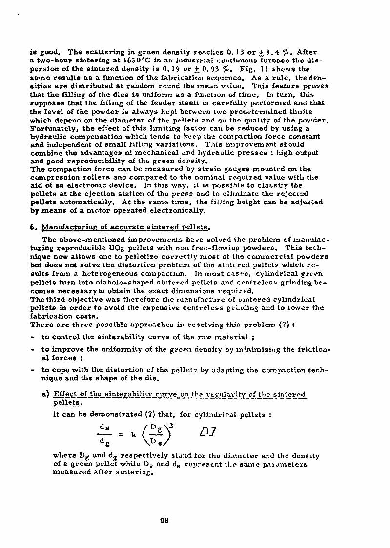
is good. The scattering in green density reaches 0. 13 or + 1.4 %. Aftera two-hour 6 inter ing at 1650°C in an industrial continuous furnace the dis-persion of the sintered density is 0. 19 or r 0.93 %. Fig. 11 shows thes at ne résulte as a function of the fabrication sequence. As a rule, the den-sities are distributed at random round the mean value. This feature provesthat the filling of the dies is uniform as a function of time. In turn» thissupposes that the filling of the feeder itselt* is carefully performed anci thatthe level of the powder is always kept between two predetermined IwnJt»which depend on the diameter of the pellets and on the quality of the powder,Fortunately, the effect of this limiting factor can be reduced by using ahydraulic compensation which tends to keep the compaction force constantand independent of small filling variations. This improvement shouldcombine the advantages of mechanical and hydraulic presses : high outputand good reproducibility of the green density.The compaction force can be measured, by strain gauges mounted on thecompression rollers and compared to the nominal required value with theaid of an electronic device. In this way, it is possible to classify thepellets at the ejection station of the press and to eliminate the rejectedpellets automatically. At the same time, the filling height can be adjustedby means of a motor operated electronically.
6. Manufacturing of accurate sintered pellets.The above-mentioned improvements have solved the problem of manufac-
turing reproducible UO2 pellets with non free-flowing powdere. This tech-nique now allows one to pelletize correctly most of the commercial powdersbut does not solve the distortion problem of the sintered pellets which re-sults from a heterogeneous compaction. Inmost cas<»s, cylindrical greenpellets turn into diabolo- shaped sintered pellets and centrelcss grinding be-comes necessary to obtain the exact dimensions required.The third objective was therefore the manufacture of wintered cylindricalpellets in order to avoid the expensive centre-less grLuiing and to lower thefabrication costs.There are three possible approaches in resolving this problem (?) :- to control the sinterability curve of the raw material ;~ to improve the uniformity of the green density by minimizing the friction-
aï forces ;- to cope with the distortion of the pellets by adapting the compaction tech-
nique and the shape of the die.
a) 2?fj3lcjtjrfJth^sJnj^£ajMj^^jaellets. "~It can be demonstrated (7) that, for cylindrical pellets :
where Dg and dg respectively stand for the diameter and the densityof a green pellet while DB and ds represent tie same parametersmeasured after sintering.
98
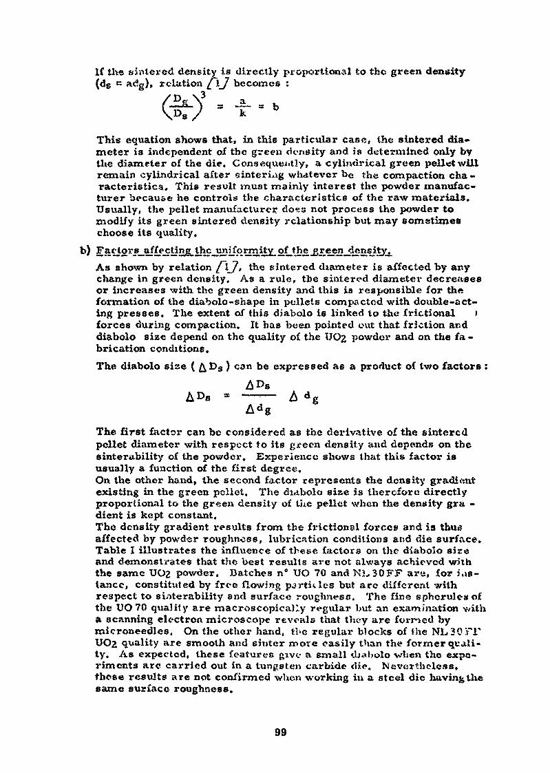
If the sintered density is directly proportional to the green density(dg K a<%), relation [ \J becomes :
3/Pg\ at .....fa- ) s .
This equation shows that, in this particular case, the sintered dia-meter is independent of the green density and is determined only bythe diameter of the die. Consequently, a cylindrical green pell «twillremain cylindrical after sinteriag whatever be the compaction cha-racteristics, This result must mainly interest the powder manufac-turer because he controls the characteristics of the raw materials.Usually, the pellet manufacturer doss not process the powder tomodify its green sintered density relationship but may sometimeschoose its quality,
As shown by relation /~\J, the sintered diameter is affected by anychange in green density. As a rule, the sintered diameter decreasesor increases with the green density and this is responsible for theformation of the diabolo-shape in pellets compacted with double-act-ing presses. The extent of this diabolo is linked to the fractional )forces during compaction. It has been pointed out that friction anddiabolo size depend on the quality of the UO2 powder and on the fa-brication conditions.The diabolo size ( &Dg ) can be expressed as a product of two factors :
A PSADS * —— __ £ dg
Adg
The first factor can be considered as the derivative of the sinteredpellet diameter with respect to its green density and depends on tbesinterability of the powder. Experience shows that this factor isusually a function of the first degree.On the other hand, the second factor represents the density gradientexisting in the green pellet. The diabolo size is therefore directlyproportional to the green density of lue pellet when the density gra -dient is kept constant.The density gradient results from the frictions! forces and is thusaffected by powder roughness, lubrication conditions and die surface.Table I illustrates the influence of these factors on the diabolo sizeand demonstrates that the best results are not always achieved withthe same UO2 powder. Batches n° UO 70 and NL30FF are, for dis-tance, constituted by free flowing pi>rtules but are different withrespect to sinterability and surface roughness. The fine spherules ofthe UO 70 quality are macroscopicaJXy regular but an examination v/itha scanning electron microscope reveals that they are formed bymicroneedles. On the other hand, tbe regular blocks of the NL30FTUOz quality are smooth and sinter move easily than the former quali-ty, As expected, these features give a small Ojabolo when the expe-riments are carried out in a tungsten carbide die. Nevertheless,those results are not confirmed when working in a steel die having thesame surface roughness.
99
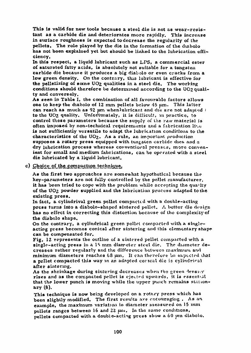
This is valid for new tools because a steel die is not as wear-resis-tant as a carbide die and deteriorates more rapidly. This increasein surface roughness is expected to decrease the regularity of thepelleta. The role played by the die in the formation of the diabolohas not been explained yet but should be linked to the lubrication effi-ciency.In this respect» a liquid lubricant such as JLPS» a commercial esterof saturated fatty acids, is absolutely not suitable for a tungstencarbide die because it produces a big diabolo or even cracks from alow green density. On the contrary, this lubricant is effective forthe pelletizing of some UO2 qualities in a steel die. The workingconditions should therefore be determined according to the UO2 quali-ty and conversely.As seen in Table I, the combination of all favourable factors allowsone to keep the diabolo of 12 mm pellets below 45 pro. This lattercan reach as much as 92 urn whenlubricant and die are not adapt <:d •'to the UO£ quality. Unfortunately, it is difficult, %n practice, tocontrol these parameters because the supply of the raw material isoften imposed by non-technical requirements and a fabrication lr^is not sufficiently versatile to adapt the lubrication conditions to thecharacteristics of the UOj. As a rule, an important productionsupposes a rotary press equipped with tungsten carbide dies and adry lubrication process whereas conventional presses, more conven-ient for small and medium fabrications, can be operated with a steeldie lubricated by a liquid lubricant.
As the first two approaches are somewhat hypothetical because thekey-parameters are not fully controlled by the pellet manxifacturer,it has been tried to cope with the problem while accepting the qualityof the UO2 powder supplied and the lubrication process adapted to theexisting press.In fact, a cylindrival green pellet compacted with a double-actingpress turns into a diabolo- shaped sintered pellet. A better die designhas no effect in correcting this distortion because of the complexity ofthe diabolo shape.On the contrary, a cylindrical green pellet compacted with a single-acting press becomes conical after sintering and this elementary shapecan be compensated for.Fig, IE represents the outline of a sintered pellet compacted with asingle-acting press in a Ie» mm diameter steel die. The diameter de-creases rather regularly and the difference between maximum andminimum diameters reaches 68 urn. It can therefore be exptcted thata pellet compacted this way in an adapted concal die is cylindricalafter sintering.As the shrinkage during sintering decreases when the green Hensuyrises and as the compacted pellet is ejected upwards, it is essentialthat the lower punch is moving while the upper punch remains station-ary (8).This technique is now being developed on a rot«.ry press which hasbeen slightly modified. The first results are encouraging . As anexample, the maximum variation in diameter measured on 15 mmpellets ranges between 16 and 22 |on». In the same conditions,pellets compacted with a double- acting press show a 60 pin diabolo.
100
It must be added that any method for ma-aufacUiring accurate pelletsrequires the use of a reproducible and xmiform powcier, Experienceptoves that such a quality is difficult to obtain for two reason».First of all, specifications are too vague because of lack of know -ledge in the mutual effect of each powder characteristic on those ofthe sintered pellets and then, most of the powder manufacturera donot woik according to ». continuous process.
?• Conclusions_,Pelletizing techniques are in continuous progress but are already very
advanced.The earlier fabrication process has been simplified in order to follow
the requirements of modern manufactures. Moreover, as the increasingdemand in UO2 pellets calls for high output pollstis<ii.g presses, the pei -for nuance of a rotary press was studied. Tne objective was to pclletisedirectly the commercial UOz powder and to obtain in curate sintered pelleté,so that the fabrication process is reduced to c»ly three steps : palletizing,sintering and control.
The first step was the deveîopmcî^t of a direct lubrication method : tlûshas been achieved by pelleti^ing a dry lubricant mixed with a carrier. Tïistechnique has been successfully applied for more than three years on adouble-sided rotary press. Half the stations is reserve*.» for the Imbricationof the tools whereas the other hull yields the production of fuel pallets.
The second improvement achieved with the aid of a rotary press is thedirect palletizing of non free-flowing powders. The filling of the die iscarried out by a special feeder equipped with rotatinp arm». This techniqueenable» one to pclictize most of the commercial UO£ pov/devs. The perform-ance of mechanical rotary preeses should still be iinproved by using a hy-draulic compensation and by controlling the pellcti«$mg parameters electron-ically.
The third step or the manufacture of accurate sintered pellets is beingstudied. The first results are satisfactory but have to be confirmed withdifferent UO^ qualities. The success depends on the pellt»ti«ing techniqueand on the quality of the raw material which murt be uniform and reprorUïci-ble.
R
(1) A.J. Flipot, A. Smolders.Lubrication Process.U.S. Patent 3,626,043 - December 7, 1971.
(2) A.J. Flipot, A. Smolders."Lubrication method for rotary-press tools".Powder Metallurgy, JL2., r>° 24, 305-315, 1969.Contribution to a Symposium on Lubrication, Friction and Wearin Po»vder Metallurgy.Eastbourne, 24-26 November 1969.
101
(3) A. J. Flipot, A. Smolders."Die wall lubrication with zinc behenate coated polystyrene baîJ&l!«Powder Metallurgy Intern., 2_, n" 4. 124-126, Nov. 1970.
(4) A.J. Flipot, R. Gilissen, A. Smolders."Importance of stéarates in the fabrication of UO2 and (U,pellets".Powder Metallurgy, 14, n' 27, 93-109> 1971.
(5) Standard Method of Test for Flow-rate of Metal Povdera.ASTM designation B 213-48 (reapproved 1965).
(6) "Radspeisevorrichtungen bci auslândischen Rotor-Tablettier-Maschinen".Translated from Mechanizacija i Avtomatizacija Proizvodstva.Moskau 25 (1971). n* 1. 42-4&.
(7) A, J. Flipot, A. Smolders."Factors controlling the shape regularity of sintered UO^ pellets".Contribution to Annual Meeting of the Powder Metallurgy JointGroup.Eastbourne» Nov. 1972.
(8) A.J. Fiipot, A. Smolders."Procédé de fabrication de pastilles de précision".Patent applied for in Belgium.
102
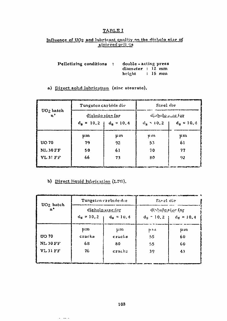
TABLE I
Influence of UOzsintered prH A t8
Pelletizing conditions t double-acting pressdiameter : )2 mmheight : 15 mm
a) Direct solid lubrication (zinc stéarate).
UO2 batchn8
UO 70NL30FFVL31 FF
Tungsten carbide die
4iabaJojize.Is.?dg = 10.Z
pin
795066
ds = 10.4
pin
926173
Steel die
di aboic j; i.4£ J S2.Ï
ds - 10.2
uni
53
7080
ds -- 10.4
|irti
61
7792
Direct )iqx\id lubric ation (LPS).
UO2 batchn»
UO70NL30FFVLSI FF
TungsU-n carbide dte
dj.abciljajsi3.%.ejlords = 1 0. 2
urncracks
6876
ds = 1 0, 4
pmcracks80
cracks
SU- el die ji
d i'i hoj oj* i. .0' for |ds - 10.2
p!U
5>5.0539
ds = 10.4 j
(um606043
»n n»rr n- Jirn mn.nnnr -
103
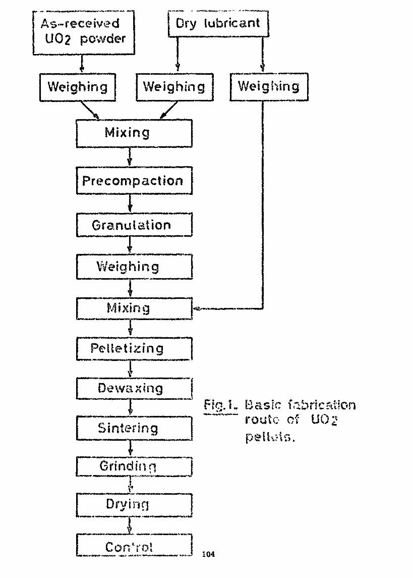
As-receivedU02 powder
**:«••
Dry lubricant
Weighing Weighing
Mixing
Precompaction
Granulation
Weighing
~~îMixing
Pelletizing
IDewaxing
Weighing
SinteringFig.1. Basic fabrication
route of UÛ2
Grind in j»"*f
M«M*«Wfc
Dry inn_i • — --—- j * -~ 11
Cor/rol 104
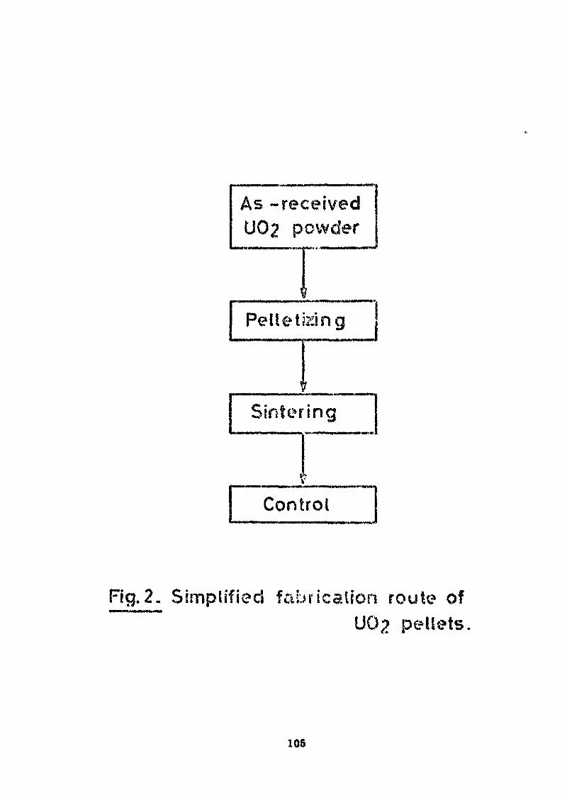
As -receivedU02 powder
$
Pelletizing
Sintering
Control
Fig.2. Simplified fabrication route ofU02 pellets
105
lubricaniprecompaction
lubricant Icompaction I
ejectionstations
suctiondevice
lubricantfillingdevice•-—a* Die No.1
stationary/
/ U02pellets
UÛ2 ejectionstations
UQ2compaction
U02precompaction
tight feederfor non free-f lev/in g
U02 pov/d&r
rotationsense
Fig. 3~ Double-sided rotary-press: v/ithlubricated dies.
106
electromagnetic separation valveelectromagnetic vibrator
fuseselectromagnetic vibrator switchimpulse lime counter
sensitivity regulationcontrol lights
/powder funnel
mm
photo-electric cellI.R. light source
container
Fig.A. Erweka GDI fiowmeter.
BATCH NUMBER
Scanning electronmicrographs
Granulometry(mesh)-50 +60-60 +70-70 +80-80 +100-100 +140-140 +200-200 +270-270 +325-325 +400
-400Flowing characteristics
(100ml)meantime in secondsAt in seconds
Apparent densityTap density
V L 4 F F
50 pm
1152023201011
52.53.303.60
NL 13 FF
20 pm
1.51.50.15.491.5(20 pm)
163.52.73.4
NL 2 FF
20pm
5251528
7 51.32.12.4
NL 30 FF
V.182016161366131
5.10.52.32.7
50pm
Fig.5. Characteristics of some free-flowing UÛ2 powders.
lubricantprecompaction
lubricantfillingdevice
lubricantcompaction
ejectionstations
stationsframe
suctiondevice
U02fillingstations
UÛ2pellets
U02 ejectionstations
]uo2I compaction
U02precompaction
r
rotationsense
Rg.6. Pelletizing of free-flowing UÛ2powder with a rotary-press.
109
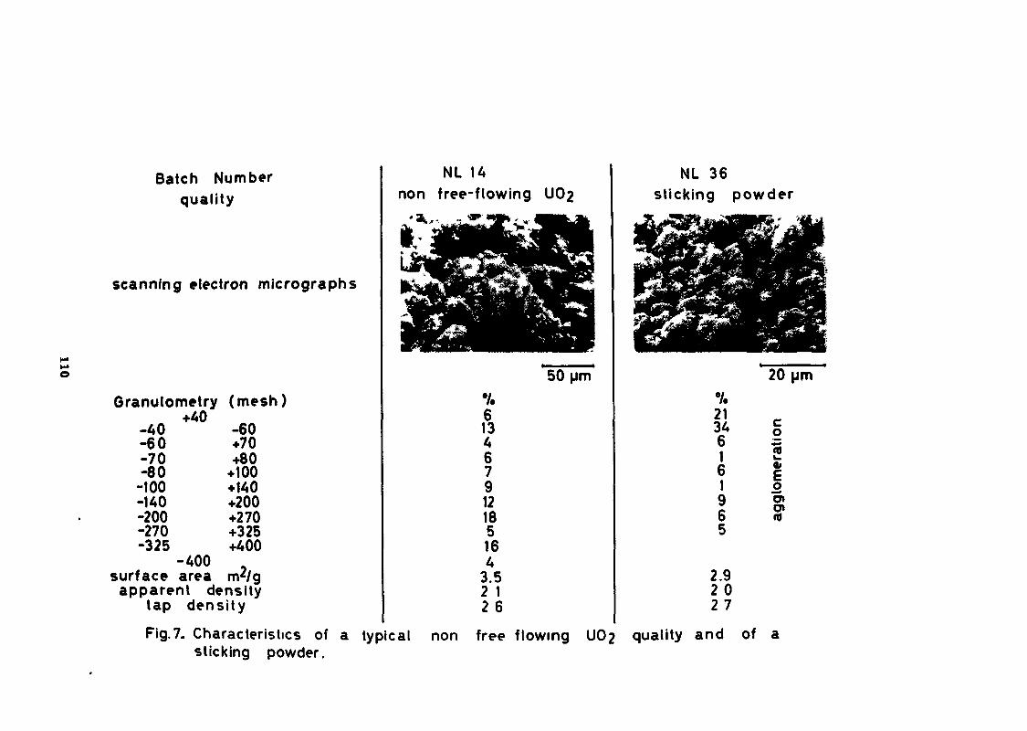
Batch Numberquality
scanning electron micrographs
Granulometry (mesh)+40
-40 -60-60 +70-70 +80-80 +100
-100 +140-140 +200-200 +270-270 +325-325 +400
-400surface area m2/gapparent density
tap density
Fig.7. Characteristics ofsticking powder.
NL 14non free-flowing U02
613467912185164
3.52 12 6
50 um
NL 36sticking powder
21346161965
2.92 02 7
20 um
co2*oo»O)CO
a typical non free flowing UOp quality and of a
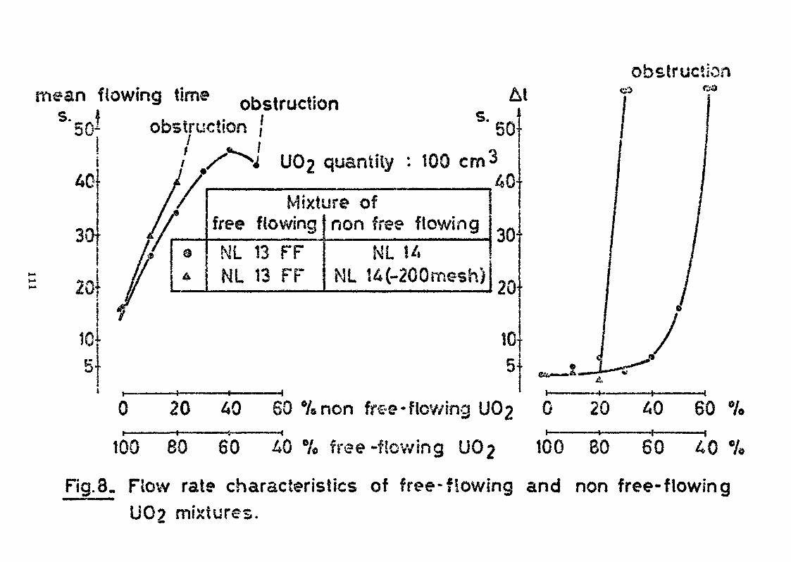
obstructionmean flowing time obstruction
obstruction |/
s.50}
30t
2Q
10-5-
UÛ2 quantily : 100 cm3
Mixture offree flowingNL 13 FFNL 13 FF
non free flowingNL 14
NL !4(-200mesh)
40-
30T
20
20 40 60 %non free-flowing UC>2 0 20 40 6 0 %
100 80 60 40 % free-flowing UC>2 100 80 60 40
Fig.8. Flow rate characteristics of free-flowing and non free-flowingU02 mixtures.
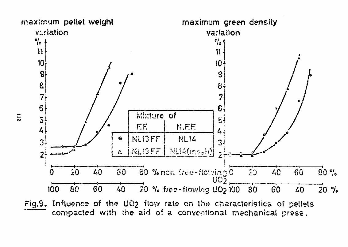
maximum pellet weightvariation«;
m10s8-7-6 -r** j
U .3 »
r
maximum green densityvariaaon
0
Mixture ofR F:
HL13FFNL13FF
40 60 80 %ncr; fi
K.F.F.
100 80 60 40 20 % free-flowing U02100 80 60 AO 20%
Fig.SL Influence of the U02 ftow rate on the characteristics of pelletscompacted with the aid of a conventional mechanical press.
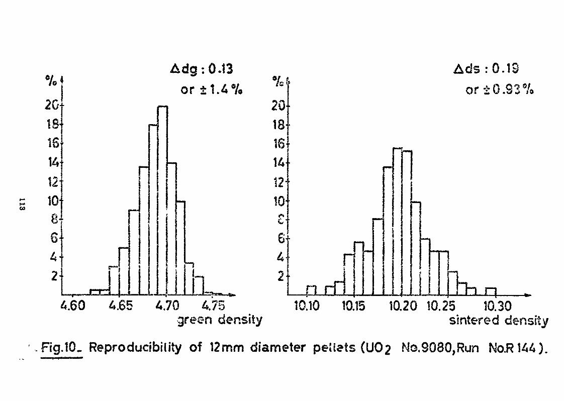
Adg:0*t3 Ads :G.18•'-*IV
2018-161412-ID-S'G-4-2
'
J
or ±1.4%•MM
mm
r•••
2018'16
1MB 1412-
•M ID-S'6-4
"!
2
»
!•
n rT
or ±G.83s/<
„
~M«l
*mm
M
•«•
«.
———— {
m n6.65 4.70 475 10.10 10.15
green density10.20 10.25 10.30
sintered density
Fig.10. Reproducibility of 12mm diameter peiiets (U02 No.9080,Run No.R144).
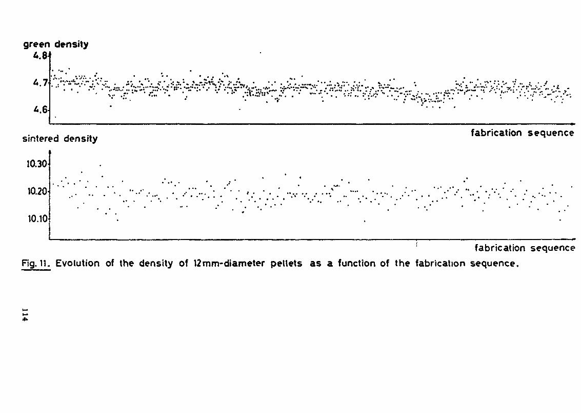
green density
4.7 •**•* •• ••«• ** .* *»
• • « * • • « • * •*•.!»* « • » • « • •• n .•*...» .•..i«*>H, » • / » • • ».»•••...,• «••«. . •«»••*•« . •• •*•. .»«••../..s .t- .. .. . . . . »»• %%••
sintered density
10.30
10.20
10.10
fabrication sequence
*•»• *
fabrication sequenceRg. il. Evolution of the density of 12mm-diameter pellets as a function of the fabrication sequence.
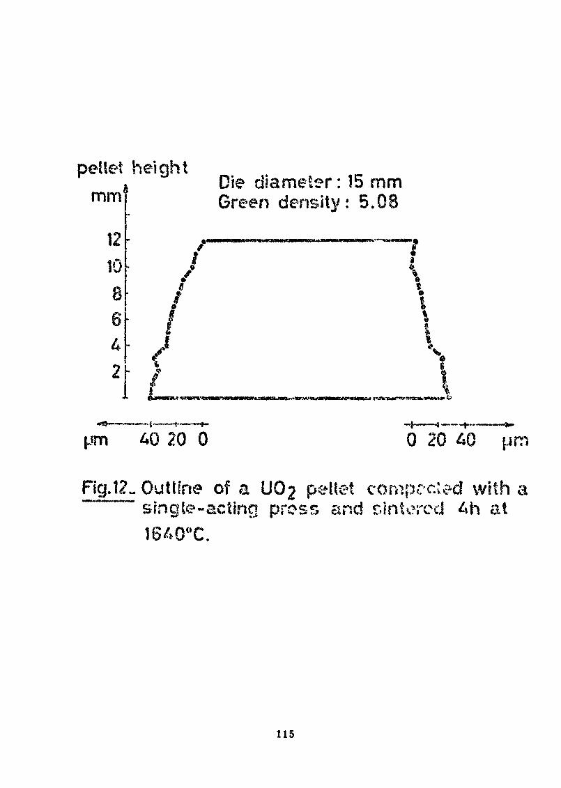
pellet heightmm
1210
42
Die diameter : !5 mmGreen density: 5,
T
»4> ft»
pm AO 20 0 0 20 40
of a UÛ2 pellet compccled with asingle-acting press and sintered 4h at
115
PERSPECTIVES DS L'KNRICHISSSKEK'T DANS LE CYCLS SU COMBUSTIBLS t
OPTIMISATION D'lfNB USIK2 BÏÏ DIFFUSION GAZ3USE
par
J,H, Coates - Commissariat à l'Energie Atomique,Paris.
P. Delarousse - Commissariat à l 'Energie Atomique,Centre de PierreXatte.
C. Lebrun - Société pour la Constructiond'Usines de Séparation Isotopique.
M» Mézin, « Commissariat à l'Energie Atomique,, " . Paris.
ABSTRACT
Between the theoretical characteristics of gaseous diffusion cascades); .ï
an area that has been largely explored since the first publications ofKarl Cohen in 1948, and the economic and, .industrial characteristics ofpresent gaseous diffusion plants, 'an area that has received a good deal ofattention at recent conferences, there is a less familiar middle groundwhere the theoretical and practical aspects meet: and it is here that onemay hope to find ways of optimizing the enrichment link of the fuel cyclebased on enriched uranium*
The paper describes this process of optimization and the prospects whichit holds out*
It consists not of a single operation but of a series of operations basedon the specific characteristics of the process itself and on what might becalled the "economic environment1' of the project. The elements of theoptimization process relate to the construction and start-up phases as muchas to the phase of commercial operation of the plant.
Attention is accordingly given to optimization of the cost of enricheduranium, optimization of the cost of separation work, and optimization ofspecific investment for a gaseous diffusion plant.
117
Since the quest for an over-all economic optimum requires numerousiterations, a summary of the mathematical tools developed by the C.E.A. forthis purpose is given.
Finally, the prospects for practical application of this optimization work
are reviewed»
RESUME
Entre le domaine des caractéristiques théoriques des cascades dediffusion gazeuse qui a été largement exploré depuis les premières publica-tions de Karl COHEN en 1948 et le domaine des caractéristiques économiqueset industrielles des usines de diffusion gazeuse qui a été fréquemmentévoqué dans des congrès récents, il existe un domaine moins connu où cesdivers aspects s'interpénétrent afin de permettre l'optimisation du maillonde l'enrichissement dans le cycle du combustible à uranium enrichi.
C'est la description de cette optimisation et les perspectivesqu'elle laisse entrevoir qui feront l'objet de la conférence.
En fait, cette optimisation ne comprend pas une opération unique maisun ensemble d'opérations qui reposent sur les caractéristiques spécifiques duprocédé d'une part, et sur ce que l'on peut appeler l'environnement économi-que du projet» En outre, ces optimisations portent aussi bien sur les phasesde construction et de démarrage que sur la phase d'exploitation commercialedes usines.
C'est ainsi que seront successivement passées en revue et commentées :l'optimisation du coût de l'uranium enrichi, l'optimisation du coût du travailde séparation, et l'optimisation de l'investissement spécifique pour une usinede diffusion glzeuse.
La recherche d'un optimum économique global exigeant de nombreusesitérations, un aperçu sera donné des moyens mathématiques qui ont été" misau point par le C.L.A. à cet effet.
Enfin,seront passées en revue les perspectives d'application quelaissent entrevoir ces travaux d'optimisation dans le domaine de l'enrichisse-ment.
RAPJPSLJW CYCLS PU COMBUSTIBLE A URANIUM Btf&ICgl, PB SES^ LA SITUATION
.PB VEHHÎCrtlSSEMlSiH
Tout outil de production doit, compte tenu des préoccupa-tions de rentabilité maximale, être optimisé. Ceci s'applique enparticulier aux différents maillons du cycle du combustible à.uranium enrichi qui est schématiquement représenté sur la figure 1»Pour faciliter la compréhension du jeu des optimisations qui serarepris en détail par la suite, le maillon de l'enrichissement qui
118
figure dans cette chaîne et qui se rapporte à une usine de diffu-sion gazeuse est ramifié vers la droite de la figure, afia deprésenter la décomposition de la valeur ajoutée correspondante.
Ainsi, il apparaît que le coût unitaire Cp de l'uraniumenrichi destiné aux réacteurs résulte de l'addition de deux termesqui représentent, d'une part une dépense en UFg naturel, d'autrepart une dépense en travail de séparation. C'est ce que traduitla relation :
CP « £ c, 4- M- CA
dans laquelle F/p et Cf sont respectivement la quantité et le coûtde l'uranium naturel consommé et AU/p et ÇA la quantité et le coûtdu travail de séparation dépensé. La flexibilité de fonctionnementde l'usine d'enrichissement prête à une optimisation du coût duproduit enrichi, optimisation qui dépend elle-même de l'enrichis-sement désiré*
Le coût de l'UPô naturel Cy dépend essentiellement du marché,étant donné que les frais de transport sont relativement négli-geables.
Le coût du travail de séparation ÇA est un compromis classi-que entre frais de réalisation et frais d'exploitation de l'usinede' séparation isotopique* Dans le cas de la diffusion gazeuse, ilfaut distinguer parmi les frais' d'exploitation la dépense enénergie qui résulte du produit de la consommation spécifiqued'énergie VA par la tarification de cette énergie t . D*ou larelation :
C$ = l£ • T* •*• *£ * t + autres frais d'exploitation
II est à noter que parmi ces différents termes, le tauxd'intértSt et par conséquent l'annuité de remboursement^", la tari-fication de l'énergie t, et dans une certaine mesure aussi lemontant de l'investissement à consentir 1/4 U sont des paramètresqui dépendent de l'environnement économique du projet. Par contre,la consommation spécifique en énergie W/àU, les frais d'exploita-tion et l'investissement I/A\J dépendent on grande partie de laqualité de la technique mise en oeuvre.
Nous verrons par la suite que I/fôu est sujet à un effet detaille important et donne lieu à plusieurs optimisations inter-médiaires. Nous verrons aussi que les frais d'exploitation del'usine hors énergie sont pratiquement inciôpandants de sa taille.
De manière à situer l'importance relative des différentesdépenses qui sont engagées dans le cycle, des valeurs indicativessont données qui permettent de constituer le diagramme de lafigure 2. Bien entendu, on ne saurait trop insister sur le ca-ractère très approximatif de cette décomposition puisqu'il fau-drait en toute rigueur préciser le type de réacteur considéré, leshypothèses techniques et économiques prises en compte, la méthodeutilisée, etc.* Mais du moins, les ordres de grandeur qui sontainsi donnés aideront à situer les optimisations qui vont mainte-nant être examinées plus en détail.
119
II - OPTIMISATIONS MISES E« OEUVflg DAKS 3/A POURSUITE D'UN PROJET
D'ENRICHISSEMENT
Les problèmes d'optimisation d'une usine de diffusiongazeuse interviennent à plusieurs stades.
Tout u*abord, lors de sa conception afin d'adapter l'usineau marché et au contexte technico~économique. Ensuite, lors de laconstruction afin d'en effectuer le démarrage dans les meilleuresconditions. Enfin, au cours de son exploitation afin de l'adapterà l'évolution du marché tant en quantité qu'en enrichissement,ainsi que d'y intégrer les améliorations technologiques obtenuesgrâce aux programmes de recherche et développement.
Mous allons passer successivement en revue ces différentsaspects.
II. 1 - CONCEPTION DU PROJET ; SES CARACTERISTIQUES PHYSIQUES ET SONBCONOMIQUS
Pans un projet d'une usine d'enrichissement par diffusiongazeuse on commence par la définition d'un marché qui s'étend enprincipe sur la durée d'exploitation de l'usine. Dans le contexteactuel» on peut penser qu'une usine de diffusion gazeuse aura unedurée d'exploitation voisine de celle des réacteurs nucléairesqu'elle dessert. Ceci permet donc de s'affranchir de considération»sur l'évolution des filières au cours du temps, étant entenduqu'une usine d'enrichissement peut être associée à un certainnombre de réacteurs qu'elle approvisionne en uranium enrichi.
Par contre, il faut dimensionner le marché à approvisionnerafin de choisir convenablement la taille de l'usine. Ceci nouspermet d'aborder un des premiers aspects importants de 1* optimi-sation qui est basé sur l'effet de taille.
a) Effet de taille
Un étage d'enrichissement est composé principalement d'uncompresseur, d'un échangeur, d'un certain nombre de réservoirset de tuyauteries, ainsi que de barrières. Les principauxmatériels, à l'exclusion des barrières, sont des produits clas-siques dans l'industrie chimique ou mécanique, et l'on sait quele prix relatif d'un matériel diminue lorsqu'on en accroît lataille et la puissance. On admet, en général, que le prix d'unmatériel varie, toutes choses égales par ailleurs, avec lapuissance 0,7 du débit qu'il traite. Ainsi, pour les matérielsconstitutifs d'une usine, l'effet de taille tend à la réalisa-tion d'unités dé grosse dimension puisqu*alors l'investissementspécifique diminue.
120
En ce qui concerne les barrières, l'effet est différent puisquela barrière eat un composant de petite dimension qu'il estnécessaire de rassembler en grand no'ibre pour constituer desdiffuseurs. On est donc confronté dans ce cas avec un effet desérie, le prix d'une barrière individuelle diminuant lorsquel'importance de la série croît. Cet nuire élément joue égale-ment dans le sens de l'accroissement de la taille de l'instal-lation. La figure 3 montre la variation du coût du travail deséparation avec la taille d'une usine de diffusion gazeuse.Ceci permet, en fonction du prix de Bi».rché, de définir unetaille critique en dessous de laquelle une installation nou-velle n'est plus compétitive»
b) Membre de tailles d'étapes
L* optimisation doit également prendre en compte un facteurimportant qui est 1'efficacité de l'usine. En effet, une usined'enrichissement est constituée d'une chaîne d'étages, et lemaximum d'efficacité résulte du non me-lange des flux au niveaude ces différents étages. Ceci conduit au concept de la casca-deidéale dans laquelle on a exclu, grâce à un choix judicieux desdébits, tous les renélanges. Ceci a cependant comme corollaireque chaque étage devrait être différent des autres, ce qui esttoutefois difficilement réalisable en pratique. Bn effet, uneusine de diffusion ga-aeus.e nécessaire pour produire un uraniumenrichi à 3 % compo-rte « en série plus d'un millier d'étages.Il est donc plus intéressant de perdre quelque peu sur l'effi-cacité de l'usine, mais gagner considérablement grâce à l'effetde série réalisable sur tous les matériels.
La figure 4 compare, des usines de structures différentes, etl'on voit, par exemple., que le passage de une à deux taillespermet un gain de l'ordre.,4e 20 $ sur l'efficacité de lacascade (cas a et e,). Par contre, l'examen du cas b montre quel'adjonction d'une troisième taille ne permet plus qu'un gainde l'ordre de 3 % sur l'efficacité. Une taille supplémentaireapporterait un gain encore plus faible. On pourrait aussiconcevoir une us.ino .constituée d'étages d'une seule taille ,dont certains seraient montés en parallèle pour donner un débitpar exemple deux, trois ou quatre fois celui de la tailleunitaire, afin de réaliser une meilleure approximation duprofil idéal. L'efficacité que l'on pourrait atteindre dansce cas (d) serait voisine.de 97 ?*. Toutefois, l'usine seraitconstituée de petits matériels, et l'on se priverait du béné-fice de l'effet de taille réalisable avec des appareillages detailles différentes. Les calculs montrent, du reste, qu'uneusine réalisée par mise en parallèle de petits étages a uneproduction moins économique qu'une usine identique réalisée enplusieurs tailles* Ceci amène à la conception d'une usine àplusieurs tailles d'étages.
c) Etages optimaux
Partant" d'une technologie donnée : performances de la barrièreet au compresseur, possibilité de réalisation le plus économi-quement possible des divers matériels, on constitue, dans une
121
première phase, un catalogue d'étapes optimaux, c'est-à-diredf-étages produisant au meilleur compte des unités de travailde séparation.
En fonction des discontinuités sur certains matériels» parexemple : débit des compresseurs lié à la vitesse de rotation,possibilité d'utiliser ou non telle technique pour la fabri-cation des échangeurs, possibilité d'assemblage des matérielsentre eux, on conçoit des étages pour chaque débit, et cedans toute la gamme des débits nécessaires. Ensuite et, grâceaux fonctions de prix des divers composants et des caracté-ristiques retenues, on déduit le coût de l'unité de travailde séparation produite dans chacun de ces étages. Cettefonction n'est du reste pas monotone et fait apparaître desdiscontinuités lors de l'apparition de butées technologiques,ce que la figure 3 ne faisait pas apparaître.
Le point délicat réside dans la détermination préalable del'ordre de grandeur des tailles probables, afin de faire desestimations aussi réalistes que possible. A cet effet, onfait appel à la constatation suivante : le coût minimum dutravail de séparation est voisin de celui produit dans1*usine ayant le.maximum d'efficacité pour un nombre detailles déterminé. Cette règle permet ainsi, en fonction dunombre de tailles, de déterminer à la fois la valeur de ceatailles et les séries des matériels mis en jeu, donc d'éta-blir les lois de prix dans des zones représentatives. C'està partir de ces étages optimaux que l'on constitue l'usine,dont le coût global de l'unité de travail de séparation estdéterminé à partir de celui des étages utilisés et de l'ef-ficacité d'ensemble de l'usine.
Ainsi, nous avons mis en lumière l'effet de la taille et dela technologie sur les choix. Ce ne sont toutefois pas leaseuls, et les paramètres économiques ont un poids aussidéterminant que celui des paramètres techniques dans lerésultat final.
Nous allons examiner en premier lieu l'influence de la tari-fication de l'électricité sur l'optimisation.
à) Tarification de l'électricité
C'est le facteur proportionnellement le plus influant surle coût de l'unité de travail de séparation. L'électricitéintervient sous deux aspects :
Tout d'abord, par l'intermédiaire de la consommation élec-trique spécifique, c'est-à-dire la quantité d'électricitéexprimée en kWh nécessaire pour produire une unité de travailde séparation. Cette valeur dépend fortement des caractéris-tiques des barrières que l'on sait réaliser, qui conditionnentle niveau de pression de fonctionnement. On arrive actuel-lement à des valeurs voisines de 2 400 kWh/UTS pouvantdescendre à environ 2 100 kWh/UTS si l'on fait de la récupé-ration d'énergie»
122
L'autre aspect, soua lequel intervient l'électricité, estcelui de. la tarification électrique. One uoine de diffusiongazeuse est une grosse consoiamatjrice d'cnerjie, puisqu'uneusine de 6 M.UTS/an nécessite en permanence une puissance del'ordre de 1 700 Krf. On tombe donc dans le domaine des tari-fications haute tension et longue durée. En outre, une usine*de diffusion gazeuse est un consommateur susceptible des'effacer lors d'incidents sur le rcseau au bénéfice d'autresclients ne pouvant tolérer d'interruption do leur fourniture.Il y a 'one là un bénéfice dont la diffusion gazeuse peuttirer quelques avantages. La part énergie représente environ50 % du coût de l'unité de travail de séparation. Dans cesconditions, une variation de 10 % sur la part énergie,qu'elle résulte d'une modification de la tarification ou dela consommation spécifique ou d'une combinaison des deux,conduira donc à une modification de 5 $» sur le coût del'unité de travail de séparation.
La figure 5 montre graphiquement la sensibilité de la diffu-sion gazeuse à une telle variation. On a fait égalementfigurer les autres facteurs, en particulier la partie amor-tissement du capital qui représente environ 45 % du total,et que nous allons examiner à présent.
e) Le taux d'intérêt
D'une manière tout à fait similaire à ce que nous avons vupour l'électricité, la part amortissement de l'unité detravail de séparation résulte de deux considérations, àsavoir, d'une part, l'investissement spécifique, c'est-à-dire l'investissement qu'il est nécessaire de faire pourproduire une unité de travail de séparation par an, et,d'autre part, le taux d'intérêt et la durée de remboursement.
L'investissement spécifique dépend du niveau technologiqueatteint, en particulier, des performances des barrières quidéfinissent le niveau de .pression de fonctionnement, doncla dimension des appareillages et leur coût de réalisation.r
fin ce qui concerne la longévité, les performances connuesdes matériels dans le temps et leur durability permettent defixer la durée d'amortissement sur laquelle il sera possiblede rembourser les emprunts et reconstituer le capital.L'autre aspect est représenté pir le taux d'intérêt pour,d'une part, la rémunération du capital et, d'autre part, lescharges de l'emprunt. L'ensemble de ces deux facteurs joue ,de manière similaire à la consommation spécifique et à latarification électrique, et l'on constate, toujours d'aprèsla figure 5, que la sensibilité aux annuités est peu diffé-rente de celle de l'énergie.
Ici une reamrque toutefois s'iupoae. Sa offet, pour la sim-plification de l'exposé, nous avons considéré séparémentl'effet de la tarification électrique et l'effet du tauxd'intérêt. En réalité les deux ne sont pas indépendants,puisque, comme nous l'avons fait remarquer, ils dépendent
123
l'un et l'autre du niveau de technologie adopté» en parti-culler des performances de la barrière. Ils apparaissent»en fait» par le jeu de 1'optimisation comme des frèressiamois. En effet, un gain sur la part énergie, qui résulte-rait par exemple d'une diminution de la tarification prati-quée, conduirait également à une diminution de l'investisse-ment spécifique par action sur les niveaux de pressions,donc les dimensions des appareillages. On constate quelorsque l'un augmente, l'autre croit également. On a donetout intérêt à minimiser l'un et l'autre de ces facteurspour le bénéfice de l'ensemble»
f) Autres paramètres
Leur importance est beaucoup plus faible puisqu'elle nereprésente que quelques pourcents du coût de l'unité detravail de séparation. Il s'agit de l'ensemble des fraisde fonctionnement que l'on peut décomposer en »
- personnel,
- frais d'exploitation divers, les fluides parexemple,
- l'entretien des matériels.
Une autre de leurs caractéristiques est que l'on ne disposeque de peu de moyens d'action sur ces facteurs. En effet ,dans une usine de taille donnée, le personnel est celuistrictement nécessaire, compte tenu d 'une automatisationpoussée de l'ensemble des tâches. Par ailleurs, les autresfrais d'exploitation représentés par les fluides et lesautres matières consommables ont été minimisés, et enfinles performances en endurance des matériels qui déterminentla part maintenance doivent nécessairement être supérieuresà plusieurs années pour la garniture des compresseurs et àune vingtaine d'années pour les autres matériels du circuit,si l'on veut que l'exploitation soit rentable» Un gain au-delà de ces valeurs, bien que restant intéressant, n'a pluad'effet déterminant sur le coût de l'unité de travail deséparation.
g) Premières conclusions
En résumé, nous avons passé en revue les différents paramètres quiinfluent sur la détermination et le dimensionnement des étages d'uneusine pour une production donnée. Nous avons pu noter au passageplusieurs optimisations :
- tout d'abord dans la définition de la cascade où il s'agit de trouverun optimum entre les avantages de l'effet de série sur les étages etl'amélioration du rendement de la cascade ce qui conduit à choisirle nombre de tailles d'étages et le nombre d'étages de chaque taille.
124
une optimisation dans la définition de l'étage où il s'agit de trouverun compromis entre ia réduction du coflt des appareillages dû à l'aug-mentation de pression et la baisse du facteur d'enrichissement quiaccompagne cette hausse de pression.
une optimisation dans la définition des composants où il s'agit dechoisir le meilleur compromis entre investissement initial et fraisd'exploitation et d'entretien.
enfin, une amélioration du couple technologie'environnement où unavantage sur l 'un entraîne une amélioration sur son complément.
Il est évident que la définition d'un projet se fait par approximationssuccessives, le résultat d'un cycle d'optimisations permettant de raffinerles données qui permettront d'aborder le cycle suivant.
t Ç
> \ t ' a.. iPar ailleurs, les études et expérimentations menées en parallèle, ainsique l'évolution, de la conjoncture économique peuvent avoir des incidencessur les choix.
Mais nous allons examiner quelques autres 'éléments qu'il est nécessairede prendre en compte lorsque l'usine est décidée, à savoir les problèmesliés à la construction et au démarrage des installations.
II* 2 - REALISATION PU PROJETOPy.HÏI.SATIOH PS LA CONSTftUCTIOM K? DU DEMARRAGE
a) Problèmes liés à la constructionj * »
Tout d'abord, précisons que la durée optimale de constructions'établit aux alentours de 6 «ans.
Cette durée comprend toutes les opérations, depuis les tra-vaux sur le .site, la aise en place des chaînes de fabricationdes matériels spécifiques, ainsi que le montage des composantset leur aise en
L'ensemble de ces opérations est lié aux cadences de fabri-cation possibles, elles-nêmes résultant des chaînes de fabri-cation que l'on construit* Ceci a, bien entendu, une incidencesur le coût des composants, dont il a bien évidemment ététenu compte au moment de la conception.
b) Problèmes liés au démarrage
Plusieurs politiques peuvent être envisagées, chacune avecsea avantages et ses inconvénients. Par exemple, on pourraiten concevoir une dano laquelle on réaliserait la totalité del'usine avant de la démarrer, et, dans ces conditions, il
125
s'écoulerait une dizaine de jours entre la mise en serviceet le début de production au régime nominal, ces 10 joursétant nécessaire pour la constitution du hold up isotopiquede l'installation.
Une autre politique consisterait à la mise en service deséléments au fur et à mesure de leur installation. Une tellestratégie aurait pour elle une bonne rentabilité de l'in-vestissement et un espoir de diminution des intérêts interca-laires. Toutefois, elle est peu praticable sous cette formeextrême, en ce sens qu'une usine tronquée, telle que cellerésultant de la mise à disposition de quelques centainesd'étages, ne permettrait pas une production à l'enrichisse-nent souhaité. On ne peut donc en pratique commencer ledémarrage que lorsque l'on a à sa disposition un nombred'étages minimum. On sera néanmoins dans des conditionsdéfavorables, ne serait-ce que par l'efficacité de l'usine*O.n est donc conduit & envisager d'autres stratégies, parexemple, de production à un enrichissetaent intermédiaireavec le premier assemblage réduit et réinjection de ce pro-duit partiellement enrichi lorsqu'on disposera d'un assem-blage plus performant, permettant ainsi l'atteinte d'un débitde production plus important, ou à une date avancée*La figure 6 est un exemple d'une stratégie avec productionintermédiaire et réinjection de cette production au cours del'étape suivante, afin d'atteindre une production importanteà 3 % dès que possible*
o) Le marché
Les hypothèses généralement prises en coopte supposent quela production est écoulée sans retard. Si ce n'était pas lecas, il faudrait prendre en compte les charges financièresrelatives à la durée de stockage. La non prise en compted'une telle hypothèse suppose implicitement que l'on connaîtbien le marché et que l'on a mis en place une politiquecommerciale permettant de trouver des débouchés aux pro-ductions visées. Un facteur intéressant provient du fait quela durée de construction d'une centrale nucléaire est un peuplus longue que la durée de construction d'une usine d'enri-chissement. Ainsi, on devrait savoir au moment de 'la décisionde construction de l'usine d'enrichissement quelles aont leacentrales qu'elle sera susceptible d'alimenter. On pourramême prendre des options environ un an ou 18 mois avant ladécision de construction, dans l'hypothèse où l'on envisageune production au cours de la période de démarrage* Parailleurs, on aura certainement intérêt à viser les enrichis-sements inférieurs à la valeur nominale de production, ce quiest le cas de la filière des réacteurs bouillants.
c) Autres éléments de décision
La réalisation d'une production en période de démarrage doitavoir un bilan positif. En effet, la réalisation d'une telleproduction nécessite des dépenses, telles que le recrutement
126
du personnel, l'énergie électrique consommés, l'uraniumnaturel de remplissage et l'uranium naturel d'alimentation.Ce dernier est en fait consommé fc un rythme plus importantque lors du fonctionnement de routine, compte tenu d'uneteneur de rejet supérieure à la valeur nossinale. Par ailleurs,la consommation électrique spécifique est accrue, comptetenu de l'efficacité plus mauvaise de l'assemblage dont ondispose, Moyennant quoi il faut être assuré que les recettesprovenant de la vente des produits restent supérieures auxdépenses que l'on encoure pour réaliser la production.
La décision résulte dans le cas général de l'examen deacomptes prévisionnels d'exploitation, dans lesquels on détailleannée par année ou fraction d'année par fraction d'année lebilan dépenses recettes pour différentes stratégies de pro-duction* Un tel examen a pour conséquence le renoncement àdes productions précoces lorsque la faible dimension del'assemblage conduit à des efficacités d'usine faibles et àdes consommations prohibitives d'uranium naturel»
e) Conclusions
Deux nouvelles optimisations sont apparues dans la phase deconstruction et de démarrage" :
t
~ tout d'abord, dans le choix de la taille des chaînesde fabrication des composants où s'opposent les avan-tages que procurent 1' et a Je CSG at des fabrications etl'accroissement des intérêts intercalaires deconstruction de l'usine d'enrichissement.
- ensuite, une optimisationideo régimes de démarragedans laquelle interviennent des considérations deremplissage, de production et d'efficacité de cascade.
11,3 - EXPLOITATION
Une usine de diffusion gazeuse est conçue pour un régimede fonctionnement déterminé. Toutefois, au cours de la vingtained'années d'exploitation de routine, des évolutions peuvent seproduire sur les besoins tant en teneur qu'en quantité : lesconditions de fonctionnement des réacteurs peuvent évoluer modi-fiant l'enrichissement des produits à recycler. Par ailleurs, lepassage en réacteur produit des isotopes nouveaux de l'uraniumdont il faut tenir compte dans le, fonctionnement de l'usine.Enfin, la connaissance cumulée du fonctionnement des matérielspermet éventuellement d'en tirer meilleur parti (accroissementde la puissance).
Nous allons examiner les différents moyens permettant demodifier les conditions de fonctionnement de l'usine
127
a) Modulât i ondes pré s s ions
La modulation des pressions peut revêtir différents aspects ,mais reste toujours soumise Ji la contrainte correspondant auxlimites de fonctionnement possibles des matériels.
Une première possibilité consiste en la modulation monotonedes pressions, c'est-à-dire d'un gonflage ou d'un dégonflagede l'ensemble des étages de l'usine. Ceci permet une évolutionde la puissance de séparation (voir figure 7) tout en mainte-nant sensiblement constant le coût du travail de séparation.Le fonctionnement de l'usine n'est plus optimal» mais on peuts'adapter dans une gamme assez large aux fluctuations dumarché. L'efficacité de l'usine est peu changée, mais l'onassiste à une certaine modification de la teneur de rejet.
Une autre possibilité est offerte par une modulation diffé-rentielle des étages.
b) Flexibilité d'alimentation
II s'agit d'une possibilité d'action sur l'usine en jouantsur le débit d'alimentation. L'accroissement de ce débitpermet d'augmenter la production, avec, en contrepartie,l'augmentation de la teneur du soutirage pauvre.
La figure 8 montre la variation de la production et de lateneur de rejet en fonction du débit d'aliaentation» Danacertaines conditions, le produit appauvri au-dessus de lateneur optimale peut être réinjecté soit dans la même uaiaeen période de pléthore, soit dans une installation nouvelletemporairement surpuissante. La flexibilité en alimentationnaturelle conduit à s'éloigner de l'optimum et pénalisequelque peu le coût du produit. Une telle stratégie posedes problèmes de surplus ou de déficit en uranium natureldans le cas d'une politique d'enrichissement à façon*
c) Prix de l'uranium naturel
Le prix de l'uranium naturel est un élément susceptible demodifier les conditions de fonctionnement d'une usine dediffusion gazeuse, en ce sens que la teneur de rejet opti-male résulte directement du rapport coût de l'alimentationau coût du travail de séparation. Si l'on s'attache it lavariation du prix de marché de l'uranium naturel vis-à-visd'une usine dont le coût du travail de séparation est fixé,on doit assister à une évolution de la teneur de rejet del'usine d'enrichissement en fonction de l'évolution ducoût de l'uranium naturel.
La figure 9 montre l'évolution de la teneur de rejet enfonction de ce paramètre.
128
La figure 10 représents, dans certaines hypothèses, lavariation de la teneur de rejet en fonction du coût del'unité de travail de séparation pour une valeur déterminéedu prix de l'uranium naturel d'alimentation.
d) E yolution de 1 a toneur du produ* *
Une usine déterminée peut produire à une teneur isotopiquedifférente de la teneur nominale ; ceci permet une adaptationvis-à-vis en partxculier d'une évolution du aarché résultant,par exemple, d'une codification des teneurs optimales néces-saire dans les réacteurs de puissance, ou d'une évolution dela répartition entre les différentes filières connues.
La figure t1 décrit les évolutions de production possiblesdans une usine donnée en fonction de la teneur isotopique etl'effet sur les teneurs de rejet de fonctionnement.
e) Autre aspects
D'autres paramètres sont éventxiellement à prendre en comptedans l'optimisation du fonctionnement d'une usine de diffu-sion gazeuse. Toutefois, ces éléments n'ont qu'une portéerelativement faible dans les choix initiaux, c'est pourquoinous nous contenterons simplement de les énumérer. Il s'agiten particulier de :
« L'évolution de la teneur isotopique des uraniumspartiellement eririchis recyclés des réacteurs. Lesteneurs prévues actuellement sont comprises entrela teneur naturelle et un enrichissement d'environ0,85 #• Béa progrès accomplis sur les taux d'irra-diation des combustibles en pile permettraient pro-bablement une baisse de la teneur des produitsréinjectés.
- Le recyclage d'uranium passé en pile a pour corol-laire la présence de nouveaux isotopes, en particu-lier de l'uranium 236 provenant de captures neutro-niques au rythme de 1 capture pour 5 fissions. Onconçoit que le fonctionnement d'une usine de diffu-sion gazeuse alimentée principalement par des pro-duits recyclés en provenance des réacteurs puisseconduire à un accroissement sensible de la teneuren uranium 2jj6. Ceci peut conduire, dans la mesureoîi les produits recyclés représentent une partimportante de l'alimentation et oîi leur teneur estvoisine ou supérieure à la teneur naturelle, a unebaisse d'efficacité dans la séparation U 235 - U 258.Bien que ceci n'ait que peu d'influence dans uneoptique de doublement accéléré de la puissancenucléaire installée, l'effet n'est pas nécessairementnégligeable si une usine de diffusion gaaeuae sertuniquement à assurer les recharges d'un certainnombre de réacteurs de puissance.
129
- Enfin, un autre élément susceptible d ' inf luer sur l'opti-misation d'ensemble résulte de l ' introduction d'améliora-tions aux matériels existants. Un tel facteur est délicatà prendre en compte a priori, et il est de pratiquehabituelle de ne prendre les anéliorations en compte quedans la mesure oîi elles apportent un gain substantiel surla période d'exploitation restant à courir, compte tenude leur installation dans une usine existante et detout*s les contraintes q».e cela implique.
Ill - MOYJSKS MATHEMATIQUES UTILISES
La variété des projets étudiés et le caractère répétitif desopérations d'optimisation ont conduit le CEA à mettre sur pied un outillagemathématique d'une ampleur considérable. Trois ensembles de programmesméritent plus particulièrement d'être cités :
- le modèle de flexibilité d'une usine- le modèle d'optimisation d'une usine- le modèle économique de projet d'usine.
111.1 - LB MODELÉ PS FLEXIBILITE
II est utilisé aussi bien pour déterminer les régimes de démarrageque pour déterminer les régimes de production d'une usine d'enrichissement.Il permet de connaître les possibilités d'adaptation d'un assemblaged'étages d'enrichissement à une évolution des besoins en teneur et enquantité. On peut par exemple faire varier la production à teneur constanteen agissant uniquement sur le débit d'alimentation en UFg naturel. Bienentendu, dans ces conditions la teneur de rejet évolue. Les courbescorrespondantes sont appelées courbes de flexibilité (voir la figure 12).Elles font apparaître une saturation lorsque l'alimentation devient trèsgrande.
Avec une affinité et une translation, on peut déduire de la courbede flexibilité P (F) une représentation de la variation du coût du produitenrichi en fonction de la production P, et de là obtenir une représentationgéométrique des concepts économiques classiques : coût unitaire moyen,coût marginal et coût unitaire moyen minimum (voir figure t3).
Le modèle de base est complété par un jeu de modèles de flexibilitédifférentielle qui permet d'explorer l'incidence de n'importe quel para-mètre sur les caractéristiques physiques et économiques de la production,et par une possibilité de prise en compte des données relatives au compor-tement des matériels.
111.2 - fcB HODSUB D'OPTIMISATION D 'UNE USINES
Du fait du caractère répétitif des étages d'enrichissement, lesusines de diffusion gazeuse se prêtent bien à une étude poussée de l'opti-misation des appareillages installés et de l'investissement correspondant,le problème peut se résumer de la façon suivante : sachant que la clientèle
130
demande une production caractérisée par d**» quantités d'uranium enrichiet les concentrations correspondantes, définir l'usine qui permet de lesproduire au meilleur prix et calculer ce prix.
Nous venons de voir que pour des valeurs de Cf et de C^ données,le meilleur prix de l'uranium enrichi sst obtenu pour une teneur derejet définie. Il faudrait donc en théoi-ie connaître déjà le coût dutravail de séparation pour fixer la teneur de rejet, donc pour figerl'usine, ce qui nécessiterait une optimisation par itération.
En fait, on s'aperçoit que le coût du travail de séparation est trèspeu sensible aux variations de la teneur 4e rejet. Il suffit donc de donnerà celle-ci une valeur plausible pour obtenir un C très proche del'optimum.
Une fois définis les objectifs de production et la teneur de rejetil faut entreprendre le calcul de la cascade rtellu conduisant au coûtminimal du travail de séparation. La méthode est la suivante :
- des formules sont établies donnant la variation du prix. des équipements en fonction de leur taille.
»- on relie la taille des équipements aux paramètres deprocédé : débits, niveaux de pression, etc...
- on définit le coût unitaire du ti-avail de séparation del'étage en fonction de sa latgeur. Inversement, on déter-mine pour chaque valeur de la largeur d'étage u«a jeude valeurs des paramètres de procédé qui conduisent à uncoût unitaire du travail de séparation d'étage qui soitminimal.
- on établit la variation du coût, unitaire minimal dutravail de séparation en fonction du niveau de remplissage.
- oti détermine par ailleurs le nombre de tailles d'étagesnécessaires et on définit pour chacune de ces tailleset le nombre d'étages nécessaires et leur niveau deremplissage.
- on calcule enfin le prix de revient moyen brut, puisen tenant compte de l'efficacité de l'assemblage, le prixde revient moyen net de l'unité de travail de séparationde l'usine.
La méthode ainsi décrite permet l'optimisation globale de la cascadeet sa définition d'ensemble mais elle ne fournit encore qu'une estimationthéorique dans la mesure ott elle ne repo&e que sur des formules de prix.Le coût réel sera donné par l'étude complète du projet. Au cours de celle-ci,des optimisations partielles pourront ôtro recherchées, selon une méthodeplus fine, comparant à production constante le coût de réalisationet les dépenses d'exploitation d'un élément déterminé.
111-3 " kB MODSJ.KSCOHOFICUp; PS PKOJKT D'USIBK
C'est une exploitation de l'ensemble des éléments technico-économi-ques d'un projet d'usine, qui est destiné»?, à dégager sous une forme syn-thétique et quantifiée la compétitivité de l'entreprise.
131
La liste qui suit donne une idée du grand nombre de paramètresqui sont pris en compte dans ce modèle : citons parmi les donnéescommerciales :
- la capacité de l'usine, sa durée de vie, le facteurd'utilisation, les perspectives de prix de vente,
parmi les données techniques :
- l'investissement, la consommation en énergie, l'endurance,les frais d'entretien et d'exploitation, les progrèstechnologiques,
parmi les données économiques :
- le plan de financement, la rémunération du capital, lerégime fiscal, le glissement des prix, l'investissement,le prix de l'énergie, le prix de la main d'oeuvre.
Faisant appel à toutes ces données, sont alors déterminés année -parannée, aussi bien pendant les périodes de construction, de démarrage etde production, les comptes prévisionnels de l'entreprise selon laméthode du cash flow actualisé.
Sont enfin tirées de ces exploitations, les caractéristiques d'en-semble du projet : durée de remboursement du financement, rendement ducapital, etc...
IV - CONCLUSION D'ENSEMBLE
Be l'examen de ces divers éléments, il résulte que leproblème d'optimisation d 'un projet d'enrichissement ae situeprincipalement au cours de la conception, de la constructionet an démarrage. Ce sont, en effet , des étapes qui condi-tionnent avec une certaine certitude l'ensemble de l'exploi-tation d'une usine de diffusion gazeuse, et qui peuvent, dece fait, être pris en compte dans le modèle économique d'en-semble du projet.
Au stade de l'exploitation interviennent, outre l'actioncommerciale qui détermine le plan de charge de l'usine d'enri-chissement, des éléments extérieurs : prix de l'UPg naturel,recyclage de l'uranium dos réacteurs, etc», qui appellent deeoptimisations touchant plusieurs maillons du cycle du combus-tible.
132
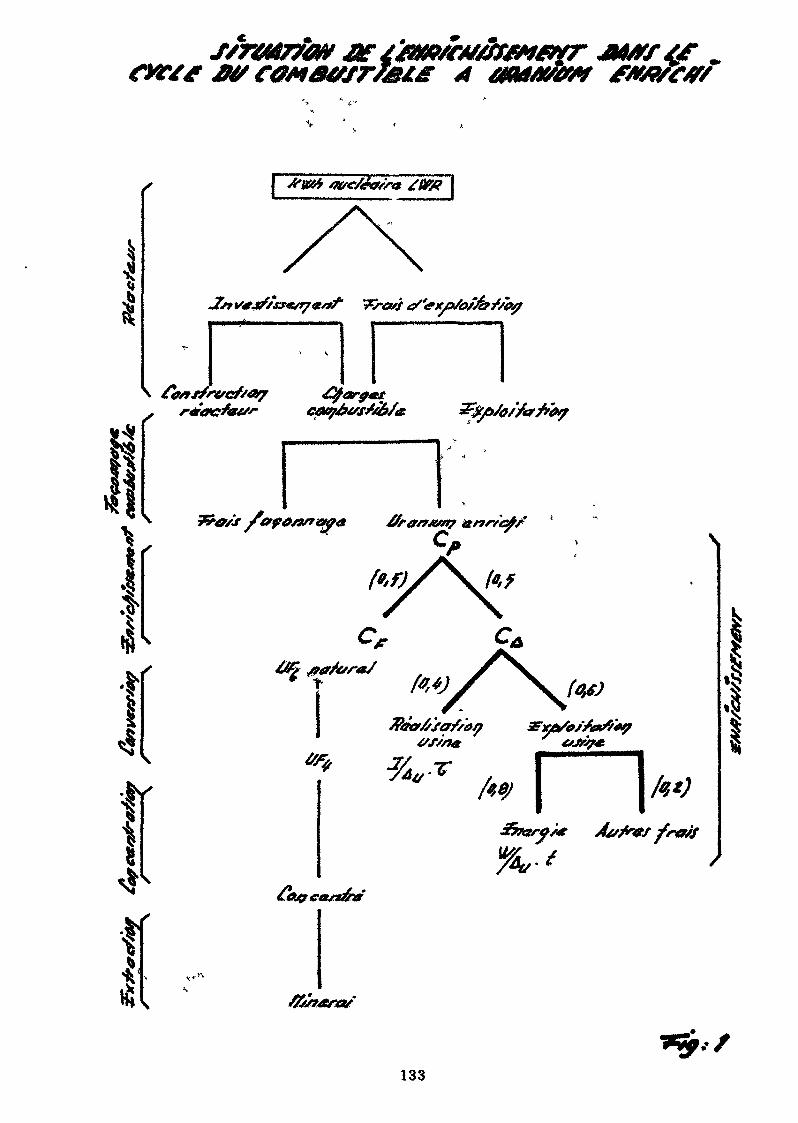
H
|£
lr
I *W6 wc/ftfs'se ZW# [
%,-tAvfrtf frwf
I
133
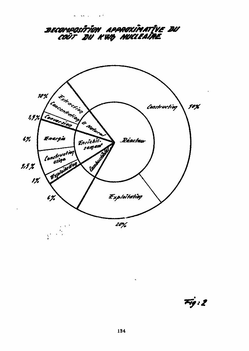
#0
f'X
134
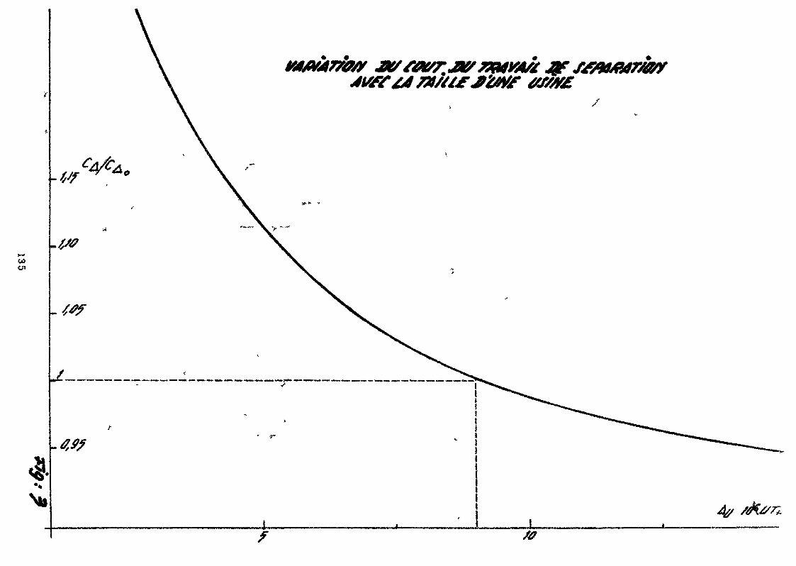
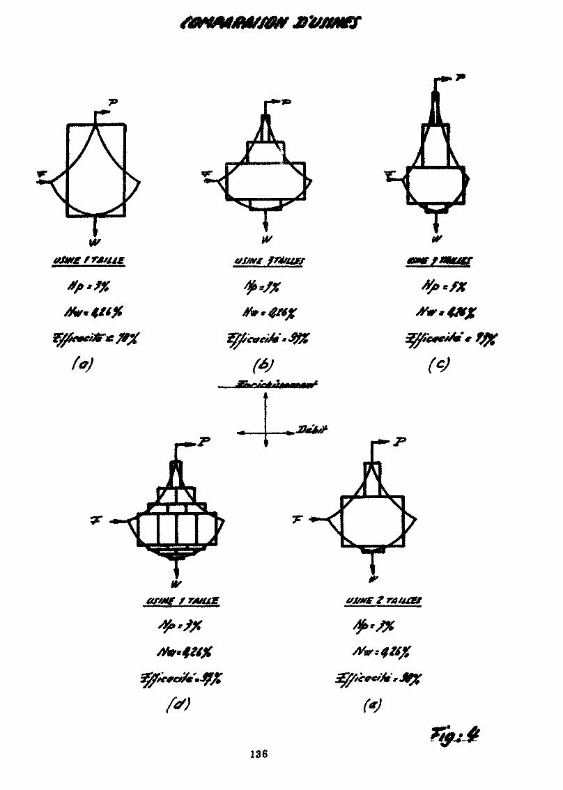
*< yw
tfjtfte fré/uf
fy*?%
w
f'J
ty*f*#**&*#
35%c*&Af*j%
w
2I*À&
"ILLLr >
136
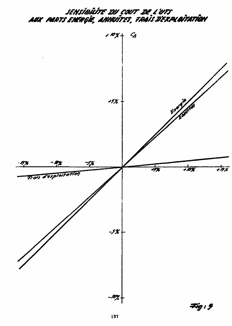
-»*
137
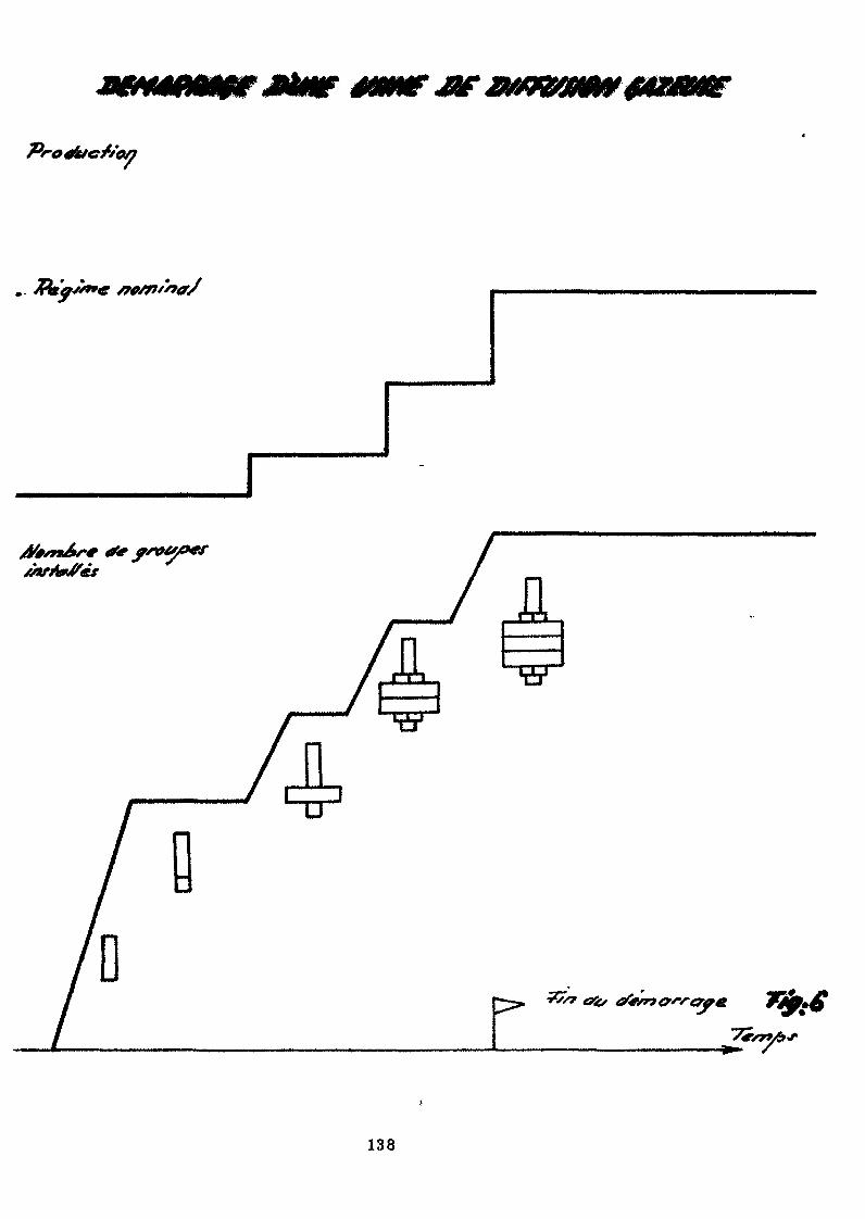
fl
/
138
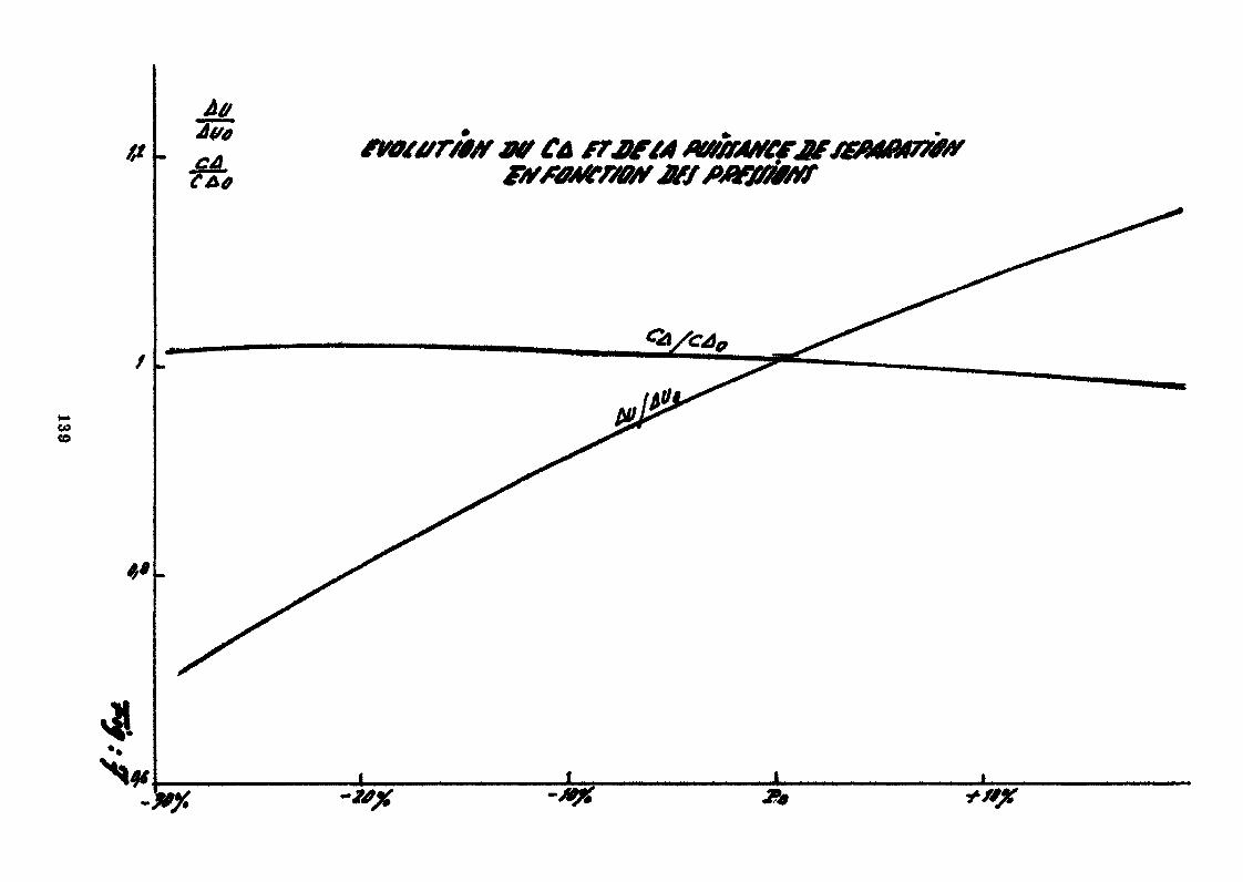
COco
Àff
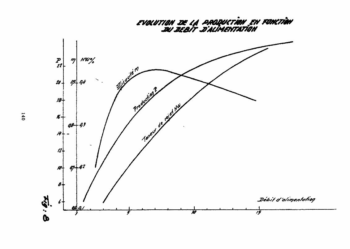
*».
0»
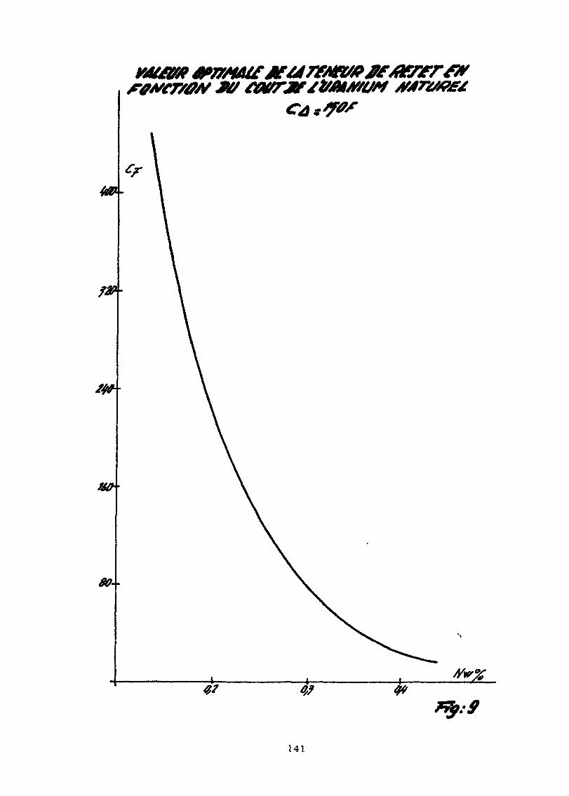
BO-
141
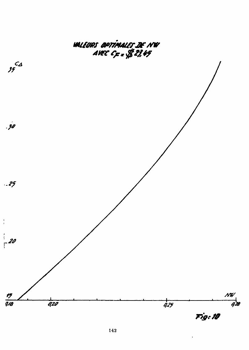
142
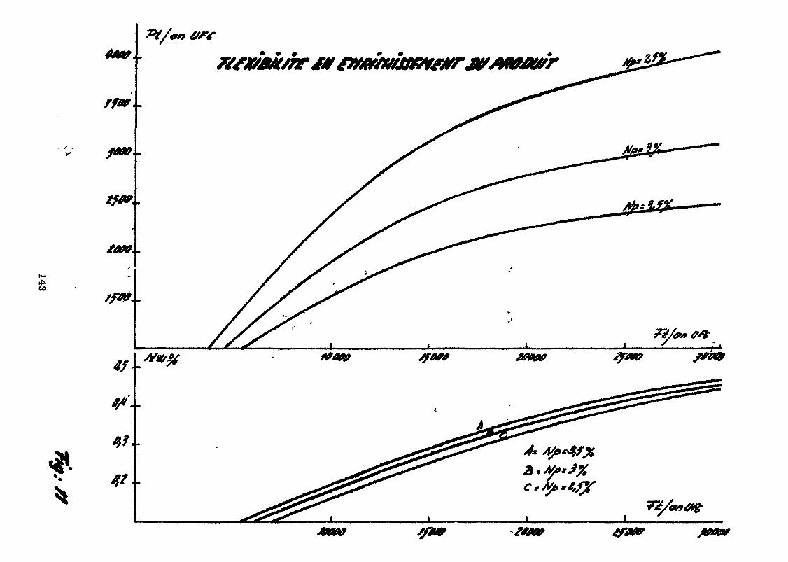
GO
*,?..
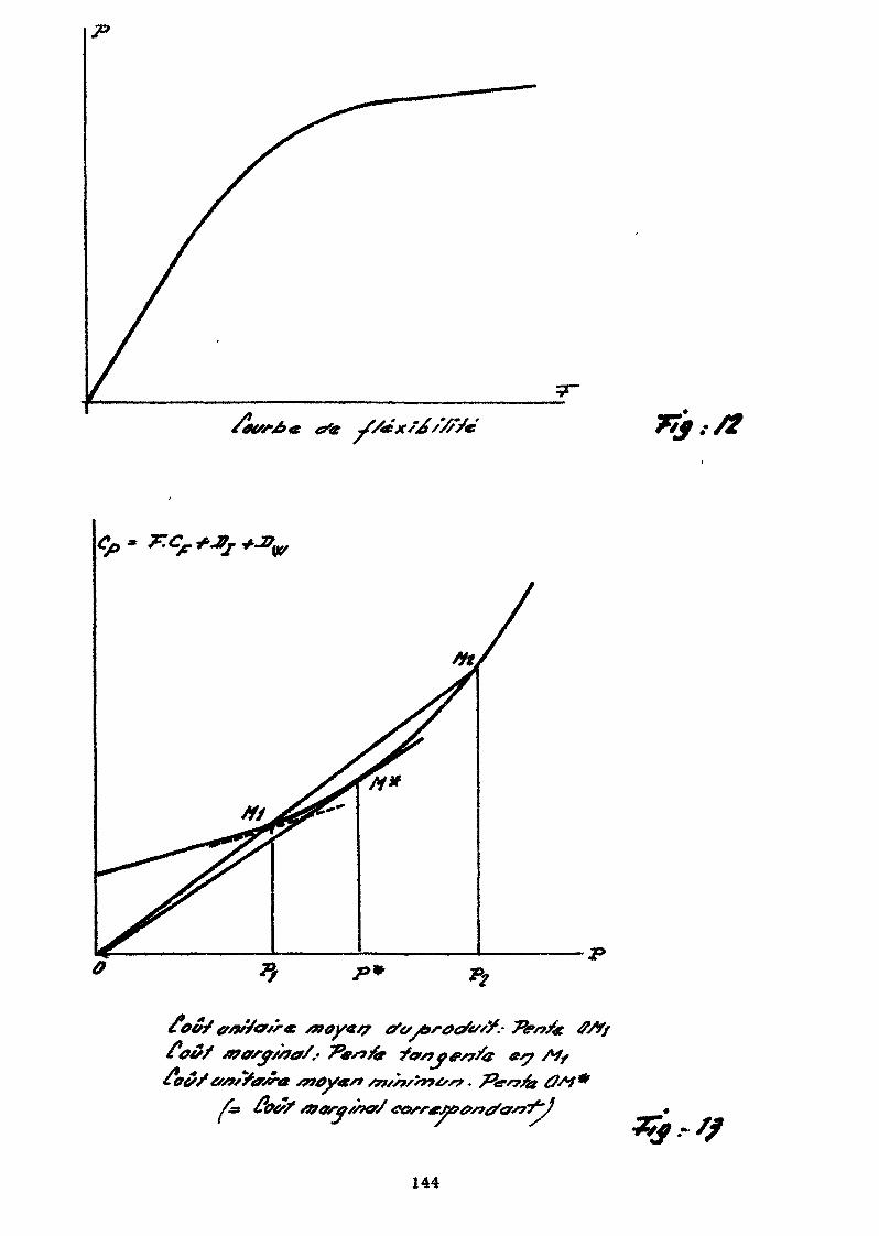
,/f
/«
144
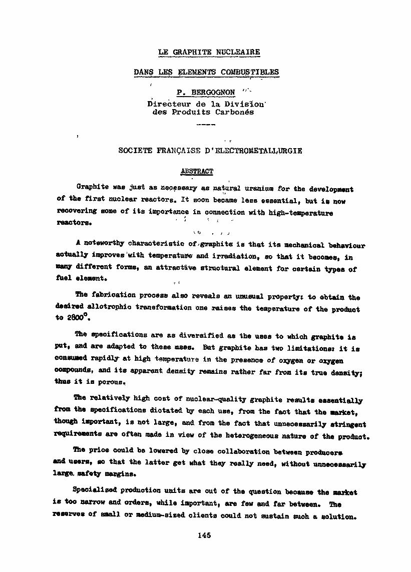
LE GRAPHITE NUCLEAIRE
DANg LES ELEMENTS COMBUSTIBLES
P. BERGOGNQN 'Directeur de la Division'des Produits Carbonés
t r
SOCIETE FRANÇAISE D ' EL12CTRQMETALLURGIE
ABSTRACT
Graphite was just as necessary as natural uranium for the developmentof the first nuclear reactors. It soon became less essential, but is nowrecovering some of its importance in connection with high-temperaturereactors* ' ' ' *
x f- , i jA noteworthy characteristic of.graphite: is that its mechanical behaviour
actually improves'with temperature and irradiation, so that it becomes, inmany different forms, an attractive structural element for certain type» offuel element*
The fabrication process also reveals an unusual property: to obtain thedesired allotrophic transformation one raises the temperature of the productto 2800°.
The specifications are as diversified as the uses to which graphite isput, and are adapted to these use». But graphite has two limitations: it i»consumed rapidly at high temperature in the presence of oxygen or oxygencompounds, and its apparent density remains rather far from its true density;thus it is porous.
The relatively high cost of nuclear-quality graphite results essentiallyfrom the specifications dictated by each use, from the fact that the market,though important, is not large, and from the fact that unnecessarily stringentrequirements are often made in view of the heterogeneous nature of the product.
The price could be lowered by close collaboration between producer»and users, so that the latter get what they really need, without unnecessarilylarge, safety margins.
Specialized production units are out of the question because the marketis too narrow and orders, while important, are few and far between. Thereserve» of small or medium-sized clients could not sustain such a solution.
145
RESUIVIE
Le graphite a été aussi nécessaire que l'uranium naturel dans ledéveloppement des premiers réacteurs nucléaires. Il a rapidementperdu de son importance, mais retrouve un regain drintérêt dans lesréacteurs haute température.
Sa caractéristique remarquable de voir sa tenue mécanique augmen-ter avec la température et l'irradiation en fait un élément de struc-ture très intéressant pour certains éléments combustibles, et cecisous des formes très variées.
Le procédé de fabrication fait également ressortir un élémentassez unique : porter le produit à 2.800° pour obtenir la transforma-tion allotropique souhaitée.
Les spécifications sont aussi diversifiées que les utilisations,et sont adaptées à ces utilisations, mais le graphite a deux limita-tions : il se consume rapidement à haute température en présenced'oxygène ou de composés oxygénés ; sa densité apparente reste assezéloignée de sa densité réelle, il est donc poreux.
Le coût plus élevé du graphite nucléaire résulte essentiellementde spécifications particulières à chaque emploi, de marchés importantsmais exigus, d'exigences souvent inutiles mais liées à son aspecthétérogène»
Les prix peuvent être abaissés par une collaboration étroite entreproducteur et utilisateur, pour que ce dernier obtienne effectivementce dont il a vraiment besoin, sans prendre de marges de sécuritéinutiles.
On ne peut pas concevoir d'unités de production spécialisées, carle marché reste trop étroit et sous forme de commandes importantesmais rares. Le fonds de roulement de petits ou moyens clients estinconcevable.
L'uranium naturel et le graphite ont été les deux éléments essen-tiels qui ont permis la réalisation de la première réaction en chaînele 2 Décembre 1942, il y a rooim> de trente ans. Mais, comme tous lesprécurseurs, ils n'ont pas eu longtemps raison et ont été plus ou moins
146
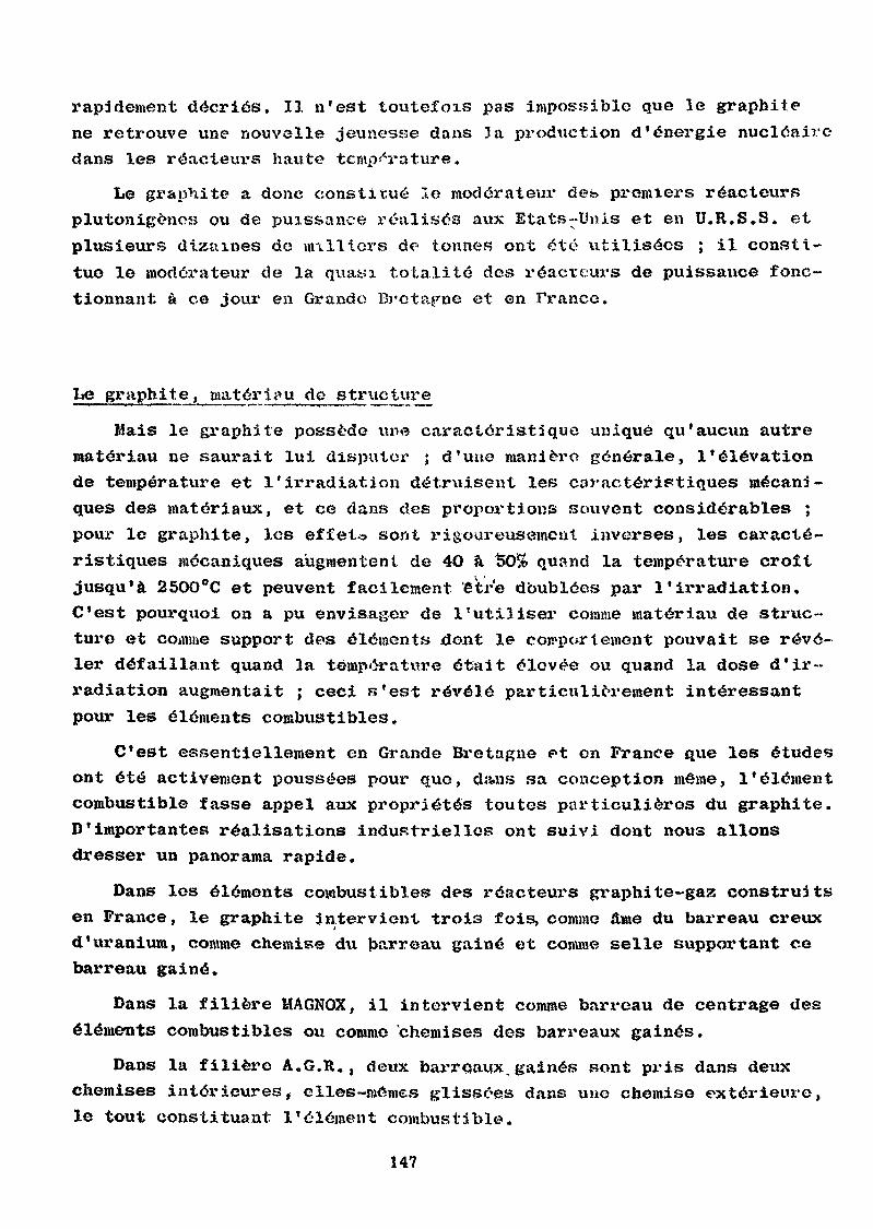
rapidement décriés. Il n'est toutefois pas impossible que le graphitene retrouve une nouvelle jeunesse dans 3a production d'énergie nucléairedans les réacteui-s haute température.
Le graphite a donc constitué le modérateur des premiers réacteursplutonigèncs ou de puissance réalisas aux Etats-Unis et en U.R.S.S. etplusieurs dizaines de milliers de tonnes ont été utilisées ; il consti-tue le modérateur de la quasi totalité des réacteurs de puissance fonc-tionnant à ce jour en Grande Bretagne et en France.
Le graphi t e, mater i<\u de structui*e
Mais le graphite possède une caractéristique unique qu'aucun autrematériau ne saurait lui disputer ; d'une manière générale, l'élévationde température et l'irradiation détruisent les caractéristiques mécani-ques des matériaux, et ce dans des proportions souvent considérables ;pour le graphite, les effet*» sont rigoureusement inverses, les caracté-ristiques mécaniques augmentent de 4O à 50& quand la température croîtjusqu'à 250O°C et peuvent facilement 'être doublées par l'irradiation.C'est pourquoi on a pu envisager de l'utiliser comme matériau de struc-ture et comme support des éléments dont le comportement pouvait se révé-ler défaillant quand la temperature était élevée ou quand la dose d'ir-radiation augmentait ; ceci s'est révélé particulièrement intéressantpour les éléments combustibles»
C'est essentiellement en Grande Bretagne et en France que les étudesont été activement poussées pour que, da»ns sa conception môme, l'élémentcombustible fasse appel aux propriétés toutes particulières du graphite.D'importantes réalisations industrielles ont suivi dont nous allonsdresser un panorama rapide.
Dans les éléments combustibles des réacteurs graphite-gajs construitsen Prance, le graphite intervient trois fois, comme âme du barreau creuxd'uranium, comme chemise du barreau gainé et comme selle supportant cebarreau gainé.
Dans la filière MAGNOX, il intervient comme barreau de centrage deséléments combustibles o« comme chemises des barreaux gainés.
Dans la filière A.G.R., deux barreaux.gainés sont pris dans deuxchemises intérieures, clles-mômes glissées dans une chemise extérieure,le tout constituant l'élément combustible.
147
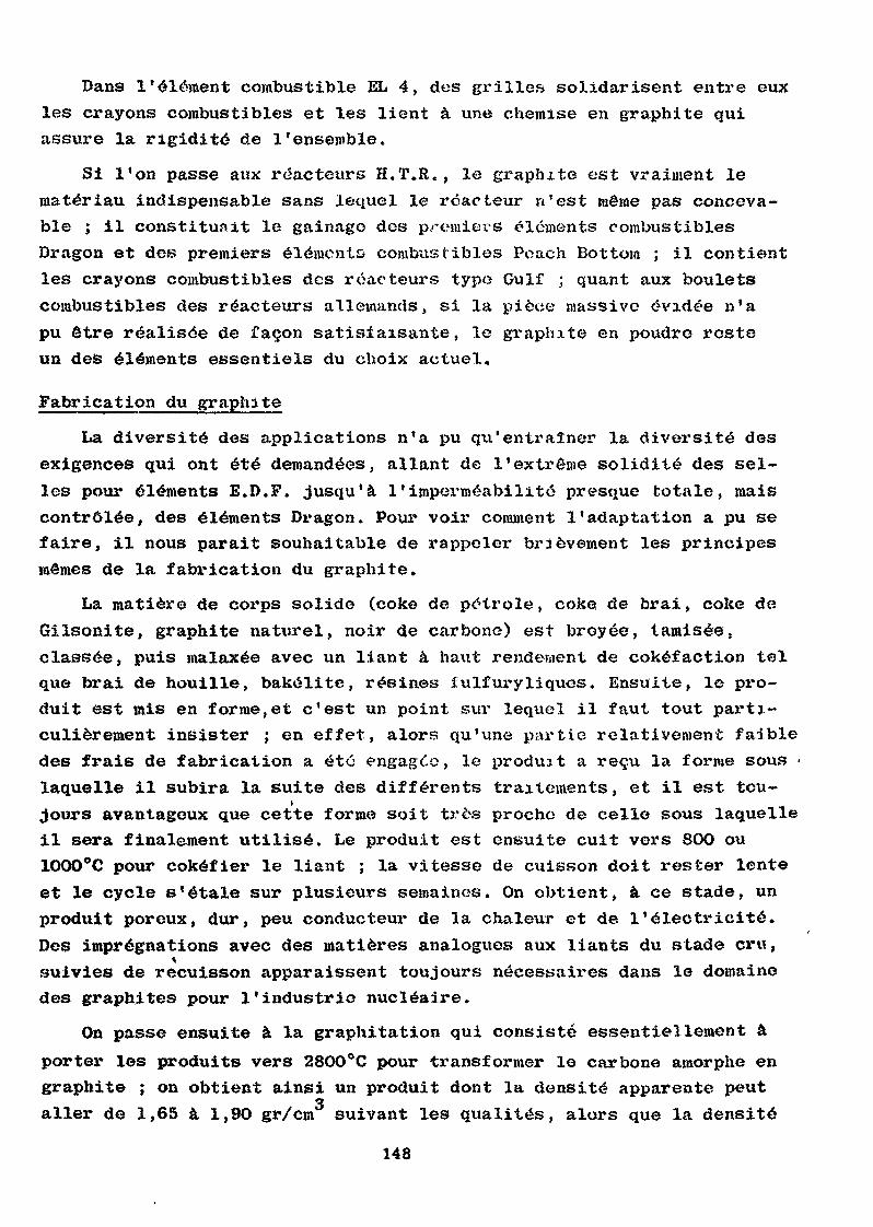
Dans l'élément combustible EL 4, des grilles solidarisent entre euxles crayons combustibles et les lient à une chemise en graphite quiassure la rigidité de l'ensemble.
Si l'on passe aux réacteurs H.T.R. , le graphite est vraiment lematériau indispensable sans lequel le réacteur n'est même pas conceva-ble ; il constituait le gainago des premiers éléments combustiblesDragon et des premiers éléments combustibles Poach Bottom ; il contientles crayons combustibles des réacteurs typo Gulf ; quant aux bouletscombustibles des réacteurs allemands, si la pièce massive évidée n'apu être réalisée de façon satisfaisante, le graphite en poudre resteun des éléments essentiels du choix actuel,
Fabrication du graphite
La diversité des applications n'a pu qu'entraîner la diversité desexigences qui ont été demandées, allant de l'extrême solidité des sel-les pour éléments E.D.F. jusqu'à l'imperméabilité presque totale, maiscontrôlée, des éléments Dragon. Pour voir comment l'adaptation a pu sefaire, il nous parait souhaitable de rappeler brièvement les principesmêmes de la fabrication du graphite.
La matière de corps solide (coke de pétrole, coke de brai, coke deGîlsonite, graphite naturel, noir de carbone) est broyée, tamisée,classée, puis malaxée avec un liant à haxit rendement de cokéfaction telque brai de houille, bakélite, résines fulfuryliques. Ensuite, le pro-duit est mis en forme,et c'est un point sur lequel il faut tout parti-culièrement insister ; en effet, alors qu'une partie relativement faibledes frais de fabrication a été engagée, le produit a reçu la forme sous •laquelle il subira la suite des différents traitements, et il est tou-jours avantageux que cette forme soit très proche de celle sous laquelleil sera finalement utilisé. Le produit est ensuite cuit vers 8OO ou1000°C pour cokéfier le liant ; la vitesse de cuisson doit rester lenteet le cycle s'étale sur plusieurs semaines. On obtient, à ce stade, unproduit poreux, dur, peu conducteur de la chaleur et de l'électricité.Des imprégnations avec des matières analogues aux liants du stade cru,tsuivies de recuisson apparaissent toujours nécessaires dans le domainedes graphites pour l'industrie nucléaire.
On passe ensuite à la graphitation qui consisté essentiellement àporter les produits vers 28OO°C pour transformer le carbone amorphe engraphite ; on obtient ainsi un produit dont la densité apparente peut3allei* de 1,65 à 1,9O gr/cm suivant les qxialités, alors que la densité
148
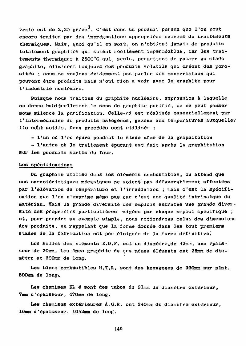
vraie est de 2,25 gr/cm . C'est donc Un produit porexix que l'on peutencore traiter par des imprégnations appropriées suivies de traitementsthermiques. Mais, quoi qu'il en soit, on n'obtient jamais de produitstotalement graphités qui soient réellement imperméables», car les trai-tements thermiques à 2SOO°G qui, seuls, permettent de passer au stadegraphite, éliminent toujours des produits volatils qui créent des poro-sités ; nous ne voulons évidemment pas parler des monocristaxix quipeuvent être produits mais n'ont rien à voir avec le graphite pourl'industrie nucléaire.
Puisque nous traitons du graphite nucléaire, expression à laquelleon donne habituellement le sens de graphite purifié, on ne peut passersous silence la purification. Celle-cj est réalisée essentiellement parl'intermédiaire de produits halogènes, gaaeux aux températures auxquellesils sdht actifs. Deux procédés sont utilisés :
- l'un où l'on épure pendant le stade môme de la graphitation- l'autre où le traitement épurant est fait après la graphitation
sur les produits sortis du four.
Les spécifications
Du graphite utilisé dans les éléments combustibles, on attend queses caractéristiques mécaniques ne soient' pas défavorablement affectéespar l'élévation de températxire et l'irradiation ; mais c'est la spécifi-cation que l'on n'exprime même pas car c'est une qualité intrinsèque dumatériau. Mais la grande diversité des emplois entraîne une grande diver-sité des propriétés particulières >xigées par chaque emploi spécifique ;et, pour prendre un exemple simple, nous retiendrons celui des dimensionsdes produits, en rappelant que la forme donnée dans les tout premiersstades de la fabrication est peu éloignée de la forme définitive'.
Les selles des éléments E.D.F. ont un diamètre,de 42mm, une épais-seur de 20mm. Les âmes graphite de ces mêmes éléments ont 25mm de dia-mètre et 60Omm de long.
Les blocs combustibles H.T.R. sont des hexagones de 36Omm sur plat,800mm de long*
Les chemises EL 4 sont des tubes de 93mm de diamètre extérieur,7mm d'épaisseur, 47Omm de long.
Les chemises extérieures A.G.R. ont 24Omm de diamètre extérieur,16mm d'épaisseur, lO52mm de long.
149
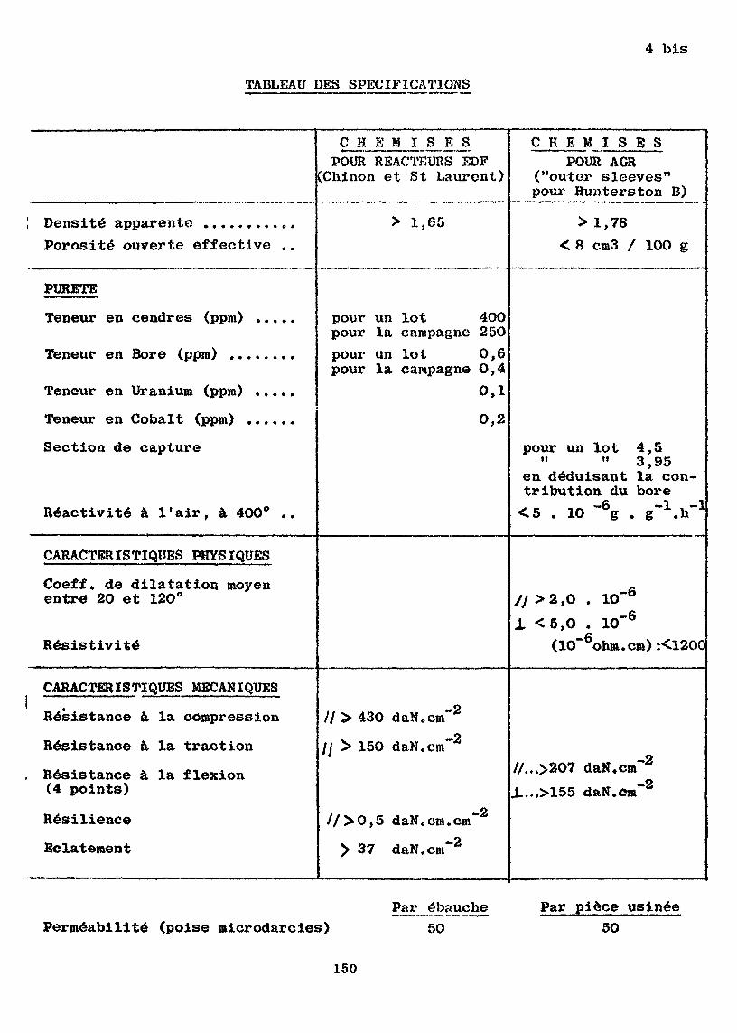
TABLEAU DES SPECIFICATIONS
4 bis
C H E M I S ESPOUR REACTEURS EDFChinon et St Laurent)
C H E M I S E SPOUR AGR
("outer sleeves"pour Hunterston B)
! Densité apparente .........Porosité ouverte effective
> 1,65 > 1,78<8 cm3 / 10O g
PURETE
Teneur en cendres (ppm) ...
Teneur en Bore (ppm)
Teneur en Uranium (ppm)
Teneur en Cobalt (ppm)
Section de capture
Réactivité à l'air, à 400a .
pour un lot 4OOpour la campagne 250pour un lot 0,6pour la campagne O,4
0,1
O,2
pour un lot 4,5" " 3,95
en déduisant la con-tribution du bore<5 . 10 ~ g . g" .h"
CARACTERISTIQUES PHYSIQUES
Coeff. de dilatation moyenentre 20 et 12O°
Résistivité
1O-6.-6
>2,O<5,O . 10( 10*" ohm.cm) :<1200
CARACTERISTIQUES MECANIQUES
Résistance à la compression
Résistance à la traction
Résistance à la flexion(4 points)
Resilience
Eclatement
// > 430 daN.cm
/y > 150 daN.cm
-2
—2
//...>207 daN.cmJ....>155 daN.cm
-2-2
//>0,5 daN.cm.cm"
> 37 daN.cnr2
Perméabilité (poise microdarcies)Par ébauche
5OPar pièce usinée
50
150
Les éléments combustibles Dragon ont 2 m de long.
Parallèlement à ces diversités de forme, se manifeste «ne diversitéde spécifications,*«t nous voudrions donnez* l'exemple de deux produit»classiques dont plusieurs dizaines et m&mc plusieurs centaines de mil-liers d'exemplaires ont été élaborés : ce sont, d'une part, les chemi-ses des réacteurs E.D.F., d'autre part les chemises extérieures A.G.R.
Tableau des spécifications(voir 4 bis)
Certaines' spécifications sont parfois très difficiles à atteindre,et nous voudrions citer l'une de celles des premiers éléments combusti-bles Dragon où la perméabilaté devait être telle qu'elle permette decontenir les produits de fission vers l'intérieur grâce à une dépvessioiinterne de l'hélium tout en évitant une» rétrodiffusion des produits defission à contre courant ; ceci avait icon^duit à des produits où la poro-sité devait être essentiellement composée de pores ayant des diamètrescompris entre O,l et 1 micron avec élimination à la fois des pores degros diamètres et de la porosité ultra-fine.
Pour en terminer avec ces aspects techniques ou technologiques,nous voudrions montrer sur un exemple que, lorsque les spécificationsinitiales sévères ont enfin pu être atteintes, il n'est pas impossiblede voir apparaitre un phénomène imprévu qui rend caducs tous les effort.qui ont été faits.
Lorsque le C.E.A. a envisagé d'armer l'intérieur des tubes d'ura-nium avec dos âmes, graphite, les études avaient conduit à imposer unespécification de porosité ouverte très sévère puisque celle-ci devait
3 ^être inférieure à 6 cm pour 1OO cm ; on voit tout de suite la diffi-culté, le produit formé contient des matières volatiles qui devront ensortir au cours des traitements thermiques et elles ne pourront sedégager qu'à% travers des porosités que l'on voudrait en même tempspratiquement inexistantes. De longues études et mises au point avaientcependant permis de réaliser industriellement des produits qui conte-naient des proportions importantes de noirs de carbone. L'événementimprévu s'est présenté lors du traitement des combustibles irradiés ;en effet, pour attaquer chimiquement l'uranium, il fallait enlever l'âmegraphite, et ceci ne pouvait guère so faire que par usinage dans unepiscine ; or ces âmes à base de noirs donnaient, dans le cadre d'un usi-nage pourtant parfaitement étudié, une poudre qui transformait l'eau de
151
la piscine en encre de Chine* Ce type d'âme a dû être abandonné ; maisaucune autre formulation ne permettait de tenir la spécification ini-tiale sur la porosité ouverte et il a donc fallu se résigner à élargir
3 3légèrement la spécification et la porter à 11 cm pour 100 cm .
Coût du graphite nucléaire
Passons maintenant aux questions relatives aux coûts de productionet abordons le problème de front, comme certainement chacun le voit. Legraphite nucléaire coûte plus cher que le graphite ordinaire, c'est uneaffirmation. Pourquoi ? C'est une question. La réponse est simple, parceque l'on ne parle pas du tout des mêmes services à rendre, et donc desmêmes qualités de produits.
Le graphite nucléaire n'est pas toujours plus cher que le graphiteordinaire, et si nous considérons deux cas qui ont des similitudes, lesempilements des réacteurs nucléaires et les échangeurs thermiques pourl'industrie chimique, on constate que les prix à la tonne du graphitelivré sont du même ordre, avec généralement un prix plus bas pour lenucléaire.
Entre le nucléaire et l'ordinaire, existe aussi une différence fonda-mentale de réaction des clients ; l'acieriste veut que son électrodetienne bien sur le four, que la consommation soit réduite, mais il laissele producteur libre de choisir ses matières premières, ses formules, sestraitements. Dans le domaine nucléaire, on est assujetti au respect despécifications.
Il n'y a guère que pour le graphite nucléaire que se trouvent formu-lées des spécifications sur la pureté, et ceci non seulement par le biaisd'un niveau de section de capture, mais également avec des limites surla teneur en cendres et sur la teneur en certaines impuretés bien préci-sées. Un traitement supplémentaire est donc indispensable.
Ce n'est Vraiment que pciur les graphites nucléaires que l'on voitapparaître des spécifications de porosité ouverte, de perméabilité, derésistance à l'oxydation à des températures bien définies, et ces spéci-fications se trouvent même souvent combinées entre elles, ce'qui exige,soit des matières premières plus rares, soit des conditions de traitementplus élaborées et, dans tous les cas, plusieurs traitements supplémentai-res.
Ensuite, et ce n'est pas la moindre des raisons d'augmentation ducoût, figurent les spécifications d'aspect qui, malgré les efforts faits
152
tant par les producteurs que par les clients, restent toujours subjecti-ves. On craint toujours que les défauts visibles sur les surfaces n'af-fectent grandement les caractéristiques mécaniques des produits ; iln'est pas très difficile de montrer que ce n'est que très rarement le
« j
cas ; et puis que dire des défauts cachés ? N'est-ce pas un peu la poli-tique de l1autruche que de s'attacher à ce qu'on voit en oubliant l'inté-rieur ? Il serait assez curieux de connaître quelle pouvait être la
'!
résistance mécanique de la barre de graphite à l'intérieur de laquelleexistait l'empreinte d'un bouchon de radiateur de Rolls Royce qui s'étaitévidemment volatilisé lors du traitement thermique ; an hasard a permisde le découvrir, mais on axirait très bien pu ne pas s'en rendre compte.
Il est généralement plus économique, et en tout cas plus efficace etplus sûr, de concevoir des tests mécaniques globaux, mettant à.1 l'épreuveles produits dans les conditions les plus voisines de celles où ilsseront utilisés.
Dans le cas des graphites utilisés pour les éléments combustiblesintervient, si l'on considère les prix à la tonne, la forme même despièces à fournir, généralement tubulaires. Nous avons vu que le premierstade est celui de la mise en forme, ici ce seront des tubes ; à ce stadeles frais sont pratiquement proportionnels à la quantité de matière miseen oeuvre mais, pour tous les traitements ultérieurs, c'est le volumeextérieur qui doit être pris en ligne de compte, car il faudra chaufferle tube et le granulé que l'on devra mettre à l'intérieur, et égalementil faut considérer que l'occupation du four est essentiellement volumique
, D??autres raisons de l'augmentation du prix ne doivent pas être pas-sées sous silence :
- les quantités commandées sont bien précises et l'on ne peut sepermettre de livrer moins que nécessaire, car il est inconcevable qu'ilmanque une barre dans un empilement. Or un cycle dé fabrication, sanscompter l'usinage, dure facilement 5 ou 6 mois auxquels il faut parfoisajouter 2 ou 3 mois pour les contrôles. Pour ne pas être déficitaire surla qualité fournie, il faut donc obligatoirement fabriquer plus quenécessaire et ce en n'ayant que très peu d'espoir de trouver un clientpour les produits excédentaires.
- Dans certains cas, les quantités commandées correspondent à destonnages très faibles ; or, en graphitation, l'unité de travail indus-trielle est le four d'au moins 3O t de capacï'té, et l'on se retrouvedans le cas précédent avec des prbduits excédentaires pour lesquels lesdébouchés n'existent pas.
153
Abaissement des prix
Comment peut-on réduire les prix ? Par la confrontation entre lecoût de production et la valeur d'usage, c'est-à-dire par le dialogueentre le fabricant et l'utilisateur. L'utilisateur doit faire un examende conscience ; les exigences qu'il a formulées, les spécificationsqu'il a demandées sont-elles en raisor directe de ses besoins réels ?Car autant il faut avoir prévu les spécifications indispensables, autantil faut faire attention aux spécifications inutiles que l'on conservepour la forme parce qu'elles sont toujours tenues ; ou l'utilisateurcroit qu'elle n'est que pure forme, alors il faut la supprimer, car lamaintenir c'est admettre qu'un jour elle ne sera pas remplie et que leproduit sera rebuté, ce dont le producteur doit tenir compte s'il estun bon gestionnaire. Chacune des limitations imposée doit être examinéepour-définir si la valeur d'usage est en rapport avec le coût de produc-tion, coût de production que fournira le fabricant.
Tin climat de confiance réciproque doit présider au dialogue, à laconfrontation, et il serait intéressant de rappeler un exemple de colla-boration où des gains très substantiels ont pu être réalisés par leclient sur des fournitures de 2O à 3O MF, sans que les intérêts du four-nisseur aient été lésés. Ou a simplement évité le gaspillage.
Dans les réacteurs E.D.F., l'empilement consiste en colonnes de1O.200mm. A priori, il est demandé pour ces colonnes un découpage en8 longueurs égales de 1.275mm ; mais une telle solution n'est absolumentpas rationnelle. En effet, on demande également, et c'est normal, que3% des barres*soient échantillonnées par prélèvement en extrémité d'untronçon de 130mm ; on demande que les produits ne soient pas écornés enextrémités ; on prévoit un descriptif des défauts locaux qui doivententraîner le rebut des barres « Si on examine le problème dans son ensem-ble, on constate que toutes les barres où l'on a prélevé des échantillonssont à rebuter, quoique les 9/1O du produit restent bons ; le cas estidentique pour les barres écornées ; on constate que toutes les barresprésentant un défaut sur une longueur sont rebutées alors que la moitiéau moins de la barre pourrait encore être bonne. Donc, sur la premièrehypothèse de 8 longueurs de 1.275mm, le producteur estime que 15% de .sesproduits seront rebutés et, bien évidemment, il en tient compte dans sonoffre. Mais ce pourcentage peut être réduit et ramené au niveau de 5%environ par une étude raisonnée du problème, et ceci en s'attachant natu-rellement à ce que la conception de l'empilement du réacteur ne soit pasmodifiée ; on construit alors l'empilement sous forme de 6 lits d'une
154
longueur maximum à définir, plus 1 lit dont la longueur sera inférieurede ISOmm pour tenir compte de l'échantillonnage et des barres écornées,plus 1 lit de longueur moitié pour tenir compte des défauts localisesau hasard. Et, à ce moment-là, l'offre peut être présentée avec l'alter-native : soit 8 lits de 1.275mm, soit 6 lits de 1.378mm, 1 lit de 1.248i»iniet 1 lit de 684mm ; mais, entre les deux termes de l'alternative, ladifférence de ±rix est de 1O%.
Uni tés de production spécialisées
Et, pour terminer, on peut se poser la question : une unité de production qui serait spécialisée pour le graphite nucléaire permettrait-ellede proposer des prix de vente satisfaisants tout en assurant une rentabi-lité correcte ?
Les contrats de fourniture de graphite nucléaire sont limités en nom-bre, irréguliers dans leur importance, quelque peu imprévisibles dansleurs dates de conclusion et également conditionnés par des prévisionsévolutives. Nous pensons donc qu'à priori un producteur qui désireraitspécialiser wn atelier pour cette production devrait accepter des chargesd'amortissement élevées qui, supportées par les produits vendus, entraî-neraient des coûts élevés ; une expérience a été faite en ce sens etl'atelier a souvent été en chômage. Il y a 7 ou 8 ans, les prévisionssur le marché français faisaient état, pour la période actuelle, de be-soins de l'ordre du million annuel de chemises pour éléments combustiblesor la réalité est bien différente, et il eût été imprudent de s'engagerdans la création d'une unité spécialisée.
Le risque déjà grand pour un producteur établi deviendrait encoreplus important pour un nouveau producteur ; en effet» les graphites nu-cléaires sont certainement ceux qui posent le plus de problèmes sur leplan de la recherche et de la mise au point . Bien souvent , dans le domainenucléaire, on voudrait assimiler le graphite à un métal dont on souhaite-rait qu'il ait toutes les qualités des métaux en plus, naturellement, deses qualités propres. L'unité devrait donc avoir à soutenir les effortsconstants d'une équipe de recherches bien étoffée, dynamique et compétenteet, par conséquent, les frais de productions seraient lourdement grevés.
Quel est l'avenir du graphite nucléaire dans les éléments combusti-bles ? D'une euphorie un peu délirante il y a quelques années on a eutendance à passer très récemment à un pessimisme noir. Nous pensons qu'ilfaut s'arrêter à un optimisme raisonné et raisonnable car la sagesse esttoujours dans le juste milieu.
155
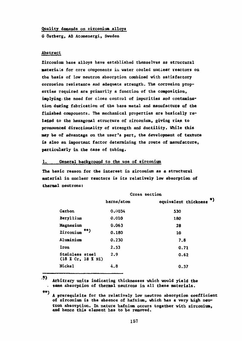
Quality demands on zirconium alloys6 Qstberg, AB Atomenergi, Sweden
Abstract
Zirconium base alloys have established themselves as structuralmaterials for core components iu water cooled nuclear reactors onthe basis of low neutron absorption combined with satisfactorycorrosion resistance and adequate strength. The corrosion prop-erties required are primarily a function of the composition,implying,the need for close control of impurities and contamina-tion during fabrication of the base metal and manufacture of thefinished components. The mechanical properties are basically re-lated to the hexagonal structure of zirconium, giving ris.e topronounced directionality of strength and ductility. While thismay be of advantage on the user's part, the development of textureis also an important factor determining the route of manufacture,particularly in the case of tubing.
^___General background to the use of zirconium
The basic reason for the interest in zirconium as a structuralmaterial in nuclear reactors is its relatively low absorption ofthermal neutrons:
Cross sectionbarns/atom equivalent thickness '
53018028107.80.710.62
0.37
*') Arbitrary units indicating thicknesses which would yield thec same absorption of thermal neutrons in all these materials.
**)A prerequisite for the relatively low neutron absorption coefficientof zirconium is the absence of hafnium, which has a very high neu-tron absorption. In nature hafnium occurs together with zirconium,and hence this element has to be removed.
157
CarbonBerylliumMagnesium
**}Zirconium 'AluminiumIronStainless steel(18 % Cr, 18 % Ni)Nickel
0.00340.0100.0630.1800.2302.532.9
4.8
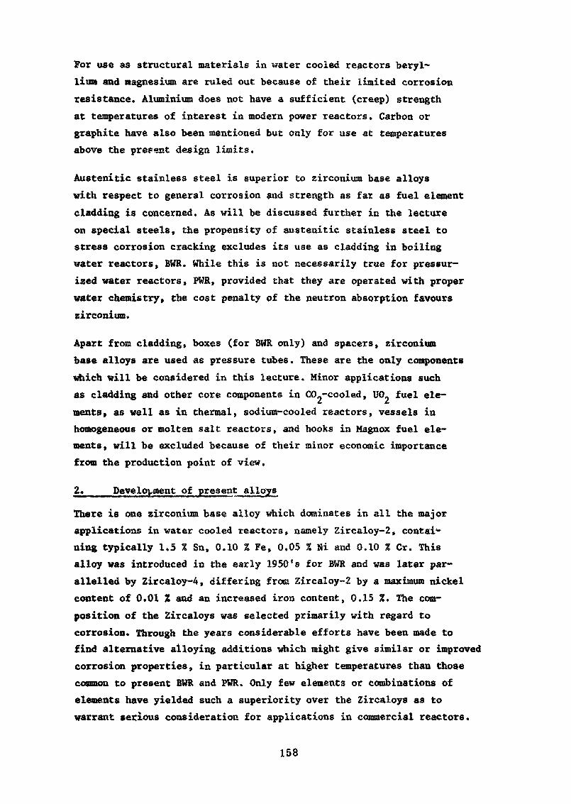
For use as structural materials in water cooled reactors beryl-lium and magnesium are ruled out because of their limited corrosionresistance. Aluminium does not have a sufficient (creep) strengthat temperatures of interest in modern power reactors. Carbon orgraphite have also been mentioned but only for use at temperaturesabove the present design limits.
Austenitic stainless steel is superior to zirconium base alloyswith respect to general corrosion and strength as far as fuel elementcladding is concerned. As will be discussed further in the lectureon special steels, the propensity of austenitic stainless steel tostress corrosion cracking excludes its use as cladding in boilingwater reactors, BtfR. While this is not necessarily true for pressur-ized water reactors, PWR, provided that they are operated with properwater chemistry, the cost penalty of the neutron absorption favourszirconium.
Apart from cladding» boxes (for BWR only) and spacers, zirconiumbase alloys are used as pressure tubes. These are the only componentswhich will be considered in this lecture. Minor applications suchas cladding and other core components in CO.-cooled» UCL fuel ele-ments» as well as in thermal, sodium-cooled reactors, vessels inhomogeneous or molten salt reactors, and hooks in Magnox fuel ele-ments, will be excluded because of their minor economic importancefrom the production point of view.
2» Development of present alloys
There is one zirconium base alloy which dominates in all the majorapplications in water cooled reactors, namely Zircaloy-2, contai-ning typically 1.5 % Sn, 0.10 % Fe, 0.05 % Hi and 0.10 % Cr. Thisalloy was introduced in the early 1950's for BWR and was later par-allelled by Zircaloy-4, differing from Zircaloy-2 by a maximum nickelcontent of 0.01 % and an increased iron content, 0.15 %. The com-position of the Zircaloys was selected primarily with regard tocorrosion. Through the years considerable efforts have been made tofind alternative alloying additions which might give similar or improvedcorrosion properties, in particular at higher temperatures than thosecommon to present BWR and PWR. Only few elements or combinations ofelements have yielded such a superiority over the Zircaloys as towarrant serious consideration for applications in commercial reactors.
158
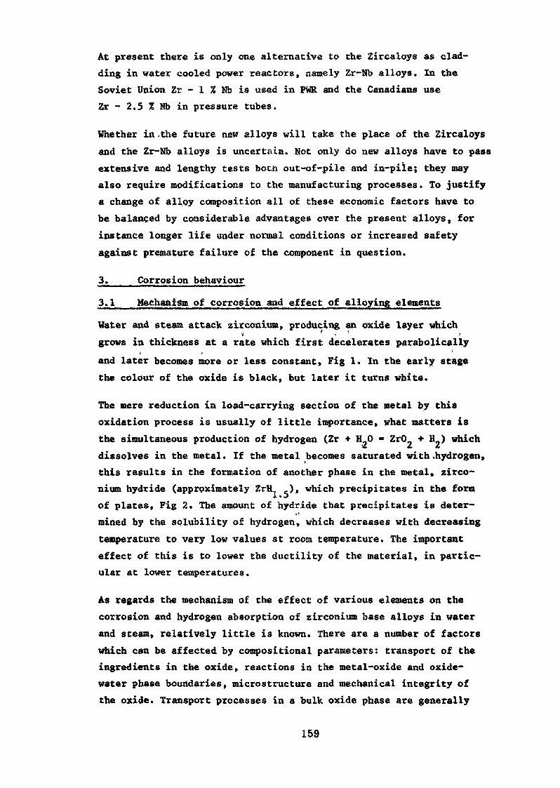
At present there is only one alternative to the Zircaloys as clad-ding in water cooled power reactors, namely Zr-Nb alloys. In theSoviet Union Zr - 1 % Nb is used in PWR and the Canadians useZr - 2.5 % Nb in pressure tubes.
Whether in .the future new alloys will take the place of the Zircaloysand the Zr-Nb alloys is uncertain. Not only do new alloys have to passextensive and lengthy tests both out-of-pile and in-piïe; they mayalso require .modifications to the manufacturing processes. To justifya change of alloy composition all of these economic factors have tobe balanced by considerable advantages over the present alloys, forinstance longer life under normal conditions or increased safetyagainst premature failure of the component in question.
3 Corrosion behaviour
3.1 Mechanism of corrosion and effect of alloying elements
Water and steam attack zirconium, producing an oxide layer which•> » «
grows in thickness at a rate which first decelerates parabolicallyand later becomes more or less constant, Fig 1. In the early stagethe colour of the oxide is black, but later it turns white.
The mere reduction in load-carrying section of the metal by thisoxidation process is usually of little importance, what matters isthe simultaneous production of hydrogen (Zr + H.O * ZrO + BL) whichdissolves in the metal . If the metal becomes saturated with .hydrogen,this results in the formation of another phase in the metal, zirco-nium hydride (approximately ZrH ,), which precipitates in the formof plates, Fig 2. The amount of hydride that precipitates is deter-mined by the solubility of hydrogen, which decreases with decreasingtemperature to very low values at room temperature. The importanteffect of this is to lower the ductility of the material, in partic-ular at lower temperatures.
As regards the mechanism of the effect of various elements on thecorrosion and hydrogen absorption of zirconium base alloys in waterand steam, relatively little is known. There are a number of factorswhich can be affected by compositional parameters: transport of theingredients in the oxide, reactions in the metal-oxide and oxide-water phase boundaries, microstructure and mechanical integrity ofthe oxide. Transport processes in a bulk oxide phase are generally
159
known to be governed by the presence of defects in the arrangementof atoms in the crystal lattice. Common rules for the effect of al-loying elements on the defect structure and the transport mechanismare not sufficient to explain even the major features of the corrosionprocess with and without irradiation. Fending a more complete under-standing of the effect of practically important factors on the cor-rosion of zirconium alloys in a nuclear environment» it seems justi-fiable to assume that one has to take into account, not only the prop-erties of the bulk oxide, but also its defect structure providingroutes for the transport of oxidizing species, in addition to crystallattice diffusion. These transport processes are likely to be affectedby irradiation, via its effects on the structure and mechanical proper-ties of the oxide and, possibly, also on the nature of the oxidizingenvironment. These effects differ from one alloy to another.
For most elements purposely added, such as tin, iron, nickel andchromium in the Zircaloys and niobium in the Zr-Nb type alloys,there is an optimum content with regard to their beneficial effecton corrosion. The total amount of alloy additions is, of course,restricted by the neutron absorption.
Concerning the alloying additions it should be noticed that theireffect is beneficial except when they are segregated in the struc-ture» A locally increased content of alloying elements, or excessiveprecipitation of them in the form of a high density of coarse parti-cles of intermetallic phases, leads to local corrosion attack. Suchagglomerates of precipitates may occur if the final melting processis carried out under argon, in which case argon bubbles are formed,accompanied by segregated zones. Another cause of areas with denseprecipitates forming is forging in a temperature range where the phaseequilibrium of the matrix is such that alloying elements becomeconcentrated in certain regions.
3.2, Impurity effects localized attack
Another compositional factor of importance from the corrosion pointof view, is the presence of elements with a negative influence oncorrosion. In this category belong not only non-metallic impuri-ties, such as nitrogen, but also metals, such as aluminium, to
160
mention only two examples. A typical specification of Zircaloy-2,with regard to the beneficial and detrimental effect of differentelements, is as follows:
Alloying elements, % Impurities, max, ppm
Sn 1.2 -1.7 Cu 50 Al 75Fe 0.07 - 0.20 C 270 Ti 50Ni 0.03 - U.Ô8 N 80Cr 0.05 - 0.15 Si 200
To limit the influence of impurities, precautions have to be takenduring early stages in the production of zirconium. Absorption ofnitrogen has to be carefully avoided during the handling of theprimary zirconium sponge. To minimize absorption of oxygen andcarbon, the melting and alloying of the metal is done by sor-ealïedconsumable- arc melting in a water-cooled copper crucible under aninert atmosphere or vacuum. Hydrogen is removed by remelting themetal under vacuum.A further important aspect of the influence of different foreignelements on corrosion is the effect of surface contamination. Thismayy in principle, occur during heating on heat treatment of thematerial in the fabrication process, during, the surface treatmentof the finished product, and during welding. During heating theelement of particular importance is nitrogen, which can in prin-ciple be avoided by using an inert atmosphere or vacuum. Welding hasto be done under an inert atmosphere, usually argon, or preferablyby electron beam welding in a vacuum.
The surface treatment, the purpose of which is to remove the con-taminated surface layer or adjust the dimensions of the product»can be done either by chemical treatment or mechanical grinding.The latter normally presents no serious contamination problems.Chemical surface treatment involves pickling or etching in a mix-ture of hydrofluoric and nitric acids, followed by rinsing inwater. If not properly rinsed, the zirconium may retain some fluo-rine-containing material on its surface. On subsequent exposure
' The same is true of excessive fluorine (and chlorine) in the Up.fuel, which makes the inside surface of cladding tubes sensitiveto corrosion attack if the U0? contains moisture. Patches ofwhite oxide are occasionally Seen also on fuel elements withnominally satisfactory surface treatment. The cause of this typeof accelerated corrosion is not known.
161
to water and steam such fluorine concentrations may give rise toaccelerated corrosion, visible as white spots.
The last occasion for surface contamination to occur is duringhandling of tubes or finished fuel rods.'Fingerprints on a zir-conium metal surface will leave behind some chloride deposits whichaccelerate the corrosion attack showing up as white markings. Pro-tection against such contamination may be obtained by applying anoxide layer to the surface by some kind of oxidizing treatment.
Finally there is another type of chemical attack which has attrac-ted considerable interest lately» namely stress corrosion on theinside surface induced by iodine, which is produced by the fis-sion of the fuel. So far the evidence of such a process in com-mercial power reactors is rather meagre. Our knowledge of howto cope with this problem is also very limited. À further phenom-enon of concern these days is the formation of localized hydridepatches on the inside of cladding, so-called blisters or sunbursts.This occurs with increasing frequency as the moisture and hydrogencontents of the fuel increases. The remedy, for lack of an under-standing of the origin of such attacks in terms of the properties ofthe metal, is to keep the moisture content of the UO. as low as possible.
4,___Mechanical properties
4.1« Déformation and texture
Stresses and strains in cladding arise from the weight of the fuelelements and the hydraulic forces of the coolant, the radial thermalgradients in the cladding wall, the pressure of the coolant and thefission gases respectively, and the geometrical changes of the U0_fuel during its life. It would take too long to give a detailedaccount of the effect of these different, often interacting typesof mechanical conditions and their relative importance. For thepurpose of this lecture only the strength and ductility require-ments of core components in relation to the mechanical propertiesof zirconium base alloys will be dealt with. Accordingly this treat-ment will begin with a brief account of the principles of the defor-mation and fracture of zirconium.
The basic property of zirconium, from the deformation point of viewis the arrangement of the atoms in the crystal structure. The zirco-nium crystal lattice has a so-called hexagonal symmetry (whilst the
162
iron crystal is cubic), Fig 3. When a metal crystal is stressed to theextent that it deforms plastically, it usually deforms by the relativeslip of layers of atoms in the lattice, Fig 4. Intuitively onerealizes that a metal with hexagonal symmetry must differ in defor-mation behaviour from cubic metals. In the latter the properties ofthe crystal are the same in all three directions of the coordinatesystem, so-called isotropy, but in the hexagonal metal crystal theproperties differ in the different ortogonal directions, so-calledanisotropy.
In a piece of polycrystalliae zirconium, made up of a large numberof crystals or grains, the orientation of the hexagonal axes ofeach grain differs from that of the other grains. The variationof the grain orientations within the piece of zirconium may bestatistic or there may be some coordination to preferred orien-<. •» /tations, so-called texture, Fig 5. Crystallographic textures occur
' * ' w * /. (i•when a piece of polycrystalline zirconium is deformed plastically,
.i
for instance during shaping by tube rolling. The reason is "that**> -i
the many differently oriented crystals or grains in the material»'respond differently to the stresses and strains imposed, becauseof the different orientations of their hexagonal crystal axis. Asa result the distribution of orientations in the population ofgrains changes from statistical into some regular texture pattern,Fig 5. This in turn makes the further response to stresses andstrain during use of the component dependent on the direction inwhich the stresses and strains are applied, Fig 6. The developmentof texture during shaping and fabrication of reactor components,tubing in. particular, and the consequences of texture for theproperties of the components are among the major areas of technicaldevelopment in this field.
In principle the requirements of certain properties in differentdirections of, for instance, a cladding tube, imposed by the mechan-ical conditions mentioned in the introduction of this section, maybe met by the adoption of a suitable route of deformation during fab-rication. All the various demands of mechanical properties can-not be met by one texture. Therefore compromises often have to bemade. A further complication to the texture problem is the occur-ence of hydride, as already described above. The hydride plates areusually not statistically oriented but show a parallel orientation
163
in a direction that is a. function of the texture and/or the deforma-tion process during fabrication of tubes or other shapes, Fig 2.A hydride plate which is oriented perpendicular to the stressdecreases the ductility, i.e. the ability to be strained plasticallybefore fracture occurs, to a larger extent than a plate parallellto the stress» In cladding tubes radiallv oriented hydrides mustbe avoided for this reason.
4«2. Irradiation effects
At this point it may be proper to bring up another complicatingfactor as regards deformation, namely the effect of neutron irradi-ation. The high energy neutrons in the reactor core knock out ordisplace zirconium atoms from their normal places in the lattice,leaving holes, or so-called vacancies, behind. In the structure thevacancies are found in the form of agglomerates, Fig 7, which im-pede the deformation process. Deformation by slip along crystal-lographic planes, Fig 3, requires that the planes contain a par-ticular deviation from the regular atomic arrangement in the formof a slight shift in position of atoms along a certain directionin the lattice, a so-called dislocation, Fig 8. It is the mov-ement of such dislocations that is retarded by the vacancy ag-glomerates induced by neutron irradiation.
On the other hand irradiation may enhance creep, i.e. slow, time-dependent deformation in which obstacles are eventually overcome byactivation processes. In this case the effect of irradiationis due either to the single vacancies which assist in the disloc-ation movement, or to changes in the internal stress distributionas a consequence of agglomeration of defects in particular con-figurations. Consequently the ability of the zirconium to deformplastically is reduced; the ductility or strain to fracture may bedecreased by irradiation. Therefore the requirements of tensileor burst ductility of zirconium tubing as delivered contain amargin to account for the irradiation etnbrittleraent. As shownby Fig 9 the relative reduction in tensile ductility differswith the amount of prior cold work.
4.3 Requirements on tensile and creep properties
From the designer's point of view the primary strength require-ment is a minimum yield strength from room temperature to the
164
operating temperature, usually 300 - 320°C for BWR and 340 - 400°Cfor PWR. The strength of tubes is measured in the longitudinaldirection by tensile tests as well as in the circumferentialdirection by burst teats. To a considerable extent the strength isdetermined by the oxygen content of the alloy» while the metallicadditions do not play any very great role in this context» Fig 10.It should be noticed that the effect of oxygen decreases withincreasing temperature.
As explained above the fabrication parameters determining thesestrength values in.tubes, as well as the ductility, are the routeof forming or shaping by extrusion, drawing, rolling or reduction.The means of achieving Various combinations of strength and duc-tility combinations using different fabrication techniques will bedescribed in another lecture. It may merely be mentioned thatthe required combination of strength and ductility is usuallyarrived at by adjusting the annealing of the cold work of thematerial, Fig 11, Deformation or cold work during forming makesthe material stronger and less ductile» as a consequence of theincrease in numbe'r of dislocations which interact with each otherand restrict their movement. Annealing changes the dislocationpattern and causes the microstructure to recrystallize-into grainswith a low dislocation density, and hence a lower -strength and higherductility. ^
Ductility enters as a critical property as soon as deviations fromprimary operating conditions are considered. .Although stresses andstrains beyond the yield limit are not normally assumed in thedesign of fuel element cladding, experience, from irradiation testsshows that some capacity for plastic straining is highly desirable.The implications of this point become particular evident when theeffect of irradiation is considered, Fig 9. In a tensile test on
' For Zr - 2.5 % Nb there is an additional means of obtainingdifferent strength and ductility levels which is not possiblewith Zircaloy. The niobium in Zr - 2.5 % Nb can be precipitatedas small particles during cooling from the fabrication temperature,giving rise to relatively high strength by affecting the movementof dislocations. By changes in the cooling rate the number and sizeof the particles, and hence the strength» can be controlled. Acommon procedure is to heat the alloy to 875 C for 15-30 min,followed by quenching (80 C/sec) to room temperature, and finallytempering at 500°C for 24 h.
165
zirconium the maximum load is a conservative measure of the abilityof the material to elongate without the development of local thin-ning, so-called plastic instability, which is the first stage inthe fracture process. To avoid plastic instability after onlyvery small strain after irradiation one has to establish a highductility already in the unirradiated stage. This is one reasonwhy ductility is considered important and uas to be taken intoaccount during fabrication.
Creep is of importance in particular for pressure tubes, whichhave to carry a substantial load from the internal pressure ofthe coolant. Again both the strength, i.e. the rate of creep defor-mation as a function of stress, and the ductility or strain tofracture are of interest, Fig 12. Broadly speaking, our knowledgeof creep in zirconium alloys is relatively limited for reasons thathave to do with the obvious lengthiness of experiments and the com-plexity of the mechanism, not to speak of the influence of irradiation.HUB mechanism depends on the stress, as indicated by Fig 13.
The conclusions from experience of the creep of zirconium as tospecifications on creep properties are rather vague for the reasonsindicated above. While, earlier, there was some preference forZr - 2.5 % Nb in heat-treatment conditions, it now seems as if cold-worked Zircaloy-2 is sometimes preferred.
5,___Summary
There are certain demands on the quality of zirconium which can besatisfied by the adoption of suitable methods for the manufactureof the material and for the fabrication of finished products. First,to ensure a low neutron absorption coefficient, it is imperative toremove hafnium, and other highly absorbing ingredients, during theproduction of the metal. Corrosion resistance is mainly a functionof composition, on the one hand permitting improvements by alloyingand, on the other, requiring maximum limits for the contents ofcertain elements. The sensitivity of corrosion to certain impu-rities makes it necessary also to avoid surface contaminationduring the finishing operations, and during welding. Mechanicalproperties are governed by the particular crystallographic struc-ture of zirconium metal, giving rise to anisotropy and texture.This provides a means of obtaining directionality of properties
166
by using different routes in shaping of the products with dueregard to the influence also on other properties, such as hydrideorientation.
Acknowledgement
The figures are from the following sources:
1. a) K llauffe, Werkstoffe und Korrosion; b) S Kass,WAPD-TM-97, 1957
2. Sandvik, Sweden
3. D Hull, Introduction to Dislocations
4. J Weertman, J R Weertman, Elementary DislocationTheory, Macmillan, p 11
5. M L Picklesimer, GEAP-4089, 1962, p 13 - 19
6. K P Stewart, B À Cheadle, Trans Met. Soc. AIME239 (1967), p 510* \
7. A Seeger, IAEA .Proceedings on Radiation Damagein Solids, 1962, p 105
8. Textbook on mechanical properties
9. L M Howe, W R Thomas, AECL-809
10. L S Rubenstein, J G Goodwin, F L Shubert, Trans ASM54(1961), p 26 ,
11. D Lee, J Nucl. Mat. :37_ (1970):2, p 167
12. F A Nichols, Mater. Sci. Eng. 6, (1970), p 172
13. G R Piercy, J Nucl. Mat. 26 (1968), p 18
167
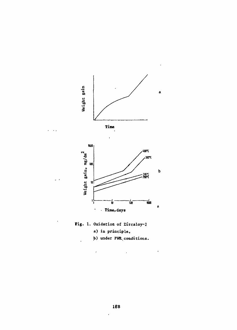
.5Cfl60
•H
Time
• Time,days
Fig. 1. Oxidation of Zircaloy-2a) in principle,b) under PWR,conditions.
168
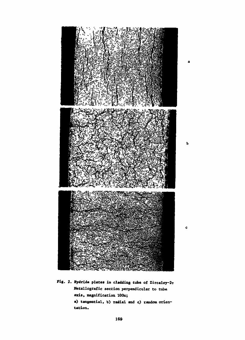
Fig. 2. Hydride plates in cladding tube of Zircaloy-2-rMetallografic section perpendicular to tubeaxis, magnification lOOx;a) tangential, b) radial and e) random orien-tation.
169
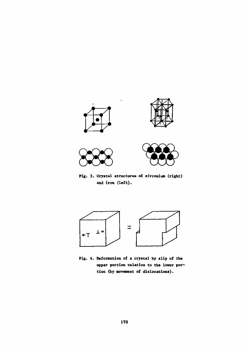
Fig. 3. Crystal structures of zirconium (right)and iron (left).
«-T
Fig. 4. Deformation of a crystal by slip of theupper portion relative to the lower por-tion (by movement of dislocations).
170
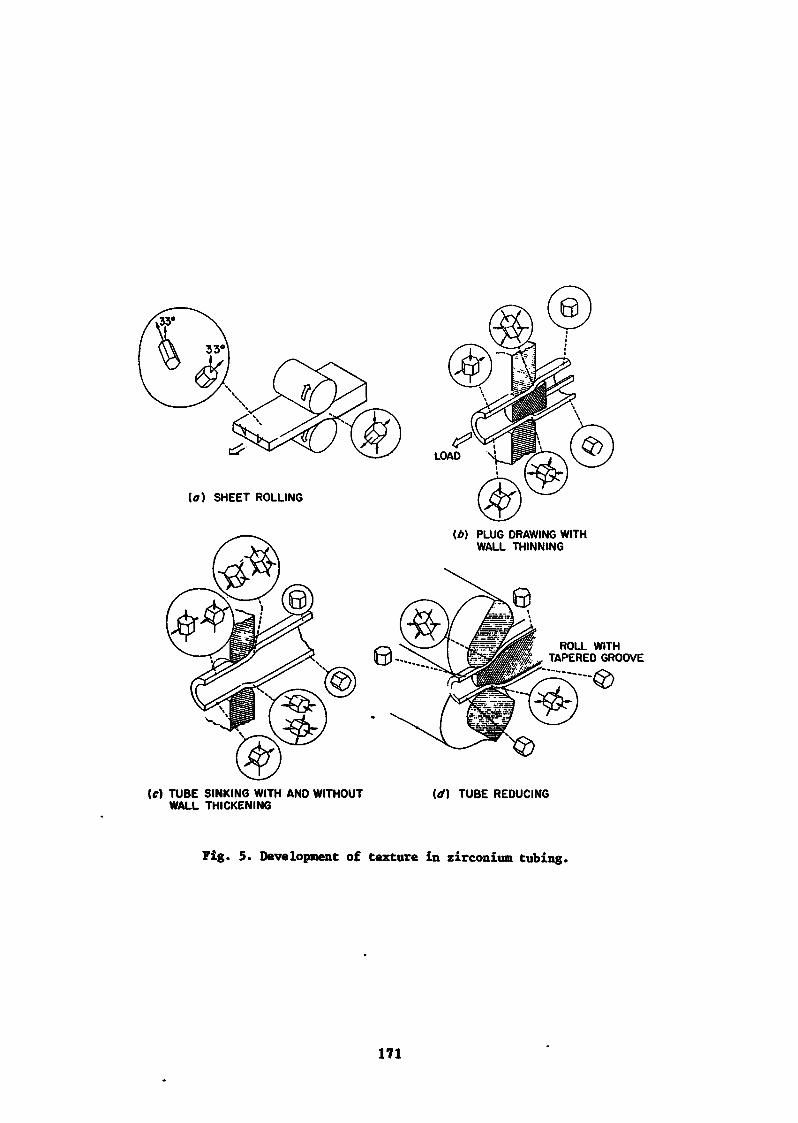
(a) SHEET ROLLING
PLUG DRAWING WITHWALL THINNING
ROLL WITHTAPERED GROOVE
(C) TUBE SINKING WITH AND WITHOUTWALL THICKENING
(<t) TUBE REDUCING
Fig. 5. Development of texture in zirconium tubing.
171
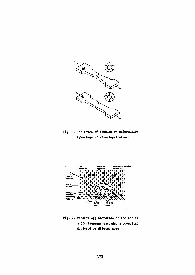
Fig. 6. Influence of texture on deformationbehaviour of Zircaloy-2 sheet.
IntentRWatoms
Fig. 7. Vacancy agglomeration at the end ofa displacement cascade, a so-calleddepleted or diluted zone.
172
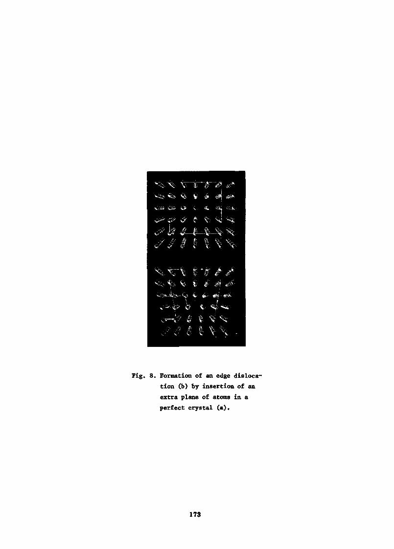
"V- T——&• ' 'i*X- V * e-
<p tf 0 XT'.W 4 f* -©>-
/III
Fig. 8. Formation of an edge disloca-tion (b) by insertion of anextra plane of atoms in aperfect crystal (a).
173
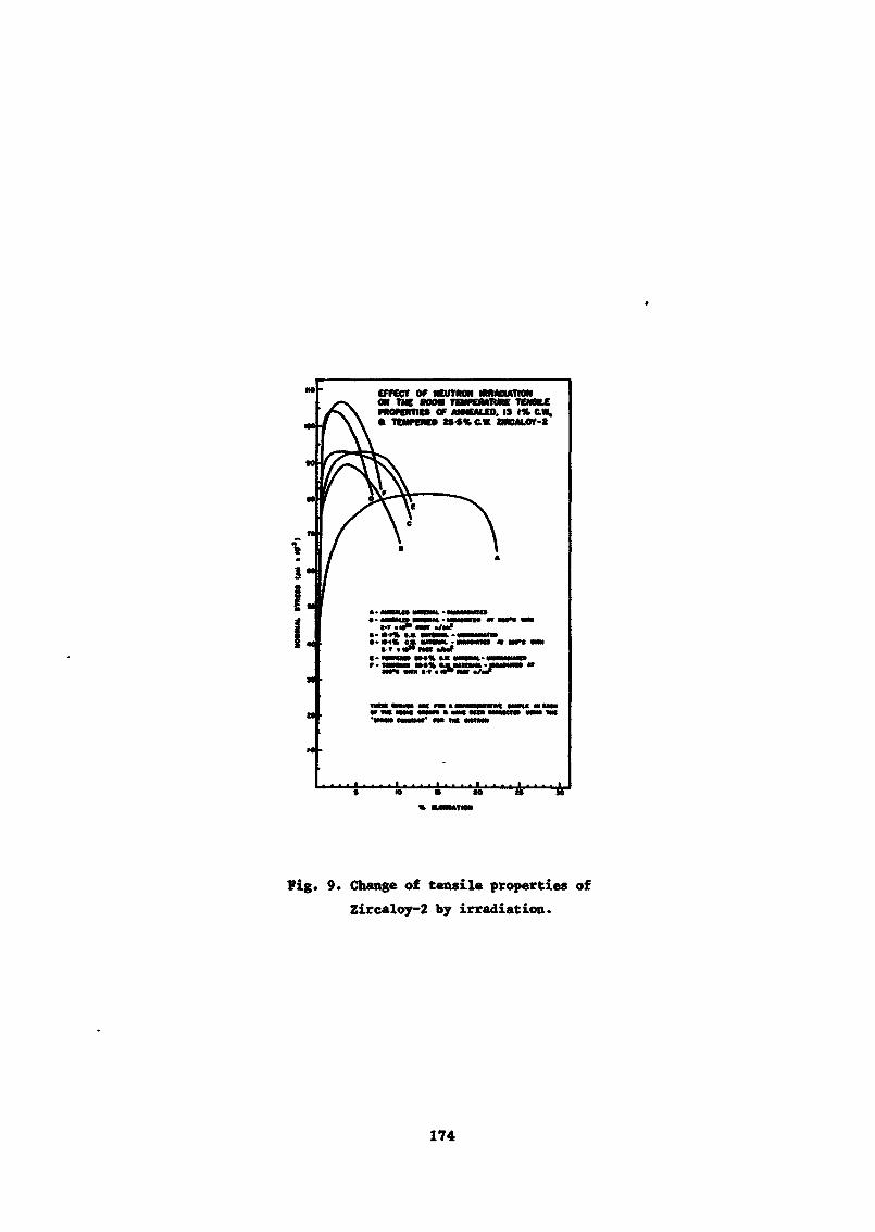
ON THE «MM TEWeUIMC TEMStLCPROPERTIES OF ANNEALED. 19 I» CM,• TEMPERED »•$%€.« ZMCM.OV-2
IN» «m *-t
Fig. 9. Change of tensile properties ofZircaloy-2 by irradiation.
174
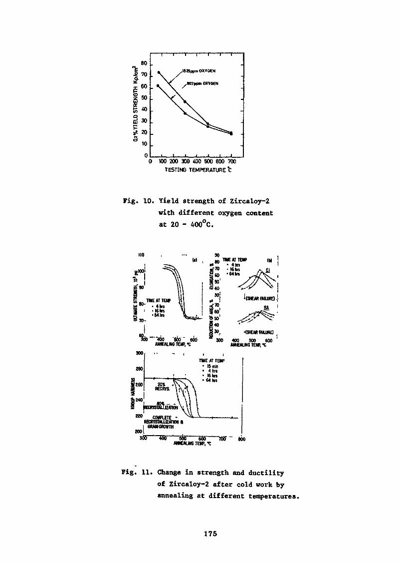
80
70
60
50
§ 30
5 20s»
xl9Kppm OXYGEN
,9Q2ppm OXYGEN
0 100 200 300 400 500 600 700TESTING TEMPERATURE t
Fig. 10. Yield strength of Zircaloy-2with different oxygen contentat 20 - 400°C.
ANNEALING TEMP. «C400 500 600
ANNEALING TEMP, *C300
280
|260
\ 240
20%BECRYS.
2001900
RECRVSWUIZATWN 8GRAM GROWTH
TIME AT TEW• 15 mln• 4 hit• I6hrs«64 to»
400 ' 500———655~ANNEAIIN6 TEMP, <C
«oo
Fig, 11. Change in strength and ductilityof Zircaloy-2 after cold work byannealing at different temperatures.
175
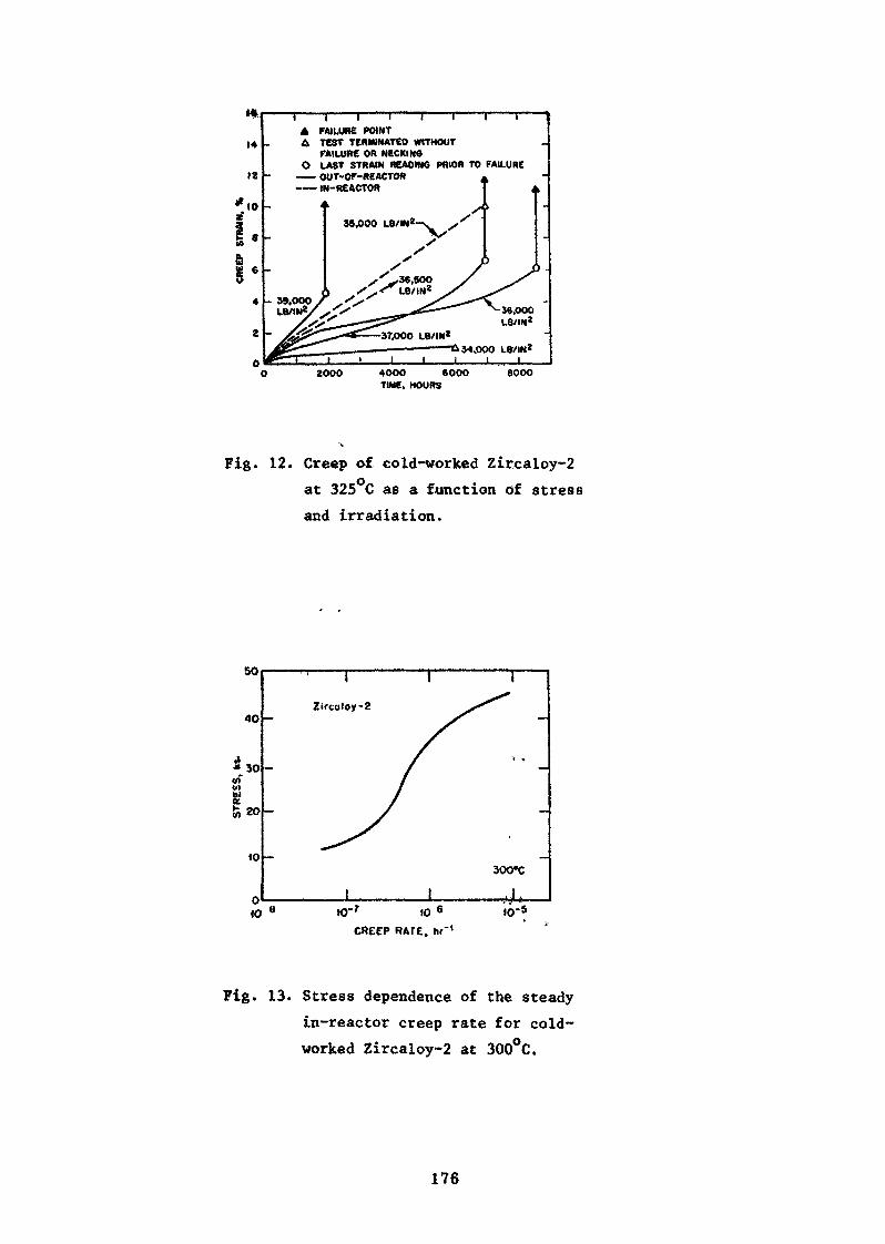
*l
14
12
8
6
4
2
0
T I I I I 1 1 IA FAILURE POINTÛ TEST TERMINATED WITHOUT
FAILURE OR NECKINOO LAST STRAIN READING PRIOR TO FAILURE
——• OUT-OF-ftEACTOR•—— IM-REACTOR
3Ç.OOOL8/IN*
34.OOO L8/IN2
2000 4000 600OTIME, HOURS
9000
Fig. 12. Creep of cold-worked Zircaloy-2at 325°C as a function of stressand irradiation.
so
40
30<f>u>
10
<0
Zirtoloy-2
I I
fO"r 10 6
CRECP RAfE, hr'1
300'C
. 1 .
Fig. 13. Stress dependence of the steadyin-reactor creep rate for cold-worked Zircaloy-2 at 300°C.
176
Quality demands on special steels
6. ôstberg, AB Atomenergi, Stockholm
Abstract
Special £ teeIs in this context are stainless steel and nickel basealloys for use as core components such as spacers in water cooledreactors and fuel element cladding in gas cooled reactors. The require-ments of importance from the production point of view relate'te corro-*sion, in particular localized corrosion of various types, and mechanicalproperties, in particular creep strength and creep ductility. Allthese properties are related, in different ways, to the compositionand heat treatment of the steels and alloys. There are no simplerules to serve as a basis for selection of stainless steels or alloysfor the applications of interest, but some guide lines can be distin-guished. From the corrosion point of view an increased nickel content upto a certain level is helpful; the carbon content has to be balancedby stabilizing additions of titanium or niobium. The desired combina-tion of creep properties, which are largely influenced by irradiation,can be accomplished by adjusting the nickel content and additions ofalloying elements which can form secondary particles dispersed withinthe metal matrix. Examples are given of the choice of steels for someapplications in present reactor systems.
1. Introduction
Special steels is a broad subject even if restricted to nuclear fuel.To cover even the most essential features of the metallurgical back-ground of the manufacture of reactor components of special steelswithin one lecture, one has to confine the treatment to a few typicalobjects* Therefore this paper deals only with the following applica-tions: spacer springs in water cooled fuel elements and claddingtubes for fuel elements in gas cooled reactors. By special steelsin these components is meant austenitic stainless steels and nickelbase alloys. The materials problems are essentially corrosion and
temperature strength and ductility.
177
To begin with a brief account will be given of the metallurgicalfactors governing the use of different types of stainless steels andrelated nickel base alloys, in particular the effect of compositionand heat treatment.
The denotation stainless steel implies in the first place resistanceonly to general corrosion or formation of a protective oxide layer onthe surface4 Broadly speaking most stainless steels are adequate forservice in nuclear reactors with regard to general oxidation. À moreselective view has to be taken when it comes to localized corrosion,i.e. stress corrosion and pitting.
Before discussing these various types of corrosion, a distinction hasto be made between different types of stainless steels or alloys. Themost common type is so-called 18/8, which is an iron base alloy con-taining 18% chromium and 8% nickel. Chromium is the alloying additionprimarily responsible for the oxidation resistance, but nickel alsocontributes in this respect. In addition nickel has the effect ofchanging the symmetry of the arrangement of,the atoms in iron basealloys from so-called body centered cubic (BCC) or ferritic into facecentered cubic (FCC) or austenitic, Fig 1.*' The major technicallyimportant consequence of this change in crystallographic characteris to improve the strength and ductility. Increasing nickel contentof iron chromium-nickel steels brings the composition eventually tothe range where the material is usually denoted a nickel base alloy,for instance an alloy with 75% Ni, 20% Cr and 5% Fe.
To complete this review of composition factors of importance for thecorrosion resistance and the mechanical properties of stainless steel,the role of carbon should be mentioned. If present in sufficientamounts, which usually means a few hundredths per cent, this elementforms precipitates or particles of carbides together with, chromiumand/or other alloying additions such as titanium or niobium. Fig 2.Precipitation of chromium carbides in grain boundaries may causedepletion of chromium in the surrounding regions, making them sensi-tive to localized corrosion attack.
"Austenitid" refers to the crystallographic symmetry of the arrange-ment of atoms. There is no obvious relationship between corrosionresistance and type of crystallographic structure. The fact thataustenitic steels often have a higher resistance to general oxida-.tioa is mainly due to the addition of nickel, which is added in orderto make t&es« steels austenitic for the sake of strength,
178
2> Corrosion
Corrosion of stainless steel in fuel element applications is a complexphenomenon which has to be treated with regard to differences betweendifferent reactor systems rather than in generalized terms. Corrosionin wate:-cooled reactors (BWR aid PWR) is in many respects differentfrom corrosion in gas-cooled reactors (AGR or HTGR) and sodium-cooledreactors (LMFBR). Common to all types of reactors, however, is thegeneral oxidation process which produces a surface scale of oxide.Resistance to this kind of corrosion is promoted by high nickel andchromium contents in a stainless steel or alloy. These alloyingelements promote the formation of a protective, slowly growing scaleconsisting of oxide (s) rich in chromium. Ine composition and struc-ture of the oxide, as well as its rate of growth, differ not only withthe alloy composition but also with the oxidizing conditions. The sameis true of the adherence of the oxide and the tendency to locallyaccelerated growth of oxide, which sometimes may be more importantthan the overall rate of growth. Examples and illustrations of sucheffects will be given in the section below on applications.
Restrictions on the content of chromium and /or nickel are imposed bythe increasing absorption of neutrons - valid, broadly speaking, onlyfor thermal reactors (BWR, PUR and AGR) - and by possible disadvan-tages with regard to mechanical properties and dimensional stability.
It is usually possible to select a composition of stainless steelsfor use in nuclear reactors with sufficient resistance to generalcorrosion to satisfy the requirement with regard to preservation ofthe section of metal in load carrying components. Apart from mecha-nical properties, however, problems may arise because of the propen-sity of stainless steel to corrode locally, leading to mechanicaldisintegration or chemical penetration.
Stress corrosion cracking in water or steam, Fig 3, is a phenomenonwhich usually occurs only in austenitic stainless steels and nickelbase alloys, but rarely in ferritic, low nickel steel. As the nameimplies, the material cracks under the combined influence of mechanicalstress and corrosion. The stress need not be Very high; a relativelysmall fraction of the yield stress is necessary if the environment iscorrosive. By the latter is usually meant that the water containschloride and oxygen. However, in some instances stress corrosion crack-ing has occurred in nickel base alloys and ordinary stainless steelalso in water with no detectable amounts of chloride or other -impurities.
179
There is no very simple relationship between the time to failure ftomstress corrosion and the critical contents of alloying elements indifferent steels, on the one nand, and the critical contents of chloride
*)and oxygen on the other. One reason for this unsatisfactory situa-tion is the complexity of the corrosion process as related to thecomposition and mi :rostructure of the matt rial. With some simplifi-cation it may be said that the resistance of austenitic stainlesssteel to chloride induced stress corrosion increases with increasingnickel content. In so-called pure water there is conflicting evidence-about the effect of nickel above 40 - 50%.
The microstructure, which is an important factor in this context, isextremely sensitive to variations in composition, in particular thecontent of minor elements such as carbon, nitrogen, sulphur and phos-phorus, and also to the heat treatment of the alloy. One effect ofminor elements is the increasing tendency to so-called intercrystallinecorrosion attack - even in the absence of stress - by increasing con-tent of carbon, precipitating in the form of particles of chromiumcarbide in grain boundaries, Fig 2, This precipitation of chromiumcarbide can take place during heat treatment of the steel between400 and 900°C. Therefore, if possible, such treatments have to beavoided as far as possible for material that is to work in a mediumknown to enhance intercrystalline corrosion. A remedy to this is toadd titanium or niobium, which ties up the carbon in the form of lessharmful carbides whilst not causing depletion of chromium.
Pitting of the surface of austenxtic stainless steels, Fig 4, occurseven without any mechanical stress in water containing chloride. Againthere is not enough experience to suggest any rules for selection ofa steel composition to be safe against this type of localized attack.
With the proper selection of alloy the corrosion effects dealt with inthis review should not cause any alarm with the coolant chemistrynormally prescribed. Serious corrosion attack may nevertheless occur
'Chloride (and oxygen) is not the only agent that can cause stress cor-rosion in stainless steels in reactor systems. Alkali, which is some-times used in pressurized water reactors to keep up the pH.to limitgeneral corrosion, may give rise to stress corrosion, in particular incarbon and low alloy steels but also to some extent in stainless steels.The remedy appears to be an increase of chromium and nickel contents.
180
if the critical species in the environment become enriched, for in-stance at crevices, or if foreign matter (crud) is deposited, givingrise to contamination and increasing the surface temperature.
What has been said so far about general oxidation applies to all typesof reactors, including helium cooled ones which normally contain someoxidizing species in the form of impurities. The same is true forgrain boundary corrosion attack, usually due to the -presence of car-bide precipitates. In a later section of the lecture particular conclu-sions to be drawn in each case will be' dealt with.
3. Mechanical properties
The requirements on mechanical properties of stainless steels andnickel base alloys naturally differ according to the application.Springs in spacers of fuel elements must have a high yield strengthand low rate of stress relaxation or creep, i.e. high resistance toslow, timefdependent deformation, Fig 5. Cladding of fuel elementsmust have a high creep strength and creep life but also high ductility.
The mechanical properties of stainless steels, of course, vary withcomposition and heat treatment. Ferritic steels differ from austeni-tic steels basically in their different crystallographic structure.For the sake of simplicity this treatment shall be confined to au-stenitic steels and alloys owing to the fact that ferritic steelsusually do not have sufficient corrosion resistance and/or high tem-perature strength and ductility ( i.e. ability of the material to be
*)deformed without fracture).
The mechanical properties of austenitic stainless steels are a functionof their composition and heat treatment, in particular the presenceof particles of second phases. The function of these particles is tocontrol the elementary processes of plastic deformation or the move-ment of the so-called dislocations in the metal matrix. In stainlesssteels carbide particles (chromium, titanium or niobium carbides)are effective for these purposes. At higher nickel contents additionsof aluminium can produce fine precipitates of nickel-aluminium phasesto increase the resistance to high temperature creep.
*) The higher ductility of austenitic steels also implies that they aremore suitable for production of thin gauges such as fuel elementcladding tubes.
181
Strength is not the only requirement as regards mechanical properties.A complication in the selection of a suitable steel for use in reactorsystems is the complementary requirement of ductility. It is true thatthe design of reactor components does not assume very much plastic de-formation. Nevertheless setae ductility is usually required - for noother reason than to accommodate unforeseen straining. This isparticularly important for components in the core where neutronirradiation reduces the ductility of metallic materials. The effectof neutrons is to knock out atoms (iron, nickel or chromium atoms)from their normal places in the crystal lattice, leaving holes orvacancies behind. The vacancies interact in various ways with themetal during its deformation, usually reducing its ability to relievestresses by slip within the grains of the metal. The net effect of thisirradiation damage is to cause the metal to fracture after a smalleramount of deformation» or at an earlier stage, than normally. Often thefracture changes from running right through the grains or crystals mak-ing up the metal to intercrystalline fracture.
In addition to the embrittling effect of vacancy agglomerates neutronirradiation gives rise to transmutations which affect the mechanicalproperties. Neutrons produce helium by reactions with practically allconstituents in stainless steel, so-called n-ct reactions. In thermalreactors one source, of helium is the small amount of boron present inmost steels and alloys. In fast reactors the high doses render import-ant the helium contributions also from nickel and chromium. The heliumthus produced by transmutations embrittles stainless steels,. There isno general theory for helium embrittlement, but a general feature seemsto be the enhancement of fracture along grain boundaries. Whether thisis generally due to the presence of the helium in the form of bubbles,in the grain boundaries as well as in the interior of the grains, orin other forms is still an open question. Some evidence indicates thatirradiation-induced precipitates may be responsible, at least undersome conditions.
Typical tensile strength and ductility values after irradiation ofa stainless steel are shown in Fig. 6.
4. Selection of steels for different reactor types
To illustrate the general features of the behaviour of special steelsfor nuclear fuel, common to more than one reactor type, a series of
182
examples will be given of the application of particular grades ofsteel in different reactors. The reactor types to. be deal with arewater-cooled reactors (PWR, WJR) and thermal gas cooled reactors (AGR).
A list of the steels with code nunfrers is shown in'the Appendix enclosed.*
In the present generation of water cooled reactor fuel elements, specialsteels ar*1 used as spacer springs * The selection of steel for thispurpose involves a compromise between yield strength, resistance*to relaxation, resistance to stress corrosion and neutron absorption,which sets a restriction on the nickel content. A high yield strengthis required to make possible a thin gauge to minimize the resistanceto the flow of the coolant. "Hie exposure to water and steam under con-ditions which enhance enrichment of chloride and crud in combinationwith the high stress constitutes a danger of stress corrosion cracking.The compromise between all these factors is usually a 304 typ«steel with 18% Cr, 8% Ni and low carbon content, but Inconel has infact also been used in this application. If welding is used for join-ing, care must be taken to avoid seasitization.
In C0_-cooled thermal reactors (AGR) the optimization of claddingmaterial with regard to corrosion resistance and mechanical propertieshas resulted in the choice of an austenitic stainless steel with 20%Cr, 25% Ni and addition of niobium to stabilize the carbon content.Again this is a compromise; alloys with higher nickel content wouldimpair the neutron economy.
Acknowledgement
I thank Dr. J. A. L. Robettson (ÀEC1, Chalk River, Canada) andthose of my colleagues who have read the manuscript and contri-buted on various points, in'particular Mr. L. Dabi on corrosionand Dr. U. Bergenlid on void swelling.
'Stainless steel was earlier used for cladding in PWR but this wasabandoned (in favour*of Zircaloy) because of failure due to stresscorrosion.
183
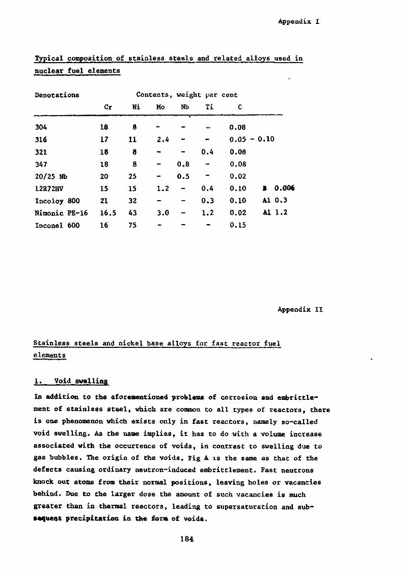
Appendix I
Typical composition of stainless steels and related alloys used innuclear fuel elements
DenotationsCr
Contents, weight per centNi Mo Nb Ti C
30431632134720/25 Nb12R72HVIncoloy 800Nimonic PE-16Inconel 600
1817181820152116,516
811882515324375
-
2.4 --
0.80.5
1.2 --3.0 --
_-0.4--
0.40.31.2-
0.080.050.080.080.020.100.100.020.15
- 0.10
B 0.006Al 0,3Al 1.2
Appendix II
Stainless steels and nickel base alloys for fast reactor fuelelements
1. Void swelling
In addition to the aforementioned problems of corrosion and embrittle*ment of stainless steel» which are common to all types of reactors, thereis one phenomenon which exists only in fast reactors, namely so-calledvoid swelling. As the name implies, it has to do with a volume increaseassociated with the occurrence of voids, in contrast to swelling due togas bubbles. The origin of the voids, Fig A is the same as that of thedefects causing ordinary neutron-induced embrittlement. Fast neutronsknock out atoms from their normal positions, leaving holes or vacanciesbehind. Due to the larger dose the amount of such vacancies is muchgreater than in thermal reactors, leading to supersaturation and sub-sequent precipitation in the for» of voids.
184
Appendix II
This is the net result of competitive processes trying to eliminatethe excess of vacancies. The simplest way of annihilating them is by reac-tion with interstitiels. The reason why cancellation of all vacanciesby interstitials does not occur is that the interstitials are pre-ferentially attracted to relatively stable aggregates» so-called dis-location loops. Actually it is these interstitials tnat are respon-sible for the volume increase, because of the strains resulting fromthese configurations, while the corresponding vacancy voids do notexert any stress on the matrix.
Sinks for defects which may be effective in reducing the swellingare dislocations» grain and phase boundaries and phases with a capa-city to absorp defects due to strains set up by differences betweentheir crystal lattice dimensions and those of the matrix.
Of practical interest is the effect of dose, temperature and metallur-gical conditions on the extent of the swelling. This is illustrated inFigs. B and C. The dose necessary t& produce void swelling varies with
22 2irradiation temperature but as a rule of thumb 10 n/cm is a thres-hold value for measurable volume changes. The temperature dependence*Fig. B, shows a maximum, made up of a rising branch owing to the in-creased mobility of the vacancies (noticeable at 300 to 400°C) and adecrease above 600°C due to thermally activated movement of vacancies,eliminating void nuclei
In future sodium cooled fast breeders the temperature of interest willrange between 400 and 6CO°C, while for gas cooled breeders the rangewill be 400 to 750°C. The point in mentioning the range is that thereare temperature gradients which will cause swelling gradients, givingrise to bending stresses.
As regards metallurgical conditions, a number of experiments attemptingto simulate fast reactor conditions have been made, indicating sometrends which are considered of general validity. Cold work (20%) oftype 316 steel decreases the swelling at low doses, but at high doses'this effect is diminished as the rate of swelling of cold-worked mate-rial increases with increasing doses. The effect of cold work is pre-sumably to provide sinks for point defects. Second phases, like so-called Y* or Ni.Al in Nimonic FE16» have proved to reduce swelling,Figs. B and C, presumably owing to the trapping of point defects atsolute atoms or precipitates. The latter may also have the effectof restricting the expansion of dislocation loops.
185
2. ,_ Selection of
The cladding of fast reactor fuel elements is subject to more de-manding conditions than perhaps any other structural material in anuclear reactor. From the corrosion point of view it has to be suffi-ciently resistant both to grain boundary attack from the coolant*corrosion on the inside surface and the dissolving action of thesodium coolant. Depending on the design, the requirements on creepproperties may differ. The most common view is that not only a rela-tively high creep strength is necessary but also some creep ductility.This seems to be a modest requirement, but it should be recognizedthat irradiation lowers the creep ductility of most candidate steelsby more than a factor of 10. On the top of this comes the swelling;rob lea, to which there is no solution in principle at this time.With regard to these requirements and the need to be ableto rely on consistent dimensional tolerances of tubing, the choiceof cladding material for the present prototype reactors is the rela-tively well known cold worked 316 stainless steel. Increasing demandson composition stability against sodium may result in a preferencefor stabilised varieties such as 321. A few other alternatives (12R72,Nimonic PE 16 etc.) .have also been considered for use in the futurecharges of fuel elements for prototype fast reactors.
The figures are from the following sources:
1. C.S, Barre tt, T.B. Massalski, Structure of Metals,Me Graw-Hill 1966, p. 225
2. Avesta Jernverk, Sweden
3. Ibid.
4. Ibid.
5. R.W.K. Honeycombe, The Plastic Deformation of Metals,Arnold, 1968, p. 352 - 354
6. D.R. Harries, J BNES 1966:1, p. 74
A. K.Q. Bagley et al, BNES Voids Conference 1971
B. P. Murray, Reactor Technology 15 (1972):!, p. 37
C. Ibid
186
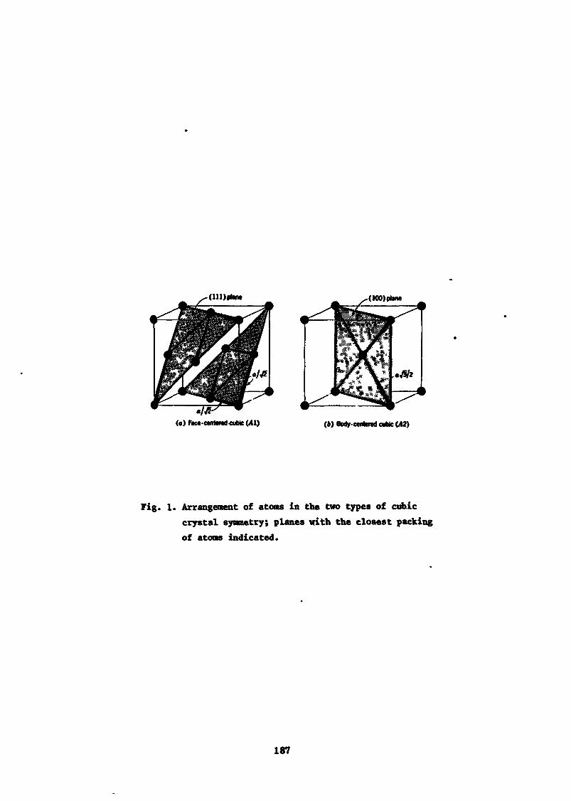
(in)*!» (100)1*1»
M Face-centered «ubte (41) (») Body-centered cubic (A2)
Fig. 1. Arrangement of atoms in the two types of cubiccrystal symmetry; planes with the closest packingof atoms indicated.
187
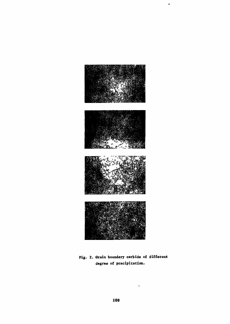
Fig. 2. Grain boundary carbide of differentdegree of precipitation.
188
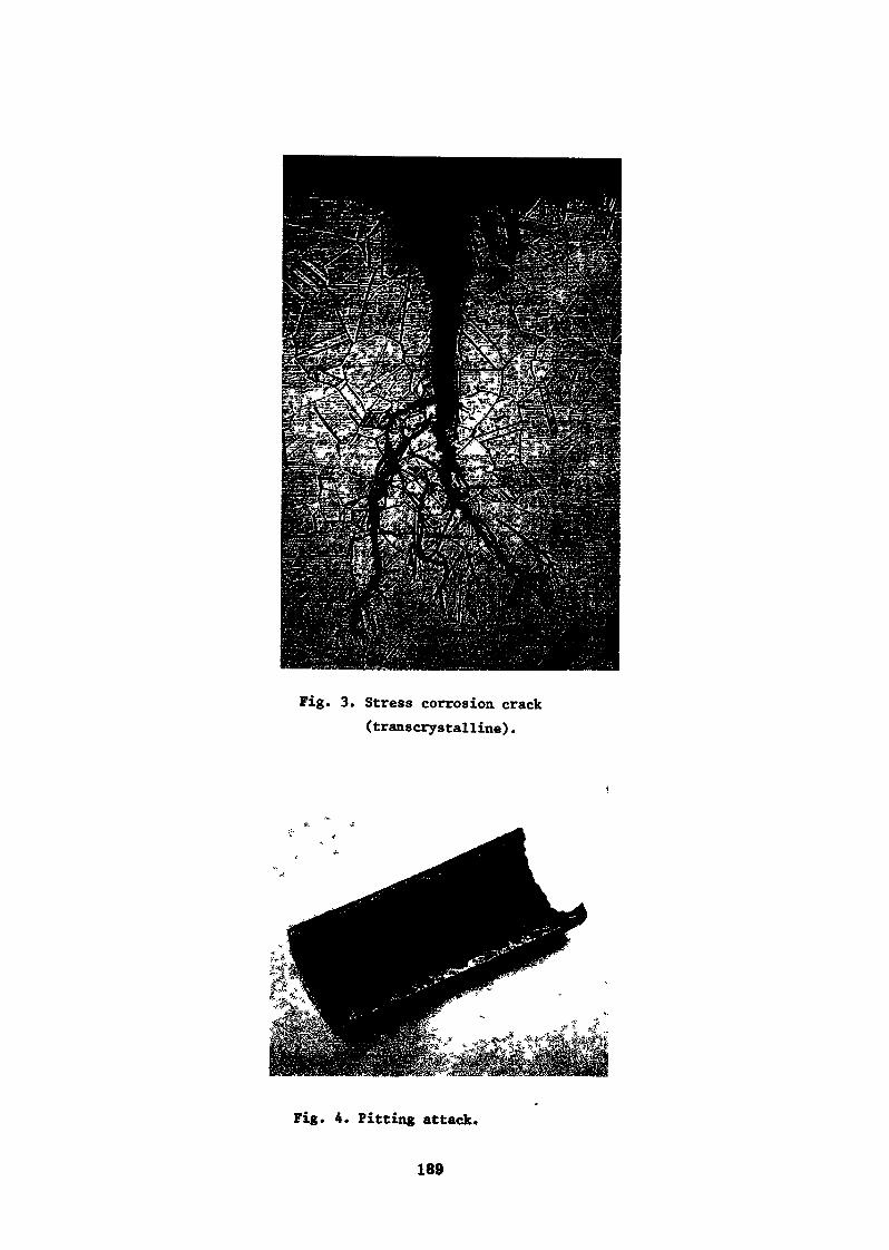
Fig. 3. Stress corrosion crack(transcrystalline).
Fig. 4. Pitting attack.
189
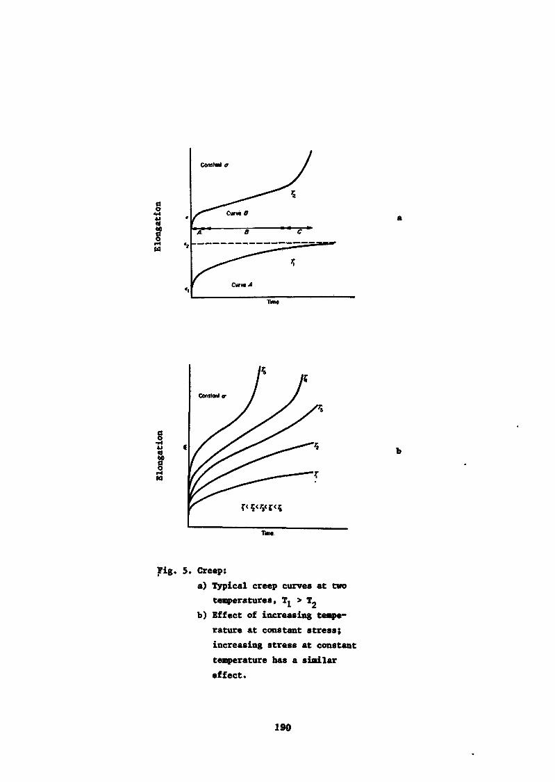
Constant <r
Curve 0
Curved
Time
Fig. 5. Creep:a) Typical creep curves at two
temperatures, T^ > T-b) Effect of increasing tempe-
rature at constant stress;increasing stress at constanttemperature has a similareffect.
190
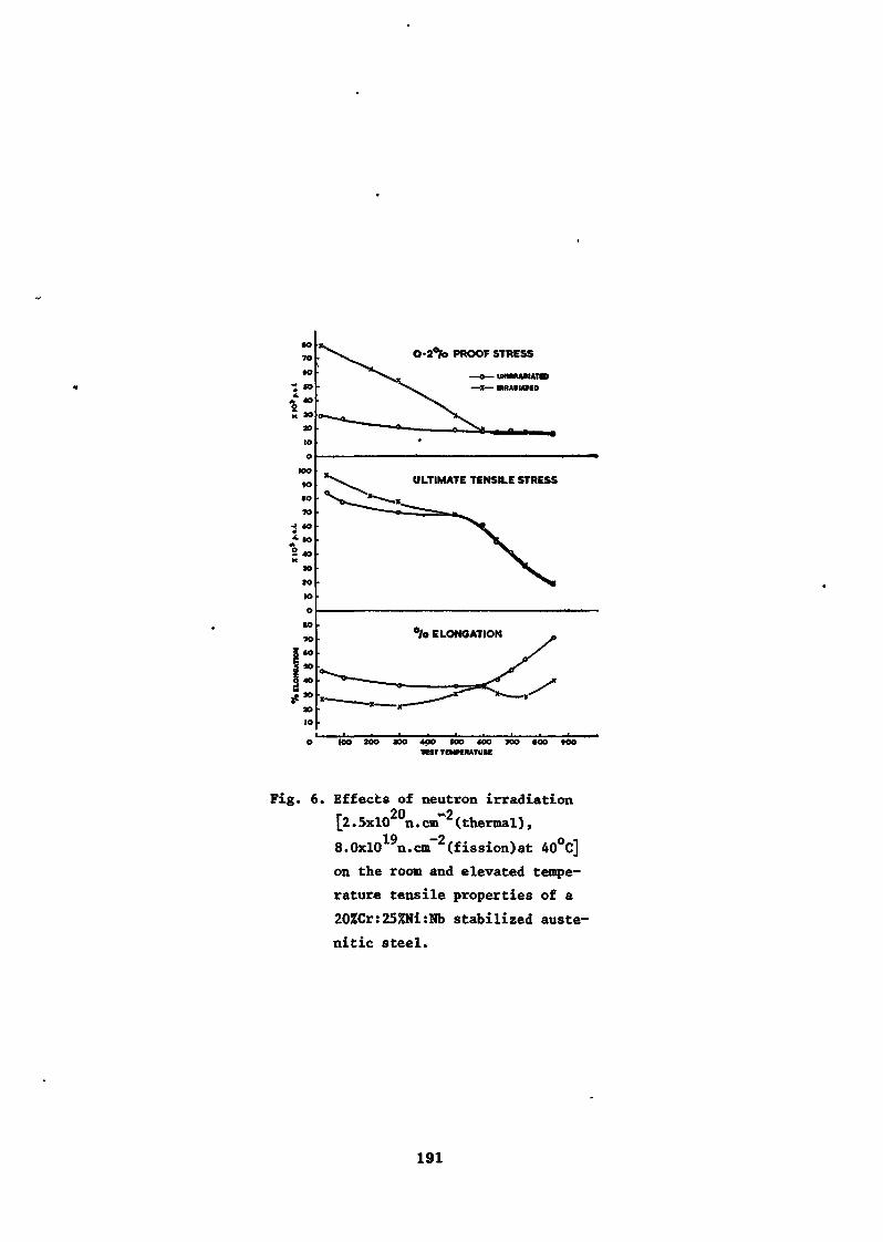
•oTO
éO
* *>
I:20
10
01
IOO«oM
70
««O
dX
30
JO
IO
Oto10
I 60
I *°| 40
f*>ao10
O-2°/o PROOF STRESS
ULTIMATE TENSILE STRESS
°/o ELONGATION
loo 200 aoo 400 soo <oo 700 «oo too•rest TCMPÏRATURC
Fig. 6. Effects of neutron irradiation[2.5xl02°n.cnf2(thermal),8.0xl019n.cm~2(fission)at 40°C]on the room and elevated tempe-rature tensile properties of a20%Cr:25%Ni:Nb stabilized auste-nitic steel.
191
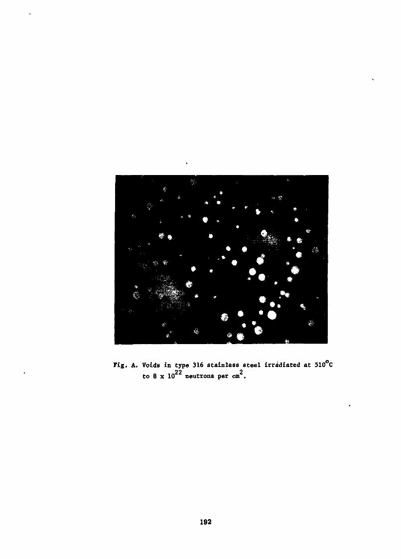
Fig. A. Voids in type 316 stainless steel irradiated at 510 C22 2to 8 x 10 neutrons per cm .
192
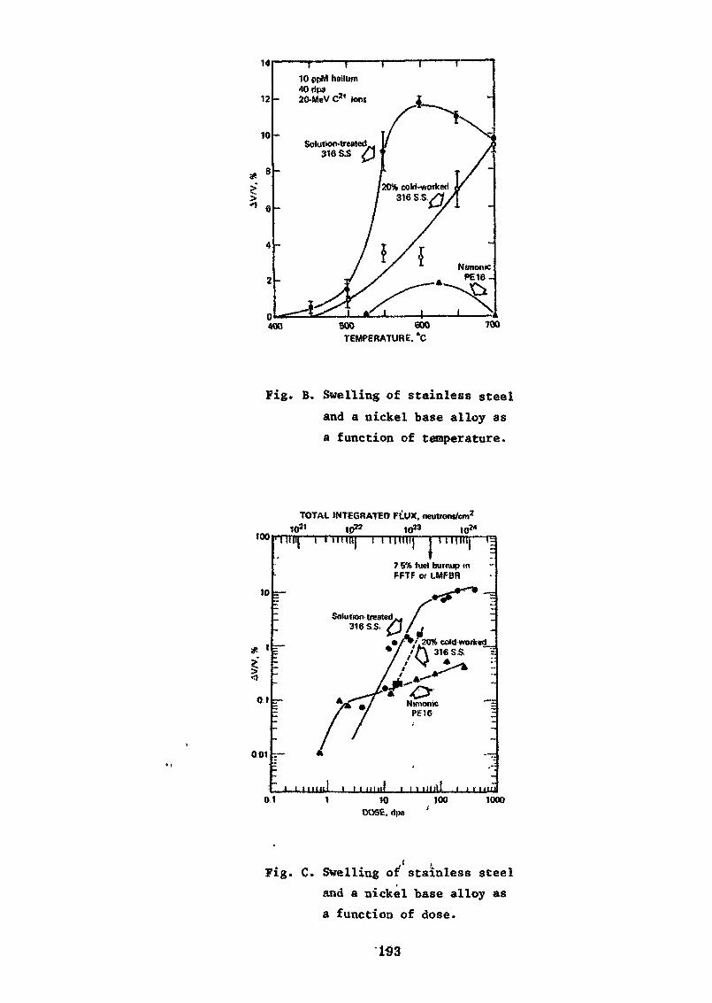
14
12 -
10 -
>
400
10 ppM helium40 Up» „20-MeV C2« ions
Solution-treated316 S.S
500 600TEMPERATURE. °C
700
Fig. B. Swelling of stainless steeland a nickel base alloy asa function of temperature.
too
10
TOTAL INTEGRATED FllUX. neutrons/cm2
1021 Ip*2 to23 10W
01
001
I Hill f I In 111! { I (I nil! T 1 I"I7 5% fuel burnup inPFTF or tMFBR
Solution treated .316 S S.
7/020% eold-wortced_
'O-Nimonic
I 1 i mill I I I null t I i mill i l l uiii0.1 10
. <Jpa100 1000
Fig. C. Swelling of stainless steeland a nickel base alloy asa. function of dose.
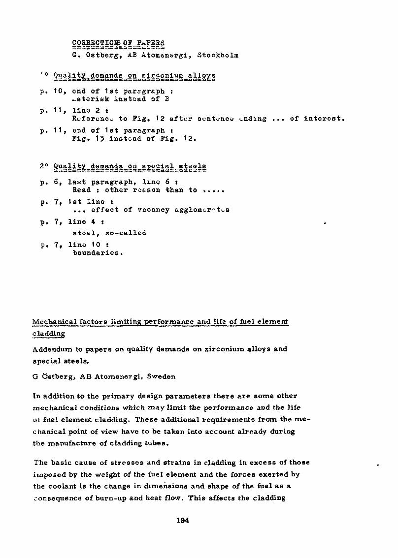
CORRECTION OP PAPERSsssssssfSssBrssBsssssssssscisssssssssa:
G. Ostberg, AB Atomenergi , Stockholm
Quality demands on zirconium alloys^^ssKssassjsssisssssssssssisiSsas^sssisssisrsssass!
p» 10, end of 1st pars graph :^sterisk instead of B
p » 11, line 2 :Reference to Fig, 12 after sentence ending ... of interest.
p. 11, end of 1st paragraph :Fig. 13 instead of Fig, 12.
2° Quality demands on special stoolsts-_: =s =r s:=fe=:s: =::= =:=::2 =::=::=:= :====;:= :ess=:s= =:==:= = =
p. 6, last paragraph, lino 6 :Read : other reason than to .....
p. 7, 1st lino :... effect of vacancy agglomcr"tc.s
p. 7, line 4 :stoel, so-called
p. 7, lino 10 :boundaries.
Mechanical factors limiting performance and life of fuel elementc ladding
Addendum to papers on quality demands on zirconium alloys andspecial steels.
G Ostberg, AB Atomenergi, Sweden
In addition to the primary design parameters there are some othermechanical conditions which may limit the performance and the lifeci fuel element cladding. These additional requirements from the me-chanical point of view have to be taken into account already duringthe manufacture of cladding txibes.
The basic cause of stresses and strains in cladding in excess of thoseimposed by the weight of the fuel element and the forces exerted bythe coolant is the change in dimensions and shape of the fuel as aconsequence of burn-up and heat flow. This affects the cladding
194
because it is brought in to close contact with the fuel during the riseto power due to the difference in thermal expansion between claddingand fuel materials (typically 6 • 10 C" for Zircaloy-2 and11 • 10* °C for UO2» at high burn-up swelling of UO, becomesmore important than thermal expansion). Fig 1. As the cladding isdeformed to followcthe changes in shape and dimensions of the fuel,ridges are formed at pellet interfaces. This leads to high, multi-axial stressesmnd strains in these regions.
In the longitudinal direction there is a successive stepwise elongationof the cladding due to the irreversibility of the straining action ofthe fuel. When the power is decreased, for instance during load-following operations, the fuel contracts in the radial direction. Thepellets eventually lose contact with the cladding and become freeto move downwards. At a subsequent power increase they makenew contact with the cladding at a lower position than before, con*sequently elongating the cladding a bit further. There is thus astepwise increase in the length of a cladding tube, so-called ratch-etting«,This process may become particularly severe if the diameterof the fuel varies from one pellet to another. Problems due to suchratchetting growth of cladding tubes have been serious in some PWR* s.Attempts to overcome or delay these problems have been made byincreasing the gap between fuel and cladding and applying an over-pressure of gas on the inside, so-called pré-pressurisation, to in-crease the time to collapse of the cladding by creep deformation.
Power cycling may correspondingly give rise to mechanical cyclingof the ridges, so-called low-cycle fatigue, eventually producing tan-gential cracks. Environmental factors, such as the presence of cor--rosive fission products might enhance the failure at such regions ofhigh local stress and strain.
In addition to the effects of the changes in shape and dimension ofthe fuel one also has to consider the consequences of cracks in thet7O~* Such cracks in the fuel occur due to the steep radial tern;*f»y«t«r« gradient, causing thermal expansion str«*a«* which theouter layer of UO_ cannot accommodate without cracking. As thecladding is in contact with the fuel, its deformation at the circum-ference is governed by the expansion of the fuel via the frictionbetween the two material*. When cracks in the fuel open up, the
195
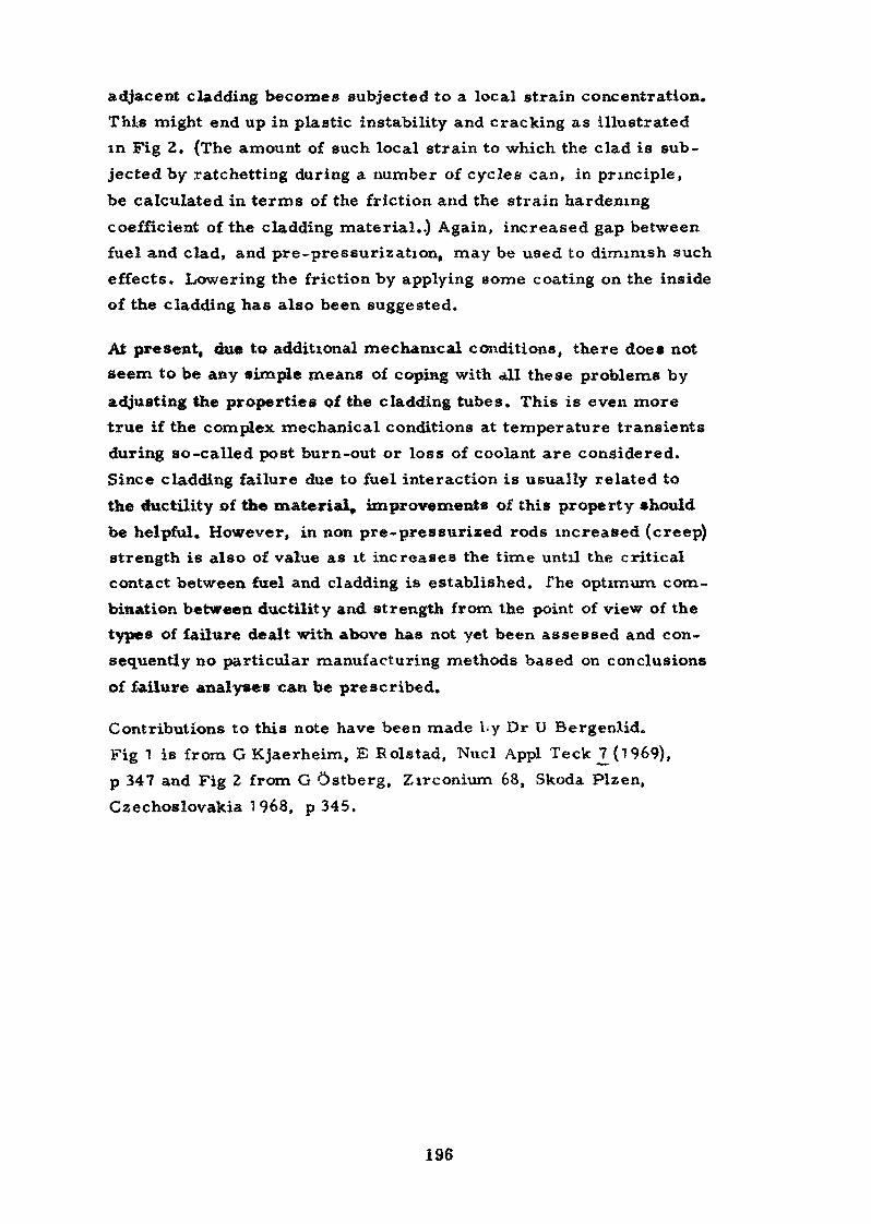
adjacent cladding becomes subjected to a local strain concentration.This might end up in plastic instability and cracking as illustratedin Fig 2. (The amount of such local strain to which the clad is sub-jected by ratchetting during a number of cycles can, in principle,be calculated in terms of the friction and the strain hardeningcoefficient of the cladding material..) Again, increased gap betweenfuel and clad, and pre-pressurization, may be used to diminish sucheffects. Lowering the friction by applying some coating on the insideof the cladding has also been suggested.
At present, due to additional mechanical conditions, there does notseem to be any simple means of coping with all these problems byadjusting the properties of the cladding tubes. This is even moretrue if the complex mechanical conditions at temperature transientsduring so-called post burn-out or loss of coolant are considered.Since cladding failure due to fuel interaction is usually related tothe ductility of the material, improvements of this property shouldbe helpful. However, in non pre-pressurized rods increased (creep)strength is also of value as it increases the time until the criticalcontact between fuel and cladding is established. The optimum com-bination between ductility and strength from the point of view of thetypes of failure dealt with above has not yet been assessed and con-sequently no particular manufacturing methods based on conclusionsof failure analyses can be prescribed.
Contributions to this note have been made by Dr U BergenXid.Fig 1 is from G Kjaerheim, E Rolstad, Nucl Appl TeckJ7(l969),p 347 and Fig 2 from G Ostberg, Zirconium 68, Skoda Plzen,Czechoslovakia 1 968, p 345.
196
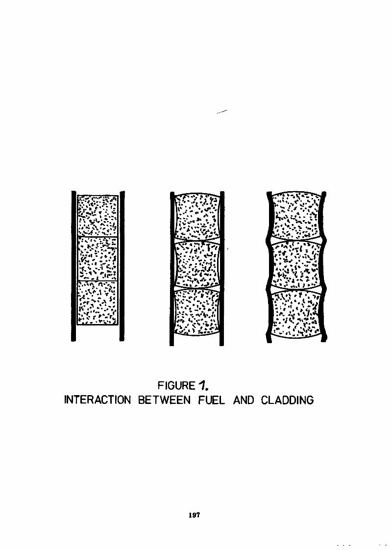
FIGURE 1.INTERACTION BETWEEN FUEL AND CLADDING
197
Fig. 2 Transverse section showing location
of a crack in the cladding near a crack in
the UO-, hydriding of Zircaloy crack walls
and shear fracture.
198
gabrication of zirconium sponge•4
G. Ostberg, AB Atomenergi, SwedenA» Ferez, Cezus, France
Abstract
The production of zirconium metal requires specialtechniques due, on the one lit id, to the particular chemicalproperties of zirconium and its compwnds and, on the other, thespecific demanda on the quality of the metal. The development ofthe proceed chemistry and the metallurgy of zirconium in the194CM s established a route for its production with the reductionof zirconium chloride by magnesium as the key reaction,preceded by purification from hafnium for reasons of nuclearquality.
1.- In tr oduc tion -
Zirconium was produced long before the nuclear agef butonly limited amounts, and by methods which were not suited toeconomical, large scale production. 1) As a consequence of thediscovery of the low neutron absorption of zirconium (after theremoval'Of hafnium which occurs with zirconium in the minerals),in the 19^0*s development work on the extraction of the metal,by the so-called Kroll method, was intensified. The key featureof the Kroll process is reduction of zirconium chloride tometallic zirconium by magnesium» The following list the sequenceof steps leading to this reduction process and the subsequenttreatment of the product :
1. Mining and concentration of the zirconium mineral, zirconor* ZrSiQ4» orthosilicate containing theoretically 6?,2 % of" ZrOg•" and 52,8 % SiO2.
!
2. Chlorination of zircon into "ZrCl/i" and SiCl't.
3. Remova2 of hafnium, yieldi ig hafnium-free ZrOjj.
k» Second Chlorination into ZrC14«
5. Reduction with magnesium, yielding zirconium raw sponge andMgCla.
6. Removal of excess magnesium by vacuum distillation.
7. Crushing, grading, hand-picking and blending of the sponge*
8. Production of solid metal ingot by melting of compactedsponge.
Ploy sheets of these operations is shown in Pigs 1. and 2»
•• . • ———If.. ..t..- • ••/«•«
1) In the 1920's Van Arkel invented a process for the productionof zirconium by the thermal decomposition of Zrl into metaland iodine. This principle is still the basis for the majorpart of the production of zirconium in the Soviet Union.
199
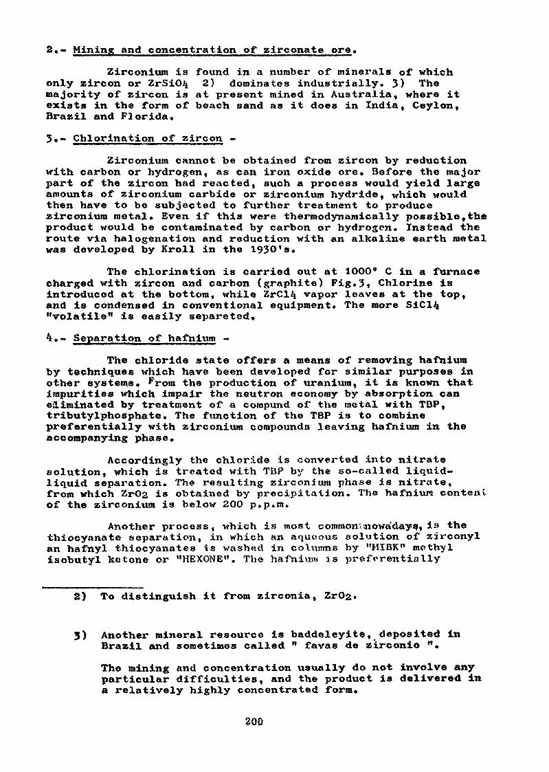
2»<- Mining and concentration of zirconate ore»
Zirconium is found in a number of minerals of whichonly zircon or ZrSiCHt 2} dominates industrially. 3) Themajority of zircon is at present mined in Australia, where itexists in the form of beach sand as it does in India, Ceylon,Brazil and Florida,
3»- Chlorination of zircon -
Zirconium cannot be obtained from zircon by reductionwith carbon or hydrogen, as can iron oxide ore» Before the majorpart of the zircon had reacted, such a process would yield largeamounts of zirconium carbide or zirconium hydride, which wouldthen have to be subjected to further treatment to producezirconium metal» Even if this were thermodynamically possible,theproduct would be contaminated by carbon or hydrogen. Instead theroute via halogeuation and reduction with an alkaline earth metalwas developed by Kroll in the 193O's,
The chlorination is carried out at 1OOO* C in a furnacecharged with zircon and carbon (graphite) Pig.3* Chlorine isintroduced at the bottom, while ZrC14 vapor leaves at the top,and is condensed in conventional equipment» The more SiCl^"volatile" is easily separeted,
4t,«- Separation of hafnium «
The chloride state offers a means of removing hafniumby techniques which have been developed for similar purposes inother systems. From the production of uranium, it is known thatimpurities which impair the neutron economy by absorption caneliminated by treatment of a compund of the metal with TBP,tributylphosphate. The function of the TBP is to combinepreferentially with zirconium compounds leaving hafnium in theaccompanying phase»
Accordingly the chloride is converted into nitratesolution, which is treated with TBP by the so-called liquid-liquid separation. The resulting zirconium phase is nitrate,from which ZrOg is obtained by precipitation. The hafnium conteulof the zirconium is below 200 p.p.m.
Another process, which is most common'•nowadays, is thethiocyanate separation, in which an aqueous solution of zirconylan hafnyl thiocyanates is washed in columns by "MIBK" methylisobutyl ketone or "HEXONE". The hafnivm* is preferentially
2) To distinguish it from zirconia,
3) Anothex* mineral resource is baddeleyite, deposited inBrazil and sometimes called " favas de zirconio "»
The mining and concentration usually do not involve anyparticular difficulties, and the product is delivered ina relatively highly concentrated form»
200
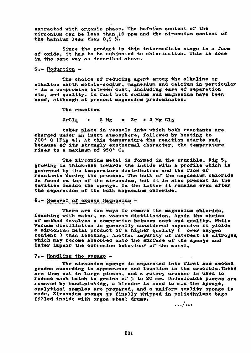
extracted with organic phase. The Hafnium content of thezirconium can be less than .10 ppm and txhe zirconium content ofthe hafnium leas than O,5 ^*
Since the product in this intermediate stage is a formof oxide, it has to be subjected to chlorination. This is donein the same way as described above*
5««- Reduction -
The choice of reducing agent among the alkaline oralkaline earth metals-sodium, magnesium and calcium in particular- is a compromise between cost, including ease of separationetc, and quality» In fact both sodium and magnésium have beenused, although at present magnesium predominates»
The reaction
+ 2 Mg a Zr + 2 Mg
takes place in vessels into which both reactants arecharged under an inert atmosphere, followed by heating to70O* C (Fig 4). At this temperature the reaction starts and,because of its strongly exothermal character, the temperaturerises to a maximum of 95 O° C»
The zirconium metal is formed in the crucible, Pig 5»growing in thickness towards the inside with a profile which isgoverned by the temperature distribution and the flow ofreactants 'during the process. The bulk of the magnesium chlorideis found on top of the zirconium, but it is also present in thecavities inside the sponge. In the latter it remains even afterthe separation of the bulk magnesium chloride*
6»- Removal of excess Magnesium -
There are two ways to remove the magnesium chloride,leaching with water, an vacuum distillation» Again the choiceof method involves a compromise between cost and quality» Whilevacuum distillation is generally considered expensive it yieldsa zirconium metal product of a higher quality ( ower oxygencontent ) than leaching» Another impurity of interest is nitrogen,which may become absorbed onto the surface of the sponge andlater impair the corrosion behaviour of the metal»
?•- Handling the sponge -The zirconium sponge is separated into first and second
grades according to appearance and location in the crucible .Theseare then cut in large pieces, and a rotary crusher is used toreduce each batch to grains of 3 to 2O mm* Undesirable pieces areremoved by hand-picking, a blender is used to mix the sponge,analytical samples are prepared, and a uniform quality sponge ismade» Zirconium sponge <$.$ finally shipped in polie thylene bagsfilled inside with argon steel drums*
201
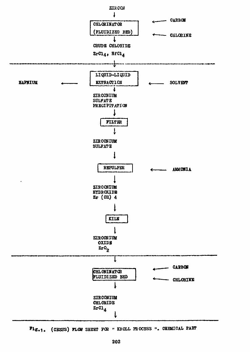
ZIRCON
HAFKIUU
CHLQRIHATOH(FLUIDIZ5D BED)
4CRUDE CHLORIDE
LIQUID-LIQpIDEXTRACTION
4ZIRCONIUMSULFATEPRECIPITATION
FILTER
CARBON
CHLORINE
SOLVENT
ZIECONIUMSULFATE
RBPULPER AMMONIA
2IFCCNIUMHYDROXIDEZr (OH) 4
JKILS [
ZIECONIUUOXIDE
TCELORINATŒPLUIDIZED BED
CABBCK
CHLOaiKE
ZIRCONIUMCHLORIDEZrCl
I
(CBZUS) FLOW SHEET FOB " KHOLL HIOCESS ". CHEMICAL PAST
202
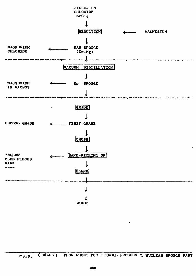
MAGNESIUMCHLORIDE
ZIRCONIUMCHLORIDE
{REDUCTION
IRAW SPONGE
<Zr-M«)
MAGNESIUM
MAGNESIUMIN EXCESS
{VACUUM DISTILLATION
iZr SPONGE
i
SECOND GRADE
YELLOWBLUE PIECESDARK
{GRADE j
iFIRST GRADE
IICRUSH)
i[HAND-PICKING UP{
i(BLEND!
INGOT
Pig. 2. ( CEZUS ) PLOW SHEET FOR " KROLL PROCESS * NUCLEAR SPONGE PART
203
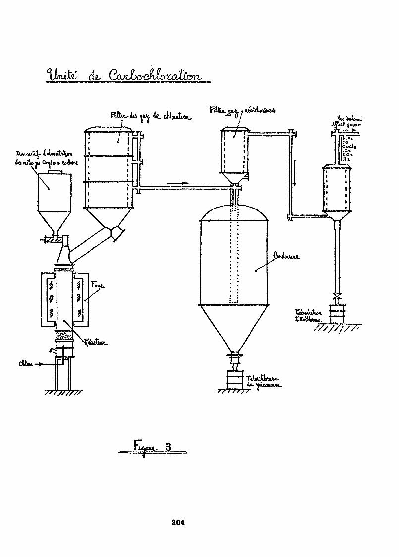
iimifc çLt
tfon.lU.vi» (Wit»
S'f/S/?77
204
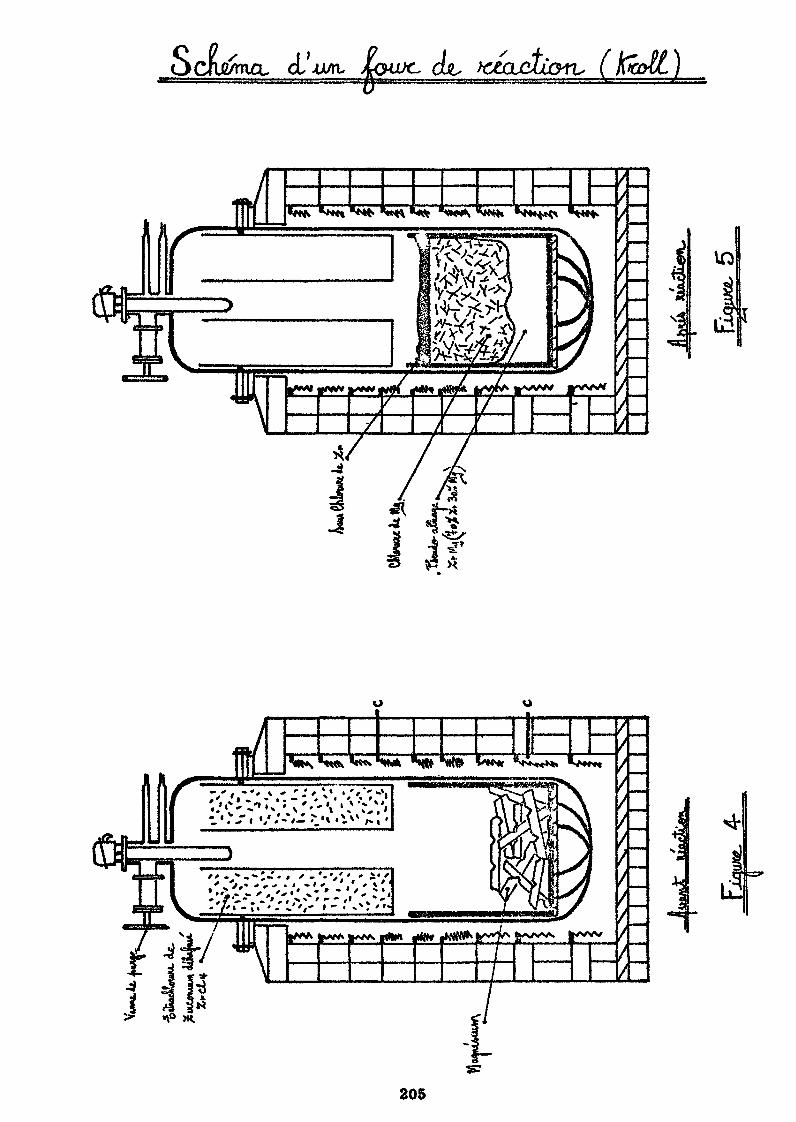
c>Cae/mcu cl' JUJTL
i
/<•*.-:-., ' -'•'/',
»^A fc^^ rtKm *HH jHtiffr
205
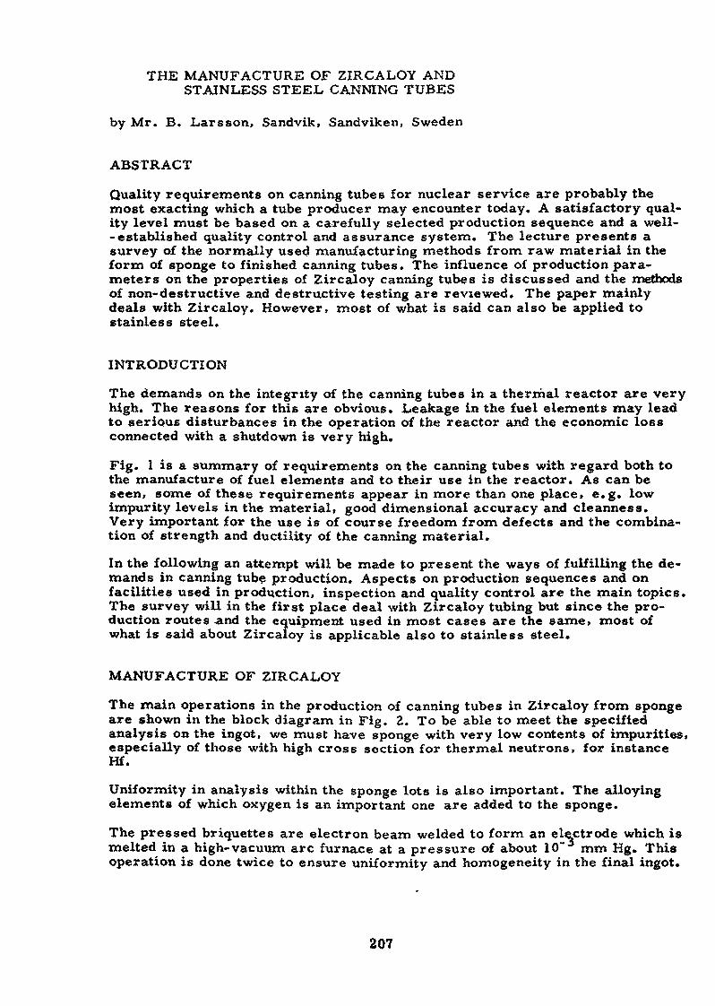
THE MANUFACTURE OF ZIRCALOY ANDSTAINLESS STEEL CANNING TUBES
by Mr. B. Larsson, Sandvik, Sandviken, Sweden
ABSTRACT
Quality requirements on canning tubes for nuclear service are probably themost exacting which a tube producer may encounter today. A satisfactory qual-ity level must be based on a carefully selected production sequence and a well-- established quality control and assurance system. The lecture presents asurvey of the normally used manufacturing methods from raw material in theform of sponge to finished canning tubes. The influence of production para-meters on the properties of Zircaloy canning tubes is discussed and the methodsof non-destructive and destructive testing are reviewed. The paper mainlydeals with Zircaloy* However, most of what is said can also be applied tostainless steel.
INTRODUCTION
The demands on the integrity of the canning tubes in a thermal reactor are veryhigh. The reasons for this are obvious. Leakage in the fuel elements may leadto serious disturbances in the operation of the reactor and the economic lossconnected with a shutdown is very high.
Fig. 1 is a summary of requirements on the canning tubes with regard both tothe manufacture of fuel elements and to their use in the reactor. As can beseen, some of these requirements appear in more than one place» e.g. lowimpurity levels in the material, good dimensional accuracy and cleanness.Very important for the use is of course freedom from defects and the combina-tion of strength and ductility of the canning material.
In the following an attempt will be made to present the ways of fulfilling the de-mands in canning tube production. Aspects on production sequences and onfacilities used in production, inspection and quality control are the main topics.The survey will in the first place deal with Zircaloy tubing but since the pro-duction routes and the equipment used in most cases are the same, most ofwhat is said about Zircaloy is applicable also to stainless steel.
MANUFACTURE OF ZIRCALOY
The main operations in the production of canning tubes in Zircaloy from spongeare shown in the block diagram in Fig. 2. To be able to meet the specifiedanalysis on the ingot, we must have sponge with very low contents of impurities,especially of those with high cross section for thermal neutrons, for instanceHf.
Uniformity in analysis within the sponge lots is also important. The alloyingelements of which oxygen is an important one are added to the sponge.
The pressed briquettes are electron beam welded to form an electrode which ismelted in a high-vacuum arc furnace at a pressure of about 10 mm Hg» Thisoperation is done twice to ensure uniformity and homogeneity in the final ingot.
207
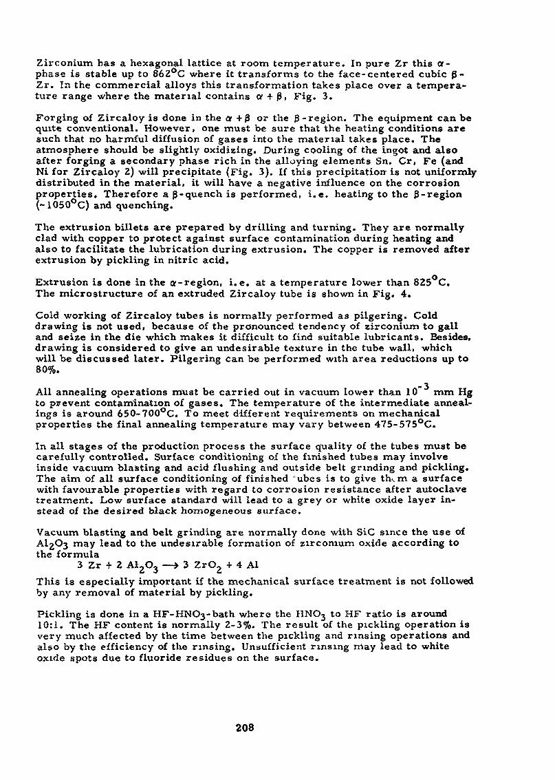
Zirconium has a hexagonal lattice at room temperature. In pure Zr this a-phase is stable up to 862°C where it transforms to the face- centered cubic p-Zr. In the commercial alloys this transformation takes place over a tempera-ture range where the material contains a + P, Fig. 3.
Forging of Zircaloy is done in the at 4- p or the 3 -region. The equipment can bequite conventional. However, one must be sure that the heating conditions aresuch that no harmful diffusion of gases into the material takes place. Theatmosphere should be slightly oxidizing. During cooling of the ingot and alsoafter forging a secondary phase rich in the alloying elements Sn. Cr, Fe (andNi for Zircaloy 2) will precipitate (Fig. 3). If this precipitation- is not uniformlydistributed in the material, it will have a negative influence on the corrosionproperties» Therefore a p-quench is performed, i.e. heating to the p-region(~1050°C) and quenching.
The extrusion billets are prepared by drilling and turning. They are normallyclad with copper to protect against surface contamination during heating andalso to facilitate the lubrication during extrusion. The copper is removed afterextrusion by pickling in nitric acid.
Extrusion is done in the a-region, i.e. at a temperatxxre lower than 825 C.The microstructure of an extruded Zircaloy tube is shown in Fig. 4.
Cold working of Zircaloy tubes is normally performed as pilgering. Colddrawing is not used, because of the pronounced tendency of zirconium to galland seize in the die which makes it difficult to find suitable lubricants. Besides,drawing is considered to give an undesirable texture in the tube wall, whichwill be discussed later. Pilgering can be performed with area reductions up to80%.
All annealing operations must be carried out in vacuum lower than 10 mm Hgto prevent contamination of gases. The temperature of the intermediate anneal-ings is around 650-700°C. To meet different requirements on mechanicalproperties the final annealing temperature may vary between 475-575°C.
In all stages of the production process the surface quality of the tubes must becarefully controlled. Surface conditioning of the finished tubes may involveinside vacuum blasting and acid flushing and outside belt grinding and pickling.The aim of all surface conditioning of finished 'ubes is to give th., m a surfacewith favourable properties with regard to corrosion resistance after autoclavetreatment. Low surface standard will lead to a grey or white oxide layer in-stead of the desired black homogeneous surface.
Vacuum blasting and belt grinding are normally done with SiC since the use ofAl;>O3 may lead to the undesirable formation of zirconium oxide according tothe formula
3 Zr + 2 A1O —> 3 ZrC -f 4 AlThis is especially important if the mechanical surface treatment is not followedby any removal of material by pickling.
Pickling is done in a HF-HNOj-bath where the HNOj to HF ratio is around10:1. The HF content is normally 2-3%. The result of the pickling operation isvery much affected by the time between the pickling and rinsing operations andalso by the efficiency of the rinsing. Unsufficient rinsing may lead to whiteoxide spots due to fluoride residues on the surface.
208
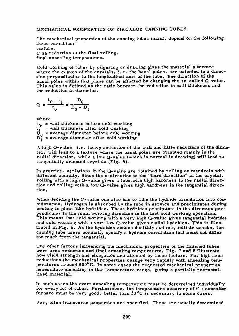
MECHANICAL PROPERTIES OF ZIRCAL.OY CANNING TUBES
The mechanical properties of the canning tubes mainly depend on the followingthree variables:texture,area reduction in the final rolling,final annealing temperature.
Cold working of tubes by pilgering or drawing gives the material a texturewhere the c-axes of the crystals, i.e. the basal poles, are oriented in a direc-tion perpendicular to the longitudinal axis of the tube. "She direction of thebasal poles within that plane can be affected by changing the so-called Q-value.This value is defined as the ratio between the reduction in wall thickness andthe reduction in diameter.
" *o Do ~ Diwhere10 = wall thickness before cold workingt, = wall thickness after cold workingUQ = average diameter before cold workingD. = average diameter after cold working
A high Q-value, i.e. heavy reduction of the wall and little reduction of the diame-ter, will lead to a texture where the basal poles are oriented mainly in theradial direction, while a low Q-value (which is normal in drawing) will lead totangentially oriented crystals (Fig. 5).
In practice, variations in the Q-value are obtained by rolling on mandrels withdifferent conicity. Since the c-direction is the "hard direction" in the crystal,rolling with a high Q-value gives a tube,with high hardness in the radial direc-tion and rolling with a low Q-value gives high hardness in the tangential direc-tion.
When deciding the C-value one also has to take the hydride orientation into con-sideration. Hydrogen is absorbed I y the tube in service and precipitates duringcooling in plate-like hydrides. These hydrides precipitate in the direction per-pendicular to the main working direction in the last cold working operation.This means that cold working with a very high Q-value gives tangential hydridesand cold working with a very low Q-value gives radial hydrides. This is illus-trated in Fig. 6. As the hydrides reduce ductility and may initiate cracks» thecanning tube users normally specify a hydride orientation that must not differtoo much from the tangential.
The other factors influencing the mechanical properties of the finished tubeswere area reduction and final annealing temperature. Fig. 7 and 8 illustratehow yield strength and elongation are affected by these factors. For high areareductions the mechanical properties change very rapidly with annealing tem-peratures around 500°C. In some cases the requested mechanical propertiesnecessitate annealing in this temperature range, giving a partially recrystal-lized material.
In such cases the exact annealing temperature must be determined individuallyfor every lot of tubes. Furthermore, the temperature accuracy of t', > annealingfurnace must be very good, better than J"3°C is necessary in some cases.
Very often transverse properties are specified. These are usually determined
209
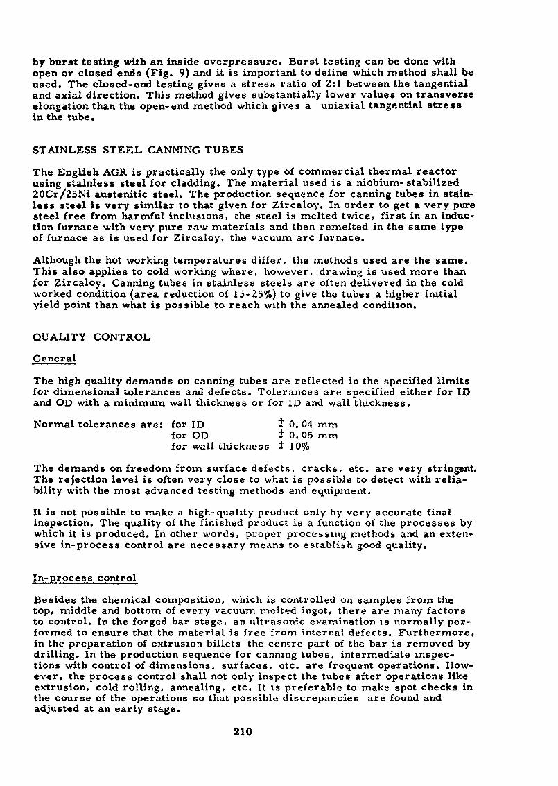
by burst testing with an inside overpressure. Burst testing can be done withopen or closed ends (Fig. 9) and it is important to define which method shall beused. The closed-end testing gives a stress ratio of 2:1 between the tangentialand axial direction* This method gives substantially lower values on transverseelongation than the open-end method which gives a uniaxial tangential stressin the tube.
STAINLESS STEEL CANNING TUBES
The English AGR is practically the only type of commercial thermal reactorusing stainless steel for cladding. The material used is a niobium-stabilized20Cr/25Ni austenitic steel. The production sequence for canning tubes in stain-less steel is very similar to that given for Zircaloy. In order to get a very puresteel free from harmful inclusions, the steel is melted twice> first in an induc-tion furnace with very pure raw materials and then remelted in the same typeof furnace as is used for Zircaloy, the vacuum arc furnace.
Although the hot working temperatures differ, the methods used are the same.This also applies to cold working where, however, drawing is used more thanfor Zircaloy. Canning tubes in stainless steels are often delivered in the coldworked condition (area reduction of 15-25%) to give the tubes a higher initialyield point than what is possible to reach with the annealed condition.
QUALITY CONTROL
General
The high quality demands on canning tubes are reflected in the specified limitsfor dimensional tolerances and defects. Tolerances are specified either for IDand OD with a minimum wall thickness or for ID and wall thickness.
Normal tolerances are: for ID * 0.04 mmfor OD t 0. 05 mmfor wall thickness t 10%
The demands on freedom from surface defects, cracks, etc. are very stringent.The rejection level is often very close to what is possible to detect with relia-bility with the most advanced testing methods and equipment.
It is not possible to make a high-quality product only by very accurate finalinspection. The quality of the finished product is a function of the processes bywhich it is produced. In other words, proper processing methods and an exten-sive in-process control are necessary means to establish good quality.
In-process control
Besides the chemical composition, which is controlled on samples from thetop, middle and bottom of every vacuum melted ingot, there are many factorsto control. In the forged bar stage, an ultrasonic examination is normally per-formed to ensure that the material is free from internal defects. Furthermore,in the preparation of extrusion billets the centre part of the bar is removed bydrilling. In the production sequence for canning tubes, intermediate inspec-tions with control of dimensions, surfaces, etc. are frequent operations. How-ever, the process control shall not only inspect the tubes after operations likeextrusion, cold rolling, annealing, etc. It is preferable to make spot checks inthe course of the operations so that possible discrepancies are found andadjusted at an early stage.
210
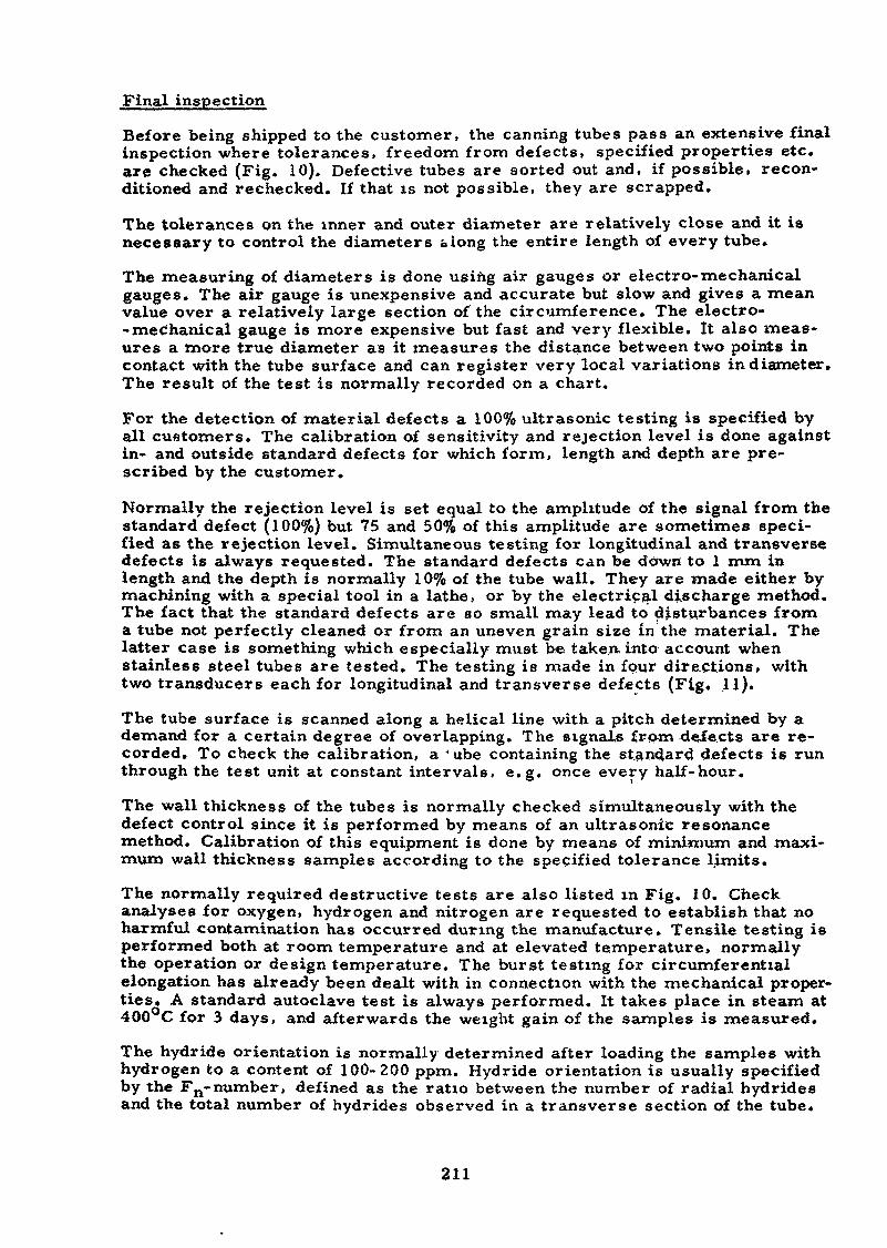
Final inspection
Before being shipped to the customer, the canning tubes pass an extensive finalinspection where tolerances, freedom from defects, specified properties etc«are checked (Fig. 10). Defective tubes are sorted out and, if possible, recon-ditioned and rechecked. If that is not possible, they are scrapped.
The tolerances on the inner and outer diameter are relatively close and it isnecessary to control the diameters along the entire length of every tube.
The measuring of diameters is done using air gauges or electro-mechanicalgauges. The air gauge is unexpensive and accurate but slow and gives a meanvalue over a relatively large section of the circumference. The electro-- mechanical gauge is more expensive but fast and very flexible. It also meas-ures a more true diameter as it measures the distance between two points incontact with the tube surface and can register very local variations in diameter.The result of the test is normally recorded on a chart.
For the detection of material defects a 100% ultrasonic testing is specified byall customers. The calibration of sensitivity and rejection level is done againstin- and outside standard defects for which form, length and depth are pre-scribed by the customer.
Normally the rejection level is set equal to the amplitude of the signal from thestandard defect (100%) but 75 and 50% of this amplitude are sometimes speci-fied as the rejection level. Simultaneous testing for longitudinal and transversedefects is always requested. The standard defects Can be down to 1 mm inlength and the depth is normally 10% of the tube wall. They are made either bymachining with a special tool in a lathe, or by the electrical discharge method.The fact that the standard defects are so small may lead to disturbances froma tube not perfectly cleaned or from an uneven grain size in the material. Thelatter case is something which especially must be taken, into account whenstainless steel tubes are tested. The testing is made in four directions» withtwo transducers each for longitudinal and transverse defects (Fig. 11).
The tube surface is scanned along a helical line with a pitch determined by ademand for a certain degree of overlapping. The signals from defects are re-corded. To check the calibration, a ' ube containing the standard defects is runthrough the test unit at constant intervals» e.g. once every half-hour.
The wall thickness of the tubes is normally checked simultaneously with thedefect control since it is performed by means of an ultrasonic resonancemethod. Calibration of this equipment is done by means of minimum and maxi-mum wall thickness samples according to the specified tolerance limits.
The normally required destructive tests are also listed in Fig. 10. Checkanalyses for oxygen, hydrogen and nitrogen are requested to establish that noharmful contamination has occurred during the manufacture. Tensile testing isperformed both at room temperature and at elevated temperature, normallythe operation or design temperature. The burst testing for circumferentialelongation has already been dealt with in connection with the mechanical proper-ties. A standard autoclave test is always performed. It takes place in steam at400 C for 3 days, and afterwards the weight gain of the samples is measured.
The hydride orientation is normally determined after loading the samples withhydrogen to a content of 100-200 ppm. Hydride orientation is usually specifiedby the Fn-number, defined as the ratio between the number of radial hydridesand the total number of hydrides observed in a transverse section of the tube*
211
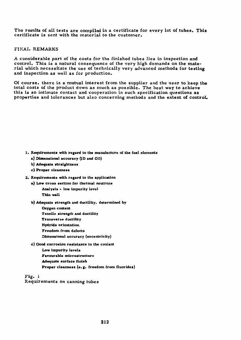
The results of all tests are compiled in a certificate for every lot of tubes. Thiscertificate is sent with the material to the customer.
FINAL REMARKS
A considerable part of the costs for the finished tubes lies in inspection andcontrol. This is a natural consequence of the very high demands on the mate-rial which necessitate the use of technically very advanced methods for testingand inspection as well as for production.
Of course, there is a mutual interest from the supplier and the user to keep thetotal costs of the product down as much as possible. The best way to achievethis is an intimate contact and cooperation in such specification questions asproperties and tolerances but also concerning methods and the extent of control.
I » Requirement» with regard to the manufacture of the fuel elementsa) Dimensional accuracy (ID and OD)b) Adequate straight ne s sc) Proper cleanness
2. Requirements with regard to the applicationa) Low cross section for thermal neutrons
Analysis - low impurity levelThin wall
b) Adequate strength and ductility, determined byOxygen contentTensile strength and ductilityTransverse ductilityHydride orientationFreedom from defectsDimensional accuracy (excentricity)
e) Good corrosion resistance to the coolantLow impurity levelsFavourable microstructureAdequate surface finishProper cleanness (e.g. freedom from fluorides)
Fig. 1Requirements on canning tubes
212
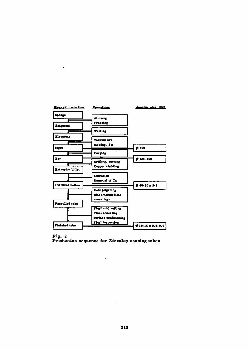
sponge
Briquette
* —————Electrode| ——— A 1
Ingot
Bar
_
t —————————Extrusion billet
, 1 ——Extruded hollow
, 1 ————Prerolled tube
Finished tube
AlloyingPressing
Welding
Vacuum arc-melting. 2 x
Forging
Drilling, turningCopper cladding
ExtrusionRemoval of Cu
Cold pUgering
annealings
Final cold rollingFinal annealingSurface conditioningFinal inspection
Fig. 2Production sequence for Zircaloy canning tubes
213
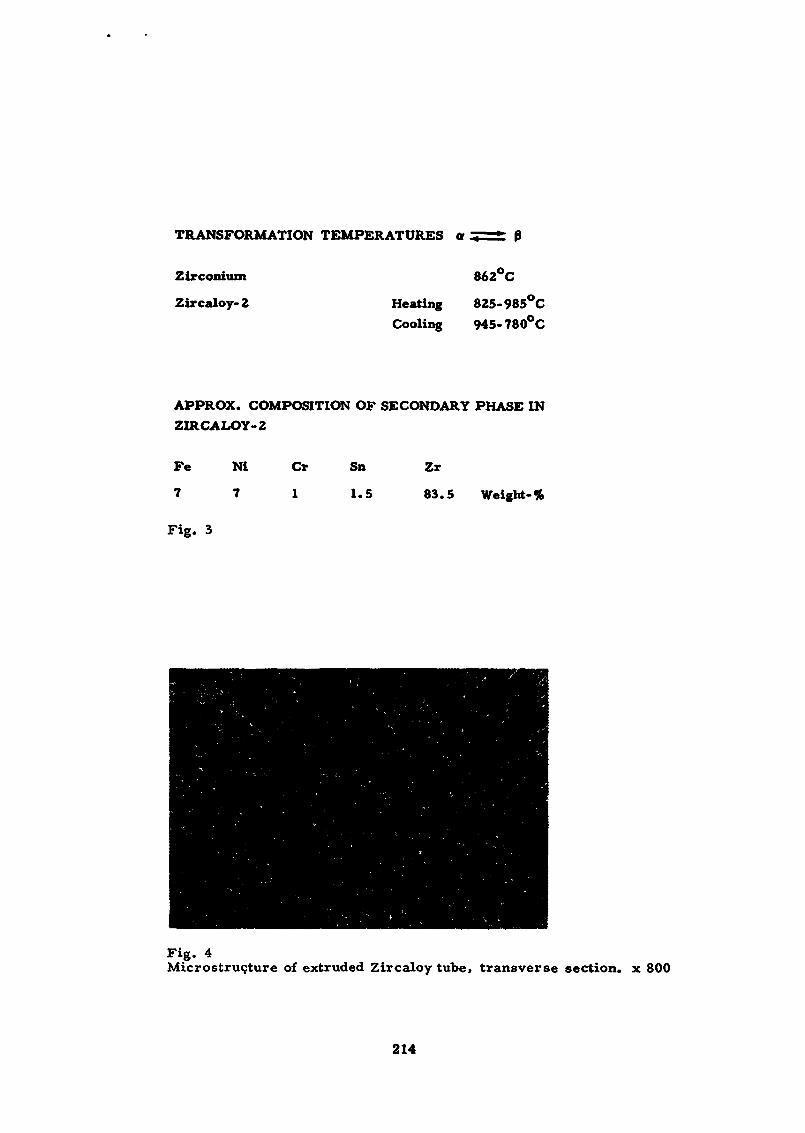
TRANSFORMATION TEMPERATURES er
Zirconium
Zircaloy-2 HeatingCooling
862°C
825-985°C945-780°C
APPROX. COMPOSITION OF SECONDARY PHASE INZIRCALOY-2
Fe
7
Fig. 3
Ni Cr Sn Zr
7 1 1.5 83.5 Weight-%
Fig. 4Microstruçture of extruded Zircaloy tube» transverse section, x 800
214
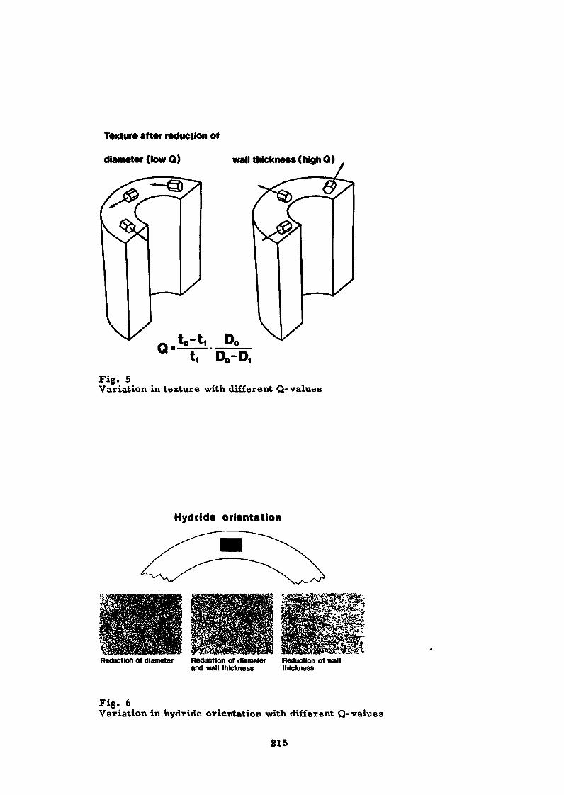
Texture after reduction of
diameter (tow Q) wall thickness (high Q)
to-t, Dfl
Fig. 5Variation in texture with different Q-values
Hydride orientation
Reduction of diameter Reduction of diameter Reduction of walland wall thickness thickness
Fig. 6Variation in hydride orientation with different Q-values
215
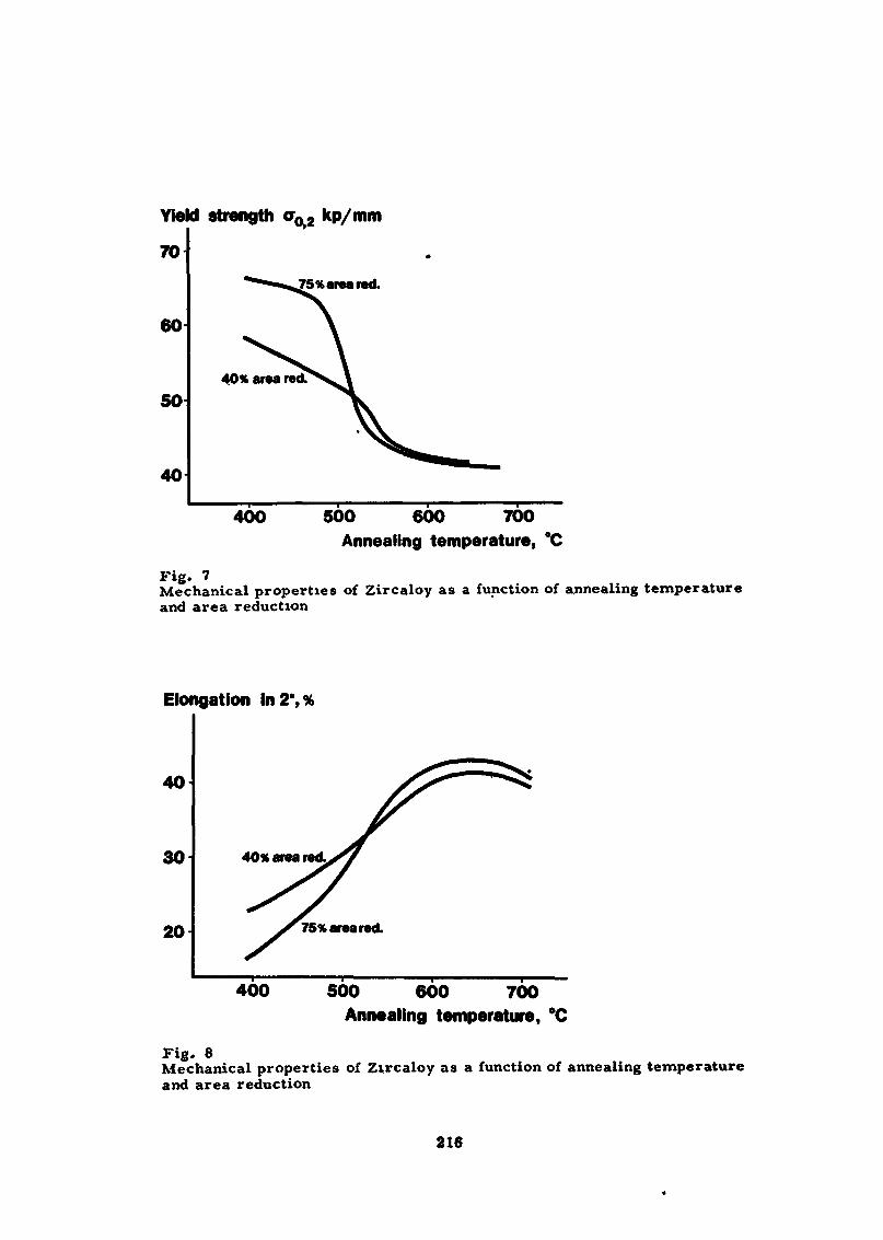
Yield strength <T02 kp/mm
70^75% area red.
60
50
40
40% area red.
400 500 600 700Annealing temperature, °C
Fig. 7Mechanical properties of Zircaloy as a function of annealing temperatureand area reduction
Elongation in 2",%
40
30
20
4O% area red.
75% area red.
400 500 600 700Annealing temperature, *C
Fig. 8Mechanical properties of Zircaloy as a function of annealing temperatureand area reduction
216
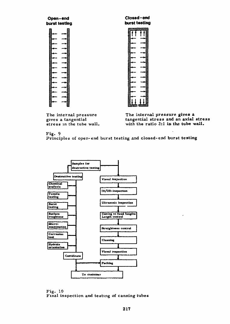
Open-endburst testing
.«— — ».
Clbu
osed-endirst testing
M38^H H
««"— • •— *•
•*- — »•«»_ — ».•* — — *•
H II
.
The internai pressuregives a tangentialstress in the tube wall.
The internai pressure gives atangential stress and an axial stresswith the ratio 2:1 in the tube wall*
Fïg. 9Principles of open-end burst testing and closed-end burst testing
Samples forr destructive testing
Destructive testing
[Chemicalanalysis
Tensiletesting
Bursttesting
I-•«•MM
mmmmam
Surface 1roughness [
Micro-examination
Corrosiontest
[Hydrideorientation
C
mmmtm
\-I-
Visual inspection
1ID/OD- inspection
J ;Ultrasonic inspection j
I ,Cutting to fixed lengthsLength control
1 ,1 "
Straigbtness control
ertificate
—————
j
I Cleaning
\ '.Visual inspection
j
Packing
!
To customer
,
H1
Fig. 10Final inspection and testing of canning tubes
217
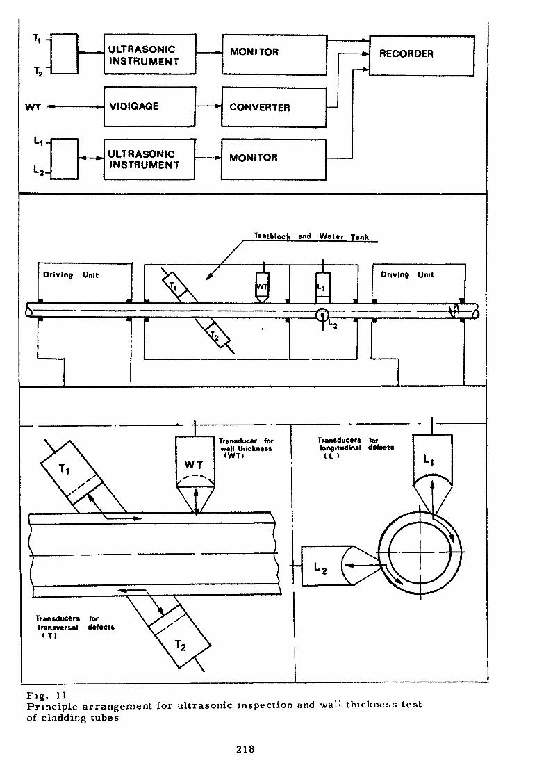
T, JULTRASONICINSTRUMENT
WT VIDIGAGE
ULTRASONICINSTRUMENT
MONITOR
CONVERTER
MONITOR
RECORDER
Testblock and Water Tank
Driving Unit Driving Unit
WT
Transducer forwall thickness(WT)
Transducers fortransversal defects( T )
Transducers forlongitudinal defects(L )
Fig. 11Principle arrangement for ultrasonic inspection and wall thickness testof cladding tubes
218
FABRICATION OP ZIRCONIUM-ALLOYCANNING MATERIALS
E. P. Baroch,Technical Director
TELEDYNE WAH CHAN<3 ALBANYAlbany, Oregon, U. S. A.
ABSTRACT
The production of canning components for a nuclear reactor
requires a high degree of quality since the failure to perform
adequately results in costs far in excess of the cost of the
components themselves. For most water reactors used for com-
mercial power generation, the components consist of zirconium
alloys, stainless steels, and nickel alloys. For the latter two
materials, conventional practices apply.
Since zirconium is a new and uncommon metal to most fab-ricators, an education process in handling it is necessary.
However, most operations common to other metals can be performed
on zirconium alloys, provided due attention is paid to its few
unique properties.
Components made of zirconium, other than fuel-clad tubing
and control rod tubes, which are discussed elsewhere, include
end plugs, spacer grids, and fluid-flow control channels. Use
of zirconium for structural components of the fuel assembly is
expected to increase as performance data become widely available,especially since matching of the physical properties of the fuel
pin with the structural components of the assembly has been
identified as an important factor in performance.
Fabrication methods for zirconium alloys must be tailoredto incorporate several often conflicting criteria, including
corrosion resistance, strength, ductility, and uniformity. And
these are, in turn, related to many other effects. For example,
219
contamination encountered in fabrication can have a large
adverse effect on ductility ana corrosion resistance. Also,
irradiation has effects on strength (or more precisely creep),
ductility, etc./ which cannot readxly be predicted based on
out~of-reactor testing.Because of these complex effects, it is necessary for a
fuel design engineer to involve himself intimately in the details
of zirconium alloy fabrication. It is equally important that
changes in fabrication procedures be considered carefully in
order to assess these interrelated effects.
INTRODUCTION
Depending upon the reactor type, the zirconium used for
components other than tubincr is relatively small. However,
the parts require attention in their design and fabrication
and all the controls attendant on the tubing are equally
necessary for these components. The use of zirconium alloys
for these components is based on a compromise of properties.
No single property of zirconium compelIs its use; however,
good performance in all required areas makes it the leading
material for a light water reactor. These performance areas
include: good corrosion resistance, moderate strength, low
neutron-capture cross section, low rate of embrittlement
due to corrosion and irradiation damage, fabricability, and
cost.
Dr. Ostberg has presented an excellent survey of the basis
for the use of zirconium1. While his discussion related primar-
ily to tubular products, these principles apply to the other
components, as we shall discuss. To do this, a pictorial tour
220
through a plant devoted primarily to the production of mill
products is presented. While many of the processing steps de-
scribed in this tour are located within a single facility, the
principles and criteria employed at other facilities are quite
similar. It should also be noted that it is possible, in
general, to perform most working and fabrication operations on
zirconium using equipment designed for such other metals as
steel, copper and brass, and aluminum. In general * working
stress requirements are less than those common to equivalent
ferrous metal working. The controlling factor on the use of a
given facility is primarily technology rather than equipment.
Several specific exceptions will be pointed out as we proceed.
TECHNICAL CONSIDERATIONS
Two primary and closely related differences exist between
zirconium and the ferrous metals: A need for levels of clean*?
liness and freedom from contamination well above most steel
practice; and, significantly increased costs for surface
conditioning. This latter need is based upon the fact that
zirconium oxidizes rather rapidly at the temperatures employed
for initial and intermediate breakdown operations. This oxide
is very hard and abrasive; moreover, the oxygen-contaminated
zone between it and the unaffected interior metal is extremely
hard, abrasive, and chemically resistant. Failure to removeit can lead to cracking during subsequent fabrication or under
the stress of operating conditions.
Mr. Larsson has discussed the need to properly homogenize
the alloy constituents within the Zircaloys in order to achieve
proper corrosion resistance2. While the alloy additions are
normally well dispersed on a macroscopic basis in the as-cast
221
ingot, segregation on a smaller scale accurs as a result of the
relatively slow cooling rate during the arc melting operation.
Also, segregation in the alloy takes place during the time
intervals when the material is heated into the alpha + beta
region (approximately 800*O1000°C). Therefore, at some stage
of the operation a homogenization heat treatment is necessary.
This is normally achieved by reheating the material into the
all-beta region (above 1000*C) and rapidly cooling the pieceinto the all~alpha region (less than 800°C). The maximum allow-
able time for this operation is approximately four minutes.
This corresponds to a cooling rate of about 65*C per minute.
Commercial practice consists of preheating in a large air
furnace and quenching into water. The maximum section thickness
which can effectively be quenched is approximately 0.25 meters.
Subsequent to quenching, all operations must be performed below
the two-phase region to prevent a significant deterioration of
the corrosion properties.Design engineers desire that the grain size of a metal be
controlled within reasonably narrow limits. As a general rule,
the grain size should be small with respect to the thickness of
the component to give good ductility. On the other hand, coarser
grain sizes give improved creep properties. For most Sircaloy
products the former criteria, fine grain size, is most desirable.
Moreover, the grain size should be uniform throughout the cross
section of a component, and in practice, a large deviation in
grain size signals a potential problem in Zircaloy,
Two closely related phenomena are active in the Zircaloy
systems which can cause a serious grain coarsening? both have
to do with critical amounts of strain within the crystallographic
lattice of the metal. If a piece of recrystaliised Zircaloy is
222
subjected to small amounts of cold work—on the order of 2 to
15%—>and recrystallized, the number of nucleation sites available
for recrystallization is very limited and an extremely coarse
grain size will result (Figure 1). Also, the thermal strain
induced during the beta quenching operation, or during welding,
can result in the nucleation and growth of extremely large grains
if the material is reheated into the high alpha region.
In both phenomena, the size of the grains produced is un-
controlled and sporatic, and may result in zones of relatively
large grains in the immediate vicinity of more desirable fine-
grained Zircaloy (Figure 2). It is easy to see that subsequent
stress on a material possessing this type of structure could
result in non-uniform stress distribution at the intersection
between the fine and coarse grain boundary components, resulting
in fracture. This is seen in Figure 3.
The effect of texture on the mechanical properties of
Zircaloy tubing is well documented in the literature. In products
other than tubing, of course, the properties are similarly affected.
Figure 4 shows graphically the effect of texture on the mechanical
properties of fully recrystallized Zircaloy strip. This is the
type used for fluid-flow channels in boiling water reactors.
It can be seen that if fabrication techniques can be properly
controlled, considerable control over final properties is possible.
One difficulty existing in the current state of the art is that
of relating simple mechanical test properties to actual service
conditions which include long-term cyclic exposure to combinations
of stress, corrosion and irradiation. Dominant among in-service
conditions is the fact that the neutron irradiation has a marked
effect upon the mechanical performance. Among the most active
223
programs currently underway are those attempting to relate long-
range irradiation test data to properties which can be controlled
in commercial fabrication of components.
The preferred orientation, or texture, development in zir-
conium creates one fabrication probl m: The metal has a memory.
Any non-uniform processing will yield a component with varying
texture, and consequently, varying properties which no amountof subsequent work will totally eliminate. Therefore, in order
to ensure control of properties, deformation operations must be
tailored to consider» even at an early stage such as forging,
the ability of the metal to recall deformation variations in the
final product.
The technology required to produce a sound, homogeneous
casting is described elsewhere in this publication1. It is
possible to improperly fabricate zirconium alloys in such a
manner that void formation may occur at grain boundaries (Figure5), or at critical stress points within the material, such as
the center of rod (shown in Ficrure 6). Using proper control,
it is, of course, possible to avoid such phenomena, This will
be discussed in the details of fabrication later.
Contamination can result if the material is subjected to
heating in a reducing atmosphere where free hydrogen is available
to contaminate the zirconium. Only 400 parts per million of
hydrogen are necessary to severely decrease the ductility of
Sircaloy in service. Fortunately, the heat transfer of zir-
conium is quite good, so times at temperature can be held low.
For example, an ingot 0.5 meters in diameter and weighing five
ton can be heated to 1050°C, ready for forging, in about four
hours. Considerably less time is needed as the section size
decreases. Even in this short period of time, an oxygen deficient
224
atmosphere can cause a large amount of hydrogen absorption into
zirconium, especially if there is also direct flame impingement.
Heating of smaller section sizes, of course, increases the
possibility of contamination.
The final consideration in the fabrication of zirconium
components that X will discuss today, and a major one, is that
of economics« It is mandatory that the quality criteria discuss-
ed above be met or the resulting material will not be satisfactory
for reactor application. However, there is still a concern that
the process selected be commercially viable. As you will see
later, there is a fairly broad choice of fabrication methods which
can be used satisfactorily provided the critical aspects of process-
ing are taken into account.
PROCESS DETAILS
Mill Products
The processing of zirconium alloys into nuclear components
can be broken into two primary categories: mill products and
components. It is not necessary that this distinction be made
in a production one, although it is one which has developed in
several facilities.
Let us look now at Figure 7 which shows schematically the
fabrication of rod material such as would be used for end plug
stock in nuclear reactors. It can be seen that methods available
are essentially those available for many other metals. Primary
ingot breakdown is normally press forging, although other methodsmay be used, provided they are compatible with the ingot starting
size. The beta-quench stage is critical, as are subsequent
reheats. Also, deformation operations—rod rolling, extrusion,
etc.—should be controlled within limits such that the heat of
225
reactors. Again, the controls necessary to prevent contamination
and maintain corrosion resistance are dominant. Variations in
mechanical properties can be achieved primarily through variations
in temperature of deformation, reduction sequences, and through use
of tension/ etc.Let us now take our tour through a facility designed primarily
for the working of reactive metals such as the Zircaloys. It is
to be noted that such a special facility is not necessary to
achieve high-quality product. However, the guidelines necessary
for satisfactory production of high-quality product are more
evident in such a plant. I will attempt to point these out in the
slides and note how similar operations can be performed in plants
which fabricate other metals, including titanium, steel, aluminum,
brass, etc.
Figure 9 shows one basic feature of Zircaloy fabrication:
The deformation stresses are very low compared to those encountered
in steel or titanium. This 2000-ton forge press is a very old one
used for many years in a tool steel facility.
The next step in the sequence is the beta-quench operation.
Conditioning is necessary after the quench to remove the heavy
layer of oxide and oxygen-contaminated metal resulting from being
in the beta region—above 1000°C—for several hours. Figure 10
shows, at 100X magnification, both the oxide layer (on the left),
and the oxygen-contaminated zone as indicated by the decreased
size of the diamond hardness indentations. Conditioning is done
by blasting with silicon carbide and local hand grinding
followed by pickling in a HF~HNOS acid bath to thoroughly remove
the contaminated metal as well as the blasting and grinding grit.
This sequence is seen in Figures 11, 12, and 13. It is interest-
ing to note that the pickling operation is of itself a good
226
control operation since any discontinuity on the slab will entrap
acid and cause discoloration as it dries.
The next series/ Figures 14 and 15, shows a slab of Zircaloy
being fabricated, sequentially, from 100 ram to about 4 mm. At
this stage, the material is air annealed, cond'tioned, and cold
rolled. The final anneal, and sometimes the last intermediate
anneal, is performed in vacm*m. Vacuum annealing is chosen
rather than air or protective gas in order to assure that surface
contamination will not result from the heat treatment» Moreover,
any hydrogen absorbed in previous heat treatments, or in pickling
and handling, will be removed. Figure 16 shows individual sheets
of channel material being cold rolled using no tension; Figure 17
shows the tension rolling of spacer strip.
It is not within the scope of this paper to become deeply
involved in vacuum technology. Suffice it to note that vacuums
achieved in fabrication of the less reactive metals, such as steel,
nickel, and titanium, are generally not satisfactory for zirconium
since zirconium's tendency to absorb hydrogen and nitrogen is
greater than these other metals.
Figure 18 shows several units used for vacuum annealing of
different sizes and shapes of zirconium alloys, including rod,
tube sheels, strip, and sheet.
Note in the previous views the general cleanliness of the
work area. While general cleanliness of a production facility
need not be this absolute, it is mandatory that the metal be kept
free of contamination: Oil and grease can decompose to cause
surface hardening and hydrogen absorption; foreign metal particles
may alloy with zirconium to cause local hard spots or cracks;
blasting grit can be entrapped and reduce effective ductility,
etc.
227
Components
As mentioned earlier, physical separation of mill product
production from component production is not essential; however,
many of the quality control ftinctions must be performed on the mill
product since inspectability and control will not be possible
later. Therefore, the inspection and test procedures we have
discussed for mill products must be completed and reviewed prior
to component manufacture if reliability is to be achieved.
The manufacture of cladding components fro» Zircaloy mill
products is considered by roost manufacturers to be proprietary
information, since critical design aspects are embodied in the
process. However, several of the production aspects of the
process will be discussed here. Figure 19 shows schematically
the production of end plugs from rod stock—an apparently simple
process, except for the requirement for rigid dimension control.
This plug must fit the tubing very closely to minimize stress
concentrations; some must also have controlled external dimensions
since they are used to locate the tube within the spacer qrid;
the external surfaces must be smooth and streamlined to minimize
fluid flow disturbance? they must be scrixpulousiy clean since they
will be welded to the tube and must also withstand the corrosion
environment. Therefore, the inspection and test procedures are
more involved than the basic machining—done either on a screw
machine or on an automatic lathe.
Zirconium and its alloys can be readily machined by conven-
tional methods. Three basic parameters should be used for all
machining operations on zirconium and its alloys: 1) slow speeds,
2) heavy feeds, and 3} a heavy flood of coolant lubricant. Care
should be taken to minimize very fine chips as they are pyrophoric
in nature. Zirconium exhibits a marked tendency to gall and work
228
harden. Therefore, higher than normal clearance angles on tools
are needed to penetrate the previously work-hardened surface and
cut a clean, coarse chip.
Satisfactory results can foe obtained with both cemented
carbide and high speed tools? however, the carbide usually gives
better finishes and higher productivity. Polishing or honing
the cutting edges will give the tool added life. Zirconium and its
alloys machine to an excellent finish, requiring relatively light
horsepower compared to alloy steel. The tool forces required
are also relatively low.
Spacer grids for light water reactors can be put in three
major categories: Those employing no zirconium components; thoseemploying only zirconium; and those employing zirconium as well
as some other material. The differences are based on severalsomewhat conflicting facts: Zirconium has a low neutron cross
section compared to most alternates; its use would yield an
overall increase in available power and in fuel efficiency.
However, the performance of Zircaloy at high stresses under
irradiation is not defined clearly enough to ensure satisfactory
performance. The critical aspect of the latter point is that of
stress relaxation—the decrease of load because of plastic strain
at constant deflection. Such stresses must be relatively high on
spacers in order to properly locate the fuel pins in a grid and
hold them rigid. Release of such stresses causes vibration and
"fretting"—a decomposition of the oxide film and subsequent
erosion of the underlying metal. Figure 21 shows the magnitude
and rapidity of this stress relaxation. Proper grid design can
take advantage of this relaxation phenomenon.
Composite grids take a&vantacre of the low neutron cross
section but use a non-zirconium component to apply pressure
229
against the tube. Tests are underway at several test locations
aimed at overcoming the limitations of the all-zirconium grid.
One problem which occurs with perculiar intensity in produc-
tion of Zircaloy spacer grids is the complexity of establishing
maximum allowable bendability* The textural effects described
earlier complicate the evaluation of this factor. The high
apparent tensile ductility—about 30 percent—coupled with
good simple bend radius—three times the thickness—have to be
evaluated conservatively when developing a design involving three-
dimensional forming operations. Minor variations in productionmethods cause lot-to-lot variations which make some designs
marginal. Extensive experience in forming of such parts is
necessary in order to avoid difficulties related to this variation,
A typical fabrication sequence for spacer strips is shown in
Figure 23.
Fluid flow channels are used primarily in BWR reactor types;
however, their manufacture gives insight as to the care and
cleanliness needed to handle Zircaloy materials, A schematic flow
diagram of such production is shown in Figure 22. Within the
framework of this outline, much variation exists including:
Intermediate shape and its methods of formation; weld method;
sizing method; nature and method of stress relief, if any;
extent of autoclaving? and many lesser details.
Several key operations performed at one facility are shown
in Figures 24 and 25. Again, note the cleanliness of the work
area.The use of zirconium alloys for all structural components in
the core, rather than the more commonly used stainless steel and
nickel alloys could result in a significant increase in neutron
economy, and thus in overall economics. Uncertainty over stress-
230
relaxation effects has caused most designers to move cautiously
in this area. However, a recent study4 has shown that use of
zirconium structural components may reduce stress on the in-
dividual fuel pins. This is especially significant since stress
on the .fuel pin appears to be the major design criteria limiting
fuel life.
Associated Facilities
Associated with the production of Zircaloy mill products
and components is the need for testing and inspection facilities*
For reasonable scheduling and material flow, some of these
facilities must be located at the site of production. Such
operations include ultrasonic inspection (Figures 26 and 27),
liquid pénétrant, dimensional inspection, and inert gas analysis.
Other test facilities need not be intimately associated with the
fabrication facility, although it is expeditious to do so. These
include: Chemical analysis, including classical wet chemical,
spectrophotometric, spectrographic, gas analysis, and specialized
instrumental techniques; corrosion test facilities, metallography,
and mechanical tests, including room and elevated-temperature
tensile test, bend or other formability tests. Some of these
facilities and tests are shown in Figures 28 through 31. It is not
essential that these test facilities be reserved for only Zircaloy
products, but considerable standardization on zirconium is necessary
and frequent recalibration is requested.
Costs
The current level of zirconium production is about five
million pounds annually. Much of it is processed in special fa-
cilities such as you have just seen. (Dr. Larsson has noted that
231
most zirconium fuel clad tubing is produced in facilities designed
and operated either primarily or exclusively on zirconium alloys.
Even organizations producing other tubular products have seen fitto segregate their zirconium product from most other products.)
Such segregation is not so critical for flat and solid round
product, nor is it so feasible until the production volume grows
significantly.
A large portion of what is saved by sharing facilities with,
say, a tool steel operation, will be consumed in higher costs
incurred in maintaining physical segregation of material. It has
already been mentioned that the vacuum furnaces needed are not
generally available in existing facilities. Blasting to remove
oxide can be best accomplished with silicon carbide grit—not too
common in most other metal working facilities. Aluminum oxide is
difficult to completely remove in subsequent operations; steel
shots and grits remove the visible oxide, but not the underlying
contaminated metal. The HF~HNQ8 acid is common to other metals,
but the standards of cleanliness are more severe.
The low modulus of zirconium alloys requires modification
of some pieces of equipment relying on this property—straighteners,
roller levellers, etc. As mentioned earlier, primary working tools
are in every way adequate.
Two components of cost are peculiar to nuclear component
manufacture: First, the high cost of quality and quality control
and second, the high capital cost of utilizing expensive machinery
on items in only intemittent demand. This latter aspect will
change as the nuclear market expands, but even the large facilities
in the major?nuclear nations are subject to intermittent low
utilization factors. Other use of this equipment is discouraged
232
by the requirements of cleanliness, radiation control, material
accountability, and material segregation.
One aspect of QC which is used to facilitate removal of
deficient material is that of material traceability. All zir-
conium alloy components are identified as to origin—-in terms of
manufacturer, ingot, and sometimes section number—at least until
fabrication of core components is initiated; often identification
is maintained throughout reactor life.
Cost of such a material accountability system is high; but• f
its ability to root out deficient, or potentially déficient,
material is deemed to be worth the investment in view of the high
cost of defective fuel.
The price of zirconium products has held relatively steady
during the past decade. Inflationary tendencies have generallybeen balanced by increased efficiencies and by the increase in
volume. Table I tabulates the general price structure of Zircaloyand the common high volume zirconium alloys. Values are shown in
U.S. dollars and are, for volume quantities, exclusive of trans-portation, duty, and product testing. Included in the cost base
are puricy and quality standards normally required by the nuclear
industry—items such as three to five analyses per ingot; inter-
mediate quality surveillance; customer access to critical process-
ing steps {except those considered to be proprietary); and product
control, except those items delineated below.
Table II shows typical testing costs. As noted, manyconsiderations can affect the actual cost. The prices shown assum
currently standardized methods and controls.
It takes only a few calculations to realize that a large
portion of the cost of Zircaloy products lies in testing and
controlling of the product. In view of the criticality of the
233
cladding application, and considering the relatively low percentage
of cost of a nuclear core spent on the Sircaloy products, it
becomes apparent that these costs of quality increments are well
advised.
CONCLUSION
The processes currently used for component production have
been described in brief. It is not possible to become involved
in all the technical aspects of this production. Overemphasisof the complexity of the operations is not intended? however,
several efforts at establishing zirconium facilities have proved
unsuccessful, and at least a portion of each facility's demise
was associated with either quality of the product or the flex-
ibility of an operation in adapting to changed conditions and
volumes. Many changes are certain to occur in coming years as
increased volume and rising costs force out many of the labor-
intensive operations we have seen today. But the basic nature of
the market appears to be well established.
-IZLIOGRAPHY;
1. G. Ostberg, This Publication, pp.2. B. Larsson, This Publication, pp.
3. R. H. Kreyns & M. W. Burkart, Journal of Nuclear Materials26 (1968) 87. ————— — ————— ———————
4. W. P. Chernok and J. R. Stewart, "Axial Growth of WaterReactor Fuel Rods", American Power Conference, Chicago,Illinois, April 18-20, 1972.
234
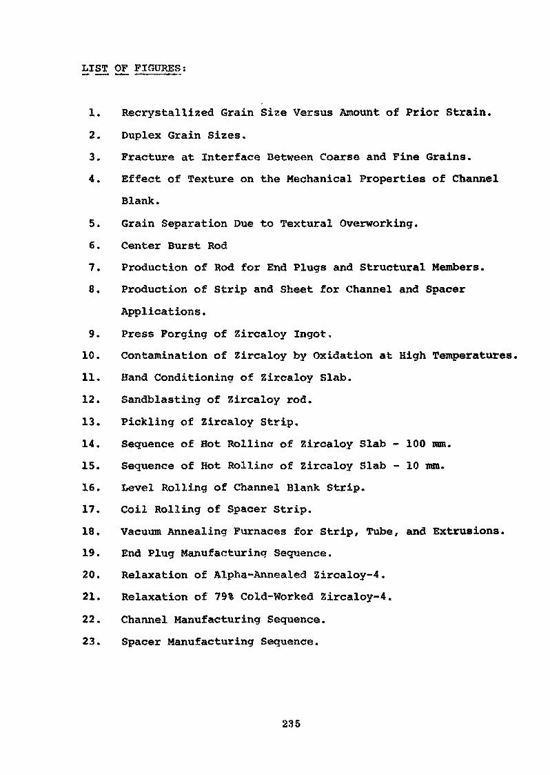
LIST OF FIGURES ;
1. Recrystallized Grain Size Versus Amount of Prior Strain.
2. Duplex Grain Sizes.
3. Fracture at Interface Between Coarse and Fine Grains.
4. Effect of Texture on the Mechanical Properties of Channel
Blank.
5. Grain Separation Due to Textural Overworking.
6. Center Burst Rod
7. Production of Rod for End Plugs and Structural Members.
8. Production of Strip and Sheet for Channel and Spacer
Applications.
9. Press Forging of Zircaloy Ingot,
10. Contamination of Zircaloy by Oxidation at High Temperatures,
11. Hand Conditioning of Zircaloy Slab.
12. Sandblasting of Zircaloy rod.
13. Pickling of Zircaloy Strip.
14. Sequence of Hot Rollincr of Zircaloy Slab - 100 ram.
15. Sequence of Hot Rollincr of Zircaloy Slab - 10 mm.
16. Level Rolling of Channel Blank Strip.
17. Coil Rolling of Spacer Strip.
18. Vacuum Annealing Furnaces for Strip, Tube, and Extrusions.
19. End Plug Manufacturing Sequence.
20. Relaxation of Alpha-Annealed 3ircaloy-4.
21. Relaxation of 79% Cold-Worked Zircaloy-4.
22. Channel Manufacturing Sequence.
23. Spacer Manufacturing Sequence.
235
LIST OF FIGURES (Continued)
24. Manufacture of Channels - Forming.
25. Manufacture of Channels - Sizing»
26. Ultrasonic Inspection of Slab by Immersion.
27. Ultrasonic Inspection of Rod.
28. Autoclave Facility for Corrosion Testing.
29. Typical Mill Product Corrosion Samples.
30. Direct Reading Spectrograph.
31. Wet Laboratory.
236
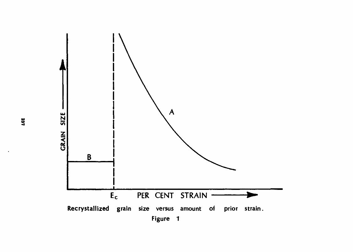
00•aN
Z
ce,(J
B
EC PER CENT STRAIN
Recrystallized grain size versus amount of prior strain.Figure 1
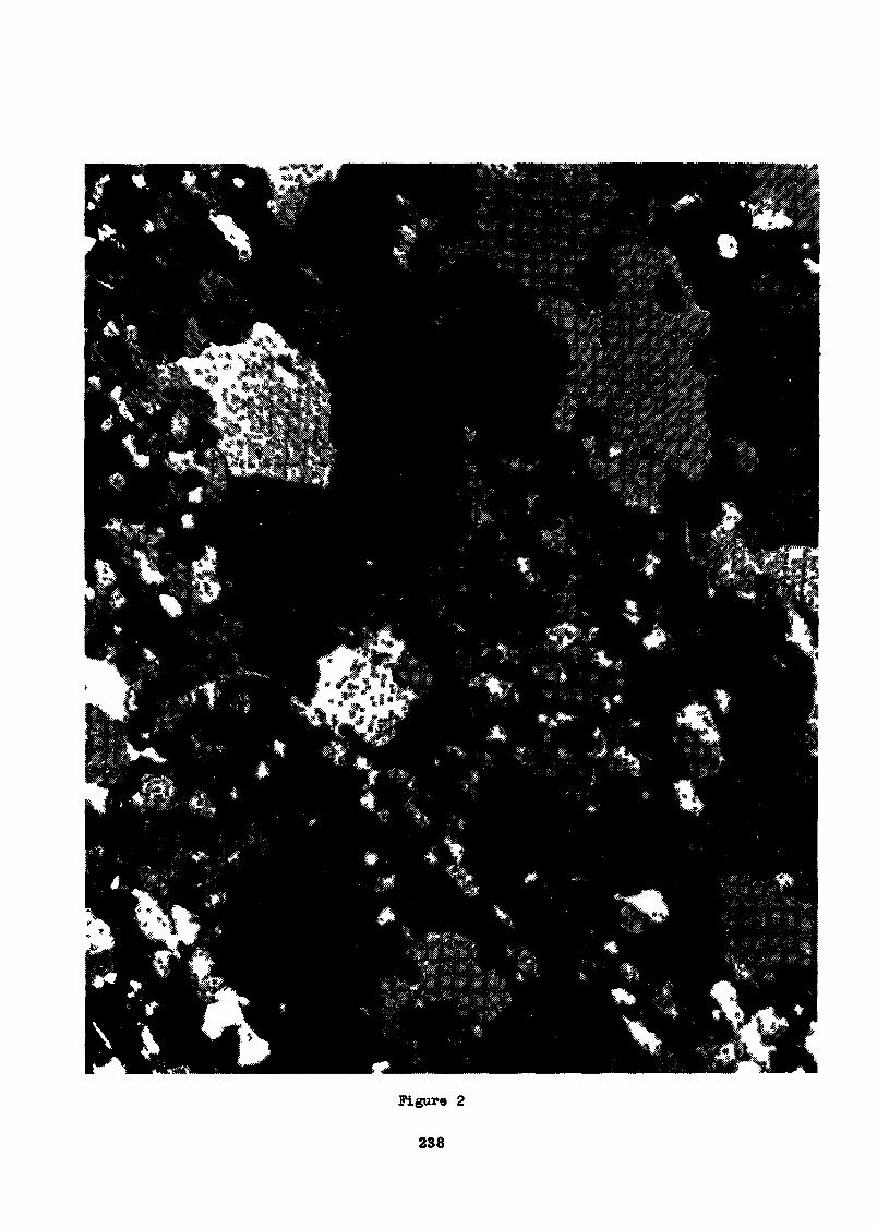
Figure 2
238
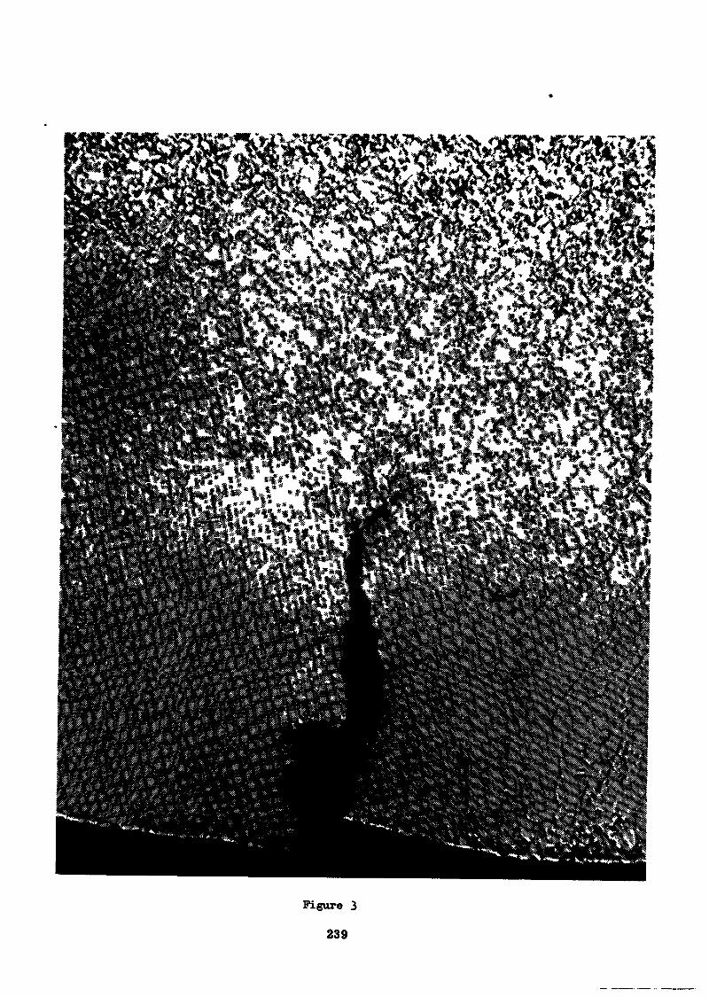
Figure 3
239
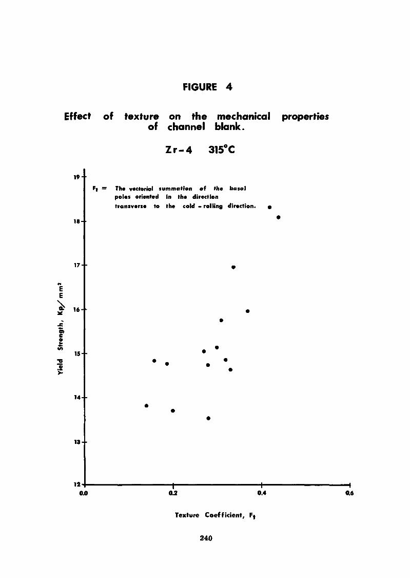
FIGURE 4
Effect of texture on the mechanical propertiesof channel blank.
Zr-4 315°C
19-
18-
17- •
«EE
15- •
14--
13--
The vectorial summation of the basalpoles oriented in the directiontransverse to the cold - rolling direction.
0.0 0.2 0.4 0.6
Texture Coefficient,
240
Figure 5
241
Figure 6
242
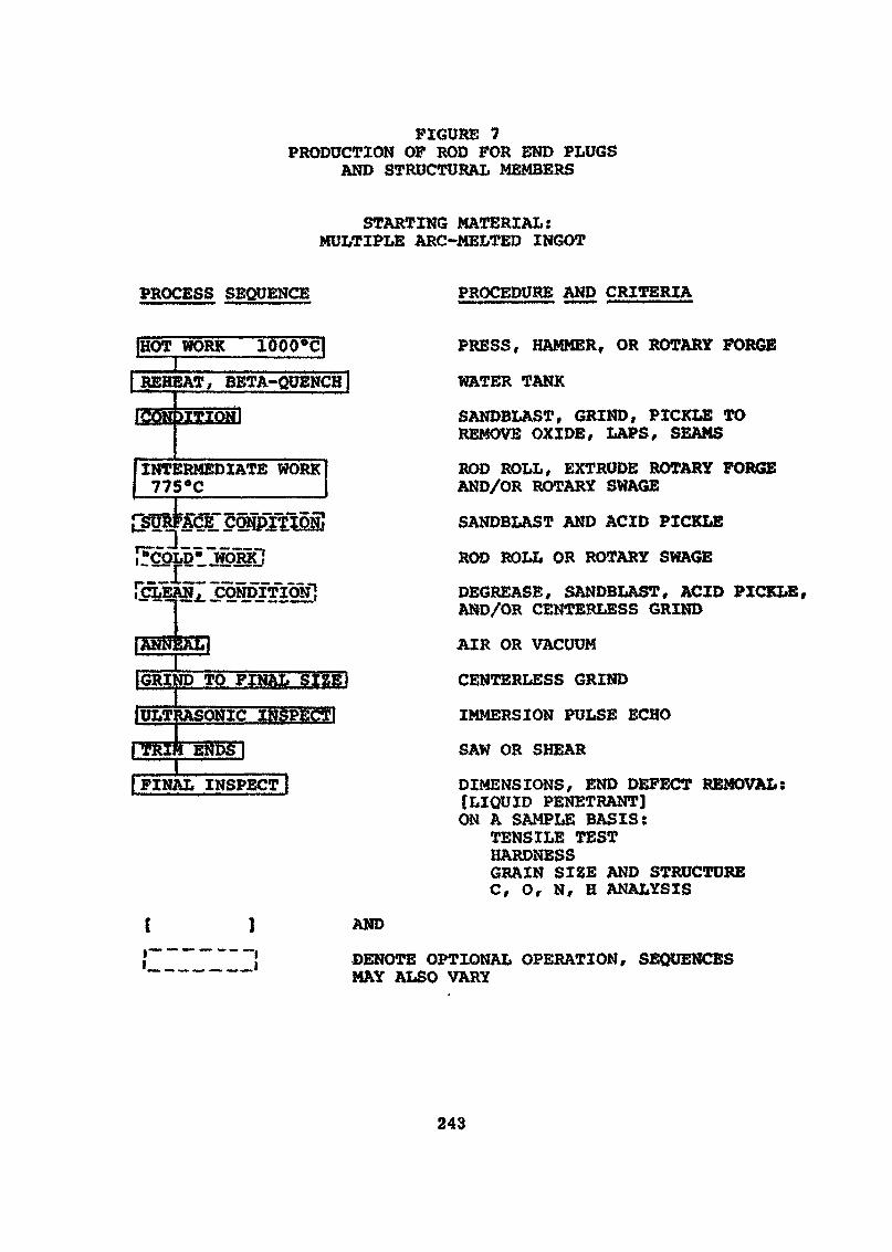
FIGURE 7PRODUCTION OP ROD FOR END PLUGS
AND STRUCTURAL MEMBERS
STARTING MATERIAL:MULTIPLE ARC-MELTED INGOT
PROCESS SEQUENCE PROCEDURE AND CRITERIA
{HOT WORK 1000*q»
| REHEAT, BETA-QUENCH I
INTERMEDIATE WORK775«C
IGRIND TO FINAL SIZEI1ULTRASONIC INSPECT!IJ ENDS |
I FINAL INSPECT [
( ]f_ _________I
AND
PRESS, HAMMER, OR ROTARY FORGE
WATER TANK
SANDBLAST, GRIND, PICKLE TOREMOVE OXIDE, LAPS, SEAMS
ROD ROLL, EXTRUDE ROTARY FORGEAND/OR ROTARY SWAGE
SANDBLAST AND ACID PICKLE
ROD ROLL OR ROTARY SWAGE
DECREASE, SANDBLAST, ACID PICKLE,AND/OR CENTERLESS GRIND
AIR OR VACUUM
CENTERLESS GRIND
IMMERSION PULSE ECHO
SAW OR SHEAR
DIMENSIONS, END DEFECT REMOVAL:[LIQUID PENETRANT]ON A SAMPLE BASIS:
TENSILE TESTHARDNESSGRAIN SIZE AND STRUCTUREC, O, N, H ANALYSIS
DENOTE OPTIONAL OPERATION, SEQUENCESMAY ALSO VARY
243
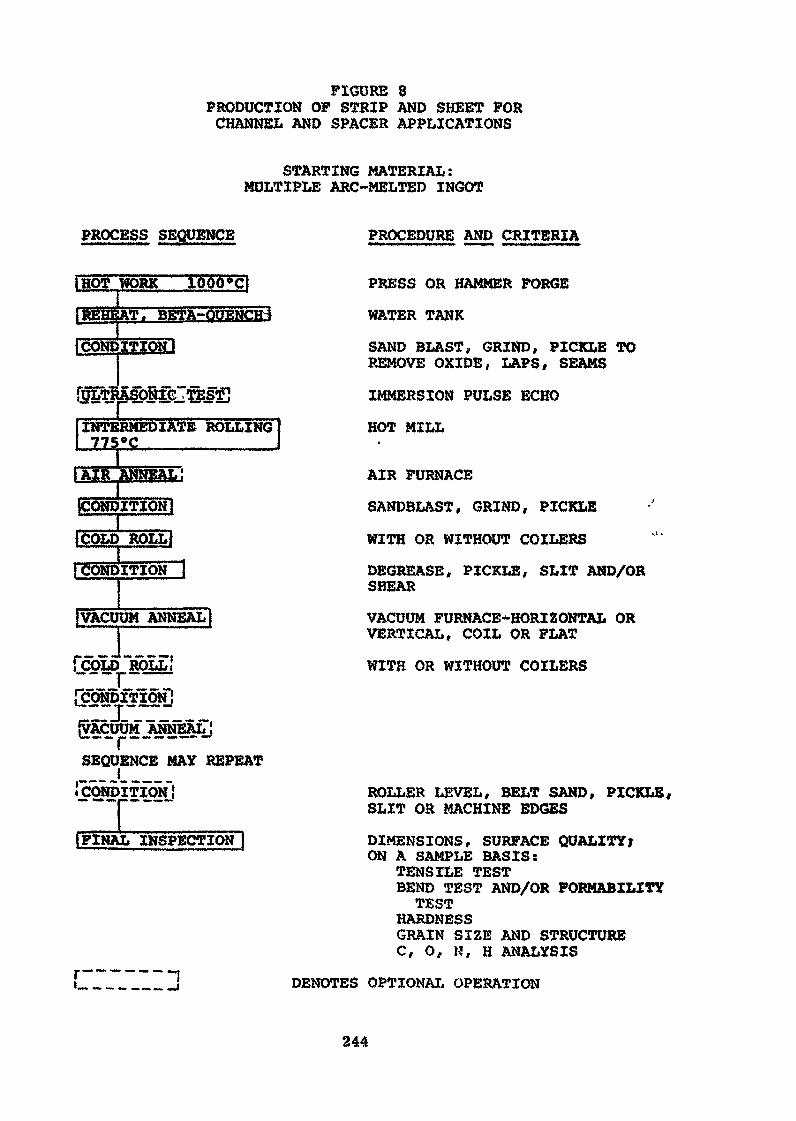
FIGURE 8PRODUCTION OP STRIP AND SHEET FORCHANNEL AND SPACER APPLICATIONS
STARTING MATERIAL:MULTIPLE ARC-MELTED INGOT
PROCESS SEQUENCE PROCEDURE AND CRITERIA
IHOT WORKI
INTERMEDIATE ROLLING775°C_________
[CONDITION]
1COLD ROLL>
rCONDITION
[VACUUM ANNEAL)
fcoLD "ROLL"!— __
{VACUUM ÂNNEÂLJ— , —SEQUENCE MAY REPEAT
IIFINAL INSPECTION }
PRESS OR HAMMER FORGE
WATER TANK
SAND BLAST, GRIND, PICKLE TOREMOVE OXIDE, LAPS, SEAMS
IMMERSION PULSE ECHO
HOT MILL
AIR FURNACE
SANDBLAST, GRIND, PICKLE
WITH OR WITHOUT COILERS
DECREASE, PICKLE, SLIT AND/ORSHEAR
VACUUM FURNACB*HORIZONTAL ORVERTICAL, COIL OR FLAT
WITH OR WITHOUT COILERS
"Î
ROLLER LEVEL, BELT SAND, PICKLE,SLIT OR MACHINE EDGES
DIMENSIONS, SURFACE QUALITY;ON A SAMPLE BASIS:
TENSILE TESTBEND TEST AND/OR FORMABILITYTEST
HARDNESSGRAIN SIZE AND STRUCTUREC, O, H, H ANALYSIS
DENOTES OPTIONAL OPERATION
244
Figure 9
245
Figure 10
246
Figure 11
247
Figure 12
248
Figure 13249
Figure 14
250
Figure 15
251
Figura
252
Figure 1?
2S3
Figure 18
254
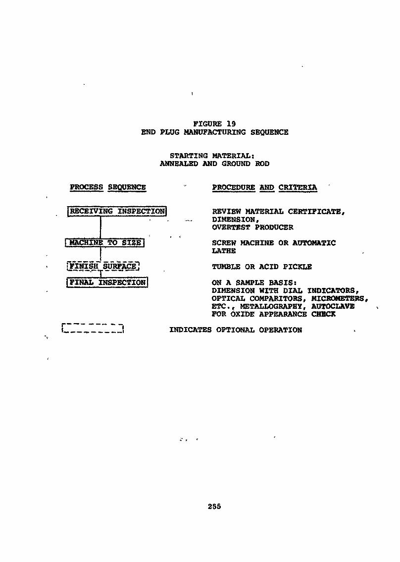
FIGURE 192ND PLUG MANUFACTURING SEQUENCE
STARTING MATERIAL:ANNEALED AND GROUND ROD
PROCESS SEQUENCE PROCEDURE AND CRITERIA
\RECEIVING INSPECTION! REVIEW MATERIAL CERTIFICATE,' : . ~. DIMENSION,
OVERTEST PRODUCER
1 MACHIN ! TO SI%E] SCREW MACHINE OR AUTOMATICLATHE
[FINISH" SURFACE] TUMBLE OR ACID PICKLE—— - ^ « - — .| FINAL INSPECTION ON A SAMPLE BASIS:
DIMENSION WITH DIAL INDICATORS,OPTICAL COMPARITORS, MICROMETERS,ETC., METALLOGRAPHY, AUTOCLAVEFOR OXIDE APPEARANCE CHECK
_JVl~L~LHi INDICATES OPTIONAL OPERATION
255
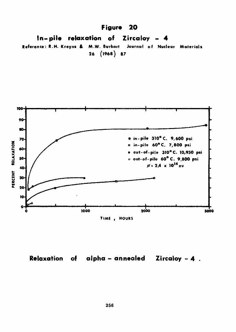
Figure 20In» pile relaxation of Zircaloy - 4
Reference: R.H. Kreyns & M.W. Burkart Journal of26 (1968) 87
Nuclear Material*
100'
90-
80-
70O
12 50-IMK
40-
g$ 30-IM
* in-pile 310° C. 9,600 p«ia in-pile 60°C. 7,800 psi
• out-of. pile 310° C. 10,950 psio out-of-pile 60° C. 9,800 psi
ft* 2.4 x 10l4nv
10
0'1000 2000 3000
TIME , HOURS
Relaxation of alpha - annealed Zircaloy - 4 .
256
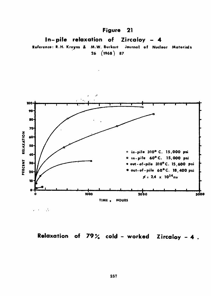
Figure 21In-pile relaxation of Zircaloy - 4
Reference: R.H. Kreyns & M.W. Burkarl Journal of Nuclear Materials26 (1968) 87
in-pile 310° C. 15,000 psio in.pile 60°C. 15,000 psi• out-of-pile 310°C. 15,600 psi* out- of -pi le 60° C. 18,400 psi
ft 3 2.4 x 10¹⁴nv
fc1000 2000 3000
TIME v HOURS
Relaxation of 79% cold ~ worked Zircaloy - 4 .
257
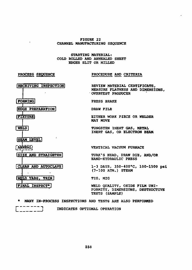
FIGURE 22CHANNEL MANUFACTURING SEQUENCE
STARTING MATERIAL:COLD ROLLED AND ANNEALED SHEET
EDGES SLIT OR MILLED
PROCESS SEQUENCE PROCEDURE AND CRITERIA
I RECEIVING INSPECTION!
1 FORMINGI
{EDGE PREPARATION!
{FIXTURE")
jWELD I
ISEAM LEVEL!r&înffiÂÏJANNEAL•-"<ISIZE AND STRAIGHTENI
I CLEAN AND AUTOCLAVE}
IWELD TABS, TRIM
jFINAL INSPECT*!
REVIEW MATERIAL CERTIFICATE,MEASURE FLATNESS AND DIMENSIONS,OVERTEST PRODUCER
PRESS BRAKE
DRAW FILE
EITHER WORK PIECE OR WELDERMAY MOVE
TUNGSTEN INERT GAS, METALINERT GAS, OR ELECTRON BEAM
VERTICAL VACUUM FURNACE
TURK'S HEAD. DRAW DIE, AND/ORHAND-EYDRAULIC PRESS
1-3 DAYS, 350-400*C, 100-1500 psi(7-100 ATM.) STEAM
TIG, MIG
WELD QUALITY, OXIDE FILM UNI-FORMITY, DIMENSIONS, DESTRUCTIVETESTS (SAMPLE)
* MANY IN-PROCESS INSPECTIONS AND TESTS ARE ALSO PERFORMED
INDICATES OPTIONAL OPERATION
258
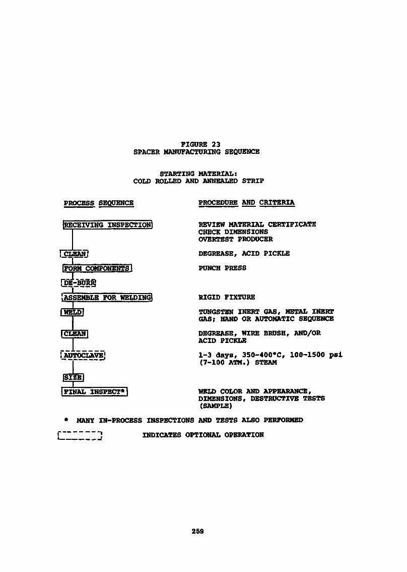
FIGURE 23SPACER MANUFACTURING SEQUENCE
STARTING MATERIAL:COLD ROLLED AND ANNEALED STRIP
PROCESS SEQUENCE PROCEDURE AND CRITERIA
[RECEIVING INSPECTION!
IFORM COMPONENTS I
ASSEMBLE FOR WELDING]
ICI SAN|
! AUTOCLAVE'
[FINAL INSPECT*»
REVIEW MATERIAL CERTIFICATECHECK DIMENSIONSOVERTEST PRODUCER
DECREASE, ACID PICKLE
PUNCH PRESS
RIGID FIXTURE
TUNGSTEN INERT GAS, METAL INERTGAS; HAND OR AUTOMATIC SEQUENCE
DECREASE, WIRE BRUSH, AND/ORACID PICKLE
1-3 days, 350-400°C, 100-1500 psi(7-100 ATM.) STEAM
WELD COLOR AND APPEARANCE,DIMENSIONS, DESTRUCTIVE TESTS(SAMPLE)
* MANY IN-PROCESS INSPECTIONS AND TESTS ALSO PERFORMED
INDICATES OPTIONAL OPERATION
259
Figure 24
Figure 25
261
Figure 26
262
Figure 27263
Figure 28
264
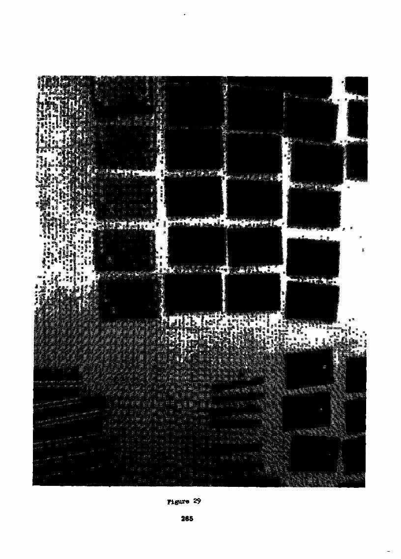
Figure 29
265
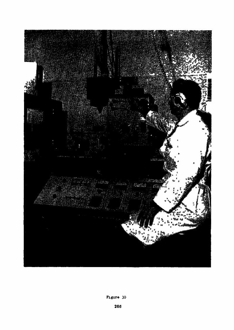
Figure 30
266
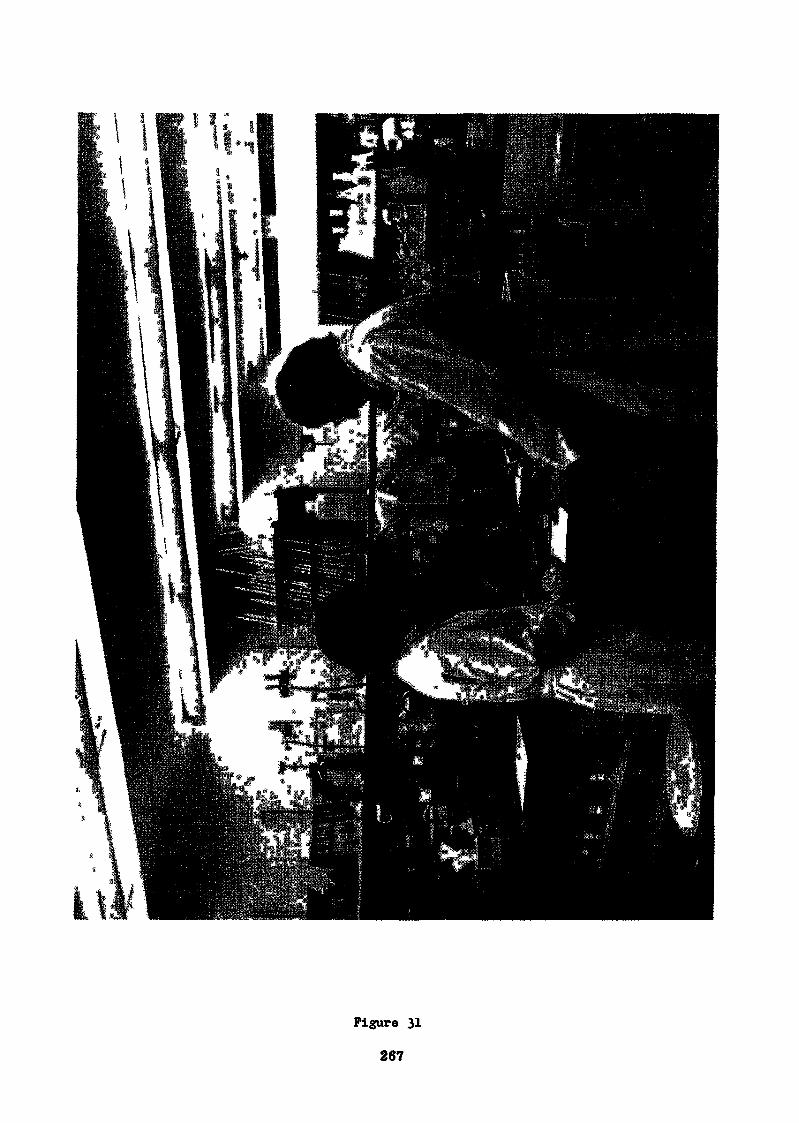
Figure 31
267
MANUFACTURE OF FUEL ELEMENTS
FROM ENRICHED UO2 POWDER IN THE UK—A REVIEW
by J. Doran
ABSTRACT
Springfields Works is the nuclear fuel centre of British NuclearIfcels Limited, a company formed from the United Kingdom Atomic EnergyAuthority in 1971 and which undertakes all large-scale production ofnuclear fuels in the United Kingdom. This Works has a long experiencein the manufacture of fuels for gas and water-cooled reactors*
The lecture describes in detail the fuel fabrication plants atSpringfields used for converting enriched uranium dioxide powder tofuel elements and assemblies having a wide range of specifications.The plants comprise:-
(a) A pellet production plant of 300 tonnes uranium perannum easily extendable to 300 tonnes uranium per annum
. and capable of operating at up to 4# enrichment, with awide range of pellet specifications.
(b) A highly automated stainless steel fuel canning plant,for pins of 5 to 20 mm diameter and 900 to 1*tOO mm long,primarily designed'for Advanced Oas-Cooled Reactor fuel,with a capacity of 500 tonnes uranium per annum andeasily extendable to 1000 tonnes uranium per annum.
(c) Canning and assembly plants for long zirconium and longstainless steel clad fuel with pin lengths up to 4500 mm,each plant handling of the order of 100 tonnes uraniumper annum and used to make different types of water-cooled reactor fuel and fast breeder reactor fuel*
The lecture recounts the operating procedures and the quality andproduction control systems in use. Reference is made to the HealthPhysics and Safety precautions necessary, the uranium accountingprocedures established and the cost control method used in large-scalenuclear fuel production.
1. INTRODUCTION
Springfields Works is the nuclear fuel centre of British Nuclear Fuels Limited, a Company formedfrom the UK Atomic Energy Authority in April 1971. This Works has a long experience in the manu-facture of fuels for gas and water-cooled reactors.The fuel fabrication plants converting enriched UO2 to finished fuel elements use a number ofprocesses to make fuels with a wide range of fuel specifications. These plants comprise :(a) A pellet production plant of 300 tes U/annum capacity easily extendable to 500 tes U/annum
and capable of operating with up to 4% enriched materials, with a wide range of pellet speci-fications.
(b) A highly automated stainless steel fuel canning plant, designed primarily for Advanced Gas-Cooled Reactor fuel and capable of handling pins in the diameter range 5 to 20 mm, and inlengths of 900 to 1400 mm. The plant capacity is at present 500 tes U/annum with facilities foreasy extension to 1000 tes U/annum. -
269
(c) Canning and assembly plants for long zirconium and long stainless steel clad fuel elements withpin lengths up to 4500 mm. Each plant can handle of the order of 100 tes U/annum as finishedfuel and they have been used for the UK Steam Generating Heavy Water Reactor (SGHWR)fuel, Boiling Water Reactor (BWR) and Pressurised Water Reactor (PWR) fuels, and FastReactor Breeder fuel.
The following account gives some details of the plant and processes used, together with operationalfeatures of interest
2. MANUFACTURE OF SINTERED ENRICHED U02 PELLETS
2.1 IntroductionThe manufacture of sintered enriched UO2 pellets is basically the same for any type of fuelelement in that enriched U02 in a suitable form for feeding to a press is converted into "green"pellets which are subsequently sintered to achieve the desired density and in most cases groundto achieve the dimensional requirements. Finally, detailed inspection is carried out.The reactor requirements and fuel element design determine the precise specification for thefuel pellet and this in turn determine» the particular choice of process variants selected for thepellet manufacturing route. The Springfields Works pellet plant has of necessity been designedmainly to meet the high density, 10.6 to 10.7 g/cc, required for AGR fuel.
2.2 Ceramic U09 Powder GranulationThe UOa feed material to the presses must have good pour qualities, flowing freely and evenlyinto the press dies thus ensuring a constant die fill at high operating speeds.Variations in the quantity of granules deposited in the die will affect the final product in someway depending upon the type of press being used, for example a mechanical press ensuringessentially constant pellet length or a hydraulic press ensuring constant green density.In order to achieve these flow characteristics, the homogenised ceramic uranium dioxide powderis first granulated. This can be achieved via a so-called binderless route by pre-pressing thepowder to briquettes and fracturing and sieving these to produce granules for pelleting. Thepreferred route in BNFL, however, uses a proprietary binding agent which amongst otheradvantages produces a green pellet of good mechanical strength. The first stage of the granu-lation process is to increase the specific surface area and activity of the powder by grinding it in ahigh pressure air fluid-energy mill. The mill used is a vertical toroid in which the uranium dioxidepowder is violently circulated by jets of dry oil-free air. When the particles have been reduced insize by attrition, they are removed from the mill in the effluent air stream which is exhaustedthrough a filter system.The milled uranium dioxide powder from the filter system is continuously slurried with solventand binder. To achieve the desired size distribution of the final granules, the slurry density iscontrolled within narrow limits. The slurry is pumped continuously to a spray drier through aswirl nozzle into the spray chamber where it is dried by preheated air. The effluent air withtnchloroethylene vapour is filtered and the trichlorocthylene recovered. The uranium dioxidegranules are continuously discharged from the base of the spray drier and classified through aseries of vibratory screens.
2.3 Performance Testing of UO2 GranulesBatches of granules will vary in quality and it is considered essential to carry out a performancetest under standard conditions on each granule batch before it is accepted for further processing.A small sample is pressed over a range of standard compaction pressures on a laboratory pressand the resulting green pellets together with a standard green pellet for comparison are debondedand sintered. The sintered densities and diameters of the green pellets are measured and indicateif the batch can be accepted within the process limitations available. If so, the data is used toselect the optimum pressing pressure and to determine the most economic die size.
2.4 The Conversion of Granules to PelletsThe granules are continuously fed to 60 tonne hydraulic, multi-punch pelleting presses, operatingunder closely controlled conditions of pressure, die fill, dwell time, etc. The pellets, which can becored or solid, are then fed to debonding furnaces where binder removal takes place at 800°C.From there the pellets are fed through sintering furnaces where densification takes place at1650°C in a hydrogen atmosphere. Following diameter grinding, the pellets are closely inspectedfor specification parameters. The important properties usually included in the specification forpellets are :Uranium Content, Stoichiometry, Isotopic Abundance, Chemical Impurities, Neutron CaptureCross Section, Moisture Content, Gas Content, Sintered Density, Surface Defects, Structureand Dimensional Parameters.
270
The chemical specification requirements are largely determined at earlier stages of manufacturealthough there is usually some removal of volatile impurities during sintering, it is, of course,essential to take precautions against contamination by, in particular, high neutron captureelements as well as the more obvious machinery contaminants such as oil and grease. Althoughisotopic abundance is not affected by thé pelleting process, enrichment integrity is obviouslyvital and good house-keeping and satisfactory movement control are essential.A wide range of pellet densities are currently specified ranging from about 90% theoreticaldensity for some water reactor fuel to over 93% theoretical density for gas-cooled reactor fuel.A number of consequences follow from the particular density range quoted in the specificationsince the greater porosity of the lower density fuel makes the pellets more prone to high moistureand gas contents. Additionally, there is the problem of further pellet densification during irradiationand possible cladding collapse.Small adjustments of pellet density can be achieved during pellet processing by varying pressconditions and furnace temperatures and times but in the main, pellet density is dependent uponthe inherent properties of the granules, which can be made from powder of high or low activitywith or without binders and additions of various types. All these variants can affect the type andamount of porosity that is produced in the pellet. Specifications of pellet structural requirementsare in general more qualitative than quantitative in nature and call for control of grain size, grainboundary porosity, within-grain porosity and macro porosity. All of these have an effect on therelease of fission product gases and the swelling of the U02 under irradiation. The individualproperties required for fuel in a particular reactor system are influenced by the workingtemperature,fuel rating and the fuel pin design concept.The macro porosity requirements can be achieved by the controlled use of additives, the porosityvarying within a matrix of standard structure. Finally, dimensional control is needed both for thefinished product and process economy. For example, strict control and careful application ofthe results of granule performance tests combined with optimum choice of die size can markedlyreduce the amount required to be ground off. As pellet chipping is the most serious cause forrejection in AGR fuel, much care has been given to the design and operating of process andhandling equipment However, chipping standards vary with different reactor requirements andin general are more severe for gas-cooled reactor systems.
2.5 Finishing of PelletsAlmost without exception, pellets are finished by grinding the cylindrical surface to dimensionaltolerances that will meet the fuel pin specification. This operation is carried out on standardcentreless grinders. Various claims are made of the advantages of either silicon carbide ordiamond impregnated cutting wheels but the effect is marginal. The real aim is the achievement ofthe requisite surface finish and dimensions at the least cost in time and rejections. Skilful presscontrol can yield dividends at this operation. There is an optimum stock removal per unit timeconsistent with machine utilisation and damage rejection rate.Too much stock to be removed can imply double or even triple passes and excessive damagelosses. Control of the press tools to match the sintering properties of a particular granule canmake a large difference to the ease with which this operation can be performed.
2.6 Quality Control and Final InspectionIn the manufacture of U02 pellets, large numbers are being dealt with and each must complywith a tight specification. Thus for the CAGR fuel there are about 50,000 pellets per tonne U offuel and higher quantities are more usual for water reactor fuel of smaller diameter.Since the consequences of fuel failure during irradiation far outweigh fuel fabrication costs, itis imperative that adequate quality control and inspection procedures are employed.Consequently, many features require 100% inspection, but some are amenable to statisticalquality control schemes as serious deviations are unlikely to occur and by their nature wouldtend to be systematic and thus easy to detect. Quality control schemes used must give a veryhigh confidence and are normally introduced at the most probable sources of rejection to assistin process control. Thus, for example, pellet length can be maintained by controlling the pressand pellet diameter by controlling the grinding machine. These are simple examples but para-meters such as density, chemical analysis and enrichment require special treatment and muchmore sophisticated control schemes. Some of the features requiring 100% inspection, e.g.surface condition, are not amenable to mechanical methods and inspectors become expert indetecting very low incidences of surface defects even when subjective standards are used.Other features, such as chipping, can be inspected mechanically and machines operating on thepneumatic pressure drop principle are used to inspect pellets for chipping. They work well onCAGR fuel pellet standards which are higher and more closely defined than water reactor pelletstandards.
271
2.7 Production Control ProcédonsMost reactor systems require enriched fuel, and large nuclear fuel fabrication plants producingfuel for several types of reactors handle a multiplicity of enrichments using feeds of granules ofvarying quality to meet different fuel specifications.This raises several problems such as criticality control, enrichment integrity and inventory controlwhich can only be overcome by sophisticated organisational and control procedures. The costof this control Is appreciable but the consequences of error are so severe both for fuel manu-facturers and the reactor operators that there is no tenable alternative.The over-riding danger of a possible criticality excursion sets the basic need for stringentformalisation of movement and storage control procedures a.id documentation. It is alsonecessary to establish proper warning systems and evacuation procedures which, to be effective,must be tested at reasonably frequent intervals.On the maintenance of enrichment integrity, the consequences of a gross enrichment mixcould be very serious for the reactor operator as well as the fuel manufacturer, and a seriousincident would cause loss of public confidence in the industry as a whole. Consequently, closecontrol and good house-keeping are essential. Further, the value of the enriched material beingprocessed is often in the region of £100,000 per tonne U. Thus several tonnes of such materialheld as work in progress can incur very high interest charges The difference between good andbad inventory control could, in the extreme, cost more than the profit margin of the fuel manu-facture. Again, because of the high costs of individual pellets and their liability to chipping, thereis considerable justification in spending time and money on careful handling procedures.
MANUFACTURE OF FUEL PINS
3.1 IntroductionBasically, fuel pin manufacture comprises the encapsulation of a stack of U02 pellets in a metallicsheath of stainless steel or zircaloy. The containment consists of a tubular can closed at each endwith a cap which is welded into position. There must be some system for ensuring the integrityof the welds and the leak tightness of the whole pin. The degree of final inspection varies withindividual fuel specifications.Typically fuel pin specifications will include such items as pellet stack lengths and weightdimensional parameters, helium content, leak tightness, absence of pellet gaps, surface conditionand contamination.
3.2 Pellet Stack Build-upThere are significant differences between the pellet stack assemblies for water and for gas-cooledreactors. Most water reactors have a large gas plenum and the pellet stack length has a full pellettolerance. Pellet stacks for gas-cooled reactors, however, present a more difficult problem asevery fifth pellet is grooved and there are tolerances on the groove positions as well as the overalllength. In fact a statistical method of pellet length control has been evolved by which it is possibleto make up a stack of 64 pellets to a tolerance on length of ±.015". It is most important in thecase of gas-cooled reactor pins to inspect the pellets carefully at stack build-up to make surethat no chipping has occurred during the transit from the Pellet Plant or during stack build-uppreparation, as any one chip larger than the permitted standard will result in a reject pin forindentation where the can wall has been forced into the chip during subsequent pressurisation.Pellet stack weight tolerances are usually determined by the pellet density specification andpresent little difficulty, the actual weights being required for accountancy purposes.
3.3 Fuel Pin FabricationAH components used for canning are the result of long programmes of development and testinginvolving many design changes before a sealed reference design is achieved.Materials have to be submitted to a reactor environment as well as the normal mechanical,physical, creep and other standard engineering tests and metallurgical proofs The end productsof all this work are very closely specified from the metal refining stage to the finished component.They are subjected to extremely stringent inspection, much of which is double-checked byindependent laboratories to ensure a high degree of confidence.As fuel manufacturers, BNFL are closely involved in this work and act as the focal organisation ina large complex of Research Establishments. Design Offices and Manufacturers. Many of themanufacturers are completely dependent upon BNFL expertise in advising on methods of fabri-cation and control.All components go through very thorough cleaning and degreasing treatment before beingintroduced to the production lint».
272
The loading of fuel stacks into the can is a straightforward procedure but can result in high lossesif care is not exercised, particularly with the thinner walled gas-cooled reactor cans. The pelletsate loaded through orifices in a sealed partition which separates the "active" from the "non-active" areas, thus minimising spread of contamination. The pellet loading operation is moredifficult in the case of gas-cooled reactor fuel as the pellet/can clearances are usually muchsh)àllér feècëûse tile can has to be pressurised onto the pellet stack without wrinkling. Automaticmàchinè'ibading has been developed on the CAGR fuel line but manual attention is also required.High ventilation of loading orifices is advantageous from the Health Physics point of view.The two most important succeeding stage" are filling with helium and end closure by welding.Helium is used for two reasons, firstly it acts as a good heat transfer medium in the reactor andsecondly it is a very satisfactory medium for leak testing by mass spectrometry.It is essential to know that helium is present in the pins and either very elaborate self-checkingfilling techniques must be used or a radio-active tracer gas may be added.Subsequent to helium filling, it is necessary to seal the closures and this is invariably done byone or another welding process. For stainless steel pins, TIG welding, resistance welding andelectron beam welding are all fairly well established processes: It is well known, however, thatthe welding of zirconium especially by the TIG process is particularly prone to porosity and BNFLhas adopted upset resistance welding with magnetic force, i.e. a variation of conventional upsetresistance butt welding whereby a highly responsive electro-magnet is used to supplement thenormal pneumatic or hydraulic force. By this means, the timing, duration and increase in magnitudeof the force supplied during welding can be accurately controlled.The welding process then becomes:(a) Heating the components to an interfacial temperature below the melting point but in the
plastic region under the influence of a low applied force.(b) The progressive coalescing of the interfaces under an increasing force.(c) The completion of the weld by upset forging accompanied by the extrusion of plastic metal
under a greater force.The resulting weld exhibits a highly localised region of fine hot forged grains. The weldingcurrent, the mechanical force current and the upset can be monitored for every weld, ensuringconsistent standards.On stainless steel pins, X-radiography is used where practicable and on the automatic rollerresistance spot welders, quality is controlled by monitors which halt production in the event ofund.er-rotation or deviation in the number or amplitude of weld pulses.
In addition to these controls, a mass spectrometer test for helium leakage is invariably specifiedand undertaken.Pins for the gas-cooled reactors are externally pressurised to lock the cans onto the pellets,every fifth of which carries a groove to provide an anti-stacking device and to even out any gapsalong the can rather than accumulate them at the upper end. Water cooled reactor pins in zircaloydo not need this procedure because of the much better heat transfer properties of the coolant andthe presence of a large gas plenum. Inde, d it is becoming more usual to pressurise the pinsinternally to .prevent collapse of the can. Heat treatment and protective coatings are variouslyspecified and are carried out in specially designed equipment. Zircaloy pins in particular arefrequently specified with a black lustrous oxide film. This is produced by pickling the tubes innitric/HF acid mixture followed by autoclaving in steam or CO2 at high temperature. Auto-claying was originally introduced as a test for the purity of the zircaloy as well astoestablishastableoxide film before introducing the pin to the coolant, but the practice is tending to become obsoleteas there is little proof of its effectiveness. It is not now currently being used for SGHWR fuel.The finished pins must be as free as possible from external contamination and statisticallysampled pins are measured in an ion chamber, for the presence of such contamination. Less thanone millionth of one gram of uranium can be detected by this means A variety of techniques areused for the decontamination of pins ranging from simple acid pickles to electrolytic techniques.As in the case of pellet manufacture, much in-line control is exercised on the canning lines and avery thorough final inspection is carried out before a pin is released for assembly into a fuelelement or cluster. This includes a 100% critical inspection for dimensional features and a 100%visual subjective examination for damage or contamination.Non-destructive testing to prove the absence of inter-pellet gaps is performed and also anenrichment confirmation check by a Gamma rate meter device which distinguishes between theU23s energy levels and those of the daughter products which vary with age from chemicalprocessing. The finally inspected fuel pin is then passed forward for assembly into fuel elements.
273
4. FUEL ELEMENT ASSEMBLY
The fuel element assembly, or duster as it is sometimes called, is, of course, particular to the reactorconcerned. AH manner of pin arrays, circular, square and hexagonal have been used.Assemblies must be designed such that build-up can take place using fairly simple engineeringtechniques giving a very high confidence that the spécification can be met as any rejection at thisstage is unacceptably expensive. The main essential is in the line-up and accuracy of the jigs whichneed to be of rigid construction. The normal procedure is to set up one or both end fittings andintermediate support grids very accurately in the jigs and to fasten them in some way, usually byriveting or welding, to support pins or tubes. Fuel pins are then inserted and these are fastened toor constrained by the end fittings.In the case of the gas-cooled reactor assemblies, the pins and grids are supported by a graphitesheath, which also provides a proportion of the moderation. A double skin sheath is used to limit theoutside temperature and thus the corrosion of the moderator.Some reference has already been made to the nature and high cost of the majority of componentsinvolving lengthy development and testing and the aspect of time needs stressing as up to two yearsmay be necessary to obtain the more sophisticated components. Because of this, the major para-meters have to be fixed in good time if the final start-up date is to be met and detailed centralisedplanning is essential.The packing of such assemblies for transport to the reactor site is expensive as the containers needto be very substantial to give adequate support and protection to the contents and must also beburst-proof, fire-proof and water-proof to meet criticality and uranium containment requirementsunder credible accident conditions.
5. HEALTH PHYSICS AND SAFETY
Originally ail development and manufacture of nuclear materials in the UK was under Governmentcontrol. Health Physics teams were set up at each station with advisory and inspection functionsas well as departmental responsibilities for the up-keep and issue of protective equipment andclothing. They were combined with the departments set up to deal with the non-nuclear safetyaspects. As these features began to pass from direct Government control, legislation was enacted todefine acceptable operational limits and methods of control and a Nuclear Installations inspectoratehas been established. The Health Physics regulations are rigorously applied and add to the cost endcomplexity of nuclear fuel manufacture. 'The prime danger with enriched uranic materials is always that of criticality and all working operationsare carried out to strict rules in compliance with a comprehensive criticality clearance certificate,without which no work can be undertaken. Wherever possible, safe by shape designs are used butthere are many operations where compliance with the regulations depend upon adequate trainingand supervisory control.As mentioned in the section on pellet manufacture, criticality alarm systems are installed whichrespond to detection of neutron activity. Immediate evacuation is mandatory when such an alarmsounds. To avoid secondary incidents arising because automatic machinery has been left functioningbut unattended, consideration has to be given to means of shutting down the plant from outside thedanger zone.Operations involving uranium powders are hazardous because of the possibility of ingestion andhave to be strictly controlled by adequate containment and extraction, the use of protective equipmentand clothing being necessary particularly on maintenance work Large quantities of enrichedmaterial could also give rise to high radiation doses and these have to be regularly monitored toensure safe working conditions.Strict monitoring of all effluents, solid, liquid and gaseous is maintained to avoid pollution of theenvironment and the standards set in the Works should meet any new regulations which might arisefrom current world wide discussions on this subjectAir filtration out of uranium processing plants is the normal rule and for fuel element and pin manu-facturing the incoming air is also filtered, minimising external contamination. Changerooms withshowering facilities have to be provided in uranic processing plants, and periodic medical exami-nations are undertaken of each person employed in an active area.
6. URANIUM ACCOUNTING
Due to the very high intrinsic value of enriched uranium and its potentially dangerous nature, amaterial balance account is essential in any uranium processing plant
274
Apart from detailed transfer documentation, analytical methods and assessments, weighing andmetering precision and competent stock-taking all play their part. Recent international controlagreements on safeguards require the disclosure to authorised agency representatives of details andprecision of control systems, materials balances and analytical techniques. These requirements areunique to the industry and involve a great deal of management time and effort as well as appreciablecapital expenditure.
7. COST CONTROL
Manufacture of nuclear fuel elements is no different from any other manufacturing activity to theextent that profitability benefits from the application of normal cost control procedures. Capital andOperating budgets are produced and cost performance is regularly monitored.On the shop floor it is essential to high-light the expensive features and, as might be expected, costreduction is significantly greater by improvements in efficiency at the tail end of themanufactureratherthan the early stages, thus each per cent improvement in uranic efficiency is twice as effective incost reduction at pelleting and five times as effective at canning and assembly as it would be at thehex reconversion stage.Comment has been made of the necessarily high integrity and consequently high cost of componentsand it may be of interest to note that component costs (not including the value of the uranium)amount to about 85% of the total canning and assembly costs of CAGR fuel.Another indication of the importance of component costs is the fact that fuel element componentcosts amount to approximately one third of the Springfields Works operating budgetPeculiar to the nuclear industry are the stringent quality control procedures necessary to meet fuelspecifications and to meet nuclear health physics requirements. The costs incurred by so doing areestimated at Springfields to be approximately 6% to 7% of the Works Operating Costs.
275
NUCLEAR FUEL FABRICATION
byT. Stern
Vice President and Genera! ManagerWestinghôuse Electric Corporation
Nuclear Fuel DivisionP.O. Box 355
Pittsburgh, Pa. 15230USA
andJ.D. Cotton
Vice President. Fuel ActivitiesWestinghôuse Electric Nuclear Energy Systems Europe
Rue Gatti de Gamond 951180 Brussels, Belgium
.Abstract
Nuclear fuel fabrication is the first step in the fuel cycle which cannot prudentlybe treated as a commodity by the purchaser. Fabrication not only involves themanufacture of a complex product to very close tolerances but also requires theuse of very sophisticated design tools, great emphasis on quality control, largeinspection staffs, and very precise materials accounting and other data processing.
In design, a great deal of time and large expenditures are required to develop thenecessary methods and tools. This involves not only development of the basic cal-cuiational procedures and computer programs but also feedback of operational datato improve the accuracy and precision of the design predictions. Five years or moremay elapse from the time a fuel region is designed until complete data on its opera-tion become available. We at Westinghôuse have been involved in fuel design for morethan fifteen years and have accumulated an extremely large body of operating data.We still find it necessary to fine tune our methods as additional data become available.
Because the fast breeder reactor will not be commercially available for more than adecade, the need for plutonium recycle in thermal reactors is obvious. This need addsan additional degree of complexity to fuel design and core management. Without adepth of design knowledge, the fuel supplier cannot hope to design fuel regionscontaining recycled plutonium which will meet the utility's power and operationalrequirements.
In a rapidly changing technology such as nuclear fuel, very large expenditures forproduct development are necessary. We at Westinghôuse apply fully 20 percent ofour total income to development, and we expect to maintain that level indefinitely.Without a very substantial sales volume, a fuel supplier cannot support developmentat the necessary level.
Like most manufacturing processes, nuclear fuel exhibits a significant economy ofscale. Having operated both a relatively small plant at Cheswick and the world'slargest water reactor fuel plant at Columbia for a number of years, we are in avery good position to evaluate the scale factor. This scale factor obviously applies
277
to the cost of the manufacturing facility and to direct production costs. Equallyimportant, and probably more so, is the fact that the very targe support staffsrequired can be used much more efficiently m a large volume operation. Fully halfof our manufacturing operations staff and a significant proportion of our engineeringstaff are involved in support areas such as quality control, health physics, materialsaccountability. A smaller supplier would require a higher proportion of staff whichwould not be used as efficiently for these areas, or would not apply the effort inthese areas we think is required. Other overhead costs are similarly reduced proportion-ally with larger volume.
In manufacturing, too, plutonium adds complexity. Because it is toxic, it must behandled in an enclosed space, for which reason increased mechanization is desirable.Because of its toxicity, environmental considerations have a much greater impact onthe design of a plutonium manufacturing facility than on a uranium plant. All ofthese considerations result in a substantially higher cost for a plutonium plant and,to a lesser extent, in higher production costs than for uranium fuel.
This paper describes the evolution of the present fuel design, how that design isused to satisfy individual utility operating needs, and the manufacturing methods andprocesses in use today. Because of the many complex and interrelated factors cited,nuclear fuel supply by relatively few large facilities seems far preferable to a greatmany smaller facilities serving local markets. Many of the benefits of scale economycan be available to smaller satellite operations through Joint ventures.
INTRODUCTION
Nuclear fuel fabrication is the first step in the fuel cycle which the purchaser cannotprudently treat as a commodity. Fabrication not, only involves the manufacture of acomplex product to very close tolerances, but also requires the use of very sophisticateddesign tools, great emphasis on quality control, large inspection staffs, and very precisematerials accounting and other data processing.
Figure 1 illustrates the processes involved in fuel fabrication and the relationshipsamong them. As knowledge accumulates in each area, it provides useful inputs to theother processes. Research and development is the central process which provides afoundation for the others and integrates the knowledge and experience into a coherentbody.
This synergistic process requires a great deai of time and very large expenditures. Forexample, five years or more may elapse from the time a fuel region is designed untilcomplete operational data become available for feedback into the design and manu-facturing processes. At the time of writing {June, 1972) sixteen reactors are operatingusing Westinghouse supplied fuel. The first of these has been operating since 1957.During those fifteen years, the fuel has generated some 100 billion kwhrs of electricalenergy. The data accumulated from that operating experience have been continuallyused to improve our design and manufacturing methods and techniques. That processcontinues today at an accelerated rate. As a result, we are able to predict nuclearcharacteristics and power distributions with remarkable accuracy and expect continuedimprovement as additional experience accumulates.
278
DESIGN
The basic fuel assembly design integrates the diverse demands of the various engineeringdisciplines to provide economic and reliable fuel operation. The goal of the nucieardesigner is to minimize non-fuel material in the core since it absorbs valuable neutrons.The mechanical designer must assure that the assembly maintains structural integritythroughout its lifetime. This is most easily done with large amounts of structuralmaterial. The thermal-hydraulic engineer specifies the addition of mixing vanes to thegrids to assure good heat transfer. These, however, also absorb neutrons and requirethe mechanical designer to exercise great care in assuring that they reliably performtheir intended function. The present design has evolved to meet, in the best waypossible, these sometimes conflicting requirements.
In using the basic assembly design to provide a first core or reload region, the primaryobjective of the nuclear engineer is to satisfy economically the operating requirementsthe utility specifies. The utility needs to accommodate changing operating requirementswhile at the same time meeting shutdown schedules that avoid refueling during peaktoad periods. Accordingly, the first step in designing a core or region is to considerthe utility's future operating requirements. These include the cycle length and theplanned manner of plant operation.
Figure 2 shows a 'schedule of events for the design of a typical reload region. Theutility tentatively sets operating requirements two years before the region is to beloaded. Final requirements must be set approximately one year before region loadingto allow ample time for uranium procurement, conversion, and enrichment. Once thecycle operating requirements have been set, the nuclear designer has three majorvariables with which to work: number of assemblies, enrichment, and arrangement ofthe assemblies.
The number of new assemblies loaded >s the primary mechanism for making majorchanges in the cycle length over a long period of time. The enrichment of the reloadregion can be varied to make small modifications in cycle lifetime. Finally, thearrangement of the fresh reload region and the partially irradiated assemblies remainingin the core can be varied to meet power peaking restraints. Because the core alwayscontains some partially irradiated fuel, the designer must account for prior operatinghistory in addition to futiire requirements.
All three variables affect the cycle lifetime and the power distribution in the core.Since it is possible, tQ, select a combination of the first two variables which wouldpreclude any core loading; pattern from satisfying the power distribution criterion orother, safety-related criteria, all three variables must be considered before a finaldesign specification is made.
The selection of the final loading pattern is essentially an iterative process. That fs,the designer selects a pattern for detailed analysis and calculates the resulting powerdistribution. This process continues until a selected pattern fails within the criterionfor maximum power peaking. Since the number of possible patterns is very large andeach calculation requires a great deal of computer time, the designer must bringconsiderable experience and engineering judgment to bear in selecting the patterns foranalysis.
By virtue of its accumulated fuel design and operating experience, Westinghouse isable to specify very precisely the number, enrichment, and arrangement of assemblies
279
necessary for a given cycle operating requirement. Because of this great body ofexperience, the Westinghouse designers have also been able to reduce substantiallythe number of iterations required to arrive at a satisfactory loading pattern, it isalso possible, when necessary, to revise the selected pattern very quickly. Whenproblems have arisen during first core loading or refueling, Westinghouse was able toresolve them expeditiously by providing new loading patterns, literally, overnight.
Reload regions must beftin in the relatively near future to incorporate plutoniumrecycle fuel. This is so because the fast breeder reactor will not be available commer-cially on a targe scale before the latter part of the 1980's. At that time, the waterreactors already installed will generate more than enough plutonium annually tosupply the fueling requirements for any conceivable breeder installation rate. Thereis, therefore, no incentive for stockpiling plutonium in anticipation of breeder require-ments. In fact, as plutonium becomes available in large quantity, there will be'greateconomic pressure to use it as soon as possible after the spent fuel has been pro-cessed.
including recycle fuel in a reload region adds greatly to the complexity of the nuclearanalysis. The nuclear characteristics of plutonium in a thermal spectrum cause increasedpower peaking in a recycle region unless corrective design measures are taken. Of thealternative solutions available, Westinghouse has selected the discrete assembly conceptas the most promising technical and economic choice, in this concept, a reload regionis composed of two kinds of assemblies with identical mechanical designs. One typecontains a uniform mixture of plutonium and natural uranium. These are interspersedwith the second type, which contains only uranium of the same enrichment whichwould be used in a standard uranium reload region. In the assemblies containingplutonium, it is necessary to use multiple plutonium concentrations selectively dis-tributed throughout the assembly to maintain acceptable power distribution. It is alsonecessary to exercise greater care in selecting the locations for the assemblies in arecycle region.
MANUFACTURING
The importance of havmg a sound, integrated manuijcturing process and a compre-hensive quality assurance program cannot be overstressed. Consider, for example, thecore for a modern four loop plant. The fuel rods alone require approximately 80,000weids, contain close to 10,000,000 UOj pellets, and use about 100 mrles of Zircaloytubing. Rod inspection must assure, with a high degree of confidence, that all thewelds are acceptable, that the pellets are within specification, and that the tubingcontains no ftaw that might cause a leak. There are similar requirements for gridsand nozzles, and for the assembly of these components into the finished product. Infact, the quality control checks made on each assembly number in the tens ofthousands.
Westinghouse began its targe scale manufacturing experience at its Cheswick,Pennsylvania facility. This plant was expanded as need dictated to a capacity of 300metric tons a year. Late in 1969, a second plant was opened in Columbia, SouthCarolina. The Columbia plant has 210,000 square feet devoted to manufacturing and50,000 square feet for office space. It has an ultimate capacity of 1000 metric tonsa year, the equivalent of twelve four loop plant cores or thirty-six reload regions peryear.
280
The Columbia plant performs at! operations necessary to manufacture finished nuclearfuel assemblies. It is the world's largest facility devoted to the manufacture of lightwater reactor fuel. Even though the Cheswick plant is the world's third largest, it isnow being phased out of operation in favor of the Columbia plant, which yields stilllower product cost.
The manufacturing operation begins with chemical conversion of uranium hexaffuoride(UFg) gas to uranium dioxide powder (UC^)- UFg gas is withdrawn from the gaseousdiffusion plant in the proper enrichment and shipped to Columbia in 4800-poundcontainers.
UFg is a solid at normal temperatures. It is sublimed in a steam chest and fed intothe process. Figure 3. Water is mixed with the gaseous UFg to convert the gas intoa manageable form that permits precise process flow control. This reaction generateshydrofluoric acid and uranyl fluoride solution. The solution is pumped to a precipi-tation tank where it reacts with ammonium hydroxide. There, the uranium precipitatesout as ammonium diuranate (ADD), a yellow solid.
The slurry is pumped into a horizontal-bowl centrifuge, Figure 4, where the solidsare separated. The solids are then fed into a rotary calciner. The overflow solutionstill contains a smalt amount of solids. Therefore, it is channeled into a very-high-frequency centrifuge where the balance of the solids is removed.
Following this, the solutions are held in quarantine tanks. Each tank is individuallychecked for uranium content before it is released as waste. This check makes surethat none of the uranium has escaped the separation process. It is a quality check, apollution control check, and an economic loss check.
The waste solution contains ammonium fluoride, which cannot be discharged into thewaste stream. The waste solutions are reacted with lime to form calcium fluoride,which is insoluble. Figure 5. The calcium fluoride is precipitated out. Thick slurriesfrom the precipitator are filtered off and buried in a land fill.
When UO2 is discharged from the calciner, it is pulverized in a hammer mill to getthe desired small final particle size. It goes through several quality control inspectionsto check the final material before it is released to the pellet area.
A direct-reading emission spectrometer is employed to analyze impurities in uraniumdioxide as well as in the metals employed in fabricating nuclear fuel. Tests performedare capable of detecting concentrations of impurities as small as three parts in tenmillion.
A thermal-emission mass spectrometer is used in the detection of the isotopes ofuranium, plutonium, lead or other elements with iow-ionization potential. This instru-ment is capable of measuring samples as small as one hundred millionth of a gram.
Slugging (low-pressure pressing) shapes the powder into a form resembling a coinabout the size of a United States quarter. The pressed "slugs" are granulated, orcrushed into small particles, and passed through a screening operation, which providesa properly balanced particle distribution. This improves the flowabiiity of the powder,which is a requirement in obtaining proper die feed for the pellet presses.
The screened granules are fed into high-speed presses, Figure 6, where the final fuelpellets are made. Control is maintained over the pressing operation so that pelletsof uniform unsintered (green) density and size are manufactured. The green densitydetermines the final size of the fuel pellet.
281
The green pellets are now sintered. Figure 7, at high temperature in electric furnaces;this process consolidates the aggregate of fine particles and results in shrinkage anddensification of the pellet. Rigid process controls are maintained over the sinteringprocess so that consistent final densities are achieved in the fuel pellets.
In the pressing and sintering operations, the fuel pellets are purposely formed slightlylarger than the final size desired. To achieve this final size, each pellet must beground to the exact dimensions required. Grinding is performed on precision centeriessgrinders. Tight process parameters are used to maintain control of pellet dimensions.After grinding, Figure 8, the peiiets are transported to the quality control area forinspection. The material which is ground off the pellets is collected and reused.
Tubing is fabricated from Zircatoy ingots produced to Westinghouse specifications.These specifications go beyond those for standard tubes and place extremely stringentrequirements on metal lographic structure, physical and chemical properties, surfacecharacteristics and dimensions. The tube is thoroughly inspected for integrity, usingsuch nondestructive techniques as eddy current or ultrasonic tests. Westinghouse manu-factures tubing made of Zircafoy at its Specialty Metals Division plant in Blairsville,Pennsylvania. Uranium fuel peiiets are inserted into the Zircaloy tubes at the fuelrod loading station. Figure 9.
End plugs for fuel rods are precision machined of Zircaioy. After the tube is loaded,the end plugs are inserted in the tube. Magnified dimensional inspection of fuel rodend plugs and nondestructive testing assures the end product meets quality andreliability standards.
Prior to insertion of the top end plug, a spring is inserted into the fuel rod and theaxial gap is checked against design requirements. The gap permits fission gas accumu-lation and axial thermal expansion of the fuel column.
The tubes are sealed by programmed TIG welding of the end plugs. Figure 10, toeach end of the tube. A unique welding machine is used which performs the entirewelding cycle automatically. After the electrode is set exactly at the proper locationon the tube, the operator merely pushes a button and the welder does the rest. Whenit stops, the operator removes the rod,
After the rods are weided and leak-tested, they are conveyed to the quality controlarea, where they are X-rayed in a highly automated unit. Figure 11. After X-ray,the rods receive 100 percent dimensional and visual checks. The welds are checkedfor burrs, pits, gouges, discoloration. The rods are roited on a flat-surfaced table, tomake sure they are not bent or bowed. They are measured against a length standard.In addition, fuel rods are weighed to ascertain the amount of uranium contained asan accountability check.
The fuel assembly support structure consists of rod cluster control guide thimblesand spring-clip grids. The grids. Figure 12, are produced from individual grid strapswhich have been punched and slotted. Completed grids are inspected for proper springtension and for dimensional accuracy. Grids are fastened to the control rod guidethimbles and the bottom end plate nozzle.
The fuel rods are supported axially along their length by the spring-clip grid assemblies.Several of the grids are mixing grids which increase the degree of intermixing coolantflow within an assembly and also between adjacent assemblies. The mixing action ofthese grids reduces the temperature gradient within and between fuel assemblies.
282
Each fuel rod is supported in two perpendicular directions by formed spring clips.This support firmly restrains the fuel rod and prevents vibration. Perpendicularity andpitch dimensions of the grids are checked very carefully. Each grid is subjected toover eight hundred individual measurements.
An assembly of bottom nozzle, thimble tubes, grids, and adapter plate provides theframework which receives the loaded fuel rods and top nozzle — thus creating thefinal fuel assembly. Fuel rods are loaded by inserting them through the grids. Duringassembly operations, Figure 13, a fine spray is directed onto each rod as it is insertedinto the grids. After rod insertion, the top nozzle is welded to the control rod guidethimbles to complete the fuel assembly. The top nozzle is engineered to support theentire fuel assembly as it is lifted and placed into the reactor.
The completed fuel assemblies are inspected and cleaned using an appropriate material.Except for the assembly and cleaning operations, all fuel assembly processing operationsare performed dry. Completed fuel assemblies are handled and stored in a mannerwhich provides a minimum 12-inch edge-to-edge spacing.The Columbia plant required an initial capital investment of $20,000,000. The initialinvestment was followed by additional capital investments to produce programmedincreases in capacity for various processes, continued product improvement, enhancedmanufacturing process development capability, further cost reduction potential, andcontinued compliance with ever more stringent standards for pollution abatement andother regulatory requirements. For example, additional chemical conversion capacitywill go on stream this year, and other processes have been mechanized extensively.Increasingly stringent quality assurance criteria have also added appreciably to thecapital investment.
The use and handling of a high cost, politically sensitive, potentially hazardousmaterial tike uranium demands elaborate safeguards, production control, and personnelprotection. Thus, there is a continuing investment requirement to maintain and improvesupport services for nuclear materials safeguards systems and personnel; for healthphysics and criticality systems and personnel; and for physical plant protection systemsand personnel. Westinghouse plans to incorporate enrichment control, over and abovethat already exercised, in the manufacturing cycle at various process points. Theseplans include installation of monitoring devices for fuel rods and UO2 powder con-tainers.
investment in support costs also reach into the areas of tooling, dies, fixtures, andmanufacturing process development and improvement. This rate of investment isinfluenced by the high rate of obsolescence related to the constant need for productdesign changes which improve or further guarantee reactor performance. AH told,investments in the areas enumerated above represent more than $10,000,000 additionalfunding since Columbia began operation.
The manufacture of high quality reactor fuel continually demands high supportcosts in areas such as process engineering, quality assurance, and laboratory services.These are only a few of the areas comprising the overhead burden which must beapplied to production cost.
Quality assurance has always been a high cost item in the fuel fabrication business;fully 20 percent of the Westinghouse fuel manufacturing personnel are engaged ininspecting the product. Westinghouse also maintains a separate group to survey theactivities and performance of our vendors at their manufacturing locations. Costs
283
related to quality assurance have expanded significantly during the past two years.Westinghouse now provides utility customers with on-slte surveillance service at thetime of fuel receipt and during all handling operations. There has also been a decidedgrowth in utility customer and third party audits of processes, written procedures,and product. These customer and third party audits naturally demand the time andinvolvement of Westinghouse personnel on a continuing basis. The United States AtomicEnergy Commission has also stepped up its activities, and International Atomic EnergyAgency inspections are also required from time to time. Inspections and audits bythese outside groups can provide added assurance to the utility regarding the final fuelproduct, but they add appreciably to the support costs of fuel manufacturing.
As mentioned above, plutonium recycle m thermal reactors will be an economicnecessity. Westinghouse has been developing the necessary technology during thepast nine years. Because plutonium is toxic, it must be handled in an enclosed space.For the same reason, environmental considerations have a much greater impact on thedesign of a plutonium facility than on a uranium plant. The design must insure againstplutonium escape in the event of earthquakes and extreme atmospheric disturbancessuch as tornadoes. These factors have a very substantial impact on the cost of thefacility. We are now designing a full scale facility for operation beginning in 1977when it will be needed to meet the increasing requirement for recycle fuel. Thisfacility wftf'be used to manufacture less than 15 percent of the fuel we will deliverin the late 197(Xs and early 1980's. For that small fraction of our total capacity, weestimate the facility will cost more than twice our investment in the Columbia plant.
j
Because recycle fuel manufacture will always be a relatively small scale operation, theproduction: and overhead costs are much higher than for uranium. The need for workingremotely increases the incentive for mechanization, and this increased mechanizationreduces the production cost penalty somewhat. The manufacturer expects to recoveran adequate return on investment. The net effect of these factors is substantiallyhigher cost for plutonium fuel.
DEVELOPMENT
The present fuel design is the result of many years evolutionary development, includingwork in nuclear physics, heat transfer, and core performance under various conditions(including postulated accidents), as well as the more obvious types of effort such asmechanical design of the assembly.
The rod cluster control (RCC) type fuel assembly. Figure 14, is the standard for ailmodern day pressurized water reactors. This concept represents neither the beginningnor the end of the technology. The earliest type of assemblies was that used in theYankee Rowe reactor, located m the United States and owned by Yankee AtomicElectric Company, and in the BR-3 reactor, located in Belgium and owned byCentre d'Etudes de l'Energie Nucléaire. These reactors have rigid assemblies usingbrazed ferrules as a method of holding the fuel rods. The logical progression was toa more open lattice, although it was considered necessary to contain the assembliesin cans. The Chooz reactor in France, owned by Société d' Energie Nucléaire Franco-Belge des Ardennes, and the Trino reactor in Italy, owned by Ente Naztonaie perI'Energia Elettrica, use this design.
The RCC fuel assembly represented a significant step forward because it eliminatedthe fuel can, distributed the control rod worth, permitted higher power densitiesand allowed the reactor vessel to be shortened. Subsequent developments on the
284
RCC have been confined to improvements in the basic design. Examples of this arethe addition of mixing vanes, reduction in parasitic absorption material, and modifiedgrid to rod supports. These improvements have been progressively incorporated intothe newer fuel designs, such as those used in the Jose' de Cabrera reactor in Spain,owned by Union Eiectrica S.A.; the Beznau No. 1 and No. 2 reactors in Switzerland,owned by Nordostschweizerisch Kraftwerke AG, and the Mihama No. 1 and No. 2reactors in Japan, owned by Kansai Electric Power Company.
The above process serves as o good ilKstration of the theme of development, whichsimply expressed is evolutionary improvement based upon prior design, experiment,and operational experience. Examination of any of the key parameters will show thisto be true whether the parameters are hot channel factors, temperature, or powerdensity. The present fuel design represents a very sizeable investment in technology.Investment m development continues at a very high level; Westinghouse assigns sometwenty percent of its total fuel income to product development. We expect fundingto remain at or near the present level indefinitely.
A rapidly expanding body of actual fuel performance data from operating plants hasbeen factored into the design. This process continues today at an accelerated rate.Using this information, design methods are verified and improved. The efforts toimprove the grid to reduce parasitic material still further, to optimize fuel rod supportforces, and to achieve optimum flow distributions are continuing. While much ofthis effort has a basic objective of improving core performance, that objective, exceptwhere it is complementary, is secondary to the objective of maintaining a high degreeof reliability. By far the majority of our resources are dedicated to extensive analyticaland experimental programs directed toward designing and manufacturing fuel with ahigh level of reliability. These programs can be grouped into four major categories:(1) fuel performance verification, (2) structural and corrosion testing, (3) loop testing,and {4} general reliability activities.
One area of fuel performance verification involves both in-pile and outof-piie verifi-cation of design codes and material specifications, relating principally to the mechanicalproperties and the corrosion resistance of Zircaloy cladding material. Another areainvolves analytical validation of design codes and fuel specifications related to fuelproperties. A third large area of investigation involves the execution of irradiationtests in operating reactors. These are aimed at evaluating the influence of irradiationon mechanical properties, corrosion, and hydriding, and at determining the combinationof power levels and burnup which may result in fuel rod failures.
Fuel assembly components are tested for strength, fatigue, and resistance to corrosion.In addition, prototype assemblies are constructed and subjected to various structuraltests to determine the static and dynamic characteristics of the assembly Under variousoperating and handling conditions. Tests include axial and lateral deflection tests, vibra-tion, torsional, and handling and loading tests.
Prototype assemblies are subjected to a series of tests in a loop that simulates actualtemperature, pressure, flow, and water chemistry conditions. Control rods are scrammedinto the fuel assembly over 200 times as part of a typical 1000 hour test. Thebehavior of the assembly, i.e., stresses, strains, vibration, etc., is monitored throughoutthe test.
A number of general reliability activities to improve the designs have also been in»corporated. Examples of these activities are {1) formal design reviews, (2) failure modeanalysis, (3) analysis of manufacturing data, and (4) analysis of operating date.
285
Another major segment of our resources is directed toward advanced fuel and processdevelopment, including plutonium recycle. Our recycle technology development hasbeen progressing for nine years. Some of the programs undertaken are operation ofthe Saxton reactor with mixed oxide fuel, achieving peak burnup greater than 50,000MWD/MT; analyses of various critical experiments; technical and economic feasibilitystudies; construction and operation of a pilot scale plutonium laboratory; and fabrica-tion of mixed oxide fuel assemblies for use in demonstration programs in the SanOnofre reactor in the United States, owned by Southern California Edison Companyand San Diego Gas and Electric Company, and in the Mihama No. 1 reactor. Theprimary effort now involves process development and equipment evaluation to supportdesign and construction of a full scale recycle fuel manufactunng facility.
VOLUME EFFECT ON COST
Experience at Cheswick and Columbia has shown that substantial base load isnecessary to provide the cost improvement and overhead absorption to result inreasonable fabrication cost. Further increases in capacity and accumulated experienceaccentuate the trend. Scale economy is very appreciable below 500 metric tons ayear, and attractive improvement potential remains available even at the 1000 metricton a year level.
Investment in inventory also shows a marked decrease due to economy of scalebecause the raw material, in-process, and finished parts inventories necessary forefficient manufacture become proportionately lower as volume increases. A largevolume also provides the flexibility to insure extensive and effective customer services.These customer services can be in response to plant construction delays or. speed-ups,or unexpected events such as a fuel assembly damaged in shipping or handling. Withits large volume, Westinghouse has and will continue to provide quick response to allcustomer problems.
Westinghouse has reached the level of scale economy wherein it can take advantageof the cost improvement related to volume, couple this advantage with experienceand a continually improving engineered design, and now offer it to various fuelmanufacturing partners. Such partnerships have been concluded in Italy (CCXREN) withFiat and Breda, and in Japan (Mitsubishi Nuclear Fuel Company, Limited), «withMitsubishi Heavy Industries and Mitsubishi Metal Mining Company, in these arrange*ments, overhead support services such as the latest design data, latest manufacturingprocesses, current quality assurance procedures, and engineering assistance are providedto the smaller company at reasonable cost. This is made possible because the heavyexpenditures necessary are spread over the large Westinghouse volume. The jointventure can, therefore, be viable at a far lower volume level than would be possiblewithout the Westtnghouse base.
Westinghouse also benefits from such arrangements by taking advantage of the exper-tise already available from programs in the countries involved and by accumulatingand assimilating the additional experience available from the joint ventures.
CONCLUSION
Efficient nuclear fuel fabrication requires continual integration of the knowledge pro-gressively derived from design, manufacturing, operation, and development. Accruing
286

the basic knowledge and evolving the present design has taken a great deal of time,effort, and money. Even at the present level of technology, Westmghouse continues toapply twenty percent of its income to further development.
Economy of scale dictates large annual volume combined with high capacity, integratedmanufacturing fact! (ties. With large volume, the fuel fabrication is able to spread theheavy expenditures necessary to continue technological improvement. Substantial basevolume is an absolute necessity for achieving economic unit fabrication cost. In marketspheres which do not provide the necessary volume base, a considerable portion of thebenefits accruing from scale economy can be realized by concluding a joint venturewith a supplier already having the requisite volume.
287
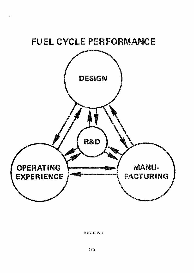
FUEL CYCLE Pi
OPERATINGEXPERIENCE
FIGURE i
288
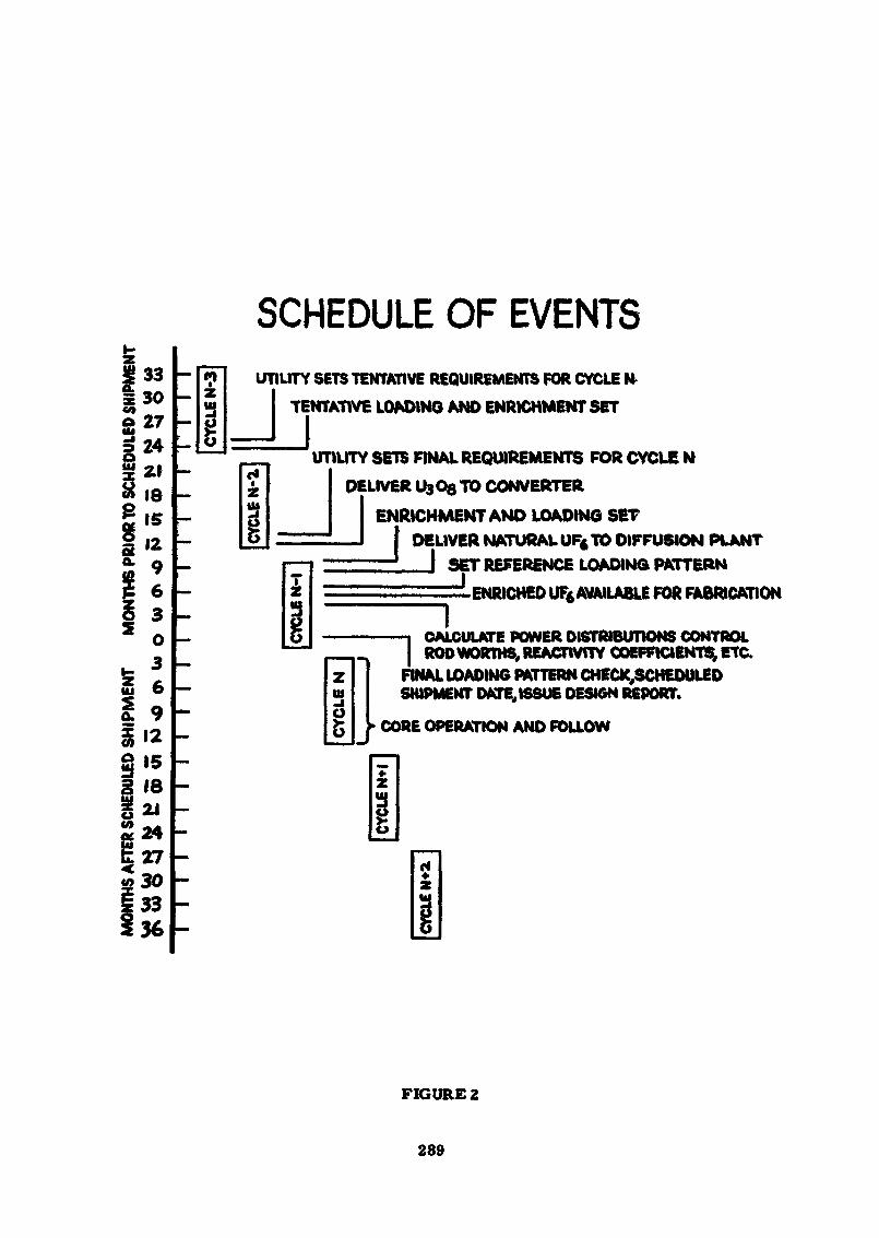
SCHEDULE OF EVENTSUTILITY SETS TENTATIVE REQUIREMENTS FOR CYCLE W
TENTATIVE LOADING AND ENRICHMENT SET
UTILITY SETS FINAL REQUIREMENTS FOR CYCLE NDELIVER U3Ofi TO CONVERTER
ENRICHMENT AND LOADING SET_J I DELIVER NATURAL UF« TO DIFFUSION PLANT
I SET REFERENCE LOADING PATTERNI•ENRICHED UF* AVAILABLE FOR FABRICATION
I
Zui
g
——I CALCULATE POWER DISTRIBUTIONS CONTROL| ROD WORTHS, REACTIVITY COEFFICIENTS, ETC.
FINAL LOADING PATTERN CHECK,SCHEDULEDSHIPMENT DATE, ISSUE DESIGN REPORT.
CORE OPERATION AND FOLLOW
FIGURE 2
289
FIGURE 3
290
W
2h
291
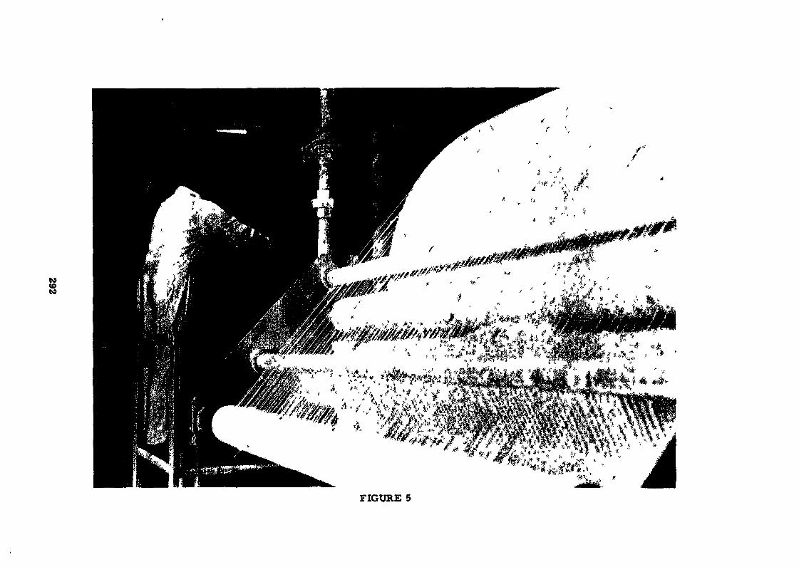
toCO
FIGURE 5
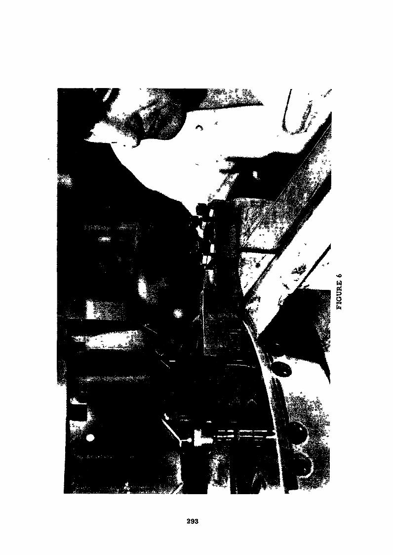
g
293
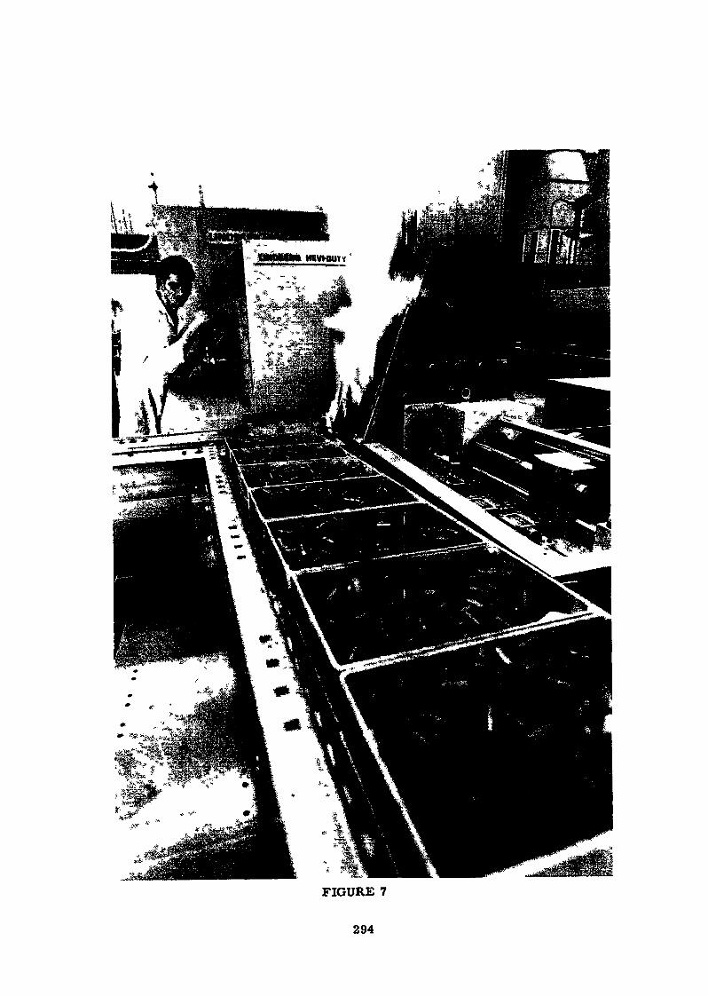
1
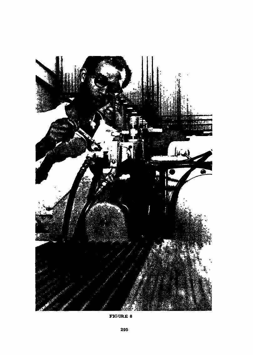
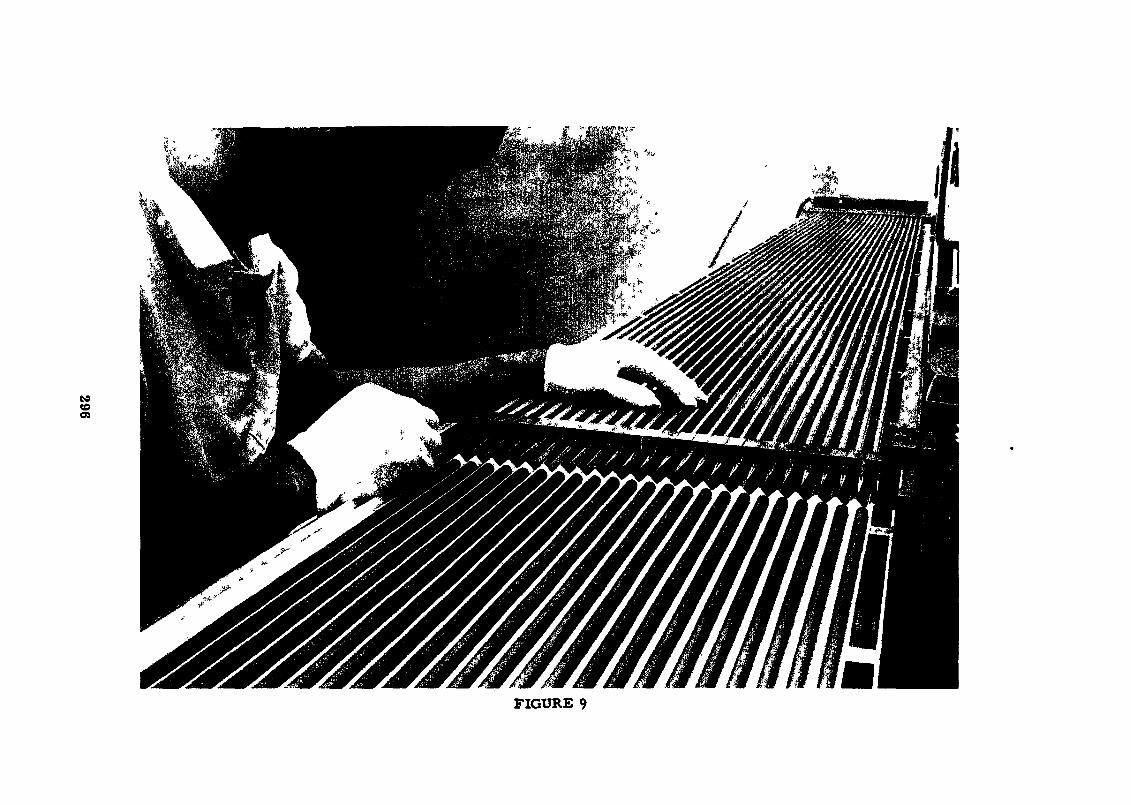
toCDOi
FIGURE 9
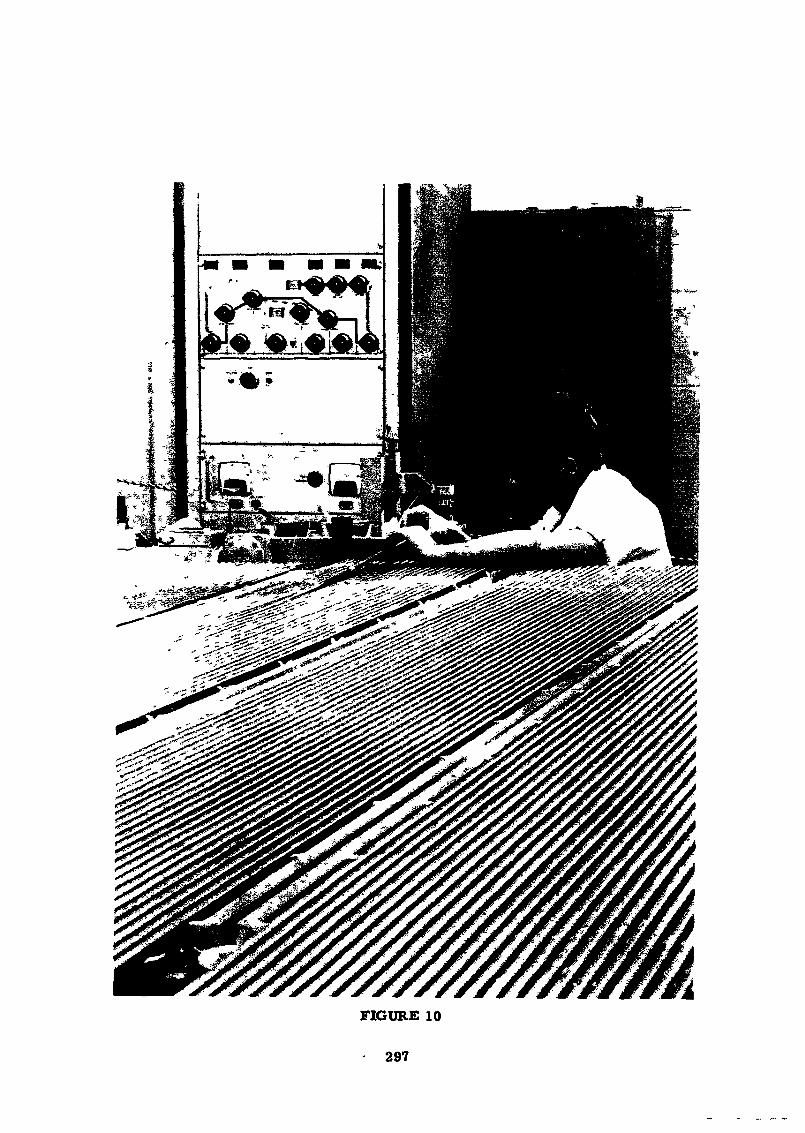
-' ,>5^ 3 :>£^VV^ ^2£iCrf?>..J*.Gt SjCaV.'C . P^
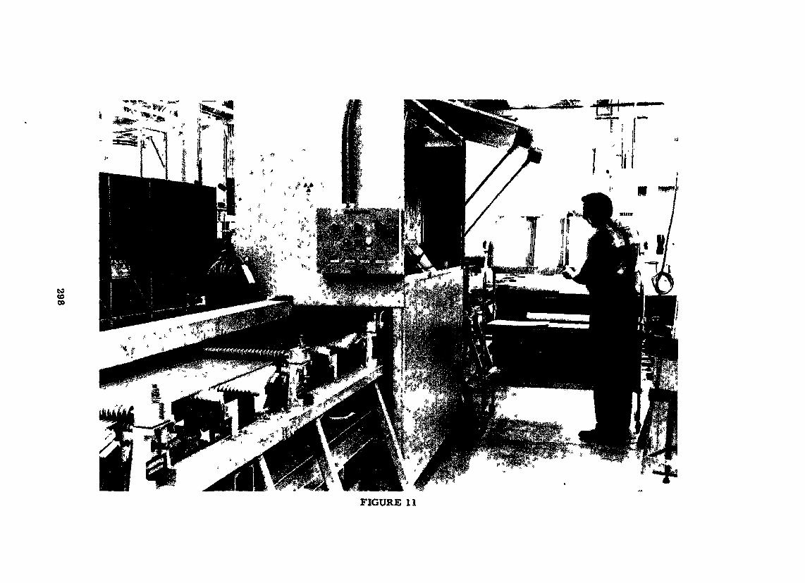
COto00
FIGURE 11

FIGURE 12
299
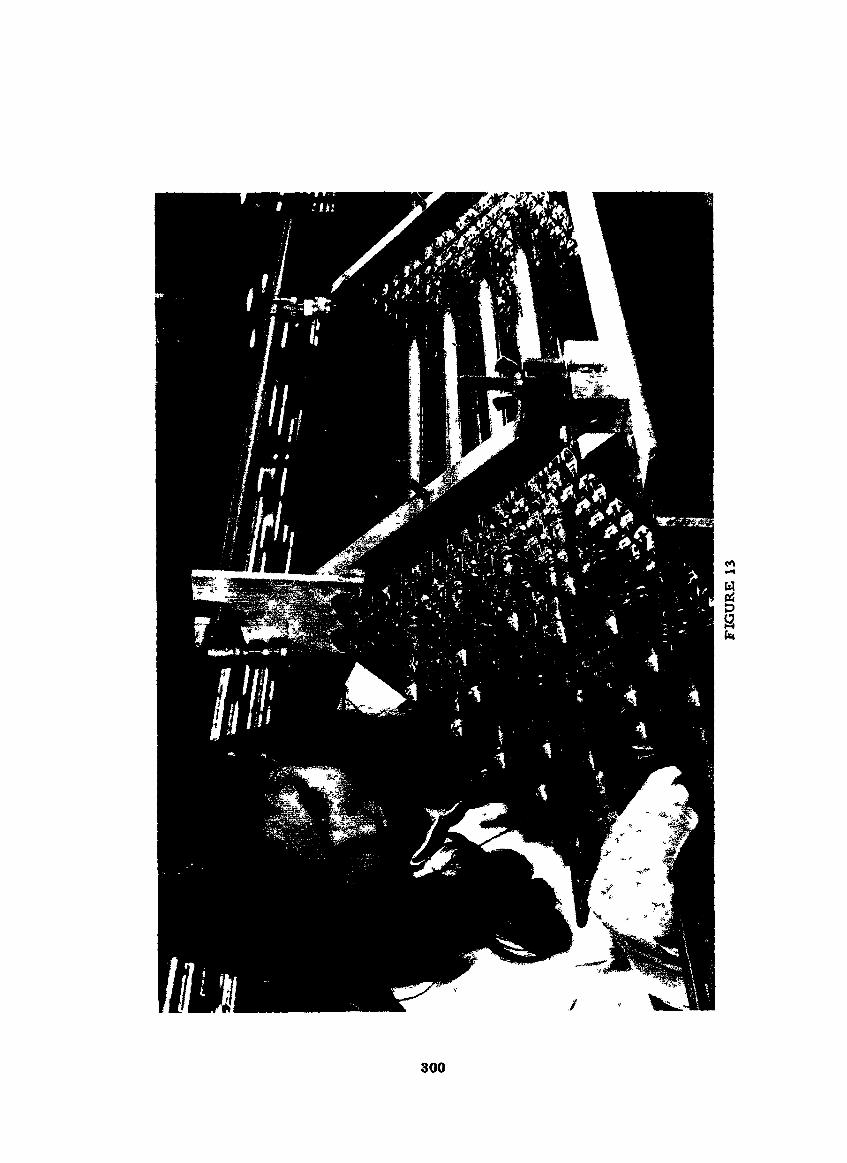
eo•«H
wtfDSUi
300
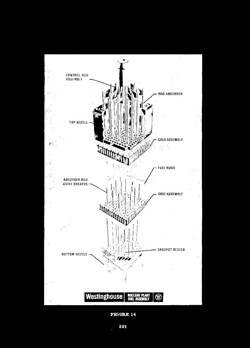
CONTROL RODASSEMBLY
TOP NOZZLE
ABSORBER RODGUIDE SHEATHS
BOTTOM NOZZLE
ROD ABSORBER
GRID ASSEMBLY
FUEL RODS
GRID ASSEMBLY
OASHPOT REGION
FIGURE 14
THE MANUFACTURE OF FUEL ELEMENTS AND THEIRASSEMBLY FOR PWR SYSTEMS
by
C. R. JohnsonCommercial Nuclear Fuel Department
Lyncb>urg, VirginiaD. E. Heybum
Nuclear Power Generation DivisionLynchburg, Virginia
ABSTRACT
Manufacturing fuel assemblies for pressurized water reactors is a developing
technology. Methods and procedures are being upgraded constantly to improve
the quality of, or remove inconsistencies from the product. The underlying
philosophy governing these manufacturing operations is one of starting with
only high quality raw materials and building quality into the product throughout
the manufacturing sequence.
Quality control of fuel manufacturing is a continuous exercise of tests and
inspections to assure that processes are under control and that only acceptable
material is allowed to remain in the production stream. New and improved
inspection methods are under development to function as on-line tests for
product quality. The goal is to reach prompt feedback of deviations from
the norm so that process adjustments can be made before rejectable material
is produced.
The fuel manufacturing business is an enterprise that is more closely tied
to financial considerations than many other manufacturing operations. Many
of the raw materials used are high in cost. This fact makes inventory control
vital and it supports capital investment decisions to increase manufacturing
capacity so as to decrease processing time. Detailed financial analyses are
necessary to arrive at the correct balance between capacity and throughput
requirements. These analyses do indicate that relatively small throughput
303
requirements are adequate to support a fuels plant with a minimal scope of
activities. As throughput requirements increase, integrating additional
activities into the facility becomes justifiable.
Organizational structures in manufacturing facilities can be quite variable.
In a fuel assembly plant, however, separate manufacturing and quality control
organizations reporting to the same manager are mandatory. Manufacturing is
responsible for making the quantity of fuel assemblies required at a level of
quality that is acceptable. The Quality Control organisation is responsible
for assuring that only products of acceptable quality are delivered to the
customer.
Selecting and training personnel for a fuel manufacturing operation is one
of the more important activities in establishing a fuels plant. Management
of the operation must be committed to manufacturing only high quality fuel
assemblies. In all aspects of training and planning and developing procedures
and equipment for fuel manufacture there must be no compromise with this
philosophy.
Nuclear fuel manufacture, like most manufacturing operations, can be a
fascinating and rewarding business. It must be approached as a business
with full recognition of the fact that sacrifices in the level of product
quality will lead to serious economic penalties. With this realization
and the help of competent people, a developing nation with a minimum of
operating reactors can enter the nuclear fuel manufacturing business on a
modest scale. This base business can be expanded in manufacturing scope
as competency is developed and the expansion is iustified by the economics
of additional throughput.
304
ÏNTRQgUCTION
In the design of nuclear fuel assemblies, fissionable material mustbe positioned and contained to provide for efficient removal ofheat produced by the fission reaction and to maintain the fuel ina controllable geometry. Improper positioning can lead to failureof the fuel element, curtailme t of reactor oper tion and radio-active contamination of the reactor's primary coolant stream.Therefore, severe economic penalties, as well as potential lossof power generating capability can result from inadequately manu-factured fuel assemblies.
While much engineering and scientific effort is expended in thedesign and testing of fuel assemblies, conservative design prac-tices must also be followed so as to design into the fuel assemblyan additional margin of safety. Conservatism is also requiredthroughout the manufacture of fuel elements for this same reason.Manufacturing facilities must be designed and operated to buildhigh quality fuel elements to the precision required by the designer.Compromises in manufacturing equipment and processes cannot bepermitted if they will adversely affect reliability and performanceof the fuel element.
Besides being technically necessary, quality and precision designand manufacture of fuel elements is the most economical approachto the nuclear fuel business. In the discussion of manufacturingmethod^, a philosophy of contiguous attention to quality will benoted. Starting with an objective of manufacturing a high qualityproduct, and constantly checking the product to assure that theobjective will be met, results in a maximum amount of acceptablematerial. Material found to be rejectable is rejected in-processbefore additional effort is invested in it. In this way, onlyacceptable material continues in production. This practice alsoprovides an early opportunity to adjust process equipment to precludecontinuing production of off specification material. The combinationof precise and timely process control to preclude production of re-jectable material and rejection of any faulty material at its lowestvalue, yields the desired product at minimum cost.
The following discussions cover areas incumbent to tne manufactureof nuclear fuel assemblies. Manufacturing methods and processes
305
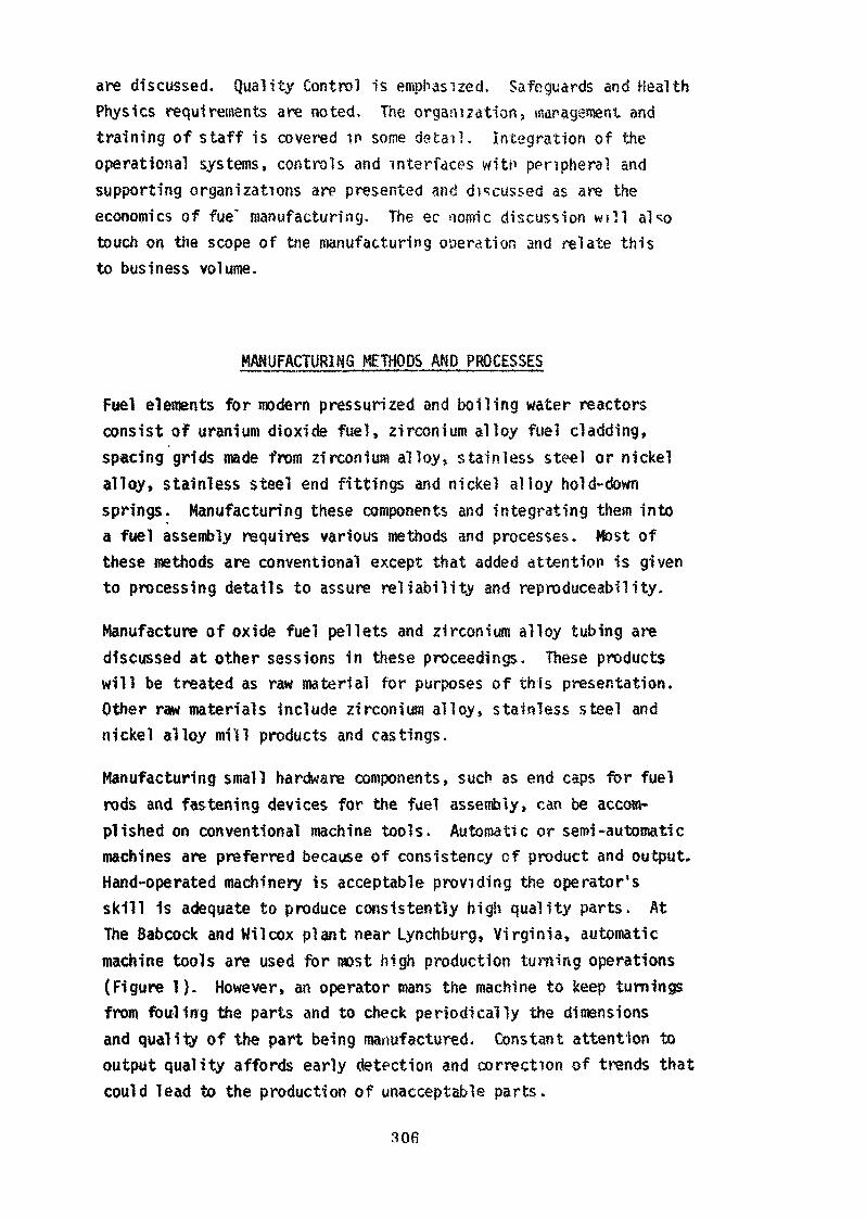
are discussed. Quality Control is emphasized. Safeguards and HealthPhysics requirements are noted. The organiZation9 maragenjent andtraining of staff is covered in some detail . Integration of theoperational systems, controls and interfaces witn peripheral andsupporting organizations are presented and discussed as are theeconomics of fue' manufacturing. The ec oomic discussion w i l l alsotouch on the scope of trie manufacturing operation and relate thisto business volume.
MANUFACTURING METHODS AND PROCESSES
Fuel elements for modern pressurized and boiling water reactorsconsist of uranium dioxide fuel, zirconium alloy fuel cladding,spacing grids made from zirconium alloy» stainless steel or nickelalloy, stainless steel end fittings and nickel alloy hold-downsprings. Manufacturing these components and integrating them intoa fuel assembly requires various methods and processes. Most ofthese methods are conventional except that added attention is givento processing details to assure reliability and reproduceability.
Manufacture of oxide fuel pellets and zirconium alloy tubing arediscussed at other sessions in these proceedings. These productswill be treated as raw material for purposes of this presentation.Other raw materials include zirconium alloy» stainless steel andnickel alloy mill products and castings.
Manufacturing small hardware components, such as end caps for fuelrods and fastening devices for the fuel assembly, can be accom-plished on conventional machine tools. Automatic or semi-automaticmachines are preferred because of consistency of product and output.Hand-operated machinery is acceptable providing the operator'sskill is adequate to produce consistently high quality parts. AtThe Babcock and Wilcox plant near Lynchburg, Virginia, automaticmachine tools are used for most high production turning operations(Figure 1). However, an operator mans the machine to keep turningsfrom fouling the parts and to check periodically the dimensionsand quality of the part being manufactured. Constant attention tooutput quality affords early detection and correction of trends thatcould lead to the production of unacceptable parts.
306
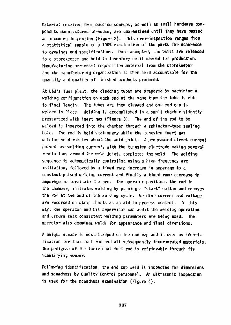
Material received from outside sources, as well as small hardware com-ponents manufactured in-house, are quarantined until they have passedan incoming inspection (Figure 2). This over-inspection ranges froma statistical sample to a 100% examination of the parts for adherenceto drawings and specifications. Once accepted, the parts are releasedto a storekeeper and held in inventory until needed for production.Manufacturing personnel requisition material from the storekeeperand the manufacturing organization is then held accountable for thequantity and quality of finished products produced.
At B&W's fuel plant, the cladding tubes are prepared by machining awelding configuration on each end at the same time the tube is cutto final length. The tubes are then clearted and one end cap iswelded in Place. Welding is accomplished in a small chanter slightlypressurized with inert gas (Figure 3). The end of the rod to bewelded is inserted into the chamber through a sphincter-type sealinghole. The rod is held stationary while the tungsten inert gaswelding head rotates about the weld joint. A programmed direct currentpulsed arc welding current, with the tungsten electrode making severalrévolu Lions around the weld joint, completes the weld. The weldingsequence is automatically controlled using a hign frequency arcinitiation, followed by a timed ramp increase in amperage to aconstant pulsed welding current and finally a timed ramp decrease inamperage to terminate the arc. The operator positions the rod inthe chamber, initiates welding by pushing a "start" button and removesthe ro^ at the end of the welding cycle. We!din»1 current and voltageare recorded on strip charts as an aid to process control. In thisway, the operator and his supervisor can audit the welding operationand «assura that consistent welding parameters are being used. Theoperator also examines welds for appearance and final dimensions.
A unique numbsr is next stamped on the end ccp and is used as identi-fication for that fuel rod and all subsequently incorporated materials.The pedigree of the individual fuel rod is retrievable through itsidentifying nun&er.
Following identification» the end cap weld is inspected for dimensionsand soundness by Quality Control personnel. An ultrasonic inspectionis used for the soundness examination (Figure 4).
307
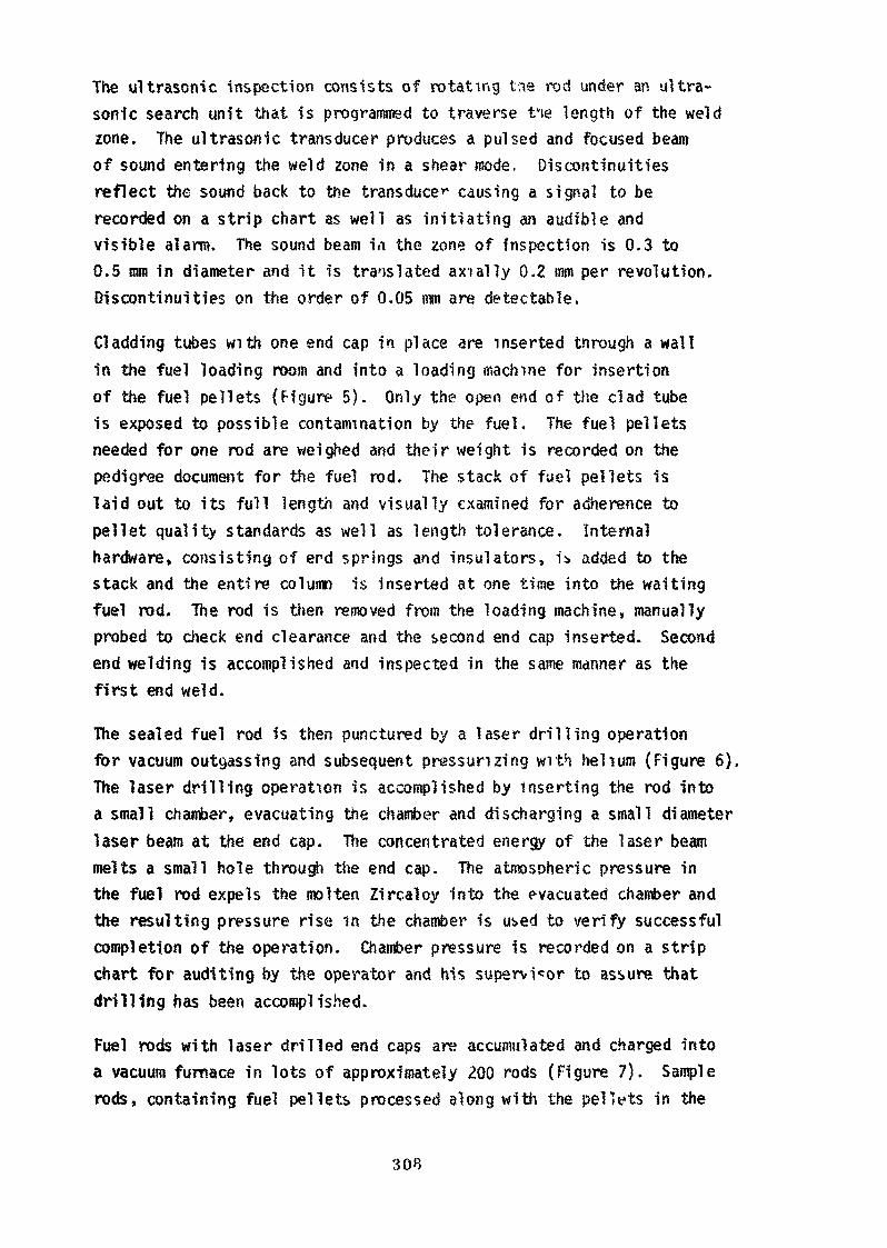
The ultrasonic inspection consists of rotating tne rod under an ultra-sonic search unit that is programmed to traverse tv!e length of the weldzone. The ultrasonic transducer produces a pulsed and focused beamof sound entering the weld zone in a shear mode. Discontinuitiesreflect the sound back to the transduce*' causing a signal to berecorded on a strip chart as well as ini t ia t ing an audible andvisible alarm. The sound beam id the zone of Inspection is 0.3 to0.5 mm in diameter and it is translated ax ia l ly 0.2 mm per revolution.Discontinuities on the order of 0.05 m are detectable.
Cladding tubes with one end cap in place are inserted through a wallin the fuel loading room and into a loading machine for insertionof the fuel pellets {Figure 5). Only the open end of the clad tubeis exposed to possible contamination by the fuel. The fuel pelletsneeded for one rod are weighed and their weight is recorded on thepedigree document for the fuel rod. The stack of fuel pellets islaid out to its full length and visually examined for adherence topellet quality standards as well as length tolerance. Internalhardware, consisting of end springs and insulators, i* added to thestack and the entire column is inserted at one time into the wait ingfuel rod. The rod is then removed from the loading machine» manuallyprobed to check end clearance and the second end cap inserted. Secondend welding is accomplished and inspected in the same manner as thefirst end weld.
The sealed fuel rod is then punctured by a laser dr i l l ing operationfor vacuum outgassing and subsequent pressurizing wi th hel ium (Figure 6).The laser drilling operation is accomplished by inserting the rod intoa small chamber, evacuating the chamber and discharging a small diameterlaser beam at the end cap. The concentrated energy of the laser beammelts a small hole through the end cap. The atmospheric pressure inthe fuel rod expels the molten Zircaloy into the evacuated chamber andthe resulting pressure rise in the chamber is used to verify successfulcompletion of the operation. Chamber pressure is recorded on a stripchart for auditing by the operator and his supervisor to assure thatdrilling has been accomplished.
Fuel rods with laser drilled end caps are accumulated and charged intoa vacuum furnace in lots of approximately 200 rods (Figure 7). Samplerods, containing fuel pellets processed along with the pellets in the
3 OB
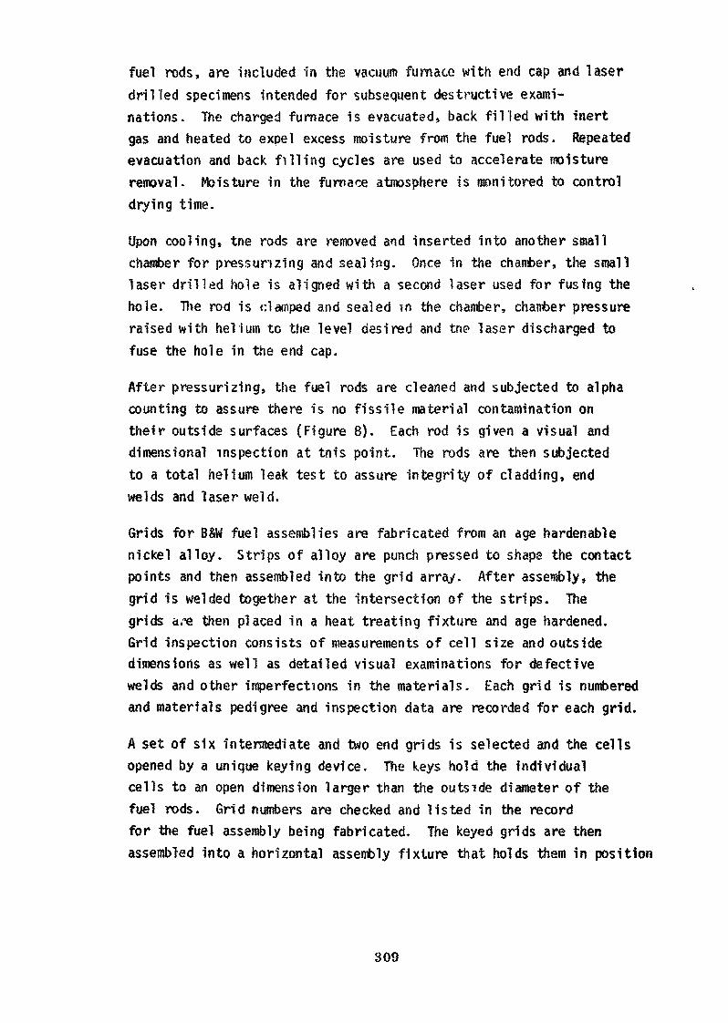
fuel rods, are included in the vacuum furnace with end cap and laserdril led specimens intended for subsequent destructive exami-nations. The charged furnace is evacuated, back f i l led with inertgas and heated to expel excess moisture from the fuel rods. Repeatedevacuation and back f i l l i ng cycles are used to accelerate moistureremoval. Moisture in the furnace atmosphere is monitored to controldrying time.
Upon cooling, tne rods are removed and inserted into another smallchamber for pressurizing and sealing. Once in the chamber, the smalllaser dr i l led hole is aligned with a second laser used for fusing thehole. The rod is clamped and sealed in the chamber, chamber pressureraised with he l ium to the level desired and trie laser discharged tofuse the hole in the end cap.
After pressurizing, the fuel rods are cleaned and subjected to alphacounting to assure there is no fissile material contamination ontheir outside surfaces (Figure 8). Each rod is given a visual anddimensional inspection at tnis point. The rods are then subjectedto a total helium leak test to assure integrity of cladding, endwelds and laser weld.
Grids for B&W fuel assemblies are fabricated from an age hardenablenickel alloy. Strips of alloy are punch pressed to shape the contactpoints and then assembled into the grid array. After assembly, thegrid is welded together at the intersection of the strips. Thegrids are then placed in a heat treating fixture and age hardened.Grid inspection consists of measurements of cell size and outsidedimensions as well as detailed visual examinations for defectivewelds and other imperfections in the materials. Each grid is numberedand materials pedigree and inspection data are recorded for each grid.
A set of six intermediate and two end grids is selected and the cellsopened by a unique keying device. The keys hold the individualcells to an open dimension larger than the outside diameter of thefuel rods. Grid numbers are checked and listed in the recordfor the fuel assembly being fabricated. The keyed grids are thenassembled into a horizontal assembly fixture that holds them in position
309
during assembly fabrication. The assembly fixture is mounted ona granite surface plate (Figure 9). When the manufacturing personnelhave satisfied themselves that the grids are in proper position,Quality Control personnel inspect them for alignment using thegranite surface plate as a plane of reference.
The assembly personnel insert fuel rods into the grids after checkingthe rod number and assuring themselves that each rod number is con-tained in the record for the fuel assembly being fabricated. Eachfuel rod is hand-wiped with acetone a< it is inserted into the grids.As the assembly is buil t up, a central instrument tube is added.Spacer sleeves are affixed to the instrument tube to act as positiveseparators between grids. After all of the fuel rods (208 in theB&W fuel assemblies) have been inserted, the grid keys are turnedand removed to release the cells to grip the fuel rods.
The sixteen control rod guide tubes are inserted into the grids andthe end fitting castings affixed to both ends. The guide tubes aremechanically fastened to the end fittings and the fasteners weldedin place to prevent their becoming loose during subsequent handlingand service. The end fittings are also attached to the end gridsby welding small insert fasteners in place. A final check of thefuel assembly record is made to assure inclusion of all part numbers.
After being released by assembly operations personnel, the fuel assemblyis placed on a transfer cart equipped with a hydraulic device fortranslating the assembly to the vertical position. Once vertical, theassembly fixture is removed. Subsequent handling is accomplished byl if t ing the assembly from the upper end fitting as it wil l be handledfor loading into the reactor.
The fuel assembly envelope dimensions are checked in a vertical enve-lope gauge (Figure 10). Sensors travel over the ful l length of theassembly in the free standing and restrained positions to check forstraightness twist, bow and envelope. Strain gauges are used to measurewater channels at eight locations over the length of the assembly.Signals from the strain gauges are converted by computer to digitalvalues for water channels. These data are then compared to standardvalues and, if acceptable, the assembly is released for further pro-cessing.
310
The hold-oown spring and spider are added to the upper end fittingand inserts limiting spider motion are welded in place. The assemblyis then transferred to a pit where a control rod with upper tolerancelimits is inserted in the fuel assembly guide tubes. This insertiontest is to measure guide tube alignment to assure control rod scramtime is within tolerance.
Final visual inspection is performed by Quality Control personnelusing high intensity lights and magnifying devices where necessary.Cleaning is accomplished by manufacturing personnel using acetone andcompressed air. When satisfactorily cleaned» the assembly is sealedin a plastic sheath and either stored in the vertical position orplaced in a shipping container for shipment to the reactor site.
Manufacturing of other components, such as burnable poison assembliesand control rod assemblies» is accomplished with the same attentionto detail as described for fuel assembly manufacture. Minimal operatordependency is a general practice. Where dependence on the operatorcannot be avoided, he is thoroughly trained and competency is establishedbefore he is permitted to work in manufacturing operations. An over-check is scheduled in the manufacturing process after such an operationto monitor the operation and assure acceptability of the product.
Each operation in the manufacturing sequence is described by a separatewritten process procedure. Copies of these procedures are reviewedby the equipment operators and retained in a packet close to the operationfor ear ' reference. Details o^ each operation tc be performed arelisted along with explanatory statements where necessary to improvethe operator's understanding of his job.
A route card listing the operations to be performed in sequence isaffixed to each group of components. These cards contain spaces foroperators to initial and date the card signifying that the operationslisted have been completed.
Internal audits aru performed periodically to assure that the processprocedures are being followed and the operations are being performedin tneir proper sequence. In this way, operators have an opportunityto suggest modifications to procedures that they feel would improve
311
the operations. Such suggestions are often found to be acceptableand, 1n such cases, the process procedure will be modified to in-corporate the change. Until the procedure has been changed andapproved, however, the previous issue remains in effect.
The manufacturing operations are fully described by formalized pro-cedures and con tilled by auditing the ^dividual operations againstthese procedures. Individual operators are not forced to rely ontheir memory for details of their operations or for routing of ma-terials through the production sequence. The operators are heldresponsible for the quality as well as the quantity of their work;however, over-checks are performed by Quality Control personnelto assure continued manufacture of high quality products.
SUAI IF CONTROL
Control of the quality of fuel assemblies incorporates assurance ofquality of raw materials, control of manufacturing and inspectionprocesses to preclude production of deviated material, and finishedproduct inspection to verify final product qual i ty and adherence todrawings and specifications. It is standard practice to not onlycontrol the quality of products but to record and document inspectionand test results. Thus a pedigree is available in the event problemsare encountered during the operating l i fe of the fuel assembly.Examination of a failed component's pedigree may provide informationon the cause of .ailure. Design or manufac tur ing modificationscan then be made to correct deficiencies that ^an lead to operatingproblems.
Raw material and component vendors are required to have formal quali tycontrol organizations and procedures. Frequent audits are performedto assure tnat the vendor is supplying quality material and that heis controlling his process so that unacceptable material is removedfrom the production stream.
Inspections of vendor supplied material may be carried out at thevendor's plant or on receipt of his product. Where special inspectionequipment is required, the fuel manufacturer may choose to witnessinspection of the product at the vendor's plant and also over-inspectthe product on receipt, using conventional procedures. In any event,
31.2
the quality of purchased materials is verified by one or more in-spections by the fuel manufacturer's quality control organization.The ultimate user of the fuel, the reactor operator, may choose toaccompany the fuel manufacturer during his source inspections.
The degree of over-inspection is dictated by the importance of thepurehas d component and by its alue. For exampl- , zircaloy tubingand bar stock to be used for fuel cl-adding and end caps are subjectedto extensive non-destructive inspections by the manufacturer. Theseinclude ultrasonic inspections covering 100% of the volume ofthe product and pénétrant inspections over those areas where themanufacturing process can cause defects. Over-inspection mightInclude the same type of ultrasonic and pénétrant inspections usingcomparable equipment to that of the manufacturer but on a statisticalsample rather than on 100% of the product.
Destructive testing of these particular raw materials is also commonpractice. Corrosion tests, mechanical property tests and checkchemical analyses are performed on samples representing the materialas it is received from the vendor.
In-house, the Quality Control organization assumes the role of auditorand over-inspector. The prime function of Quality Control is inspectionof products and auditing of procedures. If faulty material is found,it is rejected along with the lot from which it came. It is not aquality control function to segregate acceptable from unacceptablematerie", except in cases where 100% non-destructive inspections arepracticed. In these cases» a normal reject rate is established andvariations from the norm are used to effect process modifications asa form of process control.
There are continuing efforts being made to develop more exactingquality control and inspection procedures. Mainly, these efforts aredirected towards development of on-line non-destructive testing pro-cedures for continuous monitoring of the quality of the product.Results from these procedures can be fed back for continuous processcontrol so that faulty products are not produced. The ultimate goalof Quality Control is just that — preventing the production ofrejectable products.
313
Where 100% inspection is impractical or where destructive tests arerequired» samples are taken and tested as early as possible. Theproduct may be quarantined until the test results indicate that thelot represented by the sample is acceptable, or a limited quantity ofcontinued work on the product may be authorized depending on the riskinvolved. The principal objective, however, is to minimize the invest-ment of additional effort in a lot of product until its acceptabilityhas been verified.
As in the manufacturing operations, written procedures are preparedfor all quality control operations. These procedures describe indetail the nature of the inspection or test to be performed. Theyprovide such information as the types of instruments to be used,whether actual values of inspection results are to be recorded, thenumber of samples to be inspected and the disposition of rejectablematerial.
Another vital aspect of the quality control function is the assimi-lation and recording of data for the pedigree of the fuel assembly.At the conclusion of manufacture and final inspection of a fuelassembly, a conformance certification is prepared that lists theassembly number and all drawings and specifications applicable tothe assembly. This document also lists the quantity of U02 andUranium-235 contained in the fuel assembly.
The fuel assembly number is the key to tracing the pedigree ofmaterials and components that were used in its manufacture. All ofthe inspection and manufacturing history for the assembly is retainedin quality control files indexed to the fuel assembly number. Thedata and information available for each fuel assembly include:
Final inspection results, including about 3400 waterchannel dimensions.
Identification numbers for all components providingtraceability to original material certifications.
Individual fuel stack weights and Uranium-235 content.
Route cards covering the manufacturing and inspectionoperations for all components in the assembly.
314
Radiographs of end fitting components.
Variations or deviations from standard operationsand their disposition.
At the conclusion of manufacture of a core, or portion thereof thatwill bt discharged as a unit fiom the reactor, all inspection recordsare compiled Into a single file and retained until the core orbatch has been reprocessed after service.
The principal quality control function is one of over-check and feed-back. The quality control organization is responsible for checkingthe product to assure that quality standards are met and to feedback information on minor deviations that may indicate trends so thatprocessing adjustments can be made before rejectable products aremanufactured. Most of the materials making up fuel assemblies arecostly, so an efficient quality control operation is an economicnecessity. It signals the need for process corrections before theprocess reaches the point where scrap products will be produced andminimizes the expenditure of added effort on rejectable material.
To maintain this desired level of quality, approximately 35% of thetotal direct labor expended in the production of fuel assemblies isfor quality control. Compared to other manufacturing operations,this level of expenditure for quality control may be considered high.However, such an effort is justified in view of the serious and costlyopérât.onal difficulties that .an be caused if faulty fuel assembliesare placed in service. A more quantifiable justification can bereached on the basis of manufacturing performance and low reject costsdirectly attributable to an effective quality control program.
ECONOMICS OF PLANT SIZE
There are many fixed cost functions associated with nuclear fuelmanufacture. They include fissionable material accountability andsafeguards, health physics and personnel monitoring, facility licensingand attention to regulatory requirements. In a free enterpriseeconomy, the volume of business must be large enough so that thefixed costs are not a major factor affecting unit product costs.While not precise, the minimum size plant considered justifiable in
315
the United States »s one capable of assembling one fuel assembly per8-hour shift. Such a plant w i l l be primarily an assembly plant,purchasing most components of the fuel assembly in d form suitablefor direct incorporation in the final fuel assembly.
The total cost of a one assembly per 8-hour shift plant is approxi-mately 3.0 m i l l u n dollars. This covers a bu i ld ing of approximately4000 m^ area and equipment including:
Cladding preparation equipmentDegreasers, ultrasonic cleaners and associated cleaningequipmentEnd closure weldersFuel rod pressurization equipresentFuel loadersHandling equipmentUltrasonic, helium leak, alpha counting and other non-destructive inspection equipmentFuel drying equipmentAssembly fixturesEnvelope and water channel inspection equipmentChemical and metallurgical laboratory equipmentFinished fuel storage racksFuel shipping containersMachine ShopEnvironmental monitoring equipmentFuel accountability control equipmentInert gas systemsCompressed air systemElectronic maintenance equipmentMechanical and electrical maintenance shopDémineraiized water system and corrosion testautoclaves
In-house manufacture of some of the components of the fuel assemblyis justified on the basis of volume. For example, a typical fuelassembly requires about 420 end caps, 20 guide tube upper and lowerend fittings and fasteners, 32 end fitting to grid fastening inserts,420 end void support devices, about 2000 insulator pellets and roughly40,000 fuel pellets. The end caps and other small hardware components
316
can be manufactured on relatively small and inexpensive automaticmachine tools. In a one assembly per 8-hour shift plant, there is asufficient quantity required to keep one or more machines occupiednear full time in small hardware component production.
In-house manufacture of other components» even at low volume, can bejustified on quality control ar.J economic bases. For example, in-housemanufacture of insulator pellets is feasible because the manufacturingequipment requirements are minimal and the costs of purchase of thesmall quantity of pellets needed to nuclear quality specifications areexcessive. Equipment utilization in this case is low, yet justifiedbecause in-house manufacturing costs can be as much as a factor of 5below outside procurement costs.
In-house manufacture of fuel pellets for a one fuel assembly per dayproduction rate can be justified when quality considerations areincluded in the analysis. Purchase of fuel pellets entails a signifi-cant amount of over-inspection and testing on receipt to assure qualityas well as accountability. Shipping damage to the pellets is also anexpense factor. The delays encountered in vendor certification, ship-ment and receiver re-certification of the pellets represent asignificant inventory carrying cost that can be eliminated by in-house manufacture of pellets. These costs, in addition to the lessquantifiable factor of enhanced control of the quality of the pellets,support a conclusion that in-house pellet manufacture is justifiable.
In suc a case, sintering and .^inding capacity v^uld be required tomeet a production rate of 40,000 pellets per day. On an 8-hourday basis, 5000 pellets per hour are needed. This is a reasonable pro-duction rate for a low-volume press. Associated equipment can besized to match or slightly exceed this production rate without ex-cessive costs. Thus a small pellet production line is feasible even•for a "one assembly per day" fuel plant on the basis of one shiftutilization of production equipment.
Triers are technology considerations involved in determining the scopeof in-house manufacture. The technology required for small hardwaremanufacture is not sophisticated. However, manufacture of insulatorand fuel pellets does require some ceramic or high temperaturechemistry technology that may not be readily available. Access tosuch technology on a continuing basis is important also to modify and
317
improve processing and to understand and compensate Or minor variationsin the characteristics of incoming raw materials. For the initialstart-up of a "one fuel assembly per day" olant , it is prudent todefer in-house manufacture of components requiring nore sophisticatedtechnology until the basic assembly plant is performing satisfactorily.
There are other omponents of the fuel a sembly that shoulo not beconsidered for in-house manufacture until business volume is sufficientto justify a minimum sized production facility. For example, manu-facture of fuel cladding requires a significant investment in ma-chinery and equipment as do conversion facilities for the manufactureof UÛ2 powder. These businesses are discussed elsewhere in theseproceedings. As business volume grows, however, there w i l l be apoint at which powder conversion facilities, and at least finishtubing manufacturing equipment, can be justified. Integration intothese businesses should be considered as incremental increases inproduction output are required.
Figure (11) shows a conceptual layout of a basic fuel assembly plantthat has been expanded to Include component manufacturing andfinally U02 powder conversion capability.
There are economic considerations that may favor increasing the pro-duction capability of a fuel plant so as to reduce the processing timefor high cost components of the fuel assemblies. Operating the basic"one fuel assembly per day" plant on a 3-shift, 7-day schedule wi l lincrease through ut by a factor of 4. Additional equipment can alsobe added to increase throughput per shift. Increasing the "oneassembly per day" plant to two assemblies per day wi l l cost approxi-mately 300,000 dollars for additional equipment. No increase in the4000 m2 plant should be required for this doubling of capacity.
A minimum sized pellet manufacturing facility wi l l cost approximately300,000 dollars when added to an existing fuel assembly plant, pro-viding appropriate services have been included in the original assemblyplant. The throughput of this pellet plant wi l l be about one tonneof UOg per day with part of the equipment being operated on a 3-shiftschedule.
Manufacturing grids and machining end fittings to support a two assemblyper day throughput will require about 1,000,000 dollars for building,
318
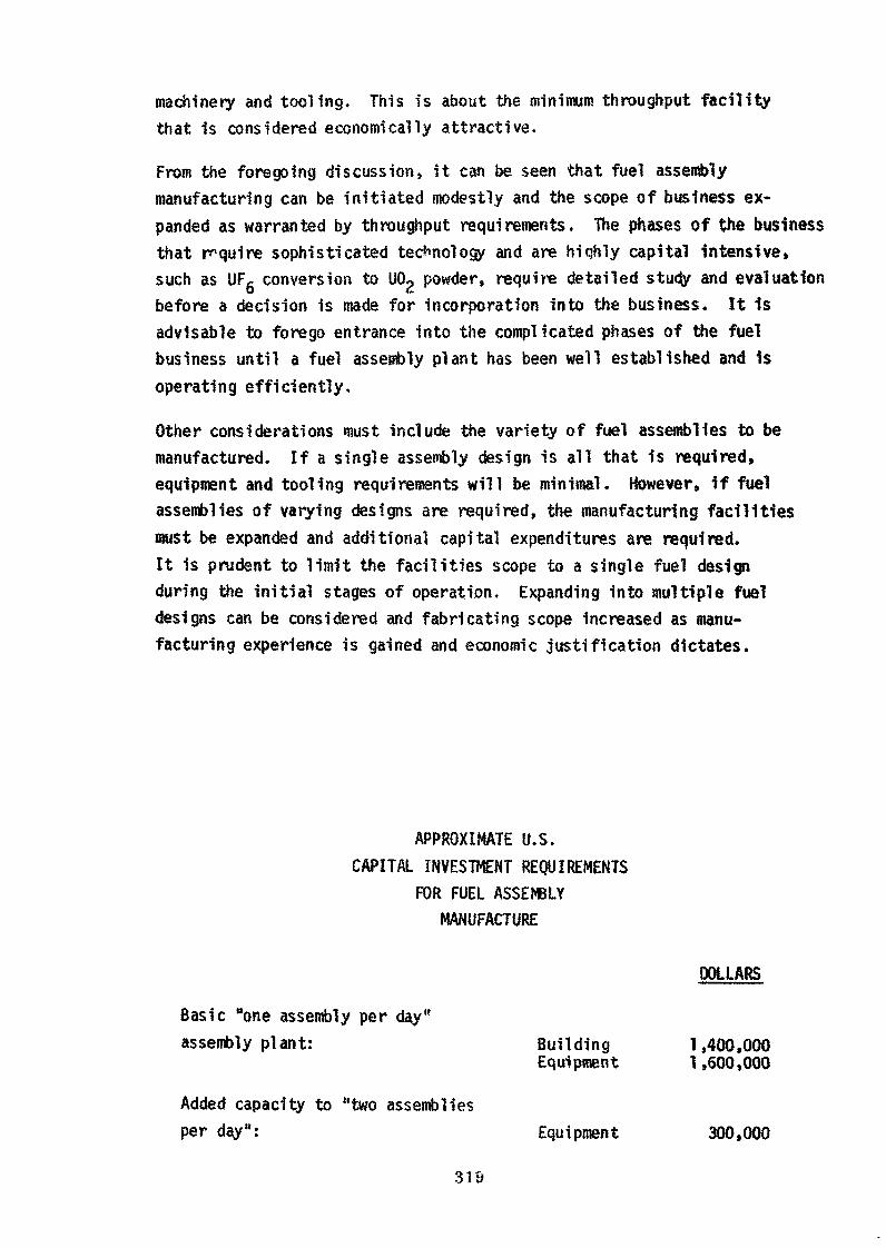
machinery and tooling. This is about the minimum throughput facilitythat is considered economically attractive.
From the foregoing discussion» it can be seen that fuel assemblymanufacturing can be initiated modestly and the scope of business ex-panded as warranted by throughput requirements. The phases of the businessthat require sophisticated technology and are hiqhly capital intensive,such as UFg conversion to U02 powder, require detailed study and evaluationbefore a decision is made for incorporation into the business. It 1sadvisable to forego entrance into the complicated phases of the fuelbusiness until a fuel assembly plant has been well established and isoperating efficiently.
Other considerations must include the variety of fuel assemblies to bemanufactured. If a single assembly design is all that is required,equipment and tooling requirements wil l be minimal. However, if fuelassemblies of varying designs are required, the manufacturing facilitiesmust be expanded and additional capital expenditures are required.It is prudent to limit the facilities scope to a single fuel designduring the initial stages of operation. Expanding into multiple fueldesigns can be considered and fabricating scope increased as manu-facturing experience is gained and economic justification dictates.
APPROXIMATE U.S.CAPITAL INVESTMENT REQUIREMENTS
FOR FUEL ASSEMBLYMANUFACTURE
DOLLARS
Basic "one assembly per day"assembly plant: Building 1,400,000
Equipment 1,600,000
Added capacity to "two assembliesper day": Equipment 300,000
319
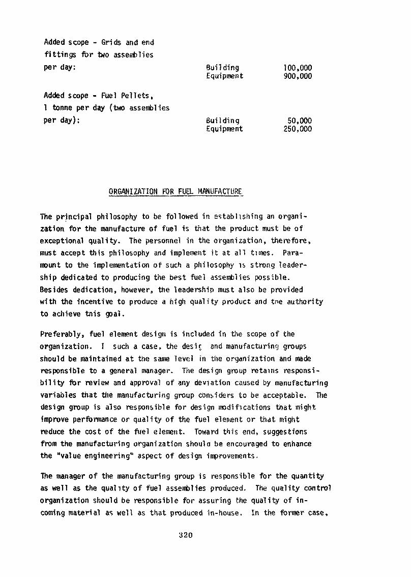
Added scope - Grids and endfittings for two assembliesper day: Building 100,000
Equipment 900,000
Added scope - Fuel Pellets,1 tonne per day (two assembliesper day): Bui ld ing 50,000
Equipment 250,000
ORGANIZATION FOR FUEL MANUFACTURE
The principal philosophy to be followed in establishing an organi-zation, for the manufacture of fuel is that the product must be ofexceptional quality. The personnel in the organization, therefore,must accept this philosophy and implement it at all times. Para-mount to the implementation of such a philosophy is strong leader-ship dedicated to producing the best fuel assemblies possible.Besides dedication, however, the leadership must also be providedwith the incentive to produce a high qual i ty product and tne authorityto achieve tnis goal.
Preferably, fuel element design is included in the scope of theorganization. Ï such a case, the desic and manufacturing groupsshould be maintained at the same level in the organization and maderesponsible to a general manager. The design group retains responsi-bili ty for review and approval of any deviation caused by manufacturingvariables that the manufacturing group considers to be acceptable. Thedesign group is also responsible for design modifications that mightimprove performance or quality of the fuel element or that, mightreduce the cost of the fuel element. Toward this end, suggestionsfrom the manufacturing organization should be encouraged to enhancethe "value engineering" aspect of design improvements.
The manager of the manufacturing group is responsible for the quantityas well as the quality of fuel assemblies produced. The quality controlorganization should be responsible for assuring the quality of in-coming material as well as that produced in-house. In the former case,
320
vendor auditing, source inspection and receipt inspection are involved.In the latter case, in-process and component inspections should beutilized to assure process control and to assure confornwnce to speci-fications as the product is being manufactured. To meet these responsi-bilities, manufacturing and quality control groups must be separateand of equal authority.
The quality control organization performs a verification functionover the products produced by the manufacturing organization. Theyshould have no responsibility for repairing non-con forming materialsor components or for separating acceptable from unacceptable material.In this way, the quality control organization is relieved of anyresponsibility to provide acceptable material. Their responsibilityis simply to assure that only acceptable material is introduced intothe manufacturing operation and that only finished products thatmeet the drawings and specifications are shipped to the customer.
This subtle definition of responsibility can account for the differencebetween an acceptable and unacceptable quality control program. Whenthe quality control group is given responsibility for modification,selection or repair of material under inspection, there is some in-centive to meet quantity goals even though such goals are not formalized.With no responsibility for modification or repair of the materialbeing inspected and only responsibility for assuring that unacceptablematerial is not introduced to the production stream, the only incentivethat the group has is to show its effectiveness in controlling quality.And this is precisely what they are responsible for.
The manufacturing group, on the other hand» has to be provided withincentive to manufacture a high quality product as well as meet Itsquantity goals. This can be accomplished by placing the responsibilityfor the quality as well as quantity of product on the manufacturinggroup. The fact that the product will be over-inspected by the qualitycontrol group should not be used as an excuse to relieve the manufac-turing group of its responsibility for building quality into theproduct. If this philosophy is maintained, the manufacturing groupwil l have an incentive to continually improve the quality of theproduct. If this philosophy is relaxed, the manufacturing groupwill have a tendency to place higher emphasis on quantity of pro-duction at the expense of quality.
321
The other principal line function, materials management, is alsocritical to the successful operation of a nuclear fuel manufacturingfacility. Acceptable materials in the quantities required to sustainproduction must be available when needed to avoid expensive delays.Most of the materials used in fuel assemblies are expensive by virtueof their precision and quality requirements. W h i l e production canbe delayed by the absence of a critical component, inflated inventoriesto preclude an "out of stock" situation is equally unacceptable becauseof the high cost of excess inventory. An eff icient materials manage-ment organization is therefore a vital part of a fuels plant organi-zation.
Because of the high value of nuclear mater 'als, and internationalagreements to restrict proliferation of nuclear weaponry, nuclear fuelprocessors must have an effective safeguards organisation. Briefly,safeguards is defined as tne prevention or prompt detection of di-version of nuclear materials. An effective safeguards program musttherefore ensure the security of operations and data from sabotageand theft, as well as ensuring that nuclear materials themselves donot fall into unauthorized hands.
In setting up a safeguards organization, personnel trained in statistics,nuclear physics, non-destructive assay, electronic data processing andaccounting procedures need to be available. Knowledge in these fieldsis required to establish valid sampling systems and routine accountingand inventory procedures to assure accurate and timely control ofthe nuclear materials assigned to the facil i ty.
Another part of the organization that must be established before theplant design is finalized is the health physics operation. Criteriafor the maintenance of a nuclear and radiologically safe work placehave been established by international organizations. Generally,regulatory controls imposed by individual countries conform to therestrictions suggested by such agencies. Interpretation and appli-cation of the guides requires both knowledge and applied experiencein such disciplines as nuclear criticality safety, accident analysis,and health physics. Early in the planning stage for a fuel plant,consultation is required with nuclear engineers» physicists, biologists,and chemists for the primary purpose of assuring a plant design thatis capable of safe operation. Involvement of these disciplines from
322
the earliest design phases through plant operation ensures thatproper safety controls are initially established and designed intothe plant and its associated equipment. This approach is advan-tageous for a number of reasons including the elimination of un-necessary conservatism in equipment design, the adaptability ofplant safety systems to future expansion, and limitation of thenecessity for "backfitting". Proper initial design, applying therecommendations of safety personnel, has been shown to reduce longrange plant operating expense and to increase productivity by elimi-nating or reducing the use of safety related controls, such as respi-rators» which detract from employee efficiency.
SELECTION AND TRAINING OF PERSONNEL
Personnel experienced in the manufacture of nuclear fuel are notgenerally available. It is usually necessary to select individualswith appropriate education and experience for the more responsiblepositions and provide them with the training necessary for nuclearfuel manufacture.
Following is a list of key personnel required for a fuel assemblyplant. The background requirements noted are not necessarilyall-inclusive and it is advisable to consider additional trainingfor car ii dates for particular f sitions on an ind vidual basis.
1. Position: Plant Manager
Background Management of high quality light equip-Recommended: manufactur1ng plant. Realization of
the nature and expense of nuclear fuel.Familiar with nuclear technology» con-sequences of fuel failures and effects ofthe reactor environment on nuclear fuelsand structural materials.
2. Position: Manager, Manufacturing
Background Manager of high quality metals fabricationRecommended: Qr ]ight equipnient manufacturing plant.
323
3. Position:
BackgroundRecommended:
4. Position:
BackgroundRecommended:
5. Position:
BackgroundRecommended:
6. Position:
BackgroundRecomir'nded:
7. Position:
BackgroundRecommended:
8. Position:
BackgroundRecommended:
9. Position:
BackgroundRecommended:
Familiar with nuclear technology and sig-nificance of quality in fuel components.Experience in high quality, precisionwelding of reactive metals.
Manager» Quality Control
Quality Control management in highquality light equipment manufacturingplant. Familiar with non-destructivetesting methods and equipment and withstatistical quality control procedures.
Manager, Manufacturing Engineering
Graduate engineer with experience inprocess development and welding ofreactive metals and stainless steels.
Manager, Production Control
Metals fabrication, light equipmentmanufacture, or chemical processindustry production control.
Manager, Nuclear Materials Control
Engineering degree with extensivemathematical statistics training.
Radiation Safety Officer
Degree in Physical Sciences or Biologywith training in radiation measure-ment and effects.
Nuclear Safety Officer
Degree in Nuclear Physics with experiencein nuclear calculations.
Manufacturing Foreman
Supervision in light equipment manu-facturing plant. Quality oriented
324
and familiar with high qualitymanufacturing, welding and assemblymethods.
10. Position: Inspection Foreman
Background Supervision of inspection of high quality,Recommended: precision equipment, familiar with sta-
tistical quality control methods andwith non-destructive testing methods.
If it is at a l l feasible, the most efficient way of further trainingpersonnel to fi l l these positions is to place them in an operatingfuel assembly plant for varying periods of time. In this way» theindividuals have an opportunity to participate in the routine of afuels plant and to gain an understanding of the underlying philoso-phy of a high quality manufacturing organization.
SUMMARY
Manufacturing fuel assemblies for pressurized water reactors Is adeveloping technology. Many of the methods and procedures used infuel manufacturing operations were developed specifically for theproduction of this critical component of the nuclear reactor.Method^ and procedures are bei>"3 upgraded constartly to improvethe qu, l i ty of, or rerove inconsistencies from the product.The underlying philosophy governing these manufacturing operationsis one of starting with only hign quality raw materials and buildingquality into the product throughout the manufacturing sequence.
Quality control of fuel manufacturing is a continuous exercise oftests and inspections to assure that processes are under control andthat only acceptable material is. allowed to remain in the productionstream. New and improved inspection methods are under developmentto function as on-line tests for product quality. The goal is toreach prompt feedback of deviations from the norm so that processadjustments can be made before rejectable material is produced. Intne fuel manufacturing business, process control is essentiallysynonomous with quality control.
325
The fuel manufacturing business is an enterprise that is more closelytied to financial considerations than many other manufacturingoperations. Many of the raw materials used are high in cost. Thisfact makes inventory control vital and it supports capital investmentdecisions to increase manufacturing capacity so as to decrease pro-cessing time. Detailed financial analyses are necessary to arrive atthe correct balance between capacity and tnroughput requirements. Theseanalyses do indicate that relatively small throughput requirementsare adequate to support a fuels plant with a minimal scope of activities.As throughput requirements increase, integrating additional activitiesinto the facility becomes justifiable. These points indicate that agradual entrance into the fuel manufacturing business is not onlydesirable but financially attractive.
Organizational structures in manufacturing facilities can be quitevariable. In a fuel assembly plant, however, separate manufacturingand quality control organizations reporting to the same managerare mandatory. Manufacturing is responsible for making the quantityof fuel assemblies required at a level of quality that is acceptable.The Quality Control organization is responsible for assuring thatonly products of acceptable quality are delivered to the customer.Any component that does not completely comply to drawings and speci-fications must be rejected unless the deviation is slight and haslittle effect on the performance of the component. The decision asto whether or not a deviation is acceptable must only be made by theorganization responsible for the component's design. To facilitateanalyses and evaluations of deviations, the manufacturing organizationshould have access to the responsible design organization.
Selecting and training personnel for a fuel manufacturing operationis one of the more important activities in establishing a fuels plant.Management of the operation must be committed to manufacturing onlyhigh quality fuel assemblies. In all aspects of planning and develop-ing procedures and equipment for fuel manufacture there must be nocompromise with this philosophy. Preferably personnel with nuclearbackgrounds should be selected to staff a new plant. Individualswith experience in areas wnere the quality of the product was highlyimportant can be trained to f i l l key positions, but they wi l l requirebackground training to establish an understanding of nuclear manu-facturing technology.
326

Nuclear fuel manufacture, like most manufacturing operations, canbe a fascinating and rewarding business. It must be approached as abusiness with full recognition of the fact that sacrifices in the levelof product quality will lead to serious economic penalties. With thisrealization and the help of competent people, a developing nation witha minimum of operating reactors can enter the nuclear fuel manufacturingbusiness on a modest scale starting with assembly operations. Thisbase business can be expanded in manufacturing scope as competency isdeveloped and the expansion is justified by the economics of additionalthroughput.
327
FIGURE 1 AUTOMATIC TURRET LATHE FOR SMALL HARDWARE MANUFACTURE
328
FIGURE 2 INCOMING INSPECTION AREA
329
FIGURE 3 END CLOSURE WELDING BOX
330
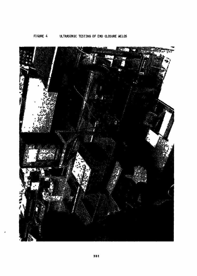
FIGURE 4 ULTRASONIC TESTING OF END CLOSURE WELDS
331

FIGURE 5 FUEL LOADING STATION
332
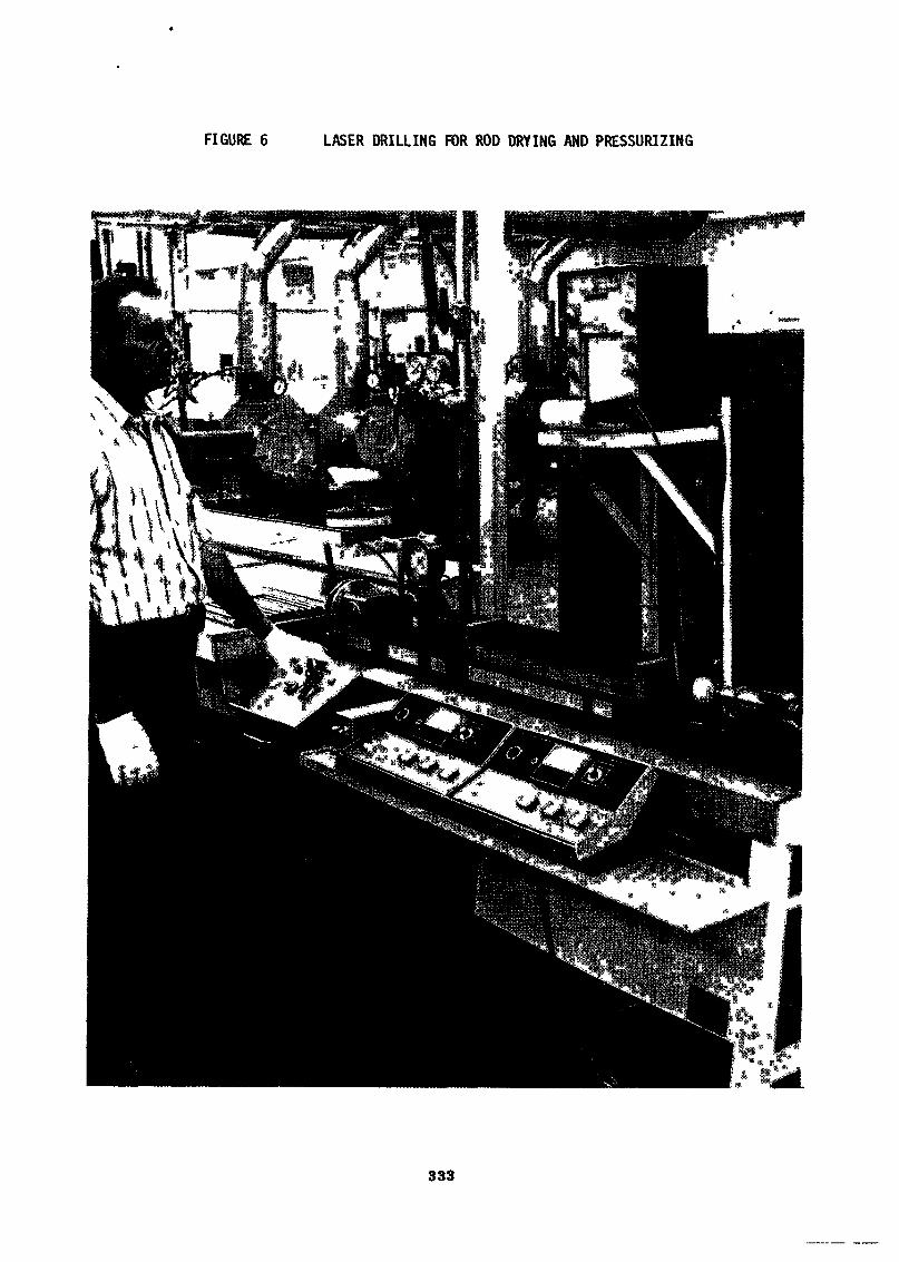
FIGURE 6 LASER DRILLING FOR ROD DRYING AND PRESSURIZING
333
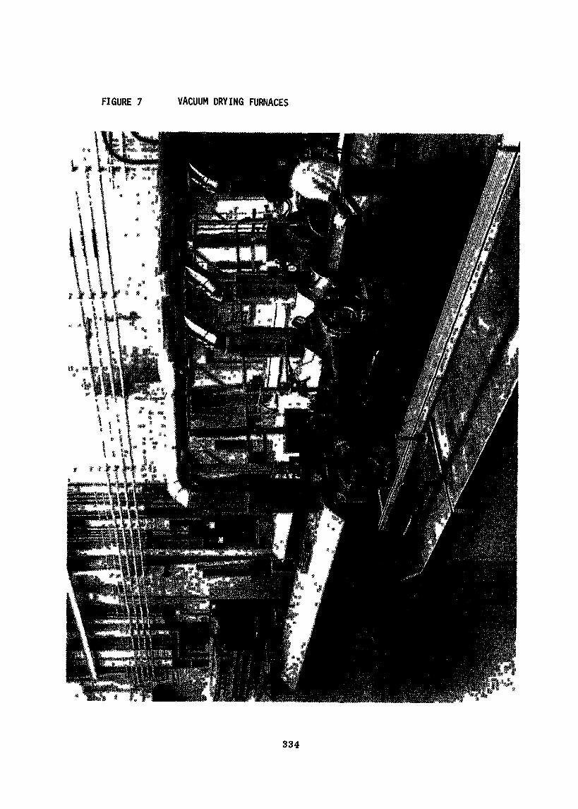
FIGURE 7 VACUUM DRYING FURNACES
334
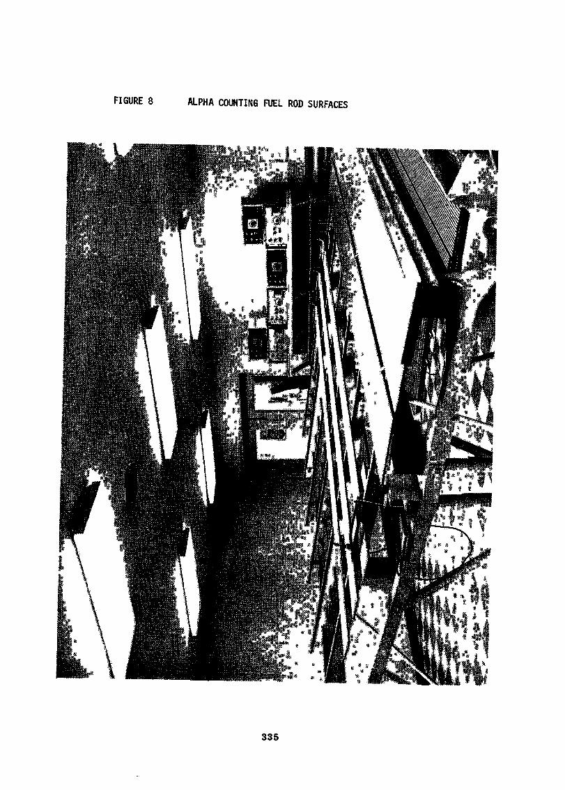
FIGURE 8 ALPHA COUNTING FUEL ROD SURFACES
335
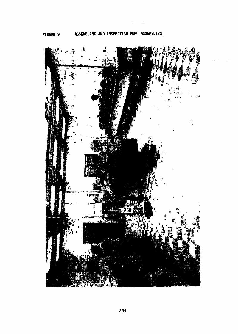
FIGURE 9 ASSEMBLING AND INSPECTING FUEL ASSEMBLIES
336
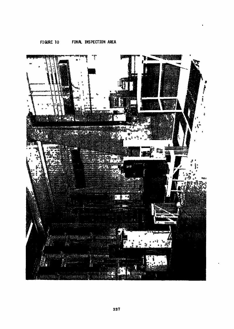
FIGURE 10 FINAL INSPECTION AREA
337
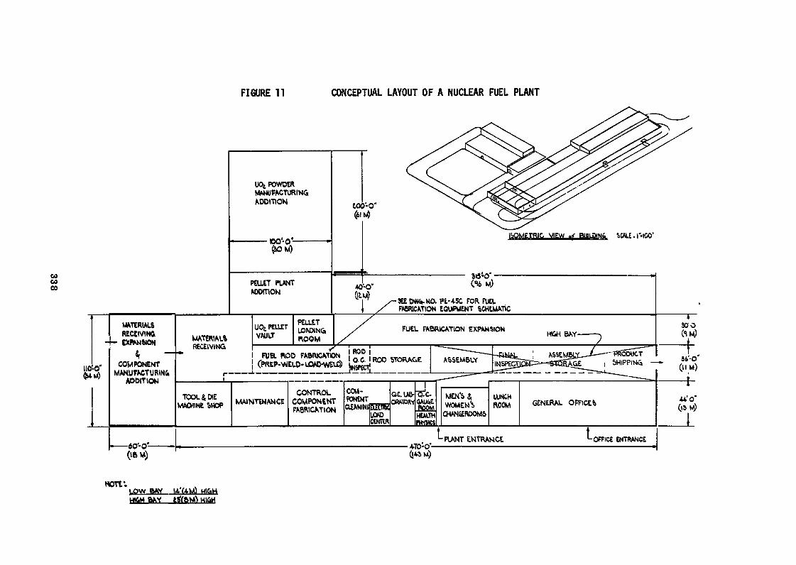
FIGURE 11 CONCEPTUAL LAYOUT OF A NUCLEAR FUEL PLANT
00CO00
UCfc POWDERMANUFACTURINGADDITION
PELLET PLANTAODmON
tOO'-O"
ISOMETRIC VIEW «< BUILDIN& UALE. I" 100'
«J-O" (16 M)
ÎEE DVW».NO. PE-45C FOR FUELFABRICATION EQUIPMENT SCHtMATJC
MATERIALSRECEIVING
-4- EXPANSION
FUEL FABRICATION EXPANSIONMATERIALSRECEIVING
FUEL BOD FABRICATIONCOMPONENT
MANUFACTURINGADDITION
GENERAL OFFICER
PLANT ENTRANCE OFFICE ENTRANCE
HOTV.LOW BAY
6AVHl&H
Boiling Water Nuclear Fuel Manufacture
W. N. MobleyR. A, Schaus
E. L. Zebroski
General Electric CompanyNuclear Energy Division
ABSTRACT
General Electric has a large and growing integrated manufacturing capabilityIn the United States with licensees and jointly owned fuel manufacturingfacilities in Europe and Japan.
Substantial research and development support is provided for all aspects offuel design operation, manufacturing process, and quality methods.
The manufacturing efforts are backed by large scale development and testingat Vallecitos, California, design analysis at San Jose, California, andProcess development in both San Jose, California and at Wilmington, NorthCarolina. Basic methods and material research is carried out at Vallecitos,California and the General Electric Research Center in Schenectady, New York.Specialized development process and pilot operations are conducted both atSan Jose and Vallecitos.
Supporting technical evaluation of design, materials, methods, and productis conducted in various reactors including GETR at Vallecitos, the Haldenreactor in Norway, and extensive field surveillance in operating reactors.
Reactivity control and power leveling in the fuel is accomplished by blendinggadolinia in various concentrations with urania.
235Segregation cf multiple enrichments of U and the special combinations ofgadolinia with urania in addition to the overall material, quality, and proc-ess control activities are maintained by a computer aided accounting and proc-ess system (MICS). The product produced is thoroughly tested by the latestquality information methods and equipment, including the scanning of completedfuel rods. The latter method can detect a single off-standard enrichment ofpellet in a fuel rod.
339
Integration of the manufacturing process as described In the text extends fromthe reduction of tube shells of zirconium alloy and the conversion of uraniumhexafluoride to the finished fuel. Limited capability for remelting of zir-conium is available in the General Electric facilities.
The combination of vertical Integration combined with multiple manufacturingfacilities all backed by extensive technical support provides a broad basethe rapid progression of fuel manufacturing technology and capability.
INTRODUCTION
The General Electric Company manufactures reactor fuel in large-scaleintegrated facilities in Wilmington, North Carolina» and under licensearrangements with jointly owned facilities in Germany, Japan, and Italy.This manufacturing effort is supported by large-scale development andtesting efforts at Vallecitos» California; design analysis and processdevelopment in San Jose, California, and in Wilmington; and basicmaterials and methods research at Vallecitos and in the GE ResearchCenter in Schenectady, New York. Specialized developmental processfacilities for UOp fuel and for plutonia-urania fuel are in operationin San Jose and Vallecitos.
Experience with the manufacture and use of zirconium-clad fuel incommercial boiling water power reactors now extends over 14 years.Continuing refinements in process, inspection methods, and manufactur-ing systems are required of the manufacturer. These changes are duein part to continually rising expectations and requirements made ofthe fuel. Typically these are: high production rates - well over1000 tons/year; increases in fuel ratings; increases in burnup;and increases in statistical reliability assurance levels - as wellas in actual fuel performance levels. Furthermore, the manufacturingplant 1s required to meet ever higher standards for health and safety,materials accountability and safeguards, waste and scrap inventorycontrol, and nuclear safety. This combination of increasing expecta-tions requires fundamental changes in the organization of manufacturingwork relative to earlier methods which were adequate in small-scaleproduction. Even in large-scale production operations, continuingflexibility is required to introduce changes as required by improved
340
design, improved processes» and improved inspection methods and sta-tistical controls. A continuing iteration must occur between theproduction lines and fuel performance results» fuel development andtesting results, and process and method development. To highlightthe nature of the continuing feedback and dynamic adaptation required,this pr sentation will cover & general scope of BWR fuel manufacture— the method and organization of the nain process and production andquality control and support activities, and the organization of inter-national and licensing activities. Following this will be discussionof the technical and developmental aspects which are a continuinginfluence on the manufacturing operation.
BWR Fuel Manufacturing - General Scope
Rapidly increasing demand for both initial and reload fuel cores forGeneral Electric BWR's has necessitated substantial growth of manufac-turing facilities. These have progressed from a modified laboratorytype shop in the late fifties, to a job shop in the early sixties.In the mid-sixties, load increase made obvious the need for a substan-tially larger manufacturing facility with capacity, processes andsystems to produce several projects simultaneously. Further expansionto capacity in excess of 1500 tons per year is in progress.
Genera1 Electric has over 14 y irs of commercial zirconium clad fuelmanufacturing experience and over 70 reactor years of cumulative oper-ating experience using zirconium clad fuel in 13 BWR's now in fullcommercial operation.
Ever greater emphasis is being placed on quality control throughoutthe manufacturing cycle. The cost of the materials is high and theaccountability demands severe. In addition it is necessary to operatesafely with appropriate attention to health physics, criticality andwith regard for increasingly restrictive environmental considerations.
A manufacturing facility today must provide substantial capacityand flexibility to accommodate multiple projects simultaneously,and to modify practice to apply design and process improvements.The latest and evolving techniques for advanced processes, inspection,
341
mechanization and automation are required to meet the demands forquality and productivity. Advanced material and production controltechniques using data processing equipment are a basic necessity.
The trend of fuel manufacturing is moving rapidly toward highcapital costs coupled with highly skilled and experienced humanresources.
GE Fuel Facilities
The Wilmington. North Carolina plant is well integrated startingwith UFC for the fuel, extruded tube rounds for the cladding, barDstock for end plugs, semi-finished castings for tie plates andstrip for channels and spacers. Rated capacity for completedfuel bundles is being expanded from 1000 tons contained uraniumper year to meet load. The product mix requires precise control
235of operations to accommodate several different U enrichmentsand concentrations of gadolinia.
In addition to these production facilities, Figure 1 shows threecurrent licensed manufacturing affiliates... Kernreaktorteilejointly owned with Allgemeine Elecktricitaets-Gesellschatt;Fabbricazioni Nucleari with Ansaldo Meccanico-Nucleare; andJapan Nuclear Fuel Company, with Hitachi, Ltd., and TokyoShibura Electric Co., Ltd.
Wilmington Manufacturing
The overall product scope of the Wilmington» North Carolina facilityis the most comprehensive. The activities in the three affiliatedcompanies will be described later.
The 2-1/2 square mile Wilmington site, as shown in Figure 2, is devotedto the manufacture of nuclear fuel and other reactor components. Thelarge building in the foreground is the Fuel Manufacturing Operation.UFg is converted to ceramic grade U02, made into pellets, loaded intocladding, degassed, welded, assembled into bundles and packed forshipment.
342
The Fuel Components Operation Is devoted to the fabrication of zircon-ium components... end plugs, tubing, flow channels, and spacers forfuel bundles. Upper and lower tie plates are manufactured 1n thenext building in addition to control blade assemblies, drives, andother stainless steel reactor internals.
The overall process is displayed in Figure 3. There are six majorcomponent groups which flow together to consummate a final fuelassembly. Each of these will be discussed in sequence.
Figure 4 shows detail of the nuclear fuel portion of the prior slide.The squares are operations, circles are inspection points, and thesolid dots designate the generation of permanent records.
Uranium hexafluoride is received in 2200 kg cylinders. After weightverification and certification of the contents, the cylinder isheated, evaporating and driving the contents into the conversionprocess. A modified ammonium diuranate process produces a ceramicgrade powder which is fed to pellet presses for the manufacture ofgreen pellets.
A chemical recovery process is employed for reprocessing of excessand reject material. Solutions can be mixed to provide maximumassurance of homogeneity, permitting adjustment of enrichments forsmaller quantities of material required for a specific project,thereb,, reducing inventories.
A fundamental philosophy of the overall fuel operation is to minimizepoints at which different feed materials are introduced into theprocess, for example green scrap is dissolved, reprecipitated,and converted to ceramic grade oxide.
The product of the primary ADU lines is processed through one seriesof lines; and the product of the reprocessing operation is processedthrough separate lines. In this manner all residual products arereprocessed in a uniform manner.
343
Throughout these operations there is strict control of process param-eters, and intermediate product to assure appropriate quality. En-richment is checked by a multiple channel enrichment analyzer» oneof which is shown in Figure 7 utilizing direct gamma emission of theproduct.
To conserve space and assure controlled location in storage,a stacker'crane and grid storage shown in Figure 5 are used forbulk containers, providing a critically safe array and easy access.
A new conversion process is being put on line which results insubstantially less waste stream generation and attendant treatment.
Production of pellets is accomplished in multiple cavity hydraulicpresses as shown in Figure 6. Prior to release of powder to thepressing operation, the enrichment is again checked by gamma count-ing in equipment shown in Figure 7. Where production volumes arehigh the, more conventional presses can be augmented with high speedpressing equipment. An enrichment identification code is pressedinto one end of each pellet.
Sintering of the green pellets is accomplished in a continuous furnacein a controlled atmosphere to achieve specified density and structurein the sintered pellets. Special control of temperature and atmos-phere profiles is used to improve yields and to provide a more uniformproduct.
Subsequent to sintering, pellets are checked for chemical impurities,gas content and density.
Pellet grinding is accomplished on centerless grinders with mechanizedloading and discharge across an inspection table ready for loading intopellet trays for drying prior to loading. After drying the pellets arechecked for moisture content.
Pellets are then stored in critically safe ca&inets with attendantidentification and material control awaiting loading.
344
Tubing with the first end plug welded in place then enters the process.Pellets from the storage cab''nets are released on a controlled basisand placed in mock-up channels weighed and inserted into the tubingas depicted in Figure 8.
After rod loading and weighing, rods are subjected to hot vacuumoutgass tig in equipment shown i>. figure 9. The treatment removesmoisture and other volatile material. Statistically selected rodsare then checked in the laboratory to assure the outgassed rods con-form to specification prior to release for bundle assembly. Finalwelding employs tungsten inert gas welding after a prior evacuationand backfill with helium.
In addition to fuel, the rods contain a plenum spring and a propri-etary hydrogen getter. The getter provides preferential absorptionof any traces of residual hydrogen or moisture.
The fuel rod is subjected to final physical inspection and scanningto assure that the pellets in the rod are of the proper enrichment.One method which has been used for lower production relies on thedecay gamma of the fuel similar to the enrichment analyzer used forpowder and pellets. The equipment is shown in Figure 10.
An active scanning technique shown in Figure 11 is being appliedwhen required by high production rates, producing more rapid andsensitive scanning than previou<* methods. Transmission gamma scan-ning of the total rod measures pellet density» simultaneously de-tecting any gaps or defects in loading. The output information isintegrated in data processing equipment providing a record andimmediate on-line readout of acceptable and nonacceptable rods.
JkOCOutput data include integrated U content providing additionalaccountability Information. Fuel rods are then stored in trays ina critically-safe array ready for fuel bundle assembly.
Manufacture of gadolima-bearing urania fuel rods follows a similarprocess except for intensive blending required to assure homogeneity.Both the blended gadolinia-urania powder and resultant sinteredpellet are checked for gadoîinia content and for solid solutiondistribution of the gadolinia.
345
The integrated operation is carried out in a segregated facility -complete unto itself - from receipt of the UO,,, Gd2'°3' the tubinShardware, until the rod is final welded. This avoids contamination oftne balance of the operation with Gd,
Tubing is manufact red in the Fuel Compone ts Operation. Extrudedtube rounds are received and inspected, then subjected to a seriesof tube reduction steps accomplished with intermediate cleaning andannealing, all with control of sensitive appropriate process variables.
After final annealing, straightening and polishing, the tubing is subjectedto rigorous nondestructive testing for dimensions, surface and internaldefects and mechanical properties. Typical ultrasonic equipment used isshown in Figure 12. After passing NOT inspection, tubing is cut to lengthand both the ID and 00 are cleaned and autoclaved. Autoclaving is followedby inspection for uniformity of the autoclaved surface. Subsequent tothis operation tubing is released for TIG welding of the first end plug.
End plugs are manufactured from bar stock by a process which precludesthe possibility of porosity. After cleaning and inspection the plugsare packaged to preserve cleanliness, stored and released as necessaryto the line for welding.
Bundle spacer assemblies are fabricated from zirconium strip and Inconelsprings. Subassemblies are placed in suitable jigs and fixtures andthe spacer welded oy a sophisticated, sequencing, multiple head TIGwelding apparatus. After inspection, the spacer is cleaned and autoclaved.The spacers are then inspected for cleanliness, packaged and stored readyfor use in bundle assembly.
Upper and lower tie plate castings are machined by numerically control-led equipment in the stainless steel facility previously mentioned,cleaned, inspected, packaged and stored ready for assembly.
With the foregoing components, the assembly of a complete fuel bundleis accomplished by placing the lower tie plate and spacers in fixtureson a suitable table. The spacer capture rod, i.e., the rod that locatesand secures the spacers axially, is placed in position. The remainingfuel rods are inserted and the upper tie plate positioned and secured.
346
The assembly table is then elevated and the bundle transferred, asshown In Figure 13, to leak checking. The bundle is then positionedin the final mechanical inspection fixture. Plastic spacers are in-serted between rods to protect the bundle from mechanical damage duringshifanent and the bundle enclosed in a protective plastic envelope.Bundles ready for shipment are then stored in the rack pending finalpacking. On receipt of fuel at reactor site, fuel randies arereinspected.
Flow channels are fabricated from strip» press formed, TIG welded,sized, cleaned, autoclaved and finally straightened. The channels arethen recleaned» inspected, and packed for shipment to the reactor sitefor assembly in bundles.
Quai1ty Assurance
Over 200 personnel are assigned directly to Quality Assurance. Theoverall function is organized as shown in Figure 14,
Increasing surveillance of fuel manufacturing processes and recordsby both customers and governmental agencies requires coordination ofcommunications centralized in the Customer Relations function.
Quality Assurance Engineering is responsible for quality systems plan-ning, advanced activities, purchased material control and quality datasystems.
Quality Information Equipment Engineering, Figure 26, provides inspec-tion and test systems engineering* nondestructive test, gage andInstrumentation control and calibration.
Process Control Engineering, a key function, assures that quality 1scontrolled at the earliest possible point in the process.
Quality verification is responsible for receiving» in-process, finalfactory and reactor site inspection. All data are reviewed to verifythat specification requirements have been met.
In addition to the 18 requirements of 10CFR50, Appendix B, there are20 additional mandatory criteria imposed by the Company.
347
Typical Quality-Information Equipment Engineering activities are thedevelopment and application of new inspection and nondestructive testmethods and equipment.
Materials from which fuel is made are subjected to an overall reactiv-ity check in a neutron test reactor prior to release for fabrication.This test assures tidt there are no inadvertent chemical constituentspresent which would act as neutron absorbers.
Manufacturing Information Control System (MICS)
Closely coupled to advanced material control» sophisticated queuingand production control, are the following: nuclear material manage-ment, inventory control, product quality data, process yields, trace-ability, and verification of product prior to release for furtherprocessing or for shipment. The Management Information Control Systemhas been provided to fulfill these needs as shown in Figure 15.
Current operations are conducted with a FACTS data system which accumu-lates production and material control data. MICS being installed hassubstantially more capability. Pertinent data fed into the system arecollated and matched against prior history including identity, weight,and quality. The system indicates whether a specific container orbatch may be released for a specific operation.
The computer system orovides redundancy to avoid production delays.Simple station input procedures identify the project, operator, thedate and time, analytical and test information, and the content innormal production units. The latter is translated in parallel intonuclear material management data. Each input station also permitsinquiry by the operator for specific information or rechecking purposes.
The system identifies containers by discrete numbers and locations,permitting tracking of material movement, providing a continuing up-to-date inventory balance. Accountability information is carried bythe same system. The system permits rapid detection and reportingof both product and uranium discrepancies to permit prompt correctiveaction.
348
The inquiry-release system is coupled with movement tracking of con-tainer movement. This will effectively preclude enrichment mixing.The inputs of quality control data provide permanent information forthe release of material for further fabrication and for accountabilitypurposes.
The bank of data generated provides a permanent product history fromraw materials, through the process operations, to the final product.
Station-by-station input permits the accurate and timely reporting ofprocess yields, and measurement of personnel and equipment performance.
With increased throughputs in which numerous enrichments are processed,nearly two million transactions will be made on the computer systemnext year just to track the uranium material in various stages of manufacture.An estimated quarter of a million container movements will be involved.At any one time an estimated 60,000 containers may be in inventory,
Nuclear Safety
There are several aspects to nuclear safety including:
1. Shipment of nuclear material.
2. Operation of the plant including criticality, accountability,and radiation control.
3. Control of airborne, liquid and solid releases from the plant.
Shipments are covered by the respective regulatory agencies 1n theinvolved countries.
Criticality control in manufacturing is obtained by a combination ofarea batch limit control and geometry. Nuclear absorbers and control ofmoderating agents may also be employed to conserve space and facilitateoperations.
Monitoring of criticality as shown in Figure 16 is achieved by a detectionsystem with gamma sensors located at strategic points in the plant.
349
The MICS system provides additional assurance of proper identificationand content of all containers to prevent improper accumulation or dischargeof radioactive material.
Airborne contamination is monitored continuously in the air filtrationsystem. Personnel exposure to airborne radioactive material is regularlymonitored'.through l,»e use of in-plant area air sampling and personallapel air samplers.
Surface radiation levels are controlled by routine monitoring withcorrective action when control limits are exceeded.
Radioactive liquid waste systems are treated in various methods dependingon their nature. Certain dissolved radioactive material is treatedby ion exchange followed by precipitation of the depleted stream andsubsequent centrifugation. Low level liquid effluents that carry particulatematerial are pK adjusted to assure precipitation of all the radioactivematerial and then centrifuged.
The underflow of the centrifuges is either reprocessed to recover uraniumif the content 1s economic or contained and buried if not.
Solid wastes including packaging material, cleanup material» discardedequipment or portions thereof if combustible, are treated by incinerationwith appropriate filtration and reprocessing of the ash; or if noncombustible,disposed of by cont inment and burial.
Radiation exposure of personnel is continuously monitored with filmbadges. In addition, regular checks for lung burden are made by a wholebody counting method. Operating personnel who may be exposed to highlysoluble forms of radioactive material are regularly checked by thebioassay method. All personnel are alpha monitored when leaving a radio-active materials area.
Environmental Control
The nuclear industry and the regulatory bodies have established limitsfor radioactive discharge. Monitoring of the environs of the factoryis routinely carried out to assure that in-plant control is effective.
350
With the spotlight on environmental control, all effluents of nuclearmanufacturing facilities are coming under ever more rigorous control.
The Wilmington facility wastes include plating wastes containing Cu,Ni, Cr, with HNO.» BgSfl HN03-HF, NH/, various oxides of nitrogenand Ni NOj. Discharge of these materials in a noncontrolled manneris prohibited and controlled discharge is limited to extremely lowlevels.
Figure 17 shows the waste recovery plant just put into operation. Thesefacilities have beer» added to augment previous facilities. Nitric andhydrofluoric acids are neutralized with lime, concentrated and stored.Nitric acids which may contain traces of radioactive material are neutralized,concentrated and settled. The supernatant liquor is centrifuged andthe underflow of the centrifuge and the precipitated compounds setaside for recovery» if economical, or packaged for burial.
International Activities
A primary aspect of international joint ventures is the extent to whichthe overall resources are extended, both technical and material. Theaffiliate is provided with consultation to assist in business planning,facility design, preparation of necessary regulatory license documents,procurement and business systems. Initial and follow-on training ofpersonnel is provided in facilities at Wilmington and San Jose. GeneralElectric personnel assigned to the affiliate are responsible for continuationand refinement of the training and for initial operation of the plant.
As necessary, e.g., during plant startup, or if specific problem areasarise, qualified personnel provide support.
Regular refresher assignments of affiliate personnel at 6E facilitiesare an integral part of the plan to provide maximum communication ofthe progress in manufacturing processes and systems.
Cross-checks on quality control tests are provided to assure agreementwith national standards and correlation from plant to plant to assureconsistency of measurement.
351
Ihe affiliates are visited periodically by a technical team to reviewoperations in the affiliated plant providing direct in-plant communication.
Backing all of the foregoing is a licensee and support technical operationat San Jose providing pertinent manufacturing information routinelyand on demand to assist in answering specific questions as they arise.
Fabbricazioni Nucleari located near Bosco Marengo in the Po Valleysouth of Milan 1s under construction at the present time and will startoperations early in the Spring of 1973. Figure 18 shows an architecturalrendering of the plant. The manufacturing product scope is light boiling
4
water fuel starting with ceramic grade UfU and finishing with completedfuel bundles shipped to the site. The operation also provides forthe assembly of mixed oxide recycle fuel.
Figure 19 shows a recent view of construction operations.
Japan Nuclear Fuel, just south of Yokohama, has been operating since1971 with a product scope similar to that for FN. The facility isshown in Figure 20. A vacuum outgassing operation within the plantis shown in Figure 21.
Kernreaktorteile near Frankfurt commenced operation in 1966 with a some-what broader product scope including the production of control blades.The overall facility is shown in Figure 22. The facility has recentlybeen expanded doubling its capacity. Figure 23 shows a portion of thepress room.
Figure 24 shows a fully automatic grinding station.
The production requirements for all three affiliated companies andWilmington are growing rapidly. KRT is scheduled for a near term majorexpansion, JNF requires a multiplier of its capacity to meet firm orderwork load and Wilmington is being enlarged and improved. As theseplants are expanded, the complexities of multiproject operation demandthe application of the latest technology and flexibility to assure thatquality products are produced. Concurrently, environmental requirementsmust be met and the product must be delivered on schedule.
352
TECHNICAL AND DEVELOPMENT - SCOPE RELATED TO FU£L MANUFACTURE
Fuel for commercial power light-water reactors has been under intensivedevelopment for over 14 years. Nevertheless, continuing pressure forincreasing fuel performance, reliability» scale of operation» and eco-nomics of each element of the fuel cycle provide continuing Increases inincentives for intensive development in manufacturing processes andspecifications. Fuel for first-generation water-cooled reactors hasbehaved extremely well, generally exceeding the stated design capabilities.Occasional defects usually have been traceable to known and correctivedeficiencies in manufacture» handling or operation.
Successive generations of design have made increasing demands on fuelperformance. For example» nominal fuel lifetimes have nearly doubledfor BWR's and nearly tripled for PWR's. Linear heat generation rates(kW/ft, or W/cm) have increased more than 50% for both BWR's and PWR's.Volumetric power density (kW/1) has increased about 60% for BWR's andalmost 100% for PWR's. Other changes have included the standardizationof use of zirconium cladding starting in the late 1950's for BWR's andin the late 1960's for PWR's, the elimination of axial segmentation forboth, and an increase in active fuel length to 12 feet. Another per-formance environment change has been the increasing requirement and useof load following - initially only with BWR's and more recently withsome PWR's.
For BWR's, the amount of energy generated using zirconium clad fuelwhich opérâtes at the increased linear power conditions of a modernlarge plant (12 kW/ft or higher) has increased six-fold in the lastthree years. A similar increase in high-rated PWR cores with zircon-ium clad will occur in the period of 1972-1974.
With the increasing levels of fuel duty and sharply increasing volumeof exposure statistics, there is more rapid and dramatic accumulationof evidence for life-limiting or "wear-out" mechanisms. In any instancethere is always the interesting question of whether a given effect onfuel is due to Inherent limitations in the design, in the environment,or in the manufacturing and inspection process.
353
The nature of fuel reliability requirements is such that the effective"end-of-life" (for a given fuel type and manufacturing history) isreached when a few tenths of a percent of the fuel rods have failed.This level of rod failure corresponds to 25% failure on a fuel bundlebasis for BWR's, and 100% failure on a bundle basis for PWR's, Exceptfor creep-collapse in some light water reactors with nonfreestandingclad designs, most of the performance-limiting phenomena observed todate are the result of statistically infrequent combinations of factors.The interesting question of design vs. environment» vs. manufacturingand inspection process» must be re-evaluated again and again eachtime there is an increase in the size of the statistical populationand whenever there are changes in design, environment or manufacturingtechniques.
For General Electric Boiling Water Reactor fuel manufacture, the fore-going involves continuing interaction between development testing,diagnostic examination of fuel from power reactors (large-scale statis-tical base) together with intensive research and development efforts onthe basic phenomena and materials properties which are perceived to besignificant in life-limiting or "wear-out" processes. The interactionsbetween the fuel and the reactor system are now increasingly importantand lead to changes in design and manufacturing.
The following development areas are significant in that they contributeto the setting and revision of manufacturing and inspection tolerances:
Fuel and Core Development Areas
(a) Nuclear methods development (reactivity and control, and over-alland local power distribution).
(b) Thermal hydraulic methods and tests (critical heat flux margins,emergency core cooling margins» local void and temperaturedistributions).
(c) Fuel modeling and stress analysis (including dimensional changes dueto thermal and burnup effects; elastic, plastic, creep, and fuelredistribution effects).
354
(d) Fission product distributions, relocation, and their effect.
(e) Materials development (properties effects of composition and processvariables, and effect of exposure variables).
Manufacturing Development Areas
The following areas of development are more directly in support of themanufacturing Unes:
(a) High capacity powder production (reduced downtime and improvedyields).
(b) Mechanization and/or automation process steps (increased sensingand automatic control of process variables and material handling).
(c) Improved powder handling and pellet pressing for production ratesup to 325,000 pellets per day per station.
(d) Increased sensitivity of inspection procedures; high speed in-line inspection; increased mechanization and/or automation ofinspection; and computerized statistical control methods for processand material variables, materials flow and balance, accountabilityand safeguards methods.
(e) Pre-testing of unit process improvements in pilot line and production-scale equipment both at Wilmington and San Jose.
Integral Testing
Design and process development is integrated in fuel testing developmentefforts. This includes the following activities;
(a) Idealized individual parameter variation tests - usually instru-mented few-rod test basis.
(b) Small-scale statistical tests with controlled environment.
{c) Large-scale statistical measurements and correlations on powerreactor fuels.
355
(d) Special Instrumentation and diagnostic measurements and observa-tions on power reactor fuels.
(e) Accelerated and overload performance tests of fuel in GETR.
Support Effort and Facilities
The manufacturing effort described here is supported by a massive, con-tinuing effort in design and product and process development and testing.A well-coordinated effort is carried on in San Jose, the VallecitosNuclear Center, and the GE Research and Development Center in Schenectady.
Effect of Specific Fuel Performance Observation on Manufacturing
Various mechanisms of failure have been observed and analyzed, both incontrolled tests and in large-scale statistical exposures in variouswater-cooled reactors. Some effects are common to several differentreactor types; some are unique to one type.
(1) Clad-splits due to tubing flaws.
(2) "Hydriding" failures due to moisture and/or hydrogenous materialsin fuel.
(3) Fuel-clad interaction.
(4) Increased surface temperature and corrosion rate resulting fromfilm deposition.
(5) Creep collapse of cladding,
(6) Gaps in pellet column.
(7) Clad fretting due to foreign material trapped at spacers.
It is evident that of these effects, the film ("crud") deposition andfretting by foreign materials are independent of fuel manufacturingprocess. Two of the items are primarily related to manufacturing[(1) and (2)]. Three of the items (fuel-clad interaction, creep col-lapse» and pellet gaps) involve a combination of design, materials
356
specifications, and manufacturing process variables and tolerances.For example, BWR's (and some PWR's) use free-standing clad, with rela-tively low working pressure and high clad strength. Creep collapsehas not been observed in BNR Zircaloy clad fuel after more than8 years" exposure.
Pellet column gaps have also not been observed in BWR's because ofhigher pellet density, larger initial fuel-to-clad clearances, andthe absence of creep collapse.
Manufacturing Changes from Fuel Performance ResultsWith the exception of the fuel film deposition problem and fretting byforeign materials (which require system remedies), each of the known orsuspected performance limitations in fuel has resulted in one or morechanges in design and associated process and inspection specifications.Some of the more significant of the resulting changes corresponding toobservations listed previously are:
(1) Tube flaws:
Improved tubing fabrication.Redundant inspection which simultaneously checks and rechecksseveral characteristics.
(2) Hydriding:
Vacuum degassing and control of process conditions, acceptablestatistical levels, incorporation of getters.
(3) Fuel-clad interaction effects:Pellet L/D reduced and edges chamfered; dishing eliminated.Clad thickness and heat treatment changed» variability reduced,increased inspection sensitivity, smaller tolerances.Smaller rod diameters.
(4) Film deposition:
System changed.
357
(5) Creep collapse:
Lower working pressure; Increased clad t/D; increased cladstrength.
(6) Gaps In pellet column:
Increased pellet density; increased radial gap; free-standing clad.
(7) Fretting by foreign material:
System changed.
Continuing Incentives for refinement of manufacturing specifications andquality levels result from the Increased statistical levels of powerreactor fuel experience. Large-scale statistical results (say 10,000rods), and increasing levels of fuel duty serve to focus development andtesting on more precisely defined material duty cycles. Such data, alongwith increasingly well-callbrated fuel modeling and stress analysis,result In progressive refinement and an improved basis for many specifi-cations and tolerances. Statistical combination of material propertydistributions, environmental condition distributions, and manufacturingprocess variable distributions can now be determined through increasinglylarge-scale fuel manufacture, exposure, and diagnostic examination.Statistically infrequent effects which were hitherto inaccessible willincreasingly determine the selection of manufacturing processes, tolerances,and inspection procedures.
Summary
Large-scale manufacture and compounding exposure data on fuel performanceleads to increasing stringent demands on the fuel manufacture, and alsoto Improved capability to meet these requirements. Continuing flexibilityto exploit refinements in process and design is necessary to meet suchdemands. Considerable evolution in BWR fuel has occurred for over 14 years,improvements, both in productivity and refinements to offset various life-limiting effects have been developed and implemented. At the same time
358
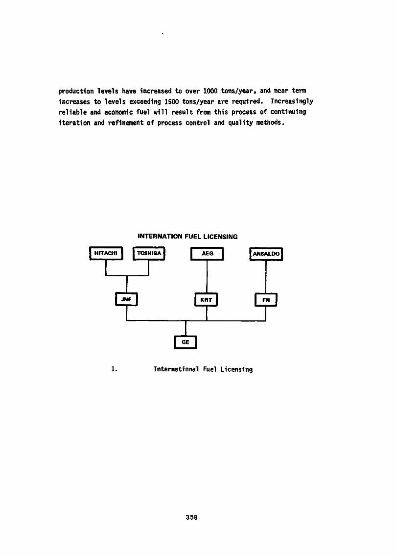
production levels have increased to over 1000 tons/year, and near termincreases to levels exceeding 1500 tons/year are required. Increasinglyreliable and economic fuel will result from this process of continuingiteration and refinement of process control and quality methods.
INTERNATION FUEL LICENSING
HITACHI I I TOSHIBA| F AEG J IANSALDO
1. International Fuel Licensing
359
2. Aerial Photograph of Wilmlngton, N. C. Plant
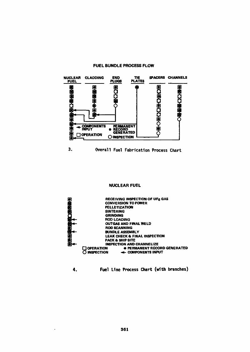
FUEL BUNDLE PROCESS FLOW
NUCLEAR CLADDING ENDFUEL PLUGS
TIE SPACERS CHANNELSPLATES
.COMPONENTS PERMANENTINPUT • RECORD
,_.____.._._., GENERATEDDOPERAT.ON
3. Overall Fuel Fabrication Process Chart
NUCLEAR FUEL
RECEIVING INSPECTION OF UF6 GASCONVERSION TO POWERPELLETIZATIONSINTERINGGRINDINGROD LOADINGOUTGAS AND FINAL WELDROD SCANNINGBUNDLE ASSEMBLYLEAK CHECK & FINAL INSPECTIONPACK & SHIP SITEINSPECTION AND CHANNELIZE
O OPERATION • PERMANENT RECORD GENERATEDO INSPECTION •*• COMPONENTS INPUT
4. Fuel Line Process Chart (with branches)
361
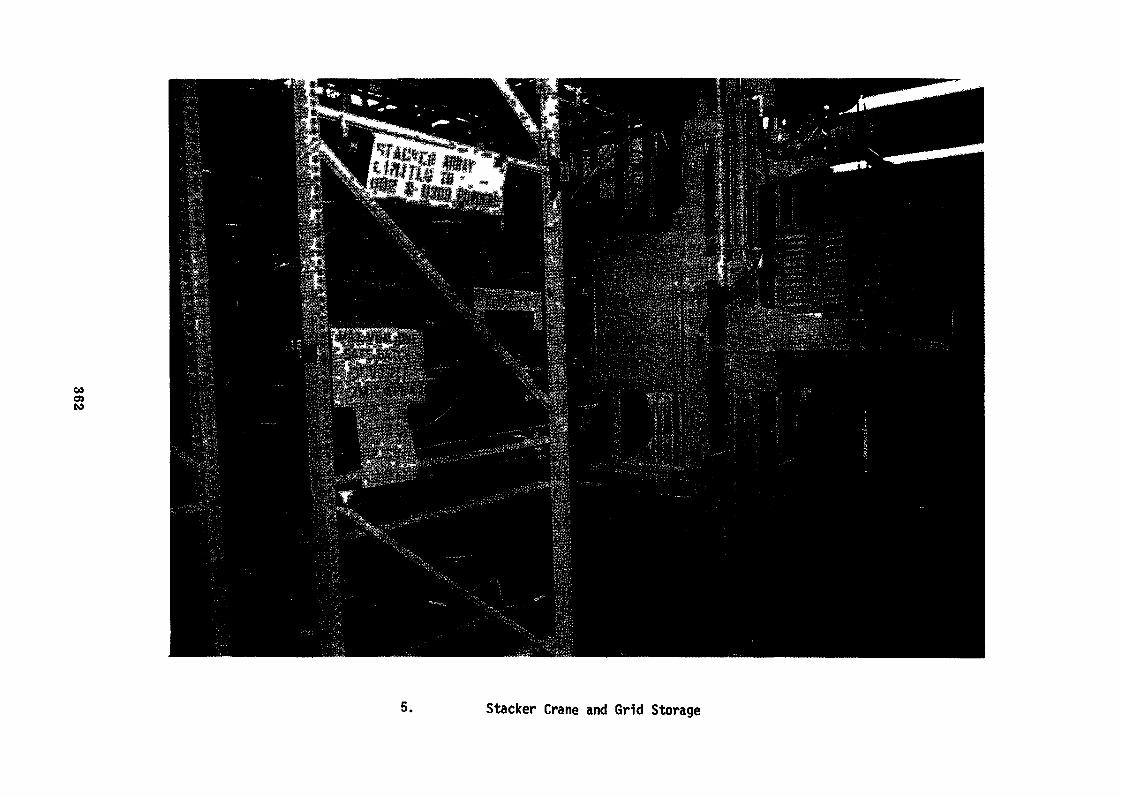
COo>to
5. Stacker Crane and Grid Storage
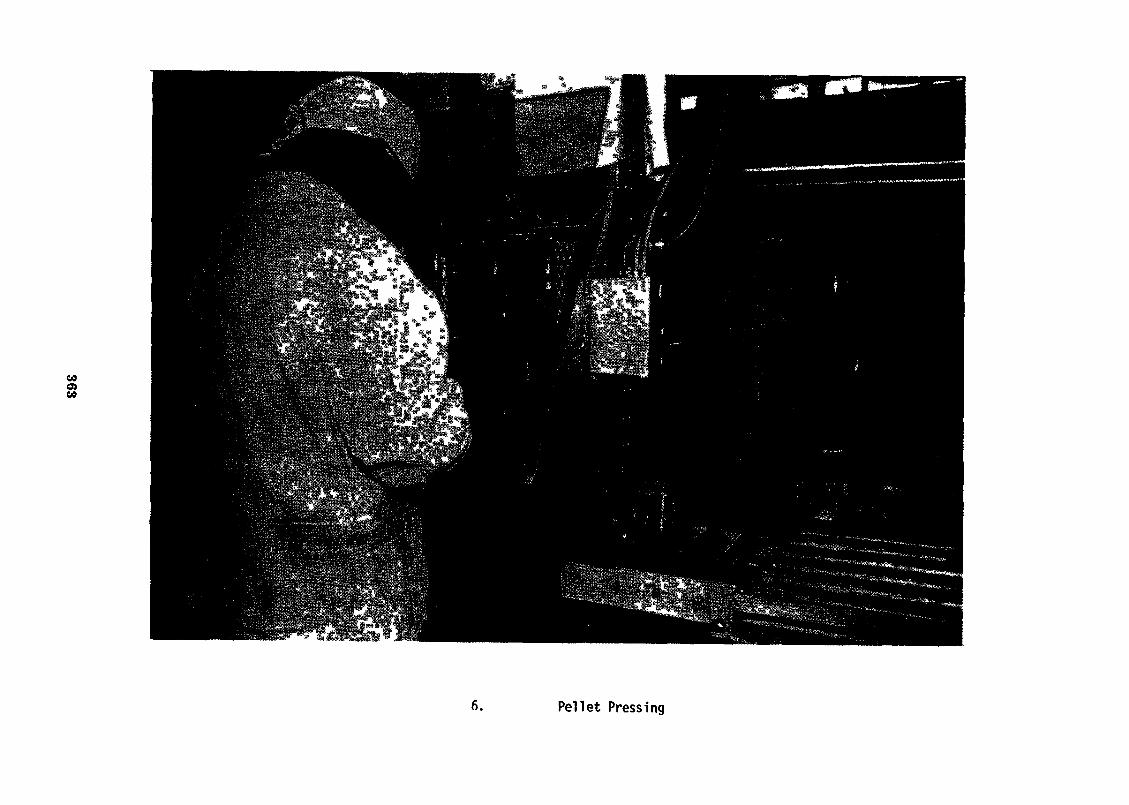
CO0)ce
6. Pellet Pressing
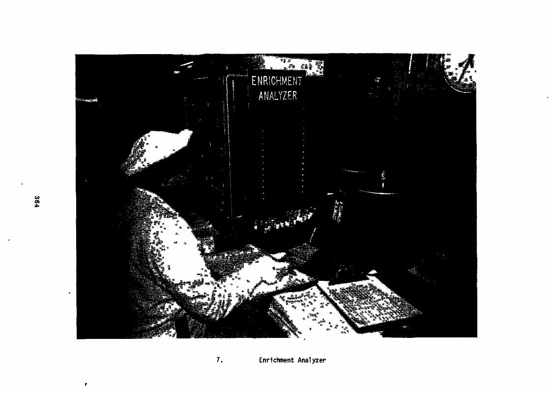
CO
7. Enrichment Analyzer
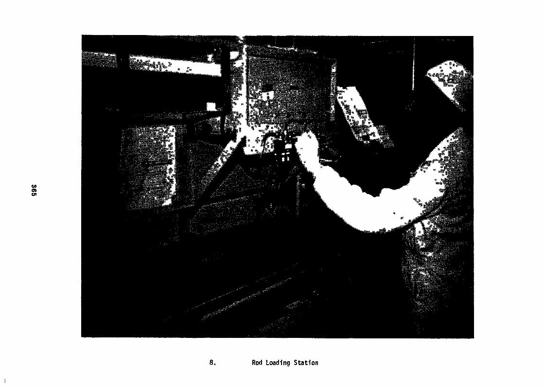
COo>
8. Rod Loading Station
Ci»eno
9. Vacuum Outgassing Operation
10. Passive Scanning
367
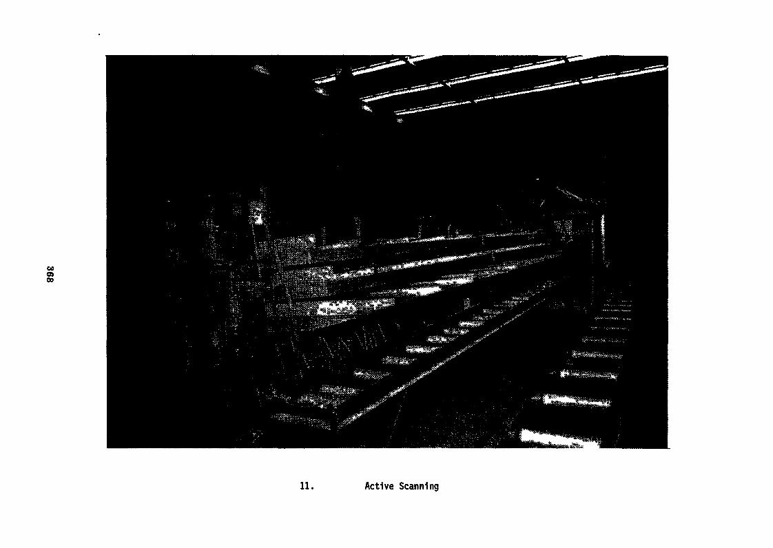
COo»00
11. Active Scanning
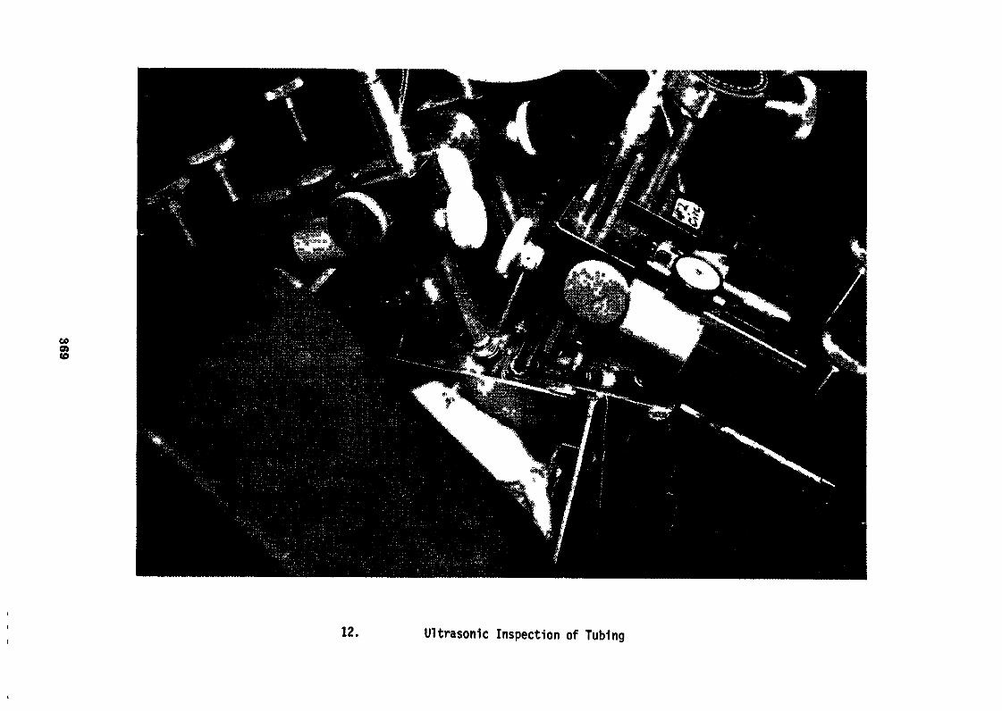
taos«0
12. Ultrasonic Inspection of Tubing
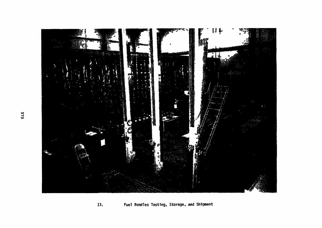
00-Jo
13. Fuel Bundles Testing, Storage, and Shipment
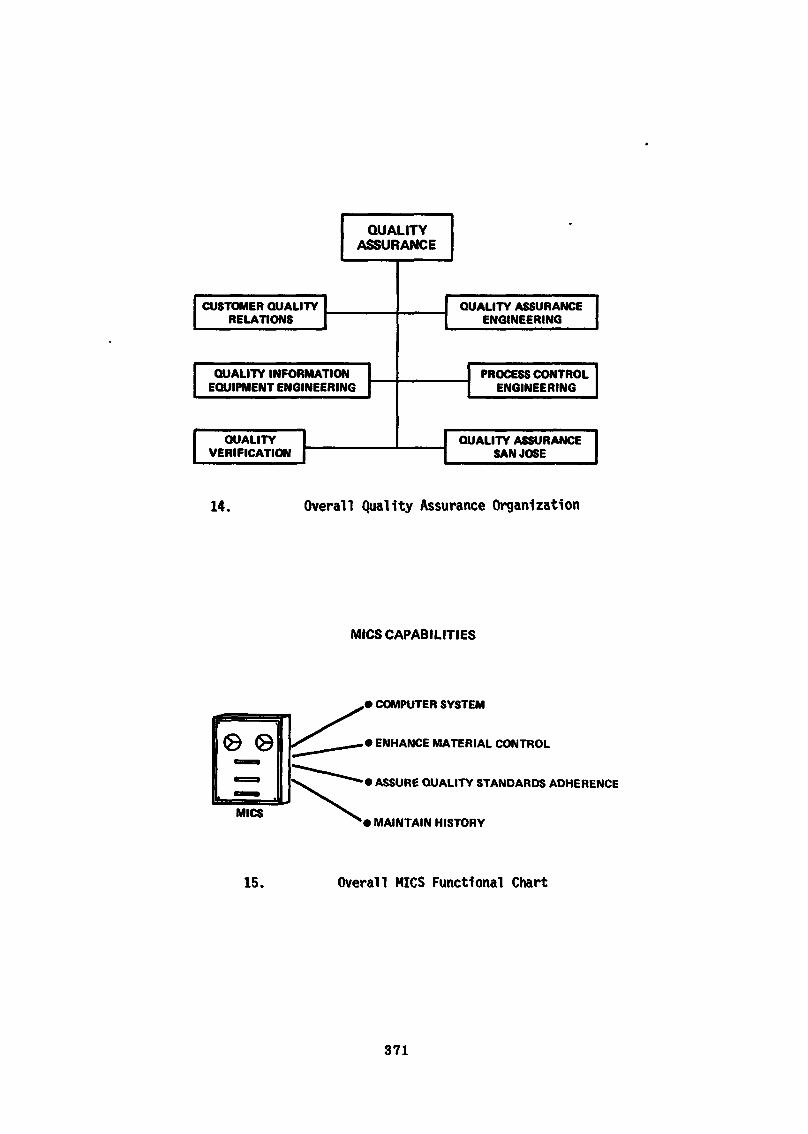
QUALITYASSURANCE
CUSTOMER QUALITYRELATIONS
QUALITY INFORMATIONEQUIPMENT ENGINEERING
QUALITYVERIFICATION
QUALITY ASSURANCEENGINEERING
PROCESS CONTROLENGINEERING
QUALITY ASSURANCESAN JOSE
14. Overall Quality Assurance Organization
MICS CAPABILITIES
0 ©
MICS
• COMPUTER SYSTEM
• ENHANCE MATERIAL CONTROL
• ASSURE QUALITY STANDARDS ADHERENCE
• MAINTAIN HISTORY
15. Overall MICS Functional Chart
371
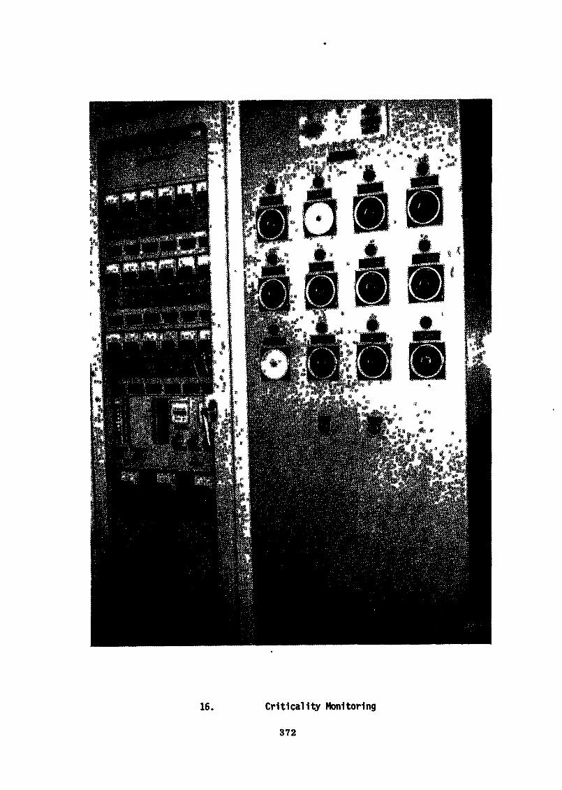
16. Critical1ty Monitoring
372
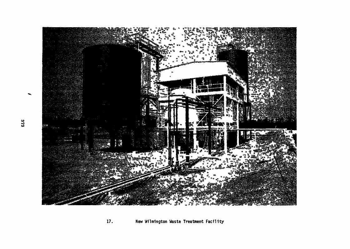
M-JCO
17. New Milmington Waste Treatment Facility
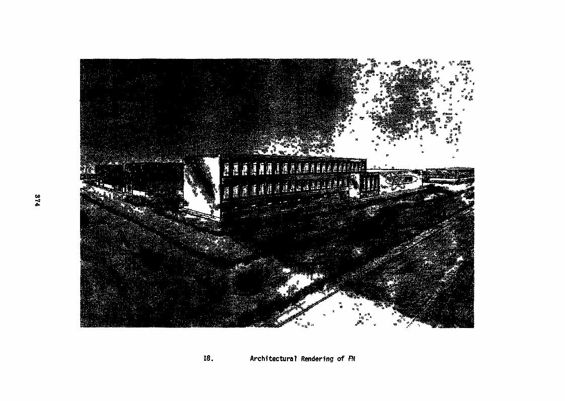
18. Architectural Rendering of FN
CO-Jen
19. FN Construction Operations
J_s
376
21. JNF Vacuum Outgasslng
377
CO-300
22. KRT Exterior
CO•s]to
23. KRT Press Room
CO00o
24. KRT Grinder Station
Production of Fuel Material and Fuel Elements
for High Temperature Seactors
E.G. Hackstein, HOXEM GmbH (F.R. Germany)
A b s t r a c t
For experimental and prototype high temperature reactorsspherical as well as prismatic fuel elements are producedusing the thorium-uranium fuel cycle.
In both types of elements the fuel material consists of coatedparticles which contain spherical ceramic fuel kernels. Thesefuel kernels which have a diameter of 200 - 600 /urn are eitheroxides or carbides. Powder metallurgical as well as chemicalprocesses are used. Production plants have throughputs ofseveral tons of kernels per year. In fluidized bed furnacesthe kernels are coated with pyrolytic carbon layers. Qoatersfor 80 kg thorium kernels per day are in operation. Two pro~auction coaters working nearly fully automatically can be runby one operator.
Up to now more then 110.000 molded spherical fuel and absorberelements have been produced for the pebble bed reactors AYRand THTE. One pressing line for THTR elements delivers 500spheres in 8 hours which then are heated up to 1900°Q.
The most actual type of prismatic elements is the GGA designused for the Fort St. Vrain reactor, a hexagonal block of790 mm height and 360 mm across flats. The production of theelements consists of three steps: machining the graphite block -production of fuel sticks - assembly.
An alternate prismatic element is the molded Nukem blockelement being still in development. The whole element includingfuel zones and cooling channels is fabricated by integral press-ing, so obtaining a fuel element with low thermal resistance,capable to reach high fuel loading.
381
For quality control precise characterization procedures havebeen developed, reaching a high degree of automation. The irra-diation performance of the fuel elements has been shown inmany reactor tests up to high neutron dose and fuel burn up.
1. Introduction
The special feature of fuel elements for high temperaturereactors is that they contain the fuel in a graphite matrix.The graphite is structure material and moderator material aswell and is also used as reflector material in the core.
Two types of fuel elements have been developed for the hightemperature reactor, the prismatic element especially in theUS and also in England, and the spherical element in the FederalRepublic of Germany; in Germany, however, during the last years,intensive efforts have been made for the development of anadvanced prismatic element.
2. Requirements
The requirements for the fuel elements are extremely high as totemperature, burn up, fast neutron dose and retention of fissionproducts.
The residence time for the fuel elements in the core is approxi-mately 4 years, and an increase of the residence time is desirable.Burn-up is nowadays between 80 000 and 700 000 MWd per ton,depending on the type of fuel cycle involved. The fast neutrondose, which essentially influences radiation behavior and residencetime, reaches values of 8 x 10²/J nvt at E greater than 0,18 MeV.
The maximum central temperature of the fuel material may reach1550 centigrades, while the surface temperature is about 1000centigrades»
382
The release of gaseous and solid fission products must "bebelow about 10 t related to the total amount of fissionproducts generated during the operation of the reactor.These requirements for the high temperature reactor fuelcan be fulfilled today.
Fuel cycle
Two different fuel cycles have been proposed for high tempera-ture reactors:
- the thorium-uranium cycle and- the uranium or so-called low-enrichment cycle
In the thorium-uranium fuel cycle a fuel element containsuranium fissile material and thorium fertile material indifferent coated particle types.Only the thorium containing fuel will be reprocessed in orderto get the U-235 free from other uranium isotopes and thisTJ-233 will be recycled after refabrication.
The ratio thorium to uranium varies from "10:1 to 20:1 dependingon the reactor design. The fuel material will reach burn-up ratesof approximately 700 000 Mtfd per ton for the fissile materialand approximately 90 000 MWd per ton for the fertile material.
The thorium-uranium cycle is used in the AVK-Reactor in theFederal Republic of Germany and in the Peach Bottom Reactor inthe United States and will be used for the Fort St. Vrain Reactorand the large power stations of 1IÎ60 MWe and also in the THTR-Reactor which is now under construction.In the so-called low-enrichment cycle 5-9 % tf-235 is used. Inthis cycle the spent fuel contains plutonium and this may bereused in high temperature reactors after reprocessing and re-fabrication. In this fuel,! cycle the uranium burn-up is about80 000 MWd per ton.
383
Recycling of plutonium however is not a specific criteriaof the low-enrichment cycle because the plutonium can alsobe used in the thorium-cycle»
A-c present time there is no high temperature reactor withlow enrichment cycle in operation or in construction.
•*. Fuel materials
4.1 Description of the fuel materials
Independently from the type of fuel element and the type offuel cycle the fuel material consists in any case of coatedparticles which contain spherical ceramic fuel kernels. Thesekernels are coated with different layers of pyrolyticallydeposited carbon. The coating ensures the retention of gaseousand solid fission products.
The ceramic fuel kernels have a diameter of 200 to 600 microns,depending on the requirements, and consist either of uraniumor thorium carbide or of the corresponding oxides. Figure 1
The pyrolytically deposited coatings are multiple layers ofcarbon or silicon carbide. There are normally 2 or 4 of theselayers. Figures 2 and .*>
&<,2 Production of fuel kernels
For the production of carbide or oxide fuel kernels powdermetallurgical as well as chemical processes are used. In thepowder metallurgical process the heavy metal oxide prowdersare granulated to spherical kernels together with differenttypes and amounts of binder, A sintering step at temperatureof about 1500 to 1700 centigrades follows.For the production of carbide kernels according to this processcarbon is added to the heavy metal oxides together with thebinder before granulation.
384
These kernels are converted into carbide at approximately1800 centigrades. Melting at about 24-00 centigrades givesdense spherical kernels. This can either be done in aninductively heated graphite powder bed or by a special arcmelting method.
During the last years chemical processes have been developedespecially for the production of oxide kernels. Here the feedmaterial are metal solutions or metal soles which are droppedby means of a nozzle system into a solution where the precipi-tation and at the same time the solidification of the dropletstakes place. Figures 4- and 3After washing, drying and calcinating these kernels aresintered to oxide kernels in an usual pushing tray furnace.Figure 6
These wet processes can be used for the production of pureuranium oxide kernels» pure thorium oxide kernels and mixedoxide kernels.The wet processes also are applicable for the production ofcarbide kernels. It is only necessary to suspend carbon intothe solution. The kernels are reacted to carbides, or they aremelted as mentioned before under the tropic of powder metallur-gical processes.
It must be pointed out that the chemical processes are moreelegant and more simple than the powder metallurgical processes,especially under the aspect of big productions.Today different wet processes are known and we can actuallysay that the production of large quantities of kernels underindustrial conditions is solved. Such production plants havethroughputs of several tons of oxide kernels per year,
4.3 Coating of fuel kernels
The deposition of pyrolytic carbon on fuel kernels is performedbatchwise in fluidized beds at temperatures between 1500 and
385
1900 centigrades» depending on the deposition gas used andon the desired properties of the coating layers. As depositiongas acetylene^methane or propene are used.
The fluidized bed consists of a graphite tube heating elementwith an inside concentric reaction tube where the carbon layersare deposited on the kernels. The diameter of such a coater isapproximately 240 mm.
The quality of the deposited carbon layers depends mainly onthe deposition rate and the deposition temperature. The conditionsfor obtaining coating layers with specified characteristics arev?ell known today. At the present time coaters with a capacityof approximately 10 kilograms per batch for thorium kernels arein operation. For uranium kernels the batch size is smaler dueto criticality problems. At a first look 10 kilograms seems tobe not a large quantity, however a throughput of up to 80 kilo-grams heavy metal within 24 hours seems to be possible»This is a capacity of 20 tons per year and the amount of thoriumfuel for a 1160 WWe reactor can be produced in one year using twocoaters«
It must be pointed out that the coating technology is nowadayson a high standard and many tons of coated particle fuel can beproduced in an industrial scale» Figure 7 shows a nearly fullyautomatically working coating furnace» In the moment two ofthese furnaces can be run by one operator» Further developmentwork is still necessary to improve process economy,
5» Fuel elements
5.1 Spherical elements
The present spherical element consists of a two componentgraphite matrix and fuel particles. The sphere has an inner corecontaining the fuel. The core has a diameter of approximately50 mm. A surrounding fuel free shell of 5 wa thickness is pressedonto the core resulting in a homogeneous structure throughout theelement.
386
For the production of spherical fuel elements a special reso-nated graphite powder is mixed with fuel particles and moldedin a rubber die to form the inner core» Finure 8. In a secondstep this fuel containing core is embeded in further resinatedgraphite powder to form the fuel free shell. After pressing thespherical element is treated at 900 centigrades, degased for ashort period at 1800 to 1900 centigrades and machined to a dia-meter of 60 mm. Figure 9 shoes a flowsheet of the productionof the molded spherical'fuel element. In the figures 10 and 11we see a metallo&raphic section and a x-ray picture of a sphericalfuel element»
More than 60.000 fuel elements of triis type have already beenproduced for the AVR reactor. At the present time fuel elementsfor the THTB are produced. 50.000 absorber elements and sub-sequently the fuel elements are produced with a rate of 1000per day. Figure 12 shows the pressing production line which hasa throughput of 500 elements per 8 hours and is run by one opera-tor. The above mentioned figures demonstrate that the sphericalelement is already produced in large quantities.
5.2 Prismatic elements
Concerning this type of element the most actual design is theGGA design. This fuel element will be used in the Port St. Vrainreactor.
The GGA element consists of a prefabricated hexagonal graphitecarrier block of 790 mm height and 360 mm across flats. Figure 13There are 102 cooling holes of 16 mm diameter as well as 210fuel holes of 12,7 mm diameter in the block. The carrier blockis machined out of an extruded cylindric graphite rod.
The fuel material is comprised in so-called fuel sticks of 50 mmlength and 12,5 *"» diameter. These fuel sticks are inserted intothe fuel holes of the block.
387
For production of the fuel sticks the required quantity offuel particles is vibrated into small aluminum tubes resultingin a dense packing. Then a fluid warm mixture of pitch binderand natural graphite powder is pressed into the aluminum tube.After cooling the fuel stick can easily be taken out of the die.The fuel sticks are heated up to about 800 centigrades and sub-sequently heated to a temperature of 1800 centigrades.
The fuel sticks produced in this way are inserted into the fuelholes of the block. The holes are then closed by a graphite plug.The essential steps of this production process are as follows:
- machining of graphite carrier blocks with hexagonalgeometry and fuel holes as well as cooling holes
- production of fuel sticks- assembly
It is possible today to produce isore than 50.000 fuel sticksper 24 hours which corresponds to 15 block type fuel elements»
An alternate approach to block type fuel elements is the moldedNUKEM block element. Figure 14The main advantages of this type of fuel element are:
- high fuel volume at high mechanical strenth
- low thermal resistance
The whole element including fuel zones and cooling channels isfabricated by integral pressing and subsequent heat treatment.Figure 13Therefore the mechanical strength is homogeneous throughoutthe block and the whole block is serving as supporting structure.More over sufficient space is available for accomodating a coolinghole pattern5 optimum with respect to low pressure drop andcooling efficiency.
388
The low thermal resistance is obtained because of two things
- high thermal conductivity of the matrix which ishomogeneous throughout the block
- efficient heat transition from the fuel particlesinto the matrix due to the absence of any gap.
This molded block type fuel element is still in the state ofdevelopment.
6. Qualitj control
The control methods allow a precise characterisation of thefuel kernels as well as of the coatings and the graphite matrix,These methods have reached an advanced degree of automationwhich can be demonstrated for instance by the control methodfor coated particles.In this case, the goal is to determine the kernel diameter,the kernel density, the thickness of the coating layers aswell as the density of the layers. This is automatically per-formed by a particle counter in combination with a computer.
7. Irradiation performance
Parallel to the laboratory development the high temperaturereactor fuel is tested in extensive irradiation programssponsered by the German government and coordinated by theXernforschungsanstalt Julien.
Figure 16 gives a survey on the most important present irra-diation test. The dose and burn-up requirements for THTR arealready exceeded by some specimens. The irradiation of theothers, marked by arrows, is continued.
The most important result is that the fuel particles and thesurrounding matrix which is used for both the spherical andthe prismatic elements are compatible with each other. Figure 17No irradiation damage can be observed after exposure to burn-up»temperature and dose values exceeding reactor operation conditions
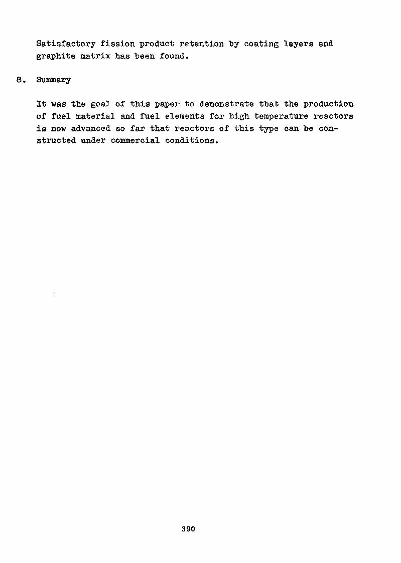
Satisfactory fission product retention "by coating layers andgraphite matrix has been found.
8. Summary
It was the goal of this paper to demonstrate that the productionof fuel material and fuel elements for high temperature reactorsis now advanced so far that reactors of this type can be con-structed under commercial conditions.
390
Figure 1
Figure 2
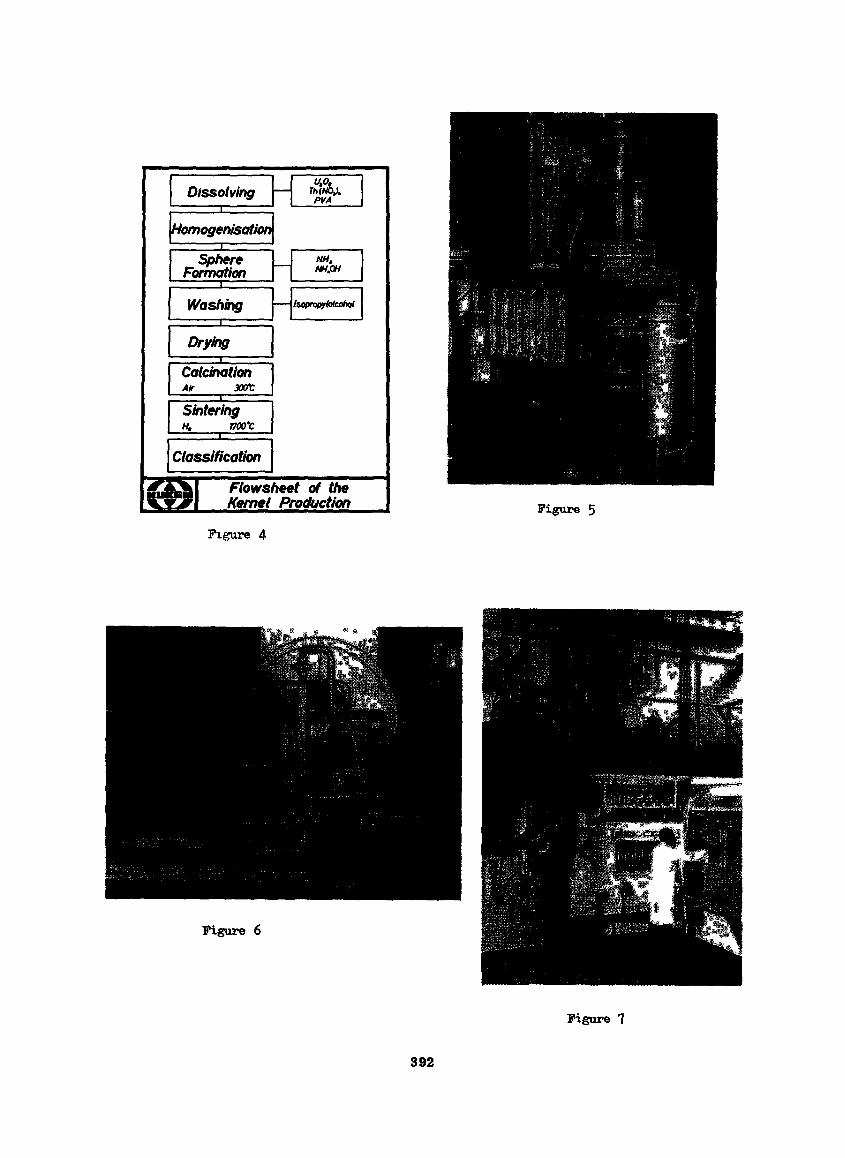
Figure 5
Figure 4
Figure 6
Figure 7
392
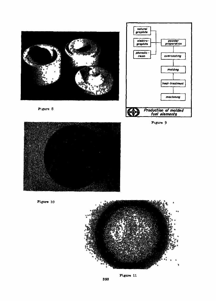
Figure 8 Production of moldedfuel elements
Figure 9
Figure 10
393Figure 11
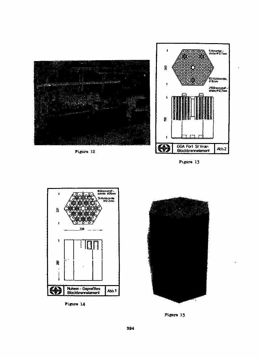
Figure 12
ôAbsorber-stobe«t27mm
W2KOhlkanale.«16mm
2WBremstotf-stâbe.«12.7mm
GGA Fort StVranBlockbrennelement Abb.2
Figure 13
18 Breortstoff -konole «26mmSiKuNkonâle
012.2mm
Nukem - GeprefttesBlockbrennelement
Figure 14
Abb1
Figure 15
394
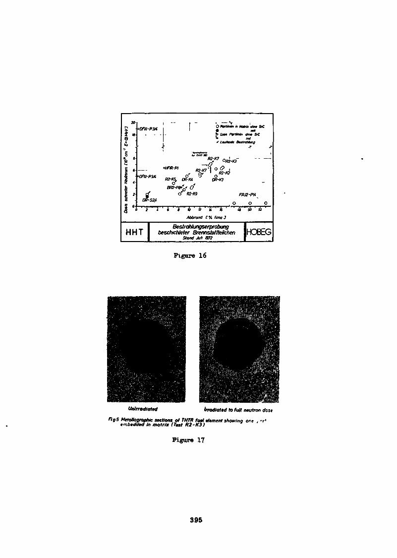
I £
»
•
"
- *
' «[
f/l«Vrt)<
5 (."frfX
l u»<M
fi>N J»»*uvss s
i -- | - . — v«OW-P3K! ! ^ *
. ... to Lost Farm
tar MUt-m
' y "fw7 ' R2-K2
BOi-PO^f (frf 0 02-K9
n-sv 0
$ ~0 ' t ' 4 ' t ' » ' » ' tt ' K ' it ' ' 1
Abbrand C% final
, ,,,T 1 BestraNungserprobungH H T 1 besehichteter Brennstoffteilchen
1 stood MI an
Matrix oint SC(i*
M» oho» S>CAM
Jr *
FRJ2-PK
0 0» SB B
IHOBEG
Figure 16
Untrrodioted irradiated to full Matron dose
fig S MetoUogrofhic sections of THTR fuel element showing ore , vembedded in matrix (Test K2-K3)
Figure 17
395

MANUFACTURING CANDU FUEL
By.William C. Durant, Manager,Nuclear Products Manufacturing and Engineering,Nuclear and Chemical Products DepartmentCANADIAN GENERAL ELECTRIC COMPANY LIMITED
397
RESUME - FABRICATION DU COMBUSTIBLE CANDU
La conception des combustibles CANDU est simple et desprocédés de fabrication conventionnels ont été utiliséspour sa production. Ces procédés peuvent être mis surpied soit par une main-d'oeuvre intensive ou par semi-automatisation. Il existe des méthodes de protection dupersonnel contre les dangers que présentent certains deces procédés. Le personnel employé dans une usine defabrication de combustibles CANDU doit posséder la comp-étence technique nécessaire pour interpréter la conceptiondu combustible en langage de fabrication, spécifier etdiriger les procédés, développer et mettre en place desméthodes de contrôle de la qualité appropriées. Le coûtpeu élevé des combustibles nucléaires est le résultat dela simplicité de conception du combustible CANDU qui apermis l'application de techniques de production convent-ionnelles.
ABSTRACT - MANUFACTURING CANDU FUEL
The design of the CANDU fuel bundle is simple, and con-ventional manufacturing processes have been modified forits production. These processes can be installed oneither a labor intensive or a semi-automated basis. Pro-cedures are available to protect personnel against thehealth hazards that are associated with some of the pro-cesses. Manufacturing organizations engaged in producingCANDU fuel require persons with the technical competenceto interpret the fuel design into manufacturing language,to specify, install and operate the processes, and to dev-elop and put in place appropriate quality control procedures.The simple design of CANDU fuel which has permitted theapplication of conventional manufacturing techniques inits fabrication has resulted in low cost fuel.
398
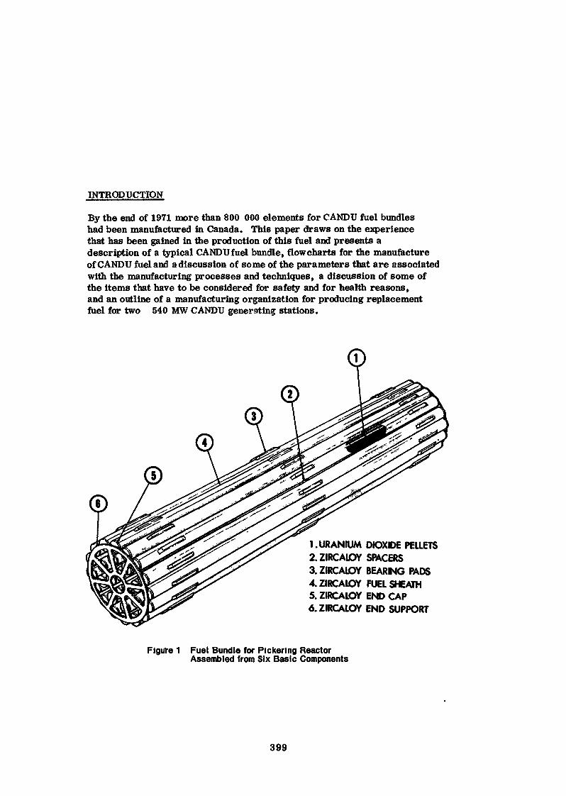
INTRODUCTION
By the end of 1971 more than 800 000 elements for CANDU fuel bundleshad been manufactured in Canada. This paper draws on the experiencethat has been gained in the production of this fuel and presents adescription of a typical CANDU fuel bundle, flowcharts for the manufactureof CANDU fuel and a discussion of some of the parameters that are associatedwith the manufacturing processes and techniques, a discussion of some ofthe items that have to be considered for safely and for health reasons,and an outline of a manufacturing organization for producing replacementfuel for two 540 MW CANDU generating stations.
1. URANIUM DIOXIDE PELLETS2.ZIRCALOY SPACERS3.ZIRCALOY BEARING PADS4.ZIRCAIOY FUEL SHEATH5. ZIRCALOY END CAP6.ZIRCALOY END SUPPORT
Figure 1 Fuel Bundle for Pickering ReactorAssembled from Six Basic Components
399
CANDU FUEL BUNDLE
For the purposes of this paper the nuclear fuel bundle for PicketingGenerating Station is used as the reference CANDU fuel biftidle. This" fuelbundle, shown in Figure 1, consists of 28 closely spaced elements each ofwhich contains high density natural UC<2 in thin Zircaloy sheath. The elementsare held together by plates welded to the ends and are separated by spacersbrazed to the sheaths. The bundle is 50 cm long and 10 cm in diameter andcontains approximately 19.7 ksj of U and 2.1 kg of Zircaloy.
Because the CANDUreactorsystemuses natural uranium as fuel, the fuelbundle has been designed to keep materials other than UO£ to a minimumin order to achieve good neutron economy. The original designers ofCANDU fuel achieved this goal by using an element that has a nominal wallthickness of 0.42 mm and by designing all other parts of the bundle as nearas possible to the minimum practical dimensions. This thin elementsheath collapses onto the pellets when the fuel bundle is exposed to theoperating pressure in the reactor. Because of this the clearance betweenthe pellets and the sheath must be kept small enough so that the sheathwill collapse without forming a sharp axial ridge. At the same time theclearance between the pellets and the sheath must be large enough tomaintain the sheath strain caused by thermal expansion of the fuel at anacceptable level. This close control on clearance between the pelletsand the sheath has placed a demanding requirement on the control of thediameter of the pellet. Similarly the fact that the sheath collapses ontothe pellets in the reactor has made it necessary to specify that the surfaceof the pellets will be free of cracks and chips for the reason that, if a chipbecomes lodged between a pellet and the sheath, additional strain will beapplied to the sheath and it may fail, ft has been found that, when the fuelpellets fragment in the reactor, this collapsible sheath holds the piecestogether so that small chips cannot move to a position between the pelletand sheath.
Space has been provided for the thermal expansion of the UO2 in eachelement by putting a dished end on each pellet and by leaving a space atthe end of the stack of pellets. Both the dish and the space at the end ofthe stack of pellets are closely controlled to ensure that there is enoughspace for the thermal expansion of the UÛ2 and, at the same time, toensure that as much fuel as possible is placed in the element. As a matterof fact, as experience has been gained in the performance of CANDU fuel,customers for this fuel in Canada have been interested in getting as muchfuel as possible into an element. To satisfy this desire, manufacturershave gradually increased the amount of fuel in an element by finding waysof controlling dimensions to closer tolerances than specified in the designand by achieving high densities in the pellets. Densities with values over10.5 gms per cc are being achieved consistently.
400
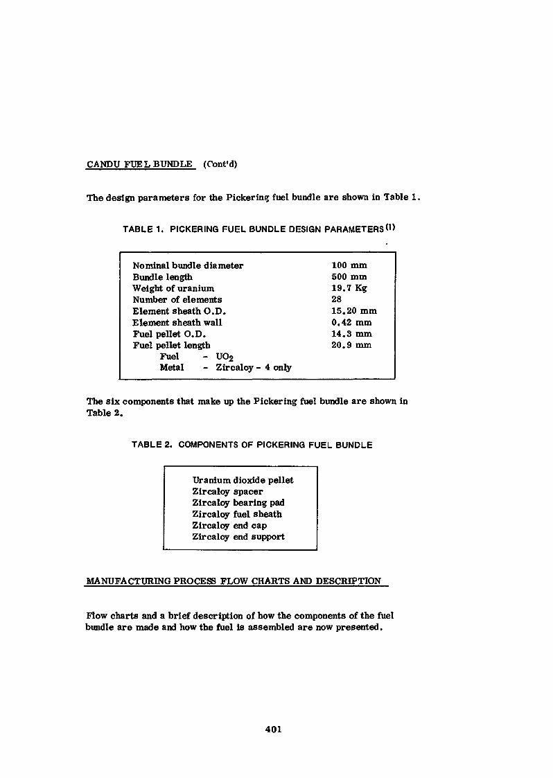
CANDU FUEL BUNDLE (Cont'd)
The design parameters for the Picket-in? fuel bundle are shown in Table 1.
TABLE 1. PICKERING FUEL BUNDLE DESIGN PARAMETERS <'>
Nominal bundle diameter 100 mmBundle length 500 mmWeight of uranium 19.7 KgNumber of elements 28Element sheath O.D. 15.20 mmElement sheath wall 0.42mmFuel pellet O.D. 14.3 mmFuel pellet length 20.9 mm
Fuel - U02Metal - Zircaloy- 4 only
The six components that make up the Pickering fuel bundle are shown inTable 2.
TABLE 2. COMPONENTS OF PICKERING FUEL BUNDLE
Uranium dioxide pelletZircaloy spacerZircaloy bearing padZircaloy fuel sheathZircaloy end capZircaloy end support
MANUFACTURING PROCESS FLOW CHARTS AND DESCRIPTION
Flow charts and a brief description of how the components of the fuelbundle are made and how the fuel is assembled are now presented.
401
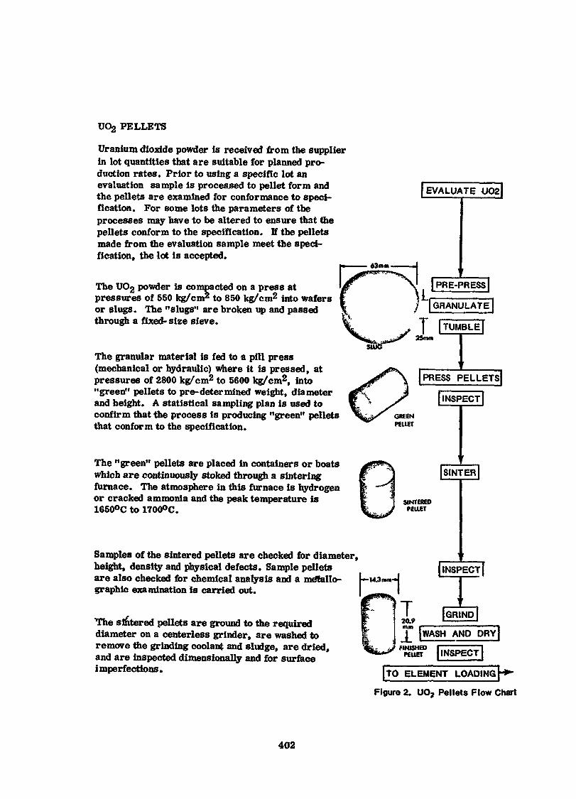
UÛ2 PELLETS
Uranium dioxide powder is received from the supplierin lot quantities that are suitable for planned pro-duction rates. Prior to using a specific lot anevaluation sample is processed to pellet form andthe pellets are examined for confer mance to speci-fication. For some lots the parameters of theprocesses may have to be altered to ensure that thepellets conform to the specification. If the pelletsmade from the evaluation sample meet the speci-fication, the lot is accepted.
The UO2 powder is compacted on a press atpressures of 550 kg/cm2 to 850 kg/cm2 into wafersor slugs. The "slugs" are broken up and passedthrough a fixed-size sieve.
The granular material is fed to a pill press(mechanical or hydraulic) where it is pressed, atpressures of 2800 kg/cm2 to 5600 kg/cm2, into"green" pellets to pre-deter mined weight, diameterand height. A statistical sampling plan is used toconfirm that the process is producing "green" pelletsthat conform to the specification.
The "green" pellets are placed in containers or boatswhich are continuously stoked through a sinteringfurnace. The atmosphere in this furnace is hydrogenor cracked ammonia and the peak temperature is1650°C to 1700°C.
Samples of the sintered pellets are checked for diameter,height, density and physical defects. Sample pelletsare also checked for chemical analysis and a métallo-graphie examination is carried out.
The sintered pellets are ground to the requireddiameter on a centerless grinder, are washed toremove the grinding coolant and sludge, are dried,and are inspected dimensionally and for surfaceimperfections.
{EVALUATE UO2J
[PRESS PELLETSJ| INSPECT |
J(]J
SINTEREDPELLET
| SINTER |
j INSPECT f
I TO ELEMENT LOADING
Figure 2. UO2 Pellets Flow Chart
402
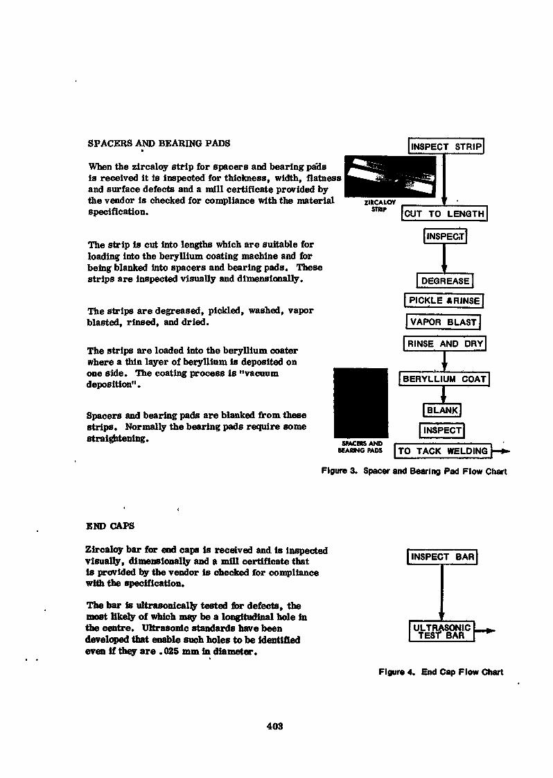
SPACERS AND BEARING PADS»
When the zircaloy strip for spacers and bearing pa3sis received it is inspected for thickness, width, flatnessand surface defects and a mill certificate provided bythe vendor is checked for compliance with the materialspecification.
The strip is cut into lengths which are suitable forloading into the beryllium coating machine and forbeing blanked into spacers and bearing pads. Thesestrips are inspected visually and dimensionally.
The strips are degreased, pickled, washed, vaporblasted, rinsed, and dried.
The strips are loaded into the beryllium coaterwhere a thin layer of beryllium is deposited onone side. The coating process is "vacuumdeposition".
INSPECT STRIP!
Spacers and bearing pads are blanked from thesestrips. Normally the bearing pads require somestraightening.
[INSPECT]
DEGREASE || PICKLE A RINSE [|VAPOR BLAST|
[RINSE AND DRY)rj BERYLLIUM COAT|^ =
|BLANK]INSPECT
SMCERSANDBEARING PADS | TO TACK WELDING f-fr-
Figure 3. Spacer and Bearing Pad Flow Chart
END CAPS
Zircaloy bar for end caps is received and is inspectedvisually, dimensionally and a mill certificate thatis provided by the vendor is checked for compliancewith the specification.
The bar is ultrasonicaljy tested for defects, themost likely of which may be a longitudinal hole inthe centre. Ultrasonic standards have beendeveloped that enable such holes to be identifiedeven if they are . 025 mm in diameter.
INSPECT BAR|
Figure 4, End Cap Flow Chart
403
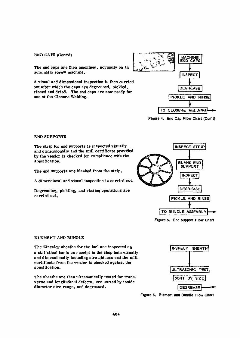
END CAPS (Cont'd)
The end caps are then machined, normally on anautomatic screw machine.
A visual and dimensional inspection is then carriedout after which the caps are degreased, pickled,rinsed and dried. The end caps are now ready foruse at the Closure Welding.
;QC1i
MACHINEEND CAPS
* ,INSPECT)|
IDEGREASE
PICKLE AND RINSE
| TO CLOSURE WELDING|
Figure 4. End Cap Flow Chart (Con't)
END SUPPORTS
The strip for end supports is inspected visuallyand dimensionally and the mill certificate providedby the vendor is checked for compliance with thespecification.
The end supports are blanked from the strip.
A dimensional and visual inspection is carried out.
Degreasing, pickling, and rinsing operations arecarried out.
INSPECT STRIP|
^ I
BLANK ENDSUPPORT
I INSPECT]*I DECREASE|
| PICKLE AND RINSE]
TO BUNDLE ASSEMBLY}—*-
Figure 5. End Support Flow Chart
ELEMENT AND BUNDLE
The Zircaloy sheaths for the fuel are inspected 04a statistical basis on receipt in the shop both visuallyand dimensionally including straightness and the millcertificate from the vendor is checked against thespecification.
The sheaths are then ultrasonically tested for trans-verse and longitudinal defects, are sorted by insidediameter size range, and degreased.
| INSPECT SHEATHJ
1 r
(ULTRASONIC TEST]SORT BY SIZE(
|DEGREASE |
Figure 6. Element and Bundle Flow Chart
404
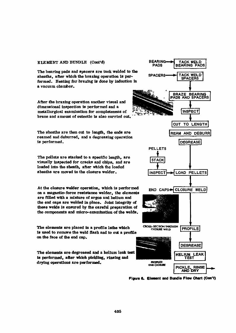
ELEMENT AND BUNDLE (Cont'd)
The bearing pads and spacers are tack welded to thesheaths, after which the brazing operation is per-formed. Heating for brazing is done by induction ina vacuum chamber.
After the brazing operation another visual anddimensional inspection is performed and ametallurgical examination for completeness ofbraze and amount of eutectic is also carried out.
The sheaths are then cut to length, the ends arereamed and deburred, and a decreasing operationis performed.
The pellets are stacked to a specific length, arevisually inspected for cracks and chips, and areloaded into the sheath, after which the loadedsheaths are moved to the closure welder.
At the closure welder operation, which is performedon a magnetic-force resistance welder, the elementsare filled with a mixture of argon and helium andthe end caps are welded in place. Joint integrity ofthese welds is ensured by the careful preparation ofthe components and micro-examination of the welds.
The elements are placed in a profile lathe whichis used to remove the weld flash and to cut a profileon the face of the end cap.
The elements are degreased and a helium leak testis performed, after which pickling, rinsing anddrying operations are performed.
BEARINPADS
IG—*t TACK WELDBEARING PADS
SPACER
BRAZE BEARINGPADS AND SPACERS
Ij INSPECT]
[CUT TO LENGTH
|REAM AND DEBURRJ[DECREASE]
PELLETS
STACK|
INSPECTl—H LOAD "PELLETS]
END CAPS») CLOSURE
CROSS-SECTION THROUGHCLOSURE WELD PROFILE
I
PROFILEDEND CLOSURE
|DEGREASE|
HELIUM LEAKTEST
PICKLE. RINSEAND DRY
Figure 6. Element and Bundle Flow Chart (Con't)
405
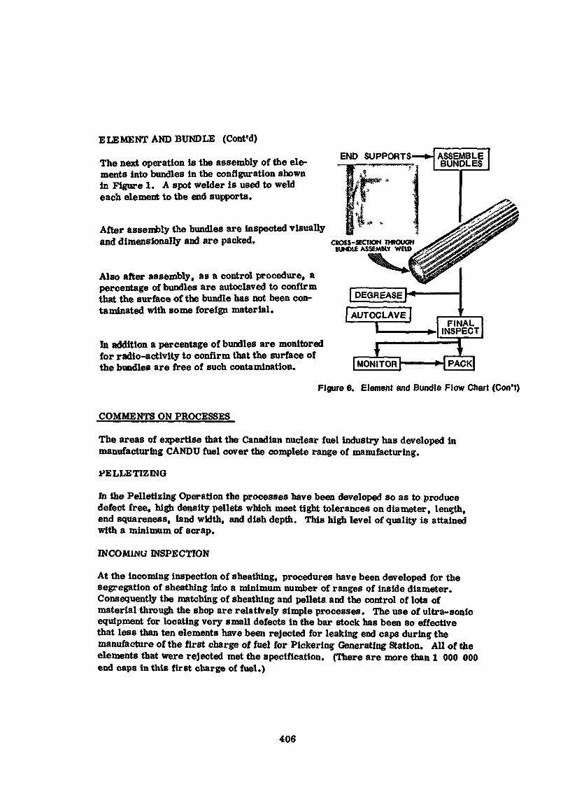
END SUPPORTS
ELEMENT AND BUNDLE (Cont'd)
The next operation is the assembly of the ele-ments into bundles in the configuration shownin Figure 1. A spot welder is used to weldeach element to the end supports.
After assembly the bundles are inspected visuallyand dimensionally and are packed. CROSS-SECTION THROUGH
BUNDLE ASSEMBLY WELD
Also after assembly, as a control procedure, apercentage of bundles are autoclaved to confirmthat the surface of the bundle has not been con-taminated with some foreign material.
In addition a percentage of bundles are monitoredfor radio-activity to confirm that the surface ofthe bundles are free of such contamination.
| DECREASE f
\ AUTOCLAVE1
1 1
FINALINSPECT
| MONITOR PACK
Figure 6. Element and Bundle Flow Chart (Con't)
COMMENTS ON PROCESSES
The areas of expertise that the Canadian nuclear fuel industry has developed inmanufacturing CANDU fuel cover the complete range of manufacturing.
PELLE HZ ING
In the Pelletizing Operation the processes have been developed so as to producedefect free, high density pellets which meet tight tolerances on diameter, length,end squareness, land width, and dish depth. This high level of quality is attainedwith a minimum of scrap.
INCOMING INSPECTION
At the incoming inspection of sheathing, procedures have been developed for thesegregation of sheathing into a minimum number of ranges of inside diameter.Consequently the matching of sheathing and pellets and the control of lots ofmaterial through the shop are relatively simple processes. The use of ultra-sonicequipment for locating very small defects in the bar stock has been so effectivethat less than ten elements have been rejected for leaking end caps during themanufacture of the first charge of fuel for Pickering Generating Station. All of theelements that were rejected met the specification. (There are more than 1 000 000end caps in this first charge of fuel.)
406
TACKÏNG AND BRAZING
The tacking and brazing operations are controlled so that the sheaths are notdeformed and so that the metallurgical and physical properties are still satisfactoryafter the sheaths have been exposed to the high brazing temperatures. In additionthe requirements for completeness of braze and maximum amount of free berylliumare met.
DIAMETRAL CLEARANCE
As mentioned early in the paper the diametral clearance between pellets andelement sheath must be closely controlled and the stack length must also be closelycontrolled. These items require a system of control which ensures that the diameterof pellets which are loaded into the fuel sheaths is that which gives the designeddiametral clearance and that the stack length leaves the required amount of spacein the element.
CLOSURE WELDÎNG
When a closure welder is being prepared for production, whether it is a new machine|ust being commissioned or an existing machine that has been maintained, the methodspersonnel make weld® with the process until they are satisfied that the welds meet thedesign requirements. A statistical sample of welds is then made during which themachine parameters are varied the way they might vary during a normal productionrun. All of the welds in this sample are examined to determine if they meet thespecification from the viewpoints of integrity and geometry, ff they do meet thespecification, the machine is turned over to the Shop for production, îf they do notmeet the specification, corrective work is continued on the machine.
Control parameters have been developed to indicate when the welding process isbeginning to deteriorate so that equipment maintenance can be carried out beforepoor welds are made. To the best of our knowledge no elements with poor weldshave been assembled into fuel bundles. In addition to weld integrity, the amountof upset in the weld must be controlled within close tolerances in order to ensurethat the finished elements will be of a length that can be assembled into a bundle.
BUNDLE ASSEMBLY
Each bundle must be assembled so mat it meets the specification with respectto squareness of the end supports, diameter, minimum spacing of elements,radia*! distance from the outer surface of the outer element to the end support,location of spacers and overall size. This last check is performed on a"GO-NO-GO" gauge which represents the smallest opening that a bundle hasto pass through in entering and leaving a fuel channel in the reactor.
407
SAFETY AND HFALTH
CRITÏCALÎTY
There is no criticality hazard in a plant that is manufacturing natural uranium fuelbecause efficient neutron reflectors such as heavy water, graphite or berylliumare never present in sufficient quantities to create a problem.
HEALTH
Uranium
Natural uranium has a very low level of radiation. As a result the dosimetry levelsestablished by the International Commission on Radiological Properties are notexceeded on a 40 hour per week exposure in a Canadian natural uranium fuel manu-facturing plant. Never-the-less personnel in these Canadian fuel plants are classifiedas Atomic Energy Workers and wear film badge dosimeters which are monitoredregularly.
Inhalation, ingestion and absorption are hazards which exist in the processing ofnatural uranium. Appropriate safety measures have to be taken in the differentareas of the fuel manufacturing plants to ensure that these hazards are kept undercontrol. For instance in the powder preparation area of the Pelletixing Shop theoperator wears a respirator and gloves, and clothimc which is laundered in the plant.In addition appropriate ventilation and dust collecting equipment are provided, fathe same manner appropriate measures are taken in other parts of the FuelManufacturing facility to protect the health of the personnel. In addition personswho handle exposed uranium dioxide are checked by regular urine analysis andmedical examinations.
Beryllium
Beryllium is more toxic than natural uranium and the precautions that are takento protect the health of the persons who work with it include adequate ventilation,appropriate protective clothing, separate lunch rooms, gloves, iaundry, personalcleanliness and appropriate housekeeping,
ACCOUNTABILITY
Accounting for uranium which contains a fissionable isotope is a .requirement ofthe International Atomic Energy Agency. A fuel manufacturing plant which isprocessing only CANDUfuel has a relatively simple accountability job comparedto fuel manufacturing plants where fuel with several enrichments is being processed.As a matter of fact a fuel manufacturing firm making CANDI7 fuel which has aninventory accounting and control system that is satisfactory from a cost point ofview, will meet the IAEA requirements. The only extra work that the IAEA regulationsinvolve is making it possible for the IAEA Inspector to witness the taking of inventoryand to provide the total input,, work-in-process, and output information to him in away that is meaningful for his work.
408
APPLICATION OF MANUFACTURING TECHNIQUES VMTH RESPECT TOUSE OF LABOUR
As has been shown the fabrication of a CANDI- fuel bundle is carried out withsimple manufacturing processes and techniques. These lend themselves eitherto the intensive use of labour or to the use of se tin-automatic equipment.
In the palletizing process either relatively inexpensive toggle presses with singlecavity molds or more expensive hydraulic presses with multi- cavity molds andmany added features may be used.
Several low-capacity muffle-type sintering furnaces or one large capacity sinteringfurnace (many types are available) can be used.
At pellet grinding and pellet inspection there is a wide range of choices between theuse of a high number of operators and simple equipment to do the work and the useof semi-automatic equipment with a proportionately lower number of operators.
In the preparation of spacers and bearing pads if the flow charts shown in Figure 3are followed, the use of persons can be intensive. On the other hand one or two ofthe processes can be changed so that they will be at least semi-automated with theresultant removal of labour.
These examples for pelletiz.ing and for spacers and bearing pads are indicative ofthe range of choices that are available throughout the total C'ANDU fuel manufacturefor using labour intensively or for using semi-automatic and automatic equipment.The choice in many cases can be made in the light of economic circumstances.
USE OF OTHER MANUFACTURING FACILITIES
There are many operations that lend themselves to the use of other manufacturingfacilities or the sharing of equipment from other manufacturing facilities by thefuel manufacturing facility. Examples are:
(a) Pellet presses, sintering furnaces and grinders used in tungsten carbidework can be modified for use in t'O2 pelletiying.
(b) Simple punch presses that are used in many processes can be used forblanking the spacers, bearing pads and end supports.
(c) An automatic screw machine in some other operation can be used to machinethe end caps from the bar stock.
The criteria that must be met if other facilities <ire rsed are those of appropriatequality control and assurance that there will not be contamination from such materialsas halogens, hydrocarbons, hydrogen, boron or cadmium.
409
In addition, if a fuel manufacturing facility is located near a metal workingfactory which has chemical and metallurgical laboratories, the chemical andmetallurgical work that has to be done for fuel manufacturing can probably beperformed with the equipment that exists in that plant or with the addition ofone or two pieces of equipment.
STAFF REQUIREMENTS FOR A FUEL MANUFACTURING FACILITY
The replacement natural uranium fuel that would be required on an annual basisfor a Nuclear Generating Station consisting of two 540 MVV Reactors similar tothose at Pickering.would be approximately 125 Mg U at approximately 00%availability and between 75% and 80% utilization. Based on Canadian experienceand the Canadian degree of semi-automation, the staffing for such a plant mightbe the following:
1. PLANT MANAGER
2. DESIGN ENGINEERING
This function would provide interpretation of the design parameters,metallurgical engineering, skills in stress analysis, heat transfer»and nuclear physics. Personnel in this function would probably alsoprovide primary liaison with the Licensor and the customer(s). Thestaffing would probably be two engineers with Bachelor or Master Degrees.
3. MANUFACTURING ENGINEERING AND QUALITY CONTROL
3.1 ^Manufacturing Engineering
This function would look after the shop equipment with respect to specifyingparameters and providing equipment for processes such as pressing pellets»sintering pellets, beryllium coating, brazing, closure welding, pickling,bundle assembly, providing day-to-day tool proving and methods work,day-to-day shop problem solving, productivity improvement work, andissuing manufacturing instructions.
In addition it could administer the plant engineering work, laundry, janitoring,waste disposal, maintenance and similar work. Staffing would probably betwo engineers, four or five methods men and five or six maintenancepersons and janitorial persons. The engineers and metnods men wouldneed a wide range of knowledge in metallurgical, mechanical and electricaltechnologies.
410
3.2 Quality Control
This function would be responsible for designing the Quality Control Systemand issuing the Quality Control Instructions to the appropriate areas.In addition it would evaluate the incoming inspection information and thein-process inspection information to determine whether items are out ofspecification or are tending to go out of specification.
The skills that are required for specifying and maintaining the non-destructivetesting equipment and measuring equipment can be made available in thepersonnel in Quality Control or in Manufacturing Engineering. It is amatter of preference and/or specific capability, If we assume it is madeavailable in the Quality Control area, the staffing of the total Quality Controlfunction will probably be one quality control engineer, with experience innon-destructive testing techniques, two technologists or engineeringassistants, and two clerks.
3.3 laboratory
The laboratory would do metallurgical examinations of pellets, brazed joints,welded joints and similar items, and chemical analysis of berylliumcontamination in the beryllium work areas, of uranium contamination inthe uranium work areas, of the pellets, of the pickling solutions, for moistuin the completed elements and such other work as may be assigned. Threeto four persons could handle this work. This is one of the services that can bepurchased from a metal working plant, if there is one located near the fuel plan
4. MATERIAL UNIT
This function would provide the following activities- purchasing, scheduling,ordering, twrentory control, dispatching, storing, receiving and shipping.Between 7 and 10 persons would be required to handle this work.
5. SHOPS
This function would do the actual manufacturing of the pellets and bundles.The pellet shop would operate three-shifts for five days and the balance ofthe shop would operate two-shifts for five days. Three to four foremen,four to five area technicians and dispatchers and 70 to 80 direct employeesincluding inspection personnel would be required in this shop for the first12 to 18 months. After this period a learning curve would apply. The a moanof learning and the cost improvements that can be achieved are directlyproportional to the desire of the personnel In the manufacturing organizatiorto set targets and achieve them.
411

6. OTHER SERVICES
This function would provide such services as employee relations,payroll, cost accounting, other accounting, plant hospital, safetywork and clerical pool. Probably 12 persons would be able to do therequired work.
SIZE OF BUILDING FOR FUEL MANUFACTURING FACILITY
A building 80 metres long and 30 metres wide would provide the space for the staff,equipment and auxiliary areas needed for manufacturing 125 Mg U of fuel per year.An approximate breakdown for the use of this space is shown in Table 3.
TABLE 3. SPACE REQUIRED FOR MANUFACTURING125 Mg U CANDU FUEL PER YEAR
Office - Plant Manager, Engineering, ManufacturingEngineering, Quality Control, Materialsand other personnel. 500 m2
Pelletizing Shop 450 m2
UO2 Stores 50 m2
Fabrication Shop 750 m2
Laundry, Washrooms and Lunch room 150 m2
Other Stores 100 m2
Maintenance 100 m2
Chemical and Metallurgical Laboratories 150 m2
Receiving and Shipping 150 m2
Total Area 2400 m2
The services required for this plant are the normal services that are requiredfor a light manufacturing plant with the exception of the large power supply forthe sintering furnaces, the high intermittent power demands for the resistancewelder, and the stringent requirements for ventilation and filtering of exhaustair from the VO2 and beryllium areas.
412
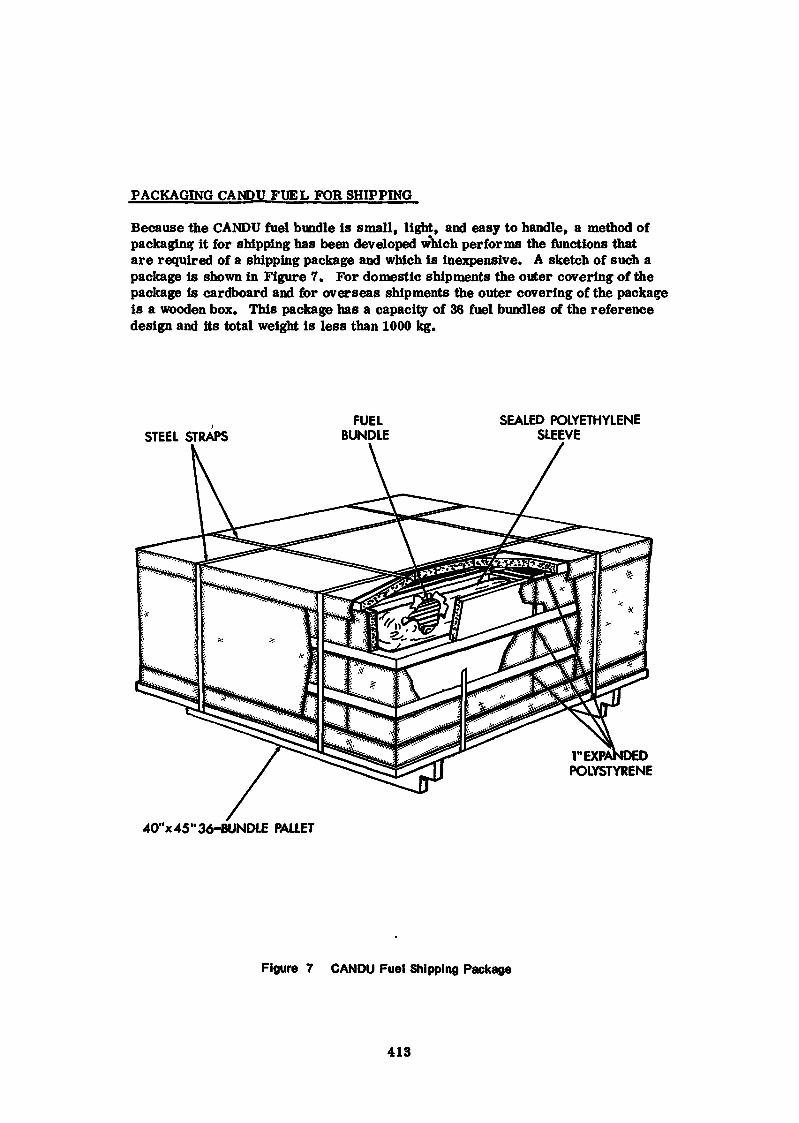
PACKAGING CANDU FUEL FOR SHIPPING
Because the CANDU fuel bundle is small, light, and easy to handle, a method ofpackaging it for shipping has been developed which performs the functions thatare required of a shipping package and which is inexpensive. A sketch of such apackage is shown in Figure 7. For domestic shipments the outer covering of thepackage is cardboard and for overseas shipments the outer covering of the packageis a wooden box. This package has a capacity of 36 fuel bundles of the referencedesign and its total weight is less than 1000 kg.
STEEL STRAPSFUEL
BUNDLESEALED POLYETHYLENE
SLEEVE
POLYSTYRENE
40"x45"36-BUNDLE PALLET
Figure 7 CANDU Fuel Shipping Package
413
COST OF CANDU FUEL
The engineers who did the early work on designing and developing CANDU Fuelconceived a fuel bundle which was inexpensive to manufacture. In his paper"Estimating CANDU Fuel Costs", A.W.L. Segel shows the distribution of fuelmanufacturing costs for CANDU fuel of the reference design at volumes of oneMg U per day. These costs are representative of what a customer pays for thisfuel at these volumes. When this fuel is used in a 540 MW Picketing Reactorand an average burn-up of 215 MW hrs/kg is achieved, the fuelling cost is 0.8 milsper kW hr.
SUMMARY
A description of manufacturing CANDU fuel has been presented which includesa verbal description of the steps followed in making the fuel together with theapplicable flow charts, comments on the process used,particularly with respectto quality control, an outline of the health precautions that are necessary, andan indication of the flexibility that is available for using labor intensively or forusing semi-automatic equipment as well as for sharing other manufacturingfacilities. In addition the staffing and space requirements for a plant capableof manufacturing 125 Mg U CANDU fuel per year are described. Finally themanufacturing of CANDU fuel results in costs which are represented by thosediscussed in recent Canadian technical papers.
References
(1) A.W.L. Segel, "Estimating CANDU Fuel Costs", AECL-4273; August 1972.
(2) L.R. Haywood et al, "Fuel for Canadian Power Reactors", AECL -3979,September 1971.
414
HTR FUEL ELEMENT TECHNOLOGY
by
L. W. GRAHAM
M. S. T. PRICE
ABSTRACT
The HTR is characterised by the use of graphite as moderator and fuel elementstructure, helium as coolant and ceramic coated fuel microspheres (coated particles)for fission product containment. The flexibility this gives, in the choice offuel cycle, is high-lighted and the consequent range of fuel element designs,varying from the pebble-bed to the several types of graphite block structures, isdescribed»
Following an outline of the philosophy underlying the design of the coatedparticles, the processes required in manufacturing HTR fuel elements are describedin sections on graphite manufacture and machining, fuel particle manufacturingprocesses, fuel body fabrication, assembly, reprocessing, refabrication and qualitycontrol. Existing HTR fuel element manufacturing plants are indicated*
The main features in HTR fuel element performance are outlined with particularemphasis on the parameters having most impact on the fabrication processes»
It is concluded that the roost neglected area of technology is refabricationand that the implications on the fuel element design and on the choice of fuelcycle should not be overlooked»
1. THE HTR SYSTEM
The High Temperature Gas-Cooled Reactor (HTR) is characterised by the use ofgraphite as the moderator and Juel structure, helium as coolant and pyrolyticcarbon and silicon carbide for fission product retention» These refractorymaterials and the inert coolant are used to lift the constraints on burn-up,rating and temperature imposed by metal cladding, to minimise thereby both theparasitic absorption of neutrons by the core structure as well as interaction ofthe coolant with the core and primary circuit materials.
In consequence the HTR is potentially the most efficient way of burningfissile material and the fuel cycles range from the possibility of thermal breedingin a U-235/Th-232/tJ-233 thorium cycle to a U-235/U-238/Pu-239 low enriched cyclewhose high burn-up eliminates the need for plutonium recovery [l~12j»
The homogeneity of the heat production in the core leads to the ability toachieve high power densities and the lack of constraints allows wide variation inthe disposition of fuel, coolant channels, moderator and control rods* The numerouspossible core designs include:
(a) hollow rod, as used in Peach Bottom [l3, 14J and the Dragon ReactorExperiment [is],
(b) the pin in block concept, with tubular [16, 17] or teledial pins £l8] ordirectly cooled fuel,
415
(c) the pebble-bed as used in the AVR £l9, 20] and to be used in the 300 MW(e)THTR £20, 21, 22\
(d) the multi-hole graphite block as in an early De Havilland concept [23 J,in Port St. Vrain [ 24, 25 J and in the large Gulf General Atomic (GGA)HTRs [26],
(e) the integral block fuel element proposed by Nukem £2?J»
Hexagonal, pentagonal and triagonal graphite moderator blocks have all beenconsidered for particular designs* Methods of optimisation of the thermal designof the fuel cell geometry have been reported £28j»
Present design assessments and economics have led to core power densitiesof *»8 MW/m3, to the use of the high enriched U-235/Th-232/tt-233 or the low enrichedU-235/U-238/PU-239 fuel cycles and to three major variants of core design, thepin-in-block, the pebble-bed and the multi-hole graphite block with the commonfeature of a replaceable core» Each solution represents a summation of relativelysmall differences in the margins set by design constraints, safety considerationsand economics*
In the pebble-bed system, fuelled graphite spheres are randomly packed ina cylindrical enclosure or reflector also of graphite. The individual fuel elementspheres, ~6 cm diameter, are recycled by removal from the base of the core andre-introduced on top of the packed bed. In contrast, the prismatic core £l7, 29]is made up of stacked graphite blocks, usually hexagonal, •*»! m long and -«50 cm widecontaining holes drilled lengthwise for coolant and fuel. Charge and dischargeare achieved by a skewer passed down a handling hole in the block* Two variants,which may be termed "Hot" or 'Cold' block designs, have been developed. In thelatter the fuel holes are large, say 75 mm diameter and consequently relativelyfew in number fc*18). These holes contain graphite tubes or pins (-«60 cm long)and coolant flows over the fuelled pins which are centrally located in the holes*This configuration leads to a block temperature close to that of the heliumcoolant. The coolant and fuel holes are ntuch smaller (•*! cm) and larger in number(200-300) in the alternative «Hot Block' design* The heat generated in the fuelis transported across the webs to the coolant holes leading to a more complexthermal stress pattern and a generally higher block temperature*
The multi-hole hot block design has been used in Fort St. Vrain [29] and isstandard for the large GGA reactors while the pebble-bed concept will be used inthe TTCTR reactor under construction at Schmehausen» The pin-in-block or coldblock design [29j is that which was offered for the 750 MW(e) low-enriched uraniumcycle Oldbury reactor £30,
the inherent flexibility of the HTR, the fuel particles can be variedto suit the particular design, fuel cycle, performance and economic situation*Thus changes in the chemical composition of the fuel kernel, in the size of theparticles and in the thicknesses and types of coating arc easily made and do notrepresent fundamental changes in the concept»
Two extreme cases illustrating the variations adopted in commercial prismaticreactor designs may be cited» In the large reactors, sold by GGA in the USA, thecoated particles are desgined within the frame of thorium utilisation and areessentially of two types? fissile and fertile [32, 33}» The fissile particlescontain pure, highly enriched uranium dicarbide or dioxide kernels Cm'200 p ta dies'.» )surrounded by a porous buffer coating of pyrolytic carbon» The thickness of Oiiscoating is designed to provide free space for the accommodation of fission products»Outside this coating is a composite pressure vessel (about 200 H m thick) ofpyrolytic carbon with a pyrolytic silicon carbide interlayer» This coating containsthe heavy burden of fission products associated with the 80% burn-'up of the vuraniuau
416
A larger fertile particle, used to breed U-233 from thorium, has a kernelabout 40011m diameter and is composed of thorium oxide or carbide coated withpyrolytic carbon. To operate the fuel cycle, this fuel is discharged after about7% heavy metal burn-upland treated to extract the bred U-233, The two types ofparticle are separated~in the reprocessing to prevent significant cross-contaminationof the U-233 with U~236 from the fissile particle»
In contrast, only a single particle was foreseen in tne low-enriched uraniumcycle offered for the Oldbury HTR [34 i Here the fuel kernel was of UO with auranium enrichment of *»S%» A marginally different philosophy, stemming from theDragon Project, is adopted to accommodate fission products in that «»»20% free spaceis built into the kernel as porosity* The buffer coating surrounding the particleis primarily to absorb fission fragment damage and is surrounded by the structuralpyrolytic carbon/silicon carbide/pyrolytic carbon coating» Here again the coatingthickness is chosen to withstand fission gas pressure and is 200 |im for an 800 pmdiameter kernel undergoing a peak fuel lifetime heavy atom burn-up of about 10%. 'The much larger particle employed in this system is advantageous in the fuelcompact which consequently has about 35% volume packing of particles* By contrast,a packing fraction up to about 60% follows from the GGA design. In the lattercase, which represents close random packing, pressing of the fuel into compactsis precluded. At the lower volume packing of 35%, however, processes have beendeveloped £35} to allow a near perfect distribution of fuel particles in a high 'density graphite matrix whose thermal conductivity is exploited in the fuel 'element design.
A fuel particle intermediate between the fissile and fertile types is usedin the 300 MW(e) THTR [2l], such that the thorium and uranium are contained in thesame particle. This is similar to the quasi-fissile particle used iri theFort St. Vrain reactor where a Th:U ratio of 4.25:1 is used to produce a fuel fora heavy atom burn-up of 20%. The same principles of particle design are used, i.e.,provision of internal free space for accommodation of fission productsî buffercoating to resist fission fragment damage; a structural and; diffusion barrier forfission products. In the pebble-bed system, where separate feed and breed elementscan also be foreseen [21 J the fuel particles are contained in a sphere made from-graphite (as in the initial charge of the AVR [is]) or moulded within a pressedgraphite body.
This variety of approaches illustrated in Pig* 1 underlines the range ofchoice now available to the reactor designer to exploit particular local circumstancesto the maximum. All of the above types of fuel are commercial manufacturing realities.
»
Sales of commercial HTRs began in August 1971 when Gulf General Atomic sold two1,100 MW(e) stations to Philadelphia Electric. Up to the time of writing a total;of 5,400 MW(e) has been sold [36, 37, 38] and further stations are on option (seeTable 1).
These massive sales clearly demonstrate that the HTR is a commercial proposition,provided it is backed by a strong enough company. Furthermore the future capabilitiesof the HTR for tasks other than steam-raising connot be ignored. These include:
s
- direct-cycle gas turbine (net station efficiency pessimistically 44.4% (39}but capable of stretch beyond 50%),
- process heat for chemical and metallurgical processes [40, 41J,
- rocket propulsion [42]«
417
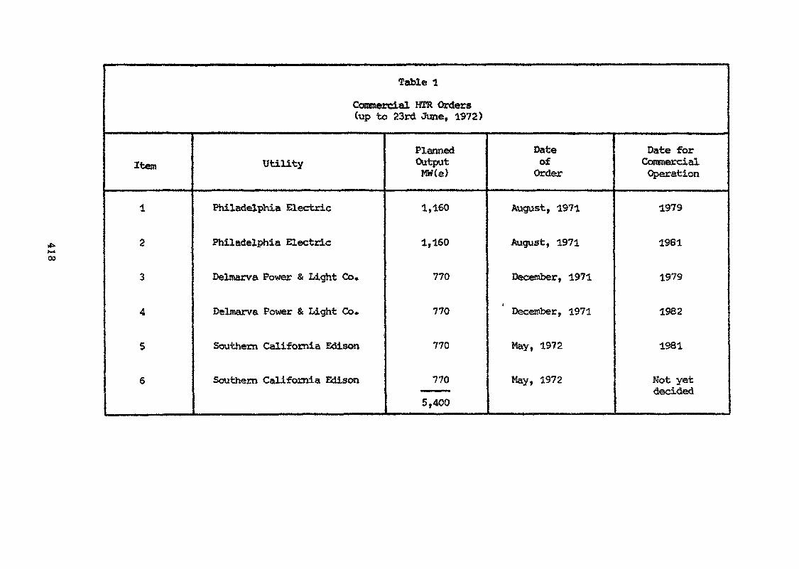
CO
Table 1
Commercial HIR Orders(up to 23rd June, 1972)
Item
1
2
3
4
5
6
Utility
Philadelphia Electric
Philadelphia Electric
Delmarva Power & Light Co»
Delmarva Power & Light Co.
Southern California Edison
Southern California Edison
PlannedOutputWW(e)
1,160
1,160
770
770
770
770
5,400
DateofOrder
August, 1971
August, 1971
December, 1971
December, 1971
May, 1972
May, 1972
Date forCommercialOperation
1979
1981
1979
1982
1981
Not yetdecided
Permutations of fuel cycle, core design and the method of heatto an extensive range of possible HTRs. The presence' of several runningis not necessarily bad, since competition within the species will sto-enaconcept. One must therefore foresee continuous development over the%t**»«** f *»• wi*^ ui*A0«* w»»^»^>-.fc>*-*-—- •.-——«-——- ——— ———-- - - «jrno «4 *i ^ >\A %v%44Av*century such that, at any one tfcae, some particular type of HTR will J*6*development whilst at the same time some other type is being sold commercially.
2. THE DESIGN OF THE COATED PARTICLE
We have seen that WCR core design is extremely flexible and that, althoughseveral different types of fuel element have evolved, it is common ground thatthe fuel is incorporated in the form of coated microspheres. The generalphilosophy of coated fuel particle design has been discussed by middle [43J andGraham 144].
The function of the coated particle is to generate heat and to retain fissionproducts whilst achieving the target fuel burn-up. Coated particles (Fig. 2)consist of a fuel kernel surrounded -by a coating. The fissile and/or fertilematerial is incorporated into the kernel generally in oxide or carbide form.Because the kernel is the substrate on which the coating layers are deposited, itis desirable that the fuel kernel should be spherical.
" As pointed out in the previous section, space is provided to accommodatefission products and kernel swelling either by incorporating the majority ofthe porosity in the kernel or in the first layer of the coating.
The coatings must, in combination, constitute a highly efficient barrier tothe release of fission products, both from the viewpoint of diffusion and mechanicalintegrity in service. They may be composed of pyrolytic carbon alone or with aninterlayer of silicon carbide. In the latter case the functions of the coatingsare as follows:
(a) Pyrolytic Carbon Buffer Layer
The buffer layer is an absorber of fission recoils and togetherwith the porosity of the kernel gives free volume sufficient toaccommodate fission products and kernel swelling. It also gives amechanical separation between the kernel and the structural layers ofthe coating.
(b) Inner Pyrocarbon Coating
This is the first of the three coatings which make up the structurallayers. It is required to have specific properties to minimise theeffects of fast neutron irradiation which lead to dimensional changesand consequent stressing. This layer also serves as a barrier to grossdiffusion of kernel material (fissile, fertile or fission products)which may affect the integrity of the silicon carbide. With uraniumdioxide kernels an additional manufacturing layer of pyrolytic carbonmay be required outside the buffer to seal off the kernel and avoidconversion to carbide if subsequent coating operations are to be carriedout at high temperature.
(c) Silicon Carbide Interlayer
The interlayer is the main diffusion barrier to metallic fissionproducts. It also plays an important role in the mechanical performanceof the particle [45] and because of its stability under fast neutronirradiation £46, 47 ] imparts dimensional stability to the whole particle.
419
(d) Outer- Pyrolytic Carbon Coating
This coating completes the particle and is the third of thestructural layers. It aids in the mechanical performance oi theparticle by putting the SiC layer into compression at an early stage ofoperation and also provides chemical protection for the silicon carbide.
3. HTR FUEL ELEMENT FABRICATION PROCESSES
3.1 Graphite Manufacture
The manufacture of nuclear graphite for use in HTRs is essentiallyconventional in that coke powder is bonded with pitch, formed to shape byextrusion or pressing and then baked «did graphitised. Additional impregnationtreatments may be necessary to achieve the required level of apparent density.The only major difference in processing is that, either a nuclear purity cokemust be used as raw material and processed under clean conditions or, moreusually, because of the paucity of pure coke sources, a less pure coke sourceis used and neutron absorbing impurities are removed as volatile halides bya purification process during the graph!tisation stage [48, 49]*
The quality of graphite to be used in HTRs may be specified using thefollowing tests, carried out at room temperature:
1. Dimensions
2. Thermal neutron absorption cross section
3. Electrical Resistivityon whole blocks•
4. Apparent Density
5. Thermal Expansion Coefficient, parallel (11) and perpendicular (t)to the axis of pressing or extrusion
6. Ultimate Tensile Strength and Modulus of Elasticity, I I and JL
7. Chemical Reactivity
The obvious importance attached to irradiation behaviour and qualitywhen using graphite in a structural role in HTRs normally implies a periodof irradiation testing to select the most suitable graphite and some longterm guarantee of quality. This latter requirement is primarily related tothe stability of the coke source. Since the coke is often a by-product itmust be expected that the quality of the coke may change over a period of,say, 10 years. Fortunately the peak fast neutron dose levels in HTRs arenot high and can be achieved in modern Materials Testing Reactors in about1 year.
3.2 Graphite Machining
The machining of graphite for HTRs is accomplished by conventionalmachine-shop techniques. The only differences from ordinary commercialpractice are that care must be taken to avoid adventitious contamination [50]with neutron absorbers or oil and that close tolerances are often specified
420
3,3 Fuel Fabrication Processes (see Fig. 3)
3.3.1 Kernel Fabrication
The kernel is an intermediate product whose chief requirement isto be a suitable feed to the next process - coating. Near-sphericalkernels can be made by agglomeration of powders or by utilising thesurface tension of a liquid to form droplets.
The powder agglomeration process involves the growth of kernelsfrom fine powder mixed with a binder [52-54] followed by heattreatment. The alternative kernel fabrication methods have theattraction of utilising liquids to form spherical droplets. Twogeneral categories of surface tension method that have been studiedare:
(i) spraying of liquid droplets into a second phase(gaseous or liquid) chosen to solidify and retain thespherical shape produced [21, 55, 56, 57, 58, 59, 60],Thus a sol or solution containing the appropriate fuelcan be injected into a second liquid under conditionswhich yield discrete droplets which gel by chemicalreaction. Hence the terras 'Sol-Gel1 or 'Gel-Precipitation'used to describe these processes*. The 'green1 spheres soformed are heat treated to give them adequate strength,
(ii) formation of fuel agglomerates or 'crumbs', each of whichis the volume of the desired kernel, followed by fusion[6l], Again a second phase is necessary to avoidcoalescence of the liquid droplets.
Kernels of given properties can be made using any of these routes,although the Sol-Gel and Gel-Precipitation processes are sometimesconsidered more amenable to control by automatic methods. On theother hand, in some cases, porosity can be incorporated more easilyusing the powder agglomeration route.
3.3.2 Coating
The original suggestion for coating nuclear fuel particles withpyrolytic carbon (PyC) was made by Huddle [62, 63 J and some preliminaryexperiments were carried out at AERE, Harwell where the coating wasapplied in a rotary tumbling bed by pyrolysis of a hydrocarbon. Thekernels must be agitated while the deposition is occurring otherwiseagglomeration and inhomogeneous deposition may occur. Of possiblemethods of achieving the desired degree of agitation, only fluidisationand tumbling have been studied in any detail. The tumbling bed avoidsthe use of fluidising gas but has technical and economic limitationsand virtually all coating of fuel kernels has been carried out as abatch process in high temperature fluidised beds.
Because it is the most "glamorous" of the unit operations in HTRfuel manufacture, it has been the subject of extensive study [64-68].The fluidising reactor is normally constructed of graphite which maybe resistance or induction heated to temperatures in the range 1200-2000°C. For the deposition of pyrolytic carbon a hydrocarbon, such
*Suggested definitions of the terns 'Sol-Gel' and 'Gel-Precipitation were givenby Hardy at an IAEA Panel held in 1968 [57 ].
421
as methane, mixed with an inert carrier, is introduced into the reactionchamber using a single nozzle, multi-nozzle, or porous plate gas entrysystem» Other, higher, hydrocarbons, such as butane or propylene[66, 69, 70, 71], may be used to impart desired properties to thepyrolytic carbon* To lay down a coating of silicon carbide (SiC)£72-75] the particles are fluidised in hydrogen or inert gas/hydrogenmixture, containing a low concentration of methyltrichlorosilane whichis generally preferred to other sources. Layers nay be deposited insequence, such as PyC/SiC/PyC in the same fluidising unit: alternativelythe large volume increase (typically a factor of 3 for the DragonReference Particle) and density decrease which occurs during coatingcan lead operators to split the coating process between more than onefurnace* Deposition rates are *»1 |im per minute»
3*3*3 Consolidation
The coated particles are either dispersed in a graphite matrix orbonded together to define their position in the reactor and incorporatethem into a thermally conducting, mechanical unit able to withstandthe temperatures as well as the thermal and irradiation induced stressesarising in service*
In the first of these processes [35, 76] the coated particlesare overcoated with a graphite matrix powder, pretreated withthermosetting resin, and the desired shape is formed by warm pressing,followed by heat treatment and degassing» Apart from complying withthe requirements listed above this process leads to a fuel body whichis relatively isotropic and the overcoating of individual particlesprovides a mechanical and chemical interparticle barrier which isolatesthe effect of an individual broken particle*
The alternative bonding processes for consolidating fuel bodiesare particularly applicable when the volume fraction occupied by theparticles is high. In one case an injection moulding process [76] isused in which close-packed beds of particles are bonded with a viscousmixture of pitch and graphite powder which is injected into the packedbed prior to carbonisation and degassing [32]. An alternative techniqueis to bond and densify the bed of coated particles with pyrolytic carbonin situ, by gaseous impregnation with natural gas at <1000°C [78-80].
3*3,4 Fuel Element Assembly
In the case of HTR fuel, the assembly of the fuel element is anextremely simple procedure. The fuel body is a mechanical unit whichcan be tested and approved as such. The graphite components are suppliedas fully machined and inspected items. It only remains to marry thecomponents together.
Except in cases where the fuel cycle involves refabrication (seebelow), assembly can therefore be carried out on an open bench, themain precaution being to prevent accidental contamination of the graphitewith neutron absorbers or oxidation catalysts.
3.3.5 Reprocessing and Refabrication
The spent fuel can merely be stored but to obtain low fuel cyclecosts, it is necessary to reprocess the fuel to extract the fissilecomponent (U-233 or Pu). In some cases, especially those using a fullyenriched uranium feed, the fuel cycle economy leads to a requirement torefabricate this fuel for further use in HTRs.
422
Reprocessing consists of the following steps;
(i) head end processing,
(ii) dissolution and solvent extraction to obtain selectiverecovery of the desired stream,
(iii) waste disposal*
Retabrication comprises the following operations:
(i) kernel preparation,
(ii) coating,
(iii) consolidation,
(iv) assembly,
(v) scrap recovery,
(vi) waste disposal»
Reprocessing
An important characteristic of the HTR fuel element, bearing onreprocessing, is the incorporation of the carbon moderator in thefuel element» The carbon: -heavy metal atom ratio is typically200-35Qo For some fuel element designs it may not be possible toguarantee separation of the spent fuel from the majority of the carbonand therefore the present schemes for reprocessing envisage treatingthe complete spent elements. Typically the elements are subjectedfirst to stage crushing followed by burning and leaching.
Low enriched fuel will contain uranium and plutonium isotopeswhich are easily separable to recover the plutonium for refabricationor sale.
In -he case of the thorium ycle, it is neces. ary to achieveselective recovery of the bred U-233 without significant cross-contamination from the partially burned-up U-235» Imperfect separationof the fissile and fertile particles is not crippling» Thus Stewartet al», £32] quote a penalty of only 0.01 mills/kWh for a 4% loss ofU-233 to the spent U-235 stream or a 20% back mixing of U-235 and U-236into the bred fuel stream» Complete mixing of the two streams wouldlead to an undesirable build-up of U-236 in multiple recycle.
There are advantages in achieving the U-233/U-235 separation byhaving different types of particle within a fuel element» Suchparticles can be designed to differ in several respects any one ofwhich can be employed for separation:
(i) the fertile particles could have all pyrolytic carboncoatings. Then the fissile particles should have asilicon carbide interlayer. In this way the U-233can be dissolved in the leach solution whilst thefissile particles remain unattacked,
423
(ii) the particles could be significantly different insize. This will normally mean that the fertileparticle is the larger in diameter,
(iii) the particles could be significantly different indensity. The use of carbon dilution in the fissileparticle may be advantageous in increasing hightemperature operating capability while at the sametime reducing the overall particle density.
Although one may commence by assuming that the importance ofreprocessing is to recover the U-233, the recycle of thedischarged U-235 is well worth investigation, having been estimatedas equivalent to 0.05-0.06 mill/kWh [33J.
The overall pattern of recycle is as illustrated in Fig. 4.
Refabrication
Apart from the fact that the operations are remote or semi-reroote the refabricaticn processes presently envisaged parallelthose of direct fabrication. It is not evident that this trendwill continue but it would ensure that the re-fabrication plantcould be worked up economically.
3,3,6 Quality Control
One of the factors which has contributed to the advance ofcoated particle fuel, from being an interesting idea to theproduction of power reactor fuel on the tonne scale, h s been theparallel development of suitable quality control and evaluationtechniques. A great advantage with HTR fuel is its subdivisioninto a very large population of «dcrospheres. Even with relativelylarge kernels of UO 800jtm diameter, 80% dense there are«*4.8 x 10** particles per tonne U. Consequently classical statisticalmethods can be applied.
The release from coated particle fuel at the start-of-lifederives from three sources:
(a) heavy metal contamination in the outer pyroiytic carboncoating,
(b) the proportion of particles without a silicon carbideinterlayer or with a defected silicon carbide layer(characterised by the equivalent defective fraction O1),
<c) the proportion of particles with all coating?» broken(characterised by the equivalent broken fraction 0)«
In normal operation a minute but predictable release will occur:this is in marked contrast with the customary situation with otherreactor types where an essentially zero fission product release isunpredictably interrupted by large releases from failed cans.
424
To guarantee that the above source terms do not change inservice it is necessary to control:
(i) the amount of free space to accommodate fissionproducts both in the kernel and the buffer layer,
(ii) the properties of the pyrocarbon layers,
(iii) the properties of the silicon carbide layer.
The operational function of Quality Control must thereforebe to control and define the source terms at the coinmenceraent ofirradiation and to control those parameters which affect particleendurance. The following parameters are used to estimate thesetwo requirements:
Coated Particles
- kernel diameter*
~ kernel porosity*
- O/U atom ratio in the kernel*
- fissile isotope abundance*
- thickness of the individual coating layers
- density of the buffer and structural coating layers
- isotropy of the individual pyrocarbon coatings
- contamination of the outer pyrocarbon layer
- ceramographic examination to check coating integrity,presence of flaws, diffusion of kernel etc.
(*May more conveniently be carried out at an earlier stage but theresults are strictly applicable to the coated particle)•
Fuel Bodies
- dimensions
- heavy metal loading
- heavy metal dispersion
- 0}— 0* Jas defined above
- matrix density
The majority of the techniques for testing of coated particle fuelhave been surveyed at a recent IAEA panel [si] whilst the analyticalmethods were described in a parallel IAEA symposium [82]. Reference [8l]
425
was a co-ordinated paper which included information on testmethods developed by AERE Harwell, UK, Belgonucleaire SA, Belgium,CEGB, Berkeley Nuclear Laboratories, UK, OSGAE Seibersdorf, Austriaas well as by the Dragon Project. Within the regional grouping ofsignatories to the Dragon Project, a Quality Control Working Partyexists which provides a forum for discussion of the philosophy ofquality management, statistical techniques and detailed test methodsas applied to HTR fuel.
4, HTR FUEL ELEMENT MANUFACTURIMG FACILITIES
4,1 Fuel
In this Section an attempt is made to indicate the known HTR fuelclement manufacturing facilities» This is an area which impinges oncommercial practice and our information is likely to be incomplète. Inone case we are «sing information which has been specially made availablefor this paper*
United States of America
In 1959 a group of 58 US Utilities called High Temperature ReactorDevelopment Associates, the USAEC and General Atomic (now Gulf General Atomic)entered into a commitment to build the 40 MW(e) Peach Bottom HTR. In parallel,development work continued at General Atomic and Oak Ridge National Laboratorywith support from the USAEC and utilities. This led to the construction ofthe 330 MW(e) Port St. Vrain HTR [36].
It is evident therefore that Gulf General Atomic, the supplier of thefuel for Peach Bottora, Fort St. Vrain (and UHTREX), has considerablemanufacturing capability and experience on thorium cycle fuel*
Coated particle fuel with and without a silicon carbide interlayer hasbeen investigated (termed TRISO and BISO respectively) [77]« The tendencyhas been to use relatively small co'atcd particles and the consequential clos.epacked beds of coated particles have been bonded using an injection mouldingprocess (see Section 3.3,3) [32, 77],
The USAEC is sponsoring programmes at Gulf General Atomic and Oak RidgeNational Laboratory on U-233 refabrication and recycle. The form of thedevelopment programme has been detailed [83J. In ORNL-4702 the total USAECbudget is given as 56.8 x 10⁶ US dollars over a ten year period notionallystarting in 1970» In practice it appears that this programme is running alittle later than that time scale. Although work is proceeding on all phasesof recycle development [32 J, at present the main emphasis (involving over 75%of the expenditure during 1972 and 1973) is on Head End Development (byGulf General Atomic) and Refabrication Process Development (by Oak RidgeNational Laboratory).
Other firms within the USA heve worked on coated particle fuel* Inparticular mention should be made of the fabrication of the first charge forthe AVR by Union Carbide Corporation [l9J at their Lawrenceburg plant»
426
Belgium
The Belgian Nuclear Research Centre (CEN/SCK Mbl) and Belgonucleairehave co-operated on coated particle fuel for many years. The powderagglomeration process developed by Gorle and Huet j.52] led to closecollaboration with the Dragon Project» The programme first centred onthe thorium cycle and the utilisation of plutonium [lO, 84, 85. 86] butsince 1966 has been modified towards the low enrichment cycle 187], Withinand between batch variability have been studied in detail and results [87]are given in Table 2.
The coating units presently available have a capacity of 1.8 tonnes U/y£87].
France
The HTR programme in France began somewhat later than in other countriesalthough, as a member country of the Dragon Agreement, there has always beenaccess to the extensive programme undertaken by the Dragon Project» TheFrench approach as elaborated by Tanguy et al., [so] is to be extremelyflexible» Work on kernels is being conducted by SPEC (Société de Fabricationd'Elément Catalytiques) using two powder agglomeration processes [80 ].Coating has been developed by CERCA (Compagnie pour l'Etude et la Realisationde Combustibles Atomiques) and it has a production capacity at the presenttime of 2»5 tonnes coated particles/y [88].
Special attention has been paid to the consolidation of the coatedparticles into fuel bodies and preparative work has been carried out bySociété le Carbone Lorraine with the powders being evaluated by the CEA L80J.A significantly different approach to consolidation using a gas-crackingprocess has been made [79, 80] (termed the BBS process) and compacts made inthis way are being irradiated in OSIRIS as well as the Dragon Reactor.
The industrial work is supported by extensive irradiation facilitiesas well as by research and development carried out by the CEA at Saclay andGrenoble.
United Kingdom [30. 31, 34, 54, 57, 72]
The following information has been supplied by Mr. J. Stephenson,UKAEA Risley:
"A manufacturing plant has been developed, constructed and operated atUKAEA Springfields to make fuel for zero energy reactors and large scaleirradiation trials, some 80,000 fuel compacts having been made. Its othermajor use has been for confirmation of plant throughput and reliability andstatistical assessment of typical production fuel.
The plant comprised the fabrication of:
kernels by the powder agglomeration route,
coated particles using large fluidised beds,
graphite overcoated particles and finally,
the consolidation of these into compacts or rods.
427
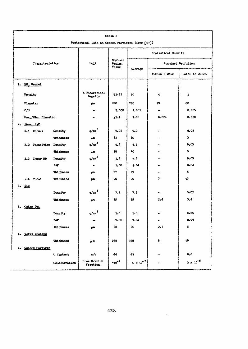
Table 2
Statistical Data on Coated Particles (from [87])
Characteristics
1. up. Kernel
Density
Diameter
0/U
Max./Min. Diameter
2. Inner PyC
2.1 Porous Density
Thickness
2.8 Transition Density
Thickness
2.3 Inner HD Density
BAP
Thickness
2.4 Total Thickness
3. SjC
Density
Thickness
4. Outer PvC
Density
BAP
Thickness
5. Total Coating
Thickness
6. Coated Particle
U Content
Contamination
Unit
% TheoreticalDensity
|tm
-
-
g/cn.3
|im
g/cm
lint
g/on
-
tin.
|in>
g/cro3
fin
g/cn
-
|»W
Hm
w/o
Free UraniunFraction
NominalDesignValue
82-93
760
2.000
«1.1
1.05
33
1.5
30
1.8
1.08
27
90
3.2
35
1.8
1.08
30
160
64
~a<10
Statistical Results
Average
90
780
2.003
1.03
1.0
30
1.6
"to
1.8
1.04
29
90
3.2
35
1.8
1.04
30
160
63
6 x 10"7
Standard Deviation
Within a Bate
4
19
-
0.024
-
-
-
-
-
-
-
7
-
2.4
-
-
2.7
8
-
-
Batch to Batch
2
60
0.005
0.020
0.05
3
0.05
5
0.05
0.04
5
13
0.02
3.4
0.05
0.04
5
10
0.6
2 x W6
428
Included in these stages of operation were methods of on line quality control.The latter was augmented in the development stage by statistical sampling methodsfor the parameters of interest for irradiation performance assessment, e.g.,density, sphericity, layer thicknesses, isotropy, damage fraction of coatedparticles in fuel bodies etc.
"It should be stressed that the manufacturing process was designed to givea high quality product rather than, for example, to achieve this by inspectionand selection. The process produced kernels with a narrow size distributionwhich further allowed tight control of coating thicknes -es in the coating step.
"The overall plant throughput was a minimum of 5 tonnes U/y. The stagethroughputs were not matched because this was not essential to meet the workobjectives. Matching would be attained in the ultimate plant by replication,unit size being dictated by geometry and uranium enrichment. Therefore in someareas stage throughputs were at least 10 tonnes U/y.
"Although the plant was optimised for the production of the UK Mark 3 HTRReference Design Fuel, it has sufficient flexibility to make a range of HTR fuels.The most recent addition to this relating to fuel pins with integral cladding -the directly cooled fuel pin concept'*.
Federal Republic of Germany
The recent Geneva conference was the occasion on which a review of productionexperience and irradiation testing in the Federal Republic of Germany was given[21]. The preparation of spherical fuel and fuel elements for the AYR and THTRreactors has been concentrated at Nukem GmbH, Wolfgang bei Hanau backed byresearch work and irradiation testing organised by the Kernforschungsanlage,JÏïlich [66]. The flow sheet of the Nukem production line for THTR sphericalelements is given in Fig. 5 reproduced from [2l}. Since Dr. K. G» Hackstein isalso presenting a paper to this study group it would be inappropriate to gointo greater detail except to point out that:
(i) KFA, Julich is carrying out work on thorium recycle [89] particularlyon the head end processing of the graphite, dissolution andextraction.
<ii) Nuicero GmbH have, more recently, been engaged in the development ofprismatic fuel components including the integral block elementmentioned earlier.
Other Countries
In various countries including Italy, (Agip Nucleare and SNAM Projetti),Japan 190 J, the Netherlands (KEMA) [9l3 and Switzerland (Eirwurenlingen) [59Jthere has been research and development on the fabrication of ceramic fuelmicrospheres suitable for use in HTRs, though the work has often been relatedto other possible reactor applications. The SNAM gel-supported precipitationprocess for microsphere preparation has been described in sufficient detail toenable comparison with Sol-Gel processes [92). Three pilot plants employingthe SNAM process have been built. One is intalled at the Casaccia ResearchCentre of CNEN to produce 5QO-900 jim dism. mixed urania-plutonia [93], Theother plants are devoted to urania production and typically each has athroughput capability of 2 tonnes U/y.
429
In Austria some early work on phase diagrams and on the development ofmanufacturing techniques was carried out by Metallwerk Plansee, Reutte forthe Dragon Project. The work as OSGAE, Seibersdorf has concentrated on thedevelopment of fabrication methods [55 J and on specialised aspects of pre-and post-irradiation testing such as the measurement of optical anisotropyin pyrocarbon coatings [94] and the measurement of internal gas pressure inirradiated particles at their operating temperature. The programme ofOSGAE has been closely linked to the Dragon Project and to the nationalprogramme of the Federal Republic of Germany.
At KEMA in the Netherlands internal gellation usina hexamethylenetetraminehas been studied for the preparation of UO spheres [91J and the processdeveloped is being used in particle model experiments carried out jointly byKEMA/KFA Julien/Dragon Project.
Dragon Project [lO. 15, 35, 43, 44, 58, 69, 70, 73, 74, 76, 81, 82, 85, 86]
The OECD High Temperature Reactor Project (Dragon) formed in 1959 isbased at AEE, Winfrith, United Kingdom and is funded by Signatoriesrepresenting 12 Countries in Western Europe. The role of the Project isto foster the HTR. It has had a large R & D programme of fuel and has themanufacturing facilities to support the operation of the 20 MW(th) DragonReactor Experiment which has now operated for over 1,100 full power days.The Dragon Project's programme has been broadly based and over the last12 years has covered virtually every type of coated particle fuel.Extensive corapaigns have been undertaken, in facilities capable of processing2 tonnes U/y, to provide fuel for the UKAEA, the CEGB and the CEA forphysics experiments.
The Project has a further role to play in helping to train staff.Thus many scientists from institutes and producers in Signatory Countrieshave had a period of secondment to the Project.
The largest size of bed which has been operated is 127 mm diameter,the upper Ijjnit contemplated for highly enriched fuel and at least 1,200coating runs have been carried out in furnaces of this size. At least100,000 fuel bodies of all types have been manufactured by the Project.
5. HTR FUEL ELEMENT PERFORMANCE
No discussion on the fabrication technology required for nuclear fuel elementswould be complete without some reference to performance aspects. This isparticularly so for the HTR as its unique features may be used to advantage whenone considers performance in relation to the fabrication. Generally speaking, thefavourable features in performance spring from an all-ceramic core and thesubdivision of the fuel within the core in a way which leads to the maximum benefiton operational and safety grounds.
Performance data on HTR fuel elements is very extensive, accumulating fromthe parallel projects in Europe [l9-22, 95] and the USA [96] over the past decadeand the successful operation of the AVR Reactor in Germany X97]» the Peach BottomReactor in the USA [983 and the OECD Dragon Reactor [95 J. Fuel elementperformance may be conveniently divided into the areas of fission product releaseand mechanical behaviour.
The unique feature of the HTR in terms of fission product release behaviouris the number of barriers which lie between the source of the fission and theenvironment. After the primary barrier of the fuel particle coating, important
430
delaying features exist in the fuel matrix, transport across gaps, slow diffusionthrough graphite and surface adsorption/evaporation phenomena: all these haveto be overcome before the fission product enters the helium coolant.
Concerning the fuel particle, the function of the various layers in termsof performance has been described from the viewpoint of both fission productmigration and mechanical endurance. Due to the very low migration rates ofrare gases in pyrocarbon coatings [99, 100 ] the release of these species bydiffusion from within the particle is aero. Very small, predictable levels ofrare gas activity derive from fuel contamination near the surface of the PyCcoating: this level is only of the order of 1 x 10~ fraction of the kernelweight and leads to negligible releases into the primary circuit [lui],Although the rate of migration of particularly important metallic fission productssuch as caesium and strontium is much higher in pyrocarbon coatings, the use ofa silicon carbide interlayer provides complete retention of these fission productsalso [102, 103].
In this situation, therefore, the dominant source term for fission productrelease is the fraction of particles with broken coatings which are present atthe start of life as an outcome of manufacture or which occur during service.Control methods relating to fabrication effects have been discussed inSection 3.3.6. The mechanisms by which coatings are ruptured during operationare:
(i) Bursting particles arising from burn-up related internalpressure.
(ii) Crackling due to stresses generated from the effects offast neutron dose.
(iii) Chemical interaction between kernel and coating.
According to the requirements of the fuel cycle and the core design fuelparticles have been designed to cover a burn-up as high as 7SO,000 MWd/t inthe fissile particles of thorium cycle reactors, to the lower level of about75,000 MWd/t in fertile* particles of the thorium cycle reactors and in thelow enriched uranium versions of the HTR. This range is achieved not byfundamental variations in the materials used but merely by geometrical adjustmentsin the design of the particle which alter the amount of internal voidage available.It also illustrates that considerable flexibility is possible which can be usedto increase the operating margins if required or to ease critical areas in thefabrication technology. A further factor assisting in this flexibility is therelative insensitivity of the fuel cycle to specific heavy metal investment whichleads to the adoption of a realistic and practicable approach to fabricationrather than the extreme in which theoretical economic considerations push the fuelrequirements beyond reasonable limits.
The mechanical performance of coated particles has been subject to much studyand apart from burn-up dependent phenomena coated particle life can be affectedby fast neutron induced dimensional changes and irradiation creep in pyrolyticcarbon. This has led to comprehensive experimental work on the parameters involvedand to the development of numerical methods to evaluate mechanical performance[104-106]. For example, where the PyC coating is restrained by the more stableand stronger silicon carbide, the irradiation induced shrinkage is prevented butresults in a tensile stress being developed in the pyrolytic carbon. The level ofthe stress is dependent on the characteristics of the pyrolytic carbon leading to
431
specification requirements in the fabrication. Generally speaking these involvespecifying the source gas, the density of the product and its crystallographicisotropy.
Chemical interactions in fuel particles are not limiting in current designsof power reactors which require peak operating temperatures of about 1250 C.Furthermore scope still exists for further developments to make way for highertemperatures of operation in more advanced systems [107].
Summarising, one can see in the coated particle the ideal form for a nuclearfuel. Unlike other systems one is not faced with large step functions in releasedue to the failure of a can which contains a large quantity of fuel. Ratherone has a statistical array of microscopic ceramic fuel elements which will notsuffer simultaneous failure since there is no sharp cut-off from anything analagousto a metallic can melt-out. Furthermore, due to the statistical spread anydeterioration is progressive and the absence of fundamental limits still allowsscope for yet further enhancement in performance.
Effects in the fuel matrix and graphite which control fission product releasecan vary enormously depending on the fuel element design and on the operatingtemperatures. Of the two materials much less attention has been paid to the matrixthan the graphite, This, in general arises from the fact that the operatingtemperature of the matrix is higher than that of the graphite. Thus migrationrates of the more important long-lived fission products are too high to be of greatbenefit when compared to the coated particle retention. On the other hand thereis evidence to show that useful retention effects can occur for caesium byadsorption in the matrix carbon. It has also been shown that gaps between matrixand graphite can lead to strong retention at the matrix surface due to the lowvapour pressure of metals adsorbed on the matrix. Although these phenomenaexist they have not been exploited in designs to date but will become moreimportant with the development of directly cooled fuel designs.
Significant fission product retention effects are present in the graphiteand in the non-fuelled zone of directly cooled fuel elements which may be treatedas graphite. Benefit results both from the time-delay in fission productsmigrating across the graphite and the rate of evaporation from the graphitesurface. Computer codes have been developed to take these into account whenassessing release phenomena in HTRs [l08J. Generally speaking it is thebehaviour of the metals particularly caesium and strontium which is of mostinterest in the fission product performance of the graphite. The migration rateof strontium in particular is sufficiently low in graphite that even at reasonablyhigh temperatures the graphite affords such a delay that a considerable sourceof strontium release from the fuel could be tolerated [109-110).
This is not so true for caesium, however, and for this isotope greaterreliance must be placed on the primary barriers in the coated particle and onevaporation phenomena at the fuel tube surface. From the fabrication viewpointthere seems to be relatively small variations in different graphites withrespect to fission product behaviour and the graphite specification for HTRcontains no points specific to fission product behaviour: instead the questionof graphites for the HTR has been always approached in the main context of thestructural integrity of the fuel element and core.
The uniqueness of graphite as a structural material lies in its increasingstrength with temperature (the UTS at 2600°C is twice the room temperature value)coupled with its relatively high thermal conductivity and low coefficient ofthermal expansion. This combination leads to it being the ideal material forwithstanding high levels of heat flux such as are experienced in High Temperature
432
Reactors operating at high specific power densities. .The alternative designs ofHTR have been outlined earlier. The common features relating to mechanicalperformance have been studied [29, 111, 112] and relate to:
(i) thermal stresses and strains,
(ii) irradiation induced stress and strains,
(iii) effects arising from mechanical interaction between different, components in the fuel element and core
, To obtain design information programmes of physical and mechanicalcharacterisation of graphite and matrix fuel bodies have been conducted and thesehave been based around extensive irradiation programmes [l!3j. It is indeedthe irradiation behaviour which is the prime component in dictating the type ofspecification for material supply [ll3].
In the case of graphite this is also very much related to the commercialavailability. Fortunately the basic HTR feature of a core replacement atintervals of about 1,000 days leads once again to a flexibility of approachsince the resulting peak fast neutron damage to the graphite is relatively modest.Thus the designer finds it possible to work within the known behaviour of thematerial and the specification for its supply relates mainly to maintainingconsistency of product.
6. CONCmSIONS
1« The underlying features of the HTR in the use of coated particles,graphite and helium lead to a system which is elegant and highly flexibleboth in terms of choice of fuel cycle and fuel element designs
2. Although coated particle technology is relatively new, manufacturehas not posed difficult problems and the unit equipment used in themanufacture is basically simple.
3* Much of the HTR fuel element rests on conventional graphite technologyand the life-time requirement in power reactors is such that requirementsare not stringent.
4. The most undeveloped area in the fuel element technology is that relatedto remote refabrication. Although the processes in manufacturing HTR fuelelements are ideally suited to this, further costly work is needed tolead eventually to a production capability and there may then be interactionson fuel element design. Because this is essentially a problem of cash flowfor the commercial organisation(s) involved, alleviated to a greater orlesser extent by governmental funding, this is certain to lead to ageographical concentration of the refabrication. It also leads to the viewthat, in the short term, fuel cycles not depending on refabrication shouldnot be lightly abandoned.
7. ACKNOWLEDGMENTS
The authors wish to thank the Chief Executive, Dragon Project forpermission to publish this paper.
433
8. REFERENCES
In these references the following abbreviations are used:
JULICH » Proc. Symposium on Advanced and High Temperature Gas-CooledReactors, Julich, 21st-25th October, 1968 (IAEA Vienna) 1969.
BRUSSELS * Proc. Conf., "Fuel Cycles of High Temperature Gas-CooledReactors", Brussels, lOth-llth June, 1965, Euratom EUR 2780e.
GENEVA « Proc. UN Internat. Conf. on Peaceful Uses of Atomic Energy,Geneva (United Nations and/or IAEA).
OAKRIDGE « Proc. ORNL Gas-Cooled Reactor Information Meeting,27th-30th April, 1970, USAEC Report CONF - 700401.
E. SchrSder, 3* H. Blomstrand and H. Bruneder, "Fuel Cycles for PowerReactors", J. Brit. Nucl. Energy Soc., 5_, 408 (1966).
H. B. Stewart, S. Jaye and D. L. Lee Jr., "Fuel Cycle Characteristics ofthe HTGR-Resultant Fuel Conservation and Economics", International NuclearIndustries Fair, Basle, 8th-14th September, 1966, (NUCLEX 66 - 1/9)CONF-660926-2, also GA-7276.
P. U. Fischer, S. Jaye and H. B. Stewart, "Alternate Fuel Cycles for theHTGR», JULICH, p. 745.
[43 Thorium Fuel Cycle, Bibliographical Series No. 39 (IAEA, Vienna) 1970.
[ 5 ] H. Gutmarm, et al., Proc. Symp. on Nuclear Energy Costs and EconomicDevelopment, Istanbul, 20th-24th October, 1969 (IAEA Vienna 1970) p. 75.
[6 ] S. Jaye, P. U. Fischer and D. H. Lee Jr., BRUSSELS, p. 583.
[ 7 J R. S. Carlsmith and W. E. Thomas, "Fuel Cycle for High TemperatureGas-Cooled Reactors Utilising Plutonium", ibid, p. 55.
£ 8 3 H. Bruneder and P. Haubert, "Plutonium Fuel Cycle Studies for a LargeHigh Temperature Graphite Moderated Reactor", ibid, p. 519.
[93 k. Massimo, "Some Aspects of the Use of Plutonium in High TemperatureReactors", ibid, p. 567.
[103 <3. W. Horsley, R. A. U. Huddle, H. Bairiot and J. Van Geel, "The Manufactureof Plutonium Fuelled Product Retaining Coated Particles for Irradiationin the Dragon Reactor Experiment", Proc. Symposium on Plutonium as aReactor Fuel, Brussels 13th-17th Marcn, 1967 (IAEA Vienna 1967), p. 203.
[llji P« R« Kasten, L. L. Bennett and W. E. Thomas, "An Evaluation of PlutoniumUse in High Temperature Gas-Cooled Reactors", ORNL-TM-3525, October, 1971.
[ 12 3 S. Brandes and B. Markowski, "Die Verwendun von Plutonium als Brennstoffin THTR11, Atomwirtschaft, 14, 128 (1969).
£ 13 3 R» B. Duffield, "Development of the High Temperature Gas-Cooled Reactor •and the Peach Bottom High Temperature Gas-Cooled Reactor Prototype",J. Brit. Nucl. Energy Soc. 5_, 305 (1966).
[ 14 3 D. V. Ragone, BRUSSELS, p. 61.
434
[15] M. S. T. Price, J. R. C. Gough and G. W. Horsley, "Fuel Elément Fabricationfor thé Dragon Reactor Experiment", J. Brit. Nucl. Energy Soc. 5, 361 (1966).
[16 } G. E. Lockett and S. B. Hosegood, JULICH, p. 155.
[17 J J. D. Hart, "Core Design for HTR-UK Review", Paper presented at Instn. Mech.Engrs. Conference on Component Design in High Temperature Reactors usingHelium as a Coolant, London, 3rd-4th May, 1972.
[18] H. Gutmann et al., OAKRIDGE, p. 726.
[19] W. P. Eatherly and M. N. Burkett, "Design and Fabrication of the AVRInjection - Moulded Fuel Element", BRUSSELS, p. 71.
[ 20 ] M. Hrovat, H. Huschka, G. Spener and P. Venet, "Fuel Elements for the AVRand THTR High Temperature Reactors", Energie Nucl. 9_, 373 (1967).
[21] L. Aumuller, E. Balthesen, K. Ehlers, K. G. Hackstein, M. Hrovat,B. Liebmann and K. RSllig, "Fuel Elements for High Temperature Reactors -Production Experience and Irradiation Testing in the Federal Republic ofGermany", 4th GENEVA 1971 Paper 385.
[22 ] "Das 300 MW Prototyp - Kernkraftwerk mit Kugelhauferv-THTR", 7 articles inAtomwirtschaft - Atomtechnik 14, March 1969.
[23 ] F. R. Bell (to De Havilland Engine Co. Ltd) Brit. Pat. 920576, 16th March,1959.
[ 24 ] A. M. Harris and A. L. Habush, "330 MW(e) Fort St. Vrain High TemperatureGas-Cooled Reactor", USAEC Report GA-8002 (1967), see also Brit.Pat. 1101600, 8th September, 1965.
[ 25 } R. C. Dahlberg, R. F. Turner and W. V. Goeddel, Nucl. Eng. Internat. 14,1073 (1969).
[26] J. W. Landis et al., 4th GENEVA 1971 Paper 833.
[ 27 ] First disclosed in oral presentation of reference £20] by Dr. K. G. Hacfcstein,Nukem GmbH.
[ 28 ] P. Marien, "Power Reactor Core Studies", J. Brit. Nucl. Energy Soc., 5,429 (1966). ~
£ 29 ] See papers presented at Instn. Mech. Engrs, Conf. on "Graphite Structuresfor Nuclear Reactors», London, 7th-9th March, 1972.
[ 30 J R. D. Vaughan, G. M. Insch and J. D. Thorn, 4th GENEVA, 1971, Paper 480.
C 31J C. Cunningham, D. J. Merrett and K. Prince, "Design of Fuel Pins for theMark III Gas-Cooled Reactor (HTR) System», ibid, 4., p. 403.
[ 32 J H. B. Stewart, R. C. Dahlberg, W. V. Goeddel, D. B. Trauger, P. Kastenand A. L. Lotts, "Utilisation of the Thorium Cycle in the HTGR", ibid,4, p. 433.
[ 33 ] R. C. Dahlberg and L. J. Colby, Letter to the Editor, Nucl. Engng. Internat.,December, 1971, p. 965.
435
£ 34 3 R. W. M. D'Eye and T. J. Heal, "Development of a Manufacturing Route forFuel for the Mark III Gas-Cooled Reactor, 4th GENEVA, 1971, 4, p. 449.
£ 35 ] G. B. Redding and D. N. Lamb, Dragon Project (to UKAEA) US Patent 3344211(Appl. date UK 30th October, 1964),
[ 36 ] Nucleonics Week, 2nd September, 1971.
£ 37 3 Nuclear Industry, December 1971, p. 16.
£ 38 3 Nuclear Industry, May 1972, p. 3.
[ 39 ] S. B. Hosegood, G. E. Lockett and R. F. Mclver, "Dragon Project EngineeringStudies on the Direct Cycle HTR", BNES Conf. on Nuclear Gas Turbines,London, 8th-9th April, 1970, Paper No. 15.
£ 40 ] S. B. Hosegood and G. E. Lockett, "Expanding Horisons for the HTR",Industries Atomiques, 4, 3, 1971.
[ 41 J n» A. Hawkes and S. B. Hosegood, "The High Temperature Gas-Cooled Reactor:A Process Heat/Electrical Energy Source for a Large Steelworks", J» Brit.Nucl. Energy. Soc., 10, 308, 1971.
[42 3 R» E. Schreiber, "Nuclear Propulsion for Space", J. Brit. Nucl, Energ.Soc. 8_, 31, (1969).
£-13] R» A. U. Huddle, "Fuel Elements for High Temperature Reactors: BasicMaterials Philosophy of the Dragon Programme", JULO.CH, p. 631.
£44] L. W. Graham, "The Development and Performance of HTR Core Materials",OAKRIDGE, p. 494.
£<î&3 A. G. Evans, C. Padgett and R. W. Davidge, Paper presented at2-1 th Pacific Coast Regional. Meeting of American Cera-nic Society,30th October-3rd November, 1971; to be published in J. Ainer. Ceram. Soc.
[46] R. J. Price, "Effects of Fast Neutron Irradiation on Pyrolytic SiliconCarbide", J. Nucl. Mat. 33, 17, (1969).
£47] R. Blackstone and E. H. Voice, "The Expansion ot Silicon Carbide byNeutron Irradiation at High Temperatures", ibid 39_, 319 (1971).
[43] L. M. Cunie, V. C. Hamister and H. G. MacPherson, Proc. 1st GENEVA, 19">3,3_, p. 151.
[ 9] P. Legendre, L. Mondet, P. Arragon, P. Cornuault, J. Gueron and H. Hering,ibid, p. 474.
[30] C. F. Willson and J.. M. Harte, "Practical Experience in the Design andErection of the Dungenesc 'B« Core", Conf. on Graphite Structures forNuclear Reactors, Inst. Mech. Engrs. London, 7th-9th March, 197?, Paper 8.
(.51] D. A. Nehrig, A. J. Neylan and E. 0. Winkler, "Design Features of the Coreand Support Structures for the Fort St. Vrain Nuclear Generating Station",ibid, Paper 28.
436
[52] F. Gorle and J. J. Huet, "The Powder Metallurgy Agglomeration Process forFabrication of Carbide Spherical Particles", Proc. Symp. 'Carbides inNuclear Energy» Harwell, November 1963, (Macmillan & Co, Ltd, London 1964),p. 763.
[53] J. B. Shennan and M. J. Nichols, «'Fabrication of Snail Uranium CarbideSpheres", ibid, p. 519.
[54] L. H. Ford and J. B. Shennan, "Ae Mechanism of Binderless Granulationand Growth of Ceramic Spheres", J. Nucl. Mat. 43, 143 (1972).
[î>5] P. Koss and H. Biidstein, Thorium Fuel Cycle AEC Symposium Staries 12,p. 253, February 1968.
[56] R. G. Wymer, "Laboratory and Engineering Studies of Sol-Gel Processesat Oakridge National Laboratory", Proc. tfanel on Sol-Gel Processes forNuclear Fuels, Vienna 6th-lOth May, 1968 (IAEA, Vienna 1968), p. 131.
[57] C. J. Hardy, "Status Report from the United Kingdom, Sol-Gel andGel-Precipitation Processes" , ibid, p. 33.
[58] M. S. T. Price, "Sol-Gel Processes in the Dragon Project. A Summary ofWork»', iMd, p,
[59] H. Schuij»acher, K. Bischoff, K. J. Notz and A. E. Ogard, "Preparation ofUraniunxTPlutonium Carbide Particles", 4th GENEVA, 6th-16th September, 1971,4, p. 391.
[60] P. A. Haas, F, G. Kitts and H. Beutler, "Preparation of Reactor Fuels bySol-Gel Processes" , Chem. Eng. Progr. Symp. Series, 63, No. 80, 1967, p. 16.
loi] L. R. Weissert and G. Schileo, "Fabrication of Thorium Fuel Elements",AEC Monograph (ANS: 1968), p. 128.
£62] R. A. U. Huddle, UKAEA Internal Document, November 1957.
[63] R. A. U. Huddle, (to UKAEA) British Patent 878,927 (March 1559).
[64] I. D. Abdelrazek, "An Analysis of Thermochemical Deposition in SpoutingBeds", University of Tennessee Ph. D. Thesis, 1969.
[65] J. C. Bokros, Carbon ,3, 17 (1965).
[66] H. Nickel, "Development of Coated Fuel Particles", KFA Jillich ReportJUL-687-RW, August 1970 (Translation).
[67] J. W. Prados, R. L. Beatty, H. Beutler, J. H. Coobs, A. R. Olsen andJ. L. Scott, "Thorium Fuel Cycle", AEC Symposium Series No. 12, p. 273,February 1968.
[68] H. B. Palmer and C» F. Cullis, "The Formation of Carbon from Gases",Chemistry and Physics of Carbon jl, 265, (Marcel Dekker? New York 1965).
[69] R. L. R. Lefevre, J. P. Praizey, M. S. T. Price and J. P. Thomas,"The Choice of Pyrocarbon Deposition Agent for Nuclear Fuel Particles",Paper presented at Carbon '72 Conference, Baden-Baden, 25th-30th June, 1972;this is an abbreviated version of D.P» Report 800.
[70] E» H. Voice and D. H. Lamb, "Butane as a Source of Pyrocarbon Coatings",ibid.
437
[7l] R. Ii. Beatty, J. L. Scott and D. V. Kiplinger, "Minimising Thermal Effectsin Fluidised Bed Deposition of Dense Isotropic Pyrolytic Carbon",
.,. ORNL Report 4531, April 1970.
[72] L. H. Ford, D. E. Y. WalJcer and I. S. Ferguson, "Fluidised Bed PyrolyticSilicon Carbide", Special Ceramics 5_, Editor P. Popper (British CeramicResearch Association, Stoke-on-Trent), In the Press.
[733 E. H. Voice and V. C. Scott, "The Formation and Structure of SiliconCarbide Pyrolytically Deposited in a Fluidised Bed of Microspheres, ibid.
[74] E. H. Voice, "Silicon Carbide as a Fission Product Barrier in Nuclear-Fuels", Mat. Res. Bull. 4_, 331, (1969).
[753 R. J. Price, "Structure and Properties of Pyrolytic Silicon Carbide",Bull. Amer. Ceram. Soc., 48., 859 (1969).
[76] E. H. Voice and E. W. Orrell, "Resin Rheology in th« Pressing of GraphiteNuclear Fuel Bodies", Paper presented at Carbon '72 Conference, Baden-Baden25th-30th June, 1972; this is an abbreviated version of D.P. Report 797.
[77] W. V. Goeddel, E. O. WLnkler and G. S. Luby, "HTGR Fuel IrradiationPerformance and Implications on Fuel Design", OAKRIDGE, p. 439.
[78] R. L. Bicfcerdike, G. Hughes, H. Ranson, D. Clark and J. N. Eastabrook,"Nuclear Graphite", Dragon Project Symposium, Bournemouth, November 1959(OEEC, ENEA: Paris) July 1961, p. 91.
[79] P. I». Blura, L. Bochirol, J. Rappeneau, P. Cornault, R. Blanchard andC. Moreau, "Fabrication et propriétés de corps carbones prepares parcraquage de gaz naturel", CEA Report R. 2535 (1964).
[80] P. Tanguy, H. Loriers, E. Maillet, A. Buisson, J. Chaboseau, 4th GENEVA,1971, Paper 585.
[8l] J. Holliday and M. S. T. Price, Paper PL 477/17 presented at IAEA Panel {on Non-Destructive Testing of Reacto1- Core Components and Pressure Vessels,Vienna, 29th November-3rd December, i97i, to be published.
[82] D. L. G. Smith, R. E. Siddall and H. Chapman, "Application of AnalyticalMethods in the Control and Evaluation of Fuel Materials for the DragonReactor Experiment, Proc. Symp. Analytical Methods in the Nuclear Fuel -Cycle, Vienna, 29th November-3rd December, 1971 (IAEA: Vienna 1972), p.253.
£83] "National HTGR Fuel Recycle Development Programme Plant", prepared byOakridge National Laboratory and Gulf General Atomic, USAEC Report 4702,August, 1971. , , '
[84] H. Bairiot and J. Vangeel, "Plutonium Coated Particles Development",Paper presented at 18th Annual Meeting of ANS Las Vegas 18th-22nd June, 1972.
[85] M. S. T. Price, H. Bairiot and A. Klusmann, "Plutonium Fuels for Feedand Breed HTR Concepts", JULICH, p. 761.
[86] P. Barr, N. Pollitt, G. B. Redding, A. Sfrfrensen and P. Svensson,«•High Temperature Irradiation Experiments on Plutonium - Bearing CoatedParticle Fuel", Proc. Symp. Plutomiun as a Reactor Fuel, Brussels, 1967(IAEA Vienna 1967), p. 391.
438
[8?J L. Aerts, M. Gaube, J. J. Huet, J. Planquart, J. Storrer andP. von der Hardt, 4th GENEVA, 6th-l6th September, 1971, Paper A/QONF49/P/288.
[88] R. Baschwitz, Private Communication, llth August, 1972»
[89] J. Bohnenstingl et al., "ïhorxum Fuel Reprocessing Research and DevelopmentWork at KPA, J&Lich", OAKRIDGE, p. 621.
(90] Y. Nakaiftura, S. Suzuki and N. Tsunoda, Symposium on Sol-Gel Processes andReactor Fuel Cycles, Gatlinburg, 4th-7th May, 1970, USABC ReportCONF-700502, p. 178.
[9l] F. W. v. d. Brugghen, J, B. W. Kanij, A. J. Noothout, 0. Votocek andM. E. A. Hermans, Sync», on Sol-Gel Processes and Reactor Fuel Cycles,Gatlinburg, 4th-7th May, 1970, USAEC Report CONF 700502, p. 253.,
[92] G. Brambilla, P. Gerontopoulos, A. G. Facchini and D. Neri, "The SNAMProcess for the Production of Ceramic Nuclear Fuel Microspheres", ibid,p. 191.
[93] M. Zifferero, Status Report from Italy Sol-Gel Research and Development,Proc. Panel on Sol-Gel Processes for Ceramic Nuclear Fuels, Vienna6th-lOth May, 1968 (IAEA Vienna 1968), p. 9.
[943 P. Kbss and K. Wallisch, "Optische Bestîmmung der Anisotropic vonPyrokbhlenstsff", Paper presented at Carbon '72 Conference, Baden-Baden,25th-30th June, 1972.
l9S] Annual Reports of the Dragon High Temperature Reactor Project, Nos. 1-13,1960-1972, OECD Nuclear Energy Agency, Paris, France.
[96] Semi Annual Reports of Gas-Cooled Reactor Programme, (1958 onvrards)Oakridge National Laboratory, Oakridge USA.
[97] H. J. Hankte, G. Ivens and A. E. Nephew, "Operating Experience of the AVRExperimental Power Station11, OAKRIDGE, p. 34.
[98] Semi Annual Reports of Philidelphia Electric Co., on the Peach BottomReactor (1963 onwards).
[99] D. L. Morris, T. S. Elleman, R. H. Barncs, "Post-Irradiation Release ofXe-133 from Pyrolytic Carbon", BMI 1634 (1963).
[lOO] H. Walther et al., "Studies on Pyrolytic Carbon on Fuel Particles",O.P. Report 405 (1966).
[lOl] R. H. Flowers, J. B, Sayers and M. S. T. Price, "Present State of Datain the Safety Analysis of HTR», O.P. Report 789, presented as Paper 16at Colloquium on Safety Aspects of HTR Systems, Noveraber 1570, OECD Paris.
[102] B. Chinaglia et al., "Ihe Diffusion of Caesium and Strontium in PyrolyticSilicon Carbide", O.P. Report 805.
(103] H. Walther, "Calculation of the Release of Fission Products from CoatedParticles", Nukleonik 11, 4, 1968 (D.P. Report 597).
[104J J. W. Prados and J. L. Scott, "Mathematical Model for Predicting CoatedParticle Behaviour", Nuclear Applications 3_ 1967 and £ 1966.
439
[l05j J. L. Kaae, "A Mathematical Model for Calculating Stresses in a Pyrocarbonand Silicon Carbide Coated Fuel Particle", J. Nucl. Mat. 32. 1969 and29 0969.
[106 J H. Walther, "A Model for Stress Analysis in Coated Fuel Particles",D»P. Report 604 and Nukleonik 11. 1968.
[l07] L. W. Graham and M. S. T. Price, "HTR Fuels and their Further Development",D.P, Report 803, NUCLEX «72 Conference, Basel, Switzerland, October 1972.
[108] G. Preinreich, "The FIPDIG Code", D.P. Report 565 and 628 (1968).
[109] R. H. Flowers, "The Relation of Fission Product Release Limitations inthe Design of a Large HTR Station", OAKRIDGE, p. 311.
[lio] F. E. Vanslager et al., "Fission Product Transport in HTGR Systems",ibid, p. 361.
[ill] E. Smith, "The Design of Prismatic High Temperature Reactor Fuel Elements",ibid, p. 474.
[112} Papers presented in Session D2 at First International Conference onStructural Mechanics in Reactor Technology, Berlin, September 197J»
(lis] P. Barr et al., "The Role of Irradiation Experiments in the Developmentof HTRs", D.P. Report 794, Presented at EAES Symposium on the Future ofNeutron Irradiation Facilities in Europe, Petten, May 1972.
440
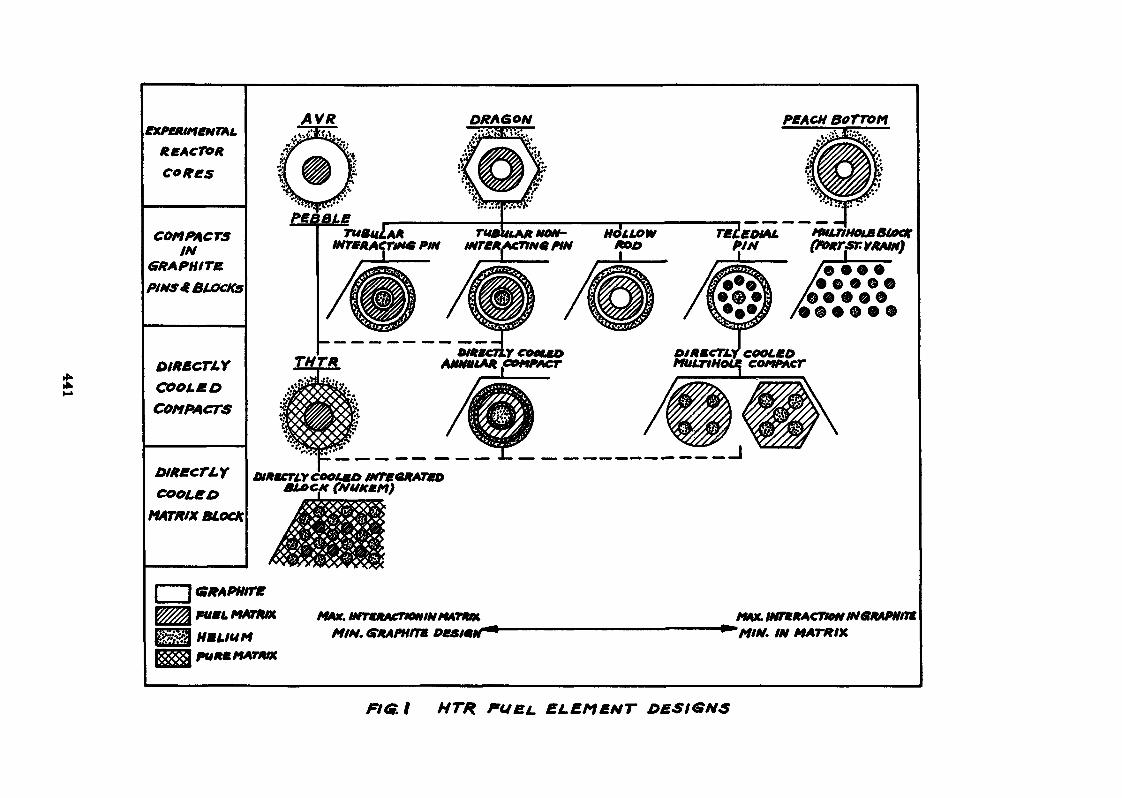
REACTORCORES
COMPACTSIN
GRAPHITE
PINS* BLOCKS
DIR&CTLYCOOLfOCOMPACTS
DIRECTLYCOOLEO
MATRIX BLOCK
AVR
fee BLETUBULAR
MTfRACTlN* PIM
|———j GRAPHITE
VZffîFUgL MATRIX
^^ HELIUM MIN. CfRAPHtn
PfACH BOTTOM
TBCEDIAL HULriHOUBBtOCKPIN (fORTSTVRAM)
DlRKCTL-f COOLEDCOMFACT
MAX. IMTeRACTfOMMGRAPHm. IN MATRIX
Fief. I HTR PURL ELEMENT
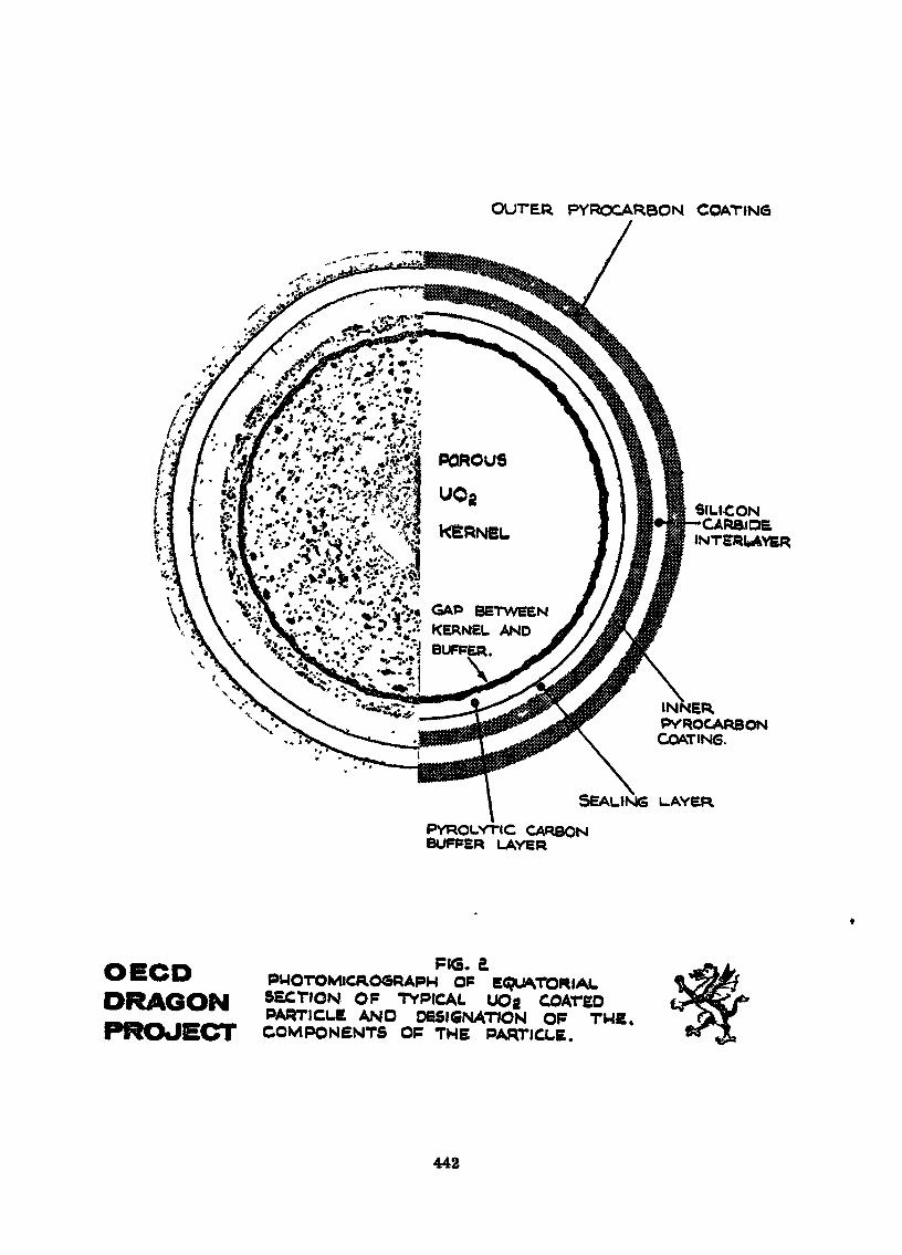
OUTER PYROCARBON COATING
POROUS
UOg
KERNEL
GAP BETWEENKERNEL ANDBUFFER.
SILICONCARB.IDE
iNTBRtAYER
INNERPYROCARBONCOATING.
SEALING L.AYERPYROLYTIC CARBONBUFPER LAYER
DRAGONPIG. &
PHOTOMICROGRAPH OP EQUATORIALSECTION OF TYPICAL UOg COATEDPARTICLE AND DESIGNATION OP THE.COMPONENTS OP THE PARTICLE.
442
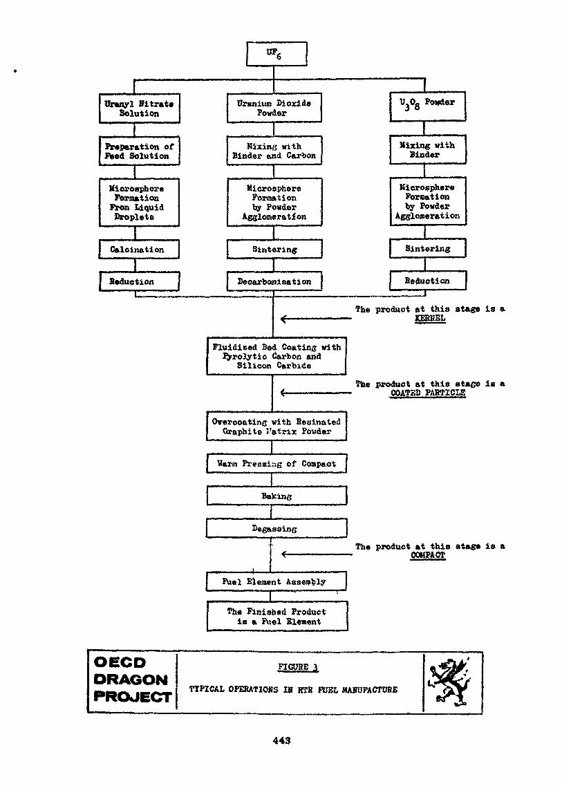
UF,
Uranyl NitrateSolution
Uranium DioxidePowder
Preparation ofFeed Solution
MicrosphereFormationFrom LiquidDroplets
U3°8,
Powder
IMixing with
Binder and Carbon
MicrosphereFormationby Powder
Agglomeration
Calcination Sintering
Mixing withBinder
KicrosphereFormationby Powder
Agglomeration
Sintering
Reduction Beearbonisation Seduction
The product at this stage is aKERNEL
Fluidised Bed Coating withPjrrolytic Carbon and
Silicon Carbide
The product at this stage is aCOATSD PAHTICLS
Overcoating with HesinatedGraphite J'atriJc Powder
Warn Pressing of Compact
Baking
Degassing
Fuel Element Assembly
The product at this stage is aCOMPACT
IThe Finished Productis a Fuel Element
OECDDRAGON
FIGUHE;_j.
TYPICAL OPERATIONS IN HTR FUEL MANUFACTURE
443
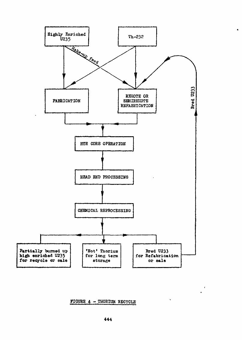
Highly Enriched
REMOTE ORSEMIREKOTBREFABRICATION
•a
1HTR CORE OPERATION
HEAB END PROCESSING
CHEMICAL REPROCESSING
1
Fart tally "burned uphigh enriched U235for recycle or sale
I•Hot1 Thoriumfor long term
storage
Bred U233for Refabrication
or sale
FIGURE 4 - THORIUM RECYCLE
444
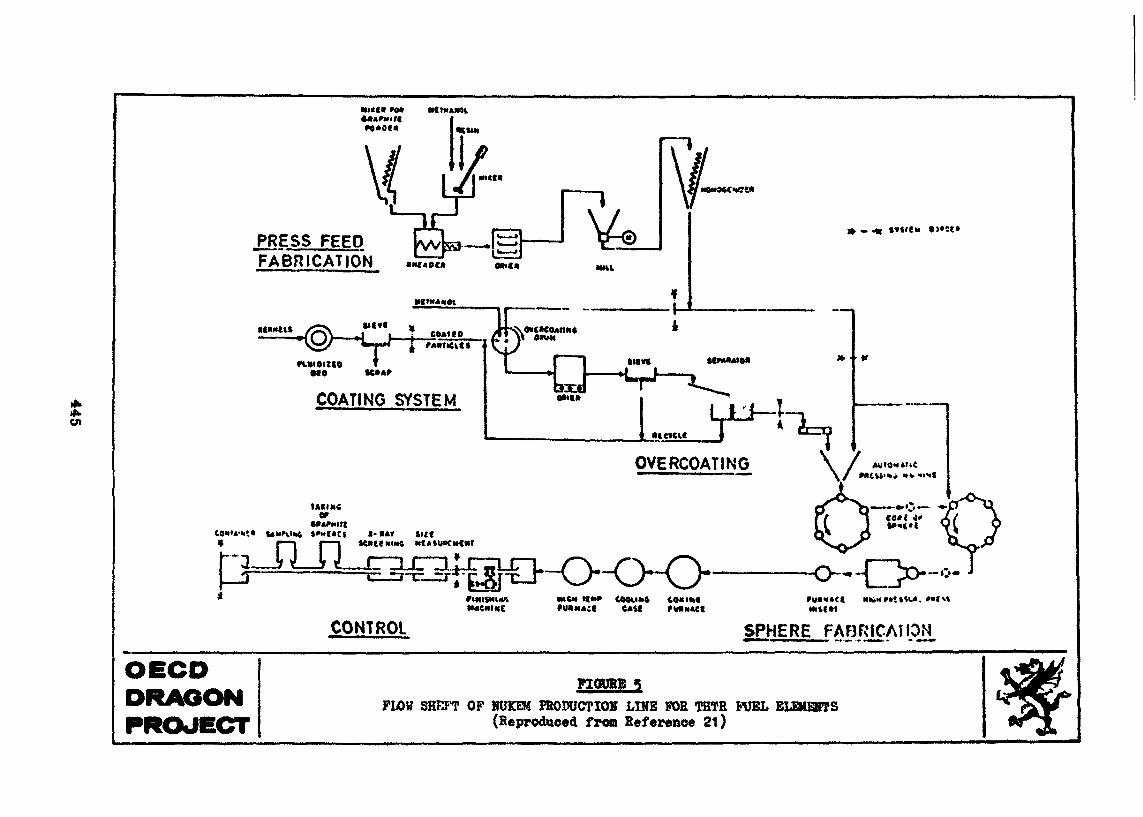
en
PRESS FEEDFABRICATION
\MNOM4MilCt*
M>C*
$l(vf
COATING SYSTEM
tâKIM<
roi-t»t suc
r— i r — i K»t(HtN6 ttt*su«CMC«T
JULM«CMIMC
HICH ItM» CQOViltft 4O«I««e*if
CONTROL SPHERE FABRICATION
OECDDRAGONPROJECT
FIOUBE 5PLOW SHKFT OP NtIKEM PROPUCTIOH LIKE FOR THTR FUEL ELEMENTS
(Reproduced fron Reference 21)
THE REPROCESSING OP IRRADIATED .?UELS
TECHNICAL AND ECONOMIC CONSIDERAI1CNS - A BEVISV
Dr. E.J. Detilleux
EurochemicMol, Belgium
ABSTRACT
The main emphasis is laid on the processing of light vaterreactor fuels» as this is the only kind vhich has reached fullindustrial scale today.
All the chemical processes used at present are derived from the"Purex Process"» developped in the United States around 1954.The main characteristics of the chemical process and the mainaspects of plant operation are reviewed.
The discharge of radioactive gases and effluents being one ofthe major problems facing the reprocessing industry, a briefstatement of the envisaged solutions is given.
Economic considerations involving investments and operationcostsy taking into account the main parameters such as thesize of the plant and its load factor, are also discussed*
Some indications of the R and D efforts currently being made todevelop reprocessing of the high temperature gas-cooled reactorare given, since no production facility is in existance as yet*
447
1. INTRODUCTION
This paper presents a survey of the technical andeconomic aspects of the reprocessing of spent reactorfuels. The main emphasis vill be laid on the repro-cessing of the light vater reactor fuels (LtfH), whichuntil today is the only process to have reached fullindustrial scale.
The processes universally adopted are aqueous processesall of which are derived from the "Purex Process",developed in the United States around 1954.
The routine discharge of radioactive gases and effluents(one of the major problems facing the reprocessingindustry) is also discussed and the possible answers tothese problems are analysed.
Economic considerations on the investments and operationare presented to complete the review on light waterreactor fuel reprocessing.
Some information on the Research and Development effortscurrently being made to enable the reprocessing of hightemperature gas-cooled reactor fuels (HTGR) arereviewed, no production facility at present existing toreprocess this type of fuel.
2. THE 33P-tOC2SSIKG 0? LIGHT VATE_l HE^CTOS *UELS
2.1. Description of the process
?igure 1 gives &n outline of the reprocessing process.
2*1*1. Si'.nt fuel ti- .ns; rt^ti R ...rid storage
The fuel is received in shielded casks transportedeither by road or rail. Up till now transports inEurope are performed in dry casks, cooled by n&turalconvection. However, in the United States transportof power reactor fuels is generally made with water-cooled containers.
Unloading of the casks and storage of the fuel isgenerally performed under-water in various intercon-nect^ pools. The storage racks arc geometricallyarranged to ensure that they are critically safe.
Fuels are normally allowed to cool for at least 150days prior to handling.
448
2*1.2* Mechanical treatment ana. dissolution
Mechanical treatment has now been adopted overall asthe preparation step prior to the fuel dissolution.
The Surocheraic plant at i-iol is the only facilityapplying chemical decanning to L7E fuels. The maindrawback of chemical decanning is the high volume ofintermediate level wastes: 4 - 5 si^/ton of uranium forstainless steel clad fuel and 8 - 1 0 ra^/ton of uraniunfor zircaloy clad fuel.
Mechanical treatments applied or envisaged can besub-divided into two main categories: shearing withoutany previous dismantling, or initial partial dismantl-ing by cutting off the end portion of each fuelelement and removing any existing casings and/orseparating the bundles of pins into sub-assemblies*
With both techniques the pins are cut into pieces»ranging in length from 1.5 to 5 cm. The cut piecesgenerally fall into a chute and are collected in fuelcanisters.
The shear is usually actuated hydraulically.
The fuel canisters, made of stainless steel perforatedsheets eventually containing boron as a neutron poison,are leached with boiling nitric acid.
Complete dissolution of oxide fuels can be achieved inabout 2 to 4 hours; metal fuels require about 24 hours*
The treatment of the off-gas implies :
- the reconversion of the nitrogen oxides resultingfrom the chemical reaction between the nitricacid and the core of fuel, into nitric acid whichis recycled to the process ;
- various treatments to remove or allow safe dis-charge via the stack of radioactive species suchas iodine, tritium and noble gases (treated inmore detail under § 2.r.2.) ;
- filtration through high efficiency filters toretain solid active or activated particules priorto discharge of exhaust through the stack*
The fuel solution is transferred to feed adjustment andaccountability tanks,.where the volume is measuredaccurately and multiple samples of the solution aretaken for analysis. This analysis represents the feedinput to the system and constitutes the financialaccountability of the plant. It is also important from
449
the standpoint of criticality control for the vholeprocess^ since the parameter usually adopted to assurethe safety of the operation is the limitation of thefissionable material. Indeed, fully geometrically safeequipment is not practical for large production plants,both from an investment and from an operation point ofview.
After the transfer of the feed solution the leachedhulls are rinsed and dried. The removed hulls areusually checked to guarantee the efficiency of the coredissolution. This check can be performed by visualinspection on hulls randomly selected from the dissol-ver canisters, or by 7T-scanning, by passing thecanisters through a neutron beam produced by anauxiliary neutron source.
The hulls are finally sealed into drums, transportedunder shielding and stored as radioactive solid waste.
Since the radiation level of these hulls is very high(10,000 rt/hr and above) these operations must be per-formed by remote control 4
figure 2 schematises the various steps of the mechanicaltreatment and dissolution operations.
2*1.3. Purification by solvent extraction
The decontamination and recovery of uranium and pluto-nium from fuel solutions is universally accomplishedtoday by solvent extraction processes, using tributylphosphate (T3P) dissolved in saturated hyclrocarbons ofthe kerosene or n-dcdecane types.
All these processes &re derived from the Purex Processapplied industrially for the first time in the UnitedStates in 1954.
Since then all attempts made to substitute other pro-cesses - such as the so-called "3ry rnothtds" forinstance, based on the distillation of fluorides - forsolvent extraction have never reached production stageand have even been withdrawn frc^i research and develop-ment programmes in many countries.
Indeed, solvent extraction presents several major ad-vantages for the reprocessing cf the spent nuclearfuels, as summarised in thé folloving table (table 1).
The main advantage of using TBP as oxtractant, is thepossibility it provides of using, nitric acid as saltingagent. Indeed, this nitric acic being easily purifiedby distillation, it is possible to recycle it into theprocess and to racLuct- the amount of radioactive effluentto be discharged by consequence.
450
Pigure 3 summarises an extraction flowsheet of the Furextype. Hovever, several versions of Purex flowsheets arein existence, but all are based on the same generalfeatures.
In the first extraction cycle or "co-decontaminationcycle" the nitric acid solution containing the uranium,plutonium, fission products and various impurities, iscontacted with the solvent (30 vol % T3P in kerosene).The organic phase extracts, in order of preference, theuranium and the plutonium and leaves almost all thefission products in the aqueous phase, which subse-quently becomes the high level radioactive aqueous wastefrom the process.
The organic phase, which contains the uranium and theplutonium, is scrubbed with nitric acid to removeadditional impurities and is then transferred into asecond contactor, where it is contacted with waterwhich strips the uranium and the plutonium back to anaqueous phase.
In the second extraction cycle or "U-Pu PartitioningCycle" the aqueous phase leaving the first cycle is -after concentration in an evaporator - fed again to anextraction-scrubbing contactor. The loaded phaseleaving this contactor is routed to another, where theuranium is separated from the plutonium by contactingthe organic phase with an aqueous solution that containsa reducing agent, such as uranous nitrate or ferroussulphainate. The plutonium which has been tetravalent upto this point of the process is now reduced to the lessextractable trivaient state, so it can be removed fromthe contactor in the aqueous phase. The uranium is thenstripped again from organic phase, in a third contactor.
One or two additional cycles of solvent extraction areused to complete the uranium product. The plutonium isprocessed through one additional solvent extractioncycle, followed by anion-exchange treatment to achievefinal purification and concentrations.
Ihe acid waste atreams are evaporated:- to concentrate them for storage ;- to decontaminate the excess of liquid ;- to recover nitric acid for recycling to the pro-
cess .
The solvent streams leaving the extraction streams arepurified from the remaining uranium, plutonium andfission products and from the degradation products ofthe diluent and the TBP resulting from the chemical 'andradiochemical damage to the organic phase. The clean-ing processes involve generally caustic and acid washesof the solvent.
451
Af,ter cleaning the solvent is recycled back to the pro-cess «
The\ extraction cycles of the reprocessing plantgenerally allov the recovery of 98.5 to 99.5 % of theuran\jLum and plutonium fed into them.
\T«ble\2 hereafter outlines the decontamination factorsusually achieved with a Purox flowsheet of the typedescribed in figure 3.
2.2. Plant
2.2.1 . General
Considerations for the design of a plant are in somerespects simriar to those facing the designer of anycomplex chemical plant, involving widely differing unitoperations and \gnit processus, and handling valuablematerials .
One of the major design problems of radiochemical plantsis the control of radioactive and fissile materialsbeing handled. The presence of large amounts of radio-active compounds requires that precautions be taken forthe protection of personnel, equipment components andprocessing reagents. Such protection must also beextended to the surrounding areas beyond the plantlimits. Radioactivity also requires remote operationof the plant and presents problems with regard to main-tenance of the equipment.
Nuclear safety also constitutes a major design problemfor radiochemical plants handling large amounts offissionable isotopes. This problem is countered by theappropriate choice of a combination of process condi-tions, plant layout and equipment sizing, along withproper plant supervision and intensive personnel train-ing.
2,2.2. Protection against radioactivity
Shielding is the Most practical and commonly used methodof ensuring personnel protection. In addition provisionmust be made for strict control of the working time ofpersonnel under certain circumstances.
Although there are more effective shielding materialsthan concrete, it is comparatively cheap and is the mostcommon material used for shielding in reprocessingplants. It serves not only a.s a. shield but also as astructural material and helps to make the plant resis-tant to external blasts.
452
As decont&nination is achieved by the various processsteps, less shielding is required along the productionline.
Shielding economies are made by dividing the buildinginto zones of various radiation levies. Table 3belov gives an example of such a segregation of areas*
2*2.3. Protection against contamination
Ventilation is the safest means of preventing thespread of airborne contamination in the working areasand plant environs. It constitutes a protectionagainst the ingestion of radioactive materials.
In practice the ventilation system is broken dovn intoareas by the level of radiation. The direction of airflov must alvays be from the area of lovest to thearea of highest radioactivity. Differential airpressures are used to ensure this control or air move-ment.
It is necessary, within the cells themselves, to operateprocess equipment at a somewhat lower pressure than thecell ventilating system, in order to avoid the possibi-lity of exhausting highly radioactive gases or vapoursinto the cell ventilating system»
Before release to the stack, all the exhausted air ispassed through batteries of filters which normallyremove 99.99$ cf the particulate matter. The stack mustbe of sufficient height to minimize recirculation orcontamination cf immediate surrounding areas underessentially all atmospheric conditions»
2.2.4. Maintenance
Because of high radiation levels present in reprocess-ing plants, the maintenance is a problem of greatmagnitude. There are two basic approaches to the pro-blem, namely remote or direct maintenance.
It is obvious that maintenance is a major considerationin plant operating time. The basic requirement in designof any type of plant is that the equipment and layoutbe such that an absolute minimum of maintenance andresulting idle-time is required.
The remote maintenance system adds considerably to theinitial cost of the plant. This increment is notmaterially altered by the size of the plant, since thecost of the various devices required remains essentiallythe same. It is difficult therefore to justify remotemaintenance for a small plant.
453
On the ether hand, the direct maintenance conceptrequires periodic shut-down and decontamination beforedirect maintenance can be performed on plant equipment*
?or production plant a suitable compromise between thetwo types of maintenance has to be found.
2.2.5» Criticalxty
The possibilities of an atomic explosion in a reprocess-ing plant are ne^li^ible . However, a critical incidentcan and will produce lethal radiation and can beexpected to produce physical damage in the immediatearea, heavily contaminating, the nearest surroundings.Furthermore, distant contamination might occur as aresult of airborne fission products or dissipatedfissionable materials. It xs obvious that the plant andequipment must be designed with suitable controls toprevent such critical incidents.
Criticality is a complicated problem, since reprocessingoperations ham'le fissionable isotopes in numerous formsand under a variety of conditions.
Moreover it is normally impossible to isolate the opera-tions to such a degree that the human element can beignored. Therefore, management must provide adequatecontrol in the design and operation of the plant andmust also educate operating personnel to prevent cnti-cality incidents.
In the plant design stages a decision must be made asto what type or types of control are to be used. Oncethe control philosophy has boon defined, all equipmentor operations used must conform to the limits established.
For any of the fissionable isotopes to become criticalcertain conditions must be met, which can be describedby the following variables :
a) mass of fissionable material
b) concentration of fissionable material
c) isotopic composition of uranium and plutoniund) components prosent along with fissionable material
(moderators)
e) poisons (soluble or not)
f) volume
454
g) geometry (shape)h) reflectioni) interactionj) primary dimensions (cylinder diameter, slab thick-
ness, etc . . . )
Safe conditions can be prescribed by selecting limitingvalues for one or better tvo indépendant variablesamongst those above.
2«3 Equipment design
2.3.1 . General
There are several factors requiring special considera-tion in equipment design for radiochemical plants» Theunique factors that must be considered are avoidance ofcriticality and the special hazards associated vith thehandling of radioactive materials.
In addition the high product recovery and purityrequire special design consideration. Other than thelimits imposed by these special problems, 'equipmentdesign follows standard practica.
2.3.2. Radiation aspects»••» an» »»•»»••—> •»•»£.••>_»—
a) TightnessBecause of the radiation problems it is essentialthat leaks be virtually non-existant. Equipment andpiping specifications demand absolute leak-tightnessas far as possible, both fur internal and externaljoints. Added expenses are esteemed necessary toensure that these specifications are met. Suchrigorous conditions are justified in view of the factthat any type of maintenance operation in a radio-chemical plant is many times more expensive and time-consuming than in any conventional plant. Thus anyreasonable effort and expense expended in the initialdesign, fabrication and installation of equipment aremore than repaid during the life of the plant interms of reduced maintenance and operating costs.
Mechanical design of plant vessels and piping inradioactive areas generally requires "all welded"construction. The welding of stainless steel equip-ment is accomplished primarily by using inert gaswelding techniques followed by various very severecheckings.
455
b) Radiation damage
The radiation levels have little effect on the metalcommonly used in fabricating cquipnent. «Radiation effects on various non-metallic materialslimit their usefulness in "hot" areas. Local shield-ing is used to protect equiprteat containing non-metallic components such as gaskets, electricalinsulation, packings, lubricating oils or greasesetc. *
Equipment with components susceptible to radiationdamage and not handling "hot" solutions directlyhave to be located outside the cells.
c) MaintenanceBecause the personnel will come into contact withthe equipment to some degree, either in replacementor maintenance (which will become necessary after a,certain time lapse, inspite of all efforts), designfeatures must be incorporated to allow decontamina-tion of the equipment while it is still in place»To facilitate decontamination operations, specifica-tions for all equipment designs and fabricationshould be stringent. Equipment should bo designedso that accessory lines and surfaces will drainfree to minimize the hold-up of active solutions.Both internal and external surfaces should be reach-able by decontamination solutions.
2.3.3. Criticality aspect
In the design of equipment, the type of criticalitycontrol to be used must be considered. Once the controlmethods are established, the process and equipment mustbe designed to meat the limiting values of the controlmethods used. Basically, plants may be designed usingmass, concentration, volume, geometry control or com-binations of these latter.
Nuclear safety may be incorporated into process equip-ment through the application of one or more of thevariables enumerated in *> 2.3.5. It is impossible forexample to design a reprocessing plant using geometryas a control, in which all the equipment is so shapedthat no critical accumulation can occur, regardless ofother factors such as the quantity of material in pro-cess, its chemical concentration or the proximity ofnoutron-reflecting bodios.
456
At the other extreme the total mass in process at anyone time can be maintained belov the minimum that cansupport a chain reaction, vith all other contributingfactors optimized.
Neither of these extremes is entirely workable.Instead the practical approach to nuclear safety isthe simultaneous application of two or more criteria,so that uneconomic extremes are avoided.
2.3.4* Materials of construction
Equipment utilised in spent fuel processing is sub-jected to varying degrees of radiation, chemical corro-sion, mechanical stresses and high temperature condi-tions .
The worst corrosive conditions occur in dissolvers,concentrators, nitric acid absorbers or fractionators,waste evaporators and storage tanks.
In choosing a material to resist corrosion the follow-ing factors must be considered :
a) the production of high purity product limits thepermissible pick-up of contaminants from the con-struction materials ;
b) the extensive problems posed by maintenance requirethat materials of construction be chosen for longlife ,-
c) the materials of construction must resist decon-taminating solutions used.
The construction material generally used is stainlesssteel of the 300 series, and most specifically 304 L,stabilized toward intergranular corrosion either byextra low carbon content or by a niobium (columbium)additive. (See table 4)
2.3.5. Chemical Process Equipment - Extraction Contactors
It is impossible, within the limits of this review, todescribe all the various types of chemical processequipment used in radiochemical plants. However, theheart of the reprocessing chemical plant being theextraction section, special attention will be paidhere to the liquid-liquid extraction contactors use'l inthe various "Purex" plants.
457
Extraction equipment used in reprocessing operationshas been developed over the past 20 years to givegood separations, decontamination and high recovery ona continuous basis» Of eq.ua! inportauce has been thedesire to make the equipment as small and compact aspossible, since the shielded buildings are quite expen-sive. Moreover, the permanent increase of the specificactivity of the solutions processed has enhanced thenecessity to minimize the contact time betvcen theorganic and the aqueous phases, in order to reduce therisks of rafiiolysis of the former.
The ideal contactor requires a minimum investment forboth associated building and equipment. It maintainsa high efficiency over a vide range of operating condi-tions, has a high capacity with a lew hold-up, isreliable in operation with simple controls anO. mininmramaintenance requirements! is flexible for processvariations and reduces the organic-aqueous phases con-tact time.
The choice of contactor for a particular process isgoverned by the desire to include as many of thesecharacteristics as possible.
a) Packed columnsrepresent the simplest type of contactor, as theyhavo no moving parts. They have been adopted inthe early stages of the reprccessin£ technology butare now almost abandoned dud to their poor perfor-mances compared -with pulsed columns end mixer-settlers of comparable size.
Indeed, in those two types of extractors, mechani-cal agitation is used to enhance the efficiency ofthe extraction processes.
b) Pulsed columns (figure 4)
use hydraulic pulsation of the liquid phases througha series of perforated plates, to enhance the rateof nass transfer.
Due to their greater efficiency, pulsed colunns aremore corapact than packed columns and thus requireless shielding. They also have a smaller liquidhold-up and therefore the risk of solvent degrada-tion by radiation is decreased.
458
Ihe hydraulic pulse is generated by application ofair pressure by a mechanical puiser located outsidethe shield,ecl cells housing the columns.
fhe capacity and efficiency of the pulsed columnsare influenced by a large number of variables suchas: pulse frequency and amplitude, perforated platogeometry, column dimensions, etc...
c) rfixer-settlers (figure 5)The "pump-mix" mixer settlers, an horizontal contac-tor in which the mixing intensity, the interfacecontrol and the hydraulic head for the aqueous phaseflow are provided by the impeller, is the type ofmixer-settler most commonly used in the reprocessingplant.j*. contactor consists of any desired number of stages(one stage being formed by a mixing chamber associ-ated with a settling chamber where the aqueous andthe organic phase separate), arranged horizontally.In spite of the fact that each stage requires anindividual motor fcr Iriving the impeller of themixing chamber, mixer-settlers have been used inmany reprocessing plants.However, the accumulation of radioactive cruds atthe interfaces ars often observed during the proces-sing of fairly radioactive solutions. Thisphenomenon, due to the rather long contact timebetween the phases at each stage, reduces to someextent the efficiency of the decontamination.Consequently, the uso of mixer-settlers to processhighly irradiated fuels such as those dischargedfrom light water power reactors is rather question-able .
d) 'ast contactors (figure 6)A large part of the efforts devoted to the adapta-tion of the Purex Process to the higher specificactivities of the spent fuels is coviously relatedto the minimization of the radiation ùama^e to thesolvent phase.Attempts to develop ether oxtractants with a betterresistance towards the radiation than TBP have beenmade without great success.It appears now that the best improvement has to befound in the contactor technology.
459
Because the radiation damage to the organic compoundsvaries proportionally with the time that these com-pounds are exposed to the ionizing radiation, andbecause this exposure time is primarily determined bythe time required to separate the aqueous ani organicphases, the main efforts have been devoted to design-ing means for shortening the time required toseparate the phases.
Centrifugal force is the most commonly consideredmeans.For the past few years reliable equipment known as"fast contactors" or "centrifugal contactors" hasbeen developed in the United States, ?rance andGermany.A hot pilot unit, of industrial scale, is in opera-tion at the Savannah River Plant in the U.S.A.The contactor is made of 18 stages of the type shownin figure 6. It operates at about 1750 revolutionsper minute.New reprocessing plants, or existing ones to beadapted for the processing of fuels from coiningpower reactors, must most probably be equipped withfast contactors, at least for the first contactorsof the first cycle.This requirement is essential if the plant usesmixer-settlers, since the overall contact-timebetween the aqueous and organic phases is by farlonger than in pulsed columns.
2.4. The waste problem
2.4*1. General
Xhe treatment, storage and disposal of radioactiveeffluents from reprocessing plants is one of the mostimportant and difficult technical problems to be solvedin the nuclear power industry.
In current fuel reprocessing schemes, the volatile orgaseous raclionuclides present in the spent fuels(e.g. I12*, 1131, Kr85, ^c^ltn, Xe?33) are volatilizedand the resulting gaseous stream is treated forremoval of SOTIO of these nuclides to meet emissionlimits.
460
Tritium is usually included in this category of vola-tile radionuclides, in spite of the fact that a largeportion of it generally follows tho water streams.
Approximately 99.95$ of the remaining fission productsare collected in the wasto from the first extractioncycle (see figure 3).
Figure 7 gives a general scheme of the origin of theradioactive wastes flora reprocessing plants.
The analysis of the problems of waste management isbeyond the scope of this review. However , due to theimportance of the subject some general considerationsare given hereafter, concerning the treatment of thevolatile and gaseous wastes an A high level liquidwastes, which are of major concern fcr reprocessingplant operators and environmentalists.
2.4.2. Volatile and gaseous wastes
It is present practice to reprocess fuels about 190days after discharge from the reactor. In these con-ditions volatile or gaseous radionuclides to be takeninto consideration are Kr85, I131, I129.
Today it is considered that the best way to dispose oftritium - present as tritiated water in all the dis-tillates of the various waste streams (see figure 7) -is to vaporise it through the chimney.
Phis is the reason why tritium is associated with thegaseous and volatile radionuclides mentioned above.
To illustrate the magnitude of the discharge of theseeffluents, data from an American origin are given intable 5 below.
Actually the required decontamination factors forare very low, for the commercial plants envisaged atpresent. However, in connection with the future pro-cessing of short cooled fuel from fast breeder reactorsseveral studies are underway, for removing noble gasesfrom off-gas streams. These include room-temperatureor low-temperature adsorption on charcoal, molecularsieves or silicagel, cryogenic distillation, extractionby liquids, trapping in clathratos and separation usingpernselective membranes.
All these processes can remove more than 90$- of thenoble gases.
461
Simultaneously useful techniques for the control ofiodine volatilxzation and its release to the atmosphereare being developed. They include: the use of nitricacid/mercuric nitrate (I).?. 102 - 103) or caustic(D.7. 10-* - 10**) scrubbers and the use of charcoaladsorbers (J.i?. 104 - 105).
These indications show that the present techniquesallow the requirements defined in table 5 to be met.
2.4.3. High level vastes
The high level vastes (0.5 to 1.2 ro^/ton of uranium,after concentration) are those which contain at least1 Ci/liter of liquid or 70 Ci/kg of solid. Thesevalues are high enough to require thick radiationshielding and cooling of the significant heat evolu-tion from decay of radioactive fission products.
This vaste must be stored for centuries to permitdecay of the major long-lived radioactive fission pro-ducts (primarily Cs137 and Si90) to non toxic levels?the small amount of plutonium present as a vaste loss(0.1 to 0.5 % of the original amount in the fuel) andsome long-lived radionuclidcs (transplutoniuni elements)require thousands of centuries to decay to non toxiclevels*
At present the only practical means of preventing theradioactivity from entering our environment is tostore the material under carefully controlled condi-tions .
At this time, major technological advances are re-quired for development of new techniques.
a) Liquid storage
Interim storage of those high level vastes as liquidshas been done safely from the early stage of theatomic power industry.
'iThe storage tanks vary in capacity from 40 m to400C ra3. The tanks are housed in concrete vaults,underground or above ground. They are generallyequipped with cooling coils for heat rénovai andairlift circulators to prevent deposition of solids.
Generally speakinp the high level wastes are storedas ecid solutions; however, some Ancrican facilitiesneutralize their waste to alkaline conditions, priorto storage.
462
Stainless steel (30* L) -is now generally used "tostore acid vaste; carbon steel has been adopted foralkaline vaste stora.%6."li '
No leakage has been reported today for stainlesssteel tanks, but fifteen carbon steel tank failureshave occurred in U.S. facilities.
The storage of acicHc wastes in soainless steeltanks is today regarded as preferable to alkalinestorage, based on :
- lover volumes- smaller volume of precipitated solids- easier control of heat removal- smaller total salt content, giving less volume
afier solidification- less tendency to leak- comparable costs.AS the nuclear industry expands, storage problemsbecome increasingly complex. In the l,ast years ithas been generally recognized that storage assolids versus liquids vould be considerably safer.The proposed policy for all U.S« commercial fuelprocessing plants stipulates that :1) the inventory of high level vastes in liquid
form vill be limited to the quantity producedin 5 years
2) the vastes in excess of this inventory must beconverted to an approved solid form
3) that the solidified vaste» must be transportedto a federal repository as soon as practicable,but in no event later than 10 years followingthe fission products separation from the irra-diatec. fuels.
It is likely that, a similar approach will be e,c!opt-ei in ether countries, making the liquid storageonly an interim solution to the problem.
b) SolidificationProcesses for the solidification and permanent dis-posal of high level vastes are being developed orconsidered in countries that have or plan t-q havereprocessing plants*The general objectives of solidification aTe :1) to reduce the mobility, solubility and volume of
wastes
463
2) to maximize the thermal conductivity and thermalstabilities of the final product.
Tablt. 6 summarises the characteristics of the mainhigh level waste solidification processes»
As shown by this table none of these processes) withthe exception of the fluid be,l calcination processdeveloped at liaho Chemical Plant, has reachedindustrial application ye I.However, the calcine obtained by the Idaho processcannot be considered as a product suitable for per-petual storage.
o) Long term disposal or storageLong term disposal or storage is a feature common toall currently practicable methods for disposal* Themethods vhich have received attention are :
- disposal as solids in salt mines- storage as solids in deep underground
caverns- storage as solids in man-made vaults- disposal as solids in ocean depths.- disposal as liquids in deep wells' •< ''
- perpetual storage as liquids in deepunderground caverns
~ perpetual storage as liquids in tanks.To ,many waste disposal experts the schemes consideredto have 'the better potential for long-term safetyare those whereby' wastes are placed in certain deepgeological formations.Placing the wastes in these locations should keepthe wastes out of nan's immediate environment forthe required length of time, the wastes would be lessaffected by future unknown conditions on the surface,caused by either man or nature» and reliance on humansurveillance should be minimized.One source of concern involved with any storage ordisposal technique is whether or not enough is knownto be certain that stored wastes will remain"eternally" out of the biosphere. Systems offeringretrievability allow for a problem that may not havebeen foreseen.
464
On the other hand, retrievability in a storagesystem would normally require more surveillance,more control records and more législation to beenforced. Today no system for final storage hasbeen definitively adopted and consequently thereis no system in actual operation.The Unite.'. States and the ^erleral Republic ofGermany are studying the storage in a salt mine»If the German project (Asse, Lover Saxony) ispursued according te a strict planning, the U.S.programme seems delayed due to local conditions.The USA3C, which still considers storage in a saltmine tc be an acceptable solution, neverthelessdecided to adopt "engineered storage facilities"for the immediate needs of the country.?rance and the United Kingdom have not yet fullydefined or announced the lines they want to followin this matter.Obviously, the management of the radioactive wastesto prevent them from entering man's biosphere insignificant quantities is a formidable task whichrequires international cooperation.
2.5. Nuclear Material Accountability
The nuclear material accountability is needed forplant operators to follow the flow of material throughthe plant, to prevent losses, to prevent undetectedaccumulations of fissionable materials which couldlead to criticality accidents, etc...
The same information is also basically required forsafeguards control, which must keep track of the fis-sile material.
Tc facilitate these operational and safeguards con-trols the reprocessing facility is generally sub-divided into Material Balance Areas. The in and outflows through each of these areas are checked as care-fully as possible.
Special attention must be paid to these requirementsright from plant design'stages, to provide eachmaterial balance area with the necessary equipment toallow efficient measurements': sampling loops, accuratevolume measurements, calibrated vessels, etc...
465
lu addition, during plant operation periodical {etleast yearly) determination of material hold-up in theplant is needed, to allov a better* compilation of theaccountability data accumulated during operation.
On the basis of the present technology an overallmaterial recovery (uranium anJ. plutonium) of minimum98$ is generally considered. "he 2% losses cover thelosses in liquid and solid wastes and the unavoidablediscrepancies in the material balance.
2 «6. Economic Cons * derations
2.6.1. Introductory .lemark
Since the most complete economic data at the author'sdisposal dates fron the end of 1969, 1970, the figurespresented below refer to the US $ of that time. Noattempt has been na«ile to actualize these figures dueto the financial events which have occurred in the mean-time»
2*6*2. lieprocessing cost and energy cost
It can be estimated that a 100v/ »-i'7(l) light waterreactor discharges 35 tons of spent uranium per year.(1 kg uranium producing 2.10 kwh).
Assuming 4.5 mills/kwh as the total electricity cost,the fuel cycle total cost would represent about1.5 mills/kwh or a third of the electricity cost. ASthe reprocessing part in the fuel cycle is generallyfixed at 5 to 10fj the reprocessing cost raay be esti-mated at 0.07 to 0.15 raills/kwh or 15 to 30 $ per kguranium.
2*6.3. Investment costs
A characteristic of reprocessing plants is their highbase cost. This is mainly due to the heavy shielding,th« requirements for remote operation and maintenancefree operation of equipment inside the cells.
Items which are essentially indépendant of capacityinclude civil engineering ventilation, instrumentation,the analytical facility and general services.
The general curve for upsealing the investment ccstfor reprocessing plants follows a law of the type :
466
where Io = reference plant costI = plant costÀ = capacity factor
x » lies between U.24 and 0.4, accordingto local contingencies.
In 1969 the investment cost of a 1 ton/day plant couldbe assumed at 40 - 45 M§ and that of a 5 t/d plant at80 - 85 M$, including all ancillary costs prior t.ttstart-up and assuming a construction time of 4 - 5years with an interest rate of
In reality the cost of a new plant may differ consi-derably from these amounts. A precise estimate canonly be made when the size and location, which has amarked impact on the waste storage and discharge possi-bilities, are fully defined.
Table 7 illustrates a possible breakdown of the invest-ment costs. These figures are purely indicative; theyhave been compiled from Eurochemic data and variousexternal publications.
Economic calculations usually adopt a depreciation timeof 15 years, but obviously the technical life-time ofa plant is generally longer.
2.6.4. Operating costs
The plant operating costs are usually sub-divided intoconstant costs, variable costs an<? maintenance costs.
a) Constant costs
Constant costs include:i) Personnel costs - Personnel requirements
depend essentially on plant lay-out, degree ofautomation, and availability of external assis-tance during maintenance periods for instance.It can be assumed that of the order of 250 aad350 persons are require! to operate plants of1 ï/day and 5 t/day respectively.
467
ii) Operating costs - These costs include plantservices which run independently of thethroughput (water, steam,electricity forventilation, air), consumable materials(apart from processing chemicals), maintenanceand spare parts, administration and insurance.
These expenses remain practically unchanged,whether the plant is in operation, maintenance ortemporarily shut-down.The constant operating costs are generally esti-mated to amount to approximately 2/3 of thepersonnel costs.
b) Variable costsThese expenses depend basically on the quantitiesof fuel handled; they mainly cover plant services(steam and electricity), process chemicals inplant waste handling and interim storage on site.Waste final conditioning and storage are not con-sidered here.Table 8 gives an indication of the distribution ofthese variable costs among their constitutingitems.
c) Maintenance costsOn one hand, maintenance costs are lover than inconventional chemical plants due to :- high investment in civil engineering (shielding)- built-in safety and strict specifications.On the other hand, repairs are more expensivebecause cf :- decontamination prior to access, which oftenmeans long shut-downs and costly reagents ;
- difficult access and restricted working condi-tions, which slow down the repair work.
Maintenance generally accounts for 7f» of the yearlyoperating expenses; man-power represents more than80#. Maintenance costs have been included in itema) above.
2.6.5. Overall reprocessing costs
Due to the high level of investment ana constant costs,high load factors and plant capacities are required inorder tc achieve reprocessing costs in the range of 15to 30 &/kg U as indicated in j 2.6.2.
Table 9 hereafter illustrates these facts.
468
2*6.6* Additional costs
Besides the operating costs discussed above, someadditional ccsts have to be taken into considerationif a total view- of the spent fuel processing economyis vantée* ^or instance :- the transport of the irradiated fuels ;- the final conditioning and storage of the high
level wastes ;
- the fissile material accountability and safeguards;- the general safety of the plant operation, includ-
ing permanent personnel training.
a) Transport costs
The transport costs of irradiated fuels are not verysensitive to distance; the most influential factorsare the utilisation coefficient of the transport con^tamers (rotation speed) and their loau factor(ratio between container weight and fuel weight).In Europe the transport costs may be evaluated at 5to 9 v/kg uranium.
b) High level waste conditioning and final storage.oil estimations in this fiel'l aro purely indicativeas no operation of this type has yet been carriedinto effect, as seen in § 2.4.3.A number of cost estimate studies have been madeand published, especially by Bloraeke and coworkersat 03NL.These studies show that for management comprising :
- interim liquid storage, solidification bypot calcination ;
- interim storage of the solids ;- transportation of the solids (2000 milesround—trip) }
- storage in salt ;
the estimated cost is of the order of 9.5 to 14.58/kg or uranium processed.Comparable costs for perpetual storage as liquidvary from 7.8 up to 9.1 O/kg U.Consequently high level waste management couldrepresent up to 3G?o of the actual reprocessing costif it is estimated around 30 e/kg (see table 9).
469
3. THE 'IEPHGC3SSIHG 0? HIGH TEMPEa^rUXE GAS-COOLED lEACïOJt
?U3LS
At present no reprocessing plant exists to processfuels from high temperature reactors. However, impor-tant 3 & D progremmes are devoted to this problem,namely in the U.S.A. (Oak Ridge National Laboratory andIdaho Chemical Plant) and the Federal Republic ofGermany { Jttli ch).
The methods for processing HTG3 fuels aim to recoverthe U-233 and the thorium from the fertile and recycledparticles and to separate the highly burned U-235particles. The high U-236 content of the latter makesthe U-235 undesirable for recycling.
It can be said today that the burn-leach process ispreferred to the grind-leach process, at least in theUnited States. The major factor in this choice is thenecessity for physically separating the particles.
The principal processing problems encountered in theburn-leach method are :
1) mechanical operation prior to burning ;
2) control of the fluid-bed burner ;
3) removal of radioactive particles and gases fromthe off-gas }
4) separation of the IT-233 containing particlesfrom the U-235 particles.
The OàNL tentative flowsheet is schematised in figure8.
Initial saving, crushing and burning tests have beensuccessfully performed vith unirradiated fuels andlong cooled Peach Bottom fuels irradiated up to41,500 HWD/t.
Preliminary tests have indicated the effectiveness ofthe screening for separating U-233, U-235 and A^Ojparticles .
A roll grinder seems satisfactory for crushing particlescoated with silicon carbide and allows an efficientexposure of the core to the thorex leach solution madeof 13 M HN03, 0.05 fo A13+ and 0.05 a P~.
If losses of uranium and thorium to the inner graphiteparticles are significant, burning of the carbon residuemay be envisaged before leaching.
470
The thorium and uranium can be separated from each otherby the thorex solvent extraction process vhich uses tri—butyl phosphate as extractant and has been applied manyyears ago at Oak Ridge National Laboratory.
An HGTft reprocessing plant requires a nevly designedhead-end system, but the solvent extraction equipmentexisting for light vater reactor fuel processing can beadjusted for use with the thorex process»
4. USED REFERENCES
- Reactor Handbook, Second Edition, Volume II, FuelReprocessing, Interscience Publishers Inc. N.Y., 1961
- Proceedings of the International Conference on theConstructive Uses of Atomic Energy, American NuclearSociety, Washington B.C., November 10-15, 1968
- The Future of Reprocessing in Europe, ?oratom Study,February 1970
- Treatment and Storage of Vastes from ReprocessingPlants, R.E. Bla&ooCrmelin's Kandbuch der Anorganischen Chemie, Vol. 71Transuranium Elements
- Solidification and .Disposal of High Level RadioactiveWastes in the United States, K.J. Schneider,Reactor Technology, Vol» 13-4, p.p. 387 - 412
- USAEC Report O^NL 4451, Siting of Tuel ReprocessingPlants and Waste Management facilities, July 1970
- Eurochemic files and data.
471
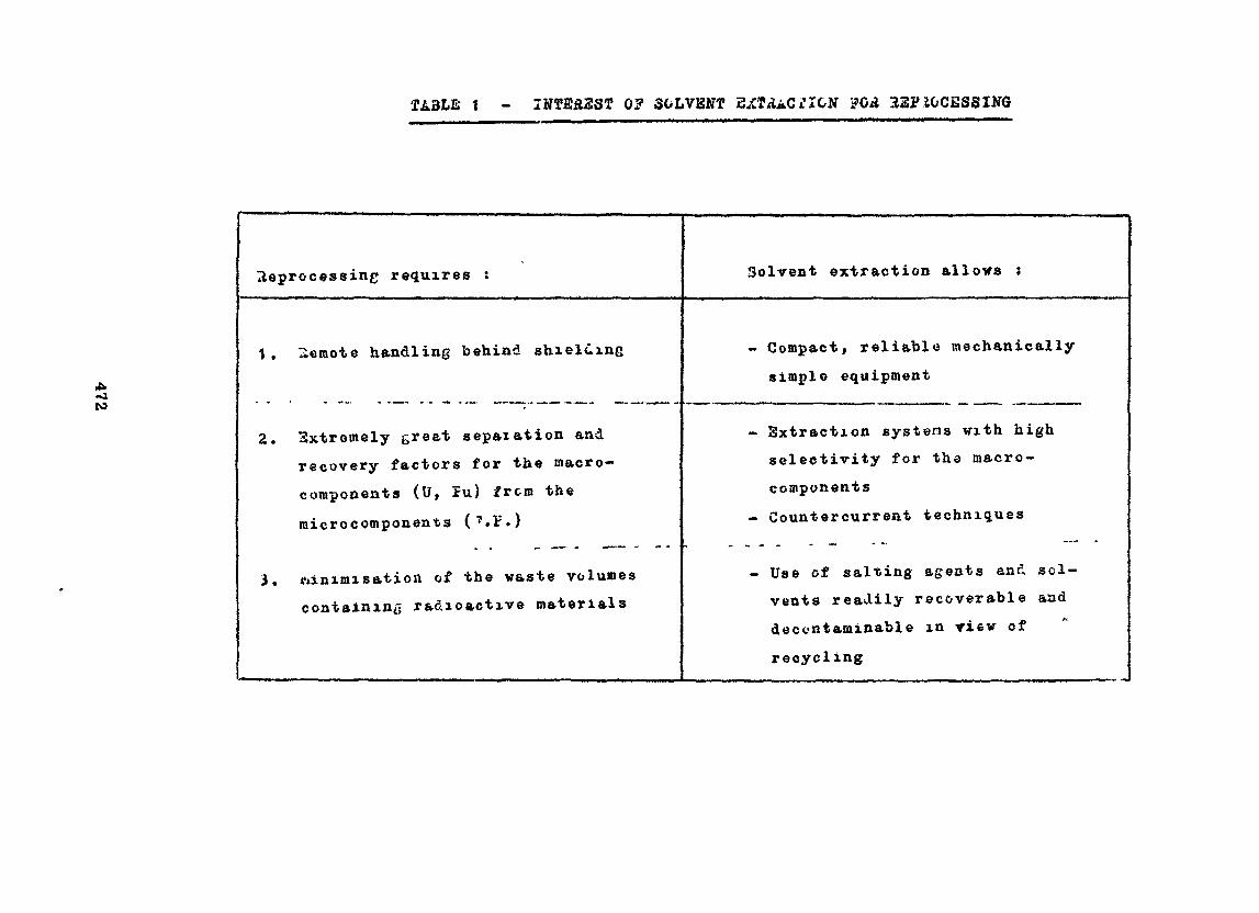
TA3LS t - ÏNTE£237 OF SOLVENT 32PJGCESSING
-ato
Heprocessing requires :
1 . Ileraote handling behind shielding
2. 3xtremely greet sepaietion andrecovery factors for the raacro-components (U, Jru) frcm the
microcomponents (?.F.)
3. ftinimisation of the waste volumescontaining radioactive materials
Solvent extraction allovs :
Compact, reliable mechanically
simple equipment
Extraction systens vith highselectivity for the macro-
ccmponentsCountercurrent techniques
Use of salting agents and sol-vents readily recoverable anddecontaminable in view of
recycling
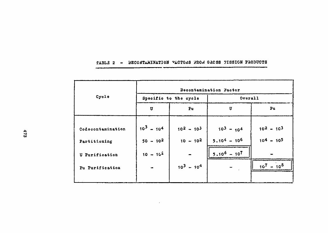
ÎA3L3 2 - GACSS 7ISSION PRODUCTS
oo
Cycle
Codec ont aminat ion
Partitioning
U Purification
Pu Purification
Decontamination factor
Specific to the cycle
U
103 - 10^
50 - 102
10 - 10^
Pu
102 - 10-*
10 - 102
103 - 104
Overall
U
103 - 104
5.10 . 1Q6
5.106 - 107
-
Pu
102 - 1C3
104 _ 105
1u7 - 108
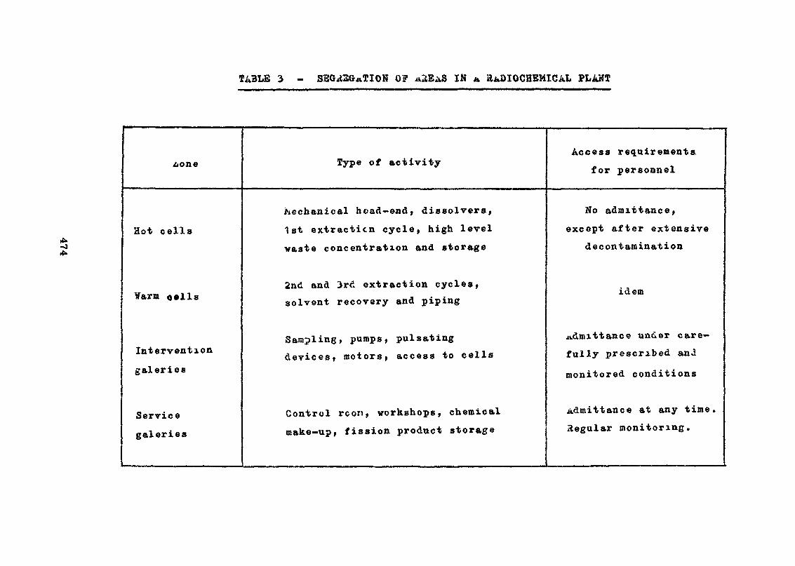
3 - SEGREGATION o? «2B&8 IN *. PLANT
bone Type of activityAccess requirements
for personnel
Hot cells
¥arm o«lls
Intervention
galeries
Service
galeries
Mechanical bead-end, dissolvers,1st extraction cycle, high levelwaste concentration and storage
2nd and 3rd extraction cycles,solvent recovery and piping
Sampling, pumps, pulsatingdevices, motors, access to cells
Control rcon, workshops, chemicalmake-up, fission product storage
No admittance,
except after extensivedecontamination
idem
admittance under care-fully prescribed an-i
monitored conditions
Admittance at any timeRegular monitoring*
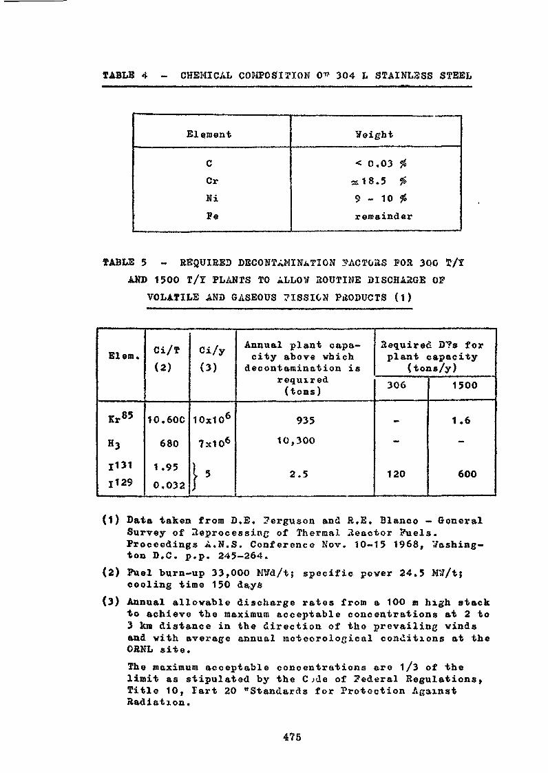
TABLE 4 - CHEMICAL COMPOSITION 0* 304 L STAINL3SS STEEL
Elément Veight
CCr
Ni
Fe
< 0.03 %d18.5 %9 - 10 foremainder
TABLS 5 - REQUIRED DECONTAMINATION FACTORS FOR 300 T/Y
AND 1500 T/Y PLANTS TO ALLOW ROUTINE DISCHARGE OF
VOLATILE AND GASEOUS 7ISSION PRODUCTS (1)
El em.
Kr85
H3
11311129
Ci/T(2)
1 0 . 60C
680
1.95
0.032
Ci/y(3)
10x106
7x10⁶
}•
Annual plant capa-city above which
decontamination isrequired(tons)
935
10,300
2.5
Required D?s forplant capacity
(tons/y)306
-
-
120
1500
1.6
-
600
(1) Data taken from D.E. 7erguson and R.E. Blanco - GeneralSurvey of Reprocessing of Thermal Reactor Fuels.Proceedings A.N.S. Conference Nov. 10-15 1968, Washing-ton D.C. p.p. 245-264.
(2) Fuel burn-up 33,000 MVd/t; specific pover 24.5 Mlf/tjcooling time 150 da.y&
(3) Annual allowable discharge rates from a 100 m high stack•to achieve the maximum acceptable concentrations at 2 to3 km distance in the direction of the prevailing windsand with average annual meteorological conditions at theCRNL site.
The maximum acceptable concentrations are 1/3 of thelimit as stipulated by the Cjde of Federal Regulations,Title 10, Tart 20 "Standards for Protection AgainstRadiation.
475
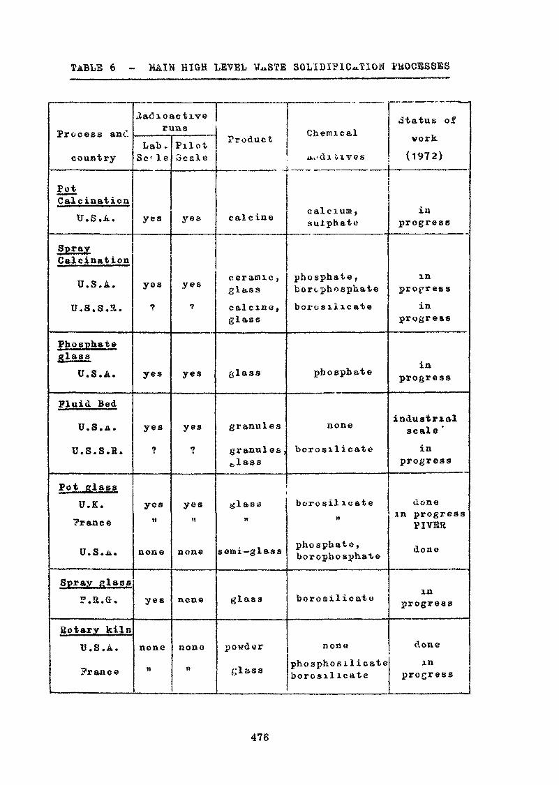
TABLE 6 - MAIN HIGH LEYBL V^STE SOLIDIFICATION PROCESSES
Process an cl
country
PotCalcination
U.S.A.
SprayCalcination
U.S.A.
U.S.S.3.
Phosphateglass
U.S.A.
Fluid Bed
U.S.A.
u.s.s.a.
Pot glassU.K.?rance
U.S. A*
Spray class».».«.
Bo tar y kilnU.S.A.
Prance
2ac! 102ri
Lab.Se' le
yes
yes
yes
yes
yos
none
yes
none
M
ictiveJUS
PilotScale
yes
yes
yes
yes
yest!
none
none
none
Product
calcine
ceramic ,glasscalcine,glass
glass
granules
granules,
glass
semi— glass
glass
powder
glass
Chemical
tt,tdl &1V6S
calcium ,sulphate
phosphate ,borcphosphatebore silicate
phosphate
none
borosilicate
borosil icate
phosphate,borophosphate
borosilicate
none
phosphosi 1 icateborosilicate
.Status of
work
(1972)
inprogress
inprogress
inprogress
inprogress
industrialscale *
inprogress
donein progress
PI VER
done
inprogress
donein
progress
476
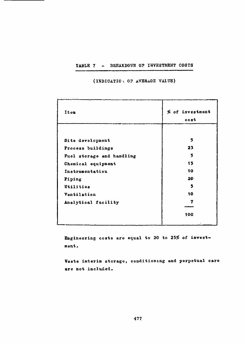
TABLE 7 - BREAKDO¥N 0? INVESTMENT COSTS
(INDICATION 0? AVERAGE VALUE)
Item of investmentcost
Site developmentProcess buildingsFuel storage and handlingChemical equipmentInstrumentationPipingUtilitiesVentilationAnalytical facility
52351510205107
100
Engineering costs are equal to 20 to 25$ of invest-ment.
Vaste interim storage, conditioning and perpetual careare not included.
477
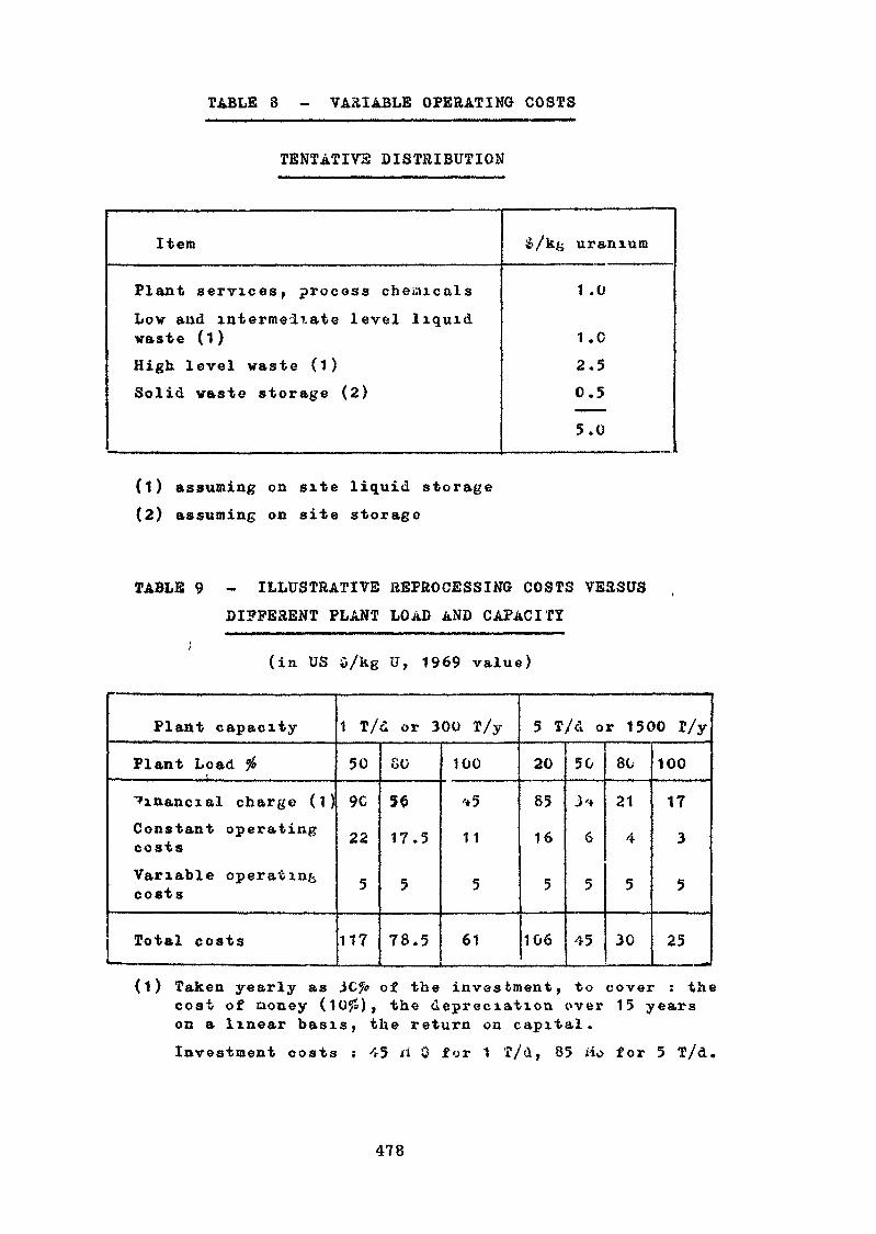
TABLE 3 - VARIABLE OPERATING COSTS
TENTATIV2 DISTRIBUTION
Item
Plant services, process chemicalsLow and intermediate level liquidwaste (1)High level waste (1)
Solid waste storage (2)
uranium
1 .0
1 .02.50.5
5.0
(1) assuming on site liquid storage(2) assuming on site storage
TABLE 9 - ILLUSTRATIVE REPROCESSING COSTS VERSUS
DIFFERENT PLANT LOAD AND CAPACITY
(in US $/kg u, 1969 value)
Plant capacity
Plant Load %
financial charge (1)Constant operatingcosts
Variable operatingcosts
Total costs— - -
1 T/d or 300 T/y
50
9C
22
5
117
80
56
17.5
5
78.5
100
'*5
11
5
61
5 T/d or 1500 T/y
20
85
16
5
106
50
J'f
6
5
45———
80
21
4
5
30
100
17
3
5
25
(1) Taken yearly as 3C?i? of the investment, to cover : thecost of cioney (10$), the depreciation over 15 yearson a linear basis, the return on capital.
Investment costs : 45 ri 0 for 1 T/d, 85 Ho for 5 T/d.
478
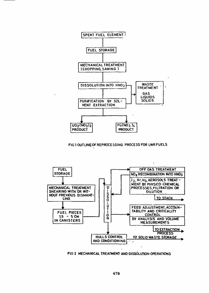
SPENT FUEL ELEMENT 1
FUEL STORAGE
MECHANICAL TREATMENT(CHOPPING, S AWING )
DISSOLUTION iNTO
PURIFICATION BY SOLVENT EXTRACTION
1
WASTETREATMENT
GASLIQUIDSSOLIDS
1
FIG î OUTLINÇOF REPROCESSING PROCESSFOR LWRFUELS
FUELSTORAGE
MECHANICAL TREATMENTSHEARING WITH OR WIT-HOUT PREVIOUS DISMANT-
LING
FUEL PIECES1,5 - 5 CM
IN CANISTERS
HULLS CONTROLAND CONDITIONING
OFF GAS TREATMENTNpx«ECOMBINATION INTOHN0312, Kr,H3.AEROSOLS TREAT -MENT BY PHYSICO-CHEMICALPROCESSES.FILTRATION OR
DILUTION
TO STACK
FEED ADJUSTMENT,ACCOUN-TABILITY AND CRITICALtTY
CONTROLBY ANALYSIS AND VOLUME
MEASUREMENTS
TO EXTRACTIONPROCESS
TO 501(0 WA STg STORAGE
FIG 2 MECHANICAL TREATMENT AND DISSOLUTION OPERATIONS
479
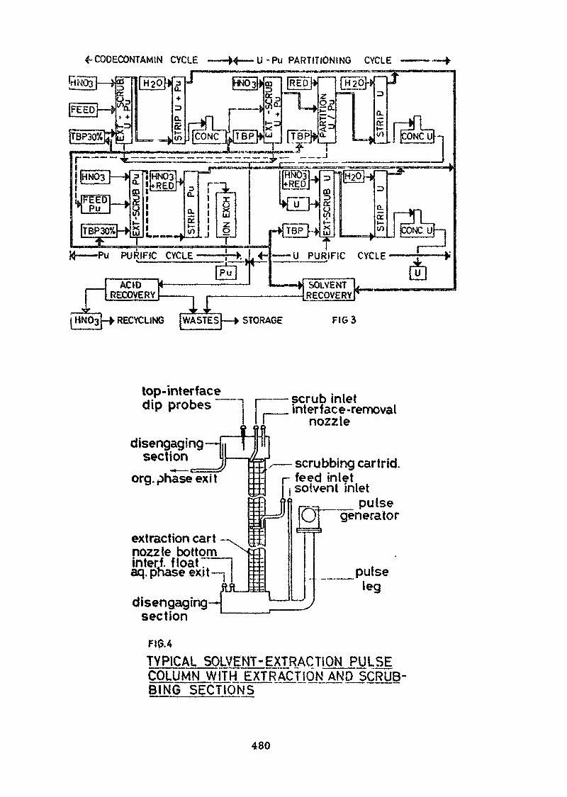
4-CODECONTAMIN CYCLE •M——U-Pu PARTITIONING CYCLE
Pu PURIFIC CYCLE U PURIFiC CYCLE
FIG 3
top-interfacedip probes
disengaging—Hsection I
org. phase ex it
extraction cart ~^vnozzle bottominterf. float:——jaq. phase exit— |
disengaging- ]section
Ul
scrub inletinterface-removal
nozzle
scrubbing cartrid.r feed inlet
solvent inlet_ _ pulse
01 generator
pulseleg
F10.4
TYPICAL SOLVENT-EXTRACTION PULSECOkUM.N_.WiIH EXTRACTION AND SCRUB-BING SECTIONS
480
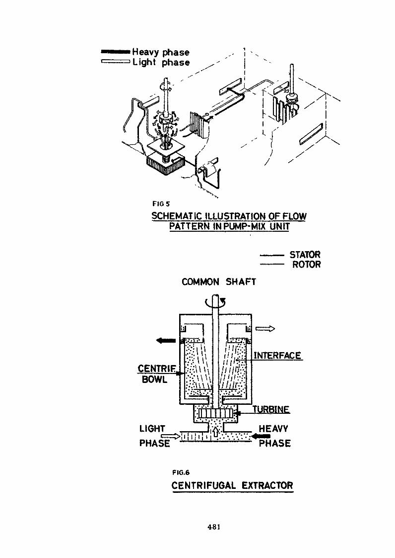
Heavy phaseLight phase
FIGSSCHEMATIC ILLUSTRATION OF FLOW
PATTERN IN PUMP-MIX UNIT
STATORROTOR
COMMON SHAFT
-CENTRIF.BOWL
[ii
<s
nFULJIm''•'•• \ V•:';;' \V
iu!u!s1 —— 1:
:-li 1 1
MM
1
3
ciLS-JL
/ / / / /
Vl MlJlll
.1.* • / # *
1 1 1^1 1 IR
1•r
^» •• » *
;.
M»
1-
kc=i>
INTERFACE
TURBINE
LIGHTPHAsf
* • " Il«d HEAVY"PHASE
FIG.6
CENTRIFUGAL EXTRACTOR
481
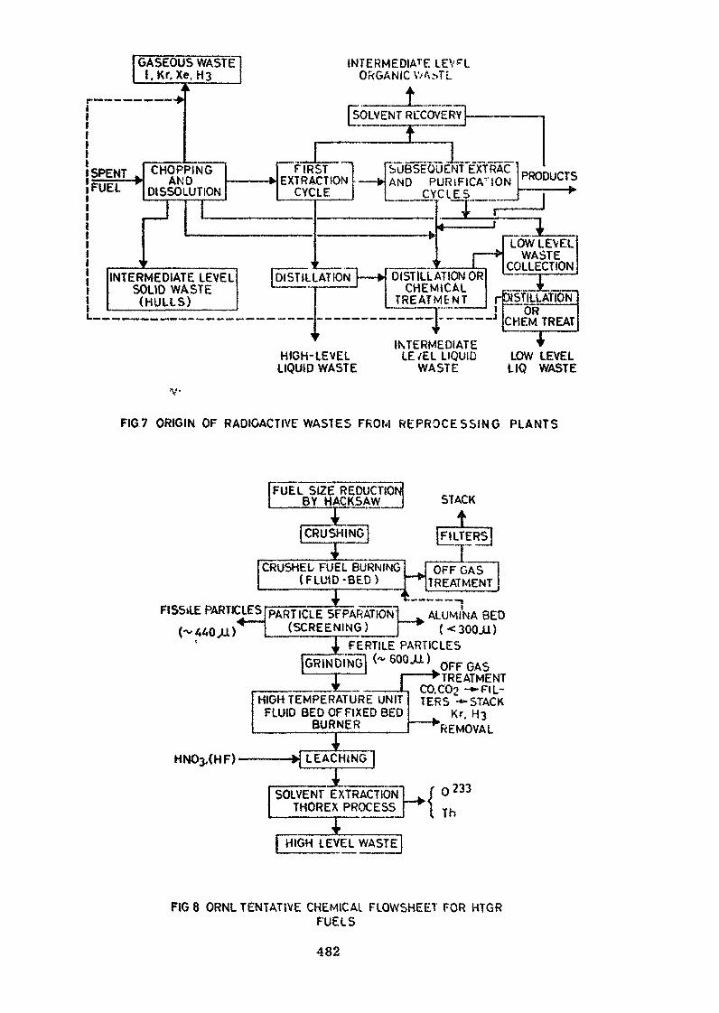
ft* •»«_*• *•«
SPENTFUEL
INTE
! "—
GASEOUS WASTEl.Kr, Xe. H3
4 k
CHOPPING> AND ——
DISSOLUTION
1 r
1
•RMEDIATE LEVELSOLID WASTE(HULLS)
INTERMEDIAREORGANIC V.-A:-
FIR—— > EXTRA
CYC
i[DÎSTILI
^
HIGH-LIQUID
1SOLVENT RCCO^
t
LEV-CLTL
/E'RY] ——
|STCTtONLE
[SUBSEO—— WAND P
CY
. . . . . ...-.t^
r
.AT IONl|
I —— H DISTILL/j vntNj_TREAT^
JENT EXTRURiFICAri<ClES
I" ~rv fif '
. r1ûkTION ORIICAL^lENT f
J^ — — - - - - 4 •--
INTERMEDIATELEVEL LE /EL LIQUIDWASTE WASTE
JJ PRODUCTS
4LOW LEV EL
> WASTECOLLECTION
-OiSTILLATlOTTOR
CHEM TREAT
LOW LEVELLIQ WASTE
V-
FIG.7 ORIGIN OF RADIOACTIVE WASTES FROM REPROCESSING PLANTS
I BY HACKSAW j STACK
FISSiLE PARTICLES
, _ £_,| CRUSH ING
4CRUSHEL FUEL BU
(FLUID -BEE
*
RNiNG))
t >3 PARTICLE SEPARATION'
(SCREENING) ~
tFILTERS!JT
,j OFF GASTREATMENT
. ALUMINA BE(<300.U)
FERTILE PARTICLES
HIGH TEMPERATURE UNITFLUID BED OF FIXED BED
BURNER
LEACHING
SOLVENT EXTRACTIONTHOREX PROCESS
OFF GASTREATMENT
CO.C02 -*• FIL-TERS -«-STACK
"^REMOVAL
0233
Th
[HIGH LEVEL WASTE
FIG 8 ORNL TENTATIVE CHEMICAL FLOWSHEET FOR HTGRFUELS
482
Implication of Reprocessing on Fabrication Techniques
YA3UJÏ NAKAMURASHINRO ABIKO
Abstract•' >
In general, fuel material composition, cladding and other structuralmaterials and fissile atom enrichment as well as fuel element and'assem-bly configurations, fabrication processes and irradiation conditioixs. haveserious efjfects on the specific processes chosen for reprocessing; andon ttte 'Other hand, species of heavy elements, chemical form and qualityspecifications of reprocessing products affect the type of refabricationtechnique, design of recycle fuel element and choice of unit processes inthe refabrication.
Therefore, it is indeed necessary to consider in detail the require-ments and impacts on fuel element design and fabrication technique fromthe standpoint of spent fuel reprocessing and also to endeavor to establishboth efficient uses and economical fabrication techniques through technol-ogy development and industrialization, when a reactor system and itsassociated fuel cycle are planned for the national power generating system.
Depending on its final enrichment, the depleted uranium may be eitherdiscarded, or re-used as blending material or as. source material for re-enrichment. While plutonium may be used for recycling in thermal re-actors , it can be used most effectively as the fast breeder reactor fuels.And whether it will be stored until the commercial fast breeder age isrealized or used for thermal recycling depends on the level of technologi-cal developments and economic conditions in a country. However, thelatter case seems to be more preferred one in many countries.
Following discussions are mainly concentrated on the fuel cyclingin thermal power reactor systems of uranium and plutonium fuels withsome references to our experiences on the plutonium fuels developmentas well as to general reviews of fuel recycling technology in advancedcountries.
483
1. Introduction
The fact that the fuel element designs and fabrication techniquesare quite different with various reactor systems, requires a specificfuel cycle to be selected for a particular reactor system adopted, becausethe selection of a fuel element design involves not only the considerationof geometry, performance and fabricability of the fuel, but also theoverall optimization of the fuel cycle cost, where the actual values ofrecovered fuel materials from reprocessing may also be taken into account.
In general, fuel material composition, cladding and other structuralmaterials as well as fuel element or assembly configuration have seriouseffects on the specific processes chosen for reprocessing on one hand,and the chemical form and quality specifications of recovered materialsaffects the tactics of re-use and thus re-conversion and re-fabricationtechniques on the other hand.
Therefore, it is indeed, necessary to consider in detail the require-ments on fuel element design and fabrication technique from the standpointof reprocessing, when the reactor system and the associated fuel cycleare selected for the national power system.
The aqueous reprocessing processes, which are the only ones to beapplied on an industrial scale presently, seem to be generally versatileand capable of accomodating large variations in fuel composition withoutor with some additional installation of head-end processing equipments.But the economy of reprocessing is largely affected by its capacity scaleand plant load factor, owing to its high capital investment.
Contrary to the reprocessing plant, the establishment of fuel fabri-cation plants does comparatively not require such a high capital invest-ment as to make it difficult on a national level, except for remote re-fabrication facility of highly radioactive recycled fuel materials.
Depending on its final enrichment, the depleted uranium may bediscarded or re-used as blending material or as source material of re-enrichment. While plutonium may be used for recycling in thermal reactorseither as the direct substitutes of enriched uranium fuel element neededfor refueling for the same reactor or as the burning fuel in some particu-lar reactors of the same or diffent type. Needless to say, plutonium ismost.effectively used as the fast breeder fuel, and might be stored untilthe commercial fast breeder age is realized
As for the U-233 and thorium, fuel-cycling, the system is still invery premature stage compared with uranium and plutonium fuel-cycling,and seems to be developed independently.
Following discussions are mainly concentrated for the fuel-recyclingin thermal power reactor systems of uranium and plutonium fuels.
2. Considerations on unit-process economy in fuel cycle stages.
2.1 General
The demand for nuclear fuel processing increases year by year witha gradual growth rate, while the process capacity is increased step-wisely as the result of additional installations. The unit-processcost is affected more or less by its plant capacity, reducing theunit cost with the increasing capacity. On the other hand, the grosseconomic demerit is much greater in case of low plant factor havinga large process capacity.
The economic character of each processing in the nuclear fuel cycleindustry is widely different. The unit cost of reprocessing involve»big fractions of the fixed capital and operational costs, and minorfractions of variable operational costs such as chemicals and utilities,
484
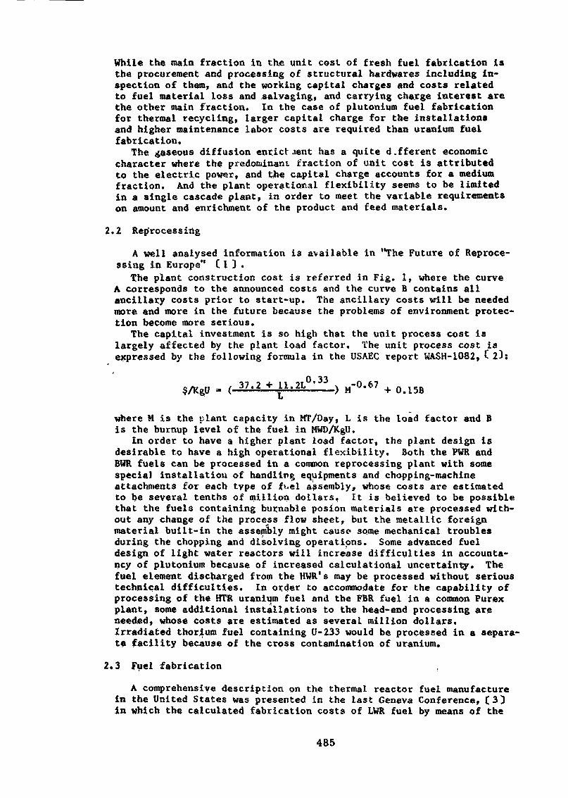
While the main fraction in the unit cost of fresh fuel fabrication isthe procurement and processing of structural hardwares including in-spection of them, and the working capital charges and costs relatedto fuel material loss and salvaging, and carrying charge interest arethe other main fraction. In the case of plutonium fuel fabricationfor thermal recycling, larger capital charge for the installationsand higher maintenance labor costs are required than uranium fuelfabrication.
The gaseous diffusion enrictaent has a quite d.fferent economiccharacter where the predominant fraction of unit cost is attributedto the electric power, and the capital charge accounts for a mediumfraction. And the plant operational flexibility seems to be limitedin a single cascade plant, in order to meet the variable requirementson amount and enrichment of the product and feed materials.
2.2 Reprocessing
A well analysed information is available in "The Future of Reproce-ssing in Europe" CI ) .
The plant construction cost is referred in Fig. 1, where the curveA corresponds to the announced costs and the curve B contains allancillary costs prior to start-up. The ancillary costs will be neededmore and more in the future because the problems of environment protec-tion become more serious.
The capital investment is so high that the unit process cost islargely affected by the plant load factor. The unit process cost isexpressed by the following formula in the USAEC report WASH-1082, C 23:
$/KgU = ( 37'2 * j;1>2L *——) M~°'67 + 0.15B
where M is the plant capacity in MT/Day, L is the load factor and Bis the burnup level of the fuel in HWD/KgU.
In order to have a higher plant load factor, the plant design isdesirable to have a high operational flexibility. Both the PWR andBWR fuels can be processed in a common reprocessing plant with somespecial installation of handling equipments and chopping-machineattachments for each type of ft.el assembly, whose costs are estimatedto be several tenths of million dollars. It is believed to be possiblethat the fuels containing burnable posion materials are processed with-out any change of the process flow sheet, but the metallic foreignmaterial built-in the assembly might cause some mechanical troublesduring the chopping and disolving operations. Some advanced fueldesign of light water reactors will increase difficulties in accounta-ncy of plutonium because of increased calculational uncertainty. Thefuel element discharged from the HWR's may be processed without serioustechnical difficulties. In order to accommodate for the capability ofprocessing of the HTR uranium fuel and the FBR fuel in a common Purexplant, some additional installations to the head-end processing areneeded, whose costs are estimated as several million dollars.Irradiated thorium fuel containing U-233 would be processed in a sépara*te facility because of the cross contamination of uranium.
2.3 fuel fabrication
A comprehensive description on the thermal reactor fuel manufacturein the United States was presented in the last Geneva Conference, (3Din which the calculated fabrication costs of LWR fuel by means of the
485
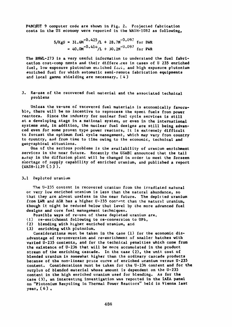
FA.BC0ST 9 computer code are shown in Fig. 2. Projected fabricationcosts in the US economy were reported in the WASH-1082 as following,
$/KgU » 31.6M~°'425/L + 28.7M"0*097 for BWR= 40.0M-°-41VL + 30.2M-°-097 for PWR
The BNWL-273 is a very useful information to understand the fuel fabri-cation cost-comp nents and their diffère .ces in cases of U 235 enrichedfuel, low exposure plutonium eiuiched faoi, and high exposure plutoniumenriched fuel for which automatic semi-remote fabrication equipmentsand local gamma shielding are necessary. (4)
3. Re-use of the recovered fuel material and the associated technicalproblems
Unless the re-use of recovered fuel materials is economically favora-ble, there will be no incentive to reprocess the spent fuels from powerreactors. Since the industry for nuclear fuel cycle services is stillat a developing stage in a national system, or even in the internationalsystems and, in addition, the nuclear fuel designs are still being advan-ced even for some proven type power reactors, it is extremely difficultto forcast the optimum fuel cycle management, which may vary from countryto country, aad from time to time owing to the economic, technical andgeographical situations.
One of the serious problems is the availability of uranium enrichmentservices in the near future. Recently the USAEC announced that the taila»say in the diffusion plant will be changed in order to meet the forseenshortage of supply capability of enriched uranium, and published a report(WASH-1139 C53 ).
3.1 Depleted uranium
The U-235 content in recovered uranium from the irradiated naturalor very low enriched uranium is less than the natural abundance, sothat they are almost useless in the near future. The depicted uraniumfrom LWR and AGR has a higher U-235 consent than the natural uranium,though it might be reduced below that level by the more advanced fueldesigns and core fuel management techniques.
Possible ways of re-use of these depleted uranium are,<1) re-enrichment following to re-conversion to UF6,(2) blending with higher enriched uranium, and(3) enriching with plutonium.
Considerations must be taken in the case (1) for the economic dis-advantage of re-conversion and re-enrichment of smaller batches withvaried U-235 contents, and for the technical penalties which come fromthe existence of U-236 that will be more accumulated in the productstream of the enriching cascade. In the case (2), the unit cost ofblended uranium is somewhat higher than the ordinary cascade productsbecause of the non-linear price curve of enriched uranium versus U-235content. Considerations must be taken for the U-236 content and for thesurplus of blended material whose amount is dependent on the U-235content in the high enriched uranium used for blending. As for thecase (3), an interesting investigation was reported in the IAEA panelon "Plutonium Recycling in Thermal Power Reactors" held in Vienna lastyear, (6) ,
486
3.2 Plutonium
The plutonium isotopic compositions and their contents in the dis-charged fuel are widely varied with the neutron energy spectrum in thereactor core and the exposure level of the fuel* The recovery cost ofplutonium from the irradiated natural or very low enriched uranium ishigher than that from the irradiated LWR uranium fuels, because of thefact that the plutonium content is lower and all the processing expensesmust be practically borne by the plutonium in the former case. (7)
Plutonium has a higher value as a fast breeder fuel than a thermalpower reactor fuel. But the annual production rate of plutonium willby far exceed over the demand for the fast breeder development in thecoming ten or fifteen years. Stock-piling of the plutonium causes someeconomic problems: hoarding of valuable material, the capital chargeinterest for its potential value as well as the actual expenses forrecovery and storage, and the deterioration due to the decay of fissilePu-241 into non-fissile Am-241. The safeguarding requires something anadditional expense.
Plutonium is a highly toxic, alpha-emitter and the dose rates ofgamma-rays and spontaneous-fission-neutrons are significant in caseof recycled plutonium owing to the higher contents of heavier isotopes.The critical My mass is so much smaller than U-235 that the accountabi-lity controls and the nuclear safety considerations arçe very Importantin the p Hi Ionium handling operations. Alpha-tight glove-boxes withlocal gantnia shielding equipped with mechanized or automated proc.ess-ma-chtn'es are necessary for the plutonium fuel fabrication in largequantities1. So the incremental fabrication cost of. the--plutoniumfuel over that of the corresponding enriched uranium fuel is signifi-cant as shown in Fig. 2.
Theoretical feasibilities of the plutonium.-recycling in AGR, HWRand LWR have been studied; however, the commercial utilization seemsto be carried out only for LWR in the near'future from the view pointsof economic feasibility and development stage of the associated tech-nologies. Plutoniun»*recycling in large PWRs and BWRs has been demon-strated in the United States and Western Europe, and is being studiedin Japan, too. Technical information exchanges and discussions havebeen we'l done in the IAEA sporsored technical paiels. f 8) A recentreview on the plutonium'fuel fabrication was reported in a journal. C9)
Present installations of plutonium fuel fabrication facilities arelimited in their numbers and capacities, and the factual incrementalfabrication cost seems to be higher than the forçast. Even if a largescale commercial plutonium recycling becomes in reality, the demandsfor plutonium fabrication are less than one fifth of. those for uraniumfuel, so the actual cost differences will be larger than the onecalculated for the same production capacity. The actual plutoniumfuel fabrication cost penalty will affect the plutonium prices in thefree market if it should exist.
3.3 LWR fuel cycle
Future cost projections for each stage of the LWR fuel recyclingare given in the WASH-1082. The projected data generally agree withthe recent cost trends, one exception of which is the revision ofuranium enrichment service charge of the USAEC.
An economic consideration of, fuel-recycling based on these costsdata and the material balance calculations was reported by the presentauthor in the last IAEA Plutonium Recycle Panel, f10j Though thecalculations did not include the transportation costs of fresh fuel
487
material and the carrying charge interests, thereby it gave only theeconomic trends, the results seemed to be suggestive for the under-standing of the economic implication of reprocessing and recovered-fuelrecycling in the LWR system which would be taken place in the nearfuture. The fact that a significant saving of the requirement forenrichment service is possible by the plutonium recycling, should bestressed.
As for the fabrication techniques of plutonium fuel for LWR recycling,almost same process-techniques as U02 pe'let fabrication are applied,that is, cold pressing, pre-sintering, sintering and centerless grindingif necessary. The differences are the powder preparation and itscharacterization. In the powder mechanical blending process, whichis a predominant process used in various facilities, fine particlesof Pu(>2 is mechanically blended with U(>2 powder by means of ball millsor kneiders, followed by V-blender-mixing according to the requirementon plutonium homogeneity. The plutonium oxide is usually derived fromoxalate precipitation by calcination at high temperature. As the PuO?forms a solid-solution with UÛ2 at the higher temperature while thefuel pellets are loaded in the reactor core, this process gives asatisfactory irradiation performances for thermal reactor conditions,unless the size of Pu<>2 particle agglomerates is not so big as a fewhundred microns. The co-precipitation process in which the plutoniumhydro-oxide precipitates together with the ammonium di-uranate fromuranium-plutonium blended nitrate solution by the addition of ammoniumhydroxide, gives a better homogeneity of plutonium in the finishedpellets. However, the process seems to be a little more expensive thanmechanically blending process, because the handling limit of plutoniumin solution state is as low as 220 grams due to the criticality consi-deration.
Since the Pu-241 decays into Am-241 with a half-life of about 13years, and the gamma emission from the daughter of Am-241 is fairlystrong, and the thereby the external radiation dose increases as theelapse of time after the reprocessing, a chemical purfication processprior to the plutonium fuel fabrication is advisable.
The fuel rod fabrication process and final assembling are the sameas those of enriched uranium fuel fabrication, though more carefuloperations are required, for the decontamination and radiation monitoring.
The alternate techniques such as vibratory compaction and associatedSol-Gel processing have been developed, and seem to be economicallypromising. However, the potential cost savings by these processes forthe thermal reactor fuel do not seem to justify the further developmentand expensive assessments including irradiation tests, from the viewpoints of the total economy of fuel fabrication as well as the conser-vative attitude of the users. CH)
3.4 HWR fuel cycle
The Standard CANDU type heavy water reactors are fueled with naturaluranium and the once-through use of the fuel has been projected. ACanadian report was presented in the IAEA Pu Recycle Panel in 1971 inwhich a fuel costs evaluation including plutonium recycling was madefor the CANDU-PHW type reactor. C123 it was reported that the pluto-nium recycling in the system will be profitable if the plutonium cannotbe sold at $8/gram or more.. As the only one valuable material in the
488
reprocessed products is plutonium, some modifications of the processflow-sheet of reprocessing and waste, management would be necessary.Since the fuel rod diameter is larger, its length is shorter «nd fuelassembly design is simpler than those of LWR fuel, the automated re-fabrication techniques would be possible tu achieve lower fabricationcost expressed as $/KgM.
A heavy water moderated and light water cooled power reactor systemis being developed in several countries. This type of the reactor issaid to have a high operation flexibility, that fs, the reactor couldbe operated not only with siigntiy enriched uranium oxide fuel butalso with uranium-plutonium mixed oxide fuel without any modificationof fuel assembly design, giving almost optimum condition of powergenerating cost for both cases. Thus this reactor will present afavorable selection of fuels for users, from time to time, dependingupon the economic situation. Should one does care to use or to feednatural uranium only, "Plutonium Self-Sustaining Cycle" would thenbe proposed, in which the natural uranium enriched with plutonium(recovered from its own spent fuel) is to be fueled. C13) As theaverage conversion ratio of HWR is around 0.7--0.8 for U-Pu cyclewhile that of LWR is 0.6 or less, the natural uranium consumption perunit power generated in LWR is 1.5 to 2 times as much as the one inHWR. The power generating cost would not be so affected by the pricechanges of uranium and enriched uranium. The fuel cycle cost in(NU+Pu) fuel system is affected by plutonium cost, enrichment andmixed oxide fabrication cost as shown in ( 131 .
.5 HTR fuel cycle
Several investigations on the fuel cycling in thorium fueled HTRswere reported in the IAEA Symposium on Thorium Utilization in PowerReactors, Vienna, June 1965 (143 , and the International Conferenceon Fuel Cycles of High Temperature Gas Cooled Reactors (153 , (163 .The USAEC report WASH-1085 contains many comprehensive informations.(173As the coated-particle (U, ThK^ fuel has shown good irradiation
behaviors, more HTRs are expected to be introduce in the nuclearpower generating systems in future. Though many elaborate develop-mental works have been carried out on both reprocessing of the irra-diated fuel and re-fabrication, there remain man> technical aspectsto be developed in these fields of the fuel cycle technologies andabove All, no commercial facilities to process large quantities of thematerial are existing at present.
A special head-end processing prior to solvent extraction is neces-sary such as. mechanical crushing and screening of irradiated fuelelements followed by burn-and-leaching.
Irradiated fissile particles contain residual U-235, bred U-233,remaining Th-232 and minor fractions of other heavy metal atoms andfission products. Irradiated fertile particles contain similar kindsof heavy elements except for U-235. The FORATOM report, referredabove (1) says as follows. "The cost of such a facility capable ofhandling 2t/d of the HTR fuel may add 10-15% to the investment costof a 5t/d LWR fuel reprocessing plant excluding the costs of develop-ment work. It is doubtful if the.HTR fuel containing thorium shouldbe processed in a plant normally handling uranium, becuase the cross-contamination of uranium isotopes will be hard to avoid. Other specificproblems are due to the higher gamma radiation and longer decay timeencountered in the thorium cycle."
489
Irradiated thorium is highly radiactive owing to the co-existenceof Th-228, Th-224 and Th-23l. And the high energy alpha particles ofthe recycled U-233 and its decay products can produce significant fastneutron dose rates as a result of {<x , n) threshold reactions withlight elements. These high radioactivities make the re-fabricationnecessarily to be performed remotely in a heavy shielding, so thatthe re-fabrication of recycled fuel in the Th-U cycle requires bothmore advanced technology and mote expensive facilities than the re-fabrication of recycled fuel in the case of U-Pu cycle. However, owingto the high burn-up of virgin as well as recycled fuels, the fuel cyclecosts in the U-Th cycle are expected to be reasonable.
An interesting analysis of the HTGR recycle economy as a functionof the time when recycling is started in the projected growth of thereactor system in the United States is reported in a ORNL publication,C181
4. Conclusion
Introduction of a large nuclear power generating capacity in a nationalsystem as well as the choice of the reactor types has a very close inter-relation-ship with the technological development and industrializationof the associated nuclear fuel cycle on the national basis.
Since different reactor systems require different fuel element designs,if multiple reactor types are adopted in a national nuclear power system,it will be necessary to install multiple fuel fabrication plants in thecountry, though some flexibilities are possible for uranium oxide fuelsfabrication for PWR, BWR and HWR capable of carrying out in a single plant.
Spent fuels reprocessing from multiple reactors will be carried outin a single plant with or without additional installations of head-endfacility depending upon economic point of views. More detail investiga-tions and development works seem to be necessary in order to decidewhether the irradiated thorium bearing-fuels should be processed in aseparate reprocessing facility or not.
Since the economy of spent fuel reprocessing largely depends on thescale of plant capacity and its load factor, the installation of reproces-sing plant should be considered both nationally and internationally» basedon the forcast of growth rate of nuclear power generation in the nation.
In the field of re-fabrication of recycle fuels, the plutonium-uranium mixed oxide fuels for LWR, HWR and AGR, if planned, can be handledin a same facility in the early stage of the development. The manufactur-ing of hardware components and final assembling may be conducted in theexisting U(>2 fuel fabrication facility.
It seems to be unpractical that the mixed carbide fuel fabrication isconducted in a same facility used for the mixed oxide fabrication, becauseseparate glove-boxes with inert gas atomosphere are necessary for theformer operation.
The thorium-U-233 mixed oxide or mixed carbide fabrication must bedone in a separate facility with the heavy shielding» and remote fabri-cation equipments.
Major questions to be answered in planning the extension of fuelcycle schemes as well as the development efforts of various reactorsystems are as follows:
(1) What is the proper timing for commercial construction of fuel fabri-cation plant, reprocessing plant, and refabrication facility?
(2) Will the plant load factor be kept at sufficient high levels?(3) Can the quality of recycle fuel be consistently high for power
reactor use under the commercial fuel war tanty system?
490
(4) How will the fuel value trends afftct, and be affected by economicimprovements in over-all recycle ttchnoio^v?
(5) What will be the market situation of nuclear fuel supply and possiblesavings of resources and service capacities at the time considered?
References
1 FORATOM, "The Future Reprocessing in Europe" 19682 WASH-1082, Current Status & Future Technical & Economic Potential
of Light Water Reactor*, 1968
3 A/COWF. 49/P/Q62, A.L. Letts et al, The status of Thermal ReactorFuel Manufacture in the United States, 19"l
4 BNWL-273, J.B. Burnhara et ai, Comparative Costs of Oxide FuelElements, The Computed Cost of Fuel Elements Enriched withor Low Exposure Plutonium or High Expo&uce Plutonium
5 WASH-Î139.
6 PL447/9-3, XAEA Panel on Pu Recycling in Thermal Power Reactors1971, F. de Waegh et al, Belgian Dewnstration Programme onPlutonium Recycle, Part III Recycle Concept for the SENA Reactor.
7 P1447/47, IAEA Panel on Pu Recycling in Thermal Power Reactors 1971,F. Lafontaine,
8 IAEA Panel on Pu Fuel, 1964, 1968, 1971
9 S,E, Rippon, Plutoniunv-Problems and Possibilities, Feb. 1972,Nuclear Engineering International
10 PL447/22, IAEA Panel on Pu Recycling in Thermal Power Reactors,1971, Y. Nakamura, Ail An Economic Consideration on PlutoniumRecycling in Light Water Reactors
11 PL447/4 , IAEA Panel on Pu Recycling in Thermal Power Reactors1971, Vandem Bemden,
12 PL447/1 , IAEA Panel on Pu Recycling in Thermal Power Reactors1971, M.F. Duret, Pu Recycle in CANDU-Type PHW Heavy Water Reactors.
13 A/CONF. 49/P/232, S. Shima et at, Development of Prototype HeavyWater Reactor (FUGEN) in Japan,
14 IAEA Symposium on Th Utilization in Power Reactors 1965.
15 international Symposium on Fuel Cycles of High Temperature GasCooled Power Reactors, 1965.
16 Second International Symposium on Thorium Fuel Cycle System, 1966.
17 WASH-1085.
IB SM/111/25, Symposium on Advanced and High-Temperature Gas-cooled Reactor
A.L. Lotts 4 R.G, Wymer» Economics and Technology of HTGR Fuel Recycle.
491
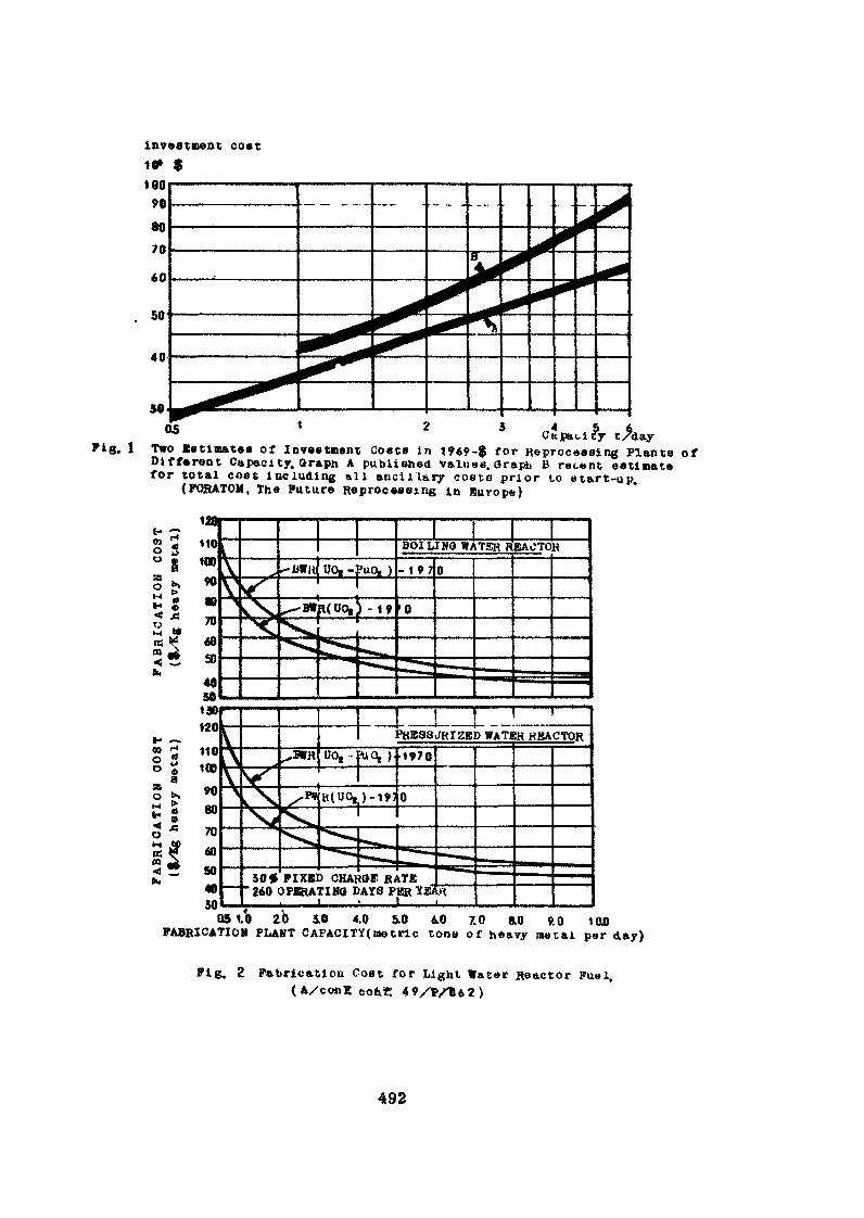
Capacity t/dayTwo Estimates of Investment Costs in 196?-$ for Reprocessing Plants ofDifferent Capacity. Oraph A published Valuee. Oraph B recent estimatefor total cost including all ancillary cost» prior to etart-up.
(FORATOM, The Future Reprocessing in Europe)
PKSSSJHIZED WATJBR HBACTOR
260 OKRRATIMO DAYS PER ÏEJI __ !__ ._ ._ . . . I___
2.b 5.0 4.0 5.0 40 7.0 &0 9.0 100FABRICATION PLANT CAFACITY(metrie tone of heavy metal per day)
Fig. 2 Fabrication Cost for Light Water Reactor Fuel.
492
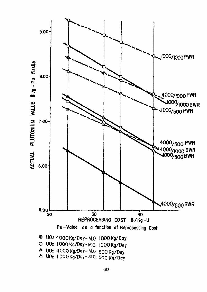
1»*S5
CLI
-ǻ4*
LU
e
<H-
4000/iooQ pWRIOOO/IOOOBWR
I000/500 PWR
30 40REPROCESSING COST 8/Kg-U
Pu-Value as a function of Reprocessing Cost
© UOa 4000 Kg/Day-M.O. 1000 Kg/DayO U02 1000 Kg/Day-M.Q 1000 Kg/Day^ U02 4000 Kg/Day- iVt.o. 500 Kg/DayA U02 1000 Kg/Day-MO. 500 Kg/Day
493
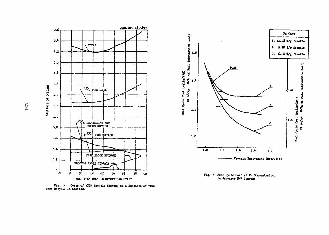
OBNL-DWO 68-3899
to
PROCESSING ANDREFABRICATIOfl
71» 76 78 ÔC 82 84 86 88 90YEAH WHO) RECYCLE OPERATIONS START
Fig. 5 Costs of HTGR Recycle Economy as a Function of Time«her. Recycle is Started. '
8•H
1.6
r-
I
•a 1.2
1.0
1.0
PuSS
PU Coat
A : 13.28 9/g fiaeile
B : 9.28 «/g fissile
C : 6.28 f/g fissile
1.2
2.0
1.6 g
5
î1A 1.6 1.8
Fissile Enrichment (HU+Pu)(#)
Fig.-4 Fuel Cycle Cost rs Pu Concentrâtionin Japanese BWR Concept
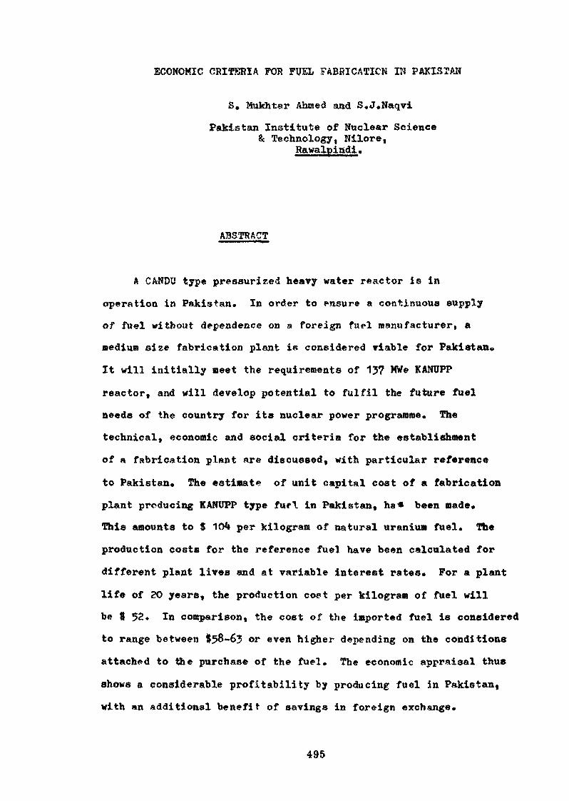
ECONOMIC CRÏTÎ5RÏA FOR FUEL FABRICATION IN PAKISTAN
S. Mukhtar Ahmed and S.J.Naqvi
Pakistan Institute of Nuclear Science& Technology, Nilore,
Rawalpindi»
ABSTRACT
A CANDU type pressurized heavy water reactor is in
operation in Pakistan. In order to ensure a continuous eupply
of fuel without dependence on a foreign fuel manufacturer, a
medium size fabrication plant is considered viable for Pakistan*
It will initially meet the requirements of 137 MWe KANUPP
reactor, and will develop potential to fulfil the future fuel
needs of the country for its nuclear power programme. The
technical, economic and social criteria for the establishment
of a fabrication plant are discussed, with particular reference
to Pakistan. The estimate of unit capital cost of a fabrication
plant producing KANUPP type furl in Pakistan, ha* been made*
This amounts to $ 104 per kilogram of natural uranium fuel. The
production costs for the reference fuel have been calculated for
different plant lives and at variable interest rates. For a plant
life of 20 years, the production coet per kilogram of fuel will
be ft 52» In comparison, the cost of the imported fuel is considered
to range between $58-63 or even higher depending on the conditions
attached to ttoe purchase of the fuel. The economic appraisal thus
shows a considerable profitability by producing fuel in Pakistan,
with an additional benefit of savings in foreign exchange.
495
1. INTRODUCTION
This paper attempts to give national views about the importance,programmes ana criteria for the establishment of a fuel fabricationplant with particular reference to the economic aspects of the project.Pakistan has recently entered the field of nuclear power production byputting up a 137 MWe pressurised heavy water reactor of CANDU type inKarachi* We further have a modest nuclear power programme of producingo\er 1000 MWe by the end of the decade by installing a 500 Mtfe powerplant in-the northern areas of Pakistan, as well as a *fOO Mtfe $aa£ purposeplant on the Makran Coast*
In order to ensure a smooth running of the power programme and toavoid continuous foreign dependence, it is planned to establish differentnuclear fuel cycle industries in Pakistan» The fuel fabrication planthas been chosen as the first industry out of the fuel cycle programmebecause,
a) the fuel fabrication occupies an important position in anuclear fuel cycle and the costs of fuel fabricationinfluence significantly the fuel cycle economics of the nuclearpower plants*
b) ensuring regular annual supply of fuel for Karachi Plant(KANOPP)is important, in order to avoid dependence on a foreign fuelsupplier*
It has,therefore, been decided to set up a medium sized fuel fabricationplant of capacity less than 100 tons/year* This plant would initiallybe used exclusively for the manufacture of KANUPP fuel anl later it couldbe adapted to other typos of fuel for the reactors to be establishedin the country.
*• PROGRAMME AND CAPABILITIES
In the beginning, the natural uraniua«zirealoy clad fuel for heavywater reactors will be manufactured under licence from some foreign fuelmanufacturer and later on capabilities will be developed to fabricateother types of fuels. The KANUPP fuel bundle is of split spacer designas shown in figure I. It has already been adopted for replacement fuel
496
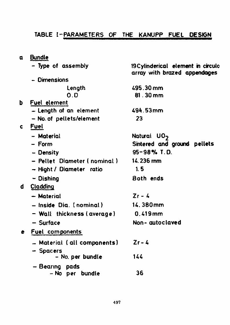
TABLE ^PARAMETERS OF THE KANUPP FUEL DESIGN
Q Bundle
e
- Type of assembly
- DimensionsLength0.0
Fuel element- Length of an element- No. of pellets/elementFuel- Material- Form- Density- Pellet Diameter ( nominal )- Might / Diameter ratio- Dishing
Cladding- Material- Inside Dia. (nominal)-Wall thickness (average)- SurfaceFuel components- Material (all components)- Spacers
- No. per bundle- Bearing pads
- No per bundle
19Cylinderical element in circulearray with brazed appendages
495.30mm81.30 mm
494.53mm23
Natural U02Sintered and ground pellets95-98% T.D.U. 236 mm
1.5Both ends
Zr- 4U. 380mm0.419mm
Non- autoclaved
Z r - 4
144
36
497
for NPD and Douglas Point, as well as for the initial charges for thePiekering reactors. It differs from the old generation wire-wrap bundledesign* It is a nineteen element bundle with over-all dimensions of81 mm in diameter and 95 tarn long, which are supported by two end platesand separated by spacers with bearing pads on the outer periphery ofthe 12 outside elements. Some parameters of the KANUPP fuel design dataare presented in table 1.
2.1The technology involved in the manufacture of the KANUPP type fuel
mentioned above can be divided into two broad categories end is brieflyexplained for récapitula ti on as follows :
- Pellet Fabrication- Bundle Fabrication
2«1»1 Pellet Fabrication!» Ike uranium dioxide powder is compacted to"green1 pellets by double pressing and -granulation technique» the •pressed green compacts are sintered in hydrogen atmosphere. The sinteredpellets, after being discharged from the sintering furnace, are groundto the required diameter in a centreless grinding operation, washed anddried for final inspection before loading*
2.1. î>i Bundle Fabrication The zircaloy fuel sheaths after degreasingare put to induction brazing. It consists of coating the zircaloy stripswith beryllium vapours, and then blanking out the bearing pads and spacersout of the zircaloy strip. Bearing pads are tack welded to 12 éléments,and the spacers to all the 19 elements. The elements are then brazedunder vacuum and cooled. The tubes are cut to exact length and weldedat its one end with prepared end-plugs by magnetic welding. The tubesare then loaded mrjiually in the upright position and the second ends-plugsarc welded once again on the magnetic welding machine. The completedelements are placed in the bundle assembly fixture where the end-platesand the elements are assembled and the complete fixture is placed in theresistance welding machine on a pneumatic indexing table. The indexingtable helps to locate each weld or clement site under the weldingelectrode and also rotates the assembly on different pitch circles.After completing this operation on both end-plates, the bundle issubjected to final inspection.
2.2. Research & Developjaent Efforts
In order to back up a successful commercial operation of thisnature, and to carry out the developmental work, the Pakistan Atomic
498
Energy Commission (PAEC) has decided to set-up well established materialslaboratories at its research Institute, PINSTËCH. The laboratoriesrelated with fuels have already been set-up, with facilities for thetreatment of yellow cake and Manufacture of uranium dioxide« thepelletization and sintering of ceramic fuels» the welding and surfacetreatment operations, measurement of powder properties, and differentfacilities for the non-destructive and destructive testing of fuelelements etc. Efforts are being m*de to oxpand the scope of non-destructive testing- facilities, in order to be able to check upand control the specifications of the incoming «iterials and the produce.For the fuels development programme, the poat-irradiation examinationfacilities are under construction and in due course of time moreelaborate metallurgical rcsewrch tools will be available in theselaboratories»
3. CRITERIA FOR ESTABLISHMENT OF PLANTS
The national criteria of Pakistan for establishing a plant isperhaps not much different from the international criteria, except thatcertain factors are to be given more importance than in a developedcountry* The main factors taken into consideration are, the economicfeasibility, technical know-how, the manpower availability, the resources,the availability of raw mat* rial and a sense of self reliance. Thesolution to most of these factors and a compromise to some extent withthe remaining factors have led to the final decision of establishing afuel fabrication plant in Pakistan*
3.1 EconomicLF Feasibility
This «actor is of prime importance internationally, and becomesa starting point for nil other factors for consideration. However, theimportance of 'foreign exchange* for a developing nation gives adifferent perspective to this factor. Contrary to the general principle
' »«,of producing at & price competitive to the imported cost and therebymaking a saving; a certain saving in foreign exchange is of significanceeven if tho over-all production cost in terms of local currency ishigher than the imported cost. The fuel fabrication plant has beenfound to be economically feasible in Pakistan nnd the detailed economicsof the fabrication plant will be dealt in the later part of the paper.
499
3»2 Technical Know-how
The technical know-how would be achieved by fabricating the fuelunder license from a competent foreign fabricator* In addition, asmentioned earlier the material « 1«boratorles at PINSTECH will providerequisite base knowledge as well as a nucleus for know-how advancement.
3«3 Manpower
Pakistan Atomic Energy Commission has over the years made effortsto build a basic trained technical manpower» which would sustain thenational power programme. In this regard, PAEC has been able to trainover $00 scientists and engineers in different nuclear fields» In orderto meet the particular requirements of tho fuel cycle programme, aNuclear Materials School has been considered to be established at PINSTECHfor the fresh professionals and technicians coming out of theuniversities and plytechnic schools. The orientation coursas innuclear materials and practical training» will further help tobuild up teams who could take care of the different projects*
3*4 Resources
Even the economic feasibility has to be reviewed in the lightof country's over-all national development programme, which considersthe merits of a project in the light of the availability of foreignloans| assistance etc. The nature of the loans not only effectsthe economic feasibility due to different interest ratc-s, but alsolimits the choice and manner of utilization of the loans in certaincases* Therefore, even tho technical merits of a project have to becompromised at times, because of its being tied up with the source ofaid/assistance.
3.5 Raw Material
The nature of a project depending on indigenous or importedraw material determines its continuous dependence on a foreign country,Hence a care has to be taken in assuring a continuous supply of rawmaterial and the foreign exchange requirements thereof* For the fuelfabrication requirements, it is planned to import continuouslythe cladding material. However, for the fuel material encouragingdeposits of uranium have been found in Dera Ghazi Khan district alongthe Indus River, The work is being carried out to determine theextent of the deposits and to exploit thorn. In the meantime the work
500
has been started to concentrate the loc-«l ore| a pilot plant of 1000••»
Ibs/day capacity has been built at Lahore and the Yellow cake hassuccessfully been produced therein.» However, till such time that theindigenous uranium is available « the fuel material will bo purchasedfrom the international market, and the plans *re in hand to assure itsavailability.
3*6 Self Reliance
Even in the case of some unfavourable economic aspects of aproject, the f net or of self reliance become» worth consideration. Thepolicies of a developing nation rely to a large extent on internationalpolitics and t the re fore, eolf sv Tficioncy to the greatest extent isdesirable.
*• SC080MIC ASPECTS OF FUEL FîvBBIC..TION
The economics of fuel fabrication in Pakistan has been studiedfor a medium size plnnt of capacity less than 100 tons/year basedon concrete offers* The fabrication cost has been worked out on jobshop basis for KANUFP type natural uranium fuel and is represented, in1972 dollars.
Cost
The unit capital cost of a plant in it/kg U is represented intable 2. The Plant would cost 9 104/kg u* with 90 p«?r cent inforeign exchange, showing a great deal of dependence on foreign loans andassistance. The taajor expenditure incurred is under the head of directcosts amounting to 8?£ of the total capital, of which the plant equipmentend hardware is the most significant, being entirely in foreign exchange.Tha plant equipment hend is inclusive of the cost of air conditioningequipment in addition to the normal process fabrication equipment. Theclimatic conditions of the site necessitate summer airconditioning,costing nearly 10$ of the totnl equipment cost. The f&e for technicalknow-how and consultation to the tune of 10#, mostly in foreign exchange,is also a significant expenditure. This adds a great strain on thetotal foreign exchange liabilities vis-a-vis the quantum of theinformation and the help extended in addition to the restrictions imposedon the utilization of the information for purposes other than specified.
Of the indirect costs, the interest on the capital during theconstruction poriod of little over 2 ye*rs is also 10# of the capital »
501
The interest rate of 6% on the foreign exchange and 8# on the localcurrency has been considered* In case softer long term foreign loans wereavailable to the government, it would make a great difference on thefabrication cost due to lower capital cost as well as its amortization*
4*2 Annual Operating Cost
The annual operating cost of the fabrication plant in S/kg U/yearis given in table III. The total operating cost inclusive of thematerial cost is $ Mi-,60 of which 82$ is in foreign exchange*
The material cost constitutes ?8# of the total operating cost,with90# in foreign exchange and 10$ for the gases etc. available in thelocal market» The calculations of the material cost have been based onUO price of $ 19/kg* The cost of all other material calculated is basedon the actual plant experience of the licensor and is known in termsof IAg of tfOg' The electricity cost has been considered as 5 mills/unit*
The royalty fee is to be paid on a fixed production extended over10 initial years of production. The royalty fe« is nearly 8$ of the-total operating cost, entirely in foreign exchange and is the secondlargest cost factor after the materials cost*
•3 Cost of Production
Different fuel production costs have been calculated by consideringthe amortization of the capital for plant life of 10-3O years and atdifferent interest rates» The interest on the locil currency componenthas been taken at a fixed rate of 8$, while the foreign exchange componenthas been discounted at 6# rate as is generally the- case, to mostoptimistic rate of 29$» The results have been shown in table IV, The twoextreme limits of fu l production coat includinr; material are 3 49*9 to58,7/kg U, with a foreign exchange- component of irounc! 80$. This wouldreadily indicate a foreign «xchange saving of the order of 20$ perkg of the fuel| even If the production cost would hive boon just compe-titive to the imported fuol. It may be noted that the net f \brication costwithout material of the type of 'uel undor consideration varies between$ 2 - $ 15» This rrm c of fabrication costs comports well with thosereported (1), (2), (?) & (if).
'A comparison of the cost of the imported fuel with that manufacturedin Pakistan is illustrated in figure 2. The cost of the foreignmanufactured fuel iê considered to be ranging between $ 58 - 63/kg U,Itis apparent that only -at 10 years plant life the fuol fabricated inPakistan is not competitive with the imported fuel at its minimum price
502
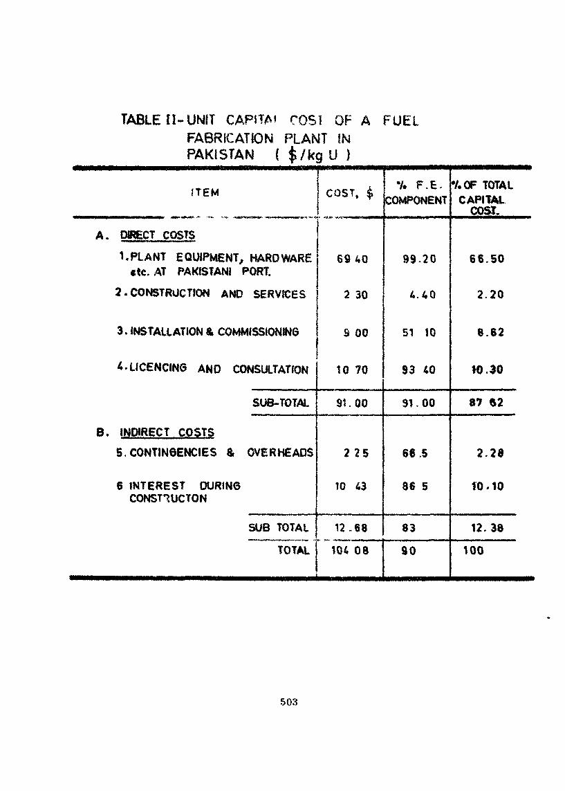
TABLE II- UNIT CAPITA' COS! OF A FUELFABRICATION PLANT INPAKISTAN ( $/kg U )
ITEM
A. DIRECT COSTS
1, PLANT EQUIPMENT, HARDWARE«tc. AT PAKISTANI PORT.
2 . CONSTRUCTION AND SERVICES
3 .INSTALLATION & COMMISSIONING
A. LICENCING AND CONSULTATION
SUB-TOTAL
B. INDIRECT COSTS
5. CONTINGENCIES & OVERHEADS
6 INTEREST DURINGCONST1UCTON
SUB TOTAL
TOTAL
COST, $
6940
2 30
S 00
10 70
91.00
2 2 5
10 43
12.68
104 08
Y. F.E.COMPONENT
99-20
4.40
51 10
S3 40
31.00
66.5
86 5
83
90
•/.OF TOTALCAPITAL
COST.
66.50
2.20
8.62
10.30
87 $2
2.28
10.10
12.38
100
503
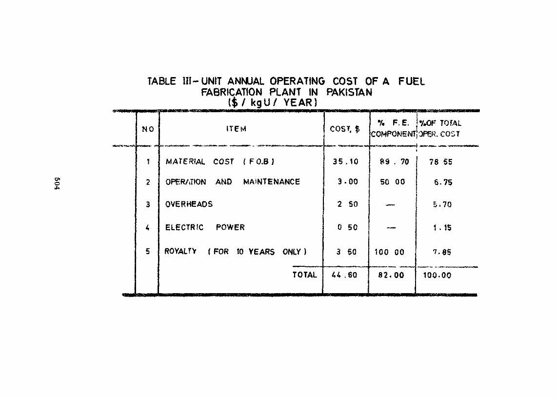
eno
TABLE ill-UNIT ANNUAL OPERATING COST OF A FUELFABRICATION PLANT IN PAKISTAN
{$/ kgU/ YEAR)
NO
f
2
3
4
5
ITEM
MATERIAL COST (F0.8Î
OPERATION AND MAINTENANCE
OVERHEADS
ELECTRIC POWER
ROYALTY ( FOR 10 YEARS ONLY )
TOTAL
COST, $
35.10
3.00
2 50
0 50
3 50
44 .60
% F.E. j%OF TOTALCOMPONENT! OPER. COST
BS . 70
50 00
—
—
100 00
82.00
78 S5
6.75i
5.70
1 , Î5
7-85
100.00
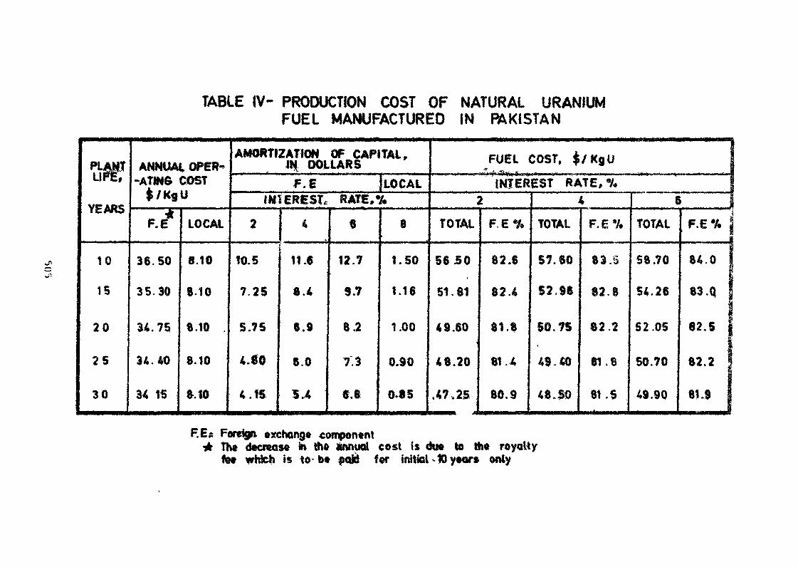
TABLE IV- PRODUCTION COST OF NATURAL URANIUMFUEL MANUFACTURED IN PAKISTAN
MSVCf AbfYEARS
10
15
20
25
30
ANNUAL OPER--ATINÔ COST
$/Kgil
e.t
36.50
35.30
34.75
34.40
34 15
LOCAL
8.10
8.10
8.10
8.10
8.10
AMORTIZATION OF CAPITAL,IN DOLLARSF.E JLOCAL
IMfERES?* RATE,%
2
10.5
7.25
5.75
4.80
4.15
4
I11.6
8.4
6,9
8.0
»•«
6
12.7
9.7
8.2
7.3
6,8
8
1.50
1.16
1.00
0.90
0.85
FUEL COST, $/KgU
INTEREST RATE,9/*2
TOTAL
56 SO
51.81
49.60
48.20
.47,25
F.E%
82.6
82.4
81.8
81 .4
80.9
4
TOTAL
57.60
S2.96
50.75
49.40
4 8. SO
F.E*
83. S
82.8
82.2
81,8
8,.S
6
TOTAL
58.70
54.28
52.05
50.70
49.90
F.E% |
84.0 I
83 .Q
62.5 1
82.2 1
81.9
F.E s Foreiga exchange component4 The decrease to th* «nnual cost is du« to Ih* royalty
fet which is to b* paie f«r initial -10 y«or« wily
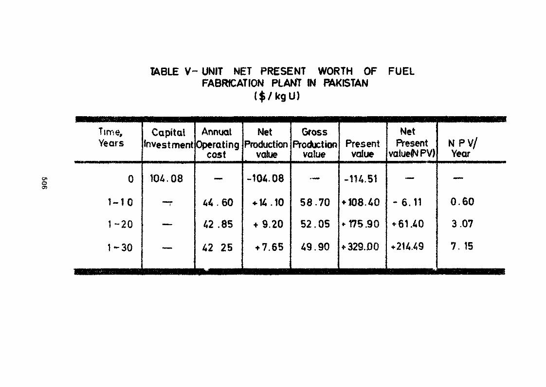
1A8LE V- UNIT NET PRESENT WORTH OF FUELFABRICATION PLANT IN PAKISTAN
($/kgU)
oO5
Time,Years
0
1-10
1-20
1-30
^MM_ -1>eM_MaM^Hl ^_M|| ._M^MM
Capitalinvestment
104.08
i
_
—
AnnualOperating
cost
_
44 . 60
42.85
42 25
NetProduction
value
-104.08
+ 14.10
+ 9.20
+ 7.65
••MMBttÉBMHMHMMMMHM
GrossProduction
value
~-
58.70
52.05
49.90
•«•••••«• ••••••«•H
Presentvalue
-114.51
+ Î08.40
075.90
+ 329JDQ
••••l HHMIHMMMMM rt Ma
NetPresent
valued PV)
«.
- 6.11
*61.40
+214.49
EMMM BMMMHMBMBMiM,.
N PV/Year
—
0.60
3.07
7. 15
«MMMMMMBaMMMMHMMHMMMnHB
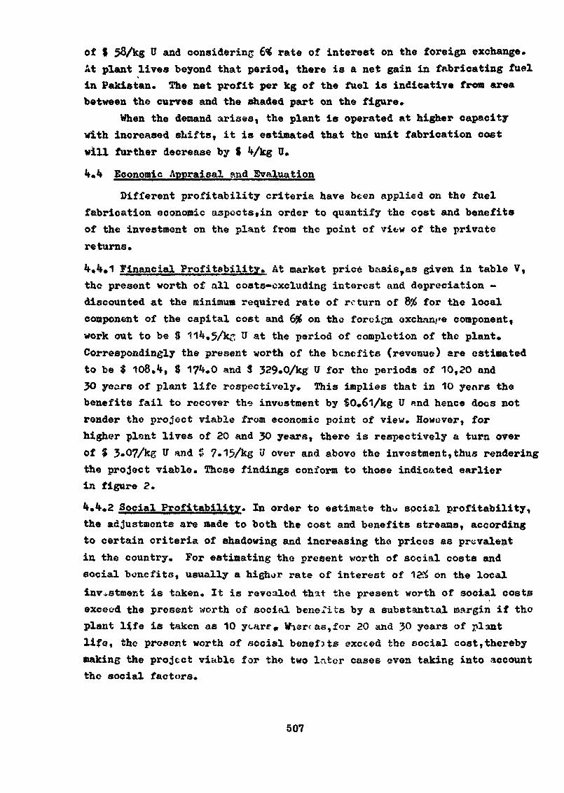
of $ 58/kg 0 and considering 6% rate of interest on the foreign exchange.At plant lives beyond that period, there is a net gain in fabricating fuelin Pakistan. The net profit per kg of the fuel is indicative from areabetween the curves and the shaded part on the figure.
When the demand arises, the plant is operated at higher capacitywith increased shifts, it is estimated that the unit fabrication costwill further decrease by $ Vkg U.
**•** Economic Appraisal and Evaluation
Different profitability criteria have been applied on the fuelfabrication economic aspects,in order to quantify the cost and benefitsof the investment on the plant from the point of vie-w of the privatereturns.
4»4«1 Financial Profitability. At market price basis,as given in table V,the present worth of all costs-excluding interest and depreciation -discounted at the minimum required rate of return of 8% for the localcomponent of the capital cost and 6# on the foreign exchange component,work out to be $ 11 .5/kf; U at the period of completion of the plant*Correspondingly the present worth of the benefits (revenue) are estimatedto be $ 108.*f, $ 17 .0 and $ 329.0/kg B for the periods of 10,20 and30 years of plant life respectively. This implies that in 10 years thebenefits fail to recover the investment by S0»6l/kg U and hence docs notrender the project viable from economic point of view. However, forhigher plant lives of 20 and JO years, there is respectively a turn overof $ 3.07/kg IT and $ ?.15Ae over and above the investment, thus renderingthe project viable. These findings conform to those indicated earlierin figure 2.
• •2 Social Profitability» In order to estimate th« social profitability,the adjustments are made to both the cost and benefits streams, accordingto certain criteria of shadowing and increasing the prices as prevalentin the country. For estimating the present worth of social costs andsocial benefits, usually a higher rate of interest of 12& on the localinvestment is taken. It is revealed that the present worth of social costsexceed the present worth of social benefits by a substantial margin if thoplant life is taken as 10 ycare» VT~iercas,for 20 and 30 years of plantlife, tho present worth of social benefits exceed the social cost,therebymaking the project viable for the two later cases oven taking into accountthe social factors.
507
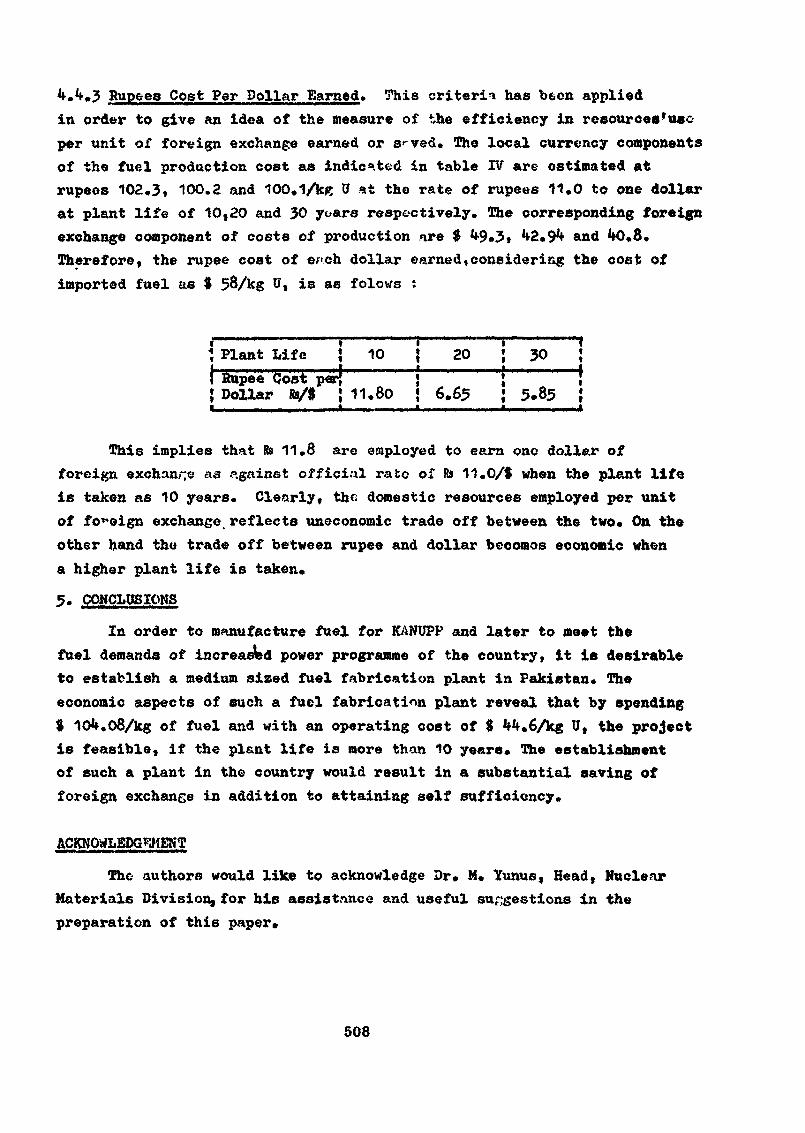
k.k.J Rupees Cost Per Dollar Earned» This criteria has been appliedin order to give an idea of the measure of the efficiency in resources*useper unit of foreign exchange earned or s--ved. The local currency componentsof the fuel production cost as indicated in table IV are estimated atrupees 102.3, 100.2 and 100,1/ks tf at the rate of rupees 11,0 to one dollarat plant life of 10,20 and 30 yoars respectively. The corresponding foreignexchange component of costs of production are $ 9.3» 2,9** and **O.8.Therefore, the rupee cost of each dollar earned,considering the cost ofimported fuel as $ 58/kg U« is as folows :
', Plant Life! Rupee (Jost j:{ Dollar te/1
\ 10s! — —; 11,80
i•ti•
20——————
6.65
30
5.85>
<ti"1
rA
This implies that te 11.3 are employed to earn one dollar offoreign exchange as .«.gainst official rate of Rs 11.0/f when the plant lifeis taken as 10 years. Clearly, the domestic resources employed per unitof foreign exchange reflects uneconomic trade off between the two* On theother hand the trade off between rupee and dollar becomes economic whena higher plant life is taken*
5. CONCLUSIONS
In order to manufacture fuel for KANUPP and later to meet thefuel demands of increased power programme of the country, it is desirableto establish a medium sized fuel fabrication plant in Pakistan. Theeconomic aspects of such a fuel fabrication plant reveal that by spending9 10 .08/kg of fuel and with an operating cost of $ Mu6/kg U, the projectis feasible, if the plant life is more than 10 years. The establishmentof such a plant in the country would result in a substantial saving offoreign exchange in addition to attaining self sufficiency»
ACKNOWLEDGEMENT
The authors would like to acknowledge Dr, M, Yunus, Head, NuclearMaterials Division, for bis assistance and useful suggestions in thepreparation of this paper»
508
R E F E R E N C E S
(1) Hulka,!., "Some Economic Aspects of Fuel Cycle in the CSSR."(Proc.Sym.Gottwaldov, 1968), IAEA Vienna (1968)55.
(2) Haga,X», 'Borne Aspects of Future Cost Trends on the RelativeEconomics of BWRs aad-PHRs." (ProciSym .Gottwaldo?, 1968), IAEAVienna (1968) 99.
<3) Fanjoy$G«R. , '"Nuclear Fuel Management - Ontario Hydro".(Proc.Sym.Gottwaldov, 1968), IAEA Vienna (1968) 213.
CO Haywood,L.R. , Robertson, J . . ^ w . w i . j aBodie,I>.L., t*Fuel For Canadian Power Reactors. Presentedat 4-th U.N.Int.Conf.on Peaceful Uses of Atomic Energy,Geneva, 197L
509
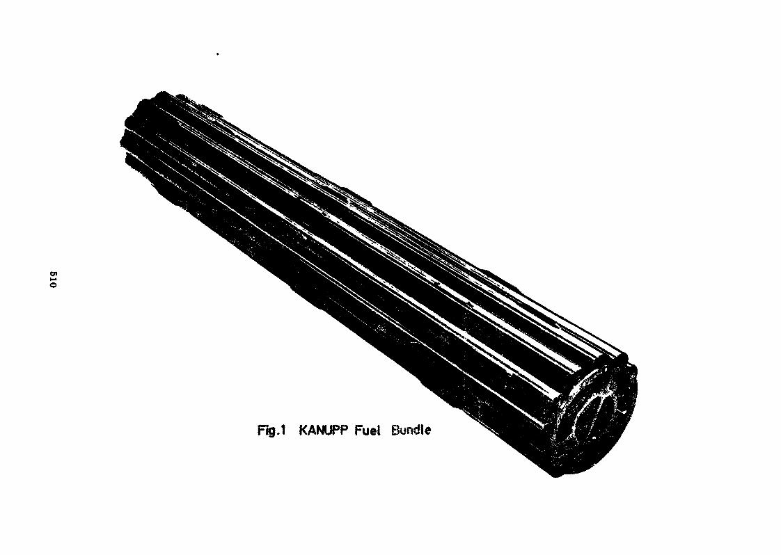
WH»o
Rg.1 KANUPP Fuel Bundle
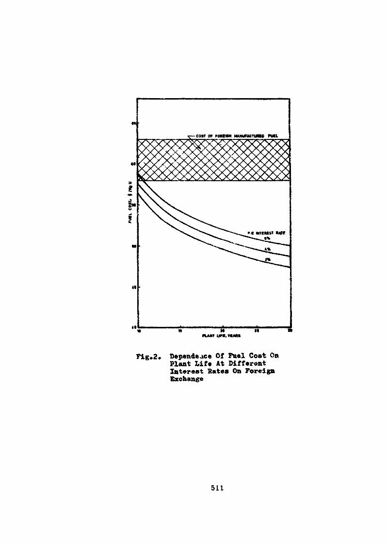
y-COtt Of 1-OKtHH mmUMCTUMO
flANT
Pig.2* Dépendance Of Fuel Cost 0»Plant Life At DifferentInterest Rates On ForeignExchange
511
I«INDUSTRIE FRANÇAISE DES COMBUSTIBLES NUCLEAIRES
A. Le Duigou
ABSTRACT
The French Nuclear fuel manufacture developed according to the needsof the national programme and, up to now, has been the responsibility ofthe Commissariat à l'Energie Atomique (C.E.A.).
The C.B. A. continuous oolicy consists of three phases;1. Design and development, eventually first fabrications within
the C.B. A.2. Entrusting one private firm with the first industrial
production together with part of R. and D.3. Call for competition of another private firm when the
need becomes large enough.
Gas-Graphite ReactorsManufacture began in 1955, m Annecy, where the works of S.T.C.N.
reached progressively a maximum output of 1200 t/y of metallic naturaluranium, S.T.C.N. has also a research and production centre in Veureynear Grenoble.
C.E.R.C.A., choosen to compete in 1961, established a research andproduction comnlex in Romans-sur-Tsere . The capacity of the metallicfuel workshor» has grown up to about 800 t/y of uranium.
The effects of that competition were very profitable (see Table II:fuel failures).
Tho decision to cut back the reactor programme decreased the fuelrequirements and unfortunately romtielled us to come back to the secondnhase with one single manufacturer since the beginning of 1972.
Heavy Water ReactorsNot very significant, fuel manufacture xs oerformed by CJB.R.C.À.
in Romans.
Fast Breeder ReactorsThe production of mixed U.Pu fuel is still in the hands of C.E.A.
(Cadarache Centre). Conventional assemblies (fertile blankets andshields) are made by both industrial firms.
Water ReactorsThe decision favouring this type »s recent enough in France; the
organization in fuel manufacture is not yet established and is stillunder negotiations.
Through its experience in submarine reactors ftiel, in other lines,in fuel management, in quality inspection on new and snent fuel, C.E.A.is ready to display a consistent part, whatever scheme shall be the finalone.
513
RESUME
L'industrie française des combustibles nucléaires s'est développéeen fonction des "besoins du programme national et relève jusqu'à présentde la responsabilité du Commissariat à l'énergie atomique (C.E.A,).
La politique suivie par le C.B.A. comporte trois phases :
1. Le C.E.A. procède seul aux études techniques et théoriques etréalise éventuellement les premiers éléments; <
2* II confie à une seule société privée les premières fabricationsindustrielles, ainsi qu'une partie de la recherche et du développement)
3. Il accepte la concurrence d'une deuxième société privée lorsque lesbesoins prennent une ampleur suffisante»
Filière graphite-gaz
La fabrication a commencé en 1955» à Annecy où la production de laSociété industrielle de combustible nucléaire (S.I.C.N.) a progressivementatteint une capacité maximale de 1200 t d'uranium métal par an* La S.I.C.N.dispose également d'un centre de recherche et de production à Veureyi près deGrenoble*
La Compagnie pour l'étude et la réalisation de combustibles atomiques(C.E.R.C.A.), admise en 1961 à entrer en concurrence, a créé un ensembleproduction-recherche à Romans—sur-Isère* La capacité maximale de l'atelierde production des combustibles graphite-gaz s'est progressivement élevéejusqu'à 800 t d'uranium par an.
Ce régime de concurrence a donné des résultats remarquables (voirtableau II intitulé "ruptures de gaines")»
La décision de restreindre le programme des réacteurs a diminué lesbesoins en combustibles et a malheureusement contraint le C.E.A. à revenirdès le début de 1972 à la deuxième phase, c'est-à-dire à la collaborationavec un seul fabricant.
Filière à eau lourde
Cette filière n'est pas très importante ; la fabrication descombustibles est assurée par l'usine de Romans de la C.E.R.C.A.
Filière à neutrons rapides
La fabrication des combustibles mixtes d'uranium-plutonium esttoujours assurée par le C.E.A. (au Centre de Cadarache). Les élémentsclassiques (couvertures fertiles et blindages) sont produits par lesdeux sociétés industrielles déjà mentionnées.
514
Filières à eau naturelle
La décision d'orienter le programme français vers ces filièresa été prise à vine date assez récente; l'organisation des fabricationsde combustibles n'est pas encore clarifiée et fait l'objet de négociations.
Port de son expérience en matière de combustibles pour sousHooarinsatomiques, d'autres réalisations, de gestion des combustibles et de contrôlede la qualité des combustibles nouveaux: et usés, le C.E.A. se prépare àjouer un rôle important, quel que soit le schéma industriel qui serafinalement retenu»
INTRODUCTION
L'industrie française des combustibles nucléaires est née ets'est développée en fonction des besoins propres du programme atomiquenational. Comme on le sait, ce programme a, dans sa première phase, étéaxé vers l'utilisation de l'uranium naturel dans les réacteurs de lafilière "graphite-gaz".
Le Commissariat à l'Energie Atomique a toujours été responsa-ble pour cette fi l ière de la conception» du développement et de laproduction de tous les combustibles.
Simultanément, il s'est préoccupé du développement d'autresfilières : HWR, HTR» surrégénérateurs.. Enfin il assure pour la MarineNationale la réalisation et le combustible des réacteurs de propulsionnucléaire des sous-marina (type PWR),
Le tableau I "onne la situation actuelle du programme françaiet de ses besoins en combustibles»
S'y ajoutent les réacteurs électrogènes à eau ordinaire,totalement français ou en participation multinationale. Nous y revien«drons.
POLITIQUE SUIVIE PAR LE C.B.A.
Que ce soit pour la production d'uranium ou pour la fabrication des éléments combustibles, la politique générale du C.E.A. a étéet reste la suivante : dans un premier temps, étudier les procédés debase, puis, dans un deuxième temps, transférer à l'industrie pri'ée 1développement et l'exploitation industrielle de ces procédés.
515
On peut ainsi distinguer schématiquement trois phases dans ledévelorp"ao"t d 'une fabrication donnée :
I ère phase t le C.E.A. étudie «eujl les procédés de base et, éventuelle-ment* réalise seul les premiers éléments.
g ème phase s Le C.E.A. confie à une société privée d 'une part lespremières fabrications industrielles» d 'autre part une partie du develop»pement des procédés utilisés. Cette part de développement, qui complèteles études que le O .K .A. continue à poursuivre dans ses propres établis-sements, est faite sous contrat d ' é tude de telle sorte que les résultatsobtenus soient la propriété du C ,K,A. Un groupe de travail assure lacoordination indispensable entre fabrication, études C .E .A . , études souscontrat.
3 ème phase : Lorsque les fabrications atteignent un volume et un chiffred'affaires suffisants, le C.E.A. accepte la concurrence. Il confie alorsen général à une deuxième société privée une partie de ses besoins, enla faisant bénéficier comme la première, du résultat des études qui luiappartiennent*
FILIERE GRAPHITE-GAZ
C'est en 1 955 Que le C.E.A. a recherché le support del'industrie privée pour la fabrication du coeur de Gl, premier réacteurplutonigène de Marcou le, aujourd'hui déclassé.
C'est la Société Alsacienne de Constructions Mécaniques, devenueen 1 957 la Société Industrielle de Combustible Nucléaire (S.I.C.N.), quis'est lancée dans cette opération en s'implantant dans une usine existan-te de mécanique et d'électricité à Annecy (Haute-Savoie).
Cette unité de production s'est développée Jusqu'à atteindreune capacité maximum de 1 200 T/an d'uranium métal. En mgrae temps laSICM a créé à Veurey près de Grenoble un centre de recherches important,dont l'atelier pilote s'est orienté progressivement vers certainesfabrications de séries d'importance modeste.
516
En 1 961» le C.E.A. a estimé que le programme français autori-sait le passage à la 3 erne phase et a suscité1 la concurrence de laCompagnie pour l'Etude et la Réalisation de Combustibles Atomiques(C,E.R.C.A.) qui produisait déjà pour le C.E.A. des combustibles àplaques pour les piles type M.T.R. Elle décida de créer un ensembleimportant (productions et recherches) à Romans-sur-Isère (Dr8me),
La capacité maximale de l'atelier de production des combusti-bles graphite-gaz a cru progressivement jusqu'à 800 T/ an environ demétal*
Ce régime de concurrence s'est maintenu depuis 1 963» année despremières fabrications significatives de C.E.R.C.A, Jusqu'en 1 971. Lesrésultats en ont été remarquables.
L'émulation technico-commerciale conduisit les fabricants àrechercher» seuls ou en collaboration avec le C.E.A.» tout ce qui permet-tait d'alléger les conditions de production t
- adaptation des équipements (exemple des fours de fusion).- suggestions d'aménagements des spécifications.- gestion plus stricte des matières ou des demi-produits de
grande valeur.- standardisation et automatisation.- levée progressive de certaines sujétions édictées à l'origine
dans un souci de sécurité.- etc, .»
Les améliorations ainsi obtenues ne l'ont Jamais été au détri-ment de la qualité, ainsi qu'en témoigne le faible nombre de ruptures degaine constatées dans les réacteurs électrogènes (cf. tableau 2).
La décision formelle de l'abandon de la filière graphite-gazannoncée fin 1 969» devait mettre un terme à cette période. Une fois lespremiers coeurs achevés (SL 2 - Bugey T ^ Vandello-î) le volume de travailen régime ne pouvait Justifier le maintien de rteux producteurs» essen-tiellement parce qu'il s'agit d'une industrie assez lourde» devantsatisfaire à des exigences spéciales de propreté» de protection» etc...
517
Aussi, depuis le début de la présente année» un seul fournisseurassure le façonnage des cartouches de la filière graphite-gaz. Dans cecas particulier, la conjoncture a amené exceptionnellement le C.E.A. arétrograder de la 3 «»» phase à la 2 ème phase exposées au paragrapheprécédent.
EVOLUTION DES PRIX DE REVIENT
Cette évolution a été très favorable depuis l'origine desfabrications pour EDP, et la décision que nous venons d'évoquer» aussidélicate et regrettable qu'elle ait été à certains titres, pouvaitseule en conserver le bénéfice.
Elle est concrétisée par le tableau N° 3 qui retrace, enfrancs courants» la variation du coût (hors uranium métal) de l'élémentcombustible EDF type 3 depuis 1 963. Cet élément alimente indifféremmentles réacteurs Chinon 2 et 2» Saint-Laurent 1 et 2 et Vandellos.
Nous avons fait figurer sur ce tableau un graphique (en poin-tillé) qui retrace pour la même période l'évolution relative des tonnagestotaux produits pour la filière. Ce dernier graphique, étant tracé enordonnées décroissantes, permet Immédiatement de juger de l'importance del'effet de masse. On constate en effet, pour ce qui est du façonnageproprement dit» que les frais fixes qui représentaient à l'origine plusdes deux tiers des charges des usines en constituent encore environ lamoitié. En ce qui concerne les matériaux de structures (gaines, bouchons,chemises de graphite) cet effet est beaucoup moins sensible car leurélaboration s'effectue dans des ensembles dont l'activité globale esttrès grande par rapport à cette activité propre (frais fixes de l'ordrede 10 à
Il n'en reste pas moins que les effets concurrentiels, Jointsaux allégements des spécifications, ont été un facteur important de bais-se des coûts. Il faut préciser en effet que l'évolution relative des prixest donnée en francs courants : or dans le même laps de temps, la varia-tion des conditions économiques aurait conduit, toutes choses égales parailleurs, à les accroître d'environ 60 £.
518
CRITERES D'IMPLANTATION DKS USINES
Nous avons vu que pour Annecy, la motivation du fondateur à1*origine était de faire profiter les nouveaux atelier» dee supportsgénéral et technique d'une installation existante.
Le site de Veurey a été choisi pour sa position au bord de1*Isère et surtout la proximité de Grenoble : zone industrielle, àforte densité de population» et scientifique avec le Centre d'EtudesNucléaires, une Université importante et plusieurs grandes écolestechniques.
La C.E.R.C.A, a retenu Romans-sur-Isère pour son extensionet sa décentralisation (sa première usine est à Bonneull en régionparisienne). Romans se trouve à proximité des Centres Nucléaires deGrenoble, Marcoule, Cadarache et du complexe de Plerrelatte. L'instal-lation a été édifiée sur un terrain en bordure de l'Isère» mais noninondable, et est reliée à une station hydroélectrique très procheet à un réseau d'effluents se rejetant dans l'Isère en aval de laville pour plus de sécurité, Enfin» une main-d'oeuvre courante rela-tivement abondante a permis de ne déplacer que les techniciens quali-fiés.
En règle générale, dans les limites de la France Métropoli-taine, 11 n'y a pas de graves problèmes d'approvisionnement en eau ouen énergie électrique. Le coût des transports reste faible dans leprix global des éléments combustibles n-ufs ; 1« proximité des Centrerd'Etudes Nucléaires est plutôt recherchée pour faciliter les échangesscientifiques et techniques. La main-d'oeuvre peut poser des problème?assez souvent catégoriels.
FILIERE A EAU LOURDE
L«*s fabrications de combustibles pour cette filière ont étéJusqu'à ce Jour assez peu significatives, se bornant à l'approvisionnement du réacteur EL 4, en plus des piles de recherche du C.E.A.
Elles sont assurées jusqu'à présent par l'usine de Romansde la C.E.R.C.A. ; un appel à la concurrence n'est pas exclu.
519
FILIERE A NEUTRONS RAPIDES
Compte tenu des sujétions particulières, la fabrication descombustibles contenant de l'oxyde de plutonium (besoins de Rapsodie etceux du coeur initial de Phénix» dont la réalisation est en voied'achèvement) est assurée dans les ateliers spécialisés du C.E.A. àCadarache. Des équipes extérieures ont déjà participé aux travaux deces ateliers ; le transfert de ce type de production au secteur privéest donc envisagé, mais l'échéance de ce transfert dépendra naturelle-ment de celle de l'avènement des réacteurs surrégénérateurs au stadeindustriel.
Par contre» les éléments plus conventionnels î couverturesfertiles» protection neutroniques etc.,. et même des aiguilles fissilesà l'oxyde d'uranium enrichi* sont produits depuis l'origine par lessociétés privées (S.I.C.N. à Veurey et C.E.R.C.A. à Romans) pour lecompte du C.E.A.
REACTEURS POUR SOUS-MARINS
Leurs éléments combustibles sont conçus et développés auC.E.A. La fabrication fait cependant intervenir l'industrie privéedans une certaine mesure.
FILIERES A EAU NATURELLE
Pour tout ce qui précède, le C.E.A. a jusqu'à ce jour conser;vé la maîtrise d'oeuvre.
La décision ayant été prise assez récemment d'orienter leprogramme français des prochaines années vers les filières à eaulégère, l'organisation des fabrications de combustibles pour cesréacteurs n'est pas encore clarifiée et fait l'objet de réflexionset négociations. Il n'est possible actuellement de faire aucuneprojection sur l'avenir.
La C.E.R.C.A. produit déjà des éléments de ce type pour leréacteur Franco-Belge de Chooz, sous licence Westinghouae, et a aussifabriqué des aiguilles de combustible pour le navire marchand nuclé-aire allemand OTTO HAHN. Elle est responsable de la fabrication de lapremière charge du réacteur de Tihange et se prépare à la produire.
520
Le Commissariat à l'Energie Atomique occupe une positionqui s'appuie sur ses acquisitions dans plusieurs catégories d'activités:
- Le Prototype à Terre de Cadarache, décidé en 1 959»opérationnel en 1 96*», a donné naissance aux propulseursnucléaires de sous-marins à l'entière satisfaction desutilisateurs. II a permis depuis d'effectuer des essaisImportants et couronnés de succès sur des combustiblesadaptables aux réacteurs électronucléaires à eau. Il serarenforcé dans un proche avenir par la Chaufferie AvancéePrototype (C.A.P.) à double objectif civil et militairequi permettra les tests les plus sévères sur des élémentsdes filières à eau naturelle, pratiquement en vraie gran-deur. Ainsi sera obtenue, par le C.F..A. lui-même (ou pardes irradiations déjà très avancées dans des réacteursextérieurs de recherche ou de puissance)» la qualifica-tion des combustibles qu'il a développés et qu'il peutd'ores et déjà produire à une capacité significative.De plus, la capacité de l'Atelier de Technologie duPlutonium de Cadarache, se basant sur l'expérience descombustibles de Rapsodie et Phénix» peut s'appliquer à laproduction d'aiguilles pour le recyclage du Plutoniumdans les réacteurs thermiques à eau ordinaire, recyclagedont l'intérêt est indéniable.
- L'expérience acquise par le C.E.A. pour la transmissionvers l'industrie privée de ses connaissances en matière deréalisations de combustibles a été exposée ci-dessus ausujet des autres filières et son efficacité est démontrée.Il en est de même pour la gestion de ce genre de produc-tions.
- Les dispositifs de contrôle de qualité dans tous lesdomaines sont parfaitement rodés au C.E.A, : inspectionsen usines, analyses chimiques et isotopiques, essaismécaniques, dynamiques ou thermiques, etc,,. Les Départe-ments Scientifiques peuvent de plus prendre rapidementen mains tout problème nouveau. Cet ensemble s'appliqueaussi bien à la fabrication qu'au suivi d'utilisationgrflce aux équipements et au psrsonnel qualifié des Labora-toire de Haute ou très Haute Activité implantés dans lesdifférents centres.
521
C'est pourquoi le C.E.A., fort de aon expérience et de nonpotentiel tant humain que matériel, se prépare à un rôle important»quel que soit le schéma industriel qui sera finalement retenu sur leplan national.
NOTA
II n'a été traité, dans le présent exposé, que de la fabri-cation proprement dite des éléments combustibles.
En ee qui concerne les matières nucléaires, la politique du3.E.A. n'a pas été différente t
• Uranium me ta 1 na ture 1 : l'élaboration des lingots a étémise au point au C.E.A., pratiquée en première phase àl'usine du Bouchet (ancienne poudrerie nationale), parta-gée ensuite avec la Société de Raffinage de l'Uraniumexploitant l'usine de Malvési près de Narbonne , puisconfiée entièrement à cette dernière lors de la chute desbesoins. (La S.R.U est devenue partie de COMURHEX parfusion).
. . d * u? '.a.n- AM"1.. f r * t tab le s La production, mise au pointau C.E.A., est partagée entre le C.E.A. et la Société desUsines Chimiques de Pierrelatte (S, U.C. P.).
- Fabrication des pastille^ jTritt^e s t la mise au point a étéfaite en commun avec la Compagnie Industrielle desCombustibles Atomiques frittes (CICAF), centre de recher-ches de Corbeville près de Saclay, La production estactuellement assurée par la Société Français*» d'Elémentscatalytiques (S. P. B.C.) dans l'usine de Bollène (voisinedu complexe de Pierrelatte).
En oe qui concerne les matériaux de structure (graphitenucléaire, gaines et accessoires en alliages de Magnésium ou deZirconium et en aciers inoxydables, «..) nous ne croyons pas qu'unexposé à ce sujet présente ici de l'intérêt t la forte positionfrançaise est connue dans les domaines du zirconium et de ses alliagesainsi que du graphite et du magnésium nucléaires.
522
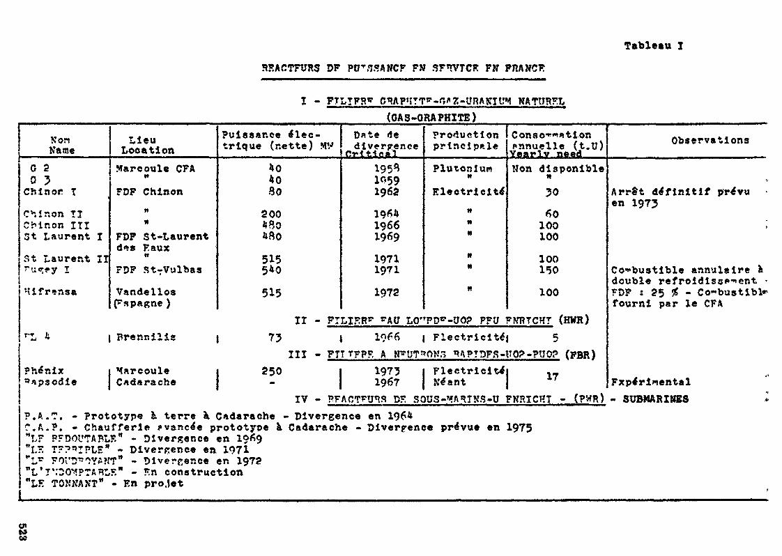
Tableau I
SEACTFURS DF PtPSSANCF FM SF»VTCK FN FRANCK
Ï - PTLTFRg NATUSFL(GAS -GRAPHITE)
NonName
G 20 ÏChlnor T
C'-.inon TICMnon ITI3t Laurent I
55 1 Laurent II~u«;«»y I
Hifrensa
LieuLocationMarcoule CFA»»FDF Chinon
nN
FDF St-Laurentd^s Faux«FDF StTVulbas
VandellosEspagne )
Puissance élec-trique (nette) MV
*040SO
200480*80
515540
515
Date dedivergence
Orltieal
19510591962
19*419661969
19711971
1972
Productionprincipale
PlutoniumwElectricité
M
n«
itit
n
Consolationpnnuelle (t.U)Yearly needNon disponible
N
5060100100
100150
100
II - FTLIKR* rAU LO'TD -UO? PFU FNRTCHT (HWR)rL * | Brennilis j 75 J 19 6 I Flectrlcltej 5
III - FTTTFPF. A N'UT"ON3 nAPTDFS-UO?-?UO? (PBR)Phénix j Marcoule j 250 I 1975»«psodie J Cftdarache j • j 1967
Flectricitei ._Néant J 17
Observations
•iArrêt définitif prévuen 1975
h
Combustible annulaire àdouble refroidlsgft-nent <FDF : 25 £ - Co-'bustibfc»fourni par le CFA
FxpérlmentalIV - PFACTTinS DK SOUS-MAnTNS-U FNRICHT - (PWR) . SUBMARINES *
L
P.A.?. - Prototype à terre à, Cadarache «C,A.P. - Chaufferie avancée prototype à"LF PFDOtrTABLF." - Divergence en 1969"LF. T??"IPLEW - Divergence en 1971"Lr FOi'D^OYANT11 - Divergence en 1972"L*I'.'DOMPTA*I,S" - Kn construction""LE TCNNAXT" - En projet
• Divergence en 1964Cadarache « Divergence prévue en 1975
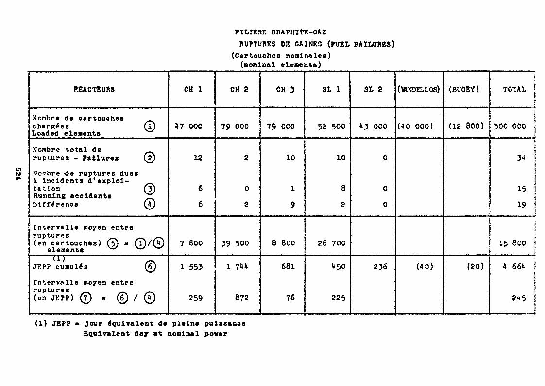
PILIERS GRAPHITE-GAZRUPTURES DE GAINES (FUEL FAILURES)
(Cartouches nominales)(nominal elements)
REACTEURS
Nombre de cartoucheschargées QLoaded elements
N'ombre total de ^ruptures - Failures (2)
Norbre -de ruptures duesà incidents d'exploi-talion @)Running accidents "XDifférence ©
Intervalle moyen entreruptures ^^ ^^^ —.(en cartouches) (5) » CD/CÏÏ/
elements " ^"^(1) -.
JEPP cumulés (6)
Intervalle moyen entreruptures _>(en JEPP) © - © / ©
CH 1
4? 000
12
6
6
7 800
1 553
259
CH 2
79 000
2
0
2
39 500
1 7**
872
CH 3
79 000
10
1
9
8 800
681
76
SL 1
52 500
10
8
2
26 700
450
225
SL 2
*3 000
0
0
0
236
(\ANDH.LÛS)
(40 000)
(40)
(BUGEY)
(12 800)
(20)
!TOTAL j
ij
300 OOC
3*
15
19
15 8CO
4 664
245
01te
(1) JEPP » jour équivalent de pleine puissanceEquivalent day at nominal power
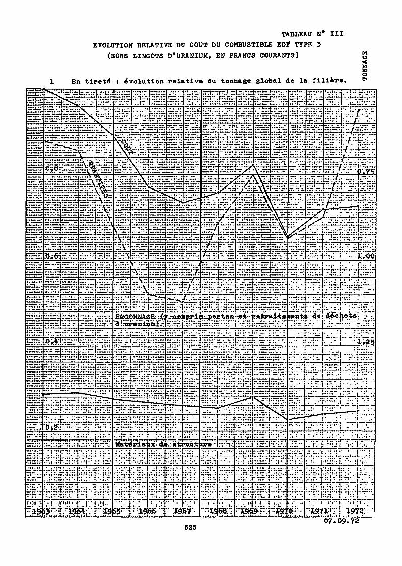
TABLEAU N° IIIEVOLUTION RELATIVE DU COUT DU COMBUSTIBLE EDP TYPE 3
(HORS LINGOTS D'URANIUM, EN FRANCS COURANTS)
En tireté : évolution relative du tonnage global de la filière.
wo85oE-i
. .iti.t. \~ tr.cit"r "n«
K" drè-" ë"fe ?«ç:fc
i -Vo* W s I -1WTT " •i "*S!j Y" / I • *37*^ s
52507. 72
Technoeconomic Prospect of fuel fabrication in suppoxtof Korean Nuclear Power Program
Byoung Whie LEEPrinicipal Research Metallurgical EngineerAtomic Energy Resear h InstituteSeoul, Korea
AbstractIn order to discuss the technoeconomic feasibility
of light water reactor fuel fabrication in Korea» theoverall picture of Korean Nuclear Power Program up tothe year 1990 along with the justification of nuclearpower generation is presented* As of June, 1972, nuclearpower generation cost was estimated to be 6.62 mills/Kwhin Korea whereas conventional oil fired thermal powergeneration cost was a.05 milla/Kwh.
Brief summary of R & l> effort in support of fuelfabrication is made. The results of activated sinter-ring of UO2 pellet by TiO^ addition has a potential forcommercial exploitation.
As a relevant data for nuclear fuel fabrication;the estimated capital iiivestement, personnel require-ment, technics! training requirements and cost of labourin Korea are summarized.
Being a labour intensive nature of fuel fabrica-tion process, this portion of fuel cycle industry canvery well be commercialized in near future»
•Present address » Director, Atomic linergy Bureau,Ministry of Science and TetHnology, Republic of Korea*
527
In discussing the technoeconomic prospect of fuel fabri-
cation in Korea, Ï would like to touch briefly on Korean
Nuclear Tower Program in order to provide a overall pictures
of fuel fabrication as a part of fuel cycle in support of
nuclear power program up to 1990»
Then, I will describe the role of Korean Atomic Energy
Research Institute in related R à D effort. Finally, I will
come to the technoeconomic prospect of fuel fabrication.
Korean Huclear Power Program
Being a natural resource deficient country, Korea has to
rely its major energy supply on import. The dependency on
imported energy would become more pronounced in future eventh-
ough there are signs of economically mineable oil, uranium and
thorium deposit*
In view of the large amount of energy to be imported, the
imported nuclear power has a definite advantage over the
imported oil fired thermal power in following respects.
1* Imported nuclear power is cheaper than the imported oil
fired thermal power.The unit power generating cost of 600 Mwe PWRUORINuclear Power Plant) can be compared to the importedoil fired £bo Mwe thermal plant as shown in table 1.
Because of these advantages, the future demand increase on
electricity would be likely to be met by mainly nuclear power.
The demand in nuclear power and fuel faorication requirements
are as shown in table 2.
528
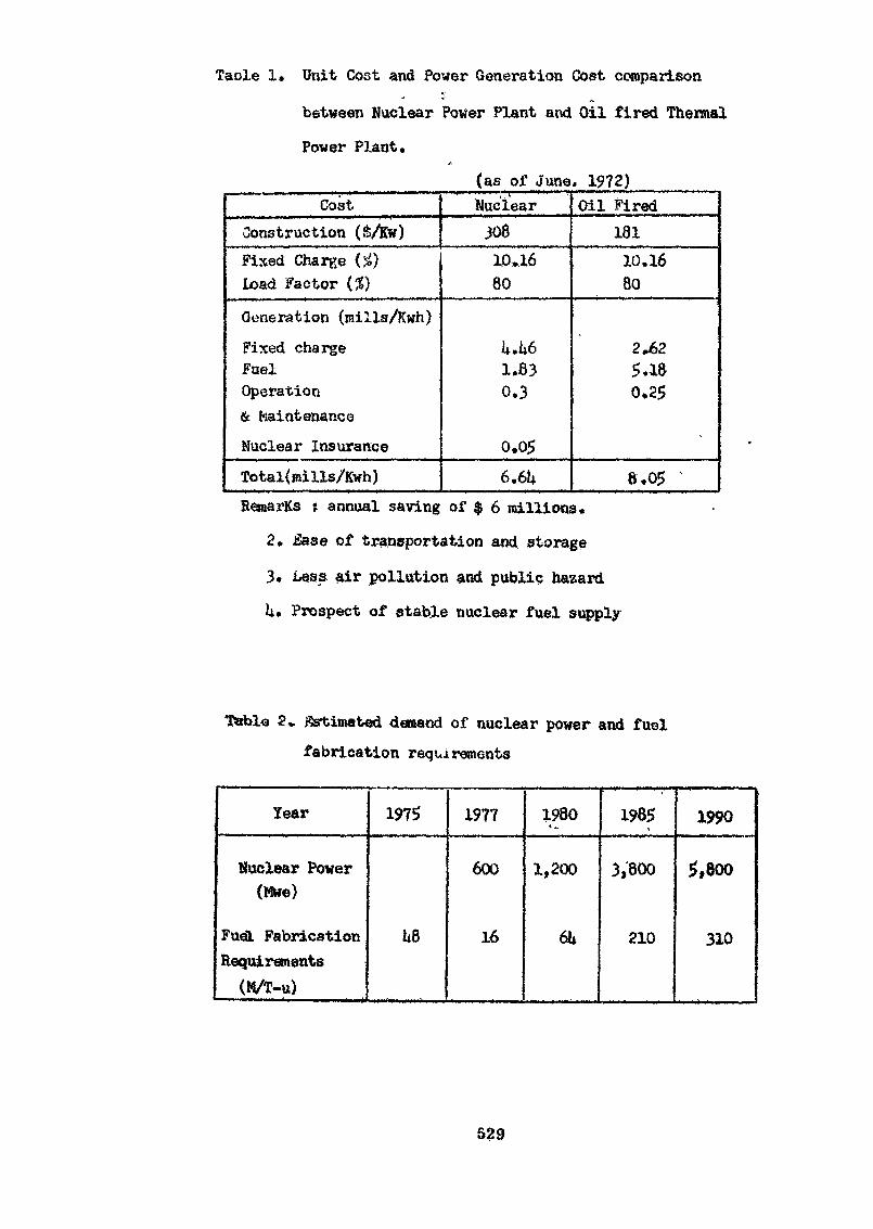
Taole 1. Unit Cost and Power Generation Cost comparison
between Nuclear Power Plant and Oil fired Thermal
Power Plant.
(as of June. 1972)Coat
Construction (VKw)Fixed Charge (£)Load Factor (%}
Generation (mills/Kwh)
Fixed chargeFuelOperation& MaintenanceNuclear InsuranceTotal(mills/Kwh)
Nuclear30810»1680
k.k61.830.3
0.056.6k
Oil Fired18110.1680
2.625.180,25
8,05 'RemarKs * annual saving of $ 6 millions.
2. Ease of transportation and storage
3. Less air pollution and public hazard
lu Prospect of stable nuclear fuel supply
Tablo 2» j8st;imat«d demand of nuclear power and fuelfabrication requirements
Year
Nuclear Power(M»e)
Fuel FabricationRequirements(M/T-u)
1975
U8
1977
600
16
1980
1,200
6h
1985
3,800
210
1990
5,800
310
529
Rjit D effort in support of Fuel Fabrication
As shown in table 1, nuclear power generation cost is
cheaper than the oil fired thennal power generation cost.
Especially, the fuel cost has an outstanding advantage in
nuclear power»
Because of Korean industrial capability, it would be some
time before Korea will be capable of manufacturing the major
hardware of nuclear power plant economically.
On the other hand, the fabrication of fuel is estimated to
be technically feasible at present state of art. Moreover,
fuel fabrication is the most labor intensive portion of
the fuel cycle. Therefore, this portion of the fuel cycle
can well be industrialized in Korea*
With these philosophy behind, R & D program in fuel
fabrication was started ia 1966 at Korea Atomic Energy
Research Institute, the related R & D programs can be grouped
as follows.
1) Fuel Fabrication
2) Fuel Reprocessing
3) Fuel Cycle Analysis
k) Fuel Economic Analysis
5) Treatment of Fission Products Waste (Sr, Cs) by
lon-fixchange Process.
6) Crystal Imperfections in the Reduction Process of
U^Og by Electron Microscopy»
Since it would be time consuming to go into every details
of related R & D programs, I will pick up few high-lights in
fuel fabrication program»
530
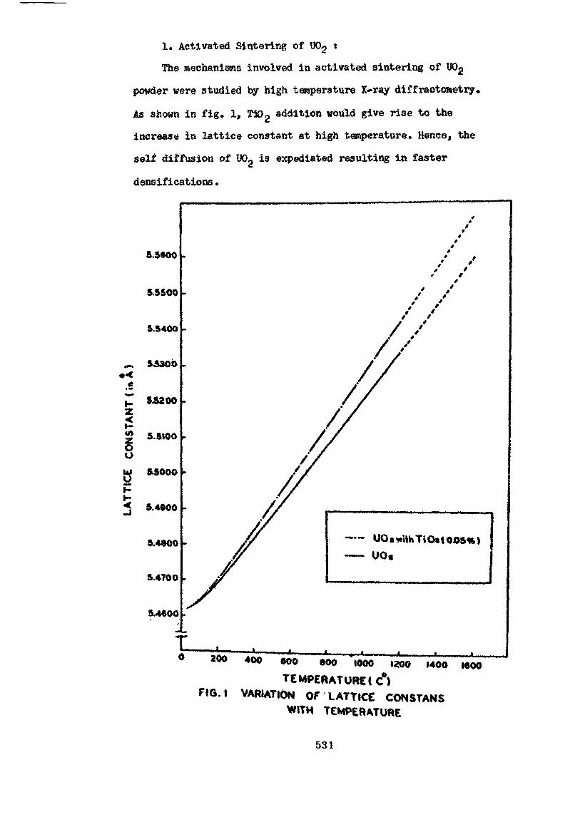
1. Activated Sintaring of W>2 «
The mechanisms involved in activated sintering of U02
powder were studied by high temperature X-ray diffractometry«
As shown in fig. 1, T102 addition would give rise to the
increase in lattice constant at high temperature. Hence, the
self diffusion of UOg is expediated resulting in faster
densifications.
5.3800
$5500
5.5400
^ 53300
5.5100
W &SOOO
< 9.4000
9.4900
9.4700
5.4900
- UOawi|htiO*(OA9%)~ UO«
200 400 900 900 1000 1200 1400 1900
TEMP£fUTURE(C°)VARIATION OF LATTICE CONSTANS
WITH TEMPERATURE
531
By activated sintering of UOp green compact, the sintering
temperature can be lowered appreciably resulting in not only
the savings in power but maintenance cost too* flhile there is
no sign of adverse effect of Ti02 additions on mechanical
properties of UOg pellet, the variations in thermal conductivity
or melting point due to additives under irradiation conditions
have to be detennined further*
2* Encapsulation j
TIG welding chamber was designed and made by machine shop.
When the material was chemically cleaned prior to the welding
and the vacuum in welding chamber by pumping was good before
flushing with helium and argon mixture gas, the quality of
welding Zircaloy h end plug on tube was excellent*
3, Feasibility study on fual fabrication pilot plant t
The preliminary feasibility study on fuel fabrication pilot
plant was made with the limited amount of technical informations
such as
WASH-1032 Current Status and future Technical and
Economic Potential of Light Water Reactors*
WASH-10?? Reactor Fuel Cycle & sts for Nuclear Poorer
Evaluation, published by the Division of
Reactor Development & Technology, USASC.
Technoeconomic Feasibility of Fuel Fabrication
Because of follow up research and the continued effort on
development in fuel fabrication, the palletization and
encapsulation techniques are fairly well established in
laboratory scale at Korea Atomic Energy Research Institute,
The inspection, nondestructive testing and helium leak
532
detection facilities have to be set up further along the
with the fuel assembling engineering developments*
In order to evaluate the fuel performance, the modest
irradiation testing and post irradiation examination program
is being planned mainly through technical cooperations with
advanced countries. In this respect, the regional colaborations
or technical assistance of IAEA would be most desirable* Along
with the ceramic fuel development, metallic fuel fabrication
techniques are being studied in order to set for the second
nuclear power plant which is under considerations*
Therefore, no foreseeable major difficulties would exist
in the technical aspects of fuel fabrication» However, the
economic aspects of fuel fabrication have quite different
picture. For this end, the plant scale factor, fabrication
cost analysis and marketability have to be studied.
Since the domestic market is very limited as shown in
table 2, the feasibility study on commercial fuel faorication
plant would t>e prematured unless the marketability is assured
in regional or world wide scale* Therefore, the commercial
soa2e operation was excluded from the feasibility studies.
The preliminary study was limited to the fuol fabrication
pilot plants to oe located at the Atomic anergy Research
Institute. The following assumptions are made;
1. U02 powder or uranium metal of nuclear fuel erade and
aircaloy tuinge and rods of appropriate dimensions are
imported as a feed materials to the plant»
2. Being a pilot plant j the start up operation, tost fuel
assembly and irradiation performance evaluation cost
are included*.
533
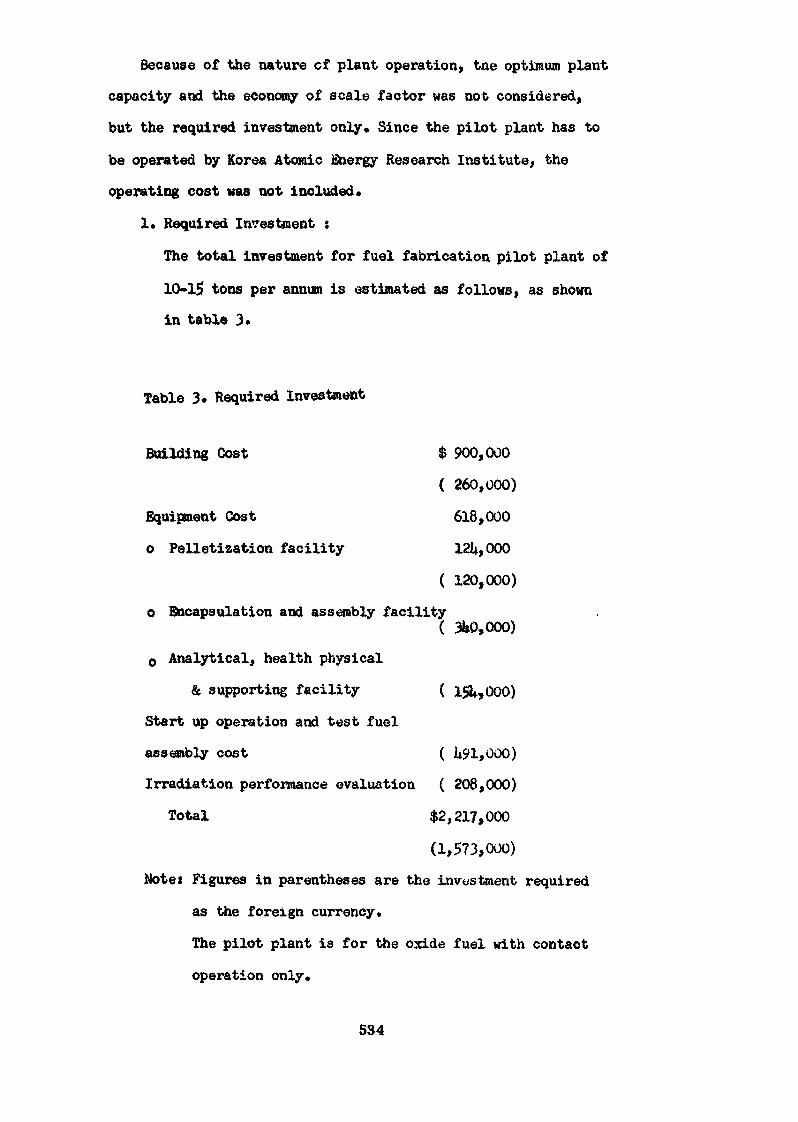
Because of the nature cf plant operation, tne optimum plant
capacity and the economy of scale factor was not considered,
but the required investment only* Since the pilot plant has to
be operated by Korea Atomic Energy Research Institute, the
operating cost was not included*
1. Required Investment :
The total investment for fuel fabrication pilot plant of
10-15 tons per annum is estimated as follows, as shown
in table 3.
Table 3. Required Investment
Building Cost $ 900,000
( 260,000)
Equipment Cost 618,000
o Pelletization facility 12U,000
( 120,000)
o Encapsulation and assembly facility
o Analytical, health physical
& supporting facility ( l<&,000)
Start up operation and test fuel
assembly cost ( U$>1,000)
Irradiation performance evaluation ( 208,000)
Total $2,217,000
(1,573,000)
Note: Figures in parentheses are the investment required
as the foreign currency*
The pilot plant is for the oxide fuel with contact
operation only*
534

2, Personnel requirement:
Because of the developmental work responsibility of the
pilot plant, the priority was placed in research than the
operating staff. For altogether, 12 graduate scientists
and engineers, 19 technicians and 15 supporting workers
would be employed,
3» Technical training requirements:
In order to operate the pilot plant and carry out tne
developmental work, all the graduate scientists and
engineers have to be trained abroad. However, technicians
and supporting workers can be trained at fual fabrication
laboratory of AERI prior to the operation start up of
pilot plant»
U. Cost of labour:
The estimated wage rate of staff personnel and workers as
of June, 1972 are as follows, as shown in table i*.
Concluding Remarks
We believe that our ur'versities and Kor- a Atomic Energy
Research Institute can train and provide the technical
manpower required for the fuel fabrication. However, we do not
have material testing reactor and post irradiation examination
facilities. Therefore, the fuel irradiation and performance
evalutions are the srea whtsre we would roost like to have a
technical assistances from advanced countries or !&£& on top
of the other phases of fuel fabrication development.
Being a laoour intensive nature of fuel fabrication
processes, we feel that this portion of fuel cycle industry
can very well be industrialized in near future.
535
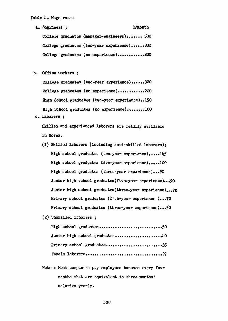
Table h» Wage rates
a» Engineers $ $/month
College graduates (manager-engineers)»...... 500
College graduates (two-year experience)......300
College graduates (no experience)............200
b. Office workers ;
College graduates (two-year experience) ««••». .300
College graduates (no experience)............200
High School graduates (two-year experience)..l50
High School graduates (no experience)........100c. Laborers ;
Skilled and experienced laborers are readily available
in Korea.
(1) Skilled laborers (including semi-skilled laborers);
High school graduates (ten-year experience ).....lli$(
High school graduates five-year experience).....100
High school graduates (three-year experience)...90
Junior high school graduates(five-year experience)..«90
Junicr high school graduâtes(three-year experience).*.70
Primary school graduates (f* 76-year experience )...?0
Primary school graduates (three-year experience) ...i>0
(2) Unskilled laborers ;
High school graduates............................$0
Junior high school graduates....................«UO
Primary school graduates.........................35
Female laborers..................................27
Note : Host companies pay employees bonuses every four
months that are equivalent to three months'
salaries yearly.
536
Session E, Economic Criteria for Fuel Fabrication
Prospects of Domestic Fabrication of Nuclear Fuel in Japan
T. Haginoya*
Abstract
Nuclear power generation in Japan will reach 60,OOOMWe by 1985
and 100,OOGMWe in 1990. In keeping with this, active measures
must be introduced to ensure safety, preserve the environment,
provide stable supplies and effective utilization of nuclear
fuel and proper management of nuclear wastes.
For the present, light water reactors are the mainstay of
nuclear power generation in Japan, their demand for enriched
uranium is expected to be 5,000 tons-SWU in 1980 and 11,000tons-SWU in 1990. Therefore uranium needed for this programwill be 8,000 S/T U308 in 1980 rising to 15,000 S/T U308 in
1990, cumulative requiremen' up to 1990 wot Id be 170,000 S/T
U308. The requirment for fuel fabrication will be 1,400 tons
in 1980 and 2,800 tons in 1990. Plutonium production in Japanis estimated to be 13 tons cumulative in 1980 and aimulative
amount of that would be 45 tons by 1985.
Environment and safety matters are great importance to develop
and utilize nuclear energy, therefore Japan is exercisingstrict control and regulation of radiation, giving much greater
consideration to such safety than to other branches of industry,
* Japan Atomic Industrial Forum
537
Various industrial groups in Japan incorporated nuclear fuel
manufacturing corporation either by themselves or jointly with
foreign companies» as the results Japan has fabrication
capacity of about 500 tons in this year and about 1,000 tons
in 1974.
1. Introduction
According to the Long-Rangé Program which has recently
revised by Japan Atomic Energy Commission. The basic policies
of the program are as follow: (1) while strongly promoting
Japan's own development efforts, this should be done in sucha way as not to disrupt international collaboration; (2) more
emphasis should be placed on basic research; (3) the implementation
of the program should be carried out effectively and efficiently
from an overall point of view.
Nuclear power supply will have to reach 60,000 MWe by1985 and 100,000 MWe by 1990. In keeping with this, active
measures must be introduced to «nsure safety, preserve the
environment, provide for stable supplies and effective
utilization of nuclear fuel and proper management of nuclearwastes.
It is essential that stable supplies of nuclear fuel besecured and effectively used in order to achieve the scale-up
envisaged in the nuclear power generation program.
The construction of conventional types of reactors must
continue for the time being, but in order to solve the problem
of stabilized fuel supplies and efficient utilization of fuel
resources, appropriate new types of power reactors must be
538
developed to make use of the full merits of nuclear power
generation. This means that the ATR and the FBR now beingdeveloped in Japan should come into commercial use between
1975 and 1984 (ATR), and between 1985 and 1994 {FRU)..i
The Advanced Thermal Reactor being developed in Japan
is a heavy water-moderated and boiling light water-cooled
type reactor. Since this type has a high neutron economy
factor, its uranium consumption, especially consumption (of
enriched uranium, can be drastically reduced compared with
the LWR.
For the present, however, the LWR will be the mainstay
of nuclear power generation, and the demand for enriched
uranium, is expected to reach 5,000 tons-SWU by 1980 and 11,000
tons-SWU by 1990.
Essential to the attainment of the foregoing, is theprovision of a stabilized large volume supply of nuclear
fuel and its effective use. Japan must secure uranium resources
and enriched uranium, and, to meet the needs of the future,
the fabrication of fuel and reprocessing of spent fuel must
be done. This calls for the establishment o* a complete
nuclear fuel cycle to ensure economic feasibility and independ-
ence. In reaching the stage of a proper fuel cycle, private
corporations, on principle, are expected to take the responsibility,
but as nuclear energy is an important state responsibility,
the Government has a big part to play in working for this end.
2. Fuel Supply
The uranium needed under the revised program will be
8,000 S/T annually by 1980 rising to 15,000 S/T by 1990.
Japan has only poar uranium resources, and xfill have to
539
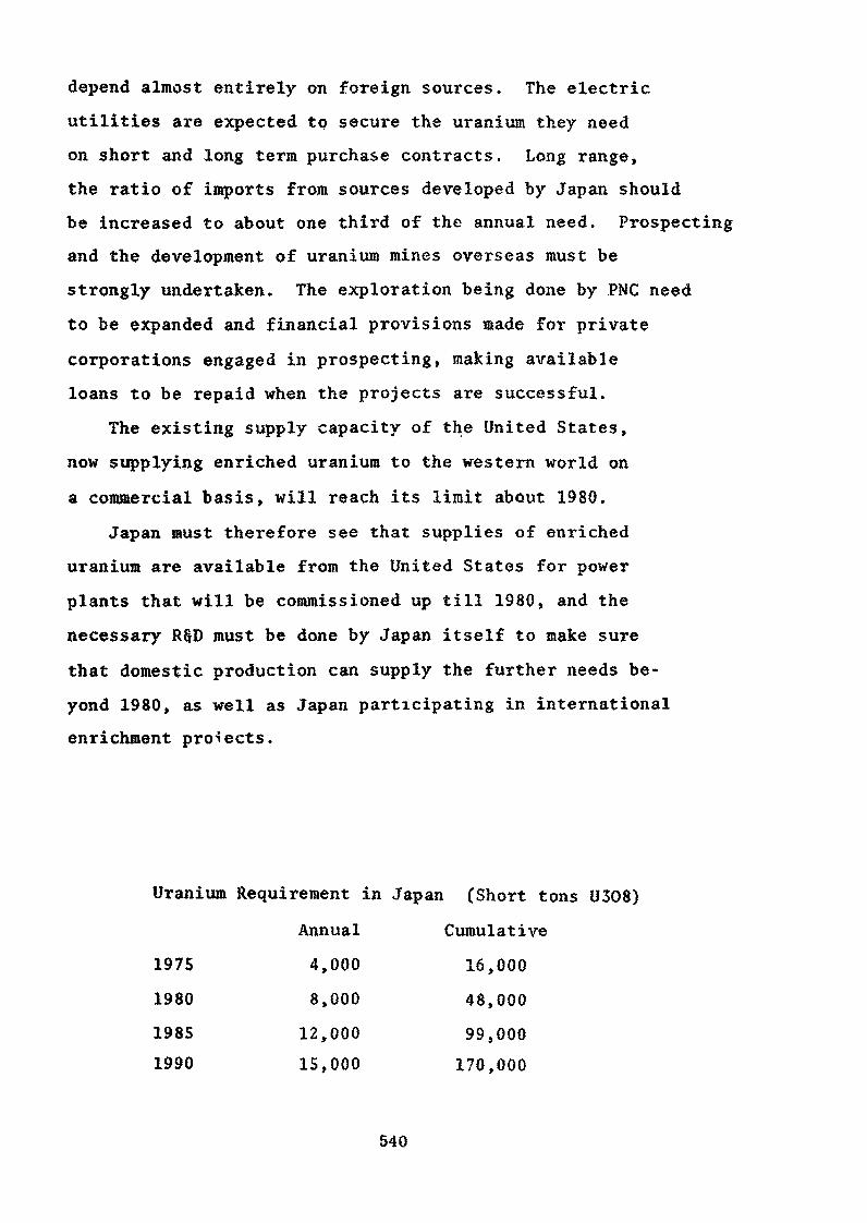
depend almost entirely on foreign sources. The electric,
utilities are expected to secure the uranium they need
on short and long terra purchase contracts. Long range,the ratio of imports from sources developed by Japan shouldbe increased to about one third of the annual need. Prospecting
and the development of uranium mines overseas must be
strongly undertaken. The exploration being done by PNC need
to be expanded and financial provisions made for private
corporations engaged in prospecting, making available
loans to be repaid when the projects are successful.
The existing supply capacity of the United States,
now supplying enriched uranium to the western world on
a commercial basis, will reach its limit about 1980.Japan must therefore see that supplies of enriched
uranium are available from the United States for power
plants that will be commissioned up till 1980, and the
necessary R§D must be done by Japan itself to make sure
that domestic production can supply the further needs be-
yond 1980, as well as Japan participating in international
enrichment projects.
Uranium Requirement in Japan (Short tons U308)
Annual Cumulative
1975 4,000 16,000
1980 8,000 48,000
1985 12,000 99,0001990 15,000 170,000
540
In nuclear fuel fabrication, domestic makers are
consolidating their basis for local fabrication, but the
foundation is not yet firm enough. Technological development
must be further promoted. The requirement for fuel fabricationwill be 1,400 tons in 1980, 2,800 tons in 1990. Conversion
to uranium hexaflouride from natural or depleted uranium is
performed abroad for the time being, however, our own
capability shall be developed, in particular for the purposeof domestic production of enriched uranium in future.
Plutonium production in Japan is estimated to be 13 tons
cumulative in 1980 and cumulative amount of that would be
45 tons by 1985, in contrary, its requirement up to 1985
would be only several tons for research purposes then
there must be 40 tons or so excess plutonium by that time.
Plutonium can be most effectively used in the FBR,
but pending its coming into commercial use, there are plans
for Pu use as fuel in the LWR, as a means of reducing the
consumption of uranium and enriched uranium. This is
considered feasible in view of the cost of storing
plutonium. The Government must take proper steps to help
private corporations engaged in technological development
on plutonium to use the facilities of PNC and JAERI.Requirement for reprocessing will reach to 700 tons
in 1980, 2,600 tons in 1990 in Japan.
For the reprocessing of spent fuel, PNC is building
the first reprocessing plant, to be ready by 1974. The
second and subsequent plants are expected to be builtand operated by private corporations, on the principlethat reprocessing of spent fuel is to be done in Japan.
54.1
But as a spent fuel reprocessing plant involves many
as yet unsolved problems -, the Government is required to
adopt a proper siting policy and provide low-interest, long-
term loans, as well as energetically promoting R § D on
reducing to th lowest practicable level the ratic active
nuclear wastes discharged into the environment.
3. Environment and Safety
Proper development and utilization of nuclear energy
is possible only when radiation is safely controlled. Japan
is so far exercising strict control and regulation of
radiation, giving much greater consideration to such
safety than to other branches of industry.
But large quantities of nuclear waste will certainly
be produced when more nuclear energy for power and other
large scale developments are carried out. The amountof radioactive matter emitted into the environment is
expected to increase accordingly. Further, multi-lateral
application of radiation, expected to expand greatly, will
increase the possibility of more people and nuclear-energy
handling staff being exposed to radiation.
To meet this situation, and to maintain the present
high level of safety and safeguard factors, even greater
efforts are needed and more consideration given to
questions of safety and preservation of the environment.
This requires proper steps on the siting of plants, safetymeasures covering all facilities and equipment, and
radiation control is necessary; studies are needed on
background radiation and its effects as well as on the
542
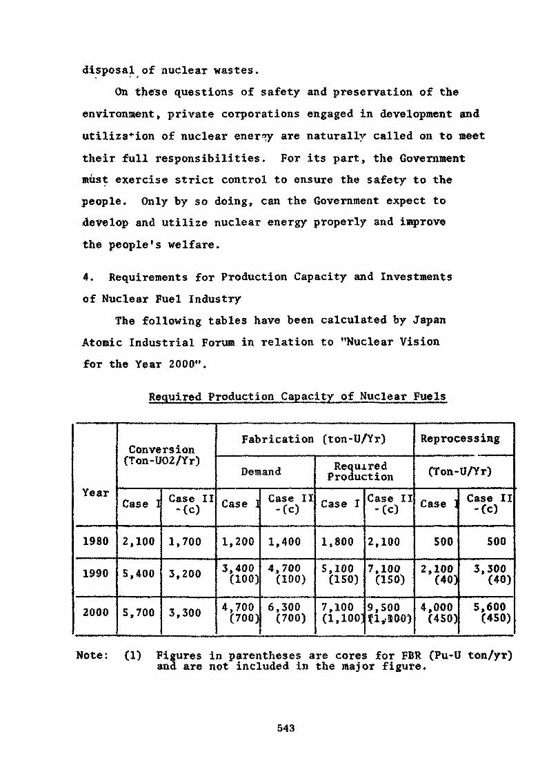
disposal of nuclear wastes.
On the'se questions of safety and preservation of the
environment» private corporations engaged in development and
utilization of nuclear ener<ry are naturally called on to meet
their full responsibilities. For its part, the Governmentmust exercise strict control to ensure the safety to thepeople. Only by so doing, can the Government expect todevelop and utilize nuclear energy properly and improve
the people's welfare.
4. Requirements for Production Capacity and Investments
of Nuclear Fuel Industry
The following tables have been calculated by JapanAtomic Industrial Forum in relation to "Nuclear Visionfor the Year 2000".
Required Production Capacity of Nuclear Fuels
Year
1980
1990
2000
Conversion(Ton-U02/Yr)
Case I
2,100
5,400
5,700
Case II-(c)
1,700
3,200
3,300
Fabrication (ton-U/Yr)
Demand
Case ]
1,200
3,400(100)
4,700(700)
Case II-(c)
1,400
4,700(100)
6,300(700)
RequiredProduction
Case I
1,800
5,100(150)
7,100(1,100]
Case II-(c)
2,100
7,100(ISO)
9,500n,'ioo>
Reprocessing
(Ton-U/Yr)
Case :
500
2,100(40)
4,000(450)
Case II-(c)
500
3,300(40)
5,600(450)
Note: (1) Figures in parentheses are cores for FBR (Pu-U ton/yr)ana are not included in the major figure.
543
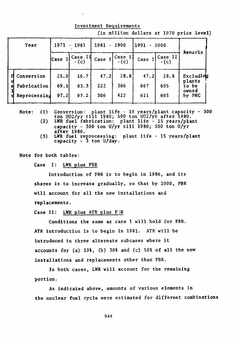
Investment Requirements(in million dollars at 1970 price level)
Year
FieIs
Conversion
Fabrication
Reprocessing
1971 - 1981i
Case I
25,0
69.5
97.2
Case 11-(c)
16.7
83.3
97.2
1981 - 1990
Case I
47.2
222
3Q6
Case I!-(c)
28.8
306
422
1991 - 2000
Case I
47.2
667
611
Case II-(c)
28.8
695
695
• Remarks
Excludinplants -to beownedby PNC
Note: (1)
(2)
(3)
Conversion: plant life - 10 years/plant capacity - 300ton U02/yr till 1980; 500 ton U02/yr after 1980.LWR fuel fabrication: plant life - 15 years/plantcapacity - 300 ton U/yr till 1980; 500 ton U/yrafter 1980.LWR fuel reprocessing: plant life - 15 years/plantcapacity - 3 ton U/day.
Note for both tables:
Case I : LWR plus FBR
Introduction of FBR is to begin in 1986, and its
shares is to increase gradually, so that by 2000, FBR
will account for all the new installations and
replacements,
Case II: LWR plus ATR plus FSR
Conditions the same as case I will hold for FBR.
ATR introduction is to begin in 1981. ATR will be
introduced in three alternate subcases where it
accounts for (a) 10%, (b) 30% and (c) 501 of all the new
installations and replacements other than FBR,
In both cases, LWR will account for the remaining
portion.As indicated above, -amounts of various elements in
the nuclear fuel cycle were estimated for different combinations
544
of reactor types. For computation of fuel requirements,case I and case II-(c), representing maximum and minimum
were taken into account to estimate yield.
5. Present Structure of Fuel Fabrication IndustryThe Mitsui group centering on Tokyo Shibaura Electric and
Ishikawajima-Harima Heavy Industries and the Tokyo Atomic
Industrial Consortium, built around Hitachi Limited jointlywith General Electric, has set up a joint venture JNF (40 percent of the capital shared put up by GB, 30 per cent by
Toshiba and 30 per cent by Hitachi). The company has been
fabricating BWR fuel at Yokosuka factory since 1970 on thebasis of a technological tieup contract with GE. Its fabri-
cating capacity is now 210 tons-U a year, but the companyobtained Government permission to expand its facilities to
490 tons a year by the spring of 1974. JNF has so far deliveredthe first and second replacement.fuel for the Tsuruga power
plant of Japan Atomic Power Co. and the first fuel for theFukushima No,2 plant of Tokyo Electric Power Co. It has contracted
for the delivery of the first fuel to Shimane No.l plantand the third replacement fuel for the Tsuruga plant.
The company is thus prepared for the fabrication of fuel forall BWR plants built by its parent companies GE, Toshiba and
Hitachi.
The Mitsubishi group is building PWR on technology itintroduced from Westinghouse Electric. Last year in December,
the group incorporated Mitsubishi Nuclear Fuel Company. Theshares of MNF's capital are 51 per cent from Mitsubishi Metal Corp.,
15 per cent from Mitsubishi Heavy Industries and 34 per
545
cent from Westinghouse. MNF has 100 tons capaerty and plans
to expand the factory to produce 280 tons within this year,its capacity must be increased to 420 tons by 1974 for
which government permission is being sought,
Furukawa Electric Co., and Sumitomo Electric Industriesin July 1972 jointly set up Nuclear Fuel Industries for the
fabrication of nuclear fuel. The new company will be the
third nuclear fuel company, following Japan Nuclear Fuel andMitsubishi Nuclear Fuel. This now means that all five nuclear
industry groups, either independently or jointly, will
have their own nuclear fuel fabrication companies bringingthe fuel fabrication business to full status in Japan. The
new company will be assisted by Gulf United Nuclear Fuel Co,on fueliidesign, fabrication and management technology.
The formation of this company which is able to manufacturefuel for both BWR and PWR, must be considered a very
important step in promoting commercial competition in thefuture nuclear fuel market.
In the field of conversion of UF6 to U02 (enriched uranium),Sumitomo Metal Mining, of the Sumitomo group, is buildinga plant with a conversion capacity of 240 tons a year at
Tokai-mura, Ibaraki Prefecture, to be completed in Octoberthis year. MNF will have a production capacity of 240 tons
a year, is scheduled to be commissioned in January next.In the manufacture of zirconium cladding tubes, demand
for which is expected to increase with the growth of thefuel conversion and fabrication business, Kobe Steel,
Sumitomo Metal Industries and Mitsubishi Metal Corporation
have already begun production. Kobe Steel has a factory
546
producing 130,000 meters of tube at Chofu, Yamaguchi Prefecture,
and capacity is planned to be increased to 400,000 metersby the end of 1973.
Sumitomo Metal Industries has facilities in its centralresearch institute for producing 50,000 meters of cladding
tubes a year. Capacity is to be increased to 150,000meters by 1974. After that, a new factory will be built
in Shiga Prefecture for annual production of 500,000 meters.Mitsubishi Metal has completed facilities at Okegawa,
producing 50,000 meters. The capacity will be increased to150,000 meters within this year and to 300,000 meters by
the end of 1975.
Zirconium Industry Company was founded last year asthe first specialized maker of zircalloy tube shells in Japan,The company is a joint venture, 25 per cent of whose capitalis provided by Mitsui § Co. and 75 per cent by the Ishizuka
Research Institute Ltd, Technology was imported from theTeledyne Wahchang Albany Company of the United States.
Using these techniques as well as techniques developed by IshizukaResearch Institute, the company is going to undertake the
full process of manufacture from zirconium sands to tubeshells. Nippon Mining Co. which has been making zirconiumsponges, is also reported to be founding a new company jointlywith Sumitomo Metal Industries.
547
..POLICY' WITJg REGARD^ TO POj^_gPIC FABRICATION' OP
K. RaoBhabha Atomic Research Center
Bombay, IndiaAbstract
In planning a sustained nuclear power programme the need for selfsufficiency in fuel fabrication is imperative. This paper describes themanner in which nuclear fuel technology has been developed in India.Natural uranium metal fuel production plants with rated capacities of30 tonnes per annum have been made operative as early as 1959 to meetthe fuel requirements of the research reactors, CIRUS and ZERLIHA. Sincethen these plants are catering to the replacement fuel requirements ofthese reactors. As a next step, development is carried out on uraniumoxide-based power reactor fuel. Aluminium-clad UOp fuel clusters forZerlina and Zircaloy-clad U02 fuel bundles for the CANDU-type powerreactor, RAPP-1, have been produced; to the extent of 40 tonnes ofcontained TJCL. Stainless steel-olad plutonium oxide fuel pins have beenproduced from plutonium separated by the reprocessing plant for thefast critical test facility at Trombay. Thorium oxide, Thorium metaland its alloys have been fabricated in small quantities for use in theresearch reactors and for collaborative efforts with Sweden and WestGermany. Separation of ir has been carried out on a laboratory scale.
For meeting the large scale fuel demands a uranium mine and millhave been commissioned in 1968 at Jadi»guda and large scale fuel productionfacilities are being commissioned at Hyderabad. The mill at Jadugudaprocesses about 1000 tonnes of ore per day. Facilities at Nuclear FuelComplex at Hyderabad are planned to produce 100 tonnes of finished fuelelements of RAPP type starting from zircon sands from Kerala and uraniumconcentrates from Jaduguda. Plants are being put up to produce enricheduranium oxide fuel assemblies towards reload fuel for Tarapur PowerStation from the enriched uranium hexafluoride procured from U.S.A.
The Huclear Power Programme has been formulated in the "Profilefor the Decade 1970-80" with a targeted installed capacity of 2700 MW(e)
549
by 1930 mainly based upon natural uranium oxide - heavy water moderatedand cooled reactor systems. Design studies and test programme are "beingundertaken for fuel for the advanced large size reactors. As a preliminaryto launching a fast breeder reactor programme based on thorium cycle,provision is included for a 40 Mtf(Th) Fast Breeder Test Reactor, FBTR,at Kalpafckam near Madras. Facilities are being nlanned for productionof fast reactor fuel; while the hot laboratories at Trombay wouldfabricate the initial fuel charge for FBTR.
Thus, with a clear foresight, fuel production facilities are madeoperative well in time for the implementation of the reactor constructionprogramme.
The per capita power eonavapUo» i* India ia very lev eoapared to the
advanced eoaatriee. A» published in m Statistic»! Tear Book 19*7* the pa*
««pit» power eonau&ptlon ia India ma 75 KSh aa again» t 6345 Ufa in ÏÏ.8»A*V
7907 DBi in CoMtda «ad 2171 MB» in Jap«a. For tb« envia«c»d ^BOIMM» i» the
•oaatxy it i« T«qr «M«Qti«l Hbat the poirer genwratioB bas to ¥e «OMidorslily
ina3Mam4« India* a reaoexcea for aa«h a large acale power «eaexatloii are
«dr«re«ly dlatzitnted i» epeoifio location» and not ttnifo»ly districted
«he oo«»ti/« Sbr inetafioe, the Mgor coal reaerrea of the eouttry
are 1» 1fee Hoxth-Eaatam «one of Ben«al-Bihar coal eelt with veiy avail
reaerrea in the eeatral part of the eountzy» The major fegriro power reaoureea
are is the aot-eaaily approaehalile hiU rangea ana ia other available liaited
zonea are very meh dependant on the vagaries of rainfall» ffae eataeliahed
oil reaoareea are very United* Taking the above into consideration the
Atoadc 3Energy Ooaaisaioa of the Government of India haa stressed «bat auelear
power prograauw haa a very taportant role to play in «eeting the power needs
of the country. Here again the established reserves of uranium are of liaited
nature and are not sufficient to sustain any significant installed aaelear
550
power capacity for » long tine based on natural «raniu» reactors. However
India is one of the forenost countries in its thoriu» reserves. As suck
India1» nuclear power psograroe has to fee launched toward* utilisation ofthorium in the long rang* planning» It ha» al»o been recognised that to
launch a p wer prograw»e based on enriched uraniua fuel is also difficult
because of the large resources that «ill be required for such a programs.
Heavy water noderatea and cooled natural cranium fuelled power reactors
offer a very advantageous «yatem for the first phase of the power generation
programme leading to plutoniua fuel baaed power reactor programme in the
second phase and finally the tfeoriuK breeder syateas» The nuclear power
strategy drawn op by the Indian Atonic Energy Coonission is shown in
Figure 1. To iapleaent such a programme the industrial infra-structure
within the country is «eagre, «bile in the conventional areas such as
generators, pumps, heat~exchangars etc* publie aeetor and private sector
industry is sowing up for catering to the needs of the country, it has •sea
realised that the nuclear fuel production in all ita aspecte has to te
arranged as a governmental activity fey the Départaient of Atoaio Energy»
Such a programs will taring not only indigenous capability of fuel production
with greater flexibility for catering to research and power reactor
construction prograttae but alao te ng in self-reliant,y in this field*
Xhe estimates have indicated that the fabrication costs are comparatively
low against the landed costs for the imported fuel. The foreign exchange
saving effected by Hie indigenous operations is also of great icportance
to a developing country» A mention need also be aade of the technological
development that comes up within the country because of carrying out such
a highly technological and sophisticated operation as fuel fabrication and
the enployjMat potentialities arising thereby»
2« Since 1950 oawarde three plants of a public sector coitpany, India»Hare Earths Ltd», vis. the Mineral sand» industry in Manavalakurichi and
551
Chavara, Rare Earths Plant at Alwaye and Thorium Fiant at Trombay ara being
operated for the Department of Atomic Energy for processing monazite sands
on the West coast of Kerala for the recovery of thorium salts and zircon and
other ainerals* The main sources of uranium are located at Jaduguda in the
SinghWna dietriet of Bihar State* A aine and mill with a rated capacity of
1000 tonriea of ore per day is being operated by the ÏÏrsniim Corporation of
India Ltd., a company under the Department of Atomic Energy formed in
October 1967.
3» As for the reactors, the construction of a 380 Mff(e) Boiling Water
Reactor station comprising of two units each of 190 Kff(e) at Tarapur (TAPS)
has seen completed by International General Electric Co. of U.S.A. in the
year 19<»9 and has been in operation since then» Two heavy water- reactors*
each of 200 InY(e) of CAETDEJ type are under construction at Banapratapsagar
near Kota, Rajasthan (RiPP I, II) and the first reactor ie scheduled for
cxiticality in July/Aagust 1972* Construction work is progressing on the
two 200 MW(e) reactors at Kalpakkam near Madras (UAFP I, II) to tecoas
critical liy 19?t* A site has seen chosen at Narora in trttar Pradesh for the
construction of two 200 Mff(e) reactor station. In its profile for the
decade 1970-1980 "Atonic Energy and Space Research", the Départaient of
Atoxic Energy has proposed a total installed capacity of 2700 Mff(e).
%ile the Tarapur reactor is based upon a slightly enriched ureniun oxide
fuel clad in zircaloy, other stations are based upon natural uranium oxide
fuel clad in Bircaloy.
4* The fabrication of fuel has been taken up on a firm basis with a
cooatitaent to supply uranium nets! fuel clad in alnodnium for the initial
load of 40 IflF('Ph) CIRUS research reactor at Trombay. A uraniuv metalproduction plant and a fuel fabrication plant were set up by 1959* T&e major
operations for metal production from the ffiagnesiu* diuranate concentrate
comprise of dissolution in nitric acid, purification by TfiP solvent
extraction and calcio-theraic reduction of the uranium tetrafluoride* Taking
552
into consideration the annual production rate of 30 tonnes the ingot sic» 1»
kept to 50 Kgms. In the fabrication plant the metal is vacua* melted and
oast, hot rolled in the alpha range, beta heat treated, machined and clad in
aluminium tubes. The detailed fabrication flow sheet is given in Figure 2.
The initial investment in the fuel fabrication plant is of the order of five
million rupees (1959 prices) with a foreign exchange component of three
million rupees. It may not be out of place to mention here that basic design
of the fuel element has been supplied by Atomic Energy of Canada Limited aad
opportunities were provided for the scientific staff to visit sow» of the
fabrication operations* The whole technical know-how had to be entirely
developed locally and the choice of the equipment and its layout, commissioning
and putting into operation has been entirely handled by the Indian personnel*
from tfee initiative and drive put into the programme it has been possible to
produce «ore than half the initial eore and a total requirement of conponenta
for the initial core loading of CIB0S* The replacement requirements are
being completely «et since then out of indigenous manufacture. The behaviour
of the fuel in the reactor has been entirely satisfactory all these years*
Having the facilities for the fabrication of uranium metal, the fuel for
ZERLINA (2 ro energy reactor for lattice investigation and new assemblies)
based on uranium metal rod clad in aluminium has been fabricated and supplied*
5* fy this time it has become apparent that for power reactors uranium
oxide fuel has considerable advantages over metal fuel* In conformity with
the decision to go in for uranium oxide fuelled heavy water reactor
development work has been taken up with regard to the technology of oxide
fuel fabrication. After considerable study of the production parameters
with regard to the pressing and sintering of ceramic grade uranium oxide
powder, aluminium clad high density uranium oxide fuel has been produced
for a full core of Zerlina reactor* This has given sufficient Insight
and experience into Hie technology of production of high density uranium
oxide pellets* ty this time a commitment was made to produce half the
553
initial core loading and stand-fey fuel for the iUgast&an-l reactor while
half the initial core loading was being imported from Canadian Weetingbouse
Company through 1SCL. During the period of fuel production in Canada,
a few of the engineers had the opportunity to watch the operations in the
Canadian Westingbcuse and with the assistance of AECL, specialised
equipments for the fuel bundle assembly hsve been procured fro» tlae
Canadian Weetinghouse as a commercial purchase» Taking the tire factor
into consideration facilities were improvised at the uranium netal fuel
fabrication plant itself fox the production of itoe above requirement»
Bven though considerable difficulties have been experienced in the early
stages of fabrication the full coH»itaent of 2500 fuel bundles with about
40 tonnes of contained uraniua oxide ha» been produced and delivered well
in tine* In addition to the inspection and quality control supervision
of the department, AECL provided quality surveillance and the fuel produced
ha» «et all the quality requirements in full* Details of the Bajasthaa
fuel, bundle are given in Annexure X and the flow sheet is shown in Figure 3*
6» To eater to the full ecale fuel requirementa of the reactor power
programs» it ie felt essential to put up a large scale production plant*
Planning ha* been done not only for the production of fuel but also the
siroaloy and other components required fox fuel manufacture and also for
the structural members of the reactor such ae coolant tubes, calandria tabes
etc» These activities are carried out at the Unclear Fuel Cosplex set up
in Hyderabad which is scheduled for commissioning ana operation before the
end of 1972* The complex will essentially have the following constituent
units a Zirconium Plant (ZP) comprising of Zirconium oxide plant, Zirconiua
sponge plant, and Zirealoy fabrication plant; Natural Uranium Oxide Plant
(UOP), Ceraaio ïuel Fabrication Plant (CFFP), Enriched Uranium Oxide Plant
(EDOP), Enriched Uranin» ^uel Fabrication Plant (Bîîî1}, and a quality
control laboratory (CPF). The locations of the Nuclear Fuel Complex and
the Keactor Systems are shown in Figure 4 and the activities at the Kuclear
554
Fuel Complex in Figure 5. As for the starting materials fox the Nuclear
Fuel Complex, zircon cones fro» the minéral beach sands plant in Kerala of
the Indian Hare Earth Ltd.? uranium com entrâtes from the Jaduguda mill of
Uranium Corporation of India Ltd* } enriched uranium in the for» of uranium
hexaflttoride fro» U.S. The total capital outlay for the Nuclear fusl Complex
is «round râpées 140 millions with a foreign exchange «opponent of rupees
47 millions and the details are «
Annual production 50 125 100 30 24capacity Tonne s/yr
Equipment and 58«68 9-52 12» 20 5-51 3«82 13.82 10J.55machineryb. Billions
Bld^.and utilities 12.J8 2. 55 3.1 2.8? 0.35 10.13 31 «1*fis» millions
The coaple* «ill provide cnployaent for around 1230 personnel
including 80 engineers/scientists, 200 supervisors, 600 technicians ana
350 semi-skilled persons. This does not include personnel for
administration, pureh&se and accounts staff»
6. The provisions at the Cerafide Puel Fabrication Plant (CFFP) and
Enriched Uranium Fuel Fabrication Plant (EPPP) are dealt with in store detail
The capacity of Gif? is initially fixed at 100 tonnes per year
based on the initial fuel inventory and sustained reload requirements of
four 200 lW(e) CaNBO-type reactors with fuel burn ups of the order of
8000 JOatfTtfS. As per the present indications, the BIFF-I reactor is
scheduled for oriticality in July/August 1972 and the other reactors »y
1976» Depending on the schedule of installation of additional reactors
of this type, the capacity of the C3FP can be increased upto 400 tonnes
per year by adding the necessary equipment and increasing the working
shifts. Important particulars of the fuel and the quantities of the TK>2
required for one reactor charge are presented in Annexure I.
555
manufacturing sequence is given in the flow sheet as shown in
5» She area required to. house the plant including the coaponent
» switch gear-roo« and< change TOO» for personnel is esti&ated at
.M. This is proposed in a 90 x 4?» 5 U single story building,
The front hey aocc atodatiag offices and change roosts is 4 meter higp
trhils the refit of the plant is 6 «eters. For au toc laving the fuel
aseeablles, a clear height of 8.5 meters is required which ie to he
arranged Isgr having a 5 meter, deep pit in the 11*4 x 7*5 meter corner rooau
Out of the four fabrication beys, three trill be utilised for natural
uraniisaa oxide fuel fateication «bile the fourth one for the fabrication
of enriched uranium oxide fuel for TAPS. The combined layout of the two
fabrication facilities ie shown in Figure 6. For ventilation of the plant,
washed and filtered air is recowoended in quantity sufficient to give
12 air changea per hour while roof extractors ere to exhaust the building
through filter».
fhe capital outlay for the plant is estin&ted at rupees 15«28 Billion • '/
(foreign exchange component is rupees 7*15 Million) out of which buildings
end services are expected to cost rupees 4*01 ad HiOB. This cost does not
include the coat of roads, area services and other ancilliaries like
«orlcafeppj, analytical facilities, cooling tower, canteen, store» etc. which
will he provided under the Coaroao» Plant Facilities at the Nuclear *"uel Cdnplex*
The total number of personnel required for the plant is estimated at
147 comprising of 8 engineers* 19 supervisors « 101 technicians and %
19 supporting staff. '.The plant will fee fully operational toy the end of -•-
this year.
The coat of operating the plant for 100 tonnes of fuel 3» estittated
to las rupees 7*47 million annually including provisions for process losses '
and 6 % interest on 6 atontha1 fuel inventories* The cost of fuel works out
to rupees 460 per Kg* of contained tJO * This coat includes the cost of
atout 20 $ U0£ recycling and. 10 $ excess eircaloy* ?he landed cost of
556
similar fuel works oat to rupees 512 per Kg» of contained TJOg. The net
fabrication costs starting from B-concentrâtes to finished prodacts
(excluding zirealoy) cones out to rupees 1J.20 idllion in the total valu»
of the product of aspaes 46.00 million. This fuel If imported woold cost
rupees 5,.20 million. The savings are only marginal due to the prices of
Indian Uranium Concentrates being much higher compared to international
prices» Indigenous manufacture of the fuel results in a foreign exchange
savings to the extent of rupees 56.9 million which is a major consideration
in undertaking this project»
The Enriched Uranium Fuel Fabrication Plant meets the reload
requirement of Tarapur Atomic Power Station (TAPS) a 580 MBF(e) Boiling
later Reactor. The capacity of the plant is fixed at 24 tonnes par year
based on the annual fuel replacements upto 20 $ of the core with fuel burn
ups of the order of 23*000 MWD/TeU» The enriched uranium hexafluoride
imported from U.S. is converted to enriched DO. ponder at the Enriched
Uranium Oxide Plant*
The TAPS «as coonissioned in May 1969 and the first refuelling «as
done with imported fuel in 1971/72. The second refuelling scheduled fox
1972/73 would be also fro» imported fuel* Unclear Fuel Complex will meet
the refuelling requirements commencing from the third reload*
Important particulars of the fuel and the quantities of the enriched
ïïOg and zircaloy required for one reactor charge are presented in the
Annexure II. The manufacturing sequence is given in the flow sheet as
shown in Figure ?• In view of the limited requirements of this type of
fuel, and the similarity in fabrication to that of natural uranium oxide
fuel the facility for TAPS fuel fabrication is located in one of the bay»
of the Ceramic Fuel Fabrication Plant as shown in Figure 6. This resulted
in considerable savings in building costs and the services* The main
fabrication area is provided in a bay measuring 90 K x 10 M. The layout
of the fabrication facility has been designed keeping in view the
557
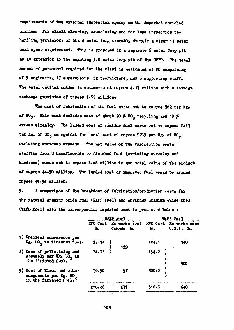
requirements of the external inspection agency on the imported enriched
uranium. For aUteli >cle airing, autoclaving and for leak inspection the
handling provisions of the 4 meter long; saseaoly dictate a clear 11 aster
head space requirement, ïhis is proposed in a seperate 6 meter deep pit
as a» extension to the existing 5.0 meter deep pit of Use CFFF. The total
ausfcss? of personnel required for the plant is estiaated at 80 comprising
of 5 «««insers, 17 supervisors» 52 technicians, and 6 supporting staff.
*he total capital outlay is estimated at rupee* 4» 17 million with a foreign
exchange provision of rupees 1.55 Billion.
îh« coot of fabrication of the fuel works out to rupees 562 per Kg,
of UOg. Xhis ooet inolade» cost of «boot 3) $£ W>2 recycling and 10 $
excess ziiealoy. The landed cost of similar fuel works out to rupee» 241?
p«r Kg. of UOg aa against the local «oat of rupees 2215 per Kg. of ÏÏOg
including enriched ttraaia». ïfce net value of the fabrication coats
starting from tr hexafluoride to finished fuel (excluding ziroaloy and
hardware) oostes out to xupee» 6.66 Billion in the total value of the product
of rupees 44*?0 Billion. The landed cost of imported fuel would be around
rupees 48*54 million.
9» A comparison of tite "breakdown of fabrication/production costs for
the natural uranium oxide fuel (R&FP fuel) and enriched uraniua oxide fuel
fuel) with the corresponding imported cost is prtKented below t
Fuel_____ TAPS fuel___RFC Cost £x~works cost KFC Cost &t~«orks cost
fe» Canada te. Bs» U.S.A. 8s.
conversion perKg* UO- in finished fuel. 57*24 ) 1@4«1 140
) 1392) Cost of pelletising and 74*72 ) 134*2
aaseaably per Kg* TJO_ i»«he finished fuel.
ocwponenta per Kg. CO,,in the finished fuel,*1
Cost of Zirc* and other 76.50 92 200*0
210.46 231 518*3 640
558
10» Thorium fuel cycle i« of great significance to countries like India which
possess large reserves of thorium» In the nuclear power generation programme
in India, the third generation reactors will 1» th-TT" breeder system»,
Development work was taken up OB thorium fuels ae early as 195& in the fuel
fabrication facility at Trombay. Thorium and thorium oxide pelletiaed fuels
canned in aluminium have teen made for Conversion étudies in CIKUS. There are
in all 90 positions available in the CIK, J-rod annulas for irradiation
purposes* Thorium metal f«vder is produced by caleio-thermic reduction of ThO*.
The flow sheet for the fabrication of thorium and thorium oxide fuel shapes is
given in Figure 8. Under a collaboration agreement with Sweden about 530 Kg*
of sintered pellets of Th02 were supplied to A.B.Atomenergi*
Under Ingo-Genaaa Technical Collaboration programme, an advanced fuel
concept is to be developed for sodium cooled fast breeders which could lead
to high breeding gain and low doubling time» The basic idea is to use thorium
metal as a matrix for the fissionable material (Plutonium or enriched uranium)
with a thin cladding* For preliminary investigations Tht Th-U (1CJÉ) alloy
strips and blocks have been supplied to KFA, Julien. These blocks are produced
by extruding Hie are melted sintered thorium*
The fuel reprocessing plant at Trombsy has successfully separated U
from the irradiated thorium rods*
11* Plutonium fuel development work was initiated with the commissioning in
19 4 of the fuel reprocessing plant at Trombay to reprocess the irradiated
fuel from CIKOS. Pure PnOg sintered pellets of about 90 £ TD have been produced
and fabricated into stainless steel clad fuel pins for the Zero Energy Pulsed
Fast Critical Assembly» Flow sheet for the fabrication of these fuel pins is
given in Figure 9* About 200 such fuel pins containing about 24 Kg. of PuOg
bave been fabricated for the critical facility»
A 40 10r(Th) fast breeder test reactor basically similar to the French
RAPSOKIE-POETISSIMO is being constructed at the Reactor Research Centra,
Madras under an agreement with CfcA, France. FBTK will have (3*7 Pu»
559
uranium oxide enriched to about 90 in t r » as fuel» According to th*
agreement, the responsibility for the whole project including the core traction
of the reactor «ill lie with the Indien Atonic Energy Commission* Indian
industry «111 have a aaxiau» share in the engineering of the project end
supply of vaterials and equipment» Investigations ere beinf carried out at
Troahay on W-PuO. fuels for developing a fabrication process for the fast
reactor fuel. Details of the FBïR fuel are given in Joitiexuie III.
The general flow sheet for the fabrication of fissile fuel assembly for FBTR
ia iren in Figure 10. The initial fuel charge for FBTE «ill he fabricated
at TroBbay. It may he mentioned here that the drawings for a similar fuel
were supplied by CEà, France and the whole technical know how starting fro»
the drawing op of the spécifications, design of the equipment, building op
of the fabrication facility and production of the fuel assemblies hae to be ~
entirely developed indigenously. Planning is in progress for the setting up
of a plutoniua fuel fabrication facility at Reactor Research Centre, Madras*
12» Concluding» the Department of Atosdc Energy bae acquired during the
laat decade a capability to process and manufacture different types of
uraniu», thoriua and plutonium fuels indigenously* The coitaaiseioning of the
large «cale fuel fabrication plants well in tixee for the iaplementation of
the reactor construction programae, is yet another milestone in our endeavour
to achieve self-sufficiency in the field of nuclear power technology.
560
Annexure I
OF KAFF HISL BUNDLE
The fuel, uranium oxide is in the for» of sintered pellet»,
14*26 an (0.5e") in diameter and about 20 am in height. One end of
the pellet is made slightly diahed. About 2* number* of auch pellet»
axe encased in a circaloy tube, 15.22 m (0.6") o*d«, 0*38 MB (0.015M)
wall thickness, and 49*5 w» (19-5") i& length, both end* of nhieh are
sealed by welding zircaloy end plugs* Nineteen «uoh tubes filled with
TJOg, called "elements" are assembled between two end plates in two
concentric rings of «ix aad twelve "elements" respectively around a
central element. The six elements of inner ring and the six alternate
elements of the outer ring are wrapped with 0.05" diaaeter «iroaloy-2
wire in a helical meaner to provote inter-eub-channel Kixing of the
coolant. The other six elements of the outer ring have spacer wires
welded on to them» In addition, all the twelve outer eleaents are
provided with wrapped bearing pads of 0.065" dia» eircaloy-2 wire, which
•pace the bundle fro» the coolant tube and reduce the wear on the
coolant tube during the fuel charging operation. This 19-element
aasenbly is called a "fuel bundle*1. The details of the RAFF fuel are
given in the enclosure»
561
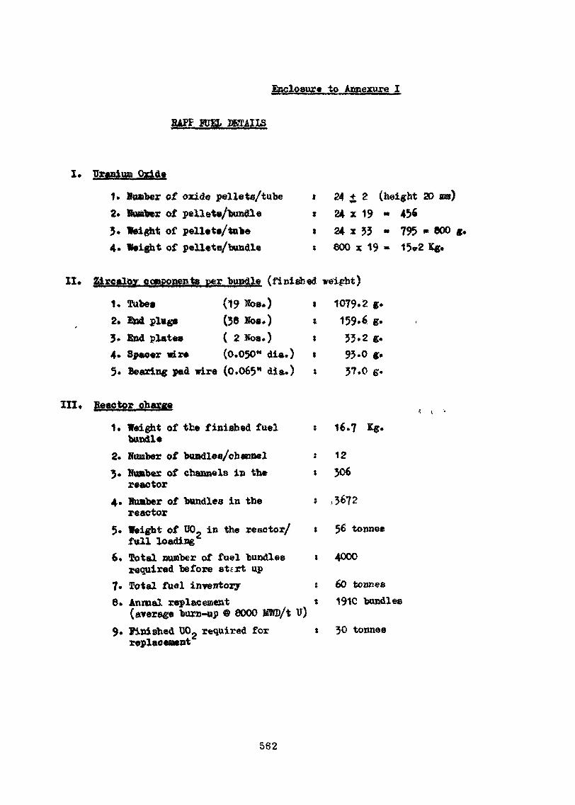
Enclosure to Annexure I
RAPE HJEL DETAILS
I» id
1. KoBber of oxide pellets/tube t2. Kuaber of pellets/bundle s3» Weight of pellets/tube s4. Weight of pellets/bundle *
24 + 2 (height 30 aw)24 x 19 * 45624 x 53 - 795 - 000 g.800 x 19 » 15cr2 Kg.
II» Zircaloy components per bundle (finished weight)
(19 NOB.)(36 Kos.)( ^ Nos.)
1. Tube»2. End plugs3» find plates4* Spacer wir« (0.030M dia.)5. Bearing pad wire (0.065W dia.)
ïttti
1079.2 «.159.6 g.33.2 «.93-0 g.37.0 g.
III* Reactor charge
1. Weight of the finished fuelbundle
2. Number of bandies/channel3. Nunbex of channels in the
reactor4. Number of bundles in the
reactor5. Weight of 00- in the reactor/
full loading6* Total number of fuel bundles
required before st*rt up7» Total fuel inventory8. Annual replacement
(average burn-up © 8000 MTO/t U)9. Finished TX>2 required for
replacement
: 16.7 *€>
12» 306
* ,3672
t 56 tonnée
s 4000
; 60 tonnes* 191C bundles
t 30 tonnes
562
Annexure II
INSCRIPTION OF TAPS FUEL ASSEMBLY
The fuel, uranium oxide slightly enriched in ÏÏ -*•% is in the fort»
of sintered pellets 12.24 son (0.482") in diameter fend about 20 am in
height. About 200 Koe. of such pellets are encased in an autoclave*
«ircaloy tube 14.28 an (0.5625") o.d., 0.69 am (0.035") wall thickness
and 3866*2 oat (153<0 in length, both ende of which are sealed by are-Î
welding sircaloy end plugs* Thirty six such tubes filled with DQgt celled
elements, are arranged in a 6 x 6 square array in between two stainless
steel tie plates. The' «pacing between the individual elements of this
long assembly is maintained by mean» of spacers, seven in each assembly.* s
One of the thirty «i* elenents, called the segmented element, locks
the Spacers in position* The entire assembly ia inserted in a four
meter long eirealoy channel of square cross section. Sach 36-eleaent
assembly contains about 160 Kg. of C02 and there are 284 such assemblies
in each reactor. The details of the TAPS fuel are given in the
enclosure.
563
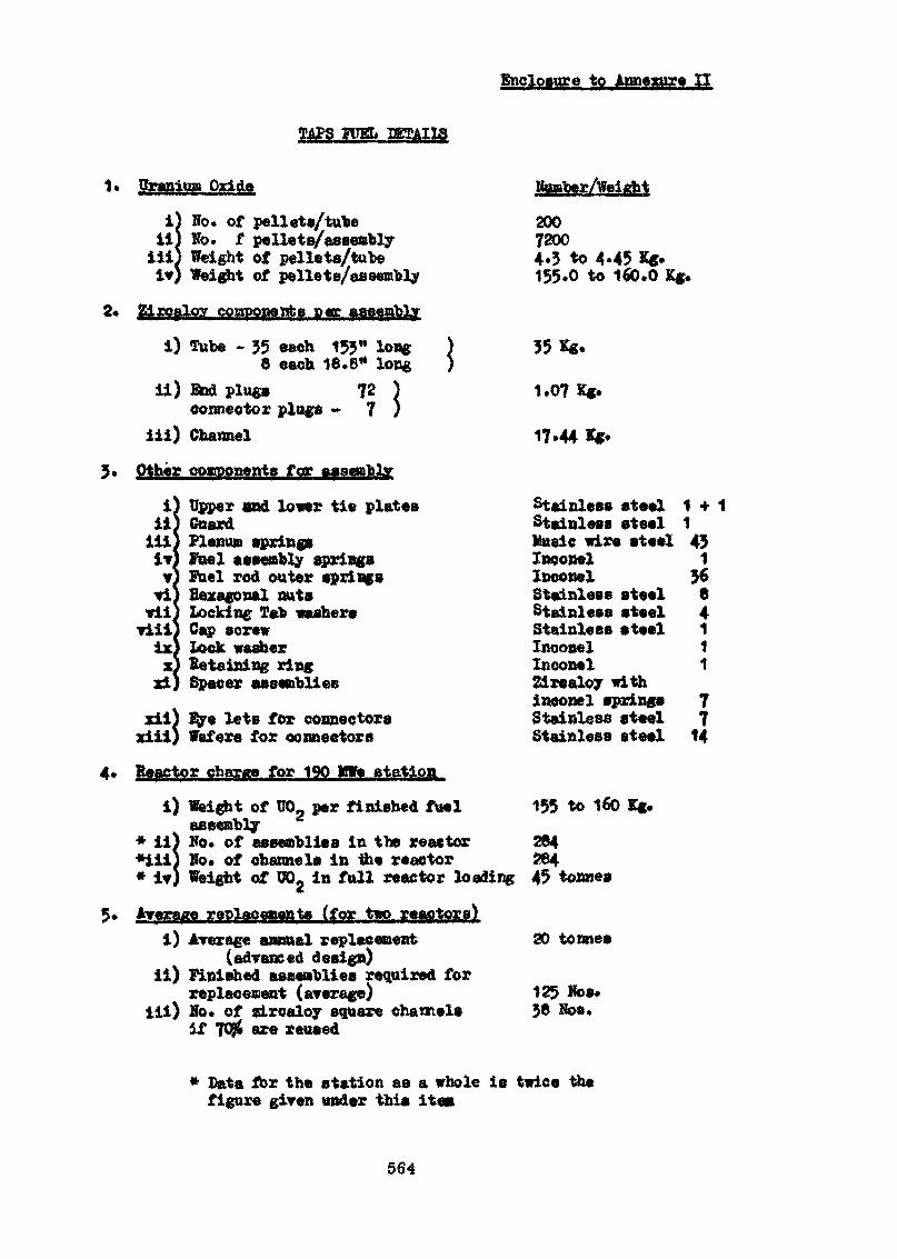
Enclosure to Anaexure II
TAPS SETAII3
Cranium Oxide
iiill
No* of pellets/tubeKo. f pellets/assemblyWeight of pellets/tubeWeight of pellets/assembly
Zircaloy postpone nt s P HT assembly
i) Tube - 35 each 153" long6 each 16*6** long
ii) End plugs 72 )connector plugs - 7 )
iii) ChannelcoBiDonenta for Aas
iilniiVvviviiViilixX
ad
Upper «nd loner tie platesGuardPlenum spring»Fuel assembly springsFuel rod outer springsHexagonal nutsLocking Tel» washersCap screwlock washerRetaining ringSpacer assemblies
xii) BJye lets for connectorsxiii) Wafers for connector a
Reactor charge for 190 Mfe station
i) Weight of TJO per finished fuelassembly
* ii) So. of aseembliea in the reactor 264*iii) Ko* of channels in the reactor $64* iv) «eight of W>2 in full reactor loading 4$ tonne»
Average replacements (for two reactors}i) Average annual replacement 20 tonnes
(advanced design)ii) Finished assemblies required for
replacement (average)iii) Ko. of «Lrcaloy square channels
if 7036 exe reused
20072004.3 to 4.45 Kg»155*0 to 160.0 Kg.
35 Kg.
1.07 Kg.
17.44 *g
Stainless steel 14-Stainless steel 1Vttaic wire steel 43Inoonel 1Inconel 36Stainless steel 6Stainless steel 4Stainless steel 1Inoonel 1Inoonel 12ir«aloy withineonel springs 7Stainless steel 7Stainless steel 14
155 to 160 Kg.
1253& Nos
Data fox the station as a whole is twice thefigure given under this itea
564
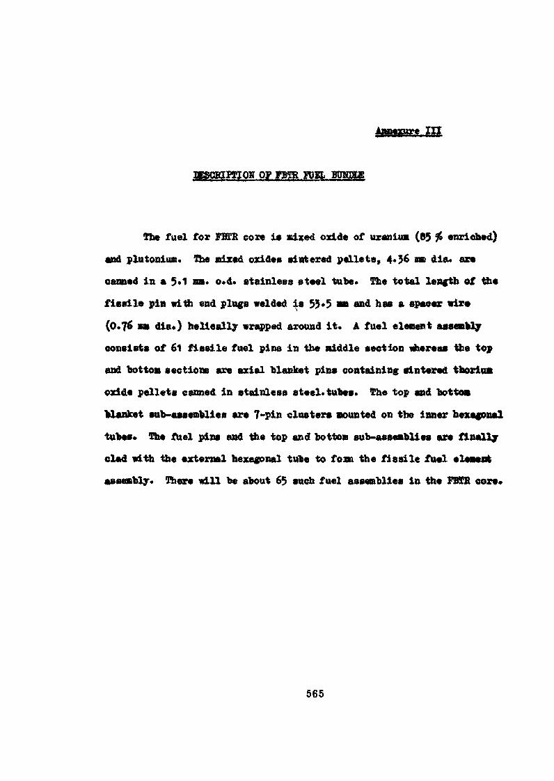
ni
nSSCBIPEIOff OF FBTR FUEL BTODSHB
The fuel for FHCB com i» nixed oxide of uraniua (85 ?» enriched)
and Plutonian. The nixed oxides sintered pallets, 4.36 no die* are
canned in a 5*1 m. o»d. stainless steel tube* The total length of the
fissile pin witfc end pings welded is 53*5 *n and has a spacer wire
(0.76 mm dia.) helically wrapped around it. A fuel element aasentlj
consists of 61 fissile fuel pins in the niddle section wherea» the top
and bottom sections are axial blanket pins containing sintered tboriui
oxide pellets canned in stainless steel*tubes» The top and bottoa
blanket sub-assemblies are 7-pin clusters «ounted on the inner hexagonal
tubes* The fuel pins and the top and bottom sub-asaeftblies are finally
clad with the external hexagonal tube to fo» the fissile fuel elesent
assembly. (Rtere will be about 65 such fuel assemblies in the PBTB core*
565
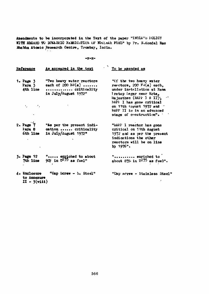
Amendments to be incorporated in the Text of the paper "INDIA«b lOLICYWITH Hfi&AKD TO JÛOMkSl'IC FABRICATION OF MUJueAR FUEL" by Pr. H.Kondal HaoBhabha Atonic Research Centre, Trombay, India.
-x-x-
Beference Aa appeared in the text To be amended BIB
1» Page 3 "Two heavy water reactorsPara 5 each of 200 foW(e) .......4th line ............. criticelity
in July/August 1972"
"Of the two heavy waterreectors, 200 *'«/(e} each,under installation at RanaIra tap '«gar near Kota.,
(Mil- 1 ft II'H 'I has gone critical
oh 11th August 1972 anaMtt1 II i» in an advancedstage of construction"« '•
2. Page 'ttara 86th line
"As per the present indi-cation ...... criticalityin July/August 1972'»
I reactor has gonecritical on 11th August1972 a«3 as per the prêtentindications the otherreactors will be on lineby 1976".
Page 12 "..... enriched to about7tb line 90? in U255 as fuel»
".......... enriched toabout 85?i in Il235 as fuel".
4* Enclosure "Cap i«rew - S. Steel"to AnnexureII
"Dap screw - Stainless Steel"
566
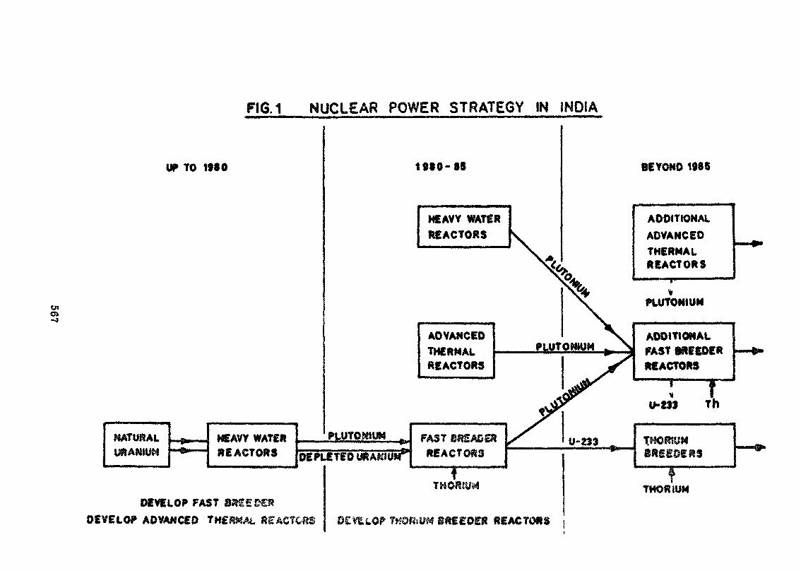
FK3.1 NUCLEAR POWER STRATEGY IN INDIA
UP TO 1990
eno>
KATUftAL HEAVY WATERREACTORS
PLU.TOMUM
DEPLETED
DEVELOP FASTDEVELOP ADVANCED
1990*98
HEAVY WATERREACTORS
ADVANCEDTHERMALREACTORS
FASTREACTORS
f
ift££0£ft REACTORS
BEYOND 1985
ADDITIONALADVANCEDTHERMALREACTORS
PLUTONIUM
ADDITIONALFAST 8RESDERREACTORS
U-Z3J Th
fTHORIUM
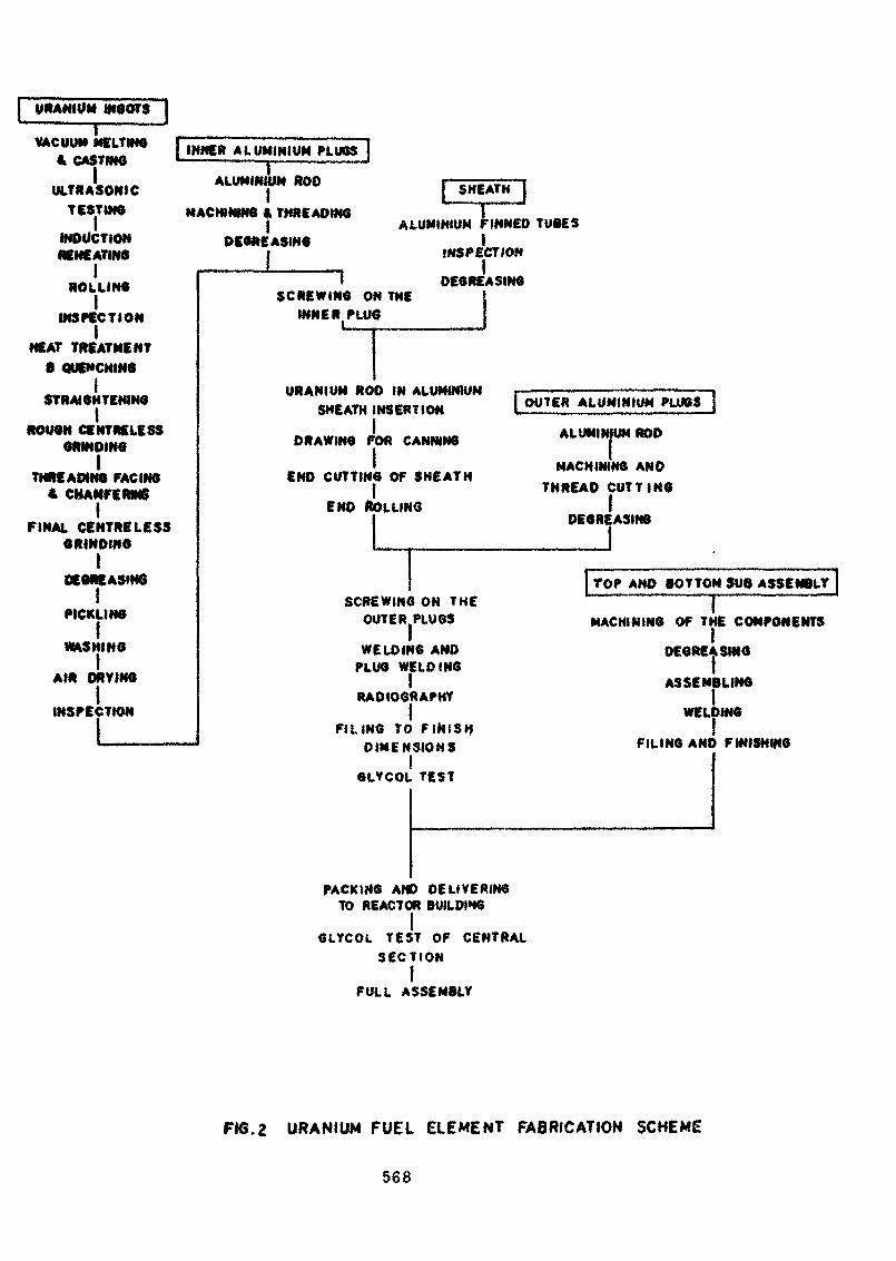
URANIUM moorsVACUUM MELTINGI CASTING
ULTRASONICTESTING
INDUCTIONREHEATING
IROLLING
IINSPECTION
MEAT TREATMENT0 QUENCHING
STRAIGHTENINGI
ROUGH CE NT «LESSGRINDING
ITHREADING FACING
* CHANFERMSI
FINAL CENTRE LESSORINOINO
I
[INNER ALUMINIUM PLUGS |ALUMINIUM ROD
MACHINING « THREADINGI
DEGREASINGI
SNEATN
IPICKLING
WASHING
AIR DRYING
INSPECTION
SCREWING ON THEINNER PLUG
ALUMINIUM FINNED TUBESI
INSPECTION
DEGREASING
URANIUM ROD IN ALUMINIUMSHEATH INSERTION
DRAWING FOR CANNINGI
END CUTTING OF SNEATN
END ROLLING
(OUTER ALUMINIUM PLUGS }ALUMINIUM ROD
MACHINING ANDTHREAD CUTTING
DEGREASING
SCREWING ON THEOUTER PLUGS
WELDING AMDPLUG WELDING
RADIOGRAPHY
FILING TO FINISHDIMENSIONS
IGLYCOL TEST
TOP AND BOTTOM SUB ASSEMBLY
MACHINING OF THE COMPONENTS
DEGREASING
ASSEMBLING
WELDING
FIL ING AND FINISHING
PACKING AND DELIVERINGTO REACTOR BUILDING
GLYCOL TEST OF CENTRALSECTION
FULL ASSEMBLY
URANIUM FUEL ELEMENT FABRICATION SCHEME
568
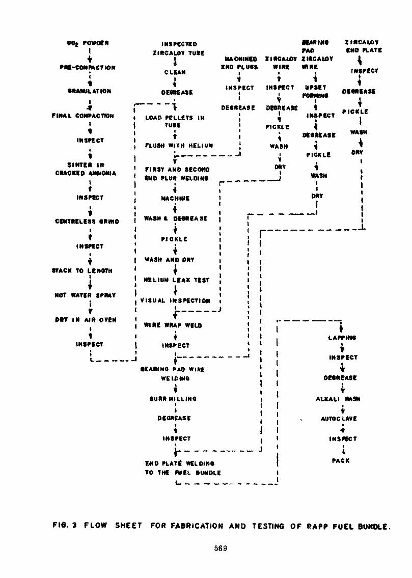
OOg POWDERtt
PRE-COMMCTION
t•RANULATION
1X
FINAL COMPACTIONlt
INSPECTit
SINTER INCRACKED AMMONIA
19
INSPECTlf
CENTRELESS CRittOlt
INSPECT
tSTACK TO LENOTH
t
NOT WATER SPRAY!f
DRY IN AIR OVEN
tINSPECT
it(._,— —• —-
INSPECTEDZIRCALOY TUSE
l MACHINED ZIRCALOY* END PLWCS WIRE
CLEAN | *
«JL, ""•:«' '"•:«'• ' ^
j *~ " ~1 DECREASE DECREASEl LOAD PELLETS IN \ y\ TUBE | MCKLE
! * Î «, FLUSH WITH HELIUM j WASH
L.—— -.-. - -J> «I $
» FIRST AND SECOND °*V
f END PLUC WELDINC __ __ »| , r~1 * «. MACHINE >1 • |
{ WASH & DECREASE | p — - ~
{ i | _««. —~.1 PICKLE ! !' ' 1 *< i { tt WASH AND DRY t ,1 ^ 1
i HELIUM LEAK TEST {
! < :f VISUAL INSPECTION ii L-— «. — -Ji * ,. - —| WIRE WRAP WELD ,
* «
' * 1{ INSPECT 1! » _ „„ __ ..„! \
f 10EARINC PAD WIRE •
WELDINQ :
BURR MILLING• |1
DECREASE
; !
•EAR INC ZIRCA10YFA» END PLATEZIRCAUOY i
*"? INSPECT
FORMINC P**1**1 iI T
INSPECT plc*Le
^DECREASE W*$H
I
^ *
•j 1 çn IP DHYt *
WASH i;DRY I
1 *
— i !i
" —— ---1-
. «. -n ,--,., « .
|
LAPP INCi
INSPECT1»W W" 1» * •
^DECREASE
ALKALI WASH
tAUTOCLAVE
INSPECT IJ
END PLATE WELD!NOTO THE FUEL BUNDLE
INSPECT
4PACK
FIG. 3 FLOW SHEET FOR FABRICATION AND TESTING OF RAPP FUEL BUNDLE
569
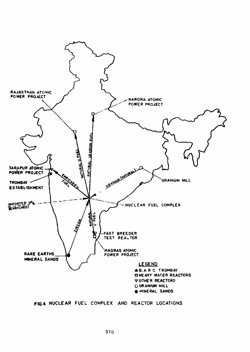
RAJAS THAN ATOMICPOWER PROJECT
NARORA ATOMICPOWER PROJECT
TARAPUR ATOMICPROJECT
TROM8AYESTABLISHMENT
UF(U .---; — NUCLEAR FUEL COMPLEX
-FAST BREEDERTEST REALTOR
RARE EARTHSMINERAL SANOS
MADRAS ATOMICPOWER PROJECT
LEGEND*B.A R C TROMBAYO HEAVY WATER REACTORSVOTHER REACTORSO URANIUM MILL^ MINERAL SANDS
FIG.4 NUCLEAR FUEL COMPLEX AND REACTOR LOCATIONS
570
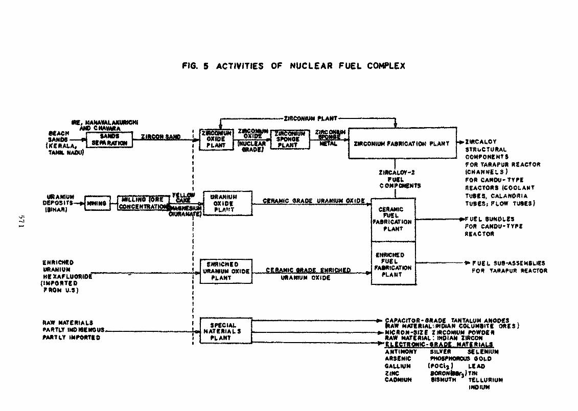
FIG. 5 ACTIVITIES OF NUCLEAR FUEL COMPLEX
*«AC«SAMOS
ME, «AKAVALAKURSCWAMD CMAWRA
|K£»ALA,TAMH.NADU)
URANIUMDEPOSITS-»
ENRICHEDURANIUMHE:(IMPORTED?ROM U.S)
RAW MATERIALSPARTLY INDIGENOUS.MftTtY IMPORTED
-*IIItIfJ
IOSIOSPLAKT (NUCLCAft«IAOC;
ItitCONIUMSPONGEPLANT ZIRCONIUM PA9K9C AT iOM PL AN 7 •IcZlftCALOY
Fuet,COMPfiNEMTS
FORtCH/FOR
REACTOR}
"TYPE
CERAMIC «RAOS USAMJUM
gMRiCMgDURANIUM oxtee ERAMJC SRA8E ÊMRJCHED
URANIUM OXIDE
CERAMICFUEL
FABRICATIONPLANT
ENRICHEDFUEL
FABRICATIONPLANT
TU8ES,TUBES» FLOW TUSES)
REACTOR
FUEL SU9-ASS£M8U£$TA«APU« «SACTÔ»
~- —————— —— ——— . —————— » ———— «SPECIAL
MATERIALSPLANT
— • ————————————————————————— 1» CAPACITOR -0*AOE TANTALUM ANOOES ,It AW MATERIAL -INDIAN COLUM9ITE ORES)
————————————————————————— »»M!CRON-$iZE ZIRCONIUM POWDERRAW MATERIAL : INDIAN ZIRCON
——————————————————————— >"ELECTRONtC-6RADE MATERIALSANTIMONY SILVER SELENIUMARSENIC PHOSPHOROUS OOLDGALLIUM (POCl)} LEAD4 ***£• tt^XPrtMfal i- \ 9MJ€, i ffv 0uw ufvf90r<i * ' •"CADMIUM SISMUTH TELLURIUM
INDIUM
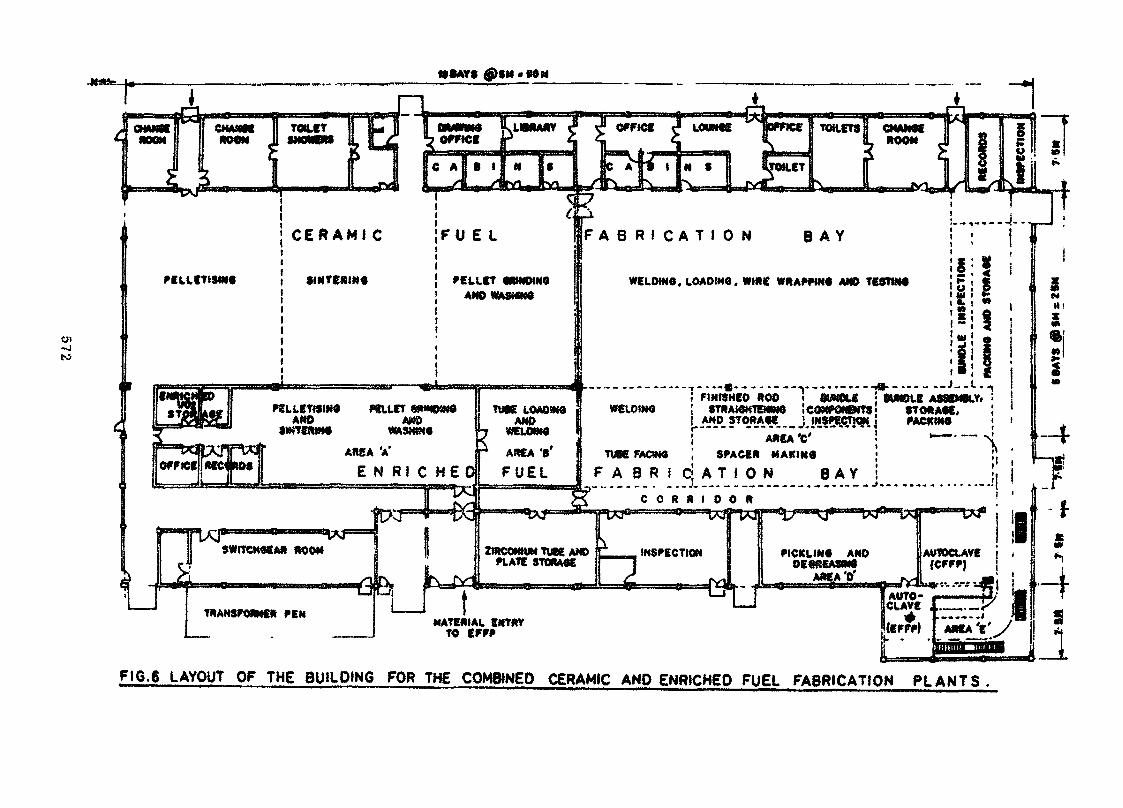
-4to
CMAMM II TOILETWON
TOILETS H CHAM4EROOM
F A B R I C A T I O N B A Y
WELDIN6. LOAOIMO. WIDE WRAPHNO AND TE3T1N4PELLETiSMC
! FINISHED ROD 1 '««OLE ; OMBLE ASSEMBLY ^ !
WELOIMO ! STRAKKtEMNO '——————— ———'"TU«E LOAOilMAND
! AREA VTUBE FACWO I SPACER MAKIM0
F A B R I C ! A T I O NE N R I C H E DC O R R I D O R
PICKLIMO ANDDE«*EA3me
ARE.A '0'PLATE STORAftE
TKANSFONMEft PENMATERIAL EMTftY
TO
F16.6 LAYOUT OF THE 8U<LD>NG FOR THE COMBINED CERAMtC AND ENRICHED FUEL FABRICATION PLANTS.
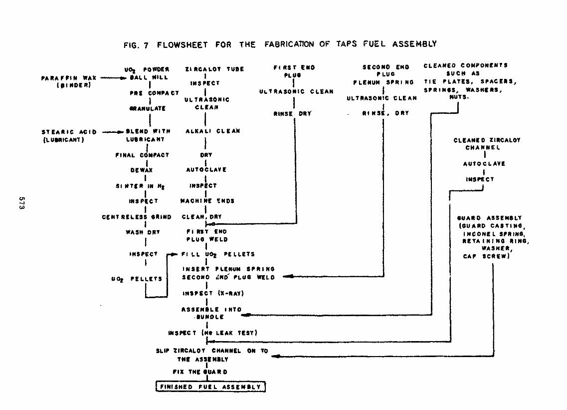
FIG. 7 FLOWSHEET FOR THE FABRICATION OF TAPS FUEL ASSEMBLY
UOj POWDER ZIRCALOY TUBE FIRST ENDPLUG
SECOND ENDPLUG
CLEANED COMPONENTSSUCH AS
(BINDER) jPRE CO HP/
1GRANULATE
1STEARIC ACID ——— »»BLEMD WIT(LUBRICANT) LUBRICANT
FINAL COMPAC1
DE WAX1
51 NTER IN Mj
1S INSPECTw 1
CENTRELESS GRIN1
WASH DRV
INSPECT
OOj PELLETS
• —INSPECT
ICT ) UlTRASO*ULTRASONIC
CLEAN1 RINSE
» ALKALI CLEAN
ir DRY
AUTOCLAVE
INSPECT
MACHINE SNDS1
D CLEAN, DRY
PLENUMIIC CLEAN
ULTRASON)
iDRY RINSf
Fi RST ENDPLUG WELD
1H»» FI LL U0{ PELLETS
INSERT PLENUM SPRINGSECOND £NO' PLUG WELD -•* ———————————— '
iINSPECT (X-RAY)
1ASSEMBLE INTO
SPRING TlSF
C CLEAN
:, DRY
Bunotfe *** ————————— —•" ————————————————————— —— -1
INSPECT (Me LEAK TEST)1 -
E PLATES, SPACERS,RINGS, WASHERS,
NUTS.
1
CLEANED ZIRCALOYCHANNEL
AUTOCLAVEI
INSPECT
, -J
GUARD ASSEMBLY(GUARD CASTING,
INCOME L SPRING.RETA !N!NG RING,
WASHER,CAP SCREW)
i— • ' • • • • • • • • • • • • • • — — —•——•••——• •' " —— .,....,...._.....,. ..,..,SLIP ZIRCALOY CHANNEL ON TO
TME ASSEMBLY1
FIX THE GUARD
| FINISHED FUEL A S S E M B L Y |
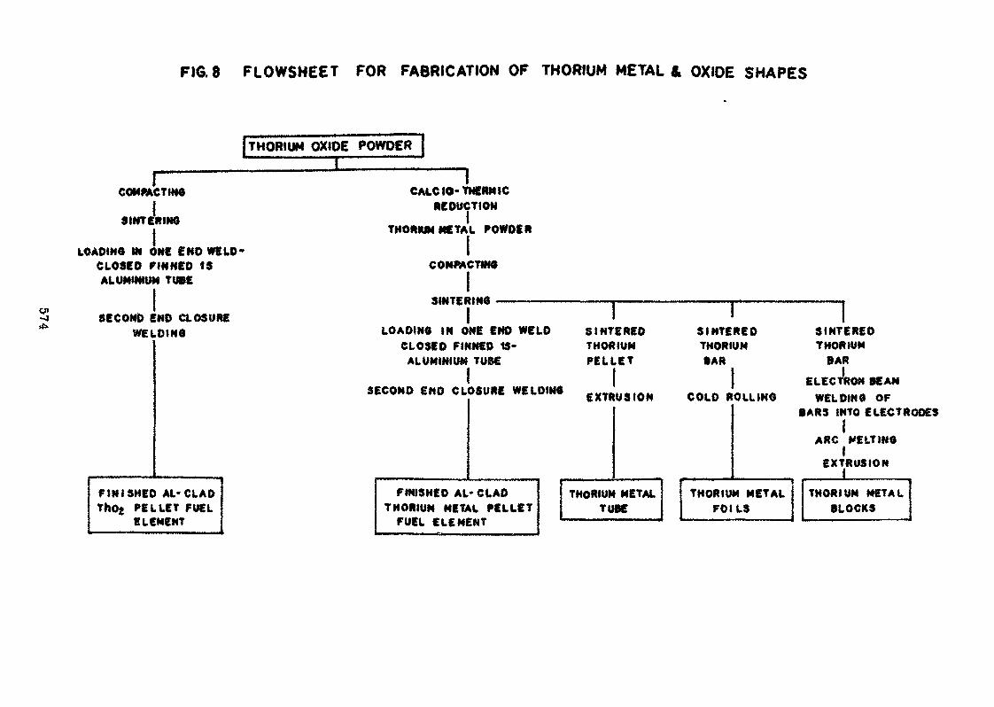
FIG.8 FLOWSHEET FOR FABRICATION OF THORIUM METAL* OXIDE SHAPES
[THORIUM OXIDE POWDER |
COMPACTING
ESINTERING
LOADING IN ONE f NO WELD'CLOSED FINNED ISALUMINIUM TUBE
CAtC 10- THERM 1CREDUCTION
THORIUM METAL POWDER
COMPACTAIS
SECOND END CLOSUREWELDING
SINTERING ——————
LOADING IN ONE END WELDCLOSED FINNED t$-
ALUMINIUM TUBE
SECOND END CLOSURE WELDING
FINISHED AL-CLADThO{ PELLET FUEL
ELEMENT
SINTEREDTHORIUMPELLET
IEXTRUSION
SINTEREDTHORIUM•AR
COLD ROLLING
SINTEREDTHORIUM
BAR
ELECTRON BEAMWELDING OF
FINISHED AL- CLADTHORIUM METAL PELLET
FUEL ELEMENT
THORIUM METALTUBE
BARS INTO ELECTR1
ARC MELTING1
EXTRUSION1
THORIUM METALFOILS
THORIUM METALBLOCKS
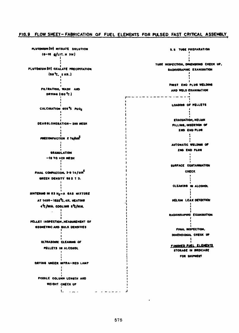
FIG. 9 PLOW SHEET- FABRICATION OF FUEL ELEMENTS FOR PULSED FAST CRITICAL ASSEMBLY
PLUTONIUM ȴl NITRATE SOLUTION
l«~«« f/L«T. » 3M|
tt
PLUTONIUM {IV) QXALATE PRECIPITATION(»0t.
S.S TUBE PREPARATION
FILTRATION, WASH AMDDRVINMlSO'C)
T0»5 INSPECTION, DIMENSIONS CHECK UP.RAOK>«*APHIC EXAMINATION
iI
END PLU« WELOiWtAND WELD EXAMINATION
CALCINATION PUOt
DEA«6LOMERATION~ «00 MESH
PRECOMPACT DM X T«/Bfff*
BRANULATION-tO to +« MESH
FINAL COMPACTION, >•» T*/COI*
OREEN DENSITV SS ft T 0.
tit
StNTERMNJ M» t» Hj-A «AS
AT 14»«-tftoVtH. HEATW9
4%/MIN. COOLIN« S%/NIN.Iiit
PELLET INSPECT»*,MEASUREMENT OF•EOMETRiC AKD SULK DENSITIES
itIi
ULTRASONIC CLEANIN» OF
PELLETS IN ALCOHOL
i
DRVNtO UNDER INFRA-RED LAMPïtt
FISSILE COLUMN LENOTH AND
«EI9HT CHECK UP*
L. .. _ ..
LOAOIN6 OP PELLETS
EVACUATION, HELIUMFILLIM*. W8SIITION OF
tMO BNDPLtt»
AUTOMATIC WELDRW OP2ND EHO PLtM
SURFACE CONTAMINATION
CHECK
CLEANIN9 IN ALCOHOL
ftAOMMMlAPMIC
MCLKW LEAK OZTECTWW
EXAMINATfON
FINAL INSPECTION,
DIMENSIONAL CHECK UPII
f tf HIp FUEL ^CEMENTSTORA«E «W «ROCA«f
FOR SHIPMENT
575
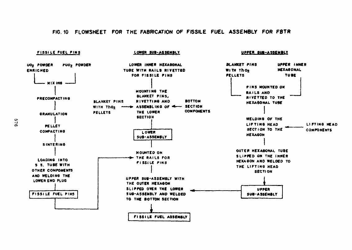
FIG. 10 FLOWSHEET FOR THE FABRICATION OF FISSILE FUEL ASSEMBLY FOR F8TR
F ISSUE FUEL P I N S LOWER SU»-ASSEMBLY UPPER SU»«A3SEMBLY
POWDER PUO; POWDERENRICHED
I——— M I X I N G ———»
PRECOMP ACTING
GRANULATION
PELLETCOMPACT t HO
S INTERIM*
LOADING INTOS S. TUBE WITH
OTHER COMPONENTSAND WE LOI MO THELOWER END PLUG
FISSILE FUEL PINS
LOWER INNER HEXAGONALTUBE WITH RAILS RiVETTED
FOR FISSILE PINS
BLANKET PINSWITHPELLETS
UPPER INNERHEXAGONAL
TUBS
BLANKET P IMSWITH TfcOg —PELLETS
MOUNTING THEBLANKET PINS,R I VETTING ANDASSEMBLING OFTHE LOWERSECTION
BOTTOMSECTIONCOMPONENTS
LOWERSUB-ASSEMBLY
MOUNTED ONTHE R A I L S FORFISSILE PINS
UPPER SUB-ASSEMBLY WITHTHE OUTER HEXAGONSLIPPED OVER THE LOWERSUB-ASSEMBLY AND WELDEDTO THE BOTTOM SECTION
iF I S S I L E FUEL ASSEMBLY
P I N S MOUNTED OKRAILS ANDR I V£TT£0 TO THEHEXAGONAL TUBE
WELDING OF THEL I F T I N G HEADSECTION TO THEHEXAGON
L I F T I N G HEAPCOMPONENTS
OUTER HEXAGONAL TUiES LIPPED ON THE I N N E RHEXAGON AND WELDED TOTHE L I F T I N G HEAD
SECTI ON
1UPPER
SUB-ASSEMBLY
ESTIMATING CANDU FUEL COSTS
by
A.W.L. Seg«l
Chalk River Nuclear LaboratoriesChalk River, Ontario
ABSTRACT
A method of estimating CANDU fuel costs is described The equations are sufficientlygeneralized .that the method can be applied to » new fabrication industry where théfabrication techniques, costs of buildings, equipment and labour, and financial practicesdiffer from those in Canada. Once a reference design cost has been established, themethod can be used to estimate the effect on fuel cost due to expansion of the industry,learning and design modifications.
When applied to Canadian industry the method estimates the known fuel costs withadequate accuracy. It is also apparent that the low cost for CANDU fuel is due largely tothe simple design and small number of components. Even when* enriched^, the «oàt ofCANDU fuel Is significantly lower than the cost of light-water reactor fuel. .
Résuméj
L'auteur décrit une méthode permettant d'estimer le coût du combustible CANDU.Les équations sont assez généralisées pour que cette méthode puisse s'appliquer à unenouvelle industrie manufacturière où les techniques de fabrication, les dépenses engagéespour les bâtiuients» l'équipement et la main-d'oeuvre, ainsi que tes pratiques financièresdiffèrent de celles du Canada. A partir d'un coût de réféference calculé, la méthodeenvisagée permet d'estimer l'effet, sot le coût du combustible, de l'expansion de lanouvelle industrie, de l'expérience acquise et des modifications apportées aux conceptsoriginaux. .
Appliquée à l'industrie canadienne, cette méthode permet d'estimer les coûts connusdu combustible, avec une bonne précision. Il est, par ailleurs, évident que le faible coût ducombustible CANDU découle en grande partie de son concept simple et du petit nombrede ses compo? nts. Même lorsqu'il est enrichi, le combustible CAND.U est nettementmoins xmleux que le combustible destiné aux réacteurs à eau légère.
577
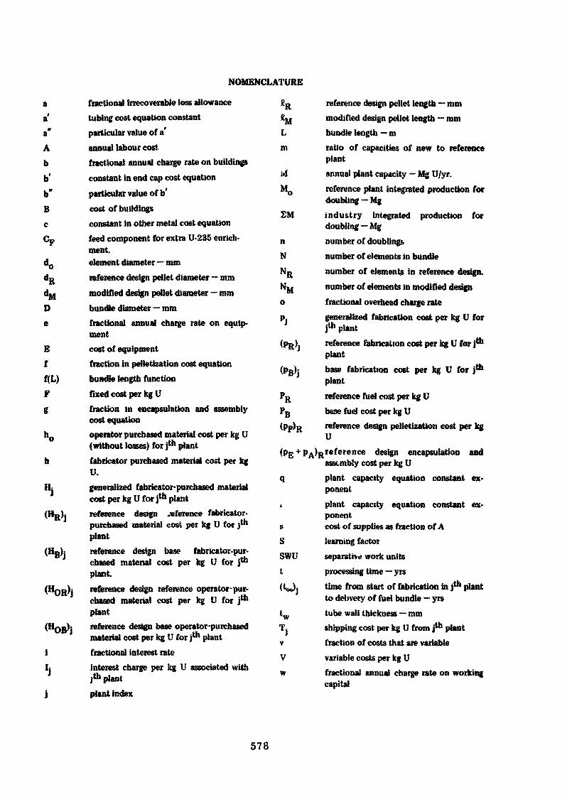
NOMENCLATURE
a fractional irrecoverable loss allowancea' tubing cost equation constanta" particular value of a'A annual labour costb fractional annual charge rate on buildingsb' constant in end cap cost equationb" particular value of b'B cost of buildingsc constant in other metal cost equationCp feed component for extra U-235 enrich-
ment.dQ element diameter — mmdR reference design pellet diameter — mmdjni modified design peltet diameter — mmD bundle diameter — mme fractional annual charge rate on equip-
mentE cost of equipmentf fraction in pelletization cost equationf(L) bundle length functionF fixed cost per kg Ug fraction in encapsulation and assembly
cost equationho operator purchased material cost per kg U
(without losses) for jth planth fabricator purchased material cost per kg
U.Hj generalized fabricator-purchased material
cost per kg Ufor jth plant(HR): reference design .«ference fabricator,
purchased material cost per kg U for Ith
plant(Kg): reference design base fabricator-pur-
chased material cost per kg U for Ith
plantreference design reference operator-pur-chased material cost per kg U for j01
plantreference design base operator-purchasedmaterial cost per kg U for j*n plant
i fractional interest rateL interest charge per kg U associated with
jtn plantj plant index
Lm
ivlM0
SM
nNNR
Njjop.
(pR)
reference design pellet length — mmmodified design pellet length — mmbundle length — mratio of capacities of new to referenceplantannual plant capacity — Mg U/yr.reference plant integrated production fordoubling — Mgindustry integrated production fordoubling — Mgnumber of doublingsnumber of elements in bundlenumber of elements in reference design.number of elements in modified designfractional overhead charge rategeneralized fabrication cost per kg U forjth plantreference fabrication cost per kg U for jth
plantbase fabrication cost per kg U for j*plantreference fuel cost per kg Ubase fuel cost per kg Ureference design pelletization cost per kgU
(pE + pA)Rreference design encapsulation andassembly cost per kg U
q plant capacity equation constant ex-ponent
i plant capacity equation constant ex-ponent
s cost of supplies as fraction of Alearning factorseparative work unitsprocessing time — yrstime from start of fabrication in j*h plantto delivery of fuel bundle — yrstube wall thickness — mmshipping cost per kg U from j1*1 plantfraction of costs that are variablevariable costs per kg Ufractional annual charge rate on workingcapital
R
(Pp)n
SSWUt
wT4
578

W weight of uranium in a fuel bundle — kg Z fractional plant load factorWM weight of uranium in modified design PR effective den&ily of reference pellet — kg
bundle - kg U/mm* UO2
WR weight of uranium in reference design PM effective density of modified designbundle — kg pellet — kg U/mm3 UOj
x constant in learning equation CANDU Canada Deuterium Uraniumy constant in learning equation PHW Pressurized heavy water
579
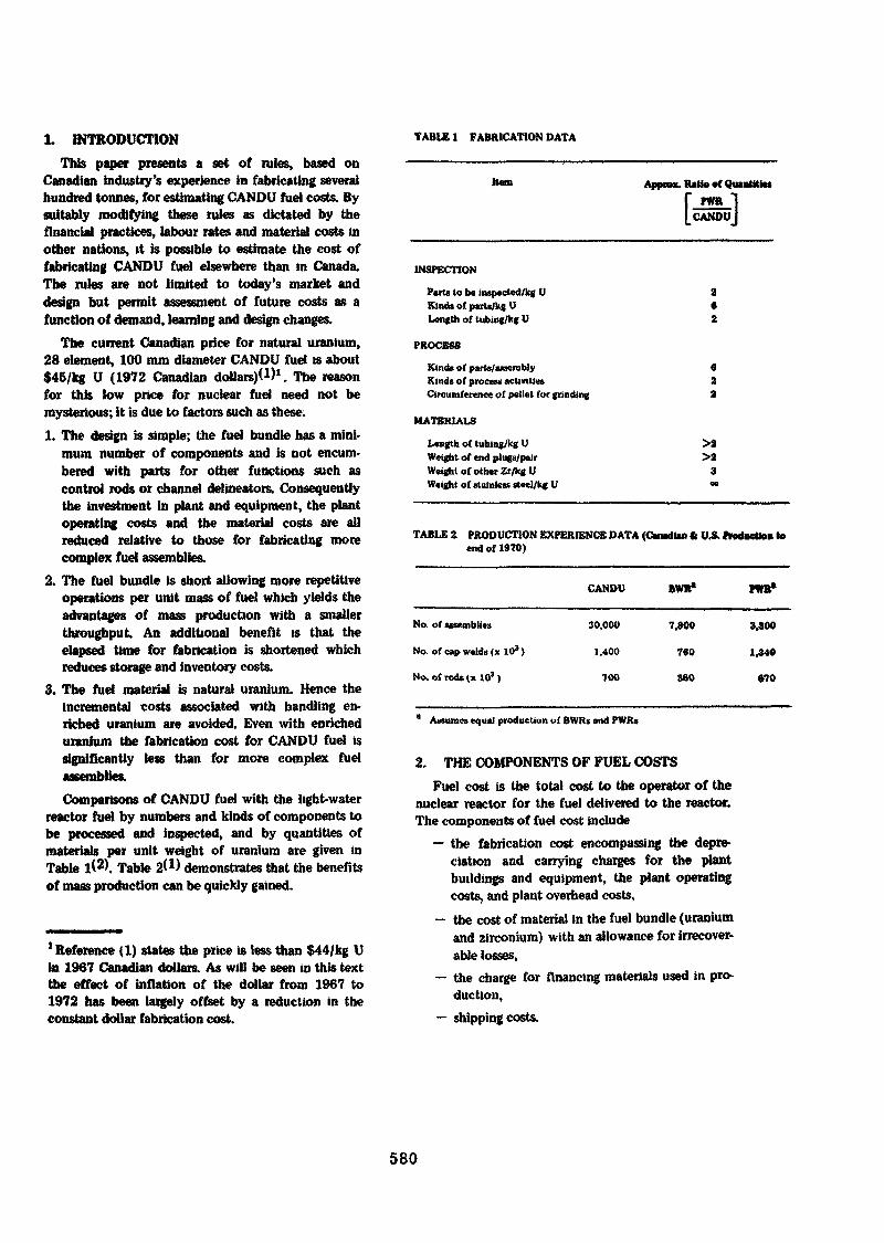
1. INTRODUCTION TABLE 1 FABRICATION DATA
This paper presents a set of rules, based onCanadian industry's experience in fabricating severalhundred tonnes, for estimating CANDU fuel costs. Bysuitably modifying these rules as dictated by thefinancial practices, labour rates and material costs inother nations, it is possible to estimate the cost offabricating CANDU fuel elsewhere than in Canada.The rules are not limited to today's market anddesign but permit assessment of future costs as afunction of demand, learning and design changes.
The current Canadian price for natural uranium,28 element, 100 mm diameter CANDU fuel is about$45/1% U (1972 Canadian dollars)*1)1. The reasonfor this low price for nuclear fuel need not bemysterious; it is due to factors such as these.1. The design is simple; the fuel bundle has a mini-
mum number of components and is not encum-bered with parts for other functions such ascontrol rods or channel delineators. Consequentlythe investment in plant and equipment, the plantoperating costs and the material costs are allreduced relative to those for fabricating morecomplex fuel assemblies.
2. The fuel bundle is short allowing more repetitiveoperations per unit mass of fuel which yields theadvantages of mass production with a smallerthroughput An additional benefit is that theelapsed time for fabrication is shortened whichreduces storage and inventory costs.
3. The fuel material is natural uranium. Hence theincremental costs associated with handling en-riched uranium are avoided. Even with enricheduranium the fabrication cost for CANDU fuel issignificantly less than for more complex fuel
Comparisons of CANDU fuel with the light-waterreactor fuel by numbers and kinds of components tobe processed and inspected, and by quantities ofmaterials per unit weight of uranium are given inTable 1<2>. Table 2<D demonstrates that the benefitsof mass production can be quickly gained.
'Reference (1) states the price is less than $44/kg Uin 1967 Canadian dollars. As will be seen in this textthe effect of inflation of the dollar from 1967 to1972 has been largely offset by a reduction in theconstant dollar fabrication cost.
Approx. Rath» of Quantifie*r PWR-)[CANDUJ
INSPECTION
Parts to be inspected/kg UKinds of parts/kg ULength of tubing/kg U
PROCESS
Kinds of parts/assemblyKinds of process activitiesCircumference of pellet for grinding
MATERIALS
Length of tubing/kg UWeight of end plugs/pairWeight of other Zr/kg UWeight of stainless steel/kg U
>2>2
3
TABLE 2. PRODUCTION EXPERIENCE DATA (Canadian ft VA. Production toend of 1970)
CANDU BWR* PWR»
No. of assemblies
No of cap welds <x 103)
No. of rods (x 103)
30,000
1.400
700
7,800
760
3SO
3,300
1,340
•70
Assumes equal production of BWRs and PWRs
2. THE COMPONENTS OF FUEL COSTSFuel cost is the total cost to the operator of the
nuclear reactor for the fuel delivered to the reactor.The components of fuel cost include
— the fabrication cost encompassing the depre-ciation and carrying charges for the plantbuildings and equipment, the plant operatingcosts, and plant overhead costs,
— the cost of material in the fuel bundle (uraniumand zirconium) with an allowance for irrecover-able losses,
— the charge for financing materials used in pro-duction,
— shipping costs.
580
To analyze and estimate fuel costs these compo-nent categories ate subdivided as necessary lo cor-respond to the separate process operation* andmaterial purchases
2.1 Fabrication Plant CostsTho plant — the buildings, equipment, supplies3
and labour force — required to fabricate fuel isadaptable. It can be planned so that the entire fut.fabrication process 1$ under one roof., or the compo-nent processes can be geographically separate. Theprocessing method can range from fully automated tohighly labour intensive. Whatever the detail of theplant, a fuel fabrication cost can be estimated Oncethis cost for a reference plant and fuel design isavailable, then the effect on cost of extrapolations inplant capacity and load factor (utilization of capa-city) can be analyzed.
The fundamental approach is lo categorize thefixed (F) and variable (V) cost components. By fixedis meant those costs that remain the same per unit ofproduct; that is, they vary linearly with plant capa-city, for example, the direct labour in a manualprocess operation such as visual inspection of acomponent, or equipment that must be increased innumbers to increase capacity represent constant costsper unit.of product. The variable cost components arethose that have a non-linear relationship to plantcapacity and load, and so are not constant per unitproduct. Examples of this type are indirect laboursuch as office staff or labour to operate equipmentthat can be scaled in size to suit plant capacity.Generally the costs of the building, equipment, in-direct labour and supplies for office and maintenanceare variable, While most, but not necessarily all, directlabour costs are fixed per unit product.
2.2 Material CostsMaterials used in fuel fabrication — UO2 and zirco-
nium alloys are the only materials in CANDU fuel —can be acquired by the fabrication plant at differentstages of preparation. The plant might be associatedwith a uranium mine, or purchase U3O8 which itwould convert to U02 or purchase the UO2 powder.For the purpose of this analysis it is assumed thematerials arc acquired as U308 for natural uraniumfuel, UP6 for enriched uranium fuel and the zireo-niurn alloys are bought in the form of tubing, fourstock and sheet. It should be apparent that if theplant carries out more or less of the materials pro-
cessing, the principles of estimating costs cnuucteterfhere can be applied lo the matvrmls processing.
Some material, usually uraniuri, is purchased bythe reactor operator and supplied to the fabricatorfor further processing. Other material, usually /.a-conium alloys, is purchased by the fabricator, ineither case, the cost of materials in the form pur-chased 1$ treated as a separate component of fuelcost The cost of processing the material is a part ofthe fabrication cost component. Due allowance mustbe made for processing losses; some* losses are irre-coverable, others are recovered its «crap which can berecycled.
The cost of uranium per unit product does notappear to vary with plant capacity and so is a fixedcost per unit product Zirconium alloy costs varyslightly with plant capacity, perhaps reflecting thebenefit of large order processing by the materialsupplier,
2.3 Financing Charges
2.3.1 Capital ChargesThe fabricator's investment in building and equip-
ment, composed of some proportion of equity anddebt must be amortized over their lifetimes. Thisannual depreciation is a charge on fuel fabrication. Inaddition, an annual return on the investment whichcould be taxable, the insurance on these assets andproperty taxes are costs of fabrication. The total ofthese, the capital charge rate, will likely differ asbetween buildings and equipment since the lattergenerally has a shorter useful life. As components ofthe fuel fabrication cost» the capital charges arevariable
2.3 2 Working CapitalA supply of capital must be available to the
fabricator to meet the operating and purchased3
material costs. Generally it is adequate to have suf-ficient to cover these costs for the lime required toprocess the product. As this capital is cycled ratherthan expended, the contribution to fabrication cost isthe charge for using it. The charge is apportionedbetween fixed and variable cost components in Ihcsame ratio at. the operating costs are divided.
2.3 3 Overheadin this category are the fabricator's costs of re-
a Supplies refers to the materials consumed in thepiant offices and shops. It does not include theuranium and zirconium materials used in the fuel.
3 Material purchased by the fabricator for processing.Material purchased by the reactor operator andsupplied to the fabricator for further processing doesnot require working capital.
581
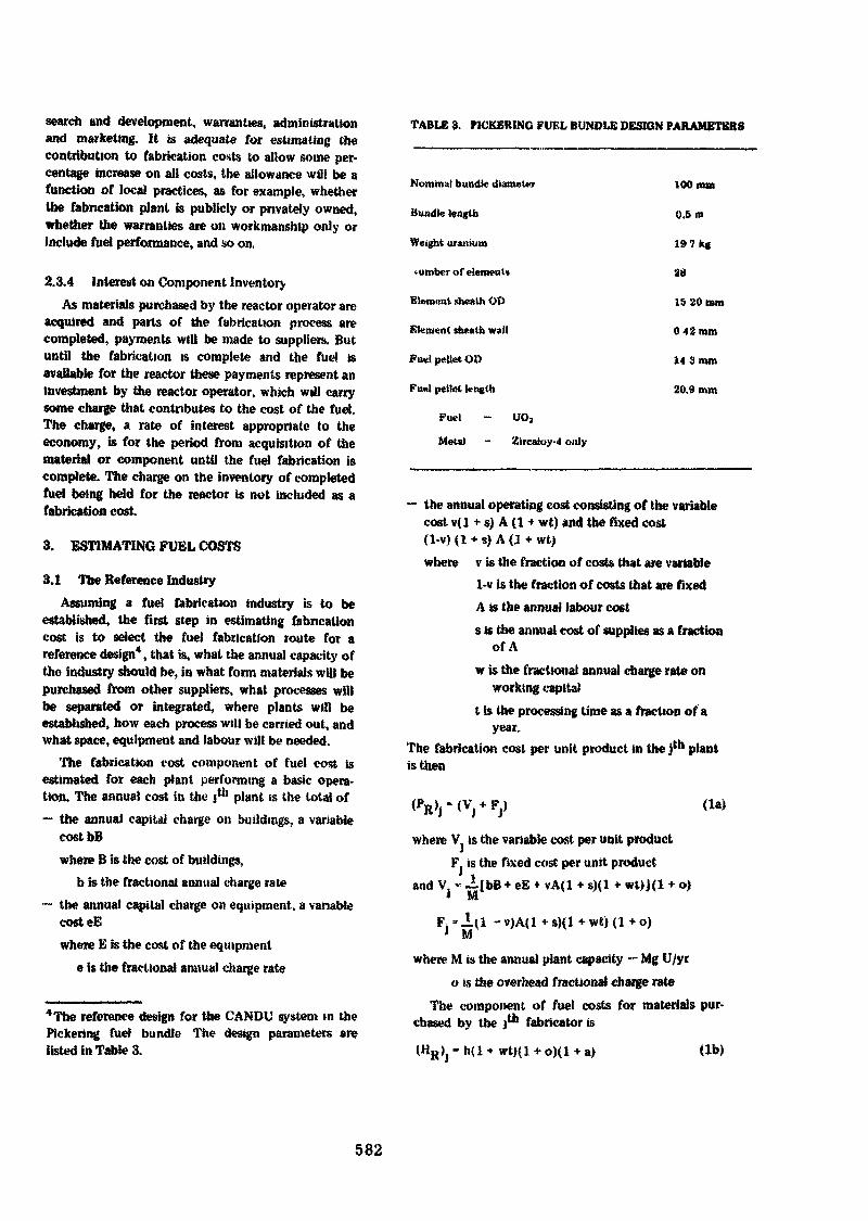
search and development, warranties, administrationand marketing. It is adequate for estimating thecontribution to fabrication costs to allow some per-centage increase on all costs, the allowance will be afunction of local practices, as for example, whetherthe fabrication plant is publicly or privately owned,whether the warranties are on workmanship only orinclude fuel performance, and so on,
2.3.4 Interest on Component InventoryAs materials purchased by the reactor operator are
acquired and parts of the fabrication process arecompleted, payments will be made to suppliers. Butuntil the fabrication is complete and the fuel isavailable for the reactor these payments represent aninvestment by the reactor operator, which will carrysome charge that contributes to the cost of the fuel.The charge, a rate of interest appropriate to theeconomy, is for the period from acquisition of thematerial or component until the fuel fabrication iscomplete. The charge on the inventory of completedfuel being held for the reactor is not included as afabrication cost.
3. ESTIMATING FUEL COSTS
3.1 The Reference IndustryAssuming a fuel fabrication industry is to be
established, the first step in estimating fabricationcost is to select the fuel fabrication route for areference design4, that is, what the annual capacity ofthe industry should be, in what form materials will bepurchased from other suppliers, what processes willbe separated or integrated, where plants will beestablished, how each process will be carried out, andwhat space, equipment and labour wilt be needed.
The fabrication cost component of fuel cost isestimated for each plant performing a basic opera-tion. The annual cost in the j*'1 plant is the total of~ the annual capital charge on buildings, a variable
costbBwhere B is the cost of buildings,
b is the fractional annual charge rate— the annual capital charge on equipment, a variable
costeEwhere E is the cost of the equipment
e is the fractional annual charge rate
TABUS 3. P1CKBRINO FUEL BUNDLE DESIGN PARAMETERS
Nominal bundle diameter
Bundle length
Weight uranium
«umber of element»
Element sheslh OD
Element sheath wall
Fuel pellet OD
Fu«l pellet length
Fuel - UO3
Metal ~ Zircaioy-4 only
100 mm
0.5 m
197kg
28
19 20 mm
042 mm
14 3mm
20.9 mm
— the annual operating cost consisting of the variablecost v(l +• s) A (1 •» wt) and the fixed cost(1-v) (1 + s) A (J + wt)where v is the fraction of costs that are variable
1-v is the fraction of costs that are fixedA is the annual labour costs is the annual cost of supplies as a fraction
of Aw is the fractional annual charge rate on
working capitalt is the processing time as a fraction of a
year.The fabrication cost per unit product in the j10 plantis then
(la)
where V is the variable cost per unit productF. is the fixed cost per unit product
and V, « -ilbB+ eE + vA(l + «){1 * wt)J(l + o)* M.
4The reference design for the CANDU system in thePicketing fuel bundle The design parameters arelisted in Table 3.
where M is the annual plant capacity — Mg U/yco is the overhead fractional charge rate
The component of fuel costs for materials pur-chased by the jth fabricator is
wt)(l a)
582
where h is the cost to the J1'1 fabricator for materialper unit producta h the fractional irrécouvrable loss nllowanco
The component in fuel costs for materials pur-chased by the reactor operator und supplied to the j1^fabricator for further processing per unit product, is
full capacity, the» Hie fabnrUon tost becomes
where b0 is the cost to the reactor operator of materialper unit product.
The interest charge on the payment* made by thereactor operator for materials or completed compo-nent inventory supplied to the i1'5 fabrication plant is
where i is the fractional annual interest ratedenotes the time as a fraction ofa year from delivery of thematerial or component to the jlhplant until delivery of thefinished fuel to the reactor
is the cost cojimonent for materialfrom the 0-1)* fabricator
is the cost component for fabri-cation by the (j-l)lh fabricator.
The component for the cost of shipping from thejtn fabricator or material supplier is T.. (le)
The reference fuel cost is the total of these com-ponents
(2)
3.2 The Effect of GrowthAs the nuclear power system grows, the fuel
fabrication industry will expand With additionalexperience new fabrication techniques will evolve.Even the fuel design will likely be modified. Thisgrowth will alter the cost of fabrication.
3.2.1 Plant Capacity and Load FactorFor each fabrication plant in the reference in-
dustry operating at its full annual capacity, i.e , 10<Fload factor, the cost per unit product was given l>\equation (la) Should the annual capacity of theplant* be changed or should it operate at lens than '
5Plant in this context can be either the expansion ofan existing plant or the addition of a new plantproducing the same product Where there are com-peting plants fabrication cost estimates arc bas«>d onthe capacity of the largest plant.
J 7, 1
where m is the ratio of tbv annual capacities of thenew plant to the rpfc-n nee plant,Z is the load factor expressed as a fraction,q and r are constant exponents. Their parti-cular values are functions of the general fuddesign.
The fabricator-purchased material costs expressed byequation (lb) are also affected by plant capacity Asa function of capacity the cost is
. - x / ~. \ ~r <3b)H.»(H R )J JV
3.2.2 LearningAs the industry gams experience, it will disuner
less costly ways of doing things and become moreefficient. This is the learning process. The cost com-ponents that arc reduced by learning, viz: fabricationand fabricator -purchased materials, are multiplied b\» learning factor, S *S 1, to estimate the cost reduc-tion due to learning. The relationship between ex-perience and learning is not likely to be linear sincvpotential additional benefits from learning decreasewith learning The learning factor can be expressed byan equation of the form
l-x{l-exp(-yn)| (4)
wjtere n is the number of production doublings, thatis, the number of times the total production of theindustry, £M, has doubled referenced to the totalproduction, MO, of the largest capacity plant in theindustry up to and im luding the first order processedthai exceeds its annual capacit> By definition.
In 2x and y are constantsBy combining equations (3a) and (3b) with (4) the
base costs for fabrication and fabricator-purchasedmatenals in (he jln fabrication plant are:
(5)
The base fuel cost for the reference design is
583
3.2.3 DesignModification of the basic CANDU design can be
anticipated. There are several reasons, viz- eachmember of the "family" of CANDU reactors imposesdifferent operating conditions upon the fuel; new fuelcycles may require modified design parameters; ex-perience in fuel performance might suggest improve-ments; or changing fabrication costs might beoptimized by altering the design Provided tue"rodded" bundle remains as the basic concept, andthe materials are UO2 (with or without enrichmentby extra U-235 or Pu additions) and zirconiumalloy metal only, the effect of design modificationson fabrication cost can be reasonably weil estimated.Some minor design modifications are not accountedfor in what follows, as for example, the number ofinter-element spacers, they generally do not changethe fabrication cost significantly, certainly less thanthe probable error in the fuel cost estimate.
To assess the fabrication cost when the design ismodified, it is first necessary to establish a base costfor the reference Picketing design for the year of thenew estimate. This is done by applying the rules setout above.
Note that if the design change involves a change ofthe fuel material, that is, if enriched uranium orplutonium is used instead of natural uranium, then anew reference fabrication cost must be computed.The change in fuel material alters not only the fuelmaterial cost but alt fabrication plant requirements.This new reference fabrication cost becomes the basecost for factoring in the effects of other designchanges.
3.2.3.1 Materials
Uranium costs up to an'1 including the cost ofpreparing UO2 powder are not affected by desipi
The zirconium alloy material supply costs aremodified by design changes as follows.a) Tubing
The cost of tubing per unit length is a function ofits dimensions and is expressed as<4)-
Cost/ra - a 11.12 (d0 -tw)tw + doJ
where a' is a constant
(7)
dQ is the outside diameter of the tube — mmL_ is the wall thickness of the tube -• mm
f»
The constant a' can be evaluated from the referencedesign dimensions and base cost. For the modifieddesign then, the cost of tubing per unit weight of
uranium is
Cost/kg U - a" — (8)
where a" te the particular value of a' for the base costreference design
:, is the length of an element in the modified• n.
N is the number of elements in the modifieddesignW i» the weight of uranium in the modified designbundle ~ kg U.
When more than one element size (diameter) is usedin a bundle, the formula should be applied to eachusing the number of elements of a size, and weight ofuranium m those elements.b) End Caps
The length of the end cap is not likely to be altered.The cost is proportional to the diameter,
Cost/end cap - b dfl (9)
The constant b' can be evaluated from the referencedesign dimensions and base cost. For the modifieddesign, the cost of end caps is
Cost/kg U - 2b" NW (10)
where b" is the particular value for b' from the basecost reference designWhen there is more than one element size in the fuelbundle, equation (10) should be applied to each usingthe number of elements of a size and the weight ofuranium in those elements.
i) Other MetalOther metal includes the end plates, element
spacers and bearing pads. The cost is basically afunction of the bundle dimensions, that is,
Cost/kg U - c D'LW (11)
Where D is the bundle diameter in mmL is the bundle length in m
The constant c is evaluated from the reference designbase cost
3.2.3.2 Pellet uationThe cost for pelletization is a function of both the
number of pellets per unit weight of uranium and the
584
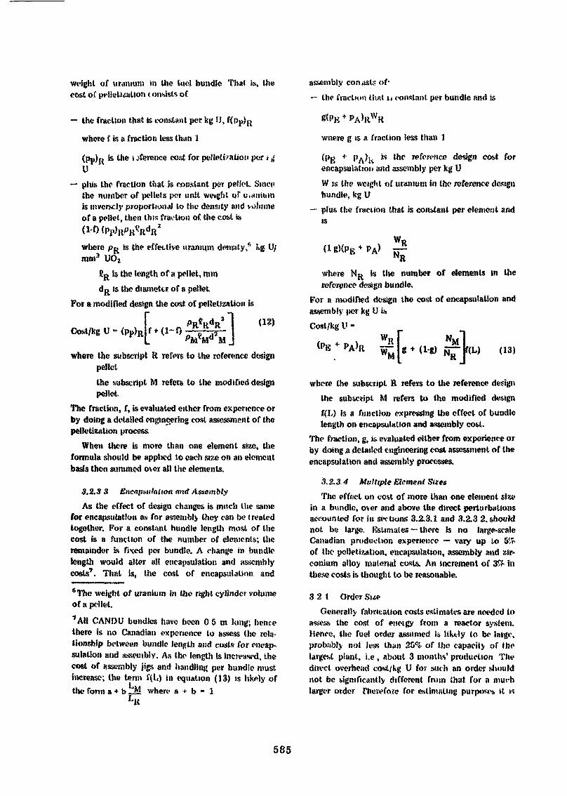
weight of uranium m the («<•! bundle That is, thecost of pellelittition < onsisls of
the fraction that is constant per kg U,
where f is a fraction less than 1
(P?)R is lne inference cost for pelleliValion per t ^Uplus the fraction that is constant per pellet. Sine»*the number of pellets per unit weight of uianiumis inver.sc)}' proportional to the density and volumeof a pellet, then this fraction of the cost is
assembly consists of-— the fraction I hat j > constant per bundle and is
where p™ is the effective uranium density,* kg U/mm3 UOj
BR is the length of a pellet, mmdR is the diameter of a pellet
For a modified design the cost of pellelization is
Cost/kg U - <pp)R(12)
where the subscript R refers to the reference designpelletthe subscript M refers to the modified designpellet
The fraction, f, is evaluated either from experience orby doing a detailed engineering cost assessment of thepalletization process.
When there is more than one element size, theformula should be applied to each size on an elementbasis then summed over all the elements.
3.2,3 3 Encapsulation and AssemblyAs the effect of design changes is much the same
for encapsulation as for assembly they can be treatedtogether. For a constant bundle length most of thecost is a function of the number of elements; theremainder is fixed per bundle. A change in bundlelength would alter all encapsulation and assemblycosts7. Thul is, the cost of encapsulation and
*Thc weight of uranium in the right cylinder volumeof a pellet.7 AH CANDU bundles have been 0 5 m long; hencethere is no Canadian experience to assess the rela-tionship between bundle length and costs for encap-sulation and assembly. As the length is increased, thecost of assembly jigs and handling per bundle mustincrease; the ten» 1\L) in equation (13) is likely ofthe form a + b _M where a + b » 1
LK
wnere g is a fraction less than 1
(Pg + P^)k 's ^c i*fownco design co.st forencapsulation and assembly per kg UW is the weight of uranium in the reference designbundle, kg Uplus Use fraction that is constant per element andis
WR
where NR is the number of elements in thereference design bundle.
For a modified design the cost of encapsulation andassembly per kg U isCost/kg U -
PA>R (13)
where the subscript R refers to the reference designthe subscript M refers to the modified designf(L) is a function expressing the effect of bundlelength on encapsulation and assembly cost.
The fraction, g, i& evaluated either from experience orby doing .a detailed engineering cost assessment of theencapsulation and assembly processes.
5. 2.3.4 Multiple Element SizesThe effect on cost of more than one clement size
in a bundle, over and above the direct perturbationsaccounted for in sections 3.2.3.1 and 3.2.3 2. shouldnot be large. Estimates ~ there is no large-scaleCanadian production experience — vary up to 5%of the palletization, encapsulation, assembly and zir-conium alloy material costs. An increment of 3& inthese costs is thought to be reasonable.
3 2 1 Order SueGenerally fabrication costs estimates are needed to
assess the cost of enetgy from a reactor system.Hence, the fuel order assumed is likely to be large,probably not Jess than 25% of the capacity of Ihelargest plant, t.e , about 3 months' production Thedirect overhead cost/kg U for such an order .shouldnot be significantly different from that for a muchlarger order Therefore for estimating purposes it is
585

arbitrarily assumed that for any order greater than25% of the annual plant capacity, the cost is inde-pendent of order size.
For order sizes less than 25% of the annual plantcapacity, it is recommended that the pelletization,encapsulation, assembly and zirconium alloy costcomponents be incremented according to the re-lationshipA(Cost)/kgU-
where A(cost)/kg U is the incremental cost
(cost) is the cost for pelletization, encapsulation,assembly and zirconium alloy materials fora large order (>25% of plant capacity)
For pelletization, encapsulation, assembly and zir-conium alloy materials the small order size cost isthen ((cost) + A(cost)]/kg U. Other cost componentsare unaffected by order size.
4. FUEL COSTS IN CANADATo illustrate, the method is applied to estimate the
cost of fuel fabricated In Canada. It is not claimedthat the numbers are accurate but they are broadlyrepresentative of the Canadian situation using fabri-cation techniques as described by W.C. Durant^) forwhich most practical production experience exists.
4.1 Pickering Natural UO2 DesignAs a substantial portion of CANDU fuel produced
to date has been for the Pickering reactors, thePickering natural UO2 fuel bundle is selected as thereference design. The reference costs are expressed in1972 Canadian dollars and derived for plants withcapacities of 1 Mg U/d operating 250 days per year, 2shifts per day at 100% load factor.*
The components of fuel cost which reflect theorganization of the fabrication process in Canada are:1. Purchase of U308 by the reactor operator.2. Conversion of Uj08 to UO2 by a powder pre-
paration (PP) plant.3. Purchase of zirconium alloy tubing, bar stock and
sheet by a pelletization, encapsulation andassembly (PEA) plant.
s The reference cost is not necessarily equivalent toUie estimated 1972 fuel cost in Canada as the plantcapacities, load factors and learning factors applicable.o the industry in Canada in 1972 differ from thoseused for the reference cost.
4. Pelletization, encapsulation and assembly in *PEA plant
5. Shipping.The financial rules that reasonably reflect
Canadian practice and current rates are summarizedin Table 4. Production times and irrecoverable lossallowances appropriate to Canadian fabrication plantsare itemized in Tables 5 and 69.
The estimated costs of buildings, equipment, andannual operation for the PP and PEA plants are listedin Table 7 and 8.
The Zircaloy-4 material costs itemized in Table 9are the costs to the fabricator for these materials. TheCanadian PEA plants do some further processing onthem; the labour for this is included in the PEA plantoperating cost. The PEA plant adds an overhead chargefor the materials it purchases from other suppliers.
From these data, the fabrication cost for thePickering natural U02 fuel is estimated as demon-strated in Table 10.TABLE 4 FINANCIAL ASSUMPTIONS FOR CANADA _____
I CAJ-IT/M.tlUKl,liS(*prt
Rviun» un Invitlnwiit toftm Twm.
Pmpccty TMC
123
e?i.oi u
TIH«| SI.O
t» isnunrd w br WÏ <Mx mi 7«n «MKy
11.4
136
I.»
«Ï!»
Tuft wt KVWHI* te <Wfc irf (run*
Hviitm on «qk*ty 12 «•
2 WORKING LAHTALUMKOKS
26% v inilura
3. OVEKHKAK ,\U,OW»NI. B
Kmtwcti md dmlopmni
W»rnmy
AdmuiMnuloii «ml mukrimi
1 •Jut row
K) •»; ..t i-,»l
Ktporltd liMhtn In yw»
M «>|KT.itt>r «ml induik» fulirtralur-puithtftll nMl*ri«l* «ltd
9 The enriched uranium route data, included forinformation, are based on Canadian industry sub-contracting some of the fabrication processes to USplants (note Appendix 1).
586
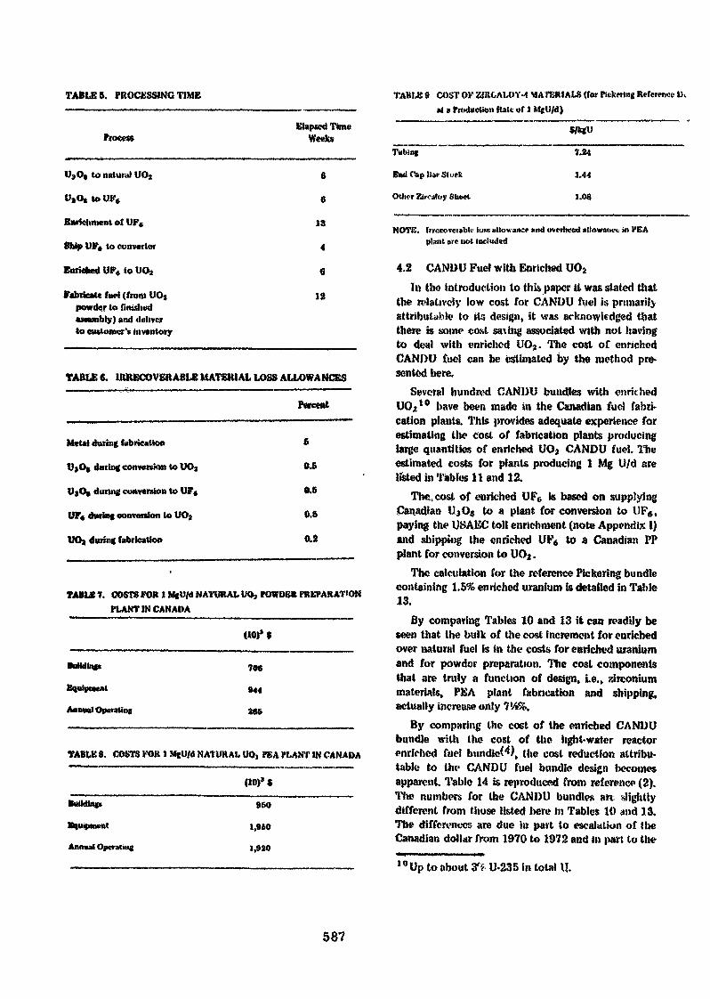
TABLES. PROCESSING TIME
Process
OjO, to natural UOj
UjO» to UF«
Enrichment of UFe
Ship UF» to converter
Enriched UF« to U0«
Fabricate fuel (from UO,
Elapsed TimeWeek»
6
9
13
4
6
12
COST OK ZIBCALOY-4 MATERIALS (for Pitkering Reference IX»t » Production Rate of t MgU/d)
powder to finidwdassembly) and deliverto customer's inventory
TABLE 6. llUtKCOVERABLE MATERIAL LOSS ALLOWANCES
Percent
Met»! during fabrication
V»O( during conversion to UOj
UjOp during convention to UF«
UF« during conversion to UOj
during fabrication
£
0.5
0.5
0.5
0.2
TABLE 7. COSTS FOR I MgU/d NATURAL UO, POWDER PREPARATION_____fLANTIM CANADA
«0)» $
Buttding*
Annual Operating
706
«44
265
TABtE 8. COSTS FOR 1 MjU/d NATURAL UO» PEA PLANT IN CANADA
(10)* $
Building»
Equipment
Annual Operating
96»
1,950
1,»20
Tubing
End Clip liar Stuck
Other Zircatoy $hc«t
7.24
a.44
1.08
NOTfi. InrecQveubk' loss allowance mid overhead ullowmw* in HEAplant ore not included
4.2 CANDU Fuel with Enriched U02
In Uio introduction to this paper it was stated thatthe relatively low cost for CANDU ftiel is primarilyattributable* to its design, it was acknowledged thatthere is some cost saving associated with not havingto deal with twichcd UO9. The cost or enrichedCANDU fuel can be estimated by the method pre-sented here.
Several hundred CANDI) bundles with enrichedU02
10 have been made in the Canadian fuel fabri-cation plants. This provides adequate experience forestimating the cost of fabrication plants producinglarge quantities of enriched UO2 CANDU fuel. Theestimated costs for plants producing 1 Mg U/d arelisted in Tables 11 and 12.
The, cost of enriched UP0 is based on supplyingCanadian UjG* to a plant for conversion to UP*,paying the U.SAKC toll enrichment (note Appendix 1)and shipping the enriched UP6 to a Canadian PPplant for conversion to UO2.
The calculation for the reference Pickering bundlecontaining 1.5% enriched uranium is detailed in Table13.
By comparing Tables 10 and 13 it can readily beseen that the bulk of the cost increment for enrichedover natural fuel is in the costs for enriched uraniumand for powder preparation. The cost componentsthat are truly a function of design, i.e., zirconiummaterials, PEA plant fabrication and shipping,actually increase only 714%.
By comparing the cost of the enriched CANDUbundle with the cost of the light-water reactorenriched fuel bundled), the cost reduction attribu-table to the CANDU fuel bundle design becomesapparent. Table 14 is .reproduced from reference (2).The numbers for the CANDU bundles art slightlydifferent from those listed here in Tables 10 <wd 13,The differences are due in part to escalation of theCanadian dollar from 1970 to 1972 and in part to the10 Up to about & U-235 in total
587
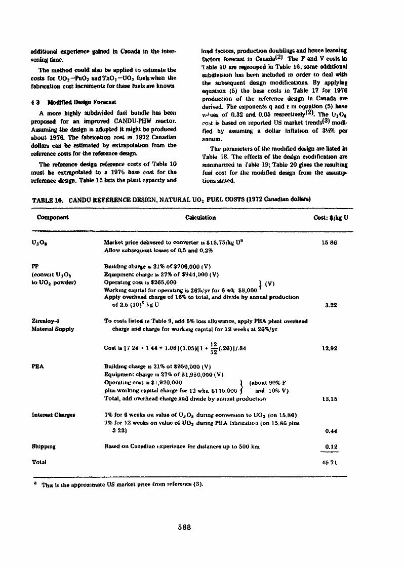
additional experience gained in Canada in the inter-vening time.
The method could also be applied to estimate thecosts for UO2-PuO2 andThO2-UO2 fuels when thefabncation cost increments for these fuels are known
4 3 Modified Design ForecastA more highly subdivided fuel bundle has been
proposed for an improved CANDU-PHW reactor.Assuming the design is adopted it might be producedabout 1976. The fabrication cost in 1972 Canadiandollars can be estimated by extrapolation from thereference costs for the reference design.
The reference design reference costs of Table 10must be extrapolated to a 1976 base cost for thereference design. Table 15 lists the plant capacity and
load factors, production doublings and hence learningfactors forecast in Canada^) The F and V costs inTable 10 are regrouped in Table 16, some additionalsubdivision has been included in order to deal withthe subsequent design modifications. By applyingequation (5) the base costs in Table 17 for 1976production of the reference design in Canada arederived. The exponents q and r in equation (5) haveVf'ues of 0.32 and 0.05 respectively*2). The U3O8cost is based on reported US market trends(^) modi-fied by assuming a dollar inflation of 3'/2% perannum.
The parameters of the modified design are listed inTable 18. The effects of the design modification aresummarized in Table 19; Table 20 gives the resultingfuel cost for the modified design from the assump-tions stated.
TABLE 10. CANDU REFERENCE DESIGN, NATURAL UO2 FUEL COSTS (1972 Canadian dollars)
Component Calculation Cost: $/kg U
Market price delivered to converter is $15.75/kg U* 15 86Allow subsequent losses of 0.5 and 0.2%
Building charge is 21% of $706,000 (V)Equipment charge is 27% of $944,000 < V)Operating cost is $265,000 I (V)Working capital for operating is 26%/yr foi 6 wk $8,000Apply overhead charge of 16% to total, and divide by annual production
of2.5(10)s k g U 3.22
To costs listed in Table 9, add 5% loss allowance, apply PEA plant overheadcharge and charge foe working capital for 12 weeks at 26%/yr
Cost is {7 24 * 1 44 + 1.081(1.05)(1 + ~-{.26)J/.84 12.92
PP(convert U3O8loUO2 powder)
Zircaloy-4Material Supply
PEA
Interest Charges
Shipping
Tola»
Building charge is 21% of $950,000 (V)Equipment charge is 27% of $1,950,000 (V)Operating cost is $ 1,920,000 ) (about 90% Fplus working capital charge for 12 wks. $115,000 / and 10% V)Total, add overhead charge and divide by annual production
7% for 6 weeks on value of UjO» during conversion to UOa (on 15.86)7% for 12 weeks on value of UO? during PEA fabrication (on 15.86 plus
322)
Based on Canadian experience for distances up to 500 km
13.15
This is the approximate US market price from reference (3).
588
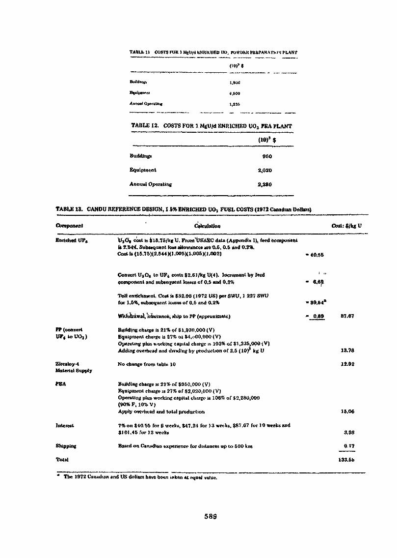
TABU* 11 COSTS KOIl t MeU/<S IfNRUtlED OO. POWUMt PKEPAHM |.>N PLANT
(19)» *
Building* 1.930
TABLE 12. COSTS FOR 1 MgU/d KNIUCHEO UOj PEA PLANT
(10)9 $
Building»
Equipment
Annual Operating
900
2,020
2,280
TABLE 13. CANDU REFERENCE DESIGN, I 5% ENRICHED UOj FUEL COSTS (1972 Canadian Dollars)
Component Calculation Cost: $/kg U
Enriched UP« UjO» cost is $15.76/kg U. From'USAfcC data (Appendix I), feed componentis 2.944. Subséquent loss allowances aie 0.6, 0.5 and W.2'*.Cost is (15.75)(2.544){1.005K1,005)(J.002)
ff (convertUF«toU02)
Zircaloy-4Material Supply
PEA
interest
Total
Convert U3O» to UF« costs $2.6J/kg U{4). Incrément by I«edcomponent and subs«tjucnt losses of 0.5 and 0.3%
Toll enrichment Cost is $32.00 {1872 US) per SWU, 1 227 SWVfor 1.6%, subsequent losses of 0.5 and 0.2%
, «hip to PP (approximate)
Building chatgc is 21% of $1,930,000 (V)Ecjuipmcnl charge is 27% 01 $4,»>00,000 (V)Operating plus working capital charge is- 103% of $1 ,235,000 < V)Adding overhead and dividing by production of 2.5 (10)' leg U
No change from table 10
Building charge is 21% of $950,000 (V)Equipment charge is 27% of $2,020,000 (V)Operating plu» working capital charge is 106% of $2.280,000(90% F, 10%V)Apply overhead and total production
7%o»$10!>!> for & weeks, $47.24 for )» weeks. $87.67 for 10wecfc»and$101.45 for 12 weeks
Based on Canadian experience (or distances up to 500 km
• 6.69
• 39.64*
• 0.69 87.67
13.76
12.92
16.06
3.08
0t7
133-&b
" The 1972 Canadian and US dollars have been v»k«n «t «ju«l value.
589
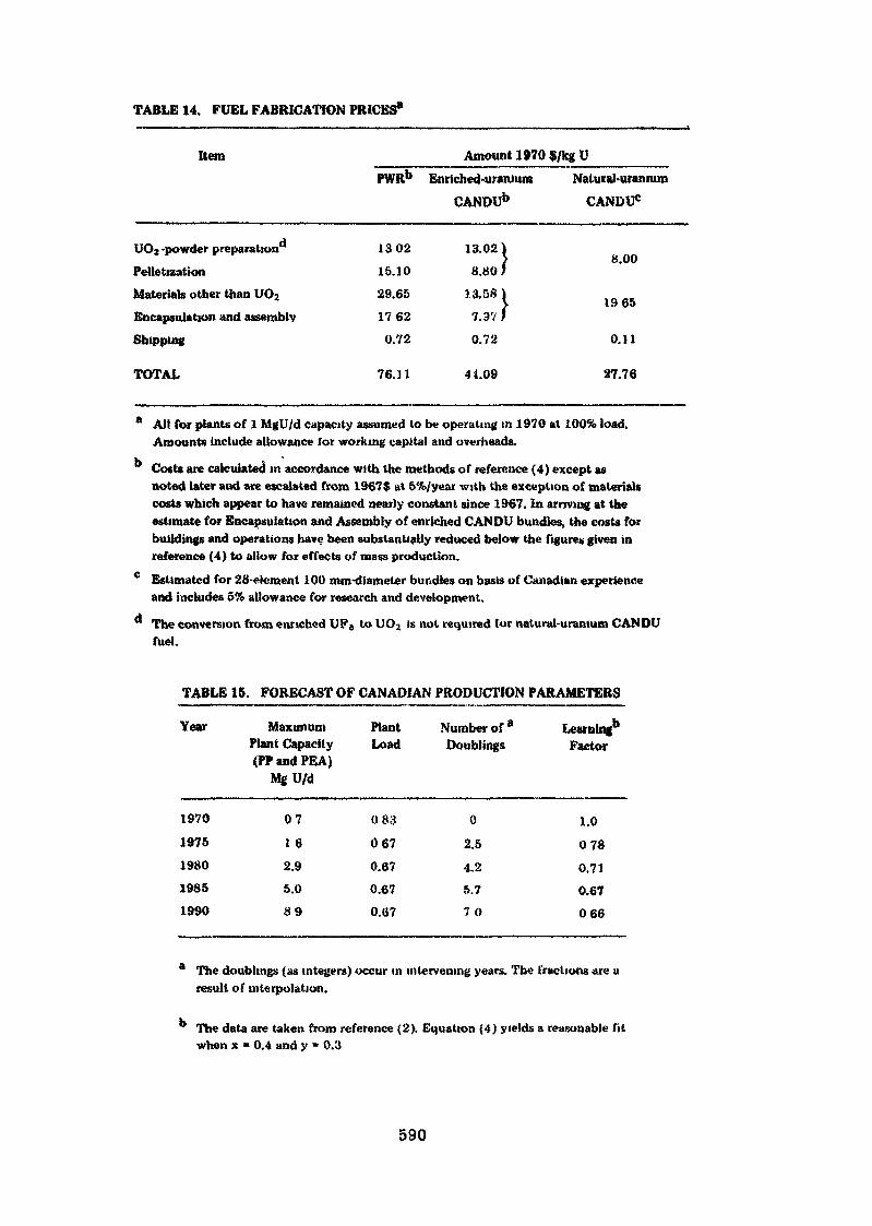
TABLE 14. FUEL FABRICATION PRICES*
Item
UO2 -powder preparation*1
PeiletizationMaterials other than UO2
Encapsulation and assembly
Shipping
PWRb
130215.1029.65
17620.72
Amount 1970 $/kg UEnriched-uranium Natural-uranium
CANDUb CANDU0
13.02 18.80 /
13.58 \7.3? }0.72
8.00
1965
0.11
TOTAL 76. J l 41.09 27.76
* All for plants of 1 MgU/d capacity assumed to be operating in 1970 at 100% load.Amounts include allowance for working capita! and overheads.
Costs are calculated in accordance with the methods of reference (4) except asnoted later and are escalated from 1967$ at 5%/year with the exception of materialscosts which appear to have remained nearly constant since 1967. In arriving at theestimate for Encapsulation and Assembly of enriched CANDU bundles, the costs forbuildings and operations have been substantially reduced below the figures given inreference (4) to allow for effects of mass production.
c Estimated for 28-elcment 100 mm-diameler bundles on basis of Canadian experienceand includes 5% allowance for research and development.
The conversion from enriched UP6 to UO2 is not required for natural-uranium CANDUfuel.
TABLE 15. FORECAST OF CANADIAN PRODUCTION PARAMETERS
Year
19701975198019851990
MaximumPlant Capacity(PP and PEA)
MgU/d
071 62.95.089
PlantLoad
083
0670.670.670.67
Number of aDoublings
02.5
4.25.770
Learning1*Factor
1.00780.710.67066
a The doublings (as integers) occur in intervening years. The fractions are uresult of interpolation.
° The data are taken from reference (2). Equation (4) yields a reasonable fitwhen x = 0.4 and y = 0.3
590
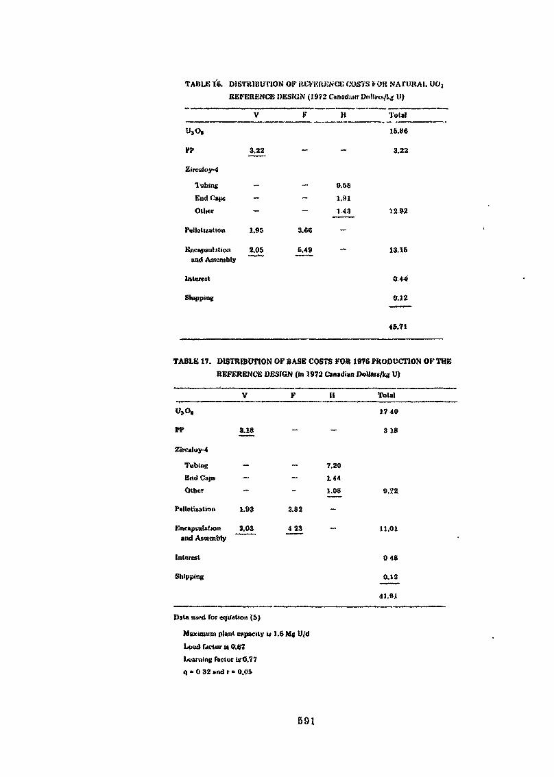
TABLE t'6. DISTRIBUTION OF REFERENCE COATS FOR NAfUKAL UOjREFERENCE DESIGN (1972 Canadian OolUcs/!^ li)
V
US08
Vf 3.22
Zircaloy-4
Tubing —
End Caps —Other
Peiletization Î.95
Encapsulation 2.05and Assembly
F H Total
15.86
- - 3.22
9.S81.91
- 143 12 92
3.66
6.49 - 13.15
Shipping
044
0.12
45.71
TABLE 17. DISTRIBUTION OF BASE COSTS FOR 1976 PRODUCTION OF THEREFERENCE DESIGN (in 1972 Canadian Dollars/kg U)
F H Tola)
0,0,
8.18
Data used for equatioi» (5)
Maximum plant capacity is 1,6 Mg U/dLoud factor « 0.6?Learning factor is 0.77q = 0 32 and r = 0.05
1740
318
Zircaloy-4
Tubing — — 7.20End Caps — — 1,44Other - - 1.08
Pelletizatio» 1.93 2.82 -
Encapsulation 2,03 4 23 —and Assembly "
Interest
Shipping
v.n
11.01
048
0.12
41.01
591
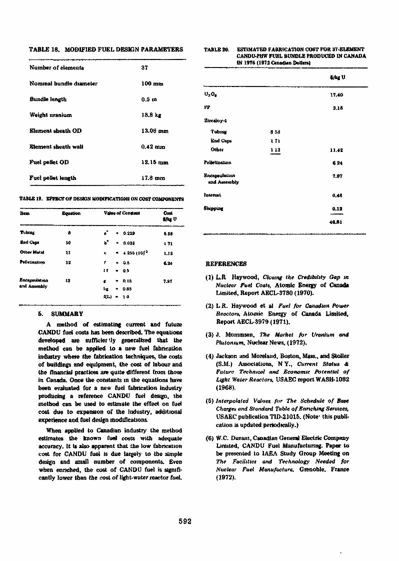
TABLE 18. MODIFIED FUEL DESIGN PARAMETERS
Number of elements
Nominal bundle diameter
Bundle length
Weight uranium
Element «heath OD
Element sheath wall
Fuel pellet OD
Fuel pellet length
37
100mm
0.5 m
18.8 kg
13.08 mm
0.42 mm
12.15 mm
17.8 mm
TABLE 19. EFFECT OF DESIGN MODIFICATIONS ON COST COMPONENTS
Item Equation Value of ContUut Cost
TubingEnd Cap*
Other Metal
PeUeUzaUon
Encapsulationand Assembly
8
10
11
12
13
a" " 0.229
b" » 0.033
« « 4 2SS (lOf 3
f « 0.5If - OS
t - 0 .15l-g " 085
«M " 10
858
171
1.13
6.24
7.97
5. SUMMARYA method of estimating current and future
CANDU fuel costs has been described. The equationsdeveloped are sufficierUy generalized that themethod can be applied to a new fuel fabricationindustry where the fabrication techniques, the costsof buildings and equipment, the cost of labour andthe financial practices are quite different from thosein Canada. Once the constants in the equations havebeen evaluated for a new fuel fabrication industryproducing a reference CANDU fuel design, themethod can be used to estimate the effect on fuelcost due to expansion of the industry, additionalexperience and fuel design modifications.
When applied to Canadian industry the methodestimates the known fuel costs with adequateaccuracy. It is also apparent that the low fabricationcost for CANDU fuel is due largely to the simpledesign and small number of components. Evenwhen enriched, the cost of CANDU fuel is signifi-cantly lower than the cost of light-water reactor fuel.
TABLE 20. ESTIMATED FABRICATION COST FOR 37-ELEM ENTCANDU-PHW FUEL BUNDLE PRODUCED IN CANADAIN 1976 (1972 Canadian Dollars)
ff
ZircaIoy-4
TubingEnd CapsOther
Peltetiiatton
Encapsulationand Assembly
Interest
Shipping
17.40
3.18
8 Sa
171113 11.42
6.24
7.»7
0.48
o.ia46.81
REFERENCES
(1) L.R Haywood, Closing the Credibility Gap mNuclear Fuel Coats, Atomic Energy of CanadaLimited, Report AECL-3780 (1970).
(2) L.R. Haywood et al Fuel for Canadian PowerReactors, Atomic Energy of Canada Limited,Report AECL-3979 (1971).
(3) J. Mommsen, The Market for Uranium andPlutonium, Nuclear News, (1972).
(4) Jackson and Moreland, Boston, Mass., and Stoller(S.M.) Associations, NY., Current Status &Future Technical and Economic Potential ofLight Water Reactors. USAEC report WASH-1082(1968).
(5) Interpolated Values for The Schedule of BaseCharges and Standard Table of Enriching Services,USAEC publication TID-21015. (Note- this publi-cation is updated periodically.)
(6) W.C. Durant, Canadian General Electric CompanyLimited, CANDU Fuel Manufacturing. Paper tobe presented to IAEA Study Group Meeting onThe Facilities and Technology Needed forNuclear Fuel Manufacture, Grenoble, France(1972).
592
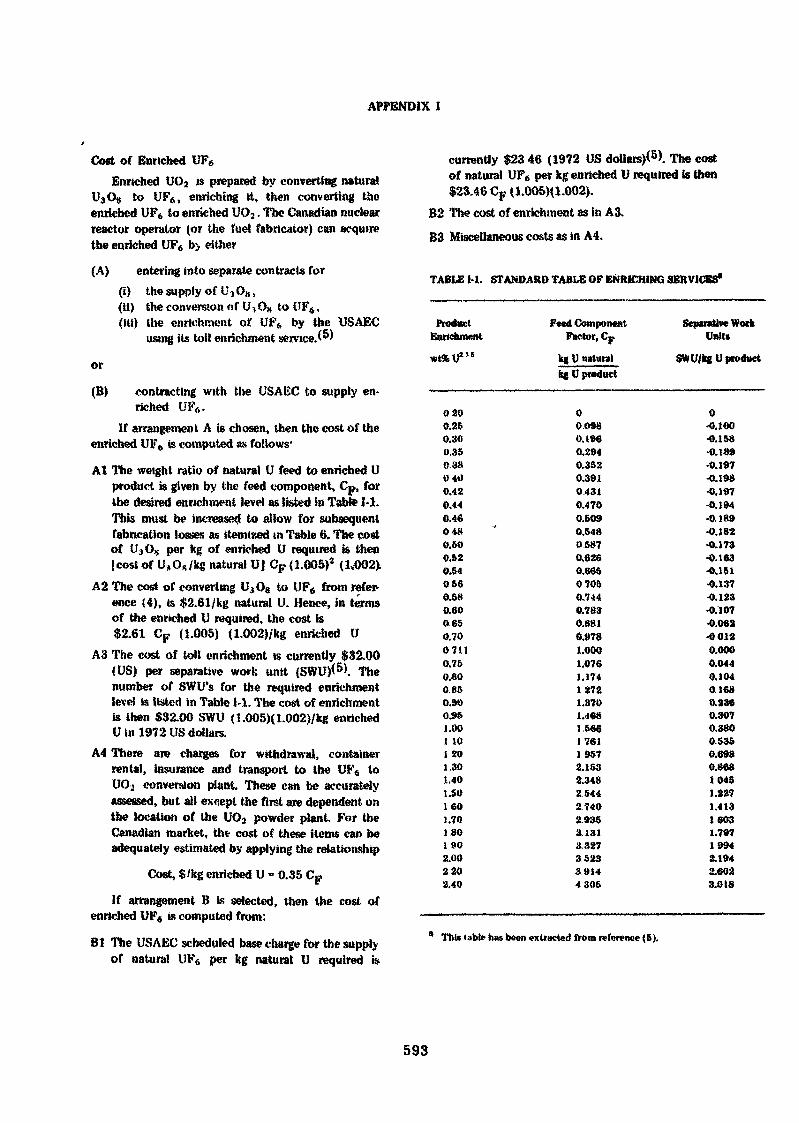
APPENDIX I
Cost of Enriched UF6
Enriched UO2 is prepared by converting naturalUâ G» to UF6, enriching it, then converting theenriched UF6 to enriched UCK. The Canadian nuclearreactor operator (or the fuel fabricator) can acquirethe enriched UF6 b> either
(A) entering into separate contracts for(i) the supply of UjO»,(il) the conversion of U, OK to UF6,(Hi) the enrichment of UF6 by the USAEC
using its toil enrichment service. )
or
(B) contracting with the USAEC to supply en-riched UP,,.
If arrangement. A is chosen, then the cost of theenriched U1T6 is computed as follows*
Al The weight ratio of natural U feed to enriched Uproduct is given by the feed component, Cp, forthe desired enrichment level as listed in Tabte M.This must be increased to allow for subsequentfabrication losses as itemized in Table 6. The costof UjO, per kg of enriched U required is then|cost of U»Os/kg natural U| CF (1.005)2 (1.002X
A2 The cost of converting U.,O8 to UF6 from refer-ence (4), is $2.61/kg natural U. Hence, in termsof the enriched U required, the cost is$2.61 CF (1.005) (1.002)/kg enriched U
A3 The cost of toll enrichment is currently $32.00(US) per separative work unit (SWU)<5>. Thenumber of SWU's for the required enrichmentlevel is listed in Table 1-1. The cost of enrichmentis then $32.00 SWU (1.005)(L002)/kg enrichedU in 1972 US dollars.
A4 There are charges for withdrawal, containerrental, insurance and transport to the UF« toUOj conversion plant. These can be accuratelyassessed, but all except the first are dependent onthe location of the UO2 powder plant. For theCanadian market, th* cost of these items can beadequately estimated by applying the relationship
Cost, $/kg enriched U - 0.35 CF
if arrangement B is selected, then the cost ofenriched UF« is computed from:
Bl The USAEC scheduled base charge for the supplyof natural UF6 per kg natural U required i»
currently $23 46 (1972 US dollars)*6). The costof natural UF6 per kg enriched U required is then$23.46 CF (1.005)(1.002).
B2 The cost of enrichment as in A3.B3 Miscellaneous costs as in A4.
TABLE M. STANDARD TABLE OF ENRICHING SERVICES*
ProductEnrichment
*t%U"s
0200.260.300.350,3»0400.420.440.460480.500.520.540560.580.800650.7007110.760.800850.900.951.00I tOi 201.301.401.501601.701 8O1 902.002203.40
Feed ComponentFactor, Cp
kg U naturalk« V product
000980.1960.2940.3520,3910.4310.4700.5090.54805870.6260.66507050.7440.7830.8810.9781.0001.076
.174272.370.468566761957
2.1532.3482.5442.7402.9353.1313.827352339144305
Separative WorkUnits
SWU/kgU product
0-0.100-0.158•0.189-0.197-0.198-0.197-0.194-0 189•0.182•0.173•0.163•0.151•0.137•0.123•0.107-0.062-00120.0000.0440.1040.1680.2360.3070.3800.5350.6980.86810451.2271.41316031.79719942.1942.6023.018
This table has been extracted from reference (6).
593
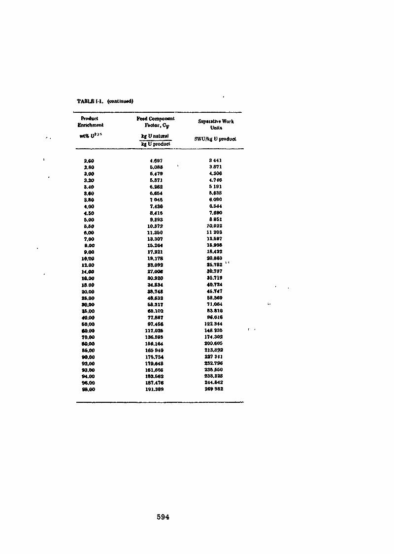
TABLE 1-1. (continued)
ProductEnrichment
wtfcU*3'
2.602803.003.203.403.60S.804.004.605.005.606.007.008.009.00
10.0012.0014.0016.00180020.0026.0030.0036.0040.0060.0060.0070.0060.0086.0090.0092.0093.0094.0096.0098.00
Peed ComponentFactor, Cj?
kf V naturalkg U product
4.6975.0886.4795.8716.2626.65470457.4368.4169.393
10.37211.36013.30716.26417.22119.17823.09227.00630.92034.83438.74648.63268.31768.10277.88797,466
117.026136.69S166.164165949176.734179.648181.606183.662187.476191.389
Separative WorkUnit»
SWU/kg I) product
34413.8714.3064.74651915.6386.0906.5447.6908851
10.02211 20313.58716.99618.42220.86325.782 "30.73735.71940.72446.74768.36971.06483,81696.616
122.344148235174.302200.605213.892227 341232.796236.660238.328244.842269982
594
DECISION CRITERIAFOR BUILDING
FUEL FABRICATION PLANTSE TRAUWAERTJ. VSRRAVBR
RapporteurÊ JONCKH6ERE
A B S T R A C T
.1
The decision Co build a fuel fabrication plant must depend on manycriteria including economic ones.
In a first part, the fuel fabrication cost for a reference plant isevaluated and an analysis is given of the influence of various parameters suchas • the size of the plant and its expected load factor, the rate of the financialcharges, the warranties of the fuel elements, etc ... . Possible externaleconomies are also taken into account.
In a second part, the world market conditions for the years to come areestimated through the description of a most probable "average11 fabrication plant.
By comparison of the world market conditions with the local ones, itis then possible to bring out a feu criteria measuring the economic and politicalinterest to build a nuclear fuel fabrication plant.
1. INTRODUCTION.
In its "Forecast of the growth of Nuclear Power" [i] , the USAEC estimatesthe cumulative capacity of nuclear power in the western world (i.e. excludingUSSR. P.R. China and Eastern Europe) to reach 95 GWe by 1975, 250 GWe by 1980and more than twice this figure by 1985. This large increase in nuclear powerover the next decade will call for a similar increase in volume of fuel fabri-cation. The questions thus arise of whore, when and which fuel fabricationplant to build.
As fast reactors are not expected to get any significant share of the marketbefore approximately 1985 £2! , the above power requirements will mainly haveto be met by LWR.s, HWR.s and HTR.s. Hence a subsidiary question : shouldthe fabrication plants be specialized in'fuel elements for one or more typesof reactor or should they be completely polyvalent ?
595

In this paper, we have chosen the solution of fully specialized fabricationplants, not only because' this approach was easier to handle, thus givingmore meaningful results, but mainly for the following reasons •
1* The present fabrication marjtet is such that most fuel suppliers are closelylinked with the reactor suppliers, so that a specialization in one type offuel is almost natural.
2° HTR fuel is so different from the other .ypes of fuel that it is almostcertain that it will be manufactured in . separate fabrication unit.
Hence there are good indications that most future fabrication plants will bespecialised in the fuel for one type of reactor. The fact that the fabricationplants have some flexibility, that enables them to produce other types of fuel,with some performance penalty, iai.ll be disregarded in this model as a minoreffect.
This leaves us with our first question about the size of fabrication plants,as a function of time and location, and this will be the object of this paper.
Although we want to put this question in an international context, it is notour ambition to develop an overall optimization model for all the fabricationplants to be built over the world.
We will rather tackle this problem from the point of view of the marginalinvestor : given well defined world market conditions for nuclear fuel fabri-cation, what must be the policy of a potential investor "
To define further the problem, we will assume that the investor wants Co doa benefit of some kind.
Thus given a certain volume of fuel fabrication one might supply, we shallinvestigate whether it is beneficial to invest in a fabrication plant ratherthan to buy on the world market. More precisely we will indicate, undercertain assumptions, some minimum demand levels under which no benefit canbe expected from a fabrication plant investment decision, given the offeron the world market.
A more advanced approach of the problem would be to try to calculate themaximum benefit one can expect from an investment decision. This is a verycomplex problem that lies outsxde the frame ol this work.
For the definition of the benefit, many options are possible. At one endof the spectrum, we have the accountants definition in which the total balanceof both solutions (plant construction or fuel import) is made. At the otherend, we find the point of view of someone anxious about the balance of payment,taking only tho.se expenses into account that are to be paid in foreign currency.We can also imagine a local development agency who is concerned with theeconomic and social development of a district and is prepared to pay somesubsidy considering the contribution of the firm to the local welfare(external economies). These three options will lead to different investmentcriteria.
The aim of this paper is more to illustrate the problem than to quantify itwith precision and to every detail. Tuerefore, we shall restrict the discuss-ions to the fuel for one type of reactor and focus the analysis ©n the variat-ions of the costs with various parameters and not on its absolute value.
596
2. DEFINITION OF THE PRODUCT.
2.1. SCOPE OF .SUPPLY.
A fuel manufacturer may offer, in addition to fuel fabrication, a largespectrum of services covering the whole fuel cycle from the procurementof base nuclear material to the disposal of spent fuel. For example,G.E. will offer three kinds of fuel services packages [3] :
1. fuel fabrication service, including fuel design and conversion ofUP, to UO, ;o t
2. initiai fuel service, i.e. fabrication service plus procurement o£yellow cake conversion to UF-, procurement of enrichment servicesand fuel management engineering ;
3. fuel cycle service, that is initial fuel service plus spent fueltransportation and reprocessing and recycle or resale of recovereduranium and plutonium.
Of course, the warranty offered fay the fuel manufacturer will be propor-tionate to the- scope of fuel services. The most comprehensive fuel cycleservice will practically carry with it the warranty of the fuel cycle cost,calculated under nominal plant operating conditions and with a conventionalfinancial charges rate. At the other end, the warranty associated to thefuel fabrication service will be limited to the mechanical integrity ofthe fuel and possibly its heat output.
For the purpose of this study, we shall adopt a still more restricteddefinition of fuel fabrication by taking away the fuel design from thescope ot supply and the corresponding charge from the fuel fabricationcost.
We define therefore fu e 1 (f abr ica t ioa as covering the following steps :
- acceptance of enriched UP, ,t the proper enrichment ;o- procurement and acceptance of rod cladding ;- fabrication or procurement of other rod and element hardware items(end caps, grids, heads and feet, .. ) ;
- conversion of UF.. to U0« ;o i- pellet fabrication (fuel palletizing, sintering, grinding) ;
- rod fabrication (fuel loading and end cap welding) ;- element fabrication (element assembling and packaging) ;- recycle or recovery of fabrication scrap ;- controls required at each fabrication step to ensure the quality ofthe final product.
The fuel warranty associated with the product will cover good workman-ship and materials exclusively.
597
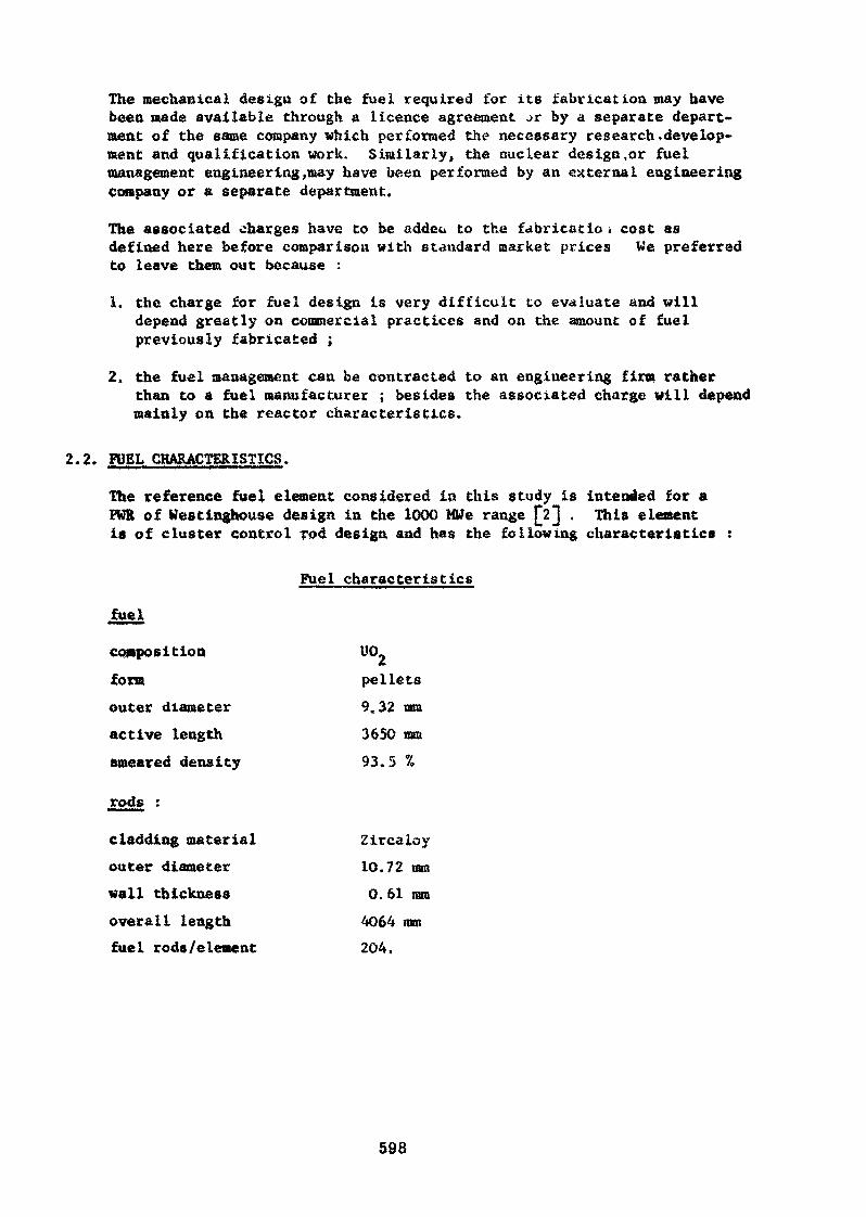
The mechanical design of the fuel required for its fabrication may havebeen made available through a licence agreement ->r by a separate depart-ment of the same company which performed the necessary research.develop»ment and qualification work. Similarly, the nuclear design,or fuelmanagement engineering,may hâve been performed by an external engineeringcompany or a separate department.
The associated charges have to be addec to the fabricatio » cost asdefined here before comparison with standard market prices We preferredto leave them out because :
1. the charge for fuel design is very difficult to evaluate and willdepend greatly on commercial practices and on the amount of fuelpreviously fabricated ;
2* the fuel management can be contracted to an engineering firm ratherthan to a fuel manufacturer ; besides the associated charge will dependmainly on the reactor characteristics.
2.2. FUEL CHARACTERISTICS.
The reference fuel element considered in this study is intended for aFUR of Westinghouse design in the 1000 MWe range [2] . This elementis of cluster control rod design and has the following characteristics :
Fuel characteristics
fuel
composition UO.form pelletsouter diameter 9.32 mmactive length 3650 mmsmeared density 93.5 %
rods :
cladding material Zircaloyouter diameter 10.72 mmwall thickness 0.61 mmoverall length 4064 mmfuel rods/element 204,
598
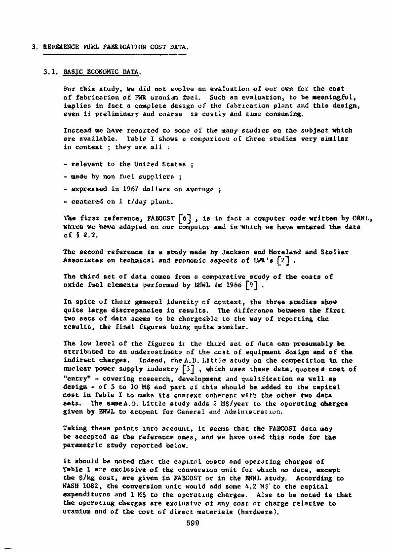
3. REFERENCE FUEL FABRICATION COST DATA.
3.1. BASJC ECONOMIC DATA>
For this study, we did not evolve an evaluation of our own for the costof fabrication of PUR uranium fuel. Such an evaluation, to be meaningful,implies in fact a complete design of the fabrication plant Ana this design,even if preliminary and coarse is costly and time consuming.
Instead we have resorted to some of the many studies on the subject whichare available. Table I shows a comparison o£ three studies very similarin context ; they are all :
- relevant to the United States ;- made by non fuel suppliers ;- expressed in 1967 dollars on average ;- centered on 1 t/day plant.
The first reference, FABOCST foj , is in fact a computer code written by ORNL,which We have adapted on our computer and in which we have entered the dataof § 2.2.
The second reference is a study made by Jackson and More land and S toi 1erAssociates on technical and economic aspects of UWR's
The third set of data comes from a comparative study of the costs ofoxide fuel elements performed by BNWL in 1966
In spite of their general identity cf context, the three studies showquite large discrepancies in results. The difference between the firsttwo sets of data seems to be chargeable to the way of reporting theresults, the final figures being quite similar.
The low level of the figures ii the third set of data can presumably beattributed to an underestimate of the cost of equipment design and of theindirect charges. Indeed, theA.D. Little study on the competition in thenuclear power supply industry £j]j , which uses these data, quotes a cost of"entry" - covering research, development and qualification as well asdesign - of 5 to 10 M$ and part of this should be added to the capitalcost in Table I to make its context coherent with the other two datasets. The same A. 0. Little study adds 2 M$/year to the operating chargesgiven by BNWL to account for General and Administration.
Taking these points into account, it seems that the FABCOST data maybe accepted as the reference ones, and we have used this code for theparametric study reported below.
It should be noted that the capital costs and operating charges ofTable I are exclusive of the conversion unit for which no data, exceptthe $/kg cost, are given in FABCOST or in the BNWL study. According toWASH 1082, the conversion unit would add some 4,2 M$' to the capitalexpenditures and 1 M$ to the operating charges. Also to be noted is thatthe operating charges are exclusive of any cost or charge relative touranium and of the cost of direct materials (hardware).
599
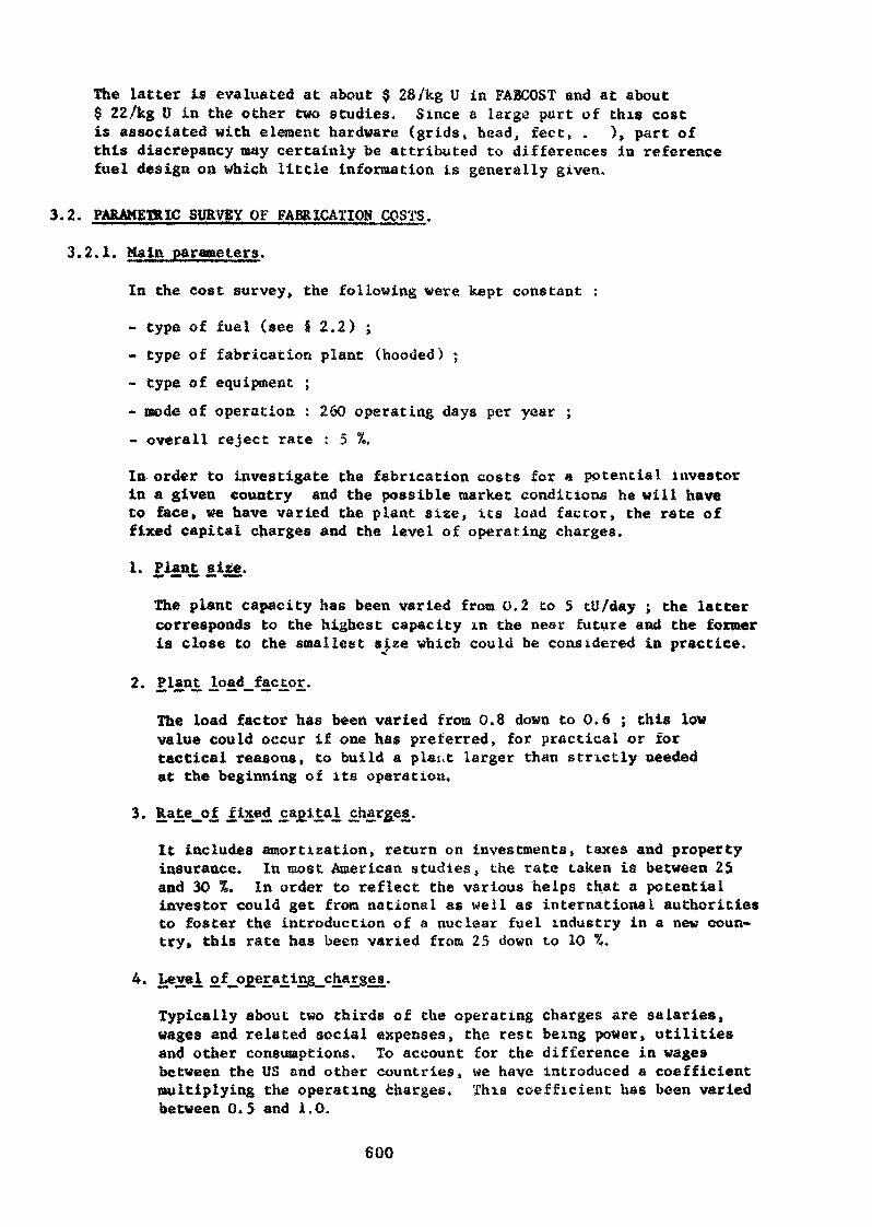
The Latter is evaluated at about $ 28 /kg U in FÂ3COST and at about$ 22 /kg U in the other two étudies. Since a large part of this costis associated with element hardware (grids, head, feet, . ), part ofthis discrepancy may certainly be attributed to differences in referencefuel design on which little information is generally given.
3.2. PARAMETRIC SURVEY OF FABRICATION COSTS.
3.2.1. Mala parame ter s .
In the cost survey, the following were kept constant :
- type of fuel (see § 2.2) ;- type of fabrication plant (hooded) ;- type of equipment ;- mode of operation : 260 operating days per year ;
reject rate : 5 %.
In order to investigate the fabrication costs for a potential investorin a given country and the possible market conditions he will haveto face, we have varied the plant size, its load factor, the rate offixed capital charges and the level of operating charges.
1. £lanjt size.
The plant capacity has been varied from 0.2 to 5 tU/day ; the lattercorresponds to the highest capacity xn the near future and the formeris close to the smallest size which could be considered in practice.
2.
The load factor has been varied from 0.8 down to 0.6 ; this lowvalue could occur if one has preferred, for practical or fortactical reasons, to build a plaut larger than strictly neededat the beginning of its opération.
3, Ratejof ,fi.xe<! £aj>ital charges
It includes amortization, return on investments, taxes and propertyinsurance. In most American studies, the rate taken is between 25and 30 %. In order to reflect the various helps that a potentialinvestor could get from national as well as international authoritiesto foster the introduction of a nuclear fuel industry in a new coun-try, this rate has been varied from 25 down to 10 %.
Typically about two thirds of the operating charges are salaries,wages and related social expenses, the rest being power, utilitiesand other consumptions. To account for the difference in wagesbetween the US and other countries, we have introduced a coefficientmultiplying the operating charges, This coefficient has been variedbetween 0.5 and 1.0.
600
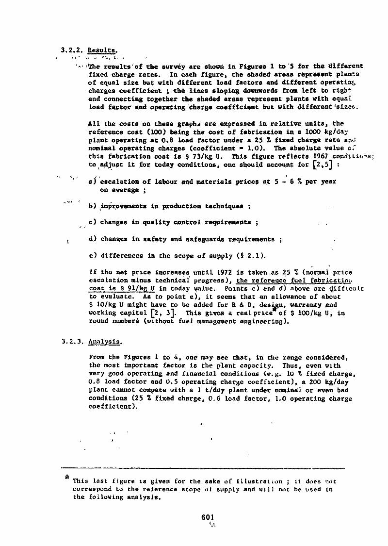
3.2.2. Results.
•The results of the survey are shown In Figures 1 to 5 for the differentfixed charge rates. In each figure, the shaded areas represent plantsof equal size but with different load factors and different operatingcharges coefficient ; the lines sloping downwards from left to rightand connecting together the shaded areas represent plants with equalload factor and operating 'charge coefficient but with different 'sizes.
All the costs on these graphs are expressed in relative units, thereference cost (100) being the cost of fabrication in a 1000 kg/dayplant operating at 0.8 load factor under a 25 % fixed charge rate «a4nominal operating charges (coefficient » 1.0). The absolute value c."this fabrication cost is $ 73/kg U. This figure reflects 1967 conditions:to adjust it for today conditions, one should account for (*2»5J :
/ t *a) escalation of labour and materials prices at 5 - 6 % per year
on average ;
b) improvements in production techniques ;
c) changes in quality control requirements ; , .
d) châtiées in safety and safeguards requirements ;
e) differences in the scope of supply (§ 2.1).
If the net price increases until 1972 is taken as 25 % (normal priceescalation minus technical progress), the reference fuel fabricationcost is $ 91/kg U in today value. Points c) and d) above areto evaluate. As to point e), it seems that an allowance of about$ 10/kg U might have to be added for R & D, design, warranty andworking capital [2, 3], This gives a real price of $ 100/kg U, inround numbers (without fuel management engineering).
3.2.3. Analysis.
From the Figures 1 to 4, one may see that, in the range considered,the most important factor is the plant capacity. Thus, even withvery good operating and financial conditions (e.g. 10 "4, fixed charge,0.8 load factor and 0.5 operating charge coefficient), a 200 kg/dayplant cannot compete with a 1 t/day plant under nominal or even badconditions (25 % fixed charge, 0.6 load factor, 1.0 operating chargecoefficient).
ftThis last f igure is given for the sake of i l lustrat ion ; it does notcorrespond to the reference scope of supply and w i l l not be used inthe following analysis.
601
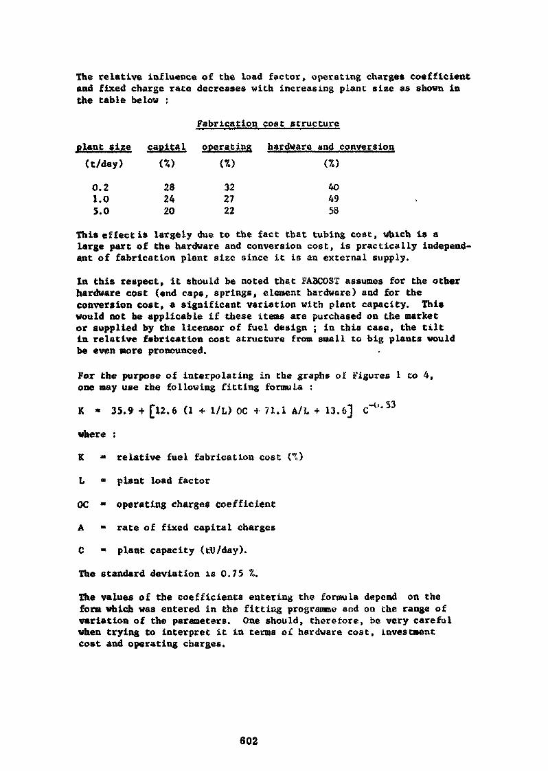
The relative influence of the load factor, operating charges coefficientand fixed charge rate decreases with increasing plant size as shown inthe table below :
Fabrication cost structure
plant size capital operating hardware and conversion(t/day) (%) (%) (Z)
0.2 28 32 401.0 24 27 495.0 20 22 58
This effect is largely due to the fact that tubing cost, which is alarge part of the hardware and conversion cost, is practically indépend-ant of fabrication plant size since it is an external supply.
In this respect, it should be noted that FABCOST assumes for the otherhardware cost (end caps, springs, element hardware) and for theconversion cost, a significant variation with plant capacity. Thiswould not be applicable if these items are purchased on the marketor supplied by the licensor of fuel design ; in this case, the tiltin relative fabrication cost structure from small to big plants wouldbe even more pronounced.
For the purpose of interpolating in the graphs olr Figures 1 to 4,one may use the following fitting formula :
K * 35.9 + [12.6 (1 + 1/L) OC + 71.1 A/L + 13.6] C"1'*53
where :
K » relative fuel fabrication cost CO
L « plant load factor
OC * operating charges coefficient
A = rate of fixed capital charges
C » plant capacity (tU/day).
The standard deviation is 0.75 Z.
The values of the coefficients entering the formula depend on theform which was entered in the fitting programme and on the range ofvariation of the parameters. One should, theretore, be very carefulwhen trying to interpret it in terms o£ hardware cost, investmentcost and operating charges.
602
, EXYERMAL .ECONOMIES QF JUKI,
3.3.1. Fue 1 supply re 1 iabi 1 1 ty and independence .
It is a well known fact that the nuclear power system provides a nation.with a considerable degree of power supply reliability £'+] , not onlybecause a nuclear reactor has an important working autonomy, but alsobecause the storage of nuclear fuel is cheaper than the storage of anycither* conventional energy sources (oil, coal, . . . ). It is also truethat this advantage is often paid, at least for some time, by an
1 increased dependence from foreign nuclear plant suppliers, fuelsuppliers and reprocessing facilities. Does the construction of alocal fuel fabrication plant bring any change in this situation ?
From the point of view of supply reliability, the storage of enricheduranium will be cheaper than that of fabricated fuel, if only because
' of the lower added value. However, this consideration would only playa significant part if one needs a Lot more working autonomy than
" what is already built in the nuclear reactor system.
The dependence on foreign fuel suppliers will be limited to purchaseorders to suppliers of natural uranium and of enrichment services and,, possibly,- to license agreements with suppliers of fuel design instead
• t toi purchase orders for fuel fabrication services. It does not seemthat this will change significantly the degree of dependence from.foreign countries.
The only case in which the building of a fabrication plant couldchange considerably the dependence picture of a nation is that ofa natural uranium reactor type : indeed there would be many potential
- suppliers of natural uranium on the international market», and, in «onethis material could even been produced locally.
Thus, the external economics resulting front: the increased supplyreliability and the reduced foreign dependence are not likely to beimportant except when the adopted reactor type uses natural uranium.
3.3.2. Environmental aspects.!
The implantation of a new fabrication plant on à site may haveenvironmental* effects of three types : it will change' the landscapeof the site, it may be a source of radiation and it produces radio»active waste.
* t
The changes to the landscape are almost inevitable but they aresimilar ,to those produced by any other industry. It is the jobof the architects to try to integrate the plant in their «naturalenvironment and nuclear fuel fabrication plants do not* seem to giverise to special difficulties. On the contrary» the high standardsof cleanliness adopted throughout the nuclear industry is found
. ' practically in, no other industry.
< From radiation point of view, it will be appreciated that unirradiatedlow enriched uranium has a very low radiation intensity. Moreover,the safety requirements ate» nowadays, well established and fairly
. ,603
easy to fulfil. This explains the very low level of radiation hazardsproduced by the nuclear industry in the past and all indications arethat it «ill remain the same in the future.
The waste disposal is presumably the only tricky environment problemof nuclear industry. However, this problem is certainly far lesssevere at the head end of the fuel cycle that at the tail end whereone has to dispose of all the radioactive fission products. Further*more, it is only the "perpetual care" which gives rise to difficultiesand this problem has to be tackled on a worldwide basis. The wastedisposal problem is therefore relatively minor for fuel fabricationand it will be but marginally affected by the location and sizes ofthe plants.
3.3.3. Impulse for scientific and economic development.
It sounds almost trivial to emphasize the scientific and economicsecondary effects of the so-called spear-head techniques. Thisidea is so broadly accepted that organizations like the NASA tendto base the justification of their whole program on the externaleconomies of this type it is supposed to produce.
i
The impulse on the scientific development associated with theconstruction and operation of a fuel fabrication plant dependsstrongly on the origin of the fuel and plants designs. If theseare developed locally, the impulse will be very significant sinceit implies very qualified engineers and physicists working on anextensive research, development and qualification programme.
If these are of foreign origin and obtained through licence orassociation agreements, the impact will be practically limitedto the formation of highly qualified technicians and workers andthis is even more so if the fuel hardware is wholly or partlypurchased abroad, for instance, from the licensor.
From economic point of view, a fuel fabrication plant can, of course,play a part in the industrialization o£ a disadvantaged district»provided enough qualified personnel is available. However, thiseconomic benefit must be compared with the one resulting from build-ing any other industry of similar importance on the same site. It maythen become clear that a more labour intensive industry is moreadvisable for the economic development of that district.
3.3.4. Coneluding comments.
From the above remarks, it is seen that the external economies,although very much dependent of local conditions, are probably morelimited than one could expect. They are also very difficult toevaluate with some accuracy.
Obviously this problem is not unique to the nuclear Industry anddoes not prevent people from taking decisions on the basis of sucheffects whether they are correctly evaluated or not. It is, there-fore, better to consider and to'analyse them seriously with the helpof experts in this field rather than to just forget about them.
604
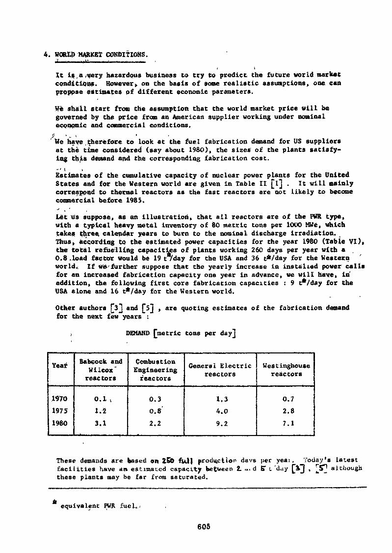
4. WORLD MARKET CONDITIONS.!.. . . t « . . _ • _ . ; . • - - - - - -
i. k
It is.a very hazardous business to try Co predict the future world marketconditions. However, on the basis of some realistic assumptions, one canproppse estimates of different economic parameters.
We shall start from the assumption that the world market price vill begoverned by the price from an American supplier working under nominaléconomie and commercial conditions.
$• *. ••We have therefore to look at the fuel fabrication demand for US suppliersat the time considered (say about I960), the sizes of the plants satisfy-ing this demand and the corresponding fabrication cost.- < i. >Estimates of the cumulative capacity of nuclear power plants for the UnitedStates and for the Western world are given in Table II [l] . It will mainlycorrespond to thermal reactors as the fast reactors are not likely to becomecommercial before 1985.j >. 'Let us suppose, as an illustration, that all reactors are of the PWR type,with a typical heavy metal inventory of 00 metric tons per 1000 MWe, whichtakes three, calendar years to burn to the nominal discharge irradiation.Thus, according to the estimated power capacities for the year 1980 (Table VI)»the total refuelling capacities of plants working 260 days per year with a ,0.8 .load factor would be 19 t/day for the USA and 36 t*/day for the Westernworld. If we further suppose that the yearly increase in installed power callsfor an increased fabrication capacity one year in advance, we will have, inaddition, the following first core fabrication capacities : 9 t*/day for theUSA alone and 16 t*/day for the Western world.
Other authors £3] and £5] , are quoting estimates of the fabrication demandfor the next few years :
. DEMAND fmetric tons per dayj
Year
mo19751980
Sabcock andWilcoxreac tors
0.1 ,1.23.1
CombustionEngineeringreactors
0.30.8'2.2
General Electricreactors
1.34.0
9.2
Westinghousereactors
0.72.87.1
These demands are based on 256 fui) production <iavs per yeaifacilities have an estimated capacity between 2, *, d £T L 'daythese plants may be far from saturated.
Today's latestJp although
equivalent PWR fuel.
605
From the above considerations it seems realistic to accept that the averagefabrication plant in the United States around 1980 will produce the equivalentof 5 t/day of PWR fuel during 208 equivalent full production days per year(or 260 days at 0.8 load factor). This figure is corroborated by a non tofar off 4.3 t/day capacity in 1980 found by an optimization study based onconstraints of estimated demand, share of the market between existing manufac-turers, intitial load factors and specific variations with time. This resultvas published in £2] .
According to Figure 1 with 25 % of fixed charge rate and unit operating factor,the corresponding cost would be 64 % of our reference cost (I t/day) or 58jg/kftin 1972 currency. We will accept this as the reference world market price.
Although this price was calculated as a production cost, we will not considerany supplementary profit margin because remuneration of the capital is alreadyincluded in the rate of fixed capital charges.
Moreover, to be representative of a market price on any place of the world,this USA price should be increased by proper transport cost. The error result-ing from neglecting this factor is of the order of 1-2 $/kg U (to be comparedwith £2] quoting 0.5 $/kg U for shipping within the USA).
However, we will also neglect the transport cost of enriched uranium, hardwareand all other imported materials when considering the local production plants(cfr. infra). In the comparison between these two solutions, both types oftransport costs will tend to counter-balance each other and the remainingerror is believed to be very small indeed.
5. DECISION CRITERIA AND PLANT SIZE.
5.1. STATING THE PROBLEM.
In the preceding chapters, we have described the variation of the costof fuel fabrication, as defined in this study, with various local para-meters and the price of fuel fabricatiri on the world market.
The question that now arises is : given these data, is it worthwhile tobuild a local fabrication plant rather than to buy fuel fabricationabroad ?
In this chapter, we shall consider this question only in terms of minimumplant size and we shall leave the problem of the corresponding fuel demandto the next chapter.
The answer to this question depends on the particular aspects of thefabrication plant which are regarded as most important by the manufactureras well as by the national authorities.
The following aspects may be considered :
- the fabrication cost level relative to market price ;- the effect on foreign currency b.alance ;- the external economies from the point of view of national economicdevelopment.
606
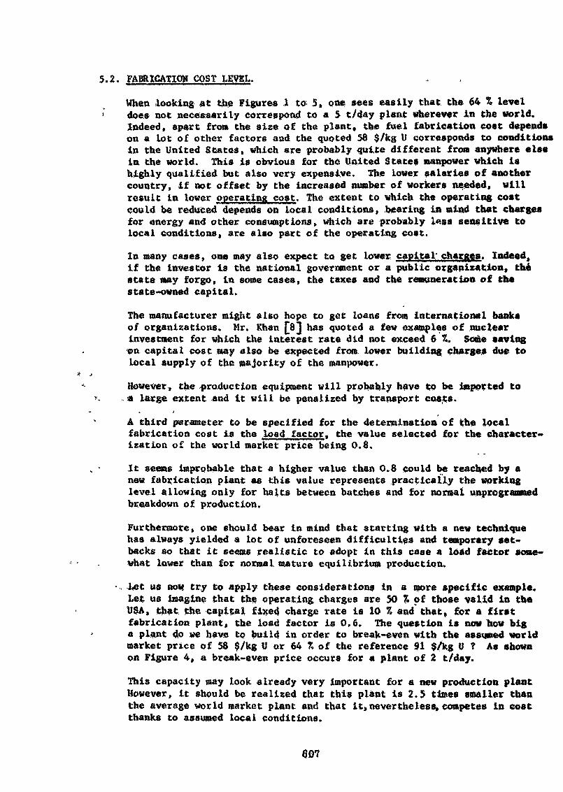
5.2. FABRICATION COST LEVEL.
When looking at the Figures .1 to 5, ot» sees easily that the 64 % level> does not necessarily correspond to a 5 t/day plant wherever in the world.
Indeed, apart from the size of the plant, the fuel fabrication coat dependson a lot of other factors and the quoted 58 $/kg U corresponds to conditionsin the United States, which are probably quite different fro» anywhere elsein. the world. This is obvious for the United States manpower which ishighly qualified but also very expensive. The lower salaries of anothercountry, if not offset by the increased number of workers needed, willresult in lower operating cost. The extent to which the operating costcould be reduced depends on local conditions, .bearing in mind that chargesfor energy and other consumptions» which are probably less sensitive tolocal conditions» are also part of the operating cost.
In many cases, one may also expect to get lower, capita I* charges. Indeed,if the investor is the national government or a public organization, thestate «ay forgo, in some cases, the taxes and the remuneration of thestate-owned capital.
The manufacturer might also hope to get loans from international banksof organizations. Mr. Khan £8^ has quoted a few examples of nuclearinvestment for which the interest rate did not exceed 6 %. Some savingon capital cost may also be expected from lower building charges due tolocal supply of the majority of the manpower.
However, the -production equipment will probably have to be imported toa large extent and it will be penalized by transport costs.
i
A third parameter to be specified for the determination of the localfabrication cost is the load factor, the value selected for the character-ization of the world market price being 0.0.
It seems improbable that a higher value than 0.8 could be reached by anew fabrication plant as this value represents practically the workinglevel allowing only for halts between batches and for normal unprogrammedbreakdown of production.
Furthermore, one should bear in mind that starting with a new techniquehas always yielded a lot of unforeseen difficulties and temporary set»backs so that it seems realistic to adopt in this case a load factor some-what lower than for normal mature equilibrium production.
. Let us now try to apply these considerations in a more specific example.Let us imagine that the operating charges are 30 % of those valid in theUSA, that the capital fixed charge rate is 10 7, and that, for a firstfabrication plant, the load factor is 0,6, The question is now how biga plant do we have to build in order to break-even with the assumed worldmarket price of 58 S/kg U or 64 % of the reference 91 $/kg U ? As shownon Figure 4, a break~even price occurs for a plant of 2 t/day.
This capacity may look already very important for a new production plantHowever, it should be realized that this plant is 2.5 times smaller thanthe average world market plant and that it,nevertheless»competes in costthanks to assumed local conditions.
607
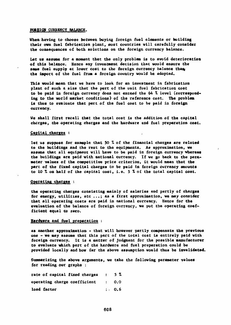
FOREIGN CURRENCY BALANCE.
When having to choose between buying foreign fuel elements or buildingtheir own fuel fabrication plant, most countries will carefully considerthe consequences of both solutions on the foreign currency balance.
Let us assume for a moment that the only problem is to avoid deteriorationof this balance. Hence any investment decision that would ensure thesame fuel supply at lower cost to the foreign currency balance tha%the import of the fuel from a foreign country would be adopted.
This would mean that we have to look for an investment in fabricationplant of such a size that the part of the unit fuel fabrication costto be paid in foreign currency does not exceed the 64 % level (correspond-ing to the world market conditions) of the reference cost. The problemis thus to evaluate that part of the fuel cost to be paid in foreigncurrency.
He shall first recall that the total cost is the addition of the capitalchsrges, the operating charges and the hardware and fuel preparation cost.
Capital charges :
let us suppose for example that 50 7» of the financial charges are relatedto the buildings and the rest to the equipments. As approximation, weassume that all equipment will have to be paid in foreign currency whereasthe buildings are paid with national currency. If we go back to the para-meter values of the competitive price criterion, it would mean that thepart of the fixed capital charges to be paid in foreign currency amountsto 10 % on half of the capital cost, i.e. 5 % of the total capital cost.
Operating charges :
the operating charges consisting mainly of salaries and partly of chargesfor energy, utilities, etc ...; as a first approximation, we may considerthat all operating costs are paid in national currency. Hence for theevaluation of the balance of foreign currency, we put the operating coef-ficient equal to zero.
Hardware and fuel preparation :
as another approximation - that will however partly compensate the previousone - we may assume that this part of the total cost is entirely paid withforeign currency. It is a matter of judgment for the possible manufacturerto evaluate which part of the hardware and fuel preparation could beprovided locally and how far the above assumption would thus be invalidated.
Summarising the above arguments, we take the following parameter valuesfor reading our graphs :
rate of capital fixed charges : S %operating charge coefficient : 0.0load factor ; • 0.6
608
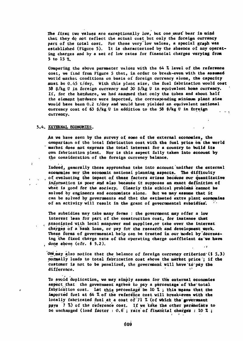
The firaç two values «re exceptionally low, but one must bear in mindthat they do «tot reflect the actual cost but only the foreign currencypart of the total cost. For these very'low values, a special graph wasestablished (Figure 5). It is characterized by the absence of any operat-ing charges and by a set of low rates for financial charges varying from5 to 15 7,.
Comparing the above parameter values with the 64 % level of the referencecost, we find from Figure 5 that, in order to break-even with the assumedworld market conditions on basis of foreign currency alone, the capacitymust be 0.45 t/day. With this plant size, the fuel fabrication would cost58 $/kg V in foreign currency and 30 $/kg U in equivalent home currency.If» for the hardware, we had assumed that only the tubes and about halfthe element hardware were imported, the corresponding minimum plant si*ewould have been 0.2 t/day and would have yielded an equivalent nationalcurrency cost of 63 $/kg U in addition to the 58 $/kg U in foreigncurrency.
5«4. EXTERNAL ECONOMIES.
.As we have seen by the survey of some of the external economies, thecomparison of the local fabrication cost with the fuel price on the world
' market does not express the total interest for a country to build itsown fabrication plant. Nor is this aspect fully taken into account bythe consideration of the foreign currency balance.
i ,Indeed,* generally these approaches take into account'neither the externaleconomies nor the economic national planning aspects, the difficulty
, of evaluating the impact of these factors arises because our quantitativeinformation is poor and also because it supposes an exact definition ofwhat is good for the society. Clearly this ethical problems cannot besolved by engineers and economists alone. But we may assume that itcan be solved by governments and that the estimated extra plant economiesof an activity will result in the grant of governmental subsidies'. '"'
The subsidies may take many forms : the government may offer a lowinterest loan for part of the construction cost, for instance that
t associated with local manpower and supplies,or take over the interestcharges of a 'bank loan, or pay for the research and development work.These forms of governmental help can be treated in our model by "decreas-ing the fixed charge rate of the operating charge coefficient es «e have
( done above (cfr. § 5.2).
'One nay also notice that the balance of foreign currency criterion'(S 5.3)normally leads to total fabrication cost above the market price ; if thecustomer is not to be penalised, the government will have to pay thedifference. ' • •
' * ,
To avoid duplication, we may simply assume for th'e external économiesaspect that the government agrees bo pay a percentage of the'totalfabrication cost. Let this percentage be 10 % ; this means that theimported fuel at 64 % of the reference cost will breakeven with thelocally fabricated fuel at a cost of 71 % (of which the governmentpays 7 %) of the reference cost. If we 'take the other parameters tobe unchanged (load factor : 0,6' ; rate'of financial charge's : 10 % ;i i _
609
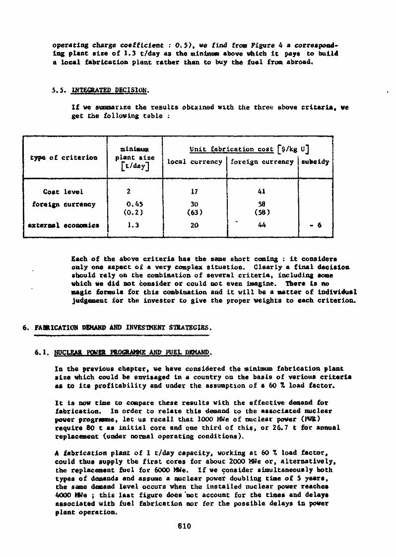
operating charge coefficient : 0.5), we find from Figure 4 a correspond-ing plant size of 1.3 t/day as the minimum above which it pays to builda local fabrication plant rather than to buy the fuel from abroad.
5.5. INTEGRATED DECISION.
If we summarize the results obtained with the three above criteria, veget the following table :
type of criterion
Cost levelforeign currency
external economies
minimumplant size[t/day]
20.45(0.2)1.3
Unit fabrication cost f$/kglocal currency
1730
(63)20
foreign currency
4158
(58)44
»Jsubsidy
- 6
Each of the above criteria has the same short coming : it considersonly one aspect of a very complex situation. Clearly a final decisionshould rely on the combination of several criteria, including somewhich we did not consider or could not even imagine. There is nomagic formula for this combination and it will be a matter of individualjudgement for the investor to give the proper weights to each criterion.
6. FABRICATION DEMAND AND INVESTMENT STRATEGIES.
NUCLEAR POWER PROGRAMME AND FUEL DEMAND.
In the previous chapter, we have considered the minimum fabrication plantsize which could be envisaged in a country on the basis of various criteriaas to its profitability and under the assumption of a 60 % load factor.
It is now time to compare these results with the effective demand forfabrication. In order to relate this demand to the associated nuclearpower programme, let us recall that 1000 MWe of nuclear power (FUR)require 80 t as initial core and one third of this, or 26.7 t for annualreplacement (under normal operating conditions).
A fabrication plant of 1 t/day capacity, working at 60 % load factor,could thus supply the first cores for about 2000 MWe or, alternatively,the replacement fuel for 6000 MWe. If we consider simultaneously bothtypes of demands and assume a nuclear power doubling time of 5 years,the same demand level occurs when the installed nuclear power reaches4000 MWe ; this last figure does 'not account for the times and delaysassociated with fuel fabrication nor for the possible delays in powerplant operation.
610
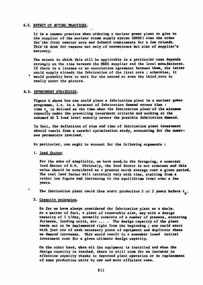
6.2. EFFECT OP BUYING PRACTICES..>
It is a common practice when ordering a nuclear power plant to give tothe supplier of the nuclear steam; supply system (NSSS) also the orderfor' the first reactor core and forward commitments for a few reloads.Thia'iB done'for reasons not only of eowertieiicé but also of supplier'swarranty.
The extent to which this will be applicable in a particular case dependsstrongly on the ties between the NSSS supplier and the local manufacturer.If there is a licence or an association agreement between them, the lattercould supply already the fabrication of the first core ; otherwise, it
* would probably have to wait for the second or even the third core toreally enter the picture.
6.3. INVESTMENT STRATEGIES.
Figure 6 shows how one could place a fabrication plant in a nuclear powerprogramme, i.e. in a forecast of fabrication demand versus time :.time t is defined as the time when the fabrication plant*of the minimumcapacity under the prevailing investment criteria and working at theassumed 60 % load level exactly covers the possible fabrication demand.
In fact» the definition of size and time of fabrication plant investmentshould result from a careful optimization study, accounting for the numer-ous parameters involved.
In particular, one ought to account for the following arguments :
1. load factor.
For the sake of simplicity, we have used»in the foregoing, a constantload factor of 0/6. Obviously, the load factor is not constant and thisvalue should be considered as & present worth average over a given period.The real load factor will certainly vary with time, starting from arather low figure and increasing to the equilibrium level over a fewyears.
The fabrication plant could thus start production 2 or 3 years before t .
2. Capacity extension.
So far we have always considered the fabrication plant as a whole.As a matter of fact, a plant of reasonable size, say with a designcapacity of I t/day, normally consists of a number of presses, sinteringfurnaces, loading units, etc ... . The design capacity of the plantneeds not to be implemented right from the beginning ; one could startwith just one of each necessary piece of equipment and duplicate theseas demand increases. This would result in a somewhat lowed initialinvestment cost for a given ultimate design capacity.
On the other hand, when all the equipment is installed and when thedesign capacity is reached, there is still room for an increase ineffective capacity thanks to improved plant operation or to replacementof some production units by new and more efficient ones.
611
3. Scale effect.
Since the fabrication cost for a given load factor decreases significantlywith plant size increase, it could be interesting to build a larger plant,The plant aize will have to be selected by making the balance of theextra investment cost, of the extra operating charges during early yearsand of the extra fuel fabrication during later years. If the increasedsize goes with delayed construction, one should also take into accountthe extra amount of fuel to order abroad before plant start-up.
7. CONCLUDING REMARKS.
For local manufacturers in countries where the nuclear power programme isstill at a low level, the application oi' the above considerations will normallyresults in not very bright prospects if the possible market is limited to thenational one.
This could be an ovcrpessimistic assumption and various ways of enlarging thepotential market are to be found.
One way would be to build a bigger plant than necessary from the nationalpoint of view and to rely on the exportation of part of the production on acompetitive price basis, possibly with the help of national authorities.
Another way would be to pool the markets of several countries in a similarposition through agreements between companies or between governments. Suchan agreement might involve a programme for building future fabrication plantsin the other countries or might cover other aspects of the fuel cycle.
One could also consider a commercial agreement with an already establishedfuel supplier and fabricate the fuel under licence. In addition to theeconomies already mentioned for research and development, one could sparemuch of the design work for the new plant and also much of its teethingproblems.
REFERENCES
Forecast of growth of nuclear power,USAEC Report - WASH 1139 (1971).
£2] Current status and future technical and economic potential of lightwater reactors,USAEC Report - «ASH 1082 (March 1968).
Competition in the nuclear power supply industry,NYO-3853-1 TID UC-2, A.D. Little INC, (December 1968).
Guide for economic evaluation of nuclear reactor plant design,NUS 531, NUS Corporation, Rockviile, Margland (January 1969).
612

A.L. Lotts, L. Goller, H.H. Klepfer and W.H.Layman,The status o£ thermal reactor fuel manufacture in the United States»P/062, Geneva Conference 6 - 16 September 1971.
f*6l A.L. Lotts, T.N, Washburn, F.J. liosman,FABCOST 9, a computer code for estimating fabrication costs for rod-bundle fuel elements,
4287 (August 1968).
J. Gaussens and R. Bonnet,Economies externes et énergie nucléaire, Symposium on internationalcomparison of nuclear power costs,London 9 - 13 October 1967.
[8] M.A. Khan,Problems of introducing nuclear power into developing countries,International survey course on technical and economic aspects ofnuclear power,Vienna, 1-12 September 1969.
J.B. Burnham, L.G. Merker, D.E. Deonigi,Comparative costs of oxide fuel elements,,BNWL - 273, Volume 2 (August 1966).
613
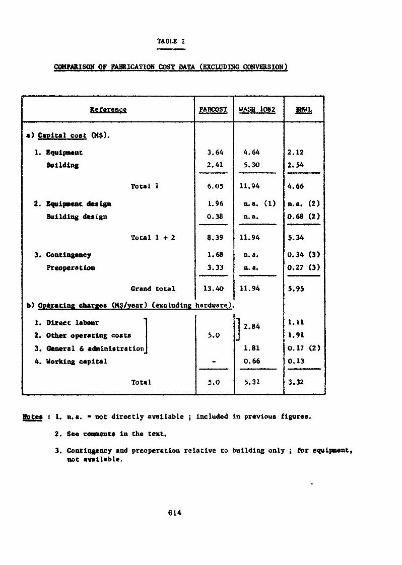
TABLE I
COMPARISON OP FABRICATION COST DATA (EXCLUDING CONVERSION)
Reference
a) Capital cost (M$).
1. EquipmentBuilding
Total 1
2* Equipment designBuilding design
Total 1-1-2
3. ContingencyPreoperation
Grand total
b) Operating charges (MC/year) (excluding
1. Direct labour2. Other operating costs3, General 6 administration
•
4. Working capital
Total
FABCOST
3.642.41
6.05
1.96
0.38
8.39
1.68
3.33
13.40
hardware),
5.0
5.0
WASH 1082
4.645.30
11.94
n.a. (1)n. a.
11.94
n.a.n. a.
11.94
41
2.84w
1.81
0.66
5.31
BllKL
2.122.54
4.66
n.a. (2)0.68 (2)
5.34
0.34 (3)0.27 (3)
5.95
1.111.910.17 (2)
0.13
3.32
Hotes : 1. n.a. « not directly available ; included in previous figures.
2. See comments in the text.
3. Contingency and preoperation relative to building only ; for equipment»not available.
614
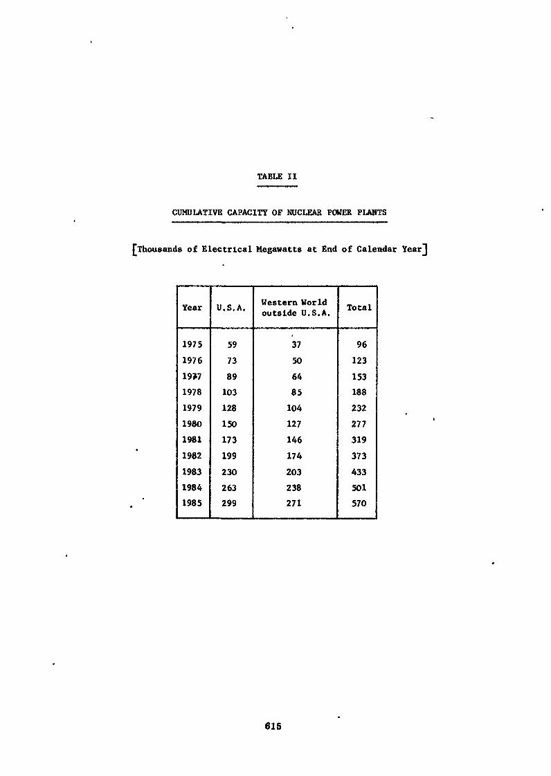
TABLE II
CUMULATIVE CAPACITY OF NUCLEAR POWER PLANTS
Thousands of Electrical Megawatts at End of Calendar Year"]
Year
1975197619>719781979198019811982198319841985
U.S.A.
59
73
89103128150
173
199230
263299
Western Worldoutside U.S.A.
3750
6485104127
146174203238271
Total
96123153188232277319373433501570
615
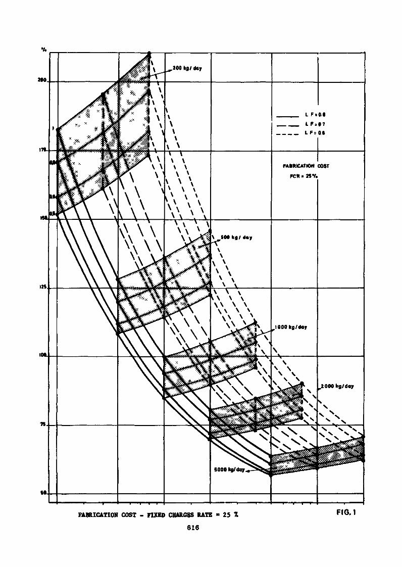
FABRICATION COST
KK « 25V.
FABRICATION COST - FIXED CHARGES RATE
616
25 FI6.1
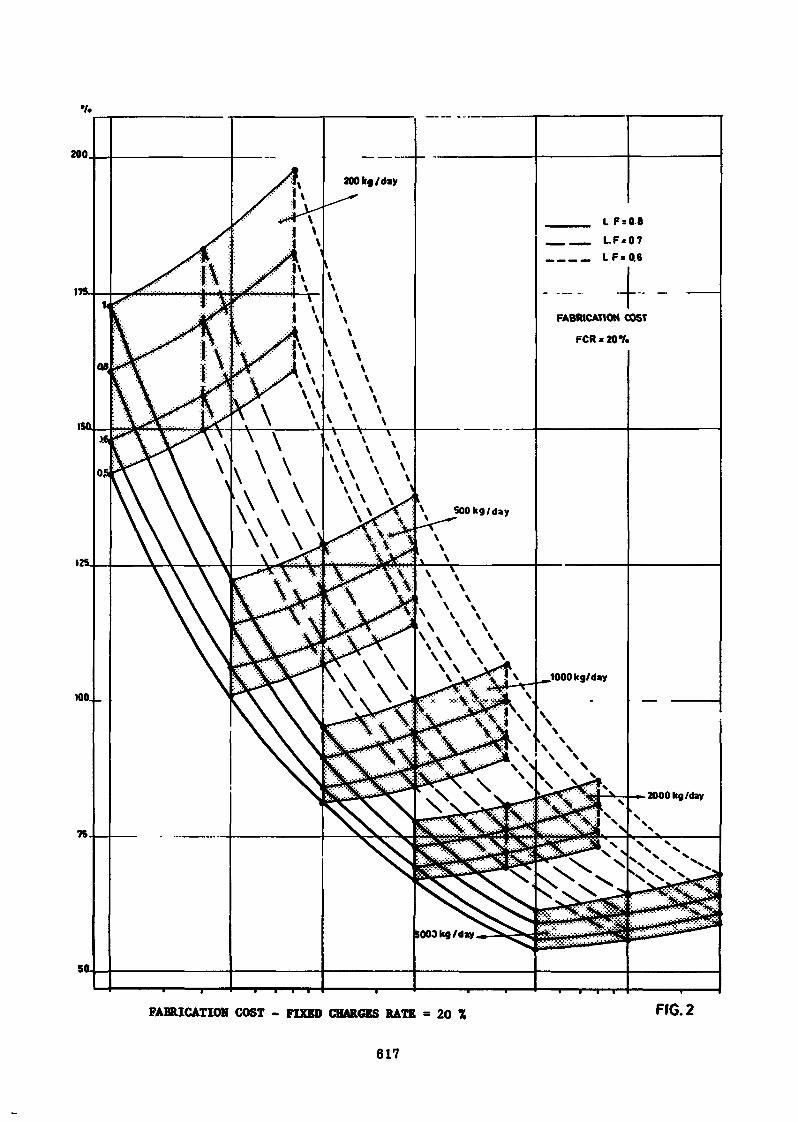
FABRICATION COST - FIXED CHARGES RATE - 20 FfG.2
617
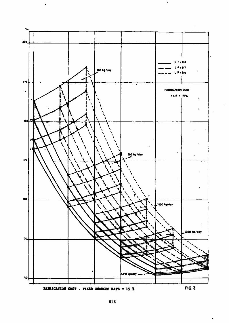
so
FABRICATION COST - FIXED CHARGES RATE - 15 X FIG. 3
618
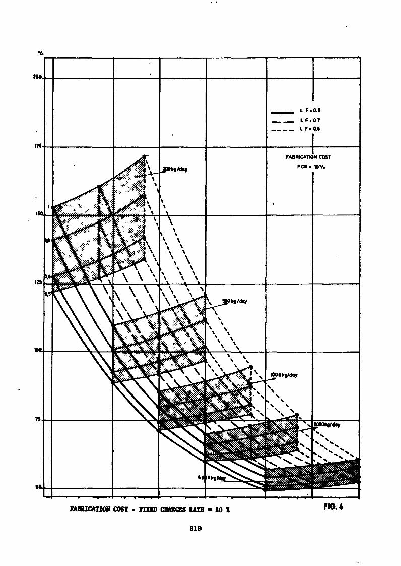
FABRICATION COST - FIXED CHARGES RATE - 10 FIG. A
619
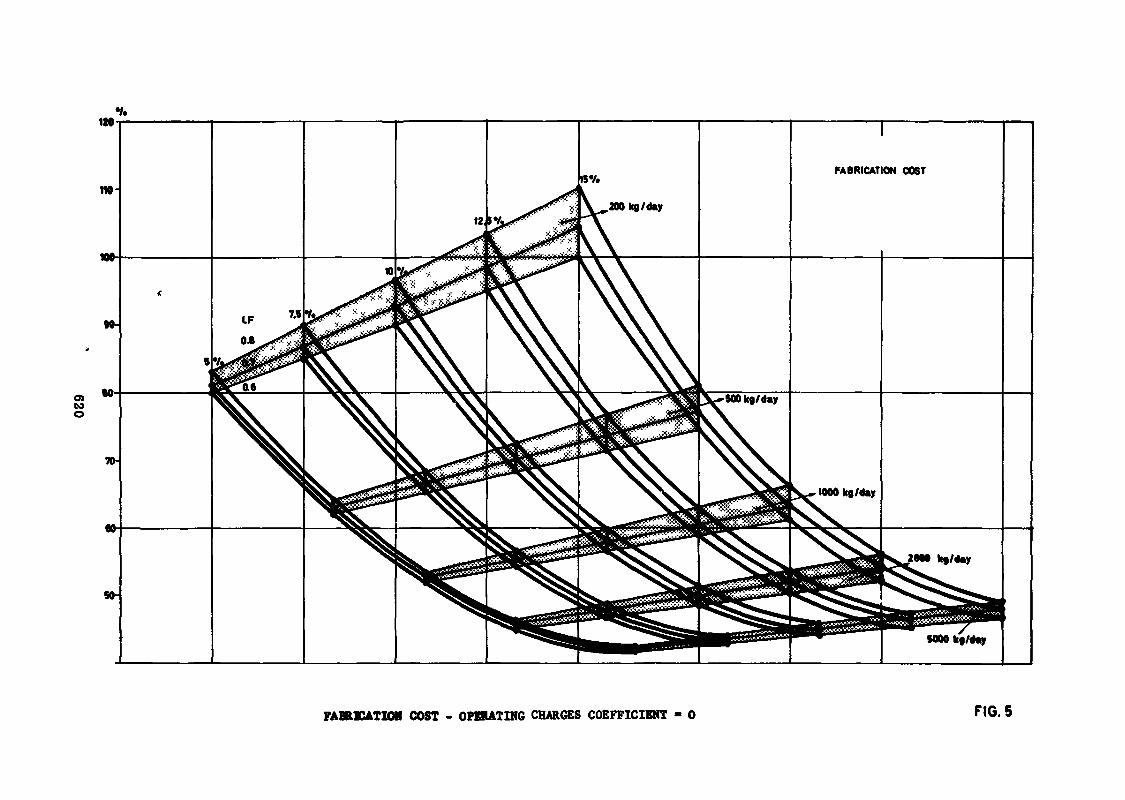
o>too
FABftKATXON COST - OPERATING CHARGES COEFFICIENT - 0 FIG. 5
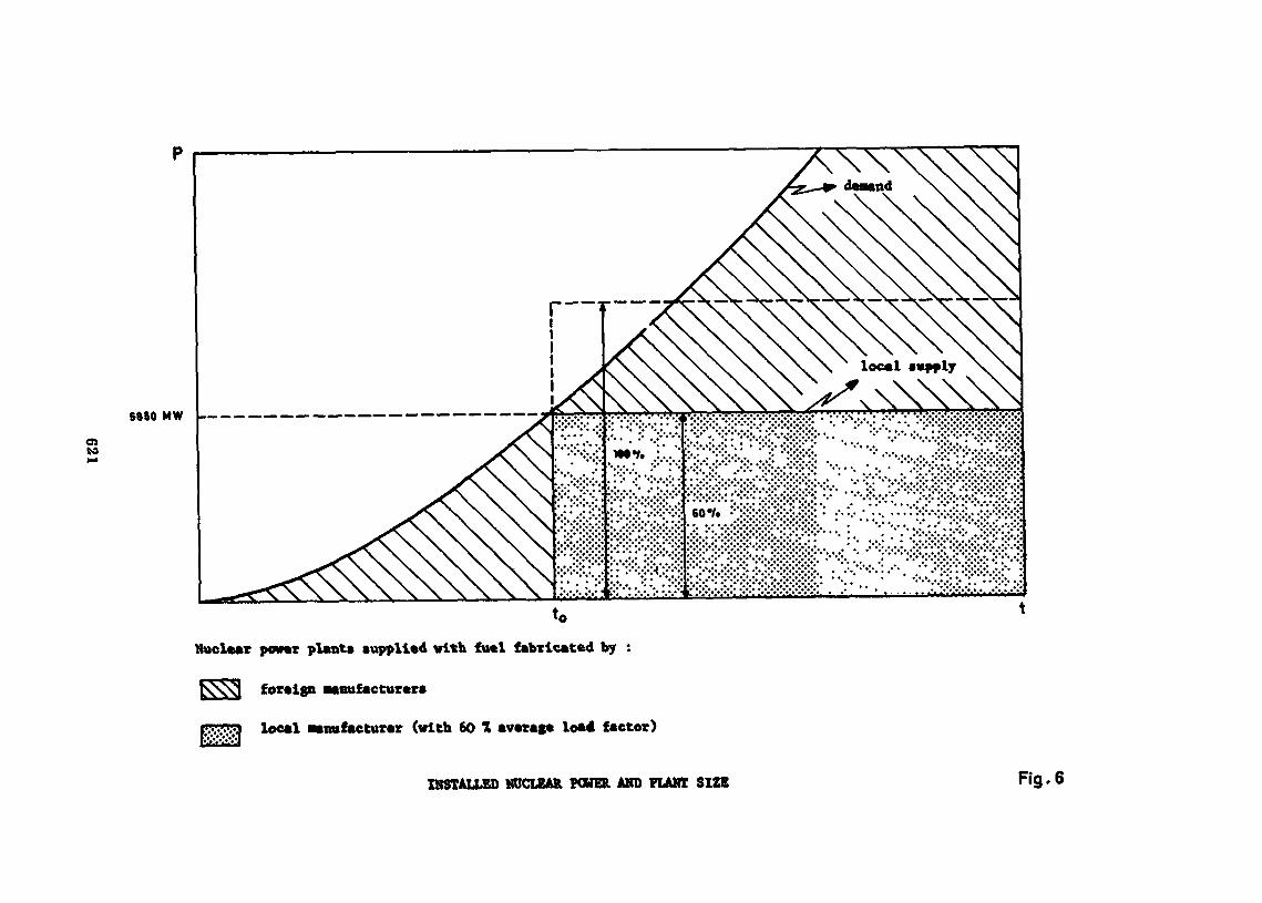
Oito
SftSO MW |———— —————— ——————————————————— ———
Nuclear power plants «applied with fuel fabricated by :
foreign «enufacturere
p- j local •anufacturer (with 60 X average load factor)
INSTALLED NUCLEAR POWER AND PLANT SIZE Rg. 6
Study Group on tho î-hciiities and Technologyneeded for TEuclear Fuel îa
Grenoble, 4-15 September 1972
LIST OP PABTICIPAWS
(L) » Lecturer
Country Name and Address
.Argentina
Australia
Austria
Belgium
Brasil
Ing. José Helmut KollComiston Nacional de Snergia Atomica ArgentinaAvenida Libertador 8250Buenos Aires
Mr. O.L. HannaAlternate Resident Representative of Australiato the International Atomic Energy AgencyPostfach 8A-1013 Vienna
Mr. Alfred ReichlGemeinschaftskerokraftwerk Tullnerfeld Ces.m.b.H.Marc Aurel-Str. 4, Stg. 1A-1010 Vienna
Mr. E. DetilleuxEurochemic (European Company for the ChemicalProcessing of Irradiated Fuels)Mol/Donk
Mr. A. FlipotŒN MolBoeretang 200B-2400 Mol
Mr. T5, JonckheereSociété Belgonucléaire35 rue des ColoniesBrussels I
Mr. D. de WassetgeManager Fuel Project ManufacturingWENESÇ (subsidiary of Westinghouse Electric Cor.)Rue Gatti de Cfamond 951180 Brussels
Mr. Mauricio Grir.bergHead, Metallurgy DivisionInstitute de Engenharia Nuclear
623
Canada
Prance
Mr. Glaner Trench de Pré i tasExpert, Metallurgy DivisionInstituto de Énergia Atomica
Mr. Juarez Tavora Veado
Mr. L.M. Villeia Ribeiro
c/o Comisao Nacional de Energia NuclearRua General Severiano 90 - BotafogoRio de Janeiro, Guanabara
Mr. William C. DurantManager Nuclear ProductsManufacturing and EngineeringCanadian General Electric Company107 Park Street WorthPeterborough, Ontario
Mr. SegelAtomic Energy of CanadaChalk River Laboratories
Mr. BoduChief dee Services de Traitement des Minerais et deRaffinage à la Sous-Direction de l'Uranium naturel duCommissariat à l'Energie Atomique29-35 it» de la Fédération75015 Paris
Mr. Savornin - Mr. DoumercCERCA26 - Romans
Mr. Léger - Mr. BoutonnetDirectorSIMO Company192 Grande Rue92 - Sèvres
Mr. BergognonDivision des Produits CarbonésSOFREM10 rue du Général PoyParie 8
Mr. Chochet-MuchySociété Comurhex10, rue du Général-Poy75008 Paris
Mr. Mézin (for Mr. Coates)Commissariat à l'Energie Atomique29-33 rue de la Fédération75015 Paris
624
Mr. Jacques BellotDirector
Mr. Albert TeboulChef de Service
both C.I.C.A.P. (Compagnie Industrielle desCombustibles Atomiques Frittes)B.P. No. 3384 - Bollène
Mr. Fuhrmann3.I.C.N. (Soctétô Industrielle desCombustibles Nucléaires)74 - Annecy
L Mr. IiO DuifjouAdjoint au Chef du S^FTC (Service do lubricationIndustrielle des Eléments Combustibles etMatériaux de Structure)CEW-FARB.P. Ko. 4Chat il Ion sous Bagneux
Mr. JeamnerreThef du SBPIC - CFîN-FAR
Mr. Guise - Mr. CugnardeyPe oh iney-Ugine-Kuh Imann16 rue de MonceauParis 75008
P.R. _.p.f Ctermany L Dr. BeckerHBG Heaktor-Brennelemente GmbHD-6451 Wolfgang bei Hanau
l, Dr. P. Vy/?en (for Dr. Hackstern)HUK5MD-6451 Vfolffjang bei Hanau
India L Dr. W.K. RaoHead, Atomic Fuels DivisionBhabha Atomic Research OnterBombay
Iran Mr« Mehdi SarramAss, ProfessorTeheran University, Kuclear CenterTeheran
Mohammed AbassianMinistry of Water andTeheran
625
Israel
Mexico
Netherlands
Mr, Michael Z. RonDirectorNuclear Fuel Fabrication FacilityN.R.C.N.c/o Israel Atomic Energy Commission26 rhov HauniversitahP.O. Box 17120Tel-Aviv
Mr. Cogliati
Mr. Benito S. TranchinaACTP NucleareCentro di MediCinaMedicinaBologna
Prof. Gianoarlo SchileoChef du programme plutonium du CNENViale Regina Margherita 1231-00198 Roma
Mr. PetskiFabrication NuclearPizza CarignonoGeneva
Mr. Shinro AbikoPower Reactor and Nuclear Fuel Corporation9-15, 1-Chôme, Akasaka, Minato-kuTokyo
Mr. Toru HaginoyaMitsubishi Metal CorporationMitsubishi Kinzoku Building5-2, 1-Chome, Ohte-Machi, Chiyoda-kuTokyo
Mr. Yasuji NakamuraManager, Nuclear Fuel DivisionPower Reactor and Nuclear Fuel Development Corporation9-13» 1-Chome, Akasaka, Minato-kuTokyo
Ing. Roberto TurnbullSupervisor de las Direcciones de MaterialesNucleares y de BénéficieInstitute Nacional de Energia NuclearAv. însurgentes Sur Num. 1079Apartado Postal 27-190Mexico, D.F.
Prof. Dr. J. Pelserc/o Reactor Centrum NederlandWesterduinweg 3Petten (NH)
626
Norway
Pakistan
Poland
Portugal
all
Romania
South Africa
Kr. P.P. SensManaging DirectorInterfuel B.V»c/o Permanent Mission of the Netherlandsto the International Atomic Energy AgencyUntere Donaustrasse 13-15A-1020 Vienna
Mr. Roar RoseDivision DirectorInstitutt for AtomenergiP.O. Box 402007 Kjeller
Mr. Steiner AasResearch ManagerInstitutt for AtomenergiP.O. Box 402007 Kjeller
Dr. Ahmed MukhtarNuclear Materials DivisionPakistan Atomic Energy CommissionP.O. Box No. 3112Karachi 29
Prof. W. Rutkowskic/o Permanent Mission of Poland to theInternational Atomic Energy AgencyHietzinger Hauptstrasse 42cA-1130 Vienna
Ing. Henrique PichIng. Emilio RosaIng. Henrique José Gomes CarvalhinhosCommission de l'Energie Nucléaire(Junta de Energia Nuclear)79 Hua de S. Pedro de AlcantaraLisboa-2
Mr. Gheorghe ObrejaDirecteur TechniqueDirection des Matériaux det Equipements NucléairesComité d'Etat pour l'Energie NucléaireB.P. 1167Romesen - 311
Mr. R. LugteriburgMaterials Evaluation SubdivisionAtomic Energy BoardPrivate Bag 256Pretoria
627
South Korea L
Sweden
Turkey
U.K.
Dr. Byoung Whie LeePrincipal Research Metallurgical Engineero/o the Office of the Atomic Energy ofthe Republic of KoreaP.O. Box 7, Chung Ryang RiSeoul
Mr. Luis Guttierrez-JordaDirector de Plantas Piloto e IndustrialesMr. José Luis Otero de la GandaraJefe de la Division de MatenalesMr. Jacobo Diaz DiazJefe de la Division de Metalurgia
a.11 Junta de Energia NuclearCiudad UniversitariaMadrid-5
Mr. Carlos Melches SerranoTechnical DirectorMr. Fernandez-Canadas
both ERUSA (Bmpresa Nacional del Uranio)Spain - Madrid
L Mr. Gustav ftstbergAB AtomenergiïfcckS-611 01 Nykoping 1
L Mr. B. LarssonSandvik ABPackS-811 01 Sandviken 1
Mr. Utfcu SadikDipl. Eng. M. Se.14/5 Meydan Sokak, CankayaAnkara
Mr. Sedat UzMr. Altan Dogu
both c/o Permanent Mission of Turkey to theInternational Atomic Energy AgencyPrinz Eugen-Strasse 40A-1040 Vienna
L Dr, H. RoganGeneral Manager
L Mr* J. Doranboth British Nuclear Fuels Ltd.
Sprahgfields WorksSalvick, PrestonLanes. PR4 OXJ
628
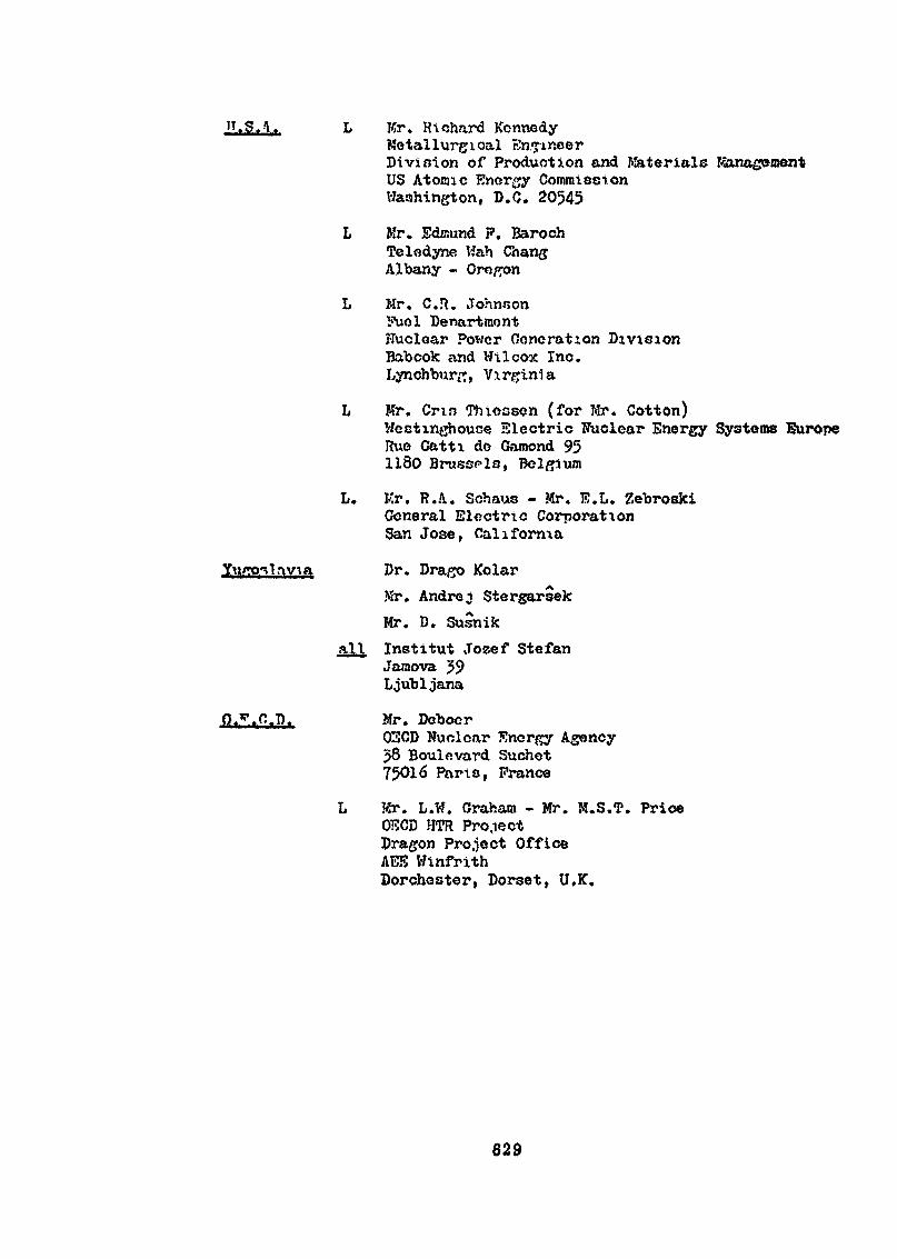
11.S..-\iT, L Kr. Richard KennedyMetallurgical En pincerDivision of Production and Materials KanageraentUS Atonic Energy CommissionWashington, B.C. 20545
L Mr. Edisund P. BarochTeledyne Wah ChangAlbany - Oregon
L Mr, C.R. Johnsonï'uGl DenartmontNuclear Power Generation DivisionBabcok and Wtlcox Inc.Lynchburf;, Virginia
L Mr. Crin Thiecsen (for Mr. Cotton)VJestinghouce Electric Nuclear Energy Systems EuropeRue Catti do Gamond 951180 Bruscpla, Belgium
L. Kr. R.A. Schaus - Mr. E.L. ZebroskiGeneral Electric CorporationSan Jose, California
Dr. Dra/jo KolarMr. Andréj StergarsekMr. D. Susnik
n).\ Institut Jozef StefanJaiaova 59Ljubljana
Mr. Deboer03CD Wucloar Energy Agency58 Boulevard Suchet75016 Paris, Prance
L Kr. L.W. Graham - Mr. K.S.T. PriceOKCD HTR Pro.iectDragon Project OfficeAEK WinfrithDorchester, Dorset, U.K.
629
Related Documents


